Service manual для принтера Epson L100, L101, L200, L201
Данная подробная инструкция поможет вам в разборке и обслуживании принтера Epson L100, L101, L200, L201.
Соблюдайте правила безопасности при работе с электрооборудованием - отключайте принтер от источника питания перед началом ремонтных работ. Работа должна выполнятся квалифицированным персоналом с соответствующими знаниями.
 Руководство подготовлено производителем, ни сайт, ни производитель не несет никакой ответственности за ущерб вследствие любых неточностей при выполнении указанных в данном Руководстве действий.
 Вся документация по обслуживанию предоставляется только для информации. Вся документация по техническому обслуживанию предназначена только для использования обученным и сертифицированным сервисным персоналом. Обслуживание оборудования, модулей, элементов или частей самостоятельно может аннулировать гарантийные обязательства, в отношении обслуживания данного оборудования.
 Соблюдайте правила безопасности при работе с электрооборудованием - отключайте принтер от источника питания перед началом ремонтных работ. Работа должна выполнятся квалифицированным персоналом с соответствующими знаниями.
Руководство подготовлено производителем, ни сайт, ни производитель не несет никакой ответственности за ущерб вследствие любых неточностей при выполнении указанных в данном Руководстве действий.
Вся документация по обслуживанию предоставляется только для информации. Вся документация по техническому обслуживанию предназначена только для использования обученным и сертифицированным сервисным персоналом. Обслуживание оборудования, модулей, элементов или частей самостоятельно может аннулировать гарантийные обязательства, в отношении обслуживания данного оборудования.
Соблюдайте правила безопасности при работе с электрооборудованием - отключайте принтер от источника питания перед началом ремонтных работ. Работа должна выполнятся квалифицированным персоналом с соответствующими знаниями.
Руководство подготовлено производителем, ни сайт, ни производитель не несет никакой ответственности за ущерб вследствие любых неточностей при выполнении указанных в данном Руководстве действий.
Вся документация по обслуживанию предоставляется только для информации. Вся документация по техническому обслуживанию предназначена только для использования обученным и сертифицированным сервисным персоналом. Обслуживание оборудования, модулей, элементов или частей самостоятельно может аннулировать гарантийные обязательства, в отношении обслуживания данного оборудования. This manual, consists of the following chapters, is intended for repair service personnel and includes information necessary for properly performing maintenance and servicing the product.
CHAPTER 1. DISASSEMBLY / REASSEMBLY;
Describes the disassembly/reassembly procedures for main parts/units of the product, and provides the standard operation time for servicing the printer Epson L200/L100.
CHAPTER 2. ADJUSTMENT;
Describes the required adjustments for servicing the product.
CHAPTER 3. MAINTENANCE;
Describes maintenance items and procedures for servicing the printer Epson L200 / L100.
CHAPTER 4. APPENDIX;
Provides the following additional information for reference:
• Power-On Sequence;
• Connector Summary;
• Troubleshooting.
Download Epson L200/L201, L100/L101. Service Manual
![]()
SERVICE MANUAL
Color Inkjet Printer
L200/L201
L100/L101
CONFIDENTIAL
SEMF10-001
Notice:
All rights reserved. No part of this manual may be reproduced, stored in a retrieval system, or transmitted in any form or by any means, electronic, mechanical, photocopying, recording, or otherwise, without the prior written permission of SEIKO EPSON CORPORATION.
All effort have been made to ensure the accuracy of the contents of this manual. However, should any errors be detected, SEIKO EPSON would greatly appreciate being informed of them.
The contents of this manual are subject to change without notice.
The above not withstanding SEIKO EPSON CORPORATION can assume no responsibility for any errors in this manual or the consequences thereof.
EPSON is a registered trademark of SEIKO EPSON CORPORATION.
Note :Other product names used herein are for identification purpose only and may be trademarks or registered trademarks of their respective owners. EPSON disclaims any and all rights in those marks.
Copyright © 2010 SEIKO EPSON CORPORATION
IJP CS Quality Assurance Department
Confidential
Safety Precautions
All safety procedures described here shall be strictly adhered to by all parties servicing and maintaining this product.
DANGER
Strictly observe the following cautions. Failure to comply could result in serious bodily injury or loss of life.
1.Always disconnect the product from the power source and peripheral devices when servicing the product or performing maintenance.
2.When performing works described in this manual, do not connect to a power source until instructed to do so. Connecting to a power source causes high voltage in the power supply unit and some electronic components even if the product power switch is off. If you need to perform the work with the power cable connected to a power source, use extreme caution to avoid electrical shock.
WARNING
Strictly observe the following cautions. Failure to comply may lead to personal injury or loss of life.
1.Always wear protective goggles for disassembly and reassembly to protect your eyes from ink in working. If any ink gets in your eyes, wash your eyes with clean water and consult a doctor immediately.
2.When using compressed air products; such as air duster, for cleaning during repair and maintenance, the use of such products containing flammable gas is prohibited.
PRECAUTIONS
Strictly observe the following cautions. Failure to comply may lead to personal injury or damage of the product.
1.Repairs on Epson product should be performed only by an Epson certified repair technician.
2.No work should be performed on this product by persons unfamiliar with basic safety knowledge required for electrician.
3.The power rating of this product is indicated on the serial number/rating plate. Never connect this product to the power source whose voltages is different from the rated voltage.
4.Replace malfunctioning components only with those components provided or approved by Epson; introduction of second-source ICs or other non-approved components may damage the product and void any applicable Epson warranty.
5.In order to protect sensitive microprocessors and circuitry, use static discharge equipment, such as anti-static wrist straps, when accessing internal components.
6.Do not tilt this product immediately after initial ink charge, especially after performing the ink charge several times. Doing so may cause ink to leak from the product because it may take some time for the waste ink pads to completely absorb ink wasted due to the ink charge.
7.Never touch the ink or wasted ink with bare hands. If ink comes into contact with your skin, wash it off with soap and water immediately. If you have a skin irritation, consult a doctor immediately.
Confidential
8.When disassembling or reassembling this product, make sure to wear gloves to avoid injuries from metal parts with sharp edges.
9.Use only recommended tools for disassembling, reassembling or adjusting the printer.
10.Observe the specified torque when tightening screws.
11.Be extremely careful not to scratch or contaminate the following parts.
Nozzle plate of the printhead
CR Scale
PF Scale
Coated surface of the PF Roller
Gears
Rollers
LCD
Scanner Sensor
Exterior parts
12.Never use oil or grease other than those specified in this manual. Use of different types of oil or grease may damage the component or give bad influence on the printer function.
13.Apply the specified amount of grease described in this manual.
14.Make the specified adjustments when you disassemble the printer.
15.When cleaning this product, follow the procedure described in this manual.
16.When transporting this product after filling the ink in the printhead, pack the printer without removing the ink cartridges in order to prevent the printhead from drying out.
17.Make sure to install antivirus software in the computers used for the service support activities.
18.Keep the virus pattern file of antivirus software up-to-date.
Confidential

About This Manual
This manual, consists of the following chapters, is intended for repair service personnel and includes information necessary for properly performing maintenance and servicing the product.
CHAPTER 1. DISASSEMBLY / REASSEMBLY
Describes the disassembly/reassembly procedures for main parts/units of the product, and provides the standard operation time for servicing the product.
CHAPTER 2. ADJUSTMENT
Describes the required adjustments for servicing the product.
CHAPTER 3. MAINTENANCE
Describes maintenance items and procedures for servicing the product.
CHAPTER 4. APPENDIX
Provides the following additional information for reference:
•Power-On Sequence
•Connector Summary
•Troubleshooting
Symbols Used in this Manual
Various symbols are used throughout this manual either to provide additional information on a specific topic or to warn of possible danger present during a procedure or an action. Pay attention to all symbols when they are used, and always read explanation thoroughly and follow the instructions.
Indicates an operating or maintenance procedure, practice or condition that, if not strictly observed, could result in serious injury or loss of life.
Indicates an operating or maintenance procedure, practice, or condition that, if not strictly observed, could result in bodily injury, damage or malfunction of equipment.
May indicate an operating or maintenance procedure, practice or condition that is necessary to accomplish a task efficiently. It may also provide additional information that is related to a specific subject, or comment on the results achieved through a previous action.
For Chapter 1 “Disassembly/Reassembly”, symbols other than indicated above are used to show additional information for disassembly/reassembly. For the details on those symbols, see “ 1.2 Disassembly/Reassembly Procedures (p14)”.
Confidential

Revision Status
|
Revision |
Date of Issue |
Description |
|
A |
October 8, 2010 |
First Release |
Confidential

|
L200/L201/L100/L101 |
Revision A |
Contents
Chapter 1 Disassembly/Reassembly
|
1.1 |
Overview |
…………………………………………………………………………………………………….. ……………………………………….. |
9 |
|
|
1.1.1 |
Tools …………………………………………………………………………………………………………………………………………….. |
9 |
||
|
1.1.2 |
Checks …………………………………………………………………………………..and precautions before disassembling |
10 |
||
|
1.1.3 |
Protection …………………………………………………………………………………………………………..for Transportation |
12 |
||
|
1.2 |
Disassembly/Reassembly ………………………………………………………………………………………………………Procedures |
14 |
||
|
1.2.1 |
Standard ……………………………………………………………………………Operation Time for servicing the product |
15 |
||
|
1.2.2 |
Disassembling/Reassembling …………………………………………………………………………………………..Flowchart |
18 |
||
|
1.2.2.1 ………………………………………………………………………………………………………………………… |
Housing Part |
18 |
||
|
1.2.2.2 …………………………………………………………………………………………………………. |
Printer Mechanism Part |
20 |
||
|
1.3 |
Details of ……………………………………………………………………………….Disassembling/Reassembling by Parts/Unit |
23 |
||
|
1.4 |
Routing FFCs/cables …………………………………………………………………………………………………………………………….. |
31 |
||
|
Chapter 2 Adjustment |
||||
|
2.1 |
Required Adjustments …………………………………………………………………………………………………………………………… |
34 |
||
|
2.2 |
Details of …………………………………………………………………………………………………………………………..Adjustments |
36 |
||
|
2.2.1 TOP ………………………………………………………………………………………………………………..Margin Adjustment |
36 |
|||
|
Chapter 3 Maintenance |
||||
|
3.1 |
Overview …………………………………………………………………………………………………………………………………………….. |
38 |
||
|
3.1.1 |
Cleaning………………………………………………………………………………………………………………………………………. |
38 |
||
|
3.1.2 |
Lubrication…………………………………………………………………………………………………………………………………… |
38 |
||
|
3.2 |
Lubrication ………………………………………………………………………………………………………….Points and Instructions |
39 |
||
|
Chapter 4 Appendix |
||||
|
4.1 |
Power-On Sequence ……………………………………………………………………………………………………………………………… |
42 |
||
|
4.2 |
Connector ……………………………………………………………………………………………………………………………….Diagram |
44 |
||
|
4.3 |
Troubleshooting……………………………………………………………………………………………………………………………………. |
45 |
||
|
4.3.1 Troubleshooting …………………………………………………………………………………………………………….Workflow |
45 |
|||
|
4.3.2 |
Fatal ……………………………………………………………………………………………………………………………Error Code |
47 |
7
Confidential

CHAPTER 1
DISASSEMBLY/REASSEMBLY
Confidential

|
L200/L201/L100/L101 |
Revision A |
1.1 Overview
This chapter describes procedures for disassembling the main parts/units of L200/L201/L100/L101. Unless otherwise specified, disassembled parts/units can be reassembled by reversing the disassembly procedure. See the cautions or tips for disassembly/reassembly described in “ 1.3 Details of Disassembling/Reassembling by Parts/Unit (p23)”.
Read the following before disassembling and reassembling.
“ Safety Precautions (p3)”
“ 1.1.2 Checks and precautions before disassembling (p10)”
When you have to remove units or parts that are not described in this chapter, see the exploded diagrams of SPI (Service Parts Information).
1.1.1 Tools
Use only specified tools to avoid damaging the printer.
|
Table 1-1. Tools |
||
|
Name |
EPSON Part Code* |
|
|
(+) Phillips screwdriver #1 |
1080530 |
|
|
(+) Phillips screwdriver #2 |
— |
|
|
Flathead screwdriver |
— |
|
|
Flathead Precision screwdriver #1 |
— |
|
|
Tweezers |
— |
|
|
Longnose pliers |
— |
|
|
Acetate tape |
1003963 |
|
|
Nippers |
— |
|
Note *: All of the tools listed above are commercially available.
EPSON provides the tools listed with EPSON part code.
|
Disassembly/Reassembly |
Overview |
9 |
Confidential
|
L200/L201/L100/L101 |
Revision A |
1.1.2 Checks and precautions before disassembling
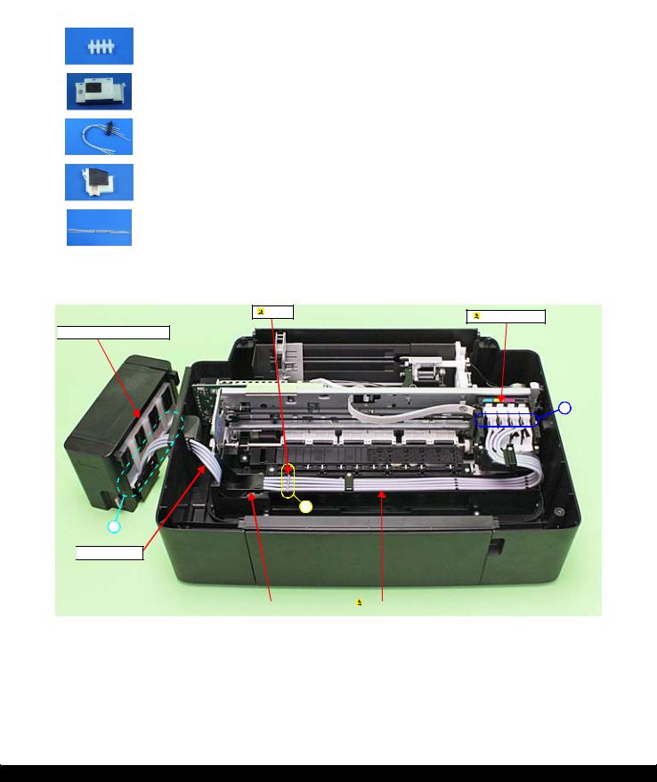
Ink may spill when removing the following parts from L200/L201/L100/L101.
This section describes the parts that may cause ink spill and the means to minimize the ink spill when removing the parts.
The parts that may cause ink spill when removing
|
Parts |
When ink may spill |
Location |
|
Joint |
Removing the tubes of the Valve Assy / Tube Assy |
A |
|
from the Joint |
||
|
Ink Supply Tank Assy |
Removing the tubes of the Valve Assy from the Joint |
|
|
Removing the tubes of the Valve Assy from the Ink |
||
|
Supply Tank Assy |
A, B |
|
|
Valve Assy |
||
|
Adapter Assy |
Removing the Tube Assy from the Adapter Assy |
C |
|
Tube Assy |
Removing the tubes of the Valve Assy / Tube Assy |
|
|
from the Joint |
A, C |
|
|
Removing the Tube Assy from the Adapter Assy |
||
Note : These parts are indicated with the  icon in disassembly/reassembly flowchart. (See “ 1.2 Disassembly/Reassembly Procedures (p14)”.)

 Ink Supply Tank Assy
C
A
B

 Valve Assy
|
Ink Tube Guide 1st |
Tube Assy |
Figure 1-1. Location
|
Disassembly/Reassembly |
Overview |
10 |
Confidential

|
L200/L201/L100/L101 |
Revision A |
Means do to minimize the ink spill
Even observing the points described in this section, ink may spill in the following situations. Therefore, be careful not to contaminate the inside of the printer or its surroundings by preparing the container to receive the leaked ink, or the like.
When removing the Valve Assy, some ink will spill from both ends of the ink tube even the Valve Lever is closed.
When removing the Tube Assy, all the ink in the ink tube will spill.
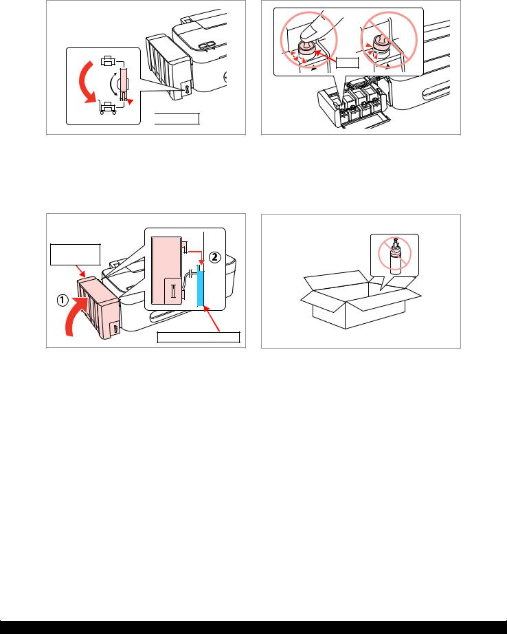
Before disassembling, confirm that the printer is in the following condition.
Choke Valve is closed
Do not turn the Valve Lever too much when closing the Choke Valve, otherwise, the Valve Lever and/or Valve Assy may get damaged.
•Before disassembling:
Turn the Valve Lever and be sure to close the Choke Valve.
•After reassembling is complete:
Open the Choke Valve to perform the print inspection.
•Before returning the printer to the user after repairing:
Make sure to turn the Valve Lever up to the choke position to close the Choke Valve before packing the printer.
|
Open position |
Choke position |
Choke position
(When checking with the Valve Lever removed.)
Valve shaft
Choke Valve shaft is secured more tightly in Choke position than in Open position.
Figure 1-2. Opening/closing the Choke Valve
Adapter Assy is removed
Before disconnecting the joint parts of the ink path, make sure that the Adapter Assy is removed from the Carriage.
|
Adapter Assy |
Carriage |
|
|
Ink path |
||
Figure 1-3. Adapter Assy
The Adapter Assy has an ink valve which cuts off the ink path when removing the Adapter Assy from the carriage.
|
Disassembly/Reassembly |
Overview |
11 |
Confidential
|
L200/L201/L100/L101 |
Revision A |
1.1.3 Protection for Transportation
Before packing the printer for returning it to the user, secure it at the specified points with strong tape to avoid damaging the printer or ink leakage during transport, and make sure to check the points as follows.
Securing each parts
Secure the following parts with strong tape (width: 22 mm).
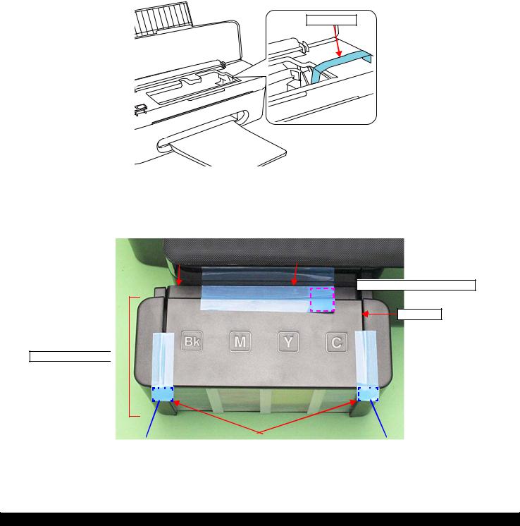
Securing the Carriage Assy
1.Cofirm that the Carriage Assy is locked in the home position.
2.Attach the unfolded end of strong tape (fold the other end back 5 mm) on the bottom left of the CR Cover.
3.Pull the tape to the right side of the housing and attach it tightly.
Strong tape
Figure 1-4. Securing the Carriage Assy
Securing the Ink Tank
•Secure both sides of the Top Cover with strong tape (x2).
•Secure the Ink Supply Tank Assy and Ink Supply Holder Assy with strong tape (x1).
|
Ink Supply Holder Assy |
Strong tape (22 mm x 105 mm) |
 Fold over the tape edge by 15 mm
Top Cover
Ink Supply Tank Assy 
|
Fold over the tape edge by 10 mm |
Strong tape (22 mm x 55 mm) |
Fold over the tape edge by 10 mm |
Figure 1-5. Securing the Ink Supply Tank Assy
|
Disassembly/Reassembly |
Overview |
12 |
Confidential
|
L200/L201/L100/L101 |
Revision A |
Points to be checked before packing the printer
The Valve Lever is on the position shown below (the Choke Valve is closed). (See Figure 1-2.)
All the caps of the Ink Supply Tank Assy are securely closed.
 Valve Lever
|
The hooks (x2) of the Ink Supply Tank Assy are |
The opened ink bottle is not included in the box. |
|
securely engaged with the Ink Supply Holder Assy. |
|
Ink Supply |
|
Tank Assy |
|
Ink Supply Holder Assy |
|
Disassembly/Reassembly |
Overview |
13 |
Confidential
|
L200/L201/L100/L101 |
Revision A |
1.2 Disassembly/Reassembly Procedures
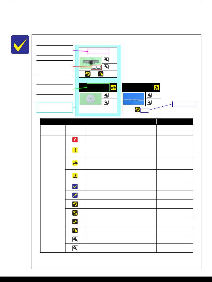
This section describes procedures for disassembling the parts/units in a flowchart format. For some parts/units, detailed procedures or precautions are provided (accordingly indicated by icons and cell’s color). Refer to the explanations in the example chart below and perform an appropriate disassembling and reassembling procedure. (See“ 1.3 Details of Disassembling/Reassembling by Parts/Unit (p23)”.)
For routing cables, see “ 1.4 Routing FFCs/cables (p31)”
The example below shows how to see the charts on the following pages.
|
Black letters indicate a |
|||||||
|
part/unit not supplied as |
Main Frame |
||||||
|
an ASP. |
|||||||
|
Shows the screw types |
4 |
||||||
|
and the specified torque |
S1 |
S5 |
5 |
||||
|
in the “Screw type/torque |
|||||||
|
list”. |
(p 24) |
(p 39) |
|||||
|
White letters indicate a |
EJ Roller Gear |
Tube Assy |
|||||
|
part/unit supplied as an |
|||||||
|
ASP. |
— |
— |
|||||
|
Shows removal/ |
— |
— |
Reference page |
||||
|
installation as a unit/assy. |
|||||||
|
is available. |
— |
(p 28) |
|||||
|
Item |
Description |
Reference |
|||||
|
Parts/unit name |
White-letter |
Parts/units supplied as an ASP |
— |
||||
|
Black-letter |
Parts/units not supplied as an ASP |
— |
|||||
|
Indicates a practice or condition that could result in |
Indicates the reference |
||||||
|
injury or loss of life if not strictly observed. |
page in blue-letter |
||||||
|
Indicates a practice or condition that could result in |
Indicates the reference |
||||||
|
damage to, or destruction of equipment if not strictly |
|||||||
|
page in blue-letter |
|||||||
|
observed. |
|||||||
|
Indicates the parts that are inevitably broken in the |
|||||||
|
disassembling procedure, and should be replaced with |
— |
||||||
|
a new one for reassembly. |
|||||||
|
Indicates the parts that may cause the ink spill when |
“ 1.1.2 Checks and |
||||||
|
precautions before |
|||||||
|
they are removed. |
|||||||
|
disassembling (p10)” |
|||||||
|
Indicates necessary check items in the disassembling/ |
Indicates the reference |
||||||
|
reassembling procedure. |
page in blue-letter |
||||||
|
Icon |
Indicates supplementary explanation for disassembly |
Indicates the reference |
|||||
|
is given. |
page in blue-letter |
||||||
|
Indicates particular tasks to keep quality of the units |
Indicates the reference |
||||||
|
are required. |
page in blue-letter |
||||||
|
Indicates particular routing of cables is required. |
Indicates the reference |
||||||
|
page in blue-letter |
|||||||
|
Indicates particular adjustment(s) is/are required. |
Chapter 2 “ Adjustment |
||||||
|
(p33)” |
|||||||
|
Indicates lubrication is required. |
Chapter 3 “ Maintenance |
||||||
|
(p37)” |
|||||||
|
Indicates the number of screws securing the parts/ |
— |
||||||
|
units. |
|||||||
|
Indicates the points secured with other than a screw |
— |
||||||
|
such as a hook, rib, dowel or the like. |
|||||||
|
Disassembly/Reassembly |
Disassembly/Reassembly Procedures |
14 |
Confidential

|
L200/L201/L100/L101 |
Revision A |
1.2.1 Standard Operation Time for servicing the product
The following are the standard operation time for servicing the product. Those are based on the MTTR result measured using a prototype.
The underlined parts/units are supplied as After Service Parts.
|
Standard Operation Time for servicing L200/L201: |
See Table 1-2. |
|
|
Standard Operation Time for servicing L100/L101: |
See Table 1-3. |
Table 1-2. Standard Operation Time (L200/L201)
|
Time (second) |
|||||
|
Parts/Unit |
Replace- |
Adjust- |
Total |
||
|
ment |
ment |
||||
|
Panel Unit |
14 |
0 |
14 |
||
|
Panel Board |
29 |
0 |
29 |
||
|
Paper Support Assy |
12 |
0 |
12 |
||
|
Paper Support Tray |
20 |
0 |
20 |
||
|
Paper Support Tray 2 |
26 |
0 |
26 |
||
|
Stacker Assy |
12 |
0 |
12 |
||
|
Tray Exit Inner |
15 |
0 |
15 |
||
|
Tray Exit Outer |
18 |
0 |
18 |
||
|
Jam Cover |
17 |
0 |
17 |
||
|
Document Cover |
9 |
0 |
9 |
||
|
Document Pad |
20 |
0 |
20 |
||
|
ASF Cover |
5 |
0 |
5 |
||
|
Ink Cartridge Cover |
18 |
0 |
18 |
||
|
Rear Cover |
10 |
0 |
10 |
||
|
Scanner Unit |
228 |
0 |
228 |
||
|
CIS |
245 |
0 |
245 |
||
|
Middle Housing Assy |
674 |
0 |
674 |
||
|
Middle Housing |
146 |
0 |
146 |
||
|
USB Cover |
146 |
0 |
146 |
||
|
LD Roller Assy |
186 |
406 |
592 |
||
|
LD Roller |
227 |
406 |
633 |
||
|
Housing Buckler |
183 |
0 |
183 |
||
|
Roller Idler Pick Assy |
160 |
0 |
160 |
||
|
CR Scale |
181 |
0 |
181 |
||
|
Main Board |
150 |
535 |
685 |
||
|
Driven Pulley Assy |
363 |
0 |
363 |
||
|
Pick Assy |
376 |
0 |
376 |
||
|
Cap Unit |
405 |
0 |
405 |
||
|
Lever Cleaner |
175 |
0 |
175 |
||
|
Cap Assy |
449 |
0 |
449 |
||
|
Time (second) |
|||||
|
Parts/Unit |
Replace- |
Adjust- |
Total |
||
|
ment |
ment |
||||
|
Printhead |
364 |
1642 |
2006 |
||
|
Holder Contact |
293 |
0 |
293 |
||
|
EJ Frame Assy |
149 |
0 |
149 |
||
|
EJ Roller |
170 |
406 |
576 |
||
|
EJ Roller Gear |
134 |
0 |
134 |
||
|
Waste Ink Pads (for |
230 |
0 |
230 |
||
|
flushing) |
|||||
|
Cover Flashing |
195 |
0 |
195 |
||
|
Porous Pad Front Paper |
159 |
0 |
159 |
||
|
Guide |
|||||
|
CR Motor |
235 |
406 |
641 |
||
|
Power Supply Unit |
129 |
406 |
535 |
||
|
Waste Ink Tray Assy |
163 |
35 |
198 |
||
|
Waste Ink Pads |
239 |
35 |
274 |
||
|
Main Frame |
501 |
406 |
907 |
||
|
Carriage Assy |
906 |
406 |
1312 |
||
|
PCB Encoder |
953 |
406 |
1359 |
||
|
Head FFC |
939 |
406 |
1345 |
||
|
Timing Belt |
915 |
406 |
1321 |
||
|
Carriage |
995 |
406 |
1401 |
||
|
Upper Paper Guide |
269 |
0 |
269 |
||
|
Pump Assy |
791 |
0 |
791 |
||
|
Gear Pump Idle |
797 |
0 |
797 |
||
|
Lever Pick Clutch |
798 |
0 |
798 |
||
|
Gear Pump |
811 |
0 |
811 |
||
|
Bracket Pump |
832 |
0 |
832 |
||
|
Roller Pump |
827 |
0 |
827 |
||
|
Waste Ink Tube |
892 |
0 |
892 |
||
|
Pump Housing |
892 |
0 |
892 |
||
|
Waste Ink Pads |
409 |
0 |
409 |
||
|
(under the Cap Assy) |
|||||
|
PF Encoder |
148 |
0 |
148 |
||
|
PF Scale |
170 |
0 |
170 |
||
|
Disassembly/Reassembly |
Disassembly/Reassembly Procedures |
15 |
Confidential
 Loading…
Additional Information:
Print, scan, and share directly from your iPhone®, iPad®, or iPod® Touch. Print photos, emails, webpages and files including Microsoft® Word, Excel®, PowerPoint® and PDF documents. Also supports Box, Dropbox, Evernote®*1, Google Drive™ and Microsoft OneDrive™. Epson iPrint makes printing easy and convenient whether your printer is in the next room or across the world. Key Features • Print, scan, and share directly from your iPhone, iPod Touch or iPad • Print from anywhere in the world to email-enabled Epson printers using remote print functionality • Print photos, PDFs and Microsoft Office documents such as Word, Excel and PowerPoint • Print stored files, email attachments, and online files from Box, Dropbox, Evernote, Google Drive and Microsoft OneDrive • Capture a document with your device camera, format, enhance, then save, ready to print • Scan from your Epson all-in-one and share your file (save to your device, send via email or save online) • Copy documents and photos using your mobile device and a nearby Epson printer • Transfer files between your device and an SD card or USB drive via an Epson printer • Check your printer’s status and ink levels • Print within a complex network environment using manual IP printer setup • Get help with a built-in FAQ section Advanced Features • Print high quality photos with automatic backlight and color cast correction • Choose and print multiple photos • Print your email attachments and stored files • Configure your print options including paper size and type, number of copies, page range and one- or two-sided printing • Print with and without borders • Switch between color or monochrome printing • Choose from different scanning resolutions and image types • Optimize print quality • Buy ink and supplies for your printer • Setup & register to Epson Connect • Manage remote printers
About This Epson l200/l100 Series Service Manual
Epson l200/l100 Series Service Manual, consists of the following chapters, is intended for repair service personnel and includes information necessary for properly performing maintenance and servicing the product.
Epson l200/l100 Table of Content
CHAPTER 1. DISASSEMBLY / REASSEMBLY
Describes the disassembly/reassembly procedures for main parts/units of the product, and provides the standard operation time for servicing the product.
CHAPTER 2. ADJUSTMENT
Describes the required adjustments for servicing the product.
CHAPTER 3. MAINTENANCE
Describes maintenance items and procedures for servicing the product.
CHAPTER 4. APPENDIX
Provides the following additional information for reference:
- Power-On Sequence
- Connector Summary
- Troubleshooting
Epson l200/l100 Overview
This chapter describes procedures for disassembling the main parts/units of L200/L201/L100/L101. Unless otherwise specified, disassembled parts/units can be reassembled by reversing the disassembly procedure. See the cautions or tips for disassembly/reassembly described in “ 1.3 Details of Disassembling/Reassembling by Parts/Unit (p23)”. Read the following before disassembling and reassembling.
- Safety Precautions (p3)
- 1.1.2 Checks and precautions before disassembling (p10)
When you have to remove units or parts that are not described in this chapter, see the exploded diagrams of SPI (Service Parts Information).
Checks and precautions before disassembling
Ink may spill when removing the following parts from L200/L201/L100/L101. This section describes the parts that may cause ink spill and the means to minimize the ink spill when removing the parts.
- The parts that may cause ink spill when removing
- Means do to minimize the ink spill
Epson l200/l100 Protection for Transportation
Before packing the printer for returning it to the user, secure it at the specified points with strong tape to avoid
damaging the printer or ink leakage during transport, and make sure to check the points as follows.
Securing each parts
Secure the following parts with strong tape (width: 22 mm).
- Securing the Carriage Assy
- Cofirm that the Carriage Assy is locked in the home position.
- Attach the unfolded end of strong tape (fold the other end back 5 mm) on the bottom left of the CR Cover.
- Pull the tape to the right side of the housing and attach it tightly.
see picture on manual pdf below
- Securing the Ink Tank
- Secure both sides of the Top Cover with strong tape (x2).
- Secure the Ink Supply Tank Assy and Ink Supply Holder Assy with strong tape (x1).
Epson l200/l100 Disassembly/Reassembly Procedures
This section describes procedures for disassembling the parts/units in a flowchart format. For some parts/units, detailed procedures or precautions are provided (accordingly indicated by icons and cell’s color). Refer to the explanations in the example chart below and perform an appropriate disassembling and reassembling procedure. (See“ 1.3 Details of Disassembling/Reassembling by Parts/Unit (p23)”.) For routing cables, see “ 1.4 Routing FFCs/cables (p31)”
Read More Epson l200/l100 Series Service Manual pdf Below
.JPG)