
Сборник руководств на английском языке по эксплуатации и техническому обслуживанию квадроциклов CFMoto моделей CF500/CF500-A/CF500-5B/CF500-5C/CF625-B/CF625-C.
- Издательство: —
- Год издания: —
- Страниц: —
- Формат: PDF
- Размер: 74,3 Mb
Руководство на английском языке по техническому обслуживанию и ремонту квадроциклов CFMoto моделей CF500 и CF500-A.
- Издательство: Chunfeng Holding Group
- Год издания: 2006
- Страниц: 254
- Формат: PDF
- Размер: 12,8 Mb

Руководство на русском языке по эксплуатации и техническому обслуживанию квадроциклов CFMoto модели CF500-A.
- Издательство: —
- Год издания: —
- Страниц: 206
- Формат: PDF
- Размер: 2,8 Mb
Руководство на русском языке по ремонту квадроциклов CFMoto модели CF500-A.
- Издательство: —
- Год издания: —
- Страниц: 266
- Формат: PDF
- Размер: 15,8 Mb

Руководство на русском языке по эксплуатации и техническому обслуживанию квадроциклов CFMoto моделей CF500-2 и CF500-2A 2008 года выпуска.
- Издательство: —
- Год издания: —
- Страниц: 144
- Формат: PDF
- Размер: 6,9 Mb

Руководство на русском языке по эксплуатации и техническому обслуживанию мотовездехода CFMoto модели CF500-3 с полным приводом.
- Издательство: —
- Год издания: —
- Страниц: 163
- Формат: PDF
- Размер: 2,1 Mb
Руководство на английском языке по техническому обслуживанию и ремонту квадроциклов CFMoto моделей CF500-5B и CF500-5C.
- Издательство: Zhejiang CFMOTO Power Co., Ltd.
- Год издания: 2009
- Страниц: 272
- Формат: PDF
- Размер: 23,2 Mb

Руководство на английском языке по эксплуатации и техническому обслуживанию мотовездеходов CFMoto Terracross моделей CF500-6/CF625-3/CF625-6 с полным приводом.
- Издательство: —
- Год издания: —
- Страниц: 135
- Формат: PDF
- Размер: 16,9 Mb

Руководство на русском языке по эксплуатации и техническому обслуживанию квадроциклов CFMoto модели CF625-X6 EFI.
- Издательство: —
- Год издания: —
- Страниц: 157
- Формат: PDF
- Размер: 43,8 Mb
Руководство на русском языке по эксплуатации и техническому обслуживанию квадроциклов CFMoto модели CF800-2X8 EFI.
- Издательство: —
- Год издания: —
- Страниц: 162
- Формат: PDF
- Размер: 3,4 Mb

Руководство на английском языке по техническому обслуживанию и ремонту квадроциклов CFMoto модели CF800-2 Terralander 800 с полным приводом.
- Издательство: Zhejiang CFMOTO Power Co., Ltd.
- Год издания: 2011
- Страниц: 316
- Формат: PDF
- Размер: 16,5 Mb

Руководство на французском языке по эксплуатации и техническому обслуживанию квадроциклов CFMoto моделей Goes 520 и Goes 520 Max с полным приводом.
- Издательство: —
- Год издания: —
- Страниц: 30
- Формат: PDF
- Размер: 2,7 Mb

Руководство на русском языке по эксплуатации и техническому обслуживанию квадроциклов CFMoto моделей HX500-S и HX500-L 2009 года выпуска.
- Издательство: —
- Год издания: —
- Страниц: 146
- Формат: PDF
- Размер: 3,8 Mb
Руководство на чешском языке по эксплуатации и техническому обслуживанию квадроциклов CFMoto модели JourneyMan Gladiator RX.
- Издательство: —
- Год издания: —
- Страниц: 31
- Формат: PDF
- Размер: 1,1 Mb

Руководство на чешском языке по эксплуатации и техническому обслуживанию квадроциклов CFMoto модели JourneyMan Gladiator X-8.
- Издательство: —
- Год издания: —
- Страниц: 24
- Формат: PDF
- Размер: 802 Kb

Руководство на чешском языке по эксплуатации и техническому обслуживанию мотовездеходов CFMoto модели JourneyMan Gladiator Z6.
- Издательство: —
- Год издания: —
- Страниц: 24
- Формат: PDF
- Размер: 823 Kb

Руководство на русском языке по эксплуатации и техническому обслуживанию мотовездеходов CFMoto модели SSV 625-Z6 EFI с полным приводом.
- Издательство: —
- Год издания: —
- Страниц: 131
- Формат: PDF
- Размер: 5,7 Mb
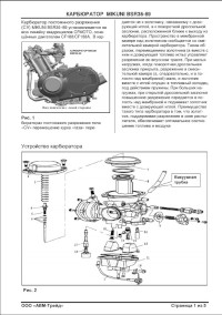
Руководство на русском языке по ремонту карбюратора Mikuni модели BSR36-89.
- Издательство: —
- Год издания: —
- Страниц: 5
- Формат: PDF
- Размер: 393 Kb
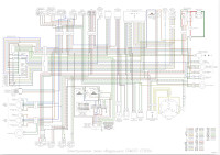
Электросхемы на русском и английсом языках квадроциклов CFMoto моделей CF500/CF500-A/CF500-X5/CF625-X6/CF800-2-X8.
- Издательство: —
- Год издания: —
- Страниц: —
- Формат: PDF
- Размер: 5,1 Mb


-
#1
Есть у кого, киньте в меня пожалуйста!

-
#2
Последнее редактирование:

-
#5
Там описание настройки иглы карбюратора.Я думаю не столь важная.
-
#6
Может быть и не в тему я при ремонте пользуюсь не только форумом(за что ему (ОГРОМНОЕ СПАСИБО) и сайтом ( промалчу ) но и книжным пособием вообще не плохо.
-

51 KB
Просмотры: 1,319

-
#13
вот моя подборка инструкций по ремонту на х6 в папке разное на х5 и х8 х 6.rar

-
#14
На Х8 есть русский сервис-мануал.
У меня в подписи.
Давнооооооо лежит….
-
#16
На х6 есть у кого сервис мануал?
-
#18
Тоже нужен сервис мануал на х6
-
#19
Поиском пробывали в гугле искать ??? Учим английский
CFMoto CF625-C Specifications | Manualzz
View online(267 pages) or download PDF(14.87 MB) CFMoto CF625-C Specifications • CF625-C Offroad Vehicle pdf manual download and more CFMoto online manuals
![]()
manualzz.com
-
#20
Сервисмануал на Z8-EFI не попадался ? Спасибо

WWW.CFMOTO.COM
CF625-B CF625-C
Service Manual

All rights reservedZhejiang CFMOTO Power Co., Ltd.
Aug. 2009

FORWARD
This manual introduces X6 EFI version( CF625-B/CF625-C) maintenance information, disassemblyprocedure, check & adjustment methods, trouble-shooting and technical specifications. There areillustrations, drawing to guide your operations.
Chapter 1 mainly introduces general operationinformation, tools, vehicle structure and basicspecifications. Chapter 2 mainly introduces check & adjustmentmethods and how to do vehicle maintenance. Chapter 3 mainly introduces disassembly,installation, adjustment, maintenance and trouble-shooting information.
CFMOTO reserves right to make improve-ments and modifications to the productswithout prior notice. Overhaul and mainte-nance should be done according to actualcondition of vehicle.
Zhejiang CFMOTO Power Co., Ltd.
Aug. 2009
CONTENTS
Maintenance Information 1
Vehicle Body, Muffler 2
Checking& Adjustment 3
Cooling & Lubricating System 4
Engine Disassembly & Assembly 5
Engine Disassembly, Check&
Assembly 6
7
8
9
Fuel Supply& Air Intake System
Front Wheel, Brake, Suspension,
Steering System
Rear Wheel, Brake, Suspension
System
Front & Rear axle 10
Electric System 11
12 Lighting, Odometer, Switch
Troubleshooting 13

Conversion TableItem Example ConversionPressure 200 kPa(2.00kgf/cm2 ) 1kgf/cm2=98.0665kPa 1kpa=1000Pa
33kPa (250mmHg) 1mmHg=133.322Pa=0.133322kPsTorque 18N m(1.8kgf m) 1kgf m=9.80665N mVolume 419ml 1ml=1cm3=1cc
1l=1000cm3
Force 12N(1.2kgf) 1kgf=9.80665N

1. Maintenance Information
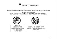
CautionsSafety Cautions1. Hazardous components in exhaust. Do not run the engine in a enclosed or poorly ventilated place for long time.
2. Do not touch the engine or muffler with bare hands after the engine has just stopped to avoid burns. Wear long-sleeve work clothes and gloves for operation.
3.Battery acid (dilute sulfuric acid) is highly caustic and may cause burns to skin and eyes. Flush with water ifsplashed to skin and get immediate medical attention. Flush with water if splashed to clothes to avoid burns. Keepbattery and liquid away from reach of children
4.Anti-freeze is poisonous. Do not drink or splash to skin, eyes or clothes. Flush with plenty of soap water if splashedto skin. If splashed into eyes, flush with water and consult the doctor. If drinking the coolant, induce vomit and consultthe doctor. Keep coolant away from reach of children.
5. Wear proper work clothes, cap and boots. If necessary, were dust-glass, gloves and safety glasses.
6. Gasoline is highly flammable. No smoking or fire. Also keep against sparks. Vaporized
gasoline is also explosive. Operate in a well-ventilated place.
7.When charging, Battery may generate hydrogen which is explosive. Charge the battery in a well-ventilated place.
8. Be careful not to get pinched by the turning parts like wheels and clutch.
9. When more than two people are operating, keep reminding each other for safety purpose.
Cautions for Disassembling and Assembling
1. Use genuine CFMOTO parts, lubricants and grease
3. Clean the mud, dust before overhauling
2. Store the disassembled parts separately in order for correct assemble.
4. Replace the disassembled washers, o-rings, piston pin retainer, cotter pin with new ones.
5. Elastic retainers might get distorted after disassembled. Do not use the loosened retainers.
6. Clean and blow off the detergent after disassembling the parts. Apply lubricants on the surface of moving parts.Measure the data during disassembly for correct assembling.
7.If you do not know the length of screws, install the screws one by one and make sure they are screwed in with samedepth.
8.Check if the disassembled rubber parts are aged and replace if necessary. Keep the
rubber parts away from grease.
9.Pre-tighten the bolts, nuts and screws, then tighten according to the specified torque,
from big to small and from inner side to outer side.
10.Replace aged rubber parts before assembling. Do not mix volatile oil and grease on the surface,due toaggressivness of fuel and oil.
11.Apply or inject recommended lubricant to the specified parts
12.Use special tools wherever necessary.
13. When ball bearing disassembled by pressing ball ring, it can not be reused.
Caution………………………………1-1 Numbers Marking Locations……….1-3 Main Parameters Table……………1-4 Maintenance Parameters Table……1-6
Tightening Torque…………………1-13Grease & Sealant…………………1-18Wiring, Pipe & Cables Layout……1-19Failure Indicator…………………….1-23

14.Turn the inner and outer rings of ball bearing to make sure the bearing will turn smoothly. Replace if any axial or radial play is found. If the surface is uneven, clean with oil and replace if the cleaning does not help.When pressing the
bearing into the machine or to the shaft.15.Install the one-side dust-proof bearing in the right direction. When assembling the open type or double-sidedustproof bearing, install with manufacturer’s mark outward.16.Keep the bearing block still when blowing dry the bearing after washing clean. Apply oil or lubricant beforeassembling.17.Install the elastic circlip properly. Turn the circlip after assembling to make sure it has been seated into theslot.18.After assembling, check if all the tightened parts are properly tightened and can move smoothly.19.Brake fluid and coolant may damage coating, plastic and rubber parts. Flush these parts with water ifsplashed.20.Install oil seal with the side of manufacturer’s mark outward. Do not fold or scratch the oil seal lip. Apply grease to the oil seal lip before assembling21.When installing pipes, insert the pipe till the end of joint. Fit the pipe clip, if any, into the groove. Replace thepipes or hoses that cannot be tightened.22.Do not mix mud or dust into engine and/or the hydraulic brake system.23.Clean the gaskets and washers of the engine casing before assembling. Remove the scratches on the jointfaces by polishing evenly with an oilstone.24.Do not twist or bend the cables too much. Distorted or damaged cables may cause poor operation.25.When assembling the parts of protection caps, insert the caps to the grooves, if any.

1. Maintenance Information
Numbers Marking Location CF625-B/CF625-CVIN Number: LCELDUS1~/LCELDUS2~Engine Number:196S-B~
Engine Number Location
VIN Number Location

Main Data TableItem Parameter
Model CF625-B/CF625-C Length CF625-B:2100mm CF625-C: 2300mm Width 1180m m Height 1230mm Wheel base CF625-B: 1290mm
CF625-C: 1490mm Engine type 196S-B Displacement CF625-B/CF625-C:594cm 3 Fuel type Unle aded gasoli ne RQ-90or above Dry weight CF625-B: 344 kg CF625-C: 358 kg Number of Passengers CF625-B:1 (driver included)
CF625-C:2 (driver included) Ma x. Load 210 kg
Tire
Front Ti re 25×8-12 40J 185/80-12 40J
Rear Tire 25×10-12 47J 270/60-12 47J
Min. Ground Clearance 275m m Turning Diameter CF625-B:4000 mm CF625-C:4750mm
Engine
Star ti ng Electrical starting, Manual Starting
Engine Type Single cylinder, 4-stroke, Liquid-cooled, 4 valves, OHC
Com bustion Cham ber Type Triang le Valve Dr iv ing Type SOHC /Chain Dri ve Bore ×Stroke 196S-B: 96m m×82.0mm Com pression Ratio 196S-B:10:1 Lubr ication Type P ressure & Splash Oil Pump Type Rotor Lubr icant Fi lter Type Full fl ow f ilter Oil Type SAE15W-40/SF Cool ing Type Closed coolant circulation Coolant Type -35 anti- rus t an ti -freeze

1. Maintenance Information
Item Param eter
Fuel Dev ice
Air Filter type Sponge element filter
Valve Type Type: CF188-B-173000 Diameter of mixing valve
36mm
Gear ing
Clutch Wet, Auto-Centr ifugal Operation M ode Autom atic(CVT)+Park ing & Gear Shift ing
Gears Shi ft Low Ge ar, High Gear & Reverse Gear Shift M ode/order Manual /L-H-N-R
( CVT )
Transmission Ratio
2.88~0.70
Gear Ratio
Final Ratio 1.333(24/18,Bevel Gear) Se condary Ratio 1.952(41/21)
Gears Low Gear : 2.25(36 /1 6) ; High Gear :1.350(27/20) ; Reverse Gear :1.471(25/17)
Total Low Gear5.857 ; High Gear : 3.514 ;
Reverse Gear:3.828
Axle Ratio
Front Axle 33 / 9 = 3.667
Rear Axle 33 / 9 = 3.667
Engine Ou tp ut M ode Front/Rear Shaft Di rec tion of Output Rotation Clockwise on forward shift
Steer ing Dev ice
Steer ing Angle
Inner 31º Outer 31º
B rake Type Front Hydraul ic Disc Rear Hydraul ic Disc
Bumper Dev ice Suspens ion Swing Arm
Frame Type Welded Steel Tube and Plate

Maintenance Parameters Table
Lubrication System
Air Inlet System
Item Standard Service Limit Engine Oil Capacity
Volume when replacing 1900mL(2.01Qts) - Volume when replacing filter
2200mL(2.32Qts) -
Recommended Oil(See Original)
·Specially for 4-stroke motorcycle SAE-15W-40
Subst itutes must be used in the following range. API type: SE or SF grade SAE type: Choose from
the left chart according to the environmental temperature
Oil Pump Rotor
Gap between Inner and Outer Rotors
0.03~0.1mm 0.15mm
Gap between Outer rotor and body
0.03~0.1mm 0.12mm
Oil pressure 130-170KPa(18.85Psi-24.66Psi) at 3000RPM
Item Standard
Fuel Tank Capacity Full capacity 18L(4.76Gallons) Valve CF188-B-173000 Inlet Pressure Sensor CF188-B-175000 Inlet Temperature Sensor CF188-B-177000 Air Bypass Valve CF188-B-172000 Injector CF188-B-171000 Idle Speed 1400±100rRPM

1. Maintenance Information
Cooling System
I tem Standar d /Param eter Ser vic e
L i m it R em ark
Ful l Capacity 2000m l 0.53Gallons R eser vo i r tank c apacity 300ml 10.14Ounces
Standard D ens ity 50% Openin g pr es sur e o f radiato r
ca p 108k pa(1 .1k gf /cm 2 ) 15.6Psi
T hermo stat
In i ti a l Temper a ture
71±3 159.8 F
F u ll open i ng Temper a ture
88 190.4 F
Fu l l open ing l if t r ange
3.5~ 4.5mm/95?
Temper a ture and
Res is ta nce of Water
Temper a ture Sens or
Temper a tu re( ) End B
R esi stance(Ω ) E nd A C
R es is tanc e(kΩ)
-20 —- 13.71-16.94
25 —— 1.825-2.155
50 176-280 —-
80 63.4-81.4 0.303-0.326 110 24.6-30.6 0.138-0.145
Temper a ture of
T hermo stat
C l ose — Open 88 ( 190 .4F )R ound 88 R ound 190.4F
O pen- Cl ose 82 ( 179 .6F )R ound 82 R ound 179.6F
C oolan t Type
-35 an t i- f r eeze , an t is epsis , h igh- bo il co olan t

Front Wheel
Rear Wheel
Brake System
I tem Standard Ope ra t ion
L im it
Fr on t W hee l
P lay o f w hee l r im
Vert i ca l 1 .0m m 2.0m m H or izon ta l 1 .0m m 2 .0m m
T ir e G ro ove - 3 .0m m
P res su r e 35k Pa ( 0.35k g f /
cm 2) / ( 5 .08Psi )
-
I tem Standar d O per a t ion L im it
R ear W hee l
P lay o f w hee l r im
Vert i ca l 1 .0mm 2 .0m m H or izon tal
1 .0mm 2 .0m m
T ir e G ro ove - 3 .0m m
P res su r e 30kP a(0 .30k g f/ cm 2)
/ (4 .35Ps i) -
I tem Standa r d O pe ra t i on L i m it
F r on t Brak e Br ake E nd P lay 0m m - Br ake D i sc T h ick ness 3 .5m m 2 .5m m
R ear Br ake Br ake E nd P lay 5 — 10 mm - Br ake P eda l Pla y 0m m - Br ake D i sc T h ick ness 7 .5m m 6 .5m m

1. Maintenance Information
Battery, Charging Device, Pickup Coil
Ignition Device
Item Standard
Ignition ECU Ignition
Spark Plug
Type Resistance Spark plug Standard DPR7EA-9(NGK) Optional DR8EA ,D7RTC Spark plug gap 0.8-0.9mm Spark Characteristic >8mm,1mpa
Igni tion Timing BTDC10ºCA 1500r/min Igni tion Coil Resistance
Initial 0.74Ω-0.78Ω Secondary 10.1kΩ-11.1 kΩ
Peak Voltage
Ignition Coil >150V Pulse Generator 2V
Starter Relay Coi l Resistance 3Ω-5Ω Secondary Starte r Relay Coil Resistance 90Ω-100Ω
Item Standard
Fuse Main 20A Auxil iary 10A×2 15A×2
L ight, Bulb Fuse
Head Light(H i/Lo) 12V—35W/35W×2 Brake Light/ Tai l Light 12V—5W×2 Turning Light 12V—21W/5W Dashboard Ind icator Light 12V—10W×4 Indicators φ5 LED Main LCD
Item Standard
AC Magneto Motor
Model Permanentmagnet AC Type Output 3-phase AC Charging Coi l Resistance(20 ) 0.2Ω-0.3Ω P ickup Coil Resistance 110Ω-140Ω Magneto without Load Vol tage/( Idle
Speed) >100V(AC),5000r/min
Max. Output Power 300W,5000r/min Rated Voltage 13.5V-15.0V, 5000r/min
Peak Voltage of Pickup Coil >120V
Rectifier Three-phase annular rectification, Silicon controlled parallel-connected regulated voltage
Battery
Capacity Capaci ty
Terminal Point Vol tage
Full y Charged 12.8V
Insuffi cient Charged <11.8V
Charging Current/time
Standard 0.9A/5~10H Quick 4A/1H
Lights, Instrument, Switches

Air Inlet Device+ Cylinder Head (mm)
Item Standard Operation Limit
Valve Diameter Intake 32.6
Exhaust 29
Valve Clearance Intake 0.05-0.10
Exhaust 0.17-0.22
Fit Clearance between Valve
Guide and Valve Stem
Intake 0.010-0.037
Exhaust 0.030-0.057
Internal dia. of Valve Guide Intake & Exhaust 5.000-5.012
Exterior dia. of Valve Stem Intake 4.975-4.990
Exhaust 4.955-4.970
Valve Stem Run-out Intake & Exhaust 0.05
Length of Valve Stem End Intake & Exhaust 2.9-3.1 2.3
Thickness of Valve Head Intake & Exhaust 0.5
Valve Head Seal Run-out Intake & Exhaust 0.03
Width of Valve Seats Seal Intake & Exhaust 0.9-1.1
Length of Valve Spring Intake & Exhaust 40 38.8
Valve Spring Tension Intake & Exhaust Tension182-210N
/Length31.5mm
Cam Height Intake 33.430-33.490 33.130
Exhaust 33.500-33.560 33.200
Fit Clearance between
Camshaft Exterior dia. &Bore.
φ22 0.032-0.066 0.150
φ17.5 0.028-0.059 0.150
Camshaft Exterior dia. φ22 21.959-21.980
φ17.5 17.466-17.484
Camshaft Bore Internal dia. φ22 22.012-22.025
φ17.5 17.512-17.525
Camshaft Run-out 0.10
Rocker Arm Internal dia. Intake & Exhaust 12.000-12.018
Rocker Arm Shaft Exterior dia. Intake & Exhaust 11.973-11.984
Plainness of Cylinder Head
Adjoining Plant 0.03 0.05
Plainness of Cylinder Head
Cover Adjoining Plant 0.03 0.05

1. Maintenance Information
Cylinder + Piston + Pisto n R ing + Crankshaft (mm )
Item Standard O perat ion
Lim it R emark
Cylinder Pressure 1000kPa
F it Clearance between
Piston and C ylinder 196S-B:0 .048-0.068 0.15
Piston Skirt dia .
196S-B:95.960-95.980
Testing the point away skirt end
4mm
95.880
In ternal dia. o f Cylinder 196S-B: 96.018-96.038
Pla inness of Cylinder
Ad join ing Plant 0 .015 0.05
Piston Ring F ree Gap Top R ing R 11.7 round 8 .9
2n d R ing R 12 round 9 .5
Piston Ring C losed G ap Top R ing 0 .20-0.35 0.60
2n d R ing 0 .15-0.30 0.60
Piston Annular Fit
Clearance
Top R ing 0 .04-0.08 0.180
2n d R ing 0.03-0.07 0.150
Thickness Piston Ring Top R ing 0.97-0.99
2n d R ing 1.17-1.19
Piston Annular W idth
Top R ing 1 .03-1.05
2n d R ing 1.22-1.24
Oil Ring 2 .51-2.53
In ternal dia. o f Piston Pin
Bore 23.002-23.008 23 .030
Exterio r dia. Piston Pin 22.995-23.000 22 .980
Rod Small End Inner d ia. 23.015-23.020 23 .040
Rod Big End Gap 0 .10-0.55 1 .0
Rod Big End Th ickness 24.95-25.00
C rankshaft Run-out 0 .03 0 .08

Clutch + Transmission (mm)
Item Standard Limit Remark
Clutch Friction plate inner dia. 140.00-140.15 140.50
Clutch Joint Rotation 1800-2400RPM
Clutch engagement 3300-3900RPM
Drive Belt Width 35.2 33.5
Driven Disc Spring Free Length 168 160
Shifter and fit flute gap 0.10-0.40 0.50
Left Shifter Sliding Thickness 5.8-5.9
Right Shifter Sliding Thickness 5.8-5.9
Plunging Flute Width 6.0-6.2
Driven Output Gear Sliding Width 6.0-6.2

1. Maintenance Information
Tightening Torque Item Torque N·m(kgf·m) Item Torque N·m(kgf·m)
5mm Bolt, nut 5(0.5) 5mm Screw 4(0.4) 6mm Bolt, nut 10(1.0) 6mm Screw 9(0.9) 8mm Bolt, nut 22(2.2) 6mmSH Bolt with flange, 10(1.0) 10mm Bolt, nut 34(3.5) 6mm Bolt with flange, nut 12(1.2) 12mm Bolt, nut 54(5.5) 8mm Bolt with flange, nut 26(2.7)
10mm Bolt with flange, nut 39(4.0) For o thers not l isted in the chart, refe r to the standard tightening torque. Notes: Apply some engine oil on the part of screw thread and adjo ining surface
Item Thread Dia.
(mm)
Quantity Torque
N·m(kgf·m) Remark
Upper Front Mounting Bolt, Engine M8×60 1 16~20
Upper Rear Mounting Bolt, Engine M10×1.25×110 1 40~50
Upper Rear Mounting Bracket Bolt, Engine M8×14 1 16~20
Upper Front Mounting Bracket Bolt, Engine M8×14 1 16~20
Low Mounting Bolt, Engine M12×1.25×140 2 50~60
Bolt, Swing Arm M10×1.25×70 16 40~50
Bolt, Rear Absorber M10×1.25×50 4 40~50
Bolt, Front Absorber M10×1.25×50 4 40~50
Bolt, Rear Wheel Shaft Holder M10×1.25×100 4 40~50
Mounting Nut, Rim 901-07.00.02 M20 16 50~60
Nut, Rim Shaft 901-07.00.03 M10 4 110~130 Mounting Screw, Rear Brake Caliper M6×25 2 18~22
Bolt, Rear Brake Caliper M10×1.25×20 2 40~50
Bolt, Front Brake Disc 901-08.00.03 M8× 8 25~30
Bolt, Front Brake Caliper M8×14 4 16~20
Locknut, Steering Stem M8×55 4 16~20
Nut, Steering Stem M10×1.25 4 40~50
Locknut, Steering Shaft M14×1.5 1 100~120
Rear Mounting Bolt, Muffler M8×30 1 16~20
Bolt, Exhaust Pipe M8×14 1 16~20
Mounting Bolt, Exhaust Pipe M8×40 1 16~20
Mounting Bolt, Rear Axle M10×1.25×110 2 40~50
Mounting Bolt, Front Axle M10×1.25×90 1 40~50
Mounting Bolt, Front Axle M10×1.25×25 2 40~50
Back End Bolt, Rear Trans Shaft 901-30.00.01 6 40~50
Front End Bolt, Rear Trans Shaft 901-29.00.01 4 35~45
Bolt, Front Trans Shaft 901-29.00.01 8 35~45
Thermo Switch CF250T-420500 1 9~12 Mounting Bolt 1, Front Rack M8×14 2 35~45 Mounting Bolt 2, Front Rack M6×12 2 25~30 Mounting Bolt , Rear Rack M8×14 4 16~20

Engine Tightening Torque Table
Item Q’ty Screw dia.(mm) Torque
(N.m) Remark
Sensor, Reverse Gear 1 M10×1.25 20
Spark Plug 1 M12×1.25 18
Water Temperature Sensor 1 Rc1/8 8 Apply screw thread sealant
Valve Clearance Adjusting Nut 4 M5 10
Drive Disc Nut 1 M20×1.5 115
Driven Disc Nut 1 M20×1.5 115
Circle Nut, Driving Disc 1 M30×1 100
Nut, Front Output Shaft 1 M14×1.5 97
Nut, Drive Bevel Gear 1 M22×1 145
Nut, Driven Bevel Gear 1 M16×1.5 150
Fixing Nut, Clutch 1 M18×1.5 70 Left handed
Limiting Nut, Driven Bevel Gear Shaft 1 M60 110 Apply screw thread sealant
Limiting Nut, Front Output Shaft 1 M55 80 Apply screw thread
sealant, left handed
Bolt, Swing Arm Shaft 2 M14×1.25 28
Drain Bolt 1 M12×1.5 30
Mounting Bolt, Overriding Clutch 6 M8 26 Apply screw thread sealant
Mounting Bolt, Magneto Stator 3 M6 10 Apply screw thread sealant
Bolt, CVT Windshield 3 M6 10 Apply screw thread sealant
Link Bolt, Oil Pipe 2 M14×1.5 18
Mounting, Oil Pump 3 M6 10
Mounting Bolt, Pressure Limiting Valve 2 M6 10
Bolt, Drive Bevel Gear Cover 4 M8 32
Bolt, Driven Bevel Gear Cover 4 M8 25
Locating Bolt, Shift 1 M14×1.5 18
Flange Bolt, Fan 1 M10×1.25 55

1. Maintenance Information
To be continued
Item Quantity Diameter(mm) Torque
(N.m) Remark
14 M6 10 Bolt, Crankcase
3 M8 25
Bolt, Driven Sector Gear 1 M6 12
Mounting Bolt, Oil Filter 1 M20×1.5 63
Oil Filter 1 3 / 4 ? ( 1 6 / i n 18~20
Bolt, Starting Motor 2 M6 10
Bolt, Cylinder Head 4 M10 46
Bolt, Cylinder Head(2 sides) 2 M6 10
1 M8 25
Upper and Lower Bolt, Cylinder 4 M6 10
Bolt, Cylinder Head Cover 12 M6 10
Bolt, Chain Tensioner 2 M6 10
Nut, Chain Tensioner 1 M8 8
Bolt, Radiator Fan 3 M6 10
Thermostat Bolt 2 M6 10
Bolt, Water Pump Cover 3 M6 6
Mounting Bolt, Water Pump 2 M6 10
Fixed Bolt, Timing Sprocket 2 M6 15 Apply screw thread sealant
M5 4.5-6
M6 8-12 Bolt without remarks
M8 18-25

Engine Tools Measuring Tools
No Name Type Function Remark
1 Vernier Calipers 0-150mm Measure length and thickness
2 Micrometers 0-25mm Measure the outer diameters of swing
arm, valve rod and camshaft
3 Dial gauge 25-50mm Measure max. lift range of camshaft
4 Dial gauge 75-100mm Measure piston skirt
5 Inner dia. Gauge, Cylinder Measure inner dia. of cylinder head
6 Inner dia. Gauge, 10-34mm Inner dia. of swing arm, piston pin hole,
and rod head hole
7 Dial Test Indicator 1/100 Run-out
8 Knife Straight Edge plainness
9 Feeler Gauge Plainness, adjusting valve clearance
10 Fuel Level Gauge Fuel level length of carburetor
11 Plastic gauge Fit clearance
12 pull tension gauge Spring bounce
13 Tachometer Engine rotation rate
14 Cylinder Pressure Meter pressure in cyclinder
15 Oil Pressure Gage Oil pressure
16 Barometer Opening pressure of radiator cover
17 Ohmmeter Resistance and voltage
18 Amperemeter Opening of currency / switch
19 Thermometer Liquid temperature
20 Timing Lights Test spark timing
21 Torque Tester One Set Tightening torque
Auxiliary Measuring Instrument
22 Alcohol Burner Warming up
23 Magnet Stand Install dialgauge
24 Slab Auxiliary measure supplementary
25 V-Block Run-out supplementary
26 Forcep Install valve clip
27 Plier Disassemble and install circlip
28 Joint Plier Disassemble and install flange
29 Impact Driver Disassemble cross recessed bolt
30 Slot Type Driver
31 Cross Type Driver

1. Maintenance Information
Special Purpose Tools
No Name Type Function Remark
1 Spark Plug Wrench 172MM-022400-922-004 Disassemble/ install spark plug
2 CVT Wrench CF188-051000-922-001
CF188-052000-922-001
Disassemble/install CVT
drive/driven disc nut
3 Oil Filter Wrench CF188-011300-922-001 Disassemble/ install oil filter
4 Piston Pin Remover CF188-040004-922-002 Disassemble piston pin
5 Magneto stator
Remover CF188-031000-922-001 Disassemble magneto stator
6 Crankcase Dissociator Divide L/R crank case
7 Crank Remover Disassemble crank shaft from
left crankcase
8 Crank Tool Install crank shaft on left
crankcase
9 Valve Spring
Compressor CF188-022006-922-001
Disassemble/ install valve
spring
10 Valve Former CF188-022004-922-001 Grind valve
11 Circ le Nut Wrench CF188-052000-922-003 Disassemble CVT driven disc
12 Driven Disc Clamp CF188-052000-922-004 Disassemble CVT driven disc
13 Driven Disc Former CF188-052000-922-002 Disassemble CVT driven disc
14 Limiting nut Wrench CF188-062204-922-001 Disassemble driven bevel gear
bearing limiting nut
15 Bearing Tool One full set Install bearing and oil ring
16 Bearing Remover One full set Disassemble bearing
17 Oil Ring Remover Disassemble bearing
18 Limiting Nut Wrench CF188-060008-922-001 Disassemble front output shaft
bearing limiting nut
19 PDA Diagnose failures of EFI
system
20 Oetiker Clamp Catcher Disassemble/ install fuel Pipe
21
22
23
24
25

Operation M aterial and Installment Supp lementary of Engine
Eng in e o peration materia ls include lubricant (oil), grease (lubrican t grease) and coolant, installment
supp lementary inclu des plane sealant and screw thread sealant.
N ame Type Parts Rem ark
lubricant
/oil
Spec ially for 4-s troke
motorcyc le
SAE-10W -40、20W-50
Substitutes m ust be used
in the follow ing range.
API type: SE or S G grade
(Replacement see 1-3)
Rotati ng sect ion and carriage in cylinder,
Rotati ng sect ion and carriage in crankcase
Rotati ng secti on and carriage in cylinder
head
See Lubricat ion Systems D iagram(5-14)
capac ity
2200m L(2.32Qts)(replace
oil)
2300 m L(2.43 Qts)( replace
oil f il ter)
2600 m L(2.75Qts )(engine
overhaul)
Lubricant w ith
molybdenum
Pis ton pin, valve rod part , valve ring, cam
shaft
Grease/ lubricant
grease
# 3 MoS2 lithium based
grease
Oil seal lip, O ring and other latex sealing,
bearing with seals, and CVT bearing/housing
Coolant -35 ant i-freeze, anti-rust,
high –boiled coolant Cool ing system , water seals
Capacity based on radiator
pi pe system
Plane sealant Coupl ing surfaces of cases, cases and
cylinder, cylinder head and cy linder head
cover
Screw thread
sealant
Som e screw thread
Coated Section Attention Grease Turning Beari ngs Throttle Cable Connecting Por tion Throttle Pedal M ovable Parts B rake Pedal Mo vable Parts Swing A rm M ovable Par ts Steer ing Inner Ci rc le Sur face Seat Lock Movable Parts Transmission M ovable Parts
Multi -purpose grease
Lubricant Grease, Sealant

1. Maintenance Information
Wiring, Pipes, Cable Layout
2
3
4
Picture 11 2 3 4 5
6
7
8
91011
12
131415
16
1.Plug-in on Front Fender(See Pic 1)
1
2.Wirings in Middle Section(See Pic 2)
3.Plug-in on Rear Fender
(See Pic 3)4.Main Cable
1.Front RH Headlight Plug-in 2.Fan Plug-in 3.Ignition Switch Plug-in 4.Backup Power Plug-in 5.Fuel SensorPlug-in 6.LH&RH Handlebar Switch Plug-in 7.2WD/4WD Switch Plug-in 8.Dashboard Plug-in 9.2WD/4WDSwitch Realy 10.4WD Locker Relay 11.Brake Light Relay 12.Flasher 13.LH Headlight Plug-in 14.Front LH TurnSignal Plug-in 5.Radiator Cap 16.Front RH Turn Signal Plug-in

Picture 2
1 2
3 4
1 2 3 4
13
12
11
10
9
8 7 6 5
1.Fan Plug-in 2.Headlight Plug-in 3.Start Servo- Relay 4.Start Relay 5.Parking Brake Plug-in 6.Battery7.Clock Setting Plug-in 8.Fuel Pump Relay 9.Oxygen Sensor Heat Fuse 10.Parking Position Diode11.Neutral Position Diode 12.Troubleshooting Plug-in 13.Fusebox Plug-in
1.Trigger Coil Plug-in 2.Magneto Plug-in 3.Speedometer Sensor Plug-in 4.Shift Switch Sensor Plug-in
Picture 3

1. Maintenance Information
1 2 3 4 5
678910111213
1 2
345
6
1.Gear Shift Mechanism 2.Oxygen Sensor Plug-in 3.Water Temp Sensor 4.Throttle Body5.MAP Sensor 6.IAT sensor 7.Idle Air Control Valve 8.Speedometer Sensor 9.Starting Motor10.Shift Rod 11.Radiator Water Outlet Hose 12.Reservoir Tank 13.Radiator Water Inlet Hose
1.Radiator Cap 2.Dashboard 3.Radiator Water Outlet Hose 4.Radiator 5.Radiator Water Outlet Hose 6.Horn

1 2 3 4
5
6
1.Rear Brake Hose 2.Master Cylinder 3.Brake Fluid Reservoir 4.Brake Cable 5.Four-way Connector 6.Front Brake Hose
1.Ignition Switch 2.Back-up Power Plug-in
1 2

1. Maintenance Information
12 3
1.Parking Cable 2.Throttle Cable 3.Choke Cable
1
2
1.Rear Turn Lights 2.Taillight

1
2
ECU
1.Front Turn Lights 2.Headlights

1. Maintenance Information
Failure Indicator
Failure Indiactor is located on the left top”1”ofinstrument.
While the indicator flashing is faulty, failure uses 4-digit flashing.For example:0650, “0” flashes 10 times, “6” flashes 6 times, “5” flashes 5 times, “0” flashes 10 times,See (Page 11-27) for the meaning of Diagnostic TroubleCode.While failure appears, use PDA to diagnose it.Connect PDA with PDA connector, the location of PDAconnector (see Page 1-19) Picture 3. the use of PDA
(see Page 11-26).
Power Output SocketOutput Voltage:DC12VThe power only supply for the rear turning light,taillight and rear registration plate lamp of the trailer.
1
Power Outlet

2 Vehicle Body and Muffler
Overhaul Info………………………………………2-1
Troubleshooting……………………………………2-1
Front Rack, Bolt Cap………………………………2-2
Seat, Seat Support & Rear Rack……………………2-3
Front Top cover, Dashboard Cover…………………2-4
Side Support (LH&RH)……………………………2-5
Rear Top Cover…………………………………2-6
Left Side Panel……………………………………2-7
Right Side Panel……………………………………2-8
Fuel Tank Top Cover, Front Fender………………2-9
Footrest Board (LH, RH)…………………………2-10
Rear Fender, Engine Skid Plate (Front, Center, Rear),
Double Seat, Protection Plate…………………2-11
Front Inner Fender (R&H), Front Protector (RH, LH)…2-13
Rear Protector (RH,LH), Bumper, Bumper Protector…2-14
Bum p er C ap………………………………2-15
Front Vent Grille, Fuel Tank………………………2-16
Bottom Plate, Fuel Tank………………………2-17
M u f f l e r … … … … … … … … … … … … 2 — 1 8
Description of Visible Parts………………………2-19
Overhaul Information
Operation Cautions
WARNING:
Gasoline is highly flammable, therefore smoke and fire are strictly forbidden in the work place. Specialattention should also be paid to sparks. Gasoline may also be explosive when it is vaporized, so opera-tion should be done in a well-ventilated place.Remove and Install muffler after it is fully cold.
This chapter is on the disassembly and installation of rack, visible parts, exhaust pipe, muffler andfuel tank.
Hoses, cables and wiring should be routed properly. Replace the gasket with a new one after muffler is removed. After muffler is installed, check if there is any exhaust leakage.
Tightening TorqueMuffler Rear Fixing Bolt: 35-45N.mMuffler Exhaust Pipe Bolt: 35-45N.mMuffler Body Fixing Bolt: 35-45N.m
Troubleshooting Loud exhaust noise Broken muffler Exhaust leakage
Insufficient power Distorted muffler Exhaust leakage
Muffler clogged

Front Rack, Bolt Cap
Remove:
Remove bolt caps;Front rack bolts can now be seen.
Remove fixing Bolt 1.(one for each on the left and right.)
Remove fixing Bolt 2;
Remove front rack.
Installation:Reverse the removal procedure for installationTightening Torque:Fixing Bolt 1, Bolt 2 35 N.m -45N.m
Fixing Bolt 3, Bolt 4 25 N.m -30N.m
Bolt Cap
Front Rack
Front Fender
Front Cover
Bolt1
Bolts 2

2 Vehicle Body and Muffler
Seat
Remove:Pull upward seat latch;Lift and push seat backward.
Installation:Press upward seat latch;Press seat forward and down.
NOTE:Shake seat left,right, front and back to make sure thatthe seat is firmly installed.
Remove:
—Seat ( 2-3)
—Bolt 1, bolt 2
Remove seat support.
Remove Bolt 3 for rear rack and rear fenderfrom rear fender bottom;Remove Bolt 1;Remove Rear Rack.
Installation:Reverse the removal procedure for installation.
Tightening TorqueBolt 1 35N m-45N mBolt 2 35N m-45N mBolt3 8N m-12N m
Seat Seat Latch
Rear Rack Bolts 1
Bolts 2
Rear Fender
Bolts 3
Seat Plate

Front Top Cover
Remove:Front Rack6 nuts;Front Top Cover.
Assemble:Reverse the removal process and direction.
Dashboard CoverRemove:—2 pieces Bolt 1—2 pieces bolt 2—Dashboard Cover
Installation:Reverse the removal process and direction forinstallation.
Bolts
Front Cover
Dashboard Cover
Bolts 1
Bolts 2

2 Vehicle Body and Muffler
Front Side Support(Left)Remove:Bolt 1;Front Side Support.
Assemble:
Reverse the removal process and direction.
Front Side Support(Right):Same as Left Side Support.
Bolts 1
Front Side Support,LH

Rear Top CoverRemove:Rear RackSeperate clasps of rear top cover from rearfender;
Remove Rear Top Cover
Installation:Reverse the remove procedure anddirection for installation .
Gear Shift Unit FenderRemove:
Bolt 1Bolt 1Bolt 2
Remove Gear Shift Unit Fender.
Installation:Reverse the remove procedure and
direction for installation .
Clips
Rear Top CoverBolt 1 Bolt 2 Fender, Gear Shifting
Bolt 2

2 Vehicle Body and Muffler
Left Side CoverRemove:
SeatLeft Side Cover BoltLeft Side Cover
Installation:Reverse the remove procedure anddirection for installation .
Rear Protector
Remove:—Rear Rack—Rear Top Cover—Rear Link Plate—Rear Left Side Support—Rear Right Side Support—Rear Turning Light Connector—Bolt 1,2,1
—Rear Protector
Installation:Reverse the remove procedure and direction
for installation.
Rear Link PlateRemove:—Bolt 3Rear Link Plate
Installation:Reverse the remove procedure and direction
for installation.
Bolts
Left Side Panel
Rear Protector
Bolts 1
Bolts 1
Bolts 2Rear Link Plate
Bolts 3

Rear Side PanelRemove:
SeatRight Side Cover Fixing Bolt
Remove connecting Bolt 1 between RightSide Panel and Front Fender at bottomof Front Fender;Remove Right Side Panel.
Installation:Reverse the remove procedure anddirection for installation .
Rear Right Side SupportRemove—Bolt 2—Remove Rear Right Side Support
Installation:Reverse the remove procedure for installation.
Removal and Installation andRear Right Side Support issame with Left side.
Right Side Panel
Bolts
Front Fender Bolts 1
Rear Side Protector,LH
Bolts 2

2 Vehicle Body and Muffler
Top Cover, Fuel TankRemove:
SeatFront RackFront Top CoverLeft Side Panel
-Right Side PanelBolt 1, 2
Bolt 3, 4Fuel Tank Cap
Remove Fuel Tank Top Cover.
Installation:Reverse the remove procedure anddirection for installation .
Front FenderRemove—Front Rack—Front Top Cover—Left, Right Side Panel—Fuel Tank Top Cover—Left,Right Side SupportLoosen Cable Connector of Front Fender;Remove Electronics Parts of Front Fender;Remove 3 Front Fender bolts fixed in Frame.
Remove 4 bolts fixed with left and rightfootrest;Remove Front Fender.
Installation:Reverse the remove procedure for installation.
Bolts 1
Fuel Tank Top Cover
Fuel Tank Cap
Bolts 2
Bolts 3Front Fender
Bolts 1
Bolts 4

Footrest,Left Side
Remove:Left Side PanelRemove three Bolt 1 and 3 nuts connectingwith Front Fender.
Remove three Bolt 2 and 3 nuts connectingwith Rear Fender.
Remove Bolt 1;Remove Left Footrest.
Installation:
Reverse the remove procedure for Installation.
Footrest,Right Side
Removal and Installation same with Left side.
Bolts 1 Bolts 1
Bolts 2 Left Footrest

2 Vehicle Body and Muffler
Rear FenderRemove:—Seat—Rear Rack—Rear Top Cover—Left,Right Side Panel—Lef,RightSide Support—Rear ProtectorRemove Battery Bracket and Fixing PlateRemove BatteryRemove Bolt 1;Remove Nut 1;Remove Electonic Parts from Rear Fender;Loosen Cable Connector from Rear Fender;Upwardingly Remove Rear Fender.
Engine Front,Middle and Rear SkidPlate; Protector Plate of DoubleSeat.
Rear Fender
Bolts 1
Bolts 1
1 2 3
4 56 7 8
9 10
11
12
13 14
1.Bolt1 6.Middle Engine Skid Plate 11.Protection Plate2.Bolt2 7.Bolt5 12.Rear Engine Skid Plate3.Front Engine Skid Plate 8.Bolt6 13.Bolt94.Bolt3 9.Bolt7 13.Bolt95.Bolt4 10.Bolt8 14.Bolt10

Disasembly
NOTE:Side skid Plate(Front,Middle, Rear)and Double Seat Protection are locatedat bottom of vehicle. The mainteanaceperson should work under bottom of vehicle when dis-assemble the above parts.For safty , make sure the vehicle isfirmly parked.
Engine Skid Plate(Front)Remove Bolt 1, 2, 3,and 4;Remove Engine Front Skid Plate.
Installation:
Reverse the remove procedure for Installation.
Engine Skid Plate(Middle)Remove Bolt 5 and 6;Remove Middle Engine Skid Plate.
Installation:Reverse the remove procedure for Installation
Double-Seat Protection PlateRemove Bolt 7 and 8;Remove Double-Seat Protection Plate.
NOTE: No Protection Plate for single-seat .
Installation:Reverse the remove procedure for Installation
Engine Skid Plate(Rear)Removal:Remove Bolt 9 and 10;Remove Rear Engine Skid Plate.
Installation:
Reverse the remove procedure for Installation

2 Vehicle Body and Muffler
Right Front Inner FenderRemoval:Remove Bolt 1 ,and remove Right Front InnerFender.
Installation:
Reverse the remove procedure for Installation.
NOTE: Hook Water Pump with Clip of RightInner Side Fender during Installation.
Left Front Inner FenderRemoval:Remove Bolt 1 ,and remove Left Front InnerFender.
Installation:
Reverse the remove procedure for Installation.
Front Left Protector
Remove:—Bolt 1Pull backward and remove front FrontLeft Protector.
Installation:Reverse the remove procedure for Installation.
Front Right Protector
Removal and Installation same with Left Side.
Bolt 1 Right Front Inner Fender
Bolts 2 Front Inner Fender,LH
Bolt

Front Left Inner FenderRemoval:Remove Bolt 1 and 2;Remove Front Left Inner Fender
Installation:
Reverse the remove procedure for Installation
Front Right Inner Fender
Removal and Installation same as Left Side.
Bumper, Bumper ProtectorRemove:Remove two Bolts of Engine Front Skid Platefixing into the Bumper.
Remove Bolt 1, 2, 3 and 4.Remove Bumper and Bumper Protector
Remove Bolt 5 connecting Bumper and Rack.
Bolt 1 Bolt 2 Front Rear Protection
Front Engine Skid Plate
Bolts
Bumper
Bolt 1Bolt 2
Bolt 3Bolt 4
Bolt 5

2 Vehicle Body and Muffler
Bumper ProtectorRemove:—Loosen Front Turning Light Connector.—Remove Bumper and Bumper Protector.Remove tapping screw 1 from Bumper;Remove Bumper Protector.
Installation:
Reverse the remove procedure for Installation.
Bumper Protector CapRemove:
Pull the two Caps from Bumper .(There are only 2 caps in this vehicle.)
Installation:
Press Caps into Bumper Pipe.
Bolts 1
Protector,Bumper
Front Turnlight
Cap,Bumper Protector

Front Vent GrillRemove:—Loosen Connector of Front Head Light—Remove Front Fender—Remove Bumper—Remove Bolt 1, 2 and 3—Remove Vent Grill
NOTE: For removal of front vent grille only,Just remove 2 fixing boltsof bumper and 2 center fixing bolts,then pull bumper down.
Installation:Reverse the removal procedure for installation.
WARNING: Gasoline is highly flammable, there-fore smoke and fire are strictly forbidden in the workplace.Special attention should also be paid to sparks.Gasoline may also be explosive when it is vaporized,
so operation should be done in a well-ventilated place.
Remove Left and Right Side PanelRemove Front FenderRemove Fuel Tank Top CoverRemove Bolt 4;
Loosen Fuel Sensor 3P Connector.
Bolts 1 Front Vent Grill
Bolts 2
Bolts 3
Fuel Tank
Bolts 4

2 Vehicle Body and Muffler
Remove Fuel Line 1 and Circlip;Remove Fuel Tank.
Installation:Reverse the removal procedure for installation.
NOTE:Be careful not to damage main cable,pipes and hoses. Main cable, cables,pipes and hoses should be routed properlyaccording to the routing drawing.Take precaution against fuel leakagewhen removing fuel Fuel Hose I.
Remove:—Fuel tank —Bolt 1—Bolt 2—Fuel tank top cover
Installation:Reverse the removal procedure forinstallation.
NOTE:Be careful not to damage main cable, pipes and hoses.Main cable, cables, pipes should be routed properly
according to the routing drawing.
Fuel Line(Circlip)
Bottom Plate,Fuel Tank Bolts

MufflerCaution: Perform disassembly onlyafter the muffler is cooled down.
Remove:—Seat (2-3)—Right side panel (2-8)—Nut1, Nut 2 for exhaust pipe elbow
Remove Bolt ;
Remove Bolt 2, Bolt 3Remove muffler .
Installation:
Reverse the removal procedure for installation.
NOTE:Replace sealing gasket when installing the muffler.
Bolt 1 Bolt 2
Bolt 2 Bolt 1
Bolt 3

2 Vehicle Body and Muffler
Visible Parts:
45
6
7
89
10
11
12
13
1415
16
17
1819
20
21
1 2
3
1.Front Suspension Protector,LH 2.Front Rack 3.Front Top Cover 4.Dashboard Cover 5.Top Cover,FuelTank 6.Seat 7.Rear Rack 8.Rear Top Cover 9.Rear Protector 10.Rear Link Plate 11.Rear SuspensionProtector,LH 12.Rear Side Protector 13.Rear Fender 14.Left Footrest 15.Left Side Panel16.Front Fender 17.Front Inner Fender 18.Front Protector 19.Front Vent Grill 20.Bumper Protector21.Front Bumper

3.Checks & Adjustment
Overhaul InfoOperation CautionsNOTE:-DO NOT keep the engine running for long time in a poorly ventilated or enclosed place because of the harmfulcomponents like CO, etc, in the exhaust gas.-The muffler and engine are still very hot when the engine is just stopped. Careless contact may cause seriousburn. Be sure to wear fatigue dress with long sleeves and gloves if the work has to be done after the engine isjust stopped.-Gasoline is highly flammable, smoking is strictly forbidden in the work place. Keep alert on the electricalsparks. Besides, vaporized gasoline is highly explosive, so work should be done in a well-ventilated place.
-Be careful that your hands or clothes not get pinched by the turning or movable parts of the driving system.
NOTE:The vehicle should be parked on hard and level ground.
Overhaul Info……………………………………………3-1 Cooling System………………………………………..3-13Maintenance Interval………………………………….3-2 Lighting System………………………………………..3-16Inspection&Maintenance…………………………….3-3 Valve Clearance…………………………………………3-17Steering Column Brake System……………………3-6 Engine Idle Speed&Spark Plug……………………..3-18Wheels…………………………………………………..3-8 Air Filter…………………………………………………..3-19Suspension System………………………………….3-10 Fuel Hose&Drive Belt…………………………………..3-20Gear Shifting,Fuel Device……………………………3-11 Inspection of Lubrication System……………………3-22Check the Throttle…………………………………….3-12 Inspection of Cylinder Pressure……………………..3-24
Inspection of Clutch Engagement…………………..3-26

M aintenance Interval
The table below lists the recommended intervals for all the required periodic maintenance work
necessary to keep the engine at its best performance and economy. Maintenance intervals are
expressed in terms of kilometer, miles and hours, whichever occurs f irst.
Note: Maintenance interval should be shortened on engines that are used in severe conditions.
Interval
I tem
Km
Initial
250km/155miles
Every
500km/300miles
Every
1000
km/600miles Remark
Hours Initial
20 hours
Every
50 hours
Every
100 hours
Valve Clearance I — I
IN: .002 ~.004in. EX: .006~.009in.
Idle Speed I I — 1400±100r/Min
Spark Plug I — I No carbon deposit Gap:.030~.040in. Replace every 6000Km
Air Filter — I C
Replace every 1200miles
High-Pressure Fuel Hose
— — I Replace every 4 years
Clutch — — I
Drive Belt — I —
Replace every 1200miles
Engine Oil R — R
Oil Filter R — R
Coolant Level I I —
Water Hose & Pipes I — I
Coolant Replace every year
I=Inspection and adjust, or replace if necessary R=Replace C=Clean

3.Checks & Adjustment
Inspection & Maintenance : Interval Item Intervals
Standard Part Item Daily 1/2
Year Annual
Steering System
Handlebar Operation agility
Steering system
Damage
Installation condition of steering system
Sway of ball stud
Brake System
Brake lever
Free play
Front: lever end 0mm Rear : lever end 0mm
Brake Efficiency
Connecting rod, oil pipe & Hose
Looseness, Slack and damage
Hydraulic brake and brake disc
Front and rear brake fluid level Brake fluid should be above LOWER limit
Brake disc damage and wear
Replace when the thickness of front brake disc is less than 2.5mm, rear brake less than 6.5mm.
Driving
System Wheel
Tire pressure
Front tire: 35kPa /5Psi Rear tire: 30kPa /4Psi
Chap and damage
Groove depth and abnormal wear
No wear indication on the surface of tire (the remained depth of groove should not be less than 1.6mm)
Loosened wheel nut and axle Sway of front wheel bearing Sway of rear wheel bearing
Buffer System
Suspension arm
Sway of Joint parts, rocker arm damage
Shock absorber
Oil leakage and damage
Function
Drive Train
Front axle Transmission, lubrication
Rear axle Transmission, lubrication
Gear box Transmission, lubrication Remove filling bolt, add oil till oil level reaches edge of filling hole.
Final shaft
(Drive shaft)
Looseness of joint parts
Sway of Spline

Item Intervals Standard
Part Item Daily 1/2
Year Annual
Drive train
Final shaft (Drive shaft)
Looseness of joint parts O O
Sway of Spline O
Electrical System
Ignition Device
Spark plug O Spark plug gap: 0.8-0.9mm/.030~.040in.
Ignition timing O Battery Terminal Joint O
Wiring Looseness and damage of joints O
Fuel device
Fuel leakage O
Throttle O Throttle grip clearance: 3~5mm
Cooling system
Coolant level O O Coolant leakage O

3.Checks & Adjustment
Item Interv als
Part I tem Daily 1/2
Year A n n u a l
Standard
Lighting device and turning indic tors Function
Alarm and lock device Function Instruments Function
Loosenes s or damage caused by improper
ins tal lation Exhaus t pipe and
muffler Function of muffler
Frame Looseness and/or damage
O thers Lubrication & grease of frame parts
Abnormal parts which can be determined
when driv ing
Make sure if there is any abnormal with relative
parts.

Steering ColumnPark the vehicle on level place, hold steering handlebar,and shake in the direction as illustrated on the rightand see if there is any sway.
In case of any movement, check if it is the problem ofthe steering stem or other parts and then do the main-tenance accordingly.
In case of movement of the steering stem, tighten thelocknut or disassemble the steering stem for furthercheck.
Park the vehicle on level place, slowly turn the handle-bar left and right to see if it can turn freely.
In case there is any hindrance, check if it is from themain cable assembly or other cables.
If no, check the steering tie-rod end, and check if thesteering stem bearing is damaged.
NOTE:Make sure the steering can be operated freely.An accident may occurif the handlebar is out of control.
Brake systemFront brake lever free playOperate front brake lever and check brake efficiencyand brake lever function.Check free play of front lever end.
Free play: 0 mm

3.Checks & Adjustment
Master Cylinder<Fluid level>Check the Brake Fluid LevelWhen the brake fluid level is near to the lower limitline, check master cylinder, brake hoses and jointsfor leakage. Remove the two mounting screws on fluidreservoir cap.Remove the cap, add DOT3 or DOT4 brake liquid tillthe upper limit line.
-Do not mix with dust or water when adding brakefluid.-Use only the recommended of brake fluidto avoid chemical reaction.-Brake fluid may cause damages to the surface of theplastic and rubber parts.Keep the fluid away from these parts.-Slightly turn the handlebar left and right till the mas-ter cylinder is in horizontal, then remove the fluid res-ervoir cap.
Brake Disc, Brake Pad< Wear of brake pad>Check the brake pad wears from the mark as indicated.Replace the brake pad if the wear has reached posi-tion of wear limit trough.Note The brake pad must be replaced with a wholeset.
Checking and replacing the brake discFront brake disc thickness: 2.5 mm ¡úReplaceRear brake disc: 6.5 mm ReplaceMin. limited thickness of the front brake disc: 2.5mmMin. limited thickness of the rear brake disc: 6.5mm
Change the Brake Fluid< Changing Brake Fluid>Change the brake fluid once every year.
Brake Fluid Reservoir Lower
Screws
Brake Disc

Wheels
Lift front wheel on level place, and make sure there isno loading on the wheels.
Shake the front wheel left and right to check whetherthe joint of front wheel is tightened and check whetherit sways.
Not tighten enough: Tighten itSway: Replace the rocker arm
Front Toe-in sizePark the vehicle on level place, measure the front toe-inToe-in: B-A=0-10mm/0-3/8in.
Toe-in out of the range: Adjust the locknut of tie-
rod
NOTE:After the toe-in has been adjusted, slowly run the ve-hicle to check whether the direction of vehicle can becontrolled by handlebar.
A
B
Locknut
Tie-rod

3.Checks & Adjustment
Tire Pressure Check the pressure of the tires with a pressure gauge.
NOTE: Check the tire pressure after tires are cooled. Driving under improper tire pressure will reduce the comfort of operation and riding, and may cause abnormal wear of the tires.
Tire TreadCheck the tire tread.Tread Height: < 3mm¡úReplace with new tires
NOTE: When the tread height is less than 3mm, the tire should be replaced immediately.
Specified pressure /tire
Pressure Gauge
>3mm

Wheel Nut and Wheel AxleCheck front and rear wheel axle nuts for looseness;Loosened axle nuts TightenTightening Torque:Front wheel axle nut:110-130N.m(11.2kgf.m-13.3kgf.m)Rear wheel axle nut:110-130N.m(11.2kgf.m-13.3kgf.m)
Movement of Wheel BearingLift the front wheel ;Make sure there is no loading on the vehicle;Shake the wheel in axial direction for any movement;
In case of any movement,disassemble the front wheel and check the bearing.
Suspension SystemPark the vehicle on lever place, press the vehicle Sev-eral times up and down as illustrated on the right.
In case of any rocking or abnormal noise, check whetherthere is any oil leakage from shock absorbers, or anydamage or looseness of suspension parts.
Axle Nut

3.Checks & Adjustment
Adjusting the Shock Absorber
Use special tools to adjust the length ofshock absorber spring according to loading requirement;Turn clockwise to adjust from high to low tochange spring preload of shocks.
Gear Shifting
Shift the gear to check for flexibility andgear engagement;
Adjust the gearshift rod if necessary;
Release the locknut to adjust the length of
gearshift rod.
Fuel DeviceStatus of the fuel system;Remove the seat Check the fuel line for any aging or damage;Aged or damaged fuel line: Replace;Check if there is cracks or bendingwith the vacuum tube;
Absorber Adjust Gear
Locknut
Gearshift RodGearshift
Fuel Line

Checking the Throttle Lever
Check the free play of throttle leverFree play: 3-5mm
Out of range: Adjust
Loosen locknut of throttle cableturn the adjustor and adjust free play of throttle lever
After adjusting, tighten locknuts and install throttlecable sleeve
Replace with a new throttle cable if the specified freeplay could not be acquired by adjustment or if thereis still stickiness with the throttle.
Adjusting the Speed LimiterThe speed limiter is to limit the opening of throttleCheck the maximum length of limiter screw threadMaximum screw thread: a=12mm
Adjust with a screw driver.
NOTE: For beginners, the speed limit should be fully tightened. Drivers with certain skills may adjust the throttle with speed limiter
Maximum length of screw thread is 12mm.It is recommended to adjust the thread length to 3-5mm.
Throttle Lever
3-5mm
Locknut of Throttle Cable
a

3.Checks & Adjustment
Cooling SystemNOTE:Check coolant level from reservoir tank.Do not check from radiator.
If the radiator cap is opened while the engine is hot(over ), the pressure of the cooling system willdrop down and the coolant will get boiled rapidly.
DO NOT open the radiator cap until the coolant tem-perature drops down.-Coolant is poisonous, DO NOT drink or splash it toskin, eyes, and clothes.-In case the coolant gets to the skin and clothes,wash with soap immediately.-In case the coolant gets into eyes, rinse with plentyof water and go to consult the doctor-In case of swallowing the coolant, induce vomit andconsult the doctor.-Keep the coolant in a safe place and away from reachof children.
Coolant levelCoolant might reduce due to natural evaporation.Check the coolant level regularly.NOTE:-Only use anti-freeze. Ordinary water may cause en-gine rust or cracks in winter due to freezing.-Park the vehicle on level ground for checking of thecoolant.Inclined vehicle body will cause incorrect judging ofthe coolant level.-Check the coolant after the engine is warmed up.Start and warm up engine.Stop the engine.Remove left side panel Check if the coolant level is between the upper andlower limit.
Reservoir Tank
Mark”Upper” Mark”Lower”

When the coolant level is below the LOWER limit,remove reservoir tank cap and add coolant till upperlimit.(Add coolant or diluted original liquid).Recommended coolant: CFMOTO coolant
Standard density: 50%( Freezing temperature of coolant varies according tothe different mixture ratio. Adjust the mixture ratioaccording to the lowest temperature in the place wherethe vehicle is used.)If the coolant reduces very fast, check if there is anyleakage.The cooling system may be mixed with air when thereis no coolant in the reservoir tank and the air shouldbe bled before adding coolant.
Coolant LeakageCheck radiator hose, water pump, water pipes andjoints for leakage.In case of any leakage, disassemble and do furthercheck.(Refer to Chapter 4)
Check the radiator hose for aging, damages or cracks.
The rubber hose will naturally get aged after a periodof service time. The aged hose may get cracked whenthe cooling system is heated. Nip the hose with fin-gers and check if there are any tiny cracks.
In case of any abnormal, replace with a new hose.
Check the clamps of the coolant pipes and hose.Tighten properly in case of any looseness.
Check radiator fins for mud and dust clog or damage.
Correct the bent fins; clean the mud with water andcompressed air. When the damaged area ofthe radiator fin is over 20%, replace with a newradiator.
Mark”Upper”
Mark”Lower”
Reservoir Tank
Radiator

3.Checks & Adjustment
Inspection of Cooling SystemCheck initially at 50 hours or 500km, replace coolantannually.Check radiator, reservoir tank and water hoses.Leakage or Damage: ReplaceCheck coolant level by observing the upper and thelower limit on the reservoir tank.If the level is below lower limit, fill coolant until thelevel reaches the upper limit.
Replacing Coolant-Remove radiator cap and reservoir tank cap-Place a pan below water pump, and drain coolant byremoving drain plug and water hose-Drain coolant from reservoir tank.
WARNING:-Do not open radiator cap when engine is hot, youmay be injured by escaping hot liquid or vapor.-Engine coolant is harmful. If coolant splashes in youreyes or clothes, thoroughly wash it away with waterand consult a doctor. If coolant is swallowed, inducevomiting and get immediate medical attention.-Keep coolant away from reach of children
-Clean radiator with fresh water, if necessary.-Connect water hose and tighten drain bolt securely.-Fill the specified coolant into the radiator.-Loosen bleed bolt on water pump, when coolantflow from bleed bolt, tighten the bolt. Install radiatorcap securely after filling coolant.-Start the engine and keep it running for severalminutes. After warm up and cooling down the engine,open radiator cap and check coolant. Fill the speci-fied coolant until the level is between the upper andlower lines on the reservoir tank.
CAUTION:Repeat the above procedures several times and makesure the radiator is filled with coolant and air isdischarged.Inspection of Cooling System
1
2
4 3 5

Check Water Temperature Gauge
When engine is not working, the water temperatureshould be in the position. Start the engine tocheck if the indicator works. If the indicator is not
working, do the maintenance in time.
Lighting SystemAdjusting headlight light beam
Turn the headlight beam adjusting screw with a crossscrewdriver and adjust the high/low beam to meet therequirement.
InstrumentWater Temp Gauge
Headlight Beam Adjusting Screw

3.Checks & Adjustment
VALVE CLEARANCE
Inspect initially at 20-hour break-in and every 100 hoursor every 1000km thereafter. Inspect the clearance af-ter removing cylinder head.
Excessive valve clearance results in valve noise andinsufficient valve clearance results in valve damage andreduced power.Check the valve clearance at the period indicated aboveand adjust the valve clearance to specification, ifnecessary.-Remove cover plate recoil starter -Remove inspection cap on left crankcase.-Remove 2 valve adjusting cover -Turn the crankshaft until the line of T.D.C. on rotoris aligned with mark of inspection hole on leftcrankcase.-Insert feeler gauge to check the clearance betweenthe valve stem end and the adjust bolt on the rockerarm.Valve Clearance (When cold)IN: 0.05-0.10mm/.002-.004in.EX: 0.17-0.22mm/.006-.009in.
NOTE:-The valve clearance must be adjusted when the en-gine is cold.-Adjust the valve clearance when the piston is at theTop Dead Center (T.D.C.) on the compression stroke.
If the clearance is incorrect, bring it into the specifiedrange using the special tool.
Loosen valve adjust bolt and nut, insert a feeler gauge(IN: 0.1mm, EX:0.2mm between the valve stem endand valve adjusting bolt, tighten valve adjust bolt, makesure it slightly contacts the feeler gauge, tighten boltand nut.
21
3
4(IN) 4(EX)
6
5

Take out the feeler gauge, measure the clearance.If the clearance is incorrect, repeat the above stepsuntil the proper clearance is obtained.Locknut: 10 N.m
CAUTION:Securely tighten the locknut after completing adjust-mentInstall:2 valve adjusting cover;Inspection cap;Recoil starter;Cover plate;Apply a small quantity of THREAD LOCKER to recoilstarter fixing bolts.
Tools:Valve adjusterFeeler gaugeMaterial:Thread Locker
ENGINE IDLE SPEEDInspect initially at 20 hours run-in and every 50 hoursor 500km thereafter.Start the engine and warm it up for several minutes,measure engine speed with a tachometer. Set theengine idle speed between 1300~1500 Rpmby turn-ing the throttle stop screw of carburetor.Engine idle speed: 1400 Rpm 100Rpm
NOTE:Make this adjustment when the engine is hotTool: Tachometer
SPARK PLUGInspect initially at 20 hours run-in and every 100 hoursor 1000km thereafter. Replace every 6000km.Remove the spark plug with a special toolSpecification: DER7EA-9(NGK)
If the electrode is extremely worn or burnt, or sparkplug has a broken insulator, damaged thread, etc, re-place the spark plug with a new one.
1
2
Valve Clearance3
4
1.Nut 2.Valve Clearance3.Rocker Arm 4.Valve
Connected with Ignition Coil

3.Checks & Adjustment
In case of carbon deposit, clean with a proper tool.
SPARK PLUG GAPMeasure the spark plug gap with a feeler gauge.Out of specification: AdjustSpark plug gap: 0.8-0.9mm/.030-.040in.
CAUTION:Check the thread size and reach when replacing thespark plug. If the reach is too short, carbon will bedeposited on the screw portion of the spark plug holeand engine damage may result.
Installation:CAUTION:To avoid damaging the cylinder head threads; first,tighten the spark plug with fingers, and then tighten itto the specified torque using the spark plug wrench.
Tightening Torque: 18 N.mTool: Spark Plug Wrench, Feeler Gauge
Air FilterInspect every 50 hours or 500 km/300miles, clean itevery 1000km/600miles if necessary.If the air cleaner is clogged with dust, intake resis-tance will be increased, with a resultant decrease inpower output and an increase in fuel consumption.Check and clean the air filter as following:Remove fixing clamp and top cover
Be careful not to drop the o-ring into the air filter boxthat is attached to the air filter top cover.Loosen screw remove filter element separatesupport filter element and filter element seat -Fill a wash pan of a proper size with a non-flam-mable cleaning solvent A. Immerse the filter elementin cleaning solvent and wash it.-Press the filter element between the palms of bothhands to remove the excess solvent. Do not twist orwring the element or it will tear.-Immerse the element in engine oil B, and thensqueeze out the excess oil leaving the element slightlywet.
0.8-0.9mm/0.030-0.040in.
2
1
4 3
5 6 7

A—Non-flammable cleaning solventB Engine oil SAE#30 or SAE15W/40.Never use with gasoline or low flash pointsolvents to clean the filter element
Inspect the filter element for tears.torn element must be replaced.
NOTE:The surest way to accelerate engine wear is tooperate the engine without the element or withtorn element. Make sure that the air filterelement is in good condition at all times.If driving under dusty conditions, clean theair filter element more frequently.
Remove the drain plug of air box to drain outany water.
Fuel HoseInspect every 100 hours or 1000km/600miles,replace every 4 years.Inspect the fuel hose for damage and fuelleakage.If any damage is found, replace the fuel hosewith a new one.
Drive BeltRemoval:Remove CVT cover
Hold the primary sheave with special tool andloosen primary sheave nut.
Special Tool: Rotor Holder
Remove primary sliding sheave 1;Hold the secondary sheave with special tooland loosen secondary sheave nut.Remove secondary sheave together with drive belt.
Special Tool: Rotor Holder
Remove drive belt from secondary sheave.
A
B
8
Fuel Hose
1

3.Checks & Adjustment
Inspection:
Inspect drive belt for wear and damage.If any cracks or damages are found,replace drive belt with a new one.
Inspect drive belt for width, if width isout of service limit, replace drive belt with a new one.Service Limit: 33.5mm/1.32in.Tool: Vernier Caliper
Installation:Reverse the removal procedure for installation.Pay attention to the following:Insert drive belt, as low as possible,between secondary sliding sheave and primaryfixed sheave.Hold secondary sheave with a special tool andtighten the nut to the specified torque.Nut, Secondary Sheave: 115 N.m/84 Ibs.ft.
Install primary sheave and nut. Hold the primarysheave with a special tool and tighten the nutto the specified torque.Nut, Primary Sheave:115N.m/84 Ibs.ft.
Turn primary sheave, until the drive belt isproperly seated and both the primary andsecondary sheaves rotate together smoothlyand without slipping.
CAUTON:-Fit the drive belt with the arrow on the drivebelt points toward normal turning direction.-The drive belt contact surface of the drivenface should be thoroughly cleaned.
Install CVT cover.

Inspection of Lubrication SystemReplace engine oil and oil filter initially at 20 hours or250km and every 100 hours or 1000km thereafter.Inspect the engine oil at every 10 hours.
Check Engine Oil Level
-Keep the engine in a level position.-Remove the fixture A, fixture B, then remove the leftside cover 1.-Remove oil dip rod 2-Clean oil dip rod, insert oil dip rod but do not tightenit.-Take out oil dip rod and check if oil is between upperand lower limit.-If the engine oil is insufficient, fill more oil until thesufficient oil is obtained.Engine Oil: SAE15W/40 classification SF or SG
-Keep the engine in a level position-Do not tighten oil dip rod when measuring oil level
Replacing Engine Oil-Remove left side cover 1, oil dip rod 2, drain bolt 3and washer 4.-Drain out the engine oil while the engine is still warm.-Clean oil dip rod, drain bolt and washer with solvent.-Install washer and drain bolt.
Drain Bolt: 30 N.m/22 Ibs.ft.
-Fill engine oil. ( about 1900ml)
A1
B
2 Oil Dip Rod
Upper
Lower
3 4

3.Checks & Adjustment
-Install oil dip rod, start the engine and allow it to runfor several minutes at idling speed.-Turn off the engine and wait for about 3 minutes, andthen check the oil level on the dipstick.Caution:The engine oil should be changed when the engine iswarm. If the oil filter should be replaced, replace en-gine oil at the same time.
Replacing Oil Filter
-Remove relative parts ( see Replacing Engine Oil)-Remove oil filter with the special tool-Install washer and drain bolt-Install new oil filter with the special tool-Fill engine oil (about 2000ml) and check (see Re-placing Engine Oil)
Tool: Oil Filter Wrench
Engine Oil CapacityWhen replacing oil: 1.9L/2.01QtsWhen replacing oil filer: 2.0 L/2.11QtsEngine overhaul:2.2 L/2.32Qts
Inspection of External Oil Pipe
Check external oil pipe for leakage or damage.
Leakage or Damage: Replace
1
Oil Filter Wrench
External Oil Pipe

Inspection of cylinder pressureCheck cylinder pressure is necessary.Cylinder Pressure: 1000kpa/145Psi
A lower cylinder pressure may be caused by:-Excessive wear of cylinder;-Wear of piston or piston ring;-Piston ring stuck in groove;-Valves not seating;-Damaged cylinder gasket or other defects.
NOTE: When cylinder pressure too low, check the above items.
Testing Cylinder Pressure
NOTE: Before testing of cylinder pressure, make surethat cylinder head bolts are tightened to the specifiedtorque and valve clearance has been properly adjusted.
-Warm up the engine before testing;-Make sure battery is fully charged;-Remove spark plug 1;-Install cylinder pressure gauge 2 in spark plug holeand tighten nut;-Keep throttle full open;-Press start button crank the engine a few seconds.Record the maximum reading of cylinder pressure.Tools: Cylinder Pressure GaugeAdaptor
1
2

3.Checks & Adjustment
Inspection of Oil PressureOil Pressure: 18.5-25Psi at 3000 Rpm;Lower or higher oil pressure may be caused by:
Oil pressure is too low-Clogged oil filter;-Leakage from oil passage;-Damaged O-ring;-Oil pump failure;-Combination of above items;
Oil pressure is too high-Oil viscosity is too high;-Clogged oil passage;-Combination of above items;Testing Oil Pressure-Remove bolt 1;-Connect tachometer 2 with ignition coil-Install oil pressure gauge 3 and joint seat to main oilgallery.-Warm up engine as per following: Summer: 10 minutes at 2000Rpm Winter: 20 minutes at 2000Rpm
After warming up, increase engine speed to 3000Rpm,and record readings of oil pressure gauge.
-After testing, apply thread locker to the thread in thehole of main oil channel. Install bolt and tighten to thespecified torque.
Tighten torque:23N.m
Tools:Oil pressure gauge Tachometer
1
Connected with Ignition Coil
2
3

Inspection of Clutch Engagement and Lock-up
CF196-S engine is equipped with a centrifugal typeautomatic clutch.Before checking the initial engagement and clutchlock-up two inspection checks must be performed tothoroughly check the operation of the drive train.
Initial Engagement Inspection-Connect tachometer to ignition coil-Start engine-Shift gear lever to “High” position-Slowly increase throttle and note down the enginespeed Rpm when the vehicle starts to move forward. Engagement speed:1800Rpm-2400RpmIf the engagement speed is out of the above range,check the following:-Clutch shoes.-Clutch shoe wheel.-Primary and secondary sheave. Refer to Chapter 12 for inspection of clutch.
Clutch Lock-up Inspection-Connect the tachometer to ignition coil;-Start the engine;-Shift gear lever to ”High” position;-Apply front and rear brakes as firmly as possible;-Fully open the throttle for a brief period and note themaximum engine speed obtained during the test cycle.Lock-up Speed: 3300Rpm-3900Rpm
WARNING:Do not apply full power for more than 5 seconds ordamage to clutch or engine may occur.If the lock-up speed is out of the above range, checkthe following:-Clutch shoes.-Clutch wheel.-Primary and secondary sheave. Refer to Chapter 12 for inspection of clutch.
Tool: Tachometer
Connected with Ignition Coil

4-1
4 Cooling and Lubrication System
Overhaul InfoTrouble ShootingPerformance OverhaulReservoir Tank
Adding CoolantCooling system chart
Engine Coolant
Radiator and water hose check and cleanCooling fan checkWater temperature transducer checkWater pump Water pump checkWater pump assembly and installationLubrication system chart
Overhaul Info
Caution: If the radiator cap is opened when the coolant temperature is above 100 ,the pressure of coolant
temperature will go down and get boiled rapidly. The steam jet may cause danger and injury. Cover the capwith a piece of cloth after the coolant temperature goes down and open the cap.
Inspection of coolant should be done after the coolant is fully cooled. Coolant is poisonous. Do not drink or splash it to skin,eye or cloth.
-If coolant splashes in eyes, throughly wash your eyes with water and consult a docter.-If coolant splashes on your clothes, quickly wash it away with water and then with soap and water.-If coolant is swallowed, induce voimting immediately and see a physician.-Store the coolant properly and keep it away from reach of the children.
Check radiator fins for mud block and/or damage. Correct the bent fins. Clean off the mud with water andcompressed air. Replace with a new one, if the damaged fin area reached 20%
The overhauling of the water pump can done without removing the engine.Coolant filling is carried through reservoir tank. Do not open the radiator cap except when disassembling
the cooling system for filling or drainage of coolant.Don’t stain the painting parts with coolant. In case of any coolant stains, flush with water immediately. After disassembly of the cooling system, check the joints for leakage with a radiator cap tester(available in
the market).Refer to Chapter 10 for overhauling of temperature transducer.
Inspection standard
Tightening torque:Drainage bolt,water pump: 8N m 0.8kgfmWater pump impeller: 10N m(1.0kgf m)
Item Standard
Coolant capacity Full capacity 1140ml/38ounces Reservior tank 300ml/10ounces Standard density 50
Opening pressure of radiator cap 108kpa(1.1kgf 15.66Psi Thermostat Valve open temperature 71 3 159.8
Full open lift under 95 ,3.5£-4.5mm

4-2
Trouble Shooting
Water Temperature Rises Too Fast
Improper radiator cap.Air in the cooling system.Malfunction of water pump.Malfunction of thermostat thermostat is not open).Clogged of radiator pipe of cooling pipe.Damaged or clogged radiator fins.Coolant is not enough.Faulty or malfunction of fan motor.
No Rise or Slow Rise of Water TemperatureMalfunction of thermostat(thermostat isn’t closed).Faulty circuit of water temperature display.
Water LeakagePoor water seal.O-rings are aged, damaged or improperly sealed.Washers are aged, damaged or improperly sealed.Improper installation of pipes.Pipes are aged, damaged or improperly sealed.

4-3
4 Cooling and Lubrication System
Performance Overhaul
Inspection of coolant density
Caution:Be sure to open the radiator cap after coolant is cooled.
Remove:Front top coverRadiator cap(counter clockwise)
Check with a densimeter if the density of coolant fitsthe temperature of using place;Check coolant for stains
Inspection of the radiator cap
CautionBe sure to open the radiator cap after coolant is cooled
Remove:-Front top cover-Radiator cap
CAUTION:
Apply water on the sealing surface of radiator cap,when attaching the tester to the radiator cap
Apply the specified pressure(radiator cap openingpressure) for 6 seconds and make sure there is nopressure drop.
Opening pressure of radiator cap:
108kPa(1.1 kgf
Radiator Cap
Densimeter
Refill Port
Radiator Cap Tester
Radiator Cap

4-4
Pressure testing of cooling systemApply the specified pressure(radiator cap openingpressure) for 6 seconds and make sure that there isdrop in pressureCAUTION:Do not apply pressure over the specified pressure[108kPa(1.1 kgf/cm2)]/15.66Psi,or the cooling systemmay be damaged.In case there is any pressure leakage,check the pipe,joint parts,joints of water pump and drainage
Replacing Coolant,Air DischargePreparation of coolantCAUTION:Coolant is poisonous,DO NOT drink or splash it toskin,eyes and clothes-If coolant splashed in your eyes,throughly wash youreyes with water and consult a doctor-If coolant splashed on your clothes,quickly wash itaway with water then with soap and water-If coolant is swallowed,induce vomit immediately andsee a physician-Store the coolant properly and keep it away from reachof childrenCAUTION:Mix the anti-freeze(undiluted) with softwater according to the temperature 5lower than the actual lowest temperature in the opera-tion area.Coolant should be made from undiluted anti-freezewith soft water.Standard density of coolant: 50%Recommended coolant: CFMOTO coolant(Direct application without having to bediluted)
Drainage of CoolantRemove the Radiator CapCAUTION:Open the radiator cap after the coolantis cooled down.Remove:-Front top cover( 2-8)-Radiator Cap( 4-3)
Radiator Cap
Densimeter
UndilutedAntifreeze Soft
Water
Coolant
Radiator Cap

4-5
4 Cooling and Lubrication System
Remove Drain BoltRemove drain bolt, seal gasket from waterpump, drain coolant.After drainage, assemble new seal gasketand drain bolt and tighten.
Reservoir Tank
Remove:-Seat-Left Side Cover-Two bolts of reservoir tank-Water hoses of reservoir tank
Remove reservoir tank
Drain coolant from reservoir tank
Wash clean the reservoir tank
Install:-reservoir tank-water hoses of reservoir tank
Drain Bolt
Reservoir Tank
Bolt

4-6
Adding CoolantAdd coolant through filling port
Start the engine and discharge air from coolingsystem. Check from filling port that air is fullydischarge from cooling system and install theradiator cap
Remove reservoir tank cap and add coolant tillthe upper limit
Caution:Check coolant level when the vehicle is onan level ground
Discharge
Discharge the air from cooling system accord-ing to the following steps:
1.Remove drain bolt ,discharge airand install it.
2.Start the engine and run it several minutes atidle speed.
3.Quickly increase throttle 3~4 times to dis-charge air from cooling system.
4.Add coolant till filling port.
5.Repeat step 2&3 till no more coolant can berefilled.
6.Check coolant level in reservoir tank and refilltill upper limit,install reservoir tank cap.
Refill Port
Upper Limit
Lower Limit

4-7
4 Cooling and Lubrication System
Cooling System
16
12
15 11 89 10
7
6
14
2 3
13
14
5
1.Water Inlet Hose 2.LH Crankcase 3.LH Sidecover 4.Water Pump2.Water Pipe 6.Cylinder Body 7.Cylinder Head Cover8.Water Temp Sensor 9.Thermostat Housing 10.Thermostat11.Water Outlet Hose 12.Radiator 13.Fan Motor 14.Thermoswitch15.Reservoir Tank 16.Radiator Cap

4-8
Engine CoolantThe cooling used in cooling system is mixture f 50%distilled water and 50% ethylene glycol antifreeze. This50:50 mixture provides the optimized corrosion resis-tance and fine heat protection.The coolant will protectthe cooling system from freezing at temperature above-30 ,the mixing ratio of coolant should be increasedto 55% or 60% according to the figure on the right.
Use high quality ethylene glycol base antifreeze andmixed with distilled water.Never mix alcohol base an-tifreeze and different brands of antifreeze
The ratio of antifreeze should not be more than 60%or less than 50%
Do not use anti-leak additive
WARNING:DO NOT open radiator cap when the engine is still
hot.Or you may be injured by scalding fluid or steam;Coolant is harmful.DO NOT swallow or stain your
skin or eyes with coolant.In case of accidental swal-low or stain,flush with plenty of water and consult thedoctor immediately;
Keep coolant away from reach of children
Inspection of Cooling CircuitRemove radiator cap 1 and connect tester 2 filler
WARNING:When removing the radiator cap tester,put a rag on
the filler to prevent splash of coolant.DO NOT allow a pressure to exceed the radiator
cap release pressure.
WARNING:DOT NOT open the radiator when the engine is stillhot
Give a pressure of 105kPa/15Psi and check if thecooling system can hold this pressure for 10 seconds.
If the pressure drops during 10 seconds,it indicatesthat there is leaakage with the cooling system.In thiscase,check the complete system and replace the leak-ing parts or components.
Anti-Freeze Density Freezing Point
50%
55%
60%
-30
-40
-55
Fre
ezin
g Po
int
-10 -20
-30
-40-50
-60-70
0
Density 0 20 40 60 80 100
Boi
ling
Poin
t
100
110
120
130
140
150
0 20 30 40 50 6010
X100Pa
1.5
0.9
0.5
0
Gau
ge P
ress
ure
Density
1
2

4-9
4 Cooling and Lubrication System
Inspection and Cleaning of Radiator andWater Hoses
Radiator Cap
Remove radiator cap
Install radiator cap to cap tester
Slowly increase pressure to 108kPa and check ifthe cap hold the pressure for at least 10 seconds.
If the cap can not meet the pressure requirement,repalce it.
Radiator Cap Valve Opening Pressure:Standard:108kPa/15.66PsiTool:Radiator Cap Tester
Radiator Inspection and Cleaning
Remove dirt or trash from radiator with compressedair.
Correct the radiator fins with a small screwdriver.
Radiator Hose Inspection
Check radiator hoses leakage or damage.If the hosesare leakaged and damaged,replace them.
Check tightening of clamps.Replace the clamps ifnecessary.
After inspection and cleaning of radiator and hoses,check coolant level.Fill coolant if necessary.
21

4-10
Inspection of Fan Motor
Remove fan motor from radiator.Turn the vanes and check if they can turn smoothly.Check fan motor.Make sure that the battery applies
12 volts to the motor and the motor will run at fullspeed while the ammeter will indicate the ampere notmore than 5A.If the motor does not work or the ampere exceeds thelimit,replace the motor
Installation:Apply a little thread locker to the boltsand tighten to the specified torque.
Fan Motor Bolt Tightening Torque:10N.m
Inspection of Thermoswitch
Remove thermoswitch.Check the thermoswitch for closing or opening by
testing it at the bench as illustrated. Connect thethermoswitch 1 to the circuit tester,place it in a ves-sel with engine oil. Place the vessel above a stove.
Heat the oil to raise the temperature slowly and takethe reading from thermostat 2 when the thermoswitchcloses and opens.
Tool:ammeterThermoswitch Operating Temperature:tandard:(OFF-ON):Approx.
(ON-OFF):Approx.
NOTE:
Avoid sharp impact on thermoswitch.Avoid contact of thermoswitch with thermometer or
vesselInstallation:Use a new O-ring 3 and tighten the
thermoswitch to the specified torque: Thermoswitch Tightening Tirque:17N.m
Check coolant level after installation of thermoswitch.
Fill coolant if necessary.
1.Radiator 2.Radiator Cap 3.Fan Motor4.Mounting Bolt 5.Fan Motor 6.Thermoswitch
12
3 4
5
AmperometerFan Motor
Battery
12
Engine Oil
3

4-11
4 Cooling and Lubrication System
Inspection of Water Temperature Sensor
Plcae a rag under water temperature sensor 1 andremove it from cyclinder head.
Check the resistance of water temperature sensoras illustrated on theright. Connect the temperaturesensor to the circuit tester,place it in a vessel withengine oil.Place the vessel above a stove.Tool: ohmmeter, thermometer
Heat the oil to raise the temperature slowly and takethe reading from ohmmeter 4 and thermometer 3.
Installation:Apply a little thread locker and install itto the cylinder head by tightening to the specifiedtorque.Water Temperature Sensor Tightening Torque:10N.m
NOTE:Avoid sharp impact on terperature sensor.Avoid contact of temperature sensor with thermom-
eter or vessel.After installation,check the coolant level.Fill coolant
if necessary.
Inspection of ThermostatRemove thermostat case.Remove thermostat.
1
3
2
4
Engine Oil
Thread Locker
B Resistance and Water Temperature
A 、 C Resistance and Water Temperature
Temperature ()
50 80 100
Resistance (Ω)
154±16
52±4 27±3
Temperature ()
-0
25 80 110
Resistance (kΩ)
171-
194
1.825- 2.155
0.303- 0.325 0.1383-
0.1451

4-12
Check thermostat pellet for cracks.If necessary, re-place it.
Test the thermostat according to the following steps:Pass a string between thermostat flange as illus-
trated on the right.
Immerse the thermostat in a beaker with water.Make sure that the thermostat is in the suspendedposition without contact to the vessel.Heat the waterby placing the beaker above a stove and observe thetemperature rise on a thermometer
Take the temperature reading from thermometerwhen the thermostat valve opensThermostat Valve Opening Temperature:
Tool:ThermometerKeep heating the water to raise the water
temperature.When the water temperature reaches thespecified valve, the thermostat valve should have beenlifted by 3.5-4.5mmLift standard of thermostat valve:water temperature 95 lift standard is 3.5-4.5mm
If thermotat valve opening temperature or thermo-stat velve lift does not reach the standards,replace it.
Inatall thermostat:Reverse the removal procedure forinstallation
Apply coolant to the rubber seal of thermostatInstall thermostat case.Tighten to the specified
torque:
Tightening Torques:10N.mWater Pump
Removal and Disassembly
Remove engine left side cover
Drain coolant
NOTE:Before draining coolant, check water pump for oil or coolant leakage. In case of oil leakage, check the water pump oil seal, O-ring. In case of coolant leakage, check the water seal
1
2
1.Thermostat2.String
4
3
Water
3.Stove 4.Thermostat
Apply Coolant
Left Side Cover

4-13
4 Cooling and Lubrication System
Remove clamps and water hoses.
Remove bolts and remove water pump.
Remove O-ring.
NOTE:Do not reuse the O-ring.
Remove the overflow tube.
Remove water pump cover screws,waterpump cover and gasket.
Remove ring and impeller
Remove seal ring 1 and rubber seal 2 .
o-ring
Overflow Tube
21

4-14
Remove mechanical seal with special tool.
NOTE:The mechanical seal does not need to be moved,if there is no abnormal condition.
NOTE:Do not reuse a removed mechanicalseal.
Put a rag on the water pump body.
Reomve oil seal.
NOTE:The oil seal does not need to be removed,if there is no abnormal condition.
NOTE:Do not reuse a removed oil seal.
Remove bearing with special tool.
NOTE:The bearing does not need to be removed,if there is no abnormal noise.
NOTE:Do not reuse a removed bearing.
Inspection of Water Pump
Bearing
Check the bearing clearance by hand,while it is stillin the water pump body.
Turn inner race of bearing to check for abnormalnoise and smooth rotation.
Replace the bearing,if there is abnormal condition.
Mechanical Seal
Check mechanical seal for damage,pay attentionto the seal face.
In case of leakage or damage,replace the mechani-cal seal. If nesessary,also replace the seal ring.
Mechanical Seal
Oil Seal
Bearing

4-15
4 Cooling and Lubrication System
Oil Seal
Check oil seal for damaged. Pay attention to the oilseal lip.
In case of damage or leakage, replace the oil seal
Water Pump Body
Checl the mating mace of water pump body withbearing and mechanical seal.If damage,replace it.
Water Pump Impeller
Check the impeller and shaft for damage.
If the impeller or shaft are damaged,replace a newpart.
Assembly and Installation of Water Pump
Install oil seal with special too.Tool:Oil Seal Installer
NOTE:The stamped mark on the oil seal faces outside.
Apply a little grease to the oil seal lip.
Tool
Apply Grease

4-16
Install mechanical seal with a suitable socket wrench.
NOTE:Apply sealant to side ”A” of mechanical seal.
Install bearing with special tool.
Tool:Bearing Installer
NOTE:The stamped mark on the bearing faces outside.
Install seal ring to impeller.
Clean off the oil and grease from mechanical sealand install into the impeller.
NOTE: ”A” side of mechanical seal faces impeller
Apply grease to impeller shaft.
Install impeller shaft to water pump body.
A
Tool
A
Apply Grease

4-17
4 Cooling and Lubrication System
Install ring to water pump shaft.
Install new gasket to water pump body.
Install water pump cover and tighten the bolts andbleed bolt.Water Pump Cover Bolts Tightening Torque:6N.m
Check impeller for smooth turning.
Install the new O-ring.
NOTE:Use the new O-ring to preventleakage.
Apply grease to O-ring.
Install the overflow tubes.
O-ring
Overflow Tube

4-18
Install water pump and tighten the bolts to the speci-fied torque.
Water pump bolts tightening torque:
10N.m
NOTE:Set the water pump shaft slot end ”B” to oilpump shaft flat side ”A”.
Connect water hoses.
Add coolant.
Install left side cover.
B
Left Side Cover

4-19
4 Cooling and Lubrication System
Illustration of CF188 Engine Lubrication System
1.Oil Drain Bolt2.Washer,Oil Drain Bolt3.Oil Pump4.Oil Bypass Valve5.External Oil Pipe6.Oil Filter7.Clutch8.Crankshaft9.Cylinder Body10.Piston11.Camshaft12.One-way Clutch13.Oil Dip Rod
11
10
9
12
8
7
13 4
3
1 2
5 6

4-20
Add oil to the engine parts(piston,cylinder body,cam-shaft and so on) which run at high speedEngine lubrication should be special oil. Engine oil isnot only used as lubrication, but also used to wash,rustproof,seal and cool.
Inspection of Lubrication system
Inspection of engine oil pump and limit pres-sure valve

5 Removal and Installation of Engine,Drive Train and Gearshift Unit
Overhaul InfoOperation Cautions
Securely support the ATV with bracket when removing or installing engine.Take care not to damage frame,engine body,bolts and cables
Wrap the frame to avoid anyy possible damage when removing or installing the engine.Following operation doesn’t require removal of engine from the vehicle:
Oil pump
Throttle body, air filter
Cylinder head cover, cylinder head, cylinder body, camshaft
CVT system, CVT cover
Gearbox
Right side cover, AC magneto, water pump
Piston, piston ring, piston pin
Following operation require removal of engine from vehicle:Crankshaft
Tightening Torque:Engine front upper mounting bolt: 35N 45N m
Engine front rear mounting bolt: 40 50N m
Bolt, engine front rear mounting bracket: 35 45N m
Bolt, engine front upper mounting bracket: 35 45N m
Overhaul Info………………………………………….5-1
Engine Removal and Installation………………….5-2
Removal and Installation of Front and Rear Axle… 5-5
Removal and Installation of Gearshift Unit…………5-7

CFMOTO
Engine Removal
Remove:—Plastic(-Chapter 2)—Air Filter(-Engine service chapter)—Throttle body (-Engine service chapter)—Clamp—Water Inlet Hose
Remove screw.
Remove gearshift rod .
Remove clamp
Remove water outlet hose
Remove Wiring Sleeve.Remove connectors of magneto, enriching device lead,pickup, water temperature transducer, gear sensor asillustrated on the right.
Water Inlet Hose Clamp
Screw
Gear Shift Rod
Water Inlet Hose Clamp
Sleeve Connectors

5 Removal and Installation of Engine,Drive Train and Gearshift Unit
Remove spark plug cap from spark plug.
Remove protection sleeve of starter relay.
Remove Nut.
Disconnect positive cable of starter relay.
Remove nut.
Remove negative cable of starter relay.
Spark Plug Cap
Positive Cable,Starter Motor
Negative Cable,Starter Motor

CFMOTO
Remove engine mounting bolts 4 locations.
Bolts

5 Removal and Installation of Engine,Drive Train and Gearshift Unit
Engine InstallationPut engine onto the frame,install the two lower mount-ing bolts and nuts
Tightening torque:
Engine lower hanger bolt:50-60N m
Install:—Water outlet and inlet hoses to engine with properclamps.—Positive and negative starting wires to engine.—Connect all the connectors.—Spark plug cap.—Gearshift rod to engine.
—Air filter, throttle body and removed parts.Removal and Installation of Front and Rear AxleSupport the vehicle with jack,stands, make sure thevehicle will not fall.
Remove:
Plastic parts for frame( Chapter 2)Front and rear wheels and arms Chapter 8)Air filter(Chapter 7)Carburetor(Chapter 7)EngineRear brake Caliper Chapter 7
65
57
810
7 11
11
12
1314
5
99
34
2
13
1.Nut 2.Bolt1 3.bOLT2 4.Front Diff 5.Bolt3 6.Front Drive Shaft 7.Clamp 8.Breather Hose 9.Bolt4 10.Rear Gearcase 11.Breather Hose,Rear Gearcase12.Rear Brake Disc 13.Bolt5 14.Rear Drive Shaft

CFMOTO
Remove nut and bolt of front axle from frame.
Remove nut and bolt of rear axle from frame.
Front Diff
BoltsFront Drive Shaft
Front Diff
Front Drive Shaft
Bolts
Rear Gearcase
Parking BrakeNuts
Rear Gearcase
Rear Drive ShaftBolts

5 Removal and Installation of Engine,Drive Train and Gearshift Unit
Remove the 18 bolts for drive shafts and front and rearaxles(Refer to 5,bolt 3)RemoveFront and rear axles,drive shafts,rear brake disc.
InstallationReverse the removal procedure for InstallationTightening torque:
Bolt,front axle:40-50N m
Bolt,rear axle:40-50N m
Bolt,front and rear drive shafts 40-50N
m
Gearshift UnitRemoveleft and right side panelFuel tank top coverFront fenderBolt 1Gearshift rod
Remove the 3 boltsRemove gearshift unit
Installation:Reverse the removal procedure for installationMake sure that gearshift is flexible.
In case of any inflexibility,adjust the gearshift rodto ensure the gear engagement.
Bolt
Gear Shift Rod Screw
Gear Shift Unit
Bolts

6 Engine Removal, Inspection & Installation
6 Engine Removal, Inspection and Installation
Engine Removal/Installation Orders and the Relative Page Numbers
Item DES Disassembly Inspection /
Maintenance Assembly
Remarks
Engine
Periphery
Water Hose/Pipe 3-2 2-11 3-69
Left Side Cover 3-2 3-69
Recoil Starter 3-2 3-49 3-68
Engine
Front
Side
Spark Plug 3-2 2-4 3-68
Cylinder Head Cover 3-3 3-14 3-66
Tensioner 3-3 3-24 3-67
Camshaft 3-3 3-21 3-65
Cylinder Head/Tensioner Plate 3-4 3-15/3-23 3-64
Cylinder/Timing Chain Guide 3-4 3-24/3-23 3-64
Piston 3-5 3-25 3-62
Engine
Left side
Starting Motor 3-5 6-3 3-62
Oil Filter 3-6 2-9 3-62
Sector Gear 3-6 3-61
Water Pump 3-7 5-7 3-61
Sheave Drum 3-7 3-48 3-60
Left Crankcase Cover/ Magneto
Stator 3-7 3-48 3-60
Magneto Rotor 3-7 3-47 3-60
Starting Driven Gear 3-8 3-47 3-59
Starting Dual Gear/Idle Gear 3-8 3-48 3-59
Oil Pump Sprocket and Chain 3-8 3-59
Engine
right side
CVT Cover 3-9 3-51 3-58
Drive Belt 3-9 3-36 3-57
Primary Sheave/Secondary
Sheave 3-9 3-30 3-57
CVT Housing/Clutch Outer Face 3-10 3-51 3-57
Clutch 3-10 3-28 3-56
Timing Chain 3-10 3-23 3-56
Engine
Center
Gear Position Bolt 3-11 3-56
Right Crankcase 3-11 3-52 3-56
Front Output Shaft Components 3-11 3-43 3-55
Driven Bevel Gear Components 3-11 3-43 3-55
Shift Cam 3-12 3-40 3-55
Guide Bar, Fork 3-12 3-39 3-55
Drive Bevel Gear Components 3-12 3-42 3-55
Main Transmission Shaft 3-12 3-38 3-54
Transmission Counter Shaft 3-12 3-38 3-54
Balancer Shaft 3-12 3-46 3-54
Crankshaft 3-13 3-27 3-54
Oil Pump, Pressure-limiting Valve 3-13 3-41 3-53
Left Crankcase 3-52
Notes: Arrowhead direction is for engine removal orders. Reverse the direction for assembly and installation.

CFMOTO
Engine Removal
Preparation before engine removal
Drain coolant (3-15).
Engine Periphery
Water Hose/Pipe
Remove water hose clamp 1,2,Remove water hose3.
Tool: Spark Plug Wrench
Turn crankshaft, align T.D.C. line A on magneto rotorwith mark B of left crankcase(piston on T.D.C).
Remove 6 bolts(M6 20)of left side cover
Remove left side cover 6.
Recoil StarterRemove 4 bolts(M6 12)of recoil starter
Remove recoil starter7.
Remove screw 4 and water hose 5.
Left Side Cover
Prepare a proper tray used for load of components.
Remove spark plug 9 with special wrench.
Spark Plug
Inspection PlugRemove inspection plug 8 with screwdriver.
Engine Front Side
Prepare necessary removal and assembly tools.
Drain engine oil
7 8
45
2
3
1
8
9
AB

6 Engine Removal, Inspection & Installation
Remove valve adjusting covers.
Remove cylinder head cover.
Remove screw plug , insert a flat screwdriver intoslot of timing chain tensioner adjuster , turn itclockwise to lock tensioner spring.
Remove tensioner bolts.Remove tensioner and gasket.
Loosen timing sprocket bolt.
Cylinder Head Cover
Timing Chain Tensioner
Camshaft
Remove timing sprocket bolt and lock.
Remove12 bolts of cylinder head cover.

CFMOTO
Remove C-ring 1.
Remove timing sprocket from camshaft, remove camshaft.
Remove cam chain guide.
Remove cylinder head bolts.
Cylinder Head
Remove cylinder head bolts diagonally.
Remove cylinder head.
Remove dowel pin and cylinder head gasket.
Cylinder
Remove timing chain guide 1.
NOTE: Take care not to drop dowel pin into crank-case
NOTE: Take care not to drop spacer, bolt, boltlock and C-ring into crankcase.
1
8

6 Engine Removal, Inspection & Installation
Remove cylinder bolt.
Remove cylinder.
Remove dowel pin and cylinder gasket.
Remove piston pin circlip 1with long nosed pliers.
Piston
NOTE:Put a clean rag under piston so as not todrop piston pin circlip into crankcase
NOTE:When installing piston, make sure its
identification conforms to that of cylinder.
When removing piston pin, clean off burrs of piston pin hole and groove. If it is difficult to remove the piston, DO NOT hammer, use a
special remover 4
Remove piston pin 2 and piston 3.
Engine Left Side
Starting Motor
Remove 2 bolts of starting motor.
Remove starting motor.
Tool: Piston Pin Remover
NOTE:When performing above removal process,besure to hook up timing chain to prevent it from fallinginto crankcase.
NOTE:Take care not to drop dowel pin intocrankcase
1
32
4
Starter Motor

CFMOTO
Oil FilterRemove oil filter with special tools.
Tool: Oil filter Remover
Remove bolt 1 of gearshift rocker arm.
Sector Gear
Remove gasket 2 and gearshift rocker arm 3.
Remove bolt of sector gear housing cover.
Remove wire clip and sector gear housing cover.
Remove dowel pin and gasket.
Remove drive sector gear 4.
Remove bolt 5 of driven sector gear.
Remove washer 6 and driven sector 7.
Special Tool
12
3
Cover,Gear ShiftSector Gear
4
5
76

6 Engine Removal, Inspection & Installation
Remove water pump screws.Remove water pump.
Water Pump
Sheave Drum
Remove the sheave drum by using a
suitable bar.Remove washer and sheave drum.
Left Crankcase Cover
Remove bolts.Remove left crankcase cover.Remove dowel pin and gasket.
Magneto RotorInstall attachment 1 to crankshaft end.
Install special tool to rotor thread; Remove rotor and woodruff key.
Tool: Rotor Remover
1
Tool

CFMOTO
Remove driven gear 1 and needle bearing.
Starting Motor Gear
Remove idle gear and shaft 4.
Remove dual gear and shaft 3.
Oil Pump Sprocket and Chain
Remove spacer 2.
Remove drive sprocket nut 5.
Remove C-ring 6.Remove oil pump drive and driven sprockets and
chain.
12
34
5
6

6 Engine Removal, Inspection & Installation
Engine Right Side CVT Cover
Remove bolts from CVT cover.
Remove CVT cover.
Remove gasket and dowel pin.
CVT(Continuously Variable Transmission)
Remove primary sheave nut with special tool.
Remove primary sliding sheave.
Remove secondary sheave nut with special tools.
Remove secondary sheave.
Tool: Sheave Holder
Remove primary fixed sheave 1.
Remove bolts for air guide plate,Remove air guide plate.
Remove drive belt.
Tool
Tool
1

CFMOTO
CVT CaseRemove bolts #1 from CVT case.
Remove outer clutch face and CVT case.
Clutch
Remove clutch shoe fixing nut with special tool.
Remove dowel pin, front and rear gasket.
Remove clutch shoe.
NOTE:The clutch shoe nut has left-hand threads
Timing Chain
Remove timing chain.
Remove nuts #2 from CVT case.
1
2
Tool Timing Chain

6 Engine Removal, Inspection & Installation
Remove left crankcase bolts.
Remove right crankcase bolts.
Separate right crankcase with special tool.
The Crankcase separator plate should be
parallel with the end face of crankcase.Crankshaft should remain in the left
crankcase half.
Tool: Crankcase separator
Driven Bevel Gear, Front Output ShaftRemove bevel gear cover bolt.
Remove driven bevel gear 3.
Remove front output shaft nut 4.
Engine CenterGear position bolt
Remove gear position bolt 1.
Remove spring and steel ball.
CAUTION:
Right Crankcase
1
Tool
3 4

CFMOTO
Remove left crankcase from driven bevel gear.
Shift Cam, Fork/Shaft
Drive Bevel Gear
Remove Shift Cam Fork /Shaft
Balancer ShaftRemove balancer shaft.
Drive Shaft, Drive Shaft
Remove Oil seal 1,Bearing limit nut 2(left roll).Remove Front Output Shaft 4 .
Remove drive shaft 7and driven shaft 8.
12
3
4
6 5
8 7
Balance Shaft

6 Engine Removal, Inspection & Installation
Remove oil pump and relief valve.Oil pump, Relief Valve
Separate crankshaft from left crankcase with special tool.
Crankshaft
Tool: Crankshaft Separator1

CFMOTO
Engine Components Inspection
Cylinder Head Cover
DisassemblyCAUTION:Each removed part should be identified to its location, and the parts should be laid outin groups designated as Exhaust”, “Intake”, sothat each will be restored to the original locationduring assembly.
Remove rocker arm shaft bolts A.
Remove rocker arm shaft by using M6 bolts B.
Cylinder Head Cover Distortion
Clean off sealant from the fitting surface of cylinderhead cover, place cylinder head cover on a surfaceplate and measure distortion with a thickness gauge.
Cylinder head Cover Distortion Limit: 0.05mm
Tool: Thickness Gauge
Distortion out of range: —Replace
Rocker Arm ShaftMeasure out diameter of rocker arm shaft with a
micrometer.
Rocker Arm Shaft O.D.: (IN, EX)Limit: 11.973~11.984mmTool: Micrometer (0~25mm)
NOTE:Cylinder head cover and cylinder head should be replaced together.
B
A
A

6 Engine Removal, Inspection & Installation
Rocker ArmWhen checking the rocker arm, check the inner
diameter of the valve rocker arm and wear of thecamshaft contact surface.
Rocker Arm I.D. : .000~12.018mm
Tool: Dial Calipers
Assembly
Cylinder Head
NOTE:Intake rocker arm shaft A has oil holes.
Apply engine oil to rocker arms and shafts.
Install rocker arms and tighten rocker arm shaft to the specified torque.
Rocker Arm Shaft Bolt: 28N.m
DisassemblyRemove intake manifold.
Remove water temperature sensor 1and
thermostat cover 2.
1
2
A
Aplly Engine OilAplly Engine Oil
1 2

CFMOTO
Remove thermostat.
Compress the valve spring and remove valve re-tainers with tweezers.
Remove valve spring upper seat and valve spring.
Tools: Valve Spring Compressor
Tweezers
Remove valve from the other side.
Remove valve stem seal ring and valve lower seat.
Tool

6 Engine Removal, Inspection & Installation
Cylinder Head DistortionClean off carbon deposit from combustion chamber.
Check the gasket surface of the cylinder head fordistortion with a straightedge and thickness gauge.Take clearance readings from several places. If anyclearance reading is out of the service limit, replacewith a new cylinder head.
Cylinder Head Distortion Service Limit: 0.05mm
Tool: Thickness Gauge
Valve Stem and Valve Guid
Lift the valve about 10mm from valve seat. Check the valve stem deflection in the directions of X and Y perpendicular to each other, with a dial gauge. If the deflection measured is out of the limit, replace either the valve or the valve guide. (If the valve stem is worn to the limit and the clearance is found to be in excess of the limit, replace the valve. If the valve stem is within the limit, replace the valve guide.Double check the clearance after replacing the valve stem or the
guide).
Valve Stem Deflection (IN & EX): 0.35mmTool: MicrometerMagnetic Stand
Valve Seat Width
Coat the valve seat with color uniformly. Fit the valve and tap the coated seat with the valve face in a rotating manner. To get a clear impression of the seating contact, use a valve lapper to hold the valve head.
The ring-like dye impression on the valve face should be continuous, without any break. The width of the dye ring, which is the visualized seat width,should be within the following range:
Valve Seat Width: 0.9-1.1mm
Tool: Valve Lapper
a
b

CFMOTO
Valve Stem Run-outSupport valve stem with V block as illustrated on
the right. Check the run-out with a dial gauge.
Service Limit: 0.05mm
Tool: Magnetism Stand
Dial Gauge (1/100)
V block
Valve Head Radial Run-out
Measure the valve head radial run-out as illustratedon the right.
Valve head Radial Run-out out of range:—Replace
Service Limit: 0.03mm
Tool: Dial Gauge (1/100)
Magnetism Stand V Block
Valve Face WearCheck each valve face for wear or damage.
Replace valve with a new one if it is found to haveabnormal wear. Measure valve head thickness T.
Valve head thickness T out of range: —ReplaceService Limit: 0.5mm
Tool: Vernier Caliper
Valve Stem O.DMeasure valve stem O.D with a micrometer
Service Limit:
IN: 4.975-4.990mm
EX: 4.955-4.970mm
Tool: Micrometer (0-25mm)
Valve Stem End
Check valve stem end for pitting or wear. In case ofany pitting or wear, resurface the valve stem end. Ifthe length T is less than service limit, replace valvewith a new one.Valve Stem End Length
Service Limit: 2.1mmTool: Vernier Caliper
T
A

6 Engine Removal, Inspection & Installation
Valve SpringValve Spring keeps valve and valve seat tight.Weakened spring results in reduced engine poweroutput and chattering noise from valve mechanism.
Measure the spring free length.Spring free length out of range: —Replace
Measure the force to compress the spring to the specified length. Valve spring tension out of range: —ReplaceService Limit: (IN/EX)182N-210N/31.5mmTool: Spring Scale.
Measure valve spring incline. Spring incline out of range:—Replace
Valve Spring Incline Limit: 2.5o/1.7mm
Assembly of Cylinder Head
Service Limit: 38.8mmTool: Vernier Caliper.
Install each valve spring seat;
Apply moly oil to valve stem seal and fit intoposition.
Material: Moly oil
NOTE: Do not reuse the valve stem seal.
Insert the valves, with stems coated with moly oilall around.
NOTE: When inserting the valve, be careful not todamage the lip of the stem seal.
a
182N-210N
31.55mm
D
Moly Oil
Moly Oil

CFMOTO
Install valve spring with small-pitch end (b) facing cylinder head. Big-pitch end (a) is marked.
Put on the valve spring retainer. Use the valve spring compressor to press down the spring. Fit the two cotter halves to the stem end and release compressor to allow the cotter to wedge in between seat and stem. Make sure that the rounded lip of the cotter fits into the groove in the stem end.
NOTE: Knock the valve end with rubberhammer. Make sure valve cotter is fit into groove.
Check the sealing effectiveness of cylinder head. Dip clean solution into valve IN/EX 1 and check for any leakage of valve seat 2 after a few minutes.
Tool: Valve Spring Compressor
Tweezers
a
b
3 21
Tool
1
2

6 Engine Removal, Inspection & Installation
Install thermostat.
Install thermostat cover.
Install water temperature sensor, apply thread locker to the thread part, tighten it to the specified torque.
Install intake pipe, apply lubricant to 0-ring.
Camshaft
Water temperature sensor Tightening torque: 10 N.m
Check camshaft for wear and run-out of cams andjournals if the engines produces abnormal noise orvibration or lacks power output. Any of these symp-toms could be caused by wear of camshaft.
NOT E: Do not try to disassemble the camshaft/automatic decompression assembly. It is notserviceable.
Apply Thread Locker
Water Temp Sensor
Apply LubricantGrease

CFMOTO
Automatic DecompressionMove the automatic decompression weight withhand and check if it is operating smoothly. If it isnot working smoothly, replace with a new camshaft/automatic decompression assembly.
Cam WearWorn cams can often cause mistimed valve
operation resulting in reduced power output. Thelimit ofcam wear is specified for both IN and EX
cams in terms of cam height¡°a¡±Measure with amicrometer the cam height.Cam height service limit:
Camshaft Journal WearCheck whether each journal is worn to the limit by
measuring camshaft journal oil clearance with the camshaft installed.
Camshaft journal oil clearance:0.15mm
Install cylinder head cover and tighten bolts evenlyand diagonally to the specified torque:
Check according to the following steps:
Clean off materials from cylinder head and cover;
Install camshaft with plastic gauge;
Tightening torque:10N mRemove cylinder head cover, read the width of the
compressed plastic gauge with envelop scale. Thereading should be taken from the widest part.
NOTE: Do not turn the camshaft with plastic gauge inplace.
If the camshaft journal oil clearance exceeds thelimit,measure the outer diameter of camshaft;Replace either cylinder head set or the camshaft iftheclearance is not correct.
Tool: Plastid Gauge
IN: 33.130mmEX: 33.200mmTool: micrometer (25-50mm)
a

6 Engine Removal, Inspection & Installation
Camshaft Journal O.D.
Measure camshaft journal O.D. with a micrometer.If the O.D. is out of range, replace camshaft with anew one.
Camshaft journal O.D. service limit:Sprocket end: 22.959 mm-21.980mmOther end: 17.466mm-17.484mmTool: micrometer (0-25mm)
Camshaft Run-out Measure the run-out with a micrometer. Replace camshaft is the run-out is out of range.
Check timing sprocket and chain for wear ordamage.
Service limit: 0.10mmTiming Sprocket and Chain
Replace with new parts if abnormal wear or damageis found.
Tensioner and Chain GuideCheck contact surface of tensioner and chain guidefor wear and damage.Replace with news parts if abnormal wear ordamage is found.
Chain Tensioner
Chain Guide

6 Engine Removal,Inspection and Installation
Chain TensionerInspection
Insert screw driver 1 into the slotted end of adjusting screw, turn it clockwise to loosen the tension and release the screwdriver.
Check tensioner for any damage or poor function. Damage, poor function:—Replace
inspect way of working stability
Check the push rod movement. If the push rod is stuck or there is a failure with spring mechanism, replace the chain tensioner with a new one.
CylinderCylinder Distortion
Check the gasket face of cylinder for distortion with a straightedge and thickness gauge and take clearance readings at 7 points as illustrated. If the largest reading at any of the 7 points of the straightedge is out of the range,replace the cylinder.
Cylinder Bore
Check cylinder wall for scratches, nicks or other damage. Replace with a new one if any
Cylinder Distortion Service Limit: 0.05mm
Measure cylinder bore diameter at three points of upper, middle and lower.
Standard Cylinder Bore:
196S-B 96.018-96.038mm
Tool: Straight edge Thickness Gauge
Tool: Cylinder Gauge Set
1

PistonPiston Diameter
Use a micrometer to measure the diameter at the point 10mm above the piston end, as illustrated on the right. If the measurement is less that the limit, replace the piston
Standard:95.960-95.980mm Limit:95.880mm
Tool:Micrometer (75-100mm)Calculate the piston to cylinder clearance accordingto the abovemeasurement.If the clearance is more than0.15mm, replace the cylinder or piston, or both.
Piston Ring to Groove ClearanceUse a thickness gauge to measure the side
clearance of topt ring and 2nd ring.If the clearance exceeds the limit, replace bothpiston and piston rings.
Top ring:0.18mm
2nd ring: 0.15mm
Standard width of piston ring groove
Top ring:1.03-1.05mm 2nd ring:1.22-1.24mm
Oil ring:2.51-2.53mm
Standard thickness of piston ring
Top ring:0.970-0.990mm
2nd ring: 1.170-1.190mm Tools: Thickness gauge
Micrometer(0-25mm)
Service Limit:
10mm

6 Engine Removal,Inspection and Installation
Piston Ring Free End Gap and End Gap
Before installing piston rings, use vernier caliper tomeasure the free end gap of each ring, and then fitring into the cylinder.Use thickness gauge to measure each ring end gap,if any ring has an excess end gap, replace thepiston ring
Piston ring free end gap limit:
Top ring:8.9mm2nd ring:9.5mm
Piston ring end gap limit:
Top Ring:0.60mm 2nd ring:0.60mm
Tool: Vernier caliper
Thickness gauge
Piston Pin and Pin Bore
Use a bore gauge to measure the inner diameter of piston pin bore.Use micrometer to measure outer diameter of piston pin.If out of limit, replace both piston and piston pin.
Piston pin bore limit: 23.030mm
Use micrometer to measure piston pin outer diameter at three points
Piston pin outer diameter limit: 22.980mm
Tools: Bore gauge (18-35mm)
Micrometer (0-25mm)

ConnectingRod/CrankshaftConnecting rod small end I.D.
Use a dial gauge to measure the I.D. of connecting rod small end. If the measurement exceeds the limit,replace the connecting rod.
Connecting rod small end I.D. : 23.040mm
Tool: Dial Gauge (18-35mm)
Check the movement of the small end of the rod and inspect the wear of the small end. Thismethod is also applicable to check and inspection of big end
Connecting Rod Deflection
Connecting Rod Deflection: 3.0mm
Tools: Dial Gauge Magnetic stand V-block
Connecting Rod Big End Side Clearance
Push the big end to one side, and use thicknessgauge to measure the other side clearance.If out of limit, replace with a new crankshaft.
Connecting Rod big end side clearance: 1.0mm
Tool: Thickness Gauge
Crankshaft Run-outSupport crankshaft with blocks as illustrated.
Put the dial gauge, slowly turn the crankshaft and measure run-out with a dial gauge. If the run-out exceeds the limit, correct or replace the crankshaft.
Run out limit: 0.08mm
Tools: dial gauge Magnetic stand V-block

6 Engine Removal,Inspection and Installation
Clutch InspectionCheck clutch for chipping, scrape, uneven wear or
heat discoloration. At the same time check depth of the grooves of clutch shoes. If any of the clutch shoes has no groove, replace the clutch.
NOTE: clutch should be replaced as anassembly..
Clutch Wheel
Check the inner clutch wheel for scratches, scuffs or bluediscoloration or unevenwear. If anydamageis found, replace the clutch wheel with a newone.
for scratches, scuffs or blue discoloration or uneven wear. If any damage is found, replace the clutch wheel with a new one.
Tool: Oil seal remover
Use special tool to assemble oil seal Tool: Oil seal installer set
Check the turning of bearing.
Abnormal damage: —Replace
Assembly
Apply lubricant grease to oil seal whenassembling.
Use special tool to remove oil seal
a
1
Oil Seal

Primary and Secondary Sheave
(17)
(16)
(15)(14)(12)
(13)
(10)(11)
(9)
(8)
(7)(6)(4)
(2)(1)
(5)(3)
A
B
ABC
N m
115
115100

6 Engine Removal,Inspection and Installation
Primary Sliding Sheave
Remove spacer
Remove Cam 1 roller 2
Check each roller and sliding face for wear and damage. Wear and damage:—Replace
Check oil seal lip for wear and damage. Wearanddamage: —Replace
NOTE: rollers should be replaced as a set.
Remove the oil seal
Roller Inspection
Oil Seal inspection
Disassemble
1 2

Primary Sliding Sheave and Fixed SheaveCheck the drive face for any abnormal conditions
such as damage or stepped wearing.Replace if necessary.
Install oil seal with special tool.
Tool: Bearing install set
AssemblyReverse the removal procedure of primary slidingand fixed sheave for installation.Pay attention to the following:
Apply grease to inner bore and oil seal lip.
Position 8 rollers on the primary sliding sheave
Install 4 dampers to cam
Install cam to primary sliding sheave.
Material: Lubricant grease
NOTE: When inserting the spacer, press down thecam so that the rollers will not come out of position.
NOTE:Wipe off any excessive grease thoroughly.Take care not to attach any lubricant grease to contact surface of drive belt.
Tool Tool
Apply lubricant grease
Apply lubricant grease

6 Engine Removal,Inspection and Installation
Install Spacer
Secondary Sheave
Use special tool and holder to hold the secondarysheave. Remove secondary sheave nut with specialtool
CAUTION:Do not remove the ring nut before attaching theclutch spring compressor.
Tool: Nut Wrench Sheave Holder
Attach special tool to the secondary sliding sheaveand compress it by turning in the tool handle.
NOTE: Make sure that spring end A is inserted into slot B of the tool handle
Remove ring nut.
Disassembly
Tool: Secondary sliding sheave spring compressor
Since a high spring force applies to the secondary sliding sheave, take special care that the secondary sliding sheave will not come off abruptly
Slowly loosen tool handle and remove the special tool.
NOTE:
A B
Tool

Remove spring 1.
Remove spring seat 2.
Remove guide pin and spacer.
Remove secondary sliding sheave 3.
O-ring and Oil Seal Check the O-ring and oil seal for wear and damage.
Remove Oil Seal.
WearandDamage: —Replace.
1 2
Guide Pin&Spacer
3
o-ringSeal Ring

6 Engine Removal,Inspection and Installation
Install oil seal with special tool. Tool: Bearing install set
Use vernier caliper to check the spring free length. If the length is shorter than the service limit, replace with a new one.
Service Limit: 145.4mm
Assembly
Check drive face for any abnormal condition such as stepped wear or damage. Replace if necessary.
Install a new O-ring
Apply lubricant grease to O-ring, oil seal lip and guide pin groove.
Material: lubricant grease
Secondary Sliding and Fixed Sheave:
Tool Tool
Apply lubricant grease
Apply lubricant grease

Install guide pin and spacer 1.
Install spring seat. Align hole A with hole B.
Install spring and spring plate. Insert spring endinto the hole.
Compress spring with special tool.
Align the secondary sheave end with springplate hole.
Tighten ring nut temporarily.
Tool: Secondary sheave spring compressor
Remove the special tool from secondary sheave.
NOTE: To avoid damage to the oil seal lip duringassembly, slide the l ip with a 0.1mm steelsheet as guide.
1
B A
Tool
Tool

6 Engine Removal,Inspection and Installation
Tighten the ring nut with special tool to the specified torque.
Tool: Ring nut wrench Sheave holder
Drive belt
Check belt for any greasy substance.
Check contact surface of belt for any cracks and damage
check belt width with venire caliper
In casse of damage, width out of range, replace with new one.
Belt width service limit:33.5mmTool: vernire caliper
WARNING:If belt surface is stainedwith grease or oil,degrease the beltthoroughly.
Ring Nut Tightening Torque:100N m

TransmissionDisassembly
Item Description Qty Item Description Qty
1 MAINSHAFT. GEARSHIFT 1 10 DRIVENGEAR, HIGH RANG 1
2 SHIFT CAM 1 11 DRIVENGEAR,
LOWRANGE 1
3 RIGHTCRANKCASE 1 12 SPRING, SHIFT FORK 1 4 LEFT CRANKCASE 1 13 RIGHT SHIFT FORK 1
5 DRIVENSECTORGEAR 1 14 GUIDE BAR 1
6 SPROCKET,
REVERSEGEAR 1 15 DRIVEN SHAFT 1
7 CHAIN, REVERSEGEAR 1 16 SPRING, SHIFT FORK 1
8 DRIVENOUTPUTGEAR 1 17 LEFT SHIFT FORK 1
9 DRIVE SECTORGEAR 1 18 SHIFT FORK ASSEMBLY 1
1
2
3
18
17
1614
1312
6
7
8
5
9
10
11
4
15

6 Engine Removal,Inspection and Installation
InspectionInspect drive bevel gear and sprocket
for stains, scratch or damage, replace if necessary.
Inspect reverse gear chain for damage,wear,replace if necessary.
Disassemble counter shaft as
illustration.
Inspect bearing surfaces for stains, damage or wear and also for bearing gaskets. Replace if necessary.

Check the shift fork clearance with a thickness gauge in the groove of its gear.Replace if clearance exceeds the limit.
Service Limit: 0.50mm
Measure shift fork groove width with vernier caliper.
Standard shift fork groove width:6.05-6.15mm
Measure shift fork thickness with vernier calipers.
Standard fork thickness:5.80-5.90mm
Check shift fork 1 and 2 for damage or bend, replace if necessary.
Install shift fork to guide bar and move left and right.In case of any unsmooth moving,
replace with a new one.
Shiftfork to Groove clearance Standard:0.10-0.30mm

6 Engine Removal,Inspection and Installation
Put the guide bar on a flat place and roll it. In case of any bend, replace with a new one.
NOTE:DO NOT attempt to correct
a bent guide bar.
Check shift fork spring for damage, repalce if necessary.
Check shift cam groove for scratches, damage.Replace if necessary.
Assembly
Reverse the removal procedure forassembly. Pay attention to the following.
NOTE:Use new retainers. Pay attention
to the direction of the retainers. Fit to the side where the thrust is as illustrated.
Coat the gears and shafts with engine oil before assembly.
WARNING:Do not reuse the retainers.Do not expand of the gap end of new
retainers too wide when assembling.Make sure that all the retainers are
properly fitted.
Thrust
Sharp Edge

When assembling the guide bar, take care not to assemble the two shift forks and springs in the opposite direction.
Guide bar; 2 Retainer 12; 3 Left shift fork; 4 Shift fork spring(small); 5 Right shift fork; 6 Shift fork spring(big); 7 Spring seat
Oil pump
Disasseble oil pump as illustrated
Check oil pump housing and cover for cracks and damage. Replace if necessary.
Measure the top clearance a between inner and outer rotors and side clearance b between outer rotor and oil pump housing. If the
clearance exceeds the limit, replace with new one.
Top clearance:0.03-0.10mm
Side clearance:0.03-0.10mm
Service limit:0.12mm
1 Oil pump housing; 2 Dowel pin;
3 Oil pump shaft; 4 Straight pin;
5 Inner rotor, oil pump;6 Outer rotor, oil pump;
7 Oil pumper cover
Service limit:0.15mm
7
6
5
(7)4
32
1
(2)
14 5
63
27
1
2
3
b
a

6 Engine Removal,Inspection and Installation
Oil Strainer InspectionCheck oil strainer 1and O-ring 2 for damage, re-
place if necessary;
Clean the surface of oil strainer with engine oil.
Relief Valve
Check the valve body 1,valve2,spring3,0-ring 4 for damage or wearing. Replace if necessary;
Drive Bevel Gear
Loosen drive bevel gear nut 3, remove the drive bevel gear 4 and adjust washer 5;
Use a clean rag to protect the drive bevel gear shaft, clamp it to the pliers;
1-Drive bevel gear cover 5-Washer 2-Output driven gear 6—Drive bevel gear shaft 3-Drive bevel gear nut 7- Bearing nut
4-Drive bevel gear 8-Bearing
Check the drive bevel gear 4 and output driven gear 2 for rust, scratch, wear or damage. Replace if necessary.
Check if the bearing 8 turns smoothly, replace with a new bearing if necessary.
Adjust Washer 5 if any of right crankcase, drive bevel gear 4, or drive bevel gear cover 1 is replaced. Refer to bevel gear adjustment for details;
Apply engine oil to bearing 8 when assembling and tighten nut 3 to the specified torque.
Drive bevel gear nut tightening torque
145N m
2
1
41
2 3
1
3 4 5
2
7
1
6
2

Front Output Shaft
Driven Bevel Gear
Check bearing 7 for smooth turning and abnormal wear. Check oil seal 5 for damage. Replace if necessary;
Apply lubrication oil to bearing 7 and oil seal 5 lip before assembly;
Remove nut 19, washer 18, coupler 17 and oil seal 16.
Protect end thread of driven bevel gear with proper device 2 Fix bevel gear cover 14 and press out driven bevel gear.
Place a clean rag 1under bevel gear cover. Remove bearing limit nut 10 with special tool 2 and remove bearing
Check driven bevel gear 8 surface for scratches, wear.Scratch or wear, replace;
Check free turning of bearing 9 and 11. Replace if necessary;
Use new oil seal 16 and O-ring 12 when assembling;
Apply lubrication oil to bearing 9 and 11 and oil seal 16, O-ring.Apply thread locker to nut 10 and tighten to the specified torque.(110N.m)
Adjust washer 13 if any of right crankcase, driven bevel gear 8 or driven bevel gear cover 14 is replaced. Refer to bevel gear ad-justment for details;
Adjust washer 1and 2 when replacing crankcase and/or bevel gear and/or bevel gear cover.
Tool: driven bevel gear nut wrench
Apply thread locker to bearing limit nut 6 (left thread) and tighten to the specified torque. (80N.m)
Tighten Nut 1 to the specified torque,front output shaft nut tightening torque:97N.m
Driven bevel gear nut tightening torque:150N.m.
Bevel Gear Washer Adjustment
8
765
4
33
1 2 33
8
910
11
1213
13 1415
16
1515
1517
33
18 1933
2
1
2
1
12

6 Engine Removal,Inspection and Installation
Bevel Gear
NOTE:Proper bevel gear engagementdepends on that the gear backlash &
tooth contact are within the proper range.
Bevel Gear BacklashInstall drive and driven gears to the crankcase. Wrap
a (-) screwdriver 3 with a rag 2 and insert it into the speed sensor hole 1 of left crankcase to fix the drive bevel gear
Adjustment:
Backlash Washer thickness
adjustment0.1mm Washer thickness
adjustment
0.2mm Increase thickness
0.1~0.2mm OK
Install special tool 3 and micrimeter 4
dial gauge micrometer
a=46mmTurn the driven bevel gear in each
direction and measure the backlash.
NOTE:Measure four points in the mutual vertical direction.
If the backlash is not within the specification,adjust the thickness of the driven bevel gear adjust washer. Re-check the backlash until the back-lash is
correct.
Bevel gear backlash:0.1-0.2mm
Tool: level gear side clearance
2
2
1
34
a

Tooth Contact InspectionAfter adjusting the backlash, checkthe tooth contact according to the followingprocedures
Remove drive and driven bevelgear shafts from crankcase;
Clean and degrease every tooth of drive and driven bevel gear
Coat the driven bevel gear with machenist’s layout dye or paste;
Install drive and driven bevel gear;Rotate the driven bevel gear several
turns in both directions;
Remove drive and driven bevel gear shafts and check the coated teeth of the drive bevel gear;
Contact 1 tooth top Incorrect
Contact2 Middle Correct
Contact3 Bottom Incorrect
If tooth contact is correct(Contact 2) continue next procedure;
If tooth contact is incorrect(Contact 1&Contact3), adjust the thickness of shim for the drive gear. Repeat above steps to check tooth contact until correct.
Adjustment:
Tooth contact Thickness adjustment
Contact 1 Decrease thickness
Contact 3 Increase thickness
NOTE:After adjusting the tooth contact,
the backlash must be checked again;If the backlash is adjusted
but tooth contact is still out of specification, replace the
drive and driven bevel gears;Both tooth contact and backlash
should be within the required specification.
2
1
3

6 Engine Removal,Inspection and Installation
Balance Shaft
Remove starter clutch nut.
Magneto Rotor
Remove the parts as illustrated on the right. Check each part for abnormal wear or damage.
Replace if necessary.
1.Balance shaft gear2.woodruf key 3.Balance shaft;4.Balance shaft sprocket5.Washer 6.Bolt
2
1 2
4
56

Check starter clutch roller and holder for abnor-mal wear or damage,replace if
necessary.
NOTE:When install the starter clutch to the magneto rotor, make sure side A is in the
right direction.
Face arrow mark B to the engine side.
Replace the starter clutch in the right direction.
Apply engine oil to starter clutchApply thread locker to bolt and
tighten to the specified torque.
Install the starter driven gear.
Tightening torque of starter clutch bolt: 26N.m. Material: Thread locker
Make that the starter driven gear turns in the opposite direction of the arrow mark B.The gear cannot turn in the direction of the arrow.
Check starter driven gear bearing. In case of anything unusual, replace the bearing.
Remove starter driven gear bearing with special tool.
Install starter driven gear bearing with special tool.
Tool:Bearing installer/Remover
Thread Locker
Tool
Tool

6 Engine Removal,Inspection & Installation
Check the gear surface for nicks or damage, replace if necessary;
Check magneto stator coil 2, pickup coil 3 fordamage,replace circuit ifnecessary;
Check bearing 4 for smooth turning. If it is stuck,
replace with a new one;
Apply thread locker to the bolt when assembling;
Tightening torque for magneto coil bolt:10N m
Check oil seal 5 for damage. Replaceif it is damaged.
Apply lubricating oil to bearing 4 and lubricant
grease to lip of oil seal 5 when assembling.
Recoil starter disassembly:1-Recoil starter2-Bolt3-Washer4-Starter pulley
Electric Starter Gear
Left crank case cover:
Check sheave drum for burrs, cracks or rust. In caseof any abnormal, replace.
Inspection
Apply Thread Locker
3
2
1
4 5
3
Apply Thread Locker
4
2
1

1.Cap, handle 2.Handle 3.Friction plate 4.Spring clamp
5.Pawl 6.Spring
7.Sheave drum 8.Rope
9.Coil spring10.Nut
Recoil Starter
Disassembly
Inspection
Check all parts for damage. Repalce if necessary.
Remove nut 10 and the parts from the starterhousing.
Disassembly is unnecessary if recoil starter workswell.
WARNING:The coil spring may quickly unwind andcause injury when the sheave drum is opened. Wearproper hand and eye protection beforehand.
1
2
9
76
5
4
310
8

6 Engine Removal,Inspection & Installation
AssemblyReverse the removal procedure for installation and payattention to the following:
Install sheave drum 1 rope 2 coil spring 3 Damper 4. Wind the rope clockwise around the sheave drum
three times and hook the rope at ofsheave drum.
WARNING:The coil spring may quickly unwind andcause injury when the sheave drum is opened. Wear
proper hand and eye protection beforehand.
Install coil spring 1 and sheave
drum 2;
Apply lubricant grease to spring;Hook coil spring end 3 to the starter housing, wind thecoil spring clockwiseHook the other end 5 of coil spring to hook part 4 of
sheave drum.
Install spring clamp 1 friction plate 2 and boltPut the end of spring clamp in the groove near the
damper.
Turn sheave drum clockwise three times to reload re-
coil spring.
Install handle 1 and handle cap 2Lead the rope through the hole of the starter housingand tie a knot 3 so that the rope would not be drawnback.
After making a tie 4,draw back previous one 3.
12
34
Apply Lubricant Grease1
3 2
45
2
1
1 2
43

CVT COVERRemove screw 5, oil seal limitator 4 .Remove oil
seal 3 with sepecial tool;Check bearing 2 for free turning. In case of any
abnormal, remove with special tool and replace with anew bearing;
NOTE:Use a new oil seal
Tool:Bearing remover Oil seal remover
Bearing installer
CVT Case
Check bearing 5 for smooth turning. In case of anyabnormal, remove screw 3 and bearing retainer 4 and
replace with a new bearing.
Install oil seal 1 into clutch housing 2 with specialtool;
Apply lubrication oil to bearing 5 and install withspecial tool; Check bearing for smooth turning. Theseal side of bearing 5 should face bearing retainer 4.
Apply lubrication oil to outer ring of bearing andinstall bearing with special tool. Check bearing forsmooth turning.
Apply grease to bearing inner side
Apply grease oil seal lip and install bearing withspecial tool. Check bearing for smooth turning
Install oil seal limitator and tighten screw after ap-plying thread locker.
Check oil seal 7. In case of any damage, replaceit.
Apply grease to oil seal lip and install with specialtool;
Install bearing retainer 4 and screw 3;
Tool:Oil seal installer Bearing installer
1.Oil Seal 2.Clutch Housing 3.Screw 4.CVT Bearing Flapping Plate 5.Bearing 6.CVT Case 7.Oil Seal
1.CVT Case Cover 2.Bearing 3.Oil Seal 4.Oil Seal Flapping Plate 5.Screw 6.Bolt 7.Washer
1
23 4 57
6
7
6
43
2
1
5

6 Engine Removal,Inspection & Installation
Crankcase1-Right crankcase 2-Bearing 3-Bearing4-Bearing 5-Bearing 6-Bearing 7-Oilseal l8-Washer,reverse gear sensor9-reverse gear sensor 10-O-ring 11-Gear sensor12-Left crankcase 13-Screw 14-Oil pipe 15-Link bolt
16-Washer 17-Bearing 18-Bearing 19-Bearing 20-Bearing
21-Bearing 22-Oil dip rod 23- O-ring24-Speed sensor 25-Bolt
26-Washer 27-Oil drainage bolt
Clean and grease the bearings, turn the inner raceof bearing and check the play, noise and smoothturning. In case of any abnormal, remove bearing withspecial tool and replace;
Check all the oil seals for wear or damage. In caseof any wear or damage, remove with special tool andreplace with a new oil seal;
Remove link bolt and oil pipe 14 and check oil pipefor crack or clog. Replace with a new one if any;
Use special tools to assemble bearnig or oil selas.Lubricant oil is applied for bearing and oil seal lips.Check bearing smooth turning after installation
NOTE:Check bearing for smooth turning afterinstalling.
Remove drainange bolt 27&clean it;
Remove gear sensor 11 and check for continuitywith reverse gear sensor 9 with a multimeter;

Install reverse gear sensor 9 and tighten to thespecified torque
Install speed sensor 24
Install oil pipe and tighten the link bolt to the speci-fied torque:
Tightening torque:18N m
Tool:Bearing remover Bearing installer Multimeter
Install gear sensor;
Install washer 26 and oil drainage bolt 27 andtighten to the specified torque;
Tightening torque:30N m
Engine Assembly
Reverse the engine removal procedure for installation.
NOTE:Clean all the parts before assembly;Make sure that the parts are in good condition with-
out any damage;Apply engine oil to the moving parts before
assembly;Apply grease to oil seal-lip&O-ring
CAUTION:Make sure that drive belt, primary and sec-ondary sheaves are clean,dirt and grease free.
Engine Center
Install oil pump and relief valve to left crankcase, as illustrated on the right. Tighten to the specified torque:
Oil pump and relief valve
1.Left crankcase 2.Oil pipe 3.Oil pipe washer 4.Pressure strip, relief
5.Relief valve
Install new o-ring and apply grease;
Tightening torque:20N m
Oil pump bolt:10N m
Relief valve bolt:10N m

6 Engine Removal,Inspection & Installation
CrankshaftInstall crankshaft to left crankcase with special tool.
NOTE:
Do not hammer the crankshaft into crankcase with plastic mallet;
Use special tool to avoid affect of conrod precision
Balance ShaftInstall balance shaft.
CAUTION: Balancer shaft driven gear should bealigned to the mark as illustrated.
Tool:control installer
Main Shaft,Counter Shaft
Install main shaft and counter shaft.
2
3
4
5
6
Balance Shaft Drive Gear Balance ShaftDriven Gear

Install shift cam 1 and shift fork 2.
Check each part for smooth turning.Install low range driven gear to counter shaft 3.
Install drive bevel gear and tighten to the specifiedtorque.
Shift Cam, Shift Fork
Drive Bevel Gear
Right CrankcaseDriven Bevel Gear
Front Output Shaft
Spray adequate engine oil to each part.
Drive bevel gear tightening torque:32N m
Install driven bevel gear and tighten to the specified torque;
Driven bevel gear tightening torque:25N m
Check bevel gear backlash (Refer to 6-44)
Install front output shaft to right crankcase.
1
2
3

Apply sealant 1 to the mating face of rightcrankcase;
NOTE:Apply sealant evenly in a uninterrupted thin line
Assemble crankcase and tap slightly with a rubberhammer for proper fitting;
Install bolt and tighten to the specified torque:
Gear Positioning Bolt
Timing Chain
Clutch
Install clutch 1 and nut 2. Tighten the nut to thespecified torque(left thread);
Clutch nut tightening
torque:70N m
NOTE:Crankcase bolts should be tightened diagonally in several steps.
Engine Right
Install 2 dowel pins 2;
M6 N m
M8: N m
Place the steel ball and install gear positioning bolt1 and tighten the bolt to the specified torque:
Tightening torque:18N m
Put on timing chain 2.
12
1 2
1
2

CVT Case
Primary sheave,secondary sheave,driveBelt
Install drive belt on secondary sheave and tap witha plastic hammer to keep the belt as low as possible.
NOTE:Install the drive belt with the arrow on
the belt turn in the clockwise direction;
Use a new gasket
Intall new O-ring 6 in spacer 8.Install spacer 8 onto the clutch housing shaft, then
install into CVT case 7.
NOTE: align oil noter on spacer with oil hole on theshaft.
Install dowel pin 4,gasket 2 gasket5,intall CVT caseassembly to the right crankcase.
Install bolt 12 and nut 3.
NOTE:Tighten bolt/nut diagonally
Install guide plate 10 and screw 11.
Install primary fixed sheave 1 as illustrated on the right.
Drive belt contact surface should be free from any grease or oil.
11 10
98
7
6
5
3
2
1
4

6 Engine Removal,Inspection & Installation
Tighten primary sheave nut with special tool to thespecified torque.
Tool:CVT Holder
Tighten secondary sheave nut with special tool tothe specified torque.
Secondary sheave tightening
torque:115N m
Tool:Rotor holder
NOTE:Turn the primary sheave until the belt is seatedin and both primary and secondary sheaves move to-gether smoothly.
CVT case cover
Install secondary sheave.
Install primary sliding sheave.
Primary sheave nut tightening torque:115N m
Install the new gasket and dowel pins.
Tool
Tool
Sealing Gasket

Engine left
Dual gear/idler gear
Starter driven gear
Install CVT case cover bolts and tighten diagonallyin several steps.
Oil pump sprocket and chain
Install oil pump drive sprocket;Install oil pump driven sprocket;Install oil pump drive chain;Tighten oil pump sprocket bolt;Install sprocket retainer with a long nose pliers.
Tool Long nose pliers.
Install dual gear shaft 1 and dual gear 2.
Install idler gear shaft 3,idler gear 4 and bush 5.
Install starting driven gear bush 6.
Bolt
Retainer
3
4
5
6

6 Engine Removal,Inspection & Installation
Magneto rotor
Left crankcase cover
NOTE:Use a new gasket
Recoil starterInstall recoil starter 1.
Install O-ring 2.
NOTE:Use a new O-ring and applylubricant grease to the O-ring
Install starting driven gear.
Install woodruff key into crankshaft groove.
Intall magneto rotor 1.
NOTE:Degrease the tapered part of rotor andcrankshaft. Use nonflammable solvent to clean offthe oily or greasy matter and fully dry the surfaces.
Install dowel pin 2 and gasket 3;
Apply lubricant grease to oil lip.Install left crankcase cover.Install bolts.
Install washer 3 and bolt 4, tighten to the specified torque.
Recoil starter bolt tightening torque:55N m
Starting Driven Gear
1
2
2
3
Apply Grease
1 2 3 4

Water pumpInstall water pump.
Sector gear Install the parts as illustrated on the right.
NOTE: Before tightening the bolts, be sure toinsert oil pump shaft into groove of water pumpshaft.
1-Sector gear cover and gasket2-Dowel pin3-Drive sector gear4-Driven sector gear5-Driven sector gear bolt
NOTE:When the shift cam is in the neutral position, the markof drive sector gear should be between the two marksof the driven sector gear
Driven sector gear tightening torque:14N m
Install gearshift rocker arm 6.
Install rocker arm bolt 7 and washer 8.
Install water pump retaining bolts.
1
23
4 5
6
7,8

6 Engine Removal,Inspection & Installation
Oil filter
Tightening torque:63N m
Tool:Oil filter wrench
Starting motor
Install starting motor.
Engine top sidePiston
The first member to go to the oil ring groove is spacer1, after placing the spacer, fit the two side rails 2.
Install the secong ring A and first ring B.
NOTE:1st ring and 2nd ring differ in shape.
Install oil filter bolt and tighten to the specified torque.
Apply engine oil to O-ring.Install oil filter, turn it by hand until the filter gasket
contacts the mating surface. Tighten the bolts.
Apply engine oil to new O-ring.
Install bolt and tighten to the specified torque.
Tightening torque: 10N.m
Install the piston rings in the order of oil ring,2 ringand 1 ring.
WARNING:When installing the spacer 1,do not overlap its two ends in the groove.
Apply Grease
Apply Grease
Correct
Incorrect
B
A

Apply a light coat of moly oil to the piston pin.
Install piston pin into holes of piston and conrod smallend.
1st and 2nd rings have letter R marked on the side.Be sure to bring the marked side to the top when fit-ting them to the piston.
Position the gaps of the three rings as illustrated onthe right. Before installing the piston into the cylinder,check that the gaps are so located.
NOTE: When installing the piston, the IN mark on pis-ton top is located to the intake side.
Place a clean rag beneath piston and install pistonpin circlip 1.
NOTE: while rotating crankshaft, pull thecam chain upward, or the chain will be caughtbetween sprocket and crankcase.
Install the dowel pins and the new cylinder gasket.
NOTE: Use a new cylinder gasket to prevent oilleakage.
1st Ring
2nd Ring
2nd Ring
Lower Blading Ring
Upper BladingRing
Piston Pin
Center Line
Wave-shape Gasket
Apply moly oil

6 Engine Removal,Inspection & Installation
NOTE: Use a new cylinder cover gasket toprevent oil leakage.
Cylinder
Cylinder head bolt tightening torque:
Initial:25N m
Final:46N m
Cylinder head nuts tightening torque: M6: 10N m
CylinderApply engine oil to piston skirt and cylinder wall.Hold each piston ring with proper position, insert
piston into the cylinder.Tighten the cylinder base bolts temporarily.
NOTE: When installing the cylinder and cylinder head,pull the cam chain upward, or the chain will be caughtbetween sprocket and crankcase.
Install chain guide 1.
Fit the dowel pin and new cylinder cover gasket.
Install the cylinder cover, tighten the cylinder headbolts diagonally to the specified torque.
Tighten the cylinder head nuts to the specifiedtorque.
M8: Initial: 10N m
Final:25N m
Tighten the cylinder top nuts and cylinder base tothe specified torque.
Tightening torque:10N m

Camshaft
Install chain tensioner.
Align mark A on magneto rotor with mark B oncrankcase.
NOTE:While rotating crankshaft, pull the cam chainupward, or the chain will be caught between sprocketand crankcase.
Align the mark A on the camshaft so that they areparallel with the mating surface of the cylinder head.
NOTE: Do not rotate the magneto rotor while doing this. when the sprocket is not positioned correctly, turn the sprocket.
Engage the chain on the sprocket with the locatingpin B as illustrated on the right.
Recheck if the position of mark A and C is correct. Ifnot, reassemble until it is correct.
BA
B
A
A
C

6 Engine Removal,Inspection & Installation
Cylinder head cover
Cylinder head cover bolt tightening torque:10N mNOTE: When tightening the cylinder headcover bolts, the piston must be at top deadcenter on the compression stroke.
Install crankshaft C-ring 1.
Install lock washer so that it covers the locating pin.
Apply thread locker to the bolts before installing,and tighten them to the specified torque.
Sprocket bolt tightening torque:15N m
Bend up the lock washer to lock the bolts.
Clean the mating surface of cylinder head and cylin-der head cover.
Install dowel pin to the cylinder head.Apply sealant to the mating surface of the cylinder
head cover.
Install cylinder head cover bolts, tighten diagonallyto the specified torque.
Apply thread locker

Chain tensionerInsert (—) screwdriver into slotted end of chain ten-
sion adjuster, turn it clockwise to lock the tensionerspring.
Install the chain tensioner and the new washer 1.Install the bolt 2, tighten it to the specified torque.
Gasket sealant applying place
Chain tensioner bolt tightening torque:10Nm
After chain tensioner is installed, turn the (—) screw-driver counter clockwise. The tensioner rod will beadvanced under spring force and push tensioneragainst chain.
Apply sealant

6 Engine Removal,Inspection & Installation
Chain tensioner screw tightening torque:8Nm
Valve adjuster cover
Spark plug
Spark plug tightening torque:18N mTool: Spark Plug Wrench
Recoil starter
Engine periphery
Valve inspection cap
Install the new gasket 3.
Install chain tensioner screw, tighten it to the speci-
fied torque.
Refer to 2-3 for valve clearance.
Use new rubber gasket and apply grease.
Install Valve Inspection Cap.
Install valve inspection cap bolt.
Install spark plug with special tool and tighten to thespecified torque.
NOTE: To avoid damage to the cylinderhead thread, screw in the spark plug withhand first, then tighten it to the specifiedtorque with spark plug wrench.
Install recoil starter.
Apply thread locker to the bolts and then tighten.
Install valve inspection cap.
Apply lubricant
Spark Plug
Apply thread locker
Valve Inspection Cap

Install left plastic cover 6.
Install water hose 5.
Install water hose 3.
Left plastic cover
Water pipe and hose
Install bolt 4.
Install clamp 1,2.

7 Fuel System, Air Intake System
Overhaul InfoTroubleshootingHigh Pressure Fuel Line Disassembly/ InstallationThrottle Body Disassembly/InstallationFuel Injector Assy Disassembly/InstallationFuel injector Assy Removal/AssemblyIdle Air control valve Disassembly/Installation

Overhaul InfoCAUTIONNOTEGasoline is highly flammable, therefore smoke and fire are strictly forbidden in the work place.Special attention should also be paid to sparks. Gasoline may also be explosive when it isvaporized, so operation should be done in a well-ventilated place.
Do not over twist or bend the cables. The twisted cables may cause poor operation.Loose the high pressure fuel line before disassembly, discharge the fuel in the high pressure fuel line
and put it in a container.When the body of throttle valve is disassembled, the air intake shall be covered by dishcloth or tape,
for avoiding the entry of other objects into the engine from the air intake side of the engine.When the vehicle will be stored for more than one month, the gasoline in the high pressure fuel line and
cap of the fuel injector must be discharged. Otherwise, the gasoline will age and form colloidal elements which may block the nozzle of fuel injector, therefore the engine cannot start or the rotate speed is unstable.
Overhail InfoEngine Starting Failure
Too much fuel in the engine.-Ail filter clogged.-Idle air pipe clogged. No fuel in the injector.-Fuel filter clogged.-High pressure fuel line clogged.-Fuel injector clogged.
Hard Starting/Stall After Starting,UnsteadyIdle Speed Idle air pipe clogged. Fuel system clogged. Ignition system not functioning properly. Fuel tank cap clogged.
Stall When Accelerating Ignition system not functioning properly Incorrect
spark plug clearance.

7 Fuel System, Air Intake System
High Pressure Fuel Line DisassemblyLoosen the special fuel line clamp on fuel injector cap.loosen the special fuel line clamp on fuel tank.Disassemble High pressure fuel line.
NOTE:Use container to keep the remaining fuelfrom high pressure fuel line, when looseningthe special fuel line clamp
High Pressure Fuel Line Installation
Reverse the disassembly procedure for installation.Use OETIKER clamp calliper to install the special fuelline clamp.
Throttle Body DisassemblyLoosen the strap and remove throttle valve connector.Loosen locknut, remove adjust nut and remove thethrottle cable from throttle rotory sleeve.Disassemble idel air outlet pipe on throttle valve.Loosen air intake connect clamp, air cleaner connect
clamp, and remove throttle valve body.
NOTE:Do not adjust the bolt on throttle body.Do not remove the cap on throttle body.
Throttle Body InstallationReverse the disassembly procedure for installation.
Fuel Injector Assy DisassemblyDisassemble the special high pressure fuelRemove the strap and fuel injector connector.Disassemble bolts and remove fuel injector cap and
injector.
Fuel Injector Assy InstallationReverse the disassembly procedure for installation.
Special Fuel LineClamp
Throttle Body Connector Idle Air Outlet Pipe
Fuel Injector Seat ClampThrottle RotarySleeve
Air Filter Clamp Locknut Ajusting Nut
Fuel Injector
Connector Bolt
High Pressure Fuel Line Fuel Injector Cap

Fuel Injector Assy RemovalUse thumbs of both hands to push two sides of fuelinjector cap snap spring, and then remove it.Seperate fuel injector cap and fuel injector.
Fuel Injector Assy AssemblyInstall fuel injector cap on the fuel injector,Align the groove of fuel injector cap snap spring to theedge of fuel injector cap;and press the snap spring
into it.
Idle Air Control Valve Disassembly
Disassemble idle intake pipe and idle outlet pipe.Loosen the strap, disassemble idle air control valveand check idle air control valve.Replace it when there is abnormal noise or it doesnot
work.
Idle Air Control Valve InstallationReverse the disassembly procedure for installation.Pay attention not to bend the intake and outlet pipe ofidle air control valve.
Fuel Injector Cap
Snap Spring
Fuel Injector
Idle Valve Connector
Idle Outlet PipeIdle Intake Pipe

8 FRONT WHEEL,BRAKE SUSPENSION,STEERING SYSTEM
OverhaulOperation NoticeAttention
The frame must be hold up firmly when overhauling front wheel, suspention system. Light,meter,switch overhaul or inspection refers to section10. Do not overpower on the tire, be careful not to destroy the tire. When disassemble the tire on the rims, to avoid destroy the rim, you required to use special tire-lever
and rim-protector.
Overhaul standard
Item Standard Service limits
Portrait 0.8mm 2.0mm Rim jump Cross 0.8mm 2.0mm Remain groove - 3.0mm
Tyre Air pressure 35kPa(0.35kgf/cm2) -
Front disc Brake lever windage 0mm -
Tightening torqueSteering tie-rod nut: 40-50 NmSteering shaft lock nut: 100-120NmFront wheel shaft nut: 110 NmSuspension fixed bolt/nut: 40-50 NmRim install nut: 50-60 NmRim shaft nut: 110-130 Nm
Overhaul ………………………………8-1 Fault Diagnosis ………………………8-2 Front Wheel……………………………8-3
Bra k e S y s tem……………………8 -4Front Suspension System……………8-7Steering System……………………8-12

Fault DiagnosisHandlebar Heavy Upper screw over tightened. Steering shaft worn or damaged. Bearing inner, external race destroy, worn, step. Steering column deformed or bent. Tire pressure incorrect.
Tire worn out.
Handlebar Shake Steering shaft destroy,bad tightening. Left and right absorber unmatch. Tire deflection. Frame deformed or bent. Tire destroyed. Wheel shaft damaged or bent.
Front Wheel Jump Rim deformed or bent. Wheel shaft bad. Tire bad. Wheel out of balance. Wheel shaft round bad tightening.
Wheel Rotation Dumb Wheel shaft bad. Front wheel shaft bent.
Brake drag.
Front Suspension Too Soft Front suspension bounce weaken.
Tire pressure too low.
Front Suspension Too Hard Front suspension bent.
Tire pressure too high.
Front Suspension AbnormalNoise Front suspension bad.
Suspension tightening parts loosen.
Brake Effet Poor Brake adjustment bad. Brake disc surface damaged. Brake pads worn out.
Special Tools:Bearing Disassemble Tooling BarBearing Disassemble Tooling Nod 10mmPress In Tooling Lever APress In Tooling Coat 28 30Guide Tool 10mmLock Nut SpannerBearing Disassemble ToolsRotor PullerDisassembleTooling BarDisassemble Heavy PunchAssemble Tooling Bar

8 FRONT WHEEL,BRAKE SUSPENSION,STEERING SYSTEM
Front wheel
DisassembleSet up front wheel with tool, ensure without any forceon the front wheel.Remove steer cap.Remove the four nuts installed in the front wheel hub,Remove front wheel.
InspectionRimInspect the rim for damage, replace the rim if needed.
Turn the wheel slowly, use centimeter measure rimjump.
Service limit:axial direction: 2.0mm
Radial direction:2.0mm
InstallationPress the rim in the tire on special matchin.Fix the rim in hubRim install nut torque:50-60 Nm
Front Wheel Hub DisassembleDisassembleRemove front wheel .Remove front brake caliper .Remove rim shaft nut.Take away brake disc and hub together.Remove front brake disc 4pcs brake bolts.Remove front wheel hub.
InstallationInstalling carry on according to the opposite sequence.
Hub bolt torque :110-130 Nm
Bolts
Rim Install Bolt
Caliper
Hub
Brake Disc
Hub Bolts

Brake SystemFront Brake CaliperDisassemblyRemove front wheel .Remove the 2pcs nuts installed on the armRemove brake caliper.
InspectionCheck if the brake caliper crack is cracked,if the tightening area oil leakage,replace if needed.
Installation
Brake caliper holding bolt torque:40-50Nm
Bolts
Front Caliper

8 FRONT WHEEL,BRAKE SUSPENSION,STEERING SYSTEM
Brake discDisassembleRemove front wheelRemove brake caliperTake away brake disc together with front wheel hub.Remove brake disc’s 4pcs nut installed in front wheelhub.Remove the brake disc.
InspectionBrake disc thickness: replace when less than 2.5mm.
InstallationInstall the brake disc wellBrake disc holding bolt torque:25-30Nm
Hand Brake Master Cylinder,Front BrakeDisassembleRemove bolt.Remove parking lever.Seperate front hand brake master cylinder handlebar.It is not necessary to remove the front hand brakemaster cylinder if not replace the brake pumpassembly.
ATTENTION:Do not use brake tube hang the brakepump,to prevent front hand brake master cylin-der backdate,so keep installing position, at thesame time, fix it in the handlebar.Brake hose routing trend according to Sction 1cable, wire traces.Must keep the brake hose routed correctly.Complete the brake system installation,brake ef-fort must be checked.
Brake Disc Bolts
Parking Brake Lever
Bolts

DisassemblyRemove foot restRemove front inner fender RHRemove bolt1, bolt2.Seperate pedal brake master cylinder from the body.
AssemblyFor assembly,reverse the disassembly procedure.
ATTENTION:To avoid air into the brake pump, thus you mustto keep the assemble position, at the same time,fix it in the vehicle body.Brake hose trend refers to Section1 cable, wiretraces. It must ensure the brake hose routing .After complete the brake system installation,checking the brake effort is required.
Brake Y-jointDisassemblyRemove front inner fender RHRemove bolt 1 then the brake Y-joint canbe remove
form the body.
AssemblyFor assembly,reverse the disassembly procedure.
ATTENTION:Brake hose routing refers to section1, cable and wire routing, the brake oil line mustbe smooth.Brake force checking is required when completethe brake system installation. If it cannot gangcontrol the brake system, check if the stem T-junction, brake force checking is required after
finish the brake system installation.
Brake Cross Joint PlugDisassemblyRemove front inner fender RHRemove bolt 1, bolt 2, then the cross joint plug canbe
remove from the body.
Bolt1 Bolt2
Footbrake Master Cylinder
Brake Hose
Bolt
Bolt1 Bolt2
Brake Cross Fitting

8 FRONT WHEEL,BRAKE SUSPENSION,STEERING SYSTEM
Assembly
For assembly,reverse the disassembly procedure.
ATTENTION:Brake hose routing refers to section1 cable, wire line traces, brake oil line must besmooth.Brake force checking is needed after finish thebrake system installation, if it cannot join control,check the cross plug.
Front Suspension System
Front Left Suspension as-sembleAttention: when repairing suspension, you must notremove both LH and RH suspension at one time, orelse the body will fall down because lack of holdingpower.
DisassemblyPut vehicle body into horizontal position, use jack holdthe wheel front firmly.Remove front wheelRemove front rim hubRemove caliperRemove front left absorber bolt 1 and tightening nut 1installed on the body.
Remove front left upper arm bolt 1 and tightening bolt1,nut 1; bolt 2 and bolt 2, nut 2 installed in the frame.
Remove front left lower arm bolt 3 and tightening bolt3’s nut 3, bolt 4 and tightening bolt 4’s nut4 installedin the frame.
Remove steering tie-rod ball pin slot nut, remove thesteering pie-rod
Pull up joint knuckle from the driveshaft, remove frontleft suspension assy.
Nut Shock Bolt
Bolt1 Bolt2
Front Shock,LHFront Upper A-arm,RHBolt2 Nut2
Bolt4 Nut4Front Lower A-arm,LH
Nut3 Bolt3

DisassemblyFront Shock AbsorberDisassemblyATTENTION:You do not need to remove any otherparts if you only replace the front suspension.
Remove front left shock absorber’s bolt 1,nut 1 installedin arm.
Remove front right shock absorber.
InspectionInspect the shock for oil leakage, oil seal damage,destroy, replace if needed.
32
28
1.Bolt GB5789 M10 1.25 10 13.Brake Disc Guard 26.Dust Boot Set,Fixed End
Bolt GB5789 M10 1.25 70 14.Bolt:GB5789 M6 12 27.Small Clamp
3.Front Shock Absorber Assy 15.Circlip 28.Front Shaft,LH
4.Nut:GB6187 M10 1.25 16.Bearing,Hub
5.Cap,Buffering Collar 17.Buttom Ball Pin
6.Buffering Collar 18.Cotter Pin
7 Cap,Buffering Collar 19.LH Steering Knuckle
8.Front Upper Arm,LH 20.M6 Nut Clamp 33.Wire
9.Circlip 21.Front Protector,LH 34.Wire10.Top Ball Pin 22.Front Axle,LH11.Slot Nut 23.Wire Clamp
10 Washer 24.Big Clamp,Fixed End
25.Bearing Set,Fixed End
30.Front Lower Arm,LH
31.Bearing Set,Motion End
32.Big Clamp,Motion End
Clamp
Clamp
29 Dust Boot Set,Front Motion End

8 FRONT WHEEL,BRAKE SUSPENSION,STEERING SYSTEM
Assembly
For assembly,reverse the diassembly procedure.
Front left shock absorber disassembly, assembly, in-
spection are as same as front right shock absorber.
Arm AssemblyAttention:There are 8 suspension arms in thevehicle, they dismantle,inspection and assemblein the same way.So here only introduce the wayto dismantle,inspection and assemble the frontleft upper arm and the front right lower arm. Otherarm assemble refers to the above.
Front RH Arm AssyDisassemblyRemove front right absorberRemove front right upper arm’s bolt 3 and tighteningnut 7, bolt 1, tightening bolt 1 and nut 7.
Remove front right lower arm’s bolt 3 and tighteningbolt 7’s nut 7 installed in the frame.Before disassembling the shock absorber, you haveto remove the wheels, brake caliper and rim hub.Before disassembling the bolts, you need to removethe steering tie-rod.Before disassembling front right lower arm assy, youneed to pull up the knuckle from the driveshaft.
Remove front right arm assy.

InspectionBall JointInspect if it can rotate flexibly between top ball joint 5and front left upper arm 22,bottom ball joint 13 andfront left lower 24. Besides, the gap between top balljoint and bottom,if it cannot move freely or the gap too
big, ball joint replacement is needed.
Right KnuckleInspect the right knuckle for damage, replace it ifneeded.
Inspect if the rim shaft inside right knuckle movesfreely, replace bearing if needed.
1.FRONT SHOCK ABSORBER2.NUT 4.CIRCLIP 5.TOP BALL JOINT
7.CIRCLIP 8.BRAKE DISC GUARD9.BOLT10.BEARING, HUB
11.WASHER 1013.BOTTOM BALL JOINT14.BUFFERING COLLAR15.CAP, BUFFERING COLLAR17.NUT CLAMP M618.BOLT19.SLOT NUT20.COTTER PIN21.BOLT22.FRONT LEFT ARM (UPPER)23.STEERING KNUCKLE ,LH
.FRONT LEFT ARM (LOWER)
25.FRONT PROTECTOR (LEFT)26.SHOCK SPACER27.Front Axle,LH
28.WIRE CLAMP
2
15
2
15

8 FRONT WHEEL,BRAKE SUSPENSION,STEERING SYSTEM
Front AxlesAttention:For this vehicle, inspection,disassem-bling and assembling the front&rear axles arein the same way.Below introduces how to
disassemble,inspect,assemble front axle,LH.
Front Axle,LH
DisassemblyAttention:You do not need to remove the frontsuspension assy from the vehicle if you only re-
pair the front axle , LH.Remove front wheel,LHRemove front brake caliper,LHRemove fornt rim hub,LHExamine dust boot, replace with new one if damaged.
Shake the front axle,LH,inspect if the universal jointmoves freely, the bearing move freely.Replace with new ones if abnormal sound or play is
found.
Attention:Double offset universal joint must canbe move freely, otherwise,it cannot control the
tires and result in accident.
Assembly
Use special tool to press the ball joint into the armassy.For assembly,reverse the disassembly procedure.
Attention: Replacement is required if theright&left arm shake after installation.
Mounting torque:40-50Nm

Steering SystemHandlebarDashboard coverDisassembyRemove dashboard cover bolt1.Remove dashboard cover.
AssemblyFor assembly,reverse the disassembly procedure.
RH Handlebar SwitchDisassemblyRemove front top cover .Remove RH handlebar switch connector.Remove the two bolts installed in handlebar tube.Remove handlebar switch, RH.
InstallationInstall the handlebar switch, RH .
Bolts 1 Cover,Dashboard
Handlebar Switch,RH
Bolts 2

8 FRONT WHEEL,BRAKE SUSPENSION,STEERING SYSTEM
Handlebar Switch, LHDisassemblyRemove 2 screws.
Remove LH handlebar switch connector.Remove handlebar switch, LH.
InstallInstall the LH handlebar switch
Rear View Mirror
Disassemblyloosen the nut in counter-clockwise direction, then turnthe rear mirror in counter-clockwise and you can takeoff the rear view mirror.
ATTENTION:Left hand rear view mirror isright hand screw thread, turn it in counter-clockwise direction when dismantling.
Loosen the nut in clockwise direction, turn the RHrear view mirror then you can take down the RH rearview mirror.
ATTENTION: RH rear view mirror is left handthread, you required to turn it in clockwisedirection when take it down.InstallationFor installation,reverse the disassembly procedure.
Screws
Connector,Handlebar Switch
Rear View Mirror,RH

Handlebar PipeDisassemblyRemove the dashboard coverRemove RH&LH handlebar switchSeperate the right and left brake pump from thehanlebar pipe.
Remove the four installation bolt, take down the handlebar.
AssemblyFor assembly,reverse the disassembly procedure.
Torque:20-30Nm(2.0-3.0kgf m
ATTENTION:Main cable assy,throttle cable,brake hose must routecorrectly.
Install Throttle CableRemove the three screws, remove RH handlebar switch cover.
Install throttle cableinstall RH handlebar switch cover.
Bolts
Screws Top Bracket,Handlebar Switch,RH
Throttle Cable

8 FRONT WHEEL,BRAKE SUSPENSION,STEERING SYSTEM
Install LH Handlebar SwitchPair the LH handlebar switch stopped onto the handlebarlocation hole.use bolt 1 tightening from the bottom.
Insert the LH handlebar switch’s connector into the mainharness.
Install RH Handlebar SwitchInstall the RH handlebar switch stopped onto the handle-bar location hole. Tightening through the bolt 2 from thebottom.
Insert the RH handlebar switch’s connector into mainharness.
Handlebar Switch,LH
Bolts 1
Handlebar Switch Connector
Handlebar Switch,RH
Bolts 2
Handlebar Switch

Install RH&LH GripClean inner LH grip and dry it. coat the connectionwith joint cement between handlebar and LH grip, putin the RH&LH grips.
ATTENTION:
The installed RH&LH grips must be placed forhours for dry the joint cement.
Install Brake PumpInstall brake pump with “up” mark facing up.Make surethe distance between brake pump and handlebar
switch us equal.
ATTENTION:
Main cable assy,throttle cable, brake hose mustroute correctly.
Install Parking Lever
Install the rear view mirrorInstall the dashboard
Install the dashboard cover
Brake Pump
GripParking Lever
Bolts241

8 FRONT WHEEL,BRAKE SUSPENSION,STEERING SYSTEM
Steering System
21
1.Bolt1 21.Washer 22.Rubber Collar 22.Nut 23.Bracket Dashboard,RH 23.Steering Ball Joint4.Bracket Dashboard,LH 24.Nut 35.Aluminum Cover,Handlebar 25.Tie-rod6.Bolt2 26.Nut 47.Front Bracket,Dashboard 27.Steering Ball Joint8.Bolt39.Lock Pad10.Adapter Plate11.Bush12.Bushing,Steering Column13.Seal Ring14.Steering Lock15.Screw16.Steering Column17.Cotter Pin18.Nut 119.Washer 120.Pitman Arm

Steering ColumnDisassemblyRemove dashboard front cover .Remove front wheel .Unhook handlebar switch connector.Use straight screwdriver and hammer ,bendout the lock pad.Remove bolt1,bolt2.Remove steering column seat, plate and bush.
Remove cotter pin.Remove steering tie-rod installation nut, washer.Press and separate the steering tie-rod fromthe steering column.
Remove steering stem installation bolt.
Raise up the steering stem and the handlebar together,
then you can remove the steering column.
InstallationFor installation,reverse the disassem-bly procedure.
ATTENTION:Check the agility after finishing theinstallation.Wires, cables must routes correctly .
Lock PadSteering Bearing Seat
Bolts Adapter Plate
Nut
Cotter PinSteering Tie-rod
Washer
Steering Tie-rod Bolt
Steering ColumnDashboardHandlebar

8 FRONT WHEEL,BRAKE SUSPENSION,STEERING SYSTEM
Steering Bearing, Oil SealDisassemblyRemove front wheelRemove steering columnRemove front ADWS arm assyUse special tool separate the steering column andthe oil seal from the body.
Special tool:Bearing Remover ComponentRotor PullerRemover Axle
Remover Heavy Bob
InstallationFor installation,reverse the disassembly procedure.
Special tool:Bearing Race Installation tool AAssembling Tooling Bar
ATTENTION:Special tool must be used when in-stall the bearing.
ATTENTION:Check the agility after finishing theinstallation.
Bearing RetainerOil Seal
BearingOil Seal

9 Rear Wheel, Rear Brake, Suspension
Overhaul Info Rear Brake SystemTroubleshooting Rear Suspension SystemRear Wheel
Overhaul InformationOperating NoticeNote
Securely support the vehicle when overhauling the rim and suspension system. Use genuine parts of bolts and nuts for rear rim and suspension. Do not overexert on the wheels to avoid possible damage to the wheels. When removing tires from rim, use special tire lever and rim protector to avoid damage to the rim.
Overhaul Standard
Tightening TorqueRear Wheel Axle Nut: NmRim Mounting Bolt: NmUpper Mounting Bolt, Shock Absorber: NmLower Mounting Bolt, Shock Absorber: Nm
I t e m St a n d a r d L i m it
Re a r W h e e l
R im V ib r a t io n
L o n g it u d in a l - 2 . 0 m m H o ri zo n t a l - 2 . 0 m m
T ire R e m a in e d T ir e T re a d - 3 . 0 m m
T ire P re s su r e 3 0 k P a / 5 P s i - Re a r
B ra k e B ra k e L e ve r F re e P l a y 1 0- 2 0 m m -

TroubleshootingRear Wheel Wobbles Rim bent Faulty Tire Tire Pressure Too Low Improper Wheel Balance Improper Tightening of Wheel Axle Nut Loosened Wheel Nut
Rear Shock Absorber is Too Soft Weak Spring Oil Leakage from Rear Shock Absorber
Rear Shock Absorber is Too Hard Bent Rear Shock Absorber Tire Pressure is Too High
Poor Brake Efficiency Improper Brake Adjustment Worn Brake Pad or Brake Disk

9 Rear Wheel, Rear Brake, Suspension
Rear WheelRemovalRefer to Front Wheel Removal
InspectionRimDamage, bent, serious scrapes
Slowly turn the wheel, measure the rim runout with adial gauge.
Service Limit: Axial:2.0mm Radial:2.0mm
InstallationRefer to Front Wheel Installation
Wheel HubRemove:
Rear WheelRim Axle NutWheel Hub
Installation:Reverse the removal procedure for installation.Tightening Torque, Rim Axle Nut:110-130Nm
Nut,Rim AxleWheel Hub

Rear BrakeRear Brake CaliperRemove:-Rear Left Wheel-2 Bolts from Arm.-Brake Caliper.
nspectionBrake Caliper: Cracks, Oil Leakage: Replace
InstallationReverse the removal procedure for installation.Note: Refer to Chapter 1 for brake hose routing.
Rear Brake DiscRemove:-Rear Left Wheel-Rear Drive Shaft-Rear Brake Caliper-6 Shear Bolts-Parking Brake-Rear Brake Disc
InspectionBrake Disc: Thickness 6.5mm Replace
InstallationReverse the removal procedure for installation.
NOTE: Refer to Chapter 1 for brake hose routing.
Parking BrakeRemove:-Rear Left Wheel-Rear Drive Shaft-Rear Brake Caliper-6 Shaft Bolts-Parking Brake
Bolts
Rear Brake Disc
Shear Bolt
Rear Drive Shaft
Nuts
Parking Brake Retainer

9 Rear Wheel, Rear Brake, Suspension
Rear Suspension SystemRear Right SuspensionNOTE:DO NOT remove both left and right suspension at the same time to avoid falling down of thevehicle.
Stabilizer BarRemove:Bolt 1,Bolt 8, glander cover 2, Rubber support 3,Bracket(8)and(5), Rubber Support(4)and(9), Nut2(2),Nut10(12),Left Ball Pin 9, Right Ball Pin 26.
Remove: Stabilizer Bar(3)
InstallationReverse the removal procedure for installation.
Disassembly1.BOLT 2.GLAND COVER3.RUBBER SUPPORT 4. BOLT5.LOCK NUT 6. BOLT7.REAR SHOCK ABSORBER8.STABILIZER BAR9.BALL PIN,LH 12. BOLT13.DUST CAP 14.CENTER SPACER15.BEARING, HUB 16.CIRCLIP17.OIL CUP18.HOLDER UNIT REAR WHEEL SHAFT20.BUFFERING COLLAR21.CAP, BUFFERING COLLAR22.BOLT 23.REAR SUSPENSION PROTECTOR,RH
24.REAR RIGHT ARM (LOWER)25.REAR RIGHT ARM (UPPER)26.BALL PIN,RH27.REAR ROCKER ARM SHAFT SEAT28.BOLT29.CONSTANT VELOCITY DRIVE SHAFT,RH REAR AXLE30.WIRE CLAMP

Rear Right AbsorberRemovalNOTE:Securely support the vehicle when remov-ing rear left and right absorbers. Suspend wheelsfrom ground.Maintenance of rear absorbers does not requireremoval of rear suspension.Remove the following parts from rear right shockabsorber:-Bolt10(25)-Nut7(27)-Bolt7(19)-Nut8(28)Remove bolt 6 & scre 6 of the rear right shock ab-sorber from the vehcile body.Remove rear right shock absorber
InstallationReverse the removal procedure for installation.
Rear Right ArmRefer to Front Left Upper Arm in Chapter13 for theremoval, inspection and installation of Rear Right Arm.
Rear Left SuspensionRefer to Rear Right Suspension for the removal, in-spection and installation of Rear Left Suspension.

10 Front Differential/Rear Gearcase
Overhaul informationStandards
Lubricating Priod
Item
Front Diff
Type
SAE15W/40 SF orSAE80W/90 GL-4
Capacity
Initial: 0.33L/Replace:0.28L
IntervalInitial Next
350kmInitial: 0.30L/Replace :0.25L
Item Pcs Specification RemarkTorque(N.m)
Front Diff Bolt MFront Diff Motor Screw M
Pinion Shaft Screw M With loctite
Front Diff nut M
Diff. gear bolt M
Oil bolt,Front Diff M
Drain bolt,Front Diff M
Rear Gearcase Bolt M
Rear Gearcase Bolt M
Nut,Input Shaft,R/A M
Bolt,Input Shaft,R/A M
Retainer, R/A M
Nut M
Drain Bolt,Front Diff M
Oil Bolt,Rear Gearcase M
Retainer M
Rear Gearcase
5000km

Inspection & OverhaulInspection and overhaul is needed if any of problems below happens to front diff and rear gearcase.
Problem Descriptions Causes
Unstable moving during accelerating, decerating or constant speed.
Abnormal sound in front diff or rear gearcase.
Engine power tranmission failure to front or rear wheels.
A.Bearing broken. B.Gear clearance over/under size. C.Gear severely worn. D.Gear blocked. E.Drive shaft broken. F.lack of lubricant. G.Foreiggn matter in front or rear gear.
NOTE:A,B,C problems are hard to distinguish. Analysis is needed based on actual break-downcatagories.Make sure engine works all right before disassembly of front diff and rear gearcase.
Observation and Judgement
1.Never ignore abnormal sound:
a. Abnormal sounds during accelerating,decelerating have little
to do with engine working, but possibly with gears being worn.
b.Constant abnormal sounds during accelerating or decelerating might be caused
by incorrect gear lash.
NOTE:Wrong assembly or adjustment of the front diff or rear gearcase will aggravate gear
worn and block;
c.Slight sounds will be noticed during low-speed driving, and
should not be heard during high-speed driving.This is caused by
gear wear.
NOTE:In case of above mentioned itmes, stop the vehicle immediately for inspection until they are
solved, or it may cause an accident
2.Check lubrication if it’s under normal condition;
3.Chcek for lubricant leakage;
a.Rear gearcase surface oil leakage;
b.Oil leakage on ground ;
c.Lubricant splash inspection.Check if there is gear case or oil seal leakage. Replace broken
parts if necessary.

10 Front Differential/Rear Gearcase
Front Diff Drive Pinion Gear
O-ring Bearing 6007
Adjust Washer Gear Motor
Bolt M O-ring
Washer Rack
Washer Pinion Shaft
Bolt M Screw M
Bolt M Bearing F1512
Front Diff Xploded View
Bearing 16007 Oil Seal
Circlip 62 Coupler
Drive Clutch Cover O-ring
Drive Clutch Nut Washe
Adjust Washer Nut M
Differential. Gear assy Screw M
Oil Seal Retainer M
Item Part Name Qty Item Part Name
Front Diff Cover
2423
2221
2031
19(10)
18
171615
14
13
1211
109
8
7
6
54
1
23
15
29 30
2827
26
25
18
Qty

Inspection After Front Diff Disassembly Check if there is damage or cracks on the front diffrential gear case cover and
bearing bore.Replace case cover if necessary;
Check if front axle bearing clearance is ok,replace bearing if needed.(Using specialtools)
Check drive pinion gear and differential gear, inspect wear surface. Replace broken or damaged gears.
Check gear motor working status. Replace if necessary.
Check if oil seal lips and O-ring are ok. Replace if necessary;
Gear motor inspection must be carried out with special equipment or tested on the vehicle.
Check other parts. Replace worn parts .

10 Front Differential/Rear Gearcase
Front Diff Assembly And Adjustment
Front Diff Case Cover Asselbly
Item ”24 ”Tightening torque 62Nm
NOTE:Use engine oil for oil seal, bearing anddrive clutch assembly;“24”Use loctite.
Front Diff Case Assembly
Note:Use engine oil for oil seal or bearing assembly.
Differential Gear Assembly
Bolt M10 Tightening torque: 45Nm
NOTE :Use engine for bearing and differen-tial gear;Use proper washer to make gearsmesh correctly.
Washer
Thickness
0.1 0.2 0.3 0.4 0.5 1.0
Item”31 ”Tightening torque 80Nm
16 15 17 18 19 31 20 22 21
23 2410
2
6
15
Pin
Adjust Washer
ShimWasher
Driven Gear
Bearing
Top Bracket,Diff
Diff Gear
Gear(center),Diff
Bearing
Bracket,Diff
Drive Gear
Gear Shaft
Sealing RingBolt M10

Front Diff Assembly And Adjustment
Tightening torque
Item ”1 ” 25Nm
Item”25” 13Nm
Bolt 25Nm
Bolt 25Nm
Item ”30 ” 13Nm
a Use proper washer 8 and 10 thick ness to
adjust gear side clearance between drive piniongear and differential gear
Standard:0.10-0.25
b Shift fork and drive clutch assembly should
be in this position when assembly of front axlemotor.
Use loctite for item”30 ”assembly.
As illustration shows:1
8
7
28
29
30
27
25
26
10
3
Drive bevel gear clearance measurement; Install
support tools,tighening bolts( ) put
up dial indicator, make sure 21 mm is between
measuring point and support tools.Turn support
tools counter-clock and read the data.
M10X1.25X60
Support Measurement ToolTightening M10X1.25X60

10 Front Differential/Rear Gearcase
c Use special equipment or vehicle control
circuit into 2WD position before gear motorassembly
d Make sure b and c is assembled prop-
erly and using illustrated positionging screwto assemble gear motor and front axle¡£
Positioning Screw( )M8X100

Rear axle exploded view
Item Part Name Qty Item Part Name Qty
1 Bolt M10 1.25 25 2
Bolt M8 25
Rear Gearcase Bearing Housing
O-ring 151 3
Adjust Washer(2)
Driven Gear,Rear Gearcase
Adjust Washer(1)
Needle Bearing
Rear Gearcase
Oil Seal SD4 65 90 9 NS
Nut M12 1.25
Washer 12.5 30 4
Coupler, Rear Gearcase
Bolt M8 35
Oil seal
Bevel Gear Bearing Housing
18 O-ring 64.5 3
Bearing 16017/C2
Bearing 6305
Bearing Retainer
Bearing Inner Race
Bearing Outer Race
Washer14.5 21 1.5
Bolt M14 1.25 12
O-ring 19 2.5
Bolt M20 1.5 12
Screw M8 45
Washer 8.2 15 1.5 Nut M8
Adjust Gasket
Drive Gear, Rear Gearcase
4
927
28
26

10 Front Differential/Rear Gearcase
Rear Gearcase Inspection After Disas-sembly Check if there are cracks or damage in rear gearcase, check mounting holes for damage .
Replace gear case or right cover if necessary.
Check all bearings,if rough or damaged,replace as needed.(Special tools are required)
Check drive bevel gear and ring gear rear axle. Replace if necessary.
Check oil seal lips, o-ring shape. Replace parts if necessary.
Check inner and outsider spline. Replace if necessary.
Check other parts. Replace if necessary.
Disassembly Of Bearing
a Disassemble needle bearing as left draw-
ing shown when necessary.
b When replacing needle bearing, rear bear-
ing housing should be heated to 150 beforeremoving bearing.

Rear Gearcase Assembly And Adjust-ment Illustration
Item ”1” 40Nm Item ”2” 25Nm Item”12” 70Nm Item”15” 25Nm Item”20” 70Nm Item”31” 16Nm Bolt 25Nm Bolt 25Nm
Tightening Torque
Use loctite for Item”29”assembly Assembly and clearance adjustment of drive
gear of rear axle
b By choosing “6” washer to adjust clearance.
c By coating color to check contact surface if
it’s ok for mating.
d Inspect installing clearance by checking bevel
gear clearance;By using assistant measurementtool to check its clearance.
Standard:0.1-0.2
Washer“8”
Wahser ”24”
Washer “6”
Thickness: 0.2 0.3 0.4
Thickness 1.0 1.2 1.4 1.6 1.8
Thickness 0.4 0.5 0.6
Keep installing point bearing clearance 0.
1-0.2 by choosing ”8’ washer.
a By choosing “24”washer to adjust clearance.
Support Measurement Tool
Tightening(M14 )1.25 60
15 20
12
24 1 2931
8
26

10 Front Differential/Rear Gearcase
f Adjust item 29 as illustrated, and make sure
its end and back clearance of drive gear is 0.3-0.6. Tighten item 31.
Driven Bevel Gear
29 31
Apply Loctite Here

11 Electric System
CHARGING SYSTEMELECTRIC STARTING SYSTEM
ELECTRICITY-SPRAYING SYSTEM
ELECTRICITY-SPRAYING SYSTEM STRUCTUREELECTRICITY-SPRAYING SYSTEM DIAGRAMELECTRICITY-SPRAYING SYSTEM MAINTENANCE NOTICEMAINTENANCE TOOL
ELECTRICITY-SPRAYING SYSTEM COMPONENTSCOMPOSITION&FUNCTION ECU THROTTLE ASSEMBLY
INLET PRESSURE SENSORINTAKE AIR TEMPERATUR SENSOR
WATER TEMPERATURE SENSOR OXYGEN SENSOR TRIGGER ODOMETER SENSOR SHIFT LEVER POSITION SENSOR FULE OIL PUMP ASSEMBLY OIL ATOMIZER IDLE AIR CONTROL IGNITION COIL
ELECTRICITY-SPRAYING SYSTEM SELF-DIAGNOSIS TROUBLE LIGHT DIAGNOSTIC EQUIPMENT
TROUBLE CODE
VEHICLE SCHEMATIC CIRCUIT CIRCUIT DIAGRAM

MAGNETO COIL RESISTANCE MEASURE TRIPHASE MAGNETOR STATOR
COIL RESISTANCE
IF THE RESISTANCE VALUE OUT OF PRE-SCRIBED VALUE, REPLACE THE STATOR COIL.
INSPECT IF THE STATOR COIL AND STATORCORE INSULATION.
TURN MULTIMETER TO
MAGNETO COIL RESISTANCE:YEL LOW-YELLOW)
INSULATING RESISTANCE: YELLOWGROUND)
MAGNETOR NON-LOADED PER FORMANCE START THE ENGINE LET IT GOES TO 5000Rpm
USE MULTIMETER MEASURE MAGNETO STATOR COIL THREE OUTPUT LINE VOLTAGE.
IT THE RESULT VALUE BELLOW THE SETTING VALUE, CHANGE A NEW MAGNETO.
ADJUST MULTIMETER TO ALTERNATING VOLT AGE GRADE MAGNETOR NON-LOADED STATE COIL VOLT AGE VALUE: 5000Rpm 200V(ALTERNATING CURRENT)
CHARGING SYSTEM
CHARGING CIRCUIT DIAGRAM
Magneto
Battery
Fuse
Load
Voltage Regulator
Regulate

11 Electric System
USE MULTIMETER MEASURE THE RESISTANCE BE TWEEN THE TERMINALS,AS BELOW FORM SHOWS, IF THERE IS ONE DATA OUT OF THE SETTING VALUE, REPLACE WITH A NEW ONE.
ADJUST MULTIMETER TO DIODE
ATTENTION: WHEN MULTIMETER PROBE UNCONNECTED,IF THE MULTIMETER SHOWS BELLOW 1.4V, THEN REPLACE IT’S BATTERY.
AFTER ENGINE RUNNING, BATTERY FULL POWER, IF VOLTAGE BETWEEN RED LINE, GREEN LINE EX CEED 15V OR UNDER 12V,REPLACE WITH A NEW ONE.
Black Red
Green
White
Red
Black
YellowYellow Yellow Green Red Black
Yellow
Yellow
Yellow
Green
Red
Black
400-500 400-500 400-500 750-800
400-500
400-500
400-500

STARTING SYSTEM
TRIGGER CIRCUIT DIAGRAM
STARTING MOTOR
Battery 12V
Ignition Sw
itch
Electric Fuel Pump
Fuel Pum
p Relay
Auxiliary RelayS
tart Sw
itch
Start Motor
M
Ignition Coil
ECUFuel Injector
Speed SignalTrouble Lam
p 12V
Map S
ensorR
Gear S
witch
4WD
/lOC
K S
witch
Override S
witch
+5V Power
Bluel
GreenTrigger
K
RPM
output
O2S
TPS
Intake Air Tem
p Sensor
WPS
IAC
V
13 12 11 10 9 8 7 6 5 4 3 2 126 25 24 23 22 21 20 19 18 17 16 14
1
2
3
54
6
4
7
8
9
10
11
1.End Cover
2.Brush Holder3.Brush Spring4.O-ring
7.Washer
5.Brush Terminal6.Starting Motor Cylinder
9.Washer8.Armature
10.Inner Cover 11.O-ring

11 Electric System
ELECTRIC BRUSH CHECK IF THE ELECTRIC BRUSH PERMANENT
SEAT ABNORMAL,CRACK,UNSMOOTH IF THERE IS ANY BROKEN, CHANGE THE WHOLE
ELECTRIC BRUSH ASSEMBLY
COMMUTATOR CHECK IF THE COMMUTATOR CHANGE COLOR,
ABNORMAL DAMAGE OR OVER WEAR. IF THERE IS WEAR OR DISCOLORATION , RE
PLACE WITH A NEW AMATURE.IF THE COMMUTATOR SURFACE
DISCOLOURATION, POLISH WITH SEND PAPER AND WIPE UP WITH DRY CLOTH. IF OVER WEAR, CUT PART OF B INSULATOR WITH
BLADE,KAME THE DISTANCE BETWEEN A AND B TO d.
d 1.5mm
ARMATURE COIL
USE MULTIMETER CHECKING IF IT IS INTERCOMMU-NICATION BETWEEN THE TERMINALS, BETWEEN TER-M I N A L S A N D A R M AT U R E S . I F T H E Y N O TCOMMUNICATION, REPLACE WITH A NEW ARMATURE.
OIL SEALCHECKING IF OIL SEAL LIP DESTROY OR OIL LEAK.IF THERE IS ANY DESTROY OR LEAKAGE, REPLACEWITH A NEW STARTING DYNAMO.

INITIATING RELAY
PUT 12V TO THE SMALL TERMINALS;THERE IS
CONTINUITY BETWEEN THE LARGE TERMINALS.
IF THE START RELAY CONTACTS,SHOULD MAKE
A CLICKING SOUND.
WHEN POWER IS TAKEN AWAY FROM THE SMALL
TERMINALS,THERE SHOULD BE NO CONTINUITY BETWEEN LARGE TERMINALS.
IF BOTH ABOVE TWO ITEMS ARE OK,IT
INDICATES THE RELAY IS OKAY. ADJUST MULTIMETER TO DIODE GRADE.
WARNING:
RELAY VOLTAGE LOADED CANNOT EXCEED 2MINS, OR ELSE,IT WILL CAUSE THE RELAY OVERHEAT AND BURN THE RELAY COIL.
USE MULTIMETER MEASURING STARTING RELAY
COIL RESISTANCE,IF THE VALUE OUT OF THE SETTING RANGE, REPLACE WITH A NEW ONE.
ADJUST MULTIMETER TO
START AUXILIARY RELAY COIL RESISTANCE:
APPLY 12VOLTS TO THE TWO TERMINALS.USE
MULTIMETER MEASURE IF CONTACTS A,B IS MEET. ADJUST MULTIMETER TO DIODE GRADE.
IF THE STARTING RELAY CLICKS .
WHEN NON-LOADED 12V VOLTAGE,THE TWO
CONTACTS UNCONNECTED.
EITHER OF THE ABOVE TWO ITEMS IS SHOWS THE
RELAY IS FINE.
ADJUST MULTIMETER TO 1X100 MEASURING
THE COIL RESISTANCE AUXILIARY RELAY COIL RESISTANCE:90-100
ATTENTION: AT THE BACK OF AUXILIARY RELAY,PARALLEL TO THE DIODE DIRECTION, IT IS THE RELAY COIL’S ANODE.
START AUXILIARY RELAY,FULE PUMP RELAY
A
B
Connect Battery Anode
Earthing

11 Electric System
STARTING ENGINE NOTICE
JOINT LINES ACCORDING TO TRIGGERCIRCUIT.
BEFORE STARTING, CHECK IF ALL THEPARTS ARE CORRECT JOINTED.ELECTRICITYSPRAYING JOINT SEE BELOW:
CHECK IF GAS CIRCUIT NORMAL.
CHECK IF OIL CHANNEL AT FAULT. IF BLOCKED,CLEAR BLOCKED PART, SECURE FUEL CHANNEL SMOOTH. IF LEAKAGE,RELINK LEAK SECTION, SECURE THE FUEL CHANNEL NO LEAKAGE.
USE FUEL PRESSURE GAUGE TO MEASURE
FUEL PRESSURE.
FULE PUMP OUTPUT PORT PRESSURE:0.3 0.01Bar
CHANGE ENGINE SHIFT HAND LEVER TO
NEUTRAL.
USE DIAGNOSTIC EQUIPMENT CHECK IF AT
FAULT, IF YES, CLEARING OF FAULT ACCORDING TO DIAGNOSTIC TROUBLE CODE.
CLOSE THROTTLE,TURN OFF THE IGNITION
SWITCH,PRESS START SWITCH 3-5 SECONDS:
START THE ENGINE, WARM UP TO IDLE SPEED
STABLE,EXAMINE IDLING SPEED:
IDLING SPEED:1400 100rpm.
Fuel Pressure Gauge

ELECTRONIC FUEL INJECTION SYS-TEM
ENGINE ELECTRONIC FUEL INJECTION SYSTEM INCLUD-ING THREE PARTS:
(1)SENSOR: TRANSFORM THE ENGINE NON-ELECTRICITY PHYSICAL QUANTITY TO ELECTRICITY QUANTITY, AND PROVIDE ALL THE INFORMATIONS TO THE ELECTRONIC CONTROL UNIT.IT IS THE ELECTRONIC CONTROL’S SPY. INCLUDING THE FOLLOWING SENSORS:
INLET PRESSURE SENSOR (LOADING INFORMATION).
INLET AIR TEMPERATURE SENSOR (AIR DENSITY INFORMATION).
THROTTLE POSITION SENSOR (LOADING INFORMATION¡¢LOADING RANGE INFORMATION, CCELERATION AND DECELERATION INFORMATION).
TRIGGER (BENT AXLE PHASE POSITION INFORMATION).
WATER TEMPERATURE SENSOR (ENGINE TEMPERATURE INFORMATION).
ODOMETER SENSOR (OUTPUT SHAFT SPEED INFORMATION).
OXYGEN SENSOR(EXCESS AIR COEFFICIENT
ABOVE 1 OR LOWER THAN 1
GEAR SENSOR GEAR INFORMATION) (INCLUDING GEAR SENSOR AND REVERSE GEAR SENSOR)
ACTUATOR: EXECUTE THE ECU INSTRUCTION. THE ACTUATORIS THE HAND OF ECU, THE MAIN ACTUATORS ARE.
FUEL PUMP ASSY(SUPPLY HIGH PRESSURE FUEL).
FUEL INJECTOR(INJECTQUOTAL FUEL,MAKE FUELSPRAY EXCELLENT).
IGNITION COIL(PROVIDE HIGH PRESSURE IGNITION ENERGY TO SPARK PLUG).
IDLE SPEED CONTROL VALVE(PROVIDE IDLE SPEED AIR INPUT).
(2)ECU: ELECTRONIC CONTROL UNIT, IT IS THE BRAIN OFTHE ENGINE MANAGEMENT SYSTEM.IT ANALYZE ANDPROCESS KINDS OF INFORMATIONS PROVIDE BY THESENSORS, REACH A CONCLUSION, AND THEN TRANS-MIT THE CONCLUTION TO THE ACTUATOR, SO AS TOENSURE THE ENGINE OPERATION UNDER OPTIMALSTATE.
FOUR WHEEL DEAD LOCK (4WD DEAD LOCKINFORMATION).
ASSISTOR SWITCH (RELIEF SPEED LIMIT INFORMATION).
Air Filter
IACV
MAP SensorIgnition Coil
Oxygen Sensor
Water Temp Sensor
Trigger
Fuel Pump Assy
Intake Air Temp SensorThrottle Body Assy

11 Electric System
ELECTRONIC FUEL INJECTION SYS-TEM DIAGRAM
ELECTRONIC FUEL INJECTION SYSTEM MAINTENANCENOTICE
USE QUALITY COMPONENTS FOR SERVICE, OR ELSE IT CANNOT GUARANTEE THE ELECTRONIC FUEL INJECTION NORMAL OPERATION.
IN THE COURSE OF MAINTENANCE, NEVER TRY TO BREAK DOWN THE ELECTRONIC PARTS.
IN THE COURSE OF MAINTENANCE, THE ELECTRONIC COMPONENTS MUST BE HANDLED CAREFULLY.
WHEN CUT DOWN OR CONNECT UP PLUG CONNECTOR, YOU MUST TURN OFF THE IGNITION SWITCH, OR ELSE THE ELECTRONIC FUEL INJECTION COMPONENTS WILL BE DAMAGED.
WHEN TAKE DOWN THE ELECTRIC FUEL PUMP, DONOT ENERGIZE THE FUEL PUMP, IT CAN GENERATE SPARK AND CAUSE FIRE.
FUEL PUMP NOT PERMITTED DO OPERATION TEST UNDER DRY STATE OR IN WATER.OR ELSE WILL SHORTEN IT’S LIFE. BESIDES,THE OIL FUEL PUMP TWO EXTREMES CANNOT REVERSE CONNECTION.
ELECTRONIC FUEL INJECTION SYSTEM FUEL SUPPLY PRESSURE IS HIGH(AROUND 300kPa),THE FUEL PIPE ALL APPLY HIGH PRESSURE RESISTANCE PIPE,SO DO NOT DISMANTLE THE PIPE WHEN THE FUEL SYSTEM NEEDED TO BE REPAIRED,YOU HAVE TO DO FUEL PIPE PRESSURE RELIEF BEFORE DISMANTLE THE OIL PIPE.PRESSURE RELIEF METHOD IS AS FOLLOWING:
REMOVE FUEL PUMP RELAY,STARTING THE ENGINE AND LET IT IDLE , UNTILL THE ENGINE DIES ITSELF.
WHEN INSPECTING THE IGNITION SYSTEM,ONLY IF NECESSARY,DO SPARK TEST,AND SHOULD BE AS FAST AS POSSIBLE, DONOT OPEN AIR SAMPER WHEN TESTING, OR ELSE PLENTY OF UNBURNED FUEL WILL ENTER THE VENT-PIPE AND DAMAGE THE TRIPLET CATALYST.
IDLE SPEED REGULATION COMPLETELY CARRY OUT BY ELECTRONIC FUEL INJECTION SYSTEM,THROTTLE VALVE GUN LIMIT SCREW ALREADY SETTED WHEN IT LEAVE THE FACTORY,IT INITIAL POSITION CANNOT BE CHANGED EASILY.
WHEN INSTALLING THE BATTERY, THE POSITIVE AND THE GROUND CANNOT BE INSTALLED WRONG. THIS SYSTEM APPLYS NEGATIVE GROUND.
WHEN ENGINE RUNNING,DON’T UNHOOK THE BATTERY
CABLE.
BEFORE CARRY OUT ELECTRONIC WELDING ON THE VEHICLE,YOU ARE REQUIRED TO UNHOOK THE BATTERY POSITIVE TERMINAL, NEGTIVE TERMINAL AND ECU.
DONOT USE METHOD IMPALE LEAD CUTICULAR TO TEST
COMPONENTS’S INPUT AND OUTPUT ELECTRICAL SIGNAL.
SET UP ENVIRONMENTAL PROTECTION CONSCIOUSNESS. TREATING THE WASTE AFTER MAINTENANCE.
FUEL PIPE’S DISMANTLE AND FUEL FILTER¡¯S REPLACEMENTSHOULD BE CARRY ON BY PROFESSIONAL PERSON IN WELL-VENTILATED PLACE.
ECU
223
11 5 26 4 1213 325 78 9 6 18 201011 1 19 1511 14 24 22 16Fule Pum
p Relay
Auxiliary Relay
Fule Pump
O2S
Fule Injector
IACV
MAP Sensor
Ignition Coil
TPS
Intake Air Temp Sensor
Ignition Coil
Override Sw
itchR
Gear Sw
itch4W
D/LO
CK Sw
itchSpeed Signal
RPM
TriggerFaut Lam
pD
iagnostic Wire

SERVICE TOOLS
TOOL NAME:DIAGNOSTIC EQUIPMENT
FUNCTION:READ CLEAR ELECTRONIC FUEL INJECTION SYSTEMTROUBLE CODE,OBSERVE DATA STREAM,COMPONENETS MOTION TESTS.
TOOL NAME:DIGITAL MULTIMETER
FUNCTION:INSPECT ELECTRONIC FUEL INJECTION SYSTEMVOLTAGE,CURRENT, RESISTANCE ETC.
TOOL NAME:VACUUM METER
FUNCTION:INSPECT INLET PIPE PRESSURE STATE.

11 Electric System
TOOL NAME:ELECTRONIC IGNITION TIMING
FUNCTION:INSPECT ENGINE ELECTRONIC SPARK TIMING.
TOOL NAME:CYLINDER PRESSURE GAUGE
FUNCTION:CHECK CYLINDER COMPRESSION.
TOOL NAME:FUEL PRESSURE GAUGE
FUNCTION:INSPECT FUEL SYSTEM PRESSURE STATE,JUDGETHE FUEL SYSTEM FUEL PUMP AND FUEL PRESSUREREGULATING VALVE WORK STATE.

ELECTRONIC FUEL INJECTION PARTS STRUC-TURE AND FUNCTION(1)ECU: ECU,IT IS THE BRAIN OF THE ENTIRE ELECTRONIC FUEL INJEC-TION SYSTEM. IT ANALYZE AND PROCESS THE INFORMATIONSPROVIDED BY THE SENSOR, REACH A CONCLUSION, THENTRANSMIT THE CONCLUSION TO THE ACTUATOR ASINSTRUCTION,SO AS TO MAKE THE ENGINE OPERATION IN OP-TIMAL STATE.
ECU EACH STITCH FUNCTION:1.IGNITION COIL CONTROL SIGNAL2.GROUND3.VEHICLE SPEED SIGNAL4.TROUBLE LAMP5.IGNITION SWITCH POWER+6.INTAKE AIR TEMPERATURE SENSOR SIGNAL7.REVERSE GEAR8.4WD DEAD LOCK SWITCH SIGNAL9.ASSISTOR SWITCH SIGNAL10.+5VPOWER OUTPUT11.IGNITION SWITCH POWER+12.TRIGGER SIGNALA13.TRIGGER SIGNALB14.OIL ATOMIZER15.OXYGEN SENSOR HEATING16.SUPPLEMENTARY RELAY17.IDLE SPEED CONTROL VALVE(CARBON TANK CON-TROL VALVE)18.WATER TEMPERATURE SENSOR SIGNAL19.INLET PRESSURE SENSOR SIGNAL20.AIR DAMPER POSITION SENSOR SIGNAL21.SENSOR22.OIL PUMP23.BATTERY POWER+24.OXYGEN SENSOR25.ENGINE SPEED OUTPUT
DISALLOW TO ADD LOAD ON CRUST OR COVERBOARD.
HANDLED CAREFULLY AND AVOID TO DROP ON THEFLOOR.
LIMIT DATA:
ECU
ECU Connector
QuantityValue
MIN Typical MAX
Battery Voltage
Nornmal Operation
Limited Function
9.0 14.0 1 16.0
Unit
V
V
Min
6.0-9.0 16.0-18.0
WithstandedOvervoltage and Time 26.0V
Limited FunctionSuch As Diagnosis
5.0
Working TempStorage Temp
-40
-40
+70
+90

11 Electric System
(2)THROTTLE VALVE ASSY: JOIN THE AIR CLEANER AND ENGINE,CONTROLTHROTTLE VALVE OFF AND ON ANGLE THROUGHTHROTTLE CABLE. AIR DAMPER POSITION SNESORTRANSMIT ANGLE SIGNAL TO ECU.
EACH PIN FUNTION:
1.CONNECT 5V POWER
2.GROUNDING
3.OUTPUT VOLTAGE SIGNAL
THE RIGHT DRAWING IS THE WIRING DIAGRAM WITHECU
IDLE SPEED LIMIT SCREW NOT ALLOWEDTO BE ADJUSTMENT.
ENGINE IDLE SPEED COMPLETELY DEPEND UPON ELECTRONIC SPRAYING SYSTEM ADJUSTMENT. DO NOT ADJUST THE IDLE SPEED SCREW.
Throttle Body Assy
Connected with Air FilterConnected with Engine
IACVMAP Sensor
12
3
TPS
TPS Wiring Diagram
EC
U
21
10
20
3 2 1
DKG
Idle Speed Ajuster

(3)MAP Sensor:MONITOR AIR PRESSURE IN MANIFOLD,PROVIDE EN-GINE LOAD INFORMATION TO ECU.
EACH STITCH FUNCTION:
1.CONNECT 5V POWER
2.GROUNDING
3.OUTPUT VOLTAGE SIGNAL
THE RIGHT DRAWING IS THE CONNECTION DRAWINGFOR SENSOR&ECU.
THE RIGHT DRAWING IS THE PERMIT FITTING LIMIT,INTHIS WAY CAN ENSURE THERE IS NO CONDENSED WA-TER INSIDE THE SENSOR,THE CONDENSED WATER CANDESTROY SENSOR INNER PRESSURE-SENSING DEVICE.
THE PICTURE BELOW IS THE RECIPROCAL DIAGRAMDRAWING FOR PRESSURE AND OUTPUT VOLTAGE.MONITOR PRESSURE RANGE:10-115kPa.
1 2 3
21 19 10 1 3 2
PU
MAP Sensor
MAP Sensor Wiring Diagram
Allowed Range of Setting Angle
Absolute Pressure Pabs in Kpa
Out
put V
olta
ge U
out i
n V
5
4.65
0.4
00 10 115

11 Electric System
(4)INTAKE AIR TEMPERATURE SENSOR(IATSensor):THIS SENSOR IS A NEGTIVE TEMPERATURE COEFFI-CIENT (NTC) THERMISTANCE,IT’S RESISTANCE VALUEDECREASE WHEN THE COOLANT TEMPERATUREINCREASE,BUT IT IS NOT LINEAR RELATION.THE SEN-SOR HAVE 2 PINS,AND THEY CAN BE EXCHANGEDUSING.
THE RIGHT DRAWING IS THE WIRING DIAGRAM FORSNESOR&ECU.
THE RIGHT DRAWING IS FOR SENSOR TEMPERATURE-RESISTANCE PROPERTY LIST.
IAT Sensor
ECU
21
61 2
IAT Sensor Wiring Diagram
Resistance Value10^4
10^3
10^2
10-20 0 20 40 60 80 100 120 120

(5)WATER TEMPERATURE SENSOR:THIS SENSOR IS A NEGTIVE TEMPERATURE COEFFI-CIENT (NTC) THERMISTANCE,IT’S RESISTANCE VALUEDECREASE WHEN THE COOLANT TEMPERATUREINCREASE,BUT IT IS NOT LINEAR RELATION.ONEGROUP PROVIDE TO ECU,MONITOR ENGINE HEATCONDITION.THE OTHER GROUP PROVIDE TO THEMETER,MONITOR WATER TEMPERATURE.
A AND C IN ONE GROUP, THEY PROVIDE WATER TEM-PERATURE TO ECU.
B ANDTHREADED PORTION IN ONE GROUP,THEYPROVIDE WATER TEMPERATURE TO THE METER.
THE RIGHT DRAWING IS THE WIRING DRAWING FORSENSOR,ECU AND METER.
THE RIGHT DRAWING IS B END AND CRUST TEMPERA-TURE PROPERTY LIST,SIGNAL PASS TO THE METER.
THE RIGHT DRAWING IS END A,C AND THE TEMPERA-TURE PROPERTY LIST, SIGNAL PASS TO THE ECU.
Water Temp Sensor
21
18
ECUA C B
Connected with ECU
Connected with Meter
Temp Range( )
B to Case End
Resistance( )
50 2
80 2
110 2
176-280
63.4-81.4
24.6-30.6
A,C to Case End
Resistance( )Temp Range
( )
-20 1
25 1
80 1
110 1
13.71-16.94
1.825-2.155
0.303-0.326
0.1383-0.1451

11 Electric System
(6)OXYGEN SENSOR:THIS SENSOR USED IN ELECTRONIC CONTROL FUELINJECTION EQUIPMENT FEEDBACK SYSTEM,TO RE-ALIZE CLOSED-LOOP CONTROL,RAISE ECU CONTROLTHE AIR-FUEL DELIVERY RATIO.IT INSTALLED IN THE EXHAUST-PIPE,MEASURINGWASTE GAS OXYGEN CONTENT,DEFINITE IF THE GASAND AIR COMPLETE BURNT,SO AS TO ENSURE UNITTRIPLET CATALYTIC CONVERTER HAVE MAXIMUM CON-
VERSION EFFICIENCY TO EXHAUST HC,CO AND NOX.
THE PINS FUNCTION: 1.CONNECT HEATING POSITIVE SOURCE(WHITE). 2. CONNECT HEATING NEGATIVE SOURCE(WHITE). 3.OUTCOMING SIGNAL NEGATIVE POLE(GRAY). 4.OUTCOMING SIGNAL POSITIVE POLE(BLACK).
THE RIGHT DRAWING IS THE WIRING DIAGRAM FOR
SENSOR AND ECU.
THE BELOW SHEET IS THE SENSOR PERFORMANCECHARACTERISTIC VALUE.
Oxygen Sensor
Fuel Pump Relay
ECU
21
24
4 3 2 1
Quantity New After 500Hours Bench Test
Performance Data Establish Exhaust Temp 350 850 350 850
840 710 840 710
20 55 20 40
Sensor Voltage(mv) When =0.97(CO=1%)
Sensor Voltage(MV) When =1.10(CO=1%)
Sensor Internal Resistance( )
Response Time(ms)(600mv-300mv)
Response Time(ms)(300mv-600mv)

(7)TRIGGER: PROVIDE ENGINE ROTATE SPEED INFORMATION TO
ECU,ECU DETERMINE IGNITION ANGLE,FUEL IN JECTION ANGLE ACCORDING TO THIS INFORMATION.
THE RIGHT DRAWING IS THE WIRING DIAGRAM FOR TRIG-GER AND ECU.
ADJUST MULTIMETER TO TRIGGER WINDING RESISTANCE:100-130IF THE TRIGGER RESISTANCE DONOT IN ABOVE
RANGE,REPLACE WITH A NEW ONE.
TESTING THE THRIGGER RESISTANCE VALUE.
CONNECT MULTIMETER AND PEAK VOLTAGE ADAPTER ACCORDING TO THE RIGHT DRAWING: +PROBE GREEN LEAD WIRE -PROBE: BLUE LEAD WIRE
ATTENTION: WHEN USE PEAK VOLTAGE ADAPTER,REFERS TOOPERATION MANUAL.
ADJUST MULTIMETER TO ALTERNATE VADJUST THE GEAR TO NEUTRAL,ADJUST IGNI-
TION SWITCH TO”ON”.PRESS ON STARTING BUTTON AND LET THE EN
GINE RUNNING FOR FEW SECONDS,THEN START TO MEASURE: THRIIGER COIL PEAK VOLTAGE.
REPEATED TIMES MEASURE, GET THE HIGHEST TRIGGER COIL PEAK VOLTAGE VALUE.; TRIGGER COIL PEAK VOLTAGE: 2V 300rpm).
MEASURING TRIGGER PEAK VOLTAGE VALUE.
IF THE TRIGGER PEAK VOTAGE DONOT IN THE ABOVE RANGE,REPLACE WITH A NEW ONE.
Green Blue
12
13
ECUBlue Green
Trigger
Magneto
Trigger Resistance
Magneto
Trigger Peak Voltage
Peak Voltage Tester

11 Electric System
(8)ODOMETER SENSOR:PROVIDE ENGINE OUTPUT SHAFT SPEED TO ECU,ECU JUDGE VEHICLE SPEED ACCORDING TO THISINFORMATION.IT IS A KIND OF HALL SWITCHCOMPONENTS,IT OUTPUT SQUARE WAVE VIA INDUC-TION FIELD.
PINS FUNTION:
1.GROUNDING
2.OUTPUT SQUARE WAVE VOLTAGE SIGNAL( IN PUT POWER VOLTAGE 80%).
3.POWER+DC12V.
THE RIGH IS THE WIRING DRAWING OF SENSOR ANDECU.
GROUNDING FOOT 1,CONNECT FOOT 3+12V.
ODOMETER SENSOR TESTING
FIXED ONE GEAR TO ODOMETER ACCORDING TO THE RIGHT DIAGRAM DISTANCE(2.5mm).
ADJUST MULTIMETER TODCV.
ROTATE THE GEAR SLOWLY,MEASURE THE VOLT AGE VALUE BETWEEN FOOT 2 AND FOOT 3 TO SEE IF IT IS VARY FROM 0V,12V.
IF NO CHANGES, THEN THE SENSOR IS DAMAGED, YOU WILL BE REQUIRED TO REPLACE WITH A NEW ONE.
123
Odometer Sensor
ECU
3
+12V Power
Grounding 1 32
Hall Switch
Odometer Sensor Wiring Diagram
3
1
2
Gear 2.5

(9)GEAR SENSOR CLUSTER:PROVIDE GEAR INFORMATION TO THE METER,SO AS TO
FUNCTIONS OF THE FOOTS:
YELLOW/BLUE-L(UNDERDRIVE)
ORANGE/BLUE-H(HIGH POSITION)
YELLOW/BLACK-P(PARK POSITION)
WHITE/YELLOW-N(NEUTRAL POSITION)
WHEN EACH OF THE FOUR GEAR IN A CERTAIN POSITION,GEAR CORRESPONDING FOOT CON DUCT TO THE ENGINE COVER, OR ELSE IT NON- CONDUCTION WITH THE ENGINE COVER.
NORMALLY, C LENGTH IS 3.5mm,IF C LENGTH3mm,OR IF B SLIDE BLOCK,YOU HAVE TO
CHANGE IT TO A NEW ONE.
(10)REVERSE GEAR ASSEMBLE: PROVIDE GEAR REVERSE INFORMATION TO ECU
AND METER,THE ECU RESTRICT VEHICLE SPEEDACCORDING TO THIS INFORMATION.
NORMALLY,A,B POINT CONDUCTION,DONOT CON-DUCT WITH THE CASE.
WHEN ENGINE BACK GEAR, A POINT NON-CON DUCTION WITH THE ENGINE CASE, OR ELSE IT IS CONDUCT WITH THE CASE.
AT THE SAME TIME,COORDINATE WITH CABLE ASSTARTING PROTECTION.
Gear Sensor
A
B
C

11 Electric System
(11)FUEL PUMP ASSY: THE OIL FUEL PUMP ASSY COMBINED OF FUEL PUMP,PLASTICBRACKET,PREFILTRATION,PRES SURE REGULATING VALVE.IT DELIVER THE FUEL TO THE ENGINE WITH A CERTAIN OIL PRES-SURE AND FLOW.
THE RIGHT DIAGRAM IS THE WIRING DIAGRAM OF THEOIL PUMP ASSY,OIL PUMP RELAY,ECU.
FUNCTIONS OF THE FOOT:
1.BLUE(GROUNDING)
2.RED(CONNECT THE OIL PUMP RELAY OUTPUT ENDING)
PERFORMANCE PARAMETER:
PRESSURE REGULATING VALVE OPENING PRESSURE:
FLOW:35L/h
THIS FUEL PUMP ASSY ALL USED INSIDE THE FUEL TANK:
DONOT RUN THE FUEL PUMP ASSY IN DRY;
HANDLE GENTLY, DONOT DROP THE FUEL PUMP ASSY ONTO THE GROUND.
BATTERY SUPPLY POWER VIA FUEL PUMP RELAY, ELECTRIC OIL FUEL PUMP CIRCUIT CLOSE ONLY WHEN STARTING AND THE ENGINE RUNNING.
MEASURING THE FUEL PRESSURE:
CONNECT FUEL PRESSURE GAUGE TO THE FUEL PUMP FUEL DISCHARGE PORT,LOCK WITH CLAMP,ENSURE THERE IS NO LEAKAGE IN CONNECT AREA:
LINK THE CIRCUIT ACCORDING TO THE ABOVE DIAGRAM;
TURN OFF THE IGNITION SWITCH,AND KILL SWITCH;
AT THIS MOMENT,THE FUEL PUMP WILL WORKING FOR 5 SECONDS,WHEN IT STOP,THE FUEL PRESSURE SHALL REACH THE AUTHORIZED PRESSURE,OR ELSE,REPLACE THEENTIRE FUEL PUMP ASSY;
WHEN STOPED OPERATION,PRESSURE HOLDING AT LEAST 0.2MPa 5 MINUTES, IF NOT, REPLACE THE FUEL PUMP ASSY.
OIL FUEL PIPE PRESSURE RELIEF:
BECAUSE OF THE HIGH PRESSURE OF FUEL SUPPLY,THE FUEL PIPES ARE ALL HIGH PRESSURE RESISTANCE PIPE.EVEN IF THE ENGINE DOES NOT WORK,THERE IS STILL HIGH PRES SURE ON THE FUEL CHANNEL,THEREFOR,DONOT DISMANTLE THE FUEL PIPE DURING SERVICING EASILY. BEFORE SERVICE THE FUEL SYSTEM,YOU REQUIRED TO DOFUEL PRESSURE RELIEF,THE METHOD IS AS BELOW:
REMOVE FUEL PUMP RELAY,START THE ENGINE AND RUN
ENGINE ON IDLE UNTILL THE ENGINE GO OUT IT SELF.
1 2
Spout
Fuel Pump Assy
Connected with ECU PIN 22
Fuel Pump Relay Fuel Pump Assy
Kill Switch
Ignition SwitchBattery Terminal

(12)FUEL INJECTOR:FUEL INJECTOR ONE END INSTALLED IN SEAT,THE
OTHER END CONNECT WITH THE FUEL PIPE VIA FUEL INJECTOR CAP.ACCORDING TO THE ECU INSTRUCTION,IT SPRAY FUEL IN FIXED TIME.SO AS TO SUPPLY OIL TO THE ENGINE AND ATOMIZING. THIS FUEL INJECTOR APPLY QUADRIPUNTAL,DO
NOT TURN AFTER FIXED THE CLAMP.
ONE SIDE OF THE PLUG MARK+CONNECT FUEL PUMP RELAY OUTPUT END, WITHOUT MARK SIDE CONNECT ECU PIN 14.
FUNCTION OF PINS:
OIL ATOMIZER RESISTANCE:
THE RIGHT IS THE WIRING DIAGRAM FOR FUEL INJEC-TOR AND ECU.
INSTALL THE FUEL INJECTOR BY PUSHING IN HAND.
WHEN DISASSEMBLE AND ASSEMBLING THE FUEL INJECTOR,YOU MUST REPLACE THE O RING.
WHEN DISMANTLING FUEL INJECTOR, IF NECESSARY,DO PRESSURE RELIEF IN ADVANCE.
CHECK FOR FUEL LEAKS AFTER INSTALLING.
FUEL INJECTOR INSTALLATION:
Connected with Fuel Injector Cap
Mark ” +”
Connected with Fuel Injector Seat
14
ECU
Connected with Fuel Pump Relay
Fuel Injector

11 Electric System
(13) IDLE SPEED CONTROL VALVE(CARBON TANK CONTROL VALVE):
CONTROL PASS-BY AIR FLOW. ECU CONTROL THEIDLE SPEED VALVE ACCORDING TO THE INFORMATIONOF ENGINE LOAD,THE ELECTRICAL PULSE DURATIONAND FREQUENCY:(DUTY RATIO).THE IDLE SPEEDVALVE HAS DIFFERENT AIR FLOW UNDER DIFFERENTPRESSURE,SO IT MUST BE CONNECTED ACCORD-ING TO PRESCRIPTIVE METHOD,OR ELSE WILLCAUSE INCORRECT IDLE SPEED,WHEN WITHOUTELECTRICAL PULSE,IDLE SPEED VALVE CLOSE.
FUNCTION OF PINS:
1.CONNECT PIN 17.
2.CONNECT OIL PUMPRELAY OUTLET END.
THE RIGHT IS THE WIRING DIAGRAM FOR IDLE SPEEDVALVE AND ECU.
WHEN FIXING THE IDLE SPEED CONTROL VALVE,IT CANNOT BE INSTALLED LIKE THE RIGHT DIAGRAM (CONNECTOR VERTICALLY DOWNWARD) TO AVOID DESTROY THE ELECTRONIC COMPONENT.
TO AVOID SOLID-BORNE SOUND TRANSMISSION, YOU CAN INSTALL THE IDLE AIR CONTROL VALVE SUSPENDED IN THE TUBE,OR USE RUBBER BOOT TO FIX IT TO THE ENGINE OR THE FRAME.
IDLE SPEED CONTROL VALVE PARAMETER LIST:
2
1
Connected with Throttle Body
Connected with Air Filter Airflow Direction
17
ECU
Idle Air Control Valve
Incorrect Installation
QuantityValue Max
Unit
V
A
HZ
m s
/h
TypicalMin
13.5
16
0.85
8
5.00
Rated VoltageResistance at 20
Rated Current
Pulse Control Frequency
Typical Pulse Control Width
Pressure Difference =700mbarShare Air Ration 100% Flow

(14)IGNITION COIL: IGNITION COIL CHANGE THE PRIMARY WIND ING LOW VOLTAGE INTO SECONDARY WINDING HIGH VOLTAGE,THROUGH SPARK PLUG DISCHARGE TO CREAT SPARK,FIRING THE FUEL AND GAS MIXTURE.
FUNCTION OF PINS:
1.GROUNDING.
2.CONNECT POWER+.
3.CONNECT ECU 1 POINT;
THE RIGHT IS THE CONNECTION CIRCUIT DIAGRAM OFIGNITION COIL AND ECU.
MEASURING SECONDARY IGNITION VOLTAGE:CONNECT THE ENGINE ACCORDING TO THE ELEC
TRONIC-SPRAY ELEMENTARY DIAGRAM.CONNECT THE PEAK VOLTAGE GUAGE ACCORD
ING TO THE RIGHT DIAGRAM.START THE ENGINE.AFTER STARTS,THE SECONDARY IGNITION VOLT
AGE SHOULD BE 15000V.
IGNITION COIL PARAMETER LIST:
Connected with High Voltage Cable
Ignition Coil
Grounding
Positive Terminal
ECU PIN 1
Ignition Coil Wiring
Primary Secondary
High Voltage Output
V Peak Voltage Tester
Spark Plug
BatteryECU
Quantity Value Unit
MIN Typical MAX
VV
A
6
0.74
10.1
0.76
10.6
7
1416.5
0.78
11.1
Rated Voltage
Working Voltage
Resistance (20-25 )Primary Winding
Secondary Winding
Primary Current

11 Electric System
ELECTRONIC FUEL INJECTION SYSTEMFAULT SELF-DIAGNOSISECU CONTINUOUSLY MONITOR THE SENSOR,ACTUATOR,RELEVENT CIRCUIT,TROUBLE LAMP,BATTERY VOLTAGE ETC,EVENTHE ECU ITSELF.ALSO THE SENSOR OUTPUT,ACTUATOR DRIVING SIGNAL,INTERNAL SIGNAL(SUCH AS CLOSED-LOOP CONTROLCOOLANT TEMPERATURE,IDLING SPEED CONTROL,BATTERY VOLTAGE CONTROL ETC),DO THE RELIABILITY MEASUREMENT.ONCE DISCOVER SOME WHERE BREAK DOWN,OR SOME SIGNAL VALVE UNTRUSTED,THE ECU WILL IMMEDIATELY SET UP FAULTRECORD INFORMATION IN RAM TROUBLE MEMORY.THE FAULT INFORMATION STORE AS TROUBLE CODE,AND DISPLAY THEFAULT IN IT’S EMERGENCE SEQUENCE. THE FAULT CANBE DIVIDED INTO TWO TYPES ¡°STEADY FAULT¡± AND RANDOM FAILUREACCORDING TO IT¡¯S EMERGENCE FREQUENCY(SUCH AS CAUSED BY BRIEF WIRE TURNOFF OR BAD CONNECTION OF THECONNECTOR.) THROUGH DIAGNOSTIC EQUIPMENT AND THE TROUBLE LAMP YOU CAN FIND THE TROUBLE PART QUICKLY.
ELECTRONIC FUEL INJECTION SYSTEM FAULT DIAGNOSIS MAINLY APPLY TROUBLE LAMP AND DIAGNOSTICEQUIPMENT.
(1)TROUBLE LAMP(MILLAMP)TROUBLE LAMP FIXED IN THE METER DESPLAYBOARD,ADOPTING LED,BY MEANS OF DIFFERENTFREQUENCY STAND FOR THE TROUBLE CODE.
THE RIGHT IS THE WIRING DIAGRAM FOR TROUBLELAMP AND ECU.CURRENT FLOW INTO ECU 4 PINSHOULD BE LESS THAN 0.5A.
a: IN BLINK CODE MODE,AND ALSO THE TROUBLE MEMOY
TROUBLE FREE:
IF ECU MONITOR THAT THE MIL LAMP IN BLINK CODE MODE,THE TROUBLE LIGHT WILL FLICKER TO SHOW THE TROUBLECORRESPONDING Pcode CODE. SINCE IGNITE ECU,MIL WILLCONTINUE BLINK 4 SECONDS,THEN HAVE A 1 SECOND SPAN,MIL BLINK WITH 2 HZ FREQUENCY TO SAY TROUBLE FREE.UNTILL START THE ENGINE,FIND OUT THE ROTATE SPEED.
TROUBLE LAMP BLINK PRINCIPLE:
READ TROUBLE INFORMATION THROUGH THE BLINK CODE
THRN ON THE IGNITION SWITCH,K LINE GROUND AFTER 2.5SECONDS,IF ECU TROUBLE MEMORY HAVE TROUBLE CODE,AT THE MOMENT, ENGINE MIL TROUBLE LAMP OUTPUT P-CODEVALUE.SUCH AS:P0203 BLINK MODE IS:BLINK 10 TIMES CON-TINUOUSLY-INTERMISSION-BLINK 3 TIMES CONTINUED.
b: IN CODE BLINK MODE,AND THE TROUBLE MEMORY
SHOWS AT FAULT.IF ECU MONITOR THAT THE MIL LAMP IN CODE BLINK MODE,THETROUBLE LAMP WILL BLINK TO SHOW THAT THE TROUBLEMEMORY CORRESPONDING Pcode CODE.SINCE IGNITE ECUINITIALIZATION,MIL WILL LIGHT 4 SECONDS,THEN HAVE A 1SECOND SPAN,MIL SHOW THE MEMORY TROUBLE CODETHROUGH BLINK CODE Pcode.IF ALL THE TROUBLES ENTEREDTHE MEMORY SHOWED BY MIL LAMP VIA BLINK CODE MODE,MIL EXTINGUISH,UNTILL EXIT BLINK CODE MODE.BLINK CODE MODE REQUIRES K LINE GROUNDING.
+12V Power
Resistance
LED
4
26
ECU

(2)DIAGNOSTIC EQUIPMENT:IT HAVE THREE PINS,POWER,GROUNDWIRE AND DATA K LINE,CONNECTWITH THE CORRESPONDING PINS IN ECU.
THE RIGHT IS THE DIAGNOSTIC EQUIPMENT OPERATIONFUNCTIONS INDICATOR DIAGRAM.SPECIFIC OPERATIONAND IT’S FUNCTIONS PLEASE REFERS TO THE DIAGNOSTICEQUIPMENT OPERATING MANUAL.
3.+12V POWER
KEY-PRESS FUNCTIONS:
LEFT-HAND BUTTON:UPWARD TURN OVER.
UPPER KEY:MENU SELECTION,UPWARD ROLLING TEXT.
RIGHT-HAND BUTTON:BACKWARD TURN OVER.
DOWN KEY:MENU SELECTION,DOWNWARD ROLLING TEXT.
CONFIRMATION KEY:ENTER OR START CURRENT OPERATION; SELECT CURRENT MENU SELECTION;
ESC ESCAPE:CANCEL OR STOP CURRENT OPERATION; RETURN TO PREVIOUS PAGE;
DIAGNOSTIC EQUIPMENT FUNCTION:
(1)EDITION INFORMATION DESPLAY:ENGINE INFORMATION,ECU HARDWARE,ECU SOFTWARE.
(2)TROUBLE DISPLAY INLET PRESSURE SENSOR,INTAKE AIR TEMPERATURE SENSOR,ENGINE TEMPERATURE SENSOR,THROTTLE POSITION SENSOR,OXYGEN SENSOR,OXYGEN SENSOR HEATING CIRCUIT,AIR-FUEL DELIVERY RATIO,FUEL INJECTOR,FUEL PUMP RELAY,REVOLU-TION SPEED SENSOR,VEHICLE SPEED SIGNAL,IDLING SPEED,IDLE AIR CONTROL,SYSTEM VOLTAGE,ECU,TROUBLE LAMP.
(3)ENGINE PARAMETER DISPLAYBATTERY VOLTAGE,ENGINE SPEED,IDLE SPEED,VEHICLE SPEED,ENGINE TEMPERATURE,ENGINE TEMPERATURE SENSOR SIG-
NAL VOLTAGE,INLET TEMPERATURE,INLET AIR TEMPERATURE SENSOR,INLET PRESSURE,AIR INPUT,MAGNETIC STEPPING MOTORTARGET LOCATION,THROTTLE POSITION SENSOR SIGNAL PRESSURE,THROTTLE OPENING,RELATIVE THROTTLE POSITION,CAR-BON TANK CONTROL VALVE DUTY RATIO,CHARGING TIME,FUEL SPOUT PILSE WIDTH,IGNITION ADVANCE ANGLE,OXYGEN SEN-SOR SHORT-TERM CORRECTION,OXYGEN SENSOR VOLTAGE,OXYGEN SENSOR LONG TERM CORRECTION,ENGINE RELATIVELOAD,CARBON TANK CONTROL RELATIVE FUEL DELIVERY,CARBON PURIFYING,CARBON LOAD,IDLING ACTUATOR TEV OPENING,AMBIENT PRESSURE,ELEVATION CORRECTION FACTOR,OIL SPOUT PHASE,RUNTIME.(4)ELECTRONIC FUEL INJECTION SYSTEM STATUS DISPLAY IGNITION TERMINAL OPEN UP,MAIN RELAY OPERATION,OIL FUEL PUMP OPERATION,REACH IDLING ROTATE SPEED,REACH EN-
GINE WORK TEMPERATURE,VEHICLE RUNNING,IDLE SPEED WORKING CONDITION,FULL LOAD WORKING CONDITION,ACTIVE DE-CELERATE OIL REDUCTION,ACTIVATE ACCELERATION CROWDING,OIL SPOUT CLOSED-LOOP CONTROL ACTIVATION,DECELERA-
TION OIL-BREAK,lambda CONTROL ACTIVATE,MIXTURE GAS SELF-LEARNING ACTIVATION,TROUBLE LAMP STATE,MIL BLINK.
(5)ACTUATOR EXPERIMENT FUNCTION TROUBLE LAMP,OIL FUEL PUMP,MAGNETIC STEPPING MOTOR,CARBON TANK CONTROL VALVE,IGNITION,FUEL SPOUT.
PINS FUNCTIONS:
1.ECU 26PIN
2.GROUNDWIRE
Left Button Up Button Right Button
Down Button
EnterESC
Power
1 2 3
3
2
1
+12V Power
ECU 26 PIN
Grounding

11 Electric System
TROUBLE CODE LIST:
REF TROUBLE CODE INSTRUCTION
1 P0030 OXYGEN SENSOR HEA TING CONTROL CIRCUITOPEN CIRCUIT
2 P0031 OXYGEN SENSOR HEA TING CONTROL CIRCUITSHORT TO GOUND
3 P0032 OXYGEN SENSOR HEA TING CONTROL CIRCUITSHORT CIRCUIT TO POWER
4 P0053 OXYGEN SENSOR HEA TING INTERNAL RESISTANCE UNRE ASONABLE
5 P0105 INLE T PRESSURE SENSOR SIGNAL NO CHANGE(ICE UP)
6 P0106 INLE T PRESSURE SENSOR UNREAS ONABLE
7 P0107 INLE T PRESSURE SENSOR SHORT CIRCUIT TO GROUND
8 P0108 INLE T PRESSURE SENSOR SHORT CIRCUIT TO P OWER
9 P0112 INLE T AIR TEMPERATURE SENS OR SIGNAL VOLTAGE TOO LOW
10 P0113 INLE T AIR TEMPERATURE SENS OR SIGNAL VOLTAGE TOO HIGH
11 P0116 ENIGNE COOLANT TEMPERATURE S ENSOR UNREASONA BLE
12 P0117 ENIGNE COOLANT TEMPERATURE S ENSOR CIRCUIT VOLTAGE TOO LOW
13 P0118 ENIGNE COOLANT TEMPERATURE S ENSOR CIRCUIT VOLTAGE TOO HIGH
14 P0122 THROTTLE POSITION S ENSOR CIRCUIT VOLTA GE UNDER L IMINAL VALUE
15 P0123 THROTTLE POSITION S ENSOR CIRCUIT VOLTA GE EX CEED L IMINAL VALUE
16 P0130 OXYGEN SENSOR SIGNAL UNREASONA BLE
17 P0131 OXYGEN SENSOR SIGNAL CIRCUIT VOLTA GETOO LOW
18 P0132 OXYGEN SENSOR SIGNAL CIRCUIT VOLTA GETOO HIGH
19 P0134 OXYGEN SENSOR CIRCUIT SIGNAL TROUBLE
20 P0201 1 CY LINDER OIL ATOMIZER CONTROL CIRCUIT OPE N CIRCUIT
21 P0261 1 CY LINDER OIL ATOMIZER CONTROL CIRCUIT S HORT CIRCUIT TO GOUND
22 P0262 1 CY LINDER OIL ATOMIZER CONTROL CIRCUIT S HORT CIRCUIT TO POWER
23 P0321 TRANSIE NT SPEED S IGNA L REFERENCE POINT TROUBLE
24 P0322 NO TRIGGE R(VEHICLE S PEED) PULSE SIGNAL (OPEN CIRCUIT OR SHORT CIRCUIT)
25 P0501 VEHICLE SPEE D SENSOR SIGNAL UNREASONAB LE
26 P0506 IDLE SP EED CONTROL ROTATING SPEED LOWER THAN TARGET IDLE SPEED
27 P0507 IDLE SP EED CONTROL ROTATING SPEED HIGHER THAN TARGET IDLE SP EED
28 P0560 SYSTEM BATTERY V OLTAGE SIGNA L UNREAS ONABLE
29 P0562 SYSTEM BATTERY V OLTAGE TOO LOW
30 P0563 SYSTEM BATTERY V OLTAGE TOO HIGH
31 P0602 ECU CODING TROUBLE
32 P0627 OIL PUMP RELAY CONTROL CIRCUIT OPENING
33 P0628 OIL PUMP RELAY CONTROL CIRCUIT SHORTCIRCUIT TO GROUND
34 P0629 OIL PUMP RELAY CONTROL CIRCUIT SHORTCIRCUIT TO POWER
35 P0650 MIL LAMP DRIVING STAGE TROUBLE
36 P2177 AIR FUEL RATIO CLOSED-LOOP CONTROL SELF-LEARNING V ALUE EXCEE D UPP ER LIMIT
37 P2178 AIR FUEL RATIO CLOSED-LOOP CONTROL SELF-LEARNING V ALUE UNDER LOWE R LIMIT
38 P1117 IDLE AIR CONTROL TEV SHORT CIRCUIT TO GROUND
39 P1118 IDLE AIR CONTROL TEV OPEN CIRCUIT

13 Lights,Instrument,Switches
Overhaul Info HornTroubleshooting DashboardBulb replacement Fuel SensorHeadlight WaterTemperature sensorIgnition SwitchHandlebar SwitchBrake Light Switch
Overhaul InformationOperation instructionsWarning
Headlight bulb will be very hot when it is turned on. Do not touch it after it is just turned off. Operation
should be done when the bulb is cooled down.
Inspection of water temperature alarm may use heat source and liquid of high temperature. Do not put
flammable matters nearby and take care not to get burnt.
The temperature of headlight is quite high when turned on. Replacing with bare hand or stained glovewillcause oil stains on the glass face which may form hot spot and cause deformation of glass face and
damage to bulb.
Pay attention to the following when replacing the bulb.
Do not replace the bulb when it is turned on. Keep ignition switch in the OFF position, and replace after
the bulb is cooled down.
-Replace the bulb with hands in clean gloves to avoid oil stains on the glass surface.
-Clean the glass with a clean rag dipped in alcohol or isoamyl acetate in case of any oil stains on the glass
surface.
If the Inspection has to be done with battery, check if the battery is normal.
Inspection of switch continuity can be done without removing the switches from the vehicle.
After the inspecting and overhauling of each part, cables and wires should be routed properly (chapter 1)
Refer to Chapter 2 for removal and installation of taillight and rear turning lights
Check standard
It em S ta ndard Fuse Main 20A
Sub-fuse 10A×2 15A×2 Light、Bulb He adl ight(Hi/Lo) 12V- 35/35W
Brake light/Ta il l ight 12V-21/5W Turning light 12V-10W×4 Da shboard indicator φ 5 LED I ndicators LCD

13 Lights,Instrument,Switches
Replacing BulbHeadlight Bulb
CautionsHeadlight bulb will be very hot when it is turned on.Do not touch it after it is just turned off.Operation should be done when the bulb is cooleddown.
Remove headlight( )
Disconnect headlight.
Remove dust-proof cap, headlight connector, circlipand replace with a new bulb.
Warning:Wear clean gloves when replacing bulb.Oil stains on the glass surface may causebreak of bulb. Clean the stained surface withalcohol or isoamyl acetate.Make sure that the three pins of the bulb shouldbe in line with the three positioning holes in thesocket when replacing the bulb.
Bulb specification:12V-35/35W
Reverse the removal procedure for installationAfter replacing the bulb, adjust headlight beam
Inspection of HeadlightTurn the ignition switch to ON position,turn light switch to the illuminatingposition and check if the headlight is on.-ON: Normal-Still off: short circuit of main cable orbroken main cable
Headlight
Dust Cover
C o m b i n e dConnector
Circlip
Headlight Connector&Bulb

13 Lights,Instrument,Switches
NOTE:Main cable,wiring and tube shouldbe routed properly( chapter 1)
Dashboard Light Bulb
Remove dashboardRemove dashboard indicator socket.Dashboard indicator:LCD
Note: If dashboard has something wrong,it’s recommended to replace whole dashboard.
Reverse the removal procedure for installation
HeadlightRemove nuts as picture shownDisconnect headlight connectorDisassemble headlight comp.
NOTE:Be careful not to damage main cable whenassembling.
After replacing, adjust the headlight beam.
NOTE:Main cables and wires should be routedproperly.
Reverse the removal procedure for installation.
Dashboard
Headlight Cable
Nut
Headlight

13 Lights,Instrument,Switches
Check according to the following table ifthe connector terminals are in continuity.
Continuity
Disassemble:Remove front cover ).Disconnect 4P connector of ignition switch.
Loosen bolt and remove ignition switch.
Reverse the removal procedure for installation.
Handlebar switch
Remove front cover( 2-4).Disconnect left and right handlebarswitch connector.Check according to the following table ifthe connector terminals are in continuity.
Continuity
Ignition Switch Connector Lighting Switch
Starter Switch
Kill Switch
Handlebar Switch Connector
ON
OFF
P
R BGB/W
BLK/BRN BRN BRN/WHT BLU WHT/BLU WHT
BLK/WHT GRN BLK/BRNBLK/YEL YEL GRY/RED

13 Lights,Instrument,Switches
DisassembleDisconnect horn connector.Remove bolt.Remove horn.
Reverse the removal procedure forinstallation.
DashboardRun the vehicle at low speed and check ifthe speed indicator moves.Faulty speedometer: Replace.
Removal and InstallationRemove front top coverRemove front cover of dashboard
Disconnect dashboard wire connector.
Remove fixing nut and remove dashboard inthe direction as illustrated on the right.
Reverse the removal procedure forinstallation.
Note:Main cables and wires shall be routedproperly.
Bolt
Connector
Horn
Bolt
Dashboard
Dashboard Connector

13 Lights,Instrument,Switches
Installation
Put fuel sensor into installation hole of fuel tank.
Fuel sensor should be fitted properly.Check for fuel leakage after installation.
Connect 2P connector
Inspection of Fuel Gauge
Switch on power supply and check if fuellevel gauge functions normally.
If fuel gauge works normally,Reverse the removal procedure forinstallation of plastic parts and seat.
Fuel Sensor Connector

13 Troubleshooting
1. Engine troubleshooting………………………………………………………………………………13-2
2. Diagnosis troubles according to EFI system Trouble Code…………………………………..13-5
3. Diagnosis troubles according to engine fault phenomena……………………………………..13-14

1.Engine troubleshooting Complaint Symptom and Possible Causes Remedy
Engine will not startor is hard to start
Compression is Too Low1.Worn cylinder Replace2.Worn piston ring Replace3.Leakage with cylinder gasket Replace4.Wear valve guide or improper valve seating Repair or Replace5.Loose spark plug Tighten6.Slow cranking of starting motor Check electrical part7.Faulty valve timing Adjust8.Improper valve clearance Adjust
No Spark from Spark Plug1. Fouled spark plug Clean or Replace2. Wet spark plug Clean and dry or replace3. Defective ignition coil Replace4. Open or short circuit with pickup coil Replace5. Faulty generator Replace
Engine stalls easily orhas unstab le id lespeed
1. Improper valve clearance Adjust2. Improper valve seating Replace or Correct3. Faulty valve guide Replace4. Worn rocker arm or rocker arm shaft Replace5. Fouled spark plug Replace6. Improper spark plug gap Replace or Adjust7. Faulty ignition coil Replace8. Clogged idle-vale inlet & exhaust pipe Adjust Fuel level9. Faulty magneto Replace

13 Troubleshooting
Complaint Symptom and Possible Causes Remedy
Poor engine running in high-speed
range.
1. Weak valve spring 2. Worn camshaft 3. Fouled spark plug 4. Insufficient spark plug gap 5. Improper valve timing 6. Faulty ignition coil 7. Weak high pressure fuel pump,
resulting in poor fuel supply 8. Dirty air filter
Replace Replace Clean or replace Adjust or replace Replace Adjust Adjust or replace Clean or replace
Exhaust smoke is dirty or thick
1. Excessive engine oil 2. Worn piston ring 3. Worn valve guide 4. Scored or scuffed cylinder wall 5. Worn valve stem 6. Worn valve stem oil seal
Check oil level and drain Replace Replace Replace Replace Replace
Engine lacks power
1. Improper valve clearance 2. Weak valve spring 3. Improper valve timing 4. Worn cylinder 5. Worn piston ring 6. Improper valve seating 7. Fouled spark plug 8. Improper spark plug gap 9. Clogged fuel injector 10. Dirty air filter 11. Worn rocker arm or rocker arm
shaft 12. Air leakage from air intake pipe 13. Excessive engine oil
Adjust Adjust Adjust Replace Replace Replace or Correct Clean or replace Clean or replace Clean or replace Adjust fuel level Clean or replace Replace Tighten or replace Check oil level and drain
Engine overheats
1. Carbon deposit on piston top 2. Insufficient or excessive engine
oil 3. Faulty oil pump 4. Clogged oil passage 5. Air leakage from air intake pipe 6. Incorrect engine oil 7. Faulty cooling system(7-5)
Clean Check level, add or drain Replace Clean Tighten or replace Change engine oil

Complaint Symptom and Possible Causes Remedy
Engine is noisy
Valve Chatter 1. Excessive valve clearance 2. Worn or broken valve spring 3. Worn rocker arm or camshaft
Adjust Replace Replace
Noise from Piston 1. Worn piston 2. Worn cylinder 3. Carbon deposit in combustion chamber 4. Worn piston pin or pin hole 5. Worn piston ring or piston ring groove
Replace Replace Clean Replace Replace
Noise from Timing chain 1. Stretched chain 2. Worn sprocket wheel 3. Faulty chain tensioner
Replace chain & sprocket Replace chain & sprocket Repair or replace
Noise from Clutch 1. Worn or damaged crankshaft spline 2. Worn inner race spline
Replace crankshaft Replace inner race
Noise from Crankshaft 1. Rattling bearing 2. Worn or burnt crank pin bearing 3. Excessive thrust clearance
Replace Replace Replace
Noise from CVT 1. Worn or slipping drive belt 2. Worn rollers in primary sheave
Replace Replace
Noise from Transmission 1. Worn or damaged gear 2. Worn or damaged input or output shafts 3. Worn bearing 4. Worn bushing
Replace Replace Replace Replace
Slipping Clutch
1. Worn or damaged clutch shoes 2. Weakened clutch shoe spring 3. Worn clutch housing 4. Worn or slipping drive belt
Replace Replace Replace Replace

13 Troubleshooting
2 Diagnosis troubles according to EFI system Trouble Code
NOTE:
1. Only start inspection and fixation when trouble is steady-state; otherwise diagnosis
would probably be wrong.
2. The “multimeter” mentioned below are numerical mutimeter; it is forbidden to use
pointer type multimeter to make EFI system inspecting.
3. When Trouble Code tells “Low Voltage”, means probably it’s Short Circuit to Ground or
Broken Circuit; When Trouble Code tells “High Voltage”, means probably it’s Short Circuit
to Power; When Trouble Code tells “Circuit Error”, means Circuit Broken or Various Errors Exist.
Diagnosis Help:
1. Trouble Code cannot be cleared, means trouble is steady-state; Focusing on the connector
wires’ possible looseness if trouble is incidental.
2. When making inspections ,do not ignore possible affect from vehicle maintenance condition,
cylinder pressure, mechanism timing.
3. If Trouble Code is cleared, it means defective on ECU; If Trouble Code is not cleared, put back
original ECU and repeat inspecting procedure to start again overhaul inspections.
Following are implications of EFI System Trouble Code,Diagnosis Measurements, Possible
Reasons and their Solutions as references.

Trouble Code: P0030 Oxygen Sensor Heating Control Circuit Broken
Note
Possible Troubles are as below
1)Circuit broken between ECU Pin and Oxygen
Sensor Pin 2.
2)Circuit broken between Oxygen Sensor Pin 1
and Main Relay.
3)Circuit broken between Oxygen Sensor Pin 1
and Pin 2.
Note
Inspect as below
1)Check if resistance between ECU Connector
Pin and Oxygen Sensor Pin 2 is normal or not.
2)Check if resistance between Oxygen Sensor
Pin 1 and Main Relay is normal or not.
3)Check if resistance between Oxygen Sensor
Pin 1 and Pin 2 is normal or not.
Trouble Code: P0031 Oxygen Sensor Heating Circuit Short to Ground.
Note
Possible Troubles are as below
1)Circuit connect to ECU Pin are short-to-ground.
Note
Inspect as below
1)Check if resistance of ECU Pin to ground is
normal or not.
Trouble Code: P0032 Oxygen Sensor Heating Circuit Short to Power
Note
Possible Troubles are as below
1)Short Circuit between ECU Pin and Oxygen
Sensor Pin 1.
2)Short Circuit between ECU Pin and other c ircuit.
Note
Inspect as below
1)Check if resistance of ECU is normal or not.
2)Check if resistance between ECU Pin and
Oxygen Sensor Pin 1 c ircuit is normal or not.
Trouble Code:P0053 Inner Resistance of Oxygen Sensor Heating not correct
Explanation: ECU system measure the Oxygen Sensor Heating Resistance to decide if heating output is
correct or not. In some conditions, Heated Oxygen Sensor would be damaged by precipitate, especially
while making cold start.
Note
Possible Troubles are as below
1 ) Oxygen Sensor Heatng function disable;
Replace Oxygen Sensor.
Note
Possible Troubles are as below
1) Check if resistance between Oxygen Sensor
Pin 1 and Pin 2 is normal or not.
Trouble Code: Air Inlet Pressure Sensor no signal variable
Note
Possible Troubles are as below
1)Air Inlet Pressure Sensor frozen or jammed.
2) Air Inlet Pressure Sensor seriously aging.
Note
Possible Troubles are as below
1)Re-install the Air Inlet Pressure Sensor after
ice melted with indoor temperature.

13 Troubleshooting
Trouble Code:P0106 Air Inlet Pressure Sensor Signal irrationally failure
Note
Possible Troubles are as below
1)Air leakage of Air Inlet Pressure Sensor.
2)Air Inlet Pressure Sensor broken.
3)Air leakage from assemble point.
4 ) Air Inlet Pressure Sensor characteristically
defluxion.
Trouble Code:P0107 Low Voltage of Air Inlet Pressure Sensor Circuit
Note
Possible Troubles are as below
1)ECU found Air Inlet Pressure Sensor signal
circuit short to ground.
Note
Inspect as below
1)Resistance between ECU Pin and Ground.
Trouble Code:P0108 High Voltage of Air In let Pressure Sensor Circuit
Note
Possible Troubles are as below
1)ECU found Air Inlet Pressure Sensor signal
circuit short to power.
Note
Inspect as below
1)Resistance of ECU Pin.
Trouble Code:P0112 Air Inlet Temperature Sensor Signal Voltage Low.
Note
Possible Troubles are as below
1 ) Circuit between ECU Pin and Air Inlet
Temperature Sensor Signal short to ground.
Note
Inspect as below
1)Check Resistance of circuit between ECU
Pin Sensor Signal and Ground.
Trouble Code:P0113 Air Inlet Temperature Sensor Signal Voltage High.
Note
Possible Troubles are as below
1 ) Circuit between ECU Pin and Air Inlet
Temperature Sensor Signal short to power.
Note
Inspect as below
1)Check if voltage of Sensor Signal of ECU
Pin is normal or not.
Trouble Code: Engine Water Temperature Sensor Indicated Temperature irrationally failure
Note
Possible Troubles are as below
1)Water Temperature Sensor need replacement

Tro uble C ode:P0117 Eng ine Water Temperature Sen so r C ircuit Voltage lo w.
Note
Possible Troubles are as below
1)Circui t betw een ECU Pin and ground short.
Note
Inspect as below
1) Check resistance between ECU Pin
and Ground.
Tro uble C ode:P0118 Eng ine Water Temperature Sen sor C ircuit Voltage high.
Note
Possible Troubles are as below
1)Short Ci rcuit between ECU c ircuit and other
circui t.
Note
Inspect as below
1) Check if voltage connected to ECU pin
is normal or not.
Tro uble C ode:P0122 Voltage o f Throttle C ontro l Positioning Sensor C ircuit lower than the
lower limit
Note
Possible Troubles are as below
1) ECU Pin s hort to ground.
Note
Inspect as below
1) Check resistance between EC U pin and
ground.
Tro uble C ode:P0123 Voltage o f Throttle C ontro l Positioning Sensor C ircuit h ig her th an the high er lim it
Note
Possible Troubles are as below
1)Circuit between ECU Pin and other pow er ci rcuit
short.
Note
Inspect as below
1) Check if EC U Pin voltage is norm al or
not.
Tro uble C ode:P0130 Oxygen Sen so r Signal irrationally failure
Explanation: When Oxygen Sensor Signal happens w ith si tuations as below, System decide
Oxygen Sensor Signal irrational ly failure
Oxygen Sensor Signal Circui t coupl ing with Heating Circ uit.
Note
Possible Troubles are as below
1)Check i f Oxygen Sensor Connector is correct or
not.
2)Check if Oxygen Sensor Signal Circ uit coupling
with Heating Circuit.
Tro uble C ode:P0131 Oxygen Sen so r C ircuit Voltage Low
Note
Possible Troubles are as below
1) Signal Circuit connected wi th ECU Pin is short
circui t to ground.
Note
Inspect as below
1)Check resistance between Signal C ircuit
connec ted w ith ECU Pin and ground.

13 Troubleshooting
Trouble Code:P0132 Oxygen Sensor C ircuit Vo ltage High
Explanation: When engine starts, ECU check the Oxygen Sensor Circuit Voltage; W hen voltage is
continuously higher than 1.5 Volt, system dec ides Oxygen Sensor Circui t Voltage is short to power.
Note
Pos sible Troubles are as below
1)Short C ircuit between Signal Circuit connect to
ECU Pin and Oxygen Sensor Oxygen Sensor Pin
1.
2)Short C ircuit between Signal Circuit connect to
ECU Pin and other power circui t.
Note
Ins pect as below
1 ) C heck resis tance between Signal C ircuit
connect to ECU Pin and Oxygen Sensor Oxygen
Sensor Pin 1
2)Check resistance of Signal Circui t connect to
ECU Pin
Trouble Code:P0133 Oxygen Sensor Aging
Explanation: Normally Air Fuel Ratio of Fuel and Air is shifting between Dense and D ilute; accordingly
Oxygen Sensor signal var iate among different values. When Oxygen Sensor is aging, it goes less
sens itive to Fuel-Air-Mixture, which makes signals var iate lower. EC U makes average cycle calculations
to Signal Variation; when i t finds cycling slower as set, it decides Oxygen Sensor Aging.
Note
Pos sible Troubles are as below
1)Oxygen Sensor Aging, need replac ement.
Trouble Code:P0134 Oxygen Sensor Signal Failure
Explanation:When engine starts, ECU check the Oxygen Sensor C ircuit Voltage; When ECU finds
voltage s tays between 0.4-0.6 volt, it decides Oxygen Sensor Signal Circuit Short.
Note
Pos sible Troubles are as below
1 ) Short Circuit between Oxygen Sensor
connected to ECU Pin.
2 ) Bad connection of Oxygen Sensor
Connectors.(Socket Oxidized)
Note
Ins pect as below
1)C heck res istance between EC U connector
and Oxygen Sensor 4.
Trouble Cod e:P0170 Self Studying fo und C losin g Loop control Air Fuel Ratio irrational when making End o f Line Testin g.
Trouble Code:P0171 Self Studying found Closing Loop control A ir Fuel Ratio too du late when
making End o f Line Testin g. Trouble Code:P0172 Self Studying found Clo sing Lo op co ntrol Air Fuel R atio too dense when
making End o f Line Testin g. (Note: This Inspec tion Proces s is only sui table when Air Inlet Pressure Sens or, Canister Control Valve
and Oxygen Sensor and s o on has not shown w ith Trouble Code; If there is any other Trouble Code,
solve other Troubles first and then inspect Fuel Route correct or not)
Trouble Code:P0201 C ylinder Injector Con trol Circuit Open
Note
Pos sible Troubles are as below
1) Injector Coi l Open C ircuit
2) Injector C onnector Socket to ECU Pin bad
connection
3) Injector Connector Socket to Main Relay bad
connection
Note
Ins pect as below
1) Check resistance of Injector
2)Check cable is connected or not

Errors coding: P0261 Control circuit of single cylinder injector short to ground Maintenance Tips: The possible faults may exists as follow: 1)All drivers ECU pin connected short to
ground
Maintenance Tips: Check the item as follow: 1)Measure ECU pin connected resistance to ground
Errors coding: P0262 Control circuit of single cylinder injector short circuit Maintenance Tips: The possible faults may exists as follow: 1 ) Short circuit between circuit ECU
connected and other electrical source circuits
Maintenance Tips: Check the item as follow: 1)Measure the voltage of circuit ECU pin
connected
Errors coding: P0321 reference point of rotate speed sensor fault Maintenance Tips: The possible faults may exists as follow: 1) Circuits connect intermittently short
circuit or intermittently open circuit. 2) Fixed position of crankshaft signal ring
deviation declination. 3) Fixed position of rotate speed sensor
declination.
Maintenance Tips: Check the items as follow: 1) Check the connection or breaking of
cable related connection. 2) Check the quantity of magneto
flywheel.
Errors coding: P0322 Non-rotate speed sensor pulse signal (short circuit or open circuit)
Explanation: After starting engine, ECU will measure signal of trigger and other signals together, judging the losing of trigger signal by signal rationality system. Maintenance Tips: The possible faults may exists as follow: 1)Trigger rotate speed sensor ECU cable connected open circuit 2 ) Trigger circuit ECU connected short circuit.
3)Trigger coil open circuit.
Maintenance Tips: 1) Measure resistance between trigger
and ECU cable connected 2) Measure resistance of trigger 3) Measure trigger peak value voltage
Errors coding: P0444 Control circuit voltage of idle air control valve open circuit Maintenance Tips: The possible faults may exists as follow: 1 ) Open circuit between ECU circuit connected and no.2 pin of idle air control valve. 2)The circuit that no.1 pin of idle air control valve connected to main relay open way. 3)Electromagnetism coil between no.1 pin
and no.2 pin open way.
Maintenance Tips: 1) Check the connection or breaking of
cable related connection. 2) Measure resistance of idle speed valve.

13 Troubleshooting
Errors coding: P0458 Control circuit voltage of idle air control valve too low
Maintenance Tips:
The possible faults may exists as follow:
1)Circuit ECU connected is short circuit
Maintenance Tips:Check the item as follow:
1 ) Measure connected to the ECU pin-to-ground
resistance whether proper or not
Errors coding: P0459 Control circuit voltage of idle air control valve too high
Maintenance Tips:
The possible faults may exists as follow:
1)Short circuit between ECU circuit connected and
No.1 pin of idle air control valve.
2)Short circuit between circuit ECU pin connected
and other electrical source circuits
Maintenance Tips:
Check the item as follow:
1)Measure the voltage of ECU pin whether
normal or not
2)Measure resistance between ECU pin and
No.1 pin of idle air control valve
Errors coding: P0501Speed sensor signal improper. Explanation: When loose throttle and keep direct to free-wheel, ECU measure engine rotate speed and
vehicle speed together. If engine lasting higher speed but vehicle speed display “0” or too low obviously,
system will judge that vehicle speed signal faults.
Maintenance Tips:
The possible faults may exists as follow:
1)The signal circuit ECU connected and vehicle
speed sensor short to ground or open to ground.
Maintenance Tips:
Check the item as follow:
1) Check circuit resistance that connecter of
ECU joint to vehicle speed signal sensor.
2)Check resistance to ground of ECU pin.
Errors coding: P0506 Rotate speed of idle air control valve slower than target idle speed
Explanation: Engine rotate speed of idle speed control valve works by closed-loop control. And it
indicates fault if ECU performs idle speed controlling after a certain time, but the actual engine speed still
slower than target idle speed.
Maintenance Tips:
The possible faults may exists as follow:
1) Idle air control valve not work.
2) Check adjust bolt of throttle valve、throttle
cable、throttle operating condition etc. whether
are in condition or not.
3)Too dirty inside of throttle valve body

Errors coding: P0507
Rotate speed of idle speed control valve faster than target idle speed
Introduction of theory and fault reason: Engine rotate speed of idle speed works by closed-loop control.
And it indicates fault if ECU performs idle speed controll ing after a certain time, but the actual engine
speed faster than target idle speed.
Maintenance Tips:
The possible faults may exists as follow:
1)Check adjust bolt of throttle valve、throttle cable、
throttle operating condition etc. whether are in
condition or not.
2)Too dirty inside of throttle valve body
3) Check crankcase enforced-air flue whether
breaks off or leaks
Errors coding: P0560 Voltage signal of system battery illogicality
Errors coding: P0562 Voltage signal of system battery is too low Errors coding: P0563 Voltage signal of system battery is too high
Maintenance Tips:
The possible faults may exists as follow:
1)Magneto damaged and disable to starting or
battery electric leakage
2)Magneto stator coil open circuit
3)Regulator of Magneto damaged
Maintenance Tips:
Check the item as follow:
1) Check the capability of generate electricity of
Magneto(measure voltage of Magneto after
starting)
Errors coding: P0627 Control circuit of oil pump relay open circuit
Errors coding: P0628 Control circuit of oil pump relay short to ground Errors coding: P0629 Control circuit of oil pump relay short circuit
Maintenance Tips:
The possible faults may exists as follow:
1 ) Open circuit/short to ground/short circuit
between control circuit of oi l pump relay
connected to ECU and oil pump.
2)Open circuit between relay and main relay
3)Magnet coil of relay open circuit
Maintenance Tips:
Check the items as follow:
1)Measure resistance or voltage of oi l pump relay
control circuit connected to ECU.
2) resistance between relay and main relay
3) resistance between the toes of relay
Errors coding: P0650 MIL lamp-driver circuit fault
Maintenance Tips:
The possible faults may exists as follow:
1)Open circuit/short to ground/short circuit on circuit of
MIL lamp-driver connected to ECU.
2)Open circuit between MIL and main relay.
3)MIL lamp burnout
Maintenance Tips:
Check the item as follow:
1 ) Measure resis tance or voltage of MIL
lamp-driver control circuit connected to ECU.

13 Troubleshooting
Errors coding: P2177
Self- learning value of air-fuel ratio, closed-loop control exceeds upper l imit
Errors coding: P2178
Self- learning value of air-fuel ratio, closed-loop control exceeds lower limit
Introduction of theory and fault reason: In order to make catalytic converters for HC, CO and
NOx to maximize conversion efficiency, the air-fuel ratio of mixture should be 14.7:1. When
the engine occurs, parts manufacturing deviation, deposition of fuel colloid on fuel injector,
intake or back of valve, gas leak of intake and exhaust system, will cause the air-fuel
ratio(14.7:1) deviation in various degrees(partial dilute or partial concentration) which
wil l lead to emission deterioration and poor engine performance. Engine control sys tem
wil l amend and self-learning fuel charge based on the extent and characteris tics of air-fuel
ratio deviation. When self-learning value reach the l imit of system setting (gas mixture
partial dilute or partial concentration, system amends the fuel charge constantly till Max),
system wil l judge that self-learning value transfinite fault.
Maintenance Tips:
The possible faults may exists as follow:
1)Injector clog needs cleaning
2)Intake and exhaus t system leaks
3)Inlet or back of intake valve has carbon build-up, needs to be decarbonized.
4)Engine parts deviation
5)Valve clearance deviation
6)Fuel sys tem pressure deviation

3.Diag nosis troub les according to engine fault phenomena
Before start to diagnosis fault, please take the primary ins pection first:
1.Engine fai lure indicator l ight works regular ly.
2.Affirm that no errors Code have been found by Diagnosis Analyze.
3.Affirm the fault that user complaint is exist, and affirm the condition of faul t happened.
Then, take external inspection:
(1) Chec k fuel pipe for has fuel leaks.
(2) Chec k vacuum tube i f rupture, kink or incorrect connection.
(3) Chec k air intake pipe w hether clogged, leaked, been staved or damaged or not.
(4) Chec k ignition c oil of ignition system whether rupture, aged or not, firing sequence whether
correct or not;
(5) Chec k ground of wiring harness make sure i t’s c lean and tight.
(6) Chec k c onnections for loose or poor contacts or not.
No tice:Pleas e maintain the faul ts as above in advance. If not, the fur ther fault d iagnosis will be affected.
Diagnosis h elp:
1.Engine has no fault records;
2.Affirm the c om plaint of fault happened;
3.Do not ignore vehicle maintenance working, cylinder pressure, mechanism tim ing, fuel etc
effect agains t system dur ing overhaul
4.Replace ECU and test i t.
If Trouble C ode is cleared, i t m eans defective on ECU;
If T rouble Code is not cleared, put back original ECU and repeat inspec ting procedure to start
again overhaul inspections.
Troublesh ooting:
Starting Fai lure/H ard Star ting.
Engine can rotate but wi ll not star t.
Hard Starting when hot.
Hard Starting when cold.
Hard Starting al l the time.
Engine work s regularly,but unsteady idle speed all the time.
Engine work s regularly,but unsteady idle speed w hen engine is in warming-up.
Engine starting normally, but id le speed uns teady after warm ing-up.
Engine starting normally, but unsteady idle speed or power off when idles.
Engine starting regular ly, but id le speed is too high.
Rotate speed can not increase or engine pow er off when in acceleration.
Reac tion slowly when in acc eleration.
No power and poor perform ance when in acceleration

13 Troubleshooting
(1)Starting Failure/Hard Starting
Possible defective part:1.Battery;2.Starter motor;3.Wiring harness or ignition switch;4.engine
mechanism part.
Overhaul:
Ref
No.
Operation Test result Next Steps
1
Check the voltage between the two poles of battery by
multimeter, the voltage whether around 8-12V or not
when engine starting.
yes next
no Replace battery
2
Keep ignition switch in engine starting station. Check
positive pole of Starter motor by multimeter, the voltage
whether above 8V or not.
yes next
no Repair or replace
wiring harness
3
Remove starter motor and check its working condition, if
c ircuit break or starter motor locked because of
improper lubricate.
yes Repair or replace
Starter Motor
no next
4
Fault only happens on winter, please check lubricating
oil if is improper for engine which caused high
resistance of starter motor.
yes
Replace appropriate
grade of lubricating
oil
no next
5
Check the resistance inside of engine mechanism
whether is high or not, which makes starter motor stop
rotates or rotate slowly.
yes
Overhaul the
resistance inside of
engine mechanism
no Repeat above steps
(2)Engine can rotate but starting failure
Possible defective part:1、no gasoline in tank;2、Fuel pump;3、Trigger;4、Ignition coil;5、engine
mechanism part.
Overhaul:
Ref
No.
Operation Test result Next Steps
1
Contact fuel pressure meter(contact front point of oil
input pipe of injector),open ignition switch and repeat it if
possible, or starting engine, check the fuel pressure
whether is around 300kPa or not
yes next
no examine and repair
oil support sys tem
2
Contact Electronic injection diagnostic meter, observe
i tem of “engine rotate speed”, starting engine, and
observe the rotate speed signal if is normally output.
Yes next
no
examine and repair
sensor wiring of
rotate speed
3
Pull out ignition coil, and contact with spark plug, keep
pole of spark plug 5mm with body of engine, starting
engine and check it whether has blue-white high spark .
yes next
no Examine and repair
ignition system.

4 Check compression of cylinder and obs erve the pressure i f is
disc repantly.
yes El im inate engine
mechanism faul t
no next
5
Contact EFI comm utator, open igni tion switc h, chec k ECU5#、
10#、 13# stitch, the power whether supply normally or not,
check 2#、21# stitch whether Put up i ron or not.
yes Diagnosis help
no Exam ine and repair
re levant wiring
(3)Hard Starting in normal status
Possible defective part:1、 fuel contain ing water;2、 fuel pum p;3、engine water temperature sensor;
4、 ignition coil
Overhaul :
Ref no Operatio n Test result N ext Steps
1
Contact fuel press ure meter(contact front point of o il input
pipe of injector), s tarting engine, check the fuel pressure
whether is around 300k Pa or not
yes next
no
examine and
repair o il
support
system
2
Pul l out ignition coi l, and contac t with s park plug, keep pole
of spark plug 5m m with body of engine, starting engine and
chec k i t whether has blue-white high pressure fi re or not.
yes next
no
Examine and
repair ignition
system.
3
Pul l out connector of engine water temperature sens or,
starting engine, observe engine whether succeed s tarting or
not at th is moment. (or in s eries a 300Ω resistant instead of
engine water temperature sens or, observe engine whether
succeed starting or not at this m om ent.)
Yes
Examine and
repair w iring
or replace
sensor
No Next
No Next
4 Check fuel and observe the faul t i f caused after fueling yes Replace fuel
no next
5
Contact EFI c ommutator, open ignition s witch, check
ECU5#、10#、13# s ti tc h the power whether supply norm ally
or not, check 2#、21# stitch whether P ut up i ron or not.
yes Diagnosis help
no
Examine and
repair relevant
wiring
(4)Hard Starting in co ld status
Possible defective part:1、 fuel contain ing water;2、 fuel pum p;3、engine water temperature sensor;
4、injector;5、ignition coil;6、throttle valve body and id le speed side air duc t; 7、engine m echanism part 。
Overhaul :

13 Troubleshooting
Ref no Operation Test result Next Steps
1
Contact fuel pressure meter(contact front point of oil input
pipe of injector), starting engine, check the fuel pressure
whether is around 300kPa or not
yes next
no examine and repair
oil support system
2
Pull out ignition coil, and contact with spark plug, keep pole
of spark plug 5mm away of body of engine, starting engine
and check it whether has blue-white spark fire or not.
yes next
no Examine and repair
ignition system.
3
Pull out connector of engine water temperature sensor,
starting engine, observe engine whether succeed starting or
not at this moment. (or in series a 2500Ωresistant instead of
engine water temperature sensor, observe engine whether
succeed starting or not at this moment.)
Yes
Examine and repair
wiring or replace
sensor
no next
4 Draw accelerograph gently, observe it whether starting
engine easily or not.
yes
Clean throttle valve
body and idle speed
air duct
no next
5
Disassembly injector, and check the injector by special
washing analysis instrument if exists the phenomena of
leaks or clogs
yes Replace
no next
6 Check fuel and observe the fault if caused after fueling yes Replace fuel
no next
7 Check compression of cylinder and observe the pressure if it
is discrepantly.
yes Eliminate engine
mechanism fault
no next
8
Contact EFI commutator, open ignition switch, check
ECU5#、10#、13# stitch, the power whether supply normally
or not, check 2#、21# stitch whether Put up iron or not.
yes Diagnosis help
no Examine and repair
relevant wiring
(5)Regularly rotate speed, but engine starting hard at any time
Possible defective part:1、fuel containing water;2、fuel pump;3、engine water temperature sensor;
4、injector;5、ignition coil;6、throttle valve body and idle speed side air duct; 7、input air duct;8、ignition
timing;9、spark plug;10、engine mechanism part
Overhaul::
Ref no Operation Test result Next Steps
1 Check air cleaner and input air duct whether are clogged or
not
yes Examine and repair
air input system
no next

2
Contact fue l pressure meter (contact front po in t o f oi l input
p ipe of injecto r), s tarting engine, check the fue l p ressure
whether is around 300k Pa or no t
yes next
no examine and repa ir
oi l suppor t system
3
Pul l ou t ign ition coi l, and contac t with spark plug, keep po le
o f spark plug 5m m away w ith body o f engine , s ta rting engine
and check it whether has b lue-white high pressure fi re or not.
yes next
no examine and repa ir
igni tion system
4 Check spark plug, look i ts type and gap if accords with
standard.
yes next
no Ad just or replace
5
Pul l ou t connector o f eng ine wa ter tem perature sens or,
star ting engine , observe engine whether succeed starting or
not a t th is moment.
yes
Exam ine and repa ir
wiring or rep lace
sensor
no next
6 Draw acce lerograph gentl y, observe it whether starting
eng ine easily o r not.
yes
Clean thro ttle valve
body and id le speed
ai r duct
no next
7
Disass em bly in jector, and check the injector by spec ial
washing analysis instrum ent if exists the phenomena of
leaks or clogs
yes replace
no next
8 Check fue l and observe the faul t i f caused after fue ling yes Replace fue l
no next
9 Check com pression o f c ylinder and observe the press ure if i s
d iscrepantly.
yes El iminate engine
mechanism faul t
no next
10 Check engine igni ti on timing if accords with standard .
yes next
no examine and repa ir
igni tion timing
11
Contact EFI com mutator, open ign ition s witch, check
ECU5#、10#、13# stitch the power whether supply norma l or
not, check 2#、 21# stitch whether Put up i ron o r no t.
yes Diagnosis help
no Exam ine and repa ir
re levant wir ing
( 6)Eng in e works regularly,bu t unstead y idle speed at any t ime
Possib le defective pa rt:1、fuel conta in ing wa ter;2、in jector ; 3、spark p lug;4、thro ttle va lve body and
idle speed side a ir duct;5、input air duct;6、id le speed va lve; 7、i gn ition tim ing;8、engine m echanism
part
Overhaul :
Ref no Operatio n Test result N ext Steps
1 Check ai r cleaner and inpu t a ir duct
whe ther are clogged or not
yes Exam ine and repa ir a ir
input system
no next

13 Troubleshooting
2 Check idle speed valve whether clogged or not. Yes Clean or replace
no next
3 Check spark plug, look its type and gap if accords with
standard.
Yes next
no Adjust or replace
4 Check throttle valve body and idle speed side air duct
whether have carbide accumulated or not.
Yes Clean
no next
5
Disassembly injector, and check the injector by spec ial
washing analysis instrument if exists the phenomena of
leaks, clogs or flux discrepantly.
Yes Fault replacement
no next
6 Check fuel and observe the fault i f caused after fueling Yes Replace fuel
no next
7 Check compression of cylinder and observe the pressure if is
discrepantly.
yes Eliminate engine
mechanism fault
no next
8 Check engine ignition timing if accords with standard.
yes next
no examine and repair
ignition timing
9
Contact EFI commutator, open ignition switch, check
ECU5#、10#、13# stitch, the power whether supply normal or
not, check 2#、21# stitch whether Put up iron or not.
yes Diagnosis help
no Examine and repair
relevant wiring
(7)Engine works regularly,but unsteady idle speed when engine is in warming-up
Possible defective part:1、fuel containing water 2、engine water temperature sensor;3、spark plug;
4、throttle valve body and idle speed side air duct; 5、input air duct;6、idle speed valve;7、engine
mechanism part
Overhaul::
Ref no Operation Test result Next Steps
1 Check air cleaner and input air duct whether are clogged
or not
yes Examine and repair
air input system
no next
2 Check spark plug, look its type and gap if accords with
s tandard.
yes next
no Adjust or replace
3
Disassembly idle speed valve and check the throttle valve
body, idle speed valve and idle speed side air duct
whether have carbide accumulated or not.
yes Clean related parts
no next
4
Pull out connector of engine water temperature sensor,
s tarting engine, observe idle speed whether is unsteady
or not when engine is in warming-up.
yes
Examine and repair
wiring or replace
sensor
no next
5
Disassembly injector, and check the injector by spec ial
washing analysis instrument if exists the phenomena of
leaks, clogs or flux discrepantly.
yes Fault replacement
no next

6 Check fuel and observe the fault if caused after fueling Yes Replace fuel
no next
7 Check compression of cylinder and observe the pressure. yes
Eliminate engine
mechanism fault
no next
8
Contact EFI commutator, open ignition switch, check
ECU5#、10#、23# stitch, the power whether supply normal or
not, check 2#、21# stitch whether Put up iron or not.
yes Diagnosis help
no Examine and repair
relevant wiring
(8)Engine starting normally, but idle speed unsteady after warming-up .
Possible defective part:1、fuel containing water 2、engine water temperature sensor;3、spark plug;
4、throttle valve body and idle speed side air duct; 5、input air duct;6、idle speed valve;7、engine
mechanism part
Overhaul:
Ref no Operation Test result Next Steps
1 Check air cleaner and input air duct whether are clogged or not yes
Examine and repair
air input system
no next
2 Check spark plug, look its type and gap if accords with
standard.
yes next
no Adjust or replace
3
Disassembly idle speed valve and check the throttle valve
body, idle speed valve and idle speed side air duct whether
have carbide accumulated or not.
yes Clean related parts
no next
4
Pull out connector of engine water temperature sensor, starting
engine, observe idle speed whether is unsteady or not when
engine is in warming-up.
yes
Examine and repair
wiring or replace
sensor
no next
5
Disassembly injector, and check the injector by special washing
analysis instrument if exists the phenomena of leaks, clogs or
flux discrepantly.
yes Fault replacement
no next
6 Check fuel and observe the fault if caused after fueling Yes Replace fuel
no next
7 Check compression of cylinder and observe the pressure if i t is
discrepantly.
yes Eliminate engine
mechanism fault
no next
8
Contact EFI commutator, open ignition switch, check ECU5#、
10#、23# stitch, the power whether supply normal or not, check
2#、21# stitch whether Put up iron or no t.
yes Diagnosis help
no Examine and repair
relevant wiring
(9)Engine starting normally, but unsteady idle speed or power off when engine in partly
loading(such as: opening head light)

13 Troubleshooting
Possible defective part:1、idle speed valve;2、injector
Overhaul:
Ref no Operation Test result Next Steps
1
Disassembly idle speed valve and check the throttle valve
body, idle speed valve and idle speed side air duct whether
have carbide accumulated or not.
yes Clean related
parts
no next
2
Observe output power whether is increasing or not when begin
loading work, namely observe the movement of ignition
advance angle、injection pulse width and air intake flowrate by
EFI diagnosis instrument
yes Turn step no.4
no next
no Examine and
repair air condition
system
3
Disassembly injector, and check the injector by special
washing analysis instrument if exists the phenomena of leaks,
clogs or flux discrepantly.
yes Fault replacement
no next
4
Contact EFI commutator, open ignition switch, check ECU5#、
10#、23# stitch, the power whether supply normal or not, check
2#、21# stitch whether is puting up iron or not .
yes Diagnosis help
no
Examine and
repair relevant
wiring
(10)Engine starting regularly, but idle speed is too high. Possible defective part:1、throttle valve body and idle speed side air duct; 2、injector seat;3、idle speed
valve;4、engine water temperature sensor;5、ignition timing.
Overhaul:
Ref no Operation Test result Next Steps
1 Check the throttle cable if is clipped or too tight. yes adjust
no next
2 Check air intake system and connector of injector seat, the air
if is leaking.
yes Examine and repair
air intake system
no next
3
Disassembly idle speed valve and check the throttle valve
body, idle speed valve and idle speed side air duct whether
have carbide accumulated or not.
yes Clean related parts
no next
4
Pull out connector of engine water temperature sensor,
starting engine, observe idle speed whether is unsteady or
not when engine is in warming-up.
yes
Examine and repair
wiring or replace
sensor
no next
5 Check engine ignition timing if accords with standard.
yes next
no examine and repair
ignition timing

6
Contact with EFI commutator, open ignition switch, check
ECU5#、10#、23# s ti tch, the power whether supply normal or not,
check 2#、21# stitch whether is puting up iron or not.
yes Diagnosis help
no Examine and repair
relevant wiring
(11)Rotate speed can not increase or engine power off when in acceleration.
Possible defective part:1、fuel containing water;2、air intake pressure sensor and throttle pos ition
sensor;3、spark plug;4、throttle valve body and idle speed side air duct;5、input air duct;6、idle
speed valve;7、fuel injector;8、ignition timing;9、muffler
Overhaul:
Ref no Operation Test result Next Steps
1 Check air cleaner if is clogged. yes
Examine and repair
air input system
no next
2
Contact fuel pressure meter(contact front point of oil
input pipe of injector), starting engine, check the fuel
pressure whether is around 300kPa or not
yes next
no examine and repair
oi l support system
3 Check spark plug, look its type and gap if accords with
standard.
yes next
no Adjust or replace
4
Disassembly idle speed valve and check the throttle valve
body, idle speed valve and idle speed side air duct
whether have carbide accumulated or not.
yes Clean related parts
no next
5 Check air intake pressure sensor、 throttle position sensor
and their wiring whether works regularly or not.
yes next
no
examine and repair
wiring or replace
sensor
6
Disassembly injector, and check the injector by special
washing analysis instrument if exists the phenomena of
leaks, clogs or flux disc repantly.
yes Fault replacement
no next
7 Check fuel and observe the fault if caused after fueling Yes Replace fuel
no next
8 Check engine ignition timing if accords with standard.
yes next
no examine and repair
ignition timing
9 Check the exhaus t gas from muffler if exhaus ts smoothly
yes next
no Repair or replace
muffler
10
Contact w ith EFI commutator, open ignition switch, check
ECU5#、10#、23# s ti tch, the power whether supply normal
or not, check 2#、21# stitch whether is puting up iron or
not.
yes Diagnosis help
no Examine and repair
relevant wiring

13 Troubleshooting
(12)Reaction slowly when in acceleration.
Possible defective part:1、fuel containing water;2、air intake pressure sensor and throttle pos ition
sensor;3、spark plug;4、throttle valve body and idle speed side air duct;5、input air duct;6、idle speed
valve;7、fuel injector;8、ignition timing;9、muffler
Overhaul:
Ref no Operation Test result Next Steps
1 Check air cleaner if is clogged. yes
Examine and repair
air input system
no next
2
Contact fuel pressure meter(contact front point of oil
input pipe of injector), starting engine, check the fuel
pressure whether is around 300kPa or not
yes next
no examine and repair oil
support system
3 Check spark plug, look i ts type and gap if accords with
standard.
yes next
no Adjust or replace
4
Disassembly idle speed valve and check the throttle
valve body, idle speed valve and idle speed s ide air
duct whether have carbide accumulated or not.
yes Clean related parts
no next
5 Check air intake pressure sensor、 throttle position
sensor and their wiring whether works regularly or not.
yes next
no
examine and repair
wiring or replace
sensor
6
Disassembly injector, and check the injector by special
washing analysis instrument if exists the phenomena
of leaks, clogs or flux discrepantly.
yes Fault replacement
no next
7 Check fuel and observe the fault if caused after fueling Yes Replace fuel
no next
8 Check engine ignition timing if accords with standard.
yes next
no examine and repair
ignition timing
9 Check the exhaust gas from muffler if exhausts
smoothly
yes next
no Repair or replace
muffler
10
Contact with EFI commutator, open ignition switch,
check ECU5#、10#、23# stitch, the power whether
supply normal or not, check 2#、21# stitch whether is
puting up iron or not.
yes Diagnosis help
no Examine and repair
relevant wiring
(13)No power and poor performance when in acceleration. Possible defective part:1、fuel containing water;2、air intake pressure sensor and throttle pos ition
sensor;3、spark plug;4、ignition coil; 5、throttle valve body and idle speed side air duct;6、input air
duct;7、idle speed valve;8、fuel injector;9、ignition timing;10、muffler

Overhaul:
R ef no Operat io n Test result N ext Steps
1 C heck the faul ts i f exist clutch skid, low tyre pressure ,
lagged brak e, improper tyre size e tc.
yes repa ir
no next
2 C heck air cleaner if is clogged. yes
Exam ine and repa ir
ai r input system
no next
3
C ontact fuel pres sure meter(contact front po int of oil
input p ipe o f in jector) , starting engine, check the fuel
p ressure whether is around 300kPa or not
yes next
no examine and repa ir
oi l support system
4
Pull out igni tion co il, and contact with s park plug, keep
pole of spark plug 5m m away w ith body of engine,
s tarting engine and c heck the h igh pressure fi re
w hether is norm al or not.
yes next
no examine and repa ir
igni tion system
5 C heck spark plug, look its type and gap if accords with
standard.
yes next
no Ad just or replace
6
D isassem bly idle s peed valve and chec k the thro ttle
valve body, idle speed valve and idle speed side a ir duct
whether have carb ide accumulated or not.
yes Clean re la ted parts
no next
7 C heck ai r intake pressure s ensor, throttle position
sensor and thei r wir ing if works regularly.
yes next
no
examine and repa ir
wiring or rep lace
sensor
8
D isassem bly injector, and check the injector by special
w ashing analys is instrum ent i f exists the phenom ena o f
leaks and clogs.
yes Fault replacem ent
no next
9 C heck fue l and observe the fault if caused a fter fueling Yes Replace fuel
no next
10 C heck engine ignition tim ing if ac cords wi th standard.
yes next
no examine and repa ir
igni tion timing
11 C heck the exhaust gas from m uffle r if exhausts
sm ooth ly
yes next
no Repair o r rep lace
muffler
12
C ontact wi th EFI com mutator, open ign ition switch ,
check ECU5# 、 10#、 23# stitch, the power whether
supply norm al or not, chec k 2#、21# stitch whether i s
puting up iron or not.
yes Diagnosis help
no Exam ine and repa ir
re levant wiring
0 Members and 1 Guest are viewing this topic.
« Last Edit: August 25, 2016, 10:55:24 AM by NMKawierider »

Logged
2013 Z6 Trail
Iron Baltic skid plates
UE Boom Speaker mount
RZR 800 Shocks
Mostly stock trail riding
25g. Rollers and A1
2016 Outlander max 570
Too new for mods yet
I can’t download from google drive. please send me an email: flashback.onme@gmail.com
thank you in advance
Logged
Google Drive
«We’re sorry. You can’t access this item because it is in violation of our Terms of Service.
Find out more about this topic at the Google Drive Help Center.»
Logged
2019 CForce 600 (for me to play)
2019 UForce 500 (for my wife and me…and work)
Google Drive
«We’re sorry. You can’t access this item because it is in violation of our Terms of Service.Find out more about this topic at the Google Drive Help Center.»
Yeah my Adobe Cloud has that issue If I post a general link in the open forum but if I just send one at a time they let me get away with it. Unfortunately I don’t have one for the X6/CF600.
Logged
2015 Z Force 800 53/Trail EPS-
Custom Air Intakes | Custom Exhaust Mod | SuperATV Harness | Custom Fenders | Custom Skid/Rock Sliders | 27″ GBC Grim Reapers | Seizmik Mirrors |Конструктор Doors | Dr Pulley Sliders | 1.5″ Wheel Spacers | BENZ Silencer (as needed) | SATV Flip Windshield W\ Rear Shield | Dual Light Bars | Diamond Plate Storage |7- 9.7″ GPS Systems | Bandit Springs Rear & Gen-3 Shocks Front | Cage Chop Mod
My Videos On YouTube
Can you email this to me? c0d3man1190@gmail.com
Logged
Can you email this to me? c0d3man1190@gmail.com
What year is your X6/CForce 600? 2009 is the latest I have.
« Last Edit: February 18, 2022, 01:32:10 PM by NMKawierider »
Logged
2015 Z Force 800 53/Trail EPS-
Custom Air Intakes | Custom Exhaust Mod | SuperATV Harness | Custom Fenders | Custom Skid/Rock Sliders | 27″ GBC Grim Reapers | Seizmik Mirrors |Конструктор Doors | Dr Pulley Sliders | 1.5″ Wheel Spacers | BENZ Silencer (as needed) | SATV Flip Windshield W\ Rear Shield | Dual Light Bars | Diamond Plate Storage |7- 9.7″ GPS Systems | Bandit Springs Rear & Gen-3 Shocks Front | Cage Chop Mod
My Videos On YouTube
Mine is 2021. It seems like they have really taken an effort to restrict the distribution of the manuals in recent years
Logged
Mine is 2021. It seems like they have really taken an effort to restrict the distribution of the manuals in recent years
Yes they have.
Logged
2015 Z Force 800 53/Trail EPS-
Custom Air Intakes | Custom Exhaust Mod | SuperATV Harness | Custom Fenders | Custom Skid/Rock Sliders | 27″ GBC Grim Reapers | Seizmik Mirrors |Конструктор Doors | Dr Pulley Sliders | 1.5″ Wheel Spacers | BENZ Silencer (as needed) | SATV Flip Windshield W\ Rear Shield | Dual Light Bars | Diamond Plate Storage |7- 9.7″ GPS Systems | Bandit Springs Rear & Gen-3 Shocks Front | Cage Chop Mod
My Videos On YouTube
Does anyone have a copy they can share?
Logged
Logged
|
Title |
File Size |
Download Links |
|
CFMoto 196S-C Parts Catalog.xls |
16Mb |
Download |
|
CFMOTO 250T-5 User s Manul.pdf |
3.6Mb |
Download |
|
CFMoto 500 — X5 (CF500-5A) Technical Service Manual.pdf |
15.4Mb |
Download |
|
CFMoto ATV CF500 Owner’s Manual.pdf |
20.4Mb |
Download |
|
CFMoto ATV CF500-2(A) Owner’s Manual 2008.pdf |
6.9Mb |
Download |
|
CFMoto ATV CF625-X6 EFI Owner’s Manual.pdf |
43.8Mb |
Download |
|
CFMoto ATV CFMoto CF800-2 Service Manual.pdf |
16.5Mb |
Download |
|
CFMoto ATV HX500-S, HX500-L. Owner’s Manual 2009.pdf |
3.8Mb |
Download |
|
CFMoto ATV JourneyMan Gladiator X8 Owner’s Manual.pdf |
802.6kb |
Download |
|
CFMoto ATV Terralander CF800-2 Owner’s Manual.pdf |
18.6Mb |
Download |
|
CFMoto ATV,UTV Accessoires Catalogue.pdf |
2.5Mb |
Download |
|
CFMoto CF 500cc Service Manual.pdf |
15.4Mb |
Download |
|
CFMoto CF125T-19/ CF150T Service Repair Manual.pdf |
69.8Mb |
Download |
|
CFMoto CF125T-21/ CF150T-5/ CF150T-5A E-Charm Owner’s Manual.pdf |
6Mb |
Download |
|
CFMoto CF150-2C V-Night Owner’s Manual.pdf |
3.1Mb |
Download |
|
CFMoto CF150-A Service Manual.pdf |
8.5Mb |
Download |
|
CFMoto CF150-A Service Repair Manual.pdf |
8.5Mb |
Download |
|
CFMoto CF150-C Owner’s Manual.rar |
782.9kb |
Download |
|
CFMoto CF150T-5/ CF150T-5A/ CF125T-21 E-Charm Owner’s Manual.pdf |
6Mb |
Download |
|
CFMoto CF250T-3 (V3) Owner’s Manual.pdf |
15Mb |
Download |
|
CFMoto CF250T-3 Service Repair Manual.pdf |
31.8Mb |
Download |
|
CFMoto CF250T-5 (V5) Owner’s Manual.pdf |
19.1Mb |
Download |
|
CFMoto CF250T-5(V5) Service Manual.pdf |
38.6Mb |
Download |
|
CFMoto CF250T-6A JET-MAX Owner’s Manual.rar |
907.1kb |
Download |
|
CFMoto CF500/ 500-A/ D/ E Parts Catalog.rar |
29.3Mb |
Download |
|
CFMoto Cf500/ Cf500 A Service Manual.pdf |
12.8Mb |
Download |
|
CFMoto CF500/ CF500-A Service Manual 2006.pdf |
12.8Mb |
Download |
|
CFMoto CF500-2/ 2A Parts Catalog.xlsx |
14.1Mb |
Download |
|
CFMoto CF500-3 Service Manual.pdf |
2.1Mb |
Download |
|
CFMoto CF500-5B/ CF500-5C Service Manual 2009.rar |
23.2Mb |
Download |
|
CFMoto CF500-5C/ CF625-C Owner’s Manual.pdf |
17.8Mb |
Download |
|
CFMoto CF500-6/ CF625-3/ CF625-6 Terracross Owner’s Manual.pdf |
16.9Mb |
Download |
|
CFMoto CF500-A Owner’s Manual.pdf |
20.1Mb |
Download |
|
CFMoto CF625-3 Owner’s Manual.pdf |
16.9Mb |
Download |
|
CFMoto CF625-3/ CF625-6/ CF500-6 Terracross Owner’s Manual.pdf |
16.9Mb |
Download |
|
CFMoto CF625-B/ CF500-5B Owner’s Manual.pdf |
17.8Mb |
Download |
|
CFMoto CF625-B/ CF625-C1 Service Manual.pdf |
14.9Mb |
Download |
|
CFMoto CF625-C/ CF500-5C Owner’s Manual.pdf |
17.8Mb |
Download |
|
CFMoto CF650NK Owner’s Manual.pdf |
8.3Mb |
Download |
|
CFMoto CF650NK Service Manual.pdf |
23.8Mb |
Download |
|
CFMoto CF800 2 Service Manual.pdf |
16.5Mb |
Download |
|
CFMoto CF800 EFI U8 Parts Catalog.rar |
23.9Mb |
Download |
|
CFMoto Engine for CF250T Service Repair Manual.pdf |
12.8Mb |
Download |
|
CFMoto Goes 520 Owner’s Manual.pdf |
2.7Mb |
Download |
|
CFMoto JournayMan Gladiator Z6 Owner’s Manual.pdf |
823.9kb |
Download |
|
CFMoto Mikuni BSR36-89 Service Repair Manual.pdf |
393.7kb |
Download |
|
CFMoto Moto CF150-A, CF150-C Owner’s Manual.pdf |
3.9Mb |
Download |
|
CFMoto Moto CF650NK. Service Manual.pdf |
23.8Mb |
Download |
|
CFMoto SSV 625-Z6 Owner’s Manual.pdf |
5.7Mb |
Download |
|
CFMoto Wiring Diagrams.rar |
5.3Mb |
Download |
CFMOTO is a brand of ATVs and motorcycle equipment manufactured in China by Zhejiang CFMOTO Power Co., Ltd. In 2019, CFMOTO, China’s largest exporter of
ATV and UTV, celebrated its 30th anniversary. The brand is widely represented in almost all countries of the world by 2,700 dealerships.
The company developed rapidly, initially producing motorcycles. And more than 10 years ago, sales of four-wheeled vehicles started — ATV ATVs and Side-by-Side ATVs.
The merits of the CFMOTO brand include the fact that they were the first in China to produce ATVs with an engine of 800 cubic meters. cm and motorcycles with an engine capacity
of more than 650 cubic meters. see. Over the 30-year history, CFMOTO has launched 98 models of vehicles and 51 mass-produced engines on the market. In addition, developing the
brand over the years, CFMOTO has registered 272 patents for the latest technical developments.
The production of machinery currently covers an area of 27 hectares, with more than 1,500 employees, and has its own R&D Center for the development and design of new products. CFMOTO — a
large high-tech enterprise pays special attention to the quality control system and technical support.