-
Contents
-
Table of Contents
-
Troubleshooting
-
Bookmarks
Quick Links
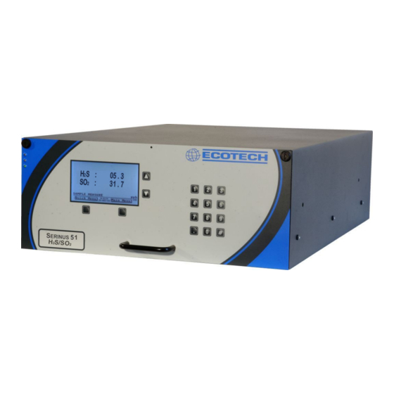
Serinus 51
SO
/H
S Analyzer
2
2
User Manual
Version: 1.0
July 2011
Tel:
(+61) 1300 364 946.
Fax:
(+61) 1300 668 763.
E-mail:
ecotech@ecotech.com.au
Spare Parts
parts@ecotech.com.au
Address:
Australia — Head Office
1492 Ferntree Gully rd Knoxfield Victoria, 3180, Australia
Related Manuals for Ecotech Serinus 51
Summary of Contents for Ecotech Serinus 51
-
Page 1
Serinus 51 S Analyzer User Manual Version: 1.0 July 2011 Tel: (+61) 1300 364 946. Fax: (+61) 1300 668 763. E-mail: ecotech@ecotech.com.au Spare Parts parts@ecotech.com.au Address: Australia — Head Office 1492 Ferntree Gully rd Knoxfield Victoria, 3180, Australia… -
Page 3
If, after reading this manual you have any questions or you are still unsure or unclear on any part of the Serinus 51 then please do not hesitate to contact Ecotech or your local Ecotech distributor. -
Page 4
• To reduce the risk of personal injury caused by electrical shock, follow all safety notices and warnings in this documentation. • If the equipment is used for purposes not specified by Ecotech, the protection provided by this equipment may be impaired. -
Page 5
To ensure that we process your factory repairs and returned goods efficiently and expeditiously, we need your help. Before you ship any equipment to our factory, please call your local Ecotech service response centre (or distributor) to obtain a return authorization number. -
Page 6
Serinus 51 User manual 1.0 CE Mark Declaration of Conformity This declaration applies to the Serinus 51 SO analyzers as manufactured by Ecotech Pty. Ltd. of 1492 Ferntree Gully Rd, Knoxfield, VIC, 3180, Australia, and which may be sold in the following… -
Page 7
Check all containers against the packing list immediately on receipt. If a shortage or other discrepancy is found, notify the carrier and Ecotech immediately. We will not be responsible for shortages against the packing list unless they are reported promptly… -
Page 8
Front Matter Serinus 51 User manual 1.0 Internationally recognized symbols used on Ecotech Equipment Electrical fuse IEC 60417-5016 Earth (ground) terminal IEC 60417-5017 Protective conductor terminal IEC 60417-5017 Equipotentiality IEC 60417-5021 Alternating current IEC 60417-5032 Caution, hot surface IEC 60417-5041 Caution, risk of danger. -
Page 9
Serinus 51 User manual 1.0 Front Matter… -
Page 10
Description: User Manual for the Serinus 51 SO S analyzer This manual is the full user manual for the Serinus 51 SO S analyzer. This manual contains all relevant information on theory, specifications, installation, operation, maintenance, calibration, communication and troubleshooting. Any information that… -
Page 11: Table Of Contents
Serinus 51 User manual 1.0 Front Matter Table of Contents INTRODUCTION ………………….1 1.1 D ……………………1 ESCRIPTION 1.2 S ………………….1 PECIFICATIONS 1.2.1 M ………………….1 EASUREMENT 1.2.2 P ………………..1 RECISION CCURACY 1.2.3 C …………………… 1 ALIBRATION 1.2.4 P ………………………
-
Page 12
Front Matter Serinus 51 User manual 1.0 3.5.2 A ………………….20 NALYZER TATE 3.5.3 G ………………… 23 ENERAL ETTINGS 3.5.4 M ………………. 23 EASUREMENT SETTINGS 3.5.5 C ………………..24 ALIBRATION MENU 3.5.6 S ……………………26 ERVICE 3.5.7 C …………………. 31 OMMUNICATIONS CALIBRATION …………………. -
Page 13
Serinus 51 User manual 1.0 Front Matter OPTIONAL EXTRAS ………………..69 8.1 D ………………..69 UAL SAMPLE FILTER 8.2 R ………………….69 ACK MOUNT KIT 8.3 I ………………….71 NTERNAL PUMP 8.3.1 P ) …………..71 NEUMATIC DIAGRAM INTERNAL PUMP 8.3.2 A… -
Page 14
Front Matter Serinus 51 User manual 1.0 List of Figures Figure 1 Simple pneumatic diagram ………………4 Figure 2 Optical measurement theory ………………5 Figure 3 Major Components …………………. 6 Figure 4 Opening the lid ………………….10 Figure 5 Instrument Back panel ………………..11 Figure 6. -
Page 15: Introduction
All measurements are automatically corrected for gas temperature and pressure changes and referenced to 0°C, 20°C or 25°C at 1 atmosphere. This allows the Serinus 51 to sample in the most useful range of SO S ambient measurement (0-25 ppb SO in air,).
-
Page 16: Power
Introduction Serinus 51 User manual 1.0 Span drift • Temperature dependant: 0.1% per °C • 24 hours: 0.5% of reading • 30 days: 0.5% of reading 1.2.4 Power Operating voltage: • 99 to 132 VAC, 198 to 264 VAC, 47 to 63 Hz Power Consumption: •…
-
Page 17: Physical Dimensions
Serinus 51 User manual 1.0 Introduction 1.2.7 Physical dimensions Case dimensions: • Length: 620mm with no handle (24.4” inches) • Width: 440mm (17.3” inches) • Height: 178mm/4RU (7” inches) Weight: 18.1kg 1.3 Nomenclature Span: A gas sample of known composition and concentration used to calibrate/check the upper range of the instrument (Sulfur Dioxide).
-
Page 18: Background/ Theory
UV from this, emission of photons occurs (300-400nm). The amount of fluorescence emitted is directly proportional to the SO concentration. The Serinus 51 follows these principles and measurement techniques: • Sample air is passed through a hydrocarbon kicker a device which removes…
-
Page 19: Kalman Filter Theory
Serinus 51 User manual 1.0 Introduction • The radiation (214nm) is focused into the fluorescence cell where it interacts with SO molecules and emits photons uniformly in all directions. • A portion of the fluorescence is collected and filtered. • Wavelengths at 310-350nm pass through the filter where they reach the photomultiplier and record a signal.
-
Page 20: Particulate Filter
Introduction Serinus 51 User manual 1.0 • The sensors for the measurement of SO (optical cell) and other relevant parameters • The control system which encompasses all circuit boards, is used to control all sensors and pneumatic components • The power supply which supplies power for all the instrument processors •…
-
Page 21: Reaction Cell
Serinus 51 User manual 1.0 Introduction Reaction Cell 1.5.4 UV lamp The UV lamp is a discharge zinc UV lamp which emits UV radiation over a broad range UV Bandpass Filter The bandpass filter only allows UV at 214nm through into the cell.
-
Page 22: Lamp Driver Pcb
Introduction Serinus 51 User manual 1.0 1.5.8 Lamp Driver PCB This driver uses a high voltage and high frequency switching supply to start and maintain the UV lamp at a constant intensity. The lamp current is set by the microprocessor and is maintained at 30 1.5.9…
-
Page 23: Communications
Serinus 51 User manual 1.0 Introduction 1.5.13 Communications Communication between the analyzer and either a data logger, laptop or network can be performed with the following communication connections located on the back panel (see Figure 5). RS232 #1 This port is designed to be used for simple RS232 communication or with a Termination Panel allowing the Serinus instrument to work as a datalogger.
-
Page 24: Installation
2.1 Initial check Packaging The packaging which the Serinus 51 is transported in is specifically designed to minimise the effects of shock and vibration during transportation. Ecotech recommends that the packaging be kept if there is a likelihood that the instrument is going to be relocated.
-
Page 25: Mounting/Siting
Figure 5 Instrument Back panel 2.3.1 Pneumatic connections The Serinus 51 contains 4 pneumatic ports on the back panel of the analyzer; the sample port, the calibration port, the exhaust port and the background air port. All tubing and fittings used should follow the instructions below: ®…
-
Page 26: Power Connections
Installation Serinus 51 User manual 1.0 • Sample inlet pressure should not exceed 5 kPa above ambient pressure • Tubing must be cut squarely and any burrs removed • Remove nut, insert tubing through back of nut with tube extending 1 inch through front •…
-
Page 27: Communications Connections
• This port is also designed to be used with a Termination Panel allowing the Serinus instrument to work as a datalogger. This function is an optional extra and should be purchased from Ecotech. RS232 #2 • Connect RS232 cable from instrument to computer, datalogger or in a daisy chain formation.
-
Page 28: Epa Reference Set Up
Installation Serinus 51 User manual 1.0 2.4 Transporting/Storage Transporting the Serinus should be done with great care. It is recommended that the packaging the Serinus was delivered in should be used for any transport as it ensures minimal damage to the instrument. When transporting or storing the instrument the following points should be followed: •…
-
Page 29: Operation
Serinus 51 User manual 1.0 Operation Operation 3.1 Warmup As the instrument is turned on it will adjust and calibrate itself ready for monitoring. No measurements are taken during the warm-up. When the main screen appears, the instrument will display the following actions being…
-
Page 30: Main Screen
Operation Serinus 51 User manual 1.0 (2) Scrolling buttons The scrolling buttons allow users to scroll up and down through menus. The scrolling buttons are also used to scroll side to side through editable fields (Date, time, concentration etc). On the main screen these buttons are used for adjusting contrast.
-
Page 31: Sampling
The USB key should not be removed whilst this is happening. 3.4 Sampling The Sampling performed by the Serinus 51 involves two cycles, an SO cycle and a H2S cycle. The SO…
-
Page 32: Menus And Screens
Operation Serinus 51 User manual 1.0 Measurement cell fills with sample air (SO Sample fill (SO Measurement of sample air (SO Sample measure (SO Aux fill (H Measurement cell fills with sample air (H measure (H Measurement of sample air (H 3.5 Menus and screens…
-
Page 33
Serinus 51 User manual 1.0 Operation This feature must be activated before removing the USB memory to safely remove the USB stick (also occurs in the service menu 3.5.6). Failure to do this may cause corruption to the data on the memory stick. -
Page 34: Analyzer State
Operation Serinus 51 User manual 1.0 3.5.2 Analyzer State Displays the status of various parameters that effect instrument measurement and various functions. There are 4 sub menus within this menu and 3 non-editable fields described below. Event Log This field enters a screen with a log of all the events that the instrument performs.
-
Page 35
Serinus 51 User manual 1.0 Operation Flow Block Temp (Optional internal pump only). If you have the optional internal pump this temperature must be within 10% of the heater set point (Section 3.5.3) to keep a constant accurate flow. 3.5.2.2 Temperatures… -
Page 36
Operation Serinus 51 User manual 1.0 Sample Flow Indicates the gas flow through the sample port of the instrument, should be around 0.70 Note: Will indicate 0.00 if the flow transducer senses flow has gone to zero. 3.5.2.4 Voltages Conc Voltage… -
Page 37: General Settings
Serinus 51 User manual 1.0 Operation 3.5.3 General Settings Decimal Places Select “Edit” to change the amount of decimal places (0-5) used for concentration on the front screen Conc units Select the units that concentration will be displayed in (ppm, ppb, ppt, mg/m ,µg/m…
-
Page 38: Calibration Menu
Operation Serinus 51 User manual 1.0 GasMeasure Cycle This field sets the time taken per measurement cycle i.e. 5 mins = 5 minutes for SO , 5 minutes for H S. The longer this time is set to the more stable readings will be, but the amount of readings per hour will decrease.
-
Page 39
Serinus 51 User manual 1.0 Operation Manual Background Will display when the instrument is performing a background (running), when this is not the case press the start button to perform a manual background. Pressure calibration This field allows the user to calibrate the pressure sensors as explained in section 4.5… -
Page 40: Service
Operation Serinus 51 User manual 1.0 • Cycle: performs a zero, then a span then returns to measure mode. The length of time spent measuring calibration gases is set in cycle time (below) • Span: this mode will take air through the calibration port so that a span calibration can be performed •…
-
Page 41
Serinus 51 User manual 1.0 Operation Save parameter List Name the file which the parameter settings will be downloaded into (at that time), used for diagnostics Load Configuration Loads instrument EEPROM setting from USB key (including calibration and communication settings, units, instrument gain etc). -
Page 42
Operation Serinus 51 User manual 1.0 3.5.6.1 Diagnostics The Diagnostics menu provides a large variety of features that allow the user to investigate problems with the analyzer or gain a greater insight into what the instrument is doing. This Menu contains 3 sub menus and 3 editable fields, the 3 editable fields are presented directly below for your convenience and the sub menus after them. -
Page 43
Serinus 51 User manual 1.0 Operation Meas. Zero (25-150) Conc Voltage (0-3) (RAW) Conc Voltage (0-3) Ref. Zero Ref. Gain -. (10-100) Ref. Voltage (1.7- 3.5) Test Pot 3.5.6.1.5 Valve menu The valve menu allows the user to observe the opening and closing of valves as well as opening and closing them manually. -
Page 44
Operation Serinus 51 User manual 1.0 Digital Inputs This menu item allows the user to set which pin the power source is located on and also displays the pins that digital inputs are located on. Note: Changes performed with this… -
Page 45: Communications
Serinus 51 User manual 1.0 Operation P/T/F Correction (H2S) Displays the correction factor applied to the H S concentration measurement. This factor corrects for changes in pressure, temperature and flow. 3.5.7 Communications 3.5.7.1 Analog Output Menu The analogue output menu is split into two sections, one for each measurement parameter (SO2, H2S).
-
Page 46
Operation Serinus 51 User manual 1.0 • Data Log setup –GUI below Data Log setup –GUI This field works in tandem with the “Data Log setup –Quick” field and is used when the parameter number is not known. The user can enter each logging parameter field (P1-P15) and scroll through all the parameters that can be logged. -
Page 47
Serinus 51 User manual 1.0 Operation 3.5.7.5 Digital Outputs Menu Assign the digital outputs 0-7… -
Page 49: Calibration
Performing a span calibration can be performed through either the Calibration port or Sample port. Span calibrations calibrate the instrument to the upper limits of normal monitoring. Ecotech recommends that 80% of full scale should be sufficient for calibrations in ambient monitoring situations 100 ppb. Follow the relevant…
-
Page 50: Multipoint Calibration
1. Ensure a suitable span source is connected to instrument from a gas calibrator (Ecotech recommends the GasCal 1100) through the sample port 2. Record analyzer instrument gains before performing calibration (section 3.5.1)
-
Page 51
Serinus 51 User manual 1.0 Calibration 3. Perform a zero calibration as described in section 4.1 4. Perform a span calibration as described in section 4.2 5. Set up a program for measuring the span concentration through 5 steps down… -
Page 52: Figure 8 Excel Graph Of Multipoint Calibration
Calibration Serinus 51 User manual 1.0 Figure 8 Excel graph of Multipoint Calibration 12. Accept the calibration if the following are found: • The gradient (m) falls between 0.98 and 1.02 • The intercept (b) lies between ±0.3. • The correlation (R ) is greater than 0.9995…
-
Page 53: Pressure Calibration
Serinus 51 User manual 1.0 Calibration 4.5 Pressure calibration The pressure calibration involves a two point calibration, one point under vacuum and another point at ambient pressure. This procedure is necessary when all settings have been wiped, when pressure readings are faulty or for diagnostic purposes. To perform…
-
Page 54: Precision Check
Calibration Serinus 51 User manual 1.0 Figure 10 Pressure menu 9. Select the set option (activate buttons) the Current Pressure window will open 10. Using the keypad, input the current pressure reading on the meter. 11. Press the “Accept” button to calibrate pressure sensors Ambient 1.
-
Page 56: Communications
Calibration Serinus 51 User manual 1.0 Communications The Serinus analyzer has four methods of communication. Each communication method is used in specific situations for data download, instrument control or both. The Serinus can perform communication through 4 different paths (RS232, USB, 25 pin Digital/Analog input/output or TCP/IP network (optional).
-
Page 57: Figure 11 Device Installer Pop Up Window
Serinus 51 User manual 1.0 Calibration 2. The Serinus analyzer must be configured to allow network use, this is done The Serinus analyzer must be configured to allow network use, this is done The Serinus analyzer must be configured to allow network use, this is done through directly connecting it with a PC.
-
Page 58: Figure 13 Device Installer — Telnet Configuration
Calibration Serinus 51 User manual 1.0 7. Click the “Telnet Configuration” tab and click “Connect” (Figure 14). Leave the IP address and port as is. Afterwards, press Enter to enter Setup Mode. This will list the various parameters set up in the Serinus and will give you menu options to change them.
-
Page 59
Serinus 51 User manual 1.0 Calibration Remote IP Address : (000) .(000) .(000) .(000) Remote Port (0) ? DisConnMode (00) ? FlushMode (00) ? DisConnTime (00:00) ?: SendChar 1 (00) ? SendChar 2 (00) ? Settings available during Channel 1 setup 11. -
Page 60: Digital/Analog Communication
Calibration Serinus 51 User manual 1.0 5.4 Digital/Analog communication External I/O port The 25 Pin Analog/Digital port on the rear of the analyzer sends and receives analog/digital signals to other devices. These signals are commonly used to activate gas calibrators or for warning alarms.
-
Page 61: Figure 15 External 25Pin I/O Individual Pin Descriptions
Serinus 51 User manual 1.0 Calibration Figure 16 External 25pin I/O individual pin descriptions Warning: The Analog and Digital Inputs and Outputs are rated to CAT I, meaning that they should be less than 12VDC. Exceeding these voltages permanently damage the instruments and void warranty…
-
Page 62: Serinus Downloader Program
Calibration Serinus 51 User manual 1.0 5.5 Serinus downloader program The Serinus Downloader program is designed to allow the user to acquire data directly from the analyzer and control it remotely. The Serinus downloader program has four main windows; “Settings” where configurations are made to communicate with the analyzer, “Data”…
-
Page 63: Figure 16 Serinus Downloader — Settings Tab
Serinus 51 User manual 1.0 Calibration Connection The user must select the type of connection that the computer is connect to the analyzer with. This is chosen in the “Connection Type” field and consists of: Direct Serial connection: Used when the analyzer is connected directly to PC via serial port…
-
Page 64: Data
Calibration Serinus 51 User manual 1.0 5.5.2 Data The Data window consists mainly of a spreadsheet with rows (numeric) and columns (labeled as per parameter). The amount of data to be uploaded into the spreadsheet is determined by the start and end date range on the left side of the main menu bar.
-
Page 65: Remote Screen
Serinus 51 User manual 1.0 Calibration 5.5.3 Remote screen The remote screen tab allows the user to connect to the Serinus instrument and control it remotely. The screen has all the same buttons as the Serinus gas analyzer and is used as virtual interface with the instrument. The screen is a screenshot and not an automatically updated feed;…
-
Page 66: Remote Terminal
Calibration Serinus 51 User manual 1.0 5.5.4 Remote terminal The remote terminal tab is a diagnostic tool used to check instrument operation and parameters. The remote terminal is used in a similar way to “ping” a computer; it is used to ensure communications are working properly.
-
Page 67: Service
Service 6.1 Pneumatic diagram Figure 21 Pneumatic diagram 6.2 Maintenance tools To perform general maintenance on the Serinus 51 the user will be require the following equipment: • Toolbox • Digital multimeter (DMM) • Computer or remote data terminal and connection cable for RS232 communication •…
-
Page 68: Maintenance Schedule
Service Serinus 51 User manual 1.0 6.3 Maintenance schedule Table 1 Maintenance Schedule Interval * Task performed Page Weekly Check inlet particulate filter, replace if full/dirty Check sample inlet system for moisture or foreign materials. Clean if necessary Perform precision check…
-
Page 69: Maintenance Procedures
Serinus 51 User manual 1.0 Service 6.4 Maintenance procedures 6.4.1 Particulate filter replacement Disconnect the external pump Slide open (Figure 22) to access the particulate filter (located in front right hand corner Unscrew the filter cap (bright blue) by turning it counterclockwise…
-
Page 70: Dfu Replacement
Service Serinus 51 User manual 1.0 6.4.3 DFU Replacement Turn off analyzer and remove power Remove Kynar nut from the end of the DFU by turning anti-clockwise (looking from DFU side) Replace DFU and ensure that the flow is in the correct direction (arrows…
-
Page 71: Figure 20 Plugged Sample And Calibration Ports
Serinus 51 User manual 1.0 Service Figure 25 Plugged sample and calibration ports Enter the main menu status menu pressure menu and compare the ambient pressure to the inst gas pressure Allow 1-2 minutes for the pressures to stabilize, check that the gas flow…
-
Page 72: Advanced Leak Check
Service Serinus 51 User manual 1.0 6.4.6 Advanced leak check If a leak is suspected a more intensive leak check can be performed. Continue from the setup in the quick leak check. Connect a pump to the exhaust port with a shut off valve (pump side)
-
Page 73: Replace Pmt Desiccant Pack
Serinus 51 User manual 1.0 Service 6.4.8 Replace PMT desiccant pack The PMT housing contains two desiccant packs to prevent condensation on the cooled PMT housing. If the desiccant expires it will result in corrosion of the PMT housing and premature cooler failure. It is recommended that the desiccant bags be changed at least annually.
-
Page 74: Replace Dfu Filter
Required equipment: Oscilloscope Proper operation of the UV lamp is essential to the Serinus 51. The UV lamp should be checked yearly to ensure it is operating within acceptable parameters and may require realignment to maintain sufficient UV light for analyzer operation. The UV lamp will need to be adjusted only when the “Reference gain pot”…
-
Page 75: Pressure Sensor Check
Serinus 51 User manual 1.0 Service Figure 28 Collets of the UV lamp Physically adjust the UV lamp (rotate and move left and right) until the maximum peak voltage on the oscilloscope is obtained. The minimum usable output from the lamp is approximately 0.25 volts amplitude (peak to peak).
-
Page 76
Service Serinus 51 User manual 1.0 3. Using a small flat screwdriver, lift the metallic clip holding the battery whilst sliding the old battery out. 4. Now place the new battery in with the positive (+) side facing up. 5. Close the main PCB and return the screws. Close the cover again. -
Page 77: Parts List
Serinus 51 User manual 1.0 Service 6.5 Parts list Below is a list of the replaceable parts of the Serinus 51. Some of these parts will not need replacing and other consumables will need constant replacing. Table 2 Parts List…
-
Page 78: Updating Firmware
Service Serinus 51 User manual 1.0 Dessicant, 5 gram pack (2 required) C050014 O-ring, Test Plug, Test lamp O010021 Fitting kynar male branch tee F030033-01 Washer neo, .174x .38x.016 F050041 O-ring BS115, viton O010004 O-ring BS015, viton (3 required) O010023…
-
Page 79: Troubleshooting
Serinus 51 User manual 1.0 Troubleshooting Troubleshooting Table 3 Troubleshoot list Error Message/ Cause Solution Problem A/D conversion Temp/press error Replace main PCB error Input pot limited to Damaged Lamp Check that lamp current is between 21 0 or 255 &…
-
Page 80: Zero Flow
Troubleshooting Serinus 51 User manual 1.0 temperature. Verify that the cell temperature is 50° ±3° C and that the TE cooler is 10° ±2° C. Low span Leaks A leak dilutes the sample stream and causes low span readings and noise.
-
Page 81: Electronic Zero Adjust
Serinus 51 User manual 1.0 Troubleshooting 7.2 Electronic Zero adjust 7.3 SO reaction cell temperature failure…
-
Page 83: Optional Extras
Rack mount kit The rack mount kit is necessary for installing the The rack mount kit is necessary for installing the Serinus 51 into a 19” rack. The into a 19” rack. The Serinus 51 is 4RU in height to install in the rack follow these steps.
-
Page 84: Figure 26 Installation Of Lid To Rack Mount Brackets
Optional Extras Serinus 51 User User manual 1.0 3. Insert the instrument lid (without the instrument) into the rack and attach to Insert the instrument lid (without the instrument) into the rack and attach to Insert the instrument lid (without the instrument) into the rack and attach to…
-
Page 85: Internal Pump
Serinus 51 User manual 1.0 Optional Extras 8.3 High pressure zero/span valve Note: This is NOT intended as a source for calibrating the instrument. This should only be used as an operational check of the instrument’s zero point and single upscale point (recommended as 80% of full scale) 8.3.1 Single pressurized calibration option…
-
Page 86: Dual Pressurized Calibration Option
Optional Extras Serinus 51 User manual 1.0 Figure 33 Single high pressure calibration option 8.3.2 Dual pressurized calibration option The dual internal pressurized calibration valves are already installed within the analyzer (Figure 34) as a zero and span calibration source, thus no other connections need to be made.
-
Page 87: Figure 30 Dual High Pressure Calibration Option
Serinus 51 User manual 1.0 Optional Extras Return to normal operation 1. Set Cal. Mode → Measure. 2. Remove the flow meter on the calibration port and connect a ¼” vent line to port. 3. Reconnect instrument fittings and place in original set up 4.
-
Page 89: Appendix A Advanced Protocol Parameter List
Serinus 51 User manual 1.0 Appendix Appendix A Advanced Protocol Parameter List Note: Parameters are for all Serinus analyzers and may not be applicable to an individual analyzer. Table 5 Advanced Protocol Parameter list Description Notes Sample / Cal Valve…
-
Page 90
Appendix Serinus 51 User manual 1.0 Analogue input 14 EXTERNAL ANALOG INPUT 1 Analogue input 15 MFC0 NOT USED CO Measure Pot : Coarse S30 Measure ZERO Coarse adjustment Pot CO Measure Pot: Fine S30 Measure ZERO Fine adjustment Pot… -
Page 91
Serinus 51 User manual 1.0 Appendix Reference Voltage Calibration State 0 = MEASURE 1 = CYCLE 2 = ZERO 3 = SPAN Primary Raw Concentration (before NOx background and gain) Secondary Raw Concentration (before NOx background and gain) NOx Background Concentration… -
Page 92
Appendix Serinus 51 User manual 1.0 5=nG/M³ Background Measure Time In seconds Sample Fill Time In seconds Sample Measure Time In seconds Aux Measure Time In seconds Aux Sample Fill Time In seconds Background Fill Time In seconds Zero Fill Time… -
Page 93
Serinus 51 User manual 1.0 Appendix 1 = «ºF», 2 = «ºK», Pressure Units 0 = «torr», 1 = «psi», 2 = «mbar», 3 = «atm», 4 = «kPa» Averaging Period 0 = » 1 Min», 1 = » 3 Mins», 2 = «… -
Page 94
Appendix Serinus 51 User manual 1.0 2 = «Advanced» Multidrop Port (COM 2) Protocol 0 = » EC9800″, 1 = «Bavarian», 2 = «Advanced» Gas1 Over Range The Upper Concentration Range when Over- Ranging is enabled for Analog Output 1… -
Page 95
Serinus 51 User manual 1.0 Appendix External Analog Input 1 External Analog Input 2 External Analog Input 3 Converter Set Point Converter Set Point Temperature… -
Page 96: Appendix B — Ec9800 Protocol
Appendix Serinus 51 User manual 1.0 Appendix B – EC9800 Protocol DCONC Function Sends the current instantaneous concentration data to the serial port. Format DCONC,{<DEVICE I.D.>}{TERMINATOR} Device response {GAS}<SPACE>{STATUS WORD}<CR><LF> All numbers are in floating point format. The STATUS WORD indicates the…
-
Page 97
Serinus 51 User manual 1.0 Appendix Device response <ACK> if the unit under test is able to perform the command, <NAK> if not. RESET Function Reboots the instrument (software reset). Format RESET, {<DEVICE I.D.>}{TERMINATOR} Device response <ACK>… -
Page 98: Appendix C — Bavarian Protocol
Appendix Serinus 51 User manual 1.0 Appendix C – Bavarian Protocol Bavarian Network Command Set Format All Bavarian Network commands follow the command format as specified in this section. The specific Bavarian commands and their function are described in section Bavarian Network Command Format: <STX><TEXT><ETX><BCC1><BCC2>…
-
Page 99
Serinus 51 User manual 1.0 Appendix…
| Document’s Content and Additional Information | Share Manual |
|---|---|
|
Ecotech Serinus 51 Operation & user’s manual
Pages Preview: Document Transcription:
See Details |
|
|
Ecotech Serinus 51 Operation & user’s manual
Pages Preview: Document Transcription:
See Details |


Table of Contents for Ecotech Serinus 51:
-
Service Serinus 51 User manual 1.0 56 6.4.3 DFU Replacement 1. Turn off analyzer and remove power 2. Remove Kynar nut from the end of the DFU by turning anti-clockwise (looking from DFU side) 3. Replace DFU and ensure that the flow is in the correct direction (arrows points toward Kynar nut) 4. Tighten kynar nut clockwise 6.4.4 Sintered filter Replacement The sintered filter is used to prevent contaminants blocking the samp
-
Serinus 51 User manual 1.0 2. The Serinus analyzer must be configured to allow network use, this is done through directly connecting it with a PC. connect the cable from the Ethernet port on the Ser the PC. Note: This step requires a free Ethernet port on the PC. If port is being used to connect to the and disconnect the cable. 3. Wait until the connection between the Ser “Limited or no Connectivity” 4. Open D
-
Installation Serinus 51 User manual 1.0 14 2.4 Transporting/Storage Transporting the Serinus should be done with great care. It is recommended that the packaging the Serinus was delivered in should be used for any transport as it ensures minimal damage to the instrument. When transporting or storing the instrument the following points should be followed: • Turn off instrument and allow to cool down • Remove all pneumatic, power and communica
-
Serinus 51 User manual 1.0 Introduction 5 • The radiation (214nm) is focused into the fluorescence cell where it interacts with SO 2 molecules and emits photons uniformly in all directions. • A portion of the fluorescence is collected and filtered. • Wavelengths at 310-350nm pass through the filter where they reach the photomultiplier and record a signal. • A reference detector monitors the emission from the zinc lamp and is used to correct for f
-
Calibration Serinus 51 User manual 1.0 48 5.5 Serinus downloader program The Serinus Downloader program is designed to allow the user to acquire data directly from the analyzer and control it remotely. The Serinus downloader program has four main windows; “Settings” where configurations are made to communicate with the analyzer, “Data” where data is downloaded into a spreadsheet and “Remote Screen” where the analyzer can be controlled directly and “Remote Terminal” which is a dia
-
Serinus 51 User manual 1.0 Front Matter i Manufacturers statement Thank you for selecting the Ecotech Serinus 51 Sulfur Dioxide Analyzer. The Serinus series is the next generation of Ecotech designed and manufactured gas analyzer, the Serinus 51 will perform Sulfur Dioxide measurements over a range of 0- 2ppm with an LDL of 0.5 ppb. This User Manual provides a complete product description including operating instructions,
-
Serinus 51 User manual 1.0 Calibration 37 3. Perform a zero calibration as described in section 4.1 4. Perform a span calibration as described in section 4.2 5. Set up a program for measuring the span concentration through 5 steps down from 80% of full scale Example for full scale of 100ppb a. Set the 1 st concentration on the gas calibrator to 80ppb, allow instrument to sample for 15 minutes, record measurement. b. Set the 2 nd concentration on the g
-
Appendix Serinus 51 User manual 1.0 84 Appendix C – Bavarian Protocol Bavarian Network Command Set Format All Bavarian Network commands follow the command format as specified in this section. The specific Bavarian commands and their function are described in section Bavarian Network Command Format: <STX><TEXT><ETX><BCC1><BCC2> Where: <STX> = ASCII Start Of Transmission = 02 hex <TEXT> = ASCII text
-
Serinus 51 User manual 1.0 Front Matter ix Table of Contents 1 INTRODUCTION ………………………………………………………………………………………………. 1 1.1 D ESCRIPTION ……………………………………………………………………………………………………. 1 1.2 S PECIFICATIONS ………………………………………………………………………………………….
-
Serinus 51 User manual 1.0 Calibration 49 Connection The user must select the type of connection that the computer is connect to the analyzer with. This is chosen in the “Connection Type” field and consists of: Direct Serial connection: Used when the analyzer is connected directly to PC via serial port Port Choose which port on the PC the Serinus is attached to Baud Rate Select the baud rate with which communication will take place (must match the baud rate set on the analyzer see the
-
Introduction Serinus 51 User manual 1.0 8 1.5.8 Lamp Driver PCB This driver uses a high voltage and high frequency switching supply to start and maintain the UV lamp at a constant intensity. The lamp current is set by the microprocessor and is maintained at 30 mA. 1.5.9 Pressure PCB The absolute pressure transducer is mounted to the measurement cell, and used to measure the sample pressure in the cell. This pressure is also used for the instrument to calculate flow. 1.5.10 Power supply The power supply is a self-contained unit housed
-
Serinus 51 User manual 1.0 Operation 15 3 Operation 3.1 Warmup As the instrument is turned on it will adjust and calibrate itself ready for monitoring. No measurements are taken during the warm-up. When the main screen appears, the instrument will display the following actions being taken (bottom of the screen): High voltage check: Instrument setting upper voltage limit for measurement Lamp Stabilize Adjusts the lamps curre
Questions, Opinions and Exploitation Impressions:
You can ask a question, express your opinion or share our experience of Ecotech Serinus 51 device using right now.
Serinus 51 User manual 1.0
Manufacturers statement
Thank you for selecting the Ecotech Serinus 51 Sulfur Dioxide Analyzer.
The Serinus series is the next generation of Ecotech designed and manufactured gas
analyzer, the Serinus 51 will perform Sulfur Dioxide measurements over a range of 0-
2ppm with an LDL of 0.5 ppb.
This User Manual provides a complete product description including operating
instructions, calibration, and maintenance requirements for the Serinus 51.
Reference should also be made to the relevant local standards, which should be used
in conjunction with this manual. Some relevant standards are listed in the References
section of this manual.
If, after reading this manual you have any questions or you are still unsure or unclear
on any part of the Serinus 51 then please do not hesitate to contact Ecotech or your
local Ecotech distributor.
Ecotech also welcomes any improvements that you feel would make this a more
useable and helpful product then please send your suggestions to us here at Ecotech.
The information contained in this manual is subject to change without notice. Ecotech
reserves the right to make changes to equipment construction, design, specifications
and /or procedures without notice.
Copyright © 2011. All rights reserved. Reproduction of this manual, in any form,
is prohibited without the written consent of Ecotech Pty Ltd.
Please help the environment and recycle the
pages of this manual when finished using it.
Notice
Front Matter
i
Reliable remote performance
Minimise maintenance through superior remote instrument control, diagnostic viewing and calibration complemented by a two-year warranty.
Comprehensive data logging
Remote logging and viewing of 200+ operational parameters.
Rack slide design
Makes accessing internal components and removing the analyser from a rack cabinet easy.
Simple programming, viewing, downloading and emailing of data
Perform all functions via Bluetooth connectivity combined with the Acoem Serinus® Remote Android app.
Reduced AQMS power usage
Low power demand and ability to operate over a wide temperature range.
See our technology in action
Schedule a free demo to get a first-hand look at how our solutions support your business.
Resources

The importance of measuring H2S
Hydrogen sulfide (H2S) is a foul-smelling colourless highly toxic, flammable, and corrosive to metals. While it can occur in nature, for example in crude oil, volcanic and natural gases, it is more commonly generated by human industrial and manufacturing activity. Depending on its concentration, H2S gas can be toxic to humans, causing a range of short and long-term ailments from headaches to loss of consciousness and even death.
Sulfur dioxide (SO2) is likewise a colourless, bad-smelling, toxic gas and similarly, can occur naturally. More often though, SO2 is released when power plants and industrial facilities burn fossil fuels; during metal extraction processes; and via vehicle and heavy equipment emissions. Short-term exposure to SO2 can harm the human respiratory system and lead to breathing difficulties.
The only way to ensure that levels of H2S and SO2 don’t exceed regulatory standards or cause harm is to implement a system of precision monitoring. Ongoing measurement is critical not only for the safety of the environment, industrial workers, and nearby communities, but it also helps to protect the integrity of industrial process equipment, pipelines and infrastructure.

Approved globally
(Based on Serinus® 50 SO2 analyser which has the following approvals)
- US EPA approval (EQSA–0809–188)
- EN approval TÜV (936/21221977/B)
- Australian Standard (AS 3580.4.1-2008)
- Russian approval (56054-13)
- French approval LSCQA
- Ukraine approval (12/3/B/24/295-17)
Applications
Discover Acoem’s case studies

Superior air quality monitoring for global environments
Air quality monitoring is increasingly important in today’s urban, industrial and rural areas. The Serinus® range of analysers has emerged through 40+ years of experience and knowledge gained from operating large air quality monitoring networks. The result is a superior portfolio of instruments that integrate seamlessly into continuous monitoring networks. They not only measure human exposure to pollutants but can be combined with trace/background monitoring as well as stack monitoring – thus becoming a vital tool for governments and organisations to track and abate air pollution and its effects on their immediate environment.
Request Pricing

Connect with Acoem
Contact us to learn more about our solutions, services, and training programs.