-
Contents
-
Table of Contents
-
Bookmarks
Related Manuals for Alfa Laval P 605
Summary of Contents for Alfa Laval P 605
-
Page 1
Separator Manual High Speed Separator P 605 Specification No. 881099-06-04/0 Book No. 9010961-02, rev. 1… -
Page 2
Published By: Alfa Laval Tumba AB 11-2013 SE-147 80 Tumba, Sweden Telephone: +46 8 530 650 00 Telefax: +46 8 530 310 40 The original instructions are in English This publication or any part there of may not be reproduced or transmitted by any process or means without prior written permission of Alfa Laval Tumba AB. -
Page 3: Table Of Contents
Contents Read this first Safety instructions Warning signs in text Environmental issues Requirements of personnel Remote start Basic principles of separation Introduction Separation by gravity Centrifugal separation Separating temperatures Separator basics Design and function 4.1.1 Application 4.1.2 Design 4.1.3 Outline of function 4.1.4 Separating function 4.1.5…
-
Page 4
5.3.2 Erosion 5.3.3 Cracks 5.3.4 Discharge mechanism 5.3.5 Bowl hood and sliding bowl bottom 5.3.6 Spindle top cone and bowl body nave 5.3.7 Threads of inlet pipe, paring disc 5.3.8 Threads on bowl hood and bowl body 5.3.9 Priming of bowl parts 5.3.10 Disc stack pressure Check points at Major Service 5.4.1… -
Page 5
6.5.1 Dismantling/assembly Water tank Brake 6.7.1 Exploded view 6.7.2 Checking of friction element Frame feet 6.8.1 Mounting of new frame feet Technical Reference Product description Directives & Standards Technical Data Connection list Basic size drawing 7.5.1 Dimensions of connections Interface Description 7.6.1 Scope 7.6.2… -
Page 6
Operating Operating routine Clarifier Operation 8.2.1 Operating water interface Purifier Operation 8.3.1 Operating water interface 8.3.2 Selection of gravity disc 8.3.3 Gravity disc nomogram Before first Start Start after a service 8.5.1 Before normal start 8.5.2 Starting and running-up procedure 8.5.3 Separation 8.5.4… -
Page 7
Study instruction manuals and observe the warnings before installation, operation, service and maintenance. Not following the instructions can result in serious accidents. In order to make the information clear only foreseeable conditions have been considered. No warnings are given, therefore, for situations arising from the unintended usage of the machine and its tools. -
Page 9: Read This First
Alfa Laval separator If the separator has been delivered and installed by Alfa Laval as a part of a processing system, this manual should be viewed as part of the System Documentation. Study carefully all instructions in any System Documentation.
-
Page 10
1 Read this first Fault finding Refer to this chapter if the separator functions abnormally. If the separator has been installed as a part of a processing system, always refer to the trouble-tracing instructions, in the System Documentation. Technical reference This chapter contains technical data concerning the separator and drawings. -
Page 11: Safety Instructions
Strictly follow the instructions for installation, operation and maintenance. • Ensure that personnel are competent and have sufficient knowledge of maintenance and operation, especially concerning emergency stopping procedures. • Use only Alfa Laval genuine spare parts and the special tools supplied.
-
Page 12
If excessive vibration occurs, stop separator and keep bowl filled with liquid during rundown. • Use the separator only for the purpose and m /h parameter range specified by Alfa Laval. kg/m r/min • Check that the gear/pulley ratio is correct for power frequency used. -
Page 13
2 Safety instructions Electrical hazard • Follow local regulations for electrical installation and earthing (grounding). • To avoid accidental start, switch off and lock power supply before starting any dismantling work. Crush hazards • Use correct lifting tools and follow lifting instructions. -
Page 14
2 Safety instructions Flying objects • Risk for accidental release of snap rings and springs when dismantling and assembly. Wear safety goggles. Health hazards • Risk for unhealthy dust when handling friction blocks/pads. Use a dust mask to make sure not to inhale any dust… -
Page 15: Warning Signs In Text
2 Safety instructions Warning signs in text Pay attention to the safety instructions in this manual. Below are definitions of the three grades of warning signs used in the text where there is a risk for injury to personnel. DANGER indicates an imminently hazardous situation which, if not avoided, will result in death or serious injury.
-
Page 16: Environmental Issues
2 Safety instructions Environmental issues Unpacking Packing material consists of wood, plastics, cardboard boxes and in some cases metal straps. Wood and cardboard boxes can be reused, recycled or used for energy recovery. Plastics should be recycled or burnt at a licensed waste incineration plant.
-
Page 17: Requirements Of Personnel
2 Safety instructions Requirements of personnel Only skilled or instructed persons are allowed to operate the machine, e.g. operating and maintenance staff. • Skilled person: A person with technical knowledge or sufficient experience to enable him or her to perceive risks and to avoid hazards which electricity/mechanics can create.
-
Page 18
2 Safety instructions… -
Page 19: Basic Principles Of Separation
3 Basic principles of separation Introduction The purpose of separation can be: • to free a liquid of solid particles, • to separate two mutually insoluble liquids with different densities while removing any solids presents at the same time, • to separate and concentrate solid particles from a liquid.
-
Page 20: Centrifugal Separation
3.4 Separating temperatures 3 Basic principles of separation Centrifugal separation In a rapidly rotating bowl, the force of gravity is replaced by centrifugal force, which can be thousands of times greater. Separation and sedimentation is continuous and happens very quickly. The centrifugal force in the separator bowl can achieve in a few seconds what takes many hours in a tank under influence of gravity.
-
Page 21: Separator Basics
4 Separator basics Design and function 4.1.1 Application The separator is a high-speed centrifugal separator intended for marine and land applications. It is specifically designed for cleaning of mineral oils from water and solid particles (sludge). The cleaned oil is discharged continuously, while the sludge is discharged at intervals.
-
Page 22: Design
(type of liquid, rotational speed, temperature, density 7 Technical Reference on etc.) specified in chapter page 131 and in the Purchase Order documents. Consult your Alfa Laval representative before any changes outside these parameters are made. 4.1.2 Design The separator comprises a frame consisting of the frame lower part, the intermediate part and the frame top part with a frame hood.
-
Page 23: Outline Of Function
4 Separator basics 4.1 Design and function 4.1.3 Outline of function The separation process takes place in the rotating bowl. Unseparated oil is fed into the bowl through the inlet (201). The oil is cleaned in the bowl and leaves the separator through the outlet (220) via a paring chamber.
-
Page 24: Separating Function
4.1 Design and function 4 Separator basics 4.1.4 Separating function Liquid flow Separation takes place in the separator bowl to which unseparated oil is fed through the inlet pipe (201). The oil is led by the distributor (T) towards the periphery of the bowl. When the unseparated oil reaches the slots of the distributor, it will rise through the channels formed by the disc stack (G) where it is evenly…
-
Page 25
4 Separator basics 4.1 Design and function Water seal in purification To prevent the oil from passing the outer edge of the top disc (I) and escaping through the water outlet (221), a water seal must be provided in the bowl. This is done by filling the bowl with water through the water inlet (206), before unseparated oil is supplied. -
Page 26: Sludge Discharge Function
4.1 Design and function 4 Separator basics 4.1.5 Sludge discharge function Sludge is discharged through a number of ports (L) in the bowl wall. Between discharges these ports are covered by the sliding bowl bottom (M), which forms an internal bottom in the separating space of the bowl.
-
Page 27
4 Separator basics 4.1 Design and function Bowl opening The key event to start a sludge discharge is the downward movement of the operating slide. This is accomplished by supply of opening water (372) to the discharge mechanism. Water is drained off through nozzles (Y) in the bowl body. -
Page 28: Power Transmission
4.1 Design and function 4 Separator basics 4.1.6 Power transmission Bowl spindle In addition to its primary role in the power transmission system, the bowl spindle also serves as: • pump for the closing water • supply pipe for the closing water •…
-
Page 29: Sensors And Indicators
4 Separator basics 4.1 Design and function 4.1.7 Sensors and indicators Sight glass The sight glass shows the oil level in the oil sump. Vibration switch (option) The vibration switch, properly adjusted, trips on a relative increase in vibration. The vibration switch is sensitive to vibration in a direction perpendicular to its base.
-
Page 30: Definitions
4.2 Definitions 4 Separator basics Definitions Back pressure Pressure in the separator outlet. Clarification Liquid/solids separation with the intention of separating particles, normally solids, from a liquid having a lower density than the particles Clarifier disc An optional disc, which replaces the gravity disc in the separator bowl, in the case of clarifier operation.
-
Page 31: Service Instructions
5 Service instructions Periodic maintenance 5.1.1 Introduction Periodic, preventive maintenance reduces the risk of unexpected stoppages and breakdowns. Maintenance logs are shown on the following pages in order to facilitate periodic maintenance. Disintegration hazards Separator parts that are worn beyond their safe limits or incorrectly assembled may cause severe damage or fatal injury.
-
Page 32
5.1 Periodic maintenance 5 Service instructions IS — Intermediate Service consists of an overhaul of the separator bowl, inlet and outlet every 3 months or 2000 operating hours. Seals in bowl and gaskets in the inlet/outlet device and operating device are renewed. MS — Major Service consists of an overhaul of the complete separator every 12 months or 8000 operating hours. -
Page 33: Maintenance Procedure
Service and Major Service The contents of the service kits are described in the Spare Parts Catalogue. Always use Alfa Laval genuine parts as otherwise the warranty will become invalid. Alfa Laval takes no responsibility for the safe operation of the equipment…
-
Page 34: Maintenance Logs
5.2 Maintenance Logs 5 Service instructions Maintenance Logs 5.2.1 Daily checks The following steps should be carried out daily. Main component and activity Part Page Notes Inlet and outlet Check for leakage Connecting housing Separator bowl Check for vibration and noise Belt transmission Check for vibration and noise Oil sump…
-
Page 35: Intermediate Service (Is)
5 Service instructions 5.2 Maintenance Logs 5.2.3 Intermediate Service (IS) Name of plant: Local identification: Separator: Manufacture No./Year: Total running hours: Product No: Date: Signature: Renew all parts included in the Intermediate Service (IS) and do the following activities. Main component and activity Part Page Notes…
-
Page 36: Major Service (Ms)
5.2 Maintenance Logs 5 Service instructions 5.2.4 Major service (MS) Name of plant: Local identification: Separator: Manufacture No./Year: Total running hours: Product No: Date: Signature: Renew all parts included in the Intermediate service (IS) and Major Service (MS) and do the following activities.
-
Page 37
5 Service instructions 5.2 Maintenance Logs Main component and activity Part Page Notes Vertical driving device Clean and inspect Oil mist fan Oil pump Water tank Pump sleeve Bowl spindle Ball bearing housing indentations Radial wobble of bowl spindle Check Oil sump Clean Oil sump… -
Page 38: Check Points At Intermediate Service
Main bowl parts to check for corrosion Inspect regularly for corrosion damage. Inspect frequently if the process liquid is corrosive. Always contact your Alfa Laval representative if you suspect that the largest depth of the corrosion damage exceeds 1,0 mm or if cracks have been found.
-
Page 39
5 Service instructions 5.3 Check points at Intermediate Service Stainless steel Stainless steel parts corrode when in contact with either chlorides or acidic solutions. Acidic solutions cause general corrosion. The chloride corrosion is characterized by local damage such as pitting, grooves or cracks. The risk of chloride corrosion is higher if the surface is: Example of chloride corrosion in stainless steel •… -
Page 40: Erosion
Disintegration hazard Inspect regularly for erosion damage. Inspect frequently if the process liquid is erosive. Always contact your Alfa Laval representative if the largest depth of any erosion damage exceeds 1,0 mm or if the surface of the sliding bowl bottom shows any sign of damage.
-
Page 41: Cracks
Always contact your Alfa Laval representative if you suspect that the largest depth of the damage exceeds 1,0 mm. Do not continue to use the separator until it has been inspected and cleared for operation by Alfa Laval.
-
Page 42: Discharge Mechanism
5.3 Check points at Intermediate Service 5 Service instructions 5.3.4 Discharge mechanism Dirt and lime deposits in the sludge discharge mechanism can cause discharge malfunction or no discharge. • Thoroughly clean and inspect the parts. Pay special attention to important surfaces (1, 2, 3 and 4).
-
Page 43
5 Service instructions 5.3 Check points at Intermediate Service Fit a new bowl hood seal ring at each Intermediate Service (IS) if the old ring is damaged or indented more than 0,5 mm. Fit a new ring as follows: Press the ring into the groove with a straight board (1”… -
Page 44
5.3 Check points at Intermediate Service 5 Service instructions Check the sealing edge (a) of the sliding bowl bottom. If damaged through corrosion or erosion or in other ways it can be rectified by turning in a lathe. Minimum permissible height of sealing edge: 4,5 mm. -
Page 45: Spindle Top Cone And Bowl Body Nave
5 Service instructions 5.3 Check points at Intermediate Service 5.3.6 Spindle top cone and bowl body nave Impact marks on the spindle cone or in the bowl body nave may cause the separator to vibrate while running. Corrosion may cause the bowl to stick firmly to the spindle cone and cause difficulties during the next dismantling.
-
Page 46: Threads On Bowl Hood And Bowl Body
When the bowl is new the alignment marks on the bowl hood and the bowl body should be aligned. If not, contact an Alfa Laval representative. G0071311 Wear…
-
Page 47: Priming Of Bowl Parts
5 Service instructions 5.3 Check points at Intermediate Service Damage The position of threads, contact and guide surfaces are indicated by arrows in the illustration. Examine for burrs and protrusions caused by impact. Clean the threads, contact and guide surfaces with a suitable degreasing agent.
-
Page 48: Disc Stack Pressure
5.3 Check points at Intermediate Service 5 Service instructions 5.3.10 Disc stack pressure The bowl hood exerts a pressure on the disc stack clamping it in place. Insufficient pressure in the disc stack may affect the bowl balance, which in turn will cause abnormal vibration of the separator and shorten the life of ball bearings.
-
Page 49: Check Points At Major Service
5 Service instructions 5.4 Check points at Major Service Check points at Major Service 5.4.1 Paring disc height adjustment The height of the paring disc above the frame hood must be measured if the bowl spindle has been dismantled or if the bowl has been replaced with a new one.
-
Page 50: Radial Wobble Of Bowl Spindle
Use the flat belt to turn the spindle. 3. Permissible radial wobble: max. 0,04 mm. If the spindle wobble is more than the maximum permitted value, contact Alfa Laval representatives. 4. Finally fit the water tank to the frame bottom part.
-
Page 51: 3-Year Service
5 Service instructions 5.5 3-year service 3-year service Exchange of frame feet 6.8.1 Mounting of new frame feet on page 129. Friction coupling Exchange of ball bearings, see 6.3 Friction coupling on page 114. Frame intermediate part Replace O-ring and gasket, see 6.2.2 Bowl spindle and frame — assembly on page 105.
-
Page 52: Lifting Instructions
5.6 Lifting instructions 5 Service instructions Lifting instructions Remove the inlet/outlet housings, the frame hood and the bowl according to the instructions 6.1.1 Inlet/outlet and bowl — dismantling on page Make sure to remove the cap nut fixing the bowl to the bowl spindle.
-
Page 53: Cleaning
5 Service instructions 5.7 Cleaning Cleaning External cleaning The external cleaning of frame and motor should be restricted to brushing, sponging or wiping while the motor is running or is still hot. Never wash down a separator with a direct water stream.
-
Page 54: Cleaning Agents
Alfa Laval cleaning liquid for lube oil and fuel oil separators. Skin irritation hazard Read the instructions on the label of the container before using the chemical cleaning agent.
-
Page 55
5 Service instructions 5.7 Cleaning Oiling (protect surfaces against corrosion) Protect cleaned carbon steel parts against corrosion by oiling. Separator parts that are not assembled after cleaning must be wiped and coated with a thin layer of clean oil and protected from dust and dirt. -
Page 56: Cleaning Of Bowl Discs
5.7 Cleaning 5 Service instructions 5.7.2 Cleaning of bowl discs Handle the bowl discs carefully to avoid damage to the surfaces during cleaning. Cut hazard Sharp edges on the separator discs may cause cuts. Mechanical cleaning is likely to scratch the disc surfaces causing deposits to form quicker and adhere more firmly.
-
Page 57: Oil Change
5 Service instructions 5.8 Oil change Oil change 5.8.1 Oil change procedure Before adding or renewing lubricating oil in the oil sump, the information concerning different oil groups, handling of oils, oil change intervals etc. given in 5.9 Lubricants on page 59 chapter must be well known.
-
Page 58
5.8 Oil change 5 Service instructions Fill the oil sump in the frame housing with new oil. The oil level should be slightly above middle of the sight glass. Information on volume see 7.3 Technical Data on page 133. Push in the oil filling device. G0069211… -
Page 59: Lubricants
5 Service instructions 5.9 Lubricants Lubricants 5.9.1 Lubrication chart, general Alfa Laval ref. 553216-01 Rev. 8 Lubricating points Type of lubricant Interval The oil bath. Lubricating oil as specified in Oil Change: Bowl spindle ball bearings are 5.9.3 Recommended lubricating 1.
-
Page 60: Recommended Lubricants
Lubricant recommendation for hygienic and non-hygienic applications Alfa Laval ref. 553217 01 Rev. 13 Lubricants with a Alfa Laval part number are approved and recommended for use. The data in the below tables is based on supplier information in regards to lubrication properties.
-
Page 61
5 Service instructions 5.9 Lubricants Paste for assembly of metallic parts, hygienic applications (NSF registered H1 is preferred) Part no Remark Quantity Designation Manufacturer Molykote D paste Dow Corning 537086-07 50 g Molykote P-1900 Dow Corning NSF Registered H1 (22 Jan 2004) Molykote TP 42 Dow Corning… -
Page 62
5.9 Lubricants 5 Service instructions Silicone grease/oil for rubber rings, hygienic and non-hygienic applications Part no Remark Quantity Designation Manufacturer No-Tox Food Grade Bel-Ray NSF Registered H1 (16 Silicone grease December 2011) Tested according to Dow Corning 360 Dow Corning Medical Fluid and complies with all National Formulary… -
Page 63
5 Service instructions 5.9 Lubricants Always follow the lubrication recommendations of the bearing manufacturer. Grease for ball and roller bearings in electric motors Part no Quantity Designation Manufacturer Remark Energrease LS2 Energrease LS-EP2 Energrease MP-MG2 APS 2 Castrol Spheerol EPL 2 Castrol Multifak EP2 Chevron… -
Page 64: Recommended Lubricating Oils
Type of frame: D/D and P/P with motor < 7,5 Two different groups of lubricating oils are approved. They are designated as Alfa Laval lubricating oil groups A and D. The numerical value after the letter states the viscosity grade.
-
Page 65: Recommended Oil Brands
5 Service instructions 5.9 Lubricants 5.9.4 Recommended oil brands Alfa Laval ref. 553218-04 Rev. 6 Paraffinic mineral lubricating oil category (ISO-L-) HM 150 . Viscosity grade (ISO 3448/3104) VG 150. The oil shall follow the requirements in one of the standards below.
-
Page 66
5.9 Lubricants 5 Service instructions Paraffinic mineral lubricating oil category HM 150 for hygienic applications. Conform to U.S. Food and Drug Administration (FDA) requirements of lubricants with incidental food contact, Title CFR 21 178.3570, 178.3620 and/or those generally regarded as safe (US 21 CFR 182). -
Page 67: Recommended Oil Brands
The following are lists of recommended oil brands. Trade names and designations might vary from country to country. Please contact your local oil supplier for more information. Brands with Alfa Laval article number are approved and recommended for use. Alfa Laval lubrication oil group D Manufacturer…
-
Page 68
5.9 Lubricants 5 Service instructions Synthetic lubricating oil, category PAO (ISO-L-) CKE 220 for hygienic applications. Conform to U.S. Food and Drug Administration (FDA) requirements of lubricants with incidental food contact, Title CRF 21 178.3570, 178.3620 and/or those generally regarded as safe (US 21 CRF 182). -
Page 69: Vibration
5 Service instructions 5.10 Vibration 5.10 Vibration 5.10.1 Vibration analysis A separator normally vibrates and produces a different sound when passing through its critical speeds during run-up and run-down. It also vibrates and sounds to some extent when running. It is good practice to be acquainted with these normal conditions.
-
Page 70: Vibration Switch (Optional)
5.10 Vibration 5 Service instructions 5.10.2 Vibration switch (optional) Adjustment of setpoint The vibration switch is adjusted with the separator in operation. The cover must be removed to gain access to the setpoint adjusting screw (1). Back-off the setpoint adjusting screw counter-clockwise (A) two or three turns.
-
Page 71: General Directions
The bearings used for the bowl spindle are special to withstand the speed, vibration, temperature and load characteristics of high-speed separators. Only Alfa Laval genuine spare parts should be used. A bearing that in appearance looks equivalent G0587321 to the correct may be considerably different in 1.
-
Page 72
5.11 General directions 5 Service instructions Assembly • Leave new bearings in original wrapping until ready to fit. The anti-rust agent protecting a new bearing should not be removed before use. • Use the greatest cleanliness when handling the bearings. To facilitate assembly and also reduce the risk of damage, first clean and then lightly smear the bearing seating on shaft (spindle) or… -
Page 73: Before Shut-Downs
5 Service instructions 5.11 General directions Angular contact ball bearings Always fit single-row angular contact ball bearings with the wide shoulder of the inner race facing the axial load (upwards on a bowl spindle). G0587211 The wide shoulder of the inner race must face the axial load.
-
Page 74
5.11 General directions 5 Service instructions… -
Page 75: Dismantling & Assembly
6 Dismantling & Assembly References to check points In the text you will find references to the check point instructions in chapter 5 Service instructions on page 31. The references appear in the text as in the following example: Check point 5.3.10 Disc stack pressure on page 48.
-
Page 76
6 Dismantling & Assembly For friction coupling and flat belt 1. Pliers for internal snap ring 2. Pliers for external snap ring 3. T-handle, extension rod and socket 16 mm 4. Adjustable wrench or spanner, width of jaws 36 mm 5. -
Page 77
6 Dismantling & Assembly… -
Page 78: Inlet/Outlet And Bowl
6.1 Inlet/outlet and bowl 6 Dismantling & Assembly Inlet/outlet and bowl G0073771…
-
Page 79
6 Dismantling & Assembly 6.1 Inlet/outlet and bowl 1. Safety device 2. Nut 3. Inlet/outlet housing 4. Interlocking switch (optional) 5. Support ring The support ring is removed from the frame hood top, at paring disc adjustment (Major Service) 6. Insert 7. -
Page 80
6.1 Inlet/outlet and bowl 6 Dismantling & Assembly G0887751 15. Bowl hood 16. Top disc 17. Bowl discs 18. Wing insert 19. Bowl discs 20. Distributor 21. Sliding bowl bottom IS. Intermediate service kit MS.Major service kit… -
Page 81
6 Dismantling & Assembly 6.1 Inlet/outlet and bowl G0074251 22. Cap nut 23. Upper distributing ring 24. Valve plug 25. Operating slide 26. Lower distributing ring 27. Bowl body 28. Nozzle SK. Sealing kit SK. Sealing kit DK.Discharge kit… -
Page 82: Inlet/Outlet And Bowl — Dismantling
6.1 Inlet/outlet and bowl 6 Dismantling & Assembly 6.1.1 Inlet/outlet and bowl — dismantling The frame hood and the heavy bowl parts must be lifted by means of a hoist. Position the hoist exactly above the bowl centre. Use an endless sling and a lifting hook with catch.
-
Page 83
6 Dismantling & Assembly 6.1 Inlet/outlet and bowl Unscrew nut clockwise and lift off inlet- outlet housing together with the connecting hoses. When removing the connecting hoses, do not drop the washer. Left-hand thread! G0821531 Remove the bolts and lift off frame hood (8). Unscrew lock ring (9) clockwise by using the special tool;… -
Page 84
6.1 Inlet/outlet and bowl 6 Dismantling & Assembly Lift out inlet pipe (14) with the paring disc. G0070231 Preparations for unscrewing of bowl hood (15): Fit the spanner to the bowl hood and secure it with the bolt (a). Fit the compression tool and screw down the central screw (b) until it stops Compress the disc stack by tightening the nut (c) firmly. -
Page 85
6 Dismantling & Assembly 6.1 Inlet/outlet and bowl 11. Lift out the top disc, the bowl discs with wing insert and the distributor. Screw the nut of the compression tool up against the eye bolt, turn the unit with the tool still attached upside down and hit it against a firm base. -
Page 86
6.1 Inlet/outlet and bowl 6 Dismantling & Assembly 15. Lift out operating slide (25) using the special tool: lifting bolts for operating slide. G0070721 16. Lift out lower distributing ring (26). G0070821 17. Lift out bowl body (27) using the special tool. 18. -
Page 87: Inlet/Outlet And Bowl — Assembly
6 Dismantling & Assembly 6.1 Inlet/outlet and bowl 6.1.2 Inlet/outlet and bowl — assembly Be sure bowl parts are not interchanged. Out of balance vibration will reduce ball bearing life. Make sure that the following check points are carried out before and during assembly of the separator bowl.
-
Page 88
6.1 Inlet/outlet and bowl 6 Dismantling & Assembly G0074251 22. Cap nut 23. Upper distributing ring 24. Valve plug 25. Operating slide 26. Lower distributing ring 27. Bowl body 28. Nozzle… -
Page 89
6 Dismantling & Assembly 6.1 Inlet/outlet and bowl G0887751 15. Bowl hood 16. Top disc 17. Bowl discs 18. Wing insert 19. Bowl discs 20. Distributor 21. Sliding bowl bottom SK. Sealing kit DK.Discharge kit… -
Page 90
6.1 Inlet/outlet and bowl 6 Dismantling & Assembly G0073771… -
Page 91
6 Dismantling & Assembly 6.1 Inlet/outlet and bowl 1. Safety device 2. Nut 3. Inlet/outlet housing 4. Interlocking switch (optional) 5. Support ring The support ring is removed from the frame hood top, at paring disc adjustment (Major Service) 6. Insert 7. -
Page 92: Check Point
6.1 Inlet/outlet and bowl 6 Dismantling & Assembly Clean the hollow part (b) of the spindle top and the radial hole (a). Wipe clean the spindle top and nave bore in the bowl body. Apply oil to the tapered end of the spindle, smear the oil over the surface and wipe off surplus with a clean cloth.
-
Page 93: Threads On Bowl Hood And Bowl Body On
6 Dismantling & Assembly 6.1 Inlet/outlet and bowl Fit the upper distributing ring so that drill mark (a) is in line with hole (c) on the distributing ring. When the distributing ring is in correct position the guide pin (b) will enter hole (c). The two guide pin (b) in the distributing ring have to be fitted properly in the hole (c).
-
Page 94
6.1 Inlet/outlet and bowl 6 Dismantling & Assembly Assemble the bowl discs with wing insert and top disc on the distributor. Note the angular positioning (six options). Ensure that the pins in the distributor fit properly into the holes of the top disc. -
Page 95
6 Dismantling & Assembly 6.1 Inlet/outlet and bowl 14. Attach the spanner and tighten the bowl hood by using a tin hammer. Strike the spanner handle until the bowl hood lies tightly against the bowl body. In a new bowl, the assembly marks now will be in line with each other. -
Page 96: Paring Disc Height Adjustment
6.1 Inlet/outlet and bowl 6 Dismantling & Assembly 18. Fit lock ring (9). Apply a thin layer of Molykote Paste 1000 to the threads and on contact and locating surfaces. Left-hand thread! G0074331 19. Fit frame hood (8) and O-ring (13). The two eye-bolts must be fitted in the holes nearest to the electric motor.
-
Page 97: Bowl Spindle And Frame
6 Dismantling & Assembly 6.2 Bowl spindle and frame Bowl spindle and frame 6.2.1 Bowl spindle and frame — dismantling Before dismantling the bowl spindle, the inlet and outlet housing, frame hood and bowl as well as the flat belt must be removed. Before dismantling, in the case of Major Service, or if the separator vibrates while running, see Check point…
-
Page 98
6.2 Bowl spindle and frame 6 Dismantling & Assembly G01131A1… -
Page 99
6 Dismantling & Assembly 6.2 Bowl spindle and frame 5. Deflector ring 6. Top bearing cover 7. Gasket 8. Fan 9. Buffer holder 10. Rubber buffer 11. Bowl spindle 12. Ball bearing holder 13. Ball bearing 14. Snap ring 15. Ball bearing 16. -
Page 100
6.2 Bowl spindle and frame 6 Dismantling & Assembly Loosen but do not remove the motor adapter screws. Remove the water tank. Remove the brake. Remove the flat belt. G01133E1 Remove the screws and lift off frame top part (4). Lip seal ring (1) must be removed in the case of 3-year service, or if found damaged. -
Page 101
6 Dismantling & Assembly 6.2 Bowl spindle and frame Clean the bowl spindle cone in place and remove deflector ring (5). G0113521 Remove, in the following sequence: Top bearing cover (6) Gasket (7) Fan (8) Buffer holder (9) Rubber buffer (10). Be very careful not to damage the wings of the buffer holder. -
Page 102
6.2 Bowl spindle and frame 6 Dismantling & Assembly Screw the cap nut counter-clockwise (left-hand thread) onto the spindle top to protect the top and bore. Lift out spindle assembly (11), rubber buffer (10) and O-ring (20). Remove snap ring (14) by using a pair of pliers and pull off ball bearing holder (12). -
Page 103
6 Dismantling & Assembly 6.2 Bowl spindle and frame 12. Pull off ball bearing (15) using a puller (B) and thrust washer (A). Pull off bearing (13) using the special mounting tool (C) and a hammer. Always discard a used bearing. G0076351 13. -
Page 104
6.2 Bowl spindle and frame 6 Dismantling & Assembly 15. Remove the screen (2) from the frame top part (4). Discard the gasket (3). This gasket is not included in any service kit, but must be ordered separately. 16. Clean the oil sump. 17. -
Page 105: Bowl Spindle And Frame — Assembly
6 Dismantling & Assembly 6.2 Bowl spindle and frame 6.2.2 Bowl spindle and frame — assembly The bowl spindle and frame is assembled in reverse sequence to dismantling. G01132b1 1. Lip seal ring Screen 3. Gasket 4. Frame, top part 3-YSK .Parts to be renewed at Three year service…
-
Page 106
6.2 Bowl spindle and frame 6 Dismantling & Assembly G01131b1… -
Page 107
6 Dismantling & Assembly 6.2 Bowl spindle and frame 5. Deflector ring 6. Top bearing cover 7. Gasket 8. Fan 9. Buffer holder 10. Rubber buffer 11. Bowl spindle 12. Ball bearing holder 13. Ball bearing 14. Snap ring 15. Ball bearing 16. -
Page 108
6.2 Bowl spindle and frame 6 Dismantling & Assembly In case of 3-year-service. Fit a new O-ring (22) and assemble the frame intermediate part (21). Use a torque wrench and tighten the screws lightly crosswise at first. Then tighten all around to 45 Nm. Secure the screws with Loctite 242. -
Page 109
6 Dismantling & Assembly 6.2 Bowl spindle and frame Inspect the tapered end and the hollow part of the bowl spindle for wear and clean if necessary. Assemble ball bearings (13 and 15). Heat the new ball bearings in oil to maximum 125 °C. -
Page 110
6.2 Bowl spindle and frame 6 Dismantling & Assembly Check that the radial hole (Ø 1 mm) in the pump sleeve is clean, and fit the pump. G0114341 Fit ball bearing holder (12) and secure it with snap ring (14). Fit O-ring (20) and rubber buffer (19). -
Page 111
6 Dismantling & Assembly 6.2 Bowl spindle and frame Assemble, in the following sequence: Rubber buffer (10) Buffer holder (9) Fan (8) Gasket (7) Top bearing cover (6) Make sure that the Ø 3 mm hole in fan (8) is clean and the lugs in the fan enter the recesses in the bowl spindle. -
Page 112
6.2 Bowl spindle and frame 6 Dismantling & Assembly 10. Assemble frame top part (4). If lip seal ring (1) has been removed, fit a new one before the frame top part is put in place. Make sure the lip seal is turned the correct way. See illustration. -
Page 113
6 Dismantling & Assembly 6.2 Bowl spindle and frame 12. Fit and adjust the flat belt, see on page Check point 5.4.2 Radial wobble of bowl spindle on page 50 13. Fit the water tank and tighten the screws. G01133A1… -
Page 114: Friction Coupling
6.3 Friction coupling 6 Dismantling & Assembly Friction coupling If the separator does not attain full speed within about 2 minutes, the friction elements or the coupling may be worn or greasy. The friction elements must then be replaced with new ones or be thoroughly cleaned from grease.
-
Page 115
6 Dismantling & Assembly 6.3 Friction coupling G0372121 1. Snap ring 2. Snap ring 3. Ball bearings 4. Washer 5. Belt pulley 6. Coupling hub 7. Friction element 8. Cover 9. Snap ring 10. Washer 11. Spring washer 12. Screw MS.Set of friction elements included in the Major service Kit for 50 Hz or 60 Hz… -
Page 116: Friction Coupling — Dismantling
6.3 Friction coupling 6 Dismantling & Assembly 6.3.1 Friction coupling — dismantling Check that the belt tightener is in backward position. Remove the motor adapter screws. Remove the water tank and the flat belt. Note that the tank must be lowered past spindle end (A) before it can be withdrawn (B).
-
Page 117
6 Dismantling & Assembly 6.3 Friction coupling Remove the screw (12), spring washer (11) and washer (10) from the friction coupling. G0170921 Complete dismantling of the friction coupling Lubricate and fit the special mounting and dismantling tool. Ease off the coupling. G0171051 A. -
Page 118
6.3 Friction coupling 6 Dismantling & Assembly Remove snap rings (1 and 2) and drive off coupling hub (6). Turn the coupling, i.e. belt pulley (5) with bearings (3), the other way round and drive off the ball bearings and washer by using a tube. -
Page 119: Friction Coupling — Assembly
6 Dismantling & Assembly 6.3 Friction coupling 6.3.2 Friction coupling — assembly Before the friction coupling is assembled, examine all parts thoroughly for wear and corrosion. Assemble the new ball bearings in belt pulley (5) by using a tube and a hammer. Apply Loctite 641 on the outer surfaces of ball bearings (3).
-
Page 120
6.3 Friction coupling 6 Dismantling & Assembly Wipe clean the motor shaft and apply a thin oil film on it. Fit the special mounting and dismantling tool to the motor shaft (by means of the small screw on one end of the tool) and press the friction coupling onto the shaft. -
Page 121: Change Of Belt
Look into the slot in the frame hood to see if separator parts are rotating or not. G0467361 Alfa Laval ref. 9007861 Rev. 2 Remove water tank or cover and brake For separators with water tank: Remove the water tank by lowering the back end of the tank and then pulling it out of the frame.
-
Page 122
6.4 Change of belt 6 Dismantling & Assembly Remove belt Adjust the belt tightener to make sure there is a gap between frame pad and belt tightener. G1058411 Loosen but do not remove the motor adapter screws. G0076622 Remove the belt. Clean the raceways and the friction coupling. -
Page 123
6 Dismantling & Assembly 6.4 Change of belt Remove the motor and the friction coupling. Lift the motor together with adapter and friction coupling. The capacity of the lifting equipment should be at least 50 kg. Lubricate the adapter and the frame surface. Make sure there is a sufficient film of lubricating paste between the adapter and the frame surface. -
Page 124
6.4 Change of belt 6 Dismantling & Assembly Tighten belt Rotate the belt tightener until it makes contact with the frame pad. G1058611 Tighten the belt by rotating the belt tightener until the end lug of the screw is in contact with the motor adapter. -
Page 125
6 Dismantling & Assembly 6.4 Change of belt Loosen the belt tightener. G1058411 Install water tank or cover and brake For separators with water tank: Install the water tank. For separators without water tank: Install the cover. Install the brake. Before starting the separator Wait at least 30 minutes before starting the separator. -
Page 126: Oil Filling Device
6.5 Oil filling device 6 Dismantling & Assembly Oil filling device 6.5.1 Dismantling/assembly Drain off the oil, see 5.8 Oil change on page Unscrew nipple (4) and pull off the oil filling device. Then unbend the round safety wire (6) and pull off nipple (4).
-
Page 127: Water Tank
6 Dismantling & Assembly 6.7 Brake Water tank Remove the water tank (1). Note that the tank must be lowered past the spindle end (A) before it can be withdrawn (B). • Check the tank interior and clean out if necessary.
-
Page 128: Checking Of Friction Element
6.7 Brake 6 Dismantling & Assembly 6.7.2 Checking of friction element A worn or oily friction element will lengthen the stopping time. Remove bracket with the brake. Examine the friction element. • If the friction element is worn; Fit a new complete spindle (includes friction element).
-
Page 129: Frame Feet
6 Dismantling & Assembly 6.8 Frame feet Frame feet 6.8.1 Mounting of new frame feet When replacing the frame feet, the separator must be lifted. Remove the bowl before lifting the separator. Follow the Lifting instructions. Loosen the foundation bolts and lift the separator.
-
Page 130
6.8 Frame feet 6 Dismantling & Assembly… -
Page 131: Technical Reference
7 Technical Reference Product description Alfa Laval ref. 9010797 Rev. 0 The separator is a component operating in an integrated system including a monitoring system. If the technical data in the system description does not agree with the technical data in this instruction manual, the data in the system description is the valid one.
-
Page 132: Directives & Standards
7.2 Directives & Standards 7 Technical Reference Directives & Standards Alfa Laval ref. 591985 Rev. 5 Declaration of Incorporation of Partly Completed Machinery The machinery complies with the relevant, essential health and safety requirements of: Designation Description 2006/42/EC Machinery Directive…
-
Page 133: Technical Data
7 Technical Reference 7.3 Technical Data Technical Data Alfa Laval ref. 561687 Rev. 3 Maximum density feed 1100 kg/m sediment 2631 kg/m Power consumption idling 0,8 kW running (at max. capacity) 1,8 kW max. power consumption 2,8 kW (at starting-up)
-
Page 134: Connection List
7.4 Connection list 7 Technical Reference Connection list Alfa Laval ref. 561658 Rev. 1 Connection Description Requirements/limits Inlet for process liquid — Flow 7.11 Performance data, in- and outlet device on page 150 — Pressure 7.11 Performance data, in- and…
-
Page 135
7 Technical Reference 7.4 Connection list Connection Description Requirements/limits Unbalance sensors, vibration — Type: Mechanical switch — Frequency range: < 300 Hz — Vibration measurement range: < 4,5 g — Internal impedance: 4 kΩ ± 5% — Reset coil voltage: 48 V DC — Reset coil power: Max. -
Page 136: Basic Size Drawing
7.5 Basic size drawing 7 Technical Reference Basic size drawing Alfa Laval ref. 565297 Rev. 2 G0922971 Connections 201 and 220 are turnable 90°. A. Maximum horizontal displacement during operation ± 20 mm. B. Maximum vertical displacement during operation ± 10 mm.
-
Page 137: Dimensions Of Connections
7 Technical Reference 7.5 Basic size drawing 7.5.1 Dimensions of connections Alfa Laval ref. 565297 Rev. 2 G0922961 All dimensions are nominal. Reservation for individual deviations due to tolerance. All connections to be installed non-loaded and flexible. Data for connections see 7.4 Connection list on…
-
Page 138: Interface Description
7.6 Interface Description 7 Technical Reference Interface Description Alfa Laval ref. 565810 Rev. 0 7.6.1 Scope This document gives information, requirements, and recommendations about operational procedures and signal processing for safe and reliable operation of the separator. It is intended to be used for designing auxiliary equipment and control systems for the separator.
-
Page 139: Goal
7 Technical Reference 7.6 Interface Description 7.6.4 Goal To eliminate situations that can cause harm, i.e. injury, damage to health or property and unsatisfactory process result are e.g.: Situation Effect Unbalance caused by uneven sediment Too high stress on bowl and bearing system accumulation in the bowl.
-
Page 140
7.6 Interface Description 7 Technical Reference Starting means: • The power to the separator motor is on. • The bowl is rotating and accelerating. Running means: • The power to the separator motor is on. • The bowl is rotating at full speed. •… -
Page 141: Handling Of Connection Interfaces
7 Technical Reference 7.6 Interface Description 7.6.6 Handling of connection interfaces Electrical connections 701 Separator motor. The separator is equipped with a 3-phase DOL (Direct On Line) started motor. There shall be an emergency stop circuit designed according to EN 418 and a power isolation device according to EN 1037.
-
Page 142
7.6 Interface Description 7 Technical Reference Signal processing in STOPPING: • If the self check system triggers, an alarm shall be given.. Signal processing in NORMAL STOP: • If to high vibrations occur the system shall turn over automatically to SAFETY STOP. Fluid connections Complementary information is given in the document Connection List. -
Page 143
7 Technical Reference 7.6 Interface Description • Displacing (the interface) before a discharge: 8.2.1 Operating water interface on page 8.3.1 Operating water interface on page 169. 220 and 221 Outlets Processing in STAND STILL: • Could be closed or open. Processing in other modes •… -
Page 144
7.6 Interface Description 7 Technical Reference • The separator bowl is closed in a discharge sequence according to procedure in “Operating Water Interface”. • For service purposes there should be a counter to count number of discharges. -
Page 145: Water Quality
Alfa Laval accepts no liability for consequences arising from unsatisfactory purified operating water supplied by the customer The following conditions must be fulfilled: 1.
-
Page 146: Foundation Drawing
7.8 Foundation drawing 7 Technical Reference Foundation drawing Alfa Laval ref. 548711 Rev. 2 G0645731 A. Centre of separator bowl. B. Center of motor C. 8 holes for foundation bolt D. Foundation bolt. Installation according to stated foundation force. E. Service side F.
-
Page 147: Interconnection Diagram
7 Technical Reference 7.9 Interconnection diagram Interconnection diagram Alfa Laval ref. 561723 Rev. 0 Reset Coil Common Heater G0931791 Vibration sensor (mechanical switch)
-
Page 148: Electric Motor
7.10 Electric motor 7 Technical Reference 7.10 Electric motor 7.10.1 Crompton Greaves Alfa Laval ref. 585146 Rev. 3 G0831191 A. M5 external earth B. ø20 conduit entry C. 4 holes drilled ø12 on a 165 P.C.D. equi-spaced as shown. D. Hole tapped M8x19 deep. To DIN 332 form D E.
-
Page 149: Abb
7 Technical Reference 7.10 Electric motor 7.10.2 ABB Alfa Laval ref. 552807 Rev. 7 G06062A1 A. Knock out openings for cable glands on both sides 2 x M25 B. Sheet-steel fan hood C. Drain holes with closable plugs to be positioned at lowest point for IM 3011 mounting position.
-
Page 150: Performance Data, In- And Outlet Device
7.11 Performance data, in- and outlet device 7 Technical Reference 7.11 Performance data, in- and outlet device Alfa Laval ref. 565805 Rev. 0 Maximum light phase counter pressure as a function of throughput and viscosity: g0931721 A. Max. light phase counter pressure, kPa B.
-
Page 151
7 Technical Reference 7.11 Performance data, in- and outlet device Alfa Laval ref. 565805 Rev. 0 Inlet pressure as a function of throughput and viscosity (30 cSt) g0931731 A. Pressure kPa B. Throughput m… -
Page 152
7.11 Performance data, in- and outlet device 7 Technical Reference Alfa Laval ref. 565805 Rev. 0 Maximum heavy capacity as a function of gravity disc: g0931741 A. litres/hour B. Gravity disc… -
Page 153
7.11 Performance data, in- and outlet device 7 Technical Reference… -
Page 154: Machine Plates And Safety Labels
7.12 Machine plates and safety labels 7 Technical Reference 7.12 Machine plates and safety labels Alfa Laval ref. 556430 Rev. 3 G0635141 1. Machine plate Separator type Serial No / Year Product No Main group no Configuration no Designation Max allowed speed (bowl)
-
Page 155
7 Technical Reference 7.12 Machine plates and safety labels 3. Safety label W A R N I N G Text on label: Read the instruction If excessive vibration Separator must stop manuals before occurs, stop separator Warning rotating before installation, operation keep bowl filled with dismantling work is… -
Page 156: Storage An Installation
The installation instructions are specifications, which are compulsory requirements. Any specific requirements from classification societies or other local authorities must be followed If the specifications are not followed, Alfa Laval can not be held responsible for any malfunctions related to the installation.
-
Page 157: Protection And Storage Of Goods
7 Technical Reference 7.13 Storage an Installation 7.13.2 Protection and storage of goods The separator must be stored indoors at 5 — 55 °C, if not delivered in a water-resistant box, designated for outdoor storage. G08736B1 If there is a risk for water condensation, the equipment must stand well ventilated and at a temperature above dew point.
-
Page 158: Storage At Out Of Operation
7.13 Storage an Installation 7 Technical Reference 7.13.3 Storage at out of operation If the separator is out of operation for more than 1 month: Lift out the bowl. Protect the spindle taper from corrosion by lubricating it with oil. Keep the separator and bowl well stored, dry and protected from mechanical damage.
-
Page 159: Before Start-Up
7 Technical Reference 7.13 Storage an Installation 7.13.4 Before start-up If the separator has been out of operation for: 1 months or longer • Pre-lubricate the spindle bearings. 6 months or longer • Perform an Intermediate service and make sure to pre-lubricate the spindle bearings.
-
Page 160: Connections To Surrounding Equipment
7.13 Storage an Installation 7 Technical Reference 7.13.5 Connections to surrounding equipment Local safety regulations If the local safety regulations prescribe that the installation has to be inspected and approved by responsible authorities before the plant is put into service, consult with such authorities before installing the equipment and have the projected plant design approved by them.
-
Page 161: Reassembly And Start Up
7 Technical Reference 7.13 Storage an Installation • Articles made of rubber or plastics (e.g. seals) must not be treated with anti-rust oil. 7.13.6 Reassembly and Start up • Clean away the anti-rust oil with white spirit. • Remove the silica gel bags from all units. •…
-
Page 162
7.13 Storage an Installation 7 Technical Reference A separator can be delivered with different types of protection: • Fixed on a pallet. The separator must be stored in a storage room well protected from mechanical damage as well as from rain and humidity. G0057111 Fixed on a pallet •… -
Page 163
7 Technical Reference 7.13 Storage an Installation Transport Specification • During transport of the separator, the frame hood and bowl must always be removed from the machine. • When lifting a separator it must always be hung securely. See chapter Lifting instructions on page Crush hazards… -
Page 164: Planning Of Installation
7.13 Storage an Installation 7 Technical Reference 7.13.8 Planning of installation Space for separator The separator shall be placed in such a way that suitable space for maintenance and repair is obtained. The space required for one or more separators can be calculated by consulting the drawings in the chapters Basic size drawing on page…
-
Page 165
7 Technical Reference 7.13 Storage an Installation Lifting height for transport of bowl Specification • A minimum height is required to lift the bowl, bowl parts and the bowl spindle, see chapter Foundation drawing on page 146. Recommendation • When two or more separators are installed it is recommended to plan the installation in such a way that parts from one separator do not have to be lifted over another separator. -
Page 166: Foundations
7.13 Storage an Installation 7 Technical Reference 7.13.9 Foundations hung When lifting a separator it must always be securely Lifting instructions on . See chapter page 52 • 7.8 Foundation drawing on page 146. • The separator must be installed on a strong and rigid foundation to reduce the influence of vibrations from adjacent machinery.
-
Page 167: Operating
8 Operating Operating routine These operating instructions describe routine procedures to be followed before and during the start, running, and stopping sequences of the separator. If system documentation is available, always follow the operating instructions therein. If there is no system documentation, the instructions below are to be followed.
-
Page 168: Clarifier Operation
8.2 Clarifier Operation 8 Operating Clarifier Operation 8.2.1 Operating water interface Alfa Laval ref. 565849 Rev. 1 Proposed operation of operating water interface. Closing the bowl: Initialise by opening connection 372 for 1 second. Close the bowl by opening connection 373 for 40 seconds.
-
Page 169: Purifier Operation
8 Operating 8.3 Purifier Operation Purifier Operation 8.3.1 Operating water interface Alfa Laval ref. 565819 Rev. 0 Proposed operation of operating water interface for purifier execution. Closing the bowl and supplying liquid seal: Initialise by opening connection 372 for 1 second.
-
Page 170: Selection Of Gravity Disc
8.3 Purifier Operation 8 Operating 8.3.2 Selection of gravity disc The separator is delivered with a set of gravity discs with different diameters for purification operation. The hole diameter of the gravity disc sets the position of the oil/water interface in the separator.
-
Page 171: Gravity Disc Nomogram
8 Operating 8.3 Purifier Operation 8.3.3 Gravity disc nomogram Alfa Laval ref. 565798 Rev. 0 g0931711 Oil density, kg/m at 15 Oil temperature, °C, °F Gravity disc hole diameter, • mm Throughput, m The nomogram is based on the properties of fresh water.
-
Page 172: Before First Start
Check that the power frequency is in agreement with P003992A the machine plate. If incorrect, resulting overspeed 50 Hz? 60 Hz? may cause breakdown. Use the separation system for the purpose, and within the limits, specified by Alfa Laval. Failure to do so could cause a violent breakdown.
-
Page 173
8 Operating 8.4 Before first Start Check the oil sump level. Top up if necessary. • The oil level should be slightly above middle of the sight glass. Too much or too little oil can damage the separator bearings. G0868543… -
Page 174: Start After A Service
8.5 Start after a service 8 Operating Start after a service Pay special attention to unusual conditions when starting the separator after a service. 8.5.1 Before normal start Check these points before every start. Make sure that the bowl is clean and that the separator is properly assembled.
-
Page 175
8 Operating 8.5 Start after a service Read the oil level. The line in the middle of the sight glass shows the minimum level. Refill if necessary. For grade and quality of oil see5.9 Lubricants on page Check the oil level Rotation Direction Check the rotation of the bowl by doing a quick start/stop. -
Page 176: Starting And Running-Up Procedure
8.5 Start after a service 8 Operating 8.5.2 Starting and running-up procedure Open the water supply valve(s). Make sure that the water supply is on 150-600 kPa (1,5-6 bar). Water supply Start the separator. Be alert for unusual noises and conditions. Note the normal occurrence of critical speed periods.
-
Page 177: Separation
8 Operating 8.5 Start after a service Check the current to the separator motor to ensure that the separator has reached full speed: During start, the current reaches a peak and then slowly drops to a low and stable value. For normal length of the start-up period see Technical Data on page 133.
-
Page 178: Stopping Procedure
8.5 Start after a service 8 Operating 8.5.4 Stopping procedure Turn off the oil feed. Feed displacement water until water flows out through the water outlet. Then close this feed. Stop the separator. Wait until the separator has come to a complete standstill.
-
Page 179: Safety Stop
8 Operating 8.5 Start after a service 8.5.5 Safety stop If the separator begins to vibrate excessively during operation, stop it immediately by pushing the safety stop. The separator motor is switched off. • Keep the bowl filled during the run-down to minimize the excessive vibration.
-
Page 180: After Safety Stop
8.6 After Safety Stop 8 Operating After Safety Stop Separator standstill Dismantling work must not be started before all rotating parts have come to a complete standstill. Entrapment hazard Make sure that rotating parts have come to a complete standstill before starting any dismantling work. I00293CB Avoid accidental start Entrapment hazard…
-
Page 181
8 Operating 8.6 After Safety Stop Separator reassembled The separator must be fully reassembled with all covers and guards in place and tightened before unlocking the power supply and starting the system. Breakdown hazard Assemble the separator completely before restart. All couplings, covers, and guards must be in place and properly tightened.
-

Alfa laval
Модуль-сепаратор Alfa laval серии BTPX 710 с выгрузкой твердой фазы. Технические данные.
Скачать
Pdf 217.72 Kb
Язык: RU -
Alfa laval
Сепарационная установка Alfa laval серии X20 для обезвоживания сырой нефти. Технические данные.
Посмотреть
Скачать
Формат: pdf|
320.26 Kb
Язык: RU
-
Alfa laval
Сепарационная установка Alfa laval серии X20 для очистки пластовой воды от нефти. Технические данные.
Посмотреть
Скачать
Формат: pdf|
309.57 Kb
Язык: RU
-
Alfa laval
Универсальный модуль-сепаратор Alfa laval серии CLARA 20 для пищевого и ферментационного производств. Технические данные.
Посмотреть
Скачать
Формат: pdf|
74.13 Kb
Язык: RU


Сепараторы фирмы Альфа Лаваль предназначены для разделения жидких и твердых компонентов, которые находятся в смеси. Это происходит за счет использования центробежной силы, которая отделяет более плотные частицы от менее плотных.
Чтобы обеспечить правильную эксплуатацию сепараторов фирмы Альфа Лаваль, необходимо следовать рекомендациям производителя, а также проводить регулярное техническое обслуживание.
СодержаниеСвернуть
- Общие сведения
- Особенности эксплуатации сепараторов фирмы Лаваль при ручном управлении
- Подготовка сепаратора к пуску и работе
- Очистка и ревизия сепаратора
- Смазка деталей сепаратора
- Периоды между осмотрами и ревизиями сепаратора
Важным аспектом эксплуатации сепараторов является правильная настройка параметров работы, таких как скорость вращения барабана и расход материала. Также необходимо следить за качеством обрабатываемого материала и принимать меры по очистке и замене фильтров и других элементов системы.
При эксплуатации сепараторов фирмы Альфа Лаваль также необходимо соблюдать правила безопасности, чтобы предотвратить возможные аварии или травмы персонала. Для этого рекомендуется использовать специальную защитную экипировку, проводить обучение персонала по правилам работы со сепараторами и выполнять регулярную проверку оборудования на наличие повреждений или износа.
Общие сведения
Для обеспечения процесса сепарирования топлива (масла) сепаратор оборудован специальными системами и устройствами. На рис. 1 приведена принципиальная схема компоновки вспомогательным оборудованием сепаратора МАРХ и на рис. 2 сепаратора МАРХ-313-ООТ.
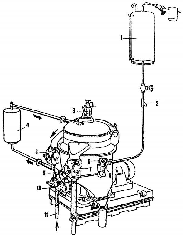
1 – водяной бак; 2 – фильтр; 3 – расходомер; 4 – подогреватель топлива; 5 – кран управления разгрузкой барабана от шлама; 6 – вестовая трубка; 7 – отвод отсепарированной воды; 8 – отвод чистого топлива (масла); 9 – кран; 10 – подающий насос топлива (масла); 11 – входной патрубок сепарируемого топлива (масла)
Важным элементом установки является водяной бак 1, который располагают на высоте 1,5-3,0 м от сепаратора. Он служит для питания системы управления выгрузкой шлама из барабана сепаратора и пополнения утечек воды. Во время работы сепаратора в баке должна постоянно находиться вода. Уровень её поддерживается по водоуказательному стеклу.
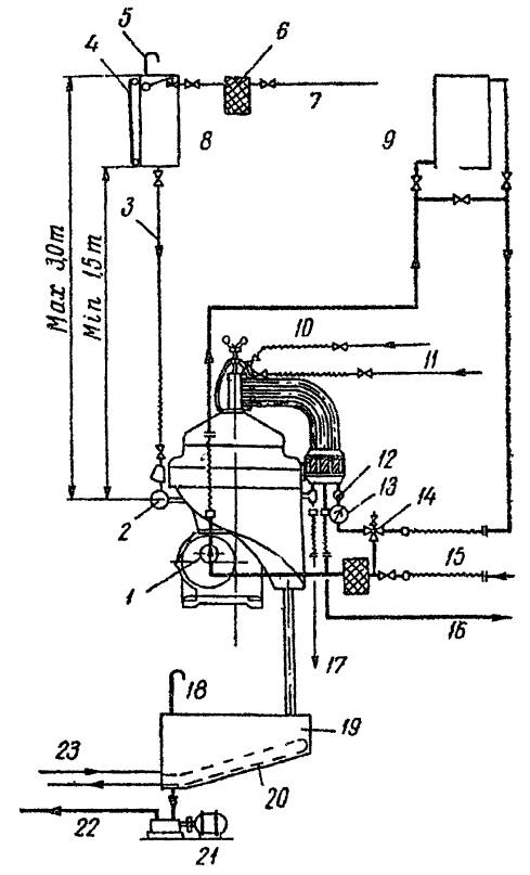
1 – приемный насос; 2 – маневровый кран; 3 – медная труба s′′; 4 – указатель уровня; 5 – вентиляционная труба 1′′; 6 – мягкий фильтр; 7 – подача холодной пресной воды; 8 – бак пресной воды гидравлического привода поршня; 9 – подогреватель; 10 – подача вспомогательной жидкости (например, для промывки масла); 11 – подача пресной воды (при 850 С) для гидравлического затвора; 12 – термометр; 13 – указатель расхода; 14 – клапан постоянного давления; 15 – подача топлива (масла) на сепаратор (минимум 1 S′′); 16 – отвод чистого топлива (масла); 17 – отсепарированная вода (минимум 1 S′′); 18 – вентиляционная труба; 19 – резервуар для шлама (минимум 500 л); 20 – змеевик подогревателя; 21 – шламовый насос; 22 – сброс за борт или в общую шламовую цистерну; 23 – паровой подогрев
Режим сепарирования требует определённой вязкости очищаемого топлива (масла). Она обеспечивается подогревом топлива в подогревателе 4. На схеме стрелками показано движение сепарируемого продукта.
Особенности эксплуатации сепараторов фирмы Лаваль при ручном управлении
При подготовке сепаратора к работе определяют оптимальную вязкость топлива и режим работы сепаратора.
В зависимости от содержания воды в сепарируемом нефтепродукте сепаратор собирают как кларификатор (осветлитель) или как пурификатор (очиститель). При сепарировании обводненных нефтепродуктов необходимо обеспечивать непрерывный отвод из барабана выделяющейся воды. Для настройки сепаратора на режим пурификации снимают кларификаторную верхнюю тарелку и вместо нее устанавливают разделительную тарелку и регулировочную шайбу. Кроме того, снимают нижнюю сплошную тарелку, перекрывающую проход нефтепродукта из тарелкодержателя в каналы, образованные отверстиями в тарелках. Причина смены нижней тарелки на тарелку с отверстиями при режиме пурификации – это необходимое условие поступления эмульсии в межтарелочное пространство по каналам, образованными отверстиями в тарелках.
Диаметр окружности, образованной отверстиями в тарелках соответствует диаметру «нейтрального слоя», т. е. условной поверхности раздела фаз топливо-вода. Процесс непрерывного отвода двух фаз из барабана сепаратора возможен при обеспечении гидравлического равновесия потоков поступающего и выходящего топлива, которое осуществляется подбором сменных регулировочных шайб.
Ориентировочно подбор регулировочной шайбы осуществляется по графикам или по таблицам для каждого сепаратора.
В практике Автоматические системы управления режимом сепарации фирмы Альфа-Лаваль (Альфакс и Алькап)эксплуатации сепараторов подбор регулировочной шайбы производят следующим образом: сначала ставят шайбу малого диаметра и далее меняют все с возрастающим диаметром отверстий до тех пор, пока из отверстия шайбы вместе с водой не начнет вытекать топливо, а затем ставят предыдущую шайбу меньшего диаметра. Настраивая таким образом работу сепаратора, находят предельно оптимальный диаметр регулировочной шайбы, при которой «нейтральный слой» будет соответствовать эффективной работе сепаратора.
Рассмотрим влияние размера диаметра регулировочной шайбы на эффективность работы сепаратора. На рис. 3 представлена схема расположения «нейтрального слоя» при правильной подобранной шайбе.
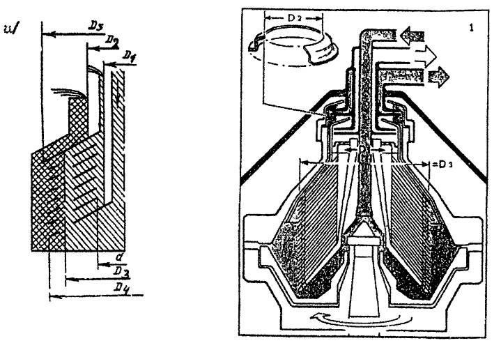
1 – вход неочищенного топлива; 2 – выход отсепарированного топлива; 3 – выход воды после сепарации.
D1 – диаметр входа топлива; D2 – диаметр регулировочной шайбы; D3 – диаметр «нейтрального слоя»; D4 – диаметр тарелок максимальный; D5 – диаметр разделительной тарелки; d – минимальный диаметр тарелок
«Нейтральный слой» расположен между краем диаметра разделительной тарелки и максимальным диаметром рабочих тарелок. Создание такого условия дает возможность прохождения топлива через весь пакет тарелок, и эффективность очистки топлива намного выше, чем при других вариантах настройки сепаратора.
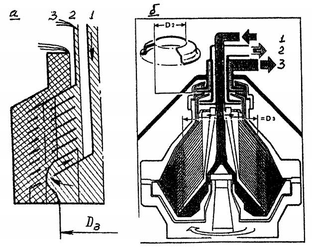
С увеличением диаметра регулировочной шайбы поверхность раздела топливо-вода перемещается ближе к стенкам барабана см. рис. 4 При перемещении её за край разделительной тарелки через отверстие регулировочной шайбы начнет вытекать топливо.
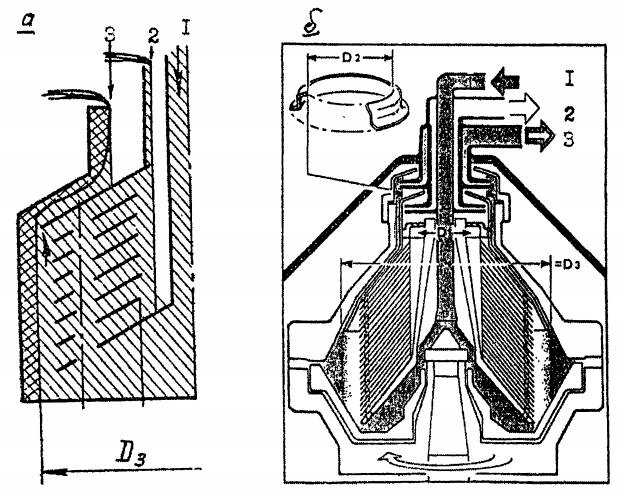
1 – неочищенного топлива; 2 – выход отсепарированного топлива; 3 – выход отсепарированной воды
Рассмотрим работу сепаратора при установке регулировочной шайбы большого диаметра. В этом варианте поверхность раздела фаз топливо-вода, т. е. «нейтрального слоя» переместится к стенке барабана и выйдет за край разделительной тарелки. Диаметр «нейтрального слоя» повышенный по сравнению с рис. 3 и как видно из рис. 4 а, б из патрубка 3 совместно с отсепарированной водой будет выходить топливо – это явление просматривается через смотровое окно сборника сепаратора и является признаком ненормальной работы сепаратора. Необходимо остановить сепаратор и заменить регулировочную шайбу на меньший диаметр.
С уменьшением диаметра регулировочной шайбы поверхность раздела фаз будет перемещаться к оси вращения (см. рис. 5).
1 – вход неочищенного продукта; 2 – выход отсепарированного топлива; 3 – выход отсепарированной воды
При этом будет наблюдаться пониженный эффект сепарирования, так как уменьшается эффективность площади тарелок.
Вариант сборки барабана сепаратора с малым диаметром регулировочной шайбы показан на рис. При данной настройке сепаратора диаметр D3 «нейтрального слоя» будет намного меньше по сравнению с диаметром D3 (рис. 3), и при работе сепаратора наблюдается в патрубке 2 выход воды в топливе, наличие которой определяют по запотеванию смотрового стекла.
Эффективность очистки сепаратора уменьшается по причине неполного использования межтарелочного пространства тарелок. Сепаратор необходимо остановить для замены регулировочной шайбы на больший диаметр D2.
В варианте выбора регулировочной шайбы из расчета сохранения положения поверхности раздела фаз вблизи отверстий «нейтрального слоя», топливо после сепаратора будет содержать повышенное количество воды – порядка 2,5-3 %.
Если регулировочная шайба выбирается из расчета расположения поверхности раздела фаз между наибольшим диаметром разделительной тарелки Др и наибольшим диаметром рабочей тарелки Дт, топливо после сепаратора выходит с содержанием воды порядка 0,3-0,4 %.
При таком режиме работы сепаратора, чтобы полностью предотвратить поступление эмульсии в каналы, образуемые отверстиями «нейтрального слоя», эти каналы перекрываются первой (нулевой) сплошной тарелкой, которая обычно устанавливается при кларификаторной сборке барабана.
При наличии двух напорных дисков – один откачивает легкую фазу (топливо или масло), а второй тяжелую фазу (воду) – такая система помогает регулировать положение поверхности раздела фаз в барабане без остановки сепаратора.
Если создать противодавление (клапаном) на магистрали тяжёлой фазы, то поверхность раздела фаз сместится к центру барабана, и наоборот, если создать противодавление на магистрали легкой фазы – поверхность раздела фаз сместится к периферии.
Такая система позволяет регулировать положение поверхности раздела фаз при изменении плотности обрабатываемого нефтепродукта до 3-4 % при температуре сепарирования. В случае больших колебаний плотности сепарируемого продукта требуется замена регулировочной шайбы.
На практике фирма Лаваль рекомендует регулировать положение поверхности раздела фаз изменением давления только со стороны легкой фазы.
Это осуществляется следующим образом:
- выбирают и устанавливают регулировочную шайбу в соответствии с рекомендацией фирмы в зависимости от плотности обрабатываемого продукта;
- устанавливается рекомендованная для данного топлива (масла) производительность и температура сепарации;
- увеличивается противодавление на магистрали разгрузки легкой фазы до тех пор, пока некоторое ее количество не появится со стороны разгрузки тяжелой фазы (воды) по манометру, отсчитывается полученное противодавление на магистрали разгрузки легкой фазы;
- на 0,5 бар снижается противодавление на магистрали легкой фазы;
- поверхность раздела фаз займет в барабане оптимальное положение;
- установленный на трубопроводе клапан постоянного давления будет поддерживать давление в процессе работы.
Подготовка сепаратора к пуску и работе
Перед запуском сепаратора необходимо произвести следующие операции:
1 Произвести наружный осмотр сепаратора и убедиться в том, что на нем нет посторонних предметов, если обнаружатся – удалить;
2 Проверить, хорошо ли зажата крышка сепаратора прижимными болтами;
3 Проверить, отпущен ли тормоз;
4 Подготовить систему подвода и отвода нефтепродукта (топлива, масла);
5 Проверить наличие масла в корпусе червячной передачи;
Уровень масла должен быть выше средней черты смотрового стекла.
6 Проверить наличие воды в напорном баке 1 рис. 1;
7 Проверить, полностью ли открыт расходомер 3 рис. 1;
8 Проверить подогреватель топлива (масла) – подведена ли греющая среда (пар или электропитание);
9 Проверить положение маневрового крана управления – он должен находиться в положении № 2 (выключено), барабан открыт;
10 Убедиться в правильности выбора и установки регулировочной шайбы;
11 Выбор регулировочной шайбы – см. инструкцию по ее подбору и рекомендации, как описано выше;
12 Пуск сепаратора осуществляется включением электродвигателя.
Примечание: в период разгона сепаратора муфта сцепления нагревается вследствие проскальзывания колодок, но после разгона, как только частота вращения горизонтального вала и электродвигателя сравнивается, муфта охлаждается.
13 При процессе пурификации – для гидравлического затвора подводят воду, подогретую до температуры топлива (масла) идущего на сепарацию. Прекращают подачу воды, когда она начнет вытекать через смотровое окошко.
Примечание: если вода начнет вытекать через трубу смотрового стекла (отвод топлива, масла) – это свидетельствует, что регулировочная шайба малого диаметра или большое давление подаваемой воды.
14 При достижении полной частоты вращения барабана – спустя 6-8 мин. с момента запуска – поставить маневровый кран управления в положение № 3. С появлением воды из вестовой трубки – поставить маневровый кран в положение № 4 (работа).
15 Открыть клапана подачи сепарируемого нефтепродукта.
16 Постепенно и медленно открывать клапан подачи топлива (масла) на сепаратор – при быстром открытии произойдет вытеснение воды гидравлического затвора и топливо (масло) поступит в патрубок отсепарированной воды.
Это явление характерно, если сепарируемое топливо (масло) имеет большой удельный вес (более 0,9 г/см3).
При настройке сепаратора на процесс кларификации заполнение барабана топливом (маслом) следует производить быстро;
17 Поставить стрелку расходомера специальным ключом на нужный расход, затем отрегулировать клапаном на давление по манометру 1 бар.
Примечание: появление брызг топлива (масла) на стекле смотрового окошка на крышке сепаратора указывает на то, что барабан закупорен шламом. В этом случае необходимо остановить барабан и произвести очистку его тарелок.
В процессе работы сепаратора необходимо контролировать следующее:
1 Не поступает ли сепарируемая жидкость в камеру переполнения, причина – барабан наполнился шламом или велика производительность сепаратора. Необходимо остановить сепаратор очистить барабан или уменьшить производительность.
2 Не содержится ли в отходах сепарации (воде) повышенного количества топлива (масла). Причина – повышенное содержание сепарируемого продукта. Может быть поставлена неправильно выбранная регулировочная шайба или заменена температура сепарирования.
3 Контролировать температурный режим поступающего нефтепродукта, поддерживая заданную температуру.
4 Контролировать нормальный температурный режим механизмов сепаратора, отсутствие вибрации и посторонних шумов, отсутствие протечек в разъемах, фланцах.
5 При остановке сепаратора, если нет необходимости в быстрой остановке барабана, лучше не пользоваться тормозами, так как при медленной остановке в барабане сохраняется водяной затвор, и при последующем запуске нет необходимости пополнять его. Кроме того, увеличивается срок работы тормозных колодок.
6 Если во время работы сепаратора барабан автоматически открывается, например, вследствие отсутствия воды в водяном баке, надо немедленно прекратить подачу топлива (масла), остановить сепаратор.
При эксплуатации сепараторов фирмы Лаваль рекомендуется два режима работы сепаратора:
- 1-й – режим работы сепаратора с максимальной производительностью в аварийных случаях, когда из-за неисправности силовой установки в масло начинает поступать большое количество воды.
- 2-й – режим работы сепаратора с оптимальной производительностью равной 1/3 от максимальной при нормальных условиях работы – для получения наилучшей очистки масла.
Практически окончательную производительность, соответствующую наилучшей очистке, определяем следующим образом:
- масло обрабатывается в течение 12 часов при рекомендованной производительности (1/3 от максимальной), затем барабан вскрывают и определяют количество отложившегося за это время шлама.
- обрабатывают масло при тех же условиях (время, температура, добавка воды), но с пониженной на 20 % производительности сепаратора от максимальной; определяют количество выделившего шлама.
- увеличивают производительность сепаратора на 10 % от первоначальной (от 1/3 максимальной) и вновь при тех же условиях работы сепаратора определяют количества шлама.
Производительность, при которой выделится наибольшее количество шлама, и будет оптимальной для данного варианта сепарирования.
Многие Сепарирование топлива и масла для эффективной работы судовых дизелейсмазочные масла модифицируются различными присадками, причем большинство из этих присадок обладают моющим (диспергирующим) действием. Моющее действие таких масел заключается не в устранении (смывании) уже образовавшихся отложений, а в предотвращении их образования.
Читайте также: Сепарация топлива для использования на судовых дизелях
Большинство применяемых присадок мало растворимы или находятся в масле в состоянии коллоидной суспензии. Выделить их в судовых сепараторах под действием центробежных сил, как правило, невозможно.
Поэтому на основе эксплуатационного опыта сепарации смазочных масел с присадками в судовых условиях некоторые фирмы предлагают следующие рекомендации:
- осуществлять одноступенчатую очистку масла при байпасном включении сепаратора;
- сепаратор работает в режиме пурификации одновременно с двигателем и после его остановки дополнительно 12 часов;
- производительность сепаратора устанавливают оптимальной (1/3 от макс.);
- поддерживать температуру сепарирования дизельных масел – около 75 °С, турбинных масел – около 65 °С;
- поддерживать температуру сепарирования моющих масел – 80 °С;
- при сепарировании масел с присадками следует добавлять 1 % горячей воды с температурой выше на 5 °С температуры масла.
Очистка и ревизия сепаратора
Для надежной работы сепаратора требуется постоянное внимание к вращающимся деталям – осмотры, ревизии и очистка.
| Таблица 1. Очистка и ревизия сепаратора | |
|---|---|
| 1. Барабан сепаратора, комплект тарелок, крышка барабана | После каждой продолжительной работы или раз в неделю |
| 2. Система управления | Производить ревизию всегда при снятии барабана с вала |
| 3. Фильтр в системе подвода управляющей воды | Вскрытие и очистка раз в месяц |
| 4. Каналы системы управления, маневровый кран | Ревизия, очистка от накипи раз в три месяца |
| 5. Корпус червячной передачи | При замене масла |
| 6. Привод вертикальный и горизонтальный, подшипники | Раз в год |
Смазка деталей сепаратора
| Таблица 2. Смазка деталей сепаратора | |
|---|---|
| 1. Корпус червячной передачи. | После каждых 1 500 часов работы сепаратора смена масла в картаре червячной передачи |
| 2. Барабан сепаратора: поверхности скольжения и ступицу корпуса барабана. | Всегда при монтаже. Касторовым масло. |
| 3. Резьба крышки барабана под малую кольцевую гайку. | Всегда при монтаже. Касторовым маслом. |
| 4. Резьба большого прижимного кольца, кольцевой гайки. | При каждой сборке. Касторовым маслом. |
| 5. Болты, в дне корпуса барабана. | Каждый раз при надевании корпуса барабана на вал. Консистентная смазка. |
| 6. Пазы для резиновых колец, подвижного дна, крышки барабана. | Всегда, при каждой сборке элементов управления. Консистентная смазка. |
| 7. Резьба клапанных гнезд, установочный винт большой кольцевой гайки. | Всегда при монтаже. Консистентная смазка. |
Периоды между осмотрами и ревизиями сепаратора
Правильная эксплуатация, профилактические осмотры, своевременно проводимый ремонт и наладка сепараторов обеспечивает длительную и безотказную работу сепаратора.
В таблице приведены периоды между ревизиями, осмотрами и смазками деталей сепаратора.
| Таблица 3. Периоды между ревизиями, осмотрами и смазками деталей сепаратора. | ||||||
|---|---|---|---|---|---|---|
| № | Проверяемый узел, деталь | 750 | 1 500 | 4 000 | 8 000 | 16 000 |
| 1 | Первая замена масла в картере | × | – | – | – | – |
| 2 | Замена минерального масла в картере сепаратора после 1 500 часов работы с мойкой картера | – | × | – | – | – |
| 3 | Замена синтетического масла в картере сепаратора после 1 500 часов работы с мойкой картера сепаратора | – | × | – | – | – |
| 4 | Смазка скользящих и направляющих поверхностей | – | – | × | – | – |
| 5 | Очистка фильтра на магистрали нефтепродукта | По необходимости | ||||
| 6 | Очистка фильтра рабочей воды | По необходимости | ||||
| 7 | Мойка и очистка пакета тарелок | После каждой продолжительной работы сепаратора | ||||
| 8 | Снятие барабана, очистка его корпуса изнутри, очистка всех отверстий сопел гидравлической системы | – | – | × | – | – |
| 9 | Снятие вертикального вала, разборка и ревизия нижнего подшипника | – | – | × | – | – |
| 10 | Разборка и ревизия подшипников верхней опоры, ревизия амортизационных пружин | – | – | × | – | – |
| 11 | Замена уплотнительных колец (5, 7, 8, 15, 16, 19) см. рис. Судовые сепараторы фирмы Альфа-Лаваль“Детальная компоновка барабана сепаратора МАРХ” | – | – | × | – | – |
| 12 | Разборка и ревизия системы гидравлического управления подвижным поршнем, очистка водяных каналов, сопел | – | – | – | × | – |
| 13 | Разборка и ревизия деталей винто-червячной передачи | – | – | – | × | – |
| 14 | Замена колодок фрикционной муфты | – | – | – | × | – |
| 15 | Замена шарикоподшипников вертикального вала | – | – | – | × | – |
| 16 | Замена подшипников горизонтального вала и червячного колеса | – | – | – | – | × |
| 17 | Ежедневный контроль: – уровень масла в картере червячной передачи; – температуры: подшипников, продукта сепарации; – давление нефтепродукта перед входом и выходом сепаратора: – протечки; – вибрации; – нагрузки электродвигателя; – времени разгона сепаратора. |
Сноски
|
О компанииЦеныПортфолиоКачествоВ помощь клиентуВакансииДумайте самиСкачатьЗаметки о переводеВопросы и ответы Посмотреть более 1000 образцов наших переводов Узнать: Стоимость письменного перевода Освоенные тематики переводов (образцы работ) Качество переводов Скачать: Договор на оказание переводческих услуг Цены на письменный перевод (Приложение к Договору) Пример коммерческого предложения на перевод технической документации |
Портфолио Сепараторы, кларификаторы, центрифуги
|
<<Назад Сепараторы, кларификаторы, центрифугиТеплообменникиНасосыТрубопроводная арматураОборудование для емкостейСмесителиСушилкиВыпариваниеФильтрацияПроизводство продуктов |


Похожие релизы
| # | Тема | Форум | Автор |
|---|---|---|---|
|
EN |
Сепараторы Альфа Лаваль / Alfa Laval Separators / Manuals, Handbooks, Instructions [PDF] |
Судовые системы и механизмы | |
|
EN |
Alfa-Laval Centufugal Type OWS — Alfa-Laval [2012, PDF] |
Судовые системы и механизмы | oleyud |
|
RU |
TeamTec Incinerator OG 200C — TeamTec AS [2002, PDF] |
Инсинераторы | kose |
|
RU |
Руководства по Transas ERS 4000 (руководство инструктора, руководство обучаемого, General Cargo-2)… |
Без категории | Loliboss |
|
RU/EN |
Сборник документации по обслуживанию, ремонту, запасным частям и аксессуарам для двигателя Yamaha… |
Ремонт и тех. обслуживание | ChigiS |
|
RU |
TeamTec Incinerator OG 120C — TeamTec AS [2004, PDF] |
Инсинераторы | kose |
|
RU |
Wärtsilä 6L20 [2005, PDF] |
Wärtsilä & Sulzer | third |
|
EN |
Wärtsilä 6L32. Instruction Manual [2008, PDF] |
Wärtsilä & Sulzer | maksyha |
|
RU |
Плот спасательный надувной ПСН-6М, ПСН-10М [1984, PDF] |
Аварийные и спасательные средства | Moryachok |
|
RU |
ТралТек – 1500 Инструкция по эксплуатации — Компания VAKI Ltd., Исландия [2014, PDF] |
Рыболовство и подводная охота | borzikp |
- Ответить