
Sometimes it’s hard writing PLC code in LAD (ladder logic) or FBD (function block diagram). Especially, if you have to do some math work or mass operations.
In these cases you can easily use SCL/ST (Structured Control Language/Structured Text.)
 Writing your first TIA code in SCL:
 Writing your first TIA code in SCL:
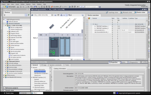
Step 1 – Create or open TIA project
Just like programming LAD or FBD, it’s necessary to create or open a project with a PLC to program in. SCL is supported by all SIMATIC PLCs (S7-300, S7-400, S7-1200 and S7-1500).
In this example, I’ll use a S7-1515-2 PN, but it will also work with other S7-1500 or S7-1200 PLCs.
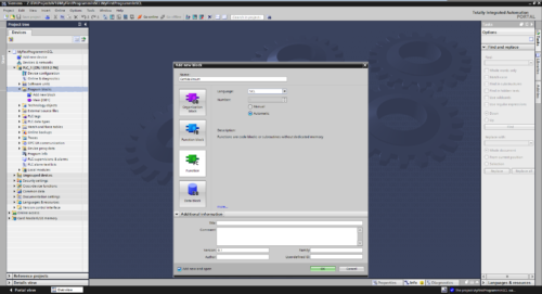
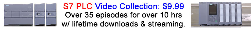
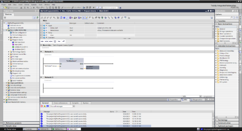
Step 2 – Add FB/FC
After the project is opened and a PLC is available, we can add a function [FC] or a function block [FB]. The difference between FC and FB is the storage capability. A FB can store data which is still available after a PLC cycle. In our case we only need a FC.
Double click “Add new block” within the “PLC/Program blocks” folder. Now the “Add new block” dialogue is opened. Here we can select the block type to create, in our case FC.
After the block type is chosen, we have to select the language to program in. The drop down list will show all possible programming languages available for the selected block type in combination with the PLC type. We will use “SCL” of course.
If you want, you can also add additional information below in the Additional Information compartment e.g. author, version, etc.. Now we can create the block by click OK in the dialogue.
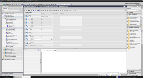
Step 3 – Modify the block interface
After the block is created, we can modify the Interface of the FC. In our case we will enter an input of type [Array[0..5] of INT], an output of type [INT], and two temp variables of type [INT].
Note: In a FB there is also a static section shown due capability to store data for more than the actual PLC cycle.
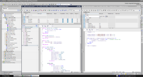
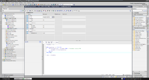
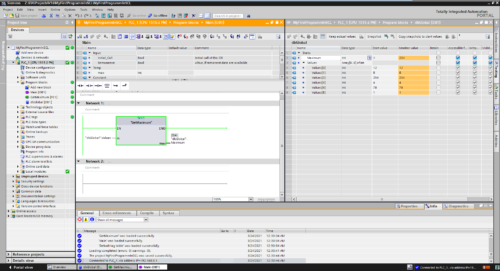
Step 4 – Enter SCL code
In the next step we enter the code to determine the maximum value of the array elements. The code will iterate from index zero to five through the array and compare if the actual value is greater than the “tempMax” value. At the end we will get the maximum value contained in the array.
At the line one we set the “tempMax” to a defined value. In this case zero.
In Line three we start the “FOR” loop. This will use the “tempCount” variable to store the actual index of our loop. It is set to zero for the start and will run until it has reached five. So we will run the loop for six times (0->1->2->3->4->5). The code of the “FOR” loop is encapsulated by the “FOR …” statement in line three and “END_FOR;” statement in line seven.
This code block contains an “IF” block which will only process its inner code if the statement “#In[#tempCount] > #tempMax” will return a “TRUE” and so the actual “maxTemp is smaller than the value of the array element with index of #tempCount.
Due to intellisense the TIA portal provides suggestions while typing code. Additional you have a favorite instruction list at the top of the text editor area just like in the editor of the other languages. Here you can add other instructions by drag them from the instructions tab.
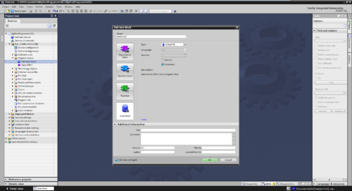
Step 5 – Provide some data
To be able to provide our program with some values we have to create a global data block [DB] to provide some data, like we did it for the FC.
We will also enter some startup data, which is provided to the global DB at Startup of the PLC.
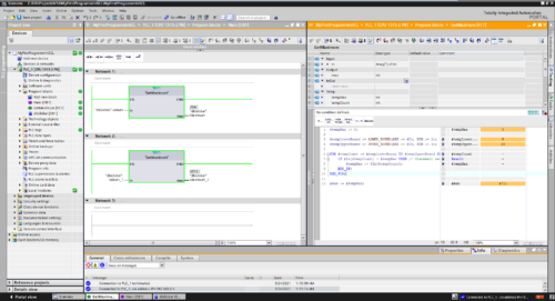
Step 6 – Call the FC in OB1
To use the FC in our PLC, we can call the block within the Main [OB1] and provide it with values from the “dbGlobal”. After we added the call, we can compile the program code and load it into our PLC or simulate it with PLCsim.
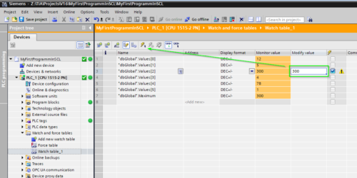
Step 7 – Testing
After connecting to the device (by selecting the PLC and click “go online”) and activate observe mode in the blocks, we can check the behavior of our program.
We can create a watch table to observe and modify values to test our code. Enter in the column “Modify value” a new value to set and click on the set button in the tool bar. The new value will be set into the variable and the code will process with the new values.
Note: Keep in mind a variable which is set by the PLC program will overwrite the manual set value at every new cycle.
You can modify the display format to e.g. show a variable in hex or binary notation like 16#09 or 2#0000 1001. So it is easier to read e.g. “status words”.
Step 8 – More generic approach
At the block interface it is possible to define the input array with variable limits to offer better reusability for blocks with arrays of different length. Here for we have to adapt the interface at the FC and add code to determine the lower and upper bound of the array. It is also able to do this with multidimensional arrays.
Note: Keep in mind this feature is only available in the newer PLCs (1200/1500).

Pros and cons
| Pro | Con |
| Easy to write complex code | Hard to track signal sequences (reason why it is not used for failsafe PLC coding) |
| Good for mass operations | Bad logically overview |
| Easy programming of switch case | Sometimes hard to read |
Note: You are free to use the programming language of choice which fits best to your needs. In previous courses we saw using SCL networks within FBD code. E.g. program complex code in an SCL Block and interlocking section of Outputs in an FBD Block.
Some other hints
To get an overview over the available commands in the different languages, there is a document from SIEMENS online support which helps me a lot.
- https://support.industry.siemens.com/cs/us/en/view/109778377
Written by Michael Elting
Mechatronics & Automation Engineer and Freelance Writer
Have a question? Join our community of pros to take part in the discussion! You’ll also find all of our automation courses at TheAutomationSchool.com.
Sponsor and Advertise: Get your product or service in front of our 75K followers while also supporting independent automation journalism by sponsoring or advertising with us! Learn more in our Media Guide here, or contact us using this form.
- Author
- Recent Posts
![]()
Michael is a freelance writer for The Automation Blog, as well as a degreed engineer of mechatronics, automation engineer, developer, trainer and mentor of internship. Beside his interests in techical topic he is a dedicated hicker and traveler.
![]()
Предложите, как улучшить StudyLib
(Для жалоб на нарушения авторских прав, используйте
другую форму
)
Ваш е-мэйл
Заполните, если хотите получить ответ
Оцените наш проект
1
2
3
4
5
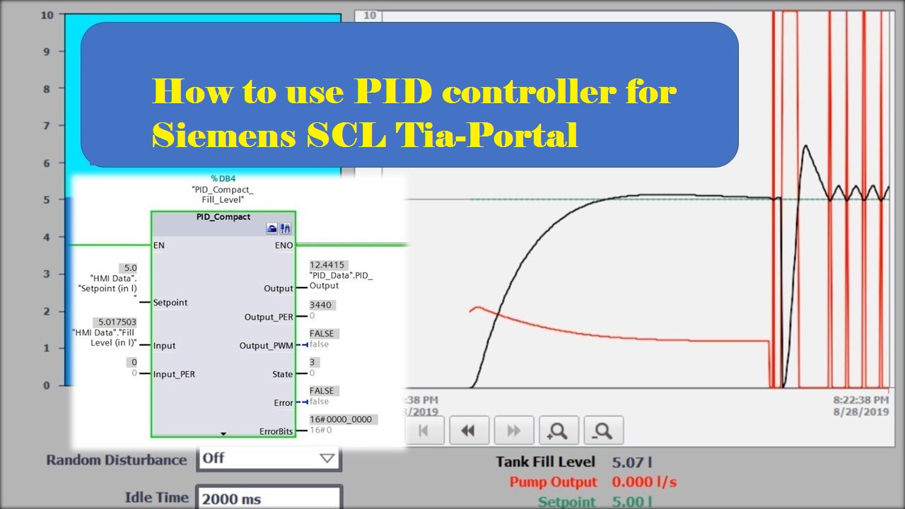
Hello,and welcome back to techme. Today we will present a special lesson of How to use PID controller for Siemens SCL Tia-Portal.
We’ve always had a lot to do with the Tia Portal’s control technology and we’ve never been satisfied with our Siemens units. We need PI controllers for pressure control and PID controllers for temperature control. Here are some of the problems:
- Different devices between different CPUs use different lib.
- It cannot be simulated.
- The source cannot be read and changed.
- Very complex with a high level of familiarity.
- Very high integration at TIA.
- Do a lot of repairs and testing until something finally worked.
instruction
he controller produce a outputs from 0 to 100. If used with a binary actor you shoud use the clock generator for pulse width modulation. The PI controller is disigned to run alone. Usefull for pressure regulation. The controller should alwasys stoped with the reset input is the regulation loop is disturbed. This prevents the integral to windup.
ir_Input = The mesuered value of pressure or themperature
ir_Setpoint = The demanded value of pressure or themperature
ir_ProportionalGain = The proportional gain, a tuning parameter
ir_IntegrationGain = The integral gain, a tuning parameter
ir_DifferentialGain = The derivative gain, a tuning parameter
itime_DifferezialActionTime = The length of the derivative action, a tuning parameter
ib_Reset = Empty the integral and sets the output to zero
or_Output = Output value in % from 0 to 100

Installing
Installation is very simple. Enter the SLC file under «External Source Files» and then execute the «Create blocks from source» menu item.
FUNCTION_BLOCK "fb_PI-Regler_TIA300_V15.0.2"

{ S7_Optimized_Access := 'FALSE' }
VERSION : 0.1
VAR_INPUT
ir_Istwert { ExternalAccessible := 'False'; ExternalVisible := 'False'; ExternalWritable := 'False'} : Real; // Istwert
ir_Sollwert { ExternalAccessible := 'False'; ExternalVisible := 'False'; ExternalWritable := 'False'} : Real; // Sollwert
ir_ProportionalVerstärkung { ExternalAccessible := 'False'; ExternalVisible := 'False'; ExternalWritable := 'False'} : Real := 20.0; // Proportional-Verstärkung
ir_IntegralVerstärkung { ExternalAccessible := 'False'; ExternalVisible := 'False'; ExternalWritable := 'False'} : Real := 5.0; // Integral-Verstärkung
ib_Reset { ExternalAccessible := 'False'; ExternalVisible := 'False'; ExternalWritable := 'False'} : Bool := FALSE; // Reset
ii_OB1_PREV_CYCLE { ExternalVisible := 'False'} : Int := 5; // Cycle time of previous OB1 scan (milliseconds)
END_VAR
VAR_OUTPUT
or_Reglerantwort { ExternalAccessible := 'False'; ExternalVisible := 'False'; ExternalWritable := 'False'} : Real; // Regler Ausgang
END_VAR
VAR
Reglerantwort_Integral { ExternalAccessible := 'False'; ExternalVisible := 'False'; ExternalWritable := 'False'} : Real;
Reglerantwort_Proportional { ExternalAccessible := 'False'; ExternalVisible := 'False'; ExternalWritable := 'False'} : Real;
VergangeneZeit { ExternalAccessible := 'False'; ExternalVisible := 'False'; ExternalWritable := 'False'} : Real; // in s
END_VAR
VAR CONSTANT
UnteresLimit : Real := 0.0; // unteres Limit
OberesLimit : Real := 100.0; // oberes Limit
END_VAR
BEGIN
//read elpsed Time in s since last Time from OB1 Temp
#VergangeneZeit := INT_TO_REAL(#ii_OB1_PREV_CYCLE)/1000;
//initialize at power_up
IF #ib_Reset THEN
#Reglerantwort_Integral := 0.0;
#or_Reglerantwort := 0.0;
ELSE
// calculate proportional part
#Reglerantwort_Proportional := #ir_ProportionalVerstärkung * (#ir_Sollwert - #ir_Istwert);
//run integrator only IF Time makes sens
IF #VergangeneZeit > 0 AND #VergangeneZeit < 0.1 THEN
#Reglerantwort_Integral := #Reglerantwort_Integral + #ir_IntegralVerstärkung *
(#ir_Sollwert - #ir_Istwert) * #VergangeneZeit;
END_IF;
// calculate output
#or_Reglerantwort := #Reglerantwort_Proportional + #Reglerantwort_Integral;
// check output FOR limits
IF #or_Reglerantwort >= #OberesLimit THEN
#or_Reglerantwort := #OberesLimit;
#Reglerantwort_Integral := #OberesLimit - #Reglerantwort_Proportional;
ELSIF #or_Reglerantwort <= #UnteresLimit THEN
#or_Reglerantwort := #UnteresLimit;
#Reglerantwort_Integral := #UnteresLimit - #Reglerantwort_Proportional;
END_IF;
END_IF;
END_FUNCTION_BLOCK
PI-Regler_S7_300_V15.0.2.SCL
FUNCTION_BLOCK fb001

   VAR_INPUT
      ir_Istwert  : Real;   // Istwert
      ir_Sollwert : Real;   // Sollwert
      ir_ProportionalVerstaerkung : Real := 20.0;   // Proportional-Verstaerkung
      ir_IntegralVerstaerkung  : Real := 5.0;   // Integral-Verstaerkung
      ib_Reset : Bool := FALSE;   // Reset
      ii_OB1_PREV_CYCLE  : Int := 5;   // Cycle time of previous OB1 scan (milliseconds)
   END_VAR

   VAR_OUTPUT
      or_Reglerantwort  : Real;   // Regler Ausgang
   END_VAR

   VAR
      Reglerantwort_Integral  : Real;
      Reglerantwort_Proportional : Real;
      VergangeneZeit : Real;   // in s
   END_VAR

   CONST
      UnteresLimit := 0.0;   // unteres Limit
      OberesLimit  := 100.0;   // oberes Limit
   END_CONST

BEGIN
    //read elpsed Time in s since last Time from OB1 Temp
    VergangeneZeit := INT_TO_REAL(ii_OB1_PREV_CYCLE)/1000;
    //initialize at power_up
    IF ib_Reset THEN
        Reglerantwort_Integral := 0.0;
        or_Reglerantwort := 0.0;
    ELSE
        // calculate proportional part
        Reglerantwort_Proportional := ir_ProportionalVerstaerkung * (ir_Sollwert - ir_Istwert);
        //run integrator only IF Time makes sens
        IF VergangeneZeit > 0 AND VergangeneZeit < 0.1 THEN
            Reglerantwort_Integral :=  Reglerantwort_Integral + ir_IntegralVerstaerkung *
            (ir_Sollwert - ir_Istwert) * VergangeneZeit;
        END_IF;
        // calculate output
        or_Reglerantwort := Reglerantwort_Proportional + Reglerantwort_Integral;
        // check output FOR limits
        IF or_Reglerantwort >= OberesLimit THEN
            or_Reglerantwort := OberesLimit;
            Reglerantwort_Integral := OberesLimit - Reglerantwort_Proportional;
        ELSIF or_Reglerantwort <= UnteresLimit THEN
            or_Reglerantwort := UnteresLimit;
            Reglerantwort_Integral := UnteresLimit - Reglerantwort_Proportional;
        END_IF;
    END_IF;

END_FUNCTION_BLOCK
Download Guide for Unity Pro plc book
В данной статье рассмотрим основы программирования в Tia Portal на примере структурированного языка управления SCL (Structured Control Language), являющегося высокоуровневым текстовым языком, основанным на языке PASCAL.
Данный язык поддерживает типовые операторы программирования, такие как присвоение (: =), математические функции (+ для сложения, — для вычитания, * для умножения, / для деления), а также использует стандартные операторы языка PASCAL, такие как IF-THEN-ELSE, CASE, REPEAT-UNTIL, GOTO и RETURN. Другие инструкции для SCL, такие как таймеры и счетчики, соответствуют LAD и FBD инструкциям.
Начнем мы изучение SCL с простых логических операций и математических выражений и сравним их с программированием на языке LADDER.
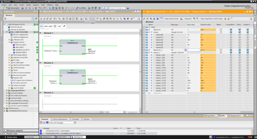
Ниже на рис. приведен пример FB блока на LAD, состоящий из пяти Network, в которых выполняются простые логические и математические операции, в том числе один таймер. Создадим подобный блок на языке SCL.

Создаем в программе новый функциональный блок и в раскрывающемся списке выберем SCL в качестве языка программирования.

Таблицу тегов будем использовать ту же самую, что и для LAD.
Начнем с самой простой задачи – логической операции AND. Значение TRUE на i1 и i2 активирует выход q1.

Для написания программы на SCL необходимо запомнить синтаксис команд — переменная всегда начинается с кавычек или #, двоеточие разделяет инструкции, = присваивает результат. Разницы между строчными и прописными символами нет. При вводе переменных, достаточно ввести первый символ и TIA Portal автоматически предложит выбрать переменную из раскрывающегося списка.
Комментарии в программе указываются с помощью двойной косой линии – слеша.

Напомню, что каждая строка должна заканчиваться точкой с запятой. Во второй строке оператор RETURN после косой черты указывает на конец программного блока, достаточно удалить эти косые черты и ПЛК не выполнит следующие строки программы. Это удобно при отладке программы.
Одна важная деталь. В блоке, созданном на языке LAD, мы можем легко добавить сегмент на языке SCL с помощью правой кнопки мыши. Таким образом, при необходимости, мы можем написать несколько длинных логических операций на SCL прямо в функциональном блоке LAD.
Переходим ко второму сегменту. В данном случае, выход будет активен, если значение хотя бы одного из входов (i1 или i3) выражения в скобках будет принимать значение TRUE и нет сигнала на входе i2.

Далее из меню основных инструкций добавим таймер с задержкой выключения — TOF. Параметры таймера указываются в скобках.

Тип таймера можно легко изменить, просто щелкнув по нему мышью.
В следующей строке напишем простое математическое выражение «А умноженное на В равно С». Если необходимо, вместо умножения можно использовать и другие операторы – сложение, вычитание, деление, сравнения и т.д.

Наконец, еще одно выражение «A + B = C», на этот раз с использованием временных переменных в функциональном блоке. В последней строке используется команда RETURN, то есть конец программного блока.

Наши последние несколько строк, написанных на SCL, заменили эти два сегмента программы LAD.

В принципе, это вся программа на SCL, которая представляет собой аналогичную программу на LAD, согласно первому рисунку в статье.
Как видим, получилось все более компактно. Кроме того, программный код можно еще немного уменьшить, удалив ненужные комментарии.
В следующем уроке мы продолжим изучение SCL и рассмотрим работу с детекторами фронтов, счетчиками.
6.2.3
Structured Control Language (SCL) is a high-level, PASCAL-based programming language
for the SIMATIC S7 CPUs. SCL supports the block structure of STEP 7. You can also
include program blocks written in SCL with program blocks written in LAD and FBD.
SCL instructions use standard programming operators, such as for assignment (:=),
mathematical functions (+ for addition, — for subtraction, * for multiplication, and / for division).
SCL uses standard PASCAL program control operations, such as IF-THEN-ELSE, CASE,
REPEAT-UNTIL, GOTO and RETURN. You can use any PASCAL reference for syntactical
elements of the SCL programming language. Many of the other instructions for SCL, such as
timers and counters, match the LAD and FBD instructions.
Because SCL, like PASCAL, offers conditional processing, looping, and nesting control
structures, you can implement complex algorithms in SCL more easily than in LAD or FBD.
The following examples show different expressions for different uses:
«C» := #A+#B;
«Data_block_1».Tag := #A;
IF #A > #B THEN «C» := #A;
«C» := SQRT (SQR (#A) + SQR (#B));
As a high-level programming language, SCL uses standard statements for basic tasks:
● Assignment statement: :=
● Mathematical functions: +, -, *, and /
● Addressing of global variables (tags): «<tag name>» (Tag name or data block name
● Addressing of local variables: #<variable name> (Variable name preceded by «#» symbol)
Arithmetic operators can process various numeric data types. The data type of the result is
determined by the data type of the most-significant operands. For example, a multiplication
operation that uses an INT operand and a REAL operand yields a REAL value for the result.
6.2.4
SCL program editor
You can designate any type of block (OB, FB, or FC) to use the SCL programming language
at the time you create the block. STEP 7 provides an SCL program editor that includes the
following elements:
● Interface section for defining the parameters of the code block
● Code section for the program code
● Instruction tree that contains the SCL instructions supported by the CPU
You enter the SCL code for your instruction directly in the code section. For more complex
instructions, simply drag the SCL instructions from the instruction tree and drop them into
your program. You can also use any text editor to create an SCL program and then import
that file into STEP 7.
Easy Book
Manual, 11/2011, A5E02486774-04
enclosed in double quotes)
Programming made easy
6.2 Easy-to-use programming languages
Assigns two local variables to a tag
Assignment to a data block tag
Condition for the IF-THEN statement
Parameters for the SQRT instruction
95
-
Preface, Contents
Part 1: Designing Programs
Part 2: Operating and Debugging
Part 3: Language Description
Appendix
Glossary, IndexStructured Control Language(SCL) for
S7-300/S7-400ProgrammingManual
This manual has the order number:
6ES7811-1CA02-8BA0
SIMATIC
-
iiStructured Control Language (SCL) for S7-300/S7-400,
ProgrammingC79000 G7076 C522 01
This manual contains notices which you should observe to ensure
your own personal safety, as well as toprotect the product and
connected equipment. These notices are highlighted in the manual by
a warningtriangle and are marked as follows according to the level
of danger:! Dangerindicates that death, severe personal injury or
substantial property damage will result if proper precautions
arenot taken.! Warningindicates that death, severe personal injury or
substantial property damage can result if proper precautions arenot
taken.! Cautionindicates that minor personal injury or property damage
can result if proper precautions are not taken.Notedraws your attention to particularly important information
on the product, handling the product, or to a particularpart of the
documentation.The device/system may only be set up and operated in conjunction
with this manual.Only qualified personnel should be allowed to install and work
on this equipment. Qualified persons aredefined as persons who are
authorized to commission, to ground, and to tag circuits,
equipment, andsystems in accordance with established safety
practices and standards.Note the following:
! WarningThis device and its components may only be used for the
applications described in the catalog or the technicaldescription,
and only in connection with devices or components from other
manufacturers which have beenapproved or recommended by
Siemens.SIMATIC, SIMATIC NET and SIMATIC HMI are registered trademarks
of SIEMENS AG.Third parties using for their own purposes any other names in
this document which refer totrademarks might infringe upon the
rights of the trademark owners.We have checked the contents of this manual for agreement with
thehardware and software described. Since deviations cannot be
precludedentirely, we cannot guarantee full agreement. However, the
data in thismanual are reviewed regularly and any necessary
corrections included insubsequent editions. Suggestions for
improvement are welcomed.Siemens AG 1998Technical data subject to change.
Disclaimer of LiabilityCopyright Siemens AG 1998 All rights
reservedThe reproduction, transmission or use of this document or
its contents isnot permitted without express written authority.
Offenders will be liable fordamages. All rights, including rights
created by patent grant or registrationof a utility model or
design, are reserved.Siemens AGBereich Automatisierungs- und
AntriebstechnikGeschaeftsgebiet
Industrie-AutomatisierungssystemePostfach 4848, D-90327
NuernbergSiemens Aktiengesellschaft 6ES7811-1CA02-8BA0
Safety Guidelines
Qualified Personnel
Correct Usage
Trademarks
-
iiiStructured Control Language (SCL) for S7-300/S7-400,
ProgrammingC79000-G7076-C522-01Preface
This manual is your guide to creating user programs in the
Structured ControlLanguage (SCL) programming language. The manual
explains the basicprocedures for creating programs using the SCL
editor, SCL compiler andSCL debugger.This manual also includes a reference section that describes the
syntax andfunctions of the language elements of SCL.This manual is intended for S7 programmers, commissioning
engineers, andmaintenance/service personnel. A working knowledge of
automationprocedures is essential.This manual is valid for release 3.0 of the STEP 7 standard
programmingsoftware package.SCL corresponds to the Structured Control Language defined in
theDIN EN-61131-3 (IEC 1131-3) standard, although there are
essentialdifferences with regard to the operations. For further
details, refer to the tableof standards in the STEP 7 file
NORM.TAB.Purpose
Audience
Scope of theManual
Compliance withStandards
-
ivStructured Control Language (SCL) for S7-300/S7-400,
ProgrammingC79000-G7076-C522-01
There is a wide range of both general and task-oriented user
documentationavailable to support you when configuring and
programming an S7programmable controller. The following
descriptions and the figure belowwill help you to find the user
documentation you require.LAD FBD SCL
CFCs forS7
ReferenceManual
Progr. Manual
UserManual
GRAPHfor S7
HiGraph
/234/
/231/
/233/ /236/ /250/
/254//251/ /252/
/xxx/: Number in the list of references
/235/
System Software for S7-300/S7-400Program Design
Standard Software for S7 and M7STEP 7
Primer
/30/
S7-300 Programmable ControllerQuick Start
System Software forS7-300/400System and StandardFunctions
UserManual
/230/
Standard Software for S7Converting S5 Programs
Language Packages
Online Help
This symbol indicates the order in which you should read
themanuals, particularly if you are a first-time user of S7.This documentation introduces the methodology.This is a
reference manual on a specific topic.The documentation is supported
by online help.Symbol Meaning
Manuals on S7-300/S7-400Hardware
Manual
STL
/232/
Overview of theSTEP 7Documentation
Preface
-
vStructured Control Language (SCL) for S7-300/S7-400,
ProgrammingC79000-G7076-C522-01Table 1-1 Summary of the Documentation
Title SubjectS7-300 ProgrammableLogic ControllerQuick Start,
PrimerThe primer provides you with a very simple introduction to the
methods ofconfiguring and programming an S7-300/400. It is
particularly suitable for first-timeusers of an S7 programmable
controller.S7-300/400 Program DesignProgramming Manual
The S7-300/400 Program Design programming manual provides you
with thebasic information you require about the structure of the
operating system and a userprogram for an S7 CPU. First-time users
of an S7-300/400 should read this manual toget a basic overview of
programming methods on which to base the design of a
userprogram.S7-300/400 System andStandard FunctionsReference Manual
The S7 CPUs have system functions and organization blocks
integrated in theoperating system that can be used when
programming. The manual provides youwith an overview of the system
functions, organization blocks and loadable standardfunctions
available with an S7 programmable controller and contains
detailedinterface descriptions explaining how to use the functions
and blocks in your userprogram.STEP 7 User Manual
The STEP 7 User Manual explains the basic use and functions of
the STEP 7automation software. Whether you are a first-time user of
STEP 7 or an experiencedSTEP 5 user, the manual will provide you
with an overview of the procedures forconfiguring, programming and
getting started with an S7-300/400 programmablecontroller. When
working with the software, you can call up the online help
whichsupports you with information about specific details of the
program.Converting S5 ProgramsUser Manual
You require the Converting S5 Programs User Manual if you want
to convertexisting S5 programs and to run them on S7 CPUs. The
manual explains how to usethe converter. The online help system
provides more detailed information about usingthe specific
converter functions. The online help system also includes an
interfacedescription of the available converted S7 functions.STL, LAD, FBD, SCL1Manuals
The manuals for the language packages STL, LAD, FBD, and SCL
contain bothinstructions for the user and a description of the
language. To program anS7-300/400, you only require one of the
languages, but you can, if required, mix thelanguages within a
project. When using one of the languages for the first time, it
isadvisable to familiarize yourself with the methods of creating a
program as explainedin the manual.When working with the software,
you can use the online help system which providesyou with detailed
information about using the editors and compilers.GRAPH1 , HiGraph1,CFC1Manuals
The GRAPH, HiGraph, and CFC languages provide you with optional
methods forimplementing sequential control systems, status control
systems, or graphicalinterconnection of blocks. The manuals contain
both the user instructions and thedescription of the language. When
using one of these languages for the first time, it isadvisable to
familiarize yourself with the methods of creating a program based
on theS7-300 and S7-400 Program Design manual. When working with
the software,you can also use the online help system (with the
exception of HiGraph) whichprovides you with detailed information
about using the editors and compilers.1 Optional package for system software for S7-300/S7-400
Preface
-
viStructured Control Language (SCL) for S7-300/S7-400,
ProgrammingC79000-G7076-C522-01
To use this SCL manual effectively, you should already be
familiar with thetheory behind S7 programs. This is explained in
the Programming Manual/234/. The language packages also use the
standard software for S7, so youyou should also be familiar with
the standard software as described in theUser Manual /231/.The manual is divided into the following parts:
Chapter 1 introduces you to programming with SCL.
Chapter 2 describes the design process on the basis of an
example whichyou can also run.Chapters 3 to 6 demonstrate how to use the SCL
developmentenvironment. They introduce you to the SCL Editor,
Compiler andDebugger.Chapters 7 to 19 form the reference section which provides you
withdetailed information about the functions of the individual
SCLinstructions.The Appendix contains the following:
A complete explanation of the SCL syntax conventions.
The glossary includes definitions of the basic terms.
The index will help you to locate a topic quickly.
References to other manuals and documentation are indicated by
numbers inslashes /…/. These numbers refer to the titles of
manuals listed inAppendix D.If you have any questions regarding the software described in
this manualand cannot find an answer here or in the online help,
please contact theSiemens representative in your area. You will
find a list of addresses in theAppendix of /70/ or /100/, or in
catalogs, and in Compuserve (goautforum). You can also contact our
Hotline under the following phone orfax number:Tel. (+49) (911) 8957000 (Fax 7001)If you have any questions or
comments on this manual, please fill out theremarks form at the end
of the manual and return it to the address shown onthe form. We
would be grateful if you could also take the time to answer
thequestions giving your personal opinion of the manual.Siemens also offers a number of training courses to introduce
you to theSIMATIC S7 automation system. Please contact your
regional training centeror the central training center in
Nuremberg, Germany for details:D90327 Nuremberg, Tel. (+49) (911) 8953154.
The users guide sections in this manual do not describe
procedures instep-by-step detail, but simply outline basic
procedures. You will find moredetailed information on the
individual dialogs in the software and how to usethem in the online
help.How to Use ThisManual
Conventions
AdditionalAssistance
Notes on Using theManual
Preface
-
viiStructured Control Language (SCL) for S7-300/S7-400,
ProgrammingC79000-G7076-C522-01Contents
Part 1: Designing Programs
1 Product Overview 1-1. . . . . . . . . . . . . . . . . . . . .
. . . . . . . . . . . . . . . . . . . . . . . . . . . . . . . . . .
1.1 What is SCL? 1-2. . . . . . . . . . . . . . . . . . . . . . . .
. . . . . . . . . . . . . . . . . . . . . . . . . . . . 1.2 What
Are the Advantages of SCL? 1-3. . . . . . . . . . . . . . . . . . .
. . . . . . . . . . . . . . 1.3 Performance Characteristics of the
Development Environment 1-5. . . . . . . . .2 Designing SCL Programs 2-1. . . . . . . . . . . . . . . . . .
. . . . . . . . . . . . . . . . . . . . . . . . . . . . . . 2.1
Overview 2-2. . . . . . . . . . . . . . . . . . . . . . . . . . . .
. . . . . . . . . . . . . . . . . . . . . . . . . . . 2.2 Defining
the Tasks 2-3. . . . . . . . . . . . . . . . . . . . . . . . . . .
. . . . . . . . . . . . . . . . . . . . 2.3 Using SCL Blocks to
Perform the Tasks 2-5. . . . . . . . . . . . . . . . . . . . . . .
. . . . . . 2.3.1 Defining the Subtasks 2-5. . . . . . . . . . . .
. . . . . . . . . . . . . . . . . . . . . . . . . . . . . . . .
2.3.2 Selecting and Assigning the Available Block Types 2-6. . . .
. . . . . . . . . . . . . . . 2.3.3 Defining the Interfaces Between
the Blocks 2-7. . . . . . . . . . . . . . . . . . . . . . . . . .
2.3.4 Defining the Input/Output Interface 2-9. . . . . . . . . . .
. . . . . . . . . . . . . . . . . . . . . . 2.3.5 Programming the
Blocks 2-10. . . . . . . . . . . . . . . . . . . . . . . . . . . .
. . . . . . . . . . . . . . 2.4 Creating the Organization Block
CYCLE 2-11. . . . . . . . . . . . . . . . . . . . . . . . . . . .
2.5 Creating the Function Block RECORD 2-12. . . . . . . . . . . .
. . . . . . . . . . . . . . . . . . 2.6 Creating the Function Block
ANALYZE 2-17. . . . . . . . . . . . . . . . . . . . . . . . . . . .
. . 2.7 Creating the Function SQUARE 2-21. . . . . . . . . . . . .
. . . . . . . . . . . . . . . . . . . . . . . 2.8 Debugging Data
2-22. . . . . . . . . . . . . . . . . . . . . . . . . . . . . . . .
. . . . . . . . . . . . . . . . . -
viiiStructured Control Language (SCL) for S7-300/S7-400,
ProgrammingC79000-G7076-C522-01
Part 2: Operating and Debugging
3 Installing the SCL Software 3-1. . . . . . . . . . . . . . . .
. . . . . . . . . . . . . . . . . . . . . . . . . . . . . .
Introduction 3-1. . . . . . . . . . . . . . . . . . . . . . . . . .
. . . . . . . . . . . . . . . . . . . . . . . . . . .3.1 User Authorization 3-2. . . . . . . . . . . . . . . . . . .
. . . . . . . . . . . . . . . . . . . . . . . . . . . . 3.2
Installing / Uninstalling the SCL Software 3-4. . . . . . . . . . .
. . . . . . . . . . . . . . . . .4 Using SCL 4-1. . . . . . . . . . . . . . . . . . . . . . . . .
. . . . . . . . . . . . . . . . . . . . . . . . . . . . . . . . . .
. . . 4.1 Starting the SCL Program 4-2. . . . . . . . . . . . . . .
. . . . . . . . . . . . . . . . . . . . . . . . . . 4.2 Customizing
the User Interface 4-3. . . . . . . . . . . . . . . . . . . . . . .
. . . . . . . . . . . . . 4.3 Working with the SCL Editor 4-5. . .
. . . . . . . . . . . . . . . . . . . . . . . . . . . . . . . . . .
. .5 Programming with SCL 5-1. . . . . . . . . . . . . . . . . . .
. . . . . . . . . . . . . . . . . . . . . . . . . . . . . . . 5.1
Creating User Programs Using SCL 5-2. . . . . . . . . . . . . . . .
. . . . . . . . . . . . . . . . 5.2 Creating and Opening an SCL
Source File 5-3. . . . . . . . . . . . . . . . . . . . . . . . . .
5.3 Entering Declarations, Statements and Comments 5-4. . . . . . .
. . . . . . . . . . . . 5.4 Saving and Printing an SCL Source File
5-5. . . . . . . . . . . . . . . . . . . . . . . . . . . . . 5.5
The Compilation Process 5-6. . . . . . . . . . . . . . . . . . . .
. . . . . . . . . . . . . . . . . . . . . 5.6 Transferring the
Compiled User Program to the PLC 5-9. . . . . . . . . . . . . . . .
. . 5.7 Creating a Compilation Control File 5-10. . . . . . . . . .
. . . . . . . . . . . . . . . . . . . . . . .6 Debugging Programs 6-1. . . . . . . . . . . . . . . . . . . .
. . . . . . . . . . . . . . . . . . . . . . . . . . . . . . . . 6.1
Overview 6-2. . . . . . . . . . . . . . . . . . . . . . . . . . . .
. . . . . . . . . . . . . . . . . . . . . . . . . . . 6.2 Monitor
Continuously Debugging Function 6-3. . . . . . . . . . . . . . . .
. . . . . . . . . 6.3 Breakpoints Active Debugging Function 6-5. .
. . . . . . . . . . . . . . . . . . . . . . . . . 6.4
Monitoring/Modifying Variables Debugging Function 6-8. . . . . . .
. . . . . . . . . . 6.5 Reference Data Debugging Function 6-9. . .
. . . . . . . . . . . . . . . . . . . . . . . . . . . 6.6 Using the
STEP 7 Debugging Functions 6-10. . . . . . . . . . . . . . . . . .
. . . . . . . . . .Contents
-
ixStructured Control Language (SCL) for S7-300/S7-400,
ProgrammingC79000-G7076-C522-01Part 3: Language Description
7 General Introduction to Basic SCL Terms 7-1. . . . . . . . . .
. . . . . . . . . . . . . . . . . . . . . . . 7.1 Language
Definition Aids 7-2. . . . . . . . . . . . . . . . . . . . . . . .
. . . . . . . . . . . . . . . . . . 7.2 The SCL Character Set 7-4.
. . . . . . . . . . . . . . . . . . . . . . . . . . . . . . . . . .
. . . . . . . . 7.3 Reserved Words 7-5. . . . . . . . . . . . . . .
. . . . . . . . . . . . . . . . . . . . . . . . . . . . . . . . . .
7.4 Identifiers in SCL 7-7. . . . . . . . . . . . . . . . . . . . .
. . . . . . . . . . . . . . . . . . . . . . . . . . . . 7.5
Standard Identifiers 7-8. . . . . . . . . . . . . . . . . . . . . .
. . . . . . . . . . . . . . . . . . . . . . . . 7.6 Numbers 7-10. .
. . . . . . . . . . . . . . . . . . . . . . . . . . . . . . . . . .
. . . . . . . . . . . . . . . . . . . . 7.7 Data Types 7-12. . . .
. . . . . . . . . . . . . . . . . . . . . . . . . . . . . . . . . .
. . . . . . . . . . . . . . . . 7.8 Variables 7-14. . . . . . . . .
. . . . . . . . . . . . . . . . . . . . . . . . . . . . . . . . . .
. . . . . . . . . . . . . 7.9 Expressions 7-16. . . . . . . . . . .
. . . . . . . . . . . . . . . . . . . . . . . . . . . . . . . . . .
. . . . . . . . 7.10 Statements 7-17. . . . . . . . . . . . . . . .
. . . . . . . . . . . . . . . . . . . . . . . . . . . . . . . . . .
. . . . 7.11 SCL Blocks 7-18. . . . . . . . . . . . . . . . . . . .
. . . . . . . . . . . . . . . . . . . . . . . . . . . . . . . . .
7.12 Comments 7-20. . . . . . . . . . . . . . . . . . . . . . . . .
. . . . . . . . . . . . . . . . . . . . . . . . . . . . .8 Structure of an SCL Source File 8-1. . . . . . . . . . . . . .
. . . . . . . . . . . . . . . . . . . . . . . . . . . . 8.1
Structure 8-2. . . . . . . . . . . . . . . . . . . . . . . . . . .
. . . . . . . . . . . . . . . . . . . . . . . . . . . . .Introduction 8-2. . . . . . . . . . . . . . . . . . . . . . . .
. . . . . . . . . . . . . . . . . . . . . . . . . . . . . Order of
Blocks 8-2. . . . . . . . . . . . . . . . . . . . . . . . . . . . .
. . . . . . . . . . . . . . . . . . . . .8.2 Beginning and End of a Block 8-4. . . . . . . . . . . . . .
. . . . . . . . . . . . . . . . . . . . . . . . 8.3 Block
Attributes 8-5. . . . . . . . . . . . . . . . . . . . . . . . . . .
. . . . . . . . . . . . . . . . . . . . . . . 8.4 Declaration
Section 8-7. . . . . . . . . . . . . . . . . . . . . . . . . . . .
. . . . . . . . . . . . . . . . . . 8.5 Code Section 8-10. . . . .
. . . . . . . . . . . . . . . . . . . . . . . . . . . . . . . . . .
. . . . . . . . . . . . . 8.6 Statements 8-11. . . . . . . . . . .
. . . . . . . . . . . . . . . . . . . . . . . . . . . . . . . . . .
. . . . . . . . . 8.7 Structure of a Function Block (FB) 8-12. . .
. . . . . . . . . . . . . . . . . . . . . . . . . . . . . . . 8.8
Structure of a Function (FC) 8-14. . . . . . . . . . . . . . . . .
. . . . . . . . . . . . . . . . . . . . . . 8.9 Structure of an
Organization Block (OB) 8-16. . . . . . . . . . . . . . . . . . . .
. . . . . . . . 8.10 Structure of a Data Block (DB) 8-17. . . . . .
. . . . . . . . . . . . . . . . . . . . . . . . . . . . . . .Overview 8-17. . . . . . . . . . . . . . . . . . . . . . . . . .
. . . . . . . . . . . . . . . . . . . . . . . . . . . . . 8.11
Structure of a User-Defined Data Type (UDT) 8-19. . . . . . . . . .
. . . . . . . . . . . . . .9 Data Types 9-1. . . . . . . . . . . . . . . . . . . . . . . .
. . . . . . . . . . . . . . . . . . . . . . . . . . . . . . . . . .
. . . . 9.1 Overview 9-2. . . . . . . . . . . . . . . . . . . . . .
. . . . . . . . . . . . . . . . . . . . . . . . . . . . . . . . .
9.2 Elementary Data Types 9-3. . . . . . . . . . . . . . . . . . .
. . . . . . . . . . . . . . . . . . . . . . . . 9.3 Complex Data
Types 9-4. . . . . . . . . . . . . . . . . . . . . . . . . . . . .
. . . . . . . . . . . . . . . . 9.3.1 DATE_AND_TIME Data Type 9-5.
. . . . . . . . . . . . . . . . . . . . . . . . . . . . . . . . . .
. . . 9.3.2 STRING Data Type 9-6. . . . . . . . . . . . . . . . . .
. . . . . . . . . . . . . . . . . . . . . . . . . . . . . 9.3.3
ARRAY Data Type 9-7. . . . . . . . . . . . . . . . . . . . . . . .
. . . . . . . . . . . . . . . . . . . . . . . 9.3.4 STRUCT Data
Type 9-8. . . . . . . . . . . . . . . . . . . . . . . . . . . . . .
. . . . . . . . . . . . . . . .Contents
-
xStructured Control Language (SCL) for S7-300/S7-400,
ProgrammingC79000-G7076-C522-01
9.4 User-Defined Data Type (UDT) 9-10. . . . . . . . . . . . . .
. . . . . . . . . . . . . . . . . . . . . . 9.5 Parameter Types
9-12. . . . . . . . . . . . . . . . . . . . . . . . . . . . . . . .
. . . . . . . . . . . . . . . . .10 Declaring Local Variables and Block Parameters 10-1. . . . .
. . . . . . . . . . . . . . . . . . . . . 10.1 Overview 10-2. . . .
. . . . . . . . . . . . . . . . . . . . . . . . . . . . . . . . . .
. . . . . . . . . . . . . . . . . 10.2 Declaring Variables and
Parameters 10-4. . . . . . . . . . . . . . . . . . . . . . . . . .
. . . . . . 10.3 Initialization 10-5. . . . . . . . . . . . . . . .
. . . . . . . . . . . . . . . . . . . . . . . . . . . . . . . . . .
. . . 10.4 Instance Declaration 10-7. . . . . . . . . . . . . . . .
. . . . . . . . . . . . . . . . . . . . . . . . . . . . . . 10.5
Static Variables 10-8. . . . . . . . . . . . . . . . . . . . . . .
. . . . . . . . . . . . . . . . . . . . . . . . . . . 10.6
Temporary Variables 10-9. . . . . . . . . . . . . . . . . . . . . .
. . . . . . . . . . . . . . . . . . . . . . 10.7 Block Parameters
10-10. . . . . . . . . . . . . . . . . . . . . . . . . . . . . . .
. . . . . . . . . . . . . . . . . 10.8 Flags (OK Flag) 10-12. . . .
. . . . . . . . . . . . . . . . . . . . . . . . . . . . . . . . . .
. . . . . . . . . . . .11 Declaring Constants and Jump Labels 11-1. . . . . . . . . . .
. . . . . . . . . . . . . . . . . . . . . . . . . 11.1 Constants
11-2. . . . . . . . . . . . . . . . . . . . . . . . . . . . . . . .
. . . . . . . . . . . . . . . . . . . . . . . 11.2 Literals 11-3. .
. . . . . . . . . . . . . . . . . . . . . . . . . . . . . . . . . .
. . . . . . . . . . . . . . . . . . . . . 11.3 Formats for Integer
and Real Number Literals 11-4. . . . . . . . . . . . . . . . . . .
. . . . 11.4 Formats for Character and String Literals 11-7. . . .
. . . . . . . . . . . . . . . . . . . . . . . 11.5 Formats for
Times 11-10. . . . . . . . . . . . . . . . . . . . . . . . . . . .
. . . . . . . . . . . . . . . . . . . . 11.6 Jump Labels 11-14. . .
. . . . . . . . . . . . . . . . . . . . . . . . . . . . . . . . . .
. . . . . . . . . . . . . . .12 Declaring Global Data 12-1. . . . . . . . . . . . . . . . . .
. . . . . . . . . . . . . . . . . . . . . . . . . . . . . . . . .
12.1 Overview 12-2. . . . . . . . . . . . . . . . . . . . . . . . .
. . . . . . . . . . . . . . . . . . . . . . . . . . . . . . 12.2
CPU Memory Areas 12-3. . . . . . . . . . . . . . . . . . . . . . .
. . . . . . . . . . . . . . . . . . . . . . . 12.3 Absolute Access
to CPU Memory Areas 12-4. . . . . . . . . . . . . . . . . . . . . .
. . . . . . 12.4 Symbolic Access to CPU Memory Areas 12-6. . . . .
. . . . . . . . . . . . . . . . . . . . . . . 12.5 Indexed Access
to CPU Memory Areas 12-7. . . . . . . . . . . . . . . . . . . . . .
. . . . . . . 12.6 Data Blocks 12-8. . . . . . . . . . . . . . . .
. . . . . . . . . . . . . . . . . . . . . . . . . . . . . . . . . .
. . . 12.7 Absolute Access to Data Blocks 12-9. . . . . . . . . . .
. . . . . . . . . . . . . . . . . . . . . . . . . 12.8 Indexed
Access to Data Blocks 12-11. . . . . . . . . . . . . . . . . . . .
. . . . . . . . . . . . . . . . 12.9 Structured Access to Data
Blocks 12-12. . . . . . . . . . . . . . . . . . . . . . . . . . . .
. . . . . .13 Expressions, Operators and Addresses 13-1. . . . . . . . . .
. . . . . . . . . . . . . . . . . . . . . . . . . 13.1 Operators
13-2. . . . . . . . . . . . . . . . . . . . . . . . . . . . . . . .
. . . . . . . . . . . . . . . . . . . . . . . 13.2 Syntax of
Expressions 13-3. . . . . . . . . . . . . . . . . . . . . . . . . .
. . . . . . . . . . . . . . . . . . 13.2.1 Addresses 13-5. . . . .
. . . . . . . . . . . . . . . . . . . . . . . . . . . . . . . . . .
. . . . . . . . . . . . . . . 13.3 Mathematical Expressions 13-7. .
. . . . . . . . . . . . . . . . . . . . . . . . . . . . . . . . . .
. . . . 13.4 Exponential Expressions 13-9. . . . . . . . . . . . .
. . . . . . . . . . . . . . . . . . . . . . . . . . . . . 13.5
Comparative Expressions 13-10. . . . . . . . . . . . . . . . . . .
. . . . . . . . . . . . . . . . . . . . . .Contents
-
xiStructured Control Language (SCL) for S7-300/S7-400,
ProgrammingC79000-G7076-C522-0113.6 Logical Expressions 13-12. . . . . . . . . . . . . . . . .
. . . . . . . . . . . . . . . . . . . . . . . . . . . . . 14 Value
Assignments 14-1. . . . . . . . . . . . . . . . . . . . . . . . . .
. . . . . . . . . . . . . . . . . . . . . . . . . . . .14.1 Overview 14-2. . . . . . . . . . . . . . . . . . . . . . .
. . . . . . . . . . . . . . . . . . . . . . . . . . . . . . . .
14.2 Value Assignments Using Variables of Elementary Data Types
14-3. . . . . . . . . 14.3 Value Assignments Using Variables of the
Types STRUCT or UDT 14-4. . . . . 14.4 Value Assignments Using
Variables of the Type ARRAY 14-6. . . . . . . . . . . . . . . 14.5
Value Assignments Using Variables of the Type STRING 14-8. . . . .
. . . . . . . . . 14.6 Value Assignments Using Variables of the
Type DATE_AND_TIME 14-9. . . . . 14.7 Value Assignments using
Absolute Variables for Memory Areas 14-10. . . . . . . . 14.8 Value
Assignments using Global Variables 14-11. . . . . . . . . . . . . .
. . . . . . . . . . . .15 Control Statements 15-1. . . . . . . . . . . . . . . . . . .
. . . . . . . . . . . . . . . . . . . . . . . . . . . . . . . . . .
. 15.1 Overview 15-2. . . . . . . . . . . . . . . . . . . . . . . .
. . . . . . . . . . . . . . . . . . . . . . . . . . . . . . . 15.2
IF Statement 15-4. . . . . . . . . . . . . . . . . . . . . . . . .
. . . . . . . . . . . . . . . . . . . . . . . . . . . 15.3 CASE
Statement 15-6. . . . . . . . . . . . . . . . . . . . . . . . . . .
. . . . . . . . . . . . . . . . . . . . . . 15.4 FOR Statement
15-8. . . . . . . . . . . . . . . . . . . . . . . . . . . . . . . .
. . . . . . . . . . . . . . . . . . 15.5 WHILE Statement 15-10. . .
. . . . . . . . . . . . . . . . . . . . . . . . . . . . . . . . . .
. . . . . . . . . . . 15.6 REPEAT Statement 15-11. . . . . . . . .
. . . . . . . . . . . . . . . . . . . . . . . . . . . . . . . . . .
. . . 15.7 CONTINUE Statement 15-12. . . . . . . . . . . . . . . .
. . . . . . . . . . . . . . . . . . . . . . . . . . . . 15.8 EXIT
Statement 15-13. . . . . . . . . . . . . . . . . . . . . . . . . .
. . . . . . . . . . . . . . . . . . . . . . . . 15.9 GOTO Statement
15-14. . . . . . . . . . . . . . . . . . . . . . . . . . . . . . .
. . . . . . . . . . . . . . . . . 15.10 RETURN Statement 15-16. . .
. . . . . . . . . . . . . . . . . . . . . . . . . . . . . . . . . .
. . . . . . . . .16 Calling Functions and Function Blocks 16-1. . . . . . . . . .
. . . . . . . . . . . . . . . . . . . . . . . . . 16.1 Calling and
Transferring Parameters 16-2. . . . . . . . . . . . . . . . . . . .
. . . . . . . . . . . . 16.2 Calling Function Blocks (FB or SFB)
16-3. . . . . . . . . . . . . . . . . . . . . . . . . . . . . . . .
16.2.1 FB Parameters 16-5. . . . . . . . . . . . . . . . . . . . .
. . . . . . . . . . . . . . . . . . . . . . . . . . . . . 16.2.2
Input Assignment (FB) 16-7. . . . . . . . . . . . . . . . . . . . .
. . . . . . . . . . . . . . . . . . . . . . . 16.2.3 In/Out
Assignment (FB) 16-8. . . . . . . . . . . . . . . . . . . . . . . .
. . . . . . . . . . . . . . . . . . . 16.2.4 Example of Calling a
Global Instance 16-10. . . . . . . . . . . . . . . . . . . . . . .
. . . . . . . . 16.2.5 Example of Calling a Local Instance 16-12. .
. . . . . . . . . . . . . . . . . . . . . . . . . . . . . . 16.3
Calling Functions 16-13. . . . . . . . . . . . . . . . . . . . . .
. . . . . . . . . . . . . . . . . . . . . . . . . . 16.3.1 FC
Parameters 16-15. . . . . . . . . . . . . . . . . . . . . . . . . .
. . . . . . . . . . . . . . . . . . . . . . . . 16.3.2 Input
Assignment (FC) 16-16. . . . . . . . . . . . . . . . . . . . . . .
. . . . . . . . . . . . . . . . . . . . . 16.3.3 Output and In/Out
Assignment (FC) 16-17. . . . . . . . . . . . . . . . . . . . . . .
. . . . . . . . . 16.3.4 Example of a Function Call 16-19. . . . .
. . . . . . . . . . . . . . . . . . . . . . . . . . . . . . . . . .
. 16.4 Implicitly Defined Parameters 16-20. . . . . . . . . . . . .
. . . . . . . . . . . . . . . . . . . . . . . . .17 Counters and Timers 17-1. . . . . . . . . . . . . . . . . . .
. . . . . . . . . . . . . . . . . . . . . . . . . . . . . . . . .
17.1 Counter Functions 17-2. . . . . . . . . . . . . . . . . . . .
. . . . . . . . . . . . . . . . . . . . . . . . . . . 17.1.1 Input
and Evaluation of the Counter Reading 17-6. . . . . . . . . . . . .
. . . . . . . . . . . 17.1.2 Counter Up (CU) 17-7. . . . . . . . .
. . . . . . . . . . . . . . . . . . . . . . . . . . . . . . . . . .
. . . . . .Contents
-
xiiStructured Control Language (SCL) for S7-300/S7-400,
ProgrammingC79000-G7076-C522-01
17.1.3 Counter Down (CD) 17-7. . . . . . . . . . . . . . . . . .
. . . . . . . . . . . . . . . . . . . . . . . . . . . . 17.1.4
Counter Up/Down (CUD) 17-8. . . . . . . . . . . . . . . . . . . . .
. . . . . . . . . . . . . . . . . . . . . 17.1.5 Example of the
Function S_CD (Counter Down) 17-8. . . . . . . . . . . . . . . . .
. . . . . 17.2 Timer Functions 17-10. . . . . . . . . . . . . . . .
. . . . . . . . . . . . . . . . . . . . . . . . . . . . . . . . . .
17.2.1 Input and Evaluation of the Timer Reading 17-14. . . . . . .
. . . . . . . . . . . . . . . . . . . 17.2.2 Pulse Timer 17-16. . .
. . . . . . . . . . . . . . . . . . . . . . . . . . . . . . . . . .
. . . . . . . . . . . . . . . . 17.2.3 Extended Pulse Timer 17-17.
. . . . . . . . . . . . . . . . . . . . . . . . . . . . . . . . . .
. . . . . . . . . 17.2.4 On-Delay Timer 17-18. . . . . . . . . . .
. . . . . . . . . . . . . . . . . . . . . . . . . . . . . . . . . .
. . . . . 17.2.5 Retentive On-Delay Timer 17-19. . . . . . . . . .
. . . . . . . . . . . . . . . . . . . . . . . . . . . . . . .
17.2.6 Off-Delay Timer 17-20. . . . . . . . . . . . . . . . . . . .
. . . . . . . . . . . . . . . . . . . . . . . . . . . . . . 17.2.7
Example of Program Using Extended Pulse Timer Function 17-21. . . .
. . . . . . . 17.2.8 Selecting the Right Timer Function 17-22. . .
. . . . . . . . . . . . . . . . . . . . . . . . . . . . . .18 SCL Standard Functions 18-1. . . . . . . . . . . . . . . . .
. . . . . . . . . . . . . . . . . . . . . . . . . . . . . . . .
18.1 Converting Data Types 18-2. . . . . . . . . . . . . . . . . .
. . . . . . . . . . . . . . . . . . . . . . . . . 18.2 Standard
Functions for Data Type Conversions 18-3. . . . . . . . . . . . . .
. . . . . . . . 18.3 Numeric Standard Functions 18-9. . . . . . . .
. . . . . . . . . . . . . . . . . . . . . . . . . . . . . . 18.4
Bit String Standard Functions 18-11. . . . . . . . . . . . . . . .
. . . . . . . . . . . . . . . . . . . . . .19 Function Call Interface 19-1. . . . . . . . . . . . . . . . .
. . . . . . . . . . . . . . . . . . . . . . . . . . . . . . . . . .
19.1 Function Call Interface 19-2. . . . . . . . . . . . . . . . .
. . . . . . . . . . . . . . . . . . . . . . . . . . . 19.2 Data
Transfer Interface with OBs 19-4. . . . . . . . . . . . . . . . . .
. . . . . . . . . . . . . . . . .Contents
-
xiiiStructured Control Language (SCL) for S7-300/S7-400,
ProgrammingC79000-G7076-C522-01Appendix
A Formal Description of Language A-1. . . . . . . . . . . . . .
. . . . . . . . . . . . . . . . . . . . . . . . . . . . A.1
Overview A-2. . . . . . . . . . . . . . . . . . . . . . . . . . . .
. . . . . . . . . . . . . . . . . . . . . . . . . . . A.2 Overview
of Terms A-5. . . . . . . . . . . . . . . . . . . . . . . . . . . .
. . . . . . . . . . . . . . . . . . . A.3 Lexical Rule Terms A-6. .
. . . . . . . . . . . . . . . . . . . . . . . . . . . . . . . . . .
. . . . . . . . . . . A.4 Formatting Characters, Delimiters and
Operators A-7. . . . . . . . . . . . . . . . . . . . A.5 Keywords
and Predefined Identifiers A-9. . . . . . . . . . . . . . . . . . .
. . . . . . . . . . . . . A.6 Address Identifiers and Block
Keywords A-12. . . . . . . . . . . . . . . . . . . . . . . . . . .
. . A.7 Overview of Non Terms A-14. . . . . . . . . . . . . . . . .
. . . . . . . . . . . . . . . . . . . . . . . . . . A.8 Overview of
Tokens A-14. . . . . . . . . . . . . . . . . . . . . . . . . . . .
. . . . . . . . . . . . . . . . . . A.9 Identifiers A-15. . . . . .
. . . . . . . . . . . . . . . . . . . . . . . . . . . . . . . . . .
. . . . . . . . . . . . . . . A.10 Naming Conventions in SCL A-16.
. . . . . . . . . . . . . . . . . . . . . . . . . . . . . . . . . .
. . . . A.11 Predefined Constants and Flags A-18. . . . . . . . . .
. . . . . . . . . . . . . . . . . . . . . . . . .B Lexical Rules B-1. . . . . . . . . . . . . . . . . . . . . . .
. . . . . . . . . . . . . . . . . . . . . . . . . . . . . . . . . .
. . . B.1 Identifiers B-2. . . . . . . . . . . . . . . . . . . . .
. . . . . . . . . . . . . . . . . . . . . . . . . . . . . . . . . .
B.1.1 Literals B-4. . . . . . . . . . . . . . . . . . . . . . . . .
. . . . . . . . . . . . . . . . . . . . . . . . . . . . . . . .
B.1.2 Absolute Addresses B-9. . . . . . . . . . . . . . . . . . . .
. . . . . . . . . . . . . . . . . . . . . . . . . . B.2 Remarks
B-11. . . . . . . . . . . . . . . . . . . . . . . . . . . . . . . .
. . . . . . . . . . . . . . . . . . . . . . . .B.3 Block Attributes B-12. . . . . . . . . . . . . . . . . . . .
. . . . . . . . . . . . . . . . . . . . . . . . . . . . . . C
Syntax Rules C-1. . . . . . . . . . . . . . . . . . . . . . . . . .
. . . . . . . . . . . . . . . . . . . . . . . . . . . . . . . . .
.C.1 Subunits of SCL Source Files C-2. . . . . . . . . . . . . .
. . . . . . . . . . . . . . . . . . . . . . . . C.2 Structure of
Declaration Sections C-4. . . . . . . . . . . . . . . . . . . . . .
. . . . . . . . . . . . . C.3 Data Types in SCL C-8. . . . . . . .
. . . . . . . . . . . . . . . . . . . . . . . . . . . . . . . . . .
. . . . . C.4 Code section C-11. . . . . . . . . . . . . . . . . .
. . . . . . . . . . . . . . . . . . . . . . . . . . . . . . . . . .
C.5 Value Assignments C-13. . . . . . . . . . . . . . . . . . . . .
. . . . . . . . . . . . . . . . . . . . . . . . . . C.6 Function
and Function Block Calls C-16. . . . . . . . . . . . . . . . . . .
. . . . . . . . . . . . . . . C.7 Control Statements C-18. . . . .
. . . . . . . . . . . . . . . . . . . . . . . . . . . . . . . . . .
. . . . . . . .D References D-1. . . . . . . . . . . . . . . . . . . . . . . .
. . . . . . . . . . . . . . . . . . . . . . . . . . . . . . . . . .
. . . . Glossary Glossary-1. . . . . . . . . . . . . . . . . . . .
. . . . . . . . . . . . . . . . . . . . . . . . . . . . . . . . . .
. . . . Index Index-1. . . . . . . . . . . . . . . . . . . . . . .
. . . . . . . . . . . . . . . . . . . . . . . . . . . . . . . . . .
. . . . . . . .Contents
-
xivStructured Control Language (SCL) for S7-300/S7-400,
ProgrammingC79000-G7076-C522-01
Contents
-
Product Overview 1
Designing SCL Programs 2
Part 1: Designing Programs
-
-2Structured Control Language (SCL) for S7-300/S7-400,
ProgrammingC79000-G7076-C522-01
-
1-1Structured Control Language (SCL) for S7-300/S7-400,
ProgrammingC79000-G7076-C522-01Product Overview
Apart from their traditional control tasks, programmable
controllersnowadays increasingly have to perform data management
tasks and complexmathematical operations. It is for these functions
in particular that we offerSCL for S7300/400 (Structured Control
Language), the programminglanguage that makes programming easier
and conforms to IEC 113-3.SCL not only assists you with normal control tasks but also with
extensiveapplications and is thus superior to the traditional
programming languagesin the following areas of application:Data management
Process optimization
Recipe management
Mathematical/statistical operations
In order to be able to work with SCL, you need a SIMATIC
programmingdevice or a PC (80486 processor or higher, 16 Mbytes of
RAM).Language CapabilityOperators
Functions
Control structures
Elementary
Complex
Data Types
Exponential/MathematicalComparatorsLinks
Timers/CountersFunction block calls
BOOL/BYTE/WORD/DWORD/INT/DINT/REAL/TIME/TIME_OF_DAY
Strings/Arrays/Structures/User-defined
Loops (FOR/WHILE/REPEAT)Alternatives (IF THEN/CASE/GOTO)
Section Description Page1.1 What is SCL? 1-21.2 What Are the
Advantages of SCL? 1-31.3 Performance Characteristics of
Development Environment 1-5SCL ProgrammingLanguage
TechnicalSpecifications
ChapterOverview
1
-
1-2Structured Control Language (SCL) for S7-300/S7-400,
ProgrammingC79000-G7076-C522-01
1.1 What is SCL?
SCL (Structured Control Language) is a high-level textual
programminglanguage which is based on PASCAL. It is also based on a
standard for PLCs(programmable logic controllers).The standard DIN
EN-61131-3 (IEC 1131-3) sets down standardized requirementsfor
programming languages for programmable controllers. The basis for
SCLis the section structured text. For precise details of standards
conformity,refer to the Compliance List in the NORM.TBL file in
STEP 7.In addition to high-level language elements, SCL also includes
languageelements typical of PLCs such as inputs, outputs, timers,
bit memory, blockcalls, etc. In other words, SCL complements and
extends the STEP 7programming software and its programming
languages Ladder Logic andStatement List.For optimum use and practical application of SCL, there is a
powerfuldevelopment environment which is matched both to specific
characteristicsof SCL and STEP 7. This development environment
consists of the followingcomponents:an Editor for writing programs consisting of functions (FCs),
functionblocks (FBs), organization blocks (OBs), data blocks (DBs)
anduser-defined data types (UDTs); the programmer is supported in
his/hertasks by powerful functions;a Batch Compiler for translating the program written using the
Editorinto MC7 machine code. The MC7 code generated will run on
allS7-300/400 CPUs from CPU 314 upwards;a Debugger which enables the programmer to check for
logicalprogramming errors within an error-free environment; the
debuggingoperation is performed in the source language.The individual components are simple and convenient to use since
they rununder Windows 95 and thus benefit from all the advantages
of that system.Editor Batch Compiler Debugger
SCL for S7-300/400
Figure 1-1 SCL development environment
High-LevelProgrammingLanguage
Development Environment
Product Overview
-
1-3Structured Control Language (SCL) for S7-300/S7-400,
ProgrammingC79000-G7076-C522-011.2 What Are the Advantages of SCL?
SCL offers you all the advantages of a high-level programming
language. Inaddition, however, it also has a number of
characteristics designed to provideassistance with structured
programming, such as:the block structure of STEP 7
ready-made blocks
compatibility with STEP 5
SCL is ideally suited to dealing with all the tasks involved in
automationprojects, which means that you can combine SCL
effectively with STEP 7 atall stages of your project.In particular,
SCL supports the STEP 7 block concept and therefore,alongside
Statement List and Ladder Logic, enables standardized
blockprogramming.STEP 7 Blocks
OB FC FB DB SFC SFBUDT
STEP 7 blocks are subunits of a user program which are delimited
on thebasis of their structure or purpose. SCL provides the
facility for creating thefollowing types of blocks:Abbrevi-ation Block Type Function
OB Organization block Interface between operating system and
userprogramFC Function Block with parameter transfer capability but
nomemoryFB Function block Block with parameter transfer capability
andmemoryDB Data block Block for storing user data
UDT User-defineddata type Block for storing user-defined data
typesHigh-LevelProgrammingLanguage
Proven BlockStructure ofSTEP 7
Types of Block
Product Overview
-
1-4Structured Control Language (SCL) for S7-300/S7-400,
ProgrammingC79000-G7076-C522-01
3 You do not have to program every function yourself. You can
also make useof ready-made blocks. These are integrated in the CPU
operating system orstored in libraries (S7lib) in the STEP 7
Standard package and can be used toprogram communications
functions, for example. The specific block typesinvolved are as
follows:Abbrevi-ation Block Type Function
SFC System function Characteristics similar to a function
(FC)SFB System function block Characteristics similar to a function
block (FB)You can use blocks programmed using SCL in combination with
StatementList (STL), Ladder Logic (LAD), and Function Block Diagram
(FBD)blocks. This means that a block written in SCL can call a
block written inSTL, LAD, or FBD. In the same way, SCL blocks can
be called by STL,LAD, or FBD programs. The programming languages of
STEP 7 and SCL(optional package) thus complement one another
perfectly.SCL blocks can be recompiled into the STEP 7 programming
languageStatement List. Recompilation from STL to SCL is not
possible.Blocks written in SCL for STEP 5 are, apart from a few
exceptions, upwardlycompatible; that is, they can also be edited,
compiled and tested using SCLfor STEP 7.Thanks to modern software engineering techniques, SCL supports
structuredprogramming.Provided you have some experience of using a high-level
programminglanguage, SCL is easy to learn because the repertoire of
language constructsin SCL is based on other high-level programming
languages.Ready-MadeBlocks
MutualCompatibility ofBlocks
Decompilation
Compatibility withSTEP 5
ProgrammingMethods
Ease of Learning
Product Overview
-
1-5Structured Control Language (SCL) for S7-300/S7-400,
ProgrammingC79000-G7076-C522-011.3 Performance Characteristics of the Development
EnvironmentThe SCL Editor is a text editor which can be used for editing
any text files.Its central purpose is the creation and editing of
source files for STEP 7programs. In a source file you can write one
or more program blocks (seebelow).Source file1
Editor
Block 1
Block i
.
.
.
.
Source file j
Figure 1-2 SCL Editor
The SCL Editor allows you to:
Edit a complete source file incorporating one or more blocks
Edit a compilation control file which with which you can
automate thecompilation of a series of source filesUse additional functions which simplify the task of editing the
source file,for example, Search and ReplaceCustomize the Editor settings to suit your specific
requirementsThe Editor does not check the syntax of text while it is being
entered.Once you have created your source files using the SCL Editor,
you musttranslate them into MC code.BatchCompiler
Block 1
Block i
.
.
Blocks in the S7program
Source file 1
Source file j.
.
SCL source file
Compilation control file
or
Figure 1-3 SCL Compiler
Editor
Compiler
Product Overview
-
1-6Structured Control Language (SCL) for S7-300/S7-400,
ProgrammingC79000-G7076-C522-01
The SCL Compiler allows you to:
Compile an SCL source file consisting of a number of blocks in a
singlecompilation runCompile a series of SCL source files using a compilation control
filewhich specifies the names of the source filesCustomize the Compiler settings to suit your specific
requirementsview all errors and warning messages which occur during the
compilationprocessEasily locate errors in the source file with an additional
facility whichprovides descriptions of the errors and hints on how
to rectify them.The SCL Debugger provides a means of checking how a program will
run onthe PLC and thereby a means of identifying any logical
errors.Debugger
S7-300/400 programmable controller
Figure 1-4 SCL Debugger
SCL provides two different debugging modes:
single-step monitoring this follows the logical processing
sequence ofthe program; you can execute the program algorithm one
instruction at atime and observe how the variable values being
processed alter in aResult window;continuous monitoring in this mode you can test out a group
ofinstructions within a block of the source file; during the test
run thevalues of the variables and parameters are displayed in
chronologicalsequence and where possible cyclically updated.The SCL development environment allows you to perform STEP 7
standardpackage functions such as displaying and modifying the CPU
mode andsetting the time directly from within SCL.Debugger
STEP 7 StandardPackage
Product Overview
-
2-1Structured Control Language (SCL) for S7-300/S7-400,
ProgrammingC79000-G7076-C522-01Designing SCL Programs
Experience shows that the easiest and quickest way to program is
if youstructure your tasks by splitting them up into individual
self-containedsections. SCL helps you to do this by enabling you to
design individualblocks efficiently.This chapter describes how to design and implement a user
program in SCL.The explanations are illustrated by a sample program
which you can runusing the debugging data supplied and your own
input and output modules.Section Description Page2.1 Overview 2-22.2 Defining the Tasks
2-32.3 Using SCL Blocks to Perform the Tasks 2-52.3.1 Defining the
Subtasks 2-52.3.2 Selecting and Assigning the Available Block Types
2-62.3.3 Defining the Interfaces Between the Blocks 2-72.3.4
Defining the Input/Output Interface 2-92.3.5 Creating the Blocks
2-102.4 Creating the Organization Block CYCLE 2-112.5 Creating the
Function Block RECORD 2-122.6 Creating the Function Block ANALYZE
2-172.7 Creating the Function SQUARE 2-212.8 Debugging Data
2-22Introduction
ChapterOverview
2
-
2-2Structured Control Language (SCL) for S7-300/S7-400,
ProgrammingC79000-G7076-C522-01
2.1 Overview
The design section shows you how to use SCL effectively. At
first, you willprobably have lots of questions, such as:How do I go about creating a program with SCL?
Which SCL language functions are suitable for performing the
task?What debugging functions are there for me to use?
These and other questions are answered in this section.
The sample program introduces the following SCL language
functions,among others:Structure and use of the various SCL block types
Calling blocks with transfer and analysis of parameters
Different input and output formats
Programming with elementary data types and arrays
Initializing variables
Program structure and the use of branches and loops
You can run the sample program on a SIMATIC S7-300 or SIMATIC
S7-400,and you will need the following peripherals:One 16-channel input module
One 16-channel output module
The program is constructed in such a way that you can perform a
quick testusing the switches on the input module and the displays
on the outputmodule. To perform a thorough test, use the SCL
debugging functions (seeChapter 6).You also have all other system
functions provided by the STEP 7 Standardpackage.Objective
SCL LanguageFunctions
Hardware for theSample Program
DebuggingFunctions
Designing SCL Programs
-
2-3Structured Control Language (SCL) for S7-300/S7-400,
ProgrammingC79000-G7076-C522-012.2 Defining the Tasks
The measured data are to be recorded by an input module, sorted
andprocessed. Assuming a required range for the measured data of 0
to 255, onebyte is required for input.The processing functions to be used are square root and square.
The resultsare to be displayed on an output module which will
require one word.Program control is to be performed via an input
byte.A measured value set by means of the eight input switches is to
be copied tothe measured data array in the memory at precisely the
point when a signalpulse is detected at the Enter switch (see
Figure 2-1). The measured dataarray is to be organized as a cyclic
buffer with a maximum of eight entries.When a signal is detected at the Sort switch, the values stored
in themeasured data array must be arranged in ascending order.
After that, thesquare root and the square of each number must be
calculated.Sort switchMeasured value
Sort measured data Calculate resultsRecord measured data
Calcula-tions
x=Signal detection
Enter switch
1
3
7
15
31
63
127
255
255
127
63
31
15
7
3
1
1
2
3
4
6
8
11
16
1
9
49
225
961
3969
16129
Overflow
Square Root Square
1 1 1 1 1 1 1 1
255
Data Entry:
X X
Figure 2-1 Recording and Processing Measured Data
Summary
RecordingMeasured Data
ProcessingMeasured Data
Designing SCL Programs
-
2-4Structured Control Language (SCL) for S7-300/S7-400,
ProgrammingC79000-G7076-C522-01
Since only one value at a time can be displayed, the following
options mustbe available:Selection of an item from a list
Selection of measured value, square root or square
The selection of an item from a list is to be implemented in
such a way that alist item is addressed by means of the following
switch setting:Three switches are used to set a code which is copied if a
signal isdetected at the fourth switch, the Code switch. From this,
an address iscalculated which is used to access the output
data.The same address identifies three possible values; that is, the
measuredvalue, its square root and its square. To select one of
these three options,two changeover switches are required (see
Figure 2-2).Data Entry:
Two changeover switches Code
Sorted data Calculated results
Data Output:
Output
Code switch
x=Signal detection
X
4
Square rootor Square
Measured value orCalculated result
10
1
3
7
15
31
63
127
255
1
2
3
4
6
8
11
16
1
9
49
225
961
3969
16129Overflow
SquareRoot
3
Address
110
Measured Value
Address
Switches on Input Module
Displays on Output Module
SelectOutput
Accessoutput data
Change-over switch
Square
Figure 2-2 Programmable Output
ProgrammableOutput
Designing SCL Programs
-
2-5Structured Control Language (SCL) for S7-300/S7-400,
ProgrammingC79000-G7076-C522-012.3 Using SCL Blocks to Perform the Tasks
The task defined above is best performed by means of a
structured SCLprogram. This involves using a modular design; that
is, the program issubdivided into a number of blocks, each of which
performs a specificsubtask. In SCL, as with the other programming
languages in STEP 7, youhave a number of block types available. For
more information on these types,see Chapters 1, 7 and 8.You can adopt the following procedure:
1. Define the subtasks
2. Select and assign the available block types
3. Define the interfaces between the blocks
4. Define the input/output interface
5. Program the blocks
2.3.1 Defining the Subtasks
The subtasks are shown as boxes in Figure 2-3. The rectangular
shaded areasrepresent the blocks. The order of the code blocks from
left to rightcorresponds to the order in which they are called.Organization BlockCYCLE
Function BlockRECORD
Function BlockANALYZE
Sort measured
data
Recordmeasured
data
Accessand selectoutput data
Calculateresults
Cyclicprogram
call
Data BlockRECORD_DATA
Datainput
Dataoutput
Square root,Square
Storedata
FunctionsSQRT
(Square Root)and SQUARE
Program flow Data flow
Figure 2-3 Creating Blocks Based on the Subtasks
Overview
Steps in the Task
Overview
Designing SCL Programs
-
2-6Structured Control Language (SCL) for S7-300/S7-400,
ProgrammingC79000-G7076-C522-01
2.3.2 Selecting and Assigning the Available Block Types
The individual blocks were selected according to the following
criteria:User programs can only be called by an OB. Since the measured
data are tobe received cyclically, an OB for a cyclic operation
call (OB1) is required.Part of the processing Data Input and Data
Output is programmed inthe OB.The subtask Record Measured Data requires a block with a memory;
that is,a function block (FB), since certain block-specific data
(for example, thecyclic buffer) must be retained from one program
cycle to the next. Thelocation for the task Store Data (memory) is
the instance data blockRECORD_DATA.The same FB can also perform the subtask Access and Select
Output Data,since this is where the required data is kept.When selecting the type of block for performing the subtasks
Sort MeasuredData and Calculate Results you must remember that an
output buffer has tobe set up which contains the calculated results
Square Root and Square foreach measured value.For that reason, this block can only be an FB. Since this FB is
called by ahigher-level FB it does not require its own DB. Its
instance data can be storedin the instance data block of the
calling FB.The type of block best suited to performing the subtasks
Calculate SquareRoot and Square is a function (FC) since the the
result can be returned as afunction value. In addition, no data
which has to be stored for more than oneprogram cycle is required
for the calculation.The standard SCL function SQRT can be used for calculating the
square root.A special function SQUARE is to be created for
calculating the square andwill also check that the value is within
the permissible range.Overview
CYCLE
RECORD
ANALYZE
SQRT (Square Root)and SQUARE
Designing SCL Programs
-
2-7Structured Control Language (SCL) for S7-300/S7-400,
ProgrammingC79000-G7076-C522-012.3.3 Defining the Interfaces Between the Blocks
The interface between two blocks is defined by declaring the
formalparameters. SCL offers the following possibilities:Input parameters: declared by means of VAR_INPUT
Output parameters: declared by means of VAR_OUTPUT
In/out parameters: declared by means of VAR_IN_OUT
When a block is called, input data is passed to it as actual
parameters. Afterthe program returns to the calling block, the
output data is prepared forcopying. An FC can transfer its result
as a function value (for details, referto Chapter 16).The OB CYCLE has no formal parameters itself. It calls the FB
RECORD andpasses to it the measured value and the control data for
its formal parameters(Table 2-1):Table 2-1 Formal Parameters of RECORD
Parameter Name Data Type Declaration Type Description
measval_in INT VAR_INPUT Measured value
newval BOOL VAR_INPUT Switch for copying measuredvalue to cyclic
bufferresort BOOL VAR_INPUT Switch for sorting andanalyzing measured
dataselectfunction
BOOL VAR_INPUT Two-way switch for selectingsquare root or
squareselection WORD VAR_INPUT Code for selecting outputvalue
newselection BOOL VAR_INPUT Switch for copying code
result_out DWORD VAR_OUTPUT Output of calculated result
measval_out DWORD VAR_OUTPUT Output of correspondingmeasured
valueOverview
RECORD
Designing SCL Programs
-
2-8Structured Control Language (SCL) for S7-300/S7-400,
ProgrammingC79000-G7076-C522-01
The FB RECORD calls the FB ANALYZE. The information they share
is themeasured value array to be sorted. For that reason, this
array is declared as anin/out parameter. A structured array is set
up as an output parameter for thecalculated results Square Root and
Square. For details of formal parameters,see Table 2-2:Table 2-2 Formal Parameters of ANALYZE
ParameterName
Data Type DeclarationType
Description
sortbuffer ARRAY[..]OF REAL
VAR_IN_OUT Measured value array,corresponds to cyclic buffer
calcbuffer ARRAY[..]OF STRUCT
VAR_OUTPUT Array for results:Structure having componentsSquare
Root and Squareof type INTThese functions are called by ANALYZE. They require an input
value andreturn their results as a function value, see Table
2-3.Table 2-3 Formal Parameters and Function Values of SQRT and
SQUAREName DataType
Declaration Type Description
value REAL VAR_INPUT Input for SQRTSQRT REAL Function value
Square root of input valuevalue INT VAR_INPUT Input for SQUARESQUARE INT Function value
Square of input valueANALYZE
SQRT and SQUARE
Designing SCL Programs
-
2-9Structured Control Language (SCL) for S7-300/S7-400,
ProgrammingC79000-G7076-C522-012.3.4 Defining the Input/Output Interface
Figure 2-4 shows the input/output interface. Note that in the
case ofinput/output in bytes, the least significant byte is at the
top and the mostsignificant byte is at the bottom. In the case of
input/output in words on theother hand, the opposite is true.Powerpack
CPU 314
Dis
play
s
Switc
hes
Channel DescriptionInput Module 0 Copy measured value 1 Initiate
sorting and calculation 2 Select result: square root or square 3
Select output: measured value or result 4 Code, Bit 0 5 Code, Bit 1
6 Code, Bit 2 7 Copy code0 to 7 Input byte: measured value
Channel DescriptionOutput Module0 to 7 Most significant byte
of output word (bits 8 to 15):Required for calculation of square
only,otherwise 00 to 7 Least significant byte of output word (bits 0 to
7):Measured value or result:square root or square
Dis
play
sSw
itche
s
Memory address:Input: 0Output: 4
PLC
Input Output
Byte 0
Byte 1
Byte 0
Byte 1
Figure 2-4 Displays and Controls
Overview
Designing SCL Programs
-
2-10Structured Control Language (SCL) for S7-300/S7-400,
ProgrammingC79000-G7076-C522-01
2.3.5 Programming the Blocks
Once the interfaces have been defined, you can create each of
the blocksseparately from one another. This is best done from the
top down; that is, inthe order CYCLE, RECORD, ANALYZE and SQUARE.
This is the order inwhich the blocks are described below.When compiling the blocks, you must remember that a block must
existbefore you can use it; that is, call it from another block.
This dictates that theorder of the blocks in the SCL source file
must be SQUARE, ANALYZE,RECORD, and CYCLE (for details, refer to
Chapter 8).The comprehensibility of the program will be improved if you use
symbolicnames for module addresses and blocks. To do this, you must
enterdefinitions in the symbol table as shown in Figure 2-5 (see
Chapter 7). Thenames must conform to the naming conventions for
either IDENTIFIERS orsymbols (for example, Input 0.0), see Appendix
A.Figure 2-5 shows the introductory comment of the SCL source file
and thesymbolic names which are to be declared in the symbol table
to permit itserrorfree compilation.(*################################################################################
SCL Program for Recording and Processing Measured Data:
A measured value whose signal is present on the input module is
copied frominput 0.0 (input switch)Subsequent processing of the measured values can be controlled
by variousswitchesAll values are stored in the working section of the function
block RECORD,the instance data block RECORD_DATA.The program is programmed symbolically. In order for it to be
compiled, details ofthe assignment of the symbolic names to the
module addresses and the blocks runningon the CPU must be
specified. This requires the following symbol table:Input IB1 BYTE // Measured value Input 0.0 I0.0 BOOL // Input
switch for copying measured valueSort switch I0.1 BOOL // Initiates
sorting and calculation Function switch I0.2 BOOL // Selects
result: square root or square Output switch I0.3 BOOL // Selects
output: measured value or result Code IW0 WORD // Code, relevant
bits 12,13 and 14Code switch I0.7 BOOL // Copies code Output QW4
INT // Measured value or result: square root or squareRECORD FB10 FB10 // Records measured values, // accesses and
selects outputRECORD_DATA DB10 FB10 // Instance data block for RECORDANALYZE
FB20 FB20 // Analyzes measured values, calculates resultsSQUARE
FC41 FC41 // Function for calculating squareCYCLE OB1 OB1 // Cyclic
operation call and input/output#################################################################################*)
Figure 2-5 Introductory Comment and Symbol Table
ProgrammingBlocks
SymbolicProgramming
IntroductoryComment andSymbol Table
Designing SCL Programs
-
2-11Structured Control Language (SCL) for S7-300/S7-400,
ProgrammingC79000-G7076-C522-012.4 Creating the Organization Block CYCLE
An OB1 was chosen because it is called cyclically by the STEP 7
system. Itperforms the following tasks for the program:Calls and supplies the function block RECORD with input and
controldata.Copies the results data from the function block RECORD
Outputs the data to the display
At the beginning of the declaration section is the 20-byte
temporary dataarray system data (see also Chapter 8).ORGANIZATION_BLOCK CYCLE
(*******************************************************************************
CYCLE corresponds to OB1; that is, it is called cyclically by the
S7 system Part 1 : Calls function block and transfers input data
Part 2 : Copies output data and outputs data with switch to
output********************************************************************************)VAR_TEMP system data : ARRAY[0..20] OF BYTE; // Range for
OB1END_VARBEGIN
(* Part 1 :
**************************************************************)RECORD.RECORD_DATA(measval_in := WORD_TO_INT(Input),
newval := Input 0.0, //Input switch as symbol resort := Sort
switch, selectfunction := Function switch, newselection := Code
switch, selection := Code);(* Part 2 :
**************************************************************)IF Output switch THEN //Switch to outputOutput :=
RECORD_DATA.result_out; //Square root or SquareELSEOutput := CREATE_DATA.measval_out; //Measured value
END_IF;
END_ORGANIZATION_BLOCK
Figure 2-6 Organization Block CYCLE (OB1)
The measured value is present at the input as data type BYTE. It
has to beconverted to data type INT. To do so, you must convert it
from WORD toINT prior conversion from BYTE to WORD is implicit in
the compilationprocess (see Chapter 18). The output on the other
hand requires noconversion, since it has been declared as data type
INT in the symbol table,see Figure 2-5.ProcessingSequence
Data TypeConversion
Designing SCL Programs
-
2-12Structured Control Language (SCL) for S7-300/S7-400,
ProgrammingC79000-G7076-C522-01
2.5 Creating the Function Block RECORD
The block type FB was chosen because certain data has to be
retained fromone program cycle to the next. This relates to the
static variables which aredeclared in the declaration block VAR,
END_VAR (see Table 2-4).Static variables are local variables whose
values are retained throughout theprocessing of every block. They
are used to save values of a function block,and are stored in the
instance data block.FUNCTION_BLOCK RECORD
(*******************************************************************************
Part 1 : Records measured data Part 2 : Initiates sorting and
calculation Part 3 : Analyzes code and prepares data for
output*******************************************************************************)Figure 2-7 Header of Function Block RECORD
Table 2-4 Static Variables for RECORD
Name Data Type Decla-rationType
Initial-izationValue
Description
measdata ARRAY [..]OF INT
VAR 8(0) Cyclic buffer for measureddata
results-buffer
ARRAY [..]OF STRUCT
VAR Array for structures withthe components squareroot and
square of thetype INTindex INT VAR 0 Index for cyclic bufferidentifying location
fornext measured valueprevval BOOL VAR FALSE Previous value forcopying measured
valueusing newvalprevsort BOOL VAR FALSE Previous value for sortingusing
resortprev-selection
BOOL VAR FALSE Previous value forcopying code
usingnewselectionaddress INT VAR 0 Address for output ofmeasured value or
resultanalyzing_block
ANALYZE,= FB 20
VAR Local instance for the FBANALYZE
ProcessingSequence
Static Variables
Designing SCL Programs
-
2-13Structured Control Language (SCL) for S7-300/S7-400,
ProgrammingC79000-G7076-C522-01Please note the initialization values which are assigned to the
variables whenthe block is initialized (after being downloaded to
the CPU). The localinstance for the FB ANALYZE is also declared in
the declaration block VAR,END_VAR. This name is used subsequently
for calling and accessing theoutput parameters. The global instance
RECORD_DATA is used to store thedata.The declaration section in this block consists of the following
components:Constants: declared between CONST and END_CONST
Input parameters: declared between VAR_INPUT and END_VAR
Output parameters: declared between VAR_OUTPUT and END_VAR
Static variables: declared between VAR and END_VAR (this
alsoincludes declaration of the local instance for the block
ANALYZE).CONST LIMIT := 7; COUNT := LIMIT + 1;END_CONST
VAR_INPUT measval_in : INT; // New measured value newval : BOOL;
// Copies measured value into cyclic buffer resort : BOOL; // Sorts
measured data selectfunction : BOOL; // Selects calculation
function, Square Root/Square newselection : BOOL; // Copies output
address selection : WORD; // Output addressEND_VARVAR_OUTPUT result_out : INT; // Calculated value measval_out :
INT; // Corresponding measured valueEND_VARVAR measdata : ARRAY[0..LIMIT] OF INT := 8(0); resultsbuffer :
ARRAY[0..LIMIT] OFSTRUCT squareroot : INT; square : INT;
END_STRUCT; index : INT := 0; prevval : BOOL := TRUE; prevsort :
BOOL := TRUE; prevselection : BOOL := TRUE; address : INT := 0;
//Converted output address analyzing_block: ANALYZE; //Declaration
of local instanceEND_VARFigure 2-8 Declaration Section of the Function Block RECORD
DeclarationSection ofRECORD
Designing SCL Programs
-
2-14Structured Control Language (SCL) for S7-300/S7-400,
ProgrammingC79000-G7076-C522-01
This is split into three sections:
If the input parameter newval is different from the prevval, a
newmeasured value is copied to the cyclic buffer.Performed by calling the function block ANALYZE if the input
parameterresort is different from prevsort.The code is read word by word. According to SIMATIC conventions,
thismeans that the upper group of switches (byte 0) contains the
most significanteight bits of the input word and the lower group of
switches (byte 1) the leastsignificant. Figure 2-9 shows the
location of the switches for setting the code.01234567
0123456
Switchesfor codenumber
Code switch
01234567
89
1011
15
121314
Switches onModule
Word inmemory
After SHRby 12 places
After AND,mask 000F
012
34567
89
1011
15
121314
012
34567
89
1011
15
121314
address
7Byte 0
Byte 1 IW0
Figure 2-9 Analysis of the Code
Figure 2-9 also shows how the address is calculated. The input
word IW0contains in bits 12 to 14 the code which is copied when a
signal is detected atthe code switch (bit 15). By shifting right
using the standard function SHRand hiding the relevant bits using
an AND mask, the address is calculated.This address is used to write the array elements (calculated
result andcorresponding measured value) to the output parameters.
Whether squareroot or square is output depends on
functionchoice.A signal at the code switch is detected by virtue of the fact
thatnewselection is different from prevselection.Designing theCode Section
Recordingmeasured data
Initiating sorting andcalculation
Analyzing the codeand preparing outputdata
Calculating theAddress
Designing SCL Programs
-
2-15Structured Control Language (SCL) for S7-300/S7-400,
ProgrammingC79000-G7076-C522-01Figure 2-10 represents the algorithm in the form of a flow
chart:Start
End
recalculate index
yes
yes
no
no
yes
FALSE
Sort cyclic buffer andperform calculations(set up results
array)ANALYZECopy calculated resultsto results array
Copy measured value to cyclic buffer,
calculate output address Analyze code and
Function BlockRECORD
Load from instancedata block
new codechanged?
newvalchanged?
resortchanged?
function-choice?
TRUE
Load square root result Load square result
Load measured value
First shift relevant bits to rightmargin then hide spaces
notrequired by means of ANDCyclic buffer is imple-mented by means ofMOD operation:when
limit is reachedstart from beginningagainLoad:Write list items with output addressesto the output
parameters so that theirvalues can be displayed afterwards.Figure 2-10 Algorithm for Recording Measured Data
Flow Chart forRECORD
Designing SCL Programs
-
2-16Structured Control Language (SCL) for S7-300/S7-400,
ProgrammingC79000-G7076-C522-01
Figure 2-11 shows the SCL formulation of the flow chart shown
inFigure 2-10; that is, the code section of the logic block.BEGIN
(* Part 1 : Records measured data
****************************************** If newval changes, the
measured value is entered. A cyclic buffer for the measured data is
implemented by means ofthe operation MOD.*)
IF newval prevval THEN index := index MOD COUNT;measdata[index]
:= measval_in;index := index + 1;END_IF;prevval := newval;
(* Part 2 : Initiates sorting and calculation
******************************* If resort changes, sorting of
cyclic buffer and performing of calculations on measured data is
initiated. Results are stored in a new array calcbuffer. *)IF resort prevsort THEN index := 0; //Reset cyclic buffer index
analyzing_block( sortbuffer := measdata); //Call
ANALYZEEND_IF;prevsort := resort;resultsbuffer := analyzing_block.calcbuffer; //Square and Square
Root(* Part 3 : Analyzes code and prepares data for output
********************* If newselection changes, the address code for
accessing thearray element for the output data is recalculated. The relevant
bits of newselection are hidden and converted intointegers.
Depending on the setting of the switch functionchoice,either
squareroot or square is prepared for output. *)IF newselection prevselection THEN address := WORD_TO_INT(SHR(IN
:= selection, N := 12) AND 16#0007);END_IF;prevselection :=
newselection;IF functionchoice THEN result_out :=
resultsbuffer[address].square;ELSE result_out :=
resultsbuffer[address].squareroot;END_IF;measval_out := measdata[address]; //Display measured data
END_FUNCTION_BLOCK
Figure 2-11 Code Section of the Function Block RECORD
Code Section ofRECORD
Designing SCL Programs
-
2-17Structured Control Language (SCL) for S7-300/S7-400,
ProgrammingC79000-G7076-C522-012.6 Creating the Function Block ANALYZE
The declaration section of this block consists of the following
components:Constants: declared between CONST and END_CONST
In/out parameters: declared between VAR_IN_OUT and END_VAR
Output parameters: between VAR_OUTPUT and END_VAR
Temporary variables: declared between VAR_TEMP and END_VAR
FUNCTION_BLOCK ANALYZE
(******************************************************************************
Part 1 : Sorts measured data in cyclic buffer Part 2 : Initiates
calculation of
results*******************************************************************************)Figure 2-12 Header of Function Block ANALYZE
CONST LIMIT := 7; END_CONST
VAR_IN_OUT sortbuffer : ARRAY[0..LIMIT] OF INT;END_VAR
VAR_OUTPUT calcbuffer : ARRAY[0..LIMIT] OF
STRUCT squareroot : INT;square : INT;
END_STRUCT;END_VAR
VAR_TEMP swap : BOOL; index, aux : INT; valr, resultr :
REAL;END_VARFigure 2-13 Declaration Section of the Function Block
ANALYZEThe in/out parameter sortbuffer is linked to the cyclic buffer
measdata;that is, the original contents of the buffer are
overwritten by the sortedmeasured data.The new array calcbuffer is created as an output parameter for
thecalculated results. Its elements are structured in such a way
that they containthe square root and the square of each measured
value.DeclarationSection ofEVALUATE
Procedure
Designing SCL Programs
-
2-18Structured Control Language (SCL) for S7-300/S7-400,
ProgrammingC79000-G7076-C522-01
Figure 2-14 shows you the relationship between the fields
described.measdata sortbuffer
calcbuffer
Figure 2-14 Interface of the FB ANALYZE
This interface shows the core element of data exchange for
processing themeasured data. The data is stored in the instance
data block RECORD_DATA,since a local instance for the FB ANALYZE
has been created in the calling FBRECORD.First of all, the measured data in the cyclic buffer is sorted
and then thecalculations performed.Sort algorithm method
The permanent exchange of values method is used for sorting the
measureddata buffer; that is, adjacent pairs of values are compared
and their orderreversed until the desired overall order is
obtained. The buffer used is thein/out parameter sortbuffer.Initiation of calculations
Once the sorting operation is complete, the program runs through
acalculation loop in which the functions SQUARE and SQRT are called
toobtain the square and square root respectively of the number in
question.Their results are stored in the structured array
calcbuffer.Designing theCode Section
Designing SCL Programs
-
2-19Structured Control Language (SCL) for S7-300/S7-400,
ProgrammingC79000-G7076-C522-01Figure 2-15 depicts the algorithm in the form of a flow
chart:swap := FALSE
I >= 1 ?
sortbuffer [I1] >
sortbuffer[I] ? Swap the values
of sortbuffer[I1] and sortbuffer[I]
SWAP = TRUE
yes
swap?
TRUE
FALSE
Enter results in the structuredresults array
Function BlockANALYZE Start
End
SQRT
SQUARE
End of REPEAT loop
Start ofFOR loop
Start of REPEAT loop
I
-
2-20Structured Control Language (SCL) for S7-300/S7-400,
ProgrammingC79000-G7076-C522-01
Figure 2-16 shows the SCL formulation of the flow chart shown
inFigure 2-15; that is, the code section of the logic block.BEGIN
(* Part 1 Sorting of data
****************************************************** Swaps
adjacent pairs of values using the bubble sort method until the
measured data buffer is correctly sorted. *)REPEATswap := FALSE;
FOR index := LIMIT TO 1 BY 1 DOIF sortbuffer[index1] >
sortbuffer[index] THENaux := sortbuffer[index];sortbuffer[index] :=
sortbuffer[index1];sortbuffer[index1] := aux;swap := TRUE;END_IF;END_FOR;
UNTIL NOT swapEND_REPEAT;
(* Part 2 Calculation of results
*********************************************** Calculates square
root using standard function SQRT and square using function SQUARE.
*)FOR index := 0 TO LIMIT BY 1 DO valr :=
INT_TO_REAL(sortbuffer[index]); resultr := SQRT(valr);
calcbuffer[index].squareroot := REAL_TO_INT(resultr);
calcbuffer[index].square := SQUARE(sortbuffer[index]);END_FOR;END_FUNCTION_BLOCK
Figure 2-16 Code Section of the Function Block ANALYZE
Code Section ofANALYZE
Designing SCL Programs
-
2-21Structured Control Language (SCL) for S7-300/S7-400,
ProgrammingC79000-G7076-C522-012.7 Creating the Function SQUARE
The program first checks whether the input value exceeds the
limit at whichthe result would be outside the integer range. If it
does, the maximum valuefor an integer is inserted. Otherwise, the
square calculation is performed. Theresult is passed over as a
function value.FUNCTION SQUARE : INT
(*******************************************************************************This
function returns as its function value the square of the input
value or, in the event of overrun, the maximum value representable
by an
integer.********************************************************************************)VAR_INPUT value : INT;END_VAR
BEGINIF value
-
2-22Structured Control Language (SCL) for S7-300/S7-400,
ProgrammingC79000-G7076-C522-01
2.8 Debugging Data
To perform the test, you require an input module at address 0
and an outputmodule at address 4 (see Figure ).Before performing
the test, set all eight switches in the upper group to theleft (0)
and all eight switches in the lower group to the right (1).Reload
the blocks to the CPU, since the initial values of the variables
mustalso be tested.Now carry out the test as described in Table 2-5.
Table 2-5 Stages of the Test
Test Action Result1 Set the code to 111 (I0.4, I0.5 and I0.6)
and copythat code by means of the code switch (I0.7).All outputs on the
output module (least significantbyte) are activated and the
displays light up.2 Display the corresponding square root by setting theoutput
switch (I0.3) to 1.The displays on the output module indicate thebinary number
10000 (=16).3 Display the corresponding square by setting thefunction switch
(I0.2) to 1.15 displays on the output module light up. Thisindicates a
memory overflow since 255 x 255 givestoo large a figure for the
integer range.4a Reset the output switch (I0.3) to 0 again. The measured value
is displayed again. All displayson the outputs of the least
significant output byteare set.4b Set the number 3; that is, the binary number 11 asthe new
measured value on the input module.The output does not change at this stage.
5a Observe the process of reading the measured value asfollows:
set the code to 000 and copy it by meansof the code switch (I0.7)
so that you cansubsequently observe the input of the data.The output module shows 0; that is, none of thedisplays lights
up.5b Switch over the input switch Input 0.0 (I0.0). Thiscopies the
value set in test stage 4.The output module displays the measured value 3,binary 11.
6 Initiate sorting and calculation by switching over thesort
switch (I0.1).The output module again shows 0 since the sortingprocess has
moved the measured value to a higherposition in the array.7 Display the measured value after sorting as follows:Set the
code 110 (I0.6 = 1, I0.5 = 1, I0.4 = 0 onIB0; corresponds to bit
14, bit 13 and bit 12 on IW0)and copy it by switching over the code
switch.The output module now shows the measured value11 again since it
is the second highest value in thearray.8a Display the corresponding results as follows:switching over
the output switch (I0.3) displays thesquare of the measured value
from stage 7.The output value 9 (binary 1001) is displayed.
8b Switch over the function switch (I0.2) to obtain thesquare
root.The output value 2 (binary 10) is displayed.
BasicRequirements
Stages of the Test
Designing SCL Programs
-
2-23Structured Control Language (SCL) for S7-300/S7-400,
ProgrammingC79000-G7076-C522-01Tables 2-6 and 2-7 describe the switches on the input module and
theexamples for square and square root. These descriptions will
enable you todefine your own tests:Input is effected by means of switches. The top eight switches
performcontrol functions, the bottom eight are used to set the
measured value.Output is effected via displays. The top group displays the
mostsignificant output byte, the bottom group the least significant
byte.Table 2-6 Control Switches
ControlSwitches
Name Description
Channel 0 Input switch Switch over to copy measured value
Channel 1 Sort switch Switch over to initiate
sorting/calculationChannel 2 Function switch Set to left (0) for square root Set to
right(1) for squareChannel 3 Output switch Set to left (0) for measured value Set
toright (1) for calculated resultChannel 4 Code Output address Bit 0
Channel 5 Code Output address Bit 1
Channel 6 Code Output address Bit 2
Channel 7 Code switch Switch over to copy code
Table 2-7 contains eight examples of measured values arranged in
order.You can enter the values in any order. Set the bit combination
for each valueand transfer this value by operating the input
switch. Once all values havebeen entered, initiate sorting and
calculation by operating the sort switch.After that, you can view
the sorted data or the calculated results (square rootor
square).Table 2-7 Sample Data for Square Root and Square
Measured Value Square Root Square
0000 0001 = 1 0, 0000 0001 = 1 0000 0000, 0000 0001 = 1
0000 0011 = 3 0, 0000 0010 = 2 0000 0000, 0000 1001 = 9
0000 0111 = 7 0, 0000 0011 = 3 0000 0000, 0011 0001 = 49
0000 1111 = 15 0, 0000 0100 = 4 0000 0000, 1110 0001 = 225
0001 1111 = 31 0, 0000 0110 = 6 0000 0011, 1100 0001 = 961
0011 1111 = 63 0, 0000 1000 = 8 0000 1111, 1000 0001 = 3969
0111 1111 = 127 0, 0000 1011 = 11 0011 1111, 0000 0001 =
161291111 1111 = 255 0, 0001 0000 = 16 0111 111, 1111 1111 =
Overflow!SupplementaryTest
Designing SCL Programs
-
2-24Structured Control Language (SCL) for S7-300/S7-400,
ProgrammingC79000-G7076-C522-01
Designing SCL Programs
-
Installing the SCL Software 3
Using SCL 4
Programming with SCL 5
Debugging Programs 6
Part 2: Operating and Debugging
-
2-26Structured Control Language (SCL) for S7-300/S7-400,
ProgrammingC79000-G7076-C522-01
-
3-1Structured Control Language (SCL) for S7-300/S7-400,
ProgrammingC79000-G7076-C522-01Installing the SCL Software
A menu-driven Setup program guides you through the process of
installingthe SCL software. The Setup program must be started using
the standardprocedure for installing software under Windows 95.To install the SCL software, you require the following:
A programming device or PC on which the STEP 7 Standard package
haspreviously been installed and witha 80486 processor (or higher) and 16 Mbytes of RAM
A color monitor, keyboard and mouse supported by
MicrosoftWindows 95A hard disk with 78 Mbytes of free storage space (10 Mbytes for
userdata, 60 Mbytes for swap-out files and 8 Mbytes for the SCL
optionalpackage)At least 1 Mbyte of free disk space on drive C: for the Setup
program (theSetup files are erased once installation is
completed)The Windows 95 operating system An MPI interface between the
programming device/PC and the PLCconsisting of:
Either a PC/MPI cable which is connected to the communications
portof your deviceOr an MPI module installed in your device. Some
programmingdevices already have an MPI interface fitted.Section Description Page3.1 User Authorization 3-23.2 Installing
/ Uninstalling the SCL Software 3-4Introduction
InstallationRequirements
ChapterOverview
3
-
3-2Structured Control Language (SCL) for S7-300/S7-400,
ProgrammingC79000-G7076-C522-01
3.1 User Authorization
Product-specific user authorization is required for using the
SCL softwarepackage. The software is protected in such a way that
it can only be used if itdetects the required authorization for the
program or software package on thehard disk of the programming
device/PC.In order to obtain user authorization, you require the
read-protectedauthorization diskette. This contains the user
authorization and theAUTHORS program, which are necessary for
displaying, installing anduninstalling the authorization.The number of possible user authorizations is specified by an
authorizationcounter on the authorization diskette. For each
authorization granted, thecounter is reduced by one. Once it
reaches zero, the disk in question can notbe used for any further
authorization.For more details and rules governing the use of authorization,
please refer tothe User Manual /231/.! CautionRead the notes in the README.WRI file on the
authorization diskette. Ifyou do not adhere to these guidelines,
the authorization may be irretrievablylost.You should complete the authorization procedure when the program
promptsyou to do so during first-time installation. Proceed as
follows:1. Insert the authorization diskette when prompted to do so.
2. Acknowledge the prompt.
The authorization details are transferred to a physical drive
(in other words,your computer records that you have
authorization).Introduction
AuthorizationDiskette
RecordingAuthorizationduring First-TimeInstallation
Installing the SCL Software
-
3-3Structured Control Language (SCL) for S7-300/S7-400,
ProgrammingC79000-G7076-C522-01If you start the SCL software when there is no record of
authorizationpresent, a message to that effect appears. To record
authorization at any pointafter installation, start the program
AUTHORS from the authorizationdiskette. This allows you to view,
install or remove user authorization. Theprogram is
menu-driven.Note
Always enter drive C: as the destination drive when installing
authorizationfor SCL.If you need to re-install authorization details, for example
after re-formattingthe drive on which the authorization details are
recorded, you must first savethose details elsewhere. To do this,
you require the original authorizationdiskette.Proceed as follows to retransfer the au
SCL: Структурированные контранические, структурированные контрольный язык.
В программном обеспечении TIA Bohara язык SCL поддерживается по умолчанию. Вы можете выбрать язык SCL напрямую, когда вы создаете блок.
Язык SCL похож на компьютерные языки высокого уровня. Если у вас есть C, Java, C ++, опыт обучения на уровне языка Python, а затем изучение SCL будет намного проще.
При программировании с языком SCL создайте состояние, петлю и суждение, такую структуру в основном используемую в IF … тогда / для / для / во время оператора, и инструкции снова добавляются в эти структуры для реализации логического суждения. Все процедуры редактируются в простом тексте, не так интуитивно понятным, как лапкой.
Большую часть более гибкого использования SCL, в основном от него людям, которые делают промышленный контроль. У меня не будет холодно для SCL, хотя я учился.
1、Новый блок функционального языка языка SCL
Функциональные блоки языка SCL могут быть созданы непосредственно в программном обеспечении TIA Bohara, как показано на следующем рисунке, нужно только выбрать SCL в раскрывающемся списке языка.

Вновь созданный программный блок открывается напрямую, и он войдет в среду редактирования SCL, как показано ниже

2, Инструкция по языку SCL
Представьте инструкции, скажите некоторые, усовершенствованные языку для написания базовых знаний.
- После завершения кода добавьте английский запястьем, указывающее, что код изменения заканчивается.
- Все программы кода являются английскими символами, введите символ в соответствии с методом английского ввода.
- Вы можете добавить китайские комментарии и добавить двойную косушку перед комментарием, а именно: //. Этот метод аннотации может добавить только аннотацию строки, а абзац будет вставлен в раздел комментариев.
- Переменные в SCL должны быть в двойных котировок, и программное обеспечение может помочь добавить переменную после определения переменной.
Каждый язык высокого уровня имеет свои основные правила. Рекомендуется, чтобы вы знали больше, не делайте ошибок в базовых знаниях.

1), инструкции по назначению
Назначения являются более распространенными инструкциями, в основном с использованием равного знака в современных языках программирования, а именно: «=».
Формат команды назначения на языке SCL — это точка толстой кишки плюс равный знак, а именно: «: =».

2), битовая логическая эксплуатация
Логические инструкции, обычно используемые на языке SCL:
- Возьмите антиинструкцию: нет, что такое же, как не инструкция на диаграмме лестницы.
- С арифметической инструкцией: и серия отношений эквивалентна трапециевидной диаграмме.
- Или арифметические инструкции: или, эквивалентно параллельному взаимоотношению на карте напоминания.
- Разные или арифметические инструкции: XOR, разные или арифметические инструкции в сложности логической операции на трапециевидной диаграмме, ни Bool не слишком заказывается.
С, или, без, разными или этими логическими операциями является основной логической математической концепцией, в этой области нет друга, рекомендуется найти соответствующую информацию.
Программы, используемые в языке SCL, следующие:

Чтобы облегчить все, чтобы понять, напишите вышеуказанное заявление на график лестницы:

3), Математические инструкции по эксплуатации
Математические инструкции по эксплуатации на языке SCL в основном такие же, как использование на трапециевидной карте, а математические операции обычно используются:
- Добавить: Использовать символ «+» Операция
- Подстанция: используйте символ «-» Операция
- Умножение: Используйте символ «*» Операция
- Разделение: используйте символ «/» Операция
- Вернуть доход: Используйте символ «мод»
- Мощность: Используйте символ «**» Операция
На рисунке ниже математическая операция с использованием языка SCL в BO.
Базовое использование языка SCL кратко введено, и я надеюсь прочитать подругу этого учебника, я могу чувствовать себя немного осведомлен о SCL в своем чувстве выражения. Язык SCL относительно небольшой, а обучение сложно, чем трапециевидное.