-
Contents
-
Table of Contents
-
Bookmarks
Quick Links
AT-101
AT-101
12-Channel ECG Unit
User Guide
Related Manuals for Schiller AT-101
Summary of Contents for Schiller AT-101
-
Page 1
AT-101 AT-101 12-Channel ECG Unit User Guide… -
Page 2
Sales and Service Information The SCHILLER sales and service centre network is world-wide. For the address of your local distributor, contact your nearest SCHILLER subsidiary. In case of dif- ficulty a complete list of all distributors and subsidiaries is provided on our internet site: http://www.schiller.ch. -
Page 3: Table Of Contents
2.1.2 Optional Features…………….9 Operating Philosophy Overview ……..10 2.2.1 Initiating Functions or Tasks …………10 2.2.2 Main Components of the AT-101 …………. 11 2.2.3 Back Panel ………………11 Keypad…………….. 12 LCD Screen …………….. 14 Operation ……….15 Start-up and Initial Preparation ……… 15 3.1.1…
-
Page 4
AT-101 Overview…………….25 4.4.1 Automatic Mode …………….26 4.4.2 Manual Mode ………………. 27 4.4.3 Screen (and Manual Printout) Settings ……….28 Memory (option)…………..30 4.5.1 Transmitting the Recordings …………31 Setup …………32 Entering the SETUP Menu ……….32 5.1.1 Navigating in the Setup Screens…………32 ECG Settings…………… -
Page 5: Safety Notes
ECG Recordings. Recordings made with the AT-101 can be used as a diagnostic aid for heart function and heart conditions. The AT-101 is desi- gned for indoor use and can be used for all patients of both sexes, all races, and all ages.
-
Page 6: Safety-Conscious Operation
The device must be serviced before reusing. Only connect the original SCHILLER patient cable to the patient socket. Safety Facilities Operating the device without the correctly rated fuse, or with defective cables, constitutes a danger to life.
-
Page 7: Operation With Other Devices
If the device is a part of a medical system, the original SCHILLER patient cable must only be used with, and connected to, the patient connector on the AT-101.
-
Page 8: Safety Symbols And Pictograms
Safety notes AT-101 Safety Symbols and Pictograms Safety Symbols and Pictograms 1.8.1 Used symbols in this document The safety level is classified according ANSI Z535.4. The following overview shows the used safety symbols and pictograms used in this manual. For a direct danger which could lead to severe personal injury or to death.
-
Page 9: Used Symbols On The Device
SCHILLER patient cable! Inappropriate disposal can lead to environmental pollution. Units/components and accessories no longer required can be returned to SCHILLER AG for disposal. Alternatively, the unit should be disposed of in a municipally appro- ved recycling centre.
-
Page 10: Terms Of Warranty
Terms of Warranty Terms of Warranty The SCHILLER AT-101 is warranted against defects in material and manufacture for the duration of one year (as from date of purchase). Excluded from this guarantee is damage caused by an accident or as a result of improper handling. The warranty entit- les free replacement of the defective part.
-
Page 11: Introduction
2 Introduction Features The SCHILLER AT-101 is a 12-channel ECG unit designed to record, display, and analyse resting ECGs. The unit has been extensively researched to give an ergono- mic, clear interface that‘s easy to use without compromising functionality. The AT-101 has the following features: 2.1.1…
-
Page 12: Operating Philosophy Overview
Introduction AT-101 Operating Philosophy Overview Operating Philosophy Overview There are broadly four types of data display as follows: Data Acquisition and ECG In this screen the real-time ECG is displayed. From this screen a continuous printout Recording Screen can be initiated and/or an auto recording can be made. In auto mode 10 seconds of ECG data is analysed and averaged and the results given on a printout.
-
Page 13: Main Components Of The At-101
2.2.3 Back Panel All externally connected hardware must be approved by SCHILLER. Connection of any hardware not approved by SCHILLER is at the owner‘s risk. The unit gua- rantee may also be invalid. See also safety note paragraph 1.6. (1) Patient cable connector…
-
Page 14: Keypad
Introduction AT-101 Keypad Keypad 78 / min FILTER OFF LEAD MANUAL MENU TEST PRINT (1) Softkeys — the function of these keys changes depending on the screen display- ed. The function of these keys is shown on the screen above the keys. If nothing is written above a softkey, it has no function for the current screen.
-
Page 15
Introduction AT-101 User Guide Keypad (4) The top figures on the number keys ‘1‘and ‘2‘(designated < and >), change the lead group displayed on the screen, forward and backward resp. (5) Auto sensitivity key — automatically sets the ECG printout sensitivity (in AUTO… -
Page 16: Lcd Screen
Introduction AT-101 LCD Screen LCD Screen The display will vary according to the current task being carried out. In all screens however, the top and bottom lines always display the same information: the top line displays system information, and the bottom line always gives the softkey options.
-
Page 17: Operation
If the unit is switched on, the relevant symbol is displayed on the LCD (7) Leave the AT-101 connected to the mains for 7 hours to fully charge the battery. Connect the potential equalisation cable and all other necessary cables at the rear of the AT-101.
-
Page 18: Battery Operation
The potential equalisation stud (see Fig. Fig. 3.1) at the rear of the unit can be used to equalise the ground potential of the AT-101 to that of all mains powered equipment in the vicinity. Use the hospital or building common ground…
-
Page 19: Inserting Printing Paper
3.1.6 Inserting Printing Paper Important The device is delivered without printing paper installed. Only use original SCHILLER printing paper. The thermo-paper is sensitive to heat, humidity and chemical vapours. Store the paper in a cool and dry area. Press the locking catch (1) to the right.
-
Page 20: Entering Patient Data
Operation AT-101 Entering Patient Data Entering Patient Data In this screen a new patient can be entered, or a the details of a selected patient can be modified. Press the patient data key. Last Name First name Pat. # Born…
-
Page 21: Resting Ecg
Resting ECG AT-101 User Guide Electrode Placement 4 Resting ECG The guidelines for patient electrode placement are provided as an overview only. They are not a substitute for medical expertise. Electrode Placement The colours shown here are according to Code 1 (European) requirements. The equi- valent code 2 colours are given on paragraph 4.2.3.
-
Page 22
Resting ECG AT-101 Electrode Placement A minimal resistance between skin and electrode is required to obtain the best ECG signal and ensure the highest quality ECG recording. Therefore please note the follo- wing points: Ensure that the patient is warm and relaxed. -
Page 23: Further Lead Combinations
Resting ECG AT-101 User Guide Further Lead Combinations Further Lead Combinations 4.2.1 Nehb Leads The Nehb leads are bipolar chest leads. They are of special interest for the diagnosis of changes in the posterior ventricle wall. Three leads are arranged in the form of a triangle, also called the “small cardiac triangle”.
-
Page 24: Electrode Positions For Additional Leads
Resting ECG AT-101 Further Lead Combinations 4.2.2 Electrode Positions for Additional Leads The clips from the chest electrodes C1 through C3 have to be removed and connec- ted to the electrodes C7 through C9 placed on the patients back in the appropriate positions.
-
Page 25: Electrodes And Neutral Electrodes Identification And Colour Code
Resting ECG AT-101 User Guide Further Lead Combinations 4.2.3 Electrodes and Neutral Electrodes Identification and Colour Code The electrode placements shown in this handbook are labelled with the colours ac- cording to Code 1 requirements. The equivalent Code 2 colours are given below.
-
Page 26: Skin/Electrode Resistance
Resting ECG AT-101 Skin/Electrode Resistance Skin/Electrode Resistance 4.3.1 High Electrode Resistance Indication If an electrode resistance is too high for a good recording, or an electrode becomes dislodged during a recording, the electrode indication (1) flashes on the screen and an 78 / min audible beep is heard.
-
Page 27: Modes Of Operation And Procedural
Resting ECG AT-101 User Guide Modes of Operation and Procedural Overview Modes of Operation and Procedural Overview Prepare Patient Connect Electrodes Switch unit on Press the Patient Key and enter data Last Name First name Pat. # Born (dd-mm-yyyy) Gender…
-
Page 28: Automatic Mode
The softkey options change at the end of the recording to enable you to save (1) the recording or to obtain an extra copy (2). When a recording has been saved, it remains stored by the AT-101 until deleted, even when the unit is switched off. Accessing re- cordings in the memory is detailed on paragraph 4.5.
-
Page 29: Manual Mode
Resting ECG AT-101 User Guide Modes of Operation and Procedural Overview 4.4.2 Manual Mode Manual mode provides a direct printout of the real-time ECG with full control of para- meter selection. To start the manual recording of a real-time ECG, press the MANUAL printout soft key (1).
-
Page 30: Screen (And Manual Printout) Settings
Resting ECG AT-101 Modes of Operation and Procedural Overview 4.4.3 Screen (and Manual Printout) Settings The following can be freely chosen during data acquisition, for both the display and for a manual printout, using the top line of keys of the keypad: Lead Group by means of the LEAD FORWARD and LEAD BACKWARD key.
-
Page 31
Resting ECG AT-101 User Guide Modes of Operation and Procedural Overview Chart Speed Select speed 5, 10, 25 or 50mm/s Key 7 is a toggle key — press once and 5 is selected, press a second time and 10mm/ s is selected. -
Page 32: Memory (Option)
Resting ECG AT-101 Memory (option) Memory (option) The memory option allows approximately 40 recordings (depending on size and pa- rameters specified when the recording was taken) to be stored, edited, printed, and transmitted over the RS-232 interface. When no more recordings can be stored, the message ‘Memory Full‘…
-
Page 33: Transmitting The Recordings
Check all settings in the SEMACOMM program – baud rate – parity — none – stop bit — 2 – time between blocks, records — 100ms Check that the transmission speed is the same in both the AT-101 and the SE- MACOMM program. Page 31…
-
Page 34
Set Data output to Comm modul — see page Set Communication mode to Net or MODEM — see page Enter initialisation codes — see page Connect the AT-101 to the your network with the RJ45 or telephone line with the RJ11. Press the TRANSMIT softkey The transmission settings are defined in Setup and are described in paragraph 5.3.2… -
Page 35: Setup
Setup AT-101 User Guide Entering the SETUP Menu 5 Setup Entering the SETUP Menu To enter the setup screen press the following keys. MENU Press the softkey MENU. Press the function key FN and the softkey SETUP. Note: MEMORY SETUP REST The Setup text above the key appears first if the FN key is pressed.
-
Page 36: Ecg Settings
Setup AT-101 ECG Settings ECG Settings Press the softkey MENU. MENU Press the function key FN and the softkey SETUP. Note: MEMORY SETUP REST The Setup text above the key appears first if the FN key is pressed. SETUP Press the softkey ECG SETTINGS.
-
Page 37: Automatic Format 1 And 2 Internal Printer
Setup AT-101 User Guide ECG Settings 5.2.1 Automatic Format 1 and 2 Internal Printer Two separate Auto formats can be defined for the internal printer. NEXT General Lead Interpretation Filter Auto. Format 2 external Auto. Format 1 external Auto Format 2 internal…
-
Page 38: Automatic Format 1 And 2 External Printer
The sensitivity of the interpretation and the printing/not printing of abnormality state- ments can additionally be set for the interpretation. These are described in paragraph 5.2.4. Full details of the interpretation option are given in the SCHILLER ECG Measurement and Interpretation booklet (art. No. 2.510179). Page 36…
-
Page 39: Filters
This filter is only effective in auto mode printout. The Baseline Stabiliser is applied to a recording (on), or not applied to a recording (off). The smoothing filter (SSF: SCHILLER smoothing filter) is a low pass filter Off/On Smoothing Filter to suppress high frequency artefacts between the QRS complexes.
-
Page 40: Interpretation (Only With Version C)
Setup AT-101 ECG Settings 5.2.4 Interpretation (Only with version C) The interpretation settings enable the user to determine whether or not certain com- ments will be added to the interpretation statements on the ECG printout. Furthermo- NEXT re, the patient’s age can be assumed (<30 or >30). Low or high can also be set for General interpretation sensitivity.
-
Page 41: Leads
Setup AT-101 User Guide ECG Settings 5.2.5 Leads Defining Lead Sequence & Printout The required settings can be selected as follows: NEXT General Lead Interpretation Filter Auto. Format 2 external Auto. Format 1 external Auto Format 2 internal external Automatic Format 1…
-
Page 42: System Settings
Press the softkey UNIT. TEST UNIT COMM EXIT AND INFO The following pages detail system settings for the AT-101: Use the SELECT softkey (1) to select the different settings Use the UP/DOWN softkeys (2) to highlight the various options. UNIT User ID User…
-
Page 43: Unit
Setup AT-101 User Guide System Settings 5.3.1 Unit Press softkey UNIT TEST UNIT COMM EXIT AND INFO Parameter Options Description User Identification (User ID) Enter user ID The user identification is printed on all recordings. The user ID can be the department, doctor or hospital etc.
-
Page 44: Communication
Setup AT-101 System Settings 5.3.2 Communication Press softkey COMM TEST UNIT COMM EXIT AND INFO Parameter Options Description Select a Baud rate according to the modem/computer used. Most compu- 9600 Baudrate ters can connect at 115200 Baud and the standard modem speed is 57600 14400 Baud.
-
Page 45: Communication With Scm
AT-101 User Guide System Settings 5.3.3 Communication with SCM The SCHILLER Communication Module (SCM) option enables the device to transmit data via modem or network to a server. Parameter Options Description • Data transmittion via RS-232 port. (see detailed setting chapter 5.3.2)
-
Page 46: Test And Information
A code of the options installed is given after the software version. These are as fol- lows: AT-101 Basic configuration V1.0 Ctm RI5.73 070.1234567 26.09.2003 = Measurement Copyright © 2002-03 = Measurement and Interpretation SCHILLER AG, Switzerland Optional configuration PRINT COMM BASE EXIT SOFTWARE SETUP TEST INIT. = Memory…
-
Page 47: Print Setup
Setup AT-101 User Guide System Settings 5.3.4.1 Print Setup To obtain a printout press the PRINT SETUP softkey. A printout of the defined settings will be produced and gives the following information, PRINT COMM BASE EXIT SOFTWARE SETUP TEST INIT.
-
Page 48: Communications Test
Installing New Software Options (Upgrade) Use the upgrade option to install any available software options (e.g. Measurement). To install new options in the AT-101, a code must be entered. This code must be ob- tained from SCHILLER. To install software option proceed as follows: Enter the TEST and INFO screen SETUP >…
-
Page 49: Default Settings
Setup AT-101 User Guide System Settings 5.3.4.5 Default Settings To reset the unit to the base default settings, press the BASE INIT softkey. As the unit resets to the default values a message is briefly displayed on the LCD. The base set-…
-
Page 50: Care & Maintenance
This test uses a special test plug (not supplied) which shorts the incoming/outgoing connectors to check transmission line and connector to ensure that the AT-101 trans- mission circuits are functioning. Details of this test are given in the AT-101 Service Handbook.
-
Page 51: Maintenance Interval For The Battery
Danger of explosion! Battery may not be burned or disposed of domestic refuse. Danger of acid burns! Do not open the battery. The battery is to be disposed of in municipally approved areas or sent back to SCHILLER AG. Page 49…
-
Page 52: Changing The Fuse And Mains Voltage
Care & Maintenance AT-101 Changing the fuse and mains voltage Changing the fuse and mains voltage The mains voltage may only be changed by qualified personnel. Before the fuse and mains voltage are changed, the device must be disconnected from the mains and remove the mains plug. See paragraph 3.1.4.
-
Page 53: Cleaning
The casing of the AT-101 can be cleaned with a soft damp cloth on the surface only. Where necessary a domestic non-caustic cleaner can be used for grease and finger marks.
-
Page 54: Replacing The Recording Paper
6.6.1 Thermal Paper Handling The thermal paper used in the AT-101 requires slightly different handling to normal paper as it can react with chemicals and to heat. However, when the following points are remembered, the paper will give reliable results: The following points apply to both storage, and when archiving the results.
-
Page 55: Fault-Finding
UP/DOWN cursors keys to change the contrast. Press the OFF key. Wait a few seconds and switch on again. • Mains supply ok, but the screen is If the screen is still not lit: Call your local SCHILLER re- still not lit presentative. QRS traces overlap •…
-
Page 56: Accessories And Disposables
Your local representative stocks all the disposables and accessories available for the AT-101. A full list of all SCHILLER representatives can be found on the SCHILLER website (www.schiller.ch). In case of difficulty contact our head office. Our staff will be pleased to help process your order or to provide any details for all SCHILLER products.
-
Page 57: Technical Data
RS-232 interface for data transmission to PC (SEMA-200) and external modem con- nection; parallel port for external printer SCM (Option) RJ45 Ethernet and RJ11 Modem (Option) for XML output to PC (SEMA-200) via Schiller Communication Server. Memory (option) Storage for up to 40 ECG recordings Environmental conditions Operating temperature, •…
-
Page 58: Technical Data For Ecg
Technical Data AT-101 Technical Data for ECG Technical Data for ECG Patient input circuit Fully floating and isolated, defibrillation-protected (only with original SCHILLER pa- tient cable) Leads • 12 simultaneous leads • Standard • Cabrera Monitor display Leads • 3-channel display of the selected leads –…
-
Page 59: Safety Standards
Technical Data AT-101 User Guide Safety Standards Safety Standards Safety standard IEC/EN 60601-1 IEC/EN 60601-2-25 IEC/EN 60601-1-2 Protection class I according to IEC/EN 60601-1 (with internal power supply) Conformity/Classification CE/IIa according Directive 93/42/EEC Protection This device is not designed for outdoor use (IP 20)
-
Page 60
Technical Data AT-101 Safety Standards Page 58… -
Page 61: Index
Modem Transmission ……Communications Test ……Transmitting the Recordings ….Myogram Filter ……..Confirm the setting …….. Myogram filter ……..Connecting AT-101 ……. Unconfirmed Report ……. Unit …………Navigation with Keypad buttons …. Date and Time ……..Unit Defaults Table ……..
-
Page 62
Index AT-101 Page 58…
Schiller AT-101 — это 12-канальный электрокардиограф, предназначенный для регистрации, визуализации и анализа ЭКГ покоя. Эргономичный интерфейс прибора обеспечивает простоту управления.
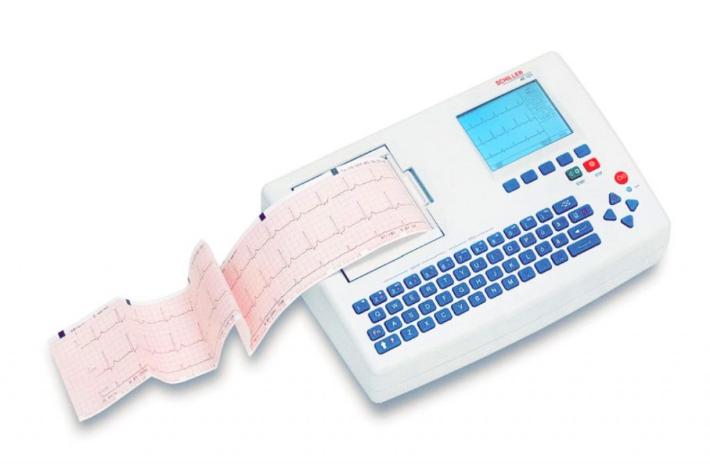
Стандартные характеристики Schiller AT-101
- Буквенно-цифровая клавиатура и выделенные функциональные клавиши для простого удобного управления.
- Встроенный высококачественный термопринтер с различными опциями формата печати, определяемыми пользователем.
- Измерения и усредненные циклы с возможностью автоматической и ручной распечатки регистрации.
Дополнительные возможности Schiller AT-101
- Внешний принтер
- Интерпретация ЭКГ
- Память на 40 регистраций
- Тромболизис
- Коммуникационный модуль SCHILLER (SCM) для передачи данных на сервер через:
- сеть Ethernet
- модем (опция)
Обзор Schiller AT-101
Экран получения данных и регистрации ЭКГ
В этом экране визуализируется ЭКГ в режиме реального времени. Из этого экрана возможен запуск длительной печати и/или произведена автоматическая регистрация. В автоматическом режиме 10 секунд регистрации ЭКГ анализируются и усредняются и результаты выводятся на печать. Формат и данные для автоматической распечатки не зависят от представления экрана и определяются в экранах настройки. Регистрация, произведенная в автоматическом режиме, также может быть сохранена в памяти для последующей распечатки или передачи.
Экран памяти
В этом экране возможен доступ к сохраненным регистрациям, их распечатка или передача.
Экран данных пациента
Ввод данных пациента через клавиатуру.
Функции
Большинство функций или заданий активируются при помощи 5 выделенных клавиш, расположенных непосредственно под ЖК-дисплеем. Функции выделенных клавиш варьируются и зависят от текущего экрана; активная функция клавиши визуализируется на экране непосредственно над клавишей.

В процессе получения данных доступны дополнительные выделенные клавиши для запуска регистрации ЭКГ в автоматическом режиме (ПУСК) и остановки ручной распечатки (СТОП). Верхний ряд буквенно-цифровой клавиатуры позволяет производить прямые установки группы отведений, скорости и чувствительности кривой, фильтра и других функций, как для экрана в режиме реального времени, так и для распечатки в ручном режиме
Основные компоненты Schiller AT-101
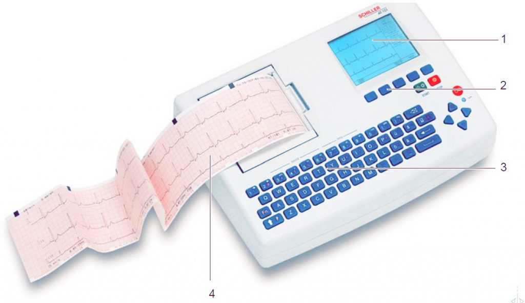
- ЖК экран
- Выделенные клавиши
- Клавиатура и выделенные функциональные клавиши
- Принтер
Задняя панель
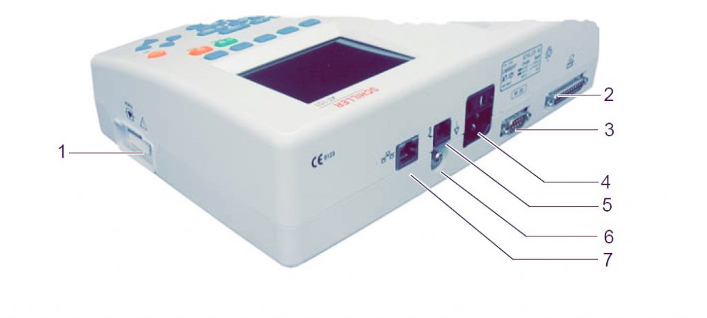
- Разъем для кабеля пациента
- Разъем LPT для подсоединения внешнего принтера
- RS-232 для подсоединения модема или ПК для экспорта сохраненных регистраций
- Сетевой разъем (с предохранителем)
- Разъем RJ11 с SCM (опция)
- Вывод заземления
- Разъем RJ45 для сети Ethernet с SCM (опция)
Клавиатура Schiller AT-101
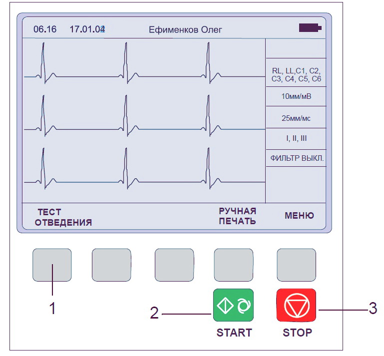
1. Выделенные клавиши — функция этих клавиш изменяется в зависимости от представленного экрана. Функция клавиши указывается на экране над клавишей. Если над клавишей не появляется пояснение ее функции, это означает, что клавиша неактивна в этом экране.
2. Регистрации ЭКГ в автоматическом режиме (в автоматическом режиме 1). Нажмите клавишу Регистр (SHIFT), затем клавишу ПУСК (2) для запуска автоматического режима 2.
3. Остановка печати.
Буквенно цифровая клавиатура
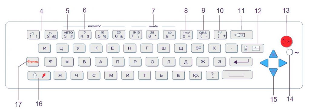
4. Верхний регистр клавиш «1» и «2» (обозначенный как < и >) изменяет группу отведений на экране на следующую или предыдущую соответственно.
5. Клавиша автоматической чувствительности — автоматически устанавливает чувствительность печати ЭКГ (только в автоматическом режиме) для подбора оптимальной силы сигнала (5мм/мВ или 10мм/мВ)
6. Верхний регистр цифровых клавиш имеет обозначения 5, 10 и 20 для выбора чувствительности ЭКГ на экране и на (ручной) печати. Возможные установки чувствительности 5, 10, 20 мм/мВ
7. Верхний регистр цифровых клавиш имеет обозначения 5/10, 25 и 50, которые являются установками скорости ЭКГ на экране и (ручной) печати. Скорость экрана может быть установлена только на 25 или 50 мм/с. Скорость распечатки в ручном режиме может быть 5, 10, 25 или 50 мм/с. Установки скорости 5 и 10 мм/с выбираются одной клавишей, которая последовательно переключается между этими установками.
8. Вставка справочного маркера 1 мВ на экране и на распечатке. Перецентровка кривой.
9. Включение / выключение бипера QRS.
10. Включение / выключение миографического фильтра. Отсекающая частота устанавливается в экране настройки.
11. Удаление последнего введенного символа.
12. Клавиша данных пациента. Нажмите эту клавишу для ввода данных нового пациента или изменения данных текущего пациента.
13. Клавиша включения /выключения.
14. Индикатор сети — горит, если прибор подключен к сети.
15. Нажмите функциональную клавишу (17) и используйте клавиши вверх / вниз для настройки контрастности экрана. При вводе данных пациента используйте клавиши вправо / влево для передвижения курсора в поле данных. Используйте стрелочки ВВЕРХ/ВНИЗ для перехода к следующей/предыдущей позиции.
16. Клавиша Регистр для выбора заглавных букв; в AT-101 Tele — включение / выключение режима GSM.
17. Функциональная клавиша. При нажатии перед другой клавишей, активирует вторую функцию этой клавиши.
Экран Schiller AT-101
Представление экрана будет варьироваться в зависимости от текущего задания. Однако во всех экранах верхняя и нижняя строки содержат одинаковую информацию: в верхней строке приводится системная информация, а нижняя строка содержит данные о функции выделенных клавиш.
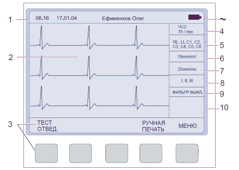
- Верхняя строка — время, дата имя пациента и текущий источник питания — сеть или аккумулятор. Когда мощность аккумулятора снижается, символ мигает.
- Область получения данных или область ввода данных.
- Обозначение выделенных клавиш. Нажатие клавиши под текстом активирует указанную функцию. Доступные опции изменяются соответственно выбранному экрану.
- Текущая ЧСС (усредняется каждые 4 сокращения и обновляется каждые 2 сек.). ЧСС приводится также на распечатке в ручном режиме. Учтите, что в авто режиме ЧСС усредняется за каждые 10 сек. регистрации.
- Подсоединение электродов — если индикатор отведения мигает (и раздается акустический сигнал тревоги), это означает, что сопротивление электрода слишком высоко. Электрод должен быть переустановлен.
- Чувствительность — 5, 10, 20 мм/мВ. Изменение чувствительности осуществляется при помощи клавиш
3(авто),4,5и6. СимволAв этом поле свидетельствует о том, что выбрана установка автоматической чувствительности (активна только при автоматическом режиме печати). - Скорость — 25 или 50 мм/с. Изменение скорости с помощью клавиш
8и9. - Индикатор отведений (текущих отведений на экране). Изменить группу отведений можно при помощи клавиш
<и>на клавиатуре. - Индикатор миографического фильтра: «Фильтр включен» или «Фильтр выключен». Фильтр активируется при помощи клавиши фильтра.
- Область для системных сообщений или инструкций.
Аккумулятор Schiller AT-101
Прибор может работать как от сети, так и от встроенного аккумулятора. Источник питания указывается в верхней строке экрана. Встроенный аккумулятор гарантирует до 3 часов работы.
- Когда прибор работает от аккумулятора, визуализируется символ батареи.
- При работе от батареи прибор автоматически выключается через 5 минут (30 секунд, если емкость батареи ограничена), если не нажимается ни одна клавиша.
- В процессе нормальной эксплуатации обслуживание не требуется. Если прибор не используется свыше 3 месяцев, батарея должна быть заряжена. Заменяйте батарею примерно каждые 4 года (в зависимости от частоты использования), если время работы от батареи снизится до 1 часа и менее.
- Прибор может оставаться подключенным к сети без риска повреждения батареи или прибора.
Для зарядки полностью разряженной батареи до 90% требуется около 7 часов. Прибор может использоваться в процессе зарядки батареи. Однако в этом случае время зарядки батареи существенно увеличится.
Заправка бумаги в Schiller AT-101
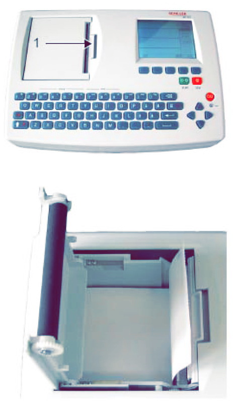
Прибор поставляется без бумаги в лотке для бумаги. Используйте только оригинальную бумагу SCHILLER. Термобумага чувствительна к жаре, влажности и химическим веществам. Храните бумагу в прохладном и сухом месте.
- Нажмите клавишу открытия лотка для бумаги (1).
- Откройте крышку лотка для бумаги.
- Вставьте бумагу.
- Закройте крышку. Убедитесь, что бумага находится точно между направляющими.
- Нажмите клавишу СТОП, чтобы передвинуть бумагу в требуемое положение.
Термочувствительная бумага, используемая на AT-101, требует условий, несколько отличающихся от условий хранения обычной бумаги, так как она может реагировать на химикаты и тепло.
При выполнении следующих пунктов можно обеспечить нормальные условия для хранения бумаги:
- До использования храните бумагу в фирменной картонной упаковке. Не снимайте картонную упаковку до начала использования бумаги.
- Храните бумагу в прохладном, темном и сухом месте.
- Не храните бумагу вблизи химикатов, например, стерилизационных растворов.
- Не храните бумагу в пластиковых коробках.
- Некоторые виды клея могут вступать в реакцию с бумагой — не приклеивайте распечатку на картонное основание при помощи клея.
Скачать инструкцию на Schiller AT-101
Скачать инструкцию и другую документацию на Schiller AT-101 можно здесь.
Руководство пользователя ( user manual ) Schiller AT-101 скачать.
Регистрационное удостоверение Schiller AT-101 скачать.
Так же смотрите сфигмоманометр Schiller BR-102 plus.
- About
- Blog
- Projects
- Help
-
Donate
Donate icon
An illustration of a heart shape - Contact
- Jobs
- Volunteer
- People
Bookreader Item Preview
texts
Schiller AT 101 Service manual
Schiller AT 101 Service manual
- Addeddate
- 2020-05-20 09:06:06
- Classification
- Clinical;Cardiac Equipment;Electrocardiograph (ECG EKG);Welch Allyn Schiller ECG EKG;Schiller AT-101
- Identifier
- manual_Schiller_AT-101_-_Service_manual
- Identifier-ark
- ark:/13960/t8dg5hx17
- Ocr
- ABBYY FineReader 11.0 (Extended OCR)
- Page_number_confidence
- 98.46
- Ppi
- 300
- Scanner
- Internet Archive Python library 1.9.0
comment
Reviews
There are no reviews yet. Be the first one to
write a review.
SIMILAR ITEMS (based on metadata)
(Ocr-Read Summary of Contents of some pages of the Schiller AT-101 Document (Main Content), UPD: 02 June 2023)
-
30, 4Resting ECG 4.4 Modes of Operation and Procedural Overview AT-101 Page 28 Art.-no.: 2.510526 Rev.: c 4.4.3 Screen (and Manual Printout) Settings The following can be freely chosen during data acquisition, for both the display and for a manual printout, using the top line of keys of the keypad: Lead Group by means of the LEAD FORWARD and LEAD BACKWARD key. The following lead groups are selectable: Standard and Cabrera Lead Group 1-4 Additional Lead Group 5-6 Two additionally …
-
21, Page 19 Resting ECG 4 AT-101 User Guide Electrode Placement 4.1 Art.-no.: 2.510526 Rev.: c 4 Resting ECG 4.1 Electrode Placement V The guidelines for patient electrode placement are provided as an overview only. They are not a substitute for medical expertise. The colours shown here are according to Code 1 (European) requirements. The equi- valent code 2 colours are given on paragraph 4.2.3.
… -
38, 5 Setup 5.2 ECG Settings AT-101 Page 36 Art.-no.: 2.510526 Rev.: c 5.2.2 Automatic Format 1 and 2 External Printer Two separate Auto formats can be defined for a external printer. Press the SELECT softkey to choose from the following options: Parameter Options Description ECG Printout No Printout No printout of the ECG given at the end of an auto mode recording (the recording can be stored in the memory and printed at a later time if …
-
8, 1 Safety notes 1.8 Safety Symbols and Pictograms AT-101 Page 6 Art.-no.: 2.510526 Rev.: c 1.8 Safety Symbols and Pictograms 1.8.1 Used symbols in this document The safety level is classified according ANSI Z535.4. The following overview shows the used safety symbols and pictograms used in this manual. For a direct danger which could lead to severe personal injury or to death. For a possibly dangerous situation, which c…
-
43, Schiller AT-101 Page 41 Setup 5 AT-101 User Guide System Settings 5.3 Art.-no.: 2.510526 Rev.: c 5.3.1 Unit « Press softkey UNIT Parameter Options Description User Identification (User ID) Enter user ID The user identification is printed on all recordings. The user ID can be the department, doctor or hospital etc. Select User ID and a blinking cursor is present — enter up to 30 characters via the keypad. Note If the unit is reset to the default settings (see following), the …
-
42, 5 Setup 5.3 System Settings AT-101 Page 40 Art.-no.: 2.510526 Rev.: c 5.3 System Settings The SYSTEM SETTINGS are entered by selecting MENU SETUP and SYSTEM SETTINGS from the initial screen: The following pages detail system settings for the AT-101: 1. Press the softkey MENU 2. Press the function key FN and the softkey SETUP. Note: The Setup text above the key appears first if the FN key is pressed. 3. Press the softkey SYSTEM SETTINGS. 4. Press the softkey UNIT…
-
26, 4Resting ECG 4.3 Skin/Electrode Resistance AT-101 Page 24 Art.-no.: 2.510526 Rev.: c 4.3 Skin/Electrode Resistance 4.3.1 High Electrode Resistance Indication 4.3.2 Electrode and Patient cable Check (Lead Test) If an electrode resistance is too high for a good recording, or an electrode becomes dislodged during a recording, the electrode indication (1) flashes on the screen and an audible beep is heard. The electro…
-
12, 2 Introduction 2.2 Operating Philosophy Overview AT-101 Page 10 Art.-no.: 2.510526 Rev.: c 2.2 Operating Philosophy Overview There are broadly four types of data display as follows: Data Acquisition and ECG Recording Screen In this screen the real-time ECG is displayed. From this screen a continuous printout can be initiated and/or an auto recording can be made. In auto mode 10 seconds of ECG data is analysed and averaged and the results given on a printout. The format and data of an auto …
-
39, Page 37 Setup 5 AT-101 User Guide ECG Settings 5.2 Art.-no.: 2.510526 Rev.: c 5.2.3 Filters There are five different filters which can be set individually as follows. Parameter Options Description Baseline filter 0.05, 0.15 or 0.3 Hz The set value is the lower limit of the frequency range and is normally set to 0.05 Hz. The settings 0.15 and 0.30 Hz should only be used when ab- solutely necessary, as the possibility exi…
-
3, Page 1 User Guide Art.-no.: 2.510526 Rev.: c AT-101 Contents 1 Safety notes ……………………………………….3 1.1 Responsibility of the User ………………………………………….. 3 1.2 Intended Use ……………………………………………………………… 3 1.3 Organisational Measures…………………………………………….. 3 1.4 Safety-conscious Operation…………………………………..…
-
25, Page 23 Resting ECG 4 AT-101 User Guide Further Lead Combinations 4.2 Art.-no.: 2.510526 Rev.: c 4.2.3 Electrodes and Neutral Electrodes Identification and Colour Code The electrode placements shown in this handbook are labelled with the colours ac- cording to Code 1 requirements. The equivalent Code 2 colours are given below. CODE 1 (usually European) CODE 2 (usually American) System Electrode identifier Colour code Electrode identifier Colour code R Red RA white Lim…
-
31, Page 29 Resting ECG 4 AT-101 User Guide Modes of Operation and Procedural Overview 4.4 Art.-no.: 2.510526 Rev.: c Chart Speed Select speed 5, 10, 25 or 50mm/s Key 7 is a toggle key — press once and 5 is selected, press a second time and 10mm/ s is selected. When the 25 or 50mm/s key is pressed, the same speed is set on both the screen and the (manual) printout. When 5 or 10 mm/s is selected, this affects the manual printout s…
-
22, Schiller AT-101 4Resting ECG 4.1 Electrode Placement AT-101 Page 20 Art.-no.: 2.510526 Rev.: c A minimal resistance between skin and electrode is required to obtain the best ECG signal and ensure the highest quality ECG recording. Therefore please note the follo- wing points: 1. Ensure that the patient is warm and relaxed. 2. Shave electrode area before cleaning. 3. Thoroughly clean the area with alcohol. 4. When applying the electrodes, ensure that a layer of gel is between the electrode and the sk…
-
6, 1 Safety notes 1.4 Safety-conscious Operation AT-101 Page 4 Art.-no.: 2.510526 Rev.: c 1.4 Safety-conscious Operation 1.5 Safety Facilities V Make sure that the staff has read and understood the operating instructions — par- ticularly the «Safety Notes» chapter. V Do not touch the unit casing during defibrillation. V To ensure patient safety, none of the electrodes including the neutral electrode, nor the patient or any person with si…
-
50, 6 Care & Maintenance 6.1 Service interval AT-101 Page 48 Art.-no.: 2.510526 Rev.: c 6 Care & Maintenance 6.1 Service interval Self-test Every time the unit is switched on a built-in test program is initiated. If an error is de- tected, the unit will not switch on and a table may be displayed giving information for the service staff. Keybord test Press all button of the keyboard. The right function is indicated by a beep and/or the ex…
-
44, 5 Setup 5.3 System Settings AT-101 Page 42 Art.-no.: 2.510526 Rev.: c 5.3.2 Communication If in doubt about any of these settings, please contact your phone company and/or modem supplier. « Press softkey COMM Parameter Options Description Baudrate 9600 14400 19200 28800 38400 57600 115200 Select a Baud rate according to the modem/computer used. Most compu- ters can connect at 115200 Baud and the standard modem speed is 57600 Baud. If…
-
48, Schiller AT-101 5 Setup 5.3 System Settings AT-101 Page 46 Art.-no.: 2.510526 Rev.: c 5.3.4.2 Communications Test 5.3.4.3 Installing New Software Options (Upgrade) Use the upgrade option to install any available software options (e.g. Measurement). To install new options in the AT-101, a code must be entered. This code must be ob- tained from SCHILLER. To install software option proceed as follows: 5.3.4.4 Update t…
-
35, Schiller AT-101 Page 33 Setup 5 AT-101 User Guide Entering the SETUP Menu 5.1 Art.-no.: 2.510526 Rev.: c 5 Setup 5.1 Entering the SETUP Menu 5.1.1 Navigating in the Setup Screens In setup screens where there are two choices, navigation to the next screen and sel- ection of specific settings. This is as follows Navigation with Softkeys Navigation with Keypad buttons To enter the setup screen press the following keys. 1. Press the softkey MENU. 2. Press the function key FN and the softkey SETUP. Note: The Setup …
-
41, Page 39 Setup 5 AT-101 User Guide ECG Settings 5.2 Art.-no.: 2.510526 Rev.: c 5.2.5 Leads 5.2.6 General (only with version m = Memory) Defining Lead Sequence & Printout The required settings can be selected as follows: Parameter Options Description Lead Sequence Standard or Cabrera Select between Standard lead sequence or Cabrera. Lead groupings are shown on page 28. Signals Simultaneous All ECG leads are printed in the same time segment (in automatic mode…
Page 2
Overview…………………………………………………………………… 25
4.4.1
Automatic Mode ……………………………………………………………………. 26
4.4.2
Manual Mode ……………………………………………………………………….. 27
4.4.3
4.5
Memory (option)………………………………………………………… 30
4.5.1
5
Setup ………………………………………………..32
5.1
5.1.1
5.2
ECG Settings…………………………………………………………….. 33
5.2.1
5.2.2
5.2.3
Filters ………………………………………………………………………………….. 36
5.2.4
5.2.5
Leads ………………………………………………………………………………….. 38
5.2.6
5.3
System Settings………………………………………………………… 39
5.3.1
Unit……………………………………………………………………………………… 40
5.3.2
Communication ……………………………………………………………………. 41
5.3.3
Communication with SCM………………………………………………………. 42
5.3.4
Test and Information ……………………………………………………………… 43
5.3.4.1 Print Setup …………………………………………………………………………… 44
5.3.4.5 Default Settings…………………………………………………………………….. 46
6
6.1
Service interval …………………………………………………………. 47
6.2
6.3
6.3.1
Charging the battery …………………………………………………………….. 48
6.3.2
Battery disposal ……………………………………………………………………. 48
6.4
6.5
Cleaning……………………………………………………………………. 50
6.5.1
Cleaning the Casing………………………………………………………………. 50
6.5.2
6.5.3
6.6
6.6.1
Thermal Paper Handling ………………………………………………………… 51
6.7
Fault-Finding …………………………………………………………….. 52
6.7.1
7
Technical Data ………………………………….54
7.1
System ……………………………………………………………………… 54
7.2
7.3
Safety Standards ………………………………………………………. 56
8
Index ………………………………………………..57
AT-101


