-
Contents
-
Table of Contents
-
Bookmarks
Quick Links
REMOTE CONTROL SYSTEM
SCANRECO RC 400.
INSTRUCTION MANUAL.
( Engelsk Ver 2 )
This instruction manual must be kept in the vehicle cab.
Doc.nr : Rc400-Manuale_v20_e.doc
Related Manuals for Scanreco RC 400
Summary of Contents for Scanreco RC 400
-
Page 1: Remote Control System
REMOTE CONTROL SYSTEM SCANRECO RC 400. INSTRUCTION MANUAL. ( Engelsk Ver 2 ) This instruction manual must be kept in the vehicle cab. Doc.nr : Rc400-Manuale_v20_e.doc…
-
Page 2: Table Of Contents
Scanreco AB, Sweden.
-
Page 3: Preface
Due to the unlimited variety of cranes, machines, objects, vehicles and equipment · on which the remote control system ( RC 400 ) are used, and the numerous standards which are frequently the subject of varying interpretation, it is impossible for Scanreco AB / Swedens, personnel to provide expert advice regarding the suitability of a given RC 400 remote control for a specific application.
-
Page 4: Table Of Contents
2. GENERAL SYSTEM DESCRIPTION. Contents : Page : General schematic of the Scanreco RC 400 · General description of the remote control system · The portable control unit · Battery operation ( See also 2.11 — 2.12 ) · Manoeuvre levers ·…
-
Page 5: General System Description
General system description 2 — 2 General schematic of the RC 400 : The Remote Control System is comprised of the following components: Control unit ( for cable or radio control ). · Electronicbox. · Crane emergency stop box. ·…
-
Page 6: General Description Of The Remote Control System
2 — 3 1. GENERAL DESCRIPTION OF THE REMOTE CONTROL SYSTEM. The Scanreco RC 400 remote control system has been specially developed for hydraulically driven mobile cranes and machinery. The system is a digital remote control system based on an extremely advanced micro-processor technology. Years of exhaustive and demanding testing have shown that the remote control system can cope with the roughest of environ- ments.
-
Page 7
General system description 2 — 4 Portable control unit with battery operation ( radio control or opto fibre cable ). A battery is located in the control unit for radio control and is very simple to change. The battery’s effective operation time is about 8 hours on one charge. ·… -
Page 8: Manoeuvre Levers
General system description 2 — 5 A brief description is given now of the component parts of the control unit. The control unit is comprised of manouevre levers for proportional control, switches for ON/OFF and function changing, micro-operation and emergency stop. ( See separate headings below ).
-
Page 9: Emergency Stop Panel
General system description 2 — 6 Emergencystop panel. There is a red emergency stop switch ( ) with a manual twist reset, a push button STOP ) and a red LED on the control unit’s emergency stop panel. ON/SIGNAL/FREQ. SHIFT The control unit is started with the sprung reset push button ( ·…
-
Page 10: On/Off Functions
General system description 2 — 7 ON/OFF and function changing functions. ON/OFF switches can be used to manoeuvre electrical, hydraulic or pneumatic ON/OFF functions. Examples of functions : Stopping and starting of the vehicle’s motor, throttle lever, beep / signal, change-over ·…
-
Page 11: Opto-Fibre Cable
General system description 2 — 8 4. CABLE FOR OPTO FIBRE OPERATION ( NOTE ! OPTION ). For opto fibre control the remote control system is complemented with an opto fibre cable, battery pack and battery charger. This means that light is used to send the control information ( not electrical impulses ).
-
Page 12: Electronicbox
General system description 2 — 9 5. ELECTRONICBOX. The electronicbox is manufactured in aluminium and is provided with attachments and contacts for connection to the portable control unit, radio receiver box and ON/OFF functions. There are also connections and contacts for supply voltage, electro-hydraulic converter valves, slide controls and dump valve.
-
Page 13: Safety Regulations And Operating
General system description 2 — 10 6. EX-CABLE ( EX ). A thin and flexible 7-core cable can be connected to the electronicbox for outgoing ON/OFF- functions, for in-going signal handling e.g. overload and lift reduction functions and for serial communications if more than one electronicbox is used in so called tandem operation.
-
Page 14: Battery Pack
Note. Battery packs supplied since 1 January 1993 have three ( 3 ) terminal connections. The centre terminal is used for Scanreco´s quick charger ( option ). The battery pack is fully compatible with all battery packs previously supplied. The effective operational capacity of the battery is approximately 8 hours per charge.
-
Page 15: Battery Charger And Battery Charging
General system description 2 — 12 9. BATTERY CHARGER AND BATTERY CHARGING. The battery charger must be mounted in a vibration free area inside the cab or indoors and be protected against damp and temperature variations. The normal charging time for an empty uncharged battery, is approximately 12-14 hours. ·…
-
Page 16: Radio Control
General system description 2 — 13 10. RADIO CONTROL ( See «11. Radio transmitter» and «12. Radio receiver box» ). For radio control operation the remote control system is complemented with a radio transmitter, a battery pack, battery charger and radio receiver box. ( See also sections «Battery pack», «Battery charger»…
-
Page 17
General system description 2 — 14 12. RADIO RECEIVER BOX. The radio receiver box is manufactured in aluminium and is provided with attachments, well proven antenna and a connector for connection to the electronics box. Since the radio receiver box can be subjected to a very tough environment, the box is encapsulated for protection against damp, heat, cold, dust, vibration and corrosive environments. -
Page 18
3. SAFETY REGULATIONS AND OPERATING INSTRUCTIONS. These instructions cover, amongst other things, those special regulations which apply for remotely controlled cranes ( cable or radio ). The driver must be aware of the contents of these safety regulations. Remote controlled cranes may only be operated by trained personnel. The portable control unit must never be passed over to any person who has not received training for remote controlled cranes. -
Page 19: Operating Instructions
Safety regulations and operating instructions 3 — 2 OPERATING INSTRUCTIONS. Before operation, the driver MUST make himself aware of the contents in the «SAFETY REGULATIONS» for remotely controlled cranes. The driver must be aware of the function of all manoeuvre levers and switches. 1.
-
Page 20: Installation Instructions
4. INSTALLATION INSTRUCTIONS. Contents : Page : General schematic of the RC 400 / During welding. · Locating the electronicbox and radio receiver box. · Mounting recommendations for the radio receiver box. · Connection of Danfoss electro-hydraulic valve and dump valve.
-
Page 21
Installation instructions for Scanreco RC 400 remote control system . When the Scanreco RC 400 is installed an electrically controlled dump valve must, for reasons of safety, always be connected between the manoeuvre valve and the tank . This means that during an emergency stop manoeuvre the dump valve will be without power and will transfer the pump flow directly to the tank thus making the crane entirely without hydraulic pressure. -
Page 22
Installation instructions 4 — 3 Installation and mounting instructions. Electronicbox : Important: The electronicbox must be mounted in accordance with the recommendations given below! To ensure the longest possible life for the electronicbox and its cables, the electronicbox must always be mounted so that the valve contacts are located facing downwards. -
Page 23
Installation instructions 4 — 4 Mounting of the radio receiver box. The connection cable ( marked ) for the radio receiver box is approximately 2 metres · long which is the maximum mounting distance from the electronicbox. For optimum radio communications the radio receiver box should be located as high and ·… -
Page 24
Installation instructions 4 — 5 2. Select a suitable location for the electronicbox on the vehicle / crane. · The contact for the cable control cable, switches for and LEDs MANUAL/ 0 / REMOTE for operational status must be located where they are easy to see and reach. Check that the electronicbox cable contacts ( cable control, , and radio receiver box ON/OFF… -
Page 25
Marked : — *Check that the same earth potential exists between the Scanreco earth cable (No. 2 ) and the vehicle’s battery minus during max. loading ( i.e. there is not a potential drop /difference as a result of poor earthing or the cable cross sectional area being insufficient). -
Page 26
Installation instructions 4 — 7 Connection schematic for ON/OFF functions. Switch EX cable No. : Function / description : 1 ON No: 1 Continuous full working throttle. 1 Centre No: — Idle. 1 OFF No: 1 Automatic connection of full throttle. 2 ON No: 2 Start vehicle motor. -
Page 27
Installation instructions 4 — 8 Connection of motor start / start lock : To protect the starter motor against unintentional re-start attempts after the vehicle motor · has already started, it is recommended that an electric «start lock» is connected in after the motor start signal from the electronicbox, EX cable pin 2 ( See connection example below ). -
Page 28: Control Unit
Installation instructions 4 — 9 Connection schematic for Scanreco RC 400. Control unit : Electronicbox : Left lever, 1A, 1B Contact No: 1 ( Valve contact, No: 1 ). Right lever, 8A, 8B Contact No: 8 ( Valve contact, No: 8 ).
-
Page 29
Installation instructions 4 — 10 9. BATTERY CHARGER AND BATTERY CHARGING. The battery charger must be mounted in a vibration free location inside the cab or indoors to give protection against damp and temperature variations. The normal charge time for an empty discharged battery is approx. 12-14 hours. ·… -
Page 30
Installation instructions 4 — 11 Changing the direction of crane movement. The description which follows describes how to change the direction of movement if the crane moves in a different direction to that desired. Example: After installation and test operation it is found for example that the 3rd and 5th lever move- ments operate in the opposite direction to that desired. -
Page 31: Radio Transmitter
Installation instructions 4 — 12 General technical data : For dimensions, see chapter 2 — «General system description». Portable control unit: Battery pack : 7.2 VDC. Control unit effective operating time : Approx. 8 hours per charge. Weight : 1.6 kg ( without battery pack and radio transmitter). Weight: 1.9 kg ( with battery pack and radio transmitter).
-
Page 32: Fault Finding
· Electrical connection schematic for electronicbox cables. · Electronicbox with lid removed. · The service workshop can check the following before Scanreco AB, Sweden is contacted. Page : Whole system not functioning ( In depth fault finding ). · Control unit red lamp not lit continuously.
-
Page 33: Radio Receiver Box
Fault finding 5 — 2 INDICATIONS WITH FUNCTIONING SYSTEM. The following LEDs must be lit on a functioning system : ( For other LED combinations and indications , see next page/pages ! ! ). A. Portable control unit turned off , the following LEDs light : «REMOTE»…
-
Page 34
Fault finding 5 — 3 Always check this ! Always check this : Is there supply to the system? Measure at the · + 24 VDC, +/- 20 %, max. 5 %Vpeak to peak crane emergency stop switch ( unloaded and loaded ). See also page 4-6 !!! Are the electronicbox fuses whole, i.e. -
Page 35
Fault finding 5 — 4 Error messages / Actions. Simple error messages can be read with the help of the LEDs on the electronicbox. LEDs 1 — 4 are used to give error messages. The first LED (No.1) always blinks with errors and then a combination of lights is shown on LEDs 1 — 4 . -
Page 36
Fault finding 5 — 5 Error messages / Actions. Simple error messages can be read with the help of the LEDs on the electronicbox. LEDs 1 — 4 are used to give error messages. The first LED (No.1) always blinks with errors and then a combination of lights is shown on LEDs 1 — 4 . -
Page 37
Incoming : + 24 VDC ( See above ) 1: Plus drive, dump valve. Movement 1. ( Scanreco´s cable and cable number in valve contact ). Outgoing supply voltage for PVEM or PVEH / Danfoss pin No: 1. Regulated voltage for PVEM or PVEH / Danfoss pin No: 2. -
Page 38
Fault finding 5 — 7 Connection schematic for electronicbox for proportional coils / electro-hydraulic slides (VOAC/Apitech/Nordhydraulic) Incoming supply voltage: + 24 VDC , +/- 20% max. 5%Vpeak to peak Cable numbering in electronicbox / Cabling : Incoming supply voltage: Dump valve : Incoming : Ground / 0 VDC. -
Page 39
Fault finding 5 — 8 Electronics box with lid removed. Plus fuse: + 10 Amp. ( Red ) / ( Standard car type fuse ). · Minus fuse: — 30 Amp. ( Green ) / ( Standard car type fuse ). ·… -
Page 40
1.A6. Remove the connectors to the functions and radio receiver box. ON/OFF 1.A7. The electronicbox is probably faulty. Contact the service workshop, retailer or Scanreco, Sweden for recommended action. 1.B. Electronicbox. No functions work and the LED on the electronicbox is lit. -
Page 41
1.D5. Radio control: Remove the radio transmitter card ( short circuits / high current consumption ?). 1.D6. Remove all manoeuvre levers ( abnormally high current consumption ? ). 1.D7. The control unit’s electronics card is probably defective. 1.D8. Contact the service workshop, distributor or Scanreco, Sweden. Doc.nr : Rc400-Manuale_v20_e.doc… -
Page 42
Fault finding 5 — 11 1.E. Portable control unit. The control unit beeps and the red LED blinks when ON/SIGNAL/FREQ.-SHIFT pressed. ( cable or radio control ). ( Electronicbox switch MANUAL / OFF / REMOTE must be in REMOTE position, the POWER LED must be lit and LED 4 must blink ). -
Page 43
Fault finding 5 — 12 2. SOME PROPORTIONAL MOVEMENTS MISSING. The whole system works, but a particular proportional movement is missing. LED indication: DIR. A: Manoeuvre lever in A-direction activated and moved. The intensity of the LED will increase with increased lever displacement. -
Page 44
Fault finding 5 — 13 2.C When manoeuvring is started with the «faulty» manoeuvre lever, movement stops. 2.C1. A short circuit, overload or other fault exists between the electronicbox valve cable and valve contact or in the electro-hydraulic slide control. 2.C1. -
Page 45
Fault finding 5 — 14 3. CERTAIN ON/OFF FUNCTIONS MISSING. ON/OFF: ON/OFF function activated. The LED is commoned and summed, i.e. only one switch at a time can be activated from the control unit for the check to be made. 3. -
Page 46
Fault finding 5 — 15 PORTABLE CONTROL UNIT TEST-MODE . Functional description. To simplify service and faultfinding, the portable control unit can be put into internal TEST- MODE. This means that the service man can easily control the control unit’s switches and manoeuvre levers, without the need to open the control unit. -
Page 47
«new» radio transmitter must be well tightened !! C. Replace the upper and lower halves, replace the screws and then test run. If the radio units still does not work contact Scanreco AB, Sweden. Doc.nr : Rc400-Manuale_v20_e.doc… -
Page 48
Fault finding 5 — 17 Repair of control cable. General : The control unit is connected to the electronicbox via a thin and flexible 3-core cable. The cable has circular type connection contacts (Amphenol / Hirchmann) at each end. Final control : Ohm measure the cable’s contacts for check of continuity. 2 ). -
Page 49
7. If this procedure does not work, repeat the programming ( see items 2-6 ). If it still does not work, contact Scanreco AB, Sweden. Information. During cable control, all control units can be used to the crane in question, i.e. during cable control the radio transmitter and radio receiver box and the identity code is disconnected automatically. -
Page 50: Spare Parts
RC 400 — SPARE PARTS AND SPARE PARTS LIST Introduction. The RC 400 remote control system is constructed using a number of standardised basic components which enables a minimum of spare parts stocks. No adjustments are required after the changing of system parts. This means quick, simple and effective service.
-
Page 51
Spare parts 6 — 2 Doc.nr : Rc400-Manuale_v20_e.doc… -
Page 52
Spare parts 6 — 3 Portable control unit ( for cable or radio control ). Item Order no. Description Notes 44082 Over section / Blue 44085 Protective frame 44086 Under section 44221 Hood (for cable contact) 44162 Cable contact 44386 Cover-plate/Display 44503 Manoeuvre lever… -
Page 53
Spare parts 6 — 4 Emergency stop box Item Order No. Description Notes. Complete emergency stop box Electronicbox Item Order No. Description Notes. 226 / S. Nr ?? Complete electronicbox (voltage) Complete electronicbox (current) Complete electronicbox (pulse width) Complete electronicbox (protocol) 44713 Mounting brackets + screw kit 44294… -
Page 54
Spare parts 6 — 5 EX-cable ( EX ) . Item Order No. Description Notes. Complete EX-cable 2.5 meter 44136 Contact Radio transmitter Item Order No. Description Notes. Radio transmitter Radio receiver box Item Order No. Description Notes. Complete radio receiver box Antenna pin 44136 Contact… -
Page 55
Spare parts 6 — 6 Battery charger Item Order No. Description Notes. Complete battery charger 10-30 VDC Complete battery charger 110-230 VAC RC400-044 Fuse ( 3 Amp. 5×20 mm) Battery pack Item Order No. Description Notes. Complete battery pack ( 7.2 VDC ) Doc.nr : Rc400-Manuale_v20_e.doc… -
Page 56: Programming Parameters And Settings
SETTINGS. General description. The Scanreco RC 400 offers considerable possibilities for system constructors of hydraulically driven mobile cranes and machines. The program in the control system is very comprehensive, flexible and has many adaptation possibilities for specific applications. The control system offers simple programming of a number of functions which can easily be turned on or off or altered during operation.
-
Page 57
). E.t.c. The Installer/system designer is responsible for seeing that the RC 400 is used correctly for all applications and is responsible for any re-programming of the system functions and the characteristics changes caused by this. -
Page 58
Programming parameters and settings 8 — Changing the direction of movement of the crane. This describes how changes in direction of movement are made if the crane moves in the opposite direction to that desired. Example: After installation and test operation it is found that the 3rd and 5th lever movements operate in the opposite direction to that desired. -
Page 59
Programming parameters and settings 8 — 2.A Individual change of manouevre valve start speed for A or B port. If the manoeuvre valve start value is to be increased or decreased for the A or B ports. Example: After installation and test operation it is found for example that the 3rd and 5th lever start speed needs to be increased or decreased for A or B ports. -
Page 60
Programming parameters and settings 8 — 2.B Individual speed reduction for A or B ports. Individual maximum manoeuvre speed reduction for any critical functions such as swing or rotation. Fully variable speed reductions can be made for manoeuvre valves in A or B ports. Example: After installation and test running it is found that the 3rd and 5th lever/movement’s maximum manoeuvre speed needs to be increased or decreased for A or B ports. -
Page 61
Programming parameters and settings 8 — 2.C Individual changes to the micro — speed control for A or B ports. For certain valves the micro-speed can be less well defined, due to non-symmetry in the valve, hydraulic system or in the crane / machine. If this is the case, the final speed of the micro- speed can be changed and adjusted (i.e. -
Page 62
Programming parameters and settings 8 — 2.D.1 Individual delays for start movements. Start delay, i.e. the time required for the manoeuvre valve slide to reach its final position from the time the manoeuvre lever leaves its neutral position. The time can be set individually between 0 and 5 seconds for A and B ports. -
Page 63
Programming parameters and settings 8 — 2.D.2 Individual delays for stop movements. Stop delay, i.e. the time required for the manoeuvre valve slide to return to its neutral position from when the manoeuvre lever is returned to its neutral position. Times can be set individually to between 0 and 5 seconds for A and B ports. -
Page 64
Most of the products are exported. The Scanreco RC 400 offers the driver a remote control system which is extremely easy to use with speed, precision and control under maximum safety. The remote control can be operated with a thin and flexible 3-core cable, an opto fibre cable or via radio control. -
Page 65
2-way direction communications, signal handling of for example ramp, blocking, hold, overload functions and the field bus CAN-BUS e.t.c. The system is developed and manufactured entirely by us. Scanreco Industrielektronik AB Box 47144 / Årsta Skolgränd 22 S-100 74 Stockholm… -
Page 66
Programming parameters and settings 8 — Controller-unit with joystick ( X-Y-Z ) Doc.nr : Rc400-Manuale_v20_e.doc…
Перейти к контенту
-
Contents
-
Table of Contents
-
Bookmarks
Quick Links
REMOTE CONTROL SYSTEM
SCANRECO RC 400.
INSTRUCTION MANUAL.
( Engelsk Ver 2 )
This instruction manual must be kept in the vehicle cab.
Doc.nr : Rc400-Manuale_v20_e.doc
Related Manuals for Scanreco RC 400
Summary of Contents for Scanreco RC 400
-
Page 1: Remote Control System
REMOTE CONTROL SYSTEM SCANRECO RC 400. INSTRUCTION MANUAL. ( Engelsk Ver 2 ) This instruction manual must be kept in the vehicle cab. Doc.nr : Rc400-Manuale_v20_e.doc…
-
Page 2: Table Of Contents
Scanreco AB, Sweden.
-
Page 3: Preface
Due to the unlimited variety of cranes, machines, objects, vehicles and equipment · on which the remote control system ( RC 400 ) are used, and the numerous standards which are frequently the subject of varying interpretation, it is impossible for Scanreco AB / Swedens, personnel to provide expert advice regarding the suitability of a given RC 400 remote control for a specific application.
-
Page 4
2. GENERAL SYSTEM DESCRIPTION. Contents : Page : General schematic of the Scanreco RC 400 · General description of the remote control system · The portable control unit · Battery operation ( See also 2.11 — 2.12 ) · Manoeuvre levers ·… -
Page 5: General Schematic Of The Scanreco Rc 400
General system description 2 — 2 General schematic of the RC 400 : The Remote Control System is comprised of the following components: Control unit ( for cable or radio control ). · Electronicbox. · Crane emergency stop box. ·…
-
Page 6: General Description Of The Remote Control System
2 — 3 1. GENERAL DESCRIPTION OF THE REMOTE CONTROL SYSTEM. The Scanreco RC 400 remote control system has been specially developed for hydraulically driven mobile cranes and machinery. The system is a digital remote control system based on an extremely advanced micro-processor technology. Years of exhaustive and demanding testing have shown that the remote control system can cope with the roughest of environ- ments.
-
Page 7
General system description 2 — 4 Portable control unit with battery operation ( radio control or opto fibre cable ). A battery is located in the control unit for radio control and is very simple to change. The battery’s effective operation time is about 8 hours on one charge. ·… -
Page 8: Manoeuvre Levers
General system description 2 — 5 A brief description is given now of the component parts of the control unit. The control unit is comprised of manouevre levers for proportional control, switches for ON/OFF and function changing, micro-operation and emergency stop. ( See separate headings below ).
-
Page 9: Emergencystop Panel
General system description 2 — 6 Emergencystop panel. There is a red emergency stop switch ( ) with a manual twist reset, a push button STOP ) and a red LED on the control unit’s emergency stop panel. ON/SIGNAL/FREQ. SHIFT The control unit is started with the sprung reset push button ( ·…
-
Page 10: On/Off Functions
General system description 2 — 7 ON/OFF and function changing functions. ON/OFF switches can be used to manoeuvre electrical, hydraulic or pneumatic ON/OFF functions. Examples of functions : Stopping and starting of the vehicle’s motor, throttle lever, beep / signal, change-over ·…
-
Page 11: Opto-Fibre Cable
General system description 2 — 8 4. CABLE FOR OPTO FIBRE OPERATION ( NOTE ! OPTION ). For opto fibre control the remote control system is complemented with an opto fibre cable, battery pack and battery charger. This means that light is used to send the control information ( not electrical impulses ).
-
Page 12
General system description 2 — 9 5. ELECTRONICBOX. The electronicbox is manufactured in aluminium and is provided with attachments and contacts for connection to the portable control unit, radio receiver box and ON/OFF functions. There are also connections and contacts for supply voltage, electro-hydraulic converter valves, slide controls and dump valve. -
Page 13: Electronicbox
General system description 2 — 10 6. EX-CABLE ( EX ). A thin and flexible 7-core cable can be connected to the electronicbox for outgoing ON/OFF- functions, for in-going signal handling e.g. overload and lift reduction functions and for serial communications if more than one electronicbox is used in so called tandem operation.
-
Page 14: Battery Pack
Note. Battery packs supplied since 1 January 1993 have three ( 3 ) terminal connections. The centre terminal is used for Scanreco´s quick charger ( option ). The battery pack is fully compatible with all battery packs previously supplied. The effective operational capacity of the battery is approximately 8 hours per charge.
-
Page 15: Battery Charger And Battery Charging
General system description 2 — 12 9. BATTERY CHARGER AND BATTERY CHARGING. The battery charger must be mounted in a vibration free area inside the cab or indoors and be protected against damp and temperature variations. The normal charging time for an empty uncharged battery, is approximately 12-14 hours. ·…
-
Page 16: Radio Control
General system description 2 — 13 10. RADIO CONTROL ( See «11. Radio transmitter» and «12. Radio receiver box» ). For radio control operation the remote control system is complemented with a radio transmitter, a battery pack, battery charger and radio receiver box. ( See also sections «Battery pack», «Battery charger»…
-
Page 17: Radio Receiver Box
General system description 2 — 14 12. RADIO RECEIVER BOX. The radio receiver box is manufactured in aluminium and is provided with attachments, well proven antenna and a connector for connection to the electronics box. Since the radio receiver box can be subjected to a very tough environment, the box is encapsulated for protection against damp, heat, cold, dust, vibration and corrosive environments.
-
Page 18
3. SAFETY REGULATIONS AND OPERATING INSTRUCTIONS. These instructions cover, amongst other things, those special regulations which apply for remotely controlled cranes ( cable or radio ). The driver must be aware of the contents of these safety regulations. Remote controlled cranes may only be operated by trained personnel. The portable control unit must never be passed over to any person who has not received training for remote controlled cranes. -
Page 19: Operating Instructions
Safety regulations and operating instructions 3 — 2 OPERATING INSTRUCTIONS. Before operation, the driver MUST make himself aware of the contents in the «SAFETY REGULATIONS» for remotely controlled cranes. The driver must be aware of the function of all manoeuvre levers and switches. 1.
-
Page 20: Installation Instructions
4. INSTALLATION INSTRUCTIONS. Contents : Page : General schematic of the RC 400 / During welding. · Locating the electronicbox and radio receiver box. · Mounting recommendations for the radio receiver box. · Connection of Danfoss electro-hydraulic valve and dump valve.
-
Page 21
Installation instructions for Scanreco RC 400 remote control system . When the Scanreco RC 400 is installed an electrically controlled dump valve must, for reasons of safety, always be connected between the manoeuvre valve and the tank . This means that during an emergency stop manoeuvre the dump valve will be without power and will transfer the pump flow directly to the tank thus making the crane entirely without hydraulic pressure. -
Page 22
Installation instructions 4 — 3 Installation and mounting instructions. Electronicbox : Important: The electronicbox must be mounted in accordance with the recommendations given below! To ensure the longest possible life for the electronicbox and its cables, the electronicbox must always be mounted so that the valve contacts are located facing downwards. -
Page 23
Installation instructions 4 — 4 Mounting of the radio receiver box. The connection cable ( marked ) for the radio receiver box is approximately 2 metres · long which is the maximum mounting distance from the electronicbox. For optimum radio communications the radio receiver box should be located as high and ·… -
Page 24
Installation instructions 4 — 5 2. Select a suitable location for the electronicbox on the vehicle / crane. · The contact for the cable control cable, switches for and LEDs MANUAL/ 0 / REMOTE for operational status must be located where they are easy to see and reach. Check that the electronicbox cable contacts ( cable control, , and radio receiver box ON/OFF… -
Page 25
Marked : — *Check that the same earth potential exists between the Scanreco earth cable (No. 2 ) and the vehicle’s battery minus during max. loading ( i.e. there is not a potential drop /difference as a result of poor earthing or the cable cross sectional area being insufficient). -
Page 26
Installation instructions 4 — 7 Connection schematic for ON/OFF functions. Switch EX cable No. : Function / description : 1 ON No: 1 Continuous full working throttle. 1 Centre No: — Idle. 1 OFF No: 1 Automatic connection of full throttle. 2 ON No: 2 Start vehicle motor. -
Page 27
Installation instructions 4 — 8 Connection of motor start / start lock : To protect the starter motor against unintentional re-start attempts after the vehicle motor · has already started, it is recommended that an electric «start lock» is connected in after the motor start signal from the electronicbox, EX cable pin 2 ( See connection example below ). -
Page 28: Control Unit
Installation instructions 4 — 9 Connection schematic for Scanreco RC 400. Control unit : Electronicbox : Left lever, 1A, 1B Contact No: 1 ( Valve contact, No: 1 ). Right lever, 8A, 8B Contact No: 8 ( Valve contact, No: 8 ).
-
Page 29
Installation instructions 4 — 10 9. BATTERY CHARGER AND BATTERY CHARGING. The battery charger must be mounted in a vibration free location inside the cab or indoors to give protection against damp and temperature variations. The normal charge time for an empty discharged battery is approx. 12-14 hours. ·… -
Page 30
Installation instructions 4 — 11 Changing the direction of crane movement. The description which follows describes how to change the direction of movement if the crane moves in a different direction to that desired. Example: After installation and test operation it is found for example that the 3rd and 5th lever move- ments operate in the opposite direction to that desired. -
Page 31
Installation instructions 4 — 12 General technical data : For dimensions, see chapter 2 — «General system description». Portable control unit: Battery pack : 7.2 VDC. Control unit effective operating time : Approx. 8 hours per charge. Weight : 1.6 kg ( without battery pack and radio transmitter). Weight: 1.9 kg ( with battery pack and radio transmitter). -
Page 32: Fault Finding
· Electrical connection schematic for electronicbox cables. · Electronicbox with lid removed. · The service workshop can check the following before Scanreco AB, Sweden is contacted. Page : Whole system not functioning ( In depth fault finding ). · Control unit red lamp not lit continuously.
-
Page 33
Fault finding 5 — 2 INDICATIONS WITH FUNCTIONING SYSTEM. The following LEDs must be lit on a functioning system : ( For other LED combinations and indications , see next page/pages ! ! ). A. Portable control unit turned off , the following LEDs light : «REMOTE»… -
Page 34
Fault finding 5 — 3 Always check this ! Always check this : Is there supply to the system? Measure at the · + 24 VDC, +/- 20 %, max. 5 %Vpeak to peak crane emergency stop switch ( unloaded and loaded ). See also page 4-6 !!! Are the electronicbox fuses whole, i.e. -
Page 35
Fault finding 5 — 4 Error messages / Actions. Simple error messages can be read with the help of the LEDs on the electronicbox. LEDs 1 — 4 are used to give error messages. The first LED (No.1) always blinks with errors and then a combination of lights is shown on LEDs 1 — 4 . -
Page 36
Fault finding 5 — 5 Error messages / Actions. Simple error messages can be read with the help of the LEDs on the electronicbox. LEDs 1 — 4 are used to give error messages. The first LED (No.1) always blinks with errors and then a combination of lights is shown on LEDs 1 — 4 . -
Page 37
Incoming : + 24 VDC ( See above ) 1: Plus drive, dump valve. Movement 1. ( Scanreco´s cable and cable number in valve contact ). Outgoing supply voltage for PVEM or PVEH / Danfoss pin No: 1. Regulated voltage for PVEM or PVEH / Danfoss pin No: 2. -
Page 38
Fault finding 5 — 7 Connection schematic for electronicbox for proportional coils / electro-hydraulic slides (VOAC/Apitech/Nordhydraulic) Incoming supply voltage: + 24 VDC , +/- 20% max. 5%Vpeak to peak Cable numbering in electronicbox / Cabling : Incoming supply voltage: Dump valve : Incoming : Ground / 0 VDC. -
Page 39
Fault finding 5 — 8 Electronics box with lid removed. Plus fuse: + 10 Amp. ( Red ) / ( Standard car type fuse ). · Minus fuse: — 30 Amp. ( Green ) / ( Standard car type fuse ). ·… -
Page 40
1.A6. Remove the connectors to the functions and radio receiver box. ON/OFF 1.A7. The electronicbox is probably faulty. Contact the service workshop, retailer or Scanreco, Sweden for recommended action. 1.B. Electronicbox. No functions work and the LED on the electronicbox is lit. -
Page 41
1.D5. Radio control: Remove the radio transmitter card ( short circuits / high current consumption ?). 1.D6. Remove all manoeuvre levers ( abnormally high current consumption ? ). 1.D7. The control unit’s electronics card is probably defective. 1.D8. Contact the service workshop, distributor or Scanreco, Sweden. Doc.nr : Rc400-Manuale_v20_e.doc… -
Page 42
Fault finding 5 — 11 1.E. Portable control unit. The control unit beeps and the red LED blinks when ON/SIGNAL/FREQ.-SHIFT pressed. ( cable or radio control ). ( Electronicbox switch MANUAL / OFF / REMOTE must be in REMOTE position, the POWER LED must be lit and LED 4 must blink ). -
Page 43
Fault finding 5 — 12 2. SOME PROPORTIONAL MOVEMENTS MISSING. The whole system works, but a particular proportional movement is missing. LED indication: DIR. A: Manoeuvre lever in A-direction activated and moved. The intensity of the LED will increase with increased lever displacement. -
Page 44
Fault finding 5 — 13 2.C When manoeuvring is started with the «faulty» manoeuvre lever, movement stops. 2.C1. A short circuit, overload or other fault exists between the electronicbox valve cable and valve contact or in the electro-hydraulic slide control. 2.C1. -
Page 45
Fault finding 5 — 14 3. CERTAIN ON/OFF FUNCTIONS MISSING. ON/OFF: ON/OFF function activated. The LED is commoned and summed, i.e. only one switch at a time can be activated from the control unit for the check to be made. 3. -
Page 46
Fault finding 5 — 15 PORTABLE CONTROL UNIT TEST-MODE . Functional description. To simplify service and faultfinding, the portable control unit can be put into internal TEST- MODE. This means that the service man can easily control the control unit’s switches and manoeuvre levers, without the need to open the control unit. -
Page 47
«new» radio transmitter must be well tightened !! C. Replace the upper and lower halves, replace the screws and then test run. If the radio units still does not work contact Scanreco AB, Sweden. Doc.nr : Rc400-Manuale_v20_e.doc… -
Page 48
Fault finding 5 — 17 Repair of control cable. General : The control unit is connected to the electronicbox via a thin and flexible 3-core cable. The cable has circular type connection contacts (Amphenol / Hirchmann) at each end. Final control : Ohm measure the cable’s contacts for check of continuity. 2 ). -
Page 49
7. If this procedure does not work, repeat the programming ( see items 2-6 ). If it still does not work, contact Scanreco AB, Sweden. Information. During cable control, all control units can be used to the crane in question, i.e. during cable control the radio transmitter and radio receiver box and the identity code is disconnected automatically. -
Page 50: Spare Parts
RC 400 — SPARE PARTS AND SPARE PARTS LIST Introduction. The RC 400 remote control system is constructed using a number of standardised basic components which enables a minimum of spare parts stocks. No adjustments are required after the changing of system parts. This means quick, simple and effective service.
-
Page 51
Spare parts 6 — 2 Doc.nr : Rc400-Manuale_v20_e.doc… -
Page 52
Spare parts 6 — 3 Portable control unit ( for cable or radio control ). Item Order no. Description Notes 44082 Over section / Blue 44085 Protective frame 44086 Under section 44221 Hood (for cable contact) 44162 Cable contact 44386 Cover-plate/Display 44503 Manoeuvre lever… -
Page 53
Spare parts 6 — 4 Emergency stop box Item Order No. Description Notes. Complete emergency stop box Electronicbox Item Order No. Description Notes. 226 / S. Nr ?? Complete electronicbox (voltage) Complete electronicbox (current) Complete electronicbox (pulse width) Complete electronicbox (protocol) 44713 Mounting brackets + screw kit 44294… -
Page 54
Spare parts 6 — 5 EX-cable ( EX ) . Item Order No. Description Notes. Complete EX-cable 2.5 meter 44136 Contact Radio transmitter Item Order No. Description Notes. Radio transmitter Radio receiver box Item Order No. Description Notes. Complete radio receiver box Antenna pin 44136 Contact… -
Page 55
Spare parts 6 — 6 Battery charger Item Order No. Description Notes. Complete battery charger 10-30 VDC Complete battery charger 110-230 VAC RC400-044 Fuse ( 3 Amp. 5×20 mm) Battery pack Item Order No. Description Notes. Complete battery pack ( 7.2 VDC ) Doc.nr : Rc400-Manuale_v20_e.doc… -
Page 56: Programming Parameters And Settings
SETTINGS. General description. The Scanreco RC 400 offers considerable possibilities for system constructors of hydraulically driven mobile cranes and machines. The program in the control system is very comprehensive, flexible and has many adaptation possibilities for specific applications. The control system offers simple programming of a number of functions which can easily be turned on or off or altered during operation.
-
Page 57
). E.t.c. The Installer/system designer is responsible for seeing that the RC 400 is used correctly for all applications and is responsible for any re-programming of the system functions and the characteristics changes caused by this. -
Page 58
Programming parameters and settings 8 — Changing the direction of movement of the crane. This describes how changes in direction of movement are made if the crane moves in the opposite direction to that desired. Example: After installation and test operation it is found that the 3rd and 5th lever movements operate in the opposite direction to that desired. -
Page 59
Programming parameters and settings 8 — 2.A Individual change of manouevre valve start speed for A or B port. If the manoeuvre valve start value is to be increased or decreased for the A or B ports. Example: After installation and test operation it is found for example that the 3rd and 5th lever start speed needs to be increased or decreased for A or B ports. -
Page 60
Programming parameters and settings 8 — 2.B Individual speed reduction for A or B ports. Individual maximum manoeuvre speed reduction for any critical functions such as swing or rotation. Fully variable speed reductions can be made for manoeuvre valves in A or B ports. Example: After installation and test running it is found that the 3rd and 5th lever/movement’s maximum manoeuvre speed needs to be increased or decreased for A or B ports. -
Page 61
Programming parameters and settings 8 — 2.C Individual changes to the micro — speed control for A or B ports. For certain valves the micro-speed can be less well defined, due to non-symmetry in the valve, hydraulic system or in the crane / machine. If this is the case, the final speed of the micro- speed can be changed and adjusted (i.e. -
Page 62
Programming parameters and settings 8 — 2.D.1 Individual delays for start movements. Start delay, i.e. the time required for the manoeuvre valve slide to reach its final position from the time the manoeuvre lever leaves its neutral position. The time can be set individually between 0 and 5 seconds for A and B ports. -
Page 63
Programming parameters and settings 8 — 2.D.2 Individual delays for stop movements. Stop delay, i.e. the time required for the manoeuvre valve slide to return to its neutral position from when the manoeuvre lever is returned to its neutral position. Times can be set individually to between 0 and 5 seconds for A and B ports. -
Page 64
Most of the products are exported. The Scanreco RC 400 offers the driver a remote control system which is extremely easy to use with speed, precision and control under maximum safety. The remote control can be operated with a thin and flexible 3-core cable, an opto fibre cable or via radio control. -
Page 65
2-way direction communications, signal handling of for example ramp, blocking, hold, overload functions and the field bus CAN-BUS e.t.c. The system is developed and manufactured entirely by us. Scanreco Industrielektronik AB Box 47144 / Årsta Skolgränd 22 S-100 74 Stockholm… -
Page 66
Programming parameters and settings 8 — Controller-unit with joystick ( X-Y-Z ) Doc.nr : Rc400-Manuale_v20_e.doc…
CONTENTS.
1.
2.
3.
INSTRUCTIONS.
4.
5.
6.
7.
OPTION : REGULATIONS AND AUTHORITIES,
8.
9.
ACCESSORIES / OPTIONS.
Design, equipment, technichal data and specification are subject to change or improvement without prior notice. The text of this manual,
or any part thereof, may not be reproduced or transmitted in any form or by any means, electronic or mechanical including photocopying,
recording, storage in an information retrieval system, or otherwise, without the prior written permission of Scanreco AB, Sweden.
Chapters 6, 7, 8 and 9 are abbreviated versions.
Doc.nr : Rc400-Manuale_v20_e.doc
TYPE APPROVAL CERTIFICATES.
Описание
Пульт радиоуправления SCANRECO RC400 G2B PR6MUD34SHF1 — это разновидность дистанционного управления, при котором пульт управления и приемник соединены с помощью радиоканала. Данные пульты, в зависимости от назначения системы, могут быть оборудованы кнопками, линейными рукоятками или джойстиками, а также дополнительными тумблерами и переключателями.
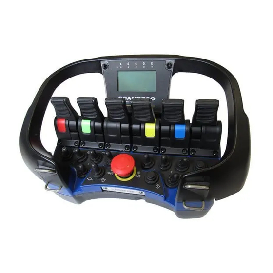
Пульт дистанционного управления оснащен 4 рукоятками управления (может быть до 6) для управления определенными операциями. В середине находится красная кнопка остановки со съемным ключом. Кнопка остановки используется, когда операция должна быть прервана, а также в случае аварийной остановки.
Слева и справа от кнопки остановки возможна установка до 10 диодов или переключателей тумблеров, которые используются для расширения функций джойстиков управления.
Кнопка «ON» используется для запуска системы.
Блок дистанционного управления питается от батареи, расположенной в нижней части коробки. В настоящее время диоды, а также встроенный зуммер, информируют оператора о функциональном состоянии системы. Также возможны дополнительные функции, связанные с управлением двигателем транспортного средства
Применение системы радиоуправления SCANRECO RC400 G2B PR6MUD34SHF1 позволяет не только обезопасить оператора, избавив его от необходимости находится в опасной близости от управляемого механизма, но, и в некоторых случаях, создать более комфортные условия работы.
Характеристики
Производитель:
FABERCOM (ИТАЛИЯ)
Файлы
Download Instruction manual of Scanreco RC400 Remote Control for Free or View it Online on All-Guides.com.

1

2

3

4

5

6

7

8

9

10

11

12

13

14

15

16

17

18

19

20

21

22

23

24

25

26

27

28

29

30

31

32

33

34

35

36

37

38

39

40

41

42

43

44

45

46

47

48

49

50

51

52

53

54

55

56

57

58

59

60

61

62

63

64

65

66

Doc.nr : Rc400-Manuale_v20_e.doc
REMOTE CONTROL SYSTEM
SCANRECO RC 400.
INSTRUCTION MANUAL.
( Engelsk Ver 2 ) This instruction manual must be kept in the vehicle cab.
Scanreco RC400: Available Instructions
Note for Owners:
Guidesimo.com webproject is not a service center of Scanreco trademark and does not carries out works for diagnosis and repair of faulty Scanreco RC400 equipment. For quality services, please contact an official service center of Scanreco company. On our website you can read and download documentation for your Scanreco RC400 device for free and familiarize yourself with the technical specifications of device.
-
Mitsubishi PAC-SF44SRA
Mitsubishi Electric BuildingAir Conditioning Control SystemSystem remote controller Type PAC-SF44SRAINSTRUCTION BOOKCarefully read this book before use. It is recommended to safe keep this book for future reference.ANWEISUNGSHANDBUCHVor Benutzung der Anlage dieses Buch sorgfältig durchlesen. Es wird empfohlen, dieses Buch zum Nachschlagen an einemsicheren Ort aufzubewahren.MANUEL D’UTILISATI …
PAC-SF44SRA Remote Control, 206
-
Klimair TEMPERO ECO CERAM REMOTE
1 TEMPERO ECO CERAM MODEL BASE & MODEL REMOTE 100mm & 160mm English Mounting, operation and maintenance Introduction Use Guarantee Product content Technical parameters Construction Installation Maintenance Operation …
TEMPERO ECO CERAM REMOTE Fan, 92
-
Castle Creations MAMBA XL X
GETTING STARTED1. Solder a high quality battery connector to the ESC (see Driver’s Ed Guide “Connectors and Power Wiring” – page 6).2. Mount the ESC and motor into the vehicle.3. Connect motor to the ESC (see Driver’s Ed Guide, “Motor Wiring” – page 7).4. Plug the RX wire and AUX wire in (see “Receiver Connections” section on the opposite side).5. Calibrate your ESC to you …
MAMBA XL X Remote Control, 2
-
Hearth & Home IntelliFire IFT-RC150
1Hearth & Home Technologies • RC150 IntelliFire™ Touch Installation Instructions • 2326-980 • 9/16Leave this manual with party responsible for use and operation.IFT-RC150 IntelliFire™ Touch Remote ControlInstallation Instructions1. IntroductionThe IFT-RC150 is a wall mounted device that is designed to control the functions of Hearth & Home Technologies products equipped wi …
IntelliFire IFT-RC150 Remote Control, 9
Popular Remote Control User Guides:
Описание
Пульт радиоуправления SCANRECO RC400 G2B PR6MUD34SHF1 — это разновидность дистанционного управления, при котором пульт управления и приемник соединены с помощью радиоканала. Данные пульты, в зависимости от назначения системы, могут быть оборудованы кнопками, линейными рукоятками или джойстиками, а также дополнительными тумблерами и переключателями.
Пульт дистанционного управления оснащен 4 рукоятками управления (может быть до 6) для управления определенными операциями. В середине находится красная кнопка остановки со съемным ключом. Кнопка остановки используется, когда операция должна быть прервана, а также в случае аварийной остановки.
Слева и справа от кнопки остановки возможна установка до 10 диодов или переключателей тумблеров, которые используются для расширения функций джойстиков управления.
Кнопка «ON» используется для запуска системы.
Блок дистанционного управления питается от батареи, расположенной в нижней части коробки. В настоящее время диоды, а также встроенный зуммер, информируют оператора о функциональном состоянии системы. Также возможны дополнительные функции, связанные с управлением двигателем транспортного средства
Применение системы радиоуправления SCANRECO RC400 G2B PR6MUD34SHF1 позволяет не только обезопасить оператора, избавив его от необходимости находится в опасной близости от управляемого механизма, но, и в некоторых случаях, создать более комфортные условия работы.
Характеристики
Производитель:
FABERCOM (ИТАЛИЯ)
Файлы
CONTENTS.
1.
2.
3.
INSTRUCTIONS.
4.
5.
6.
7.
OPTION : REGULATIONS AND AUTHORITIES,
8.
9.
ACCESSORIES / OPTIONS.
Design, equipment, technichal data and specification are subject to change or improvement without prior notice. The text of this manual,
or any part thereof, may not be reproduced or transmitted in any form or by any means, electronic or mechanical including photocopying,
recording, storage in an information retrieval system, or otherwise, without the prior written permission of Scanreco AB, Sweden.
Chapters 6, 7, 8 and 9 are abbreviated versions.
Doc.nr : Rc400-Manuale_v20_e.doc
TYPE APPROVAL CERTIFICATES.

Document Revision Language
66024 C English
Instruction ManualRemote Control system RC400

Document type Document number Rev Page
Manual 66024 C 2 of 37
Contents1 General ……………………………………………………………………… 3
1.1 Terminology 3
2 Preface ……………………………………………………………………… 4
2.1 General information 4
3 General system description……………………………………………. 5
3.1 Schematic overview of Scanreco RC-400 5
3.2 General description of Scanreco RC-400 6
3.3 The Portable Control Unit (PCU) 7
3.4 Central unit (CU) 13
3.5 Valve and connection-cables 15
3.6 Crane stop function box (optional) 19
3.7 Battery pack 20
3.8 Battery charger and battery charging 22
4 Safety regulations and operating instructions …………………..25
4.1 Safety regulations 25
4.2 Operating instructions 26
5 Installation Instructions……………………………………………….27
5.1 General schematic of the RC 400 27
5.2 Important notice during welding 27
5.3 Locating the central unit 27
5.4 Mounting recommendations 28
5.5 Cable kit assembly instruction 29
6 Troubleshooting ………………………………………………………….31
6.1 General information 31
6.2 Indications from the Portable Control Unit 31
6.3 Indications on the Central Unit 33
6.4 Non-functional system 35
7 Programming parameters and settings…………………………….36
7.1 General description 36
7.2 Authorisation level 1 37
All rights reserved.
Design, equipment, technical data and specification are subject to change or improvement
without prior notice. The text of this manual, or any part thereof, may not be reproduced or
transmitted in any form or by any means, electronic or mechanical including photocopying,
recording, storage in an information retrieval system, or otherwise, without the prior written
permission of Scanreco AB, Sweden.

Document type Document number Rev Page
Manual 66024 C 3 of 37
Document information
Attribute Information
Document type Manual
Title Instruction manual
Subtitle Remote Control System Scanreco RC-400
Document number 66024
Revision C
Revision date 2009-09-25
Revision history
Revision Date Name Note
A 2008-12-09 SCANRECO AB First creation of document
B 2009-06-15 SCANRECO AB
C 2009-09-25 SCANRECO AB
1 General
1.1 Terminology
Abbreviation Description
PCU Portable Control Unit
CU Central Unit
LED Light Emitting Diode
DV Dump Valve

Document type Document number Rev Page
Manual 66024 C 4 of 37
2 Preface
2.1 General informationThis manual is intended as a complement to the crane / machine instruction bookand covers the Scanreco RC 400 Remote Control System.
The Scanreco RC 400 offers the driver an extremely advanced remote control systemwith speed, precision, control and maximum safety.
In order to ensure your safety and the safety of your crane / machine you shouldstudy and learn these instructions. This will enable you to quickly familiarise yourselfwith your new remote control system and how to utilise it.
• Remotely controlled cranes may only be operated by qualified personnel. Thedriver must be aware of the contents of chapter 4 «Safety regulations andOperating instructions» before operation is started. Serious accidents mayoccur if these instructions are not followed.
• To protect the portable control unit from damage and for safety reasons, thecontrol unit must be kept in a locked cab.
• Follow the instructions given in the crane handbook regarding moving thecrane from its parking position, the best arm positioning while loads are beinghandled and parking of the crane.
• Due to the unlimited variety of cranes, machines, objects, vehicles andequipment on which the remote control system are used, and the numerousstandards which are frequently the subject of varying interpretation, it isimpossible for the personnel at Scanreco to provide expert advice regardingthe suitability of a given remote control for a specific application. It is theresponsibility of the purchaser to determine the suitability of any Scanrecoremote control product for an intended application and to insure that it isinstalled and guarded in accordance with all country, federal, state, local, andprivate safety and health regulation, codes, standards and Scanrecorecommendation (this manual). If the Scanreco RC 400 will be used in asafety critical application, the customer / driver must undertake appropriatetesting and evaluation to prevent injury to the ultimate user. Scanreco doesnot take responsibility for any damage or injure
• Unauthorized tampering with Scanreco automatically invalidates guarantee.
To the operator:
Pause for a while and give yourself extra time to read chapters 3 (General systemdescription) and 4 (Safety regulations and Operating instructions).
To the installer:
Pause for a while and give yourself extra time to read chapters 5 (Installationinstructions) and «Inspection / Installation documents”.

Document type Document number Rev Page
Manual 66024 C 5 of 37
3 General system description
3.1 Schematic overview of Scanreco RC-400The Remote Control System is comprised of the following components (see figure3.1):
Figure 3.1 Schematic overview of the Scanreco RC-400.
General scope of delivery (see your specification and Figure 3.1).
No Description Qty
1 Portable Control unit (PCU) 1
2 Central unit (CU) 1
3 Battery charger 1
4 Battery cassette (NiMH 7.2 VDC) 2
5 Manoeuvre cable (10 meters) 1
6 Emergency stop box (Optional) 1
7 Cable kit supply cables + digital outputs 1
8 Cable kit valves cables (analogue outputs) 1
67 8
3
42
1
5

Document type Document number Rev Page
Manual 66024 C 6 of 37
3.2 General description of Scanreco RC-400The Scanreco RC 400 remote control system has been especially developed forhydraulically driven mobile cranes and machinery. The system is a digital remotecontrol system based on an extremely advanced microprocessor technology. Years ofexhaustive and demanding testing have shown that the remote control system cancope with the roughest of environments.
The system is protected against electromagnetic and radio frequency radiation andcan be installed onto all hydraulic valve types (voltage, current pulse width, orprotocol steered) found on the market.
In its basic form the remote control system is comprised of a portable control unitwith manoeuvre levers for proportional control and switches for ON/OFF functions, acentral unit with connection cable for driving proportional electro-hydraulic slidecontrollers.
Digitally coded control information (lever deflection and switch position) is sent fromthe control unit via electric cable or via radio to the central unit. The control unit andcentral unit translate the magnitude and direction of the manoeuvre lever deflectionsand switch positions to corresponding valve function, speed and direction and thuscrane movement.
Important notice:
The Scanreco Remote control system RC-400 described in this instruction manualshould be distinguished from the similar Scanreco remote control systems RC-400 G4as the main components in these two system types product family (Portable controlunits and central units) are not compatible with each other and varies in appearanceand functionality.

Document type Document number Rev Page
Manual 66024 C 7 of 37
3.3 The Portable Control Unit (PCU)The Portable Control Unit is impact, weather resistant, light weight and compact. Theportable control units can be with linear levers or with joysticks (see figure 3.2below).
Figure 3.2 The available range of portable control units.
No Description
1 MAXI-Joystick is available for 1-8 (Setup: 2-0-2 / 2-2-2 / 2-3-2 / 3-2-3 / 3-0-3).
2 MAXI-Linear is available for 1-8 linear levers
3 MINI-Joystick is available for 1-6 (Setup: 2-0-2 / 2-2-2).
4 MINI-Linear is available for 1-6 linear levers
The manoeuvre levers and joysticks are fully proportional and have spring return tothe zero position, i.e. a «dead-man’s-handle». The control units have a stop functionwhich will immediately stop all movement.
All manoeuvre levers/joysticks are protected with a protective frame againstunintentional activation and against mechanical damage. The control unit has multi-step micro-speed operation as standard enabling instantaneous temporary reductionof speed. It can also be equipped with a large number of switches for ON/OFFfunctions. A LED and sound signal are used to indicate such things as operating andbattery status and for a simple and diagnostic fault finding (see Figure 3.4).

Document type Document number Rev Page
Manual 66024 C 8 of 37
3.3.1 Battery operation
A battery is located in the lower part of the control unit for radio control operationand is very simple to change.
• The effective operation time of the battery is about 8 hours on one charge.
• When the battery is approaching time for charging, the control unit beeps three(3) times as a warning and at the same time the LED starts to blink on thecontrol unit.
• The battery must be used until the LED goes out, after which it can be changed.If the battery capacity is too low the control unit cannot be activated.
• The battery capacity and operational performance is reduced in extremely coldconditions. The battery is automatically charged during operation by cablecontrol.
• In order to reduce battery loading and for safety reasons, the control unit isturned off automatically, after the unit has been idle for more than approximatelyfive (5) minutes.
3.3.2 Manoeuvre levers / joystickThe control unit is comprised of manoeuvre levers for proportional control, switchesfor ON/OFF, micro-operation and stop function (see separate headings below).
Figure 3.3 Overview of panel of PCU.

Document type Document number Rev Page
Manual 66024 C 9 of 37
3.3.3 Stop function panelThere is a red stop function switch (STOP) with a manual twist reset, a push buttonand a red LED on the control unit’s stop function panel, see figure 3.4.
The control unit is started with the spring reset push button ( )
All movement of the crane is stopped if the stop function is activated on the controlunit. The red LED indicates operating and battery status.
Figure 3.4 View of a stop function panel.
3.3.4 Changing radio channelsIt is possible to change the radio channel by quickly pressing the button markedtwice. There are 10 different radio channels to switch between by pressing thisbutton in sequence.
Important notice:
Scanreco will introduce an automatic frequency management to the RC400 systemsin end of 2009 making the above described function; chapter 3.3.4 changing radiochannels, obsolete.
The automatic frequency management ensures a more reliable radio transmissionhighly resistant to radio interference thanks to intelligent frequency hoppingtechnology automatically handling frequency changes.
The operator then no longer needs to manage radio frequency and the risk ofinterference is minimized.
This user manual is printed prior to the introduction of the automatic frequencymanagement, for further information; please consult your distributor.

Document type Document number Rev Page
Manual 66024 C 10 of 37
3.3.5 Switch Panels
The switches on the switch panel allow actuation of digital functions via toggleswitches and push buttons, see figure 3.5 and 3.6. digital functions can be used tomanoeuvre electrical, hydraulic or pneumatic ON/OFF functions. Examples offunctions:
• Stopping and starting of the vehicle’s motor, throttle lever, beep / signal,change-over valves, function changing for ex. 7:th and 8:th function, etc.
Make sure that you always know which digital functions that are connected forON/OFF manoeuvring.
Figure 3.5 Left switch panel on MAXI PCU.
Figure 3.6 Left switch panel on MINI PCU.

Document type Document number Rev Page
Manual 66024 C 11 of 37
3.3.6 Micro-speed control
This return spring switch can be used to reduce the operating speed in five (5) stepsfrom 100% to 60%, 50%, 40%, 30% and 20% speed by limiting the hydraulicsteering. The regulation of the function’s speed is still made over the entire leverstroke and with retained resolution.
• With impulses from the spring loaded toggle switch to the left, towards the turtle, speed reduction can be produced from 100% to 60%, 50%, 40%, 30%
and 20% steering.
• Movement of the switch to the right, towards the rabbit , will produce 100%steering once again.
• For safety reasons, a return to 100% steering can only be made if all manoeuvrelevers are in their zero positions.
• When the green LED is blinking, the Micro-speed function is activated. Thenumber of blinks indicates the operating speed as defined in the table below. Ifthe stop function is pressed on the controller unit, the controller unit will startfrom the last chosen speed.
Green LED Indication
not lit 0 to 100 % speed (normal speed)
1 blink every third second 0 to 60 % speed
2 blink every third second 0 to 50 % speed
3 blink every third second 0 to 40 % speed
4 blink every third second 0 to 30 % speed
5 blink every third second 0 to 20 % speed

Document type Document number Rev Page
Manual 66024 C 12 of 37
3.3.7 Cable for cable control
The control unit can be connected to the central unit via a thin and flexible 5-corecable. The cable has round contacts (M12) at each end.
The cable feeds the digital coded control information from the Portable Control Unit tothe Central Unit. The cable is available in standard lengths of 10 meters.
Pin no Function
1 Data
2 GND
3 RS232 TX
4 RS232 RX
5 +24 VDC
3.3.8 Technical data (PCU)
Item Technical data
Battery pack 7.2 VDC
Portable Control Unit effectiveoperating time
Approximately 8 hours per charge
Weight / MAXI/Linear 1,95/2,20 kg (without/with battery pack)*
Weight / MAXI/Joystick 1,75/2,00 kg (without/with battery pack)*
Weight / MINI/Linear 1,45/1,70 kg (without/with battery pack)*
Weight / MINI/Joystick 1,30/1,55 kg (without/with battery pack)*
Dimensions MAXI (WxHxD) 350x160x190 mm*
Dimensions MINI (WxHxD) 290x160x190 mm*
IP class IP65
Ambient temperature (Celsius / Farenheit)
-25°C to +70°C /approx. -15°F to to +160°F
*Weights and dimensions are approximate and depending on configuration.

Document type Document number Rev Page
Manual 66024 C 13 of 37
3.4 Central unit (CU)The central unit is manufactured in plastic and is provided with contacts forconnection to the portable control unit (for cable remote operation), for supplyvoltage, the electro-hydraulic converter valves, dump valve and ON/OFF functions.
Since the central unit can be exposed to very tough environments, the box isencapsulated to give protection from damp, heat, cold, dust, vibration and corrosiveenvironments.
The central unit has short circuit proof inputs and outputs and has protection againstpolarity reversal, over-voltage, large incoming voltage transients and EMC / RF.Connection of the central unit can therefore be made without risk of damage. Thecentral unit is delivered for supply voltages of +12 / +24 VDC (+/- 20 %) withnegative ground. There is one standard car type fuse located inside the central unit.
Plus fuse: + 10 Amp.
A transformer for standard mains voltages can also be used to provide the centralunit with supply voltage. Primary voltage: 110, 115, 220-240, 380, 440 VAC andsecondary voltage + 12 / +24 VDC (+/- 10%).
The central unit is equipped with:
1. Standard antenna
2. Operational mode switch (Remote/Manual: See Chapter 4.2 Operationalinstructions)
3. Cable connector for cable control / Programming port
4. Status LED´s
5. 7-segment LED Display
Figure 3.7 The central unit.
11
2
33
4
52

Document type Document number Rev Page
Manual 66024 C 14 of 37
3.4.1 Technical data (CU)
Item Technical data
Supply voltage 12 VDC / 24 VDC (+/- 20% / max. 5% V peak topeak)
Internal fuse Plus: + 10 Amp. (Standard car fuse / Red)
Max. over-voltage Approximately 33 VDC (Fuse blows)
Proportional functions 1 — 8 double operating proportional functions
Dump valve drive Max. 2,0 Ampere (short circuit proof)
ON/OFF drive Max. 1,8 Ampere (short circuit proof)
Regulation signals Voltage or PWM (Other upon request)
Current consumption at idle 40 mA
Weight 1,20 Kg (Valve and connection cables notincluded)
Dimensions (WxHxD) 227x205x78 mm
IP Class IP65
Ambient temperature (Celsius / Farenheit)
-25°C to +70°C /approx. -15°F to to +160°F

Document type Document number Rev Page
Manual 66024 C 15 of 37
3.5 Valve and connection-cablesThere are several connection cables depending on the valves and the extra functionsused. In Figure 3.8 an example of a cable kit to Danfoss valves is shown.
Figure 3.8 An example of a cable kit to Danfoss valves.

Document type Document number Rev Page
Manual 66024 C 16 of 37
3.5.1 Terminal connections
Figure 3.9 The figure illustrates inside terminal connectors for the standard CentralUnits type 2000 (Danfoss) and type 3000 (PWM).
Important notice:
If a central unit is delivered without pre-mounted cables; the installer is stronglyadvised to follow the instructions given in chapter 5.5 in this manual, pages 27 and28; Installation instructions — Cable kit assembly instruction.
K7 ( + / -, DV)
K4 (EX1)
K6 (EX2)
K1 (Analog outputs 1-4)
K3 (Analog outputs 5-8)

Document type Document number Rev Page
Manual 66024 C 17 of 37
3.5.2 Terminal schematics for Danfoss type Central UnitK7 MainPin no. DescriptionK7.1 Supply (+12/24 VDC)K7.2 GNDK7.3 DV +K7.4 DV GND
K1 Analog outputs K3 Analog outputsPin no. No. Description Pin no. No. DescriptionK1.1 Danfoss module supply K3.1 Danfoss module supplyK1.2 Danfoss regulated supply K3.2 Danfoss regulated supplyK1.3 GND K3.3 GNDK1.4
1
Fault monitor K3.4
5
Fault monitorK1.5 Danfoss module supply K3.5 Danfoss module supplyK1.6 Danfoss regulated supply K3.6 Danfoss regulated supplyK1.7 GND K3.7 GNDK1.8
2
Fault monitor K3.8
6
Fault monitorK1.9 Danfoss module supply K3.9 Danfoss module supplyK1.10 Danfoss regulated supply K3.10 Danfoss regulated supplyK1.11 GND K3.11 GNDK1.12
3
Fault monitor K3.12
7
Fault monitorK1.13 Danfoss module supply K3.13 Danfoss module supplyK1.14 Danfoss regulated supply K3.14 Danfoss regulated supplyK1.15 GND K3.15 GNDK1.16
4
Fault monitor K3.16
8
Fault monitor
K4 EX1 — Digital outputs / inputs K6 EX2 — Digital outputs / inputsPin no. Description Pin no. DescriptionK4.1 Digital output 1 K6.1 On / SignalK4.2 Digital output 2 K6.2 Digital output 7K4.3 Digital output 3 K6.3 Digital output 8K4.4 Digital output 4 K6.4 Digital output 9K4.5 Digital output 5 K6.5 GNDK4.6 Digital output 6 K6.6 Digital output 10K4.7 GND K6.7 Digital output 11K4.8 Digital input 1 K6.8 Digital output 12 / Digital input 4K4.9 Digital input 2 K6.9 Digital output 13K4.10 Digital input 3 K6.10 GNDK4.11 Input supply (+VDC)
K8 EX3 — Optional featuresPin no. DescriptionK8.1 Customer specificK8.2 Customer specificK8.3 Customer specificK8.4 Customer specificK8.5 Customer specific

Document type Document number Rev Page
Manual 66024 C 18 of 37
3.5.3 Terminal schematics for PWM type Central UnitK7 MainPin no. DescriptionK7.1 Supply (+12/24 VDC)K7.2 GNDK7.3 DV +K7.4 DV GND
K1 Analog outputs K3 Analog outputsPin no. No. Description Pin no. No. DescriptionK1.1 PWM + K3.1 PWM +K1.2
1AGND K3.2
5AGND
K1.3 PWM + K3.3 PWM +K1.4
1BGND K3.4
5BGND
K1.5 PWM + K3.5 PWM +K1.6
2AGND K3.6
6AGND
K1.7 PWM + K3.7 PWM +K1.8
2BGND K3.8
6BGND
K1.9 PWM + K3.9 PWM +K1.10
3AGND K3.10
7AGND
K1.11 PWM + K3.11 PWM +K1.12
3BGND K3.12
7BGND
K1.13 PWM + K3.13 PWM +K1.14
4AGND K3.14
8AGND
K1.15 PWM + K3.15 PWM +K1.16
4BGND K3.16
8BGND
K4 EX1 — Digital outputs / inputs K6 EX2 — Digital outputs / inputsPin no. Description Pin no. DescriptionK4.1 Digital output 1 K6.1 On / SignalK4.2 Digital output 2 K6.2 Digital output 7K4.3 Digital output 3 K6.3 Digital output 8K4.4 Digital output 4 K6.4 Digital output 9K4.5 Digital output 5 K6.5 GNDK4.6 Digital output 6 K6.6 Digital output 10K4.7 GND K6.7 Digital output 11K4.8 Digital input 1 K6.8 Digital output 12 / Digital input 4K4.9 Digital input 2 K6.9 Digital output 13K4.10 Digital input 3 K6.10 GNDK4.11 Input supply (+VDC)
K8 EX3 — Optional featuresPin no. DescriptionK8.1 Customer specificK8.2 Customer specificK8.3 Customer specificK8.4 Customer specificK8.5 Customer specific

Document type Document number Rev Page
Manual 66024 C 19 of 37
3.6 Crane stop function box (optional)The crane stop function box is a separate unit for fixed mounting on the vehicle (seefigure 3.10). The crane stop function box must be connected between the vehiclebattery and the central unit.
• When the stop function is activated the main power supply to the entire remotecontrol system is disconnected.
• The crane stop function must be suitably located and easily accessible.
• Before operation is started, the driver must inform all fellow-workers about thestop function and its location.
• Crane stop function box is not a scope of delivery from Scanreco – it is theinstallers responsibility.
With the central unit switch in MANUAL position and an electric dump valve, the stopfunction is also available during manual hand lever operation. (See also chapter 4″Safety regulations and Operating instructions»).
Figure 3.10 Stop function box.

Document type Document number Rev Page
Manual 66024 C 20 of 37
3.7 Battery packThe battery pack is impact and weather resistant and is located in the battery holderin the Portable Control Unit. The battery pack is rechargeable 7.2 VDC and of NickelMetal hybrid (NiMH) type (see figure 3.11). The battery pack is protected againstshort circuits.
Figure 3.11 The battery pack.
• The effective operational capacity of the battery is approximately 8 hours percharge.
• When the battery is approaching time for recharging, the control unit beeps three(3) times as a warning and at the same time the LED starts to blink on thecontrol unit.
• The battery must be used until the LED goes out, after which it can be changed.If the battery capacity is too low the control unit cannot be activated.
• The battery capacity and operational performance is reduced in extremely coldconditions. The battery is automatically charged during operation by cablecontrol.
• In order to reduce battery loading and for safety reasons, the control unit isturned off automatically, after the unit has been idle for more than approximatelyfive (5) minutes.
Important notice:
• Use only batteries / battery chargers supplied by Scanreco, Sweden for thespecific product.
• Do not charge batteries in hazardous environments.
• Do not attempt to use a battery pack that is damaged, leaking, swollen orcorroded.
• Avoid usage of battery / battery charger outside of the specified ambienttemperature.

Document type Document number Rev Page
Manual 66024 C 21 of 37
3.7.1 Technical data (Battery)
Item Technical data
Type 6 Cell NiMH battery
Nominal voltage 7.2 VDC
Weight 0,20 kg
Dimensions (WxHxD) 150x50x28 mm
IP Class IP65
Ambient temperature (Celsius / Farenheit)
-0°C to +45°C /approx. -32°F to to +115°F

Document type Document number Rev Page
Manual 66024 C 22 of 37
3.8 Battery charger and battery charging
3.8.1 General description
The battery charger is using two different modes of charging. Initially the unit willcharge with a high current until the battery is charged, and then it reduces to atrickle charge mode until battery is removed. The normal charging time for an emptybattery is approximately 3 hours. The battery charger is designed not to damage thebattery even with long continuous charging (see figure 3.12).
Figure 3.12 The battery charger.
3.8.2 Installation• The battery charger must be mounted in a vibration free area inside the cab or
indoors and be protected against damp, direct sunlight and temperaturevariations.
• Operating ambient temperature is 0° C to +70° C, but could be narrowerdepending on the battery specification.
• The supply voltage to the battery charger should be +10 VDC to +35 VDC,externally fused with 3.0 Amp fuse.
• The batter charger is constructed so that no damage will occur from longcontinuous charging.
• Polarity for connection cable: Inc Marked Cable = +
• Maximum power consumption for battery charger with battery: ≈ 400 mA
• Power consumption for battery charger without battery: ≈ 10-20 mA
• After connection the cable connector, put the cable inside the cable track asillustrated in figure 3.13 below.

Document type Document number Rev Page
Manual 66024 C 23 of 37
Figure 3.13 After connecting the cable connector; put the cable inside the cabletrack.
3.8.3 OperationThe battery charger will start a charge cycle when a new battery is inserted (greenLED starts blinking). After approx. 3 hours the battery is charged and ready for use(green LED is continuous ON). If the power supply is lost, the battery charger willremember the charging status and continue with a fast charge mode or trickle chargemode when the power is on again. As a safety precaution the charger will stopcharging after 3 hours whether the battery is fully energized or not. The green LEDwill be continuously ON.
There are two LED indicators on the battery charger:
• Red LED (power) — Indicates supply power.
• Green LED (charging status) is blinking — Battery is charging (the charger is infast charge mode).
• Green LED (charging status) is continuously ON — Battery is charged (the chargeris in trickle charge mode).
3.8.4 Battery charging via cable controlIf the operator is using the cable control facility and the battery is placed in theportable control unit, the battery will be charged automatically. The cable controlfacility could also be used as a battery charger when the system is not used. Placethe battery in the portable control unit (stop function pressed) and connect the cablebetween the portable control unit and the electronic box (emergency stop on thecrane released). Charging time is approx. 12-14 hours.
The Central Unit must however be in Remote mode.

Document type Document number Rev Page
Manual 66024 C 24 of 37
3.8.5 Technical data (Battery charger)
Item Technical data
Supply voltage 10 VDC to 30 VDC
Fuse Not included: Use only with 3 A. external fuse
Battery charger current consumptionwithout battery pack ≈ 10 — 20 mA
Battery charger current consumptionwith battery pack ≈ 130 — 140 mA
Weight 0,25 kg
Dimensions (WxHxD) 252x85x36 mm
IP Class IP21
Ambient temperature (Celsius / Farenheit)
-0°C to +70°C /approx. -32°F to to +160°F

Document type Document number Rev Page
Manual 66024 C 25 of 37
4 Safety regulations and operatinginstructions
4.1 Safety regulationsThese instructions cover those special regulations which apply for remotely controlledcranes (cable or radio). The driver must be aware of the contents of these safetyregulations.
Remote controlled cranes may only be operated by trained personnel. The portablecontrol unit must never be passed over to any person who has not received trainingfor remote controlled cranes. If these instructions are not followed, serious accidentscan occur.
THE OPERATOR MUST:
• Check that the control unit matches the crane / machine which he is to operate.
• Acquaint himself with the symbols and positions for operating functions anddirections.
• Every time before starting work, check the stop function on the portablecontroller unit by doing the following:
1. Operate a crane / machine function and press the stop button on the portablecontroller unit. The crane must immediately come to a standstill. No furthercrane movements are possible.
2. If the cranes movement is not interrupted, crane operation must be stoppedimmediately and a service workshop visited.
• During operation, walk or stand at a suitable distance from the crane to be ableto get a good view of the operation. No unauthorised persons may be within thecrane’s working area.
• Be aware that it is forbidden to convey loads over himself or fellow workers.
• Release all manoeuvre levers (dead-man’s-handles) if crane movement control islost and then immediately press the stop function on the control unit and theemergency stop on the crane.
• The stop function on the control unit should always be in the depressed positionwhenever the unit is not in use. This applies even for short stoppages, forexample, if the driver wishes to move.
• After a completed run, press the stop function on the control unit and on thecrane. The control unit must be kept out of reach of unauthorised persons.
• Always report equipment faults or shortcomings to the person responsible for thecrane.
• Check that none of the safety devices have been altered or removed.
• Refer to the current regulations / instructions regarding «Personnel lifting withcranes”, “Overloading/overload protection «, «Visible signals during the operationof cranes» and «The location of cranes close to airports and high-tension powerlines».
• Be aware of any other pertinent regulations and of any local regulations whichmay apply. These are to be found in the relevant safety regulations regardingcrane transport.

Document type Document number Rev Page
Manual 66024 C 26 of 37
• Be aware of the contents in «OPERATING INSTRUCTIONS» and the handling andmethod of working of the remote control system. See next section «Operatinginstructions».
4.2 Operating instructionsBefore operation, the driver must make himself aware of the contents in the «SAFETYREGULATIONS» for remotely controlled cranes. The driver must be aware of thefunction of all manoeuvre levers and switches.
1. For remote control: Place the central unit operational mode switch into REMOTE.
2. For manual/emergency operation: Place the central unit operational mode switchinto MANUAL. Power is now only supplied to the dump valve and the crane’sfunctions can be manoeuvred directly from the valve’s hand levers.
3. Twist up the emergency stop switches on the crane and on the control unit.
4. Cable operation: Connect the control cable between the control unit and thecentral unit (crane).
5. Radio operation: Place a newly charged battery in the control unit’s batteryholder.
6. Press and the red LED will light continuously.
7. The system is now ready for operation. The driver must be aware of allmanoeuvre lever/joystick and switch functions before operation is started.
8. To switch off or to activate the stop function the stop function switches on thecontrol unit and the emergency stop on the crane should be pressed down. Thestop function on the control unit should always be in the depressed positionwhenever the unit is not in use. This applies even for short stoppages, forexample, if the driver wishes to move.
9. To ensure a long life for the control unit and for reasons of safety, the controlunit must be kept locked in the cab. The control unit should be regularly wipedoff with a damp cloth for example.

Document type Document number Rev Page
Manual 66024 C 27 of 37
5 Installation Instructions
5.1 General schematic of the RC 400When the Scanreco RC 400 is installed an electrically controlled dump valve must, forreasons of safety, always be connected between the manoeuvre valve and the tank.This means that during an emergency stop manoeuvre the dump valve will bewithout power and will transfer the pump flow directly to the tank thus making thesystem entirely without hydraulic pressure.
Figure 5.1
5.2 Important notice during weldingImportant: It is sometimes necessary to weld a truck/machine. During welding thesystem’s electrical connections must always be disconnected from other equipment,i.e. power supply cables (+ and -), all valve contacts, the EX cables contact must bedisconnected.
5.3 Locating the central unitImportant: The central unit must be mounted in accordance with therecommendations given below (see figure 5.2). To ensure the longest possible life forthe central unit and its cables, the central unit must always be mounted so that thevalve contacts are located facing downwards. The central unit must not be mountedso that the cables face upwards. The reason for this is to hinder water from runningvia the cables, towards the central unit
(The cables on the central unit are thus not subjected to long periods of accumulatedwater, damp, salt etc). The central unit should be mounted in a vibration freelocation and not close to strong heat sources (for example exhaust pipes etc).
1
2
3
4
67 8
5

Document type Document number Rev Page
Manual 66024 C 28 of 37
Figure 5.2 How to mount the Central Unit.
5.4 Mounting recommendations• For optimum radio communications the central unit and its antenna should be
located as high and free as possible. An antenna screened and surrounded byfixed objects will considerably impair radio reception. An external antenna isavailable upon request.
• The antenna pin must not touch any metal object.
• The central unit should be mounted in a vibration free location and not besubjected to strong sources of heat (for example exhaust pipes etc).
• Supply and valve cables should be mounted facing downwards!

Document type Document number Rev Page
Manual 66024 C 29 of 37
5.5 Cable kit assembly instructionIn order to maximize product life and prevent involuntary service stops, this cablemounting guide should be consulted before attempting to assemble the cable kit.
If grease is not already applied to the areas shown in the picture, be sure to addwater resistant grease suitable for electronic applications in relevant quantities to theareas mentioned.
Figure 5.3 Central unit with lid removed.

Document type Document number Rev Page
Manual 66024 C 30 of 37
Pierce the membrane and feed the cable through it. A tight fit ensures a good seal.
Secure the cable with a tie strap or similar.
Figure 5.4 Membrane. Figure 5.5 Tie strap.
Apply grease as shown on the picture. Cover all exposed metal and fill all cavities.
For best result, apply grease in the cavities on the connector prior to fitting the singlewire connectors to it.
Figure 5.6 Applied grease. Figure 5.7 Cable orientation.

Document type Document number Rev Page
Manual 66024 C 31 of 37
6 Trouble shouting (maintenance/faultfinding)
6.1 General informationIn the event of non-functionality:
The operator can check the following before contacting the service workshop.
The service workshop should check the following before distributor or ScanrecoAB, Sweden, is contacted.
Always check the Type- and Serial number on the related systems Portable ControlUnit and Central Unit before distributor or Scanreco AB, Sweden, is contacted.
6.2 Indications from the Portable Control UnitStatus and alarm indications can be read from the Portable Control Units LED MICROand LED ON and also via built in buzzer (see figure 6.1).
1 = Left hand side of stop button; LED MICRO
2 = Right hand side of stop button; LED ON
3 = Sound, via internal buzzer
Figure 6.1 Status and alarm indication on portable control unit.
1 2

Document type Document number Rev Page
Manual 66024 C 32 of 37
6.2.1 Operational status indicationsThe Portable Control Unit uses LED ON and LED MICRO to indicate current status andalarms.
A functional system should indicate the following on LED ON:
LED ON lit red; this means that the Portable Control Unit is active and transmittingdata towards the Central Unit either via cable or radio.
LED ON flashing red once every second; this means that the battery isapproaching time for charging, this indication precedes by the buzzer that beepsthree (3) times.
LED MICRO is used to indicate current micro mode
LED MICRO flashing green one, two, three, four or five times every thirdsecond; this means that the micro function is active, see chapter 3.3.6 for furtherinformation.
6.2.2 Error codesDuring start-up of the Portable Central Unit a self test is conducted, any errors foundare presented by an error code using ON LED and buzzer flashing/alarming a certainamount of times, the number of times represents a certain error:
Indications Meaning
1Lever/Joystick at position 1 not in neutral position at start-up ordefective
2Lever/Joystick at position 2 not in neutral position at start-up ordefective
3Lever/Joystick at position 3 not in neutral position at start-up ordefective
4Lever/Joystick at position 4 not in neutral position at start-up ordefective
5Lever/Joystick at position 5 not in neutral position at start-up ordefective
6Lever/Joystick at position 6 not in neutral position at start-up ordefective
7Lever/Joystick at position 7 not in neutral position at start-up ordefective
8Lever/Joystick at position 8 not in neutral position at start-up ordefective
13 Emergency stop failure during self test

Document type Document number Rev Page
Manual 66024 C 33 of 37
6.3 Indications on the Central UnitStatus and error code indications can be read from the Central Units 2 front sideLED’s (LED DV and LED STATUS) and thru lid window monitoring internal double 7-segment LED display, locations are displayed on below figure. (see figure 6.2).
Figure 6.2 Indicators on the Central Unit.
6.3.1 Operational status indications
Operational status indications can be read from the LED STATUS and LED DV.
A functional system should indicate the following on LED ON:
LED STATUS lit red; Central Unit is in standby mode
LED STATUS lit green; Central Unit is in operational standby mode, or inoperational mode
LED STATUS flashing red; Error code sequence (Check double 7-segment LEDdisplay for further information.
The LED DV is used to indicate current status for the Dump Valve output
LED DV lit red; Indicates that the DV-output is active
STATUS LED`s
7-segmentLED display

Document type Document number Rev Page
Manual 66024 C 34 of 37
6.3.2 Error codesThe Central Unit will indicate detected errors via the double 7-segment LED display.
If the Central Unit detects an error it will be indicated by the LED STATUS flashingred whilst the the double 7-segment LED display indicates the error code with thedigits “Er” followed by four digits in two blocks with the corresponding error code.
Example on error code sequence:
“Er” -> “15” ->”1A” -> ““Er” -> “15” ->”1A” ->“Er” -> “15” ->”1A” ->
The error code sequence will repeat itself three times if the error is considered a softerror and reboot to standby mode, if the error is considered a hard error the errorcode sequence will be continued until supply power is disconnected.
Below list over error codes and their meaning
Indication
Block 1 Block 2
Meaning
01. 01-07 Checksum error (Block 2 declares type)
02. 02 DV output short circuit
04. 01-14 Digital output short circuit (Block 2 declares whichoutput)
07. 1A-8B Analog output error (Block 2 declares which output)
15. 1A-8B Analog output short circuit (Block 2 declares whichoutput)
16. 1A-8B Analog output interruption (Block 2 declares whichoutput)
17. 01 Supply voltage too low
17. 02 Supply voltage too high

Document type Document number Rev Page
Manual 66024 C 35 of 37
6.4 Non-functional systemAlways check the following:
• Is there +12 VDC / +24 VDC, +/- 20 %, max. 5 %Vpeak to peak supply to thesystem? Measure at the emergency stop switch (unloaded and loaded).
• Does the system operate via cable control function?
• Does the system work manually, i.e. with the system in MANUAL mode?
• Place switch into «REMOTE» position, check and verify how the Central UnitsLEDs and double 7-segment LED display indicate.
• Activate Portable Control Unit, check and verify how the Portable Control UnitsLEDs and buzzer indicate.
• Activate each available function one at a time, check and verify how the CentralUnits and/or Portable Control Unit indicate.

Document type Document number Rev Page
Manual 66024 C 36 of 37
7 Programming parameters and settings
7.1 General descriptionThe Scanreco RC 400 offers considerable possibilities for system constructors ofhydraulically driven mobile cranes and machines. The program in the control systemis very comprehensive, flexible and has many adaptation possibilities for specificapplications. The control system offers simple programming of a number of functionswhich can easily be turned on or off or altered during operation.
To obtain the best manoeuvre characteristics in the simplest way, all programming / calibration of manoeuvre characteristics is made during operation (so called on-line).All programming / calibration are made from the portable control unit. Programmingis simple and does not require tools / instruments.
The control system is furnished with and prepared for 2-way (duplex)communications and for signal handling of functions such as ramp, parallel, lock,»dead-man’s», hold, double and overload / lift reduction etc.
The levels of authorisation are divided into four main groups:
• Authorisation level 1 (Installer)
• Authorisation level 2 (Well trained installer, well trained service personnel)
• Authorisation level 3 (Well trained crane and valve manufacturer, well trainedsystem constructor)
• Authorisation level 4 (Scanreco AB, Sweden).

Document type Document number Rev Page
Manual 66024 C 37 of 37
7.2 Authorisation level 1
7.2.1 Changing direction of movement
This describes how changes in direction of movement are made if the crane moves inthe opposite direction to that desired.
Example:
After installation and test operation it is found that the 3rd and 5th lever movementsoperate in the opposite direction to that desired. See the example below for how tochange the 3rd and 5th lever movements.
DO AS FOLLOWS
1. Remove the battery pack. Connect the cable between the Portable ControlUnit and Central Unit and test run the crane. Then press the stop button onthe Portable Control Unit and emergency stop on the crane.
2. Twist up the stop on the Portable Control Unit and on the crane.
3. Press the Portable Control Unit’s ON-button. The red LED should lightcontinuously.
4. Produce impulses in very quick succession with spring return switch MICRO toRIGHT in the OFF direction until the Portable Control Unit gives a long beepsignal. Wait approx. 12 seconds until the next long beep signal then continuewith no 5 below.
Note 1. The red LED will be extinguished each time the Portable Control Unitgives a beep signal.
Note. 2. If you do not receive the first long beep signal, start again from no 1above and execute no 3 and no 4. quicker. No 3 above and no 4. must beexecuted within max. 5 seconds.
5. Now press ON-button once.
The Portable Control Unit’s built-in beeper will give a short beep once every 5seconds to confirm that the items above have been done correctly. If anyother beep signals are heard you must restart from item 1 again. Now youcan easily change direction, see no 6 below.
6. Now you can operate the crane. Move the 3rd control lever (which isoperating in the opposite direction to that desired) and give switch MICRO animpulse to the LEFT in the ON direction.
The crane will now change direction and continue with the same selectedspeed, in the opposite direction. Do the same with the 5th manoeuvre lever.
Move the 5th manoeuvre lever (which is operating in the opposite direction tothat which is desired) and give toggle switch MICRO an impulse to the LEFT inthe ON direction. The crane will now immediately change direction andcontinue with the same selected speed in the opposite direction. If a directionchange has been made earlier for a particular lever, do the same as abovebut give toggle switch MICRO an impulse to the RIGHT, in the OFF direction.
Operate and check that all crane directions go in the desired direction.
7. Press the stop button on the Portable Control Unit
Programming is now completed and the crane is operating in the directionsyou decided in item 6. For radio operation, remove the cable control and testrun the crane.
If you are not satisfied with any direction/directions, repeat the above actions.


www.scanreco.se