-
Contents
-
Table of Contents
-
Troubleshooting
-
Bookmarks
Quick Links
FOREWORD
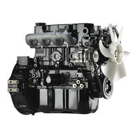
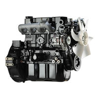
This service manual is written to familiarize you with the maintenance of your S4Q, S4Q2 Diesel Engine. If the
engine is carefully maintained it will deliver a long productive life and efficient performance marked by power and
economy.
Before you attempt to inspect, disassemble, or repair the engine, read this manual carefully to learn more about the
engine and how to care for it properly. All descriptions, illustrations, specifications, and serial numbers in this manual
are effective as of the date printing of this manual.
The information contained in this manual applies to the engine model produced at the time of publication.
It should be noted that specifications and design may change due to improvements made thereafter.
Service Manual
Mitsubishi SQ-Series diesel engines
Version 08/2004
Copyright © 2004 MHI Equipment Europe B.V.
ENGLISH
1 / 174
Service Manual Mitsubishi SQ-Series diesel engines
Version 08/2004
Summary of Contents for Mitsubishi S4Q
This manual is also suitable for:
S4q2
- Manuals
- Brands
- Mitsubishi Manuals
- Engine
- S4Q2
Manuals and User Guides for Mitsubishi S4Q2. We have 3 Mitsubishi S4Q2 manuals available for free PDF download: Service Manual, User Manual
Mitsubishi S4Q2 Service Manual (200 pages)
Brand: Mitsubishi
|
Category: Engine
|
Size: 3.94 MB
Table of Contents
-
Methods of Indication
3
-
Abbreviations, Standards, Etc.
4
-
Units of Measurement
4
-
General Contents
5
-
Safety Cautions
6
-
General
14
-
Outline
15
-
External View for Power Unit
15
-
Engine Left View
15
-
Engine Right View
15
-
External View for Power Unit (High Speed Specification)
16
-
External View for Generator
17
-
External View for Generator (High Speed Specification)
18
-
Outline of Fuel System
19
-
Outline of Lubrication System
19
-
Outline of Cooling System
20
-
Outline of Inlet and Exhaust Systems
20
-
Engine Serial Number
21
-
Engine Model and Application Code
21
-
Specifications
22
-
Maintenance Standards
24
-
Maintenance Standards Table
25
-
Tightening Torque Table
31
-
Important Bolts and Nuts
31
-
Standard Bolts and Nuts
32
-
Standard Eyebolts
32
-
Standard Union Nuts
32
-
Taper Bolts
32
-
Sealants Table
33
-
Basic and Special Tools
34
-
Basic Tools
35
-
Special Tools
36
-
Overhaul Instructions
38
-
Determination of Overhaul Timing
39
-
Measurement of Compression Pressure
40
-
Preparation for Inspection
40
-
Preparation for Disassembly
41
-
Removing Electrical Wiring
42
-
Draining Coolant
42
-
Draining Engine Oil
42
-
Disassembly of Engine Main Parts
43
-
Cylinder Head and Valve Mechanisms
44
-
Removal of Rocker Shaft Assembly
45
-
Disassembly of Rocker Shaft Assembly
45
-
Removal of Cylinder Head Bolts
45
-
Removal of Valves and Valve Springs
45
-
Removal of Valve Stem Seals
46
-
Cleaning of Cylinder Head Bottom Surface
46
-
Measurement of Piston Protrusions
46
-
Flywheel
47
-
Removal of Flywheel
48
-
Removal of Oil Seal Case (Optional)
48
-
Removal of Flywheel Housing
48
-
Timing Gears, Camshaft and Oil Pan
49
-
Removal of Crankshaft Pulley
50
-
Removal of Timing Gear Case
50
-
Measurement of Backlashes
50
-
Measurement of Idler Gear End Play
51
-
Removal of Idler Gear
51
-
Camshaft End Play
51
-
Reversal of Crankcase
51
-
Removal of Oil Pan and Oil Pan Gasket
52
-
Removal of Oil Pump
52
-
Removal of Camshaft
52
-
Removal of Front Plate
52
-
Pistons, Connecting Rods, Crankshaft and Crankcase
53
-
Laying Crankcase on Its Side
54
-
Measurement of Connecting Rod End Play
54
-
Removal of Connecting Rod Caps
54
-
Preparation for Removal of Pistons
55
-
Removal of Pistons
55
-
Removal of Piston Ring
55
-
Removal of Piston Pins
55
-
Measurement of Crankshaft End Play
56
-
Removal of Main Bearing Caps
56
-
Removal of Crankshaft
56
-
Arrangement of Bearings
56
-
Inspection and Repair of Engine Main Parts
57
-
Measurement of Distortion of Cylinder Head Bottom Surface
58
-
Measurement of Rocker Arm Inside Diameter and Rocker Shaft Diameter
58
-
Measurement of Valve Spring Perpendicularity and Free Length
58
-
Measurement of Pushrod Deflection
59
-
Measurement of Valve Stem Diameter
59
-
Measurement of Clearance between Valve Stem and Valve Guide
59
-
Replacement of Valve Guides
60
-
Inspection of Valve Faces
60
-
Replacement of Valve Seats
61
-
Refacing Valve Faces
62
-
Regrinding Valve Seats
62
-
Lapping Valves against Valve Seats
62
-
Replacement of Combustion Jets
63
-
Measurement of Flywheel Flatness
64
-
Replacement of Ring Gear
64
-
Inspection of V-Belt Groove for Wear
65
-
Inspection of Oil Seal Contact Surface
65
-
Replacement of Idler Bushing
65
-
Replacement of Idler Shaft
66
-
Measurement of Cam Lift
66
-
Measurement of Camshaft Journal Diameter and Journal Bore Diameter
66
-
Measurement of Camshaft Deflection
67
-
Removal of Camshaft Gear
67
-
Installation of Camshaft Gear and Thrust Plate
67
-
Measurement of Piston Outside Diameter
68
-
Inspection of Pistons and Piston Rings
68
-
Measurement of Piston Ring End Gap
69
-
Measurement of Piston Pin Bore and Piston Pin
69
-
Measurement of Clearance between Connecting Rod Bushing and Piston
69
-
Replacement of Connecting Rod Bushing
70
-
Inspection of Connecting Rods for Bend and Twist
70
-
Inspection of Oil Clearance of Connecting Rod Bearing
71
-
Inspection of Oil Clearance of Main Bearing
72
-
Inspection of Oil Contact Surface
73
-
Measurement of Crankshaft Deflection
74
-
Removal of Crankshaft Gear
74
-
Installation of Crankshaft Gear
74
-
Measurement of Cylinder Bore
75
-
Measurement of Distortion of Crankcase Upper Surface
76
-
Inspection of Cam Contacting Surfaces of Tappets
76
-
Measurement of Clearance between Tappet and Tappet Guide Bore
76
-
Reassembly of Engine Main Parts
77
-
Installation of Piston Rings
80
-
Preparation for Piston Installation
81
-
Installation of Connecting Rod Bolts and Bearings
81
-
Installation of Pistons
81
-
Installation of Connecting Rod Caps
82
-
Positioning Crankcase Upright
83
-
Installation of Front Plate
84
-
Installation of Camshaft
84
-
Installation of Oil Pump
84
-
Installation of Oil Pan
85
-
Installation of Idler Gear
85
-
Inspection after Timing Gear Installation
86
-
Installation of Oil Seal
86
-
Installation of Timing Gear Case
86
-
Installation of Crankshaft Pulley
87
-
Installation of Flywheel Housing
88
-
Installation of Oil Seal Case
88
-
Installation of Flywheel
88
-
Measurement of Flywheel Runout
88
-
Installation of Valve Stem Seals
89
-
Installation of Valves and Valve Springs
89
-
Installation of Cylinder Head Gasket
89
-
Installation of Cylinder Head
90
-
Tightening of Cylinder Head Bolts
90
-
Assembly of Rocker Arm and Rocker Shaft Assembly
90
-
Installation of Rocker Shaft Assembly
90
-
Adjustment of Valve Clearances
91
-
Removal of Fuel System
93
-
Fuel Filter
94
-
Fuel Injection Pipe, Fuel Leak-Off Pipe and Fuel Injection Nozzle
96
-
Fuel Injection Pump
98
-
Removal of Fuel Injection Pump
100
-
Disassembly, Inspection and Reassembly of Fuel System
101
-
Disassembly and Inspection of Fuel Filter
102
-
Reassembly of Fuel Filter
104
-
Disassembly of Fuel Injection Nozzles
106
-
Inspection of Fuel Injection Nozzles
106
-
Reassembly of Fuel Injection Nozzles
108
-
Installation of Fuel System
109
-
Installation of Fuel Injection Pump
112
-
Removal of Lubrication System
117
-
Oil Filter, Oil Cooler and Relief Valve
118
-
Oil Pan, Oil Pump and Oil Pressure Switch
119
-
Disassembly, Inspection and Reassembly of Lubrication System
120
-
Disassembly and Inspection of Oil Pump
121
-
Measurement of Clearance between Outer Rotor and Inner Rotor
121
-
Measurement of Rotor and Case End Play
121
-
Measurement of Clearance between Outer Rotor and Pump Case
122
-
Reassembly of Oil Pump
122
-
Inspection of Oil Filter, Oil Cooler and Relief Valve
123
-
Adjustment of Relief Valve
123
-
Installation of Lubrication System
124
-
Oil Filler, Oil Cooler and Relief Valve
126
-
Removal of Cooling System
127
-
Cooling Fan, Fan Pulley and V-Belt
128
-
Thermostat
129
-
Water Pump
130
-
Disassembly, Inspection and Reassembly of Cooling System
131
-
Disassembly of Water Pump
132
-
Inspection of Water Pump
132
-
Disassembly of Thermostat
133
-
Inspection of Thermostat
133
-
Inspection of Thermo Switch
134
-
Installation of Cooling System
135
-
Removal of Inlet and Exhaust Systems
139
-
Inlet Manifold
140
-
Exhaust Manifold
141
-
Disassembly, Inspection and Reassembly of Inlet and Exhaust Systems
142
-
Inlet Manifold and Exhaust Manifold
143
-
Measurement of Exhaust Manifold Distortion
143
-
Installation of Inlet and Exhaust Systems
144
-
Removal of Electrical System
147
-
Starter
148
-
Alternator
149
-
Glow Plugs
150
-
Disassembly, Inspection and Reassembly of Electrical System
151
-
Disassembly and Inspection of Starter
152
-
Inspection of Starter
153
-
Reassembly of Starter
156
-
Inspection and Adjustment after Reassembly
157
-
Disassembly of Alternator
160
-
Inspection and Repair of Alternator
162
-
Reassembly of Alternator
164
-
Inspection of Glow Plugs
165
-
Installation of Electrical System
166
-
Inspection, Adjustment, Break-In Operation and Performance Tests
170
-
Adjustment of Engine
171
-
Draining of Fuel System
172
-
Bleeding of Fuel System
172
-
Inspection of Fuel Injection Timing (Distributor-Type Fuel Injection Pump Specification)
174
-
Inspection of Fuel Injection Timing (In-Line Fuel Injection Pump Specification)
175
-
Adjustment of Fuel Injection Timing
176
-
Inspection and Adjustment of V-Belt Tension
176
-
Adjustment of Governor
177
-
Break-In Operation
182
-
Starting up
182
-
Break-In Period
182
-
Disassembly and Reassembly of General Parts
185
-
Oil Seals
185
-
O-Rings
185
-
Bearings
186
-
Lock Plates
186
-
Split Pins and Spring Pins
186
Advertisement

Mitsubishi S4Q2 User Manual (174 pages)
Brand: Mitsubishi
|
Category: Engine
|
Size: 3.55 MB
Table of Contents
-
How to Use this Manual
2
-
Table of Contents
3
-
General
8
-
Engine Model and Application Codes
9
-
Engine Serial Number Location
9
-
-
1 Outline
8
-
External View
8
-
-
2 Specifications
10
-
General Instructions
11
-
3 Determination of Overhaul Timing
12
-
4 Testing the Compression Pressure
13
-
5 Tips on Disassembly and Reassembly
15
-
Disassembly
15
-
Reassembly
15
-
-
6 Precautions for Disassembly and Reassembly
16
-
Oil Seals
16
-
O-Rings
16
-
Bearings
17
-
Lock Plates
17
-
Split Pins and Spring Pins
17
-
-
Engine Main Parts
19
-
7 Cylinder Heads and Valve Mechanism
20
-
Disassembly
20
-
Removing Cylinder Head
21
-
Inspection
24
-
Reassembly
32
-
Valve Clearance Adjustment
36
-
-
8 Flywheel
38
-
Disassembly
38
-
Inspection
40
-
Reassembly
41
-
-
9 Timing Gears, Camshaft and Oil Pan
43
-
Disassembly
43
-
Inspection
48
-
Crankshaft Pulley
49
-
Reassembly
53
-
-
10 Pistons, Connecting Rods, Crankshaft and Crankcase
58
-
Disassembly
58
-
Inspection
64
-
Connecting Rods
68
-
Reassembly
76
-
-
Inlet and Exhaust System
85
-
11 Description
86
-
12 Disassembly, Inspection and Reassembly
87
-
Cooling System
89
-
Cooling System 13 Description
90
-
-
13 Description
90
-
14 Water Pump, Fan
91
-
Inspection
91
-
-
15 Thermostat
92
-
Inspection
92
-
-
Fuel System
93
-
16 Description
94
-
17 Fuel System Bleeding
95
-
18 Disassembly
96
-
19 Fuel Injection Timing Check
98
-
20 Fuel Filter (Paper-Element Cartridge Type)
100
-
Disassembly and Inspection
100
-
-
21 Fuel Injection Nozzles
101
-
Disassembly
101
-
Testing
102
-
Reassembly
104
-
-
Lubrication System
105
-
22 Description
106
-
23 Oil Pump
107
-
Disassembly
107
-
Inspection
107
-
Reassembly
108
-
-
24 Oil Filter
109
-
Inspection
109
-
-
25 Pressure Relief Valve
110
-
Inspection
110
-
-
Electrical System General
112
-
Wiring Diagrams
112
-
-
27 Starter
114
-
Inspection before Disassembly (Inspection of Assembly)
114
-
Removal
116
-
Disassembly
117
-
Inspection
118
-
Reassembly
121
-
Inspection and Testing after Reassembly
122
-
-
28 Alternator
124
-
On-Vehicle Inspection
124
-
Removal
126
-
Disassembly
127
-
Inspection
129
-
Assembly
132
-
Installation
132
-
-
29 ETR Type Stop Solenoid
134
-
General
134
-
Solenoid Specification
135
-
Inspection
136
-
Connecting Rod Adjustment
136
-
-
30 Glow Plugs
137
-
Removal
137
-
Inspection
137
-
Installation
137
-
-
Testing and Adjusting
139
-
31 Bench Test
140
-
Starting up
140
-
Inspection after Starting up
140
-
Bench Testing (Dynamometer) Conditions
141
-
Inspection and Adjustment after Bench Testing
141
-
-
32 Idling Speed and Maximum Speed Setting Inspection and Adjustment
142
-
33 Performance Test
144
-
Engine Equipment Condition
144
-
Tests and Their Purposes
144
-
Other Inspections
144
-
Adjustment Engine Output
144
-
-
Troubleshooting
149
-
ENGLISH Service Manual Mitsubishi SQ-Series Diesel Engines
156
-
-
34 Causes of Engine Problems and Remedies
149
-
Maintenance Standards
159
-
35 Maintenance Standards Table
160
-
36 Tightening Torques
166
-
Important Bolts and Nuts
166
-
Standard Bolts
167
-
Standard Studs
167
-
Standard Plugs
167
-
-
37 Thread Sealants
168
-
38 Maintenance Schedule
169
-
Special Tools
171
-
39 Special Tool List
172
Mitsubishi S4Q2 Service Manual (7 pages)
Brand: Mitsubishi
|
Category: Engine
|
Size: 0.45 MB
Advertisement
Advertisement
Related Products
-
Mitsubishi S4Q
-
Mitsubishi S4S
-
Mitsubishi S4L
-
Mitsubishi S4L2
-
Mitsubishi S4S-DT
-
Mitsubishi S4L-T
-
Mitsubishi S4L2-T
-
Mitsubishi S16R
-
Mitsubishi S12A2
-
Mitsubishi SOHC-4G64
Mitsubishi Categories
![]()
Air Conditioner
Controller
![]()
Projector
Automobile
Engine
More Mitsubishi Manuals
|
|
Related Devices:
|
Types of Manuals:
The main types of Mitsubishi S4Q2 instructions:
- User guide — rules of useing and characteristics
- Service manual — repair, diagnostics, maintenance
- Operation manual — description of the main functions of equipment
Engine Instructions by Mitsubishi:
-
Aviation Design F-100
1F-100for AMT Pegasus jet engineor Jet CAT P-120 / P-160AssemblyManualZI le chenet, 91490 Milly La Foret, FRANCETel : 33 1 64 98 93 93Fax : …
F-100 Engine, 24
-
HE PARAMOTORES R 220
HE PARAMOTORES Woan rkshop, Installation Instructions d Operator’s Manual For: R 220 E Version Edi n: V01 ngine tioFor information ONLY. Without commitment to advise modifications HE Paramotores S.L. C/ Constitución – Nave Nº 6 28511 Valdilecha Prov. Madrid – España Tel. / Fax. + …
R 220 Engine, 25
-
Mitsubishi S6R2 Series
January 2011Pub. No. 99410-12140The operator and supervisor are requested to read this Oper-ation and Maintenance Manual carefully before operating theengine or conducting inspection and maintenance.Never operate the engine or conduct maintenance work with-out completely understanding this manual.OPERATION &MAINTEN …
S6R2 Series Engine, 118
-
Briggs & Stratton 700 DOV Series
700/750 SERIES DOV AIR-COOLED ENGINES273521 Twin Cylinder OHV Air-Cooled Engines276781 Single Cylinder OHV Air-Cooled Engines271172 Twin Cylinder L-Head Air-Cooled Engines270962 Single Cylinder L-Head Air-Cooled Engines276535 Two-Cycle Snow EnginesCE8069 Out of Production Engines (1919-1981)Repair Manuals for other Bri …
700 DOV Series Engine, 78
-
Oriental motor BMU Series
Brushless Motor30 W / 60 W / 120 WQUICK START GUIDEBMU SeriesConnector typeHM-5191And others…..Remove the panel.Refer to «8 Convenient functions.»Many other useful features are also availableCN1 : 3 pinCN4 : 9 pin To display the rotation speed of the gearhead output shaft To display the size of a lo …
BMU Series Engine, 2
-
Joy-it COM-MOTOR05
COM-MOTOR05 Servomotor FS90R with caster1. GENERAL INFORMATIONDear customer,thank you for choosing our product. In the following, we will show you what is important to observe during the commissioning and the usage.Should you encounter any unexpected problems during use, please do not hesitate to contact us. …
COM-MOTOR05 Engine, 6
-
SIMONINI Victor 1 Plus
Operators Manual Victor 1 Plus / Victor 1 Super This handbook aims to bring to the attention of key technical, functional and maintenance of your motor VICTOR 1. Read carefully the following pages, will be synonymous with safety, reliability and great satisfaction durable. This manual is considered part of t …
Victor 1 Plus Engine, 15
File Specifications:1138/1138117-s4q.pdf file (18 Jul 2023) |
Accompanying Data:
Mitsubishi S4Q Engine PDF Service Manual (Updated: Tuesday 18th of July 2023 11:32:05 AM)
Rating: 4.2 (rated by 94 users)
Compatible devices: S16R, S4Q2, S16R2-PTAW, S6S, 4G5 SERIES, S6B, S6B3, L-Series.
Recommended Documentation:
Service Manual (Text Version):
(Ocr-Read Summary of Contents of some pages of the Mitsubishi S4Q Document (Main Content), UPD: 18 July 2023)
-
Mitsubishi S4Q User Manual
-
Mitsubishi S4Q User Guide
-
Mitsubishi S4Q PDF Manual
-
Mitsubishi S4Q Owner’s Manuals
Recommended: EM60, WGM511, AIRFLOW DUPLEXVENT DV145SE, DEH-2820MP
Links & Tools
-
Robert Bosch GmbHBosch eBike Systems72703 ReutlingenGERMANYwww.bosch-ebike.com0 275 007 XD2 (2018.04) T / 73 WEUde Originalbetriebsanleitungen Original operating instructionsfr Notice d’utilisation d’originees Instrucciones de servicio originalespt Manual de instruções originalit Istruzioni …
Active Line series 73
-
© 2006 Mercury Marine 496 MAG Bravo Models 90-864839061 1106NOTE: The following applies to CE marked products only.Declaration of Conformance – Mercury MerCruiserThis sterndrive or inboard engine when installed in accordance to MercuryMerCruisers’ instructions complies with the require …
496 MAG Bravo 146
-
Service Manual QSB6.7 CM2350 B112Volume 1Cummins Inc.Box 3005Columbus, Indiana, U.S.A., 47202Registered OfficeCummins Ltd.49 — 51 Gresham Road,Staines,Middlesex TW18 2BD,EnglandRegistration 573951 EnglandCopyright© 2017Cummins Inc.Service Manual QSB6.7 CM2350 B112 Volume 1 Bulletin 4358498 Printed in U.S. …
QSB6.7 51
-
SMLNeoTubular MotorInstallation and use instructions and warningsWarning: follow these personal safety instructions very carefully.Important safety instructions; save these instructions for future use. Istruzioni ed avvertenze per l’installazione e l’usoAttenzione: per la sicurezza delle persone è importante …
NEO S 12
Operating Impressions, Questions and Answers:
Download or browse on-line these Service Manual for Mitsubishi S4Q2 Engine.
More Manuals:
In case you failed to obtain relevant information in this document, please, look through related operating manuals and user instructions for Mitsubishi S4Q2.
Just click one of the links below to go to the selected manual:


Summary of Contents:
 |
[Page 1] Mitsubishi S4Q2 Service Manual 99719-77100 For use with FD10N, FD15N, FD18N, FD20CN Chassis Service Manual. S4Q2 Diesel Engine 24467-up FD10N F16D-00011-up, F16D-10001-up FD15N F16D-50001-up, F16D-60001-up FD18N F16D-70001-up, F16D-80001-up FD20CN F16D-85001-up, F16… |
 |
[Page 2] Mitsubishi S4Q2 … |
 |
[Page 3] Mitsubishi S4Q2 FOREWORD This service manual covers S4Q2 Diesel Engine of Mitsubishi Forklift Trucks and gives detailed maintenance and repair information. The instructions are grouped by systems to serve the convenience of your ready reference. Long productive lif… |
 |
[Page 4] Mitsubishi S4Q2 Hou to Use This Manual In this service manual, the Mitsubishi Diesel Engine (standard model for land use) specifications, maintenance standards and adjustment procedure as well as service procedures such as disassembly, inspection, repair and reassem… |
 |
[Page 5] Mitsubishi S4Q2 2. Terms Used in This Manual Nominal value: Indicates the standard dimension of a part to be measured. Standard: Indicates the dimension of a part, the clearance between parts, or the standard performance. Since the value is indicated in a range n… |
 |
[Page 6] Mitsubishi S4Q2 … |
 |
[Page 7] Mitsubishi S4Q2 GROUP INDEX Items 1 2 3 4 5 6 7 8 9 10 11 12 GROUP INDEX GENERAL GENERAL INSTRUCTIONS ENGINE MAIN PARTS INLET AND EXHAUST SYSTEM COOLING SYSTEM FUEL SYSTEM OIL SYSTEM ELECTRICAL SYSTEM TESTING AND ADJUSTING TROUBLESHOOTING MAINTENANCE S… |