-
Contents
-
Table of Contents
-
Troubleshooting
-
Bookmarks
Quick Links
All manuals and user guides at all-guides.com
DC-530
Counting Scale
Version 2.01
Counting Scale
Operation Manual
95145
Related Manuals for Digi DC-530
Summary of Contents for Digi DC-530
-
Page 1
All manuals and user guides at all-guides.com DC-530 Counting Scale Version 2.01 Counting Scale Operation Manual 95145… -
Page 2
All manuals and user guides at all-guides.com… -
Page 3: Table Of Contents
2.4 Powering Up the DC-530 ……..
-
Page 4
8.3 Specifications …………..57 DC-530 Limited Warranty………………….58… -
Page 5: Introduction
This manual contains operating procedures for the DC-530 counting scale and provides the user with all the information necessary for its setup and operation. It is organized based on the procedures you will likely follow when setting up and using your counting scale. This manual applies to Version 2.01 of the DC-530 counting scale series.
-
Page 6: Modes Of Operation
Table 1-2. DC-530 Display Specifications 1.3.2 Indicator Lamps Table 1-3 shows a list of the indicator lamps that the DC-530 uses to provide additional information about the value being displayed. The indicator lamps are illuminated when the specific function is being performed. Indicator Lamp…
-
Page 7: Display Elements
All manuals and user guides at all-guides.com 1.3.3 Display Elements The DC-530’s display shows different elements depending on whether it is in “Normal Counting Mode” or “TEP (Teraoka Error Prediction) Counting Mode”. Figure 1-2. Normal Counting Mode Display Elements Figure 1-3. TEP Counting Mode Display Elements…
-
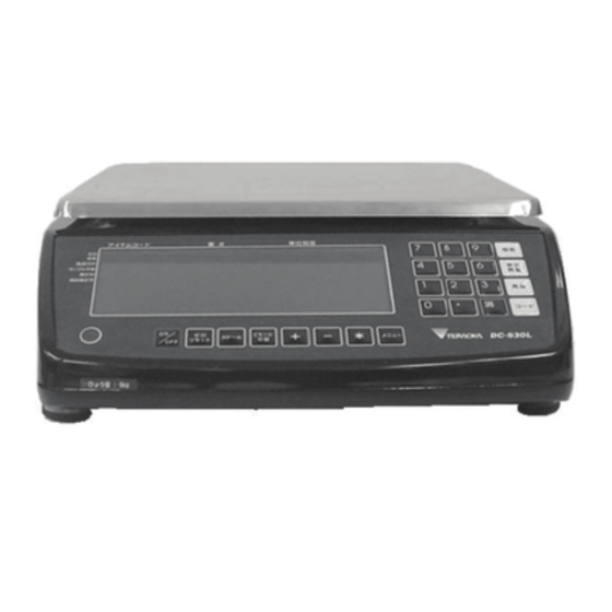
Page 8: Key Functions
1.3.4 Key Functions The DC-530 features many functions for managing item information and scale operation. Table 1-4 lists the keys and key functions of the DC-530 keyboard and keypad. Some keys have different functions depending on what mode or function you are in.
-
Page 9
Counting Mode — Used to set the Unit Weight. Program Mode — Used to register an item code being entered into memory. POUND key- Used to call up or recal an item code from memory. Table 1-4. DC-530 Key Functions Introduction… -
Page 10: Installation
8. Store the DC-530 scale box for possible future use. Repacking If the DC-530 counting scale must be returned for modification, calibration or repair, it must be properly packed with sufficient cushioning materials. Whenever possible, use the original carton when shipping the DC-530.
-
Page 11: Setting Up
1. Connect the AC power cord under the scale base as shown in Figure 2-2. Figure 2-2. AC Plug-in and ON/OFF Switch Location on Underside of DC-530 2. Plug the AC power cord into a grounded 115 VAC receptacle and switch the ON/OFF rocker switch on the bottom right-hand side of the scale to the “On”…
-
Page 12: Start-Up Screens
Once the date and time have been set, the internal clock will be maintained by the main board battery even when the DC-530 is not plugged in or turned off. The procedure below can also be used to adjust the time when moving from Standard to Daylight Savings Time or when the scale is moved to a new facility in a different time zone.
-
Page 13: Replacement Parts
All manuals and user guides at all-guides.com Replacement Parts The following table lists the part numbers and descriptions of replacement parts available for the DC-530 Counting Scale. RLWS Part Number Description 97002 Platter 97003 Platter Support (without rubber stops) 97004…
-
Page 14: Configuration Settings
Setting the specifications allows you to modify the functionality of the DC-530. Use the tables in this section to view the options you can modify. For example, if you want to deactivate the DC-530’s ability to enter Tare weights digitally, refer to the specification table and locate SPEC 35, Bit 2.
-
Page 15
010: 4800 [DEFAULT] 011: 2400 100: 1200 Parity Stop Bit Data Length RS232C1 Force Balance 00: Even [DEFAULT] 0: 1 [DEFAULT] 0: 7 [DEFAULT] 01: Odd 1: 2 1: 8 10: None 11: None Table 3-1. DC-530 Customer Specifications Configuration Settings… -
Page 16
Uni Bloc Average Sample (filter function) During Unit Weight Calculating 0: No [DEFAULT] 0: No 00: 16 samples 1: Yes 1: Yes [DEFAULT] 01: 32 samples 10: 64 samples [DEFAULT] 11: 128 samples Table 3-1. DC-530 Customer Specifications DC-530 Operation Manual… -
Page 17: Configuring Weight And Measurement Specifications (Dealer/Technician Maintenance)
PLEASE RESAMPLE” will appear. 56 — 59 not currently in use Table 3-1. DC-530 Customer Specifications Configuring Weight and Measurement Specifications (Dealer/Technician Maintenance) 1. To configure customer specifications, press the MODE key to enter the Menu Screen. 2. In the Mode Menu Screeen, hold down the REZERO key while entering 142 from the numeric keypad.
-
Page 18
100: 0.0000 Weight Decimal Point Position (Uni Bloc) (when internal count span is 1,000,000) 000: 000000 001: 00000.0 [DEFAULT] 010: 0000.00 011: 000.000 100: 00.0000 101: 0.00000 not currently in use Table 3-2. DC-530 Weight and Measurement Specifications DC-530 Operation Manual… -
Page 19
0000: No Check 1000: ± 5.0d 0001: ± 0.1d 1001: ± 10.0d 0010: ± 0.2d 0011: ± 0.3d 0100: ± 0.4d 0101: ± 0.5d [DEFAULT] 0110: ± 1.0d 0111: ± 2.0d Table 3-2. DC-530 Weight and Measurement Specifications Configuration Settings… -
Page 20
0010: ± 0.2d 0011: ± 0.3d 0100: ± 0.4d 0101: ± 0.5d [DEFAULT] 0110: ± 1.0d 0111: ± 2.0d 1000: ± 5.0d 1001: ± 10.0d 31 — 34 not currently in use Table 3-2. DC-530 Weight and Measurement Specifications DC-530 Operation Manual… -
Page 21
00: >=Net 5d & gross 21d [DEFAULT] 0: No [DEFAULT] 1: Yes [DEFAULT] 01: >=Net 1d & stable 1: Yes 10: >=Net 1d & stable & quantity=0 NOTE: For auto tare clear, 10: >=net 5d & stable Table 3-2. DC-530 Weight and Measurement Specifications Configuration Settings… -
Page 22
SPEC 36 Bit 0 — Zero Reset When Scale Change and SPEC 37 Bit 1 — Clear Tare When Re-Zero Operation are both set to 1: Yes Table 3-2. DC-530 Weight and Measurement Specifications DC-530 Operation Manual… -
Page 23
Mask Condition at Connection Check Sampling Overflow 0: No [DEFAULT] 0: No [DEFAULT] 0: kg/g 0: 1d 1: Yes 1: Yes 1: lb [DEFAULT] 1: 9d [DEFAULT] not currently in use Table 3-2. DC-530 Weight and Measurement Specifications Configuration Settings… -
Page 24: Calibration
All manuals and user guides at all-guides.com Calibration The DC-530 Counting Scale is a high-precision instrument. Although the scale needs very little maintenance, you may want to check the calibration after every month or so of normal usage. To do this you will need to have a test weight of approximately the total capacity of the scale (i.e.
-
Page 25
All manuals and user guides at all-guides.com full capacity of the scale (i.e. a 10 lb weight for 10 lb capacity scale, etc.) If the reference weight is not equal to the full capacity of the scale, it must at least be greater than 10% of the full scale capacity. Enter the value of the weight placed on the platter using the numeric keys before pressing the # [CODE] key. -
Page 26: Scale Operations
For some applications, a dual-platform scale utilizing the DC-530’s optional capability to connect a second scale may be the best selection.
-
Page 27: Teraoka Error Prediction (Tep) Function
Coupled with the DC-530’s internal counting resolution of 1/1,000,000, the TEP Function assures your precise counting of high-value items. The Mode Menu Screen The starting point for using the DC-530 scale is the Mode Menu Screen. From this screen you have four options to choose from: 1. Counting Mode — to enter the Counting Mode Screen on which weights and counts are displayed;…
-
Page 28: Digital Tare, Tare Weight Known
• SPEC 38, Bit 3 DIGITAL TARE WHEN LOADED must be set to “1: YES” in order for both One Touch Tare and Digital Tare functions to be used at the same time. • SPEC 46, Bit 3 TARE INCREASE and SPEC 46, Bit 1 OVERWRITE THE TARE must both be set to “1: YES” to allow DC-530 Operation Manual…
-
Page 29: Tare Accumulation
1. Press REZERO to zero the scale. 2. Place a number of pieces of the item to be sampled on the scale. The DC-530 assumes that you are using a 10 piece sample unless you indicate otherwise in the next step. For maximum accuracy, count the sample into your hand and then add the entire sample to the bin at one time, instead of adding them one or two at a time.
-
Page 30: Normal Counting Mode — Unit Weight Operation By Key Entry
Weight, based on the Unit Weight established by the sampling process. To store this Unit Weight in the DC-530’s memory associated with an Item Code so that you can recall it in the future, see Section 6.2. 7. To clear the Unit Weight, remove all weight from the scale platter and press the C (Clear) key.
-
Page 31: Normal Counting Mode — Part Accumulation And Part Subtraction
The scale will display the number of pieces as well as the Total Weight, based on the Unit Weight you keyed in. To store this Unit Weight in the DC-530’s memory associated with an Item Code so that you can recall it in the future, see Section 6.2.1.
-
Page 32: Normal Counting Mode — Part Subtraction
ITEM NOT FOUND information on how to program item data into the DC-530’s memory, see Section 6.1. 2. Place Container 1 (full of parts) on the scale and press the + (Plus) key to store the total in Container 1.
-
Page 33: Normal Counting Mode — Negative Counting
All manuals and user guides at all-guides.com 3. Remove Container 1 from the platform. 4. Place Container 2 (full of parts) on the scale. Press the — (Minus) key to subtract the new quantity from the total. The display will show the total which will be the difference between Container 1 and Container 2, then return to the Normal Counting Mode screen.
-
Page 34: Counting Out Of A Full Container — See Total Amount Remaining In The Container
The TEP Counting Mode is generally used for high-value parts for which you want to avoid even the generally very small counting errors introduced by sample variances. A repeated sampling procedure allows the DC-530 scale to develop weight variance plots and thereby calculate a maximum safe quantity that can be counted without error.
-
Page 35
All manuals and user guides at all-guides.com 1. Press REZERO to zero the scale. 2. Press the TEP key to enter the Teraoka Error Prediction Mode. 3. Count out a number of parts to be sampled and place them on the scale (for example 10 pieces). For maximum accuracy, count the 10 piece sample into your hand and then add the entire sample to the bin at one time, instead of adding them one or two at a time. -
Page 36
SAMPLING 9 TIMES 8. As you continue sampling, at the bottom of the display the DC-530 will show a bar graph of the Unit Weight curve it is developing. After the ninth sample, the scale’s display will turn red indicating that the sampling operation is complete. -
Page 37: Tep Mode — Unit Weight Operation By Key Entry
The scale will display the number of pieces as well as the Total Weight, based on the Unit Weight you keyed in. To store this Unit Weight in the DC-530’s memory associated with an Item Code so that you can recall it in the future, see Section 6.2.1.
-
Page 38: Tep Mode — Part Accumulation And Part Subtraction
6. When done counting this part, remove all weight from the platter and press the C (Clear) key to clear the Unit Weight. 5.6.4 TEP Mode — Part Accumulation and Part Subtraction Part accumulation and part subtraction in TEP Mode follow the same procedures as in Normal Counting Mode. Please see Section 5.5.3 DC-530 Operation Manual…
-
Page 39: Tep Mode — Negative Counting
Toggle Between Scales The external scale option for the DC-530 Counting Scale can be ordered by ordering Part #94911 at the time you purchase your scale. To toggle between Scales 1 and 2, press the SCALE key. The display will show the platform being used for weighing.
-
Page 40: Sample, Count And Print A Label
All manuals and user guides at all-guides.com Sample, Count and Print a Label NOTE: For this function to be used on the DC-530, an external printer must be connected to the scale. For more information on how to connect an external printer, see Section 7.1.
-
Page 41: Scale Programming
All manuals and user guides at all-guides.com Scale Programming The DC-530 can store information for up to 200 of the parts you count most frequently, eliminating the need for re-entering data during parts counting and greatly speeding up your counting operations.
-
Page 42
Press the + (Plus) key. The cursor will move to the field for Set Point 1. 4. You cannot edit the Scale Number field in Item Registration mode. The DC-530 will automatically set the Scale Number field to the scale the item sample was taken on. The Scale Number field can be edited in the Edit Item mode (See Section 6.2.3). -
Page 43: Updating The Record Of An Existing Item
UNIT WEIGHT key to go to the Item Programming screen. 2. Enter existing three digit Item Code for the item to be updated and press the DC-530 key. The screen will flash red and then indicate that the Item Code you have entered already exists in memory.
-
Page 44: Update An Existing Item From The Programming Mode
All manuals and user guides at all-guides.com 2. Enter the three digit Item Code for an item you have previously programmed into the DC-530’s item memory and press the # key. The scale will recall the Unit Weight and Tare Weight (if any) previously programmed for ths item.
-
Page 45
4. At the flashing cursor enter the three digit Item Code for the existing item to be updated and press the # key. The DC-530 will retrieve the data already programmed into memory for this Item Code and display it, moving the cursor to the Unit Weight field 5. -
Page 46: Deleting Item Codes
200 item memory is currently programmed. (In the example below, 25 items have already been programmed and 175 can still be entered.) 3. In the Item Programming Screen, press the 2 key to enter the Delete Item Screen. DC-530 Operation Manual…
-
Page 47
All manuals and user guides at all-guides.com 4. Enter the three digit Item Code of the item to be deleted, then press the # key to call up that item. The scale will display the information stored for that Item Code. 5. -
Page 48: Setting A General Setpoint
Setting a General Setpoint User Specifications 01 and 02 set the parameters of the DC-530’s use of any setpoints that are programmed. User Specification 01, Bits 3 and 2 — Set Point Operation, establish whether setpoints will be associated with individual Item Codes or be general or common setpoints applied to all items.
-
Page 49
All manuals and user guides at all-guides.com • Specification 02, Bit 2 — Setpoint Selection, sets whether the setpoint is programmed on the basis of pieces or weight. The default is 0: Pieces. • Specification 02, Bit 3 — Buzzer Output Type, sets whether the buzzer sounds as “Proper” or “Scare/ Over”. -
Page 50: External Devices: Printers, Pcs, Scanners And Scales
SPEC 55 — Download Print Format to 0001 The DC-530 can be connected to an external printer using the RS-232C-2 port on the scale. You can order a printer cable from the DC-530 to the LP2824 by ordering Rice Lake Part No. 64661.
-
Page 51: Printer Label Formats
SPEC 10 — RS232C2 Parity Bit/Stop Bit/Data Length to 1001 • SPEC 55 — Download Print Format to 0000 You can order a printer cable from the DC-530 to the Epson printers by ordering Rice Lake Part No. 32810. DC-530 Side Printer Side…
-
Page 52: Zebra Lp2844 Barcode Printer
Item Label, and the other for a Total Accumulation Label. Figure 7-3. Zebra Sample Weight and Count Label Without Entering or Recalling an Item Code Figure 7-4. Zebra Sample Item Label Figure 7-5. Zebra Sample Total Label When Not Entering or Recalling an Item Code DC-530 Operation Manual…
-
Page 53: Epson Tm-U220 Tape Printer
Setting the Scale Specifications for Communication to a PC The DC-530’s RS-232C-3 port (see Figure 7-1) can be used to connect the scale to a PC and output the data string to the computer. The following specifications must be set for the data transfer to take place. (For more information on setting specifications, see Section 3.0.):…
-
Page 54: Pin Assignments
All manuals and user guides at all-guides.com 7.3.3 Pin Assignments The DC-530 counting scale is connected to a PC using a 9 pin D-SUB connector configured as follows: DC-530 Side PC Side DIN8 Connector 9 PIN D-SUB (female) SIGNAL SIGNAL 7.3.4…
-
Page 55: Output Data Formats With Headers
All manuals and user guides at all-guides.com 7.3.5 Output Data Formats With Headers The DC-530 can output two types of headers — Header Codes and Titles. The data transmission string format when output with Header Codes is as follows: HEADER…
-
Page 56: Setpoint Connector
Table 7-2. Setpoint Connector Pin Assignments Bar Code Scanner A laser scanner allows for instantaneous and accurate input of basic data for an item. The DC-530 has bar code scanning capabilities by plugging the optional QS-6000 Bar Code Scanner (Part No. 65619) into the RS232C-1 port on the scale (see Figure 7-1).
-
Page 57: Remote Scale Channel
Remote Scale Channel The Remote Scale option for the DC-530 can be ordered as Rice Lake Part No. 9491. When this option is installed, a remote scale platform can be connected at the right-hand side of the ports and connectors strip on the back of the DC-530.
-
Page 58: Remote Platforms Available
17″ x 21″ (DIGI S-TL Platform) 1500.0 lbs 24″ x 28″ (DIGI S-UL Platform) 2500.0 lbs 36″ x 36” or 48″ x 48″ (DIGI Summit 3000 Platform) 5000.0 lbs 48″ x 48″ (DIGI Summit 3000 Platform) 10000.0 lbs 48″ x 48″ or 60″ x 60″ (DIGI Summit 3000 Platform) 25000.0 lbs…
-
Page 59: Appendices
Appendices Error Message List The DC-530’s alphanumeric display allows for detailed error messages. Use Table 8-1 below to find the error message, possible causes for the error and ways to correct the problem. If these suggestions fail to correct the situation, please contact your DIGI dealer for assistance.
-
Page 60: Troubleshooting
Also make sure that the scale is on a stable surface. Move the scale to another location if necessary. Table 8-2. Solutions in Troubleshooting DC-530 Operation Manual…
-
Page 61: Specifications
All manuals and user guides at all-guides.com Specifications Operating Conditions • Operating Temperature- -10°C ~ +40°C (OIML) • Operating Humidity — 15%~ 85% RH Electrical Specifications • Power Source — AC117/100V • Charge Current — 800 mA • Main Board Backup Battery-Lithium rechargeable battery for data protection •…
-
Page 62: Dc-530 Limited Warranty
All manuals and user guides at all-guides.com DC-530 Limited Warranty Rice Lake Weighing Systems (RLWS) warrants that all RLWS equipment and systems properly installed by a Distributor or Original Equipment Manufacturer (OEM) will operate per written specifications as confirmed by the Distributor/OEM and accepted by RLWS.
Инструкция по предпродажной подготовке
весов DIGI DS-708.
- Распаковать весы.
- Проверить весы на наличие механических повреждений.
- Сверить заводской номер.
- Если в зимнее время весы находились на неотапливаемом складе или транспортировались, дать им прогреться в выключенном состоянии не менее 2-х часов.
- Выкрутить транспортные болты. Эти болты (с резьбой М6) находятся на нижней стороне весов в одном из углублений (Это углубление – самое большое). Один болт – анкерный под шестигранный ключ. Второй – на самом деле шпилька с контргайкой «на 10» и анкерным отверстием в торце. ВНИМАНИЕ! Если транспортные винты не вывернуты, при включении весы в рабочий режим не выйдут, во всех разрядах индикатора будет высвечиваться цифра 8. Попытка откалибровать весы с невывернутыми болтами приведет к выдаче сообщения об ошибке при калибровке нуля.
- Включить весы. Во время теста дисплея проверить исправность всех сегментов индикаторов. Об окончании теста свидетельствует индикация нулей в разрядах.
- Перейти в режим служебных настроек.
- Установите SPEC-и согласно таблице приведённой ниже:
Для переключения служебного переключателя ввернуть болт М4×11,5 в отверстие в середине передней части дна весов. Для этого можно использовать болт вкрученный в отверстие в углублении.
 SPAN switch
Болт для переключения SPAN switch
Клавишей «» выбирается разряд SPEC-а, клавишей «» – значение этого разряда [*] ввод нового значения и переход к следующему спеку .
|
Вход в режим установки SPEC-ов от 0 ÷ 3. Удерживая |
|
|
00 |
0000 |
|
01 |
0101 |
|
02 |
1000 |
|
03 |
0000 |
|
Нажмите «Т» для выхода из режима установки SPEC-ов. |
|
|
Вход в режим установки SPEC-ов от 4÷ 19. Выключите весы. Отверните четыре болта с задней стороны по углам пластмассового корпуса индикатора и переведите переключатель SPAN SWITCH (см. Рис1) в положение ON. Для входа в меню сервисных настроек нажмите |
|
|
04 |
1001 |
|
05 |
1101 |
|
06 |
0100 |
|
07 |
0000 |
|
08 |
1000 |
|
09 |
1001 |
|
10 |
0000 |
|
11 |
0011 |
|
12 |
Для 6кг – 0001 Для 15кг – 0010 Для 30кг — 0011 |
|
13 |
0101 |
|
14 |
1001 |
|
15 |
0000 |
|
16 |
0000 |
|
17 |
1000 |
|
18 |
0000 |
|
19 |
0000 |
|
Нажмите «Т» для выхода из режима установки SPEC-ов. |
 нажмите последовательно [ ← ] [ ← ] [ ← ]
 и удерживая данную клавишу нажмите последовательно [ ← ] [ T ] [ ← ]
Проверьте исправность сегментов индикатора. С помощью эталонных гирь проверьте показания весов на максимальном пределе измерения. С помощью гирь весом от 20d проверьте правильность показаний индикатора при установке гири по углам платформы. При правильных показаниях перейдите к пункту 11.
Стандартная калибровка (SPEC 12 BIT3=”0”)
Перед началом калибровки установите платформу по уровню, очистите платформу от посторонних предметов и убедитесь, что за платформу ни чего не задевает.
Индикация: ( ● Горит постоянно ○ Мигает )
1:ZERO(ноль) 2:NET(тара) 3:Вес стабилен ( ~ ) 4:M(память) 5:Удерживание 6:Kг/Фунт
|
Действия |
Дисплей |
Индикаторы |
Примечания |
|||||
|
Весовой |
1 |
2 |
3 |
4 |
5 |
6 |
||
| Режим взвешивания |
0.00 |
● |
● |
После стабилизации веса | ||||
Удерживая нажмите [←][ T ][ T ] нажмите [←][ T ][ T ] |
888888 |
● |
● |
|||||
|
CAL |
● |
● |
||||||
|
15.000 |
○ |
● |
Отображается калибровочный вес. | |||||
| Используя клавиши [←] и [↑] введите используемый Вами калибровочный вес. |
5.000 |
○ |
● |
[←] – Выбор разряда [↑] – Установка значения |
||||
| Нажмите [ * ] |
5.000 |
○ |
● |
Ввод введенного значения | ||||
| Нажмите [ * ] |
CAL 0 |
○ |
● |
Калибровка нуля. | ||||
|
—— |
Может занять несколько минут | |||||||
| Установите калибровочный вес на геометрический центр платформы и нажмите [ * ] |
CAL SP |
● |
||||||
|
—— |
Калибровка нагруженной платформы. Может занять несколько минут. | |||||||
| Уберите калибровочный вес с платформы. |
5.000 |
● |
||||||
| Режим взвешивания |
0.00 |
● |
● |
После стабилизации веса |
*Примечание:
- Ds-708 может быть откалиброван весом не ниже 10% НПВ, оптимальная точность калибровки достигается при условии что калибровочный вес = НПВ.
- SPAN Switch должен быть в положении ON.
ВНИМАНИЕ! Если калибровка весов не производится, необходимо посмотреть данные АЦП. Они должны быть постоянны, если на платформу не оказывается воздействие.
Проверка внутреннего разрешения и показаний АЦП.
Индикация: ( ● Горит постоянно ○ Мигает )
1:ZERO(ноль) 2:NET(тара) 3:Вес стабилен ( ~ ) 4:M(память) 5:Удерживание 6:Kг/Фунт
|
Действия |
Дисплей |
Индикаторы |
Примечания |
|||||
|
Весовой |
1 |
2 |
3 |
4 |
5 |
6 |
||
| Режим взвешивания |
0.00 |
● |
● |
После стабилизации веса | ||||
Удерживая нажмите [←][←][ T ] нажмите [←][←][ T ] |
888888 |
● |
● |
|||||
|
0 |
● |
● |
Дисплей показаний АЦП. При пустой платформе значение = 0 | |||||
|
Нажмите [↑] |
15012 |
● |
● |
Дисплей показаний внутреннего разрешения. | ||||
|
Нажмите [ T ] для выхода из данного режима и перехода в режим взвешивания. |
0.00 |
● |
● |
Если весы имеют интерфейс, то проверьте исправность интерфейса RS-232. Для этого выключите весы и подсоедините интерфейсный кабель к COM-порту компьютера. Запустите программу Norton Terminal, выберите тип терминала «HEX» и настройте параметры порта следующим образом: 9600 бит/с, 8 инф. бит, 1 стоп, без четности. ВНИМАНИЕ! Указанные выше параметры последовательного порта соответствуют настройкам весов, вводимых производителем. При необходимости работы с другими параметрами последовательного порта следует выставить соответствующим образом настройки весов (SPEC’и). См. инструкцию по эксплуатации. Включите весы. Поставьте на платформы гирю (например, весом 5 кг), нажмите на кнопку «Т». Поставьте на платформу вторую гирю (например, весом 10 кг), не снимая первой. В правой части Norton Terminal’а должны появляться строки вида: «0010.00.0050.00.»
Выключите весы. Ввинтите в резьбовое отверстие, через которое нажимается кнопка Span Button, самый короткий болт с отверстием в головке (этот и последующий болты берутся из прилагаемого к весам комплекта). Вывинтите винт крепления корпуса весов из расположенного рядом отверстия и ввинтите вместо него самый длинный болт с отверстием в головке. Эти два болта предназначены для пломбирования при поверке весов. Опломбируйте весы.
Упакуйте весы.
Вложите в коробку весов:
- Инструкцию пользователя на Русском языке [предварительно отпечатать на принтере и скрепить бендером].
- Поверочный лист с отметкой о поверке весовой платформы данного типа.
- Копию сертификата соответствия. Упакуйте весы.
Примечание:
В поверочный лист необходимо вписать, параметры данной весовой платформы, серийный номер весовой платформы.
(Ocr-Read Summary of Contents of some pages of the Digi SM-5000BS Document (Main Content), UPD: 03 March 2023)
-
81, SM-5500 Series_SM-5000BS Service Manual 3 rd Edition 75 9) Waiting for connecting the server. 10) In SVGA Customer Display menu, touch [SETUP] to go to server setup mode. 11) In server setup mode, touch the Layout column will show the layout listing and select the layout. 12) Touch and hold the scrolling bar to adjust the speaker volume.
… -
194, Digi SM-5000BS SM-5500 Series_SM-5000BS Service Manual 3 rd Edition 188 12. PORT PIN CONFIGURATION AND CABLE 12.1 Ethernet Port Straight cable is for Client / Server connection. Crossover cable is for Hub-to-Hub connection. (Some models of the Hub do not need crossover cable for Hub-to-Hub connection. Please refer to the Hub operation manual if in doubt) Preferable type: CviLux Preferable type: CviLux CJP3 / CviL…
-
58, SM-5500 Series_SM-5000BS Service Manual 3 rd Edition 52 5) Select [SAVE] button to save the changed setting. 5.5.5 Weigh & Measure SPEC Procedure Picture 1) In Registration mode, select [MENU] [MAINTENANCE] [MAINTENANCE] [SCALE] [W&M SPEC] to go to W&M (Weigh & Measure) SPEC mo…
-
116, SM-5500 Series_SM-5000BS Service Manual 3 rd Edition 110 5) Keying password [teraoka] (invisible) and press [Enter]. 6) Keying command [cd /opt/pcscale] and press [Enter] button. 7) Keying the write checksum command and press [Enter] button. Note: a) From STD structure screen software to New structure screen software conversion. Write Checksum Command is: ./wrtchksum b) From New str…
-
158, Digi SM-5000BS SM-5500 Series_SM-5000BS Service Manual 3 rd Edition 152 9.4.3 Disassembly of Display Board and Operator (8.4” TFT LCD) Display Screw Type: 101 – Sems B M4x20 102 – Hex Cap M4x12 102 Case AG (2 ND Hinge BTM) 440167023007XX 102 101 101 Case AB (Hinge Top) 440167023002XX Step 2: Step 1:
… -
209, SM-5500 Series_SM-5000BS Service Manual 3 rd Edition 203 21: F6 F6 22: F7 F7 23: F8 F8 141b111: Alternate Label Format When THD Diagnostic Failed (*SM5500) 0: Not Use 1: F1 2 : F2 3: F3 4: F4 5: F5 6: F6 7: F7 8: F8 Current Format + Offset 30 141b115: Auto Print Status In Label Format By Function Key. 0: Disable 1: Enable 13.3.3.7 Nutrition 141b081: Print Position For Serving Size And Serving Container …
-
48, SM-5500 Series_SM-5000BS Service Manual 3 rd Edition 42 5.4 Cassette Loading 5.4.1 Label Printing 5.4.2 Receipt Printing 5.4.3 Linerless Label Printing ( ) ( ) Label: ( Δ X) These stickers are paste and set as the default factory setting. Receipt: (O) This sticker is given together with the accessory items, for customer to set as an option. Paste the sticker to the third hole without removi…
-
137, SM-5500 Series_SM-5000BS Service Manual 3 rd Edition 131 9.1.6 Disassembly of Display Board and Operator (8.4” TFT LCD) Display Screw Type: 101 – Truss Head M4x6 102 – Sems B M3x6 101 Cover AO (SMIC-28-2) 440155028015X X 101 101 101 102 Case AA (SM1C-21-2) 4401550230…
-
109, SM-5500 Series_SM-5000BS Service Manual 3 rd Edition 103 Note: i. Sometime the cash drawer not opening maybe is the powers energize not enough, when this case happening can try to set the different value e.g. [100ms] in Drawer1 Open Pulse Width. ii. This scale are allow to support 2 unit cash drawer at the same time in 1 cash drawer port, but need to using special cable for connecting 2 unit. …
-
126, SM-5500 Series_SM-5000BS Service Manual 3 rd Edition 120 25) Waiting for process sending file until completed. 26) When completed the monitor will show RedBoot>. Keying command [fis write –f 0xa03f0000 –b 0x100000 –l 0x10000] and press keyboard [Enter] button. 27) When confirmation displayed, keying [y] and press keyboard [Enter] button. 28) Waiting processing until completed. …
-
35, SM-5500 Series_SM-5000BS Service Manual 3 rd Edition 29 MULTI BARCODE COMMUNICATION LABEL RECEIPT SETTING PASSWORD E-LABEL & HI TOUCH QUEUE SYSTEM & TURN CHIME MODULE SPEC OTHER SCALE PRICE SCALE TARE SCALE TAX SCALE SPEC SCALE OPERATION SCALE SUBCPU DATABASE BOOT FLASH OS VERSION MEMORY SYSTEM INFO DISK SPACE OFF Switch off the power supply …
-
162, SM-5500 Series_SM-5000BS Service Manual 3 rd Edition 156 9.4.5 Disassembly of Receipt & Cutter Controller Board and 2 nd Printer Screw Type: 101 – Sems B M4x8 102 – Sems B M4x6 102 102 101 101 101 101 101 101 2 n d Printer Front Cover 2 n d Printer Kit Step 2: Step 1:
… -
120, SM-5500 Series_SM-5000BS Service Manual 3 rd Edition 114 7. Close the printer door by pushing at the lower area of the printer door until a lock sound is heard. Refer to diagram below: 8. Turn ON the scale, and depress [FEED] key to feed label/receipt. 7.8.2 Basic Cleaning Clean scale surfaces and platter periodically with a soft damp cloth. Do not use alcohol or detergent. …
-
151, SM-5500 Series_SM-5000BS Service Manual 3 rd Edition 145 101 101 101 101 101 Customer Display Kit Screw Type: 101 – Sems B M4x8 102 – Sems B M4x6 102 102 Step 6: Step 5:
… -
167, Digi SM-5000BS SM-5500 Series_SM-5000BS Service Manual 3 rd Edition 161 9.5 SM-5000BS 9.5.1 Disassembly of Platter Support 9.5.2 Disassembly of Pole Block Support BG (Plate 5000) 440155088033X X Platter Screw Type: 101 – Sems B M4x10 101 101 101 101 Cover AB (Pole Bottom) 4401167028002X X 101 101 Leg AB (SM56-B34) 440155053002XX Screw Type: 101 – P-P Tapping M4x8 Step 1:
… -
185, SM-5500 Series_SM-5000BS Service Manual 3 rd Edition 179 Connector Function CN2 For Wireless Bridge (AP2001G) CN3 USB Keyboard / Mouse CN4 Debug Port Connector CN5 Customer Display Connector CN6 Ethernet Connector (RJ45) CN7 Operator Display Connector CN8 2 ND VGA Boa…
-
4, 9.2.4 Disassembly of CPU & Base Board…………………………………………………………………………135 9.2.5 Disassembly of Top Cover……………………………………………………………………………………..136 9.2.6 Disassembly of Power Supply Unit and AD Board …………………………………………………….137 9.2.7 Disassembly of Load Cell …………………………………………………………….…
-
198, SM-5500 Series_SM-5000BS Service Manual 3 rd Edition 192 142A021 Capacity of Load Cells If SPEC142E031 =00 ( 1/3000) 0: 6 Kg 1: 15 Kg 2: 30 Kg 3: 15 Kg (1/7500) * — single range only If SPEC142E031 =01 ( 1/6000) 0: 6 Kg — single range only 1: Not Used 2: 30 Kg — single range only 3: Not Used If SPEC142E031 =10 ( 1/7500…