
![]()
Schmitz Cargobull Trailer Services Technology
Schmitz Cargobull Trailer Services Technology
Owner s Manual. Semitrailer container. T
Adobe Acrobat Document
5.0 MB
![]()
Schmitz Cargobull Trailer
Schmitz Cargobull Trailer
2m2h4viy9w6dwg4a.pdf
Adobe Acrobat Document
9.3 MB
The German company Schmitz Cargobull AG is one of the most famous manufacturers of semi-trailers and trailers.
Distinctive features of products manufactured under this brand are the following: a wide range, traditional German quality, constant updating and improvement of the model range. The leading
position of the company on the world market makes it worthwhile to take a closer look at trailers and semi-trailers from Schmitz Cargobull.
The Schmitz Cargobull AG model line includes several types of semi-trailers. The most requested ones include:
1. Vans. They are used to transport various goods — from frozen or fresh products to furniture, clothing and other various goods. Depending on the functional purpose, they are divided into
several subspecies: isothermal semi-trailer with additional thermal insulation; refrigerators Schmitz with a full-fledged refrigeration unit; conventional body vans of a universal orientation.
2. Curtains. The characteristic features of this type of trailers and semi-trailers are a strong metal supporting frame of the van, covered with an awning, which can be quickly and easily removed
from one of the sides. The result is high speed and convenience in loading and unloading operations, thereby minimizing downtime. The end part of the trailer is equipped with metal swing gates,
which also contributes to the comfortable operation of the equipment.
3. Dump trucks. The company produces two types of similar products — bodies for installation on a car chassis and tipper semi-trailers. Their main advantage is the option, obvious from the
name, that allows you to independently unload the transported materials or goods. The main areas of use of such equipment are construction sites, agro-industrial enterprises and manufacturers of
building materials.
4. Container chassis. Semi-trailers are designed to transport containers of standard sizes. Their design is characterized by a modular system. It has several configuration options, which allows
you to choose the best one for the specific needs of the owner.
5. Interchangeable systems. Schmitz Cargobull swap vans are mainly used in intermodal transport, which involves the active use of rail transport. The installed equipment and the
dimensions of the semi-trailer provide a quick reloading of goods from the railway wagon to the van and back.
6. Rolling carts. They are a device for connecting a truck tractor with a semi-trailer or forming a road train. They are used for completing various trailers, including those produced by other
manufacturers.
Trailer equipment of the German company occupies a significant share of the world market. The leading position of the enterprise was the result of a combination of several factors. The main
reasons for successful activity are a combination of excellent technical and operational characteristics of the produced trailers, a high level of service and maintenance at a reasonable cost of
production. A serious additional argument in favor of buying equipment from Schmitz Cargobull is a wide and diverse range of models that allows you to find a semi-trailer of the
right size, load capacity and functionality.

Axle & Brake Service Manual
TM Series Axles including Disc and Drum Brake variants
1
2
3
4
5
APPENDIX
INDEX
Section Description
QUICK REFERENCE WARRANTY CHART
IDENTIFYING THE AXLE
Identifying the Axle Type, Identifying the Serial Number
INTRODUCTION TO THE TM AXLE RANGE
AXLE INSTALLATION
TM MAINTENANCE SCHEDULE
TECHNICAL DATA TABLES
Table 1: Fastener Torque Values
Table 2: Recommended Lubricants
Table 3: Hub Bearing Grease Fill Volumes
TM DRUM BRAKE SERVICE
TM DISC BRAKE SERVICE
TM HUB SERVICE FOR DRUM BRAKES
TM HUB SERVICE FOR DISC BRAKES
ADDITIONAL PROCEDURES
AXLE & BRAKE SERVICE FAULTS
Page
3
8
12
13
9
8
13
23
33
39
41
46
2
TM Service
TM Hubs
Any component not referred to below is covered by a 1 yr / 100,000 km warranty for mechanical failure only.
Labour costs can only be claimed at an agreed rate with ArvinMeritor Service Department prior to work commencing.
For full warranty terms and conditions see ‘ArvinMeritor Warranty Terms and Conditions’ Publication No 4.84.1
TM
1 yr / 100,000 km
Hub cap & screws
1 yr / 100,000 km
Hub cap gasket.
Mechanical failure only
1 yr / 100,000 km
Oil seal.
Mechanical failure only
TM DX195
1 yr / 100,000 km
Hub cap & screws
1 yr / 100,000 km
Hub cap & screws
3 yr / 300,000 km
Axle end fixings
3 yr / 300,000 km
TM Hub assembly
1 yr / 100,000 km
Hub cap gasket.
Mechanical failure only
1 yr / 100,000 km
Oil seal.
Mechanical failure only
1 yr / 100,000 km
Hub cap & screws
3 yr / 300,000 km
Axle end fixings
3 yr / 300,000 km
TM Hub assembly
3
TM Service
DX 195 Disc Brake for TM Axles
Any component not referred to below is covered by a 1 yr / 100,000 km warranty for mechanical failure only.
Labour costs can only be claimed at an agreed rate with ArvinMeritor Service Department prior to work commencing.
For full warranty terms and conditions see ‘ArvinMeritor Warranty Terms and Conditions’ Publication No 4.84.1
2 yrs/200,000 km
Caliper assembly
1 yr / 100,000 km
Brake retaining clips.
4
1 yr / 100,000 km
Brake pad assemblies.
Mechanical failure only
1 yr / 100,000 km
ABS components
1 yr / 100,000 km
ABS components
2 yr / 200,000 km
Brake rotor.
Mechanical Failure only
TM Service
TM Axle shown
Any component not referred to below is covered by a 1 yr / 100,000 km warranty for mechanical failure only.
Labour costs can only be claimed at an agreed rate with ArvinMeritor Service Department prior to work commencing.
For full warranty terms and conditions see ‘ArvinMeritor Warranty Terms and Conditions’ Publication No 4.84.1
1 yr / 100,000 km
Brake shoe assemblies.
Mechanical failure only 1 yr / 100,000 km
Assister spring
1 yr / 100,000 km
Retaining spring
2 yr / 200,000 km
Anchor pin assembly
1 yr / 100,000 km
ABS components
2 yr / 200,000 km
Cam bearing
1 yr / 100,000 km
ABS components
2 yr / 200,000 km
Camshaft
1 yr / 100,000 km
Return spring
5 yr / 500,000 km
Axle beam weld assembly, Ex works.
Including Flexair spring seat.
(3 yr / 300,000 km
TM beam non-
ArvinMeritor welded)
1 yr / 100,000 km
Brake shoe assemblies.
Mechanical failure only
2 yr / 200,000 km
Cam roller assembly
3 yr / 300,000 km
Brake drum. Mechanical failure only
1 yr / 100,000 km
Dust covers & screws
5
TM Service
Identifying the Axle Type
Anti-Lock Type
(Table D)
Steer Axle
Self (S)/Command (C)
T M
Axle series loading
(Table A)
Wheel fixing to suit single (S) or twin wheels (T)
Brake size and type denoted by letters
(Table B)
Number of wheel bolts either 8 or 10
Type of wheel bolts
(Table C)
Table A – TM Loading – Standard and Low Loader
Axle
Series
20,000
22,500
25,000
Nominal
Highway Axle
Rating kg
9,500
10,170
11,690
Maximum
Offset mm
460
490
490
The axle ratings shown are for normal highway applications and any special application for installation must be approved by ArvinMeritor Design Engineering.
Track – spring centres
NB: Offset =
2
TABLE C – TM WHEEL FIXING CODING CHART
Axle Letter
Code
S
M
J
MX
MXA
B
Wheel Mounting
7 ⁄
8
” BSF (SMMT)
M22mm x 1.5mm metric (DIN)
‘Trilex’ type
ISO 4107 type with M22mm x 1.5mm
wheel bolts
ISO 4107 type with M22mm x 1.5mm
wheel bolts for alloy wheels
Japanese M20 x 1.5mm
TABLE B – TM BRAKE CODING CHART
Axle Letter
Code
P
Q
ZA
Z
AA
AC
B
O
Brake
310mm x 190mm
350mm x 200mm
394mm x 180mm
420mm x 150mm
420mm x 180mm
420mm x 200mm
420mm x 220mm
380mm x 180mm Stopmaster
TABLE D – TYPE OF ANTI-LOCK SENSING
Axle Letter
Code
A
Exciter Type
60/45T
Pressed Steel
Suitable For
Grau MGX2 & MGX2E
Bendix MDR & MDRA
W 100/80T
Solid Ring
Wabco
Bosch
Grau DGX & MGX100
Bendix AL-4T
Note: Please refer to relevant anti-lock manufacturers service manual for specific service and replacement instructions.
Identifying the Serial Number
Brake Lining Type Build Month
Sequential Number
Build Year
Order Number
6
TM Service
Introduction to the TM Axles Range
AXLE BEAMS
The ROR Mark III TM Series Axle is manufactured to a very high standard of beam engineering. The beam material is heat treated to provide an excellent yield strength whilst maintaining a good ductility.
The carbon equivalent of the beam material is controlled to ensure that pre-heating is not necessary when welding per the provisions of BS
5135.
It is advisable to have ArvinMeritor Engineering Department review the application of any welded bracketry if not previously approved.
The Beam Spindles are forged and heat treated to high strength.
Quality is built-in; the whole process is self monitoring with 100% checks of critical dimensions.
All ROR beams are manufactured to ensure the beam is straight and in line. Some slight distortion will occur when spring seats are welded to the beam but in general this is negligible. If cambered beams are required – these must be ordered specially.
AIR CHAMBER BRACKETS AND CAM BRACKETS
All Mark III beams come equipped with air chamber brackets and cam brackets welded in the correct position to ensure brake actuators operate in the optimum way. Replacement beams are normally supplied without air chamber brackets or spring seats.
SPRING SEATS AND AIR SUSPENSION AXLE
ADAPTERS
ArvinMeritor can supply axles with the above components welded to individual customer requirements.
ANTI-LOCK OPTIONS
Axles can be ordered with anti-lock sensor equipment already installed and tested.
BRAKING
ArvinMeritor offers S cam brakes in three diameters – 420mm diameter as standard available in three widths, 350 and 310mm diameter for low loader applications. The brake design incorporates
ROR patented quick change brake shoes. The 380mm diameter
Stopmaster is also available.
ROR’s Mark III axles are fitted with non-asbestos brake linings.
(Effective from 1st January 1992.) Materials are capable of meeting
UK/EEC braking regulations.
As a general guide, ArvinMeritor recommends:-
TANDEM AXLE TRAILER (Normal Use)
TRI-AXLE TRAILER (Normal Use)
TANDEM AXLE TRAILER (Heavy Duty Use)
420×180 brakes
420×180 brakes
420×220 brakes
BRAKE SHOES
ROR quick-change design shoe is accurately produced by manufacturing processes ensuring all shoes are capable of being relined several times. When relined with the ROR original part the necessity to machine the linings on the axle is eliminated.
The anchor pin and roller areas are induction hardened to prevent wear.
Each shoe is coated with a rust inhibiting finish.
Every ROR shoe is marked with an ROR logo – look for this guarantee to avoid being the recipient of non-genuine lower quality shoes.
For TM Series Axles fitted with the option of Q+ brake assemblies, refer to Axle & Brake Service Manual, LM Series.
ANCHOR PINS AND BUSHES
The Mark III axle has new sealed anchor pins with indented greased bronze bushes. This unique feature keeps the pin working, providing consistent brake performance. The ‘O’ ring seals keep contaminants away from the bush area. From June 1991 all axles using 420mm brakes have a fabricated anchor bracket which has a stainless steel anchor pin bush.
CAMSHAFTS – CAMSHAFT BUSHES & SPHERICAL
BEARING ASSEMBLIES
The Mark III axle camshaft is an induction hardened one piece forging with an SAE 10 spline. It runs in bushes that are grease packed. The cam bush is bronze whilst the spherical bearing is glass-filled nylon encased in a heavy gauge steel housing. From June 1991 axles with
420 dia brakes have used a pressed steel anchor bracket with a bolton spherical bearing at the cam head end of the camshaft.
SEALS
All ROR axles contain unitized seals. These seals are suitable for either grease filled or oil filled operation. Low Loader axles use special high temperature synthetic seals to prevent leakage even when operating at elevated temperatures.
HUBS
Hubs are normally grease filled but are available oil-filled on request.
HUBODOMETERS
Available on request. Specify tyre size and Kilometers or Miles.
SLACK ADJUSTERS
ArvinMeritor will supply their own automatic slack adjuster on request.
RUBBER SEALING
From June 1991 all axles with 420mm brakes have camshaft rubber seals fitted as standard. For other brake sizes the camshaft sealing kit is available as an option.
7
TM Service
Introduction to ROR DX195
Disc Brake
The ROR DX195 Air Disc Brake is one of a family of modular high performance, low weight, high efficiency brakes designed for Trailers,
Trucks, Coaches, Buses and other Commercial vehicles.
The brake has a cast caliper, which straddles the brake rotor and houses two lining pads. Clamping force is produced by a standard industry air chamber, amplified via a high efficiency shallow throw eccentric and balance beam assembly.
The caliper is carried on a saddle which is a fixed support bolted to a torque plate on the axle beam.
Equalised clamping action on the inner and outer pads is generated by allowing the caliper to “float” on the two slide pins fixed to the saddle.
Clamping force created by the primary actuation is applied to the inner pad, which forces it into contact with the rotor. Reactive force through the caliper body applies equal clamping force to the outer “Fixed” pad.
The slide pins also allow the caliper to freely position itself on the saddle to compensate for the reduction in lining pad thickness due to wear.
Lining wear would result in correspondingly longer actuation lever throw and excessive chamber stroke. To eliminate the problem, the brake incorporates an inbuilt automatic adjustment mechanism.
The auto-adjuster operates on each clamping action to sense excessive pad-rotor clearance, and reduces excessive clearance by a fixed proportion with each actuation.
For brake set up and new lining installation, the brake incorporates provision for manual adjustment, easily made using a standard
Hexagon key.
8
TM Service
Axle Installation
INTRODUCTION
The following notes and recommendations are offered as a guide to the trailer manufacturer and service engineer. They are based on experience gained from both the manufacture and the servicing of single and multiple axle installations.
STRESSES ON AXLE BEAMS
The stresses on the axle beam under the load take two forms. The upper portion of the beam is subjected to a COMPRESSION stress equal to the TENSION stress of the lower portion. Along the beam centre is a zone of minimum stress, often named the neutral stress zone area.
Fig. 1 is a simplified sketch of the transverse section of a tubular axle and spring showing these three zones. Fig. 2 is a graphic representation of the degree of stress in the wall of the tube when the beam is under load.
When an air suspension is assembled to the axle beam of a design which uses the beam as a torsional member of the air suspension, then an additional allowance must be added to determine overall beam strength. In this application beam strength is composed of maximum load, air suspension torsional stress and braking stress. In general the
22,500 Series axle beam should be applied as a minimum rating.
ArvinMeritor Engineering should be contacted for written approval of application.
The length of the arrows “X” represents the amount of stress at a given point. From this illustration it is evident that the two opposite stresses diminish as the horizontal centre line is approached. The stress imparted by the action of braking is taken into consideration in rating axle capacity. The axle beam strength is computed by adding together the maximum load and braking stress to which the beam will be subjected. A reasonable allowance of both is then added as a safety factor.
When the axle beam is suddenly relieved of its load and torsional stresses, then torsion, compression and brake stresses are momentarily relaxed. These stresses are re-applied and reversed many times during normal axle life. For this reason, the steel from which the beam is manufactured must have certain qualities of ductility which will permit it to absorb shock, and to flex whilst retaining its calculated strength.
COMPRESSION
STRESS
NEUTRAL STRESS
AREA
TENSION STRESS
FIG. 1
X
X
X
X
FIG. 2
HOW WELDING AFFECTS BEAM MATERIAL
All welds made on the beam create, in effect, an extreme local heat treatment. The heat generated by the weld causes the material immediately adjacent to the weld to become hardened, substituting the undesirable characteristic of brittleness for the original and desirable quality of ductility. This small hardened area becomes the weakest part of the tube creating a notch effect.
Since the same characteristics of relative stress apply in both cases it can be seen that the loss of strength at the weld area can cause failure. The notch can be at the bottom of the beam as well as at the top. Either case is at the maximum stress location.
Some welding tips to minimise the notch effect:
1. Make all “tack” welds at least one inch long.
2. Keep the number of tack welds to a minimum – if possible clamp the bracket tightly to the beam and eliminate tack welds.
3. If more than one bead of weld is required make the second run
(third etc) runs with different start points and BEFORE the first run cools down (descaling between runs of course).
4. Remove oil, and if possible paint from surfaces to be joined.
RECOMMENDED LOCATION OF WELDS
Fig. 3 illustrates the recommended location of the weld fillet for round beams. All welds should be located in the area of minimum stress. The direction of welding should be as near the horizontal as possible.
Welding around the corners of brackets or spring seats should be avoided. It is important that all welds should be excluded from an area of 50º of either side of the bottom vertical centre line of the beam.
Avoid welds of a circumferential nature on the lower half of the beam.
Where the brackets fit down the side of the beam they should have a corner radius of approximately 1” (25mm). The purpose of this radius is to avoid local concentration of stress.
The illustrations show the recommended weld location for the various parts to be attached to the axle beam. None of these parts has been welded to the beam at points of maximum stress.
The welding rod used should meet BS 639 and BS 1719 (British
Standard) specification. They should not be broken at the end of the fillet, instead the electrode should be “backed-up” to fill the crater that would otherwise remain.
9
TM Service
Use the voltage and amperage recommended by the electrode manufacturers. This will provide the best fusion and strongest weld and will minimise the detrimental side effects such as localised hardening and residual stress. Deposit the required amount of metal with the least number of passes practicable – one pass to be preferred. If a second pass is required first thoroughly clean the weld.
MOST IMPORTANT
1. Do not test the arc on the axle beam or springs.
2. Fillet welds up to 12mm (1⁄2”) can be used on round axle beams and the attachment should fit as close as possible to avoid excessive welding – minimum recommended fitted weld 8mm
(5⁄16”) where practicable. It is important to remove all scale in fillet welds prior to painting. If this is not adhered to it will precipitate corrosion in these important weld areas.
MIN
50°
50°
MIN
3.75” (95mm)
NO WELD
NO WELD
MAX
WELD
AREA
FIG. 3
10
TM Service
TM Axle Maintenance Schedule
SERVICE ROUTINE
TM – Disc & Drum
CHECK BRAKE ADJUSTMENT AND
CHECK WHEEL NUT TORQUES
TM – Drum
LUBRICATE CAMSHAFT BEARINGS
CHECK BRAKE ADJUSTMENT
CHECK OIL LEVEL (OIL FILLED HUBS)
TM – Drum
BRAKE INSPECTION & SERVICE
TM – Disc
BRAKE INSPECTION & SERVICE
TM – Disc & Drum
HUB AND BEARING INSPECTION:
INCLUDING OIL SEAL REPLACEMENT,
HUB CAP GASKET REPLACEMENT AND
HUB OIL RENEWAL (WHERE APPLICABLE)
TM – Disc & Drum
MAJOR HUB SERVICE
FREQUENCY
• Before entering service.
• After 150 km.
• After 1500 km.
• Every 3 months.
• After any wheel fixing removal.
• After any brake service.
• Recommended maximum at 3 monthly intervals.
Note: If other than ROR Brake Lubricant Total Fina is used or where vehicles are in contact with severe abrasives a max of 6 week interval necessary.
• Linings should be inspected every 6 weeks or 25,000 kms and must be replaced as an axle set if worn down to the wear indicator (8mm).
Full stripdown should be prior to 2nd annual test or at 1st reline, whichever is soonest.
THEN
Annually or at every subsequent brake reline. Whichever is most frequent.
• Pads, caliper and rotor should be inspected every 50,000 kms or
3 months. Pads must be replaced when worn to a minimum lining thickness of 3mm. Always replace pads as an axle set.
At intervals of 100,000 kms, or every 6 months, (preferably when changing pads), the opportunity should be taken to remove any accumulations of wear debris and rust from the edge of the rotor, and from the pad location points in the caliper. Check also condition and location of sealing boots.
The above service intervals are recommended maximums under normal operating conditions. Unusual ambient temperatures or adverse operating conditions (e.g. dusty atmospheres or severe gradients) will require more frequent service intervals. It is the responsibility of the vehicle operator to establish these intervals.
• Whenever hubs are removed from axle.
• Annually after 1st major hub overhaul.
• If a problem is found during inspection.
• Prior to 2nd annual test or after 200,000 km, whichever occurs first.
THEN
Annually or subsequent 100,000 km intervals, whichever is most frequent.
11
TM Service
Technical Data Tables
TABLE 1:
FASTENER TORQUE VALUES – DRUM/DISC BRAKE
Hub cap – grease . . . . . . . . . . . . . . . . . . . . . . . . . . . . . . . . . . . . . . . . . . . . . .16-30 Nm
Hub cap – oil . . . . . . . . . . . . . . . . . . . . . . . . . . . . . . . . . . . . . . . . . . . . . . . . .25-30 Nm
Dust covers – forged A/Bkt . . . . . . . . . . . . . . . . . . . . . . . . . . . . . . . . . . . . . . .16-30 Nm
Dust covers – pressed A/Bkt . . . . . . . . . . . . . . . . . . . . . . . . . . . . . . . . . . . . . .50-60 Nm
Spherical bearing (spline end) . . . . . . . . . . . . . . . . . . . . . . . . . . . . . . . . . . . . .50-60 Nm
Spherical bearing (cam head end) . . . . . . . . . . . . . . . . . . . . . . . . . . . . . . . . . .50-60 Nm
ABS sensor . . . . . . . . . . . . . . . . . . . . . . . . . . . . . . . . . . . . . . . . . . . . . . . . . .7.5-11 Nm
ABS exciter ring (310-350 brakes) . . . . . . . . . . . . . . . . . . . . . . . . . . . . . . . . .7.5-11 Nm
Axle adjustment nut . . . . . . . . . . . . . . . . . . . . . .Refer to Setting Procedure, Section 3.11
Axle lock nut . . . . . . . . . . . . . . . . . . . . . . . . . . . . . . . . . . . . . . . . . . . . . . .350-375 Nm
TABLE 2:
FASTENER TORQUE VALUES – DISC BRAKE ONLY
Rotor flange bolts . . . . . . . . . . . . . . . . . . . . . . . . . . . . . . . . . . . . . . . . . . . 230/270 Nm
Caliper retaining bolts . . . . . . . . . . . . . . . . . . . . . . . . . . . . . . . . . . . . . . . . 280/320 Nm
Blanking plug adjuster access . . . . . . . . . . . . . . . . . . . . . . . . . . . . . . . . . . . . 10/17 Nm
Lever clamp bolt/nut . . . . . . . . . . . . . . . . . . . . . . . . . . . . . . . . . . . . . . . . . . . 31/37 Nm
Air chamber nuts . . . . . . . . . . . . . . . . . . . . . . . . . . . . . . . . . . . . . . . . . . . . 175-200 Nm
TABLE 3:
RECOMMENDED LUBRICANTS
Manufacturer
ROR Hub Grease
Shell
Mobil
Castrol
Texaco
Total
B.P.
Esso
Silkoline
Eurol
Axel Christiernsson
Fina
SKF
GB Lubricants
Grease Filled Hub
Blue Lithium EP2
Shell Calithia EP2T
Shell Alvania EP (LF)2
Mobilux EP2
Spheerol EPL2
Multifak EP2
Multis EP2
L.S. EP2
Beacon EP2
Silkoline G62
Universalfett EP2
Lithac 162EP
Marson EPL2
LGEP2
GB Lithium EP2
Brake Components and Camshaft Bearings:
ROR Brake Lubricant – (Total Fina CERAN WRC2)
Spindle Bearing Journal:
Optimol Optimoly White Paste T
Oil Filled Hub
Spirax EP90
Mobilube GX90
Castrol Hypoy EP90
Multigear EP85W/90
Total EP90
Gear Oil 90EP
GX 85/90
TABLE 4:
HUB & BEARING GREASE FILL VOLUMES
Hub Cavity . . . . . . . . . . . . . . . . . . . . . . . . . . . . . . . . . . . . . . . . . . . . . . . . . 200-250 gm
Inner Bearing . . . . . . . . . . . . . . . . . . . . . . . . . . . . . . . . . . . . . . . . . . . . . . . . . 45-50 gm
Outer Bearing . . . . . . . . . . . . . . . . . . . . . . . . . . . . . . . . . . . . . . . . . . . . . . . . 45-50 gm
Hub Cap . . . . . . . . . . . . . . . . . . . . . . . . . . . . . . . . . . . . . . . . . . . . . . . . . . . . . . . . . . Nil
12
TM Service
Section 1
TM Drum Brake Service
13
TM Service
SECTION 1
Major Brake Service
Braking can be divided into sub-systems each requiring maintenance to ensure correct performance:
The Air System
The Foundation Brakes
The Brake Actuation
The Load Sensing/Anti-Lock System
The Air System
Since April 1983 it has been a legal requirement to fit air pressure test points at the following points in the air system.
1) Each side of the load sensing valve.
2) The slowest brake actuator to respond when the brakes are applied.
In addition to these some trailer manufacturers fit a test point close to the air reservoir.
With the aid of an air pressure test gauge (21214100) and connecting hose (21214101) the air pressure can be checked at the test points.
The air pressure, measured at the test point close to one of the brake chambers, should reach 6.5 to 7.5 bar with maximum application of the tractor brakes. If a load sensing valve is fitted it will be necessary to either have the trailer loaded to capacity or disconnect the load sensing valve linkage at the axle.
If the pressure reading is not reached then disconnect the trailer’s yellow line and with a suitable coupling measure the air pressure at the yellow coupling. If there is ample pressure at this point the fault lies in the trailer air system and must be traced and rectified.
The Foundation Brakes
420mm, 350mm, 310mm.
The Brake Actuation
1.1 REMOVING BRAKE SHOES – SERIES III
Using a screwdriver between brake shoe gussets ease out both retainer springs (Fig. 1).
Take hold of bottom shoe pulling it off the anchor pin, tilt forward and lift off camshaft head (Fig. 2).
Remove brake return spring.
Lift off top shoe.
1.2 INSPECTION
Inspect brake anchor pins and bushes for wear.
For Mark III anchor pins – check and replace ‘O’ rings as required.
Inspect cam rollers. If removed from the brake shoe, the roller-retainer clip must be replaced by a new unit.
FIG. 1
FIG. 2
Inspect brake shoes for wear at anchor pin and cam roller at location point.
Prior to re-assembly the following parts should be lightly coated with
ROR high perfomance brake lubricant.
(i) Bores of Camshaft Bushes.
(ii) Cam Rollers and camshaft head profile.
(iii) Brake Anchor Pin bearing surfaces and holes in Brake Shoe
Gussets.
Ensure pressure greasing is carried out to the four grease nipples on each axle. Use ROR high perfomance brake lubricant.
Check brake drums for cracks, scoring or other damage.
Replace all worn parts with genuine ROR parts. The use of non-Original
ROR parts will nullify all warranty and may substantially reduce service life.
14
TM Service
1.3 RE-FITTING BRAKE SHOES 420MM & 350MM
Fit spring pins and rollers, lubricate ‘D’ holes with ROR high perfomance brake lubricant (Fig. 3).
Attach bottom shoe to spring, push down and in towards cam head, and onto anchor pin (Fig. 6).
LUBRICATE
FIG. 3
Fit anchor pins applying ROR high perfomance brake lubricant inside the anchor pin bushes (Fig. 4).
Fit both retaining springs to top shoe, with screwdriver pull spring down and ease into bottom shoe (Fig. 7).
FIG. 6
Fit top shoe and hang return spring from pin (Fig. 5).
FIG. 4
FIG. 7
IMPORTANT:
If anchor pin bushes require replacement, ArvinMeritor recommends fitting the new bronze indented bushes 21016666A sealed anchor pins
No. 21205193G and ‘O’ rings No. 21220668 (see page 20). The use of tool 21205456 is recommended as demonstrated in Fig. 8.
FIG. 5 FIG. 8
15
TM Service
1.4 RE-FITTING BRAKE SHOES 310MM
Fit spring pins and cam rollers, lubricate ‘D’ holes with ROR high perfomance brake lubricant.
Fit top shoe and hang return spring from pin (Fig. 9).
Fit both retaining springs to both shoes (Fig. 11).
FIG. 9
Attach bottom shoe to spring, push down and in towards cam head
(Fig. 10).
Lift top shoe and fit anchor pin.
Lever down bottom shoe and fit anchor pin – do not over stretch springs (Fig. 12).
FIG. 11
FIG. 12
FIG. 10
16
TM Service
1.5 REFITTING BRAKE SHOES 420MM WITH
PRESSED STEEL ANCHOR BRACKET
Lubricate as on page 15 (Fig. 3 & 4).
Brake shoe fitted with rolled roll pin (Fig. 13).
Anchor bracket with anchor pins fitted (Fig. 14).
Offer both brake shoes together to anchor bracket (Fig. 15).
Lift lower shoe into place (Fig. 16).
Fit retainer spring (Fig. 17).
FIG. 13
FIG. 14
FIG. 15
FIG. 16
FIG. 17
17
TM Service
1.6 CAMSHAFT AND BUSHINGS
1.6.1 REMOVAL
With brake shoes removed as described in previous section.
Remove slack adjuster.
Remove circlip adjacent to brake anchor bracket and withdraw camshaft. The circlip will not be fully removable until the splined end is clear of the spherical bearing.
Inspect nylon bushes or bronze bush in the anchor bracket. Remove bushes if worn.
Inspect spherical bearing for serviceability. This is a sealed assembly containing no user serviceable components.
Unscrew the securing bolts and remove the spherical bearing.
1.6.2 REPLACEMENT CAMSHAFTS
Stepped Camshafts
In use on production axles with 350 dia. brakes from October 1984 and axles fitted with 420 and 394 dia. brakes from January 1985, the stepped camshaft is stiffer in torsion, making for improved brake times and reduced air consumption, both very important under EEC/ECE braking regulations, furthermore, it is fitted as standard with a thin walled phosphor bronze bush in the anchor bracket, having superior wear and temperature characteristics to the P.E.S. bushes used with earlier designs of camshafts.
On the earlier design of camshaft (Fig. 18) both the cam and spherical bearing journals were the same diameter, with the shaft machined its full length. This camshaft was used in conjunction with two nylon cam bushes or single bronze cambush having integral ‘O’ ring seals.
The cam journal has been increased in diameter on the latest ‘stepped’ cam design (Fig. 19) specifically for use with a one piece phosphor bronze cam bush. In addition the camshaft now carries the ‘O’ ring seals (part number 21016721). This camshaft is not machined along its length with one exception, camshafts for use with the 310 x 190 brake when used with Neway air suspension. The camshaft number suffixed with an L or R for left and right hand is stamped into the shaft.
The new design can and should be used in preference to the earlier design when replacement becomes necessary. Only the phosphor bronze cam bush (part number 21209990) can be used with the new camshaft, this bush replacing the two nylon bushes.
In order to fit stepped camshafts in axles as a replacement for the earlier design of camshaft it will be necessary to use the following parts.
Camshaft bush kits containing these items are available.
Kit No. – AXL 131
1 ⁄
2 axle set suitable for T, U, TH and TM Axles pre May 1974.
Kit No. – AXL 132
1 ⁄
2 axle set suitable for TH and TM Axles after May 1974.
Fig. 20 shows the rolled spline camshaft used with 420mm brakes on axles produced from 1st January 1992 it has the pressed steel anchor braket with a bolt-on cam head spherical bearing.
This is identified by the snap ring groove in the centre of the cam head bearing journal.
Similar rolled spline camshafts without the snap ring groove were introduced on axles with 310mm and 350mm brakes.
FIG. 18
FIG. 19
FIG. 20
18
TM Service
REMOVAL OF THE 420mm CAMSHAFT
Having removed the slack adjuster the camshaft is released from the snap ring by tapping the spline end with a suitable soft faced hammer.
It is necessary for the phosphor bronze bush to be a tight press fit into the anchor bracket. Should the anchor bracket be worn (see Fig. 21) it will be necessary to machine the cam bore to accommodate the oversize phosphor bronze cam bush (part number 21213259). If it is necessary to fit oversize cam bushes the anchor bracket reamer tool should be used and is available as follows:
Part Number
21206670/1
21206670/2
21206670/4
21206670/5
21209271/1
21218572/1
21209272/1
21206670/3
Description
Cutter
Shaft
Sleeve
Pins (two required)
Jig for 310mm diameter brakes
Jig for 350mm diameter brakes
Jig for 394mm diameter brakes
Jig for 420mm diameter brakes
RECOMMENDED NOT RECOMMENDED
ArvinMeritor recommends replacing the plastic bushes with phosphor bronze. These bushes are available in four sizes.
PHOSPHOR BRONZE BUSHES
21204703 – old type camshafts
21209990 – new type “stepped” camshafts
21209623 – oversize bush for old type camshaft bores after reaming
21213259 – oversize bush for stepped camshaft
IMPORTANT:
When fitting cam bush the cross holes must be towards the cam head, as shown (Fig. 23).
FIG. 21
1.6.3 REFITTING
If it is necessary to replace the cam bushings, this can be easily done using special tool 21219919 (Fig. 22). Cam bush must be inserted from camhead side of anchor bracket.
FIG. 23
The camhead spherical bearing (Fig. 24) used on axles after June ‘91 with the pressed steel anchor bracket applies to 420mm brakes only.
Refit or replace bearing leaving bolts loose, fit the camshaft ensuring the snap ring has locked into the groove in the bearing journal. Rotate the camshaft to ensure free operation, tighten bearing bolts to the torque specified in table 1 page 12.
FIG. 22
FIG. 24
19
TM Service
1.8 ANCHOR PINS AND BUSHES
The Mark III Axle has a sealed anchor pin system. The anchor pin has two oil and heat resistant ‘O’ rings as shown in Fig. 26 and is coated with Dacromet – a zinc rich coating with excellent corrosion resistance.
The pin and ‘O’ rings are fitted into an indented bronze bush. The indents are designed to hold additional grease to lubricate the anchor pin over an extended period. An additional benefit is the ease of removing anchor pins whenever a major overhaul is carried out.
FIG. 25
Refit or replace spherical bearing leaving bolts loose. ArvinMeritor offers a new Mark III spherical bearing (Part No. 15213430) which retains its grease pack and is more durable (Fig. 25).
Fit the ‘O’ rings onto the camshaft (with old type cam fit ‘O’ ring into bush). Slide the cam head washer onto the camshaft. Slide the camshaft through the anchor bracket but not through the spherical bearing at this stage. Fit bevel washer (concave side facing anchor bracket) and circlip onto the shaft. Slide the camshaft through the spherical bearing simultaneously pushing the bevel washer and circlip up to the anchor bracket. Ensure the circlip is fitted correctly into the groove.
Rotate the cam to ensure correct alignment and free operation. Tighten the spherical bearing bolts or Powerlok screws to 50-60 Nm (30 lbf ft).
Rotate camshaft by hand to check that it moves freely. If it does not slacken spherical bearing bolts, realign camshaft and retighten bolts.
Check again for free rotation. Grease pack the spherical bearings through their grease nipples with Total Extemp or equivalent, until grease exudes from body.
1.7 SPRINGS
The return spring is an essential component for correct brake function.
It should be examined for any relaxation in the coils or any wear or notching in the hooks.
The retainer springs keep the shoes in contact with the anchorpins.
They should also be inspected for any relaxation and hook damage.
IMPORTANT:
It is strongly recommended that return and retainer springs are renewed as a matter of course during annual brake servicing.
FIG. 26
The sealed anchor pins and indented bushes are available in kit form from your ArvinMeritor Stockist and are interchangeable with earlier designs of anchor pin bushes used with quick change brake shoes.
Qty/Brake
2
4
2
Description
Anchor Pin
‘O’ Ring
Bush
Part Number
21205193G
21220668
21016666A
From June ‘91 axles with 420mm brake have a pressed steel anchor bracket which uses a stainless steel bush part number 21221028.
1.9 RELINING BRAKE SHOES
It is recommended that the correct lining be used to maintain the EEC performance levels designed and approved for your vehicle. A change in lining may substantially change the braking performance and could render the vehicle illegal. ROR linings are precisely contoured to fit ROR shoes and “bed-in” with the least number of stops.
The ROR shoe is coated with a rust inhibiting paint. When relining the shoe platform should be cleaned and recoated with a rust-proof primer.
The hardened anchor pin and cam roller location points must be inspected for damage. Renew shoe if these areas are damaged.
Part numbers for various components to suit the different camshafts are given in the following table.
Description
Cam Bush ‘O’ Ring
Cam Head Washer
Bevel Washer
Circlip
Qty/
Brake
1
1
2
2
1
Plastic Cam Bushes
OLD CAMSHAFT
Part No.
Qty/
Brake
1 21016720
21016721
21006593
21006624
99070006
1
1
1
Bronze Bush
Part No.
21016721
21006593
21006624
99070006
Qty/
Brake
2
NEW STEPPED
CAMSHAFT
Part No.
21016721
1
1
1
21202756
21202757
99070011
20
TM Service
The ROR patented series III shoe is capable of many relines. Make certain your stockist is giving you genuine ROR shoes when you exchange the original shoes. Look for the ROR logo and patent number on every shoe gusset.
1.10 BRAKE DRUMS
If, upon inspection, drums are crazed and cracked it is an indication that the brake has been running excessively hot. Fitting new drums will not correct the cause of the problem. The following list are possible causes: a. The towing vehicle is fitted with a predominance valve and it is set to make the trailer brakes do most of the check braking.
b. Badly set or malfunctioning automatic slack adjuster.
c. Use of trailer brakes ONLY to check vehicle speed during long descents.
d. The use of a non approved lining.
e. Malfunction in air actuation system (see following Section).
In all cases the use of pressure test gauges at each test point will enable you to ascertain what is happening.
Light crazing of the braking surface indicates that the drum has been overheated but does not render the drum unserviceable. However brake drums with any other damage e.g. rivet grooving, must be rectified or replaced immediately.
Re-machining of drums is permissible if surface damage is slight with the exception of the 310mm brake drum which must always be replaced. The maximum bore diameters that the drums can be machined to are:
420 – 423mm
350 – 354mm
310 – No re-machining.
Oversize cam rollers (21006610A) must be used in conjunction with remachined drums.
Drums should be clean and dry before refitting. Care should be taken with loose dust as stated in The Garage Workers’ Asbestos Code (Page
45). Replacement brake drums from ArvinMeritor are supplied with a protective coating that does not need removing before fitting.
1.11 DUST COVERS
Dust Covers are provided with inspection apertures to assess lining wear. These apertures are closed with rubber plugs which must always be replaced.
Pre June 91 Dust Covers are fixed with six M8 x 1.25 tightened to the torque specified in table 1 page 12. If additional sealing is required –
ArvinMeritor offers an optional rubber sealing kit (Fig. 27).
Included:
1. U-Shaped moulded sealing strip to close the Dust Cover around the
Cam end of the Anchor Bracket.
2. Rubber Collar to close the end of the Camshaft bush (retained with a cable tie).
3. Outer rubber collar to close the Spherical bearing assembly
(retained with a cable tie).
FIG. 27
4. Inner rubber collar to close the Spherical bearing assembly (retained by the Slack Adjuster).
From June ‘91 axles fitted with pressed steel anchor brackets, 420mm brakes only, have dust covers retained by four M10 screws tightened to the torque specified in table 1, page 12.
From August ’97 TM Series axles with 420 diameter brakes are fitted with the “LM style” dust cover.
To refit with the camshaft removed: Ensure the filler plate locating tag is engaged around the end of the anchor bracket and secure with two
M10 screws. Tighten to the torque specified in table 1, page 12.
Fit the one piece dust cover ensuring it is correctly located onto the two filler plate studs. Tighten the two M10 screws and the two M8 nuts to the torque values specified in table 1, page 12.
If the camshaft is to be refitted prior to the dust cover: Clean the full length of the camshaft prior to assembly. Slide the under-head rubber boot onto the camshaft, lightly grease the cam head journal and slide the cam head bearing onto the camshaft towards the cam head until the spring clip is ready to engage in the groove (light resistance will be felt).
Slide the inner rubber boots, cover plate and spline end spherical bearing onto the camshaft.
Ensure the faces of the anchor bracket and camshaft bracket are clean.
Pass the cam head through the key hole slot in the brake anchor bracket and slide the spline end through the cam bracket slot. Fasten both camshaft bearings in position using the M10 screws. DO NOT
FULLY TIGHTEN THE BEARING SECURING SCREWS UNTIL THE BRAKE
SHOES ARE RE-ASSEMBLED.
Ensure the filler plate locating tag is engaged around the end of the anchor bracket and secure with two M10 screws. Tighten to the torque specified in table 1, page 12.
Fit the one piece dust cover ensuring it is correctly located onto the two filler plate studs. Tighten the two M10 screws and the two M8 nuts to the torque values specified in table 1, page 12.
21
TM Service
1.12 LOAD SENSING AND ANTI-LOCK SYSTEMS
1.12.1 GENERAL
All trailers manufactured to EEC Regulations are fitted with either load sensing, anti-lock, or both systems.
Although the legislation in the UK requires that only one of the above systems is fitted ArvinMeritor recommends the use of load sensing when anti-lock is fitted for two reasons:
1. to achieve a good brake balance unladen when used with load sensed towing vehicles.
2. to minimise the risk of trailer swing should the trailer antilock system fail and revert to full braking.
Many towing vehicles are fitted with “predominance” valves to boost the trailer coupling head pressure compared to the towing vehicle’s brake pressure: some trailer brake valves also incorporate this feature.
Fitting load sensing to the trailer will minimise the adverse effects of
too much predominance, especially at low brake pressures with an unladen or lightly laden trailer.
1.12.2 LOAD SENSING SYSTEMS
The basic purpose of load sensing is to reduce the likelihood of wheels locking with different loads being carried.
The load sensing valve adjusts the air pressure according to how much weight is being carried.
All new trailers fitted with load sensing are also fitted with a plate showing the setting pressures which correspond to the laden and unladen weights.
The load sensing valve setting should be checked periodically and corrections made as necessary.
Air pressure test points are provided in the brake lines each side of the load sensing valve so that both the input and output pressures can be measured, the test point on the output side of the load sensing valve may be located close to one of the brake actuators.
With the aid of test gauges connected to both test points the air pressures can be measured and checked against the values shown on the load sensing data plate for the corresponding axle weights.
When an annual Government inspection is performed and braking is measured against the axle design weights it is important that the load sensing valve is in the fully laden position during the test.
Normally in the fully laden position the load sensing valve output pressure will equal the input pressure which on a full brake application should be between 6.5 and 7.5 bar.
To achieve this the trailer must be fully loaded. If not, the load sensing valve must be disconnected which should only be done at the test station and must be reconnected before leaving the test station.
Whenever the trailer is tested on the ‘raised’ rollers it is essential that the load sensing valve is disconnected and set fully open: i.e. laden to ensure that full brake pressure is achieved for all axles.
Always disconnect the load sensing valve linkage at the axle and not at the valve control arm (see Fig. 28).
When testing an air suspended trailer on raised rollers, it is not readily possible to disconnect an air suspension load sensing valve. Instead, a fitting can be fabricated to accept both the input and output brake lines thus by-passing the load sensing valve.
22
FIG. 28
1.12.3 ANTI-LOCK SYSTEMS
Unlike load sensing systems that adjust the brake pressure proportional to the load being carried anti-lock systems monitor wheel speed and only modulate that brake pressure when the system detects that a sensed wheel is about to lock.
All anti-lock systems have sensors and exciter rings fitted to measure the speed of two or more wheels.
If the hub and drum are removed from an axle fitted with sensors it is important to remember to push the sensor fully outwards so that the exciter ring will push it back when the hub and drum are re-fitted. This will ensure that the correct gap is re-set between the sensor and exciter ring. Refer to page 36.
All anti-lock systems incorporate a warning light which should extinguish when the trailer is in motion. If it fails to do so then a fault has developed and the system must be thoroughly checked by trained personnel using specialised test equipment. Contact the supplier of your anti-lock equipment direct.
It should be possible to achieve between 6.5 and 7.5 bar pressure in the trailer actuators on a full brake application which can be checked with the aid of a test gauge connected to the test point close to one of the brake actuators.
In addition anti-lock systems are automatically switched off at very low vehicle speeds and should not be active during brake roller tests (3-5 mph).
TM Service
Section 2
TM Disc Brake Service
23
TM Service
SECTION 2
Brake and Servicing
2.1 NOMENCLATURE
Caliper Slide Pin
Adjuster Barrel
Manual Adjustment Port
Block
Over-Ride Clutch
Actuation Eccentric
Load Plate
Adjuster Barrel Gear
Adjuster Cassette
Adjuster Bevel Gear
One-Way Clutch
Spindle Screw
FIG. 1
Eccentricity
FIG. 3
All radial loads in the eccentric shaft and block are taken through precision needle roller assemblies maintaining an efficiency of around
97%, due to the complete absence of any sliding friction in the system.
Clamping:
The caliper assembly is free to “float” on the slide pins attached to the fixed saddle. Clamping force exerted on the inner pad by the eccentric action on the balance beam creates an equal and opposite reactive force in the caliper body (Fig. 4).
This reaction provides the clamping force for the outer pad, ensuring that both pads are loaded onto the rotor with an equal force.
2.2 OPERATING PRINCIPLES:
Actuation:
Linear force from the Air Chamber is translated by lever action to rotary torque on the main actuation shaft and eccentric.
The eccentric is located in a balance beam (actuation block) and rotation of the shaft causes the block to “lift” or travel forward (Fig. 2).
Bridge
FIG. 4
Linear Input Force
FIG. 2
24
TM Service
2.3 MAIN AUTO-ADJUST PARTS
Input shaft & eccentric
Main Block
Bevel gear
Adjuster gear and barrel
Cassette
(adjuster gear train)
Torque takes up clearance
Spindle Screw
Adjustment gear segment
Load Plate
FIG. 5
2.4 AUTOMATIC ADJUSTMENT MECHANISM
Step 1:
• Actuating lever moves and eccentric shaft rotates.
• Block “lifts”, begins to move forward, carrying the adjuster sleeves and pistons (Fig. 6).
• Eccentric shaft turns within the gear plate segment – taking up clearance between tongue and shoulders (Fig. 7).
FIG. 7
NOTE:
This clearance governs the final pad/rotor running clearance, and is specific to each brake. It is vital that the correct (original) gear plate segment is retained matched to the eccentric shaft. Use of an unmatched gear plate segment, will alter the pad rotor running clearances perhaps outside of permissible limits.
STEP 2:
• Gear segment begins to turn.
• Main adjuster gear turns, in mesh with lower gear segment.
• Main adjuster drives through the one way clutch and the over-ride clutch to turn the central gear.
• Complete gear train turns, in mesh with the central gear. The adjuster barrels begin to turn.
At this stage one of two conditions will be encountered: SEE STEP 3A
OR 3B.
FIG. 6
25
TM Service
STEP 3A:
No Adjustment is required as clearance is correct
• At the point when the adjusters begin to turn, the pads contact the rotor and clamping force begins to build up.
• The clamping force generates friction in the screw threads between the adjuster sleeves and pistons, and friction under the flanged head of the adjuster sleeves. (Fig. 8).
Clamping Force
• The friction build up prevents further rotation of the adjuster sleeves – instead the over-ride clutch begins to slip. The adjuster drive train is locked by the friction in the system and no adjustment takes place. The main gear turns but does not transmit motion beyond the over-ride clutch into the adjuster train (Fig. 8).
STEP 4
Brakes Released
• When the pressure to the air chamber is relieved – the actuating lever will be retracted. The eccentric shaft and quadrant gear will reverse with the centre gear.
The one way clutch free-wheels preventing reverse transmission into the adjuster gear train and the adjuster sleeves do not move, thus holding the adjustment (Fig. 10).
Friction Build-up
Barrels Stationary
Bevel Gear Turns
Over-Ride Clutch Slips
FIG. 8
• The friction build up prevents rotation of the adjuster sleeves – instead the over-ride clutch begins to slip. The adjuster drive train is locked by the friction in the system and no adjustment takes place.
The main gear turns but does not transmit motion beyond the override clutch into the adjuster train.
STEP 3B
Adjustment is required as clearance is excessive.
• Before the pads contact the rotor, the adjuster sleeves are turned by the gear train. Rotation of the sleeves has the effect of unscrewing the adjuster piston within the sleeves thus increasing the effective length of the pistons and decreasing the travel required (Fig. 9).
Barrels Stationary
Adjustment Barrel Gears
Stationary
Bevel Gear Reverses
One-Way Clutch Slips
(No Gears Turn)
FIG. 10
Damping
• Compression springs ensure that the adjuster train has the necessary amount of predetermined friction, which prevents vibration in service from disturbing the clearance setting (Fig. 11).
Adjustment Plungers
Unscrew
Barrels Rotate
Adjustment Barrel Gears
Turn
Bevel Gear Turns
One-Way Clutch Turns
Gears
FIG. 9
• When the pads contact the rotor a clamping force is generated and this is fed back into the adjuster sleeves and pistons, generating friction in the adjuster screw threads, and friction under the flanged head of the adjuster sleeves. (Fig. 8).
26
Damping Springs
FIG. 11
TM Service
2.5 MANUAL ADJUSTMENT
Under normal operation the automatic adjustment mechanism will maintain correct pad to rotor clearance.
Provision is made for manual adjustment of the brake which may be required under the following conditions:
1) Where the pads cannot be removed due to wear on the rotor – in this case the pads will have to be retracted by back adjusting the brake.
2) Where new pads are to be fitted – it will be necessary to fully retract the adjusters to accommodate full thickness pads.
The brake is manually adjusted by turning one of the adjuster barrels by means of a 6mm standard hexagon key. The gear train will ensure that the other adjuster barrel will be turned by an equal amount.
Access for the hexagon key is gained by removal of the blanking plug
(Fig. 12) in the back plate.
FIG. 12
The adjustment direction depends on the particular installation of the brake – the handing of the eccentric, and the air chamber position.
In general, de-adjustment or “back adjustment” is achieved when the key is turned in the direction which produces load clicks. (This indicates that the torque limiter is working). Turning in the opposite direction will result in a smoother silent action, which will give positive adjustment and reduce pad to rotor clearance (Fig. 13).
NOTE:
Opening the adjusters from fully worn pad condition to fully retracted position requires approximately 20 turns.
CAUTION:
When backing the brake off stop turning the key when resistance is felt. This indicates that the adjuster pistons are fully retracted. Further turning could lock the adjuster pistons in the sleeves and cause damage to the internal components. When this resistance is felt, adjust the brake out 1/4 turn to ensure that Auto Adjustment will take place.
* DO NOT USE AN AIR GUN
2.6 BRAKE INSPECTION AND TROUBLE SHOOTING
WARNING:
Do not work under a vehicle supported only by jacks. Jacks can slip or fall over and cause serious personal injury. Support the vehicle with safety stands, block the wheels to prevent the vehicle from moving.
Inspection Schedules
Inspect the brake according to one of the following schedules. Use the schedule that gives the most frequent inspection.
• The schedule for chassis lubrication used by your fleet.
• The schedule for chassis lubrication recommended by the manufacturer of the chassis.
• At least every 3 months.
• During tyre replacement.
Inspection should include the following:
1. Stroke length: Check the adjusted chamber stroke as follows
(Fig. 14).
a. Measure the distance from the bottom of the air chamber to the centre of the large clevis pin while the brakes are released.
b. Have another person apply the brakes using 80-90 psi of air pressure.
MEASURE ADJUSTED CHAMBER STROKE
Measure this distance
FIG. 13
FIG. 14
NOTE
If the vehicle does not have an application pressure gauge, build tank pressure to 100 psi, shut off the engine, then make and hold a full brake application. This will give 80-90 psi in the air chamber.
27
TM Service
c. Measure the distance from the air chamber to the centre of the large clevis pin while the brakes are applied.
d. The difference between the measurement is the adjusted chamber stroke.
2. Pad wear: The pads must be replaced at or before the amount of pad material reaches a thickness of 2mm.
3. Anti-rattle springs: The pads have anti-rattle springs attached.
Inspect for bent, cracked or broken springs. If springs are damaged, replace with new. Refer to “Pad Removal and Replacement”.
6 Poor stopping power
• Long stopping distances
• Poor driver feel
• High brake pressures
• Lack of normal response
• Vehicle pulls to one side
7 Shimmey or brake pull
Vehicle air systems malfunction
Brakes out of adjustment
Vehicle overload
Contamination on pads
Companion brakes not working properly
Refer to 1, 2 and 6
Rotor run out and thickness variation
4. Seals: Caliper should be replaced if any of the seals are found to be cracked, torn or damaged in any way.
5. Caliper slides freely on slide pins: Clearance between the rotor and the pad should be transferred from the inboard rotor surface to the outboard rotor surface by sliding the caliper back and forth.
6. Disc (Rotor): Inspect the rotor for cracks, deep scores or other damage. Replace the rotor when necessary.
Inspection and Troubleshooting
CONDITION
1 Air Chamber exceeds 50mm maximum stroke requirement at 80 to 90 psi
2 Brake Drag
POSSIBLE CAUSES
Improper initial adjustment or inoperative automatic adjuster
Incorrect pad to rotor clearance
3 Short outboard/inboard pad life
CHECK FOR
Recheck chamber stroke after twenty brake applications.
CORRECTIONS
If the air chamber still overstrokes then replace the caliper/saddle assembly per
Section 2.9
Replace caliper/saddle assembly Minimum stroke at 80-90 psi to be
22mm
Improper initial adjustment
Vehicle air system malfunction
Readjust per Section 2.7
Repair or replace parts as required
Caliper seized or sticking on slide pins
Damaged slide pin seals
Caliper should move back and forth by hand with pads removed
Replace caliper/saddle assembly
4 Short pad life
5 Brake smoking
Refer to 2 and 3
Abusive use of brake system
Rotor surface
Non genuine pads
Vehicle overload
Companion brakes not working properly
High brake temperature
Contamination of pads
Refer to 2 and 3
Driver technique
Refer to 2 and 3
Train drivers
Cracks or heavy heat checking. Refer to Section 2.8
Refer to Section 2.8 for rotor inspection
See GAWR limitations on vehicle I.D.
plate.
Inspect companion vehicles brakes and air systems
Refer to 2, 3 and 4
Grease, oil etc., on pads
Fit ROR pads
Observe vehicle manufacturers load recommendations
Adjust or repair as required
Refer to 2, 3 and 4
Inspect hub seal. Replace as required. Clean rotor and caliper assembly. Replace pads per Section 2.7
Proper air pressure at the chamber inlet
Stroke exceeds 50mm requirement
Have the air system evaluated by a qualified brake system specialist
Replace caliper/saddle assembly.
Refer to Section 2.9
See GAWR limitations on vehicle I.D.
plate
Grease, oil etc., on pads
Observe vehicle manufacturer’s load recommendations
Inspect hub seal and replace pads per
Section 2.7
Adjust or repair as required Inspect companion vehicle brakes and air system
Refer to 1, 2 and 6 Refer to 1, 2 and 6
Replace hub and rotor assembly
28
TM Service
2.7 PAD REMOVAL AND REPLACEMENT
The pads must be replaced at or before the amount of pad materials reaches a thickness of 2mm.
WARNING:
Caution should be exercised in handling both asbestos and nonasbestos materials.
CAUTION:
Replace the pads on both brakes of a single axle, or all six brakes of a triaxle at the same time. If you do not replace all the pads at the same time, poor brake performance may occur.
1. Put blocks in front and behind the wheel so that the vehicle cannot roll.
WARNING:
Do not work under a vehicle supported only by jacks. Jacks can slip or fall over and cause serious personal injury. Support the vehicle with safety stands. Block the wheels to prevent the vehicle from moving.
2. Raise the vehicle enough to get clearance to remove the wheel and tyre. Support the axle with safety stands. Remove the wheel and tyre.
3. Remove the adjuster plug from the air chamber bracket
(Fig. 12).
4. Using a 6mm Allen key, carefully back off the brake.
(Fig. 13 and 14a). CAUTION – Read section 2.5, Manual
Adjustment.
RH BRAKE ASSEMBLY
FIG. 15 FIG. 16
10.Inspect for damaged boots and replace the caliper if boots are
damaged.
11.See Section 2.8 for rotor inspection and instructions.
12.Slide the caliper outboard then install the pad and spring assembly in the outboard side. If pads are to be reused, place the pad marked outboard (in Step 6) back in the outboard position. Take care to prevent the load plate hanging up on the saddle guides.
13.Slide the caliper inboard and install the inboard pad and spring assembly. If pads are to be reused, place the pad marked inboard
(in Step 6) back in the inboard position.
14.Pull down the stabiliser bar compressing the springs and install the stabiliser bar retainer pin and split pin bending its long leg.
15.To adjust the initial caliper clearance, adjust the caliper by reducing the caliper to rotor clearance to zero (See Fig. 14a for the adjusting direction). Make sure that the load plate is in full contact with the pad backing plate. Back-off the brake seven clicks to set the initial clearance.
16.Reinstall the adjuster plug and washer.(Fig. 12).
Tighten to the torque value specified in table 2, page 12.
Increase Clearance
Allen Wrench
Decrease Clearance
RH BRAKE ASSEMBLY
Allen Wrench
Decrease Clearance Increase Clearance
FIG. 14a
5. Remove the stabiliser bar split pin and stabiliser bar retainer pin.
Hinge the stabiliser bar up and out of the way. (Fig. 15 and 16).
6. Lift the inner pad out of the caliper assembly. If these pads are not to be replaced, mark the pads as inboard and outboard (Fig. 17).
7. Slide the caliper outward and remove the outboard pad.
8. Verify that the caliper will slide freely on the slide pins. The caliper can get jammed if moved past its working range. If this occurs use a rubber mallet to get the caliper back to its working range and verify that it will slide freely.
9. Remove any dirt or rust from the pad contact surfaces on the saddle.
FIG. 17
29
TM Service
2.8 ROTOR INSPECTION
Rotors should be examined in situ, whenever the brakes are serviced or new pads are fitted – or immediately if erratic braking performance is noted. The rotor condition should be visually checked for the following surface conditions, and replaced with a new rotor if suspect or defective.
A Surface Crazing (Fig 18a)
Light short random crazing surfaces are normal and acceptable.
B Radial Cracks (Fig 18a)
Short light cracks up to 0.5mm in width and a maximum of 1.0mm in depth are acceptable – providing they do not extend radially across more than 75% of the braking surface.
C Tangential Scoring (Fig 18a)
A series of light circular grooves is normal, and permissible if the maximum depth of the grooves is 0.5mm. Severe grooving indicated that skimming of the rotor is required – providing the minimum thickness of the rotor can be maintained (see skimming). Wear and grooving should be approximately equal on both surfaces. If the wear patterns differ significantly, the brake is not functioning correctly and should be examined.
D Heat Spotted Rotor (Fig 18a)
This condition indicates that the rotor has been subjected to extremely high temperatures that have caused a structural change in the rotor material and have caused the rotor to be more susceptible to cracking.
Rotors may be turned to remove hard raised areas (See skimming). If resurfacing does not remove the spots the rotor must be replaced.
Rotor Run Out
Use a Dial test Indicator (DTI) to check the run-out both axially and radially as in (Fig.
18b).
Axial
Run-out should not exceed 0.3mm over the rotor braking surface when the rotor is turned on properly adjusted wheel bearings. Excessive run-out may be due to incorrect mounting of the hub, fastener torque’s or mal-adjusted bearings.
Radial
Run out should not exceed 0.8mm total indicator reading.
Thickness
Rotor thickness must not vary by more than
0.13mm across any two points of the rotor faces.
Skimming
Resurfacing the rotor is permissible until the minimum thickness is reached 41mm.
Surface finish after machining should be 5 microns maximum.
Max length =
75% of ‘A’
A
C
‘A’
B
FIG. 18b
2.9 CALIPER REMOVAL AND REPLACEMENT
CAUTION:
Note to assist assembly on some axles. The two extreme fixings engage slots on the torque plate. Never leave the caliper with only these two fixings in place. Falling hazard! (Fig. 19a and Fig. 19b).
CAUTION:
Do not used the stabiliser bar for handling purposes. Damage to the bar could result.
D
FIG. 14
➨ ➨
FIG. 19a FIG. 19b
30
TM Service
Removing the caliper assembly: Refer to (Fig. 25)
1. Follow steps 1-7 of the lining change procedures (Section 2.7) to remove the linings.
2. Remove the ‘R’ clip and clevis pin from the lever (Fig. 20).
5. Lift the caliper away from the disc.
Installing the caliper assembly:
1. Lift the caliper over the rotor. Read CAUTION Page 30
Fig. 19a, Fig. 19b if assembly slots exist on the torque plate.
2. Align the bottom caliper bolt holes and hand start one of the inner fasteners, fitted with a hardened washer.
3. Hand start the remaining 5 bolts, starting on the top half of the torque plate.
4. Tighten the six fasteners to the torque value specified in table 2 using a 24mm 1/2” drive square socket. (Fig. 23)
FIG. 20
3. Remove the air chamber (Fig. 21).
FIG. 21
4. Remove the caliper mounting bolts. Take care not to allow the caliper to fall (Fig. 22). Remember that the caliper has a weight of
35kgs!
FIG. 23
Important
For 80mm levers, chamber fits lower (near) end of slot
For 90mm levers, chamber fits upper (far) end of slot
5. Mount the air chamber to the caliper assembly.(Fig. 24). Tighten the air chamber nuts and washers to to the torque value specified in table 2. (Page 12)
FAR
NEAR
FIG. 24
6. Install the clevis in and ‘R’ clip (Fig. 20).
7. Follow steps 12 to 16 described in Section 2.7 to fit the pads and adjust the brake.
FIG. 22
31
TM Service
Outboard Pad
Pad Backing Plate
Load Plate
Stabiliser Bar
Retainer Pin
Inboard Pad
Pad and Spring
Assembly
Pad Backing Plate
Stabiliser Bar
Split Pin
Adjuster
Plug Washer
Adjuster Plug
FIG. 25
2.10 FITTING A NEW ROTOR AND ABS RING
With the oil seal fitted, placed the hub, oil seal end upwards, on a clean, flat surface and cover the bore with a clean cloth to protect the bearings and grease from contamination. Check that the pole wheel mounting spigot on the hub is clean and free from rust using medium emery paper to clean it up if necessary. Ensure no emery dust or other debris contaminates the bearings or grease.
Drift the pole wheel onto the hub spigot using the TM oil seal driver
(ROR part no. 21218568) ensuring it bottoms out against the mounting shoulder. (Fig. 26).
Lower the rotor over the fitted pole wheel, aligning the M12 tapped holes in the rotor with the corresponding fixing locations in the hub flange.
NB: All rotor fixings must be tightened to the torque value specified in table 2, page 12
WARNING: ROTOR WEIGHT IS 32 KGS
32
FIG. 26
TM Service
Section 3
TM Hub Service for
Drum Brakes
33
TM Service
SECTION 3
Major Hub Service
3.1 GENERAL
Although inspection of brake lining thickness (min 8.25mm/0.325”) can be determined by the removal of rubber plugs in the dust covers, complete internal inspection and overhaul can only be achieved by the removal of the hub and drum assembly.
The number of re-usable parts will not be known until the assembly is stripped. Clean containers should be used to keep each set of hub components together and free from dirt.
When the hub is removed a full inspection of the internal components is advisable. Bearing in mind the length of time and/or mileage each component will have to endure until the hubs are again removed proceed as follows.
3.2 REMOVING THE HUB & DRUM
If oil filled, drain hub and remove hub cap.
Remove bearing locknut, lockwasher and adjusting nut using suitable
ROR hub nut box spanner.
Slacken off brakes by use of the slack adjuster .
Withdraw hub/drum ensuring outer bearing does not fall out of the hub.
If difficulty is experienced in withdrawing the hub it may be necessary to use withdrawal tool No. 21200141 as shown in Fig. 1.
FIG. 2
NOTE
ArvinMeritor recommends the use of a wheel dolly No. 21217493 to remove the wheels, hub, and drum assembly. This service aid will speed up the work, can be used easily by one man – and most important – will prevent seal and bearing damage.
The wheel dolly (Fig. 2) is available through ArvinMeritor Commercial
Vehicle Aftermarket Division.
The wheel dolly and hub puller have proven to pay for themselves in substantially reduced downtime and unnecessary damage to components such as seals and bearings.
FIG. 1
34
TM Service
3.3 HUB SEALS (GREASE OR OIL)
3.3.1 REMOVAL
As a rule oil seals should be replaced whenever the hub and drum are removed. Special care must be taken not to damage the inner bearing.
Two types of seal are found on ROR axles:
1. Unitised seal – NO WEAR SLEEVE FITTED.
2. Grease seal with wear sleeve fitted to axle. From July 1980, all
ROR axles are fitted with unitized seals and therefore NO wear sleeves are required.
3.3.2 FITTING NEW SEALS
ArvinMeritor specifies Unitized seals, which do not require wear sleeves.
Seals must be installed in the hub using service tool No. 21218568 as shown in Fig. 3. The use of the seal tool will ensure that seals are positioned squarely. Avoid problems – use the proper tool.
✓
✗
FIG. 4
FIG. 3
3.3.3 REMOVAL OF WEAR SLEEVE
To remove the wear sleeve carefully tap with a ball hammer, taking care not to damage the spindle.
NOTE 1
Prior to installing any seal in the hub make certain that the seal bore is free of any nicks, gouges or other damage. This will prevent any leakage around the seal’s outer diameter.
NOTE 2
Unitized seals are directly interchangeable with the older grease seal after removal of the wear sleeve.
3.4 GREASE FILLED HUBS
Fill hub cavity with correct grease quantity (see Fig. 4). Specification in table 4 Page 12.
Pack hub cap with correct grease quantity (see Fig. 5). Specification in table 4 Page 12.
Pressure pack or carefully hand pack each bearing. The two bearings together should contain 80gm.
FIG. 5
3.5 OIL FILLED HUBS
Fill to a level between the rings found on the hub cap window (380ml approx.).
3.6 CONVERTING FROM GREASE TO OIL
Oil filled bearings are better lubricated and have proven to be necessary when running in hot conditions to give long life. Should you wish to convert to oil filled:-
1. Remove hub and drum, if original bearings are to be re-used ensure they are refitted in the original hubs.
2. Clean out the grease from the hub cavity and wash out both bearings with a suitable cleaner. If the bearings are dried with the use of an air jet avoid rotating the bearings at high speed.
3. Refit inner bearing into hub and fit new unitized oil seal.
4. Refit hub and drum assembly, refit outer bearing and adjust bearings as per previous instructions and instructions on page 37.
5. Fit new oil filled hub cap and gasket.
Standard Oil Filled ………………………………………………….. 21200624
Hubodometer Oil Filled ……………………………………………. 21204834
Gasket Oil Filled ……………………………………………………… 21021002
6. Fill to level marked in hub cap window with EP90 oil.
7. Readjust brakes.
35
TM Service
3.7 BEARINGS
All ROR axles come with a built-in bearing end float that is pre-set.
There should be no need to adjust this setting. However, if any hubs are disassembled it is important that the adjustment procedure for hub and drum replacement is followed (see page 37).
The bearings used in ROR axles are selected to give the user maximum service life. To ensure the long life of these bearings, the following procedures are recommended.
3.7.1 BEARING REMOVAL AND INSPECTION
Remove hub and drum, this releases the outer bearing cone.
Remove oil seal, this releases the inner bearing cone.
Clean all the old grease from the hub, bearing cones and hub cap with clean paraffin or diesel fuel oil. DO NOT USE PETROL, HOT SOLUTION
OR STEAM CLEANING. Dry the parts using an air jet or with clean absorbent cloth or paper. Care must be taken not to rotate bearings at high speed when using an air jet.
After thoroughly cleaning, hold up the bearing between the light and eyes and turn the cage slowly inspecting each roller and raceway for:
(i) Pitting.
(ii) Flaking.
(iii) Discolouring.
(iv) Corrosion.
If there is any doubt as to the condition of the bearing, discard it and fit a replacement. At this stage it will be necessary to remove bearing cups from hubs.
Four cut-outs in the casting allow a soft steel drift to be used to remove inner cup, using each cut-out alternately. The bearing will be removed with relative ease and without damage.
NOTE:
Hardened steel drifts or brass bars must not be used.
3.7.2 BEARING REPLACEMENT
Ensure hub is thoroughly cleaned.
Insert inner bearing cup into hub, then using tool No. 21205452 drive cup into hub ensuring cup fits squarely to its shoulder. Tool No.
21205451 is used for outer bearing cup.
Thoroughly pack the inner bearing cone with grease (see table 4, page
12) ensuring grease reaches the inner raceway. For oil filled hubs a light coating of oil should be applied to the rollers.
Fit the seal in accordance with instructions on page 16. This will keep the bearing in position until the hub is fitted to spindle.
Pack hub cavity with correct quantity of grease specified in table 4
Page 12. of grease. As a guide, grease should not be above the level of outer bearing cup’s smallest diameter (see table 4, page 12 for approved grease).
Thoroughly pack outer bearing cone and place on clean surface ready for re-assembly.
3.8 SPINDLE END INSPECTION
Before replacing the hub and drum assembly it is good practice to inspect the spindle end.
Although bearings are designed to creep on journal in order to distribute the load evenly – excessive journal wear may require beam replacement. The lower limit of journal sizes are: Inner bearing
89.91mm, Outer bearing 64.91mm.
3.9 ANTI-LOCK OPTION
If the hub and drum being serviced is fitted with an anti-lock sensor – make certain the sensor is clean and pushed outwards in its housing before refitting hub and drum assembly (Fig. 6).
FIG. 6
3.10 PLASTIC SENSORS
If the sensor is excessively worn (see Fig. 7), it must be replaced. Refer to manufacturers instructions.
Examine the Exciter Ring and renew if any damage is found. When fitted to 420mm diameter brakes the pressed steel exciter ring (for use with the plastic sensor) is held in place by the wheel bolts – for removal see page 42 on wheel bolts.
The action of replacing the hub and drum assembly will correctly position the sensor against the Exciter Ring.
For any other problems with the anti-lock system contact the anti-lock supplier.
✓ ✗
COIL CASING
FIG. 7
36
TM Service
3.11 HUB AND DRUM REPLACEMENT
Correct setting of bearing end float is essential. The following procedure has been proven to provide correct end float.
CAUTION:
Noticeable end float in the cold (standing) condition will decrease when hub reaches normal operating temperature.
Feed hub/drum assembly onto spindle until inner bearing reaches shoulder.
Fit outer bearing and adjusting nut (Fig. 8).
FIG. 10
FIG. 8
Tighten adjusting nut to lightly pinch bearings – AT THE SAME TIME
ROTATING THE HUB & DRUM TO SEAT THE BEARINGS (Fig. 9).
FIG. 11
FIG. 9
Tighten adjusting nut to 70Nm with special pre-set torque wrench (Part
No. 21206783), adaptor (21218567) and box spanner (21218566)
Fig. 10.
Back off adjusting nut 2 1 ⁄
2
-3 flats.
Assemble Lock Washer and Locknut, tighten to torque specified in table
1 page 12 using torque wrench (Fig. 11).
Check that hub and drum rotate freely (Fig. 12).
The above sequence must be strictly observed.
FIG. 12
8. Pack hub cap with quantity of grease specified in table 4 page 12.
9. Fit new gasket and attach hub cap. Tighten hub cap screws to torque specified in table 1 page 12.
37
TM Service
38
TM Service
Section 4
TM Hub Service for
Disc Brakes
39
TM Service
SECTION 4
Hub and Bearing Removal and
Inspection
The hub removal, service and re-fitting procedures are similar to those described in Section 3. However, in the case of disc brake installations, the following additional procedures are required.
4.1 SLACKEN WHEEL NUTS:
Before lifting the axle it is advisable to slacken the wheel nuts.
Lift axle enough to get clearance to remove wheel. Support axle with safety stands and remove wheel and tyre.
Warning:
Do not work under a vehicle supported only by jacks. Jacks can slip or fall over and cause serious personal injury. Support the vehicle with safety stands and block the wheels ro prevent the vehicle from moving.
4.2 DE-ADJUST BRAKES
Release trailer brakes and de-adjust caliper and remove pads. (See section 2.7 Pad Removal and Replacement).
4.3 REMOVE CALIPER
Remove the brake caliper as described in Section 2 of this Manual.
4.4 HUB REMOVAL PROCEDURE
Remove the hub and rotor assembly as described in Section 3 of this
Manual.
4.5 ROTOR REMOVAL
Place the hub and rotor assembly on a clean, flat surface. Using a wheel bolt removal tool (ROR part no. 21205455) drift the wheels studs through the hub/rotor flange.
Remove the two retaining screws and separate the hub and rotor. Tap the edge of the rotor mounting flange between the knock out grooves if necessary.
4.6 HUB SERVICE AND INSPECTION
Carry out hub service and inspection procedures as described in
Section 3 of this Manual.
4.7 ROTOR REPLACEMENT
If the existing rotor is to be re-used, refer to Section 2 of this Manual for inspection details prior to re-fitting.
With the hub placed, oil seal end upwards, on a clean, flat surface, lower the rotor over the fitted pole wheel, aligning the M12 tapped holes in the rotor with the corresponding fixing locations in the hub flange.
Fit the rotor retaining screws.
NB: All rotor fixings must be tightened to the torque value specified in table 2, page 12
WARNING: ROTOR WEIGHT IS 32 KGS.
4.8 HUB REPLACEMENT
Replace the hub and rotor assembly as described in Section 3 of this
Manual.
4.9 CALIPER AND PAD REPLACEMENT
Replace the caliper, refit the pads and ensure correct brake adjustment as described in Section 2 of this Manual.
40
TM Service
Section 5
Additional Procedures for
Disc & Drum Brakes
41
TM Service
SECTION 4
Additional Procedures
5.1 WHEEL FIXINGS
Currently there are three different types of wheel mounting in common use:
• British Standard system using 7⁄8” BSF thread and 80º conical seatings, (usually with L.H. and R.H. threads)
• DIN metric system with M22 threads and spherical seatings
• ISO system again using M22 threads but locates the wheels by the centre bore on a spigot on the hub.
It is imperative that trailer manufacturers and operators ensure that the wheels and wheel mountings on the axle are compatible before assembling wheels to the axles and tightening to the recommended torque settings.
The achievable clamp load can vary considerably for a given applied torque depending upon a member of variable factors such as the surface condition of the bolts and nut threads.
To ensure accurate and positive location of the wheel, all mating surfaces should be free from dirt, excessive paint, rust and damage.
The only satisfactory method of maintaining the correct torque figures, which are based on coated and lightly oiled threads, is by using a correctly calibrated torque wrench.
All ROR axles with DIN and ISO fixings have RIGHT HAND THREADED
BOLTS ON BOTH SIDES OF THE AXLES. Adhesive labels are available to highlight this.
If inspection reveals damage to bolts, cones or wheels, replacement is recommended. THIS CONDITION IS USUALLY DIRECTLY RELATED TO
IMPROPER TIGHTENING.
The wheel bolt – being a safety critical component – should only be replaced with ORIGINAL ROR PARTS.
5.2 REMOVAL AND REFITTING OF WHEEL BOLTS
(REFER TO WHEEL BOLT CHART FIG. 3)
ROR bolts are pressed into the hub and drum assembly and retained by serrations and the press fit in the hub.
Damage to wheelbolts is caused by:-
• Loose wheel nuts
• Over tightened wheel nuts
• Mismatched wheel and fixings
• Cross threadings
• Mismatched bolts and nuts
To remove – They should be carefully pressed or hammered out using
the wheel bolt removal tool (ROR Part No. 21205455) (Fig. 1).
IMPORTANT:
ALL MATING SURFACES SHOULD BE CLEAN, DRY AND FREE OF BURRS
PRIOR TO REASSEMBLY.
To replace – Care should be taken to align the serrations of bolt and
hub. They must be driven FULLY home with the wheel bolt driving tool
(ROR Part No. 21211274) (Fig. 2), using the sequence as for wheel nut tightening. Ensure no gap exists between hub, drum and wheelbolt head. When fitted the anti-lock Exciter Ring is retained by the wheel bolts. When driving the wheel bolts home great care should be taken not to damage the Exciter Ring.
FIG. 1
FIG. 2
42
TM Service
Wheel Fixing Systems
Type
B.S.F.
7/8”
550/600 Nm
400/450 lbf ft
Single Wheel
Nut – 21016416/7
Bolt – 21020735/6
DIN
550/600 Nm
400/450 lbf ft
Nut – 21006511
Bolt – 21022167
Cone – 21006512
ISO
700/750 Nm
500/550 lbf ft
Nut – 21226395
Bolt – 21022167
Alloy Wheels
(ISO)
700/750 Nm
500/550 lbf ft
Nut – 21226395
Bolt – 21020997
Japanese (Twin Metric)
Bolts R.H. 21211162
L.H. 21211163
Twin Wheels
FIG. 3
Nut – 21016416/7
Bolt – 21018490/1
Cone – 21201588
Nut – 21006511
Bolt – 21020997
Outer Cone – 21006512
Inner Cone – 21019026
Nut – 21226395
Bolt – 21020997
Nut – 21226395
Bolt – 21206355
Optional “Clean Thread”
Closed End Nut (M22 x 1.5)
For Steel & Alloy Wheels – 21226397
43
TM Service
5.3 THE BRAKE ACTUATION
This includes the correct attachment of the brake chamber or spring brake; the correct connection of the push rod to the slack adjuster
(either manual or automatic); and the setting and adjustment of the slack adjuster.
5.3.1 AIR CHAMBER BRACKET ATTACHMENT
ArvinMeritor welds its air chamber brackets at the angles shown in
Fig. 4 to give the optimum air chamber installation with the slack adjuster length shown: any deviation from this may detract from the optimum brake performance. To check the angle use a combination protractor and level gauge. Measure the edge of the cam braket and the face of the air chamber bracket as shown in Fig. 4 and add the two angles.
AIR CHAMBER
MOUNTING
BRACKET
ANGLE X + Y = ANGLE A
(SEE TABLE)
ANGLE ‘Y’
ANGLE ‘X’
ArvinMeritor do not recommend the use of a sliding clevis. If one is fitted it will be necessary to fit a pull-off spring between the slack adjuster and the air chamber bracket (Part No. 21210215).
AIR CHAMBER FITTING HOLES IN BRACKET
420/350mm
A-B 152mm LEVER
A-C 140mm LEVER
A-D 127mm LEVER
310mm
CAM BRACKET
FIG. 4
Brake
Size
420
350
310
Angle
‘A’
107º
110º
95º
Slack Adjuster
Lengths
127, 140 & 152mm
(5, 5 1 ⁄
2
, 6in)
127, 140 & 152mm
(5, 5 1 ⁄
2
, 6in)
127 to 152mm
(5 to 6in)
Installed
Length*
185mm
165mm
195mm
*Note: Installed length is the distance between the clevis pin centre and the mounting face of the air chamber with the brakes released.
5.3.2 AIR CHAMBER TO SLACK ADJUSTER
(Manual Slack Adjusters)
Position the air chamber in place on the mounting bracket, ensuring the correct hole pairing on the bracket is used corresponding to the slack adjuster lever length being fitted (see Fig. 5). Secure the air chamber to the air chamber mounting bracket using the mounting provided to ensure the chamber does not move during the setting up procedure and tighten to a torque of 120-130 Nm (85-95 lbf ft).
Fit the slack adjuster to the camshaft applying Total Extemp or equivalent grease to the spline. Connect pushrod clevis to slack adjuster assembly. Optimum braking is achieved when the angle between the pushrod and slack adjuster arm is 90º with the brakes applied.
FIG. 5
5.4 FITTING OF HUBODOMETER
The TM axle may be fitted with an hubodometer by using a special hub cap. It is not possible to fit an hubodometer to a standard hub cap and attempting to do so will affect the hub sealing and may damage the spindle.
For hubodometer types up to 85mm outside diameter use hub cap
Meritor Part No. 21224904.
It is advisable to assemble the hubodometer to the hub cap prior to fitting the hub cap to the axle. Place the hub cap on a clean, flat surface. Fit the nut to a suitable open ended spanner and using a small amount of grease place the washer onto the nut.
Using the spanner, position the nut and washer under the mounting hole in the cross bar of the hub cap. Lower the hubodometer through the hole to engage the thread. Rotate the hubodometer to screw the nut along the mounting stud until hand tight. Finally tighten the nut with the spanner in the normal way (Fig. 6).
The hub cap and gasket can now be fitted to the axle as described in
Section 3.
FIG. 6
44
TM Service
5.5 GARAGE WORKERS’ ASBESTOS CODE
1. DON’T blow dust out of brake drums or clutch housings with an air line.
2. DO use properly designed drum cleaning equipment which prevents dust escaping, or use clean wet rags to clean out drums or housings. Put used rags in a plastic waste bag while still wet.
3. DON’T grind or drill linings unless the machine has exhaust ventilation or there is a ventilated booth to do the work in.
4. DON’T use brushes to sweep up dust.
5. DO use a special (Type H) vacuum cleaner to remove dust.
6. DO wet dust thoroughly and scrape it up if you haven’t got a vacuum.
7. DO wear the protective clothing, such as overalls, provided by your employer.
8. DON’T take the protective clothing home. It should be cleaned by your employer.
9. DON’T use equipment if it is not maintained and checked. Ask to see the examination reports for ventilation systems.
45
TM Service
APPENDIX
Axle and Brake Service Faults – Drum
HUBS – RUNNING HOT
PREMATURE BEARING FAILURE
POSSIBLE CAUSES
Bearing adjustment too tight.
Insufficient lubrication.
Low loader on heavy duty high speed operation.
SUGGESTED CORRECTION
Adjust per page 37.
Remove and re-pack bearings. Convert to oil.
Convert to oil, page 35.
Bearing adjustment incorrect.
Condensation (water) in bearings (due to vehicle parked for long periods).
Dirt, foreign material in grease.
Bearings loose in hub.
Adjust per page 37.
Convert to oil, page 35.
Clean and re-pack bearings (see p.36).
Change hub and bearings (see p.36).
LOOSE WHEELS
BROKEN OR BENT AXLE BEAM
Incorrect torque.
Worn cones, worn bolts.
Mismatched wheels & wheel fasteners.
Damaged wheels, mounting face not flat.
Excessive paint on hub/wheel mounting face.
See Fig. 3, page 43.
Fit new cones/bolts.
See Fig. 3, page 43.
Replace wheels.
Clean all paint, grease spigots, and re-torque per Fig. 3, page 43.
Welding across high stress zone.
Air Suspension brackets – poor welding practice.
Excessive shock loading (Sleeping Policeman,
Pot Holes, Kerb mounting, etc.)
Overloading.
Notched beam due to poor rework of brackets.
See page 10.
Wrong capacity beam used. Follow recommendations page 10.
Replace beam with higher capacity.
Use higher capacity beam.
Fit new beam. Do not attempt to reweld beam.
GREASE OR OIL LEAKS
LOW BRAKE PERFORMANCE
Incorrect assembly or seal (damaged).
Seal lips – (low loader) distorted.
Damaged/worn hub cap gasket.
Hubodometer stem leaks.
Low air pressure due to:a) valve malfunction in trailer system.
Refer to page 35.
Fit new temperature seal (refer to p.34).
Replace and torque capscrews as per page 12.
Fit ‘O’ ring to Hubodometer stem and re-torque.
b) incorrectly set load sensing valve.
c) insufficient pressure from tractor.
Check air pressure at coupling and at trailer actuators. If actuator pressure is low isolate valve concerned and replace.
Check load sensing valve input and output pressures, compare with data plate and re-set valve.
Check pressure at trailer couplings, if low consult tractor manufacturer.
46
TM Service
LOW BRAKE PERFORMANCE
(continued)
RAPID LINING WEAR
(see also brakes dragging)
EXCESSIVE BRAKE DRUM WEAR
BRAKES BINDING OR DRAGGING
POSSIBLE CAUSES
Incorrect brake actuator installation.
Brake components corroded, dirty, dry or seized.
SUGGESTED CORRECTION
Refer to p.44 for correct installation.
Brake overhaul and maintenance required.
See Section 1 on foundation brakes.
Renew any worn components with latest design.
Clean as per ArvinMeritor Trailer Bearing
Maintenance booklet, or replace linings.
Brake linings glazed. (This condition indicates that the trailer brakes are only being subjected to light duty usage and may require a detailed check of the trailer design performance and the suitability of the tractor/trailer combination.)
Brake linings soaked by oil.
Brakes out of adjustment.
Replace linings and fit new hub seal.
Manually adjust brakes.
Check functions of slack adjuster, replace if faulty. (Check function of locking collar on manual slack adjusters).
Malfunction of automatic slack adjuster.
Braking tractor/trailer combination by applying trailer brakes only.
Incorrect function of load sensing valve.
Check operation of automatic slack adjuster.
Check for excessive camshaft play at spherical bearing and replace if necessary.
Should only be used momentarily to check trailer swing if necessary, the trailer should never be dragged with brakes applied.
Check operating linkage and repair if broken.
Check setting of load sensing valve.
Incompatible tractor/trailer combination due to:a) Operating load sensed tractors with trailers with anti-lock at loads well below the laden rating.
b) Tractor is providing too much trailer lead (predominance).
Fit load sensing to the trailers.
Check predominance setting of trailer control valve fitted to tractor unit and adjust if necessary.
Check that tractor and trailer are not both fitted with valves providing predominance.
Review trailer brake duty cycle (see comments in previous section).
Renew linings. Fit brake sealing kit.
Overheating through excessive braking.
(Can result in heat checking and possible eventual failure.)
Contaminated brake linings. (It is possible for fine abrasive grit to penetrate into brake mechanism, for example as a result of shotblasting or nature of load carried.)
Failed brake shoe return spring.
Badly worn spherical bearing and camshaft bush.
Incorrectly adjusted brakes.
Replace spring.
Replace worn components with latest design.
Not backed off sufficiently when manually adjusted.
Check for faulty slack adjuster.
47
TM Service
BRAKES BINDING OR DRAGGING
(continued)
UNEVEN LINING WEAR
UNEXPECTED WHEEL LOCK
POSSIBLE CAUSES
Brakes not releasing properly.
Faulty valve in trailer brake system.
Spring brakes beginning to operate.
Tapered wear across brake shoes.
Excessive wear on one brake shoe.
Malfunction of anti-lock system.
Anti-lock functions correctly but one axle locks.
Unladen or lightly loaded trailer not fitted with load sensing or anti-lock.
Spring brakes applied automatically.
Trailer relay emergency valve applied brakes automatically.
SUGGESTED CORRECTION
If axle concerned is fitted with mechanical hand brake tie bar and the brake actuators have slotted clevis assemblies, fit external return spring 21210215 between slack adjuster and brake actuator mounting bracket.
Camshaft binding, re-align camshaft
(refer to page 18).
Check for residual pressure in brake actuators.
Check trailer brake system for trapped residual pressure in brake actuators.
Check spring brakes for broken spring.
(If found DO NOT disassemble spring chamber split unit at service diaphragm.)
Make sure trailer is not being used before reservoir is fully pressurised.
Check for excessive build-up of fluid in trailer reservoir and drain.
Check for bent anchor bracket and straighten.
Check for worn out spherical bearing.
(Cam bush should be renewed at the same time.)
Refer to anti-lock manufacturers instructions or have system checked out by authorised agent.
Check load distribution between axles.
Refer to trailer manufacturer.
Fit either load sensing or anti-lock system.
Check for pipe failure in spring brake circuit.
Check for failure of spring brake diaphragm.
(A broken spring could be the cause – if suspected DO NOT disassemble spring chamber split unit at service diaphragm.)
Check for piping failure or valve malfunction.
Check trailer control valves on tractor unit.
48
TM Service
49
TM Service
50
TM Service
51
Meritor HVS Limited
Commercial Vehicle Systems
Rackery Lane, Llay
Wrexham LL12 0PB
U.K.
Telephone: +44 (0)1978 852141
Fax: +44 (0)1978 856173
Meritor HVS (Mitry-Mory) S.A.
Commercial Vehicle Systems
Z.I. du Moulin à Vent
9 rue des Frères Lumière
77290 Mitry-Mory
France
Telephone: +33 (0)1 64.27.44.61
Fax: +33 (0)1 64.27.30.45
Meritor HVS (Verona) s.r.l.
Commercial Vehicle Systems
Via Monte Fiorino, 23
37057 San Giovanni Lupatoto
Verona
Italy
Telephone: +39 045 8750399
Fax: +39 045 8750640 / 8750513
Meritor HVS (Barcelona) S.A.
Commercial Vehicle Systems
Ctra. Granollers — Sabadell Km. 13,3
Poligono Argelagues
08185 Lliçà de Vall
Spain
Telephone: +34 (9)3 843 95 68
Fax: +34 (9)3 843 83 59
ArvinMeritor Inc.
World Headquarters
2135 West Maple Road
Troy, Michigan 48084
U.S.A.
Telephone: +1 248 435 1000
ArvinMeritor
Commercial Vehicle Aftermarket AG
Neugutstrasse 89
8600 Dübendorf
Switzerland
Telephone: +41 (0)1 824 8200
Fax: +41 (0)1 824 8264
ArvinMeritor
Commercial Vehicle Systems
Postbus 255
5700AG Helmond
Churchilllaan 204A
5705BK Helmond
Holland
Telephone: +31 (0)492 535805
Fax: +31 (0)492 547175
ArvinMeritor South Africa
Commercial Vehicle Systems
Telephone: +27 (0) 83 602 1603
For further information contact
Meritor HVS Limited
Commercial Vehicle Systems
Rackery Lane, Llay
Wrexham LL12 0PB
U.K.
Telephone: +44 (0)1978 852141
Fax: +44 (0)1978 856173 www.arvinmeritor.com
© Copyright 2002
Meritor Automotive
All rights Reserved
Publication 4.98.1
Descriptions and specifications were in effect at the time of publication and are subject to change without notice or liability. Meritor reserve the right to make design improvements, change or discontinue parts at any time.
Оси прицепов и полуприцепов SAF, BPW, ROR, тормозные системы, подвеска
Скачать книгу (размер 1 829 Kb , формат fb2, страниц 360)
Жанр : Разное
Издательство : ДИЕЗ
Год издания : 2006
В настоящем издании представлено руководство по техническому обслуживанию и ремонту, а также каталоги деталей осевых агрегатов прицепов и полуприцепов производства фирм SAF, BPW, ROR. Приведено руководство по техническому обслуживанию дисковых тормозов фирмы KNORR, а также описаны устройство и принципы работы пневматических элементов производства фирмы WABCO. Книга будет полезна всем владельцам грузовых автомобилей, специалистам, работающим в области авторемонта, а также всем интересующимся грузовой автотехникой.
Источник: www.fb2portal.ru
Книга Оси прицепов и полуприцепов SAF, каталог з/ч. Руководство по ремонту и обслуживанию тормозных систем, подвески. СпецИнфо

Ремонт прицепов и полуприцепов
Книга Оси прицепов и полуприцепов САФ серий SK500, SK 500 Plus, SK RS, SK RB, RBM, WRZM, SBK, SNK, SNF, SK RS, RZ, K, SK RLS. Каталог деталей. Руководство по характеристикам, ремонту и обслуживанию тормозных систем и подвески.
В настоящем издании представлено руководство по техническому обслуживанию и ремонту, а также каталоги основных деталей осевых агрегатов прицепов и полуприцепов производства SAF серии SK 500, SK 500 Plus, SK RS, SK RB, RBM, WRZM, SBK, SNK, SNF, SK RS/RZ/K, SK RLS.
Книга будет полезна всем владельцам грузовых автомобилей, специалистам, работающим в области авторемонта, а также всем интересующимся грузовой автотехникой.
В книге доступно описано техническое обслуживание тормозов и пневматики прицепа и полуприцепа SAF, представлен ремонт и каталог деталей прицепной техники фирмы SAF серии SK 500, SK 500 Plus, SK RS, SK RB, RBM, WRZM, SBK, SNK, SNF, SK RS/RZ/K, SK RLS.
Купить книгу по ремонту и обслуживанию осей прицепов и полуприцепов SAF серий SK500, SK 500 Plus, SK RS, SK RB, RBM, WRZM, SBK, SNK, SNF, SK RS, RZ, K, SK RLS, каталог деталей Вы можете в нашем интернет-магазине с доставкой Почтой России или курьером по Москве.
- Идентификация мостов и подвески SAF……………5
- Мост SAF SK 500………………………………….6
- Регулировка люфта ступичных подшипников, смазка………………………………..9
- Тормозной механизм SNK 420…………………………………….11
- Барабанные тормоза, контроль и регулировка…………………………24
- Дисковые тормоза………………………………30
- Поворотные оси SAF SK RLS 9042/11242…………………………..43
- Каталог деталей осей SAF…………………………………….46
Похожие товары

ремонт осей полуприцепа


Интернет-портал Легион-Автодата создан для удобных покупок: автолитературы, программ для диагностики автомобиля, диагностических приборов, адаптеров elm327, автоаксессуаров и инструментов для авторемонта. Купить книги и приборы для диагностики и ремонта автомобиля Вы можете в нашем интернет магазине.
Удобно оплатить руководства по ремонту и эксплуатации выбранных Вами марок авто любой из платежных систем.
Заказать доставку автокниги почтой без предоплаты, курьером по Москве, регионам и в более 200 пунктов самовывоза по всей России.
Информация
Новости
Обновление MotorData Professional (февраль 2023)
Обновление MotorData Professional (декабрь 2022)
Статьи

Toyota Mark 2 Blit 1JZ-FSE 2002. Плохо заводится, система зажигания

Mitsubishi L-300, 4G-64, 1992. После переборки двигателя, высокая частота холостого хода, при движении на ХХ – глохнет Или основы диагностики на практическом примере. Часть 2


- Время работы офиса:
- Пн. — Пт. с 9 до 18 Мск +7 (916) 910-12-38 —>
- +7 (495) 107-90-37
- 8 (800) 707-90-37
- Прием заказов через
- интернет-магазин круглосуточно
- О компании
- Контакты
- Автолитература
- Autodata
- Motordata Professional
- Motordata OBD
- Диагностические приборы
- Автоаксессуары
- Адаптеры ELM327 | OBD
- Программы для автосервисов
Мы в социальных сетях
Поделиться страницей


Источник: autodata.ru
Руководство по ремонту осей прицепов, полуприцепов SAF, BPW, ROR
ИДЕНТИФИКАЦИЯ МОСТОВ И ПОДВЕСКИ ФИРМЫ SAF 5
ВЫБОР НАИБОЛЕЕ ПОДХОДЯЩЕЙ КОМБИНАЦИИ ТРАНСПОРТНОГО СРЕДСТВА МОСТ SAFSK 500 6
КОМПОНЕНТЫ МОСТА SAF SK 500 7
РУКОВОДСТВО ПО ОБСЛУЖИВАНИЮ МОСТОВ SAF SK 500 8
ТРЕБОВАНИЯ SAF 8
ОСИ SK 500 PLUS, SK RS 9042 И МОСТ НОВОГО ПОКОЛЕНИЯ SK 500 PLUS ET 0 9
РЕГУЛИРОВКА ЛЮФТА СТУПИЧНЫХ ПОДШИПНИКОВ, СМАЗКА 9
СПЕЦИФИКАЦИЯ СМАЗКИ 9
ТОРМОЗНОЙ МЕХАНИЗМ SNK 420 11
РЕМОНТ ТОРМОЗОВ 11
ТОРМОЗНЫЕ НАКЛАДКИ 15
ЗАМЕНА ТОРМОЗНЫХ НАКЛАДОК 15
ТОРМОЗНОЙ БАРАБАН 16
УСТАНОВКА ТОРМОЗНЫХ КОЛОДОК 17
ПРОТОЧКА ТОРМОЗНЫХ НАКЛАДОК 18
УСТАНОВКА СТУПИЦЫ КОЛЕСА С ТОРМОЗНЫМ БАРАБАНОМ 19
РЕМОНТ КОЛЕСНЫХ ПОДШИПНИКОВ 21
РЕГУЛИРОВКА ПОДШИПНИКОВ КОЛЕСА РАЗЛИЧНЫХ ТИПОВ ОСЕЙ 23
БАРАБАННЫЕ ТОРМОЗА, КОНТРОЛЬ И РЕГУЛИРОВКА 24
ПРОВЕРКА УСТАНОВКИ УГЛОВ КОЛЕС 26
ПОЛУПРИЦЕП С ЗАДНИМ УПРАВЛЯЕМЫМ МОСТОМ 27
ПРИЦЕП 27
ИНСТРУКЦИЯ ПО ЗАТЯЖКЕ БОЛТА ВТУЛКИ ПОЛУРЕССОРЫ 28
ПНЕВМАТИЧЕСКАЯ ПОДВЕСКА 28
РЕГУЛИРОВКА УРОВНЯ ПЛАТФОРМЫ 28
АВТОМАТИЧЕСКИЙ РЫЧАГ ТИПА S-ABA 29
ПРОВЕРКА ФУНКЦИОНИРОВАНИЯ 29
ДИСКОВЫЕ ТОРМОЗА 30
ОСОБЕННОСТИ ДИСКОВЫХ ТОРМОЗОВ 30
ПОИСК НЕИСПРАВНОСТЕЙ ДИСКОВЫХТОРМОЗОВ 30
ОБСЛУЖИВАНИЕ ОСЕЙ SK RS/RZ 9022 К/11222 К (22.5″) 9019 К/11019 К (19.5″) 31
ПРОВЕРКА АВТОМАТИЧЕСКОГО МЕХАНИЗМА РЕГУЛИРОВКИ ЗАЗОРА 33
ПРОВЕРКА ТОРМОЗНЫХ КОЛОДОК 33
РЕМОНТ ТОРМОЗОВ 34
ПОВОРОТНЫЕ ОСИ SAF SK RLS 9042/11242 43
РЕГУЛИРОВКА ЗАДНЕЙ ПОВОРОТНОЙ ОСИ 44
КАТАЛОГ ДЕТАЛЕЙ ОСЕЙ SAF 46
ОСИ SK 1000 ЕТ С 01.02.98 46
ОСИ SKRS 9042 15.02.98 49
ОСИ SK RZ 9030 15.02.98 50
ОСИ RBM 8442 01. 03.94 52
ОСИ RLSM8442 15.02.92 54
ОСИ SKRLS 9042 15.02.98 58
OCИ WRZM 11035-10 01.03.94 62
ОСИ SK RS 11019 К 64
OCИ SKRB9022K 66
ПНЕВМОПОДВЕСКА Еи416Н 68
ПНЕВМОПОДВЕСКА М 70
ПНЕВМОПОДВЕСКА АР311/ЕМ311 74
ПНЕВМОПОДВЕСКА AR 211 76
ПНЕВМОПОДВЕСКА AR 213 78
ПНЕВМОПОДВЕСКА AR 313 80
ПНЕВМОПОДВЕСКА AR316/EU316 82
ПНЕВМОПОДВЕСКА AR 413 84
ПНЕВМОПОДВЕСКА U 86
ТЕХНИЧЕСКИЕ ХАРАКТЕРИСТИКИ, ОБСЛУЖИВАНИЕ И РЕМОНТ ОСЕЙ BPW 93
СЕРВИС BPW 93
ИНСТРУКЦИЯ ПО СЕРВИСУ 94
ОСМОТР ПОСЛЕ ПРИЕМА В ЭКСПЛУАТАЦИЮ 94
ОСИ BPW ДЛЯ ПРИЦЕПОВ 96
ПНЕВМОПОДВЕСКИ ВРW 102
ОСЕВЫЕ АГРЕГАТЫ BPW СЕРИИ VA.VB.VG 106
ОСЕВЫЕ АГРЕГАТЫ BPW СЕРИИ W, BW, GW 109
БАЛКИ ОСЕЙ, КРОНШТЕЙНЫ ТОРМОЗА 110
ОПРЕДЕЛЕНИЕ ТИПА БАЛОК ОСЕЙ ПРИ ЗАМЕНЕ 110
КАТАЛОГ ДЕТАЛЕЙ ОСЕЙ BPW 112
ОСИ Н / КН СТАНД./ЕСО ТОРМОЗ-1/2 112
ОСИ Н / КН ECO/ECOWuiТОРМОЗ С УПОРНЫМ РОЛИКОМ (BPW 95) 112
ТОРМОЗНОЙ ВАЛ И ПОДШИПНИКИ 114
OCHN 118
ОСИН / К 118
ТРЕЩОТКИ 123
РУЧНАЯ ТРЕЩОТКА GSK, ВОЗВРАТНЫЕ ПРУЖИНЫ 124
АВТОМАТИЧЕСКИЕ ТРЕЩОТКИ ECO-MASTER 125
ТРЕЩОТКИ ECO-MASTER- ОСИ СЕРИЙ H /R 126
ТРЕЩОТКИ ECO-MASTER-ОСИ СЕРИЙ КН /KR 127
ТРЕЩОТКИ ECO-MASTER-ОСИ СЕРИЙ NH /NR 128
ИНСТРУКЦИИ ПО УСТАНОВКЕ ECO-MASTER 129
КРЕПЛЕНИЕ ТРЕЩОТКИ 130
ДЕТАЛИ ТОРМОЗА 132
БАРАБАННЫЕ ТОРМОЗА BPW 132
ДЕТАЛИТОРМОЗА SN 42 2 132
ДЕТАЛИТОРМОЗА SN 36 134
ДЕТАЛИТОРМОЗА SN 30 136
ДЕТАЛИТОРМОЗА SN 42 С УПОРНЫМ РОЛИКОМВ PW 95 138
ДЕТАЛИТОРМОЗА SN 36 С УПОРНЫМ РОЛИКОМВ PW 95 139
ДЕТАЛИ ТОРМОЗА SN 30 С УПОРНЫМ РОЛИКОМВ PW 95 140
ТОРМОЗНОЙ БАРАБАН SN 42 H /R 141
ТОРМОЗНОЙ БАРАБАН SN 36 КН /KR 142
ТОРМОЗНОЙ БАРАБАН SN 30 NH /NR 142
КРЕПЛЕНИЕ ТОРМОЗНОГО БАРАБАНА 143
ТОРМОЗНЫЕ ЩИТЫ 144
ТОРМОЗНОЙ ЦИЛИНДР 146
ПОДШИПНИКИ СТУПИЦЫ, УПЛОТНЕНИЯ СТУПИЦЫ 147
ПОДШИПНИКИ СТУПИЦЫ BPW 147
СТУПИЦА ECO/ECO MAXX 154
СТУПИЦА ЕСО*-1 156
СТАНДАРТНЫЙ ПОДШИПНИК СТУПИЦЫ 158
СМАЗКА СТУПИЦЫ КОЛЕСА, РЕГУЛИРОВКА ПОДШИПНИКА 162
ПРИСПОСОБЛЕНИИ ДЛЯ СМАЗКИ КОНИЧЕСКИХ РОЛИКОПОДШИПНИКОВ 165
ДЕТАЛИ ABS 165
ОБШАЯ ИНФОРМАЦИЯ 165
ОСИН /R 166
КОМПЛЕКТЫ ДЛЯ МОДЕРНИЗАЦИИ 166
ОСИКН /KR 168
КОМПЛЕКТ ДЛЯ МОДЕРНИЗАЦИИ 169
ОСИ NH /NR 170
КОМПЛЕКТЫ ДЛЯ МОДЕРНИЗАЦИИ ABS 173
CHCTEMATRILEX 174
КОЛЕСНЫЕ ШПИЛЬКИ 176
ОДИНАРНЫЕ КОЛЕСА 178
ДВОЙНЫЕ КОЛЕСА 181
КОЛПАКИ СТУПИЦЫ СО ВСТРОЕННЫМ СЧЕТЧИКОМ ПРОБЕГА 184
ТЕХНИЧЕСКИЕ ХАРАКТЕРИСТИКИ, ОБСЛУЖИВАНИЕ И РЕМОНТ ОСЕЙ ROR 189
OCMLM, LMC 189
ОПРЕДЕЛЕНИЕ ТИПА ОСИ 189
ИДЕНТИФИКАЦИЯ СЕРИЙНОГО НОМЕРА 189
ТЕХОБСЛУЖИВАНИЕ ОСЕЙ LM, LMC BP LS EP2 190
РЕКОМЕНДУЕМЫЕ СМАЗКИ 191
ТЕХНИЧЕСКОЕ ОБСЛУЖИВАНИЕ БАРАБАННЫХ ТОРМОЗОВ LM/LMC 191
ТЕХНИЧЕСКОЕ ОБСЛУЖИВАНИЕ ДИСКОВЫХТОРМОЗОВ LM/LMC 195
ПРОВЕРКА ТОРМОЗНОГО ДИСКА 197
ДЕМОНТАЖ И ЗАМЕНА СУППОРТА 198
ТЕХНИЧЕСКОЕ ОБСЛУЖИВАНИЕ СТУПИЦЫ LM С БАРАБАННЫМИ ТОРМОЗАМИ 198
ОСИТМ 201
ОПРЕДЕЛЕНИЕ ТИПА ОСИ 201
БАЛКА ОСИ 202
ТЕХНИЧЕСКИЕ ХАРАКТЕРИСТИКИ ОСЕЙ ТМ 202
ТЕХНИЧЕСКОЕ ОБСЛУЖИВАНИЕ БАРАБАННЫХ ТОРМОЗОВ СЕРИИ ТМ 203
ТОРМОЗНОЙ ВАЛ И ВТУЛКИ 205
КАПИТАЛЬНЫЙ РЕМОНТ СТУПИЦЫ 207
ЭКСПЛУАТАЦИОННЫЕ НЕИСПРАВНОСТИ ТОРМОЗНОЙ СИСТЕМЫ ОСИ (БАРА6АННЫЙ ТОРМОЗ) 209
ПНЕВМОПОДВЕСКА 211
ИДЕНТИФИКАЦИЯ ТИПА ПОДВЕСКИ 211
ИДЕНТИФИКАЦИЯ СЕРИЙНОГО НОМЕРА 211
ТЕХНИЧЕСКОЕ ОБСЛУЖИВАНИЕ ПНЕВМОПОД8ЁСКИ 212
СНЯТИЕ И УСТАНОВКА ПНЕВМОПОДУШЕК 213
СНЯТИЕ И ЗАМЕНА АМОРТИЗАТОРОВ МОДЕЛИ FLEXAIR 215
СНЯТИЕ И ЗАМЕНА АМОРТИЗАТОРОВ МОДЕЛИ FLEXLITE 215
СНЯТИЕ И ЗАМЕНА ОСИ 216
СНЯТИЕ И ЗАМЕНА ПРОДОЛЬНЫХ РЫЧАГОВ ПОДВЕСКИ МОДЕЛЕЙ FLEXAIR И FLEXLITE 217
ЗАМЕНА ШАРНИРНЫХ ВТУЛОК 218
ПОВТОРНОЕ ЦЕНТРИРОВАНИЕ ОСИ (ТРЕКИНГ) 218
ЭКСПЛУАТАЦИОННЫЕ НЕИСПРАВНОСТИ 219
МЕХАНИЧЕСКАЯ ПОДВЕСКА SMT MERITOR 221
ТАБЛИЦА СООТВЕТСТВИЯ НАГРУЗОК 221
ИДЕНТИФИКАЦИЯ ПОДВЕСКИ 221
ТЕХНИЧЕСКОЕ ОБСЛУЖИВАНИЕ 221
КАТАЛОГ ДЕТАЛЕЙ ОСЕЙ ROR 224
OCMLM 224
ДЕТАЛИ СТУПИЦЫ 224
ТОРМОЗНЫЕ КУЛАЧКОВЫЕ ВАЛЫ 226
ТОРМОЗНЫЕ ЭЛЕМЕНТЫ 228
ЭЛЕМЕНТЫ СИСТЕМЫ ABS 229
ДЕТАЛИ ТОРМОЗНОГО ВАЛА 230
ОСИ LM СО СТУПИЦЕЙ DX195 232
ТОРМОЗНОЙ ДИСК И ЧАСТИ СИСТЕМЫ ABS 232
ОСИ LMDX195 234
ТОРМОЗНЫЕ ЭЛЕМЕНТЫ 234
АКТИВАТОРЫ И ВОЗДУШНЫЕ КАМЕРЫ 235
OCHLMC 236
ДЕТАЛИ СТУПИЦЫ 236
OCMLMDX195 237
ЗАМЕНЯЕМЫЕ ЧАСТИ 237
ОСИТА 238
ДЕТАЛИ СТУПИЦЫ 238
ТОРМОЗНЫЕ ЭЛЕМЕНТЫ 240
ДЕТАЛИ ABS 241
ТОРМОЗНОЙ ВАЛ 242
ОСИТА DDUCO 246
СТУПИЦА. ТОРМОЗНОЙ ДИСК И ABS 246
ОСИ ТАС 248
ДЕТАЛИ СТУПИЦЫ 248
OCИ D DUCO 249
ТОРМОЗНЫЕ ЭЛЕМЕНТЫ 249
ВОЗДУШНЫЕ КАМЕРЫ 250
ОСИТМ 251
ИДЕНТИФИКАЦИЯ ТИПА ОСИ И СЕРИЙНОГО НОМЕРА 251
ЭЛЕМЕНТЫ СИСТЕМЫ ABS 252
ТОРМОЗНЫЕ ЭЛЕМЕНТЫ 253
ДЕТАЛИ СТУПИЦЫ 254
ТОРМОЗНОЙ ВАЛ 256
РАЗМЕРЫ ТОРМОЗНЫХ ВАЛОВ 258
ТОРМОЗНОЙ ВАЛ 260
ОСИ ТМ DX195 262
СТУПИЦА, ТОРМОЗНОЙ ДИСК И ЭЛЕМЕНТЫ СИСТЕМЫ ABS 262
ВОЗДУШНЫЕ ТОРМОЗНЫЕ КАМЕРЫ 265
ОСИ ТЕ 266
ИДЕНТИФИКАЦИЯ ТИПА ОСИ И СЕРИЙНОГО НОМЕРА 266
ТОРМОЗНОЙ ВАЛ 267
ТОРМОЗНЫЕ ЭЛЕМЕНТЫ 268
ДЕТАЛИ СИСТЕМЫ ABS 269
КАТАЛОГ ДЕТАЛЕЙ СТУПИЦЫ 270
ПНЕВМОПОДВЕСКА ОСЕЙ 272
ПНЕВМОПОДВЕСКА ОСЕЙ XL9000 272
ПНЕВМОПОДВЕСКА ОСЕЙ XL9000L 273
ПНЕВМОПОДВЕСКА ОСЕЙ XL9000H 274
ПНЕВМОПОДВЕСКА ОСЕЙ XL9000HL 275
ПНЕВМОПОДВЕСКА ОСЕЙ FL9000NB 276
ПНЕВМОПОДВЕСКА ОСЕЙ FL9000 278
ПНЕВМОПОДВЕСКА ОСЕЙ FL9000L 280
ПНЕВМОПОДВЕСКА ОСЕЙ FL9000H 232
ПНЕВМОПОДВЕСКА ОСЕЙ FL9000HL 284
ПНЕВМОПОДВЕСКА ОСЕЙ FL9000HLL 286
ПНЕВМОПОДВЕСКА ОСЕЙ FL9000M 288
ПНЕВМОПОДВЕСКА ОСЕЙ FL11000 290
ПНЕВМОПОДВЕСКА ОСЕЙ FP11000 292
ПНЕВМОПОДВЕСКА ОСЕЙ FL11000L 294
ПНЕВМОПОДВЕСКА ОСЕЙ FL110O0/150 296
ПНЕВМОПОДВЕСКА ОСЕЙ FL11000D 298
ПНЕВМОПОДВЕСКА ОСЕЙ FL11000B 300
ПНЕВМОПОДВЕСКА ОСЕЙ FL11O00LB 302
ПНЕВМОПОДВЕСКА ОСЕЙ FL11000CT 304
ПНЕВМОПОДВЕСКА ОСЕЙ FL11000CS 305
ПНЕВМОПОДВЕСКА ОСЕЙ FL11000LS 306
ПНЕВМОПОДВЕСКА ОСЕЙ FL11000S 308
ПНЕВМОПОДВЕСКА ПОДЪЕМНОЙ ОСИ 310
ДВУСТОРОНИЙ ПОДЪЕМНИК 311
ПОДЪЕМНИК 312
ДИСКОВЫЕ ТОРМОЗА ФИРМЫ KNQRR
ТЕХНИЧЕСКИЕ ХАРАКТЕРИСТИКИ, ОБСЛУЖИВАНИЕ И ДЕТАЛИ ТОРМОЗОВ KNORR 315
ПЕРЕЧЕНЬ КОНСТРУКТИВНЫХ ЭЛЕМЕНТОВ 315
ДИСКОВЫЕ ТОРМОЗНЫЕ МЕХАНИЗМЫ СТАНДАРТНОГО И РАДИАЛЬНОГО ИСПОЛНЕНИЙ 319
ОПИСАНИЕ КОНСТРУКЦИИ И ПРИНЦИП ДЕЙСТВИЯ 320
ТЕХНИКА БЕЗОПАСНОСТИ ПРИ ПРОВЕДЕНИИ РЕМОНТНЫХ РАБОТ НА ДИСКОВЫХ ТОРМОЗНЫХ
МЕХАНИЗМАХ 322
ПРОВЕРКА ДИСКОВЫХ ТОРМОЗНЫХ МЕХАНИЗМОВ 322
ЗАМЕНА ТОРМОЗНЫХ КОЛОДОК 327
ЗАМЕНА УПОРОВ С ГОФРИРОВАННЫМИ ПЫЛЬНИКАМИ 329
РЕМОНТ РАЗГЕРМЕТИЗАЦИИ ПОДВИЖНОЙ СКОБЫ С ИСПОЛЬЗОВАНИЕМ «КОМПЛЕКТА УПЛОТНИТЕЛЬНЫХ ЭЛЕМЕНТОВ ДЛЯ НАПРАВЛЯЮЩИХ 330
РЕМОНТ ПОДВИЖНОЙ СКОБЫ С ИСПОЛЬЗОВАНИЕМ «КОМПЛЕКТА НАПРАВЛЯЮЩИХ ВТУЛОК И ГИЛЬЗ 331
ЗАМЕНА ПОДВИЖНОЙ СКОБЫ 332
ЗАМЕНА СУППОРТА 333
ЗАМЕНА ТОРМОЗНОГО ЦИЛИНДРА 333
ПНЕВМАТИЧЕСКАЯ АРМАТУРА ПРИЦЕПОВ И ПОЛУПРИЦЕПОВ WABCO~ ТЕХНИЧЕСКИЕ ХАРАКТЕРИСТИКИ, ОБСЛУЖИВАНИЕ И ДЕТАЛИ ПНЕВМАТИЧЕСКОЙ АРМАТУРЫ WABCO 337
ТОРМОЗНЫЕ КЛАПАНЫ ПРИЦЕПОВ 337
МАГИСТРАЛЬНЫЕ ФИЛЬТРЫ И КЛАПАНЫ РАСТОРМАЖИВАЙ И Я 339
ТОРМОЗНЫЕ КРАНЫ ПРИЦЕПОВ 340
КЛАПАНЫ ОГРАНИЧЕНИЯ ДАВЛЕНИЯ 343
УСКОРИТЕЛЬНЫЕ КЛАПАНЫ 344
РАЗОБЩАЮЩИЙ КЛАПАН И КЛАПАН БЫСТРОГО РАСТОРМАЖИВАНИЯ 344
КЛАПАН СООТНОШЕНИЯ ДАВЛЕНИЙ 345
МАГНИТНЫЕ КЛАПАНЫ 346
ТОРМОЗНОЙ КРАН ПРИЦЕПА СО ВСТРОЕННЫМ РЕГУЛЯТОРОМ ТОРМОЗНЫХ СИЛ (РТС) 347
ТОРМОЗНОЙ КРАН ПРИЦЕПА СО ВСТРОЕННЫМ РЕГУЛЯТОРОМ ТОРМОЗНЫХ СИЛ (РТС) 348
АВТОМАТИЧЕСКИЕ РЕГУЛЯТОРЫ ТОРМОЗНЫХ СИЛ 349
Все материалы, опубликованные на сайте http:// avtoliteratura .ru , фотоизображение или тексты, являются объектом авторского права. Торговые знаки и логотипы, а так же авторские и смежные права принадлежат их законным владельцам. Частичное или полное копирование текстов, слоганов и фотоизображений без письменного согласия владельцев сайта запрещено и влечет за собой ответственность согласно действующему законодательству
Главное отличие нашего магазина от всех других магазинов автокниги в том, что у нас действительно есть в наличии та автомобильная литература, которая представлена на сайте
Источник: avtoliteratura.ru
Руководства по эксплуатации
Уважаемые посетители!
В данном разделе для Вашего удобства собрана официальная информация о гарантийных условиях; регламенту периодического технического обслуживания; руководства и мануалы по установке,эксплуатации, ремонту и обслуживанию полуприцепов, элементов, узлов и агрегатов компаний-производителей Grunwald, BPW, SAF, Hyva, Hella. Вся информация представлена исключительно в ознакомительных целях.
По всем вопросам, рекомендуем Вам обращаться к официальным представителям компаний-производителей.
Официальная сервисная служба Grunwald Россия: тел.: +7 (915) 122-22-03; e-mail: service@grunwald.ru
|
|
|
|
|
|
|
|
|
|
|
|
|
|
|
|
|
|
|
|
|
|
|
|
|
|


—

ПОЛУПРИЦЕП ТЕНТОВАННЫЙ
«ТОНАР»
модели 97461 и 974611
РУКОВОДСТВО ПО ЭКСПЛУАТАЦИИ И
ТЕХНИЧЕСКОМУ ОБСЛУЖИВАНИЮ
ООО МЗ «ТОНАР»
2013 г.
- ВВЕДЕНИЕ
Настоящее «Руководство по эксплуатации» содержит основные сведения по устройству, техническому обслуживанию и эксплуатации полуприцепа.
Внимательно ознакомьтесь с данным руководством перед началом эксплуатации полуприцепа.
Автомобильные полуприцепы модели 97461 и 974611 предназначены для междугородних и международных перевозок различных затаренных грузов по дорогам I и II категории (согласно СниП 2.05.02-85 « Автомобильные дороги»), рассчитанным на пропуск автомобильных поездов с осевой нагрузкой 78,5 кН (8тс) и более. Полуприцепы трехосные, с бортами и тентом, имеющие сзади распашные двери.
Полуприцепы предназначены для эксплуатации с седельными тягачами, имеющими присоединительные размеры по ИСО-1726-78 и ГОСТ 12105-74, с нагрузкой на седельно-сцепное устройство свыше 98,1 кН (10тс) и имеет сцепной шкворень диаметром 2″ (50,8 мм) согласно ИСО 337-87 и DIN 74080.
Полуприцепы рассчитаны на эксплуатацию в районах с умеренным климатом, при температуре окружающего воздуха от минус 45ºС до плюс 45ºС и относительной влажности воздуха до 80 %.при плюс 20ºС.
Конструкция полуприцепов постоянно совершенствуется, поэтому некоторые конструктивные изменения могут быть не отражены в настоящем издании.
- ТРЕБОВАНИЯ БЕЗОПАСНОСТИ И ПРЕДУПРЕЖДЕНИЯ
2.1. Нормальная работа полуприцепов и длительный срок эксплуатации могут быть обеспечены только при соблюдении всех рекомендаций, изложенных в настоящем руководстве.
2.2. Масса перевозимого груза не должна превышать значений, указанных в разделе 3. Груз должен быть закреплен на стандартных поддонах (1200800 мм) и равномерно распределен по всей поверхности пола.
ВНИМАНИЕ: Перевозка неравномерно распределённого груза, груза большой массы сосредоточенного на небольшой площади и груза «навалом» может привести к:
— повреждению тента, каркаса или бортов, заклиниванию бортов;
— повреждениям рамы (прогибу, остаточной деформации, разрывам, трещинам) и настила пола;
— перераспределению масс, приходящихся на седельно-сцепное устройство и на оси полуприцепов, а также снизить устойчивость и управляемость транспортного средства.
2.3. Давление воздуха в шинах должно быть 0,87 МПа (8,8 кгс/см2)
2.4.Сцепку и расцепку тягача с полуприцепом нужно производить на ровной горизонтальной площадке с твердым покрытием.
2.5. При стоянке на уклоне, необходимо устанавливать противооткатные башмаки под колеса полуприцепа.
2.6. Установка различного оборудования и механизмов на полуприцепы допускается только после согласования с заводом-изготовителем. В противном случае потребитель лишается права предъявлять рекламации на преждевременный выход из строя полуприцепа.
2.7.
Запрещается:
- движение автопоезда, если давление в пневмосистеме привода тормозов ниже 6,0 кг/см2 (по манометру тягача);
- движение полуприцепа с открытыми дверьми;
- выезд автопоезда с не подсоединенными, а также неисправными пневматической и электрической системами;
- производить расцепку автопоезда при поднятых стойках опорного устройства;
- производить погрузо-разгрузочные работы с незафиксированными дверьми;
- оставлять груженый полуприцеп на опорных стойках;
- производить сварочные работы на п/прицепе с неотключенными разъемами от электронного блока EBS;
- производить загрузку полуприцепа погрузчиком с нагрузкой на ось более 5460кг.
- эксплуатация гружёного или порожного полуприцепа с установленными в гнезда кониками если верхняя часть коников не стянута между собой ремнями крепления груза.
— перевозить неравномерно распределённый груз, груз «навалом», груз большой массы сосредоточенный на небольшой площади.
- ТЕХНИЧЕСКАЯ ХАРАКТЕРИСТИКА
| модель
97461 |
модель
974611 |
|
| 3.1. Масса перевозимого груза, кг | 27550 | 26600 |
| 3.2. Масса снаряженного транспортного средства, кг | 6950 | 7900 |
| 3.3. Полная масса транспортного средства, кг | 34500 | |
3.4. Распределение полной массы по осям, кг
|
10500 24000 |
|
| 3.5. Основные размеры полуприцепа показаны
на рис. |
рис. 1 | рис. 1а |
| 3.6. Максимальная скорость движения полу-
прицепа, км/ч |
100 | |
| 3.7. Подвеска | Зависимая, на продольных упругих рычагах с пневматическими упругими элементами и телескопическими гидравлическими амортизаторами | |
| 3.8. Оси колес | Производства ООО МЗ «ТОНАР»
с максимальной нагрузкой до 10000 кг* |
|
| 3.9. Колеса | Дисковые 11,75 х 22,5 | |
| 3.10. Шины | Бескамерные 385/65R 22,5 | |
| 3.11. Рабочая тормозная система | С двухпроводным пневматическим приводом,
с электронным управлением EBS конфигурации 2S/2M. Тормозные механизмы барабанные с внутренними колодками. |
|
| 3.12. Стояночная тормозная
система |
Механический привод от пружинных энергоаккумуляторов на средней и задней осях. | |
| 3.13. Аварийная тормозная сис-
тема |
При обрыве соединительных магистралей с тягачом – рабочие тормозные камеры всех осей;
При утечке воздуха из системы полуприцепа – пружинные энергоаккумуляторы средней и задней осей. |
|
| 3.14. Электрооборудование | Выполнено по двухпроводной схеме с номинальным напряжением 24 В (12В по заказу) | |
| 3.15. Опорное устройство | Механическое с двухступенчатым, двухскоростным редуктором, максимальный ход 450мм; | |
| 3.16. Рама | Сварная из лонжеронов двутаврового сечения переменного по высоте, соединенных поперечинами. В передней части рамы размещена плита наката со шкворнем. |
* — допускается установка по заказу осей от других производителей.
- ОПИСАНИЕ УСТРОЙСТВА И РАБОТЫ СОСТАВНЫХ ЧАСТЕЙ ПОЛУПРИЦЕПА, ИХ РЕГУЛИРОВАНИЕ И ТЕХНИЧЕСКОЕ ОБСЛУЖИВАНИЕ
4.1. Рама.
Рама полуприцепа состоит из двух параллельно расположенных лонжеронов двутаврового сечения, соединенных между собой поперечинами. В задней части рамы установлен буфер безопасности. Между опорным устройством и передней осью c обеих сторон установлена боковая защита. В передней части рамы имеется гнездо для установки сцепного шкворня. Сцепной шкворень крепится к гнезду болтами. В задней части рамы на лонжеронах имеются отверстия для вытаскивания (при необходимости) полуприцепа назад, установлены полукрылья, защищающие фургон и сзади идущий транспорт от попадания грязи с колес полуприцепа.
4.2. Платформа
Основанием платформы служит рама полуприцепа. Боковые борта откидные, крепятся запорами к стойкам. Платформа оборудована задней дверью с запорами кулачкового типа. Настил из ламинированной фанеры толщиной 27мм крепится к поперечинам рамы самонарезными винтами. Передний борт металлический, съемный. Также платформа может быть оборудована устройствами крепления морских контейнеров, гнёздами под установку коников.
- Тент и каркас
4.3.1. Полуприцеп, оборудованный П-образным сдвижным тентом, имеет следующие особенности при эксплуатации:
— конструкция сдвижного тента обеспечивает возможность проведения погрузочно-разгрузочных работ полуприцепа без снятия тента полуприцепа, сдвинув тент полностью или частично.
— для растентовывания полуприцепа необходимо вытащить трос из люверсов. Приподнять штангой, входящей в комплект полуприцепа, заднюю балку каретки механизма сдвижной крыши вверх. Вывести заднюю балку из зацепления с фиксатором, установленным на продольном профиле. Сдвинуть крышу и боковины тента на необходимую длину. При необходимости можно сдвинуть боковую стойку каркаса в любую сторону, предварительно демонтировав доски каркаса тента, справа и слева от сдвигаемой стойки. Возможно перемещение только одной боковой стойки каркаса тента с каждой стороны.
Сдвигать одновременно более одной стойки с каждой стороны каркаса тента категорически запрещается.
Сборку каркаса и тента произвести в обратной последовательности.
— для складывания крыши полуприцепа необходимо открыть ворота и закрепить их в этом положении боковыми фиксаторами. Сдвинуть тент вперед по ходу движения, зацепив крюком штанги за заднюю каретку сдвижного механизма. В конце хода механизм запирания крыши, установленный на задней каретке зафиксирует положение каретки на каркасе тента.
По окончании складывания крыши проверить зацепление фиксаторов задней каретки крыши.
Внимание. Категорически запрещается производить складывание крыши полуприцепа при снятых цепях в передней части крыши.
4.3.2. Полуприцеп, оборудованный сдвижной крышей и боковинами имеет следующие особенности при эксплуатации.
Конструкция тента со сдвижными крышей и боковинами обеспечивает возможность проведения погрузочно-разгрузочных работ полуприцепа без снятия тента полуприцепа, сдвинув боковую панель или панель крыши полностью или частично.
Для растентовывания боковины полуприцепа необходимо вытащить трос из замков натяжения тента. Ослабить вертикальное натяжение тента раскрыв замки натяжения. Вывести скобы замков натяжения из зацепления с рамой прицепа. Ослабить натяжение вдоль борта тента натяжным устройством. Приподнять трубу установленную на натяжном устройстве к которой закреплен тент, вверх и, потянув на себя, вывести трубу из зацепления с валом механизмом натяжки. Сдвинуть боковину тента на необходимую длину. При необходимости можно сдвинуть боковые стойки каркаса в любую сторону предварительно демонтировав доски каркаса тента справа и слева от сдвигаемых стоек. Возможно перемещение всех боковых стоек каркаса только с одной стороны.
Сдвигать одновременно все стойки каркаса с двух сторон категорически запрещается.
Сборку каркаса и тента произвести в обратной последовательности.
Для складывания крыши полуприцепа необходимо открыть ворота и закрепить их в этом положении боковыми фиксаторами. Приподнять заднюю балку вверх входящей в комплект полуприцепа штангой. Потянув за середину троса, расположенного на задней каретке механизма сдвигания крыши, вывести фиксаторы крыши из зацепления. Сдвинуть полотно крыши вперед по ходу движения, зацепив крюком штанги за петли, расположенные снаружи полуприцепа в районе откидывающейся балки. При сборке крыши зацепить крюком штанги за петлю в задней части панели крыши и сдвинуть её назад. В конце хода механизм запирания крыши, установленный на задней каретке зафиксирует положение каретки на каркасе тента. Опустить заднюю балку, потянув штангой за петлю расположенную в средней части балки.
По окончании складывания крыши проверить зацепление фиксаторов задней каретки крыши.
Конструкция тента позволяет производить растентовывание и затентовывание полуприцепа с полотна дороги.
Внимание! Категорически запрещается производить складывание крыши полуприцепа при снятом тросе тента в передней части крыши.
4.3.3. Для усиления каркаса тента при движении не загруженного или частично загруженного полуприцепа необходимо установить ремни крепления груза зацепив крюком 5 за верхнюю перемычку на стойке каркаса тента с одной
стороны, за скобу 3 крепления груза на противоположной стороне полуприцепа
и натянуть ремень при помощи храпового механизма 2. Второй ремень установить на противоположной стойке и зацепить за противоположную скобу крепления груза и так же натянуть ремень при помощи храпового механизма 2.
Аналогично установить ремни крепления груза на каждой стойке каркаса тента.
(Рис 13)
4.3.4. Установка ремней крепления груза
(рис12)
Для того, чтобы установить ремень крепления груза на бортовой, тентованный, с П-образным сдвижным тентом или тентованный бортовой полуприцеп, необходимо ремень 1 , зацепить крюком 5 за скобу крепления груза 3 и натянуть ремень при помощи храпового механизма 2.
Внимание! При безгаражном хранении полуприцепа и длительных остановках в зимний период возможно накопление большого количества снега на крыше полуприцепа, которое может привести к поломке каркаса тента. Во избежание этого необходимо своевременно очищать крышу от снега.
- Подвеска
- На прицепе устанавливается пневматическая зависимая подвеска с осями производства ООО МЗ «ТОНАР». (Рис. 2)
На чтение 7 мин Просмотров 1.5к. Опубликовано 25.10.2019
К сожалению, полуприцепы ломаются достаточно часто. Характер поломок может быть различным – дефекты несущей конструкции, трещины в раме, повреждение сцепного шкворня, нарушение работы электрики. Но какие признаки указывают на наличие неисправностей? Существующие виды реставрации? Сколько стоит ремонт полуприцепов? Ниже мы узнаем ответы на эти вопросы.
Содержание
- Признаки неисправностей
- Ремонт полуприцепа
- Виды ремонтных работ
- Усиление и восстановление рамы
- Ремонт ходовой
- Ремонт сцепного шкворня
- Сварочные работы
- Кронштейны подвесок
- Рама ворот и боковые стойки
- Лонжероны
- Согласование тормозных систем
- Регулировка соосности
- Ремонт электрики
- Ремонт несущей конструкции
- Покраска
- Реставрация полуприцепа
- Стоимость ремонтных работ
- Заключение
Признаки неисправностей
Ремонт самосвальных грузовиков, рефрижераторов, прицепов и полуприцепов, также ремонт осей полуприцепов начинается с полной диагностики. При этом учитываются конструктивные особенности, пробег, время эксплуатации, особенности применения автомобиля. Однако водитель не всегда может вовремя понять, что с его прицепом что-то не так. Ведь некоторые повреждения или дефекты не имеют явных «симптомов».
Чтобы избежать этой проблемы, опытные водители рекомендуют проводить сервис полуприцепов хотя бы 2 раза в году, чтобы быть всегда в курсе относительно состояния техники.

Однако существует ряд специфических «симптомов», которые однозначно указывают на наличие поломки:
- Серьезный увод прицепа из стороны в сторону во время движения на небольшой скорости.
- При совершении поворота начинают скрипеть колоса или оси.
- При движении грузовой машины нарушается продольная устойчивость прицепа.
- Проблемы с торможением (задержки, скрип).
Обратите внимание! Отсутствием «симптомов» страдают прицепы и отдельные детали даже самых качественных брендов – «Крона» (Krone), Tohap, «Шмитц», Grunwald, МАЗ, Haldex, «Бецема». Поэтому о своевременном сервисе забывать нельзя.
Ремонт полуприцепа
Чтобы составить план починки, работнику автомастерской необходимо понять причины возникновения неисправностей. Ведь это напрямую влияет на характер дефектов.
Причины поломок:
- Естественный износ, который усиливается по мере увеличения срока эксплуатации.
- Повреждение полуприцепа при перевозке крупных или опасных грузов.
- Попадание грузового автомобиля с полуприцепом в ДТП или аварийную ситуацию.
Чтобы узнать дополнительную информацию о восстановлении автоприцепа, посмотрите вот это видео:
Виды ремонтных работ
После проведения сервисной диагностики составляется перечень всех обнаруженных дефектов. На основании этих данных составляется план предстоящих работ, которые приведут грузовую платформу в норму.
Базовые услуги:
- усиление рамы,
- ремонт полов полуприцепов,
- проведение сварки для осевых кронштейнов,
- починка электрических элементов,
- восстановление тормоза.
Вид работ зависит от типа конструкции и эксплуатации. Например, полуприцеп самосвал шмитц нуждается в усилении грузоподъемности.
Усиление и восстановление рамы
Напольная рамка представляет собой «хребет» конструкции платформы. При серьезном износе или повреждении рамы не только нарушается нормальная эксплуатация грузовика. Также создается угроза жизни для других участников движения.
Примеры поломки – смещение или деформация лонжеронов, появление трещин различных форм и размеров, перекос общей плоскости рамы. Для восстановления используются автомобильные стапели и поперечины. Они позволяют выровнять и восстановить геометрическую форму.

Может проводиться и сварка (для устранения трещин, для усиления конструкции и так далее).
Ремонт ходовой
Повреждение этого элемента также серьезно нарушает функциональность платформы.
Ремонт ходовой части полуприцепа включает в себя такие работы:
- Замена или починка осей, на которые крепятся колеса.
- Ремонт или замена амортизаторов (также производится их усиление для повышения технических свойств платформы).
- Комплексная починка подвески – наварка металлических элементов, создание новой резьбы и так далее.
- Замена, настройка работы пневматики.
Важно! Для починки ходовой полуприцепов не нужно покупать новые детали – достаточно ремонтировать или восстановить старые.
Ремонт сцепного шкворня
Для восстановления работы сцепного шкворня проводятся следующие работы:
- Удаление старых и монтаж новых заклепок, болтов.
- Выравнивание плиты, к которой прикрепляется шкворень.
- Укрепление поврежденного шкворня или утяжеление с помощью надстройки.
- Полный монтаж с нуля нового шкворня.
При повреждении старого шкворня некоторые люди проворачивают его на 180 или 90 градусов, а потом прикручивают к плите. Делать такой ремонт категорически не рекомендуется, поскольку вы получите крайне ненадежную конструкцию.
Детальная информация видна на видео:
Сварочные работы
Для соединения поврежденных металлических элементов лучше всего использовать сварку. Также она пригодится для утяжеления некоторых фрагментов полуприцепа, что равномерно распределит вес по площади конструкции. На практике чаще всего к сварке прибегают для монтажа кронштейнов подвески, рам, боковых стоек, а также лонжеронов.
Кронштейны подвесок
При длительной эксплуатации платформы могут выйти из строя кронштейны-запиратели. Для восстановления делается сварка. Перед починкой деталь дополнительно прикручивают к платформе с помощью болтов. После этого проводится сварка всех частей. Для усиления к кронштейну приваривается уголок или металлический фрагмент.
Рама ворот и боковые стойки
Для восстановления геометрии также может применяться сварка. Прямое соединение элементов не выполняется, поскольку напольная рама и стойки получатся неустойчивыми, а при малейшем серьезном ударе они развалятся. Чтобы избежать этой проблемы, навариваются треугольные уголки. В народе их называют косынками. Это заметно повышает прочность конструкции.
Лонжероны

При повреждении образуются трещины. Однако заваривать их напрямую – неэффективный метод, поскольку при малейшем напряжении лонжерон вновь выйдет из строя.
Качественное восстановление выполняется следующим образом:
- На месте трещины вырезается небольшое прямоугольное, квадратное или ромбовидное отверстие. Потом в него вставляется пластина соответствующей формы, и только после этого выполняется сварка.
- Сверху на пластину дополнительно приваривается прямоугольная плита с нижним заступом. Она должна полностью покрывать трещину.
Согласование тормозных систем
Во время ремонта также производится осмотр тормоза полуприцепа. Большинством платформ для торможения используется пневматический привод, который работает на энергии сжатого воздуха. При необходимости производится замена пневматики (ремонт осуществляется только в случае незначительных дефектов).
Регулировка соосности
При длительной эксплуатации также может происходить повреждение осевых кронштейнов, что приводит к изменению положения уровня колес относительно борта.
Для устранения этой проблемы следует выполнить регулировку соосности. Для этого снимаются колеса и заменяются кронштейны. Иногда изменение уровня осей происходит из-за повреждения плит, к которым крепятся кронштейны, в таком случае необходимо сделать усиление с помощью сварки.
Обратите внимание! По требованию заказчика во время ремонта выполняется установка новых осей для крепления дополнительных колес.
Детальная инструкция видна на видео:
Ремонт электрики
Многие современные полуприцепы оборудуются электронными датчиками и автономными блоками. Они выполняют множество функций: регулируют темпера-туру, опускают ворота, фильтруют воздух, выполняют торможение, следят за состоянием кузова.
Сервисное обслуживание включает в себя проверку всех этих приборов, а при необходимости производится замена или ремонт поврежденного элемента.
Это особенно важно в холодильных конструкциях. Например, полуприцеп рефрижератор schmitz sko 24 требует анализа системы каждый год. Это позволяет заранее установить причины неполадок.
Ремонт несущей конструкции
В эту категорию входят следующие работы:
- Восстановление или замена сцепного шкворня.
- Усиление бортовых стенок с помощью металлической сварки.
- Замена или починка пола, упоров, лап-держателей.
Ремонт осуществляется после диагностики, составления плана и внесения правок. При необходимости мастер также выполняет монтаж дополнительного оборудования на несущую конструкцию по требованию клиента.
Сюда также относят работы с тканевой часть прицепа. Например, натяжитель тента полуприцепа шмитц, сокрытие дыр и прочее.
Покраска
Также для починки может выполняться покраска полуприцепа. Она осуществляется с помощью специальных камер и приспособлений, а вручную эта операция делается редко.

При этом обратите внимание, что такая покраска выполняет сразу несколько функций:
- Защита внутренней/внешней поверхности от коррозии.
- Теплоизоляция кузовной части.
- Защита внутренней поверхности от бактерий, грибков, болезнетворных организмов.
- Декоративная функция.
Реставрация полуприцепа
Точный перечень и список услуг, которые нужны для починки, определяются на основании диагностики. Обычно осуществляется так называемая ремонтная реставрация – она состоит из стандартного перечня, а при необходимости в этот список включаются дополнительные услуги.
План реставрации выглядит так:
- Починка рамы и ходовой.
- Кузовной ремонт и усиление полуприцепов.
- Замена фурнитуры – навесов, резиновых уплотнителей и так далее.
- Диагностика тормоза + электрических элементов.
- Антикоррозийная покраска.
Стоимость ремонтных работ
Цена починки определяется автомастерской в зависимости от различных пара-метров: перечень услуг, качество деталей, тип автомобиля (полуприцеп, самосвал, рефрижераторный транспорт).
Прайс-лист выглядит так:
| Тип детали | Минимальная расценка (тысячи рублей) |
| Рама | 20 |
| Ходовая | 15 |
| Сцепной шкворень | 7,5 |
| Сварка | 5 |
| Торможение | 10 |
| Соосность | 15 |
| Электрика | 10 |
| Несущая конструкция | 15 |
| Покраска | 10 |
Заключение
Подведем итоги. Полуприцепы ломаются по разным причинам – аварии, длительная эксплуатация, повреждение платформы грузами и так далее. Чтобы прицеп был всегда в строю, необходимо периодически проводить проверку. При обнаружении повреждений следует выполнить ремонт.
Стоимость услуг определяется автомастерской на основании стандартных тарифов. Также можно сделать починку своими руками. Однако для этого нужны специальные навыки и умения.
Детальная информация по реставрации видна на видео:
Руководства по эксплуатаци на полуприцепную технику Grunwald
Руководство по эксплуатации на трехосный универсальный полуприцеп-контейнеровоз Grunwald — в формате PDF
Руководство по эксплуатации на трехосный универсальный полуприцеп-контейнеровоз Grunwald. Приложение №1 — в формате PDF
Руководство по эксплуатации на полуприцеп-тентованная платформа Grunwald — в формате PDF
Руководство по эксплуатации на полуприцеп-тентованная платформа Grunwald. Приложение №1 — в формате PDF
Руководство по эксплуатации на полуприцеп самосвальный Grunwald — в формате PDF
Руководство по эксплуатации на низкорамный полуприцеп тяжеловоз Grunwald — в формате PDF
Осевые агрегаты BPW:
Периодичность технического обслуживания. Оси и осевые агрегаты компании BPW для полуприцепной техники — в формате PDF
Инструкция по техническому обслуживанию. оси для прицепов и осевые агрегаты BPW — в формате PDF
Гарантийные документы ECO Plus. Системы ходовой части с пневматической подвеской — в формате PDF
Осевые агрегаты SAF:
Агрегат пневмоподвески 9 тонн с дисковым тормозом 19,5 » и 22,5 » . SAF Intradisc plus Integral — в формате PDF
Руководство по эксплуатации. Оси с пневматической системой подвески и дисковыми тормозными механизмами — в формате PDF
Руководство по эксплуатации. Оси с пневматической системой подвески и барабанными тормозными механизмами — в формате PDF
Гидроцилиндры HYVA:
Диагностика. Примеры повреждений и нарушение эксплуатации — в формате PDF
Инструкция по эксплуатации и выполнении технического обслуживания гидроцилиндров HYVA — в формате PDF
Руководство по эксплуатации и обслуживании гидрооборудования HYVA — в формате PDF
Сервисная книга. Эксплуатация и обслуживание гидроцилиндров HYVA — в формате PDF
Электрооборудование HELLA:
Руководство по эксплуатации электрооборудования Hella — в формате PDF
Дополнительные опции:
Инструкция Wabco SMARTBOARD — в формате PDF
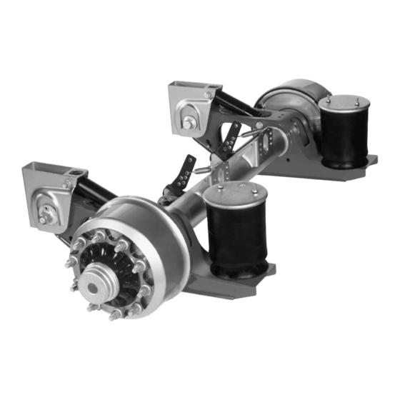
- Manuals
- Brands
- SAF Manuals
- Automobile Parts
- SKRS 9042 SK 500 plus
- System maintenance and repair manual
-
Contents
-
Table of Contents
-
Bookmarks
Quick Links
Maintenance and
Repair Manual
SK RS 9042 — SK 500 plus
Edition 01/2006
Service
Summary of Contents for SAF SKRS 9042 SK 500 plus
-
Page 1
Maintenance and Repair Manual SK RS 9042 — SK 500 plus Edition 01/2006 Service… -
Page 2: Saf Axle Identification
Body type……………………….Chassis no……………………….Year of manufacture ……………………Registration, date-in-service………………….Spare parts service for SAF axles and suspension systems When ordering spare parts, quote correct axle identification serial no., refer to the axle type plate. Please enter the vehicle identification…
-
Page 3: Table Of Contents
Use the part numbers from the valid spare parts documents for identification of spare parts. SAF axles and suspension units are subject to continuous further development; the data and drawings contained in the manual may therefore differ from the details given in the operating permit.
-
Page 4: A) Component Description
A) Component Description The components of the SAF axle Types SK 500 plus have important technical details which distinguish them from other axle types: – Great ease of installation (e.g. only 1/4 of the working time is now required for brake repairs) –…
-
Page 5
A) Component Description Wheel bearing: Thanks to the protected installation of generously dimensioned wheel bearings, long service lives can be achieved. Grease changing at brake repairs is no longer necessary. After 500,000 km or after 60 months’ operation, the following 2 procedures are possible: 1) Inspection of the wheel bearing for further serviceability with grease change and replacement of the seal rings. -
Page 6: A) Component Description
A) Component Description Wheel bearing clearance The wheel bearing clearance has to be adjusted as in the past. Axle nuts The axle nuts have a right-hand thread on both sides. The wheel hub is secured with a lock nut. Brake shoes The brake shoes are each supported spherically on a ball and are held by a spring clamp.
-
Page 7: B) General Service Instructions For Saf Axles And Suspension Units
We recommend the use of original SAF spare parts. A close-knit service network of SAF partner companies is available for the technical support of the SAF axles and suspension systems and for the supply of original SAF spare parts (see rear cover or on the Internet under www.saf-axles.com).
-
Page 8: C) Maintenance Instructions
Vehicles used under extreme conditions: service at suitably reduced intervals Warranty claims will only be accepted as long as the operating and maintenance instructions have been complied with and if SAF approved spare parts have been fitted.
-
Page 9: Maintenance Schedule For Sk Rs 9042 — Sk 500 Plus
Tighten axle nut W.A.F. 85 (22) to a torque of 150 Nm, Wheel bearings: turning the wheel hub at the same time. SAF Part No. 4 387 0011 05 Back off the axle nut by 2 1/2 holes of the locking collar Camshaft: (23).
-
Page 10
D) Spare part illustrations SK RS 9042 — SK 500 plus Torque wrench settings Use a torque wrench. Wheel nuts: U-bolts: Shock absorber: The use of impact wrenches Spigot-hub-centred fixing: (diagonally in three stages) M 24 / 400 Nm is not accepted. M 22 x 1.5 / 600 Nm M 22 / 650 Nm Bolt-centred fixing:… -
Page 11
D) Spare part designation SK RS 9042 — SK 500 plus Item Parts designation Item Parts designation Axle beam assembly Brake lining set including items 3 — 25 including items 71 — 73 Spherical mounting plate Brake lining, cam roller side Protective plug for ABS Brake lining, ball side Ball… -
Page 12: E) Installation Instructions
Lever the hub cap (SAF Part No. 1 434 1041 00) off the wheel hub using one of the recesses around the circumference of the hub cap.
-
Page 13
E) Installation instructions Brake drum cleaning: The brake drum may only be cleaned using a dry cleaning material. Liquid cleansers, high-pressure cleaners or machine cleaning are not permitted. With this type of cleaning there is a danger of cleansing fluid entering the wheel bearing with a consequent failure of the wheel bearing lubrication. -
Page 14
E) Installation instructions Remove the spring clip from the groove in the camshaft and pull the camshaft com- pletely out of the bearing. Arrangement and installation position of the camshaft bearings, see drawing on page 13. Remove the bolts from the compact bearing and replace with a new bearings (see page 10, item 81 with parts 85.1 — 88.1, and item 10 with parts 11, 15 and 18). -
Page 15
Replace the complete compact bearing assembly on the slack adjuster. Coat the splines on the camshaft and the splines on the slack adjuster with copper paste (SAF Part No. 4 387 0007 00). Suitable greases, see chapter “Maintenance instructions”. Push washer and new sealing sleeve onto the camshaft. -
Page 16
Corrosion-proofed steel rivets are used for securing the linings. The brake linings have a monitoring shoulder on the face end indi- cating the brake lining type approved by SAF and the wear limit for the minimum brake lining thickness. Only brake linings of the same quality may be installed on the same axle. -
Page 17
E) Installation instructions The brake lining must contact the brake drum over its full surface. The corners of the brake lining must not be broken and the lining must not be cracked at the rivets. Required riveting force: 25,000 N Read off the required working pressure on the setting plate of the rivetter and set the pressure at the pressure gauge. -
Page 18
The compact wheel bearing units are not removed when turning down the brake drum. Centre wheel hub on the brake drum lathe using clamping device, SAF Part No. 3 434 1060 00 Further machining of the brake drum can then be carried out as nor- mal in the workshop. -
Page 19
E) Installation instructions Check the proper mounting of the cam roller on the brake shoes. The cam roller must not jam in the mounting. It must turn easily, but without radial clearance. Replace the cam roller if the journal is severely worn. When installing new cam rollers, a secure mounting in the brake shoe can be achieved by pressing in the two side faces in a vice. -
Page 20
Completely coat the wheel bearing seats on the stub shaft and in the wheel hub with SAF fitting paste (SAF Part No 4 387 0015 06). See chapter “Maintenance instructions” for recommended media. -
Page 21
Push the complete wheel hub unit with brake drum onto the stub shaft. Screw on the axle nut. Axle nut wrench: SAF Part No. 2 012 0023 01 Hub end-float setting Tighten hub nut (22) to a torque of 150 Nm at the same time rotating the hub and drum. -
Page 22
E) Installation instructions Check that the cover plate of the brake shoes is correctly installed and correct the positioning, if necessary, using a clamp. Checking the brake lining thickness The brake lining thickness can be checked at the two sight holes in the rear cover plate. -
Page 23: Repairing The Wheel Bearings
E) Installation instructions Repairing the wheel bearings Changing the wheel bearing grease As the operations are identical for both procedures, the descriptions are contained in the same chapter. Arrangement of wheel bearing assembly with seals After 500,000 km or after 60 months’ operation, the following 2 procedures are possible: 1) Inspection of the wheel bearing for further serviceability with grease change and replacement of the seal rings.
-
Page 24
Thoroughly clean the hub housing. Installing the wheel bearing assembly Install seal ring (38) and protective ring (38.1) in the hub housing. Press both bearing outer races into the hub housing until they bottom using installation drift, SAF Part No. 3 434 3308 00. -
Page 25
SAF Part No. 3 434 1036 00. Install the exciter ring. Installation drift, SAF Part No. 3 434 3308 00 If the hubs are subsequently painted, ensure that the contact surface for the wheel and brake drum are not painted. -
Page 26: F) Slack Adjuster
F) Slack adjuster Braking system – checking and adjustment S-cam brakes with manual slack adjusters Due to normal brake drum and brake lining wear, the wheel brakes must be regularly adjusted in order to maintain the full brake cylinder stroke. To ensure maximum brake efficiency, the clearance between brake lining and drum must be kept to an absolute minimum.
-
Page 27: Adjustment Of Haldex Automatic Slack Adjusters
• For the anchor bracket mounting (11), ensure that the 2 U-profiles engage firmly together. • Observe the correct push rod length “L” as indicated in the SAF specifications. • Fit slack adjuster retaining clip on camshaft. • Membrane brake cylinder •…
-
Page 28: Adjustment Of S-Aba Automatic Slack Adjusters
(slack adjuster) up to its end position • Observe the correct push rod length “L” as without applying excessive force. indicated in the SAF specifications. • Membrane brake cylinder Before installing the automatic slack adjuster, ensure that the brake chamber push rod is in released position.
-
Page 29: G) Track Control
G) Track control Commercially available optical measuring instruments must be used for performance of the track control on SAF SK Series axles. 1) For the original installation in the vehicle manufacturer’s works using universal centering on the wheel studs. 2) For the service inspection using universal rim centering.
-
Page 30
Semi-trailers with trailing steering axle Distance A, B, C, max. permissible deviation 1.0 mm. Axle alignment responsablety of vehicle manufacturer. Axle toe in/out + 12’ = + 3.0 mm/m, Axle camber + 12’ (SAF manufacturing tolerance) (values apply to unloaded vehicle) Trailer Distance A, B, C, max. -
Page 31: H) Service Tools
H) Service tools 1. Lever for hub cap SAF Part No. 1 434 1041 00 2. Axle nut wrench W.A.F. 85 SAF Part No. 2 012 0023 01 3. Wheel hub puller SAF Part No. 4 434 3822 00 4. Installation drift for unitised seal…
-
Page 32
H) Service tools 5. Wheel bearing installation drift SAF Part No. 3 434 3308 00 6. Brake shoe clamping device SAF Part No. 3 349 1001 00 7. Clamping rings for brake drum lathe SAF Part No. 3 434 1060 00… -
Page 33: I) Tightening Torque In Nm
I) Tightening torque in Nm The following tightening torques are only valid if no other values are given in the axle maintenance chart. Torque wrenches settings, impact wrench not permissible. Thread Material W.A.F. 10,9 12,9 W.A.F. 13 M 8 x 1 M 10 W.A.F.
-
Page 34
0 21 22 75 13 21 +386 26 16 58 35 +386 26 16 58 35 www.saf-axles.com Otto Sauer Achsenfabrik GmbH · Hauptstraße 26 · D-63856 Bessenbach Tel +49 (0) 60 95 / 301-0 · Fax +49 (0) 60 95 / 301-259 · www.saf-axles.com…
-
Содержания книг
- Руководство по ремонту осей прицепов, полуприцепов SAF, BPW, ROR
ИДЕНТИФИКАЦИЯ МОСТОВ И ПОДВЕСКИ ФИРМЫ SAF 5
ВЫБОР НАИБОЛЕЕ ПОДХОДЯЩЕЙ КОМБИНАЦИИ ТРАНСПОРТНОГО СРЕДСТВА {ТЯГАЧ + ПОЛУПРИЦЕП) 6
МОСТ SAFSK 500 6
КОМПОНЕНТЫ МОСТА SAF SK 500 7
РУКОВОДСТВО ПО ОБСЛУЖИВАНИЮ МОСТОВ SAF SK 500 8
ТРЕБОВАНИЯ SAF 8
ОСИ SK 500 PLUS, SK RS 9042 И МОСТ НОВОГО ПОКОЛЕНИЯ SK 500 PLUS ET 0 9
РЕГУЛИРОВКА ЛЮФТА СТУПИЧНЫХ ПОДШИПНИКОВ, СМАЗКА 9
СПЕЦИФИКАЦИЯ СМАЗКИ 9
ТОРМОЗНОЙ МЕХАНИЗМ SNK 420 11
РЕМОНТ ТОРМОЗОВ 11
ТОРМОЗНЫЕ НАКЛАДКИ 15
ЗАМЕНА ТОРМОЗНЫХ НАКЛАДОК 15
ТОРМОЗНОЙ БАРАБАН 16
УСТАНОВКА ТОРМОЗНЫХ КОЛОДОК 17
ПРОТОЧКА ТОРМОЗНЫХ НАКЛАДОК 18
УСТАНОВКА СТУПИЦЫ КОЛЕСА С ТОРМОЗНЫМ БАРАБАНОМ 19
РЕМОНТ КОЛЕСНЫХ ПОДШИПНИКОВ 21
РЕГУЛИРОВКА ПОДШИПНИКОВ КОЛЕСА РАЗЛИЧНЫХ ТИПОВ ОСЕЙ 23
БАРАБАННЫЕ ТОРМОЗА, КОНТРОЛЬ И РЕГУЛИРОВКА 24
ПРОВЕРКА УСТАНОВКИ УГЛОВ КОЛЕС 26
ПОЛУПРИЦЕП С ЗАДНИМ УПРАВЛЯЕМЫМ МОСТОМ 27
ПРИЦЕП 27
ИНСТРУКЦИЯ ПО ЗАТЯЖКЕ БОЛТА ВТУЛКИ ПОЛУРЕССОРЫ 28
ПНЕВМАТИЧЕСКАЯ ПОДВЕСКА 28
РЕГУЛИРОВКА УРОВНЯ ПЛАТФОРМЫ 28
АВТОМАТИЧЕСКИЙ РЫЧАГ ТИПА S-ABA 29
ПРОВЕРКА ФУНКЦИОНИРОВАНИЯ 29
ДИСКОВЫЕ ТОРМОЗА 30
ОСОБЕННОСТИ ДИСКОВЫХ ТОРМОЗОВ 30
ПОИСК НЕИСПРАВНОСТЕЙ ДИСКОВЫХТОРМОЗОВ 30
ОБСЛУЖИВАНИЕ ОСЕЙ SK RS/RZ 9022 К/11222 К (22.5″) 9019 К/11019 К (19.5″) 31
ПРОВЕРКА АВТОМАТИЧЕСКОГО МЕХАНИЗМА РЕГУЛИРОВКИ ЗАЗОРА 33
ПРОВЕРКА ТОРМОЗНЫХ КОЛОДОК 33
РЕМОНТ ТОРМОЗОВ 34
ПОВОРОТНЫЕ ОСИ SAF SK RLS 9042/11242 43
РЕГУЛИРОВКА ЗАДНЕЙ ПОВОРОТНОЙ ОСИ 44
КАТАЛОГ ДЕТАЛЕЙ ОСЕЙ SAF 46
ОСИ SK 1000 ЕТ С 01.02.98 46
ОСИ SKRS 9042 15.02.98 49
ОСИ SK RZ 9030 15.02.98 50
ОСИ RBM 8442 01. 03.94 52
ОСИ RLSM8442 15.02.92 54
ОСИ SKRLS 9042 15.02.98 58
OCИ WRZM 11035-10 01.03.94 62
ОСИ SK RS 11019 К 64
OCИ SKRB9022K 66
ПНЕВМОПОДВЕСКА Еи416Н 68
ПНЕВМОПОДВЕСКА М 70
ПНЕВМОПОДВЕСКА АР311/ЕМ311 74
ПНЕВМОПОДВЕСКА AR 211 76
ПНЕВМОПОДВЕСКА AR 213 78
ПНЕВМОПОДВЕСКА AR 313 80
ПНЕВМОПОДВЕСКА AR316/EU316 82
ПНЕВМОПОДВЕСКА AR 413 84
ПНЕВМОПОДВЕСКА U 86
ТЕХНИЧЕСКИЕ ХАРАКТЕРИСТИКИ, ОБСЛУЖИВАНИЕ И РЕМОНТ ОСЕЙ BPW 93
СЕРВИС BPW 93
ИНСТРУКЦИЯ ПО СЕРВИСУ 94
ОСМОТР ПОСЛЕ ПРИЕМА В ЭКСПЛУАТАЦИЮ 94
ОСИ BPW ДЛЯ ПРИЦЕПОВ 96
ПНЕВМОПОДВЕСКИ ВРW 102
ОСЕВЫЕ АГРЕГАТЫ BPW СЕРИИ VA.VB.VG 106
ОСЕВЫЕ АГРЕГАТЫ BPW СЕРИИ W, BW, GW 109
БАЛКИ ОСЕЙ, КРОНШТЕЙНЫ ТОРМОЗА 110
ОПРЕДЕЛЕНИЕ ТИПА БАЛОК ОСЕЙ ПРИ ЗАМЕНЕ 110
КАТАЛОГ ДЕТАЛЕЙ ОСЕЙ BPW 112
ОСИ Н / КН СТАНД./ЕСО ТОРМОЗ-1/2 112
ОСИ Н / КН ECO/ECOWuiТОРМОЗ С УПОРНЫМ РОЛИКОМ (BPW 95) 112
ТОРМОЗНОЙ ВАЛ И ПОДШИПНИКИ 114
OCHN 118
ОСИН / К 118
ТРЕЩОТКИ 123
РУЧНАЯ ТРЕЩОТКА GSK, ВОЗВРАТНЫЕ ПРУЖИНЫ 124
АВТОМАТИЧЕСКИЕ ТРЕЩОТКИ ECO-MASTER 125
ТРЕЩОТКИ ECO-MASTER- ОСИ СЕРИЙ H /R 126
ТРЕЩОТКИ ECO-MASTER-ОСИ СЕРИЙ КН /KR 127
ТРЕЩОТКИ ECO-MASTER-ОСИ СЕРИЙ NH /NR 128
ИНСТРУКЦИИ ПО УСТАНОВКЕ ECO-MASTER 129
КРЕПЛЕНИЕ ТРЕЩОТКИ 130
ДЕТАЛИ ТОРМОЗА 132
БАРАБАННЫЕ ТОРМОЗА BPW 132
ДЕТАЛИТОРМОЗА SN 42 2 132
ДЕТАЛИТОРМОЗА SN 36 134
ДЕТАЛИТОРМОЗА SN 30 136
ДЕТАЛИТОРМОЗА SN 42 С УПОРНЫМ РОЛИКОМВ PW 95 138
ДЕТАЛИТОРМОЗА SN 36 С УПОРНЫМ РОЛИКОМВ PW 95 139
ДЕТАЛИ ТОРМОЗА SN 30 С УПОРНЫМ РОЛИКОМВ PW 95 140
ТОРМОЗНОЙ БАРАБАН SN 42 H /R 141
ТОРМОЗНОЙ БАРАБАН SN 36 КН /KR 142
ТОРМОЗНОЙ БАРАБАН SN 30 NH /NR 142
КРЕПЛЕНИЕ ТОРМОЗНОГО БАРАБАНА 143
ТОРМОЗНЫЕ ЩИТЫ 144
ТОРМОЗНОЙ ЦИЛИНДР 146
ПОДШИПНИКИ СТУПИЦЫ, УПЛОТНЕНИЯ СТУПИЦЫ 147
ПОДШИПНИКИ СТУПИЦЫ BPW 147
СТУПИЦА ECO/ECO MAXX 154
СТУПИЦА ЕСО*-1 156
СТАНДАРТНЫЙ ПОДШИПНИК СТУПИЦЫ 158
СМАЗКА СТУПИЦЫ КОЛЕСА, РЕГУЛИРОВКА ПОДШИПНИКА 162
ПРИСПОСОБЛЕНИИ ДЛЯ СМАЗКИ КОНИЧЕСКИХ РОЛИКОПОДШИПНИКОВ 165
ДЕТАЛИ ABS 165
ОБШАЯ ИНФОРМАЦИЯ 165
ОСИН /R 166
КОМПЛЕКТЫ ДЛЯ МОДЕРНИЗАЦИИ 166
ОСИКН /KR 168
КОМПЛЕКТ ДЛЯ МОДЕРНИЗАЦИИ 169
ОСИ NH /NR 170
КОМПЛЕКТЫ ДЛЯ МОДЕРНИЗАЦИИ ABS 173
CHCTEMATRILEX 174
КОЛЕСНЫЕ ШПИЛЬКИ 176
ОДИНАРНЫЕ КОЛЕСА 178
ДВОЙНЫЕ КОЛЕСА 181
КОЛПАКИ СТУПИЦЫ СО ВСТРОЕННЫМ СЧЕТЧИКОМ ПРОБЕГА 184
ТЕХНИЧЕСКИЕ ХАРАКТЕРИСТИКИ, ОБСЛУЖИВАНИЕ И РЕМОНТ ОСЕЙ ROR 189
OCMLM, LMC 189
ОПРЕДЕЛЕНИЕ ТИПА ОСИ 189
ИДЕНТИФИКАЦИЯ СЕРИЙНОГО НОМЕРА 189
ТЕХОБСЛУЖИВАНИЕ ОСЕЙ LM, LMC BP LS EP2 190
РЕКОМЕНДУЕМЫЕ СМАЗКИ 191
ТЕХНИЧЕСКОЕ ОБСЛУЖИВАНИЕ БАРАБАННЫХ ТОРМОЗОВ LM/LMC 191
ТЕХНИЧЕСКОЕ ОБСЛУЖИВАНИЕ ДИСКОВЫХТОРМОЗОВ LM/LMC 195
ПРОВЕРКА ТОРМОЗНОГО ДИСКА 197
ДЕМОНТАЖ И ЗАМЕНА СУППОРТА 198
ТЕХНИЧЕСКОЕ ОБСЛУЖИВАНИЕ СТУПИЦЫ LM С БАРАБАННЫМИ ТОРМОЗАМИ 198
ОСИТМ 201
ОПРЕДЕЛЕНИЕ ТИПА ОСИ 201
БАЛКА ОСИ 202
ТЕХНИЧЕСКИЕ ХАРАКТЕРИСТИКИ ОСЕЙ ТМ 202
ТЕХНИЧЕСКОЕ ОБСЛУЖИВАНИЕ БАРАБАННЫХ ТОРМОЗОВ СЕРИИ ТМ 203
ТОРМОЗНОЙ ВАЛ И ВТУЛКИ 205
КАПИТАЛЬНЫЙ РЕМОНТ СТУПИЦЫ 207
ЭКСПЛУАТАЦИОННЫЕ НЕИСПРАВНОСТИ ТОРМОЗНОЙ СИСТЕМЫ ОСИ (БАРА6АННЫЙ ТОРМОЗ) 209
ПНЕВМОПОДВЕСКА 211
ИДЕНТИФИКАЦИЯ ТИПА ПОДВЕСКИ 211
ИДЕНТИФИКАЦИЯ СЕРИЙНОГО НОМЕРА 211
ТЕХНИЧЕСКОЕ ОБСЛУЖИВАНИЕ ПНЕВМОПОД8ЁСКИ 212
СНЯТИЕ И УСТАНОВКА ПНЕВМОПОДУШЕК 213
СНЯТИЕ И ЗАМЕНА АМОРТИЗАТОРОВ МОДЕЛИ FLEXAIR 215
СНЯТИЕ И ЗАМЕНА АМОРТИЗАТОРОВ МОДЕЛИ FLEXLITE 215
СНЯТИЕ И ЗАМЕНА ОСИ 216
СНЯТИЕ И ЗАМЕНА ПРОДОЛЬНЫХ РЫЧАГОВ ПОДВЕСКИ МОДЕЛЕЙ FLEXAIR И FLEXLITE 217
ЗАМЕНА ШАРНИРНЫХ ВТУЛОК 218
ПОВТОРНОЕ ЦЕНТРИРОВАНИЕ ОСИ (ТРЕКИНГ) 218
ЭКСПЛУАТАЦИОННЫЕ НЕИСПРАВНОСТИ 219
МЕХАНИЧЕСКАЯ ПОДВЕСКА SMT MERITOR 221
ТАБЛИЦА СООТВЕТСТВИЯ НАГРУЗОК 221
ИДЕНТИФИКАЦИЯ ПОДВЕСКИ 221
ТЕХНИЧЕСКОЕ ОБСЛУЖИВАНИЕ 221
КАТАЛОГ ДЕТАЛЕЙ ОСЕЙ ROR 224
OCMLM 224
ДЕТАЛИ СТУПИЦЫ 224
ТОРМОЗНЫЕ КУЛАЧКОВЫЕ ВАЛЫ 226
ТОРМОЗНЫЕ ЭЛЕМЕНТЫ 228
ЭЛЕМЕНТЫ СИСТЕМЫ ABS 229
ДЕТАЛИ ТОРМОЗНОГО ВАЛА 230
ОСИ LM СО СТУПИЦЕЙ DX195 232
ТОРМОЗНОЙ ДИСК И ЧАСТИ СИСТЕМЫ ABS 232
ОСИ LMDX195 234
ТОРМОЗНЫЕ ЭЛЕМЕНТЫ 234
АКТИВАТОРЫ И ВОЗДУШНЫЕ КАМЕРЫ 235
OCHLMC 236
ДЕТАЛИ СТУПИЦЫ 236
OCMLMDX195 237
ЗАМЕНЯЕМЫЕ ЧАСТИ 237
ОСИТА 238
ДЕТАЛИ СТУПИЦЫ 238
ТОРМОЗНЫЕ ЭЛЕМЕНТЫ 240
ДЕТАЛИ ABS 241
ТОРМОЗНОЙ ВАЛ 242
ОСИТА DDUCO 246
СТУПИЦА. ТОРМОЗНОЙ ДИСК И ABS 246
ОСИ ТАС 248
ДЕТАЛИ СТУПИЦЫ 248
OCИ D DUCO 249
ТОРМОЗНЫЕ ЭЛЕМЕНТЫ 249
ВОЗДУШНЫЕ КАМЕРЫ 250
ОСИТМ 251
ИДЕНТИФИКАЦИЯ ТИПА ОСИ И СЕРИЙНОГО НОМЕРА 251
ЭЛЕМЕНТЫ СИСТЕМЫ ABS 252
ТОРМОЗНЫЕ ЭЛЕМЕНТЫ 253
ДЕТАЛИ СТУПИЦЫ 254
ТОРМОЗНОЙ ВАЛ 256
РАЗМЕРЫ ТОРМОЗНЫХ ВАЛОВ 258
ТОРМОЗНОЙ ВАЛ 260
ОСИ ТМ DX195 262
СТУПИЦА, ТОРМОЗНОЙ ДИСК И ЭЛЕМЕНТЫ СИСТЕМЫ ABS 262
ВОЗДУШНЫЕ ТОРМОЗНЫЕ КАМЕРЫ 265
ОСИ ТЕ 266
ИДЕНТИФИКАЦИЯ ТИПА ОСИ И СЕРИЙНОГО НОМЕРА 266
ТОРМОЗНОЙ ВАЛ 267
ТОРМОЗНЫЕ ЭЛЕМЕНТЫ 268
ДЕТАЛИ СИСТЕМЫ ABS 269
КАТАЛОГ ДЕТАЛЕЙ СТУПИЦЫ 270
ПНЕВМОПОДВЕСКА ОСЕЙ 272
ПНЕВМОПОДВЕСКА ОСЕЙ XL9000 272
ПНЕВМОПОДВЕСКА ОСЕЙ XL9000L 273
ПНЕВМОПОДВЕСКА ОСЕЙ XL9000H 274
ПНЕВМОПОДВЕСКА ОСЕЙ XL9000HL 275
ПНЕВМОПОДВЕСКА ОСЕЙ FL9000NB 276
ПНЕВМОПОДВЕСКА ОСЕЙ FL9000 278
ПНЕВМОПОДВЕСКА ОСЕЙ FL9000L 280
ПНЕВМОПОДВЕСКА ОСЕЙ FL9000H 232
ПНЕВМОПОДВЕСКА ОСЕЙ FL9000HL 284
ПНЕВМОПОДВЕСКА ОСЕЙ FL9000HLL 286
ПНЕВМОПОДВЕСКА ОСЕЙ FL9000M 288
ПНЕВМОПОДВЕСКА ОСЕЙ FL11000 290
ПНЕВМОПОДВЕСКА ОСЕЙ FP11000 292
ПНЕВМОПОДВЕСКА ОСЕЙ FL11000L 294
ПНЕВМОПОДВЕСКА ОСЕЙ FL110O0/150 296
ПНЕВМОПОДВЕСКА ОСЕЙ FL11000D 298
ПНЕВМОПОДВЕСКА ОСЕЙ FL11000B 300
ПНЕВМОПОДВЕСКА ОСЕЙ FL11O00LB 302
ПНЕВМОПОДВЕСКА ОСЕЙ FL11000CT 304
ПНЕВМОПОДВЕСКА ОСЕЙ FL11000CS 305
ПНЕВМОПОДВЕСКА ОСЕЙ FL11000LS 306
ПНЕВМОПОДВЕСКА ОСЕЙ FL11000S 308
ПНЕВМОПОДВЕСКА ПОДЪЕМНОЙ ОСИ 310
ДВУСТОРОНИЙ ПОДЪЕМНИК 311
ПОДЪЕМНИК 312
ДИСКОВЫЕ ТОРМОЗА ФИРМЫ KNQRR
ТЕХНИЧЕСКИЕ ХАРАКТЕРИСТИКИ, ОБСЛУЖИВАНИЕ И ДЕТАЛИ ТОРМОЗОВ KNORR 315
ПЕРЕЧЕНЬ КОНСТРУКТИВНЫХ ЭЛЕМЕНТОВ 315
ДИСКОВЫЕ ТОРМОЗНЫЕ МЕХАНИЗМЫ СТАНДАРТНОГО И РАДИАЛЬНОГО ИСПОЛНЕНИЙ 319
ОПИСАНИЕ КОНСТРУКЦИИ И ПРИНЦИП ДЕЙСТВИЯ 320
ТЕХНИКА БЕЗОПАСНОСТИ ПРИ ПРОВЕДЕНИИ РЕМОНТНЫХ РАБОТ НА ДИСКОВЫХ ТОРМОЗНЫХ
МЕХАНИЗМАХ 322
ПРОВЕРКА ДИСКОВЫХ ТОРМОЗНЫХ МЕХАНИЗМОВ 322
ЗАМЕНА ТОРМОЗНЫХ КОЛОДОК 327
ЗАМЕНА УПОРОВ С ГОФРИРОВАННЫМИ ПЫЛЬНИКАМИ 329
РЕМОНТ РАЗГЕРМЕТИЗАЦИИ ПОДВИЖНОЙ СКОБЫ С ИСПОЛЬЗОВАНИЕМ «КОМПЛЕКТА УПЛОТНИТЕЛЬНЫХ ЭЛЕМЕНТОВ ДЛЯ НАПРАВЛЯЮЩИХ 330
РЕМОНТ ПОДВИЖНОЙ СКОБЫ С ИСПОЛЬЗОВАНИЕМ «КОМПЛЕКТА НАПРАВЛЯЮЩИХ ВТУЛОК И ГИЛЬЗ 331
ЗАМЕНА ПОДВИЖНОЙ СКОБЫ 332
ЗАМЕНА СУППОРТА 333
ЗАМЕНА ТОРМОЗНОГО ЦИЛИНДРА 333
ПНЕВМАТИЧЕСКАЯ АРМАТУРА ПРИЦЕПОВ И ПОЛУПРИЦЕПОВ WABCO~ ТЕХНИЧЕСКИЕ ХАРАКТЕРИСТИКИ, ОБСЛУЖИВАНИЕ И ДЕТАЛИ ПНЕВМАТИЧЕСКОЙ АРМАТУРЫ WABCO 337
ТОРМОЗНЫЕ КЛАПАНЫ ПРИЦЕПОВ 337
МАГИСТРАЛЬНЫЕ ФИЛЬТРЫ И КЛАПАНЫ РАСТОРМАЖИВАЙ И Я 339
ТОРМОЗНЫЕ КРАНЫ ПРИЦЕПОВ 340
КЛАПАНЫ ОГРАНИЧЕНИЯ ДАВЛЕНИЯ 343
УСКОРИТЕЛЬНЫЕ КЛАПАНЫ 344
РАЗОБЩАЮЩИЙ КЛАПАН И КЛАПАН БЫСТРОГО РАСТОРМАЖИВАНИЯ 344
КЛАПАН СООТНОШЕНИЯ ДАВЛЕНИЙ 345
МАГНИТНЫЕ КЛАПАНЫ 346
ТОРМОЗНОЙ КРАН ПРИЦЕПА СО ВСТРОЕННЫМ РЕГУЛЯТОРОМ ТОРМОЗНЫХ СИЛ (РТС) 347
ТОРМОЗНОЙ КРАН ПРИЦЕПА СО ВСТРОЕННЫМ РЕГУЛЯТОРОМ ТОРМОЗНЫХ СИЛ (РТС) 348
АВТОМАТИЧЕСКИЕ РЕГУЛЯТОРЫ ТОРМОЗНЫХ СИЛ 349
© Автолитература 2008
Все материалы, опубликованные на сайте http://avtoliteratura.ru, фотоизображение или тексты, являются объектом авторского права. Торговые знаки и логотипы, а так же авторские и смежные права принадлежат их законным владельцам. Частичное или полное копирование текстов, слоганов и фотоизображений без письменного согласия владельцев сайта запрещено и влечет за собой ответственность согласно действующему законодательству
Главное отличие нашего магазина от всех других магазинов автокниги в том, что у нас действительно есть в наличии та автомобильная литература, которая представлена на сайте