- Manuals
- Brands
- Interacoustics Manuals
- Measuring Instruments
- Titan
- Instructions for use manual
-
Contents
-
Table of Contents
-
Bookmarks
Quick Links
Instructions for Use – EN
Titan
D-0100608-G — 2017/02
Related Manuals for Interacoustics Titan
Summary of Contents for Interacoustics Titan
-
Page 1
Instructions for Use – EN Titan D-0100608-G — 2017/02… -
Page 3: Table Of Contents
2.16 Use of the IP30 ABR Transducer with Ear tips, Foam Inserts or EarCups (ABRIS440 only) ……………………..20 2.17 Safety Precautions to take when connecting the Titan…………. 21 2.18 Software Installation ………………….27 2.19 Installation of the Driver ………………..29 2.20…
-
Page 4
Using the Print Wizard …………………. 84 Maintenance ……………………..87 General Maintenance Procedures ………………87 Cleaning the Probe Tip ………………… 88 Concerning Repair ………………….89 Warranty ……………………..89 General Technical Specification ………………..91 Titan Hardware – Technical Specifications …………… 91 Electromagnetic Compatibility (EMC) …………….101… -
Page 5: Introduction
Distortion Product Otoacoustic Emissions. The target population for Titan with DPOAE440 includes all ages. The Titan with ABRIS440 is intended for use in the audiologic evaluation and documentation of ear and nerve disorders using auditory evoked potentials from the inner ear, the auditory nerve and the brainstem.
-
Page 6
Titan Instruction for Use — EN Page 2 The system consists of the following included and options parts: IMP440 DPOAE440 ABRIS440 TEOAE440 Included parts: Included parts: Included parts: Included parts: Titan handheld unit with Titan handheld unit with Titan handheld unit with… -
Page 7: Probe, Transducers And Cable Configurations
Titan Instruction for Use — EN Page 3 1.3.1 Probe, Transducers and Cable Configurations Titan operates with different transducers and cable configurations. The table below shows which transducers and cable configurations are possible for use with the Titan. Transducer/cable configuration IMP440/WBT440…
-
Page 8: Warnings
Titan Instruction for Use — EN Page 4 Warnings Throughout this manual the following meanings of warnings, cautions and notices apply: WARNING indicates a hazardous situation which, if not avoided, could result in death or serious injury. CAUTION, used with the safety alert symbol, indicates a hazardous situation which, if not avoided, could result in minor or moderate injury.
-
Page 9: Unpacking And Installation
Keep carton for future shipment Titan comes in its own shipping carton, which is specially designed for the Titan. Please keep this carton. It will be needed if the instrument has to be returned for service.
-
Page 10: Markings
Failing to do so may endanger the environment. The CE-mark indicates that Interacoustics A/S meets the requirements of Annex II of the Medical Device Directive 93/42/EEC. TÜV Product Service, Identification No.
-
Page 11: Hardware Installation
ETL listing marking Hardware installation When connecting the Titan to the mains supply and to a computer, the following warnings must be observed: 1. This equipment is intended to be connected to other equipment thus forming a Medical Electrical System. External equipment intended for connection to signal input, signal output or other connectors shall comply with the relevant product standard e.g.
-
Page 12
ESD (electrostatic discharge) precautions. The precautionary symbol: 8. The best way to protect the Titan from ESD is to avoid the build-up of electrostatic charges through the use of conductive footwear and floor coverings. Humidification of the air is also an effective preventive means. -
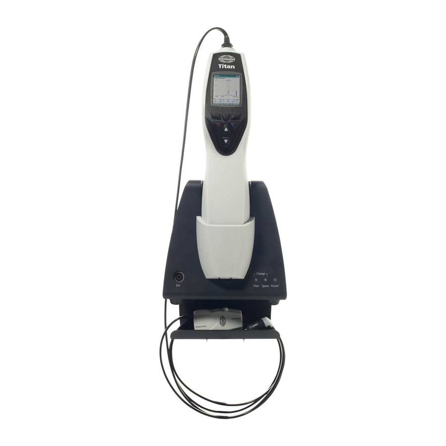
Page 13: Installing The Cradle
Titan Instructions for Use — EN Page 9 Installing the cradle Slide off the back plate of the cradle. Connect the printer cable to the rear of the cradle (1), power supply (2) and USB cable (4) or optical USB cable (3 and 4).
-
Page 14
Titan Instructions for Use — EN Page 10 Place the steel cable holder into the holes provided on the back of the cradle. Mount the spare battery inside the cradle. Now the cradle is ready to be used with the Titan placed in it. -
Page 15
3 screw holes on the wall. Make sure that the height is chosen in a way that you can still read the Titan display when it is placed in its cradle. Drill the holes and insert the plugs provided. Use three screws to mount the retaining plate to the wall. -
Page 16: Cradle Indication Lights
Cradle Indication Lights The LEDs on the cradle indicate the following: LED 1 will show a solid green light when the Titan is placed inside the cradle and its battery is fully charged. LED 1 will flash green while the battery is charging.
-
Page 17: Installing The Sanibel Mpt-Ii Thermal Printer
Titan Instructions for Use — EN Page 13 Installing the Sanibel MPT-II Thermal Printer 2.8.1 Battery pack insertion and charging Insert battery as shown. Connect the power charger to the outlet on the right hand side of the printer. The blue light on the top of the printer will indicate charging is occurring.
-
Page 18
1. Turn the printer on by holding down the power button for 2 seconds. 2. On the Titan hand held unit, go to My Titan | Printer and press Search. 3. Let the instrument search for Bluetooth devices. This may take up to 1 minute. -
Page 19: Installing Bluetooth For Direct Printing With Hp Officejet 100 Mobile Printer Or A Thermal Printer
Connecting the Titan directly through USB will NOT allow you to print. Note that the HP printers allow the use of a pin code for the use of Bluetooth. Titan will NOT be able to print to your printer if this function is used.
-
Page 20: Charging The Battery
USB adaptor can be used to connect the Titan to the medically approved mains power supply when the cradle is not in use. Then the battery in Titan is charged within the same time frame as if it was placed in the cradle.
-
Page 21: Changing Probes And Extension Cords On The Titan
Note that the length of the tubing influences the pump speed in the IMP440 module. When the probe is directly connected to the Titan, pump speeds are about 60% higher than when it is connected via the long clinical extension cable (shoulder box) or PreAmplifier cable. For the most accurate measurements it is recommended to use probe while connected via the long clinical extension cable (shoulder box) or PreAmplifier cable.
-
Page 22: Connecting Transducers To The Shoulder Box And Preamplifier
Connecting transducers to the shoulder box and PreAmplifier You can only perform contralateral stimulation during impedance reflex measurements when the long clinical extension cable (shoulder box) or PreAmplifier cable is connected to the Titan. When using the long clinical extension cable (shoulder…
-
Page 23: Placing The Montage-Indication Stickers On The Preamplifier
Titan Instructions for Use — EN Page 19 Placing the Montage-Indication Stickers on the PreAmplifier A sheet containing Montage-Indication stickers has been enclosed to provide assistance to the user for correct placement of the electrodes and cables. Each sheet contains two stickers; the top one showing the mastoid montage setup and the bottom one showing the nape montage setup.
-
Page 24: Use Of The Eartone Abr Transducer With Ear Tips, Foam Inserts Or Earcups (Abris440 Only)
The ID EARTone ABR transducer is for use with the 3.5mm or 4.0mm infant ear tips, foam insert ear tips or the Titan probe ear tips via an adaptor. The transducer is labeled “Calibrated for use with inserts”. The ID EARTone Earcup transducer is for use with EarCups via an adaptor. The transducer is labeled “Calibrated for use with EarCups”.
-
Page 25: Safety Precautions To Take When Connecting The Titan
Please note that if connections are made to standard equipment like printers and networks, special precautions must be taken in order to maintain medical safety. Please follow instructions below. Fig 1. Titan used with the medically approved power supply and DC USB adaptor. Medical power supply Mains outlet Titan alone Fig.
-
Page 26
Titan Instructions for Use — EN Page 22 Fig. 3. Titan used with the Cradle, medically approved power supply and Bluetooth printer. Fig 4. Titan used with the Cradle, medically approved power supply and a wired printer powered by a battery. -
Page 27
Titan Instructions for Use — EN Page 23 Fig. 5. Titan used with the Cradle, medically approved power supply and Bluetooth connection to a… -
Page 28
Titan Instructions for Use — EN Page 24 Fig. 6. Titan used with the Cradle, medically approved safety transformer and a wired connection to a PC. Not suitable for ABRIS440 use as patient safety is not maintained – refer Fig. 8. -
Page 29
Titan Instructions for Use — EN Page 25 Fig. 7. Titan used with the Cradle, medically approved safety transformer, wired connection to a PC, and a Bluetooth connection to printer. Not suitable for ABRIS440 use as patient safety is not… -
Page 30
Titan Instructions for Use — EN Page 26 Fig. 8. Titan used with the Cradle, medically approved power supply, optical USB connection to a PC, and a Bluetooth connection to printer. Suitable configuration for use with ABRIS440 – patient safety is… -
Page 31: Software Installation
Important note on the use of Normative Data You are about to install the Titan Suite software. Some parts of the software have normative data available that can be displayed and compared to recordings made. If it is preferred not to display normative data, these can be deselected in the test protocols in question or new alternative protocols without normative data can be created and used.
-
Page 32
7, Windows 8 and Windows Insert the installation DVD and follow the steps below to install the Titan Suite software. If the installation procedure does not start automatically, click “Start”, then go to “My Computer” and double click the DVD/CD- RW drive to view the contents of the installation DVD. -
Page 33: Installation Of The Driver
Now that the Titan Suite software is installed, you must install the driver for the Titan. 1. Connect the Titan via a USB connection (directly or via the cradle) to the PC. Turn the Titan on by pressing down either the R or L button on the handheld unit.
-
Page 34: Standalone Installation Of Titan Suite
Page 30 Standalone Installation of Titan Suite If you do not want to run the Titan Suite through Noah 4 or OtoAccess™ you can make a shortcut on the desktop to directly launch the Titan Suite as a standalone module.
-
Page 35: Bluetooth Installation Quick Guide (Windows 7)
7 PC/laptop using Bluetooth. Turn on the Titan Handheld Unit (HHU) and your Windows® 7 PC/laptop: 1. Select Protocol | My Titan |Titan and change Bluetooth Connection to PC, by pressing the R or L button. 2. From the task bar, left click on the Bluetooth Icon and select Add Device.
-
Page 36
8. On connection, the Suite will finish launching and the Titan HHU screen will show “PC-controlled” Now the Titan can be operated from PC in the same way as if it was connected via a USB cable. Note: If the Titan will not connect correctly and your PC has its manufacturer’s Bluetooth Driver… -
Page 37: Bluetooth Installation Quick Guide (Windows 8 & 10)
Turn on the Titan Handheld Unit (HHU) and your Windows 8 or 10 PC/laptop: 1. Select Protocol | My Titan |Titan and change Bluetooth Connection to PC, by pressing the R or L button. 2. From the task bar, right click on the Bluetooth Icon and select Add a Bluetooth Device.
-
Page 38
8. On connection, the Suite will finish launching and the Titan HHU screen will show “PC-controlled”. Now the Titan can be operated from PC in the same way as if it was connected via a USB cable. Note: If the Titan will not connect correctly and your PC has its manufacturer’s Bluetooth Driver… -
Page 39: Operating Instructions
Titan Instructions for Use — EN Page 35 3 Operating Instructions The instrument is switched on by pressing either the R or L button on the handheld unit. When operating the instrument, please observe the following general precautions: 1. Use this device only as described in this manual.
-
Page 40: Handling And Selection Of Ear Tips
For more stable testing, we recommend using an extension cord with a mushroom shaped ear tip. Make sure that this ear tip inserts completely into the ear canal. Mushroom shaped ear tips allow you to test ‘hands free’ from the Titan. This reduces the chance of contact noise disturbing the measurement.
-
Page 41: Switching The Titan On And Off
1 second. NOTICE The Titan takes approximately 2 seconds to boot up. Allow the unit to warm up for 1 minute before use. Probe Status The probe status is indicated by the color of the light at the end of the extension cord, on the shoulder box or on the probe status bar in the software.
-
Page 42: Operating Titan In Handheld Mode
You will have to turn off the handheld unit and change battery or place the Titan in the cradle to be able to continue testing. Upon restarting the Titan, the previously measured data will be recovered and you can continue with your measurements without retesting.
-
Page 43
Titan Instructions for Use — EN Page 39 ABRIS440 The circles on the baby’s head indicate the electrode montage for the test and the status of the electrode impedance; green = acceptable, amber = poor. The selected transducer name is displayed next to the baby’s head. -
Page 44: Done Screen
3.5.4 Done Screen The Titan will automatically go to the Done! screen when it has finished testing a protocol. From here, measurements from both ears can be reviewed, printed and/or saved.
-
Page 45: Select Client & Save
Select Client & Save From this screen you can either save data to an existing client that has been uploaded to the Titan from your database or save data to a new client name. New clients will always get the name “ID #”, where # stands for the next available unique client number.
-
Page 46: Edit New Screen
This screen shows a list of clients. Some of the clients may have been uploaded from your database to Titan hand held unit. When one or more sessions are stored on the Titan, the box in front of the client’s name is filled.
-
Page 47: View Details Screen
Titan Instructions for Use — EN Page 43 3.5.8 View Details Screen This screen shows the details entered for the selected client. From here you can either use the Top left button to go back to the View Client screen or use the Top middle button to edit the client details in the Edit Details screen 3.5.9…
-
Page 48: View Session Screen
Top left takes you back to the View Sessions screen Top middle button will print all. Note that this will only occur if a printer is connected to the Titan via Bluetooth or wired to the Titan cradle with the hand held unit is sitting in the cradle…
-
Page 49: Setup Screen
Titan Instructions for Use — EN Page 45 3.5.13 Setup Screen From the My Titan screen, the settings concerning the Titan hand held unit can be changed. Operating from this screen: Top left button brings you back to the Select Protocol screen Top middle button has no function Top right button selects the highlighted setting to be viewed.
-
Page 50: Titan Screen
Titan Instructions for Use — EN Page 46 3.5.16 Titan Screen Use the Up and Down buttons to go to the next or previous item. Use the Right and Left buttons to adjust the settings in: Bluetooth can either be connected to a printer, to the PC or…
-
Page 51: License Screen
Top left button to save and go back to the Setup screen. 3.5.20 About Screen Here you will find information about the Titan’s firmware version and calibration dates. Pressing the Up and Down buttons simultaneously will give you the…
-
Page 52: Probe Test For Teoae
Check and clean the probe tip for wax or debris and redo the probe test. If the probe test fails a second time, the Titan must not be used to test on patients. Contact your local distributor for assistance.
-
Page 53: Functioning Probe
Stop the test, clean the probe and/or move to a quieter area and perform the test again. If the probe test still indicates a faulty probe after a second test, the Titan must not be used to test on patients. Contact your local distributor for assistance.
-
Page 54
Titan Instructions for Use — EN Page 50 Figure 5 – Stimulus stability levels warning. Clean probe tip and perform probe test again Note: Failure of the daily probe test also indicates that TEOAE measurements performed since the last successful probe test may be invalid and patients may need to be retested. Hence, the… -
Page 55: Operating In Pc Controlled Mode
3.7.4 Crash Report In the event that the Titan Suite crashes and the details can be logged by the system, the Crash Report window will appear on the test screen (as shown below). The crash report provides information to Interacoustics about the error message and extra information can be added by the user outlining what they were doing before the crash occurred to assist in fixing the problem.
-
Page 56
Titan Instructions for Use — EN Page 52… -
Page 57: Pc Controlled Operation Via Bluetooth
PC allows the use of Bluetooth and that it is switched on. Check that your Titan is setup to use its Bluetooth for connecting to a PC (and not to a printer). This is done by switching on the hand held unit and pressing Protocol | My Titan | Titan… Item Bluetooth connection should be set to “PC”.
-
Page 58: Using The Main Tab
Titan hand held unit. • Menu | Setup | Set time on hardware sets the time on the Titan hand held unit to match the time on the PC when connected. •…
-
Page 59
By pressing the License button you are able to change the license keys of the Titan Suite. The license keys for the Titan are specific for each serial number and define which modules, tests, protocol settings and other functionalities are available. Never change the license key without help of an authorized technician. -
Page 60
3. Open the Module Selection dialog box, go to the Measurement tab and double click on the Titan Suite icon. 4. After the Titan Suite has opened in the Main tab, click on the icon for Client upload. 5. The single selected patient details from Noah 4 will appear in the Client search list. -
Page 61
Titan Instructions for Use — EN Page 57 5. Patient sessions which were already linked to a patient from OtoAccess™ are automatically downloaded without prompting. In the instance where you have patients (e.g, ID 1) stored on the handheld unit that are not linked to patients in the OtoAccess™… -
Page 62
In the Copy to PC column, the checkboxes for the downloaded sessions will now be grayed out to avoid downloading them twice to the database. When the Titan is disconnected from your PC the download screen will be reset. To download patient information to Noah 4: When working through Noah 4, only one patient at a time can be selected in the database. -
Page 63: Using The Imp Module
Titan Instructions for Use — EN Page 59 Using the IMP module The following operations are available on the Imp tab of Titan Suite. Menu provides access to Setup, Print, Edit or Help (refer to the Additional Information document for more details about the menu items).
-
Page 64
Titan Instructions for Use — EN Page 60 Combined view or Single view button to toggle between combined and single view. This icon is only available if during the protocol. Setup, the Display wizard is used to make a Combined view. -
Page 65
Titan Instructions for Use — EN Page 61 List of age groups will show when the protocol contains a wide band tympanometry test. The selection in this list will by default match the known age of the patient. Changing the age will impact which normative data is displayed in absorbance graphs. -
Page 66
This Start (and Stop) button is used to start and stop the manual pressure changing. When stopped, Titan will try to keep the pressure constant. With the duration slider you can set the stimulus length to 10, 15, 20, 25 or 30 seconds during manual reflex decay testing. -
Page 67: Using The 3D Tympanometry And Absorbance Test
Titan Instructions for Use — EN Page 63 Using the 3D Tympanometry and Absorbance test The display of the 3D tympanometry test allows viewing results during or after testing in three ways by selecting the corresponding tab. The 3D graph contains all resulting data points of the pressure sweep.
-
Page 68
Titan Instructions for Use — EN Page 64 Activating Draw pressure line (tymp) highlights a tympanogram in the 3D graph at the frequency selected with the slider. Activating Tymp view results in the 3D graph automatically rotating to a 2 dimensional view in which absorbance is displayed as function of pressure, like in the example below. -
Page 69
Titan Instructions for Use — EN Page 65 The following numerical information is displayed: — The equivalent ear canal volume — The lowest available resonance frequency at peak pressure. The tympanogram found at this resonance frequency can be interesting for differentiating between some pathologies (for… -
Page 70
Titan Instructions for Use — EN Page 66 — Child (Avrg 800Hz to 2000Hz) to display the averaged tympanogram between 800 and 2000 Hz which is only available when the protocol uses calibration values valid up to an age of 6… -
Page 71: Using The Abris Module
Titan Instructions for Use — EN Page 67 Using the ABRIS module The following section describes the elements of the ABRIS screen. Menu provides access to Setup, Print, Edit or Help (refer to the Additional Information document for more details about the menu items).
-
Page 72
Titan Instructions for Use — EN Page 68 Save & Exit saves the current session in Noah 4 or OtoAccess™ (or to a commonly used XML file when running in standalone mode) and exits the Suite. Toggle Ear changes from right to left ear and vice versa in all modules. -
Page 73
Titan Instructions for Use — EN Page 69 Patient noise displays the EEG peak values. EEG displays the raw EEG. Displays the EEG rejection level and the arrow buttons allow modification of the rejection level The electrode impedance values are displayed for the corresponding electrode (white, red and blue). -
Page 74
Titan Instructions for Use — EN Page 70 Impedance is not ideal warning window will appear if any of the electrode impedance indicators are amber in color. The user needs to confirm whether they wish to proceed with testing if impedance values are poor. -
Page 75: Using The Dpoae Module
Titan Instructions for Use — EN Page 71 Using the DPOAE module The following section describes the elements of the DPOAE screen. Menu provides access to Setup, Print, Edit or Help (refer to the Additional Information document for more details about the menu items).
-
Page 76
Titan Instructions for Use — EN Page 72 Go to current session takes you back to the current session. Probe status is shown by a colored bar with description next to it. When the probe status is Out of ear it will show the color of the selected ear (blue for left and red for right). -
Page 77
Titan Instructions for Use — EN Page 73 Before testing, the Timer symbol indicates after how much time the DPOAE test will automatically stop. During testing the timer counts down to zero. You can disable the countdown by clicking on the timer during testing. As a result the timer will begin counting up and indicate how much test time has passed. -
Page 78
Titan Instructions for Use — EN Page 74 The response graph shows the response recorded by the probe microphone (in dB SPL) as a function of the frequency (in Hz). Only the frequency range that is relevant for the currently measured or currently selected point is plotted. -
Page 79
Stop when the additional points are sufficiently tested. Next measurement point interrupts the automatic test procedure and forces the Titan to start testing the next frequency immediately. This function is available when max test point has been selected in the protocol. -
Page 80
Press Stop when the additional points are sufficiently tested. Next measurement point interrupts the automatic test procedure and forces the Titan to start testing at the next intensity immediately. This function is available when max test point has been selected in the protocol. -
Page 81
Titan Instructions for Use — EN Page 77 Screening results can be PASS, REFER or INCOMPLETE and are indicated above the measurement as soon as the result is available. If the “Enabled Pass/Refer” checkbox is not checked for the selected protocol, no labeling will appear. -
Page 82: Using The Teoae Tab
Titan Instructions for Use — EN Page 78 Using the TEOAE tab The following section describes the elements of the TEOAE screen. Menu provides access to Setup, Print, Edit or Help (refer to the Additional Information document for more details about the menu items).
-
Page 83
Titan Instructions for Use — EN Page 79 List of Defined Protocols allows for selecting a test protocol for the current test session (refer to the Additional Information document for more details about protocols). Temporary setup allows for making temporary changes to the selected protocol. -
Page 84
Titan Instructions for Use — EN Page 80 Peak pressure should be selected when wanting to perform a pressurized OAE test. You must run a tympanogram measurement in the IMP module first for the selected ear before testing with Peak pressure is possible. -
Page 85
Titan Instructions for Use — EN Page 81 The SNR (Signal-to-noise ratio) is displayed within each of the frequency bands tested and is calculated in dB. Hovering the mouse over a frequency band shows details about the ongoing or finished measurement. -
Page 86
Titan Instructions for Use — EN Page 82 The waveform reproducibility window range is indicated by a black line on the x axis. Only the waveform within this range accounts for the calculation of the waveform reproducibility percentage. Clicking on the aqua or purple circles at the end of each waveform… -
Page 87
Titan Instructions for Use — EN Page 83 Screening results can be PASS, REFER or INCOMPLETE and are indicated above the measurement as soon as the result is available. If the “Enabled Pass/Refer” checkbox is not checked for the selected protocol, no labeling will appear. -
Page 88: Using The Print Wizard
If you want to make a template for general use, or select an existing one for printing: Go to Menu | Print | Print wizard… in any of the Titan Suite tabs (IMP, DPOAE, TEOAE or ABRIS) b. If you want to make a template or select an existing one to link to a specific protocol: Go to Module tab (IMP, DPOAE, TEOAE or ABRIS) relating to the specific protocol and select Menu | Setup | Protocol setup.
-
Page 89
13. To leave the Print Wizard without selecting or changing a template press Cancel. Right clicking on a specific template provides a drop down menu offering an alternative method for performing the options as described above: More detailed information about the Print Wizard can be found in the Titan Additional Information document. -
Page 90
Titan Instructions for Use — EN Page 86… -
Page 91: Maintenance
Titan Instructions for Use — EN Page 87 4 Maintenance General Maintenance Procedures The performance and safety of the instrument will be maintained if the following recommendations for care and maintenance are observed: 1. It is recommended that the instrument go through at least one annual service, to ensure that the acoustical, electrical and mechanical properties are correct.
-
Page 92: Cleaning The Probe Tip
Titan Instruction for Use – EN Page 88 Cleaning the Probe Tip In order to secure correct measurements it is important to make sure that the probe system is kept clean at all times. Therefore please follow the below illustrated instructions on how to remove e.g. cerumen from the small acoustic and air pressure channels of probe tip.
-
Page 93: Concerning Repair
DGS Diagnostics Sp. z o.o., ul. Sloneczny Sad 4d, 72-002 Doluje, Polska. This should also be done every time an instrument is returned to Interacoustics. (This of course also applies in the unlikely worst case scenario of death or serious injury to a patient or user).
-
Page 94
Titan Instruction for Use – EN Page 90… -
Page 95: General Technical Specification
5 General Technical Specification Titan Hardware – Technical Specifications Medical CE-mark The CE-mark indicates that Interacoustics A/S meets the requirements of Annex II of the Medical Device Directive 93/42/EEC. Approval of the quality system is made by TÜV – identification no0123…
-
Page 96
Titan Instructions for Use — EN Page 92 Reflex Functions Signal sources Tone — Contra, Reflex: 250, 500, 1000, 2000, 3000, 4000, 6000, 8000 Hz. Tone — Ipsi, Reflex: 500, 1000, 2000, 3000, 4000 Hz. NB noise — Contra, Reflex: 250, 500, 1000, 2000, 3000, 4000, 6000, 8000 Hz. -
Page 97
Titan Instructions for Use — EN Page 93 DPOAE Stimulus Frequency range: 500 to 10000 Hz Nominal frequency: Frequency step: 25 Hz Level: 30 to 80 dB SPL (75 dB SPL for 6kHz and 65 dB SPL for 8kHz to… -
Page 98
Memory Theoretically, an infinite amount of test results can be stored on the PC. The Titan hand held unit is delivered with a 8 GB memory card, enough for storing more than a quarter of a million tests. Thermal printer (Optional) Type: Thermal (Bluetooth) printer with recording paper in rolls. -
Page 99
Titan Instructions for Use — EN Page 95 Table 1: Frequencies and Intensity Ranges for IMP440 Titan Maximums IMP TDH39 CIR55 EARtone 3A/IP30 IOW IPSI DD45 Center Reading Reading Reading Reading Reading Freq. Tone Tone Tone Tone Tone [Hz] [dB HL]… -
Page 100
Titan Instructions for Use — EN Page 96 Specification of input/output connections Inputs Connector type Electrical properties 3V through 10K Ω is forced to ground Patient response Jack, 3,5mm 4- Handheld switch: pole Pin 1: GND when activated Pin 2: Signal… -
Page 101
Titan Instructions for Use — EN Page 97 Calibration Properties Telephonics TDH39 with a static force of 4.5N ±0.5N Calibrated Contralateral Earphone: Transducers and/or EARtone 3A/IP30 and/or CIR55 insert phone Probe system: Ipsilateral Earphone: is integrated in the probe system… -
Page 102
Titan Instructions for Use — EN Page 98 Reflex Calibration Standards and Spectral Properties: General Specifications for stimulus and audiometer signals are made to follow IEC 60645-5 Contralateral Pure tone: ISO 389-1 for TDH39 and ISO 389-2 for CIR 55. -
Page 103
-0.8 -0.5 31 (3150Hz) 4000 -1.6 -0.8 6000 15.5 20.5 26 (6300Hz) 8000 -0.5 27.5 31.5 58.5 32 Chirp 26.5 26.5 25.5 50 27.5 Chirp Chirp High Click 30.5 32.5 61.5 33.5 *All figures in bold are Interacoustics Standard values. -
Page 104
The performance and specifications of the instrument can only be guaranteed if it is subject to technical maintenance at least once per year. This should be carried out by a workshop authorized by Interacoustics. Interacoustics puts diagrams and service manuals at the disposal of authorized service companies. -
Page 105: Electromagnetic Compatibility (Emc)
The TITAN has been tested for EMC emissions and immunity as a standalone TITAN . Do not use the TITAN adjacent to or stacked with other electronic equipment. If adjacent or stacked use is necessary, the user should verify normal operation in the configuration.
-
Page 106
Note: UT is the A.C. mains voltage prior to application of the test level. Guidance and manufacturer’s declaration — electromagnetic immunity The TITAN is intended for use in the electromagnetic environment specified below. The customer or the user of the TITAN should assure that it is used in such an environment,… -
Page 107
EARTone ABR Stereo ID Headset 0.5m Screened EarCup Stereo ID Headset 0.5m Screened IP30 Earcup stereo ID headset 0.5m Screened IP30 ABR stereo ID earphone 0.5m Screened Essential performance • The Titan has no ESSENTIAL PERFORMANCE as defined in IEC 60601-1… -
Page 109
Other : Date : Person : Please provide e-mail address or fax No. to whom Interacoustics may confirm reception of the returned goods: The above mentioned item is reported to be dangerous to patient or user In order to ensure instant and effective treatment of returned goods, it is important that this form is filled in and placed together with the item.
TITAN IMPACT 740 Безвоздушный распылитель высокого давления Руководство пользователя
ТЕХНИЧЕСКИЕ ХАРАКТЕРИСТИКИ / ОСОБЕННОСТИ
| Конфигурация | Высокая тележка | Низкая тележка |
| Имя | 740 | 740 |
| Модель # | 805-007 | 805-008 |
| Характеристики | ||
| Галлонов в минуту | 0.80 (3.03 л/мин) | 0.80 (3.03 л/мин) |
| Максимальные размеры наконечника | 0.029 « | 0.029 « |
| Максимальное давление | 3300 фунтов на квадратный дюйм (22.8 МПа) | 3300 фунтов на квадратный дюйм (22.8 МПа) |
| Вес | 83 кг. | 81 кг. |
| Максимальная длина шланга | 300 « | 300 « |
| Питания | Бесщеточный двигатель постоянного тока мощностью 2.0 л.с., 100–120 В переменного тока, 50/60 Гц, 15 А | Бесщеточный двигатель постоянного тока мощностью 2.0 л.с., 100–120 В переменного тока, 50/60 Гц, 15 А |
| Требование к генератору | 5000 Вт (отключить функцию холостого хода) | 5000 Вт (отключить функцию холостого хода) |
| Включенные аксессуары | ||
| Пистолет | RX-Про | RX-Про |
| Шланг для распыления | 50 футов (15 м) № по каталогу 316-505 | 50 футов (15 м) № по каталогу 316-505 |
| Спрей-фильтр | 60 меш, P/N 0089958 | 60 меш, P/N 0089958 |
| Литература | ||
| Руководство по эксплуатации (форма № 0552881) | Английский/французский/испанский включены в комплект поставки продукта и доступны в Интернете по адресу www.titantool.com | Английский/французский/испанский включены в комплект поставки продукта и доступны в Интернете по адресу www.titantool.com |
| Руководство по обслуживанию (форма № 2424936) | Английский/французский/испанский языки доступны онлайн по адресу www.titantool.com | Английский/французский/испанский языки доступны онлайн по адресу www.titantool.com |
| Руководство RX-Pro (форма № 0538801) | Все языки включены в продукт и доступны в Интернете по адресу www.titantool.com | Все языки включены в продукт и доступны в Интернете по адресу www.titantool.com |
| Комплаенс | ||
 |
Соответствует UL STD 1450 Сертифицировано по CSA STD C22.2 № 68 | Соответствует UL STD 1450 Сертифицировано по CSA STD C22.2 № 68 |
 |
ПРЕДУПРЕЖДЕНИЕ! ПРЕДЛОЖЕНИЕ 65 КАЛИФОРНИИ ПРЕДУПРЕЖДЕНИЕ Этот продукт может подвергнуть вас воздействию химических веществ, включая свинец, которые, как известно в штате Калифорния, вызывают рак, врожденные дефекты или другие нарушения репродуктивной функции. За дополнительной информацией обращайтесь к www.P65warnings.ca.gov. |
ПРАВИЛА БЕЗОПАСНОСТИ ПРИ БЕЗВОЗДУШНОМ РАСПЫЛЕНИИ
ПОЯСНЕНИЕ ИСПОЛЬЗУЕМЫХ СИМВОЛОВ
Данное руководство содержит информацию, которую необходимо прочитать и понять перед использованием оборудования. Когда вы подходите к области, отмеченной одним из следующих символов, обратите особое внимание и обязательно соблюдайте меры предосторожности.
Этот символ указывает на потенциальную опасность, которая может привести к серьезной травме или смерти. Важная информация по безопасности будет следовать.Внимание
Этот символ указывает на потенциальную опасность для вас или оборудования. Важная информация, которая расскажет, как предотвратить повреждение оборудования или как избежать причин легких травм. Опасность кожных инъекций
 Опасность возгорания из-за паров растворителей и красок
 Опасность взрыва из-за растворителя, паров краски и несовместимых материалов.
 Опасность травм при вдыхании вредных паров
 Опасность поражения электрическим током
![]() Примечания содержат важную информацию, которой следует уделить особое внимание.
Примечания содержат важную информацию, которой следует уделить особое внимание.
ИНСТРУКЦИИ ПО ЗАЗЕМЛЕНИЮ
Этот продукт должен быть заземлен. В случае короткого замыкания заземление снижает риск поражения электрическим током за счет отвода электрического тока. Этот продукт оснащен шнуром с заземляющим проводом и соответствующей заземляющей вилкой.
Вилка должна быть вставлена в розетку, которая правильно установлена и заземлена в соответствии со всеми местными правилами и постановлениями.
ПРЕДУПРЕЖДЕНИЕ — Неправильная установка заземляющей вилки может привести к поражению электрическим током.
Если требуется ремонт или замена шнура или вилки, не подключайте зеленый заземляющий провод ни к одной из плоских клемм. Провод с изоляцией, имеющей зеленую внешнюю поверхность с желтыми полосами или без них, является заземляющим проводом и должен быть подключен к заземляющему контакту.
Проконсультируйтесь с квалифицированным электриком или специалистом по обслуживанию, если инструкции по заземлению не совсем понятны, или если вы сомневаетесь в правильности заземления продукта. Не модифицируйте прилагаемую вилку. Если вилка не подходит к розетке, обратитесь к квалифицированному электрику для установки подходящей розетки.
Этот продукт предназначен для использования в цепи с номинальным напряжением 120 В и имеет вилку заземления, которая выглядит как вилка, показанная ниже. Убедитесь, что изделие подключено к розетке такой же конфигурации, что и вилка. С этим продуктом нельзя использовать адаптер.

ОПАСНОСТИ БЕЗОПАСНОСТИ
ПРЕДУПРЕЖДЕНИЕ: ИНЪЕКЦИОННАЯ ТРАВМА
Струя под высоким давлением, создаваемая этим оборудованием, может проколоть кожу и подлежащие ткани, что приведет к серьезной травме и возможной ampуткация.
Не относитесь к травме от распыления как к безобидному порезу. В случае повреждения кожи лакокрасочными материалами или растворителями немедленно обратитесь к врачу для быстрого и квалифицированного лечения. Сообщите врачу об используемом материале покрытия или растворителе.
ПРОФИЛАКТИКА
- Не направляйте пистолет и не распыляйте на людей или животных.
- Держите руки и другие части тела подальше от выделений. Для бывшегоampле, не пытайтесь остановить утечку какой-либо частью тела.
- НИКОГДА не кладите руку перед пистолетом. Перчатки не защитят от инъекций.
- ВСЕГДА держите защитную насадку на месте во время распыления. Защита наконечника обеспечивает некоторую защиту, но в основном является предупреждающим устройством.
- Используйте только наконечник сопла, указанный производителем.
- Соблюдайте осторожность при очистке и замене наконечников форсунок. В случае засорения наконечника сопла во время распыления ВСЕГДА блокируйте курок пистолета, выключайте насос и сбрасывайте давление перед обслуживанием, очисткой наконечника или защиты или заменой наконечника. Давление не будет сброшено при выключении двигателя. Клапан PRIME/SPRAY или клапан сброса давления необходимо повернуть в соответствующее положение, чтобы сбросить давление в системе. См. ПРОЦЕДУРА СБРОСА ДАВЛЕНИЯ, описанную в руководстве по эксплуатации насоса.
- Не оставляйте устройство под напряжением или под давлением без присмотра. Когда устройство не используется, выключите его и сбросьте давление в соответствии с инструкциями производителя.
- Струя под высоким давлением может ввести токсины в организм и вызвать серьезные телесные повреждения. В случае инъекции немедленно обратитесь за медицинской помощью.
- Проверьте шланги и детали на наличие признаков повреждения, утечка может привести к попаданию материала на кожу. Проверяйте шланг перед каждым использованием. Замените все поврежденные шланги или детали. Используйте только оригинальные шланги высокого давления TITAN для обеспечения функциональности, безопасности и долговечности.
- Эта система способна производить 3300 фунтов на квадратный дюйм / 228 бар. Используйте только запасные части или аксессуары, указанные производителем и рассчитанные на давление не менее 3300 фунтов на квадратный дюйм. Сюда входят распылительные наконечники, защитные кожухи форсунок, пистолеты, удлинители, фитинги и шланги.
- Всегда включайте блокировку курка, когда не распыляете. Убедитесь, что блокировка курка работает правильно.
- Перед эксплуатацией устройства убедитесь, что все соединения безопасны.
- Знайте, как быстро остановить агрегат и сбросить давление. Тщательно ознакомьтесь с элементами управления. Давление не будет сброшено при выключении двигателя. Клапан PRIME/SPRAY или клапан сброса давления необходимо повернуть в соответствующее положение, чтобы сбросить давление в системе. См. ПРОЦЕДУРА СБРОСА ДАВЛЕНИЯ, описанную в руководстве по эксплуатации насоса.
- Всегда снимайте наконечник распылителя перед промывкой или очисткой системы.
ПРИМЕЧАНИЕ ДЛЯ ВРАЧА: Инъекция в кожу является травматическим повреждением, которое может привести к возможным ampутация. Важно лечить травму как можно скорее. НЕ откладывайте лечение до исследования токсичности. Токсичность вызывает озабоченность у некоторых покрытий, вводимых непосредственно в кровоток. Может быть рекомендована консультация с пластическим хирургом или реконструктивным хирургом кисти.
ПРЕДУПРЕЖДЕНИЕ: РУКАВ ВЫСОКОГО ДАВЛЕНИЯ
Шланг для краски может протечь из-за износа, перекручивания и неправильного обращения. Утечка может привести к попаданию материала на кожу.
Проверяйте шланг перед каждым использованием.
ПРОФИЛАКТИКА
- Избегайте резких изгибов или перегибов шланга высокого давления. Наименьший радиус изгиба составляет около 8 дюймов (20 см).
- Не наезжайте на шланг высокого давления. Защищайте от острых предметов и краев.
- Немедленно замените любой поврежденный шланг высокого давления.
- Никогда не ремонтируйте поврежденные шланги высокого давления самостоятельно!
- Электростатическая зарядка пистолетов-распылителей и шланга высокого давления разряжается через шланг высокого давления. По этой причине электрическое сопротивление между соединениями шланга высокого давления должно быть равно или меньше 1 МОм.
- По соображениям функциональности, безопасности и долговечности используйте только оригинальные шланги высокого давления Titan.
- Перед каждым использованием проверяйте все шланги на наличие порезов, утечек, истирания или вздутия покрытия. Проверьте на наличие повреждений или движения муфт. Немедленно замените шланг при наличии любого из этих условий.
Никогда не ремонтируйте шланг для краски. Замените его другим заземленным шлангом высокого давления. - Убедитесь, что шнур питания, воздушный шланг и распылительные шланги проложены таким образом, чтобы свести к минимуму опасность поскользнуться, споткнуться и упасть.
ПРЕДУПРЕЖДЕНИЕ: ВЗРЫВ ИЛИ ПОЖАР
Легковоспламеняющиеся пары, такие как пары растворителей и красок, в рабочей зоне могут воспламениться или взорваться.
ПРОФИЛАКТИКА
- Не распыляйте легковоспламеняющиеся или горючие материалы рядом с открытым пламенем, контрольными лампами или источниками возгорания, такими как горячие предметы, сигареты, двигатели, электрическое оборудование и электроприборы.
Избегайте образования искр при подключении и отключении шнуров питания. - Будьте предельно осторожны при использовании материалов с температурой воспламенения ниже 100ºF (38ºC). Температура воспламенения – это температура, при которой жидкость может выделять достаточное количество паров для воспламенения.
- Краска или растворитель, протекающие через оборудование, могут стать причиной статического электричества. Статическое электричество создает риск возгорания или взрыва в присутствии паров краски или растворителя. Все части системы распыления, включая насос, шланг в сборе, пистолет-распылитель и объекты в зоне распыления и вокруг нее, должны быть должным образом заземлены для защиты от статического разряда и искрения. Используйте только токопроводящие или заземленные шланги высокого давления для безвоздушного распыления краски, указанные производителем.
- Убедитесь, что все контейнеры и системы сбора заземлены, чтобы предотвратить статический разряд.
- Не используйте краску или растворитель, содержащие галогенированные углеводороды. Например, хлор, отбеливатель, плесени, метиленхлорид и трихлорэтан. Они несовместимы с алюминием.
Свяжитесь с поставщиком покрытия о совместимости материала с алюминием. - Держите место распыления хорошо проветриваемым. Обеспечьте хороший приток свежего воздуха через зону, чтобы воздух в зоне распыления не скапливался в легковоспламеняющихся парах. Держите узел насоса в хорошо проветриваемом помещении. Не распыляйте насос в сборе.
- Не курите в зоне распыления.
- Не используйте выключатели света, двигатели или аналогичные искрообразователи в зоне распыления.
- Следите за тем, чтобы на месте не было контейнеров с краской или растворителем, тряпок и других легковоспламеняющихся материалов.
- Знайте состав распыляемой краски и растворителей. Прочтите все паспорта безопасности материалов (SDS) и этикетки на контейнерах с красками и растворителями. Следуйте инструкциям по технике безопасности производителей красок и растворителей.
- Поместите насос на расстоянии не менее 20 футов (6.1 метра) от распыляемого объекта в хорошо проветриваемом помещении (при необходимости добавьте дополнительный шланг). Легковоспламеняющиеся пары часто тяжелее воздуха. Пол должен быть очень хорошо вентилируемым. Насос содержит детали, образующие дугу, которые испускают искры и могут воспламенить пары.
- Пластик может вызывать статические искры. Никогда не вешайте пластик, чтобы закрыть спрей.
область. Не используйте пластиковые салфетки при распылении легковоспламеняющихся материалов. - Оборудование огнетушителя должно быть в наличии и работать.
ПРЕДУПРЕЖДЕНИЕ: ОПАСНЫЕ ПАРЫ
Краски, растворители и другие материалы могут нанести вред при вдыхании или контакте с телом. Пары могут вызвать сильную тошноту, обморок или отравление.
ПРОФИЛАКТИКА
- При распылении использовать средства защиты органов дыхания. Прочтите все инструкции, прилагаемые к маске, чтобы убедиться, что она обеспечивает необходимую защиту.
- Необходимо соблюдать все местные правила, касающиеся защиты от опасных паров.
- Надевайте защитные очки.
- Для защиты кожи необходимы защитная одежда, перчатки и, возможно, крем для защиты кожи. Соблюдайте предписания производителя в отношении лакокрасочных материалов, растворителей и чистящих средств в установках подготовки, обработки и очистки.
ПРЕДУПРЕЖДЕНИЕ: ОБЩАЯ ИНФОРМАЦИЯ
Этот продукт может привести к серьезным травмам или материальному ущербу.
ПРОФИЛАКТИКА
- Всегда надевайте соответствующие перчатки, защитные очки, одежду и респиратор или маску при покраске.
- Не используйте и не распыляйте рядом с детьми. Не подпускайте детей к оборудованию.
- Не перегибайте палку и не стойте на неустойчивой опоре. Всегда сохраняйте устойчивое положение и равновесие.
- Будьте бдительны и следите за своими действиями.
- Не работайте с устройством в утомленном состоянии, под воздействием наркотиков или алкоголя.
- Не перегибайте и не перегибайте шланг. Безвоздушный шланг может дать течь из-за износа, перекручивания и неправильного обращения. Утечка может привести к попаданию материала на кожу.
- Не подвергайте шланг воздействию температур или давлений, превышающих указанные производителем.
- Не используйте шланг в качестве силового элемента, чтобы тянуть или поднимать оборудование.
- Используйте минимально возможное давление для промывки оборудования.
- Соблюдайте все соответствующие местные, государственные и национальные нормы, регулирующие вентиляцию, противопожарную защиту и эксплуатацию.
- Стандарты безопасности правительства США были приняты в соответствии с Законом о безопасности и гигиене труда (OSHA). С этими стандартами, особенно с частью 1910 Общих стандартов и частью 1926 Строительных норм, следует обращаться.
- Перед каждым использованием проверяйте все шланги на наличие порезов, утечек, истирания или вздутия покрытия. Проверьте на наличие повреждений или движения муфт. Немедленно замените шланг при наличии любого из этих условий. Никогда не ремонтируйте шланг для краски. Замените проводящим шлангом высокого давления.
- Не распыляйте на открытом воздухе в ветреную погоду.
- Всегда вынимайте шнур из розетки перед работой с оборудованием (только для электрических моделей).
ОБСЛУЖИВАНИЕ
ПРОЦЕДУРА СБРОСА ДАВЛЕНИЯ
Обязательно соблюдайте Процедуру сброса давления при выключении распылителя для любой цели, включая обслуживание или регулировку любой части системы распыления, замену или очистку распылительных наконечников или подготовку к очистке.
- Заблокируйте пистолет, переведя замок спускового крючка пистолета в запертое положение.
- Выключите распылитель, переместив переключатель ON/OFF в положение OFF.
- Поверните ручку регулировки давления против часовой стрелки в положение OFF в черной зоне.
- Разблокируйте пистолет, переведя замок спускового крючка пистолета в открытое положение.
- Крепко держите металлическую часть пистолета сбоку от металлического контейнера, чтобы заземлить пистолет и избежать накопления статического электричества.

- Нажмите на курок пистолета, чтобы сбросить давление, которое все еще может быть в шланге.
- Заблокируйте пистолет, переведя замок спускового крючка пистолета в запертое положение.

- Переместите клапан PRIME/SPRAY вниз в положение PRIME.


ОБЩИЕ ПРИМЕЧАНИЯ ПО РЕМОНТУ И ОБСЛУЖИВАНИЮ
Для ремонта этого опрыскивателя необходимы следующие инструменты:
Отвертка Phillips: шестигранный ключ 3/8 дюйма
Плоскогубцы с игольчатыми губками: шестигранный ключ 5/16 дюйма
Разводной ключ: шестигранный ключ 1/4 дюйма
Резиновый молоток: шестигранный ключ 3/16 дюйма
Плоская отвертка: шестигранный ключ 5/32 дюйма
Шестигранный ключ 5/64 дюйма
- Перед ремонтом любой части опрыскивателя внимательно прочитайте инструкции, включая все предупреждения.
 Внимание
Никогда не тяните за провод, чтобы отсоединить его. Если потянуть за провод, разъем может отсоединиться от провода. - Проверьте свой ремонт перед регулярным использованием опрыскивателя, чтобы убедиться, что проблема устранена. Если опрыскиватель не работает должнымview процедура ремонта, чтобы определить, все ли было сделано правильно. Обратитесь к таблицам поиска и устранения неисправностей, чтобы определить другие возможные проблемы.
- Убедитесь, что зона обслуживания хорошо проветривается, если во время очистки используются растворители. Всегда надевайте защитные очки во время обслуживания. В зависимости от типа чистящего растворителя может потребоваться дополнительное защитное оборудование. Всегда обращайтесь к поставщику растворителей за рекомендациями.
- Если у вас есть дополнительные вопросы, касающиеся безвоздушного распылителя Titan, позвоните в компанию Titan:
Служба поддержки клиентов (США)………………………………. 1-800-526-5362
ЗАМЕНА ДВИГАТЕЛЯ
- Отключите прибор от сети.
- Ослабьте и снимите два (2) винта кожуха двигателя. Снимите кожух двигателя.
- Ослабьте и снимите три (3) винта защитной панели. Снимите поддон для живота.
- Ослабьте и снимите два (2) винта крышки двигателя. Снимите кожух двигателя.
- Отсоедините все провода между двигателем и распылителем.
- Ослабьте и снимите четыре (4) винта панели управления. Снимите панель управления.
- Отсоедините провода между двигателем и панелью управления.
- Ослабьте и снимите два (2) винта контроллера мотора. Снимите контроллер двигателя.
- Ослабьте и снимите четыре (4) винта дефлектора двигателя. Снимите дефлектор двигателя.
- Ослабьте и снимите шесть (6) винтов крепления двигателя.
- Вытащите двигатель из картера коробки передач.
- Сняв двигатель, осмотрите шестерни в картере коробки передач на наличие повреждений или чрезмерного износа. При необходимости замените шестерни.
- Установите новый двигатель в картер коробки передач.
- Закрепите двигатель шестью (6) крепежными винтами двигателя.
- Подсоедините провода между распылителем и новым двигателем. (см. электрическую схему в разделе «Список деталей» данного руководства).
- Поместите перегородку на конец узла двигателя. Закрепите четырьмя (4) винтами перегородки двигателя.
- Поместите контроллер мотора на место за перегородкой мотора. Закрепите двумя (2) винтами контроллера мотора.
- Подсоедините все провода между двигателем и распылителем.
- Подсоедините провода между двигателем и панелью управления.
- Установите панель управления на место и закрепите четырьмя (4) винтами панели управления.
- Установите крышку мотора обратно на контроллер мотора. Закрепите двумя (2) винтами крышки двигателя.
- Установите защитный кожух на место и закрепите его тремя (3) винтами.
- Наденьте кожух двигателя на двигатель в сборе.
- Закрепите кожух двигателя двумя (2) винтами кожуха двигателя.


ЗАМЕНА ШЕСТЕРН
- Выполните шаги 1-11 раздела Замена узла двигателя, чтобы снять двигатель и панель управления.
- Осмотрите шестерню якоря на конце двигателя на наличие повреждений или чрезмерного износа. Если шестерня полностью изношена, замените двигатель в сборе.
- Снимите и осмотрите 1-й сtagэлектронная передача и 2-я сtage зубчатые передачи на наличие повреждений или чрезмерного износа. Замените, если необходимо.
- Осмотрите узел переднего редуктора на наличие повреждений или чрезмерного износа. Если он поврежден или изношен, замените узел переднего редуктора.
 Очистите и заполните полость коробки передач до задней поверхности каждой шестерни смазкой Lubriplate (P/N 314-171).
 - Установите двигатель обратно в картер коробки передач.
- Выполните шаги 13–24 раздела Замена узла двигателя, чтобы заменить двигатель и панель управления.


ЗАМЕНА ДАТЧИКА
- Отключите прибор от сети.
- Ослабьте и снимите два (2) болта крепления фильтра. Сдвиньте фильтр в сборе с тележки.
- Ослабьте и снимите два (2) винта кожуха двигателя. Снимите кожух двигателя.
- Ослабьте и снимите два (2) винта крышки двигателя. Снимите кожух двигателя.
- Отсоедините провод датчика от контроллера двигателя.

- Вытащите втулку из монтажной пластины и сдвиньте ее вверх по валу преобразователя, пока она не выйдет из монтажной пластины.
- С помощью гаечного ключа ослабьте и снимите преобразователь с корпуса фильтра. Осторожно проденьте провод датчика через монтажную пластину.
- Сдвиньте втулку со старого датчика на новый датчик.
- Пропустите новый провод преобразователя через монтажную пластину и обратно к контроллеру мотора.
- Вкрутите новый преобразователь в корпус фильтра и надежно затяните гаечным ключом. Прежде чем ввинчивать датчик в корпус фильтра, убедитесь, что уплотнительное кольцо на датчике на месте.
- Вставьте втулку в монтажную пластину.
- Подсоедините провод преобразователя к контроллеру мотора (см. электрическую схему в разделе «Список деталей» данного руководства).
- Установите крышку мотора обратно на контроллер мотора. Закрепите двумя (2) винтами крышки двигателя.
- Наденьте кожух двигателя на двигатель в сборе.
- Закрепите кожух двигателя двумя (2) винтами кожуха двигателя.


ЗАМЕНА КЛАПАНА ЗАЛИВКИ/РАСПЫЛЕНИЯ
Выполните следующую процедуру, используя комплект для замены клапана PRIME/SPRAY P/N 700-248.
- Вытолкните штифт с канавкой из рукоятки клапана.
- Снимите рукоятку клапана и основание кулачка.
- С помощью гаечного ключа ослабьте и снимите узел корпуса клапана.
- Убедитесь, что прокладка на месте, и ввинтите новый узел корпуса клапана в блок фильтра. Надежно затяните ключом.
- Поместите основание кулачка на корпус клапана в сборе. Смажьте основание кулачка консистентной смазкой и выровняйте кулачок с блоком фильтра с помощью установочного штифта.
- Совместите отверстие на штоке клапана с отверстием в рукоятке клапана.
- Вставьте штифт с канавкой в рукоятку клапана и через шток клапана, чтобы зафиксировать рукоятку клапана в нужном положении.


ОБСЛУЖИВАНИЕ ЖИДКОСТНОЙ СЕКЦИИ
Используйте следующие процедуры для обслуживания клапанов и переуплотнения жидкостной секции. Выполните следующие шаги, прежде чем выполнять какое-либо техническое обслуживание жидкостной секции.
- Ослабьте и снимите четыре винта передней крышки. Снимите переднюю крышку.
- Остановите распылитель в нижней точке его хода, чтобы поршень находился в самом нижнем положении.
- Выполните процедуру сброса давления и отключите распылитель от сети. Прежде чем продолжить, выполните процедуру сброса давления, описанную ранее в этом руководстве. Кроме того, соблюдайте все другие предупреждения, чтобы снизить риск травм от инъекций, травм от движущихся частей или поражения электрическим током. Всегда отключайте опрыскиватель от сети перед обслуживанием!
- Снимите шланг обратки с кл.amp на сифонной трубке.
- Отвинтите сифонную трубку/сифонный комплект от донного клапана.
- Ослабьте и снимите шланг высокого давления с ниппеля на задней части верхнего корпуса жидкостной секции.
ОБСЛУЖИВАНИЕ КЛАПАНОВ
Конструкция жидкостной секции позволяет получить доступ к нижнему клапану и седлу, а также к выпускному клапану и седлу без полной разборки жидкостной секции. Возможно, клапаны не садятся должным образом из-за мусора, застрявшего в седле нижнего или выпускного клапана. Используйте следующие инструкции для очистки клапанов и перестановки или замены седел.
- Ослабьте и снимите корпус нижнего клапана с нижнего корпуса.
- Очистите корпус нижнего клапана от мусора и осмотрите корпус и седло нижнего клапана. Если седло повреждено, переверните или замените седло.
- Используя два гаечных ключа, одним ключом удерживайте верхний корпус за лыски под ключ, а другим ослабьте нижний корпус. Снимите нижний корпус.
- С помощью ключа на 3/8 дюйма ослабьте и снимите фиксатор выпускного клапана со штока поршня.
 Всегда обслуживайте выпускной клапан с присоединенным к насосу поршневым штоком.
Это предотвратит вращение штока поршня во время разборки выпускного клапана. - Очистите весь мусор и осмотрите фиксатор и седло выпускного клапана. Если седло повреждено, переверните или замените седло.
- Снимите, очистите и осмотрите клетку выпускного клапана и шар выпускного клапана. Замените, если они изношены или повреждены.
- Соберите клапаны, выполнив действия, описанные выше, в обратном порядке.


![]() Во время повторной сборки убедитесь, что уплотнительные кольца из витона и опорные кольца из ПТФЭ между верхним и нижним корпусом, а также между
Во время повторной сборки убедитесь, что уплотнительные кольца из витона и опорные кольца из ПТФЭ между верхним и нижним корпусом, а также между
нижний корпус и корпус нижнего клапана смазаны консистентной смазкой и установлены на место.
ПЕРЕУПЛОТНЕНИЕ ЖИДКОСТНОЙ СЕКЦИИ
- Снимите узел нижнего клапана и нижнюю часть корпуса, выполнив шаги процедуры «Обслуживание клапанов» выше.
 Для этой процедуры выпускной клапан не нужно снимать со штока поршня.
 - Ударьте по откидной гайке мягким молотком, чтобы она повернулась против часовой стрелки и ослабла.
- Поверните секцию жидкости против часовой стрелки, чтобы снять ее с корпуса коробки передач.
- Поместите верхнюю часть корпуса вертикально в тиски с помощью cl.ampна лысках под ключ.
 Не затягивайте тиски слишком сильно. Может произойти повреждение верхней части корпуса.
 - С помощью гаечного ключа снимите фиксатор верхнего уплотнения.
- Сдвиньте шток поршня вперед, пока поршень не выйдет из Т-образного паза на узле ползуна.
- Вытащите поршень через нижнюю часть верхнего корпуса.
- Осмотрите шток поршня на предмет износа и при необходимости замените.
- Снимите верхнюю и нижнюю прокладки с верхнего корпуса.
 Будьте осторожны, чтобы не поцарапать, не поцарапать и не повредить верхнюю часть корпуса во время удаления уплотнений.
 - Очистите верхнюю часть корпуса. Осмотрите верхнюю часть корпуса на наличие повреждений и при необходимости замените.
- Снимите пластиковую пленку с верхней упаковки и инструмента для предварительной формовки. Внимание
Разрежьте полиэтиленовую пленку ножницами. Не разрезайте полиэтиленовую пленку канцелярским ножом, так как это может привести к повреждению уплотнительных колец. - Сдвиньте верхнюю прокладку с приспособления для калибровки/установки (по направлению к кончику) и установите в верхнюю часть верхнего корпуса так, чтобы приподнятая кромка на прокладке была направлена вниз.
- Вставьте распорку поверх верхней прокладки.
- Ввинтите фиксатор верхнего уплотнения в верхний корпус и затяните с усилием 25–30 футофунтов.
Установите верхнюю набивку поднятой кромкой вниз.
- Предварительно сформируйте нижнее уплотнение с помощью инструмента для определения размера нижнего уплотнения (входит в комплект для повторного уплотнения). Установите нижнее уплотнение так, чтобы уплотнительное кольцо ближе всего к поверхности уплотнения было обращено вверх. Ближе кверху
- Частично вставьте нижнее уплотнение в нижнюю часть верхнего корпуса так, чтобы сторона с уплотнительным кольцом, ближайшая к поверхности уплотнения, была обращена вверх.
Установите нижнее уплотнение так, чтобы уплотнительное кольцо ближе всего к поверхности уплотнения было обращено вверх.
- Вставьте нижнее уплотнение в нужное положение с помощью инструмента для вставки нижнего уплотнения (см. список деталей узла жидкостной секции, чтобы узнать номер инструмента для вставки нижнего уплотнения).
- Поместите инструмент для вставки поршня (входящий в комплект для переуплотнения) поверх штока поршня.
- Вставьте шток поршня в нижнюю часть верхнего корпуса через нижнее уплотнение, через верхнее уплотнение и наружу через держатель верхнего уплотнения. При переуплотнении жидкостной секции убедитесь, что приподнятая кромка на дне нижнего уплотнения полностью выходит за пределы уплотнения вокруг штока поршня после вставки штока поршня.
- Снимите инструмент для вставки поршня с верхней части штока поршня.
- Вставьте верхнюю часть штока поршня в Т-образный паз на узле ползуна.
- Поворачивайте отбойную гайку против часовой стрелки, пока она не окажется заподлицо с верхней частью корпуса.
- Смажьте резьбу на верхнем корпусе противозадирным составом. Снимите верхнюю часть корпуса с тисков.
- Ввинтите верхнюю часть корпуса в корпус коробки передач, поворачивая по часовой стрелке.
- Продолжайте поворачивать верхнюю часть корпуса по часовой стрелке, пока стопорная гайка не окажется заподлицо с корпусом редуктора. Если ниппель на верхнем корпусе не обращен к задней части устройства, поверните верхний корпус против часовой стрелки, пока ниппель не будет обращен к задней части устройства. Не поворачивайте верхнюю часть корпуса более чем на один полный оборот.
- Как только ниппель будет установлен, поверните накидную гайку по часовой стрелке, пока она не коснется корпуса редуктора.
- Ударьте по откидной гайке мягким молотком, чтобы затянуть ее на корпусе коробки передач.
- Убедившись, что уплотнительное кольцо из витона и опорное кольцо из ПТФЭ смазаны и находятся на месте, ввинтите нижний корпус в верхний корпус. Используя два гаечных ключа, одним ключом удерживайте верхний корпус за лыски под ключ, а другим затяните нижний корпус.
- Подсоедините шланг высокого давления к ниппелю на задней части корпуса и затяните гаечным ключом. Не перегибайте шланг. Убедитесь, что шланг с низким райдером не касается рамы тележки. Если это так, переместите ниппель, поворачивая верхнюю часть корпуса, пока шланг не выйдет из рамы, а ниппель не окажется в пределах 45º от задней части устройства.
- Убедившись, что уплотнительное кольцо из витона и опорное кольцо из ПТФЭ смазаны и находятся на месте, соберите узел обратного клапана и ввинтите его в нижний корпус. Надежно затяните.
- Вкрутите сифонную трубку/сифонный комплект в донный клапан и надежно затяните. Перед сборкой обязательно оберните резьбу переходника нижней трубы/сифонной трубки тефлоновой лентой.
- Замените возвратный шланг в кл.amp на сифонной трубке.
- Поместите переднюю крышку на корпус редуктора и закрепите ее четырьмя винтами передней крышки.
- Включите распылитель, следуя процедуре, описанной в разделе «Эксплуатация» данного руководства, и проверьте наличие утечек.


![]() Доступен комплект для переупаковки P/N 805-1010. Для достижения наилучших результатов используйте все детали, входящие в этот комплект.
Доступен комплект для переупаковки P/N 805-1010. Для достижения наилучших результатов используйте все детали, входящие в этот комплект.
ЗАМЕНА ФИЛЬТРОВ
НАСОС ФИЛЬТР
- Ослабьте и снимите корпус фильтра вручную.
- Снимите фильтр с основной пружины.
- Осмотрите фильтр. По результатам осмотра очистите или замените фильтр.
- Осмотрите уплотнительное кольцо. По результатам осмотра очистите или замените уплотнительное кольцо.
- Наденьте новый или очищенный фильтр на пружину сердечника, установив адаптер пружины фильтра на место. Вставьте фильтр в центр корпуса фильтра.
- Наденьте корпус фильтра на фильтр и ввинтите его в корпус фильтра до упора.


![]() Корпус фильтра следует затянуть вручную, но убедитесь, что корпус фильтра полностью вставлен в насосный блок.
Корпус фильтра следует затянуть вручную, но убедитесь, что корпус фильтра полностью вставлен в насосный блок.
ФИЛЬТР ДЛЯ ПИСТОЛЕТА
- Отсоедините верхнюю часть спусковой скобы от корпуса пистолета.
- Используя нижнюю часть спусковой скобы в качестве гаечного ключа, ослабьте и снимите узел рукоятки с головки пистолета.
- Вытащите старый фильтр из корпуса пистолета. Очистите или замените.
- Вставьте новый фильтр коническим концом вперед в головку пистолета.
- Ввинтите узел рукоятки в головку пистолета. Затяните спусковым ключом.
- Защелкните спусковую скобу обратно на корпус пистолета.


![]() Для получения более подробной информации, информации о номерах деталей и полных сборочных чертежей см. Руководство пользователя безвоздушного пистолета RXPro.
Для получения более подробной информации, информации о номерах деталей и полных сборочных чертежей см. Руководство пользователя безвоздушного пистолета RXPro.
УСТРАНЕНИЕ
| Проблема | Вызывать | Решения |
| А. Устройство не будет работать. | 1. Устройство не подключено к сети. 2. Сработал выключатель. 3. Установлено слишком низкое давление (ручка регулировки давления, установленная на минимальное значение, не подает питание на блок). 4. Неисправная или ослабленная проводка. 5. Чрезмерная температура двигателя. 6. Переключатель ВКЛ/ВЫКЛ неисправен. |
1. Подключите устройство. 2. Сбросьте прерыватель. 3. Поверните ручку регулировки давления по часовой стрелке, чтобы подать питание на устройство и увеличить настройку давления. 4. Осмотрите или отнесите в авторизованный сервисный центр Titan. 5. Дайте двигателю остыть. 6. Замените переключатель ВКЛ/ВЫКЛ. |
| B. Устройство не заправляется | 1. Впускной клапан заклинил. 2. Клапан ЗАЛИВКИ/РАСПЫЛЕНИЯ находится в положении РАСПЫЛЕНИЯ. 3. Утечка воздуха в сифонной трубке/всасывающем патрубке. 4. Фильтр насоса и/или впускной фильтр забит. 5. Засорилась сифонная трубка/всасывающий патрубок. |
1. Вставьте шток толкателя. 2. Поверните клапан ЗАЛИВКИ/РАСПЫЛЕНИЯ по часовой стрелке в положение ЗАЛИВКИ. 3. Проверьте соединение сифонной трубки и всасывающего патрубка и затяните или повторно заклейте соединение тефлоновой лентой. 4. Снимите фильтрующий элемент насоса и очистите его. Снимите впускной экран и очистите его. 5. Снимите сифонную трубку/всасывающий комплект и очистите. |
| C. Установка не создает и не поддерживает давление. | 1. Наконечник распылителя изношен. 2. Распылительный наконечник слишком большой. 3. Ручка регулировки давления установлена неправильно. 4. Засорился фильтр насоса, фильтр пистолета или впускной фильтр. 5. Материал вытекает из обратного шланга, когда клапан ЗАЛИВКИ/РАСПЫЛЕНИЯ находится в положении РАСПЫЛЕНИЯ. 6. Утечка воздуха в сифонной трубке/всасывающем патрубке. 7. Внешняя утечка жидкости. 8. Имеется утечка во внутренней секции жидкости (изношены и/или загрязнены уплотнения, изношены шары клапанов). 9. Изношенные седла клапанов. 10. Двигатель работает, но не вращается |
1. Замените наконечник распылителя, следуя инструкциям, прилагаемым к пистолету-распылителю. 2. Замените наконечник распылителя наконечником с меньшим отверстием, следуя инструкциям, прилагаемым к пистолету-распылителю. 3. Поверните ручку регулировки давления по часовой стрелке, чтобы увеличить настройку давления. 4. Снимите фильтрующий элемент насоса и очистите его. Снимите фильтр пистолета и очистите его. Снимите впускной экран и очистите его. 5. Очистите или замените клапан PRIME/SPRAY. 6. Проверьте соединение сифонной трубки и всасывающего патрубка и затяните или повторно заклейте соединение тефлоновой лентой. 7. Проверьте все соединения на наличие внешних утечек. При необходимости подтяните соединения. 8. Очистите клапаны и выполните обслуживание жидкостной секции в соответствии с процедурой «Обслуживание жидкостной секции» в разделе «Техническое обслуживание» данного руководства. 9. Поменяйте местами или замените седла клапанов, следуя процедуре «Обслуживание жидкостной секции» в разделе «Техническое обслуживание» данного руководства. 10. Отнесите устройство в авторизованный сервисный центр Titan. |
| D. Утечка жидкости в верхнем конце жидкостной секции. | 1. Изношена верхняя набивка. 2. Шток поршня изношен. |
1. Заново упакуйте насос, следуя процедуре «Обслуживание жидкостной секции» в разделе «Техническое обслуживание» данного руководства. 2. Замените поршневой шток, следуя процедуре «Обслуживание секции жидкости» в разделе «Техническое обслуживание» данного руководства. |
| E. Чрезмерный помпаж пистолета-распылителя. | 1. Неправильный тип шланга для безвоздушного распыления. 2. Наконечник распылителя изношен или слишком велик. 3. Чрезмерное давление. |
1. Замените шланг шлангом для безвоздушного распыления краски длиной не менее 50 футов с заземленной текстильной оплеткой диаметром 1/4 дюйма. 2. Замените наконечник распылителя, следуя инструкциям, прилагаемым к пистолету-распылителю. 3. Поверните ручку регулировки давления против часовой стрелки, чтобы уменьшить давление распыления. |
| F. Плохой рисунок распыла | 1. Распылительный наконечник слишком велик для используемого материала. 2. Неправильная установка давления. 3. Недостаточная подача жидкости. 4. Распыляемый материал слишком вязкий. |
1. Замените распылительный наконечник на новый или меньшего размера, следуя инструкциям, прилагаемым к пистолету-распылителю. 2. Поверните ручку регулировки давления, чтобы отрегулировать давление для правильного распыления. 3. Очистите все экраны и фильтры. 4. Добавьте к материалу растворитель в соответствии с рекомендациями производителя. |
| G. Устройству не хватает питания. | 1. Регулировка давления слишком низкая. 2. Неправильный объемtagэлектронная поставка. | 1. Поверните ручку регулировки давления по часовой стрелке, чтобы увеличить настройку давления. 2. Переподключите входную громкостьtagе для 120 В переменного тока. |
ГАРАНТИИ
Компания Titan Tool, Inc. («Титан») гарантирует, что на момент поставки первоначальному покупателю для использования («Конечный пользователь») оборудование, на которое распространяется настоящая гарантия, не имеет дефектов материалов и изготовления. За исключением какой-либо специальной, ограниченной или расширенной гарантии, опубликованной Титаном, обязательства Титана по этой гарантии ограничиваются бесплатной заменой или ремонтом тех частей, которые, к разумному удовлетворению Титана, признаны дефектными в течение двенадцати (12) месяцев после продажа конечному пользователю. Настоящая гарантия действительна только в том случае, если устройство установлено и эксплуатируется в соответствии с рекомендациями и инструкциями компании Titan.
Настоящая гарантия не распространяется на повреждения или износ, вызванные истиранием, коррозией или неправильным использованием, небрежностью, несчастным случаем, неправильной установкой, заменой компонентов других производителей или т.ampконтакт с устройством таким образом, чтобы нарушить его нормальную работу.
Неисправные детали должны быть возвращены в авторизованный сервисный центр Titan. Все транспортные расходы, включая возврат на завод, если это необходимо, несет и предварительно оплачивает конечный пользователь. Отремонтированное или замененное оборудование будет возвращено конечному пользователю с предоплатой транспортировки.
ДРУГИХ ЯВНЫХ ГАРАНТИЙ НЕТ. НАСТОЯЩИМ КОМПАНИЯ TITAN ОТКАЗЫВАЕТСЯ ОТ ВСЕХ ПОДРАЗУМЕВАЕМЫХ ГАРАНТИЙ, ВКЛЮЧАЯ, ПОМИМО ПРОЧЕГО, ГАРАНТИИ КОММЕРЧЕСКОЙ ПРИГОДНОСТИ И ПРИГОДНОСТИ ДЛЯ ОПРЕДЕЛЕННОЙ ЦЕЛИ, В СТЕПЕНИ, РАЗРЕШЕННОЙ ЗАКОНОМ. ПРОДОЛЖИТЕЛЬНОСТЬ ЛЮБЫХ ПОДРАЗУМЕВАЕМЫХ ГАРАНТИЙ, ОТ КОТОРЫХ НЕЛЬЗЯ ОТКАЗАТЬСЯ, ОГРАНИЧЕНА ПЕРИОДОМ ВРЕМЕНИ, УКАЗАННЫМ В ЯВНОЙ ГАРАНТИИ. НИ ПРИ КАКИХ ОБСТОЯТЕЛЬСТВАХ ОТВЕТСТВЕННОСТЬ TITAN НЕ МОЖЕТ ПРЕВЫШАТЬ СУММУ ЦЕНЫ ПОКУПКИ. ОТВЕТСТВЕННОСТЬ ЗА КОСВЕННЫЕ, СЛУЧАЙНЫЕ ИЛИ ОСОБЫЕ УБЫТКИ В СООТВЕТСТВИИ С ЛЮБЫМИ ГАРАНТИЯМИ ИСКЛЮЧАЕТСЯ В СТЕПЕНИ, РАЗРЕШЕННОЙ ЗАКОНОМ.
TITAN НЕ ДАЕТ НИКАКИХ ГАРАНТИЙ И ОТКАЗЫВАЕТСЯ ОТ ВСЕХ ПОДРАЗУМЕВАЕМЫХ ГАРАНТИЙ КОММЕРЧЕСКОЙ ПРИГОДНОСТИ И ПРИГОДНОСТИ ДЛЯ ОПРЕДЕЛЕННОЙ ЦЕЛИ В ОТНОШЕНИИ ПРИНАДЛЕЖНОСТЕЙ, ОБОРУДОВАНИЯ, МАТЕРИАЛОВ ИЛИ КОМПОНЕНТОВ, ПРОДАВАЕМЫХ, НО НЕ ПРОИЗВОДИМЫХ TITAN. НА ЭТИ ИЗДЕЛИЯ, ПРОДАВАЕМЫЕ, НО НЕ ПРОИЗВОДИМЫЕ КОМПАНИЕЙ TITAN (НАПРИМЕР, ГАЗОВЫЕ ДВИГАТЕЛИ, ПЕРЕКЛЮЧАТЕЛИ, ШЛАНГИ И Т. Д.), ПОДЛЕЖИТ ГАРАНТИИ ИХ ПРОИЗВОДИТЕЛЯ, ЕСЛИ ТАКАЯ СУЩЕСТВУЕТ. TITAN ПРЕДОСТАВИТ ПОКУПАТЕЛЮ РАЗУМНУЮ ПОМОЩЬ В ПОДАЧЕ ЛЮБЫХ ПРЕТЕНЗИЙ О НАРУШЕНИИ НАСТОЯЩИХ ГАРАНТИЙ.
СХЕМА ЗАПАСНЫХ ЧАСТЕЙ
ГЛАВНАЯ СБОРКА

| # | ВЛИЯНИЕ 740 | Описание | Кол-во |
| 1 | 805-433A | Кожух двигателя | 1 |
| 2 | 700-681 | Винт поддона живота | 3 |
| 3 | 805-431 | поддон для живота | 1 |
| 4 | 9802266 | Винт кожуха двигателя | 2 |
| 5 | 805-490 | Крышка поддона живота | 1 |
| 6 | 700-139 | Винт поддона живота | 2 |
| 7 | 805-269A | Фильтр в сборе (см. отдельный список) | 1 |
| 8 | 813-555 | Фитинги | 1 |
| 9 | 9885640 | Колено, 45º | 1 |
| 10 | 800-904 | Возвратная трубка (только для вертикальной тележки) | 1 |
| 11 | 0552585 | Шланг | 1 |
| 12 | 9802266 | Винт | 2 |
| 13 | 805-462 | Крышка контроллера мотора | 1 |
| 14 | 9805317 | Ручка винта | 2 |
| 15 | 805-332 | Крышка ручки, задняя | 1 |
| 16 | 805-404A | Сборка шнура питания | 1 |
| 17 | 805-333 | Крышка ручки, перед. | 1 |
| 18 | — | Привод в сборе (см. отдельный список) | 1 |
| 19 | 700-139 | Винт панели управления | 4 |
| 20 | 0552550A | Панель управления в сборе, включая позиции 35-40) | 1 |
| 21 | 800-929 | Предохранитель, 15А | 1 |
| 22 | 9804916 | Винт блока предохранителей | 1 |
| 23 | 0522210 | Блок предохранителей | 1 |
| 24 | 805-254A | Лицевая панель/масленка в сборе | 1 |
| 25 | 700-139 | Винт лицевой панели | 4 |
| 26 | 805-467 | Крюк для ведра (только для вертикальной тележки) | 1 |
| 27 | 9821503 | Стопорная шайба (только для вертикальной тележки) | 2 |
| 28 | 858-625 | Винт крюка для ведра (только для вертикальной тележки) | 2 |
| 29 | 805-236A | Сборка жидкостной секции | 1 |
| 30 | 730-334 | Зажим (только для вертикальной тележки) | 1 |
| 31 | 451-241 | Сифонная трубка (только вертикальная тележка) | 1 |
| 32 | 805-439 | Grommet | 1 |
| 33 | 800-437 | Датчик в сборе | 1 |
| 34 | — | Сифон в сборе (низкий райдер) | 1 |
| 35 | 0552554 | Крышка панели управления | 1 |
| 36 | 700-176 | Гайка с уплотнением | 1 |
| 37 | 704-598 | Установочный винт | 1 |
| 38 | 805-354 | Ручка управления | 1 |
| 39 | 9850936 | Коммутатор | 1 |
| 40 | 0508579 | Потенциометр | 1 |
| 41 | 710-046 | Входной фильтр | 1 |
| 0551972 | Ограничитель перенапряжения (не показан, см. схему) | 1 |
ПРИВОД В СБОРЕ

![]() Все электромонтажные работы должны выполняться авторизованным сервисным центром.
Все электромонтажные работы должны выполняться авторизованным сервисным центром.
| # | ВЛИЯНИЕ 740 | Описание | Кол-во |
| 1 | 805-229A | Сборка корпуса | 1 |
| 2 | 805-241A | Слайдер в сборе | 1 |
| 3 | 805-445 | Упорная шайба | 1 |
| 4 | 805-239 | Коленчатый вал/шестерня в сборе | 1 |
| 5 | 805-240 | 1-й сtagэлектронная передача | 1 |
| 6 | 805-265A | Сборка двигателя | 1 |
| 7 | 700-681 | Винт крепления двигателя | 6 |
| 8 | 805-494 | Дефлектор двигателя | 1 |
| 9 | 700-139 | Винт перегородки двигателя | 4 |
| 10 | 805-839 | Контроллер двигателя | 1 |
| 11 | 770-099 | Стяжка | 1 |
| 12 | 9802266 | Винт контроллера мотора | 2 |
| 13 | 0522027 | Конденсаторная сборка | 1 |
СБОРКА ТЕЛЕЖКИ
(P/N 0552524A)

| # | ВЛИЯНИЕ 740 | Описание | Кол-во |
| 1 | 805-279A | Сборка ручки | 1 |
| 2 | 856-921 | Винт | 4 |
| 3 | 856-002 | Стиральная машина | 4 |
| 4 | 0552526 | Корзина | 1 |
| 5 | 0294635 | Конический клапан | 2 |
| 6 | 9885571 | Конический клапан | 2 |
| 7 | 0294534 | Проставка колеса | 4 |
| 8 | 0278373 | Колесо | 2 |
| 9 | 9890104 | Крышка оси | 2 |
СЕКЦИЯ ЖИДКОСТИ

| # | ВЛИЯНИЕ 740 | Описание | Кол-во |
| 1 | 805-505 | Держатель уплотнения | 1 |
| 2 | 805-449 | Сбивная гайка | 1 |
| 3 | 800-327 | Прокладка | 1 |
| 4 | — | Верхнее уплотнение в сборе | 1 |
| 5 | 805-435 | Верхний корпус | 1 |
| 6 | 0508343 | Фитинги | 1 |
| 7 | — | Нижний сальник в сборе | 1 |
| 8 | 800-354 | Кольцо износа | 1 |
| 9 | 800-332 | Уплотнительное кольцо, витон | 2 |
| 10 | 800-333 | Уплотнительное кольцо, ПТФЭ | 2 |
| 11 | 805-436 | Нижний корпус | 1 |
| 12 | 805-437A | Шток поршня | 1 |
| 13 | 800-348 | Уплотнение выпускного клапана | 1 |
| 14 | 0507452 | Верхняя клетка | 1 |
| 15 | 9841502 | Шарик выпускного клапана | 1 |
| 16 | 0507454 | Стиральная машина | 1 |
| 17 | 0294516 | Седло выпускного клапана | 1 |
| 18 | 800-336 | Держатель выпускного клапана | 1 |
| 19 | 800-322 | Нижняя клетка | 1 |
| 20 | 51519 | Входной шар | 1 |
| 21 | 00310 | Входное седло | 1 |
| 22 | 9871218 | О-образное кольцо | 1 |
| 23 | 800-305 | Донный клапан | 1 |
| 24 | 805-235A | Поршень в сборе (включает позиции 12-18) | |
| 805-1010 | Комплект переупаковки (включает позиции 3-4, 7-10, 13, 15, 16, 20 и 22) | ||
| 800-359 | Инструмент для вставки поршня |
СБОРКА ФИЛЬТРА

| # | ВЛИЯНИЕ 740 | Описание | Кол-во |
| 1 | 800-905 | Корпус фильтра | 1 |
| 2 | 14058 | Пружина фильтра | 1 |
| 3 | 730-067 | Сборка фильтра | 1 |
| 4 | 702-251 | адаптер | 1 |
| 5 | 757-105 | Весна | 1 |
| 6 | 800-906 | О-образное кольцо | 1 |
| 7 | 800-908 | Конический клапан | 1 |
| 8 | 805-508 | Корпус фильтра | 1 |
| 9 | 700-537 | Прокладка | 1 |
| 10 | 800-925 | Перепускной клапан в сборе | 1 |
| 11 | 700-252 | кулачковая база | 1 |
| 12 | 700-697 | Ручка клапана | 1 |
| 13 | 700-759 | Пазовый штифт | 1 |
| 14 | 812-003 | Фитинги | 1 |
| 700-258 | Перепускной клапан в сборе (включает позиции 9-13) |
СБОРКА НИЗКОГО РАЙДЕРА

| # | ВЛИЯНИЕ 740 | Описание | Кол-во |
| 1 | 805-564 | Корзина | 1 |
| 2 | 700-1041 | Капельная чашка | 1 |
| 3 | 800-593 | Колесо | 2 |
| 4 | 0294534 | Проставка колеса | 4 |
| 5 | 9890104 | Крышка оси | 2 |
| 6 | 9805230 | Винт капельницы | 1 |
| 7 | 856-002 | Стиральная машина | 4 |
| 8 | 856-921 | Винт | 4 |
| 9 | 9885571 | Конический клапан | 2 |
| 10 | 0294635 | Конический клапан | 2 |
| 11 | 590-506 | Стиральная машина | 2 |
| 12 | 590-504 | Ручка рукава | 2 |
| 13 | 9841504 | Пружинная кнопка | 2 |
| 14 | 590-508 | Штифт | 2 |
| 15 | 800-592 | Сборка ручки | 1 |
УЗЕЛ СИФОНА LOW RIDER

| # | ВЛИЯНИЕ 740 | Описание | Кол-во |
| 1 | 800-903 | Обратный шланг | 1 |
| 2 | 0507965 | Сифонная трубка | 1 |
| 3 | 710-046 | Входной экран | 1 |
| 4 | 730-334 | Clamp | 1 |
| 5 | 710-081 | Адаптер сифонной трубки | 1 |
| 700-742 | Галстучная накидка (не показана) | 1 | |
| 710-204 | Сифонная трубка в сборе (включает поз. 2-5) |
ЭТИКЕТКИ
| ВОЗДЕЙСТВИЕ 740 | Описание |
| 805-809 | Этикетка на передней обложке |
| 805-811 | Этикетка на крышке двигателя |
| 805-818 | Предупреждающая этикетка |
| 0552878 | Крышка панели управления |
ЭЛЕКТРИЧЕСКАЯ СХЕМА

![]() Все электромонтажные работы должны выполняться авторизованным сервисным центром.
Все электромонтажные работы должны выполняться авторизованным сервисным центром.
АКСЕССУАРЫ
| # | Описание |
| Пистолеты-распылители | |
| 0538020 | RX-Pro на 2 пальца с наконечником TR-1 |
| 0538022 | 2 Finger RX-Pro с наконечником TR-1 и шлангом |
| Насадки для распыления и аксессуары | |
| 662-ХХХ | Совет SC-6+* |
| 695-ХХХ | Наконечник TR-1* |
| 692-ХХХ | Наконечник TR-2* |
| 671-ХХХ | Наконечник для тонкой отделки* |
| 0289228 | Нет защиты наконечника сборки |
| 651-139 | Поворотный наконечник |
| 661-020 | Комплект седла наконечника и уплотнения (5 шт.) |
| Фильтры | |
| 0089957 | Фильтр грубой очистки (зеленый) |
| 0089958 | Фильтр средней сетки (белый) |
| 0089959 | Фильтр тонкой очистки (желтый) |
| 0089960 | Сверхтонкий сетчатый фильтр (красный) |
| Расширения | |
| 651-070 | 6 ″ удлинитель наконечника |
| 651-071 | 12 ″ удлинитель наконечника |
| 651-072 | 18 ″ удлинитель наконечника |
| 651-073 | 24 ″ удлинитель наконечника |
| 310-390 | 3-футовый удлинитель |
| 310-391 | 6-футовый удлинитель |
| Безвоздушный шланг и аксессуары | |
| 316-505 | Безвоздушный шланг 1/4″ x 50 футов |
| 316-506 | Гибкий шланг 3/16″ x 5 футов |
| 490-012 | Соединитель шланга 1/4″ x 1/4″ |
| 0508239 | Манометр высокого давления |
| 310-150 | Комплект прижимных роликов 9 дюймов |
| 0538900 | Комплект направляющих для распыления |
| Смазочные и чистящие средства | |
| 314-482 | Жидкий щит™ 1 кварта |
| 314-480 | Piston Lube™, 8 унций |
| 700-926 | Piston Lube™, 1 кварта |
| 0297055 | Насосный щит™ |
| 0508071 | Краска Мате 1 литр |
| Сервисные комплекты (опционально) | |
| 805-1010 | Комплект для переупаковки |
| 800-359 | Инструмент для вставки поршня |
| 700-258 | Перепускной клапан в сборе |
Перейдите на www.titantool.com для размеров наконечника
РАСПОЛОЖЕНИЕ СЕРИЙНОГО НОМЕРА
РЕГИСТРАЦИЯ ПРОДУКТА
Зарегистрируйте свой продукт на сайте www.titantool.com
СОЕДИНЕННЫЕ ШТАТЫ ПРОДАЖИ И ОБСЛУЖИВАНИЕ
WEB: www.titantool.com
ТЕЛЕФОН: 1-800-526-5362
1770 Фернбрук Лейн
Minneapolis, MN 55447
МЕЖДУНАРОДНЫЙ
EMAIL: iмеждународный@titantool.com
Документы / Ресурсы
Рекомендации
-
Page 1: User Manual
USER MANUAL TITAN PXA270 RISC based PC/104 Single Board Computer Rev. 4.0 — April 2009 — ETH_TITAN_USM DIGITAL TECHNOLOGIES FOR A BETTER WORLD www.eurotech.com…
-
Page 2
The warranty on all third party manufactured products utilised by Eurotech is limited to 1 year. Eurotech will make all reasonable effort to repair the product or replace it with an identical variant. Eurotech reserves the right to replace the returned product with an alternative variant or an equivalent fit, form and functional product. -
Page 3: Table Of Contents
Contents Contents Introduction……………………..5 TITAN ‘at a glance’ …………………..6 TITAN features ………………….7 TITAN support products………………..10 Product handling and environmental compliance …………11 Conventions……………………12 Getting started ……………………13 Using the TITAN ………………….13 Detailed hardware description ………………..15 TITAN block diagram ………………..15 TITAN address map………………..16 Translations made by the MMU………………17…
-
Page 4
TITAN user manual Appendix G — Ethernet Breakout details…………….. 96 Appendix H — Acronyms and abbreviations …………….98 Appendix I — RoHS-6 Compliance — Materials Declaration Form………. 100 Eurotech Group Worldwide Presence……………… 101… -
Page 5: Introduction
Introduction Introduction The TITAN is an ultra low power PC/104 compatible single board computer based on the Intel 520MHz PXA270 XScale processor. The PXA270 is an implementation of the Intel XScale micro architecture combined with a comprehensive set of integrated peripherals, including: •…
-
Page 6: Titan ‘At A Glance
TITAN user manual TITAN ‘at a glance’ SDIO socket 10/100 Base-T Ethernet Audio — In/Out/MIC/AMP Jumpers Quick Capture camera Digital I/O Power (inc battery input) Touchscreen Five serial ports Ethernet LEDs JTAG Battery Intel PXA270 XScale 520MHz processor AMD Mirrorbit…
-
Page 7: Titan Features
32K data cache, 32K instruction cache, 2K mini data cache. System memory • Fixed on-board memory: 64/128MB SDRAM (32-bit wide SDRAM data bus). Silicon disk • Fixed on-board memory: 16MB Flash (TITAN-Lite only) or 32/64MB Flash. SRAM • 256KB of SRAM battery backed on-board. Serial ports •…
-
Page 8: Audio And Touchscreen
TITAN user manual Date/time support • Real time clock – battery backed on-board (external to PXA270). • ± 1 minute/month accuracy. Video • 18-bit flat panel interface for STN and TFT displays on 40-pin boxed connector. • Up to 800×600 resolution.
-
Page 9: Battery Backup
Introduction Temperature sensor • C temperature sensor. Battery backup • On-board battery holder containing a lithium-ion non-rechargeable CR2032, 3V, 220mAh battery. • Battery disconnect jumper. Test support • JTAG interface (10-pin header). • Download data to FLASH memory. • Debug and connection to In-Circuit Emulator (ICE). Power requirements •…
-
Page 10: Titan Support Products
Appendix E — ZEUS-FPIF details, page 88, for further details. • ZEUS-FPIF-CRT, a board that allows the TITAN to drive a CRT monitor or an analogue LCD flat panel. Sync on green and composite sync monitors are not supported. Appendix F — ZEUS-FPIF-CRT details, page 93, for further details.
-
Page 11: Product Handling And Environmental Compliance
This includes storing the board in appropriate anti- static packaging and wearing a wrist strap when handling the board. Packaging Please ensure that, should a board need to be returned to Eurotech, it is adequately packed (preferably in the original packing material). Electromagnetic compatibility (EMC) The TITAN is classified as a component with regard to the European Community EMC regulations and it is the user’s responsibility to ensure that systems using the board are…
-
Page 12: Conventions
TITAN user manual Conventions The following symbols are used in this guide: Symbol Explanation Note — information that requires your attention. Caution – proceeding with a course of action may damage your equipment or result in loss of data. Jumper is fitted.
-
Page 13: Getting Started
15. Using the SDIO socket The TITAN is fitted with a SDIO socket mounted on the top side of the board. The socket is connected to a PXA270 MMC/SD/SDIO controller interface. The TITAN supports hot swap changeover of the cards and notification of card insertion. See the sections SDIO, page 28, and J7 –…
-
Page 14
Contact details are provided in Eurotech Group Worldwide Presence, page 101. To use a PC/104 board with the TITAN, plug it into J13 for 8-bit cards and J13/J14 for 8/16-bit cards. See the sections PC/104 interface, page 29, and J14 &… -
Page 15: Detailed Hardware Description
Detailed hardware description The following section provides a detailed description of the functions provided by the TITAN. This information may be required during development after you have started adding extra peripherals or are starting to use some of the embedded features.
-
Page 16: Titan Address Map
TITAN user manual TITAN address map PXA270 chip select Physical address Bus width Description CS0# 0x00000000 – 0x03FFFFFE 16-bit FLASH memory / Silicon disk CS1# 0x04000000 – 0x07FFFFFE 16-bit Ethernet controller 0x08000000 – 0x0FFFFFFF Reserved CS4# 0x10000000 – 0x1000000E 16-bit COM4 0x10000010 –…
-
Page 17: Translations Made By The Mmu
MSDN web site (www.msdn.microsoft.com) under Windows CE Memory Architecture. PXA270 processor The TITAN board is based on a PXA270 processor, www.intel.com/design/pca/prodbref/253820.htm. The PXA270 processor is an integrated system-on-a-chip microprocessor for high-performance, low-power portable handheld and handset devices. It incorporates on- the-fly voltage and frequency scaling and sophisticated power management.
-
Page 18
The standard variant of the TITAN board includes the 520MHz version of the PXA270. The TITAN-LITE board is fitted with the a 312MHz version of the PXA270. The maximum speed available for extended temperature versions of the TITAN is 416MHz. -
Page 19: Pxa270 Gpio Pin Assignments
Detailed hardware description PXA270 GPIO pin assignments The table below summarizes the use of the 118 PXA270 GPIO pins, their direction, alternate function and active level. For embedded Linux the GPIO pins are setup by Redboot. For Windows CE, they are setup by the OS and not by the boot loader. For details of pin states during reset see the Pin Usage table in the PXA27x Processor Family Electrical, Mechanical and Thermal Specification.
-
Page 20
TITAN user manual GPIO Wake-up No AF Signal name Active Function Sleep source See section… Backlight on/off or variable Flat panel display 16 2 PWM0 Output inverter brightness if PWM support datasheet PC/104 interface 17 0 PC104_IRQ Input ‘OR’ of PC/104 interrupts… -
Page 21
Detailed hardware description GPIO Wake-up No AF Signal name Active Function Sleep source See section… 1 DCD1 Input Input COM1 data carrier detect 1 DSR1 Input COM1 data sender ready Input 1 RI1 Input COM1 ring indicator Input 2 TXD1 Output NA COM1 transmit data 2 DTR1… -
Page 22
TITAN user manual GPIO Wake-up No AF Signal name Active Function Sleep source See section… 2 LCD_D10 Output NA LCD data bit 10 2 LCD_D11 Output NA LCD data bit 11 2 LCD_D12 Output NA LCD data bit 12 2 LCD_D13… -
Page 23
Detailed hardware description GPIO Wake-up No AF Signal name Active Function Sleep source See section… Quick Capture 3 CIF_DD4 Input Camera interface data 4 Input camera interface Input 0 RECOVER Factory SW Recovery Input 1 MMDAT0 Bidir SDIO data 0 Input 2 CIF_DD6 Input… -
Page 24: Interrupt Assignments
TITAN user manual Interrupt assignments Internal interrupts For details of the PXA270 interrupt controller and internal peripheral interrupts, please refer to the PXA270 Developer’s Manual on the Development Kit CD. External interrupts The following table lists the PXA270 signal pins used for external interrupts:…
-
Page 25: Real Time Clock
Detailed hardware description Real time clock The TITAN uses an external real time clock (RTC) (Intersil ISL1208) to store the date and time and provide power management events. The RTC is connected to the I C bus of the PXA270 processor and is accessible through I C bus address 0x6F.
-
Page 26: Watchdog Timer
TITAN user manual Watchdog timer The TITAN uses an external watchdog timer (MAX6369), which can be used to protect against erroneous software. The watchdog timer can be programmed using WD_SET0-2 for timeout periods between 1ms and 60s. When the timeout occurs the TITAN is reset.
-
Page 27: Memory
There are two standard memory configurations supported by the TITAN: 64MB or 128MB of SDRAM located in bank 0. The 128MB option is not available for the standard TITAN- Lite variants. The SDRAM is configured as 16MB x 32-bits (64MB), or 32MB x 32-bits (128MB) by 2 devices, each with 4 internal banks of 4MB or 8MB x 16-bits.
-
Page 28: Sdio
64KB. The TITAN also has a 256KB SRAM device fitted, arranged as 256Kbit x 8-bits. Access to the device is on 16-bit boundaries; whereby the least significant byte is the SRAM data and the 8-bits of the most significant byte are don’t care bits.
-
Page 29: Pc/104 Interface
PC/104 interface The TITAN PC/104 interface is emulated from the PXA270 PC card interface to support 8/16-bit ISA bus style signals. As the interface is an emulation, the TITAN does not support some PC/104 features. Please refer to the section…
-
Page 30
TITAN user manual PC/104 8-bit I/O read access cycle A<0:15> VALID DATA VALID IOCS16 SBHE IOCHRDY BALE 345ns 180ns 233ns PC/104 8-bit I/O write access cycles A<0:15> VALID DATA VALID IOCS16 SBHE IOCHRDY BALE 144ns 180ns 341ns 157ns * = PC/104 add-on-board dependant… -
Page 31
Detailed hardware description PC/104 16-bit I/O read access cycle A<0:15> VALID DATA VALID IOCS16 SBHE IOCHRDY BALE 143ns 65ns 245ns 191ns 340ns PC/104 16-bit I/O write access cycles A<0:15> VALID DATA VALID IOCS16 SBHE IOCHRDY BALE 143ns 61ns 151ns 65ns 191ns 336ns 153ns… -
Page 32
TITAN user manual PC/104 8-bit memory read access cycle 8-bit memory read access cycles are not supported by the PXA270 PCMCIA controller for common memory space. PC/104 8-bit memory write access cycle A<0:23> VALID DATA VALID IOCS16 SBHE IOCHRDY BALE… -
Page 33
Detailed hardware description PC/104 16-bit memory write access cycles A<0:23> VALID DATA VALID IOCS16 SBHE IOCHRDY BALE MEMW SMEMW 143ns 61ns 167ns 65ns 183ns 336ns 153ns * = PC/104 add-on-board dependant Issue D… -
Page 34
I1_REG or I2_REG register. If no further interrupts are pending the TITAN hardware drives GPIO 17 low once the interrupt has been cleared at the source. -
Page 35
In cases where other PC/104 IRQs are asserted while the driver is processing a PC/104 IRQ, the TITAN drives GPIO 17 low for 375ns to 500ns once this interrupt has been cleared. This short low pulse indicates to the PXA270 that there is another pending interrupt. -
Page 36: Flat Panel Display Support
TITAN user manual Unsupported PC/104 interface features The TITAN does not support the following PC/104 bus features: • DMA is not supported. Therefore, AEN signal is set to a constant logical zero. • Bus mastering is not supported. Therefore, do not connect any other master add-on board to the TITAN PC/104 interface.
-
Page 37
The PXA270 can directly interface to 18-bit displays, but from a performance point of view it is better to use 16-bits only. 18-bit operation requires twice the bandwidth of 16-bit operation. The following table shows TFT panel data bit mapping to the TITAN: Panel data bus bit 18-bit TFT… -
Page 38
TITAN user manual STN panel data bit mapping to the TITAN Panel data bus bit Dual scan colour STN Single scan colour STN Dual scan mono STN FPD 15 DL7(G) FPD 14 DL6(R) FPD 13 DL5(B) FPD 12 DL4(G) FPD 11… -
Page 39
Detailed hardware description LCD logic and backlight power The display signals are +3.3V compatible. The TITAN contains power control circuitry for the flat panel logic supply and backlight supply. The flat panel logic is supplied with a switched +3.3V (default) or +5V supply (see the section LCD supply voltage jumper –… -
Page 40
ZEUS-FPIF. STN BIAS voltage The TITAN can provide a negative and a positive bias voltage for STN type displays. The negative and positive bias voltages are set to -22V and +22V respectively. Pin connections for these can be found in section J4 –… -
Page 41: Lvds Interface
LVDS interface There is an optional Low-Voltage Differential Signalling (LVDS) interface available on the TITAN. LVDS combines high data rates with low power consumption. The benefits of LVDS include low-voltage power supply compatibility, low noise generation, high noise rejection and robust transmission signals.
-
Page 42: Audio
The WM9712L AC’97 CODEC may be turned off if it is not required. See the section Audio power management, page 62, for details. Connection to the TITAN audio features is via header J6. See the table below for pin assignments and section J6 – Audio connector, page 69, for connector and mating connector details.
-
Page 43: Usb
Detailed hardware description USB host There are two USB host interfaces on the TITAN. These comply with the Universal Serial Bus Specification Rev. 1.1, supporting data transfer at full-speed (12Mbps) and low- speed (1.5Mbps). There are four signal lines associated with each USB channel: VBUS, DATA+, DATA and GND.
-
Page 44
TITAN from a USB host when the TITAN has no power on the VCC input on J15 pin 1. Reverse powering the TITAN from the VBUSn pins can make the TITAN operate erratically and may cause serious damage to the TITAN. -
Page 45: Ethernet
100Mbps speed is selected. Ethernet Breakout interface board provides the user with an RJ45 connector with LEDs to connect an Ethernet cable to the TITAN (see page 96). Contact Eurotech (see Eurotech Group Worldwide Presence, page 101) for purchasing information for the Ethernet Breakout.
-
Page 46: Serial Coms Ports
Serial COMs ports There are five high-speed, fully functionally compatible 16550 serial UARTs on the TITAN. Four of these channels can be used as RS232 serial interfaces, and the remaining one, COM5, can be configured as RS422 or RS485. Connection to the TITAN COMs ports is via header J1. See section J1 –…
-
Page 47
SEL_RS485# is at logic ‘1’ upon reset. The control signal SEL_TERM is used to enable/disable the RS422/485 line termination and must be enabled if the TITAN board is at the end of the network. This is shown in the following table: SEL_TERM (GPIO 115) COM5 termination resistors (120Ω) -
Page 48
Only one transmitter should be switched on at a time. The TITAN uses the RTS signal to control transmission. When this signal is at logic ‘1’ the driver is switched off and data can be received from other devices. When the RTS line is at logic ‘0’… -
Page 49
Receivers enabled always Receivers enabled always Receivers enabled always Duplex mode full Duplex mode full Duplex mode half SEL_485# HIGH SEL_485# HIGH SEL_485# Only set SEL_TERM to logic high if the TITAN is at the end of the network. Issue D… -
Page 50: I²C
TITAN user manual I²C The PXA270 I²C interface is brought out to the COMs connector J1. See the section J1 – COMS ports, page 66, for connection details. The I²C bus is also used with the Quick Capture interface. See the section…
-
Page 51: Quick Capture Camera Interface
Detailed hardware description Quick Capture camera interface ® The Quick Capture interface is a component of Intel Quick Capture technology which provides a connection between the PXA270 processor and a camera image sensor. The Quick Capture interface is designed to work primarily with CMOS-type image sensors and supports resolutions up to 4 mega pixels.
-
Page 52: General Purpose I/O
PXA270 wake-up sources from sleep mode. Temperature sensor There is a Philips LM75A temperature sensor on the TITAN. The LM75A is a temperature-to-digital converter using an on-chip band-gap temperature sensor and Sigma-delta A-to-D conversion technique. The device is also a thermal detector providing…
-
Page 53: Jtag And Debug Access
Majic probe have been used to debug the PXA270 processor on the TITAN. There are many other debug tools that can be interfaced to the TITAN for access to the JTAG Interface of the PXA270 processor. The tables below detail the pins connections between the TITAN and Macraigor…
-
Page 54: Power And Power Management
Power and power management Power supplies The TITAN is designed to operate from a single +5V ±5% (4.75V to +5.25V) supply. The power connector J15 has a +12V connection defined, but is not required for the TITAN under normal operation. It can be used to supply +12V to the PC/104 stack if required.
-
Page 55
LCDEN and BKLEN respectively. They are switched off on power-on, reset, sleep or deep-sleep. Do NOT attempt to power the TITAN using the VCC_PER, VBUS 1 or VBUS 2 pins! VCC_PER is an isolated +5V supply switched under hardware control from the VCC input on J15 pin 1. -
Page 56
4.45 Based on the worst-case figures of 4.45µA current consumption, a 220mAh CR2032 battery cell will backup the TITAN (whilst in continuous deep sleep) for > 5 years. The TITAN does not provide a battery charging circuit. If the TITAN is to be used at operating temperature extremes, please be aware that if the battery cell is fitted they are typically rated at -30˚C to +60˚C. -
Page 57: Processor Power Management
Power and power management Processor power management First available in the PXA270 processor, wireless Intel SpeedStep® technology dynamically adjusts the power and performance of the processor based on CPU demand. This can result in a significant decrease in power consumption. In addition to the capabilities of Intel Dynamic Voltage Management, the Intel XScale micro architecture of the PXA27x family incorporates three new low power states.
-
Page 58
PXA270 power supplies (VCC_CORE, VCC_SRAM, VCC_PLL, VCC_IO excluding VCC_BATT) are powered off for minimized power consumption. On the TITAN, the main +3.3V rail supplies the VCC_IO power domain of the PXA270. Since the +3.3V supply is switched off in deep-sleep mode, all the on-board peripherals are powered off and it is not possible to use external wake-up sources. -
Page 59: Peripheral Devices Power Management
Power and power management Peripheral devices power management The following table gives the estimated power consumption of on-board peripherals: Low power mode On-board peripheral Maximum power consumption Minimum consumption Operating mode Ethernet 303.6mW (92mA at 3.3V) 23.1mW Power down DM9000A (7mA at 3.3V) Eth config 6.6mW (2mA at 3.3V)
-
Page 60
TITAN user manual The table below gives examples of the power drawn by specific external peripheral devices: Device Part number Condition Power (mW) Socket WiFi 802.11b WL6200-480 Idle (listening) SDIO Transmitting 64MB FlashDio™ USB FDU100A Inserted (no access) memory stick Reading consistently NEC 5.5″… -
Page 61
If the USB voltage VBUSx is short-circuited, or more than 500mA is drawn from any VBUSx supply, the switch turns off the power supply and protects the device and board automatically. The VBUSx power supplies are derived from the TITAN +5V supply. The following table shows the PXA270 assignments for power enable and over-current… -
Page 62
TITAN user manual Audio power management The audio CODEC Wolfson WM9712L supports the standard power down control register defined by AC’97 standard (26h). In addition, the individual sections of the chip can be powered down through register 24h. Significant power savings can be achieved by disabling parts of WM9712L that are not used. -
Page 63
Power and power management Temperature sensor power management The LM75A device can be set to operate in two modes: normal or shut down. In normal operation mode, the temp-to-digital conversion is executed every 100ms and the Temp register is updated at the end of each conversion. In shut down mode, the device becomes idle, data conversion is disabled and the Temp register holds the latest result;… -
Page 64: Connectors, Leds And Jumpers
TITAN user manual Connectors, LEDs and jumpers The following diagram shows the location of the connectors, LEDs and jumpers on the TITAN: JP5 J11 J13 & J14 The connectors on the following pages are shown in the same orientation as the picture above, unless otherwise stated.
-
Page 65: Connectors
Connectors, LEDs and jumpers Connectors There are 12 connectors on the TITAN for accessing external devices. Connector Function Connector details in section Serial ports J1 – COMS ports, page Camera J2 – Camera interface connector, page GPIO J3 – GPIO…
-
Page 66
TITAN user manual J1 – COMS ports Connector: Oupiin 3014-40GRB/SN, 40-way, 2.54mm (0.1″) x 2.54mm (0.1″) dual row IDC boxed header Mating connector: FCI 71600-040LF Signal name Signal name SCL (I²C ) SDA (I²C ) GND (I²C ) +3V3 (I²C ) -
Page 67
VCC_PER (+5V) 2 VCC_PER (+5V) Do NOT attempt to power the TITAN using the VCC_PER pins! VCC_PER is an isolated +5V supply switched under hardware control from the VCC input on J15 pin 1. ALWAYS provide +5V to VCC on J15 pin 1. -
Page 68
TITAN user manual J4 – LCD connector Connector: Oupiin 3214-40C00RBA/SN, 40-way, 1.27mm (0.05″) x 2.54mm (0.1″) right angled boxed header Mating connector: Oupiin 1203-40GB/SN (available from Eurotech on request) Signal name Signal name BLKEN# BLKSAFE GPIO 16/PWM0 LCDSAFE NEGBIAS POSBIAS… -
Page 69
Connectors, LEDs and jumpers J5 – Touchscreen connector Connector: Neltron 2417SJ-05-F4, 5-way, 2mm (.079″) Pitch Wire-to-Board Header Mating connector: Molex 87369-0500, 2mm (.079″) Pitch Crimp Housing Mating crimps: Molex 50212 Signal name TSRY+/TR TSRY-/BL TSRX+/BR TSRX-/TL J6 – Audio connector Connector: Neltron 2417SJ-12-PHD, 12-way, 2mm header Mating connector: JST PHDR-12VS Mating crimps: JST SPHD-002T-P0.5… -
Page 70
TITAN user manual J7 – SDIO socket Connector: Molex 67840-8001, 2.50mm (.098″) pitch SD memory card connector Signal name MMDAT3 MMCMD +3V3 MMCLK MMDAT0 MMDAT1 MMDAT2 MMC_WP +3V3 MMC_CD Issue D… -
Page 71
Connectors, LEDs and jumpers J8 – LVDS connector Connector: Hirose DF13-20DP-1.25V(55), 20-way, 1.27mm (0.05″) double row straight pin header LVDS mating connector: Hirose DF13-20DS-1.25C LVDS mating connector crimps: Hirose DF13-2630SCFA Eurotech recommended cable: Amphenol 165-2899-945 Signal name Signal name +3V3 +3V3 LVDS_D0-… -
Page 72
TITAN from a USB host when the TITAN has no power on the VCC input on J15 pin 1. Reverse powering the TITAN from the VBUSn pins can make the TITAN operate erratically and may cause serious damage to the TITAN. -
Page 73
Connectors, LEDs and jumpers J12 – Ethernet status LEDs connector Connector: Neltron 2417SJ-06-PHD, 6-way, 2mm (0.079″) x 2mm (0.079″) pin housing Mating connector: Neltron 2418HJ-06-PHD Mating connector crimps (x4): Neltron 2418TJ-PHD Signal name Signal name +3V3 LINK +3V3 SPEED +3V3 Issue D… -
Page 74
BALE VCC_PER (+5V) Do NOT attempt to power the TITAN using the VCC_PER pins! VCC_PER is an isolated +5V supply switched under hardware control from the VCC input on J15 pin 1. ALWAYS provide +5V to VCC on J15 pin 1. -
Page 75
256KByte static RAM and RTC, and internal 256KByte static RAM and RTC. A +12V connection is defined, but is not required for the TITAN under normal operation. It can be used to supply +12V to the PC/104 stack if required. -
Page 76
TITAN user manual JP2 – LCD logic supply selection Connector: Oupiin 2011-1x3GSB/SN, 3-way, 2.54mm (0.1″) single row through-hole header. Signal name VCC_PER (+5V) LCD logic supply +3V3 JP3 – LVDS MSL selection Connector: Oupiin 2011-1x2GSB/SN, 2-way, 2.54mm (0.1″) single row through-hole header. -
Page 77
Connectors, LEDs and jumpers JP6 – JTAG enable Connector: Oupiin 2011-1x2GSB/SN, 2-way, 2.54mm (0.1″) single row through-hole header Signal name VCC (+5V) VCC_JTAG This jumper is used to enable debug of PXA270 using JTAG interface. Description JTAG Enable Normal Operation (Default) Only insert jumper for JTAG access to PXA270. -
Page 78: Status Leds
TITAN user manual Status LEDs There is a single status LED on the TITAN, which indicates FLASH access to the FLASH memory / silicon disk. Jumpers There are nine user selectable jumpers on the TITAN; the use of each one is explained below.
-
Page 79
Connectors, LEDs and jumpers LCD supply voltage jumper – LK2 on JP2 This jumper selects the supply voltage for the LCD logic supply: Description Supply LCD logic with 5V. Supply LCD logic with 3.3V [factory default]. If the LCD requires a 5V supply, please refer to the LCD datasheet to ensure that the display is compatible with 3.3V logic. -
Page 80
Read as ‘1’ [factory default]. USER_LINKA to C, LK4, 5 and 6 respectively (GPIO 13, 35 and 113 respectively), may be used to wake the TITAN from sleep. One way of doing this is to connect a momentary push to make switch across the USER_LINK and GND. -
Page 81
This jumper is used to enable debug of PXA270 using the JTAG interface: Description JTAG enable. Normal operation [factory default]. Only insert jumper LK9 for JTAG access to the PXA270. LK9 MUST be removed before putting the TITAN into deep sleep. Issue D… -
Page 82: Appendix A — Board Version / Issue
TITAN version/issue on top side TITAN version/issue on bottom side If it is not possible to physically look at the TITAN, the board version and issue can be read from the CPLD board version / issue register [BV_REG] at the address 0x11000000.
-
Page 83
Appendix A — Board version / issue Mod box The mod box indicates the ECO level that the TITAN is at for a particular version / issue of the board. The mod box is located on the bottom side behind the video connector J4,… -
Page 84: Appendix B — Specification
TITAN user manual Appendix B — Specification Microprocessor PXA270 312MHz (TITAN-Lite only) 416/520MHz XScale processor (520MHz as standard option). Cache 32K data cache, 32K instruction cache, 2K mini data cache. System memory Fixed on-board memory: • 64MB SDRAM (32-bit wide SDRAM data bus).
-
Page 85
Appendix B — Specification Watchdog timer Internal to PXA270, causes reset on timeout; timeout range 307ns-1321s. Real time clock Accuracy +/- 1 minute/month. General I/O 16 x general purpose I/O. Temperature sensor C temperature sensor. Test support JTAG interface. Power requirements 5V +/-5%. -
Page 86: Appendix C — Mechanical Diagram
Appendix C — Mechanical diagram Unit of measure = mm (1inch = 25.4mm) When mounting the TITAN use only M3 (metric) or 4-40 (US) screws. The mounting pad is 6.35mm, 0.25″, and the hole is 3.175mm, 0.125″, so ensure any washers fitted are smaller than the pad.
-
Page 87: Appendix D — Reference Information
Appendix D — Reference information Appendix D — Reference information Product information Product notices, updated drivers, support material, 24hr-online ordering: www.eurotech-ltd.co.uk PC/104 consortium PC/104 specifications, vendor information and available add-on products: www.PC/104.org USB information Universal Serial Bus (USB) specification and product information: www.usb.org…
-
Page 88: Appendix E — Zeus-Fpif Details
TITAN user manual Appendix E — ZEUS-FPIF details The ZEUS-FPIF allows easy connection between the TITAN and a TFT or STN LCD flat panel display. Details of the ZEUS-FPIF are shown below: The connectors on the following pages are shown in the same orientation as the picture above.
-
Page 89
Appendix E — ZEUS-FPIF details J1 – TITAN LCD cable connector Connector: Oupiin 3215-40CSB/SN, 40-way, 1.27mm (0.05″) x 2.54mm (0.1″) straight- boxed header Mating connector: Oupiin 1203-40GB/SN (available from Eurotech on request) Signal name Signal name BLKEN# BLKSAFE GPIO 16/PWM0… -
Page 90
TITAN user manual J2 – Generic LCD connector Connector: Oupiin 3012-34GSB/SN, 34-way, 2.54mm (0.1″) x 2.54mm (0.1″) straight- boxed header Mating connector: Fujitsu FCN-723-B034/2 Mating connector crimps: Fujitsu FCN-723J-AU/Q (as it is possible to connect a crimp type connector to PL2, a wide range of LCD displays can be connected with a custom cable) -
Page 91
Appendix E — ZEUS-FPIF details J3 – Direct connection to a NEC NL3224BC35-20 5.5inch 320×240 TFT display Connector: Oupiin 2345-33TD2/SN Mating cable: Eunsung 0.5x33x190xAx0.035×0.3x5x5x10x10 Signal name Signal name FPD 10 PCLK LCLK (HSYNC) FCLK (VSYNC) FPD 0 FPD 1 FPD 2 FPD 11 FPD 3 FPD 12… -
Page 92
TITAN user manual J4 – Backlight inverter connector Connector: FCI 76384-407LF Mating connector: FCI 65240-007LF Mating connector crimps: FCI 76357-401LF Signal name BKLSAFE BKLSAFE BKLEN# BRT_CTRL J5 – STN bias connector Connector: FCI 76384-404LF Mating connector: FCI 65240-004LF Mating connector crimps: FCI 76357-401LF… -
Page 93: Appendix F — Zeus-Fpif-Crt Details
Appendix F — ZEUS-FPIF-CRT details Appendix F — ZEUS-FPIF-CRT details The ZEUS-FPIF-CRT allows the TITAN to drive a CRT monitor or an analogue LCD flat panel. Sync on green and composite sync monitors are not supported. The connectors on the following pages are shown in the same orientation as the picture above.
-
Page 94
TITAN user manual J1 – TITAN LCD cable connector Connector: Oupiin 3215-40CSB/SN, 40-way, 1.27mm (0.05″) x 2.54mm (0.1″) straight- boxed header Mating connector: Oupiin 1203-40GB/SN (available from Eurotech on request) Signal name Signal name CLOCK HSYNC VSYNC FPD14 FPD15 FPD12… -
Page 95
Appendix F — ZEUS-FPIF-CRT details J2 – CRT connector Connector: Oupiin 7916-15FA/SN, 15-way, female, high density, right-angled D-Sub. Signal name Signal name Signal name RED GND GREEN GREEN GND BLUE BLUE GND HSYNC 5V_VGASAFE VSYNC TTL GND SYNC GND (As viewed from the connector pins) Issue D… -
Page 96: Appendix G — Ethernet Breakout Details
TITAN user manual Appendix G — Ethernet Breakout details Eurotech can provide an Ethernet breakout board with an RJ45 connector to interface to the TITAN Ethernet connectors J11 and J12. The Ethernet breakout board features brackets for panel mounting ease. It also features easy connection between the TITAN…
-
Page 97
Signal name Bob Smith Termination Bob Smith Termination LANGND LANGND Ethernet LED signal mapping between TITAN and Ethernet breakout connectors Ethernet breakout PL2 – TITAN J12 – Ethernet status 1x 4-way header LED’s connector Signal name Signal name LINK LED+ 3.3V… -
Page 98: Appendix H — Acronyms And Abbreviations
TITAN user manual Appendix H — Acronyms and abbreviations Amplifier Application Program(ming) Interface BTUART Bluetooth Universal Asynchronous Receiver / Transmitter CCCR Core Clock Configuration Register CODEC Coder/Decoder Communication Port CPLD Complex Programmable Logic Device Central Processing Unit (PXA270) CMOS Complementary Metal Oxide Semiconductor…
-
Page 99
Standard Universal Asynchronous Receiver / Transmitter Thin Film Transistor, a type of LCD flat-panel display screen Transmit UART Universal Asynchronous Receiver / Transmitter Universal Serial Bus Video Graphics Adapter, display resolution 640 x 480 pixels TITAN-ICE TITAN-Industrial Compact Enclosure Issue D… -
Page 100: Appendix I — Rohs-6 Compliance — Materials Declaration Form
TITAN TITAN-520-Mx-Fx Eurotech has based its material content knowledge on a combination of information provided by third parties and auditing our suppliers and sub-contractor’s operational activities and arrangements. This information is archived within the associated Technical Construction File. Eurotech has taken reasonable steps to provide representative and accurate information, though may not have conducted destructive testing or chemical analysis on incoming components and materials.
-
Page 101: Eurotech Group Worldwide Presence
Eurotech Group Worldwide Presence AMERICAS EUROPE ASIA North America Central & Southern Europe Japan EUROTECH USA EUROTECH Italy ADVANET US toll free +1 800.541.2003 tel. +39 0433.485.411 tel. +81 86.245.2861 tel. +1 301.490.4007 fax +39 0433.485.499 fax +81 86.245.2860 fax +1 301.490.4582 e-mail: sales-it@eurotech.com…
-
Page 102
www.eurotech.com…