-
Contents
-
Table of Contents
-
Bookmarks
Quick Links
®
R&S
PR100
Portable Receiver
Manual
Related Manuals for Rohde & Schwarz PR100
Summary of Contents for Rohde & Schwarz PR100
-
Page 1
® R&S PR100 Portable Receiver Manual… -
Page 2
Printed in Germany – Subject to change – Data without tolerance limits is not binding. ® R&S is a registered trademark of Rohde & Schwarz GmbH & Co. KG. Trade names are trademarks of the owners. The following abbreviations are used throughout this manual: ® R&S PR100 is abbreviated as R&S PR100. -
Page 3: Table Of Contents
Index: Index:…………………………3 Performance Check ……………………8 Symbols and safety labels………………9 Tags and their meaning………………9 Basic safety instructions ………………10 Quality certificate……………………12 EC certificate…………………….. 13 Support center address ………………….14 Operating principle……………………. 15 Set-up ……………………….. 20 Front view ………………….20 Top view ………………….
-
Page 4: Table Of Contents
7.5.6 LAN ……………………66 Memory Configuration Menu…………….69 7.6.1 Direct Save & Auto Save………………. 69 Antenna Configuration Menu …………….71 SCPI Interface ……………………72 Document Outline………………..72 Legend ………………….. 72 Abbreviations Used…………………… 72 SCPI Commands ……………………73 SCPI introduction ………………..73 9.1.1 Common Command Structure …………….
-
Page 5: Table Of Contents
11.14.2 Sense Panorama Scan subsystem PSC …………211 Sense Frequency Scan subsystem SWE…………….217 11.15 STATus subsystem ………………224 11.16 SYSTem subsystem ………………229 11.17 TRACe|DATA subsystem …………….246 11.18 TRACe|DATA:UDP subsystem …………..259 UDP Data Streams ………………. 266 12.1 Stream Packet Structure……………….
-
Page 6: Performance Check
R&S PR100 User Manual 1 Performance Check Before using the product for the first time, please read the following: S a f e t y I n s t r u c t i o n s Rohde & Schwarz makes every effort to maintain the most stringent safety standards as regards its products and to guarantee its customers the highest possible level of safety.
-
Page 7: Symbols And Safety Labels
R&S PR100 User Manual 1.1 Symbols and safety labels Compliance with safety instructions will help prevent personal injury or damage caused by hazards of any kind. It is therefore essential to carefully read and comply with the following safety instructions before commissioning the product.
-
Page 8: Basic Safety Instructions
R&S PR100 User Manual 1.3 Basic safety instructions 1. The product should be operated only under the operating conditions and in the situations specified by the manufacturer; its ventilation must not be obstructed during operation. Unless otherwise specified, the following requirements apply to R&S…
-
Page 9
R&S PR100 User Manual without a mains switch are integrated into racks or systems, a disconnecting device must be provided at the system level. 10. Never use the product if the power cable is damaged. Take appropriate safety measures and carefully lay the power cable to ensure that the latter cannot be damaged and that no one can be hurt, for example by tripping over the cable or receiving an electric shock. -
Page 10: Quality Certificate
R&S PR100 User Manual surfaces that are not rigid, such as sofas or carpets, or inside a closed housing, unless this is well ventilated. 24. Do not place the product on equipment that generates heat, such as a radiator or fan heater.
-
Page 11: Ec Certificate
R&S PR100 User Manual 3 EC certificate…
-
Page 12: Support Center Address
R&S PR100 User Manual 4 Support center address Should you have any questions regarding this Rohde & Schwarz instrument, please call our Support center hotline at Rohde & Schwarz Vertriebs-GmbH. Our team will be happy to answer your questions and work with you to find a solution.
-
Page 13: Operating Principle
7.5 GHz are processed in the subsequent stages. The uncontrolled 21.4 MHz IF can also be tapped ahead of the A/D converter via a BNC socket of the R&S®PR100 for further external processing. Digital signal processing…
-
Page 14
User Manual High receiver sensitivity, high signal resolution The R&S® PR100 features an IF bandwidth of up to 10 MHz. This allows even very short signal pulses to be captured since the receiver displays the large bandwidth of 10 MHz in a single spectrum about the set center frequency without any scanning being required. -
Page 15
R&S PR100 User Manual The R&S®PR100 uses an FFT length N of 2048 points to generate the IF spectrum. To calculate these points, the 12.8 kHz sampling band in the above example is divided into 2048 equidistant frequency slices, which are also referred to as “bins”… -
Page 16
125 Hz to 100 kHz. The resolution bandwidth corresponds to the width of the frequency slices (bin width) mentioned under «IF spectrum» above. Based on the selected bin width and start and stop frequency, the R&S®PR100 automatically determines the required FFT length and the width of the frequency window for each scan step. -
Page 17
R&S PR100 User Manual Basic sequence of steps in fast panorama scan mode Selection of resolution for panorama scan by varying the bin width. Selection of 12.5 kHz bin width to capture a radio service using 12.5 kHz channel spacing… -
Page 18: Set-Up
R&S PR100 User Manual 6 Set-up 6.1 Front view 1 Aux. / Ext Ref. / IF 7 On/off switch interfaces 8 Input keys 2 LAN 9 Unit keys interface 10 Cursor keys 3 Softkeys 11 Key lock 4 Function keys…
-
Page 19: Top View
It then describes typical uses by means of screenshots. 6.3 Unpacking the instrument The R&S PR100 is supplied in form-fit packaging consisting of an upper and lower shell. The two shells are held together by a sleeve which encloses the packaging.
-
Page 20: Setting Up The Instrument
Depending on operating conditions, the device can be set up perfectly for both operation and the viewing angle of the display. When used as a desktop instrument, the R&S PR100 can either lie flat or stand up using the folding stand on the back.
-
Page 21: Inserting The Battery
The cover must first be pulled downwards to unlock it and then folded upwards to open it. The battery is NOT fitted in the R&S PR100 on delivery and must therefore be fitted before the device can be used for the first time.
-
Page 22: Charging The Battery
AC power outlet. 6.7 Charging the Battery The R&S PR100 is equipped with a lithium ion battery. The battery permits approximately 3.5 hours’ operation at room temperature when it is fully charged. Caution! On delivery, the R&S PR100’s battery is not fully…
-
Page 23: Switching On The Monitoring Receiver
6.8 Switching on the monitoring receiver To switch on the R&S PR100, press the grey button at the bottom left of the front panel. When the R&S PR100 is switched on, the settings in use when it was last switched off are loaded.
-
Page 24: Ambient And Operating Conditions
Excess voltage category 2 Pollution level 2 6.10 Preventive maintenance Any dirt should be removed from the R&S® PR100 with a soft damp cloth and a mild detergent. In case of a fault the following safety-critical parts should only be replaced with original Rohde &…
-
Page 25
R&S PR100 User Manual AUX1 IN/OUT (at top) External control signals can, for example, be fed to the receiver via the AUX1 IN/OUT connector. AUX2 IN/OUT Control signals for measurements triggered externally can be fed in via the AUX2 input/output connector (e.g. for coverage measurement applications). -
Page 26
R&S PR100 User Manual IF output The unregulated 21.4 MHz IF signal is transmitted via the IF OUT BNC socket. USB interface The instrument is equipped with a USB1.1 interface for reading data stored on the SD card. -
Page 27
3 m may be used (see recommended accessories). Mechanical hardware protection Mechanical hardware protection for the R&S PR100 at a workstation can be provided by installing a Kensington lock in the receiver’s housing. SD memory card The SD card for storing measurements or user settings is inserted into the upper… -
Page 28
R&S PR100 User Manual Screen settings The R&S PR100 screen is a 6.5″ VGA display. The brightness of the backlight can be adjusted between 0% and 100%. To obtain a balance between battery operating time and screen display quality, set backlighting to the minimum level necessary. -
Page 29
Use the rotary knob or the cursor keys to select the setting you want and confirm by pressing ENTER. Country-specific settings The R&S PR100 supports multiple languages and can display text in the language of your choice. Softkey lettering is always in English. The default setting (factory setting) is also English. -
Page 30
R&S PR100 User Manual Setting the date Press the CONF key. Press the GENERAL softkey. Set the receiver’s date. Enter the date using the numeric keypad and then confirm by pressing ENTER. Press the CONF key. Press the GENERAL softkey. -
Page 31: Software Update
Enter the date using the numeric keypad and confirm it by pressing ENTER. Once the minutes have been entered, the R&S PR100 checks whether the time entered is valid. If the time is not valid, the R&S PR100 will set the next valid time. 6.12 Software update To operate the R&S PR100 with the latest features, it is recommended to install the…
-
Page 32: Option Code Activation
R&S PR100 User Manual Switch the instrument of Insert the SD card into the SD card slot on the right side of the PR100 Connect a mains-adapter (otherwise the PR100 will refuse to start the firmware update) During pressing the buttons [LOCK] and [8] at the same time, switch on the PR100.
-
Page 33: Configuration Menus
R&S PR100 User Manual 7 Configuration Menus 7.1 RX Configuration Menu All menu – lines can be selected and activate by using the rotating wheel or using the arrow – keys and the ENTER – button. 7.1.1 General RX Frequency: By selecting the RX Frequency it is possible to key in the RX Frequency.
-
Page 34
R&S PR100 User Manual Bandwidth: Selects the demodulation bandwidth Available Bandwidths: 150Hz, 300Hz, 600Hz, 1.5KHz, 2.4KHz, 6KHz, 9KHz, 12KHz, 15KHz, 30KHz, 50KHz, 120KHz, 150KHz, 250KHz, 300KHz, 500KHz Squelch: Select this menu-item to set SQUELCH ON of OFF… -
Page 35
R&S PR100 User Manual Squelch Level: Select to setting up the squelch level. Adjustable from -30dBZV to +110dBZV. Attenuator: Use this menu-item to switch the Attenuator ON or OFF. -
Page 36
R&S PR100 User Manual Automatic Frequency Control: This menu-item allows you to activate or deactivate automatic frequency correction. Manual Gain Control: Switches the Manual Gain Control ON or OFF… -
Page 37: Antenna (Only With Option Field Strength Measurement)
R&S PR100 User Manual Manual Gain: Setting up the Gain for the manual gain control. Adjustable from -30dBZV to +110dBZV. Only active, if manual gain control is ON 7.1.2 Antenna (only with option Field Strength Measurement) Antenna: This menu-item allows you to select the connected Antenna.
-
Page 38
R&S PR100 User Manual HE-300 20 MHz .. 200 MHz, HE-300 200 MHz .. 500 MHz, HE-300 500 MHz .. 7 GHz Antenna Mode: This menu-item allows you to select the mode of the antenna. Available Modes: Active, Passive. Antenna Lines: Activate the ANT0 or ANT1 –… -
Page 39: Tone
R&S PR100 User Manual 7.1.3 Tone Tone: Select this menu-item to switch the tone ON or OFF the. Tone Mode: Select this menu-item to select Available Modes: Tone, AF + Tone…
-
Page 40: Measure
R&S PR100 User Manual Tone Threshold: Setting up the threshold — level for the Tone. Adjustable from -14 dBZV to +94 dBZV. Tone Gain: Select the Octave/Gain for the Tone. Available Modes: Octave/20 dB, Octave/40 dB 7.1.4 Measure…
-
Page 41
R&S PR100 User Manual Level Type: Selects the level measurement mode. Available modes: Max Peak, Average, RMS, Sample Measure Time Mode: Select the mode for the measure time. Available modes: Default (Auto), Manual… -
Page 42: Bfo (Cw Only)
R&S PR100 User Manual Measure Time: Setting up the measure time. Adjustable from +500.000 Zs to +900 s. Measuring Mode: Setting up the measuring mode. Available modes: Continuous, Periodic 7.1.5 BFO (CW only)
-
Page 43: Direct Conversion Threshold
R&S PR100 User Manual Beat Frequency Oszillator (BFO): Use this field to set the BFO frequency. Please note that this value is irrelevant unless the demodulation mode is CW. Adjustable from -8.000 kHz to +8 kHz. 7.1.6 Direct Conversion Threshold Direct Conversion Threshold: Setting up the conversion Threshold.
-
Page 44: Scan Configuration Menu
R&S PR100 User Manual Frequency Reference: Choose between INTERNAL or EXTERNAL reference. IF Output: Select this menu-item to switch the IF Output ON or OFF. 7.2 Scan Configuration Menu 7.2.1 Frequency Scan…
-
Page 45
R&S PR100 User Manual Scan Start Frequency: Setting up the start frequency for the frequency scan. Scan Stop Frequency: Setting up the stop frequency for the frequency scan. -
Page 46: Memory Scan
R&S PR100 User Manual Frequency Scan Stepsize: Setting up the step size frequency for the frequency scan from 1 Hz to 1 GHz RF Panorama Scan Resolution BW: Select the resolution BW for the panorama scan. Available resolution BWs: 125 Hz, 250 Hz, 500 Hz, 625 Hz, 1.25 kHz, 2.5 kHz, 3.125 kHz, 6.25 kHz, 12.5 kHz, 25 kHz, 50 kHz, 100 kHz…
-
Page 47
R&S PR100 User Manual Scan Start Line: Select the start line for the memory scan. Max. lines: 1024 Scan Stop Line: Select the stop line for the memory scan. Max. lines: 1024… -
Page 48: Scan Options
R&S PR100 User Manual Use Squelch From Memory: Select this menu-item to switch using squelch from memory ON or OFF. 7.3.1 Scan Options No Signal Time Mode: Choose between OFF or VARIABLE for the no signal time mode.
-
Page 49
R&S PR100 User Manual No Signal Time: Setting up the no signal time. Adjustable from 0.0 s to 60 s Dwell Time Mode: Choose between MANUAL or INFINITE for the no dwell time mode. -
Page 50
R&S PR100 User Manual Dwell Time: Setting up the dwell time. Adjustable from 0.0 s to 60 s. Scan Cycle Mode: , Choose between MANUAL or INFINITE for the no scan cycle mode. -
Page 51: Display
R&S PR100 User Manual Number of Cycles: Enter the number of cycles for the scans. Only selectable if scan cycle mode is Manual. Max. Number of Cycles: 1000 7.4 Display 7.4.1 RX Screen Level Bar Low Limit: Setting up the low limit for the level bar. Adjustable from -30 dBZV to +110 dBZV…
-
Page 52: If-Pan Screen
R&S PR100 User Manual Level Bar Range: Setting up the level bar range. Available ranges: 30 dB, 60 dB, 90 dB. 7.4.2 IF-PAN Screen IF-PAN Level Reference: Setting up the level reference for IF-PAN. Adjustable from -30 dBZV to +110 dBZV…
-
Page 53
R&S PR100 User Manual IF-PAN Level Range: Setting up the IF-PAN level range. Adjustable from 10 dB to 140 dB in 1 dB steps. IF-PAN Span: Select the IF-PAN span. Available spans: 10 kHz, 20kHz, 50 kHz, 100 kHz, 200 kHz, 200 kHz, 500 kHz, 1… -
Page 54: Rf-Pan Screen
R&S PR100 User Manual IF-PAN Display Mode: Select the display mode. Available modes: Normal, Max Hold, Avg, Min Hold 7.4.3 RF-PAN Screen RF-PAN Level Reference: Setting up the level reference for RF-PAN. Adjustable from -30 dBZV to +110 dBZV.
-
Page 55: Waterfall Screen
R&S PR100 User Manual RF-PAN Level Range: Setting up the RF-PAN level range. Adjustable from 10 dB to 140 dB in 1 dB steps. RF-PAN Display Mode: Select the display mode. Available modes: Normal, Max Hold, Avg, Min Hold 7.4.4 Waterfall Screen…
-
Page 56
R&S PR100 User Manual Waterfall Speed: Setting up the number of lines/s. Adjustable from 0.1 lines/s to 20 lines/s Waterfall Level Reference: Setting up the level reference for the waterfall screen. Adjustable from 30 dBZV to +110 dBZV. -
Page 57
R&S PR100 User Manual Waterfall Level Range: Select to adjust the level range for the waterfall. Adjustable from 10 dB to 140 dB in 1 dB steps. Waterfall Color Table: Select to setting up the colors for the waterfall screen. -
Page 58: General Configuration Menu
R&S PR100 User Manual 7.5 General Configuration Menu 7.5.1 General Set Date: Setting up the date. Set Time: Setting up the time.
-
Page 59: Local Settings
R&S PR100 User Manual 7.5.2 Local Settings Language: Select your preferred language. Available languages: English, Portuguese, French Date Format: Setting up the date format. Available formats: dd/mm/yyyy, mm/dd/yyyy…
-
Page 60
R&S PR100 User Manual 7.5.3 Display Display Backlight: Setting up the backlight. Adjustable from 0% to 100%. Be careful! If 0% backlight is selected, the display will be black! Display Color Scheme: Select the display color scheme. Available schemes: Indoor, Outdoor, B&W (Black and White) -
Page 61
R&S PR100 User Manual Flywheel Stepsize: Setting up the stepsize for the flywheel: Adjustable from 1Hz to 500MHz. User Key 1: Setting up the function for the user key 1. Available functions: VFO A/B, Tone On/Off, SQL On/Off, MGC On/Off, Direct Save,… -
Page 62: Audio
R&S PR100 User Manual User Key 2: Setting up the function for the user key 2. Available functions: VFO A/B, Tone On/Off, SQL On/Off, MGC On/Off, Direct Save, Run+, Run-, Suppress. 7.5.5 Audio Audio Volume: Setting up the volume for the audio output. Adjustable from 0% to 100%…
-
Page 63
R&S PR100 User Manual Left – Right Balance: Setting up the audio balance. Adjustable from -50% to +50%. Audio Output: Select the audio output mode. Available modes: Auto Select, Headphone Only… -
Page 64
R&S PR100 User Manual Keyclicks: Setting up the volume for the key clicks. Adjustable from 0% to 100%. System Beeper: Setting up the volume for the system beeper. Adjustable from 0% to 100% 7.5.6 LAN… -
Page 65
R&S PR100 User Manual DHCP: Enable or disable DHCP. IP-Adress: Setting up the IP-Address. Default: 172.17.75.1… -
Page 66
R&S PR100 User Manual Subnet Mask: Setting up the subnet mask. Default: 255.255.255.0 Port: Setting up the port. Default for LAN: 5555… -
Page 67: Memory Configuration Menu
R&S PR100 User Manual Reset to Factory Settings: Select to reset all settings. 7.6 Memory Configuration Menu 7.6.1 Direct Save & Auto Save Direct Save Start Location: Setting up the start location for the direct save function.
-
Page 68
R&S PR100 User Manual Direct Save Stop Location: Setting up the stop location for the direct save function. Auto Save Start Location: Setting up the start location for the auto save function. -
Page 69: Antenna Configuration Menu
R&S PR100 User Manual Auto Save Stop Location: Setting up the stop location for the auto save function. 7.7 Antenna Configuration Menu Only Available with the Field Strength Measurement Option. Include: Include or exclude an antenna. Select: Activate or deactivate an antenna.
-
Page 70: Scpi Interface
However, measurements can consist of large sets of data. Outputting that over the SCPI interface could delay the reaction time to commands, which is why the PR100 also offers the data in another format that can be sent via the UDP/IP protocol (internet).
-
Page 71: Scpi Commands
R&S PR100 User Manual Abbreviation Meaning ASCII American Standard Code for Information Interchange Not Applicable SCPI Standard Commands for Programmable Instruments Event Status Enable Event Status Register Internet Protocol Individual STatus Least Significant Byte Message AVailable Monitoring Receiver Most Significant Byte…
-
Page 72: Common Command Structure
R&S PR100 User Manual consist of several keywords. Queries are formed by directly appending a question mark to the header. 9.1.1 Common Command Structure Common commands consist of a header preceded by an asterisk «*» and one or several parameters, if any.
-
Page 73: Structure Of A Command Line
R&S PR100 User Manual DISPlay:WINDow:CATalog? List all available display modes. Optional keywords Some command systems permit certain keywords to be optionally inserted into a command or omitted. These keywords are marked by square brackets in the description. Some commands are considerably shortened by these optional keywords, although the full command length is also recognized by the device.
-
Page 74: Responses To Queries
R&S PR100 User Manual This command line contains two commands. The first command is part of the DISPlay system and is used to specify the level of the display backlight. The second command is part of the SYSTem system and sets the audio volume to maximum.
-
Page 75: Parameters
R&S PR100 User Manual Example: FORMat:BORDer? Response: SWAPped 9.1.5 Parameters Most commands require a parameter to be specified. The parameters must be separated from the header by a «white space». Permissible parameters are numerical values, Boolean parameters, text, character strings, block data and expressions.
-
Page 76
R&S PR100 User Manual INFinity stands for +^. For queries the numerical value 9,9E37 is output. NINF Negative INFinity (NINF) stands for -^. For queries the numerical value -9,9E37 is output. In a measured-value query, this value is output if the measurement cannot be carried out (e.g. -
Page 77: Syntax Elements
R&S PR100 User Manual ASCII character # introduces the data block. The next number indicates how many of the following digits describe the length of the data block. In the example the 4 following digits indicate the length to be 5168 bytes. The data bytes follow;…
-
Page 78: Structure Of An Scpi Status Register
R&S PR100 User Manual The STB receives information from the other registers and evaluates whether an SRQ or IST message has to be generated: The IST flag («Individual STatus») and the “parallel poll enable” register (PRE) allocated to it are also part of the status reporting system.
-
Page 79
R&S PR100 User Manual To a Higher-Order Register CONDition PTRan- NTRan- EVENt ENABle General Status Register sition sition & & & & & & & & & & & = logical AND F 1 = logical OR of all bits… -
Page 80
R&S PR100 User Manual ENABle bit = 0: the associated EVENt bit does not contribute to the summary bit ENABle bit = 1: if the associated EVENT bit is «1», the summary bit is set to «1» as well. This section can be written into and read by the user in any way. Its contents is not changed during reading. -
Page 81: Description Of The Status Registers
R&S PR100 User Manual OPERation TRACe OPERation:SWEepi Status Status Hold reserved MTRACE not empty Running up reserved MTRACE limit exceeded Running down reserved MTRACE total full FScan active SWEeping ITRACE not empty MScan active MEASuring ITRACE limit exceeded not used…
-
Page 82
R&S PR100 User Manual assumes the highest level within the SCPI hierarchy. A special feature is that bit 6 acts as the summary bit of the other bits of the status byte. The STATUS BYTE is read out using the command «*STB?». -
Page 83
R&S PR100 User Manual Meaning OPERation status register summary bit The bit is set if an EVENt bit is set in the OPERation-status register and the corresponding ENABle bit is set to 1. A set bit indicates that the device is just performing an action. The type of action can be determined by polling the OPERation-status register. -
Page 84
R&S PR100 User Manual Meaning Command Error This bit is set if an undefined and syntactically incorrect command is received. An error message with a number between -100 and -199 denoting the error in greater detail is entered into the error queue (see Section 9.3). -
Page 85
R&S PR100 User Manual Meaning Running up This bit is set if sweeping is to be carried out in the direction of increasing frequency values or memory location numbers. Running down This bit is set if sweeping is to be carried out in the direction of decreasing frequency values or memory location numbers. -
Page 86
R&S PR100 User Manual Table 6: Bit allocation of STATus:TRACe register Meaning MTRACE not empty This bit is set if the MTRACE contains at least one measured value. MTRACE limit exceeded This bit is set if the number of measured values contained in the MTRACE exceeds the threshold given by the command TRACe:LIMit[:UPPer] MTRACE. -
Page 87
R&S PR100 User Manual 9.2.1.7 STATus:EXTension register This register contains in the CONDition part information on different receiver states which cannot be assigned to the other registers. Information about the actions the unit had carried out since the last read out is stored in the EVENt part. -
Page 88
R&S PR100 User Manual Meaning PSCAN configuration changed This bit is set if the PSCAN data-set is changed by manual control or by another remote client. See also Table 8. With bits 0 to 2 and 7 to 9 and 12 to 14, the host can be informed via an SRQ about parameter changes. -
Page 89: Use Of The Status Reporting System
R&S PR100 User Manual Set by change of: Reset by query: not used, always 0 (was used for DSCAN in EB200) Frequency, demodulation, MEM:CONT? 0 … 1023 bandwidth, threshold value, MEM: CONT: MPAR? 0 … 1023 antenna number, attenuation, squelch enable, AFC Query bit: (set, reset).
-
Page 90
Once an SRQ has been received, the contents of the status-byte register can be polled. For SCPI over TCP/IP, polling is done by sending the string “&POL”. The PR100 device then answers with the string “&<value><CR><LF>”, where <value> is the decimal value of the contents of the STB. -
Page 91: Resetting Values Of The Status Reporting System
R&S PR100 User Manual 9.2.3 Resetting values of the status reporting system Table 10 comprises the different commands and events causing the status reporting system to be reset. None of the commands, except for *RST, influences the functional device settings. In particular, DCL does not change the device settings.
-
Page 92
R&S PR100 User Manual 0,»No error» This message is output if the error queue does not contain entries Table 12: Command Error — Faulty command; sets bit 5 in the ESR register Error code from queue Error explanation query -100,»Command error»… -
Page 93
R&S PR100 User Manual Error code from queue Error explanation query -128,»Numeric data not The command contains a number which is not allowed» allowed at this position. Example: Command FORMat:BORDer requires the indication of a text parameter. -131,»Invalid suffix» The suffix is invalid for this instrument. Example: nHz is not defined. -
Page 94
R&S PR100 User Manual Error code from queue Error explanation query -200,»Execution error» Error during execution of the command. -211, “Trigger Ignored” A trigger is igored when e.g. it occurs before the measuring time has elapsed. This can happen when the trigger time is smaller than the measuring time. -
Page 95
R&S PR100 User Manual UNTERMINATED» instrument is addressed as a talker and receives incomplete data. -430,»Query The query cannot be processed. Example: The DEADLOCKED» input and output buffers are full, the instrument cannot continue the operation. -
Page 96: Commands Description
R&S PR100 User Manual Table 16: Device-dependent Error; sets bit 3 in the ESR register Error code from queue Error explanation query 1,»Device dependent The error is not further specified. error» 3, “Ethernet error” Error in ethernet connection has been recognized.
-
Page 97: Common Commands
R&S PR100 User Manual SENSe . :BANDwidth|:BWIDth The two following commands of identical meaning can be formed. They set the frequency of the device to 123 MHz: SENSe:BANDwidth 150E3 SENSe:BWIDth 150E3 A vertical stroke in indicating the parameters marks alternative possibilities in the sense of «or».
-
Page 98
R&S PR100 User Manual *TRG no query *TST? only query *WAI also query *CLS CLEAR STATUS sets the status byte (STB), the standard event register (ESR) and the EVENt sections of the QUEStionable and the OPERation register to zero. The command does not alter the mask and transition parts of the registers. -
Page 99: Instrument Behaviour
R&S PR100 User Manual PARALLEL-POLL REGISTER ENABLE sets parallel poll enable register to the value indicated. Query *PRE? returns the contents of the parallel poll enable register in decimal form. *RST RESET sets the device to a defined default status. The default setting is indicated in the description of the commands.
-
Page 100: Error Situations
R&S PR100 User Manual • Value Representation This applies to all commands that return a value. This value must be presented to the user with an adequate accuracy. • Default Values Each parameter that can be set or queried via SCPI has a default value after applying the *RST command.
-
Page 101: Value Representation
R&S PR100 User Manual • accept the rounded value. Differences with EB200/EM050 Devices: • The EB200 operates as described above, but does rounding before the range checking. That means that a value that is out of range, but within the resolution of the minimum or maximum, is accepted.
-
Page 102
R&S PR100 User Manual 10.5.2.1 Fixed Frequency Mode (FFM/CW) FFM is short for Fixed Frequency Mode. The modes correspond exactly to those of the SCPI command Fixed Frequency Mode uses a single running state. 10.5.2.2 Frequency Scan Mode FSCAN SENS:FREQ:MODE. In both Fscan and Mscan mode, the devices has several… -
Page 103: User Manual
R&S PR100 User Manual STOPPED (State == RUN+ && Key(RUN+)) OR Key(Run+ OR (State == RUN- && Key(RUN-)) Key(Run-) tm(t_level) Calculate level RUNNING level >= Squelch AND t_dwell > 0 Key(Run+) OR Start tm(t_dwell) Key(Run-) OR (State == RUN+ && Key(RUN+)) OR tm(t_dwell) (State == RUN- &&…
-
Page 104: Commands Reference
R&S PR100 User Manual 10.5.2.3 Memory Scan Mode MSCAN Memory Scan Mode shows exactly the same behaviour as the Frequency Scan Mode in the way of internal states as presented in Figure 4. 10.5.2.4 Panorama Scan Mode PSCAN In Panorama Scan Mode only states Stopped and Running are applicable.
-
Page 105: Abort Subsystem
R&S PR100 User Manual 11.2 ABORt subsystem ABORt Stop command for scans. This command stops an active scan and is the counterpart of INIT:IMM. Parameters: none Example: ABORt 11.3 CALCulate subsystem CALCulate :IFPan :AVERage :TYPE MINimum|MAXimum|SCALar|OFF Setting of the averaging procedure for the IF-panorama data.
-
Page 106
R&S PR100 User Manual CALCulate :IFPan :CLEar Restart of the averaging function for the IF-panorama data. The value obtained from IF-panorama measurements thus far is deleted, and a new value is obtained. Parameters: none Example: CALCulate:IFPan:CLEar CALCulate :IFPan . :MARKer:MAXimum[:PEAK] Centering of the IF-panorama spectrum to the absolute-level maximum. -
Page 107
R&S PR100 User Manual CALCulate :IFPan . :MARKer:MAXimum:LEFT The center of the IF-panorama spectrum is moved toward the nearest maximum on the left. This changes the receiver frequency SENS:FREQ:CW. Parameters: none Example: CALCulate:IFPan:MARKer:LEFT CALCulate :IFPan . :MARKer:MAXimum:RIGHt The center of the IF-panorama spectrum is moved toward the nearest maximum on the right. -
Page 108
R&S PR100 User Manual CALCulate :PSCan :AVERage :TYPE MINimum|MAXimum|SCALar| OFF Setting of the averaging procedure for the panorama-scan data. Each FFT sample is processed separately, e.g. for the MAXimum type a maximum value is kept for each bin in a panorama scan. -
Page 109
R&S PR100 User Manual CALCulate :PSCan :CLEar Restart of the averaging function for the panorama-scan data. The values for each bin in the FFTs measured thus far are deleted, and new values are obtained. Parameters: none Example: CALCulate:PSCan:CLEar CALCulate :PSCan . -
Page 110: Diagnostic Subsystem
R&S PR100 User Manual CALCulate :PSCan . :MARKer:MAXimum:LEFT Moves the reveiver frequency to the maximum that lies to the left of the current frequency in the RF-panorama scan. This changes the receiver frequency SENS:FREQ:CW. If squelch is on, only the maxima that are above the squelch level are taken into account.
-
Page 111: Display Subsystem
R&S PR100 User Manual DIAGnostic [:SERVice] :INFO :SVERsion? Query of the software version. Parameters: none Result: Software version Example: DIAGnostic:INFO:SVERsion? -> V[12.34] “V” indicates this is a release version, “B” is for beta versions 12 is the major version number 24 is the minor version num 11.5 DISPlay subsystem…
-
Page 112
R&S PR100 User Manual Example: DISPlay:BRIGhtness? -> 0.45… -
Page 113
R&S PR100 User Manual DISPlay :CMAP:DEFault Selection of display-colors for indoor use. Parameters: none Example: DISPlay:CMAP:DEFault DISPlay :CMAP INDoor|OUTDoor|BW Selection of display color-scheme. Parameters: INDoor Color-scheme for indoor use OUTDoor Color-scheme for outdoor use Black and White color-scheme Example: DISPlay:CMAP OUTDoor… -
Page 114
R&S PR100 User Manual DISPlay :DATE :FORMat DDMMyyyy|MMDDyyyy Sets the date format used for display Parameters: DDMMyyyy E.g. 31/12/2005 MMDDyyyy E.g. 12/31/2005 Example: DISPlay:DATE:FORMat MMDDyyyy DISPlay :DATE :FORMat? Query the date format used for display Parameter: none Result: DDMM, MMDD Example: DISPlay:DATE:FORMat? ->… -
Page 115
R&S PR100 User Manual DISPlay :FSTRength <Boolean> Enable or disable the display of field strength information. Note that the information can only be shown if a valid K-factor has been set. Parameters: enable field-strength display OFF disable field-strength display Example:… -
Page 116
R&S PR100 User Manual DISPlay :FSTRength? Query whether field-strength is displayed or not Parameters: none Result: Example: DISPlay:FSTRength? -> 0 DISPlay :IFPan :LEVel :RANGe <numeric_value>|MINimum|MAXimum Sets the range of signal levels that is displayed in a panorama view. Different levels within this range can be distinguished in the view. The top-end of the range is equal to “DISP:IFP:LEV:REF”. -
Page 117
R&S PR100 User Manual DISPlay :IFPan :LEVel :RANGe? [MINimum|MAXimum] Query the range of signal levels that is displayed in an IFPan view Parameter: none query of current range MINimum|MAXimum query of minimum|maximum range Result: signal-level range in dBZV Example: DISPlay:IFPan:LEVel:RANGe? -> 30… -
Page 118
R&S PR100 User Manual DISPlay :IFPan :LEVel :REFerence? [MINimum|MAXimum] Query of maximum signal-level that can be displayed in an IFPan view Parameter: none query of current reference level MINimum|MAXimum query of lowest|highest reference level Result: reference level in dBZV Example: DISPlay:IFPan:LEVel:REFerence? ->… -
Page 119
R&S PR100 User Manual DISPlay :LEVel :LIMit :MINimum? [MINimum|MAXimum] Query of lower limit for the level-bar display This setting only applies if the tone mode if off (OUTP:TONE:STAT OFF). If tone mode is on, the device determines the lower limit itself. -
Page 120
R&S PR100 User Manual DISPlay :LEVel :RANGe? [MINimum|MAXimum] Query range of signal levels that is displayed in a level-bar view This setting only applies if the tone mode if off (OUTP:TONE:STAT OFF). If tone mode is on, the device determines the lower limit itself. -
Page 121
R&S PR100 User Manual DISPlay :PSCan :LEVel :RANGe? [MINimum|MAXimum] Query the range of signal levels that is displayed in a panorama view Parameter: none query of current range MINimum|MAXimum query of minimum|maximum range Result: signal-level range in dBZV Example: DISPlay:PSCAN:LEVel:RANGe? -> 30… -
Page 122
R&S PR100 User Manual DISPlay :PSCan :LEVel :REFerence? [MINimum|MAXimum] Query of maximum signal-level that can be displayed in a panorama view Parameter: none query of current reference level MINimum|MAXimum query of lowest|highest reference level Result: reference level in dBZV Example: DISPlay:PSCAN:LEVel:REFerence? ->… -
Page 123
R&S PR100 User Manual DISPlay :WATerfall :CMAP? Query the current color map for waterfall display Parameter: none Result: string with the name of the color map Example: DISPlay:CMAP? -> “Black-White” DISPlay :WATerfall :CMAP :CATalog? Produces a list of all available color maps as a comma separated list… -
Page 124
R&S PR100 User Manual DISPlay :WATerfall :CMAP :RANGe <numeric_value>|MINimum|MAXimum Determines the signal-level range over which distinguishing colors are assigned to different signal levels. The range starts at the threshold (DISP:WAT:CMAP:THR) as the lower end of the range. Parameters: <numeric_value> range in dBZV… -
Page 125
R&S PR100 User Manual DISPlay :WATerfall :CMAP :THReshold <numeric_value>|MINimum|MAXimum Signal levels below this threshold all get the same background color in the waterfall display. I.e. no distinguishing color is assigned to different signal levels below the threshold. Parameters: <numeric_value> threshold in dBZV… -
Page 126
R&S PR100 User Manual DISPlay :WATerfall :HOLD [:STATe] <Boolean > Freezes the waterfall. When the state is OFF, the waterfall is frozen. In case the state is ON, the waterfall runs again. Parameters: waterfall runs OFF waterfall is frozen Example:… -
Page 127
R&S PR100 User Manual DISPlay :WATerfall :SPEed <numeric_value>|MINimum|MAXimum Controls the speed of the waterfall display. Parameters: <numeric_value> number of lines per second MINimum|MAXimum slowest|fastest speed Example: DISPlay:WATerfall:SPEed 10 DISPlay :WATerfall :SPEed? [MINimum|MAXimum] Query of speed of the waterfall display. Parameter:… -
Page 128
R&S PR100 User Manual DISPlay :WINDow <display> Controls what is displayed. In case a window is chosen that is incompatible with the current scan mode (see SENS:FREQ:MODE), an error is generated: — 221, “Settings conflict”, and no change is made. In case the MR is put into a mode that is incompatible with the currently selected display mode, the display mode defaults to “RX + Spectrum”. -
Page 129
R&S PR100 User Manual DISPlay :WINDow :CATalog? Query of available displays. Parameter: none Result: “RX Only” Receive information in whole screeen (not possible with PSCAN scan mode) “RX + Spectrum” Receive information in upper part and spectrum in lower part of screen “Spectrum”… -
Page 130: Format Subsystem
R&S PR100 User Manual DISPlay :WINDow :STORe <file name> Creates a screen dump of the display in PNG format and stores it in a file on storage card with the name <file name>. Parameters: file name Name and path of file to store the screen dump in.
-
Page 131
R&S PR100 User Manual FORMat [:DATA] ASCii|PACKed [, length] Specifies the output format of queries that output measurement data. The length parameter is currently only used for the ASCii setting. In this case, a length larger than zero determines the number of significant digits to be returned. -
Page 132
R&S PR100 User Manual FORMat :MEMory? Query of output format of the queries mentioned under the FORM:MEM command. Parameters: none Result: ASC, PACK Example: FORMat:MEMory? -> PACK… -
Page 133: Initiate Subsystem
R&S PR100 User Manual FORMat :SREGister ASCII|BINary|HEXadecimal|OCTal Specifies with which data format is used for the queries of all CONDition, EVENt, ENABle, PTRansition, NTRansition registers and all IEEE-488.2 status registers. Parameters: ASCii output as decimal figure in ASCII code (e.g. 128) BINary output as binary figure in ASCII code (e.g.
-
Page 134
R&S PR100 User Manual Remark: All M-trace, I-trace and IFPan-trace buffers are cleared after executing an INITiate command. Only the first measurement value is stored in the trace- buffers when the measurement mode is set to continuous. Values will be… -
Page 135: Input Subsystem
R&S PR100 User Manual 11.8 INPut subsystem INPut :ATTenuation :STATe <Boolean> Switch on/off of input attenuator. Parameters: attenuator on OFF attenuator off Example: INPut:ATTenuation:STATe ON INPut :ATTenuation . :STATe? Query of the input attenuator setting. Parameters: none Result: Example: INPut:ATTenuation:STATe? -> 1…
-
Page 136: Measure Subsystem
R&S PR100 User Manual 11.9 MEASure subsystem MEASure :MODE CONTinuous|PERiodic In the PERiodic measurement mode all detectors are discharged after the measurement time has elapsed and the next measurement is started. Only the individual measured values per measuring period are displayed.
-
Page 137
R&S PR100 User Manual MEASure :TIME <numeric_value>|MINimum|MAXimum|DEFault Setting of the measuring time for all measuring functions. Remark: The measuring time has an effect on the level detectors. When the level mode is set to average, AVG, the measuring time determines the averaging time. -
Page 138: Memory Subsystem
R&S PR100 User Manual 11.10 MEMory subsystem This subsystem contains all the functions necessary to operate the device’s memory locations. A Memory location can be addressed in the following ways: CURRENT the currently selected memory location 0 … 1023 memory location 0 to memory location 1023…
-
Page 139
R&S PR100 User Manual MEMory :CONFig :CATalog? Outputs the name of the memory configuration. This name can only be modified by uploading another configuration via the MEMory:CONFig command. Parameter: none Result: Name of memory configuration file, in a format identical to that of MMEM:CAT? (see [Orion SCPI]). -
Page 140
R&S PR100 User Manual MEMory : CONFig? Outputs the configuration of the memory locations as block data. Parameters: none Result: <block_data> of file contents Example: MEMory:CONFig? -> <block-data specific for memory configuration>… -
Page 141
R&S PR100 User Manual MEMory :CONTents <mem_loc>, <mem_paras>|<packed_struct> Loading a memory location. The memory contents can be specified in two ways: <mem_paras> A comma-separated list of parameters in a specific order. <packed_struct> A device specific binary format, provided as a Block Data. -
Page 142
R&S PR100 User Manual The block data is a structure that is defined as follows: 32-bit aligned 8-bit aligned 16-bit aligned 8-bit aligned <F> (8 bytes) <THR> <DEM> <BW> <ANT> <ATT> <ATTA> <SQUC> <AFC> <ACT> Not used Remark: The parameter <ACT> is ignored for the RX memory-location (current RX settings). -
Page 143
R&S PR100 User Manual MEMory :CONTents? <mem_loc> Query of contents of memory location. Parameters: <mem_loc> CURRENT|0…1023|RX Result: Depending on the setting by the command FORMat:MEMory, either ASCII or binary data are output. See MEM:CONT command for the format specifications. Depending on the setting by the command FORMat:BORder, the data are either big- or little-endian. -
Page 144
R&S PR100 User Manual MEMory :CONTents . :MPAR? <<mem_loc>> Query of memory-location parameter <ACT>. Parameters: <mem_loc> CURRENT|0…1023 Result: 0, 1 Example: MEMory:CONTents:MPAR? 1 -> 0 MEMory :COPY <src_loc>, <dest_loc> Copy the contents of one memory (source) to another (destination). Parameters: <src_loc>… -
Page 145: Memory List Subsystem
R&S PR100 User Manual MEMory :EXCHange <mem_loc1>, <mem_loc2> Exchange of contents of two memory locations. The contents of location <mem_loc1> is swapped with that of location <mem_loc2>. In case one of the locations is RX, and RX would get an impossible value due to the exchange, the RX value remains unchanged, and the other location gets RX’s value.
-
Page 146: Index
R&S PR100 User Manual order of increasing frequency). To accomodate both an unordered and an ordered accesss of the memory locations, the memory list is used. The memory list has a number of items, one for each memory location. Each item links to a certain memory location.
-
Page 147: Memory Save Subsystem
R&S PR100 User Manual MEMory :LIST :MEMory? <mem_loc> Find the memory-list item that links to <mem_loc> Parameter: <mem_loc> 0…1023 Result: integer number in the range [0,1023] NONE No memory-list item link to <mem_loc> Example: MEMory:LIST:MEMory? 60 -> 25 MEMory :LIST :SORT <order>…
-
Page 148
R&S PR100 User Manual MEM:SAVE:AUTO:STOP). This setting is ignored in case the squelch is off (see OUTP:SQU:STAT). Parameters: <mem_loc> 0…1023 Example: MEMory:SAVE:AUTO:STARt 120 MEMory :SAVE :AUTO :STARt? Query of first memory location for auto save Parameter: none Result: 0…1023 Example: MEMory:SAVE:AUTO:STARt? ->… -
Page 149
R&S PR100 User Manual Result: 0…1023 Example: MEMory:SAVE:AUTO:STOP? -> 180 MEMory :SAVE :DIRect :STARt <mem_loc> Sets first memory location that is used to save receiver settings when the direct save button is pressed. The last location is set with MEM:SAVE:DIR:STOP. A start location that is larger than the stop location is rejected with error -221(“Settings conflict”). -
Page 150: Mmemory Subsystem
R&S PR100 User Manual MEMory :SAVE :DIRect :STOP <mem_loc> Sets the last memory location that is used to save receiver settings when the direct save button is pressed. The first location is set with MEM:SAVE:DIR:STAR. A stop location that is smaller than the start location is rejected with error -221(“Settings conflict”).
-
Page 151
R&S PR100 User Manual <file_name> string of characters <file_type> the file extension (part after the last dot in the name) <file_size> size of the file in bytes <file_date> date of file in format <day>, <month>, <year> The format in NOT influenced by the DISP:DATE:FORM command. -
Page 152
R&S PR100 User Manual MMEMory :CATalog :DIRectories? List the directories in the current directory of the mass storage device. Parameter: none Result: <used_storage>, <available_storage> {, <file_entry>} <file_entry> = <file_name>, <file_type>, <file_size> <used_storage> used storage in bytes <available_storage> available storage in bytes <file_name>… -
Page 153
R&S PR100 User Manual MMEMory :CDIRectory <folder_name> Change the default (current) folder (directory) to the specified one. The default folder is used for all other MMEMory commands and queries. In case the folder does not exist, an error is generated: .-292, “Referenced name does not exist”… -
Page 154
R&S PR100 User Manual MMEMory :DATA <file_name>, <block_data> Creates a new file, or overwrites an existing one, with the name <file_name>, and fills it with the binary data in <block_data> Parameters: <file_name> file: String of characters (comma not allowed) <block_data>… -
Page 155
R&S PR100 User Manual MMEMory :FILE <file_name>, <block_data> Alias of MMEM:DATA Remark: See MMEM:DATA MMEMory : FILE? <file_name> Alias of MMEM:DATA? Remark: See MMEM:DATA? MMEMory :FILE :DATE <file_name>, <year>, <month>, <day> Sets the modification date of an existing file. In case <file_name> does not exist, an error is generated: .-292, “Referenced name does not exist”. -
Page 156
R&S PR100 User Manual MMEMory : FILE :DATE? <file_name> Outputs the modification date of an existing file. In case <file_name> does not exist, an error is generated: .-292, “Referenced name does not exist”. Parameters: <file_name> file: String of characters (comma not allowed) Result: <year>, <month>, <day>… -
Page 157
R&S PR100 User Manual MMEMory : FILE :TIME? <file_name> Outputs the modification time of an existing file. In case <file_name> does not exist, an error is generated: .-292, “Referenced name does not exist”. Parameters: <file_name> file: String of characters (comma not allowed) Result: <hours>, <minutes>, <seconds>… -
Page 158: Output Subsystem
R&S PR100 User Manual Parameters: <src_name> source file/folder: String of characters (comma not allowed) <dest_name> destination file/folder: String of characters (comma not allowed) Example: MMEMory:MOVE “file1”, “file2” MMEMory :RDIRectory <folder_name> Removes an existing folder <folder_name> in the current folder of the mass storage device.
-
Page 159
R&S PR100 User Manual *Parameters: Manual Automatic Example: OUTPut:AUX:AUTO? -> 1 OUTPut :BITaux[<numeric_suffix>] . [:STATe] <Boolean> Sets the antenna-selection bits. In case another antenna is chosen via ROUT:SEL, these settings are changed again. <numeric_suffix> bit 1 corresponds to antenna-bit 1… -
Page 160
R&S PR100 User Manual OUTPut :BYTaux . [:STATe] <numeric_value> Sets all antenna-selection bits with a single command. Parameters: <numeric_value> value of the antenna-selection bits (0 to 3, #H00 to #H03, #B0 to #B11, #Q0 to #Q3) *RST state: Example: OUTPut : BYTAux 7… -
Page 161
R&S PR100 User Manual OUTPut . [:STATe] <Boolean> Sets the IF output state. If it is ON, the MR activates a separate output on which it puts the received-signal, that has been mixed downwards to the IF frequency and bandwidth limited to 10 MHz. -
Page 162
R&S PR100 User Manual OUTPut :SQUelch :CONTrol MEMory|NONE When retrieving RX settings from a memory location, the squelch state and value are also retrieved when OUTP:SQU:CONT is set to MEMory. Otherwise, the squelch state and value are not retrieved and their settings remain unchanged. -
Page 163
R&S PR100 User Manual OUTPut :SQUelch . [:STATe] <Boolean> Switch on/off of squelch. Parameters: squelch on OFF squelch off Example: OUTPut:SQUelch ON OUTPut :SQUelch [:STATe]? Query of squelch setting. Parameters: none Result: State: OUTPut:SQUelch? -> 1… -
Page 164
R&S PR100 User Manual OUTPut :SQUelch :THReshold . [:UPPer] <numeric_value>|UP|DOWN|MINimum|MAXimum Setting of squelch threshold. Parameters: <numeric_value> squelch threshold in dBZV UP|DOWN increase|decrease of squelch threshold by the value set with the command OUTPut:SQUelch:THReshold[:UPPer]:STEP[:INCRement MINimum|MAXimum setting the lowest/highest squelch threshold Example:… -
Page 165
R&S PR100 User Manual OUTPut :SQUelch :THReshold . [:UPPer] :STEP [:INCRement] <numeric_value>|MINimum|MAXimum Setting the stepwidth for the command OUTP:SQU:THR[:UPP] UP|DOWN Parameters: <numeric_value> stepwidth of squelch threshold in dBZV MINimum|MAXimum setting the smallest|largest stepwidth Example: OUTP:SQU:THR:STEP 10 dBuV OUTPut :SQUelch :THReshold . -
Page 166
R&S PR100 User Manual OUTPut :TONE :CONTrol ONLY|WITHaf It can be selected whether, in the TONE mode, only the level tone or also the AF is output via the audio channel. Parameters: WITHaf level tone and AF is output. ONLY only level tone is output. -
Page 167
R&S PR100 User Manual OUTPut :TONE :GAIN <numeric_value>|MINimum|MAXimum|UP|DOWN Setting of tone gain. See also OUTP:TONE:THR for a description of its use. Parameters: <numeric_value> Tone gain in Octave/ <numeric_value>dB MINimum|MAXimum setting the lowest/highest tone gain Remark: The range can be set in discrete steps. Intermediate values are therefore rounded to the nearest discrete value. -
Page 168
R&S PR100 User Manual OUTPut :TONE [:STATe] <Boolean> Switch on/off of level tone function. When on, a tone is output depending on the level magnitude. Parameters: level tone on OFF level tone off Example: OUTPut:TONE ON OUTPut :TONE [:STATe]? Query of the TONE mode. -
Page 169
R&S PR100 User Manual OUTPut :TONE :THReshold <numeric_value>|UP|DOWN|MINimum|MAXimum Setting the tone-level reference-threshold. It determines what signal level is to be output as 400 Hz: e.g. usually this is set to 0 dBZV, which means that a signal of that strength produces a tone of 400 Hz. Together with the settings OUTP:TONE:GAIN, this setting determines the frequency of the tone for each received signal level. -
Page 170
R&S PR100 User Manual OUTPut :TONE :THReshold :STEP . [:INCRement] <numeric_value>|MINimum|MAXimum Setting the stepwidth for the OUTP:TONE:THR UP|DOWN command. Parameters: <numeric_value> stepwidth for level tone reference threshold in dBZV MINimum|MAXimum setting the smallest/largest stepwidth Example: OUTP:TONE:THR:STEP 10 dBZV OUTPut :TONE… -
Page 171: Program Preset Subsystem
R&S PR100 User Manual 11.13 Program preset subsystem This sub-system allows saving of all settings of the device as a “preset”. The settings saved into a preset can be recalled, after which all the settings in the preset are restored. The commands below allow for saving to and recalling from presets.
-
Page 172
R&S PR100 User Manual PROGram : PRESet :DEFine <name> Defines the name <name> for all current settings of the device. Parameters: <name> String of characters enclosed in double quotes Remark: Beware that user defined preset names, using PROG:PRES:DEF <name>, are not visible in the User Interface of the instrument. The User Interface always display User Preset <nr>… -
Page 173
R&S PR100 User Manual PROGram : PRESet . :DELete <name> Deletes a preset with the name <name>. Parameters: <name> String of characters enclosed in double quotes Error: -292 Referenced name, preset, does not exist. Example: PROG:PRES:DELete “User Preset 1” PROGram… -
Page 174: Sense Subsystem
R&S PR100 User Manual PROGram : PRESet :SELect <name> Recalls all settings of a preset with the name <name>, and restores those settings in the device. When a preset with the specified name is not present, the error -292, “Referenced name does not exist” is generated.
-
Page 175
R&S PR100 User Manual [SENSe] :CORRection :ANTenna ACTive|PASSive Sets the mode of the selected antenna. Parameters: ACTive For active (= amplifying) antennas PASSive For passive (= non amplifying) antennas Example: SENSe:CORRection:ANTenna ACT [SENSe] :CORRection :ANTenna? Query of antenna mode Parameters:… -
Page 176
R&S PR100 User Manual [SENSe] :DATA? [<data_handle>] Query of the most current measured values of active sensor functions. Measurement values may not be available yet at the moment when this query is issued, for example. immediately after a receiver setting have been changed. -
Page 177
R&S PR100 User Manual [SENSe] :DEModulation AM|FM| PULSe|CW|LSB|USB|IQ|ISB|A0|A1 Switchover of type of demodulation. Parameters: switch on FM demodulator switch on AM demodulator PULSe switch on pulse demodulator CW, A1 switch on SSB demodulator with a beat frequency USB switch on SSB demodulator upper sideband… -
Page 178
R&S PR100 User Manual [SENSe] :DEModulation :BFO :FREQuency <numeric_value>|MINimum|MAXimum Set the beat frequency. Parameters: <numeric_value> value of beat frequency MINimum|MAXimum setting the lowest|highest beat frequency Example: SENSe:DEModulation:BFO:FREQuency 2.4 kHz [SENSe] :DEModulation :BFO :FREQuency? [MINimum|MAXimum] Query of beat frequency. Parameters: none… -
Page 179
R&S PR100 User Manual [SENSe] :DETector . [:FUNCtion] AVG|FAST|PEAK|RMS Selecting the level-measuring process. Parameters: AVG measure the average value FAST measure the instantaneous value PEAK measure the maximum peak-value RMS measure the root-mean-square value Example: DETector RMS [SENSe] :DETector . [FUNCtion]? Query of the level-measuring process. -
Page 180
R&S PR100 User Manual [SENSe] :FREQuency :AFC <Boolean> Switch on/off the AFC function. If AFC is not possible for the currently selected receiver mode, error -221,»Settings conflict» is generated. Parameters: AFC function on OFF AFC function off Example: SENSe:FREQuency:AFC ON… -
Page 181
R&S PR100 User Manual [SENSe] :FREQuency :CONVersion :THReshold <numeric_value>|MINimum|MAXimum Set the conversion threshold. This determines at which frequency the device switches from normal to direct path reception. During normal reception, the signal is modulated downward to an intermediate frequency. When the frequency drops below the conversion threshold, the downward modulation is skipped, hence the name “direct path”… -
Page 182
R&S PR100 User Manual [SENSe] :FREQuency [:CW|FIXed] <numeric_value>|UP|DOWN|MINimum|MAXimum Setting of receiver frequency. Parameters: <numeric_value> frequency value UP|DOWN increase|decrease of receiver frequency by the value set in the command SENS:FREQuency[:CW|FIX]:STEP[:INCRement] MINimum|MAXimum setting the lowest|highest receiver frequency Example: FREQuency 101.2 MHz [SENSe]… -
Page 183
R&S PR100 User Manual [SENSe] :FREQuency [:CW|FIXed] :STEP [:INCRement] <numeric_value>| MINimum|MAXimum Setting of receiver frequency.step size Parameters: <numeric_value> frequency value MINimum|MAXimum setting the lowest|highest frequency step size Example: FREQuency:STEP 1 MHz [SENSe] :FREQuency [CW|FIXed] :STEP [:INCRement]? [MINimum|MAXimum] Query of receiver frequency. -
Page 184
R&S PR100 User Manual [SENSe] :FREQuency :MODE CW|FIXed|SWEep|MSCan|PSCan Changing the operating mode of the receiver. Parameters: CW | FIXed receiver monitors a frequency (CW and FIXed have equal meanings) SWEep receiver is in frequency-scan mode (see SENSe:SWEep) MSCan receiver is in memory-scan mode (see SENSe:MSCan) -
Page 185
R&S PR100 User Manual [SENSe] :FREQuency :PSCan :CENTer <numeric_value>|MINimum|MAXimum Setting of center frequency of an RF-panorama scan. This command uses “SENS:FREQ:PSC:SPAN?” to calculate new start and stop frequencies. It thus changes SENS:FREQ:PSC:STAR and SENS:FREQ:PSC:STOP. Parameters: <numeric_value> center frequency MINimum|MAXimum setting the lowest|highest center frequency… -
Page 186
R&S PR100 User Manual [SENSe] :FREQuency :PSCan :SPAN <numeric_value>|MINimum|MAXimum Setting the frequency span of an RF-panorama scan.This command uses “SENS:FREQ:PSC:CENT?” to calculate new start and stop frequencies. It thus changes SENS:FREQ:PSC:STAR and SENS:FREQ:PSC:STOP. Parameters: <numeric_value> frequency span MINimum|MAXimum setting the lowest|highest frequency span… -
Page 187
R&S PR100 User Manual [SENSe] :FREQuency :PSCan :STARt <numeric_value>|MINimum|MAXimum Setting of start frequency of an RF-panorama scan. This value is mapped onto the same variable as the frequency scan start frequency, meaning that if the start frequency changes for PSCan it automatically changes for frequency scan, SWE, as well. -
Page 188
R&S PR100 User Manual [SENSe] :FREQuency :PSCan :STOP <numeric_value>|MINimum|MAXimum Setting the stop frequency of an RF-panorama scan. This value is mapped onto the same variable as the frequency scan stop frequency, meaning that if the stop frequency changes for PSCan it automatically changes for frequency scan, SWE, as well. -
Page 189
R&S PR100 User Manual [SENSe] :FREQuency :SPAN <numeric_value>|UP|DOWN |MINimum|MAXimum Selection of frequency span for IF panorama. Only certain discrete ranges are offered. If an unavailable frequency range is entered it will be brought up to the next higher discrete range. -
Page 190
R&S PR100 User Manual [SENSe] :FREQuency :STARt <numeric_value>|MINimum|MAXimum Setting of start frequency of a frequency scan. This value is mapped onto the same variable as the PSCan start frequency, meaning that if the start frequency changes for frequency scan, SWE, it automatically changes for PSCan as well. -
Page 191
R&S PR100 User Manual [SENSe] :FREQuency :STOP <numeric_value>|MINimum|MAXimum Setting the stop frequency of a frequency scan. This value is mapped onto the same variable as the PSCan stop frequency, meaning that if the stop frequency changes for frequency scan, SWE, it automatically changes for PSCan as well. -
Page 192
R&S PR100 User Manual [SENSe] :FUNCtion :CONCurrent <Boolean> Determines whether several sensor functions can at the same time be switched or not. If CONCurrent = OFF, the command SENSe:FUNCtion[:ON] has the effect of a 1-out-of-n selection (one is switched on, the previously activated is automatically switched off). -
Page 193
R&S PR100 User Manual [SENSe] :FUNCtion :OFF <sensor_function> {,<sensor_function>} Switch off of one or several sensor functions. See SENS:FUNC:ON for a list of functions. Parameters: Remark: If any of the sensor functions is changed, the trace data set MTRACE is always deleted. -
Page 194
R&S PR100 User Manual [SENSe] :FUNCtion :OFF :COUNt? Query of the number of sensor functions being inactive. Parameters: none Result: Number of sensor functions being inactive Example: FUNCtion:OFF:COUNt? -> 2 [SENSe] :FUNCtion [:ON] <sensor_function> {,<sensor_function>} Switch on of one or several sensor functions. -
Page 195
R&S PR100 User Manual Parameters: none Result: List of sensor functions switched on. If no function is active, a zero string («») is output. The list has a specific order: 1. «VOLT:AC» level measurement switched on 2. «FREQ:OFFS» offset measurement switched on 3. -
Page 196
R&S PR100 User Manual [SENSe] :GCONtrol [:FIXed|MGC] <numeric_value>|UP|DOWN|MINimum|MAXimum Setting of MGC value. Parameters: <numeric_value> gain control factor in dB UP|DOWN increase|decrease of the MGC value by the value set in the command SENSe:GCONtrol[:FIXed|MGC]:STEP[:INCRement]. MINimum|MAXimum setting the smallest|largest MGC value MIN = no gain control -> maximum sensitivity MAX = maximum gain control ->… -
Page 197
R&S PR100 User Manual [SENSe] :GCONtrol [:FIXed|MGC]? [MINimum|MAXimum] Query of the MGC value. Parameters: none query of current MGC value MINimum|MAXimum query of smallest|largest MGC value Result: Gain control Example: GCONtrol? -> 50 [SENSe] :GCONtrol [:FIXed|MGC] :STEP [:INCRement] <numeric_value>|MINimum|MAXimum Setting the stepwidth for the command SENSe:GCONtrol[:FIXed|MGC] UP|DOWN. -
Page 198
R&S PR100 User Manual [SENSe] :GCONtrol [:FIXed|MGC] :STEP [:INCRement]? [MINimum|MAXimum] Query of the MGC stepwidth. Parameters: none query of currently set stepwidth MINimum|MAXimum query of smallest|largest stepwidth Result: MGC stepwidth in dB Example: GCONtrol:STEP? -> 10 [SENSe] :GCONtrol :MODE FIXed|MGC|AUTO|AGC… -
Page 199: Sense Memory Scan Subsystem Msc
R&S PR100 User Manual [SENSe] :GCONtrol :MODE? Query of type of gain control. Parameters: none Result: FIX, AUTO Example: GCONtrol:MODE? -> AUTO 11.14.1 Sense Memory Scan subsystem MSC The MSCan system controls the memory-scan function of the device, provided the memory scan has been activated by SENSe:FREQuency:MODE MSCan.
-
Page 200
R&S PR100 User Manual Result: Index of current memory location. Example: MSCan:CHANnel? 357… -
Page 201
R&S PR100 User Manual [SENSe] :MSCan :CONTrol :OFF <control_function> {,<control_function} Switches off one or more scan-control mechanisms. This value is mapped onto the same variable as the frequency scan control mechanism variable, meaning that a change affects both scan modes. -
Page 202
R&S PR100 User Manual [SENSe] :MSCan :CONTrol :[ON] <control_function> {,<control_function>} Command for switch-on of the ‘STOP:SIGNal’ function. When this function is off, the memory scan stops at each location with a signal for the dwell-time. When this function is on, the dwell-time is controlled by the presence of a… -
Page 203
R&S PR100 User Manual [SENSe] :MSCan :CONTrol [:ON]? Query of scan-control mechanism that is switched on. Parameters: none Result: A list of the scan-control mechanisms that are switched on is output. If nothing is switched on, a zero string («») is output. The following strings can be expected: «… -
Page 204
R&S PR100 User Manual [SENSe] :MSCan :COUNt <numeric_value>|MINimum|MAXimum|INFinity The number of MSCans to be done in response to the command “INIT:IMM”. Note that the scan mode must be MSCan. This value is mapped onto the same variable as the frequency scan and pscan count variable, meaning that a change affects all scan modes. -
Page 205
R&S PR100 User Manual [SENSe] :MSCan :DIRection UP|DOWN Sets scan direction. This value is mapped onto the same variable as the frequency scan direction variable, meaning that a change affects both scan modes. Parameters: scans in direction of ascending memory numbers… -
Page 206
R&S PR100 User Manual [SENSe] :MSCan :DWELl <numeric_value>|MINimum|MAXimum|INFinity Setting the dwell time. This value is mapped onto the same variable as the frequency scan dwell variable, meaning that a change affects both scan modes. Parameters: <numeric_value> dwell time in seconds… -
Page 207
R&S PR100 User Manual [SENSe] :MSCan :HOLD :TIME <numeric_value>|MINimum|MAXimum Setting the hold time for a signal-controlled scan continuation. If the signal disappears during the dwell time, the hold time is started. After completion of the hold time, the scan is continued with the next frequency even if the dwell time has not yet been completed. -
Page 208
R&S PR100 User Manual [SENSe] :MSCan :LIST :STARt <numeric_value>|MINimum|MAXimum Sets the memory list item from which a memory scan starts. A start location that is larger than the stop location is rejected with error -221(“Settings conflict”). Parameters: <numeric_value> integer number in the range [0,1023]… -
Page 209: Sense Panorama Scan Subsystem Psc
R&S PR100 User Manual [SENSe] :MSCan :LIST :STOP <numeric_value>|MINimum|MAXimum Sets the last memory-list item that is used for a memory scan. The first list item is set with SENS:MSC:LIST:STAR. A start location that is larger than the stop location is rejected with error -221(“Settings conflict”).
-
Page 210
R&S PR100 User Manual Parameters: <numeric_value> number of scans MIN|MAX minimum/maximum number INFinty infinite number Example: PSCan:COUN 100 [SENSe] :PSCan :COUNt? [MINimum|MAXimum] Output of number of RF-panorama scans. Parameters: none Current number of scans MIN|MAX minimum/maximum number Result: Number of scans; 9.9E37 is output for an infinite number… -
Page 211
R&S PR100 User Manual [SENSe] :PSCan :DIRection UP|DOWN Sets scan direction. This value is mapped onto the same variable as the frequency scan direction variable, meaning that a change affects both scan modes. Parameters: scan with increasing frequency DOWN scan with decreasing frequency… -
Page 212
R&S PR100 User Manual [SENSe] :PSCan :STEP <numeric_value>|UP|DOWN|MINimum|MAXimum Sets the resolution of an RF-panorama scan. Essentially, it sets the channel- spacing of the FFT samples: i.e. the FFT-bin width. Parameters: <numeric_value> frequency spacing of FFT samples UP|DOWN next/previous possible resolution… -
Page 213
R&S PR100 User Manual [SENSe] :ROSCillator . :EXTernal :FREQuency? Query of what the external reference frequency must be. Parameters: none Result: 10000000 Example: ROSCillator:EXTernal:FREQuency? -> 10000000 [SENSe] :ROSCillator . :INTernal :FREQuency? Query of what the internal reference frequency must be. -
Page 214
R&S PR100 User Manual [SENSe] :ROSCillator :SOURce INTernal|EXTernal Setting whether external or internal reference frequency is to be used. Parameters: INTernal internal reference oscillator EXTernal external reference oscillator Example: ROSCillator:SOURce EXTernal [SENSe] :ROSCillator . :SOURce? Query of reference oscillator to be used. -
Page 215: Sense Frequency Scan Subsystem Swe
R&S PR100 User Manual Sense Frequency Scan subsystem SWE The SWEep system controls the frequency function of the device if the frequency scan has been activated by the SENSe:FREQuency:MODE SWEep command. Each scan is initiated by INITiate[:IMMediate]. [SENSe] :SWEep :CONTrol :OFF <control _function>…
-
Page 216
R&S PR100 User Manual [SENSe] :SWEep :CONTrol :[ON] <control _function> {,<control_function>} Command for switch-on of the STOP:SIGNalfunctions. With «STOP:SIGNal» the disappearance of the signal during the dwell time signals the start of the hold-time. When either the hold-time or the dwell-time has elapsed, scanning continues. -
Page 217
R&S PR100 User Manual [SENSe] :SWEep :COUNt <numeric_value>|MINimum|MAXimum|INFinity Sets the number of sweeps. This value is mapped onto the same variable as the memory scan and panorma scan count variable, meaning that a change affects all scan modes. Parameters: <numeric_value>… -
Page 218
R&S PR100 User Manual [SENSe] :SWEep :DIRection UP|DOWN Setting the scan direction. This value is mapped onto the same variable as the memory scan direction variable, meaning that a change affects both scan modes. Parameters: scan with increasing frequency DOWN… -
Page 219
R&S PR100 User Manual [SENSe] :SWEep :DWELl <numeric_value>|MINimum|MAXimum|INFinity Setting the dwell time. This value is mapped onto the same variable as the memory scan dwell time variable, meaning that a change affects both scan modes. Parameters: <numeric_value> dwell time in seconds… -
Page 220
R&S PR100 User Manual [SENSe] :SWEep :HOLD :TIME <numeric_value>|MINimum|MAXimum Setting the hold time for a signal-controlled scan continuation. If the signal disappears during the dwell time, the hold time is started. After completion of the hold time, the scan is continued with the next frequency even if the dwell time has not yet been completed. -
Page 221
R&S PR100 User Manual [SENSe] :SWEep :STEP <numeric_value>|MINimum|MAXimum Setting the frequency stepwidth for the frequency scan. Parameters: <numeric_value> frequency value MINimum|MAXimum setting the smallest/biggest frequency stepwidth Example: SWEep:STEP 25 kHz [SENSe] :SWEep :STEP? [MINimum|MAXimum] Query of frequency stepwidth of a frequency scan. -
Page 222: Status Subsystem
R&S PR100 User Manual [SENSe] :SWEep :SUPPress Insert current frequency into suppress list. The range is obtained from the bandwidth according to the following formulae: SSTARTn = SENSn:FREQ — SENSn:BAND/2 SSTOPn = SENSn:FREQ + SENSn:BAND/2 The frequency pair is inserted into an empty space of the trace. Free spaces (gaps) are characterized by a frequency pair with each having the value 0 (zero).
-
Page 223
R&S PR100 User Manual :PTRansition <numeric_value> :PTRansition? :OPERation :CONDition? :ENABle <numeric_value> :ENABle? [:EVENt]? :NTRansition <numeric_value> :NTRansition? :PTRansition <numeric_value> :PTRansition? :SWEeping :CONDition? :ENABle <numeric_value> :ENABle? [:EVENt]? :NTRansition <numeric_value> :NTRansition? :PTRansition <numeric_value> :PTRansition? :PREset :QUEStionable :CONDition? :ENABle <numeric_value> :ENABle? [:EVENt]? :NTRansition <numeric_value>… -
Page 224
R&S PR100 User Manual Remark: Leading zero’s are not displayed. Result: The FORMat:SREGister command determines the output format. Example: STATus:OPERation:CONDition? -> #H8 STATus OPERation :ENABle <numeric_value> Setting the enable section of the OPERation status register. Parameters: <numeric_value> value of the enable section (e.g. -
Page 225
R&S PR100 User Manual Result: The FORMat:SREGister command determines the output format. Example: STATus:OPERation? -> #H8 STATus OPERation :NTRansition <numeric_value> Setting the negative transition filter of the OPERation status register. Parameters: <numeric_value> value of the NTRansition section (e.g. 0..65535 or #H0..#HFFFF) -
Page 226
R&S PR100 User Manual *RST state: will not be changed by *RST Example: STATus:OPERation:PTRansition #B1111111111111111 STATus OPERation :PTRansition? Query of the positive transition filter of the OPERation status register. Parameters: none Remark: Leading zero’s are not displayed. Result: The FORMat:SREGister command determines the output format. -
Page 227: System Subsystem
R&S PR100 User Manual STATus :PRESet Setting the STATus registers with default values according to: Register ENABle/PTR/N PRESet value STATus:OPERational ENABle 65535 STATus:QUEStionable ENABle 65535 STATus:TRACe ENABle 65535 65535 STATus:EXTension ENABle 65535 65535 STATus:OPERation:SW ENABle 65535 65535 Parameters: none Example:…
-
Page 228
R&S PR100 User Manual SYSTem :AUDio :BALance <numeric_value>|MINimum|MAXimum Sets the balance of AF for the headphones. Parameters: <numeric_value> balance of AF from -0.5 to +0.5 -0.50 = only left channel 0.00 = mid position 0.50 = only right channel MINimum|MAXimum… -
Page 229
R&S PR100 User Manual SYSTem :AUDio :OUTPut AUTO|HPHone Switches between automatic selection of the audio output (via the speaker or via the headphone), or always output via the headphone. Parameters: AUTO Output is directed to a headphone when it is connected, and to… -
Page 230
R&S PR100 User Manual SYSTem :AUDio :VOLume? [MINimum|MAXimum] Query of AF volume. Parameters: none MINimum|MAXimum min. | max. volume Result: Audio volume Example: SYSTem:AUDio:VOLume? -> 0.50 SYSTem :BEEPer :VOLume <numeric_value>|MINimum|MAXimum Sets the volume of the beeper. Parameters: <numeric_value> volume of beeper from 0 to 1 0.00… -
Page 231
R&S PR100 User Manual SYSTem :COMMunicate :GPIB :SELF :RTERmintator EOI This command is only provided to remain compatible with specific R&S tools that send this command. It does nothing, but does not return an error either. Parameters: Example: SYSTem:COMMunicate:GPIB:SELF:RTER EOI… -
Page 232
R&S PR100 User Manual SYSTem :COMMunicate :LAN :SUBMask <ip-address> Sets the subnet mask of all IP communication. Note that setting this to another subnet might result in losing connection with the device.Therefore, it is most convenient to change all communication settings on the same line. -
Page 233
R&S PR100 User Manual SYSTem :COMMunicate :SOCKet :ADDRess <ip-address> Sets the IP-address of the ethernet connection of the device. Note that setting this to another address results in losing connection with the device.Therefore, it is most convenient to change all communication settings on the same line. -
Page 234
R&S PR100 User Manual SYSTem :COMMunicate :SOCKet :DHCP [:STATe] <Boolean> Determines whether the IP address is set automatically by the DHCP protocol. Parameters: Turn DHCP on (IP address determined by DHCP server in network) OFF Turn DHCP on (IP address must be set manually) -
Page 235
R&S PR100 User Manual SYSTem :COMMunicate :SOCKet :PORT <numeric_value> Sets the IP-port number of the SCPI parser. Note that setting this to another address results in losing connection with the device.Therefore, it is most convenient to change all communication settings on the same line. The settings will not take effect until the new-line has been received. -
Page 236
R&S PR100 User Manual SYSTem :DATE <year>, <month>, <day> Sets the current date for the device Parameters: <year> integer number in the range [2000-2099] <month> integer number in the range [1,12] (1 = January, 12 = December) <day> integer number in the range [1,31] Error: In case the date is invalid, an execution error -200,»Execution error»… -
Page 237
R&S PR100 User Manual SYSTem :ERRor [:NEXT]? Returns the error code and description of the error at the front of the queue. The error is also removed from the queue. Parameters: none Result: Next entry of Error Queue. If the Error Queue is empty, 0, «No error» is output Example: SYSTem:ERRor? ->… -
Page 238
R&S PR100 User Manual SYSTem :ERRor :CODE :ALL? Returns just the error codes of all errors in the queue, and empties the queue. Parameters: none Result: Comma-separated list of error codes. If the Error Queue is empty, 0 is output Example: SYSTem:ERRor:CODE:ALL? ->… -
Page 239
R&S PR100 User Manual SYSTem :FIRMware :UPDate This command will update the firmware of the instrumen. Remark: The instrument will look for a new firmware version on the SD-Card. If correct firmware is found, than the firmware will be installed without any user- confirmation. -
Page 240
R&S PR100 User Manual SYSTem :KCLick :VOLume <numeric_value>|MINimum|MAXimum Sets the volume of the key clicks. Parameters: <numeric_value> volume of beeper from 0 to 1 = key clicks off = key clicks at maximum volume MINimum|MAXimum beeper off|beeper on Example: SYSTem:KCLick:VOLume 0.5… -
Page 241
R&S PR100 User Manual SYSTem :PRESet :FACTory Resets the device to factory settings by executing the command sequence: • *RST • STATus:PRESet followed by resetting the following settings: • IP Subnet mask (see SYST:COMM:LAN:SUBM) • IP Address (see SYST:COMM:SOCK:ADDR) • IP Port (see SYST:COMM:SOCK:PORT) •… -
Page 242
R&S PR100 User Manual SYSTem :PRESet :MEASurements Reset only measurement related settings of the device. Parameters: None Example: SYSTem:PRESet:MEASurements SYSTem :SECurity . :OPTion <code> A special optional firmware can be activated by entering a certain option code. The unit must be switched on anew to activate this optional software. For a list of possible options, see the common command “*OPT?”. -
Page 243
R&S PR100 User Manual SYSTem :TIME <hours>, <minutes>, <seconds> Sets the current time for the device Parameters: <hours> integer number in the range [0:23] <minutes> integer number in the range [0:59] <seconds> any number in the range [0:60] The seconds are specified by a real number that is rounded toward the resolution of the device’s internal clock accuracy. -
Page 244: Trace|Data Subsystem
R&S PR100 User Manual SYSTem :VERSion? Query of SCPI standard used by the device. Parameters: none Result: Version in format YYYY.V, where YYYY stands for the corresponding version year and V for the corresponding revision number of this year. Example: SYSTem:VERSion? ->…
-
Page 245
R&S PR100 User Manual Suppress Traces: SSTART, SSTOP Suppress lists are stored as two predefined traces, SSTART (= Suppress START) and SSTOP (=Suppress STOP). The suppress list has 100 elements with each element consisting of two frequencies. The frequency pair specifies a frequency range which is suppressed during the scan. -
Page 246
R&S PR100 User Manual TRACe|DATA :CATalog? Query of all defined trace names Parameters: none Result: «MTRACE», «ITRACE», «IFPAN», «SSTART», «SSTOP», “UDP” TRACe|DATA [:DATA] <trace_name>, <numeric_value> {, <numeric_value>} | <block> Writing data to a trace. Existing data is lost. Remark: Only the suppress traces can be written to. -
Page 247
R&S PR100 User Manual TRACe|DATA [:DATA]? <trace_name> Query of trace data. After the query, the trace is cleared, except for the SSTART and SSTOP traces. Parameters: <trace_name> name of desired trace (MTRACE, ITRACE, IFPAN or SSTART, SSTOP) Error: If the trace name is unknown, an error -141,»Invalid character data» will be generated. -
Page 248
R&S PR100 User Manual MTRACE Output of measured values of all sensor functions switched on. If no function is switched on, NaN (Not a Number) is output. The INF value 9.9E37 is entered into the result buffers MTRACE and ITRACE to mark the end of the trace. -
Page 249
R&S PR100 User Manual IFPAN If there are no data available then a NaN (Not a Number) will be output. 1. “VOLTage:AC» Suppress Traces Output the list of frequencies contained in the trace. 1. Frequency Remark: INF (range limit flag) will be coded in the PACKed format as follows:… -
Page 250
R&S PR100 User Manual TRACe|DATA :FEED? <trace_name> Query of data block connected with the trace. Does not apply to SSTART and SSTOP traces. Parameters: <trace_name> see TRACe[:DATA]? Error: If the trace name is unknown, an error -141, «Invalid character data» will be generated. -
Page 251
R&S PR100 User Manual TRACe|DATA :FEED :CONTrol <trace_name>, ALWays|SQUelch|NEVer Determines how a trace is loaded with data. Data are always added to a trace; i.e. the trace is not emptied first (see also TRAC:FEED:CONT:RECM). To empty a trace, it must be read with TRACe? Parameters: <trace-name>… -
Page 252
R&S PR100 User Manual TRACe|DATA :LIMit [:UPPer] <trace_name>, <numeric_value>|MINimum|MAXimum Setting the limit of a trace. If the limit is exceeded, the Limit exceeded Flag will be set in the STATus:TRACe register. Parameters: <trace_name> see TRACe[:DATA]? <numeric_value> limit in percentage of the maximum trace length… -
Page 253
R&S PR100 User Manual TRACe|DATA :POINts? <trace_name>[,MINimum|MAXimum] Query of number of values stored in a trace. The number of values stored in the suppress traces is always 100. Thus, the MAXimum and MINimum value is also 100. Parameters: <trace_name> see TRACe[:DATA]? -
Page 254
R&S PR100 User Manual TRACe|DATA :SUPPress :CONFig :CATalog? Outputs the name of the frequency suppress-list. This name can only be modified by uploading another configuration via the TRACe:SUPP:CONFig command. Parameter: none Result: Name of suppress list files, in a format identical to that of MMEM:CAT? (see [Orion SCPI]). -
Page 255
R&S PR100 User Manual TRACe|DATA :SUPPress : CONFig? Outputs the frequency suppress-list as block data. Parameters: none Result: <block_data> of file contents Example: TRACe:SUPP:CONFig? -> <block-data specific for frequency suppress-list >… -
Page 256
R&S PR100 User Manual TRACe|DATA :VALue <trace_name>, <index>, <numeric_value> Setting an element of a trace. Parameters: <trace_name> name of the trace, only SSTART and SSTOP are allowed <index> Index of the element within the trace that is to be set. -
Page 257: Trace|Data:udp Subsystem
R&S PR100 User Manual 11.18 TRACe|DATA:UDP subsystem This sub-system controls what trace data are sent over UDP to a remote client. Each destination to which UDP data can be sent is called a UDP- address (which is equivalent to an IP address and port number). This sub- system keeps a list of all UDP-addresses that are used.
-
Page 258
R&S PR100 User Manual TRACe|DATA :UDP :DEFault :FLAG :OFF <ip-address> , <ip-port>, <flag> {, <flag>} Changes the UDP-address of the default address and removes the specified flags if present. Parameters: <ip-address> string representing IP dot notation of IP address (e.g. -
Page 259
R&S PR100 User Manual TRACe|DATA :UDP :DEFault :TAG :OFF <ip-address> , <ip-port>, <tag> {, <tag>} Changes the UDP-address of the default address and removes the specified tags if present. Parameters: <ip-address> string representing IP dot notation of IP address (e.g. -
Page 260
R&S PR100 User Manual TRACe|DATA :UDP :DEFault :TAG [:ON] <ip-address> , <ip-port>, <tag> {, <tag>} Changes the UDP-address of the default address and adds the specified tags that determine what data is included in traces. In case a tag is added to the default address that has flags that are incompatible with this tag (e.g. -
Page 261
R&S PR100 User Manual TRACe|DATA :UDP :FLAG :OFF <ip-address> , <ip-port>, <flag> {, <flag>…} Sets a UDP-address and removes the specified flags if present. If the maximum number of UDP addresses (TRACe:UDP? MAX) has been reached an error is generated: -310, “Maximum number of UDP addresses exceeded”. -
Page 262
R&S PR100 User Manual TRACe|DATA :UDP :FLAG [:ON] <ip-address> , <ip-port>, <flag> {, <flag>…} Sets a UDP-address and adds the specified flags that determine what data is included in traces. If the maximum number of UDP addresses (TRACe:UDP? MAX) has been reached an error is generated: -310, “Maximum number of UDP addresses exceeded”. -
Page 263
R&S PR100 User Manual TRACe|DATA :UDP :TAG :OFF <ip-address> , <ip-port>, <tag> {, <tag>…} Sets a UDP-address and removes the specified tags if present. If the maximum number of UDP addresses (TRACe:UDP? MAX) has been reached an error is generated: -310, “Maximum number of UDP addresses exceeded”. -
Page 264: Udp Data Streams
R&S PR100 User Manual TRACe|DATA :UDP :TAG [:ON] <ip-address> , <ip-port>, <tag> {, <tag>…} Sets a UDP-address and adds the specified tags that determine what data is included in traces. If the maximum number of UDP addresses (TRACe:UDP? MAX) has been reached an error is generated: -310, “Maximum number of UDP addresses exceeded”.
-
Page 265
R&S PR100 User Manual The data items as defined by the <trace selector flags> are not included automatically, but must be selected through an SCPI command (see TRACe:UDP:FLAGs). Not all items are possible with every data stream type. For every data stream type, the items that are allowed are mentioned explicitly. -
Page 266
R&S PR100 User Manual Table 19: Data Types Terminal C Data Type Remarks <header magic number> unsigned long Always 0x000EB200 <header minor version- unsigned Version that is incremented for number> short small changes in format that maintain compatibility. For the traces in this document, the minor version is “30”. -
Page 267
R&S PR100 User Manual The data fields in the common header are always sent in Big Endian order (= most significant byte first). For <optional header> and <trace data> the order is determined by the selector flag SWAP (see Table 20): if SWAP is not set the order is Big Endian, if set the order is Little Endian. -
Page 268
The “FREQuency:RX” flag is compatible with the older receivers and supports frequencies < 4 GHz. Since the PR100 frequency range is > 4 GHz a new flag FREQuency:HIGH:RX is introduced. Backwards compatibility is realized by adding the higher 32 bits of a frequency at the end of the optional header. -
Page 269
R&S PR100 User Manual Table 22: Audio Format <optional header> and <trace data> 32-bit aligned 8-bit aligned 16-bit aligned 8-bit aligned Audio mode Audio frame len Audio frequency low (4 bytes) Audio bandwidth Audio demodulation id Audio demodulation mode (8 bytes) -
Page 270: Fscan
R&S PR100 User Manual SFD0101 Compatible SFD099 Table 25: Audio Data Formats (All Compatible with EB200, Req. SFD0247, except for the GSM format that is not supported in the Orion MR). Each channel is sampled at a certain rate (second column) with a number of bits accuracy (third column).
-
Page 271
R&S PR100 User Manual FScan stop frequency low (4 bytes) FScan frequency step (4 bytes) FScan start frequency high (4 bytes) FScan stop frequency high (4 bytes) reserved (2bytes) trace data: (where n = <trace number of items>) n times short, in case <trace selector flags> has LEVEL set n times long, in case <trace selector flags>… -
Page 272: Mscan
R&S PR100 User Manual Table 27: FScan Data Types Terminal C Data Type Remarks <FScan cycle count> short Output of “SENS:SWE:COUN?” Range: [1, 1000] Infinity: 1001 <FScan hold time> short Output of “SENS:SWE:HOLD:TIME?” in <FScan dwell time> short Output of “SENS:SWE:DWEL?”…
-
Page 273
R&S PR100 User Manual MScan cycle count MScan hold time MScan dwell time MScan direction up MScan stop signal reserved (2 bytes) trace data: (where n = <trace number of items>): n times short, in case <trace selector flags> has LEVEL set n times long, in case <trace selector flags>… -
Page 274: Ifpan
R&S PR100 User Manual CW frequency low (4 bytes) CW frequency high (4 bytes) trace data: (where n = <trace number of items>) n times short, in case <trace selector flags> has LEVEL set n times long, in case <trace selector flags> has OFFSET set n times short, in case <trace selector flags>…
-
Page 275
R&S PR100 User Manual Table 33: IFPan Data Types Terminal C Data Type Remarks <IFPan frequency low> unsigned long Lower 32 bit of center of IFPan span (“SENS:FREQ:CW?”) in <IFPan span unsigned long Output of frequency> “SENS:FREQ:SPAN?” in Hz <IFPan reserved>… -
Page 276
R&S PR100 User Manual IF demodulation mode (8 bytes) IF sample count (8 bytes) IF frequency high (4 bytes) I sample nr 1 Q sample nr 1 I sample nr 2 Q sample nr 2 I sample nr <trace number of items>… -
Page 277: Pscan
R&S PR100 User Manual Table 35: IF Data Types Terminal C Data Type Remarks <IF mode> short Always 1 <IF frame length> short Number of bytes for each IQ sample-pair: always 4. <IF sample rate> long Sampling rate in samples/s <IF frequency low>…
-
Page 278
R&S PR100 User Manual PSCAN stop frequency high (4 bytes) FFT LEVEL nr 1 (in case <trace FFT LEVEL nr <trace number of selector flags> has LEVEL set) items> (in case <trace selector flags> has LEVEL set) FFT FREQUENCY LOW nr 1 ( in case <trace selector flags> has FREQ_LOW set) FFT FREQUENCY LOW nr <trace number of items>… -
Page 279
PSCAN RBW, the last sample is not measured at the PSCAN stop frequency. The PR100 will round off the PSCAN nrOfSamples to + 1 if the span is not a multiple of the PSCAN RBW. -
Page 280: Default Values
R&S PR100 User Manual Figure 5 shows the payload of a PSCAN UDP package where the trace selector flags “LEVEL”, “FREQ_LOW”, “FREQ_HIGH”, and “OPTIONAL_HEADER” are set. A PSCAN cycle is a single scan from start till the stop frequency. The last sample of a cycle will be the “end marker” value.
-
Page 281
R&S PR100 User Manual Waterfall signal level range WAT:CMAP:RANG 60.0 10.0 140.0 Waterfall signal level threshold WAT:CMAP:THR dBµV Waterfall hold WAT:HOLD bool Waterfall speed WAT:SPEE lines/s Window mode WIND RX+Spectrum enum 13.2 FORMat subsystem Item Command [FORM:] Factory Unit *RST… -
Page 282
R&S PR100 User Manual IFPAN frequency span FREQ:SPAN FSCAN frequency start FREQ:STAR 100G FSCAN frequency stop FREQ:STOP 108M 100G Detector functions concurrent FUNC:CONC bool Detector functions off FUNC:OFF string Detector functions off counter FUNC:OFF:COUN Detector functions on FUNC:ON “” string…
(Ocr-Read Summary of Contents of some pages of the Rohde & Schwarz PR100 Document (Main Content), UPD: 13 February 2023)
-
209, R&S PR100 User Manual [SENSe] . :MSCan . . :LIST . . . :STOP <numeric_value>|MINimum|MAXimum Sets the last memory-list item that is used for a memory scan. The first list item is set with SENS:MSC:LIST:STAR. A start location that is larger than the stop location is rejected with error -221(“Settings conflict”). Parameters: <numeric_value> integ…
-
144, R&S PR100 User Manual MEMory . :CONTents . . :MPAR? <<mem_loc>> Query of memory-location parameter <ACT>. Parameters: <mem_loc> CURRENT|0…1023 Result: 0, 1 Example: MEMory:CONTents:MPAR? 1 -> 0 MEMory . :COPY <src_loc>, <dest_loc> Copy the contents of one memory (source…
-
108, R&S PR100 User Manual d CALCulate . :PSCan . . :AVERage . . . :TYPE MINimum|MAXimum|SCALar| OFF Setting of the averaging procedure for the panorama-scan data. Each FFT sample is processed separately, e.g. for the MAXimum type a maximum value is kept for each bin in a panorama scan. Parameters: MINimum Keep minimum v…
-
47, R&S PR100 User Manual Scan Start Line: Select the start line for the memory scan. Max. lines: 1024 Scan Stop Line: Select the stop line for the memory scan. Max. lines: 1024
… -
156, R&S PR100 User Manual MMEMory . : FILE . . :DATE? <file_name> Outputs the modification date of an existing file. In case <file_name> does not exist, an error is generated: .-292, “Referenced name does not exist”. Parameters: <file_name> file: String of characters (comma not allowed) Result: <year>, <month>, <d…
-
32, Rohde & Schwarz PR100 R&S PR100 User Manual Switch the instrument of Insert the SD card into the SD card slot on the right side of the PR100 Connect a mains-adapter (otherwise the PR100 will refuse to start the firmware update) During pressing the buttons [LOCK] and [8] at the same time, switch on the PR100. Keep both buttons [LOCK] and [8] pressed for about 5 seco…
-
87, R&S PR100 User Manual 9.2.1.7 STATus:EXTension register This register contains in the CONDition part information on different receiver states which cannot be assigned to the other registers. Information about the actions the unit had carried out since the last read out is stored in the EVEN…
-
262, R&S PR100 User Manual d TRACe|DATA . :UDP . . :FLAG . . . [:ON] <ip-address> , <ip-port>, <flag> {, <flag>…} Sets a UDP-address and adds the specified flags that determine what data is included in traces. If the maximum number of UDP addresses (TRACe:UDP? MAX) has been reached an er…
-
116, R&S PR100 User Manual d DISPlay . :FSTRength? Query whether field-strength is displayed or not Parameters: none Result: 0 OFF 1 ON Example: DISPlay:FSTRength? -> 0 d DISPlay . :IFPan . . :LEVel . . . :RANGe <numeric_value>|MINimum|MAXimum Sets the range of signal levels that is displayed in a panorama view. Differ…
-
95, R&S PR100 User Manual UNTERMINATED» instrument is addressed as a talker and receives incomplete data. -430,»Query DEADLOCKED» The query cannot be processed. Example: The input and output buffers are full, the instrument cannot continue the operation.
… -
97, Rohde & Schwarz PR100 R&S PR100 User Manual SENSe . :BANDwidth|:BWIDth The two following commands of identical meaning can be formed. They set the frequency of the device to 123 MHz: SENSe:BANDwidth 150E3 = SENSe:BWIDth 150E3 A vertical stroke in indicating the parameters marks alternative possibilities in the sense of «or». The effect of the command is different,…
-
20, R&S PR100 User Manual 6.4 Setting up the instrument The R&S PR100 portable monitoring receiver is designed for stationary, in-vehicle and in particular for portable use. Depending on operating conditions, the device can be set up perfectly for both operation and the viewing angle of the d…
-
222, R&S PR100 User Manual d [SENSe] . :SWEep . . :SUPPress Insert current frequency into suppress list. The range is obtained from the bandwidth according to the following formulae: SSTARTn = SENSn:FREQ — SENSn:BAND/2 SSTOPn = SENSn:FREQ + SENSn:BAND/2 The frequency pair is inserted into an empty space of the trace. Free spaces (gaps) are characterize…
-
35, Rohde & Schwarz PR100 R&S PR100 User Manual Squelch Level: Select to setting up the squelch level. Adjustable from -30dBZV to +110dBZV. Attenuator: Use this menu-item to switch the Attenuator ON or OFF.
… -
4, 7.5.6 LAN ……………………………………………………………………………………………………. 66 7.6 Memory Configuration Menu…………………………………………………………………. 69 7.6.1 Direct Save & Auto Save……………………………………………………………………….. 69 7.7 Antenna Configuration Menu …………………………………………………………………. 71 8 SCPI Interface …
-
30, R&S PR100 User Manual Setting the date Press the CONF key. Press the GENERAL softkey. Set the receiver’s date. Enter the date using the numeric keypad and then confirm by pressing ENTER. Press the CONF key. Press the GENERAL softkey. Set the date format Use t…
-
53, R&S PR100 User Manual IF-PAN Level Range: Setting up the IF-PAN level range. Adjustable from 10 dB to 140 dB in 1 dB steps. IF-PAN Span: Select the IF-PAN span. Available spans: 10 kHz, 20kHz, 50 kHz, 100 kHz, 200 kHz, 200 kHz, 500 kHz, 1 MHz, 2 MHz, 5 MHz, 10 MHz
…
Page 1 — Application brochure
Radiomonitoring & RadiolocationApplication Brochure | 01.00Short-range detection in mobile radio networksR&S®PR100 Radio Interference Detect
Page 2 — Table of Contents
103.5 Short-time RFI hidden in stable wanted signalsUse the panorama scan to display the spectrum of the JGSM downlink from 925 MHz to 960 MHzShort-t
Page 3 — Introduction
Rohde & Schwarz R&S®PR100 Radio Interference Detection and Analysis 114.1 Preparation, preliminary checks, tipsMake sure there are no bas
Page 4 — RFI and the user
124.2 RFI detection method4.2.1 Scanning overviewStrong signals close to transmitter locations can cause in-termodulation in the frontend of the R&
Page 5 — Terminology
Rohde & Schwarz R&S®PR100 Radio Interference Detection and Analysis 134.2.2 Locating the direction of strongest signal strengthConnect a
Page 6
144.2.3 Uplink scanning via base station diversity antenna connectionSome OAM alarms and messages rely on values measured in the base station. This
Page 7
Rohde & Schwarz R&S®PR100 Radio Interference Detection and Analysis 15GSM 900 MHz uplink band with broadband RFI due to faulty switching
Page 8 — detection settings
164.2.4 Uplink RFI screenshotsDIFF mode with spectrum and waterfall screen.Lower curve: DIFF mode activated to display a wanted signal ▷ waiting for i
Page 9
Rohde & Schwarz R&S®PR100 Radio Interference Detection and Analysis 175.1.3 General tips for detecting RFI in the downlink bandRFI in th
Page 10 — signals
18WCDMA band 1 downlink spectrum and waterfall analysis, six channels on air.TETRA downlink band 4, four channels on air.GSM1800 downlink band, marker
Page 11 — Detecting RFI in the
Rohde & Schwarz R&S®PR100 Radio Interference Detection and Analysis 19DAB channels between 200 MHz and 235 MHz. All three DAB channels ha
Page 13
20The zoom function expands the IF display for a more detailed analysis of the RFI.Zoom to 2 MHz.Zoom to 10 kHz.Zoom to 50 kHz.Zoom functionPeak funct
Page 14
Rohde & Schwarz R&S®PR100 Radio Interference Detection and Analysis 21Marker menu selected: 2nd RFI signal IF realtime span of 500 kHz.IF
Page 15
22WCDMA TX bandwidth problem in WCDMA downlink band: defective amplifier and/or faulty duplex filter and/or intermodulating antenna system.Bluetooth
Page 17
24Service name Downlink Uplink Signal bandwidthCH # start CH # stopWCDMA_1 2100 (Band 1) 0 1922.4 MHz 5 MHz 9612 9888WCDMA_1 2100 (Band 1) 2112.4 MHz
Page 18
Rohde & Schwarz R&S®PR100 Radio Interference Detection and Analysis 25Service name Downlink Uplink Signal bandwidthCH # start CH # stopN
Page 19
26Service name Downlink Uplink Signal bandwidthCH # start CH # stopLTE Band-12 728 MHz 698 MHz 1.4 MHz to 20 MHz 5000 5179LTE Band-13 746 MHz 777 MHz
Page 20
Rohde & Schwarz R&S®PR100 Radio Interference Detection and Analysis 277.1 ITU ISM bands Frequency range Center frequency Availability6.76
Page 21
287.3 WLAN channels, 2.4 GHz band Channel Frequency FCC Canada ETSI Spain France Japan1 2412 MHz● ● ● ●2 2417 MHz● ● ● ●3 2422 MHz● ● ● ●4 2427 MHz● ●
Page 22 — Additional RFI
Rohde & Schwarz R&S®PR100 Radio Interference Detection and Analysis 29RFI internal signals are often generated due to faulty base station
Page 23 — Cellular bands, paging
Rohde & Schwarz R&S®PR100 Radio Interference Detection and Analysis 3This application brochure serves as a guideline and manual for mobi
Page 24 — CH # start CH # stop
30Support of WiMAX™ IEEE 802.16e measurements J together with the R&S®ROMES drive test software (R&S®TSMW-K28) I/Q baseband measurement with
Page 25
Rohde & Schwarz R&S®PR100 Radio Interference Detection and Analysis 31Designation Type Order No.Base unitPortable Receiver R&S®PR100
Page 26
Rohde & Schwarz GmbH & Co. KGEurope, Africa, Middle East +49 89 4129 137 74 c[email protected] North America 1 888 TEST RSA (1
Page 27 — 7.2 Bluetooth® bands
4Today’s wireless telecommunications systems use digital modulation for upconversion in the transmitters and digi-tal demodulation for downconversion
Page 28
Rohde & Schwarz R&S®PR100 Radio Interference Detection and Analysis 5The following is a list of common terms associated with the detectio
Page 29 — R&S®ROMES
62.5 Adjacent channel interfererFollowing the example from 2.4, an interfering signal is referred to as an adjacent channel interferer if it is locat
Page 30
Rohde & Schwarz R&S®PR100 Radio Interference Detection and Analysis 72.12 R&S®HE300 active directional antenna: direction finding,
Page 31 — Ordering information
83.2 Settings for interference detection with the R&S®HE300 active directional antennaTune the R&S®PR100 to the center frequency of the J tar
Page 32
Rohde & Schwarz R&S®PR100 Radio Interference Detection and Analysis 93.4 RFI on the same frequency, but shortly after the wanted signalSe
- Программируемые устройства
- ПР100
- Руководство по эксплуатации
Введение
Настоящее Руководство по эксплуатации предназначено для ознакомления
обслуживающего персонала с устройством, принципом действия, конструкцией,
технической эксплуатацией и обслуживанием устройства управляющего
многофункционального ПР100, в дальнейшем
по тексту именуемого «прибор» или «ПР100».
Подключение, настройка и техобслуживание прибора должны производиться
только квалифицированными специалистами после прочтения настоящего
руководства по эксплуатации.
Прибор изготавливается в различных модификациях, указанных в коде
полного условного обозначения:
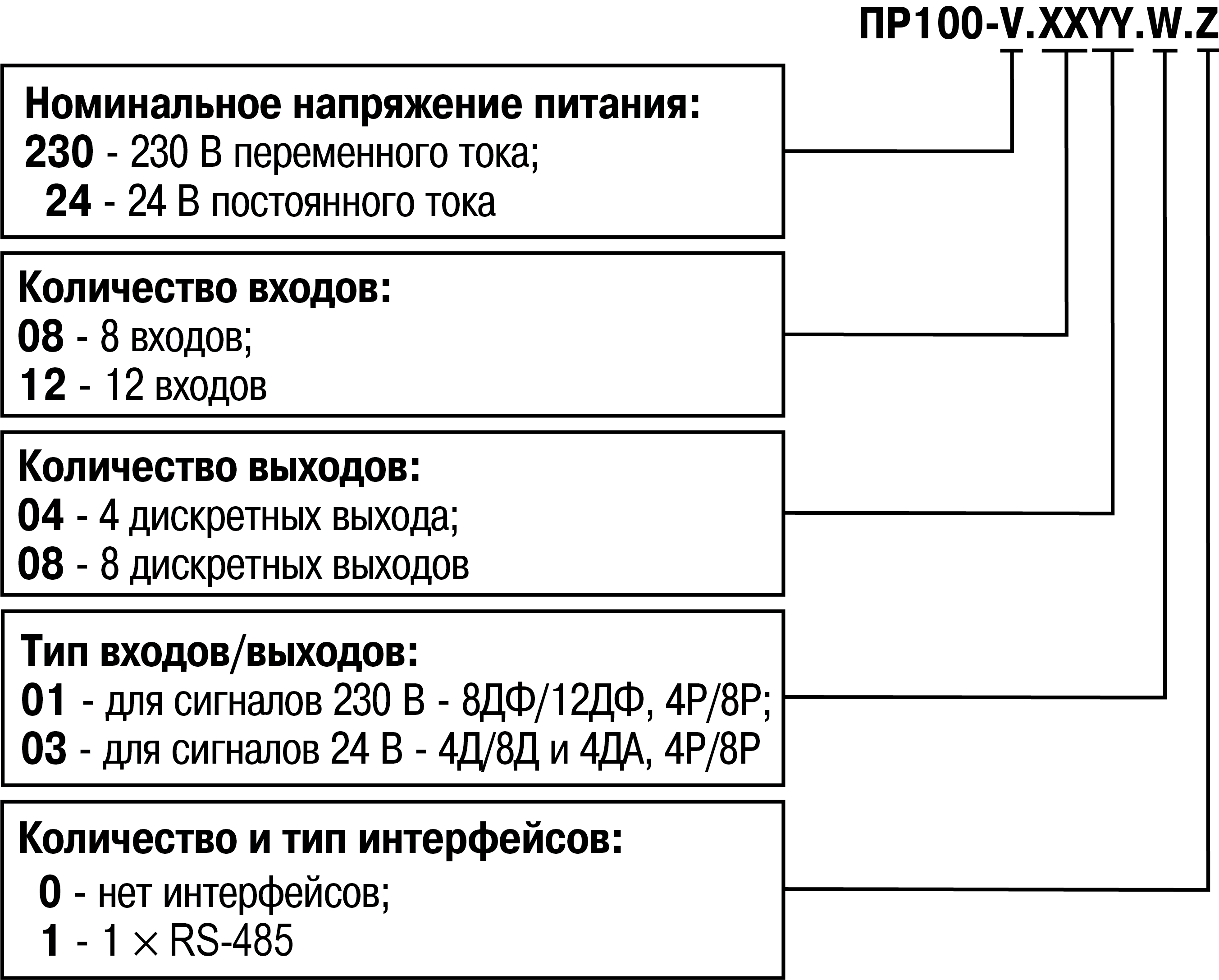
 Примечание
Расшифровка буквенных индексов входов и выходов
приведена в таблице.
Пример наименования при заказе: ПР100-230.0804.01.0.
Приведенное условное обозначение указывает, что изготовлению и
поставке подлежит ПР100, работающий при номинальном напряжении питания
230 В переменного тока и оснащенный:
- восемью дискретными входами для сигналов 230 В переменного тока;
- четырьмя дискретными выходами типа электромагнитное реле;
-
без интерфейсов.
Термины и аббревиатуры
-
Выходной элемент (ВЭ) – элемент схемы прибора, служащий
для подключения исполнительных механизмов или коммутации внешнего
управляющего сигнала. -
ОЗУ – оперативное запоминающее устройство, оперативная
память. -
ПЗУ – постоянное запоминающее устройство, энергонезависимая
память. -
ПК – персональный компьютер.
-
ПО – программное обеспечение.
-
Пользовательская программа – программа, созданная в
среде OwenLogic. -
Modbus – открытый протокол обмена по сети RS-485, разработан
компанией ModiCon, в настоящий момент поддерживается независимой организацией
Modbus-IDA (www.modbus.org). -
OwenLogic – специализированная
среда программирования прибора на основе визуального языка графических
диаграмм FBD (Function Block Diagram). -
Retain-память – энергонезависимая память для хранения
значений Retain-переменных пользовательской программы.
-
Retain-переменные – переменные пользовательской программы,
значение которых сохраняется при выключении питания прибора..
-
RTC (Real Time Clock) – часы реального времени.
Назначение и функции
ПР100 предназначен для построения автоматизированных систем управления
технологическим оборудованием в промышленности, жилищно-коммунальном
и сельском хозяйстве.
Прибор программируется в OwenLogic на языке
FBD. Пользовательская программа записывается в энергонезависимую Flash-память
прибора.
Прибор выпускается согласно ТУ 26.51.70-025-46526536-2018.
Функции прибора:
- работа по пользовательской программе, записанной в память;
-
работа в сети RS-485 по протоколу Modbus RTU/Modbus ASCII в
режиме Master или Slave (для модификаций с интерфейсом RS-485); - обработка входных сигналов от датчиков;
- управление подключенными устройствами с помощью дискретных сигналов.
Технические характеристики и условия эксплуатации
Технические характеристики
Модификации прибора
| Модификация | Тип питания | Входы | Выходы | Наличие интерфейса RS-485 |
|
|---|---|---|---|---|---|
| Дискретные | Аналоговые | Дискретные | |||
| ПР100-230.0804.01.0 | ~230 В | 8 ДФ | — | 4 Р |
Нет |
| ПР100-230.0804.01.1 | ~230 В | 8 ДФ | — | 4 Р | Да |
| ПР100-230.1208.01.0 | ~230 В | 12 ДФ | — | 8 Р | Нет |
| ПР100-230.1208.01.1 | ~230 В | 12 ДФ | — | 8 Р | Да |
| ПР100-24.0804.03.0 | =24 В | 4 Д | 4 ДА | 4 Р | Нет |
| ПР100-24.0804.03.1 | =24 В | 4 Д | 4 ДА | 4 Р | Да |
| ПР100-24.1208.03.0 | =24 В |
8 Д |
4 ДА |
8 Р | Нет |
| ПР100-24.1208.03.1 | =24 В | 8 Д | 4 ДА | 8 Р | Да |
|
Расшифровка буквенных индексов входов и выходов приведена |
Коды входов/выходов
| Тип | Таблица характеристик |
|---|---|
| Дискретный вход для сигналов =24 В (вход типа «Д») |
таблица |
| Дискретный вход для сигналов ~230 В (вход типа «ДФ») |
таблица |
| Универсальный аналоговый вход (вход типа «ДА») | таблица |
| Дискретный выход типа «электромагнитное реле» (выход типа «Р») | таблица |
Характеристики питания 24 В
| Параметр | Значение |
|---|---|
|
Диапазон напряжения питания |
=9…30 В (номинальное =24 В) |
|
Гальваническая развязка |
Есть |
|
Электрическая прочность изоляции между входом питания и |
1500 В |
|
Потребляемая |
4 Вт |
| Защита от подачи питающего напряжения неправильной полярности |
Есть |
Характеристики питания 230 В
| Параметр | Значение |
|---|---|
|
Диапазон переменного напряжения питания |
90 до 264 В (номинальное 230 В, при 50 Гц) |
| Диапазон постоянного напряжения питания | 127…373 В (номинальное 230 В) |
|
Гальваническая развязка |
Есть |
|
Электрическая прочность изоляции между входом питания и |
2300 В |
|
Потребляемая мощность, не более |
8 ВА |
Основные технические характеристики
|
Наименование |
Значение |
|---|---|
| Интерфейсы связи | |
| Тип интерфейса | RS-485 |
| Количество, не более (зависит от модификации) |
1 |
| Протокол связи | Modbus-RTU, Modbus-ASCII |
| Режим работы | Master/Slave |
| Скорость передачи данных |
9600, 14400, 19200, 38400, 57600, 115200 бит/с |
| Электрическая прочность изоляции между RS-485 и другими цепями |
1500 B |
| Индикация и управление | |
| Элементы индикации и управления |
см. раздел |
| Вычислительные ресурсы и дополнительное оборудование |
|
|
Минимальное время цикла (зависит от |
1 мс |
| Объем памяти для сетевых переменных (режим Slave) |
128 байт |
|
Модули расширения |
Нет |
|
Встроенные часы реального времени |
Есть |
| Точность хода часов реального времени |
± 3 с/сутки |
| Программирование | |
|
Среда программирования |
OwenLogic |
|
Объем Retain-памяти |
1 кбайт |
|
Объем ПЗУ |
128 кбайт |
|
Объем ОЗУ |
16 кбайт |
|
Интерфейс программирования |
USB |
| Общие | |
| Тип корпуса | Для крепления на DIN-рейку (35 мм) |
| Габаритные размеры прибора | 88 × 90 × 58 мм |
| Степень защиты корпуса по ГОСТ 14254 | IP20 |
| Масса прибора, не более (для всех вариантов исполнений) |
0,5 кг |
| Средний срок службы | 8 лет |
Характеристики входов
Характеристики дискретных входов «Д»
|
Наименование |
Значение |
|---|---|
| Номинальное напряжение питания цифровых входов (постоянного тока) |
24 В |
|
Напряжение «логической единицы» |
8,5…30 В |
|
Ток «логической единицы» |
2…5 мА |
|
Напряжение «логического нуля» |
минус 3…плюс 5 В |
|
Ток «логического нуля» |
0…15 мА |
|
Минимальная длительность импульса, воспринимаемая дискретным входом |
2 мс |
|
Максимальное время реакции на событие по дискретному входу |
30 мс |
|
Электрическая прочность изоляции |
2830 В |
Характеристики дискретных входов «ДФ»
|
Наименование |
Значение |
|---|---|
| Номинальное напряжение питания цифровых входов (переменного тока) |
230 В |
|
Напряжение «логической единицы» |
164…264 В |
|
Ток «логической единицы» |
0,75…1,5 мА |
|
Напряжение «логического нуля» |
0…40 В |
|
Ток «логического нуля» |
0…0,5 мА |
|
Минимальная длительность импульса, воспринимаемая дискретным входом |
25 мс |
|
Максимальное время реакции на событие по дискретному входу |
50 мс |
|
Электрическая прочность изоляции |
2830 В |
Характеристики универсальных входов «ДА»
|
Наименование |
Значение |
|---|---|
| Разрешающая способность АЦП |
12 бит |
| Режим аналогового входа |
|
|
Тип измеряемых униполярных |
|
| сигнал постоянного напряжения |
0…10 В |
| сигнал постоянного тока |
4…20 мА |
|
Предел основной приведенной погрешности |
± 0,5 % |
|
Дополнительная приведенная к диапазону измерений погрешность измерения |
0,5 от основной |
|
Дополнительная приведенная погрешность, вызванная изменением температуры |
0,5 % |
|
Предельное положительное входное напряжение, для режима дискретного |
30 В |
|
Входное сопротивление для режима 0…10 В, не менее |
61 кОм |
|
Гальваническая развязка |
Отсутствует |
| Режим дискретного входа |
|
| Порог переключения входа из состояния «логическая единица» в состояние «логический ноль» |
1…8 В (устанавливается в OwenLogic) |
| Порог переключения входа из состояния «логический ноль» в состояние «логическая единица» |
2…9 В (устанавливается в OwenLogic) |
|
Входной ток в режиме дискретного входа, при входном напряжении 15…30 В |
2…15 мА |
| Номинальное напряжение питания цифровых входов (постоянного тока) |
24 В |
|
Гальваническая развязка |
Отсутствует |
| Минимальная длительность импульса, воспринимаемая дискретным входом (постоянный ток) |
5 мс |
| Максимальная частота сигнала, воспринимаемая дискретным входом постоянного тока |
100 Гц |
|
Перед подключением |
Характеристики выходов
Характеристики дискретных выходов типа «Р»
|
Наименование |
Значение |
|---|---|
|
Тип выходного устройства |
Электромагнитное реле (нормально разомкнутые |
|
Электрическая прочность изоляции между |
|
|
Коммутируемое напряжение в нагрузке: |
|
|
30 В (резистивная нагрузка) |
|
250 В (резистивная нагрузка) |
|
Допустимый ток нагрузки, не более |
|
|
Допустимый ток нагрузки, не менее |
10 мА (при 5 В постоянного тока) |
|
Электрический ресурс реле, не менее |
|
Условия эксплуатации
Прибор предназначен для эксплуатации в следующих условиях:
- закрытые взрывобезопасные помещения без агрессивных паров и газов;
- температура окружающего воздуха от минус 40 до плюс 55 °С;
- верхний предел относительной влажности воздуха: не более 80 %
при +35 °С и более низких температурах без конденсации влаги; - допустимая степень загрязнения 1 (несущественные загрязнения или
наличие только сухих непроводящих загрязнений); - атмосферное давление от 84 до 106,7 кПа.
По устойчивости к климатическим воздействиям
во время эксплуатации прибор соответствует группе исполнения В4 по
ГОСТ Р 52931–2008.
По устойчивости к механическим воздействиям во
время эксплуатации прибор соответствует группе исполнения N2 по ГОСТ Р 52931–2008
(частота вибрации от 10 до 55 Гц).
По устойчивости к воздействию атмосферного давления
прибор относится к группе Р1 по ГОСТ Р 52931–2008.
Прибор отвечает требованиям по устойчивости к
воздействию помех в соответствии с ГОСТ IEC 61131-2–2012.
По уровню излучения радиопомех (помехоэмиссии)
прибор соответствует ГОСТ 30804.6.3.
Прибор устойчив к прерываниям, провалам и выбросам
напряжения питания для переменного тока в соответствии с требованиями ГОСТ 30804.6.3.
Меры безопасности
По способу защиты обслуживающего персонала от поражения электрическим
током, прибор относится к классу II ГОСТ IEC
61131-2-2012.
Во время эксплуатации, технического обслуживания
и поверки прибора следует соблюдать требования ГОСТ 12.3.019–80, «Правил
эксплуатации электроустановок потребителей» и «Правил охраны труда
при эксплуатации электроустановок».
Во время эксплуатации прибора открытые контакты клеммника находятся
под опасным для жизни напряжением. Прибор следует устанавливать в
специализированных шкафах, доступных только квалифицированным специалистам.
Любые подключения к прибору и работы по его техническому обслуживанию
следует производить только при отключенном питании прибора и подключенных
к нему устройств.
Не допускается попадание влаги на контакты выходного разъема и
внутренние электроэлементы прибора. Прибор запрещено использовать
в агрессивных средах с содержанием в атмосфере кислот, щелочей, масел и т. п.
Настройка и программирование
Ввод в эксплуатацию
Для ввода в эксплуатацию прибора следует:
-
Соединить ПК и прибор с помощью USB кабеля.
-
Подсоединить источник питания к съемному клеммнику.
 Предупреждение
Перед подачей питания на ПР100-230.Х следует проверить уровень напряжения питания. Если
напряжение выше 264 В, то прибор может выйти выйдет из строя.Перед подачей питания на ПР100-24.Х
следует проверить правильность подключения напряжения питания и его
уровень:- если напряжение ниже 9 В, то прибор прекращает функционировать,
но не выходит из строя, поэтому не гарантируется его работа; - если напряжение выше 30 В, то прибор может выйти из строя;
-
в случае неверного подключения к источнику постоянного напряжения
(перепутана полярность) прибор не включится.
- если напряжение ниже 9 В, то прибор прекращает функционировать,
-
Съемный клеммник подключить к прибору.
ПредупреждениеВ случае изменения температуры окружающего воздуха с низкой на
высокую в приборе возможно образование конденсата. Чтобы избежать
выхода прибора из строя рекомендуется выдержать прибор в выключенном
состоянии не менее 1 часа. -
Подать питание на прибор.
-
Убедиться в отсутствии системных ошибок (см. раздел).
-
Запустить OwenLogic и настроить часы.
-
Снять питание и отключить USB кабель.
-
Подключить провод USB и подать питание. Проверить время/дату.
В случае сброса часов заменить батарейку (см. раздел). Если часы работают корректно, то обесточить прибор. -
Настроить входы и выходы. Если требуется, настроить сетевой
интерфейс. -
Создать пользовательскую программу OwenLogic и записать ее в память прибора. Пользовательская программа записывается
в энергонезависимую память прибора и запускается после включения питания
или перезагрузки прибора.ПримечаниеЗаписать в память прибора
пользовательскую программу можно с помощью специально созданного исполняемого
файла (см. Мастер тиражирования в справке OwenLogic). -
Снять питание.
-
Подсоединить линии связи «прибор – устройства» съемным клеммникам.
-
Съемные клеммники подключить к прибору (см. Приложение Описание клеммников).
Если после включения питания пользовательская программа не начала
выполняться, необходимо повторно записать пользовательскую программу
в прибор. Если пользовательскую программу не удалось записать, то
следует остановить программу, переведя переключатель Работа/Стоп в
положение Стоп (см. раздел).
Настройка универсальных входов
Для выбора сигнала датчика следует задать параметр «Сигнал датчика»
в OwenLogic.
 Предупреждение
Каждый из типов сигнала подключается с помощью
индивидуальных клемм:
-
отдельная клемма для сигнала тока;
-
отдельная клемма для сигналов напряжения и дискретных сигналов.
 Внимание
Подача сигналов, не соответствующих аппаратной
конфигурации каналов, приводит к выходу из строя прибора. Перед включением
следует проверить конфигурацию входа.
Меню настройки универсальных входов расположено в OwenLogic во вкладке Прибор/Настройка прибора (см. рисунок).

входа
Настройки универсального входа
| Название | Описание |
|---|---|
| Режим работы входа | Позволяет выбрать между двумя режимами работы: аналоговый или дискретный |
| Постоянная времени фильтра | Постоянная времени фильтрации встроенного сглаживающего цифрового фильтра. Увеличение значения параметра улучшает помехозащищенность канала, но одновременно увеличивает его инерционность, т. е. реакция прибора на быстрые изменения входной величины замедляется |
| Аналоговый режим | |
| Сигнал датчика |
Выбор типа входного сигнала:
|
| Нижняя граница измерения | Задает минимальный уровень измеренного сигнала |
| Верхняя граница измерения | Задает максимальный уровень измеренного сигнала |
| Дискретный режим | |
| Уровень переключения в “0” | Задает границу определения «логического нуля» |
| Уровень переключения в “1” | Задает границу определения«логической единицы» |
Работа входа в аналоговом режиме
Для измерения токового сигнала 4…20 мА в прибор встроен шунтирующий
резистор номиналом 121 Ом для каждого канала. В приборе масштабируются
шкалы измерения для каналов «0…10 В» и «4…20 мА», после чего контролируемые
физические величины отображаются непосредственно в единицах их измерения
(атмосферах (кг/см2), кПа и т. д.). Для каждого такого
датчика следует установить диапазон измерения:
-
нижняя граница диапазона измерения задается параметром «нижняя
граница измерения» и соответствует минимальному уровню выходного сигнала
датчика; -
верхняя граница диапазона измерения задается параметром «верхняя
граница измерения» и соответствует максимальному уровню выходного
сигнала датчика.
Для сигнала 4…20 мА параметр «Смещение десятичной точки» используется
во время обмена по протоколу Modbus и определяет точность передаваемого
значения в формате целого числа.
Используется датчик с выходным током 4…20 мА, контролирующий
давление в диапазоне 0…25 атм, в параметре «нижняя граница измерения»
задается значение «0,00», а в параметре «верхняя граница измерения»
— значение «25,00» (см. рисунок). Теперь значения на аналоговом входе будут
измеряться в атмосферах.
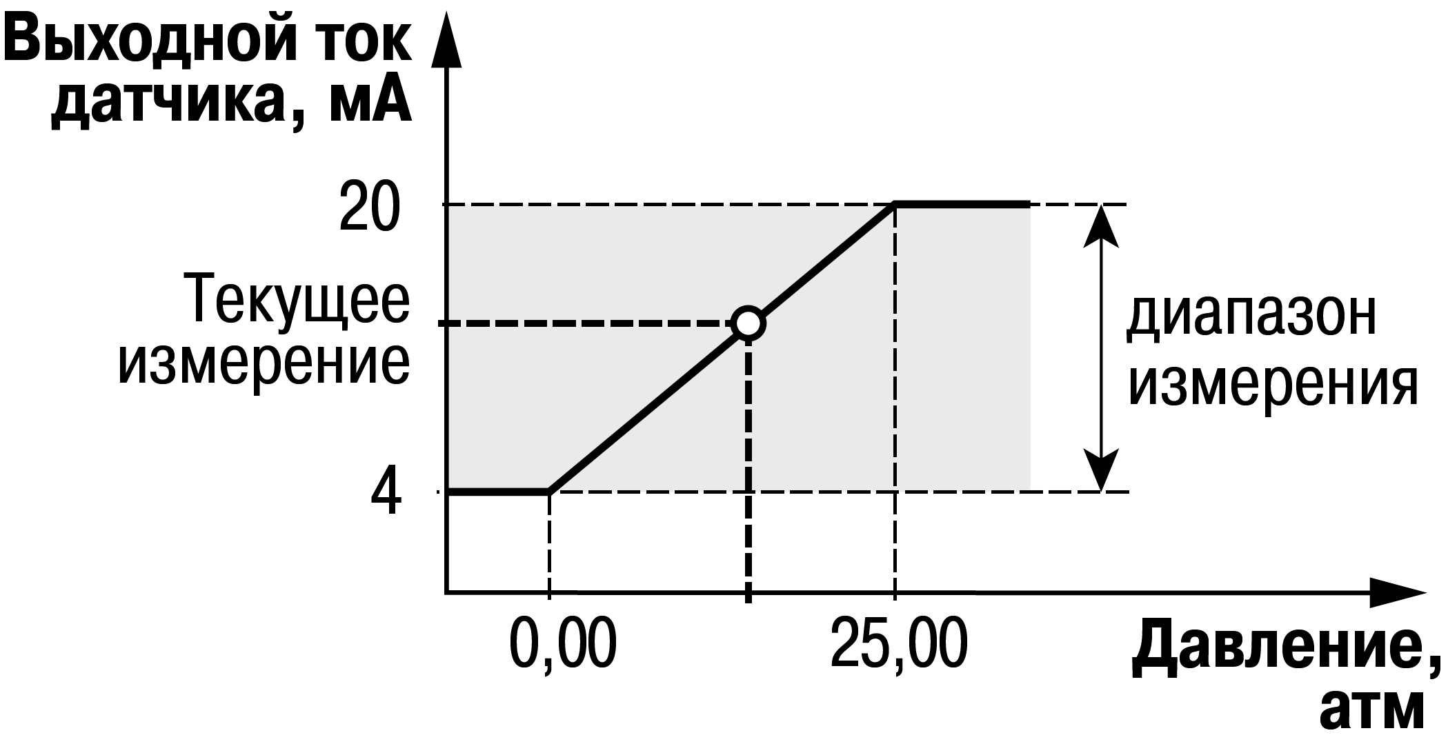
диапазона измерения
Значения в приборе представлены в абсолютном виде (float32).
Работа входа в дискретном режиме
Вход работает в режиме компаратора. Минимальный уровень «логического
нуля» — 0 В, максимальный уровень «логической единицы» 30 В (см. рисунок).
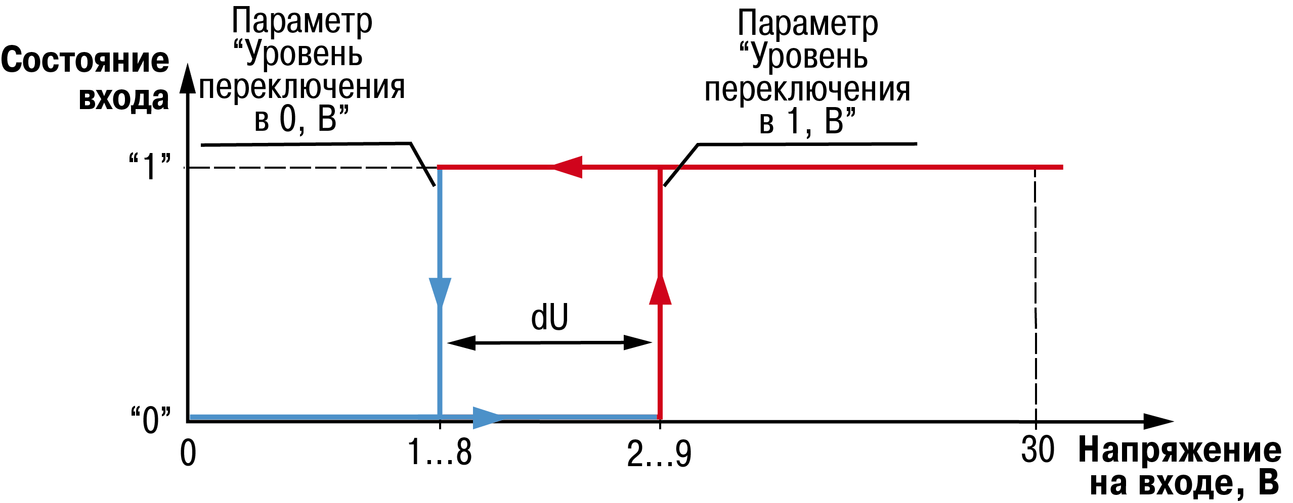
Чтобы избежать неоднозначности определения состояния входа, следует
устанавливать параметр «Уровень переключения в “1”» больше параметра
«Уровень переключения в “0”», как минимум, на 0,5 В.
Если входное напряжение попадает в диапазон dU (см. рисунок), то состояние входа не меняется.
Условия изменения состояния входа:
-
состояние входа изменится с «0» на «1» только при достижении
входным напряжением «Минимального уровня логической единицы» (в настройках OwenLogic это параметр «Уровень переключения в “1”»); -
состояние входа изменится с «1» на «0» только при достижении
входным напряжением «Максимального уровня логического нуля» (в настройках OwenLogic это параметр «Уровень переключения в “0”»).
Настройка дискретных входов
Для модификаций прибора с питанием =24 В у дискретных входов есть
настройка «Фильтр дребезга контактов».
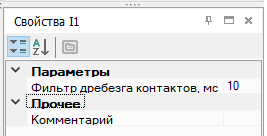
Настройка дискретного входа
| Название | Описание |
|---|---|
| Фильтр дребезга контактов | Задает значение сглаживающего фильтра дребезга контактов. Увеличение значения параметра улучшает помехозащищенность канала, но одновременно увеличивает его инерционность, т. е. реакция прибора на быстрые изменения входной величины замедляется |
Сетевой интерфейс
Общие сведения
В приборе, в зависимости от модификации, устанавливается один интерфейс
RS-485 для организации работы по стандартному протоколу Modbus.
Для работы прибора по RS-485 следует настроить режим и параметры
обмена в OwenLogic.
Прибор работает по протоколу Modbus по одному режимов обмена данными:
Modbus-RTU (Master/Slave) или Modbus-ASCII (Master/Slave). Режим работы
Master/Slave можно выбрать в настройках прибора в OwenLogic.
В настройках прибора в OwenLogic выбирается
режим работы Master/Slave и подключаются/ отключаются подтягивающие
резисторы линий связи A и B.
Подтягивающие резисторы устанавливаются для задания определенного
состояния линий связи, когда в сети RS-485 нет передачи. Резисторы
устанавливаются в одном месте сети RS-485, как правило, возле Мастера.
Если прибор настроен на работу в режиме Master, то рекомендуется подключить
подтягивающие резисторы, если в режиме Slave – отключить.
Режим Master
На линии связи допускается наличие только одного устройства в режиме
Master.
В режиме Master прибор поддерживает следующие возможности:
- чтение по таймеру;
- чтение/запись по событию;
- запись по изменению (используется по умолчанию).
Прибор поддерживает управление до 16 устройствами. Каждое устройство
поддерживает до 256 переменных. Допускается использование одинаковых
адресов и имен переменных для каждого устройства.
Режим Slave
Прибор работает по протоколу Modbus по одному из режимов обмена
данными: Modbus-RTU (Slave) или Modbus-ASCII (Slave). Прибор автоматически
распознает режим обмена.
Прибор в режиме Slave поддерживает следующие функции:
- чтение значений из нескольких регистров флагов, хранения и ввода;
- чтение значений из одиночных регистров флагов, хранения и ввода;
-
запись значений в несколько регистров хранения и флагов;
- запись значений в одиночные регистры хранения и флагов.
Регистры прибора, доступные по протоколу Modbus, приведены в разделе .
Карта регистров Modbus
Функции чтения:
-
0х01 (read coil status);
-
0х02 (read multiple registers);
-
0х03 (read holding registers);
-
0х04 (read input registers).
Функции записи:
-
0х05 (force single coil);
-
0х06 (preset single register);
-
0х0F (force multiple coils);
-
0х10 (preset multiple registers).
Параметры битовой маски могут читаться функциями 0х03 и 0х01 —
в этом случае номер регистра следует умножить на 16 и прибавить номер
бита.
Поддерживаемые типы данных:
-
int16 — беззнаковое целое (2 байта), на каждый параметр
отводится один регистр Modbus; -
float32 — с плавающей точкой (4 байта), занимает два
соседних регистра Modbus. Число передается младшим регистром вперед
(little-endian);
-
bit — булевский тип, занимает один бит.
Типы доступа: R — только чтение, RW — чтение/запись.
Регистры, доступные по протоколу Modbus
|
Наименование модификации |
Параметр |
Тип переменной (тип функции Modbus) |
Адреса регистров (hex) |
Адреса регистров (dec) |
Тип доступа |
|---|---|---|---|---|---|
|
Дискретные входы |
|||||
| ПР100-24.0804.03.1 |
Дискретные входы (входы DI1…DI4) |
bit (01, 02) |
1000–1003 |
4096–4100 |
R |
|
int16 (03, 04) |
100 |
256 | R | ||
| ПР100-230.0804.01.1, ПР100-24.1208.03.1 |
Дискретные входы (входы DI1…DI8) |
bit (01, 02) |
1000–1007 |
4096–4103 |
R |
|
int16 (03, 04) |
100 |
256 | R | ||
| ПР100-230.1208.01.1 |
Дискретные входы (входы DI1…DI12) |
bit (01, 02) |
1000–1011 |
4096–4107 |
R |
|
int16 (03, 04) |
100 |
256 | R | ||
| Аналоговые входы | |||||
|
ПР100-24.0804.03.1, ПР100-24.1208.03.1 |
Универсальный вход № 1 (число с плавающей точкой) |
float32 (03, 04) |
B00, B01 |
2816, 2817 | R |
|
Универсальный вход № 2 (число с плавающей точкой) |
float32 (03, 04) |
B02, B03 |
2818, 2819 | R | |
|
Универсальный вход № 3 (число с плавающей точкой) |
float32 (03, 04) |
B04, B05 |
2820, 2821 | R | |
|
Универсальный вход № 4 (число с плавающей точкой) |
float32 (03, 04) |
B06, B07 |
2822, 2823 | R | |
|
Универсальный вход № 1 (целое число = результат измерения × 10dp) |
int16 (03, 04) |
B80 |
2944 | R | |
|
Универсальный вход № 2 (целое число = результат измерения × 10dp) |
int16 (03, 04) |
B81 |
2945 | R | |
|
Универсальный вход № 3 (целое число = результат измерения × 10dp) |
int16 (03, 04) |
B82 |
2946 | R | |
|
Универсальный вход № 4 (целое число = результат измерения × 10dp) |
int16 (03, 04) |
B83 |
2947 | R | |
|
Смещение десятичной точки № 1 (dp) |
int16 (03, 04) |
BC0 |
3008 | R | |
|
Смещение десятичной точки № 2 (dp) |
int16 (03, 04) |
BC1 |
3009 | R | |
|
Смещение десятичной точки № 3 (dp) |
int16 (03, 04) |
BC2 |
3010 | R | |
|
Смещение десятичной точки № 4 (dp) |
int16 (03, 04) |
BC3 |
3011 | R | |
|
Универсальный вход AI1 (дискретный режим) |
bit (01, 02) |
1010 |
4112 | R | |
|
Универсальный вход AI2 (дискретный режим) |
bit (01, 02) |
1011 |
4113 | R | |
|
Универсальный вход AI3 (дискретный режим) |
bit (01, 02) |
1012 |
4114 | R | |
|
Универсальный вход AI4 (дискретный режим) |
bit (01, 02) |
1013 |
4115 | R | |
|
Дискретные выходы |
|||||
| ПР100-230.0804.01.1, ПР100-24.0804.03.1 |
Дискретные выходы (Q1…Q4, F1, |
bit (01, 02, 05, 0F) |
0–5 |
0–5 | RW* |
|
int16 (03, 04, 06, 10) |
0 |
0 | RW* | ||
|
ПР100-230.1208.01.1, ПР100-24.1208.03.1 |
Дискретные выходы (Q1…Q8, F1, |
bit (01, 02, 05, 0F) |
0–9 |
0–9 | RW* |
|
int16 (03, 04, 06, 10) |
0 |
0 | RW* | ||
| Сетевые и служебные переменные | |||||
|
Все модификации |
Сетевые переменные |
bit (01, 02, 05, 0F) |
2000–23F0 |
8192–9200 | RW |
|
int16 (03, 04, 06, 10) |
200–23F |
512–575 | RW | ||
|
Все модификации |
Секунды |
int16 (03, 04, 06, 10) |
400 |
1024 | RW |
|
Минуты |
int16 (03, 04, 06, 10) |
401 |
1025 | RW | |
|
Часы |
int16 (03, 04, 06, 10) |
402 |
1026 | RW | |
|
Число |
int16 (03, 04, 06, 10) |
403 |
1027 | RW | |
|
Месяц |
int16 (03, 04, 06, 10) |
404 |
1028 | RW | |
|
Год |
int16 (03, 04, 06, 10) |
405 |
1029 | RW | |
|
День недели |
int16 (03, 04) |
406 |
1030 | R | |
|
Неделя в месяце |
int16 (03, 04) |
407 |
1031 | R | |
|
Неделя в году |
int16 (03, 04) |
408 |
1032 | R | |
|
* Запись состояния выходов по RS-485 возможна, если |
Монтаж
Установка
Опасность
Монтаж должен производить только обученный специалист
с допуском на проведение электромонтажных работ. При проведении монтажа
следует использовать индивидуальные защитные средства и специальный
электромонтажный инструмент с изолирующими свойствами до 1000 В.
Во время монтажа прибора следует учитывать меры безопасности из раздела.
Прибор следует монтировать в шкафу, конструкция которого должна
обеспечивать защиту от попадания в него влаги, грязи и посторонних
предметов.
Предупреждение
Монтировать и подключать следует только предварительно
сконфигурированный прибор.
Для монтажа прибора следует:
-
Подготовить на DIN-рейке место для установки в соответствии
с размерами прибора (см. рисунок).Габаритные размеры - Вставив отвертку в проушину, оттянуть защелку (см. рисунок, 1). Прибор установить на DIN-рейку.
- Прибор прижать к DIN-рейке (см. рисунок, 2, стрелки 1 и 2). Отверткой
вернуть защелку в исходное положение. - Смонтировать внешние устройства с помощью ответных клеммников
из комплекта поставки.
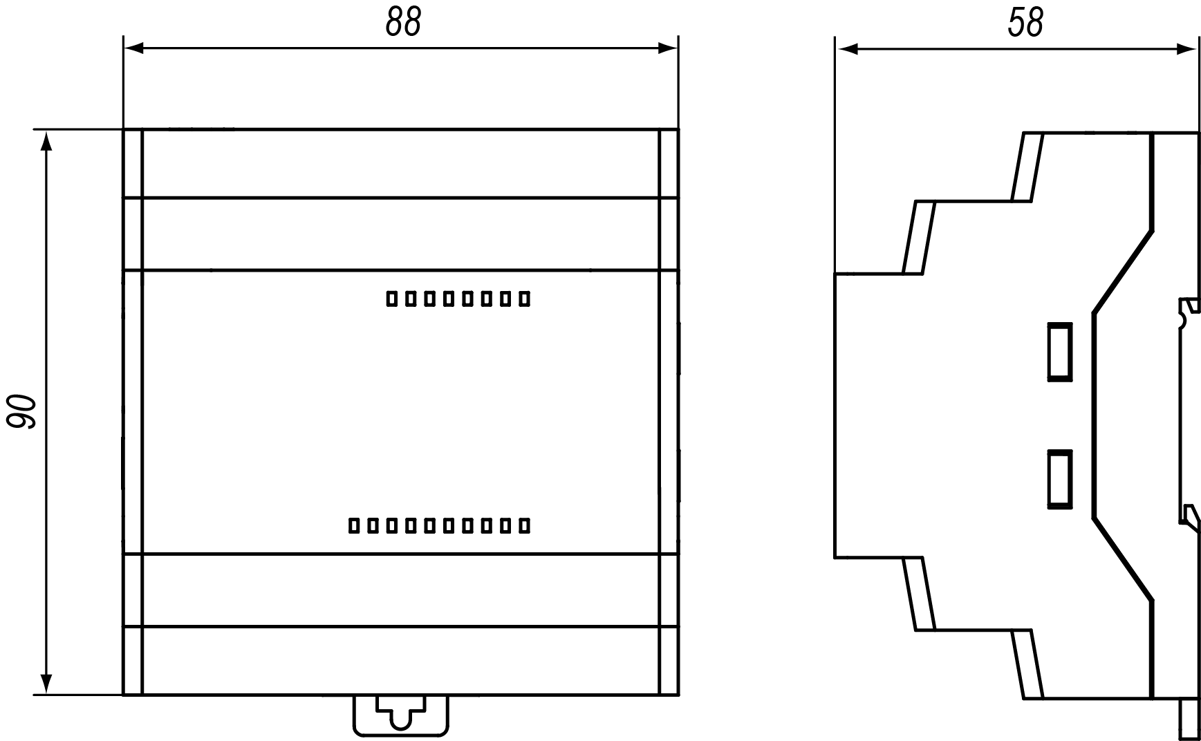
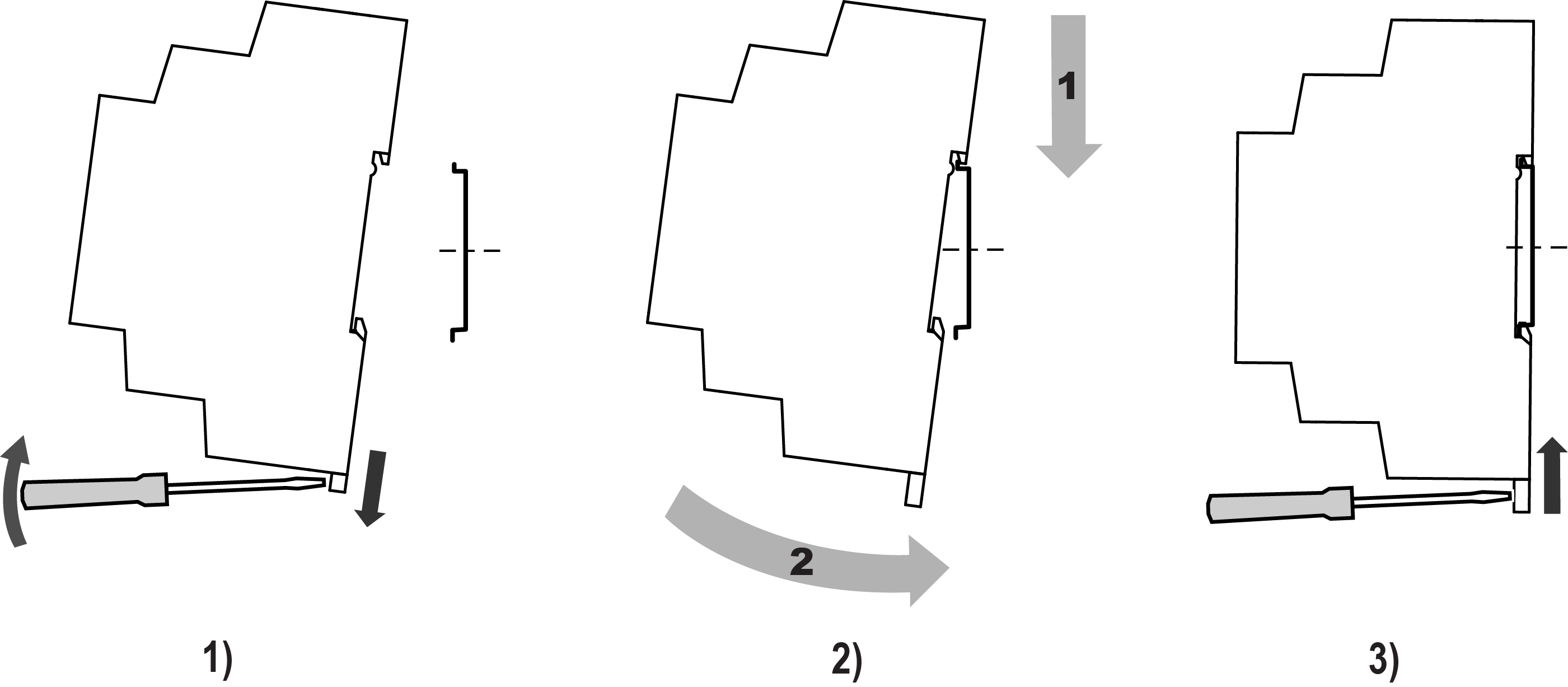
Для демонтажа прибора следует:
- Отсоединить съемные части клемм от прибора (см. раздел).
- В проушину защелки вставить острие отвертки.
-
Защелку отжать, после чего прибор отвести от DIN-рейки.
«Быстрая» замена
Конструкция клемм позволяет оперативно заменить прибор.
Для «быстрой» замены прибора следует:
-
Обесточить все линии связи подходящие к прибору, в том числе
линии питания. -
Отделить от прибора съемные части клемм с подключенными внешними
линиями связи с помощью отвертки (см. рисунок). -
Снять прибор с DIN-рейки, на его место установить другой прибор
(аналогичной модификации) с предварительно удаленными разъемными частями
клемм. -
К установленному прибору подсоединить отделенные ранее части
клемм с подключенными внешними линиями связи.
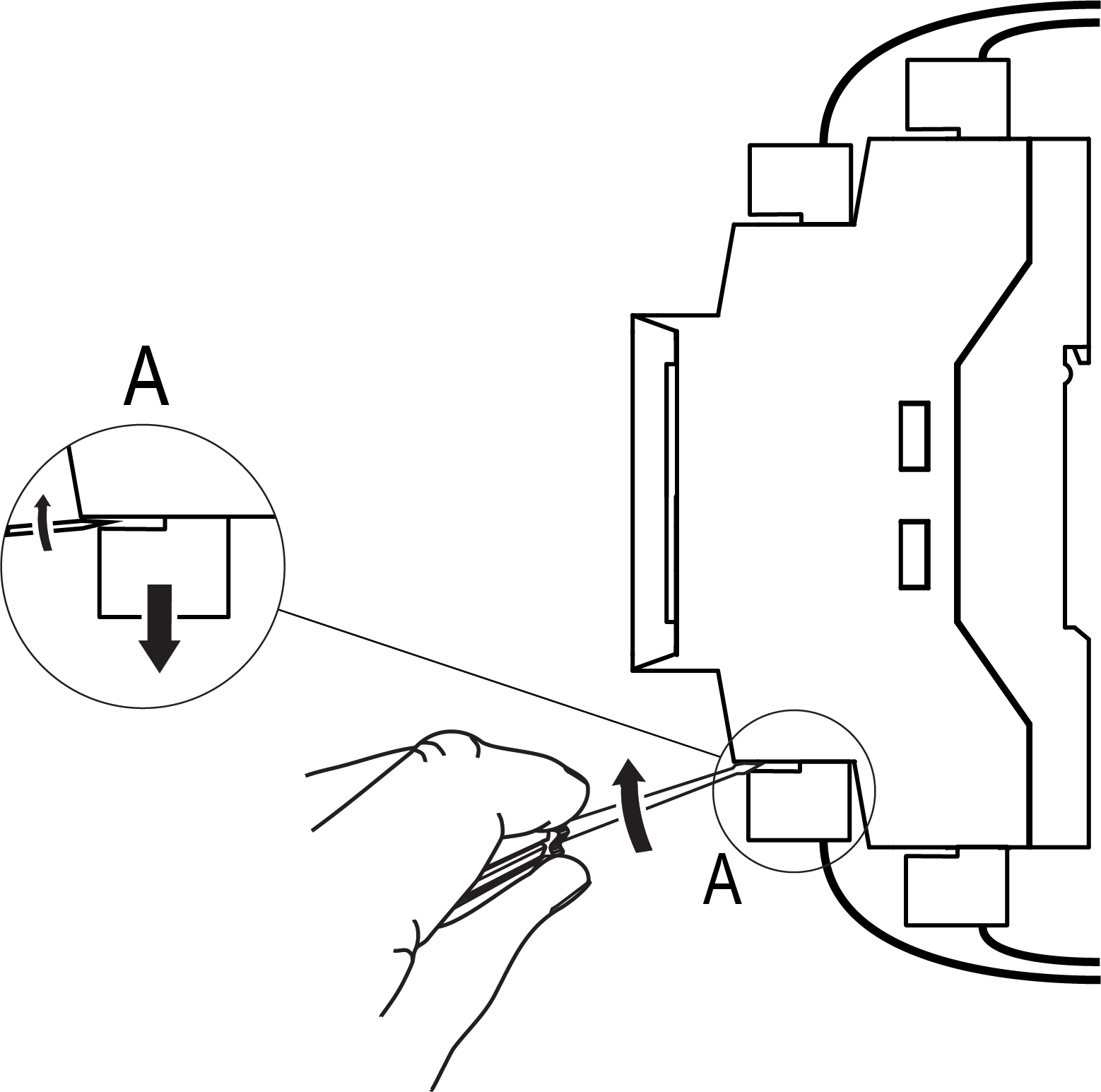
Подключения
Рекомендации к подключению
Прибор следует подключать к сети переменного тока от сетевого фидера,
не связанного непосредственно с питанием мощного силового оборудования.
Во внешней цепи рекомендуется установить выключатель, обеспечивающий
отключение прибора от сети.
Внимание
Питание каких-либо устройств от сетевых контактов
прибора запрещается.
Для обеспечения надежности электрических соединений рекомендуется
использовать медные многожильные кабели, концы которых перед подключением
следует тщательно зачистить и залудить или использовать кабельные
наконечники. Жилы кабелей следует зачищать так, чтобы их оголенные
концы после подключения к прибору не выступали за пределы клеммника.
Сечение жил кабелей должно быть не более 2,5 мм2.
Для записи пользовательской программы прибор подключается через
интерфейсный порт microUSB к USB-порту ПК.
Внимание
Перед подключением разъема USB прибор должен
быть обесточен!
Аналоговые входы и интерфейс USB не имеют гальванической развязки
между собой. Для безопасной работы с данными портами, подключаемое
к ним оборудование должно иметь одинаковый потенциал цепей заземления,
или иметь гальваническую изоляцию. Чтобы избежать выхода из строя
прибора, перед включением оборудования следует убедиться, что подключаемые
к данным портам устройства имеют одинаковый потенциал цепей заземления.
Если нет возможности обеспечить одинаковый потенциал цепей заземления,
то не следует подключать устройства к аналоговым входам и USB одновременно.
Например, во время программирования прибора по USB следует отключать
от аналоговых входов кабели или использовать устройства с гальванической
развязкой (устройство гальванической развязки интерфейса USB, ноутбук
с питанием от батареи и т. п.).
Предупреждение
Питание датчиков, концевых выключателей
и других периферийных устройств, подключаемых к аналоговым входам
прибора, должно осуществляться только от источника питания с усиленной
изоляцией согласно ГОСТ IEC 61131-2-2012, чтобы исключить появление
опасного напряжения на портах прибора.
Внимание
Запрещается запитывать датчики и прибор от одного
источника питания!
Помехи и методы их подавления
На работу прибора могут оказывать влияние внешние помехи:
- возникающие под действием электромагнитных полей (электромагнитные
помехи), наводимые на прибор и на линии связи с внешним оборудованием; - в питающей сети.
Для уменьшения влияния электромагнитных помех рекомендуется:
- надежно экранировать сигнальные линии, экраны следует электрически
изолировать от внешнего оборудования на протяжении всей трассы и подсоединить
к заземленному контакту щита управления; - установить прибор в металлическом шкафу, внутри которого не должно
быть никакого силового оборудования, корпус шкафа должен быть заземлен.
Для уменьшения помех, возникающих в питающей сети рекомендуется:
- монтируя систему, в которой работает прибор, следует учитывать
правила организации эффективного заземления и прокладки заземленных
экранов:- все заземляющие линии и экраны прокладывать по схеме «звезда»
с обеспечением хорошего контакта с заземляемым элементом; - заземляющие цепи должны быть выполнены кабелями наибольшего сечения.
- все заземляющие линии и экраны прокладывать по схеме «звезда»
Для уменьшения уровня помех можно применять программные фильтры,
которые настраиваются индивидуально для каждого входа. Программные
фильтры доступны для:
- всех типов аналоговых датчиков;
- дискретных входов с номинальным напряжением 24 В.
Примечание
Увеличение значения постоянной времени фильтра аналогового
входа замедляет реакцию прибора на быстрые изменения входной величины.
Гальваническая развязка
Схемы гальванической развязки
Подключение датчиков
Общие сведения
Предупреждение
Для защиты входных цепей прибора от возможного
пробоя зарядами статического электричества, накопленного на линиях
связи «прибор – датчик», перед подключением к клеммнику прибора их
жилы следует на 1–2 секунды соединить с винтом функционального заземления
(FE) щита.
Во время проверки исправности датчика и линии связи следует отключить
прибор от сети питания. Чтобы избежать выхода прибора из строя при
«прозвонке» связей, следует использовать измерительные устройства
с напряжением питания не более 4,5 В. Для более высоких напряжений
питания измерительных устройств отключение датчика от прибора обязательно.
Подключение дискретных датчиков к входам типа «ДФ» и «Д»
Подключение аналоговых датчиков
Внимание
В случае использования универсальных входов в
аналоговом режиме следует правильно подключать датчики к соответствующим
контактам аналоговых входов: датчики с выходом 0…10 В и дискретные
датчики подключать только к контактам аналоговых входов «U», а датчики
с выходом 0…20 мА подключать только к контактам аналоговых входов
«I».
Режимы работы универсального входа переключаются в OwenLogic (см. раздел).
Внимание
Требуется обеспечить соответствие между подключением
датчика к определенным клеммам и настройкой в OwenLogic.
Параметры линии соединения прибора с датчиком приведены в таблице
ниже.
Параметры линии связи прибора с датчиками
| Тип датчика |
Длина линий, м, не более |
Сопротивление линии, Ом, не более |
Исполнение линии |
|---|---|---|---|
| Унифицированный сигнал постоянного тока | 100 | 100 | Двухпроводная |
| Унифицированный сигнал напряжения постоянного тока | 100 | 5 | Двухпроводная |
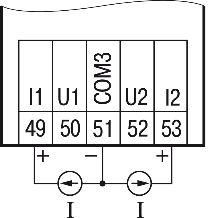
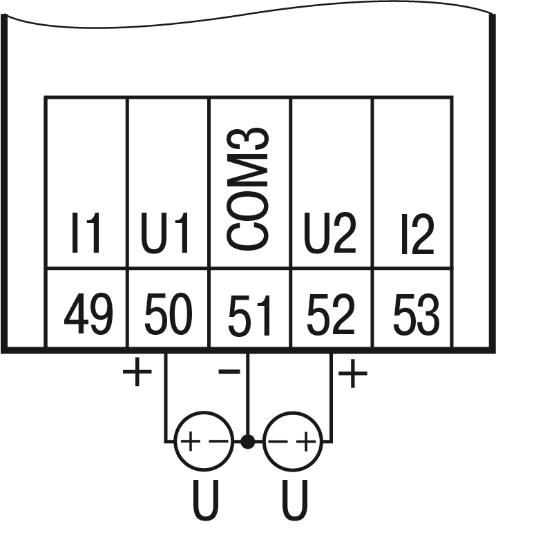
0…10 В»
Подключение нагрузки к ВЭ
Подключение нагрузки к ВЭ типа «Р»
Электромагнитное реле предназначено для коммутации силовых цепей
напряжением не более 250 В переменного тока и рабочим током не более
5 А.
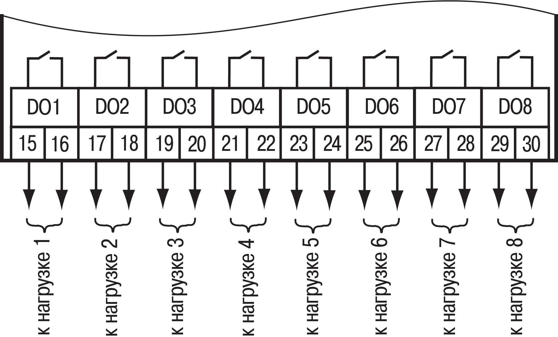
Подключение к сети RS-485
Следует обеспечить максимально-возможную близость значений сопротивления
согласующего резистора Rсогл и волнового сопротивления
кабеля. Стандартные кабели для организации сети RS-485 имеют волновое
сопротивление 120 Ом.
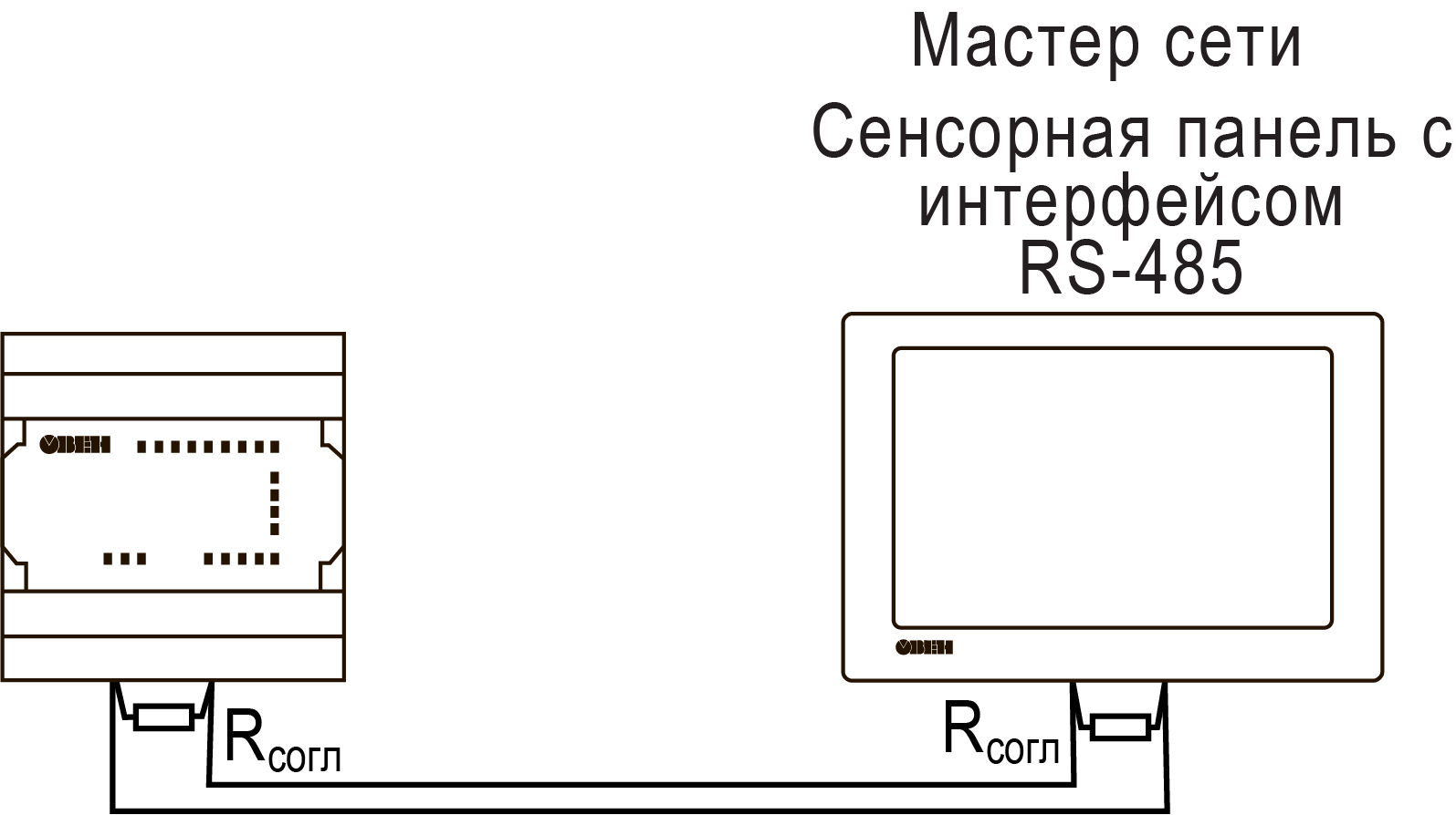
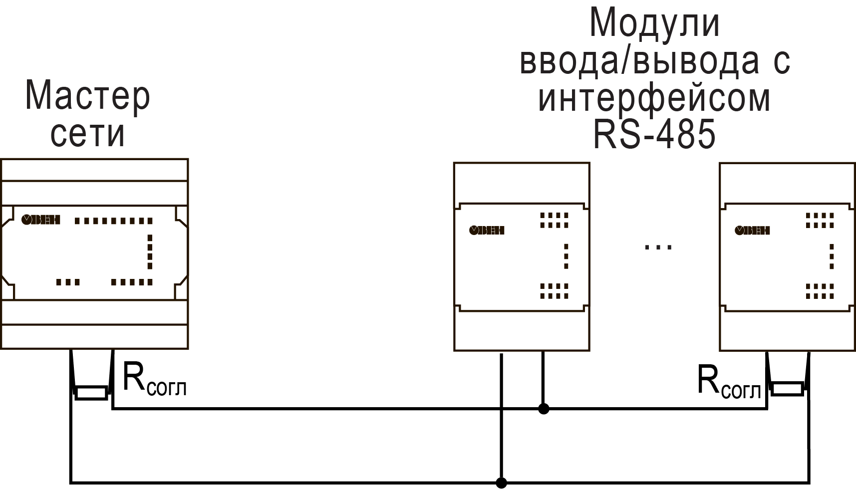
Подключение к ПК
Разъем для программирования прибора располагается под крышкой (см. раздел). Для подключения прибора к ПК следует
использовать кабель microUSB B — USB A.
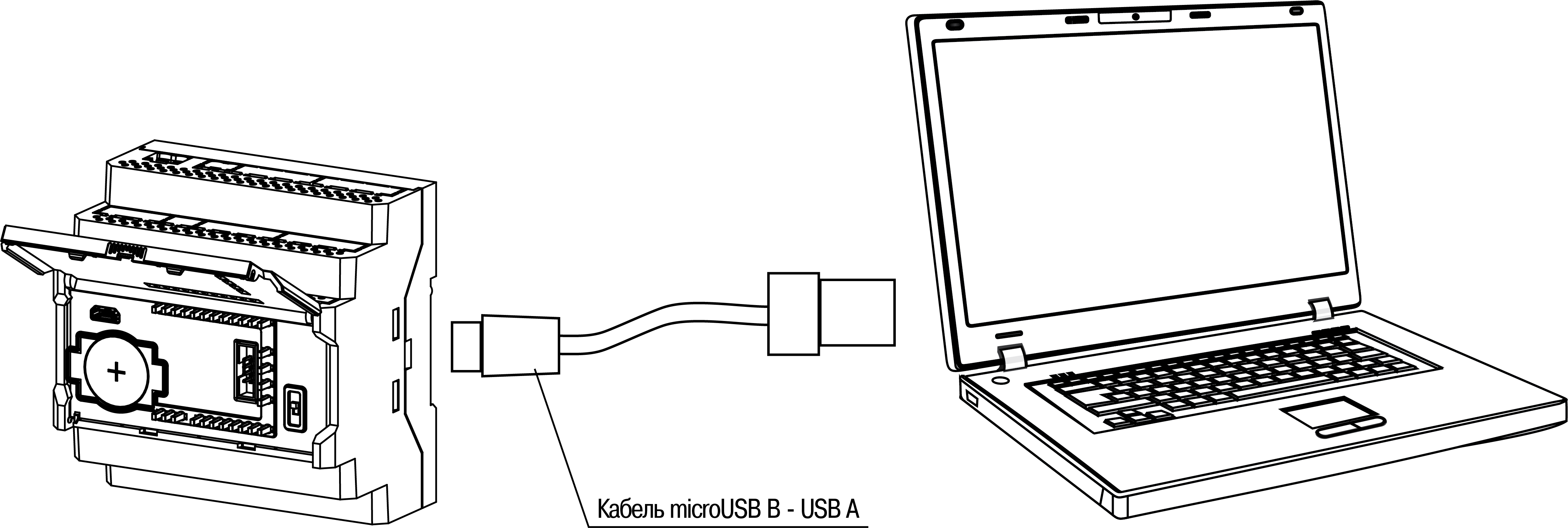
Эксплуатация
Управление и индикация
На лицевой панели прибора расположены светодиоды (см. рисунок ниже).
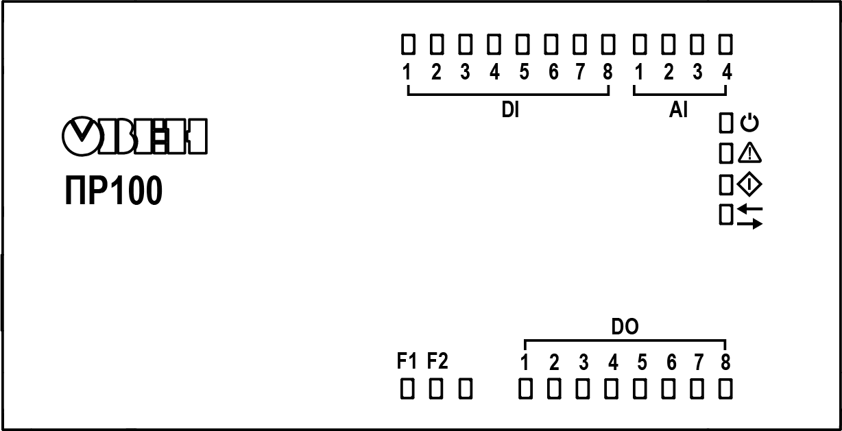
панель прибора
Назначение светодиодов
| Светодиод | Статус | Назначение |
|---|---|---|
|
(зеленый) |
Светится | На прибор подано питание |
 (красный) (красный) |
Светится |
1) Сбой программы; 2) Ошибка RETAIN; 3) Системная ошибка (подробнее см. раздел) |
| Мигает | Перегрев прибора из-за нарушения условий эксплуатации |
|
| F1 (зеленый) | — | Определяется при программировании |
| F2 (зеленый) | — | |
|
DI1…DI8* (зеленые) |
Светится | На соответствующий вход подано напряжение, соответствующее уровню «логической единицы» |
|
AI1…AI4** (зеленые) |
Светится | Соответствующий аналоговый вход настроен как дискретный и, если на вход подано напряжение, соответствующее уровню «логической единицы» |
|
DO1…DO8* (зеленые) |
Светится | Соответствующий дискретный выход находится в активном состоянии (реле замкнуто) |
|
(двухцветный, красный |
— | Зависит от положения переключателя Работа/Стоп (см. раздел) |
| Светится (красный) | Основное питание отключено, питание от USB, пользовательская программа не выполняется |
|
| Светится (зеленый) | Основное питание подключено, пользовательская программа выполняется |
|
|
Светится (красный) Мигает (зеленый) |
Основное питание подключено, запись пользовательской программы в прибор |
|
 |
— | Cветодиод не задействован |
|
* Нумерация отличается у различных модификаций. ** Есть в модификациях с питанием 24 В. |


Лицевая панель прибора представляет собой подвижный элемент, соединенный
с верхней частью корпуса с помощью двух петель.
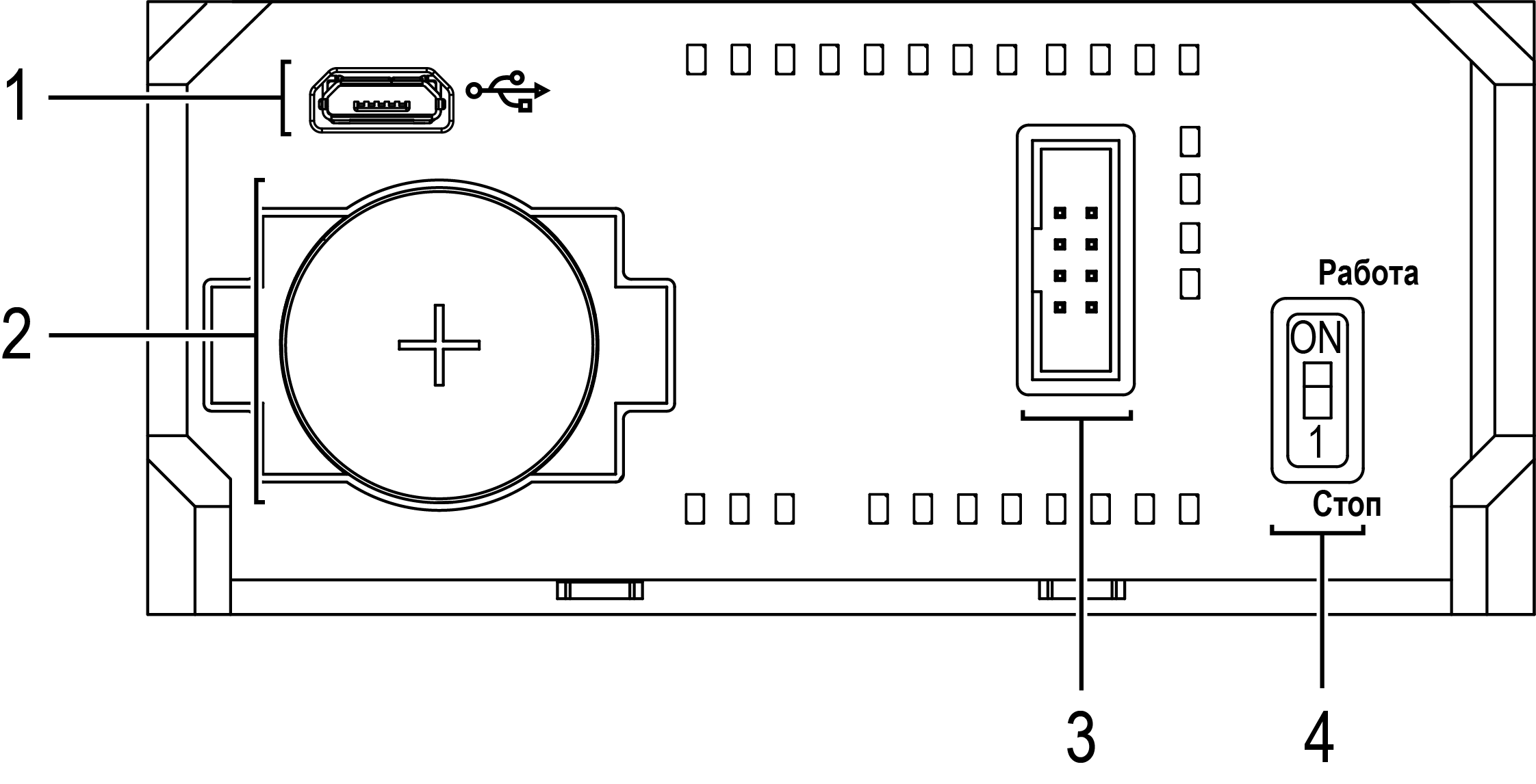
Под лицевой панелью расположены:
-
Мicro-USB порт для подключения прибора к ПК.
- Слот с батареей RTC.
-
Сервисный разъем. Предназначен для диагностики прибора в сервисном
центре. - Переключатель Работа/Стоп.
Переключатель Работа/Стоп
| Положение переключателя |
Функция |
|---|---|
| Работа | Пользовательская программа выполняется |
| Стоп | Пользовательская программа остановлена. Можно обновить встроенное ПО прибора (разделе). Или заменить пользовательскую программу, если она вызывает некорректную работу прибора |
| Прибор работает в режиме модуля ввода/вывода (см. раздел) |
Функции переключателя Работа/Стоп
Установка переключателя в положение Стоп:
-
позволяет сменить:
-
встроенное ПО прибора (разделе);
-
пользовательскую программу, если она вызывает некорректную
работу прибора.
-
- переводит прибор в режим модуля ввода/вывода (см. раздел).
Режимы работы
По включению напряжения питания (основного или от USB), прибор
анализирует положение переключателя Работа/Стоп. Далее прибор
проводит самодиагностику.
Для программирования прибора достаточно питания от USB. При питании
от USB, не работают входы, выходы и интерфейс RS-485.
Пользовательская программа, если она записана в память прибора,
начинает выполняться сразу после подачи основного питания на клеммы
1 и 2.
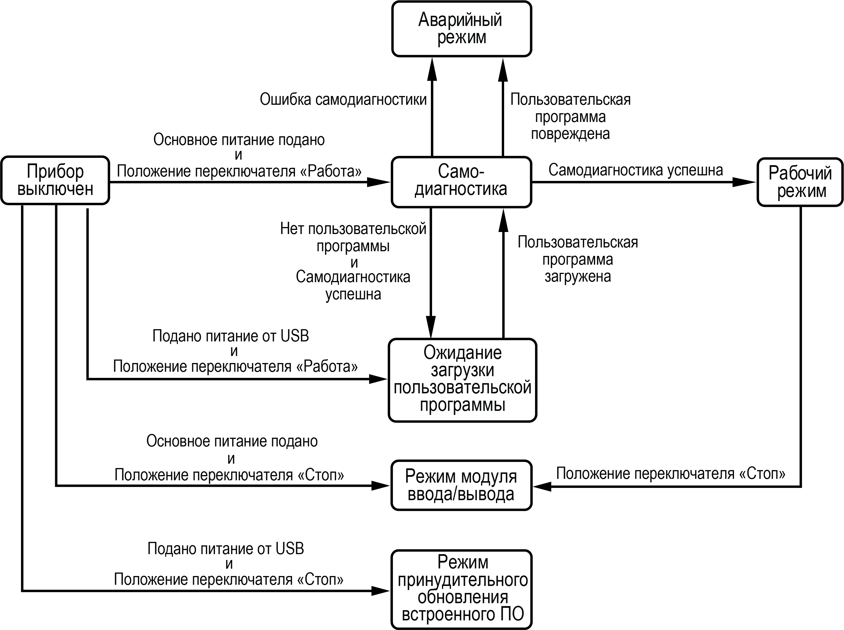
Рабочий режим
В рабочем режиме прибор повторяет следующую последовательность
(рабочий цикл):
- начало цикла;
- чтение состояния входов;
- выполнение кода пользовательской программы;
- запись состояния выходов;
- переход в начало цикла.
В начале цикла прибор считывает состояния входов и копирует считанные
значения в область памяти входов. Далее выполняется код пользовательской
программы, которая работает с копией значений входов.
Аварийный режим
В случае возникновения аварийной ситуации прибор переходит в аварийный
режим.
В таблице ниже представлены примеры аварийных ситуаций и рекомендации
по их устранению.
Неисправности и способы их устранения
|
Индикация светодиода |
Причина |
Рекомендации |
|---|---|---|
| Мигает | Перегрев прибора из-за нарушения условий эксплуатации |
Создать в помещении, где установлен |
| Светится |
Сбой программы. Не совпала контрольная |
Обновить встроенное ПО прибора. Повторно загрузить пользовательскую программу в прибор. В случае неудачи обратиться в сервисный центр |
|
Ошибка RETAIN. Не удалось восстановить |
||
|
Системная ошибка. Работа прибора невозможна |
Режим модуля ввода/вывода
Если переключатель Работа/Стоп перевести в положение Стоп (см. раздел), то пользовательская
программа будет остановлена и прибор начнет работать в режиме модуля
ввода/вывода.
Для работы в режиме модуля ввода/вывода следует предварительно
настроить интерфейс RS-485 в режим Slave (из OwenLogic). В режиме модуля ввода/вывода доступен опрос входов и
запись выходов, но сетевые переменные недоступны.
Часы реального времени
Прибор оснащен встроенными часами реального времени. При наличии
питания прибора часы реального времени питаются от него. В случае
отсутствия питания часы реального времени питаются от батареи.
Энергии полностью заряженной батареи хватает на непрерывную работу
часов реального времени в течение 5 лет. В случае эксплуатации прибора
при температуре на границах рабочего диапазона время работы часов
сокращается.
В OwenLogic можно настроить коррекцию показаний
часов реального времени прибора с помощью часов ПК или с помощью корректирующего
значения (см. руководство пользователя OwenLogic).
Обновление встроенного ПО
В приборе можно изменять версии встроенного программного обеспечения
через интерфейс программирования.
Для смены встроенного ПО следует подготовить:
-
ПК с ОС Windows Vista/7/8/10, установленным OwenLogic и доступом в Интернет;
-
установить драйвер прибора на ПК.
OwenLogic может обновить ПО прибора во время
записи пользовательской программы.
Если встроенное ПО не получается автоматически обновить, то его
можно обновить принудительно. Принудительное обновление встроенного
ПО может потребоваться, если прибор не определяется в OwenLogic, но подключение прибора корректно отображается
в Диспетчере устройств.
Для принудительной смены встроенного ПО следует:
-
Подключить прибор к ПК кабелем USB.
-
Подать питание на прибор.
-
Открыть крышку на лицевой стороне прибора. Установить переключатель
Работа/Стоп в положение Стоп. Светодиод начинает светиться красным.
В данном режиме блокируется встроенное ПО и пользовательская программа. -
Проверить в диспетчере устройств Windows какой СОМ-порт был
присвоен прибору. -
В OwenLogic указать номер присвоенного
COM-порта: Прибор/Настройка порта. -
В меню OwenLogic выбрать пункт Прибор/Обновить
встроенное ПО. Если модель прибора определена неверно, то из списка
выбрать нужную модель.ПримечаниеУточнить модель можно
по надписи на боковой поверхности прибора. -
Запустить обновление встроенного ПО нажатием кнопки Выбрать.
В процессе смены встроенного ПО светодиод
светит красным и мигающим зеленым
одновременно. Установить переключатель в положение Работа.
Запускается пользовательская программа. Светодиод переключается на зеленый цвет.
Если проблемы с работоспособностью прибора не удалось решить после
принудительной смены встроенного ПО, то следует обратиться в сервисный
центр.
Техническое обслуживание
Общие указания
Во время выполнения работ по техническому обслуживанию прибора
следует соблюдать требования безопасности из раздела.
Техническое обслуживание прибора проводится не реже одного раза
в 6 месяцев и включает следующие процедуры:
- проверка крепления прибора;
- проверка винтовых соединений;
- удаление пыли и грязи с клеммника прибора.
Замена элемента питания
Примечание
Во время смены батарейки допускается не отключать
питающее напряжение от прибора. Во время замены батарейки при подключенном
основном питании значения часов не сбрасываются.
Для замены элемента питания следует:
-
Подцепив за рифленую зону (см. рисунок, стрелка 1), открыть
крышку на лицевой панели прибора (стрелка 2). -
Отверткой подцепить батарейку справа и, придерживая ее, достать
из прибора. -
Соблюдая полярность, вставить новую батарейку.
-
Закрыть крышку.
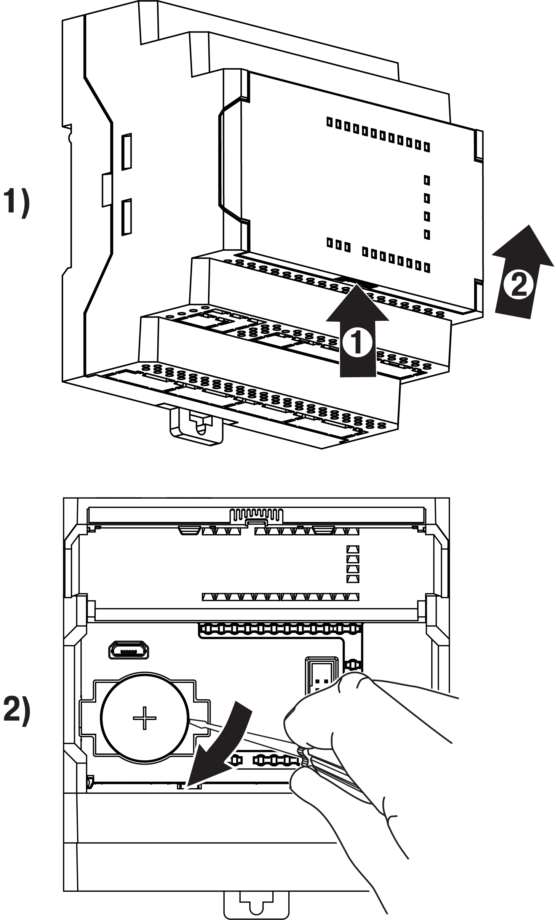
Маркировка
На корпус прибора нанесены:
- наименование прибора;
- степень защиты корпуса по ГОСТ 14254;
- напряжение и частота питания;
- потребляемая мощность;
- класс защиты от поражения электрическим током по ГОСТ IEC 61131-2-2012;
- знак соответствия требованиям ТР ТС (ЕАС);
- страна-изготовитель;
- заводской номер прибора и год выпуска.
На потребительскую тару нанесены:
- наименование прибора;
- знак соответствия требованиям ТР ТС (ЕАС);
- страна-изготовитель;
- заводской номер прибора и год выпуска.
Упаковка
Упаковка прибора производится в соответствии
с ГОСТ 23088-80 в потребительскую тару, выполненную из коробочного
картона по ГОСТ 7933-89.
Упаковка прибора при пересылке почтой производится по ГОСТ 9181-74.
Комплектность
| Наименование | Количество |
|---|---|
| Прибор | 1 шт. |
| Краткое руководство |
1 экз. |
| Паспорт и Гарантийный талон | 1 экз. |
| Комплект клеммных соединителей |
1 шт. |
Примечание
Изготовитель оставляет за собой право внесения
дополнений в комплектность прибора.
Транспортирование и хранение
Прибор должен транспортироваться в закрытом транспорте любого вида.
В транспортных средствах тара должна крепиться согласно правилам,
действующим на соответствующих видах транспорта.
Условия транспортирования должны соответствовать
условиям 5 по ГОСТ 15150-69 при температуре окружающего воздуха от
минус 25 до плюс 55 °С с соблюдением мер защиты от ударов и вибраций.
Прибор следует перевозить в транспортной таре поштучно или в контейнерах.
Условия хранения в таре на складе изготовителя
и потребителя должны соответствовать условиям 1 по ГОСТ 15150-69. В воздухе не должны присутствовать агрессивные примеси.
Прибор следует хранить на стеллажах.
Гарантийные обязательства
Изготовитель гарантирует соответствие прибора требованиям ТУ при
соблюдении условий эксплуатации, транспортирования, хранения и монтажа.
Гарантийный срок эксплуатации – 24 месяца со дня продажи.
В случае выхода прибора из строя в течение гарантийного срока при
соблюдении условий эксплуатации, транспортирования, хранения и монтажа
предприятие-изготовитель обязуется осуществить его бесплатный ремонт
или замену.
Порядок передачи прибора в ремонт содержится в паспорте и в гарантийном
талоне.
Назначение контактов клеммника
Примечание
Серой заливкой указаны неиспользуемые клеммы.
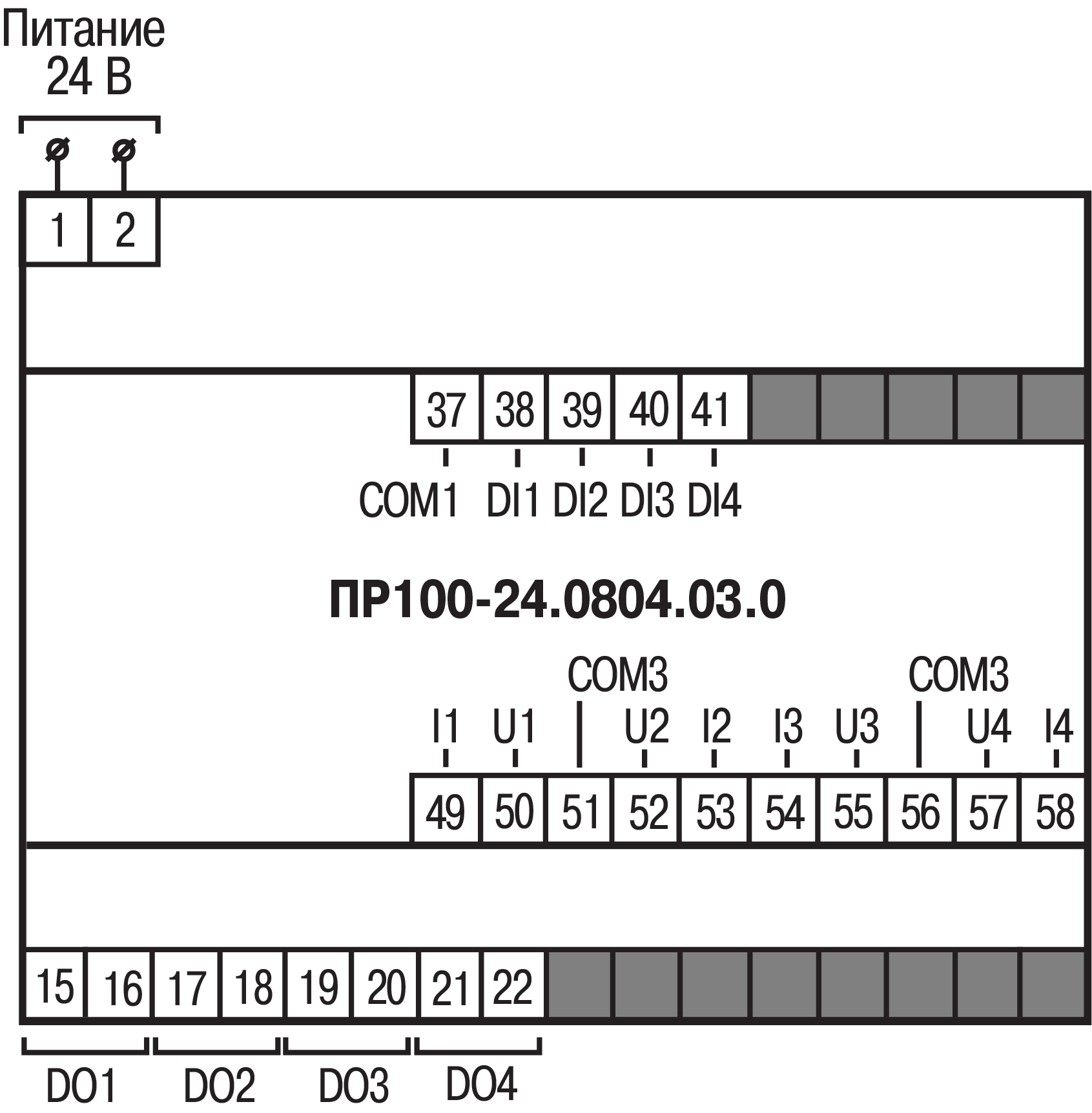
Назначение контактов клеммной колодки ПР100-24.0804.03.0
|
Номер контакта |
Назначение |
Номер контакта |
Назначение |
|---|---|---|---|
|
1 |
Входное напряжение питания (24 В) – контакт «—» |
— | — |
|
2 |
Входное напряжение питания (24 В) – контакт «+» |
— | — |
|
37 |
Общий контакт для входов 1…4 |
— | — |
|
38 |
Дискретный вход 1 (24 В) |
— | — |
|
39 |
Дискретный вход 2 (24 В) |
— | — |
|
40 |
Дискретный вход 3 (24 В) |
49 |
Аналоговый вход 1 (ток) |
|
41 |
Дискретный вход 4 (24 В) |
50 |
Аналоговый вход 1 (напряжение) |
|
15 |
Дискретный выход 1 |
51 |
Общий контакт аналоговых входов 1 и 2 |
|
16 |
Дискретный выход 1 |
52 |
Аналоговый вход 2 (напряжение) |
|
17 |
Дискретный выход 2 |
53 |
Аналоговый вход 2 (ток) |
|
18 |
Дискретный выход 2 |
54 |
Аналоговый вход 3 (ток) |
|
19 |
Дискретный выход 3 |
55 |
Аналоговый вход 3 (напряжение) |
|
20 |
Дискретный выход 3 |
56 |
Общий контакт аналоговых входов 3 и 4 |
|
21 |
Дискретный выход 4 |
57 |
Аналоговый вход 4 (напряжение) |
|
22 |
Дискретный выход 4 |
58 | Аналоговый вход 4 (ток) |
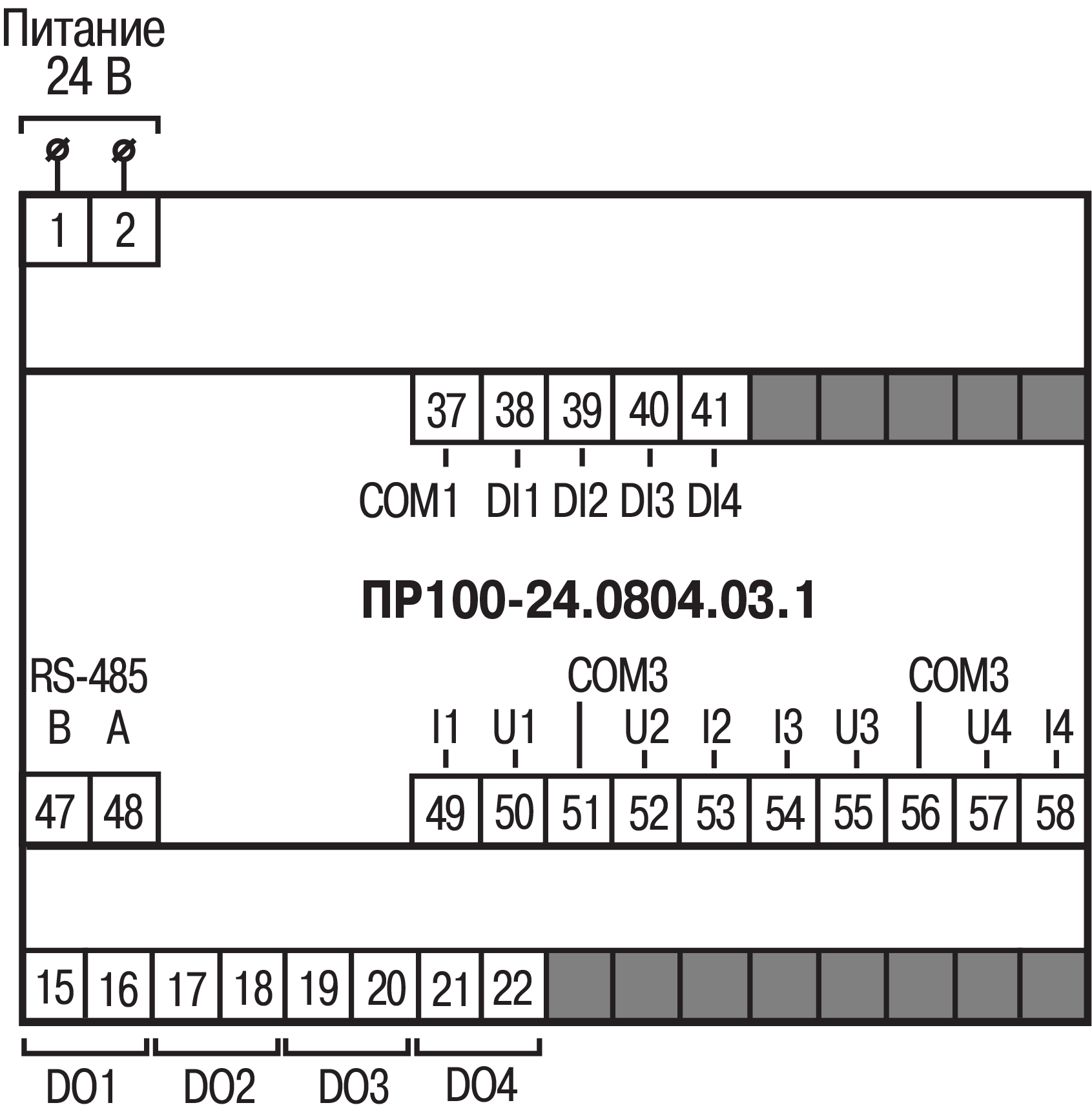
Назначение контактов клеммной колодки ПР100-24.0804.03.1
|
Номер контакта |
Назначение |
Номер контакта |
Назначение |
|---|---|---|---|
|
1 |
Входное напряжение питания (24 В) – контакт «—» |
47 | Клемма «В» интерфейса RS-485 |
|
2 |
Входное напряжение питания (24 В) – контакт «+» |
48 | Клемма «A» интерфейса RS-485 |
|
37 |
Общий контакт для входов 1…4 |
— | — |
|
38 |
Дискретный вход 1 (24 В) |
— | — |
|
39 |
Дискретный вход 2 (24 В) |
— | — |
|
40 |
Дискретный вход 3 (24 В) |
49 |
Аналоговый вход 1 (ток) |
|
41 |
Дискретный вход 4 (24 В) |
50 |
Аналоговый вход 1 (напряжение) |
|
15 |
Дискретный выход 1 |
51 |
Общий контакт аналоговых входов 1 и 2 |
|
16 |
Дискретный выход 1 |
52 |
Аналоговый вход 2 (напряжение) |
|
17 |
Дискретный выход 2 |
53 |
Аналоговый вход 2 (ток) |
|
18 |
Дискретный выход 2 |
54 |
Аналоговый вход 3 (ток) |
|
19 |
Дискретный выход 3 |
55 |
Аналоговый вход 3 (напряжение) |
|
20 |
Дискретный выход 3 |
56 |
Общий контакт аналоговых входов 3 и 4 |
|
21 |
Дискретный выход 4 |
57 |
Аналоговый вход 4 (напряжение) |
|
22 |
Дискретный выход 4 |
58 | Аналоговый вход 4 (ток) |
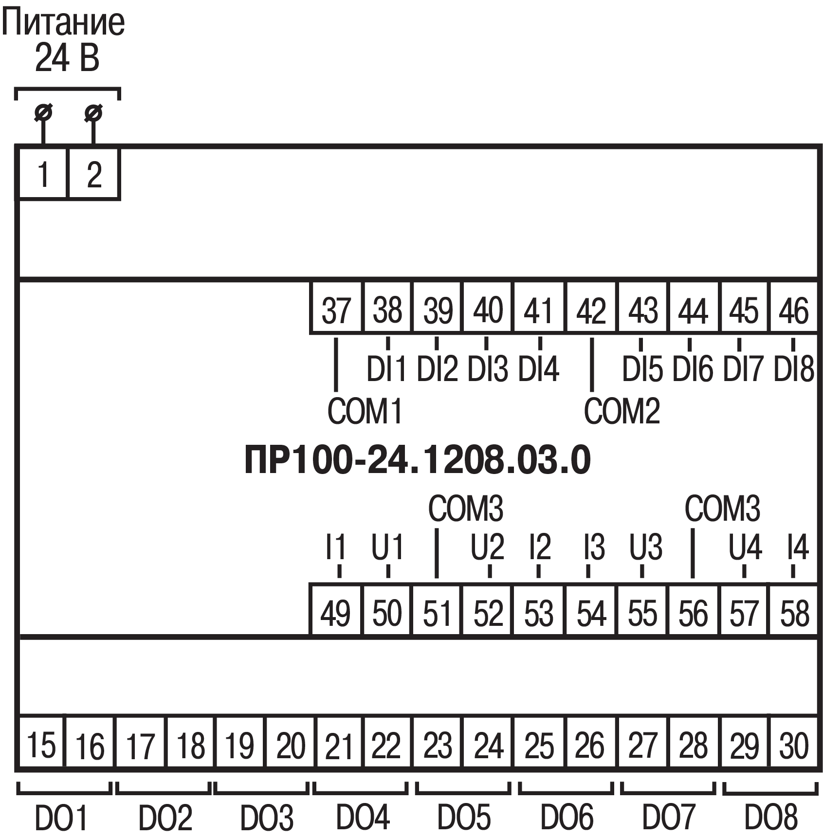
Назначение контактов клеммной колодки ПР100-24.1208.0
|
Номер контакта |
Назначение |
Номер контакта |
Назначение |
|---|---|---|---|
|
1 |
Входное напряжение питания (24 В) – контакт «—» |
24 |
Дискретный выход 5 |
|
2 |
Входное напряжение питания (24 В) – контакт «+» |
25 |
Дискретный выход 5 |
|
37 |
Общий контакт для входов 1…4 |
26 |
Дискретный выход 6 |
|
38 |
Дискретный вход 1 (24 В) |
27 |
Дискретный выход 6 |
|
39 |
Дискретный вход 2 (24 В) |
28 |
Дискретный выход 7 |
|
40 |
Дискретный вход 3 (24 В) |
29 |
Дискретный выход 7 |
|
41 |
Дискретный вход 4 (24 В) |
30 |
Дискретный выход 8 |
|
42 |
Общий контакт для входов 5…8 |
— | — |
|
43 |
Дискретный вход 5 (24 В) |
— | — |
|
44 |
Дискретный вход 6 (24 В) |
— | — |
|
45 |
Дискретный вход 7 (24 В) |
49 |
Аналоговый вход 1 (ток) |
|
46 |
Дискретный вход 8 (24 В) |
50 |
Аналоговый вход 1 (напряжение) |
|
15 |
Дискретный выход 1 |
51 |
Общий контакт аналоговых входов 1 и 2 |
|
16 |
Дискретный выход 1 |
52 |
Аналоговый вход 2 (напряжение) |
|
17 |
Дискретный выход 2 |
53 |
Аналоговый вход 2 (ток) |
|
18 |
Дискретный выход 2 |
54 |
Аналоговый вход 3 (ток) |
|
19 |
Дискретный выход 3 |
55 |
Аналоговый вход 3 (напряжение) |
|
20 |
Дискретный выход 3 |
56 |
Общий контакт аналоговых входов 3 и 4 |
|
21 |
Дискретный выход 4 |
57 |
Аналоговый вход 4 (напряжение) |
|
22 |
Дискретный выход 4 |
58 | Аналоговый вход 4 (ток) |
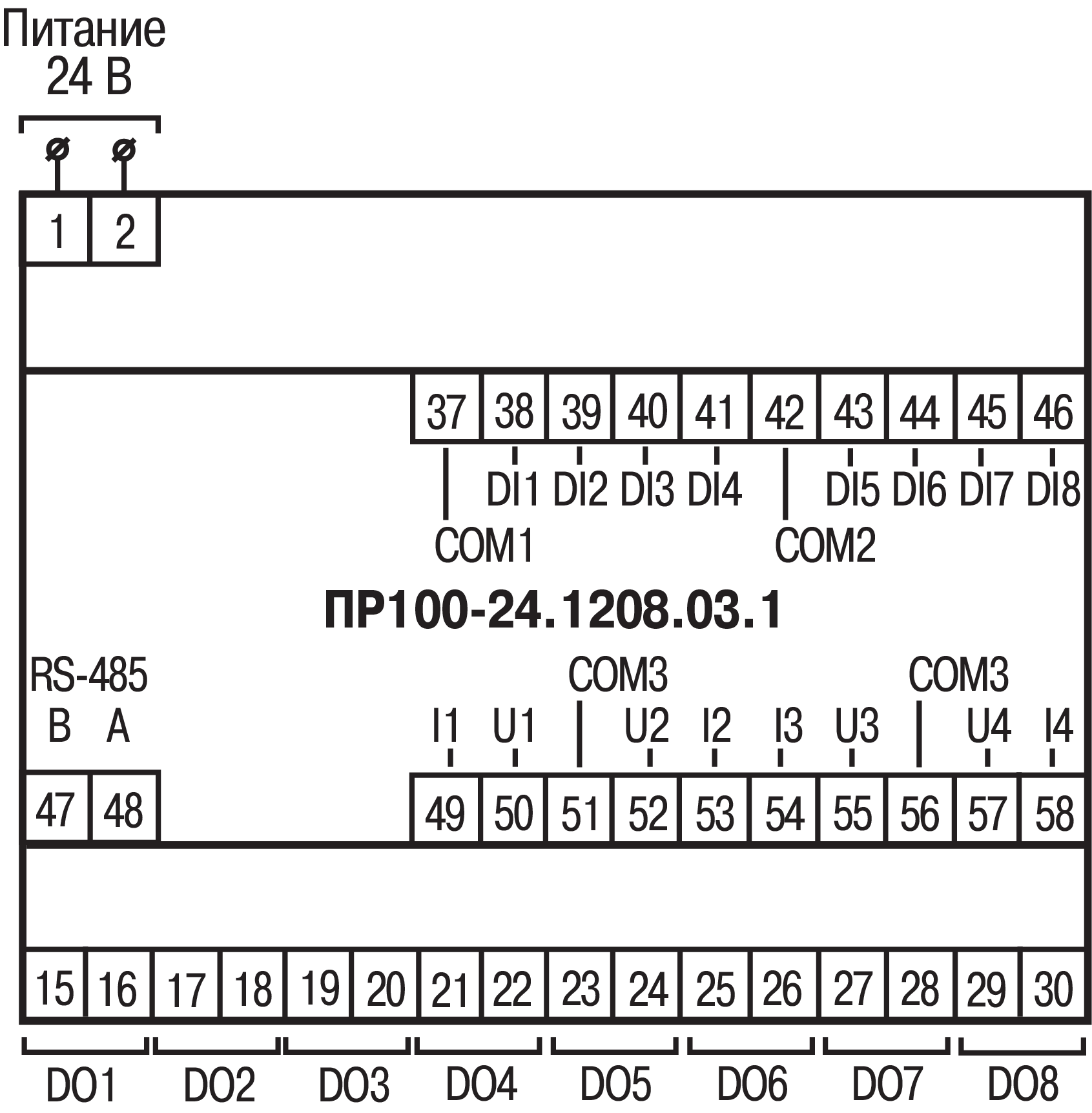
Назначение контактов клеммной колодки
|
Номер контакта |
Назначение |
Номер контакта |
Назначение |
|---|---|---|---|
|
1 |
Входное напряжение питания (24 В) – контакт «—» |
24 |
Дискретный выход 5 |
|
2 |
Входное напряжение питания (24 В) – контакт «+» |
25 |
Дискретный выход 5 |
|
37 |
Общий контакт для входов 1…4 |
26 |
Дискретный выход 6 |
|
38 |
Дискретный вход 1 (24 В) |
27 |
Дискретный выход 6 |
|
39 |
Дискретный вход 2 (24 В) |
28 |
Дискретный выход 7 |
|
40 |
Дискретный вход 3 (24 В) |
29 |
Дискретный выход 7 |
|
41 |
Дискретный вход 4 (24 В) |
30 |
Дискретный выход 8 |
|
42 |
Общий контакт для входов 5…8 |
31 |
Дискретный выход 8 |
|
43 |
Дискретный вход 5 (24 В) |
47 | Клемма «В» интерфейса RS-485 |
|
44 |
Дискретный вход 6 (24 В) |
48 | Клемма «A» интерфейса RS-485 |
|
45 |
Дискретный вход 7 (24 В) |
49 |
Аналоговый вход 1 (ток) |
|
46 |
Дискретный вход 8 (24 В) |
50 |
Аналоговый вход 1 (напряжение) |
|
15 |
Дискретный выход 1 |
51 |
Общий контакт аналоговых входов 1 и 2 |
|
16 |
Дискретный выход 1 |
52 |
Аналоговый вход 2 (напряжение) |
|
17 |
Дискретный выход 2 |
53 |
Аналоговый вход 2 (ток) |
|
18 |
Дискретный выход 2 |
54 |
Аналоговый вход 3 (ток) |
|
19 |
Дискретный выход 3 |
55 |
Аналоговый вход 3 (напряжение) |
|
20 |
Дискретный выход 3 |
56 |
Общий контакт аналоговых входов 3 и 4 |
|
21 |
Дискретный выход 4 |
57 |
Аналоговый вход 4 (напряжение) |
|
22 |
Дискретный выход 4 |
58 | Аналоговый вход 4 (ток) |
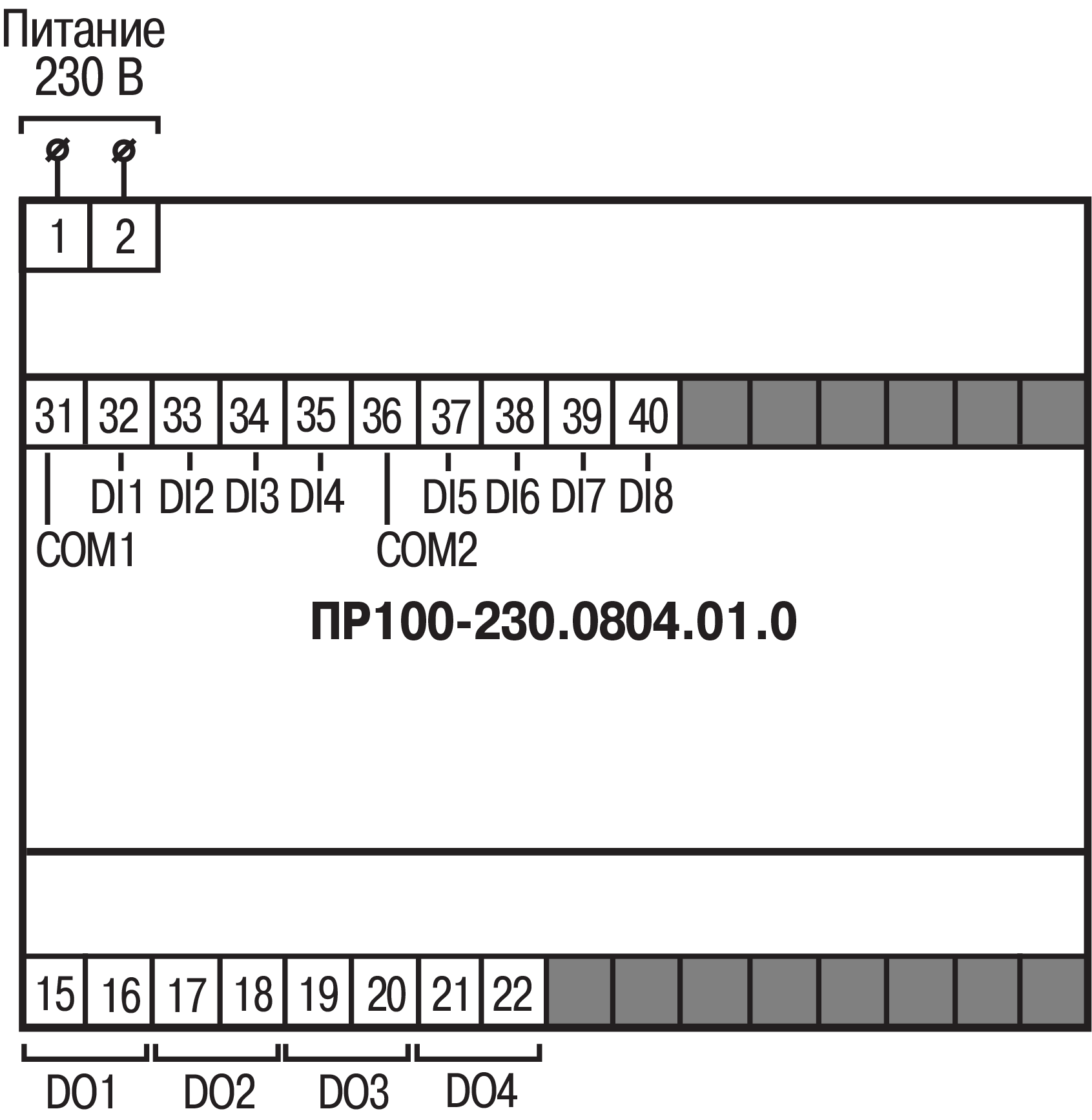
Назначение контактов клеммной колодки ПР100-230.0804.01.0
|
Номер контакта |
Назначение |
Номер контакта |
Назначение |
|---|---|---|---|
|
1 |
Входное напряжение питания (230 В) |
15 |
Дискретный выход 1 |
|
2 |
Входное напряжение питания (230 В) |
16 |
Дискретный выход 1 |
|
31 |
Общий контакт для входов 1…4 |
17 |
Дискретный выход 2 |
|
32 |
Дискретный вход 1 (230 В) |
18 |
Дискретный выход 2 |
|
33 |
Дискретный вход 2 (230 В) |
19 |
Дискретный выход 3 |
|
34 |
Дискретный вход 3 (230 В) |
20 |
Дискретный выход 3 |
|
35 |
Дискретный вход 4 (230 В) |
21 |
Дискретный выход 4 |
|
36 |
Общий контакт для входов 5…8 |
22 |
Дискретный выход 4 |
|
37 |
Дискретный вход 5 (230 В) |
— | — |
|
38 |
Дискретный вход 6 (230 В) |
— | — |
|
39 |
Дискретный вход 7 (230 В) |
— | — |
|
40 |
Дискретный вход 8 (230 В) |
— | — |
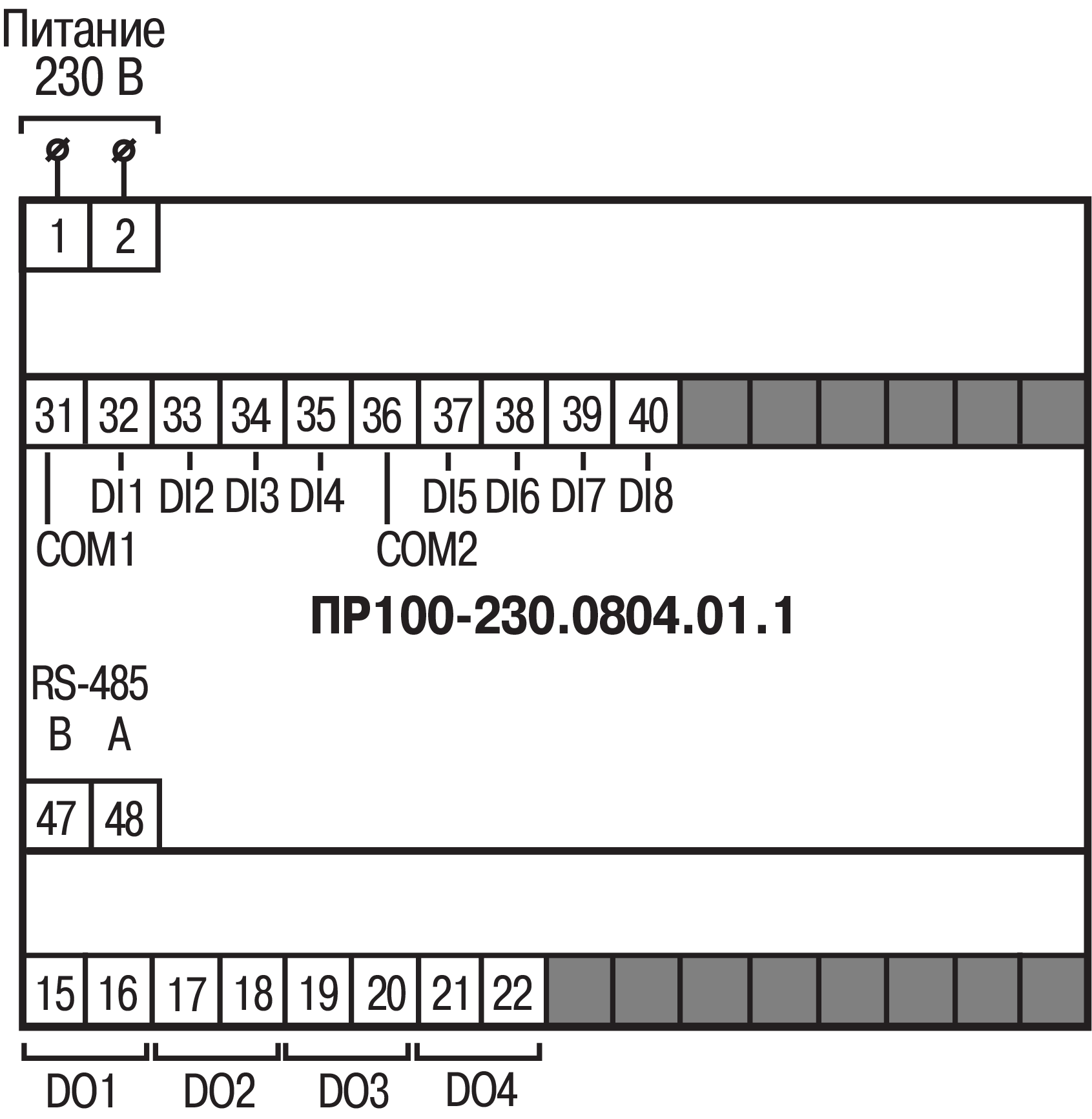
Назначение контактов клеммной колодки ПР100-230.0804.01.1
|
Номер контакта |
Назначение |
Номер контакта |
Назначение |
|---|---|---|---|
|
1 |
Входное напряжение питания (230 В) |
15 |
Дискретный выход 1 |
|
2 |
Входное напряжение питания (230 В) |
16 |
Дискретный выход 1 |
|
31 |
Общий контакт для входов 1…4 |
17 |
Дискретный выход 2 |
|
32 |
Дискретный вход 1 (230 В) |
18 |
Дискретный выход 2 |
|
33 |
Дискретный вход 2 (230 В) |
19 |
Дискретный выход 3 |
|
34 |
Дискретный вход 3 (230 В) |
20 |
Дискретный выход 3 |
|
35 |
Дискретный вход 4 (230 В) |
21 |
Дискретный выход 4 |
|
36 |
Общий контакт для входов 5…8 |
22 |
Дискретный выход 4 |
|
37 |
Дискретный вход 5 (230 В) |
— | — |
|
38 |
Дискретный вход 6 (230 В) |
— | — |
|
39 |
Дискретный вход 7 (230 В) |
47 | Клемма «В» интерфейса RS-485 |
|
40 |
Дискретный вход 8 (230 В) |
48 | Клемма «A» интерфейса RS-485 |
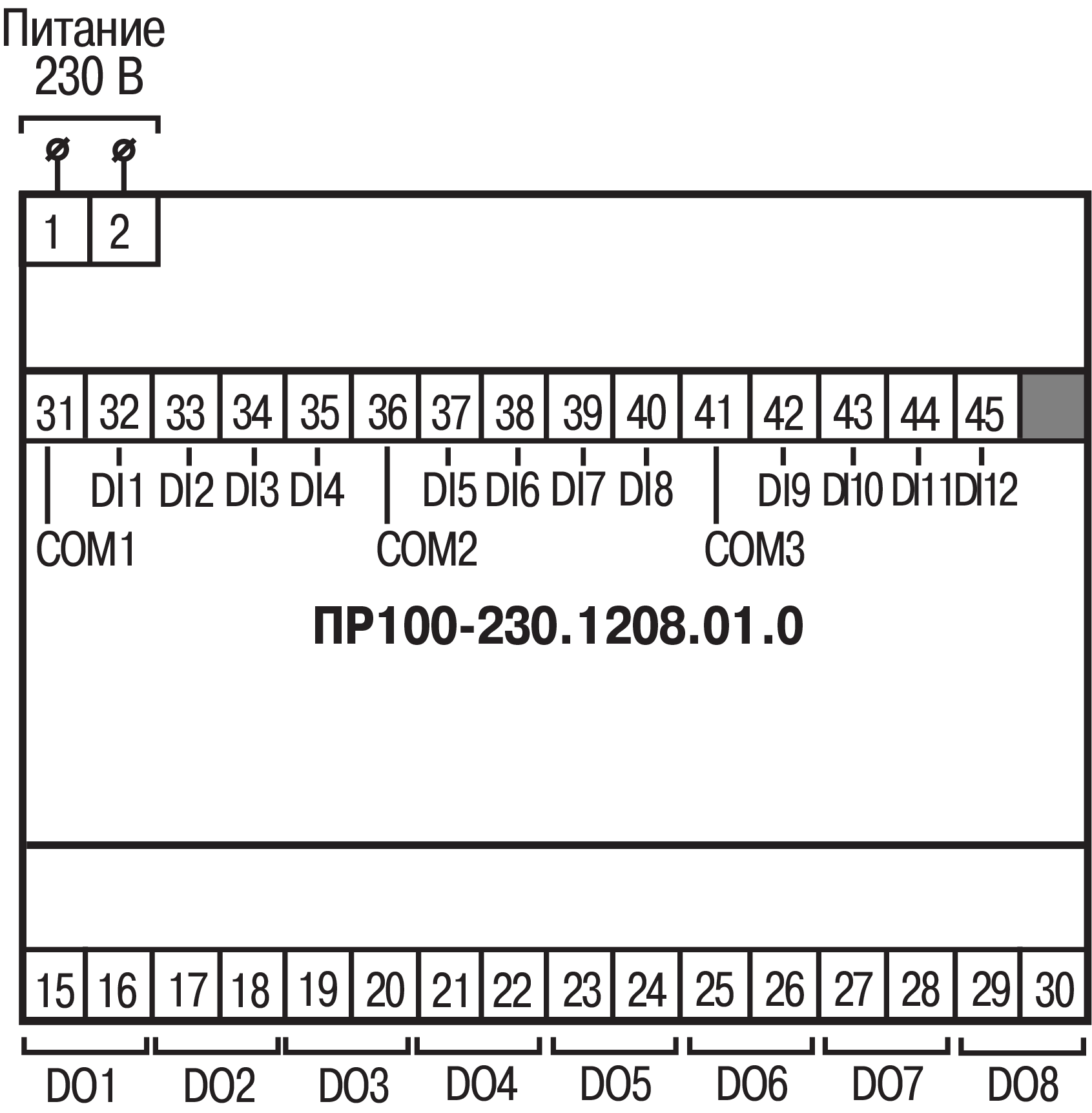
Назначение контактов клеммной колодки ПР100-230.1208.01.0
|
Номер контакта |
Назначение |
Номер контакта |
Назначение |
|---|---|---|---|
|
1 |
Входное напряжение питания (230 В) |
15 |
Дискретный выход 1 |
|
2 |
Входное напряжение питания (230 В) |
16 |
Дискретный выход 1 |
|
31 |
Общий контакт для входов 1…4 |
17 |
Дискретный выход 2 |
|
32 |
Дискретный вход 1 (230 В) |
18 |
Дискретный выход 2 |
|
33 |
Дискретный вход 2 (230 В) |
19 |
Дискретный выход 3 |
|
34 |
Дискретный вход 3 (230 В) |
20 |
Дискретный выход 3 |
|
35 |
Дискретный вход 4 (230 В) |
21 |
Дискретный выход 4 |
|
36 |
Общий контакт для входов 5…8 |
22 |
Дискретный выход 4 |
|
37 |
Дискретный вход 5 (230 В) |
23 |
Дискретный выход 5 |
|
38 |
Дискретный вход 6 (230 В) |
24 |
Дискретный выход 5 |
|
39 |
Дискретный вход 7 (230 В) |
25 |
Дискретный выход 6 |
|
40 |
Дискретный вход 8 (230 В) |
26 |
Дискретный выход 6 |
|
41 |
Общий контакт для входов 9…12 |
27 |
Дискретный выход 7 |
|
42 |
Дискретный вход 9 (230 В) |
28 |
Дискретный выход 7 |
|
43 |
Дискретный вход 10 (230 В) |
29 |
Дискретный выход 8 |
|
44 |
Дискретный вход 11 (230 В) |
30 |
Дискретный выход 8 |
|
45 |
Дискретный вход 12 (230 В) |
— | — |
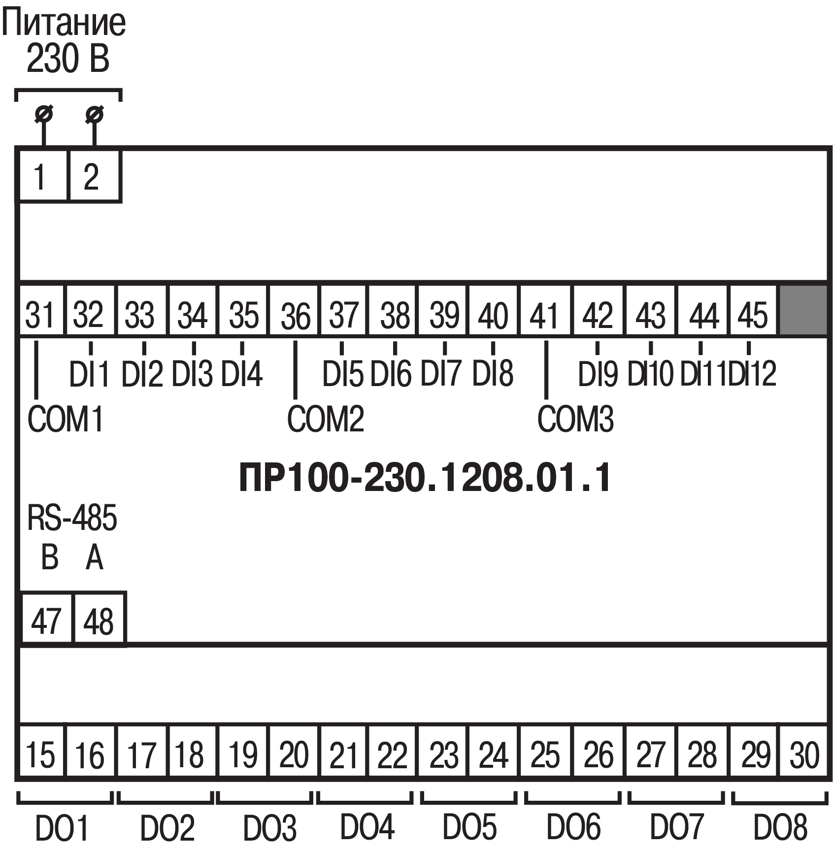
Назначение контактов клеммной колодки ПР100-230.1208.01.1
|
Номер контакта |
Назначение |
Номер контакта |
Назначение |
|---|---|---|---|
|
1 |
Входное напряжение питания (230 В) |
15 |
Дискретный выход 1 |
|
2 |
Входное напряжение питания (230 В) |
16 |
Дискретный выход 1 |
|
31 |
Общий контакт для входов 1…4 |
17 |
Дискретный выход 2 |
|
32 |
Дискретный вход 1 (230 В) |
18 |
Дискретный выход 2 |
|
33 |
Дискретный вход 2 (230 В) |
19 |
Дискретный выход 3 |
|
34 |
Дискретный вход 3 (230 В) |
20 |
Дискретный выход 3 |
|
35 |
Дискретный вход 4 (230 В) |
21 |
Дискретный выход 4 |
|
36 |
Общий контакт для входов 5…8 |
22 |
Дискретный выход 4 |
|
37 |
Дискретный вход 5 (230 В) |
23 |
Дискретный выход 5 |
|
38 |
Дискретный вход 6 (230 В) |
24 |
Дискретный выход 5 |
|
39 |
Дискретный вход 7 (230 В) |
25 |
Дискретный выход 6 |
|
40 |
Дискретный вход 8 (230 В) |
26 |
Дискретный выход 6 |
|
41 |
Общий контакт для входов 9…12 |
27 |
Дискретный выход 7 |
|
42 |
Дискретный вход 9 (230 В) |
28 |
Дискретный выход 7 |
|
43 |
Дискретный вход 10 (230 В) |
29 |
Дискретный выход 8 |
|
44 |
Дискретный вход 11 (230 В) |
30 |
Дискретный выход 8 |
|
45 |
Дискретный вход 12 (230 В) |
47 | Клемма «В» интерфейса RS-485 |
| — | — | 48 | Клемма «A» интерфейса RS-485 |
Юстировка
Общие указания
Юстировка прибора заключается в проведении технологических операций,
обеспечивающих восстановление метрологических характеристик прибора
в случае изменения их после длительной эксплуатации.
Внимание
Необходимость проведения юстировки определяется
по результатам поверки прибора и должна производиться только квалифицированными
специалистами метрологических служб, осуществляющих эту поверку.
Юстировка выполняется в OwenLogic и с помощью
эталонных источников сигналов, имитирующих работу датчиков и подключаемых
к контактам прибора. Во время юстировки прибор вычисляет соотношения
между поступившим входным сигналом и опорным сигналом.
Вычисленные соотношения (коэффициенты юстировки) записываются в
энергонезависимую память прибора и используются как базовые для выполнения
всех дальнейших расчетов.
Каждый аналоговый вход имеет собственные коэффициенты юстировки
для каждого типа датчика.
Если вычисленные значения коэффициентов выходят за пределы, установленные
для него во время разработки прибора, в OwenLogic выводится сообщение о причине этой ошибки.
Юстировка универсального входа
Для выполнения юстировки следует:
-
Подключить к контактам входа прибора дифференциальный вольтметр
В1-12 в режиме калибратора напряжений или аналогичный ему источник
образцового напряжения с классом точности не ниже 0,05. -
Соединить прибор с калибратором по схеме, приведенной на рисунке
ниже с соблюдением полярности подключения.Подключение
калибратора напряженияВ случае использования входа для
измерения сигналов «4…20 мА» рекомендуется провести юстировку входа,
предварительно выбрав параметр «Тип датчика» равным «4…20 мА». Калибратор
тока следует подключить по схеме, изображенной на рисунке ниже.Подключение
калибратора тока -
Запустить OwenLogic и выбрать в меню
пункт «Прибор» → «Юстировка входов/выходов» для запуска
мастера юстировки. В диалоговом окне «Выбор элемента» выбрать пункт
«Аналоговые входы» (см. рисунок).Меню юстировки -
Далее в окне «Настройка параметров» выбрать значение параметра
«Тип датчика» «0…10 В» для юстировки датчика с выходом в виде напряжения
или «4…20 мА» для юстировки датчика с выходом в виде тока (см. рисунок).Меню настройки параметров - Установить уровни для юстировки, постоянную времени фильтра и
канал. Увеличение постоянной времени фильтра увеличивает время юстировки,
но позволяет получить более точные калибровочные коэффициенты. Юстировку
проходит каждый канал в отдельности. Если выбрать настройку «все
каналы», то юстировка проходит по всем четырем каналам, поэтому необходимо
подавать соответствующие уровни сигнала на все каналы сразу. - Нажать кнопку «Далее» и следовать указаниям менеджера юстировки.
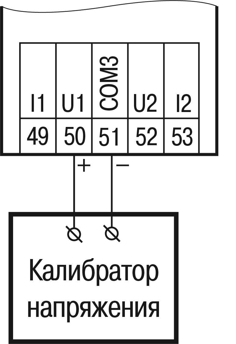
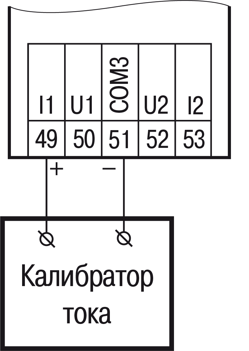
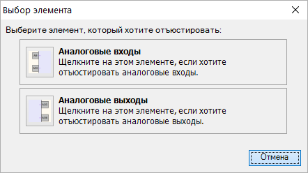
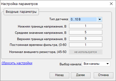
Предупреждающие сообщения
В данном руководстве применяются следующие предупреждения:
Опасность
Ключевое слово ОПАСНОСТЬ сообщает о непосредственной
угрозе опасной ситуации, которая приведет к смерти или серьезной
травме, если ее не предотвратить.
Внимание
Ключевое слово ВНИМАНИЕ сообщает о потенциально
опасной ситуации, которая может привести к небольшим травмам.
Предупреждение
Ключевое слово ПРЕДУПРЕЖДЕНИЕ сообщает о потенциально
опасной ситуации, которая может привести к повреждению имущества.
Примечание
Ключевое слово ПРИМЕЧАНИЕ обращает внимание на полезные
советы и рекомендации, а также информацию для эффективной и безаварийной
работы оборудования.
| Ограничение ответственности |
|
Ни при |