-
Contents
-
Table of Contents
-
Troubleshooting
-
Bookmarks
Related Manuals for Automationdirect.com DL06
Summary of Contents for Automationdirect.com DL06
-
Page 1
DL06 Micro PLC User Manual Volume 2 of 2 Manual Number: D0-06USER-M… -
Page 2
DL06 Micro PLC User Manual, 3rd Edition, Rev. C… -
Page 3
Copyright 2011, Automationdirect.com Incorporated All Rights Reserved No part of this manual shall be copied, reproduced, or transmitted in any way without the prior, written consent of Automationdirect.com Incorporated. AutomationDirect retains the exclusive rights to all information included in this document. -
Page 4
Nulle partie de ce manuel ne doit être copiée, reproduite ou transmise de quelque façon que ce soit sans le consentement préalable écrit de la société Automationdirect.com Incorporated. AutomationDirect conserve les droits exclusifs à l’égard de tous les renseignements contenus dans le présent document. -
Page 5
I/O Quick Selection Guide ………………1–5 Quick Start ……………………. 1–6 Steps to Designing a Successful System …………..1–10 Questions and Answers about DL06 Micro PLCs ………… 1–12 Chapter 2: Installation, Wiring, and Specifications Safety Guidelines ………………….. 2–2 Plan for Safety ………………….2–2 Three Levels of Protection ……………… -
Page 6
D0–06DD1 I/O Wiring Diagram …………….2–36 D0–06DD2 I/O Wiring Diagram …………….2–38 D0–06DR I/O Wiring Diagram …………….2–40 D0–06DD1–D I/O Wiring Diagram …………….. 2–42 D0–06DD2–D I/O Wiring Diagram …………….. 2–44 D0–06DR–D I/O Wiring Diagram …………….2–46 DL06 Micro PLC User Manual, 3rd Edition, Rev. D… -
Page 7
Solve PID Loop Equations ………………3–16 Write Outputs ………………….3–16 Write Outputs to Specialty I/O …………….3–16 Diagnostics ………………….3–17 I/O Response Time ………………..3–17 Is Timing Important for Your Application? ………….. 3–17 DL06 Micro PLC User Manual, 3rd Edition, Rev. D… -
Page 8
System Parameters and Default Data Locations (V Data Type) ……. 3–29 DL06 Aliases ………………….3–31 DL06 Memory Map ………………..3–32 X Input/Y Output Bit Map ………………3–33 Stage Control/Status Bit Map …………….. 3–34 Control Relay Bit Map ………………… 3–36 DL06 Micro PLC User Manual, 3rd Edition, Rev. D… -
Page 9
Determining the MODBUS Address ……………. 4–12 If Your Host Software Requires the Data Type and Address ……..4–13 Example 1: V2100 ………………..4–14 Example 2: Y20 …………………. 4–14 Example 3: T10 Current Value …………….4–14 DL06 Micro PLC User Manual, 3rd Edition, Rev. D… -
Page 10
Chapter 5: Standard RLL Instructions Introduction ………………….. 5–2 Using Boolean Instructions ………………5–5 END Statement ………………….5–5 Simple Rungs ………………….5–5 Normally Closed Contact ………………5–6 Contacts in Series ………………… 5–6 Midline Outputs ………………….. 5–6 DL06 Micro PLC User Manual, 3rd Edition, Rev. D… -
Page 11
Using Pointers ………………….5–55 Logical Instructions (Accumulator) …………….. 5–69 Math Instructions ………………..5–86 Transcendental Functions………………5–118 Bit Operation Instructions ………………5–120 Number Conversion Instructions (Accumulator) ……….5–127 Shuffle Digits Block Diagram …………….5–139 DL06 Micro PLC User Manual, 3rd Edition, Rev. D… -
Page 12
Reading ASCII Input Strings ……………… 5–210 Writing ASCII Output Strings …………….5–210 Managing the ASCII Strings …………….. 5–211 Intelligent Box (IBox) Instructions ……………. 5–230 Chapter 6: Drum Instruction Programming Introduction ………………….. 6–2 viii DL06 Micro PLC User Manual, 3rd Edition, Rev. D… -
Page 13: Table Of Contents
Timed Drum with Discrete Outputs (DRUM) …………6–12 Event Drum (EDRUM) ……………….. 6–14 Handheld Programmer Drum Mnemonics ………….. 6–16 Masked Event Drum with Discrete Outputs (MDRMD) ……….. 6–19 Masked Event Drum with Word Output (MDRMW) ……….6–21 DL06 Micro PLC User Manual, 3rd Edition, Rev. D…
-
Page 14
Exclusive Transitions ………………..7–14 Stage Program Design Considerations …………..7–15 Stage Program Organization ……………… 7–15 How Instructions Work Inside Stages …………..7–16 Using a Stage as a Supervisory Process …………..7–17 DL06 Micro PLC User Manual, 3rd Edition, Rev. D… -
Page 15
Adjusting the Bias ………………..8–11 Step Bias Proportional to Step Change in SP …………8–12 Eliminating Proportional, Integral or Derivative Action ……….. 8–12 Velocity Form of the PID Equation …………….8–12 DL06 Micro PLC User Manual, 3rd Edition, Rev. D… -
Page 16
PV Analog Filter …………………. 8–55 Creating an Analog Filter in Ladder Logic …………… 8–56 Use the DirectSOFT Filter Intelligent Box Instructions ……….8-57 FilterB Example ………………….. 8-57 Ramp/Soak Generator ………………… 8–58 DL06 Micro PLC User Manual, 3rd Edition, Rev. D… -
Page 17
Standard Maintenance ………………… 9–2 Diagnostics ……………………. 9–2 Diagnostics ………………….. 9–2 Fatal Errors ………………….. 9–2 Non-fatal Errors ………………….9–2 V-memory Error Code Locations …………….9–3 Special Relays (SP) Corresponding to Error Codes ………… 9–3 xiii DL06 Micro PLC User Manual, 3rd Edition, Rev. D… -
Page 18
Bit Override Forcing ………………..9–19 Bit Override Indicators ……………….. 9–19 Reset the PLC to Factory Defaults …………….9–20 Chapter 10: LCD Display Panel Introduction to the DL06 LCD Display Panel …………10–2 Keypad .. 10–2 Snap-in installation ………………..10–3 Display Priority ………………….10–4 Menu Navigation ………………… -
Page 19
Example program: alarm text from V-memory with embedded V-memory data .. 10–30 Appendix A: Auxiliary Functions Introduction …………………..A–2 Purpose of Auxiliary Functions ………………A–2 Accessing AUX Functions via DirectSOFT …………..A–3 Accessing AUX Functions via the Handheld Programmer ……….A–3 DL06 Micro PLC User Manual, 3rd Edition, Rev. D… -
Page 20
AUX 75 Erase HPP EEPROM ………………A–9 AUX 76 Show EEPROM Type ………………A–9 AUX 8* — Password Operations …………….A–9 AUX 81 Modify Password ………………A–9 AUX 82 Unlock CPU ………………..A–10 AUX 83 Lock CPU………………..A–10 DL06 Micro PLC User Manual, 3rd Edition, Rev. D… -
Page 21
Instructions ………………..C–23 PLUS Drum Instructions ………………..C–23 Clock/Calendar Instructions ………………C–24 MODBUS Instructions …………………C–24 ASCII Instructions ………………..C–24 Appendix D: Special Relays DL06 PLC Special Relays ………………. D–2 Startup and Real-Time Relays ……………… D–2 xvii DL06 Micro PLC User Manual, 3rd Edition, Rev. D… -
Page 22
Calculating Your Preset Values …………….E–13 X Input Configuration ……………….. E–14 Writing Your Control Program …………….E–15 Program Example 1: Counter Without Presets …………E–16 Program Example 2: Counter With Presets …………. E–18 xviii DL06 Micro PLC User Manual, 3rd Edition, Rev. D… -
Page 23
Logical I/O Functions ………………… E–41 Setup for Mode 30 ………………..E–42 Profile/Velocity Select Register …………….E–43 Profile Parameter Table ………………. E–43 Automatic Trapezoidal Profile …………….. E–43 Step Trapezoidal Profile ………………E–44 Velocity Control ………………… E–44 DL06 Micro PLC User Manual, 3rd Edition, Rev. D… -
Page 24
Pulse Catch Timing Parameters …………….E–72 Setup for Mode 50 ………………..E–73 X Input Configuration ……………….. E–74 Program Example 1: Pulse Catch …………….E–75 Mode 60: Discrete Inputs with Filter …………..E–76 Purpose ……………………E–76 DL06 Micro PLC User Manual, 3rd Edition, Rev. D… -
Page 25
Signed vs. Unsigned Integers ………………I–8 AutomationDirect.com Products and Data Types ………….I–9 DirectLOGIC PLCs…………………. I–9 C-more/C-more Micro-Graphic Panels …………… I–9 Appendix J: European Union Directives (CE) European Union (EU) Directives …………….J-2 Member Countries …………………J-2 DL06 Micro PLC User Manual, 3rd Edition, Rev. D… -
Page 26
Step 2: Load Number of Bytes to Transfer …………..K–10 Step 3: Specify Master Memory Area …………..K–11 Step 4: Specify Slave Memory Area …………….K–12 Communications from a Ladder Program ……………K–13 Multiple Read and Write Interlocks ……………..K–13 xxii DL06 Micro PLC User Manual, 3rd Edition, Rev. D… -
Page 27
Table of Contents MODBUS RTU Communications …………….K–14 ASCII Communications ……………….K–14 Index xxiii DL06 Micro PLC User Manual, 3rd Edition, Rev. D… -
Page 28
Table of Contents Notes xxiv DL06 Micro PLC User Manual, 3rd Edition, Rev. D… -
Page 29: Introduction
hapter hapter hapter hapter hapter hapter nstructIon rogrammIng In This Chapter… Introduction ………………6–2 Step Transitions…………….6–4 Overview of Drum Operation …………6–8 Drum Control Techniques ………….. 6–10 Drum Instruction …………….6–12…
-
Page 30: Purpose
Chapter 6: Drum Instruction Programming Introduction Purpose The Event Drum (EDRUM) instruction in the DL06 CPU electronically simulates an electro-mechanical drum sequencer. The instruction offers enhancements to the basic principle, which we describe first. Drum Terminology Drum instructions are best suited for repetitive processes that consist of a finite number of steps.
-
Page 31: Drum Chart Representation
Compare the two, and you will find that they are equivalent! If you can see their equivalence, you are well on your way to understanding drum instruction operation. Step Output DL06 Micro PLC User Manual, 3rd Edition, Rev. D…
-
Page 32: Step Transitions
Chapter 6: Drum Instruction Programming Step Transitions Drum Instruction Types There are two types of Drum instructions in the DL06 CPU: • Timed Drum with Discrete Outputs (DRUM) • Time and Event Drum with Discrete Outputs (EDRUM) The two drum instructions include time-based step transitions, and the EDRUM includes event-based transitions as well.
-
Page 33: Timer And Event Transitions
(X0) remains true. When the counts for Step 1 have expired, then the drum moves to Step 2. The outputs change immediately to match the new pattern for Step 2. DL06 Micro PLC User Manual, 3rd Edition, Rev. D…
-
Page 34: Event-Only Transitions
Counter bit CT10 turns on when the drum cycle is complete, and turns off when the drum is reset. DL06 Micro PLC User Manual, 3rd Edition, Rev. D…
-
Page 35: Last Step Completion
F F F f f f F F F R es et Input Active? R es et Res et Drum Complete bit CT10 = 0 G o to Pres et Step DL06 Micro PLC User Manual, 3rd Edition, Rev. D…
-
Page 36: Overview Of Drum Operation
• Preset Step – A step number from 1 to 16 that you define (typically is step 1). The drum moves to this step whenever Reset is on, and whenever the CPU first enters run mode. DL06 Micro PLC User Manual, 3rd Edition, Rev. D…
-
Page 37: Powerup State Of Drum Registers
You can monitor these to determine the drum’s progress through its control cycle. The DL06 has 128 counters (CT0 – CT177 in octal). • Events – Either an X, Y, C, S, T, or CT type discrete point serves as step transition inputs. Each step has its own event.
-
Page 38: Drum Control Techniques
Drum Complete bit (CT10), and forces the drum to enter the preset step. NOTE: The timing diagram shows all steps using equal time durations. Step times can vary greatly, depending on the counts/step programmed. 6-10 DL06 Micro PLC User Manual, 3rd Edition, Rev. D…
-
Page 39: Self-Resetting Drum
Just use a control relay contact such as C0 for the step transition event. Elsewhere in ladder logic, you may use C0 as an output coil, making it dependent on many other events (contacts). 6-11 DL06 Micro PLC User Manual, 3rd Edition, Rev. D…
-
Page 40: Drum Instruction
EDRUM instruction. Timed Drum with Discrete Outputs (DRUM) The Timed Drum with Discrete Outputs is the most basic of the DL06’s drum instructions. It operates according to the principles covered on the previous pages. Below is the instruction in chart form as displayed by DirectSOFT.
-
Page 41
Therefore, the duration of step 1 is (25 x 0.1) = 2.5 seconds. In the last rung, the Drum Complete bit (CT10) turns on output Y0 upon completion of the last step (step 10). A drum reset also resets CT10. Start Reset Drum Complete Direct SOFT 5 Display 6-13 DL06 Micro PLC User Manual, 3rd Edition, Rev. D… -
Page 42: Event Drum (Edrum)
This process stops when the last step is complete, or when the Reset input is energized. The drum enters the preset step chosen upon a CPU program-to-run mode transition, and whenever the Reset input is energized. 6-14 DL06 Micro PLC User Manual, 3rd Edition, Rev. D…
-
Page 43
In the last rung, the Drum Complete bit (CT4) turns on output Y0 upon completion of the last step (step 11). A drum reset also resets CT4. START RESET DRUM COMPLETE 6-15 DL06 Micro PLC User Manual, 3rd Edition, Rev. D… -
Page 44: Handheld Programmer Drum Mnemonics
Counts per step dddd DEF K0000 0 — 9999 Events dddd DEF K0000 X, Y, C, S, T, CT, SP see memory map Output pattern gggg DEF K0000 0 — FFFF 6-16 DL06 Micro PLC User Manual, 3rd Edition, Rev. D…
-
Page 45
( DEF K0000 ) ( DEF K0000 ) ( DEF 0000 ) SHFT NEXT NEXT ( DEF 0000 ) SHFT NEXT ( DEF K0000 ) NEXT (Continued on next page ) 6-17 DL06 Micro PLC User Manual, 3rd Edition, Rev. D… -
Page 46
NOTE: You may use the NXT and PREV keys to skip past entries for unused outputs or stops. NOTE: For ease of operation when using the EDRUM instruction, we recommend using DirectSOFT over the handheld programmer. 6-18 DL06 Micro PLC User Manual, 3rd Edition, Rev. D… -
Page 47: Masked Event Drum With Discrete Outputs (Mdrmd)
0 – 9999 Event eeee X, Y, C, S, T, ST, GX, GY. CT, SP Discrete Outputs Fffff X, Y, C, GX, GY see memory map Output Mask Ggggg 6-19 DL06 Micro PLC User Manual, 3rd Edition, Rev. D…
-
Page 48
Set Mask Registers Direct SOFT 5 Display NOTE: The ladder program must load constants in V2000 through V2012 to cover all mask registers for the eleven steps used in this drum. 6-20 DL06 Micro PLC User Manual, 3rd Edition, Rev. D… -
Page 49: Masked Event Drum With Word Output (Mdrmw)
0 – 9999 Event eeee X, Y, C, S, T, ST, GX, GY, SP see memory map Word Output Fffff see memory map Output Mask Ggggg see memory map 6-21 DL06 Micro PLC User Manual, 3rd Edition, Rev. D…
-
Page 50
Set Mask Registers Direct SOFT 5 Display NOTE: The ladder program must load constants in V2000 through V2012 to cover all mask registers for the eleven steps used in this drum. 6-22 DL06 Micro PLC User Manual, 3rd Edition, Rev. D… -
Page 51
hapter hapter hapter hapter hapter hapter PLUS PLUS tage tage RogRamming RogRamming In This Chapter… Introduction to Stage Programming ……….7–2 Learning to Draw State Transition Diagrams ……..7–3 Using the Stage Jump Instruction for State Transitions ….. 7–7 Stage Program Example: Toggle On/Off Lamp Controller ….7–8 Four Steps to Writing a Stage Program ………. -
Page 52: Chapter 7: Rll
• Study each stage programming concept by working through each example. The examples build progressively on each other. • Read the Stage Questions and Answers at the end of the chapter for a quick review. DL06 Micro PLC User Manual, 3rd Edition, Rev. D…
-
Page 53: Learning To Draw State Transition Diagrams
ON state. In a boolean sense, Y0=ON state. Next, we will implement the state diagram first as RLL, then as a stage program. This will help you see the relationship between the two methods in problem solving. DL06 Micro PLC User Manual, 3rd Edition, Rev. D…
-
Page 54: Rll Equivalent
PLC scan, the CPU will not execute Stage S1, so the motor output Y0 will turn off. The Off state (Stage 0) will be ready for the next cycle. DL06 Micro PLC User Manual, 3rd Edition, Rev. D…
-
Page 55: Let’s Compare
NOTE: If the ISG is within the retentive range for stages, the ISG will remain in the state it was in before power down and will NOT turn itself on during the first scan. DL06 Micro PLC User Manual, 3rd Edition, Rev. D…
-
Page 56: What Stage Bits Do
• Octal numbering – Stages are numbered in octal, like I/O points, etc. So “S8” is not valid. • Total Stages – The DL06 offers up to 1024 stages (S0 to 1777 in octal). • No duplicates – Each stage number is unique and can be used just once.
-
Page 57: Using The Stage Jump Instruction For State Transitions
Jmp Note: Assume we start with Stage 0 active and stage 1 inactive for both examples. NOTE: Assume we start with Stage 0 active and Stage 1 inactive for both examples. DL06 Micro PLC User Manual, 3rd Edition, Rev. D…
-
Page 58: Stage Program Example: Toggle On/Off Lamp Controller
(ISG). In the ON state, we add special relay contact SP1, which is always on. Push–Off State Note that even as our programs grow more complex, it is still easy to correlate the state transition diagram with the stage program! DL06 Micro PLC User Manual, 3rd Edition, Rev. D…
-
Page 59: Four Steps To Writing A Stage Program
• Make each state a stage. Remember to number stages in octal. Up to 1024 total stages are available in the DL06, numbered 0 to 1777 in octal. • Put transition logic inside the stage which originates each transition (the stage each arrow points away from).
-
Page 60: Stage Program Example: A Garage Door Opener
Down limit The controller has two outputs to drive the motor. Lower Y1 is the up (raise the door) command, and Y2 is the down (lower the door) command. 7-10 DL06 Micro PLC User Manual, 3rd Edition, Rev. D…
-
Page 61: Draw The State Diagram
Stage S5 to the DOWN stage S0, where we began. NOTE: The only special thing about an initial stage (ISG) is that it is automatically active at powerup. Afterwards, it is just like any other. 7-11 DL06 Micro PLC User Manual, 3rd Edition, Rev. D…
-
Page 62: Add Safety Light Feature
Light stage. The path out of the Light stage goes nowhere, indicating the Light stage just becomes inactive, and the light goes out! Output equations: Y1 = RAISE Y2 = LOWER Y3 = LIGHT RAISE Push–UP DOWN LIGHT LOWER Push–DOWN 7-12 DL06 Micro PLC User Manual, 3rd Edition, Rev. D…
-
Page 63: Using A Timer Inside A Stage
K1800 Stage 6. That is, the door can go up, down, or whatever, but the light will be on for precisely 3 minutes. 7-13 DL06 Micro PLC User Manual, 3rd Edition, Rev. D…
-
Page 64: Add Emergency Stop Feature
The second and third rungs implement the transitions we need. Note the opposite relay to Push-UP contact usage for X3, which ensures the stage will execute only one of the JMP instructions. 7-14 DL06 Micro PLC User Manual, 3rd Edition, Rev. D…
-
Page 65: Stage Program Design Considerations
The monitor Monitor Status stage could set the stage bit for Status and Reset the stages Control and Recipe. E-Stop and Alarm Monitoring 7-15 DL06 Micro PLC User Manual, 3rd Edition, Rev. D…
-
Page 66: How Instructions Work Inside Stages
Drum – Realize that the drum sequencer is its own process, and is a different programming method than stage programming. If you need to use a drum with stages, be sure to place the drum instruction in an ISG stage that is always active. 7-16 DL06 Micro PLC User Manual, 3rd Edition, Rev. D…
-
Page 67: Using A Stage As A Supervisory Process
The standard Counter instruction does not have this global reset capability. You may still use a regular Counter instruction inside a stage… however, the reset input to the counter is the only way to reset it. 7-17 DL06 Micro PLC User Manual, 3rd Edition, Rev. D…
-
Page 68: Power Flow Transition Technique
Jump Set Stage Logic a Stage Reset Stage The following diagram is a typical stage view of a ladder program containing stages. Note the left-to-right direction of the flow chart. 7-18 DL06 Micro PLC User Manual, 3rd Edition, Rev. D…
-
Page 69: Parallel Processing Concepts
The transition condition (X3 in this case) must be located in the last convergence stage. The transition condition only has power flow when all convergence stages in the group are active. 7-19 DL06 Micro PLC User Manual, 3rd Edition, Rev. D…
-
Page 70: Convergence Jump (Cvjmp)
• The CVJMP instruction must only be used in a convergence stage, as it is invalid in regular or initial stages. • Convergence Stages or CVJMP instructions may not be used in subroutines or interrupt routines. 7-20 DL06 Micro PLC User Manual, 3rd Edition, Rev. D…
-
Page 71: Rll Plus (Stage) Instructions
The following example is a simple RLL program. This program utilizes an initial stage, PLUS stage, and jump instructions to create a structured program. Direct SOFT Handheld Programmer Keystrokes SHFT SHFT 7-21 DL06 Micro PLC User Manual, 3rd Edition, Rev. D…
-
Page 72: Initial Stage (Isg)
0–1777 In the following example, only stage ISG0 will be active when program execution begins. When X1 is on, program execution will jump from Initial Stage 0 to Stage 1. 7-22 DL06 Micro PLC User Manual, 3rd Edition, Rev. D…
-
Page 73: Converge Stage (Cv) And Converge Jump (Cvjmp)
Converge Stages must be programmed in the main body of the application program. This means they cannot be programmed in Subroutines or Interrupt Routines. Operand Data Type DL06 Range Stage 0–1777 7-23 DL06 Micro PLC User Manual, 3rd Edition, Rev. D…
-
Page 74
X4 is on. The CVJMP will deactivate S10 and S11, and activate S20. Then, if X5 is on, the program execution will jump back to the initial stage, S0. DirectSOFT Direct SOFT32 Handheld Programmer Keystrokes SHFT SHFT SHFT SHFT CVJMP 7-24 DL06 Micro PLC User Manual, 3rd Edition, Rev. D… -
Page 75: Block Call (Bcall)
The Block End instruction is a label used with the Block instruction. It marks the end of a BEND block of stages. There is no operand with this instruction. Only one Block End is allowed per Block Call. 7-25 DL06 Micro PLC User Manual, 3rd Edition, Rev. D…
-
Page 76
Jump Set Stage a Stage Output Reset Stage The following diagram is a typical stage view of a ladder program containing stages. Note the left-to-right direction of the flow chart. 7-26 DL06 Micro PLC User Manual, 3rd Edition, Rev. D… -
Page 77: Questions And Answers About Stage Programming
1 scan by including a stage Jump instruction at the bottom of the rung. Then the ladder will execute on the last scan before its stage jumps to a new one. 7-27 DL06 Micro PLC User Manual, 3rd Edition, Rev. D…
-
Page 78
And a good process design will be mostly sequential, with only one stage on at a time. However, all the processes in the program may be active simultaneously. 7-28 DL06 Micro PLC User Manual, 3rd Edition, Rev. D… -
Page 79
PeratIon In This Chapter… DL06 PID Control …………….8–2 Introduction to PID Control …………..8–4 Introducing DL06 PID Control …………. 8–6 PID Loop Operation …………….8–9 Ten Steps to Successful Process Control ……….8–16 PID Loop Setup ……………… 8–18 PID Loop Tuning …………….8–40 Using the Special PID Features ………… -
Page 80: Chapter 8: Pid Loop Operation
DL06 analog modules. All process variables, gain values, alarm levels, etc., associated with each loop reside in a Loop Variable Table in the CPU. The DL06 CPU reads process variable (PV) inputs during each scan. Then, it makes PID loop calculations during a dedicated time slice on each PLC scan, updating the control output value.
-
Page 81
Select PV alarm settings for Low–low, Low, High, and High-high conditions PV Deviation Specify alarms for two ranges of PV deviation from the setpoint value Rate of Change Detect when PV exceeds a rate of change limit you specify DL06 Micro PLC User Manual, 3rd Edition, Rev. D… -
Page 82: Introduction To Pid Control
The ON-OFF controller is used in some industrial control applications, but is not practical in the majority of industrial control processes. The most common process controller that is used in industry is the PID controller. DL06 Micro PLC User Manual, 3rd Edition, Rev. D…
-
Page 83
Its job is to anticipate the probable growth of the error and generate a contribution to the output in advance. DL06 Micro PLC User Manual, 3rd Edition, Rev. D… -
Page 84: Introducing Dl06 Pid Control
(setpoint) as long as there are no disturbances (cold water) in the process. The DL06 PLC has the ability to directly accept signals from electronic sensors, such as thermocouples, pressure, VFDs, etc. These signals may be used in mathematically derived control systems.
-
Page 85
PLC to the manufacturing process and back to the PLC is the closed loop control. Loop Configuring External and Monitoring Disturbances PLC System Setpoint Value Error Term Control Output Loop Manufacturing Calculation Process – Process Variable DL06 Micro PLC User Manual, 3rd Edition, Rev. D… -
Page 86: Process Control Definitions
Loop Monitoring – The function which allows an operator to observe the status and performance of a control loop. This is used in conjunction with the loop configuring to optimize the performance of a loop (minimize the error term). DL06 Micro PLC User Manual, 3rd Edition, Rev. D…
-
Page 87: Pid Loop Operation
I/O modules serve only to convert electronic signals into digital form (or vice versa). The DL06 uses two types of PID controls: “position” and “velocity”. These terms usually refer to motion control situations, but here we use them in a different sense: •…
-
Page 88: Reset Windup Protection
— Kr(PV ) + Mx The DL06 by default will keep the normalized output M in the range of 0.0 to 1.0. This is done by clamping M to the nearer of 0.0 or 1.0 whenever the calculated output falls outside this range.
-
Page 89: Freeze Bias
The choice of whether to use the default loop action or to freeze the bias is dependent on the application. If large, step changes to the setpoint are anticipated, then it is probably better to select the freeze bias option (see page 8-34). 8-11 DL06 Micro PLC User Manual, 3rd Edition, Rev. D…
-
Page 90: Step Bias Proportional To Step Change In Sp
“n” from the equation at time “n-1”. The velocity equation is given by: = M — M = Kc * (e ) + Ki * (PV — 2 * PV + PV 8-12 DL06 Micro PLC User Manual, 3rd Edition, Rev. D…
-
Page 91: Bumpless Transfer
Bumpless II (see page 8-26). The transfer type is selected when the loop is set up. Loop Alarms The DL06 allows the user to specify alarm conditions that are to be monitored for each loop. Alarm conditions are reported to the CPU by setting up the alarms in DirectSOFT using the PID setup alarm dialog when the loop is setup.
-
Page 92: Loop Operating Modes
V-memory. All alarms are monitored while in automatic. Cascade Cascade mode is an option with the DL06 PLC and is used in special control applications. If the cascade feature is used, the loop will operate as it would if in automatic mode except for the fact that a cascaded loop has a setpoint which is the control output from another loop.
-
Page 93
M = Kc * e — Kr * (Y ) + Mx Velocity Algorithm DM = Kc * (e ) + Ki * e — Kr * (Y — 2 * Y 8-15 DL06 Micro PLC User Manual, 3rd Edition, Rev. D… -
Page 94: Ten Steps To Successful Process Control
The example shown sends the PV and Control Output signals for two loops through the same set of modules. Automationdirect offers DL06 analog input modules with 4 channels per module that accept 0 – 20mA or 4 – 20mA signals. Also, analog input and output combination modules are now available.
-
Page 95
Step 10: Save Parameters When the loop tests and tuning sessions are complete, be sure to save all loop setup parameters to disk. 8-17 DL06 Micro PLC User Manual, 3rd Edition, Rev. D… -
Page 96: Pid Loop Setup
Some Things to Do and Know Before Starting Have your analog module installed and operational before beginning the loop setup (refer to the DL05/06 Option Modules User Manual, D0-OPTIONS-M). The DL06 PLC gets its PID loop processing instructions from V-memory tables. There isn’t a PID instruction that can be used in RLL, such as a block, to setup the PID loop control.
-
Page 97
Chapter 8: PID Loop Operation NOTE: The DL06 CPU’s PID algorithm requires DirectSOFT Version 5.0 (or later) and firmware version 2.1 (or later). See our website for more information: www.automationdirect.com. The Loop Table contains data for only the number of loops that V–Memory… -
Page 98: Loop Table Word Definitions
Chapter 8: PID Loop Operation Loop Table Word Definitions These are the loop parameters associated with each of the four loops available in the DL06. The parameters are listed in the following table. The address offset is in octal, to help you locate specific parameters in the loop table.
-
Page 99: Pid Mode Setting 1 Bit Descriptions (Addr + 00)
13 PV Deviation alarm select write 14 PV rate-of-change alarm select write Loop with CPU Loop Independent 15 Loop mode is independent from CPU mode when set write mode of CPU mode 8-21 DL06 Micro PLC User Manual, 3rd Edition, Rev. D…
-
Page 100: Pid Mode Setting 2 Bit Descriptions (Addr + 01)
If bit 10 and bit 13 each have a value of 1, then bits 11 and 12 are not read, and bit 13 defines the data format, (the output range is automatically unipolar). 8-22 DL06 Micro PLC User Manual, 3rd Edition, Rev. D…
-
Page 101: Mode/Alarm Monitoring Word (Addr + 06)
This byte will have the values 1, 2, 3, 4, 5, 6, 7, 8, 9, A, B, C, D, E, F, and 10, which represent segments 1 to 16 respectively. If the byte=0, then the Ramp/Soak table is not active. 8-23 DL06 Micro PLC User Manual, 3rd Edition, Rev. D…
-
Page 102: Ramp/Soak Table Location (Addr + 34)
Starting Addr out of upper V-memory range read – Error 2–3 Reserved for Future Use – – – Starting Addr in System Parameter V-memory Range read – Error 5–15 Reserved for Future Use – – – 8-24 DL06 Micro PLC User Manual, 3rd Edition, Rev. D…
-
Page 103: Configure The Pid Loop
Ladder PID calculation. Each calculation generates a new control output Program value. With the DL06 CPU, you can set the sample rate of a loop Scan from 50 ms to 99.99 seconds. Most loops do not require a fresh Calculate PID Loops PID calculation on every PLC scan.
-
Page 104
(-4095 to 4095 or -32767 to 32767) and requires a sign bit. Bipolar selection displays input/output as magnitude plus sign, not two’s complement. The bipolar selection is not available when 16-bit data format is selected. 8-26 DL06 Micro PLC User Manual, 3rd Edition, Rev. D… -
Page 105
PID loop modes will be helpful. The DL06 provides the three standard control modes: Manual, Automatic, and Cascade. The sources of the three basic variables SP, PV and control output are different for each mode. -
Page 106
If bit 15 is set to one, then the loops will run independently of the CPU mode. It is like having two independent processors in the CPU… one is running the RLL program and the other is running the process loops. 8-28 DL06 Micro PLC User Manual, 3rd Edition, Rev. D… -
Page 107
Manual Mode using DirectSOFT. After you change the loop’s parameter settings, restore bit 15 to a value of 1 to re-establish PID operation independent of CPU. 8-29 DL06 Micro PLC User Manual, 3rd Edition, Rev. D… -
Page 108
Enable Limiting. This will activate the Upper and Lower fields for the values to be entered. Set the limits around the SP value to prevent an operator from entering 8-30 DL06 Micro PLC User Manual, 3rd Edition, Rev. D… -
Page 109
Common format has been chosen (see page 8-26). WARNING: If the Upper Limit is set to zero, the output will never get above zero. In effect, there will be no control output. 8-31 DL06 Micro PLC User Manual, 3rd Edition, Rev. D… -
Page 110
XX.XX. An entry of “0000” allows removal of the derivative term from the PID equation (a common practice). This accommodates applications which require only proportional and/or integral loops. Most control loops will operate as a PI loop. 8-32 DL06 Micro PLC User Manual, 3rd Edition, Rev. D… -
Page 111
• Non-linear process – some processes (such as chemical pH control) require non-linear controllers for best results. Another application is surge tank control, where the Control Output signal must be smooth. 8-33 DL06 Micro PLC User Manual, 3rd Edition, Rev. D… -
Page 112
If you have set limits on the control output other than the range (i.e, 0–4095 for a unipolar/12-bit loop), the bias term still uses the end of range for the stopping point and bias freeze will not work. 8-34 DL06 Micro PLC User Manual, 3rd Edition, Rev. D… -
Page 113
XXXX Low-low Alarm Low–low Alarm NOTE: The Alarm dialog can be left as it first appears, without alarm entries. The alarms can then be setup in the DirectSOFT PID View. 8-35 DL06 Micro PLC User Manual, 3rd Edition, Rev. D… -
Page 114
13 of the PID Mode 1 Setting V+00 word. Remember the alarm hysteresis feature works in conjunction with both the deviation and absolute value alarms, and is discussed at the end of this section. 8-36 DL06 Micro PLC User Manual, 3rd Edition, Rev. D… -
Page 115
PV absolute value will not reach the point where the material in process would be ruined. The DL06 loop controller provides a programmable PV Rate-of-Change Alarm, as shown below. The rate-of-change is specified in PV units change per loop sample time. This value is programmed into the loop table location V+21. -
Page 116
PV has not reached setpoint. Loop Calculation Overflow/Underflow Error NOTE: Overflow/underflow can be alarmed in PID View. The optional C-more operator interface panel (see the automationdirect.com website) can also be setup to read these error bits using the PID Faceplate templates. 8-38… -
Page 117
NOTE: It is good practice to save your project after setting up the PID loop by selecting File from the menu toolbar, then Save project > to disk. In addition to saving your entire project, all the PID parameters are also saved. 8-39 DL06 Micro PLC User Manual, 3rd Edition, Rev. D… -
Page 118: Pid Loop Tuning
Make sure you thoroughly consider the impact of any changes to minimize the risk of injury to personnel or damage to equipment. The auto tune in the DL06 is not intended to be used as a replacement for your process knowledge.
-
Page 119: Manual Tuning Procedure
• Increase the Proportional gain in small increments, such as 4, 6, 7, etc., until the control output response begins to oscillate. This is the Proportional gain that should be recorded. 8-41 DL06 Micro PLC User Manual, 3rd Edition, Rev. D…
-
Page 120
Small adjustments of the parameters can make the control output more precise or more unstable. It is sometimes acceptable to have a small overshoot to make the control output react quicker. 8-42 DL06 Micro PLC User Manual, 3rd Edition, Rev. D… -
Page 121
If there is little or no response, increase the derivative by increments of 0.5 until there is an improvement to the output trend. Recall that the derivative gain reacts with a rate of change of the error. 8-43 DL06 Micro PLC User Manual, 3rd Edition, Rev. D… -
Page 122: Alternative Manual Tuning Procedures By Others
G = Gu/5.0 Ti = 3/Pu (repeats/minute) Td = Pu/2 (minutes) For some overshoot, but better response to disturbances: G = Gu/3 Ti = 3/Pu (repeats/minute) Td = Pu/3 (minutes) 8-44 DL06 Micro PLC User Manual, 3rd Edition, Rev. D…
-
Page 123: Auto Tuning Procedure
Make sure you thoroughly consider the impact of any changes to minimize the risk of injury to personnel or damage to equipment. The auto tune in the DL06 is not intended to be used as a replacement for your process knowledge.
-
Page 124
SP value must be more than 5% of the PV range from the actual PV before starting the auto tune cycle (for the DL06, 12 bit PV should be 205 counts or more below the SP for forward-acting loops, or 205 counts or more above the SP for reverse-acting loops). -
Page 125
From the PV response, the auto tune function calculates the gains and the sample time. It automatically places the results in the corresponding registers in the loop table. 8-47 DL06 Micro PLC User Manual, 3rd Edition, Rev. D… -
Page 126
NOTE: If your PV fluctuates rapidly, you probably need to use the built-in analog filter (see page 8–55) or create a filter in ladder logic (see example on page 8–56). 8-48 DL06 Micro PLC User Manual, 3rd Edition, Rev. D… -
Page 127: Use Directsoft 5 Data View With Pid View
The Data View window can be used just as it is shown above for troubleshooting your PID logic, and it can be most useful when tuning the PID loop. 8-49 DL06 Micro PLC User Manual, 3rd Edition, Rev. D…
-
Page 128: Open Pid View
The PID View will open and appear over the Ladder View which can be brought into view by clicking on its tab. When using the Data View and the PID View together, each view can be sized for better use as shown on the facing page. 8-50 DL06 Micro PLC User Manual, 3rd Edition, Rev. D…
-
Page 129
Process Variable and Setpoint trends are color coded. The loop name area turns red whenever there is an overflow error. 8-51 DL06 Micro PLC User Manual, 3rd Edition, Rev. D… -
Page 130
SP, PV and Output values, along with the other PID addresses. Refer to the Loop Table Word Definitions (page 8-20) for details for each word in the table. This is also a good data type reference for each word in the table. 8-52 DL06 Micro PLC User Manual, 3rd Edition, Rev. D… -
Page 131: Using The Special Pid Features
Chapter 8: PID Loop Operation Using the Special PID Features It’s a good idea to understand the special features of the DL06 and how to use them. You may want to incorporate some of these features for your PID. How to Change Loop Modes…
-
Page 132: Operator Panel Control Of Pid Modes
• A loop which develops an error condition automatically goes to Manual. • If the minor loop of a cascaded pair of loops leaves Cascade Mode for any reason, its major loop automatically goes to Manual Mode. 8-54 DL06 Micro PLC User Manual, 3rd Edition, Rev. D…
-
Page 133: Pv Analog Filter
PV. There are two equivalent methods of filtering the PV input to make the loop more stable. The first method is accomplished using the DL06’s built-in filter. The second method achieves a similar result using ladder logic.
-
Page 134: Creating An Analog Filter In Ladder Logic
PID loop PV (loop PV is a binary number). Loads the BCD number filtered value from the accumulator into location V1402 to use V1402 in your application or PID loop. 8-56 DL06 Micro PLC User Manual, 3rd Edition, Rev. D…
-
Page 135: Use The Directsoft Filter Intelligent Box Instructions
A value of 1 results with no filtering. The filtered value will be placed in V2100. NOTE: See Chapter 5, page 242, for more detailed information. 8-57 DL06 Micro PLC User Manual, 3rd Edition, Rev. D…
-
Page 136: Ramp/Soak Generator
The ladder program can monitor the status of the ramp soak profile (current ramp/segment number). Ramp/soak table Setpoint Control Output Ramp/soak Loop Generator Calculation Ramp/soak controls – Process Variable 8-58 DL06 Micro PLC User Manual, 3rd Edition, Rev. D…
-
Page 137: Ramp/Soak Table
32 words elsewhere in user V-memory. Of course, you may locate all the tables in one group, as long as they do not overlap. 8-59 DL06 Micro PLC User Manual, 3rd Edition, Rev. D…
-
Page 138
Ramp End SP Value + 15 Ramp Slope + 35 Ramp Slope + 16 Soak Duration + 36 Soak Duration + 17 Soak PV Deviation + 37 Soak PV Deviation 8-60 DL06 Micro PLC User Manual, 3rd Edition, Rev. D… -
Page 139: Ramp/Soak Table Flags
X0 can turn on, and the B2033.0 PD contact uses the leading edge to set the proper control bit to start the ramp soak profile. This uses the Set Bit-of-word instruction. 8-61 DL06 Micro PLC User Manual, 3rd Edition, Rev. D…
-
Page 140: Ramp/Soak Profile Monitoring
Using DirectSOFT’s PID View will be a real time-saver, because it will draw the profile on-screen for you. Be sure to set the trending timebase slow enough to display completed ramp-soak segment pairs in the waveform window. 8-62 DL06 Micro PLC User Manual, 3rd Edition, Rev. D…
-
Page 141: Directsoft Ramp/Soak Example
Program the Ramp/Soak Control in Relay Ladder Refer to the Ramp/Soak Flag Bit Description table on page 8-60 when adding the control rungs to your program similar to the ladder rungs below. 8-63 DL06 Micro PLC User Manual, 3rd Edition, Rev. D…
-
Page 142: Test The Profile
Chapter 8: PID Loop Operation Test the Profile Test your profile using PID View. 8-64 DL06 Micro PLC User Manual, 3rd Edition, Rev. D…
-
Page 143: Cascade Control
Using cascaded loops is an advanced control technique, superior to individual loop control in certain situations. As the name implies, cascade means that one loop is connected to another loop. In addition to Manual (open loop) and Auto (closed loop) Modes, the DL06 also provides Cascaded Mode.
-
Page 144: Cascaded Loops In The Dl06 Cpu
Cascade Mode, and only the outer-most (major) loop will be in Auto Mode. You can cascade together as many loops as necessary on the DL06, and you may have multiple groups of cascaded loops. For proper operation on cascaded loops you must use the same data range (12/15 bit) and unipolar/bipolar settings on the major and minor loop.
-
Page 145: Tuning Cascaded Loops
5. Tune the major loop, following the standard loop tuning procedure in this section. The response of the major loop PV is actually the overall response of the cascaded loops together. 8-67 DL06 Micro PLC User Manual, 3rd Edition, Rev. D…
-
Page 146: Time-Proportioning Control
Chapter 8: PID Loop Operation Time-Proportioning Control The PID loop controller in the DL06 CPU generates a smooth control output signal across a numerical range. The control output value is suitable to drive an analog output module, which connects to the process. In the process control field, this is called continuous control, because the output is on (at some level) continuously.
-
Page 147: On/Off Control Program Example
Y0 turns off when T1 times out. The STRNE contact prevents Y0 from energizing during the one scan when T0 resets T1. Y0 is the actual control output. END coil marks the end of the main program. 8-69 DL06 Micro PLC User Manual, 3rd Edition, Rev. D…
-
Page 148: Feedforward Control
Use of this feature is an option available to you on the DL06. However, it’s best to implement and tune a loop without feedforward, and adding it only if better loop performance is still needed.
-
Page 149: Feedforward Example
The step changes in the bias are the result of our two feed-forward writes to the bias term. We can see the PV variations are greatly reduced. The same technique may be applied for changes in setpoint. 8-71 DL06 Micro PLC User Manual, 3rd Edition, Rev. D…
-
Page 150: Pid Example Program
PID table for loop 1 has a beginning address of V2100. All of the analog I/O modules used with the DL06 are setup in a similar manner. Refer to the DL05/DL06 Options Manual for the setup information for the particular module that you will be using.
-
Page 151
Note: The value stored in V1400 must be in the same scale as the PV value, or tenths of a degree in this example. Manual Mode Request B2100.0 Auto Mode Request B2100.1 8-73 DL06 Micro PLC User Manual, 3rd Edition, Rev. D… -
Page 152: Technical Support
For a step-by-step tutorial, go to the Technical Support section located on our website, www. automationdirect.com. Once you are at the website, click on Technical Support Home. After this page opens, find and select Guided Tutorials located under the Using Your Products column.
-
Page 153: Troubleshooting Tips
V+03 location. Verify the analog module is generating the value, and the ladder is working. Q. The Derivative gain doesn’t seem to have any affect on the output. 8-75 DL06 Micro PLC User Manual, 3rd Edition, Rev. D…
-
Page 154
• There may be a process disturbance that is over-powering the loop. Make sure the PV is relatively steady when the SP is not changing. 8-76 DL06 Micro PLC User Manual, 3rd Edition, Rev. D… -
Page 155: Glossary Of Pid Loop Terminology
On/Off Control A simple method of controlling a process, through on/off application of energy into the system. The mass of the process averages the on/off effect for a relatively smooth PV. A simple ladder program can convert the DL06’s continuous loop output to on/off control. 8-77…
-
Page 156
The word “transfer” probably refers to the transfer of control of the control output depending on the particular mode change. Velocity Algorithm The control output is calculated to represent the rate of change (velocity) for the become equal to the SP. PV to 8-78 DL06 Micro PLC User Manual, 3rd Edition, Rev. D… -
Page 157: Bibliography
Process Control, Third Edition Instrument Engineer’s Handbook Process Measurement and Analysis, Third Edition Instrument Author (Editor-in-Chief): Bela G. Liptak Engineer’s Handbook Publisher: Chilton ISBN 0–8019–8242–1 Author (Editor-in-Chief): Bela G. Liptak Publisher: Chilton ISBN 0–8019–8197–2 8-79 DL06 Micro PLC User Manual, 3rd Edition, Rev. D…
-
Page 158
Chapter 8: PID Loop Operation Notes 8-80 DL06 Micro PLC User Manual, 3rd Edition, Rev. D… -
Page 159
hapter hapter hapter hapter hapter hapter aintenance and aintenance and roubleshooting roubleshooting In This Chapter… Hardware System Maintenance …………9–2 Diagnostics ………………9–2 CPU Indicators …………….. 9–6 Communications Problems ………….. 9–7 I/O Point Troubleshooting …………… 9–8 Noise Troubleshooting …………..9–10 Machine Startup and Program Troubleshooting …… -
Page 160: Chapter 9: Maintenance And Troubleshooting
Diagnostics Diagnostics Your DL06 Micro PLC performs many pre-defined diagnostic routines with every CPU scan. The diagnostics can detect various errors or failures in the PLC. The two primary error classes are fatal and non-fatal.
-
Page 161: V-Memory Error Code Locations
Program memory error SP45 I/O error SP46 Communications error SP50 Fault instruction was executed SP51 Watchdog timeout SP52 Syntax error SP53 Cannot solve the logic SP54 Communication error SP56 Table instruction overrun DL06 Micro PLC User Manual, 3rd Edition, Rev. D…
-
Page 162: Dl06 Micro Plc Error Codes
Handheld Programmer ROM error E523 Bad operation – CPU in Test Program E652 Handheld Programmer RAM error E524 Bad operation – CPU in Program E525 Mode Switch not in Term position DL06 Micro PLC User Manual, 3rd Edition, Rev. D…
-
Page 163: Program Error Codes
Invalid ISG / SG address E471 Duplicate Coil reference E434 Invalid RTC E472 Duplicate TMR reference E435 Invalid RT E473 Duplicate CNT reference E436 Invalid INT address E499 Print Instruction E437 Invalid IRTC DL06 Micro PLC User Manual, 3rd Edition, Rev. D…
-
Page 164: Cpu Indicators
4. If the connections are acceptable, reconnect the system power and verify the voltage at the DL06 power input is within specification. If the voltage is not correct, shut down the system and correct the problem.
-
Page 165: Communications Problems
For problems in communicating with DirectSOFT on a personal computer, refer to the DirectSOFT programming user manual. It includes a troubleshooting section that can help you diagnose PC problems in communications port setup, address or interrupt conflicts, etc. DL06 Micro PLC User Manual, 3rd Edition, Rev. D…
-
Page 166: I/O Point Troubleshooting
• Because of the removable terminal blocks on the DL06, the easiest method to determine if an I/O circuit has failed is to replace the unit if you have a spare. However, if you suspect a field device is defective, that device may cause the same failure in the replacement PLC as well.
-
Page 167: Handheld Programmer Keystrokes Used To Test An Output Point
Chapter 9: Maintenance and Troubleshooting Output points can be set on or off in the DL06 series CPUs. If you want to do an I/O check- out independent of the application program, follow the procedure below: Step Action Use a handheld programmer or DirectSOFT to communicate online to the PLC.
-
Page 168: Noise Troubleshooting
Installing an isolation transformer for all AC sources can correct this problem. DC sources should be well-grounded good quality supplies. • Separate input wiring from output wiring. Never run low-voltage I/O wiring close to high voltage wiring. 9-10 DL06 Micro PLC User Manual, 3rd Edition, Rev. D…
-
Page 169: Machine Startup And Program Troubleshooting
Chapter 9: Maintenance and Troubleshooting Machine Startup and Program Troubleshooting The DL06 Micro PLCs provide several features that can help you debug your program before and during machine startup. This section discusses the following topics which can be very helpful.
-
Page 170: Special Instructions
CPU automatically exits Run Mode and enters Program Mode. Remember, all outputs are turned off during Program Mode. The following diagram shows an example of a condition that returns the CPU to Program Mode. 9-12 DL06 Micro PLC User Manual, 3rd Edition, Rev. D…
-
Page 171: Duplicate Reference Check
NOTE: You can use the same coil in more than one location, especially in programs containing Stage instructions and / or OROUT instructions. The Duplicate Reference check will find occurrences, even though they are acceptable. 9-13 DL06 Micro PLC User Manual, 3rd Edition, Rev. D…
-
Page 172: Comparative Boolean
Chapter 9: Maintenance and Troubleshooting Run Time Edits The DL06 Micro PLC allows you to make changes to the application program during Run Mode. These edits are not “bumpless.” Instead, CPU scan is momentarily interrupted (and the outputs are maintained in their current state) until the program change is complete. This means if the output is off, it will remain off until the program change is complete.
-
Page 173: Run Time Edit Example
Press the arrow key to move to the X. Then enter the new contact (C10). RUNTIME EDIT? SHFT STR C10 Press ENT to confirm the change. (Note, once you press ENT , the next address is displayed. OR C0 9-15 DL06 Micro PLC User Manual, 3rd Edition, Rev. D…
-
Page 174: Forcing I/O Points
There are many times, especially during machine startup and troubleshooting, that you need the capability to force an I/O point to be either on or off. Before you use a programming device to force any data type, it is important to understand how the DL06 CPUs process the forcing requests.
-
Page 175
The force operation from the programming device can still change the point status. override enabled X0 at input module Y0 force from programmer Y0 in image register Y0 at output module 9-17 DL06 Micro PLC User Manual, 3rd Edition, Rev. D… -
Page 176: Regular Forcing With Direct Access
Chapter 9: Maintenance and Troubleshooting The following diagrams show a brief example of how you could use the DL06 Handheld Programmer to force an I/O point. Remember, if you are using the Bit Override feature, the CPU will retain the forced value until you disable the Bit Override or until you remove the force.
-
Page 177: Bit Override Forcing
Y10 – Y20. From a clear display, use the following keystrokes to display the status of Y10 – Y20. STAT NEXT Override bit is on Point is on 9-19 DL06 Micro PLC User Manual, 3rd Edition, Rev. D…
-
Page 178: Reset The Plc To Factory Defaults
Port 2 or another configurable port, you may be disconnected when this operation is complete. NOTE: Retentive ranges will be reset to the factory settings.. NOTE: Manually addressed IO will be reset to factory default settings.. 9-20 DL06 Micro PLC User Manual, 3rd Edition, Rev. D…
-
Page 179
Chapter 9: Maintenance and Troubleshooting The PLC has now been reset to factory dafaults and you can proceed to program the PLC. 9-21 DL06 Micro PLC User Manual, 3rd Edition, Rev. D… -
Page 180
Chapter 9: Maintenance and Troubleshooting Notes: 9-22 DL06 Micro PLC User Manual, 3rd Edition, Rev. D… -
Page 181
In This Chapter… Introduction to the DL06 LCD Display Panel ……..10–2 Keypad ………………. 10–2 Snap-in installation …………….. 10–3 Display Priority …………….10–4 Menu Navigation …………….10–5 Confirm PLC Type, Firmware Revision Level, Memory Usage, Etc. .. 10–6 Examining Option Slot Contents ………… -
Page 182: Introduction To The Dl06 Lcd Display Panel
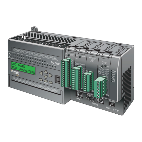
Introduction to the DL06 LCD Display Panel The DL06 LCD Display Panel is a 16 character, two row display that mounts directly on the face of the DL06 PLC. The LCD is backlit for easy readability in most lighting situations.
-
Page 183: Snap-In Installation
50 — 60Hz 2.0A, 6 — 27V 2.0A PWR: 100-240V 50-60Hz 40VA D0-06DR from the slot on the face of the DL06. 21 22 INPUT: 12 — 24V 3 — 15mA slide and lift cover WARNING: Remove power to the PLC X13 X14 X23 N.C.
-
Page 184: Display Priority
E r r o r (or other current display screen), and the E 4 * * P R O G R A M appropriate error code is displayed for diagnostic purposes. 10-4 DL06 Micro PLC User Manual, 3rd Edition, Rev. D…
-
Page 185: Menu Navigation
1 to screen 2. MENU Screen 2 M E N U S C R E E N > M 1 : P L C I N F O . 10-5 DL06 Micro PLC User Manual, 3rd Edition, Rev. D…
-
Page 186: Confirm Plc Type, Firmware Revision Level, Memory Usage, Etc
STOP (for Stop or Program Mode), TEST-STOP (for Test Stop Mode), or TEST-RUN (for Test Run Mode). You can put the DL06 in the Test Run Mode from the Test Stop Mode. MENU NOTE: The menu screen examples shown in this section assume the password/lock feature is not turned on.
-
Page 187
Default screen MENU Press ESC once more to return to the D L 0 6 P L C M a y default screen. 1 4 : 2 2 : 1 1 10-7 DL06 Micro PLC User Manual, 3rd Edition, Rev. D… -
Page 188: Menu 2, M2:System Cfg
Step 2.4 MENU M 2 : O P T I O N S L O T F 0 — 0 4 A D — 1 MENU 10-8 DL06 Micro PLC User Manual, 3rd Edition, Rev. D…
-
Page 189
M 2 : S Y S T E M C F G . MENU Return to default screen D L 0 6 P L C M a y 1 4 : 5 7 : 2 1 10-9 DL06 Micro PLC User Manual, 3rd Edition, Rev. D… -
Page 190: Monitoring And Changing Data Values
Bit 8 of V7742 changes the data format the up and down arrow keys to scroll to to decimal (five digits). other memory locations. 10-10 DL06 Micro PLC User Manual, 3rd Edition, Rev. D…
-
Page 191
D L 0 6 P L C M a y Push the ESC key five (5) times to return to the default screen. 1 5 : 0 2 : 1 3 10-11 DL06 Micro PLC User Manual, 3rd Edition, Rev. D… -
Page 192: Pointer Values
M O N I T O R return to Step 3.2 (five times to return to > B I T M O N I T O R the default screen). 10-12 DL06 Micro PLC User Manual, 3rd Edition, Rev. D…
-
Page 193: Bit Monitor
OFF to ON or ON to OFF. MENU M 3 : B I T — 0 2 2 5 0 0 C H G = S T A T : O F F 10-13 DL06 Micro PLC User Manual, 3rd Edition, Rev. D…
-
Page 194: Changing Date And Time
0 5 — 0 8 — 0 2 date to the chosen value. Press ENT again if the date is correct. You will automatically return to Step 4.2, and the new date will be displayed. MENU 10-14 DL06 Micro PLC User Manual, 3rd Edition, Rev. D…
-
Page 195
S E T ? 1 3 : 5 3 : 3 2 again if the date is correct. You will automatically return to Step 4.2, and the new date will be displayed. MENU 10-15 DL06 Micro PLC User Manual, 3rd Edition, Rev. D… -
Page 196
Press the ENT key to save the format changes. Press ESC until the default screen reappears. Date and Time Variables and Formats _date:us US format MM/DD/YY _date:e European format DD/MM/YY _date:a Asian format YY/MM/DD _time:12 12 hour format HH:MMAM/PM _time:24 24 hour format HH:MM:SS 10-16 DL06 Micro PLC User Manual, 3rd Edition, Rev. D… -
Page 197: Setting Password And Locking
The LCD password inhibits unauthorized personnel from modifying the data in the DL06 with the LCD keypad. Even though the LCD password is locked, the user can still modify the data in the DL06 with DirectSOFT or the D2-HPP. The LCD Display Panel does not support the multi-level password.
-
Page 198
Press the ENT key at Step 5.2, and the display is now locked. If you do not wish to lock the display at this point, press ESC. MENU 10-18 DL06 Micro PLC User Manual, 3rd Edition, Rev. D… -
Page 199
Here, the display prompts you to enter a M 5 : P S W D * * * * * * * password. L O C K 0 0 0 0 0 0 0 10-19 DL06 Micro PLC User Manual, 3rd Edition, Rev. D… -
Page 200: Reviewing Error History
0 5 — 2 2 — 0 2 down arrow key to scroll through the E 4 0 1 1 0 : 4 3 A M historical record of error messages. 10-20 DL06 Micro PLC User Manual, 3rd Edition, Rev. D…
-
Page 201: Toggle Light And Beeper, Test Keys
The piezo electric buzzer can be M 7 : L C D T E S T & S E T configured to provide pushbutton > B E E P feedback. 10-21 DL06 Micro PLC User Manual, 3rd Edition, Rev. D…
-
Page 202: Plc Memory Information For The Lcd Display Panel
Chapter 10: LCD Display Panel PLC Memory Information for the LCD Display Panel The valid memory ranges for storing text messages in the DL06 are: V400 — V677 V1200 — V7577 V10000 — V17777 Data Format Suffixes for Embedded V-memory Data Several data formats are available for displaying V-memory data on the LCD.
-
Page 203: Reserved Memory Registers For The Lcd Display Panel
V7742. When C0 is on, bit 12 is turned on. Bit 12 turns on the beeper in the LCD Display Panel. The C1 contact resets bit 12 to the off state. B7742.12 B7742.12 10-23 DL06 Micro PLC User Manual, 3rd Edition, Rev. D…
-
Page 204: V7742 Bit Definitions
LCD back light setting flag (default = 1) Bit 14 = Light OFF = Light ON LCD installed status flag (Read only) Bit 15 = LCD is not installed = LCD is installed 10-24 DL06 Micro PLC User Manual, 3rd Edition, Rev. D…
-
Page 205: Changing The Default Screen
A u t o m a t i o n D i r e c t 4 instructions for changing date and time information. NOTE: It is possible to return to the factory default screen by writing 0 to V7743 and cycling power. 10-25 DL06 Micro PLC User Manual, 3rd Edition, Rev. D…
-
Page 206: Dl06 Lcd Display Panel Instruction (Lcd)
Starting V Memory Address: A aaa Number of Characters: NOTE: The LCD Display Panel instruction is supported by DirectSOFT, Ver. 5 or later. It is not supported by the D2-HPP handheld programmer. 10-26 DL06 Micro PLC User Manual, 3rd Edition, Rev. D…
-
Page 207: Ascii Character Codes
First Digit character available for display. 2 3 4 5 6 7 Example: To display an upper case A, write 41 HEX to the memory location identified by the LCD instruction. 10-27 DL06 Micro PLC User Manual, 3rd Edition, Rev. D…
-
Page 208: Example Program: Alarm With Embedded Date/Time Stamp
Line Number: «Alarm 1 » Line Number: _date:us » » _time:12 A l a r m 0 5 / 0 8 / 0 4 5 : 2 3 P M 10-28 DL06 Micro PLC User Manual, 3rd Edition, Rev. D…
-
Page 209: Example Program: Alarm With Embedded V-Memory Data
Alarm 1 Active One-shot Alarm 1 LCD Msg One-shot Line Number: «Alarm 1» Line Number: «Parts= » V2500:B A l a r m P a r t s 2 4 3 7 10-29 DL06 Micro PLC User Manual, 3rd Edition, Rev. D…
-
Page 210: Example Program: Alarm Text From V-Memory With Embedded V-Memory Data
Starting V Memory Address: V10001 Number of Characters: Line Number: Starting V Memory Address: V10011 Number of Characters: A l a r m P a r t s 3 5 8 9 10-30 DL06 Micro PLC User Manual, 3rd Edition, Rev. D…
-
Page 211
ppendix ppendix ppendix uxilAry unctions In This Appendix… Introduction ………………A–2 AUX 2* — RLL Operations …………..A–4 AUX 3* — V-memory Operations …………. A–4 AUX 4* — I/O Configuration …………A–5 AUX 5* — CPU Configuration …………A–5 AUX 6* — Handheld Programmer Configuration ……A–8 AUX 7* —… -
Page 212: Appendix A: Auxiliary Functions
Set Retentive Ranges AUX 8* — Password Operations Test Operations Modify Password Override Setup Unlock CPU HSIO Interface Configuration Lock CPU Scan Control Setup NOTE: * — Supported HP — Handheld Programmer function DL06 Micro PLC User Manual, 3rd Edition, Rev. D…
-
Page 213: Accessing Aux Functions Via Directsoft
AUX 31 CLR V MEMORY You can also enter the exact AUX number to go straight to the sub-menu. Enter the AUX number directly AUX 3* V OPERATIONS AUX 31 CLR V MEMORY DL06 Micro PLC User Manual, 3rd Edition, Rev. D…
-
Page 214: Aux 21 Check Program
AUX 3* — V-memory Operations AUX 31 Clear V-memory AUX 31 clears all the information from the V-memory locations available for general use. This AUX function is available on the PLC/Clear PLC sub-menu within DirectSOFT. DL06 Micro PLC User Manual, 3rd Edition, Rev. D…
-
Page 215: Aux 4* — I/O Configuration
AUX 55 Set Watchdog Timer DL06 PLCs have a watchdog timer that is used to monitor the scan time. The default value set from the factory is 200 ms. If the scan time exceeds the watchdog time limit, the CPU automatically leaves RUN mode and enters PGM mode.
-
Page 216: Aux 56 Cpu Network Address
Appendix A: Auxiliary Functions AUX 56 CPU Network Address Since the DL06 CPU has an additional communication port, you can use the Handheld to set the network address for port 2 and the port communication parameters. The default settings are: •…
-
Page 217: Aux 59 Bit Override
AUX 5D Select PLC Scan Mode The DL06 CPU has two program scan modes, fixed and variable. In fixed mode, the scan time is lengthened to the time you specify (in milliseconds). If the actual scan time is longer than the fixed scan time, then the error code E504 BAD REF/VAL is displayed.
-
Page 218: Aux 6* — Handheld Programmer Configuration
AUX 71 copies information from the CPU memory to an EEPROM installed in the Handheld Programmer.You can copy different portions of EEPROM (HP) memory to the CPU memory as shown in the previous table. DL06 Micro PLC User Manual, 3rd Edition, Rev. D…
-
Page 219: Aux 72 Hpp Eeprom To Cpu
AUX 72 HPP EEPROM to CPU AUX 72 copies information from the EEPROM installed in the Handheld Programmer to CPU memory in the DL06. You can copy different portions of EEPROM (HP) memory to the CPU memory as shown in the previous table.
-
Page 220: Aux 82 Unlock Cpu
CPU to the factory for password removal. It is the policy of Automationdirect to clear the PLC memory along with the password. NOTE: The DL06 CPUs support multi-level password protection of the ladder program. This allows password protection while not locking the communication port to an operator interface. The multi- level password can be invoked by creating a password with an upper case “A”…
-
Page 221: Dl06 Error Codes
DL05 E rror oDEs In This Appendix… DL06 Error Codes …………….B–2…
-
Page 222
AUX 55 to extend the time allotted to the watchdog timer. TIME-OUT The DL06 battery is low and should be replaced. SP43 will be on and the error code will be E041 stored in V7757. The CPU indicator will blink if the battery is less than 2.5 VDC (refer to the CPU BATTERY LOW table on page 3-6). -
Page 223
Appendix B: DL06 Error Codes DL06 Error Code Description A data error was encountered during communication with the DL06. Check to ensure cabling E321 is correct and not defective. Power cycle the system and, if the error continues, replace the COMM ERROR DL06 first and then the handheld programmer, if necessary. -
Page 224
CVJMP has been used in a subroutine or a program interrupt routine. INVALID CV JUMP ADDRESS E484 CVJMP is not preceded by the CV instruction. A CVJMP must immediately follow the CV instruction. MISSING CV INSTRUCTION DL06 Micro PLC User Manual, 3rd Edition, Rev. D… -
Page 225
An operation which is invalid in the PROGRAM mode was attempted by the handheld programmer. BAD OP–PGM E525 An operation was attempted by the handheld programmer while the DL06 mode switch was in a position other than the TERM position. MODE SWITCH DL06 Micro PLC User Manual, 3rd Edition, Rev.D… -
Page 226
The operation attempted is not allowed during a Run Time Edit. CPU MODE E540 The DL06 has been password locked. To unlock the DL06 use AUX82 with the password. CPU LOCKED E541 The password used to unlock the DL06 with AUX82 was incorrect. -
Page 227
ppendix ppendix ppendix nstructIon nstructIon xEcutIon xEcutIon ImEs ImEs In This Appendix… Introduction ………………C–2 Instruction Execution Times …………. C–3… -
Page 228: Appendix C: Instruction Execution Times
Introduction This appendix contains several tables that provide the instruction execution times for DL06 Micro PLCs. Many of the execution times depend on the type of data used with the instruction. Registers may be classified into the following types: • Data (word) Registers •…
-
Page 229: Instruction Execution Times
2nd #: T, CT (N pt), GX, GY 16.8 µs + 2.7 µs x N 1.4 µs 1wd: Y 5.6 µs 5.4 µs PAUSE 2wd: Y (N points) 9.2 µs + 0.3 µs x N 4.8 µs DL06 Micro PLC User Manual, 3rd Edition, Rev. D…
-
Page 230: Comparative Boolean Instructions
V:Data Reg. 30.3 µs 30.3 µs P:Indir. (Bit) V:Bit Reg. 30.3 µs 30.3 µs K:Constant 27.4 µs 27.4 µs P:Indir. (Data) 51.0 µs 51.0 µs P:Indir. (Bit) 51.0 µs 51.0 µs DL06 Micro PLC User Manual, 3rd Edition, Rev. D…
-
Page 231
V:Data Reg. 29.9 µs 29.9 µs P:Indir. (Bit) V:Bit Reg. 29.9 µs 29.9 µs K:Constant 27.4 µs 27.4 µs P:Indir. (Data) 51.0 µs 51.0 µs P:Indir. (Bit) 51.0 µs 51.0 µs DL06 Micro PLC User Manual, 3rd Edition, Rev. D… -
Page 232
V:Data Reg. 29.9 µs 29.9 µs P:Indir. (Bit) V:Bit Reg. 29.9 µs 29.9 µs K:Constant 27.4 µs 27.4 µs P:Indir. (Data) 51.0 µs 51.0 µs P:Indir. (Bit) 51.0 µs 51.0 µs DL06 Micro PLC User Manual, 3rd Edition, Rev. D… -
Page 233
7.6 µs 7.6 µs V: Data Reg. STRN V:Bit Reg 7.6 µs 7.6 µs K:Constant 4.8 µs 4.8 µs P:Indir. (Data) 30.2 µs 30.2 µs P:Indir. (Bit 30.2 µs 30.2 µs DL06 Micro PLC User Manual, 3rd Edition, Rev. D… -
Page 234
P:Indir. (Bit) V:Data Reg 29.9 µs 29.9 µs V:Bit Reg 29.9 µs 29.9 µs K:Constant 27.4 µs 27.4 µs P:Indir. (Data 51.0 µs 51.0 µs P:Indir. (Bit) 51.0 µs 51.0 µs DL06 Micro PLC User Manual, 3rd Edition, Rev. D… -
Page 235
P:Indir. (Bit) V:Data Reg. 29.9 µs 29.9 µs V:Bit Reg. 29.9 µs 29.9 µs K:Constant 27.4 µs 27.4 µs P:Indir. (Data) 51.0 µs 51.0 µs P:Indir. (Bit) 51.0 µs 51.0 µs DL06 Micro PLC User Manual, 3rd Edition, Rev. D… -
Page 236
V:Data Reg 29.9 µs 29.9 µs P:Indir. (Bit) V:Bit Reg 29.9 µs 29.9 µs K:Constant 27.4 µs 27.4 µs P:Indir. (Data) 51.0 µs 51.0 µs P:Indir. (Bit) 51.0 µs 51.0 µs C-10 DL06 Micro PLC User Manual, 3rd Edition, Rev. D… -
Page 237: Immediate Instructions
1st #: Y 2nd #: K Constant 23.1 µs, 22.8 µs+1.4µsxN 0.9 µs, 0.9 µs RSTI 1st #: Y 2nd #: Y (N pt) 23.2 µs, 22.8 µs+1.4µsxN 0.9 µs, 0.9 µs C-11 DL06 Micro PLC User Manual, 3rd Edition, Rev. D…
-
Page 238: Bit Of Word Boolean Instructions
P:Indir. (Bit) 41.1 µs 29.1 µs 13.5 µs 1.4 µs V:Data Reg. 13.5 µs 1.4 µs V:Bit Reg. P:Indir. (Data) RSTB 41.3 µs 29.1 µs P:Indir. (Bit) 41.3 µs 29.1 µs C-12 DL06 Micro PLC User Manual, 3rd Edition, Rev. D…
-
Page 239: Timer, Counter And Shift Register
4.6 µs K:Constant 35.4 µs 30.2 µs 67.8 µs P:Indir. (Data) 30.2 µs 67.8 µs P:Indir. (Bit) C (N points to shift) 9.8 µs 17.8 µs + 0.9 µs x N C-13 DL06 Micro PLC User Manual, 3rd Edition, Rev. D…
-
Page 240: Accumulator Data Instructions
V:Data Reg. 17.2 µs 1.0 µs V:Bit Reg. 17.2 µs 1.0 µs OUTX P:Indir. (Data) 43.4 µs 1.0 µs P:Indir. (Bit) 43.4 µs 1.0 µs NONE 8.4 µs 1.0 µs C-14 DL06 Micro PLC User Manual, 3rd Edition, Rev. D…
-
Page 241: Logical Instructions
V:Data Reg. 9.9 µs 1.0 µs V:Bit Reg. 9.9 µs 1.0 µs CMPD K:Constant 6.7 µs 1.0 µs P:Indir. (Data) 35.4 µs 1.0 µs P:Indir. (Bit) 35.4 µs 1.0 µs C-15 DL06 Micro PLC User Manual, 3rd Edition, Rev. D…
-
Page 242: Math Instructions
P:Indir. (Bit) 419.8 µs 0.9 µs 398.3 µs 0.9 µs V:Data Reg. 398.3 µs 0.9 µs V:Bit Reg. DIVD P:Indir. (Data) 390.9 µs 0.9 µs P:Indir. (Bit) 390.9 µs 0.9 µs C-16 DL06 Micro PLC User Manual, 3rd Edition, Rev. D…
-
Page 243
48.1 µs 1.0 µs V:Data Reg. 48.1 µs 1.0 µs V:Bit Reg. ADDR K:Constant 41.7 µs 1.0 µs P:Indir. (Data) 74.3 µs 1.0 µs P:Indir. (Bit) 74.3 µs 1.0 µs C-17 DL06 Micro PLC User Manual, 3rd Edition, Rev. D… -
Page 244
COSR None 213.1 µs 1.0 µs TANR None 285.5 µs 1.0 µs ASINR None 489.8 µs 1.0 µs ACOSR None 508.3 µs 1.0 µs ATANR None 317.1 µs 1.0 µs C-18 DL06 Micro PLC User Manual, 3rd Edition, Rev. D… -
Page 245: Differential Instructions
V:Data Reg. (N bits) ROTL V:Bit Reg. (N bits) 16.4 µs 1.0 µs K:Constant (N bits) 12.7 µs 1.0 µs ENCO None 33.9 µs 0.9 µs DECO None 5.7 µs 1.0 µs C-19 DL06 Micro PLC User Manual, 3rd Edition, Rev. D…
-
Page 246: Number Conversion Instructions
P:Indir. (Data) 1.0 µs P:Indir. (bit) 66.8 µs 1.0 µs V: Data Reg (N bits) FIND V:Bit Reg. (N bits) 66.8 µs 1.0 µs K:Constant(N bits) 64.0 µs 1.0 µs C-20 DL06 Micro PLC User Manual, 3rd Edition, Rev. D…
-
Page 247
59.5 µs 1.0 µs SETBIT V:Bit Reg. (N bits) 59.5 µs 1.0 µs V: Data Reg (N bits) 59.5 µs 1.0 µs RSTBIT V:Bit Reg. (N bits) 59.5 µs 1.0 µs C-21 DL06 Micro PLC User Manual, 3rd Edition, Rev. D… -
Page 248: Cpu Control Instructions
X, Y, C, T, CT, SP, S, $ 1614.0 µs 4.4 µs V:Data Reg. 1614.0 µs 4.4 µs V:Bit Reg. 1614.0 µs 4.4 µs P:Indir. (Data) 1630.0 µs 4.4 µs P:Indir. (Bit) 1630.0 µs 4.4 µs C-22 DL06 Micro PLC User Manual, 3rd Edition, Rev. D…
-
Page 249: Intelligent I/O Instructions
Drum Instructions DL06 Instruction Legal Data Types Execute Not Execute DRUM 840.0 µs 339.6 µs EDRUM 753.2 µs 357.0 µs MDRMD 411.3 µs 216.4 µs MDRMW 378.6 µs 147.0 µs C-23 DL06 Micro PLC User Manual, 3rd Edition, Rev. D…
-
Page 250: Clock/Calendar Instructions
111.7 µs 1.3 µs CMPV 12.2 µs 1.3 µs SWAPB 109.8 µs 1.3 µs VPRINT Text Data 161.6 µs 1.3 µs PRINTV 163.3 µs 1.3 µs ACRB 3.9 µs 1.1 µs C-24 DL06 Micro PLC User Manual, 3rd Edition, Rev. D…
-
Page 251
In This Appendix… DL06 PLC Special Relays …………..D–2… -
Page 252: Appendix D: Special Relays
On when the mode switch is in the STOP position. SP20 Forced stop mode On when the STOP instruction is executed. SP22 Interrupt enabled On when interrupts have been enabled using the ENI instruction. DL06 Micro PLC User Manual, 3rd Edition, Rev. D…
-
Page 253: Accumulator Status
SP75 Data error On if a BCD number is expected and a non–BCD number is encountered. SP76 Load zero On when any instruction loads a value of zero into the accumulator. DL06 Micro PLC User Manual, 3rd Edition, Rev. D…
-
Page 254: Hsio Pulse Output Relay
Slot 1 SP relay for option card SP240-337 Slot 2 SP relay for option card SP340-437 Slot 3 SP relay for option card SP430-537 Slot 4 SP relay for option card DL06 Micro PLC User Manual, 3rd Edition, Rev. D…
-
Page 255: Counter 1 Mode 10 Equal Relays
Current = target value On when the counter current value equals the value in V3705/3704 SP567 Current = target value On when the counter current value equals the value in V3707/3706 DL06 Micro PLC User Manual, 3rd Edition, Rev. D…
-
Page 256: Counter 2 Mode 10 Equal Relays
Current = target value On when the counter current value equals the value in V3765/3764 SP617 Current = target value On when the counter current value equals the value in V3767/3766 DL06 Micro PLC User Manual, 3rd Edition, Rev. D…
-
Page 257
ppendix hapter ppendix speed speed nput and nput and ulse ulse utput utput eatures eatures In This Appendix… Introduction ………………E–2 Choosing the HSIO Operating Mode ……….E–4 Mode 10: High-Speed Counter …………E–7 Mode 20: Up/Down Counter …………E–24 Presets and Special Relays …………..E–27 Mode 30: Pulse Output …………..E–38 Mode 40: High-Speed Interrupts ………..E–67 Mode 50: Pulse Catch Input …………E–72… -
Page 258: Appendix E: High-Speed Input And Pulse Output Features
Specifications DL06 Part Number Discrete Input Type Discrete Output Type High-Speed Input Pulse Output D0–06AA D0–06AR Relay D0–06DA D0–06DD1 D0–06DD2 D0–06DR Relay D0–06DD1–D D0–06DD2–D D0–06DR–D Relay DL06 Micro PLC User Manual, 3rd Edition, Rev. D…
-
Page 259: Dedicated High- Speed I/O Circuit
The internal CPU’s main task is to execute the ladder program and read/write all I/O points during each scan. In order to service high-speed I/O events, the DL06 includes a special circuit which is dedicated to a portion of the I/O points. Refer to the DL06 block diagram in the figure below.
-
Page 260: Choosing The Hsio Operating Mode
If an input point is not specifically used to support a particular mode, it usually operates as a filtered input by default. Similarly, output points operate normally unless Pulse Output mode is selected. DL06 Micro PLC User Manual, 3rd Edition, Rev. D…
-
Page 261: Default Mode
Output Default Mode Mode 60 (Filtered Inputs) is the default mode. The DL06 is initialized to this mode at the factory, and any time you initialize the scratchpad memory. In the default condition, X0–X3 are filtered inputs (10 ms delay) and Y0–Y1 are standard outputs.
-
Page 262: Configuring The Hsio Mode
X0 – X3. V7634 xxxx Other memory locations may require configuring, depending V7635 xxxx on the HSIO mode (see the corresponding section for V7636 xxxx particular HSIO modes). X3 V7637 xxxx DL06 Micro PLC User Manual, 3rd Edition, Rev. D…
-
Page 263: Mode 10: High-Speed Counter
Y2 — Y17 Y0 — Y1 HSIO I/O data V-memory Counter 1 Counter 2 Mode Select Filter CLK Reset CLK Reset V7633 0010 X2 — X3 X4 — X23 Input Circuit DL06 Micro PLC User Manual, 3rd Edition, Rev. D…
-
Page 264: Wiring Diagram
12-24 VDC Supply Interfacing to Counter Inputs The DL06’s DC inputs are flexible in that they detect current flow in either direction, so they can be wired to a sensor with either sourcing or sinking outputs. In the following circuit, a sensor has an open-collector NPN transistor output.
-
Page 265: Setup For Mode 10
Preset? V3634 0000 2500 SPxxx V3632 0000 2000 V3636 0000 3175 Output V3634 0000 2500 V3636 0000 3175 Update V3706 0921 0000 V3706 0921 0000 High Word Word High Word Word DL06 Micro PLC User Manual, 3rd Edition, Rev. D…
-
Page 266: Absolute And Incremental Presets
Absolute presets trigger events at the preset values, 50, 100, and 150. Incremental presets trigger events at the cumulative totals: 50, 150, and 300. E-10 DL06 Micro PLC User Manual, 3rd Edition, Rev. D…
-
Page 267: Preset Data Starting Location
NOTE: In absolute mode each successive preset must be greater than the previous preset value. If a preset value is less than a lower-numbered preset value, the CPU cannot compare to that value, since the counter can only count upwards. E-11 DL06 Micro PLC User Manual, 3rd Edition, Rev. D…
-
Page 268: Equal Relay Numbers
V7630. To change the table location. use the LDA and OUT instructions as shown on the previous page. E-12 DL06 Micro PLC User Manual, 3rd Edition, Rev. D…
-
Page 269: Calculating Your Preset Values
All go off when the counter resets. Equal Relays SP540 SP541 SP542 NOTE: Each successive preset must be two numbers greater than the previous preset value. In the industrial lathe example, B>A+2 and C>B+2. E-13 DL06 Micro PLC User Manual, 3rd Edition, Rev. D…
-
Page 270: Input Configuration
‘0107’ are set in V7636 or V7637 and preset values are changed during program execution, the DL06 recognizes the changed preset values at the time of the reset. When ‘0207’ or ‘0307’ are set in V7636 or V7637, the CPU does not check for changed preset values, so the DL06 has a faster reset time.
-
Page 271: Writing Your Control Program
Appendix E: High-speed Input and Pulse Output Features Writing Your Control Program The mnemonic for the counter instruction is UDC (up-down counter).The DL06 can have up to 128 counters, labeled CT0 through CT177. The high speed counter in the HSIO circuit is accessed in ladder logic by using UDC CT174 and CT176. It uses counter registers CT174 through CT177 exclusively when the HSIO mode 10 is active (otherwise, CT174 through CT177 are available for standard counter use).
-
Page 272: Program Example 1: Counter Without Presets
The Preload Input in the middle is always off. The third rung’s Reset K99999999 input is always off, because we will use the external reset. continued on next page E-16 DL06 Micro PLC User Manual, 3rd Edition, Rev. D…
-
Page 273
The execution of the above CMPD instruction turns on special relay contact SP62 if the current count is greater than the comparison number (K345678). END coil marks the end of the main program. E-17 DL06 Micro PLC User Manual, 3rd Edition, Rev. D… -
Page 274: Program Example 2: Counter With Presets
When the lead screw turns, the counter device generates pulses which the DL06 can count. The three preset variables A, B, and C represent the positions (number of pulses) corresponding to each of the three grooves. In this example, only one high-speed counter is used.
-
Page 275
(Y1), so they are logically ORed together . Preset 3 Input X2 will be energized inside the interrupt routine if X2 external interrupt was the source. Return from the interrupt service routine. E-19 DL06 Micro PLC User Manual, 3rd Edition, Rev. D… -
Page 276
X2. The X2 contact will be on (inside the interrupt routine only) if the interrupt was caused by the external reset, X2 input. E-20 DL06 Micro PLC User Manual, 3rd Edition, Rev. D… -
Page 277: Program Example 3: Counter With Preload
The third rung’s Reset input is normally off, because we will use the external reset. You can optionally reset the counter value on each powerup using the SP0 contact. continued on next page E-21 DL06 Micro PLC User Manual, 3rd Edition, Rev. D…
-
Page 278
V1174-V1175. Enable the counter by setting C0, when the preolad pulse on C1 has occurred (C1 is off). END coil marks the end of the main program. E-22 DL06 Micro PLC User Manual, 3rd Edition, Rev. D… -
Page 279: Using Counters
1. Check the LED status indicator for X2 (counter 1) and X3 (counter 2) to make sure it is active when you want a reset. Or, if you are using an internal reset, use the status mode of DirectSOFT to monitor the reset input to the counter. E-23 DL06 Micro PLC User Manual, 3rd Edition, Rev. D…
-
Page 280: Mode 20: Up/Down Counter
For standard up/down counting, input X0 is dedicated to the up counting signal, and input X1 is dedicated to the down counting signal. The X2 input resets the counter to zero when energized. E-24 DL06 Micro PLC User Manual, 3rd Edition, Rev. D…
-
Page 281: Quadrature Encoder Signals
Motor Amplifier A general wiring diagram for encoders to the DL06 in HSIO Mode 20 is shown below. Encoders with sinking outputs (NPN open collector) are probably the best choice for interfacing. If the encoder sources to the inputs, it must output 12 to 24 VDC. Note that encoders with 5V sourcing outputs will not work with DL06 inputs.
-
Page 282: Interfacing To Encoder Outputs
Appendix E: High-speed Input and Pulse Output Features Interfacing to Encoder Outputs The DL06’s DC inputs are flexible in that they detect current flow in either direction, so they can be wired to an encoder with either sourcing or sinking outputs. In the following circuit, an encoder has open-collector NPN transistor outputs.
-
Page 283: Setup For Mode 20
V-memory Preset Data = Preset? Interrupt V3630 0000 1000 Current Routine Instruction V3632 0000 2000 Program SPxxx V3634 0000 2500 Output V3636 0000 3175 Update V3706 0921 0000 High Word Word E-27 DL06 Micro PLC User Manual, 3rd Edition, Rev. D…
-
Page 284: X Input Configuration
When ‘0007’ or ‘0107’ are set in V7636 and preset values are changed during program execution, the DL06 recognizes the changed preset values at the time of the reset. When ‘0207’ or ‘0307’ are set in V7636 the CPU does not check for changed preset values, so the DL06 has a faster reset time.
-
Page 285: Writing Your Control Program
Appendix E: High-speed Input and Pulse Output Features Writing Your Control Program The mnemonic for the counter is UDC (up-down counter). The DL06 can have up to 128 counters, labeled CT0 through CT177. The quadrature counter in the HSIO circuit is accessed in ladder logic by using UDC CT174.
-
Page 286: Program Example 1: Quadrature Counting With An Interrupt
CT174 always enables the counter . The dummy input is used by the built-in compiler . K18724 END coil marks the end of the main program. continued on next page E-30 DL06 Micro PLC User Manual, 3rd Edition, Rev. D…
-
Page 287
0 on the rising edge of the reset. Presets for up/down counting have been stored in memory locations V3630 through V3635. The next even numbered location following this has FFFF to indicate we have no more presets. E-31 DL06 Micro PLC User Manual, 3rd Edition, Rev. D… -
Page 288: Program Example 2: Up/Down Counting With Standard Inputs
X1, the value in V1175/V1174 will decrement. Actual counts V1174 K450 When the pulse count reaches and exceeds 450, the «over 450» light (Y20) will turn on. Continued on next page. E-32 DL06 Micro PLC User Manual, 3rd Edition, Rev. D…
-
Page 289
(Y22) turns on and will stay on for 30 seconds after the count falls below 500. Counter output CT174 TIMER 0 OUTPUT K300 Over 500 latch END coil marks the end of the main program. E-33 DL06 Micro PLC User Manual, 3rd Edition, Rev. D… -
Page 290: Program Example 3: Quadrature Counting
OUTD mode has been selected. V3630 K6000 OUTD V3632 K7500 OUTD V3634 K8000 OUTD V3636 KFFFF Tell CPU that there are no more presets. OUTD V3640 Continued on next page. E-34 DL06 Micro PLC User Manual, 3rd Edition, Rev. D…
-
Page 291
Drill press down. Drill turning. Drill fully extended. Limit switch 1. Drill press down. Drill press up. Drill fully retracted. (home position) Limit switch 2. One-shot bit. Continued on next page. E-35 DL06 Micro PLC User Manual, 3rd Edition, Rev. D… -
Page 292
Forwarding SP542 Positioning Table. Drilling sequence initiation. Forwarding SP543 Positioning Table. Reversing Positioning Table. Drilling sequence initiation. Position Table home limit switch Reversing (resets counter to zero). Positioning Table. RSTI E-36 DL06 Micro PLC User Manual, 3rd Edition, Rev. D… -
Page 293: Troubleshooting Guide For Mode 20
V7636 for X2 is set to 7. Or, if you are using an internal reset, use the status mode of DirectSOFT to monitor the reset input to the counter. E-37 DL06 Micro PLC User Manual, 3rd Edition, Rev. D…
-
Page 294: Mode 30: Pulse Output
HSIO function automatically calculates the entire motion profile. The figure below shows the DL06 generating pulse and direction signals to the drive amplifier of a stepper positioning system. The pulses accomplish the profile independently and without interruption to ladder program execution in the CPU.
-
Page 295: Functional Block Diagram
Hopefully, the above discussion will explain why some I/O reference names have dual meanings in Pulse Output Mode. Please read the remainder of this section with care, to avoid confusion about which actual I/O function is being discussed. E-39 DL06 Micro PLC User Manual, 3rd Edition, Rev. D…
-
Page 296: Wiring Diagram
Appendix 2 to learn how to calculate and install R pullup. Y0, Y1 Pulse Output Power +DC power pullup Drive Input (sourcing) Output Input (sinking) Input (sinking) Supply Common – Ground E-40 DL06 Micro PLC User Manual, 3rd Edition, Rev. D…
-
Page 297: Motion Profile Specifications
External Interrupt — If the interrupt feature is selected for the Automatic Trapezoidal profile or the Step Trapezoidal Profile, the DL06 keeps outputting pulses until X1 turns on. After it is on, the unit outputs the pulses that are defined as the Target position.
-
Page 298: Setup For Mode 30
4 to 7, C to F = Automatic Trapezoidal Profile Range = 0, 4 to 999, representing 40 Hz to 10 kHz pulse rate 0, 1, 8, 9 = Step Trapezoidal Profile 2 = Velocity Profile E-42 DL06 Micro PLC User Manual, 3rd Edition, Rev. D…
-
Page 299: Profile/Velocity Select Register
4 to 100 x 10 pps * If you select to use interrupt, the DL06 will not start looking for your target count until the interrupt X1 is on. ** To set a negative number, put 8 in the most significant digit. For example: -8388608 is 88388608 in V3631 and V3632.
-
Page 300: Step Trapezoidal Profile
1 to 9999 Pulses * If you select to use interrupt, the DL06 will not start looking for your target count until the interrupt X1 is on. ** To set a negative number, put 8 in the most significant digit. For example: -8388608 is 88388608 in V3631 and V3632.
-
Page 301: Choosing The Profile Type
100 ms to 10 secs 0 pulses 7000 pulses Acceleration Deceleration The user determines the starting velocity, the acceleration/deceleration times, and the total number of pulses. The CPU computes the profile from these inputs. E-45 DL06 Micro PLC User Manual, 3rd Edition, Rev. D…
-
Page 302: Step Trapezoidal Profiles Defined
Only the first velocity value needs to be defined. The remaining velocity values can be created while motion is in progress. Arrows in the profile shown indicate velocity changes. Velocity Control Profile Velocity (Hz) Time E-46 DL06 Micro PLC User Manual, 3rd Edition, Rev. D…
-
Page 303: Automatic Trapezoidal Profile Operation
You can also use the external interrupt (X1). Once the external interrupt feature is selected for the profile, the DL06 keeps outputting the pulses until X1 turns on. Then, the DL06 outputs the pulses defined as the target position.
-
Page 304: Program Example 1: Automatic Trapezoidal Profile Without External Interrupt
Output this constant to V7637, configuring X3. V7637 * If the Locate Parameter Table is not used you must remove both the LDA function and the OUT function below it. Continued on next page. E-48 DL06 Micro PLC User Manual, 3rd Edition, Rev. D…
-
Page 305: Preload Position Value
HSIO to preload the current position with the value in V1174/V1175. Turn on Y1 for 1 scan. The off-to-on transition causes the HSIO to preload the current position with the value in V1174/V1175. E-49 DL06 Micro PLC User Manual, 3rd Edition, Rev. D…
-
Page 306: Program Example 2: Automatic Trapezoidal Profile With External Interrupt
Y0 to start the profile. Immediately the HSIO turns off the Profile Complete signal (SP104), so the ladder program can monitor the move’s completion by sensing the signal’s on state. E-50 DL06 Micro PLC User Manual, 3rd Edition, Rev. D…
-
Page 307
Output this constant to V7637, configuring X3. V7637 * If the Locate Parameter Table is not used you must remove both the LDA function and the OUT function below it. E-51 DL06 Micro PLC User Manual, 3rd Edition, Rev. D… -
Page 308
The profile will begin when the start input (X3) is given. Then the motion begins an indefinite move, which lasts until an external interrupt on X1 occurs. Then the motion continues on for 5000 more pulses before stopping. E-52 DL06 Micro PLC User Manual, 3rd Edition, Rev. D… -
Page 309: Program Example 3: Automatic Trapezoidal Profile With Home Search
CW Limit until it hits the Home Switch, then travels past it and reverse slowly back to the Home Switch. A value of 0 will be loaded to V1174 (CTA174) to represent the Home position. E-53 DL06 Micro PLC User Manual, 3rd Edition, Rev. D…
-
Page 310
40 Hz (4 x 10 pps). V3633 The constant K1 selects an acceleration time Acceleration and deceleration time of 0.1 seconds (1 x 100ms). V3634 Deceleration V3635 Continued on next page E-54 DL06 Micro PLC User Manual, 3rd Edition, Rev. D… -
Page 311
Once the CW Limit is found, the DL06 will stop the Pulse Output, load a negative value, thus reversing direction. It does this by LDD K80000200 into V3631. The “8” in the left-most position of the value loaded (8xxxxxxx) will cause Y1 to turn on. -
Page 312
The Pulse Output is now activated again, but in the direction the motor was initially started. Delay to reverse direction Return to Home Set C5 to indicate the CW home search has begun. Pulse Out Turn on Pulse Out again. Off Home Switch Reset C4. E-56 DL06 Micro PLC User Manual, 3rd Edition, Rev. D… -
Page 313
If the CW limit is encountered, the program searches for home in the CCW direction, passes it slightly, and does the final CW search for home. After reaching home, the last ladder rung preloads the current position to “0”. E-57 DL06 Micro PLC User Manual, 3rd Edition, Rev. D… -
Page 314: Step Trapezoidal Profile Operation
You can also use the external interrupt (X1). Once the external interrupt feature selected for the profile, the DL06 keeps outputting the pulses until X1 turns on. Then the DL06 outputs the pulses defined as the target position.
-
Page 315: Program Example 4: Step Trapezoidal Profile
V3631 * If the Locate Parameter Table is not used you must remove both the LDA function and the OUT function below it. Continued on next page E-59 DL06 Micro PLC User Manual, 3rd Edition, Rev. D…
-
Page 316
5 deceleration velocity of 800 Hz. Output this constant to V3643 which is required to select the step 5 deceleration velocity of 800 Hz. V3643 Continued on next page E-60 DL06 Micro PLC User Manual, 3rd Edition, Rev. D… -
Page 317
Velocity V1174 Turn on Y1 for 1 scan. The of f -to-on transition causes the HSIO to preload the current position with the value in V1174/V1175. E-61 DL06 Micro PLC User Manual, 3rd Edition, Rev. D… -
Page 318: Velocity Profile Operation
Unlike the trapezoidal and registration profiles, you must specify the desired direction of travel with velocity profiles. Load the direction select register (V3631/V3632 by default) with 8000 0000 hex for CCW direction, or 0 for CW direction. E-62 DL06 Micro PLC User Manual, 3rd Edition, Rev. D…
-
Page 319: Program Example 5: Velocity Profile
Output this constant to V7637, configuring X3. V7637 * If the Locate Parameter Table is not used you must remove both the LDA function and the OUT function below it. E-63 DL06 Micro PLC User Manual, 3rd Edition, Rev. D…
-
Page 320
Load the constant K600 which is required to select a velocity of 6000 pps when the operator closes X4. K600 Output this constant to V3633, the location of the velocity parameter register. The speed will change immediately. V3633 E-64 DL06 Micro PLC User Manual, 3rd Edition, Rev. D… -
Page 321: Automatic Trapezoidal Profile Error Codes
Error code descriptions are given above. 3. Check target value – The profile will not pulse if the count value is equal to the target value (ex. count =0, target=0). E-65 DL06 Micro PLC User Manual, 3rd Edition, Rev. D…
-
Page 322: Symptom: The Motor Turns In The Wrong Direction
1. Wiring – If you have selected CW and CCW type operation, just swap the wires on Y0 and Y1 outputs. 2. Direction control – If you have selected Pulse and Direction type operation, just change the direction bit to the opposite state. E-66 DL06 Micro PLC User Manual, 3rd Edition, Rev. D…
-
Page 323: Mode 40: High-Speed Interrupts
DL06 Output Circuit Y0, Y1 Y2 — Y17 HSIO I/O data Interrupt Interrupt Timer V-memory Interrupt Mode select V7633 0040 Filter Filter X1, X2, X3 X4 — X23 Input Circuit E-67 DL06 Micro PLC User Manual, 3rd Edition, Rev. D…
-
Page 324: Setup For Mode 40
CPU Scan Input Update Ladder Program X0, External Interrupt Execution Interrupt Routine Current Program TIMER Instruction Interrupt source / Time select Input Update V7634 xxx4 X1-X3, External Interrupts E-68 DL06 Micro PLC User Manual, 3rd Edition, Rev. D…
-
Page 325: External Interrupt Timing Parameters
10) and use point 03 for a high speed interrupt. You should read the individual sections for any alternate mode you might choose. There you will find instructions on how to select a high speed interrupt as a secondary feature. E-69 DL06 Micro PLC User Manual, 3rd Edition, Rev. D…
-
Page 326: Program Example 1: External Interrupt
Set output Y5 Return to the main ladder program. Interrupt Routine Insert interrupt service routine rungs here for your application. SETI Set output Y6. Return to the main ladder program. E-70 DL06 Micro PLC User Manual, 3rd Edition, Rev. D…
-
Page 327: Program Example 2: Timed Interrupt
NOTE: X0 Cannot be used in the main program logic; however, using X0 to set C10, for instance, will allow the use of C10 in the main program logic. Do not forget to reset C10. E-71 DL06 Micro PLC User Manual, 3rd Edition, Rev. D…
-
Page 328: Mode 50: Pulse Catch Input
NOTE: The pulse catch and filtered input functions are opposite in nature. The pulse catch feature seeks to capture narrow pulses, while the filter input feature seeks to reject narrow pulses. E-72 DL06 Micro PLC User Manual, 3rd Edition, Rev. D…
-
Page 329: Setup For Mode 50
We recommend using the first method above so that the HSIO setup becomes an integral part of your application program. An example program later in this section shows how to do this. E-73 DL06 Micro PLC User Manual, 3rd Edition, Rev. D…
-
Page 330: X Input Configuration
(xx = filter time) 0 — 99 ms (BCD) Interrupt 0004 V7637 Pulse Catch Input 0005 (default) Filtered Input xx06 (xx = filter time) 0 — 99 ms (BCD) E-74 DL06 Micro PLC User Manual, 3rd Edition, Rev. D…
-
Page 331: Program Example 1: Pulse Catch
Use the pulse catch input to set output Y1 on. This will work even for a very short pulse on X1. END coil marks the end of the main program. E-75 DL06 Micro PLC User Manual, 3rd Edition, Rev. D…
-
Page 332: Mode 60: Discrete Inputs With Filter
In this case, the logical input to the ladder program remains in the OFF state (input pulse was filtered out). Filter Time Filter Time Physical Input Logical Input Time Physical Input Logical Input E-76 DL06 Micro PLC User Manual, 3rd Edition, Rev. D…
-
Page 333: Setup For Mode 60
V7636 Filtered Input xx06 (xx = filter delay time) 0 — 99 ms (BCD) (default) V7637 Filtered Input xx06 (xx = filter delay time) 0 — 99 ms (BCD) (default) E-77 DL06 Micro PLC User Manual, 3rd Edition, Rev. D…
-
Page 334: Program Example: Filtered Inputs
70 ms filter time constant. K7006 Output this constant to V7637, configuring X3. V7637 Main Program Insert Main Program rungs here for your application. END coil marks the end of the main program.. E-78 DL06 Micro PLC User Manual, 3rd Edition, Rev. D…
-
Page 335: Dl06 Plc Memory
PLC M PLC M eMory eMory In this Appendix… DL06 PLC Memory …………….F–2…
-
Page 336
When designing a PLC application, it is important for the PLC user to understand the different types of memory in the PLC. The DL06 CPU uses two types of memory: RAM and EEPROM. RAM is Random Access Memory and EEPROM is Electrically Erasable Programmable Read Only Memory. -
Page 337
V7400 = 1111 V7400 = 1111 K2222 OUT V7400 V7400 = 2222 V7400 = 1111 Not changed Cycle power Copy V7400 = 1111 V7400 = 1111 This appears to be previous data returning. DL06 Micro PLC User Manual, 3rd Edition, Rev. D… -
Page 338
Appendix F: PLC Memory Notes DL06 Micro PLC User Manual, 3rd Edition, Rev. D… -
Page 339: Ascii Conversion Table
ppendix ppendix ASCII T Able In this Appendix… ASCII Conversion Table …………..G–2…
-
Page 340
Appendix G: ASCII Table Appendix G: ASCII Table ASCII Conversion Table DECIMAL TO HEX TO ASCII CONVERTER ASCII ASCII ASCII ASCII space “ & ‘ < > DL06 Micro PLC User Manual, 3rd Edition, Rev. D… -
Page 341: Product Weight Table
ppendix ppendix ppendix roduct roduct eights eights In this Appendix… Product Weight Table …………..H–2…
-
Page 342
D0–06DR-D 1.72 lb./780 g. D0–06AA 1.78 lb./807 g. D0–06DA 1.76 lb./798 g. D0–06DD1 1.68 lb./762 g. D0–06DD1-D 1.64 lb./743 g. D0–06DD2-D 1.64 lb./743 g. D0–06DD2 1.68 lb./798 g. D0–06LCD 0.12 lb./54.4g. DL06 Micro PLC User Manual, 3rd Edition, Rev. D… -
Page 343: Octal Numbering System
Binary Coded Decimal (BCD) Numbering System ……I–5 Real (Floating Point) Numbering System ……….. I–5 BCD/Binary/Decimal/Hex/Octal — What is the Difference? ….I–6 Data Type Mismatch …………….. I–7 Signed vs. Unsigned Integers …………I–8 AutomationDirect.com Products and Data Types ……I–9…
-
Page 344: Introduction
213 (1*2 + 1*2 +1*2 + 1*2 +1*2 or 128 + 64 + 16 Binary/Decimal Bit Pattern Bit # Power Decimal Bit Value Max Value 65535 Table 2 DL06 Micro PLC User Manual, 3rd Edition, Rev. D…
-
Page 345: Hexadecimal Numbering System
“h” at the end is just a label to make sure we know that it is a hex number. Also, D8AF can be written with a labeling prefix as “0xD8AF”. DL06 Micro PLC User Manual, 3rd Edition, Rev. D…
-
Page 346: Octal Numbering System
= 3 x 7 x 8 = 7 x 64 = 448 4 x 8 = 4 x 512 = 2048 2520 decimal equivalent DL06 Micro PLC User Manual, 3rd Edition, Rev. D DL06 Micro PLC User Manual, 3rd Edition, Rev. C…
-
Page 347: Binary Coded Decimal (Bcd) Numbering System
The first bit of the mantissa is typically assumed to be “1.fff”, where “f” is the field of fraction bits. The Internet can provide a more in-depth explanation of the floating point numbering system. One website to look at is: http://www.psc.edu/general/software/packages/ieee/ieee.html DL06 Micro PLC User Manual, 3rd Edition, Rev. D…
-
Page 348: Bcd/Binary/Decimal/Hex/Octal — What Is The Difference
The unfortunate side effect is that unless the data type is documented, it’s difficult to know what the data type is unless it contains the letters A-F. DL06 Micro PLC User Manual, 3rd Edition, Rev. D DL06 Micro PLC User Manual, 3rd Edition, Rev. C…
-
Page 349: Data Type Mismatch
Look at the following example and note the same value represented by the different numbering systems. 0100 0011 Binary 0001 0010 0011 0100 Binary Decimal Decimal 0110 0111 0100 0110 0110 0000 Octal Octal DL06 Micro PLC User Manual, 3rd Edition, Rev. D DL06 Micro PLC User Manual, 3rd Edition, Rev. C…
-
Page 350: Signed Vs. Unsigned Integers
1111 1111 1001 1100 Table 12 More information about 2’s complement can be found on the Internet at the following websites: http://www.evergreen.edu/biophysics/technotes/program/2s_comp.htm DL06 Micro PLC User Manual, 3rd Edition, Rev. D DL06 Micro PLC User Manual, 3rd Edition, Rev. C…
-
Page 351: Automationdirect.com Products And Data Types
Real number format is “Floating PT 32”. More available formats are, “BCD int 32”, “Unsigned int 32” and “Signed int 32”. DL06 Micro PLC User Manual, 3rd Edition, Rev. D DL06 Micro PLC User Manual, 3rd Edition, Rev. C…
-
Page 352
Appendix I: Numbering Systems Appendix I: Numbering Systems Notes I-10 I-10 DL06 Micro PLC User Manual, 3rd Edition, Rev. D DL06 Micro PLC User Manual, 3rd Edition, Rev. C… -
Page 353
ppendix ppendix ppendix uropEan uropEan nion nion (cE) (cE) irEctivEs irEctivEs In This Appendix… European Union (EU) Directives …………J-2 Basic EMC Installation Guidelines …………J-5… -
Page 354: European Union (Eu) Directives
Ultimately, we are all responsible for our various pieces of the puzzle. As manufacturers, we must test our products and document any test results and/or installation procedures that are necessary to comply with the Directives. As a machine builder, you are responsible for DL06 Micro PLC User Manual, 3rd Edition, Rev. D…
-
Page 355: General Safety
(as a whole) complies with these Directives and to keep up with applicable Directives and/or practices that are required for compliance. As of January 1, 1999, the DL05, DL06, DL205, DL305, and DL405 PLC systems manufactured by Koyo Electronics Industries or FACTS Engineering, when properly installed and used, conform to the Electromagnetic Compatibility (EMC), Low Voltage Directive, and Machinery Directive requirements of the following standards.
-
Page 356: Special Installation Manual
World Wide Web at http://euro–op.eu.int/indexn.htm Another source is: British Standards Institution – Sales Department Linford Wood Milton Keynes MK14 6LE United Kingdom The quickest contact is via the World Wide Web at http://www.bsi.org.uk DL06 Micro PLC User Manual, 3rd Edition, Rev. D…
-
Page 357: Basic Emc Installation Guidelines
If necessary, clear warnings and instructions should be provided on the cabinet exterior, such as recommending the use of earth straps of similar devices, or the powering off of equipment inside the enclosure. DL06 Micro PLC User Manual, 3rd Edition, Rev. D…
-
Page 358: Ac Mains Filters
1000-5-2. The Machinery Directive also requires that the common terminals of PLC input modules and common supply side of loads driven from PLC output modules be connected to the protective earth ground terminal. DL06 Micro PLC User Manual, 3rd Edition, Rev. D…
-
Page 359: Equi–Potential Grounding
Shielded cables are also efficient emitters of RF noise from the PLC system, and can interact in a parasitic manner in networks and between multiple sources of interference. DL06 Micro PLC User Manual, 3rd Edition, Rev. D…
-
Page 360: Analog And Rs232 Cables
PLCs and/or operator interfaces should be routed well away from other equipment and their associated cabling. You can make special serial cables where the cable shield is connected to the enclosure’s earth ground at both ends, the same way as external cables are connected. DL06 Micro PLC User Manual, 3rd Edition, Rev. D…
-
Page 361: Analog Modules And Rf Interference
EU commission’s official site at: http://ec.europa.eu/index_en.htm. DC Powered Versions Due to slightly higher emissions radiated by the DC powered versions of the DL06, and the differing emissions performance for different DC supply voltages, the following stipulations must be met: •…
-
Page 362: Items Specific To The Dl06
• Warning: If the equipment is used in a manner not specified by the manufacturer, the protection provided by the equipment may be impaired. J-10 DL06 Micro PLC User Manual, 3rd Edition, Rev. D…
-
Page 363
ppendix ppendix ppendix ntroductIon to serIal communIcatIons In this Appendix… Introduction to Serial Communications ……….K–2… -
Page 364: Introduction To Serial Communications
The recommended cable for RS422 is network 6 RXD– AutomationDirect L19772 (Belden 8102) 1 1 R TS+ 12 R TS– or equivalent. PORT 2 14 CTS+ Master 15 CTS– 7 0 V DL06 Micro PLC User Manual, 3rd Edition, Rev. D…
-
Page 365: Communications Protocols
K-Sequence protocol is not available for use by a master DL06 PLC. Therefore, it cannot be used for networking between PLCs. Its primary use in the DL06 PLC is as a slave to DirectSOFT programming software and to an operator interface.
-
Page 366
Appendix K: Introduction to Serial Communications DirectNET protocol is available for use by a master or by a slave DL06 PLC. This, and the fact that it is native protocol, makes it ideal for PLC-to-PLC communication over a point-to- point to multipoint network using the RX and WX instructions. -
Page 367: Dl06 Port Specifications
RTS off delay time = 0 ms Station Number = 1 Baud rate = 19200 Stop bits = 1 Parity = odd Format = Hex Echo Suppression = RS-422/485 (4-wire) or RS-232C DL06 Micro PLC User Manual, 3rd Edition, Rev. D…
-
Page 368
Appendix K: Introduction to Serial Communications Port Setup Using DirectSOFT or Ladder Logic Instructions Port 2 on the DL06 can be configured for communications using the various protocols which have been previously mentioned. Also, the communications parameters can be configured to match the parameters in the other device(s) with which the PLC will be communicating. -
Page 369: Port 2 Setup For Rll Using K-Sequence, Directnet Or Modbus Rtu
Secondary Address K-Sequence, DirectNET (DirectNET) xaaaaaaa (DirectNET) & MODBUS RTU _aaaaaaa (K-Sequence pps0 ebbb xaaa aaaa & MODBUS RTU) 0 = Hex K-Sequence: 1-90 1 = ASCII DirectNET: 1-90 MODBUS: 1-247 DL06 Micro PLC User Manual, 3rd Edition, Rev. D…
-
Page 370
1 = RS-485 (2 wire) 001 = 600 11 = Even 010 = 1200 011 = 2400 DL05/06: V7656 100 = 4800 101 = 9600 110 = 19200 111 = 38400 DL06 Micro PLC User Manual, 3rd Edition, Rev. D… -
Page 371
RS232-C/RS422; 19,200 baud; 8 data bits; V-memory buffer starting at V2000; and no flow control, you would use the relay ladder logic shown below. K3012 V7655 K8670 V7656 O2000 V7650 DL06 Micro PLC User Manual, 3rd Edition, Rev. D… -
Page 372: K-Sequence Communications
The DirectNET protocol can be used to communicate to another PLC or to other devices that can use the DirectNET protocol. The DL06 can be used as either a master, using port 2 or as a slave, using either port 1 or port 2.
-
Page 373: Step 3: Specify Master Memory Area
The number of bytes specified also depends on the type of data you want to obtain. For example, the DL06 Input points can be accessed by V-memory locations or as X input locations. However, if you only want X0 – X27, you’ll have to use the X input data type because the V-memory locations can only be accessed in 2-byte increments.
-
Page 374: Step 4: Specify Slave Memory Area
• DirectNET slaves – specify the same address in the WX and RX instruction as the slave’s native I/O address • MODBUS DL405, DL205, or DL06 slaves – specify the same address in the WX and RX instruction as the slave’s native I/O address •…
-
Page 375: Communications From A Ladder Program
KF201 to ensure proper execution and switch from stage to stage allowing only one of them to be active at a K0003 time. O40400 C100 K-13 DL06 Micro PLC User Manual, 3rd Edition, Rev. D…
-
Page 376: Modbus Rtu Communications
MODBUS RTU protocol. The protocol is very common and is probably the closest thing to an “industry standard” protocol in existence. The DL06 can be a MODBUS RTU slave on either port 1 or port 2, and it can be a MODBUS RTU master on port 2. The RS 485 wiring standard may be used on port 2 for the MODBUS RTU protocol only.
-
Page 377
V-memory Operations, A–4 Comparative Boolean Instructions, 5–26 Components, 1–6 Connecting DC I/O, 2–18 Basic EMC Installation Guidelines, J-4 Connections Battery Backup, 3–8 power input, 1–8 BCD Numbering System, I–5 programming device, 1–8 DL06 Micro PLC User Manual, 3rd Edition, Rev. C… -
Page 378: Control Relay Bit Map
DL06 Port Pinouts, K–5 DL06 Port Specifications, K–5 Hexadecimal Numbering System, I–3 Drum Instruction, 6–12 High-Speed Counter, E–7 chart representation, 6–3 High-speed I/O wiring, 2–29 counter assignments, 6–6 High-Speed Interrupts, E–64 DL06 Micro PLC User Manual, 3rd Edition, Rev. C…
-
Page 379
Timer, Counter and Shift Register, 5–39 Mode 60, E–73 Transcendental, 5–118 Mode Switch, 3–6 Intelligent Box (IBox) Instruction Index, 5–230 Motion Control, E–2 Mounting Guidelines, 2–7 Clearances, 2–8 K-Sequence, K–10 MRX instruction, 4–22 MWX instruction, 4–22 DL06 Micro PLC User Manual, 3rd Edition, Rev. C… -
Page 380: Quick Start
Calculation Overflow/Underflow Error, 8–38 Hysteresis, 8–38 Mode/Alarm Bit Description, 8–23 Ramp/Soak Generator, 8–58 Monitor Limit, 8–35 Controls, 8–61 Programming Error, 8–38 DirectSOFT 5 Ramp/Soak Example, 8–63 PV Deviation, 8–36 Profile Monitoring, 8–62 Rate-of-Change, 8–37 DL06 Micro PLC User Manual, 3rd Edition, Rev. C…
-
Page 381: Slot Numbering
Step Trapezoidal Profile, E–46 Simple Rungs, 5–5 STOP Instruction, 9–12 Sinking / sourcing concepts, 2–16 Syntax Check, 9–11 Slot Numbering, 4–3 System Design, 1–10 SP Data Type, 3–28 Special Instructions, 9–12 Special Relays, D–2 DL06 Micro PLC User Manual, 3rd Edition, Rev. C…
-
Page 382: Wiring Guidelines
D0–06DD1 I/O Wiring Diagram, 2–36 D0–06DD1–D I/O Wiring Diagram, 2–42 D0–06DD2 I/O Wiring Diagram, 2–38 D0–06DD2–D I/O Wiring Diagram, 2–44 D0–06DR I/O Wiring Diagram, 2–40 D0–06DR–D I/O Wiring Diagram, 2–46 Wiring Guidelines, 2–11 DL06 Micro PLC User Manual, 3rd Edition, Rev. C…
If you have problems viewing a PDF document or wish
to save a PDF, right-click on the link to
the document, select «Save Target As» or «Save As», and
select the location where the file will be saved.
Chapter 1
![]()
Chapter 2
![]()
Chapter 3
![]()
Chapter 4
![]()
Chapter 5
![]()
Chapter 6
![]()
Chapter 7
![]()
Chapter 8
![]()
Chapter 9
![]()
Chapter 10
![]()
Automation Direct DL06 Monitor PDF User Guides and Manuals for Free Download: Found (2) Manuals for Automation Direct DL06 Device Model (Getting Started, Operation & User’s Manual)
More Monitor Device Models:
-
Newasia
NA8820
1NA8820 User Guide 3 Main Function and Technique Index Main Function: ) Refrigeration Controlling (Refrigeration / heat): temperature display, temperature controlling (refrigeration/heat mode can be set),compressor start delay protection, temperature sensor error alarm. ) Defrost Controlling: 2 defrost modes (ele …
NA8820 Monitor, 4
-
Abus
TVAC10014
TVAC10014 Bedienungsanleitung Version 04/2020 Originalbedienungsanleitung in deutscher Sprache. Für künftige Verwendung aufbewahren! …
TVAC10014 Monitor, 26
-
LG
24BL650C
P/NO : MFL62449386 (1908-REV00)CHASSIS :MODEL :CAUTIONBEFORE SERVICING THE CHASSIS, READ THE SAFETY PRECAUTIONS IN THIS MANUAL. SERVICE MANUALCONFIDENTIALLED MONITORSERVICE MANUALLM8EA24BL650C 24BL650C-BA27BL650C 27BL650C-BACopyright © 2018 — 2019 LG Electronics Inc. All rights reserved. Only training and service pu …
24BL650C Monitor, 13
-
4D systems
gen4-uLCD-43 D
www.4dsystems.com.auWhat’s included? gen4-uLCD-43 (D/DT/DCT) gen4-Interface Board 30-way Flat Flex Cable (FFC)gen4-uLCD-43 D/DT/DCT4.3” Slim Intelligent Display Module with embeddedDIABLO16 Processor and Resistive or Capacitive Touch PanelSupporting Documents Datasheet, CAD step model, applicabledownloads …
gen4-uLCD-43 D Monitor, 6
Recommended Documentation: