- Руководства по ремонту
- Руководство по ремонту Шкода Фабия 2000-2007 г.в.
Руководство по ремонту Skoda Fabia / Шкода Фабиа
Общая информация об автомобиле.
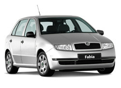
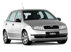
Fabia – легковой переднеприводный автомобиль с поперечным расположением силового агрегата, предназначенный для эксплуатации на дорогах с твердым покрытием.
Семейство автомобилей Fabia включает три базовые модели, различающиеся кузовами: Skoda Fabia 1.4 с кузовом типа хэтчбек, Skoda Fabia 1.4 Combi с кузовом типа универсал и Skoda Fabia 1.4 Sedan с кузовом типа седан Кузов седан предназначен в основном для перевозки пассажиров и небольшого багажа. Кузов хэтчбек более универсален, в нем можно перевозить крупногабаритный багаж, сложив заднее сиденье и увеличив за счет этого багажное отделение. Универсал – это грузопассажирский кузов, позволяющий перевозить значительный объем груза при сложенном заднем сиденье. Багажное отделение универсала намного превышает по объему багажное отделение хэтчбека. Все кузова цельнометаллические несущей конструкции.
Существуют четыре базовые комплектации автомобиля: Basic, Classik, Comfort и Elegance, различающиеся установленными на них двигателями и оборудованием.
Двигатели четырехцилиндровые бензиновые или дизельные рабочим объемом от 1,0 до 1,9 л. Все двигатели оборудованы системой улавливания паров топлива и каталитическими нейтрализаторами в системе выпуска отработавших газов.
Автомобиль оснащен двухконтурной рабочей тормозной системой с гидравлическим приводом и вакуумным усилителем, что повышает его безопасность. Передние тормозные механизмы дисковые, задние – барабанные или дисковые.
Благодаря переднеприводной компоновке автомобиль обладает улучшенными по сравнению с заднеприводными моделями характеристиками управляемости, особенно при прохождении поворотов и на скользкой дороге.
↓ Комментарии ↓
1. Шкода Фабия
1.0 Skoda Fabia
1.2. Технические характеристики автомобилей
1.3 Паспортные данные
1.4 Ключи
1.5 Двери
1.6 Капот
1.7 Багажник
1.8 Регулировка сидений
1.9 Увеличение вместимости багажника
1.10 Ремни безопасности
1.11. Подушки безопасности системы Airbag
1.12 Безопасность детей
1.13 Заправка автомобиля
1.14 Топливо
1.15 Органы управления
1.16 Комбинация приборов
1.17 Блок контрольных ламп
1.18 Рычаг переключения передач
1.19 Рычаг стояночного тормоза
1.20 Регулировка рулевой колонки
1.21 Выключатель (замок) зажигания
1.22 Подрулевой переключатель
1.23 Подсветка приборов
1.24 Корректор фар
1.25 Центральный переключатель
1.26 Прикуриватель
1.27 Пепельница
1.28 Вещевые ящики
1.29 Аварийная сигнализация
1.30 Подогрев передних сидений
1.31 Обогрев заднего стекла
1.32 Выключатель антипробуксовочной системы (ASR)
1.33 Вентиляция и отопление салона
1.34 Кондиционер
1.35 Зеркала заднего вида
1.36 Стеклоподъемники с электроприводом
1.37 Солнцезащитные козырьки
1.38 Люк в крыше с электроприводом
1.39 Сдвижная крыша с электроприводом
1.40 Освещение салона
1.41 Багажник на крыше
1.42 Тягово-сцепное устройство
1.43 Обкатка автомобиля
1.44 Пуск двигателя
1.45 Остановка двигателя
1.46 Пуск двигателя от внешнего источника
1.47 Пуск двигателя буксировкой
1.48 Буксировка автомобиля
1.49 Поднятие автомобиля
1.50. Колеса и шины
1.51 Очистители и омыватели стекол
1.52 Аккумуляторная батарея
1.53 Уход за автомобилем
1.54 Сервисная книжка
2. Двигатель
2.0 Двигатель
2.2. Установка поршня первого цилиндра в положение ВМТ такта сжатия
2.3 Замена ремня привода генератора
2.4. Замена и регулировка натяжения ремня привода распределительного вала
2.5 Замена цепи привода распределительного вала
2.6 Подбор распределительной шестерни коленчатого вала
2.7 Замена прокладки головки блока цилиндров
2.8 Замена сальника распределительного вала
2.9 Замена маслосъемных колпачков
2.10 Замена переднего сальника коленчатого вала
2.11 Задний сальник коленчатого вала
2.12. Ремонт головки блока цилиндров
2.13. Ремонт двигателя
3. Система смазки
3.0 Система смазки
3.1 Снятие и установка масляного картера двигателя
3.2 Ремонт масляного насоса на двигателях 1,0 л, 37 кВт и 1,4 л, 50 кВт
3.3 Замена масляного насоса
3.4 Масляный фильтр дизельного двигателя
3.5 Проверка уровня масла в картере двигателя
3.6 Замена масла и масляного фильтра
4. Система питания
4.0 Система питания
4.2 Замена фильтрующего элемента воздушного фильтра
4.3 Замена датчика указателя уровня топлива
4.4 Снятие и установка топливного бака
4.5 Проверка воздушного клапана
4.6 Проверка гравитационного клапана
4.7 Замена топливного фильтра
4.8 Проверка клапана подогрева топлива
4.9 Замена адсорбера системы улавливания паров топлива
4.10 Замена топливного радиатора
4.11 Снятие и установка вакуумного насоса дизельного двигателя
4.12 Снятие и установка впускной трубы двигателя
4.13 Снятие и установка педали акселератора
4.14. Снятие и установка форсунок
4.15 Проверка цепи питания форсунок бензинового двигателя
4.16 Проверка сопротивления насос-форсунки
4.17 Проверка свечей накаливания дизельного двигателя 1,9 л, 47 кВт
4.18 Проверка цепи питания свечей накаливания
4.19 Проверка датчика температуры охлаждающей жидкости
4.20 Проверка датчика температуры воздуха, поступающего в двигатель
4.21 Проверка датчика температуры топлива дизельного двигателя 1,9 л, 74 кВт
4.22 Проверка датчика частоты вращения коленчатого вала
4.23 Проверка привода дроссельной заслонки
4.24 Проверка датчика положения распределительного вала
4.25 Проверка элекромагнитного клапана рециркуляции отработавших газов
4.26 Проверка реле топливного насоса двигателей 1,4 л, 55 и 74 кВт
4.27 Проверка электромагнитного клапана продувки адсорбера
4.28 Снятие и установка турбокомпрессора
4.29 Снятие и установка промежуточного охладителя воздуха
4.30 Проверка клапана давления наддува
5. Система охлаждения
5.0 Система охлаждения
5.1 Проверка герметичности системы охлаждения
5.2 Проверка пробки расширительного бачка
5.3 Снятие и установка радиатора на моделях без кондиционера
5.4 Снятие и установка радиатора на моделях с кондиционером
5.5 Снятие и установка водяного насоса на моделях с бензиновыми двигателями
5.6 Снятие и установка водяного насоса на моделях с дизельными двигателями
5.7 Снятие и установка вентилятора радиатора
5.8 Замена датчика включения вентилятора
5.9 Снятие и установка термостата
5.10 Проверка термостата
5.11 Замена шлангов системы охлаждения двигателя
5.12 Проверка уровня охлаждающей жидкости
5.13 Замена охлаждающей жидкости
6. Система выпуска отработавших газов
6.0 Система выпуска отработавших газов
6.1 Проверка герметичности системы выпуска отработавших газов
6.2 Снятие и установка приемной трубы глушителя (бензиновые двигатели)
6.3 Снятие и установка приемной трубы глушителя (дизельные двигатели)
6.4 Замена узлов глушителя в сборе (резонатора или глушителя)
6.5 Система рециркуляции отработавших газов (двигатели 1,4 л, 55 и 74 кВт)
6.6 Система рециркуляции отработавших газов (двигатели 1,9 л, 74 кВт)
6.7 Система рециркуляции отработавших газов (двигатели 1,9 л, 47 кВт)
7. Трансмиссия и ходовая часть
7.0 Трансмиссия и ходовая часть
7.1. Технические характеристики коробок передач (КП)
7.2. Передняя подвеска
7.3. Задняя подвеска
8. Рулевое управление
8.0 Рулевое управление
8.1 Снятие и установка рулевого колеса
8.2 Снятие и установка возвратного и контактного колец в сборе
8.3. Рулевая колонка
8.4. Рулевой механизм (без усилителя)
8.5. Рулевой механизм (с усилителем)
9. Тормозная система
9.0 Тормозная система
9.1. Педальный узел
9.2 Вакуумный усилитель
9.3 Главный тормозной цилиндр
9.4 Регулятор давления (на моделях без ABS)
9.5. Тормозной механизм переднего колеса типа FS III
9.6. Тормозной механизм переднего колеса типа FS II
9.7. Тормозной механизм заднего колеса (барабанный)
9.8. Тормозной механизм заднего колеса (дисковый)
9.9. Стояночный тормоз
9.10. Антиблокировочная система (ABS)
10. Электрооборудование
10.0 Электрооборудование
10.2 Аккумуляторная батарея
10.3. Система зажигания
10.4 Снятие и установка комбинации приборов
10.5. Очиститель и омыватель ветрового стекла
10.6. Очиститель и омыватель стекла двери задка
10.7 Замена ламп
10.8 Снятие и установка фары
10.9 Снятие и установка заднего фонаря
10.10 Замена дополнительного фонаря сигнала торможения
10.11 Выключатели и переключатели
10.12 Снятие и установка звуковых сигналов
10.13 Снятие и установка динамиков
10.14 Снятие и установка антенны
11. Кузов
11.0 Кузов
11.2. Передняя дверь
11.3. Задняя дверь
11.4. Сиденья
11.5. Ремни безопасности
11.6 Снятие и установка панели приборов
11.7 Снятие и установка тягово-сцепного устройства
11.8. Отопитель
12. Электросхемы
12.0 Электросхемы
12.1. Символы, встречающиеся на схемах электрооборудования
12.2 Cхемы электрооборудования автомобиля Шкода Фабиа
Кто-то уже выкладывал все файлы по нашей Фабии. Выложу ещё раз, чтобы не потерялось. Файлы на русском языке с заводским руководством по ремонту большинства двигателей, коробок передач, кузовни, электроники, ходовой всех версий и т. п.
Папка в Яндекс.Диске — yadi.sk/d/4XE83o-tluSkFA
Коробки передач
АКПП 001 — yadi.sk/i/rLycVhHDyX8E9A
КПП 002 — yadi.sk/i/tbFh97Hp-NoiwA
КПП 02R — yadi.sk/i/xIPUOOUGv67XQA
КПП 02T — yadi.sk/i/AOMj1Fn9A-65WA
КПП 0A8 — yadi.sk/i/bdmoWStnXSt-AA
Бензиновые двигатели
1,0 (50 л.с.) и 1,4 (60/68 л.с.)
Механическая часть — yadi.sk/i/XXiWGmOXM00eHQ
Впрыск — yadi.sk/i/CagNOY6T8YdTbw
1,2 (54 л.с.) и 1,2 (64 л.с.)
Механическая часть — yadi.sk/i/Dic_RVed8t4cRA и yadi.sk/i/pYxH1SFt5FLKDQ
Впрыск — yadi.sk/i/cxUpOow22b0xew
1,4 (75 л.с.) и 1,4 (101 л.с.)
Механическая часть — yadi.sk/i/ddODrv2mOQGzxA
Впрыск — yadi.sk/i/AyYQA_nNPg30Hg
2,0 (115 л.с.)
Механическая часть — yadi.sk/i/avtsCyu45nC31Q
Впрыск — yadi.sk/i/nljDwTii5CD2zQ
Дизельные двигатели
1,4 TDI (75 л.с.)
Механическая часть — yadi.sk/i/FIZKM7lnD82Pkg
Впрыск — yadi.sk/i/oeOQsL4yDjRkDQ
1,9 SDI (64 л.с.)
Механическая часть — yadi.sk/i/0QMzWGp240t2nQ
Впрыск — yadi.sk/i/YtfVyvTc4QzIXA
1,9 TDI (100 л.с.)
Механическая часть — yadi.sk/i/tpVn7SMolo9Diw
Впрыск — yadi.sk/i/FAB07jDoaO4eBw
1,9 TDI RS (130 л.с.)
Механическая часть — yadi.sk/i/t9ddX6HCfwYOzw
Впрыск — yadi.sk/i/UYSLIYtWl_1m8g
Электроника и схемы
Электрооборудование — yadi.sk/i/jkDQNlRUPe3GRQ
Схемы электрические 1 — yadi.sk/i/_FKOUkUs1BeZpg
Схемы электрические 2 — yadi.sk/d/auG3fH0R_4ApEw
Схемы электрические 3 — yadi.sk/i/1-swiFc-fNTcQA
Всё остальное
Отопление и кондиционер — yadi.sk/i/6Afrhm6TO9sn_A
Ходовая часть — yadi.sk/i/tTEyzhhGU8Sg0A
ТО — yadi.sk/i/qx15l-bmrq7DXQ
Кузов, жестяные работы — yadi.sk/i/zcP3pNP0cQgh8g
Кузов, сборочные работы — yadi.sk/i/y50h0MSiJ6KixQ
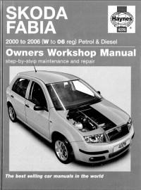
Руководство на английском языке по техническому обслуживанию и ремонту автомобиля Skoda Fabia 2000-2006 годов выпуска.
- Автор: A.K. Legg
- Издательство: Haynes Publishing
- Год издания: 2006
- Страниц: 373
- Формат: PDF
- Размер: 122,1 Mb

Руководство по эксплуатации, техническому обслуживанию и ремонту автомобиля Skoda Fabia с 1999 года выпуска с бензиновыми и дизельными двигателями.
- Автор: —
- Издательство: Техническая книга
- Год издания: 2007
- Страниц: 246
- Формат: PDF
- Размер: 234,9 Mb

Руководство по техническому обслуживанию и ремонту автомобиля Skoda Fabia 2000-2006 годов выпуска с бензиновыми и дизельными двигателями.
- Автор: —
- Издательство: Алфамер
- Год издания: —
- Страниц: 384
- Формат: —
- Размер: —
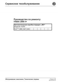
Руководство по техническому обслуживанию и ремонту автомобиля Skoda Fabia с 2000 года выпуска.
- Автор: —
- Издательство: Skoda Auto
- Год издания: —
- Страниц: —
- Формат: PDF
- Размер: 553,0 Mb
Руководство по техническому обслуживанию и ремонту автомобиля Skoda Fabia с 2007 года выпуска.
- Автор: —
- Издательство: Skoda Auto
- Год издания: —
- Страниц: —
- Формат: PDF
- Размер: 33,8 Mb

Руководство по эксплуатации и ремонту автомобиля Skoda Fabia с 2000 года выпуска с бензиновыми и дизельными двигателями.
- Автор: —
- Издательство: Монолит
- Год издания: —
- Страниц: 428
- Формат: —
- Размер: —

Руководство по эксплуатации и ремонту автомобилей Skoda Fabia/Fabia Combi/Fabia Sport Edition с 2007 года выпуска с бензиновыми и дизельными двигателями.
- Автор: —
- Издательство: Монолит
- Год издания: —
- Страниц: 350
- Формат: —
- Размер: —

Сборник руководств по эксплуатации и техническому обслуживанию автомобиля Skoda Fabia второго поколения.
- Автор: —
- Издательство: Skoda Auto
- Год издания: -/2010/2014
- Страниц: 284/276/213
- Формат: PDF
- Размер: 84,6 Mb
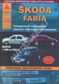
Руководство по эксплуатации, техническому обслуживанию и ремонту автомобиля Skoda Fabia 1999-2008 годов выпуска с бензиновыми и дизельными двигателями.
- Автор: —
- Издательство: Арго-Авто
- Год издания: —
- Страниц: 664
- Формат: —
- Размер: —
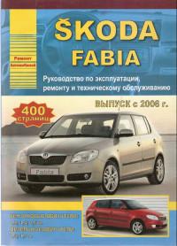
Руководство по эксплуатации, техническому обслуживанию и ремонту автомобиля Skoda Fabia с 2006 года выпуска с бензиновыми и дизельными двигателями.
- Автор: —
- Издательство: Арго-Авто
- Год издания: 2009
- Страниц: 400
- Формат: —
- Размер: —
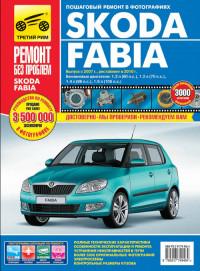
Руководство по эксплуатации, техническому обслуживанию и ремонту автомобиля Skoda Fabia с 2007 года выпуска с бензиновыми двигателями объемом 1,2/1,4/1,6 л.
- Автор: —
- Издательство: Третий Рим
- Год издания: 2012
- Страниц: 325
- Формат: —
- Размер: —
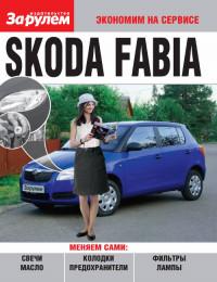
Руководство по техническому обслуживанию автомобиля Skoda Fabia второго поколения.
- Автор: —
- Издательство: За рулем
- Год издания: 2010
- Страниц: 89
- Формат: PDF
- Размер: 35,7 Mb

Руководство по эксплуатации, техническому обслуживанию и ремонту автомобиля Skoda Fabia с 2007 года выпуска.
- Автор: —
- Издательство: Мир автокниг
- Год издания: —
- Страниц: 400
- Формат: —
- Размер: —
-
Contents
-
Table of Contents
-
Bookmarks
Quick Links
Service
Workshop Manual
FABIA 2000
1.4/55; 1.4/74 Engine — Mechanical Components
Edition 08.99
Engine code
Service Department. Technical Information
AUA AUB BBY BBZ BKY
5
Printed in Czech Republic
S00.5306.00.20
Related Manuals for Skoda FABIA 2000
Summary of Contents for Skoda FABIA 2000
-
Page 1
Service Workshop Manual FABIA 2000 1.4/55; 1.4/74 Engine — Mechanical Components Edition 08.99 Engine code AUA AUB BBY BBZ BKY Service Department. Technical Information Printed in Czech Republic S00.5306.00.20… -
Page 2
Service The Workshop Manual is intended only for use within the Organisation Škoda. Printed in Czech Republic S00.5306.00.20 It is not permitted to pass it on to other persons. © ŠKODA AUTO a. s. -
Page 3
FABIA 2000 1.4/55; 1.4/74 Engine — Mechanical Components List of Supplements to Workshop Manual FABIA 2000 1.4/55; 1.4/74 Engine — Mechanical Components Edition 08.99 Suppleme Edition Subject Article Number 08.99 Basic Edition S00.5306.00.20 07.00 Supplement to Basic Edition S00.5306.01.20 05.01 Modifications in Rep. -
Page 4
FABIA 2000 1.4/55; 1.4/74 Engine — Mechanical Components List of Supplements Edition 05.05 S00.5306.06.20… -
Page 5
FABIA 2000 1.4/55; 1.4/74 Engine — Mechanical Components Table of Contents 00 – Technical Data Technical Data ………………00-1 page — Engine number ………………00-1 page — Engine characteristics …………….00-1 page 10 – Removing and Installing Engine Removing and Installing Engine ………….. -
Page 6: Table Of Contents
FABIA 2000 1.4/55; 1.4/74 Engine — Mechanical Components Parts of the Cooling System …………….. 19-1 page — Parts of the cooling system fitted to body …………19-1 page — Coolant regulator — Summary of components …………. 19-1 page — Coolant pump — Summary of components …………
-
Page 7: Technical Data
FABIA 2000 1.4/55; 1.4/74 Engine — Mechanical Components 00 – Technical Data 00-1 Technical Data Engine number The engine number („engine identification characters“ and „serial number“) is indicated on the end face of the cylinder block at the gearbox side below the coolant ther- mostat housing.
-
Page 8: Fabia 2000 1.4/55; 1.4/74 Engine — Mechanical Components
FABIA 2000 1.4/55; 1.4/74 Engine — Mechanical Components Technical Data Edition 05.05 00-1 page S00.5306.06.20…
-
Page 9
FABIA 2000 1.4/55; 1.4/74 Engine — Mechanical Components 10 – Removing and Installing Engine 10-1 Removing and Installing Engine Removing engine Special tools, test and measuring equipment and auxiliary items required ♦ Lifting device, e.g. -MP 9-201- ♦ Tensioning block -MP 9-101- ♦… -
Page 10
FABIA 2000 1.4/55; 1.4/74 Engine — Mechanical Components – Pull off hose -1- (for engines as of 04.02) and remove the engine guard -2- with air filter upwards -arrows-. – Open cap of expansion reservoir to release pressure in the cooling system. -
Page 11
FABIA 2000 1.4/55; 1.4/74 Engine — Mechanical Components ♦ Plug connection of the electric wiring to the radiator fans ♦ Plug connection of the thermo-switch -F18- ♦ Plug connection of the electric wiring to the main headlights and fog lights… -
Page 12
FABIA 2000 1.4/55; 1.4/74 Engine — Mechanical Components Continued for all vehicles – Disconnect earth strap of the gearbox. – Release spring strap clamps and disconnect hoses of the coolant regulator housing: ♦ Heater intake hose ♦ Hose of the expansion reservoir ♦… -
Page 13
FABIA 2000 1.4/55; 1.4/74 Engine — Mechanical Components – Release screws -arrows- from engine mounting -A- and from the gearbox mount -B-. – Lower engine/gearbox unit and push towards the front. Note The engine/gearbox unit must be guided carefully so as not to damage the body. -
Page 14
FABIA 2000 1.4/55; 1.4/74 Engine — Mechanical Components – Secure engine/gearbox unit in the engine and gear- box mount -arrows- and tighten the screws to the indi- cated tightening torque ⇒ 10-1 page 7. – Position the vent hose for the coolant reservoir on the ventilation tube and draw together with retaining clips. -
Page 15: Tightening Torques
FABIA 2000 1.4/55; 1.4/74 Engine — Mechanical Components ♦ Plug connection of the electric wiring to the radiator fans ♦ Plug connection of the thermo-switch -F18- ♦ Plug connection of the electric wiring to the main headlights and fog lights –…
-
Page 16
FABIA 2000 1.4/55; 1.4/74 Engine — Mechanical Components ♦ Do not use degreased parts. ♦ Unless otherwise indicated the following tightening torques apply: Component Torque Bolts, nuts 9 Nm 13 Nm 20 Nm 40 Nm M 12 70 Nm deviations: ⇒… -
Page 17
FABIA 2000 1.4/55; 1.4/74 Engine — Mechanical Components 13 – Crankgear 13-1 Disassembling and assembling engine Summary of components of ribbed V-belt on vehicles fitted with AC 1 — Tensioning pulley for ribbed V-belt Swing out the tensioning pul- ley with ring spanner… -
Page 18
FABIA 2000 1.4/55; 1.4/74 Engine — Mechanical Components Removing and installing V-ribbed belt Special tools, test and measuring equipment and auxiliary items required ♦ Clamping lever -MP 1-203- Vehicles with air conditioning Routing of the V-ribbed belt Belt drive with AC compressor:… -
Page 19
FABIA 2000 1.4/55; 1.4/74 Engine — Mechanical Components – Position clamping lever -MP 1-203-, secure by insert- ing a pin and and push AC generator towards the crankshaft. Remove the released ribbed V-belt from the AC genera- tor — belt pulley. -
Page 20
FABIA 2000 1.4/55; 1.4/74 Engine — Mechanical Components 13 — Crankshaft toothed belt sprocket pay attention to position of toothed belt when installing ⇒ 13-1 page 4 14 — 12 Nm replace 15 — V-ribbed belt pulley pay attention to locating element when installing removing and installing ⇒… -
Page 21
FABIA 2000 1.4/55; 1.4/74 Engine — Mechanical Components Removing – Pull off hose -1- (for engines as of 04.02) and remove engine protection -2- with air filter upwards -arrows-. – Remove V-ribbed belt ⇒ 13-1 page 2. – Remove top toothed belt guard. -
Page 22
FABIA 2000 1.4/55; 1.4/74 Engine — Mechanical Components – Install supporting device -MP 9-200- according to the illustration. – Remove the top securing screw from the bottom toothed belt guard below the engine mount. MP 9-200 – Release the coolant expansion reservoir and lay aside. -
Page 23
FABIA 2000 1.4/55; 1.4/74 Engine — Mechanical Components – Insert the two fixing pins through the locating holes of the camshaft sprockets up to the stop in the fit holes in the cylinder head cover. Note The two fixing pins are correctly inserted if the end parts -D- are flush with line -A-. -
Page 24
FABIA 2000 1.4/55; 1.4/74 Engine — Mechanical Components – Mark the pointer position of the tensioning pulley -1-. Load timing belt by firmly pressing down with thumb -arrows-. The pointer must move. – Relieve the toothed belt again. – Turn the crankshaft two turns in the running direction of the engine. -
Page 25
FABIA 2000 1.4/55; 1.4/74 Engine — Mechanical Components Procedure – Position crankshaft on TDC cylinder 1. The chamfered tooth must correspond with the marking on the sealing flange -arrow-. – Fit the coupling drive — toothed belt. If the toothed belt has been used pay attention to the rotation direction. -
Page 26
FABIA 2000 1.4/55; 1.4/74 Engine — Mechanical Components – Loosely fit the tensioning pulley with the fixing screw and turn with the Allan screw in the -direction of the ar- row-. – Tighten fixing screw manually. The recess of the base plate -1- must be positioned on the screw head -2- in the cylinder block. -
Page 27
FABIA 2000 1.4/55; 1.4/74 Engine — Mechanical Components – Attach engine mount to cylinder block. Tightening torque 50 Nm. – Screw the engine console to the body with screws -B-. S13-0233 – Secure the engine console to the engine mount on the cylinder block with screws -A-. -
Page 28
FABIA 2000 1.4/55; 1.4/74 Engine — Mechanical Components Disassembling and assembling engine Edition 05.05 13-1 page S00.5306.06.20… -
Page 29: Cylinder Block
FABIA 2000 1.4/55; 1.4/74 Engine — Mechanical Components 13-2 Removing and installing cylinder block Aluminium cylinder block WARNING! The crankshaft must not be removed. Merely re- leasing the crankshaft bearing cover will result in deformations of the bearing seats of the cylinder block.
-
Page 30
FABIA 2000 1.4/55; 1.4/74 Engine — Mechanical Components 12 — Gasket replace 13 — Oil pump must be replaced completely when fitting pay attention to the driver on the crankshaft ⇒ item 15 must be positioned on dowel sleeves removing and installing ⇒ Chapter 17-1 14 — Gasket ring replace ⇒… -
Page 31
FABIA 2000 1.4/55; 1.4/74 Engine — Mechanical Components – Press in gasket ring with pressure plate -T 10022/1- up to the stop. – Installing the main drive — toothed belt ⇒ Chap. 13-1. Removing and installing drive plate Special tools, test and measuring equipment and auxiliary items required ♦… -
Page 32
FABIA 2000 1.4/55; 1.4/74 Engine — Mechanical Components – Check dimension -a- in three points and determine mean value. Specified value: 19.7…21.3 mm. Note The measurement is made through the hole of the drive plate to the milled surface of the cylinder block. -
Page 33
FABIA 2000 1.4/55; 1.4/74 Engine — Mechanical Components – Screw 3 screws M6x35 into the threaded bores of the sealing flange -arrows-. – Press out sealing flange together with rotor from the crankshaft by alternately screwing the screws into the sealing flange. -
Page 34
FABIA 2000 1.4/55; 1.4/74 Engine — Mechanical Components – Grip assembly device -T 10017- or -T 10134- on clamping surface -B- of the threaded spindle in a vice. – Securing clip -A- from the new sealing flange (flange for assembly device -T 10017-) .. -
Page 35
FABIA 2000 1.4/55; 1.4/74 Engine — Mechanical Components – Lay the front side of the sealing flange on a clean and level surface. – Press the rotor -A- -arrows-, until it rests on the level surface. Note The top side of the rotor and the front side of the sealing flange must be flush. -
Page 36
FABIA 2000 1.4/55; 1.4/74 Engine — Mechanical Components – Lay the sealing flange with the front side on theas- sembly device -T 10017- in such a way that the posi- tioning pin -A- sinks into the hole -B- of the rotor. -
Page 37
FABIA 2000 1.4/55; 1.4/74 Engine — Mechanical Components – Unscrew hexagon nut -A- up to the end of the thread- ed spindle. – Screw assembly device with Allan screws -A- up to the stop onto the crankshaft flange. – Screw in two M6x35 mm screws -A- by about 3 turns for sealing flange guide into the cylinder block. -
Page 38
FABIA 2000 1.4/55; 1.4/74 Engine — Mechanical Components For assembly device T 10017: – Move the assembly cup -A- by hand in the -direction of the arrow- until the rotor -B- rests on the crankshaft flange -C-. Guide bolts -D- on assembly device -T 10017- must at the same time sink into the thread- ed bore of the crankshaft. -
Page 39
FABIA 2000 1.4/55; 1.4/74 Engine — Mechanical Components D — Inspecting the fitting position of the rotor on the crankshaft – Unscrew hexagon nut -A- up to the end of the thread- ed spindle. – Unscrew two M6x35 mm screws -B- from the cylinder block. -
Page 40
FABIA 2000 1.4/55; 1.4/74 Engine — Mechanical Components – Tighten the new fixing screws of the sealing flange crosswise. Tightening torque: 12 Nm. – Install engine speed sender -arrow-. Tightening torque: 5 Nm. – Installing oil pan ⇒ Chapter 17-1. -
Page 41
FABIA 2000 1.4/55; 1.4/74 Engine — Mechanical Components 13-3 Disassembling and assembling piston and conrod 1 — Circlip 2 — Piston pin if stiff, heat piston to approx. 60°C removing and installing with driver -MP 1-304- 3 — Piston check ⇒ Fig. 3 in 13-3… -
Page 42
FABIA 2000 1.4/55; 1.4/74 Engine — Mechanical Components Fig. 1: Inspecting piston ring gap clearance – Push in ring at right angles to the cylinder wall from the top through to the bottom cylinder opening, about 15 mm from the cylinder edge. -
Page 43
FABIA 2000 1.4/55; 1.4/74 Engine — Mechanical Components Fig. 4: Inspecting cylinder bore Special tools, test and measuring equipment and auxiliary items required ♦ Internal precision measuring instrument 50…100 mm – Measure at three points crosswise in a transverse di- rection -A- and lengthwise -B-. -
Page 44
FABIA 2000 1.4/55; 1.4/74 Engine — Mechanical Components Disassembling and assembling piston and conrod Edition 05.04 13-3 page S00.5306.05.20… -
Page 45: Cylinder Head
FABIA 2000 1.4/55; 1.4/74 Engine — Mechanical Components 15 – Cylinder Head, Valve Gear 15-1 Removing and installing cylinder head Note ♦ When installing a replacement cylinder head, all the contact surfaces between the hydraulic supporting el- ements, roller rocker arms and the cams must be oiled before installing the cylinder head cover.
-
Page 46
FABIA 2000 1.4/55; 1.4/74 Engine — Mechanical Components for installing, clip onto hydraulic supporting element with locking clip 12 — Hydraulic supporting element do not interchange before installing, inspect axial play of the camshafts ⇒ Chapter 15-2 oil contact surfaces… -
Page 47
FABIA 2000 1.4/55; 1.4/74 Engine — Mechanical Components Engines with engine identification letters BKY 1 — Coupling drive-toothed belt before removing mark run- ning direction check for wear do not kink removing and installing, ten- sioning ⇒ Chapter 13-1 2 — 10 Nm… -
Page 48
FABIA 2000 1.4/55; 1.4/74 Engine — Mechanical Components 22 — Rear timing belt guard 23 — Cylinder head cover removing and installing ⇒ 15-1 page 4 turn (90 °) 24 — 10 Nm + torque a further replace Tighten crosswise from the middle outwards… -
Page 49
FABIA 2000 1.4/55; 1.4/74 Engine — Mechanical Components – Release the screws at the noise insulation -arrows- and remove noise insulation. – Removing the two toothed belts ⇒ Chapter 13-1. Note ♦ The camshafts are located in the cylinder head cover. -
Page 50
FABIA 2000 1.4/55; 1.4/74 Engine — Mechanical Components WARNING! Wear protective gloves when working with sealant and grease remover! – Clean sealing surface on cylinder head and cylinder cover and remove sealant residues with chemical gasket remover. – Ensure that no dirt and sealant residues get into the cylinder head. -
Page 51
FABIA 2000 1.4/55; 1.4/74 Engine — Mechanical Components Further installation occurs in a similar way in reverse or- der to removal. Removing and installing cylinder head Special tools, test and measuring equipment and auxiliary items required ♦ Supporting device -MP 9-200- ♦… -
Page 52
FABIA 2000 1.4/55; 1.4/74 Engine — Mechanical Components ♦ Vacuum hose from the brake servo unit to the intake manifold ♦ 4 pin plug connection from the intake manifold pres- sure sender under the intake manifold at front right and 2 pin plug connection from the knock sensor MP 9-200 ♦… -
Page 53
FABIA 2000 1.4/55; 1.4/74 Engine — Mechanical Components – Insert the cylinder head. Pay attention to the dowel pins in the cylinder block. – Insert new cylinder head bolts and tighten by hand. – Tighten the cylinder head bolts in the order shown as follows: –… -
Page 54
FABIA 2000 1.4/55; 1.4/74 Engine — Mechanical Components Testing the compression Special tools, test and measuring equipment and auxiliary items required ♦ Spark plug wrench, e.g. -3122 B- ♦ Compression tester, e. g. -V.A.G 1763- ♦ Extractor -T 10094- Test condition •… -
Page 55
FABIA 2000 1.4/55; 1.4/74 Engine — Mechanical Components – Install the spark plugs again and then tighten fully to 30 Nm. The further assembly is carried out in reverse order to disassembly. – Interrogate the fault memory ⇒ Vehicle Diagnosis, Measuring and Information System VAS 5051;… -
Page 56
FABIA 2000 1.4/55; 1.4/74 Engine — Mechanical Components Removing and installing cylinder head Edition 05.05 15-1 page S00.5306.06.20… -
Page 57
FABIA 2000 1.4/55; 1.4/74 Engine — Mechanical Components 15-2 Repairing Valve Gear 1 — 20 Nm + torque a further turn (90 °) replace to release and tighten use tool -T 10016- ⇒ Fig. 1 in 15-2 page 2 2 — Camshaft sprocket… -
Page 58
FABIA 2000 1.4/55; 1.4/74 Engine — Mechanical Components 18 — Valve stem seal replace ⇒ 15-2 page 8 19 — Valve guide check ⇒ 15-2 page 7 20 — Oil pressure switch 0.03 … 0.07 MPa (0.3 … 0.7 bar) -F1-, 25 Nm inspect ⇒… -
Page 59
FABIA 2000 1.4/55; 1.4/74 Engine — Mechanical Components Fig. 2: Checking the axial play of the camshafts MP 3-447 Special tools, test and measuring equipment and auxiliary items required ♦ Universal dial gauge holder -MP 3-447- ♦ Dial gauge Carry out measurement with the cylinder head cover re- moved and the end covers installed ⇒… -
Page 60
FABIA 2000 1.4/55; 1.4/74 Engine — Mechanical Components Fig. 5: Reworking lower cylinder head sealing sur- face Permissible reworking dimension of cylinder head: a = at least 108.25 mm. Reworking valve seats Special tools, test and measuring equipment and auxiliary items required ♦… -
Page 61
FABIA 2000 1.4/55; 1.4/74 Engine — Mechanical Components The max. permissible reworking dimension is shown in the figures for reworking the valve seats as dimension „b“. Reworking valve seats Reworking inlet valve seat = ∅ 28.7 mm = max. permissible reworking dimension = 1,5 …… -
Page 62
FABIA 2000 1.4/55; 1.4/74 Engine — Mechanical Components ∅ Mill- ∅ Milling ∅ Mill- Valve seat ing cut- cutter ing cut- 90° ter 90° 120° ter 60° Inlet valve 21/34 Exhaust valve 21/34 120° Milling sequence 1 — Machine valve seat with 90° milling tool until until a perfect contact pattern is achieved. -
Page 63
FABIA 2000 1.4/55; 1.4/74 Engine — Mechanical Components Removing – Removing the two toothed belts ⇒ Chapter 13-1. – Turn crankshaft slightly back. Note Camshaft sprockets must be interlocked with -T 10016- in the fit holes in the cylinder head cover. -
Page 64
FABIA 2000 1.4/55; 1.4/74 Engine — Mechanical Components Procedure – Insert valve into guide. End of valve stem must be flush with guide. Because of the different stem diame- ters only use inlet valve in inlet guide or outlet valve in outlet guide. -
Page 65
FABIA 2000 1.4/55; 1.4/74 Engine — Mechanical Components – Connect pressure hose to compressed air (min. 6 bar overpressure (0.6 MPa)) and remove the valve springs with -MP 1-229-. – Pull off valve stem seals with extractor -MP 1-230-. Installing –… -
Page 66
FABIA 2000 1.4/55; 1.4/74 Engine — Mechanical Components Repairing Valve Gear Edition 05.05 15-2 page S00.5306.06.20… -
Page 67
FABIA 2000 1.4/55; 1.4/74 Engine — Mechanical Components 17 – Lubrication 17-1 Removing and installing parts of the lubrication system Note The engine oil level must never exceed the max. marking — risk of damage to catalytic converter! ⇒ Inspection and Maintenance. -
Page 68
FABIA 2000 1.4/55; 1.4/74 Engine — Mechanical Components pay attention to installation instructions on oil filter 15 — Oil pump with pressure relief valve, open for an overpressure of 0.45 MPa (4.5 bar) must be replaced completely when fitting pay attention to the driver on the crankshaft ⇒ item 30 must be positioned on dowel sleeves removing and installing ⇒… -
Page 69
FABIA 2000 1.4/55; 1.4/74 Engine — Mechanical Components only for engines with the engine codes BBY, BKY and BBZ 34 — O-ring replace if damaged 35 — To induction pipe only for engines with the engine codes BBY, BKY and BBZ 36 — Oil pressure switch 0.03…0.07 MPa (0.3…0.7 bar) -F1-, 25 Nm… -
Page 70
FABIA 2000 1.4/55; 1.4/74 Engine — Mechanical Components Installing Note ♦ Pay attention to the ‘use by date’ on sealant. ♦ The oil pan must be installed within 5 minutes after ap- plying the silicone sealant. ♦ The oil pan can be better and more securely installed if M6 threaded pins are inserted as guides in two loca- tions on the cylinder block flange. -
Page 71
FABIA 2000 1.4/55; 1.4/74 Engine — Mechanical Components – Secure toothed belt gear -1- to the crankshaft with fix- ing screw -2-. – Position crankshaft on TDC cylinder 1: The chamfered tooth of the toothed belt must correspond with the marking on the oil pump -arrow-. -
Page 72
FABIA 2000 1.4/55; 1.4/74 Engine — Mechanical Components – Position the bushing -T 10022- on the crankshaft and tighten the Allan screw of the inserting device -MP 1-207- by hand. – Insert new seal on the dowel sleeves -A-. T10022… -
Page 73
FABIA 2000 1.4/55; 1.4/74 Engine — Mechanical Components – Screw tester in the cylinder head instead of the oil pressure switch. – Connect brown cable of tester to earth (-). – Connect diode test lamp to battery positive and to oil pressure switch. -
Page 74
FABIA 2000 1.4/55; 1.4/74 Engine — Mechanical Components Removing and installing parts of the lubrication system Edition 05.05 17-1 page S00.5306.06.20… -
Page 75: Parts Of The Cooling System Fitted To Body
FABIA 2000 1.4/55; 1.4/74 Engine — Mechanical Components 19 – Cooling 19-1 Parts of the Cooling Sys- Note ♦ When the engine is warm the cooling system is under pressure. Before repairs, if necessary reduce pres- sure by opening the cap on the coolant expansion res- ervoir.
-
Page 76
FABIA 2000 1.4/55; 1.4/74 Engine — Mechanical Components Inspect pressure relief valve with coolant system tester, e.g. -V.A.G 1274- and adapter -V.A.G 1274/9- for leaks. Test pressure 0.14 … 0.16 MPa (1.4 …1.6 bar) 14 — Bracket for connector 15 — Bottom coolant hose… -
Page 77: Coolant Regulator — Summary Of Components
FABIA 2000 1.4/55; 1.4/74 Engine — Mechanical Components Coolant regulator — Summary of components 1 — Spring strap clip 2 — Self-tapping screw, 9 Nm 3 — from bottom of radiator 4 5 6 7 8 9 10 11 ⇒ item 15 in 19-1 page 2…
-
Page 78: Coolant Pump — Summary Of Components
FABIA 2000 1.4/55; 1.4/74 Engine — Mechanical Components Coolant pump — Summary of components 1 — Main drive-toothed belt before removing mark run- ning direction check for wear do not kink Toothed belt routing ⇒ Chapter 13-1 removing and installing, ten- sioning ⇒…
-
Page 79: Connection Diagram For Coolant Hoses
FABIA 2000 1.4/55; 1.4/74 Engine — Mechanical Components Connection diagram for coolant hoses 1 — Expansion reservoir 2 — Coolant pipe screwed onto the cylinder head cover 3 — Heat exchanger for heating 4 — ATF radiator only for vehicles with auto-…
-
Page 80: Removing And Installing Radiator
FABIA 2000 1.4/55; 1.4/74 Engine — Mechanical Components – Open drain valve -arrow- at radiator. Note Observe the disposal instructions for coolant! Filling up – Close drain plug on radiator. – Install the noise insulation. Select the appropriate coolant additive from the electron- ic original spare parts catalogue Škoda or from the list of…
-
Page 81: Removing And Installing Coolant Pump
FABIA 2000 1.4/55; 1.4/74 Engine — Mechanical Components – Disconnect the connector plug from the thermo-switch -F18-. – Remove lock carrier and lay aside ⇒ Body Work; Rep. Gr. 50. – Release the fixing screws of the radiator and remove together with fan shroud and fan.
-
Page 82
FABIA 2000 1.4/55; 1.4/74 Engine — Mechanical Components Note ♦ The integrated gasket of the coolant pump must not be removed from the pump. ♦ If leak and damage present, replace the coolant pump with gasket completely. ♦ Cover the toothed belt with a cloth before removing the coolant pump in oder to protect it from the coolant. -
Page 83: 20 — Fuel Supply
FABIA 2000 1.4/55; 1.4/74 Engine — Mechanical Components 20 – Fuel Supply 20-1 Removing and installing parts of the fuel supply system Note ♦ The fuel supply system must be bled after removal of the fuel filter, fuel delivery unit and the fuel rail .
-
Page 84
FABIA 2000 1.4/55; 1.4/74 Engine — Mechanical Components as spare parts in the kit with a new gasket ring ⇒ item 9 and O-ring ⇒ item 10 after replacing the fuel filter, bleed ⇒ 20-1 page 10 the fuel supply with the valve on the fuel strip… -
Page 85: Safety Precautions When Working On The Fuel Supply System
FABIA 2000 1.4/55; 1.4/74 Engine — Mechanical Components Fig. 1: Installation position of flange of fuel deliv- ery unit Marking on the flange must be aligned with marking on the fuel tank -arrows-. Blue return-flow line -1- on the connection with the mark- ing -R-.
-
Page 86
FABIA 2000 1.4/55; 1.4/74 Engine — Mechanical Components ♦ Carefully cover or close opened components if the re- pair is not completed immediately. ♦ Only install clean parts: Remove spare parts from their wrapping immediately before fitting. Do not use any parts which have been stored unwrapped (e.g. -
Page 87: Removing And Installing The Fuel Gauge Sender
FABIA 2000 1.4/55; 1.4/74 Engine — Mechanical Components Note ♦ When inserting the fuel delivery unit, ensure that the fuel gauge sensor is not bent. ♦ Moisten the gasket ring of the flange with fuel before fitting. ♦ Make sure the fuel hoses fit tightly.
-
Page 88: Inspecting The Fuel Pump And Fuel System
FABIA 2000 1.4/55; 1.4/74 Engine — Mechanical Components – Fold the rear seat forwards. – Remove the fuel delivery unit guard and disconnect the plug connection from the fuel delivery unit flange. – Removing rear axle ⇒ Running Gear; Rep. Gr. 42.
-
Page 89
FABIA 2000 1.4/55; 1.4/74 Engine — Mechanical Components ♦ Pressure gauge appliance, e.g. -V.A.G 1318- ♦ Adapter, e.g. -V.A.G 1318/1- ♦ Adapter, e.g. -V.A.G 1318/11- ♦ Adapter, e.g. -V.A.G 1318/17- ♦ Adapter, e.g. -V.A.G 1318/23- ♦ Torque wrench ♦ Measuring vessel ♦… -
Page 90
FABIA 2000 1.4/55; 1.4/74 Engine — Mechanical Components If no open circuit was detected: – Replacing fuel delivery unit ⇒ 20-1 page 4. Inspecting fuel flow rate Test conditions • Supply voltage OK • Remote control -V.A.G 1348/3A- is connected. -
Page 91
FABIA 2000 1.4/55; 1.4/74 Engine — Mechanical Components – Check the fuel lines for possible diameter restrictions V.A.G 1318 (kinks) or blocking. V.A.G 1318/11 – Disconnect hose -1- of the feed line from the fuel filter inlet (filter version with integrated fuel pressure regu- V.A.G 1318/1… -
Page 92
FABIA 2000 1.4/55; 1.4/74 Engine — Mechanical Components Vent the fuel system – Remove cover from the fuse holder. – Remove fuse No. 61 from the fuse holder. – Connect remote control -V.A.G 1348/3A- with the adapter cable combination from the adapter cable set in fuse holder 61 and to positive terminal of battery (+). -
Page 93: Inspecting The Operating And Holding Pressure Of The Fuel, Inspecting The Non-Return Valve Of The Fuel Pump
FABIA 2000 1.4/55; 1.4/74 Engine — Mechanical Components – Screw adapter -V.A.G 1318/20-1- onto adapter -V.A.G 1318/20-. – Turn the valve (at T-union) anti-clockwise, until it is ful- ly opened. – Screw adapter -V.A.G 1318/20- fully onto the vent valve.
-
Page 94
FABIA 2000 1.4/55; 1.4/74 Engine — Mechanical Components – Connect the pressure gauge -V.A.G 1318- with adapt- V.A.G 1318/11 er -V.A.G 1318/11- and -V.A.G 1318/17- to the fuel V.A.G 1318/17 feed line, the shut-off cock on the measuring device must be in position -A-. -
Page 95
FABIA 2000 1.4/55; 1.4/74 Engine — Mechanical Components WARNING! Maximum pressure of the fuel delivery unit is 7 bar (0.7 MPa). If this pressure is reached the fuel deliv- ery unit may be damaged. If the nominal value of min. 3 bar (0.3 MPa) is reached: –… -
Page 96
FABIA 2000 1.4/55; 1.4/74 Engine — Mechanical Components – Open shut-off cock on the measuring device -position – Activate the remote control and simultaneously close the shut-off cock in the measuring device in position -B-. – If a pressure of min. 3 bar (0.3 MPa) is reached, dis- connect the remote control and observe the drop in pressure on the manometer. -
Page 97: Inspecting Electronic Power Control (Electronic Throttle)
FABIA 2000 1.4/55; 1.4/74 Engine — Mechanical Components 20-2 Inspecting Electronic Power Control (Electronic throttle) Summary of components 1 — Bracket removing and installing ⇒ Running Gear; Rep. Gr. 46 2 — Connecting plug black, 6 pin 3 — Accelerator pedal position sender (-G79- and -G185-) inspect ⇒…
-
Page 98
FABIA 2000 1.4/55; 1.4/74 Engine — Mechanical Components Inspecting Electronic Power Control (Electronic throttle) Edition 07.00 20-2 page S00.5306.01.20… -
Page 99: Activated Charcoal Filter System
FABIA 2000 1.4/55; 1.4/74 Engine — Mechanical Components 20-3 Activated Charcoal Filter System Summary of components of activated charcoal filter system Note The hose connections are secured with spring strap clamps or quick strap clamps. Observe the safety precautions ⇒ Chap. 20-1.
-
Page 100
FABIA 2000 1.4/55; 1.4/74 Engine — Mechanical Components Activated Charcoal Filter System Edition 07.00 20-3 page S00.5306.01.20… -
Page 101: 26 — Exhaust System
FABIA 2000 1.4/55; 1.4/74 Engine — Mechanical Components 26 – Exhaust System 26-1 Removing and installing parts of the exhaust sys- Note ♦ When performing installation work on the exhaust sys- tem, make sure the exhaust system is not mounted under tension and has adequate clearance from the vehicle body.
-
Page 102
FABIA 2000 1.4/55; 1.4/74 Engine — Mechanical Components 9 — Lambda probe after catalyst -G131-, 50 Nm coat only thread with hot bolt paste -G 052 112 A3-; hot bolt paste must not get into the slot of the probe body inspect ⇒… -
Page 103: Exhaust Manifold, Front Exhaust Pipe With Pre-Catalytic Converter And Catalyst And Component Parts — Engine With Engine Identification Characters Bky
FABIA 2000 1.4/55; 1.4/74 Engine — Mechanical Components Exhaust manifold, front exhaust pipe with pre-catalytic converter and catalyst and component parts — Engine with engine identification characters BKY 1 — Hot air collector/shield 2 — 10 Nm 3 — Exhaust manifold…
-
Page 104: Silencer With Hangers
FABIA 2000 1.4/55; 1.4/74 Engine — Mechanical Components Silencer with hangers 1 — 25 Nm 2 — Hanger Check fitting position 3 — Rear silencer Cylinder version as of 03.03 for first equipment building unit with front silencer, re- place individually when car-…
-
Page 105
FABIA 2000 1.4/55; 1.4/74 Engine — Mechanical Components Test conditions • Fuse No. 24 -arrow — must be O.K. • Exhaust system must be tight between the catalyst and the cylinder head. • Coolant temperature minimum 80 °C. • All electrical consumers, e.g. lights and rear window heater, must be switched off. -
Page 106
FABIA 2000 1.4/55; 1.4/74 Engine — Mechanical Components the catalyst need not necessarily be replaced, it need only be replaced if the next exhaust emission test fails or if there is visible damage to the catalyst. If the exhaust emission test fails or if the catalyst is dam- aged: –… -
Page 107: Exhaust Gas Recirculation System
FABIA 2000 1.4/55; 1.4/74 Engine — Mechanical Components 26-2 Exhaust gas recirculation system Note The exhaust gas recirculation system is controlled by the 4LV control unit -J537- via the exhaust gas recirculation valve -N18- with exhaust gas recirculation potentiometer -G212-.
-
Page 108: Summary Of Components Of . Exhaust Gas Recirculation — Engine With Engine Identification Characters Bky 05.05
FABIA 2000 1.4/55; 1.4/74 Engine — Mechanical Components Summary of components of exhaust gas recirculation — engine with engine identifi- cation characters BKY 05.05 1 — EGR valve -N18- with EGR po- tentiometer -G212- Inspect exhaust gas recircu- lation valve -N18- ⇒ 1.4/55;…
-
Page 109
FABIA 2000 1.4/55; 1.4/74 Engine — Mechanical Components Test sequence – Disconnect the 6 pin plug from the EGR valve. – Switch on ignition. – Connect the multimeter for voltage measurement to contact 2 + 4 of the 6-pin plug. -
Page 110
FABIA 2000 1.4/55; 1.4/74 Engine — Mechanical Components – Check wiring between the test box and the plug for in- terruption according to the Current Flow Diagram. Plug contact Bush to text box -V.A.G. 1598/31- Line resistance: max. 1.5 Ω…
Skoda Fabia (Шкода Фабия) 2000-2007 г.в.
Fabia – легковой переднеприводный автомобиль с поперечным расположением силового агрегата, предназначенный для эксплуатации на дорогах с твердым покрытием.
Семейство автомобилей Fabia включает три базовые модели, различающиеся кузовами: Skoda Fabia 1.4 с кузовом типа хэтчбек, Skoda Fabia 1.4 Combi с кузовом типа универсал и Skoda Fabia 1.4 Sedan с кузовом типа седан Кузов седан предназначен в основном для перевозки пассажиров и небольшого багажа. Кузов хэтчбек более универсален, в нем можно перевозить крупногабаритный багаж, сложив заднее сиденье и увеличив за счет этого багажное отделение. Универсал – это грузопассажирский кузов, позволяющий перевозить значительный объем груза при сложенном заднем сиденье. Багажное отделение универсала намного превышает по объему багажное отделение хэтчбека. Все кузова цельнометаллические несущей конструкции.
Существуют четыре базовые комплектации автомобиля: Basic, Classik, Comfort и Elegance, различающиеся установленными на них двигателями и оборудованием.
Двигатели четырехцилиндровые бензиновые или дизельные рабочим объемом от 1,0 до 1,9 л. Все двигатели оборудованы системой улавливания паров топлива и каталитическими нейтрализаторами в системе выпуска отработавших газов.
Автомобиль оснащен двухконтурной рабочей тормозной системой с гидравлическим приводом и вакуумным усилителем, что повышает его безопасность. Передние тормозные механизмы дисковые, задние – барабанные или дисковые.
Благодаря переднеприводной компоновке автомобиль обладает улучшенными по сравнению с заднеприводными моделями характеристиками управляемости, особенно при прохождении поворотов и на скользкой дороге.
1. Шкода Фабия
1.0 Skoda Fabia
1.2. Технические характеристики автомобилей
1.3 Паспортные данные
1.4 Ключи
1.5 Двери
1.6 Капот
1.7 Багажник
1.8 Регулировка сидений
1.9 Увеличение вместимости багажника
1.10 Ремни безопасности
1.11. Подушки безопасности системы Airbag
1.12 Безопасность детей
1.13 Заправка автомобиля
1.14 Топливо
1.15 Органы управления
1.16 Комбинация приборов
1.17 Блок контрольных ламп
1.18 Рычаг переключения передач
1.19 Рычаг стояночного тормоза
1….
2. Двигатель
2.0 Двигатель
2.2. Установка поршня первого цилиндра в положение ВМТ такта сжатия
2.3 Замена ремня привода генератора
2.4. Замена и регулировка натяжения ремня привода распределительного вала
2.5 Замена цепи привода распределительного вала
2.6 Подбор распределительной шестерни коленчатого вала
2.7 Замена прокладки головки блока цилиндров
2.8 Замена сальника распределительного вала
2.9 Замена маслосъемных колпачков
2.10 Замена переднего сальника коленчатого вала
2.11 Задний саль…
3. Система смазки
3.0 Система смазки
3.1 Снятие и установка масляного картера двигателя
3.2 Ремонт масляного насоса на двигателях 1,0 л, 37 кВт и 1,4 л, 50 кВт
3.3 Замена масляного насоса
3.4 Масляный фильтр дизельного двигателя
3.5 Проверка уровня масла в картере двигателя
3.6 Замена масла и масляного фильтра
…
4. Система питания
4.0 Система питания
4.2 Замена фильтрующего элемента воздушного фильтра
4.3 Замена датчика указателя уровня топлива
4.4 Снятие и установка топливного бака
4.5 Проверка воздушного клапана
4.6 Проверка гравитационного клапана
4.7 Замена топливного фильтра
4.8 Проверка клапана подогрева топлива
4.9 Замена адсорбера системы улавливания паров топлива
4.10 Замена топливного радиатора
4.11 Снятие и установка вакуумного насоса дизельного двигателя
4.12 Снятие и установка впускной тр…
5. Система охлаждения
5.0 Система охлаждения
5.1 Проверка герметичности системы охлаждения
5.2 Проверка пробки расширительного бачка
5.3 Снятие и установка радиатора на моделях без кондиционера
5.4 Снятие и установка радиатора на моделях с кондиционером
5.5 Снятие и установка водяного насоса на моделях с бензиновыми двигателями
5.6 Снятие и установка водяного насоса на моделях с дизельными двигателями
5.7 Снятие и установка вентилятора радиатора
5.8 Замена датчика включения вентилятора
5.9 Снятие и уст…
6. Система выпуска отработавших газов
6.0 Система выпуска отработавших газов
6.1 Проверка герметичности системы выпуска отработавших газов
6.2 Снятие и установка приемной трубы глушителя (бензиновые двигатели)
6.3 Снятие и установка приемной трубы глушителя (дизельные двигатели)
6.4 Замена узлов глушителя в сборе (резонатора или глушителя)
6.5 Система рециркуляции отработавших газов (двигатели 1,4 л, 55 и 74 кВт)
6.6 Система рециркуляции отработавших газов (двигатели 1,9 л, 74 кВт)
6.7 Система рециркуляции отработав…
7. Трансмиссия и ходовая часть
7.0 Трансмиссия и ходовая часть
7.1. Технические характеристики коробок передач (КП)
7.2. Передняя подвеска
7.3. Задняя подвеска
…
8. Рулевое управление
8.0 Рулевое управление
8.1 Снятие и установка рулевого колеса
8.2 Снятие и установка возвратного и контактного колец в сборе
8.3. Рулевая колонка
8.4. Рулевой механизм (без усилителя)
8.5. Рулевой механизм (с усилителем)
…
9. Тормозная система
9.0 Тормозная система
9.1. Педальный узел
9.2 Вакуумный усилитель
9.3 Главный тормозной цилиндр
9.4 Регулятор давления (на моделях без ABS)
9.5. Тормозной механизм переднего колеса типа FS III
9.6. Тормозной механизм переднего колеса типа FS II
9.7. Тормозной механизм заднего колеса (барабанный)
9.8. Тормозной механизм заднего колеса (дисковый)
9.9. Стояночный тормоз
9.10. Антиблокировочная система (ABS)
…
10. Электрооборудование
10.0 Электрооборудование
10.2 Аккумуляторная батарея
10.3. Система зажигания
10.4 Снятие и установка комбинации приборов
10.5. Очиститель и омыватель ветрового стекла
10.6. Очиститель и омыватель стекла двери задка
10.7 Замена ламп
10.8 Снятие и установка фары
10.9 Снятие и установка заднего фонаря
10.10 Замена дополнительного фонаря сигнала торможения
10.11 Выключатели и переключатели
10.12 Снятие и установка звуковых сигналов
10.13 Снятие и установка динамиков
10.14 …
11. Кузов
11.0 Кузов
11.2. Передняя дверь
11.3. Задняя дверь
11.4. Сиденья
11.5. Ремни безопасности
11.6 Снятие и установка панели приборов
11.7 Снятие и установка тягово-сцепного устройства
11.8. Отопитель
…
12. Электросхемы
12.0 Электросхемы
12.1. Символы, встречающиеся на схемах электрооборудования
12.2 Cхемы электрооборудования автомобиля Шкода Фабиа
…

