- Manuals
- Brands
- Husqvarna Manuals
- Chainsaw
- H130 Mark II
- Workshop manual
-
Contents
-
Table of Contents
-
Troubleshooting
-
Bookmarks
Quick Links
Workshop manual
H130, H135 Mark II
English
English — 1
Related Manuals for Husqvarna H130 Mark II
Summary of Contents for Husqvarna H130 Mark II
-
Page 1
Workshop manual H130, H135 Mark II English English — 1… -
Page 2: Table Of Contents
Workshop Manual H130, H135 Mark II Contents 1 Introduction and safety regulations ..3 2 Technical data ……..6 3 Service tools ……….8 4 Service data ……..10 5 Chain brake ……..12 6 Chain catcher ……..15 7 Muffler ……….16 8 Start/stop switch ………17 9 Throttle trigger lockout, throttle trigger and spring ……..19 10 Starter ……….21…
-
Page 3: Introduction And Safety Regulations
Introduction and safety regulations 1 Introduction and safety regulations 1.5 Layout 1.1 General This Workshop Manual can be used in two different This Workshop Manual provides a comprehensive ways: description of how to troubleshoot, repair and test the chainsaw. A description of different safety measures that •…
-
Page 4
Introduction and safety regulations 1.1 General instructions 1.2 Special instructions The workshop where chainsaw repairs are to be done The fuel used in the chainsaw has the following must be equipped with safety equipment as set out in hazardous properties: local regulations. -
Page 5
Introduction and safety regulations 1.3 Symbols on the chainsaw 1.4 Symbols in this Workshop Manual The following symbols are moulded into the chainsaw casing. This symbol indicates a risk of personal Choke injury if instructions are not followed. Use protective gloves. Fuel pump Use protective goggles. -
Page 6: Technical Data
Technical data 2 Technical data Displacement Bore Stroke Max. power/rpm / cubic inch Ømm/Øinch mm/inch kW/hp / rpm 38.2/2.33 39/1.535 32/1.260 1.5/9000 38.2/2.33 39/1.535 32/1.260 1.6/9000 Spark plug gap Ignition system Air gap Carburettor type mm/inch mm/inch 0.5/0.02 Digital MBU-84 0.3/0.01 Walbro WTA 36 0.5/0.02…
-
Page 7
Technical data Idling speed Engage speed Max. speed Spark plug 3000 /- 200 4200 12500 NGK BPMR7A 3000 /- 200 4200 12500 NGK BPMR7A Fuel tank volume Oil pump capacity Oil tank volume Automatic oil pump Litres/US pint /min Litres/US pint 0.35/0.74 9 cm /min at 9000 rpm… -
Page 8: Service Tools
Service tools 3 Service tools 8 — English…
-
Page 9
Service tools The tools listed here are service tools intended for use on the chainsaw in question. In addition to these tools, a standard set of hand tools is required. Item Description Used for Article number Piston stop Locking the crankshaft 575 29 36-01 Cover plate, exhaust Sealing the exhaust port… -
Page 10: Service Data
Service data 4 Service data 2.0 — 2.7 Nm 4 mm 2.8 — 4.0 Nm 8 mm 12.0 ~ 14.0 Nm 19 mm 6.0 — 8.0 Nm 4 mm 3.0 — 4.0 Nm 5.0 — 6.0 Nm 1.0 — 1.5 Nm 2.5 — 3.5 Nm 2.5 — 3.0 Nm 2.5 — 3.5 Nm…
-
Page 11
Service data 2.8 — 4.0 Nm 2.5 — 3.5 Nm 1.9 — 3.0 Nm 2.8 — 4.0 Nm 2.5 — 3.5 Nm 11 — 27 Nm 13 mm 0.9 — 1.4 Nm 2.5 — 3.5 Nm 2.5 — 3.5 Nm 1.9 — 3.0 Nm 13.5 — 20.3 Nm 3.4 — 4.5 Nm… -
Page 12: Chain Brake
Chain brake 5 Chain brake 5.1 Dismantling WARNING! Exercise care to ensure the spring does not fly out and cause personal injury. Wear protective goggles. 1. Loosen the bar nuts and remove the clutch cover, guide bar and saw chain. See figure 1. 2.
-
Page 13
Chain brake 5.2 Cleaning and inspection • Carefully clean and check all parts. Parts must be replaced if cracked or show signs of other defects. Always use original spare parts. • Measure the thickness of the chain brake band. It must not be less than 0.6 mm at any point. See Figure 5. -
Page 14
Chain brake 5.4 Function check For this test, the engine must not be running. Check that the chain brake engages as follows: 1. Hold the chainsaw over a stable surface as shown in Figure 9. The distance between the bar and surface is given in the table below. -
Page 15: Chain Catcher
Chain catcher 6 Chain catcher 6.1 Dismantling the chain catcher 1. Remove the clutch cover. 2. Dismantle the bar and chain. 6.2 Cleaning and inspection Inspect the chain catcher and replace it if it is damaged. See figure 1. 6.3 Assembly 1.
-
Page 16: Muffler
Muffler 7 Muffler 7.1 Dismantling WARNING! Do not touch the muffler until it has cooled. Risk of burn injuries. 1. Remove the cylinder cover. 2. Remove the screw (A) and the muffler cover (B). 3. Remove the bolts (C) and pull out the: — muffler (D), — gasket (E), — cooling plate (F).
-
Page 17: Start/Stop Switch
Start/stop switch 8 Start/stop switch 8.1 Dismantling 1. Remove the cylinder cover. 2. Remove the air filter. 3. Use a screwdriver to eject the primer bulb (A) from the air filter holder (B). See Figure 1. Fig. 1 4. Remove the screws (C). See Figure 2. 5.
-
Page 18
Start/stop switch 8.4 Function check Clean the mating surfaces and check the resistance as follows: Measure the resistance by connecting a multimeter to the blue cable and the cylinder (earth). See Figure 4. NOTE! The switch must be in the “on” position to give the correct reading. -
Page 19: Throttle Trigger Lockout, Throttle Trigger And Spring
Throttle trigger lockout, throttle trigger and spring 9 Throttle trigger lockout, throttle trigger and spring 9.1 Dismantling 1. Remove the cylinder cover, air filter, air filter holder and clutch cover. 2. Remove the screw (A) holding the antivibration ele- ment (B). See Figure 1. 3.
-
Page 20
Throttle trigger lockout, throttle trigger and spring 9. Remove the tank unit and front handle. See Figure Fig. 4 10. Remove the screw (J) and the handle cover (K). See Figure 5. 11. Knock out the pin (L) and remove the throttle trigger (M) See Figure 5. -
Page 21: Starter
Starter 10 Starter 10.1 Dismantling 1. Loosen the four screws holding the starter to the crankcase. Lift the starter off the chainsaw. See Figure 1. 2. Pull out the handle 20-30 cm (A) and take out the cord from the slot in the starter pulley (B). See Figure 2.
-
Page 22
Starter 10.4 Cord tension check 1. Wind the cord onto the starter pulley and rotate the pulley clockwise until the cord is correctly tensioned. See Figure 5. 2. Pull out the cord completely. 3. In this position it should be possible to turn the pul- ley by hand an additional 1/2 — 3/4 turn. -
Page 23: Ignition System
Ignition system 11 Ignition system 11.1 Test the ignition system If there is a fault in the ignition system the ignition module must be tested before the ignition system is removed. See chapter 20. 11.2 Dismantling 1. Remove the cylinder cover and the starter unit. 2.
-
Page 24: Flywheel
6. Remove the screws (A), pawls (B), springs (C) and washers (D). See Figure 2. Fig. 2 7. A special tool (502 51 49-02 )from Husqvarna is required to dismantle and assemble the flywheel. Center the tool on the crankshaft. Select the appropriate screw, supplied with the tool, and fit the screws in the holes for the start hooks.
-
Page 25
Flywheel 8. Mount the screw press in the center and screw it down far enough to ensure it is secure in the plate. Lock the outer socket with a wrench and screw in the centre screw until the flywheel releases. See Figure 4. -
Page 26: Centrifugal Clutch
Centrifugal clutch 13 Centrifugal clutch 13.1 Dismantling 1. Make sure that the chain brake is disengaged. 2. Remove the cylinder cover. 3. Remove the clutch cover, bar and chain. 4. Disconnect the spark plug cable. Remove the spark plug and fit piston stop 502 54 15-01 in its place. 5.
-
Page 27: Lubrication System
Lubrication system 14 Lubrication system WARNING! Insufficient lubrication of the chain can result in the chain breaking, which can cause serious or even life-threatening injury. The lubrication system consists of the following parts: • Oil pump • Suction hose with filter •…
-
Page 28: Carburettor
Carburettor 15 Carburettor WARNING! The fuel used in the chainsaw has the following hazardous properties: 1. The fluid and its vapour are poison- ous. 2. Can cause skin irritation. 3. Is highly inflammable. 15.1 Description The drawings accompanying this description do not cor- respond with the carburettor on the chainsaw.
-
Page 29
Carburettor 15.3 Function The carburettor operates differently in the following modes: • Cold start mode • Idling mode • Part throttle mode • Full throttle mode In the cold start mode (see Figure 4) the choke valve (H) is fully closed. This increases the vacuum in the car- burettor so that fuel is sucked more easily from all the diffuser jets (D, E and F). -
Page 30
Carburettor 15.4 Dismantling the carburettor 1. Remove the cylinder cover. 2. Remove the air filter. 3. Use a screwdriver to eject the primer bulb (A) from the air filter holder (B). See Figure 8. Fig. 8 4. Remove the screws (C). See Figure 9. 5. -
Page 31
Carburettor Fig. 12 13. Loosen the screws (A) and remove top cover (B). • That the fuel screen is intact and clean. Remove control diaphragm (C) and gasket (D). • That the inlet manifold is undamaged. See Figure 12. 14. Loosen the screw (E) and lift out the needle valve (I) with the lever arm (F), the axle (H) and the spring (G). -
Page 32
Carburettor 15.6 Assembly Observe cleanliness when assembling the carburettor. The slightest contamination can cause malfunctions. 1. If throttle and choke valves with shafts, lever arms and springs have been removed, these must be assembled. The springs are tightened 1-2 turns. Lubricate the shaft bearings using a light oil. -
Page 33
Carburettor 15.8 Manifold 1. Pull the flange (L) off the inlet pipe (J). See Figure Fig. 15 2. Remove the 4 screws. See Figure 16. Fig. 16 3. Remove the insulation wall (K) and inlet pipe (J) from the cylinder. See Figure 17. 15.9 Assemble on the saw 1. -
Page 34
Carburettor 15.10 Carburettor adjustment WARNING! The guide bar, saw chain and clutch cover must be fitted before the chain saw is started, other-wise the clutch may come loose causing personal injury. WARNING! Wear ear protection when making adjustments with the engine running. WARNING! Do not use the chainsaw until it has been adjusted so that the saw chain is still… -
Page 35: Tank Unit
Tank unit 16 Tank unit WARNING! The fuel used in the chainsaw has the following hazardous properties: The fluid and its fumes are poisonous. Can cause skin irritation. Is highly inflammable. 16.1 Dismantling Fuel hoses positions. See Figure 1. NOTE! Fluted pliers may not be used with the fuel hose.
-
Page 36
Tank unit 16.3 Replacing the primer bulb Unsnap the suction hose (B) and return hose (A) from the primer bulb (E). See Figure 1. 16.4 Cleaning and inspection Clean all parts and check that the fuel hose is intact. 16.5 Assembly 1. -
Page 37: Anti-Vibration System
Anti-vibration system 17 Anti-vibration system WARNING! The fuel used in the chainsaw has the following hazardous properties: 1. The fluid and its fumes are poisonous. 2. Can cause skin irritation. 3. Is highly inflammable. 17.1 Dismantling 1. Remove the cylinder cover, air filter, air filter holder and clutch cover.
-
Page 38: Piston And Cylinder
Piston and cylinder 18 Piston and cylinder 18.1 Dismantling 1. Remove: — Cylinder cover — Spark plug — Air filter and air filter holder — Starter unit and air guide plate — Ignition module — Flywheel — Clutch cover — Clutch — Muffler — Anti-vibration element — Oil system…
-
Page 39
Piston and cylinderr 8. Remove the circlips (A) and press out the gudgeon pin (B). Remove the piston. See Figure 3. 9. Remove the piston ring (C). 18.2 Cleaning and inspection Clean all parts, scrape off all the remains of any gasket material and scrape off carbon deposits from the follo- wing surfaces: 1. -
Page 40
Piston and cylinder 7. That the intake manifold and it’s rubber seals are undamaged. See figure 6. Fig. 6 Faults and causes Score marks on the piston (A). See Figure 7. 1. Incorrect carburettor setting. Too high over-speed. 2. Too low octane fuel. 3. -
Page 41
Piston and cylinder 2. Place the piston with the arrow facing the exhaust port. Slide the gudgeon pin bearing (D) in and fit the circlips (C). See figure 3. 3. Compress the piston ring with a piston ring squeeze tool (589 55 57-01). Insert the tool into the cylinder and carefully fit the cylinder on the piston. -
Page 42: Bar Bolt
Bar bolt 19 Bar bolt 19.1 Dismantling 1. Drain the oil tank. 2. Knock through the old guide bar bolts so that they fall into the oil tank. See Figure 1. Fig. 1 3. Remove the bolts from the oil tank. See Figure 2. Fig.
-
Page 43: Test The Ignition
20 Test the ignition 20.1 Spark test Disconnect the spark plug from the cylinder. Connect Ignition Tester to spark plug cap and ground the clip to the cylinder fins. See Figure 1. Adjust the knob to 6 mm gap between the two electrodes, read 6 marks on the corresponding scale.
-
Page 44: Troubleshooting
Troubleshooting 21 Troubleshooting Uneven idling Blocked fuel filter 21.1 General troubleshooting Blocked fuel line Leaking inlet hose (rubber) The different faults which may occur on the chainsaw Loose carburettor mounting are divided into four groups. Within each group Worn throttle valve axle possible operating faults are listed to the left while the Loose throttle valve screw probable fault alternatives are listed to the right.
-
Page 45
Troubleshooting Low power Tank venting clogged Blocked fuel filter Impulse channel leaking Blocked impulse channel The cover on the carburettor pump side is loose Faulty pump diaphragm Blocked air filter Control system sticking Leaking control system (air or fuel) Control system incorrectly as- sembled Loose diaphragm Hole in diaphragm… -
Page 46
115 98 13-26 2019-02-27 46 — English…

Сборник руководств на английском, французском, немецком, испанскои и итальянском языках по эксплуатации и техническому обслуживанию квадроциклов и мотоциклов Husaberg серий CR/SM/SMR/TE/TC/TCX/WR.
- Издательство: Husqvarna
- Год издания: —
- Страниц: —
- Формат: PDF
- Размер: 87,5 Mb
Руководство на английском, французском, немецком, испанскои и итальянском языках по техническому обслуживанию и ремонту мотоциклов Husqvarna TE 350-410 и TE-TC 610 1995 года выпуска.
- Издательство: —
- Год издания: —
- Страниц: 219
- Формат: PDF
- Размер: 30,0 Mb
В руководстве представлена информация об устройстве и работе всех узлов и агрегатов мотоцикла.
- Издательство: Алфамер
- Год издания: —
- Страниц: 220
- Формат: —
- Размер: —
Несмотря на наличие сервисных центров по обслуживанию и ремонту бензоинструмента, многие владельцы бензопил предпочитают ремонтировать их самостоятельно. Приступая к самостоятельному ремонту, необходимо знать из чего состоит бензопила, как диагностировать неисправности и иметь набор инструментов, который может понадобиться для проведения ремонта.
В этой статье разберем как провести самостоятельный ремонт бензопилы Хускварна и что для этого необходимо.
Содержание
- Что нужно для ремонта Хускварны своими руками
- Алгоритм разборки пилы Хускварна
- Снятие боковой крышки и пильной гарнитуры
- Стартер
- Снятие маховика и сцепления
- Передняя рукоятка
- Воздушный фильтр и карбюратор
- Масляный насос
- Двигатель
- Как и когда регулировать зажигание на пиле Хускварна
- Основные неисправности и способы их устранения
- Бензопила Хускварна не заводится
- Если пила заводится, но плохо
- Цепь бензопилы крутится на холостом ходу
- Почему бензопила Хускварна глохнет при нажатии на газ
- Почему не смазывается цепь на бензопиле Хускварна
- Итог
- Сейчас читают
Что нужно для ремонта Хускварны своими руками
Для проведения самостоятельного ремонта пилы Хускварна, необходимо иметь несколько специфических инструментов, которые можно купить в специализированных магазинах или изготовить самостоятельно. В первую очередь может понадобиться:
Совет: При ремонте любых бензоинструментов удобно использовать медицинский зажим и пинцет. Также потребуется иметь набор головок, шлицевую отвертку и набор ключей Torx.
Алгоритм разборки пилы Хускварна
Процесс разборки бензопилы Хускварна достаточно прост. Для того чтобы все сделать правильно и не сломать детали корпуса или ЦПГ, необходимо производить разборку в следующем порядке:
- Верхняя крышка.
- Крышка тормоза цепи и пильной гарнитуры.
- Стартер.
- Маховик и сцепление.
- Передняя рукоятка.
- Карбюратор.
- Масляный насос.
- Двигатель.
В зависимости от модели Хускварны, порядок разборки может немного отличаться.
Важно: прежде чем приступать к разборке бензопилы, необходимо её очистить. При работе пилой образуется много стружки и древесной пыли, которая при разборке может попасть во внутренние части бензопилы Husqvarna.
Снятие боковой крышки и пильной гарнитуры
Боковая крышка или ещё её называют крышкой тормоза пильной цепи, удерживается при помощи двух гаек на тринадцать.
Открутив гайки, крышка снимается с направляющих шпилек, после чего можно снять шину и цепь с бензопилы. В некоторых моделях пил Хускварна установлен специальный механизм, который позволяет демонтировать крышку и пильную гарнитуру без помощи специальных инструментов.
Стартер
Стартер находится с правой стороны Хускварны и удерживается на нескольких винтах. Раскрутив которые, можно легко снять стартер и тем самым получить доступ к маховику и катушке зажигания.
Снятие маховика и сцепления
Для того чтобы раскрутить гайку маховика необходимо выкрутить свечу зажигания и установить вместо неё стопор поршня.
Если у вас нет специального стопора, то вместо него можно использовать старый шнурок от стартера бензопилы. На шнурке необходимо навязать узелки на расстоянии 2-3 см, после чего, при помощи отвертки, вложить его через свечное отверстие внутрь цилиндра. Шнурок ограничит ход поршня, тем самым предотвратит проворачивание коленчатого вала и обезопасит поршень от повреждений.
Как только стопор поршня установлен в цилиндр, можно раскручивать гайку маховика. Поле того как гайка раскручена, необходимо при помощи молотка и выколотки из мягкого материала, нанести один резкий удар, установив выколотку на вал крепления маховика. Это необходимо для демонтажа маховика с вала, т. к. конструкция предусматривает установку и затяжку этого элемента с большим усилием.
Более подробно узнать о том, как правильно снимать маховик с бензопилы Хускварна, а также о том, как полностью разобрать пилу, можно посмотрев видео. Мастер пошагово объясняет весь процесс и демонстрирует все необходимые инструменты:
Для того чтобы раскрутить сцепление потребуется специальный ключ. Если ключа нет, то его можно изготовить из старой головки на двадцать два, обточив её определенным образом при помощи наждака.
Сцепление имеет левую резьбу и раскручивается по часовой стрелке.
Не пытайтесь откручивать сцепление при помощи молотка и зубила, как советуют некоторые умельцы. Используя данные инструменты, Вы рискуете сломать корпус сцепления и увеличить затраты на проведение ремонта. Также это может повредить подшипникам коленчатого вала.
Передняя рукоятка
Снять переднюю рукоятку Хускварны достаточно просто, т. к. она крепится к амортизаторам при помощи винтов.
Воздушный фильтр и карбюратор
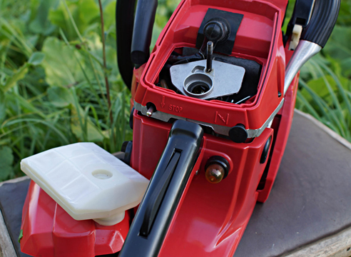
Для снятия карбюратора необходимо отсоединить от него топливный шланг и тяги заслонок, сделать это удобно после того, как демонтирован воздушный фильтр, который устанавливается сразу же за карбюратором и удерживается при помощи двух гаек на 10. После того как воздушный фильтр демонтирован, а топливный шланг и тяги отсоединены, достаточно просто потянуть карбюратор на себя и снять его со шпилек.
Используйте для снятия карбюратора пинцет и медицинские зажимы.
Масляный насос
На Хускварне масляный насос установлен с правой стороны бензопилы. Снять его можно только после того, как раскручено сцепление. Для снятия не потребуется специального инструмента, т.к. винты крепления изготовлены под обычную крестовую отвертку. После того как винты выкручены, необходимо приподнять насос и отсоединить от него масленые шланги.
Двигатель
Для снятия двигателя на бензопиле Хускварна, после того как демонтированы карбюратор, сцепление, маховик и глушитель, потребуется выкрутить четыре винта его крепления к корпусу.
После того как двигатель снят, от него можно открутить катушку зажигания, не забыв предварительно отсоединить провода, идущие от нее к выключателю зажигания. Катушку также можно снимать сразу после того, как снят стартер.
Сборка бензопилы Хускварна должна проводится в обратной последовательности, при этом затягивать гайку маховика и сцепление необходимо с усилием, значение которого указано в инструкции по эксплуатации бензопилы.
Как и когда регулировать зажигание на пиле Хускварна
У пользователей бензопил Хускварна, часто возникает вопрос: как и когда регулировать зажигание. Ответить на него просто. На бензопилах Хускварна установлена электронная катушка зажигания и маховик, в которых не предусмотрена возможность регулировки. Единственное, что можно регулировать, это зазор между катушкой и маховиком.
Для регулировки зазора в домашних условиях необходимо вырезать из пластиковой бутылки щуп, после чего ослабить винты крепления катушки. Далее, щуп устанавливается между контактами катушки и маховиком. Винты затягиваются.
Регулировать зазор необходимо при проведении ТО или при обнаружении задиров на поверхности маховика. Такие задиры свидетельствуют о том, что зазор полностью отсутствует.
Если после того как зазор между катушкой и маховиком выставлен, а детали продолжают соприкасаться, то необходимо проверить на износ подшипники коленчатого вала. Возможно, они сильно изношены и требуют замены.
Основные неисправности и способы их устранения
Приступая к ремонту бензопилы, необходимо иметь представление о том, какие она может иметь неисправности, а также как эти неисправности устраняются. Итак, давайте рассмотрим признаки неисправностей и способы их устранения.
Бензопила Хускварна не заводится
Если Хускварна не заводится, первое в чем нужно убедиться, это соблюдение вами алгоритма запуска пилы, а также наличие топлива в баке. Подробная инструкция о том, как провести запуск холодной бензопилы и его заправку, имеется в руководстве по использованию пилы, которое поставляется со всеми бензопилами Хускварна.
В том случае, если вы все делаете правильно, но пила не откликается, причина может скрываться в неисправности системы зажигания или отсутствии подачи топлива.
Для более точного определения причин такого поведения бензопилы, необходимо провести осмотр свечи зажигания, после чего проверить её на наличие искры.
Если свеча мокрая, а при проверке искры её не обнаружено, стоит попробовать заменить саму свечу. Замена не дала результатов, значит проблема может скрываться в катушке зажигания, проверить которую самостоятельно достаточно сложно.
Проверить исправность катушки, можно установив её на заранее исправную пилу аналогичной модели либо заменив деталь на исправную.
В том случае если искра есть, а свеча сухая — проблемы в топливной системе. Для устранения нужно провести её полную диагностику. Топливная система состоит из карбюратора и топливной магистрали. Не имея определенного опыта, можно проверить топливную магистраль на наличие порывов, а также чистоту топливного фильтра, установленного в баке. Полную диагностику и ремонт карбюратора лучше доверить профессионалам.
Если пила заводится, но плохо
Причиной затрудненного запуска пилы может стать неисправность или неправильная регулировка карбюратора. В том случае, когда карбюратор переливает, бензопила будет легко заводиться на горячую, но достаточно сложно на холодную, особенно после длительного простоя.
Косвенным признаком чрезмерного количества топливной смеси, поступающей в цилиндр при работе бензопилы, является выхлоп. Если при работе бензопилы выделяется много белого дыма, стоит проверить пропорции приготовления топливной смеси и регулировки карбюратора.
Цепь бензопилы крутится на холостом ходу
Если цепь Хускварны вращается на холостом ходу, то можно сделать вывод о том, что имеются неисправности в механизме сцепления или холостой ход не отрегулирован. Для устранения неисправности, необходимо снять крышку тормоза пильной цепи и осмотреть целостность пружины сцепления. Дефектное сцепление заменить.
Если сцепление исправно, для устранения прокручивания цепи необходимо откорректировать обороты холостого хода при помощи регулировочного винта, обозначенного буквой (Т) или провести полную регулировку карбюратора.
Важно: возможная причина самостоятельного увеличения холостого хода, это появление подсоса воздуха в картер двигателя или карбюратор, что может привести к серьезным повреждениям ЦПГ.
Почему бензопила Хускварна глохнет при нажатии на газ
Если пила глохнет сразу после нажатия на газ, необходимо провести осмотр свечи зажигания, который поможет точнее диагностировать неисправность. Мокрая свеча, свидетельствует о неисправности или неправильной регулировки карбюратора, в таком случае, исправить ситуацию можно проведя полную диагностику, ремонт и регулировку данного узла. Если ремонт и регулировки не помогли, необходимо заменить карбюратор на новый.
Еще одна причина, по которой Husqvarna может глохнуть при нажатии на газ, это неисправности в топливной системе, а точнее, затруднения подачи топлива к карбюратору. Необходимо проверить чистоту топливного фильтра, а также целостность топливных шлангов.
В процессе сборки бензопилы при проведении его полного ремонта, можно пережать топливный шланг, идущий из бака к карбюратору, что ограничит или полностью прекратит подачу топлива и сделает работу пилы невозможным.
Почему не смазывается цепь на бензопиле Хускварна
Если на вашей бензопиле полностью прекращена подача смазки пильной цепи, значит необходимо проверить всю масляную систему.
Причин может быть несколько:
- Неисправность масляного насоса;
- Засор фильтрующего элемента, установленного в баке;
- Неисправность сапуна масляного бака;
- Разрыв масляного шланга;
- Несовпадения масляного отверстия на шине и на корпусе пилы (если подача прекратилась после установки новой пильной шины);
- Засор масляного канала в корпусе пилы;
- Засор канала подачи масла в шине;
- Неисправность шестерни привода масляного насоса.
Итог
Самостоятельный ремонт бензопил Хускварна возможен только в том случае, если имеются хоть какие-то знания о работе двухтактного двигателя, а также принципах, по которым устроена бензопила. Как показывает практика, разобрать бензопилу Хускварна несложно, гораздо сложнее её собрать и при этом не усугубить её неисправность. Заранее рассчитывайте свои силы и не надейтесь, что вы сможете отремонтировать пилу, не имея определенного опыта. В некоторых случаях даже опытные мастера прилагают массу усилий, чтобы правильно диагностировать неисправность.
Бензиновые пилы Husqvarna пользуются огромным спросом, как среди начинающих садовников, так и среди опытных вальщиков леса. Модели шведской марки обладают рядом таких важных преимуществ, как надежность, сбалансированность и высокий рабочий ресурс. При этом каждая бензопила Husqvarna имеет простую конструкцию, что позволяет легко обслуживать ее и оперативно устранить возникшую поломку.
Устройство бензопилы Хускварна
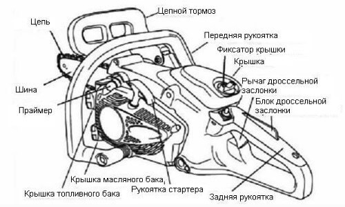
В отличие от бензопил других, не менее известных производителей, модели шведской компании Husqvarna имеют довольно простую конструкцию, что существенно упрощает их самостоятельный ремонт. В собранном виде на бензопилах шведского бренда можно увидеть:
- Корпус, который включает в себя защитные крышки, предотвращающие повреждение основных деталей и механизмов пилы;
- Рукоятки – с передней и задней стороны, а также рукоятку на шнуре стартера;
- Кнопки управления, переключатели и рычаг цепного тормоза;
- Глушитель, снижающий уровень шума при работе;
- Шину и пильную цепь;
- 2 отдельных пластиковых резервуары – для топливной смеси и для масла;
- Щиток, защищающий правую руку оператора.
Под усиленным корпусом бензопилы Husqvarna помещен силовой агрегат, карбюратор, стартер и система зажигания. В зависимости от модели и ее стоимости, в конструкцию бензопилы также может быть включен ряд дополнительных опций.
Для того, что продлить сроки эксплуатации бензопилы и уменьшить износ ее основных деталей, необходимо внимательно изучить и придерживаться всех советов, указанных производителем в руководстве по применению. Ниже перечислим ряд наиболее распространенных вопросов, связанных с эксплуатацией китайской и шведской бензопилы производства Husqvarna, и дадим детальные ответы на них.
Какой бензин заливать в бензопилу Хускварна?
Чтобы приготовить заправочную смесь для бензопил Хускварна, следует использовать топливо марки АИ-92. Крайне редко в инструкциях по эксплуатации к более новым моделям данной марки указывается, что для приготовления смеси можно использовать 95-ый бензин.
Как показывает практика, лучше этого не делать, так как страна-производитель садовых инструментов Хускварна – Швеция, бензин в которой гораздо лучше по качеству, чем в странах постсоветского пространства.
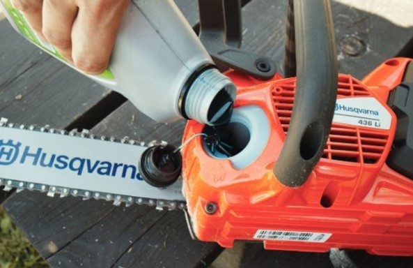
Какое масло подходит для бензопилы Хускварна?
Запчасти в конструкции бензопил компании Husqvarna могут прослужить достаточно длительное время при условии, что владелец инструмента не будет экономить на моторном масле.
Для разбавления заправочной смеси можно использовать масло на основе минералов или синтетики. Второй вариант всегда будет стоить дороже, но и эффект от его применения будет в разы лучше.
Соотношение бензина и масла для бензопилы Хускварна
На соотношение используемого бензина и масла влияет мощность имеющейся в распоряжении бензопилы. Если мощность инструмента меньше 2 л. с., – то пропорция бензина и масла будет составлять 1:40. Иными словами, в 1 литре горючего нужно разбавлять 25 мл моторного масла. Если мощность бензопилы Husqvarna составляет более 2 л. с., то разводить бензин для бензопилы Хускварна потребуется в пропорции 1:50, то есть, в 1 литре топлива разбавлять 20 мл масла.
Правильная обкатка бензопилы Хускварна
Производить обкатку следует не только перед первым применением агрегата марки Husqvarna, но после каждого длительного хранения инструмента. Выполняется эта процедура в таком порядке:
- Заведите бензопилу и дайте ей поработать в течении 2–3 минут. При этом распиливать ветки или бревна категорически запрещено;
- После этого переходите к спиливанию мелкие сучья;
- Еще через полчаса можно начинать распиловку крупных бревен.
Обязательно придерживайтесь указанных инструкций – это поможет вам продлить сроки эксплуатации мотора и карбюратора.
Типичные неисправности и ремонт бензопил бренда Husqvarna
Владельцы бензопил Хускварна сталкиваются с поломками своих инструментов крайне редко. Однако если это все-таки случилось, то можно попытаться устранить неисправность своими руками. О том, как определить поломку, и отремонтировать бензопилу Хускварна без помощи мастера – поговорим более подробно.
Как отрегулировать карбюратор на бензопиле Хускварна?
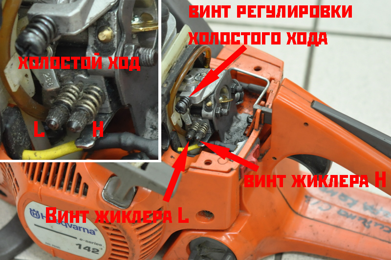
На случай, если не заводиться бензопила Хускварна, или она не развивает обороты – причина этому кроется в нарушении заводских настроек карбюратора. Для этого у инструмента имеются 3 винта, обозначенные буквами «H», «L» и «T».
Чтобы настроить бензопилу Husqvarna, нужно действовать в таком порядке:
- Регулировка карбюратора пилы начинается с 5-минутного прогревания ее мотора. После этого начните поворачивать винт «L» до момента, пока не услышите максимальные обороты, выдаваемые ее мотором. Затем сразу же поверните винт на четверть оборота в противоположном направлении;
- Затем одной рукой нажмите и удерживайте курок газа на протяжении 10 секунд. При этом второй рукой поверните винт «H» на четверть оборота, чтобы создать максимальную нагрузку на мотор;
- После этого отпустите курок газа и начните поворачивать винт «T «по направлению движения стрелки часов. Как только цепь начнет вращение по шине, поверните винт в обратную сторону до момента остановки цепи.
Устройство карбюратора бензопилы Хускварна довольно простое, благодаря чему с его настройкой сможет справиться даже новичок.
Как снять сцепление на бензопиле Хускварна?
Если бензопила не заводиться на горячую или глохнет при нажатии на газ, то причина этой типичной проблемы кроется в износе сцепления. Чаще всего восстановить его оказывается невозможным, поэтому для ремонта потребуется полностью заменить испорченный механизм. Замена сцепления выглядит следующим образом:
- Демонтируйте воздушный фильтр и открутите свечу зажигания. При необходимости протрите пространство около свечи бензопилы;
- На следующем этапе потребуется снять звездочку с бензопилы Хускварна – это даст возможность внимательно осмотреть механизм на наличие засорений;
- Катушка сцепления выкручивается по направлению стрелки часов. Под ней расположена прижимная шайба, которую также нужно извлечь;
- В конце производиться замена звездочки и устанавливается новое сцепление. Сборка бензопилы Husqvarna выполняется в обратном порядке.
Первые несколько запусков мотора бензопилы будут сопровождаться звенящими звуками – это связано с тем, что ведущая звездочка будет проворачиваться, пока окончательно не встанет на свое место.
Не поступает масло на цепь бензопилы Husqvarna – причины и решение
Если вы не знаете, почему не связывается цепь, то первое, что от вас требуется – это проверить масляный насос. В некоторых случаях, когда не крутиться цепь – причина может крыться в нарушении герметичности масляных шлангов. В любом из этих случаев нужно действовать в таком порядке:
- Для начала снимается защитная крышка и пружина стартера, после чего демонтируется воздушный фильтр бензопилы.
- Под ним в правой части расположен масляный насос, который нужно осмотреть на наличие трещин и других повреждений. Если есть необходимость – замените насос;
- Если вы заметили, что масляные шланги отошли от своего основания, значит, их также потребуется заменить новыми деталями.
Установив новые запасные части, можно продолжить работу с инструментом. В дальнейшем используйте только качественно масло от проверенных производителей. Большое значение также имеет правильно выбранный угол заточки цепи бензопилы Хускварна, так как от него зависит скорость движения и интенсивность смазки пильного элемента.
Бензопилы Хускварна – модельный ряд шведской компании
Компания Хускварна известна огромным ассортиментом представленных на рынке фирменных бензопил. Предлагаем вашему вниманию обзор бензопил Хускварна с подробным описанием наиболее популярных моделей.
Husqvarna 61
Эта бензопила Husqvarna эффективно и быстро спиливает старые толстые ветки и помогает заготовить большое количество дров. Технические параметры этой популярной модели включают:
- Мощность – 3,9 л. с./2900 Ватт;
- Размер штатной шины – 45 см;
- Резервуар для пополнения горючего – 750 мл;
- Масляный резервуар – 400 мл;
- Вес в готовом к применению виде – 6,6 кг.
Данная бензопила Хускварна обладает небольшими размерами, благодаря чему для ее транспортировки подойдет даже небольшая сумка.
Husqvarna 136
Эта полупрофессиональная бензопила Husqvarna применяется преимущественно в целях ухода за большими садовыми территориями. Технические характеристики данной бензопилы Хускварна включают:
- Мощность – 2,2 л. с./1600 Ватт;
- Длина шины з комплекта – 45 см;
- Резервуар для пополнения топлива – 410 мл;
- Масляный резервуар – 175 мл;
- Вес в эксплуатационном виде – 4 кг.
В основу конструкции данной бензопилы Husqvarna вложена кованая поршневая группа, что существенно повышает износостойкость и увеличивает выносливость модели.
Husqvarna 235
Эта профессиональная бензопила Хускварна получила высочайший спрос благодаря грамотно продуманной конструкции и сбалансированности. Технические параметры данной модели Husqvarna включают:
- Мощность – 1,7 л. с./1300 Ватт;
- Размер заводской шины – 30 см;
- Резервуар для пополнения горючего – 300 мл;
- Резервуар для смазочного состава – 200 мл;
- Эксплуатационный вес – 3,5 кг.
Скромные размеры бензопилы позволяют легко поместить ее в кейс для перевозки.
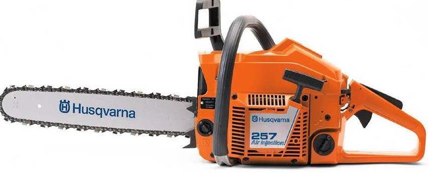
Бензопилы Husqvarna 257 XP и Husqvarna 455 Rancher
Эти бензопилы Хускварна на отлично справляются с распиловкой небольших бревен и спиливанием старых сучьев. Эксплуатационные параметры бензопил описаны ниже в таблице.
| Модель бензопилы | Husqvarna 257 XP | Husqvarna 455 Rancher |
| Мощность | 3,7 л. с./2700 Ватт | 3,5 л. с./2600 Ватт |
| Размер штатной шины | 45 см | 45 см |
| Резервуар для пополнения топливной смеси | 600 мл | 440 мл |
| Резервуар для смазочного состава | 350 мл | 320 мл |
| Масса в готовом к использованию виде | 5,5 кг | 6,1 кг |
Мощности этих моделей вполне достаточно для того, чтобы собственноручно изготовить ледобур из бензопилы или другие полезные хозяйственные агрегаты.
Бензопилы Husqvarna 262 XP и Husqvarna 576 XP
Эти бензопилы Husqvarna изначально предназначены в целях применения в наиболее тяжелых условиях и легко справляются с распиловкой довольно толстых брусьев и длительным спиливанием больших деревьев. Конструктивные параметры данных агрегатов описаны ниже в таблице.
| Модель бензопилы | Husqvarna 262 XP | Husqvarna 576 XP |
| Мощность | 4,7 л. с./3400 Ватт | 5,6 л. с./4200 ватт |
| Размер штатной шины | 50 см | 50 см |
| Резервуар для пополнения горючего | 600 мл | 700 мл |
| Масляный резервуар | 300 мл | 400 мл |
| Масса в готовом к применению виде | 5,8 кг | 7,2 кг |
Каждая из этих бензопил Husqvarna снабжена выносливым 2-таткным мотором цепным тормозом и регулируемым масляным насосом.
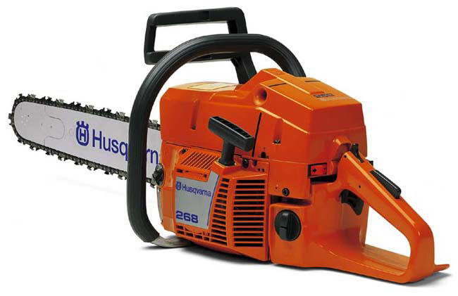
Бензопилы Husqvarna 268 и Husqvarna 562 XP
Основная область применения этих бензопил – интенсивная валка леса и строительство. Параметры моделей описаны в таблице.
| Модель бензопилы | Husqvarna 268 | Husqvarna 562 XP |
| Мощность | 4,4 л. с./3200 Ватт | 4,7 л. с./3500 Ватт |
| Размер заводской шины | 45 см | 45 см |
| Резервуар для заливки горючего | 600 мл | 650 мл |
| Резервуар для масла | 270 мл | 290 мл |
| Масса в готовом к работе виде | 5,7 кг | 6,3 кг |
Данные бензопилы Husqvarna комплектуются надежным цепным тормозом и регулируемым насосом подкачки масла.
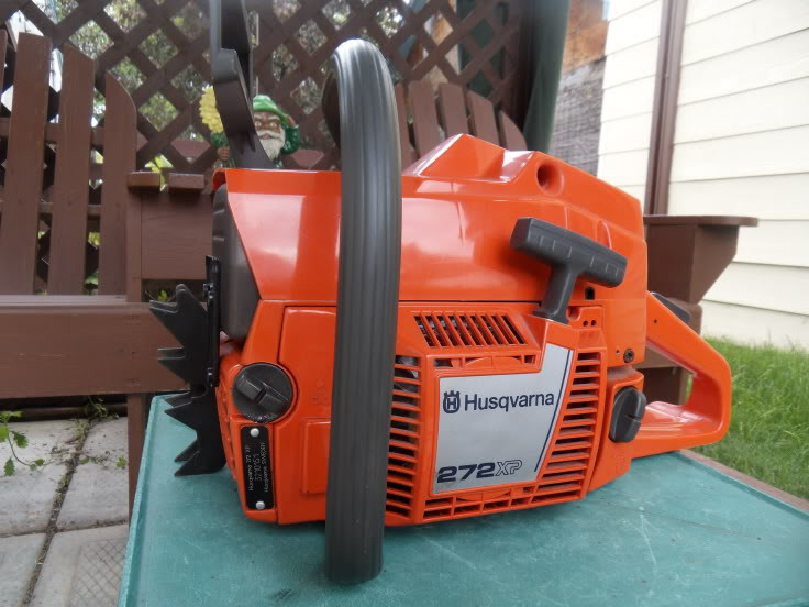
Бензопилы Husqvarna 272 XP и Husqvarna 372 XP
Эти бензопилы Husqvarna применяются для валки лесных деревьев и распиливания толстых бревен для строительства. Параметры моделей подробно описаны в таблице.
| Модель бензопилы | Husqvarna 272 XP | Husqvarna 372XP |
| Мощность | 4,9 л. с./3600 Вт | 5,5 л. с./3900 Ватт |
| Размер штатной шины | 45 см | 50 см |
| Резервуар для топливной смеси | 750 мл | 770 мл |
| Масляный резервуар | 500 мл | 400 мл |
| Эксплуатационная масса | 6,7 кг | 7 кг |
Технические показатели этих моделей позволяют использовать для работы с ними фирменные насадки для бензопилы Хускварна.
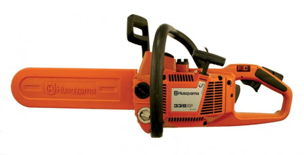
Бензопилы Husqvarna 339 XP и Husqvarna 353
Обе эти модели практически не отличаются собой по конструкции. Основная разница состоит только в том, что модель Husqvarna 339XP обладает более скромными техническими параметрами. Показатели бензопил детально описаны в таблице.
| Модель бензопилы | Husqvarna 339 XP | Husqvarna 353 |
| Мощность | 2,45 л. с./1800 Ватт | 3,26 л. с./2400 Ватт |
| Размер штатной шины | 35 см | 40 см |
| Резервуар для заливки топлива | 360 мл | 500 мл |
| Масляный резервуар | 200 мл | 300 мл |
| Эксплуатационная масса | 5 кг | 5,6 кг |
Обе модели отлично подходят для распиловки бревен, а также спиливания небольших и средних веток.
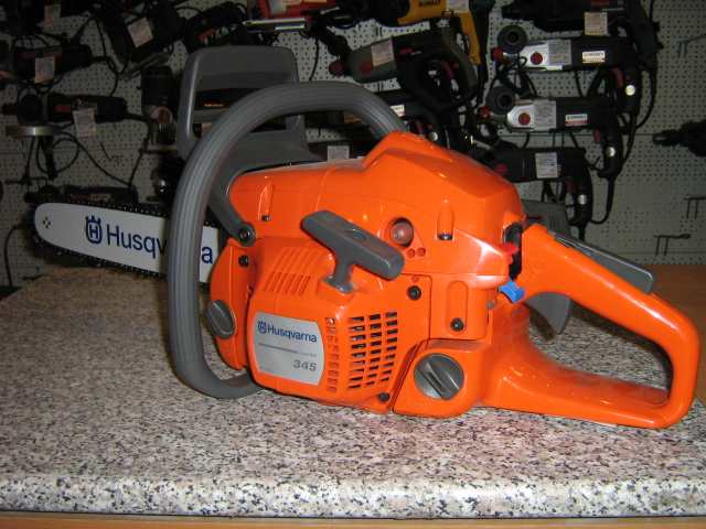
Husqvarna 345E
Эта модель попала в наш обзор благодаря наличию ряда полезных фирменных опций и высокой выносливости. Среди параметров бензопилы Хускварна 345 следует выделить:
- Мощность – 2,7 л. с./2000 Ватт;
- Размер шины из комплекта – 35 см;
- Резервуар для заливки горючего – 500 мл;
- Резервуар для масла – 270 мл;
- Масса в готовом к применению виде – 5,1 кг.
Данная бензопила Husqvarna активно используется в целях удаления толстых веток и спиливания небольших садовых деревьев.
Бензопилы Husqvarna 440E II и Husqvarna 445E II
Обе бензопилы Хускварна обладают практически одинаковой конструкцией и показателями производительности. Параметры моделей детально описаны ниже в таблице.
| Модель бензопилы | Husqvarna 440E II | Husqvarna 445E II |
| Мощность | 2,2 л. с./1600 Ватт | 2,2 л. с./1600 Ватт |
| Размер штатной шины | 40 см | 40 см |
| Резервуар для заливки горючего | 370 мл | 370 мл |
| Масляный резервуар | 250 мл | 250 мл |
| Эксплуатационный вес | 4,8 кг | 5 кг |
Модели Husqvarna 440 и Husqvarna 445 хорошо показали себя при спиливании средних и небольших деревьев, а также обработке бревен для обогрева.
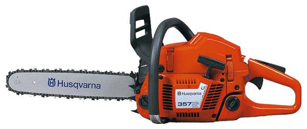
Бензопилы Husqvarna 357 XP и Husqvarna 365H
Эти бензопилы Хускварна нашли применение в коммунальных предприятиях. Благодаря своей экономичности и длительным срокам службы они также пользуется спросом среди владельцев больших садовых участков. Параметры моделей Husqvarna 357 и Husqvarna 365H подробно описаны ниже в таблице.
| Модель бензопилы | Husqvarna 357 | Husqvarna 365H |
| Мощность | 4,3 л. с./3200 Ватт | 4,6 л. с./3900 Ватт |
| Размер штатной шины | 45 см | 45 см |
| Резервуар для пополнения топливной смеси | 680 мл | 770 мл |
| Резервуар для масла | 380 мл | 420 мл |
| Эксплуатационная масса | 6 кг | 6,5 кг |
Данные бензопилы Хускварна обладают завидной надежностью и хорошим качеством сборки.
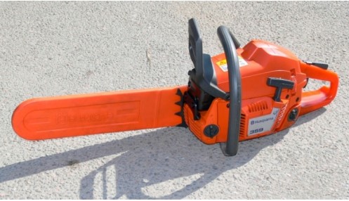
Бензопилы Husqvarna 359 и Husqvarna 395XP
Эта бензопилы Хускварна предназначены для ухода за большими садовыми территориями и интенсивной вырубки леса. Технические параметры моделей описаны в таблице.
| Модель бензопилы | Husqvarna 359 | Husqvarna 395XP |
| Мощность | 3,9 л. с./2900 Ватт | 6,66 л. с./5200 Ватт |
| Размер заводской шины | 40 см | 60 см |
| Резервуар для заливки топлива | 680 мл | 900 мл |
| Резервуар для смазочного средства | 380 мл | 500 мл |
| Эксплуатационная масса | 5,8 кг | 8, 1 кг |
Данные модели комплектуются надежными моторами, существенно расширенными карбюраторами и улучшенными системами зажигания.
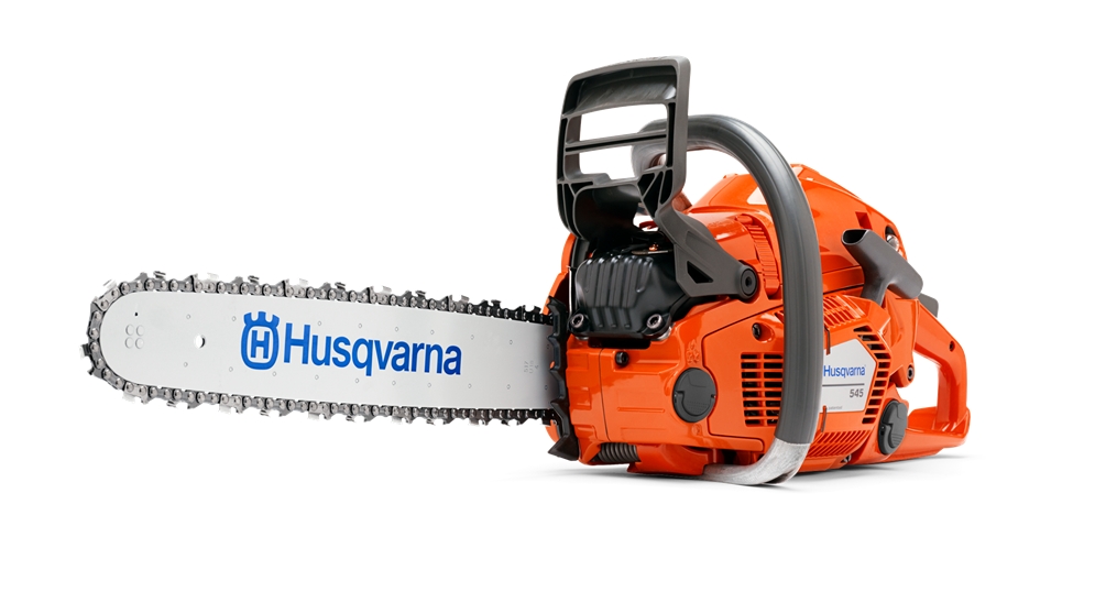
Бензопилы Husqvarna 545 и Husqvarna 555
Данные бензопилы хорошо и быстро справляются с распиловкой достаточно толстых брусьев и оперативным спиливанием мелких и средних деревьев. Характеристики моделей описаны ниже в таблице.
| Модель бензопилы | Husqvarna 545 | Husqvarna 555 |
| Мощность | 3,4 л. с./2500 Ватт | 4,3 л. с./3200 Ватт |
| Размер рекомендуемой шины | 45 см | 50 см |
| Резервуар для заливки горючего | 520 мл | 650 мл |
| Резервуар для смазочного материала | 270 мл | 330 мл |
| Масса в готовом к применению виде | 5,4 кг | 6 ег |
В конструкции данного инструмента присутствует качественная система гашения вибраций и мгновенный инерционный тормоз.
- Manuals
- Brands
- Husqvarna Manuals
ManualsLib has more than 9712 Husqvarna manuals
Lawn Mower
Oven
Vacuum Cleaner
Accessories
970584901
Quick Start Manual
HA 110
Operator’s Manual
• Operator’s Manual
• Operator’s Manual
• Operator’s Manual
HA 110, HA 110
Operator’s Manual
HA 850
Operator’s Manual
• Operator’s Manual
• Operator’s Manual
• Operator’s Manual
• Operator’s Manual
HEDGE TRIMMER ATTACHMENT
Operator’s Manual
Automobile Accessories
593 02 50-01
Instruction Manual
953 51 17-01
Operating Instructions Manual
T-80012
Operating Instructions Manual
T-80013
Operating Instructions Manual
T-80014
Operating Instructions Manual
T-80016
Operating Instructions Manual
T-80017
Operating Instructions Manual
T-80018
Operating Instructions Manual
Show all Husqvarna Automobile Accessories manuals
Automower
315, 320
Operator’s Manual
• Operator’s Manual
• Quick Manual
• Operator’s Manual
• Operator’s Manual
• Quick Manual
• Operator’s Manual
• Operator’s Manual
• Operator’s Manual
• Quick Manual
• Quick Manual
• Operator’s Manual
• Operator’s Manual
• Operator’s Manual
• Operator’s Manual
• Operator’s Manual
• Operator’s Manual
• Operator’s Manual
• Operator’s Manual
• Operator’s Manual
• Technical Manual
• Operator’s Manual
• Operator’s Manual
• Operator’s Manual
• Operator’s Manual
• Quick Manual
• Operator’s Manual
• Operator’s Manual
• Quick Manual
• Operator’s Manual
• Quick Manual
• Operator’s Manual
• Quick Manual
• Quick Manual
• Operator’s Manual
440 e-series
Operator’s Manual
• Owner’s Manual
• Operation Manual
• Operator’s Manual
• Operator’s Manual
• Operator’s Manual
• Operator’s Manual
AUTOMOWER 105
Operator’s Manual
• Operator’s Manual
• Quick Manual
• Quick Manual
• Operator’s Manual
• Quick Manual
• Operator’s Manual
• Operator’s Manual
• Operator’s Manual
• Operator’s Manual
• Operator’s Manual
• Operator’s Manual
• Operator’s Manual
• Operator’s Manual
• Operator’s Manual
• Quick Manual
• Quick Manual
• Quick Manual
• Operator’s Manual
• Operator’s Manual
• Operator’s Manual
• Operator’s Manual
• Operator’s Manual
• Quick Manual
• Operator’s Manual
• Operator’s Manual
• Operator’s Manual
• Operator’s Manual
• Quick Manual
• Operator’s Manual
• Operator’s Manual
AUTOMOWER 310
Operator’s Manual
• Quick Manual
• Operator’s Manual
• Operator’s Manual
• Quick Manual
• Quick Manual
• Operator’s Manual
• Operator’s Manual
• Operator’s Manual
• Quick Manual
• Quick Manual
• Operator’s Manual
• Operator’s Manual
• Operator’s Manual
• Operator’s Manual
• Operator’s Manual
• Operator’s Manual
• Operator’s Manual
• Operator’s Manual
• Operator’s Manual
• Technical Manual
• Operator’s Manual
• Operator’s Manual
• Operator’s Manual
• Operator’s Manual
• Quick Manual
• Operator’s Manual
• Operator’s Manual
• Quick Manual
• Operator’s Manual
• Quick Manual
• Operator’s Manual
• Quick Manual
• Quick Manual
• Operator’s Manual
• Operator’s Manual
AUTOMOWER 420
Quick Manual
• Operator’s Manual
• Quick Manual
• Operator’s Manual
• Operator’s Manual
• Installation Manual
• Operator’s Manual
• Operator’s Manual
• Operator’s Manual
• Operator’s Manual
• Operator’s Manual
• Quick Manual
• Operator’s Manual
• Operator’s Manual
• Operator’s Manual
• Workshop Manual
• Operator’s Manual
• Operator’s Manual
• Operator’s Manual
• Operator’s Manual
• Operator’s Manual
• Quick Manual
• Operator’s Manual
• Operator’s Manual
• Operator’s Manual
• Technical Manual
• Operator’s Manual
• Operator’s Manual
• Quick Manual
• Quick Manual
• Quick Manual
• Quick Manual
• Operator’s Manual
• Quick Manual
• Operator’s Manual
• Operator’s Manual
AUTOMOWER 430X
Quick Manual
• Operator’s Manual
• Quick Manual
• Operator’s Manual
• Operator’s Manual
• Installation Manual
• Operator’s Manual
• Operator’s Manual
• Operator’s Manual
• Operator’s Manual
• Operator’s Manual
• Gluing Instructions
• Quick Manual
• Operator’s Manual
• Operator’s Manual
• Operator’s Manual
• Workshop Manual
• Operator’s Manual
• Operator’s Manual
• Operator’s Manual
• Operator’s Manual
• Operator’s Manual
• Quick Manual
• Operator’s Manual
• Operator’s Manual
• Operator’s Manual
• Technical Manual
• Operator’s Manual
• Operator’s Manual
• Quick Manual
• Quick Manual
• Quick Manual
• Quick Manual
• Operator’s Manual
• Quick Manual
• Operator’s Manual
• Operator’s Manual
• Quick Manual
• Operator’s Manual
• Quick Manual
AUTOMOWER 450X
Quick Manual
• Operator’s Manual
• Quick Manual
• Operator’s Manual
• Operator’s Manual
• Installation Manual
• Quick Manual
• Operator’s Manual
• Operator’s Manual
• Operator’s Manual
• Operator’s Manual
• Operator’s Manual
• Quick Manual
• Operator’s Manual
• Operator’s Manual
• Operator’s Manual
• Workshop Manual
• Operator’s Manual
• Operator’s Manual
• Operator’s Manual
• Operator’s Manual
• Operator’s Manual
• Quick Manual
• Operator’s Manual
• Operator’s Manual
• Operator’s Manual
• Technical Manual
• Operator’s Manual
• Operator’s Manual
• Quick Manual
• Quick Manual
• Quick Manual
• Quick Manual
• Operator’s Manual
• Quick Manual
• Operator’s Manual
• Operator’s Manual
• Operator’s Manual
• Quick Manual
• Operator’s Manual
• Quick Manual
Battery Charger
100-B380X
Operator’s Manual
• Operator’s Manual
• Operator’s Manual
• Operator’s Manual
• Operator’s Manual
100-B750X
Operator’s Manual
• Operator’s Manual
• Operator’s Manual
• Operator’s Manual
• Operator’s Manual
100-C1800
Operator’s Manual
100-C1800X
Operator’s Manual
• Operator’s Manual
100-C900X
Operator’s Manual
• Operator’s Manual
• Operator’s Manual
40-B140
Operator’s Manual
• Operator’s Manual
• Operator’s Manual
40-B70
Operator’s Manual
• Operator’s Manual
• Operator’s Manual
Show all Husqvarna Battery Charger manuals
Battery Pack
40-B140
Operator’s Manual
• Operator’s Manual
• Operator’s Manual
40-B70
Operator’s Manual
• Operator’s Manual
• Operator’s Manual
967187001
Workshop Manual
BLi40-B70
Operator’s Manual
BLi520x
Operator’s Manual
• Operator’s Manual
BLi940x
Operator’s Manual
• Operator’s Manual
Blower
111750
Operator And Parts Manual
111750 / HCS1372
Operator And Parts Manual
115 09 83-95
Operator’s Manual
115 149727 R01
Operator And Parts Manual
115 24 05-95
Operator’s Manual
115 31 90-95
Operator’s Manual
1153191-26
Operator’s Manual
125B
Operator’s Manual
• Operator’s Manual
• Operator’s Manual
• Operator’s Manual
• Operator’s Manual
• Operator’s Manual
• Operator’s Manual
• Operator’s Manual
Show all Husqvarna Blower manuals
Brush Cutter
101 90 47-26 142RB/152RB
Operator’s Manual
115iL
Operator’s Manual
• Operator’s Manual
• Operator’s Manual
• Operator’s Manual
123HD60
Operator’s Manual
• Operator’s Manual
• Operator’s Manual
• Workshop Manual
123HD65X
Operator’s Manual
• Operator’s Manual
• Workshop Manual
125C
Operator’s Manual
• Operator’s Manual
• Operator’s Manual
• Workshop Manual
125L
Operator’s Manual
• Operator’s Manual
• Operator’s Manual
• Workshop Manual
125R
Operator’s Manual
• Operator’s Manual
128R
Operator’s Manual
• Operator’s Manual
• Operator’s Manual
129 LDX
Operator’s Manual
• Operator’s Manual
• Operator’s Manual
• Operator’s Manual
• Workshop Manual
• Operator’s Manual
129DJx
Operator’s Manual
• Operator’s Manual
• Workshop Manual
Show all Husqvarna Brush Cutter manuals
Camera Accessories
100-B380X
Operator’s Manual
• Operator’s Manual
• Operator’s Manual
• Operator’s Manual
• Operator’s Manual
100-B750X
Operator’s Manual
• Operator’s Manual
• Operator’s Manual
• Operator’s Manual
• Operator’s Manual
40-B140
Operator’s Manual
• Operator’s Manual
• Operator’s Manual
40-B70
Operator’s Manual
• Operator’s Manual
• Operator’s Manual
BLi10
Operator’s Manual
• Operator’s Manual
Show all Husqvarna Camera Accessories manuals
Chainsaw
100-B380X
Operator’s Manual
• Operator’s Manual
• Operator’s Manual
• Operator’s Manual
• Operator’s Manual
100-B750X
Operator’s Manual
• Operator’s Manual
• Operator’s Manual
• Operator’s Manual
• Operator’s Manual
1100 CD
Operator’s Manual
• Service Manual
115 13 81-26
Operator’s Manual
115 13 81-95
Operator’s Manual
115 13 81-96
Operator’s Manual
115 13 82-49
Operator’s Manual
115 13 82-95
Operator’s Manual
115 13 82-96
Operator’s Manual
1150901-95
Operator’s Manual
Show all Husqvarna Chainsaw manuals
Chippers/Shredders
Rider Pro 15
Operator’s Manual
• Operator’s Manual
• Operator’s Manual
• Operator’s Manual
• Workshop Manual
• Workshop Manual
• Operator’s Manual
• Operator’s Manual
Cleaning Equipment
Construction Equipment
AME 600
Operator’s Manual
Show all Husqvarna Construction Equipment manuals
Control Systems
Automower Connec
Operator’s Manual
Cookers
free standing cooker
Operating Manual
Regina Gastronome QSG1000X
Instruction Manual
Cordless Saw
FS 800 E
Operator’s Manual
FS 800 EM
Operator’s Manual
Cut-off machines
K 7000
Operator’s Manual
• Operator’s Manual
• Workshop Manual
• Workshop Manual
• Operator’s Manual
• Operator’s Manual
K 7000 Ring
Operator’s Manual
• Operator’s Manual
Cutter
268K, 272K
Operator’s Manual
• Workshop Manual
272K
Operator’s Manual
• Workshop Manual
3120K
Operator’s Manual
• Workshop Manual Supplement
371K
Operator’s Manual
• Operator’s Manual
• Workshop Manual Supplement
• Operator’s Manual
• Operator’s Manual
375K
Operator’s Manual
• Operator’s Manual
967348001
Operator’s Manual
Show all Husqvarna Cutter manuals
DC Drives
PG680
Operator’s Manual
• Price List
• Operator’s Manual
• Operator’s Manual
• Operator’s Manual
• Programming
• Operator’s Manual
PG820
Operator’s Manual
• Price List
• Operator’s Manual
• Operator’s Manual
• Operator’s Manual
• Programming
Dishwasher
Cardinal
Operating Manual
CARDINAL 5120
User Instructions
Drill
1152417-30
Operator’s Manual
143AE15
Operator’s Manual
• Operator’s Manual
970445607
Operator’s Manual
AD 10
Price List
• Operator’s Manual
• Workshop Manual
DM 200
Operator’s Manual
• Operator’s Manual
• Workshop Manual
DM 220
Price List
• Operator’s Manual
• Operator’s Manual
• Operator’s Manual
• Operator’s Manual
• Operator’s Manual
• Operator’s Manual
• Workshop Manual
• Operator’s Manual
Show all Husqvarna Drill manuals
Dust Collector
C 3000
Operator’s Manual
• Operator’s Manual
• Operator’s Manual
C 5500
Operator’s Manual
• Operator’s Manual
• Operator’s Manual
DC 6000
Operator’s Manual
• Operator’s Manual
• Workshop Manual
• Operator’s Manual
Show all Husqvarna Dust Collector manuals
Edger
125E
Operator’s Manual
• Operator’s Manual
225E
Operator’s Manual
• Operator’s Manual
322E
Operator’s Manual
• Operator’s Manual
323E, 325E
Operator’s Manual
• Operator’s Manual
• Operator’s Manual
• Operator’s Manual
323Ex Series
Operator’s Manual
325E X-series
Operator’s Manual
• Operator’s Manual
• Operator’s Manual
Show all Husqvarna Edger manuals
Engine
450 Rancher
Operator’s Manual
• Operator’s Manual
• Operator’s Manual
• Operator’s Manual
• Spare Parts
• Owner’s Manual
• Operator’s Manual
• Workshop Manual
• Workshop Manual
• Workshop Manual
• Operator’s Manual
537566801
Operator’s Manual
537566901
Operator’s Manual
DMS 160 A
Price List
• Operator’s Manual
• Operator’s Manual
DMS 160 AT
Operator’s Manual
• Operator’s Manual
DMS 160 GYRO
Price List
• Operator’s Manual
• Operator’s Manual
HH 163MP
Operator’s Manual
HH 196MP
Operator’s Manual
HH 196OB
Operator’s Manual
Show all Husqvarna Engine manuals
Farm Equipment
544 97 65-01
Operating Manual
544 97 65-02
Operating Manual
T200 Compact pro
Operating Manual
Fishing Equipment
225AI15
Operator’s Manual
• Operator’s Manual
225AI15/AI25
Operator’s Manual
225AI25
Operator’s Manual
• Operator’s Manual
326AI25
Operator’s Manual
• Operator’s Manual
Floor Machine
967 93 20-01
Operator’s Manual
BG 250Petrol
Operator’s Manual
BMC 335
Operator’s Manual
• Operator’s Manual
BMC 335RC
Operator’s Manual
• Operator’s Manual
BMG 444
Operator’s Manual
BMG 444SC
Operator’s Manual
Show all Husqvarna Floor Machine manuals
Freezer
Garden Machinery Accessories
123L
Operator’s Manual
• Operator’s Manual
• Operator’s Manual
529351902
Operator’s Manual
967 29 67-01
Operator’s Manual
Aspire P5-P4A
Operator’s Manual
Aspire PE5-P4A
Operator’s Manual
BA101
Operator’s Manual
• Operator’s Manual
HA 110
Operator’s Manual
• Operator’s Manual
• Operator’s Manual
• Operator’s Manual
HA 850
Operator’s Manual
• Operator’s Manual
• Operator’s Manual
• Operator’s Manual
• Operator’s Manual
Show all Husqvarna Garden Machinery Accessories manuals
Grass trimmer
136LiC
Operator’s Manual
• Workshop Manual
• Operator’s Manual
• Workshop Manual
243RJ
Workshop Manual
• Operator’s Manual
333J SERIES
Operator’s Manual
335RJX series
Operator’s Manual
• Operator’s Manual
• Operator’s Manual
• Operator’s Manual
• Operator’s Manual
524LK
Operator’s Manual
• Operator’s Manual
• Operator’s Manual
• Operator’s Manual
• Operator’s Manual
• Operator’s Manual
Grill Accessories
DS 50 Gyro
Operator’s Manual
Grinder
36
Operator’s Manual
• Workshop Manual
• Operator’s Manual
966042601
Operator’s Manual
968999239
Operator’s Manual
CG 200
Operator’s Manual
• Operator’s Manual
• Operator’s Manual
PG 280
Operator’s Manual
• Operator’s Manual
PG 280 SF
Price List
• Operator’s Manual
• Operator’s Manual
• Operator’s Manual
• Operator’s Manual
• Operator’s Manual
Show all Husqvarna Grinder manuals
Hedge trimmer
226HS75S
Operator’s Manual
• Operator’s Manual
• Operator’s Manual
• Operator’s Manual
226HS99S
Operator’s Manual
• Operator’s Manual
• Operator’s Manual
• Operator’s Manual
Hob
Indoor Furnishing
Industrial Equipment
A 1000
Operator’s Manual
• Operator’s Manual
A 2000
Operator’s Manual
• Operator’s Manual
• Operator’s Manual
DCR 100
Workshop Manual
• Operator’s Manual
DCR 300
Workshop Manual
• Operator’s Manual
Show all Husqvarna Industrial Equipment manuals
Inverter
PP518
Price List
• Operator’s Manual
Lawn and Garden Equipment
1010000-01
Owner’s Manual
143AE15
Operator’s Manual
• Operator’s Manual
225L Lite
Operator’s Manual
• Operator’s Manual
• Operator’s Manual
225LD
Operator’s Manual
• Operator’s Manual
• Operator’s Manual
232L
Operator’s Manual
• Operator’s Manual
• Operator’s Manual
• Operator’s Manual
236R
Operator’s Manual
• Operator’s Manual
250PS
Operator’s Manual
• Workshop Manual
295-6273-01
Owner’s Manual
315, 320
Operator’s Manual
• Operator’s Manual
• Quick Manual
• Operator’s Manual
• Operator’s Manual
• Quick Manual
• Operator’s Manual
• Operator’s Manual
• Operator’s Manual
• Quick Manual
• Quick Manual
• Operator’s Manual
• Operator’s Manual
• Operator’s Manual
• Operator’s Manual
• Operator’s Manual
• Operator’s Manual
• Operator’s Manual
• Operator’s Manual
• Operator’s Manual
• Technical Manual
• Operator’s Manual
• Operator’s Manual
• Operator’s Manual
• Operator’s Manual
• Quick Manual
• Operator’s Manual
• Operator’s Manual
• Quick Manual
• Operator’s Manual
• Quick Manual
• Operator’s Manual
• Quick Manual
• Quick Manual
• Operator’s Manual
Show all Husqvarna Lawn and Garden Equipment manuals
Lawn Mower
YTH1848XP
Owner’s Manual
• Owner’s Manual
• Owner’s Manual
• Owner’s Manual
YTH1542XP
Owner’s Manual
• Owner’s Manual
• Owner’s Manual
• Owner’s Manual
• Owner’s Manual
• Owner’s Manual
• Owner’s Manual
Show all Husqvarna Lawn Mower manuals
Lawn Mower Accessories
110163 / CZ38
Operator And Parts Manual
115 145727
Operator And Parts Manual
115 247227 R1
Operator’s Manual
45-0429-669
Assebly Instructions
525 88 56-01
Operator And Parts Manual
529606801
Installation Instructions
529880501
Operator’s Manual
539 110164
Operator And Parts Manual
Show all Husqvarna Lawn Mower Accessories manuals
Lawn mowers
Z 242F
Operator’s Manual
• Operator’s Manual
• Operator’s Manual
• Operator’s Manual
• Operator’s Manual
Lawn Sweeper
325L X Series
Operator’s Manual
• Operator’s Manual
• Operator’s Manual
• Operator’s Manual
• Operator’s Manual
• Operator’s Manual
326SX Series
Operator’s Manual
• Operator’s Manual
326SX-SERIES
Operator’s Manual
• Operator’s Manual
45-02092
Repair Parts Manual
Lawn tractor
LGTH24V54
Operator’s Manual
LTH125
Owner’s Manual
• Owner’s Manual
• Instruction Manual
TS 142
Operator’s Manual
• Operator’s Manual
• Instruction Manual
TS 343
Instruction Manual
YTA18542 / 96045005500 NO. 960 45 00-55
Operator’s Manual
• Operator’s Manual
• Operator’s Manual
• Operator’s Manual
• Operator’s Manual
YTH220TWIN
Instruction Manual
Lawnmower
HU725AWDH
Operator’s Manual
• Operator’s Manual
Log Splitter
Media Converter
CF 67TCI4P
Operator’s Manual
Microwave Oven
QN 4035
Operating Instructions Manual
QN 4039
Instruction Manual
QN 4041
Operating Instructions Manual
QN 4041X
Operating Instructions Manual
QN4036
Operating Instructions Manual
Motorcycle
125/2002
Owner’s Manual
• Owner’s Manual
1989 510 TE
Owner’s Manual / Workshop Manual
1989 510 TX
Owner’s Manual / Workshop Manual
2002 CR 125
Owner’s Manual
2002 CR 250
Owner’s Manual
2002 TC 570
Owner’s Manual
2002 TE 570
Owner’s Manual
2002 TE 570-Enduro USA
Owner’s Manual
Show all Husqvarna Motorcycle manuals
Motorcycle Accessories
2101393104430A
Information
2620199902168
Information
26509915000HA
Information
26510915000HA
Information
Show all Husqvarna Motorcycle Accessories manuals
Motorcycles
SM 400-450-510 R/2007
Workshop Manual
SMR 450- R/2007
Workshop Manual
TC 250-450-510/2007
Workshop Manual
• Workshop Manual
TE 250-450-510/2007
Workshop Manual
Mower
967 672601-00
Operator’s Manual
TC 239T
Instruction Manual
V554
Operator’s Manual
• Operator’s Manual
Mowers
Z 246
Operator’s Manual
• Operator’s Manual
• Operator’s Manual
Other
DS 150
Operator’s Manual
• Operator’s Manual
• Operator’s Manual
• Operator’s Manual
• Operator’s Manual
• Operator’s Manual
DS 500
Operator’s Manual
• Operator’s Manual
• Operator’s Manual
DS250
Operator’s Manual
• Operator’s Manual
• Operator’s Manual
• Operator’s Manual
• Operator’s Manual
DS250 Series
Operator’s Manual
DS250 Single speed
Manual
DS250 Single speed short
Manual
Outdoor Cart
539104726
Quick Start Manual
Oven
115iHD55
User Manual
• Operator’s Manual
• Operator’s Manual
Built-in oven
Operating Manual
Show all Husqvarna Oven manuals
Paint Sprayer
321S15
Operator’s Manual
• Operator’s Manual
321S25
Operator’s Manual
• Operator’s Manual
BP4E
Owner’s/Operator’s Manual
Show all Husqvarna Paint Sprayer manuals
Pole Saw
120iTK4-P
Operator’s Manual
• Operator’s Manual
323HE3
Operator’s Manual
• Operator’s Manual
• Operator’s Manual
• Operator’s Manual
• Operator’s Manual
323P4, 325P4, 325P5
Operator’s Manual
• Operator’s Manual
• Operator’s Manual
• Operator’s Manual
• Operator’s Manual
325HDA55 Series
Operator’s Manual
325HDA55 x-series, 325HE3, 325HE3 x-series, 325HE4 x-series
Operator’s Manual
• Operator’s Manual
• Operator’s Manual
• Operator’s Manual
• Operator’s Manual
325HDA65 X-series
Operator’s Manual
• Operator’s Manual
325HE3 Series
Operator’s Manual
325HE3 X-series
Operator’s Manual
• Operator’s Manual
• Operator’s Manual
• Operator’s Manual
• Operator’s Manual
• Operator’s Manual
• Operator’s Manual
• Operator’s Manual
• Operator’s Manual
325HE4 Series
Operator’s Manual
Show all Husqvarna Pole Saw manuals
Portable Generator
1055 GN
Operator’s Manual
1365GN
Owner’s Manual
• Operator’s Manual
• Owner’s Manual
• Operator’s Manual
1935
Owner’s Manual
• Owner’s Manual
420 GN
Operator’s Manual
• Illustrated Parts List
Show all Husqvarna Portable Generator manuals
Power Hammer
DXR-310
Operator’s Manual
• Price List
• Operator’s Manual
• Quick Start Manual
Power Pack
PP 325 E
Operator’s Manual
• Owner’s/Operator’s Manual
• Operator’s Manual
• Operator’s Manual
PP 345 E
Operator’s Manual
PP 492
Operator’s Manual
• Operator’s Manual
• Operator’s Manual
PP 70
Operator’s Manual
• Operator’s Manual
PP490
Operator’s Manual
• Operator’s Manual
Show all Husqvarna Power Pack manuals
Power Supply
PP 325 E
Operator’s Manual
• Owner’s/Operator’s Manual
• Operator’s Manual
• Operator’s Manual
PP 492
Operator’s Manual
• Operator’s Manual
• Operator’s Manual
PP 70
Operator’s Manual
• Operator’s Manual
PP220
Operator’s Manual
• Operator’s Manual
• Operator’s Manual
QC80
Owner’s Manual
• Operator’s Manual
• Operator’s Manual
• Operator’s Manual
• Operator’s Manual
QC80F
Operator’s Manual
• Operator’s Manual
• Operator’s Manual
• Operator’s Manual
• Operator’s Manual
Power Tool
1400
Price List
• Operator’s Manual
• Manual
• Manual
• Manual
AD 10
Price List
• Operator’s Manual
• Workshop Manual
AME 1600
Operator’s Manual
BV 20G
Safety And Operating Instructions Manual
• Operator’s Manual
CD 40
Price List
• Operator’s Manual
CS 10
Price List
• Operator’s Manual
• Operator’s Manual
CS 2512
Price List
• Operator’s Manual
• Operator’s Manual
• Operator’s Manual
• Operator’s Manual
• Operator’s Manual
DC 1400
Price List
• Manual
DC5500
Operator’s Manual
• Price List
• Operator’s Manual
• Operator’s Manual
Show all Husqvarna Power Tool manuals
Power Tool Accessories
PAB1100
Operator’s Manual
ST723
Product Service Bulletin
Pressure Washer
1337PW
Owner’s Manual
• Owner’s Manual
1906
Owner’s Manual
• Owner’s Manual
5525PW
Operator’s Manual
• Operator’s Manual
Show all Husqvarna Pressure Washer manuals
Protection Device
HP100-1
Operator’s Manual
HP100-2
Operator’s Manual
HP200-1
Operator’s Manual
HP200-2
Operator’s Manual
HP310-1
Operator’s Manual
HP310-2
Operator’s Manual
Style 4982
Product User Manual
Style 4984
Product User Manual
Style 4986
Product User Manual
Style 4987
Product User Manual
Show all Husqvarna Protection Device manuals
Push mower
961430095
Operator’s Manual
HU550F
Illustrated Parts List
• Operator’s Manual
Racks & Stands
CD 40
Price List
• Operator’s Manual
DS 150
Operator’s Manual
• Operator’s Manual
• Operator’s Manual
• Operator’s Manual
• Operator’s Manual
• Operator’s Manual
DS 40 Gyro
Operator’s Manual
DS 500
Operator’s Manual
• Operator’s Manual
• Operator’s Manual
DS250
Operator’s Manual
• Operator’s Manual
• Operator’s Manual
• Operator’s Manual
• Operator’s Manual
DS50 AT
Operator’s Manual
DS50 ATS
Operator’s Manual
Show all Husqvarna Racks & Stands manuals
Ranges
Refrigerator
QR2645WQR2645XQR2640W
User Manual
Remote Control
PP 480 HF
Operator’s Manual
• Operator’s Manual
Ride-on mower
LT125
Illustrated Parts Breakdown
• Instruction Manual
• Owner’s Manual
• Owner’s Manual
• Owner’s Manual
• Instruction Manual
M-ZT 61
Parts Manual
• Operator’s Manual
• Operator’s Manual
• Operator’s Manual
• Operator’s Manual
MZ 54S
Operator’s Manual
• Operator’s Manual
• Parts Manual
MZ52
Parts Manual
• Operator’s Manual
• Operator’s Manual
• Operator’s Manual
• Operator’s Manual
• Operator’s Manual
• Operator’s Manual
MZ52LE
Operator’s Manual
• Operator’s Manual
• Operator’s Manual
• Operator’s Manual
MZ61
Operator’s Manual
• Operator’s Manual
• Operator’s Manual
• Operator’s Manual
• Operator’s Manual
Rider 318
Operator’s Manual
• Operator’s Manual
• Operator’s Manual
• Operator’s Manual
Rider 320 AWD
Operator’s Manual
• Operator’s Manual
• Operator’s Manual
Z 242F
Operator’s Manual
• Operator’s Manual
• Operator’s Manual
• Operator’s Manual
• Operator’s Manual
Show all Husqvarna Ride-on mower manuals
Robotics
DXR 145
Operator’s Manual
DXR 275
Operator’s Manual
DXR 305
Operator’s Manual
DXR 315
Operator’s Manual
DXR-310
Operator’s Manual
• Price List
• Operator’s Manual
• Quick Start Manual
DXR140
Price List
• Operator’s Manual
• Quick Start Manual
DXR250
Price List
• Operator’s Manual
• Quick Start Manual
DXR270
Operator’s Manual
• Quick Start Manual
DXR300
Operator’s Manual
• Operator’s Manual
• Quick Start Manual
Safety Equipment
536 50 46-01
Operator’s Manual
5776165-11
Operator’s Manual
5791167-01
Operator’s Manual
5791167-02
Operator’s Manual
5791167-03
Operator’s Manual
5791167-04
Operator’s Manual
Climbing Rope 11.5 mm
Operator’s Manual
Climbing Rope 11.8 mm
Operator’s Manual
Show all Husqvarna Safety Equipment manuals
Sander
MP 250 S
Operator’s Manual
Scandinavia 400
Instruction Manual
• Operator’s Manual
• Operator’s Manual
• Operator’s Manual
• Operator’s Manual
• Operator’s Manual
• Operator’s Manual
• Operator’s Manual
• Operator’s Manual
Saw
1152450-26
Operator’s Manual
120
Operator’s Manual
• Operator’s Manual
• Operator’s Manual
• Operator’s Manual
• Workshop Manual
130 Mark II
Operator’s Manual
• Operator’s Manual
• Operator’s Manual
• Operator’s Manual
135 Mark II
Operator’s Manual
• Operator’s Manual
• Operator’s Manual
• Operator’s Manual
• Operator’s Manual
• Operator’s Manual
• Operator’s Manual
165R
Workshop Manual
• Workshop Manual
250PS
Operator’s Manual
• Workshop Manual
272 XPG
Operator’s Manual
272XP
Operator’s Manual
• Workshop Manual
• Operator’s Manual
• Operator’s Manual
Show all Husqvarna Saw manuals
Scrubber
A 1000
Operator’s Manual
• Operator’s Manual
A 2000
Operator’s Manual
• Operator’s Manual
• Operator’s Manual
A 600
Operator’s Manual
• Operator’s Manual
PG 540
Operator’s Manual
• Operator’s Manual
Seeders
966067001
Operator’s Manual
966067101
Operator’s Manual
966067201
Operator’s Manual
966067801
Operator’s Manual
DT18BF
Operator’s Manual
• Operator’s Manual
DT22
Operator’s Manual
• Operator’s Manual
DTF22
Operator’s Manual
• Operator’s Manual
DTF226
Operator’s Manual
• Operator’s Manual
Show all Husqvarna Seeders manuals
Sewing Machine
1030 BioClip
Operator’s Manual
• Spare Parts
• Technical Brief
1100 CD
Operator’s Manual
• Service Manual
Show all Husqvarna Sewing Machine manuals
Sewing Machine Accessories
VIKING Do All Quilters Hoop
Manual
Sling
Multi Sling
Operator’s Manual
Snow Blower
1130ST
Owner’s Manual
• Owner’s Manual
9027ST
Owner’s Manual
• Owner’s Manual
1030 BioClip
Operator’s Manual
• Spare Parts
• Technical Brief
10527 SBE
Owner’s Manual
• Operator’s Manual
10527SB-LS
Owner’s Manual
Show all Husqvarna Snow Blower manuals
Snowthrower
ST 227P
Instruction Manual
• Operator’s Manual
• Operator’s Manual
• Operator’s Manual
Sprayers
BP5
Owner’s/Operator’s Manual
• Owner’s/Operator’s Manual
Spreader
Steam Cleaner
587932801
Operator’s Manual
Tiller
540000073
Operations & Parts Manual
540000073 / TA36
Operations & Parts Manual
586 63 67-01
Operating Instructions Manual
700 DRT 96093000402
Operator’s Manual
700DRT
Owner’s Manual
• Owner’s Manual
• Operator’s Manual
917.250092
Owner’s Manual
917.250093
Owner’s Manual
• Owner’s Manual
917.296250
Owner’s Manual
Show all Husqvarna Tiller manuals
Tools
Toy
HUV 4214 2009
Maintenance And Service Manual
HUV 4214 2010
Maintenance And Service Manual
HUV 4414 2009
Maintenance And Service Manual
HUV 4414 2010
Maintenance And Service Manual
HUV 4414X 2009
Maintenance And Service Manual
HUV 4414X 2010
Maintenance And Service Manual
HUV4210 2005 Series
Maintenance Service Manual
HUV4210 2006 Series
Maintenance Service Manual
HUV4210-E 2005
Maintenance Service Manual
HUV4210-E 2006
Maintenance Service Manual
Show all Husqvarna Toy manuals
Tractor
289580
Owner’s Manual
• Illustrated Parts List
• Owner’s Manual
289580/LGTH2454
Illustrated Parts List
50 Special
Operator’s Manual
• Workshop Manual
• Owner’s Manual
• Workshop Manual
917.289571
Illustrated Parts List
960 41 00-52
Illustrated Parts List
96041005207
Illustrated Parts List
96041022100
Illustrated Parts List
96043009000
Illustrated Parts List
96043014000
Repair Parts Manual
96043014300
Repair Parts Manual
Show all Husqvarna Tractor manuals
Transformer
DXR-310
Operator’s Manual
• Price List
• Operator’s Manual
• Quick Start Manual
DXR140
Price List
• Operator’s Manual
• Quick Start Manual
DXR250
Price List
• Operator’s Manual
• Quick Start Manual
DXR270
Operator’s Manual
• Quick Start Manual
DXR300
Operator’s Manual
• Operator’s Manual
• Quick Start Manual
Trimmer
1153286-26
Operator’s Manual
115iHD45
Operator’s Manual
• Operator’s Manual
115iHD55
User Manual
• Operator’s Manual
• Operator’s Manual
115iL
Operator’s Manual
• Operator’s Manual
• Operator’s Manual
• Operator’s Manual
115iPT4
Operator’s Manual
• Operator’s Manual
Show all Husqvarna Trimmer manuals
Trowels
970 46 55-08
Operator’s Manual
970 46 55-09
Operator’s Manual
970 46 55-10
Operator’s Manual
970 46 55-11
Operator’s Manual
970 46 56-08
Operator’s Manual
970 46 56-09
Operator’s Manual
970 46 56-11
Operator’s Manual
BG 245E
Operator’s Manual
Show all Husqvarna Trowels manuals
Utility Vehicle
2005 HUV4213
Owner’s Manual
2007 HUV 4213-G
Owner’s Manual
2007 HUV 4213-GXP
Owner’s Manual
2007 HUV 4421-D
Owner’s Manual
2007 HUV 4421-DXP
Owner’s Manual
2007 HUV 4421-G
Owner’s Manual
2007 HUV 4421-GXP
Owner’s Manual
2007 HUV4421D
Owner’s Manual
2007 HUV4421DXP
Owner’s Manual
2007 HUV4421G
Owner’s Manual
Show all Husqvarna Utility Vehicle manuals
Vacuum Cleaner
1400
Price List
• Operator’s Manual
• Manual
• Manual
• Manual
DC 1400
Price List
• Manual
DC 3300
Operator’s Manual
• Operator’s Manual
DC5500
Operator’s Manual
• Price List
• Operator’s Manual
• Operator’s Manual
DE 110
Operator’s Manual
• Operator’s Manual
Show all Husqvarna Vacuum Cleaner manuals
Ventilation Hood
QC 520
User Manual
• User Manual
QC 620
User Manual
• User Manual
QC 720
User Manual
• User Manual
Vibratory rammers & tampers
EP 121B
Operator’s Manual
• Operator’s Manual
EP 271B
Operator’s Manual
• Operator’s Manual
EP 371B
Operator’s Manual
• Operator’s Manual
EP 601B
Operator’s Manual
• Operator’s Manual
Show all Husqvarna Vibratory rammers & tampers manuals
Washer
Washer/Dryer
Washing machine
Water Filtration Systems
C 3000
Operator’s Manual
• Operator’s Manual
• Operator’s Manual
Water Heater
WT 15i
Operator’s Manual
• Operator’s Manual
Water Pump
PP 325 E
Operator’s Manual
• Owner’s/Operator’s Manual
• Operator’s Manual
• Operator’s Manual
PP 455 E
Operator’s Manual
VP200
Price List
• Operating Instructions Manual
W 100D
Operator’s Manual
• Workshop Manual
W 40P
Workshop Manual
• Operator’s Manual
W50P
Operator’s Manual
• Operator’s Manual
Show all Husqvarna Water Pump manuals
Welding System
PP 440 HF
Operator’s Manual
• Operator’s Manual
• Operator’s Manual
-
Бензопилы
-
Швейные машинки

Husqvarna инструкции и сервис мануалы для устройств. Электрические и принципиальные блок-схемы, диаграммы, сервис-гайды, списки запчастей и инструкции по ремонту техники Husqvarna собраны с официального сайта компании.
- Manuals
- Brands
- Husqvarna Manuals
- Saw
- K 1270
- Workshop manual
-
Contents
-
Table of Contents
-
Troubleshooting
-
Bookmarks
Quick Links
Workshop Manual
K1270
English
Related Manuals for Husqvarna K1270
Summary of Contents for Husqvarna K1270
-
Page 1
Workshop Manual K1270 English… -
Page 3: Table Of Contents
Clutch …………66 Cutting head ……….70 Wet system ……….75 Handle …………76 Troubleshooting ……..81 Husqvarna AB has a policy of continuous product development and therefore reserves the right to modify the design and appearance of products without prior notice.
-
Page 4: Index
Index 1. INDEX Air duct …………… 22 Handle …………..75 Air filter …………20,35 Air Filter service ……….35 Ignition module ……….29,32 Anti-vibration …………23 Ignition system ………… 29 Inlet manifold ……….22,36 Basic modules ………… 17 Inlet nozzle …………23 Bearing ……………
-
Page 5
Index English -… -
Page 6: Introduction And Safety
2.5. TOOLS Special tools are required for some stages. All service tools are listed in the Workshop Manual. Usage is made apparent in each section. Always use Husqvarna’s original: • Spare parts • Service tools • Accessories — English…
-
Page 7
Introduction and safety instructions 2.8. GENERAL INSTRUCTIONS 2.10. SYMBOLS ON THE MACHINE The workshop where the machine is to be repaired The symbols below are embedded on the machine must be equipped with safety equipment in accord- ance with local regulations. No one may repair the machine unless they have Choke control read and understood the content of this Workshop… -
Page 8: Technical Data
CYLINDER K1270 K1260 K1260 Model K1260 is equipped with a chill casted cylinder with integrated scavenging port. K1270 Model K1270 is equipped with a die cast cylinder with lids. CYLINDER FOR K1270 AND K1260 INLET MANIFOLD K1270 K1260 K1260 After dismantling the carburettor the inlet manifold can be removed.
-
Page 9
Then dismantel the flange washer, the dust protec- tion and finally the three screws and the plate. K1270 First dismantle the belt guard and the front pulley. Then dismantle the four screws and the springs. DISMANTLING THE BLADE GUARD FOR K1260 AND K1270 English -… -
Page 10
K1260 The air filter cover of K1260 consists of two parts. K1270 The air filter cover of K1270 consists of one sigle part. The cover is equiped with a button for the decompression valve. AIR FILTER COVER FOR K1260 AND K1270… -
Page 11: Engine Special Tools
531 03 06-23 Flywheel puller Pressure tester Kit consisting of pump Puller for the flywheel. Fits with pressure gauge and all petrol-driven Husqvarna nozzles, hose and sealing cutters. plug for universal use. • Dismantling the flywheel. • Leakage testing the crankcase.
-
Page 12
Engine special tools 503 55 22-01 544 10 36-02 Sealing plug Bearing press Replaces the decompres- • Dismantling the main sion valve. bearing. • Leakage testing the • Assembly of the crank- crankcase. shaft. • Assembly of the clutch’s 504 91 40-01 support washer on the crank shaft. -
Page 13: Service Data
Service data 5. SERVICE DATA 3 — 4 3 — 4 Fully tightened 1 — 2 17 — 23 7 — 9 10 — 12 3 — 4 20 — 33 Fully tightened 3 — 4 NOTE! Some of the screws are captive screws and will remain into the cover.
-
Page 14
Service data 3 — 4 Fully tightened 11 — 13 1 — 1,4 17 — 23 10 — 18 Ricin oil 15 — 17 10 — 14 8 — 9 — English… -
Page 15
Service data 10 — 12 20 — 33 10 — 12 20 — 33 5 — 7 38 — 42 2 — 10 English -… -
Page 16
Service data 9 — 11 3 — 4 35 — 40 9 — 11 8 — 11 7 — 9 35 — 40 8 — 11 6 — 9 5 — 6 6 — 9 6 — 9 5 — 6 Fully tightened 4 — 6 4 — 6… -
Page 17: Components — Orientation
Components — orientation 6. COMPONENTS – ORIENTATION 6.1. COMPONENTS A. Cutting blade B. Blade guard C. Adjustable handle for the blade guard D. Front handle E. Air filter cover F. Cylinder cover G. Filler cap H. Starter handle Starter J. Tool bracket with combination wrench K.
-
Page 18: Dismantling Into Basic Modules
Dismantling into basic modules 7. DISMANTLING INTO BASIC MODULES 7.1. BASIC MODULES This chapter shows how the machine is built up of basic modules, for example, the starter, carburet- tor, air filter system, etc. The purpose is to illustrate how you can easily and effectively dismantle and assemble the machine in its basic modules.
-
Page 19
Dismantling into basic modules 7.2. STARTER 1. Loosen the 4 screws on the guard. 2. Dismantle the starter. DISMANTLE STARTER 7.3. CUTTING HEAD 1. Loosen the screws on the cutting head. 2. Slacken off the belt tension using the adjuster screw. -
Page 20
Dismantling into basic modules 5. Loosen the hoses by the water valve. Lift off the belt from the pulley and remove the cutting head. DISMANTLE CUTTINGHEAD STEP 5 6. Loosen the bolt on the rear belt guard. (Tightening torque when assembling 6.6–8.1 lbf·ft/9–11 Nm.) 7. -
Page 21
Dismantling into basic modules 7.5. AIR FILTER 1. Remove the cover’s three screws and remove the ait filter cover. REMOVE THE HOOD 2. Unscrew the filter’s centre screw. 3. Vacuum the area around the filter. Carefully lift up the paper filter so that dust does not fall into the carburettor inlet. -
Page 22
Dismantling into basic modules 7.7. CARBURETTOR 1. Unscrew the two screws at the inlet elbow to release the carburettor. CARBURETTOR 2. Loosen the wire nipple on the opposite side. CARBURETTOR 3. Remove the fuel hose (1). Turn the carburettor (2) and remove the choke (3) . CARBURETTOR 4. -
Page 23
Dismantling into basic modules 7.8. AIR DUCT 1. Dismantle the entire air filter unit, cylinder cover and starter. Note how the cable to the stop switch and the ignition lead are fitted in the air duct. 2. Loosen the ignition lead from the spark plug and release the cable from the air duct. -
Page 24
Dismantling into basic modules 2. Release the inlet manifold from the cylinder by opening the hose clamp (1) with a screwdriver. 3. Remove the impulse hose (2) from the flange (4) and push down the insulation wall (3). 4. Remove the flange (4) from the inlet manifold. 5. -
Page 25
Dismantling into basic modules DIVIDING THE MACHINE Remove the vibration dampers outer screws: • above the filler cap (1) • next to the handle frame (2) • below the flywheel (3) • above the ground support (4) • next to the cylinder (5) •… -
Page 26: Starter
Starter 8. STARTER 8.1. REPLACING THE STARTER CORD Dismantle the starter. 8.2. ELIMINATE THE SPRING FORCE FROM THE RETURN SPRING 1. Pull out the starter cord approximately 12 in./30 cm. Hold the starter pulley with your thumb and place the cord in the cut-out on the starter pulley.
-
Page 27
Starter 8.3. ATTACH THE NEW STARTER CORD The starter cord should be 45 in./115 cm long and have a diameter of .16 in./4 mm. 1. Insert one end of the cord from the top through the hole in the starter pulley and then out through the notch for the cord. -
Page 28
Starter 3. Carefully lift up the plate above the spring with a screwdriver. If the spring is assumed to be broken, you should put a cloth over the plate to dampen the spring motion if it pops out of the spring housing. -
Page 29
Starter DISMANTLING/ASSEMBLING The starter pawls are fitted using a shoulder screw. Note the position of the springs in relation to the flanges on the flywheel so that they are fitted correctly. NOTE! Do not forget the washer (A) that should lie under the starter pawls against the flywheel. -
Page 30: Ignition System
The design is such that the ignition point does not Volts Ignition point need to readjustment. Husqvarna K1270 has integrated overspeed protection in the electronic unit that limits the engine’s speed to 9,300 rpm. The ignition system consists of the primary coil (A) Electronic…
-
Page 31
Ignition system 9.4. TROUBLESHOOTING Examine the ignition system first when the engine does not start. CHECK THE IGNITION SPARK 1. Earth the spark plug against the cylinder. 2. Move the stop button to the operating position. Pull the starter handle as with starting. 3. -
Page 32
Ignition system 2. Insert a pair of pointed pliers in spark plug connection and pull out the spring and cable end. 3. If the connection is defective, the ignition lead can be shortened slightly. Make a new hole in the cable with a awl and fit the connection spring. -
Page 33
Ignition system DISMANTLING THE STOP SWITCH 1. Remove the screw (1). 2. Push the switch by hand in the direction indi- cated by the arrow (2). 3. Use a screwdriver to pry the inner part of the stop switch in the opposite direction, as indicated by the arrow (3) 4. -
Page 34: Flywheel
NOTE! Striking tools must never be used for removing or fitting the nut! REMOVE CENTRE NUT TOOLS A special tool 502 51 49-02 from Husqvarna is required to dismantle and assemble the flywheel. The tool fits virtual all flywheels on Husqvarna power cutters.
-
Page 35
Flywheel CENTRE THE TOOL 5. Centre the tool on the crankshaft. Select the appropriate screw, supplied with the tool, and fit the screws in the holes for the start hooks. CENTRE THE TOOL MOUNT THE SCREW PRESS 6. Mount the screw press in the centre and screw it down far enough to ensure it is secure in the plate. -
Page 36: Air Filter
Air filter 11. AIR FILTER 11.1. FUNCTION The centrifugal cleaning is the first step in the air purification of the inlet air. The fins on the flywheel supply the cylinder with cooling air (large arrow) while they are also the active part of the centrifugal cleaning of the engine’s inlet air.
-
Page 37: Inlet System
Inlet system 12. INLET SYSTEM 12.1. INLET MANIFOLD The inlet manifold joins the carburettor and cyl- inder. The inlet manifold insulates the carburettor from cylinder heat and also provides the carburet- tor with vibration damping. The inlet manifold has separate ducts for the fuel-air mixture and clean air.
-
Page 38
Inlet system 5. Remove the fuel hose (1). Turn the carburettor (2) and remove the choke (3). 6. Lift off the carburettor. REMOVE CARBURETTOR SmartCarb™ The channel, marked by arrows, connects the carburettor’s measurement chamber with inlet air in the inlet elbow. Pressure equalisation between these allows the carburettor to provide the right fuel/air mixture regardless of how fouled the filter may be. -
Page 39
Inlet system 2. Release the inlet manifold from the cylinder by opening the hose clamp (1) with a screwdriver. 3. Remove the impulse hose (2) from the flange (4) and push down the insulation wall (3). 4. Remove the flange (4) from the inlet manifold. 5. -
Page 40: Fuel System
Fuel system 13. FUEL SYSTEM FUEL FILTER Dismantle the filler cap and pull out the section holding the filler cap in position when fuelling. Catch the fuel hose with the help of tool 502 50 83-01. DISMANTLE THE FUEL FILTER Pull out the fuel filter.
-
Page 41
Fuel system 13.1. CHECK FUEL HOSE 1. Detach the fuel hose at the carburettor and plug the fuel hose. 2. Repeat the pressure test. If pressure can build up the hose is intact and the carburettor must be checked. FUEL SYSTEM HOSES To work with the fuel system’s hoses, the machine must be divided at the antivibration elements, see: chapter 7.12 Anti-vibration on page 24. -
Page 42
Fuel system 13.3. TANK VALVE – FUNCTION TEST The easiest way of testing the tank valve is by the “mouth method”. For reasons of hygiene, attach a suitable hose to the white part of the valve. Test the tank valve by first sucking in the direction towards the tank –… -
Page 43: Carburettor
Carburettor 14. CARBURETTOR COMPONENTS A. Throttle valve B. Throttle lever for accelerator C. Throttle lever for choke D. Lever for start throttle E. Connection to Air Purge A. Thr F. Fuel line from tank B. Thr G. Impulse channel, from crankcase to carburettor C.
-
Page 44
Carburettor 14.1. CARBURETTOR VERSIONS The carburettor technology is being continuously developed and refined. The carburettor version can be read from the marking as shown in the illustration, for example, W69 950. The components that are subject to service are usually identical from version to version, such as needle valve, pump diaphragm, measurement chamber diaphragm etc. -
Page 45
Carburettor a leaking needle valve, or a leaking carburettor. Check that the screws on the pump and measure- ment chamber covers are tightened. Testing can also be performed with the carburettor assembled on the machine. Drain the fuel from the carburettor by pressurising this repeatedly before the measurement values are read. -
Page 46
Carburettor MEASUREMENT CHAMBER DIAPHRAGM – INSPECTION Make a visual inspection of the diaphragm with regard to cracks and leakage. Fuel on the top, towards the cover, indicate leakage. Change the diaphragm. NEEDLE VALVE A faulty needle valve is the most common cause of malfunction caused by the carburettor. -
Page 47
Carburettor PUMP UNIT – FUNCTION The pump diaphragm (A) is driven by the pressure variations in the crankcase, which are led to the top of the pump diaphragm. The fuel on the underside of the diaphragm is pumped to the valves (B). The counter pressure of the measurement chamber diaphragm against the needle valve in the measurement chamber controls the valves’… -
Page 48
Carburettor CHANNELS BLOWING CLEAN THE CARBURETTOR In connection with a service on the carburettor it is appropriate to blow out any particles from the channels using compressed air. The measurement chamber diaphragm and the pump diaphragm as well as the needle valve must be dismantled before starting to blow clean. -
Page 49
Carburettor TACHOMETER 502 71 14-01 The instrument is induction sensing and does not need to be connected directly to the ignition lead. The air filter cover can be fitted when testing. The supplied antenna cable does not normally need to be used. TACHOMETER Adjusting outdoors Naturally the idle speed must be adjusted outdoors… -
Page 50: Decompression Valve
Decompression valve 15. DECOMPRESSION VALVE 15.1. FUNCTION The decompression valve reduces the compres- sion in the cylinder when starting. DECOMPRESSION VALVE POSITION A limited quantity of fuel/air mixture leaks out through the decompression valve, as shown in fig. (A). As soon as the engine fires the valve will close due to the combustion pressure, as in fig.
-
Page 51: Cylinder/Piston
Cylinder/Piston 16. CYLINDER/PISTON 16.1. COMPRESSION TEST The compression test indicates leakage from the combustion chamber. If the machine lacks engine power and is difficult to start this may be due to poor compression. Close the decompression valve or fit the sealing plug 503 55 22-01 to eliminate the decompression valve as the source of the fault.
-
Page 52
Cylinder/Piston 4. Remove the cylinder base gasket. TOOLS The following steps requires the use of tool kit 502 50 70-01, containg piston ring compressors, to press together the piston rings when assembling. The support plate is placed between the piston and the crankcase to facilitate the work. -
Page 53
Cylinder/Piston GUDGEON PIN PUNCH 505 38 17-05 The gudgeon pin punch is used to press out the gudgeon pin. It is also used for assembly. DISMANTLE THE GUDGEON PIN Push out the gudgeon pin in any direction. Can usually be done by hand. If it is tight, it can be knocked out with a small hammer and gentle force. -
Page 54
Cylinder/Piston 16.4. WEAR TOLERANCES CYLINDER Inspect the cylinder bore against the light. As long as the surface layer has not been broken through, the cylinder is in working order. Aluminium from the piston can be removed using emery cloth, particle size approximately 120 grit. Carefully clean after sanding. -
Page 55
The cause of engine failure is often difficult to establish, primarily when the machine’s history is not known. The typical cases below can provide some guidance. (Pistons from Husqvarna K1260.) NORMAL WEAR Typical normal wear is easiest to see on the piston sections that face the exhaust and inlet sides. -
Page 56
Cylinder/Piston SCORING, LACK OF OIL Damage of this type is always the result of over- heating. The cores are usually on the exhaust side, which is the hottest. Inlet side can show similar damage. Check whether the machine has broken down due to an incorrect oil mixture, or no oil at all. -
Page 57
Cylinder/Piston CYLINDER FOOT GASKET NOTE! It is very important that the cylinder foot fits tightly to the crankcase. 1. Carefully clean any old gasket residue from the surfaces that are in contact with the gasket. 2. Note the gasket’s assembly to the cylinder. Turn the gasket ensuring the impulse channel remains open to the crankcase. -
Page 58: Crankcase
Crankcase 17. CRANKCASE 17.1. LEAKAGE TEST A leaking crankcase results in reduced crankcase compression. A typical sign is that the machine is difficult to start. TOOLS Tools 502 71 39-01 and 506 34 45-01 are required during the leakage test to seal the exhaust port and inlet port.
-
Page 59
Crankcase 17.3. CRANKCASE SEAL TOOLS In order to change the crankcase sealing rings, you will need puller 502 50 55-01, assembly wedge 502 50 52-01 and assembly punch 502 50 82-01. DISMANTLING 1. Press down the puller and tighten the puller’s conical thread in the sealing ring. -
Page 60
Crankcase 17.4. SEPARATING THE CRANKCASE TOOLS A universal puller (504 90 90-02) and a special tool (grip plate) from Husqvarna (544 06 00-02) are needed to spilt the crankcase. STARTING POSITION Dismantle the basic modules from the crankcase. Note that the crankshaft’s stuffing boxes are to be dismantled. -
Page 61
Crankcase Clutch side 4. Heat the bearing seat on the clutch side to about 200 °F/100 °C. DIVIDING THE CRANKCASE STEP 3 5. Support the crankcase with wooden blocks as close to the crankshaft as possible. Knock out the crankshaft from the crankcase using a plastic hammer. -
Page 62
Crankcase IF THE BEARING DOES NOT RELEASE FROM THE CRANKCASE Normally the bearing should release from the crankshaft during dismantling. The bearing is dismantled from the crankshaft using the puller 531 00 48-67. 1. First fit the puller plate behind the bearing. 2. -
Page 63
Crankcase Place the sleeve in the tool kit against the bearing and knock this out with a large plastic mallet. PLACE SLEEVE ASSEMBLY 3. Use the tool kit 506 37 61-02 for bearing assembly in both crankcase halves. 4. Place the bearing on the support plate and hold it under the crankcase half. -
Page 64
Crankcase 17.6. CRANKSHAFT TOOLS Use the tool kit 544 10 36-02 to press the crank- shaft into the bearing, after first fitting this in the relevant crankcase half. The threaded mandrel for the clutch and flywheel side is M12V and M10x1, respectively. ASSEMBLY 1. -
Page 65
Crankcase Assemble the other crankcase half using the same method as the first. Use the fitting, M10x1. Support the crankcase half in position with a long screw at the rear attachment point. Fit the crankcase bolts as soon as possible to ensure that the gasket is properly fitted and that the crankcase halves meet in the correct position. -
Page 66: Clutch
Clutch 18. CLUTCH 18.1. DISMANTLING 1. Dismantle the cutting head, the rear belt guard, the air filter cover, and the filter base. FIT THE PISTON STOP 2. Lock the crankshaft’s travel by fitting the piston stop 504 91 06-05 instead of the spark plug. CLUTCH — FIT THE PISTON STOP UNSCREW THE CLUTCH –…
-
Page 67
Clutch 18.3. ASSEMBLY PISTON STOP Lock the crankshaft’s travel using the piston stop 504 91 06-05 instead of the spark plug. Tightening torque 26–30 lbf·ft/35–40 Nm. NOTE! For reasons of safety it is important that the clutch is assembled with the right tightening torque. -
Page 68
Clutch ASSEMBLY 4. Pre-fit the springs in the part of the shoes that have the narrow space. 5. Turn the springs with the hook to the side marked “Off”. 6. Turn the clutch and turn the springs in place using an awl. CLUTCH ASSEMBLY CLUTCH ASSEMBLY BEARING REPLACEMENT –… -
Page 69
Clutch DISMANTLING 1. Fit the screw with the large washer on the bearing. 2. Fit the socket and cover in position. 3. Fit a washer and nut. CLUTCH — DISMANTLE THE BEARINGS STEP 1 4. It is a good idea to secure the Allen key in a vice. -
Page 70: Cutting Head
Cutting head 19. CUTTING HEAD 19.1. DISMANTLING THE BLADE GUARD/BEARING HOUSING This chapter describes dismantling of the cutting head components and and provides instructions for replacing the blade shaft bearing. Start by dismantling the blade guard inkluding the cutting according to chapter 7.3. 1.
-
Page 71
Cutting head 6. Remove the center screw and lift the belt pulley. off. DISMANTLING THE CUTTING HEAD STEP 6 Four mounting screws holding the bearing house are now accessible. Unscrew the four screws using a screwdriver. DISMANTLING THE CUTTING HEAD STEP 7 The bearing house and the remaining components can now be dismantled in the order shown in the illustration. -
Page 72
Cutting head 19.2. BEARING REPLACEMENT BLADE SHAFT HOUSING The bearing housing carries dual ball bearings for the blade’s drive shaft. The belt pulley with retarder is located on the opposite side. The bearing and axle has been designed to provide a distinct position for the shaft in the axial direction and to prevent the risk of incorrect fitting. -
Page 73
Cutting head REMOVE THE BEARINGS FROM THE AXLE 4. Remove the bearings using a universal puller. BEARINGS REPLACEMENT — REMOVE BEARING ALTERNATIVE 1: FITTING WITH PRESS 5. Support the bearing housing under the area for the bearing with, for example, a piece of wood so that the bearing housing is horizontal. -
Page 74
Cutting head FIT BEARING ON THE AXLE 6. Place the bearing on the axle and place the axle in pressing device (C). This bearing provides support to the inner ring, which is important here. 7. Use a plastic hammer to push or knock the axle down until the spacer meets the bearing’s inner ring. -
Page 75: Wet System
Wet system 20. WET SYSTEM 20.1. DESIGN A spray nozzle is located on each side of the blade guard. The water strikes a section of the cutting blade and the centrifugal force carries it out towards the blade’s diamond segment. The spray nozzles are available with several different hole diameters depending on the type of machine and application.
-
Page 76: Handle
Handle 21. HANDLE 21.1. REAR HANDLE – CONTROLS The handle unit is permanently attached to the fuel tank. This chapter deals with maintenance work on the rear handle control. Maintenance work related to the fuel tank is described in the “Fuel system” chapter.
-
Page 77
Handle 21.5. THROTTLE LOCK 1. Press in the throttle in the handle top. Press the throttle forwards with a screwdriver and lift up the rear edge. HANDLE — THROTTLE LOCK 2. Pull out the throttle from the handle. 3. Remove the throttle lock. HANDLE — THROTTLE LOCK NOTE! Important! If the white lever for the throttle wire is not included, as shown below, it… -
Page 78
Handle 21.6. THROTTLE 1. Pull up the throttle until it stops. 2. Raise the white lever for the throttle wire and place it in the position shown. HANDLE — REMOVE THE THROTTLE STEP 1 AND 2 3. Press the unit at a slight angle to the side, as shown, and at the same time work out the handle. -
Page 79
Handle 21.8. FIT THE THROTTLE LOCK 1. Position the spring loop in the intended slot in the throttle, as shown in the divided handle view to the right. HANDLE — FIT THE THROTTLE LOCK DIVIDED HANDLE VIEW- THE SPRING LOOP POSITION 2. -
Page 80
Handle — English… -
Page 81: Troubleshooting
Troubleshooting 22. TROUBLESHOOTING 22.1. ENGINE DOES NOT START Remove the spark plug from the cylinder, and holding the cylinder, pull the recoil starter and check whether any sparks appear between the spark plug electrodes. Symptom/Category Cause Action There are no sparks at the spark plug 1.
-
Page 82
Troubleshooting 22.2. ENGINE STOPS WORKING DURING OPERATION Symptom/Category Cause Action There are no sparks at the spark plug 1. The switch has accidentally been set to off Set the switch to the left position 2. The plug cap has come off Fit it completely back on 3. -
Page 83
Troubleshooting 22.4. INSUFFICIENT OUTPUT OR UNSTABLE ROTATION Symptom/Category Cause Action 1. Air has entered through the fuel pipe joint, Insert it securely etc. 2. Air has entered the fuel pipe due to a Replace crack or pin hole 3. Air has entered through the insulator pulse Insert it securely pipe insertion part, etc. -
Page 84
2016W06…
Страница 1 из 20
-
- Регистрация:
- 20.06.15
- Сообщения:
-
281
- Благодарности:
- 700
Rombovod
Живу здесь
- Регистрация:
- 20.06.15
- Сообщения:
- 281
- Благодарности:
- 700
Инструкции, сервис мануалы по ремонту бензопил. Деталировки
Иногда нужна информация по ремонту и кодам запчастей бензопил, создал тему чтоб все было под рукой. Если у вас имеется инструкции, каталоги запчастей, пожалуйста выкладывайте здесь. Попробуем создать некую базу информации. Пользовательскую информацию по работе с бензопилой не выкладывайте, только специальную для сервис центров. Husqwarn 44
Вложения:
-
- Регистрация:
- 20.06.15
- Сообщения:
-
281
- Благодарности:
- 700
Rombovod
Живу здесь
- Регистрация:
- 20.06.15
- Сообщения:
- 281
- Благодарности:
- 700
Husqvarna 55, 55 Rancher EPA, 55 EU 1
Вложения:
-
- Регистрация:
- 20.06.15
- Сообщения:
-
281
- Благодарности:
- 700
Rombovod
Живу здесь
- Регистрация:
- 20.06.15
- Сообщения:
- 281
- Благодарности:
- 700
Husqvarna 137, 142
Вложения:
-
- Регистрация:
- 20.06.15
- Сообщения:
-
281
- Благодарности:
- 700
Rombovod
Живу здесь
- Регистрация:
- 20.06.15
- Сообщения:
- 281
- Благодарности:
- 700
Husqvarna 230,235,235е,240,240е
Вложения:
-
- Регистрация:
- 20.06.15
- Сообщения:
-
281
- Благодарности:
- 700
Rombovod
Живу здесь
- Регистрация:
- 20.06.15
- Сообщения:
- 281
- Благодарности:
- 700
-
- Регистрация:
- 20.06.15
- Сообщения:
-
281
- Благодарности:
- 700
Rombovod
Живу здесь
- Регистрация:
- 20.06.15
- Сообщения:
- 281
- Благодарности:
- 700
Продолжение следует. Мне вопрос к админам, а может запаковать все в RAR в один файл? Еще будет много, это только начало. Но архив будет весом около 200мб, такой с телефона вряд ли кто скачает .
-
- Регистрация:
- 20.06.15
- Сообщения:
-
281
- Благодарности:
- 700
Rombovod
Живу здесь
- Регистрация:
- 20.06.15
- Сообщения:
- 281
- Благодарности:
- 700
Питался загрузить файл *Инструкция для ремонтных мастерских* весом 7.5мб выкинул ошибку.
-
- Регистрация:
- 20.06.15
- Сообщения:
-
281
- Благодарности:
- 700
Rombovod
Живу здесь
- Регистрация:
- 20.06.15
- Сообщения:
- 281
- Благодарности:
- 700
Руководство для ремонтных мастерских 362XP 365 372XP
Вложения:
-
- Регистрация:
- 21.11.11
- Сообщения:
-
37.934
- Благодарности:
- 71.119
wind1wind
Супер-Модератор
- Регистрация:
- 21.11.11
- Сообщения:
- 37.934
- Благодарности:
- 71.119
- Адрес:
- Сахалинская область, остров Кунашир
Другими словами, предлагаете дополнение к теме https://www.forumhouse.ru/threads/140704/ ?
Ограничение по размеру загружаемых файлов на текущий момент, если не ошибаюсь, 2 Мб.
Пути обхода этого ограничения.
Первый. Файл упаковывается в многотомный zip-архив с размерами каждого тома до 2 Мб. Затем каждый том архива загружается как отдельное вложение.
Второй. Поскольку вызвавший проблемы файл наверняка «PDF», то существуют программы, которые постранично делят такие файлы на части. После разделения на части с размерами каждой до 2 Мб их так же станет возможно загрузить на форум. -
- Регистрация:
- 20.06.15
- Сообщения:
-
281
- Благодарности:
- 700
Rombovod
Живу здесь
- Регистрация:
- 20.06.15
- Сообщения:
- 281
- Благодарности:
- 700
Спасибо, за информацию, буду загружать по частьям. Да только специальная информация не доступная пользователью.
-
- Регистрация:
- 20.06.15
- Сообщения:
-
281
- Благодарности:
- 700
Rombovod
Живу здесь
- Регистрация:
- 20.06.15
- Сообщения:
- 281
- Благодарности:
- 700
Руководство для ремонтных мастерских WM, 36, 40, 41, 42, 45, 51, 55, 61, 242, 246, 254, 257, 262, 268, 272, 268 K, 272 K, 272 S, 281, 288, 394, 3120, 2002-10
Вложения:
-
- Регистрация:
- 20.06.15
- Сообщения:
-
281
- Благодарности:
- 700
Rombovod
Живу здесь
- Регистрация:
- 20.06.15
- Сообщения:
- 281
- Благодарности:
- 700
Руководство для ремонтных мастерских 340 345 346XP 350 351
Вложения:
-
- Регистрация:
- 20.06.15
- Сообщения:
-
281
- Благодарности:
- 700
Rombovod
Живу здесь
- Регистрация:
- 20.06.15
- Сообщения:
- 281
- Благодарности:
- 700
Каталог запчастей Husqvarna 257
Вложения:
-
- Регистрация:
- 20.06.15
- Сообщения:
-
281
- Благодарности:
- 700
Rombovod
Живу здесь
- Регистрация:
- 20.06.15
- Сообщения:
- 281
- Благодарности:
- 700
Каталог запчастей Husqvarna 334xpt
Вложения:
-
- Регистрация:
- 20.06.15
- Сообщения:
-
281
- Благодарности:
- 700
Rombovod
Живу здесь
- Регистрация:
- 20.06.15
- Сообщения:
- 281
- Благодарности:
- 700
Каталог запчастей Husqvarna 262,262XPH
Вложения:
Страница 1 из 20
Главная страница » Инструкция, деталировка и руководство по ремонту для бензопилы Husqvarna (Хускварна) 365

Здесь Вы можете скачать инструкцию, деталировку и руководство для ремонтных мастерских по бензопиле Husqvarna (Хускварна) 365. Поскольку 365-я является профессиональной бензопилой, то кроме деталировки и инструкции предлагаю для скачивания и руководство для сервисов.
В инструкции вы найдете указания по правильному обращению с бензопилой, периодичность замены фильтров и свечи.
Скачать инструкцию для бензопилы Husqvarna (Хускварна) 365:
В деталировке вы сможете найти номера деталей бензопилы для заказа.
Скачать деталировку для бензопилы Husqvarna (Хускварна) 365:
Руководство по ремонту бензопилы Husqvarna 365 предназначено для сервисных центров.
Скачать руководство для сервисов бензопилы Husqvarna 365:
|
Title |
File Size |
Download Links |
|
Husqvarna 125 TC EU Owner’s Manual.pdf |
3.1Mb |
Download |
|
Husqvarna 240 CR Engine WorkShop Manual.pdf |
6.7Mb |
Download |
|
Husqvarna 510 TC Workshop Manual 1989.pdf |
33.1Mb |
Download |
|
Husqvarna CR/WR 125 Workshop Manual 2004.pdf |
12.1Mb |
Download |
|
Husqvarna CR/WR 125 Workshop Manual.pdf |
16.6Mb |
Download |
|
Husqvarna CR/WR 250 Workshop Manual 2004.pdf |
46.1Mb |
Download |
|
Husqvarna CR/WR125 Service Manual.pdf |
3.4Mb |
Download |
|
Husqvarna CR125, WR125 Owner’s Manual 2002.pdf |
3.4Mb |
Download |
|
Husqvarna CR250, WR250/360 Owner’s Manual 2002.pdf |
3.7Mb |
Download |
|
Husqvarna MJ2004 Owner’s Manual.pdf |
5.8Mb |
Download |
|
Husqvarna NUDA 900 R Workshop Manual 2012.pdf |
48.7Mb |
Download |
|
Husqvarna SM 610 Workshop Manual.pdf |
50.5Mb |
Download |
|
Husqvarna SM400/450, TC250/450, TE250/450 Owner’s Manual 2004.pdf |
5.8Mb |
Download |
|
Husqvarna SM570, TC570, TE570 Owner’s Manual 2002.pdf |
4.9Mb |
Download |
|
Husqvarna SM610S, TE610E Owner’s Manual 2004.pdf |
7.2Mb |
Download |
|
Husqvarna SMR 630 Workshop Manual.pdf |
50.6Mb |
Download |
|
Husqvarna SMR400/450/510, TC250/450/510, TCX250/450/510, TE250/450/510 Owner’s Manual.pdf |
3.7Mb |
Download |
|
Husqvarna SMR630 Owner’s Manual.pdf |
4.8Mb |
Download |
|
Husqvarna TC 250 Workshop Manual 2010.pdf |
27.1Mb |
Download |
|
Husqvarna TC 250R Workshop Manual 2013.pdf |
45.3Mb |
Download |
|
Husqvarna TC 449 2011 I.E. Workshop Manual.pdf |
46.6Mb |
Download |
|
Husqvarna TC 450 Workshop Manual.pdf |
21.6Mb |
Download |
|
Husqvarna TC250/450/510, SMR400/450/510, TCX250/450/510, TE250/450/510 Owner’s Manual.pdf |
3.7Mb |
Download |
|
Husqvarna TC250/450, TE250/450, SM400/450 Owner’s Manual 2004.pdf |
5.8Mb |
Download |
|
Husqvarna TC570, TE570, SM570 Owner’s Manual.pdf |
4.9Mb |
Download |
|
Husqvarna TE 250 Workshop Manual.pdf |
32.5Mb |
Download |
|
Husqvarna TE 250-450-510 TC 250-450-510 SM 400-450-510 SMR 450 Repair Manual.pdf |
31.4Mb |
Download |
|
Husqvarna TE 310 Workshop Manual 2009.pdf |
61.4Mb |
Download |
|
Husqvarna TE 630 Workshop Manual 2011.pdf |
31Mb |
Download |
|
Husqvarna TE250/450/510, SMR400/450/510, TC250/450/510, TCX250/450/510 Owner’s Manual 2004.pdf |
3.7Mb |
Download |
|
Husqvarna TE250/450, TC250/450, SM400/450 Owner’s Manual 2004.pdf |
5.8Mb |
Download |
|
Husqvarna TE510/510 Centennial Owner’s Manual.pdf |
38.1Mb |
Download |
|
Husqvarna TE570, TC570, SM570 Owner’s Manual 2002.pdf |
4.9Mb |
Download |
|
Husqvarna TE610E, SM610S Owner’s Manual 2004.pdf |
7.2Mb |
Download |
|
Husqvarna TR650 Terra Wiring Diagrams.pdf |
418.9kb |
Download |
|
Husqvarna WRE 125 Owner’s Manual.pdf |
3.7Mb |
Download |
|
Husqvarna WRE 125 Workshop Manual 2006.pdf |
18.8Mb |
Download |
|
Husqvarna WRE 125 Workshop Manual 2011.pdf |
23.8Mb |
Download |
Husqvarna Motorcycles is a KTM subsidiary producing racing motorcycles for motocross, supermoto and enduro. The
company began manufacturing motorcycles back in 1903 in Husqvarna, Sweden, as a subsidiary of Husqvarna AB.
Husqvarna started producing bicycles at the end of the 19th century. In 1903, motorcycle production was established. In 1920, Husqvarna built its own engine factory. Soon, a
V-shaped four-stroke two-cylinder engine with a volume of 550 cm3 was developed with a lateral arrangement of valves, similar in design to Harley-Davidson motors.
Throughout the 60s and 70s, Husqvarna shone victories in the world of motocross, having won 14 world championships in the classes 125cm³, 250cm³ and 500cm³ and in endurance
racing, in total winning 24 world championships.
Husqvarna Motorcycles was sold to the Italian motorcycle manufacturer Cagiva in 1987. BMW bought Husqvarna Motorcycles in 2007 from MV Agusta Motor S.p.A., owned by Cagiva.
Husqvarna produces a wide range of motorcycles for enduro, motocross and supermotos. Motorcycles are delivered with two or four-stroke engines, from 125 cm3 to 576 cm3 in volume. In 2005, Gerald
Delepin won the supermoto world championship with the Husqvarna SMR660.
In 2013, the BMW Group sold Husqvarna Motorcycles. The Austrian company Pierer Industrie AG, a co-owner of the motorcycle company KTM and HUSABERG, became the buyer of Husqvarna.
2018 Husqvarna TE250i-TE300i Service Repair Manual
2018 Husqvarna FE 450-501 Service repair manual
2018 Husqvarna FC -FX 450 Service Repair Manual
2018 Husqvarna FS 450 Service repair manual
2018 Husqvarna FC -FX 350 Service repair manual
2018 Husqvarna FC 250 Service repair manual
2018 Husqvarna FE 250 Service repair manual
2018 Husqvarna FE 350 Service repair manual
2018 Husqvarna TC 65 Service Repair Manual
2018 Husqvarna TC 50 Service Repair Manual
2017 Husqvarna FE 450-501 Service Repair Manual
2017 Husqvarna FS 450 Service Repair Manual
2017 Husqvarna FC-FX 450 Service Repair Manual
2017 Husqvarna FE 350 Service Repair Manual
2017 Husqvarna FC FX 350 Service Repair Manual
2017 Husqvarna FE 250 Service Repair Manual
2017 Husqvarna FC 250 Service Repair Manual
2017 Husqvarna TE 250 – 300 Service Repair Manual
2017 Husqvarna TE 150 TX 125 Service Repair Manual
2017 Husqvarna TC 65 Service Repair Manual
2017 Husqvarna TC 50 Service Repair Manual
2016 Husqvarna FE 450-501 Service Repair Manual
2016 Husqvarna FS 450 Service Repair Manual
2016 Husqvarna FC 450 Service Repair Manual
2016 Husqvarna FE 350 Service Repair Manual
2016 Husqvarna FC 350 Service Repair Manual
2016 Husqvarna FC 250 Service Repair Manual
2016 Husqvarna FE 250 Service Repair Manual
2016 Husqvarna TE 250 – 300 Service Repair Manual
2016 Husqvarna TE 125 Service Repair Manual
2015 Husqvarna FE 450-501 Service Repair Manual
2015 Husqvarna FC 450 Service Repair Manual
2015 Husqvarna FS 450 Service Repair Manual
2015 Husqvarna FE 350 Service Repair Manual
2015 Husqvarna FE 350 Reperaturanleitung (Deutch)
2015 Husqvarna FE 250 Service Repair Manual
2015 Husqvarna FC 350 Service Repair Manual
2015 Husqvarna TE 250 – 300 Service Repair Manual
2015 Husqvarna FC 250 Service Repair Manual
2015 Husqvarna TE 125 Service Repair Manual
2014 Husqvarna FE 450-501 Service Repair Manual
2014 Husqvarna FC 450 Service Repair Manual
2014 Husqvarna FE 350 Service Repair Manual
2014 Husqvarna FC 350 Service Repair Manual
2014 Husqvarna FE 250 Service Repair Manual
2014 Husqvarna FC 250 Service Repair Manual
2011-2013 Husqvarna TE 449 & TE 511 Repair Manual


