
57,2 Мб
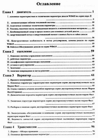
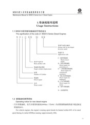
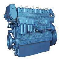
Каталог деталей тяжелого автомобиля Sinotruk HOWO
Формат: pdf
-
Год:
2008
-
Страниц:
698
-
Язык:
русский
-
Размер:
57,2 Мб
-
Категории:
Владельцы грузовиков HOWO могут воспользоваться данным каталогом для получения информации о своем автомобиле. Это отличный каталог, который содержит подробные схемы деталей и таблицы с их номерами.
46,5 Мб
Руководство по эксплуатации и техническому обслуживанию
Формат: pdf
-
Год:
2007
-
Страниц:
312
-
Язык:
русский
-
Размер:
46,5 Мб
-
Категории:
Отличное руководство для автовладельцев HOWO, которое поможет вам очень быстро отыскать поломку, чтобы заняться ее устранением. К тому же, в руководстве приведено много информации по ремонту и эксплуатации автомобиля.
21,6 Мб
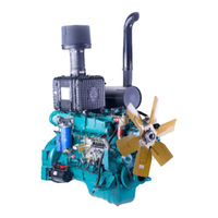
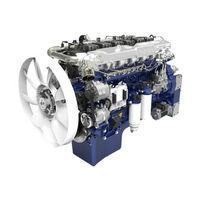
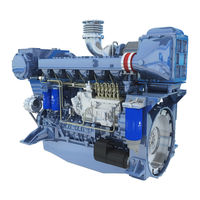
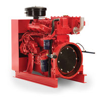
Каталог деталей дизельного двигателя Weichai (Steyr) WD615
Формат: doc
-
Год:
2008
-
Страниц:
66
-
Язык:
русский, английский
-
Размер:
21,6 Мб
-
Категории:
Издание предлагает ознакомиться с техническими характеристиками Weichai (Steyr) WD615 – двигателя известного как Steyr (модификационное название) и широко распространенного во всем мире, в том числе и у нас.
42 Мб
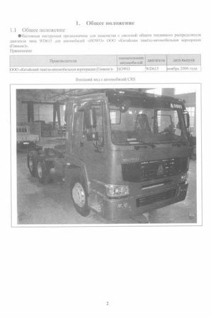
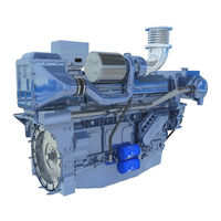
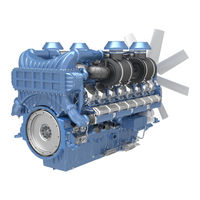
Cистема питания дизельных двигателей Weichai WD615 на
Формат: pdf
-
Год:
2006
-
Страниц:
294
-
Язык:
русский
-
Размер:
42 Мб
-
Категории:
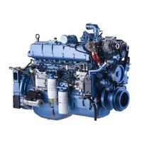
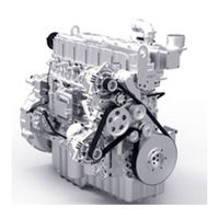
Компания HOWO является лидером в сфере производства двигателей для грузовиков. Дизели данной марки широко известны как в ряде азиатских государств, так и в России. Неплохое качество и прекрасная производительность гарантирует двигателям заслуженную популярность.
- Manuals
- Brands
- WEICHAI Manuals
- Engine
- WP6GNA
- Assembly/disassembly manual
-
Contents
-
Table of Contents
-
Bookmarks
Quick Links
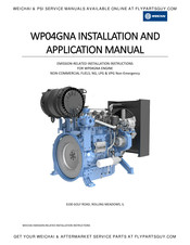
WEICHAI & PSI SERVICE MANUALS AVAILABLE ONLINE AT FLYPARTSGUY.COM
Assembly & Disassembly Manual
Gas Engine
Model: WP6GNA
WEICHAI AMERICA CORP.
Related Manuals for WEICHAI WP6GNA
Summary of Contents for WEICHAI WP6GNA
-
Page 1
WEICHAI & PSI SERVICE MANUALS AVAILABLE ONLINE AT FLYPARTSGUY.COM Assembly & Disassembly Manual Gas Engine Model: WP6GNA WEICHAI AMERICA CORP. -
Page 2
Weichai America Corp. Purpose This manual is intended to inform customers on how to assemble and disassemble the Weichai America 6 Liters naturally aspirated engine. This document will be provided to customer so they can incorporate this information into their manuals and service documents. -
Page 3: Table Of Contents
WEICHAI & PSI SERVICE MANUALS AVAILABLE ONLINE AT FLYPARTSGUY.COM Weichai America Corp. Table of Contents Disassembly & Assembly of Engine ………………5 1.1 Safety Precautions ………………….5 1.2 Environmental Protection Measures …………….. 5 1.3 Notes for Disassembly and Assembly of Engine …………… 5 Fuel System …………………….
-
Page 4
WEICHAI & PSI SERVICE MANUALS AVAILABLE ONLINE AT FLYPARTSGUY.COM Weichai America Corp. 7.2 Fan Assembly and Disassembly ………………27 7.3 Thermostat Disassembly and Assembly …………….. 28 7.4 Water Pump Assembly and Disassembly …………… 29 Front Cover Components ………………..30 8.1 Torque Vibration Damper and Crankshaft Pulley Assembly and Disassembly ….30 8.2 Gear Housing Assembly and Disassembly ………….. -
Page 5
WEICHAI & PSI SERVICE MANUALS AVAILABLE ONLINE AT FLYPARTSGUY.COM Weichai America Corp. 11.4 Assembly and disassembly of crank-rod mechanism……….61 11.5 Assembly and disassembly of piston-rod assembly ……….61 11.6 Assembly and disassembly of crankshaft system ……….65 11.7 Assembly and disassembly of crankshaft bearing shell …….. -
Page 6: Disassembly & Assembly Of Engine
WEICHAI & PSI SERVICE MANUALS AVAILABLE ONLINE AT FLYPARTSGUY.COM Weichai America Corp. 1 Disassembly & Assembly of Engine Safety Precautions Please strictly comply with instructions in this manual to safely and properly disassemble and assemble the engine. Environmental Protection Measures Please comply with relevant laws and regulations on environmental protection when handling oil and hydrocarbon waste.
-
Page 7: Fuel System
WEICHAI & PSI SERVICE MANUALS AVAILABLE ONLINE AT FLYPARTSGUY.COM Weichai America Corp. 2 Fuel System Fuel System Assembly and Disassembly 2.1.1 Fuel System Exploded View Fig. 2-1 Exploded view of gas supply system 2.1.2 Fuel System Disassembly Procedure 1. Remove ECU.
-
Page 8: Lpg Intake System Assembly And Disassembly
WEICHAI & PSI SERVICE MANUALS AVAILABLE ONLINE AT FLYPARTSGUY.COM Weichai America Corp. LPG Intake System Assembly and Disassembly 2.2.1 LPG Intake System Exploded View Fig. 2-2 Exploded view of LPG supply system 2.2.2 LPG Intake System Disassembly Procedure 1. Remove the clamps from the gas hose. Separate the hose from the NG intake system.
-
Page 9: Ng Shut-Off Valve Assembly And Disassembly
WEICHAI & PSI SERVICE MANUALS AVAILABLE ONLINE AT FLYPARTSGUY.COM Weichai America Corp. 2. Check the coolant fittings and hoses for leaks. NG Shut-Off Valve Assembly and Disassembly 2.3.1 NG Shut-Off Valve Exploded View Fig. 2-3 Exploded view of electromagnetic valve 2.3.2 NG Shut-Off Valve Disassembly Procedure…
-
Page 10: Electronic Pressure Regulator (Epr) Assembly And Disassembly
WEICHAI & PSI SERVICE MANUALS AVAILABLE ONLINE AT FLYPARTSGUY.COM Weichai America Corp. Electronic Pressure Regulator (EPR) Assembly and Disassembly 2.4.1 EPR Exploded View Fig. 2-4 Exploded view of electronic pressure regulating valve 2.4.2 EPR Disassembly Procedure 1. Remove the socket head bolts and washers bolting the gas pipe joint to the EPR.
-
Page 11
WEICHAI & PSI SERVICE MANUALS AVAILABLE ONLINE AT FLYPARTSGUY.COM Weichai America Corp. Fig. 2-5 Exploded view of mixer Part Name Part Name Part Name Screws Diaphragm Spring Mixer Cover Ring Adjustment Screw Air Fuel Regulator Spring Gasket Valve Diaphragm Screws… -
Page 12
WEICHAI & PSI SERVICE MANUALS AVAILABLE ONLINE AT FLYPARTSGUY.COM Weichai America Corp. Reverse the Disassembly Procedure (2.5.2) to assemble the Mixer Diaphragm. 2.5.4 Mixer Diaphragm Inspection and Maintenance If gas flow is insufficient: 1. Rotate the adjustment screw clockwise to increase the flow of gas. -
Page 13: Intake And Exhaust System
WEICHAI & PSI SERVICE MANUALS AVAILABLE ONLINE AT FLYPARTSGUY.COM Weichai America Corp. 3 Intake and Exhaust System Intake and Exhaust System Assembly and Disassembly 3.1.1 Intake and Exhaust System Exploded View Fig. 3-1 Exploded view of intake and exhaust system Fig.
-
Page 14
WEICHAI & PSI SERVICE MANUALS AVAILABLE ONLINE AT FLYPARTSGUY.COM Weichai America Corp. 3.1.2 Intake and Exhaust System Disassembly Procedure 1. Loosen the clamps on the air filter elbow, elbow pipe breather connection, and the mixer hose. Remove the air filter elbow, elbow pipe, and mixer hose. -
Page 15: Intake Manifold Assembly And Disassembly
WEICHAI & PSI SERVICE MANUALS AVAILABLE ONLINE AT FLYPARTSGUY.COM Weichai America Corp. Intake Manifold Assembly and Disassembly 3.2.1 Intake Manifold Exploded View Fig. 3-3 Exploded view of intake manifold 3.2.2 Intake Manifold Disassembly Procedure 1. Remove the nuts bolting the intake manifold to the engine block. Remove the intake manifold and gaskets.
-
Page 16
WEICHAI & PSI SERVICE MANUALS AVAILABLE ONLINE AT FLYPARTSGUY.COM Weichai America Corp. Fig. 3-4 Exploded view of exhaust manifold 3.3.2 Exhaust Manifold Disassembly Procedure CAUTION: All parts of the exhaust manifold and exhaust elbow will be extremely hot after engine operation. -
Page 17: Ignition System Assembly And Disassembly
WEICHAI & PSI SERVICE MANUALS AVAILABLE ONLINE AT FLYPARTSGUY.COM Weichai America Corp. 3. Do not reuse exhaust manifold attachment bolts more than twice. 3.3.4 Exhaust Manifold Inspection and Maintenance 1. Check for cracks in the exhaust manifold and deformations in the exhaust elbow flange. Replace the exhaust manifold and exhaust elbow if necessary.
-
Page 18: Signal Generator Assembly And Disassembly
WEICHAI & PSI SERVICE MANUALS AVAILABLE ONLINE AT FLYPARTSGUY.COM Weichai America Corp. Fig. 3-6 Exploded view of ignition system 3.4.2 Ignition System Disassembly Steps 1. Unplug the wiring harness connector from the ECU and ignition coil. 2. Remove ignition coil bolts and ignition coils.
-
Page 19
WEICHAI & PSI SERVICE MANUALS AVAILABLE ONLINE AT FLYPARTSGUY.COM Weichai America Corp. Fig. 3-7 Exploded view of signal generator 3.5.2 Signal Generator Disassembly Procedure 1. Remove the connecting bolts of the pump gear and signal generator. 2. Remove the hex nuts between signal generator flange and engine block. -
Page 20: Engine Control Unit (Ecu) Assembly And Disassembly
WEICHAI & PSI SERVICE MANUALS AVAILABLE ONLINE AT FLYPARTSGUY.COM Weichai America Corp. Engine Control Unit (ECU) Assembly and Disassembly 3.6.1 ECU Exploded View Fig. 3-8 Exploded view of 3.6.2 ECU Disassembly Procedure 1. Remove the fuse box bolts. Remove the fuse box from the bracket.
-
Page 21
WEICHAI & PSI SERVICE MANUALS AVAILABLE ONLINE AT FLYPARTSGUY.COM Weichai America Corp. electromagnetic torque. The ring gear mechanism drives the starting engine rotation. The starter motor’s main components are the DC motor, one-way clutch, reduction gear train, electromagnetic switches, and the starter relay. See the dismantled starting system in Fig. 4-1. -
Page 22: Engine Accessory System
WEICHAI & PSI SERVICE MANUALS AVAILABLE ONLINE AT FLYPARTSGUY.COM Weichai America Corp. 5 Engine Accessory System Engine Accessory System Assembly and Disassembly 5.1.1 Engine Accessory System Exploded View The engine accessory system consists primarily of the belt and alternator. Fig. 5-1 Exploded view of engine accessory system 5.1.2 Engine Accessory System Disassembly…
-
Page 23
WEICHAI & PSI SERVICE MANUALS AVAILABLE ONLINE AT FLYPARTSGUY.COM Weichai America Corp. Fig. 5-2 Exploded view of generator 5.2.2 Alternator Disassembly Procedure 1. Remove the alternator lock nut to loosen the belt if it has not already been removed. Remove the belt from the alternator pulley. -
Page 24: Closed Crankcase Ventilation (Ccv) Breather System Assembly And Disassembly
WEICHAI & PSI SERVICE MANUALS AVAILABLE ONLINE AT FLYPARTSGUY.COM Weichai America Corp. 6 Closed Crankcase Ventilation (CCV) Breather System Assembly and Disassembly CCV Breather System Assembly and Disassembly 6.1.1 CCV Breather System Exploded View Air Inlet Air Outlet Oil Return Fig.
-
Page 25: Ccv Breather Assembly And Disassembly
WEICHAI & PSI SERVICE MANUALS AVAILABLE ONLINE AT FLYPARTSGUY.COM Weichai America Corp. Hex Nut Rubber Hose Clamp Clamp Formed Hose Bolt Bracket Bolt Oil Return Pipe Hex Bolt Washer 6.1.2 CCV Breather System Disassembly Procedure 1. Loosen the clamps on the air outlet. Remove all air outlet formed and rubber hoses.
-
Page 26
WEICHAI & PSI SERVICE MANUALS AVAILABLE ONLINE AT FLYPARTSGUY.COM Weichai America Corp. Fig. 6-2 Exploded view of CCV breather Fig. 6-3 Schematic diagram of disassembly 6.2.2 CCV Breather Disassembly Open the top cover of the breather by tool or hand. Remove the breather filter element. -
Page 27: Cooling System
WEICHAI & PSI SERVICE MANUALS AVAILABLE ONLINE AT FLYPARTSGUY.COM Weichai America Corp. 7 Cooling System Cooling System Disassembly and Assembly 7.1.1 Cooling System Exploded View The cooling system ensures that the engine can operate at the proper operating temperature. Forced circulation cooling is most effective at keeping the engine within the normal operating temperature range.
-
Page 28: Fan Assembly And Disassembly
WEICHAI & PSI SERVICE MANUALS AVAILABLE ONLINE AT FLYPARTSGUY.COM Weichai America Corp. 7. Remove the middle cushion block of water pump. 7.1.3 Cooling System Assembly Procedure Reverse the Disassembly Procedure (7.1.2) to assemble the Cooling System. Fan Assembly and Disassembly 7.2.1 Fan Exploded View…
-
Page 29: Thermostat Disassembly And Assembly
WEICHAI & PSI SERVICE MANUALS AVAILABLE ONLINE AT FLYPARTSGUY.COM Weichai America Corp. Thermostat Disassembly and Assembly 7.3.1 Thermostat Exploded View Fig. 7-3 Exploded view of thermostat 7.3.2 Thermostat Disassembly Procedure 1. Loosen the clamps around the hose connecting the water pipe and thermostat. Remove the hose.
-
Page 30: Water Pump Assembly And Disassembly
WEICHAI & PSI SERVICE MANUALS AVAILABLE ONLINE AT FLYPARTSGUY.COM Weichai America Corp. Water Pump Assembly and Disassembly 7.4.1 Water Pump Exploded View Fig. 7-4 Exploded view of water pump 7.4.2 Water Pump Disassembly Procedure 1. Remove the water pump pulley.
-
Page 31: Front Cover Components
WEICHAI & PSI SERVICE MANUALS AVAILABLE ONLINE AT FLYPARTSGUY.COM Weichai America Corp. 8 Front Cover Components Torque Vibration Damper and Crankshaft Pulley Assembly and Disassembly 8.1.1 Torque Vibration Damper and Crankshaft Pulley Exploded View Fig. 8-1 Exploded view of damper, pulley, and hub 8.1.2 Torque Vibration Damper and Crankshaft Pulley Disassembly Procedure…
-
Page 32: Gear Housing Assembly And Disassembly
WEICHAI & PSI SERVICE MANUALS AVAILABLE ONLINE AT FLYPARTSGUY.COM Weichai America Corp. Tightening torque: 60~70Nm; Test value: 65~80Nm. 8.1.4 Torque Vibration Damper and Crankshaft Pulley Inspection and Maintenance 1. Check the crankshaft pulley for any damage and distortion. Replace if necessary.
-
Page 33
WEICHAI & PSI SERVICE MANUALS AVAILABLE ONLINE AT FLYPARTSGUY.COM Weichai America Corp. Bolt Bolt Front Oil Seal Bolt Shaft Bolt Intermediate Oil Fill Plug Shaft Intermediate Gear Washer Plate Stud Bolt Bolt 8.2.2 Gear Housing Disassembly Procedure 1. Remove the intermediate gear. -
Page 34
WEICHAI & PSI SERVICE MANUALS AVAILABLE ONLINE AT FLYPARTSGUY.COM Weichai America Corp. Fig. 8-3 Locating pin installation for Gear Housing (2) Apply sealant on the sealing surface of the Gear Housing. Ensure that the sealant is evenly distributed and continuous. -
Page 35: Intermediate Gear Assembly And Disassembly
WEICHAI & PSI SERVICE MANUALS AVAILABLE ONLINE AT FLYPARTSGUY.COM Weichai America Corp. Fig. 8-5 Gear Housing installation (4) Place the bolts with gaskets in their corresponding holes. Tighten them with a pneumatic impact wrench and an open-end wrench. Key Point 2: Assembling: Oil seals and seal rings should be checked before assembling.
-
Page 36
WEICHAI & PSI SERVICE MANUALS AVAILABLE ONLINE AT FLYPARTSGUY.COM Weichai America Corp. Fig. 8-6 Exploded view of intermediate gear 8.3.2 Intermediate Gear Disassembly Procedure 1. Locate the four M10 bolts to be removed. 2. Remove four bolts and the washer. -
Page 37: Cylinder Heads And Valves
WEICHAI & PSI SERVICE MANUALS AVAILABLE ONLINE AT FLYPARTSGUY.COM Weichai America Corp. or pin-shaft for any wear. Check the oil passage for any blockage. 9 Cylinder Heads and Valves Lifting Lugs Assembly and Disassembly 9.1.1 Lifting Lugs Exploded View Fig. 9-1 Exploded view of lifting lugs 9.1.2 Lifting Lugs Disassembly Procedure…
-
Page 38
WEICHAI & PSI SERVICE MANUALS AVAILABLE ONLINE AT FLYPARTSGUY.COM Weichai America Corp. Fig. 9-2 Exploded view of cylinder head cover 9.2.2 Cylinder Head Cover Disassembly Procedure 1) Loosen the cylinder head cover bolts. Remove the bolts and the washers. 2) Pull the covers up vertically to remove them. Remove all gaskets. -
Page 39: Rocker And Rocker Shaft Assembly And Disassembly
WEICHAI & PSI SERVICE MANUALS AVAILABLE ONLINE AT FLYPARTSGUY.COM Weichai America Corp. Rocker and Rocker Shaft Assembly and Disassembly 9.3.1 Rocker and Rocker Shaft Exploded View Fig. 9-3 Exploded view of rocker and rocker shaft 9.3.2 Rocker and Rocker Shaft Disassembly Procedure 1.
-
Page 40: Tappet And Pushrod Assembly And Disassembly
WEICHAI & PSI SERVICE MANUALS AVAILABLE ONLINE AT FLYPARTSGUY.COM Weichai America Corp. ⑤ Install valve pushrod, refer to assembly of valve pushrod for details; ① Pre-tighten rocker seat, align rocker adjusting screw socket head to valve pushrod round head, tighten the hexagon bolts to 40~45Nm.
-
Page 41
WEICHAI & PSI SERVICE MANUALS AVAILABLE ONLINE AT FLYPARTSGUY.COM Weichai America Corp. Fig. 9-4 Exploded view of tappet and pushrod 9.4.2 Tappet and Pushrod Disassembly Procedure 1. After removing rockers and rocker shafts, pull the pushrods out vertically. 2. After removing camshaft, directly take out valve tappet, place them orderly;… -
Page 42: Cylinder Heads Assembly And Disassembly
WEICHAI & PSI SERVICE MANUALS AVAILABLE ONLINE AT FLYPARTSGUY.COM Weichai America Corp. 2. Ensure that the oil channels of valve tappet and pushrod are smooth. 3. Ensure that the pushrod is not crooked. Check wear condition on the outside surface.
-
Page 43
WEICHAI & PSI SERVICE MANUALS AVAILABLE ONLINE AT FLYPARTSGUY.COM Weichai America Corp. 3. Remove the cylinder head gasket. If more than one cylinder head gasket needs to be disassembled, mark the cylinder number on the gaskets for reference. 4. Remove the intake and exhaust valve module. Refer to disassembly of valve mechanism (9.6) for details 5. -
Page 44
WEICHAI & PSI SERVICE MANUALS AVAILABLE ONLINE AT FLYPARTSGUY.COM Weichai America Corp. Clean the cylinder head, focusing on the combustion chamber surface, valve seat, intake and exhaust valves, and intake and exhaust passages. Remove the carbon deposits and mucilage glue, and check the surface condition. -
Page 45: Assembly And Disassembly Of Valve
WEICHAI & PSI SERVICE MANUALS AVAILABLE ONLINE AT FLYPARTSGUY.COM Weichai America Corp. 3. Clearance between valve rod and valve guide pipe: Internal surface of valve guide pipe is the contacting surface between valve rod and valve guide pipe, if clearance between valve rod and valve guide pipe exceeds allowed value due to abrasion, then the guide effect will at state, which may affect reliability of the engine.
-
Page 46
WEICHAI & PSI SERVICE MANUALS AVAILABLE ONLINE AT FLYPARTSGUY.COM Weichai America Corp. Fig. 9- 9 Exploded view of valve 9.6.2 Steps to disassemble valve ① Depress valve springs with vale spring compressor or valve overhead plier or other tools, take out valve lock clamp, upper valve spring seat and lower valve spring seat and valve springs orderly;… -
Page 47
WEICHAI & PSI SERVICE MANUALS AVAILABLE ONLINE AT FLYPARTSGUY.COM Weichai America Corp. 9.6.4 Inspection and maintenance of valve ① Check whether valve rod and its end faces are worn; ② Check whether valve conical surface is worn or damaged; ③ Check valve conical surface and retainer end faces for carbon deposit;… -
Page 48: Oil & Lubrication System
WEICHAI & PSI SERVICE MANUALS AVAILABLE ONLINE AT FLYPARTSGUY.COM Weichai America Corp. 10 Oil & Lubrication System 10.1 Assembly and disassembly of oil sump. 10.1.1 Exploded view of oil sump. Fig. 10-1 Exploded view of oil sump 10.1.2 Steps to disassemble oil sump.
-
Page 49: Disassembly And Assembly Of Engine Oil Strainer
WEICHAI & PSI SERVICE MANUALS AVAILABLE ONLINE AT FLYPARTSGUY.COM Weichai America Corp. Apply sealant on fitting surface of engine block and partially apply sealant on oil sump, place sealing gasket on the fitting surface. Lift and place oil sump, be careful and avoid crashing the fitting surface.
-
Page 50: Disassembly And Assembly Of Lubricating System
WEICHAI & PSI SERVICE MANUALS AVAILABLE ONLINE AT FLYPARTSGUY.COM Weichai America Corp. 10.3 Disassembly and Assembly of Lubricating System 10.3.1 Exploded View of Lubricating System Fig. 10-3 Exploded view of lubricating system 10.3.2 Steps to Disassemble Lubricating System ① Remove oil sump, refer to disassembly of oil sump for details.
-
Page 51
WEICHAI & PSI SERVICE MANUALS AVAILABLE ONLINE AT FLYPARTSGUY.COM Weichai America Corp. Fig. 10- 4 Exploded view of piston nozzle 10.4.2 Steps to disassemble piston nozzle. ① Remove the hexagon bolt (key point 1) ② Remove the piston nozzle (key point 2) 10.4.3 Steps to assemble piston nozzle… -
Page 52: Disassembly And Assembly Of Engine Oil Pump
WEICHAI & PSI SERVICE MANUALS AVAILABLE ONLINE AT FLYPARTSGUY.COM Weichai America Corp. 10.5 Disassembly and Assembly of Engine Oil Pump 10.5.1 Exploded View of Engine Oil Pump Fig. 10-5 Exploded view of engine oil pump 10.5.2 Steps to Disassemble Engine Oil Pump Remove the two hexagon bolts and self-locking nut, take down engine oil pump, as shown in Fig.
-
Page 53: Disassembly And Assembly Of Engine Oil Cooler
WEICHAI & PSI SERVICE MANUALS AVAILABLE ONLINE AT FLYPARTSGUY.COM Weichai America Corp. Fig. 10-6 Exploded view of engine oil filter 10.6.2 Steps to Disassemble Engine Oil Filter Remove the filter with dedicated tool, as shown in Fig. 10-6. 10.6.3 Steps to Assemble Engine Oil Filter 1) Check the O-shape seal ring of engine oil filter before assembling, make sure there is no manufacturing defect and damage, replace the O-ring if necessary.
-
Page 54: Disassembly And Assembly Of Main Oil Gallery Pressure Limiting Valve
WEICHAI & PSI SERVICE MANUALS AVAILABLE ONLINE AT FLYPARTSGUY.COM Weichai America Corp. Fig. 10-7 Exploded view of engine oil cooler 10.7.2 Steps to Disassemble Engine Oil Cooler Loose the connecting bolts and take down the cooler, as shown in Figure 10-7.
-
Page 55: Disassembly And Assembly Of Deputy Oil Pressure Limiting Valve
WEICHAI & PSI SERVICE MANUALS AVAILABLE ONLINE AT FLYPARTSGUY.COM Weichai America Corp. Fig. 10-8 Exploded View of Main Oil Gallery Pressure Limiting Valve 10.8.2 Steps to Disassemble Main Oil Gallery Pressure Limiting Valve Screw off main oil gallery pressure limiting valve, as shown in Fig. 10-8 10.8.3 Steps to Assemble Main Oil Gallery Pressure Limiting Valve…
-
Page 56: Crank-Rod Mechanism
WEICHAI & PSI SERVICE MANUALS AVAILABLE ONLINE AT FLYPARTSGUY.COM Weichai America Corp. Fig. 10-9 Exploded view of deputy oil pressure limiting valve 10.9.2 Steps to Disassemble Deputy Oil Pressure Limiting Valve Screw off and take down deputy oil pressure limiting valve, as shown in Fig. 10-9.
-
Page 57
WEICHAI & PSI SERVICE MANUALS AVAILABLE ONLINE AT FLYPARTSGUY.COM Weichai America Corp. Fig. 11-1 Exploded view of flywheel housing 11.1.2 Steps to disassemble flywheel housing ① Remove fixing bolts of flywheel housing (Key point 1). ② Remove speed sensor ③… -
Page 58: Assembly And Disassembly Of Flywheel And Ring Gear
WEICHAI & PSI SERVICE MANUALS AVAILABLE ONLINE AT FLYPARTSGUY.COM Weichai America Corp. flywheel housing and engine block. Bolts and tools: M10-10.9 hexagon bolts (×12), M12-10.9 hexagon bolts (×6), 17mm and 19mm socket spanner. Step 1: Preassemble the bolts Step 2: Follow the sequence of arrow to tighten the M10 bolts, tighten torque for M10 bolts is 80~85Nm.
-
Page 59
WEICHAI & PSI SERVICE MANUALS AVAILABLE ONLINE AT FLYPARTSGUY.COM Weichai America Corp. Fig. 11 — 2 Exploded view of flywheel and ring gear 11.2.2 Steps to disassemble flywheel and ring gear Disassembling steps are contrary to assembling ones. 11.2.3 Steps to assemble flywheel and ring gear. -
Page 60: Assembly And Disassembly Of Front Oil Seal And Rear Oil Seal
WEICHAI & PSI SERVICE MANUALS AVAILABLE ONLINE AT FLYPARTSGUY.COM Weichai America Corp. ③ Check whether flywheel ring gear is damaged. 11.3 Assembly and disassembly of front oil seal and rear oil seal 11.3.1 Exploded view of front oil seal and rear oil seal.
-
Page 61
WEICHAI & PSI SERVICE MANUALS AVAILABLE ONLINE AT FLYPARTSGUY.COM Weichai America Corp. Assembling 1) Clean the junction surface and install 2 pins into engine body. 2) Apply sealant on the junction surface of rear oil seal cover. 3) Apply oil on surface of crankshaft flange, assemble rear oil seal and tighten bolt. Bolt tightening sequence is: 1-2-6-7-3-4-5-8-9-10。… -
Page 62: Assembly And Disassembly Of Crank-Rod Mechanism
WEICHAI & PSI SERVICE MANUALS AVAILABLE ONLINE AT FLYPARTSGUY.COM Weichai America Corp. 11.4 Assembly and disassembly of crank-rod mechanism. 11.4.1 Exploded view of crank-rod mechanism. Fig. 11-5 Exploded view of crank-rod mechanism 11.4.2 Steps to disassemble crank-rod mechanism ① Check before disassembling. Check connecting rod axial backlash, check tightening torque of connecting rod bolts;…
-
Page 63
WEICHAI & PSI SERVICE MANUALS AVAILABLE ONLINE AT FLYPARTSGUY.COM Weichai America Corp. Fig.11-6 Schematic diagram of piston-rod assembly Fig. 11-7 Exploded view of piston-rod assembly 11.5.2 Steps to disassemble piston-rod assembly 1) Check before disassembling. Check connecting rod axial backlash, check tightening torque of connecting rod bolts;… -
Page 64
WEICHAI & PSI SERVICE MANUALS AVAILABLE ONLINE AT FLYPARTSGUY.COM Weichai America Corp. 2) Tilt and lay the engine on its side, rotate the flywheel until the to-be removed piston is in BDC, and then remove connecting rod bolts and cap;… -
Page 65
WEICHAI & PSI SERVICE MANUALS AVAILABLE ONLINE AT FLYPARTSGUY.COM Weichai America Corp. 120° to that of the first compression ring, and opening direction of oil ring should be 120° to both that of first compression ring and second compression ring, also should be perpendicular to piston pin center line. -
Page 66: Assembly And Disassembly Of Crankshaft System
WEICHAI & PSI SERVICE MANUALS AVAILABLE ONLINE AT FLYPARTSGUY.COM Weichai America Corp. 11.5.4 Inspection and maintenance of piston-rod assembly 1) Check whether there is crack on combustor throat fillet and piston pin boss; Check piston skirt and piston head for cylinder scoring phenomenon; Check wear condition of piston pin hole.
-
Page 67
WEICHAI & PSI SERVICE MANUALS AVAILABLE ONLINE AT FLYPARTSGUY.COM Weichai America Corp. ② Take down crankshaft and flywheel, remove front and rear thrust plates and flywheel bearing. Remove oil seals; place the crankshaft on bracket (for long time storage, the crankshaft should be placed vertical);… -
Page 68
WEICHAI & PSI SERVICE MANUALS AVAILABLE ONLINE AT FLYPARTSGUY.COM Weichai America Corp. ⑨ Press lower bearing shell and lower thrust plate (the side with oil groove should face crankshaft) into crankcase and assemble the crankshaft. ⑩ Apply clean lubricating oil on crankcase bolt bearing surface and main bearing bolt thread. -
Page 69: Assembly And Disassembly Of Crankshaft Bearing Shell
WEICHAI & PSI SERVICE MANUALS AVAILABLE ONLINE AT FLYPARTSGUY.COM Weichai America Corp. 11.7 Assembly and disassembly of crankshaft bearing shell 11.7.1 Exploded view of crankshaft bearing shell Fig. 11- 11 Exploded view of crankshaft bearing shell 11.7.2 Steps to disassemble crankshaft bearing shell Push the shells out with hand, and mark the removed shells (should be corresponded with holes on engine block and crankcase).
-
Page 70: Assembly And Disassembly Of Thrust Plates
WEICHAI & PSI SERVICE MANUALS AVAILABLE ONLINE AT FLYPARTSGUY.COM Weichai America Corp. 11.8 Assembly and disassembly of thrust plates. 11.8.1 Exploded view of thrust plates. Fig. 11- 12 Exploded view of thrust plates 11.8.2 Steps to disassemble thrust plates ①…
-
Page 71: Assembly And Disassembly Of Camshaft
WEICHAI & PSI SERVICE MANUALS AVAILABLE ONLINE AT FLYPARTSGUY.COM Weichai America Corp. 11.9 Assembly and disassembly of camshaft 11.9.1 Exploded view of camshaft Fig. 11- 13 Exploded view of camshaft 11.9.2 Steps to disassemble camshaft Disassembling steps are contrary to assembling ones.
-
Page 72
WEICHAI & PSI SERVICE MANUALS AVAILABLE ONLINE AT FLYPARTSGUY.COM Weichai America Corp. ④ Install gaskets, flange, washers and hexagon bolts on camshaft threaded end. Measure the axial clearance of camshaft, which should be 0.1~0.29mm, if the clearance is too small, check whether there is burr between camshaft and sector plate. -
Page 73: Engine Block Assembly
WEICHAI & PSI SERVICE MANUALS AVAILABLE ONLINE AT FLYPARTSGUY.COM Weichai America Corp. Rotate crankshaft to check whether 0 tick of each gear is normally engaged. 11.9.4 Inspection and maintenance of camshaft ① Check whether there is wear trace on cam face that contacting tappet, check main journal for seizure and abrasion.
-
Page 74
WEICHAI & PSI SERVICE MANUALS AVAILABLE ONLINE AT FLYPARTSGUY.COM Weichai America Corp. Cup pulg Camshaft bushing Stud Camshaft Camshaft bushing Cup plug bushing Cylinder liner Dipstick O seal ring Plug O seal ring Stud Seal plug Cup plug Stud Rivet washer 12.1.2 Steps to disassemble engine block:… -
Page 75
WEICHAI & PSI SERVICE MANUALS AVAILABLE ONLINE AT FLYPARTSGUY.COM Weichai America Corp. a. Pre-tighten to 30N.m b. turn 120°±4° c. turn 120°±4° again. The figure below show the tightening sequence of cylinder head bolt in every cylinder head. (3) The tightening sequence of cylinder head is:… -
Page 76: Steps To Assemble And Disassemble Engine Block Module
WEICHAI & PSI SERVICE MANUALS AVAILABLE ONLINE AT FLYPARTSGUY.COM Weichai America Corp. Place cylinder sleeve vertically on engine block, install seal rings on the sleeve and engine block and then assemble the sleeve, knock it to the right place evenly with nylon rod.
-
Page 77
WEICHAI & PSI SERVICE MANUALS AVAILABLE ONLINE AT FLYPARTSGUY.COM Weichai America Corp. Fig. 12-2 Exploded view of engine block 12.2.2 step to disassemble Engine Block Module (1) Remove main bearing bolts (key point 1); (2) Remove main bearing caps (key point 2);… -
Page 78
WEICHAI & PSI SERVICE MANUALS AVAILABLE ONLINE AT FLYPARTSGUY.COM Weichai America Corp. For 6-cylinder engine, 14 M14-10.9 main bearing bolts are used to fix the bearings. As shown in Fig. 4-3, start with middle bearings, do the tightening work from middle to two ends evenly, follow the procedures below: Firstly pre-tighten each bolt to 70Nm, and tighten the bolts for further 90°±4°. -
Page 79
WEICHAI & PSI SERVICE MANUALS AVAILABLE ONLINE AT FLYPARTSGUY.COM Weichai America Corp. 13 APPENDIX A Appendix A: Torsional Torque and Tightening Method for Main Bolts and Nuts Bolts Bolts Specification Tightening torque(N·m) Inspect value (N·m) Intake manifold bolt 45~50 40~60 Exhaust manifold bolt 45~50… -
Page 80
WEICHAI & PSI SERVICE MANUALS AVAILABLE ONLINE AT FLYPARTSGUY.COM Weichai America Corp. 14 APPENDIX B Appendix B: Tolerance Clearance for Main Parts of Gas Engine (Reference value) Items Theoretical value (mm) Main bearing clearance 0.05~0.11 Connecting rod bearing clearance 0.045~0.09 Crankshaft axial clearance 0.04~0.25… -
Page 81
WEICHAI & PSI SERVICE MANUALS AVAILABLE ONLINE AT FLYPARTSGUY.COM Weichai America Corp. 15 APPENDIX C Appendix C: The Evaluation Criteria for Main Friction Wear of Gas Engine (Reference value) Wear limit Clearance limit Parts life (mm) (mm) (hours) Closed clearance of the first (top) ring 1.70… -
Page 82
WEICHAI & PSI SERVICE MANUALS AVAILABLE ONLINE AT FLYPARTSGUY.COM Weichai America Corp. 3100 Golf Road Rolling Meadows, IL 60008 http://www.WeichaiAmerica.com/…
|
View errors |
The corresponding element in the |
Questions |
The cause of the error |
Method of eliminating |
Error code |
||
|
Errors associated with starting the engine |
AD converter malfunction in ECU |
ECU. Error in signal processing has led to failure, did not even start the engine. |
|
Replacing The ECU |
1 |
1 |
1 |
|
Bug synchronous signals |
Signal synchronization errors can lead to abnormal fuel injection, hard starting, exhaust black smoke, abnormal noise of engine etc. |
Error signals measured sensor crankshaft or camshaft speed sensor |
Check connections and crankshaft sensor. Check the clearances of the crankshaft sensor and the flywheel within 1.0 ± 0.5 mm |
1 |
1 |
2 |
|
|
1 |
1 |
3 |
|||||
|
1 |
1 |
4 |
|||||
|
Item error processing time at ECU |
Engine stalls, won’t start |
|
Replace The ECU |
1 |
1 |
5 |
|
|
|
Lack of engine power |
|
Switch off the power and ECU reset ECU, if the problem is not resolve itself, replace the ECU |
1 |
1 |
6 |
|
|
Error starting relay |
The engine does not start. |
Damage to the wiring harness, damage the actuator relay |
Check the Starter relay and its circuit |
1 |
2 |
1 |
|
|
Switch error T15 |
|
|
Check breaker T15 |
1 |
2 |
2 |
|
|
Switch error T50 |
|
Activation switch more 120s |
Check the switch T50 |
1 |
2 |
3 |
|
|
Battery |
Power fault |
Battery voltage too high (> 36V) or too low (< 6V) |
Check the wiring harness battery, engine and car |
1 |
2 |
4 |
|
|
Pulse spectrum diagram FMTC |
|
Error setting |
Change setting |
1 |
2 |
5 |
|
|
The power supply of the sensor in ECU |
Error in ECU or short circuit pressure sensor inlet (2.33), oil pressure sensor (2.32) with power car (24V) or grounding |
Check the wiring harnesses, pressure sensors, inlet oil pressure (maximum current supply 90mA) |
1 |
3 |
1 |
||
|
Lack of engine power |
Error in ECU or KZ supply (1.84) sensor no. 2 accelerator pedal |
Check sensor no. 2 accelerator pedal (maximum current supply for SSP2 90mA) |
|||||
|
Lack of engine power |
Error in ECU or shorted power supply (1.84) sensor no. 1 pedal or SHORT CIRCUIT pressure sensor line (2.13) |
Check sensor no. 1 pedal pressure sensor line (SSP3 power Max current 50mA) |
|||||
|
Error main relay |
General pipe pressure limiting valve (PRV) is open, the engine’s lack of |
Short circuit element flow measurement (3.09 3.10) |
Check wires on flow sensor SHORT CIRCUIT or open circuit |
1 |
3 |
2 |
|
|
Output short circuit power supply ECU (1.04 2.03) |
Check the wires for the presence of: 2.03 1.04? CZ (Note: you must use the power output of the ECU is not allowed to use external power |
||||||
|
The relevant elements of the common system backbone |
Pressure sensor line |
Open the pressure limiting valve tubes General Highway |
Flow measurement element damage or SHORT-CIRCUITS, open circuit |
Check flow measurement items and a bunch of wires on the presence of a SHORT CIRCUIT or breakage |
1 |
3 |
3 |
|
Faulty pressure limiting valve common Highway |
The issue of fuel lines. Pressure sensor line, the element flow measurement, occlusion and bypass the supplied fuel will lead to too many |
Check out toplioprovody and a pressure sensor line, flow measurement element |
1 |
3 |
4 |
||
|
Flow dimension member error |
Flow measurement element is damaged or kz, open circuit wiring harness |
Check flow measurement elements and a bundle of wires |
1 |
3 |
5 |
||
|
General line item |
Dekompressirovanija valve for line pipes |
Serious valve wear dekompressirovanija causes abnormal fluctuation of pressure line |
Occlusion the low pressure fuel line (including the fuel feed and bypass fuel) causes frequent opening or opening the valve of dekompressirovanija |
Replace the ramp |
1 |
3 |
6 |
|
Injector |
Error injector cylinder 1 |
Lack of engine power, unstable (engine troit) |
Bad contact harnesses atomizers or breakage of the wires |
Check wiring harness and their connection with nozzle |
1 |
4 |
1 |
|
Error injector cylinder 2 |
1 |
4 |
2 |
||||
|
Error injector cylinder 3 |
1 |
4 |
3 |
||||
|
Error injector cylinder 4 |
1 |
4 |
4 |
||||
|
Error injector cylinder 5 |
1 |
4 |
5 |
||||
|
Error injector cylinder 6 |
1 |
4 |
6 |
||||
|
Capacitor control injector |
Error 1 condenser control nozzles 1.2.3 |
1 |
5 |
1 |
|||
|
Error 1 condenser control nozzles 4.5.6 |
1 |
5 |
2 |
||||
|
Chip injection |
Injector control chip error |
1 |
5 |
3 |
|||
|
Injection |
Does not reach the minimum number of normal working nozzles |
Stopping the engine |
Short-circuit or disconnection harnesses more than 3 cylinders |
Check wiring harness injectors each cylinder |
1 |
5 |
4 |
|
Limitation of nozzles in ECU |
|
|
|
1 |
5 |
5 |
|
|
The important switches, sensors |
Water in fuel |
Water content indicator lamp in the fuel burning, the water level alarm |
Diesel fuel coarse purification filter filled with water |
Drain the water from diesel fuel |
2 |
1 |
1 |
|
Sensor error 1 pedals |
Revolutions of the crankshaft around 1000 rpm |
Open circuit or defective accelerator pedal |
Check the chain on the presence of breakage and SHORT CIRCUIT, Replace the accelerator pedal |
2 |
2 |
1 |
|
|
Sensor error 2 pedals |
|||||||
|
Clutch sensor error |
Cruise cannot be executed |
Faulty sensors or open circuit |
Check sensor wiring harness |
2 |
2 |
3 |
|
|
Brake switch error |
2 |
2 |
3 |
||||
|
Brake switch error |
Activating the brake fails, it is not allowed to carry out cruise |
Before the cruise, you should press the brake pedal |
2 |
2 |
3 |
||
|
Confidence check error valve gas and brake |
|
Simultaneous pressing the pedal of acceleration and brake pedals |
Check the chain sensor brakes on presence of CZ |
2 |
2 |
5 |
|
|
Motor protection |
|
Overclocking engine (> 2650rpm) |
|
2 |
2 |
6 |
|
|
|
|
|
2 |
2 |
7 |
||
|
Reconfiguring the engine torque |
Not successfully increase torque |
Too large an input torque transmission box |
|
2 |
2 |
8 |
|
|
Remote valve gas pedal |
Not effect pedal remote gas valve |
Sensor error valve gas pedal or short circuit, open wire harnesses |
Check the sensor wire harness, if necessary replacement pedals gas valve |
2 |
2 |
9 |
|
|
Inlet pressure sensor |
Emergency towing |
Sensor error or short circuit, open circuit |
Check the sensor wire harness, if necessary, replace the sensor |
2 |
3 |
1 |
|
|
Atmospheric pressure sensor |
This sensor installed on the ECU, check the likelihood of clogging |
2 |
3 |
2 |
|||
|
Intake temperature sensor |
Check the sensor wire harness, if necessary, replace the sensor |
2 |
3 |
3 |
|||
|
Coolant temperature sensor |
Emergency towing is not the normal operation of the heater air inlet |
Check the sensor wire harness, if necessary, replace the sensor |
2 |
4 |
1 |
||
|
Coolant temperature too high |
When the coolant temperature is above 105 degrees, the engine is operated with limited capacity |
Coolant temperature too high |
Check engine cooling system |
2 |
4 |
2 |
|
|
Oil pressure too high |
Oil pressure distortion if the device uses a CAN bus |
Error sensor oil pressure or oil pressure too high |
Too high oil temperature |
2 |
4 |
3 |
|
|
Oil pressure too low |
|
Oil pressure too low |
|||||
|
Oil temperature sensor |
|
Too high oil temperature |
2 |
4 |
4 |
||
|
Too high oil temperature alarm |
|
Too high oil temperature |
|||||
|
Test water temperature sensor |
|
|
|
2 |
4 |
5 |
|
|
Monitoring of fuel pressure in the line |
High-pressure fuel line issue/low pressure fuel line (leaked) |
Hard start, will not start. Open the pressure limiting valve, leaking large amount of high-pressure fuel |
Too much flow resistance of fuel or fuel leaks. |
Check the fuel lines to the engine. If you need replacement filters, fuel line, etc. |
2 |
5 |
1 |
|
2 |
5 |
2 |
|||||
|
2 |
5 |
3 |
|||||
|
2 |
5 |
4 |
|||||
|
2 |
5 |
5 |
|||||
|
2 |
5 |
6 |
|||||
|
2 |
5 |
7 |
|||||
|
ECU |
ECU system return to its original position |
Open the pressure limiting valve, emergency towing |
Internal error in ECU |
After disconnecting the AC switch. If the matter is not resolved, you should replace the ECU |
2 |
6 |
1 |
|
|
Test on overclocking |
|
|
|
2 |
6 |
2 |
|
ECU check and measurement equipment internal ECU |
Chip CJ940 |
Engine ignition fault |
Communication error |
After disconnecting the current restart System |
2 |
6 |
3 |
|
Too high tension |
|||||||
|
Too low internal stress |
|||||||
|
ECU chip and Watchdog |
Fault ignition engine (after AC restart) |
Communication error |
2 |
6 |
4 |
||
|
EEPROM (erasable programmable read only memory) |
On kilometre information may not be registered |
|
Replacing The ECU |
2 |
6 |
5 |
|
|
ECU functions and switches |
Solenoid valve exhaust brake |
Exhaust brake is defective |
Short circuit motor brake solenoid valve (2.06) with meals |
Check the exhaust brake solenoid valve circuit |
3 |
1 |
1 |
|
Short circuit motor brake solenoid valve (2.06) weighing |
|||||||
|
AC Compressor Relay |
AC compressor not working |
Error connecting AC Compressor Relay |
Check the relay and its compounds |
3 |
1 |
3 |
|
|
Inlet heating relay |
Heating air inlet may not function correctly. |
Short circuit relay with ground or power |
To verify a connection relay heating air inlet |
3 |
2 |
1 |
|
|
|
|
3 |
2 |
2 |
|||
|
3 |
2 |
3 |
|||||
|
Vehicle speed sensor |
May not be a cruise out of the car button has no effect |
Exceeding the maximum speed of the car or not reliable signals of the speed of the car, not a stable voltage |
Check the vehicle speed sensor connection, if necessary, replace the sensor |
3 |
2 |
4 |
|
|
Many provisions of the switch |
Torque limitation, limiting speed and other functions cannot be performed |
Error wiring harnesses or resistor |
Error wiring harnesses or resistor |
3 |
2 |
7 |
|
|
Lamp system |
The indicator function of the respective lamps are not met |
Connection failed or connection is not implemented |
Test connection |
3 |
3 |
1 |
|
|
Lamp cold start |
3 |
3 |
2 |
||||
|
Signal lamp |
3 |
3 |
3 |
||||
|
Water in fuel lamp |
3 |
3 |
4 |
||||
|
Cruise switch |
May not be a cruise/PTO, or cruise/PTO goes out of action |
Cruise switch error |
It is recommended that you switch samovosstanovitelnyj |
3 |
4 |
1 |
|
|
Exhaust brake switch |
|
|
|
3 |
4 |
2 |
|
|
Switch out of the car |
Start without a car could not be implemented |
Sticking switch |
Check the circuit breaker or circuit wires |
3 |
4 |
3 |
|
|
External dimension |
Check Disable ignition |
Lack of engine power, not stable operation |
Disabling cylinder No. 1 |
Check the appropriate nozzle, sealing lid cylinder, valve clearance, etc. |
5 |
1 |
1 |
|
Disabling cylinder No. 2 |
5 |
1 |
2 |
||||
|
Disabling cylinder # 3 |
5 |
1 |
3 |
||||
|
Disabling multiple cylinders |
5 |
1 |
4 |
||||
|
Disabling cylinder No. 4 |
5 |
3 |
1 |
||||
|
Disabling cylinder # 5 |
5 |
3 |
2 |
||||
|
Disabling cylinder # 6 |
5 |
3 |
3 |
||||
|
External dimension |
|
|
|
5 |
3 |
4 |
|
|
These faults relate to functional indication. When applying the diagnostic tool for the revitalization of internal measuring functions will turn |
5 |
2 |
1 |
||||
|
5 |
2 |
2 |
|||||
|
5 |
2 |
3 |
|||||
|
Issues related to starting |
The issue of synchronous signals |
|
Poor surface of the teeth of the flywheel |
Replacement flywheel |
5 |
4 |
1 |
- Manuals
- Brands
- WEICHAI Manuals
- Engine
ManualsLib has more than 41 WEICHAI Engine manuals
Click on an alphabet below to see the full list of models starting with that letter:
B
D
R
W
Popular manuals

75 pages
WD615 Manual
163 pages
WD10 Service Manual
57 pages
WP12 Operating Instructions Manual
33 pages
WP10 Operation And Maintenance Manual
38 pages
WP13 Series Operation And Maintenance Manual
53 pages
WP10 Series Operation And Maintenance Manual
25 pages
WP13C450-18 Operation And Maintenance Manual
17 pages
WP12C500 Operation And Maintenance Manual
33 pages
WP13 Operation And Maintenance Manual

90 pages
WP6GTA Assembly/Disassembly Manual

82 pages
WP6GNA Assembly/Disassembly Manual
91 pages
Baudouin PowerKit 12M33 Series Operation And Maintenance Manual

111 pages
WP10GTA Assembly/Disassembly Manual
28 pages
WP2.1C Operation And Maintenance Manual
41 pages
WP7 Euro VI User Operation & Maintenance Manual
142 pages
BAUDOUIN PowerKit 16M33 Series Operation And Maintenance Manual
134 pages
WD615 Series Usage Instructions

33 pages
WP4GNA Operation And Maintenance Manual
92 pages
R6160 Series Operating Instructions Manual
23 pages
WP4GNA Installation And Application Manual
Models
Document Type
B
Baudouin M33 PowerKit

Operation And Maintenance Manual
Baudouin PowerKit 12M33 Series
Operation And Maintenance Manual
BAUDOUIN PowerKit 16M33 Series
Operation And Maintenance Manual
BAUDOUIN PowerKit 16M33NG
Operation And Maintenance Manual
D
DEUTZ 226B Series
Usage Instruction
R
R6160 Series
Operating Instructions Manual
R6160A-5
Operating Instructions Manual
R6160A-6
Operating Instructions Manual
W
WD10
Service Manual • Manual
WD12
Manual
WD615
Manual • Usage Instructions
WD618
Manual
WP06 G NA
Operation And Maintenance Manual
WP06 G TA
Operation And Maintenance Manual
WP06 Series
Operation And Maintenance Manual
WP10
Operation And Maintenance Manual • Operation And Maintenance Manual • Operation And Maintenance Manual
WP10.240
Operation And Maintenance Manual
WP10.270
Operation And Maintenance Manual
WP10.300
Operation And Maintenance Manual
WP10.336
Operation And Maintenance Manual
WP10GTA
Assembly/Disassembly Manual
WP10NA
Installation And Application Manual
WP12
Operating Instructions Manual
WP12C350
Operation And Maintenance Manual
WP12C400
Operation And Maintenance Manual
WP12C500
Operation And Maintenance Manual
WP13 Series
Operation And Maintenance Manual • Operation And Maintenance Manual
WP13.480
Operation And Maintenance Manual
WP13.500
Operation And Maintenance Manual
WP13.530
Operation And Maintenance Manual
WP13.550
Operation And Maintenance Manual
WP13C450-18
Operation And Maintenance Manual
WP13GNA
Operation And Maintenance Manual
WP13GTA
Operation And Maintenance Manual • Installation And Application Manual • Assembly/Disassembly Manual
WP2.1C
Operation And Maintenance Manual
WP3.9C
Operation And Maintenance Manual
WP4GNA
Installation And Application Manual • Operation And Maintenance Manual • Assembly/Disassembly Manual
WP6GNA
Assembly/Disassembly Manual
WP6GTA
Assembly/Disassembly Manual
WP7 Euro VI
User Operation & Maintenance Manual
WP7.270E61
User Operation & Maintenance Manual