- 32417
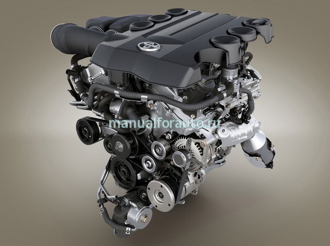
Подробное описание обслуживание и ремонта двигателя 1gr-fe
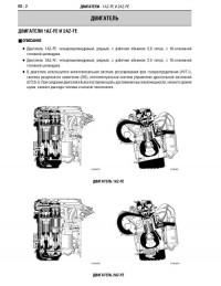
Двигатель toyota 1gr-fe устанавливают на модели
Toyota 4Runner
Toyota FJ Cruiser
Toyota Hilux
Toyota Land Cruiser 200
Toyota Land Cruiser Prado 120
Toyota Land Cruiser Prado 150
Toyota Tacoma
Toyota Tundra
Lexus GX 400 (China)
1gr fe характеристики
DOHC 60 V6
Рабочий объем 4 л (3956 куб. см)
Диаметр цилиндра 94 мм
Ход поршня 95 мм
Мощность 285 л.с. (392 Н · м)
Степень сжатия 10:1
Автор: Toyota
Формат: PDF
Размер архива: 6.3 мб
Добавлять комментарии могут только зарегистрированные пользователи.
[
Регистрация
|
Вход
]
Сборник руководств на английском языке по техническому обслуживанию и ремонту двигателей Toyota моделей 1AZ-FE/1AZ-FSE/2AZ-FE.
- Автор: —
- Издательство: Toyota Motor Company
- Год издания: —
- Страниц: —
- Формат: PDF
- Размер: 9,7 Mb
Руководство на английском языке по техническому обслуживанию и ремонту двигателей Toyota моделей 1C/2C/2C-T.
- Автор: —
- Издательство: Toyota Motor Company
- Год издания: —
- Страниц: —
- Формат: JPG
- Размер: 81,4 Mb
Сборник руководств на английском языке по техническому обслуживанию и ремонту двигателя Toyota модели 1CD-FTV.
- Автор: —
- Издательство: Toyota Motor Company
- Год издания: —
- Страниц: —
- Формат: PDF
- Размер: 7,6 Mb

Сборник руководств на английском языке по техническому обслуживанию и ремонту двигателей Toyota моделей 1HD-T/1HZ/1PZ.
- Автор: —
- Издательство: Toyota Motor Company
- Год издания: 1990
- Страниц: —
- Формат: PDF
- Размер: 79,6 Mb
Руководство на английском языке по техническому обслуживанию и ремонту двигателя Toyota модели 1MZ-FE.
- Автор: —
- Издательство: Toyota Motor Company
- Год издания: —
- Страниц: 599
- Формат: PDF
- Размер: 21,2 Mb

Руководство на английском языке по техническому обслуживанию и ремонту двигателя Toyota модели 1N.
- Автор: —
- Издательство: Toyota Motor Company
- Год издания: 1987
- Страниц: —
- Формат: PDF
- Размер: 82,3 Mb
Руководство на английском языке по техническому обслуживанию и ремонту двигателей Toyota моделей 1RZ/1RZ-E/2RZ/2RZ-E.
- Автор: —
- Издательство: Toyota Motor Company
- Год издания: —
- Страниц: —
- Формат: PDF
- Размер: 22,2 Mb
Сборник руководств на английском языке по техническому обслуживанию и ремонту двигателей Toyota моделей 1ZZ-FE/3ZZ-FE.
- Автор: —
- Издательство: Toyota Motor Company
- Год издания: —
- Страниц: —
- Формат: PDF
- Размер: 5,2 Mb

Руководство на английском языке по техническому обслуживанию и ремонту двигателя Toyota модели 2F.
- Автор: —
- Издательство: Toyota Motor Company
- Год издания: 1980
- Страниц: 138
- Формат: PDF
- Размер: 15,3 Mb
Руководство на английском языке по техническому обслуживанию и ремонту двигателей Toyota моделей 2H/12H-T.
- Автор: —
- Издательство: Toyota Motor Company
- Год издания: 1985
- Страниц: 338
- Формат: PDF
- Размер: 478,7 Mb
Руководство на английском языке по техническому обслуживанию и ремонту двигателей Toyota моделей 2K/3K-C/3K-H/4K/4K-C.
- Автор: —
- Издательство: Toyota Motor Company
- Год издания: 1981
- Страниц: —
- Формат: PDF
- Размер: 27,4 Mb
Руководство на английском языке по техническому обслуживанию и ремонту двигателей Toyota моделей 2T/2T-B/2T-C/2T-G/3T/3T-C.
- Автор: —
- Издательство: Toyota Motor Company
- Год издания: 1987
- Страниц: —
- Формат: PDF
- Размер: 22,7 Mb
Сборник руководств на английском языке по техническому обслуживанию и ремонту двигателей Toyota моделей 3S-FE/3S-GE/5S-FE.
- Автор: —
- Издательство: Toyota Motor Company
- Год издания: —
- Страниц: —
- Формат: PDF
- Размер: 386,1 Mb

Руководство на английском языке по техническому обслуживанию и ремонту двигателей Toyota моделей 3ZZ-FE и 4ZZ-FE.
- Автор: —
- Издательство: Motorist
- Год издания: —
- Страниц: 129
- Формат: PDF
- Размер: —
Руководство на английском языке по техническому обслуживанию и ремонту двигателей Toyota моделей 4A-F и 4A-GE.
- Автор: —
- Издательство: Motorist
- Год издания: —
- Страниц: 320
- Формат: PDF
- Размер: —
Руководство на английском языке по техническому обслуживанию и ремонту двигателя Toyota модели 4A-GE.
- Автор: —
- Издательство: Toyota Motor Company
- Год издания: 1997
- Страниц: —
- Формат: PDF
- Размер: 13,2 Mb
Руководство на английском языке по техническому обслуживанию и ремонту двигателя Toyota модели 4Y.
- Автор: —
- Издательство: Toyota Motor Company
- Год издания: —
- Страниц: 209
- Формат: PDF
- Размер: 23,0 Mb
Руководство на английском языке по техническому обслуживанию и ремонту двигателей Toyota моделей 7M-GE/7M-GTE.
- Автор: —
- Издательство: Toyota Motor Company
- Год издания: 1987
- Страниц: —
- Формат: PDF
- Размер: 29,6 Mb
Сборник руководств на английском языке по техническому обслуживанию и ремонту двигателей Toyota моделей B/2B/3B/11B/13B/13B-T.
- Автор: —
- Издательство: Toyota Motor Company
- Год издания: 1994/-
- Страниц: 338/269
- Формат: PDF
- Размер: 581,8 Mb

Сборник руководств на английском языке по техническому обслуживанию и ремонту двигателей Toyota моделей L/2L/2L-T/3L/5L.
- Автор: —
- Издательство: Toyota Motor Company
- Год издания: 1984/-
- Страниц: 228/-
- Формат: PDF
- Размер: 33,9 Mb

Сборник руководств на английском языке по диагностике, техническому обслуживанию и ремонту механических и автоматических КПП автомобилей Toyota.
- Автор: —
- Издательство: Toyota Motor Company
- Год издания: —
- Страниц: —
- Формат: PDF
- Размер: 409,5 Mb
Руководство по техническому обслуживанию и ремонту двигателей Toyota моделей 1AZ-FE/2AZ-FE/2AD-FTV.
- Автор: —
- Издательство: —
- Год издания: —
- Страниц: 145
- Формат: PDF
- Размер: 7,5 Mb

Руководство по техническому обслуживанию и ремонту двигателей Toyota моделей 1C/2C/2C-T.
- Автор: —
- Издательство: Легион-Автодата
- Год издания: —
- Страниц: 146
- Формат: —
- Размер: —

Руководство по техническому обслуживанию и ремонту двигателей Toyota моделей 1G-E/1G-FE/1G-GE/1G-GTE/1G-GZE/7M-GE/7M-GTE устанавливавшихся на автомобили 1980-1993 годов выпуска.
- Автор: —
- Издательство: Легион-Автодата
- Год издания: —
- Страниц: 250
- Формат: —
- Размер: —

Руководство по техническому обслуживанию и ремонту двигателей Toyota моделей 1GR-FE/2GR-FE/2GR-FSE/3GR-FE/3GR-FSE/4GR-FSE.
- Автор: —
- Издательство: Легион-Автодата
- Год издания: —
- Страниц: 362
- Формат: —
- Размер: —
Руководство по техническому обслуживанию и ремонту двигателей Toyota моделей 1JZ-FSE/1JZ-GE/1JZ-GTE/2JZ-GE/2JZ-GTE.
- Автор: —
- Издательство: Легион-Автодата
- Год издания: —
- Страниц: 292
- Формат: —
- Размер: —

Руководство по техническому обслуживанию и ремонту двигателей Toyota моделей 1KD-FTV/2KD-FTV.
- Автор: —
- Издательство: Легион-Автодата
- Год издания: —
- Страниц: 280
- Формат: —
- Размер: —

Руководство по техническому обслуживанию и ремонту двигателей Toyota моделей 1ZZ-FE/2ZZ-GE/3ZZ-FE/4ZZ-FE.
- Автор: —
- Издательство: Легион-Автодата
- Год издания: —
- Страниц: 192
- Формат: —
- Размер: —

Руководство по техническому обслуживанию и ремонту двигателей Toyota моделей 2C-TE/3C-E/3C-T/3C-TE.
- Автор: —
- Издательство: Легион-Автодата
- Год издания: —
- Страниц: 182
- Формат: —
- Размер: —
Руководство по техническому обслуживанию и ремонту двигателей Toyota моделей 4A-F/4A-FE/4A-GE/5A-F/5A-FE/7A-FE.
- Автор: —
- Издательство: Легион-Автодата
- Год издания: —
- Страниц: 232
- Формат: —
- Размер: —

Руководство по техническому обслуживанию и ремонту двигателей Toyota моделей 4E-FE/5E-FE.
- Автор: —
- Издательство: Легион-Автодата
- Год издания: —
- Страниц: 128
- Формат: —
- Размер: —

Руководство по техническому обслуживанию и ремонту двигателей Toyota моделей B/3B/11B/14B/15B-F/15B-FT.
- Автор: —
- Издательство: Легион-Автодата
- Год издания: —
- Страниц: 126
- Формат: —
- Размер: —

Руководство по техническому обслуживанию и ремонту двигателей Hino моделей J08C-TP, J08C-TR, J05C, J05C-TD, J05D, J05E-TE, J05E-TC, J05E-TD, S05C, S05C-B, S05C-TA, S05C-TB, S05D.
- Автор: —
- Издательство: Легион-Автодата
- Год издания: —
- Страниц: 190
- Формат: —
- Размер: —

Руководство по техническому обслуживанию и ремонту двигателей Hino моделей J05C, S05C, S05C-B, S05C-TA, S05C-TB, S05D устанавливаемых на автомобили Hino Dutro и Toyota Dyna/Toyoace.
- Автор: —
- Издательство: Легион-Автодата
- Год издания: —
- Страниц: 120
- Формат: —
- Размер: —

Руководство по техническому обслуживанию и ремонту двигателей Toyota моделей 1AZ-FE/1AZ-FSE/2AZ-FE/2AZ-FSE.
- Автор: —
- Издательство: Легион-Автодата
- Год издания: —
- Страниц: 288
- Формат: —
- Размер: —

Руководство по техническому обслуживанию и ремонту двигателя Toyota модели 1G-FE устанавливавшихся на автомобили 1992-2006 годов выпуска.
- Автор: —
- Издательство: Легион-Автодата
- Год издания: —
- Страниц: 104
- Формат: —
- Размер: —

Руководство по техническому обслуживанию и ремонту двигателей Toyota моделей 1HD-FT/1HD-FTE/1HD-T/1HZ/1PZ.
- Автор: —
- Издательство: Легион-Автодата
- Год издания: —
- Страниц: 176
- Формат: —
- Размер: —

Руководство по техническому обслуживанию и ремонту двигателей Toyota моделей 1KZ-T/1KZ-TE/2L/2L-T/2L-THE/2L-TE/3L.
- Автор: —
- Издательство: Легион-Автодата
- Год издания: —
- Страниц: 163
- Формат: —
- Размер: —

Руководство по техническому обслуживанию и ремонту двигателей Toyota моделей 1NZ-FE/2NZ-FE.
- Автор: —
- Издательство: Легион-Автодата
- Год издания: 2008
- Страниц: 236
- Формат: —
- Размер: —

Руководство по техническому обслуживанию и ремонту двигателей Toyota моделей 2L/2L-T/3L/5L.
- Автор: —
- Издательство: Легион-Автодата
- Год издания: 2007
- Страниц: 144
- Формат: —
- Размер: —

Руководство по техническому обслуживанию и ремонту двигателей Toyota моделей 3S-FE/3S-GE/3S-GTE/4S-Fi/4S-FE/5S-FE.
- Автор: —
- Издательство: Легион-Автодата
- Год издания: —
- Страниц: 184
- Формат: —
- Размер: —

Руководство по техническому обслуживанию и ремонту двигателей Toyota моделей 3S-FE/3S-FSE устанавливавшихся на автомобили 1996-2003 годов выпуска.
- Автор: —
- Издательство: Легион-Автодата
- Год издания: 2006
- Страниц: 208
- Формат: —
- Размер: —


Предыдущую запись по жалобам обиженных заблокировали, публикую по новой.

После скачивания мануала, для его просмотра, необходимо извлечь файлы из архива!
При просмотре файлов прямо в архиве — они не отображаются!
___________________________________________
ССЫЛКА НА МАНУАЛ
КАЧАЕМ ЧЕРЕЗ КОМПЬЮТЕР! ЧЕРЕЗ ТЕЛЕФОН МОЖЕТ ВЫДАТЬ ОШИБКУ!
___________________________________________
Объем файла 102 Mb.
При возникновении проблем с доступом к архиву, пишите мне в личку


мануал lexus gx 470, мануал prado 120, книга gx470, книга prado 120, 1GR-FE
Руководства по ремонту Toyota/Lexus
Название : Russian Repair Manual (06/2015—>) (RM27T2)
Russian Repair Manual (06/2015—>) (RM27T2)
Язык : RU
Автомобили :
   => TOYOTA / Land Cruiser / GRJ150 / all engines / all transmissions
   => TOYOTA / Land Cruiser / TRJ150 / all engines / all transmissions
   => TOYOTA / Land Cruiser / KDJ150 / all engines / all transmissions
   => TOYOTA / Land Cruiser / GDJ150 / all engines / all transmissions
   => TOYOTA / Land Cruiser / GDJ155 / all engines / all transmissions
   => TOYOTA / Land Cruiser / KDJ155 / all engines / all transmissions
/Russian Repair Manual (06/2015-->) (RM27T2)

EM–166 1GR-FE ENGINE MECHANICAL – ENGINE UNIT
EM
REASSEMBLY1. REASSEMBLY CYLINDER HEAD SUB-ASSEMBLY
Refer to the procedures up to «REASSEMBLY CYLINDER HEAD» (See page EM-82).
2. INSTALL STUD BOLT(a) Install the stud bolts as shown in the illustration.
Torque: Stud bolt A11 N*m (112 kgf*cm, 8.1 ft.*lbf)Stud bolt B4.5 N*m (46 kgf*cm, 40 in.*lbf)Stud bolt C4.0 N*m (41 kgf*cm, 35 in.*lbf)Stud bolt D4.0 N*m (41 kgf*cm, 35 in.*lbf)
3. INSTALL STRAIGHT PIN(a) Using a plastic-faced hammer, tap in a new straight
pin.Standard protrusion:
Pin A:22.5 to 23.5 mm (0.886 to 0.925 in.)
Front Side
52 mm
Lower Side
Rear Side
56 mm
23 mm
A
AAB
BB
C
C
C
18 mm
D
D
D
Upper Side
A126356E01

1GR-FE ENGINE MECHANICAL – ENGINE UNIT EM–167
M
E
Pin B:10.5 to 11.5 mm (0.413 to 0.453 in.)
Pin C:8.5 to 9.5 mm (0.335 to 0.374 in.)
Pin D:5.5 to 6.5 mm (0.217 to 0.256 in.)
4. INSTALL TIGHT PLUG(a) Apply adhesive around new tight plugs.
Adhesive:Toyota Genuine Adhesive 1324, Three Bond 1324 or the equivalent
(b) Using SST, install the tight plugs as shown in the illustration.SST 09550-60010 (09951-00350), 09950-70010
(09951-07150)
10 mm
10 mm
8mm
36mm
22 mm
18mm 12 mm
12 mm
12 mm
Protrusion Height: 22.5 to 23.5 mm Protrusion Height: 5.5 to 6.5 mm
Protrusion Height: 5.5 to 6.5 mm
Protrusion Height: 5.5 to 6.5 mm
Protrusion Height: 10.5 to 11.5 mm
Protrusion Height: 8.5 to 9.5 mm
D
D
D
4 mm
4 mm
4 mm
CC
CC
B
B
A
Front Side
Rear Side
Upper Side
Front Side
Rear Side
Lower Side
D
D
A076062E04

EM–168 1GR-FE ENGINE MECHANICAL – ENGINE UNIT
EM
Standard depth:0.2 to 1.2 mm (0.008 to 0.047 in.)
5. INSTALL OIL JET(a) Using a screw driver and hammer, tap in the oil jet.
6. INSTALL NO. 1 SUB-ASSEMBLY OIL NOZZLE(a) Using a 5 mm socket hexagon wrench, install the 3
oil nozzles.Torque: 9.0 N*m (92 kgf*cm, 80 in.*lbf)
7. INSTALL HOLE SNAP RING(a) Using a small screwdriver, install a new snap ring
onto the side of the piston pin hole.HINT:Check that the end gap of the snap ring does not overlap with the pin hole cutout portion of the piston.
Right Side Left Side 0.2 to 1.2 mm(0.008 to 0.47 in.)
A076064E05
26 to 27°A076392E04
A076051E01
A032958E01

1GR-FE ENGINE MECHANICAL – ENGINE UNIT EM–169
M
E
8. INSTALL WITH PIN PISTON SUB-ASSEMBLY(a) Gradually heat the piston to about 80°C (176°F).
(b) Coat the piston pin with engine oil.(c) Align the front marks of the piston and connecting
rod, and push in the piston pin with a thumb.
9. INSTALL HOLE SNAP RING(a) Using a small screwdriver, install a new snap ring
onto the other side of the piston pin hole.HINT:Make sure that the gap in the snap ring does not overlap with the pin hole cutout portion of the piston.
10. INSTALL PISTON RING SET(a) Install the oil ring expander and 2 side rails by hand.(b) Using a piston ring expander, install the 2
compression rings.NOTICE:Install compression ring No. 2 with the painted mark facing upward.
(c) Position the piston rings so that the ring ends are as shown.
80°C (176°F)
P012417E10
Front Mark
Front Mark
A075846E02
A032958E01
Upward
Painted Mark
A076073E01
No. 2Compression
No. 1Compression
Front Mark
Oil Ring
Lower Side Rail
Upper Side Rail
Expander
A076074E04

EM–170 1GR-FE ENGINE MECHANICAL – ENGINE UNIT
EM
11. INSTALL CONNECTING ROD BEARING(a) Align the bearing claw with the groove of the
connecting rod or connecting cap.NOTICE:Clean the back side of the bearing and the bearing surface of the connecting rod and keep them free of oil.
12. INSTALL CRANKSHAFT BEARINGHINT:There are 2 types of main bearings with different widths (19.0 mm (0.748 in.) and 22.4 mm (0.882 in.)) for use in the inspection. Install the 22.4mm (0.882 in.) bearings in the No. 1 and No. 4 cylinder block journal positions with the main bearing cap. Install the 19.0 mm (0.748 in.) bearings in the No. 2 and No. 3 positions.(a) Clean each main journal and bearing.
(b) Install the 4 upper bearings.(1) Install the upper bearings near the center of the
cylinder block.NOTICE:• The widths of the No. 1 and No. 4 journal
bearings are different from those of the No. 2 and No. 3 journal bearings. Therefore, confirm the identity of each journal bearing prior to installation.
• Do not apply engine oil to the bearing installation surfaces of the cylinder block and the back side of the bearings.
• Check that the oil groove on the cylinder block can be seen through the oil supply holes of the upper bearing.
(c) Install the 4 lower bearings.(1) Install the lower bearings near the center of the
cylinder block.NOTICE:Do not apply engine oil to the bearing or its contact surface.HINT:The number marked on each main bearing cap indicates the installation position.
P012402E01
No. 1 and No. 4
22.4 mm 19.0 mm
No. 2 and No. 3
Upper
Lower
A076063E05
A094746E02
Mark1, 2, 3, or 4
A076065E01

1GR-FE ENGINE MECHANICAL – ENGINE UNIT EM–171
M
E
13. INSTALL CRANKSHAFT(a) Apply engine oil to the upper bearing and install the
crankshaft onto the cylinder block.(b) Install the 2 upper thrust washers onto the No. 2
journal position of the cylinder block.(1) Push the crankshaft toward the front (rear)
side.(2) Install the 2 upper thrust washers with the oil
grooves facing outward.
(c) Install the 2 lower thrust washers onto the No. 2 bearing cap with the grooves facing outward.
(d) Examine the front marks and numbers, check the sequence number is as shown in the illustration and install the bearing caps on the cylinder block.
(e) Apply a light coat of engine oil to the threads of the bearing cap bolts.
(f) Temporarily install the 8 main bearing cap bolts in the inside positions.
(g) Install the main bearing caps. Tighten the 2 bolts for each bearing cap until the clearance between the bearing cap and the cylinder block is under 6 mm (0.23 in.).
A076393E01
A076075E01
A076067E01
Less than 6 mmA076069E02

EM–172 1GR-FE ENGINE MECHANICAL – ENGINE UNIT
EM
(h) Using a plastic-faced hammer, lightly tap the bearing cap to ensure a proper fit.
(i) Apply a light coat of engine oil to the threads of the main bearing cap bolts.
(j) Install the 16 main bearing cap bolts. Using several steps, tighten the bolts uniformly in the sequence shown in the illustration.Torque: 61 N*m (622 kgf*cm, 45 ft.*lbf)
(k) Mark the front side of the bearing cap bolts with paint.
(l) Retighten the bearing cap bolts 90° in the sequence as shown.
(m) Check that the painted marks are now at a 90° angle from the front.
(n) Check that the crankshaft turns smoothly.
(o) Using several steps, tighten the 8 main bearing cap bolts uniformly in the sequence shown in the illustration.Torque: 25 N*m (255 kgf*cm, 18 ft.*lbf)
14. INSTALL PISTON SUB-ASSEMBLY WITH CONNECTIONG ROD(a) Apply engine oil to the cylinder walls, pistons, and
surfaces of connecting rod bearings.(b) Check the position of the piston ring ends.
A076070E01
715
1 23 4
65
8
914
13
10
11
12
16
A076071E04
Painted Mark
Front
90°
90°
A076072E03
3 7
12
4
56
8
A075843E03
Front Mark
A076385E02

1GR-FE ENGINE MECHANICAL – ENGINE UNIT EM–173
M
E
(c) Using a piston ring compressor, push the correct number piston and connecting rod into each cylinder with the front mark of the piston facing forward.NOTICE:• Clean the back side of the bearing and the
bearing surface of the connecting rod cap and keep them free of oil.
• Match the numbered connecting rod cap with the connecting rod.
(d) Check that the protrusion of the connecting rod cap is facing in the correct direction.
(e) Apply a light coat of engine oil to the threads of the connecting rod cap bolts.
(f) Tighten the bolts alternately to the specified torque.Torque: 25 N*m (250 kgf*cm, 18 ft.*lbf)
(g) Mark the front side of the each connecting cap bolt with paint.
(h) Retighten the cap bolts 90° as shown.(i) Check that the crankshaft turns smoothly.
15. INSTALL REAR ENGINE OIL SEAL RETAINER(a) Remove any old packing material and oil from the
contact surfaces of the oil seal retainer and cylinder block.
(b) Apply a continuous bead of seal packing (diameter 2 to 3 mm (0.08 to 0.12 in.)) to the oil seal retainer as shown in the illustration.Seal packing:
Toyota Genuine Seal Packing Black, Three Bond 1207B or the equivalent
NOTICE:Parts must be assembled within 3 minutes of application. Otherwise, the seal packing must be removed and reapplied.
Protrusion
A075149E02
A075150E03
90°
90°Front
Painted Mark
A075151E03
Seal Width: 2 to 3 mm
Seal Packing
A076269E03

EM–174 1GR-FE ENGINE MECHANICAL – ENGINE UNIT
EM
(c) Install the oil seal retainer with the 5 bolts and 2 nuts.Torque: Nut
9.0 N*m (92 kgf*cm, 80 in.*lbf)Bolt10 N*m (102 kgf*cm, 7.4 ft.*lbf)
16. INSTALL KNOCK SENSOR(a) Install the 2 knock sensors with the 2 bolts as shown
in the illustration.Torque: 20 N*m (204 kgf*cm, 15 ft.*lbf)
(b) Connect the knock sensor connectors.(c) Install the knock sensor wire.
17. INSTALL NO. 1 WATER OUTLET PIPE(a) Install the water outlet pipe with the 3 bolts.
Torque: 10 N*m (102 kgf*cm, 7.4 ft.*lbf)18. INSTALL CYLINDER HEAD GASKET
(a) Remove any old packing material and oil from the contact surfaces of the cylinder head and cylinder block.
LH Bank:
RH Bank: Upper
Upper
Engine Rear
Engine Front
15°
15°
A078438E04
G036807E01

1GR-FE ENGINE MECHANICAL – ENGINE UNIT EM–175
M
E
(b) Apply a continuous bead of seal packing (diameter 2.5 to 3 mm (0.098 to 0.118 in.)) to a new cylinder head gasket as shown in the illustration.Seal packing:
Toyota Genuine Seal Packing Black, Three Bond 1207B or the equivalent
NOTICE:Install the cylinder head within 3 minutes of applying the seal packing. After installation, cylinder head bolts must be tightened within 15 minutes. Otherwise, the seal packing must be removed and reapplied.
(c) Place the cylinder head gasket on the cylinder block surface with the Lot No. stamp upward.NOTICE:• Install the cylinder head gasket in the correct
direction.• Place the cylinder head carefully in order not
to damage the gasket with the bottom part of the head.
19. INSTALL CYLINDER HEAD SUB-ASSEMBLY(a) Place the cylinder head RH on the cylinder head
gasket.(b) Install the 8 cylinder head bolts.
HINT:• The cylinder head bolts are tightened in 2
successive steps (steps (*1), (*2) and (*3)).• If any cylinder head bolts are broken or
deformed, replace them.(1) Apply a light coat of engine oil to the threads
and under the heads of the cylinder head bolts.(2) Using several steps, uniformly install and
tighten the 10 cylinder head bolts and plate washers with a bi-hexagon wrench 10 mm in the sequence shown in the illustration.Torque: 36 N*m (367 kgf*cm, 27 ft.*lbf)If any cylinder head bolts do not meet the torque specification, replace them.NOTICE:Do not drop the washers into the cylinder head.
10 to 15 mm
10 to 15 mm
1.25 to 1.5 mm
Seal Packing
Gasket
2.5 to 3 mm
A076271E02
Lot No.
A076272E03
1
7
8
6
5
4
3
2
A076273E02

EM–176 1GR-FE ENGINE MECHANICAL – ENGINE UNIT
EM
(3) Mark the front of the cylinder head bolt with paint. (*1)
(4) Retighten the cylinder head bolts by 180° as shown. (*2)
(5) Check that the painted marks are now at 180° from the engine front. (*3)
20. INSTALL NO. 2 CYLINDER HEAD GASKET(a) Remove any old packing material and oil from the
contact surfaces of the cylinder head and cylinder block.
(b) Apply a continuous bead of seal packing (Diameter 2.5 to 3 mm (0.098 to 0.118 in.)) to a new cylinder head gasket as shown in the illustration.Seal packing:
Toyota Genuine Seal Packing Black, Three Bond 1207B or the equivalent
NOTICE:Install the cylinder head within 3 minutes of applying the seal packing. After installation, cylinder head bolts must be tightened within 15 minutes. Otherwise, the seal packing must be removed and reapplied.
(c) Place the cylinder head gasket on the cylinder block surface with the Lot No. stamp upward.NOTICE:• Be careful of the installation direction.• Place the cylinder head carefully in order not
to damage the gasket with the bottom part of the head.
21. INSTALL CYLINDER HEAD LH(a) Place the cylinder head LH on the cylinder head
gasket.(b) Install the 8 cylinder head bolts.
HINT:• The cylinder head bolts are tightened in 2
successive steps (steps (*4), (*5) and (*6)).• If any cylinder head bolts are broken or
deformed, replace them.(1) Apply a light coat of engine oil to the threads
and under the heads of the cylinder head bolts.
180°
Engine Front
Paint Mark
A076274E02
10 to 15 mm
10 to 15 mm
Seal Packing
1.25 to 1.5 mm
Gasket
2.5 to 3 mm
A076275E02
Lot No.A076276E02

1GR-FE ENGINE MECHANICAL – ENGINE UNIT EM–177
M
E
(2) Using several steps, uniformly install and tighten the 8 cylinder head bolts and plate washers with a bi-hexagon wrench 10 mm in the sequence shown in the illustration.Torque: 36 N*m (367 kgf*cm, 27 ft.*lbf)If any cylinder head bolts do not meet the torque specification, replace them.NOTICE:Do not drop the washers into the cylinder head.
(3) Mark the front of the cylinder head bolt with paint. (*4)
(4) Retighten the cylinder head bolts by 180° as shown. (*5)
(5) Check that the painted marks are now at 180° from the engine front. (*6)
(c) Install the 2 cylinder head bolts.(1) Apply a light coat of engine oil to the threads of
the cylinder head bolts.(2) Using several steps, uniformly install and
tighten the 10 cylinder head bolts and plate washers with a bi-hexagon wrench 10 mm in the sequence shown in the illustration.Torque: 30 N*m (306 kgf*cm, 22 ft.*lbf)
22. INSTALL NO. 1 CAMSHAFT BEARING(a) Align the bearing claw with the claw groove of the
bearing cap, and push in the camshaft bearing.NOTICE:• Install the bearing while aligning it with the oil
hole in the bearing cap.• Clean the back side of the bearing and the
surface of the bearing cap and keep them free of oil.
23. INSTALL NO. 2 CAMSHAFT BEARING(a) Install the No. 2 camshaft bearing onto the cylinder
head.NOTICE:Clean the back side of the bearing and the bearing surface of the cylinder head and keep them free of oil.
1 5
6 4 7
8 3
2A076277E01
180°
Engine Front
Paint Mark
A076274E02
1
2
A072969E05
Claw
A126364E01
A076279E01

EM–178 1GR-FE ENGINE MECHANICAL – ENGINE UNIT
EM
24. INSTALL CAMSHAFTSNOTICE:Keep the camshaft level while it is being removed. The camshaft thrust clearance is very small and failing to keep it level could crack or damage the cylinder head journal surface, which receives the thrust force. This could subsequently lead the camshaft to seize or break. Perform the following steps to avoid such problems.(a) Set the crankshaft position.
(1) Using the crankshaft pulley set bolt, turn the crankshaft, and set the crankshaft set key in the left horizontal position as indicated.NOTICE:Setting the crankshaft at the wrong angle could cause the piston head and valve head to come into contact with each other when the camshaft is installed. This could cause damage, so always set the camshaft at the correct angle.
(b) Apply new engine oil to the thrust portion and journal of the camshafts.
(c) Install the camshafts of bank 1.(1) Place the 2 camshafts on the cylinder head RH
with the No. 1 cam lobes facing as shown the illustration.
(2) Install the 8 bearing caps in their correct locations.
(3) Apply a light coat of engine oil to the threads of the bearing cap bolts.
90°
Set Key
TurnA076280E02
Bank 1:
A076281E05
Bank 1:
A076282E05

1GR-FE ENGINE MECHANICAL – ENGINE UNIT EM–179
M
E
(4) Using several steps, uniformly tighten the 16 bearing cap bolts in the sequence shown in the illustration.Torque: 10 mm (0.39 in.) head
9.0 N*m (92 kgf*cm, 80 in.*lbf)12 mm (0.47 in.) head24 N*m (245 kgf*cm, 18 ft.*lbf)
(5) Using a wrench, turn the camshafts clockwise until each camshaft knock pin comes to a position 90° to the cylinder head.
(d) Install the camshafts of bank 2.(1) Place the 2 camshafts on the cylinder head LH
with the No.1 cam lobes facing as shown the illustration.
(2) Install the 8 bearing caps in the correct locations as shown.
(3) Apply a light coat of engine oil to the threads and under the heads of the bearing cap bolts.
(4) Using several steps, uniformly tighten the 16 bearing cap bolts in the sequence shown in the illustration.Torque: 10 mm (0.39 in.) head
9.0 N*m (92 kgf*cm, 80 in.*lbf)12 mm (0.47 in.) head24 N*m (245 kgf*cm, 18 ft.*lbf)
1
2
3
4
6
7
8
59
10
11
12
14
15 13
16
Bank 1:
A072967E13
90 °
Bank 1:
90 °
A076283E07
Bank 2:
A126365E01
Bank 2:
A076285E05
3
6
4
79
8
5
2
1
10
11
12
13
14
15
16
Bank 2:
A072968E12

EM–180 1GR-FE ENGINE MECHANICAL – ENGINE UNIT
EM
25. INSTALL NO. 2 CHAIN TENSIONER ASSEMBLY(a) While pushing in the tensioner, insert a pin of φ 1.0
mm (0.039 in.) into the hole to fix it.
(b) Install chain tensioner No. 2 with the bolt.Torque: 19 N*m (194 kgf*cm, 14 ft.*lbf)
26. INSTALL CAMSHAFT TIMING GEARS AND NO. 2 CHAIN (for Bank 1)(a) Align the yellow mark links with the timing marks (1
dot mark) of camshaft timing gears as shown in the illustration.
(b) Align the timing marks on the camshaft timing gears with the timing marks on the bearing caps, and install the camshaft timing gears with the chain onto the bank 1 camshafts.
(c) Temporarily install the 2 camshaft timing gear bolts.NOTICE:Do not push the camshaft timing gear assembly onto the camshaft forcibly when installing it.
(d) Hold the hexagonal portion of the camshaft with a wrench, and tighten the 2 bolts.Torque: 100 N*m (1,020 kgf*cm, 74 ft.*lbf)
(e) Remove the pin from chain tensioner No. 2.
Push
A076286E01
A072962E01
Mark Links
Timing MarksA076287E03
Timing Marks
Timing MarksG036841E02
Hold Tighten
G036834E03

1GR-FE ENGINE MECHANICAL – ENGINE UNIT EM–181
M
E
27. INSTALL NO. 3 CHAIN TENSIONER ASSEMBLY(a) While pushing in the tensioner, insert a pin of φ 1.0
mm (0.039 in.) into the hole to hold it.
(b) Install chain tensioner No. 3 with the bolt.Torque: 19 N*m (194 kgf*cm, 14 ft.*lbf)
28. INSTALL CAMSHAFT TIMING GEARS AND NO. 2 CHAIN (for Bank 2)(a) Align the yellow mark links with the timing marks (1
dot mark and 2 dot marks) on the camshaft timing gears as shown in the illustration.
(b) Align the timing marks on the camshaft timing gears with the timing marks on the bearing caps, and install the camshaft timing gears with the chain onto the bank 2 camshafts.
(c) Temporarily install the 2 camshaft timing gear bolts.NOTICE:Do not push the camshaft timing gear assembly onto the camshaft forcibly when installing it.
(d) Hold the hexagonal portion of the camshaft with a wrench, and tighten the 2 bolts.Torque: 100 N*m (1,020 kgf*cm, 74 ft.*lbf)
(e) Remove the pin from chain tensioner No. 3.
Push
A076289E01
A072965E01
Mark Links
Timing MarksA076290E03
Timing Marks
Timing MarksG036852E02
Tighten Hold
G036836E02

EM–182 1GR-FE ENGINE MECHANICAL – ENGINE UNIT
EM
29. INSTALL NO. 1 CHAIN VIBRATION DAMPER(a) Install chain vibration damper No. 1 with the 2 bolts.
Torque: 19 N*m (194 kgf*cm, 14 ft.*lbf)
30. INSTALL CRANKSHAFT TIMING GEAR OR SPROCKET(a) Align the timing gear set key with the key groove of
the timing gear.(b) Install the timing gear onto the crankshaft with the
gear side facing inward.
31. INSTALL CHAIN TENSIONER SLIPPER
32. INSTALL NO. 1 CHAIN TENSIONER ASSEMBLY(a) While turning the stopper plate of the tensioner
clockwise, push in the plunger of the tensioner as shown in the illustration.
(b) While turning the stopper plate of the tensioner counterclockwise, insert a bar of φ 3.5 mm (0.138 in.) into the holes in the stopper plate and tensioner to fix the stopper plate.
(c) Install the chain tensioner with the 2 bolts.Torque: 10 N*m (102 kgf*cm, 7.4 ft.*lbf)
33. INSTALL CHAIN SUB-ASSEMBLY(a) Set the No. 1 cylinder to TDC/ compression.
(1) Align the timing marks of the camshaft timing gears and bearing caps.
A076292E01
Inward
A076293E01
Stopper PlateStopper PlatePush
A076294E02
RH Bank:
LH Bank:
Timing Marks
Timing Marks
Timing MarksG036843E03

1GR-FE ENGINE MECHANICAL – ENGINE UNIT EM–183
M
E
(2) Using the crankshaft pulley set bolt, turn the crankshaft to align the crankshaft set key with the timing line of the cylinder block.
(b) Align the yellow mark link with the timing mark of the crankshaft timing gear.
(c) Align the orange mark links with the timing marks of the camshaft timing gears, and install the chain.
34. INSTALL NO. 2 CHAIN VIBRATION DAMPER(a) Instal the 2 No. 2 chain vibration dampers.
35. INSTALL IDLE SPROCKET ASSEMBLY(a) Apply a light coat of engine oil to the rotating surface
of idle gear shaft No. 1.
Timing Line
Set Key
A076296E02
Timing Mark
Mark Link
A076297E03
Mark Links
Timing MarksG036259E02
G036844E01

EM–184 1GR-FE ENGINE MECHANICAL – ENGINE UNIT
EM
(b) Temporarily install idle gear shaft No. 1 together with idle gear shaft No. 2 while aligning the knock pin of idle gear shaft No. 1 with the knock pin groove of the cylinder block.NOTICE:Install the idle gear in the correct direction.
(c) Using a 10 mm hexagon wrench, tighten idle gear shaft No. 2.Torque: 60 N*m (612 kgf*cm, 44 ft.*lbf)
(d) Remove the bar from the chain tensioner.
36. INSTALL TIMING CHAIN OR BELT COVER SUB-ASSEMBLY(a) Remove any old packing material and oil from the
contact surfaces of the timing chain cover, cylinder head and cylinder block.
(b) Install a new O-ring onto the cylinder head LH as shown in the illustration.
(c) Apply a continuous bead of seal packing (diameter 3 to 4 mm (0.12 to 0.16 in.)) to the timing chain cover as shown in the illustration.Seal packing:
Water pump part:Toyota Genuine Seal Packing 1282B, Three Bond 1282B or the equivalent
Other parts:Toyota Genuine Seal Packing Black, Three Bond 1207B or the equivalent
NOTICE:• Install the timing chain cover within 3 minutes
of applying the seal packing. After installation, the timing chain cover bolts and nuts must be tightened within 15 minutes. Otherwise, the seal packing must be removed and reapplied.
• Do not apply seal packing to A as shown in the illustration.
Knock Pin
Forward
A076299E02
G036845E01
Seal Packing
Seal Packing
Water Pump Part
Water Pump Part
Seal Width 3 to 4 mm
3 to 4 mm
3 to 4 mm
16.7 mm
3 to 4 mm
B — B’
B
B
A
Seal Packing
A076303E08

1GR-FE ENGINE MECHANICAL – ENGINE UNIT EM–185
M
E
(d) Keep the seal surface between the cylinder block and the cylinder head shown in the illustration free of oil before installing the chain cover.
(e) Align the key way of the oil pump drive rotor with the rectangular portion of the crankshaft timing gear, and slide the timing chain cover into place.
(f) Install the timing chain cover with the 15 bolts and 2 nuts. Tighten the bolts and nuts uniformly in several steps.Torque: 23 N*m (235 kgf*cm, 17 ft.*lbf)NOTICE:• Do not wrap the chain and slipper beyond the
timing chain cover seal line.• After installing the timing chain cover, install
the water pump within 15 minutes.HINT:Each bolt length is as follows:
(g) Install the timing chain cover plate with the 4 bolts.Torque: 9.0 N*m (92 kgf*cm, 80 in.*lbf)
37. INSTALL WATER PUMP ASSEMBLY(a) Install a new gasket and the water pump with the 17
bolts.Torque: Bolt A
9.0 N*m (92 kgf*cm, 80 in.*lbf)Bolt B23 N*m (235 kgf*cm, 17 ft.*lbf)
38. INSTALL OIL PAN SUB-ASSEMBLY(a) Remove any old packing material and oil from the
contact surfaces of the cylinder block, rear oil seal retainer and oil pan.
A126368
15
A076304E01
A
A
AA
AB
B
BBB
BA
A
A A
Nut NutG036855E02
Bolt length
A 25 mm (0.98 in.)
B 55 mm (2.17 in.)
BB
B
B
B
B
B
B
B
A
A
AA
A A
AA
A072954E05

EM–186 1GR-FE ENGINE MECHANICAL – ENGINE UNIT
EM
(b) Install the 4 stud bolts.Torque: 4.0 N*m (41 kgf*cm, 35 in.*lbf)
(c) Install a new O-ring onto the oil pump.
(d) Apply a continuous bead of seal packing (diameter 3 to 4 mm (0.12 to 0.16 in.)) to the oil pan as shown in the illustration.Seal packing:
Toyota Genuine Seal Packing Black, Three Bond 1207B or the equivalent
NOTICE:Install the oil pan within 3 minutes of applying the seal packing. After installation, the oil pan bolts and nuts must be tightened within 15 minutes. Otherwise, the seal packing must be removed and reapplied.
A
B
14
9.0A
2416.5
9.027.5
B [mm]
A126369E01
A076306E01
Seal Packing
Seal Width: 3 to 4 mmG036851E02

1GR-FE ENGINE MECHANICAL – ENGINE UNIT EM–187
M
E
(e) Install the oil pan with the 17 bolts and 2 nuts. Tighten the bolts and nuts uniformly in several steps.Torque: 10 mm (0.39 in.) head
10 N*m (102 kgf*cm, 7 ft.*lbf)12 mm (0.47 in.) head21 N*m (214 kgf*cm, 16 ft.*lbf)
HINT:Each bolt length is as follows:
39. INSTALL OIL STRAINER SUB-ASSEMBLY(a) Install a new gasket, then install the oil strainer with
the 2 nuts.Torque: 9.0 N*m (92 kgf*cm, 80 in.*lbf)
40. INSTALL NO. 2 OIL PAN SUB-ASSEMBLY(a) Remove any old packing material and be careful not
to drop any oil on the No. 2 contact surfaces of the oil pan and oil pan.
(b) Apply a continuous bead of seal packing (diameter 3 to 4 mm (0.12 to 0.16 in.)) as shown in the illustration.Seal packing:
Toyota Genuine Seal Packing Black, Three Bond 1207B or the equivalent
NOTICE:Install the No. 2 oil pan within 3 minutes of applying the seal packing. After installation, the No. 2 oil pan bolts and nuts must be tightened within 15 minutes. Otherwise, the seal packing must be removed and reapplied.
(c) Install the No. 2 oil pan with the 10 bolts and 2 nuts. Tighten the bolts and nuts uniformly in several steps.Torque: Bolt
9.0 N*m (92 kgf*cm, 80 in.*lbf)Nut10 N*m (102 kgf*cm, 7.4 ft.*lbf)
41. INSTALL OIL PAN DRAIN PLUG(a) Install the drain plug with a new gasket.
Torque: 40 N*m (408 kgf*cm, 30 ft.*lbf)
AA
B
B
B B B
BB A
NutNut B
A AC
C
BA
A126352E01 Bolt length
A 25 mm (0.98 in.)
B 45 mm (1.77 in.)
C 14 mm (0.55 in.)
A072951E03
Seal Packing
Seal Width: 3 to 4 mmA076308E02
A126351

EM–188 1GR-FE ENGINE MECHANICAL – ENGINE UNIT
EM
42. INSTALL CRANKSHAFT PULLEY(a) Using SST, fix the pulley and tighten the bolt.
SST 09213-54015 (91651-60855), 09330-00021Torque: 250 N*m (2,549 kgf*cm, 185 ft.*lbf)
43. SET NO. 1 CYLINDER TO TDC/COMPRESSION44. INSPECT VALVE CLEARANCE45. ADJUST VALVE CLEARANCE46. INSTALL CYLINDER HEAD COVER SUB-ASSEMBLY
(a) Remove any old packing material and oil from the contact surfaces of the cylinder head, timing chain cover and cylinder head cover.
(b) Install the gasket onto the cylinder head cover.(c) Apply a continuous bead of seal packing (diameter
2 to 3 mm (0.08 to 0.12 in.)) to the cylinder head and timing chain cover as shown in the illustration.Seal packing:
Toyota Genuine Seal Packing Black, Three Bond 1207B or the equivalent
NOTICE:Install the cylinder head cover within 3 minutes of applying the seal packing. After installation, the cylinder head cover bolts and nuts must be tightened within 15 minutes. Otherwise the seal packing must be removed and reapplied.
(d) Install the seal washers onto the bolts.(e) Install the cylinder head cover with the 10 bolts and
2 nuts. Tighten the bolts and nuts uniformly in several steps.Torque: Bolt A
10 N*m (102 kgf*cm, 7.4 ft.*lbf)Bolt B9.0 N*m (92 kgf*cm, 80 in.*lbf)Nut9.0 N*m (92 kgf*cm, 80 in.*lbf)
HINT:Each bolt length is as follows:
47. INSTALL CYLINDER HEAD COVER SUB-ASSEMBLY LH(a) Remove any old packing material and oil from the
contact surfaces of the cylinder head, timing chain cover and cylinder head cover.
(b) Apply adhesive to the threads of the ventilation valve.Adhesive:
Part No. 08833-00070, THREE BOND 1324 or the equivalent
SST
A076309E02
Seal Width: 2 to 3 mm
Seal Packing
A076310E02
A
A
A
A
AAA
B BB
Nut NutA072943E02
Bolt length
A 25 mm (0.98 in.)
B 60 mm (2.36 in.)

1GR-FE ENGINE MECHANICAL – ENGINE UNIT EM–189
M
E
(c) Install the ventilation valve onto the cylinder head cover.Torque: 27 N*m (275 kgf*cm, 20 ft.*lbf)
(d) Install the gasket onto the cylinder head cover.(e) Apply a continuous bead of seal packing (diameter
2 to 3 mm (0.08 to 0.12 in.)) to the cylinder head and timing chain cover as shown in the illustration.Seal packing:
Toyota Genuine Seal Packing Black, Three Bond 1207B or the equivalent
NOTICE:Install the cylinder head cover of 3 minutes of applying the seal packing. After installation, the cylinder head cover bolts and nuts must be tightened within 15 minutes. Otherwise, the seal packing must be removed and reapplied.
(f) Install the seal washers onto the bolts.(g) Install the cylinder head cover with the 10 bolts and
2 nuts. Tighten the bolts and nuts uniformly in several steps.Torque: Bolt A
10 N*m (102 kgf*cm, 7.4 ft.*lbf)Bolt B9.0 N*m (92 kgf*cm, 80 in.*lbf)Nut9.0 N*m (92 kgf*cm, 80 in.*lbf)
HINT:Each bolt length is as follows:
48. INSTALL OIL CONTROL VALVE FILTER(a) Check that no foreign objects on the mesh part of
the 2 filters.(b) Install a new gasket onto each new plug.(c) Insert the filters into the plugs.(d) Apply adhesive to 2 or 3 threads of the plugs.
Adhesive:Part No. 08833-00080, THREE BOND 1344 LOCTITE 242 or the equivalent
(e) Install the plugs onto each cylinder head.Torque: 62 N*m (632 kgf*cm, 46 ft.*lbf)
49. INSTALL CRANKSHAFT POSITION SENSOR(a) Install the crankshaft position sensor with the bolt.
Torque: 10 N*m (102 kgf*cm, 7.4 ft.*lbf)
Seal Packing
Seal Width: 2 to 3 mmA076311E02
A A A A
AA
A BB B
NutNut A072944E02
Bolt length
A 25 mm (0.98 in.)
B 60 mm (2.36 in.)
Mesh Part Apply Adhesive
A076312E02
G036795E01

EM–190 1GR-FE ENGINE MECHANICAL – ENGINE UNIT
EM
50. INSTALL VVT SENSOR(a) Apply a light coat of engine oil to the O-ring of each
VVT sensor.(b) Install the 2 VVT sensors with the 2 bolts.
Torque: 8.0 N*m (82 kgf*cm, 71 in.*lbf)
51. INSTALL CYLINDER BLOCK WATER DRAIN COCK SUB-ASSEMBLY(a) Apply adhesive to 2 or 3 threads of the drain cock
ends.Adhesive:
Part No. 08833-00070, THREE BOND 1324 or the equivalent
(b) Tighten the drain cocks to the specified torque, and rotate them clockwise as shown in the illustration.Torque: 25 N*m (255 kgf*cm, 18 ft.*lbf)NOTICE:• Do not rotate the drain cocks more than 1
complete revolution (360°) after tightening the drain cocks to the specified torque.
• Do not loosen the drain cocks after setting them correctly.
52. INSTALL OIL LEVEL GAUGE GUIDE(a) Install a new O-ring onto the oil level gauge guide.(b) Apply a light coat of engine oil to the O-ring.(c) Push the oil level gauge guide end into the guide
hole of the oil pan.(d) Install the oil level gauge guide with the bolt.
Torque: 9.0 N*m (92 kgf*cm, 80 in.*lbf)53. INSTALL SPARK PLUG
(a) Using a spark plug wrench, install the 6 spark plugs.Torque: 20 N*m (200 kgf*cm, 14 ft.*lbf)
54. INSTALL WATER INLET(a) Install a new gasket onto the timing chain cover.(b) Install a new O-ring onto the water by-pass outlet
pipe.
Bank 1: Bank 2:
G036794E02
Adhesive
A076531E03
45 45
45 15
A076313E01
O-Ring
Push
A076314E02
A121044

1GR-FE ENGINE MECHANICAL – ENGINE UNIT EM–191
M
E
(c) Install the water inlet with the 5 bolts.Torque: 9.0 N*m (92 kgf*cm, 80 in.*lbf)
55. INSTALL WATER BY-PASS HOSE(a) Install the water by-pass hose with the 2 clamps.
56. INSTALL NO. 2 WATER BY-PASS HOSE(a) Install the No. 2 water by-pass hose with the 2
clamps.
57. INSTALL NO. 3 WATER BY-PASS HOSE(a) Install the No. 3 water by-pass hose with the 2
clamps.58. INSTALL WITH THERMOSTAT WATER INLET SUB-
ASSEMBLY(a) Install a new O-ring and the water inlet with
thermostat with the 3 nuts.Torque: 9.0 N*m (92 kgf*cm, 80 in.*lbf)
59. INSTALL OIL FILTER BRACKET SUB-ASSEMBLY(a) Install the 2 stud bolts.
Torque: 10 N*m (102 kgf*cm, 7.4 ft.*lbf)(b) Install a new gasket.
(c) Install the oil filter bracket with the 3 bolts and 2 nuts.Torque: 19 N*m (194 kgf*cm, 14 ft.*lbf)
A126462
A121042
A121046
A120414

EM–192 1GR-FE ENGINE MECHANICAL – ENGINE UNIT
EM
60. INSTALL ENGINE OIL PRESSURE SWITCH ASSEMBLY(a) Apply adhesive to 2 or 3 threads of the oil pressure
switch.Adhesive:
Part No. 08833-00080, THREE BOND 1344, LOCTITE 242 or the equivalent.
(b) Using a 24 mm deep socket wrench, install the oil pressure switch.Torque: 15 N*m (153 kgf*cm, 11 ft.*lbf)
61. INSTALL OIL FILTER UNION(a) Using a 12 mm hexagon wrench, install the oil filter
union.Torque: 30 N*m (306 kgf*cm, 22 ft.*lbf)
62. INSTALL OIL FILTER SUB-ASSEMBLY(a) Clean the oil filter contact surface on the oil filter
bracket.(b) Apply clean engine oil to the rubber gasket of a new
oil filter.(c) Tighten the oil filter by hand until the rubber gasket
comes into contact with the seat of the filter bracket.(d) Using SST, tighten it an additional 3/4 turn to set the
oil filter.SST 09228-07501Torque: 18 N*m (184 kgf*cm, 13 ft.*lbf)
63. INSTALL CAMSHAFT TIMING OIL CONTROL VALVE ASSEMBLY (for Bank 2)(a) Install the camshaft timing oil control valve bank 2
with the bolt.Torque: 9.0 N*m (92 kgf*cm, 80 in.*lbf)
64. INSTALL CAMSHAFT TIMING OIL CONTROL VALVE ASSEMBLY (for Bank 1)(a) Install the camshaft timing oil control valve bank 1
with the bolt.Torque: 9.0 N*m (92 kgf*cm, 80 in.*lbf)
Adhesive
A085603E01
SST
3/4 Turn
A126372E01
A126464
A126463

1GR-FE ENGINE MECHANICAL – ENGINE UNIT EM–193
M
E
65. INSTALL WATER BY-PASS JOINT RR(a) Install a new O-ring onto the water outlet pipe.(b) Install the 2 gaskets onto the bank 1 and bank 2
cylinder heads.
(c) Install the water by-pass rear joint with the 2 bolts and 4 nuts.Torque: 9.0 N*m (92 kgf*cm, 80 in.*lbf)
66. INSTALL ENGINE COOLANT TEMPERATURE SENSOR(a) Install the engine coolant temperature sensor with a
new gasket.Torque: 20 N*m (200 kgf*cm, 14 ft.*lbf)
67. INSTALL ENGINE HANGERS(a) Install engine hanger No. 1 with the 2 bolts.
Torque: 33 N*m (336 kgf*cm, 24 ft.*lbf)(b) Install engine hanger No. 2 with the 2 bolts.
Torque: 33 N*m (336 kgf*cm, 24 ft.*lbf)
A121045
A121043
A126461
No. 1 No. 2
A072941E02