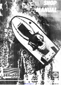
-
Contents
-
Table of Contents
-
Bookmarks
Quick Links
Summary of Contents for Rotax 2005 717 RFI
-
Page 1
www.SeaDooManuals.net… -
Page 2
2005 Engine Shop Manual ® ROTAX 717 and 787 RFI™ ENGINES www.SeaDooManuals.net… -
Page 3
™ Registered trademarks of Bombardier Recreational Products Inc. (BRP) or its affiliates. ® * Trademark of Bombardier Inc. used under license. BOMBARDIER LUBE ® RFI™ Rotax ® SEA-DOO ® Sea-Doo Synthetic Grease TOPS™ This document contains the trademarks of the following companies: Loctite ®… -
Page 4: Table Of Contents
TABLE OF CONTENTS SAFETY NOTICE ………………III INTRODUCTION ..
-
Page 5
TABLE OF CONTENTS 06 – TECHNICAL SPECIFICATIONS …………….57 787 RFI ENGINE 01 –… -
Page 6: Safety Notice
SAFETY NOTICE SAFETY NOTICE This ENGINE SHOP MANUAL has been prepared as a guide to correctly service and repair the 717 and 787 RFI Rotax ® engines. This edition was primarily published to be used by technicians who are already familiar with all service procedures relating to BRP products.
-
Page 7: Introduction
The Engine Identification Number is located on the This ENGINE SHOP MANUAL covers the 717 and upper crankcase on PTO side. 787 RFI Rotax made engines. It should be used in conjunction with the appropriate VEHICLE SHOP MANUAL. The information and component/system descrip- tions contained in this manual are correct at time of writing.
-
Page 8: Arrangement Of This Manual, Illustrations And Procedures
INTRODUCTION ARRANGEMENT OF THIS MANUAL, ILLUSTRATIONS AND PROCEDURES The manual is divided into many major sections as you can see in the main table of contents at the beginning of the manual. Several sections are divided in various subsec- tions. There is a table of contents at the beginning of many sections.
-
Page 9
INTRODUCTION Page heading indicates section and subsection detailed. Subsection title indicates beginning of the subsection. Italic sub-title above exploded view indicate pertaining models. Drop represents a liquid product to be applied to a surface. In this case Loctite 243 to screw threads. -
Page 10
INTRODUCTION Sub-title with part name(s) from exploded view. Section 06 FUEL SYSTEM Title indicates main procedure to be carried-out. To remove carburetors from engine, proceed as fol- Inspect parts for corrosion dammage (shaft, butterfly, lows: spring screw, check valve housing, etc.). Sub-sub-title in Remove air vent tube support. -
Page 11: Engine Measurement
Section 01 ENGINE MEASUREMENT Subsection 01 (MEASUREMENT PROCEDURES) MEASUREMENT PROCEDURES CYLINDER OUT OF ROUND NOTE: This section explains the procedures to correctly measure engine components. For the Using a cylinder bore gauge, measure cylinder engine technical specifications, refer to INSPEC- diameter at 16 mm (5/8 in) from top of cylinder.
-
Page 12: Piston/Cylinder Wall Clearance
Section 01 ENGINE MEASUREMENT Subsection 01 (MEASUREMENT PROCEDURES) 1. Combustion chamber NOTE: When checking the combustion chamber volume, engine must be cold, piston must be free of carbon deposit and cylinder head must be lev- eled. TYPICAL – Remove both spark plugs and bring one piston 1.
-
Page 13
Section 01 ENGINE MEASUREMENT Subsection 01 (MEASUREMENT PROCEDURES) 1. Micrometer set to the piston dimension F01D0NA Proceed with FINAL MEASUREMENT PROCE- 1. Measuring perpendicularly (90°) to piston pin axis DURE WITH EITHER A USED OR NEW PISTON A. See previous table below. -
Page 14: Ring/Piston Groove Clearance
Section 01 ENGINE MEASUREMENT Subsection 01 (MEASUREMENT PROCEDURES) 1. Micrometer set to the piston dimension Proceed with FINAL MEASUREMENT PROCE- 1. Indicator set to zero DURE WITH EITHER A USED OR NEW PISTON below. Position the dial bore gauge at 16 mm (5/8 in) be- low cylinder top edge.
-
Page 15: Ring End Gap
Section 01 ENGINE MEASUREMENT Subsection 01 (MEASUREMENT PROCEDURES) CRANKSHAFT (ASSEMBLED NOTE: Ring/piston groove clearance can be cor- rectly measured only on rectangular ring which is ENGINE) bottom ring. The following checks can be performed with en- gine in watercraft without overhauling engine. Crankshaft Alignment at Center Main Journal Since it is an assembled crankshaft it can become…
-
Page 16: Crankshaft (Disassembled Engine)
Section 01 ENGINE MEASUREMENT Subsection 01 (MEASUREMENT PROCEDURES) 1. Connecting rod journal alignment here Such misalignment may make it difficult to manu- ally turn the crankshaft. Verification can be done by measuring deflection each end of crankshaft. If deflection is found greater than specified toler- ance, this indicates worn bearing(s), bent and/or F01D4IA misaligned crankshaft.
-
Page 17
Section 01 ENGINE MEASUREMENT Subsection 01 (MEASUREMENT PROCEDURES) Crankshaft Deflection Crankshaft deflection is measured each end with a dial indicator. First, check deflection with crankshaft crankcase. If deflection exceeds the specified tolerance, it can be either ball bearings wear, bent or twisted crankshaft at connecting rod journal. -
Page 18: Rotary Valve
Section 01 ENGINE MEASUREMENT Subsection 01 (MEASUREMENT PROCEDURES) 1. 45° feeler gauge If rotary valve cover clearance is out of specifica- F01D1WA tions, machine rotary valve cover seating surface 1. Measuring big end axial play or replace the cover. 2. Feeler gauge SOLDERING WIRE METHOD Connecting Rod Straightness Remove rotary valve cover.
-
Page 19
Section 01 ENGINE MEASUREMENT Subsection 01 (MEASUREMENT PROCEDURES) Rotary Valve Shaft Deflection Remove cover then clean and measure com- pressed soldering wire thickness, it must be Deflection is measured with a dial gauge. Install within the specified tolerance. rotary valve shaft in crankcase half, without its If rotary valve cover clearance is over specified tol- gear. -
Page 20: Engine
Section 02 717 ENGINE Subsection 01 (LEAK TEST) LEAK TEST SERVICE TOOLS Description Part Number Page engine leak test kit …………… 295 500 352 ……….. 11 large hose pincher …………..529 032 500 ……….. 13 small hose pincher…………..295 000 076 ……..11–13 GENERAL When pressurizing the engine, first confirm that the components of the leak test kit are not leaking…
-
Page 21
Section 02 717 ENGINE Subsection 01 (LEAK TEST) 1. Loop hose and use clamps 2. Use two washers with exhaust manifold stud 3. Hose with adapter and nipple Activate pump and pressurize engine cooling sys- tem to 34 kPa (5 PSI). Wait 3 minutes and check if pressure drops;… -
Page 22
Section 02 717 ENGINE Subsection 01 (LEAK TEST) If no leak is found on the PTO side outer seal, remove magneto flywheel and verify crankshaft outer seals. Proceed with the ROTARY VALVE SHAFT testing if the crankshaft outer seals are not leaking. Rotary Valve Shaft NOTE: It is mandatory to drain the injection oil from the rotary valve shaft. -
Page 23
Section 02 717 ENGINE Subsection 01 (LEAK TEST) 1. Pump with reducer and nipple Activate pump and pressurize to 34 kPa (5 PSI). Check plug of the rotary valve shaft in crankcase. Remove PTO side spark plug. If pressure drops, it indicates a defective PTO side crankshaft inner seal or crankcase is not sealed correctly. -
Page 24: Engine Leakage Diagnostic Flow Chart
Section 02 717 ENGINE Subsection 01 (LEAK TEST) ENGINE LEAKAGE DIAGNOSTIC FLOW CHART PRESSURIZE ENGINE COOLING SYSTEM IS SYSTEM LEAKING? CHECK TESTING KIT REPLACE O-RING OF CYLINDER HEAD PRESSURIZE ENGINE AND/OR CYLINDER BASE GASKET IS ENGINE LEAKING? RECHECK ENGINE SEALING CHECK TESTING KIT CHECK ALL JOINTED SURFACES, SCREW/STUD THREADS.
-
Page 25: Magneto System
Section 02 717 ENGINE Subsection 02 (MAGNETO SYSTEM) MAGNETO SYSTEM SERVICE TOOLS Description Part Number Page extension handle …………..295 000 125 ……….. 19 M8 x 35 screws…………..420 841 591 ……….. 19 magneto coil centering tool ……….420 876 922 ……….. 22 magneto puller…………..
-
Page 26
Section 02 717 ENGINE Subsection 02 (MAGNETO SYSTEM) smr2005-076-001_aen smr2005-076 www.SeaDooManuals.net… -
Page 27: Disassembly
Section 02 717 ENGINE Subsection 02 (MAGNETO SYSTEM) DISASSEMBLY NOTE: If socket is found too large to be inserted in puller plate, machine or grind its outside diameter NOTE: The magneto system can be disassembled as necessary. without removing the engine from the watercraft. Magneto Cover Remove screws no.
-
Page 28
Section 02 717 ENGINE Subsection 02 (MAGNETO SYSTEM) Proceed as follows: – Before removing the armature plate, find a crankcase locating lug (the top one in this ex- ample). – Place a cold chisel at the end of chosen lug, then punch a mark on armature plate at this point. -
Page 29: Cleaning
Section 02 717 ENGINE Subsection 02 (MAGNETO SYSTEM) Generating Coil To replace generating coil no. 12: – Heat the armature plate to 93°C (200°F) around the screw holes to break the threadlocker bond. F00D09A 1. Heat the armature plate CAUTION: Protect harness from flame. –…
-
Page 30: Assembly
Section 02 717 ENGINE Subsection 02 (MAGNETO SYSTEM) ASSEMBLY Generating Coil Strip end of old wire then crimp and solder on new coil. Apply Loctite 243 (blue) (P/N 293 800 060) to screws no. 13 and install the new coil no. 12 on armature plate.
-
Page 31
Section 02 717 ENGINE Subsection 02 (MAGNETO SYSTEM) NOTE: Do not spray anticorrosion spray into mag- neto flywheel threaded holes. 1. Clean thoroughly and degrease replacement part using a non oil base solvent. 2. Apply coating in light thin coats. Refer to the manufacturer’s instructions. -
Page 32: Top End
Section 02 717 ENGINE Subsection 03 (TOP END) TOP END SERVICE TOOLS Description Part Number Page aligning tool …………….420 876 904 ……….. 34 circlip installer …………… 529 035 562 ……….. 32 piston pin puller …………..529 035 503 ……..28, 30 piston ring compressor…………
-
Page 33
Section 02 717 ENGINE Subsection 03 (TOP END) smr2005-077-001_aen smr2005-077 www.SeaDooManuals.net… -
Page 34: General
Section 02 717 ENGINE Subsection 03 (TOP END) GENERAL Remove cylinder screws no. 7. Remove cylinders no. 6, while making sure con- The 2-stroke Rotax engine rotates counterclock- ® necting rods do not hit crankcase edge. wise seen from the rear (PTO flywheel).
-
Page 35
Section 02 717 ENGINE Subsection 03 (TOP END) F01D43A TYPICAL 1. Openings covered with rag and rubber pad 1. Puller 2. Shoulder sleeve 3. Sleeve To remove circlip no. 9, insert a pointed tool in piston notch then pry it out and discard. –… -
Page 36: Cleaning
Section 02 717 ENGINE Subsection 03 (TOP END) TYPICAL TYPICAL 1. Tool cut-out toward bottom of piston 1. Remove shoulder sleeve – Firmly hold puller and rotate handle to pull pis- Carefully remove the piston no. 8. ton pin no. 10. The needles no.
-
Page 37: Inspection
Section 02 717 ENGINE Subsection 03 (TOP END) INSPECTION Piston At assembly, place the pistons no. 8 with the let- Refer to table below to find top end engine dimen- ters ″AUS″ (over an arrow on the piston dome) fac- sion specifications.
-
Page 38
Section 02 717 ENGINE Subsection 03 (TOP END) F01D0Q A 1. Outer ring removal after inner sleeve insertion into bore TYPICAL 1. Piston pin 2. Shoulder sleeve – Make sure thrust washers no. 12 are present each side of rollers. –… -
Page 39
Section 02 717 ENGINE Subsection 03 (TOP END) F01D0RA F01D0TA 1. Piston pin flush here 1. Pulling inner sleeve half 2. Thrust washers Circlip – Place piston over connecting rod and align Always use new circlips no. 9. bores, then gently tap piston pin with a fiber hammer to push out inner plastic ring on oppo- WARNING site side. -
Page 40
Section 02 717 ENGINE Subsection 03 (TOP END) Cylinder Base Gasket NOTE: The general procedure is to install a new gasket of the same thickness. However, if you do not know the gasket thickness that was installed or if a crank repair has involved replacement of connecting rods, refer to COMBUSTION CHAM- BER VOLUME MEASUREMENT in ENGINE MEA- TYPICAL… -
Page 41
Section 02 717 ENGINE Subsection 03 (TOP END) The aligning tool (P/N 420 876 904) or the exhaust manifold can be used to align cylinders. 1. Slide this edge NOTE: Ring compressor will not fit on oversize parts. Make sure to align ring end gap with piston locat- ing pin. -
Page 42
Section 02 717 ENGINE Subsection 03 (TOP END) TORQUING SEQUENCE Cylinder Head Exhaust Manifold Install cylinder head gasket. Make sure to install O-rings no. 14 around spark Make sure gaskets are properly positioned prior to plug holes and O-ring no. 15 of cylinder head as finalizing manifold installation. -
Page 43: Bottom End
Section 02 717 ENGINE Subsection 04 (BOTTOM END) BOTTOM END SERVICE TOOLS Description Part Number Page bearing heater…………… 529 035 969 ……….. 43 distance gauge …………..529 034 800 ……….. 44 Distance ring…………….. 420 876 569 ……….. 41 MAG side ring halves …………420 276 025 ……….. 41 Protective cap……………
-
Page 44
Section 02 717 ENGINE Subsection 04 (BOTTOM END) smr2005-078 www.SeaDooManuals.net… -
Page 45: General
Section 02 717 ENGINE Subsection 04 (BOTTOM END) GENERAL Using a suitable wrench or socket with a break- er bar, unscrew PTO flywheel COUNTERCLOCK- Engine has to be removed from watercraft to take WISE when facing it and hold extension handle apart bottom end.
-
Page 46
Section 02 717 ENGINE Subsection 04 (BOTTOM END) – starter, refer to appropriate VEHICLE SHOP MANUAL – rotary valve cover and valve, refer to ROTARY VALVE section – engine top end, refer to TOP END section. Put engine on a stand. Loosen crankcase screws. F01D1LA TYPICAL 1. -
Page 47: Cleaning
Section 02 717 ENGINE Subsection 04 (BOTTOM END) 1. Puller (P/N 420 877 635) 2. Protective cap (P/N 420 876 557) 3. Distance ring (P/N 420 876 569), MAG side only 4. Ring (P/N 420 977 490), both sides 5. MAG side ring halves (P/N 420 276 025) 6.
-
Page 48: Inspection
Section 02 717 ENGINE Subsection 04 (BOTTOM END) FIRST PASS TYPICAL Crankcase Crankcase mating surfaces are best cleaned us- ing a combination of the chisel gasket remover (P/N 413 708 500) and a brass brush. Brush a first pass in one direction then make the final brushing perpendicularly (90°) to the first pass cross (hatch).
-
Page 49: Assembly
Section 02 717 ENGINE Subsection 04 (BOTTOM END) TOLERANCE ENGINE New parts MEASUREMENT Wear limit 0.050 mm N.A. N.A. (.002 in) Crankshaft deflection 0.030 mm N.A. N.A. (.001 in) Connecting rod 0.311 mm 0.677 mm 1.2 mm (.012 in) (.026 in) (.047 in) big end axial play Crankcase…
-
Page 50
Section 02 717 ENGINE Subsection 04 (BOTTOM END) Touch the inner race of the bearing with the tem- Slide in the inner bearing. Push bearing to end perature indicator stick (P/N 529 035 970). Stick position. will liquefy when the bearing reach the proper Install the retaining disk. -
Page 51
Section 02 717 ENGINE Subsection 04 (BOTTOM END) NOTE: It is recommended to apply this specific sealant as described here to get an uniform appli- cation without lumps. If you do not use the roller method, you may use your finger to uniformly dis- tribute the sealant. -
Page 52
Section 02 717 ENGINE Subsection 04 (BOTTOM END) Crankcase Screws Using the same tools as for disassembly proce- dure, torque PTO flywheel to 110 N•m (81 lbf•ft). Apply Loctite 518 (P/N 293 800 038) on screw threads and Molykote 111 (P/N 413 707 000) be- low head screws. -
Page 53: Rotary Valve
Section 02 717 ENGINE Subsection 05 (ROTARY VALVE) ROTARY VALVE SERVICE TOOLS Description Part Number Page degree wheel……………. 529 035 607 ……….. 55 puller………………420 876 488 ……….. 49 pusher………………. 420 876 501 ……….. 51 pusher………………. 420 876 605 ……….. 52 TDC gauge…………….
-
Page 54
Section 02 717 ENGINE Subsection 05 (ROTARY VALVE) smr2005-079-001_aen smr2005-079 www.SeaDooManuals.net… -
Page 55: General
Section 02 717 ENGINE Subsection 05 (ROTARY VALVE) GENERAL Rotary Valve Shaft To remove the rotary valve shaft assembly, the The clearance of rotary valve cover or rotary valve engine must be removed from watercraft (refer to shaft gear backlash can be performed without tak- appropriate VEHICLE SHOP MANUAL).
-
Page 56
Section 02 717 ENGINE Subsection 05 (ROTARY VALVE) Shaft Bearing To remove bearing no. 8 use a bearing extractor such as Snap-on no. CJ-950 (or equivalent) as il- lustrated. Slide off distance sleeve no. 14, re- move snap ring no. 7 and washer no. 15 then press shaft out. -
Page 57: Cleaning
Section 02 717 ENGINE Subsection 05 (ROTARY VALVE) Rotary Valve Shaft Refer to table below to find dimension specifica- tions. For measurement procedures, refer to EN- GINE MEASUREMENT section. Close puller claws so that they can be inserted TOLERANCES ENGINE in end bearing.
-
Page 58
Section 02 717 ENGINE Subsection 05 (ROTARY VALVE) 1. Shield side (toward gear) Push bearing until it stops on its seat. 1. Seal 2. Ball bearing 3. Bearing extractor Snap-on CJ-950 Install washer no. 15, snap ring no. 7 and slide distance sleeve no. -
Page 59
Section 02 717 ENGINE Subsection 05 (ROTARY VALVE) A00C0YA 1. Pusher Push shaft until its stops on bearing seat. 1. Rotary valve shaft 2. Push shaft until it stops Snap Ring Position snap ring no. 4 so that its sharp edge faces outwards. -
Page 60
Section 02 717 ENGINE Subsection 05 (ROTARY VALVE) smr2005-079 www.SeaDooManuals.net… -
Page 61: Rotary Valve Timing
Section 02 717 ENGINE Subsection 05 (ROTARY VALVE) ROTARY VALVE TIMING CAUTION: Never use the ridge molded in crank case as a timing mark. The degree wheel (P/N 529 035 607) and the TDC gauge (P/N 295 000 143) are required to measure rotary valve opening and closing angles in relation with MAG side piston.
-
Page 62
Section 02 717 ENGINE Subsection 05 (ROTARY VALVE) 65° F01D3EB CLOSING MARK Step 1: Top of MAG inlet port. Align 360° line of degree wheel Step 2: Find 65° on outer scale of degree wheel and mark here – Remove degree wheel. –… -
Page 63: Technical Specifications
Section 02 717 ENGINE Subsection 06 (TECHNICAL SPECIFICATIONS) TECHNICAL SPECIFICATIONS ENGINE Engine type ROTAX 717, 2-stroke Induction type Rotary valve Type Water cooled, water injected Exhaust system Water injection fitting (head) 3.5 mm (.139 in) Water injection fitting (cone) 3.5 mm (.139 in)
-
Page 64: Rfi Engine
Section 03 787 RFI ENGINE Subsection 01 (LEAK TEST) LEAK TEST SERVICE TOOLS Description Part Number Page engine leak test kit …………… 295 500 352 ……..59–60 small hose pincher…………..295 000 076 ……..60–61 supplementary engine leak test kit……..295 500 780 ……..59–60 GENERAL It is also very important after servicing the engine, even for a complete engine rebuilt, to perform an-…
-
Page 65
Section 03 787 RFI ENGINE Subsection 01 (LEAK TEST) Engine Cooling System Remove the exhaust manifold gasket and ensure the surface is clean. Install the appropriate exhaust manifold plate from the engine leak test kit (P/N 295 500 352). Tighten plate using fasteners provided in the kit. -
Page 66
Section 03 787 RFI ENGINE Subsection 01 (LEAK TEST) Install pump to the exhaust plate fitting. If no leak is found on the PTO side outer seal, remove magneto flywheel and verify crankshaft outer seals. Proceed with the ROTARY VALVE SHAFT testing if the crankshaft outer seals are not leaking. -
Page 67
Section 03 787 RFI ENGINE Subsection 01 (LEAK TEST) Remove PTO side spark plug. If pressure drops, it indicates a defective PTO side crankshaft inner seal or crankcase is not sealed correctly. Remove MAG side spark plug. If pressure drops, it indicates a defective MAG side crankshaft inner seal or crankcase is not sealed correctly. -
Page 68: Engine Leakage Diagnostic Flow Chart
Section 03 787 RFI ENGINE Subsection 01 (LEAK TEST) ENGINE LEAKAGE DIAGNOSTIC FLOW CHART PRESSURIZE ENGINE COOLING SYSTEM IS SYSTEM LEAKING? CHECK TESTING KIT REPLACE O-RING OF CYLINDER HEAD PRESSURIZE ENGINE AND/OR CYLINDER BASE GASKET IS ENGINE LEAKING? RECHECK ENGINE SEALING CHECK TESTING KIT CHECK ALL JOINTED SURFACES, SCREW/STUD THREADS.
-
Page 69: Magneto System
Section 03 787 RFI ENGINE Subsection 02 (MAGNETO SYSTEM) MAGNETO SYSTEM SERVICE TOOLS Description Part Number Page crankshaft protector …………. 420 876 557 ……….. 67 installer handle …………..420 877 650 ……….. 69 magneto puller…………..420 976 235 ……….. 67 oil seal pusher……………
-
Page 70
Section 03 787 RFI ENGINE Subsection 02 (MAGNETO SYSTEM) smr2005-081-001_aen smr2005-081 www.SeaDooManuals.net… -
Page 71: Disassembly
Section 03 787 RFI ENGINE Subsection 02 (MAGNETO SYSTEM) DISASSEMBLY Rotor and Ring Gear NOTE: Crankshaft can also be locked by using the NOTE: The magneto system can be disassembled PTO flywheel extractor tool. For procedure, refer without removing the engine from the watercraft. to BOTTOM END.
-
Page 72: Cleaning
Section 03 787 RFI ENGINE Subsection 02 (MAGNETO SYSTEM) REMOVE SCREWS 1. Magneto housing Stator Assembly Remove holding plate no. 9 and withdraw plug from cover. TYPICAL Unscrew bolts no. 10 and remove stator no. 11 1. Puller from magneto cover. Tighten puller screw and at the same time, tap on screw head using a hammer to release magneto rotor from its taper.
-
Page 73: Assembly
Section 03 787 RFI ENGINE Subsection 02 (MAGNETO SYSTEM) Clean crankshaft taper and threads using pulley flange cleaner (P/N 413 711 809). Apply the pulley flange cleaner (P/N 413 711 809) on a rag first then clean the crankshaft. ASSEMBLY Stator Install the stator no.
-
Page 74
Section 03 787 RFI ENGINE Subsection 02 (MAGNETO SYSTEM) Crankshaft Position Sensor Install crankshaft position sensor no. 3 on mag- neto housing. Apply Molykote 111 (P/N 413 707 000) on its O-ring. Apply Loctite 767 (antiseize lubricant) (P/N 293 800 070) on screw threads then torque it to 9 N•m (80 lbf•in). -
Page 75: Top End
Section 03 787 RFI ENGINE Subsection 03 (TOP END) TOP END SERVICE TOOLS Description Part Number Page circlip installer …………… 529 035 562 ……….. 83 piston pin puller …………..529 035 503 ……..78, 81 piston ring compressor…………420 876 979 ……….. 84 rubber pad …………….
-
Page 76
Section 03 787 RFI ENGINE Subsection 03 (TOP END) smr2005-082-001_aen smr2005-082 www.SeaDooManuals.net… -
Page 77: General
(PTO flywheel). The 787 RFI engine has a rotary valve to control opening and closing of the intake and it is also equipped with the Rotax Adjustable Variable Ex- haust (RAVE) system. RAVE System (Rotax Adjustable Variable Exhaust)
-
Page 78: Disassembly
Section 03 787 RFI ENGINE Subsection 03 (TOP END) MAINTENANCE There are no wear parts anywhere in the system and there are no adjustments to be periodical- ly checked. The only possible maintenance re- quired would be cleaning of carbon deposits from the guillotine slide.
-
Page 79
Section 03 787 RFI ENGINE Subsection 03 (TOP END) 1. Remove spring 1. Bellows removed from piston Remove spring no. 30 retaining bellows no. 21 to valve piston no. 20. Unscrew valve piston no. 20 from sliding valve no. 22. NOTE: Hold the sliding valve to prevent it from turning. -
Page 80
Section 03 787 RFI ENGINE Subsection 03 (TOP END) 1. Remove spring 1. Remove O-ring Remove supporting ring no. 28. Remove sliding valve no. 22. 1. Remove supporting ring 1. Remove sliding valve Remove O-ring no. 23. Remove bellows no. 21. smr2005-082 www.SeaDooManuals.net… -
Page 81
Section 03 787 RFI ENGINE Subsection 03 (TOP END) Remove tuned pipe, refer to the appropriate VE- HICLE SHOP MANUAL. Proceed with ENGINE ON BENCH WORK. Engine on Bench Work Remove cylinder screws no. 13. Remove cylinders no. 9, while making sure con- necting rods do not hit crankcase edge. -
Page 82
Section 03 787 RFI ENGINE Subsection 03 (TOP END) F01D43A TYPICAL 1. Openings covered with rag and rubber pad 1. Puller 2. Shoulder sleeve 3. Sleeve To remove circlip no. 5, insert a pointed tool in piston notch then pry it out and discard. –… -
Page 83: Cleaning
Section 03 787 RFI ENGINE Subsection 03 (TOP END) TYPICAL TYPICAL 1. Tool cut-out toward bottom of piston 1. Remove shoulder sleeve – Firmly hold puller and rotate handle to pull pis- – Carefully remove the piston no. 3. ton pin no. 4. –…
-
Page 84: Inspection
Section 03 787 RFI ENGINE Subsection 03 (TOP END) INSPECTION ASSEMBLY Refer to table below to find top end engine dimen- Assembly is essentially the reverse of disassem- sion specifications. For dimension measurement bly procedures. However pay particular attention procedures, refer to ENGINE MEASUREMENT. to the following.
-
Page 85
Section 03 787 RFI ENGINE Subsection 03 (TOP END) IDENTIFICATION GASKET THICKNESS HOLES 0.3 mm (.012 in) 0.4 mm (.016 in) 0.5 mm (.020 in) 0.6 mm (.024 in) 0.8 mm (.031 in) Piston At assembly, place the pistons no. 3 with the let- ters ″AUS″… -
Page 86
Section 03 787 RFI ENGINE Subsection 03 (TOP END) NOTE: Make sure thrust washers are present Replacement roller bearings are delivered in a con- each side of needles. venient plastic mounting device. For installation, proceed as follows: – Install the shoulder sleeve tool on the opposite side of the piston pin. -
Page 87
Section 03 787 RFI ENGINE Subsection 03 (TOP END) F01D0RA F01D0TA 1. Piston pin flush here 1. Pulling inner sleeve half 2. Thrust washers Circlip – Place piston over connecting rod and align Always use new circlips. bores, then gently tap piston pin with a fiber hammer to push out inner plastic ring on oppo- WARNING site side. -
Page 88
Section 03 787 RFI ENGINE Subsection 03 (TOP END) Cylinder To easily slide cylinder no. 9 over piston, use the piston ring compressor (P/N 420 876 979). TYPICAL 1. Circlip installer – Remove sleeve from pusher then insert circlip into its bore. –… -
Page 89
Section 03 787 RFI ENGINE Subsection 03 (TOP END) When reassembling cylinders to crankcase, it is Torque screws in a criss-cross sequence for each important to have them properly aligned so that cylinder to 20 N•m (15 lbf•ft). Repeat the proce- exhaust flanges properly match up with exhaust dure, retightening all cylinder screws to 40 N•m manifold. -
Page 90: Adjustment
Section 03 787 RFI ENGINE Subsection 03 (TOP END) Apply also Molykote 111 (P/N 413 707 000) on Torque exhaust manifold screws to 24 N•m threads of screws no. 14. (17 lbf•ft) as per following illustrated sequence. Repeat the procedure, retightening screws to Torque cylinder head screws no.
-
Page 91: Bottom End
Section 03 787 RFI ENGINE Subsection 04 (BOTTOM END) BOTTOM END SERVICE TOOLS Description Part Number Page bearing heater…………… 529 035 969 ……….. 94 distance gauge …………..529 034 900 ……….. 96 Distance ring…………….. 420 876 569 ……….. 91 extension handle …………..295 000 125 ……….. 89 gear/bearing puller …………..
-
Page 92
Section 03 787 RFI ENGINE Subsection 04 (BOTTOM END) smr2005-083 www.SeaDooManuals.net… -
Page 93: General
Section 03 787 RFI ENGINE Subsection 04 (BOTTOM END) GENERAL Engine has to be removed from watercraft to take apart bottom end. Refer to appropriate VEHICLE SHOP MANUAL. Engine top end has to be disassembled to take apart bottom end. Refer to TOP END section in this manual.
-
Page 94
Section 03 787 RFI ENGINE Subsection 04 (BOTTOM END) Put engine on a stand. Loosen crankcase screws. F01D1LA TYPICAL 1. Separate halves by prying at provided lugs Remove crankshaft and counterbalance shaft. 1. M10 x 73.5 flanged screws 2. M8 x 53.5 flanged screws Crankshaft End Bearings Put engine back on a support. -
Page 95
Section 03 787 RFI ENGINE Subsection 04 (BOTTOM END) 1. Puller (P/N 420 877 635) 2. Protective cap (P/N 420 876 557) 3. Distance ring (P/N 420 876 569) 4. Ring (P/N 420 977 490) 5. Ring halves (P/N 420 977 475) 6. -
Page 96
Section 03 787 RFI ENGINE Subsection 04 (BOTTOM END) 1. Puller (P/N 420 877 635) 2. Protective cap (P/N 420 876 557) 3. Ring (P/N 420 977 480) 4. Ring halves (P/N 420 876 330) 5. Screw M8 x 40 (P/N 420 840 681) 1. -
Page 97: Cleaning
Section 03 787 RFI ENGINE Subsection 04 (BOTTOM END) Use a press to remove the gear no. 14 from the counterbalance shaft. F00D0TA CLEANING TYPICAL General Discard all oil seals, gaskets, O-rings and sealing Crankcase rings. Crankcase mating surfaces are best cleaned us- Clean oil passages and make sure they are not ing a combination of the chisel gasket remover clogged.
-
Page 98: Inspection
Section 03 787 RFI ENGINE Subsection 04 (BOTTOM END) TOLERANCE WEAR MEASUREMENT NEW PART LIMIT mm (in) Crankshaft N.A. 0.05 (.020) deflection MAG Crankshaft N.A. 0.08 (.003) deflection CENTER Crankshaft N.A. 0.03 (.001) deflection PTO Connecting rod big min. 0.230 (.008) 1.2 (.047) end axial play max.
-
Page 99
Section 03 787 RFI ENGINE Subsection 04 (BOTTOM END) Touch the inner race of the bearing with the tem- perature indicator stick (P/N 529 035 970). Stick will liquefy when the bearing reach the proper temperature. TYPICAL CAUTION: Bearing should not be heated to TYPICAL more than 80°C (176°F). -
Page 100
Section 03 787 RFI ENGINE Subsection 04 (BOTTOM END) Install distance ring no. 12. Position its chamfer toward crankshaft counterweight. Slide inner bearing on crankshaft until it bottoms. To properly position outer bearing, distance gauge (P/N 529 034 900) must be temporarily installed against inner bearing. -
Page 101
Section 03 787 RFI ENGINE Subsection 04 (BOTTOM END) Crankcase Sealant Application IMPORTANT: When beginning the application of the crankcase sealant, the assembly and the first torquing should be done within 10 minutes. It is suggested to have all you need on hand to save time. -
Page 102
Section 03 787 RFI ENGINE Subsection 04 (BOTTOM END) F00D0PA Do not apply in excess as it will spread out inside 1. Marks must be aligned crankcase. Turn by hand the crankshaft and counterbalance Crankshaft and Counterbalance Shaft shaft. Make sure they do not interfere with the Install crankshaft no. -
Page 103
Section 03 787 RFI ENGINE Subsection 04 (BOTTOM END) F00D0QA 1. Hollow side facing bearing Crankcase Halves Counterbalance Shaft Gear Oil Assemble crankcase halves. When crankcase assembly is completed, add Crankcase Screws 30 mL (1 oz) of motor oil SAE 30 to the counter- Apply Loctite 518 (P/N 293 800 038) on screw balance shaft gear through the crankcase filler threads and Molykote 111 (P/N 413 707 000) be-… -
Page 104
Section 03 787 RFI ENGINE Subsection 04 (BOTTOM END) F01D84A 1. O-ring Apply Loctite 767 (anti-seize lubricant) (P/N 293 800 070) to crankshaft threads. Using the same tools as for disassembly proce- dure, torque PTO flywheel to 110 N•m (81 lbf•ft). smr2005-083 www.SeaDooManuals.net… -
Page 105: Rotary Valve
Section 03 787 RFI ENGINE Subsection 05 (ROTARY VALVE) ROTARY VALVE SERVICE TOOLS Description Part Number Page Degree wheel …………… 529 035 607 ……… 109 handle ………………. 420 877 650 ……… 106 puller………………290 876 488 ……… 103 pusher………………. 290 876 609 ……… 106 pusher……………….
-
Page 106
Section 03 787 RFI ENGINE Subsection 05 (ROTARY VALVE) 787 RFI Engines smr2005-084-001_aen smr2005-084 www.SeaDooManuals.net… -
Page 107: General
Section 03 787 RFI ENGINE Subsection 05 (ROTARY VALVE) GENERAL Rotary Valve Shaft To remove the rotary valve shaft assembly, the The clearance of rotary valve cover or rotary valve engine must be removed from watercraft (refer to shaft gear backlash can be performed without tak- appropriate VEHICLE SHOP MANUAL).
-
Page 108
Section 03 787 RFI ENGINE Subsection 05 (ROTARY VALVE) Shaft Bearing To remove bearing no. 8 use a bearing extractor such as Snap-on no. CJ-950 (or equivalent) as il- lustrated. Slide off distance sleeve no. 14, re- move snap ring no. 7 and washer no. 15 then press shaft out. -
Page 109: Cleaning
Section 03 787 RFI ENGINE Subsection 05 (ROTARY VALVE) Rotary Valve Shaft Refer to table below to find dimension specifica- tions. For measurement procedures, refer to EN- GINE MEASUREMENT section. Close puller claws so that they can be inserted TOLERANCES ENGINE in end bearing.
-
Page 110
Section 03 787 RFI ENGINE Subsection 05 (ROTARY VALVE) 1. Shield side (toward gear) Push bearing until it stops on its seat. 1. Seal 2. Ball bearing 3. Bearing extractor Snap-on CJ-950 Install washer no. 15, snap ring no. 7 and slide distance sleeve no. -
Page 111
Section 03 787 RFI ENGINE Subsection 05 (ROTARY VALVE) 290876609 Push shaft until it stops on bearing seat. F01D8OA Snap Ring Position snap ring no. 4 so that its sharp edge faces outwards. Rotary Valve The rotary valve no. 13 controls the opening and closing of the inlet ports. -
Page 112
Section 03 787 RFI ENGINE Subsection 05 (ROTARY VALVE) There is no identification code on the valve. To find out the duration, place an angle finder on the valve and measure the valve cut-out angle or use the following template. smr2005-084 www.SeaDooManuals.net… -
Page 113: Rotary Valve Timing
Section 03 787 RFI ENGINE Subsection 05 (ROTARY VALVE) ROTARY VALVE TIMING CAUTION: Never use the ridge molded in crankcase as a timing mark. The following tools are required to measure rotary valve opening and closing angles in relation with MAG side piston.
-
Page 114
Section 03 787 RFI ENGINE Subsection 05 (ROTARY VALVE) 65° F01D3EB CLOSING MARK Step 1: Top of MAG inlet port. Align 360° line of degree wheel Step 2: Find 65° on outer scale of degree wheel and mark here – Remove degree wheel. –… -
Page 115: Technical Specifications
4.0 mm (.157 in) Exhaust system Water injection fitting (cone) Not applicable Water injection fitting (muffler) 4.5 mm (.177 in) Exhaust valve Rotax Adjustable Variable Exhaust (RAVE) Electric start Starting system Fuel/oil mixture VROI (Variable Rate Oil Injection) Lubrication Oil injection pump…
-
Page 116
Exhaust system Water injection fitting (cone) Not applicable Water injection fitting (muffler) 3 x 3.5 mm (.138 in) Exhaust valve Rotax Adjustable Variable Exhaust (RAVE) Starting system Electric start Fuel/oil mixture VROI (Variable Rate Oil Injection) Lubrication Oil injection pump… -
Page 117
www.SeaDooManuals.net…
2005 Rotax 717 RFI Engine Shop Manual Watercraft.pdf
2005 Rotax 717 RFI Engine Shop Manual Watercraft.pdf
2005 Rotax 717 RFI Engine Shop Manual Wa
Adobe Acrobat Document
6.9 MB
2005 Rotax 787 RFI Engine Shop Manual Watercraft.pdf
2005 Rotax 787 RFI Engine Shop Manual Watercraft.pdf
2005 Rotax 787 RFI Engine Shop Manual Wa
Adobe Acrobat Document
6.9 MB
2005 SeaDoo ROTAX 1503 4-TEC Engine.pdf
2005 SeaDoo ROTAX 1503 4-TEC Engine.pdf
2005 SeaDoo ROTAX 1503 4-TEC Engine.pdf
Adobe Acrobat Document
19.6 MB
Rotax 1630 ACE engine specifications.pdf
Rotax 1630 ACE engine specifications.pdf
Rotax 1630 ACE engine specifications.pdf
Adobe Acrobat Document
1.1 MB
ROTAX 4-TEC 150, 150 ECT200 ECT and 250 ECT Operators Manual.pdf
ROTAX 4-TEC 150, 150 ECT200 ECT and 250 ECT Operators Manual.pdf
ROTAX 4-TEC 150, 150 ECT200 ECT and 250
Adobe Acrobat Document
7.7 MB
For lovers of speed and turbocharged power units in the first place in importance comes such a characteristic as engine power. Guided by this factor, the manufacturer installed 215 hp
turbo-charged engines on GTX, RXP, RTX aquabike. and cooling system. The RXP jet ski model has become a bestseller, for this reason there is a need for more spare parts for a jet ski. RTX and GTX
models equipped with a four-stroke engine rated at 215 hp are no less popular among people who attach great importance to the power of the power unit. In the engine design, an intermediate
cooling system is used, due to which the temperature of the air compressed by the supercharger is reduced before being fed into the combustion chamber. This process allows you to increase the
density of the mixture, and, accordingly, the engine power. If there is a need to repair this unit, it is not recommended to independently perform this operation with the help of purchased parts,
it is better to contact a service center where specialists will make a complete replacement of the module.
Closed-loop cooling system appeared on Sea Doo watercraft equipped with Rotax engines, this design is
currently the standard for jet skis of this model. The only nuance that should be taken into account is some difficulty in repairing using spare parts, but the overall impression of the system is
positive, and at the same time, it is popular with customers. The radiator’s aluminum wall acts as a radiator in this design, which transmits heat. Due to this, the temperature of the engine is
regulated and it is cooled. To cool the engine, water is taken from the reservoir, and the system protects the power unit from the formation of corrosion and dirt during operation.
This four-stroke power unit appeared on sale in 2006 and has established itself as a reliable and easy-to-use engine. Containing such positive aspects as high efficiency and smooth running, jet
skis equipped with the Rotax engine have an affordable price, hence the high customer demand for this model. In addition, the Rotax engine does not provide large financial costs
for maintenance and operation, and the design itself meets the environmental standards of three stars. This model is suitable for people who are just starting to professionally engage in speed
sports or just amateur laypersons.
The four-stroke Rotax power unit, with a power of 155 hp, is considered one of the most economical engines in its class. A distinctive feature of this model is reliability along with high
performance. This three-cylinder engine is widely known throughout the world due to its virtually silent operation.
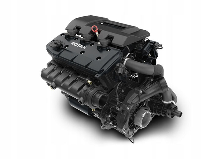

ROTALK NEWS Episode 5
Rotax-powered Sling aircraft from The Aircraft Factory, the AVMAP Navigation and engine monitoring system, and the Rotax powered Tucano Experimental and Light-Sport Aircraft.

ROTALK NEWS Episode 4
ROTAX’s 915iS-powered Aquila A211 test aircraft, the Scheibe SF-25C Falke (first-ever 912-equipped aircraft!) and ROTAX factory in Gunskirchen, Austria.

ROTALK NEWS Episode 3
Michael Smith’s Rotax-Powered Searey Circumnavigation, the amazing Rotax-Powered Lockwood Aircam and Anthony Caere’s chimpanzee rescue operations.
Руководство на английском языке по техническому обслуживанию и ремонту гидроциклов Sea-Doo модели 5802.
- Год издания: 1989
- Страниц: 173
- Формат: PDF
- Размер: 30,9 Mb
Руководство на английском языке по техническому обслуживанию и ремонту гидроциклов Sea-Doo моделей 5803-5810 (GT).
- Год издания: 1989
- Страниц: 194
- Формат: PDF
- Размер: 27,5 Mb
Руководство на английском языке по техническому обслуживанию и ремонту гидроциклов Sea-Doo моделей 5804 SP, 5811 GT и 5850 XP.
- Год издания: 1991
- Страниц: 224
- Формат: PDF
- Размер: 31,6 Mb
Руководство на английском языке по техническому обслуживанию и ремонту гидроциклов Sea-Doo моделей SP 5805/GTS 5812/XP 5851/GTX 5860.
- Год издания: 1992
- Страниц: 286
- Формат: PDF
- Размер: 45,5 Mb
Руководство на английском языке по техническому обслуживанию и ремонту гидроциклов Sea-Doo моделей SP 5806/SPX 5807/SPI 5808/GTS 5813/Explorer 5820/XP 5852/GTX 5861.
- Год издания: 1993
- Страниц: 305
- Формат: PDF
- Размер: 53,1 Mb
Руководство на английском языке по техническому обслуживанию и ремонту гидроциклов Sea-Doo моделей GTS 5814/Explorer 5821/XP 5854/GTX 5862/SP 5870/SPX 5871/SPI 5872.
- Год издания: 1994
- Страниц: 320
- Формат: PDF
- Размер: 67,3 Mb
Руководство на английском языке по техническому обслуживанию и ремонту гидроциклов Sea-Doo моделей GTS 5815/XP 5857/GTX 5863/SP 5873/SPX 5874/SPI 5875.
- Год издания: 1995
- Страниц: 618
- Формат: PDF
- Размер: 58,3 Mb
Сборник руководств на английском языке по техническому обслуживанию и ремонту гидроциклов Sea-Doo моделей GSX 5620/GTX 5640/GTS 5817/GTI 5865/GTI 5866/SP 5876/SPX 5877/SPI 5878/HX 5881.
- Год издания: 1996
- Страниц: 39/316
- Формат: PDF
- Размер: 20,3 Mb
Руководство на английском языке по техническому обслуживанию и ремонту гидроциклов Sea-Doo моделей GS 5621/GSI 5622/GSX 5624/GTI 5641/GTX 5642/SPX 5661/XP 5662/GTS 5818/SPX 5834/SP 5879/HX 5882.
- Год издания: 1997
- Страниц: 372
- Формат: PDF
- Размер: 51,4 Mb
Сборник руководств на английском языке по техническому обслуживанию и ремонту гидроциклов Sea-Doo моделей GS 5626/GS 5844/GSX Limited 5629/GSX Limited 5845/GTI 5836/GTI 5841/GTS 5819/GTX 5837/GTX 5842/GTX RFI 5666/GTX RFI 5843/SPX 5636/SPX 5839/XP 5665/XP5667.
- Год издания: 1998
- Страниц: 47/56/426
- Формат: PDF
- Размер: 102,4 Mb
Руководство на английском языке по техническому обслуживанию и ремонту гидроциклов Sea-Doo моделей GS 5846/GS 5847/GSX Limited 5848/GSX Limited 5849/GSX RFI 5637/GSX RFI 5638/GTS 5883/GTX Limited 5888/GTX Limited 5889/GTX RFI 5886/GTX RFI 5887/SPX 5636/SPX 5828/XP Limited 5868/XP Limited 5869.
- Год издания: 1999
- Страниц: 496
- Формат: PDF
- Размер: 85,7 Mb
Руководство на английском языке по техническому обслуживанию и ремонту гидроциклов Sea-Doo моделей GS 5644/GSX RFI 5645/GTI 5647/GTX 5653/GTX RFI 5648/GTX RFI 5515/XP 5651.
- Год издания: 2000
- Страниц: 456
- Формат: PDF
- Размер: 57,7 Mb
Руководство на английском языке по техническому обслуживанию и ремонту гидроциклов Sea-Doo моделей GTX DI 5649/RX 5513/RX DI 5646.
- Год издания: 2000
- Страниц: 351
- Формат: PDF
- Размер: 50,2 Mb
Руководство на английском языке по техническому обслуживанию и ремонту гидроциклов Sea-Doo моделей GS 5519/GTI 5523/GTS 5521/GTX 5527/GTX 5538/GTX DI 5529/GTX DI 5541/GTX RFI 5525/GTX RFI 5555/RX 5533/RX 5543/RX DI 5535/RX DI 5537/XP 5531.
- Год издания: 2001
- Страниц: 561
- Формат: PDF
- Размер: 75,3 Mb
Руководство на английском языке по техническому обслуживанию и ремонту гидроциклов Sea-Doo моделей GTI 5558-5559/GTI California 6116/GTI LE 5560-5561/GTI LE California 6117/GTX 5587-5588/GTX 4-TEC 5573-5574, 5593-5594/GTX DI 5563-5564, 5595-5596/GTX RFI 5565-5566/LRV DI 5460/RX 5579-5582/RX DI 5583-5586, 5591-5592/XP 5577-5578.
- Год издания: 2002
- Страниц: 557+505
- Формат: PDF
- Размер: 69,0 Mb
Руководство на английском языке по техническому обслуживанию и ремонту гидроциклов Sea-Doo моделей GTI/GTI LE/GTI LE RFI/GTX 4-TEC/GTX DI/LRV DI/RX DI/XP DI.
- Год издания: 2003
- Страниц: 779
- Формат: PDF
- Размер: 52,3 Mb
Сборник руководств на английском языке по техническому обслуживанию и ремонту гидроциклов Sea-Doo моделей 3D RFI/GTI/GTI LE/GTI LE RFI/GTX 4-TEC/GTX Supercharged/GTX Limited Supercharged/GTX Wakeboard Edition/RXP 4-TEC Supercharged/XP Di.
- Год издания: 2004
- Страниц: 89/801
- Формат: PDF
- Размер: 68,0 Mb
Руководство на английском языке по техническому обслуживанию и ремонту гидроциклов Sea-Doo с двухтактными двигателями.
- Год издания: 2005
- Страниц: 391
- Формат: PDF
- Размер: 39,5 Mb
Руководство на английском языке по техническому обслуживанию и ремонту гидроциклов Sea-Doo моделей 4-TEC.
- Год издания: 2005
- Страниц: 314
- Формат: PDF
- Размер: 27,0 Mb
Руководство на английском языке по техническому обслуживанию и ремонту двигателей Rotax моделей 717 и 787 RFI гидроциклов Sea-Doo.
- Год издания: 2005
- Страниц: 117
- Формат: PDF
- Размер: 6,9 Mb
Руководство на английском языке по техническому обслуживанию и ремонту двигателей Rotax модели 1503 4-TEC гидроциклов Sea-Doo.
- Год издания: 2005
- Страниц: 124
- Формат: PDF
- Размер: 19,6 Mb
Руководство на английском языке по техническому обслуживанию и ремонту гидроциклов Sea-Doo моделей 4-TEC.
- Год издания: 2006
- Страниц: 403
- Формат: PDF
- Размер: 94,9 Mb
Руководство на английском языке по техническому обслуживанию и ремонту гидроциклов Sea-Doo моделей 4-TEC.
- Год издания: 2007
- Страниц: 407
- Формат: PDF
- Размер: 50,9 Mb
Руководство на английском языке по техническому обслуживанию и ремонту гидроциклов Sea-Doo моделей 4-TEC.
- Год издания: 2008
- Страниц: 555
- Формат: PDF
- Размер: 50,9 Mb
Руководство на английском языке по техническому обслуживанию и ремонту гидроциклов Sea-Doo моделей GTX Limited IS 255 и RXT IS 255.
- Год издания: 2009
- Страниц: 555
- Формат: PDF
- Размер: 43,2 Mb
Дополнение к руководству на английском языке по техническому обслуживанию и ремонту гидроциклов Sea-Doo моделей 4-TEC.
- Год издания: 2009
- Страниц: 60
- Формат: PDF
- Размер: 19,8 Mb
Руководство на английском языке по техническому обслуживанию и катеров Sea-Doo моделей Challenger, Speedster и Sportster.
- Год издания: 1996
- Страниц: 274
- Формат: PDF
- Размер: 14,5 Mb
-
Page 1
www.SeaDooManuals.net… -
Page 2
2005 Engine Shop Manual ® ROTAX 717 and 787 RFI™ ENGINES www.SeaDooManuals.net… -
Page 3
™ Registered trademarks of Bombardier Recreational Products Inc. (BRP) or its affiliates. ® * Trademark of Bombardier Inc. used under license. BOMBARDIER LUBE ® RFI™ Rotax ® SEA-DOO ® Sea-Doo Synthetic Grease TOPS™ This document contains the trademarks of the following companies: Loctite ®… -
Page 4: Table Of Contents
TABLE OF CONTENTS SAFETY NOTICE ………………III INTRODUCTION ..
-
Page 5
TABLE OF CONTENTS 06 – TECHNICAL SPECIFICATIONS …………….57 787 RFI ENGINE 01 –… -
Page 6: Safety Notice
SAFETY NOTICE SAFETY NOTICE This ENGINE SHOP MANUAL has been prepared as a guide to correctly service and repair the 717 and 787 RFI Rotax ® engines. This edition was primarily published to be used by technicians who are already familiar with all service procedures relating to BRP products.
-
Page 7: Introduction
The Engine Identification Number is located on the This ENGINE SHOP MANUAL covers the 717 and upper crankcase on PTO side. 787 RFI Rotax made engines. It should be used in conjunction with the appropriate VEHICLE SHOP MANUAL. The information and component/system descrip- tions contained in this manual are correct at time of writing.
-
Page 8: Arrangement Of This Manual, Illustrations And Procedures
INTRODUCTION ARRANGEMENT OF THIS MANUAL, ILLUSTRATIONS AND PROCEDURES The manual is divided into many major sections as you can see in the main table of contents at the beginning of the manual. Several sections are divided in various subsec- tions. There is a table of contents at the beginning of many sections.
-
Page 9
INTRODUCTION Page heading indicates section and subsection detailed. Subsection title indicates beginning of the subsection. Italic sub-title above exploded view indicate pertaining models. Drop represents a liquid product to be applied to a surface. In this case Loctite 243 to screw threads. -
Page 10
INTRODUCTION Sub-title with part name(s) from exploded view. Section 06 FUEL SYSTEM Title indicates main procedure to be carried-out. To remove carburetors from engine, proceed as fol- Inspect parts for corrosion dammage (shaft, butterfly, lows: spring screw, check valve housing, etc.). Sub-sub-title in Remove air vent tube support. -
Page 11: Engine Measurement
Section 01 ENGINE MEASUREMENT Subsection 01 (MEASUREMENT PROCEDURES) MEASUREMENT PROCEDURES CYLINDER OUT OF ROUND NOTE: This section explains the procedures to correctly measure engine components. For the Using a cylinder bore gauge, measure cylinder engine technical specifications, refer to INSPEC- diameter at 16 mm (5/8 in) from top of cylinder.
-
Page 12: Piston/Cylinder Wall Clearance
Section 01 ENGINE MEASUREMENT Subsection 01 (MEASUREMENT PROCEDURES) 1. Combustion chamber NOTE: When checking the combustion chamber volume, engine must be cold, piston must be free of carbon deposit and cylinder head must be lev- eled. TYPICAL – Remove both spark plugs and bring one piston 1.
-
Page 13
Section 01 ENGINE MEASUREMENT Subsection 01 (MEASUREMENT PROCEDURES) 1. Micrometer set to the piston dimension F01D0NA Proceed with FINAL MEASUREMENT PROCE- 1. Measuring perpendicularly (90°) to piston pin axis DURE WITH EITHER A USED OR NEW PISTON A. See previous table below. -
Page 14: Ring/Piston Groove Clearance
Section 01 ENGINE MEASUREMENT Subsection 01 (MEASUREMENT PROCEDURES) 1. Micrometer set to the piston dimension Proceed with FINAL MEASUREMENT PROCE- 1. Indicator set to zero DURE WITH EITHER A USED OR NEW PISTON below. Position the dial bore gauge at 16 mm (5/8 in) be- low cylinder top edge.
-
Page 15: Ring End Gap
Section 01 ENGINE MEASUREMENT Subsection 01 (MEASUREMENT PROCEDURES) CRANKSHAFT (ASSEMBLED NOTE: Ring/piston groove clearance can be cor- rectly measured only on rectangular ring which is ENGINE) bottom ring. The following checks can be performed with en- gine in watercraft without overhauling engine. Crankshaft Alignment at Center Main Journal Since it is an assembled crankshaft it can become…
-
Page 16: Crankshaft (Disassembled Engine)
Section 01 ENGINE MEASUREMENT Subsection 01 (MEASUREMENT PROCEDURES) 1. Connecting rod journal alignment here Such misalignment may make it difficult to manu- ally turn the crankshaft. Verification can be done by measuring deflection each end of crankshaft. If deflection is found greater than specified toler- ance, this indicates worn bearing(s), bent and/or F01D4IA misaligned crankshaft.
-
Page 17
Section 01 ENGINE MEASUREMENT Subsection 01 (MEASUREMENT PROCEDURES) Crankshaft Deflection Crankshaft deflection is measured each end with a dial indicator. First, check deflection with crankshaft crankcase. If deflection exceeds the specified tolerance, it can be either ball bearings wear, bent or twisted crankshaft at connecting rod journal. -
Page 18: Rotary Valve
Section 01 ENGINE MEASUREMENT Subsection 01 (MEASUREMENT PROCEDURES) 1. 45° feeler gauge If rotary valve cover clearance is out of specifica- F01D1WA tions, machine rotary valve cover seating surface 1. Measuring big end axial play or replace the cover. 2. Feeler gauge SOLDERING WIRE METHOD Connecting Rod Straightness Remove rotary valve cover.
-
Page 19
Section 01 ENGINE MEASUREMENT Subsection 01 (MEASUREMENT PROCEDURES) Rotary Valve Shaft Deflection Remove cover then clean and measure com- pressed soldering wire thickness, it must be Deflection is measured with a dial gauge. Install within the specified tolerance. rotary valve shaft in crankcase half, without its If rotary valve cover clearance is over specified tol- gear. -
Page 20: Engine
Section 02 717 ENGINE Subsection 01 (LEAK TEST) LEAK TEST SERVICE TOOLS Description Part Number Page engine leak test kit …………… 295 500 352 ……….. 11 large hose pincher …………..529 032 500 ……….. 13 small hose pincher…………..295 000 076 ……..11–13 GENERAL When pressurizing the engine, first confirm that the components of the leak test kit are not leaking…
-
Page 21
Section 02 717 ENGINE Subsection 01 (LEAK TEST) 1. Loop hose and use clamps 2. Use two washers with exhaust manifold stud 3. Hose with adapter and nipple Activate pump and pressurize engine cooling sys- tem to 34 kPa (5 PSI). Wait 3 minutes and check if pressure drops;… -
Page 22
Section 02 717 ENGINE Subsection 01 (LEAK TEST) If no leak is found on the PTO side outer seal, remove magneto flywheel and verify crankshaft outer seals. Proceed with the ROTARY VALVE SHAFT testing if the crankshaft outer seals are not leaking. Rotary Valve Shaft NOTE: It is mandatory to drain the injection oil from the rotary valve shaft. -
Page 23
Section 02 717 ENGINE Subsection 01 (LEAK TEST) 1. Pump with reducer and nipple Activate pump and pressurize to 34 kPa (5 PSI). Check plug of the rotary valve shaft in crankcase. Remove PTO side spark plug. If pressure drops, it indicates a defective PTO side crankshaft inner seal or crankcase is not sealed correctly. -
Page 24: Engine Leakage Diagnostic Flow Chart
Section 02 717 ENGINE Subsection 01 (LEAK TEST) ENGINE LEAKAGE DIAGNOSTIC FLOW CHART PRESSURIZE ENGINE COOLING SYSTEM IS SYSTEM LEAKING? CHECK TESTING KIT REPLACE O-RING OF CYLINDER HEAD PRESSURIZE ENGINE AND/OR CYLINDER BASE GASKET IS ENGINE LEAKING? RECHECK ENGINE SEALING CHECK TESTING KIT CHECK ALL JOINTED SURFACES, SCREW/STUD THREADS.
-
Page 25: Magneto System
Section 02 717 ENGINE Subsection 02 (MAGNETO SYSTEM) MAGNETO SYSTEM SERVICE TOOLS Description Part Number Page extension handle …………..295 000 125 ……….. 19 M8 x 35 screws…………..420 841 591 ……….. 19 magneto coil centering tool ……….420 876 922 ……….. 22 magneto puller…………..
-
Page 26
Section 02 717 ENGINE Subsection 02 (MAGNETO SYSTEM) smr2005-076-001_aen smr2005-076 www.SeaDooManuals.net… -
Page 27: Disassembly
Section 02 717 ENGINE Subsection 02 (MAGNETO SYSTEM) DISASSEMBLY NOTE: If socket is found too large to be inserted in puller plate, machine or grind its outside diameter NOTE: The magneto system can be disassembled as necessary. without removing the engine from the watercraft. Magneto Cover Remove screws no.
-
Page 28
Section 02 717 ENGINE Subsection 02 (MAGNETO SYSTEM) Proceed as follows: – Before removing the armature plate, find a crankcase locating lug (the top one in this ex- ample). – Place a cold chisel at the end of chosen lug, then punch a mark on armature plate at this point. -
Page 29: Cleaning
Section 02 717 ENGINE Subsection 02 (MAGNETO SYSTEM) Generating Coil To replace generating coil no. 12: – Heat the armature plate to 93°C (200°F) around the screw holes to break the threadlocker bond. F00D09A 1. Heat the armature plate CAUTION: Protect harness from flame. –…
-
Page 30: Assembly
Section 02 717 ENGINE Subsection 02 (MAGNETO SYSTEM) ASSEMBLY Generating Coil Strip end of old wire then crimp and solder on new coil. Apply Loctite 243 (blue) (P/N 293 800 060) to screws no. 13 and install the new coil no. 12 on armature plate.
-
Page 31
Section 02 717 ENGINE Subsection 02 (MAGNETO SYSTEM) NOTE: Do not spray anticorrosion spray into mag- neto flywheel threaded holes. 1. Clean thoroughly and degrease replacement part using a non oil base solvent. 2. Apply coating in light thin coats. Refer to the manufacturer’s instructions. -
Page 32: Top End
Section 02 717 ENGINE Subsection 03 (TOP END) TOP END SERVICE TOOLS Description Part Number Page aligning tool …………….420 876 904 ……….. 34 circlip installer …………… 529 035 562 ……….. 32 piston pin puller …………..529 035 503 ……..28, 30 piston ring compressor…………
-
Page 33
Section 02 717 ENGINE Subsection 03 (TOP END) smr2005-077-001_aen smr2005-077 www.SeaDooManuals.net… -
Page 34: General
Section 02 717 ENGINE Subsection 03 (TOP END) GENERAL Remove cylinder screws no. 7. Remove cylinders no. 6, while making sure con- The 2-stroke Rotax engine rotates counterclock- ® necting rods do not hit crankcase edge. wise seen from the rear (PTO flywheel).
-
Page 35
Section 02 717 ENGINE Subsection 03 (TOP END) F01D43A TYPICAL 1. Openings covered with rag and rubber pad 1. Puller 2. Shoulder sleeve 3. Sleeve To remove circlip no. 9, insert a pointed tool in piston notch then pry it out and discard. –… -
Page 36: Cleaning
Section 02 717 ENGINE Subsection 03 (TOP END) TYPICAL TYPICAL 1. Tool cut-out toward bottom of piston 1. Remove shoulder sleeve – Firmly hold puller and rotate handle to pull pis- Carefully remove the piston no. 8. ton pin no. 10. The needles no.
-
Page 37: Inspection
Section 02 717 ENGINE Subsection 03 (TOP END) INSPECTION Piston At assembly, place the pistons no. 8 with the let- Refer to table below to find top end engine dimen- ters ″AUS″ (over an arrow on the piston dome) fac- sion specifications.
-
Page 38
Section 02 717 ENGINE Subsection 03 (TOP END) F01D0Q A 1. Outer ring removal after inner sleeve insertion into bore TYPICAL 1. Piston pin 2. Shoulder sleeve – Make sure thrust washers no. 12 are present each side of rollers. –… -
Page 39
Section 02 717 ENGINE Subsection 03 (TOP END) F01D0RA F01D0TA 1. Piston pin flush here 1. Pulling inner sleeve half 2. Thrust washers Circlip – Place piston over connecting rod and align Always use new circlips no. 9. bores, then gently tap piston pin with a fiber hammer to push out inner plastic ring on oppo- WARNING site side. -
Page 40
Section 02 717 ENGINE Subsection 03 (TOP END) Cylinder Base Gasket NOTE: The general procedure is to install a new gasket of the same thickness. However, if you do not know the gasket thickness that was installed or if a crank repair has involved replacement of connecting rods, refer to COMBUSTION CHAM- BER VOLUME MEASUREMENT in ENGINE MEA- TYPICAL… -
Page 41
Section 02 717 ENGINE Subsection 03 (TOP END) The aligning tool (P/N 420 876 904) or the exhaust manifold can be used to align cylinders. 1. Slide this edge NOTE: Ring compressor will not fit on oversize parts. Make sure to align ring end gap with piston locat- ing pin. -
Page 42
Section 02 717 ENGINE Subsection 03 (TOP END) TORQUING SEQUENCE Cylinder Head Exhaust Manifold Install cylinder head gasket. Make sure to install O-rings no. 14 around spark Make sure gaskets are properly positioned prior to plug holes and O-ring no. 15 of cylinder head as finalizing manifold installation. -
Page 43: Bottom End
Section 02 717 ENGINE Subsection 04 (BOTTOM END) BOTTOM END SERVICE TOOLS Description Part Number Page bearing heater…………… 529 035 969 ……….. 43 distance gauge …………..529 034 800 ……….. 44 Distance ring…………….. 420 876 569 ……….. 41 MAG side ring halves …………420 276 025 ……….. 41 Protective cap……………
-
Page 44
Section 02 717 ENGINE Subsection 04 (BOTTOM END) smr2005-078 www.SeaDooManuals.net… -
Page 45: General
Section 02 717 ENGINE Subsection 04 (BOTTOM END) GENERAL Using a suitable wrench or socket with a break- er bar, unscrew PTO flywheel COUNTERCLOCK- Engine has to be removed from watercraft to take WISE when facing it and hold extension handle apart bottom end.
-
Page 46
Section 02 717 ENGINE Subsection 04 (BOTTOM END) – starter, refer to appropriate VEHICLE SHOP MANUAL – rotary valve cover and valve, refer to ROTARY VALVE section – engine top end, refer to TOP END section. Put engine on a stand. Loosen crankcase screws. F01D1LA TYPICAL 1. -
Page 47: Cleaning
Section 02 717 ENGINE Subsection 04 (BOTTOM END) 1. Puller (P/N 420 877 635) 2. Protective cap (P/N 420 876 557) 3. Distance ring (P/N 420 876 569), MAG side only 4. Ring (P/N 420 977 490), both sides 5. MAG side ring halves (P/N 420 276 025) 6.
-
Page 48: Inspection
Section 02 717 ENGINE Subsection 04 (BOTTOM END) FIRST PASS TYPICAL Crankcase Crankcase mating surfaces are best cleaned us- ing a combination of the chisel gasket remover (P/N 413 708 500) and a brass brush. Brush a first pass in one direction then make the final brushing perpendicularly (90°) to the first pass cross (hatch).
-
Page 49: Assembly
Section 02 717 ENGINE Subsection 04 (BOTTOM END) TOLERANCE ENGINE New parts MEASUREMENT Wear limit 0.050 mm N.A. N.A. (.002 in) Crankshaft deflection 0.030 mm N.A. N.A. (.001 in) Connecting rod 0.311 mm 0.677 mm 1.2 mm (.012 in) (.026 in) (.047 in) big end axial play Crankcase…
-
Page 50
Section 02 717 ENGINE Subsection 04 (BOTTOM END) Touch the inner race of the bearing with the tem- Slide in the inner bearing. Push bearing to end perature indicator stick (P/N 529 035 970). Stick position. will liquefy when the bearing reach the proper Install the retaining disk. -
Page 51
Section 02 717 ENGINE Subsection 04 (BOTTOM END) NOTE: It is recommended to apply this specific sealant as described here to get an uniform appli- cation without lumps. If you do not use the roller method, you may use your finger to uniformly dis- tribute the sealant. -
Page 52
Section 02 717 ENGINE Subsection 04 (BOTTOM END) Crankcase Screws Using the same tools as for disassembly proce- dure, torque PTO flywheel to 110 N•m (81 lbf•ft). Apply Loctite 518 (P/N 293 800 038) on screw threads and Molykote 111 (P/N 413 707 000) be- low head screws. -
Page 53: Rotary Valve
Section 02 717 ENGINE Subsection 05 (ROTARY VALVE) ROTARY VALVE SERVICE TOOLS Description Part Number Page degree wheel……………. 529 035 607 ……….. 55 puller………………420 876 488 ……….. 49 pusher………………. 420 876 501 ……….. 51 pusher………………. 420 876 605 ……….. 52 TDC gauge…………….
-
Page 54
Section 02 717 ENGINE Subsection 05 (ROTARY VALVE) smr2005-079-001_aen smr2005-079 www.SeaDooManuals.net… -
Page 55: General
Section 02 717 ENGINE Subsection 05 (ROTARY VALVE) GENERAL Rotary Valve Shaft To remove the rotary valve shaft assembly, the The clearance of rotary valve cover or rotary valve engine must be removed from watercraft (refer to shaft gear backlash can be performed without tak- appropriate VEHICLE SHOP MANUAL).
-
Page 56
Section 02 717 ENGINE Subsection 05 (ROTARY VALVE) Shaft Bearing To remove bearing no. 8 use a bearing extractor such as Snap-on no. CJ-950 (or equivalent) as il- lustrated. Slide off distance sleeve no. 14, re- move snap ring no. 7 and washer no. 15 then press shaft out. -
Page 57: Cleaning
Section 02 717 ENGINE Subsection 05 (ROTARY VALVE) Rotary Valve Shaft Refer to table below to find dimension specifica- tions. For measurement procedures, refer to EN- GINE MEASUREMENT section. Close puller claws so that they can be inserted TOLERANCES ENGINE in end bearing.
-
Page 58
Section 02 717 ENGINE Subsection 05 (ROTARY VALVE) 1. Shield side (toward gear) Push bearing until it stops on its seat. 1. Seal 2. Ball bearing 3. Bearing extractor Snap-on CJ-950 Install washer no. 15, snap ring no. 7 and slide distance sleeve no. -
Page 59
Section 02 717 ENGINE Subsection 05 (ROTARY VALVE) A00C0YA 1. Pusher Push shaft until its stops on bearing seat. 1. Rotary valve shaft 2. Push shaft until it stops Snap Ring Position snap ring no. 4 so that its sharp edge faces outwards. -
Page 60
Section 02 717 ENGINE Subsection 05 (ROTARY VALVE) smr2005-079 www.SeaDooManuals.net… -
Page 61: Rotary Valve Timing
Section 02 717 ENGINE Subsection 05 (ROTARY VALVE) ROTARY VALVE TIMING CAUTION: Never use the ridge molded in crank case as a timing mark. The degree wheel (P/N 529 035 607) and the TDC gauge (P/N 295 000 143) are required to measure rotary valve opening and closing angles in relation with MAG side piston.
-
Page 62
Section 02 717 ENGINE Subsection 05 (ROTARY VALVE) 65° F01D3EB CLOSING MARK Step 1: Top of MAG inlet port. Align 360° line of degree wheel Step 2: Find 65° on outer scale of degree wheel and mark here – Remove degree wheel. –… -
Page 63: Technical Specifications
Section 02 717 ENGINE Subsection 06 (TECHNICAL SPECIFICATIONS) TECHNICAL SPECIFICATIONS ENGINE Engine type ROTAX 717, 2-stroke Induction type Rotary valve Type Water cooled, water injected Exhaust system Water injection fitting (head) 3.5 mm (.139 in) Water injection fitting (cone) 3.5 mm (.139 in)
-
Page 64: Rfi Engine
Section 03 787 RFI ENGINE Subsection 01 (LEAK TEST) LEAK TEST SERVICE TOOLS Description Part Number Page engine leak test kit …………… 295 500 352 ……..59–60 small hose pincher…………..295 000 076 ……..60–61 supplementary engine leak test kit……..295 500 780 ……..59–60 GENERAL It is also very important after servicing the engine, even for a complete engine rebuilt, to perform an-…
-
Page 65
Section 03 787 RFI ENGINE Subsection 01 (LEAK TEST) Engine Cooling System Remove the exhaust manifold gasket and ensure the surface is clean. Install the appropriate exhaust manifold plate from the engine leak test kit (P/N 295 500 352). Tighten plate using fasteners provided in the kit. -
Page 66
Section 03 787 RFI ENGINE Subsection 01 (LEAK TEST) Install pump to the exhaust plate fitting. If no leak is found on the PTO side outer seal, remove magneto flywheel and verify crankshaft outer seals. Proceed with the ROTARY VALVE SHAFT testing if the crankshaft outer seals are not leaking. -
Page 67
Section 03 787 RFI ENGINE Subsection 01 (LEAK TEST) Remove PTO side spark plug. If pressure drops, it indicates a defective PTO side crankshaft inner seal or crankcase is not sealed correctly. Remove MAG side spark plug. If pressure drops, it indicates a defective MAG side crankshaft inner seal or crankcase is not sealed correctly. -
Page 68: Engine Leakage Diagnostic Flow Chart
Section 03 787 RFI ENGINE Subsection 01 (LEAK TEST) ENGINE LEAKAGE DIAGNOSTIC FLOW CHART PRESSURIZE ENGINE COOLING SYSTEM IS SYSTEM LEAKING? CHECK TESTING KIT REPLACE O-RING OF CYLINDER HEAD PRESSURIZE ENGINE AND/OR CYLINDER BASE GASKET IS ENGINE LEAKING? RECHECK ENGINE SEALING CHECK TESTING KIT CHECK ALL JOINTED SURFACES, SCREW/STUD THREADS.
-
Page 69: Magneto System
Section 03 787 RFI ENGINE Subsection 02 (MAGNETO SYSTEM) MAGNETO SYSTEM SERVICE TOOLS Description Part Number Page crankshaft protector …………. 420 876 557 ……….. 67 installer handle …………..420 877 650 ……….. 69 magneto puller…………..420 976 235 ……….. 67 oil seal pusher……………
-
Page 70
Section 03 787 RFI ENGINE Subsection 02 (MAGNETO SYSTEM) smr2005-081-001_aen smr2005-081 www.SeaDooManuals.net… -
Page 71: Disassembly
Section 03 787 RFI ENGINE Subsection 02 (MAGNETO SYSTEM) DISASSEMBLY Rotor and Ring Gear NOTE: Crankshaft can also be locked by using the NOTE: The magneto system can be disassembled PTO flywheel extractor tool. For procedure, refer without removing the engine from the watercraft. to BOTTOM END.
-
Page 72: Cleaning
Section 03 787 RFI ENGINE Subsection 02 (MAGNETO SYSTEM) REMOVE SCREWS 1. Magneto housing Stator Assembly Remove holding plate no. 9 and withdraw plug from cover. TYPICAL Unscrew bolts no. 10 and remove stator no. 11 1. Puller from magneto cover. Tighten puller screw and at the same time, tap on screw head using a hammer to release magneto rotor from its taper.
-
Page 73: Assembly
Section 03 787 RFI ENGINE Subsection 02 (MAGNETO SYSTEM) Clean crankshaft taper and threads using pulley flange cleaner (P/N 413 711 809). Apply the pulley flange cleaner (P/N 413 711 809) on a rag first then clean the crankshaft. ASSEMBLY Stator Install the stator no.
-
Page 74
Section 03 787 RFI ENGINE Subsection 02 (MAGNETO SYSTEM) Crankshaft Position Sensor Install crankshaft position sensor no. 3 on mag- neto housing. Apply Molykote 111 (P/N 413 707 000) on its O-ring. Apply Loctite 767 (antiseize lubricant) (P/N 293 800 070) on screw threads then torque it to 9 N•m (80 lbf•in). -
Page 75: Top End
Section 03 787 RFI ENGINE Subsection 03 (TOP END) TOP END SERVICE TOOLS Description Part Number Page circlip installer …………… 529 035 562 ……….. 83 piston pin puller …………..529 035 503 ……..78, 81 piston ring compressor…………420 876 979 ……….. 84 rubber pad …………….
-
Page 76
Section 03 787 RFI ENGINE Subsection 03 (TOP END) smr2005-082-001_aen smr2005-082 www.SeaDooManuals.net… -
Page 77: General
(PTO flywheel). The 787 RFI engine has a rotary valve to control opening and closing of the intake and it is also equipped with the Rotax Adjustable Variable Ex- haust (RAVE) system. RAVE System (Rotax Adjustable Variable Exhaust)
-
Page 78: Disassembly
Section 03 787 RFI ENGINE Subsection 03 (TOP END) MAINTENANCE There are no wear parts anywhere in the system and there are no adjustments to be periodical- ly checked. The only possible maintenance re- quired would be cleaning of carbon deposits from the guillotine slide.
-
Page 79
Section 03 787 RFI ENGINE Subsection 03 (TOP END) 1. Remove spring 1. Bellows removed from piston Remove spring no. 30 retaining bellows no. 21 to valve piston no. 20. Unscrew valve piston no. 20 from sliding valve no. 22. NOTE: Hold the sliding valve to prevent it from turning. -
Page 80
Section 03 787 RFI ENGINE Subsection 03 (TOP END) 1. Remove spring 1. Remove O-ring Remove supporting ring no. 28. Remove sliding valve no. 22. 1. Remove supporting ring 1. Remove sliding valve Remove O-ring no. 23. Remove bellows no. 21. smr2005-082 www.SeaDooManuals.net… -
Page 81
Section 03 787 RFI ENGINE Subsection 03 (TOP END) Remove tuned pipe, refer to the appropriate VE- HICLE SHOP MANUAL. Proceed with ENGINE ON BENCH WORK. Engine on Bench Work Remove cylinder screws no. 13. Remove cylinders no. 9, while making sure con- necting rods do not hit crankcase edge. -
Page 82
Section 03 787 RFI ENGINE Subsection 03 (TOP END) F01D43A TYPICAL 1. Openings covered with rag and rubber pad 1. Puller 2. Shoulder sleeve 3. Sleeve To remove circlip no. 5, insert a pointed tool in piston notch then pry it out and discard. –… -
Page 83: Cleaning
Section 03 787 RFI ENGINE Subsection 03 (TOP END) TYPICAL TYPICAL 1. Tool cut-out toward bottom of piston 1. Remove shoulder sleeve – Firmly hold puller and rotate handle to pull pis- – Carefully remove the piston no. 3. ton pin no. 4. –…
-
Page 84: Inspection
Section 03 787 RFI ENGINE Subsection 03 (TOP END) INSPECTION ASSEMBLY Refer to table below to find top end engine dimen- Assembly is essentially the reverse of disassem- sion specifications. For dimension measurement bly procedures. However pay particular attention procedures, refer to ENGINE MEASUREMENT. to the following.
-
Page 85
Section 03 787 RFI ENGINE Subsection 03 (TOP END) IDENTIFICATION GASKET THICKNESS HOLES 0.3 mm (.012 in) 0.4 mm (.016 in) 0.5 mm (.020 in) 0.6 mm (.024 in) 0.8 mm (.031 in) Piston At assembly, place the pistons no. 3 with the let- ters ″AUS″… -
Page 86
Section 03 787 RFI ENGINE Subsection 03 (TOP END) NOTE: Make sure thrust washers are present Replacement roller bearings are delivered in a con- each side of needles. venient plastic mounting device. For installation, proceed as follows: – Install the shoulder sleeve tool on the opposite side of the piston pin. -
Page 87
Section 03 787 RFI ENGINE Subsection 03 (TOP END) F01D0RA F01D0TA 1. Piston pin flush here 1. Pulling inner sleeve half 2. Thrust washers Circlip – Place piston over connecting rod and align Always use new circlips. bores, then gently tap piston pin with a fiber hammer to push out inner plastic ring on oppo- WARNING site side. -
Page 88
Section 03 787 RFI ENGINE Subsection 03 (TOP END) Cylinder To easily slide cylinder no. 9 over piston, use the piston ring compressor (P/N 420 876 979). TYPICAL 1. Circlip installer – Remove sleeve from pusher then insert circlip into its bore. –… -
Page 89
Section 03 787 RFI ENGINE Subsection 03 (TOP END) When reassembling cylinders to crankcase, it is Torque screws in a criss-cross sequence for each important to have them properly aligned so that cylinder to 20 N•m (15 lbf•ft). Repeat the proce- exhaust flanges properly match up with exhaust dure, retightening all cylinder screws to 40 N•m manifold. -
Page 90: Adjustment
Section 03 787 RFI ENGINE Subsection 03 (TOP END) Apply also Molykote 111 (P/N 413 707 000) on Torque exhaust manifold screws to 24 N•m threads of screws no. 14. (17 lbf•ft) as per following illustrated sequence. Repeat the procedure, retightening screws to Torque cylinder head screws no.
-
Page 91: Bottom End
Section 03 787 RFI ENGINE Subsection 04 (BOTTOM END) BOTTOM END SERVICE TOOLS Description Part Number Page bearing heater…………… 529 035 969 ……….. 94 distance gauge …………..529 034 900 ……….. 96 Distance ring…………….. 420 876 569 ……….. 91 extension handle …………..295 000 125 ……….. 89 gear/bearing puller …………..
-
Page 92
Section 03 787 RFI ENGINE Subsection 04 (BOTTOM END) smr2005-083 www.SeaDooManuals.net… -
Page 93: General
Section 03 787 RFI ENGINE Subsection 04 (BOTTOM END) GENERAL Engine has to be removed from watercraft to take apart bottom end. Refer to appropriate VEHICLE SHOP MANUAL. Engine top end has to be disassembled to take apart bottom end. Refer to TOP END section in this manual.
-
Page 94
Section 03 787 RFI ENGINE Subsection 04 (BOTTOM END) Put engine on a stand. Loosen crankcase screws. F01D1LA TYPICAL 1. Separate halves by prying at provided lugs Remove crankshaft and counterbalance shaft. 1. M10 x 73.5 flanged screws 2. M8 x 53.5 flanged screws Crankshaft End Bearings Put engine back on a support. -
Page 95
Section 03 787 RFI ENGINE Subsection 04 (BOTTOM END) 1. Puller (P/N 420 877 635) 2. Protective cap (P/N 420 876 557) 3. Distance ring (P/N 420 876 569) 4. Ring (P/N 420 977 490) 5. Ring halves (P/N 420 977 475) 6. -
Page 96
Section 03 787 RFI ENGINE Subsection 04 (BOTTOM END) 1. Puller (P/N 420 877 635) 2. Protective cap (P/N 420 876 557) 3. Ring (P/N 420 977 480) 4. Ring halves (P/N 420 876 330) 5. Screw M8 x 40 (P/N 420 840 681) 1. -
Page 97: Cleaning
Section 03 787 RFI ENGINE Subsection 04 (BOTTOM END) Use a press to remove the gear no. 14 from the counterbalance shaft. F00D0TA CLEANING TYPICAL General Discard all oil seals, gaskets, O-rings and sealing Crankcase rings. Crankcase mating surfaces are best cleaned us- Clean oil passages and make sure they are not ing a combination of the chisel gasket remover clogged.
-
Page 98: Inspection
Section 03 787 RFI ENGINE Subsection 04 (BOTTOM END) TOLERANCE WEAR MEASUREMENT NEW PART LIMIT mm (in) Crankshaft N.A. 0.05 (.020) deflection MAG Crankshaft N.A. 0.08 (.003) deflection CENTER Crankshaft N.A. 0.03 (.001) deflection PTO Connecting rod big min. 0.230 (.008) 1.2 (.047) end axial play max.
-
Page 99
Section 03 787 RFI ENGINE Subsection 04 (BOTTOM END) Touch the inner race of the bearing with the tem- perature indicator stick (P/N 529 035 970). Stick will liquefy when the bearing reach the proper temperature. TYPICAL CAUTION: Bearing should not be heated to TYPICAL more than 80°C (176°F). -
Page 100
Section 03 787 RFI ENGINE Subsection 04 (BOTTOM END) Install distance ring no. 12. Position its chamfer toward crankshaft counterweight. Slide inner bearing on crankshaft until it bottoms. To properly position outer bearing, distance gauge (P/N 529 034 900) must be temporarily installed against inner bearing. -
Page 101
Section 03 787 RFI ENGINE Subsection 04 (BOTTOM END) Crankcase Sealant Application IMPORTANT: When beginning the application of the crankcase sealant, the assembly and the first torquing should be done within 10 minutes. It is suggested to have all you need on hand to save time. -
Page 102
Section 03 787 RFI ENGINE Subsection 04 (BOTTOM END) F00D0PA Do not apply in excess as it will spread out inside 1. Marks must be aligned crankcase. Turn by hand the crankshaft and counterbalance Crankshaft and Counterbalance Shaft shaft. Make sure they do not interfere with the Install crankshaft no. -
Page 103
Section 03 787 RFI ENGINE Subsection 04 (BOTTOM END) F00D0QA 1. Hollow side facing bearing Crankcase Halves Counterbalance Shaft Gear Oil Assemble crankcase halves. When crankcase assembly is completed, add Crankcase Screws 30 mL (1 oz) of motor oil SAE 30 to the counter- Apply Loctite 518 (P/N 293 800 038) on screw balance shaft gear through the crankcase filler threads and Molykote 111 (P/N 413 707 000) be-… -
Page 104
Section 03 787 RFI ENGINE Subsection 04 (BOTTOM END) F01D84A 1. O-ring Apply Loctite 767 (anti-seize lubricant) (P/N 293 800 070) to crankshaft threads. Using the same tools as for disassembly proce- dure, torque PTO flywheel to 110 N•m (81 lbf•ft). smr2005-083 www.SeaDooManuals.net… -
Page 105: Rotary Valve
Section 03 787 RFI ENGINE Subsection 05 (ROTARY VALVE) ROTARY VALVE SERVICE TOOLS Description Part Number Page Degree wheel …………… 529 035 607 ……… 109 handle ………………. 420 877 650 ……… 106 puller………………290 876 488 ……… 103 pusher………………. 290 876 609 ……… 106 pusher……………….
-
Page 106
Section 03 787 RFI ENGINE Subsection 05 (ROTARY VALVE) 787 RFI Engines smr2005-084-001_aen smr2005-084 www.SeaDooManuals.net… -
Page 107: General
Section 03 787 RFI ENGINE Subsection 05 (ROTARY VALVE) GENERAL Rotary Valve Shaft To remove the rotary valve shaft assembly, the The clearance of rotary valve cover or rotary valve engine must be removed from watercraft (refer to shaft gear backlash can be performed without tak- appropriate VEHICLE SHOP MANUAL).
-
Page 108
Section 03 787 RFI ENGINE Subsection 05 (ROTARY VALVE) Shaft Bearing To remove bearing no. 8 use a bearing extractor such as Snap-on no. CJ-950 (or equivalent) as il- lustrated. Slide off distance sleeve no. 14, re- move snap ring no. 7 and washer no. 15 then press shaft out. -
Page 109: Cleaning
Section 03 787 RFI ENGINE Subsection 05 (ROTARY VALVE) Rotary Valve Shaft Refer to table below to find dimension specifica- tions. For measurement procedures, refer to EN- GINE MEASUREMENT section. Close puller claws so that they can be inserted TOLERANCES ENGINE in end bearing.
-
Page 110
Section 03 787 RFI ENGINE Subsection 05 (ROTARY VALVE) 1. Shield side (toward gear) Push bearing until it stops on its seat. 1. Seal 2. Ball bearing 3. Bearing extractor Snap-on CJ-950 Install washer no. 15, snap ring no. 7 and slide distance sleeve no. -
Page 111
Section 03 787 RFI ENGINE Subsection 05 (ROTARY VALVE) 290876609 Push shaft until it stops on bearing seat. F01D8OA Snap Ring Position snap ring no. 4 so that its sharp edge faces outwards. Rotary Valve The rotary valve no. 13 controls the opening and closing of the inlet ports. -
Page 112
Section 03 787 RFI ENGINE Subsection 05 (ROTARY VALVE) There is no identification code on the valve. To find out the duration, place an angle finder on the valve and measure the valve cut-out angle or use the following template. smr2005-084 www.SeaDooManuals.net… -
Page 113: Rotary Valve Timing
Section 03 787 RFI ENGINE Subsection 05 (ROTARY VALVE) ROTARY VALVE TIMING CAUTION: Never use the ridge molded in crankcase as a timing mark. The following tools are required to measure rotary valve opening and closing angles in relation with MAG side piston.
-
Page 114
Section 03 787 RFI ENGINE Subsection 05 (ROTARY VALVE) 65° F01D3EB CLOSING MARK Step 1: Top of MAG inlet port. Align 360° line of degree wheel Step 2: Find 65° on outer scale of degree wheel and mark here – Remove degree wheel. –… -
Page 115: Technical Specifications
4.0 mm (.157 in) Exhaust system Water injection fitting (cone) Not applicable Water injection fitting (muffler) 4.5 mm (.177 in) Exhaust valve Rotax Adjustable Variable Exhaust (RAVE) Electric start Starting system Fuel/oil mixture VROI (Variable Rate Oil Injection) Lubrication Oil injection pump…
-
Page 116
Exhaust system Water injection fitting (cone) Not applicable Water injection fitting (muffler) 3 x 3.5 mm (.138 in) Exhaust valve Rotax Adjustable Variable Exhaust (RAVE) Starting system Electric start Fuel/oil mixture VROI (Variable Rate Oil Injection) Lubrication Oil injection pump… -
Page 117
www.SeaDooManuals.net…

