-
Contents
-
Table of Contents
-
Troubleshooting
-
Bookmarks
Related Manuals for Komatsu 82E Series
Summary of Contents for Komatsu 82E Series
-
Page 1
SEBM035103 DIESEL ENGINE © 2008 All Rights Reserved Printed in Japan 01-08 (01) 00-1… -
Page 2
PREFACE PREFACE This manual describes the service procedures for the 82E – 98E series engines of indirect injection system. Please use this manual for accurate, quick and safe servicing of the said engine. Since the explanation in this manual assumes the standard type engine, the specifications and components may partially be different from the engine installed on individual machine. -
Page 3
LIST OF REVISED PAGES The affected pages are indicated by the use of the Mark Indication Action required following marks. It is requested that necessary actions be taken to these pages according to the table below. Page to be newly added Page to be replaced Replace Page to be deleted… -
Page 4
LIST OF REVISED PAGES Time of Time of Time of Time of Time of Mark Page Mark Page Mark Page Mark Page Mark Page revision revision revision revision revision 10-1 10-2 10-3 10-4 10-5 11-1 11-2 11-3 8-10 11-4 8-11 11-5 8-12 11-6… -
Page 5
SAFETY LABELS SAFETY LABELS • Most accidents are caused by negligence of basic safety rules and precautions. For accident prevention, it is important to avoid such causes before development to accidents. Please read this manual carefully before starting repair or maintenance to fully understand safety precau- tions and appropriate inspection and maintenance procedures. -
Page 6
SAFETY PRECAUTIONS SAFETY PRECAUTIONS (1) SERVICE AREA • Sufficient Ventilation Inhalation of exhaust fumes and dust particles may be hazardous to ones health. Running engines welding, sanding, painting, and polishing tasks should be only done in well ventilated areas. • Safe / Adequate Work Area The service area should be clean, spacious, level and free from holes in the floor, to prevent «slip»… -
Page 7
(4) GENUINE PARTS and MATERIALS • Genuine Parts Always use genuine KOMATSU parts or KOMATSU recommended parts and goods. Damage to the engine, shortened engine life and or personal injury may result. 00-5 82E-5 – 98E-5 SERIES… -
Page 8
SAFETY PRECAUTIONS (5) FASTENER TORQUE • Torqueing Fasteners Always follow the torque values and procedures as designated in the shop manual. Incorrect values, procedures and or tools may cause dam- age to the engine and or personal injury. (6) ELECTRICAL SYSTEM •… -
Page 9
SAFETY PRECAUTIONS (8) FURTHER PRECAUTIONS • Fueling / Refueling Keep sparks, open flames or any other form of ignition (match, cigarette, etc.) away when fueling/refueling the unit. Fire and or an explosion may result. • Hot Surfaces. Do NOT touch the engine (or any of its components) during running or shortly after shutting it down. -
Page 10
PRECAUTIONS FOR SERVICE WORK PRECAUTIONS FOR SERVICE WORK 1. Precautions for Safety Read the safety precautions given at the beginning of this manual carefully and always mind safety in work. 2. Preparation for Service Work Preparation is necessary for accurate, efficient service work. Check the customer ledger file for the history of the engine. -
Page 11
HOW TO READ THIS MANUAL HOW TO READ THIS MANUAL 1. Range of Operation Explanation This manual explains the troubleshooting, installation/removal, replacement, disassemble/reassembly, inspection, adjustment and adjusting operation procedures for the 82E-5 to 98E-5 series engines with direct injection system. Refer to the shop manual for each of the fuel injection pump, governor, starting motor and alternator except for their installation. -
Page 12
HOW TO READ THIS MANUAL • Contents omitted in this manual Though the following jobs are omitted in the explanation in this manual, they should be conducted in actual work: 1) Jacking up and lifting 2) Cleaning and washing of removed parts as required 3) Visual inspection 3. -
Page 13
APPLICATION CATEGORY APPLICATION CATEGORY Application code Usage Eng. Rev. type. Revolution speed (rpm) Generator drive Constant 1,500/1,800 General use Variable 2,000 – 2,500 ★ For engine application category described in Chapter 1, Specifications. Engine Nomenclature — Model Cylinder bore (mm) Diesel engine Number of cylinders 00-11… -
Page 14
APPLICABLE MACHINE, SERIAL NUMBER APPLICABLE MACHINE, SERIAL NUMBER Engine Machine model Machine Serial No. Remarks 3D82AE-5M PC27MR-2 15001 and up 3D84E-5N PC30MR-2 20001 and up 3D84E-5X WA30-5 26001 and up WA40-3 19001 and up S3D84E-5X WA50-3 23001 and up S3D84E-5PBA PC35MR-2 6736 and up High altitude spec. -
Page 15: Table Of Contents
CONTENTS GENERAL ………………….1-2 INSPECTION AND ADJUSTMENT …………..2-1 TROUBLESHOOTING ………………3-1 DISASSEMBLY, INSPECTION AND REASSEMBLY OF ENGINES….4-1 LUBRICATION SYSTEM ………………5-1 COOLING SYSTEM ………………… 6-1 FUEL INJECTION PUMP/GOVERNOR…………… 7-1 TURBOCHARGER………………..8-1 STARTING MOTOR………………… 9-1 ALTERNATOR………………..10-1 ELECTRIC WIRING ………………. 11-1 SERVICE STANDARDS ………………
-
Page 16: General
1. GENERAL GENERAL Specifications……………………….1-3 Engine External Views ……………………1-51 Structural Description…………………….. 1-52 82E-5 – 98E-5 SERIES…
-
Page 17
1. GENERAL Specifications 3D82AE Engine name Unit 3D82AE Engine specification class – Type – Vertical, in-line, 4-cycle, water-cooled diesel engine Combustion chamber – Direct injection Number of cylinders – Cylinder bore x stroke mm x mm 82 x 84 l (cc) Displacement 1.331 (1,331) Revolving… -
Page 18
1. GENERAL 3D84E Engine name Unit 3D84E Engine specification class – Type – Vertical, in-line, 4-cycle, water-cooled diesel engine Combustion chamber – Direct injection Number of cylinders – Cylinder bore x stroke mm x mm 84 x 90 l (cc) Displacement 1.496 (1,496) Revolving… -
Page 19
1. GENERAL S3D84E Engine name Unit S3D84E Engine specification class – Type – Vertical, in-line, 4-cycle, water-cooled diesel engine Combustion chamber – Direct injection Number of cylinders – Cylinder bore x stroke mm x mm 84 x 90 l (cc) Displacement 1.496 (1,496) Revolving… -
Page 20
1. GENERAL Engine name Unit S3D84E (High altitude spec.) Engine specification class – Type – Vertical, in-line, 4-cycle, water-cooled diesel engine Combustion chamber – Direct injection Number of cylinders – Cylinder bore x stroke mm x mm 84 x 90 l (cc) Displacement 1.496 (1,496) -
Page 21
1. GENERAL 3D88E Engine name Unit 3D88E Engine specification class – Type – Vertical, in-line, 4-cycle, water-cooled diesel engine Combustion chamber – Direct injection Number of cylinders – Cylinder bore x stroke mm x mm 88 x 90 l (cc) Displacement 1.642 (1,642) Revolving… -
Page 22
1. GENERAL 4D84E Engine name Unit 4D84E Engine specification class – Type – Vertical, in-line, 4-cycle, water-cooled diesel engine Combustion chamber – Direct injection Number of cylinders – Cylinder bore x stroke mm x mm 84 x 90 l (cc) Displacement 1.995 (1,995) Revolving… -
Page 23
1. GENERAL S4D84E Engine name Unit S4D84E Engine specification class – Type – Vertical, in-line, 4-cycle, water-cooled diesel engine Combustion chamber – Direct injection Number of cylinders – Cylinder bore x stroke mm x mm 84 x 90 l (cc) Displacement 1.995 (1,995) Revolving… -
Page 24
1. GENERAL 4D88E Engine name Unit 4D88E Engine specification class – Type – Vertical, in-line, 4-cycle, water-cooled diesel engine Combustion chamber – Direct injection Number of cylinders – Cylinder bore x stroke mm x mm 88 x 90 l (cc) Displacement 2.190 (2,190) Revolving… -
Page 25
1. GENERAL 4D94LE Engine name Unit 4D94LE Engine specification class – Type – Vertical, in-line, 4-cycle, water-cooled diesel engine Combustion chamber – Direct injection Number of cylinders – Cylinder bore x stroke mm x mm 94 x 110 l (cc) Displacement 3.054 (3,054) Revolving… -
Page 26
1. GENERAL 4D98E Engine name Unit 4D98E Engine specification class – Type – Vertical, in-line, 4-cycle, water-cooled diesel engine Combustion chamber – Direct injection Number of cylinders – Cylinder bore x stroke mm x mm 98 x 110 l (cc) Displacement 3.319 (3,319) Revolving… -
Page 27
1. GENERAL S4D98E Engine name Unit S4D98E Engine specification class – Type – Vertical, in-line, 4-cycle, water-cooled diesel engine Combustion chamber – Direct injection Number of cylinders – Cylinder bore x stroke mm x mm 98 x 110 l (cc) Displacement 3.319 (3,319) Revolving… -
Page 29
GENERAL 1. GENERAL Engine External Views 1-51 82E-5 – 98E-5 SERIES… -
Page 30
1. GENERAL Structural Description 1-52 82E-5 – 98E-5 SERIES… -
Page 31: Inspection And Adjustment
2. INSPECTION AND ADJUSTMENT INSPECTION AND ADJUSTMENT Periodic Maintenance Schedule ………………….2-2 Periodic Inspection and Maintenance Procedure …………….. 2-3 2.2.1 Check before daily operation …………………… 2-3 2.2.2 Inspection after initial 50 hours operation ………………… 2-5 2.2.3 Inspection every 50 hours……………………2-8 2.2.4 Inspection every 250 hours or 3 months…………………
-
Page 32: Periodic Maintenance Schedule
2. INSPECTION AND ADJUSTMENT Periodic Maintenance Schedule The engine periodic inspection timing is hard to determine as it varies with the application, load status, qualities of the fuel and lubricating oils used and handling status. General rules are described here. Q : User-maintenance w : Parts replacement q : Shop-inspection Maintenance period Every…
-
Page 33: Periodic Inspection And Maintenance Procedure
2. INSPECTION AND ADJUSTMENT Periodic Inspection and Maintenance Procedure 2.2.1 Check before daily operation Be sure to check the following points before starting an engine every day. Inspection Item Visual check around engine Fuel tank level check and fuel supply Lube oil level check and replenishment Cooling water level check and replenishment Fuel pipe and cooling water pipe inspection and maintenance…
-
Page 34
2. INSPECTION AND ADJUSTMENT (Unit: l ) Model Total volume Effective volume 3D82AE (S)3D84E, 3D88E (S)4D84E, 4D88E 4D94LE, (S)4D98E 10.5 Lube oil capacity may differ from the above volume depending on an engine installed on a machine unit. (b) Replenishing oil pan with lube oil If the remaining engine oil level is low, fill the oil pan with the specified engine oil to the specified level through the filler port. -
Page 35: Inspection After Initial 50 Hours Operation
2. INSPECTION AND ADJUSTMENT IMPORTANT: If the cooling water runs short quickly or when the radiator runs short of water with the coolant recovery tank level unchanged, water may be leaking or the air tightness may be lost. Increase in the coolant recovery tank water level during operation is not abnormal.
-
Page 36
2. INSPECTION AND ADJUSTMENT In early period of use, the engine oil gets dirty rapidly because of the initial wear of internal parts. Replace the engine oil earlier. Lube oil filter should also be replaced when the engine oil is replaced. The procedure of lube oil and lube oil filter replacement is as follows. -
Page 37
2. INSPECTION AND ADJUSTMENT (2) V-belt tension check When there is not enough tension in the V-belt, the V-belt will slip making it impossible for the alternator to generate power and cooling water pump and cooling fan will not work causing the engine to overheat. -
Page 38: Inspection Every 50 Hours
2. INSPECTION AND ADJUSTMENT 2.2.3 Inspection every 50 hours Be sure to check the following points every 50 hours operation. Inspection Item Fuel tank draining Water separator draining Bleeding the fuel system Battery electrolyte level check and battery recharging (1) Fuel tank draining 1) Prepare a waste oil container.
-
Page 39
2. INSPECTION AND ADJUSTMENT (3) Bleeding the fuel system Bleed the fuel system according to the following procedures. When there is air in the fuel sys- tem, the fuel injection pump will not be able to function. 1) Check the fuel oil level in the fuel tank. Refuel if insufficient. -
Page 40
2. INSPECTION AND ADJUSTMENT Battery structure (1) Electrolyte level • Check the level of fluid in the battery. When the amount of fluid nears the lower limit, fill with battery fluid (available in the market) to the upper limit. If operation con- tinues with insufficient battery fluid, the bat- tery life is shortened, and the battery may overheat and explode. -
Page 41
2. INSPECTION AND ADJUSTMENT (b) Measurement with hydrometer When using a hydrometer, the measured specific gravity must be corrected according to the temperature at the time of measure- ment. The specific gravity of battery electro- lyte is defined with 20°C as the standard. Since the specific gravity increases or decreases by 0.0007 when the temperature varies by 1°C, correct the value according to… -
Page 42: Inspection Every 250 Hours Or 3 Months
2. INSPECTION AND ADJUSTMENT 2.2.4 Inspection every 250 hours or 3 months Be sure to check the following points every 250 hours or 3 months operation, whichever comes first. Inspection Item Lube oil and filter replacement Radiator fin cleaning V-belt tension check Inspection and adjustment of governor lever and accelerator Air cleaner cleaning and element replacement (1) Lube oil and filter replacement (The second replacement and after)
-
Page 43
2. INSPECTION AND ADJUSTMENT (4) Inspection and adjustment of governor lever and accelerator The governor lever and accelerating devices (accelerating lever, pedal, etc.) of the machine unit are connected by an accelerating wire or rod. If the wire becomes stretched or the con- nections loose, the deviation in the position may result and make operation unsafe. -
Page 44
2. INSPECTION AND ADJUSTMENT 3) Blow air [0.29 – 0.49 MPa {3.0 – 5.0 kg/ }] from inside the element to blow dust off as shown in the illustration right. Apply the air blowing pressure as low as possible so as not to damage the element. If having the air cleaner with double ele- ments, never remove and clean the inner element. -
Page 45: Inspection Every 500 Hours Or 6 Months
2. INSPECTION AND ADJUSTMENT 2.2.5 Inspection every 500 hours or 6 months Be sure to check the following points every 500 hours or 6 months operation, whichever comes first. Inspection Item Water separator cleaning Fuel filter element replacement Air cleaner cleaning and element replacement (1) Water separator cleaning Periodically wash the water separator element and inside cup with clean fuel oil.
-
Page 46
3D82AE – 4D88E YM119802-55800 5) Bleed the fuel system. Refer to 2.2.3.(3) IMPORTANT: Be sure to use genuine Komatsu part (super fine mesh filter). Otherwise, it results in engine dam- age, uneven engine performance and shorten engine life. (3) Air cleaner cleaning and element replacement Replace the air cleaner element periodically even if it is not damaged or dirty. -
Page 47: Inspection Every 1,000 Hours Or One Year
2. INSPECTION AND ADJUSTMENT 2.2.6 Inspection every 1,000 hours or one year Be sure to check the following points every 1,000 hours or one year operation, whichever comes first. Inspection Item Cooling water replacement Diaphragm ass’y inspection Turbocharger blower cleaning* Intake/exhaust valve clearance adjustment Fuel injection nozzle pressure inspection (1) Cooling water replacement…
-
Page 48
2. INSPECTION AND ADJUSTMENT g) When filling with the cooling water for the first time or replacing, the air contains in the cooling water system. So, as the air in the cooling water system is self-bleeded during engine operation, the cool- ing water level in the radiator and coolant recovery tank will be lowered. -
Page 49
2. INSPECTION AND ADJUSTMENT (3) Turbocharger blower cleaning When engine speed seems sluggish or the exhaust color looks poor, the blades of the turbocharger-blower may be dirty. Wash the turbine blower in such a case. (a) General items 1) As for washing, use washing liquid and clear water. 2) Washing time is the time when about 10% of the boost pressure decreases more than that of usual operation state as a standard. -
Page 50
2. INSPECTION AND ADJUSTMENT (4) Intake/exhaust valve clearance adjustment Make measurement and adjustment while the engine is cold. (a) Valve clearance measurement 1) Remove the rocker arm cover above cylinder head. 2) Set the No.1 cylinder in the compres- sion TDC. Turn the crankshaft to bring the piston of the No.1 cylinder to its compression top dead center while watching the rocker… -
Page 51
2. INSPECTION AND ADJUSTMENT In case of 3-cylinder engines, turn the crankshaft 240° and make adjustment for the No.3 cylinder. Then adjust the No.2 cylinder in this order. The cylinder to be adjusted first does not have to be the No.1 cylinder. Select and adjust the cylin- der where the piston is the nearest to the top dead center after turning, and make adjustment for other cylinders in the order of ignition by turning the crankshaft 240°… -
Page 52
2. INSPECTION AND ADJUSTMENT Push the bridge head so that a cross head and two valve stem heads may contact each other uniformly, and adjust an adjusting bolt so that a gap of the v a l v e s t e m h e a d m a y b e c o m e 0 . Tighten a locknut after a cross head is fixed with a wrench. -
Page 53
2. INSPECTION AND ADJUSTMENT (5) Fuel injection nozzle pressure inspection Wear protective glasses when testing injection from the fuel injection valve. Never approach the injection nozzle portion with a hand. The oil jetting out from the nozzle is at a high pressure to cause loss of sight or injury if coming into careless contact with it. -
Page 54
2. INSPECTION AND ADJUSTMENT [Informative: Fuel injection valve structure] (b) Spray pattern inspection After adjustment to the specified valve opening pressure, use a nozzle tester and check the spray pattern and seat oil-tight- ness. Seat oil tightness check • After injecting a few times, increase the pressure gradually. -
Page 55
2. INSPECTION AND ADJUSTMENT Spray and injection states • Operate the nozzle tester lever at a rate of once or twice a second and check no abnormal injection. • If normal injection as shown below can- not be obtained, replace the fuel injec- tion valve. -
Page 56: Inspection Every 2000 Hours Or 2 Years
2. INSPECTION AND ADJUSTMENT 2.2.7 Inspection every 2000 hours or 2 years Be sure to check the following points every 2,000 hours or two years operation, whichever comes first. Inspection Item Cooling water path flushing and maintenance Fuel pipe and cooling water pipe inspection and maintenance Intake/exhaust valve seat lapping Fuel injection timing adjustment Fuel injection pump inspection and adjustment…
-
Page 57
– (the fuel injection angle of a disassembled previous fuel injection pump) [NOTICE] Tell the fuel injection pump number to Komatsu, and inquire the injection angle of the pump when it is hard to find out. 6) Put the fuel injection pump on the gear case temporarily and install the drive gear on the cam shaft with checking the ID marks, which were put on the fuel injection pump drive gear and the idle gear at the time of the disassembling. -
Page 58
2. INSPECTION AND ADJUSTMENT 7) Adjust the injection angle difference, calculated in the above 5), at 0.25° in the unit in the installation angle of the fuel injection pump while reading the mark (minimum 0.5° and cam angle) of the adjustment sticker. -
Page 59: Adjusting The No-Load Maximum Or Minimum Speed
2. INSPECTION AND ADJUSTMENT Adjusting the No-load Maximum or Minimum Speed 1) After warming the engine up, gradually raise the speed and set it at the no-load maximum revolution. 2) If the no-load maximum speed is out of the stan- dard, adjust it by turning the high idle limiting bolt.
-
Page 60: Water Leak Check In Cooling Water System
2. INSPECTION AND ADJUSTMENT Water Leak Check in Cooling Water System Check cooling water leakage from the cooling water system visually. If any problem is found, inspect as follows. 1) Fill cooling water to the normal level in the radia- tor, and install the cap tester on the radiator.
-
Page 61: Thermostat Inspection
2. INSPECTION AND ADJUSTMENT Thermostat Inspection Place the thermostat in a container filled with water. Heat it while measuring the water temperature, and see that the thermostat is actuated at temperature of following table. Valve opening Full open lift Model Temperature (Temperature) (°C)*…
-
Page 62: Adjusting Operation
2. INSPECTION AND ADJUSTMENT Adjusting Operation Perform the adjusting operation of an engine as follows after the maintenance job: 1) Supply the fuel oil, lubricating oil and cooling water. Note: Check the levels of the lubricating oil and cooling water again after test running (for about 5 minutes) and add as required.
-
Page 63: Troubleshooting
3. TROUBLESHOOTING TROUBLESHOOTING Preparation Before Troubleshooting………………… 3-2 Quick Reference Table for Troubleshooting ………………3-3 Troubleshooting by Measuring Compression Pressure……………. 3-6 82E-5 – 98E-5 SERIES…
-
Page 64
3. TROUBLESHOOTING Preparation Before Troubleshooting If the signs of a trouble appear, it is important to lecture on the countermeasure and treatment before becoming a big accident not to shorten the engine life. When the signs of a trouble appear in the engine or a trouble occurs, grasp the trouble conditions fully by the next point and find out the cause of sincerity according to the troubleshooting. -
Page 65
3. TROUBLESHOOTING 82E-5 – 98E-5 SERIES… -
Page 66
3. TROUBLESHOOTING 82E-5 – 98E-5 SERIES… -
Page 67
3. TROUBLESHOOTING 82E-5 – 98E-5 SERIES… -
Page 68
3. TROUBLESHOOTING Troubleshooting by Measuring Compression Pressure Compression pressure drop is one of major causes of increasing blowby gas (lubricating oil contamination or increased lubricating oil consumption as a resultant phenomenon) or starting failure. The compression pres- sure is affected by the following factors: 1) Degree of clearance between piston and cylinder 2) Degree of clearance at intake/exhaust valve seat 3) Gas leak from nozzle gasket or cylinder head gasket… -
Page 69
3. TROUBLESHOOTING (3) Engine speed and compression pressure (for reference) (4) Measured value and troubleshooting When the measured compression pressure is below the limit value, inspect each part by referring to the table below. Item Cause Corrective action • Air cleaner element •… -
Page 70: Disassembly, Inspection And Reassembly Of Engines
4. DISASSEMBLY, INSPECTION AND REASSEMBLY OF ENGINES DISASSEMBLY, INSPECTION AND REASSEMBLY OF ENGINES Complete Disassembly and Reassembly ………………… 4-2 4.1.1 Introduction ……………………….4-2 4.1.2 Special service tools ……………………..4-3 4.1.3 Complete disassembly…………………….. 4-8 4.1.4 Precautions before and during reassembly ………………4-12 4.1.5 Adjusting operation ……………………..
-
Page 71: Complete Disassembly And Reassembly
4. DISASSEMBLY, INSPECTION AND REASSEMBLY OF ENGINES Complete Disassembly and Reassembly 4.1.1 Introduction Make preparation as follows before starting engine inspection and service: 1) Fix the engine on a horizontal base. Be sure to fix the engine securely to prevent injury or damage to parts due to falling during the work. 2) Remove the cooling water hose, fuel oil pipe, wire harness, control wires etc.
-
Page 72: Special Service Tools
4. DISASSEMBLY, INSPECTION AND REASSEMBLY OF ENGINES 4.1.2 Special service tools (1) Special Tools Tool name Applicable model and tool size Illustration Model 3D82AE 4D94LE Valve guide tool (S)4D98E (for extracting valve 4D84E guide) (S)3D84E 3D88E, 4D88E S4D84E *Locally manufactured Model 3D82AE 4D84E…
-
Page 73
4. DISASSEMBLY, INSPECTION AND REASSEMBLY OF ENGINES Tool name Applicable model and tool size Illustration Model 3D82AE 15.2 15.8 4D84E Stem seal inserter (S)3D84E 16.2 13.5 18.8 (for inserting stem 4D88E seal) S4D84E 12.9 11.5 10.0 4D94LE 15.2 11.8 (S)4D98E *Locally manufactured Filter wrench (for removal / installa-… -
Page 74
4. DISASSEMBLY, INSPECTION AND REASSEMBLY OF ENGINES Tool name Applicable model and tool size Illustration Piston ring replacer (for removal / installa- Available on the market tion of piston ring) Locally manufactured Crankshaft pulley (for 4D94LE) installing tool (Refer to 4.3.6 in detail) (2) Measuring instruments Instrument name Application… -
Page 75
4. DISASSEMBLY, INSPECTION AND REASSEMBLY OF ENGINES Instrument name Application Illustration Depth micrometer For measuring of valve sink For measuring valve spring inclination and Square straightness of parts V-block For measuring shaft bend For tightening nuts and bolts to the specified Torque wrench torque For measuring gaps between ring and ring… -
Page 76
4. DISASSEMBLY, INSPECTION AND REASSEMBLY OF ENGINES Instrument name Application Illustration For measuring injection spray pattern of fuel injec- Nozzle tester tion nozzle and injection pressure Digital thermometer For measuring temperatures Contact For measuring revolution by contacting the mor- type tise in the revolving shaft Speed- ometer… -
Page 77: Complete Disassembly
4. DISASSEMBLY, INSPECTION AND REASSEMBLY OF ENGINES 4.1.3 Complete disassembly Peripheral parts such as air cleaner, muffler and radiator differ in installation and types for each application. Therefore, description in this Chapter is started with the steps to be taken just after the peripheral parts have been removed.
-
Page 78
4. DISASSEMBLY, INSPECTION AND REASSEMBLY OF ENGINES Step Removal Parts Remarks 1) Remove cylinder head tightening bolt. 1) Lay a cardboard or the like on the floor and 2) Remove cylinder head assembly. place cylinder head assembly on it so as not to 3) Remove cylinder head gasket. -
Page 79
4. DISASSEMBLY, INSPECTION AND REASSEMBLY OF ENGINES Step Removal Parts Remarks 1) Remove oil pan and spacer. 1) Put the cylinder block with the attaching sur- face of the cylinder head facing down. 2) Carefully protect the combustion surface of the cylinder block from damage. -
Page 80
4. DISASSEMBLY, INSPECTION AND REASSEMBLY OF ENGINES Step Removal Parts Remarks 1) Remove main bearing cap bolt. While shaking 1) Before extracting crankshaft, measure the main bearing cap, remove main bearing cap side gap around it. together with lower main bearing metal. 2) Extract crankshaft, taking care not to damage 3) Remove upper main bearing metal. -
Page 81: Precautions Before And During Reassembly
4. DISASSEMBLY, INSPECTION AND REASSEMBLY OF ENGINES 4.1.4 Precautions before and during reassembly To reassemble engine components, reverse the procedure of disassembly. However, follow the precautions below and the precautions from in chapter 4 to in chapter 7 particularly before and during reassembly. (1) Cleaning the component Use particular care to clean the cylinder block, cylinder head, crankshaft, and camshaft.
-
Page 82: Cylinder Head: Disassembly, Inspection And Reassembly
4. DISASSEMBLY, INSPECTION AND REASSEMBLY OF ENGINES Cylinder Head: Disassembly, Inspection and Reassembly 4.2.1 Components (2-valve cylinder head) 4.2.2 Disassembly procedure Disassemble in the order of the numbers shown in the illustration. 1) Remove the alternator ass’y. (Point 1) 2) Remove the fan, pulley and V belt. 3) Remove the thermostat case.
-
Page 83: Reassembly Procedure
4. DISASSEMBLY, INSPECTION AND REASSEMBLY OF ENGINES 4.2.3 Reassembly procedure Reverse order of the disassembly procedure. 4-14 82E-5 – 98E-5 SERIES…
-
Page 84: Servicing Points
4. DISASSEMBLY, INSPECTION AND REASSEMBLY OF ENGINES 4.2.4 Servicing points Point 1 [Disassemble] • Loosen the mounting bolt while supporting the alternator. Do not tilt the alternator toward the cylinder block in haste since it may damage the alterna- tor or pinch a finger. [Reassemble] •…
-
Page 85
4. DISASSEMBLY, INSPECTION AND REASSEMBLY OF ENGINES Point 6 1) Removing pipe seals of 4 valve head. [Disassemble] • Take off a rocker arm cover in case of 4 valve head after removing fuel injection pipes and pipe seals. [NOTICE] Attention is necessary because a fuel nozzle is caught in a pipe seal and the pipe seal is dam- aged when a rocker arm cover is lifted with a… -
Page 86
4. DISASSEMBLY, INSPECTION AND REASSEMBLY OF ENGINES [NOTICE] 1) When a diaphragm is damaged, pressure control inside the crankcase becomes insufficient, and troubles occur. When the internal pressure of the crankcase decreases too much due to the damage of a spring, much blowby gas containing oil is reduced in intake air system, and it may cause the combustion defect by the early dirt of the intake valve or the urgent rotation of the engine by the oil burning. -
Page 87
4. DISASSEMBLY, INSPECTION AND REASSEMBLY OF ENGINES Point 9 [Disassemble] • Carefully remove the fuel injection valve so as not to leave the top end protector from being left inside the cylinder. [Reassemble] • Replace the fuel injection valve protector with a new one. -
Page 88
4. DISASSEMBLY, INSPECTION AND REASSEMBLY OF ENGINES 4.2.5 Parts inspection and measurement (1) Cylinder head Clean the cylinder head, mainly the combustion surface, valve seats and intake/exhaust ports, remove carbon deposit and bonding agent, and check the surface state. (a) Appearance check Check mainly discoloration and crack. -
Page 89
4. DISASSEMBLY, INSPECTION AND REASSEMBLY OF ENGINES (2) Valve guide Mainly check damage and wear on the inside wall. Apply the service part No. when replacing a part. Model Service part No. Suction YM124060-11800 3D82AE (2-valve) Exhaust YM119802-11810 4D84E Suction YM120130-11860 (S)3D84E 3D88E, 4D88E… -
Page 90
4. DISASSEMBLY, INSPECTION AND REASSEMBLY OF ENGINES (3) Intake/exhaust valve Mainly clean and check damage and wear at the valve stem and seat. (a) Seat contact: See (1)-(d) above. (b) Stem outside diameter: See (2) above. (c) Valve head thickness Model Part Standard… -
Page 91
4. DISASSEMBLY, INSPECTION AND REASSEMBLY OF ENGINES (5) Valve rocker arm Mainly inspect valve head cap contact surface, inside surface defects and wear. Slight surface defects shall be corrected with an oilstone. Model Items Standard Limit 3D82AE Arm hole 16.00 – 16.02 16.07 (S)3D84E diameter (S)4D84E… -
Page 92
4. DISASSEMBLY, INSPECTION AND REASSEMBLY OF ENGINES 4.2.6 Valve seat correction [NOTICE] Always check the oil clearance between the valve and valve guide before correcting the valve seat. If it exceeds the limit, replace the valve or valve guide first to make the clearance satisfy the standard. After correc- tion, wash the valve and the cylinder head sufficiently with diesel oil to remove all grinding powder or compound. -
Page 93
4. DISASSEMBLY, INSPECTION AND REASSEMBLY OF ENGINES 4.2.7 Valve guide replacement 1) Use a valve guide extraction tool (12.1-1 in Chapter 12) and extract the valve guide from the cylinder head. 2) Put liquid nitrogen or ether (or alcohol) with dry ice added in a container and put the valve guide for replace- ment in it for cooling. -
Page 94
4. DISASSEMBLY, INSPECTION AND REASSEMBLY OF ENGINES 4.2.8 Valve stem seal replacement Always use a new seal after the intake/exhaust valve is disassembled. Since the one for the exhaust valve is marked with yellow paint, do not confuse the intake and exhaust valves. 1) Apply engine oil to the lip. -
Page 95: Gear Train And Camshaft
4. DISASSEMBLY, INSPECTION AND REASSEMBLY OF ENGINES Gear Train and Camshaft 4.3.1 Components 4.3.2 Disassembly procedure Disassemble in the order of the numbers in the illustration. 1) Perform steps 1) to 12) of the cylinder head disassembly procedure. 2) Remove the cooling water pump. 3) Remove the crankshaft pulley.
-
Page 96: Servicing Points
4. DISASSEMBLY, INSPECTION AND REASSEMBLY OF ENGINES 4.3.4 Servicing points Point 1 [Disassemble] • Remove the crankshaft pulley using a gear puller after removing the crankshaft pulley set bolt. When removing the pulley using the gear puller, use a pad and carefully operate so as not to damage the thread.
-
Page 97
4. DISASSEMBLY, INSPECTION AND REASSEMBLY OF ENGINES Point 3: (Refer to 7.2.5 in chapter 7) [Disassemble] • Remove the mounting nut of the fuel injection pump drive gear, remove the gear using the gear puller, and remove the fuel injection pump. Do not forget to remove the stay on the rear side. -
Page 98
4. DISASSEMBLY, INSPECTION AND REASSEMBLY OF ENGINES [Disassemble] • Since the camshaft gear is shrink-fit, heat it to 180°C – 200°C for extraction. • For camshaft removal, raise the engine with its mounting flange at the bottom. After removing the thrust metal mounting bolt from the camshaft gear hole, extract the camshaft carefully so as not to damage the bearing bushing. -
Page 99: Parts Inspection And Measurement
4. DISASSEMBLY, INSPECTION AND REASSEMBLY OF ENGINES 4.3.5 Parts inspection and measurement (1) Camshaft Mainly check the contact between the tappet and cam contact surface, bearing seizure and wear, and gear damage. (a) Shaft bend measurement Support the camshaft with V blocks. Rotate the camshaft and measure the runout at the center of the camshaft and at each journal with a dial gauge.
-
Page 100
4. DISASSEMBLY, INSPECTION AND REASSEMBLY OF ENGINES Model Place Item Standard Limit Bushing I.D. 44.990 – 45.055 45.130 Gear side Camshaft O.D. 44.925 – 44.950 44.890 Oil clearance 0.040 – 0.130 0.240 Bushing I.D. 45.000 – 45.025 45.100 Intermediate 3D82AE – 4D88E Camshaft O.D. -
Page 101: Oil Seal Replacement (Gear Case Side)
4. DISASSEMBLY, INSPECTION AND REASSEMBLY OF ENGINES 4.3.6 Oil seal replacement (Gear case side) 1) Replace the oil seal with a new one when the gear case is disassembled. Extract the used oil seal. 2) Insert a new oil seal. Fit the position of the oil seal insertion to the end face of the gear case. (Refer to the below figure.) 3) Apply lithium grease to the oil seal lips.
-
Page 102: Cylinder Block
4. DISASSEMBLY, INSPECTION AND REASSEMBLY OF ENGINES Cylinder Block 4.4.1 Components 4.4.2 Disassembly procedure: Disassemble in the order of the numbers in the illustration. 1) Perform steps 1) to 12) in the cylinder head disassembly procedure. 2) Perform steps 1) to 12) in the gear train disassembly procedure. 3) Remove the oil pan.
-
Page 103: Servicing Points
4. DISASSEMBLY, INSPECTION AND REASSEMBLY OF ENGINES 4.4.4 Servicing points Point 1: Oil pan [Disassemble] • Sealant is applied to the oil pan mounting sur- face on the block. Carefully operate so as not to damage or distort the bonding surface. [Reassemble] •…
-
Page 104
4. DISASSEMBLY, INSPECTION AND REASSEMBLY OF ENGINES [Reassemble] Apply sealant (Part No.YM 977770-01212) and install the mounting flange by matching the two dowel pins. After assembly, raise the engine with its mounting flange on the bottom side. Unforeseen injury may arise due to falling of slipping when raising or reversing the engine. -
Page 105
4. DISASSEMBLY, INSPECTION AND REASSEMBLY OF ENGINES [Disassemble] • Remove the bearing caps, cap side bearings, and thrust metals. Place each thrust metal with identification of the position and direction. T h e po s i ti o n nu m be r o f r e a s s em b l i ng i s punched on a metal cap (except for both ends) and a cylinder block. -
Page 106
4. DISASSEMBLY, INSPECTION AND REASSEMBLY OF ENGINES Point 6: Piston pin and rings [Disassemble] • Using the piston ring replacer (see 4.1.2 in Chapter 4), remove the piston rings. • Remove the circlip and remove the piston pin by pushing it out. [Reassemble] •… -
Page 107: Parts Inspection And Measurement
4. DISASSEMBLY, INSPECTION AND REASSEMBLY OF ENGINES 4.4.5 Parts inspection and measurement (1) Cylinder block Especially clean head surface, cylinder bores and oil holes, and check after removing any car- bon deposit and bonding agent. (a) Appearance inspection Check if there is any discoloration or crack. If crack is suspected, perform color check.
-
Page 108
4. DISASSEMBLY, INSPECTION AND REASSEMBLY OF ENGINES (c) If the limit is exceeded or any surface defect is found, repair by boring and honing. Use an oversized piston (and new piston rings) as required. Oversized piston (0.25 mm, with piston rings) Model Part No. -
Page 109
4. DISASSEMBLY, INSPECTION AND REASSEMBLY OF ENGINES (2) Crankshaft Mainly check seizure and wear of the crankpins and journals. Since the crankshaft gear is shrink-fitted, heat to 180 to 200°C when extrac- tion is necessary. (a) Shaft portion color check After washing the crankshaft, inspect it by means of color check or a magnaflux inspector. -
Page 110
4. DISASSEMBLY, INSPECTION AND REASSEMBLY OF ENGINES Crankpin Model & Item Standard Limit Pin outside diameter 42.952 – 42.962 42.902 3D82AE Metal thickness 1.487 – 1.500 — Oil clearance 0.038 – 0.090 0.150 Pin outside diameter 47.952 – 47.962 47.902 (S)3D84E –… -
Page 111
4. DISASSEMBLY, INSPECTION AND REASSEMBLY OF ENGINES Crank journal Model Item Standard Limit Journal O.D. 46.952 – 46.962 46.902 3D82AE Metal thickness 1.987 – 2.000 — Oil clearance 0.038 – 0.080 0.150 Journal O.D. 53.952 – 53.962 53.902 (S)3D84E – 4D88E Metal thickness 1.995 –… -
Page 112
4. DISASSEMBLY, INSPECTION AND REASSEMBLY OF ENGINES • Dimension R and finishing precision of crank- shaft journal and pin As for grinding processing of journal and pin, machine it by using the grinding wheel of the dimension R of below table. Surface finishing precision standard on journal and pin: Ry=0.8S super polishing… -
Page 113
4. DISASSEMBLY, INSPECTION AND REASSEMBLY OF ENGINES (4) Piston Especially clean the combustion surface, cir- cumference, ring grooves and piston pin bosses, and check after removing any carbon deposit. Any burr at a ring groove or snap ring groove shall be removed. If crack is suspected, inspect by color check. -
Page 114
4. DISASSEMBLY, INSPECTION AND REASSEMBLY OF ENGINES (b) Piston pin hole measurement Measure the outside diameter of piston pin and the inside diameter of piston pin hole. Calculate the clearance between piston pin and piston pin hole. If any data exceeds the limit, replace the part with a new one. -
Page 115
4. DISASSEMBLY, INSPECTION AND REASSEMBLY OF ENGINES Piston ring dimension Model Part Item Standard Limit Ring groove width 2.065 – 2.080 — Ring width 1.970 – 1.990 1.950 Top ring Side clearance 0.075 – 0.110 — End clearance 0.200 – 0.400 0.490 Ring groove width 2.035 –… -
Page 116
4. DISASSEMBLY, INSPECTION AND REASSEMBLY OF ENGINES (5) Connecting rod (a) Appearance inspection Inspect the portion near the boundary of the chamfered portion and I-beam section of the big and small ends of the connecting rod as well as the portion near the oil hole of the bushing at the small end for cracks, defor- mation, and discoloration. -
Page 117
4. DISASSEMBLY, INSPECTION AND REASSEMBLY OF ENGINES (d) Rod big end measurement Measure the crankpin and bushing accord- ing to 4.4.5.(2)(c) described above. Calculate the oil clearance of a crank pin metal and a crank pin from the measured values of the crank pin metal inner diameter and the crank pin outside diameter. -
Page 118
4. DISASSEMBLY, INSPECTION AND REASSEMBLY OF ENGINES (6) Tappet Mainly check the tappet contact surface with the cam and push rod. Slight surface defects shall be corrected with an oilstone. (a) Tappet stem outside diameter measurement Model Item Standard Limit Tappet 12.000 –… -
Page 119: Piston Pin Bushing Replacement
4. DISASSEMBLY, INSPECTION AND REASSEMBLY OF ENGINES 3) Apply the honing fluid to the Flex-Hone and turn the electric drill at 300 to 1,200 rpm. Then insert the Flex-Hone into the cylinder bore while turn- ing it, and move it up and down for about 30 sec. to obtain a honing mark with a cross hatch angle of 30 to 40°.
-
Page 120: Lubrication System
5. LUBRICATION SYSTEM LUBRICATION SYSTEM Lubrication System Diagram……………………. 5-2 Trochoid Pump Components …………………… 5-3 Disassembly (Reverse the procedure below for assembly)…………..5-3 Servicing Points ………………………. 5-3 Parts Inspection and Measurement …………………. 5-4 82E-5 – 98E-5 SERIES…
-
Page 121
5. LUBRICATION SYSTEM Lubrication System Diagram Note: It varies in the specifications of each model whether oil cooler and piston cooling of the * mark are attached. 82E-5 – 98E-5 SERIES… -
Page 122
5. LUBRICATION SYSTEM Trochoid Pump Components Trochoid pump (3D82AE – (S)3D88E) Trochoid pump (4D94LE/(S)4D98E) Disassembly (Reverse the procedure below for assembly) 1) Loosen the belt, and remove the radiator pulley, fan and V-belt. See 4.2.2. 2) in Chapter 4. 2) Remove the crankshaft pulley. See 4.3.2. 3) in Chapter 4. 3) Remove the gear case cover. -
Page 123
5. LUBRICATION SYSTEM Parts Inspection and Measurement 5.5.1 Trochoid pump inspection and measurement (1) Outside clearance of outer rotor Insert a gap gauge between a outer rotor and a pump body, and measure the clearance. Outside clearance Model Standard Limit 3D82AE –… -
Page 124
5. LUBRICATION SYSTEM (4) Rotor shaft clearance (4D94LE/(S)4D98E) Measure the outside diameter of rotor shaft and the shaft hole diameter of gear case. Calculate the clearance from that difference. Model Inspection item Standard Limit Gear case bearing I.D. 12.980 – 13.020 13.05 4D94LE, (S)4D98E Rotor shaft O.D. -
Page 125: Cooling System
6. COOLING SYSTEM COOLING SYSTEM Cooling Water System …………………….. 6-2 Cooling Water Pump Components ………………….. 6-2 Disassembly (Reverse the procedure below for assembly)…………..6-3 Servicing Points ………………………. 6-3 82E-5 – 98E-5 SERIES…
-
Page 126
6. COOLING SYSTEM Cooling Water System Cooling Water Pump Components 82E-5 – 98E-5 SERIES… -
Page 127
6. COOLING SYSTEM Disassembly (Reverse the procedure below for assembly) 1) Remove the alternator. See 4.2.2. 1) in Chapter 4. 2) Remove the fan, V-belt and pulley. See 4.2.2. 2) in Chapter 4. 3) Remove the cooling water pump. (Point 1, in below 6.4) 4) Remove the thermostat. -
Page 128: Fuel Injection Pump/Governor
7. FUEL INJECTION PUMP/GOVERNOR FUEL INJECTION PUMP/GOVERNOR Introduction ……………………….7-2 Fuel Injection Pump ……………………..7-2 7.2.1 Fuel system diagram ……………………..7-2 7.2.2 External view and components ………………….7-3 7.2.3 Disassembly procedure ……………………7-3 7.2.4 Assembly procedure ……………………..7-4 7.2.5 Servicing points ………………………. 7-4 82E-5 –…
-
Page 129: Introduction
7. FUEL INJECTION PUMP/GOVERNOR Introduction t is described about the features of the fuel injection pump, disassembly, assembly and adjustment pro- cedure. Fuel injection pump is the most important equip- ment, which is enable to make the sensitive adjust- ment according to the variable load of the engine. Therefore all of the parts are required not only very precise machining but also finest, assembling with top level.
-
Page 130: External View And Components
7. FUEL INJECTION PUMP/GOVERNOR 7.2.2 External view and components 7.2.3 Disassembly procedure Disassembly from the engine body 1) Remove the cooling fan, pulley and V-belt. 2) Remove the fuel injection pipe, fuel oil piping, fuel return pipe and rear stay. See point 1 of 7.2.5. 3) Remove the fuel injection pump cover (the cover of the drive gear).
-
Page 131: Assembly Procedure
7. FUEL INJECTION PUMP/GOVERNOR 7.2.4 Assembly procedure Reverse the disassembly procedure and adjust the fuel injection timing finally. See (4) of 2.2.7. 7.2.5 Servicing points Point 1 [Disassemble] • Block an entrance with the tape so that trash may not enter the fuel injection pipe and the fuel injection pump.
-
Page 132
7. FUEL INJECTION PUMP/GOVERNOR Point 3 [Disassemble] There is an acoustic material part to name as fuel injection pump spacer between the fuel injection pump and the cylinder block. Loosen fuel injection pump installation bolts with a closed wrench when disassembling a fuel injection pump. -
Page 133: Turbocharger
8. TURBOCHARGER TURBOCHARGER Structure and Functions……………………8-2 8.1.1 Main specifications ……………………..8-2 8.1.2 Construction……………………….8-2 8.1.3 Structural and functional outline ………………….8-3 8.1.4 Components ……………………….8-3 8.1.5 Components ……………………….8-4 Service Standards and Tightening Torque ………………. 8-5 8.2.1 Service standards ……………………..8-5 8.2.2 Tightening torque……………………..
-
Page 134: Structure And Functions
8. TURBOCHARGER Structure and Functions 8.1.1 Main specifications Applicable engine model (application) S3D84E (VM) S4D84E (VM) Turbocharger model RHB31 RHB51 Turbocharger specification Standard (w/waste gate) Turbine type Radial flow Blower (compressor) type Centrifugal Lubrication method External lubrication Max. continuous allowable speed rpm 250,000 180,000 Max.
-
Page 135
8. TURBOCHARGER 8.1.3 Structural and functional outline Part name Part name Turbine shaft Turbine housing Oil thrower M6 hexagon bolt Turbine side seal ring Turbine side clamp Seal plate Lock washer Journal bearing Bearing housing Thrust bearing Retaining ring Compressor housing M3 countersunk flat head screw M5 hexagon bolt Compressor wheel… -
Page 136: Components
8. TURBOCHARGER 8.1.5 Components Part name Part name Turbine shaft Bolt Thrust bushing Lock plate Oil thrower Bearing housing Seal ring Retaining ring Seal ring Screw Seal ring (turbine side) Screw Lock nut Lock washer Impeller Heat protector Seal plate Liquid gasket Journal bearing Waste gate actuator…
-
Page 137: Service Standards And Tightening Torque
8. TURBOCHARGER Service Standards and Tightening Torque 8.2.1 Service standards RHB31/RHB51 type Unit: mm Standard dimension Wear limit RHB31 RHB51 RHB31 RHB51 Turbine shaft journal outside diameter (A) 6.257 – 6.263 7.99 – 8.00 6.25 7.98 Turbine shaft seal ring groove width (E) 1.038 –…
-
Page 138: Tightening Torque
8. TURBOCHARGER 8.2.2 Tightening torque RHB31/ RHB51 type Nm {kgcm} Tightening torque Part Thread diameter RHB31 RHB51 Waste gate actuator set bolt 3.9 – 4.9 {40 – 50} 3.9 – 4.9 {40 – 50} 11.8 – 12.8 {120 – 130} 11.8 –…
-
Page 139: Periodic Inspection Procedure
8. TURBOCHARGER Periodic Inspection Procedure 8.3.1 Periodic inspection intervals Periodically inspect the turbocharger for the overall conditions and fouling. The inspection interval varies with the operating conditions, but refer to the table below for the guideline for each application. Application Inspection interval Every 6 months Every 12 months…
-
Page 140: Waste Gate Valve Adjustment Procedure
8. TURBOCHARGER 8.3.3 Waste gate valve adjustment procedure Rotor play in radial direction It is indispensable to adjust the waste gate valve opening pressure and lift after its overhaul or inner parts replacement. Negligence of this adjustment will adversely affect the engine performance. [NOTICE] If the adjustment is impossible, give up overhaul but replace the whole turbocharger assembly.
-
Page 141
8. TURBOCHARGER (b) Measuring instruments and devices Dial gauge Capable of measuring 0 to 10 mm (A flat head type is recommendable.) Manometer Mercury column or electrical type (capable of measuring 0 to 1500 mmHg) Pressure regulating valve Allowing gradual adjustment in a range between 0 – 0.196 MPa {0 – 2 kg/cm Pressure reducing valve Used for suppressing the air supply pressure at 0.49 MPa {5 kg/cm } or less. -
Page 142: Disassembly Procedure
8. TURBOCHARGER Disassembly Procedure 8.4.1 Preparation for disassembly In addition to the general tools, the following special tools are required for turbocharger disassembly and reas- sembly: Tool name Illustration For removing thrust bearing and thrust bushing Material: Copper or brass Pliers For removing floating bearing circlip Pliers…
-
Page 143: Inspection Before Disassembly
8. TURBOCHARGER 8.4.2 Inspection before disassembly 1) Inspect the turbine wheel and compressor impeller for any undesirable contact and the rotor for smooth rotation. 2) Measure the rotor play as described in section 8.3(2.2). • Rotor axial play Wear limit: mm •…
-
Page 144: Washing And Inspection Procedure
8. TURBOCHARGER Washing and Inspection Procedure 8.5.1 Washing (1) Inspection before washing Visually inspect each part before washing to check trace of seizure, wear, foreign matter or carbon adhe- sion. Carefully inspect for identifying the cause of trouble especially when a fault has occurred. Major inspection items Check point Checking position…
-
Page 145: Inspection Procedure
8. TURBOCHARGER 8.5.2 Inspection procedure (1) Compressor housing (7) Inspect the compressor housing for any contact trace with the compressor impeller, surface defect, dent or crack at joint surface, and replace it if defective. (2) Turbine housing (11) Inspect any trace of contact with the turbine wheel, exfoliation due to degradation by oxida- tion of the cast surface, thermal deformation or crack.
-
Page 146
8. TURBOCHARGER (6) Thrust bushing, oil thrower (2) and thrust bear- ing (6) Inspect each part for wear, surface defect and discoloration. Replace with a new one if defective even within the wear limit. (a) Thrust bushing Measure the distance between grooves (K) of the thrust bushing, and replace with a new one if the wear limit is exceeded. -
Page 147
8. TURBOCHARGER (8) Bearing housing (15) 1) Inspect the housing for cast surface exfoliation due to oxidation and degradation, dent or crack. 2) Inspect circlip (16) for chipping or crack, and replace with a new one if defective. 3) Measure the (B) and (F) portions of the bearing housing shown in the figure below. -
Page 148: Reassembly Procedure
8. TURBOCHARGER Reassembly Procedure 8.6.1 Preparation for reassembly 1) Prepare general tools, special tools, liquid gas- ket (Three Bond No.1207) and Locktite No.242 before reassembling the turbocharger. 2) Always replace the following parts with new ones: • Turbine side seal ring 1 pc. •…
-
Page 149
8. TURBOCHARGER (3) Thrust bearing installation 1) Fit thrust bushing on turbine shaft (1). 2) Apply lubricating oil on the bearing portion of thrust bearing (6) and install it in bearing housing (15). 3) Apply Locktite on the threaded portion of M3 Torx T machine screw (17) for thrust bearing installation, and use Torx torque driver for installation by tightening to the specified… -
Page 150
8. TURBOCHARGER (5) Compressor impeller installation 1) Fit compressor impeller (18) onto turbine shaft (1). 2) Set a box spanner (10 mm) on the turbine side end of turbine shaft (1), and tighten shaft end nut (19). Note: Since the shaft end nut has left- handed screw, pay attention to the tightening direction. -
Page 151: Handling After Disassembly And Reassembly
8. TURBOCHARGER Handling after Disassembly and Reassembly When installing the turbocharger on the engine or handling the turbocharger after installation, strictly observe the instructions given below. Especially pay careful attention for preventing foreign matter entrance into the turbocharger. 8.7.1 Instructions for turbocharger installation Lubrication system 1) Pour new lubricating oil through the oil filler port before installation on the engine, and manually turn the tur- bine shaft to lubricate the floating and thrust bearings.
-
Page 152: Troubleshooting
8. TURBOCHARGER Troubleshooting Sufficient turbocharger performance and required engine output cannot be obtained if there is any fault. In such a case, first check each engine part to see there is no engine fault. Then inspect the turbocharger for trouble- shooting according to the procedure shown below.
-
Page 153: Sudden Oil Decrease
8. TURBOCHARGER 8.8.3 Sudden oil decrease Cause Corrective action 1) Excessive bearing wear causing abnormal wear or • Turbocharger disassembly and repair damage of seal ring 8.8.4 Decrease in output Cause Corrective action 1) Gas leak from any part in exhaust piping •…
-
Page 154: Starting Motor
9. STARTING MOTOR STARTING MOTOR For 4D94LE/(S)4D98E…………………….. 9-2 9.1.1 Specifications……………………….9-2 9.1.2 Components ……………………….9-3 9.1.3 Troubleshooting ………………………. 9-4 9.1.4 Names of parts and disassembly procedure ………………9-5 9.1.5 Inspection and maintenance……………………. 9-9 9.1.6 Service standards ……………………..9-14 9.1.7 Assembly ……………………….9-15 9.1.8 Characteristic test ……………………..
-
Page 155: For 4D94Le/(S)4D98E
9. STARTING MOTOR For 4D94LE/(S)4D98E As a representative example of starting motor, the one for 4D94LE and (S)4D98E is shown in this chapter. 9.1.1 Specifications Manufacturer’s model (Hitachi) — S13-204 S13-205 Parts No. — YM129900-77010 YM129900-77020 Nominal output Weight Revolution direction (as viewed from pinion) —…
-
Page 156: Components
9. STARTING MOTOR 9.1.2 Components 82E-5 – 98E-5 SERIES…
-
Page 157: Troubleshooting
9. STARTING MOTOR 9.1.3 Troubleshooting 82E-5 – 98E-5 SERIES…
-
Page 158
9. STARTING MOTOR 9.1.4 Names of parts and disassembly procedure (1) Disassembling order 1) Nut M8 (Disconnect the connecting wire.) See the disassembly drawing. 2) Screw M4 (2) 3) Through bolt M5 (2) Rear cover 5) Brush holder 6) Yoke ass’y. 7) Armature Bolt M6 (2) 9) Magnetic switch…
 -
Page 159
9. STARTING MOTOR (2) Disassembly procedure 1) Nut M8 Remove the magnetic switch nut M8 (12 mm), and disconnect the connecting wire. 2) Screw M4 (2) 3) Through bolt M5 (2) 4) Rear cover Remove the M4 screw fastening the brush holder and remove through bolt M5 for rear cover removal. -
Page 160
9. STARTING MOTOR 6) Yoke Ass’y. 7) Armature Remove the brush holder. The armature and yoke ass’y can now be removed. Bolt M6 (2) 9) Magnetic switch Remove bolt M6 (10 mm), and the magnetic switch can be removed. 10) Dust cover 11) Shift lever Take the dust cover out from the gear case. -
Page 161
9. STARTING MOTOR 12) Screw M4 (3) 13) Bearing retainer 14) Gear case Remove screw M4, and the bearing retainer and clutch ass’y can be removed. 15) Pinion stopper clip Remove the bearing retainer at the edge and the bearing, and shift the pinion stopper toward the pinion. -
Page 162: Inspection And Maintenance
9. STARTING MOTOR 9.1.5 Inspection and maintenance (1) Armature (a) Commutator outside diameter Measure the commutator outside diameter and replace the commutator if the measured value is less than the limit. Standard Limit 36.5 35.5 (b) Armature coil continuity test Check continuity between commutator seg- ments with a multimeter.
-
Page 163
9. STARTING MOTOR (d) Armature and commutator run-out Use a dial gauge and measure the armature core run-out and commutator run-out. Cor- rect or replace if the limit is exceeded. Standard Limit Armature 0.03 Commutator 0.03 (e) Commutator surface inspection If the commutator surface is roughened, grind with #500 to #600 emery cloth. -
Page 164
9. STARTING MOTOR (2) Field coil (a) Field coil continuity test Check continuity between field coil termi- nals. Good if continuity exists. If no continuity (coil disconnection), replace the field coil. (b) Field coil insulation test Check continuity between field coil terminal and yoke. -
Page 165
9. STARTING MOTOR (4) Brush holder (a) Brush holder insulation test Check the continuity between the brush holder (+ side) and base (– side) with a mul- timeter. Good if no continuity exists. If continuity exists (insulation defect), replace the brush holder. (b) Brush spring inspection Inspect the brush spring pressure. -
Page 166
9. STARTING MOTOR (b) Series coil continuity test Check continuity between the S and M ter- minals. Good if continuity exists. If no continuity (coil disconnection), replace the magnetic switch. (c) Contact continuity test Depress the magnetic switch with the plunger at the bottom. -
Page 167: Service Standards
9. STARTING MOTOR (b) Pinion sliding inspection Check if the pinion slide smoothly in the axial direction. If damaged, rusted or heavy in sliding, repair it. If grease is applied too much on the pinion shaft, sliding becomes heavy. (c) Ball bearing inspection Rotate the ball bearing while holding the outer race with fingertips.
-
Page 168: Assembly
9. STARTING MOTOR 9.1.7 Assembly The assembly procedure is the reverse of the disas- sembly procedure, but pay attention to the following points: (1) Grease application points • Gears in the gear case • Shift lever operating portion • Pinion sliding portion •…
-
Page 169
9. STARTING MOTOR (3) Pinion projection length Connect the positive (+) lead from the battery to terminal S and negative (–) lead to terminal M. Turn the switch ON and measure the pinion moving distance l l l l in the thrust direction. Perform this test within 10 seconds. -
Page 170: Characteristic Test
9. STARTING MOTOR 9.1.8 Characteristic test Since the characteristics can be checked roughly by means of a simple no-load test as explained below. Note: Complete the test quickly since the rating of the starting motor is 30 seconds. (1) No-load test Fix the starting motor on a test bench and connect wiring as shown below.
-
Page 171: 10. Alternator
10. ALTERNATOR 10. ALTERNATOR 10.1 The 40A Alternator for 3D84E and Other Models…………….10-2 10.1.1 Components ……………………….10-2 10.1.2 Specifications……………………….10-3 10.1.3 Wiring diagram………………………. 10-3 10.1.4 Standard output characteristics ………………….10-4 10.1.5 Inspection ……………………….10-4 10.1.6 Troubleshooting ……………………..10-5 10-1 82E-5 –…
-
Page 172: 10.1 The 40A Alternator For 3D84E And Other Models
10. ALTERNATOR 10.1 The 40A Alternator for 3D84E and Other Models As a representative example of alternator, the alternator of 40A is shown in this chapter. 10.1.1 Components (1) Parts related to the alternator (2) Alternator components of the disassembly and assembly 10-2 82E-5 –…
-
Page 173: Specifications
10. ALTERNATOR 10.1.2 Specifications Manufacturer’s model (Hitachi) — ACFA68 Parts No. — YM129423-77200 Rating — Continuous Battery voltage Nominal output (13.5V heat) Rated revolution 5,000 Operating revolution 1,350 – 18,000 Grounding characteristics — Minus side grounding Direction of revolution (viewed from pulley) —…
-
Page 174: Standard Output Characteristics
10. ALTERNATOR 10.1.4 Standard output characteristics The standard output characteristics of this alternator are shown as the right figure. 10.1.5 Inspection (1) V belt inspection 1) Inspect the matter whether there are not crack, stickiness and wear on the belt visually.
-
Page 175: Troubleshooting
10. ALTERNATOR 10.1.6 Troubleshooting 10-5 82E-5 – 98E-5 SERIES…
-
Page 176: 11. Electric Wiring
11. ELECTRIC WIRING 11. ELECTRIC WIRING 11.1 Electric Wiring Diagram ……………………11-2 11.2 Precaution on Electric Wiring………………….11-4 11.2.1 Alternator ……………………….11-4 11.2.2 Starting motor ……………………….. 11-5 11.2.3 Current limiter ……………………….. 11-6 11.2.4 Section area and resistance of electric wire ………………11-7 11-1 82E-5 –…
-
Page 177: 11.1 Electric Wiring Diagram
11. ELECTRIC WIRING 11.1 Electric Wiring Diagram 11-2 82E-5 – 98E-5 SERIES…
-
Page 178
11. ELECTRIC WIRING 11-3 82E-5 – 98E-5 SERIES… -
Page 179: 11.2 Precaution On Electric Wiring
(3) When the L line is used for control purposes Consult with Komatsu first before connecting any load other than the charge lamp to the L line. Damage to the alternator and related equipment will not be warranted without such prior consultation.
-
Page 180: Starting Motor
Be sure to use the safety relay to prevent over-running. This safety relay is supplied as an option. Consult Komatsu first when planning to install a safety relay at your own. In the case of failure to consult with Komatsu, our warranty will not be applied to all the electrical equipment.
-
Page 181: Current Limiter
(5) Non-use of the Komatsu wiring diagram Use without prior consultation of any wiring diagram other than that provided by Komatsu removes any breakdown of any electrical equipment from the warranty. (6) Installation environment Observe the following when installing the current limiter: 1) Do not install it on the engine.
-
Page 182: Section Area And Resistance Of Electric Wire
11. ELECTRIC WIRING 11.2.4 Section area and resistance of electric wire (1) Allowable maximum cable length (Terminal resistance is not included.) 2 m z 20 m z 50 m z Cable construction Cable size Note1 Ref. Note2 Resistance ( z /m) Element No.
-
Page 183: 12. Service Standards
12. SERVICE STANDARDS 12. SERVICE STANDARDS 12.1 Engine Tuning……………………….. 12-2 12.2 Engine Body ……………………….12-3 12.2.1 Cylinder head……………………….12-3 12.2.2 Gear train and camshaft ……………………12-6 12.2.3 Cylinder block ……………………….. 12-7 12.3 Lubricating Oil System (Trochoid Pump) ………………12-12 12-1 82E-5 –…
-
Page 184: 12.1 Engine Tuning
12. SERVICE STANDARDS 12.1 Engine Tuning Refer- Inspection item Standard Limit ence page Gap at intake/exhaust valve heads mm 0.15 – 0.25 — 2.2.6(4) Used part 10 – 14 — Between alternator and crank pulley New part 8 – 12 —…
-
Page 185: 12.2 Engine Body
12. SERVICE STANDARDS 12.2 Engine Body 12.2.1 Cylinder head (1) Cylinder head Inspection item Standard Limit Reference page Combustion surface distortion 0.05 or less 0.15 Intake 0.35 – 0.55 3D82AE (2-valve head) Exhaust 0.30 – 0.50 3D84E – 4D84E Intake 0.30 –…
-
Page 186
12. SERVICE STANDARDS (2) Intake/exhaust valve and guide Reference Inspection item Standard Limit page Guide inside diameter 7.000 – 7.015 7.08 Intake Valve stem outside diameter 6.945 – 6.960 6.90 Clearance 0.040 – 0.070 0.18 3D82AE (2-valve head) Guide inside diameter 7.000 –… -
Page 187
12. SERVICE STANDARDS (3) Valve spring Inspection item Standard Limit Reference page 3D82AE (2-valve) 44.4 43.9 4D84E – 4D88E (2-valve) 42.0 41.5 Free length S4D84E (4-valve) 37.4 36.9 4D94LE, (S)4D98E (4-valve) 39.7 39.2 4.2.5.(4) 3D82AE (2-valve) — 4D84E – 4D88E (2-valve) —… -
Page 188
12. SERVICE STANDARDS 12.2.2 Gear train and camshaft (1) Camshaft Inspection item Standard Limit Reference page Side gap 0.05 – 0.20 0.30 4.3.4 Bending (1/2 the dial gauge reading) 0 – 0.02 0.05 3D82AE – 4D88E 38.600 – 38.800 38.350 4.3.5(1) Cam height 4D94LE, (S)4DS8E… -
Page 189: Cylinder Block
12. SERVICE STANDARDS (2) Idle gear shaft and bushing Inspection item Standard Limit Reference page Shaft outside diameter 45.950 – 45.975 45.900 Bushing inside diameter 46.000 – 46.025 46.075 4.3.5(2) Clearance 0.025 – 0.075 0.175 (3) Backlash of each gear Model Inspection item Standard…
-
Page 190
12. SERVICE STANDARDS (2) Crankshaft Inspection item Standard Limit Reference page Bending (1/2 the dial gauge reading) 0.02 Pin outside diameter 42.952 – 42.962 42.902 Metal inside diameter 43.000 – 43.042 — 3D82AE Metal thickness 1.487 – 1.500 — Clearance 0.038 –… -
Page 191
12. SERVICE STANDARDS (3) Thrust bearing Inspection item Standard Limit Reference page Crankshaft side gap All models 0.13 – 0.23 0.28 4.4.4 (4) Piston and ring Piston Inspection item Standard Limit Reference page 3D82AE 81.950 – 81.980 81.905 Piston outside (S)3D84E, (S)4D84E 83.940 –… -
Page 192
12. SERVICE STANDARDS Piston ring Model Inspection item Standard Limit Reference page Ring groove width 2.065 – 2.080 — Ring width 1.970 – 1.990 1.950 Top ring Side clearance 0.075 – 0.110 — End clearance 0.200 – 0.400 0.490 Ring groove width 2.035 –… -
Page 193
12. SERVICE STANDARDS (5) Connecting rod Inspection item Standard Limit Reference page Thrust clearance 0.2 – 0.4 — 4.4.4 Rod small end Model Item Standard Limit Reference page Bushing inside diameter 23.025 – 23.038 23.068 3D82AE Pin outside diameter 22.995 – 23.000 22.967 Clearance 0.025 –… -
Page 194: Lubricating Oil System (Trochoid Pump)
12. SERVICE STANDARDS 12.3 Lubricating Oil System (Trochoid Pump) (1) Outside clearance of outer rotor Model Standard Limit Reference page 3D82AE – 4D88E 0.12 – 0.21 0.30 5.5.1(1) 4D94LE, (S)4D98E 0.100 – 0.155 0.25 (2) Side clearance of outer rotor Model Standard Limit…
-
Page 195: 13. Tightening Torque For Bolts And Nuts
13. TIGHTENING TORQUE FOR BOLTS AND NUTS 13. TIGHTENING TORQUE FOR BOLTS AND NUTS 13.1 Tightening Torques for Main Bolts and Nuts ………………13-2 13.2 Tightening Torques for Standard Bolts and Nuts…………….13-3 13-1 82E-5 – 98E-5 SERIES…
-
Page 196
13. TIGHTENING TORQUE FOR BOLTS AND NUTS 13.1 Tightening Torques for Main Bolts and Nuts Thread diameter Lubricating oil appli- Tightening torque Reference Part and engine model x pitch cation (thread portion, Nm {kgm} page and seat surface) 61.7 – 65.7 3D82AE M9 x 1.25 {6.3 –… -
Page 197
13. TIGHTENING TORQUE FOR BOLTS AND NUTS 13.2 Tightening Torques for Standard Bolts and Nuts Nominal thread Tightening torque Item Remarks diameter x pitch Nm {kgm} 9.8 – 11.8 M6 x 1 {1.0 – 1.2} 22.6 – 28.4 M8 x 1.25 {2.3 –…
 Bolt M6 (2) 9) Magnetic switch…
 ИНСТРУКЦИИ ПО РЕМОНТУ ДВС
На нашем сайте пока представлены не все у нас имеющиеся модели, если не нашли что искали пишите нам на почту ak.zxzxzx@ro.ru
6D170-2
S6D155-4B
S6D140-1
S6D125-1
SAA6D114E-3
SAA6D102
|
Title |
File Size |
Download Links |
|
Komatsu WB93R-5, WB97R-5 Workshop Manuals [RAR] |
176.1Mb |
Download |
|
Komatsu WB91R-2 / WB93R-2 Backhoe-Loader Shop Manual [PDF] |
14.5Mb |
Download |
|
Komatsu WB91R-2 / WB93R-2 Operation & Maintenance Manual |
9.5Mb |
Download |
|
Komatsu WB93R-5 F500003 Shop Manual [PDF] |
55.4Mb |
Download |
|
Komatsu WB93R-5 F50003 Backhoe-Loader Shop Manual [PDF] |
55.4Mb |
Download |
|
Komatsu WB93R-5M WEAM006000 Backhoe-Loader Operation & |
17.5Mb |
Download |
|
Komatsu WB97R Shop Manual [PDF] |
21.8Mb |
Download |
|
Komatsu WB97R-5 F50003 Backhoe-Loader Shop Manual [PDF] |
33.9Mb |
Download |
|
Komatsu WB97S-2 97SF10431 Backhoe-Loader Service Manual [PDF] |
17Mb |
Download |
|
Komatsu WB97S-2 97SF11205 Backhoe-Loader Shop Manual [PDF] |
9.7Mb |
Download |
|
Komatsu WB97S-5 F00003 Backhoe-Loader Shop Manual [PDF] |
61.2Mb |
Download |
![]()
Komatsu WB91R/WB93R Workshop Manual
WB91-93_M_WEAM002304_WB91R_WB93R-2.pdf
Adobe Acrobat Document
10.1 MB
![]()
Komatsu Backhoe-Loader WB97S-5 Repair Manual
WB97S-5_S_.pdf
Adobe Acrobat Document
61.8 MB
|
Title |
File Size |
Download Links |
|
Komatsu D155AX-5 Bulldozers Service Repair Manuals [RAR] |
42Mb |
Download |
|
Komatsu D150A-1 8408 / D155A-1 15001 Shop Manual [PDF] |
165.6Mb |
Download |
|
Komatsu D155A-2 Parts Book [PDF] |
14.2Mb |
Download |
|
Komatsu D155AX-5 70001 Shop Manual [PDF] |
9.6Mb |
Download |
|
Komatsu D155AX-5 75001 Operation & Maintenance Manual |
7.4Mb |
Download |
|
Komatsu D155AX-5 76243 Operation & Maintenance Manual |
9.1Mb |
Download |
|
Komatsu D155AX-6 80001 Operation & Maintenance Manual |
10.5Mb |
Download |
|
Komatsu D31EX-21 — 50501 / D31PX-21 — 50501 / D37EX-21 — 5709 / |
6.5Mb |
Download |
|
Komatsu D31EX-21 50001 / D31PX-21 50001 / D37EX-21 5001 / D37PX-21 |
86.6Mb |
Download |
|
Komatsu D355A-3 Service Manual rus [PDF] |
82.7Mb |
Download |
|
Komatsu D55S-3 Dozer Shovel Shop Manual [PDF] |
15.1Mb |
Download |
|
Komatsu D65E,P-12 600001 / D65EX,PX-12 600001 Operation & |
10.2Mb |
Download |
|
Komatsu D65E,P-12 / D65EX,PX-12 Shop Manual [PDF] |
56Mb |
Download |
|
Komatsu D65EX-15E0 — 69001 / D65PX-15E0 — 69001 Operation & |
8.1Mb |
Download |
|
Komatsu D65PX-16 SAAD114E-3E Parts Book [PDF] |
14.1Mb |
Download |
|
Komatsu D85EX-15 — 10001 / D85PX-15 — 1001 Operation & |
10.2Mb |
Download |
|
Komatsu D85EX-15 / D85PX-15 Shop Manual [PDF] |
78.2Mb |
Download |
|
Komatsu Galeo D155AX-6 80001 Shop Manual [PDF] |
56.2Mb |
Download |
|
Komatsu Galeo D65EX-15E0 — 69001 / D65PX-15E0 — 69001 / D65WX-15EO — |
52.3Mb |
Download |
|
Komatsu GD 511a-1 Parts Manual [PDF] |
3.8Mb |
Download |
![]()
Komatsu Bulldozer D31EX/D37EX/D39EX/ PX-21 Operation & Maintenance Manual
Komatsu Bulldozer D31EX-D37EX-D39EX, PX-
Adobe Acrobat Document
7.8 MB
![]()
Komatsu D155AX-5 Bulldozers Service Repair Manuals
Komatsu D155AX-5 Bulldozers Service Repa
compressed file archive
42.0 MB
Komatsu D37PX-21_M_EEAM024300_D31_37_39_EX_PX_21_0509 Bulldozers Service Repair Manuals
Komatsu D37PX-21_S_SEBM025607 Bulldozers Service Repair Manuals
Komatsu D55S_3_S_BE2 Bulldozers Service Repair Manuals
Komatsu D65EX,PX-15_69UP_M_ Bulldozers Service Repair Manuals
Komatsu d65ex15 shop manual Bulldozers Service Repair Manuals
Komatsu D65PX-12_M_SEAD001202 Bulldozers Service Repair Manuals
Komatsu D68-E8_M_0107154637_001 Bulldozers Service Repair Manuals
Komatsu D85EX-15_M_EEAM022804_D85EX_PX-15_0509 Bulldozers Service Repair Manuals
Komatsu D85EX-15_S_SEBM029101_D85EX-15 Bulldozers Service Repair Manuals
Komatsu D155A-1_S_SEBM0170A07R_0403 Bulldozers Service Repair Manuals
Komatsu D155AX-5_M_EEAM020802_D155AX-5 Bulldozers Service Repair Manuals
Komatsu D155AX-5_S_SEBM016204_%20D155AX-5_0407 Bulldozers Service Repair Manuals
Komatsu D155AX-5_S_SEBM016205_D155AX-5_0407 Bulldozers Service Repair Manuals
Komatsu D155AX-6_S_SEN00596-02 Bulldozers Service Repair Manuals
Komatsu D155AX-6-_M_0602 Bulldozers Service Repair Manuals
Komatsu D155AX-76UP_M_EEAM020802_D155AX-5 Bulldozers Service Repair Manuals
Komatsu Bulldozer D31EX-D37EX-D39EX, PX-21 Operation & Maintenance Manual
Komatsu Bulldozer D65E,P-12 D65EX,PX-12 Shop Manual
Komatsu D155AX-5 Bulldozers Service Repair Manuals
KOMATSU D355A-3 Service Manual
Komatsu d85ex15 tier2 Bulldozers Service Repair Manuals
Komatsu d155ax6 Bulldozers Service Repair Manual
|
Title |
File Size |
Download Links |
|
Komatsu 730e-10 Mining Truck Parts Manual [PDF] |
31.7Mb |
Download |
|
Komatsu 730E [PDF] |
202.9kb |
Download |
|
Komatsu 830E Shop Manual [PDF] |
12.1Mb |
Download |
|
Komatsu Galeo HM300-2 Articulated Dump Truck Operation & |
8.9Mb |
Download |
|
Komatsu Galeo HM350-1 Articulated Dump Truck Operation & |
6.9Mb |
Download |
|
Komatsu HD320,325-3 Dump Truck Operation & Maintenance Manual |
7.2Mb |
Download |
|
Komatsu HD465-7R Parts Book [PDF] |
5.6Mb |
Download |
|
Komatsu HD785-7 Off-Highway Truck Service Manual [PDF] |
1.6Mb |
Download |
|
Komatsu HD785-7 Parts Book [PDF] |
7.1Mb |
Download |
|
Komatsu HD785-7 Shop Manual [PDF] |
47.9Mb |
Download |
|
Komatsu HM400-5 Articulated Dump Truck Manual [PDF] |
2.8Mb |
Download |
![]()
Komatsu Galeo HM300-2 Service Manual
Komatsu Galeo HM300-2 Service Manual.pdf
Adobe Acrobat Document
9.0 MB
![]()
Komatsu HD320, 325-3 Dump Truck Shop Manual
Komatsu HD320, 325-3 Dump Truck Shop Man
Adobe Acrobat Document
7.2 MB
![]()
Komatsu Galeo HM350-1 Dump Truck Shop Manual
Komatsu Galeo HM350-1 Dump Truck Shop Ma
Adobe Acrobat Document
7.4 MB
![]()
Komatsu HD785-7 Service Manual
Komatsu HD785-7 Service Manual.pdf
Adobe Acrobat Document
1.6 MB
Komatsu Galeo HM300-2 Service Manual
Komatsu Galeo HM350-1 Dump Truck Shop Manual
Komatsu HD320, 325-3 Dump Truck Shop Manual
Komatsu HD785-7 Service Manual
Komatsu HM400 Manual
![]()
SA6D125-2 engine Service Manual
SA6D125-2 engine Service Manual.pdf
Adobe Acrobat Document
20.5 MB
![]()
Komatsu 6D170 Service Manual
Komatsu 6D170 Service Manual.pdf
Adobe Acrobat Document
6.2 MB
|
Title |
File Size |
Download Links |
|
Komatsu 102 Series Diesel Engine Factory Service Manual rus |
24.5Mb |
Download |
|
Komatsu 108 Series Diesel Engine Shop Manual [PDF] |
11.1Mb |
Download |
|
Komatsu 125-2 Series Diesel Engine Shop Manual [PDF] |
20.5Mb |
Download |
|
Komatsu 140-3 Series Diesel Engine Shop Manual [PDF] |
82.6Mb |
Download |
|
Komatsu 3D82AE / 3D84E / 3D88E / 4D88E / 4D98E / 4D106 / S4D84E / |
28.9Mb |
Download |
|
Komatsu 6D125 Engine Manual [PDF] |
1.5Mb |
Download |
|
Komatsu 6D170-1 Series Diesel Engine Shop Manual [PDF] |
17Mb |
Download |
|
Komatsu 6D170-2 Diesel Engine Factory Service Manual rus [PDF] |
6.1Mb |
Download |
|
Komatsu D85 Eervice Manual [PDF] |
7.4Mb |
Download |
|
Komatsu Engine Parts Catalogue 2013 [PDF] |
32.9Mb |
Download |
|
The Gold Book of Komatsu — Spare Parts Catalog [PDF] |
2.4Mb |
Download |
Komatsu D155_S_ENGINE_SEBM022209_140-3%20SERIES_0410
Komatsu FAI_80_P_Transmission 80DT
Komatsu FAI_P_axle_Transmission
Komatsu FAI226_P_1_Transmission
Komatsu FAI226_P_Transmission
Komatsu 6D170 Service Manual
KOMATSU 155 4-series diesel engine Service Manual
Komatsu M11 Series Engines Shop Manual
Komatsu S4D102E-1_S_ engine Service Manual
Komatsu S4D106_S_WEBMTNV000 engine Service Manual
Komatsu S6D108_S_SEBE62210104_ENGINES_108_1_0504 Service Manual
Komatsu S6D170E-1_S_SEBES6161000 engine Service Manual
Komatsu SA6D102E-1 engine Service Manual
Komatsu SA6D102E-1_S_ engine Service Manual
Komatsu SA6D125-2 engine Service Manual
![]()
Komatsu Galeo PC14R-2 Hydraulic Excavator Operation & Maintenance Manual
Komatsu Galeo PC14R-2 Hydraulic Excavato
Adobe Acrobat Document
6.3 MB
![]()
Komatsu Galeo PC110R-1 Hydraulic Excavator Operation & Maintenance Manual
Komatsu Galeo PC110R-1 Hydraulic Excavat
Adobe Acrobat Document
5.6 MB
![]()
Komatsu Galeo PC20MR-2 Hydraulic Excavator Operation & Maintenance Manual
Komatsu Galeo PC20MR-2 Hydraulic Excavat
Adobe Acrobat Document
8.6 MB
![]()
Komatsu PC27R-8 Service Manual
Komatsu PC27R-8 Service Manual.pdf
Adobe Acrobat Document
3.9 MB
|
Title |
File Size |
Download Links |
|
Komatsu FAI 80 P Transmission 80DT Parts Catalog [PDF] |
774.2kb |
Download |
|
Komatsu FAI P axle Parts Catalog [PDF] |
278.4kb |
Download |
|
Komatsu Galeo PC110R-1 Hydraulic Excavator Operation / Maintenance |
5.1Mb |
Download |
|
Komatsu Galeo PC14R-2 Hydraulic Excavator Operation / Maintenance |
5.7Mb |
Download |
|
Komatsu Galeo PC14R-2 Hydraulic Excavator Operation & Maintenance |
5.7Mb |
Download |
|
Komatsu Galeo PC14R-2 Service Manual [PDF] |
5.7Mb |
Download |
|
Komatsu Galeo PC16R-2 Hydraulic Excavator Operation / Maintenance |
5.7Mb |
Download |
|
Komatsu Galeo PC20MR-2 Hydraulic Excavator Operation / Maintenance |
8Mb |
Download |
|
Komatsu Galeo PC27MR-2, PC35MR-2 Hydraulic Excavator Operation / |
7.1Mb |
Download |
|
Komatsu Galeo PC30MR-2, PC35MR-2 Hydraulic Excavator Operation / |
7.3Mb |
Download |
|
Komatsu Galeo PC340LC-7E0 / PC340NLC-7E0 K45001 Shop Manual |
57.4Mb |
Download |
|
Komatsu Galeo PC800 / PC800LC Shop Manual [PDF] |
24.2Mb |
Download |
|
Komatsu Galeo PC800-8, PC850-8 Field Assembly Instruction |
6.9Mb |
Download |
|
Komatsu PC 300 Service Manual [PDF] |
38.6Mb |
Download |
|
Komatsu PC05-6F Hydraulic Excavator — Parts Book [PDF] |
7.8Mb |
Download |
|
Komatsu PC12R-8, PC12R-8 HS, PC15R-8, PC15R-8 HS Hydraulic Excavator |
5.2Mb |
Download |
|
Komatsu PC12R-8, PC15R-8 Hydraulic Excavator Shop Manual [PDF] |
8.2Mb |
Download |
|
Komatsu PC130-6K, PC150LGP-6K Hydraulic Excavator Service Manual |
3Mb |
Download |
|
Komatsu PC130-6K, PC150LGP-6K Hydraulic Excavator Shop Manual |
49.7Mb |
Download |
|
Komatsu PC130-7 Hydraulic Excavator Service Manual [PDF] |
9.6Mb |
Download |
|
Komatsu Pc130-7 Spare Parts Catalogue [PDF] |
13Mb |
Download |
|
Komatsu PC138US Operation / Maintenance Manual [PDF] |
10.4Mb |
Download |
|
Komatsu PC138US-8 / PC138USLC-8 Hydraulic Excavator Operation & |
10.4Mb |
Download |
|
Komatsu PC138USLC Operation / Maintenance Manual [PDF] |
10.4Mb |
Download |
|
Komatsu PC160-6K, PC180LC-6K, PC180NLC-6K, PC200EN-6K, PC200EL-6K |
16.9Mb |
Download |
|
Komatsu PC160-6K, PC180LC, PC180NLC-6K Hydraulic Excavator Service |
51.4Mb |
Download |
|
Komatsu PC180 / P / 3 Parts Book [PDF] |
2.3Mb |
Download |
|
Komatsu PC180 / P / 32 Parts Book [PDF] |
346.3kb |
Download |
|
Komatsu PC180LC-3K, PC180LLC-3K, PC180NLC-3K Hydraulic Excavator — |
20.5Mb |
Download |
|
Komatsu PC180LC-3K, PC180LLC-3K, PC180NLC-3K Hydraulic Excavator |
9.3Mb |
Download |
|
Komatsu PC200 Manual Free [PDF] |
3.6Mb |
Download |
|
Komatsu PC200 Parts Manual [PDF] |
16.7Mb |
Download |
|
Komatsu Pc200-6 Custom Parts Book [PDF] |
8.1Mb |
Download |
|
Komatsu PC200-6 Shop Manual [PDF] |
43.2Mb |
Download |
|
Komatsu PC200, 200LC-6, PC210, 210LC-6 mighty, pc220, PC220LC — 6, |
8.8Mb |
Download |
|
Komatsu PC20R-8 — F30791 / PC27R-8 — F31103 Operation & |
3.5Mb |
Download |
|
Komatsu PC20R-8 / PC27R-8 Hydraulic Excavator Operation & |
3.5Mb |
Download |
|
Komatsu PC20R-8, PC27R-8 Hydraulic Excavator Operation / Maintenance |
7.2Mb |
Download |
|
Komatsu PC20R-8, PC27R-8 Hydraulic Excavator Operation / Maintenance |
3.4Mb |
Download |
|
Komatsu PC210 Service Manual [PDF] |
42.4Mb |
Download |
|
Komatsu PC210 / 210LC-6k, PC240 / 240LC, PC240NLC-6K Shop Manual |
55.3Mb |
Download |
|
Komatsu PC210-10MO, PC210LC-10MO Parts Book [PDF] |
27.7Mb |
Download |
|
Komatsu PC210-11 / PC240-11 / PC290-11 and PC360-11 / PC390-11 / |
12.6Mb |
Download |
|
Komatsu PC210-240 M EEAM006011 / PC210-2406K Operation & |
9.8Mb |
Download |
|
Komatsu PC210-3 / P / Final Drive Parts Book [PDF] |
309.4kb |
Download |
|
Komatsu PC210-3KP, PC210LC-3KP, PC240-3KP, PC240LC-3KP, PC240NLC-3KP |
23.1Mb |
Download |
|
Komatsu PC210-7K — K41848 / PC210LC-7K- K41848 / PC210NLC-7K — K41848 |
9.6Mb |
Download |
|
Komatsu PC210-7K / PC210LC-7K / PC210NLC-7K / PC230NHD-7K / |
9.4Mb |
Download |
|
Komatsu PC210-7K, PC210LC, PC210NLC-7K, PC230NHD-7K, PC240LC, |
9.4Mb |
Download |
|
Komatsu PC210-8, PC210LC-8, PC210NLC-8, PC230NHD-8, PC240LC-8, |
73.8Mb |
Download |
|
Komatsu PC210, 210LC-6K PC240LC, PC240NLC-6K Hydraulic Excavator |
28.4Mb |
Download |
|
Komatsu PC210, 210LC, 210NLC, PC240LC, 240NLC-7K Hydraulic Excavator |
47.6Mb |
Download |
|
Komatsu PC210, PC210LC-6K, PC240, PC240LC, PC240NLC-6k Hydraulic |
55.3Mb |
Download |
|
Komatsu PC210, PC210LC, PC210NLC-8, PC230NHD-8, PC240LC, PC240NLC-8, |
13.1Mb |
Download |
|
Komatsu PC220-7 Excavator Serial 60629 Parts Catalog [PDF] |
11.3Mb |
Download |
|
Komatsu Pc228-3 Spare Parts Catalogue [PDF] |
10.5Mb |
Download |
|
Komatsu PC25-1 / PC30-7 / PC40-7 / PC45-1 Hydraulic Excavator |
9.2Mb |
Download |
|
Komatsu PC27MR-2,PC30MR-2, PC35MR-2, PC50MR-2 — Parts & Service |
1.2Mb |
Download |
|
Komatsu PC290LC-6K K30001, PC290NLC-6K K30001 Operation & |
8.3Mb |
Download |
|
Komatsu PC290LC-7K — K40001, PC290NLC-7K — K40001 Operation & |
8.4Mb |
Download |
|
Komatsu PC290LC-7K — K40395, PC290NLC-7K — K40395 Operation & |
8.2Mb |
Download |
|
Komatsu PC290LC-8, PC290NLC-8 Shop Manual [PDF] |
57Mb |
Download |
|
Komatsu PC340-6K / PC340LC-6K / PC340NLC-6K K30001 Operation & |
4.5Mb |
Download |
|
Komatsu PC340-6K / PC340LC-6K / PC340NLC-6K K30001 Shop Manual |
50.5Mb |
Download |
|
Komatsu PC340-6K / PC340LC-6K / PC340NLC-6K K32001 Shop Manual |
28Mb |
Download |
|
Komatsu PC340, PC340LC-6K, PC340NLC-6k Shop Manual [PDF] |
50.5Mb |
Download |
|
Komatsu PC340LC-7K — K40001, PC340NLC-7K — K40001 Operation & |
9.9Mb |
Download |
|
Komatsu PC340LC-7K / PC340NLC-7K K40001 Shop Manual [PDF] |
112.8Mb |
Download |
|
Komatsu PC340LCD / NLCD-7K Parts Book [PDF] |
6.8Mb |
Download |
|
Komatsu PC350LC-8 — K50001 / PC350NLC-8 — K50001 / PC350LCD-8 — |
19.6Mb |
Download |
|
Komatsu PC350LC-8 / PC350NLC-8 Hydraulic Excavator Operation & |
19.6Mb |
Download |
|
Komatsu PC400-6 / PC400LC-6 32001, C450-6 / PC450LC-6 12001 Shop |
43.4Mb |
Download |
|
Komatsu PC450-6K / PC450LC-6K — K30001 Operation & Maintenance |
2.9Mb |
Download |
|
Komatsu PC450-6K / PC450LC-6K — K30001 Shop Manual [PDF] |
52.3Mb |
Download |
|
Komatsu PC450-8 / PC450LC-8 / PC450LCD-8 / PC450LCHD-8 — K50001 Shop |
19.1Mb |
Download |
|
Komatsu PC600 / 600LC-7 Loading Shovel Manual [PDF] |
2.7Mb |
Download |
|
Komatsu PC600-8 / PC600LC-8 k50001 Operation & Maintenance Manual |
14.7Mb |
Download |
|
Komatsu PC650-5 / PC650SE-5 / PC650LC-5 20001, PC710-5 / PC710SE-5 |
33.2Mb |
Download |
|
Komatsu PC650LC-8R Parts Book [PDF] |
12Mb |
Download |
|
Komatsu PC75UU-2 Parts Book [PDF] |
4.1Mb |
Download |
|
Komatsu PC800-8 — 50001 / PC800LC-8 — 50001 Operation & |
9.7Mb |
Download |
|
Komatsu PW130ES-6K — K35001 Operation & Maintenance Manual |
6.8Mb |
Download |
|
Komatsu PW130ES-6K Hydraulic Excavator Shop Manual [PDF] |
7.7Mb |
Download |
|
Komatsu PW130ES-6K, PW130ES-6K Shop Manual [PDF] |
15.9Mb |
Download |
|
Komatsu PW150ES-6K — K35001 Operation & Maintenance Manual |
6.3Mb |
Download |
|
Komatsu PW160-7E0 00 H55051 Shop Manual [PDF] |
42.2Mb |
Download |
|
Komatsu PW160-7H 00 H50051 Shop Manual [PDF] |
39.9Mb |
Download |
|
Komatsu PW160-7H H50051 Shop Manual [PDF] |
39.9Mb |
Download |
|
Komatsu PW160-7K — K40001 Operation & Maintenance Manual |
8.4Mb |
Download |
|
Komatsu PW160-7K K40001 Shop Manual [PDF] |
43.1Mb |
Download |
|
Komatsu PW170ES-6K — K34001 Operation & Maintenance Manual |
7.4Mb |
Download |
|
Komatsu PW170ES-6K K32001 Shop Manual [PDF] |
20.5Mb |
Download |
|
Komatsu PW180-7E0 H55051 Shop Manual [PDF] |
42.3Mb |
Download |
|
Komatsu PW200-7K / PW220-7K — K40146 Operation & Maintenance |
15.1Mb |
Download |
Instructions for installing a Graco automatic lubrication system on a Komatsu PC210-11, PC490-11 Excavator
Komatsu Excavator PC340, PC340LC-6K, PC340NLC-6k Shop Manual
Komatsu Galeo PC14R-2 Hydraulic Excavator Operation & Maintenance Manual
Komatsu Galeo PC14R-2 Service Manual
Komatsu Galeo PC16R-2 Hydraulic Excavator Operation & Maintenance Manual
Komatsu Galeo PC20MR-2 Hydraulic Excavator Operation & Maintenance Manual
Komatsu Galeo PC27MR-2, PC35MR-2 Hydraulic Excavator Operation & Maintenance Manual
Komatsu Galeo PC30MR-2, PC35MR-2 Hydraulic Excavator Operation & Maintenance Manual
Komatsu Galeo PC110R-1 Hydraulic Excavator Operation & Maintenance Manual
Komatsu PC12R-8, PC12R-8 HS, PC15R-8, PC15R-8 HS Hydraulic Excavator Service Manual
Komatsu PC12R-8, PC15R-8 Hydraulic Excavator Shop Manual
Komatsu PC20R-8, PC27R-8 Hydraulic Excavator Operation & Maintenance Manual_WEBM000201
Komatsu PC20R-8, PC27R-8 Hydraulic Excavator Operation & Maintenance Manual
Komatsu PC25-1 Operation & Maintenance Manual
Komatsu PC27MR-2,PC30MR-2, PC35MR-2, PC50MR-2 — Parts & Service Manuals
Komatsu PC27R-8 Operation & Maintenance Manual
Komatsu PC27R-8 Service Manual
Komatsu PC30-7 Operation & Maintenance Manual
Komatsu PC40-7 Operation & Maintenance Manual
Komatsu PC45-1 Operation & Maintenance Manual
Komatsu PC130-6K, PC150LGP-6K Hydraulic Excavator Service Manual
Komatsu PC130-6K, PC150LGP-6K Hydraulic Excavator Shop Manual
Komatsu PC130-7 Hydraulic Excavator Service Manual
Komatsu PC138US Operation & Maintenance Manual
Komatsu PC138USLC Operation & Maintenance Manual
Komatsu PC160-6K, PC180LC-6K, PC180NLC-6K, PC200EN-6K, PC200EL-6K Hydraulic Excavator Service Manual
Komatsu PC160-6K, PC180LC, PC180NLC-6K Hydraulic Excavator Service Manual
Komatsu PC180LC-3K, PC180LLC-3K, PC180NLC-3K Hydraulic Excavator Parts Book
Komatsu PC200,200LC-6, PC210,210LC-6 mighty, pc220, PC220LC — 6, PC230, PC230LC-6 mighty Hydraulic Excavator Service Manuals
Komatsu PC210, 210LC-6K PC240LC, PC240NLC-6K Hydraulic Excavator Service Manual
Komatsu PC210, 210LC, 210NLC, PC240LC, 240NLC-7K Hydraulic Excavator Service Manual
Komatsu PC210, PC210LC-6K, PC240, PC240LC, PC240NLC-6k Hydraulic Excavator Service Manual
Komatsu PC350LC-8 Operation & Maintenance Manual
Komatsu PC350NLC-8 Operation & Maintenance Manual
Komatsu PC600 — Brochure
Komatsu PC800-8, PC800LC-8 Hydraulic Excavator
Komatsu PW130ES-6K Hydraulic Excavator Shop Manual
Komatsu PC05_P_filters
Komatsu PC05_P_track_idler
Komatsu PC210-240_M_EEAM006011_PC210-240_6K Excavator Service Manual
Komatsu PC210-240_M_UEAM001704_PC210_PC230_PC240-7K_0310 Excavator Service Manual
Komatsu PC210-240_M_UEAM003900_PC210_PC230_PC240-7K_0406 Excavator Service Manual
Komatsu PC210-240-7K_M_UEAM001704_PC210_PC230_PC240-7K_0310 Excavator Service Manual
Komatsu PC210-240-8K_M_UEAM004904_PC210_LC_NLC_PC230NHD_PC240LC_NLC-8_0609 Excavator Service Manual
Komatsu PC240-6K_S_eebm000505 Excavator Service Manual
Komatsu PC240-8K_M_UEAM004904_PC210_LC_NLC_PC230NHD_PC240LC_NLC-8_0609 Excavator Service Manual
Komatsu PC240-8K_S_UEN00084_01_PC210-230-240-8_0603 Excavator Service Manual
Komatsu PC290_290LC-8_S_ Excavator Service Manual
Komatsu PC290_M_UEAM001603_PC290-7K_0310 Excavator Service Manual
Komatsu PC290-6K_S_manual Excavator Service Manual
Komatsu PC290LC_NLC-6K_M_0606 Excavator Service Manual
Komatsu PC340_M_UEAM001505_PC340_LC_%20NLC_7K_0408 Excavator Service Manual
Komatsu pc340-6 Excavator Service Manual
Komatsu PC340-6K_M_eeam008000 Excavator Service Manual
Komatsu PC340-6K_S_eebm000804_pc340-LC-NLC-6k Excavator Service Manual
Komatsu PC340NLC-7K_S_0408 Excavator Service Manual
Komatsu PC340NLCD_P_UEPB005302reduced Excavator Service Manual
Komatsu PC450_LC_LCD-8_M_0703 Excavator Service Manual
Komatsu PC450-6_S_30000UP_SEBM014508 Excavator Service Manual
Komatsu PC450-6_S_32000UP_SEBM014508 Excavator Service Manual
Komatsu PC450LC-6_M_0609 Excavator Service Manual
Komatsu PC600LC-8_M_ Excavator Service Manual
Komatsu PC650-5_S_SEBM000607 Excavator Service Manual
Komatsu pc800 field assembly Excavator Service Manual
Komatsu PW130_S_UEBM001201_PW130ES-6k Excavator Service Manual
Komatsu PW130ES-6K_35000UP_M_0310 Excavator Service Manual
Komatsu PW150_M_UEAM000106_PW150ES-6K_0310 Excavator Service Manual
Komatsu PW160_M_UEAM003201_PC160-7_0411 Excavator Service Manual
Komatsu PW160-7E0_S_CSS-Net_2007-05-04 Excavator Service Manual
Komatsu PW160-7H_M_CSS-NET_2006-07 Excavator Service Manual
Komatsu PW160-7K_S_0411 Excavator Service Manual
Komatsu PW170_M_UEAM000502_PW170ES-6K Excavator Service Manual
Komatsu PW170_S_UEBM000801_PW170ES-6K Excavator Service Manual
Komatsu PW180-7E0_S_CSS-NET_23-01-2007 Excavator Service Manual
Komatsu PW200-7K_M_UEAM003700_PW200_PW220-7K_0406 Excavator Service Manual
Komatsu pc800-8 Excavator Service Manual
Komatsu pw160-7 german Excavator Service Manual
Komatsu PC340LC_340NLC-7_0605 Excavator Service Manual
Komatsu PC340LC_PC340NLC-7K40000 Excavator Service Manual
Komatsu PC290LC_NLC_7_0412 Excavator Service Manual
![]()
Komatsu SK714_M_WEAM003300_SK714-5 Service Manuals
SK714_M_WEAM003300_SK714-5.pdf
Adobe Acrobat Document
11.1 MB
![]()
Komatsu SK714/815/S/WEBM005500/SK714/SK815/SK815-520 turbo Service Manuals
SK714-815_S_WEBM005500_SK714_SK815_SK815
Adobe Acrobat Document
7.7 MB
![]()
Komatsu SK714_M_WEAM003301_SK714-5 Service Manuals
SK714_M_WEAM003301_SK714-5.pdf
Adobe Acrobat Document
11.2 MB
![]()
Komatsu SK820T_M_WEAM005102_SK820-520 turbo Service Manuals
SK820T_M_WEAM005102_SK820-5%20turbo.pdf
Adobe Acrobat Document
21.2 MB
|
Title |
File Size |
Download Links |
|
Komatsu SK1020-5 turbo 37CTF00431 Operation & Maintenance Manual |
18.5Mb |
Download |
|
Komatsu SK714 / Sk815-5 turbo Shop Manual [PDF] |
6.9Mb |
Download |
|
Komatsu SK714-5 37AF00004 Operation & Maintenance Manual |
10.7Mb |
Download |
|
Komatsu SK714-5 / SK815-5 / SK815-5 turbo Skid Steer Loader Operation |
7.5Mb |
Download |
|
Komatsu SK818-5 Skid Steer Loader Operation & Maintenance Manual |
20.6Mb |
Download |
|
Komatsu SK818-5 / SK820-5 turbo Shop Manual [PDF] |
7.5Mb |
Download |
|
Komatsu SK820-5 turbo Skid Steer Loader Operation & Maintenance |
20.6Mb |
Download |
Komatsu SK714_M_WEAM003300_SK714-5 Service Manuals
Komatsu SK714_M_WEAM003301_SK714-5 Service Manuals
Komatsu SK714-815_S_WEBM003400_sk714_sk815-5 Service Manuals
Komatsu SK714-815_S_WEBM005500_SK714_SK815_SK815-520 turbo Service Manuals
Komatsu SK818_M_WEAM004502_SK818-5 Service Manuals
Komatsu SK818-820_S_WEBM005000_SK818_SK820-520 turbo Service Manuals
Komatsu SK820T_M_WEAM005102_SK820-520 turbo Service Manuals
Komatsu SK1020_M_WEAM005205_SK1020-520 turbo Service Manuals
In 1921, Komatsu was founded as a small construction machinery repair shop in the city of Komatsu on the west coast of Japan by the entrepreneur Meitaro Takeuchi (Maitaro
Takeiichi). This was preceded by the organization in 1917 Komatsu Iron Works Division for the production of coal and mining equipment. To do this, engineers working in Komatsu, have been trained
in Europe and the US, focusing on the international level. The company’s foundation date is May 13, 1921, when Komatsu Iron Works separates from Takeuchi Mining Co., and becomes Komatsu Ltd.

At first she was engaged in caterpillar tractors, bulldozers, cross-country vehicles, armored vehicles, hydraulic presses, loaders, cranes and excavators. Only in 1951, modeled on American cars
«Euclid» (Euclid) was built the first 15-ton dump truck «HD150», very similar to the Soviet MAZ-525. Its production began in 1953 at the Kawasaki plant near Tokyo, which belonged to Ikegai. The
development of the first model was in 1968 an 18-ton dump truck «HD180» with a body capacity of 10 m3, a 6-cylinder 12-liter Cummins engine in 230 hp, a mechanical 5-speed gearbox, a spring
suspension And pneumatic drive of drum brakes.
In 1973, the first model of the world level appeared — a 32-ton dumper HD320 of its own design with a 6-cylinder Komatsu diesel engine (19.2 liters, 450 horsepower), a 6-speed
hydromechanical box Torqflow, , Hydropneumatic suspension of wheels and a single cabin. Two years later, one of the largest dump trucks in the world was manufactured — a 120 ton «HD1200» with a
Cummins V12 diesel engine (46.3 liters, 1200 hp), liquid-cooled disc brakes and a 51- Inch wheels.

It was offered with an 8-speed hydromechanical gearbox or with an electric transmission and traction motor-wheels. Both machines became the basis of all subsequent gamut Komatsu.
At the same time, the company began active international cooperation: in 1970 a branch was opened in the USA (since 1985 assembly of dump trucks was started there), in 1975 — the largest branch
in Brazil, and since 1979, diesel electric dump trucks HD1200 (Up to the end of the XX century they were supplied with 1000 pieces).
In the 1980s, the Komatsu program increased to 8 base models from HD180 to HD785 with a payload capacity of 18-78 tons with its own in-line 6-cylinder engines or a V8 turbocharged diesel engine
(12.2-30.9 liters ., 280-890 hp). The «HD1200» series with bodies of 46-70 m3 </ sup was offered in variants «HD1200-1» with electric or «HD1200M-1» with hydromechanical transmission and V12
diesels (1145-1290 hp). The 160-ton «HD1600» program with a total mass of 267.5 tons with a 90-cubic body, a diesel engine
«Cummins» V16 (50.3 liters, 1496 hp) and a semi-automatic 7-speed gearbox closed the program.

In the early 90’s, the program included 18 models from «HD205» to «HD1600M» with a carrying capacity of 20-160 tons. Specially for Russia, a 136-ton diesel-electric version of the «HD1200-1D»
with a capacity of 1350 horsepower was created to work in deep quarries. Since 1987, 3-axle construction dump-trucks «НА250» and «НА270» (6 × 6) with a carrying capacity of 25-27 tons were
produced with articulated frame and diesel engine with a capacity of 243 hp, created together with the Norwegian company «Moxi» (Mohu). On the basis of dump trucks, a 1000-strong truck tractor
was built to operate as part of the «HD1400» road train with a 150-ton semi-trailer with bottom unloading.
Komatsu also produced several special HS chassis for industrial use with a payload capacity of 20-55 tons, airfield tractors «WT», and also participated in the creation of «KNWF»
(6 × 6) timber carriers for countries of the councils. In 1988, Komatsu began cooperation with the American company Dresser, which shortly before bought back the production of Haulpak dump trucks
from VABCO (WABCO) from Peoria. Since January 1996, it became part of Komatsu and became known as Komatsu America International Co. (Komatsu America International Co.).

So, to the very extensive program, the whole range of Holpec cars with a lifting capacity of 32-220 tons with hydromechanical and electric transmission (models from 140M to 830E) was added,
renamed Komatsu Holpak. In 1996, the production of one of the world’s largest dump trucks «930E» with a payload capacity of 310 tons started with a diesel engine MTU (MTU) V16 with a capacity of
2,686 hp. And an electric transmission. By the end of the 20th century, Komatsu had become a transnational concern for the production of road construction equipment, heavy dump trucks and diesel
engines with a total of about 30,000 employees.
|
Заводские диллерские инструкции и руководства по ремонту, обслуживанию спецтехники Komatsu на бульдозеры, грейдеры, экскаваторы, погрузчики, краны, карьерные самосвалы. Заказать каталог запчастей или руководство по ремонту Komatsu. Для заказа необходимо указать модель транспортного средства, модель установленного двигателя, серийный номер и год выпуска. При указании своего E-MAIL, обращайте внимание на точность его написания, т.к. если он будет указан не верно, мы не сможем с Вами связаться. Отправить заявку. Руководство по ремонту Komatsu, руководство по обслуживанию Коматсу, электрические схемы (схема электрическая, электросхемы, принципиальные схемы электропроводки) Komatsu, гидравлические схемы Komatsu, руководство по ремонту и обслуживанию двигателя Komatsu.
ВНИМАНИЕ! ИНФОРМАЦИЯ НА АНГЛИЙСКОМ ЯЗЫКЕ. Komatsu D20P-7A & D21 Series, Komatsu D31 thru D58 Series Komatsu D61EX-12/PX-12 thru D85EX-15/PX 15 Series Komatsu D87E-2/P-2 thru D375A-2, Komatsu D375A-3 thru D575A-3 Komatsu BR350JG-1, BR380JG-1, BR480RG-1, BR500JG-1, BR550JG-1, WD600-1/-1H, WD600-3 & WD900-3 Komatsu CD60R-1, CD110R-1/-2 & SK714-5 thru SK1020-5 Series Komatsu GD530A-2, GD650A-2 & GD670A-2 Series Komatsu GD555-3C, GD655-3C, GD675-3C, GD705A-4, GD750A-1 & GD825A-2, Komatsu CD60R-1, CD110R-1/-2 & SK714-5 thru SK1020-5 Series Komatsu WB140-2 & WB150-2 Series Komatsu BR350JG-1, BR380JG-1, BR480RG-1, BR500JG-1, BR550JG-1, WD600-1/-1H, WD600-3 & WD900-3 Komatsu WB140PS-2, WB150PS-2 & WB150AWS-2 Series Komatsu 150A/FA & 830, 850, 870 Series Hydraulic Cranes & Motor Graders Komatsu 515C, 515C/CH, 520C/CH & 560C Wheel Loaders Komatsu 150A/FA & 830, 850, 870 Series Hydraulic Cranes & Motor Graders Komatsu TD-7H, TD-8H, TD-9H, TD-15H, TD-20H, TD-25H & TD-40C Crawler Dozers Komatsu PC270-6, PC270-7, PC300-6 & PC300-7 Series Komatsu PC300-5 & PC400-5 Series & PC650-5 Komatsu PC270-6, PC270-7, PC300-6 & PC300-7 Series Komatsu PC400-6/-7 Series & PC600LC-6/-7 Komatsu PC750-6/LC-6, PC750LC-7, PC1000-1, PC1100-6, PC1250-7 & PC1800-6 Komatsu Wheeled Excavators & Hydraulic Excavator Attachments Komatsu 210M, 330M & 530M Dump Trucks Komatsu 730E, 830E & 930E Dump Trucks Komatsu HA250-1, HA270-1 & HD325-6 thru HD1500-5 Dump Trucks Komatsu HM300-1, HM350-1 & HM400-1 Articulated Dump Trucks Komatsu PC03-2 thru PC27R-8 Komatsu PC30-7 thru PC75UU-3 Komatsu PC78MR-6 thru PC120LC-6 Series Komatsu PC128US-1/-2 thru PC180LC-6 Komatsu PC200-5, PC200-6 thru PC250-6 & PC200-7 THRU PC250-7 Series — KA Products Komatsu PC200-5 thru PC200-7 Series — Imported Products Komatsu PC03-2 thru PC27R-8 Hydraulic Excavators Komatsu WA500-1 Series Komatsu WA500-3/-3L, WA600-3/-3L, & WA700-3/-3L Komatsu WA600-1 & WA700-1 Series Komatsu WA500-3/-3L, WA600-3/-3L, & WA700-3/-3L Komatsu WA800-1/2 & WA900-1 Series Komatsu WA800-3 thru WA1200-3 Series PC30MRX-1 With 3D84E-3 Series Engine
PC300LC-6 Serial Number 32001 & Up Komatsu WA30-5 thru WA95-3 Komatsu WA120-1LC, WA180-1LC & WA250-1LC Komatsu WA120-3 & WA180-3 Series Komatsu WA150L-5 thru WA320L-5 Series Komatsu WA250-3 & WA320-3 Series Komatsu WA320-1LC thru WA380-1LC Komatsu WA380-3 thru WA450-3 Series Komatsu WA420-1LC thru WA450-2 Komatsu WA380-5 thru WA480-5L |
||
 Каталоги запчастей Komatsu, руководство по ремонту Komatsu, руководство по обслуживанию Коматсу, электрические схемы Komatsu, гидравлические схемы Komatsu, сервис мануалы, руководство по ремонту двигателя Коматсу
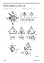
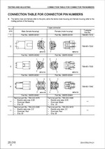
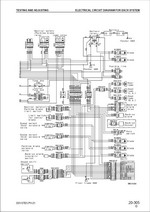
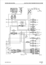
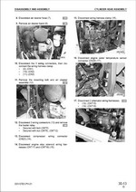
 Инструкция по эксплуатации Komatsu
- Главная
- /
- Справочная информация
Справочная информация
- Руководство водителя автопогрузчика (скачать в формате «doc.»)
- Инструкция по ремонту двигателей погрузчиков «NISSAN» K15, K21, K25 (скачать в формате «doc.»)
- Инструкция по ремонту двигателей погрузчиков «KOMATSU FORKLIFT» 4D92E, 4D94LE, 4D98E (скачать в формате «doc.»)
- Инструкция по ремонту двигателей погрузчиков «KOMATSU» 4LB1, 4LC1, 4LE1 (скачать в формате «doc.»)
- Инструкция по ремонту двигателя погрузчика «Toyota» 5K (скачать в формате «doc.»)