Профиль abb1612
Хорошая библиотека по дизельной тематике

abb1612
Был 3 недели назад
Александр
Я езжу на Volkswagen Multivan 2.5TDI
Санкт-Петербург, Россия
Думаю многим может быть полезна. Мануалы, статьи, каталоги, техническая документация.
Упор сделан на топливную аппаратуру, тнвд и форсунки.
Например, Бошевская книга «Системы управления дизельными двигателями» перевод с немецкого
или книга «Диагностика дизельных двигателей». Губертуса Гюнтера
или учебное пособие БОШ «Дизельные аккумуляторные топливные системы Common Rail». .
Много статей умных людей по ремонту топливной аппаратуры и диагностике дизельных двигателей
Но не только.
Вот руководство по диагностике и ремонту T4: VW Caravelle/Transporter/Multivan/California
или реновское руководство по ремонту двигателей G9
26 марта 2019
13
Разместить рекламу
Реклама
Войдите или зарегистрируйтесь, чтобы писать комментарии, задавать вопросы и участвовать в обсуждении.
Войти
Зарегистрироваться
Сервис мануал TOYOTA AVENSIS 2AD-FTV/FHV Engine. OPERATION, May, 2005
Приведено описание топливной системы Common rail, ТНВД и пьезофорсунок фирмы Денсо двигателей 2AD-FTV/FHV автомобилей Тойота Авенсис 2,0л. Edited and published by DENSO CORPORATION Service Department.
Читать/скачать…(pdf, 1.1Mb)
Руководство по диагностике и ремонту. Электронная система управления двигателями серий ISB (4-цилиндровый) и ISBe (4 и 6-цилиндровый). Электронная система управления двигателями серий ISB (4-цилиндровый) и ISBe (4 и 6-цилиндровый). Bulletin Number 4960589. © 2000-2010 Cummins Inc. All rights reserved.
Настоящее руководство предназначено для оказания помощи при определении причин неисправностей, имеющих отношение к двигателю. В нем также содержатся описания рекомендованных процедур ремонта.
Скачать…(rar, 66,4Mb) в архиве файл в формате справки Windows
Руководство по ремонту двигателя G9. Техническая нота 6022A.
Техническая нота 6022A. Руководство по ремонту двигателя G9. (GXX, и G9T или G9U) на русском языке. © Renault s.a.s 2008.
Читать/скачать…(pdf, 7.4 Mb)
Расположение и цоколевка диагностического разъема
Приведена информация о месте расположения и цоколевке диагностического разъема у большинства автомобилей. Также указан кабель, используемый при диагностике с помощью Bosch KTS.
Информация взята из программы Bosch ESI(tronic)
Скачать…(rar, 9.3 Mb). В архиве файл в формате справки Windows
Руководство по ремонту форсунок CR фирмы Делфи на русском языке
РУКОВОДСТВО ПО РЕМОНТУ. ФОРСУНКА COMMON RAIL (DFI1) – ПРОЦЕДУРА РЕМОНТА. Подготовлено и издано:Delphi France SAS. DDNX299B(RU)
Читать/скачать… (pdf, 3.4 Mb)
Инструкция по ремонту форсунки CR АЗПИ А-04-011-00-00-01
Настоящее руководство распространяется на электрогидроуправляемые форсунки «А-04-011-00-00-01», предназначенные для установки на автомобильные дизельные двигатели ЯМЗ-6585, ЯМЗ-6565 производства ОАО «Автодизель», поставляемые на комплектацию и в запасные части и устанавливает требования к организации и проведению их ремонта.
Читать/скачать… (pdf, 3.7 Mb)
Обзор систем электронного управления EDC 7 и топливной системы Common Rail 3438PE. MAN Nutzfahrzeuge Aktiengesellschaft. Сервисная информация (ru)
Аккумуляторная топливная система Common Rail вместе с системами управления Bosch EDC 7 устанавливается в грузовые автомобили, автобусы и шасси автобусов MAN серийно с 2002 года. Здесь кратко описаны разновидности систем EDC, их новые возможности, версии программ, дано сравнение устройств и программ, а также приведены указания по устранению неисправностей.
Читать/скачать… (pdf, 3.53 Mb)
Каталог повреждений электромагнитных форсунок CR Bosch
Дефектный каталог электромагнитных форсунок CR Bosch используется для принятия решения по рекламациям. Приведены картины неисправностей, возможные причины и решения по гарантии.
Читать/скачать… (pdf, 9.67 Mb)
Руководство по эксплуатации. Двигатели Д245 Е3
Минский моторный завод. Руководство по эксплуатации. Двигатели Д-245.7Е3, Д-245.9Е3, Д-245.30Е3, Д-245.35Е3. Минск 2007
Читать/скачать… (pdf, 4.3 Mb)
Оригинальный мануал по ремонту ТНВД серии DPC-DPCN фирмы Делфи (en)
WORKSHOP MANUAL ТНВД DPC-DPC (en) фирмы Делфи. © Delphi Diesel System France
Читать/скачать… (pdf, 32.6 Mb)
Диагностика системы Common Rail двигателей K9K 700 (rus). Техническая нота 3473A, XB07 — XC07
Оригинальное руководство по диагностике системы Common Rail двигателей K9K 700 на русском языке. © RENAULT 2001
Читать/скачать…(pdf, 624 Kb)
Особенности автомобилей, оснащенных двигателем К9К 700. Техническая нота 3458А (rus), Service 0422.
Руководство по ремонту автомобилей Рено Кангу, Клио 1,5 л. с двигателями К9К 700. © RENAULT 2000
Читать/скачать… (pdf, 1.33 Mb)
Оригинальный мануал по ТНВД Денсо V3, V4, V5
ECD-V Series Electronically Controlled Distributor. Type Fuel Injection System.
Описание конструкции, принципа работы и основных элементов электронных ТНВД Денсо с управляющим клапаном
Читать/скачать… (pdf, 4.2 Mb)
Регулировочные таблицы ТНВД производства ТПС (ЯЗДА, ЯЗТА)
В архиве регулировочные таблицы ТНВД КАМАЗ (33, 332, 334, 337), ЯМЗ, ТМЗ (60, 80, 90, 133, 173, 175, 185, 423), ММЗ (363, 772, 773, 774)
Скачать… (rar, 934 Kb)
Применяемость ТНВД ТПС (ЯЗДА, ЯЗТА)
Приведены данные о применяемости и основных характеристиках ТНВД производства ТПС (ЯЗДА, ЯЗТА) — V-образных, КОМПАКТ-32, КОМПАКТ-40, 60-, 80-, 90, 185, 423
Скачать… (xls, 144 Kb)
SERVICE MANUAL (REPAIR SERVICE & MAINTENANCE) VRZ (en)
В архиве сервис-мануал по ремонту ТНВД типа VRZ фирмы Zexel. Устанавливался на двигатели 4М41.
Скачать… (rar, 5.0 Mb)
Топливная аппаратура для двигателей ЯМЗ, соответствующих требованиям нормативов Евро-3. Руководство по эксплуатации
РЭ содержит описание конструкции, принципа действия и технического обслуживания шестисекционных и восьмисекционных топливных насосов высокого давления (ТНВД) типа «Компакт-40» с электронной системой управления (ЭСУ) в сборе с механизмом электромеханическим исполнительным, насосом топливоподкачивающим и муфтой демпферной, форсунок.
Скачать… (doc, 673 Kb)
Ремонт и техническое обслуживание электронной системы управления модели ЭСУ–1А. ИНСТРУКЦИЯ
Настоящая инструкция предназначена для проведения диагностики, поиска неисправностей и проведения ремонта системы ЭСУ-1А, устанавливаемой на автомобили «МАЗ» уровня ЕВРО-3. Разработчик Открытое акционерное общество «Ярославский завод дизельной аппаратуры» (ОАО «ЯЗДА»).
Читать/скачать… (pdf, 1,62 Mb)
Оригинальный мануал ТНВД серии DP210 фирмы Делфи
WORKSHOP MANUAL ТНВД серии DP210 фирмы Делфи. © Delphi Diesel System France
Читать/скачать… (pdf, 5.4 Mb)
Сервис мануал по системе Common Rail Denso (en)
Сервис мануал по системе Common Rail Denso: описание элементов системы, в т.ч. ТНВД HP-0 — HP-4, форсунок, рампы, диагностических сканеров
Читать/скачать… (pdf, 6.5 Mb)
Материалы по сиcтеме Covec-F на примере двигателя D4BH 2,5л Hyundai (en)
В архиве сервис-мануал по системе Covec-F и описание ТНВД с электросхемами автомобиля Хундай Н1
Скачать… (rar, 5.5 Mb)
- Главная
-
Сервис
- Руководства по ремонту
Руководства по ремонту ЯМЗ
Обращаем Ваше внимание, что руководства по ремонту постоянно дорабатываются и
обновляются. Имеющиеся на данной странице руководства имеют последнюю редакцию, а
значит могут отличаться от документов выпущенных ранее и поставленных в комплекте с
двигателем. Поэтому при пользовании документами обращайте внимание на год его
издания.
Руководство по ремонту двигателей ЯМЗ-536, ЯМЗ-5361, ЯМЗ-5363, ЯМЗ-53602, ЯМЗ-53622, ЯМЗ-53642
pdf, 94.67 МБ
Руководство по ремонту двигателей ЯМЗ-5344-10, ЯМЗ-53442
pdf, 85.64 МБ
Руководство по ремонту двигателей ЯМЗ-6565, 6585
pdf, 22.17 МБ
Руководство по ремонту двигателей ЯМЗ-5341-10, ЯМЗ-5341-11
pdf, 112.61 МБ
Руководство по ремонту двигателей ЯМЗ-236М2, 238М2
pdf, 23.42 МБ
Руководство по ремонту двигателей ЯМЗ-5342, ЯМЗ-5344
pdf, 89.11 МБ
Руководство по ремонту газовых двигателей ЯМЗ-53414,-53424,-53444
pdf, 74.16 МБ
Руководство по ремонту двигателей ЯМЗ-650
pdf, 17.07 МБ
Руководство по ремонту двигателей ЯМЗ-651
pdf, 30.27 МБ
- Manuals
- Brands
- Sisu Diesel Manuals
- Engine
- 645 Series
- Workshop manual
-
Contents
-
Table of Contents
-
Bookmarks
Quick Links
WORKSHOP MANUAL
SISUDIESEL 645
8368 41000
Related Manuals for Sisu Diesel 645 Series

Summary of Contents for Sisu Diesel 645 Series
-
Page 1
WORKSHOP MANUAL SISUDIESEL 645 8368 41000… -
Page 2
Sisu Diesel Inc. FIN–37240 Nokia, Finland Telephone: +358 3 341 7111 E–mail: info.sisudiesel@sisudiesel.com www.sisudiesel.com Diesel Engines, After Sales Telefax: +358 3 341 7333 Sisu Diesel Inc. takes no responsibility for any damages caused because of incorrect information in this manual… -
Page 3: Table Of Contents
Contents 0—0 CONTENTS TO THE USER …………… . . 0—1 Engine type designations .
-
Page 4
Contents 0—0 5. CRANKSHAFT A. Removing crankshaft …………5—1 B. -
Page 5: To The User
In this Workshop Manual the regular service procedure is not handled as this is explained in the 645—engines Operator’s Manual. As Sisu Diesel Inc. is continuously developing the products, all rights are reserved without separate notice to change the adjust- ments, accessories and service — and repair procedure.
-
Page 6: Location Of The Engine Serial No
To the User 0—2 Location of the engine serial no. 40— 1 Lifting the engine Safe lifting of the engine is done with a lifting device WARNING where the lifting force effects the lifting ears vertically. 40— 2 A = Engine lifting ears Engine weight (dry, without flywheel and electrical equipment).
-
Page 7: Safety Instructions
Safety Instructions 0—3 SAFETY INSTRUCTIONS When you are operating the engine or working near it, use hearing protectors to avoid noise injuries. In the service — and repair work of the engine there is al- ways the possibility of injury. Before starting the work Stop the engine always before service — or repair work.
-
Page 8: Special Tools
Special Tools 0—4 SPECIAL TOOLS Order no Description 9104 51500 Puller for cylinder liner 9104 52000 Milling cutter for cylinder liner seat 9104 52700 Centring tool for flywheel housing 9104 52600 Drift for fitting rear crankshaft seal 9103 94600 Drift for fitting front crankshaft seal 9052 46620 Drift for 40 mm cup plug 9052 46650…
-
Page 9
Special Tools 0—5 40— 3… -
Page 10: Engine Specification
Engine Specifications 0—6 ENGINE SPECIFICATIONS PRINCIPAL DIMENSIONS AND DATA Motor type ……….. Number of cylinders .
-
Page 11: Technical Data
Technical Data 0—7 TECHNICAL DATA Cylinder block Holes for guide pins …………13,250…13,320 mm Main bearing housing diameter .
-
Page 12: Valves, Rocker Arms And Tappets
Technical Data 0—8 Valves, rockers and tappets With a valve clearance of 1,0 mm: — inlet valve opens …………0˚±2˚…
-
Page 13: Crankshaft
Technical Data 0—9 Camshaft end play with 0,5 mm gasket between cylinder block and timing gear housing and between timing gear housing and front cover ……0,5…1,0 mm Cam height (distance between back of cam and tip of cam): — inlet valve…
-
Page 14: Timing Gears
Technical Data 0—10 Timing gears Tooth backlash: Crankshaft—idler gear …………0,05…0,25 mm Idler gear —camshaft gear .
-
Page 15: Piston, Piston Rings And Pin
Technical Data 0—11 Piston, rings and pin Minimum distance between piston and cylinder head (measured with a piece of lead wire thought the injector location hole) ……..0,900…1,150 mm Piston diameter: — 15 mm from lower edge…
-
Page 16: Coolant Pump
Technical Data 0—12 Coolant pump Outside diameter of bearing ……….52 mm Inside diameter of bearing housing in pump body .
-
Page 17: Tightening Torques
Tightening Torques 0—13 TIGHTENING TORQUES Object Cylinder head bolts …………80 Nm +90˚+90˚…
-
Page 18: Construction
Construction 0—14 CONSTRUCTION General 645—engine is liquid cooled, 6—cylinder, 4—stroke, in —line diesel engine with direct injection. It is designed with wet, re- placeable, mid support cylinder liners, oil—cooled pistons and two separate cylinderheads. The engines have a rigid and ribbed cylinder block. The crank mechanism is designed for supercharging.
-
Page 19: Cylinder Head
Construction 0—15 Crank mechanism The crankshaft is forged from chrome alloy special steel and is induction hardened at the bearing and sealing surfaces. This makes it possible to grind bearings four times without a new heat treatment. Gear wheels are located at the front end of the crankshaft.
-
Page 20: Timing Gears
Construction 0—16 Timing gears There are two main types of a timing gear assemblies, so— called narrow — and broad timing gear casing. The timing gear train consists of hardened, helically cut gear wheels. The gears are encased by the timing gear casing which is fitted to the front of the engine.
-
Page 21: Lubricating System
Construction 0—17 40— 7 Lubricating system Lubricating system 1. Oil pump 2. Oil pressure regulating valve The engine has a pressure lubricating system in which the oil 3. Oil cooler pump (gear pump) is attached to the cylinder block lower 4.
-
Page 22: Cooling System
Construction 0—18 The cooling system 40— 8 1. Radiator 2. Coolant pump 3. By —pass pipe 4. Thermostats 5. Expansion tank 6. Oil cooler Cooling system The gear driven coolant pump is attached to the front face of the timing gear housing. The thermostat housing is mounted on front end of the cylinder head.
-
Page 23: Inlet And Exhaust System
Construction 0—19 40— 10 Inlet and exhaust system The filter system for the engine inlet air comprises a cyclone The turbocharger is turbo—compressor driven by exhaust type precleaner, and a paper filter which acts as the main filter. gas. The compact design of the turbocharger is sensitive to The incoming air is made to rotate in the cyclone precleaner.
-
Page 24
Cylinder Block 1—1 WORK INSTRUCTIONS 1. CYLINDER BLOCK 9104 51500 A. Measuring cylinder liner wear 1. Using a micrometer set the dial gauge to zero using a new cylinder liner indicating the initial dimension of the bore: 111,00 mm. 2. Clean the inner surface of the cylinder liner thoroughly before measurement. -
Page 25
Cylinder Block 1—2 41— 3 Order numbers of the camshaft bushings and hole diameters Order no. Hole diameter for the bushings. 1. 8363 22610 55,62…55,65 Note! Numbering begins from the front end of the engine. 2. 8368 52460 55,42…55,45 3. 8368 52459 55,22…55,25 4. -
Page 26
Cylinder Block 1—3 F. Oversize bushings for camshaft If the location of the camshaft bushing is damaged, a bushing with a 0,2 / 0,4 mm oversize outer diameter can be fitted. 266 mm 272 mm 134 mm 7,2…8,0 mm 0,1…0,4 mm 41— 6 Camshaft oversize bearing bushings. -
Page 27
Cylinder Block 1—4 H. Fitting cylinder liner 5. Fit the cylinder liners and fix each liner with two press tools 910166300. Measure the cylinder liner height with a dial gauge and holder 9025 79200. Zero the dial gauge against a 1. -
Page 28
Cylinder Block 1—5 Black Green 41— 11 8. Fit the o—rings into the grooves in the cylinder block and lubricate them with a liquid soap (not with engine oil). 41— 12 9. Press the cylinder liners into the cylinder block. It should be easy to press them fully home. -
Page 29
Flywheel Housing 2—1 2. FLYWHEEL HOUSING A. Fitting flywheel housing The flywheel housing is centred on the cylinder block by two 9104 52700 tension pins. Even the flywheel housings which are delivered as spare parts have ready —made holes for the pins. 1. -
Page 30
Flywheel Housing 2—2 5. Fit the seal as follows: — Do not remove the plastic sleeve in before hand. — NOTE! FIT THE SEAL DRY, NOT OILED 42— 5 O = Sleeve T = Seal — Put the sleeve against the crankshaft rear end so that the sleeve is on the shaft bevelling. -
Page 31
Cylinder Head 3—1 3. CYLINDER HEAD C. Checking cylinder head 1. Remove the soot from the exhaust ports, clean the sealing A. Removing cylinder head surfaces and wash the cylinder head. 2. Check for cracks and other damage. 1. Clean the engine externally and drain the coolant. Discon- nect the coolant hoses from the cylinder head and the ther- mostat housing. -
Page 32
Cylinder Head 3—2 9101 65900 21 mm 43— 4 5. Measure the clearance between the valve stem and the valve guide with a dial gauge. Lift the valve so that the valve head is 15 mm from the face of the cylinder head, and measure the clearance. -
Page 33
Cylinder Head 3—3 F. Changing valve seat rings G. Grinding valves Exhaust and inlet valves are fitted with separate valve seat In order to ensure that there is a proper seal around the rings. If the sealing surface is damaged so badly that it cannot valves, there is a difference in the sealing surface angles. -
Page 34
Cylinder Head 3—4 I. Fitting cylinder head 1. Measure the length of the cylinder head bolts. Compare with dimensions shown in figure below. Change too long bolts. max. 142 43— 11 max. 188,5 4. Picture above show the correct tightening order of the cylin- der head bolts. -
Page 35: Camshaft Gear
Valve Mechanism 4—1 4. VALVE MECHANISM 60˚ A. Reconditioning valve mechanism 1. Check the valve tappets, especially the contact surface against the camshaft. Worn or damaged tappets should be discarded. 44— 4 5. Fit the plug to the other end of the rocker arm shaft. Lubri- cate the shaft and fit various parts in a correct order.
-
Page 36
Valve Mechanism 4—2 C. Adjusting valves 7. Separate the camshaft from the gear wheel using a press or suitable drift. 8. Clean the parts which are to be refitted. 9. Fit the key in its groove. Heat the camshaft gear to 200˚C in an oven and fit it on the shaft. -
Page 37: Crankshaft
Crankshaft 5—1 5. CRANKSHAFT A. Removing crankshaft 1. Remove the oil sump. 2. Unscrew the lubricating oil pump pressure pipe fixing screws from the cylinder block. Remove the oil pump and the suction and pressure pipes. 3. Remove the flywheel and the flywheel housing. 4.
-
Page 38: Fitting Crankshaft
Crankshaft 5—2 D. Fitting crankshaft 0,10…0,38 mm 1. Clean the oilways, bearing shells and bearing locations. Check that the crankshaft is clean. 45— 6 5. Check that the crankshaft can rotate without binding. Check the end float using a dial gauge. The correct end float is 0,10…
-
Page 39: Connecting Rods And Pistons
Connecting Rods and Pistons 6—1 6. CONNECTING RODS AND PISTONS 44,025… A. Removing pistons together with 44,040 connecting rods 1. Remove the oil sump and the oil inlet and pressure pipes. 2. Remove the cylinder head. 3. Scrape off the possible soot in the cylinder liner. If the turn- ing edge is clearly marked, smooth it down carefully with a scraper.
-
Page 40
Connecting Rods and Pistons 6—2 Earlier used connecting rod New connecting rod from engine number L 1110 max. 66,50 Torx E18 40 Nm + 90˚ 40 Nm + 90˚+ 90˚ Measure the length of the connecting rod screws. The length Note! Always change the screws when opened. -
Page 41: Changing Piston Rings
Connecting Rods and Pistons 6—3 D. Changing piston rings 4. Fit the piston rings on the piston using the piston ring pliers. Ensure that the rings are fitted in the correct groove and that ”TOP”, or the manufacturer’s designation, faces upwards. 1.
-
Page 42: Fitting Piston Pin
Connecting Rods and Pistons 6—4 F. Fitting piston pin 1. Place the connecting rod inside the piston and push the piston pin into place. 9105 18700 46— 14 3. Use a piston ring strap or preferably a fitting tool (9105 18700).
-
Page 43: Flywheel
Flywheel 7—1 7. FLYWHEEL 3. Tighten the flywheel retaining screws evenly to a torque of 200 Nm. Note! Flywheel delivered as spare parts do not have injection A. Changing starter ring gear on fly- timing mark. Make the marking on the new flywheel in con- wheel nection with installation.
-
Page 44: Timing Gear Assembly
Timing Gear Assembly 8—1 8. TIMING GEAR ASSEMBLY 9. Remove the timing gear casing. Ensure that no sealing sur- faces are damaged. 10. Remove the crankshaft front seal ring from the front cas- A. Removing timing gear casing ing cover and clean all parts removed. As the timing gear casing bottom face forms a part of the mat- B.
-
Page 45
Timing Gear Assembly 8—2 Narrow timing gear casing 180 Nm 22 Nm 9103 94600 48— 6 48— 4 4. Assemble the idler gear as in picture. Place the o— ring be- 7. Fit the protective plate into the bottom of the seal position tween the shaft and the cylinder block and fit the idler gear in and fit the crankshaft front seal with special tool 9103 94600. -
Page 46
Timing Gear Assembly 8—3 Broad timing gear casing 48— 10 6. Check the tooth backlash, which should be 0,05…0,25 7. Fit the drive unit shaft and camshaft axial controller in the 48— 8 front cover (apply sealing compound to the thread). Fit the cover and hit in the tension pins. -
Page 47: Tensioning Device
Tensioning Device 9—1 9. TENSIONING DEVICE B. Fan drive device A. Tesioning device for ribbed belt 350 Nm 200 Nm 49— 3 80 Nm 1. Assemble the drive device as the picture shows. Fit inner bearing and circlip. Fill the bearing housing partially with heat resistant ball bearing grease (NLGI 2).
-
Page 48: Lubrication System
Lubrication System 10—1 10. LUBRICATION SYSTEM B. Removing and dismantling lubri- cating oil pump A. Reconditioning of oil relief valve 1. Drain the engine oil and remove the oil sump. for lubricating oil pressure 2. Remove the oil pump suction and pressure pipe. If the engine lubricating oil pressure is insufficient or if it va- 3.
-
Page 49: Assembling And Fitting Lubricating Oil Pump
Lubrication System 10—2 C. Assembling and fitting lubricat- D. Fitting oil sump gasket ing oil pump Fit the oil sump gasket with the silicone stripes against the cyl- 1. Fit the gear wheels in the pump body. Fit the cover using inder block (self carrying and casted oil sumps).
-
Page 50: Oil Cooler
Lubrication System 10—3 F. Oil cooler Practically there are two different oil coolers, the difference being position of the oil filter, see picture. 410— 9 To remove Fitting oil cooler 1. Open the coolant drain plug under the oil cooler and drain 1.
-
Page 51
Lubrication System 10—4 G. Lubricating oil quality requirements — Turbocharged engines API CF —4, CG —4, CH—4 ACEA E2/E3 —96, E4 —98, E5 —99 API CG —4, CH—4 ACEA E3 —96, E4 —98, E5 —99 — Low emission (E) engines TEMPERATURE ˚C —40 —30… -
Page 52: Cooling System
Cooling System 11—1 11. COOLING SYSTEM To replace A. Quality requirements of coolant The coolant used must meet the standards ASTM D 3306 or BS 6580:1992. — Mixing proportion should be 40—60 % of ethylene/propy- lene —glycol based coolant and the rest water. The best ratio is 50/50 %.
-
Page 53: Reconditioning Coolant Pump
Cooling System 11—2 C. Reconditioning the coolant pump 10. Fit the pump housing using new gasket. 11. Fit the pump using new o—ring Note! If both coolant pump and injection pump are removed, 411— 2 fit the coolant pump first (one fitting screw can not be fitted as injection pump is in position).
-
Page 54: Checking Air Cleaner
Inlet and Exhaust System 12—1 12. INLET AND EXHAUST SYS- C. Checking turbocharger If a fault is suspected in the turbocharger it can be located in the following way: An engine that is equipped with a turbocharger is a great deal 1.
-
Page 55: Fitting Turbocharger
Inlet and Exhaust System 12—2 If any defects or wear are confirmed, the turbocharger should be reconditioned. If the engine does not work correctly and the turbocharger is not defective or too worn, the fault could be traced to one of the following items: — Blocked air filter.
-
Page 56: Fitting Intercooler
Inlet and Exhaust System 12—3 E. Fitting intercooler 412— 4 1. Using a new gaskets, fit the intake manifold to the cylinder head. 2. Fit the cooler with thrust plates to the intake manifold. Note! A conventional gasket is not used but apply a continu- ous bead of silicone sealing to the sealing surface.
-
Page 57: Fuel System
Fuel System 13—1 13. FUEL SYSTEM Note! This manual gives only general instructions for repair and service measures related to the fuel system. This applies particularly to the injection pump which can be repaired only by a specially trained person who has the necessary special tools and gauges.
-
Page 58
Fuel System 13—2 413— 1 Fuel system 1. Fuel tank 6. Injector 2. Prefilter 7. Solenoid valve 3. Feed pump 8. Glow plug 4. Fuel filters 9. Overflow valve 5. Injection pump Fuel system, description Symptoms of dirty or faulty injectors are: — Knocking is an indication that one of the injectors is faulty. -
Page 59
Fuel System 13—3 Bosch— P injection pump Injection pump 1. Boost control 2. Cold start solenoid 3. Speed lever 4. Injection timing indicator 5. Lube oil into the injection pump 6. Hand pump 7. O —ring seal 8. Return of lube oil to engine 9. -
Page 60
Fuel System 13—4 The pump element consists of one plunger and one cylinder which are a matched pair and because of the fine tolerances the whole element should be changed as a complete unit. The cylinder has two passages: inlet passage and release passage. -
Page 61
Fuel System 13—5 Governor chambers. When the boost pressure decreases, the control rod moves towards the smaller amount of injected fuel. Important! The boost control unit has been adjusted in the factory, and adjustments afterwards are not necessary. 1. Governor weight 2. -
Page 62: Bleeding Fuel System
Fuel System 13—6 A. Bleeding fuel system B. Bleeding thermostart system Always remove air from the glow plug fuel pipe when the pipe or reservoir has been emptied during repair work etc. This prevents damages to the glow plug caused by lack of fuel during starting.
-
Page 63: Measuring Fuel Feed Pressure
Fuel System 13—7 C. Measuring fuel feed pressure E. Changing fuel feed pump valves 1. Clean the fuel injection pump and the filter and the pipes 1. Clean the feed pump. Disconnect fuel pipes to the feed between them. pump. Remove the feed pump. 413— 11 413— 12 2.
-
Page 64
Fuel System 13—8 5. Turn the indicator pin and push it into the hole so that the groove at the end of the pin points towards the pump. 6. If the pin groove fits on the boss on the governor weight as- sembly, the injection timing is correct. -
Page 65: Adjusting Fuel Injection Timing
Fuel System 13—9 G. Adjusting fuel injection timing 2. Ensure that the throttle lever is in the idling position and that the engine is at normal operating temperature. If the timing is incorrect, adjust as follows: 3. Start the engine and loosen the adjusting screw of the addi- tional spring so that it does not affect the idling speed.
-
Page 66: Fitting Fuel Injection Pump
Fuel System 13—10 3. Lubricate the o—ring and place the injection pump so that the key on the pump shaft aligns with the key slot inside the gear. Tighten the gear nut to 200 Nm and fit the cover. 9052 48900 4.
-
Page 67: Reconditioning Injectors
Fuel System 13—11 M. Reconditioning injectors 1. Secure the injector in a suitable way. 2. Unscrew the nozzle cap nut. Remove the nozzle and the parts inside the holder. 3. Clean the nozzle in cleaning fluid both inside and outside. 4.
-
Page 68: Fitting Injector In Engine
Fuel System 13—12 O. Fitting delivery pipes 6. Before assembling, all parts should be carefully cleaned in clean fuel or testing fluid. 7. Put the same thickness of shim back as were fitted earlier. 1. Check the state of the pipes. If there are kinks, damage by Note possible adjustment of the opening pressure.
-
Page 69: Fuel Quality Requirement
Fuel System 13—13 Fuel quality requirement Requirement Test method Density, +15˚C 0,82…0,86 kg/dm ASTM D 4052, EN ISO 12185 Viskosity, +40˚C 1,2…4,5 mm ASTM D 445, ISO 3104 Sulphur content max. 0,2 % m/m ASTM D 4294, ISO 8754 Cetane index min.
-
Page 70: Equipment And Feeding Tables
Equipment and Feeding Table 14—1…
-
Page 71
Equipment and Feeding Table 14—2… -
Page 72
Equipment and Feeding Table 14—3… -
Page 73: Electrical System
15—1 15. ELECTRICAL SYSTEM A. Alternators Magneti Marelli A 127 45 A/65 A (Sisu Diesel no. 8366 40127 45 A) (Lucas) (Sisu Diesel no. 8366 40128 65 A) Nominal voltage …………. . .
-
Page 74
15—2 Bosch N1 28 V 10/80 A (Sisu Diesel no. 8353 39751) Nominal voltage …………. . -
Page 75
Electrical System 15—3 Iskra AAK 5118 14 V 95 A (Sisu Diesel no. 8366 40927) (Sisu Diesel no. 8366 66225) Nominal voltage …………. . -
Page 76
15—4 Bosch N1 28 V 10/80 A 2 —pole (Sisu Diesel no. 8366 64152) Nominal voltage …………. . -
Page 77: Starters
Electrical System 15—5 B. Starters Magneti Marelli M 127/2,8 12 V (Sisu Diesel no. 8353 31592) (Lucas) Values, unloaded Running speed ………….
-
Page 78
Electrical System 15—6 Iskra AZJ3234 12 V 3,1 kW z11 (Sisu Diesel no. 8366 40949) Values, unloaded Running speed ………… -
Page 79
Electrical System 15—7 Iskra AZJ3319 12 V 3 kW z10 (Sisu Diesel no. 8366 40949) Values, unloaded Running speed ………… -
Page 80: Fitting Stop Solenoid
Electrical System 15—8 C. Fitting stop solenoid A Running position B Stop position 415— 5 E. Temperature sensor For a correct use of the dual coil solenoid (pull coil and hold coil) the plunger should reach the end of its magnetic stroke at each pulse.
17,2 Мб
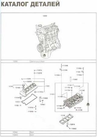
Каталог запчастей автомобилей FAW Vita и FAW Vita C1 (2007-)
Формат: pdf
-
Год:
2009
-
Страниц:
50
-
Язык:
русский
-
Размер:
17,2 Мб
-
Категории:
Двигатели
9,49 Мб
Автомобили УАЗ-451М, УАЗ-451ДМ, УАЗ-452А, УАЗ-452В,
Формат: djvu
-
Год:
1973
-
Страниц:
321
-
Язык:
русский
-
Размер:
9,49 Мб
-
Категории:
Двигатели
5,47 Мб
Автомобили УАЗ-31512, 3152, 37411, 39121, 39621, 2206,
Формат: djvu
-
Год:
2000
-
Страниц:
257
-
Язык:
русский
-
Размер:
5,47 Мб
-
Категории:
Двигатели
2,48 Мб
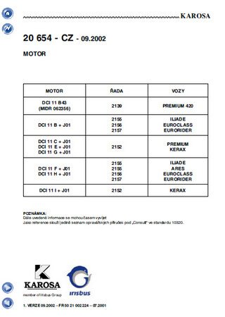
Двигатели Renault DCI11 B43, DCI11B (DCI11C, DCI11E,
Формат: pdf
-
Год:
2002
-
Страниц:
242
-
Язык:
чешский
-
Размер:
2,48 Мб
-
Категории:
Двигатели
4,93 Мб
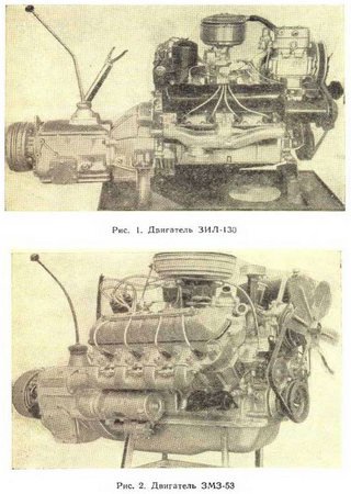
Двигатели ЗИЛ-130, ЗИЛ-375ЯЧ, ЗМЗ-13, ЗМЗ-53, ЗМЗ-54,
Формат: djvu
-
Год:
1968
-
Страниц:
176
-
Язык:
русский
-
Размер:
4,93 Мб
-
Категории:
Двигатели
1,54 Мб
Каталог запчастей автобусов Tata LP/LPO 1512C
Формат: pdf
-
Год:
2006
-
Страниц:
426
-
Язык:
английский
-
Размер:
1,54 Мб
-
Категории:
Двигатели

1,21 Мб
Каталог запчастей грузовика Tata LPT 613 Euro 3
Формат: pdf
-
Год:
2009
-
Страниц:
260
-
Язык:
английский
-
Размер:
1,21 Мб
-
Категории:
Двигатели
7,3 Мб
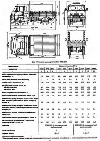
Автомобили УАЗ-31512, 31514, 3153, 3741, 3962, 2206, 33036,
Формат: djvu
-
Год:
1999
-
Страниц:
199
-
Язык:
русский
-
Размер:
7,3 Мб
-
Категории:
Двигатели
48,2 Мб
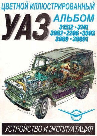
Автомобили УАЗ-31512, 3741, 3962, 2206, 3303, 3909, 39091:
Формат: pdf
-
Год:
1996
-
Страниц:
83
-
Язык:
русский
-
Размер:
48,2 Мб
-
Категории:
Двигатели
8,94 Мб
Двигатели Chaoyang 100, 102, 105: Руководство по
Формат: pdf
-
Год:
2007
-
Страниц:
210
-
Язык:
английский
-
Размер:
8,94 Мб
-
Категории:
Двигатели
8,73 Мб
Руководство по обслуживанию двигателя Navistar
Формат: pdf
-
Год:
1997
-
Страниц:
562
-
Язык:
английский
-
Размер:
8,73 Мб
-
Категории:
Двигатели
144 Мб
Двигатели КамАЗ-740.11, 740.13, 740.14, 740.30, 740.50,
Формат: pdf
-
Год:
2002
-
Страниц:
250
-
Язык:
русский
-
Размер:
144 Мб
-
Категории:
Двигатели
2,04 Мб
Дизельный двигатель Weichai WP12 Euro 3: Руководство по
Формат: pdf
-
Год:
2007
-
Страниц:
53
-
Язык:
английский
-
Размер:
2,04 Мб
-
Категории:
Двигатели
2,06 Мб
Руководство по ремонту двигателей Volvo Penta
Формат: pdf
-
Год:
2004
-
Страниц:
140
-
Язык:
английский
-
Размер:
2,06 Мб
-
Категории:
Двигатели
36,5 Мб
Каталог запчастей автобусов Neoplan N116 (3H, 3HC, 3HL)
Формат: pdf
-
Год:
2002
-
Страниц:
645
-
Язык:
английский, немецкий, французский, итальянский
-
Размер:
36,5 Мб
-
Категории:
Двигатели
25,2 Мб
Каталог деталей и сборочных единиц трактора ЧТЗ Т-10М
Формат: pdf
-
Год:
2013
-
Страниц:
446
-
Язык:
английский, русский
-
Размер:
25,2 Мб
-
Категории:
Двигатели

19,1 Мб
Бульдозеры Shantui SD22, SD22E, SD22S, SD22D: Руководство
Формат: pdf
-
Год:
2012
-
Страниц:
313
-
Язык:
русский
-
Размер:
19,1 Мб
-
Категории:
Двигатели

324 Мб
Каталог запчастей трубоукладчика Komatsu D355C-3
Формат: pdf
-
Год:
2008
-
Страниц:
888
-
Язык:
английский, русский
-
Размер:
324 Мб
-
Категории:
Двигатели

42 Мб
Автомобили TagAZ Road Partner (SsangYong Musso, SsangYong
Формат: pdf
-
Год:
1998
-
Страниц:
545
-
Язык:
русский
-
Размер:
42 Мб
-
Категории:
Двигатели
18,5 Мб
Каталог запчастей двигателей Cummins NT/NTA855
Формат: pdf
-
Год:
2008
-
Страниц:
129
-
Язык:
английский, китайский
-
Размер:
18,5 Мб
-
Категории:
Двигатели
1 2 3 4 5 6 7 8 9 10 … 13