Профиль abb1612
Хорошая библиотека по дизельной тематике

abb1612
Был 3 недели назад
Александр
Я езжу на Volkswagen Multivan 2.5TDI
Санкт-Петербург, Россия
Думаю многим может быть полезна. Мануалы, статьи, каталоги, техническая документация.
Упор сделан на топливную аппаратуру, тнвд и форсунки.
Например, Бошевская книга «Системы управления дизельными двигателями» перевод с немецкого
или книга «Диагностика дизельных двигателей». Губертуса Гюнтера
или учебное пособие БОШ «Дизельные аккумуляторные топливные системы Common Rail». .
Много статей умных людей по ремонту топливной аппаратуры и диагностике дизельных двигателей
Но не только.
Вот руководство по диагностике и ремонту T4: VW Caravelle/Transporter/Multivan/California
или реновское руководство по ремонту двигателей G9
26 марта 2019
13
Разместить рекламу
Реклама
Войдите или зарегистрируйтесь, чтобы писать комментарии, задавать вопросы и участвовать в обсуждении.
Войти
Зарегистрироваться
- Manuals
- Brands
- Lombardini Manuals
- Engine
- CHD series
- Workshop manual
-
Contents
-
Table of Contents
-
Troubleshooting
-
Bookmarks
Quick Links
WORKSHOP MANUAL
CHD series Engine
cod. 1-5302-345
Related Manuals for Lombardini CHD series
Summary of Contents for Lombardini CHD series
-
Page 1
WORKSHOP MANUAL CHD series Engine cod. 1-5302-345… -
Page 3
LOMBARDINI. Information presented within this manual assumes the following: 1 — The person or people performing service work on LOMBARDINI series engines is properly trained and equipped to safely and professionally perform the subject operation; 2 — The person or people performing service work on LOMBARDINI series engines possesses adequate hand and LOMBARDINI special tools to safely and professionally perform the subject service operation;… -
Page 4
REGISTRATION OF MODIFICATIONS TO THE DOCUMENT Any modifications to this document must be registered by the drafting body, by completing the following table. Drafting Document Model Review Edition Revision Issue date Endorsed body code N° date CUSE/ATLO 1-5302-345 50534 6° 31-12-89 01-12-2009 — 4 — Workshop Manual LDW CHD _ cod. 1.5302.345 — 6° ed_rev. 05… -
Page 5: Table Of Contents
CHAPTER INDEX This manual gives the main instructions on how to repair LOMBARDINI diesel engines LDW 1503 — 1603 — 2004 — 2004/T — 2204 — 2204/T, fluid cooling circuit, updates as of December 1 2009. INDEX GENERAL REMARKS AND SAFETY INFORMATION …………….9 — 11 General safety during operating phases ……………………. 11 General Service manual notes ……………………….
-
Page 6
Chapter index Cooling fan …………………………….29 Crankshaft end play ………………………….. 44 Crankshaft for engines with dynamic equalizer (only four-cylinder engines)…………..47 Crankshaft front and rear oil seal ………………………. 45 Crankshaft lubrication ducts ……………………….45 Crankshaft timing gear …………………………45 Cylinder head ……………………………. -
Page 7
Chapter index Timing belt operating angles (with valve clearance set to zero)………………55 V belt ………………………………29 Valve guide insertion, after driving ……………………..33 Valve guides and cylinder head ……………………….32 Valve material ……………………………. 32 Valve recess and sealing surfaces ……………………..33 Valve removal ……………………………. -
Page 8
Chapter index ELECTRIC SYSTEM……………………..73 — 82 Alternator type Iskra, AAK3139 14V 80A ……………………75 Alternator type Iskra, type AAK3570 28V 35A (for 24 V outfits) ………………77 Alternator type Marelli AA 125 R 14V 45A ……………………73 Alternator type Marelli AA 125 R 14V 65A ……………………74 Characteristic curves for alternator type AAK3570 28V 35A (for 24 V outfits) …………… 77 Characteristic curves for alternator type Iskra, AAK3139 14V 80A ……………. -
Page 9: General Remarks And Safety Information
GENERAL REMARKS AND SAFETY INFORMATION WARRANTY CERTIFICATE — The products manufactured by Lombardini Srl are warranted to be free from conformity defects for a period of 24 months from the date of delivery to the first end user. — For engines fitted to stationary equipment, working at constant load and at constant and/or slightly variable speed within the setting limits, the warranty covers a period up to a limit of 2000 working hours, if the above mentioned period (24 months) is not expired.
-
Page 10: Safety And Warning Decals
• Variations to the functional parameters of the engine, adjustments to the fuel flow rate and rotation speed, removal of seals, demounting and refitting of parts not described in the operation and maintenance manual by unauthorized personnel shall relieve LOMBARDINI from all and every liability for deriving accidents or for failure to comply with the laws in merit. • On starting, make sure that the engine is as horizontal as possible, unless the machine specifications differ. In the case of manual start-ups, make sure that the relative actions can take place without the risk of hitting walls or dangerous objects, also considering the movements made by the operator.
-
Page 11: General Safety During Operating Phases
• Only check belt tension when the engine is off. • Only use the eyebolts installed by LOMBARDINI to move the engine. These lifting points are not suitable for the entire machine; in this case, the eyebolts installed by the manufacturer should be used.
-
Page 12: Technical Information
TECHNICAL INFORMATION POSSIBLE CAUSES AND TROUBLE SHOOTING THE ENGINE MUST BE STOPPED IMMEDIATELY WHEN: 1) — The engine rpms suddenly increase and decrease 2) — A sudden and unusual noise is heard 3) — The colour of the exhaust fumes suddenly darkens 4) — The oil pressure indicator light turns on while running.
-
Page 13
Technical information TROUBLE POSSIBLE CAUSE Damaged injector Injection pump valve damaged Injector not adjusted Faulty fuel feeding pump Hardened pump control rod Broken or loose supplementary start- up spring Worn or damaged pumping element Incorrect tuning of injection components (delivery balancing advance) Cracked or broken precombustion chamber Oil level too high… -
Page 14: Approval Data
Technical information MANUFACTURER AND MOTOR IDENTIFICATION DATA The identification plate shown in the figure can be found directly on the engine. It contains the following information: A) Manufacturer’s identity B) Engine type C) Engine serial number D) Maximum operating speed E) Number of the customer version (form K) F) Approval data Approval data The approval reference directives EC are on the engine plate.
-
Page 15: Overall Dimensions
Technical information OVERALL DIMENSIONS LDW 1503-1603 Note : Dimensions shown in mm DIMENSIONS mm 215.7 356.4 233 max 147.5 99.6 231.3 250.2 283.3 425.2 154.2 187.5 Workshop Manual LDW CHD _ cod. 1.5302.345 — 6° ed_rev. 05 — 15 -…
-
Page 16
Technical information LDW 2004 — 2204 TAPPO SCARICO ACQUA WATER DRAIN PLUG TAPPO SCARICO OLIO OIL DRAIN PLUG Note : Dimensions shown in mm DIMENSIONS mm 187.5 156.5 356.3 231.3 154.2 215.7 99.6 425.2 283.3 — 16 — Workshop Manual LDW CHD _ cod. 1.5302.345 — 6° ed_rev. 05… -
Page 17
Technical information LDW 2004/T — 2204/T Note : Dimensions shown in mm DIMENSIONS mm 166.7 186.3 224.8 233.1 156.5 153.5 386.1 168.7 373.2 452.5 133.5 190.5 468.1 Workshop Manual LDW CHD _ cod. 1.5302.345 — 6° ed_rev. 05 — 17 -… -
Page 18: Technical Specifications
Technical information TECHINICAL SPECIFICATIONS ENGINE TYPE CHD LDW 1503 LDW 2004 LDW 2004/T Cylindres Bore Stroke Displacement 1551 2068 2068 Cm³ Compression ratio 22:1 22:1 22:1 R.P.M. 3000 3000 3000 N 80/1269/CEE-ISO 1585-DIN 70020 26.4 44.1 Power KW ISO 3046 — 1 IFN — DIN 6270 24.6 42.0 33.0…
-
Page 19
Technical information ENGINE TYPE CHD PLUS LDW 1603 LDW 2204 LDW 2204/T Cylindres Bore Stroke 90.4 90.4 90.4 Displacement 2199 Cm³ 1649 2199 Compression ratio 22:1 22:1 22:1 R.P.M. 3000 3000 3000 N 80/1269/CEE-ISO 1585-DIN 70020 49.2 30.0 38.0 Power KW ISO 3046 — 1 IFN — DIN 6270 27.6 34,5… -
Page 20: Characteristics Power, Torque And Specific Fuel Consumption Curves
Technical information PERFORMANCE DIAGRAMS CHARACTERISTICS POWER, TORQUE AND SPECIFIC FUEL CONSUMPTION CURVES LDW 1503 LDW 1603 LDW 2004 LDW 2004/T N (80/1269/CEE — ISO 1585) AUTOMOTIVE RATING: intermittent operation with variable speed and variable load. NB (ISO 3046 — 1 IFN) RATING WITH NO OVERLOAD CAPABILITY: Continuous light duty operation with constand speed and variable load.
-
Page 21
Power decreases by approximately 1% every 100 m altitude and by 2% every 5°C above 25°C. Engine power can be influenced by the type of coupling used with the cooling fan. Important Non-approval by Lombardini for any modifications releases the company from any damages incurred by the engine. Note: Consult LOMBARDINI for power, torque curves and specific consumptions at rates differing from those given above. Workshop Manual LDW CHD _ cod. 1.5302.345 — 6° ed_rev. 05… -
Page 22: Maintenance — Prescribed Lubricant — Refilling
MAINTENANCE — RECOMMENDED OIL TYPE — REFILLING ROUTINE ENGINE MAINTENANCE Caution – Warning Failure to carry out the operations described in the table may lead to technical damage to the machine and/or system. EXTRAORDINARY MAINTENANCE AFTER THE FIRST 50 WORKING Engine oilreplacement.
-
Page 23: Acea Regualtions — Acea Sequences
Maintenance — Recommended oil type — Refilling LUBRICANT SAE Classification n the SAE classification, oils differ on the basis of their viscosity, and no other qualitative characteristic is taken SAE 10W* into account. SAE 20W* The first number refers to the viscosity when the engine SAE 30* is cold (symbol W = winter), while the second considers viscosity with the engine at régime.
-
Page 24: Prescribed Lubricant
Maintenance — Recommended oil type — Refilling PRESCRIBED LUBRICANT AGIP SINT 2000 API CF — SH specifications TURBODIESEL ACEA B3-B4 5W40 MIL — L-2104 C/46152 D In the countries where AGIP products are not available, use oil API CF/SH for Diesel engines or oil corresponding to the military specification MIL-L-2104 C/46152 D.
-
Page 25: Aviation Fuel
ENGINE TYPE CAPACITY (Litres) Without radiator For information concerning the capacity of Lombardini radiators, please contact Lombardini directly. The total volume for refilling the cooling liquid varies according to the type of engine and radiator. FUEL RECOMMENDATIONS Purchase diesel fuel in small quantities and store in clean, approved containers. Clean fuel prevents the diesel fuel injectors and pumps from clogging. Do not overfill the fuel tank.
-
Page 26: Recommendations For Disassembling And Assembling
– Besides disassembly and reassembly operations this chapter also includes checking and setting specifications, dimensions, repair and operating instructions. – Always use original LOMBARDINI spare parts for proper repair operations. – The operator must wash, clean and dry components and assemblies before installing them. – The operator must make sure that the contact surfaces are intact, lubricate the coupling parts and protect those that are prone to oxidation.
-
Page 27: Disassembly/Reassembly
Disassembly / Reassembly Oil-bath air cleaner Danger – Attention Never clean the filtering element 6 using solvents with a highly flash point. This could cause an explosion ! Caution – Warning During repair operations, when using compressed air, wear eye protection. Check gaskets and replace if necessary.
-
Page 28: Air Filter Clogging Indicator
Disassembly / Reassembly Dry air components 1 Main cartridge 6 Rubber connecting hose to the 2 Safety cartridge air filter — manifold or compressor. 3 Axial cover 7 Air filter restriction switch 4 Vacuator valve 8 Mounting for clogging indicator 5 Cap complete with clamp 9 Fastener Scavenging valve 4 must be positioned as in figure 4. The cartridge can be cleaned by blowing compressed air breadthways outside and inside the cartridge, at a pressure not greater than 5 atmospheres, or in necessity case by knocking the…
-
Page 29: Belt
Disassembly / Reassembly «V» belt Danger – Attention Check the belt tension only when the engine is not running. Tension adjustment: Loosen alternator fixing bolts C. Stretch belt so that a 100 Nm load located half-way between the two pulleys causes a 10÷15 mm flexure. Pull strongly alternator externally and tighten fixing bolts C. The final torque must be 40 Nm. If you use the belt tension gauge type DENSO BTG-2, the correct value of tension must be from 20 to 25 kg.
-
Page 30: Flywheel
Disassembly / Reassembly Flywheel Caution – Warning During the demounting phases, pay particular attention to prevent the flywheel from dropping as this could seriously injure the operator. Wear protective goggles when removing the flywheel ring. Remove the bolts which attach the flywheel to the crankshaft; when refitting tighten to 140 Nm after checking that the locating pin is in its seat. To remove the starter ring gear, it is recommended to cut it into several portions with an iron hacksaw and then use a chisel.
-
Page 31: Valve Removal
Disassembly / Reassembly Rocker arm assemly Loosen the screws which fasten the assembly to the head. When refitting tighten to 50 Nm. Inside the rocker arm pin flows the oil that lubricates the rocker arms and feeds the hydraulic tappets. To clean the rocker-arm pin inside, remove the two tightening screws C at the ends (fig. 17). When refitting apply a drop of Loctite 270 onto the threads. To check the pin and the rocker-arm pin bearings for wear compare the measured values with the parameters in the table below.
-
Page 32: Valve Guides And Cylinder Head
Disassembly / Reassembly Valve spring — Check Check the overall state of the valve springs. Replace if damaged or if they have lost their original elasticity. First of all, use a gauge to check that the free length matches the measurements given below.
-
Page 33: Valve Guide Insertion, After Driving
Disassembly / Reassembly Valve guide insertion, after driving Press guides considering the L distance from the head plane X. Dimensions Clearance Limit value Ref. Ref. (mm) (mm) (mm) ÷ ÷ ÷ ÷ ÷ Oil seal in the valves guides, (intake and exhaust) To prevent the seal 1 warping when mountig the valve guide 3 put it into the tool 2 part no.
-
Page 34: Hydraulic Diagram For Feeding The Tappets
0.04 and does not receed over 0.02 mm from the head plane level. The precombustion chamber plugs of the CHD PLUS series engines have a different internal volume from the CHD series; therefore, they are not interchangeable. Hydraulic tappet valve control…
-
Page 35: Hydraulic Tappet Operation
Disassembly / Reassembly Hydraulic tappet operation The operating principle of the hydraulic tappet is based on the incompressibility of the liquids and on controlled leakage. Through push rod 1, the pressurised oil gets into the tappet in chamber A (low-pressure chamber), maintaining a constant flow of oil in the above chamber as well as in the high-pressure chamber B. The oil can only enter chamber B through the non-return valve 2 and leave through the clearance between the plunger 3 and the tappet body 4 (controlled leakage).
-
Page 36: Cylinder Roughness
Disassembly / Reassembly Cylinders Reset dial gauge with a calibrated ring. Check diameter size D at 1, 2 and 3; repeat the same operation at the same places after turning the dial gauge by 90°. Check for wear in the X area where piston rings are located. Limit value (mm) ÷…
-
Page 37: Piston Rings — Clearance Between Grooves
Disassembly / Reassembly Piston weight Weigh the pistons when replacing them in order to avoid unbalance. The difference in weight should not exceed 6 g. Piston rings — End gaps Place piston rings into the cylinder and measure end gap A. 1st ring ÷…
-
Page 38: Cylinder Head Gasket
Disassembly / Reassembly Piston — Refitting Connect piston to connecting rod after lubricating piston pin and introducing it by exerting pressure with your thumb. Position the two piston pin circlips and check that they are well inside their seats. Using a ring compressor introduce the piston into the cylinder with combustion chamber facing the injection pump side.
-
Page 39: Assembling And Tightening The Cylinder Head On Engines With Hydraulic Tappets
Disassembly / Reassembly Cylinder head tightening for engines without hydraulic tappets Use a torque wrench (fitted with tool for angular tightening). It is recommended to replace the screws whenever the head is disassembled. Important The cylinder head must never be retightened. It is advisable to lubricate the lower part of the screws with anti-seize of the type MOLYSLIP AS COMPOUND 40.
-
Page 40: Connecting Rod
Disassembly / Reassembly Tightening must be carried out as shown in figure 59. Once the final torque 50 Nm is reached, wait thirty minutes before manually rotating the engine to verify that the pistons do not collide LDW 1503 with the valves, if the engine turns freely start the engine normally, 1603 otherwise wait another 30 minutes before repeating the operation. At first start-up the engine may run irregularly until all the air contained in the tappets has been drained.
-
Page 41: Connecting Rod Alignment
The three connecting rod/piston assemblies should be fitted back into their original cylinders. Mark them with references to avoid mistake. Note: The custom at LOMBARDINI is to consider the cylinder on the flywheel side as the first cylinder. Workshop Manual LDW CHD _ cod. 1.5302.345 — 6° ed_rev. 05…
-
Page 42: Center Main Bearings
Disassembly / Reassembly Center main bearings The main bearing caps and the crankcase have reference holes marked on them (one, two or three). Important In the assembly stage make sure that the number of holes on the bearings matches those on the crankcase and that they are on the same side.
-
Page 43: Check Clearance Between Main Bearings And Journals
Disassembly / Reassembly Check clearance between main bearings and journals Use «Perfect Circle Plastigage» A and position it with a few drops of oil at the center of the half bearing. Tighten bolts to 120 Nm. Determine clearance by measuring the squeezed portion of the plastigage with the indexed scale supplied.
-
Page 44: Crankshaft End Play
Disassembly / Reassembly Grease the shoulder half-rings so that they will remain in their seats during assembly. Halves should be fitted with grooves A as shown in the figure 77-78. Thrust bearing thickness = 2.31÷2.36 mm; oversize halves with thickness increased by 0.1 and 0.2 mm are available as spares. Thrust bearing, oversizes Grinding B according to the above table, following half-rings can be assembled:…
-
Page 45: Crankshaft Front And Rear Oil Seal
Disassembly / Reassembly Crankshaft front and rear oil seal The front oil seal A is located in the oil pump cover while the rear oil seal ring B, is positioned in the flange on the flywheel side. Replace seals if warped, hardened or damaged. In case of replacement: •…
-
Page 46: Checking Main Journals And Crank Pins
Disassembly / Reassembly Checking main journals and crank pins Use an outside micrometer gauge. The main bearing, the crankshaft bearing and the thrust washers have been unified as from engine serial number 7306062 for LDW1503, from serial number 7303552 for LDW 2004 and from serial number 7305782 for LDW 2004/T.
-
Page 47: Crankshaft For Engines With Dynamic Equalizer (Only Four-Cylinder Engines)
Disassembly / Reassembly Crankshaft for engines with dynamic equalizer (only four- cylinder engines). The crankshaft comes with seat for the control gear of the counter-rotating shaft dynamic balancer. Components: 1 Control gear for counter-rotating shafts 2 Seat for the control gear of counter-rotating shafts Ref.
-
Page 48: Front Cover
Disassembly / Reassembly Front cover To remove front cover 1 bring the 1st cylinder to the top dead center, remove throttle cover 2 and release spring 3. When refiting replace gasket 4 and 5. Tighten front cover 1 to 25 Nm. Idler gear and hub Components: 1 Idle wheel 4 Fitting…
-
Page 49: Dimensions For Injection Pump Delivery Control Yoke Adjustement
Disassembly / Reassembly Speed governor Important During reassembly, make sure the components are undamaged and verify they work properly. Malfunctioning of the speed governor can cause serious damage to the engine and to people in the vicinity of it. Components: 1 Gear 2 Bell 3 Counterweights…
-
Page 50: Camshaft Gear — Speed Governor Counter Weights
Disassembly / Reassembly Camshaft gear — Speed governor counter weights Components: 1 Camshaft gear 2 Governor weights 3 Governor weight support 4 Governor weight pin The governor weights 2 are housed inside the camshaft gear 1. The weights 2 can be of two types: light or heavy, depending on the speed rate and the type of application.
-
Page 51: Camshaft
Disassembly / Reassembly Summary tables of the governor equipment according to the speed variation. N.Spring Spring serial number Weight type N.Spring Spring serial number Weight type Duty Duty Duty Duty Duty Duty Duty Duty Light Light Light Light Duty Duty Light Duty * Idle frame…
-
Page 52: Camshaft Bushing Replacement
Disassembly / Reassembly Checking camshaft bushing internal diameter Use a bore gauge. If the diameter size does not correspond to the given value remove the bushings using the special tool (pic. 109 and 110) and replace. Camshaft journals and bushings in model LDW 1503 Clearance Worn limit Dimensions…
-
Page 53: Intake, Exhaust And Injection Cam Height For Models Ldw 2004- 2004/T
Disassembly / Reassembly Intake, exhaust and injecton cam height for model LDW 1503 ÷ ÷ ÷ ÷ ÷ ÷ Limit value (mm) A1 =1 cyl. intake cam S1 = 1 cyl exhaust cam I1 = 1 cyl injection cam A2 = 2 S2 =2 I2 = 2 cyl.
-
Page 54: Camshaft Timing
Disassembly / Reassembly Camshaft timing Fit idler gear B by making timing mark 2 coincide with timing mark 1 on the camshaft control gear A and mark 3 with 4 on the timing gear C. Valve timing without considering timing marks Locate piston 1 (on flywheel) at the top dead center. Position two small rods A of the same length onto the tappets.
-
Page 55: Timing Belt Operating Angles (With Valve Clearance Set To Zero)
Disassembly / Reassembly Engines with mechanical tappets Timing angles for checking puposes (valve clearance = 2 mm) α = 14° after S (corresponding to 35 mm on the flywheel) β = 6° after I (corresponding to 15 mm on the flywheel) γ = 17° before I (corresponding to 43 mm on the flywheel) δ = 15° before S (corresponding to 38 mm on the flywheel) Timing angles for operating purposes (valve clearance 0.15 mm) α…
-
Page 56: Camshaft End Play
Disassembly / Reassembly Camshaft end play Check camshaft end play after removing the cylinder head, the injection and the fuel pumps from the engine. Check that plate 1 is tightened. Position the dial gauge on the camshaft front surface; push and pull the camshaft.
-
Page 57
Disassembly / Reassembly ……………………………………………………………………………………………………………………………………………………………………………………………………………………………………………………………………………………………………………………………………………………………………………………………………………………………………………………………………………………………………………………………………………………………………………………………………………………………………………………………………………………………………………………………………………………………………………………………………………………………………………………………………………………………………………………………………………………………………………………………………………………………………………………………………………………………………………………………………………………….. Workshop Manual LDW CHD _ cod. -
Page 58: Turbocharger
TURBOCHARGER Turbocharger It is installed on the engine in two versions: with air intake on the flywheel side and with air intake on the fan side. To control the supercharge air pressure, screw the pressure gauge into the M8 holes A and B both for the version with air intake on flywheel side (fig. 120) and for air intake on fan side (fig.121).
-
Page 59: Checking Actuator Setting — «Waste Gate» Valve Control Rod Stroke Adjustment
Checking actuator setting — «Waste gate» valve control rod stroke adjustment Important This test must be done with the engine stationary. Disconnect pipe 7 from the compressor side. Using a T coupling, connect up with a pressure gauge 4 (scale from zero to 2 bar) and with the compressed air mains pipe complete with reduction unit 5.
-
Page 60: Lubrication System
LUBRICATION SYSTEM Danger – Attention The engine may be damaged if operated with insufficient lube oil. It is also dangerous to supply too much lube oil to the engine because a sudden increase in engine rpm could be caused by its combustion. Use proper lube oil preserve your engine.
-
Page 61: Oil Filter Cartridge
Lubrication system Oil pump Components: 1 Suction port 5 External rotor 2 Delivery port 6 Internal rotor 3 Oil pressure adjusting Valve port 7 Key 4 Gasket The oil pump is driven by the crankshaft via key 7. Rotor 6 is locked in the circumferential but not in the axial direction.
-
Page 62: Oil Pressure Check
Lubrication system Oil pressure check On completing assembly, fill with engine oil and fuel; connect a 10 bar pressure gauge to the pressure switch fitting. Start the engine and check pressure as a function of the oil temperature. Oil pressure curve for LDW 1503 — 1603 Fig. 134 — The curve is obtained at the oil filter level constant engine speed of 850 rpm in no-load conditions. Fig. 135 — The curve is obtained at the oil filter level with engine working at 3000 rpm at the N power.
-
Page 63
Lubrication system …………………………….Notes : …………………………………………………………………………………………………………………………………………………………………………………………………………………………………………………………………………………………………………………………………………………………………………………………………………………………………………………………………………………………………………………………………………………………………………………………………………………………………………………………………………………………………………………………………………………………………………………………………………………………………………………………………………………………………………………………………………………………………………………………………………………………………………………………………………………………………………………. -
Page 64: Cooling System
COOLING SYSTEM Danger – Attention — The fluid coolant circuit is pressurized. — Inspections must only be made when the engine has cooled and even in this case, the radiator or expansion chamber plug must be unscrewed with the utmost caution. — If an electric fan is installed, do not approach a hot engine since the fan itself could start up even when the engine is at a standstill.
-
Page 65: Expansion Tank And Cap
Cooling system Expansion tank and cap The expansion tank is separated from the radiator and is fitted with a coolant fill cap. The cap comes with vacuum valve 1 and pressure relief valve 2. The pressure relief valve opens at a pressure of 0.7 bar. Checking for cooling system leaks Remove the cap from the expansion tank and check coolant level.
-
Page 66: Fuel System
FUEL SYSTEM Fuel feeding/injection circuit Components: 1 — Tank 2 — Fuel feeding pump 3 — Fuel filter 4 — Fuel delivery tube 5 — Injector pumps overflow tube 6 — Injection pump 7 — High-pressure tube between pump and injector 8 — Injector 9 — Injector return tube 10 — Solenoid valve Fuel filter Components:…
-
Page 67: Electric Fuel Pump (24V)
Max capacity: 100 l/h Injection pump The injection pump of a simplified Q type has been designed by LOMBARDINI for installation on engines of the CHD series. The injection system includes three or four separate pumps each of which feeds a cylinder. Located on the crankcase at the level of the corresponding cylinder, pumps are directly operated by the camshaft.
-
Page 68: How To Reassemble Injection Pump Components
Fuel system How to reassemble injection pump components Fit the plunger with helix E directed towards the discharge union B; if it is erroneously fitted with spiral facing the fuel feed union A the injection pump will not operate (thus the possibility of the engine overspeeding is completely ruled out); complete reas- sembly following fig. 154 …
-
Page 69: How To Reassemble Injection Pump Feeding Tubes
Fuel system How to reassemble injection pump feeding tubes 1 Pliers for 6 mm diam. tubes (intake) — Part No. 7104-1460- 2 Pliers for 8 mm diam. tubes (discharge) — Part No. 7104- 1460-023 Feeding and discharge tubes are made of nylon; they fit into the injection pump unions by exerting pressure and using special pliers and a plastic hammer.
-
Page 70: Checking Injection Pump Delivery
Fuel system Injection pump P. No. 6590-249 — Plunger and barrel assembly Components: 1 Pump body 2 Barrel 3 Plunger 4 Plunging blade Note: Barrel 2 forms an integral part of the pump body 1. For this reason both the barrel and plunger 3 should not be replaced.
-
Page 71: Checking Low Pressure Injection Timing For Engines With Hydraulic Tappets
Fuel system Checking low pressure injection timing for engines with hydraulic tappets To verify the delivery starting point, the first operation to carry out is to disconnect the nylon tubes at the inlet 4 and outlet 3 of every injection pump. Then, disassemble the air filter, the intake manifold and the rocker arm cap. Now disassemble the whole rocker-arm pin and, after removing the push rods, reassemble it.
-
Page 72: Injection Timing Correction By Changing The Pad Thickness
Fuel system Injection timing correction by changing the pad thickness Should it be necessary to correct the injection static advance, remove the injection pump from the engine block and replace pad B inside the injection tappets with one of a different thickness (to extract pad B use a magnet C).
-
Page 73: Alternator Type Marelli Aa 125 R 14V 45A
ELECTRIC SYSTEM Alternator type Marelli AA 125 R 14V 45A Characteristics: Rated voltage ……14V Rated current ……45A Max. speed ……..14000 giri/1′ Peak speed (max 15 min)..15000 rpm Bearing on control side ….6203.2z Bearing on manifold side …6201-2z/C3 Voltage regulator …….RTT 119 AC RH direction of rotation.
-
Page 74: Alternator Type Marelli Aa 125 R 14V 65A
Electric system Alternator type Marelli AA 125 R 14V 65A Characteristics: Rated voltage ……14V Rated current ……65A Max. speed ……..14.000 giri/1′ Peak speed (max 15 min) ..15.000 rpm Bearing on control side ….6203.2z Bearing on manifold side …6201-2z/C3 Voltage regulator …….RTT 119 AC RH direction of rotation.
-
Page 75: Electric System
Electric system Alternator type Iskra, AAK3139 14V 80A Characteristics: Rated voltage ………..14V Rated current …………80A Speed of the load starting point ……1350 rpm Maximum permanent intermittent speed (max. 15′) ……13000 -15000 rpm Front bearing …………6303 — 2RS — C3 Rear bearing ………….6201 — 2RS — C3 Max.
-
Page 76: Connection Diagram For Preheating Control Unit
B Off Position C On Position D Starting Position Battery 3 is not supplied by LOMBARDINI. Anyhow, for installation we recommend a battery for all the ran ge of engines with the following particulars, see following table. Normal starting conditions: Capacity (K20) = 88 Ah Rapid discharge intensity (DIN standards at -18°C) = 330 A…
-
Page 77: Alternator Type Iskra, Type Aak3570 28V 35A (For 24 V Outfits)
Electric system Alternator type Iskra, type AAK3570 28V 35A (for 24 V out- fits) Characteristics: Rated voltage ……….28V Rated current ……….35A Speed of the load starting point …… 1140 rpm Maximum permanent intermittent speed (max. 15′) ……13000 -15000 rpm Front bearing ……….
-
Page 78: Connection Diagram For Preheating Control Unit
Rapid discharge intensity (DIN standards at -18°C) = 450 A Note: This electric starting diagram holds for both 45A and 65A alternators. Battery 3 is not supplied by LOMBARDINI. Anyhow, for installation we recommend a battery for all the range of engines with the following particulars, see following table.
-
Page 79: Characteristic Curves For Starting Motor Type Bosch Ev 12V 2.2 Kw
Electric system Starting Motor 12V Bosch type EV 12V 2.2 Kw RH direction of rotation. Note: Apply to a Bosch service center for any tipe of repair. Characteristic curves for starting motor type Bosch EV 12V 2.2 kW The solid lines were obtained at a temperature of +20°C; the dotted lines were obtained at a temperature of -20°C.Battery type 110 Ah 450A.
-
Page 80: Characteristic Curves For Starting Motor Iskra Type Aze 4598 24V 3 Kw
Electric system Starting Motor 24V Iskra type AZE 4598 24V 3 kW RH direction of rotation. Characteristic curves for starting motor Iskra type AZE 4598 24V 3 kW The thick lines were obtained at a temperature of +20°C; the thin lines were obtained at a temperature of -20°C.
-
Page 81: Glow Plug Controller Relay With Coolant Temperature Sensor
Electric system Pre-heating glow plug Components: 1 Sheath 2 Regulation filament 3 Heating filament Installation torque 20 Nm. Glow plug Type Nominal voltage Current ÷ ) » ) » after after Sheath surface C ° after ) » C ° ) » after temperature C °…
-
Page 82: Coolant High Temperature Lamp Switch
Electric system Coolant high temperature lamp switch Characteristics: Single-pole circuit, normally open Supply voltage ……6÷24V Absorbed power ……3W Circuit closing temperature ..107÷113°C When refitting tighten to 25 Nm. Thermistor for electric thermometer Thermistor features Resistance Ω Temperature °C ÷ ÷ ÷ ÷ ÷ ÷ ÷…
-
Page 83: Settings
SETTINGS Idling speed setting in no-load conditions (standard) After filling with oil, fuel and coolant, start the engine and warm up for 10 minutes. Adjust idling speed at 850÷950 rpm by turning screw 1 then tighten lock nut. Note: Speed decreases when loosening screw 1 and increases when tightening it. Full speed setting in no-load conditions (standard) Before carrying out this operation, make sure that the engine adjustment is standard;…
-
Page 84: Application Diagram For Tampering System Adjustment Screw And
Settings Fuel limiting device (fig. 208-209) When starting up the engine the fuel limiting device has the aim of preventing excessive smoke at the exhaust. Use the delivery adjustment rod of the injection pumps 5 Fig.209 in a constant manner when ambient temperature is above 15°C. As the temperature gradually falls, this device gradually lessens its action to then exclude it at 0°C.
-
Page 85: Engine Storage
ENGINE STORAGE ENGINE STORAGE — When the engines are not for more than 6 months, they have to be protected performing the operations described in the following pages. If the engine is not to be used for extensive periods, check the storage area conditions and the type of packaging and make sure that these are suitable for correct storage.
-
Page 86: Main Torque Specifications
TORQUE SPECIFICATIONS AND USE OF SEALANT MAIN TORQUE SPECIFICATIONS Reference ( fig. Ø and pitch Torque Type of POSITION N° and page) sealant Alternator fixing bolt 10×1,5 fig. 8 — pag. 29 Diesel fuel union bolts 14×1.5 Flywheel housing 10×1.5 Preheating glow plug 12×1.25 fig. 197 — pag. 81 Roker arm cover 8×1.25 fig. 13÷15 — pag. 30 Main bearing cap…
-
Page 87: Torque Specifications And Use Of Sealant
Torque specifications and use of sealant Table of tightening torques for standard screws (coarse thread) Resistance class (R) 10.9 12.9 Quality/ Dimensions R>400N/mm R>500N/mm R>600N/mm R>800N/mm R>1000N/mm R>1200N/mm Diameter 1000 1200 1050 1500 1800 1088 1450 2000 2400 Table of tightening torques for standard screws (fine thread) Resistance class (R) 10.9 12.9…
-
Page 88: Special Tools
SPECIAL TOOLS SPECIAL TOOLS DESCIPTION Part No. Fuel delivery equalization tool. Allows the adjustment of individual unit injector fuel 7104-1460-090 delivery. Glass column for fuel delivery 7104-1460-072 equalization tool. Camshaft bushing replacement 7104-1460-021 tool Static timing tool 7271-1460-024 T.D.C. determination fixture. 7107-1460-075 Pliers for injection pump feeding tubes 1 7104-1460-022 1 For tube diam.
-
Page 89
…………………………….Notes : ………………………………………………………………………………………………………………………………………………………………………………………………………………………………………………………………………………………………………………………………………………………………………………………………………………………………………………………………………………………………………………………………………………………………………………………………………………………………………………………………………………………………………………………………………………………………………………………………………………………………………………………………………………………………………………………………………………………………………………………………………………………………………………………………………………………………………………….Workshop Manual LDW CHD _ cod. 1.5302.345 — 6° ed_rev. 05 — 89 -… -
Page 90
CHD series Engine cod. 1-5302-345 La Lombardini si riserva il diritto di modificare in qualunque momento i dati contenuti in questa pubblicazione. Lombardini se rèserve le droit de modifier, à n’importe quel moment, les données reportées dans cette publication. Data reported in this issue can be modified at any time by Lombardini.

57,2 Мб
Каталог деталей тяжелого автомобиля Sinotruk HOWO
Формат: pdf
-
Год:
2008
-
Страниц:
698
-
Язык:
русский
-
Размер:
57,2 Мб
-
Категории:
Владельцы грузовиков HOWO могут воспользоваться данным каталогом для получения информации о своем автомобиле. Это отличный каталог, который содержит подробные схемы деталей и таблицы с их номерами.
46,5 Мб
Руководство по эксплуатации и техническому обслуживанию
Формат: pdf
-
Год:
2007
-
Страниц:
312
-
Язык:
русский
-
Размер:
46,5 Мб
-
Категории:
Отличное руководство для автовладельцев HOWO, которое поможет вам очень быстро отыскать поломку, чтобы заняться ее устранением. К тому же, в руководстве приведено много информации по ремонту и эксплуатации автомобиля.
21,6 Мб
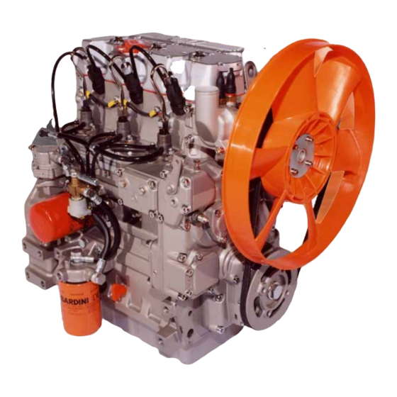
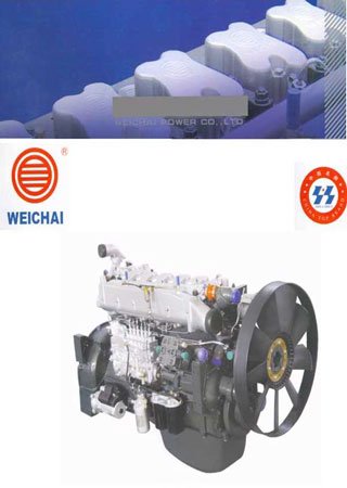
Каталог деталей дизельного двигателя Weichai (Steyr) WD615
Формат: doc
-
Год:
2008
-
Страниц:
66
-
Язык:
русский, английский
-
Размер:
21,6 Мб
-
Категории:
Издание предлагает ознакомиться с техническими характеристиками Weichai (Steyr) WD615 – двигателя известного как Steyr (модификационное название) и широко распространенного во всем мире, в том числе и у нас.
42 Мб
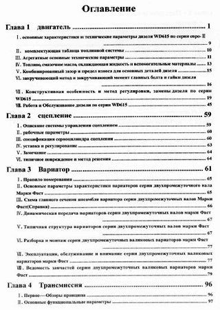
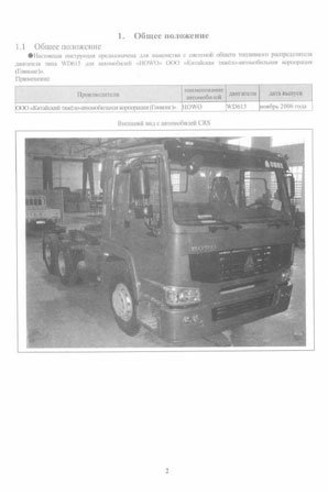
Cистема питания дизельных двигателей Weichai WD615 на
Формат: pdf
-
Год:
2006
-
Страниц:
294
-
Язык:
русский
-
Размер:
42 Мб
-
Категории:
Компания HOWO является лидером в сфере производства двигателей для грузовиков. Дизели данной марки широко известны как в ряде азиатских государств, так и в России. Неплохое качество и прекрасная производительность гарантирует двигателям заслуженную популярность.

Презентация на французском языке дизельного двигателя марки SOFIM объемом 2.8 л. Содержит информации о технических характеристиках, настройке и обслуживанию.
- Автор: —
- Издательство: Citroen
- Год издания: 2003
- Страниц: 85
- Формат: PDF
- Размер: 1,5 Mb
Руководство на английском языке по ремонту и техническому обслуживанию дизельных двигателей Citroen 1984-1996 годов выпуска.
- Автор: A.K. Legg and Finn Deakon
- Издательство: Haynes Publishing
- Год издания: 1996
- Страниц: 159
- Формат: PDF
- Размер: 12,2 Mb

Руководство на немецком языке по техническому обслуживанию и ремонту дизельных двигателей Citroen/Peugeot/Fiat/Lancia объемом 1.8/1.9/2.0/2.1 литра 1994-2001 годов выпуска.
- Автор: —
- Издательство: —
- Год издания: —
- Страниц: 112
- Формат: PDF
- Размер: 21,5 Mb

Руководства по ремонту
Руководства по ремонту силовых агрегатов ЯМЗ.
Руководства предназначены для ознакомления всех заинтересованных лиц с расширенными сведениями по устройству, работе и техническому обслуживанию, порядку сборки и разборки двигателей и агрегатов, по проведению текущего и капитального ремонта и техническим требованиям на капитальный ремонт двигателей ЯМЗ всех комплектаций и исполнений. Также данные документы предназначены для использования специалистами сервисной сети ОАО «Автодизель» и других предприятий, имеющих лицензию на проведение ремонтных работ.
![]() 35,9 Мб Руководство: устройство, работа и ремонт двигателей ЯМЗ-7511
35,9 Мб Руководство: устройство, работа и ремонт двигателей ЯМЗ-7511