- Manuals
- Brands
- Deutz Manuals
- Engine
- TCD 2012 L04/06 V2
- Operation manual
-
Contents
-
Table of Contents
-
Bookmarks
Quick Links
Operation Manual
TCD 2012 L04/06 V2
TCD 2013 L04/06 V2
Related Manuals for Deutz TCD 2012 L04/06 V2
Summary of Contents for Deutz TCD 2012 L04/06 V2
-
Page 1
Operation Manual TCD 2012 L04/06 V2 TCD 2013 L04/06 V2… -
Page 2
Only DEUTZ original parts may be used when repairs — Danger to life. manufacturer. The engine may only be used, carrying out maintenance/repair work on the maintained and repaired by persons who are engine. -
Page 3
Operation Manual TCD 2012 L04/06 V2 TCD 2013 L04/06 V2 312 1890 en Engine number: Please enter the engine number here. This will simplify the handling of customer service, repair and spare parts queries (see Section 2.1). Illustrations and data in this instruction manual are subject to technical changes in the course of improvements to the engines. -
Page 4
Foreword Dear customer, The liquid-cooled engines made by DEUTZ are developed for a wide variety of applications. An extensive range of variants ensures that the respective special requirements are met. Your engine is equipped according to the installation, i.e. not all the parts and components described in this instruction manual are installed on your engine. -
Page 5: Table Of Contents
Contents Operation General Care and maintenance Initial commissioning Engine description work 3.1.1 Filling engine oil Engine type Lubrication system 3.1.2 Filling fuel 2.1.1 Company plate 6.1.1 Oil change intervals 3.1.3 Filling / bleeding cooling system 2.1.2 Location of company plate 6.1.2 Checking oil level, changing engine oil 3.1.4…
-
Page 6
Contents Add-on parts 6.7.1 Battery 6.7.2 Three-phase current generator 6.7.3 Transportation suspension Faults, causes and remedies Fault table Engine management 7.2.1 Engine protection function of the electronic engine controller EMR3 7.2.2 Using the diagnosis button 7.2.3 Table of fault blink codes Engine corrosion protection Corrosion protection Technical data… -
Page 7: General
It goes without saying that DEUTZ Diesel conscientiously. Special care should be taken parts. Original parts from DEUTZ AG are Engines meet the highest standards for en-…
-
Page 8: Engine Description
Engine description 2.1 Engine type 2.2 Engine diagrams 2.3 Lube oil circuit 2.4 Fuel circuit 2.5 Coolant circuit 2.6 Electrics…
-
Page 9: Location Of Company Plate
Engine description 2.1 Engine type 2.1.1 Company plate 2.1.2 Location of company plate © 35 985 0 © 38 987 1 © 43 834 0 The company plate C is fixed to the cylinder The engine type A, engine number B and the head cover crankcase.
-
Page 10
Engine description 2.1 Engine type 2.1.3 Engine number 2.1.4 Cylinder numbering © 43 833 0 © 38989 0 The engine number is stamped on the crankcase The cylinders are counted consecutively, starting (arrow) and on the company plate. from the flywheel. -
Page 11
Engine description 2.2 Engine diagrams 2.2.1 Operation side TCD 2012 L04 2V Oil filler Combustion air inlet Cover Generator Fuel pump Tension pulley with torsion spring Oil cooler Exchangeable fuel filter 10 Exchangeable lube oil filter 11 Oil tray 12 Hydraulic pump or compressor mounting possibility 13 Flywheel 14 Crankcase bleeding valve… -
Page 12
Engine description 2.2 Engine diagrams 2.2.2 Starter side TCD 2012 L04 2V 18 Exhaust manifold 19 Turbocharger 20 Oil filler (optional) 21 Engine mounting 22 Oil return line from turbocharger 23 Relay (starter) 24 V-rib belt 25 Coolant inlet 26 Coolant outlet 27 Coolant pump 28 Connection cabin heater or compensation line… -
Page 13
Engine description 2.2 Engine diagrams 2.2.3 Operation side TCD 2012 L06 2V Oil filler Combustion air inlet Transport eyes Generator Fan hub Fuel pump V-rib belt drive on crankshaft V-rib belt Tension pulley with torsion spring 10 Coolant pump 11 Exchangeable lube oil filter (1x optional) 12 Oil drain screw 13 Oil dipstick 14 Lube oil cooler… -
Page 14
Engine description 2.2 Engine diagrams 2.2.4 Starter side TCD 2012 L06 2V 23 Crankcase bleeding valve 24 Charge air pipe 25 Solenoid valve for exhaust gas recirculation 26 SAE housing 27 Oil tray 28 Starter cover 29 Oil return line from turbocharger 30 Exhaust turbocharger 31 Charge air connection to charge air cooler 32 Coolant inlet… -
Page 15
Engine description 2.2 Engine diagrams 2.2.5 Operation side TCD 2013 L04 2V Combustion air inlet (heating flange installation facility, optional) Connection cabin heater or compensation line Fan (drive coolant pump) Generator Belt pulley on crankshaft V-belt Fuel pump drive Exchangeable fuel filter Exchangeable lube oil filter 10 Oil cooler 11 Drive facility (e.g. -
Page 16
Engine description 2.2 Engine diagrams 2.2.6 Starter side TCD 2013 L04 2V 19 Oil filler (optional) 20 SAE housing 21 Engine mounting 22 Oil drain screw 23 Oil tray 24 Starter 25 Lube oil return from turbocharger 26 Turbocharger 27 Coolant inlet 28 Charge air connection to cooler 29 Coolant outlet 30 Exhaust manifold… -
Page 17
Engine description 2.2 Engine diagrams 2.2.7 Operation side TCD 2013 L06 2V Combustion air inlet Oil filler Transport eyes Generator Coolant pump Exchangeable lube oil filter Exchangeable fuel filter Oil tray Oil dipstick 10 Oil drain screw 11 Oil return line crankcase bleeding 12 Engine mounting 13 SAE housing 14 Plug to control unit… -
Page 18
Engine description 2.2 Engine diagrams 2.2.8 Starter side TCD 2013 L06 2V 19 Turbocharger 20 Exhaust manifold 21 Starter 22 Lube oil line to turbocharger 23 Coolant drain screw 24 Coolant inlet 25 V-rib belt 26 Fan 27 Tension pulley with torsion spring 28 Connection compensation line 29 Ventilation line to compensation tank 30 Coolant outlet from engine to cooler… -
Page 19: Lube Oil
Engine description 2.3 Lube oil circuit 2.3.1 Lube oil diagram (example) Oil tray Intake pipe Lube oil pump 3.1 Safety valve Lube oil cooler 4.1 Return shutoff valve (only in 2012) 4.2 By-pass valve 4.3 By-pass valve oil filter 4.4 Pressure control valve Exchangeable lube oil filter Main oil pipe 6a Internal exhaust gas recirculation…
-
Page 20
Engine description 2.4 Fuel circuit 2.4.1 Fuel diagram Fuel container Fuel pre-filter with pre-pressure pump possibility for filling the low pressure area (to be provided by the customer) Line to fuel pump Fuel pump Fuel filter Fuel supply line to fuel control unit Rail High-pressure pump Fuel line to injector… -
Page 21
2.5 Coolant circuit Engine description 2.5.1 Coolant diagram (example) © 43 897 4… -
Page 22: Coolant
2.5 Coolant circuit Engine description Coolant outlet at the cooler Thermostat Coolant feed line to pump Coolant pump Lube oil cooler Cylinder cooling Cylinder head cooling Coolant inlet to heating Heating 10 Coolant to thermostat 11 Heating connection 12 Compensation line 13 Ventilation line to compensation tank 14 Coolant outlet to cooler 15 Compensation tank…
-
Page 23: Electrical Cable Connections For
Engine description 2.6 Electrics 2.6.1 Electrical cable connections for monitoring Solenoid valve EGR (optional) Coolant temperature Charge air pressure/temperature transmitter Connection facility example: Control unit not mounted on the engine Engine control unit Speed governor via crankshaft Rail pressure, on side of rail Oil level transmitter (optional) Oil pressure transmitter 10 Fuel pressure…
-
Page 24
Engine description 2.6 Electrics Other application-side components (depending on the application) Water trap fuel filter, see chap. 6.2.3 Override key, see chap. 3.3.1 (for temporary bypassing of the engine protection functions) Coolant level transmitter Separate engine stop switch Fan control Switch for brake contact, engine brake, clutch Drive speed sensor, drive speed control unit (+ — keys, for speed increase reduction) -
Page 25: Initial Commissioning
Operation 3.1 Initial commissioning 3.2 Starting 3.3 Operation monitoring 3.4 Shutting down 3.5 Operating conditions…
-
Page 26: Filling Engine Oil
Operation 3.1 Initial commissioning 3.1.2 Filling fuel 3.1.1 Filling engine oil © 43 838 2 © 43 843 2 The engines are generally supplied without oil Only use clean, standard, branded diesel fuel. For filling. fuel quality see 4.2. Fill engine with lube oil through the oil filler (1) Depending on the outdoor temperature, use on the cylinder head cover.
-
Page 27: Filling / Bleeding Cooling System
Operation 3.1 Initial commissioning 3.1.3 Filling / bleeding 3.1.4 Other preparations cooling system Check battery and cable connections, see 6.7.1. Trial run — After preparations carry out a short trial run of approx. 10 min. Do not fully load the engine. During and after the trial run — Check engine for tightness.
-
Page 28: Electrical Starting
Operation 3.2 Starting 3.2.1 Electrical starting without cold start aid Before starting make sure that Insert key there is nobody in the engine/ — Step 0 = no operating voltage. work machine danger area. Turn key to the right After repairs: Check that all — Step 1 = operating voltage, protective equipment is — Warning lights light up.
-
Page 29
Operation 3.2 Starting with cold start aid Heating plug/heating flange © 26 411 0 Insert key. — Step 0 = no operating voltage. Turn key to the right. — Step 1 = operating voltage, — Warning lights 1+2+3 light up. — Pre-heat until heating indicator goes out. -
Page 30: Operation Monitoring
Operation 3.3 Operation monitoring 3.3.1 Engine oil pressure The EMR3 system monitors the engine condition and itself. Oil pressure light Oil pressure gauge The states are indicated by the diagnostic lamp. Lamp test: The diagnostic lamp lights for about 2s after ignition (ignition lock stage 1).
-
Page 31: Coolant Temperature
Operation 3.3 Operation monitoring 3.3.2 Coolant temperature 3.3.3 Coolant level © 26 246 0 © 26 291 1 The needle of the temperature display should Light on coolant level display comes on (contact always be in the green area, and only as an is via float switch/ level probe if coolant level exception in the yellow/green area.
-
Page 32: Electrical Shutdown
Operation 3.4 Shutting down 3.4.1 Electrical shutdown © 26 411 0 Turn the key to the left (to step 0) and remove. Warning lights go out. Note: The control unit remains active for about another 40 seconds to save the system data (lag) and then switches itself off.
-
Page 33: Operating Conditions
Operation 3.5 Operating conditions 3.5.1 Winter operation Lube oil viscosity Battery — A well-charged battery is a — Select the viscosity (SAE class) prerequisite for a good cold start, according to the ambient temperature see 6.7.1. before starting the engine, see 4.1.2. — Heating the battery to approx.
-
Page 34: High Ambient Temperature
Operation 3.5 Operating conditions 3.5.2 High ambient temperature, high altitude When the altitude or ambient temperature increases, the air density decreases. This impairs the maximum engine performance, exhaust quality, temperature level and, in extreme cases, the starting performance. For transient operation, usage up to 1500 m altitude and a temperature of 30 °C is permissible, for stationary operation 1000 m altitude and a temperature of 40 °C is…
-
Page 35: Operating Substances
Operating substances 4.1 Lube oil 4.2 Fuel 4.3 Coolant…
-
Page 36
Biodegradable lube oils may be used in dominant. Basically all engine oils are mixable so DEUTZ engines if they meet the requirements of that a complete lube oil change from one oil type this operating manual. -
Page 37
Operating substances 4.1 Lube oil 4.1.1 Quality Lube oils are classified by DEUTZ according to DEUTZ lube oil quality classes DQC I — 02 DQC II — 05 DQC III — 05 DQC IV — 05 their performance and quality class (DQC : Deutz… -
Page 38
Salzbergen Wintershall TFG 10W-40 Europe Texaco Ursa Super TDX 10W-40 Europe Ursa Premium FE 5W-30 Europe TOTAL TOTAL RUBIA TIR 8600 10W-40 worldwide EXPERTY 10W-40 worldwide T 4-1-3 Release list for DEUTZ lube oil quality class DQC III — 05… -
Page 39
Fuchs Titan Cargo SL 5W-30 worldwide FUCHS EUROPE SHELL International Shell Rimula Ultra 5W-30 Europe, code country-specific, varies Shell Rimula Ultra 10W-40 Europe, code country-specific, varies T 4-1-4 Release list for DEUTZ lube oil quality class DQC IV — 05… -
Page 40
Operating substances 4.1 Lube oil 4.1.2 Quality The ambient temperature at the installation site or area of application of the engine is decisive for the choice of the right viscosity class. Too high a viscosity can lead to starting difficulties, too low a viscosity can endanger the lubrication effect and cause high lube oil consumption. -
Page 41
For questions regarding this please contact Paraffin mixing proportion your DEUTZ partner. fuels defined by law. These correspond to the diesel fuels according to EN 590 and ASTM D 975 Only carry out mixing in the tank! described in this operating manual. -
Page 42
(city water). carbonate hardness proportion of total hardness min 3 dGH. Water quality data are obtainable from the local waterworks. A test case can be requested from DEUTZ Service (order no. 1213 0382) for checking your water quality. -
Page 43: Coolant Preparation
The inspection of the concentration of cooling system preservative can be carried out with The best results are achieved with DEUTZ cooling standard testing devices (e.g. refractometer). system preservatives: Container Order no.
-
Page 44: Maintenance
Maintenance 5.1 Maintenance schedule 5.2 Maintenance diagram 5.3 Maintenance work carried out…
-
Page 45
Maintenance 5.1 Maintenance schedule check= set= clean=L renew= Industrial engines ⇓ check 2x daily before or during the 1st trial run, during the running-in phase or The engine maintenance times given are maximum permissible job when commissioning new and overhauled engines times. -
Page 46
Maintenance 5.1 Maintenance schedule clean= L check= set= renew= Enhancements or modifications max. permissible job times in operating hours (oh) every for engines with EPA acceptance ⇓ check 2x daily before or during the 1st trial run, during the running-in phase or The engine maintenance times given are maximum permissible job times. -
Page 47
6 000 oh E 60 extended partial overhaul authorised specialists 12 000 oh E 70 general overhaul authorised specialists *) approximate value, depends on the type of engine application and/or regular engine maintenance. Please contact your responsible DEUTZ Service partner. -
Page 48
Maintenance 5.2 Maintenance diagram The maintenance diagram shown on this page is supplied with every engine in self- adhesive form. It should be stuck onto a well visible location on the engine or equipment. Check that this is the case! If not, request a replacement from your engine or equipment supplier! The maintenance schedule is decisive for… -
Page 49
Maintenance 5.3 Maintenance work carried out Signature / stamp Op. hrs. Date Signature / stamp Op. hrs. Date 50-150 1000 1250 1125 1500 1375 1750 1625 2000 1875 2250 2115 2500 2375 2750 * after commissioning new and overhauled engines The maintenance work carried out methodically can be recorded in the table and confirmed. -
Page 50
Maintenance 5.3 Maintenance work carried out Op. hrs. Date Signature / stamp Op. hrs. Date Signature / stamp 2875 3000 3125 3250 3375 3500 3625 3750 3875 4000 4125 4250 4375 4500 4625 4750 4875 5000 5125 5250 5375 5500 5625 5750 The maintenance work carried out methodically can be recorded in the table and confirmed. -
Page 51
Maintenance 5.3 Maintenance work carried out Signature / stamp Op. hrs. Date Signature / stamp Op. hrs. Date 6000 5875 6250 6125 6375 6500 6625 6750 6875 7000 7125 7250 7375 7500 7625 7750 7825 8000 8125 8250 8375 8500 8625 8750 The maintenance work carried out methodically can be recorded in the table and confirmed. -
Page 52
Maintenance 5.3 Maintenance work carried out Op. hrs. Date Signature / stamp Op. hrs. Date Signature / stamp 8875 9000 9250 9125 9500 9375 9750 9625 10000 9875 10250 10125 10500 10375 10750 10625 11000 10875 11250 11125 11500 11375 11750 11625 The maintenance work carried out methodically can be recorded in the table and confirmed. -
Page 53: Add-On Parts
Care and maintenance work 6.1Lubrication system 6.2Fuel system 6.3Cooling system 6.4Combustion air filter 6.5Belt drive 6.6Setting work 6.7Add-on parts…
-
Page 54
Care and maintenance work 6.1 Lubrication system 6.1.1 Oil change intervals If the lube oil change intervals are planned The oil change times depend on the engine in terms of operating hours, the lube oil application and the quality of the lube oil. change intervals for installed engines 6.1.1.1 apply. -
Page 55
Care and maintenance work 6.1 Lubrication system 6.1.1.1 Lube oil change intervals for installed engines Lube oil quality Deutz lube oil quality class DQC I-02 DQC II-05 DQC III-05 DQC iV-05 ACEA specification E2-96 E3-96/E5-02/E07-04 E4-99/E6-04 E4-99/E6-04 see chap 6.1.1.3 only fully synthetic… -
Page 56
Care and maintenance work 6.1 Lubrication system 6.1.2 Checking oil level, changing engine oil 6.1.2.1 Checking oil level 6.1.2.2Changing engine oil © 26 023 0 © 26 022 0 © 25 729 0 Position the engine or vehicle so as to be level. Warm up the engine. -
Page 57
Care and maintenance work 6.1 Lubrication system 6.1.3 Changing oil filter © 25 882 0 © 25 880 0 © 25 881 0 When anti-rotation lock is installed: Clean the sealing surface of the filter support Tighten the lube oil filter cartridge with a three- Loosen clamping screws and remove for any dirt there may be. -
Page 58
Care and maintenance work 6.1 Lubrication system 6.1.4 Cleaning / changing oil filter (cup) © 30 0 74 1 © 43 937 0 © 300 74 0 Change the round sealing ring 2 and lightly oil. Switch off engine. Collect any lube oil which may run out. Press new paper filter cartridge 5 into the clip Loosen lube oil filter cover 1 with two or three Crease the paper filter cartridge 5 in the… -
Page 59
Care and maintenance work 6.1 Lubrication system… -
Page 60
Care and maintenance work 6.2 Fuel system Additional regulations for DEUTZ Common Cleanliness hints and measures for Regulations for working on the fuel system handling DEUTZ Common Rail Systems Rail Systems Engine must be switched off! Danger to life! Never work on… -
Page 61
Care and maintenance work 6.2 Fuel system 6.2.1 Changing fuel filter © 25 882 0 © 25 880 0 © 25 881 0 Close fuel stopcock. Lightly oil the fuel filter cartridge or wet with Tighten the fuel filter cartridge with a three- Loosen fuel filter cartridge with standard tool diesel fuel. -
Page 62
Care and maintenance work 6.2 Fuel system 6.2.2 Cleaning / changing fuel filter (cup) © 43 938 0 © 30 074 0 © 43 937 0 Switch off engine. Collect any fuel which may run out. Change the round sealing ring 2 and lightly oil. Loosen fuel filter cover 1 with two or three Slightly bend paper filter cartridge 5 sideways Press new paper filter cartridge 5 into the clip… -
Page 63
Care and maintenance work 6.2 Fuel system 6.2.3 Fuel pre-filter, changing / bleeding filter insert 1 Fuel supply to pump Clean any dirt from the sealing surface of the 2 Fuel return from control block FCU new filter cartridge (5) and the reverse side (Fuel Control Unit) of the filter head 3 Fuel hand pump with bayonet… -
Page 64
Care and maintenance work 6.3 Cooling system 6.3.1 Cleaning intervals 6.3.2 Cleaning cooling system The cooling system soiling depends on thetype of engine application. The risk of soiling is increased by oil and fuel residues on the engine. Therefore pay particular attention to tightness when operating under high dust exposure. -
Page 65
Care and maintenance work 6.3 Cooling system © 43 903 0 Cleaning with steam or hot water Remove oil and greasy residues with a gentle jet setting (do not spray directly on sensitive engine parts, e.g. generator, wiring, electrical- components, fan drive). Warm up the engine so that the water residues evaporate. -
Page 66
Care and maintenance work 6.3 Cooling system 6.3.4 Filling / bleeding 6.3.3 Emptying cooling system cooling system © 43 839 0 © 39 850 1 Open cooler cover. Open cooler cover. The cooling system (if constructed under Position collecting dish underneath locking Loosen locking screw item 1 (chap.6.3.3). -
Page 67
Care and maintenance work 6.4 Combustion air filter 6.4.1 Cleaning intervals The soiling of the combustion air filter de- pends on the dust content of the air and the selected filter size. If a high dust exposure is to be expected, a cyclone separator can be connected to the combustion air filter. -
Page 68
Care and maintenance work 6.4 Combustion air filter 6.4.2 Emptying cyclone pre- 6.4.3 Cleaning oil bath air filter separator © 25 886 0 © 25 887 1 Loosen wing nut 1 and lift housing cover 2. Turn off the engine and wait approx. 10 min In the event of heavy soiling, clean filter hou- Remove the dust container 3 from the base of until the oil has run out of the filter housing 1. -
Page 69
Care and maintenance work 6.4 Combustion air filter 6.4.4 Dry air filter Dust discharge valve Filter cartridge © 25 888 1 © 25 889 0 Empty the dust discharge valve 1 by squee- Check filter cartridge for damage to the filter Open clamping bracket 1. -
Page 70
Care and maintenance work 6.5 Belt drive 6.5.1 Checking V-belt 2013 example © 43 894 0 © 26 261 1 Visual inspection of entire length of V-belt for To check the V-belt tension — Carefully lift the measuring device, without damages. -
Page 71
Care and maintenance work 6.5 Belt drive 6.5.2 Changing V-rib belt 6.5.3 Checking wear limit of V-rib belt © 43 851 0 © 31 814 4 The wear limit of the V-rib belt is checked as Push tension roller 1 with ratchet 3 in direction follows: of arrow until locking pin 4 can be fixed in the Check the distance between the projection… -
Page 72
Care and maintenance work 6.6 Setting work 6.6.1 Checking valve clearance, setting if necessary © 43 849 0 © 43 831 1 Loosen lock nut 1 Hold rotation angle disc 3 tight against Before setting the valve clearance allow the twisting. -
Page 73
Care and maintenance work 6.6 Setting work © 44 304 0 © 44 305 0 Valve clearance setting inlet valve Hold rotation angle disc 3 tight against twisting. in exhaust gas return line (EGR): Tighten the lock nut 6. Loosen lock nut 6. Perform the setting on every inlet valve (see Place rotation angle disc 3 with crow’s foot chap. -
Page 74
Care and maintenance work 6.6 Setting work 6.6.2 Setting control piston clearance in exhaust gas recirculation (EGR) © 43 830 1 © 43 832 0 Loosen lock nut 1. After setting the valve clearance, the control Place the rotation angle disc and socket wrench piston clearance should be set as follows: insert on the setting screw 2 Place the turning device over the fastening… -
Page 75
Care and maintenance work 6.6 Setting work 6.6.3 Diagram for setting valve / control piston clearance Engine TCD 2012/2013 L04 2V Engine TCD 2012/2013 L06 2V Ignition sequence: 1–3–4–2 Ignition sequence: 1–5–3–6–2–4 Valves Cylinder Valves Cylinder overlap overlap set to set to Valve operlap: Outlet valve not yet closed, inlet Valve operlap: Outlet valve not yet closed, inlet… -
Page 76: Battery
Care and maintenance work 6.7 Add-on parts 6.7.1 Battery 6.7.1.1 Checking battery and cable 6.7.1.3 Checking acid density 6.7.1.2 Checking the acid level connections © 25 895 0 © 24 232 3 © 25 896 0 Remove sealing caps 1. Keep the battery clean and dry.
-
Page 77
Care and maintenance work 6.7 Add-on parts Acid density in [kg/ l] Charge level Normal Tropics 1.28 1.23 well charged 1.20 1.12 half charged, re-charge 1.12 1.08 discharged, charge immediately The gases released by the battery are explosive! Avoid sparks and open fire in the vicinity of the battery! Do not allow acid to get on skin or clothes! -
Page 78: Transportation Suspension
Care and maintenance work 6.7 Add-on parts 6.7.2 Three-phase current 6.7.3 Transportation suspension generator Notes on three-phase current system: Do not interrupt the connections between the battery, generator and governor when the engine is running. If, however, an engine must be started and operated without battery, the connection go- vernor / generator is to be separated before starting.
-
Page 80: Faults, Causes And Remedies
Faults, causes and remedies 7.1 Fault table 7.2 Engine management…
-
Page 81
A corresponding fault table can be found overleaf. If you cannot recognise the cause of a fault or cannot remedy a fault yourself, please contact your DEUTZ Service. Before starting make sure that there is nobody in the engine/ work machine danger area. -
Page 82
7.1 Fault table Faults, causes and remedies Faults Action Engine doesn’t start up, or starts up with difficulty Engine doesn’t start up and diagnosis light is blinking Check Engines starts up, but runs irregularly or misfires Engine gets too hot. Temperature warning system is activated Change Engine lacks power Engine lacks power and diagnosis light is lit up… -
Page 83
7.1 Fault table Faults, causes and remedies Faults Action Engine doesn’t start up, or starts up with difficulty Check Engine doesn’t start up and diagnosis light is blinking Engines starts up, but runs irregularly or misfires Change Engine gets too hot. Temperature warning system is activated Clean Engine lacks power Fill up… -
Page 84: Engine Protection Function Of The
7.2 Engine management Faults, causes and remedies 7.2.3 Table of fault blink codes 7.2.1 Engine protection function of 7.2.2 Using the diagnosis button the electronic engine controller EMR3 Depending on the design of the monitoring With the diagnosis button (1) the fault at hand can functions, the EMR3 can protect the engine be read out as a blink code.
-
Page 85
7.2 Engine management Faults, causes and remedies Blinkcode Function / Component Error Short Long Short 0.4s 0.8s 0.4s Output to coolant temperature light Signal faulty, Overtemperature control unit Hand accelerator Signal faulty / implausible Suction air temperature sensor Signal faulty Gear oil temperature sensor Signal faulty Monitoring rail pressure… -
Page 86
7.2 Engine management Faults, causes and remedies Blinkcode Function / Component Error Short Long Short 0.4s 0.8s 0.4s Monitoring camshaft/crankshaft No camshaft signal, no crankshaft signal Monitoring camshaft/crankshaft Deviation between the camshaft and crankshaft signal Engine protection: Overspeed/override status implausible Fuel low pressure sensor Signal faulty Monitoring fuel low pressure… -
Page 87
7.2 Engine management Faults, causes and remedies Blinkcode Function / Component Error Short Long Short 0.4s 0.8s 0.4s Monitoring oil pressure Pressure outside the nominal range Monitoring coolant temperature Temperature above the nominal range Monitoring suction intake air temperature Temperature above the nominal range Monitoring coolant state Level below the nominal range Monitoring fuel temperature… -
Page 88
7.2 Engine management Faults, causes and remedies Blinkcode Function / Component Error Short Long Short 0.4s 0.8s 0.4s Hydraulic oil temperature sensor Signal faulty Monitoring hydraulic oil temperature Temperature outside the nominal range Monitoring battery Voltage outside the nominal range Output to cold start aid indicator lamp Signal faulty, overtemperature control unit Output to external EGR actuator… -
Page 89
7.2 Engine management Faults, causes and remedies Blink code Function / Component Error Short Long Short 0,4s 0,8s 0,4s Output to start relay Signal faulty, overtemperature control unit Output to error lamp Signal faulty, overtemperature control unit Monitoring terminal 15 No signal detected Monitoring terminal 50 Permanent signal detected… -
Page 90: Engine Corrosion Protection
Engine corrosion protection 8.1 Corrosion protection…
-
Page 91
Engine corrosion protection 8.1Corrosion protection Corrosion protection If the engine should be shut down for a long period of time, corrosion protection will be necessary in order to prevent rust formation. The measures described here apply for a shutdown period of up to approx. 6 months. Before the engine is commissioned again the corrosion protection should be removed. -
Page 92: Technical Data
Technical data 9.1 Engine and setting data 9.2 Screw tightening torques 9.3 Tools…
-
Page 93
[°C] ————————————————————- 50 ———————————————————— Direction of rotation —————————————————— rotation to left —————————————————- Injection system Deutz Common Rail (DCR) ——————————— DCR + PLD —————————— DCR ———————————— Pump Line Nozzle (PLD) Weight TDC 2012 without cooling system according to DIN 70020-A [approx.kg] ————————————— 410 ———————————— 530 ————————————-… -
Page 94
Technical data 9.1 Engine and setting data Engine type —————————— TDC 2012 L04 2V —————— TDC 2012 L06 2V ————————— Cooling —————————————— Liquid-cooled / cooling system protection ————————— Coolant quantity (only engine content without cooler)[approx.ltr.] ————————————— 5.6 ————————————- 7.3 ————————————- Permissible continuous coolant temperature engine outlet [°C] ————————————————————— max.110 ——————————————————- Temperature difference between Coolant inlet/outlet… -
Page 95
[°C] ————————————————————- 50 ———————————————————— Direction of rotation —————————————————— rotation to left —————————————————- Injection system Deutz Common Rail (DCR) [bar] ———————————- DCR+PLD ——————————- DCR ———————————— Pump Line Nozzle (PLD) Weight TDC 2013 without cooling system according to DIN 70020-A [approx.kg] ————————————— 450 ———————————— 590 ————————————-… -
Page 96
Technical data 9.1 Engine and setting data Engine type —————————— TDC 2013 L04 2V —————— TDC 2013 L06 2V ————————— Cooling —————————————— Liquid-cooled / cooling system protection ————————— Coolant quantity (only engine content without cooler)[approx.ltr.] ————————————— 7.2 ————————————- 9.8 ————————————- Permissible continuous coolant temperature engine outlet [°C] ————————————————————— max.105 ——————————————————- Temperature difference between Coolant inlet/outlet… -
Page 97
Technical data 9.2 Screw tightening torques Installation Pre-tightening Re-tightening Total Comments [Nm] 1st step 2nd step 3rd step 4th step Cylinder head cover – – – – – 9 ± 1 Nm Lock nut Valves – – – – – 20 ±… -
Page 98
The special tools listed in this chapter must be ordered from: FA.WILBÄR Postfach 14 05 80 D-42826 Remscheid http://www.deutz-tools.com 25899 0 ©26 002 0 Order No. 8189 Order No. 8115 For engines of series 2012/2013, the TORX Measuring device for checking the prescribed screw system BN. -
Page 99
Technical data 9.3 Tools Rotation angle disc Socket wrench insert Crow’s foot wrench © 44 306 0 © 44 307 0 © 43 202 1 Order No. 8190 Order No. 8193 (5 mm) valve clearance Order No. 8199 Rotation angle disc for setting the valve/ Order No. -
Page 100
Technical data 9.3 Tools Turning gear © 35 423 1 Order No. 100 330 For turning over the engine (as add-on on the torsional vibration damper). -
Page 101: Service
Service Service For many years DEUTZ has stood for pioneering Thus, DEUTZ is not just a name for innovative Deutz-Mülheimer Str. 147-149 development in engine construction. As an inde- engines. But also for a complete service package D-51063 Cologne pendent manufacturer we offer a complete…
-
Page 102
DEUTZ AG Service-Information Systems Deutz-Mülheimer Str. 147-149 D-51057 Köln Tel.: ++49 (0)2 21-8 22-0 Fax: ++49 (0)2 21-8 22-53 58 Internet: www.deutz.de Printed in Germany All rights reserved 1st Edition, © 01/06 the engine company Order No.: 0312 1890…
-
Page 1
Operation Manual TCD 2012 L04/06 V2 TCD 2013 L04/06 V2… -
Page 2
Only DEUTZ original parts may be used when repairs — Danger to life. manufacturer. The engine may only be used, carrying out maintenance/repair work on the maintained and repaired by persons who are engine. -
Page 3
Operation Manual TCD 2012 L04/06 V2 TCD 2013 L04/06 V2 312 1890 en Engine number: Please enter the engine number here. This will simplify the handling of customer service, repair and spare parts queries (see Section 2.1). Illustrations and data in this instruction manual are subject to technical changes in the course of improvements to the engines. -
Page 4
Foreword Dear customer, The liquid-cooled engines made by DEUTZ are developed for a wide variety of applications. An extensive range of variants ensures that the respective special requirements are met. Your engine is equipped according to the installation, i.e. not all the parts and components described in this instruction manual are installed on your engine. -
Page 5: Table Of Contents
Contents Operation General Care and maintenance Initial commissioning Engine description work 3.1.1 Filling engine oil Engine type Lubrication system 3.1.2 Filling fuel 2.1.1 Company plate 6.1.1 Oil change intervals 3.1.3 Filling / bleeding cooling system 2.1.2 Location of company plate 6.1.2 Checking oil level, changing engine oil 3.1.4…
-
Page 6
Contents Add-on parts 6.7.1 Battery 6.7.2 Three-phase current generator 6.7.3 Transportation suspension Faults, causes and remedies Fault table Engine management 7.2.1 Engine protection function of the electronic engine controller EMR3 7.2.2 Using the diagnosis button 7.2.3 Table of fault blink codes Engine corrosion protection Corrosion protection Technical data… -
Page 7: General
It goes without saying that DEUTZ Diesel conscientiously. Special care should be taken parts. Original parts from DEUTZ AG are Engines meet the highest standards for en-…
-
Page 8: Engine Description
Engine description 2.1 Engine type 2.2 Engine diagrams 2.3 Lube oil circuit 2.4 Fuel circuit 2.5 Coolant circuit 2.6 Electrics…
-
Page 9: Location Of Company Plate
Engine description 2.1 Engine type 2.1.1 Company plate 2.1.2 Location of company plate © 35 985 0 © 38 987 1 © 43 834 0 The company plate C is fixed to the cylinder The engine type A, engine number B and the head cover crankcase.
-
Page 10
Engine description 2.1 Engine type 2.1.3 Engine number 2.1.4 Cylinder numbering © 43 833 0 © 38989 0 The engine number is stamped on the crankcase The cylinders are counted consecutively, starting (arrow) and on the company plate. from the flywheel. -
Page 11
Engine description 2.2 Engine diagrams 2.2.1 Operation side TCD 2012 L04 2V Oil filler Combustion air inlet Cover Generator Fuel pump Tension pulley with torsion spring Oil cooler Exchangeable fuel filter 10 Exchangeable lube oil filter 11 Oil tray 12 Hydraulic pump or compressor mounting possibility 13 Flywheel 14 Crankcase bleeding valve… -
Page 12
Engine description 2.2 Engine diagrams 2.2.2 Starter side TCD 2012 L04 2V 18 Exhaust manifold 19 Turbocharger 20 Oil filler (optional) 21 Engine mounting 22 Oil return line from turbocharger 23 Relay (starter) 24 V-rib belt 25 Coolant inlet 26 Coolant outlet 27 Coolant pump 28 Connection cabin heater or compensation line… -
Page 13
Engine description 2.2 Engine diagrams 2.2.3 Operation side TCD 2012 L06 2V Oil filler Combustion air inlet Transport eyes Generator Fan hub Fuel pump V-rib belt drive on crankshaft V-rib belt Tension pulley with torsion spring 10 Coolant pump 11 Exchangeable lube oil filter (1x optional) 12 Oil drain screw 13 Oil dipstick 14 Lube oil cooler… -
Page 14
Engine description 2.2 Engine diagrams 2.2.4 Starter side TCD 2012 L06 2V 23 Crankcase bleeding valve 24 Charge air pipe 25 Solenoid valve for exhaust gas recirculation 26 SAE housing 27 Oil tray 28 Starter cover 29 Oil return line from turbocharger 30 Exhaust turbocharger 31 Charge air connection to charge air cooler 32 Coolant inlet… -
Page 15
Engine description 2.2 Engine diagrams 2.2.5 Operation side TCD 2013 L04 2V Combustion air inlet (heating flange installation facility, optional) Connection cabin heater or compensation line Fan (drive coolant pump) Generator Belt pulley on crankshaft V-belt Fuel pump drive Exchangeable fuel filter Exchangeable lube oil filter 10 Oil cooler 11 Drive facility (e.g. -
Page 16
Engine description 2.2 Engine diagrams 2.2.6 Starter side TCD 2013 L04 2V 19 Oil filler (optional) 20 SAE housing 21 Engine mounting 22 Oil drain screw 23 Oil tray 24 Starter 25 Lube oil return from turbocharger 26 Turbocharger 27 Coolant inlet 28 Charge air connection to cooler 29 Coolant outlet 30 Exhaust manifold… -
Page 17
Engine description 2.2 Engine diagrams 2.2.7 Operation side TCD 2013 L06 2V Combustion air inlet Oil filler Transport eyes Generator Coolant pump Exchangeable lube oil filter Exchangeable fuel filter Oil tray Oil dipstick 10 Oil drain screw 11 Oil return line crankcase bleeding 12 Engine mounting 13 SAE housing 14 Plug to control unit… -
Page 18
Engine description 2.2 Engine diagrams 2.2.8 Starter side TCD 2013 L06 2V 19 Turbocharger 20 Exhaust manifold 21 Starter 22 Lube oil line to turbocharger 23 Coolant drain screw 24 Coolant inlet 25 V-rib belt 26 Fan 27 Tension pulley with torsion spring 28 Connection compensation line 29 Ventilation line to compensation tank 30 Coolant outlet from engine to cooler… -
Page 19: Lube Oil
Engine description 2.3 Lube oil circuit 2.3.1 Lube oil diagram (example) Oil tray Intake pipe Lube oil pump 3.1 Safety valve Lube oil cooler 4.1 Return shutoff valve (only in 2012) 4.2 By-pass valve 4.3 By-pass valve oil filter 4.4 Pressure control valve Exchangeable lube oil filter Main oil pipe 6a Internal exhaust gas recirculation…
-
Page 20
Engine description 2.4 Fuel circuit 2.4.1 Fuel diagram Fuel container Fuel pre-filter with pre-pressure pump possibility for filling the low pressure area (to be provided by the customer) Line to fuel pump Fuel pump Fuel filter Fuel supply line to fuel control unit Rail High-pressure pump Fuel line to injector… -
Page 21
2.5 Coolant circuit Engine description 2.5.1 Coolant diagram (example) © 43 897 4… -
Page 22: Coolant
2.5 Coolant circuit Engine description Coolant outlet at the cooler Thermostat Coolant feed line to pump Coolant pump Lube oil cooler Cylinder cooling Cylinder head cooling Coolant inlet to heating Heating 10 Coolant to thermostat 11 Heating connection 12 Compensation line 13 Ventilation line to compensation tank 14 Coolant outlet to cooler 15 Compensation tank…
-
Page 23: Electrical Cable Connections For
Engine description 2.6 Electrics 2.6.1 Electrical cable connections for monitoring Solenoid valve EGR (optional) Coolant temperature Charge air pressure/temperature transmitter Connection facility example: Control unit not mounted on the engine Engine control unit Speed governor via crankshaft Rail pressure, on side of rail Oil level transmitter (optional) Oil pressure transmitter 10 Fuel pressure…
-
Page 24
Engine description 2.6 Electrics Other application-side components (depending on the application) Water trap fuel filter, see chap. 6.2.3 Override key, see chap. 3.3.1 (for temporary bypassing of the engine protection functions) Coolant level transmitter Separate engine stop switch Fan control Switch for brake contact, engine brake, clutch Drive speed sensor, drive speed control unit (+ — keys, for speed increase reduction) -
Page 25: Initial Commissioning
Operation 3.1 Initial commissioning 3.2 Starting 3.3 Operation monitoring 3.4 Shutting down 3.5 Operating conditions…
-
Page 26: Filling Engine Oil
Operation 3.1 Initial commissioning 3.1.2 Filling fuel 3.1.1 Filling engine oil © 43 838 2 © 43 843 2 The engines are generally supplied without oil Only use clean, standard, branded diesel fuel. For filling. fuel quality see 4.2. Fill engine with lube oil through the oil filler (1) Depending on the outdoor temperature, use on the cylinder head cover.
-
Page 27: Filling / Bleeding Cooling System
Operation 3.1 Initial commissioning 3.1.3 Filling / bleeding 3.1.4 Other preparations cooling system Check battery and cable connections, see 6.7.1. Trial run — After preparations carry out a short trial run of approx. 10 min. Do not fully load the engine. During and after the trial run — Check engine for tightness.
-
Page 28: Electrical Starting
Operation 3.2 Starting 3.2.1 Electrical starting without cold start aid Before starting make sure that Insert key there is nobody in the engine/ — Step 0 = no operating voltage. work machine danger area. Turn key to the right After repairs: Check that all — Step 1 = operating voltage, protective equipment is — Warning lights light up.
-
Page 29
Operation 3.2 Starting with cold start aid Heating plug/heating flange © 26 411 0 Insert key. — Step 0 = no operating voltage. Turn key to the right. — Step 1 = operating voltage, — Warning lights 1+2+3 light up. — Pre-heat until heating indicator goes out. -
Page 30: Operation Monitoring
Operation 3.3 Operation monitoring 3.3.1 Engine oil pressure The EMR3 system monitors the engine condition and itself. Oil pressure light Oil pressure gauge The states are indicated by the diagnostic lamp. Lamp test: The diagnostic lamp lights for about 2s after ignition (ignition lock stage 1).
-
Page 31: Coolant Temperature
Operation 3.3 Operation monitoring 3.3.2 Coolant temperature 3.3.3 Coolant level © 26 246 0 © 26 291 1 The needle of the temperature display should Light on coolant level display comes on (contact always be in the green area, and only as an is via float switch/ level probe if coolant level exception in the yellow/green area.
-
Page 32: Electrical Shutdown
Operation 3.4 Shutting down 3.4.1 Electrical shutdown © 26 411 0 Turn the key to the left (to step 0) and remove. Warning lights go out. Note: The control unit remains active for about another 40 seconds to save the system data (lag) and then switches itself off.
-
Page 33: Operating Conditions
Operation 3.5 Operating conditions 3.5.1 Winter operation Lube oil viscosity Battery — A well-charged battery is a — Select the viscosity (SAE class) prerequisite for a good cold start, according to the ambient temperature see 6.7.1. before starting the engine, see 4.1.2. — Heating the battery to approx.
-
Page 34: High Ambient Temperature
Operation 3.5 Operating conditions 3.5.2 High ambient temperature, high altitude When the altitude or ambient temperature increases, the air density decreases. This impairs the maximum engine performance, exhaust quality, temperature level and, in extreme cases, the starting performance. For transient operation, usage up to 1500 m altitude and a temperature of 30 °C is permissible, for stationary operation 1000 m altitude and a temperature of 40 °C is…
-
Page 35: Operating Substances
Operating substances 4.1 Lube oil 4.2 Fuel 4.3 Coolant…
-
Page 36
Biodegradable lube oils may be used in dominant. Basically all engine oils are mixable so DEUTZ engines if they meet the requirements of that a complete lube oil change from one oil type this operating manual. -
Page 37
Operating substances 4.1 Lube oil 4.1.1 Quality Lube oils are classified by DEUTZ according to DEUTZ lube oil quality classes DQC I — 02 DQC II — 05 DQC III — 05 DQC IV — 05 their performance and quality class (DQC : Deutz… -
Page 38
Salzbergen Wintershall TFG 10W-40 Europe Texaco Ursa Super TDX 10W-40 Europe Ursa Premium FE 5W-30 Europe TOTAL TOTAL RUBIA TIR 8600 10W-40 worldwide EXPERTY 10W-40 worldwide T 4-1-3 Release list for DEUTZ lube oil quality class DQC III — 05… -
Page 39
Fuchs Titan Cargo SL 5W-30 worldwide FUCHS EUROPE SHELL International Shell Rimula Ultra 5W-30 Europe, code country-specific, varies Shell Rimula Ultra 10W-40 Europe, code country-specific, varies T 4-1-4 Release list for DEUTZ lube oil quality class DQC IV — 05… -
Page 40
Operating substances 4.1 Lube oil 4.1.2 Quality The ambient temperature at the installation site or area of application of the engine is decisive for the choice of the right viscosity class. Too high a viscosity can lead to starting difficulties, too low a viscosity can endanger the lubrication effect and cause high lube oil consumption. -
Page 41
For questions regarding this please contact Paraffin mixing proportion your DEUTZ partner. fuels defined by law. These correspond to the diesel fuels according to EN 590 and ASTM D 975 Only carry out mixing in the tank! described in this operating manual. -
Page 42
(city water). carbonate hardness proportion of total hardness min 3 dGH. Water quality data are obtainable from the local waterworks. A test case can be requested from DEUTZ Service (order no. 1213 0382) for checking your water quality. -
Page 43: Coolant Preparation
The inspection of the concentration of cooling system preservative can be carried out with The best results are achieved with DEUTZ cooling standard testing devices (e.g. refractometer). system preservatives: Container Order no.
-
Page 44: Maintenance
Maintenance 5.1 Maintenance schedule 5.2 Maintenance diagram 5.3 Maintenance work carried out…
-
Page 45
Maintenance 5.1 Maintenance schedule check= set= clean=L renew= Industrial engines ⇓ check 2x daily before or during the 1st trial run, during the running-in phase or The engine maintenance times given are maximum permissible job when commissioning new and overhauled engines times. -
Page 46
Maintenance 5.1 Maintenance schedule clean= L check= set= renew= Enhancements or modifications max. permissible job times in operating hours (oh) every for engines with EPA acceptance ⇓ check 2x daily before or during the 1st trial run, during the running-in phase or The engine maintenance times given are maximum permissible job times. -
Page 47
6 000 oh E 60 extended partial overhaul authorised specialists 12 000 oh E 70 general overhaul authorised specialists *) approximate value, depends on the type of engine application and/or regular engine maintenance. Please contact your responsible DEUTZ Service partner. -
Page 48
Maintenance 5.2 Maintenance diagram The maintenance diagram shown on this page is supplied with every engine in self- adhesive form. It should be stuck onto a well visible location on the engine or equipment. Check that this is the case! If not, request a replacement from your engine or equipment supplier! The maintenance schedule is decisive for… -
Page 49
Maintenance 5.3 Maintenance work carried out Signature / stamp Op. hrs. Date Signature / stamp Op. hrs. Date 50-150 1000 1250 1125 1500 1375 1750 1625 2000 1875 2250 2115 2500 2375 2750 * after commissioning new and overhauled engines The maintenance work carried out methodically can be recorded in the table and confirmed. -
Page 50
Maintenance 5.3 Maintenance work carried out Op. hrs. Date Signature / stamp Op. hrs. Date Signature / stamp 2875 3000 3125 3250 3375 3500 3625 3750 3875 4000 4125 4250 4375 4500 4625 4750 4875 5000 5125 5250 5375 5500 5625 5750 The maintenance work carried out methodically can be recorded in the table and confirmed. -
Page 51
Maintenance 5.3 Maintenance work carried out Signature / stamp Op. hrs. Date Signature / stamp Op. hrs. Date 6000 5875 6250 6125 6375 6500 6625 6750 6875 7000 7125 7250 7375 7500 7625 7750 7825 8000 8125 8250 8375 8500 8625 8750 The maintenance work carried out methodically can be recorded in the table and confirmed. -
Page 52
Maintenance 5.3 Maintenance work carried out Op. hrs. Date Signature / stamp Op. hrs. Date Signature / stamp 8875 9000 9250 9125 9500 9375 9750 9625 10000 9875 10250 10125 10500 10375 10750 10625 11000 10875 11250 11125 11500 11375 11750 11625 The maintenance work carried out methodically can be recorded in the table and confirmed. -
Page 53: Add-On Parts
Care and maintenance work 6.1Lubrication system 6.2Fuel system 6.3Cooling system 6.4Combustion air filter 6.5Belt drive 6.6Setting work 6.7Add-on parts…
-
Page 54
Care and maintenance work 6.1 Lubrication system 6.1.1 Oil change intervals If the lube oil change intervals are planned The oil change times depend on the engine in terms of operating hours, the lube oil application and the quality of the lube oil. change intervals for installed engines 6.1.1.1 apply. -
Page 55
Care and maintenance work 6.1 Lubrication system 6.1.1.1 Lube oil change intervals for installed engines Lube oil quality Deutz lube oil quality class DQC I-02 DQC II-05 DQC III-05 DQC iV-05 ACEA specification E2-96 E3-96/E5-02/E07-04 E4-99/E6-04 E4-99/E6-04 see chap 6.1.1.3 only fully synthetic… -
Page 56
Care and maintenance work 6.1 Lubrication system 6.1.2 Checking oil level, changing engine oil 6.1.2.1 Checking oil level 6.1.2.2Changing engine oil © 26 023 0 © 26 022 0 © 25 729 0 Position the engine or vehicle so as to be level. Warm up the engine. -
Page 57
Care and maintenance work 6.1 Lubrication system 6.1.3 Changing oil filter © 25 882 0 © 25 880 0 © 25 881 0 When anti-rotation lock is installed: Clean the sealing surface of the filter support Tighten the lube oil filter cartridge with a three- Loosen clamping screws and remove for any dirt there may be. -
Page 58
Care and maintenance work 6.1 Lubrication system 6.1.4 Cleaning / changing oil filter (cup) © 30 0 74 1 © 43 937 0 © 300 74 0 Change the round sealing ring 2 and lightly oil. Switch off engine. Collect any lube oil which may run out. Press new paper filter cartridge 5 into the clip Loosen lube oil filter cover 1 with two or three Crease the paper filter cartridge 5 in the… -
Page 59
Care and maintenance work 6.1 Lubrication system… -
Page 60
Care and maintenance work 6.2 Fuel system Additional regulations for DEUTZ Common Cleanliness hints and measures for Regulations for working on the fuel system handling DEUTZ Common Rail Systems Rail Systems Engine must be switched off! Danger to life! Never work on… -
Page 61
Care and maintenance work 6.2 Fuel system 6.2.1 Changing fuel filter © 25 882 0 © 25 880 0 © 25 881 0 Close fuel stopcock. Lightly oil the fuel filter cartridge or wet with Tighten the fuel filter cartridge with a three- Loosen fuel filter cartridge with standard tool diesel fuel. -
Page 62
Care and maintenance work 6.2 Fuel system 6.2.2 Cleaning / changing fuel filter (cup) © 43 938 0 © 30 074 0 © 43 937 0 Switch off engine. Collect any fuel which may run out. Change the round sealing ring 2 and lightly oil. Loosen fuel filter cover 1 with two or three Slightly bend paper filter cartridge 5 sideways Press new paper filter cartridge 5 into the clip… -
Page 63
Care and maintenance work 6.2 Fuel system 6.2.3 Fuel pre-filter, changing / bleeding filter insert 1 Fuel supply to pump Clean any dirt from the sealing surface of the 2 Fuel return from control block FCU new filter cartridge (5) and the reverse side (Fuel Control Unit) of the filter head 3 Fuel hand pump with bayonet… -
Page 64
Care and maintenance work 6.3 Cooling system 6.3.1 Cleaning intervals 6.3.2 Cleaning cooling system The cooling system soiling depends on thetype of engine application. The risk of soiling is increased by oil and fuel residues on the engine. Therefore pay particular attention to tightness when operating under high dust exposure. -
Page 65
Care and maintenance work 6.3 Cooling system © 43 903 0 Cleaning with steam or hot water Remove oil and greasy residues with a gentle jet setting (do not spray directly on sensitive engine parts, e.g. generator, wiring, electrical- components, fan drive). Warm up the engine so that the water residues evaporate. -
Page 66
Care and maintenance work 6.3 Cooling system 6.3.4 Filling / bleeding 6.3.3 Emptying cooling system cooling system © 43 839 0 © 39 850 1 Open cooler cover. Open cooler cover. The cooling system (if constructed under Position collecting dish underneath locking Loosen locking screw item 1 (chap.6.3.3). -
Page 67
Care and maintenance work 6.4 Combustion air filter 6.4.1 Cleaning intervals The soiling of the combustion air filter de- pends on the dust content of the air and the selected filter size. If a high dust exposure is to be expected, a cyclone separator can be connected to the combustion air filter. -
Page 68
Care and maintenance work 6.4 Combustion air filter 6.4.2 Emptying cyclone pre- 6.4.3 Cleaning oil bath air filter separator © 25 886 0 © 25 887 1 Loosen wing nut 1 and lift housing cover 2. Turn off the engine and wait approx. 10 min In the event of heavy soiling, clean filter hou- Remove the dust container 3 from the base of until the oil has run out of the filter housing 1. -
Page 69
Care and maintenance work 6.4 Combustion air filter 6.4.4 Dry air filter Dust discharge valve Filter cartridge © 25 888 1 © 25 889 0 Empty the dust discharge valve 1 by squee- Check filter cartridge for damage to the filter Open clamping bracket 1. -
Page 70
Care and maintenance work 6.5 Belt drive 6.5.1 Checking V-belt 2013 example © 43 894 0 © 26 261 1 Visual inspection of entire length of V-belt for To check the V-belt tension — Carefully lift the measuring device, without damages. -
Page 71
Care and maintenance work 6.5 Belt drive 6.5.2 Changing V-rib belt 6.5.3 Checking wear limit of V-rib belt © 43 851 0 © 31 814 4 The wear limit of the V-rib belt is checked as Push tension roller 1 with ratchet 3 in direction follows: of arrow until locking pin 4 can be fixed in the Check the distance between the projection… -
Page 72
Care and maintenance work 6.6 Setting work 6.6.1 Checking valve clearance, setting if necessary © 43 849 0 © 43 831 1 Loosen lock nut 1 Hold rotation angle disc 3 tight against Before setting the valve clearance allow the twisting. -
Page 73
Care and maintenance work 6.6 Setting work © 44 304 0 © 44 305 0 Valve clearance setting inlet valve Hold rotation angle disc 3 tight against twisting. in exhaust gas return line (EGR): Tighten the lock nut 6. Loosen lock nut 6. Perform the setting on every inlet valve (see Place rotation angle disc 3 with crow’s foot chap. -
Page 74
Care and maintenance work 6.6 Setting work 6.6.2 Setting control piston clearance in exhaust gas recirculation (EGR) © 43 830 1 © 43 832 0 Loosen lock nut 1. After setting the valve clearance, the control Place the rotation angle disc and socket wrench piston clearance should be set as follows: insert on the setting screw 2 Place the turning device over the fastening… -
Page 75
Care and maintenance work 6.6 Setting work 6.6.3 Diagram for setting valve / control piston clearance Engine TCD 2012/2013 L04 2V Engine TCD 2012/2013 L06 2V Ignition sequence: 1–3–4–2 Ignition sequence: 1–5–3–6–2–4 Valves Cylinder Valves Cylinder overlap overlap set to set to Valve operlap: Outlet valve not yet closed, inlet Valve operlap: Outlet valve not yet closed, inlet… -
Page 76: Battery
Care and maintenance work 6.7 Add-on parts 6.7.1 Battery 6.7.1.1 Checking battery and cable 6.7.1.3 Checking acid density 6.7.1.2 Checking the acid level connections © 25 895 0 © 24 232 3 © 25 896 0 Remove sealing caps 1. Keep the battery clean and dry.
-
Page 77
Care and maintenance work 6.7 Add-on parts Acid density in [kg/ l] Charge level Normal Tropics 1.28 1.23 well charged 1.20 1.12 half charged, re-charge 1.12 1.08 discharged, charge immediately The gases released by the battery are explosive! Avoid sparks and open fire in the vicinity of the battery! Do not allow acid to get on skin or clothes! -
Page 78: Transportation Suspension
Care and maintenance work 6.7 Add-on parts 6.7.2 Three-phase current 6.7.3 Transportation suspension generator Notes on three-phase current system: Do not interrupt the connections between the battery, generator and governor when the engine is running. If, however, an engine must be started and operated without battery, the connection go- vernor / generator is to be separated before starting.
-
Page 80: Faults, Causes And Remedies
Faults, causes and remedies 7.1 Fault table 7.2 Engine management…
-
Page 81
A corresponding fault table can be found overleaf. If you cannot recognise the cause of a fault or cannot remedy a fault yourself, please contact your DEUTZ Service. Before starting make sure that there is nobody in the engine/ work machine danger area. -
Page 82
7.1 Fault table Faults, causes and remedies Faults Action Engine doesn’t start up, or starts up with difficulty Engine doesn’t start up and diagnosis light is blinking Check Engines starts up, but runs irregularly or misfires Engine gets too hot. Temperature warning system is activated Change Engine lacks power Engine lacks power and diagnosis light is lit up… -
Page 83
7.1 Fault table Faults, causes and remedies Faults Action Engine doesn’t start up, or starts up with difficulty Check Engine doesn’t start up and diagnosis light is blinking Engines starts up, but runs irregularly or misfires Change Engine gets too hot. Temperature warning system is activated Clean Engine lacks power Fill up… -
Page 84: Engine Protection Function Of The
7.2 Engine management Faults, causes and remedies 7.2.3 Table of fault blink codes 7.2.1 Engine protection function of 7.2.2 Using the diagnosis button the electronic engine controller EMR3 Depending on the design of the monitoring With the diagnosis button (1) the fault at hand can functions, the EMR3 can protect the engine be read out as a blink code.
-
Page 85
7.2 Engine management Faults, causes and remedies Blinkcode Function / Component Error Short Long Short 0.4s 0.8s 0.4s Output to coolant temperature light Signal faulty, Overtemperature control unit Hand accelerator Signal faulty / implausible Suction air temperature sensor Signal faulty Gear oil temperature sensor Signal faulty Monitoring rail pressure… -
Page 86
7.2 Engine management Faults, causes and remedies Blinkcode Function / Component Error Short Long Short 0.4s 0.8s 0.4s Monitoring camshaft/crankshaft No camshaft signal, no crankshaft signal Monitoring camshaft/crankshaft Deviation between the camshaft and crankshaft signal Engine protection: Overspeed/override status implausible Fuel low pressure sensor Signal faulty Monitoring fuel low pressure… -
Page 87
7.2 Engine management Faults, causes and remedies Blinkcode Function / Component Error Short Long Short 0.4s 0.8s 0.4s Monitoring oil pressure Pressure outside the nominal range Monitoring coolant temperature Temperature above the nominal range Monitoring suction intake air temperature Temperature above the nominal range Monitoring coolant state Level below the nominal range Monitoring fuel temperature… -
Page 88
7.2 Engine management Faults, causes and remedies Blinkcode Function / Component Error Short Long Short 0.4s 0.8s 0.4s Hydraulic oil temperature sensor Signal faulty Monitoring hydraulic oil temperature Temperature outside the nominal range Monitoring battery Voltage outside the nominal range Output to cold start aid indicator lamp Signal faulty, overtemperature control unit Output to external EGR actuator… -
Page 89
7.2 Engine management Faults, causes and remedies Blink code Function / Component Error Short Long Short 0,4s 0,8s 0,4s Output to start relay Signal faulty, overtemperature control unit Output to error lamp Signal faulty, overtemperature control unit Monitoring terminal 15 No signal detected Monitoring terminal 50 Permanent signal detected… -
Page 90: Engine Corrosion Protection
Engine corrosion protection 8.1 Corrosion protection…
-
Page 91
Engine corrosion protection 8.1Corrosion protection Corrosion protection If the engine should be shut down for a long period of time, corrosion protection will be necessary in order to prevent rust formation. The measures described here apply for a shutdown period of up to approx. 6 months. Before the engine is commissioned again the corrosion protection should be removed. -
Page 92: Technical Data
Technical data 9.1 Engine and setting data 9.2 Screw tightening torques 9.3 Tools…
-
Page 93
[°C] ————————————————————- 50 ———————————————————— Direction of rotation —————————————————— rotation to left —————————————————- Injection system Deutz Common Rail (DCR) ——————————— DCR + PLD —————————— DCR ———————————— Pump Line Nozzle (PLD) Weight TDC 2012 without cooling system according to DIN 70020-A [approx.kg] ————————————— 410 ———————————— 530 ————————————-… -
Page 94
Technical data 9.1 Engine and setting data Engine type —————————— TDC 2012 L04 2V —————— TDC 2012 L06 2V ————————— Cooling —————————————— Liquid-cooled / cooling system protection ————————— Coolant quantity (only engine content without cooler)[approx.ltr.] ————————————— 5.6 ————————————- 7.3 ————————————- Permissible continuous coolant temperature engine outlet [°C] ————————————————————— max.110 ——————————————————- Temperature difference between Coolant inlet/outlet… -
Page 95
[°C] ————————————————————- 50 ———————————————————— Direction of rotation —————————————————— rotation to left —————————————————- Injection system Deutz Common Rail (DCR) [bar] ———————————- DCR+PLD ——————————- DCR ———————————— Pump Line Nozzle (PLD) Weight TDC 2013 without cooling system according to DIN 70020-A [approx.kg] ————————————— 450 ———————————— 590 ————————————-… -
Page 96
Technical data 9.1 Engine and setting data Engine type —————————— TDC 2013 L04 2V —————— TDC 2013 L06 2V ————————— Cooling —————————————— Liquid-cooled / cooling system protection ————————— Coolant quantity (only engine content without cooler)[approx.ltr.] ————————————— 7.2 ————————————- 9.8 ————————————- Permissible continuous coolant temperature engine outlet [°C] ————————————————————— max.105 ——————————————————- Temperature difference between Coolant inlet/outlet… -
Page 97
Technical data 9.2 Screw tightening torques Installation Pre-tightening Re-tightening Total Comments [Nm] 1st step 2nd step 3rd step 4th step Cylinder head cover – – – – – 9 ± 1 Nm Lock nut Valves – – – – – 20 ±… -
Page 98
The special tools listed in this chapter must be ordered from: FA.WILBÄR Postfach 14 05 80 D-42826 Remscheid http://www.deutz-tools.com 25899 0 ©26 002 0 Order No. 8189 Order No. 8115 For engines of series 2012/2013, the TORX Measuring device for checking the prescribed screw system BN. -
Page 99
Technical data 9.3 Tools Rotation angle disc Socket wrench insert Crow’s foot wrench © 44 306 0 © 44 307 0 © 43 202 1 Order No. 8190 Order No. 8193 (5 mm) valve clearance Order No. 8199 Rotation angle disc for setting the valve/ Order No. -
Page 100
Technical data 9.3 Tools Turning gear © 35 423 1 Order No. 100 330 For turning over the engine (as add-on on the torsional vibration damper). -
Page 101: Service
Service Service For many years DEUTZ has stood for pioneering Thus, DEUTZ is not just a name for innovative Deutz-Mülheimer Str. 147-149 development in engine construction. As an inde- engines. But also for a complete service package D-51063 Cologne pendent manufacturer we offer a complete…
-
Page 102
DEUTZ AG Service-Information Systems Deutz-Mülheimer Str. 147-149 D-51057 Köln Tel.: ++49 (0)2 21-8 22-0 Fax: ++49 (0)2 21-8 22-53 58 Internet: www.deutz.de Printed in Germany All rights reserved 1st Edition, © 01/06 the engine company Order No.: 0312 1890…
Description
This Service Manual is for the Deutz tcd 2012 l04 2v , at over 366 pages This is the same manual that the dealer repair shops use! It contains hundreds of pictures and diagrams containing all the information you need to repair and troubleshoot your Deutz engine.
Size:12mb
Model:BF4M 2012,BF4M 2012 C,BF6M 2012 C
Make:Deutz
Language: English
Format :PDF
Necessities: SumatraPDF or Adobe Reader
Compatible OS: Windows/Mac/Tablet/IOS /Android
CONTENTS:
Technische Daten / Bildzeichenerklärung
Specification data / Key to symbols
Caractéristiques techniques / Légende des symboles
Datos técnicos / Leyenda de los pictogramas
Prüfen und Einstellen
Control and adjustment
Contrôle et réglage
Verificación y ajustes
Bauteile instand setzen
Repair of components
Remise en état des composants
Reparación de componentes
Demontage und Montage, Motor komplett
Disassembly and re-assembly of complete engine
Démontage et remontage, moteur complet
Desarmado y ensamblado, motor completo
Bauteile ab- und anbauen
Removal and re-installation of components
Démontage et remontage des composants
Desmontaje y montaje de componentes
Werkzeuge
Tools
Outils
Herramientas
Deutz Engines 912, BF4M2012, F4M2011, BF4M2011, 1011F operators, service and maintenance manuals, error codes list, DTC, spare parts manuals & catalogues, wiring diagrams, schematics free download PDF
![]()
Deutz logo
Deutz engine manuals free download are available for free download.
| Title | File Size | Download Links |
| Deutz 2008-2009 Parts Manual [PDF] | 3.1Mb | Download |
| Deutz 2008-2009 Service Manual [PDF] | 4.4Mb | Download |
| Deutz 226B Operation Manual [PDF] | 8.5Mb | Download |
| Deutz 413 Parts Manual [PDF] | 4.5Mb | Download |
| Deutz Accessories Catalogue [PDF] | 5.2Mb | Download |
| Deutz BF4M1013C Spare Parts Catalogue [PDF] | 3Mb | Download |
| Deutz BFM 1015 Series – BF6M 1015 C, BF8M 1015, BF8M 1015 C, BF8M 1015 CP, BF6M 1015 CP Workshop Manual [PDF] | 12.3Mb | Download |
| Deutz D 2008-2009 Workshop Manual [PDF] | 4.6Mb | Download |
| Deutz D 909 / 910, B / FL 1011 / F / 2011, B / FL 912 / 913 / 914 / C, B / FL 413 F / 513 / C / CP, B / FM 1011 F 2011 Installation Manual [PDF] | 7.8Mb | Download |
| Deutz Engine D2008 2009 Workshop Manual PDF [PDF] | 3.8Mb | Download |
| Deutz Engine Fire Protection – Operation Manual [PDF] | 21.2Mb | Download |
| Deutz Engine S-BV6-8-9M628 Operation Manual [PDF] | 10Mb | Download |
| Deutz FL 411 Service Manual [PDF] | 8.7Mb | Download |
| Deutz FL 413 Service Manual [PDF] | 8.7Mb | Download |
| Deutz Serie 7 Agrotron Service Manual [PDF] | 4.1Mb | Download |
| Gt-50dz Tow Tractor With Deutz Engine [PDF] | 36.1Mb | Download |
Deutz 912
| Title | File Size | Download Links |
| Deutz 912 Parts Manual [PDF] | 4.3Mb | Download |
| Deutz 912 Technical Specifications [PDF] | 384.6kb | Download |
| Deutz 912-913 Repair Manual [PDF] | 5.8Mb | Download |
| Deutz 912-913 Service Manual [PDF] | 2.6Mb | Download |
| Deutz 912-913 Workshop Manual [PDF] | 34.5Mb | Download |
| Deutz F 3 L912 / W, F 4 L912 / W, F 5 L912 / W, B / F6 L912 / W Spare Parts Catalog [PDF] | 15.7Mb | Download |
Deutz 914
| Title | File Size | Download Links |
| Deutz 914 Parts Manual [PDF] | 4.3Mb | Download |
| Deutz 914 Service Manual [PDF] | 2.7Mb | Download |
| Deutz Engine 914 Operation Manual [PDF] | 3.2Mb | Download |
Deutz 1008
| Title | File Size | Download Links |
| Deutz – Workshop Manual BFM 1008F part 1 [PDF] | 2.5Mb | Download |
| Deutz – Workshop Manual BFM 1008F part 2 [PDF] | 2.2Mb | Download |
| Deutz Engines B / FM 1008 / F Workshop Manual [PDF] | 2.7Mb | Download |
Deutz 1011
| Title | File Size | Download Links |
| Deutz 0312 1936 2011 Workshop Manual [PDF] | 20.6Mb | Download |
| Deutz 1011 Parts Manual [PDF] | 1.9Mb | Download |
| Deutz 1011F Workshop Manual [PDF] | 4.7Mb | Download |
| Deutz BF4m1011F Engine Service Parts Manual [PDF] | 4.2Mb | Download |
| Deutz Engine 1011F Werkstatthandbuch [PDF] | 10.3Mb | Download |
| Deutz Engine 1011F Workshop Manual [PDF] | 10.6Mb | Download |
| Deutz Engine B-F L 1011F B-FM 1011F Operation Manual – Engine Description [PDF] | 1.1Mb | Download |
| Deutz Engine B-F L 1011F B-FM 1011F Operation Manual – Engine Operation [PDF] | 157.3kb | Download |
| Deutz Engine B-F L 1011F B-FM 1011F Operation Manual – Engine Preservation [PDF] | 14.2kb | Download |
| Deutz Engine B-F L 1011F B-FM 1011F Operation Manual – Faults, Causes and Remedies [PDF] | 25.1kb | Download |
| Deutz Engine B-F L 1011F B-FM 1011F Operation Manual – General [PDF] | 24.2kb | Download |
| Deutz Engine B-F L 1011F B-FM 1011F Operation Manual – Notes [PDF] | 144.3kb | Download |
| Deutz Engine B-F L 1011F B-FM 1011F Operation Manual – Operating Media [PDF] | 411.2kb | Download |
| Deutz Engine B-F L 1011F B-FM 1011F Operation Manual – Routine Maintenance [PDF] | 299.2kb | Download |
| Deutz Engine B-F L 1011F B-FM 1011F Operation Manual – Service and Maintenance [PDF] | 429.8kb | Download |
| Deutz Engine B-F L 1011F B-FM 1011F Operation Manual – Technical Specifications [PDF] | 53.8kb | Download |
| Deutz Engine B-FL 1011F Operation Manual [PDF] | 2.9Mb | Download |
| Deutz F3M 1011F, BF3M, F4M, BF4M Service Manual [PDF] | 1.3Mb | Download |
Deutz 1012 1013
| Title | File Size | Download Links |
| Deutz 1012 1013 Operation and Maintenance Manual [PDF] | 3.8Mb | Download |
| Deutz 1012-1013 Service Manual [PDF] | 3.6Mb | Download |
| Deutz Engine 1012-1013 Workshop Manual [PDF] | 4.7Mb | Download |
Deutz 1015
| Title | File Size | Download Links |
| Deutz 1015 Maintenance Manual rus [PDF] | 2.8Mb | Download |
| Deutz BFM 1015 Workshop Manual [PDF] | 3.9Mb | Download |
Deutz 2011
| Title | File Size | Download Links |
| Deutz 0312 1936 2011 Workshop Manual- competence level 3 [PDF] | 20.6Mb | Download |
| Deutz 0312 4004 2011 Workshop Manual- competence level 2 [PDF] | 7.5Mb | Download |
| Deutz 2011 – Operation Manual [PDF] | 2.7Mb | Download |
| Deutz D 2011 w, TD 2011 w, TCD 2011 w Workshop Manual- competence level 2 [PDF] | 9.9Mb | Download |
| Deutz D 2011, TD 2011 Workshop Manual- competence level 2 [PDF] | 15.8Mb | Download |
| Deutz Engine B-FL-FM 2011 Operation Manual [PDF] | 7.1Mb | Download |
| Deutz F2M 2011, F3M 2011, F4M 2011, BF3M 2011, BF4M 2011, BF3L 2011, BF4L 2011 F2L 2011, F3L 2011, F4L 2011 Operation Manual [PDF] | 5.2Mb | Download |
| Deutz F4M 2011 Technical Specifications [PDF] | 278.7kb | Download |
| Deutz F4M2011 Service Manual pdf [PDF] | 5.2Mb | Download |
Deutz 2012
| Title | File Size | Download Links |
| Deutz 2012 Service Manual [PDF] | 9.5Mb | Download |
| Deutz BF4M 2012 Operation Manual [PDF] | 4.6Mb | Download |
| Deutz BF4M2012 Workshop Manual [PDF] | 14.3Mb | Download |
| Deutz Engine 2012 Operation Manual [PDF] | 3.7Mb | Download |
| Deutz Engine BF6M 1013 Operation Manual [PDF] | 3.3Mb | Download |
| Deutz Engine BFM-2012 Workshop Manual [PDF] | 8.7Mb | Download |
Deutz TCD 2012
| Title | File Size | Download Links |
| Deutz TCD 2012-2013 Service Manual [PDF] | 3.9Mb | Download |
| Deutz TCD2012 Instruction Manual [PDF] | 5.1Mb | Download |
Deutz TCD 2013
| Title | File Size | Download Links |
| Deutz Engine TCD 2013 2V Workshop Manual [PDF] | 26.9Mb | Download |
| Deutz Engine TCD 2013 L04-06 4V Instruction Manual – Care and maintenance work [PDF] | 1017.5kb | Download |
| Engine corrosion protection [PDF] | 119kb | Download |
| Engine Description [PDF] | 2.1Mb | Download |
| Faults, causes, and remedies [PDF] | 79.7kb | Download |
| General [PDF] | 13.1kb | Download |
| Maintenance [PDF] | 493.5kb | Download |
| Operating substances [PDF] | 44.7kb | Download |
| Operation Manual [PDF] | 15.6kb | Download |
| Operation [PDF] | 151.7kb | Download |
| Service [PDF] | 22.5kb | Download |
| Technical data [PDF] | 72.2kb | Download |
| Deutz TCD 2013 4V – Industry Workshop Manual [PDF] | 535.7kb | Download |
Deutz Engine TCD 2015 Service Manual
| Title | File Size | Download Links |
| General [PDF] | 18.1kb | Download |
| Job card overview [PDF] | 20.3Mb | Download |
| Special tools [PDF] | 299.3kb | Download |
| Standard tools [PDF] | 93.2kb | Download |
| Technical data [PDF] | 185.4kb | Download |
| User notes [PDF] | 51.8kb | Download |
| Deutz TCD 2015 Service Manual [PDF] | 3.2Mb | Download |
Deutz Engines
Modern technologies and materials, top quality, dependability, durability, and longevity are all features of Deutz diesel engines manufactured in Germany. German brand engines have high specific power and torque at the lightest possible weight for power plants with such specs. As a result, Deutz engines, which use the company’s unique innovations, can function well even in the most adverse circumstances and at a high maximum load for extended periods without diminishing motor resources or increasing overhaul time, therefore saving operational expenses.
After years of research at the company’s scientific and design bureaus, Deutz engineers developed motors that balance low operating costs and little impact on the environment. Because of their low fuel consumption, power plants from the German company Deutz are among the most cost effective in the world per kilowatt-hour produced, and they conform to the strictest standards for environmental protection. This means you may save money on gasoline and put Deutz generator installations close to where people live and work.
The Deutz 413 Series consists of V-shaped (V-Twin) diesel engines with 6, 8, 10, or 12 cylinders, a horizontal selection shaft, and valves in the upper location (OHV) for use in industrial and domestic applications. Focused on usage in sub-zero temperatures (down to -30 degrees Celsius), the 137 hp. (100 kW) to 322 hp. (236 kW) range of power and forced air conditioning;
Four-stroke, overhead-valve (OHV), horizontal power-shaft (HPS), and forced-air-cooled (FAC.) Deutz 912 Series diesel engines are designed for typical circumstances and may produce anywhere from 47 horsepower (34 kilowatts) to 111 horsepower (70 kW) (82 kW). The W models have a two-stage fuel combustion mechanism;
The Deutz 913 Series consists of 4-stroke, 3, 4, and 6-cylinder diesel engines with OHV, a horizontal power shaft, and forced air cooling, designed for use in typical circumstances and ranging in output from 59 horsepower (44 kilowatts) to 191 horsepower (141 kilowatts);
The Deutz 914 Series consists of four-stroke, three-, four-, five-, and six-cylinder diesel engines designed for professional and household appliances, featuring overhead valves, a horizontal power shaft, and forced air cooling, and optimized for normal conditions of operation between 59 horsepower (44 kilowatts) and 189 horsepower (141 kilowatts);
The Deutz 912/914 Genset Series includes 19 hp (14 kW) to 97.9 hp (4-stroke, 2, 3, 4, 6, 6-cylinder, OHV, horizontal air-cooled shaft, air-cooled) diesel engines for electro generators designed for usage in normal and harsh climatic situations (73 kW) manufactured with a mechanical or electronic (optional) fuel supply regulator;
The Deutz 1008 Series is a line of four-stroke, 2, 3, and 4-cylinder diesel engines designed for use in construction machinery, featuring overhead valves (OHV), a horizontal power shaft, liquid cooling, and an emphasis on operating in harsh environments, with outputs ranging from 17.7 horsepower (13 kilowatts) to 42 horsepower (31 kilowatts).
The Deutz 1011 Series is a line of 30-liter, 4-stroke, 2-, 3-, and 4-cylinder diesel engines used in construction machinery. These engines have overhead valves (OHV), a horizontal power shaft, and liquid cooling and are optimized for usage in harsh climates. (22 kW) up to (89.5 hp) (61 kW). Gas emission regulations that are in line with those of the European Union’s STEP II and the United States CFR 40, part 89, Tier II;
The Deutz 1013 Series consists of 4-stroke, 4- and 6-cylinder diesel engines with OHV, the horizontal power shaft, liquid cooling, and an output range of 154 hp (115 kW) to 313 hp (233 kW) for use in industrial and construction equipment in both mild and severe climates.
The Deutz 1015 Series consists of 6- and 8-cylinder V-shaped diesel engines with OHV, a horizontal power shaft, liquid cooling, and an output range of 407 hp (300 kW) to 598 hp (440 kW) that are designed for usage in typical climates.
The Deutz 1013/1015 Genset Series consists of four-stroke, six- and eight-cylinder diesel engines for electric generators, with overhead valves (OHV), a horizontal power shaft, liquid cooling, and an output ranging from 103 horsepower (77 kilowatts) to 571 horsepower (362 kilowatts) (426 kW) produced using both a mechanical regulator and electronic control (as an extra);
With power ranging from 31 horsepower (23 kilowatts) to 88 horsepower (65 kilowatts), the Deutz 2011 Series consists of 2, 3, 4, and 4-cylinder diesel engines for mobile medium-power mobile equipment with OHV, horizontal power shaft, air or liquid cooling, and an emphasis on operation in normal climatic conditions; the L models feature a heat exchanger.
The Deutz TCD 2011 Series is a line of air-cooled, OHV, horizontally-mounted, 2- and 3-cylinder diesel engines for medium-power mobile equipment ranging in output from 31 to 100 horsepower (23 to 74 kilowatts) (74.9 kW). Meet the gas emission requirements of European Union (EU) STEP III and United States (US) Tier 3;
Deutz f4m2011
The Deutz 2012 Series is a line of four- and six-cylinder diesel engines designed for medium-power mobile equipment. They feature overhead valves (OHV), a horizontal power shaft, and liquid cooling and are optimized for use in typical climates. Their output ranges from 101.8 horsepower (74.9 kilowatts) to 210 horsepower (155 kilowatts).
The Deutz TCD 2012 Series is a four-stroke and six-cylinder diesel engine line designed for medium-power mobile equipment. They feature overhead valves (OHV), a horizontal power shaft, and liquid cooling and are optimized for use in temperate climates.
The Deutz 2011/2012 Genset Series consists of four-stroke 2, 3, and 4-cylinder diesel engines for electric generators with overhead valves, horizontal power shafts, liquid or air cooling, and a primary focus on operation in both normal and difficult climatic conditions, with outputs ranging from 15.5 horsepower (11.4 kilowatts) to 101 horsepower (75 kilowatts);
The Deutz TCD2013 Series is a line of four- and six-cylinder diesel engines designed for use in mobile medium-power equipment. These engines feature overhead valves (OHV), a horizontal power shaft, liquid cooling, and are optimized for use in temperate climates. Their output ranges from 173 horsepower (129 kilowatts) to 325.9 horsepower (243 kW). Meet the requirements for gas emissions set out by the European Union’s STEP III A and the United States’ Tier 3;
The Deutz TCD2013 Genset Series consists of four- and six-cylinder diesel engines with an output ranging from 121 horsepower (90 kilowatts) to 314 horsepower (234 kilowatts) with an emphasis on normal climate operating.
The Deutz TCD 2015 Series consists of 6 and 8-cylinder, OHV, the horizontal power shaft, liquid-cooled, industrial diesel engines designed for usage in typical climates and capable of producing between 489 horsepower (360 kilowatts) and 670 horsepower (500 kilowatts);
The Deutz TCD 2.9-16 liter Series consists of 4, 6, and 8-cylinder diesel engines for mobile equipment; their engine volumes range from 2.9 to 16 liters; they feature overhead valves (OHV), a horizontal power shaft, water cooling, and are optimized for use in extreme climates; their outputs range from 50 horsepower (36.9 kW) to 697 horsepower (600 lb-ft) (520 kW).
Ремонт и техобслуживание двигателей Deutz TCD 2013 и Deutz TCD 2012
Информация для специалистов сервиса и инженеров обслуживающих двигателя Deutz TCD 2013 и Deutz TCD 2012:
Разборка двигателя Deutz TCD 2013
Ременные передачи Deutz TCD 2013 и Deutz TCD 2012
Замена поликлинового ремня
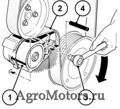 — Нажать натяжной ролик (1) торцевым ключом (3) в направлении стрелки, пока штифтовый ограничитель Ш 6 мм (4) не будет фиксироваться в монтажном отверстии. Теперь поликлиновой ремень (2) ненатянут.
— Сначала снять поликлиновой ремень (2) с самого маленького ролика или натяжного ролика.
— Установить новый поликлиновой ремень (2).
— Удерживать натяжной ролик с помощью торцевого ключа и вынуть штифтовый ограничитель.
— Натянуть новый поликлиновой ремень с помощью натяжного ролика и торцевого ключа (3). Проверить, чтобы поликлиновой ремень правильно прилегал в своей направляющей.
Проверка удлинения ремня
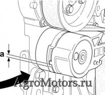
— Проверить предел износа поликлинового ремня следующим образом.
— Измерить расстояние между выступом подвижного натяжного рычага и упором неподвижного натяжного корпуса.
— Если расстояние «а» меньше 3 мм, ремень с натяжным роликом необходимо заменить.
Регулировка зазора клапанов Deutz TCD 2013 и Deutz TCD 2012
Регулировака клапанов Deutz TCD 2013 L6 4V и Deutz TCD 2013 L4 4V
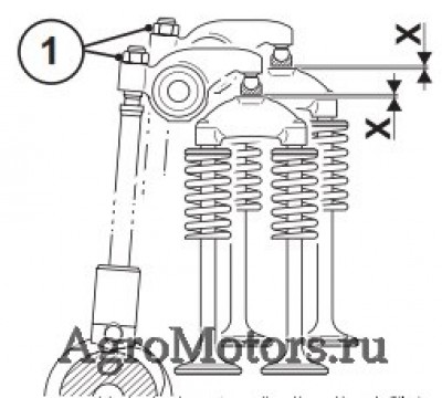 — Ослабить воздушный клапан и повернуть в сторону.
— Снять крышку головки цилиндров.
— Перед регулировкой зазора клапанов дать двигателю остыть не меньше 30 мин.: температура масла ниже 80 °C.
— Наложить прокручивающее устройство над крепежными болтами ременных шкивов.
— Прокрутить двигатель, пока не будет достигнуто перекрытие клапанов, цилиндр 1. Цилиндры настраиваются согласно схеме настройки.
Указание:
— Перекрытие клапанов обозначает:
— Выпускной клапан EX еще не закрыт, впускной клапан IN начинает открываться.
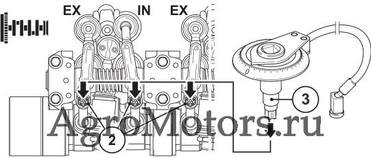
— Надеть шайбу углового закручивания (3) (номер заказа: 8190) и насадку на торцевой ключ (4) (номер заказа: 8193) на винт регулировки зазора клапанов (2).
— Ослабить контргайку (1) специальным инструментом (номер заказа: 8199).
— Зафиксировать магнит шайбы углового закручивания.
— Поворачивать шайбу углового закручивания по часовой стрелке до прилегания (коромысло клапана без зазора) и установить шкалу на ноль.
— Поворачивать шайбу углового закручивания против часовой стрелки, пока не будет достигнут заданный градус угла закручивания:
— Зафиксировать шайбу углового закручивания (3) от перекручивания.
— Затянуть контргайку (1) (момент затяжки 20 Нм).
— Выполнить регулировку на каждом цилиндре.
— Установить уплотнение (при необходимости новое).
— Визуально проверить и при необходимости заменить винты и резиновые элементы.
— Установить крышку головки цилиндров (при необходимости с новым уплотнением) и затянуть винты согласно инструкции: 9 Нм
— Повернуть воздушный клапан в положение и закрепить.
Схема настройки зазора клапанов
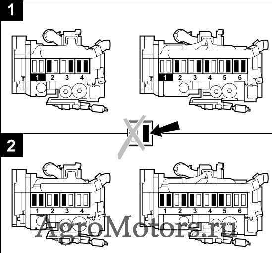
— Соответствие фаз распределения на коленчатом и распределительном вале при новом монтаже обеспечивается отметками на шестернях.
— Коленчатый вал может поворачиваться различными прокручивающими устройствами.
Положение коленчатого вала 1
— Поворачивать коленчатый вал, пока оба клапана на цилиндре 1 не перекроются (выпускной клапан еще не закрыт, впускной клапан начинает открываться.)
— Настраиваемые коромысла клапанов в начальном состоянии / при поставке имеют зазор.
Настройка зазора клапанов:
— Ослабить контргайку на обозначенных коромыслах клапанов (см. рисунок).
— Регулировочный винт по угловому методу IN = 75° EX = 105°
— Затянуть контргайку с моментом затяжки 20 Нм.
Положение коленчатого вала 2
— Повернуть коленчатый вал на один оборот, то есть 360°, перекрытие клапанов на цилиндре 4 или 6 в зависимости от модели.
— Теперь установить обозначенные на рисунке 2 коромысла клапанов, как описано выше.
Регулировака клапанов Deutz TCD 2012 L6 4V и Deutz TCD 2012 L4 4V
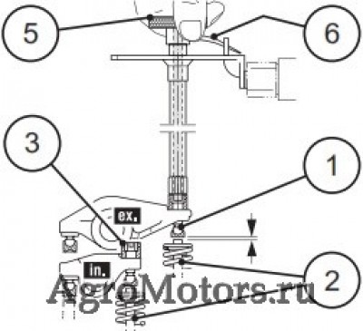 — Снять крышку головки цилиндров.
— Наложить прокручивающее устройство над крепежными болтами ременных шкивов.
— Перед регулировкой зазора клапанов дать двигателю остыть не меньше 30 мин.: температура масла ниже 80 °C.
— Инструмент ( 86).
— Прокрутить двигатель, пока не будет достигнуто перекрытие клапанов, цилиндр 1. Цилиндры настраиваются согласно схеме настройки.
Указание:
— Перекрытие клапанов обозначает:
— Выпускной клапан EX еще не закрыт, впускной клапан IN начинает открываться.
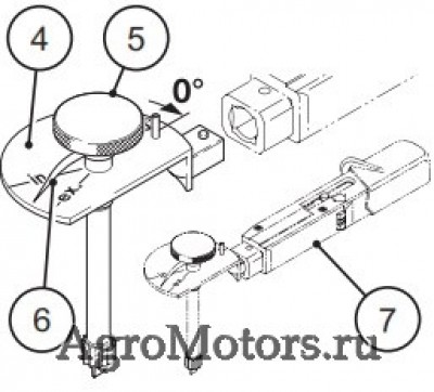 — Настроить зазор клапанов на соответствующем цилиндре устройством для настройки (номер заказа: 100340).
— Для этого ослабить все контргайки (3) настраиваемого коромысла.
— Повернуть регулировочные винты (1) против часовой стрелки на один оборот назад.
— Закрутить регулировочный винт (1) на настраиваемом коромысле в направлении часовой стрелки без зазора. То есть, между коромыслом клапана и клапаном (2) не должно быть зазора, а на клапан не должно оказываться давление.
— Установить стрелку (6) на рифленой ручке (5) измерительной пластины (4) на „0°“, при этом больше не перекручивать рифленую ручку (5).
— Удерживать измерительную пластину (4) точно в этом положении и поворачивать регулировочный винт (1) ручкой (5) против часовой стрелки, пока стрелка (6) не будет стоять на отметке „in“ или „ex“.
— Удерживать ручку (5) точно в этом положении и закрутить контргайку (3) динамометрическим ключом (7) с моментом затяжки 20 Нм.
— Выполнить регулировку на каждом цилиндре.
— Установить уплотнение (при необходимости новое).
— Визуально проверить и при необходимости заменить винты и резиновые элементы.
— Установить крышку головки цилиндров (при необходимости с новым уплотнением) и затянуть винты согласно инструкции: 9 Нм.
— Повернуть воздушный клапан в положение и закрепить.
Регулировка зазора клапанов для двигателя TCD 2013 L4 4V
| Последовательность зажигания: 1 — 3 — 4 — 2 | ||||
| Клапаны | Цилиндр | |||
| перекрытие | 1 | 3 | 4 | 2 |
| регулировка | 4 | 2 | 1 | 3 |
| Перекрытие клапанов | ||||
| Выпускной клапан еще не закрыт, впускной клапан начинает открываться |
Регулировка зазора клапанов для двигателя TCD 2013 L6 4V
| Последовательность зажигания: 1 — 5 — 3 — 6 — 2 — 4 | ||||||
| Клапаны | Цилиндр | |||||
| перекрытие | 1 | 5 | 3 | 6 | 2 | 4 |
| регулировка | 6 | 2 | 4 | 1 | 5 | 3 |
| Перекрытие клапанов | ||||||
| Выпускной клапан еще не закрыт, впускной клапан начинает открываться |
Регулировка моторного тормоза Deutz TCD 2013 и Deutz TCD 2012
Проверка и настройка зазора управляющего золотника в моторном тормозе
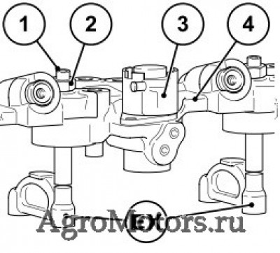 1 Регулировочный винт зазора клапанов
2 Контргайка
3 Электромагнитный клапан (электронное управление)
4 Управляющий мостик
— После настройки зазора клапана.
– Блок управления для моторного тормоза уже установлен.
— Прокрутить двигатель, пока не будет достигнуто перекрытие клапанов, цилиндр 1.
— Выполнить зазор управляющего золотника на каждом выпускном клапане.
— Затем выполнить те же действия, что и при зазоре клапанов.
Указание:
Перекрытие клапанов обозначает: Выпускной клапан еще не закрыт, впускной клапан начинает открываться, см. схему настройки клапанов.
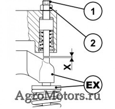 — При необходимости настроить зазор управляющего золотника, для этого:
— Открутить контргайку (2).
— Надеть зазор управляющего золотника X с регулировочным устройством ( 64) на регулировочный винт (1) в EX и настроить следующим образом:
– Зафиксировать магнит
– Затем повернуть под угловым градусом 432° назад (рукой или динамометрическим ключом):
– Поворачивать регулировочное устройство без зазора, пока управляющий золотник не будет прилегать к клапанному мостику, при этом установить шкалу на «0».
EX = выпускной клапан 432° при резьбе M8 (соответствует зазору 1,5 мм)
— Выполнить проверку или регулировку на каждом цилиндре.
— Снова установить крышку головки цилиндров с новым уплотнением.
— Повернуть воздушный клапан в положение и закрепить.
EX = выпускной клапан
Источник
Deutz PDF Service Manuals, Fault Codes and Wiring Diagrams
Deutz 2008-2009 Service Manual.pdf
Deutz 226B Operation Manual.pdf
Deutz D 2008-2009 Workshop Manual.pdf
Deutz Engine D2008 2009 Workshop Manual PDF.pdf
Deutz Engine Fire Protection — Operation Manual.pdf
Deutz Engine S-BV6-8-9M628 Operation Manual.pdf
Deutz FL 411 Service Manual.pdf
Deutz FL 413 Service Manual.pdf
Deutz Serie 7 Agrotron Service Manual.pdf
Gt-50dz Tow Tractor With Deutz Engine.pdf
Deutz 1011 Parts Manual.pdf
Deutz 2008-2009 Parts Manual.pdf
Deutz 413 Parts Manual.pdf
Deutz 912 Parts Manual.pdf
Deutz 914 Parts Manual.pdf
Deutz Accessories Catalogue.pdf
Deutz BF4M1013C Spare Parts Catalogue.pdf
Deutz 912-913 Service Manual.pdf
Deutz 912-913 Workshop Manual Workshop Manual.pdf
Deutz 912-913 Workshop Manual.pdf
Deutz 914 Service Manual.pdf
Deutz Engine 914 Operation Manual.pdf
Deutz — Workshop Manual BFM 1008F part 1.pdf
Deutz — Workshop Manual BFM 1008F part 2.pdf
Deutz Engines B_FM 1008_F Workshop Manual.pdf
Deutz 0312 1936 2011 Workshop Manual.pdf
Deutz 1011F Workshop Manual.pdf
Deutz BF4m1011F Engine Service Parts Manual.pdf
Deutz Engine 1011F Werkstatthandbuch.pdf
Deutz Engine 1011F Workshop Manual.pdf
Deutz Engine B-F L 1011F B-FM 1011F Operation Manual — Engine Description.pdf
Deutz Engine B-F L 1011F B-FM 1011F Operation Manual — Engine Operation.pdf
Deutz Engine B-F L 1011F B-FM 1011F Operation Manual — Engine Preservation.pdf
Deutz Engine B-F L 1011F B-FM 1011F Operation Manual — Faults, Causes and Remedies.pdf
Deutz Engine B-F L 1011F B-FM 1011F Operation Manual — General.pdf
Deutz Engine B-F L 1011F B-FM 1011F Operation Manual — Notes.pdf
Deutz Engine B-F L 1011F B-FM 1011F Operation Manual — Operating Media.pdf
Deutz Engine B-F L 1011F B-FM 1011F Operation Manual — Routine Maintenance.pdf
Deutz Engine B-F L 1011F B-FM 1011F Operation Manual — Service and Maintenance.pdf
Deutz Engine B-F L 1011F B-FM 1011F Operation Manual — Technical Specifications.pdf
Deutz Engine B-FL 1011F Operation Manual.pdf
Deutz F3M 1011F, BF3M, F4M, BF4M Service Manual.pdf
Deutz 1012 1013 Operation and Maintenance Manual.pdf
Deutz 1012-1013 Service Manual.pdf
Deutz Engine 1012-1013 Workshop Manual.pdf
Deutz 1015 Service Manual.pdf
Deutz BFM 1015 Workshop Manual.pdf
Deutz 0312 1936 2011 Workshop Manual- competence level 3.pdf
Deutz 0312 4004 2011 Workshop Manual- competence level 2.pdf
Deutz 2011 — Operation Manual.pdf
Deutz D 2011 w, TD 2011 w, TCD 2011 w Workshop Manual- competence level 2.pdf
Deutz D 2011, TD 2011 Workshop Manual- competence level 2.pdf
Deutz Engine B-FL-FM 2011 Operation Manual.pdf
Deutz 2012 Service Manual.pdf
Deutz Engine 2012 Operation Manual.pdf
Deutz Engine BF6M 1013 Operation Manual.pdf
Deutz Engine BFM-2012 Workshop Manual.pdf
Deutz TCD 2012-2013 Service Manual.pdf
Deutz TCD2012 Instruction Manual.pdf
Deutz Engine TCD 2013 2V Workshop Manual.pdf
Deutz Engine TCD 2013 L04-06 4V Instruction Manual — Care and maintenance work.pdf
Deutz Engine TCD 2013 L04-06 4V Instruction Manual — Engine corrosion protection.pdf
Deutz Engine TCD 2013 L04-06 4V Instruction Manual — Engine description.pdf
Deutz Engine TCD 2013 L04-06 4V Instruction Manual — Faults, causes and remedies.pdf
Deutz Engine TCD 2013 L04-06 4V Instruction Manual — General.pdf
Deutz Engine TCD 2013 L04-06 4V Instruction Manual — Maintenance.pdf
Deutz Engine TCD 2013 L04-06 4V Instruction Manual — Operating substances.pdf
Deutz Engine TCD 2013 L04-06 4V Instruction Manual — Operation Manual.pdf
Deutz Engine TCD 2013 L04-06 4V Instruction Manual — Operation.pdf
Deutz Engine TCD 2013 L04-06 4V Instruction Manual — Service.pdf
Deutz Engine TCD 2013 L04-06 4V Instruction Manual — Technical data.pdf
Deutz TCD 2013 4V — Industry Workshop Manual.pdf
Deutz Engine TCD 2015 Workshop Manual — General.pdf
Deutz Engine TCD 2015 Workshop Manual — Job card overview.pdf
Deutz Engine TCD 2015 Workshop Manual — Special tools.pdf
Deutz Engine TCD 2015 Workshop Manual — Standart tools.pdf
Deutz Engine TCD 2015 Workshop Manual — Technical data.pdf
Deutz Engine TCD 2015 Workshop Manual — User notes.pdf
Deutz TCD 2015 Service Manual.pdf
Parts manuals
The German company Deutz AG has been producing engines for more than 130 years. Its emblem on diesel engines and gas engines is evidence of the highest quality of products, in which the rich experience of several generations of talented German engineers and technicians is accumulated. The range of power units offered in 2001 includes dozens of basic models of motors for various purposes with a power from 4 to 7,400 kW. The long way of Deutz AG to today’s achievements begins in the distant 1864. We will get acquainted with its main stages, especially since in the history of the firm there were mutually beneficial contacts with our country.
So, the year 1864-th. German designer and inventor Nikolaus Otto, one of the first creators of an efficient internal combustion engine, gets acquainted with an entrepreneur from Cologne, Evgeny Longen, a very wealthy and technically competent man, and inspires him to create a company that would manufacture industrial combustion engines-atmospheric gas engines.
Longen helps Otto to obtain a patent for the engine and conducts a «wide advertising campaign», demonstrating the motor at many exhibitions in the Old and New World. Finally, in 1867, the sample was awarded a gold medal at an exhibition in Paris, and interest in it reached the level at which it was worth starting its production. In 1869, launched a large plant near Cologne, in the suburbs of Doitz. The new enterprise is named after the names of its owners «Longen, Otto and Roosen». At the same time, the license for the production of the internal combustion gas engine of the English company Crossley is being sold.
So, in the Old World a new compact energy source appeared on the market, ready to compete with bulky steam engines. In 1872 a new technical director — Gottlieb Daimler (the future inventor of the car) was appointed to the reconstructed enterprise, and Wilhelm Maybach — the person no less legendary in the automotive industry — became the head of the design department. The company receives the new name Gasmotoren-Fabrik Deutz AG and expands the scope of application of engines.
In 1879 Nikolaus Otto successfully completes the experiment to create the world’s first four-stroke engine with compression of the fuel-air mixture before its ignition — the prototype of most modern gasoline engines. Encouraged by the success, the enterprise is again being reconstructed and preparing for a new round of development, despite the departure of G. Daimler and V. Maybach from it. In 1886, Otto received his Ph.D. from the University of Wurzburg and, together with Robert Bosch, developed an electrical ignition system.
So, working engines that consumed a gasoline mixture, appeared. They are compact, fast and affordable. And all this, thanks to the pioneer of engine building, the company Deutz. In 1896, the history of the automobile industry begins. At the same time much more powerful gasoline engines began to be installed on railroad locomotives.
However, the technical department of the company was not asleep. In 1898, a fundamentally new engine was constructed and presented to the public, having compression ignition. In honor of the author, Rudolf Diesel, he was called a diesel engine. A new era in motor-building began.
By 1907, the design of the first sample had been worked out and patented; It was possible to start the production of diesel engines. Their consumption increased, and the size range expanded. After the short-term production of Deutz-Bugatti cars (1907 — 1912) with the participation of the very creator, Ettore Bugatti, who worked in the company from 1907 to 1909, the management turned its eyes to the tractors. The first machine of its own design came off the assembly line in 1924. The model was called Deutz MTN 222 and was equipped with special pulleys for driving agricultural equipment.
At the same time, different types of engines were produced — for cars and trucks, rail cars, as well as industrial engines that were sent to other companies. Since 1921 the company was officially called Motorenfabrik Deutz AG. In 1938 — the next transformation. Having acquired new plants, the company became known as Klockner-Humboldt-Deutz AG (KHD). In the same year, its technical department developed another novelty — the first diesel with air cooling. However, soon everything changed abruptly. The bombing of factories by aircraft of the USSR and its allies destroys 74% of the entire industrial potential of the concern. It was, as can be easily guessed, in late 1944 — the first half of 1945.
A new stage, called «restoration of former grandeur,» began in 1949. It was then that management decided to resurrect the production of agricultural tractors with air-cooled diesel engines. The goods were dispersed in the market instantly. Gradually, together with the tractors, the production of trucks and buses began, which bore the brand of Magirus-Deutz and was considered one of the best in Europe.
By 1964, a new Technical Center was built near Cologne, which increased the competitiveness of the structures being built. Machines with the KHD brand (dump trucks, construction chassis, diesel engines) have been exhibited many times since 1964 at exhibitions in Moscow and have been evaluated by domestic experts. When the construction of the Baikal-Amur Mainline began, Deutz AG received an unprecedented order for the supply in the USSR of 10,000 (!) First-class dump trucks that formed the basis of the contractors’ car fleet. Striking, but true: some of them are still on the go.
After the purchase of the USSR, the license for the right to produce Deutz diesel engines with air cooling, the specialists of the German company together with Russian engineers did a great job of conducting full-scale tests of the motors on trucks Ural-375D, the ones for which they were intended. The design of the diesel engines was fully adapted to operation at temperatures from -40 to + 40 ° C. The work was carried out in 1966 — 1980 gg. As a result, a plant was built in Kustanai (now the Republic of Kazakhstan), designed to supply several tens of thousands of motors per year. It was not possible to launch this enterprise before 1991, and then the Soviet Union did not. However, the experience gained in researching diesel engines under extreme conditions has benefited both Deutz specialists and ours.
In 1975, the brand Magirus-Deutz disappeared from the automobile directories of current products. The truck and bus division was part of IVECO, a multinational concern controlled by FIAT. And the company Deutz AG continued to engage in engine construction and tractors. In 1978, the production of a 4 millionth internal combustion engine was commemorated in the year 1867. The next such event occurred only in 1989. And also in connection with the release of a 4 millionth diesel engine, but only with air cooling. Their production began in 1944. In 1995, the department for the production of tractors and agricultural machines was sold to the Italian company Same Group, and the firm Deutz AG focused on where it started: the engines supplied to a wide variety of manufacturers. «Everything has returned to normal.»
However, the history of this amazing company does not end there . There are still many interesting projects ahead of it, among them . the organization of the assembly of Deutz diesel engines in Russia. Were you surprised? Nothing surprising. We need good diesel engines, and Russia needs Deutz AG. That’s all.
Источник