- Manuals
- Brands
- Deutz Manuals
- Engine
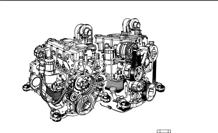
- TCD 2012 L04/06 V2
- Operation manual
-
Contents
-
Table of Contents
-
Bookmarks
Quick Links
Operation Manual
TCD 2012 L04/06 V2
TCD 2013 L04/06 V2
Related Manuals for Deutz TCD 2012 L04/06 V2
Summary of Contents for Deutz TCD 2012 L04/06 V2
-
Page 1
Operation Manual TCD 2012 L04/06 V2 TCD 2013 L04/06 V2… -
Page 2
Only DEUTZ original parts may be used when repairs — Danger to life. manufacturer. The engine may only be used, carrying out maintenance/repair work on the maintained and repaired by persons who are engine. -
Page 3
Operation Manual TCD 2012 L04/06 V2 TCD 2013 L04/06 V2 312 1890 en Engine number: Please enter the engine number here. This will simplify the handling of customer service, repair and spare parts queries (see Section 2.1). Illustrations and data in this instruction manual are subject to technical changes in the course of improvements to the engines. -
Page 4
Foreword Dear customer, The liquid-cooled engines made by DEUTZ are developed for a wide variety of applications. An extensive range of variants ensures that the respective special requirements are met. Your engine is equipped according to the installation, i.e. not all the parts and components described in this instruction manual are installed on your engine. -
Page 5: Table Of Contents
Contents Operation General Care and maintenance Initial commissioning Engine description work 3.1.1 Filling engine oil Engine type Lubrication system 3.1.2 Filling fuel 2.1.1 Company plate 6.1.1 Oil change intervals 3.1.3 Filling / bleeding cooling system 2.1.2 Location of company plate 6.1.2 Checking oil level, changing engine oil 3.1.4…
-
Page 6
Contents Add-on parts 6.7.1 Battery 6.7.2 Three-phase current generator 6.7.3 Transportation suspension Faults, causes and remedies Fault table Engine management 7.2.1 Engine protection function of the electronic engine controller EMR3 7.2.2 Using the diagnosis button 7.2.3 Table of fault blink codes Engine corrosion protection Corrosion protection Technical data… -
Page 7: General
It goes without saying that DEUTZ Diesel conscientiously. Special care should be taken parts. Original parts from DEUTZ AG are Engines meet the highest standards for en-…
-
Page 8: Engine Description
Engine description 2.1 Engine type 2.2 Engine diagrams 2.3 Lube oil circuit 2.4 Fuel circuit 2.5 Coolant circuit 2.6 Electrics…
-
Page 9: Location Of Company Plate
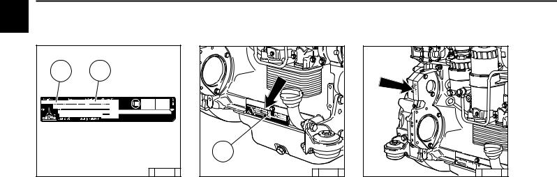
Engine description 2.1 Engine type 2.1.1 Company plate 2.1.2 Location of company plate © 35 985 0 © 38 987 1 © 43 834 0 The company plate C is fixed to the cylinder The engine type A, engine number B and the head cover crankcase.
-
Page 10
Engine description 2.1 Engine type 2.1.3 Engine number 2.1.4 Cylinder numbering © 43 833 0 © 38989 0 The engine number is stamped on the crankcase The cylinders are counted consecutively, starting (arrow) and on the company plate. from the flywheel. -
Page 11
Engine description 2.2 Engine diagrams 2.2.1 Operation side TCD 2012 L04 2V Oil filler Combustion air inlet Cover Generator Fuel pump Tension pulley with torsion spring Oil cooler Exchangeable fuel filter 10 Exchangeable lube oil filter 11 Oil tray 12 Hydraulic pump or compressor mounting possibility 13 Flywheel 14 Crankcase bleeding valve… -
Page 12
Engine description 2.2 Engine diagrams 2.2.2 Starter side TCD 2012 L04 2V 18 Exhaust manifold 19 Turbocharger 20 Oil filler (optional) 21 Engine mounting 22 Oil return line from turbocharger 23 Relay (starter) 24 V-rib belt 25 Coolant inlet 26 Coolant outlet 27 Coolant pump 28 Connection cabin heater or compensation line… -
Page 13
Engine description 2.2 Engine diagrams 2.2.3 Operation side TCD 2012 L06 2V Oil filler Combustion air inlet Transport eyes Generator Fan hub Fuel pump V-rib belt drive on crankshaft V-rib belt Tension pulley with torsion spring 10 Coolant pump 11 Exchangeable lube oil filter (1x optional) 12 Oil drain screw 13 Oil dipstick 14 Lube oil cooler… -
Page 14
Engine description 2.2 Engine diagrams 2.2.4 Starter side TCD 2012 L06 2V 23 Crankcase bleeding valve 24 Charge air pipe 25 Solenoid valve for exhaust gas recirculation 26 SAE housing 27 Oil tray 28 Starter cover 29 Oil return line from turbocharger 30 Exhaust turbocharger 31 Charge air connection to charge air cooler 32 Coolant inlet… -
Page 15
Engine description 2.2 Engine diagrams 2.2.5 Operation side TCD 2013 L04 2V Combustion air inlet (heating flange installation facility, optional) Connection cabin heater or compensation line Fan (drive coolant pump) Generator Belt pulley on crankshaft V-belt Fuel pump drive Exchangeable fuel filter Exchangeable lube oil filter 10 Oil cooler 11 Drive facility (e.g. -
Page 16
Engine description 2.2 Engine diagrams 2.2.6 Starter side TCD 2013 L04 2V 19 Oil filler (optional) 20 SAE housing 21 Engine mounting 22 Oil drain screw 23 Oil tray 24 Starter 25 Lube oil return from turbocharger 26 Turbocharger 27 Coolant inlet 28 Charge air connection to cooler 29 Coolant outlet 30 Exhaust manifold… -
Page 17
Engine description 2.2 Engine diagrams 2.2.7 Operation side TCD 2013 L06 2V Combustion air inlet Oil filler Transport eyes Generator Coolant pump Exchangeable lube oil filter Exchangeable fuel filter Oil tray Oil dipstick 10 Oil drain screw 11 Oil return line crankcase bleeding 12 Engine mounting 13 SAE housing 14 Plug to control unit… -
Page 18
Engine description 2.2 Engine diagrams 2.2.8 Starter side TCD 2013 L06 2V 19 Turbocharger 20 Exhaust manifold 21 Starter 22 Lube oil line to turbocharger 23 Coolant drain screw 24 Coolant inlet 25 V-rib belt 26 Fan 27 Tension pulley with torsion spring 28 Connection compensation line 29 Ventilation line to compensation tank 30 Coolant outlet from engine to cooler… -
Page 19: Lube Oil
Engine description 2.3 Lube oil circuit 2.3.1 Lube oil diagram (example) Oil tray Intake pipe Lube oil pump 3.1 Safety valve Lube oil cooler 4.1 Return shutoff valve (only in 2012) 4.2 By-pass valve 4.3 By-pass valve oil filter 4.4 Pressure control valve Exchangeable lube oil filter Main oil pipe 6a Internal exhaust gas recirculation…
-
Page 20
Engine description 2.4 Fuel circuit 2.4.1 Fuel diagram Fuel container Fuel pre-filter with pre-pressure pump possibility for filling the low pressure area (to be provided by the customer) Line to fuel pump Fuel pump Fuel filter Fuel supply line to fuel control unit Rail High-pressure pump Fuel line to injector… -
Page 21
2.5 Coolant circuit Engine description 2.5.1 Coolant diagram (example) © 43 897 4… -
Page 22: Coolant
2.5 Coolant circuit Engine description Coolant outlet at the cooler Thermostat Coolant feed line to pump Coolant pump Lube oil cooler Cylinder cooling Cylinder head cooling Coolant inlet to heating Heating 10 Coolant to thermostat 11 Heating connection 12 Compensation line 13 Ventilation line to compensation tank 14 Coolant outlet to cooler 15 Compensation tank…
-
Page 23: Electrical Cable Connections For
Engine description 2.6 Electrics 2.6.1 Electrical cable connections for monitoring Solenoid valve EGR (optional) Coolant temperature Charge air pressure/temperature transmitter Connection facility example: Control unit not mounted on the engine Engine control unit Speed governor via crankshaft Rail pressure, on side of rail Oil level transmitter (optional) Oil pressure transmitter 10 Fuel pressure…
-
Page 24
Engine description 2.6 Electrics Other application-side components (depending on the application) Water trap fuel filter, see chap. 6.2.3 Override key, see chap. 3.3.1 (for temporary bypassing of the engine protection functions) Coolant level transmitter Separate engine stop switch Fan control Switch for brake contact, engine brake, clutch Drive speed sensor, drive speed control unit (+ — keys, for speed increase reduction) -
Page 25: Initial Commissioning
Operation 3.1 Initial commissioning 3.2 Starting 3.3 Operation monitoring 3.4 Shutting down 3.5 Operating conditions…
-
Page 26: Filling Engine Oil
Operation 3.1 Initial commissioning 3.1.2 Filling fuel 3.1.1 Filling engine oil © 43 838 2 © 43 843 2 The engines are generally supplied without oil Only use clean, standard, branded diesel fuel. For filling. fuel quality see 4.2. Fill engine with lube oil through the oil filler (1) Depending on the outdoor temperature, use on the cylinder head cover.
-
Page 27: Filling / Bleeding Cooling System
Operation 3.1 Initial commissioning 3.1.3 Filling / bleeding 3.1.4 Other preparations cooling system Check battery and cable connections, see 6.7.1. Trial run — After preparations carry out a short trial run of approx. 10 min. Do not fully load the engine. During and after the trial run — Check engine for tightness.
-
Page 28: Electrical Starting
Operation 3.2 Starting 3.2.1 Electrical starting without cold start aid Before starting make sure that Insert key there is nobody in the engine/ — Step 0 = no operating voltage. work machine danger area. Turn key to the right After repairs: Check that all — Step 1 = operating voltage, protective equipment is — Warning lights light up.
-
Page 29
Operation 3.2 Starting with cold start aid Heating plug/heating flange © 26 411 0 Insert key. — Step 0 = no operating voltage. Turn key to the right. — Step 1 = operating voltage, — Warning lights 1+2+3 light up. — Pre-heat until heating indicator goes out. -
Page 30: Operation Monitoring
Operation 3.3 Operation monitoring 3.3.1 Engine oil pressure The EMR3 system monitors the engine condition and itself. Oil pressure light Oil pressure gauge The states are indicated by the diagnostic lamp. Lamp test: The diagnostic lamp lights for about 2s after ignition (ignition lock stage 1).
-
Page 31: Coolant Temperature
Operation 3.3 Operation monitoring 3.3.2 Coolant temperature 3.3.3 Coolant level © 26 246 0 © 26 291 1 The needle of the temperature display should Light on coolant level display comes on (contact always be in the green area, and only as an is via float switch/ level probe if coolant level exception in the yellow/green area.
-
Page 32: Electrical Shutdown
Operation 3.4 Shutting down 3.4.1 Electrical shutdown © 26 411 0 Turn the key to the left (to step 0) and remove. Warning lights go out. Note: The control unit remains active for about another 40 seconds to save the system data (lag) and then switches itself off.
-
Page 33: Operating Conditions
Operation 3.5 Operating conditions 3.5.1 Winter operation Lube oil viscosity Battery — A well-charged battery is a — Select the viscosity (SAE class) prerequisite for a good cold start, according to the ambient temperature see 6.7.1. before starting the engine, see 4.1.2. — Heating the battery to approx.
-
Page 34: High Ambient Temperature
Operation 3.5 Operating conditions 3.5.2 High ambient temperature, high altitude When the altitude or ambient temperature increases, the air density decreases. This impairs the maximum engine performance, exhaust quality, temperature level and, in extreme cases, the starting performance. For transient operation, usage up to 1500 m altitude and a temperature of 30 °C is permissible, for stationary operation 1000 m altitude and a temperature of 40 °C is…
-
Page 35: Operating Substances
Operating substances 4.1 Lube oil 4.2 Fuel 4.3 Coolant…
-
Page 36
Biodegradable lube oils may be used in dominant. Basically all engine oils are mixable so DEUTZ engines if they meet the requirements of that a complete lube oil change from one oil type this operating manual. -
Page 37
Operating substances 4.1 Lube oil 4.1.1 Quality Lube oils are classified by DEUTZ according to DEUTZ lube oil quality classes DQC I — 02 DQC II — 05 DQC III — 05 DQC IV — 05 their performance and quality class (DQC : Deutz… -
Page 38
Salzbergen Wintershall TFG 10W-40 Europe Texaco Ursa Super TDX 10W-40 Europe Ursa Premium FE 5W-30 Europe TOTAL TOTAL RUBIA TIR 8600 10W-40 worldwide EXPERTY 10W-40 worldwide T 4-1-3 Release list for DEUTZ lube oil quality class DQC III — 05… -
Page 39
Fuchs Titan Cargo SL 5W-30 worldwide FUCHS EUROPE SHELL International Shell Rimula Ultra 5W-30 Europe, code country-specific, varies Shell Rimula Ultra 10W-40 Europe, code country-specific, varies T 4-1-4 Release list for DEUTZ lube oil quality class DQC IV — 05… -
Page 40
Operating substances 4.1 Lube oil 4.1.2 Quality The ambient temperature at the installation site or area of application of the engine is decisive for the choice of the right viscosity class. Too high a viscosity can lead to starting difficulties, too low a viscosity can endanger the lubrication effect and cause high lube oil consumption. -
Page 41
For questions regarding this please contact Paraffin mixing proportion your DEUTZ partner. fuels defined by law. These correspond to the diesel fuels according to EN 590 and ASTM D 975 Only carry out mixing in the tank! described in this operating manual. -
Page 42
(city water). carbonate hardness proportion of total hardness min 3 dGH. Water quality data are obtainable from the local waterworks. A test case can be requested from DEUTZ Service (order no. 1213 0382) for checking your water quality. -
Page 43: Coolant Preparation
The inspection of the concentration of cooling system preservative can be carried out with The best results are achieved with DEUTZ cooling standard testing devices (e.g. refractometer). system preservatives: Container Order no.
-
Page 44: Maintenance
Maintenance 5.1 Maintenance schedule 5.2 Maintenance diagram 5.3 Maintenance work carried out…
-
Page 45
Maintenance 5.1 Maintenance schedule check= set= clean=L renew= Industrial engines ⇓ check 2x daily before or during the 1st trial run, during the running-in phase or The engine maintenance times given are maximum permissible job when commissioning new and overhauled engines times. -
Page 46
Maintenance 5.1 Maintenance schedule clean= L check= set= renew= Enhancements or modifications max. permissible job times in operating hours (oh) every for engines with EPA acceptance ⇓ check 2x daily before or during the 1st trial run, during the running-in phase or The engine maintenance times given are maximum permissible job times. -
Page 47
6 000 oh E 60 extended partial overhaul authorised specialists 12 000 oh E 70 general overhaul authorised specialists *) approximate value, depends on the type of engine application and/or regular engine maintenance. Please contact your responsible DEUTZ Service partner. -
Page 48
Maintenance 5.2 Maintenance diagram The maintenance diagram shown on this page is supplied with every engine in self- adhesive form. It should be stuck onto a well visible location on the engine or equipment. Check that this is the case! If not, request a replacement from your engine or equipment supplier! The maintenance schedule is decisive for… -
Page 49
Maintenance 5.3 Maintenance work carried out Signature / stamp Op. hrs. Date Signature / stamp Op. hrs. Date 50-150 1000 1250 1125 1500 1375 1750 1625 2000 1875 2250 2115 2500 2375 2750 * after commissioning new and overhauled engines The maintenance work carried out methodically can be recorded in the table and confirmed. -
Page 50
Maintenance 5.3 Maintenance work carried out Op. hrs. Date Signature / stamp Op. hrs. Date Signature / stamp 2875 3000 3125 3250 3375 3500 3625 3750 3875 4000 4125 4250 4375 4500 4625 4750 4875 5000 5125 5250 5375 5500 5625 5750 The maintenance work carried out methodically can be recorded in the table and confirmed. -
Page 51
Maintenance 5.3 Maintenance work carried out Signature / stamp Op. hrs. Date Signature / stamp Op. hrs. Date 6000 5875 6250 6125 6375 6500 6625 6750 6875 7000 7125 7250 7375 7500 7625 7750 7825 8000 8125 8250 8375 8500 8625 8750 The maintenance work carried out methodically can be recorded in the table and confirmed. -
Page 52
Maintenance 5.3 Maintenance work carried out Op. hrs. Date Signature / stamp Op. hrs. Date Signature / stamp 8875 9000 9250 9125 9500 9375 9750 9625 10000 9875 10250 10125 10500 10375 10750 10625 11000 10875 11250 11125 11500 11375 11750 11625 The maintenance work carried out methodically can be recorded in the table and confirmed. -
Page 53: Add-On Parts
Care and maintenance work 6.1Lubrication system 6.2Fuel system 6.3Cooling system 6.4Combustion air filter 6.5Belt drive 6.6Setting work 6.7Add-on parts…
-
Page 54
Care and maintenance work 6.1 Lubrication system 6.1.1 Oil change intervals If the lube oil change intervals are planned The oil change times depend on the engine in terms of operating hours, the lube oil application and the quality of the lube oil. change intervals for installed engines 6.1.1.1 apply. -
Page 55
Care and maintenance work 6.1 Lubrication system 6.1.1.1 Lube oil change intervals for installed engines Lube oil quality Deutz lube oil quality class DQC I-02 DQC II-05 DQC III-05 DQC iV-05 ACEA specification E2-96 E3-96/E5-02/E07-04 E4-99/E6-04 E4-99/E6-04 see chap 6.1.1.3 only fully synthetic… -
Page 56
Care and maintenance work 6.1 Lubrication system 6.1.2 Checking oil level, changing engine oil 6.1.2.1 Checking oil level 6.1.2.2Changing engine oil © 26 023 0 © 26 022 0 © 25 729 0 Position the engine or vehicle so as to be level. Warm up the engine. -
Page 57
Care and maintenance work 6.1 Lubrication system 6.1.3 Changing oil filter © 25 882 0 © 25 880 0 © 25 881 0 When anti-rotation lock is installed: Clean the sealing surface of the filter support Tighten the lube oil filter cartridge with a three- Loosen clamping screws and remove for any dirt there may be. -
Page 58
Care and maintenance work 6.1 Lubrication system 6.1.4 Cleaning / changing oil filter (cup) © 30 0 74 1 © 43 937 0 © 300 74 0 Change the round sealing ring 2 and lightly oil. Switch off engine. Collect any lube oil which may run out. Press new paper filter cartridge 5 into the clip Loosen lube oil filter cover 1 with two or three Crease the paper filter cartridge 5 in the… -
Page 59
Care and maintenance work 6.1 Lubrication system… -
Page 60
Care and maintenance work 6.2 Fuel system Additional regulations for DEUTZ Common Cleanliness hints and measures for Regulations for working on the fuel system handling DEUTZ Common Rail Systems Rail Systems Engine must be switched off! Danger to life! Never work on… -
Page 61
Care and maintenance work 6.2 Fuel system 6.2.1 Changing fuel filter © 25 882 0 © 25 880 0 © 25 881 0 Close fuel stopcock. Lightly oil the fuel filter cartridge or wet with Tighten the fuel filter cartridge with a three- Loosen fuel filter cartridge with standard tool diesel fuel. -
Page 62
Care and maintenance work 6.2 Fuel system 6.2.2 Cleaning / changing fuel filter (cup) © 43 938 0 © 30 074 0 © 43 937 0 Switch off engine. Collect any fuel which may run out. Change the round sealing ring 2 and lightly oil. Loosen fuel filter cover 1 with two or three Slightly bend paper filter cartridge 5 sideways Press new paper filter cartridge 5 into the clip… -
Page 63
Care and maintenance work 6.2 Fuel system 6.2.3 Fuel pre-filter, changing / bleeding filter insert 1 Fuel supply to pump Clean any dirt from the sealing surface of the 2 Fuel return from control block FCU new filter cartridge (5) and the reverse side (Fuel Control Unit) of the filter head 3 Fuel hand pump with bayonet… -
Page 64
Care and maintenance work 6.3 Cooling system 6.3.1 Cleaning intervals 6.3.2 Cleaning cooling system The cooling system soiling depends on thetype of engine application. The risk of soiling is increased by oil and fuel residues on the engine. Therefore pay particular attention to tightness when operating under high dust exposure. -
Page 65
Care and maintenance work 6.3 Cooling system © 43 903 0 Cleaning with steam or hot water Remove oil and greasy residues with a gentle jet setting (do not spray directly on sensitive engine parts, e.g. generator, wiring, electrical- components, fan drive). Warm up the engine so that the water residues evaporate. -
Page 66
Care and maintenance work 6.3 Cooling system 6.3.4 Filling / bleeding 6.3.3 Emptying cooling system cooling system © 43 839 0 © 39 850 1 Open cooler cover. Open cooler cover. The cooling system (if constructed under Position collecting dish underneath locking Loosen locking screw item 1 (chap.6.3.3). -
Page 67
Care and maintenance work 6.4 Combustion air filter 6.4.1 Cleaning intervals The soiling of the combustion air filter de- pends on the dust content of the air and the selected filter size. If a high dust exposure is to be expected, a cyclone separator can be connected to the combustion air filter. -
Page 68
Care and maintenance work 6.4 Combustion air filter 6.4.2 Emptying cyclone pre- 6.4.3 Cleaning oil bath air filter separator © 25 886 0 © 25 887 1 Loosen wing nut 1 and lift housing cover 2. Turn off the engine and wait approx. 10 min In the event of heavy soiling, clean filter hou- Remove the dust container 3 from the base of until the oil has run out of the filter housing 1. -
Page 69
Care and maintenance work 6.4 Combustion air filter 6.4.4 Dry air filter Dust discharge valve Filter cartridge © 25 888 1 © 25 889 0 Empty the dust discharge valve 1 by squee- Check filter cartridge for damage to the filter Open clamping bracket 1. -
Page 70
Care and maintenance work 6.5 Belt drive 6.5.1 Checking V-belt 2013 example © 43 894 0 © 26 261 1 Visual inspection of entire length of V-belt for To check the V-belt tension — Carefully lift the measuring device, without damages. -
Page 71
Care and maintenance work 6.5 Belt drive 6.5.2 Changing V-rib belt 6.5.3 Checking wear limit of V-rib belt © 43 851 0 © 31 814 4 The wear limit of the V-rib belt is checked as Push tension roller 1 with ratchet 3 in direction follows: of arrow until locking pin 4 can be fixed in the Check the distance between the projection… -
Page 72
Care and maintenance work 6.6 Setting work 6.6.1 Checking valve clearance, setting if necessary © 43 849 0 © 43 831 1 Loosen lock nut 1 Hold rotation angle disc 3 tight against Before setting the valve clearance allow the twisting. -
Page 73
Care and maintenance work 6.6 Setting work © 44 304 0 © 44 305 0 Valve clearance setting inlet valve Hold rotation angle disc 3 tight against twisting. in exhaust gas return line (EGR): Tighten the lock nut 6. Loosen lock nut 6. Perform the setting on every inlet valve (see Place rotation angle disc 3 with crow’s foot chap. -
Page 74
Care and maintenance work 6.6 Setting work 6.6.2 Setting control piston clearance in exhaust gas recirculation (EGR) © 43 830 1 © 43 832 0 Loosen lock nut 1. After setting the valve clearance, the control Place the rotation angle disc and socket wrench piston clearance should be set as follows: insert on the setting screw 2 Place the turning device over the fastening… -
Page 75
Care and maintenance work 6.6 Setting work 6.6.3 Diagram for setting valve / control piston clearance Engine TCD 2012/2013 L04 2V Engine TCD 2012/2013 L06 2V Ignition sequence: 1–3–4–2 Ignition sequence: 1–5–3–6–2–4 Valves Cylinder Valves Cylinder overlap overlap set to set to Valve operlap: Outlet valve not yet closed, inlet Valve operlap: Outlet valve not yet closed, inlet… -
Page 76: Battery
Care and maintenance work 6.7 Add-on parts 6.7.1 Battery 6.7.1.1 Checking battery and cable 6.7.1.3 Checking acid density 6.7.1.2 Checking the acid level connections © 25 895 0 © 24 232 3 © 25 896 0 Remove sealing caps 1. Keep the battery clean and dry.
-
Page 77
Care and maintenance work 6.7 Add-on parts Acid density in [kg/ l] Charge level Normal Tropics 1.28 1.23 well charged 1.20 1.12 half charged, re-charge 1.12 1.08 discharged, charge immediately The gases released by the battery are explosive! Avoid sparks and open fire in the vicinity of the battery! Do not allow acid to get on skin or clothes! -
Page 78: Transportation Suspension
Care and maintenance work 6.7 Add-on parts 6.7.2 Three-phase current 6.7.3 Transportation suspension generator Notes on three-phase current system: Do not interrupt the connections between the battery, generator and governor when the engine is running. If, however, an engine must be started and operated without battery, the connection go- vernor / generator is to be separated before starting.
-
Page 80: Faults, Causes And Remedies
Faults, causes and remedies 7.1 Fault table 7.2 Engine management…
-
Page 81
A corresponding fault table can be found overleaf. If you cannot recognise the cause of a fault or cannot remedy a fault yourself, please contact your DEUTZ Service. Before starting make sure that there is nobody in the engine/ work machine danger area. -
Page 82
7.1 Fault table Faults, causes and remedies Faults Action Engine doesn’t start up, or starts up with difficulty Engine doesn’t start up and diagnosis light is blinking Check Engines starts up, but runs irregularly or misfires Engine gets too hot. Temperature warning system is activated Change Engine lacks power Engine lacks power and diagnosis light is lit up… -
Page 83
7.1 Fault table Faults, causes and remedies Faults Action Engine doesn’t start up, or starts up with difficulty Check Engine doesn’t start up and diagnosis light is blinking Engines starts up, but runs irregularly or misfires Change Engine gets too hot. Temperature warning system is activated Clean Engine lacks power Fill up… -
Page 84: Engine Protection Function Of The
7.2 Engine management Faults, causes and remedies 7.2.3 Table of fault blink codes 7.2.1 Engine protection function of 7.2.2 Using the diagnosis button the electronic engine controller EMR3 Depending on the design of the monitoring With the diagnosis button (1) the fault at hand can functions, the EMR3 can protect the engine be read out as a blink code.
-
Page 85
7.2 Engine management Faults, causes and remedies Blinkcode Function / Component Error Short Long Short 0.4s 0.8s 0.4s Output to coolant temperature light Signal faulty, Overtemperature control unit Hand accelerator Signal faulty / implausible Suction air temperature sensor Signal faulty Gear oil temperature sensor Signal faulty Monitoring rail pressure… -
Page 86
7.2 Engine management Faults, causes and remedies Blinkcode Function / Component Error Short Long Short 0.4s 0.8s 0.4s Monitoring camshaft/crankshaft No camshaft signal, no crankshaft signal Monitoring camshaft/crankshaft Deviation between the camshaft and crankshaft signal Engine protection: Overspeed/override status implausible Fuel low pressure sensor Signal faulty Monitoring fuel low pressure… -
Page 87
7.2 Engine management Faults, causes and remedies Blinkcode Function / Component Error Short Long Short 0.4s 0.8s 0.4s Monitoring oil pressure Pressure outside the nominal range Monitoring coolant temperature Temperature above the nominal range Monitoring suction intake air temperature Temperature above the nominal range Monitoring coolant state Level below the nominal range Monitoring fuel temperature… -
Page 88
7.2 Engine management Faults, causes and remedies Blinkcode Function / Component Error Short Long Short 0.4s 0.8s 0.4s Hydraulic oil temperature sensor Signal faulty Monitoring hydraulic oil temperature Temperature outside the nominal range Monitoring battery Voltage outside the nominal range Output to cold start aid indicator lamp Signal faulty, overtemperature control unit Output to external EGR actuator… -
Page 89
7.2 Engine management Faults, causes and remedies Blink code Function / Component Error Short Long Short 0,4s 0,8s 0,4s Output to start relay Signal faulty, overtemperature control unit Output to error lamp Signal faulty, overtemperature control unit Monitoring terminal 15 No signal detected Monitoring terminal 50 Permanent signal detected… -
Page 90: Engine Corrosion Protection
Engine corrosion protection 8.1 Corrosion protection…
-
Page 91
Engine corrosion protection 8.1Corrosion protection Corrosion protection If the engine should be shut down for a long period of time, corrosion protection will be necessary in order to prevent rust formation. The measures described here apply for a shutdown period of up to approx. 6 months. Before the engine is commissioned again the corrosion protection should be removed. -
Page 92: Technical Data
Technical data 9.1 Engine and setting data 9.2 Screw tightening torques 9.3 Tools…
-
Page 93
[°C] ————————————————————- 50 ———————————————————— Direction of rotation —————————————————— rotation to left —————————————————- Injection system Deutz Common Rail (DCR) ——————————— DCR + PLD —————————— DCR ———————————— Pump Line Nozzle (PLD) Weight TDC 2012 without cooling system according to DIN 70020-A [approx.kg] ————————————— 410 ———————————— 530 ————————————-… -
Page 94
Technical data 9.1 Engine and setting data Engine type —————————— TDC 2012 L04 2V —————— TDC 2012 L06 2V ————————— Cooling —————————————— Liquid-cooled / cooling system protection ————————— Coolant quantity (only engine content without cooler)[approx.ltr.] ————————————— 5.6 ————————————- 7.3 ————————————- Permissible continuous coolant temperature engine outlet [°C] ————————————————————— max.110 ——————————————————- Temperature difference between Coolant inlet/outlet… -
Page 95
[°C] ————————————————————- 50 ———————————————————— Direction of rotation —————————————————— rotation to left —————————————————- Injection system Deutz Common Rail (DCR) [bar] ———————————- DCR+PLD ——————————- DCR ———————————— Pump Line Nozzle (PLD) Weight TDC 2013 without cooling system according to DIN 70020-A [approx.kg] ————————————— 450 ———————————— 590 ————————————-… -
Page 96
Technical data 9.1 Engine and setting data Engine type —————————— TDC 2013 L04 2V —————— TDC 2013 L06 2V ————————— Cooling —————————————— Liquid-cooled / cooling system protection ————————— Coolant quantity (only engine content without cooler)[approx.ltr.] ————————————— 7.2 ————————————- 9.8 ————————————- Permissible continuous coolant temperature engine outlet [°C] ————————————————————— max.105 ——————————————————- Temperature difference between Coolant inlet/outlet… -
Page 97
Technical data 9.2 Screw tightening torques Installation Pre-tightening Re-tightening Total Comments [Nm] 1st step 2nd step 3rd step 4th step Cylinder head cover – – – – – 9 ± 1 Nm Lock nut Valves – – – – – 20 ±… -
Page 98
The special tools listed in this chapter must be ordered from: FA.WILBÄR Postfach 14 05 80 D-42826 Remscheid http://www.deutz-tools.com 25899 0 ©26 002 0 Order No. 8189 Order No. 8115 For engines of series 2012/2013, the TORX Measuring device for checking the prescribed screw system BN. -
Page 99
Technical data 9.3 Tools Rotation angle disc Socket wrench insert Crow’s foot wrench © 44 306 0 © 44 307 0 © 43 202 1 Order No. 8190 Order No. 8193 (5 mm) valve clearance Order No. 8199 Rotation angle disc for setting the valve/ Order No. -
Page 100
Technical data 9.3 Tools Turning gear © 35 423 1 Order No. 100 330 For turning over the engine (as add-on on the torsional vibration damper). -
Page 101: Service
Service Service For many years DEUTZ has stood for pioneering Thus, DEUTZ is not just a name for innovative Deutz-Mülheimer Str. 147-149 development in engine construction. As an inde- engines. But also for a complete service package D-51063 Cologne pendent manufacturer we offer a complete…
-
Page 102
DEUTZ AG Service-Information Systems Deutz-Mülheimer Str. 147-149 D-51057 Köln Tel.: ++49 (0)2 21-8 22-0 Fax: ++49 (0)2 21-8 22-53 58 Internet: www.deutz.de Printed in Germany All rights reserved 1st Edition, © 01/06 the engine company Order No.: 0312 1890…
Instant Download
This is a Original Workshop Manual for Deutz TCD 2012 2V Diesel Engines in PDF format.
This Service Repair Manual has easy-to-read text sections with high quality diagrams and instructions.
Workshop Manual Covers:
1 Foreword
2 General
3 User notes
3.1 General
3.2 Specifications
3.2.1 Safety regulations and rules for the prevention of accidents
3.2.2 Disposal regulations
3.3 Operating manual and workshop manual
3.4 Job cards
3.5 Explanation of symbols
4 Technical data
4.1 Testing and setting data
4.2 Tightening specifications
5 Job card overview
5.1 Sorted alphabetically
5.2 Sorted numerically
5.3 Job card references
6 Job cards
7 Commercial tools
8 Special tools
File Format PDF
Printable Yes
Compatible All Versions of Windows & Mac
Language English
Requirements Adobe PDF Reader
Instant download means there will be no shipping cost or watting for a paper or CD to arrive in the mail.
You will get this manual immediately after payment!!
Have any questions please contact me.
![]()
Руководство по эксплуатации
2012
© 2003

© 2003
●Внимательно прочитайте это руководствопоэксплуатацииистрогособлюдайте
содержащиеся в нем указания. Таким
образомВыизбежитенесчастныхслучаев, сохраните гарантию изготовителя и
получите в свое распоряжение полно-
функциональный двигатель, постоянно готовый к работе.
●Двигатель предназначен для работы исключительнопоназначению,определен-
ному в документации на комплект постав-
ки, и имеет соответствующую конструкцию, разработанную изготовителем
оборудования (использование по
назначению). Любое другое применение рассматривается как использование не
по назначению. Изготовитель не несет
ответственности за возникший по этой причине ущерб. Весь риск при этом
полностью возлагается на пользователя.
●Киспользованиюпоназначениюотносится
также соблюдение правил эксплуатации,
обслуживания и ремонта, установленных изготовителем. К эксплуатации, обслужи-
ванию и ремонту двигателя допускается
только изучивший настоящее руководство и проинструктированный по технике безопасности персонал.
●Следует также соблюдать соответствующие правила предотвращения не-
счастныхслучаевипрочиеобщепринятые
правила техники безопасности и производственной гигиены.
●На работающем двигателе могут представлять опасность травмирования:
— вращающиеся и горячие детали;
На двигателях с принудительным зажиганием:
— системазажигания(высокоеэлектрическое
напряжение). Избегайте прикосновения!
●Самовольное внесение изменений в конструкцию двигателя исключает
ответственность изготовителя за
понесенный в результате этого ущерб. Кроме того, вмешательство в системы
подачи топлива и регулирования может
понизитьмощностьдвигателяиухудшить состав выхлопных газов. При этом не
будет обеспечиваться соблюдение
законодательных норм по охране окружающей среды.
●Не допускается изменять, загораживать или закрывать приток охлажда-
ющего воздуха к вентилятору.
Изготовитель не несет ответственности за возникшие в результате
этого повреждения.
●При выполнении работ по обслужи-
ванию и ремонту двигателя следует
применять только фирменные запасные части DEUTZ. Они изготовлены
специально для Вашего двигателя и
обеспечивают его безотказную работу. При несоблюдении этого условия
гарантия аннулируется.
●Работы по обслуживанию и очистке можно выполнять только на выклю-
ченном и охлажденном двигателе. При
этом следует следить за тем, чтобы было отключено электрооборудование
и вынут ключ зажигания.
Следует соблюдать правила предупреждения несчастных случаев при
работе на электроустановках (напри-
мер, стандарт -VDE-0100/-0101/-0104/- 0105, „Меры предосторожности при
работе с токоведущими частями,
находящимися под опасным напряжением“).
На время очистки с применением
жидкостей необходимо плотно закрыть
все части электрооборудования.

Номер двигателя:
Впишитездесьномердвигателя. Этооблегчит
решениевопросовприобращениивсервисную службу по поводу обслуживания, ремонта и
заказа запасных частей (см. раздел 2.1).
Приведенные в этом руководстве по
эксплуатации иллюстрации и данные могут отличаться от реального оборудования из-за
технических усовершенствований двигателя.
Полная или частичная перепечатка и размножениевлюбойформевозможнытолько
с письменного разрешения изготовителя.
Руководство по
эксплуатации
2012
0312 1370 ru
© 2003

Предисловие
Уважаемыйзаказчик!
Двигатели с жидкостным охлаждением
маркиDEUTZ предназначеныдляширокого
кругаприменения. Приэтомбогатыйвыбор предлагаемых вариантов обеспечивает
выполнение самых разнообразных
требований заказчика.
Вашдвигательоборудованвсоответствии
сегоконкретнымназначением, поэтомуна нем установлены не все узлы и детали,
описанные в настоящем руководстве по
эксплуатации.
Мыстаралисьясновыделитьэтиразличия,
чтобы облегчить поиск указаний по эксплуатации и обслуживанию для конкретного варианта оборудования.
Обязательно прочитайте эти указания
передтем, какприступитьквводудвигателя в эксплуатацию, и соблюдайте их при его эксплуатации и обслуживании.
Мы всегда готовы помочь Вам по любому вопросу.
Ваша
Компания DEUTZ AG

Содержание
|
1. |
Общиесведения |
3.2.1 |
Электрический пуск |
6. Работы по уходу и |
|
|
2. |
Описаниедвигателя |
3.3 |
Контроль функционирования |
обслуживанию |
|
|
3.3.1 |
Давление масла |
6.1 |
Система смазки |
||
|
2.1 |
Модель |
3.3.2 |
Температураохлаждающейжидкости |
6.1.1 |
Интервалы замены масла |
|
2.1.1 |
Фирменная табличка |
3.4 |
Останов двигателя |
6.1.2 |
Проверка уровня масла, замена |
|
2.1.2 |
Расположение фирменной |
3.4.1 |
Механический останов |
моторного масла |
|
|
таблички |
3.4.2 |
Электрический останов |
6.1.3 |
Замена масляного фильтра |
|
|
2.1.3 |
Номер двигателя |
3.5 |
Условия эксплуатации |
6.1.4 Очистка / замена масляного |
|
|
2.1.4 |
Нумерация цилиндров |
3.5.1 |
Зимняя эксплуатация |
фильтра (стакана) |
|
|
2.2 |
Общий вид двигателя |
3.5.2 |
Повышенная температура |
6.2 |
Топливная система |
|
2.2.1 |
Рабочая сторона 2012 |
окружающей среды, высокогорье |
6.2.1 |
Замена топливного фильтра |
|
|
Зубчатая ременная передача |
4. |
Горюче-смазочные |
6.2.2 Очистка / замена топливного |
||
|
2.2.2 |
Сторона стартера 2012 |
фильтра (стакана) |
|||
|
Зубчатая ременная передача |
материалы |
6.2.3 |
Топливныйфильтрпредварительной |
||
|
2.2.3 |
Рабочая сторона 2012 |
4.1 |
Моторное масло |
очистки,очистка и замена фильтру- |
|
|
2.2.4 |
Сторона стартера 2012 |
4.1.1 |
Качество |
ющего вкладыша-удаление воды |
|
|
2.3 |
Система смазки |
4.1.2 |
Вязкость |
6.2.4 Удаление воздуха из топливной |
|
|
2.3.1 |
Схема смазки |
4.2 |
Топливо |
системы с топливным фильтром |
|
|
2.4 |
Топливная система |
4.2.1 |
Качество |
предварительной очистки |
|
|
2.4.1 |
Схема топливной системы |
4.2.2 |
Зимнее топливо |
6.2.5 Удаление воздуха из топливной |
|
|
2.5 |
Система жидкостного охлаждения |
4.3 |
Охлаждающая жидкость |
системы без топливного фильтра |
|
|
2.5.1 |
Схемажидкостногоохлаждения2012 |
4.3.1 |
Качество воды для охлаждающей |
предварительной очистки |
|
|
3. |
Управление |
жидкости |
6.3 |
Система охлаждения |
|
|
4.3.2 |
Приготовление охлаждающей |
6.3.1 |
Интервалы очистки |
||
|
3.1 |
Ввод в эксплуатацию |
жидкости |
6.3.2 |
Очистка системы охлаждения |
|
|
3.1.1 |
Заправка моторного масла |
4.3.3 |
Средство защиты системы |
6.3.3 |
Сливание системы охлаждения |
|
3.1.2 |
Заправка топлива |
охлаждения |
6.3.4 Заправка системы охлаждения и |
||
|
3.1.3 Заправка системы охлаждения и |
5. |
Техническое |
удаление воздуха 2012 |
||
|
удаление воздуха |
6.4 Воздушный фильтр для камеры |
||||
|
3.1.4 |
Прочие подготовительные работы |
обслуживание |
сгорания |
||
|
3.2 |
Пуск двигателя |
5.1 |
График техобслуживания |
6.4.1 |
Интервалы очистки |
|
5.2 |
Схема техобслуживания |
6.4.2 |
Сливание циклонного сепаратора |
||
|
5.3 |
Выполненные работы по |
грубой очистки |
|||
|
техобслуживанию |
6.4.3 |
Сухой воздушный фильтр |

Содержание
6.5Ременная передача
6.5.1Проверка приводного ремня
—2012 стандартный
—2012 с зубчатым ремнем
6.5.2Натяжение приводного ремня
Насос охлаждающей жидкости / топливный насос
6.5.3Замена приводного ремня Насос охлаждающей жидкости /
топливный насос
6.5.4Приводной ремень Замена зубчатого приводного
ремня
6.5.5Натяжение приводного ремня Генератор
6.5.6Замена приводного ремня Генератор
6.5.7Зубчатый приводной ремень,
пределы износа, проверка
6.6Регулировочные работы
6.6.1Проверказазораклапанов, при
необходимости– регулировка
6.7Вспомогательные узлы
6.7.1Аккумулятор
6.7.2Генератор переменного тока
6.7.3Транспортная подвеска
7.Неисправности, их причины и устранение
8.Консервациядвигателя
8.1Консервация
9.Технические данные
9.1Характеристики двигателя и
регулировочные данные
9.2Моменты затяжки резьбовых соединений
9.3Инструмент
10. Сервис
7.1Таблица неисправностей
© 31493 0

Общие сведения
|
1 |
||||
|
Двигатели DEUTZ |
Обслуживание и уход |
Сервис |
||
представляют собой результат
многолетних исследований и разработок. Приобретенные при этом опыт и знания в сочетании с высочайшими требованиями к качеству гарантируют изготовление двигателей с продолжительным сроком
службы, исключительной надежностью и
умереннымрасходомтоплива. Самособой разумеется, что выполняются все строгие требованияпоохранеокружающейсреды.
имеютрешающеезначениедлятого, чтобы двигатель полностью отвечал поставленнымтребованиям. Поэтомуисключительно важнособлюдатьустановленнуюпериодичность обслуживания и тщательно выполнятьвсеработыпообслуживаниюиуходу. В особенности нужно следить за такими отклонениями от нормальных условий работы, которыеусложняютэксплуатацию.
Осторожно при работающем двигателе!
Работы по обслуживанию и ремонту должны выполнятьсятольконавыкл.двигателе.Следует убедиться, чтодвигательнельзязапуститьбез
присмотра – опасность несчастного случая! Снятые во время обслуживания защитные приспособленияобязательнонужноустановить
на место после окончания работ. При эксплуатации двигателя в закрытых или подземныхпомещенияхнеобходимособлюдать правилаохранытруда. Привыполненииработ
на работающем двигателе следует надевать прилегающую рабочую одежду. Заправлять топливо разрешается только при выкл. двигателе.
Безопасность
Этот знак сопровождает все указания по технике
!безопасности, несоблюдение
может привести к возникновению прямой
угрозы здоровью и жизни
обслуживающего персонала. Строго соблюдайте эти указания. Обязательно проинструктируйте по технике безопасности весь обслуживающий
персонал. Кромеэтогоследуетсоблюдать законодательные предписания „Общих правил техники безопасности и предупреждения несчастных случаев“.
По вопросам устранения неисправностей и приобретения запасных частей обращайтесь в наши сервисные представительства. В случае выхода двигателя из строя наш обученный персонал позаботится о быстром и квалифицированном ремонте с использованием фирменных запасный частей.
Асбест
В деталях двигателей DEUTZ
не содержится асбест.

1
![]()
Описаниедвигателя
2
2.1Модель
2.2Общий вид двигателя
2.3Система смазки
2.4Топливная система
2.5Система жидкостного охлаждения
© 2003
|
Описаниедвигателя |
2.1 Модель |
|||||
|
2 |
2.1.1 |
Фирменнаятабличка |
2.1.2 |
Расположение |
2.1.3 |
Номер двигателя |
|
фирменнойтаблички |
||||||
|
A |
B |
|||||
|
C |
||||||
|
© 26 332 3 |
© 31 488 0 |
© 31 823 0 |
||||
|
Модель A, номер двигателя B, а также |
Фирменная табличка C прикреплена на |
Номер двигателя выбит на картере |
||||
|
техническиеданныевыбитынафирменной |
картере коленвала. |
коленвала (стрелка) и на фирменной |
||||
|
табличке. |
табличке. |
© 2003
|
2.1 Модель |
Описаниедвигателя |
|||
|
2.1.4 |
Нумерацияцилиндров |
2 |
||
|
1 |
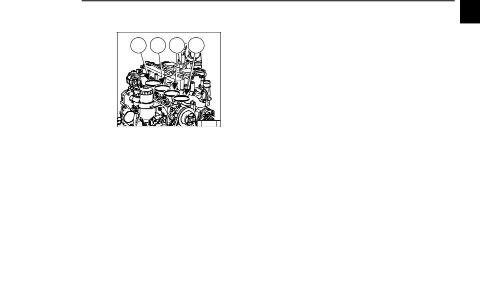
2 |
3 |
4 |
|
|
© 31 813 0 |
||||
|
Цилиндры считаются по порядку, начиная |
||||
|
от маховика. |
© 2003
|
Описаниедвигателя |
2.2 Общийвиддвигателя |
|||||||
|
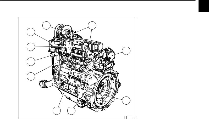
2 |
2.2.1 |
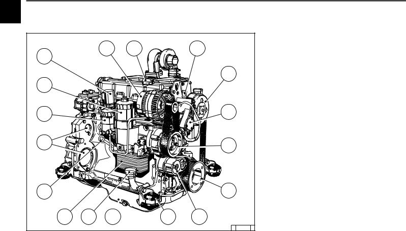
Рабочая сторона 2012 |
||||||
|
Зубчатаяременная передача |
||||||||
|
1 |
Генератор |
|||||||
|
1 |
2 |
3 |
2 |
Заправка масла |
||||
|
17 |
3 |
Штуцер для антифриза — |
||||||
|
4 |
расширительный патрубок |
|||||||
|
Шкив для ремня вентилятора |
||||||||
|
4 |
5 |
Топливный насос |
||||||
|
6 |
Насос охлаждающей жидкости |
|||||||
|
16 |
7 |
Зубчатый шкив на коленчатом валу |
||||||
|
8 |
Натяжной ролик |
|||||||
|
9 |
Опоры |
|||||||
|
10 |
Масляный поддон |
|||||||
|
15 |
5 |
11 |
Маслозаправочная горловина |
|||||
|
12 |
Корпус масляного фильтра с |
|||||||
|
маслорадиатором |
||||||||
|
13 |
Масломер |
|||||||
|
14 |
Установочное место для: |
|||||||
|
14 |
6 |
компрессора или гидравлического |
||||||
|
насоса |
||||||||
|
15 |
Вкладыш топливного фильтра |
|||||||
|
16 |
Вкладыш масляного фильтра |
|||||||
|
17 |
Подъемный электромагнит |
|||||||
|
13 |
7 |
|||||||
|
© 2003 |
12 |
11 |
10 |
9 |
8 |
|||
|
© 31 482 0 |
|
2.2 |
Общий вид двигателя |
Описание двигателя |
||
|
2.2.2 |
Сторона стартера 2012 |
2 |
||
|
Зубчатаяременная передача |
||||
|
18 |
Турбонагнетатель |
|||
|
18 |
19 |
19 |
Подвеска двигателя |
|
|
20 |
Регулятор оборотов |
|||
|
27 |
21 |
Маховик |
||
|
22 |
Корпус SAE |
|||
|
23 |
Стартер |
|||
|
24 |
Выхлопной коллектор |
|||
|
25 |
Впускной патрубок охлаждающей |
|||
|
26 |
жидкости |
|||
|
20 |
26 |
Фланец для подогрева не показан |
||
|
27 |
Корпус термостата — Выпускной |
|||
|
патрубок охлаждающей жидкости |
||||
|
25 |
||||
|
24 |
||||
|
21 |
||||
|
23 |
22 |
© 2003 |
||
|
© 31 483 0 |

|
Описание двигателя |
2.2 |
Общий вид двигателя |
|||||
|
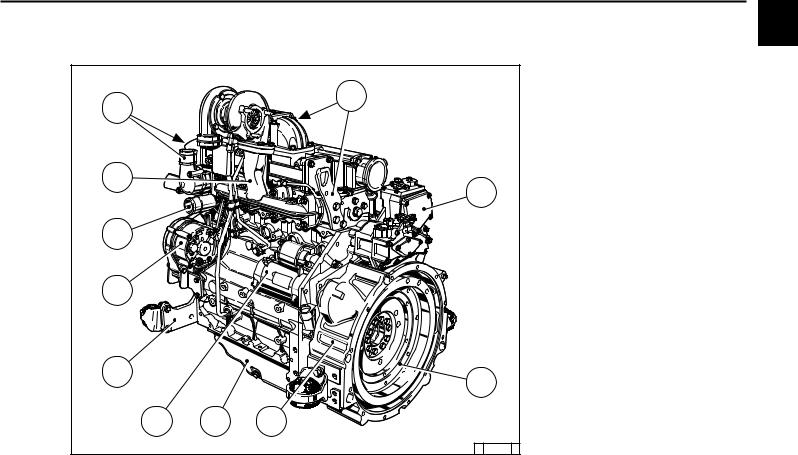
2 |
2.2.3 |
Рабочая сторона 2012 |
|||||
|
1 |
Турбонагнетатель |
||||||
|
14 |
1 |
2 |
Фланец для подогрева |
||||
|
3 |
Вентилятор |
||||||
|
4 |
Генератор |
||||||
|
5 |
Клиноременный шкив на коленчатом |
||||||
|
13 |
валу |
||||||
|
6 |
Насос охлаждающей жидкости |
||||||
|
2 |
7 |
Топливный насос |
|||||
|
8 |
Заправка масла |
||||||
|
9 |
Корпус масляного фильтра с |
||||||
|
маслорадиатором |
|||||||
|
12 |
10 |
Корпус масляного фильтра с |
|||||
|
фильтрующим вкладышем |
|||||||
|
3 |
11 |
Масломер |
|||||
|
12 |
Топливный фильтр |
||||||
|
11 |
13 |
Подъемный электромагнит |
|||||
|
14 |
Маслозаправочная горловина |
||||||
|
4 |
|||||||
|
10 |
|||||||
|
2003© |
9 |
||||||
|
8 |
7 |
6 |
© 31 484 0 |
||||
|
5 |
|
2.2 Общийвиддвигателя |
Описаниедвигателя |
||||
|
2.2.4 |
Сторона стартера 2012 |
2 |
|||
|
15 |
Подвеска двигателя |
||||
|
15 |
16 |
Регулятор оборотов |
|||
|
25 |
17 |
Маховик |
|||
|
18 |
Корпус SAE |
||||
|
19 |
Масляный поддон |
||||
|
20 |
Стартер |
||||
|
21 |
Опоры |
||||
|
22 |
Генератор |
||||
|
24 |
23 |
Впускной патрубок охлаждающей |
|||
|
16 |
жидкости |
||||
|
24 |
Выхлопной коллектор |
||||
|
25 |
Выпускной патрубок охлаждающей |
||||
|
23 |
жидкости |
||||
|
22 |
|||||
|
21 |
17 |
||||
|
20 |
19 |
18 |
© 2003 |
||
|
© 31 485 0 |
Описание двигателя
© 2003
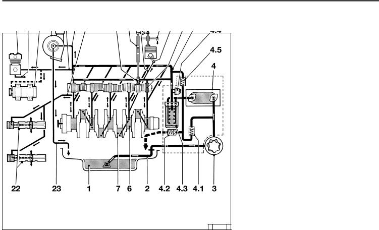
2.3 Система смазки
1Масляный поддон
2Всасывающий патрубок
3Масляный насос
4Маслорадиатор
4.1Перепускнойклапантеплообменника
4.2Запорный клапан
4.3Сменный масляный фильтр
4.4Датчик давления масла
4.5Регулировочныйклапанмасляного фильтра
5Главный маслопровод
6Коренной подшипник
7Подшипник шатуна
8Подшипник распределительного вала
9Трубка на форсунку
10Форсунка для охлаждения поршня
11Толкатель с импульсной смазкой коромысла
12Шток толкателя, масляный канал для
смазки коромысла
13Коромысло
14Возвратный маслопровод в масляный
поддон
15Маслопровод на турбонагнетатель
16Турбонагнетатель
17Маслопровод на компрессор или гидравлический насос
18Компрессор
19Гидравлический насос
20Возвратный маслопровод с
компрессораилигидравлическогонасоса
21Маслопровод на балансировочный механизм (2x)
22Балансировочные валы
23Турбонагнетатель — возвратный
маслопровод в картер коленвала
© 31 808 1
|
2.4 Топливная система |
Описание двигателя |
||||||||||
|
2.4.1 |
Схематопливной системы |
2 |
|||||||||
|
Пример: со стаканным фильтром |
|||||||||||
|
8 |
9 |
7 |
1 |
Топливный бак |
|||||||
|
2 |
Топливопровод на топливный насос |
||||||||||
|
10 |
3 |
Топливный насос |
|||||||||
|
4 |
Топливопровод на топливный фильтр |
||||||||||
|
5 |
Топливный фильтр |
||||||||||
|
5 |
6 |
Топливопровод на насосы высокого |
|||||||||
|
7 |
давления |
||||||||||
|
Топливный насос высокого давления |
|||||||||||
|
11 |
8 |
Топливопровод на клапан впрыска |
|||||||||
|
9 |
Клапан впрыска |
||||||||||
|
12 |
10 |
Полый винт с клапаном регулировки |
|||||||||
|
11 |
давления |
||||||||||
|
Возвратный топливопровод |
|||||||||||
|
13 |
12 |
вытекающего топлива |
|||||||||
|
Возвратный топливопровод в |
|||||||||||
|
13 |
топливный бак |
||||||||||
|
Поддерживать максимально |
|||||||||||
|
возможное расстояние |
|||||||||||
|
При наличии загрязнений в |
|||||||||||
|
топливе |
для |
защиты |
|||||||||
|
! |
двигателей |
настоятельно |
|||||||||
|
рекомендуется установка |
2003 |
||||||||||
|
фильтра предварительной |
|||||||||||
|
1 |
2 |
4 |
3 |
6 |
очистки / ручного |
насоса |
|||||
|
между топливным баком и |
|||||||||||
|
© |
|||||||||||
|
© 31 809 1 |
двигателем. |

|
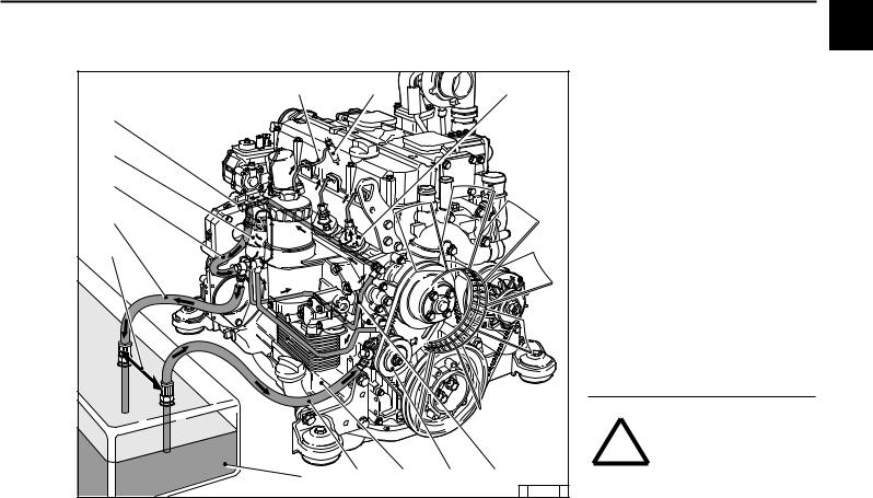
Описание двигателя |
2.5 |
Система жидкостного охлаждения |
|||||
|
2 |
2.5.1 |
Схема жидкостного охлаждения 2012 |
|||||
|
Пример: со стаканным фильтром |
|||||||
|
1 |
Корпус термостата |
||||||
|
12 |
2 |
Насос охлаждающей жидкости |
|||||
|
3 |
Маслорадиатор |
||||||
|
4 |
Охлаждение цилиндров |
||||||
|
11 |
5 |
Охлаждение головки цилиндров |
|||||
|
13 |
10 |
6 |
Трубкастеплообменниканадвигатель |
||||
|
7 |
Теплообменник |
||||||
|
6 |
8 |
Трубка с двигателя на теплообменник |
|||||
|
9 |
Вентиляционный патрубок из головки |
||||||
|
цилиндров в компенсационный бачок |
|||||||
|
8 |
10 |
Компенсационный бачок |
|||||
|
11 |
Трубкастеплообменниканатермостат |
||||||
|
5 |
12 |
Компенсационный патрубок для |
|||||
|
7 |
охлаждающей жидкости |
||||||
|
13 |
Возвратная трубка охлаждающей |
||||||
|
жидкости с подогрева |
|||||||
|
1 |
14 |
Трубка охлаждающей жидкости на |
|||||
|
подогревсгладкимприводнымремнем |
|||||||
|
2 |
15 |
Трубка охлаждающей жидкости на |
|||||
|
подогрев с зубчатым приводным |
|||||||
|
ремнем |
|||||||
|
15 |
9 |
||||||
|
3 |
|||||||
|
© 2003 |
4 |
14 |
|||||
|
© 31 810 1 |
![]()
Управление
3
3.1Ввод в эксплуатацию
3.2Пуск двигателя
3.3Контроль функционирования
3.4Останов двигателя
3.5Условия эксплуатации
© 2003
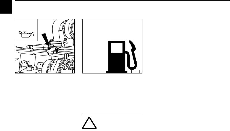
|
Управление |
3.1 Вводвэксплуатацию |
|||||||
|
3 |
3.1.1 |
Заправка моторного |
3.1.2 |
Заправка топлива |
||||
|
масла |
||||||||
|
OIL |
FUEL |
|||||||
|
© 31 491 0 |
© 26 398 0 |
|||||||
|
Как правило, двигатели поставляются не |
Следует применять только очищенное |
|||||||
|
заправленными маслом. |
дизельное топливо общего назначения. |
|||||||
|
Двигатель следует заправить маслом через |
Качество топлива см. в разделе 4.2. |
|||||||
|
заправочную горловину (стрелка). |
Принеобходимостиустановитьтопливный |
|||||||
|
Заправочные объемы см. в разделе 9.1. |
фильтр предварительной очистки. |
|||||||
|
Качествоивязкостьмасласм. вразделе4.1. |
Вслучаесомненийобратитесьвсервисное |
|||||||
|
представительство. |
от |
температуры |
||||||
|
В |
зависимости |
|||||||
|
окружающего воздуха |
необходимо |
|||||||
|
применять летнее или зимнее дизельное |
||||||||
|
топливо. |
||||||||
|
2003 |
! |
Заправлять |
топливо |
|||||
|
разрешается |
только |
при |
||||||
|
выключенном |
двигателе! |
|||||||
|
© |
Следить |
за |
чистотой! |
Не |
||||
|
разливать топливо! |
||||||||

3.1 Вводвэксплуатацию
3.1.3Заправкасистемы охлажденияиудаление воздуха
●2012: согласно указаниям изготовителя системы охлаждения
●Агрегатный двигатель: согласно
указаниям изготовителя системы охлаждения
3.1.4Прочие
подготовительные
работы
●Проверить аккумулятор и кабельные соединения, см. раздел 6.7.1.
●Пробный пуск
— После выполнения подготовительных
работвыполнитьпробныйпусквтечение примерно 10 минут, по возможности без
нагрузки.
Работы во время пробного пуска и после него
— Проверить герметичность уплотнений двигателя.
После остановки двигателя
—Проверить уровень масла, при
необходимостидолить, см. раздел6.1.2.
—Подтянуть приводной ремень, см.
раздел 6.5.
●Обкатка
Во время обкатки, в течение приблизительно 200 часов работы,
рекомендуется проверять уровень масла два раза в день. По окончании
периода обкатки достаточно одной
проверки в день.
●При вводе в эксплуатацию законсервированного двигателя
Выполнить расконсервацию согласно
указаниям в разделе 8.1.
|
Управление |
3.2 Пускдвигателя |
||
|
3 |
|||
|
3.2.1 Электрический пуск |
Безвспомогательногоустройства |
||
пускахолодногодвигателя
Перед пуском двигателя следует убедиться в том, что ! в опасной зоне двигателя или рабочейустановкиникогонет.
После ремонта: Проверить, чтобы были
установлены на место все защитные приспособления, аиздвигателяубранвесь инструмент.
При пуске с помощью фланца для подогрева не применять другие вспомогательные средства пуска (например, впрыск с помощью пускового пилота). Опасность несчастного случая!
Внимание! Категорическизапрещается запускатьдвигательпридемонтированном регуляторе оборотов.
Отсоединить клеммы аккумулятора!
|
2 |
|
|
1 |
|
|
© 31 824 0 |
© 25 745 0 |
|
● По возможности отсоединить двигатель |
● Вставить ключ. |
||
|
от |
приводимого |
устройства |
— Положение 0 = рабочее напряжение |
|
выключением сцепления. |
выключено. |
© 2003
Максимальная продолжительность непрерывного пуска составляет 20 секунд.
Если двигатель не запускается, повторить
попытку пуска черезодну минуту.
Если не удается запустить двигатель после
двух попыток, следует устранить причину неисправности с помощью таблицы поиска
неисправности (раздел 7.1).
●Установить рычаг регулятора оборотов
1 по стрелке в положение средних
оборотов или ниже.
●Рычаг останова 2 перевести в рабочее
положение.
(против стрелки, поз. 1).
●Повернуть ключ вправо.
—Положение 1 = рабочее напряжение
включено
—Загораются сигнальные лампы 1 и 2.
●Прижатьключиповернутьегодалеевправо,
преодолевая сопротивление пружины
—Положение 2 = без функции
—Положение 3 = пуск двигателя.
●Отпустить ключ, как только двигатель
заработает
—Сигнальные лампы погаснут.
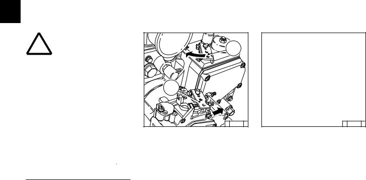
3.2 Пуск двигателя
Совспомогательнымустройством дляпускахолодногодвигателя Фланецдляподогрева
© 25 746 2
●Вставить ключ.
—Положение 0 = рабочее напряжение выключено.
●Повернуть ключ вправо.
—Положение 1 = рабочее напряжение включено.
—Загораются сигнальные лампы. Подогревать, пока не погаснет индикатор подогрева.
●Прижатьключиповернутьегодалеевправо,
преодолевая сопротивление пружиныю
—Положение 2 = без функции
—Положение 3 = пуск двигателя.
●Отпустить ключ, как только двигатель
заработает.
—Сигнальные лампы погаснут.

|
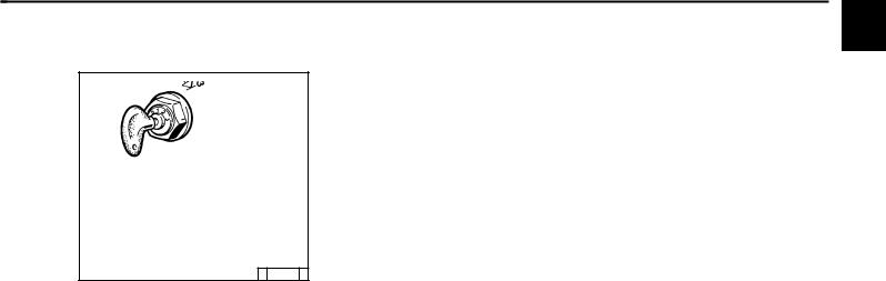
Управление |
3.3 Контроль функционирования |
|||
|
3 |
3.3.1 Давление масла |
|||
|
Сигнальнаялампадавлениямасла |
Указатель давления масла |
Манометр давления масла |
||
|
© |
25 752 |
1 |
© |
25 753 |
0 |
© |
25 754 |
0 |
●Сигнальнаялампадавлениямаслагорит при включенном рабочем напряжении
на выключенном двигателе.
●При работающем двигателе сигнальная
лампа давления масла должна
погаснуть.
|
● Стрелка должна находиться в зеленом |
● Стрелка измерителя давления масла |
|
поле общей рабочей зоны. |
должна показывать минимальное |
|
давление масла (см. раздел 9.1). |
© 2003
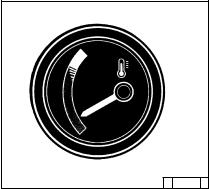
|
3.3 |
Контроль функционирования |
Управление |
||
|
3.3.2 |
Температура |
3 |
||
|
охлаждающей |
||||
|
жидкости |
©26 246 0
●Стрелкауказателятемпературыдолжна постоянно находиться в зеленой зоне и
только изредка переходить в желтозеленую. Перемещение стрелки в
оранжевую зону свидетельствует о
перегреве двигателя.
Остановить двигатель и устранить неисправностьспомощьютаблицы(см.
раздел 7.1).
© 2003
 Loading…
client@manualforauto.ru

- Магазин Manualforauto
- Как заказать
- Доставка
- Гарантия
- Возврат товара
Все файлы и ссылки на файлы, выложенные на сайте, были найдены в сети интернет как свободно распростроняемые и предоставлены лишь для ознакомления с ними, последующим удалением с вашего компьютера и покупкой (при необходимости) у авторов продукции. Если вы являетесь правообладателем какого либо контента и не желаете его свободного распространения,
сообщите нам и нарушение будет устранено.
#Автолитература
This highly detailed repair manual covers all repairs and servicing. All technical details taken directly from the manufacturer can be found in this manual, It is the factory manual from the manufacturer. Deutz TCD 2012 2V Diesel Engine service repair manual is the same manual used by professional technicians, mechanics and workshops around the world.
Deutz TCD 2012 2V Diesel Engine service repair manual has easy to read text sections with top quality diagrams and instructions, will guide you through fundamentals of maintaining and repairing, step-by-step, to teach you what the factory trained technicians already know by heart. For that reason, you will not find it difficult to repair or to maintain some of the innovative features loaded on the vehicle when you have the manual. Using this repair manual is the true way to keep your vehicle working properly.
Models Covers:
Deutz Engine TCD 2012 L4 2V
Deutz Engine TCD 2012 L6 2V
Manual Covers:
1.Foreword
2 General
3 User notes
3.1 General
3.2 Specifications
3.2.1 Safety regulations and rules for the prevention of accidents
3.2.2 Disposal regulations
3.3 Operating manual and workshop manual
3.4 Job cards
3.5 Explanation of symbols
4 Technical data
4.1 Testing and setting data
4.2 Tightening specifications
5 Job card overview
5.1 Sorted alphabetically
5.2 Sorted numerically
5.3 Job card references
6 Job cards
7 Commercial tools
8 Special tools
More Theres——–
============
** Total Pages: 387
** File Format: PDF
** Language: English
** Requirements: Adobe PDF Reader & WinZip
** Compatible: All Versions of Windows & Mac, Linux OS, Iphone, Ipad, Android etc…
NO waiting! You will have instant access to your download! All pages are printable, No shipping fee, No waiting nervously for the postal delivery, you can start doing your repairs right away!
We will always try to get the full satisfaction of our customers. Even after you have purchased this manual, we will pay full attention to any issues, regardless of the nature of the situation.
THE DOWNLOAD LINK WILL ALSO BE SENT TO YOUR E-MAIL.
So please make sure your email address is correct. Don’t Forget to Check Spam / Junk if can’t find the new message in your email inbox immediately.
Any questions please contact: admin@servicemanualperfect.com
Thanks for visiting!