Руководство по ремонту хэш-платы Antminer T17 [EN]
Editor-in-Chief: Li Yan
Version date: 2019.7.2
File Category: Maintenance Plan
Content of this Volume: It mainly describes the troubleshooting of various faults of T17, and how to use the test
tool for accurate positioning.
I. Maintenance Tools
1. General electric screwdriver
2. Fluke 15b+ Multimeter, tweezers, V9-v1.2 test jig, T17 chassis with power set
3. Hot air gun (welding temperature is 260 degrees±2 degrees)
4. Constant temperature soldering iron (welding temperature is 300-350 degrees)
5. Environmentally friendly flux solder paste, lead-free low temperature (melting point at 150 degrees) solder wire, anhydrous alcohol, water for cleaning panel,
6. OM550 low temperature solder paste, BM1397AE tinning steel mesh jig
II. Component Structure of the Hash Board

III. Signal Transmission Circuit
1. Signal transmission channel, signal CLK-RST-BO-CO is transmitted from the first chip to the second, and till the 72nd, RI signal is reversely transmitted from the 72ndchips to the first chip, as the figure below:

2. Signal test point identification and test point arrangement order (there are a total of 48 chips on the hash board, and 12 voltage domains), as shown below:

Distribution of test points in voltage domain


3. Signal communication circuit from IO socket to chip

Picture of J1-IO socket
 Schematic diagram of J1-IO socket


IV. Power Circuit
1. The power supply voltage of each board is (T17 jig test voltage output is 17V). There are 10 voltage domains, and the voltage of each two voltage domains is 1.7V.

V. Cases of Single Board Test Troubleshooting
5.1 Single board jig test asic=0
Failure analysis:
1. Whether the jig cable and hash board are in good contact.
2. The T17 hash board J6-J7 should have a voltage of 17V when testing the jig.
3. When testing the jig, measure whether there is voltage between the 10 voltage domains.
3.1 If there is no voltage in the voltage domain, it is necessary to see whether the normal working voltage of the pin 4 of Q7, Q8, Q9, Q11 is low level of 0V. If it is high level, then it depends on whether the pin 1 of Q10 is high level of 3.3v, if Q10 does not have 3.3V Voltage, that is, U3-PIC loses firmware or there is no power supply.

Schematic diagram of PIC

17V output control circuit

3.2. If the power supply is normal and there is voltage in voltage domain, then the RI signal of the chip should be measured to see if the RI signal has a voltage of 1.8V. When measuring the RI signal, it should start from the test point of the last chip. If there is voltage in the last chip, measure whether the 20th chip has RI -1.8v, and the rest can be done in the same manner, when finding the chip that does not have RI output voltage, first measure the 1.8V power supply of this chip, if there is no power supply of 1.8V, then check the 1.8V power supply circuit. The 1.8V power supply circuit is supply powers to the LDO pin 1 through the voltage division of the voltage domain. The pin 5 of LDO outputs voltage of 1.8V. (Each voltage domain has -1.8 V LDO to supply power to chip). If there is no output, this LDO should have a problem. If 1.8V is normal, measure the ground resistance of the test point after the power is cut off and compare with the OK board to see if there is any resistance abnormality; if the resistance value is normal, and there is no problem with soldering. This chip should have a problem. (Re-tin the removed chip and solder it to a good board to verify it. If there is no RI signal, it proves that the chip is damaged, replace the chip.)
1.8V power supply circuit


5.2 Fault phenomenon is ASIC=7
Analysis: ASIC=7,
1. In a single board test, 7 chips can be found. It can be judged that the RI signal is normal. If the 8th chip cannot be found, we will directly measure the voltage of the 7th chip U198-CLK-RST-CO to see if the power supply is normal. If CLK does not have a voltage of 0.8V, then it depends on the power supply circuit of CLK.
2-CLK circuit analysis: If CLK does not have 0.8V, first check whether the 0.8V power supply of the bad chip voltage domain is normal, the 0.8V power supply circuit is obtained by voltage domain division, and 1.8V power supply mode is the same, as for the maintenance method for pin 5 output 0.8V, refer to the 1.8V maintenance method (note that there are 2 out of 3 chips outputting 0.8V LDO power supply in each chip in each domain of T17, and each LDO supplies to 2 chips).
0.8v power supply schematic


If the 0.8V power supply circuit does not have a 0.8V output, then see if the 0.8V LDO power supply has a supply voltage of about 3.2V. If it has, see if the LDO is soldered insufficiently or short-circuited. If there is a 0.8V output, then see the ground resistance of the chip, if the resistance is correct, it should be a bad chip.
По вопросам приобретения продукции обращайтесь к нашему менеджеру по продажам:![]() [email protected]
[email protected]
По вопросам ремонта майнера и послепродажного обслуживания обращайтесь к менеджеру по ремонту:![]() [email protected]
[email protected]
По вопросам делового сотрудничества обращайтесь:![]() [email protected]
[email protected]
ЖАЛОБЫ И ПРЕДЛОЖЕНИЯ
Если вы недовольны транзакцией или у вас есть ценные предложения для нас, свяжитесь с нами по этому адресу электронной почты:![]() [email protected]
[email protected]
Скачать и просмотреть руководство по ремонту, запуску и обслуживанию асик майнеров AntMiner, Whatsminer, Innosilicon, Avalon онлайн
На этой странице вы можете прочесть и скачать все необходимые руководства.
Но, конечно, вы всегда можете связаться с нами по WhatsApp +79275104327, по электронной почте Этот адрес электронной почты защищен от спам-ботов. У вас должен быть включен JavaScript для просмотра. или оставить сообщение в чате, если у вас есть какие-либо (технические) вопросы о наших продуктах.
Руководство по ремонту [PDF] Antminer
Руководство по ремонту хэш-платы Antminer D3
Руководство по ремонту хэш-платы Antminer S9
Руководство по ремонту хэш-платы Antminer S9K
Руководство по ремонту хэш-платы Antminer S11
Руководство по ремонту хэш-платы Antminer S15 T15
Руководство по ремонту хэш-платы Antminer S17+
Руководство по ремонту хэш-платы Antminer S17E
Руководство по ремонту хэш-платы Antminer S17
Руководство по ремонту хэш-платы Antminer T9
Руководство по ремонту хэш-платы Antminer T17+
Руководство по ремонту хэш-платы Antminer T17
Руководство по ремонту хэш-платы Innosilicon miner
Руководство по ремонту хэш-платы Antminer WhatsMiner M10
Руководство по ремонту хэш-платы Antminer Whatsminer M20S
Инструкция по установке [PDF]
Antminer
Руководство Antminer D3
Руководство Antminer DR3
Руководство Antminer DR5
Руководство Antminer E3
Руководство Antminer L3
Руководство Antminer R4
Руководство Antminer S1
Руководство Antminer S2
Руководство Antminer S3
Руководство Antminer S4+
Руководство Antminer S5+
Руководство Antminer D3
Руководство Antminer S7
Руководство Antminer S9 Hydro
Руководство Antminer S9
Руководство Antminer S9k
Руководство Antminer S9SE
Руководство Antminer S11
Руководство Antminer S15
Руководство Antminer S17+
Руководство Antminer S17E
Руководство Antminer S17
Руководство Antminer S17Pro
Руководство Antminer T17
Руководство Antminer S19
Руководство Antminer S19Pro
Руководство Antminer T9
Руководство Antminer T15
Руководство Antminer T17+
Руководство Antminer T17E
Руководство Antminer T19
Руководство Antminer X3
Руководство Antminer Z9 Mini
Руководство Antminer Z9
Руководство Antminer Z11
Руководство Antminer Z15
Avalon
Avalonminer 1047 Manual
Avalonminer 1066 Manual
Avalonminer 1026 Manual
Avalonminer 1066 Pro Manual
Avalonminer 1146 Pro Manual
Innosilicon
Innosilicon A4+Manual
Innosilicon A6 Manual
Innosilicon A9 Manual
Innosilicon D9 DCR Manual
Innosilicon S11 Sia Manual
Innosilicon T2T 32T Manual
Innosilicon T2TZ 30T Manual
Innosilicon T3+57T Manual
Loveminer
Loveminer A1 Manual
Whatsminer
WhatsMiner D1 Manual
WhatsMiner M3 Manual
WhatsMiner M10 Manual
WhatsMiner M20S Manual
WhatsMiner M21 Manual
WhatsMiner M21S Manual
WhatsMiner M30S Manual
WhatsMiner M31S Manual
WhatsMiner M32 Manual
руководство по блоку питания и руководство по ремонту [PDF]
Руководство Antminer APW3
Руководство Antminer APW5
Руководство по ремонту блоков питания Antminer APW9 и APW9+
Руководства по Antminer, ремонт antminer , ремонт whatsminer, ремонт innosilicon, ремонт avalon, руководство по ремонту асиков
Руководство по ремонту [PDF]
Antminer
- Руководство по ремонту хэш-платы Antminer D3
- Руководство по ремонту хэш-платы Antminer S9
- Руководство по ремонту хэш-платы Antminer S9 K
- Руководство по ремонту хэш-платы Antminer S11
- Руководство по ремонту хэш-платы Antminer S15 T15
- Руководство по ремонту хэш-платы Antminer S17+
- Руководство по ремонту хэш-платы Antminer S17E
- Руководство по ремонту хэш-платы Antminer S17
- Руководство по ремонту хэш-платы Antminer T9
- Руководство по ремонту хэш-платы Antminer T17+
- Руководство по ремонту хэш-платы Antminer T17
- Руководство по ремонту хэш-платы Innosilicon miner
- Руководство по ремонту хэш-платы Antminer WhatsMiner M10
- Руководство по ремонту хэш-платы Antminer Whatsminer M20S
Инструкция по установке [PDF]
Antminer
- Руководство Antminer D3
- Руководство Antminer DR3
- Руководство Antminer DR5
- Руководство Antminer E3
- Руководство Antminer L3
- Руководство Antminer R4
- Руководство Antminer S1
- Руководство Antminer S2
- Руководство Antminer S3
- Руководство Antminer S4+
- Руководство Antminer S5+
- Руководство Antminer D3
- Руководство Antminer S7
- Руководство Antminer S9 Hydro
- Руководство Antminer S9
- Руководство Antminer S9 k
- Руководство Antminer S9 SE
- Руководство Antminer S11
- Руководство Antminer S15
- Руководство Antminer S17+
- Руководство Antminer S17 E
- Руководство Antminer S17
- Руководство Antminer S17 Pro
- Руководство Antminer T17
- Руководство Antminer S19
- Руководство Antminer S19 Pro
- Руководство Antminer T9
- Руководство Antminer T15
- Руководство Antminer T17+
- Руководство Antminer T17 E
- Руководство Antminer T19
- Руководство Antminer X3
- Руководство Antminer Z9 Mini
- Руководство Antminer Z9
- Руководство Antminer Z11
- Руководство Antminer Z15
Avalon
- Avalonminer 1047 Manual
- Avalonminer 1066 Manual
- Avalonminer 1026 Manual
- Avalonminer 1066 Pro Manual
- Avalonminer 1146 Pro Manual
Innosilicon
- Innosilicon A4+Manual
- Innosilicon A6 Manual
- Innosilicon A9 Manual
- Innosilicon D9 DCR Manual
- Innosilicon S11 Sia Manual
- Innosilicon T2T 32T Manual
- Innosilicon T2TZ 30T Manual
- Innosilicon T3+57T Manual
Loveminer
- Loveminer A1 Manual
Whatsminer
- WhatsMiner D1 Manual
- WhatsMiner M3 Manual
- WhatsMiner M10 Manual
- WhatsMiner M20S Manual
- WhatsMiner M21 Manual
- WhatsMiner M21S Manual
- WhatsMiner M30S Manual
- WhatsMiner M31S Manual
- WhatsMiner M32 Manual
руководство по блоку питания и руководство по ремонту [PDF]
- Руководство Antminer APW3
- Руководство Antminer APW5
- Руководство по ремонту блоков питания Antminer APW9 и APW9+

Муравьиный майнер
- Руководство по ремонту хэшборда Antminer D3
- Хэшборд Antminer L3+ Ремонт Гид
- Хэшборд Antminer S9 S9i S9j Ремонт Гид
- Хэшборд Antminer S9K S9se Ремонт Гид
- Хэшборд Antminer T9 T9+ Ремонт Гид
- Хэшборд Antminer Z11 Ремонт Гид
- Хэшборд Antminer S11 Ремонт Гид
- Хэшборд Antminer S15 T15 Ремонт Гид
- Антмайнер S17+ Хэшборд Ремонт Гид
- Хэшборд Antminer S17e T17e Ремонт Гид
- Хэшборд Antminer S17 Ремонт Гид
- Хэшборд Antminer T17+ Ремонт Гид
- Хэшборд Antminer T17 Ремонт Гид
- Руководство по ремонту HashBoard Antminer S19
- Руководство по ремонту хэш-платы Antminer S19j Pro
- Руководство по ремонту хеш-платы Antminer S19 Pro
Whatsminer
- Руководство по ремонту хэшборда WhatsMiner M3
- Руководство по ремонту хэшборда Whatsminer M20S M21S
- Руководство по ремонту хэшборда WhatsMiner M10
Источник питания
- Антмайнер APW3
- Антмайнер APW3+
- Антмайнер APW7
- Антмайнер APW8
- антмайнер APW9
- Антмайнер APW9+
- Антмайнер APW12
- WhatsMiner P21
Контрольный список
- Антмайнер L3+
- Антмайнер S9 S9i S9j
- Антмайнер L7
- Антмайнер S17e T17e
Связаться с нами
Что вам не хватает? Не уверен, что вам нужно? В любом случае, пожалуйста, свяжитесь с нашей фантастической службой поддержки, чтобы помочь вам.
Пожалуйста, оставьте свои контактные данные, чтобы мы могли связаться с вами как можно скорее..
-
#61
Как рекомендация к действию из доступного мне мануала, а то ещё придётся рассказать, что сами чипы они тоже имеют термоинтерфейс, и могут быть датчиками температур в том числе
-

F6471450-91A1-4339-85A2-1F38D8156A14.jpeg
940,7 КБ · Просмотры: 224
-
#62
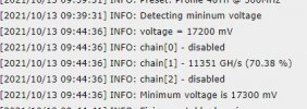
Итак Доброго дня.
Прошил VNISH лог внизу.
Походу беда с датчиками температуры.
-
7-9-2021_13.16.txt
10,5 КБ · Просмотры: 59
-
#63
Как рекомендация к действию из доступного мне мануала, а то ещё придётся рассказать, что сами чипы они тоже имеют термоинтерфейс, и могут быть датчиками температур в том числе
А где взять этот мануал?
-
#64
Шёл вместе с моим обучением за 150К ₽… учился я в миасик центре… И явно им переплатил, раза эдак в два.
-
#65
Блин зачем я сюда зашёл, расстройство одно. Зачем я купил этот с 17…
-
#67
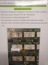
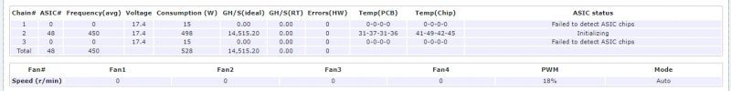
Вот что происходит. 2 плата показывает 40 чипов, с 3 то же какой то кошмар. Вот. А было так что поработала 1 плата, перезагрузил и стали все работать. А вот сегодня в другую розетку надо было переставить и опять вот такое.
-
#68
теперь вот так стало
-

Безымянный1.jpg
327,3 КБ · Просмотры: 139
-
#69
вот смотрите теперь вот так
-
Безымянный2.jpg
333,8 КБ · Просмотры: 142
-
#70
Нужен реболл двух плат, отвал
-
#71
а со стоковой прошивкой норм все было?
про этот мануал речь?
-
Antminer T17 Hash Board Repair Guide.pdf
1,3 МБ · Просмотры: 141
-
#72
вот смотрите теперь вот так
рестарт после отдыха, полчаса, пусть платы остынут, на горячую может не стартануть.
-
#73
Основная проблема 17ой серии — припой. Он очень быстро деградирует. Если поплыла хэш-плата — чипы по очереди будут выходить из строя, вылечишь одни — вылезут другие.
Мои пока работают при +5 +10 хорошо. Думаю, для них это самая комфортная температура — главное не допускать постоянных перепадов температуры — например, утром +10 гр, а днем +30 и так каждый день — будет деформация припоя. А вентиляторы у Т17, почти постоянно работают на максимуме вне зависимости от температуры.
Надо ли ставить т17+ боком на блок питания?
-
#74
Основная проблема 17ой серии — припой. Он очень быстро деградирует. Если поплыла хэш-плата — чипы по очереди будут выходить из строя, вылечишь одни — вылезут другие.
Мои пока работают при +5 +10 хорошо. Думаю, для них это самая комфортная температура — главное не допускать постоянных перепадов температуры — например, утром +10 гр, а днем +30 и так каждый день — будет деформация припоя. А вентиляторы у Т17, почти постоянно работают на максимуме вне зависимости от температуры.
Их боком ставить лучше?!
-
#75
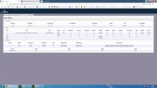
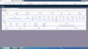
Добрый день !
Подскажите почему автотюн иногда отключает хэш платы на s17 pro на прошивке VNISH ?
Да так отключает, что на другой прошивке платы так же остаются отключены.
Приходиться включать автотюн под другую нагрузку и ждать, что он их разблокирует, а потом останавливать автотюн и то он все равно сам потом включается.
Если кто сталкивался с такой проблемой сообщите решение проблемы пожалуйста.
Спасибо !
-

Скриншот 13-10-2021 124606.jpg
73,6 КБ · Просмотры: 85
-

Скриншот 13-10-2021 125636.jpg
123,7 КБ · Просмотры: 145
-
#76
а в ТП не пробовал сперва обратиться? за что ты им отчисляешь?
-
#77
а в ТП не пробовал сперва обратиться? за что ты им отчисляешь?
Спасибо !
-
#79
Подскажите пожалуйста, на какой припой лучше садить радиаторы на t17 и s17, запутался уже, информации разной много
-
#80
Подскажите пожалуйста, на какой припой лучше садить радиаторы на t17 и s17, запутался уже, информации разной много
Рекомендуют на этот.
ASIC Miner ICERIVER KAS KS0 Profitability
ASIC Miner ICERIVER KAS KS0 Profitability In the realm of cryptocurrency mining, the Iceriver KAS KS0 miner has garnered widespread attention. Tailored specifically for the Kaspa network’s KHeavyHash algorithm, it boasts high hashing power and low power consumption, making it an ideal choice for many miners. In this article, we will comprehensively assess IceRiver KS0 profitability while considering the Kaspa market conditions and the attributes of KS0 miner. Kaspa Market Dynamics Kaspa is a vibrant cryptocurrency network aimed at delivering high performance and scalability for everyday transactions. At the time of writing this article, the Kaspa coin trades at approximately $0.04959. But it’s essential to note that cryptocurrency markets are highly susceptible to price volatility. Hence, investors must remain vigilant about market dynamics. Additionally, the Kaspa network’s mining difficulty and reward mechanisms play a role in mining returns. Attributes of the IceRiver KS
How to repair antminer T17 Hashboard and repair guide manual download
This version contains the basic circuit schematic diagram and chip signal direction and voltage introduction
We currently publish in Chinese and the English version will be released soon
Basic overview:
Antminer T17 single hash board uses a total of 30 hash chips, the model is «BM1397», and the signal direction is sequentially transmitted from U1 to U30.
Signal direction: «CLK / CO / BO / RST», transferred from U1 to U30, «RI» is transferred from U30 to U1

It also passes 5 test points for testing and maintenance
The five test points are: CLK-CO-RI-BO-RST
(Please note: The location of the test points in different voltage domains are also different, please refer to the picture notes)
For notes and instructions on the test points, please see the following articles:

The whole board has 30 chips, divided into 10 voltage domains, and each voltage domain contains 3 chips
For the description of the voltage domain, please refer to the following articles:
Explanation of the voltage domain of Antminer Hash Board

At the same time, we also provide a more detailed circuit diagram for reference:

Antminer T17 hash board repair guide download address:
Click to download Antminer T17 Hashboard Repair Guide
Related antmienr repair tools:
More Antminer repair tools
Popular posts from this blog
How to test the voltage and ground value of the power supply unit of the Antminer S9 hash board? Antminer S9 hash board Antminer S9 hash board power supply unit Voltage and ground value test of Antminer S9 power supply unit 12V voltage test Test method: adjust the Fluke 15B+ multimeter to the DC gear; the red test lead is placed on the positive pole of the power interface of the hash board, and the black test lead is placed on the negative pole of the power interface. PIC chip voltage test There is a white dot next to the PIC chip, which is 1st Pin. Test method : Adjust the Fluke 15B+ multimeter to the DC gear, measure whether the 1st Pin of the PIC chip has output, and the normal voltage is about 3.3V. If there is no 3.3V, please check the connection status of the hash board test line to see if the hash board is normal; if not, you need to re-program the PIC. MOS tube voltage test There is a black dot on the MOS tube, which is the 1st Pin (Figure 1). This is because the voltage of t
How to repair ASIC miner hash board Important parts of ASIC miners – Hash board One ASIC miner consists of 3 to 5 Hash board, a control board, a casing, and software, among which the Hash board are easiest to broken. because the ASIC bitcoin miner hash board consists of many serially connected ASIC chips. When they work, they will be in a high-temperature environment for a long time. In this environment, it is easy to burn the chip or scatter the solder due to high temperature which makes the hash board or the mining machine unable to work and no hash rate. How to quickly detective which chips broken it’s the most important when we repairing ASIC miners The Antminer chips fixture fast efficient and easy to use Bitmain Antminer repair inspection tool The ASIC bitcoin miner hash board consists of many serially connected ASIC chips. When they work, they will be in a high-temperature environment for a long time. In this environment, it is easy to burn the chip or scatter the solder du