- Manuals
- Brands
- Minsk Tractor Works Manuals
- Tractor
- Belarus 1221B.2
- Disassembly-assembly manual
-
Contents
-
Table of Contents
-
Bookmarks
Quick Links
BELARUS
1221.2/1221В.2
1221.3/1221.4
1221-0000010 РРС
DISASSEMBLY-ASSEMBLY MANUAL
Minsk Tractor Works 2010
Summary of Contents for Minsk Tractor Works Belarus 1221B.2
-
Page 1
BELARUS 1221.2/1221В.2 1221.3/1221.4 1221-0000010 РРС DISASSEMBLY-ASSEMBLY MANUAL Minsk Tractor Works 2010… -
Page 2
You can obtain more detailed information from your dealer of trade mark BELARUS. _______________________________________________________________________ Minsk Tractor Works RUE, 2010 All rights reserved. No part of this manual may be reproduced in any form whatsoever without written permission of Minsk Tractor Works RUE. -
Page 3: Table Of Contents
Disassembly-assembly manual for tractor BELARUS-1221.2/1221В.2/1221.3/1221.4 CONTENTS INTRODUCTION …………………………..7 1 SAFETY REQUIREMENTS……………………….8 2 GENERAL …………………………..10 3 DISMOUNTING AND MOUNTING OF ENGINE AND ITS SYSTEMS …………..12 3.1 DISMOUNTING-MOUNTING OF ENGINES MMZ AND DEUTZ …………….12 3.2 DISMOUNTING OF SUPERCHARGED AIR COOLER (SAC), MOUNTED ON TRACTORS BELARUS-1221.320 3.3 DISMOUNTING OF SUPERCHARGED AIR COOLER (SAC), MOUNTED ON TRACTORS BELARUS-1221.4 WITH ENGINE MMZ …………………………
-
Page 4
Disassembly-assembly manual for tractor BELARUS-1221.2/1221В.2/1221.3/1221.4 4.3 CLUTCH …………………………..44 4.3.1 DISASSEMBLY-ASSEMBLY OF CLUTCH CONTROL UNITS BELARUS-1221.2/1221.3/1221.4 ….44 4.3.1.1 DISASSEMBLY-ASSEMBLY OF CLUTCH CONTROL UNITS FOR BELARUS-1221В.2 ……45 4.3.2 DISASSEMBLY-ASSEMBLY OF CLUTCH COUPLING ………………48 4.3.3 MOUNTING DISKS OF CLUTCH COUPLING ON ENGINE FLYWHEEL …………51 4.3.4 ADJUSTING POSITION OF SQUEEZE LEVERS ………………… -
Page 5
Disassembly-assembly manual for tractor BELARUS-1221.2/1221В.2/1221.3/1221.4 4.6.14 ADJUSTMENT OF FOOT BRAKE, VALVE AND REGULATOR OF PNEUMATIC SYSTEM PRESSURE .. 115 4.6.15 ADJUSTMENT OF PARKING BRAKE, BRAKE VALVE AND REGULATOR OF PNEUMATIC SYSTEM PRESSURE …………………………..116 4.6.16 MULTI-DISK FOOT AND PARKING BRAKES OPERATING IN OIL BATH ……….117 4.6.18 DISASSEMBLY OF LEFT-SIDE MULTI-DISK BRAKE OPERATING IN OIL BATH …….. -
Page 6
Disassembly-assembly manual for tractor BELARUS-1221.2/1221В.2/1221.3/1221.4 7.1.1 DISASSEMBLY-ASSEMBLY OF UNITS OF THE HYDROSTATIC STEERING CONTROLMOUNTED ON TRACTORS BELARUS-1221.4 WITH ENGINE DEUTZ» ………………201 7.1.2 DISASSEMBLY-ASSEMBLY OF UNITS OF THE HYDROSTATIC STEERING CONTROLMOUNTED ON TRACTORS BELARUS-1221В.2 ……………………..204 7.2 STEERING COLUMN ……………………….207 7.2.1 DISASSEMBLY-ASSEMBLY OF STEERING COLUMN …………….. -
Page 7
Disassembly-assembly manual for tractor BELARUS-1221.2/1221В.2/1221.3/1221.4 11.1.1 DISMOUNTING ELEMENTS OF ELECTRICAL EQUIPMENT OF ENGINE (MMZ) MOUNTED ON TRACTORS BELARUS-1221.2/1221В.2 ……………………261 11.1.2 DISMOUNTING ELECTRICAL EQUIPMENT ELEMENTS OF ENGINE (MMZ) MOUNTED ON TRACTORS BELARUS-1221.3 …………………………262 11.1.3 DISMOUNTING ELECTRICAL EQUIPMENT ELEMENTS OF ENGINES (MMZ OR DEUTZ) MOUNTED ON TRACTORS BELARUS-1221.4 …………………….. -
Page 8: Introduction
Data contained in this manual is accurate at the time of this manual compilation. As tractors BELARUS are continually updated, Minsk Tractor Works PA reserves the right to introduce design amendments without notifying the customers. All data given in this manual can be amended, and illustrative materials can differ from those describing tractors currently manufactured.
-
Page 9: Safety Requirements
Disassembly-assembly manual for tractor BELARUS-1221.2/1221В.2/1221.3/1221.4 1 SAFETY REQUIREMENTS For your safety purpose carefully study this manual before starting maintenance and repair works. Pay particular attention to all warnings and recommendations given in this manual. Always consult operating and maintenance manual issued by the manufacturer. 1.
-
Page 10
Disassembly-assembly manual for tractor BELARUS-1221.2/1221В.2/1221.3/1221.4 10. For washing parts and assembly units use special washing agents. When using kerosene or benzene for washing, observe fire safety regulations; make washing in ventilated premises. Keep tidy working place where dismounting-mounting works are underway. 11. -
Page 11: General
Disassembly-assembly manual for tractor BELARUS-1221.2/1221В.2/1221.3/1221.4 2 GENERAL Tractor BELARUS 1221 and its modifications belong to general purpose row-crop wheeled tractors of traction class 2 with axle arrangement 4 x 4. They are designed for various agricultural works with mounted, half-mounted, trailer machines and implements, loading-unloading mechanisms, driving stationary agricultural machinery, as well as transport works in different climatic regions.
-
Page 12
Disassembly-assembly manual for tractor BELARUS-1221.2/1221В.2/1221.3/1221.4 Steering is hydrostatic (HSC); supply pump is of gear type, actuating mechanism – two hydraulic cylinders of two-way action. Wheels with pneumatic low-pressure tires. Rear wheels – driving, front wheels – driving and guiding. Size of main tires: front wheels — 420/70R24;… -
Page 13: Dismounting And Mounting Of Engine And Its Systems
Disassembly-assembly manual for tractor BELARUS-1221.2/1221В.2/1221.3/1221.4 3 DISMOUNTING AND MOUNTING OF ENGINE AND ITS SYSTEMS 3.1 Dismounting-mounting of engines MMZ and Deutz Dismounting-mounting engine MMZ, mounted on tractors BELARUS 1221.2/1221В.2/1221.3 Figure 3.1 Mounting engine (MMZ) on tractors BELARUS 1221.2/1221В.2/1221.3/1221.4 а) dismantle tractor facia, see section 8.2 “Dismounting-mounting of facia of tractor BELARUS 1221.2/1221В.2”;…
-
Page 14
Disassembly-assembly manual for tractor BELARUS-1221.2/1221В.2/1221.3/1221.4 1) for tractors BELARUS 1221.2/1221В.2, see section 11.1.1 “Dismounting elements of engine electrical equipment (MMZ) mounted on tractors BELARUS 1221.2/1221В.2”; 2) for tractors BELARUS 1221.3, see sections: — 11.5.4 “Operations performed when replacing engine”; — 11.6.1 “Operations performed when replacing engine”; — 11.7.1 “Operations performed when replacing engine”;… -
Page 15
Disassembly-assembly manual for tractor BELARUS-1221.2/1221В.2/1221.3/1221.4 j) disconnect fuel lines from coarse fuel filter 6 (Figure 3.3), installed only on tractor BELARUS 1221.4 with engine MMZ; Figure 3.3 Mounting coarse fuel filter on MMZ. k) dismantle air purifier, as described in section 3.9 “Disassembly-assembly of air purifier unit installed on tractors BELARUS 1221.2/1221В.2/1221.3/1221.4 (with engine MMZ)”;… -
Page 16
Disassembly-assembly manual for tractor BELARUS-1221.2/1221В.2/1221.3/1221.4 1- support fastening bolt; 2- adjustment bolt; 3- check nut; 4- support; 5- shock absorber Figure 3.4 Front engine support o) connect lifting mechanism to diesel, for slinging diagram see (Figures 3.5); 1 – eye bolt; 2 –steel rope (chain); 3 – beam; 4 – grip; Figure 3.5 Diagram of slinging diesel MMZ… -
Page 17
Disassembly-assembly manual for tractor BELARUS-1221.2/1221В.2/1221.3/1221.4 p) separate front driving axle together with spars and radiators from tractor and roll it away from diesel; ATTENTION! To prevent turning over of front axle take off ballast loads or put supports under them. q) unscrew bolts 10, 11 (Figure 3.1) that fasten rear diesel sheet to clutch body, disconnect diesel having pulled it forward until clutch coupling goes out of clutch body bell, and raise it using lifting mechanism;… -
Page 18
Disassembly-assembly manual for tractor BELARUS-1221.2/1221В.2/1221.3/1221.4 а) Dismantle tractor facia, see section 8.3 “Dismounting-mounting facia of tractor BELARUS 1221.3/1221.4”; b) drain cooling fluid from tractor cooling system; c) drain oil from engine, having unscrewed plug in lower section of engine casing; d) drain oil from HSC system, see section 7.1.1 “Disassembly-assembly of hydrostatic steering controlunits mounted on tractors BELARUS 1221.4 with engine Deutz”;… -
Page 19
Disassembly-assembly manual for tractor BELARUS-1221.2/1221В.2/1221.3/1221.4 i) dismantle air purifier, as described in section 3.10 “Disassembly-assembly of air purifier unit mounted on tractors BELARUS 1221.4 Deutz”; l) dismantle HSC oil lines 8, 5 (Figure 3.8) and undock from engine oil lines 10 by dismounting brace 9;… -
Page 20
Disassembly-assembly manual for tractor BELARUS-1221.2/1221В.2/1221.3/1221.4 Figure 3.9 Diagram of slinging engine Deutz р) undock FDA with front bar and radiators from tractor, and roll it aside from diesel; ATTENTION! To prevent FDA turning over remove ballast loads or put supports under them. q) unscrew bolts (Figure 3.6) that fasten rear diesel sheet to clutch body, disconnect diesel having pulled it forward until clutch coupling goes out of clutch body bell, and raise it using lifting mechanism;… -
Page 21
Disassembly-assembly manual for tractor BELARUS-1221.2/1221В.2/1221.3/1221.4 3.2 Dismounting of supercharged air cooler (SAC), mounted on tractors BELARUS-1221.3 а) loosen collars 2 (Figure 3.10) and shift heat-resistant silicon branch pipes 3 off air conduits 1 and cooler 8; b) unscrew bolts 4, 5, 7 that fasten cooler to water radiator and air conduit to inlet collector, remove cooler, air conduit and spacer 6. -
Page 22: With Engine Mmz
Disassembly-assembly manual for tractor BELARUS-1221.2/1221В.2/1221.3/1221.4 3.3 Dismounting of supercharged air cooler (SAC), mounted on tractors BELARUS-1221.4 with engine MMZ а) loosen collars 10, 11, 12 (Figure 3.11); b) shift heat-resistant silicon branch pipes 13, 14, 15, 16 off air conduits 1, 2, 3 and supercharged air cooler 9;…
-
Page 23: Dismounting Of Supercharged Air Cooler (Sac), Mounted On Tractors Belarus-1221.4
Disassembly-assembly manual for tractor BELARUS-1221.2/1221В.2/1221.3/1221.4 3.4 Dismounting of supercharged air cooler (SAC), mounted on tractors BELARUS-1221.4 with engine Deutz а) loosen collars 12 (Figure 3.12) and shift heat-resistant silicon branch pipes 5, 14, 15 off air conduits 1, 2, 3 and supercharged air cooler 16; b) unscrew bolts fastening the cooler to water radiator and dismantle the cooler.
-
Page 24: Dismounting-Mounting Of Cooling System Mounted On Tractors Belarus-1221.4 With Engine Mmz
Disassembly-assembly manual for tractor BELARUS-1221.2/1221В.2/1221.3/1221.4 3.5 Dismounting-mounting of cooling system mounted on tractors BELARUS-1221.4 with engine MMZ а) drain cooling fluid from tractor cooling system; b) untignten collars 2 (Figure 3.13) and disconnect hoses 7, 8; c) unscrew three bolts 18, 21 and dismantle expansion tank 14; d) dismantle SAC, as described in section 3.3 “Dismounting supercharged air cooler (SAC), mounted on tractors BELARUS-1221.4 with engine MMZ”;…
-
Page 25: Dismounting-Mounting Of Cooling System Mounted On Tractors Belarus-1221.4 With Engine Deutz
Disassembly-assembly manual for tractor BELARUS-1221.2/1221В.2/1221.3/1221.4 3.6 Dismounting-mounting of cooling system mounted on tractors BELARUS-1221.4 with engine Deutz Figure 3.14 Cooling system a) drain cooling fluid from tractor cooling system; b) disconnect hose 10, sleeves 29, 30, 31 from radiator 24 (Figure 3.14); c) unscrew two bolts 15 and dismantle expansion tank 4;…
-
Page 26: 1221.2/1221В.2/1221.3 With Engine Mmz
Disassembly-assembly manual for tractor BELARUS-1221.2/1221В.2/1221.3/1221.4 Dismounting-mounting cooling system mounted tractors BELARUS- 1221.2/1221В.2/1221.3 with engine MMZ а) drain cooling fluid from tractor cooling system; b) untighten collars 7 (Figure 3.15) or 49, 48 and disconnect hoses 14, 16, 26; c) unscrew three bolts 31, 32, 33 and dismantle expansion tank ок 24; d) disconnect wires of terminal carrier socket, if installed, on fan diffuser 6;…
-
Page 27: Disassembly-Assembly Of Fuel Tank 1221-1101500, Mounted On Tractors Belarus
Disassembly-assembly manual for tractor BELARUS-1221.2/1221В.2/1221.3/1221.4 3.8 Disassembly-assembly of fuel tank 1221-1101500, mounted on tractors BELARUS- 1221.2/1221В.2/1221.3/1221.4 with engines MMZ and Deutz, with two cylinders of lift linkage (hydraulic lift of the hydraulic system) 1) drain diesel fuel out of tank 22 (Figure 3.16) via draing point 30; 2) dismantle draining point 30;…
-
Page 28
Disassembly-assembly manual for tractor BELARUS-1221.2/1221В.2/1221.3/1221.4 Figure 3.16 Fuel tank… -
Page 29: Disassembly-Assembly Of Air Purifier Unit Mounted On Tractors Belarus- 1221.2/1221В.2/1221.3/1221.4 (Mmz)
Disassembly-assembly manual for tractor BELARUS-1221.2/1221В.2/1221.3/1221.4 3.9 Disassembly-assembly of air purifier unit mounted on tractors BELARUS- 1221.2/1221В.2/1221.3/1221.4 (MMZ) а) dismount facia, as described in in section 8.3 “Dismounting-mounting facia of tractors BELARUS-1221.3/1221.4”; b) loosen collars 6 and 9 (Figure 3.17); c) dismantle branch pipes 7, 10 and air conduit 8; d) loosen collars 11;…
-
Page 30: Disassembly-Assembly Of Air Purifier Unit Mounted On Tractors Belarus-1221.4 Deutz
Disassembly-assembly manual for tractor BELARUS-1221.2/1221В.2/1221.3/1221.4 3.10 Disassembly-assembly of air purifier unit mounted on tractors BELARUS-1221.4 Deutz а) dismount facia, as described in in section 8.3 “Dismounting-mounting of facia of tractors BELARUS-1221.3/1221.4”; b) unscrew bolts 15 (Figure 3.18); c) dismantle arms 16, 17; d) loosen collars 12;…
-
Page 31: Disassembly-Assembly Of Exhaust System Of Tractors Belarus-1221.4
Disassembly-assembly manual for tractor BELARUS-1221.2/1221В.2/1221.3/1221.4 3.11 Disassembly-assembly of exhaust system of tractors BELARUS-1221.4 а) unscrew bolts 4 (Figure 3.19); b) dismantle guarding 5; c) loosening fastening of collars 7; d) dismantle metal sleeve 6; e) loosening fastening of collars 20; f) dismantle metal sleeve 19;…
-
Page 32
Disassembly-assembly manual for tractor BELARUS-1221.2/1221В.2/1221.3/1221.4 1 – outlet pipe; 2, 4, 10, 11, 13, 15, 18 – bolt; 3 – damper; 5 – guarding; 6 – metal sleeve; 7 – collar; 8 – nut; 9 – brace; 12 – support; 14 – cross piece; 16 – spacer; 17 – branch pipe; 19 – metal sleeve;… -
Page 33: Disassembly-Assembly Of Fuel Supply Control Mounted On Tractors Belarus-1221В.2
Disassembly-assembly manual for tractor BELARUS-1221.2/1221В.2/1221.3/1221.4 3.12 Disassembly-assembly of fuel supply control mounted on tractors BELARUS-1221В.2 а) dismantle manual control of fuel supply, and to do this dismantle cover of right side panel, see section 8.4 “Disassembly-assembly of facia panels of right side panel”; b) dismantle tie-rods 20, 22, 23 (Figure 3.20), having disconnected cotter pins 19 and pins 18;…
-
Page 34
Disassembly-assembly manual for tractor BELARUS-1221.2/1221В.2/1221.3/1221.4… -
Page 35: Disassembly-Assembly Of Fuel Supply Control, Mounted On Tractors Belarus- 1221.2/1221.3
Disassembly-assembly manual for tractor BELARUS-1221.2/1221В.2/1221.3/1221.4 3.13 Disassembly-assembly of fuel supply control, mounted on tractors BELARUS- 1221.2/1221.3 а) Dismount cover of right side panel, see section 8.4 “Disassembly-assembly of facia panels of right side panel”; b) dismantle tie-rods 20, 22, 23, (Figure 3.21) having disconnected cotter pins 19 and pins 18; c) unscrew nuts 8;…
-
Page 36
Disassembly-assembly manual for tractor BELARUS-1221.2/1221В.2/1221.3/1221.4… -
Page 37: Disassembly-Assembly Of Fuel Supply Control, Mounted On Tractors Belarus-1221.4
Disassembly-assembly manual for tractor BELARUS-1221.2/1221В.2/1221.3/1221.4 3.14 Disassembly-assembly of fuel supply control, mounted on tractors BELARUS-1221.4 with engines MMZ и Deutz а) disconnect harness 33 (Figure 3.22); b) unscrew bolts 25, 29 and 32; c) dismantle pedal 24 and plate 28; d) dismantle cover of right side panel, see section 8.4 “Disassembly-assembly of facia panels of right side panel”;…
-
Page 38: Transmission
Disassembly-assembly manual for tractor BELARUS-1221.2/1221В.2/1221.3/1221.4 4 TRANSMISSION Transmission is designed for transfer and conversion of torque from engine to rear drive wheels, drive of front driving axle and rear PTO shank, as well as for driving pump of hydraulic hinge system.
-
Page 39
Disassembly-assembly manual for tractor BELARUS-1221.2/1221В.2/1221.3/1221.4 21 – tie-rod of clutch; 22 – shaft of FDA drive; 26 – bolts for fastening GB levers; 27 – cardan shaft of FDA. Figure 4.2 Technical data: Torque for tightening bolts of butt between clutch coupling body and GSB body is 320…400 N·m; butt of GSB body –… -
Page 40: Transmission Disassembly (General Provisions)
Disassembly-assembly manual for tractor BELARUS-1221.2/1221В.2/1221.3/1221.4 4.1 Transmission disassembly (general provisions) a) drain oil from transmission, having unscrewed two draining plugs; b) put transmission with engine on supports; c) disconnect and dismantle pipelines of control system and transmission lubrication system passing through bodies’ butts; d) disconnect transmission from engine and dismantle tractor parts and units that hinder further disassembly;…
-
Page 41: Dismounting (Disconnection) Of Clutch Coupling Body
Disassembly-assembly manual for tractor BELARUS-1221.2/1221В.2/1221.3/1221.4 g) dismantle HSC metal oil lines by having disconnected them from high-pressure sleeves: 1) for tractors BELARUS-1221.2/1221.3/1221.4 (MMZ) see section 7.1 “Disassembly-assembly of hydrostatic steering controlunits mounted on tractors BELARUS-1221.2/1221.3/1221.4 with engine MMZ”; 2) for tractors BELARUS-1221В.2, see section 7.1.2 “Disassembly-assembly of hydrostatic steering controlunits mounted on tractors BELARUS-1221В.2”;…
-
Page 42
Disassembly-assembly manual for tractor BELARUS-1221.2/1221В.2/1221.3/1221.4 f) disconnect oil line 2 for lubrication of the shell of FDA drive cardan shaft (Figure 4.1); g) disconnect harness of FDA control, see section: 1) for tractors BELARUS-1221.3: — 11.5.3 “Control of DI and FDA 1221-8700410 (electrical part), mounted on tractors BELARUS- 1221.3”;… -
Page 43: Dismounting (Disconnection) Of Gear Box Body
Disassembly-assembly manual for tractor BELARUS-1221.2/1221В.2/1221.3/1221.4 n) dismantle oil tank, see section 9.1.1 “Disassembly-assembly of hydraulic system units. Dismounting of oil tank from tractor with cabin dismantled (for hydraulic system with distributor RP 70-1221); or Dismounting of oil tank from tractor with cabin dismantled (for hydraulic system with distributor RS 213 Mita)”;…
-
Page 44: Transmission Assembly
Disassembly-assembly manual for tractor BELARUS-1221.2/1221В.2/1221.3/1221.4 f) bring under gear box (GB) body screwed support Р 7010-00 (or identical to it) (Figure 4.6) until it fully touches GB body; g) to disconnect butt “GB body – RA body” remove GB cover 19 (Figure 4.1) and cover of FDA 9 to get access to bolts to be unscrewed, then unscrew ten bolts (М18) 17 and two nuts 11, and take the units apart.
-
Page 45: Clutch
Disassembly-assembly manual for tractor BELARUS-1221.2/1221В.2/1221.3/1221.4 4.3 Clutch 4.3.1 Disassembly-assembly of clutch control units BELARUS-1221.2/1221.3/1221.4 а) unscrew bolt 4 (Figure 4.7), remove rod 2 and strap 1; b) disconnect tie-rod 22, having pulled out pins 13; c) unscrew yokes 24 and nuts 23 off tie-rod 22; d) remove washer (20) and spring (21);…
-
Page 46: Disassembly-Assembly Of Clutch Control Units For Belarus-1221В.2
Disassembly-assembly manual for tractor BELARUS-1221.2/1221В.2/1221.3/1221.4 4.3.1.1 Disassembly-assembly of clutch control units for BELARUS-1221В.2 Observe the following sequence of disassembly of clutch control units (Figure 4.8): Figure 4.8 Clutch control…
-
Page 47
Disassembly-assembly manual for tractor BELARUS-1221.2/1221В.2/1221.3/1221.4 Figure 4.9 Working cylinder а) drain brake fluid from the system, and to do it: 1) remove protective cap 8 (Figure 4.9) from the working cylinder; 2) put on pipe connection 9 one end of hose and put another end in clean vessel; 3) unscrew pipe connection 9 by half turn: 3.1) keep pressing pedal 39 (Figure 4.8) until fluid is released from hydraulic system on reversal;… -
Page 48
Disassembly-assembly manual for tractor BELARUS-1221.2/1221В.2/1221.3/1221.4 3) unscrew nut 11 and tie-rod 12; 4) unscrew cover 10, remove ring 15; 5) make assembly of working cylinder in sequence reverse to disassembly; Figure 4.10. Main cylinder of clutch control on reversal e) disassembly hydraulic booster (Figure 4.11); to do this; 1) remove covers 3, having unscrewed bolts 8, 10;… -
Page 49: Disassembly-Assembly Of Clutch Coupling
Disassembly-assembly manual for tractor BELARUS-1221.2/1221В.2/1221.3/1221.4 Make assembly and mounting of parts and assemblies of clutch control in sequence reverse to disassembly. Before assemblying main and working cylinders hydraulic boosters must be clean. Presence of foreign particles (dust, paint, chips, pile) is not allowed. Before assembly of main cylinder and working cylinder on reversal grease friction surfaces with thin layer of braking fluid NEVA-M under Specification TU 2451-053-36732629-2003.
-
Page 50
Disassembly-assembly manual for tractor BELARUS-1221.2/1221В.2/1221.3/1221.4 Figure 4.13 f) remove second driven disk 7 (Figure 4.14); Figure 4.14 g) install squeezing device 1 on disks as an assembly (Figure 4.15);… -
Page 51
Disassembly-assembly manual for tractor BELARUS-1221.2/1221В.2/1221.3/1221.4 Figure 4.15 h) unscrew technological bolts 2 (Figure 4.15) (М12х40); i) dismantle retaining plates 3 by unscrewing six bolts 5 and pull out adjustment nuts 4; j) unscrew nut of squeezing device and dismount supporting disk; l) unpin pin and dismount axles of squeeze levers and squeeze levers. -
Page 52: Mounting Disks Of Clutch Coupling On Engine Flywheel
Disassembly-assembly manual for tractor BELARUS-1221.2/1221В.2/1221.3/1221.4 4.3.3 Mounting disks of clutch coupling on engine flywheel Perform mounting of clutch coupling disks on engine flywheel in the following order: а) mount first driven disk with hub long end facing flywheel; b) mount middle disk as an assembly inside flywheel along three grooves; c) mount second driven disk with hub short end facing middle disk;…
-
Page 53
Disassembly-assembly manual for tractor BELARUS-1221.2/1221В.2/1221.3/1221.4 Figure 4.19 c) adjust position of squeeze levers by adjustment nuts 1, having set distance from supporting surfaces of levers to end face of supporting disk hub equal to 13.5…14.5 mm. Figure 4.20 Variation of dimension for individual leverов must not exceed 0.3 mm. After adjustment secure nuts 4 (Figure 4.20) against turning through by retaining plates 5. -
Page 54: Reduction Gear Section Of Clutch Coupling Body
Disassembly-assembly manual for tractor BELARUS-1221.2/1221В.2/1221.3/1221.4 4.3.5 Reduction gear section of clutch coupling body Drive shaft 6 (Figure 4.21) of stand-alone PTO, mounted on two bearings 3 and 5, has two gear rings. Smaller gear ring is permanently engaged with gear 2 of pump drive for hydraulic hinge system, and gear 14 of the first stage of PTO reduction gear;…
-
Page 55: Disassembly Of The Reduction Gear Section Of Clutch Coupling Body
Disassembly-assembly manual for tractor BELARUS-1221.2/1221В.2/1221.3/1221.4 4.3.6 Disassembly of the reduction gear section of clutch coupling body 1 – shaft; 2 – bolt; 3 – yoke; 4 – bearing; 5 – tap; 6 – nut; 7 – arm; 8 – spacer; 9 – sealing ring; 10 –…
-
Page 56
Disassembly-assembly manual for tractor BELARUS-1221.2/1221В.2/1221.3/1221.4 а) first drain oil from clutch coupling body. b) disconnect tractor skeleton in plane “diesel”- “clutch body” — «gear box c) disconnect and remove meshed filler neck, side and bottom covers, covers’ spacers. To dismount lever of switching clutch coupling and tie-rod, do the following: а) unpin pin and pull out pin 2 (Figure 4.23), disconnect tie-rod 1. -
Page 57
Disassembly-assembly manual for tractor BELARUS-1221.2/1221В.2/1221.3/1221.4 Figure 4.25 c) press bearing 1 from shaft (Figure 4.26); Figure 4.26 d) unscrew crown nut 1 (Figure 4.27) of PTO drive driven shaft; Figure 4.27 e) knock driven shaft 1 (Figure 4.28) of PTO drive outwards and extract it from clutch body together with gear of stage II;… -
Page 58
Disassembly-assembly manual for tractor BELARUS-1221.2/1221В.2/1221.3/1221.4 Figure 4.28 h) remove ring 1 (Figure 4.29) that locks gear 2 on shaft 4; i) remove washer 3 and gear 2; Figure 4.29 j) remove bearing 1 (Figure 4.30) from shaft 2; Figure 4.30 k) remove locking wire, unscrew bolt 3 (Figure 4.31) for fastening yoke 2;… -
Page 59
Disassembly-assembly manual for tractor BELARUS-1221.2/1221В.2/1221.3/1221.4 Figure 4.31 m) unscrew bolt 5 (Figure 4.32) and remove plate 6; n) knock roller 4 inside clutch body; o) extract yoke 2 (Figure 4.31) and gear 7 (Figure 4.33) of I stage of reduction gear. Figure 4.32 Figure 4.33 To dismount pump driving gears of transmission hydraulic system do the following:… -
Page 60
Disassembly-assembly manual for tractor BELARUS-1221.2/1221В.2/1221.3/1221.4 Figure 4.34 b) press out gear 1 (Figure 4.35) together with axle, bearingом and locking ring; c) remove washer 2; Figure 4.35 d) remove locking ring 3 (Figure 4.36 а); e) press axle 1 (Figure 4.36 а) with bearing 2 off gear 4 (Figure 4.36 б); f) press bearing off axle;… -
Page 61
Disassembly-assembly manual for tractor BELARUS-1221.2/1221В.2/1221.3/1221.4 g) press out shaft-gear 1 (Figure 4.37) together with bearingом and locking ring; h) pull out gear 2; Figure 4.37 i) remove locking ring 1 (Figure 4.38); j) press out bearing 2; Figure 4.38 k) press bearing 1 (Figure 4.39) off clutch body. Figure 4.39… -
Page 62
Disassembly-assembly manual for tractor BELARUS-1221.2/1221В.2/1221.3/1221.4 To dismount driving gear of hinge hydraulic system pump do the following: а) unscrew bolt 2 (Figure 4.40) and remove thrust washer 3; b) unscrew two bolts 1 and remove bar 4; Figure 4.40 c) using knocker 1 (Figure 4.41) press gear axle off clutch body; Figure 4.41 d) pull out gear 2 (Figure 4.42) with two bearings and two rings through upper hatch of clutch body;… -
Page 63
Disassembly-assembly manual for tractor BELARUS-1221.2/1221В.2/1221.3/1221.4 f) turn gear over and press our the second bearing; Figure 4.43 g) press out bushing 1 (Figure 4.44); Figure 4.44 To dismount shaft of driving PTO drive, tap arm do the following: а) unscrew three nuts 1 (Figure 4.45); b) inside threaded openings of tap arm 2 screw technological bolts (М10 х30) 3 and using them press tap arm off clutch body;… -
Page 64
Disassembly-assembly manual for tractor BELARUS-1221.2/1221В.2/1221.3/1221.4 d) press off clutch body driving shaft of PTO drive 1 (Figure 4.46) with two bearings; Figure 4.46 e) press sealing ring off tap arm (Figure 4.47); Figure 4.47 f) press bearing 1 off driving shaft of PTO drive (Figure 4.48); Figure 4.48… -
Page 65
Disassembly-assembly manual for tractor BELARUS-1221.2/1221В.2/1221.3/1221.4 g) remove locking ring 1 from the shaft (Figure 4.49); Figure 4.49 h) press the second bearing 2 off the shaft (Figure 4.50); Figure 4.50 g) press sealing ring 1 (Figure 4.51) off the shaft of PTO drive. Figure 4.51… -
Page 66: Assembly Of Clutch Coupling Body
Disassembly-assembly manual for tractor BELARUS-1221.2/1221В.2/1221.3/1221.4 4.3.7 Assembly of clutch coupling body Make assembly in sequence reverse to disassembly, and while doing so,: а) lubricate with consistent grease cavities of sealing rings pressed inside tap arm and driving shaft of PTO drive, as well as friction surfaces of tap arm, surface of roller 4 (Figure 4.32). b) gears and shafts must freely and without jams rotate in bearings.
-
Page 67: Gear Box
Disassembly-assembly manual for tractor BELARUS-1221.2/1221В.2/1221.3/1221.4 4.4 Gear box 4.4.1 Disassembly of gear box. Dismounting gear box а) unscrew bolts 1 (Figure 4.52), remove cover 2 of GB control; Figure 4.52 b) remove small collars 12 (Figure 4.53) anf disconnect hoses 13 of rear PTO drive; c) unscrew bolts 5, 9 and dismantle pipelines: 4 lubrications of FDA bushing, pipeline 2 –…
-
Page 68: Dismounting Hydraulic System Units, Gears’ Assembly And Gear Shifting Yokes
Disassembly-assembly manual for tractor BELARUS-1221.2/1221В.2/1221.3/1221.4 Figure 4.54 4.4.2 Dismounting hydraulic system units, gears’ assembly and gear shifting yokes а) unscrew bolts 1 (Figure 4.55) and dismount left side cover 2; Figure 4.55 b) move lever for switching on transmission pump 1 (Figure 4.56) clockwise to the end; Figure 4.56 c) unscrew fastening bolts 2 (Figure 4.56), using dismounting bolts 3 remove pump drive 4 (Figure 4.57) as an assembly;…
-
Page 69
Disassembly-assembly manual for tractor BELARUS-1221.2/1221В.2/1221.3/1221.4 Figure 4.57 d) unscrew bolts 2 (Figure 4.58), dismantle filter-distributor 1, meshed filter 3 and spacers; Figure 4.58 e) unscrew bolts 1 (Figure 4.59) and dismount yokes’ body 2 as an assembly with yokes;… -
Page 70
Disassembly-assembly manual for tractor BELARUS-1221.2/1221В.2/1221.3/1221.4 Figure 4.59 f) extract driving shaft of rear power-take-off 6 (Figure 4.60); g) remove collars 5 and disconnect pipe 3 for lubrication supply to primary shaft 2; h) unscrew bolts 1 and nut 7 for fastening cup 4 to GB body, screw two bolts in technological openings “А”… -
Page 71
Disassembly-assembly manual for tractor BELARUS-1221.2/1221В.2/1221.3/1221.4 j) remove springs 6, 11, fixing elements 1, 10, pin 5, balls 2, 4, 9, 18, and axle 3; Figure 4.61 k) unpin and unscrew bolts 2 (Figure 4.62) of yokes 1 on leads 3, knock leads out of body and pull out yokes;… -
Page 72: Disassembly Of Gears’ Assembly
Disassembly-assembly manual for tractor BELARUS-1221.2/1221В.2/1221.3/1221.4 Figure 4.63 4.4.3 Disassembly of gears’ assembly а) unscrew bolts 1 (Figure 4.64) and remove bushing of lubricant conduit 3 , cover 2 , cup 4; b) unscrew nuts 5, dismount thrust washers; Figure 4.64 с) press cup 9 (Figure 4.65) together with bearings 6 off shafts 7 and 8;…
-
Page 73
Disassembly-assembly manual for tractor BELARUS-1221.2/1221В.2/1221.3/1221.4 Figure 4.65 Disassembly of primary shaft: а) remove washer 1 (Figure 4.66), gear 3, bearing 2, synchronizer 6; Figure 4.66 b) remove locking ring 4, press bushing of synchronizer 5, remove gear 7 and bearing 8; с) press bearing 19 (Figure 4.68) off shaft 9 (Figure 4.67), bearing 17 (Figure 4.68), gear 16, synchronizer 13. -
Page 74
Disassembly-assembly manual for tractor BELARUS-1221.2/1221В.2/1221.3/1221.4 d) remove locking ring 15, bushing of synchronizer 14, bearing 11, gear 12. Figure 4.68 Disassembly of intermediate shaft: а) press off intermediate shaft 5 (Figure 4.69) gears 1, 2, 3, 4; Figure 4.69 b) dismantle bushings 1 (Figure 4.70); Figure 4.70 с) press off bearing 1 (Figure 4.71);… -
Page 75
Disassembly-assembly manual for tractor BELARUS-1221.2/1221В.2/1221.3/1221.4 Figure 4.71 d) press off cup 3 (Figure 4.72) bearings 1 and 2. Figure 4.72 4.4.4 Disassembly of reduction gear section. Secondary shaft Figure 4.73… -
Page 76
Disassembly-assembly manual for tractor BELARUS-1221.2/1221В.2/1221.3/1221.4 To Figure 4.73: 1 – nut; 2 – washer; 3 – bearing; 4 – ring; 5 – washer; 6 – washer; 7 – bearing; 8 – gear; 9 – clutch; 10 – bushing; 11 — gear; 12 — gear; 13 — seat; 14 — washer; 15 — bolt; 16 — bearing; 17 — shaft; 18 — spacer;… -
Page 77
Disassembly-assembly manual for tractor BELARUS-1221.2/1221В.2/1221.3/1221.4 Figure 4.75 e) press off cup 1 (Figure 4.76) external bearing shell; Figure 4.76 f) press off shaft 1 (Figure 4.77) internal shell of bearing 2. Figure 4.77… -
Page 78: Disassembly Of Reduced Gears’ Shaft
Disassembly-assembly manual for tractor BELARUS-1221.2/1221В.2/1221.3/1221.4 4.4.5 Disassembly of reduced gears’ shaft 1 — pipe; 2 – pipe connection; 3 — cup; 4 — bolt; 5 — washer; 6 — throttle; 7 — nut; 8 — washer; 9 — bearing; 10 — washer; 11 — gear; 12 — gear; 13 — ring; 14 — bushing; 15 — bearing; 16 — gear; 17 — clutch;…
-
Page 79
Disassembly-assembly manual for tractor BELARUS-1221.2/1221В.2/1221.3/1221.4 с) unscrew nut 1 (Figure 4.81) and remove cup 2; Figure 4.81 d) unscrew bolts 1 (Figure 4.82) and remove locking bars 2; Figure 4.82 e) knock out shaft 1 (Figure 4.83) so that to remove locking ring 2; Figure 4.83 f) knock out shaft with bearings, bushing and nut, as shown in figure 4.84;… -
Page 80
Disassembly-assembly manual for tractor BELARUS-1221.2/1221В.2/1221.3/1221.4 Figure 4.84 g) extract from GB body gears, bushings and tooth clutch (Figure 4.85); Figure 4.85 h) unscrew nut 1 (Figure 4.86); i) press bearing 2 off shaft; j) remove bushing 3, bearing 4. Figure 4.86… -
Page 81: Disassembly Of Gear Train Shaft
Disassembly-assembly manual for tractor BELARUS-1221.2/1221В.2/1221.3/1221.4 4.4.6 Disassembly of gear train shaft 1 – shaft; 2 – ring; 3 – bearing; 4 – gear; 5 – ring; 6 – gear; 7 – bearing; 8 – bushing; 9 – bearing; 10 – gear; 11 – bushing; 12 – bearing; 13 – bar; 14 – washer; 15 – bolt; 16 – bushing; 17 – impeller; 18 –…
-
Page 82
Disassembly-assembly manual for tractor BELARUS-1221.2/1221В.2/1221.3/1221.4 Figure 4.89 с) press bearing 1 (Figure 4.90) off gear 2; Figure 4.90 d) through opening in gear 1 (Figure 4.91) press external shell of bearing 2 off gear boring, extract bushing 4 and bearing 3; Figure 4.91… -
Page 83
Disassembly-assembly manual for tractor BELARUS-1221.2/1221В.2/1221.3/1221.4 e) using puller press off shaft 1 (Figure 4.92) gear 2 with internal bearing shell; Figure 4.92 f) remove locking ring 1 (Figure 4.93), knock out shaft 2, extract gear 3; Figure 4.93 Dismount FDA drive in accordance with recommendations of section “Disassembly of FDA drive”… -
Page 84
Disassembly-assembly manual for tractor BELARUS-1221.2/1221В.2/1221.3/1221.4 b) unpin washer 2 (Figure 4.95) and unscrew bolt 3, dismantle yoke 1; Figure 4.95 с) unscrew bolt 11 (Figure 4.96) and extract washer 12, spring 10, guide 9, ball 8 and lead 7; Figure 4.96 d) remove locking ring 5, unscrew bolt 1 and remove plate 2;… -
Page 85: Disassembly Of Control Mechanism
Disassembly-assembly manual for tractor BELARUS-1221.2/1221В.2/1221.3/1221.4 4.4.7 Disassembly of control mechanism а) unscrew bolts 4 (Figure 4.97), remove cover 6 and spacer 5; b) dismantle clamps 9 and sheathes 8; с) unpin pin and knock out pins 2, 7; d) pull out levers 1, remove yokes 17, 18 and springs 16; e) extract spherical joints 3;…
-
Page 86: Assembly Of Gear Box
Disassembly-assembly manual for tractor BELARUS-1221.2/1221В.2/1221.3/1221.4 4.4.8 Assembly of gear box Assembly GB in reverse order. Parts must be washed. Bearings, balls and friction bushings must be lubricated with oil. Torques of boltов: 8 – 1.4…1.7 kgf m; 16 — 12.. .14 kgf m; 10 — 3…3.5 kgf m;…
-
Page 87
Disassembly-assembly manual for tractor BELARUS-1221.2/1221В.2/1221.3/1221.4 Figure 4.98… -
Page 88: Rear Axle
Disassembly-assembly manual for tractor BELARUS-1221.2/1221В.2/1221.3/1221.4 4.5 Rear axle 4.5.1 Disassembly of rear axle а) unscrew cap nut 1 of oil line 5 (Figure 4.99); b) unscrew bolts 2 for fastening housing 3 of interlock clutch of differential and foot brake; с) dismantle housing 3 with adapter 4;…
-
Page 89
Disassembly-assembly manual for tractor BELARUS-1221.2/1221В.2/1221.3/1221.4 А – dismounting opening; 1 – left-side sleeve of half-axle; 2 – bolt; 3 – left-side cup; 4 – bushing; 5 – driven gear; 6 – cover; 7 – differential as an assembly; 8 – bearing; 9 – driven gear; 10 – right-side cup;… -
Page 90
Disassembly-assembly manual for tractor BELARUS-1221.2/1221В.2/1221.3/1221.4 Differential а) fix differential as an assembly in bench vice or special device; b) unscrew bolts 2 (Figure 4.102), disconnect cover 3 of differential and remove it; с) remove washer 4, gear 5; d) pull out cross-piece 6 with satellites 7, washers 8 and rollers 17; e) extract gear 15 and washer 14;… -
Page 91
Disassembly-assembly manual for tractor BELARUS-1221.2/1221В.2/1221.3/1221.4 Differential interlocking clutch а) unscrew bolts 12 (Figure 4.104); b) remove cover 13, diaphragm 14, squeeze disk 15, shaft 16, disks 17, 18, 19, 20; 1 – body; 2 – ring; 3 – bushing; 4 – spring; 5 – ring; 6 – connection pipe; 7 – adapter; 8 – sealant; 9 –… -
Page 92
Disassembly-assembly manual for tractor BELARUS-1221.2/1221В.2/1221.3/1221.4 Final drive а) fix half-axle 3 (Figure 4.106) to prevent turning through; b) remove locking washer 14, unscrew 15 and dismount carrier as an assembly; с) remove crown gear 11; d) unbend locking plates 18 and unscrew bolts 17; e) screw two bolts Ml8 inside dismounting openings of hub flange 10;… -
Page 93
Disassembly-assembly manual for tractor BELARUS-1221.2/1221В.2/1221.3/1221.4 i) using inertion hammer press external shell of bearing 2 off sleeve 3, pull out ring 1 (Figure 4.108). Figure 4.108 Carrier а) using knocker knock out build-up pins 5 aiming to centre (Figure 4.109), via spacer of soft metal press out axles 6 of satellites;… -
Page 94
Disassembly-assembly manual for tractor BELARUS-1221.2/1221В.2/1221.3/1221.4 1 – bearing; 2 – gear; 3 – bearing; 4 – cup; 5 – ring; 6 – shell; 7 – shaft; 8 – sealing ring; 9 – locking ring; 10 – sealing ring; 11 – thrust ring; 12 – external shell of bearing. Figure 4.110 с) press out shell 6 with sealing ring as an assembly using puller and two dismountin threaded openining in shell;… -
Page 95: Assembly Of Rear Axle
Disassembly-assembly manual for tractor BELARUS-1221.2/1221В.2/1221.3/1221.4 Figure 4.112 g) using gear 2 (Figure 4.113) and stand press off shaft 3 internal shell 1 of bearing; Figure 4.113 4.5.2 Assembly of rear axle Differential а) put differential body 13 (Figure 4.114) in vertical position using bench vice or a device; b) put on differential body 13 gear 10, secure it with bolts 11, nuts 9 with locking plates 16;…
-
Page 96
Disassembly-assembly manual for tractor BELARUS-1221.2/1221В.2/1221.3/1221.4 in oil. Check quality of assembly: insert in differential drive gear shaft of main drive and also check half- axle gear 5 which must turn through with satellites 7 and gear 15 without jams. ATTENTION! Before starting the assembly lubricate washers 4 and 14, gears 5 and 15, pins of cross-piece 6, rollers 17, satellites 7 and washers 8 with transmission oil. -
Page 97
Disassembly-assembly manual for tractor BELARUS-1221.2/1221В.2/1221.3/1221.4 f) install on half-axle splines carrier 3 as an assembly, washer 12 and torque 10 to 200…220 N m (20…22 kgf/l) without spacers 11, while turning half-axle for rollers of bearings to take proper position; g) release bolt 10 and tighten it again by hand;… -
Page 98
Disassembly-assembly manual for tractor BELARUS-1221.2/1221В.2/1221.3/1221.4 Shaft-torsion а) mount bushing 3 (Figure 4.116) on splines of torsion 4 to the end on collar; b) mount on splines of torsion 4 gear 2 and secure it locking ring 1. Figure 4.116 Carrier, cup, clutch of differential interlock Make assembly of carrier, cup in sequence reverse to disassembly. -
Page 99
Disassembly-assembly manual for tractor BELARUS-1221.2/1221В.2/1221.3/1221.4 ATTENTION! Total thickness of diametrically opposite stacks of spacers must be identical. d) insert bearings 6 inside borings of body 3 to the end; e) press bearings 8 (Figure 4.118) inside seats of cups 7; 7 –… -
Page 100
Disassembly-assembly manual for tractor BELARUS-1221.2/1221В.2/1221.3/1221.4 7 – top cover; 8, 13 – sleeve; 9 – locking bolt; 10 – PTO crown gear; 11 — PTO drive clutch; 12 – bolt. Figure 4.120 j) install sleeves 8 and 13 (Figure 4.120) as an assembly with planetary mechanisms and tighten them with bolts 12 (М=18…22 kgf/l);… -
Page 101: Adjusting Rear Axle
Disassembly-assembly manual for tractor BELARUS-1221.2/1221В.2/1221.3/1221.4 m) mount foot and parking-reserve brakes, differential imtelock clutch, see section 4.6 “Brakes”; n)mount top cover of rear axle and secure it with bolts; o) mount hubs for fastening rear wheels, and to do this: 1) mount hub 2 (Figure 4.122) on half-axle;…
-
Page 102
Disassembly-assembly manual for tractor BELARUS-1221.2/1221В.2/1221.3/1221.4 b) unscrew bolts for fastening cup 2 (Figure 4.124) and screwing them inside dismounting openinings in flange, press out the cup to extent allowing free dismantling of adjustment shims 4; с) by reducing thickness of stack of spacers 4 under flange of left cup 2, obtain such tension of differential bearings, that effort applied to external end face of driven gear teeth of main drive in order to turn through differential in bearings was in the range of 3..5 kgf (30…50 N). -
Page 103
Disassembly-assembly manual for tractor BELARUS-1221.2/1221В.2/1221.3/1221.4 b) fix gear 2 (Figure 4.126) against turning through and, while swinging driven gear 4, measure lateral clearance in the engagement. Measure clearance at least in three positions of driven gear 4 in every 120°. 1 –… -
Page 104
Disassembly-assembly manual for tractor BELARUS-1221.2/1221В.2/1221.3/1221.4 If tooth contact doesn’t correspond to the above-mentioned conditions, adjust engagement following recommendations given in table. Table 4.1 Position of tooth contact on driven gear The way to obtain correct engagement Diagram of gears Forward Back run Correct gears’… -
Page 105: Brakes
Disassembly-assembly manual for tractor BELARUS-1221.2/1221В.2/1221.3/1221.4 4.6 Brakes Tractors are equipped with foot-driven working brakes and separate parking stand-by brake with manually driven lever. Left- and right-side foot brakes are engaged for simultaneous braking of both wheels with interlocked pedals, or separately for brake left or right wheel. Separate braking is used in performing some works when enhanced tractor, or tractor aggregate manoevrability is required with minimum turning radii through inside wheel braking.
-
Page 106: Dismounting Of Parking And Right-Side Foot Brake As An Assembly
Disassembly-assembly manual for tractor BELARUS-1221.2/1221В.2/1221.3/1221.4 4.6.1 Dismounting of parking and right-side foot brake as an assembly 1.- brake shaft; 2 – braking disk; 3 – tie-rod; 4 – yoke; 5 – pin; 6 – pin; 7 – sheath; 8 – lever; 9 – spherical washer;…
-
Page 107: Disassembly Of Lever For Parking Brake Control
Disassembly-assembly manual for tractor BELARUS-1221.2/1221В.2/1221.3/1221.4 4.6.3 Disassembly of lever for parking brake control а) remove lever 2 (Figure 4.129) as an assembly with tie-rod 11 from axle 15 by unscrewing nut 8; b) remove sector (5) from cabin side plate, by unscrewing nuts (7); с) loosen check nut 12 and unscrew yoke 13 from yie-rod 11;…
-
Page 108: Dismounting Of Brakes’ Levers
Disassembly-assembly manual for tractor BELARUS-1221.2/1221В.2/1221.3/1221.4 4.6.4 Dismounting of brakes’ levers а) unscrew bolts 25 (Figure 4.130) and remove pedals with rods 1, 2; b) remove return springs 24 of brakes levers 3, 4, remove cotter pin 26 and washer 27 from roller 18, unscrew bolt 5, remove right-side lever 3, unscrew bolt 7 and remove left-side lever 4;…
-
Page 109: Disassembly Of Differential Interlock Clutch
Disassembly-assembly manual for tractor BELARUS-1221.2/1221В.2/1221.3/1221.4 1 – fastening bolt; 2 – adjustment bolt; 3 – oil line of rear axle DI; 4 – cap nut; 5 – adapter; 6 – DI housing; 7 – housing of left-side brake. Figure 4.131 4.6.6 Disassembly of differential interlock clutch а) unscrew bolts 9 (Figure 4.132) and remove 7, diaphragm 6 and pressure disk 5;…
-
Page 110: Dismounting Of Left-Side Foot Brake
Disassembly-assembly manual for tractor BELARUS-1221.2/1221В.2/1221.3/1221.4 During subsequent assembly: а) disks 2 (Figure 4.132) must move along splines of interlock shaft (4) under its own weight; b) disks’ facia should have no traces of oil or grease; c) bolts 9 must be torqued to 14…18 N•m. 4.6.7 Dismounting of left-side foot brake Unpin checknut and unscrew adjustment bolt-tie-rod 17 (Figure 4.133), remove spherical washer.
-
Page 111: Disassembly Of Right-Side Three-Disk Brake
Disassembly-assembly manual for tractor BELARUS-1221.2/1221В.2/1221.3/1221.4 Assembly of right-side two-disk brake (dry) а) put thin coating of grease LITOL-24 on surface of profile grooves of disks 3 (Figure 4.133), put five balls inside them 5; b) mount second pressure disk 3 with grooves on balls and tighten them with springs 4; с) mount tie-rods 10, naving connected them with disks 3 by means of pins 14, and with yoke 12 –…
-
Page 112: Assembly Of Right-Side Three-Disk Brake (Dry Type)
Disassembly-assembly manual for tractor BELARUS-1221.2/1221В.2/1221.3/1221.4 1 – housing; 2 – brake disk; 3 – pressure disk; 4 – tightening spring; 5 – pin; 6 – tie-rod; 7 – yoke; 8 – pin; 9 – checknut; 10 – spherical washer; 11 – adjustment bolt; 12 – cotter pin; 13 – nut; 14 – steel ball (5 pcs.);…
-
Page 113: Assembly Of Left-Side Foot Brake And Differential Interlock Clutch
Disassembly-assembly manual for tractor BELARUS-1221.2/1221В.2/1221.3/1221.4 4.6.11 Assembly of left-side foot brake and differential interlock clutch а) make assembly and installation of the left-side brake in a way similar to assembly and installation of the right-side foot brake; b) align, using shaft 1 of final drive driving gear, disks 3, interlock clutches and secure them with two diametrally located riveted rods 4 (screwdriver type);…
-
Page 114
Disassembly-assembly manual for tractor BELARUS-1221.2/1221В.2/1221.3/1221.4 b) mount brake shaft 7, having first lubricated with consistent grease its mounting neck “А” and sealing rings 10 of shaft 6; с) mount on splines of shaft 7 brake disk 3, and then subassembled set “Housing with disks (item 1)”;… -
Page 115: Assembly Of Parking Brake Control Lever
Disassembly-assembly manual for tractor BELARUS-1221.2/1221В.2/1221.3/1221.4 4.6.13 Assembly of parking brake control lever а) press handle 1 on lever 2 (Figure 4.138); b) insert tie-rod 17 inside lever handle 2, connect it to fixing element 3 and fix with cotter pinом 16; с) from upper end insert inside handle 1 of lever 2 washer 18, spring 19, press tie-rod 17 from below, and screw button 20 on it;…
-
Page 116: Adjustment Of Foot Brake, Valve And Regulator Of Pneumatic System Pressure
Disassembly-assembly manual for tractor BELARUS-1221.2/1221В.2/1221.3/1221.4 i) adjust control of parking brake, see section 4.6.15 “Adjustment of parking brake, brake valve and regulator of pneumatic system pressure”; 1 – handle; 2 – sector; 3 – fixing element; 4 – tie-rod; 5 – checknut; 6 – pin;7,9 – lever; 8 — bolt Figure 4.139 4.6.14 Adjustment of foot brake, valve and regulator of pneumatic system pressure 1 –…
-
Page 117: Adjustment Of Parking Brake, Brake Valve And Regulator Of Pneumatic System Pressure
Disassembly-assembly manual for tractor BELARUS-1221.2/1221В.2/1221.3/1221.4 2 – adjustment bolt; 3 – checknut Figure 4.141 b) screw bolts 2 inside adjustment yokes or unscrew them to an extent that full travel of brakes’ right-side pedal was in the range of 115…125 mm upon effort 120…130 N, and braking distance was no more than 6 m at speed of 20 km/hour with effort no more than 600 N on pedals interlocked with bar, and also non-simultaneity of wheels braking start no more than 1 m (by impression).
-
Page 118: Multi-Disk Foot And Parking Brakes Operating In Oil Bath
Disassembly-assembly manual for tractor BELARUS-1221.2/1221В.2/1221.3/1221.4 Figure 4.142 Note. For tractors equipped (optional) with multi-disk brakes, that operate in oil bath, operations of adjusting foot brakes and parking brakes are identical to described above for tractors with dry type brakes. 1 – lever for parking brake control; 2 – lever; 3 – lever; 4 – lever; 5 – pin; 6 – yoke; 7 – checknut; 8 –…
-
Page 119
Disassembly-assembly manual for tractor BELARUS-1221.2/1221В.2/1221.3/1221.4 Attention! Pressure disks of dry and “wet” brakes have identical overall and mounting dimensions, but they are not interchangeable. It is strictly forbidden to install disks of dry brakes on “wet” brakes, and visa versa, as it affects safety of tractors operation Intermediate disks 3 are secured against turning through in bodies 1, 13 by means of shoulders, made on the external contour. -
Page 120: Disassembly Of Left-Side Multi-Disk Brake Operating In Oil Bath
Disassembly-assembly manual for tractor BELARUS-1221.2/1221В.2/1221.3/1221.4 4.6.18 Disassembly of left-side multi-disk brake operating in oil bath а) put tractor on even horizontal terrain and block wheels with wedges from front and rear sides to exclude accidental tractor movement; b) jack up left rear section of tractor until the wheel is lifted from support ground, and put secure support under the left-side sleeve of rear axle;…
-
Page 121
Disassembly-assembly manual for tractor BELARUS-1221.2/1221В.2/1221.3/1221.4 i) dismount body (1) with foot brake as an assembly, having screwed two bolts in disassembly threaded openings “А” of brake body; k) remove body from mounting pins and pedals’ roller 4; l) put body with brake as an assembly 1 on the bench, see (Figure 4.146), (with cup cover “А” upwards);… -
Page 122: Assembly Of Left-Side Brake
Disassembly-assembly manual for tractor BELARUS-1221.2/1221В.2/1221.3/1221.4 1 – body; 2 – nut; 3 – pin; 4 – tie-rod; 5 – brake disk (8 pcs.); 6 – intermediate disk (6 pcs.); 7 – pin; 8 – screw; 9 – washer; 10 – sheath; 11 – screw; 12 – plate; 13 – spacer; 14 – cotter pin; 15 – cup cover;…
-
Page 123
Disassembly-assembly manual for tractor BELARUS-1221.2/1221В.2/1221.3/1221.4 Number Thickness S, mm Without number ‐0.1 1 ‐0.12 2 ‐0.12 3 3.6‐0.12 4 3.8‐0.12 5 4.0‐0.12 6 4.2‐0.12 7 4.4‐0.12 3) visually check quality of spacer 13 (Figure 4.150) and if damaged, install new poronyte 1 mm thick spacer;… -
Page 124
Disassembly-assembly manual for tractor BELARUS-1221.2/1221В.2/1221.3/1221.4 Figure 4.151 А-А (2:1) Figure 4.152 Adapter for assembly and installation of brake Spline parameters Module Number of teeth Angle of initial а contour profile Misalignment of Хm +1.125 initial contour Roller diameter Roller size 61.157 М… -
Page 125
Disassembly-assembly manual for tractor BELARUS-1221.2/1221В.2/1221.3/1221.4… -
Page 126
Disassembly-assembly manual for tractor BELARUS-1221.2/1221В.2/1221.3/1221.4 Material — steel Hardness – 255-302 НВ 7) mount brake (Figure 4.153) on tractor by performing the following operations: 7.1 bring brake together with aligning mandrel “А” to the end face of shank of final drive gear ‘С”; 7.2) ) insert shank of mandrel “В”… -
Page 127: Disassembly Of Right-Side Foot Brake
Disassembly-assembly manual for tractor BELARUS-1221.2/1221В.2/1221.3/1221.4 4.6.20 Disassembly of right-side foot brake а) make necessary preparatory operations described in section 4.6.20 “Disassembly of left-side multi-disk foot brake operating in oil bath”; b) for tractors BELARUS-1221.2/1221.3 with hydromechanical drive of rear PTO (Figure 4.154 а, с) make the following operations: 1) disconnect tie-rod of rear PTO control 7 from lever of control valve 8;…
-
Page 128
Disassembly-assembly manual for tractor BELARUS-1221.2/1221В.2/1221.3/1221.4 1 – pedals roller; 2,4 – pin; 3 – PTO lever; 5 – washer; 6 – cotter pin; 7 – parking brake lever ; 8 – adjustment bolt of parking brake Figure 4.155 1) remove cotter pin 6 and washer 5 from pedals’ roller (1); 2) unpin and remove pins 2, 4 and disconnect control tie-rods from levers 3, 7;… -
Page 129
Disassembly-assembly manual for tractor BELARUS-1221.2/1221В.2/1221.3/1221.4 1 – cup; 2 – friction disk; 3 – intermediate disk; 4 – pedals’ roller; 5 – sealing sheath; 6 – pressure disk; 7 – ball; 8 – parking brake; 9 – cover; 10 –spacer; 11 – parking brake shaft; 12 – drain plug; 13 –… -
Page 130
Disassembly-assembly manual for tractor BELARUS-1221.2/1221В.2/1221.3/1221.4 1 – 1 – cup; 2 – friction disk; 3 – intermediate disk; 4 – pedals’ roller; 5 – sealing sheath; 6 – pressure disk; 7 – ball; 8 – parking brake; 9 – cover; 10 –spacer; 11 – parking brake shaft; 12 – drain plug;… -
Page 131: Assembly Of Right-Side Foot Brake
Disassembly-assembly manual for tractor BELARUS-1221.2/1221В.2/1221.3/1221.4 14) put body with brake as an assembly on the bench, with cup cover 2 upwards (Figure 4.159) and disassembly the brake, having first unscrewed three screws 1 15) remove cover 2 and spacer 3. Brake disassembly is similar to disassembly made in item “н”…
-
Page 132
Disassembly-assembly manual for tractor BELARUS-1221.2/1221В.2/1221.3/1221.4 2 – brake disk; 3 – intermediate disk; 11 – parking brake shaft; 13 – brake body; “А”. Plane. “В”. Parking brake shaft neck. “С”. Opening of drive gear (right-side). “Е”. Final drive gear. Figure 4.160 d) install spacer 10 and cover 9, (Figure 4.161);… -
Page 133
Disassembly-assembly manual for tractor BELARUS-1221.2/1221В.2/1221.3/1221.4 f) mount on tractor all dismounted parts for control of foot and parking brakes, as well as parts for rear PTO control; g adjust travel of right-side brake pedal using bolt 19, (Figure 4.163), as described above, see item “b”… -
Page 134
Disassembly-assembly manual for tractor BELARUS-1221.2/1221В.2/1221.3/1221.4 1 – parking brake lever; 2 — clamp; 3 – sector Figure 4.164 If the tractor is equipped with pneumatic brake and operates with trailer equipped with pneumatic brakes, adjust travel of parking brake lever in the following way: а) shift lever 1, (Figure 4.164), to extreme forward (disengaged) position;… -
Page 135
Disassembly-assembly manual for tractor BELARUS-1221.2/1221В.2/1221.3/1221.4 e) by turning adjustment bolt 18, (Figure 4.163), adjust travel of lever (1) so that parking brake was fully engaged on the 2 or 3 tooth of sector 3 (Figure 4.164); f) tighten check nut 8 (Figure 4.165) and 21а (Figure 4.163); g) mount back in place right-side rear wheel, torque wheel fixing nuts to 200…250 N·m. -
Page 136: Disassembly-Assembly Of Brakes Control On Reversal Of Belarus-1221В.2
Disassembly-assembly manual for tractor BELARUS-1221.2/1221В.2/1221.3/1221.4 4.7 Disassembly-assembly of brakes control on reversal of BELARUS-1221В.2 Observe the following sequence of brakes control on reversal (Figure 4.166): а) drain braking fluid from the system, and to do this: 1) take off sheath 1 of reverse 2 main cylinder, remove protective cap from by-pass valve 3 of reverse 4 working brake cylinder;…
-
Page 137
Disassembly-assembly manual for tractor BELARUS-1221.2/1221В.2/1221.3/1221.4 Figure 4.166… -
Page 138
Disassembly-assembly manual for tractor BELARUS-1221.2/1221В.2/1221.3/1221.4 Figure 4.167… -
Page 139: Dismounting Of Components Of One-Wire Pneumatic Drive Of Trailer Brakes On Tractors Belarus-1221.2/1221.3
Disassembly-assembly manual for tractor BELARUS-1221.2/1221В.2/1221.3/1221.4 4.8 Dismounting of components of one-wire pneumatic drive of trailer brakes on tractors BELARUS-1221.2/1221.3 Attention: Before starting disassembly of components of trailer brakes’ pneumatic drive, release compressed air from the system. To do this, pull upwards ring for condensate release valve 6 (Figure 4.168).
-
Page 140
Disassembly-assembly manual for tractor BELARUS-1221.2/1221В.2/1221.3/1221.4 Dismounting of connection head 1 (Figure 4.170): а) unscrew cap nut 3 and disconnect from connection head 1 pipeline 4; b) unscrew connection pipe 2 and remove connection head 1. Figure 4.170 Make assembly of components of the pneumatic drive of tractor trailer brakes in order reverse to disassembly. -
Page 141: Dismounting Of Components Of Two-Wire Pneumatic Drive Of Trailer Brakes On Tractors Belarus-1221.2/1221.3
Disassembly-assembly manual for tractor BELARUS-1221.2/1221В.2/1221.3/1221.4 4.9 Dismounting of components of two-wire pneumatic drive of trailer brakes on tractors BELARUS-1221.2/1221.3 Attention: Before starting disassembly of components of trailer brakes’ pneumatic drive, release compressed air from the system. To do this, pull upwards ring for condensate release valve 6 (Figure 4, item 6).
-
Page 142
Disassembly-assembly manual for tractor BELARUS-1221.2/1221В.2/1221.3/1221.4 Dismounting of connection heads 1 and 5 (Figure 4.173): а) unscrew cap nuts 3 and 7; b) disconnect from connection heads 1 and 5 pipelines 4 and 8; and then unscrew connection pipes 2and 6 c) remove connection heads 1 and 5. -
Page 143: Dismounting Of Components Of Combined Pneumatic Drive Of Trailer Brakes For Tractor Belarus-1221.4 With Engine Deutz
Disassembly-assembly manual for tractor BELARUS-1221.2/1221В.2/1221.3/1221.4 4.10 Dismounting of components of combined pneumatic drive of trailer brakes for tractor BELARUS-1221.4 with engine Deutz Attention: Before starting disassembly of components of trailer brakes pneumatic drive, release compressed air from the system. To do this, pull upwards ring for condensate release valve 6 (Figure 4.174).
-
Page 144
Disassembly-assembly manual for tractor BELARUS-1221.2/1221В.2/1221.3/1221.4 Figure 4.175 Dismounting connection head 1 (Figure 4.176): а) unscrew cap nut 3 and disconnect from connection head 1 pipeline 4; b) unscrew connection pipe 2 and remove connection head 1. Figure 4.176 Dismounting connection heads 1 and 8 (Figure 4.177): а) unscrew cap nuts 3 and 6;… -
Page 145
Disassembly-assembly manual for tractor BELARUS-1221.2/1221В.2/1221.3/1221.4 Figure 4.177 Make assembly of components of the pneumatic drive of tractor trailer brakes in order reverse to disassembly. Attention: After assembly check air tightness of the system, parameters of pressure regulator and brake valve actuation. Design and principle of operation, procedure of check and adjustment are described in operating manual enclosed with each tractor. -
Page 146: Dismounting Of Components Of One-Wire Pneumatic Drive Of Trailer Brakes For Tractor Belarus-1221.4 With Engine Mmz
Disassembly-assembly manual for tractor BELARUS-1221.2/1221В.2/1221.3/1221.4 4.11 Dismounting of components of one-wire pneumatic drive of trailer brakes for tractor BELARUS-1221.4 with engine MMZ Attention: Before starting disassembly of components of trailer brakes’ pneumatic drive, release compressed air from the system. To do this, pull upwards ring for condensate release valve 9 (Figure 4.178).
-
Page 147
Disassembly-assembly manual for tractor BELARUS-1221.2/1221В.2/1221.3/1221.4 Dismounting of connection head 1 (Figure 4.180): а) unscrew cap nut 3 and disconnect from connection head 1 pipeline 4; b) unscrew connection pipe 2 and remove connection head 1. Figure 4.180 Make assembly of components of the pneumatic drive of tractor trailer brakes in order reverse to disassembly. -
Page 148: Dismounting Of Components Of Two-Wire Pneumatic Drive Of Trailer Brakes
Disassembly-assembly manual for tractor BELARUS-1221.2/1221В.2/1221.3/1221.4 4.12 Dismounting of components of two-wire pneumatic drive of trailer brakes Attention: Before starting disassembly of components of trailer brakes’ pneumatic drive, release compressed air from the system. To do this, pull upwards ring for condensate release valve 9 (Figure 4.181).
-
Page 149
Disassembly-assembly manual for tractor BELARUS-1221.2/1221В.2/1221.3/1221.4 Dismounting of connection heads 1, 5 (Figure 4.183): а) unscrew cap nuts 3and 7 and disconnect from connection heads 1 and 5 pipelines 4 and 8; b) unscrew connection pipes 2, 6 and remove connection heads 1, 5. Figure 4.183 Make assembly of components of the pneumatic drive of tractor trailer brakes in order reverse to disassembly. -
Page 150: Disassembly-Assembly Of Rear Pto
Disassembly-assembly manual for tractor BELARUS-1221.2/1221В.2/1221.3/1221.4 4.13 Disassembly-assembly of rear PTO Dismounting of hatch cover and rear axle cover: а) unscrew four bolts 2 (М8х16) and one bolt М12х20 (Figure 4.184), dismount access hatch cover (1) and spacer; b) unscrew nineteen bolts (3) (М12х30), dismount cover of rear axle body (4) and spacer. 1 –…
-
Page 151
Disassembly-assembly manual for tractor BELARUS-1221.2/1221В.2/1221.3/1221.4 e) unscrew nuts 1 and take off guarding 2; f) unscrew six boltов 4 (М10х35 – 5 pcs.шт., М10х40 – 1 pc.); g) ) screw two disassembly bolts inside cover 5 and dismount planetary PTO reduction gear off rear axle body;… -
Page 152
Disassembly-assembly manual for tractor BELARUS-1221.2/1221В.2/1221.3/1221.4 Disassembly-assembly of planetary PTO reduction gear 1 – bearing; 2 – bushing; 3 – nut; 4 – lever; 5 – arm; 6 – lever; 7 – pin; 8 – shaft; 9 – ring, 10 – axle;… -
Page 153
Disassembly-assembly manual for tractor BELARUS-1221.2/1221В.2/1221.3/1221.4 22 – nut Figure 4.188; b) press out bearing 21 and carrier 18 together with satellites 19 (figures 4.187, 4.189); During subsequent assembly bearing (21) pust be pressed in carrier (18) to the end of shoulder (Figure 4.189);… -
Page 154
Disassembly-assembly manual for tractor BELARUS-1221.2/1221В.2/1221.3/1221.4 9, 10 – brake band; 31- eccentric shaft; 35 – check ring; 41 – axle Figure 4.190 ATTENTION! When tractor is equipped with planetary PTO reduction gear having wider brake band on driven drum (sun drum), make subsequent assembly in a way for wider band (В=56 mm) to be on the side of PTO cover 3 –… -
Page 155
Disassembly-assembly manual for tractor BELARUS-1221.2/1221В.2/1221.3/1221.4 16 – axle; 17 – pin; 19 — satellite; 20 – bearing. Figure 4.192 During subsequent assembly: а) lubricate openings matching satellites’ bearings with consistent grease; b) openings in satellites’ axles must be aligned with carrier openings for pressing in pins. Radial lubrication openings must face from centre outwards;… -
Page 156
Disassembly-assembly manual for tractor BELARUS-1221.2/1221В.2/1221.3/1221.4 During subsequent assembly press bearings in a way to provide installation of check rings; с) remove lock ring 13 (Figure 4.195) and disconnect from drum 14 sun gear 15; 13 – lock ring; 14 – drum; 15 – sun gear Figure 4.195 d) remove lock ring 8 (Figure 4.196) and press bearing 7 with collar 6 off cover 3;… -
Page 157
Disassembly-assembly manual for tractor BELARUS-1221.2/1221В.2/1221.3/1221.4 Dismounting of control roller and shift clutch: а) remove safety wire and unscrew locking bolt 2 (Figure 4.198); b) remove lead 3 and control roller 1; с) remove shift clutch лючения 4; 1 – control roller; 2 – locking bolt; 3 – lead; 4 – shift clutch Figure 4.198 During subsequent assembly: Tighten locking screw and securely lock with wire. -
Page 158
Disassembly-assembly manual for tractor BELARUS-1221.2/1221В.2/1221.3/1221.4 1 – crown gear; 3 – cup; 8 – check nut; 9 – locking screw Figure 4.200 b) knock out crown gear shaft 7 as an assembly with gear 1, cup 3 and bearing 4 (Figure 4.199); с) dismount shift clutch (if it is still in place) (Figure 4.201);… -
Page 159
Disassembly-assembly manual for tractor BELARUS-1221.2/1221В.2/1221.3/1221.4 Figure 4.203 e) remove locking ring 2 (Figure 4.202), and disconnect crown gear from shaft 7; f) remove locking ring 6 (Figure 4.204) and press ball bearing 4 off cup 3; 3 – cup; 4 – bearing; 6 – locking ring Figure 4.204 During subsequent assembly: а) before mounting crown gear inside rear axle body, align opening «А»… -
Page 160: Disassembly-Assembly Of Rear Pto Control
Disassembly-assembly manual for tractor BELARUS-1221.2/1221В.2/1221.3/1221.4 4.13.1 Disassembly-assembly of rear PTO control Control of rear PTO 1221М-4216005 – electrohydraulic and mounted on tractors equipped with brakes operating in oil bath (wet brakes). ATTENTION: Disassembly-assembly of rear PTO control 1221M-4216005 must be made on shut- off tractor 1-arm;…
-
Page 161
Disassembly-assembly manual for tractor BELARUS-1221.2/1221В.2/1221.3/1221.4 а) to dismount sleeves 11, 12, 13 (Figure 4.206) unscrew bolts 15 and remove rings 16 and sleeves 11, 12, 13; b) to dismount hydraulic cylinder 5, remove cotter pina 25 и 29 and washers 17 and 22. с) to dismount lever 6, unscrew bolt 20. -
Page 162
Disassembly-assembly manual for tractor BELARUS-1221.2/1221В.2/1221.3/1221.4 с) dismount lever 2, having unscrewed bolt 17; d) dismount tie-rod 9 with handle 14, and to do this remove cotter pin 25 (view “А”) and washer e) remove valve 7 and arm 8,to which it is fastened, having unscrewed two bolts 18 with washers 20 and 28. -
Page 163: Adustment Of Pto
Disassembly-assembly manual for tractor BELARUS-1221.2/1221В.2/1221.3/1221.4 4.13.2 Adustment of PTO Note: Make adjustment of PTO control in special workshop. During subsequent assembly: а) during factory assembly or repair eccentric axle 5 (Figure 4.209) is installed in extreme right position (the flat is vertically on the right side) and fastened with locking plate 3 and bolt 4; b) install lever 1 in neutral position, having aligned openings in lever and rear axle body by means of rod 8 mm in diameter, or bolt (2) М10х60;…
-
Page 164
Disassembly-assembly manual for tractor BELARUS-1221.2/1221В.2/1221.3/1221.4 Make adjustment of PTO brake bands during tractor operations in the following cases: а) PTO slips; b) value of dimension “А” (Figure 4.210) in position “PTO off” (rod is drawn in) is less than 38 mm, or in position “PTO on”… -
Page 165: Front Driving Axle (Fda)
Disassembly-assembly manual for tractor BELARUS-1221.2/1221В.2/1221.3/1221.4 5 FRONT DRIVING AXLE (FDA) 5.1 Drive of front driving axle FDA drive is designed for transfer of torque from gear box to FDA. It includes reduction gear with multi-disk friction hydraulically driven clutch, torsion, cardan shaft and drive control system. Drive friction clutch is located inside GB body on the right side of tractor movement.
-
Page 166: Disassembly Of Fda Drive
Disassembly-assembly manual for tractor BELARUS-1221.2/1221В.2/1221.3/1221.4 When tractor travels forward without slippage shaft (5), connected to FDA wheels, has greater rotation speed than gear (1) and drum (3), connected to gear (1) via stack of disks (2), turns against shaft (5). Knuckles of drum (3) move half-clutch across splines of shaft (5) in axial direction, squeezing spring (7).
-
Page 167
Disassembly-assembly manual for tractor BELARUS-1221.2/1221В.2/1221.3/1221.4 Figure 5.3 2) unstake corbel of nut (2) (figure 5.4), fix shaft (1) to prevent rotation, unscrew nut (2) and remove locking washer 3; Figure 5.4 3) using spacer made of soft metal (brass, etc.), knock out shaft (1) (figure 5.5) as an assembly forward in tractor movement direction;… -
Page 168
Disassembly-assembly manual for tractor BELARUS-1221.2/1221В.2/1221.3/1221.4 4) pull hydraulically squeezed clutch (1) out of GB body, (figure 5.6), as an assembly with gear 2; Figure 5.6 5 press out of gear box body bearing (2) (figure 5.7) and bushing (1) back as tractor travels; Figure 5.7 6) dismount from shaft (3) (figure 5.56) bushing (1), half-clutch (2), spring 4;… -
Page 169
Disassembly-assembly manual for tractor BELARUS-1221.2/1221В.2/1221.3/1221.4 Figure 5.9 11) press bearings (1) out of gear 2 (Figure 5.10); Figure 5.10 12) remove locking ring (1), (figure 5.11), and pull out of drum (10) a stack of friction disks (9), guides (6) and springs (7); 13) remove locking ring (3), cup (4) and spring 5;… -
Page 170: Assembly Of Fda Drive
Disassembly-assembly manual for tractor BELARUS-1221.2/1221В.2/1221.3/1221.4 1) remove locking rings (4), avoiding their deformation; 2) press out needle bearings 5; 3) disconnect flange (1) and sliding yoke 6; 4) remove cross-pieces 2; 5) remove end face sealings of cross-pieces 3. Perform assembly in sequence reverse to disassembly. Figure 5.12 5.1.2 Assembly of FDA drive Perform assembly in sequence reverse to disassembly, and in doing this:…
-
Page 171
Disassembly-assembly manual for tractor BELARUS-1221.2/1221В.2/1221.3/1221.4 Figure 5.14 с) while mounting shaft (3) (figure 5.15) see that its splines were alighed with splines of half-clutch (2) and drum (1). After clutch is installed in gear box body torque nut (4) to 80… 100 N•m. (8…10 kgf m) and centre- pop in shaft grooves;… -
Page 172
Disassembly-assembly manual for tractor BELARUS-1221.2/1221В.2/1221.3/1221.4 e) before mounting cardan shaft grease external surface of sliding yoke (1) (figure 5.17) with oil that is filled in transmission body; Figure 5.17 f) torque nuts (2) for fastening flange (3) of cardanshaft to 35…45 N·m. (3.5…4.5 kgf m); g) to install cover (2) on transmission (2) (figure 5.18) as an assembly, unscrew plug (3) and align bushing (1) with cover opening using rod of 5…6 mm;… -
Page 173: Adjustment And Tesing Fda Drive
Disassembly-assembly manual for tractor BELARUS-1221.2/1221В.2/1221.3/1221.4 5.1.3 Adjustment and tesing FDA drive Adjusting free travel of the stack of disks of hydraulically squeezed clutch Measure free travel “А” (figure 5.20) of the stack. If free travel exceeds allowable value add one driven disk or replace stack of disks.
-
Page 174
Disassembly-assembly manual for tractor BELARUS-1221.2/1221В.2/1221.3/1221.4 b) put under end face of switch (5), (figure 5.21) initial number (5-6 pcs) of adjusting shims (4); с) by removing one adjusting shim after another, obtain such position of switch when its contacts are closed; d) put half-clutch to position “II”, when knuckles of halg-clutch and drum are fully taken apart and pusher is recessed in extreme position;… -
Page 175
Disassembly-assembly manual for tractor BELARUS-1221.2/1221В.2/1221.3/1221.4 1 – oil tank; 2 – metering vessel; 3 — hydraulically squeezed clutch; 4 – pressure gauge; 5 — throttle; 6 — filter; 7 – safety valve; 8 – oil pump Figure 5.23… -
Page 176: Disassembly Of Fda With Planetary-Cylindrical Reduction Gears
Disassembly-assembly manual for tractor BELARUS-1221.2/1221В.2/1221.3/1221.4 5.2 Disassembly of FDA with planetary-cylindrical reduction gears 5.2.1 Disassembly of FDA final drive Dismounting and disassembly of driving gear of the final drive: а) unscrew bolts 2 for fastening final drive body 3; b) screw two disassembly bolts (1) in threaded openings of body and dismount driving gear as an assembly (Figure 5.24);…
-
Page 177
Disassembly-assembly manual for tractor BELARUS-1221.2/1221В.2/1221.3/1221.4 To figure 5.25: 1 – driving gear of the final drive; 2, 5 – conical roller earings;3 – driving gear body; 4 – adjusting rings; 6 – oil retaining ring; 7 – sealing rings; 8 – plug; 9 – flange; 10 – washer; 11 – crown nut; 12 – cotter pin. -
Page 178
Disassembly-assembly manual for tractor BELARUS-1221.2/1221В.2/1221.3/1221.4 1- bolt; 2 – disassembly bolt; 3- cover; 4 — differential Figure 5.28 с) using extractor press off internal shells of conical roller bearings 3. d) unlock and unscrew nut 2, (Figure 5.29). 1 – differential as an assembly; 2 – nut; 3 – bearing Figure 5.29 e) using special extractor press driven conical gear (2) off differential body as an assembly 1, (Figure 5.30). -
Page 179
Disassembly-assembly manual for tractor BELARUS-1221.2/1221В.2/1221.3/1221.4 f) unbend locking plates (1), unscrew nuts (2) and take differential boxes apart 3 and 4, (Figure 5.31). 1 – locking plate; 2 – nut; 3, 4 – differential box. Figure 5.31 g) remove satellites’ axles (6) together with satellites 5, (Figure 5.32); h) pull out of boxes (1) and (8) half-axle gears (4), pressure cups (3), drive disks (2) and driven disks (7). -
Page 180: Assembly And Adjustment Operations
Disassembly-assembly manual for tractor BELARUS-1221.2/1221В.2/1221.3/1221.4 5.2.2 Assembly and adjustment operations а) adjust pretension in bearings 2, 3 of final drive driving gear 4, which must nor exceed 0.04 mm (Figure 5.33). Adjust tension by grinding oone one adjusting rings 5 and tightening crown nut 7. b) torque crown nut 7 to 120…150 N m.
-
Page 181
Disassembly-assembly manual for tractor BELARUS-1221.2/1221В.2/1221.3/1221.4 e) mount differential 5 with conical roller bearingами 6 inside body 3 of FDA, (Figure 5.35). f) put set pf spacers 2 with total thickness 2.0…2.5 mm on the right side between FDA body 3 and sleeve 9. -
Page 182
Disassembly-assembly manual for tractor BELARUS-1221.2/1221В.2/1221.3/1221.4 1 – flange; 2 – body of final drive gear as an assembly; 2 – stack of spacers; 4 – driving gear of final drive; 5 – driving gear of final drive; 6 – body of FDA; 2 – filler plug. Figure 5.36 IMPORTANT! Lateral clearance and tooth contact are adjusted after adjusting pretension of bearings of the gear of final drive and differential (Figure 5.33). -
Page 183
Disassembly-assembly manual for tractor BELARUS-1221.2/1221В.2/1221.3/1221.4 Table 5.1 Tooth contact on How to adjust gears’ engagement Adjustment driven gear diagram Correct gears engagement under small load Bring driving gear towards the driven one Shift driving gear aside from the driven one. Shift driven gear (differential) aside from the driving one Bring driven gear (differential) closer to… -
Page 184: Disassembly Of Planetary-Cylindrical Reduction Gear
Disassembly-assembly manual for tractor BELARUS-1221.2/1221В.2/1221.3/1221.4 5.3 Disassembly of planetary-cylindrical reduction gear Dismounting of steering rod and joint of hydraulic cylinder rod а) unlock and unscrew crown nut 3 (Figure 5.38); b) press ball pin (1) out of swivel lever (2) and disconnect steering rod; с) press pin of hydraulic cylinder rod (4) out of arm (5);…
-
Page 185
Disassembly-assembly manual for tractor BELARUS-1221.2/1221В.2/1221.3/1221.4 1 – nut; 2 – body bushing; 3 – hydraulic cylinder arm; 4 – swivel lever; 5 – reduction gear body. Figure 5.39 Dismounting of reduction gear а) to make dismounting of reduction gear easier, wrap steel rope around reduction gear body, and using lifting mechanism pull the rope to balance mass of reduction gear, (Figure 5.40) Figure 5.40 b) unscrew four bolts (1), screw two disassembly bolts in threaded openings (2) of pivot axle (3) -
Page 186
Disassembly-assembly manual for tractor BELARUS-1221.2/1221В.2/1221.3/1221.4 1 – bolt; 2 – disassembly threaded openings; 3 – upper pivot axle; 4 – adjustment spacers; 5 – lower pivot axle; 6 – swivel knuckle. Figure 5.41 NOTE: Adjusting shims (4) are installed only under flange of upper swivel axle (3). Disassembly of wheel reduction gear а) unscrew bolts (3) and remove cover (2) together with spacer 1, (Figure 5.42) 1 –… -
Page 187
Disassembly-assembly manual for tractor BELARUS-1221.2/1221В.2/1221.3/1221.4 NOTE: To fasten cover to cup use bolts М8 1 – cup; 2 – nut; 3 – flange shank Figure 5.43 с) unscrew bolts (2) for fastening cover (3). Screw two disassembly bolts (1) in cover threaded openings and dismount cover together with flange (4), (Figure 5.44). -
Page 188
Disassembly-assembly manual for tractor BELARUS-1221.2/1221В.2/1221.3/1221.4 1 – flange; 2 — bearing; 3 — carrier; 4 – distance ring; 5 – block of gears; 6, 7 – locking rings; 8 – spherical bearing Figure 5.45 e) unbend corners of washer (2) from corner of bolt head (1); unscrew bolt (1) and remove washers (2), (3);… -
Page 189
Disassembly-assembly manual for tractor BELARUS-1221.2/1221В.2/1221.3/1221.4 Dismounting of bearings of pivot axles а) pull cup of bearing (1) out of FDA sleeve using suitable tool, (Figure 5.47). 1 – bearing cup; 2 – bearing; 3 – FDA sleeve Figure 5.47 b) using suitable extractor (2) press out of sleeve external shell of conical roller bearing (1), and in a similar way press out lower shell, (Figure 5.48). -
Page 190
Disassembly-assembly manual for tractor BELARUS-1221.2/1221В.2/1221.3/1221.4 5.4 Assembly and adjustment operations а) adjust axial play in conical roller bearings (2) of drive cylindrical gear (3) using spacers (4) between cup (6) and body (5). Clearance or tension should not exceed 0.05 mm, (Figure 5.49). Torque bolt (1) to 120…140 N•m.and lock with bending washer 2, (Figure 5.46) 1 –… -
Page 191
Disassembly-assembly manual for tractor BELARUS-1221.2/1221В.2/1221.3/1221.4 с) bearings 2, 4 (figure 5.51) must be adjusted without clearance, make adjustment by torquing nut (2) to 180…200 N•m. with its subsequent unscrewing by angle 15…20; during tightening rotate body of wheel reduction gear so that rollers of bearings were correctly positioned in shells. After adjustment lock the nut by deformation of nut gorbel inside the cut of flange shaft. -
Page 192
Disassembly-assembly manual for tractor BELARUS-1221.2/1221В.2/1221.3/1221.4 1) put upper and lower bearings 2 and cup of bearing (1) inside half-axle sleeve (3), (Figure 5.53) 1 – bearing cup; 2 – bearing; 3 – FDA sleeve Figure 5.53 2) match borings in sleeve (6) and body (5) and mount upper axle (3) together with spacers (4) and ring (3) inside opening of bodyand sleeve, having first lubricated sealing ring with grease LITOL-24, (Figure 5.54). -
Page 193
Disassembly-assembly manual for tractor BELARUS-1221.2/1221В.2/1221.3/1221.4 turn axle by 180 , so that the second good lug coinsided with axis of pusher, sensor of wheel turning angle. 1 – extension; 2 – bottom left-side axle of pivot Figure 5.55 7) Adjust preload in conical roller bearings of pivot axles. Tension is considered correct if effort of knucle turn applied to flange (5), is 60…80 N. -
Page 194
Disassembly-assembly manual for tractor BELARUS-1221.2/1221В.2/1221.3/1221.4 e) check and, if necessary, adjust maximum allowable angles of knuckle turn (1), which must be within 39…40 (figure 5.57) when measured from position corresponding to straight movement. Make adjustment of maximum permissible turn to the left or right by means of adjustment screw (2), which is locked with checknut (3). -
Page 195: Wheels And Hubs
Disassembly-assembly manual for tractor BELARUS-1221.2/1221В.2/1221.3/1221.4 6 WHEELS AND HUBS 6.1 Mounting-dismounting works on wheel dismantled from tractor Mounting and dismounting tires are dangerous operations, hence they must be carried out only by competent persons who have corresponding professional knowledge and skills, and relevant equipment.
-
Page 196
Disassembly-assembly manual for tractor BELARUS-1221.2/1221В.2/1221.3/1221.4 l) when dismounting the tire never try to loosen tire beads, valves, remove control valve and release air out of the tire. -
Page 197: Dismounting Rear Wheel And Hub
Disassembly-assembly manual for tractor BELARUS-1221.2/1221В.2/1221.3/1221.4 6.2 Dismounting rear wheel and hub а) put tractor on even ground, having placed stops for front and rear wheels; b) jack up corresponding sleeve of the half-axle; с) unscrew eight nuts 6; d) dismount rear wheel. 6.2.1 Disassembly-assembly of rear wheel hub а) clean half-axle from mud;…
-
Page 198: Steering
Disassembly-assembly manual for tractor BELARUS-1221.2/1221В.2/1221.3/1221.4 7 STEERING 7.1 Disassembly-assembly of units of hydrostatic steering controlmounted on tractors BELARUS-1221.2/1221.3/1221.4 with engine MMZ» Dismounting HSC oil tank: а) unscrew plug 1 (Figure 7.1) and drain oil out of oil tank; b) disconnect hose 10, having loosened collar 9; с) having unscrewed valve 14, disconnect oil line 6;…
-
Page 199
Disassembly-assembly manual for tractor BELARUS-1221.2/1221В.2/1221.3/1221.4 1 – plug; 2, 7, 13, 15 – ring; 3 – body; 4 – meshed filter; 5 – filler plug; 6 – oil gauge; 8, 9 – bolt; 10 – washer; 11 – cover; 12 – safety valve; 14 – filtering element; 16 – cup. Figure 7.2 Oil tank… -
Page 200
Disassembly-assembly manual for tractor BELARUS-1221.2/1221В.2/1221.3/1221.4 Dismounting of metering pump: а) disconnect high-pressure sleeves 3, 4, 5 (Figure 7.1) and oil line 13; b) unscrew four fastening bolts and disconnect metering pump 2; с) put metering pump in polyethylene bag. Mount metering pump on tractor in reverse order. Disassembly-assembly of metering pump: ATTENTION! Accounting for extraordinary complexity and responsibility of metering pump from the point of view of steering safety, its disassembly and assembly can be performed only by… -
Page 201
Disassembly-assembly manual for tractor BELARUS-1221.2/1221В.2/1221.3/1221.4 М-М Figure 7.3 Disassembly-assembly of steering hydraulic cylinder: а) unscrew screw 9 (Figure 7.4); b) unscrew cap nut5; с) pull out of cylinder body 17 rod 2 with piston 4 and front cover 1; d) unbend locking holes on corbel of nut 3 and unscrew nut; e) remove piston 4, front cover 1 and cap nut 5. -
Page 202: Disassembly-Assembly Of Units Of The Hydrostatic Steering Controlmounted On Tractors Belarus-1221.4 With Engine Deutz
Disassembly-assembly manual for tractor BELARUS-1221.2/1221В.2/1221.3/1221.4 Figure 7.4 Hydraulic cylinder Make assembly of hydraulic cylinder in reverse order: а) before assembly lubricate with oil sealing elements 12, 13, 14, 15, 16; b) put on rod 2 cap nut 5, front cover 1, piston 4; с) torque nut 5 to 80 N m and lock it (bend gorbel of nut 5 in grooves on rod 2;…
-
Page 203
Disassembly-assembly manual for tractor BELARUS-1221.2/1221В.2/1221.3/1221.4 Figure 7.5 а… -
Page 204
Disassembly-assembly manual for tractor BELARUS-1221.2/1221В.2/1221.3/1221.4 Disassembly-assembly of HSC oil tank of tractor BELARUS-1221.4 with engine Deutz Figure 7.5 б HSC tank of tractor “BELARUS-1221.4 Deutz” а) unscrew drain plug 10 (Figure 7.5 b) of HSC oil tank 2 (Figure 7.5 а) and oil out of it; b) disconnect hose 1 (Figure 7.5 а), having loosened collar 3;… -
Page 205: Disassembly-Assembly Of Units Of The Hydrostatic Steering Controlmounted On Tractors Belarus-1221В.2
Disassembly-assembly manual for tractor BELARUS-1221.2/1221В.2/1221.3/1221.4 k) close oil tank openings with plugs or wrap with polyethylene film; Mount HSC oil tank on tractor in reverse order.Copper rings of valve 7 (Figure 7.5 а) replace for new ones. Oil is filled in oil tank via filter 12 (Figure 7.5 b) by unscrewing filler plug 14. 7.1.2 Disassembly-assembly of units of the hydrostatic steering controlmounted on tractors BELARUS-1221В.2 Dismounting of metering pump 2:…
-
Page 206
Disassembly-assembly manual for tractor BELARUS-1221.2/1221В.2/1221.3/1221.4 2) unscrew bolts 16 for mounting valve of reverse 17; 3) dismount valve of reverse 17; Disassembly-assembly of reverse valve: 1) having unscrewed locking nut 2 (Figure 7.7), unscrew lever 1 off control valve 5 and remove stopper 3;… -
Page 207
Disassembly-assembly manual for tractor BELARUS-1221.2/1221В.2/1221.3/1221.4 Valve is assemblied in reverse order: а) before assembly wash parts in diesel fuel and wipe with clean cloth; b) grease rings and control valve with thin layer of consistent lubricant LITOL-24; Checking proper assembly of reverse valve: а) lever 1 (Figure 7.7) must turn within stops 6 within angle of 96 degrees in extreme positions I and II (Figure 7.9), lever must be fixed with stopper 9 (Figure 7.7);… -
Page 208: Steering Column
Disassembly-assembly manual for tractor BELARUS-1221.2/1221В.2/1221.3/1221.4 7.2 Steering column 7.2.1 Disassembly-assembly of steering column Tractor steering column without reverse steering station consists of pipe (13), (figure 7.10) and arm (1), which are secured with screws (40), nuts (33) and cotter pins (39). Inside pipe (13), in shock absorbers (18) on polyamide bushings (19) shaft (15) with rigidly fixed on it yoke (10) of cardan shaft is installed.
-
Page 209
Disassembly-assembly manual for tractor BELARUS-1221.2/1221В.2/1221.3/1221.4 Shank (16) with pin (17) can move free along longitudinal grooves of shaft (15) to provide adjustment of steering wheel (26) by height. Shaft (15) is secured by nut (20) with check nut (21). Under nut (21) baffle (46) of turn indicator is installed. -
Page 210
Disassembly-assembly manual for tractor BELARUS-1221.2/1221В.2/1221.3/1221.4 Figure 7.11 m) unpin and unscrew by wrench S = 27 мм nuts (38) on both sides of arm (1), and the pull out screws (40); n) remove pipe (13), made as one piece with yoke (12) and sector 35; o) unpin and disconnect tie-rod (41), from clamp 45 (Figure 7.12);… -
Page 211
Disassembly-assembly manual for tractor BELARUS-1221.2/1221В.2/1221.3/1221.4 р) remove retainer ring (44) and clamp (45). Make assembly of steering column on the following order: 1 secure arm (1) (figure 7.13) in bench vice, lubricate axle (А) with grease LITOL-24; 2) put clamp (45) on axle (А) and lock with ring (44); Figure 7.13 3) insert bushing 2, (Figure 7.14) in arm 1;… -
Page 212
Disassembly-assembly manual for tractor BELARUS-1221.2/1221В.2/1221.3/1221.4 Figure 7.15 7) put spring 42, (Figure 7.16), between clamp and pipe Figure 7.16 mount shock absorbers (18), (figure 7.17) up to shoulders in upper and lower end faces of pipe (13);…
 -
Page 213
Disassembly-assembly manual for tractor BELARUS-1221.2/1221В.2/1221.3/1221.4 Figure 7.17 9) install bushing (19) in shock absorber (18) on the bottom side of pipe (13) to the end; 10) lubricate inside surface of bushing (19) with grease LITOL-24; 11) put on the end face of washer (32) grease LITOL-24 and press with hand to end face of bushing (19);… -
Page 214
Disassembly-assembly manual for tractor BELARUS-1221.2/1221В.2/1221.3/1221.4 17) insert upper bushing (19), (figure 7.19) inside pipe (13), having first lubricated inside surface with grease LITOL-24; 18) put on pipe (13) baffle (46); 19) screw nut (20) and check nut (21) onthreaded shank of shaft (15); 20) press cardan connection to pipe (13), having selected plays between bushings, shock absorbers and end faces of pipe;… -
Page 215: Disassembly-Assembly Of Steering Column Of The Reverse Control Station
Disassembly-assembly manual for tractor BELARUS-1221.2/1221В.2/1221.3/1221.4 26) secure sheath (29), (figure 7.21) with screws (4) (figure 7.10) in section 10.4 “Dismounting- mounting dashboard 80-3805010-Д1 of tractors Belarus-1025/1025.2/1025.3” to arm of dashboard; 27) screw up clamp (23), (figure 7.21), and close with cover (22); 28) install tie-rod (41), (figure 7.10), and connect it to clamp (45) using washer and cotter pin Figure 7.21 Checking if assembly was properly made:…
-
Page 216
Disassembly-assembly manual for tractor BELARUS-1221.2/1221В.2/1221.3/1221.4 Figure 7.22 Within tube 1, in shock absorbers 6 on plyamide bushings 7 shaft 8 with firmly secured cardan shaft is installed. In a way similar to forward travel steering column, shank with pin can move to maximum in longitudinal grooves of shaft 8, providing adjustment of steering wheel by height. -
Page 217
Disassembly-assembly manual for tractor BELARUS-1221.2/1221В.2/1221.3/1221.4 Tilting angle of the steering column and wheel are stepwise adjusted by means of tooth sector 15 (Figure 7.22), made as one piece with arm 2 of tube 1 and fixing elements 16 (Figure 7.24) with spring 17 and control lever 18 (Figure 7.22). -
Page 218
Disassembly-assembly manual for tractor BELARUS-1221.2/1221В.2/1221.3/1221.4 d) unbend washers 5 (Figure 7.22); e) unscrew by 2-3 turns nuts 4 and unscrew screws 3 together with nuts 4; f) remove arm 2; g) unbend stop washer 14 (Figure 7.23) on the side of nuts 13; h) unscrew nut 13 and pull out bolt 12 together with second washer 14;… -
Page 219
Disassembly-assembly manual for tractor BELARUS-1221.2/1221В.2/1221.3/1221.4 i) holding cardan 9 pull shaft 8 upwards to the end (Figure 7.22); j) screw to the end nut 10, then unscrew it by 0.5 – 1.0 turn and lock with check nut 11. Axial play of shaft 8 must not exceed 1 mm;… -
Page 220: Disassembly Of Steering Rod
Disassembly-assembly manual for tractor BELARUS-1221.2/1221В.2/1221.3/1221.4 7.3 Disassembly of steering rod 1 – ball pin; 2 – upper insert; 3 – ring; 4 – sheath; 5 – insert; 6 – lower insert; 7 – ring; 8 – plug; 9 – wire; 10, 16 – joint body; 11 – nut; 12 – pipe; 13 – nut; 14 – nut; 15 – cotter pin Figure 7.27 Steering rod Make disassembly of steering tie-rod (figure 7.17) in the following order: a) unscrew by 1-2 turn nuts (11) и…
-
Page 221: Cabin
Disassembly-assembly manual for tractor BELARUS-1221.2/1221В.2/1221.3/1221.4 8 CABIN Cabin of tractors BELARUS-1221.2/1221В.2/1221.3/1221.4 has protective properties providing operator safety during tractor turn over in emergency situations. The cabin is equipped with ventilation and heating systems. Noice and vibration parameters on the operator’s working seat meet requirements set to cabins of tractors of this series.
-
Page 222
Disassembly-assembly manual for tractor BELARUS-1221.2/1221В.2/1221.3/1221.4 e) unscrew bolts 25 and remove pedals 1 and 2, of left- and right-side brakes, (Figure 4.130) section 4.6.4 “Dismounting levers of brakes”; f) dismantle clutch control by doing the following: 1) disconnect pipeline 35, flexible sleeve 15 (Figure 8.1), by unscrewing cap nuts; 2) disconnect pusher of main cylinder on reversal 40 from 39, by pulling out pin 11;… -
Page 223
Disassembly-assembly manual for tractor BELARUS-1221.2/1221В.2/1221.3/1221.4 Figure 8.2 g) dismount fuel supply control, and to do this: 1) unpin pins and dismount tie-rod 28 of pedal 25 for fuel supply control, (Figure 3.18) section 3.12 “Disassembly-assembly of fuel supply control, mounted on tractors BELARUS-1221В.2” and (Figure 3.19) section 3.13 “Disassembly-assembly of fuel supply control, mounted on tractors BELARUS- 1221.2/1221.3”;… -
Page 224
Disassembly-assembly manual for tractor BELARUS-1221.2/1221В.2/1221.3/1221.4 i) disengage cooling loop of air conditioner by means of quick-disconnect connections BRS-81 2 (Figure 8.13) section 8.8 “Dismounting-mounting air conditioner on tractors BELARUS- 1221.3/1221.4”, and undock heater hoses; j) unpin four cotter pinа 8, nuts М16 (Figure 8.5); k) unscrew four nuts 7 (М16), remove washers 6 and bottom vibration isolaters 5;… -
Page 225
Disassembly-assembly manual for tractor BELARUS-1221.2/1221В.2/1221.3/1221.4 А-А Б-Б 1 – washer; 2 – bolt (М16); 3 – cup of vibration isolator; 4 – upper vibration isolator; 5 – lower vibration isolator; 6 – washer; 7 – nut; 8 – cotter pin. Figure 8.5… -
Page 226: Dismounting-Mounting Of Facia Of Tractor Belarus-1221.2/1221В.2
Disassembly-assembly manual for tractor BELARUS-1221.2/1221В.2/1221.3/1221.4 8.2 Dismounting-mounting of facia of tractor BELARUS-1221.2/1221В.2 Figure 8.6 Facia of tractors Dismount facia, and to do this perform the following: а) dismount hood 1 (Figure 8.6), and to do this: 1) pull lever of lock 2; 2) lift hood 1 up and fix tie-rod 3 in opening of arm 4;…
-
Page 227: Dismounting-Mounting Facia Of Tractors Belarus-1221.3/1221.4
Disassembly-assembly manual for tractor BELARUS-1221.2/1221В.2/1221.3/1221.4 8.3 Dismounting-mounting facia of tractors BELARUS-1221.3/1221.4 1 – side plate; 2 – side plate; 3 – lock; 4 – fixing element; 5 – support; 6 – mask; 7 – control rope; 8 – nut; 9 – loop; 10 – hood; 11 – monocyclon; 12 – control rope; 13 – cotter pin; 14 – pneumatic lift; 15 –…
-
Page 228
Disassembly-assembly manual for tractor BELARUS-1221.2/1221В.2/1221.3/1221.4 To dismount the facia do the following: а) dismantle side panels 1 and 2 (Figure 8.7), and to do this: 1) pull levers of locks 3 down; 2) raise side panels 1 and 2 up and pull to remove fixing elements from supports 5; b) remobe mask 6, and to do this: 1) pull control rope 7;… -
Page 229: Disassembly-Assembly Of Facia Panels Of The Right-Side Panel
Disassembly-assembly manual for tractor BELARUS-1221.2/1221В.2/1221.3/1221.4 8.4 Disassembly-assembly of facia panels of the right-side panel а) unscrew bolts (10) and (11), remove cover (3) (figure 8.8); b) unscrew bolts (11) and remove panel (1); c) unscrew bolts (11) and remove arm (2). Make assembly in sequency reverse to disassembly.
-
Page 230: Disassembly-Assembly Of Panels 85-6702550 Of Front Cabin Wall
Disassembly-assembly manual for tractor BELARUS-1221.2/1221В.2/1221.3/1221.4 8.5 Disassembly-assembly of panels 85-6702550 of front cabin wall а) 1) unscrew bolt (6) (figure 8.9)) (section D-D), (7) (section В-В), remove left-side panel (4) 80- 6700320; b) unscrew bolts (5) (section Н-Н), (7) (section В-В), remove right-side lower panel (1) 85- 6700330, c) remove right-side higher panel (2) 85-6700340;…
-
Page 231: Disassembly-Assembly Of Rear Wheels’ Fenders
Disassembly-assembly manual for tractor BELARUS-1221.2/1221В.2/1221.3/1221.4 8.6 Disassembly-assembly of rear wheels’ fenders 8.6.1 Disassembly-assembly of plastic fenders of tractors’ rear wheels To dismount fender do the following: a) take cups (2) off bolts (5) (figure 8.10); b) unscrew bolts (4) and (5); c) remove bolts (4), (5) with washers (6), (7) and (8);…
-
Page 232: Disassembly-Assembly Of Metal Fenders Of Tractors’ Rear Wheels
Disassembly-assembly manual for tractor BELARUS-1221.2/1221В.2/1221.3/1221.4 1 – sealant; 2 – cup; 3 – fender; 4 – bolt М8-6gx20.88.35.019 State Standard GOST 7796-70; 5 – bolt М6-6gx20.88.35.019 State Standard GOST 7798-70; 6 – washer С6.01.019 State Standard GOST 6958-78; 7 – washer С8.01.019 State Standard GOST 6958-78; 8 – washer 8Л Industry Standard ОСТ…
-
Page 233
Disassembly-assembly manual for tractor BELARUS-1221.2/1221В.2/1221.3/1221.4 Make assembly in reverse sequence: a) on cabin snug up fender (19) by means of bolts (12) and washers (15) and (17); b) snug up flap (18) on cabin by means of bolts (9), (12) and washers (14), (15) and (17); c) connect fender (19) and flap (18) by means of bolts (10), nuts (13), washers (14) and (16);… -
Page 234: Disassembly-Assembly Of Front Wheels’ Fenders Of Tractors Belarus-1221 And Modifications
Disassembly-assembly manual for tractor BELARUS-1221.2/1221В.2/1221.3/1221.4 8.7 Disassembly-assembly of front wheels’ fenders of tractors BELARUS-1221 and modifications а) unscrew bolts 11 (Figure 8.12) and remove fenders 12; b) unscrew bolts 4 and remove posts 5 and 13; с) unscrew bolts 2 and remove supports 1 and bushings 14. Make assembly in sequence reverse to disassembly.
-
Page 235: Dismounting-Mounting Of Air Conditioner (Option) Mounted On Tractors Belarus- 1221.3/1221.4
Disassembly-assembly manual for tractor BELARUS-1221.2/1221В.2/1221.3/1221.4 8.8 Dismounting-mounting of air conditioner (option) mounted on tractors BELARUS- 1221.3/1221.4 ATTENTION! Any works that involve disconnection of cooling loop elements, must be performed by trained personnel and use special equipment for maintenance of air conditioners. When set of quick-connecting connections BRS-81 is available, cooling loop can be disconnected without pumping out cooling agent.
-
Page 236
Disassembly-assembly manual for tractor BELARUS-1221.2/1221В.2/1221.3/1221.4 Figure 8.14 Dismounting air conditioner from engine Deutz. b) if set of quick-connecting connections BRS-81 (2) is available, undock cooling loop by means of wrenches “S29” and “S30”. с) while preventing connection pipes (fittings) of air conditioner hoses from unwinding, dismount compressor (3), filter-dehydrator (4) and condenser (5). -
Page 237
Disassembly-assembly manual for tractor BELARUS-1221.2/1221В.2/1221.3/1221.4 d) level of cooling fluid in the radiator of diesel cooling system must drop down; e) fill radiator of diesel cooling system with cooling fluid up to required level (up to mark «МАХ» on the expansion tank). Air condition system is assembled in reverse sequence. -
Page 238: Check And Adjustment Of Tension Of The Belt Of Air Conditioner Compressor Drive
Disassembly-assembly manual for tractor BELARUS-1221.2/1221В.2/1221.3/1221.4 8.9 Check and adjustment of tension of the belt of air conditioner compressor drive Check of tension of the belt of air conditioner compressor drive: Tension of belt 1 (figures 8.15, 8.16) of air conditioner compressor drive is considered normal if sag of its branch “engine crank shaft pulley –…
-
Page 239
Disassembly-assembly manual for tractor BELARUS-1221.2/1221В.2/1221.3/1221.4 Figure 8.16 Check and adjustment of tension of the belt of air conditioner compressor drive of diesel Deutz. Adjustment of tension of the belt of air conditioner compressor drive: Adjustment of belt tension (1) (figures 8.15, 8.16) must be made by turning compressor on rotation axle “А”… -
Page 240: Hydraulic Hinge System
Disassembly-assembly manual for tractor BELARUS-1221.2/1221В.2/1221.3/1221.4 9 HYDRAULIC HINGE SYSTEM 9.1 Disassembly-assembly of hydraulic hinge units. Figure 9.1…
-
Page 241
Disassembly-assembly manual for tractor BELARUS-1221.2/1221В.2/1221.3/1221.4 Disassembly-assembly of hydraulic hoist (without dismounting it from tractor) 1) lower the hinge to extreme bottom position; 2) drain oil from body 1 of hydraulic hoist (Figure 9.1), gavong unscrewed drain conical plug 23 on the left side of hydraulic hoist;… -
Page 242
Disassembly-assembly manual for tractor BELARUS-1221.2/1221В.2/1221.3/1221.4 Hydraulic hoist is assembled in reverse sequence. Before assembly sheck state of all sealing elements, rings 16 pressed in shells in particular, three rubber and four plastic rings in distributor grooves – twisting of rings and their mechanical damage (cuts, cracks, delamination) are not allowed, lubricate sealants and surfaces that contact them during assembly, with fat grease. -
Page 243
Disassembly-assembly manual for tractor BELARUS-1221.2/1221В.2/1221.3/1221.4 с) remove cotter pin on roller 41, that fastens position link 38; d) pull out roller 41 holding position lever 42, until sealing rings doesn’t go out of hollow roller of power link 36; e) remove position lever, having unscrewed fastening bolt; — on bottom bushing 37 (Figure 9.1) (leakage between bushing and body) and on bottom roller 35 (leakage between bushing and lever 21): а) unpin and remove from lever 21 front end of power tie-rod 20;… -
Page 244
Disassembly-assembly manual for tractor BELARUS-1221.2/1221В.2/1221.3/1221.4 b) extract spring 11, thrust 9 and retarding valve 4; с) unscrew two boltа for fastening cover 24, remove cover as an assembly with bushing 25 and pusher 26 and extract control valve 3 from the side of removed cover, without removing retaining ring from it;… -
Page 245
Disassembly-assembly manual for tractor BELARUS-1221.2/1221В.2/1221.3/1221.4 o) insert relief valve 2 inside body 1 of distributor, check how easily it rotates inside body – movement must take place under its own weight or upon light touch of little finger of hand; р) put spring 15 and screw plug 14, having checked state of rubber sealing ring on it;… -
Page 246
Disassembly-assembly manual for tractor BELARUS-1221.2/1221В.2/1221.3/1221.4 1-body, 2-stop ring, 3-plunger, 4-guide ring 5-collar, 6-mud retainer. Figure 9.3 Plunger cylinder design: с) turn plunger around axis so that cut on the stop ring faced the opening; d) put screwdriver inside opening and place one edge of stop ring inside mounting groove; e) while retaining the ring inside mounting groove, rotate plunger until stop ring entirely moves inside mounting groove;… -
Page 247: Disassembly-Assembly Of Hydraulic System Assemblies
Disassembly-assembly manual for tractor BELARUS-1221.2/1221В.2/1221.3/1221.4 9.1.1 Disassembly-assembly of hydraulic system assemblies Dismounting-mounting of distributor RP 70-1221: а) disconnect control tie-rods 1 (Figure 9.4), 2 from distributor 3; b) disconnect from distributor (3) pressure oil line (4), oil lines of outlets 5, 6, 7, 8, 9, 10, drain oil line 11;…
-
Page 248
Disassembly-assembly manual for tractor BELARUS-1221.2/1221В.2/1221.3/1221.4 Disassembly-assembly of pump drive on oil tank dismounted from tractor: а) disconnect from pump suction branch pipe (16) and pressure conduit (4) (Figure 9.4); b) unscrew bolts 2 (Figure 9.5) and nuts 13 for fastening pump 1 to oil tank 17 (Figure 9.6); с) dismount pump 1 (Figure 9.5) and spacer 3;… -
Page 249
Disassembly-assembly manual for tractor BELARUS-1221.2/1221В.2/1221.3/1221.4 Figure 9.6 NOTE: If drive is not equipped with handle, yoke 15 (Figure 9.6) on shaft (16) is not fixed, and shaft (16) is fastened by bolt 18 (Figure 9.7) to oil tank 17. Figure 9.7 Dismounting oil tank of tractor with cabin dismantled (for hydraulic system with distributor RP 70-1221): а) put vessel with at least 25 litres capacity under drain bolt (10) in bottom of oil tank (1),… -
Page 250
Disassembly-assembly manual for tractor BELARUS-1221.2/1221В.2/1221.3/1221.4 e) disconnect collars of drain hose (12) on the oil tank and on hydraulic hoist (2) and remove it having first released the fastening. f) disconnect sleeves (6) of rear left-side outlets of distributor and remove them, having first released the fastening. -
Page 251
Disassembly-assembly manual for tractor BELARUS-1221.2/1221В.2/1221.3/1221.4 с) to avoid ingress of foreign particles inside internal cavity of oil lines, wrap up ends of all dismounted oil lines with polyethylene and place them on clean surface. d) unscrew three nuts (12) that fasten distributor arm (13) to oil tank (15) and dismount distributor (3) together with arm (13;… -
Page 252
Disassembly-assembly manual for tractor BELARUS-1221.2/1221В.2/1221.3/1221.4 с) disconnect sleeves (13) of right-side rear outlets from pipelines in the area of oil tank, and remove them, having first released fastening. d) disconnect pressure sleeve (7) from distributor and hydraulic hoist (2) and dismount it, having first released fastening. -
Page 253: Disassembly-Assembly Of Rear Hinge Device (Rhd) Of Tractor Equipped With Hydraulic Hoist
Disassembly-assembly manual for tractor BELARUS-1221.2/1221В.2/1221.3/1221.4 9.2 Disassembly-assembly of rear hinge device (RHD) of tractor equipped with hydraulic hoist Disassembly and assembly of RHD presents no problems, except for disassembly and assembly of gear braces (1) (Figure 9.11) (see below). 1-braces; 2-lower tie-rods; 3-lifting lever; 4, 5-bolts of brace cover. Figure 9.11…
-
Page 254
Disassembly-assembly manual for tractor BELARUS-1221.2/1221В.2/1221.3/1221.4 Disassembly of gear brace: а) disconnect brace from lifting lever 3 and lower tie-rod 2 (Figure 9.11); 2) unscrew four bolts 4, 5 (Figure 9.11) and remove cover 2 (Figure 9.12), as an assembly with handle 3;… -
Page 255: Disassembly-Assembly Of Lifting Type Tractive-Drawing Device (Tdd) With Hydraulic Hoist
Disassembly-assembly manual for tractor BELARUS-1221.2/1221В.2/1221.3/1221.4 9.3 Disassembly-assembly of lifting type tractive-drawing device (TDD) with hydraulic hoist Disassembly of TDD is made in the following sequence, see (figures 9.13, 9.14, 9.15, 9.16): а) remove clip 1 (figures 9.13, 9.15), having first unscrewed nuts 2 (Figure 9.15); b) pull out pin, having first unscrewed bolts (4) and removed plate 5 (Figure 9.14);…
-
Page 256
Disassembly-assembly manual for tractor BELARUS-1221.2/1221В.2/1221.3/1221.4 Figure 9.14 g) knock out pin 14 (Figure 9.16), screw tie (15) inside left-side guide (10) and, having pulled out bushing (16), remove tie (15) through openings in right-side guide (11), having first screwed it out of left-side guide;… -
Page 257
Disassembly-assembly manual for tractor BELARUS-1221.2/1221В.2/1221.3/1221.4 Figure 9.16 Make assembly in reverse sequence, and: а) screw pins 18, 19 and 20 (Figure 9.14) with threaded part with tough thread in rear axle body – for normal thread, as from the opposite side the flat is increased b) when installing tie 15 (Figure 9.16), screw it in left-side guide (10), and having installed bushing (16), unscrew to the end with shoulder inside bushing;… -
Page 258: Disassembly-Assembly Of Semi-Frame And Ballast
Disassembly-assembly manual for tractor BELARUS-1221.2/1221В.2/1221.3/1221.4 10 DISASSEMBLY-ASSEMBLY OF SEMI-FRAME AND BALLAST 10.1 Disassembly-assembly semi-frame tractors BELARUS- 1221.2/1221В.2/1221.3/1221.4 Disassembly semi-frame in the following sequence: а) unscrew and extract bolts 5 and washers 6 (Figure 10.1); b) extract bushings 4 and disconnect spars 1 and 2. Make assembly of semi-frame in sequency reverse to disassembly: а) put in place spars 1 and 2;…
-
Page 259: Disassembly-Assembly Of Ballast
Disassembly-assembly manual for tractor BELARUS-1221.2/1221В.2/1221.3/1221.4 10.2 Disassembly-assembly of ballast а) remove string 5, (Figure 10.2), having unscrewed nut 14 with washers 6 and 13; b) dismount loads 4; с) unscrew and extract bolts 10 and 16 with washers 12 and 19 and nuts 15; d) dismount eyelet 8 with pivot 1;…
-
Page 260: Disconnection Of Front Beam From Engine Deutz
Disassembly-assembly manual for tractor BELARUS-1221.2/1221В.2/1221.3/1221.4 10.3 Disconnection of front beam from engine Deutz To disconnect front beam (Figure 10.3) from engine do the following: а) unscrew bolts 3, 5 and 6, that fasten front beam 1 to diesel casing; b) undock front beam off engine; с) extract two bushings 4 from beam, if they are easily extracted.
-
Page 261: Electrical Equipment
Disassembly-assembly manual for tractor BELARUS-1221.2/1221В.2/1221.3/1221.4 11 ELECTRICAL EQUIPMENT 11.1 Dismounting-mounting of elements of the electrical equipment for engines mounted on tractors BELARUS-1221.2/1221В.2/1221.3/1221.4 with engines MMZ и Deutz Electrical equipment of the engine includes: а) engine harness, harness of voltage converter (starting system 24 V), bunch of glow plugs, designed for connecting assemblies and elements of the engine in its electrical part;…
-
Page 262: Dismounting Elements Of Electrical Equipment Of Engine (Mmz) Mounted On Tractors Belarus-1221.2/1221В.2
Disassembly-assembly manual for tractor BELARUS-1221.2/1221В.2/1221.3/1221.4 11.1.1 Dismounting elements of electrical equipment of engine (MMZ) mounted on tractors BELARUS-1221.2/1221В.2 Figure 11.1 а) to dismount harness of electrical equipment for engine do the following: 1) disconnect from generator 33 (Figure 11.1) terminals “14V”, “D” and “W”; 2) disconnect wires from sensor of air purifier clogging 14, situated in front of air filter;…
-
Page 263: Dismounting Electrical Equipment Elements Of Engine (Mmz) Mounted On Tractors Belarus-1221.3
Disassembly-assembly manual for tractor BELARUS-1221.2/1221В.2/1221.3/1221.4 с) to dismount harness of voltage converter 4 (Figure 11.1) (start-up system 24 С) do the following: 1) disconnect from generator 33 terminals “14V” and “D”; 2) unscrew figure nut 28 and remove starter housing, unscrew nut М10 and disconnect wire; 3) disconnect carrier socket “А”…
-
Page 264
Disassembly-assembly manual for tractor BELARUS-1221.2/1221В.2/1221.3/1221.4 Figure 11.2 Engine MMZ To dismount harness of engine electrical equipment 21 (figures 11.2, 11.3) perform operations given in item “а” of section 11.1.1 “Dismounting electrical equipment elements of engine (MMZ) mounted on tractors BELARUS-1221.2/1221В.2”; Figure 11.3 Engine Deutz… -
Page 265
Disassembly-assembly manual for tractor BELARUS-1221.2/1221В.2/1221.3/1221.4 To dismount harness of glow plugs 30 (figures 11.2, 11.3) perform operations given in item “а” of section 11.1.2 “Dismounting electrical equipment elements of engine (MMZ) mounted on tractors BELARUS-1221.3” Replacement of some elements of engine electrical equipment: To replace box of fuses 20 dismantle all incoming wiring and unscrew two screws М6;… -
Page 266: Disassembly-Assembly Of Storage Battery Compartment And Starting System Elements Mounted On Tractors Belarus-1221.2
Disassembly-assembly manual for tractor BELARUS-1221.2/1221В.2/1221.3/1221.4 11.2 Disassembly-assembly of storage battery compartment and starting system elements mounted on tractors BELARUS-1221.2 Disassembly-assembly of storage battery compartment and elements of engine starting system is, as a rule, connected with failure of some elements. It includes: а) replacement of “ground”…
-
Page 267
Disassembly-assembly manual for tractor BELARUS-1221.2/1221В.2/1221.3/1221.4 To replace two storage batteries 1 (Figure 11.4), do the following: а) remove terminals from storage batteries, loosening bolts 13; b) unscrew nuts of clamps 11, that fix storage batteries; с) pull out the batteries. Make mounting and erection in reverse sequence, with torques borne in mind: а) torque terminals of «ground»… -
Page 268: Disassembly-Assembly Of Storage Battery Compartment And Starting System Elements Mounted On Tractors Belarus-1221В.2/1221.3/1221.4 With Engines Mmz And Deutz
Disassembly-assembly manual for tractor BELARUS-1221.2/1221В.2/1221.3/1221.4 11.3 Disassembly-assembly of storage battery compartment and starting system elements mounted on tractors BELARUS-1221В.2/1221.3/1221.4 with engines MMZ and Deutz» Disassembly-assembly of storage battery compartment and elements of engine starting system is, as a rule, connected with failure of some elements. It includes: а) replacement of “ground”…
-
Page 269
Disassembly-assembly manual for tractor BELARUS-1221.2/1221В.2/1221.3/1221.4 Figure 11.5 Disassembly-assembly of storage battery compartment and elements of start-up system. -
Page 270: Dismounting-Mounting Of Elements Of Transmission Electrical Equipment
Disassembly-assembly manual for tractor BELARUS-1221.2/1221В.2/1221.3/1221.4 11.4 Dismounting-mounting of elements of transmission electrical equipment Dismounting of transmission harness on tractor BELARUS-1221 and its modifications: а) disconnect connector “L” of harness 1 (Figure 11.6) from connector of dashboard, situated on front cabin wall; b) dismantle harness 1 (Figure 11.6), and disconnect its carrier sockets from: 1) switch of start interlock а…
-
Page 271
Disassembly-assembly manual for tractor BELARUS-1221.2/1221В.2/1221.3/1221.4 Dismounting of air pressure sensor 2 (Figure 11.6): а) disconnect coupling carrier socket of harness 1 (Figure 11.6 view “В”); b) unscrew sensor 2; с) remove sealing ring 11; When installing new sensor torque it to from 20 to 25 N m, having put new sealing ring 11 to provide air tightness. -
Page 272
Disassembly-assembly manual for tractor BELARUS-1221.2/1221В.2/1221.3/1221.4 Figure 11.7 When tractor is not equipped with pneumatic system. Figure 11.8 Specific feature of electrical equipment of tractors BELARUS-1221.4… -
Page 273: Control Of Tractor Units
Disassembly-assembly manual for tractor BELARUS-1221.2/1221В.2/1221.3/1221.4 11.5 Control of tractor units 11.5.1 Control of rear hinge device (RHD) 1221 – 8700610 mounted on tractors BELARUS- 1221.2/1221В.2 To replace control panel 3 or electronic unit 10 (Figure 11.9) remove cover of right side panel, see section 8.4 “Disassembly-assembly of facia panels of right side board”…
-
Page 274: Operations To Be Performed When Dismounting/Mounting Cabin
Disassembly-assembly manual for tractor BELARUS-1221.2/1221В.2/1221.3/1221.4 To replace electronic unit 10 perform the following actions: а) unscrew bolts 11 with nuts 12 for fastening unit 10 to right side panel; b) disconnect twenty five-contact connector of harness 13 from unit 10; с) dismount electronic unit 10;…
-
Page 275
Disassembly-assembly manual for tractor BELARUS-1221.2/1221В.2/1221.3/1221.4… -
Page 276
Disassembly-assembly manual for tractor BELARUS-1221.2/1221В.2/1221.3/1221.4 11.5.3 Control of DI and FDA 1221-8700410 (electrical part) mounted on tractors BELARUS- 1221.3 To replace switch ВК 12-51 (sensor of turn angle of drive wheels), mounted on FDA left side (during forward movement of tractor) do the following: а) turn drive wheels to the end left (right) side to the end;… -
Page 277
Disassembly-assembly manual for tractor BELARUS-1221.2/1221В.2/1221.3/1221.4 Installation of new switch ВК 12-51 is made in reverse order. Torque of switch 2 — (45±5) Nm. Number of adjustment spacers (1) is provided by adjustment of switch actuation (2). Actuation of switch (2) (contacts opening) must take place when drive wheels turn to angle over (13±2)° to any side (decrease of the number of adjustment spacers leads to reduction of switch actuation angle). -
Page 278
Disassembly-assembly manual for tractor BELARUS-1221.2/1221В.2/1221.3/1221.4… -
Page 279: Control Of Di, Fda And Front Pto 1221-8700210-Д (Electrical Part) Mounted On
Disassembly-assembly manual for tractor BELARUS-1221.2/1221В.2/1221.3/1221.4 11.6 Control of DI, FDA and front PTO 1221-8700210-Д (electrical part) mounted on tractors BELARUS-1221.3 To replace switch ВК 12-51 (sensor of turn angle of drive wheels), mounted on FDA left side (during forward movement of tractor) do the following: а) turn drive wheels to the end left (right) side to the end;…
-
Page 280
Disassembly-assembly manual for tractor BELARUS-1221.2/1221В.2/1221.3/1221.4 Installation of new switch ВК 12-51 is made in reverse order. Torque of switch 2 — (45±5) Nm. Number of adjustment spacers (1) is provided by adjustment of switch actuation (2). Actuation of switch (2) (contacts opening) must take place when drive wheels turn to angle over (13±2)° to any side (decrease of the number of adjustment spacers leads to reduction of switch actuation angle). -
Page 281
Disassembly-assembly manual for tractor BELARUS-1221.2/1221В.2/1221.3/1221.4… -
Page 282: Control Of Di, Fda, Pto And Reduction Gear 1221-8700250-Д (Electrical Part) Mounted On Tractors Belarus 1221.3
Disassembly-assembly manual for tractor BELARUS-1221.2/1221В.2/1221.3/1221.4 11.7 Control of DI, FDA, PTO and reduction gear 1221-8700250-Д (electrical part) mounted on tractors BELARUS 1221.3 To replace switch ВК 12-51 (sensor of turn angle of drive wheels), mounted on FDA left side (during forward movement of tractor) do the following: а) turn drive wheels to the end left (right) side to the end;…
-
Page 283
Disassembly-assembly manual for tractor BELARUS-1221.2/1221В.2/1221.3/1221.4 Installation of new switch ВК 12-51 is made in reverse order. Torque of switch 2 — (45±5) Nm. Number of adjustment spacers (1) is provided by adjustment of switch actuation (2). Actuation of switch (2) (contacts opening) must take place when drive wheels turn to angle over (13±2)° to any side (decrease of the number of adjustment spacers leads to reduction of switch actuation angle). -
Page 284: Operations To Be Made When Dismounting-Mounting The Cabin
Disassembly-assembly manual for tractor BELARUS-1221.2/1221В.2/1221.3/1221.4 11.7.2 Operations to be made when dismounting-mounting the cabin: а) before dismounting the cabin disconnect connectors of cabin harness (8) from engine harness (7) and transmission harness (18); b) After mounting the cabin connect terminals of cabin harness (8) to engine harness (7) and transmission harness (18).
-
Page 285
Disassembly-assembly manual for tractor BELARUS-1221.2/1221В.2/1221.3/1221.4… -
Page 286: Control Of Di And Fda, Mmz Or Deutz, (Electrical Part) Mounted Ontractors Belarus 1221.4
Disassembly-assembly manual for tractor BELARUS-1221.2/1221В.2/1221.3/1221.4 11.8 Control of DI and FDA, MMZ or Deutz, (electrical part) mounted ontractors BELARUS 1221.4 To replace switch ВК 12-51 (sensor of turn angle of drive wheels), mounted on FDA left side (during forward movement of tractor) do the following: а) turn drive wheels to the end left (right) side to the end;…
-
Page 287: Operations To Be Performed When Replacing Engine
Disassembly-assembly manual for tractor BELARUS-1221.2/1221В.2/1221.3/1221.4 Installation of new switch ВК 12-51 is made in reverse order. Torque of switch 2 — (45±5) Nm. Number of adjustment spacers (1) is provided by adjustment of switch actuation (2). Actuation of switch (2) (contacts opening) must take place when drive wheels turn to angle over (13±2)° to any side (decrease of the number of adjustment spacers leads to reduction of switch actuation angle).
-
Page 288: Operations To Be Made When Dismounting-Mounting The Cabin
Disassembly-assembly manual for tractor BELARUS-1221.2/1221В.2/1221.3/1221.4 11.8.2 Operations to be made when dismounting-mounting the cabin: а) before dismounting the cabin disconnect connectors of cabin harness (8) from engine harness (7) and transmission harness (18); b) After mounting the cabin connect terminals of cabin harness (8) to engine harness (7) and transmission harness (18).
-
Page 289
Disassembly-assembly manual for tractor BELARUS-1221.2/1221В.2/1221.3/1221.4… -
Page 290: Control Of Engine Deutz 1221.4 — 8700910-Б, Mounted On Tractors Belarus 1221.4
Disassembly-assembly manual for tractor BELARUS-1221.2/1221В.2/1221.3/1221.4 11.9 Control of engine Deutz 1221.4 – 8700910-Б, mounted on tractors BELARUS 1221.4 To replace sensor 5 of cooling fluid level do the following: а) disconnect connector of harness 3 (Figure 11.19) from sensor 5; b) unscrew sensor 5 from tank and remove ring.
-
Page 291: Operations To Be Performed In Replacing Engine
Disassembly-assembly manual for tractor BELARUS-1221.2/1221В.2/1221.3/1221.4 To replace engine control elements mounted on panel 8, do the following: а) extract sex screws 9 for fastening panel 8; b)extract panel 8 with elements fixed to it and connected harness 2, 10 from seat on the right-side post plate;…
-
Page 292: Control Of Engine Mmz 1221.4 — 8700910-М, Mounted On Tractors Belarus 1221.4
Disassembly-assembly manual for tractor BELARUS-1221.2/1221В.2/1221.3/1221.4 11.10 Control of engine MMZ 1221.4 – 8700910-М, mounted on tractors BELARUS 1221.4 To replace engine control elements mounted on panel 6, do the following: а) unscrew sex screws 9 for fastening panel 6; b)extract panel 6 with elements fixed to it and connected harness 2, 10 from seat on the right-side post plate;…
-
Page 293: Operations To Be Performed In Replacing Engine
Disassembly-assembly manual for tractor BELARUS-1221.2/1221В.2/1221.3/1221.4 To replace unit 12 of switching and protection of series 1000 do the following: а) disconnect connectors of harness 3, 8 and tips of harness 1 from unit 12; b) unscrew four screws 11 for fastening unit 12 to arm 10; с) remove unit 12 from arm 10;…
-
Page 294: Dismounting-Mounting And Disassembly-Assembly Of Dashboard
Disassembly-assembly manual for tractor BELARUS-1221.2/1221В.2/1221.3/1221.4 11.11 Dismounting-mounting and disassembly-assembly of dashboard 11.11.1 Dismounting-mounting of dashboard 80-3805010-Д1 mounted on tractors BELARUS-1221.2/1221В.2 а) dismount petticoat panels of control station, see section 8.5 “Disassembly-assembly of panels 85-6702550 on front cabin wall”; b) disconnect from dashboard connectors 1 (Figure 11.21) on engine and transmission; с) disconnect from carrier socket 2, dashboard harness the carrier socket of cabin roof harness;…
-
Page 295
Disassembly-assembly manual for tractor BELARUS-1221.2/1221В.2/1221.3/1221.4 Disassembly-assembly of dashboard: To completely disassembly dashboard first dismount it from tractor (see section 11.11.1 “Dismounting-mounting dashboard 80-3805010-Д1 mounted tractors BELARUS- 1221.2/1221В.2)” above, and then perform the following: а) unscrew screws 1 (Figure 11.22), 2 and quick-dismounting screw 3; b) unscrew screws 4, 5 that fasten panel to relay 6;… -
Page 296
Disassembly-assembly manual for tractor BELARUS-1221.2/1221В.2/1221.3/1221.4 e) to replace sealant 10 first unscrew screws 1 and 2, raise dashboard 4 and replace sealant; Replacing other components see (Figure 11.23); а) to replace boxes of fuses 1, 3, 4 disconnect wires from them, then extract boxes from fixing extensions of cover and replace them. -
Page 297
Disassembly-assembly manual for tractor BELARUS-1221.2/1221В.2/1221.3/1221.4 ATTENTION: When connecting wires anew follow follow electrical wiring diagram given in the operating manual of this tractor. n) to replace of combination of devices 33 unscrew nuts that fasten device, remove retaining clamps, then remove device on the face side of dashboard panel; o)to replace switch of emergency alarm 26, disconnect from it harness carrier socket, then switch device on the side of face surface of dashboard panel 21 and replace it;… -
Page 298: Dismounting Of Dashboard Mounted On Tractors Belarus-1221.3/1221.4
Disassembly-assembly manual for tractor BELARUS-1221.2/1221В.2/1221.3/1221.4 11.11.2 Dismounting of dashboard mounted on tractors BELARUS-1221.3/1221.4 а) dismount petticoat panels of control station, see section 8.5 “Disassembly-assembly of panels 85-6702550 on front cabin wall”; b) disconnect from dashboard connectors 1 (Figure 11.21) on engine and transmission on the basis of dashboard;…
-
Page 299
Disassembly-assembly manual for tractor BELARUS-1221.2/1221В.2/1221.3/1221.4 Disassembly-assembly of dashboard To disassembly dashboard first dismount it from tractor (see section 11.11.2 «Dismounting- mounting dashboard mounted on tractors BELARUS-1221.3/1221.4. To completely disassembly dashboard do the following: а) unscrew two screws 1 (Figure 11.25), two screws 5, as well as and two quick-dismounting screw 9;… -
Page 300
Disassembly-assembly manual for tractor BELARUS-1221.2/1221В.2/1221.3/1221.4 с) replace three boxes of fuses and replace cover. To replace relay installed on bar 2 (Figure 11.25) do the following: а) remove bar 2 and to do this: 1) unscrew screw 5 and screw 8, having disconnect from relay carrier socket and wires; 2) unscrew screws for fastening corresponding relays (one for each) and replace relay. -
Page 301
Disassembly-assembly manual for tractor BELARUS-1221.2/1221В.2/1221.3/1221.4 Figure 11.26 f) to replace plate 13 unscrew nut 14 that fastens switch of starter 16 and replace the plate; g) to replace key switches 15 disconnect carrier socket of harness or wires, connected to corresponding switch, then remove switches on the side of panel 21 face surface of dashboard, and replace them;… -
Page 302
Disassembly-assembly manual for tractor BELARUS-1221.2/1221В.2/1221.3/1221.4 n) to replace switch of emergency alarm 26, disconnect from it harness carrier socket, then remove switch device on the side of face surface of dashboard panel 21 and replace it; o) to replace plug 27 slightly squeeze fastening extension of plug on the side of face surface of dashboard panel 21 and replace it;…
 mount shock absorbers (18), (figure 7.17) up to shoulders in upper and lower end faces of pipe (13);…
 Каталоги для скачивания
Быстрая навигация: Тракторы, Дизели, Спецтехника
Тракторы
-
КДС BELARUS 800, 820, 890, 892, 900, 920, 950, 952, 90S, 92S, 92SL
(zip, 25 Мб)
-
КДС BELARUS 900, 900.2, 900.3, 920, 920.2, 920.3, 950, 950.2, 950.3, 952, 952.2, 952.3
(zip, 91 Мб)
Дизели
-
Д-260.2S2-64, Д-260.2S2-89, Д-260.2S2–60, Д-260.4S2-98, Д-260.4S2-68, Д-260.1S2- 59, Д-260.7S2-77, Д-260.16-88, Д-260.2S2-100, Д-260.2S2-101, Д-260.2S2-103
(zip, 7 Мб)
Спецтехника
Нормативы трудоемкости выполнения операций технического обслуживания (ТО) тракторов BELARUS-512, BELARUS-82.1/82.2, BELARUS-1221 (с модификациями), BELARUS-1523 (с модификациями), BELARUS-2022, BELARUS-3522, BELARUS-2522ДВ/3022ДВ и др.
Перечень сельскохозяйственных орудий и машин белорусского и импортного производства, агрегатируемых с тракторами марки «BELARUS» тяговых классов 1,4 … 6 т.с.
- Главная
- Сервис и запчасти
Каталоги для скачивания
Тракторы, Спецтехника, Дизели
Тракторы
-
КДС BELARUS 800, 820, 890, 892, 900, 920, 950, 952, 90S, 92S, 92SL
(zip, 25 Мб)
-
КДС BELARUS 900, 900.2, 900.3, 920, 920.2, 920.3, 950, 950.2, 950.3, 952, 952.2, 952.3
(zip, 91 Мб)
Дизели
-
Д-260.2S2-64, Д-260.2S2-89, Д-260.2S2–60, Д-260.4S2-98, Д-260.4S2-68, Д-260.1S2- 59, Д-260.7S2-77, Д-260.16-88, Д-260.2S2-100, Д-260.2S2-101, Д-260.2S2-103
(zip, 7 Мб)
Спецтехника
Нормативы трудоемкости выполнения операций технического обслуживания (ТО) тракторов BELARUS-512, BELARUS-82.1/82.2, BELARUS-1221 (с модификациями), BELARUS-1523 (с модификациями), BELARUS-2022, BELARUS-3522, BELARUS-2522ДВ/3022ДВ и др.
Перечень сельскохозяйственных орудий и машин белорусского и импортного производства агрегатируемых с тракторами марки «BELARUS» тяговых классов 1,4 … 6 т.с.
- О компании
- Пресс-центр
-
Контакты
- Услуги и ремонт
- Техника в аренду
-
Продукция
- ЧТЗ
- МТЗ
- Прочее
- Шины
- ПОРШНЕВАЯ КАМАЗ
- ТУРБОКОМПРЕССОР КАМАЗ
- Условия продаж
- Поставщикам
- Ссылки
-
Фотогалерея
Новости
01.07.15
Новый телефон!!!

Уважаемые клиенты. Для вашего удобства у нас появился новый, сотовый, короткий номер 638-238!
Архив новостей
Главная
/ Продукция
/ ЧТЗ
/ Запчасти
/ Каталоги, инструкции
/ Инструкция по разборке и сборке трактора Т10
Инструкция по разборке и сборке трактора Т10
|
|
Цена: 567 руб. |

- Описание
Контакты
- 185031, Петрозаводск,
ул. Заводская 16
(3 этаж) - Пн. — чт. с 9:00 до 17:00
Пятница с 9:00 до 15:00
Выходные — суббота, воскресенье - (8142) 70-23-41, 70-18-55
Моб. т: 638-238 или 8-911-403-8238
- (8142) 70-23-41, 70-18-55
- tractor@onego.ru
Погода
|
Петрозаводск |
|
влажность: давление: ветер: |
Погода на 10 дней от sinoptik.com.ru
Курс валют предоставлен сайтом old.kurs.com.ru
Все основные сборочные единицы можно снять с трактора при частичной его разборке. Только при капитальном ремонте необходима полная разборка трактора.
При разборке трактора и агрегатов на сборочные единицы и детали нужно соблюдать следующие основные требования:
1. Для каждой операции необходимо применять предусмотренное оборудование, приспособления и инструмент. Агрегаты, сборочные единицы и детали массой более 20 кг следует поднимать при помощи схваток, захватов или скоб. Не допускается захватывать детали за рабочие поверхности.
2. Разбирать сборочные единицы при ремонте следует только в том объеме, который требуется для устранения неисправностей.
3. Детали, соединенные сваркой, развальцовкой, клепкой или прессовой посадкой, разборке не подлежат, кроме случаев, вызываемых условиями ремонта.
4. Запрещается при разборке нарушать комплектовку совместно обработанных или подобранных деталей. Не допускается обезличивание деталей и сборочных единиц.
5. Выпрессовывать втулки, подшипники и валы необходимо съемниками или на прессе при помощи оправок. Не разрешается применять стальные молотки, зубила или выколотки для удара непосредственно по деталям. При снятии подшипников с вала усилие следует прикладывать к его внутреннему кольцу, а при выпрессовке подшипника из гнезда — к наружному. Передача усилия через тела качения не допускается.
6. Вывертывать шпильки нужно только в тех случаях, когда это необходимо по условиям разборки агрегата или сборочной единицы, а также при замене шпильки или детали.
7. Разобранные детали и сборочные единицы должны быть промыты.
8. Отверстия снятых с трактора сборочных единиц гидросистем следует заглушить пробками.
9. Стаканы подшипников и фланцы со специальными резьбовыми отверстиями необходимо выпрессовывать при помощи демонтажных болтов.
10. Для расконтривания замковых и стопорных шайб или пластин следует применять специальные оправки и приспособления.
11. Не допускается при отвертывании смятие граней и шлицев болтов, гаек и винтов.
12. Перед установкой промытых деталей трущиеся поверхности необходимо смазать тонким слоем чистого моторного масла.
13. Подшипники перед установкой следует хорошо промыть и смазать маслом, которым они смазываются в процессе работы.
14. Поверхность паронитовых прокладок перед установкой смазать слоем графитной смазки.
Разборка трактора на сборочные единицы
Очистить трактор от пыли, грязи и вымыть. Для мойки трактора рекомендуется применять водный раствор препарата «Тракто-рин» концентрацией 10 г/л. Температура раствора 75…85°С, давление не менее 0,9 МПа (9 кгс/см2). Перед мойкой трактора снять фары, датчики, аккумуляторные батареи, вентилятор на щитке приборов, реле-регулятор, генератор и сиденья. Слить топливо, масло и охлаждающую жидкость. Масло сливать сразу же после остановки трактора, пока оно горячее и малой вязкости. После удаления масла, топлива и охлаждающей жидкости сливные отверстия закрыть.
Разбирать трактор рекомендуется в следующем порядке.
Демонтировать навесное устройство. Установить трактор на подставки и снять с ведущих мостов колеса.
Демонтировать облицовку. Для этого снять боковые щитки, облицовку радиатора в сборе с крышкой капота и неподвижную часть облицовки с воздухоочистителем и выпускной трубой. Снять топливные баки с воздушными баллонами и задние крылья. Демонтировать трубы системы отопления, тормозной системы и системы питания, отсоединить перемычку заземления от кабины, провода от щитка приборов, снять рулевую колонку, отсоединить приводы управления и демонтировать кабину. Отсоединить тяги следящего устройства, трубопроводы гидросистем управления поворотом и навесного устройства и снять постамент.
Отсоединить и снять карданный вал от двигателя к коробке передач, демонтировать блок охлаждения двигателя и снять двигатель. Отсоединить и снять карданный вал переднего ведущего моста, отсоединить от коробки передач промежуточный карданный вал, снять коробку передач, промежуточный карданный вал и карданный вал заднего моста. Снять с рамы трактора контейнеры аккумуляторных батарей. Отсоединить и снять трубы системы смазки двигателя и управления поворотом и трубы тормозной системы. Отъединить и снять раму с котлом обогрева. Снять передний и задний ведущие мосты.
Разборка коробки передач
Рекомендуется разбирать коробку передач на стенде-кантователе ПИ М-1881-05 при помощи специальных съемников.
Снятие верхней половины картера и ведущего вала. Расконтрить и снять тягу (рис. 75), снять пружину с рычага педали слива и кронштейна, снять пружину с механизма переключения передач. Отвернуть болты крепления мостика и снять мостик в сборе. Отвернуть болты и снять кронштейн в сборе со стопором. Вывести из прорези валика кулисы палец рычага привода управления муфтами грузового вала и снять кулису. Отвернуть болты крепления рычагов и снять рычаги с валиков. Отвернуть болты крепления кронштейнов, снять кронштейн и вынуть валики. Снять тяги, вывернуть болты крепления крышки и снять крышку в сборе с рычагами. Отвернуть зажимные болты и снять трубы с фильтра, механизма переключения передач, тормозов-синхронизаторов и гидроаккумуляторов. Отвернуть болты крепления и снять механизм переключения передач и привод управления муфтами грузового вала. Отвернуть болты крепления гидроаккумулятора и снять его. Отвернуть накидную гайку и отсоединить трубу от рукава. Отвернуть болты крепления ведущего вала к картерам, болты 52 крепления корпуса привода тахоспидометра к нижней половине картера, рым и гайки со шпилек, болтов и призонных болтов, выпрессовать призон-ные болты и снять верхнюю половину картера. Снять ведущий вал с гнезда нижней половины картера.
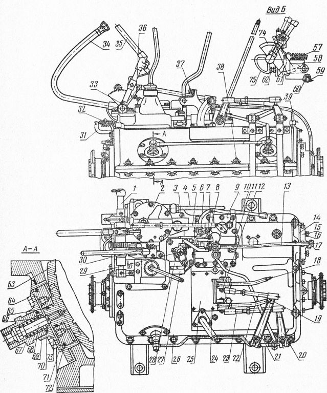
Рис. 75. Коробка передач:
1 — мостик; 2 фильтр; 3, 11, 16, 24, 40, 43, 44, 46, 47, 52, 55. 57, 64 и жимные болты; 7, 20, 21 и 75-рычаги; 8 – рычаг переключения передач, кладки; 15 – гидроаккумулятор; 18 – рычаг включения муфты на раздаточном 27 и 28 – валики кулисы; 29 – палец рычага; 30, 32 и 67 – пружины; 31, 41, 56 и ночного тормоза; 36, 37 и 62 – упорные болты; 39 -рым; 42 -валик; ра; 60 – регулировочная прокладка; 61 – стопор; 63 – колодка тормозка-жета; 74 — сектор. 68 -болты; 4, 10, 13, 26, 49 и 54 трубы; 5, 22 и 23- тяги; 6 и 17- за-9 — механизм переключения передач; 12, 38, 47 и S3 — гайки; 14, 59 и 70 — провалу; 19 — рычаг включения муфты передачи заднего хода; 25 и 73 — крышки; 58 — кронштейны; 33 — кулиса; 34 — рычаг педали слива; 35 — рычаг стоя-45 — поддон; 48 — проставка; 50 — рукав; 51 — корпус привода тахосиидомет-синхронизагора; 65 — кольцо; 66 — шайба; 69 — штуцер; 71 — поршень
Снять масляный фильтр. Вывернуть болты крепления корпуса привода тахоспидометра и конического редуктора привода масляного насоса к верхней половине картера и вынуть вал привода насоса. Снять со шлицов вала конический редуктор. Вывернуть из крышки штуцер с прокладкой, болт с пружиной и шайбой. Вынуть и разъединить колодку тормозка и поршень из крышки. Вывернуть болты и снять крышку с прокладкой.
Снятие поддона с масляным насосом и разборка вала привода насоса. Перед снятием поддона рекомендуется установить коробку передач поддоном вверх. Отвернуть гайки с призонных болтов, болтов и снять поддон с насосом и проставкой.
Вал приводов насосов следует разбирать в таком порядке. Снять корпус (рис. 76), отвернуть гайку, снять шестерню и вынуть штифт. Спрессовать с вала стакан с подшипником. Снять втулку, шестерню с подшипниками, муфту, кольцо, шестерню с подшипниками. Выпрессовать подшипники 5 и 10 из шестерен, выпрессовать подшипник из стакана и вынуть штифт.
Разборка раздаточного вала. Передвинуть муфту (рис. 77) на вал, расконтрить и отвернуть гайку, снять уплотнительное кольцо, вывернуть болты и при помощи демонтажных болтов спрессовать крышку в сборе с подшипником и фланцем. Вынуть вал из картера коробки передач. Отвернуть гайку и спрессовать обойму с фланцем.
Отвернуть болты, снять крышки и, отвернув болты, вынуть валики. Отвернуть болты и снять корпуса и рычаг. Расконтрить и вывернуть винт, снять палец и вилку с передвижной зубчатой муфты. Снять зубчатую муфту.
Вывести вилку из отверстия корпуса и, повернув относительно оси раздаточного вала, вынуть вилку из муфты. Снять кольца, выпрессовать (со стороны резьбового конца вала) вал. Находящиеся на нем детали будут спрессованы по мере продвижения вала. Снять кольцо 4 и выпрессовать обойму.
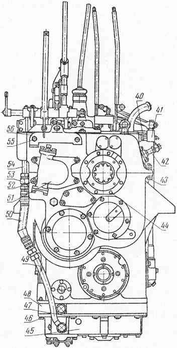
Рис. 76. Вал привода насоса коробки передач:
1 и 15-втулки; 2 — вал; 3. 4, 9, 11, 12, 32 и 52 — кольца; 5, 10, 34 и — подшипники: б —муфта; 7, 16, 17 и 46 – валики; 8 — ось сухаря; 13, 19, 22. 23, 26. 27, 28. 43. 49. 50 и 53 – болгы. 14. 29 и 33 -шестерни: 18-валик насоса; 20 и 31 — корпуса; 21. 36 . 37 и 38 — штифты; 24 — ведущий вал; 25 — корпус клапана; 30 — стакан; 35 — гайка; 39 – картер; 40. 48 и 54 — крышки; 41 — манжета; 42 и 47 — прокладки; 45 — картер (верхняя половина); 51 — валик вилки; 55 — вилка; 56 — сухарь.
Разборка промежуточного и грузового валов. Отвернуть болты (рис. 78) и снять крышку, кольцо, выпрессовать ось и вынуть из картера шестерню заднего хода в сборе с подшипниками.
Перед разборкой промежуточного вала необходимо отвернуть болты и при помощи демонтажных болтов снять крышки с прокладками. Отвернуть контргайку и гайку и снять стопорное кольцо. Выпрессовать промежуточный вал (со стороны резьбового конца вала) и по мере его продвижения вынуть из картера внутреннее кольцо подшипника с роликами, шестерни, втулку, шестерни, втулку, шестерню и при выходе вала из роликоподшипника снять втулку, шестерню, втулку и шестерню.
При помощи демонтажных болтов выпрессовать из картера обоймы и стакан с наружным кольцом роликоподшипника, выпрессовать подшипник из картера и спрессовать подшипник с вала.
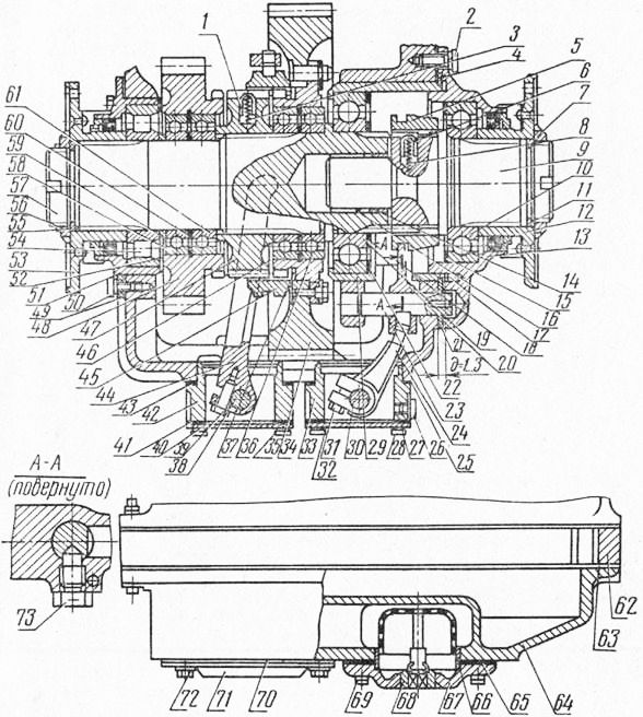
Рис. 77. Раздаточный вал с поддоном коробки передач:
1 и б-фиксаторы; 2, 28, 31, 35, 39, 50, 69 и 72-болты; 3 и Н – пружины; 4, П. 15, 18, 22, 37, 46, 52, 55, 58, 59 и 60 – кольца; 5 и 45 – муфты; 7 и 56 — гайки; 9-вал; 10, 16, 19, 36, 54 и 61 — подшипники; 12 и 53 — фланцы; 13, 32, 40 и 67 —крышки; 14 — втулка; 17 — штифт; 20 и 44 — вилки; 21, 25, 27, 41, 43, 49, 63, 65 и 70 – прокладки; 23 -палец; 24 — рычаг; 26 и 68 — пробки; 29 и 51 — обоймы; 30 и 38 — валики; 33, 42 и 62 — корпуса; 34, 47 и 48 — шестерни; 57 — раздаточный вал; 64 — поддон; 66 — сетка; 71 — насос; 73 — винт.
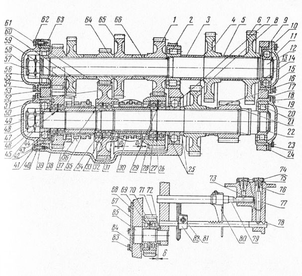
Рис. 78. Промежуточный и грузовой валы коробки передач:
1, 4, 6, 8, 21, 28, 38, 52, 59, 60, 64, 65 и 71-шестерни; 2, 7, 14, 20, 27, 36, 43. 50, 55 и 69 – подшипники; 3, 5, 16, 25, 61 и 66 — втулки; 9, 39 и 53 – регулировочные прокладки; 10, 17, 24, 40, 54, 68 и 75 – прокладки; 11, 22, 26 , 29, 32. 33, 34, 42, 44, 46 , 70, 72 и 84 – кольца; 12 – промежуточный вал; 13. 19, 48, 58 и 67-крышки; 15 — обойма; 18, 41, 62 и Si —болты; 23, 51 и 63 -щстаканы; 30 и 35 — зубчатые муфты; 31 и 37 — шлицевые втулки; 45, 47, 56, 57 и 81 – гайки; 49 — грузовой вал; 73 и 77-фиксаторы; 74 – пробка; 76 — пружина; 78 и 79 — валики-рейки; 80 и 82 — вилки; 85 — ось.
Перед выпрессовкой грузового вала необходимо снять с передвижных муфт вилки. Для этого расконтрить и вывернуть пробки фиксаторов, вынуть фиксаторы. Отвернуть гайку и выпрессовать клинья вилок. Вынуть валики-рейки и снять вилки. Выпрессовать грузовой вал так же, как и промежуточный, и вынуть из картера снятые по мере продвижения вала детали. Выпрессовать при помощи демонтажных болтов стаканы.
Разборка ведущего вала. Ведущий вал целесообразно разбирать на гидрофицированном стенде ОГТ-3985 или при помощи съемников в следующем порядке. Установить вал вертикально так, чтобы торец вала со стороны первой передачи был вверху. Расконтрить и вывернуть винт (рис. 79), отвернуть гайку с пружиной и снять уплотнительное кольцо с шайбой. Ввернуть в маслопровод демонтажный болт и выпрессовать маслопровод. Захватить съемником за нажимной диск фрикциона первой передачи и спрессовать его вместе с правой опорой вала в сборе. Снять с вала правый диск. Спрессовать шестерню в сборе с подшипниками, отвернуть и снять с вала гайку крепления среднего барабана и спрессовать нажимной диск, средний барабан с дисками и снять средний диск в сборе.
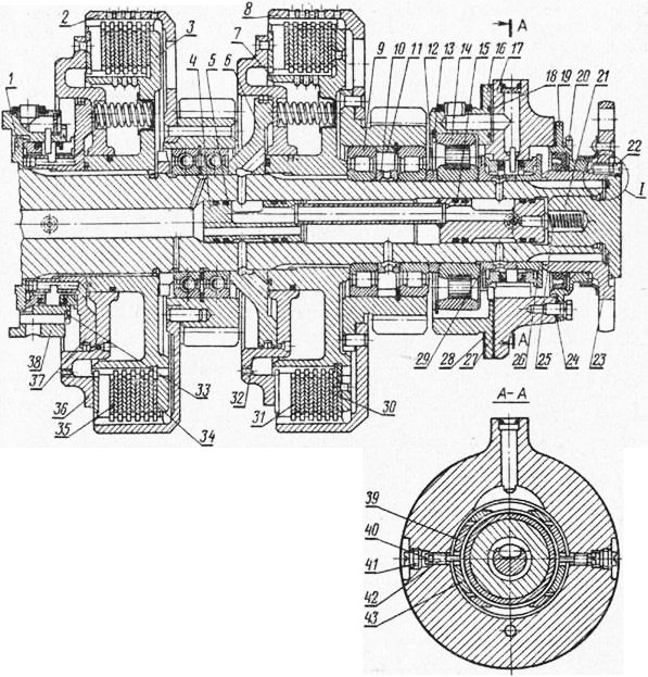
Рис. 79. Ведущий вал (I и II передачи)
Расконтрить и вывернуть болты и разобрать среднюю опору.
Установить ведущий вал так, чтобы торец вала со стороны четвертой передачи был вверху. Снять с вала маслопровод (рис. 80), левую опору, фрикционы четвертой передачи, шестерню, фрикцион третьей передачи и диск. Снять среднюю опору в сборе и кольцо. Спрессовать внутреннюю обойму подшипника и снять полукольца. Разобрать снятые с вала сборочные единицы.
Разборка фрикционов ведущего вала приведена на примере фрикциона четвертой передачи. Фрикционы остальных передач разбирать в порядке, указанном ниже.
Вынуть из канавок шестерни уплотнительные кольца. Снять нажимной диск и вынуть из левого барабана пружины со стаканами.
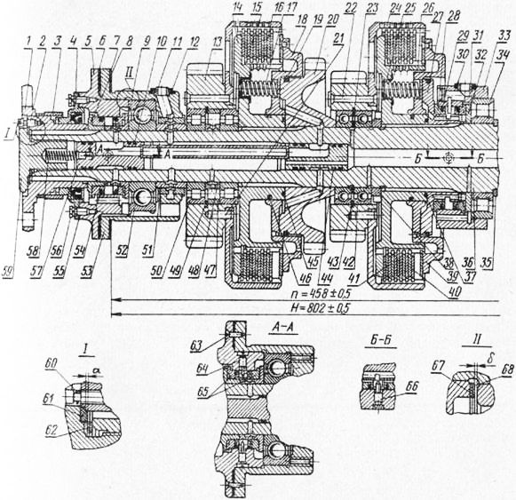
Рис. 80. Ведущий вал (III и IV передачи):
Вынуть левый барабан и диски из шестерни, выпрессовать подшипники и вынуть кольца.
Разборка правой и левой опор вала приведена на примере правой опоры. Снять фланец в сборе, вывернуть болты и снять крышку с манжетой. Вынуть из фланца втулки и чугунные кольца с манжетами. Вывернуть винты и вынуть из обоймы кольцо и выпрессовать подшипник.
Разборка ведущего моста
Ведущий мост рекомендуется разбирать при помощи оборудования, разработанного ГОСНИТИ, в следующем порядке.
Разборка конечных передач и тормозов. Установить ведущий мост на стенд для разборки. Отвернуть болты (рис. 81) крепления крышки и снять крышку с шарикоподшипником и регулировочными прокладками при помощи технологических болтов, вынуть полуось с солнечной шестерней, вывернуть болты крепления водила к ступице, ввернуть технологические болты и спрессовать водило в сборе с сателлитами с буртиков ступицы. Рас-шплинтовать и отвернуть болты крепления стопорной планки круглой гайки венечной шестерни, снять стопорную планку и отвернуть гайку. Снять венечную шестерню с внутренним кольцом роликоподшипника со шлицев трубы кожуха полуоси и распорную втулку. Вывернуть болты (рис. 82) крепления козырьков к суппортам, снять козырьки и спрессовать ступицу в сборе с тормозным барабаном.
В таком же порядке разобрать другую половину ведущего моста. Расшплинтовать и вынуть оси (рис. 82) соединения тормозных камер с рычагами тормоза, отвернуть гайки крепления тормозных камер к кронштейнам и снять тормозные камеры. Отвернуть стопорный болт и снять рычаг тормоза в сборе с кулака тормоза, выпрессовать кулаки из кронштейнов и суппортов. Снять поочередно пружины (рис. 82) колодок тормоза с пальцев тормозных колодок. Отвернуть гайки крепления оси тормозных колодок, выпрессовать оси из отверстий колодки и суппорта тормоза и вынуть колодки (рис. 82) тормоза из проушин суппорта. Отвернуть болты крепления суппорта тормоза к кожуху полуоси и снять суппорт. Вывернуть болты крепления кронштейнов к кожуху полуоси, снять кронштейны и регулировочные прокладки. Вывернуть болты крепления кожуха полуоси к картеру главной передачи, ввернуть технологические болты и спрессовать кожух полуоси. Разобрать снятые сборочные единицы.
Разборка главной передачи с дифференциалом. Отвернуть винты (рис. 83) крепления вставки к картеру главной передачи, ввернуть технологические болты, спрессовать и вынуть из картера вставку в сборе со стаканом конического роликоподшипника, с ведомой конической шестерней и дифференциалом. Отвернуть болты крепления крышки и стакана к картеру. Ввернуть технологические болты, спрессовать и вынуть стакан с роликоподшипником, крышкой, ведущей конической шестерней и цилиндрическим роликоподшипником из картера.
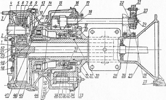
Рис. 81. Ведущий мост:
1, 6, 38 и 44 – подшипники; 2 – ось; 3 – шпилька; 4 – водило; 5, 23, 28 и 39 – регулировочные прокладки; 7, 8, 10, 11, 30, 36, 37, 47 и 49 кольца; 9 -сателлит; 12 -ступица; 13 – стопорная планка; 14, 15, 19, 24, 25, 26, 35 и 53 – болты; 16 -суппорт; 17 кулак; 18, 20, 31, 42 и 43 — втулки: 21 – рычаг; 22 – кронштейн; 27 -кожух; 29 и 34 – манжеты; 32 и 52 — крышки; 33 и 46 – гайки; 40 – ось; 41 – тормозной барабан; 45 — венечная шестерня; 48 — пробка; 50 — полуось; 51 — шестерня.
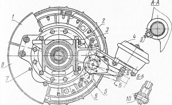
Рис. 82. Основной тормоз:
1 и 8 — козырьки; 2 и 5 —колодки; 3 — пружина; 4 — тормозная камера ; 6 — стопорная планка; 7 — болт; 9 – масленка; 10 — ось.
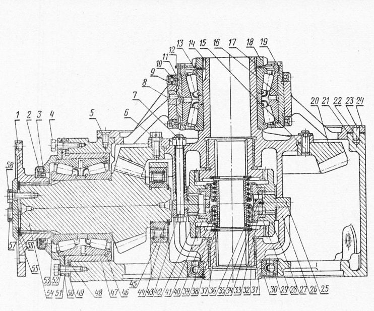
Рис. 83. Главная передача :
1 – фланец; 2 и 39 -пружины; 3 – манжета; 4. 6, 43 и 57 – болты, 5 и 9 – винты; 7 – шплинт; 8. 15 и 23 – штифты; 10, 17 и 55 — шайбы; 11, 18 и 19 – гайки; 12, 30, 33, 34, 35, 36, 37, 45 и 56 — кольца; 13, 28, 24, 44 и 46 — подшипники; 14 и -ступицы; 16, 40 и 47 — стаканы; 20 – ведомая коническая шестерня; 21, 50 и 51 — прокладки; 22 – картер; 24 – вставка; 25 – ведущая муфта; 26 — чаша; 27 — полумуфта; 31 и 38 – втулки; 41 – муфта; 42 — шпонка; 48 и 49 — регулировочные прокладки; 52 -крышка; 53 — маслоотражатель; 54 — ведущая шестерня; 58 — проволока.
Разборка дифференциала с ведомой конической шестерней. Расконтрить и вывернуть гайку со ступицы ведомой конической шестерни. Вывести кольцо из канавки гайки и вывернуть гайку. Расконтрить и вывернуть стопорные винты кольцевых гаек стакана роликоподшипника. Отвернуть кольцевую гайку и снять вставку со стакана роликоподшипника. Спрессовать со ступицы стакан с наружным и внутренним кольцами роликоподшипника. Спрессовать другое внутреннее кольцо подшипника с роликами. Отвернуть другую кольцевую гайку со стакана и выпрессовать из стакана наружную обойму роликоподшипника.
Расшплинтовать и отвернуть болты крепления ведомой конической шестерни к ступице, а также гайки стяжных болтов дифференциала. Снять кольцо и спрессовать шарикоподшипник.
Выпрессовать штифт из ступицы и ведомой шестерни и снять шестерню. Выпрессовать стяжные болты из ступицы ведомой конической шестерни, ведущей муфты и чаши дифференциала и снять ступицу ведомой конической шестерни, ступицу ведомой полумуфты, ведомую полумуфту, чашу и втулку дифференциала. Выбить из паза ведущей муфты шпонку, вынуть пружинное кольцо и кольцо ведущей муфты.
Расшплинтовать болты крепления шайбы фланца ведущей конической шестерни, отвернуть болты, снять шайбу и уплотнительное кольцо, фланец, крышку с сальником. Снять стопорное кольцо и спрессовать роликоподшипник. Спрессовать с шестерни стакан с наружной и внутренней обоймой роликоподшипника. Выпрессовать из стакана наружную обойму роликоподшипника и спрессовать внутреннюю обойму роликоподшипника с шестерни.
Разборка конечной передачи. Снять с полуоси стопорное кольцо, солнечную шестерню и другое стопорное кольцо. Отвернуть болты крепления тормозного барабана к ступице и снять тормозной барабан. Отвернуть болты крепления крышки и снять крышку, вынуть из крышки стопорное кольцо и выпрессовать самоподжимные сальники. Выпрессовать из ступицы шарикоподшипники и распорные кольца.
Снять пружинное кольцо и выпрессовать из ступицы наружную обойму роликоподшипника. Спрессовать с венечной шестерни внутреннюю обойму роликоподшипника. Снять стопорное кольцо с оси сателлитов и спрессовать с оси сателлиты с первым роликоподшипником и наружной обоймой второго подшипника. Снять с оси распорное кольцо и спрессовать внутреннюю обойму подшипника. Выпрессовать из сателлита наружное кольцо роликоподшипника. Снять и разобрать остальные сателлиты.
Отвернуть гайки винтов (рис. 84) крепления тормозных накладок к колодке тормоза и снять тормозные накладки с колодок. Отвернуть винт крепления сухаря к колодке тормоза и снять сухарь с колодки и выпрессовать втулку оси.
Отвернуть гайки стяжных болтов крышки (рис. 85) с корпуса рычага тормоза. Вывернуть пробку фиксатора, вынуть пружину и шарик фиксатора. Выпрессовать ось червяка из корпуса, заглушку, вынуть червяк и червячную шестерню из корпуса.
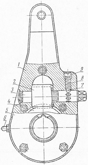
Рис. 85. Рычаг тормоза:
1 — рычаг; 2 — червяк; 3 — ось червяка; 4 — червячная шестерня; 5 — крышка; 6 — масленка; 7-шарик; 8 — пружина; 9 – пробка.
Разборка редуктора привода насосов
Снять с картера крышки (рис. 86) с прокладками, отсоединить и снять трубу. Отсоединить и снять насосы. Снять фланцы с прокладками и вынуть из втулки муфты. Отвернуть контргайку и гайку крепления валика и вынуть валик из картера. Вывести из паза муфты вилку и вынуть ее из картера. Вынуть из крышки уплотнение и снять с вала стопорное кольцо и упорное кольцо.
Отвернуть болты, снять крышку с прокладкой и вынуть из картера вал в сборе с подшипником и муфтой. Спрессовать шестерню в сборе с подшипником, предварительно сняв стопорное кольцо. Отвернуть гайки и снять крышку с прокладкой. Снять стопорное кольцо и, выпрессовы-вая из катера стакан в сборе со втулкой, снять шестерню. Снять патрубок с прокладкой.
Снять с насосов угловые муфты и регулятор расхода масла. Снять стопорное кольцо и спрессовать со втулки стакан с подшипниками. Снять стопорное кольцо и выпрессовать из стакана подшипники.
Спрессовать с вала подшипник, предварительно сняв стопорное кольцо, снять муфту, вынуть пружину, шарики и снять кольцо.
Разборка промежуточной опоры
Отвернуть болты (рис. 87) крепления задней и передней крышек к корпусу и снять крышки в сборе.
Снять стопорное кольцо с вала. Выпрессовать вал из корпуса опоры. Выпрессовать передний стакан. Снять шарикоподшипник с переднего конца вала. Выпрессовать задний стакан с шарикоподшипником. Вынуть стопорное кольцо из заднего стакана.
Выпрессовать шарикоподшипник из заднего стакана. Вынуть из выточек в крышках уплотнение. Выпрессовать из крышек манжеты. Вывернуть пробку-сапун и пробки.
Разборка карданной передачи
Перед началом разборки подшипниковой сборочной единицы на карданном валу переднего моста необходимо отвернуть круглую гайку (рис. 88) и снять скользящую вилку со шлицев карданного вала, снять шайбу, сальник и гайку.
Расконтрить и отвернуть болты крепления крышек игольчатых роликоподшипников. Снять балансировочные пластины и крышки подшипников.
Выпрессовать игольчатые подшипники из отверстий вилок и фланцев-вилок. Вынуть крестовины. Снять с крестовин уплотнительные кольца и обоймы. (Если нет балансировочного стенда, перед началом разборки карданных валов промаркировать все детали для установки их на прежние места в процессе сборки.)
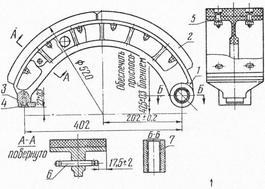
Рис. 84. Колодка тормоза:
1 — основание колодки; 2 — накладка; 3 — сухарь; 4 и 5 — винты; 6 — ось; 7 — втулка.
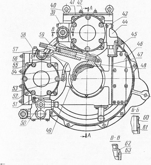
Рис. 86. Редуктор привода насосов:
1 — стакан; 2, 4, 17, 19, 22, 41. 47 и 56 — прокладки; 3 — фланец; 5 – штифг; 6, 11, 13, 15, 21, 24, 30, 32, 33, 34 и 38 – кольца; 7 – насос НШ-67Л; 8, 45, 60 и 62 — штуцеры; 9 – гайка; 10, 28, 42. 46 и 55 — крышки; 12 — уплотнение; 14 — вал; 16, 26 и 31 — подшипники; 18 и 29 -шестерни; 20 — патрубок; 23 – шарик; 25 – пружина; 27, 35, 36, 39, 44 и 58 – муфты; 37 – втулка; 40 — рым; 43, 51, 59, 61 и 63 — уплотнительные кольца: 48 – вилка; 49 – сухарь; 50 – регулятор расхода масла; 52 – насос НШ-100Л; 53 – зажимной болт; 54 — труба; 57 – валик.
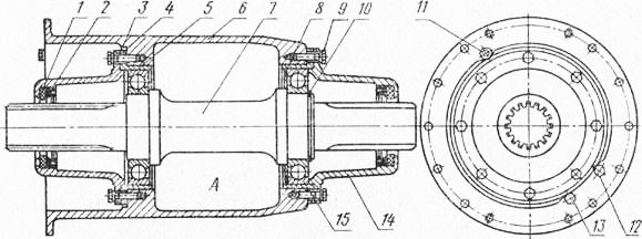
Рис. 87. Промежуточная опора:
1, 8 и 10 — кольца; 2 —манжета; 3 — прокладка; 4 — регулировочная прокладка; 5 — стакан; б — корпус; 7 — вал; 9 — болт; 11 — пробка-сапун; 12 — пробка контрольного отверстия; 13 — пробка сливного отверстия; ./4 —крышка; 15 — подшипник.
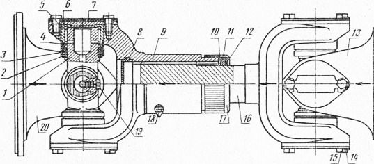
Рис. 88. Карданный вал;
1 — крестовина; 2 — обойма; 3 — кольцо; 4, 10 и 12 — шайбы; 5 — подшипник; б —крышка; 7 —пластина; 8 — заглушка; 9 – вилка; 11 — сальник; 13 и 20 — фланцы-вилки; 14 — болт; 15 — планка; 16 – вал; 17 — гайка; 18 — масленка; 19 — пробка.
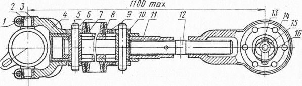
Рис. 89. Центральная тяга навесного устройства:
1 — болт; 2 — цапфа; 3 и 5 — втулки; 4 – вилка; б и 15 — пальцы; 7 — пружина; 8 и 11 — трубы; 9 — регулировочная шайба; 10 — кольцо; 12 —вит; 13 — чека; 14 — шарнир; 16 — кольцо.
Разборка навесного устройства
Расшплинтовать и вынуть оси и пальцы соединения вертикальных раскосов с главными нижними тягами. Снять вертикальные раскосы. Отвернуть гайки с двух опор и снять при помощи кран-балки вал рычагов в сборе. Вынуть пружинные шплинты и отвернуть гайки крепления горизонтальных раскосов. Вынуть оси и отсоединить горизонтальные раскосы от левой и правой нижних тяг. Вынуть шплинты и отвернуть гайки крепления нижних тяг вместе с шайбами. Выбить оси и снять обе тяги в сборе.
Отвернуть гайки и вынуть болты вместе с шайбами. Снять левый и правый упоры.
Разборка вала рычагов. Установить на стенд для разборки и сборки вал рычагов в сборе и закрепить на нем левую опору.
Расшплинтовать стопорные шайбы, отвернуть и выбить болты и втулки из проушин вилки центральной тяги. Снять центральную тягу в сборе. Расстопорить и отвернуть болты крепления заглушек, снять заглушки и шайбы со стороны главных рычагов навесного устройства. Спрессовать главный правый рычаг с вала, снять шайбу, правую опору вала рычагов, правую пружину, втулку, правый хомут, центральную тягу, левый хомут и левую пружину. Вынуть вал из рычагов из левой опоры. Снять с вала шайбу и спрессовать левый главный рычаг. Отсоединить и снять со стенда левую опору.
Разборка центральной тяги. Уложить центральную тягу на монтажный стол. Отвернуть задний шарнир (рис. 89) в сборе, вывернуть стяжной винт из трубы. Заложить задний шарнир в приспособление для расклепки на прессе и срезать заклепки. Разобрать задний шарнир, вынув палец и чеку. Расшплинтовать пальцы и, сжав прессом тарельчатые пружины, выбить палец и втулку. Снять нажимное кольцо шайбы, тарельчатые пружины, выбить второй палец и втулку, вывести внутреннюю трубу из наружной. Свинтить вилку с наружной трубы.
Разборка левой нижней тяги. Уложить левую тягу на монтажный стол. Расшплинтовать гайку (рис. 90). Отвернуть гайку и выбить ось из корпуса левой тяги. Снять рычаг с корпуса левой тяги. Расшплинтовать чеку и вынуть ее.
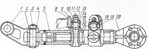
Рис. 90. Нижняя тяга навесного устройства:
1 рычаг; 2 -ось; 3 и 6 – шплинты; 4 и 11 – гайки; 5 – корпус; 7-рукоятка; 8 и 19 – чеки; 9 и 18 – кольца; 10 стопор; 12 – уплотнитсльное кольцо; 13 – болт; 14 -шайба; 15 -крышка; 16 – прокладка; 17 —пружина; 20 – выдвижная тяга.
Разборка гидравлической системы управления навесным устройством
Разборка гидрораспределителя. Снятый с трактора гидрораспределитель очистить от пыли и грязи, промыть в керосине или дизельном топливе. Разборка гидрораспределнтеля может быть частичной, например при замене отдельных деталей, при техническом обслуживании, регулировке клапанов, или полной. Степень разборки гидрораспределителя определяется после испытания на стенде.
Гидрораспределитель установить в приспособление или тиски с медными губками и разбирать в следующем порядке.
Отвернуть гайки и снять рукоятки управления золотниками, а гайки навернуть на рычаги. Отвернуть винты и снять крышку, чехол вместе с кольцом, прокладки, кольца и рычаг. Отвернуть болты крепления верхней и нижней крышек к корпусу. Снять крышки с прокладкой. Вынуть из корпуса золотники вместе с обоймами фиксаторов. Запрещается обезличивать золотники и корпус. Для разборки предохранительного клапана снять пломбу, отвернуть колпачок и снять прокладку. Ослабить затяжку контргайки, вывернуть регулировочный винт вместе с контргайкой и прокладкой . Вынуть пружину, направляющую и шарик предохранительного клапана. Седло клапана вывертывать вместе с кольцами специальным ключом только при замене. При промывке дизельным топливом и продувке сжатым воздухом каналов полостей и кольцевых камер рекомендуется вывернуть из корпуса угольники, пробки, а также крышку с прокладкой.
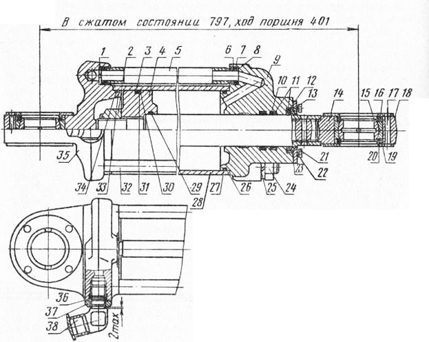
Рис. 94. Гидроцилиндр:
1, 22 и 25 — пружинные шайбы; 2, 24 и 37- гайки; 3, 7. 11, 26, 30 и 34- защитные шайбы; 4 — поршень; 5 — маслопровод; 6 — шайба; 8, 10, 27, 29, 31, 33 и 36 — уплотнительные кольца; 9, 13, 16 и 35 — крышки; 12 — манжета; 14 — шток; 15 — подшипник; 17 — заклепка; 18- головка штока; 19 — кольцо; 20 — сальник; 21 — болт; 23 — скребок; 28 — корпус; 32 — шпилька; 38 — угольник.
Для разборки перепускного клапана отвернуть болты и снять фланец. Легкими ударами через деревянную или пластмассовую наставку вытолкнуть кверху перепускной клапан в сборе. Вынуть пяту с кольцом, пружину, направляющую с кольцом. Если нужно заменить седло перепускного клапана, его выпрессовывают, пользуясь специальной оправкой.
Для разборки золотник поместить в приспособление так, чтобы верхняя средняя часть вошла в прорезь упора. Благодаря этому золотник удерживается от поворота. Вывернуть пробку, вынуть пружину фиксатора, нижний стакан, пружину, верхний стакан, обойму фиксатора, втулку фиксатора, шарик и бустер. Вывернуть гильзызолотника вместе с прокладками и фильтрами. Вывернуть регулировочный винт и вынуть пружину. Вставить в гильзу деревянную или пластмассовую наставку и через направляющую легкими ударами молотка выпрессовать гнездо месте с шариковым клапаном.
Разборка гидроцилиндра. Установить гидроцилиндр в приспособление и отвернуть четыре гайки вместе с шайбами со шпилек и снять заднюю крышку, корпус, маслопровод с защитными шайбами, шайбой и уплотнительным кольцом. Снять уплотнительное кольцо задней крышки. Вынуть шпильки. Отвернуть гайку штока и вынуть фрикционную шайбу, снять поршень со штока. Снять с поршня защитные шайбы, уплотнительное кольцо и кольцо. Вынуть шток из передней крышки, снять уплотнительные кольца и защитные шайбы. Отвернуть болты и снять крышку скребков. Извлечь из передней крышки скребки и манжеты. Извлечь заклепки, вынуть крышку, сальник, кольцо и выпрессовать шарнирный подшипник.