
Руководство на английском языке по техническому обслуживанию и ремонту автомобиля Iveco Daily Euro 4.
- Автор: —
- Издательство: Iveco
- Год издания: 2006
- Страниц: 1132
- Формат: PDF
- Размер: 74,9 Mb
Руководство на английском языке по техническому обслуживанию и ремонту автомобиля Iveco Daily.
- Автор: —
- Издательство: Iveco
- Год издания: 2004
- Страниц: 1898
- Формат: PDF
- Размер: 87,9 Mb

Руководство на английском языке по ремонту автомобиля Iveco Daily с 1978 года выпуска.
- Автор: —
- Издательство: Motorist
- Год издания: —
- Страниц: 1805
- Формат: —
- Размер: —
Руководство по эксплуатации, техническому обслуживанию и ремонту автомобилей Iveco Daily/Turbo Daily/New Daily с 1989/1996 годов выпуска.
- Автор: —
- Издательство: Диез
- Год издания: —
- Страниц: 296
- Формат: —
- Размер: —
Руководство по эксплуатации и ремонту автомобилей Iveco Daily и Iveco Turbo Daily с 1999 года выпуска с дизельными двигателями объемом 2,3/2,8/3,0 л.
- Автор: —
- Издательство: Монолит
- Год издания: —
- Страниц: 284
- Формат: —
- Размер: —

Руководство по эксплуатации, техническому обслуживанию и ремонту автомобилей Iveco Daily с 2000 года выпуска.
- Автор: —
- Издательство: Диез
- Год издания: —
- Страниц: 448
- Формат: —
- Размер: —
Руководство по ремонту автомобилей Iveco Daily с 2000 года выпуска.
- Автор: —
- Издательство: Диез
- Год издания: —
- Страниц: 416
- Формат: —
- Размер: —
Руководство по эксплуатации, техническому обслуживанию и ремонту автомобилей Iveco Daily с 2006 года выпуска.
- Автор: —
- Издательство: Диез
- Год издания: —
- Страниц: 464
- Формат: —
- Размер: —
Руководство по ремонту и каталог запчастей автомобиля Iveco Daily с 2006 года выпуска.
- Автор: —
- Издательство: Диез
- Год издания: —
- Страниц: 360
- Формат: —
- Размер: —

Руководство по эксплуатации и техническому обслуживанию малотоннажных грузовиков Iveco Daily.
- Автор: —
- Издательство: Iveco
- Год издания: —
- Страниц: 202
- Формат: PDF
- Размер: 1,5 Mb
Руководство по эксплуатации и техническому обслуживанию автомобиля Iveco Daily.
- Автор: —
- Издательство: Iveco
- Год издания: 1999
- Страниц: 150
- Формат: PDF
- Размер: 1,3 Mb


- Manuals
- Brands
- Iveco Manuals
- Trucks
- NEW DAILY
- Instructions manual
-
Bookmarks
Quick Links
N
D
EW
AILY
B
ODYBUILDERS INSTRUCTIONS
I
SSUE 2014
Related Manuals for Iveco NEW DAILY
Summary of Contents for Iveco NEW DAILY
-
Page 1
AILY ODYBUILDERS INSTRUCTIONS SSUE 2014… -
Page 2
IVECO S.p.A Technical Application & Homologation Strada delle Cascinette, 424/34 10156 Torino (TO) — Italy www.iveco.com Printed 603.95.789 – 1 ed. 02/2014 Images and text: IVECO S.p.A. 2014 All rights reserved. -
Page 3
NEW DAILY – GUIDELINES FOR TRANSFORMATION AND GUIDELINES FOR TRANSFORMATION AND VERSIONS UPDATE DATA GUIDELINES FOR TRANSFORMATION AND VERSIONS UPDATE DATA Section Description Page Revision date – Printed 603.95.789 – 1 Ed. — Base 02/2014… -
Page 4
— Printed 603.95.789 – Base 02/2014… -
Page 5
Data and information contained in this publication may be outdated as a result of changes adopted by IVECO, at any time, for tech- nical or commercial reasons or due to the need to adapt the vehicle to new legal requirements. -
Page 6
— Printed 603.95.789 – Base 02/2014… -
Page 7
INDEX OF SECTIONS GENERAL INFORMATION CHASSIS INTERVENTIONS APPLICATIONS OF SUPERSTRUCTURES POWER TAKE-OFFS ELECTRONIC SUB-SYSTEMS ADBLUE AND SCRT SYSTEM DAILY PEOPLE CARRIER DAILY CNG AND CNG WITH “RECOVERY MODE” — Printed 603.95.789 – Base 02/2014… -
Page 8
— Printed 603.95.789 – Base 02/2014… -
Page 9
SECTION 1 GENERAL INFORMATION — Printed 603.95.789 – Base 02/2014… -
Page 10
— Printed 603.95.789 – Base 02/2014… -
Page 11
ELECTRONICALLY ….. . . 1.3 IVECO AUTHORISATION …. -
Page 12
NEW DAILY – GENERAL INFORMATION GENERAL INFORMATION – Printed 603.95.789 – 1 Ed. — Base 02/2014… -
Page 13
It should be noted that the collaboration with IVECO is based on the assumption that the Bodybuilder uses the maximum of their technical and organisational skills and that operations are technically and perfectly complete. As outlined below, the topic is extens- ive and we can only provide the rules and minimum precautions that can allow development of the technical initiative. -
Page 14
● the implementation; ● the compliance of the design and implementation to any specific indications provided by IVECO and the laws in force in the countries where the vehicle is destined; ● effects on functionality, safety, reliability and, in general, good behaviour of the vehicle;… -
Page 15
(e.g. approval documents/test reports). Before signing the Technical Agreement IVECO reserves the right to visit the Bodybuilder, in order to verify qualifications to carry out the fittings and/or processing for which the above collaboration is requested. -
Page 16
● training and qualification of staff. The availability of ISO 9001 certification, even though not required, is considered very important by IVECO. 1.10 ACCIDENT PREVENTION Do not allow unauthorised staff to intervene or operate on the vehicle. It is forbidden to use the vehicle with safety devices that have been tampered with or are damaged. -
Page 17
● carry out the controls set forth in the Pre-Delivery Inspection (PDI) list available in the IVECO network, for the items being worked on (obviously the other items of the PDI will be the responsibility of the Dealer, such as the guarantee pamphlet);… -
Page 18
NEW DAILY – GENERAL INFORMATION GENERAL INFORMATION 1.13 VEHICLE NAMES 1.13 VEHICLE NAMES The commercial name of IVECO vehicles (for example New DAILY 40-150) does not match the type approval name. A com- plete example is provided below. Type approval name New DAILY 40C15HA SV /P ●… -
Page 19
The dimensions and masses of vehicles allowed on the axles are shown in the drawings, the technical descriptions and, more gener- ally, on the documents on the official IVECO website. Defects refer to vehicles in their standard versions; the use of special equip- ment may lead to changes on the masses and their distribution on the axles. -
Page 20
NEW DAILY – GENERAL INFORMATION GENERAL INFORMATION 1.15 DIMENSIONS AND GROUND Figure 2 204643 Example for calculating the position of the centre of gravity of the payload plus superstructure W = Payload plus superstructure W2 = Measurement of payload on rear axle… -
Page 21
NEW DAILY – GENERAL INFORMATION GENERAL INFORMATION 1.15 DIMENSIONS AND GROUND Figure 4 204645 Even distribution of load Uneven distribution of load (attention to loads on axles and minimum ratio) Height of centre of gravity For the cab version and no-load vehicle, the value of the height of the centre of gravity is shown on the specific technical docu- mentation for each model (cab version diagram). -
Page 22
● in prescribing the adoption of adequate precautions for driving. Any cases where evaluation is difficult should be submitted to IVECO for approval. 3. Loads that result in increased aerodynamic actions In fittings characterised by high vertical and surface development (e.g.: advertising panelling), the hight of the centre of thrust, de- termined in the case of cross-wind, must be evaluated very carefully. -
Page 23
Respect of the permitted masses All the limits shown on IVECO documentation must be respected. It is particularly important to evaluate the maximum ground on the front axle in any load condition, in order to ensure the necessary steering features in all road surface conditions. -
Page 24
NEW DAILY – GENERAL INFORMATION GENERAL INFORMATION 1.17 GENERAL REGULATION FOR THE PREVENTION OF FIRE RISK ● adequate ventilation must be maintained for the brakes and battery casing (particularly in the execution of truck bodies); ● in the placement of fenders and wheel arches, free shaking of the rear wheels must be guaranteed, even under the conditions of use with chains. -
Page 25
SECTION 2 CHASSIS INTERVENTIONS — Printed 603.95.789 – Base 02/2014… -
Page 26
— Printed 603.95.789 – Base 02/2014… -
Page 27
NEW DAILY – CHASSIS INTERVENTIONS CHASSIS INTERVENTIONS Contents Contents 2.7 ASSEMBLING AN ADDITIONAL AXLE ..2.8 GEARBOX MODIFICATION … . 2.1 GENERAL CHASSIS MODIFICATION STANDARDS …… -
Page 28
NEW DAILY – CHASSIS INTERVENTIONS CHASSIS INTERVENTIONS Contents 2.19 INSTALLING A RETARDER … . 2.20 REAR UNDER-RUN PROTECTION (RUP) ……. -
Page 29
NEW DAILY – CHASSIS INTERVENTIONS CHASSIS INTERVENTIONS 2.1 GENERAL CHASSIS MODIFICATION STANDARDS CHASSIS INTERVENTIONS 2.1 GENERAL CHASSIS MODIFICATION STANDARDS Keep in mind that: ● weldings on the supporting structures of the chassis are absolutely forbidden (except as prescribed in Para- graph»Weldings» ( ➠ Page 9) and in Chapters 2.4 ( ➠ Page 15), and 2.5 ( ➠ Page 19));… -
Page 30
5 minutes after application of the paint. For ground connections at the signal level (e.g. sensors or devices with low absorption), absolutely never use standardised IVECO M1 points (ground connection of the batteries), M2 or M8 (grounding the starter motor, depending on the position of the guide) and connect the signal cable ground on points separate from the power cables and wires that serve as radio frequency screens. -
Page 31
NEW DAILY – CHASSIS INTERVENTIONS CHASSIS INTERVENTIONS 2.1 GENERAL CHASSIS MODIFICATION STANDARDS A x B x t A x B x t Rear overhang Wheelbase Side member section Side member section Class Type chassis [mm] wheelbase area rear overhang area [mm]… -
Page 32
NEW DAILY – CHASSIS INTERVENTIONS CHASSIS INTERVENTIONS 2.2 DRILLS ON THE CHASSIS Stresses on the chassis The following stress value in static conditions cannot be exceeded for any reason whatsoever: Note static stress σ allowed on chassis: 120 N/mm In any case, respect any more restrictive limits placed by national standards. -
Page 33
NEW DAILY – CHASSIS INTERVENTIONS CHASSIS INTERVENTIONS 2.2 DRILLS ON THE CHASSIS Screws and nuts We generally recommend the use of the same type and class of screws and nuts as those employed for similar anchorages on the original vehicle (see Table 2.3). -
Page 34
NEW DAILY – CHASSIS INTERVENTIONS CHASSIS INTERVENTIONS 2.2 DRILLS ON THE CHASSIS ● if an electric circuit breaker (main switch) is present, wait for it to complete the cycle; ● disconnect the negative pole from the battery; ● disconnect the positive pole of the battery without connecting it to earth; do NOT short-circuit the negative pole;… -
Page 35
Holes of 20 mm diameter can be sealed off by using chamfered washers welded on both sides. 2.3 RUST AND PAINT PROTECTION Note All components mounted on the chassis must be painted in compliance with IVECO Standard 18-1600 Colour IC444 RAL 7021 — 70/80 gloss. -
Page 36
See Table III Coupling with other materials must not cause the «battery effect”. Coatings free from chromium salts. Coatings free of hexavalent chromium. Table 2.6 — Painted parts — IVECO Standard 18 — 1600 (Prospectus III) Classes Cycle phase description –… -
Page 37
NEW DAILY – CHASSIS INTERVENTIONS CHASSIS INTERVENTIONS 2.3 RUST AND PAINT PROTECTION Classes Cycle phase description – Powders (40-110 μm) – VARNISH – – Low temperature single-component (30-40 μm) This operation must be performed when dealing with cutting burr, oxidation, weld slag, or laser-cut surfaces. -
Page 38
NEW DAILY – CHASSIS INTERVENTIONS CHASSIS INTERVENTIONS 2.3 RUST AND PAINT PROTECTION Table 2.8 — Unpainted or aluminium modified parts or add-ons Class Type of protection A — B – Stainless steel – Geomet – Zinc coating Free from hexavalent chromium… -
Page 39
If the dimensions of the superstructure are suitable, it is best to use wheelbases in standard production because this allows the use of original drive shafts and pre-defined crossbar positions. Nevertheless, IVECO must issue its authorisation for wheelbases below the minimum or maximum approved standard sizes on the market. -
Page 40
Generally speaking, shortening the wheelbase will have a negative effect on braking. Table 2.10 indicates the wheelbase modification limits. Contact the IVECO Department — Homologation & Technical Application to find out at what conditions (brake cylinders, minimum tare, theoretically admissible loads, tyres, height of centre of gravity) trans- formation can be allowed. -
Page 41
— along the entire contour of the wheelbase — until achieving area strength modulus equal to IVECO values for the same wheelbase or for the next admissible greater length. In alternative, for cases allowed by local standards, larger counter-frame profiles can be adopted. -
Page 42
NEW DAILY – CHASSIS INTERVENTIONS CHASSIS INTERVENTIONS 2.4 WHEELBASE MODIFICATION Figure 6 208210 Reinforcements on the chassis Figure 7 shows some examples of possible solutions. The reinforcements must be continuous and extend over the entire length of the vehicle’s chassis, up to the cab. To connect them to the side member, in the case of an angle profile, rivets or screws of resistance class 8.8 must be used;… -
Page 43
When modifying the rear overhang it is necessary to take note of the variations that this modification inflicts on distribution of axle loads, in compliance with loads established by IVECO (see Chapter 1.15 ( ➠ Page 11)). Limits set by national law must also be respected, as well as maximum distances from the rear structural edge and heights from ground, defined for towing hook and under-run protection. -
Page 44
NEW DAILY – CHASSIS INTERVENTIONS CHASSIS INTERVENTIONS 2.5 REAR OVERHANG MODIFICATION Elongation Possible solutions, in relation to the length of the extension, are shown in Figures 8, 9 and 10. Cuts can be of straight type. The minimum dimensions of the reinforcements to apply in the area of modification are shown in Figure 2.3. -
Page 45
NEW DAILY – CHASSIS INTERVENTIONS CHASSIS INTERVENTIONS 2.6 INSTALLING THE TOW HOOK Figure 10 208213 When the elongation is rather large, the need of an additional crossbar must be evaluated on a case to case basis in order to ensure proper torsional strength of the frame. The insertion of an extra crossbar having characteristics similar to the series is necessary, however, when two cross members are spaced more than 1200 mm apart. -
Page 46
NEW DAILY – CHASSIS INTERVENTIONS CHASSIS INTERVENTIONS 2.6 INSTALLING THE TOW HOOK Figure 11 196787 1. 2. Free field for towing hooks Free field for coupling hooks according to standard DIN 74058 ESC-152 In cases where the connection flange of the drawbar coupling does not have holes suitable to those on the existing rear crossbar of the vehicle, the latter may be authorised for modification upon application of adequate reinforcements. -
Page 47
Hooks with pins can only be installed on the truck version and require the use of a suitable cross member. Both types, if not supplied directly by IVECO, must be type-approved in compliance with current legislation. Table 2.11 lists certain data for the tow couplings available from the production line. -
Page 48
NEW DAILY – CHASSIS INTERVENTIONS CHASSIS INTERVENTIONS 2.6 INSTALLING THE TOW HOOK X = length of the load bed [m], (see Figure 12) L = theoretical drawbar length, distance between the centre of the drawbar eye and the centre line of the trailer axles [m], (see Figure 12) ≥… -
Page 49
Rear crossbar in lowered position When the drawbar coupling must be lowered from its original position, IVECO may issue an authorisation to lower the original drawbar or install an additional drawbar, which is the same as the original, in a lowered positioned. -
Page 50
The maximum tilt values of the drive shaft for the vehicle series must be respected, even for interventions on the rear engine axle suspensions. Contact the IVECO Technical Application for any difficulties; and send them a diagram with the length and tilt of the new transmis- sion for a constant-velocity check. -
Page 51
NEW DAILY – CHASSIS INTERVENTIONS CHASSIS INTERVENTIONS 2.8 GEARBOX MODIFICATION Lengths allowed The maximum work lengths which can be produced, both for the middle and sliding sections “LG” or “LZ” (see Figure 16), can be determined in relation to the external diameter of the existing vehicle pipe and the maximum running rpm (see for- mula and Table 2.13). -
Page 52
NEW DAILY – CHASSIS INTERVENTIONS CHASSIS INTERVENTIONS 2.8 GEARBOX MODIFICATION Engine Engine code [rpm] Power [HP] Gearbox F1CFA401A*A .14G WG 3600 2840.6 0.791 F1CFA401A*B Check the engine code on the engine plate Note Usually, the fork universal joints of the same shaft must not be rotated. -
Page 53
1 ° . If it is between 1 ° and 1 ° 30′ it must be authorised by IVECO. If it is more than 1 ° 30′ it should be assumed as not authorised. -
Page 54
Furthermore, the wheelbase on these vehicles may not be reduced beyond the shortest value for the series (e.g. tipper truck). We recommend using original IVECO gearboxes; if this is not possible, the use of raw steel pipes with a yield load of at least 420… -
Page 55
To adjust the latter, proceed as indicated in Paragraph «Braking corrector» ( ➠ Page 50), envisaging for the load to be applied at hole (9) a value matching the stiffness characteristics of the new spring. If it is not possible to comply with this ration in all load conditions, contact IVECO for a new check of compliance with legal require- ments. -
Page 56
2.10 MODIFYING THE ENGINE AIR INTAKE AND EXHAUST SYSTEMS Note The characteristics of the engine air intake and exhaust systems must not be modified. Modifications, if authorised by IVECO, must not vary the original intake vacuum and exhaust counter-pressure values. -
Page 57
(min. 150 mm) from electrical systems and plastic pipes (shorter distances progressively require plate guards, thermal insulators or the replacement of plastic pipes with steel ones). Authorisation must always be obtained from IVECO. 2.11 MODIFYING THE ENGINE COOLING SYSTEM The good operating conditions of the original system must not be altered, especially for what concerns the radiator, free surface of the radiator and pipes (dimension and layout). -
Page 58
We recommend using IVECO type heating systems whenever it is necessary to install an additional heating system. On vehicles where IVECO does not employ these heaters, installation must be done in compliance with the instructions issued by the equipment Manufacturer (installation of heaters, pipes, electric system, etc.) and in relation to the following indications. -
Page 59
NEW DAILY – CHASSIS INTERVENTIONS CHASSIS INTERVENTIONS 2.12 MODIFICATIONS TO THE HEATING/CONDITIONING PLANT Figure 21 204649 1. Main heater A. Solenoid valve (3) open 2. Optional supplementary heater B. Solenoid valve (3) closed 3. Solenoid valve 4. Additional heater installed by body builder … -
Page 60
(in shape and performance) to the standard model envisaged by IVECO; ● installation of the evaporator unit and of the bellow inside the cab (in cases where not provided directly from IVECO) must be planned as not to negatively impact control functions and access to equipment;… -
Page 61
Fitting a spoiler or baggage rack On request, versions are available developed for IVECO on the basis of its design and verifications. If “kits“ of other origins are fitted, follow the specific indications supplied by the manufacturer. -
Page 62
NEW DAILY – CHASSIS INTERVENTIONS CHASSIS INTERVENTIONS 2.13 WORK ON SHEET METAL Figure 22 204647 1. Roof panel 5. Internal rear cross member 2. Cutting limit area 6. Rear wall 3. Side finishing of roof 7. Door area rear finishing 4. -
Page 63
NEW DAILY – CHASSIS INTERVENTIONS CHASSIS INTERVENTIONS 2.13 WORK ON SHEET METAL Work on bodywork (vans) Fitting baggage racks The installation must be carried out using the fixing devices specifically envisaged on the roof (low roof and medium roof versions), bearing in mind the following indications: ●… -
Page 64
NEW DAILY – CHASSIS INTERVENTIONS CHASSIS INTERVENTIONS 2.13 WORK ON SHEET METAL Work on the roof a) Fitting a transparent roof At the time of publication of these Directives, it is still not possible to collect information and components for this kind of conver- sion. -
Page 65
NEW DAILY – CHASSIS INTERVENTIONS CHASSIS INTERVENTIONS 2.13 WORK ON SHEET METAL Figure 25 102433 d) Opening side windows Opening side windows in van vehicles requires the specific precautions and expedients indicated below. ● Cut the sheet metal, taking care to maintain a profile with a minimum width of: ■… -
Page 66
NEW DAILY – CHASSIS INTERVENTIONS CHASSIS INTERVENTIONS 2.13 WORK ON SHEET METAL Figure 26 208214 1. Internal support structure 3. Bonding with semi-structural material 2. Gasket 4. Cutting area e) Interior shelves Installing inside shelves must be carried out with great care to ensure suitable stiffness and self-support. The lower support must involve the floor support structure (cross members and longitudinal profiles) and must be implemented in a manner that ensures uniform load distribution. -
Page 67
NEW DAILY – CHASSIS INTERVENTIONS CHASSIS INTERVENTIONS 2.13 WORK ON SHEET METAL Work on the structure and floor Over and above the indications and precautions already mentioned, also bear in mind that: ● when drilling holes in the box sections, avoid areas where stresses are more concentrated (especially uprights A and B);… -
Page 68
To perform work of this kind, confirmation must be obtained from IVECO of the suitability of the original suspension devices. In outline, it may be possible to adopt solutions that are equivalent to those envisaged in routine production for similar versions. -
Page 69
NEW DAILY – CHASSIS INTERVENTIONS CHASSIS INTERVENTIONS 2.13 WORK ON SHEET METAL A deep cab may affect the handling and safety of the vehicle (suspension, commands). Inasmuch, ▶ it must be carried out with the utmost care and all necessary precautions. -
Page 70
Note Replacing the tyres with others of measure or load bearing capacity that differs from the specifications recorded at vehicle approval require IVECO certification, as well as a test to determine whether the braking system requires adjustment. The vehicle must then be presented to the competent Body that will inspect the new tyres and the vehicle documents. -
Page 71
Modifications may not be made to brake cylinders and callipers, adjustment units and valves, ▶ parking brake, braking control and servo systems. Any modification of the braking system MUST be authorised by IVECO. ▶ If the national standards provide it, the vehicle must be presented to the competent authority for inspection. -
Page 72
NEW DAILY – CHASSIS INTERVENTIONS CHASSIS INTERVENTIONS 2.15 WORK ON THE BRAKING SYSTEM Metal pipes Additions and replacements must envisage: ● for materials, dimensions, couplings: Standard ISO 4038 ● radii of curvature (referring to the centre line of the pipe ⌀ = 4.76 mm): min 25 mm ●… -
Page 73
NEW DAILY – CHASSIS INTERVENTIONS CHASSIS INTERVENTIONS 2.15 WORK ON THE BRAKING SYSTEM For each intervention on the piping, verify whether there is the need, depending on the supplier, ▶ to use always new couplings or if it is possible to reuse those originally present through the use of appropriate tools (pliers). -
Page 74
If this happens, the system switches off and you must wait for the preset time before resuming the operation. When replacing the modulator (supplied by IVECO Parts already filled with brake fluid in every ▶ part), it is enough to use the manual bleed procedure, taking care however not to empty it and not to cycle the pump and solenoid before filling is completed. -
Page 75
NEW DAILY – CHASSIS INTERVENTIONS CHASSIS INTERVENTIONS 2.15 WORK ON THE BRAKING SYSTEM Note If there are new springs, prior to adjustment make sure that the rear suspension has settled correctly. To do this, partially load the vehicle (about 2/3 of maximum limit), drive over bumpy ground and brake several times in forward and reverse gear. -
Page 76
NEW DAILY – CHASSIS INTERVENTIONS CHASSIS INTERVENTIONS 2.15 WORK ON THE BRAKING SYSTEM Figure 32 102436 8. Union screw 9. Hole for application of calibration load ESP (Electronic Stability Program) ESP is an electronic function that contributed to the active safety of the vehicle and inasmuch is compulsory under European Regu- lations. -
Page 77
The following paragraph describes the main situations that may arise. Note Reprogramming the control unit or degrading of the ESP system must exclusively be performed by the IVECO Assistance Service. – Printed 603.95.789 – 1 Ed. — Base 02/2014… -
Page 78
HHC (Hill Holder Control) to facilitate breakaway from a standstill in ascent Variation of P.T.T. Variations of vehicle P.T.T. must be authorised by IVECO and only in certain special cases is tins compatible with the presence of the ESP system. -
Page 79
2.16 ELECTRICAL SYSTEM: CURRENT INTERVENTIONS AND DRAWS Modification or replacement of stabilising bars The modification or replacement of stabilising bars must be authorised by IVECO and is not compatible with the presence of the ESP system. Inasmuch, if authorisation is granted, Derating of this system is compulsory, except as indicated in Attachment XI of Directive 2007/46/EC. -
Page 80
NEW DAILY – CHASSIS INTERVENTIONS CHASSIS INTERVENTIONS 2.17 PART RELOCATION AND ANCHORAGE OF ADDITIONAL UNITS AND EQUIPMENT Figure 34 114198 To minimise torsional stress on the chassis of the vehicle it is advisable to perform the installation in correspondence with a cross- bar, especially in the case of high mass units. -
Page 81
(see end of paragraph). IVECO does not provide versions fully prepared for the ADR, although production vehicles do already comply for some electrical parts, mechanical components and materials inside the cab. The Bodybuilder, upon request, is given a «declaration» containing details of the sections in the ECE document that have already been complied with by the vehicle up from the origin. -
Page 82
Since this is not within the content of the ADR preparation given by IVECO, when ordering the vehicle must be chosen the optional 00741 «Without rear glazing”. -
Page 83
The installation of a retarder brake is complex and requires the perfect integration with electric ▶ and electronic vehicle systems: therefore approval by IVECO is always necessary. Fitting an additional retarder (always and only an electro-magneitc type with electronic management) requires action on the pro- peller shaft and inasmuch must be authorised by IVECO. -
Page 84
2.21 REAR MUD GUARDS AND WHEEL ARCHES On cab version vehicles without rear fenders, the Body builder must implement solutions equal to those provided by IVECO. For the realisation of the fenders, the wheel arch boxes and the shaping of the superstructure, keep in mind that: ●… -
Page 85
NEW DAILY – CHASSIS INTERVENTIONS CHASSIS INTERVENTIONS 2.22 RAIN FLAP 2.22 RAIN FLAP In cases where legislation requires it and if not present yet, it is necessary to ensure that the complete vehicle is equipped with suitable rain flaps. For installation, it is necessary to comply with the distances required by the laws in force. -
Page 86
NEW DAILY – CHASSIS INTERVENTIONS CHASSIS INTERVENTIONS – Printed 603.95.789 – 1 Ed. — Base 02/2014… -
Page 87
SECTION 3 APPLICATIONS OF SUPERSTRUCTURES — Printed 603.95.789 – Base 02/2014… -
Page 88
— Printed 603.95.789 – Base 02/2014… -
Page 89
NEW DAILY – APPLICATIONS OF SUPERSTRUCTURES APPLICATIONS OF SUPERSTRUCTURES Contents Contents 3.9 INSTALLATION OF TAIL LIFTS … 3.10 TILT BEDS (BREAKDOWN RECOVERY) 3.1 CONSTRUCTION OF THE COUNTER …….. -
Page 90
NEW DAILY – APPLICATIONS OF SUPERSTRUCTURES APPLICATIONS OF SUPERSTRUCTURES – Printed 603.95.789 – 1 Ed. — Base 02/2014… -
Page 91
Following are the characteristics of certain materials which were taken into account in some of the applications stated below. Table 3.1 — Material to be used for the construction of superstructures Std IVECO 15-2110 and 15-2812 Breaking strength… -
Page 92
NEW DAILY – APPLICATIONS OF SUPERSTRUCTURES APPLICATIONS OF SUPERSTRUCTURES 3.1 CONSTRUCTION OF THE COUNTER CHASSIS Resistance modulus W Recommended C profile [mm] 24 ≤ W ≤ 26 80 X 60 X 6 27 ≤ W ≤ 30 80 X 60 X 7 100 X 50 X 5 31 ≤… -
Page 93
IVECO. Please note that in defining the minimum size of the reinforcement profiles in addition to the limit of the allowable stress for aluminium, reference must be made to the different Elastic Modulus with respect to steel (approx. -
Page 94
NEW DAILY – APPLICATIONS OF SUPERSTRUCTURES APPLICATIONS OF SUPERSTRUCTURES 3.2 ELEMENTS MAKING UP THE COUNTER CHASSIS 3.2 ELEMENTS MAKING UP THE COUNTER CHASSIS Longitudinal profiles The side members of the added structure must be continuous, extended as much as possible toward the front of the vehicle and towards the rear area of the front spring support;… -
Page 95
NEW DAILY – APPLICATIONS OF SUPERSTRUCTURES APPLICATIONS OF SUPERSTRUCTURES 3.2 ELEMENTS MAKING UP THE COUNTER CHASSIS Figure 4 193867 1. Normal boxed profiles 3. 15 mm lintel (width of the wing of the profile) 2. Gradual passage from the boxed section to the open section It is necessary to create continuity of support between the profiles of the counter chassis and those of the chassis;… -
Page 96
NEW DAILY – APPLICATIONS OF SUPERSTRUCTURES APPLICATIONS OF SUPERSTRUCTURES 3.2 ELEMENTS MAKING UP THE COUNTER CHASSIS Cross members A sufficient number of crossbars, possibly to be placed in correspondence with the fastening clamps to the chassis, must brace the two sections of the counter chassis. -
Page 97
Choosing the type of connection The choice of the type of connection to be used, if not provided by IVECO originally, is very important for the purposes of contri- bution of the counter chassis in terms of strength and stiffness. -
Page 98
NEW DAILY – APPLICATIONS OF SUPERSTRUCTURES APPLICATIONS OF SUPERSTRUCTURES 3.3 CONNECTION BETWEEN CHASSIS AND COUNTER CHASSIS Alternatively, use the connection in Figure 11, using the screws that connect the rear crossbar to the frame. In all other cases, it is absolutely forbidden to put holes in the wings. -
Page 99
In the event in which the vehicle chassis is already equipped with brackets for the attachment of a body of a type established by IVECO, these brackets must be used for this purpose. For the brackets applied to the counter chassis or to the superstructure, resistance characteristics not less than those originally mounted on the vehicle should be provided (see Table 2.7 and Table 3.1). -
Page 100
NEW DAILY – APPLICATIONS OF SUPERSTRUCTURES APPLICATIONS OF SUPERSTRUCTURES 3.3 CONNECTION BETWEEN CHASSIS AND COUNTER CHASSIS Also bear in mind that: in the case of superstructures that generate high bending and twisting moments (e.g. a crane behind the cab), the counter chassis must be properly sized to support them;… -
Page 101
NEW DAILY – APPLICATIONS OF SUPERSTRUCTURES APPLICATIONS OF SUPERSTRUCTURES 3.3 CONNECTION BETWEEN CHASSIS AND COUNTER CHASSIS Connection with longitudinal and transverse sealing plates (rigid junction) The type of mounting shown in Figure 11, made with plates that are welded or bolted to the counter chassis and fixed with nails or screws to the vehicle chassis, ensures a good capacity for reacting to longitudinal and transverse thrusts and the greatest contribu- tion to the stiffness of the assembly. -
Page 102
Fastening is achieved through specially crafted brackets along the vertical rib of the side members; if such connections have not already been specified by IVECO, they must be made according to the instructions in Chapter 3.3 — Paragraph «Connection with brackets»… -
Page 103
NEW DAILY – APPLICATIONS OF SUPERSTRUCTURES APPLICATIONS OF SUPERSTRUCTURES 3.4 CONTAINER APPLICATION practice to provide a rigid connection on the end of the rear overhang (one per side), obtained with screws or plates on the upper wing of the side member (see Figures 11 and 12). -
Page 104
The use of tipper bodies, rear and three sided, generally subjects the chassis to considerable stress. Therefore, please observe the following indications. The use of a stabiliser bar on all IVECO models for which it is an optional, is recommended. The counter chassis must be: ■… -
Page 105
NEW DAILY – APPLICATIONS OF SUPERSTRUCTURES APPLICATIONS OF SUPERSTRUCTURES 3.4 CONTAINER APPLICATION The rear tipping hinge must be fitted on the counter chassis; its position must be as near as possible to the rear support of the rear suspension. In order not to affect the stability of the vehicle during tipping and to not excessively increase the stress on the chassis, it must be respected the distances indicated in Figure 16. -
Page 106
NEW DAILY – APPLICATIONS OF SUPERSTRUCTURES APPLICATIONS OF SUPERSTRUCTURES 3.5 TRACTOR FOR SEMI-TRAILER 3.5 TRACTOR FOR SEMI-TRAILER Note The range does not include vehicles designed to tow trailers. To carry out conversion of a cab vehicle (in category N2 or N3), a specific IVECO authorisation is required. -
Page 107
Fifth wheel All fifth wheels can be used on IVECO vehicles if their load capacity, size and performance are declared suitable by the manufac- turer depending on their specific use. Fifth wheel couplings must meet national and/or international legal requirements and be of an approved type. For mounting on the support structure and the number of screws, as well as the size and placement of the longitudinal and transversal stops, it is advisable to follow the manufacturer’s instructions. -
Page 108
NEW DAILY – APPLICATIONS OF SUPERSTRUCTURES APPLICATIONS OF SUPERSTRUCTURES 3.6 TRANSPORT OF INSEPARABLE MATERIALS (TRAILER TRUCKS) Electric system Make changes in compliance with the general provisions in Chapter 5.4 . Note For vehicles equipped with ESP system, it is necessary to perform system degradation as indicated in Chapter 2.15 — Paragraph «Electronic Brake Control Devices ABS «. -
Page 109
(approximately 400 mm – see Figure 19) and arranged near suspension mounts. Specifically, the front anchoring flexibility must be suited to contain the necessary torsional movements of the chassis; ● other anchoring solutions must be authorised by IVECO. Figure 19 208921 – Printed 603.95.789 – 1 Ed. — Base 02/2014… -
Page 110
Special cases, whose M value falls within the areas designated by letter “E” in the mentioned Table (or for higher values) must be checked individually each time and must receive specific authorisation from IVECO. Figure 20 102468 g = acceleration of gravity equals 9.81 m/s… -
Page 111
NEW DAILY – APPLICATIONS OF SUPERSTRUCTURES APPLICATIONS OF SUPERSTRUCTURES 3.8 INSTALLING A CRANE L = horizontal distance between the payload application point W and vehicle centre line [m] W = mass of the crane at its centre of gravity [kg] l = horizontal distance between centre of gravity of crane and vehicle centre line [m] The Bodybuilder must, case by case, check the vehicle stability and take all necessary precau- ▶… -
Page 112
Close the reinforcement section in the crane assembly area. E = To be checked case-by-case. Send IVECO technical documentation with verification of stress and stability. When a higher modulus of resistance is required for the superstructure also use the latter for the crane. -
Page 113
60C, 65C, 70C 174x69x5 E = To be checked case-by-case. Send IVECO technical documentation with verification of stress and stability. When a higher modulus of resistance is required for the superstructure also use the latter for the crane. Note For the dimensions of the profiles see Table 3.2. -
Page 114
NEW DAILY – APPLICATIONS OF SUPERSTRUCTURES APPLICATIONS OF SUPERSTRUCTURES 3.9 INSTALLATION OF TAIL LIFTS Removable cranes The installation of removable cranes on the rear overhang may be carried out according to the specifications of the previous para- graph provided the type of fixing used between the crane and the counter chassis does not cause additional stress to the vehicle’s frame. -
Page 115
NEW DAILY – APPLICATIONS OF SUPERSTRUCTURES APPLICATIONS OF SUPERSTRUCTURES 3.9 INSTALLATION OF TAIL LIFTS • D for tail lifts with stabilisers M [Nm] = W • C + W To compensate for frame flexing, which is inevitable when the tail lift is in operation, the body builder may use reinforcement structures with larger dimensions than those indicated in Table 3.11. -
Page 116
Since, when used to remove snow, the vehicle is weighted at the rear and the maximum speed is limited (e.g. 40 km/h), a small increase in maximum axle load may be allowed upon specific assessment and authorisation by IVECO. It should be possible to use all the elements of the vehicle front panel (e.g. tow-bar, supports for windscreen cleaner); otherwise, equivalent systems must be provided in compliance with the safety requirements. -
Page 117
Cowl chassis versions They are made specifically for the installation of special bodies or equipment (shop vans, motor homes, etc.). The indications and precautions shown on the technical documentation (chassis diagram) provided by IVECO must be carefully respected. Motor home… -
Page 118
The installation of this outfit on 33S-35S (single-wheel) vehicles is possible with prior adoption of specific reinforcement flaps on the chassis, which can be ordered in original with specific opt. No. 74131 or at IVECO Parts with spare part No. 504267869. -
Page 119
NEW DAILY – APPLICATIONS OF SUPERSTRUCTURES APPLICATIONS OF SUPERSTRUCTURES 3.14 SPECIAL OUTFITS Figure 25 208929 View from below 1. 3. Reinforcement flap Cab block 2. 4. First counter chassis attachment Chassis flap section detail The flaps must have a minimum thickness of 4 mm and enough length to cover the side members of the chassis in front of the cab block area and behind the first fastening point of the counter chassis (see Figure 25);… -
Page 120
NEW DAILY – APPLICATIONS OF SUPERSTRUCTURES APPLICATIONS OF SUPERSTRUCTURES – Printed 603.95.789 – 1 Ed. — Base 02/2014… -
Page 121
SECTION 4 POWER TAKE-OFFS — Printed 603.95.789 – Base 02/2014… -
Page 122
— Printed 603.95.789 – Base 02/2014… -
Page 123
NEW DAILY – POWER TAKE-OFFS POWER TAKE-OFFS Contents Contents 4.1 GENERAL SPECIFICATIONS … . . 4.2 PTO FROM GEARBOX …. -
Page 124
NEW DAILY – POWER TAKE-OFFS POWER TAKE-OFFS – Printed 603.95.789 – 1 Ed. — Base 02/2014… -
Page 125
NEW DAILY – POWER TAKE-OFFS POWER TAKE-OFFS 4.1 GENERAL SPECIFICATIONS POWER TAKE-OFFS 4.1 GENERAL SPECIFICATIONS Different types of power take-offs (PTO) for motion withdrawal can be mounted for operating auxiliary units. Depending on the type of use and performance required, the application can be fitted to: ●… -
Page 126
NEW DAILY – POWER TAKE-OFFS POWER TAKE-OFFS 4.1 GENERAL SPECIFICATIONS In full compliance of the Manufacturer’s transmission specifications, the kinematic forces from the power take-off to the relevant apparatus should be carefully considered (angles, rpm, moment) during the design phase as well as the dynamic behaviour in the installation phase. -
Page 127
Drive may be taken from the layshaft via flanges or fittings located to the rear side or lower part of the gearbox. Table 4.1 shows available torque levels and the ratios between output rpm and engine rpm for the different types of IVECO op- tional gearbox/PTO combinations. -
Page 128
The maximum available torque refers to a speed of 1500 rpm in output from the PTO. For higher speeds, proportionally reduce the available torque value. IVECO reserves the right to void the guarantee on the gearbox if malfunctions are due to the PTO and, in that ▶… -
Page 129
Note Any intervention on the driveshaft carried out without prior authorisation from IVECO will immediately invalidate the warranty. 4.5 PTO MANAGEMENT Note At the time of publication of these Directives, the information in this Chapter may have been subject to changes. It is therefore recommended that any possible modifications are verified by consulting www.ibb.iveco.com. -
Page 130
Figure 4 209819 Note For the description of the features and ways of using the Expansion Module, consult the specific IVECO manual. «After market» PTO installation If you plan to install a PTO «after market», it is necessary to verify that the vehicle is equipped with opt. Cruise Control. -
Page 131
PTO configured connector Pneumatic suspension configured connectors 3. Bracket for optional connectors 2) If the vehicle is equipped with the Expansion Module, the following is to be ordered from IVECO Parts: ● the PTO installation kit; ● the wiring for the electrical connection of the PTO to the pre-installation on the bonnet (Figure 5) on the right of the engine compartment;… -
Page 132
T61 relay (30-87) for PTO from Expansion Module T62 relay (30-87) for PTO from Expansion Module – Note The «after market» installation of a PTO means, once installation is complete, referring to IVECO Customer Service to update the ECU software though the teleservice. PTO Mode Given the distinction between PTOs for manual or automatic transmission, up to two homogenous PTOs can be installed on the vehicle. -
Page 133
NEW DAILY – POWER TAKE-OFFS POWER TAKE-OFFS 4.5 PTO MANAGEMENT It is necessary to switch off the PTO when a torque withdrawal is not in progress. ▶ Before turning off the engine using the body builder connector, the PTO must be disengaged. In ▶… -
Page 134
NEW DAILY – POWER TAKE-OFFS POWER TAKE-OFFS 4.5 PTO MANAGEMENT Multiple State Switch An additional feature used to manage the number of revolutions with PTO engaged, available on the 12-way body builder con- nector (pin 3 — pin 8). To obtain this feature, the circuit shown in the diagram in Figure 8 must be implemented. -
Page 135
If the user wishes to store engine speed values other than those set by IVECO, the system allows the desired value for each switch position to be programmed following the procedure described in the Paragraph «PTO Mode — Engine speed adjustment for motion withdrawal». -
Page 136
NEW DAILY – POWER TAKE-OFFS POWER TAKE-OFFS – Printed 603.95.789 – 1 Ed. — Base 02/2014… -
Page 137
SECTION 5 ELECTRONIC SUB-SYSTEMS — Printed 603.95.789 – Base 02/2014… -
Page 138
— Printed 603.95.789 – Base 02/2014… -
Page 139
NEW DAILY – ELECTRONIC SUB-SYSTEMS ELECTRONIC SUB-SYSTEMS Contents Contents 5.1 ELECTRONIC SYSTEM ….5.2 BODY BUILDER CONNECTORS .. -
Page 140
NEW DAILY – ELECTRONIC SUB-SYSTEMS ELECTRONIC SUB-SYSTEMS – Printed 603.95.789 – 1 Ed. — Base 02/2014… -
Page 141
NEW DAILY – ELECTRONIC SUB-SYSTEMS ELECTRONIC SUB-SYSTEMS 5.1 ELECTRONIC SYSTEM ELECTRONIC SUB-SYSTEMS 5.1 ELECTRONIC SYSTEM Below is the location of the ECUs and connectors that can be installed on the vehicle. It is not permitted to connect devices or electrical circuits directly to the control units described ▶… -
Page 142
NEW DAILY – ELECTRONIC SUB-SYSTEMS ELECTRONIC SUB-SYSTEMS 5.2 BODY BUILDER CONNECTORS 5.2 BODY BUILDER CONNECTORS Specific connection points for body builder applications have been prepared in the electrical system in the vehicle; this way it is possible to maintain the functional integrity of the system and the validity of the guarantee. -
Page 143
NEW DAILY – ELECTRONIC SUB-SYSTEMS ELECTRONIC SUB-SYSTEMS 5.2 BODY BUILDER CONNECTORS Table 5.2 — Basic functions of 20 pin connector Description Signal Remarks By providing a positive, the motor which starts the vehicle engine is powered. Operation only takes place when the key is turned in the lock. -
Page 144
NEW DAILY – ELECTRONIC SUB-SYSTEMS ELECTRONIC SUB-SYSTEMS 5.2 BODY BUILDER CONNECTORS Description Signal Remarks Output Ground max 15 A Not connected Not connected Not connected 12-pole connector (72075) Figure 4 101554 Existing part on vehicle (male) Counterpart to be coupled (female) Table 5.3… -
Page 145
NEW DAILY – ELECTRONIC SUB-SYSTEMS ELECTRONIC SUB-SYSTEMS 5.2 BODY BUILDER CONNECTORS Description Signal Remarks Additional horns (to interface with the relay) Output Horn Ground = horn active Max 150 mA Open circuit = horn not active Multiple switch Available for power take-offs… -
Page 146
NEW DAILY – ELECTRONIC SUB-SYSTEMS ELECTRONIC SUB-SYSTEMS 5.2 BODY BUILDER CONNECTORS Figure 6 208223 1. Body builders connector 3. Interface responsibility of the designer of the processor 2. Separation diode REQUIRED 4. Signal processor The body builder must install a special separation diode so as not to lower the V voltage. -
Page 147
NEW DAILY – ELECTRONIC SUB-SYSTEMS ELECTRONIC SUB-SYSTEMS 5.2 BODY BUILDER CONNECTORS Figure 7 208224 1. Body builders connector 3. Interface responsibility of the designer of the processor 2. Separation diode REQUIRED 4. Signal processor The body builder must install a special separation diode so as not to lower the V voltage. -
Page 148
Electrical work (e.g. removing cables, adding circuits, replacing equipment or fuses, etc.), per- ▶ formed in a manner inconsistent with the IVECO instructions or b y unqualified personnel, can cause serious damage to electronic control units and compromise driving safety. -
Page 149
Note For more detailed information on the vehicle’s electrical system of, refer to the NEW DAILY Repair Manual, printout No. 603.95.723. -
Page 150
Interventions on the electrical system (e.g. removal of cables, addition of circuits, replacement ▶ of equipment or fuses etc.) carried out in a manner which is not compliant with IVECO’s instruc- tions or carried out by non qualified personnel, can cause severe damage to on-board systems (control units, wiring, sensors etc.), affect driving safety and good operation of the vehicle and… -
Page 151
● do not use other devices (battery charger) to start the engine. When in doubt, contact the IVECO assistance network. Any damage to the electronic control units caused by failure to comply with the procedure de- ▶… -
Page 152
NEW DAILY – ELECTRONIC SUB-SYSTEMS ELECTRONIC SUB-SYSTEMS 5.4 ELECTRICAL SYSTEM: CURRENT INTERVENTIONS AND DRAWS Ground points In general, original vehicle ground connections are not to be modified; in cases where these connections must be moved or new connections added, use the holes present on the chassis to the extent possible, taking care to: ●… -
Page 153
NEW DAILY – ELECTRONIC SUB-SYSTEMS ELECTRONIC SUB-SYSTEMS 5.4 ELECTRICAL SYSTEM: CURRENT INTERVENTIONS AND DRAWS Figure 11 208940 1. Engine earth Engine compartment ground on left chassis side member 2. Battery ground 3. Chassis cable ground … -
Page 154
NEW DAILY – ELECTRONIC SUB-SYSTEMS ELECTRONIC SUB-SYSTEMS 5.4 ELECTRICAL SYSTEM: CURRENT INTERVENTIONS AND DRAWS Figure 13 208942 Engine compartment ground near front right headlight Figure 14 208943 Engine compartment ground near front left headlight – Printed 603.95.789 – 1 Ed. — Base 02/2014… -
Page 155
NEW DAILY – ELECTRONIC SUB-SYSTEMS ELECTRONIC SUB-SYSTEMS 5.4 ELECTRICAL SYSTEM: CURRENT INTERVENTIONS AND DRAWS Figure 15 208944 m6/ms6. Signal/power ground inside cab on the central body Ground inside cab on the central body panel below the panel below the tachograph tachograph … -
Page 156
NEW DAILY – ELECTRONIC SUB-SYSTEMS ELECTRONIC SUB-SYSTEMS 5.4 ELECTRICAL SYSTEM: CURRENT INTERVENTIONS AND DRAWS As far as electronic components are concerned, the following instructions should be followed: ● electronic control units must be connected to the system ground when equipped with metal housings ●… -
Page 157
NEW DAILY – ELECTRONIC SUB-SYSTEMS ELECTRONIC SUB-SYSTEMS 5.4 ELECTRICAL SYSTEM: CURRENT INTERVENTIONS AND DRAWS Electromagnetic comparability It is recommended that electrical, electro-mechanical and electronic devices which comply with the following immunity require- ments for electromagnetic emissions, both irradiated and conducted, are used, as shown below:… -
Page 158
191312 a ≥ 6 mm The values in the table are only to be considered respected if the device comes form «IVECO Spare Parts” or it has been certified as per the international standards ISO, CISPR, VDE etc. Whenever equipment is used which runs on mains power (220 V AC) for its primary or secondary source of power, it must be checked to ensure that its characteristics are in line with IEC regulations. -
Page 159
NEW DAILY – ELECTRONIC SUB-SYSTEMS ELECTRONIC SUB-SYSTEMS 5.4 ELECTRICAL SYSTEM: CURRENT INTERVENTIONS AND DRAWS Figure 20 98915 1. Antenna support 4. Fastening screw M6x8.5 (tighten to a tightening torque of 2. Gasket 2 Nm) 3. Fixed joint cover 5. Aerial 6. -
Page 160
NEW DAILY – ELECTRONIC SUB-SYSTEMS ELECTRONIC SUB-SYSTEMS 5.4 ELECTRICAL SYSTEM: CURRENT INTERVENTIONS AND DRAWS To determine whether the system is functioning well and to check that the antenna is calibrated, it is suggested that the following information is taken into account:… -
Page 161
NEW DAILY – ELECTRONIC SUB-SYSTEMS ELECTRONIC SUB-SYSTEMS 5.4 ELECTRICAL SYSTEM: CURRENT INTERVENTIONS AND DRAWS Figure 23 208938 1. Buttons on the steering wheel 2. USB socket For cowl version vehicles the ceiling fixture with microphone is provided in the box of accompanying material. -
Page 162
NEW DAILY – ELECTRONIC SUB-SYSTEMS ELECTRONIC SUB-SYSTEMS 5.4 ELECTRICAL SYSTEM: CURRENT INTERVENTIONS AND DRAWS Figure 24 208949 1. Driver’s side 2. Passenger side Figure 25 208947 1. Bluetooth microphone Table 5.7 Description Cable Ground White Signal + Vcc Shielded The connector of the microphone connection, on the cab wiring side, is located in correspondence with the ceiling connectors. -
Page 163
1.5 dB in the 1575.42 ± 1.023 MHz band. Radio installation The original IVECO radio, either as original equipment or aftermarket, is integrated into the system on the CAN network and allows: ●… -
Page 164
Caution: the connection is standard but the signal settings are not. In the case of installation of ▶ devices different from the official IVECO product, see the relative documentation and verify the correspondence of the signals present on the connector to interface with the vehicle. -
Page 165
These tests can be performed using the ECU (electronic control units), on-board diagnostic or IVECO service. IVECO reserves the right to lapse the guarantee on the vehicle if any work not in accordance with its guidelines is performed. -
Page 166
NEW DAILY – ELECTRONIC SUB-SYSTEMS ELECTRONIC SUB-SYSTEMS 5.4 ELECTRICAL SYSTEM: CURRENT INTERVENTIONS AND DRAWS ● the vapour release point must not be in areas where sparks can be triggered or near hear sources; ● the maximum allowable temperatures, for a short period of time, are 50°C for conventional batteries and 40°C for AGM or gel batteries. -
Page 167
Additional alternators a) the diesel-powered NEW DAILY is equipped with an advanced («smart») alternator commanded by the engine control unit. This alternator is capable of delivering electrical current only when it is really necessary, and is able to always guarantee a correct state of battery charge through the sensor on the negative pole. -
Page 168
ELECTRONIC SUB-SYSTEMS 5.4 ELECTRICAL SYSTEM: CURRENT INTERVENTIONS AND DRAWS b) On the CNG powered NEW DAILY the «smart» alternator is not provided and the connection between alternators must be made as in Figure 29. The first equipment alternator has the L line connected directly to the Body Computer which carries out excitation and diagnosis, while the additional alternator is connected, as for the previous version, with a diagnostic light and external excitation. -
Page 169
NEW DAILY – ELECTRONIC SUB-SYSTEMS ELECTRONIC SUB-SYSTEMS 5.4 ELECTRICAL SYSTEM: CURRENT INTERVENTIONS AND DRAWS Drawing current Information about the points where you can take samples of available current and directions to be followed are below. Figure 30 209809 1. 3. -
Page 170
NEW DAILY – ELECTRONIC SUB-SYSTEMS ELECTRONIC SUB-SYSTEMS 5.4 ELECTRICAL SYSTEM: CURRENT INTERVENTIONS AND DRAWS Precautions In general it is advisable to: ● adopt, where necessary, adequate protection fuses applied in the vicinity of the sample; ● protect cables inserted into the proper sheathing or corrugated cables, installing according to the recommendations in Chapter 5.4 ( ➠… -
Page 171
NEW DAILY – ELECTRONIC SUB-SYSTEMS ELECTRONIC SUB-SYSTEMS 5.4 ELECTRICAL SYSTEM: CURRENT INTERVENTIONS AND DRAWS Table 5-9 — List of Fuses on Body Computer Location Amperage [A] Description – Spare – Spare Coils of T17 — T19 — T30 — T50 — T52 — T53 — T64 –… -
Page 172
NEW DAILY – ELECTRONIC SUB-SYSTEMS ELECTRONIC SUB-SYSTEMS 5.4 ELECTRICAL SYSTEM: CURRENT INTERVENTIONS AND DRAWS Fuses and replays on the engine compartment SCM control unit Figure 33 208475 Table 5-10 — List of fuses on SCM Diesel version Location Amperage [A] Description… -
Page 173
NEW DAILY – ELECTRONIC SUB-SYSTEMS ELECTRONIC SUB-SYSTEMS 5.4 ELECTRICAL SYSTEM: CURRENT INTERVENTIONS AND DRAWS Location Amperage [A] Description Fuel pump ESV1 Heated mirrors Heated mirrors and windscreen EDC (main loads) Main relay and automated gearbox Cooling pump Cigarette lighter EDC (secondary loads — not for F1C E5) –… -
Page 174
NEW DAILY – ELECTRONIC SUB-SYSTEMS ELECTRONIC SUB-SYSTEMS 5.4 ELECTRICAL SYSTEM: CURRENT INTERVENTIONS AND DRAWS Location Amperage Description – Baruffaldi coupling (from climate control unit) – Horn – Power drainage of key – Fuel pump – Main relay – Engine start-up prevention –… -
Page 175
NEW DAILY – ELECTRONIC SUB-SYSTEMS ELECTRONIC SUB-SYSTEMS 5.4 ELECTRICAL SYSTEM: CURRENT INTERVENTIONS AND DRAWS Location Amperage [A] Description – Spare 30 or 15 ESV1 or 8HP70 Wiping Power socket Side Marker Lights IBS sensor Body computer (2 power supply) Internal cab fans Baruffaldi coupling –… -
Page 176
NEW DAILY – ELECTRONIC SUB-SYSTEMS ELECTRONIC SUB-SYSTEMS 5.4 ELECTRICAL SYSTEM: CURRENT INTERVENTIONS AND DRAWS Location Amperage Description – Spare – Spare – Heated windscreen and mirrors – Climate control unit compressor – Heated rear windows – Unit heater – – –… -
Page 177
NEW DAILY – ELECTRONIC SUB-SYSTEMS ELECTRONIC SUB-SYSTEMS 5.4 ELECTRICAL SYSTEM: CURRENT INTERVENTIONS AND DRAWS Fuses on CBA1 control unit on battery Figure 35 208221 Table 5.15 — List of fuses on CBA1 Location Amperage [A] Description Power supply CBA2 Power supply SCM and Body builders… -
Page 178
NEW DAILY – ELECTRONIC SUB-SYSTEMS ELECTRONIC SUB-SYSTEMS 5.4 ELECTRICAL SYSTEM: CURRENT INTERVENTIONS AND DRAWS Any damage caused by failure to comply with procedure is not covered by warranty. ▶ Additional circuits The additional circuits must be separated from the vehicle and protected by means of a specific fuse As already seen in chapter 5.4 ( ➠… -
Page 179
● Incorrect installation of electrical accessories may affect occupant safety and cause severe damage to the vehicle. Contact IVECO if you have any questions. ● Avoid coupling with signal transmission cables (e.g. ABS), for which a preferential path has been defined for electromagnetic requirements (EMI). -
Page 180
NEW DAILY – ELECTRONIC SUB-SYSTEMS ELECTRONIC SUB-SYSTEMS 5.4 ELECTRICAL SYSTEM: CURRENT INTERVENTIONS AND DRAWS Trailer socket added by body builder If the vehicle is not ordered with the trailer socket, you can order a KIT, available as a spare part, as follows: ●… -
Page 181
2. Connector ST63 to connect to chassis wiring 3. 13-pin trailer socket 72016 trailer control unit For further details on connections and installation, request wiring diagrams from IVECO. Any damage to the light system caused by failure to comply with procedure is not covered by ▶… -
Page 182
The installation of the lateral lights must be performed on the additional structures (containers, vans, etc.), while the electric power supply must be obtained by the specific ST38 connector on the chassis (see Figure 41). In order to keep the electrical characteristics of the contacts of the female socket unchanged, the hood supplied by IVECO must be left attached. -
Page 183
There are no side marker lights for vehicles of a shorter length, as they are not mandatory even though there is a connector.. If it is necessary to install them, you must go to the IVECO service network to enable the Body Computer. -
Page 184
● the circuit breaker on the battery (CBA1) is activated and disables the secondary loads; ● the locks unlock and the out swinging door opens (if IVECO original); ● the ceiling lights stay on; ●… -
Page 185
NEW DAILY – ELECTRONIC SUB-SYSTEMS ELECTRONIC SUB-SYSTEMS 5.4 ELECTRICAL SYSTEM: CURRENT INTERVENTIONS AND DRAWS Figure 43 209818 Predisposition for an additional rear central door lock system (Vans) The «van» versions include the following options: ● opt 5864 «Centralised door locking system + Predisposition for an additional rear centralised door locking system», which provides an outlet on the central column. -
Page 186
NEW DAILY – ELECTRONIC SUB-SYSTEMS ELECTRONIC SUB-SYSTEMS 5.4 ELECTRICAL SYSTEM: CURRENT INTERVENTIONS AND DRAWS Figure 44 139393 The following diagram shows the connections between the rear door socket and the actuator/door lock switch (Figure 45). Figure 45 208226 Connection diagram of configuration for rear door A. -
Page 187
NEW DAILY – ELECTRONIC SUB-SYSTEMS ELECTRONIC SUB-SYSTEMS 5.4 ELECTRICAL SYSTEM: CURRENT INTERVENTIONS AND DRAWS The body builder must also provide an identical connection to the driver and passenger side doors for the side outlets. Figure 47 208226 Driver and passenger side door connection diagram A. -
Page 188
NEW DAILY – ELECTRONIC SUB-SYSTEMS ELECTRONIC SUB-SYSTEMS 5.4 ELECTRICAL SYSTEM: CURRENT INTERVENTIONS AND DRAWS Closed circuit → when the door is open Figure 49 208229 1. 3. Bonnet open sensor Alarm siren 2. Engine bonnet socket For the operation mode refer to the Use and Maintenance Manual. -
Page 189
SECTION 6 ADBLUE AND SCRT SYSTEM — Printed 603.95.789 – Base 02/2014… -
Page 190
— Printed 603.95.789 – Base 02/2014… -
Page 191
NEW DAILY – ADBLUE AND SCRT SYSTEM ADBLUE AND SCRT SYSTEM Contents Contents 6.1 GENERAL INFORMATION ….6.2 THE NITROGEN OXIDE CATALYTIC REDUCTION PRINCIPLE …. -
Page 192
NEW DAILY – ADBLUE AND SCRT SYSTEM ADBLUE AND SCRT SYSTEM – Printed 603.95.789 – 1 Ed. — Base 02/2014… -
Page 193
6.1 GENERAL INFORMATION To comply with Euro VI requirements on engine gas emissions, IVECO has developed the «SCRT» (Selective Catalytic Reduction Technology) system, consisting of the combined action of a diesel particulate filter (DPF) and post-treatment of exhaust gas (SCR). -
Page 194
NEW DAILY – ADBLUE AND SCRT SYSTEM ADBLUE AND SCRT SYSTEM 6.3 INSTRUCTIONS 6.3 INSTRUCTIONS The following instructions are intended for the AdBlue injection system of the Bosch DeNO 3.1 type. If changes are made to the chassis which involve this system, the following procedure must be followed under all circumstances: ●… -
Page 195
● The tank is secured to the chassis with specific brackets; any modifications must be authorized by IVECO. ● The Heating Pot / Supply Module must be positioned above the centre of gravity of the tank. -
Page 196
● respect the original incline of the filler in relation to the ground; any variation in this value must be authorized by IVECO. Note The parts in plastic must be at least 200 mm from any heat source (eg. exhaust system); if heat-protecting panels are used this distance can be reduced to 80 mm. -
Page 197
Z > 0 4. Siphon S > 0 With regards the position of the DM module, please note that modifications cannot be made to the solutions which are IVECO approved and normally produced. The reference cases are indicated below – Printed 603.95.789 – 1 Ed. — Base 02/2014… -
Page 198
NEW DAILY – ADBLUE AND SCRT SYSTEM ADBLUE AND SCRT SYSTEM 6.3 INSTRUCTIONS Figure 5 208933 A. C. Config. 1 — DAILY 35S — Wheelbase 3520 mm — Gsx Config. 3 — DAILY 40C/70C — Wheelbase 4100 mm — B. -
Page 199
NO sensor cable. Operations on pipes for AdBlue and heating water Note Interventions which do not replicate existing solutions in production must be authorized by IVECO. For this reason, please note the following: ●… -
Page 200
NEW DAILY – ADBLUE AND SCRT SYSTEM ADBLUE AND SCRT SYSTEM 6.3 INSTRUCTIONS Pipe assembly tools Figure 7 189108 1. Plastic pipe mounting pliers (Part 99387101) 3b. Support for fitting NW10 for water pipes (Part. 2a. Clamping jaws for AdBlue pipe (Part 99387102) 99387105) 2b. -
Page 201
APPENDIX A DAILY PEOPLE CARRIER — Printed 603.95.789 – Base 02/2014… -
Page 202
— Printed 603.95.789 – Base 02/2014… -
Page 203
NEW DAILY – DAILY PEOPLE CARRIER DAILY PEOPLE CARRIER Contents Contents A.1 CHASSIS ……Transport …… -
Page 204
NEW DAILY – DAILY PEOPLE CARRIER DAILY PEOPLE CARRIER – Printed 603.95.789 – 1 Ed. — Base 02/2014… -
Page 205
IVECO does not accept claims after delivery or claims not recorded on the designated forms countersigned by the transporter. For any claim, please provide the vehicle identification number: this number is on the core of the right chassis side member in the wheel arch near the suspension. -
Page 206
The bodywork structure must be considered a load bearing unit together with the chassis: the bending, torsion and thrust stresses must be absorbed by the unit. This layout is made necessary by the relative flexibility of the chassis. Please contact the IVECO Quality Department for any relev- ant queries. -
Page 207
Note The Body builder is entirely responsible for anchoring the seats to the frame as well as carrying out the inspection (destructive) and approval tests. The figures below show some details of the structure and how to secure the fixed seats and runner seats taken from IVECO draw- ings no. 5801805133 and 5801752010. -
Page 208
NEW DAILY – DAILY PEOPLE CARRIER DAILY PEOPLE CARRIER A.3 BODYWORK CONSTRUCTION Figure 1 173264 Seat securing floor frame – Printed 603.95.789 – 1 Ed. — Base 02/2014… -
Page 209
NEW DAILY – DAILY PEOPLE CARRIER DAILY PEOPLE CARRIER A.3 BODYWORK CONSTRUCTION Figure 2 173265 Example: Fixed seat installation diagram (see Drawing 5801805133) – Printed 603.95.789 – 1 Ed. — Base 02/2014… -
Page 210
NEW DAILY – DAILY PEOPLE CARRIER DAILY PEOPLE CARRIER A.3 BODYWORK CONSTRUCTION Figure 3 173266 Example: Runner seat installation diagram (see Drawing 5801752010) – Printed 603.95.789 – 1 Ed. — Base 02/2014… -
Page 211
To prevent any interference with these elements, the AdBlue tank must be shifted slightly along the chassis side member. In this case, in order to use pipes which are longer but generally available from IVECO Parts, it is recommended that one of the positions provided for in the production of Daily Vendor and Minibus is replicated. -
Page 212
NEW DAILY – DAILY PEOPLE CARRIER DAILY PEOPLE CARRIER A.4 NOISE EMISSIONS AND THERMAL INSULATION Wheelchair lift for disabled passengers For this type of transport, the access door compartment must be equipped with a lift; furthermore, inside the vehicle there must be a reserved area with specific dimensions. -
Page 213
IVECO is to be informed of the results and is to be consulted in relation to any modifications of the fine tuning. -
Page 214
NEW DAILY – DAILY PEOPLE CARRIER DAILY PEOPLE CARRIER A.6 BODY BUILDER CONNECTORS Figure 5 208221 Relay and fuse box on the battery CBA 1 Table A.2 Ref. Fuse capacity Function 150A Power supply CBA 2 200A Power supply SCM and Body builders… -
Page 215
NEW DAILY – DAILY PEOPLE CARRIER DAILY PEOPLE CARRIER A.6 BODY BUILDER CONNECTORS 12 pin connector (72076) for People Carrier Figure 6 101554 Existing part on vehicle (male) Counterpart to be coupled (female) Table A.3 Code Description 500314814 12 way male connector 500314820 Male contact for cable from 0.3 to 0.5 mm… -
Page 216
NEW DAILY – DAILY PEOPLE CARRIER DAILY PEOPLE CARRIER A.7 ROAD TESTS Description Signal Observations TGC OFF inlet 100 mA +12V = TGC OFF TGC ON inlet 100 mA +12V = TGC ON A.7 ROAD TESTS a) Before starting the road test, the following checks must be carried out with the vehicle stopped: ●… -
Page 217
APPENDIX B DAILY CNG AND CNG WITH “RECOVERY MODE” — Printed 603.95.789 – Base 02/2014… -
Page 218
— Printed 603.95.789 – Base 02/2014… -
Page 219
NEW DAILY – DAILY CNG AND CNG WITH «RECOVERY MODE» DAILY CNG AND CNG WITH «RECOVERY MODE» Contents Contents B.1 GENERAL INFORMATION ….B.2 SAFETY REGULATIONS …. -
Page 220
NEW DAILY – DAILY CNG AND CNG WITH «RECOVERY MODE» DAILY CNG AND CNG WITH «RECOVERY MODE» – Printed 603.95.789 – 1 Ed. — Base 02/2014… -
Page 221
(eg: airports, refineries, etc.). Note IVECO designs, approves and constructs CNG vehicles which comply fully with the Regulation ECE 110 currently in force. Interventions on the engine power supply system which:… -
Page 222
After replacing the valves, or after any intervention on the high-pressure system, a HYDRAULIC ▶ PRESSURE TEST (300 bar) must be carried out by IVECO CUSTOMER SERVICE, who will issue a test certificate following a positive result. – Printed 603.95.789 – 1 Ed. — Base 02/2014… -
Page 223
NEW DAILY – DAILY CNG AND CNG WITH «RECOVERY MODE» DAILY CNG AND CNG WITH «RECOVERY MODE» B.3 SYSTEM INTERVENTIONS Repainting outfitted chassis The following must be protected from paint: ● the stainless steel pipes of the methane supply system; ●… -
Page 224
NEW DAILY – DAILY CNG AND CNG WITH «RECOVERY MODE» DAILY CNG AND CNG WITH «RECOVERY MODE» B.3 SYSTEM INTERVENTIONS List of components Medium pressure gas pipe Figure 1 117679 1. Tublex-product code — Date of manufacture — Batch. The gas pipe connecting the reduction unit to the accumulator (rail) is of the flexible type with helical coils, made of AISI 321 stain- less steel, internal diameter 6.5 mm, covered with a AISI 304 stainless steel braid, covered by a heat-shrink sheath, fittings made of… -
Page 225
NEW DAILY – DAILY CNG AND CNG WITH «RECOVERY MODE» DAILY CNG AND CNG WITH «RECOVERY MODE» B.3 SYSTEM INTERVENTIONS Connecting pipes between VBE solenoid valves The VBE solenoid valve connecting pipes are made of AISI 304 stainless steel without joint welds, with an outer diameter of 6 mm and an internal diameter of 4 mm. -
Page 226
NEW DAILY – DAILY CNG AND CNG WITH «RECOVERY MODE» DAILY CNG AND CNG WITH «RECOVERY MODE» B.3 SYSTEM INTERVENTIONS Figure 4 117682 ”T” ADJUSTABLE FITTING AISI 316 TJ stainless steel ogive joint Figure 5 117683 ”T” INTERMEDIATE FITTING AISI 316 TJ stainless steel ogive joint –… -
Page 227
NEW DAILY – DAILY CNG AND CNG WITH «RECOVERY MODE» DAILY CNG AND CNG WITH «RECOVERY MODE» B.3 SYSTEM INTERVENTIONS Figure 6 117714 STRAIGHT CROSSING FITTING AISI 316 TJ stainless steel ogive joint Emptying the gas circuit Before important repairs (i.e. welding) on the vehicle or engine the gas system must be ventil- ▶… -
Page 228
NEW DAILY – DAILY CNG AND CNG WITH «RECOVERY MODE» DAILY CNG AND CNG WITH «RECOVERY MODE» B.3 SYSTEM INTERVENTIONS Partial discharge Figure 7 208204 1. A. Pressure reducer Open tap 2. C. High gas pressure pipes Closed tap 3. … -
Page 229
NEW DAILY – DAILY CNG AND CNG WITH «RECOVERY MODE» DAILY CNG AND CNG WITH «RECOVERY MODE» B.3 SYSTEM INTERVENTIONS Total discharge Totally discharging the circuit includes ventilating the cylinders. In order to allow for safe evacuation of the gas, remove the VBE valve shutters and ventilate the circuit downstream of the cylinders’ manual cocks. -
Page 230
NEW DAILY – DAILY CNG AND CNG WITH «RECOVERY MODE» DAILY CNG AND CNG WITH «RECOVERY MODE» B.3 SYSTEM INTERVENTIONS Figure 10 117662 ● Extract the circlip (4). The valve still contains a small amount of highly pressurised gas. To avoid any risk of injury, de- ▶… -
Page 231
NEW DAILY – DAILY CNG AND CNG WITH «RECOVERY MODE» DAILY CNG AND CNG WITH «RECOVERY MODE» B.3 SYSTEM INTERVENTIONS Bleeding Half open the valve cocks (5) (see Figure 7). This allows the pressurised gas to enter the pipes: take maximum care. After emptying, ensure ▶… -
Page 232
NEW DAILY – DAILY CNG AND CNG WITH «RECOVERY MODE» DAILY CNG AND CNG WITH «RECOVERY MODE» B.3 SYSTEM INTERVENTIONS Figure 14 117663 ● Check that the coil (4) is not damaged. If necessary, replace the coil. ● Fit the spring washer (4) (see Figure 10) and the coil (4) (see Figure 14) to the shaft (1) (see Figure 10). -
Page 233
NEW DAILY – DAILY CNG AND CNG WITH «RECOVERY MODE» DAILY CNG AND CNG WITH «RECOVERY MODE» B.3 SYSTEM INTERVENTIONS Figure 15 117664 ● Remove the screws (2) and take out the guard (1). Figure 16 117665 ● Unscrew the couplings (1) and (7) and disconnect the piping (2) and (6) from the couplings of the VBE valve (3) disconnect the electrical connection (5) from the coil(4). -
Page 234
NEW DAILY – DAILY CNG AND CNG WITH «RECOVERY MODE» DAILY CNG AND CNG WITH «RECOVERY MODE» B.3 SYSTEM INTERVENTIONS Figure 17 117666 ● With the specific wrench 99355018 (1) unscrew and remove the VBE valve (3) from the cylinder (2). -
Page 235
NEW DAILY – DAILY CNG AND CNG WITH «RECOVERY MODE» DAILY CNG AND CNG WITH «RECOVERY MODE» B.3 SYSTEM INTERVENTIONS Fitting assembly Figure 18 118974 ● Fit the seal rings (2) and (3) onto the pipe. ● Insert the pipe (5) into the seat of the valve (1), appropriately adjusting the cylinder to avoid pre-tensioning the piping.. -
Page 236
NEW DAILY – DAILY CNG AND CNG WITH «RECOVERY MODE» DAILY CNG AND CNG WITH «RECOVERY MODE» B.4 CYLINDERS B.4 CYLINDERS Figure 19 117674 1. Cylinder 2. Solenoid valve The CNG, compressed at a pressure of 200 bar, is stored in some cylinders, positioned in the chassis frame and protected by spe- cial sheet metal guards. -
Page 237
NEW DAILY – DAILY CNG AND CNG WITH «RECOVERY MODE» DAILY CNG AND CNG WITH «RECOVERY MODE» B.4 CYLINDERS Periodic overhaul According to the standard ECE/ONU R110, gas cylinders for vehicles must be checked AT LEAST EVERY 48 MONTHS from the first registration date, unless local legislation requires otherwise. -
Page 238
NEW DAILY – DAILY CNG AND CNG WITH «RECOVERY MODE» DAILY CNG AND CNG WITH «RECOVERY MODE» B.5 FUSES AND RELAYS Figure 22 117715 ● Unscrew the nuts (5) and remove the cover (4). ● Disconnect the electrical connection (1) from the coil (2) of the VBE solenoid valve. -
Page 239
NEW DAILY – DAILY CNG AND CNG WITH «RECOVERY MODE» DAILY CNG AND CNG WITH «RECOVERY MODE» B.7 POWER TAKE-OFFS B.7 POWER TAKE-OFFS The procedures for the engagement and disengagement of power take-offs are similar to those described in Section 4 for diesel engine vehicles, unless it is necessary (in the process of engaging) to increase the engine speed to 1200 rpm before operating the PTO switch as in Figure 4.4. -
Page 240
— Printed 603.95.789 – Base 02/2014…
![]() Скачать бесплатно руководства по ремонту автомобилей в PDF формате
Скачать бесплатно руководства по ремонту автомобилей в PDF формате
Электронные книги : Руководства по ремонту, советы по эксплуатации, ремонту двигателей и электрооборудования, технические характеристики различных марок автомобилей
Скачать бесплатно электронные книги , инструкции и руководства по ремонту автомобилей, книги по ремонту и эксплуатации автомобилей, и другие автокниги, а также автокаталоги, карты, атласы, учебные пособия для подготовки водителей, CD диски по автомобильной тематике, каталоги запчастей для автомобилей, автокниги по ремонту, эксплуатации и обслуживанию автомобилей, как российских, так и зарубежных производителей, издательств технической литературы, таких как Третий Рим, Арус, Монолит, Мир Автокниг, За рулем, Легион Автодата
Acura, Alfa Romeo, Audi, Beifan Benchi, BMW, Buick, BYD, Cadillac, Chery, Chevrolet, Chrysler, Citroen, Dacia, Dadi, Daewoo, DAF, Daihatsu, Derways, Dodge, Dong Feng, FAW, Fiat, Ford, Foton, Freightliner, Geely, GMC, Great Wall, Groz, Hania, Hino, Holden, Honda, HOWO, Hummer, Hyundai, Infiniti, International, Iran, Isuzu, Iveco, Jeep, Kenworth, Kia, Lancia, Land Rover, Range Rover, Lexus, Lifan, Lincoln, MAN, Maxus, Mazda, Mercedes-Benz, Mercury, Mini, Mitsubishi, Nissan, Oldsmobile, Opel, Peterbilt, Peugeot, Plymouth, Pontiac, Porsche, Renault, Rover, Saab, Samsung, Saturn, Scania, Scion, Seat, Setra, Shaanxi, Skoda, SsangYong, Subaru, Suzuki, TagAZ, Tata, Toyota, VolksWagen, Volvo, Vortex, ZAZ, АЗЛК, Москвич, ВАЗ, Lada, ГАЗ, Донинвест, ЗИЛ, Иж, КамАЗ, КрАЗ, ЛиАЗ, ЛуАЗ, МАЗ, МЗКТ, ПАЗ, УАЗ, УРАЛ
Home » Iveco » Iveco Daily Owner’s, Service and Repair Manuals PDF
Iveco Daily owner’s, operators, service and maintenance manuals, error codes list, DTC, spare parts manuals & catalogues, wiring diagrams, schematics free download PDF
See also:
| Title | File Size | Download Links |
| Iveco Daily 2000my – Repair Manual PDF [PDF] | 96.1Mb | Download |
| Iveco Daily 2004 Repair Manual [PDF] | 89.6Mb | Download |
| Iveco DAILY 2012 Body Builder Instructions [PDF] | 4.1Mb | Download |
| Iveco DAILY 4×4 2020 Body Builder Instructions [PDF] | 20.6Mb | Download |
| Iveco DAILY 4×4 Body Builder Instructions [PDF] | 7.8Mb | Download |
| Iveco DAILY 4×4 Instructions Manual [PDF] | 3.7Mb | Download |
| Iveco Daily Engine Service Repair Manual PDF [PDF] | 13.7Mb | Download |
| Iveco Daily Euro 4 2006 Repair Manual [PDF] | 75.4Mb | Download |
| Iveco Daily Euro 4 2006-2009 Manual en Instrukcja Napraw [PDF] | 86.6Mb | Download |
| Iveco Daily Javitasi Kezikonyv Elektromos [PDF] | 108.1Mb | Download |
| Iveco Daily Manual para las reparaciones mecanica,electrico,electronica [PDF] | 96.4Mb | Download |
| Iveco Daily manual pdf [PDF] | 1.3Mb | Download |
| Iveco Daily manual [PDF] | 6.2Mb | Download |
| Iveco Daily Service Manual [PDF] | 1.4Mb | Download |
| Iveco Daily Service Repair Manual PDF [PDF] | 109.2Mb | Download |
| Iveco Daily Use and Maintenance [PDF] | 18.1Mb | Download |
| Iveco New Daily E6 Technical Specifications [PDF] | 3.7Mb | Download |
| Iveco NEW DAILY Manual [PDF] | 9.1Mb | Download |
| Assembly Instructions [PDF] | 3.6Mb | Download |
| Iveco MY 2016 Body Builder Instructions [PDF] | 17.4Mb | Download |
| Sistema Electrico Iveco Turbo Daily PDF manual [PDF] | 2.7Mb | Download |
Commercial vans are indispensable in the city, transporting goods non-stop, delivering passengers, and performing various business tasks. Commercial vans, the Iveco Daily, performed exceptionally well. The Iveco Daily – fast, efficient, and comfortable cars – is dedicated to this page with technical guides because the number of users of these vans is noticeably increasing every year. And, of course, every van owner wants the equipment to work as long as possible without the slightest complaint, beautifully achieving the set work goals. This is possible if you pay attention to the Iveco Daily repair manual, which provides complete information on the operation and maintenance, electrical equipment, and repair of vans of the specified brand. These cars have diesel engines with a working volume of 2.3, 3.0 liters.
So, the Iveco Daily repair manual will be a good help not only for attentive car owners but also for car service specialists, as well as their assistants. This is a well-thought-out and high-quality manual. The manual opens with theoretical information regarding these vans. Here are not only the features of their design but also the precautions necessary in the process of operating the machine and repairing it. Also included is an extensive IVECO DAILY owner’s manual with detailed examples and a comprehensive chapter on van maintenance. This chapter clearly shows all the work aimed at preventing malfunctions. In addition, the rules for their implementation are indicated.

Iveco Daily
In order to understand the operation of the machine’s electrical part, you need to know the Iveco Daily wiring diagrams available in the manual to effectively influence its operation. The head of the Iveco Daily repair is clearly and thoroughly presented. Iveco Daily manuals in PDF are intended for owners ready to work with the machine on their own, so the manual pages are illustrated with descriptions of the exact actions in case of various types of breakdowns, explain how to fix the van, adjust, change parts, and so on.
![]()
МАЛОТОННАЖНЫЕ ГРУЗОВИКИ
DAILY
Эксплуатация и техническое обслуживание

2
Опасно для людей: несоблюдение или неполное соблюдение изложенных в на стоящем руководстве требований может привести к тяжелым последствиям — к ранению или к гибели людей.
Опасно, возможно серьезное повреж дение автомобиля: невыполнение или неполное выполнение изложенных в на стоящем руководстве требований может привести к серьезной поломке автомо биля, а в некоторых случаях — к утрате права на гарантийное обслуживание.
Общая опасность: соединяет в себе оба указанных выше типа опасности.
Защита окружающей среды: приводятся правильные приемы эксплуатации авто мобиля, которые оказывают минималь ное воздействие автомобиля на окружа ющую среду.
На следующих страницах Руководства вы встретите эти символы. Ими отме чены пункты, на которые следует об ратить особое внимание. Для того чтобы обеспечить личную безопас ность, а также надежную работу ав томобиля, следует тщательно выпол нять отмеченные символами указания.

|
Содержание |
|||||||
|
3 |
|||||||
|
Кабина |
5 |
||||||
|
Органы управления |
20 |
||||||
|
Запуск двигателя и движение автомобиля |
57 |
||||||
|
Модификации, поставляемые заказчикам |
109 |
||||||
|
Работы по ТО, выполняемые водителем самостоятельно |
125 |
||||||
|
Комплект инструмента |
145 |
||||||
|
Проверочные работы, выполняемые водителем |
149 |
||||||
|
Плановое техническое обслуживание |
165 |
||||||
|
Характеристики и технические данные |
181 |
||||||
|
Таблички с предупредительными надписями |
203 |
||||||
|
Предохранители |
207 |
||||||
|
Автомобили, работающие на сжатом природном газе |
217 |
||||||
|
Алфавитный указатель |
251 |
||||||

4
При установке аксессуаров, дополнительного оборудования или изменении конструкции несущих элементов кузова строго следуйте указаниям IVECO («Руководство для изготовителей кузовов» можно получить у официальных дилеров компании).
Любые отклонения от указаний компании изготовителя должны получить одобрение IVECO. Несоблюдение упомянутых указаний ведет к утере права на гарантийное обслуживание.

Кабина автомобиля разработана с учетом самых современных требований эрго номики. Кабина просторна, безопасна, в ней обеспечен максимальный комфорт. В этом разделе приводится описание следующих элементов:
|
■ Двери |
7 |
|
■ Приборная панель |
9 |
|
■ Кнопочный пульт управления |
18 |
Кабина

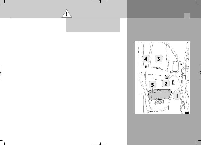
Двери
1.Ручка стеклоподъемника.
2.Рычаг дверного замка.
3.Ручка двери.
4.Кнопка блокировки замка.
5.Вещевой ящик.
Возможен несчастный случай: во время движения автомобиля двери должны быть плотно закрыты.


Приборная панель
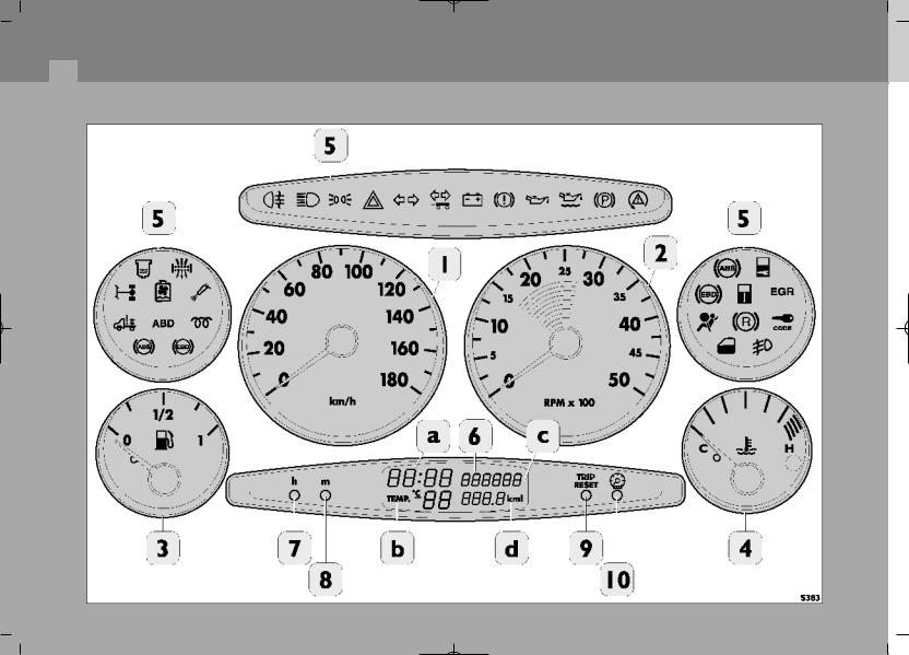
Соседние файлы в предмете [НЕСОРТИРОВАННОЕ]
- #
- #
- #
- #
- #
- #
- #
- #
- #
- #
- #