- Manuals
- Brands
- Foxconn Manuals
- Motherboard
ManualsLib has more than 388 Foxconn Motherboard manuals
Click on an alphabet below to see the full list of models starting with that letter:
4
5
6
7
8
9
A
B
C
D
E
F
G
H
I
K
M
N
P
Q
R
T
W
X
Z
Popular manuals
78 pages
G31MXP User Manual
77 pages
G31MV-K User Manual
66 pages
H61MXE Series User Manual
47 pages
G31MX User Manual
73 pages
G41MXE Series User Manual
72 pages
H61MX Series User Manual
2 pages
G33M Quick Install Manual

72 pages
H55MXV User Manual
73 pages
45CMX User Manual
75 pages
G41MX 2.0 User Manual
51 pages
G41MD User Manual
73 pages
H61M-S User Manual
71 pages
H61MXL Series User Manual
112 pages
H61MXV Series User Manual
108 pages
M61PMV Series User Manual
68 pages
H61S Series User Manual

71 pages
H61MD Series User Manual
29 pages
945GZ7MC User Manual

44 pages
A6VMX Series User Manual

109 pages
H67MP series User Manual
Models
Document Type
4
400M01 Series

Manual
45CMV series
User Manual
45CMV-K
User Manual
45CMX
User Manual
45CMX-K
User Manual
45CS
User Manual
45CSX
User Manual
45CTD
Quick Installation
45CTP
Quick Installation
45GMX
User Manual
46GMX-S
User Manual
5
520A
User Manual
560A
User Manual
6
600A01 series
User Manual
6100M2MA series
User Manual
648C7MF series
User Manual
648FX4MR-ES Layout
Easy Installation Manual
648FX7MF series
User Manual
6497MB Series
User Manual
6497MC series
User Manual • User Manual
650M02 Series
Manual
651M02 Series
Manual
661FX4MR-ES Layout
Easy Installation Manual
661FX7MF series
User Manual
661FX7MJ Series
User Manual • Manual
661FXME
Easy Installation Manual
661GX7MJ Series
User Manual • Manual
661GX7MJ-H
Manual
661M03 Series
User Manual
661MXPlus
Easy Installation Manual
661MXPro
Easy Installation Manual
671MX Series
User Manual
7
720A Series
User Manual
720AL Series
User Manual
720AX
User Manual
720AX-K
User Manual
720MX Series
User Manual
720MX-K
User Manual
730A Series
User Manual
755 series
User Manual
755A01 series
User Manual
755FXK8AA series
User Manual
760A01 series
User Manual
760GXK8MB series
User Manual • User Manual
760GXK8MC
Manual
761GXK8MC
User Manual
761GXM2MA series
User Manual
8
845GV4MR-ES
Easy Installation Manual
845GVME-S
Easy Installation Manual
848P7MB
Manual
865A01 G series
User Manual
865A01 PE series
User Manual
865A01 series
User Manual
865G
User Manual
865G7MF Series
Manual
865GPE7MC
User Manual
865GV
User Manual
865GV7MF Series
Manual
865GVPE7MC
User Manual
865M01 G Series
User Manual
865M01 GV series
User Manual
865M01 PE Series
User Manual
865M01 series
User Manual
865PE7MC
User Manual
865PE7MF Series
Manual
875A02
Manual
9
910GL7MH Series
Manual
915G
Manual
915G7MC
User Manual
915G7MH Series
Manual
915GL
Manual
915GL7MC
User Manual
915GL7MH Series
Manual
915GV
Manual
915GV7MC
User Manual
915GV7MH Series
Manual
915M03 Series
Manual
915M07 series
User Manual
915P
Manual
915P7MC
User Manual
915P7MH Series
Manual
915PL
Manual
915PL7AE series
User Manual
915PL7MH Series
Manual
925XE7AA series
User Manual
945G
User Manual
945G7AD
Manual
945G7MD
User Manual • User Manual
945G7ME
Quick Install
945GZ
User Manual
945GZ7MC
User Manual
945P7AA series
User Manual
945P7AD Manual
Manual
945P7MC
User Manual
945P7MD
User Manual • User Manual
945PL
User Manual
946GZ User’s manual
Manual
955X7AA series
User Manual
975X7AB
Manual
A
A55A Series
User Manual
A55M Series
User Manual
A55MX Series
User Manual
A690GM2MA
User Manual • Quick Install
A690VM2MA
User Manual • Quick Install
A6GMV Series
User Manual
A6VMX Series
User Manual • Quick Installation
A6VMX-K
User Manual
A6VMX-S
User Manual
A74GA Series
User Manual
A74ML 3.0 Series
User Manual
A74ML Series
User Manual
A74ML-K
User Manual
A74ML-K 3.0
User Manual
A74MX Series
User Manual
A74MX-K
User Manual
A74MX-S
User Manual
A75A Series
User Manual
A75M Series
User Manual
A75MX Series
User Manual
A76GMV
User Manual
A76ML Series
User Manual
A76ML-K
User Manual
A76ML-K 3.0
User Manual
A78AX 3.0 Series
User Manual
A78AX Series
User Manual
A78AX-K
User Manual
A78AX-S
User Manual
A79A Series
User Manual
A79A-S
User Manual
A7DA 3.0 Series
User Manual
A7DA Series
User Manual
A7DA-S
User Manual
A7DA-S 3.0
User Manual
A7GM Series
User Manual
A7GM-S
User Manual
A7GM-S 2.0
User Manual • User Manual
A7GMP series
User Manual
A7GMP-S
User Manual
A7GMX Series
User Manual
A7GMX-K
User Manual
A7GMX-S
User Manual
A7VA Series
User Manual
A7VA-S
User Manual
A7VML Series
User Manual
A7VML-K
User Manual
A7VMX Series
User Manual
A7VMX-K
User Manual
A7VMX-S
User Manual
A85GM Series
User Manual
A88GM Deluxe
User Manual
A88GM Series
User Manual
A88GMV Series
User Manual
A88GMX Series
User Manual
A9DA Series
User Manual
A9DA-S
User Manual
AHD1S
User Manual
AHD1S-K
User Manual
B
B75M
User Manual • User Manual
B75MX Series
User Manual
B75MX-D
User Manual
B75MX-S
User Manual
BLACKOPS
User Manual
Bloodrage
User Manual
Bloodrage GTI
User Manual
C
C51XEM2AA
User Manual
Cinema Deluxe
User Manual
Cinema II Deluxe
User Manual
Cinema II Premium
User Manual
Cinema II Series
User Manual
Cinema Premium
User Manual
D
D250S
User Manual • User Manual
D255
User Manual
D255-S
User Manual
D270S
User Manual • User Manual
D41S series
User Manual
D41S-V
User Manual
D42S
User Manual
D42S 3.0
User Manual
D51S series
User Manual
D51S-V
User Manual
D52S
User Manual
D52S 3.0
User Manual
D70S Series
User Manual
D70S-D
User Manual
D70S-P
User Manual
D70S-PD
User Manual
D70S-V
User Manual
D70S-VD
User Manual
Destroyer
User Manual
E
ELA
User Manual
ELA Series
User Manual
ELECTRIC DRYER
Manual
F
FlamingBlade
User Manual
FlamingBlade GTI
User Manual
FlamingBlade Series
User Manual
Flat Panel Monitor
User Manual
G
G31 MX series
User Manual • Quick Installation
G31AX SERIES
User Manual
G31AX-K
User Manual
G31MV Series
User Manual
G31MV-K
User Manual
G31MX 2.0 Series
User Manual
G31MX-K
User Manual
G31MX-S
User Manual
G31MXP
User Manual
G31MXP-K
User Manual
G31S
User’s Manual & Installation And Servicing Instructions
G31S-K
User’s Manual & Installation And Servicing Instructions
G33M
Quick Install Manual
G41AP Series
User Manual
G41AP-S
User Manual
G41M Series
User Manual
G41M-S
User Manual
G41M-V
User Manual
G41MD
User Manual • User Manual
G41MD-V
User Manual
G41MX
User Manual
G41MX 2.0
User Manual
G41MX-F 2.0
User Manual
G41MX-K
User Manual
G41MX-K 2.0
User Manual
G41MXE
User Manual
G41MXE-K
User Manual
G41MXP Series
User Manual
G41MXP-V
User Manual
G41S Series
User Manual
G41S-K
User Manual
G43MX Series
User Manual
G43MX-K
User Manual
G45M Series
User Manual
G45M-S
User Manual
G45MG Series
User Manual
G46 GMX series
User Manual
G9657MA series
Manual
G9657MC
User Manual
H
H55A Series
User Manual
H55M Series
User Manual
H55M-S
User Manual
H55M-V
User Manual
H55MX-S Series
User Manual
H55MXV LE
User Manual
H55MXV Series
User Manual
H61A Series
User Manual
H61AP Series
User Manual
H61AP-S
User Manual
H61M Series
User Manual • User Manual
H61M-S
User Manual
H61MD Series
User Manual
H61MD-V
User Manual
H61MX EL
User Manual • User Manual
H61MX Series
User Manual • User Manual
H61MXE Series
User Manual
H61MXE-K
User Manual
H61MXE-S
User Manual
H61MXE-V
User Manual
H61MXL Series
User Manual
H61MXP Series
User Manual
H61MXV Series
User Manual
H61S Series
User Manual
H67A Series
User Manual
Manual
H67A-S
User Manual
Manual
H67M Series
User Manual • User Manual
H67M-S
User Manual • User Manual
H67M-V
User Manual • User Manual
H67MP series
User Manual
H67MXV Series
User Manual • User Manual
H67S Series
User Manual • User Manual • User Manual
H77M Series
User Manual
H77M-S
User Manual
H77MXV Series
User Manual
H77MXV-D
User Manual
H81MX Series
User Manual
H81MXV Series
User Manual
H87MX Series
User Manual
I
IGPSK7MA series
User Manual
Inferno Katana
User Manual
Inferno Katana GT..
User Manual
Inferno Katana GTI
User Manual
Inferno Katana Series
User Manual
K
K7S741GXMG
Easy Installation Manual
K7S741GXMG-6L
Easy Installation Manual • Specification
K7S741MG
Easy Installation Manual
K7S741MG-6L
Easy Installation Manual
K8M890M2MA
User Manual
K8S755A series
Manual
K8S760MG series
User Manual
K8T890M2AB
Quick Install
M
M61PML Series
User Manual
M61PML-K
User Manual
M61PMP Series
User Manual
M61PMP-K
User Manual
M61PMV Series
Manual • User Manual
M61PMV-E
Manual • User Manual
M61PMVK
User Manual
M61PMX series
User Manual
M78A Series
User Manual
M78MX Series
User Manual
M7PMX series User’s
Manual
M7VMX series
User Manual
M7VMX-K
User Manual
M7VMX-S
User Manual
MARS
User Manual
MCP61PM2MA
User Manual
MCP61SM2MA
User Manual
MCP61VM2MA
User Manual
MF2
User Manual
N
N570SM2AA
User Manual
NF3250GK8AA
Manual
NF3250K8AA
Manual
NF3GK8MA series
User Manual
NF3UK8MA
User Manual
NF4K8AC series
User Manual
NF4K8MC
User Manual
NF4SK8AA series
Manual
NF4UK8AA series
User Manual
NF4UK8AC series
User Manual
NF4XK8MC
User Manual
P
P31A Series
User Manual • User Manual
P31A-G
User Manual
P31A-S
User Manual • User Manual
P31A-U
User Manual
P35A Series
User Manual
P35A-S
User Manual
P35AP-S Series
User Manual
P35AX Series
User Manual
P35AX-S
User Manual
P41A Series
User Manual
P41A-G
User Manual
P43A Series
User Manual
P43A-S
User Manual
P43AL Series
User Manual
P43AL-V
User Manual
P45A Series
User Manual
P45A-S
User Manual
P45AL Series
User Manual
P45AL-S
User Manual
P4M800P7MA series
User Manual
P4M800P7MB
Manual
P4M8907MA
Manual
P4M8907SA
User Manual
P55A
User Manual
P55A-S
User Manual
P55MX Series
User Manual
P67A Series
User Manual
P67A-S
User Manual
P9657AA
Manual
P9657AB User’s
Manual
P9657MA series
Manual
PL7MA User’s
Manual
Q
Q45M Series
User Manual
Q57M Series
User Manual
Q67M series
User Manual • User Manual
Q67M-S
User Manual
Q77M Series
User Manual • User Manual
Q9657MA series
Manual
Q9657MC
User Manual
Quantumian 1 Series
User Manual
Quantumian1
User Manual
R
R10-A1
User Manual
R10-H1
User Manual
R20-A1
User Manual
R20-H1
User Manual
R30-A1
User Manual
R30-H1
User Manual
R40-A1
User Manual
R40-H1
User Manual • Specification
R50-A1
User Manual
R50-H1
User Manual
Rattler
User Manual
Rattler GTI
User Manual
Rattler Series
User Manual
Renaissance
User Manual
Renaissance II
Manual
T
T20-H3
User Manual
T70S Series
User Manual
T70S-F
User Manual
T70S-V
User Manual
T70S-VF
User Manual
W
WinFast 6100K8MA Series
User Manual
WinFast 6150K8M Series
User Manual
WinFast 748K7AA
Installation Manual
X
X38A
User Manual
Z
Z68A-S Series
User Manual
Z75A Series
User Manual
Z75A-S
User Manual
Z75M-S Series
User Manual • User Manual
Z77A Series
User Manual
Z77A-S
User Manual
Вы можете бесплатно скачать инструкции в PDF для Foxconn Настольные компьютеры.
У нас есть 25 бесплатных инструкций в PDF для 25 Foxconn Настольные компьютеры.
-
a
-
n
-
r
-
t
В настоящее время вы находитесь на странице с руководствами Foxconn материнская плата. Выберите один из продуктов, чтобы сразу перейти к руководству по этому продукту. Не можете найти Foxconn ? Тогда попробуйте вбить в поле поиска Foxconn и модель, чтобы найти нужное руководство Foxconn. На ManualsPDF.ru в настоящее время имеется 30 руководств Foxconn . Самые популярные Foxconn материнская плата:
- Foxconn G41MXE
- Foxconn H61MX
- Foxconn H61MXV
Последнее добавленное руководство Foxconn было добавлено , и это Foxconn G41M.
-
Page 1
Инструкция для материнской платы Foxconn Q67M-S Перейти в карточку товара 8 800 775 98 98… -
Page 2
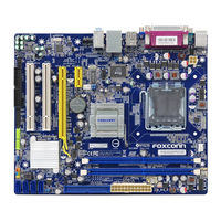
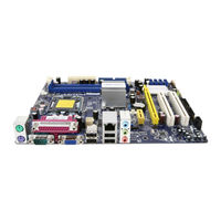
Q67M Series Motherboard User’s Manual… -
Page 3
Statement: This manual is the intellectual property of Foxconn, Inc. Although the information itself to inform the user of these changes. Trademark: All trademarks are the property of their respective owners. Version: User’s Manual V1.1 for Q67M Series mother�oard. Q67M Series mother�oard. -
Page 4: Declaration Of Conformity
Declaration of conformity HON HAI PRECISION INDUSTRY COMPANY LTD 66 , CHUNG SHAN RD., TU-CHENG INDUSTRIAL DISTRICT, TAIPEI HSIEN, TAIWAN, R.O.C. declares that the product Mother�oard Q67M-S Q67M-S is in conformity with accordance with 89/336 EEC-EMC Directive) distur�ance characteristics of information technology equipment Part 3: Limits (equipment input current <= 16A per phase)
-
Page 5
Declaration of conformity Trade Name: FOXCONN Model Name: Q67M-S Responsi�le Party: PCE Industry Inc. Type of Product: Mother�oard Manufacturer: HON HAI PRECISION INDUSTRY COMPANY LTD Address: 66 , CHUNG SHAN RD., TU-CHENG INDUSTRIAL DISTRICT, TAIPEI HSIEN, TAIWAN, R.O.C. Supplementary Information: must accept any interference received, including interference that may cause undesired operation. -
Page 6: Installation Precautions
Installation Precautions comes out as a spark which will quickly damage your electronic equipment. Please wear an electrostatic discharge (ESD) wrist strap when handling components such as a mother�oard, CPU or memory. CPU, memory, expansion cards or other peripherals. It is recommended to unplug the AC power cord from the power supply outlet.
-
Page 7: Table Of Contents
TABLE OF CONTENTS Chapter 1 Product Introduction …………….Layout………………….. Back Panel Connectors …………….Chapter 2 Hardware Install Install the CPU and CPU Cooler …………..7 Install the Memory ……………… Install an Expansion Card …………..Install other Internal Connectors …………13 Jumpers ………………..18 Chapter 3 BIOS Setup Main ………………….
-
Page 8
………….69 Intel® Matrix Storage Manager …………..71 Create a RAID Driver Diskette …………………………. Create RAID in BIOS…………….Install a New Windows XP …………..Technical Support : Support Website : http://www.foxconnchannel.com Support Website : http://www.foxconnsupport.com Worldwide online contact Support : http://www.foxconnsupport.com/inquiry.aspx CPU Support List : http://www.foxconnsupport.com/cpusupportlist.aspx Memory, VGA Compatibility List :… -
Page 9
Thank you for �uying Foxconn Q67M Series mother�oard. Foxconn products are engineered to maximize computing power, providing only what you need for �reak-through performance. With advanced overclocking capa�ility and a range of connectivity features for today multi-media computing requirements, Q67M-S Q67M-S ena�les you to unleash more power from your computer. -
Page 10
® For the latest CPU information, please visit: http://www.foxconnsupport.com/cpusupportlist.aspx ® Chipset Intel Memory Expansion Slots 1 x PCI Express x16 slot 1 x PCI Express x1 slot Storage Q67 chipset: — 1 x Floppy connector Support hot plug and NCQ (Native Command Queuing ) Giga�it LAN chip Giga�it LAN chip Audio… -
Page 11
1 x TPM connector 1 x LPT connector Back Panel Connectors 1 x VGA port 1 x Serial port 1 x DVI-D port 8-channel Audio ports Hardware Monitor System voltage detection CPU/System temperature detection CPU/System fan speed detection CPU overheating warning CPU/System fan speed control PCI Express x1 Low power consumption and power management features… -
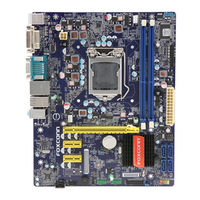
Page 12: Layout
1-2 Layout 13 Front Panel Connector 3. PCI Express x16 Slot PCI Express x1 Slot PCI Slots 17. Floppy Connector 6. Front Audio Connector 18. CIR Connector 7. Speaker Connector 19. LPT Connector 8. S/PDIF Out Connector 9. Intel® ME Jumper (MFG) DDR3 DIMM Slots 11.
-
Page 13: Back Panel Connectors
1-3 Back Panel Connectors Serial Port Port DVI-D Port Port LAN Port Line Out Line In Rear Speaker Su�woofer Side Speaker Microphone In USB Ports VGA Port USB Ports Audio Ports 1. PS/2 Keyboard Port 2. USB Ports 3. Serial Port 4.
-
Page 14
7. RJ-45 LAN Port The Ethernet LAN port provides Internet connection at up to data rate. Active Link Left: Active Right: Link LAN Type Status Description Status Description No Link No Link Green Data Green Blinking Activity Orange… -
Page 15
This chapter introduces the hardware installation process, including the installation of the CPU, memory, power supply, slots, pin headers and the mounting of jumpers. Caution should �e exercised during the installation of these modules. Please refer to the mother�oard layout prior to any installation and read the contents in this chapter carefully. -
Page 16: Install The Cpu And Cpu Cooler
2-1 Install the CPU and CPU Cooler Read the following guidelines �efore you �egin to install the CPU : installing the CPU to prevent hardware damage. (Or you may locate the notches on �oth sides of the CPU and alignment keys on the CPU socket.) and damage of the CPU may occur.
-
Page 17
Follow the steps to install the CPU onto the CPU socket : Before installing the CPU, make sure to turn off the computer and unplug the power cord from the power outlet to prevent damage to the CPU. 1. Release the CPU socket lever. Release the CPU socket lever. -
Page 18: Install The Cpu Cooler
Install the CPU Cooler Follow the steps �elow to correctly install the CPU cooler on the mother�oard. 1. Apply and spread an even ther- mal grease on the surface of CPU. cooler to the holes of the mother- �oard, push them straight down from the top, and the �olts will �e fastened on the mother�oard.
-
Page 19: Install The Memory
2-2 Install the Memory Read the following guidelines �efore you �egin to install the memory : memory of the same capacity, �rand, speed, and chips �e used. installing the memory to prevent hardware damage. one direction. If you are una�le to insert the memory, switch the direction. This mother�oard provides four DDR3 memory sockets and supports Dual Channel Technology.
-
Page 20
Before installing a memory module, make sure to turn off the computer and unplug the Before installing a memory module, make sure to turn off the computer and unplug the power cord from the power outlet to prevent damage to the memory module. Be sure to install DDR3 DIMMs on this mother�oard. -
Page 21: Install An Expansion Card
2-3 Install an Expansion Card that came with your expansion card. installing an expansion card to prevent hardware damage. PCI Express x16 PCI Express x1 Follow the steps below to correctly install your expansion card in the expansion slot. 1. Locate an expansion slot that supports your card. Remove the metal slot cover from the chas- sis �ack panel.
-
Page 22: Install Other Internal Connectors
2-4 Install other Internal Connectors Power Connectors This mother�oard uses an ATX power supply. In order not to damage any device, make sure all the devices have �een installed properly �efore applying the power supply. 24-pin ATX Power Connector : PWR1 PWR1 is the ATX power supply connector.
-
Page 23
Audio Connector : F_AUDIO The audio connector supports HD Audio standard. It AUD_GND PRESENCEJ provides the Front Audio output choice. SENSE1_RETURN SENSE_SEND EMPTY F_AUDIO S/PDIF OUT Connector : SPDIF_OUT EMPTY SPDIF_OUT The connector is used for S/PDIF output. SPDIF_OUT EMPTY Speaker Connector : SPEAKER The speaker connector is used to connect speaker of the chassis. -
Page 24
Front Panel Connector : FP1 This mother�oard includes one connector for connecting the front panel switch and LED Indicators. HDD-LED PWR-LED Hard Disk LED Connector (HDD-LED) RESET-SW PWR-SW Connect to the chassis front panel IDE indicator LED. EMPTY pin connector is directional with +/- sign. Reset Switch (RESET-SW) Attach the connector to the Reset switch on the front panel of the case;… -
Page 25
TPM Connector : TPM The TPM (Trusted Platform Module) provides the a�ility LFRAMEn EMPTY to the PC to run applications more secure and to make LRESETn NC_3 transactions and communication more trustworthy. To LAD3 utilize this function, you should purchase additional LAD1 device and install it. -
Page 26: Jumpers
2-5 Jumpers For some features needed, users can change the jumper settings on this mother�oard to modify them. This section explains how to use the various functions of this mother�oard �y changing the jumper settings. Users should read the following content carefully prior to modifying any jumper setting.
-
Page 27
Intel ® ME Jumper: MFG This mother�oard uses MFG jumper to ena�le or disa�le Intel® Management Engine function. Intel® Management Engine (ME) is an em�edded microcontroller located in Intel chipset. It provides latest IT management features such as Intel® AMT, that allows to improve management of corporate assets. -
Page 28
This chapter tells how to change system settings through the BIOS Setup menus. Detailed descriptions of the BIOS param- eters are also provided. You have to run the Setup Program when the following cases occur : 1. An error message appears on the screen during the system Power On Self Test (POST) process. -
Page 29: Enter Bios Setup
Enter BIOS Setup The BIOS is the communication �ridge �etween hardware and software, correctly setting up the BIOS parameters is critical to maintain optimal system performance. Power on the computer, Press <DEL> to enter Setup, <F7> to Boot Menu the screen, you can press <DEL> key to enter Setup. We do not suggest that you change the default values in the BIOS Setup, and we shall not �e responsi�le for any damage which resulted from the change you made.
-
Page 30: Main
Main Aptio Setup Utility — Copyright (C) 2010 American Megatrends, Inc. Main Advanced Chipset Boot Power Health Security Save & Exit Main System �ate System �ate [Tue 10/28/2010] Set the �ate. Use Tab to System Time [09:09:21] switch between �ate elements. Access Level Administrator Model Name Q67M ME Version 7.0.0.1152 BIOS Version A61F116E Build �ate and Time 12/14/2010 16:17:27 Halt On [All, but keyboard] CPU Brand Name: CPU Brand Name: CPU Brand Name: → ← : Select Screen Genuine Intel(R) CPU 0 @ 2.40GHz ↑ ↓…
-
Page 31
[No Errors]: No error can result in system halt. [All, �ut key�oard]: All errors �ut key�oard can result in system halt. It displays the current CPU name. This item displays the total memory size. The size is depending on how many memory mod- ules are installed in your system �efore powering on. -
Page 32: Advanced
Aptio Setup Utility — Copyright (C) 2010 American Megatrends, Inc. Main Advanced Chipset Boot Power Health Security Save & Exit Advanced ▶ Fox Control Center Fox Control Center ▶ Trusted Computing ▶ CPU Configuration ▶ Performance Tuning ▶ SATA Configuration ▶ Intel IG� SWSCI OpRegion ▶ USB Configuration ▶ AMT Configuration ▶ Onboard �evice Configuration → ← : Select Screen ↑ ↓ : Select Item Enter: Select +/-: Change Opt. F1: General Help F2: Previous Values F3: Optimized �efaults F4: Save & Exit ESC: Exit Version 2.02.1205. Copyright (C) 2010 American Megatrends, Inc. Press <Enter> to go to relative su�menu. Fox Control Center Aptio Setup Utility — Copyright (C) 2010 American Megatrends, Inc.
-
Page 33
Aptio Setup Utility — C opyright (C) 2010 American Megatrends, Inc. Advanced TPM Configuration Enable or �isable TPM TPM SUPPORT [�isabled] support. O.S. will not show TPM. Reset of platform is required. Current TPM Status Information NO TPM Hardware → ← : Select Screen ↑ ↓ : Select Item Enter: Select +/-: Change Opt. F1: General Help F2: Previous Values F3: Optimized �efaults F4: Save & Exit ESC: Exit Version 2.02.1205. Copyright (C) 2010 American Megatrends, Inc. This item is used to decide whether to support TPM (Trusted Platform Module) device func- device on the mother�oard and set this item to [Ena�led], then save changing and reset your computer, otherwise the operation system can not show the relative information. -
Page 34
C1E represents Enhanced HALT State. It is a feature which CPU uses to reduce power consumption when in halt state. C1E drops the CPU’s multiplier and voltage to lower levels when a HLT (halt) command is issued. This item is used to ena�le/disa�le the C1E support. This item is used to ena�le/disa�le the Hyper-Threading Technology feature. -
Page 35
You can select the EIST (Processor Power Management, PPM) through this item. Enhanced Intel SpeedStep® technology (EIST) allows the system to dynamically adjust processor voltage and core frequency, which can result in decreased average power consumption and decreased average heat production. There are some system requirements must �e met, including CPU, chipset, mother�oard, BIOS and operation system. -
Page 36
Aptio Setup Utility — Copyright (C) 2010 American Megatrends, Inc. Advanced Select �VMT Mode used by Intel IG� SWSCI OpRegion Configuration Internal Graphics �evice. �VMT Mode Select [�VMT Mode] �VMT/FIXE� Meory [256MB] Spread Spectrum Clock [�isabled] → ← : Select Screen ↑ ↓ : Select Item Enter: Select +/-: Change Opt. F1: General Help F2: Previous Values F3: Optimized �efaults F4: Save & Exit ESC: Exit Version 2.02.1205. Copyright (C) 2010 American Megatrends, Inc. This item is used to select DVMT Mode used �y Internal Graphics Device. This item is used to select DVMT/FIXED Meory size used �y Internal Graphics Device. -
Page 37
This item is used to ena�le or disa�le the support for USB devices. This item is used to ena�le the support for USB devices on legacy OS. If you have a USB key�oard or mouse, set to ena�led. [Ena�led]: This option will ena�le the legacy USB support. [Disa�led]: This option will keep USB devices availa�le only for EFI applications. -
Page 38
Aptio Setup Utility — Copyright (C) 2010 American Megatrends, Inc. Advanced Onboard �evice Configuration Intel Onboard LAN Controller [Enabled] Onboard LAN PXE OpROM [�isabled] Audio Configuration Azalia H� Audio [Enabled] ▶ Super IO Configuration → ← : Select Screen ↑ ↓ : Select Item Enter: Select +/-: Change Opt. F1: General Help F2: Previous Values F3: Optimized �efaults F4: Save & Exit ESC: Exit Version 2.02.1205. Copyright (C) 2010 American Megatrends, Inc. This item is used to ena�le or disa�le the on�oard LAN controller. This item is used to ena�le or disa�le on�oard LAN �oot option ROM. -
Page 39
This item is used to ena�le or disa�le the Floppy disk controller. This item is used to ena�le or disa�le the serial port (COM). This item shows the resource assigned to the serial port. This item is used to select an optimal settings for the serial port. This item is used to change the serial port mode. -
Page 40: Chipset
Chipset Aptio Setup Utility — C opyright (C) 2010 American Megatrends, Inc. Main Advanced Chipset Boot Power Health Security Save & Exit Chipset ▶ North Bridge North Bridge Parameters ▶ ME Subsystem → ← : Select Screen ↑ ↓ : Select Item Enter: Select +/-: Change Opt. F1: General Help F2: Previous Values F3: Optimized �efaults F4: Save & Exit ESC: Exit Version 2.02.1205. Copyright (C) 2010 American Megatrends, Inc. Press <Enter> to go to its su�menu. Aptio Setup Utility — C opyright (C) 2010 American Megatrends, Inc. Chipset Memory Information Low MMIO resources align at…
-
Page 41
This item is used to ena�le or disa�le the VT-d feature. Intel ® Virtualization Technology for Directed I/O (VT-d) can help end users improve security and relia�ility of the systems and also improve performance of I/O devices in virtualized environment. Initial Graphic Adapter This item is used to select which graphics controller is used as the primary �oot device. -
Page 42
Aptio Setup Utility — Copyright (C) 2010 American Megatrends, Inc. Chipset Integrated Clock Chip Integrated Clock Chip Configuration Enabled/�isabled. ICC OverClocking Lib Version 7.0.0.29 Number of ICC Profiles : Current ICC Profile Index : ICC Enable [Enabled] ICC Set Clock Enables [Enabled] Send ICC Lock Registers [Enabled] Set Profile [Enabled] Set Profile Index → ← : Select Screen ▶ ICC OverClocking ↑ ↓ : Select Item Enter: Select +/-: Change Opt. F1: General Help F2: Previous Values F3: Optimized �efaults F4: Save & Exit ESC: Exit Version 2.02.1205. Copyright (C) 2010 American Megatrends, Inc. This item is used to ena�le or disa�le the Integrated Clock Chip(ICC). -
Page 43: Boot
Boot Aptio Setup Utility — C opyright (C) 2010 American Megatrends, Inc. Main Advanced Chipset Boot Power Health Security Save & Exit Boot Boot Configuration Select the keyboard NumLock Bootup Numlock State [On] state Quiet Boot [Enabled] CSM16 Module Version 07.64 Boot Option Priorities Boot Option #1 [SATA: W�C W�1600AA…] Hard �rive BBS Priorities → ← : Select Screen ↑ ↓ : Select Item Enter: Select +/-: Change Opt. F1: General Help F2: Previous Values F3: Optimized �efaults F4: Save & Exit ESC: Exit Version 2.02.1205. Copyright (C) 2010 American Megatrends, Inc. availa�le settings are: On (default) and Off. This item is used to ena�le/disa�le the quiet �oot.
-
Page 44: Power
Power Aptio Setup Utility — C opyright (C) 2010 American Megatrends, Inc. Main Advanced Chipset Boot Power Health Security Save & Exit Power ACPI Sleep State [S3] Select the highest ACPI sleep state the system will enter Resume By PS2 Keyboard [Enabled] when the SUSPEN� button is Resume By Onboard LAN [�isabled] pressed. Resume By USB �evice(s) [Enabled] Resume By PCI PME [�isabled] Resume By PCIE PME [�isabled] Resume By RTC [�isabled] Energy-using Products [Enabled] Restore AC Power Loss [Power Off] → ← : Select Screen ↑ ↓ : Select Item Enter: Select +/-: Change Opt.
-
Page 45
Disa�led: Normal ACPI function. This item is used to set which state the PC will take with when it resumes after an AC power loss. -
Page 46: Health
Health Aptio Setup Utility — C opyright (C) 2010 American Megatrends, Inc. Main Advanced Chipset Boot Power Health Security Save & Exit Health Case Open Warning [�isabled] Case Open Warning CPU Temperature : +19 C System Temperature : +30 C CPU Fan Speed : 2008 RPM System Fan 1 Speed : N/A CPU Vcore : +0.972 V �RAM Voltage : +1.608 V +12V SYS : +11.971 V +5V SYS : +3.002 V VBAT : +3.120 V Smart Fan Function [�isabled] → ← : Select Screen ↑ ↓ : Select Item Enter: Select +/-: Change Opt.
-
Page 47: Security
Security Aptio Setup Utility — C opyright (C) 2010 American Megatrends, Inc. Main Advanced Chipset Boot Power Health Security Save & Exit Security Set Setup Administrator Password �escription Password If ONLY the Administrator’s password is set, then this only limits access to Setup and is only asked for when entering Setup. If ONLY the User’s password is set, then this is a power on password and must be entered to boot or enter Setup. In Setup the User will have Administrator rights. The password must be 3 to 20 characters long. Administrator Password → ← : Select Screen User Password ↑ ↓ : Select Item Enter: Select H�� Security Configuration +/-: Change Opt. H�� 0:W�C W�1600AA F1: General Help F2: Previous Values F3: Optimized �efaults F4: Save & Exit ESC: Exit Version 2.02.1205. Copyright (C) 2010 American Megatrends, Inc.
-
Page 48: Save & Exit
Aptio Setup Utility — C opyright (C) 2010 American Megatrends, Inc. Main Advanced Chipset Boot Power Health Security Save & Exit Save & Exit Reset system setup a fter saving Save Changes and Reset the changes. �iscard Changes and Reset Restore �efaults Boot Override SATA: W�C W�1600AAJS-22B4A0 → ← : Select Screen ↑ ↓ : Select Item Enter: Select +/-: Change Opt.
-
Page 49
The utility CD that came with the mother�oard contains useful software and several utility drivers that enhance the mother�oard features. This chapter includes the following information: Note : Because each module is independent, so the section num�er will �e reorganized and unique to each module, please understand. -
Page 50: Utility Cd Content
Utility CD content This mother�oard comes with one Utility CD. You can simply put it into your CD/DVD-ROM drive, and the main menu will �e displayed on your PC screen to guide you how to install. Use these options to install all the drivers for your system. You should install the drivers in order, and you need to restart your computer after all the drivers have �een installed.
-
Page 51
Manual Installation Step �y Step Automatic Installation �y One Click Drop to System Tray Exit the program Visit Foxconn’s Show Utilities Show Drivers Browse CD View the User’s Manual We�site Choose the items you want to Install… -
Page 52
2. Utility Use these options to install additional software programs. And click “User’s Manual“ �utton to view the product manual. -
Page 53: Fox One
FOX ONE FOX ONE is a powerful utility for easily modifying system settings. It also allows users to monitor various temperature values, voltage values, frequencies and fan speeds at any time. With FOX ONE, you can : CPU voltages, fan speeds, and other system performance options. Depending on hardware support, voltage monitoring and Fox Intelligent Stepping features are optional and only supported in some models.
-
Page 54
Show CPU Tool�ar Information Alert Lamp Switch Button Skin Button Exit Minimum Homepage Monitor Frequency/Voltage/Fan speed/Temperature value Toolbar Use the tool�ar to navigate to other pages. Alert Lamp When the system is in healthy state, the color of alert lamp is green. When the system is in a�normal state, the alert lamp color is red. -
Page 55
Exit Click this �utton to exit the program. Minimum Click this �utton to drop the FOX ONE to Windows system tray located at the lower right corner of your screen. Click this �utton to visit Foxconn mother�oard we�site : http://www.foxconnchannel.com… -
Page 56
1). Monitor interval (ms) : which are to are to �e displayed on Simple Mode screen. Minimum value is 1 second. To select which message of system settings are to �e displayed in the Simple Mode. Messages such as CPU frequency, voltage…etc., they can �e displayed one �y one in Simple Mode. -
Page 57
Step 1 : Click Cali�ration icon, a message pops out to ask for continue. Select Yes. Later on, when the FOX ONE program is activated, and F.I.S. feature (in CPU Page) is also ena�led, FOX ONE will automatically adjust your CPU clock according to your system loadings. -
Page 58
This page lets you select (or overclock) CPU clock to meet the current performance level of the system. The fastest and suita�le CPU clock running for current system can �e calculated �y FOX ONE automatically or manually input �y yourselves. Manual : You can press the up/down �utton to adjust your CPU clock. -
Page 59
You can see the system is raising CPU clock until the system hangs. Push RESET �utton on the front panel of your system to restart the computer. Run FOX ONE program again, it will inform you the previous test found recommended CPU clock for your system. -
Page 60
Select FOX Intelligent Stepping will allow your system to automatically adjust your CPU clock rate �ased on different system loadings. For example, if you select Power Gaming, CPU clock will �e driven to run at its maximum speed. While in Energy Saving, CPU will lower down its speed to a minimum. -
Page 61
This page lets you to set CPU high limit temperature and ena�le the alert function. Go to Limit Show current CPU Setting page temperature value Ena�le alert function when the CPU temperature is higher than high limit value Show current high limit value of the CPU temperature Set high limit �y… -
Page 62
This page lets you to set CPU fan low limit rpm and ena�le the alert function. Show current CPU fan rpm value Ena�le alert function when the CPU fan runs slower than the low limit rpm value Show current low limit rpm value of CPU fan Set low limit rpm �y dragging the lever… -
Page 63
This page lets you to set FAN1 fan low limit rpm and ena�le the alert function. Show current FAN1 fan rpm value Ena�le alert function when the FAN1 fan runs slower than low limit rpm value Show current low limit rpm value of FAN1 fan Set low limit rpm �y dragging the lever… -
Page 64
This page lets you ena�le Smart Fan function or set the fan speed �y manual. Go to Fan page Ena�le or disa�le smart fan function Set fan speed �y dragging the lever Apply the changes… -
Page 65: Fox Liveupdate
FOX LiveUpdate is a useful utility to �ackup and update your system BIOS, drivers and utilities �y local or online. Supporting Operating Systems : Please set the BIOS setting “BIOS Write Protect” or “Super BIOS Protect” to [Disa�led] when running this application. 1.
-
Page 66
1-2 Local Update — Backup which it is stored, prevented that you may need them to recover your BIOS later. Click here 1-3 Local Update — Update BIOS) �efore the setup wizard starts. FOX LiveUpdate can automatically �ackup old BIOS �efore update. This feature can �e… -
Page 67: Online Update
2. Online Update 2-1 Online Update — Update BIOS This page lets you update your system BIOS from Internet. Click “start”, it will search the new Click here Current information Search new BIOS from Internet Select BIOS to update Browse detailed information Update BIOS Close the window…
-
Page 68
Select the driver to update Browse detailed information Install the selected driver Close the window 2-3 Online Update — Update Utility This page lets you update utilities from Internet. Click “start”, it will search the new utilities from Click here Current information Search new utilities from Internet… -
Page 69
2-4 Online Update — Update All This page lets you update your system drivers from Internet. Click “start”, it will search all new Click here Current information Search all new BIOS/ drivers/utilities from Internet Browse detailed BIOS information Browse detailed driver information Browse detailed utility information… -
Page 70
This page lets you set auto search options. After you ena�le the auto search function, FOX message on the task �ar to inform you to do the next step. Click here Set auto search options Set auto search the latest FOX LiveUpdate Select search which kind of… -
Page 71
auto search from internet and prompt you to install the new version. Prompt you to install the new FOX LiveUpdate This page lets you set the �ackup BIOS location and determine if the FOX LiveUpdate can auto determine if the FOX LiveUpdate can auto run when the system starts up. -
Page 72
and without any interruption. Click here Select which BIOS ROM mother�oard with �ackup BIOS ROM ) Select to clear CMOS Reset to default value Apply the changes We recommend that you had �etter keep the default setting unchanged to avoid any damage. -
Page 73: Fox Logo
FOX LOGO FOX LOGO is a simple and useful utility to �ackup, change and delete the �oot time Logo. The �oot Logo is the image that appears on screen during POST (Power-On Self-Test). change the �oot time Logo. Boot time Logo will �e displayed if you ena�le the BIOS Supporting Operating Systems : Main screen Exit…
-
Page 74: Fox Dmi
FOX DMI FOX DMI is a full Desktop Management Interface viewer, and it provides three DMI data formats : Report, Data Fields and Memory Dump. With DMI information, system maker can easily analyze and trou�leshoot your mother- �oard if there is any pro�lem occurred. Supporting Operating Systems : Please operate this utility as the comments shows.
-
Page 75
This chapter will include the following information : Introduction ® Matrix Storage Manager… -
Page 76
system. (Windows Vista has in-�ox driver �y its own and can skip this step). What kinds of hardware and software you need here : 3. Several SATA hard disks. A mother�oard driver CD. 6. Windows XP or Vista Install CD. -
Page 77
RAID (Redundant Array of Independent Disks) is a method for computer data storage schemes that divide and/or replicate data among multiple hard drives. RAID can �e designed to provide increased data relia�ility (fault tolerance) or increased I/O ® (input/output) performance, or �oth. The mother�oard comes with the Intel PCH. -
Page 78
RAID 0 (Stripe) mem�er fails, it affects the entire array. The disk array data capacity is equal to the num�er of drive mem�ers times the capacity of the smallest mem�er. The striping RAID 1 (Mirror) RAID 1 writes duplicate data onto a pair of drives and reads �oth sets of data in parallel. -
Page 79
® Intel ® The Intel capacity, or data safety provided �y different RAID functions. In this section, we will use four SATA hard disks as an example to guide you how to second volume will also �e well descri�ed. In each screen, there is also a message �ar a�out each key’s function, such as <Ta�>, <Enter>, <Del>…etc. -
Page 80
If you want to install a �rand new Windows XP on a AHCI or RAID system, you need to a RAID driver diskette for use in installing your Windows XP system. Windows Vista has native RAID driver in itself, you can skip these steps. drive A:, this diskette will �e formatted later. -
Page 81
6. You can input a volume la�el for this diskette, click message. RAID driver into this diskette. Later, when in the process of installing Windows XP in your RAID system, it will ask you a RAID device. Serial ATA Hard Disks : ca�les. -
Page 82: Create Raid In Bios
1. Enter the BIOS setup �y pressing <DEL> key during the POST(Power On Self Test). tion to [RAID Mode]. Aptio Setup Utility — C opyright (C) 2010 American Megatrends, Inc. Advanced SATA Configuration (1) I�E Mode. (2) AHCI Mode. (3) RAI� Mode. SATA Mode [RAI� Mode] SATA Port1 Not Present SATA Port2 Not Present SATA Port3 Not Present SATA Port4 Not Present SATA Port5 Not Present → ←…
-
Page 83: Create Raid Volume
Create RAID Volume Create RAID 0 (1st Volume) 1. Select “1. Create RAID Volume” from the menu and press <Enter>. The menu appears : CREATE VOLUME MENU Name: RAID Level: Disks: Select Disks Strip Size: Capacity: Sync: Create Volume HELP Enter a unique volume name that has no special characters and is 16 characters or less.
-
Page 84
Disks system. CREATE VOLUME MENU Name: RAID Level: Port Drive Model Serial # Size Status Non-RAID Disk Non-RAID Disk SAMSUNG HD161HJ Non-RAID Disk Non-RAID Disk Non-RAID Disk CREATE VOLUME MENU Name: RAID Level: Port Drive Model Serial # Size Status Non-RAID Disk Non-RAID Disk SAMSUNG HD161HJ… -
Page 85
6. It is now entering “ ” menu. Use Up or Down arrow key to select the desired selected �ased on different applications. Some suggested choices are : CREATE VOLUME MENU Name: RAID Level: Disks: Select Disks Strip Size: Capacity: Sync: Create Volume HELP… -
Page 86
8. In “Create Volume” item, press <Enter>. CREATE VOLUME MENU Name: RAID Level: Disks: Select Disks Strip Size: Capacity: Sync: Create Volume Create Volume HELP Press ENTER to create the specified volume. A warning message will appear : Are you sure you want to create this volume ? (Y/N) : MAIN MENU 1. -
Page 87
Create RAID0 (2nd Volume) 1. Select “1. Create RAID Volume” from the menu and press <Enter>. The menu appears : CREATE VOLUME MENU Name: RAID Level: Disks: Select Disks Strip Size: Capacity: Sync: Create Volume HELP Enter a unique volume name that has no special characters and is 16 characters or less. -
Page 88
Disks second volume system. CREATE VOLUME MENU Name: RAID Level: Port Drive Model Serial # Size Status Non-RAID Disk Non-RAID Disk SAMSUNG HD161HJ Mem�er Disk Mem�er Disk Non-RAID Disk <Space> key to select them. Two signs will appear to indicate the selections. Press <Enter>… -
Page 89
6. It goes to “ at this time, you can not input any value in capacity as there is no additional volume availa�le. selected �ased on different applications. Some suggested choices are : CREATE VOLUME MENU Name: RAID Level: Disks: Select Disks Strip Size: Capacity:… -
Page 90
A message will appear : Are you sure you want to create this volume ? (Y/N) : MAIN MENU 1. Create RAID Volume 1. Create RAID Volume 3. Reset Disks to Non-RAID RAID Volume : Name Level Stripe Size Status Boota�le Normal Normal… -
Page 91: Create Raid
Create RAID 1 1. Select “1.Create RAID Volume” from the main menu and press <Enter>. Name CREATE VOLUME MENU Name: TryRAID1 RAID Level: Disks: Select Disks Strip Size: Capacity: Sync: Create Volume HELP Enter a unique volume name that has no special characters and is 16 characters or less.
-
Page 92
Disks” item. Press <Enter> to display the hard disks list for this RAID1 system. CREATE VOLUME MENU Name: TryRAID1 RAID Level: RAID1(Mirror) Port Drive Model Serial # Size Status Non-RAID Disk Non-RAID Disk SAMSUNG HD161HJ Non-RAID Disk Non-RAID Disk Non-RAID Disk to com�ine them as RAID1, then press <Space>… -
Page 93
6. It will skip “ ” menu for RAID1. CREATE VOLUME MENU Name: TryRAID1 RAID Level: RAID1(Mirror) Disks: Select Disks Strip Size: Capacity: Sync: Create Volume HELP The default value indicates the maximum capacity using the selected disks. Entering a lower capacity allows you to create a second volume on these disks 7. -
Page 94
1. Select “1.Create RAID Volume” from the main menu and press <Enter>. Name CREATE VOLUME MENU Name: RAID Level: Disks: Select Disks Strip Size: Capacity: Sync: Create Volume HELP Enter a unique volume name that has no special characters and is 16 characters or less. -
Page 95
Disks option. Strip CREATE VOLUME MENU Name: RAID Level: Disks: Select Disks Strip Size: Capacity: Sync: Create Volume HELP The following are typical values: 6. In “Capacity” item, use the default value, and press <Enter>. The default value is 7. Select “Create Volume” and press <Enter>. A warning message will appear : Are you sure you want to create this volume ? (Y/N) : Press <Y>… -
Page 96
Create RAID5 (Parity) 1. Select “1.Create RAID Volume” from the main menu and press <Enter>. Name CREATE VOLUME MENU Name: RAID Level: Disks: Select Disks Strip Size: Capacity: Sync: Create Volume HELP Enter a unique volume name that has no special characters and is 16 characters or less. -
Page 97
Disks” item. Press <Enter> to display the hard disks list for this CREATE VOLUME MENU Name: RAID Level: Port Drive Model Serial # Size Status Non-RAID Disk Non-RAID Disk SAMSUNG HD161HJ Non-RAID Disk Non-RAID Disk Non-RAID Disk Select 3 to 6 disks to use in creating the volume. CREATE VOLUME MENU Name: RAID Level:… -
Page 98
6. Use Up or Down arrow key to select the desired strip size when entering “Strip CREATE VOLUME MENU Name: RAID Level: Disks: Select Disks Strip Size: Capacity: Sync: Create Volume HELP The following are typical values: 7. In “Capacity” item, use the default value, and press <Enter>. The default value is 8. -
Page 99: Delete Raid Volume
Delete RAID Volume 2. Delete RAID Volume” in main menu and press <Enter>. MAIN MENU 1. Create RAID Volume 3. Reset Disks to Non-RAID RAID Volume : Name Level Stripe Size Status Boota�le Normal Physical Disks: Port Drive Model Serial # Size Type/Status(Vol ID) SAMSUNG HD161HJ…
-
Page 100
3. After <DEL> key is pressed, the screen appears as �elow: DELETE VOLUME MENU Name Level Drives Capacity Status Boota�le Normal DELETE VOLUME VERIFICATION HELP (This does not apply to Recovery volumes) Deleting a volume will reset the disks to non-RAID. WARNING: (This does not apply to Recovery volumes) MAIN MENU… -
Page 101: Reset Disks To Non-Raid
Reset Disks to Non-RAID Reset RAID volume allows you to replace a failed disk with a new one, and the ® getting into Intel Matrix Storage Manager utility, �ecause the utility will ask you which Matrix Storage Manager utility, �ecause the utility will ask you which Manager utility, �ecause the utility will ask you which hard disk the new re�uild will �e performed.
-
Page 102
3. Select Hitachi hard disk as the one to �e reset. Press <Enter>. A dou�le MAIN MENU 1. Create RAID Volume 3. Reset Disks to Non-RAID RESET RAID DATA Resetting RAID disk will remove its RAID structures 3. Reset Disks to Non-RAID 6. -
Page 103
Example 2. Reset a RAID5 system Select “3. Reset Disks to Non-RAID” in main menu and press <Enter>. MAIN MENU 3. Reset Disks to Non-RAID 1. Create RAID Volume RAID Volume : Name Level Stripe Size Status Boota�le Normal Physical Disks: Port Drive Model Serial # Size… -
Page 104
DEGRADED VOLUME DETECTED MAIN MENU DEGRADED VOLUME DETECTED 3. Reset Disks to Non-RAID 6. Exit a disk initiates a re�uild. re�uild completes in the operating system. Select the port of the destination disk for re�uilding (ESC to exit): Port Drive Model Serial # Size RAID Volume :… -
Page 105
1. “Recovery Volume Options” is only availa�le when “Recovery” is �uilt. Here, we take TryRecovery as an example, select “ ” in main menu and press <Enter>. The screen displays: RECOVERY vOLUME OPTIONS Ena�le Only Recovery Disk Ena�le Only Recovery Disk HELP Ena�le Only Recovery Disk — ena�les recovery disk if avalia�le and disa�les master disk. -
Page 106
Update mode to On-Request. MAIN MENU 1. Create RAID Volume 3. Reset Disks to Non-RAID RAID Volume : Name Level Stripe Size Status Boota�le NeedUpdate Physical Disks: Port Drive Model Serial # Size Type/Status(Vol ID) SAMSUNG HD161HJ Non-RAID Disk… -
Page 107
Exit RAID BIOS 5. Exit” in main menu and press <Enter>. The screen displays : MAIN MENU 1. Create RAID Volume 3. Reset Disks to Non-RAID RAID Volume : Name Level Stripe Size Status Boota�le Normal CONFIRM EXIT Physical Disks: Port Drive Model Are you sure you want to exit? (Y/N): Serial #… -
Page 108: Install A New Windows Xp
5-4 Install a New Windows XP hen you set the SATA Mode in BIOS to either AHCI or RAID, you need to follow these steps to install your Windows XP system. 1. Press <DEL> to enter BIOS Setup during POST. 3.
-
Page 109
Windows Setup Setup could not determine the type of one or more mass storage devices installed in your system, or you have chosen to manually specify an adapter. Currently, Setup will load support for the following mass storage device(s): <none> * To specify additional SCSI adapters, CD-ROM drivers, or special disk controllers for use with Windows, including those for which you have a device support disk from a mass storage device… -
Page 110
7. Depending on South Bridge chip of your system, select appropriate driver for it. ® Here, we choose Intel Press <Enter> to select it. Windows Setup You have chosen to configure a SCSI Adapter for use with Windows, using a device support disk provided �y an adapter manufacturer. Select the SCSI Adapter you want from the following list, or press ESC to return to the previous screen. -
Page 111
9. Windows will display the partition of your system, you have to create partitions as many as you wish, assign them C:, D: or E: drive names. After partitions were done, you can press <Enter> to continue. It will ask you to format your hard disk, then Windows XP Professional Setup The following list shows the existing partitions and unpartitioned space on this computer. -
Page 112
материнской платы Foxconn Q67M-S Описание Характеристики…
Руководства пользователя, инструкции и руководства для продуктов foxconn.
Поиск
Это руководство по установке и эксплуатации предназначено для локальной системы 5G NR Foxconn RPQN O-RU с номером модели RPQN7800, включая историю версий и заявления об отказе от ответственности. Узнайте о последовательностях включения питания, советах по устранению неполадок и многом другом. Обеспечьте бесперебойную работу вашей системы с помощью этого всеобъемлющего ресурса.
Узнайте, как проверить, нормально ли работает ваше устройство Foxconn RPQN O-RU, с помощью этого руководства пользователя. Получите ценную информацию о добавлении коммутаторов и изменении конфигураций. Ознакомьтесь с часто задаваемыми вопросами и советами по устранению неполадок для модели RPQN7801.
Узнайте, как настраивать и управлять модулем Foxconn RLP0003 WiFi 6E BT 5.2 M.2 2230 с помощью этого руководства пользователя. Этот модуль WLAN 802.11a/b/g/n/ac/ax и BT 5.2 с моделью NFA765 и производителем PN T99H294.02 поддерживается на устройствах Microsoft Windows 10 с 32-разрядной шиной PCI Express, памятью 32 МБ или больше и процессор 300 МГц или выше. Следуйте инструкциям по созданию, редактированию, импорту, экспорту и переключению между конфигурациями pro.files, а также подключаться к разным сетям в инфраструктурном или ad hoc режимах.