
Берсерк
Участник
- Регистрация
- 21 Окт 2008
- Сообщения
- 151
- Реакции
- 195
- Возраст
- 42
- Местонахождение
-
Ярославль
- Имя
-
Егор
- Техника
-
веласЫпед да и тот сломан…
-
#1
ДругЕ ))
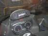
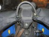
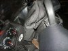
может кто-нибудь поделиться сервис мануалом на Снежик Yamaha Venture Multi Purpose 2007 года???
Может у кого-нить есть в электронном виде? очень надо

Michael55
Старожил
- Регистрация
- 25 Янв 2010
- Сообщения
- 1.042
- Реакции
- 4
- Возраст
- 41
- Местонахождение
-
Карелия у Ладоги
- Имя
-
Михаил
- Техника
-
остался только МТЗ82
Берсерк
Участник
- Регистрация
- 21 Окт 2008
- Сообщения
- 151
- Реакции
- 195
- Возраст
- 42
- Местонахождение
-
Ярославль
- Имя
-
Егор
- Техника
-
веласЫпед да и тот сломан…
-
#3
Michael55 написал(а):
viewtopic.php?f=41&t=11840
 :)")
 :)")
большущее спасибо и низкий поклон за помосч ))
Вложения
-
114,8 KB
Просмотры: 277 -
135,5 KB
Просмотры: 257 -
134 KB
Просмотры: 207
-
Page 1
E115A 115B 140B SERVICE MANUAL 61U-28197-5H-11… -
Page 2: Important Information
NOTICE This manual has been prepared by Yamaha primarily for use by Yamaha dealers and their trained mechanics when performing maintenance procedures and repairs to Yamaha equipment. It has been written to suit the needs of persons who have a basic understanding of the mechanical and electrical concepts and procedures inherent in the work, for without such knowledge attempted repairs or service to the equipment could render it unsafe or unfit for use.
-
Page 3: Table Of Contents
Contents General information INFO Specification SPEC Periodic check and adjustment Fuel system FUEL Power unit POWR Lower unit LOWR Bracket unit BRKT Electrical system ELEC Troubleshooting TRBL SHTG Index…
-
Page 5: General Information
INFO General information How to use this manual …………….1-1 Manual format ………………1-1 Symbol ………………… 1-2 Safety while working ………………. 1-3 Fire prevention ………………1-3 Ventilation ………………..1-3 Self-protection ………………1-3 Parts, lubricant, and sealant …………..1-3 Good working practice …………….1-4 Disassembly and assembly …………..
-
Page 6: How To Use This Manual
INFO General information How to use this manual Manual format The format of this manual has been designed to make service procedures clear and easy to under- stand. Use the information below as a guide for effective and quality service. 9 Parts are shown and detailed in an exploded diagram and are listed in the components list (see in the figure below for an example page).
-
Page 7: Symbol
7 Apply Yamaha 2-stroke outboard motor oil q Apply corrosion resistant grease 8 Apply gear oil (Yamaha grease D) 9 Apply water resistant grease (Yamaha grease A) w Apply low temperature resistant grease 0 Apply molybdenum disulfide grease (Yamaha grease C)
-
Page 8: Safety While Working
Parts, lubricant, and sealant Use only genuine Yamaha parts, lubricants, and sealants or those recommended by Yamaha, when servicing or repairing the out- board motor. Ventilation Gasoline vapor and exhaust gas are heavier than air and extremely poisonous.
-
Page 9: Good Working Practice
Safety while working 6. Keep a supply of clean, lint-free cloths for Disassembly and assembly wiping up spills, etc. 1. Use compressed air to remove dust and dirt during disassembly. Good working practice 2. Apply engine oil to the contact surfaces Special service tool of moving parts before assembly.
-
Page 10: Identification
115BE, 115BET, 140BET Serial number The outboard motor serial number is stamped on a label attached to the port clamp bracket. 6G410010 YAMAHA MOTOR CO., LTD. MADE IN JAPAN PAYS D’ORIGINE JAPON 6B410020 1 Model name 2 Approved model code…
-
Page 11: Special Service Tool
Identification/Special service tool Special service tool Digital tachometer Compression gauge 90890-06760 90890-03160 Timing light Flywheel holder 90890-03141 90890-06522 Leakage tester Flywheel puller 90890-06840 90890-06521 Ball bearing attachment Digital caliper 90890-06704 90890-06663 Driver rod LS Vacuum/pressure pump gauge set 90890-06606 90890-06756 61U5H11…
-
Page 12
INFO General information Needle bearing attachment Gear puller 90890-06609, 90890-06610, 90890-06611, 90890-06612, 90890-06653, 90890-06654 90890-06540 Bearing separator Driver rod L3 90890-06534 90890-06652 Cylinder gauge Ball bearing attachment 90890-06759 90890-06633, 90890-06636 90890-06637, 90890-06656 Support Bearing outer race attachment 90890-02394 90890-06620, 90890-06624 Bearing inner race attachment Small end bearing installer 90890-06640, 90890-06662… -
Page 13
Special service tool Piston slider Stopper guide plate 90890-06530 90890-06501 Dial gauge set Bearing housing puller claw L 90890-01252 90890-06502 Shift rod push arm Center bolt 90890-06052 90890-06504 Ring nut wrench 3 Stopper guide stand 90890-06511 90890-06538 Bearing puller assembly Ring nut wrench extension 90890-06535 90890-06513… -
Page 14
INFO General information Bearing outer race puller assembly Driver rod SS 90890-06523 90890-06604 Bearing depth plate Driver rod SL 90890-06603 90890-06602 Pinion height gauge Drive shaft holder 6 90890-06710 90890-06520 Pinion nut holder Shimming plate 90890-06715 90890-06701 Backlash indicator Driver rod LL 90890-06706 90890-06605 61U5H11… -
Page 15
Special service tool Magnet base plate Test harness (4 pins) 90890-07003 90890-06878 Magnet base B Trim and tilt wrench 90890-06844 90890-06587 Digital circuit tester Ignition tester 90890-03174 90890-06754 Up relief fitting 90890-06773 Peak voltage adaptor B Down relief fitting 90890-03172 90890-06774 Test harness (4 pins) Hydraulic pressure gauge… -
Page 16: Propeller Selection
INFO General information Propeller selection Selection When the engine speed is at the full throttle The performance of a boat and outboard operating range (4,500–5,500 r/min), the motor will be critically affected by the size and ideal propeller for the boat is one that pro- type of propeller you choose.
-
Page 17: Predelivery Check
Propeller selection Checking the battery Predelivery check (E, ET, WH) To make the delivery process smooth and 1. Check the capacity, electrolyte level, and efficient, the predelivery checks should be specified gravity of the battery. completed as explained below. Recommended battery capacity: Checking the fuel system CCA/EN: 430 A 1.
-
Page 18: Checking The Remote Control Cable (Remote Control Model)
INFO General information Checking the remote control cable 4. Check that the remote control lever is in the neutral position, and check that the (Remote control model) center of the set pin 5 is aligned with the 1. Set the remote control lever to the neutral alignment mark a on the bottom cowling.
-
Page 19: Checking The Steering System
Predelivery check Checking the steering system Checking the gear shift and throttle 1. Check the steering friction for proper operation adjustment. 1. Check that the gear shift operates smoothly when the shift lever or remote control lever is shifted from neutral to for- ward or reverse.
-
Page 20: Checking The Ptt System (Et)
INFO General information 3. Check that the choke solenoid operates Checking the PTT system when the engine start switch is pushed (ET) in. (E, ET) 1. Check that the outboard motor tilts up and down smoothly when operating the PTT unit. 2.
-
Page 21: Checking The Cooling Water Pilot Hole
Predelivery check Checking the cooling water pilot hole Break-in 1. Start the engine, then check that the During the test run, perform the break-in cooling water is discharged from the operation in the following 5 stages. 1. 10 minutes a at the lowest possible cooling water pilot hole.
-
Page 22: After Test Run
INFO General information After test run 1. Check for water in the gear oil. 2. Check for fuel leakage in the cowling. 3. Flush the cooling water passage with fresh water using the flushing kit 1 and with the engine running at idle. 6S310070 Be sure to supply sufficient water when flushing the cooling water passage, other-…
-
Page 23: Specification
SPEC Specification General specification ………………2-1 Maintenance specification …………….2-5 Power unit (E115A models) ……………2-5 Lower unit (E115A models)…………….2-7 Electrical (E115A models)…………….2-7 Power unit (115B, 140B models) ………….2-10 Lower unit (115B, 140B models) ………….2-12 Electrical (115B, 140B models) ……………2-12 Dimension ………………..2-15 Tightening torque………………2-19 Specified torque………………2-19…
-
Page 24: General Specification
SPEC Specification General specification Model Item Unit E115AMH E115AWH E115AE E115AET Dimension Overall length mm (in) 1,458 (57.4) 828 (32.6) Overall width mm (in) 600 (23.6) Overall height mm (in) 1,558 (61.3) 1,435 (56.5) mm (in) 1,611 (63.4) — mm (in) 1,684 (66.3) 1,561 (61.5) Boat transom height…
-
Page 25
General specification Model Item Unit E115AMH E115AWH E115AE E115AET Cooling system Water Exhaust system Propeller boss Lubrication system Pre-mixed fuel and oil Fuel and oil Fuel type Regular unleaded gasoline Engine oil 2-stroke outboard motor oil Engine oil grade NMMA-certified TC-W3 Gear oil type Hypoid gear oil Gear oil grade (*1) -
Page 26
SPEC Specification Model Item Unit 115BE 115BET 140BET Dimension Overall length mm (in) 828 (32.6) Overall width mm (in) 600 (23.6) Overall height mm (in) 1,435 (56.5) mm (in) 1,561 (61.5) Boat transom height mm (in) 508 (20.0) mm (in) 635 (25.0) Weight (with aluminum propeller) -
Page 27
General specification Model Item Unit 115BE 115BET 140BET Cooling system Water Exhaust system Propeller boss Lubrication system Pre-mixed fuel and oil Fuel and oil Fuel type Regular unleaded gasoline Engine oil 2-stroke outboard motor oil Engine oil grade NMMA-certified TC-W3 Gear oil type Hypoid gear oil Gear oil grade (*1) -
Page 28: Maintenance Specification
SPEC Specification Maintenance specification Power unit (E115A models) Model Item Unit E115AMH E115AWH E115AE E115AET Power unit Minimum compression — 450 (4.5, 64) pressure (*1) at electric starter (kgf/cm , psi) at manual starter 400 (4.0, 57) — Cylinder head…
-
Page 29
Maintenance specification Model Item Unit E115AMH E115AWH E115AE E115AET Piston ring Top ring Dimension B mm (in) 1.970–1.990 (0.0776–0.0783) Dimension T mm (in) 2.700–2.900 (0.1063–0.1142) End gap mm (in) 0.30–0.40 (0.0118–0.0157) Side clearance mm (in) 0.02–0.06 (0.0008–0.0024) Oversize outside diameter mm (in) 90.25 (3.5531) mm (in) -
Page 30: Lower Unit (E115A Models)
SPEC Specification Lower unit (E115A models) Model Item Unit E115AMH E115AWH E115AE E115AET Gear backlash Pinion-to-forward mm (in) 0.32–0.50 (0.0126–0.0197) Pinion-to-reverse mm (in) 0.80–1.17 (0.0315–0.0461) Pinion gear shims 0.10, 0.12, 0.15, 0.18, 0.30, 0.40, 0.50 Forward gear shims 0.10, 0.12, 0.15, 0.18, 0.30, 0.40, 0.50 Reverse gear shims 0.10, 0.12, 0.15, 0.18, 0.30, 0.40, 0.50…
-
Page 31
Maintenance specification Model Item Unit E115AMH E115AWH E115AE E115AET Charge coil output peak voltage (B/R–L: High-speed) at Cranking (unloaded) at Cranking (loaded) at 1,500 r/min (loaded) at 3,500 r/min (loaded) (R–Br: Low-speed) at Cranking (unloaded) at Cranking (loaded) at 1,500 r/min (loaded) at 3,500 r/min (loaded) Charge coil resistance at 20°C (68°F) -
Page 32
SPEC Specification Model Item Unit E115AMH E115AWH E115AE E115AET PTT system Trim sensor resistance Ω — 239–379 at 20°C (68°F) (P–B) Fluid type — Dexron 2 Motor type — 64E00 Output — 0.40 Brushes Standard length mm (in) — 9.8 (0.39) Wear limit mm (in) —… -
Page 33: Power Unit (115B, 140B Models)
Maintenance specification Power unit (115B, 140B models) Model Item Unit 115BE 115BET 140BET Power unit Minimum compression 450 (4.5, 64) pressure (*1) (kgf/cm , psi) Cylinder head Warpage limit mm (in) 0.10 (0.0039) (lines indicate straightedge position) Cylinder Bore size mm (in) 90.000–90.020 (3.5433–3.5441) Piston…
-
Page 34
SPEC Specification Model Item Unit 115BE 115BET 140BET Piston ring Top ring Dimension B mm (in) 1.970–1.990 (0.0776–0.0783) Dimension T mm (in) 2.700–2.900 (0.1063–0.1142) End gap mm (in) 0.30–0.50 (0.0118–0.0197) Side clearance mm (in) 0.02–0.06 (0.0008–0.0024) Oversize outside diameter mm (in) 90.25 (3.5531) mm (in) 90.50 (3.5630) -
Page 35: Lower Unit (115B, 140B Models)
Maintenance specification Lower unit (115B, 140B models) Model Item Unit 115BE 115BET 140BET Gear backlash Pinion-to-forward mm (in) 0.32–0.50 (0.0126–0.0197) Pinion-to-reverse mm (in) 0.80–1.17 (0.0315–0.0461) Pinion gear shims 0.10, 0.12, 0.15, 0.18, 0.30, 0.40, 0.50 Forward gear shims 0.10, 0.12, 0.15, 0.18, 0.30, 0.40, 0.50 Reverse gear shims 0.10, 0.12, 0.15, 0.18, 0.30, 0.40, 0.50 Electrical (115B, 140B models)
-
Page 36
SPEC Specification Model Item Unit 115BE 115BET 140BET Charge coil output peak voltage (B/R–L: High-speed) at Cranking (unloaded) at Cranking (loaded) at 1,500 r/min (loaded) at 3,500 r/min (loaded) (R–Br: Low-speed) at Cranking (unloaded) at Cranking (loaded) at 1,500 r/min (loaded) at 3,500 r/min (loaded) Charge coil resistance at 20°C (68°F) -
Page 37
Maintenance specification Model Item Unit 115BE 115BET 140BET PTT system Trim sensor resistance Ω — 239–379 at 20°C (68°F) (P–B) ATF Dexron 2 Fluid type — Motor type — 64E00 Output — 0.40 Brushes Standard length mm (in) — 9.8 (0.39) Wear limit mm (in) —… -
Page 38: Dimension
SPEC Specification Dimension Exterior E115A mm (in) 325 (12.8) 539 (21.2) 845 (33.3) L: 1,005 (39.6) Y: 1,055 (41.5) 570 (22.4) X: 1,120 (44.1) 270 (10.6) 64 (2.5) MH, WH 616 (24.3) 61U2001M 2-15 61U5H11…
-
Page 39
Maintenance specification E115A, 115B, 140B mm (in) 539 (21.2) L: 1,005 (39.6) 482 (19.0) X: 1,120 (44.1) 214 (8.4) 64 (2.5) 616 (24.3) ** ET 6IU2002M 61U5H11 2-16… -
Page 40
SPEC Specification Clamp bracket mm (in) 182 (7.2) 182 (7.2) 163.5 (6.4) 163.5 (6.4) 62 (2.4) 13 (0.5) 13 (0.5) 125.4 (4.9) 125.4 (4.9) 6IU2003M 2-17 61U5H11… -
Page 41
Maintenance specification mm (in) 180 (7.1) 180 (7.1) 163.5 (6.4) 163.5 (6.4) 82 (3.2) 13 (0.5) 13 (0.5) 6G42003M 101.5 (4.0) 101.5 (4.0) 125.4 (4.9) 125.4 (4.9) 61U5H11 2-18… -
Page 42: Tightening Torque
SPEC Specification Tightening torque Specified torque Tightening torques Part to be tightened Thread size N·m kgf·m ft·lb Fuel system Intake silencer cover bolt Manual injection cable end bolt Screw (carburetor) — Plug (carburetor) — Plug (float chamber) — Fuel pump screw —…
-
Page 43
Thread size N·m kgf·m ft·lb Lower unit Check screw — Drain screw — Lower case mount bolt 28.8 Lower case mount nut (E115A: Y-transom) — 28.8 Trim tab bolt 28.8 Water pump housing bolt 13.3 Ring nut — 10.3 76.0 Pinion nut —… -
Page 44: General Torque
SPEC Specification General torque General torque specifications This chart specifies tightening torques for Nut (A) Bolt (B) standard fasteners with a standard ISO N·m kgf·m ft·lb thread pitch. Tightening torque specification 8 mm for special components or assemblies are 10 mm provided in applicable sections of this manu- 12 mm 14 mm…
-
Page 45
Periodic check and adjustment Maintenance interval chart …………….3-1 Top cowling ………………..3-2 Checking the top cowling …………….. 3-2 Fuel system ………………..3-2 Checking the fuel joint and fuel hose (fuel joint-to-carburetor) ….3-2 Checking the fuel filter …………….3-2 Power unit ………………… -
Page 46: Periodic Check And Adjustment
Check / charge 3-14 Cooling water passages Clean Cowling clamp Check Fuel filter (can be dis- Check / clean assembled) Fuel system Check Fuel tank (Yamaha por- Check / clean — table tank) Gear oil Change 3-12 Lubrication points Lubricate 3-14…
-
Page 47: Top Cowling
Maintenance interval chart/Top cowling/Fuel system Top cowling Fuel system Checking the top cowling Checking the fuel joint and fuel 1. Check the fitting by pushing the cowling hose (fuel joint-to-carburetor) with both hands. Adjust the fittings if nec- 1. Check the fuel hose connections and fuel essary.
-
Page 48: Periodic Check And Adjustment
Periodic check and adjustment 5. Install the spark plug temporary tight, Power unit then to the specified torque with a spark Checking the spark plug plug wrench. 1. Disconnect the spark plug caps, and then remove the spark plugs. Spark plug: 25 N·m (2.5 kgf·m, 18.4 ft·lb) 2.
-
Page 49: Checking The Cooling Water Passage
Power unit/Control system 3. Check for water flow at the cooling water Water pilot hole. If there is no water flow, check Valve lift a temperature the cooling water passage inside of the 48–52°C 0.05 mm (0.002 in) outboard motor. (118.4–125.6°F) (valve begins to tilt) above…
-
Page 50: Checking The Control Link And Throttle Link Position
Periodic check and adjustment NOTE: Checking the control link and throt- Make a note that how many times you turn tle link position out the throttle stop screw. 1. Remove the throttle cable. 3. Loosen the throttle lever tightening 2. Measure the length of control link rod 1. screws 3 and 4 clockwise.
-
Page 51: Checking The Engine Idle Speed
Control system 3. Turn the throttle stop screw 3 in direc- 8. Tighten the throttle lever tightening screw 4 counterclockwise on the lower carbu- tion a or b until the specified engine idle retor. speed is obtained. NOTE: The screw 4 is left hand thread. 9.
-
Page 52: Checking The Gear Shift Operation
Periodic check and adjustment 4. Connect the cable joint 3, install the nut 2. Set the throttle grip or remote control 2, and then tighten the lock nut 1. lever to the fully closed position. 61U30095 61U30085 3. Adjust the position of the throttle cable 5.
-
Page 53: Checking The Ignition Timing
Control system 6. Install the shift cable joint 3, install the 4. Make sure to align the center of the set pin a on the shift lever with the align- clip 2, and then tighten the locknut 1. ment mark b on the bottom cowling. 61U30100 7.
-
Page 54: Checking The Choke Solenoid (E, Et)
61U30250 Engine speed (throttle fully opened): 5,500 r/min Engine idle speed: 700–800 r/min Timing plate position: E115A: Timing light 3: 90890-03141 BTDC 22–24° 115B: 4. Check that the ATDC 5° scale a on the BTDC 24–26° flywheel magnet is aligned with the point-…
-
Page 55: Bracket
Control system/Bracket Checking the PTT fluid level Bracket (ET) Checking the PTT operation 1. Fully tilt the outboard motor up, and then (ET) support it with the tilt stop lever 1. 1. Fully tilt the outboard motor up and down a few times and check the entire trim and tilt range for smooth operation.
-
Page 56: Lower Unit
Periodic check and adjustment 3. If necessary, add sufficient fluid of the 3. Fully tilt the outboard motor up, then sup- port it with the tilt stop lever 2 to check recommended type until it overflows out of the filler hole. the lock mechanism of the lever.
-
Page 57: Changing The Gear Oil
Bracket/Lower unit Changing the gear oil 1. Tilt the outboard motor so that the gear oil drain screw at the lowest point possi- ble. 2. Place a drain pan under the drain screw 1, remove the drain screw, then the check screw 2 and let the oil drain com- pletely.
-
Page 58: Checking The Lower Unit For Air Leakage
Periodic check and adjustment Checking the lower unit for air leak- General Checking the anode 1. Check the anode and trim tab. Clean if there are scales, grease, or oil. Do not over pressurize the lower unit, oth- erwise the oil seals may be damaged. 1.
-
Page 59: Checking The Battery (Wh, E, Et)
Lower unit/General Checking the battery (WH, E, ET) NOTE: 9 Batteries vary per manufacturer. The proce- 1. Check the battery electrolyte level. If the dures mentioned in this manual may not level is at or below the minimum level always apply, therefore, consult the instruc- mark a, add distilled water until the level tion manual of the battery.
-
Page 60
Periodic check and adjustment 61U30170 6G430530 NOTE: 6G430500 Apply grease to the grease nipple until it flows from the bushings a. 2. Apply low temperature resistant grease to the area shown. 6G430510 6G430540 3. Apply corrosion resistant grease to the area shown. -
Page 61
FUEL Fuel system Hose routing ………………..4-1 Fuel hose and breather hose …………..4-1 Fuel line ………………….4-3 Carburetor ………………… 4-6 Disassembling the carburetor …………..4-12 Checking the carburetor ……………. 4-12 Assembling the carburetor …………..4-13 Fuel pump ………………..4-15 Checking the fuel pump …………….. -
Page 62: Fuel System
FUEL Fuel system Hose routing Fuel hose and breather hose 61U4001A 1 Fuel hose (fuel joint-to-fuel filter) 2 Fuel hose (fuel filter-to-manual injection : MH, WH) 3 Fuel hose (fuel filter-to-fuel pump) 4 Manual injection pump : MH, WH 5 Fuel hose (manual injection-to-upper carburetor : MH, WH) 6 Fuel hose (fuel pump-to-carburetor) 61U5H11…
-
Page 63
Hose routing PORT STBD MH, WH E, ET 61U4001B 1 Breather hose (manifold-to-cylinder body #2) 2 Breather hose (manifold-to-cylinder body #4) 3 Breather hose (breather hose-to-manual injection) 4 Breather hose (manifold-to-manual injection) 5 Breather hose (breather hose-to-manual injection hose) 6 Breather hose (manifold-to-cylinder body #1) 7 Breather hose (cylinder body #3-to-manual injection hose) 8 Breather hose (manifold-to-intake silencer) 9 Breather hose (manifold-to-cylinder body #3) -
Page 64: Fuel Line
FUEL Fuel system Fuel line 4 N·m (0.4 kgf·m, 3.0 ft·lb) 61U4040E Part name Q’ty Remarks M6 × 16 mm Bolt Fuel filter assembly Lock tie MH, WH Not reusable Lock tie Not reusable E, ET Fuel hose Fuel hose MH, WH Fuel hose Joint…
-
Page 65
Fuel line 4 N·m (0.4 kgf·m, 3.0 ft·lb) 61U4040E Part name Q’ty Remarks Fuel pump assembly Gasket Not reusable Fuel hose Joint Fuel hose Fuel hose M6 × 10 mm MH, WH Bolt Start-in-gear protection cable MH, WH M6 × 12 mm MH, WH Bolt M5 ×… -
Page 66
FUEL Fuel system 6G44040E Part name Q’ty Remarks M6 × 16 mm Bolt Washer Holder M6 × 14 mm Bolt Bracket Fuel filter assembly O-ring Not reusable Fuel filter element Fuel filter cup 61U5H11… -
Page 67: Carburetor
Fuel line/Carburetor Carburetor E, ET 6 N·m (0.6 kgf·m, 4.4 ft·lb) 61U4060E Part name Q’ty Remarks M6 × 20 mm Bolt Cover Gasket Not reusable M6 × 20 mm Bolt Intake silencer M6 × 20 mm Bolt Breather hose Gasket Not reusable Upper carburetor assembly Lower carburetor assembly…
-
Page 68
FUEL Fuel system E, ET 6 N·m (0.6 kgf·m, 4.4 ft·lb) 61U4060E Part name Q’ty Remarks M6 × 16 mm Bolt Choke solenoid Intake silencer Grommet 61U5H11… -
Page 69
Carburetor MH, WH 6 N·m (0.6 kgf·m, 4.4 ft·lb) 2 N·m (0.2 kgf·m, 1.5 ft·lb) 10 N·m (1.0 kgf·m, 7.4 ft·lb) 61U4070E Part name Q’ty Remarks Plug Gasket Screw Plate Gasket Not reusable Main air bleed Pilot screw Spring Screw Gasket Air bleed plug Pilot air jet… -
Page 70
FUEL Fuel system 6 N·m (0.6 kgf·m, 4.4 ft·lb) 2 N·m (0.2 kgf·m, 1.5 ft·lb) 10 N·m (1.0 kgf·m, 7.4 ft·lb) 61U4070E Part name Q’ty Remarks Gasket Not reusable Plug Gasket Main jet Drain plug Gasket Float chamber Plug Gasket Pilot jet ø5 ×… -
Page 71
Carburetor E, ET 6 N·m (0.6 kgf·m, 4.4 ft·lb) 2 N·m (0.2 kgf·m, 1.5 ft·lb) 10 N·m (1.0 kgf·m, 7.4 ft·lb) 61U4065E Part name Q’ty Remarks Plug Gasket Screw Plate Pilot screw Spring Screw Gasket Air bleed plug Pilot air jet Carburetor body Needle valve Clip… -
Page 72
FUEL Fuel system 6 N·m (0.6 kgf·m, 4.4 ft·lb) 2 N·m (0.2 kgf·m, 1.5 ft·lb) 10 N·m (1.0 kgf·m, 7.4 ft·lb) 61U4065E Part name Q’ty Remarks Gasket Main jet Float chamber Plug Gasket Pilot jet ø5 × 16 mm Screw Throttle stop screw Spring Lower carburetor assembly… -
Page 73: Disassembling The Carburetor
Carburetor Disassembling the carburetor 4. Check the pilot screw and needle valve for bends or wear. Replace the pilot NOTE: screw and needle valve if necessary. 9 Before disassembling the carburetors, make sure to note the number of times the pilot screw is turned out from the seated position to its set position.
-
Page 74: Assembling The Carburetor
FUEL Fuel system Assembling the carburetor ∫ 1. Install the gaskets 1, plugs 2, pilot air jets 3, and air bleed plugs 4, main air bleed 5 onto the carburetor body. å 6G440110 å MH, WH ∫ E, ET 61U40100 4.
-
Page 75
Carburetor NOTE: When disassemble the carburetor, be sure to set the pilot screw by the specified times. Pilot screw turns out: E115A : 1–1 1/2 115B : 3/8–7/8 140B : 5/8–1 1/8 7. Install the carburetor assembly. 61U5H11 4-14… -
Page 76: Fuel Pump
FUEL Fuel system Fuel pump 3.5 N·m (0.35 kgf·m, 2.6 ft·lb) 6G44030E Part name Q’ty Remarks Base Gasket Not reusable Diaphragm Body assembly ø5 × 28 mm Screw Washer Check valve Body Gasket Not reusable Diaphragm Collar O-ring Not reusable Cover Plate Spring…
-
Page 77: Checking The Fuel Pump
Fuel pump Checking the fuel pump 6. Apply the specified positive pressure and check that there is no air leakage. 1. Place a drain pan under the fuel hose Disassemble the fuel pump if necessary. connections, and then disconnect the fuel hoses from the fuel pump.
-
Page 78: Assembling The Fuel Pump
FUEL Fuel system NOTE: Assembling the fuel pump Make sure that the gaskets and diaphragms NOTE: are kept in place through the assembly Clean the parts and soak the valves and the process. diaphragms in gasoline before assembly to obtain prompt operation of the fuel pump when starting the engine.
-
Page 79
— MEMO — 61U5H11 4-18… -
Page 80: Powr
POWR Power unit Power unit ………………… 5-1 Checking the compression pressure …………5-1 Disassembling the manual starter (MH, WH) ……..5-14 Checking the spiral spring (MH, WH) ………… 5-15 Checking the drive pawl (MH, WH) …………5-15 Checking the starter rope (MH, WH) …………. 5-15 Assembling the manual starter (MH, WH) ……….
-
Page 81
Checking the piston ring ……………. 5-37 Checking the piston ring side clearance ……….5-38 Checking the piston pin boss bore …………5-38 Checking the piston pin …………….. 5-38 Checking the internal anode …………..5-38 Checking the connecting rod small end axial play …….. 5-39 Checking the connecting rod big end side clearance …… -
Page 82: Power Unit
POWR Power unit Power unit 5. If the compression pressure is below specification and the compression pres- Checking the compression pressure sure for each cylinder is unbalanced, add 1. Start the engine, warm it up for 5 min- a small amount of engine oil to the cylin- utes, and then turn it off.
-
Page 83
Power unit E,ET 25 N·m (2.5 kgf·m, 18.4 ft·lb) 61U5010E 8 N·m (0.8 kgf·m, 5.9 ft·lb) Part name Q’ty Remarks M8 × 35 mm MH, WH Bolt Grommet MH, WH Manual starter assembly MH, WH Collar MH, WH M6 × 20 mm MH, WH Bolt Power unit Dowel… -
Page 84
POWR Power unit E,ET 25 N·m (2.5 kgf·m, 18.4 ft·lb) 61U5010E 8 N·m (0.8 kgf·m, 5.9 ft·lb) Part name Q’ty Remarks M8 × 135 mm Bolt Apron Apron M6 × 25 mm E, ET Bolt Grommet E, ET Collar E, ET Grommet E, ET Flywheel cover… -
Page 85
Power unit 186 N·m (18.6 kgf·m, 137 ft·lb) 3 N·m (0.3 kgf·m, 2.2 ft·lb) 61U5020E Part name Q’ty Remarks Washer Starter pulley MH, WH M8 × 25 mm MH, WH Bolt Flywheel magnet M6 × 60 mm Bolt Stator assembly Pulser coil assembly ø5 ×… -
Page 86
POWR Power unit 186 N·m (18.6 kgf·m, 137 ft·lb) 3 N·m (0.3 kgf·m, 2.2 ft·lb) 61U5020E Part name Q’ty Remarks Washer Rectifier Regulator M6 × 12 mm Bolt Main harness Control link If equipped ø5 × 20 mm Screw Hour meter If equipped Case If equipped… -
Page 87
Power unit 61U5030E Part name Q’ty Remarks Joint Lock nut Control link rod Throttle link rod M6 × 25 mm Bolt Collar Wave washer Lock nut Screw Spring Screw M8 × 45 mm Bolt Washer Collar Bushing 61U5H11… -
Page 88
POWR Power unit 61U5030E Part name Q’ty Remarks Bushing Spring Control lever 1 Plastic washer Washer Bracket M8 × 30 mm Bolt Bushing Control lever 2 61U5H11… -
Page 89
Power unit 6IU5060E Part name Q’ty Remarks ø6 × 16 mm Screw Cover ø6 × 40 mm Screw CDI unit Charge coil coupler M6 × 12 mm Bolt Spark plug cap M6 × 20 mm Bolt Ignition coil M6 × 12 mm Bolt M6 ×… -
Page 90
POWR Power unit WH, E 30 N·m (3.0 kgf·m, 22.1 ft·lb) 29 N·m (2.9 kgf·m, 21.4 ft·lb) 9 N·m (0.9 kgf·m, 6.6 ft·lb) 4 N·m (0.4 kgf·m, 3.0 ft·lb) 61U5050E Part name Q’ty Remarks M8 × 45 mm Bolt Starter motor Washer M8 ×… -
Page 91
Power unit WH, E 30 N·m (3.0 kgf·m, 22.1 ft·lb) 29 N·m (2.9 kgf·m, 21.4 ft·lb) 9 N·m (0.9 kgf·m, 6.6 ft·lb) 4 N·m (0.4 kgf·m, 3.0 ft·lb) 61U5050E Part name Q’ty Remarks M6 × 12 mm Bolt Clamp Holder PTT relay (up) Holder PTT relay (down) -
Page 92
POWR Power unit MH, WH 61U5040E Part name Q’ty Remarks Manual starter case Plastic washer Spiral spring Collar Sheave drum Washer Clip Collar Drive pawl Spring Spring Drive plate Washer M6 × 16 mm Bolt M6 × 12 mm Bolt Washer M6 ×… -
Page 93
Power unit MH, WH 61U5040E Part name Q’ty Remarks Rope guide Roller Bushing M6 × 30 mm Bolt Grommet Collar M6 × 20 mm Bolt Bracket Damper Starter handle Bracket M6 × 12 mm Bolt Cotter pin Washer Start-in-gear protection cable 61U5H11 5-12… -
Page 94
POWR Power unit MH, WH 61U5040E Part name Q’ty Remarks Spring Guide Bolt Stopper Spring Starter rope 5-13 61U5H11… -
Page 95: Disassembling The Manual Starter (Mh, Wh)
Power unit Disassembling the manual starter 3. Remove the bolt, drive plate 6, spring (MH, WH) 7, drive pawl 8, spring 9, clip 0, wash- er q and collar w. 9 The sheave drum can pop out. Hold the sheave drum with your hand, then pull it out.
-
Page 96: Checking The Spiral Spring (Mh, Wh)
POWR Power unit Assembling the manual starter 6. Remove the plastic washers r, spiral spring t from the manual starter case. (MH, WH) 1. Install the starter rope 1 into the sheave drum 2. 2. Install the manual starter handle 3. 61U50040 7.
-
Page 97
Power unit 4. Install the plastic washer 4 and spiral 6. Install the collar 8, washer 9, clip 0, spring 5 into the manual starter case 6. drive pawl q, spring w, spring e, and drive plate r. 61U50520 61U50060 NOTE: Install the outer end c of the spiral spring onto the pin d of the starter case. -
Page 98: Removing The Power Unit
POWR Power unit 1. Remove the CDI unit cover, start-in-gear 9. Pull the manual starter handle several protection cable 1, then remove the times in the direction of the arrow to manual starter and starter pully (MH, check that the sheave drum turns WH).
-
Page 99
Power unit 8. Remove the bracket bolt w 3. Disconnect the 10-pin main harness cou- manual pler 5. injection pump cable end e and start-in- gear protection cable end r. 61U50470 61U50460 4. Disconnect the fuel hose 6. 61U50461 61U50560 5. -
Page 100: Removing The Flywheel Magnet
POWR Power unit 11. Remove the power unit by removing the 2. Remove the flywheel magnet. bolts i, bolts o and nuts p. 61U50590 6B450090 Removing the flywheel magnet 1. Loosen the flywheel magnet nut. To prevent damage to the engine or tools, screw in the flywheel puller set bolts evenly and completely so that the fly- wheel puller is parallel to the flywheel…
-
Page 101: Removing The Electrical Component
Power unit Removing the electrical component 1. Remove the cover 1 and disconnect the coupler. 61U50630 4. Remove the starter relay 8 and the PTT relay assembly 9. 61U50600 61U50600 61U50610 2. Remove the hour meter 2. 61U50650 61U50615 5. Remove the starter motor 0. 3.
-
Page 102
POWR Power unit 6. Disconnect the ignition coil leads, and then remove the CDI unit q and case w. 61U50600 5-21 61U5H11… -
Page 103
Power unit/Intake manifold Intake manifold 4 N·m (0.4 kgf·m, 3.0 ft·lb) 8 N·m (0.8 kgf·m, 5.9 ft·lb) MH, WH E, ET 4 N·m (0.4 kgf·m, 3.0 ft·lb) 8 N·m (0.8 kgf·m, 5.9 ft·lb) 61U5070E Part name Q’ty Remarks Gasket Not reusable Reed valve Gasket Not reusable… -
Page 104
POWR Power unit 4 N·m (0.4 kgf·m, 3.0 ft·lb) 8 N·m (0.8 kgf·m, 5.9 ft·lb) MH, WH E, ET 4 N·m (0.4 kgf·m, 3.0 ft·lb) 8 N·m (0.8 kgf·m, 5.9 ft·lb) 61U5070E Part name Q’ty Remarks Bracket Bracket Intake manifold Bracket MH, WH M6 ×… -
Page 105: Intake Manifold
Intake manifold Removing the intake manifold Checking the reed valve 1. Check the reed valves for bends a. 1. Remove the carburetor assemblies and the fuel hoses. Replace the reed valves if above specifi- cation. 2. Disconnect the breather hoses 1. 6G450180 61U50370 Valve bending limit a:…
-
Page 106: Exhaust Cover
POWR Power unit Exhaust cover 4 N·m (0.4 kgf·m, 3.0 ft·lb) 8 N·m (0.8 kgf·m, 5.9 ft·lb) 4 N·m (0.4 kgf·m, 3.0 ft·lb) 8 N·m (0.8 kgf·m, 5.9 ft·lb) 4 N·m (0.4 kgf·m, 3.0 ft·lb) 8 N·m (0.8 kgf·m, 5.9 ft·lb) 61U5080E Part name Q’ty…
-
Page 107: Removing The Exhaust Cover
Exhaust cover Removing the exhaust cover Checking the PCV 1. Remove the exhaust cover bolts in the 1. Remove the PCV. sequence shown. 2. Check the PCV for wear or deformation. Replace the PCV if necessary. 3. Check the grommet for deformation. Replace the grommet if necessary.
-
Page 108: Cylinder Head
POWR Power unit Cylinder head MH, WH 25 N·m (2.5 kgf·m, 18.4 ft·lb) 4 N·m (0.4 kgf·m, 3.0 ft·lb) 8 N·m (0.8 kgf·m, 5.9 ft·lb) E, ET 4 N·m (0.4 kgf·m, 3.0 ft·lb) 15 N·m (1.5 kgf·m, 11.1 ft·lb) 8 N·m (0.8 kgf·m, 5.9 ft·lb) 30 N·m (3.0 kgf·m, 22.1 ft·lb) 61U5090E Part name…
-
Page 109
Cylinder head MH, WH 25 N·m (2.5 kgf·m, 18.4 ft·lb) 4 N·m (0.4 kgf·m, 3.0 ft·lb) 8 N·m (0.8 kgf·m, 5.9 ft·lb) E, ET 4 N·m (0.4 kgf·m, 3.0 ft·lb) 15 N·m (1.5 kgf·m, 11.1 ft·lb) 8 N·m (0.8 kgf·m, 5.9 ft·lb) 30 N·m (3.0 kgf·m, 22.1 ft·lb) 61U5090E Part name… -
Page 110: Removing The Cylinder Head
POWR Power unit Removing the cylinder head 5. Remove the cylinder head bolts in the sequence shown. 1. Remove the spark plugs. 2. Remove the thermostat cover bolts in the PORT STBD sequence as shown, and then remove the thermostat. 61U50170 61U50210 3.
-
Page 111
Cylinder head 2. Check the cylinder head warpage using a straightedge 1 and thickness gauge 2 in 4 directions as shown. Replace the cylinder head if above specification. 61U50240 61U50250 Cylinder head warpage limit: 0.10 mm (0.0039 in) 61U5H11 5-30… -
Page 112: Crankcase
POWR Power unit Crankcase 12 N·m (1.2 kgf·m, 8.9 ft·lb) 20 N·m (2.0 kgf·m, 14.8 ft·lb) 37 N·m (3.7 kgf·m, 27.3 ft·lb) 10 N·m (1.0 kgf·m, 7.4 ft·lb) 18 N·m (1.8 kgf·m, 13.3 ft·lb) 61U5100E Part name Q’ty Remarks M6 × 25 mm Bolt Oil seal Not reusable…
-
Page 113
Crankcase 19 N·m (1.9 kgf·m, 14.0 ft·lb) 36 N·m (3.6 kgf·m, 26.6 ft·lb) 23 N·m (2.3 kgf·m, 17.0 ft·lb) 19 N·m (1.9 kgf·m, 14.0 ft·lb) 36 N·m (3.6 kgf·m, 26.6 ft·lb) 61U5110E Part name Q’ty Remarks M8 × 22 mm Bolt Piston and connecting rod assembly Roller bearing… -
Page 114
POWR Power unit 61U5120E Part name Q’ty Remarks Connecting rod Piston (starboard side) Washer Needle bearing Clip Not reusable Piston pin Piston ring set Piston (port side) 5-33 61U5H11… -
Page 115: Removing The Crankcase
Crankcase Removing the crankcase 1. Remove the bearing housing bolts. 6G450270 61U50280 2. Remove the oil seal housing bolts. NOTE: Insert a flat-head screw driver between the pry tabs to pry off the crankcase. Disassembling the bearing housing 1. Remove the oil seal 1 and O-rings 2. 6G450280 3.
-
Page 116: Disassembling The Oil Seal Housing
POWR Power unit Disassembling the oil seal housing NOTE: 9 Mark each piston with the identification 1. Remove the oil seals and O-ring. number a of the corresponding cylinder. Also, mark each connecting rod and con- necting rod cap with an identification num- ber b as shown.
-
Page 117: Disassembling The Crankshaft
Crankcase Disassembling the crankshaft Checking the piston diameter 1. Remove the seal rings 1. 1. Measure the piston outside diameter at the specified measuring point. Replace the piston and piston rings as a set if out of specification. 61U50290 NOTE: To remove the seal rings 1, widen the seal 6G450410 ring end gap a, and then remove the ring…
-
Page 118: Checking The Cylinder Bore
6F650430 NOTE: Be sure to rebore the cylinder for matching Piston ring end gap a: the replacement oversize pistons, when E115A: using the specified oversize pistons. 0.30–0.40 mm (0.0118–0.0157 in) 115B, 140B: Top: Piston clearance: 0.30–0.50 mm (0.0118–0.0197 in) 0.080–0.085 mm…
-
Page 119: Checking The Piston Ring Side Clearance
Replace the piston and piston rings as a set if out of specification. 6S350110 6G450420 Piston pin diameter: Piston ring side clearance: E115A: Top ring and 2nd piston ring: 21.495–21.500 mm 0.02–0.06 mm (0.8463–0.8465 in) (0.0008–0.0024 in) 115B, 140B: 23.065–23.070 mm…
-
Page 120: Checking The Connecting Rod Small End Axial Play
POWR Power unit Checking the connecting rod small Checking the crankshaft 1. Measure the crankshaft journal diameter end axial play a and crankpin diameter b. Replace the 1. Measure the connecting rod small end crankshaft if out of specification. axial play. Replace the bearing and con- necting rod if above specification.
-
Page 121: Assembling The Crankshaft
Crankcase 2. Install the seal rings 4. 2. Measure the crankshaft runout. Replace the crankshaft if above specification. 61U50700 NOTE: First pass the seal ring 4 over the crankpin a, and then widen the seal ring end gap b 61U50430 to install the ring into the crankshaft groove.
-
Page 122: Assembling The Bearing Housing
POWR Power unit Assembling the bearing housing Assembling the oil seal housing 1. Install the needle bearing. 1. Apply grease to the new oil seals, new O- ring and then install them into the oil seal housing. 6G450620 6G450640 Do not reuse the needle bearing, always replace it with a new one.
-
Page 123: Assembling The Piston And Connecting Rod Assembly
1. Set the crankshaft in the cylinder block. 61U50720 NOTE: 9 Face the embossed “YAMAHA” mark a on the connecting rod in the same direction as the “UP” mark b on the piston. 9 Use the small end bearing installer 7 to install the needle bearings.
-
Page 124
POWR Power unit 2. Install the pistons into the cylinders with Piston slider 3: the “UP” mark on the piston crown facing 90890-06530 towards the flywheel magnet. 3. Install the connecting rod bearings and connecting rod caps onto the connecting rods, and then tighten the connecting rod bolts 4 to the specified torques in 5 stages. -
Page 125
Crankcase NOTE: 4. Install the bearing housing onto the cylin- Do not get any sealant on the journals. der block. 7. Install the dowels, crankcase onto the cylinder block, and then temporarily tight- en the crankcase bolts. 61U50760 NOTE: Install the bearing housing with the arrow mark facing toward the cylinder block. -
Page 126
POWR Power unit 12. Install the new gasket 5, exhaust inner 10. Tighten the crankcase bolts to the speci- cover 6, new gasket 7, exhaust outer fied torques in 2 stages and in the cover 8, and then tighten the exhaust sequence shown. -
Page 127
Crankcase 13. Install the new gaskets 9 and the cylin- 15. Install the new gaskets e and the cylin- der head 0, and then tighten the cylinder der head covers r, and then tighten the head bolts to the specified torques in 2 cylinder head cover bolts to the specified stages and in the sequence shown. -
Page 128
POWR Power unit 16. Install the new gaskets, thermostats and the thermostat covers, and then tighten MH, WH the thermostat cover bolts to the speci- fied torques in 2 stages and in the sequence shown. 61U50810 61U50160 Intake manifold bolt u: 1st: 4 N·m (0.4 kgf·m, 3.0 ft·lb) NOTE: 2nd: 8 N·m (0.8 kgf·m, 5.9 ft·lb) -
Page 129
Crankcase 61U50835 å MH, WH ∫ E, ET 20. Install the starter motor i, pulser coil 61U50605 assembly o and stator assembly p onto 22. Install the starter relay f, the PTT relay the power unit. assembly g and Rectifier Regulator h onto the power unit. -
Page 130: Installing The Power Unit
POWR Power unit Installing the power unit 23. Install the hour meter into the case, and 1. Clean the power unit matching surface, and then onto the power unit. install the dowels 1 and a new gasket 2. 61U50850 2. Install the power unit 3, and then tighten 61U50636 the power unit bolts 4, bolts 5 and nut 6 to the specified torque.
-
Page 131
Crankcase 3. Install the apron 7, and then tighten the 6. Install the bushing w and clip e. apron bolt 8 to specified torque. 6G450905 7. Connect the choke link rod. 8. Connect the 10-pin main harness coupler 61U50585 Apron bolt 8: 8 N·m (0.8 kgf·m, 5.9 ft·lb) 4. -
Page 132
POWR Power unit 15. Connect the negative battery cable o, 10. Install the Woodruff key and flywheel positive battery cable p, and PTT motor magnet. lead a. å 11. Tighten the flywheel magnet nut to the specified torque. 61U50355 Apply force in the direction of the arrows shown, to prevent the flywheel holder from slipping off easily. -
Page 133: Adjusting The Timing Plate
Crankcase Adjusting the timing plate Cylinder #1 piston position (BTDC): E115A, 115B: NOTE: 3.33 mm (0.1311 in) Remove the all spark plugs and lock plate 140B: before adjusting the timing plate. 3.91 mm (0.1539 in) 1. Remove the manual starter or flywheel 5.
-
Page 134: Adjusting The Ignition Timing Stopper
2. 61U50905 61U50910 Timing plate position: Specified length c : E115A: BTDC 23° (Reference data) E115A, 115B: 115B: 24.5 mm (0.96 in) BTDC 25° 140B: 140B: 22.0 mm (0.87 in) BTDC 22° 2. Set the control lever 1 to the full 5.
-
Page 135
Crankcase Timing plate position: ATDC 5° 6. Set the control lever 1 to the full retard position, and check that the adjusting screw 2 contact with the stopper. 61U10045 7. Check that the mark 3 on the flywheel magnet aligned with the pointer 4 on the pulser coil assembly. -
Page 136
POWR Power unit — MEMO — 5-55 61U5H11… -
Page 137: Lowr
LOWR Lower unit Lower unit …………………..6-1 Removing the lower unit …………….6-4 Removing the water pump and shift rod ………..6-5 Checking the water pump and shift rod………….6-5 Propeller shaft housing ……………..6-6 Removing the propeller shaft housing assembly……..6-8 Disassembling the propeller shaft assembly ……….6-8 Disassembling the propeller shaft housing……….6-8 Checking the propeller shaft housing …………6-9 Checking the propeller shaft…………..6-9…
-
Page 138: Lower Unit
M10 × 45 mm Bolt M10 × 70 mm Bolt Trim tab Spacer Propeller Washer Washer Cotter pin Not reusable Dowel E115A: Y-transom M10 × 45 mm Bolt Grommet E115A: Y-transom Spring washer E115A: Y-transom Washer E115A: Y-transom Extension E115A: Y-transom 61U5H11…
-
Page 139
Lower unit 18 N·m (1.8 kgf·m, 13.3 ft·lb) 9 N·m (0.9 kgf·m, 6.6 ft·lb) 61U6020E Part name Q’ty Remarks Shift rod Oil seal Not reusable Cover O-ring Not reusable Spring Circlip M6 × 20 mm Bolt Joint Woodruff key M8 × 45 mm Bolt Cover Seal… -
Page 140
LOWR Lower unit 18 N·m (1.8 kgf·m, 13.3 ft·lb) 9 N·m (0.9 kgf·m, 6.6 ft·lb) 61U6020E Part name Q’ty Remarks Spacer Washer Wave washer Impeller Outer plate cartridge Gasket Not reusable Dowel Rubber seal Plate Check screw Gasket Not reusable Drain screw Dowel Lock tie… -
Page 141: Removing The Lower Unit
å vent the propeller from turning, and then remove the propeller nut and propeller. 61U60040 å E115A: Y-transom 6. Remove the stud bolts. (E115A: Y-transom) 61U60010 9 Do not hold the propeller with your hands when loosening or tightening it.
-
Page 142: Removing The Water Pump And Shift Rod
LOWR Lower unit Removing the water pump and shift Checking the water pump and shift 1. Remove the water pump housing 1, col- 1. Check the water pump housing. Replace lar 2, spacer 3, washer 4, wave wash- if there is deformation. er 5, washer 6 and impeller 7.
-
Page 143: Propeller Shaft Housing
Propeller shaft housing Propeller shaft housing 103 N·m (10.3 kgf·m, 76.0 ft·lb) 4 N·m (0.4 kgf·m, 3.0 ft·lb) 61U6030E Part name Q’ty Remarks Shift rod joint Ball Shift slider Ball Ball Spring Dog clutch Crosspin Spring Propeller shaft Reverse gear shim —…
-
Page 144
LOWR Lower unit 103 N·m (10.3 kgf·m, 76.0 ft·lb) 4 N·m (0.4 kgf·m, 3.0 ft·lb) 61U6030E Part name Q’ty Remarks Straight key Needle bearing Oil seal Not reusable Claw washer Ring nut Cooling water inlet cover ø5 × 45 mm Screw 61U5H11… -
Page 145: Removing The Propeller Shaft Housing Assembly
Propeller shaft housing Removing the propeller shaft hous- Stopper guide plate 4: ing assembly 90890-06501 1. Remove the ring nut from the lower case, Bearing housing puller claw L 5: use the special service tools. 90890-06502 Center bolt 6: 90890-06504 Disassembling the propeller shaft assembly 1.
-
Page 146: Checking The Propeller Shaft Housing
LOWR Lower unit Checking the propeller shaft 2. Remove the ball bearing. 1. Check the propeller shaft. Replace if bent or worn. 2. Measure the propeller shaft runout. Do not reuse the bearing, always replace S6P26200 it with a new one. Stopper guide plate 2: Runout limit: 0.02 mm (0.0008 in) 90890-06501…
-
Page 147: Assembling The Propeller Shaft Housing
Propeller shaft housing 2. Install the dog clutch 5 onto the propeller 6. The hole in the dog clutch align with the shaft 6. 2 holes (propeller shaft and shift slider). NOTE: 7. Install the cross pin 0 and spring q. Face the marking side to original direction, and then install the dog clutch 5.
-
Page 148
LOWR Lower unit 2. Apply grease to new oil seals, and then 4. Install the reverse gear assembly into the install them into the propeller shaft hous- propeller shaft housing using a press. ing to the specified depth. 61U60080 NOTE: Install an oil seal halfway into the propeller shaft housing, then the other oil seal. -
Page 149: Drive Shaft And Lower Case
Drive shaft and lower case Drive shaft and lower case 93 N·m (9.3 kgf·m, 68.6 ft·lb) 61U6040E Part name Q’ty Remarks Drive shaft Sleeve Cover Oil seal Not reusable M8 × 25 mm Bolt Drive shaft housing Needle bearing O-ring Not reusable Pinion shim —…
-
Page 150: Removing The Drive Shaft
LOWR Lower unit Removing the drive shaft Disassembling the drive shaft 1. Loosen the pinion nut. housing 1. Remove the cover, oil seals, and needle bearing. 6F660190 S6P26070E Drive shaft holder 6 1: 90890-06520 Needle bearing attachment 1: Pinion nut holder 2: 90890-06610 90890-06715 Driver rod L3 2: 90890-06652…
-
Page 151: Disassembling The Lower Case
Drive shaft and lower case 2. Remove the needle bearing from the for- 2. Remove the taper roller bearing outer ward gear using a chisel. race and shim(s). 61U60030 6G460100 Bearing outer race puller assembly 3: 90890-06523 Do not reuse the bearing, always replace NOTE: it with a new one.
-
Page 152: Checking The Lower Case
LOWR Lower unit Checking the lower case Needle bearing attachment 3: 1. Check the skeg and torpedo. Replace the 90890-06609 lower case if cracked or damaged. Driver rod SL 4: 90890-06602 Assembling the lower case Bearing depth plate 5: 1. Install the original shim(s) and taper roller 90890-06603 bearing outer race.
-
Page 153: Assembling The Drive Shaft Housing
Drive shaft and lower case Assembling the drive shaft housing Installing the drive shaft 1. Install the new needle bearing into the 1. Install the forward gear into the lower drive shaft housing to the specified case. depth. 2. Install the thrust bearing 1 and original shim(s) 2 onto the drive shaft 3.
-
Page 154: Installing The Propeller Shaft Housing
LOWR Lower unit 6F660310 61U60130 NOTE: Drive shaft holder 6 7: Face the shift rod joint connect part to 90890-06520 upward. Pinion nut holder 8: 90890-06715 4. Install the original shim(s) 4 and pro- peller shaft housing assembly 5 into the Pinion nut: lower case, and then install the straight 93 N·m (9.3 kgf·m, 68.6 ft·lb)
-
Page 155: Installing The Water Pump And Shift Rod
Drive shaft and lower case 2. Install a new gasket 2, the outer plate cartridge 3, and dowels 4. 6F600065 NOTE: 9 To secure the ring nut, bend one tab q of the claw washer into a slot in the ring nut. 9 Bend all other tabs toward the propeller shaft housing assembly.
-
Page 156: Installing The Lower Unit
LOWR Lower unit NOTE: 6. Install the new O-ring q and insert car- 9 When installing the pump housing, apply tridge w into the pump housing e. grease to the inside of the housing, and then turn the drive shaft clockwise while pushing down the pump housing.
-
Page 157
Shift rod push arm: 90890-06052 3. Install the 2 dowels 1 into the lower unit and extension 2 (E115A: Y-transom). 4. Connect the speedometer hose 3. 5. Install the lower unit into the upper case, and then tighten the lower case mount bolts 4 or nuts to the specified torque. -
Page 158
LOWR Lower unit 9. Insert a gear oil tube or gear oil pump into the drain hole and slowly fill the gear oil until oil flows out of the check hole and no air bubbles are visible. 69D10050 Recommended gear oil: Hypoid gear oil API: GL-4 SAE: 90… -
Page 159: Shimming
Shimming Shimming 6G46090E 61U5H11 6-22…
-
Page 160: Selecting The Pinion Shim
LOWR Lower unit Shimming 2. Install the pinion and pinion nut, and then tighten the nut to the specified torque. NOTE: 9 Shimming is not required when assembling Pinion nut: the original lower case and inner parts. 93 N·m (9.3 kgf·m, 68.6 ft·lb) 9 Shimming is required when assembling the 3.
-
Page 161: Selecting The Forward Gear Shim
Shimming 5. Calculate the pinion shim thickness (T3) Example: as shown in the examples below. If “T3” is 0.70 mm, then the pinion shim is 0.68 mm. If “T3” is 0.74 mm, then the pinion shim is 0.72 mm. Selecting the forward gear shim 1.
-
Page 162: Selecting The Reverse Gear Shim
LOWR Lower unit 2. Calculate the forward gear shim thick- Available shim thicknesses: ness (T1) as shown in the examples 0.10, 0.12, 0.15, 0.18, 0.30, 0.40 and below. 0.50 mm Example: If “T1” is 0.85 mm, then the forward gear shim is 0.82 mm.
-
Page 163: Backlash
Shimming/Backlash NOTE: 4. Select the reverse gear shim(s) (T2) as 9 Without the O-ring, when measuring the follows. reverse gear height. Calculated numeral 9 Select the shim thickness (T2) by using the Rounded numeral at 1/100th place specified measurement(s) and the calcula- 1, 2 tion formula.
-
Page 164
LOWR Lower unit 3. Install the special service tools so that it 5. Set the lower unit upside down. pushes against the propeller shaft. 6S360190 NOTE: Install the dial gauge so that the plunger a NOTE: contacts the mark b on the backlash indica- While turning the drive shaft clockwise 5–6 times to contact the gear evenly it tightens tor. -
Page 165
Backlash 8. Remove the special service tools from 10. Slowly turn the drive shaft clockwise and the propeller shaft. counterclockwise, and measure the backlash when the drive shaft stops in 9. Apply a load to the reverse gear by each direction. installing the propeller 8, the spacer 9 (without the washer 0), then the washer q as shown. -
Page 166: Brkt
BRKT Bracket unit Tiller handle ………………..7-1 Checking the throttle cable and shift cable ……….7-4 Assembling the tiller handle……………7-4 Lubricating the throttle gear……………7-4 Bottom cowling ………………..7-5 Upper case, steering arm …………….7-8 Disassembling the upper case …………..7-12 Checking the upper case……………..7-13 Assembling the upper case …………..7-13 Removing the steering arm …………..7-17 Removing the oil seal of swivel bracket (MH, WH, E)……7-17 Installing the oil seal of swivel bracket (MH, WH, E)…….7-17…
-
Page 167
Tilt cylinder and trim cylinder…………..7-48 Disassembling the tilt cylinder and trim cylinder ……..7-50 Checking the tilt cylinder and trim cylinder ……….7-51 Assembling the tilt piston and trim piston ……….7-51 Assembling the PTT unit ……………..7-52 Bleeding the PTT unit …………….7-55 Bleeding the PTT unit (built-in) …………..7-56 PTT electrical system ………………7-57 Checking the fuse ………………7-57 Checking the PTT relay …………….7-57… -
Page 168
BRKT Bracket unit Tiller handle 11 N·m (1.1 kgf·m, 8.1 ft·lb) 37 N·m (3.7 kgf·m, 27.3 ft·lb) 4 N·m (0.4 kgf·m, 3.0 ft·lb) 3 N·m (0.3 kgf·m, 2.2 ft·lb) 61U7010E 37 N·m (3.7 kgf·m, 27.3 ft·lb) Part name Q’ty Remarks Throttle cable M6 ×… -
Page 169
Tiller handle 11 N·m (1.1 kgf·m, 8.1 ft·lb) 37 N·m (3.7 kgf·m, 27.3 ft·lb) 4 N·m (0.4 kgf·m, 3.0 ft·lb) 3 N·m (0.3 kgf·m, 2.2 ft·lb) 61U7010E 37 N·m (3.7 kgf·m, 27.3 ft·lb) Part name Q’ty Remarks Washer Bushing Collar Ball Spring Shift lever… -
Page 170
BRKT Bracket unit 11 N·m (1.1 kgf·m, 8.1 ft·lb) 37 N·m (3.7 kgf·m, 27.3 ft·lb) 4 N·m (0.4 kgf·m, 3.0 ft·lb) 3 N·m (0.3 kgf·m, 2.2 ft·lb) 61U7010E 37 N·m (3.7 kgf·m, 27.3 ft·lb) Part name Q’ty Remarks ø6 × 8 mm Screw ø5 ×… -
Page 171: Tiller Handle
Tiller handle Checking the throttle cable and shift cable 1. Check that the operation of the throttle cable and shift cable. 2. Check the inner wire, outer wire of the throttle cable and shift cable. Replace if the outer wire is bent or damaged and the rubber seals are damaged.
-
Page 172: Bottom Cowling
BRKT Bracket unit Bottom cowling 24 N·m (2.4 kgf·m, 17.7 ft·lb) 61U7030E Part name Q’ty Remarks Clip Shift rod Bushing Washer Shift lever O-ring Not reusable Washer Bushing Bracket Grease nipple Not reusable Circlip Grommet Ball Spring Bolt 61U5H11…
-
Page 173
Bottom cowling 61U7040E Part name Q’ty Remarks Clamp M6 × 20 mm Bolt Plate M8 × 20 mm Bolt Bracket Holder Holder M6 × 12 mm Bolt Wave washer Clamp lever M6 × 12 mm Bolt Collar Pilot hole Lock lever M8 ×… -
Page 174
BRKT Bracket unit 61U7040E Part name Q’ty Remarks M6 × 28 mm Bolt Grommet M8 × 35 mm Bolt Ground lead Grommet Collar Washer Grommet Hose Screw E, ET Bracket E, ET Bracket E, ET 61U5H11… -
Page 175: Upper Case, Steering Arm
Bottom cowling/Upper case, steering arm Upper case, steering arm 51 N·m (5.1 kgf·m, 37.6 ft·lb) 71 N·m (7.1 kgf·m, 52.4 ft·lb) 61U7060E Part name Q’ty Remarks Grommet Upper mount Bracket Washer Rubber washer Washer Bolt Damper Washer M10 × 45 mm Bolt Mount housing Spring…
-
Page 176
BRKT Bracket unit 51 N·m (5.1 kgf·m, 37.6 ft·lb) 71 N·m (7.1 kgf·m, 52.4 ft·lb) 61U7060E Part name Q’ty Remarks Washer Ground lead M14 × 180 mm Bolt Upper case assembly Ground lead Hose M10 × 45 mm Bolt M6 × 10 mm Bolt Cover Screw… -
Page 177
Upper case, steering arm 21 N·m (2.1 kgf·m, 15.5 ft·lb) 18 N·m (1.8 kgf·m, 13.3 ft·lb) 18 N·m (1.8 kgf·m, 13.3 ft·lb) 18 N·m (1.8 kgf·m, 13.3 ft·lb) 61U7070E Part name Q’ty Remarks M8 × 45 mm Bolt M8 × 30 mm Bolt Gasket Not reusable… -
Page 178
BRKT Bracket unit 21 N·m (2.1 kgf·m, 15.5 ft·lb) 18 N·m (1.8 kgf·m, 13.3 ft·lb) 18 N·m (1.8 kgf·m, 13.3 ft·lb) 18 N·m (1.8 kgf·m, 13.3 ft·lb) 61U7070E Part name Q’ty Remarks Dowel Upper case Rubber seal Pipe Rubber seal Bushing Circlip Hose… -
Page 179: Disassembling The Upper Case
Upper case, steering arm 3. Remove the bolts q, exhaust manifold Disassembling the upper case w and gasket e. 1. Remove the bolts 1, 2, muffler assem- bly 3 and rubber seal 4 from the upper case 5. 61U70040 4. Remove the bolts r, lower exhaust guide t and gasket y from the upper exhaust guide u.
-
Page 180: Checking The Upper Case
BRKT Bracket unit 2. Install a new gasket 3, the lower exhaust 5. Remove the circlip, and then remove guide 4, and bolts 5, and then tighten drive shaft bushing. the bolts to the specified torque. 61U70220 Bearing puller assembly i: 90890-06535 Stopper guide stand o: 90890-06538…
-
Page 181
Upper case, steering arm 4. Install the rubber damper 9 and clip 0 onto the muffler q. 5. Install the cooling water pipe w onto the muffler q. 6. Install the new gasket, muffler q onto the exhaust guide assembly e, and then tighten the bolts r to the specified torque. -
Page 182
BRKT Bracket unit 10. Install the upper mounts a and bracket 12. Install the lower mounts f and mount s into the upper case assembly, and housings j and tighten the bolts k. then tighten it with the bolts d. 61U70240 S60V7230 NOTE:… -
Page 183
Upper case, steering arm MH, WH, E 36 N·m (3.6 kgf·m, 26.6 ft·lb) 61U7080E Part name Q’ty Remarks Steering arm Washer Bushing Bracket assembly O-ring Not reusable Bushing Washer Steering yoke Circlip Trim stopper Damper Not reusable Oil seal 61U5H11 7-16… -
Page 184: Removing The Steering Arm
BRKT Bracket unit Removing the steering arm Installing the oil seal of swivel 1. Remove the circlip 1. bracket (MH, WH, E) 1. Install the bushing 1 and oil seal 2. S69J7075 61U70250 2. Remove the steering yoke 2 as shown. Needle bearing attachment 3: 90890-06654 Driver rod L3 4: 90890-06652…
-
Page 185: Installing The Steering Arm
Upper case, steering arm 4. Install the steering yoke 9 to the steer- Installing the steering arm ing arm 3 by aligning the center a of the 1. Install the washer 1 and bushing 2 onto yoke with the center b of the steering the steering arm 3.
-
Page 186: Installing The Upper Case
BRKT Bracket unit Installing the upper case 1. Install the upper and lower mount assem- bly into the bracket assembly 1 simulta- neously. 2. Install the upper mount nuts 2 and lower mount nuts 3, and then tighten them to the specified torques.
-
Page 187: Clamp Bracket And Swivel Bracket
Upper case, steering arm/Clamp bracket and swivel bracket Clamp bracket and swivel bracket 15 N·m (1.5 kgf·m, 11.1 ft·lb) 61U7035E Part name Q’ty Remarks Self-locking nut M10 × 45 mm Bolt Clamp bracket Grease nipple Ground lead Washer Bushing Swivel bracket Bushing Shock absorber Bushing…
-
Page 188
BRKT Bracket unit 15 N·m (1.5 kgf·m, 11.1 ft·lb) 61U7035E Part name Q’ty Remarks Anode M6 × 30 mm Bolt Tilt pin Circlip 7-21 61U5H11… -
Page 189
Clamp bracket and swivel bracket 61U7140E Part name Q’ty Remarks Tilt stop lever Bushing Tilt lock lever Spring Plate M6 × 10 mm Bolt Distance collar Collar Cotter pin Lever Cotter pin Washer Bracket 61U5H11 7-22… -
Page 190
BRKT Bracket unit 61U7140E Part name Q’ty Remarks M6 × 16 mm Bolt Spring Lever Lever Washer Cotter pin Spring Washer Tilt lock lever Tilt stop lever 7-23 61U5H11… -
Page 191: Removing The Clamp Bracket (Mh, Wh, E)
Clamp bracket and swivel bracket Removing the clamp bracket (MH, WH, E) 9 Do not tamper or attempt to open the shock absorber. 9 Do not subject the shock absorber to an open flame or any other source of high heat.
-
Page 192: Disassembling The Swivel Bracket (Mh, Wh, E)
BRKT Bracket unit Disassembling the swivel bracket Assembling the swivel bracket (MH, WH, E) (MH, WH, E) 1. Remove the 2 large springs 1 and 2 cot- 1. Install the rod 1 and rod 2 into the tilt ter pins 2. lock lever 3, and then install the tilt lock lever to the swivel bracket 4.
-
Page 193: Assembling The Clamp Bracket (Mh, Wh, E)
Clamp bracket and swivel bracket 6. Install the lever y to the swivel bracket 4 with the cotter pin u. 7. Install the lever i to the lever y with the 2 cotter pins o. 8. Install the 2 large springs p. 9.
-
Page 194
BRKT Bracket unit 15 N·m (1.5 kgf·m, 11.1 ft·lb) 2 N·m (0.2 kgf·m, 1.5 ft·lb) 61U7020E Part name Q’ty Remarks Swivel bracket Clamp bracket Clamp bracket Self-locking nut Grease nipple Ground lead ø6 × 12 mm Screw Washer Bushing Trim sensor ø6 ×… -
Page 195
Clamp bracket and swivel bracket 15 N·m (1.5 kgf·m, 11.1 ft·lb) 2 N·m (0.2 kgf·m, 1.5 ft·lb) 61U7020E Part name Q’ty Remarks Through tube M8 × 20 mm Bolt Tilt stop lever Bushing Collar Distance collar Spring pin Spring Spring hook M6 ×… -
Page 196
BRKT Bracket unit 61U7090E Part name Q’ty Remarks PTT unit PTT motor lead Lock tie Not reusable Circlip M8 × 16 mm Bolt Washer Shaft Bushing M6 × 10 mm Bolt Ground lead Trim sensor lead 7-29 61U5H11… -
Page 197: Removing The Ptt Unit (Et)
Clamp bracket and swivel bracket Removing the PTT unit (ET) 1. Fully tilt the outboard motor up, and then Do not remove the tilt stop lever 1 from support it with the tilt stop lever 1. the clamp brackets. 5. Remove the lock ties 6, and then pull out the PTT motor lead 7.
-
Page 198: Installing The Clamp Bracket (Et)
BRKT Bracket unit 3. Assemble the clamp brackets, washers, swivel bracket, trim sensor, and then install the through tube. 6G470765 NOTE: 9 Align the projection inside of the trim sensor cam with the through tube hole a, and then 61U70360 install it.
-
Page 199: Installing The Ptt Unit (Et)
Clamp bracket and swivel bracket Installing the PTT unit (ET) 7. Fasten the PTT motor lead and trim sen- sor lead with the lock ties 9. 1. Fully tilt the outboard motor up, and then support it with the tilt stop lever 1. 6G470720 61U70280 9 When installing the PTT unit without…
-
Page 200: Adjusting The Trim Sensor Cam (Et)
BRKT Bracket unit 5. If the trim sensor voltage is out of specifi- Adjusting the trim sensor cam (ET) cation, adjust the trim sensor cam 2 until 1. Fully retract the PTT unit. the specified trim sensor setting voltage is obtained. 2.
-
Page 201: Ptt Unit
Clamp bracket and swivel bracket/PTT unit PTT unit 7 N·m (0.7 kgf·m, 5.2 ft·lb) 5 N·m (0.5 kgf·m, 3.7 ft·lb) 5 N·m (0.5 kgf·m, 3.7 ft·lb) 61U7100E Part name Q’ty Remarks PTT motor Reservoir Reservoir cap Not reusable O-ring O-ring Not reusable M6 ×…
-
Page 202: Checking The Hydraulic Pressure
BRKT Bracket unit Checking the hydraulic pressure 1. Fully extend the trim and tilt rams. 2. Remove the reservoir cap, and then check the fluid level in the reservoir. 6G470240 NOTE: 6G470250 If the fluid is at the correct level, the fluid NOTE: should overflow out of the filler hole when the Quickly install the special service tools before…
-
Page 203
PTT unit 8. Reverse the PTT motor leads between 10. Remove the reservoir cap, and then the battery terminals to fully extend the check the fluid level. trim and tilt rams, and then measure the hydraulic pressure. 6G470240 NOTE: 6G470270 If the fluid is at the correct level, the fluid should overflow out of the filler hole when the Battery… -
Page 204
BRKT Bracket unit 13. Connect the PTT motor leads to the bat- 15. Remove the special service tools, and tery terminals to fully retract the trim and then install the manual valve and circlip. tilt rams, and then measure the hydraulic NOTE: pressure. -
Page 205
PTT unit/PTT motor PTT motor 61U7110E Part name Q’ty Remarks ø4 × 15 mm Screw Stator Armature O-ring Not reusable ø4 × 12 mm Screw Brush holder Brush 1 Brush 2 Brush holder Brush spring PTT motor base Oil seal Not reusable Bearing ø4 ×… -
Page 206: Ptt Motor
BRKT Bracket unit 4. Remove the armature from the PTT Disassembling the PTT motor motor base. 1. Loosen the bolts 1, remove the PTT motor 2, O-ring 3, gear pump filter 4, and joint 5 from the gear pump housing. Do not allow grease or oil to contact the commutator.
-
Page 207: Checking The Ptt Motor
PTT motor 3. Measure the commutator undercut b. Replace the armature if below specifica- 9 Do not pull the PTT motor leads out from tion limit. the stator. 9 Do not touch the bimetal a, otherwise the operation of the circuit breaker can be affected.
-
Page 208: Checking The Filter
BRKT Bracket unit 5. Measure the brush length. Replace if Assembling the PTT motor below specification limit. 1. Connect the PTT motor leads 1, and then tighten the screws 2. 6S370150 6G470370 Brush standard length: 9.8 mm (0.39 in) 2. Install the spring and push the brushes 3 Wear limit f: into the brush holder, and then install the 4.8 mm (0.19 in)
-
Page 209
PTT motor/Gear pump Gear pump 6 N·m (0.6 kgf·m, 4.4 ft·lb) 8 N·m (0.8 kgf·m, 5.9 ft·lb) 8 N·m (0.8 kgf·m, 5.9 ft·lb) 3 N·m (0.3 kgf·m, 2.2 ft·lb) 61U7120E Part name Q’ty Remarks M5 × 16 mm Bolt Gear pump assembly Ball Shuttle piston O-ring… -
Page 210
BRKT Bracket unit 6 N·m (0.6 kgf·m, 4.4 ft·lb) 8 N·m (0.8 kgf·m, 5.9 ft·lb) 8 N·m (0.8 kgf·m, 5.9 ft·lb) 3 N·m (0.3 kgf·m, 2.2 ft·lb) 61U7120E Part name Q’ty Remarks Up-relief valve seat O-ring Not reusable Filter O-ring Not reusable Down-relief valve Valve pin… -
Page 211: Gear Pump
Gear pump 3. Remove the bolts 9, gear pump cover Disassembling the gear pump hous- 0, drive gear q and driven gear w. 1. Remove the bolts 1 and gear pump housing 2. 61U70170 NOTE: 61U70180 Make sure that the O-rings 3, valve pin 4, NOTE: and valve seat assembly 5 are removed.
-
Page 212: Checking The Main Valve
BRKT Bracket unit 5. Cover the pump housing with a clean Checking the main valve cloth, and then blow compressed air 1. Check the main valve 1. Clean if there is through holes a and b while holding the dirt or residue. cloth down.
-
Page 213: Assembling The Gear Pump Housing
Gear pump 4. Install the balls 0, shuttle pistons q, and Assembling the gear pump housing balls w into the gear pump cover. 1. Install a new O-ring 1, up-relief valve seat 2, ball 3, absorber valve pin 4, and spring 5 into the gear pump hous- ing.
-
Page 214
BRKT Bracket unit 7. Install a new O-ring r onto the down- relief valve t. 8. Install the filter y, down-relief valve t, and filter u into the gear pump housing 6G470500 9. Install a new O-ring o, p onto the man- ual valve a. -
Page 215
Gear pump/Tilt cylinder and trim cylinder Tilt cylinder and trim cylinder 127 N·m (12.7 kgf·m, 93.7 ft·lb) 132 N·m (13.2 kgf·m, 97.4 ft·lb) 96 N·m (9.6 kgf·m, 70.8 ft·lb) 61U7130E Part name Q’ty Remarks Tilt ram Trim ram Cylinder body Free piston Backup ring O-ring… -
Page 216
BRKT Bracket unit 127 N·m (12.7 kgf·m, 93.7 ft·lb) 132 N·m (13.2 kgf·m, 97.4 ft·lb) 96 N·m (9.6 kgf·m, 70.8 ft·lb) 61U7130E Part name Q’ty Remarks O-ring Not reusable O-ring Not reusable Washer Ball Valve Spring 7-49 61U5H11… -
Page 217: Tilt Cylinder And Trim Cylinder
Tilt cylinder and trim cylinder Disassembling the tilt cylinder and 5. Drain the fluid. trim cylinder 6. Install the trim piston assemblies, and 1. Hold the PTT body in a vise using alu- then temporarily tighten the trim cylinder minum plates on the both sides. end screws.
-
Page 218: Checking The Tilt Cylinder And Trim Cylinder
BRKT Bracket unit Checking the tilt cylinder and trim Assembling the tilt piston and trim cylinder piston 1. Install the new dust seal 1 and new O- 1. Disassemble the tilt piston assembly. rings 2 and 3 onto the tilt cylinder end screw.
-
Page 219: Assembling The Ptt Unit
Tilt cylinder and trim cylinder 6. Install a new backup ring w and a new Recommended PTT fluid: O-ring e onto the free piston r. ATF Dexron II Fluid quantity: 30 cm (1.0 US oz, 1.1 Imp oz) 2. Push the free piston 1 into the tilt cylin- der until it bottoms out.
-
Page 220
BRKT Bracket unit 4. Install the trim piston assemblies into the Gear pump housing mounting bolt 8: trim cylinders, and then tighten the trim 8 N·m (0.8 kgf·m, 5.9 ft·lb) cylinder end screws to the specified torque. 7. Install the O-ring into the reservoir cap. 8. -
Page 221
Tilt cylinder and trim cylinder 13. Remove all of the air bubble using a syringe or suitable tool. NOTE: Turn the joint with a screwdriver to bleed the gear pump. 14. Install a new O-ring w and the PTT motor e, and then tighten the bolts r to the 6G470650 specified torque. -
Page 222: Bleeding The Ptt Unit
BRKT Bracket unit 6. Connect the PTT motor leads to the bat- Bleeding the PTT unit tery terminals to fully retract the trim and 1. Tighten the manual valve 1 clockwise. tilt rams. 6G470830 Battery Rams PTT motor lead terminal 2.
-
Page 223: Bleeding The Ptt Unit (Built-In)
Tilt cylinder and trim cylinder 8. Check the fluid level when the tilt ram is 3. Support the outboard motor with the tilt stop lever 1. fully extended. Add sufficient fluid if nec- essary. Bleeding the PTT unit (built-in) 1. Check the manual valve is fully tightened, and then connect the battery to the bat- tery leads.
-
Page 224: Ptt Electrical System
BRKT Bracket unit 7. Install the reservoir cap, and then tighten 3. Connect the sky blue (Sb) lead or the it to the specified torque. light green (Lg) lead to the positive bat- tery terminal and the black (B) lead to the NOTE: negative battery terminal as shown.
-
Page 225: Elec
ELEC Electrical system Checking the electrical component…………..8-1 Measuring the peak voltage …………..8-1 Electrical component ………………8-2 Port view ………………..8-2 Starboard view……………….8-3 Aft view ………………….8-4 Top view …………………8-5 Ignition and ignition control system …………8-6 Checking the ignition spark gap …………..8-6 Checking the spark plug cap …………..8-6 Checking the ignition coil…………….8-7 Checking the CDI unit…………….8-7 Checking the pulser coil …………….8-8…
-
Page 226: Electrical System
ELEC Electrical system Checking the electrical NOTE: 9 Before measuring the peak voltage, check component all wiring for proper connection and corro- Measuring the peak voltage sion, and check that the battery is fully To check the electrical components or mea- charged.
-
Page 227: Electrical Component
Checking the electrical component/Electrical component Electrical component Port view 61U80040D 1 Starter motor (WH, E, ET) 2 Starter relay (WH, E, ET) 3 PTT relay (ET) 4 Ignition coil 5 Fuse holder (20A: WH, E, ET) 61U5H11…
-
Page 228: Starboard View
ELEC Electrical system Starboard view å ç ∫ ∫ 61U80020B 1 Choke solenoid (E, ET) å To pulser coil assembly. 2 Rectifier Regulator ∫ To CDI unit. ç To wire harness. 3 Hour meter (if equipped) 61U5H11…
-
Page 229
Electrical component Aft view å ∫ ∫ å BOTTOM 61U80030C 1 Ignition coil #1 2 Ignition coil #2 3 Ignition coil #3 4 Ignition coil #4 5 Spark plug 6 Spark plug cap 7 Thermoswitch 8 CDI unit 9 PCV 61U5H11… -
Page 230: Top View
ELEC Electrical system Top view å å 61U80010A 1 Spark plug 2 Thermoswitch 3 Ignition coil #1 4 Ignition coil #2 5 Rectifier Regulator 6 Starter motor (WH, E, ET) 7 Stator assembly 8 Pulser coil assembly 9 Neutral switch (WH) 61U5H11…
-
Page 231: Ignition And Ignition Control System
Ignition and ignition control system Ignition and ignition control Checking the spark plug cap 1. Check the spark plug caps. Replace if system cracked or damaged. Checking the ignition spark gap 1. Disconnect the spark plug caps from the spark plugs. 2.
-
Page 232: Checking The Ignition Coil
ELEC Electrical system Checking the ignition coil Checking the CDI unit 1. Remove the spark plug cap from the 1. Remove the CDI unit cover. spark plug. 2. Connect the digital circuit tester with 2. Disconnect the ignition coil connectors. peak voltage adaptor B to the ignition coil lead and the ground.
-
Page 233: Checking The Pulser Coil
Ignition and ignition control system Checking the pulser coil 1. Remove the CDI unit cover. 2. Connect the test harness to the pulser coil. 3. Measure the pulser coil output peak volt- age. Replace the pulser coil if less than specification.
-
Page 234: Checking The Thermoswitch
ELEC Electrical system Checking the thermoswitch Test harness 1: 90890-06871 1. Place the thermoswitches in a container of water and slowly heat the water. Charge coil output peak voltage: (low-speed) Red (R) – Brown (Br) Unloaded Loaded r/min Cranking 1,500 3,500 DC V (100)
-
Page 235: Checking The Engine Start Switch (Wh, E, Et)
Ignition and ignition control system/Starting system Checking the engine start switch Checking the engine stop lanyard (WH, E, ET) switch 1. Disconnect the 10-pin main harness cou- 1. Check the engine stop lanyard switch for pler. continuity. Replace if there is no continu- ity.
-
Page 236: Checking The Starter Relay (Wh, E, Et)
ELEC Electrical system Checking the starter relay Checking the neutral switch (WH) 1. Check the neutral switch for continuity. (WH, E, ET) Replace if there is no continuity. 1. Remove the starter relay 1. 6F680140 61U80030 2. Connect the digital circuit tester leads to Switch Lead color the starter relay terminals.
-
Page 237
Starting system/Starter motor (WH, E, ET) Starter motor (WH, E, ET) 30 N·m (3.0 kgf·m, 22.1 ft·lb) 9 N·m (0.9 kgf·m, 6.6 ft·lb) 18 N·m (1.8 kgf·m, 13.3 ft·lb) 61U8010E Part name Q’ty Remarks M8 × 25 mm Bolt Starter motor bracket Clip Pinion stopper Spring… -
Page 238
ELEC Electrical system 30 N·m (3.0 kgf·m, 22.1 ft·lb) 9 N·m (0.9 kgf·m, 6.6 ft·lb) 18 N·m (1.8 kgf·m, 13.3 ft·lb) 61U8010E Part name Q’ty Remarks Screw M6 × 115 mm Bolt 8-13 61U5H11… -
Page 239: Removing The Starter Motor Pinion
Starter motor (WH, E, ET) Removing the starter motor pinion 1. Slide the pinion stopper 1 down using the box wrench, and then remove the clips 2. 6G480220 2. Measure the commutator diameter a. Replace the armature if below specifica- tion limit.
-
Page 240: Checking The Brush
ELEC Electrical system 4. Check the armature for continuity. 2. Check the brush holder assembly for Replace the armature if not shown as continuity. Replace the brush holder if not below chart. shown as below chart. 6G480270 Brush continuity: 6G480256 Brush 1 –…
-
Page 241: Charging System
Starter motor (WH, E, ET)/Charging system Charging system Checking the Rectifier Regulator 1. Disconnect the Rectifier Regulator (R) Checking the lighting coil connector, then connect the digital circuit 1. Disconnect the lighting coil connector. tester to Rectifier Regulator (R) connec- tor and ground 2.
-
Page 242: Checking The Hour Meter
ELEC Electrical system Checking the hour meter 1. Disconnect the hour meter coupler from the wiring harness. 2. Connect the positive battery lead to the yellow (Y) terminal a, also connect the negative battery lead to the black (B) ter- minal b, and then check that the hour meter displayed the all segments which has been illuminated for 2 seconds.
-
Page 243: Trbl Shtg
TRBL TRBL SHTG SHTG Troubleshooting Troubleshooting the power unit …………..9-1 Troubleshooting the power unit…………..9-1 Troubleshooting the PTT unit…………..9-6 Troubleshooting the lower unit …………..9-7 61U5H11…
-
Page 244
TRBL TRBL SHTG SHTG Troubleshooting Troubleshooting the power unit Troubleshooting the power unit (trouble code not available) The trouble shooting when a trouble code is not available consists of the following 4 items. Symptom 1: Specific trouble conditions. Symptom 2: Trouble conditions of an area or individual part. Cause 1: The content considered as the trouble factors of symptom 2. -
Page 245
Troubleshooting the power unit Refer Symptom 2 Cause 1 Cause 2 Checking step page Stuck piston Manual starter Disassemble and — 5-17 Piston lock due to check the power unit. or starter motor water or oil in the com- operates, but bustion chamber the engine does not crank… -
Page 246
TRBL SHTG Troubleshooting Refer Symptom 2 Cause 1 Cause 2 Checking step page Measure the pulser coil Pulser coil out- resistance. put peak volt- Pulser coil malfunction age less than Change the pulser coil specifications and check the ignition spark. Spark plug does not spark Measure the charge… -
Page 247
Trouble shooting the power unit Refer Symptom 2 Cause 1 Cause 2 Checking step page Fuel not sup- Float height Disassemble and Carburetor malfunction 4-12 plied properly improperly check the carburetor. Spark plug gap Check the spark plug Spark plug malfunction improperly gap and condition. -
Page 248
TRBL SHTG Troubleshooting Symptom 1: Limited engine speed (below 2,000 r/min) Refer Symptom 2 Cause 1 Cause 2 Checking step page Clogged cooling water Check the cooling — inlet water inlet. Check the impeller. Water pump impeller Check the Woodruff malfunction 9Buzzer comes key. -
Page 249
Troubleshooting the power unit Troubleshooting the PTT unit Symptom 1: PTT unit does not operate Refer Symptom 2 Cause 1 Cause 2 Checking step page Short, open, or loose Check the wiring har- connection of the — PTT relay does ness continuity. -
Page 250
TRBL SHTG Troubleshooting Symptom 1: PTT unit does not hold the outboard motor up Refer Symptom 2 Cause 1 Cause 2 Checking step page Manual valve Check the manual Manual valve opened — malfunction valve for open. Insufficient PTT fluid —… -
Page 251
Checking the PTT fluid level (ET) ….3-10 Checking the PTT motor……7-40 Adjusting the ignition timing stopper..5-53 Checking the PTT operation (ET)….3-10 Adjusting the start-in-gear protection Checking the PTT relay ……7-57 (MH, WH) ……….3-4 Checking the PTT system (ET) ….1-15 Adjusting the throttle cable ……3-6 Checking the Rectifier Regulator …..8-16 Adjusting the timing plate ……5-52 Checking the anode………3-13… -
Page 252
Checking the reservoir……7-45 Checking the spark plug ……3-3 Electrical (115B, 140B models) ….2-12 Checking the spark plug cap …..8-6 Electrical (E115A models) ……2-7 Checking the spiral spring (MH, WH) ..5-15 Electrical component ………8-2 Checking the starter motor operation ..8-15 Exhaust cover ……….5-25 Checking the starter motor pinion …8-14… -
Page 253
Selecting the forward gear shim ….6-24 Lower unit ………3-11, 6-1 Selecting the pinion shim……6-23 Lower unit (115B, 140B models) …..2-12 Selecting the reverse gear shim ….6-25 Lower unit (E115A models) …….2-7 Selection ……….1-11 Lubricating the outboard motor….3-14 Self-protection……….1-3 Lubricating the throttle gear…….7-4 Serial number ……….1-5… -
Page 254
WIRING DIAGRAM E115AMH Color code : Black 1 Thermoswitch : Brown 2 Spark plug : Green 3 Ignition coil : Gray 4 CDI unit 5 Charge coil : Blue : Pink 6 Lighting coil : Red 7 Pulser coil : White 8 Rectifier Regulator B/R : Black/red 9 Engine stop lanyard switch… -
Page 256
YAMAHA MOTOR CO., LTD. Printed in Japan Oct. 2005 – 1.2 × 1 ! Printed on recycled paper (E_1) -
Page 257
E115AMH 1 2 3 4 1 2 3 4 1 2 3 4… -
Page 258
WIRING DIAGRAM E115AE, E115AWH, 115BE Color code 1 Starter motor : Black 2 Starter relay : Brown 3 Battery : Green : Gray 4 Fuse (20A) 5 Thermoswitch : Blue 6 Spark plug : Light green 7 Ignition coil : Pink : Red 8 CDI unit 9 Charge coil… -
Page 259
E115AE,E115AWH,115BE Gy/B Gy/B 1 2 3 4 1 2 3 4 1 2 3 4 Gy/B… -
Page 260
Pulser coil Gy/B : Gray/black t Rectifier Regulator G/W : Green/white W/B : White/black y Choke solenoid u Hour meter (E115A) W/G : White/green i Trim sender W/L : White/blue o Over revolution W/R : White/red W/Y : White/yellow å… -
Page 261
E115AET,115BET,140BET Gy/B Gy/B 1 2 3 4 1 2 3 4 1 2 3 4 1 2 3 Gy/B Gy/B…
Описание конструкции снегохода Yamaha.
- Год издания: —
- Страниц: 65
- Формат: PDF
- Размер: 6,9 Mb
Руководство на английском языке по техническому обслуживанию и ремонту снегохода Yamaha BR250F.
- Год издания: 1981
- Страниц: 191
- Формат: PDF
- Размер: 8,7 Mb

Руководство по эксплуатации и техническому обслуживанию снегоходов Yamaha BR250TG и Yamaha VK540EG.
- Год издания: 2001
- Страниц: 88
- Формат: PDF
- Размер: 8,7 Mb
Дополнение к руководству по техническому обслуживанию и ремонту снегохода Yamaha ET300E.
- Год издания: 1980
- Страниц: 8
- Формат: PDF
- Размер: 790 Kb

Сборник руководств по эксплуатации и техническому обслуживанию снегоходов Yamaha FX Nytro моделей FX10/RFX10 различных модификаций.
- Год издания: 2007-2012
- Страниц: 94/118/122
- Формат: PDF
- Размер: 32,0 Mb
Сборник руководств на английском языке по эксплуатации и техническому обслуживанию снегоходов Yamaha FX Nytro модели FX10 различных модификаций.
- Год издания: 2007-2011
- Страниц: 92/104
- Формат: PDF
- Размер: 18,5 Mb

Руководство на английском языке по техническому обслуживанию и ремонту снегохода Yamaha FX Nytro модели FX10 различных модификаций.
- Год издания: 2007
- Страниц: 410
- Формат: PDF
- Размер: 13,5 Mb

Руководство по эксплуатации и техническому обслуживанию снегоходов Yamaha MM700/VT700/VX700ER.
- Год издания: 2001
- Страниц: 100
- Формат: PDF
- Размер: 9,2 Mb

Сборник руководств на английском языке по эксплуатации и техническому обслуживанию снегоходов Yamaha MM600/MM700/SX600/VT600/VT700/VX600/VX700 различных модификаций.
- Год издания: 1998-2002
- Страниц: —
- Формат: PDF
- Размер: 32,0 Mb

Сборник руководств по эксплуатации и техническому обслуживанию снегоходов Yamaha PZ50/RPZ50 Venture различных модификаций.
- Год издания: 2006/2012
- Страниц: 110/120
- Формат: PDF
- Размер: 11,7 Mb

Сборник руководств на английском языке по эксплуатации и техническому обслуживанию снегоходов Yamaha PZ50 Phazer, Venture различных модификаций.
- Год издания: 2006-2009
- Страниц: 88/92/98/104
- Формат: PDF
- Размер: 21,6 Mb

Сборник руководств на английском языке по техническому обслуживанию и ремонту снегохода Yamaha PZ50 Phazer, Venture различных модификаций.
- Год издания: 2006-2007
- Страниц: 424/114
- Формат: PDF
- Размер: 21,2 Mb

Руководство на английском языке по техническому обслуживанию и ремонту снегоходов Yamaha PZ500C и Yamaha VT500XLC.
- Год издания: 1998
- Страниц: 209
- Формат: PDF
- Размер: 6,0 Mb

Руководство на английском языке по эксплуатации и техническому обслуживанию снегоходов Yamaha PZ 500D/PZ500MLD/VT500XLD.
- Год издания: 1999
- Страниц: 83
- Формат: PDF
- Размер: 2,4 Mb

Сборник руководств по эксплуатации и техническому обслуживанию снегоходов Yamaha RS10/RS90/RSG90/RST90 RS Vecror, RS Venture различных модификаций.
- Год издания: 2004/2011/2012
- Страниц: 100/108/162
- Формат: PDF
- Размер: 31,0 Mb

Сборник руководств на английском языке по эксплуатации и техническому обслуживанию снегоходов Yamaha RS90/RSG90/RST90 RS Vector, RS Venture различных модификаций.
- Год издания: 2004-2011
- Страниц: —
- Формат: PDF
- Размер: 63,5 Mb

Сборник руководств на английском языке по техническому обслуживанию и ремонту снегоходов Yamaha RS90/RSG90/RST90 RS Venture различных модификаций.
- Год издания: 2004/2006/2008
- Страниц: 414/202/299
- Формат: PDF
- Размер: 37,1 Mb

Сборник руководств по эксплуатации и техническому обслуживанию снегоходов Yamaha RX10/RXW10 Apex различных модификаций.
- Год издания: 2001-2012
- Страниц: —
- Формат: PDF
- Размер: 28,6 Mb

Сборник руководств на английском языке по эксплуатации и техническому обслуживанию снегоходов Yamaha RX90/RXW90 Apex различных модификаций.
- Год издания: 2002-2010
- Страниц: —
- Формат: PDF
- Размер: 48,2 Mb

Руководство на английском языке по эксплуатации и техническому обслуживанию снегоходов Yamaha SRX700G.
- Год издания: 2001
- Страниц: 84
- Формат: PDF
- Размер: 6,6 Mb

Сборник руководств по эксплуатации и техническому обслуживанию снегоходов Yamaha SXV60/SXV70/VT60/VT70 различных модификаций.
- Год издания: 2003
- Страниц: 113/127
- Формат: PDF
- Размер: 10,5 Mb

Сборник руководств на английском языке по эксплуатации и техническому обслуживанию снегоходов Yamaha SXV60/SXV70/VT60/VT70 различных модификаций.
- Год издания: 2001-2005
- Страниц: —
- Формат: PDF
- Размер: 48,3 Mb

Сборник руководств по эксплуатации и техническому обслуживанию снегоходов Yamaha VK10/VK10D RS Viking.
- Год издания: 2007/2012
- Страниц: 98/108
- Формат: PDF
- Размер: 15,6 Mb

Сборник руководств на английском языке по эксплуатации и техническому обслуживанию снегоходов Yamaha VK10L и Yamaha VK10X.
- Год издания: 2005/2007
- Страниц: 98/88
- Формат: PDF
- Размер: 7,9 Mb

Дополнение к руководству по техническому обслуживанию и ремонту снегоходов Yamaha VK10L/VK10W.
- Год издания: 2005-2006
- Страниц: 360/103
- Формат: PDF
- Размер: 12,2 Mb

Руководство по эксплуатации и техническому обслуживанию снегоходов Yamaha VK540E/VK540EC.
- Год издания: 2012
- Страниц: 82
- Формат: PDF
- Размер: 3,2 Mb

Сборник руководств на английском языке по эксплуатации и техническому обслуживанию снегоходов Yamaha VK540EG/VK540EK.
- Год издания: 2001/2004
- Страниц: 76
- Формат: PDF
- Размер: 4,8 Mb

Руководство на английском языке по техническому обслуживанию и ремонту снегохода Yamaha VK540EK.
- Год издания: 2000
- Страниц: 211
- Формат: PDF
- Размер: 4,9 Mb

Руководство по эксплуатации и техническому обслуживанию снегохода Yamaha VT500XL.
- Год издания: 2001
- Страниц: 84
- Формат: PDF
- Размер: 8,2 Mb
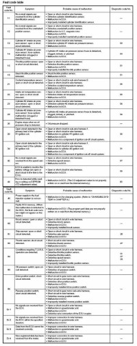
Коды неисправностей Yamaha.
- Год издания: —
- Страниц: 11
- Формат: JPG
- Размер: 1,7 Mb

Руководства по эксплуатации, обслуживанию и ремонту снегоходов Yamaha
Описание конструкции снегохода Yamaha.
- Год издания: —
- Страниц: 65
- Формат: PDF
- Размер: 6,9 Mb
Service Manual Yamaha BR250F.
Руководство на английском языке по техническому обслуживанию и ремонту снегохода Yamaha BR250F.
- Год издания: 1981
- Страниц: 191
- Формат: PDF
- Размер: 8,7 Mb
Руководство пользователя Yamaha BR250TG/VK540EG.
Руководство по эксплуатации и техническому обслуживанию снегоходов Yamaha BR250TG и Yamaha VK540EG.
- Год издания: 2001
- Страниц: 88
- Формат: PDF
- Размер: 8,7 Mb
Supplementary Service Manual Yamaha ET300E.
Дополнение к руководству по техническому обслуживанию и ремонту снегохода Yamaha ET300E.
- Год издания: 1980
- Страниц: 8
- Формат: PDF
- Размер: 790 Kb
Руководство пользователя Yamaha FX Nytro.
Сборник руководств по эксплуатации и техническому обслуживанию снегоходов Yamaha FX Nytro моделей FX10/RFX10 различных модификаций.
- Год издания: 2007-2012
- Страниц: 94/118/122
- Формат: PDF
- Размер: 32,0 Mb
Owner`s Manual Yamaha FX Nytro.
Сборник руководств на английском языке по эксплуатации и техническому обслуживанию снегоходов Yamaha FX Nytro модели FX10 различных модификаций.
- Год издания: 2007-2011
- Страниц: 92/104
- Формат: PDF
- Размер: 18,5 Mb
Service Manual Yamaha FX Nytro.
Руководство на английском языке по техническому обслуживанию и ремонту снегохода Yamaha FX Nytro модели FX10 различных модификаций.
- Год издания: 2007
- Страниц: 410
- Формат: PDF
- Размер: 13,5 Mb
Руководство пользователя Yamaha MM700/VT700/VX700ER.
Руководство по эксплуатации и техническому обслуживанию снегоходов Yamaha MM700/VT700/VX700ER.
- Год издания: 2001
- Страниц: 100
- Формат: PDF
- Размер: 9,2 Mb
Owner`s Manual Yamaha MM/SX/VT/VX 600/700.
Сборник руководств на английском языке по эксплуатации и техническому обслуживанию снегоходов Yamaha MM600/MM700/SX600/VT600/VT700/VX600/VX700 различных модификаций.
- Год издания: 1998-2002
- Страниц: —
- Формат: PDF
- Размер: 32,0 Mb
Руководство пользователя Yamaha PZ50.
Сборник руководств по эксплуатации и техническому обслуживанию снегоходов Yamaha PZ50/RPZ50 Venture различных модификаций.
- Год издания: 2006/2012
- Страниц: 110/120
- Формат: PDF
- Размер: 11,7 Mb
Owner`s Manual Yamaha PZ50.
Сборник руководств на английском языке по эксплуатации и техническому обслуживанию снегоходов Yamaha PZ50 Phazer, Venture различных модификаций.
- Год издания: 2006-2009
- Страниц: 88/92/98/104
- Формат: PDF
- Размер: 21,6 Mb
Service Manual Yamaha PZ50.
Сборник руководств на английском языке по техническому обслуживанию и ремонту снегохода Yamaha PZ50 Phazer, Venture различных модификаций.
- Год издания: 2006-2007
- Страниц: 424/114
- Формат: PDF
- Размер: 21,2 Mb
Service Manual Yamaha PZ500C/VT500XLC.
Руководство на английском языке по техническому обслуживанию и ремонту снегоходов Yamaha PZ500C и Yamaha VT500XLC.
- Год издания: 1998
- Страниц: 209
- Формат: PDF
- Размер: 6,0 Mb
Owner`s Manual Yamaha PZ500/VT500.
Руководство на английском языке по эксплуатации и техническому обслуживанию снегоходов Yamaha PZ 500D/PZ500MLD/VT500XLD.
- Год издания: 1999
- Страниц: 83
- Формат: PDF
- Размер: 2,4 Mb
Руководство пользователя Yamaha RS10/RS90/RSG90/RST90.
Сборник руководств по эксплуатации и техническому обслуживанию снегоходов Yamaha RS10/RS90/RSG90/RST90 RS Vecror, RS Venture различных модификаций.
- Год издания: 2004/2011/2012
- Страниц: 100/108/162
- Формат: PDF
- Размер: 31,0 Mb
Owner`s Manual Yamaha RS90/RSG90/RST90.
Сборник руководств на английском языке по эксплуатации и техническому обслуживанию снегоходов Yamaha RS90/RSG90/RST90 RS Vector, RS Venture различных модификаций.
- Год издания: 2004-2011
- Страниц: —
- Формат: PDF
- Размер: 63,5 Mb
Service Manual Yamaha RS90/RSG90/RST90.
Сборник руководств на английском языке по техническому обслуживанию и ремонту снегоходов Yamaha RS90/RSG90/RST90 RS Venture различных модификаций.
- Год издания: 2004/2006/2008
- Страниц: 414/202/299
- Формат: PDF
- Размер: 37,1 Mb
Руководство пользователя Yamaha RX10/RXW10.
Сборник руководств по эксплуатации и техническому обслуживанию снегоходов Yamaha RX10/RXW10 Apex различных модификаций.
- Год издания: 2001-2012
- Страниц: —
- Формат: PDF
- Размер: 28,6 Mb
Owner`s Manual Yamaha RX10/RXW10.
Сборник руководств на английском языке по эксплуатации и техническому обслуживанию снегоходов Yamaha RX90/RXW90 Apex различных модификаций.
- Год издания: 2002-2010
- Страниц: —
- Формат: PDF
- Размер: 48,2 Mb
Owner`s Manual Yamaha SRX700G.
Руководство на английском языке по эксплуатации и техническому обслуживанию снегоходов Yamaha SRX700G.
- Год издания: 2001
- Страниц: 84
- Формат: PDF
- Размер: 6,6 Mb
Руководство пользователя Yamaha SXV60/70 и VT60/70.
Сборник руководств по эксплуатации и техническому обслуживанию снегоходов Yamaha SXV60/SXV70/VT60/VT70 различных модификаций.
- Год издания: 2003
- Страниц: 113/127
- Формат: PDF
- Размер: 10,5 Mb
Owner`s Manual Yamaha SXV60/70 и VT60/70.
Сборник руководств на английском языке по эксплуатации и техническому обслуживанию снегоходов Yamaha SXV60/SXV70/VT60/VT70 различных модификаций.
- Год издания: 2001-2005
- Страниц: —
- Формат: PDF
- Размер: 48,3 Mb
Руководство пользователя Yamaha VK10.
Сборник руководств по эксплуатации и техническому обслуживанию снегоходов Yamaha VK10/VK10D RS Viking.
- Год издания: 2007/2012
- Страниц: 98/108
- Формат: PDF
- Размер: 15,6 Mb
Owner`s Manual Yamaha VK10.
Сборник руководств на английском языке по эксплуатации и техническому обслуживанию снегоходов Yamaha VK10L и Yamaha VK10X.
- Год издания: 2005/2007
- Страниц: 98/88
- Формат: PDF
- Размер: 7,9 Mb
Supplementary Service Manual Yamaha VK10.
Дополнение к руководству по техническому обслуживанию и ремонту снегоходов Yamaha VK10L/VK10W.
- Год издания: 2005-2006
- Страниц: 360/103
- Формат: PDF
- Размер: 12,2 Mb
Руководство пользователя Yamaha VK540.
Руководство по эксплуатации и техническому обслуживанию снегоходов Yamaha VK540E/VK540EC.
- Год издания: 2012
- Страниц: 82
- Формат: PDF
- Размер: 3,2 Mb
Owner`s Manual Yamaha VK540.
Сборник руководств на английском языке по эксплуатации и техническому обслуживанию снегоходов Yamaha VK540EG/VK540EK.
- Год издания: 2001/2004
- Страниц: 76
- Формат: PDF
- Размер: 4,8 Mb
Service Manual Yamaha VK540EK.
Руководство на английском языке по техническому обслуживанию и ремонту снегохода Yamaha VK540EK.
- Год издания: 2000
- Страниц: 211
- Формат: PDF
- Размер: 4,9 Mb
Руководство пользователя Yamaha VT500XL.
Руководство по эксплуатации и техническому обслуживанию снегохода Yamaha VT500XL.
- Год издания: 2001
- Страниц: 84
- Формат: PDF
- Размер: 8,2 Mb
Коды неисправностей Yamaha.
Коды неисправностей Yamaha.
- Год издания: —
- Страниц: 11
- Формат: JPG
- Размер: 1,7 Mb
Скидки от справочной
При упоминании АСС вы можете получить скидки на запчасти и услуги
Автомобильная Справочная Служба: автоновости, запчасти в Красноярске для иномарок и отечественных автомобилей, машины в разборках, ремонт автомобилей, адреса и телефоны фирм, доска объявлений, каталоги запчастей, руководства по обслуживанию и ремонту.
Вся представленная на сайте информация носит информационный характер и ни при каких условиях не является публичной офертой.
Источник
Техобслуживание снегохода Yamaha
Многие владельцы снегоходов Yamaha (Venture, Warrior, Viking Professional) и других моделей четырехтактных снегоходов разного размера и мощности сталкиваются с проблемой предсезонного обслуживания своего снежного кома. Для проведения технического обслуживания снегоход необходимо погрузить на прицеп и доставить в мотоциклетную мастерскую. Если ваш снежок находится в теплом гараже и у вас есть необходимые инструменты, мы дадим вам несколько полезных советов, как самостоятельно выполнять обслуживание снегохода. Рассмотрите возможность обслуживания снегохода Yamaha RS Viking Professional с 3-цилиндровым двигателем Genesis. Для начала подвешиваем гуся-снежка на расстоянии 5-10 см от поверхности. Это необходимо для проверки степени натяжения гусеницы и диагностики работы приводного механизма. Перед запуском двигателя обязательно проверьте уровень масла в расширительном бачке снегохода, он по ходу находится справа от двигателя. Но прежде чем откручивать щуп для проверки масла, обязательно отсоедините штуцер от щупа. На снегоходе Yamaha Professional щуп для измерения уровня моторного масла также является индикатором уровня масла в баке. Если уровень масла неправильный, загорится сигнальная лампа давления масла на приборной панели «снежный ком». После проверки уровня масла можно заводить двигатель. Электросхема снегоходов Yamaha сделана таким образом, что при включении зажигания не включается приборная панель, и многие владельцы зимних внедорожников считают это неисправностью. Но это совсем не так. Панель приборов, как и все прочие гаджеты на снегоходе, за исключением электростартера, подключается только к генератору. Пока не запустится двигатель снегохода и не заработает генератор, порядок и фары работать не будут. Как только двигатель заведен, его нужно прогреть 10-15 минут. Масло для снегохода следует менять только при прогретом двигателе. Yamaha Viking Professional сливает моторное масло в двух местах. 1. Из расширительного бачка масла. 2 От поддона двигателя. (Под моторным отсеком откручиваем 2 винта и снимаем люк, затем откручиваем масляный фильтр и винт слива моторного масла.) Замена масляного фильтра на снегоходе Yamaha Viking Professional невозможна без специального ключа. Если вы решили проводить техническое обслуживание снегохода самостоятельно, убедитесь, что все инструменты, необходимые для обслуживания снегохода, находятся под рукой. При установке нового масляного фильтра обязательно смажьте резиновое уплотнительное кольцо маслом. Доливать масло нужно не только в расширительный масляный бачок, но и непосредственно в сам двигатель. В верхней части головки двигателя имеется заливная горловина. Заливаем в двигатель примерно 0,5 литра, остальное в маслобак на уровне. Далее приступаем к замене трансмиссионного масла в коробке передач снегохода. Сливной болт (m6) находится сбоку на рейке, т.е внутри коробки передач внизу. После слива снова затяните болт и залейте в коробку передач снегохода новое трансмиссионное масло до необходимого уровня. Если вы закончили с маслами, переходите к системе охлаждения. Нам нужно проверить уровень антифриза в радиаторе снегохода. Откручиваем крышку радиатора и наблюдаем за уровнем антифриза, при необходимости доливаем. Так же проверяем уровень охлаждающей жидкости в расширительном бачке системы охлаждения. Приступаем к осмотру ремня вариатора на предмет различного износа и повреждений. Если ремень вариатора на снегоходе «воспалился», это легко определить по внешнему виду. В этом случае неравномерный износ ремня при движении создает сильные удары в вариаторе, и снегоход разгоняется неравномерно. Принцип замены ремня примерно одинаков на всех вариаторах Yamaha. Закончив с двигателем, перейдем к обслуживанию подвески снегохода. Первым делом нужно осмотреть всю подвеску. Если повреждений нет, проверьте люфт в узлах различных шарниров и затяжку всех болтов и гаек. Перед началом сезона подвеску снегохода необходимо сбрызнуть смазкой. В подвешенном состоянии проверяем натяжение гусеницы и соосность по полозьям. Кстати, горки снегохода — расходный материал, и на их состояние нужно время от времени обращать внимание. Если вовремя не заменить изношенные направляющие, можно отказаться от гусеницы или алюминиевых направляющих.
Подробнее: Электрическая схема управления форсункой двигателя ВАЗ 21074
Как заменить масло в снегоходе
Зима приближается. Все говорит об очередной смене сезона. Снег уже выпал и прочно обосновался в Скалистых горах, как будто он напоминает Среднему Западу, что зима не за горами. Пора подготовить снегоход к работе перед началом сезона. И лучше всего начать с замены масла.
Для владельцев Yamaha Nytro замена масла рекомендуется на заводе-изготовителе после завершения обкатки двигателя (500 миль), а затем после каждых 2500 миль цикла. Но мы думаем, что независимо от количества пройденных километров, неплохо начинать новый сезон со свежим маслом. Почему мы об этом говорим? Дело в том, что при простое снегохода в межсезонье в топливной системе и двигателе начинает скапливаться конденсат. Конечно, вы можете просто следовать рекомендациям производителя, но снегоход прослужит намного дольше, если вы начнете проводить техническое обслуживание до начала сезона.

Профилактическое обслуживание вашего оборудования поможет вам сэкономить время и деньги на последующий ремонт.
Когда показания манометра достигли отметки 500 миль, мы по совету корпорации Yamaha решили заменить масло в нашем Nytro MTX 2012. Yamaha прислала нам комплект для замены, предназначенный для двух трехцилиндровых моделей. Масло полностью синтетическое, есть масляный фильтр и комплект прокладок. Комплект имел номер LUB-SMBCG-KT-05. Yamaha продает его в США по цене 61,99 доллара$.
Трой Джонсон одобрил наши усилия и решил помочь нам заменить масло на Yamaho Nytro. «Вы были правы, решив сделать это в начале зимы 2013 года».
Вот он, небольшой ящик с инструментами Джонсона. После продажи своей доли в Yamaha Джонсон продолжил разработку высокопроизводительных продуктов для обслуживания и ремонта снегоходов Yamaha и других компаний и моделей оборудования. Он специализируется на настройке подвески, турбонагнетателей и других систем. Джонсон также предлагает разнообразные туры в районе Грей-Ривер недалеко от Альп в Вайоминге. Он заключил сделку с Yamaha и может организовать частные конюшни и использовать трассу за Скалистыми горами. Гонки проходят на снегоходах Hillclimb ассоциации RMSHA. Если вам нужна дополнительная информация, вы можете связаться с ним в Lincoln County Customs (LCC), Alpine, WY (307-654-6637).
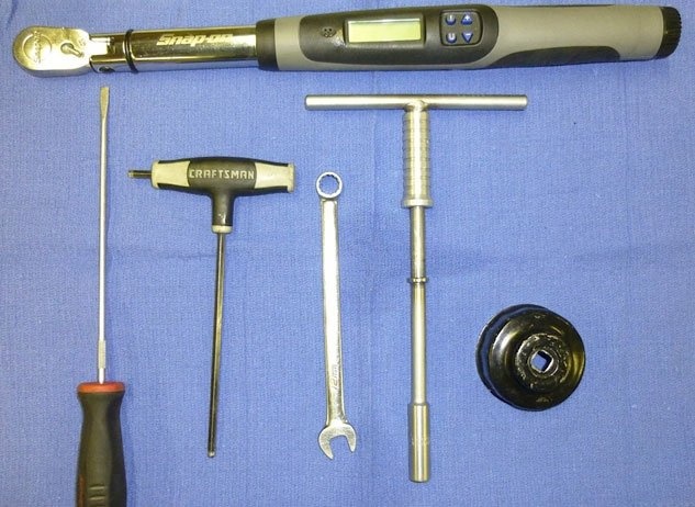
У вас будут все необходимые инструменты, в том числе динамометрический ключ, необходимый для замены масла в вашем Nytro.
Многие владельцы снегоходов Yamaha пользуются услугами сервисных центров и оставляют свои автомобили для подготовки и хранения в межсезонье. Но вы можете поменять масло самостоятельно. Вот основные инструкции, действующие для всех моделей:
Запустите двигатель и дайте ему поработать на холостом ходу не менее 10 минут. Это нагреет двигатель и повысит температуру масла.
Поскольку вам придется работать под снегоходом, необходимо предусмотреть приспособление для его подъема. Джонсон поднял его с помощью гидравлического подъемника, а затем установил на трех алюминиевых стойках. Один установлен под основанием тренажера и по два под каждой лыжей. Убедитесь, что ваше предприятие стабильно — это важно для безопасной работы.
Узнать больше: Что такое предпусковой подогреватель для дизельного двигателя
Теперь нужно снять капюшон и две боковые панели.
С помощью небольшой отвертки с плоским лезвием откройте боковые (нижние) пластиковые крышки, они фиксируются обычными зажимами.
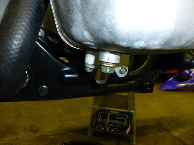
Здесь показано отверстие для слива синтетического масла.
Открутите по два болта с каждой стороны гаечным ключом на 10 мм. Запомните и обратите внимание на место установки черных и цветных фланцевых шайб, которые помогут вам правильно установить снегоход в будущем. Сохраните все болты и гайки, они будут использованы повторно. Если у вас есть смартфон с видеокамерой, используйте ее, чтобы снимать весь процесс.
Снимите защитную крышку с нижней части устройства, открутив четыре фиксатора. Также снимите горизонтальную стяжку в задней части снегохода.
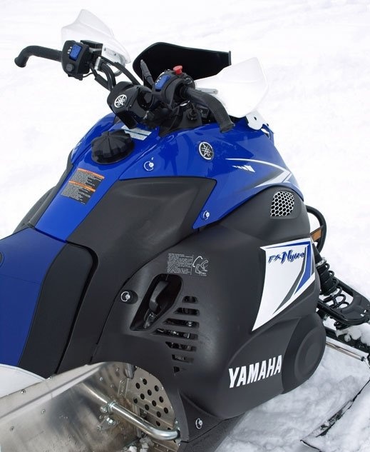
Снимите пластиковую крышку, чтобы получить доступ к двигателю и масляному фильтру.
Сняв все крышки, вы получите доступ к масляному фильтру и увидите сливную пробку. По совету Джонсона теперь доступна дополнительная проверка двигателя. Поскольку крышки все еще открыты, внимательно осмотрите трансмиссию, двигатель и детали трансмиссии, муфты и сцепление. Вы можете найти изношенный ремень, ослабленные крепежные болты, сломанный подшипник или грязь, застрявшую в электронике снегохода.
Чтобы открыть поддон для сбора капель, вам понадобится шестигранный ключ на 5 мм. Чуть ниже масляного фильтра вы найдете несколько винтов. Выбирайте только один, с медной шайбой (это маслосливная пробка). Откручиваем и даем маслу стечь в подготовленную емкость.
Теперь снимаем масляный фильтр. Обратите внимание, что в цилиндрах небольшое количество масла. Дело в том, что Yamaha использует особую систему сухого картера. В случае с Nytro большая часть масла находится в резервуаре с правой стороны двигателя.
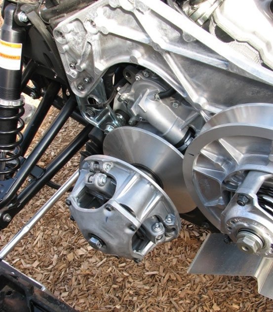
Сняв пластиковую крышку, не позволяйте себе отвлекаться на обслуживание сцепления и других узлов двигателя.
Некоторые особенности использования сухого картера:
Есть конструктивные отличия из-за использования этой системы — моторное масло обычно скапливается под блоком цилиндров в нижней части двигателя. В системе с сухим картером пространство ограничено нижней крышкой, и правильное размещение двигателя имеет решающее значение. Масляного поддона также нет, что делает всю конструкцию легче. Еще одна причина для установки системы с сухим картером — обеспечение смазки двигателя во время неожиданных или крутых поворотов машины. Фактически, снегоход может спускаться или подниматься с горы, а надежная система сухого картера снижает риск нехватки масла или аэрации. Обеспечивает постоянный поток масла.
Единственная слабость этой системы в том, что она не может обеспечить правильную работу двигателя при опрокидывании снегохода. В этом случае необходимо срочно выключить машину. Джонсон рекомендует горным велосипедистам использовать специальное крепление для предотвращения опрокидывания инструмента.
Но вернемся к замене масла.
Подставьте емкость под поддон снегохода и отверните пробку сливного отверстия масляного бака гаечным ключом на 12 мм. У вас должно быть слито около трех с половиной литров масла.
Подробнее: Датчик неисправности системы двигателя
Современные снегоходы оснащены заниженными четырехтактными двигателями. Для их ремонта придется заново разбирать машину. Найдите время, чтобы выполнить плановую проверку основных систем.
На масляном фильтре вы найдете две небольшие медные шайбы. Разберите и используйте предоставленный комплект для замены.
Пришло время заменить сливные пробки. Yamaha рекомендует использовать специальный динамометрический ключ с двойной вилкой и фильтр. Для картера крутящий момент составляет до 7 фунт-футов, для капота — не более 11.
Нанесите небольшое количество масла на прокладку и установите масляный фильтр, затянув крепежные болты с усилием 10 фут-фунтов.
После переустановки масляного фильтра двигатель необходимо залить маслом. Снимите крышку бака и с помощью указателя уровня залейте в двигатель необходимое количество синтетического масла.
Теперь нужно убедиться в отсутствии протечек, для этого запустить двигатель и внимательно осмотреть поддон. Обратите внимание на состояние креплений и расположение прокладок. Просто дайте двигателю поработать на холостом ходу три-четыре минуты, чтобы вся система полностью заполнилась. Если утечек не обнаружено, снимите крышки и проверьте уровень масла. Джонсон пояснил, что это нужно делать сразу после остановки двигателя, иначе масло будет стекать в картер, а манометры покажут низкий уровень.
Поддерживайте уровень моторного масла на уровне чуть менее четырех литров. Не затягивайте пробку слишком сильно, на ней есть щуп, и если вы его хорошо затянете, вы получите ошибочные показания. Проверьте затяжку крышки заливной горловины и при необходимости затяните подходящим ключом. Как только это будет сделано, замена масла завершена.
Проверяйте емкости с отработанным маслом, очень часто в них обнаруживаются неиспользуемые болты или детали крепления. Избегать попадания отработанного масла на кожу, при работе рекомендуется использовать специальные нитриловые перчатки.
Установите на место все защитные кожухи с нижней стороны снегохода. Здесь могут пригодиться предыдущие фильмы о смартфонах.
Затем проверьте затяжку болтовых соединений гусениц и системы стабилизации. Здесь рекомендуется обращаться к руководству оператора вашего снегохода для получения информации обо всех соединениях и уровнях усилия. Срок службы снегохода зависит от соблюдения этих рекомендаций. Проверьте гусеницу, заднюю подвеску и рельсы. Правильная центровка избавит машину от преждевременного и дорогостоящего ремонта и значительно продлит срок ее службы.
Наблюдайте за состоянием передней подвески и при необходимости отрегулируйте. Убедитесь, что А-образные рычаги свободно перемещаются вверх / вниз, а все ножки не имеют ржавчины и грязи. При необходимости смажьте их.
Планируйте, что на замену масла потребуется от 45 минут до 1 часа (это для начала). В дальнейшем все операции займут гораздо меньше времени. Кроме того, потратьте еще несколько минут, чтобы проверить заднюю и переднюю подвеску и оценить износ движущихся частей. Это поможет вам понять, насколько хорошо ваш Nytro (или любой другой снегоход) подготовлен к зимнему сезону.
Мы рады, что перед тем, как приступить к работе в одиночку, обратились за помощью к профессионалам. Джонсон помог нам ценным советом и значительно сократил время на выполнение всех операций. Как и любое транспортное средство, снегоход требует правильного ухода. Это значительно продлевает срок его службы и делает его безопасным в использовании.