- Manuals
- Brands
- Yamaha Manuals
- Motorcycle
- FJR1300AE
- Owner’s manual
-
Contents
-
Table of Contents
-
Troubleshooting
-
Bookmarks
Quick Links
OWNER’S MANUAL
FJR1300AE
MOTORCYCLE
Read this manual carefully before oper-
ating this vehicle.
FJR1300-AE
B96-28199-E0
Related Manuals for Yamaha FJR1300-AE
Summary of Contents for Yamaha FJR1300-AE
-
Page 1
OWNER’S MANUAL FJR1300AE MOTORCYCLE Read this manual carefully before oper- ating this vehicle. FJR1300-AE B96-28199-E0… -
Page 2
EAU69311 Read this manual carefully before operating this vehicle. This manual should stay with this vehicle if it is sold. YAMAHA MOTOR ELECTRONICS CO., LTD. 1450-6, Mori, Mori-machi, Shuchi-gun, Shizuoka-ken, 437-0292 Japan DECLARATION of CONFORMITY Product: IMMOBILIZER Model: 1MC-00 Supplied by… -
Page 3
Please take the time to read this manual thoroughly, so as to enjoy all advantages of your FJR1300-AE. The Owner’s Manual does not only instruct you in how to operate, inspect and maintain your motorcycle, but also in how to safeguard your- self and others from trouble and injury. -
Page 4: Important Manual Information
*Product and specifications are subject to change without notice. EAU10201 FJR1300-AE OWNER’S MANUAL ©2015 by Yamaha Motor Co., Ltd. 1st edition, October 2015 All rights reserved. Any reprinting or unauthorized use without the written permission of Yamaha Motor Co., Ltd.
-
Page 5: Table Of Contents
Table of contents Safety information ……1-1 For your safety – pre-operation checks ……….4-1 Description ……..2-1 Left view ……….2-1 Operation and important riding Right view……..2-2 points……….5-1 Controls and instruments….2-3 Starting the engine……5-2 Shifting……….5-3 Instrument and control functions..3-1 Tips for reducing fuel Immobilizer system ……3-1 consumption……..
-
Page 6
Table of contents Checking and lubricating the throttle grip and cable….6-28 Checking and lubricating the brake and shift pedals….6-28 Checking and lubricating the brake and clutch levers….. 6-29 Checking and lubricating the centerstand and sidestand ..6-29 Lubricating the rear suspension … 6-30 Lubricating the swingarm pivots …….. -
Page 7: Safety Information
Safety information EAU1028B an accident or equipment damage. See page 4-1 for a list of pre-operation checks. Be a Responsible Owner This motorcycle is designed to As the vehicle’s owner, you are re- carry the operator and a passen- sponsible for the safe and proper oper- ger.
-
Page 8
Safety information Many accidents involve inexperi- • The passenger should always enced operators. In fact, many op- hold onto the operator, the seat erators who have been involved in strap or grab bar, if equipped, accidents do not even have a cur- with both hands and keep both rent motorcycle license. -
Page 9
Safety information Avoid Carbon Monoxide Poisoning extra care when riding a motorcycle All engine exhaust contains carbon that has added cargo or accessories. monoxide, a deadly gas. Breathing Here, along with the information about carbon monoxide can cause head- accessories below, are some general aches, dizziness, drowsiness, nausea, guidelines to follow if loading cargo to confusion, and eventually death. -
Page 10
Genuine before using it to make sure that it Yamaha accessories, which are avail- does not in any way reduce able only from a Yamaha dealer, have ground clearance or cornering been designed, tested, and approved clearance, limit suspension travel, by Yamaha for use on your vehicle. -
Page 11: Specifications
Safety information operator and may limit control torcycle, such as the frame or up- ability, therefore, such accesso- per front fork triple clamp (and not, ries are not recommended. for example, to rubber-mounted Use caution when adding electri- handlebars or turn signals, or cal accessories.
-
Page 12: Description
Description EAU63371 Left view 1. Coolant reservoir (page 6-15) 2. Accessory box (page 3-36) 3. Owner’s tool kit (page 6-2) 4. Final gear oil filler bolt (page 6-14) 5. Final gear oil drain bolt (page 6-14) 6. Air filter element (page 6-17) 7.
-
Page 13: Right View
Description EAU63391 Right view 1. Storage compartment (page 3-35) 2. Fuel tank cap (page 3-29) 3. Electronically adjustable suspension system (page 3-40) 4. Windshield (page 3-12) 5. Fuses (page 6-34) 6. Battery (page 6-32) 7. Brake pedal (page 3-26) 8. Rear brake fluid reservoir (page 6-25)
-
Page 14: Controls And Instruments
Description EAU63401 Controls and instruments 10,11 1. Clutch lever (page 3-24) 2. Rear view mirror (page 3-40) 3. Left handlebar switches (page 3-23) 4. Clutch fluid reservoir (page 6-25) 5. Multi-function meter unit (page 3-10) 6. Main switch/steering lock (page 3-2) 7.
-
Page 15: Instrument And Control Functions
Do not grind any key or alter its cess, take the vehicle along with all shape. three keys to a Yamaha dealer to have Do not disassemble the plastic them re-registered. Do not use the key part of any key.
-
Page 16: Main Switch/Steering Lock
Instrument and control functions Keep the standard keys as well EAU10474 Main switch/steering lock as keys of other immobilizer systems away from this vehi- cle’s code re-registering key. Keep other immobilizer system keys away from the main switch as they may cause signal inter- ference.
-
Page 17
Instrument and control functions To unlock the steering EWA10062 WARNING Never turn the key to “OFF” or “LOCK” while the vehicle is moving. Otherwise the electrical systems will be switched off, which may result in loss of control or an accident. EAU10694 LOCK The steering is locked and all electrical… -
Page 18: Indicator Lights And Warning Lights
TIME TRIP 0:06 initially when the key is turned to “ON”, or if the warning light remains on, have a Yamaha dealer check the electrical 1. Immobilizer system indicator light “ ” circuit. 2. Left turn signal indicator light “…
-
Page 19
If this occurs, braking. Have a Yamaha dealer have a Yamaha dealer check the on- check the brake system and electri- board diagnostic system. cal circuits as soon as possible. -
Page 20
Immobilizer system indicator do not start the engine, take the light “ ” When the key is turned to “OFF” and vehicle and all 3 keys to a Yamaha 30 seconds have passed, the indicator dealer to have the standard keys re-registered. -
Page 21: Cruise Control System
Instrument and control functions EAU54192 Cruise control system A.TEMP This model is equipped with a cruise C.TEMP control system designed to maintain a set cruising speed. TIME TR The cruise control system operates only when riding in 3rd gear at speeds between about 50 km/h (31 mi/h) and 160 km/h (100 mi/h), 4th or 5th gear at speeds between about 50 km/h (31…
-
Page 22
Instrument and control functions Adjusting the set cruising speed While the cruise control system is op- erating, push the “RES+” side of the cruise control setting switch to in- crease the set cruising speed or the “SET–” side to decrease the set speed. Pushing the setting switch once will change the speed in increments of ap- 1. -
Page 23
Instrument and control functions set cruising speed. You will not be able to use the resume function until a new In some cases, the cruise control sys- cruising speed has been set. tem may not be able to maintain the set cruising speed when the vehicle is Automatic deactivation of the cruise traveling uphill or downhill. -
Page 24: Multi-Function Meter Unit
Instrument and control functions EAU58235 Multi-function meter unit 12 3 9 10 GEAR A.TEMP ˚C C.TEMP ˚C TIME TRIP 0:06 1. Menu switch “MENU” 2. Select switch “ ” 1. “RESET” button multi-function meter unit 2. “TCS” button equipped with the following: 3.
-
Page 25
1. Tachometer play segments will flash repeatedly. 2. Tachometer red zone Have a Yamaha dealer check the vehi- cle. The electric tachometer allows the rid- er to monitor the engine speed and Eco indicator keep it within the ideal power range. -
Page 26
Instrument and control functions Transmission gear display Function display GEAR GEAR A.TEMP ˚C A.TEMP ˚C C.TEMP ˚C C.TEMP ˚C TIME TRIP 0:06 TIME TRIP 0:06 1. Neutral indicator light “ ” 1. Function display 2. Transmission gear display This display shows the selected gear. The neutral position is indicated by “… -
Page 27
Instrument and control functions The following pages contain an expla- Selecting the information display nation of the grip warmer, information GEAR display, and windshield functions. See TRIP-1 page 3-40 for an explanation of the TRIP-2 preload and damping force adjusting functions. -
Page 28
Instrument and control functions The odometer shows the total distance In this case, push the select switch to traveled by the vehicle. switch the display in the following or- der: Tripmeter displays: TRIP-F → Display–1 → Display–2 → Display–3 → TRIP-F TRIP-1 To reset a tripmeter, use the select switch to select the information display… -
Page 29
Instrument and control functions If the message “Hi” flashes, stop the vehicle, then stop the engine, and let There are also “TIME–2” and “TIME–3” the engine cool. (See page 6-38.) elapsed time displays, but they cannot be set to the information display. See GEAR “Setting mode”… -
Page 30
If there is a malfunction, “– –.–” will SET” button again for 2 seconds while be continuously displayed. Have a the display is flashing. Yamaha dealer check the vehicle. Adjusting the windshield position After resetting the average fuel con- To move the windshield up, push sumption display, “_ _._”… -
Page 31
Instrument and control functions and return to the normal display, push Adjusting the temperature levels of the and hold the menu switch “MENU” grip warmer settings again for at least 2 seconds. 1. Use the select switch to highlight “Grip Warmer”. Display Description This function allows you to… -
Page 32
Instrument and control functions Grip Warmer MENU Grip Warmer Hi g h Maintenance Time Trip Middle Unit Display Brightness Clock 4. Use the select switch to highlight 2. Push the “MENU” switch, and “Middle” or “Low”, and then chan- then push the “RESET” button to ge the setting using the same pro- select the item to reset. -
Page 33
Instrument and control functions 2. Push the “MENU” switch to dis- play “TIME–2” and “TIME–3”. To Unit reset a time trip, push the “RE- SET” button to select the item to km or mile reset. km/L or L/100km km/L Time Trip 0:07 TIME-2 3. -
Page 34
Instrument and control functions Unit Display-1 km or mile A.TEMP km/L or L/100km C.TEMP km/L TIME TRIP 4. Use the select switch to select the Selecting the display items item to show, and then push the 1. Use the select switch to highlight “MENU”… -
Page 35
Instrument and control functions Adjusting the meter panel brightness 3. When the hour digits start flash- 1. Use the select switch to highlight ing, use the select switch to set “Brightness”. the hours. MENU Clock Grip Warmer Maintenance Time Trip 5 55 Unit Display… -
Page 36: D-Mode (Drive Mode)
Instrument and control functions EAU49432 D-mode (drive mode) All Reset D-mode is an electronically controlled engine performance system with two mode selections (touring mode “T” and sports mode “S”). Push the drive mode switch “MODE” to switch between modes. (See page 3-24 for an explanation of the drive mode switch.) The odometer and the clock cannot be…
-
Page 37: Handlebar Switches
Instrument and control functions EAU1234J EAU12461 Handlebar switches Turn signal switch “ ” To signal a right-hand turn, push this Left switch to “ ”. To signal a left-hand turn, push this switch to “ ”. When released, the switch returns to the cen- ter position.
-
Page 38: Clutch Lever
Instrument and control functions EAU12781 EAU12832 Cruise control switches Clutch lever See page 3-7 for an explanation of the cruise control system. EAU54231 Menu switch “MENU” This switch is used to perform selec- tions in the function display and setting mode display of the multi-function me- ter unit.
-
Page 39: Shift Pedal
Instrument and control functions EAU12872 EAU26825 Shift pedal Brake lever The brake lever is located on the right side of the handlebar. To apply the front brake, pull the lever toward the throttle grip. 1. Shift pedal The shift pedal is located on the left side of the motorcycle and is used in combination with the clutch lever when 1.
-
Page 40: Brake Pedal
Instrument and control functions EAU39542 EAU73181 Brake pedal This model’s anti-lock brake system (ABS) features a dual electronic control system, which acts on the front and rear brakes independently. Operate the brakes with ABS as you would conventional brakes. If the ABS is activated, a pulsating sensation may be felt at the brake lever or brake ped- al.
-
Page 41: Traction Control System
However, special tools are wet roads. If sensors detect that the required, so please consult your rear wheel is starting to slip (uncon- Yamaha dealer. trolled spinning), the traction control ECA16831 system assists by regulating engine NOTICE…
-
Page 42
20 km/h (12 mi/h). If the “TCS” indicator/warning light and/or engine trouble warning light still remain on after resetting, the motorcycle may still be ridden; howev- er, have a Yamaha dealer check the motorcycle as soon as possible. 3-28… -
Page 43: Fuel Tank Cap
Instrument and control functions EAU13075 EAU13222 Fuel tank cap Fuel Make sure there is sufficient gasoline in the tank. EWA10882 WARNING Gasoline and gasoline vapors are extremely flammable. To avoid fires and explosions and to reduce the risk of injury when refueling, follow these instructions.
-
Page 44
Your Yamaha engine has been de- signed to use regular unleaded gaso- line with a research octane number of 3-30… -
Page 45: Fuel Tank Overflow Hose
Instrument and control functions EAU72970 EAU13447 Fuel tank overflow hose Catalytic converters This vehicle is equipped with catalytic converters in the exhaust system. EWA10863 WARNING The exhaust system is hot after op- eration. To prevent a fire hazard or burns: …
-
Page 46: Seats
Instrument and control functions EAU39496 Rider seat Seats To remove the rider seat Passenger seat 1. Remove the passenger seat. 2. Push the rider seat lock lever, lo- To remove the passenger seat cated under the back of the rider 1.
-
Page 47: Adjusting The Rider Seat Height
Instrument and control functions The rider seat height can be ad- EAU39633 Adjusting the rider seat height justed to change the riding posi- The rider seat height can be adjusted tion. (See the following section.) to one of two positions to suit the rid- er’s preference.
-
Page 48
Instrument and control functions 6. Align the projection on the bottom of the rider seat with the “H” posi- tion slot, and then push the rear of the seat down to lock it in place as shown. 1. Rider seat holder cover 4. -
Page 49: Storage Compartments
Instrument and control functions 5. Insert the projection on the front of EAU73350 Storage compartments the rider seat into seat holder A as This vehicle is equipped with two stor- shown. age compartments. Storage compartment A is located un- der the rider seat. (See page 3-32.) 1.
-
Page 50: Accessory Box
Instrument and control functions Do not subject the IMU to EAU39482 Accessory box strong shocks or moisture. The accessory box is located beside Do not obstruct the IMU breath- the meter panel. er hole and do not clean it with compressed air.
-
Page 51: Adjusting The Headlight Beams
Instrument and control functions Do not exceed the maximum EAU39612 Adjusting the headlight beams load of 212 kg (467 lb) for the ve- The headlight beam adjusting knobs hicle. are used to raise or lower the height of the headlight beams. It may be neces- sary to adjust the headlight beams to increase visibility and help prevent blinding oncoming drivers when carry-…
-
Page 52: Handlebar Position
The handlebars can be adjusted to one ing vents of three positions to suit the rider’s The cowling vents can be opened 20 preference. Have a Yamaha dealer ad- mm (0.79 in) for added ventilation to just the position of the handlebars. suit the riding conditions.
-
Page 53
Instrument and control functions 1. Projection 1. Projection 2. Upper slot 2. Lower slot 3. Quick fastener 3. Quick fastener 4. Install the quick fastener. 4. Install the quick fastener. To close a cowling vent Make sure that the cowling vent panels 1. -
Page 54: Rear View Mirrors
Instrument and control functions EAU39672 EAU55424 Rear view mirrors Adjusting the front and rear The rear view mirrors of this vehicle suspension can be folded forward or backward for This model is equipped with an elec- parking in narrow spaces. Fold the mir- tronically adjustable suspension sys- rors back to their original position be- tem.
-
Page 55
Yamaha dealer check the sus- pension system. To adjust the preload 1. Turn the key to “ON”, start the en- gine, and then shift the transmis- sion into neutral. 2. Push the menu switch “MENU” to switch the function display to the preload adjusting function. -
Page 56
Instrument and control functions GEAR GEAR GEAR GEAR HARD If the preload is adjusted repeat- While the preload is being adjusted, the information display may change as edly, the preload setting picto- follows. gram will flash 4 times and the … -
Page 57
Instrument and control functions GEAR GEAR HARD 1. Damping force setting 1. Function display 2. Damping force setting level 2. Damping force adjusting function 3. Use the select switch to select “HARD”, “STD” or “SOFT”. If the preload setting was not complet- ed correctly: GEAR … -
Page 58
6. Push the menu switch “MENU”. sembly yourself. Take the shock absorber assembly to a Yamaha If the vehicle moves while you are ad- dealer for any service. justing the damping force, the informa- tion display will change to the display mode. -
Page 59: Sidestand
Therefore, check this system regularly and have a Yamaha dealer repair it if it does not function properly. 3-45…
-
Page 60
Does the engine start? The neutral switch may not be working correctly. The motorcycle should not be ridden until checked by a Yamaha dealer. With the engine still running: 6. Move the sidestand up. 7. Keep the clutch lever pulled. -
Page 61: Auxiliary Dc Jack
Instrument and control functions 5. Insert the accessory plug into the EAU39656 Auxiliary DC jack auxiliary DC jack. EWA14361 WARNING To prevent electrical shock or short- circuiting, make sure that the cap is installed when the auxiliary DC jack is not being used. ECA15432 NOTICE The accessory connected to the…
-
Page 62: Cornering Lights
Instrument and control functions EAU73031 Cornering lights 1. Cornering light This model is equipped with 3 corner- ing lights on each side. The cornering lights come on to help illuminate the road when the vehicle is leaned over. According to the direction of the turn, the cornering lights for that side come on.
-
Page 63: For Your Safety — Pre-Operation Checks
Do not operate the vehicle if you find any problem. If a problem cannot be corrected by the procedures provided in this manual, have the vehicle inspected by a Yamaha dealer. Before using this vehicle, check the following points:…
-
Page 64
For your safety – pre-operation checks ITEM CHECKS PAGE • Check operation. • If soft or spongy, have Yamaha dealer bleed hydraulic system. 6-23, Clutch • Check fluid level in reservoir. 6-25 • If necessary, add specified brake fluid to specified level. -
Page 65: Operation And Important Riding Points
This model is equipped with: there is a control or function you do not an inertial measurement unit (IMU) understand, ask your Yamaha dealer. that will stop the engine in case of EWA10272 turnover. In this case, turn the key WARNING to “OFF”…
-
Page 66: Starting The Engine
The neutral indi- the clutch lever pulled and the cator light should come on. If not, sidestand up. ask a Yamaha dealer to check the See page 3-45 for more informa- electrical circuit. tion. 3. Start the engine by pushing 1.
-
Page 67: Shifting
Operation and important riding points EAU16673 and drive train, which are not Shifting designed withstand shock of forced shifting. EAU16682 To start out and accelerate 1. Pull the clutch lever to disengage the clutch. 2. Shift the transmission into first gear.
-
Page 68: Tips For Reducing Fuel Consumption
Operation and important riding points clutch lever in, use the brakes to EAU16811 Tips for reducing fuel con- slow the motorcycle, and continue sumption to downshift as necessary. Fuel consumption depends largely on 4. Once motorcycle your riding style. Consider the follow- stopped, the transmission can be ing tips to reduce fuel consumption: shifted into the neutral position.
-
Page 69: Engine Break-In
There is never a more important period period, immediately have a in the life of your engine than the period Yamaha dealer check the vehi- between 0 and 1600 km (1000 mi). For cle. this reason, you should read the fol- lowing material carefully.
-
Page 70: Parking
Operation and important riding points EAU17214 Parking When parking, stop the engine, and then remove the key from the main switch. EWA10312 WARNING Since the engine and exhaust system can become very hot, park in a place where pedestri- ans or children are not likely to touch them and be burned.
-
Page 71: Periodic Maintenance And Adjustment
If you are not familiar with vehicle ser- vice, have a Yamaha dealer perform service. EWA15123 WARNING Turn off the engine when performing…
-
Page 72: Owner’s Tool Kit
If you do not have the tools or experi- ence required for a particular job, have a Yamaha dealer perform it for you.
-
Page 73: Periodic Maintenance Chart For The Emission Control System
From 50000 km (30000 mi), repeat the maintenance intervals starting from 10000 km (6000 mi). Items marked with an asterisk should be performed by a Yamaha dealer as they require special tools, data and technical skills. EAU63322…
-
Page 74: General Maintenance And Lubrication Chart
Periodic maintenance and adjustment EAU64031 General maintenance and lubrication chart ODOMETER CHECK OR READINGS MAINTENANCE JOB ITEM X 1000 km X 1000 mi √ √ • Clean. Air filter element √ √ • Replace. • Check operation, fluid level and √…
-
Page 75
Periodic maintenance and adjustment ODOMETER CHECK OR READINGS MAINTENANCE JOB ITEM X 1000 km X 1000 mi Brake lever pivot √ √ √ √ √ • Lubricate with silicone grease. shaft Brake pedal pivot • Lubricate with lithium-soap- √ √ √… -
Page 76
Periodic maintenance and adjustment ODOMETER CHECK OR READINGS MAINTENANCE JOB ITEM X 1000 km X 1000 mi • Check operation. • Check throttle grip free play, and adjust if necessary. √ √ √ √ √ 28 * Throttle grip • Lubricate cable and grip hous- ing. -
Page 77: Removing And Installing Panels
Periodic maintenance and adjustment EAU18773 EAU54133 Removing and installing pan- Panel A The panels shown need to be removed to perform some of the maintenance To remove the panel jobs described in this chapter. Refer to 1. Remove the bolts and the quick this section each time a panel needs to fasteners.
-
Page 78
Periodic maintenance and adjustment Make sure that the fuses are covered and located to the inside of the panel lip. 1. Slot 2. Projection To install the panel 1. Fit the slot at the front of the panel under the projection on the front 1. -
Page 79
Periodic maintenance and adjustment 1. Panel C 1. Panel B 2. Quick fastener screw 2. Install the seats. 3. Bolt 3. Pull the bottom of the panel out- ward, pull the front of the panel downward, and then slide the panel forward to release it in the rear as shown. -
Page 80: Checking The Spark Plugs
The spark plugs are important engine components, which should checked periodically, preferably by a Yamaha dealer. Since heat and depos- its will cause any spark plug to slowly erode, they should be removed and checked in accordance with the peri- odic maintenance and lubrication 1.
-
Page 81: Canister
Periodic maintenance and adjustment EAU36111 EAU19888 Canister Engine oil and oil filter car- tridge The engine oil level should be checked before each ride. In addition, the oil must be changed and the oil filter car- tridge replaced at the intervals speci- fied in the periodic maintenance and lubrication chart.
-
Page 82
3. Place an oil pan under the engine An oil filter wrench is available at a to collect the used oil. Yamaha dealer. 4. Remove the engine oil filler cap, 6. Apply a thin coat of clean engine the engine oil drain bolt and its… -
Page 83
See page 8-1. correct, immediately turn the engine Oil quantity: Oil change: off and have a Yamaha dealer check 3.80 L (4.02 US qt, 3.34 Imp.qt) the vehicle. With oil filter removal: 4.00 L (4.23 US qt, 3.52 Imp.qt) 11. -
Page 84: Final Gear Oil
Final gear oil The final gear case must be checked for oil leakage before each ride. If any leakage is found, have a Yamaha deal- er check and repair the vehicle. In ad- dition, the final gear oil level must be…
-
Page 85: Coolant
(See page 3-38.) 3. Check the coolant level in the Recommended final gear oil: coolant reservoir. Yamaha genuine shaft drive gear oil SAE 80W-90 API GL-5 Oil quantity: The coolant should be between the mi- 0.20 L (0.21 US qt, 0.18 Imp.qt) nimum and maximum level marks.
-
Page 86
Have a engine is hot. [EWA15162] Yamaha dealer change the coolant. WARNING! Never attempt to remove the radiator cap when the engine is hot. [EWA10382] 1. -
Page 87: Cleaning The Air Filter Element
Periodic maintenance and adjustment EAU72990 Cleaning the air filter element The air filter element should be cleaned or replaced at the intervals specified in the periodic maintenance and lubrica- tion chart. Clean or, if necessary, re- place the air filter element more frequently if you are riding in unusually wet or dusty areas.
-
Page 88: Checking The Engine Idling Speed
EAU44735 Checking the engine idling speed Check the engine idling speed and, if necessary, have it corrected by a Yamaha dealer. Engine idling speed: 1000–1100 r/min 1. Fuel tank overflow hose 8. Install the intake air shroud by in- stalling the screw and the quick fastener screws.
-
Page 89: Checking The Throttle Grip Free Play
Measure the throttle grip free play as and/or engine noise. To prevent this shown. from occurring, the valve clearance must be adjusted by a Yamaha dealer at the intervals specified in the periodic maintenance and lubrication chart. 1. Throttle grip free play Throttle grip free play: 1.0–3.0 mm (0.04–0.12 in)
-
Page 90: Tires
The tires must be checked before each ride. If the center tread depth reaches the specified limit, if the tire has a nail or glass fragments in it, or if the side- wall is cracked, have a Yamaha dealer replace the tire immediately. 6-20…
-
Page 91
EWA10472 their suitability for further use. WARNING EWA10902 Have a Yamaha dealer replace WARNING excessively worn tires. Besides The front and rear tires should being illegal, operating the vehi- be of the same make and de-… -
Page 92: Cast Wheels
If any damage is found, have high speeds. a Yamaha dealer replace the Brand-new tires can have a rel- wheel. Do not attempt even the atively poor grip on certain road smallest repair to the wheel.
-
Page 93: Clutch Lever
If there 1. No brake lever free play is air in the hydraulic system, have a Yamaha dealer bleed the system be- There should be no free play at the fore operating the motorcycle.
-
Page 94: Brake Light Switches
Since the brake light ified in the periodic maintenance and switches are components of the cruise lubrication chart. control system, they must be adjusted by a Yamaha dealer, who has the nec- EAU43432 Front brake pads essary professional knowledge and ex- perience.
-
Page 95: Checking The Brake And Clutch Fluid Levels
If a brake pad is damaged or if the lining thickness is less than 0.8 mm (0.03 in), have a Yamaha dealer replace the brake pads as a set. 1. Minimum level mark Rear brake 1.
-
Page 96
Clean the filler caps before re- suddenly, have a Yamaha dealer check moving. Use only DOT 4 brake the cause before further riding. fluid from a sealed container. -
Page 97: Changing The Brake And Clutch Fluids
Yamaha dealer check or re- at the intervals listed below or whenev- place it. WARNING! Damage to the er they are damaged or leaking.
-
Page 98: Checking And Lubricating The Throttle Grip And Cable
In pedals should be checked before each addition, the cable should be lubricat- ride, and the pedal pivots should be lu- ed by a Yamaha dealer at the intervals bricated if necessary. specified in the periodic maintenance Brake pedal chart.
-
Page 99: Checking And Lubricating The Brake And Clutch Levers
Clutch lever WARNING If the centerstand or sidestand does not move up and down smoothly, have a Yamaha dealer check or re- pair it. Otherwise, the centerstand or sidestand could contact the ground and distract the operator, resulting in a possible loss of control.
-
Page 100: Lubricating The Rear Suspension
The pivoting points of the rear suspen- The swingarm pivots must be lubricat- sion must be lubricated by a Yamaha ed by a Yamaha dealer at the intervals dealer at the intervals specified in the specified in the periodic maintenance periodic maintenance and lubrication and lubrication chart.
-
Page 101: Checking The Front Fork
If any free there is no danger of it falling play can be felt, have a Yamaha over. dealer check or repair the steer- [EWA10752] 2.
-
Page 102: Checking The Wheel Bearings
(See page 6-7.) hub or if the wheel does not turn This model is equipped with a VRLA smoothly, have a Yamaha dealer (Valve Regulated Lead Acid) battery. check the wheel bearings. There is no need to check the electro- lyte or to add distilled water.
-
Page 103
ECA16531 NOTICE To charge the battery Always keep the battery charged. Have a Yamaha dealer charge the bat- Storing a discharged battery can tery as soon as possible if it seems to cause permanent battery damage. have discharged. Keep in mind that the… -
Page 104: Replacing The Fuses
Periodic maintenance and adjustment EAU54515 Replacing the fuses 12 13 The fuse boxes and individual fuses are located under panel A. (See page 6-7.) 16 15 1. ABS motor fuse 2. ABS solenoid fuse 3. Fuel injection system fuse 4. Backup fuse (for clock and immobilizer sys- tem) 5.
-
Page 105: Vehicle Lights
There are no user replaceable Main fuse 2: bulbs. 30.0 A Terminal fuse 1: If a light does not come on, check the 3.0 A fuses and then have a Yamaha dealer Headlight fuse: check the vehicle. 7.5 A ECA16581 Brake light fuse: NOTICE 1.0 A…
-
Page 106: Troubleshooting
The following troubleshooting charts represent quick and easy procedures for checking these vital systems your- self. However, should your motorcycle require any repair, take it to a Yamaha dealer, whose skilled technicians have the necessary tools, experience, and know-how to service the motorcycle properly.
-
Page 107: Troubleshooting Charts
Check the vehicle. compression. 4. Compression The engine does not start. There is compression. Have a Yamaha dealer check the vehicle. Operate the electric starter. There is no Have a Yamaha dealer check the vehicle. compression. 6-37…
-
Page 108
Start the engine. If the engine overheats again, The coolant level is have a Yamaha dealer check and repair the cooling system. If coolant is not available, tap water can be temporarily used instead, provided that it is changed to the recommended coolant as soon as possible. -
Page 109: Motorcycle Care And Storage
Rust and corrosion can develop matte colored finished parts. Be even if high-quality components are sure to consult a Yamaha dealer for used. A rusty exhaust pipe may go un- advice on what products to use be- noticed on a car, however, it detracts fore cleaning the vehicle.
-
Page 110
Motorcycle care and storage structed. Also, thoroughly rinse compounds for plastic may the area off with water, immedi- leave scratches on the wind- ately dry it, and then apply a cor- shield. Test the product on a rosion protection spray. small hidden part of the wind- … -
Page 111
3. To prevent corrosion, it is recom- Consult a Yamaha dealer for ad- mended to apply a corrosion pro- vice on what products to use. tection spray metal, … -
Page 112: Storage
Motorcycle care and storage der head so that the electrodes EAU26244 Storage are grounded. (This will limit sparking during the next step.) Short-term d. Turn the engine over several Always store your motorcycle in a cool, times with the starter. (This will dry place and, if necessary, protect it coat the cylinder walls with oil.) against dust with a porous cover.
-
Page 113
Motorcycle care and storage Make any necessary repairs before storing the motorcycle. -
Page 114: Specifications
Overall length: Final gear oil: 2230 mm (87.8 in) Overall width: Type: 750 mm (29.5 in) Yamaha genuine shaft drive gear oil SAE Overall height: 80W-90 API GL-5 1325/1455 mm (52.2/57.3 in) Quantity: Seat height: 0.20 L (0.21 US qt, 0.18 Imp.qt) 805/825 mm (31.7/32.5 in)
-
Page 115
Specifications 2nd: Front wheel: 1.722 (31/18) Wheel type: 3rd: Cast wheel 1.350 (27/20) Rim size: 4th: 17M/C x MT3.50 1.111 (30/27) Rear wheel: 5th: Wheel type: 0.963 (26/27) Cast wheel 6th: Rim size: 0.846 (22/26) 17M/C x MT5.50 Chassis: Unified brake system: Frame type: Operation: Diamond… -
Page 116
Specifications Battery: Headlight fuse: 7.5 A Model: Brake light fuse: GT14B-4 1.0 A Voltage, capacity: Signaling system fuse: 12 V, 12.0 Ah (10 HR) Bulb wattage × quantity: 7.5 A Ignition fuse: Headlight: 20.0 A Radiator fan motor fuse: Brake/tail light: 10.0 A ×… -
Page 117: Consumer Information
Yamaha dealer. area. VEHICLE IDENTIFICATION NUMBER: EAU26442 Engine serial number…
-
Page 118: Diagnostic Connector
Consumer information label in the space provided. This infor- EAU69910 Diagnostic connector mation will be needed when ordering spare parts from a Yamaha dealer. 1. Diagnostic connector The diagnostic connector is located as shown.
-
Page 119: Index
Index Fuel consumption, tips for reducing ..5-4 Fuel tank cap ……..3-29 ABS …………3-26 Fuel tank overflow hose……3-31 ABS warning light……..3-5 Fuses, replacing……..6-34 Accessory box……..3-36 Air filter element, cleaning ….6-17 Auxiliary DC jack ……..3-47 Handlebar position, adjusting….
-
Page 120
Index Storage ………..7-4 Storage compartments ……3-35 Suspension, adjusting the front and rear ………….3-40 Swingarm pivots, lubricating ….6-30 Throttle grip and cable, checking and lubricating………..6-28 Throttle grip free play, checking …6-19 Tires …………6-20 Tool kit …………6-2 Traction control system ……3-27 Traction control system indicator/warning light ……3-5 Troubleshooting……..6-36 Troubleshooting charts……6-37… -
Page 122
Original instructions PRINTED ON RECYCLED PAPER PRINTED IN JAPAN 2015.12-0.3×1 CR…

Руководство по эксплуатации и техническому обслуживанию мотоциклов Yamaha FJR1300A.
- Издательство: Yamaha Motor Co., Ltd.
- Год издания: 2010
- Страниц: 105
- Формат: PDF
- Размер: 6,0 Mb

Руководство по эксплуатации и техническому обслуживанию мотоциклов Yamaha FJR1300AS.
- Издательство: Yamaha Motor Co., Ltd.
- Год издания: 2009
- Страниц: 105
- Формат: PDF
- Размер: 4,1 Mb
Сборник руководств на английском языке по эксплуатации и техническому обслуживанию мотоциклов Yamaha моделей FJR13AD(C)/AEV(C)/AEY(C)/AV(C)/AX(C)/AZ(C).
- Издательство: Yamaha Motor Co., Ltd.
- Год издания: 2005-2012
- Страниц: —
- Формат: PDF
- Размер: 23,8 Mb

Сборник руководств на английском языке по эксплуатации и техническому обслуживанию мотоциклов Yamaha моделей FJR1300/A/AP/AS(C)/AT(C)/N/R/RC/S(C)/T(C).
- Издательство: Yamaha Motor Co., Ltd.
- Год издания: 2001-2010
- Страниц: —
- Формат: PDF
- Размер: 64,7 Mb
Руководство на английском языке по ремонту мотоциклов Yamaha моделей FJR1300 и FJR1300N 2001 года выпуска.
- Издательство: Yamaha Motor Co., Ltd.
- Год издания: —
- Страниц: 617
- Формат: PDF
- Размер: 15,2 Mb
Руководство на английском языке по ремонту мотоциклов Yamaha моделей FJR1300A и FJR1300AV 2006 года выпуска.
- Издательство: Yamaha Motor Co., Ltd.
- Год издания: 2006
- Страниц: 586
- Формат: PDF
- Размер: 23,3 Mb
Руководство (дополнение) на английском языке по ремонту мотоциклов Yamaha моделей FJR1300, FJR1300A, FRJ1300AS и FRJ1300S 2004 года выпуска.
- Издательство: Yamaha Motor Co., Ltd.
- Год издания: 2003
- Страниц: 44
- Формат: PDF
- Размер: 1,7 Mb

Сборник руководств на английском, французском, немецком, испанском и итальянском языках по ремонту мотоциклов Yamaha моделей FJR1300, FJR1300A и др.
- Издательство: Yamaha
- Год издания: —
- Страниц: —
- Формат: ISO
- Размер: 1,7 Gb

|
Каталог файлов
Наклейки на авто Наклейки на авто Мои файлы | Мануалы и руководства по FJR1300. Разные мануалы и рукаводства для FJR разных годов… Мануалы | 5JW1-AE5 FJR1300(A) 2004 Supplementary Service Manual.pdf Supplementary Service Manual Мои файлы | 5JW1-AE4 FJR1300(A) 2003 Supplementary Service Manual.pdf Supplementary Service Manual Мои файлы | Сравнительная таблица Yamaha FJR1300. Сравнение разных поколений и годов выпуска. Мои файлы | РОН ЭЙРС «НА МИЛЮ ДАЛЬШЕ» Секреты мотодальнобоя из первых рук Мои файлы | FJR1300 2002 Supplementary Service Manual Руководство по обслуживанию и ремонту FJR1300 2002. Использовать совместно с руководством FJR1300 2001. Мои файлы | Электрическая схема FJR1300 (USA) (2003) Цветная схема. Мои файлы | Маркировки аккумуляторов Найден в интернете экселевский файлик с расшифровкой маркировок аккумуляторов. Мои файлы | Part Numbers Найден в интернете экселевский файли с партнамберами. Мои файлы | 1-10 11-14 |
На этой странице вы можете совершенно бесплатно скачать Руководство по эксплуатации Yamaha FJR1300.
У документа PDF Руководство по эксплуатации 106 страниц, а его размер составляет 4.72 Mb.
Читать онлайн Мотоциклы Yamaha FJR1300 Руководство по эксплуатации

Скачать файл PDF «Yamaha FJR1300 Руководство по эксплуатации» (4.72 Mb)
Популярность:
22363 просмотры
Подсчет страниц:
106 страницы
Тип файла:
Размер файла:
4.72 Mb
Прочие инструкции Yamaha FJR1300

Прочие инструкции Yamaha Мотоциклы


Прочие инструкции Yamaha


3P6-28199-20

INTRODUCTION
EAU10100
Welcome to the Yamaha world of motorcycling!
As the owner of the FJR1300AV, you are benefiting from Yamaha’s vast experience and newest technology regarding the design and manufacture of high-quality products, which have earned Yamaha a reputation for dependability.
Please take the time to read this manual thoroughly, so as to enjoy all advantages of your FJR1300AV. The owner’s manual does not only instruct you in how to operate, inspect and maintain your motorcycle, but also in how to safeguard yourself and others from trouble and injury.
In addition, the many tips given in this manual will help keep your motorcycle in the best possible condition. If you have any further questions, do not hesitate to contact your Yamaha dealer.
The Yamaha team wishes you many safe and pleasant rides. So, remember to put safety first!
IMPORTANT MANUAL INFORMATION
EAU10151
Particularly important information is distinguished in this manual by the following notations:
The Safety Alert Symbol means ATTENTION! BECOME ALERT! YOUR SAFETY IS
INVOLVED!
|
Failure to follow WARNING instructions could result in severe injury or death to the |
||||
|
WARNING |
motorcycle operator, a bystander, or a person inspecting or repairing the motor- |
|||
|
cycle. |
||||
|
A CAUTION indicates special precautions that must be taken to avoid damage to |
||||
|
CAUTION: |
||||
|
the motorcycle. |
||||
|
NOTE: |
A NOTE provides key information to make procedures easier or clearer. |
|||
NOTE:
●This manual should be considered a permanent part of this motorcycle and should remain with it even if the motorcycle is subsequently sold.
●Yamaha continually seeks advancements in product design and quality. Therefore, while this manual contains the most current product information available at the time of printing, there may be minor discrepancies between your motorcycle and this manual. If you have any questions concerning this manual, please consult your Yamaha dealer.
EWA10030
 WARNING
PLEASE READ THIS MANUAL CAREFULLY AND COMPLETELY BEFORE OPERATING THIS MOTORCYCLE.
*Product and specifications are subject to change without notice.
IMPORTANT MANUAL INFORMATION
EAU10200
FJR1300AV
OWNER’S MANUAL ©2005 by Yamaha Motor Co., Ltd.
1st edition, December 2005 All rights reserved.
Any reprinting or unauthorized use without the written permission of Yamaha Motor Co., Ltd.
is expressly prohibited. Printed in Japan.

TABLE OF CONTENTS
|
SAFETY INFORMATION ……………… |
1-1 |
|
Location of important labels ………… |
1-5 |
|
DESCRIPTION ……………………………. |
2-1 |
|
Left view …………………………………… |
2-1 |
|
Right view …………………………………. |
2-2 |
|
Controls and instruments…………….. |
2-3 |
|
INSTRUMENT AND CONTROL |
|
|
FUNCTIONS ………………………………… |
3-1 |
|
Immobilizer system ……………………. |
3-1 |
|
Main switch/steering lock ……………. |
3-2 |
|
Indicator and warning lights ………… |
3-3 |
|
Speedometer ……………………………. |
3-5 |
|
Tachometer ……………………………… |
3-5 |
|
Multi-function display …………………. |
3-6 |
|
Handlebar switches …………………. |
3-11 |
|
Clutch lever …………………………….. |
3-13 |
|
Shift pedal ………………………………. |
3-13 |
|
Brake lever …………………………….. |
3-14 |
|
Brake pedal ……………………………. |
3-14 |
|
ABS ………………………………………. |
3-14 |
|
Fuel tank cap ………………………….. |
3-15 |
|
Fuel ……………………………………….. |
3-16 |
|
Catalytic converter …………………… |
3-17 |
|
Seats …………………………………….. |
3-17 |
|
Adjusting the rider seat height …… |
3-18 |
|
Storage compartments …………….. |
3-20 |
|
Accessory box ………………………… |
3-21 |
|
Adjusting the headlight beams ….. |
3-22 |
|
Handlebar position …………………… |
3-22 |
|
Opening and closing the |
|
|
cowlings ……………………………… |
3-22 |
|
Rear view mirrors ……………………. |
3-23 |
|
Adjusting the front fork …………….. |
3-24 |
|
Adjusting the shock absorber |
|
|
assembly …………………………….. |
3-25 |
|
Locks for the optional sidecases |
|
|
and travel trunk ……………………. |
3-27 |
|
Sidestand ………………………………. |
3-27 |
|
Ignition circuit cut-off system …….. |
3-28 |
|
Auxiliary DC jack …………………….. |
3-30 |
|
PRE-OPERATION CHECKS …………. |
4-1 |
|
Pre-operation check list ……………… |
4-2 |
|
OPERATION AND IMPORTANT |
|
|
RIDING POINTS…………………………… |
5-1 |
|
Starting the engine ……………………. |
5-1 |
|
Shifting ……………………………………. |
5-2 |
|
Tips for reducing fuel |
|
|
consumption …………………………. |
5-3 |
|
Engine break-in ………………………… |
5-3 |
|
Parking ……………………………………. |
5-4 |
|
PERIODIC MAINTENANCE AND |
|
|
MINOR REPAIR …………………………… |
6-1 |
|
Owner’s tool kit …………………………. |
6-1 |
|
Periodic maintenance and |
|
|
lubrication chart …………………….. |
6-2 |
|
Removing and installing panels ….. |
6-5 |
|
Checking the spark plugs …………… |
6-8 |
|
Engine oil and oil filter cartridge ….. |
6-9 |
|
Final gear oil ………………………….. |
6-12 |
|
Coolant …………………………………. |
6-13 |
|
Cleaning the air filter element …… |
6-15 |
|
Checking the engine idling |
|
|
speed …………………………………. |
6-16 |
|
Checking the throttle cable free |
|
|
play ……………………………………. |
6-17 |
|
Valve clearance ……………………… |
6-17 |
|
Tires ……………………………………… |
6-17 |
|
Cast wheels …………………………… |
6-20 |
|
Clutch lever ……………………………. |
6-20 |
|
Adjusting the rear brake light |
|
|
switch ………………………………… |
6-20 |
|
Checking the front and rear brake |
|
|
pads …………………………………… |
6-21 |
|
Checking the brake and clutch |
|
|
fluid levels …………………………… |
6-21 |
|
Changing the brake and clutch |
|
|
fluids ………………………………….. |
6-23 |
|
Checking and lubricating the |
|
|
cables ………………………………… |
6-23 |
|
Checking and lubricating the |
|
|
throttle grip and cable …………… |
6-23 |
|
Checking and lubricating the |
|
|
brake and shift pedals ………….. |
6-24 |
|
Checking and lubricating the |
|
|
brake and clutch levers ………… |
6-24 |
|
Checking and lubricating the |
|
|
centerstand and sidestand ……. |
6-25 |

TABLE OF CONTENTS
|
Lubricating the swingarm |
|
|
pivots ………………………………….. |
6-25 |
|
Lubricating the rear suspension … |
6-26 |
|
Checking the front fork …………….. |
6-26 |
|
Checking the steering ………………. |
6-27 |
|
Checking the wheel bearings ……. |
6-27 |
|
Battery …………………………………… |
6-28 |
|
Replacing the fuses …………………. |
6-29 |
|
Replacing a headlight bulb ……….. |
6-30 |
|
Front turn signal light ……………….. |
6-32 |
|
Replacing a rear turn signal light |
|
|
bulb or a tail/brake light bulb ….. |
6-32 |
|
Replacing the license plate light |
|
|
bulb ……………………………………. |
6-33 |
|
Replacing an auxiliary light bulb … |
6-33 |
|
Troubleshooting ………………………. |
6-34 |
|
Troubleshooting charts …………….. |
6-35 |
|
MOTORCYCLE CARE AND |
|
|
STORAGE …………………………………… |
7-1 |
|
Care ………………………………………… |
7-1 |
|
Storage ……………………………………. |
7-3 |
|
SPECIFICATIONS ……………………….. |
8-1 |
|
CONSUMER INFORMATION…………. |
9-1 |
|
Identification numbers ……………….. |
9-1 |
|
Motorcycle noise regulation |
|
|
(for Australia) ………………………… |
9-2 |
 SAFETY INFORMATION
 SAFETY INFORMATION
EAU10281
MOTORCYCLES ARE SINGLE
1TRACK VEHICLES. THEIR SAFE USE AND OPERATION ARE DEPENDENT UPON THE USE OF PROPER RIDING TECHNIQUES AS WELL AS THE EXPERTISE OF THE OPERATOR. EVERY OPERATOR SHOULD KNOW THE FOLLOWING REQUIREMENTS BEFORE RIDING THIS MOTORCYCLE.
HE OR SHE SHOULD:
●OBTAIN THOROUGH INSTRUCTIONS FROM A COMPETENT SOURCE ON ALL ASPECTS OF MOTORCYCLE OPERATION.
●OBSERVE THE WARNINGS AND MAINTENANCE REQUIREMENTS IN THE OWNER’S MANUAL.
●OBTAIN QUALIFIED TRAINING IN SAFE AND PROPER RIDING TECHNIQUES.
●OBTAIN PROFESSIONAL TECHNICAL SERVICE AS INDICATED BY THE OWNER’S MANUAL
AND/OR WHEN MADE NECESSARY BY MECHANICAL CONDITIONS.
Safe riding
●Always make pre-operation checks. Careful checks may help prevent an accident.
●This motorcycle is designed to carry the operator and a passenger.
●The failure of motorists to detect and recognize motorcycles in traffic is the predominating cause of automobile/motorcycle accidents. Many accidents have been caused by an automobile driver who did not see the motorcycle. Making yourself conspicuous appears to be very effective in reducing the chance of this type of accident.
Therefore:
•Wear a brightly colored jacket.
•Use extra caution when you are approaching and passing through intersections, since intersections are the most likely places for motorcycle accidents to occur.
•Ride where other motorists can see you. Avoid riding in another motorist’s blind spot.
●Many accidents involve inexperienced operators. In fact, many operators who have been involved in accidents do not even have a current motorcycle license.
•Make sure that you are qualified and that you only lend your motorcycle to other qualified operators.
•Know your skills and limits. Staying within your limits may help you to avoid an accident.
•We recommend that you practice riding your motorcycle where there is no traffic until you have become thoroughly familiar with the motorcycle and all of its controls.
●Many accidents have been caused by error of the motorcycle operator. A typical error made by the operator is veering wide on a turn
1-1
 SAFETY INFORMATION
due to EXCESSIVE SPEED or undercornering (insufficient lean angle for the speed).
•Always obey the speed limit and never travel faster than warranted by road and traffic conditions.
•Always signal before turning or changing lanes. Make sure that other motorists can see you.
●The posture of the operator and passenger is important for proper control.
•The operator should keep both hands on the handlebar and both feet on the operator footrests during operation to maintain control of the motorcycle.
•The passenger should always hold onto the operator, the seat strap or grab bar, if equipped, with both hands and keep both feet on the passenger footrests.
•Never carry a passenger unless he or she can firmly place both feet on the passenger footrests.
●Never ride under the influence of alcohol or other drugs.
●This motorcycle is designed for onroad use only. It is not suitable for off-road use.
Protective apparel
The majority of fatalities from motorcycle accidents are the result of head injuries. The use of a safety helmet is the single most critical factor in the prevention or reduction of head injuries.
●Always wear an approved helmet.
●Wear a face shield or goggles. Wind in your unprotected eyes could contribute to an impairment of vision that could delay seeing a hazard.
●The use of a jacket, heavy boots, trousers, gloves, etc., is effective in preventing or reducing abrasions or lacerations.
●Never wear loose-fitting clothes, otherwise they could catch on the control levers, footrests, or wheels and cause injury or an accident.
●Never touch the engine or exhaust system during or after operation. They become very hot and can
cause burns. Always wear protective clothing that covers your legs, ankles, and feet.
● A passenger should also observe 1 the above precautions.
Modifications
Modifications made to this motorcycle not approved by Yamaha, or the removal of original equipment, may render the motorcycle unsafe for use and may cause severe personal injury. Modifications may also make your motorcycle illegal to use.
Loading and accessories
Adding accessories or cargo to your motorcycle can adversely affect stability and handling if the weight distribution of the motorcycle is changed. To avoid the possibility of an accident, use extreme caution when adding cargo or accessories to your motorcycle. Use extra care when riding a motorcycle that has added cargo or accessories. Here are some general guidelines to follow if loading cargo or adding accessories to your motorcycle:
1-2
 SAFETY INFORMATION
Loading
The total weight of the operator, passenger, accessories and cargo must
1 not exceed the maximum load limit.
Maximum load:
212 kg (467 lb)
When loading within this weight limit, keep the following in mind:
●Cargo and accessory weight should be kept as low and close to the motorcycle as possible. Make sure to distribute the weight as evenly as possible on both sides of the motorcycle to minimize imbalance or instability.
●Shifting weights can create a sudden imbalance. Make sure that accessories and cargo are securely attached to the motorcycle before riding. Check accessory mounts and cargo restraints frequently.
●Never attach any large or heavy items to the handlebar, front fork, or front fender. These items, including such cargo as sleeping
bags, duffel bags, or tents, can create unstable handling or a slow steering response.
Accessories
Genuine Yamaha accessories have been specifically designed for use on this motorcycle. Since Yamaha cannot test all other accessories that may be available, you must personally be responsible for the proper selection, installation and use of non-Yamaha accessories. Use extreme caution when selecting and installing any accessories.
Keep the following guidelines in mind, as well as those provided under “Loading” when mounting accessories.
●Never install accessories or carry cargo that would impair the performance of your motorcycle. Carefully inspect the accessory before using it to make sure that it does not in any way reduce ground clearance or cornering clearance,
limit suspension travel, steering travel or control operation, or obscure lights or reflectors.
•Accessories fitted to the handlebar or the front fork area can create instability due to improper weight distribution or aerodynamic changes. If accessories are added to the handlebar or front fork area, they must be as lightweight as possible and should be kept to a minimum.
•Bulky or large accessories may seriously affect the stability of the motorcycle due to aerodynamic effects. Wind may attempt to lift the motorcycle, or the motorcycle may become unstable in cross winds. These accessories may also cause instability when passing or being passed by large vehicles.
•Certain accessories can displace the operator from his or her normal riding position. This improper position limits the freedom of movement of the opera-
1-3
![]()
 SAFETY INFORMATION
tor and may limit control ability, therefore, such accessories are not recommended.
●Use caution when adding electrical accessories. If electrical accessories exceed the capacity of the motorcycle’s electrical system, an electric failure could result, which could cause a dangerous loss of lights or engine power.
Gasoline and exhaust gas
●GASOLINE IS HIGHLY FLAMMABLE:
•Always turn the engine off when refueling.
•Take care not to spill any gasoline on the engine or exhaust system when refueling.
•Never refuel while smoking or in the vicinity of an open flame.
●Never start the engine or let it run for any length of time in a closed area. The exhaust fumes are poisonous and may cause loss of consciousness and death within a short time. Always operate your motorcycle in an area that has adequate ventilation.
●Always turn the engine off before leaving the motorcycle unattended and remove the key from the main switch. When parking the motorcycle, note the following:
•The engine and exhaust system may be hot, therefore, park the motorcycle in a place where pedestrians or children are not likely to touch these hot areas.
•Do not park the motorcycle on a slope or soft ground, otherwise it may fall over.
•Do not park the motorcycle near a flammable source, (e.g., a kerosene heater, or near an open flame), otherwise it could catch fire.
●When transporting the motorcycle in another vehicle, make sure that it is kept upright. If the motorcycle should lean over, gasoline may leak out of the fuel tank.
●If you should swallow any gasoline, inhale a lot of gasoline vapor, or allow gasoline to get into your eyes, see your doctor immediately. If any gasoline spills on your skin
or clothing, immediately wash the affected area with soap and water and change your clothes.
1
1-4

 SAFETY INFORMATION
EAU10381
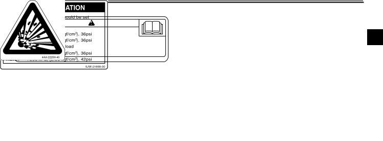
Location of important labels
Please read the following important labels carefully before operating this vehicle.
1
1-5
 SAFETY INFORMATION
 Before you operate this vehicle, read the owner’s manual.
 Prima di usare il veicolo, leggete il manuale di istruzioni.
 Lire le manuel du propriétaire avant d’utiliser ce véhicule.
 Lesen Sie die Bedienungsanleitung bevor Sie dieses Fahrzeug fahren.
  Antes de conducir este vehículo, lea el Manual del Propietario.
5PA-21568-00
2
1
270 kPa, {2.70 kgf/cm2}, 39psi
290 kPa, {2.90 kgf/cm2}, 42psi
270 kPa, {2.70 kgf/cm2}, 39psi
290 kPa, {2.90 kgf/cm2}, 42psi
3P6-21668-00
1-6

DESCRIPTION
EAU10410
Left view
2
1.Accessory box (page 3-21)
2.Front fork spring preload adjusting bolt (page 3-24)
3.Front fork rebound damping force adjusting knob (page 3-24)
4.Owner’s tool kit (page 6-1)
5.Rider seat (page 3-17)
6.Passenger seat (page 3-17)
7.Final gear oil filler bolt (page 6-12)
8.Final gear oil drain bolt (page 6-12)
9. Shock absorber assembly spring preload adjusting lever (page 3-25) 10.Air filter element (page 6-15)
11.Shift pedal (page 3-13) 12.Engine oil filler cap (page 6-9)
13.Engine oil filter cartridge (page 6-9) 14.Engine oil level check window (page 6-9)
2-1

DESCRIPTION
EAU10420
Right view
2
1.Storage compartment (page 3-20)
2.Fuel tank cap (page 3-15)
3.Fuse box (page 6-29)
4.Windshield (page 3-11)
5.Battery (page 6-28)
6.Main fuse (page 6-29)
7.Front fork compression damping force adjusting screw (page 3-24)
8.Brake pedal (page 3-14)
9.Shock absorber assembly rebound damping force adjusting knob (page 3-25)
10.Rear brake fluid reservoir (page 6-21)
2-2
DESCRIPTION
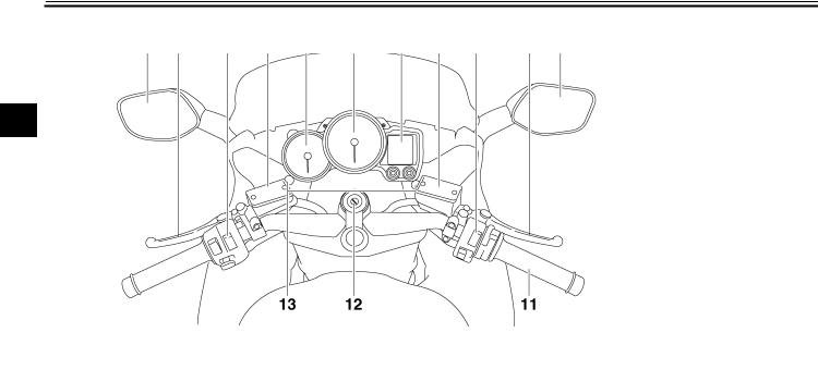
EAU10430
Controls and instruments
2
1.Rear view mirror (page 3-23)
2.Clutch lever (page 3-13)
3.Left handlebar switches (page 3-11)
4.Clutch fluid reservoir (page 6-21)
5.Tachometer (page 3-5)
6.Speedometer (page 3-5)
7.Multi-function display (page 3-6)
8.Front brake fluid reservoir (page 6-21)
9. Right handlebar switches (page 3-11) 10.Brake lever (page 3-14)
11.Throttle grip (page 6-17)
12.Main switch/steering lock (page 3-2) 13.Headlight beam adjusting knob (page 3-22)
2-3
INSTRUMENT AND CONTROL FUNCTIONS
EAU10972
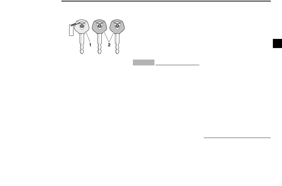
Immobilizer system
1.Code re-registering key (red bow)
2.Standard keys (black bow)
This vehicle is equipped with an immobilizer system to help prevent theft by re-registering codes in the standard keys. This system consists of the following.
●a code re-registering key (with a red bow)
●two standard keys (with a black bow) that can be re-registered with new codes
●a transponder (which is installed in the code re-registering key)
●an immobilizer unit
●an ECU
● an immobilizer system indicator light (See page 3-3.)
The key with the red bow is used to register codes in each standard key. Since re-registering is a difficult process, take the vehicle along with all three keys to a Yamaha dealer to have them re-reg- istered. Do not use the key with the red bow for driving. It should only be used for re-registering the standard keys. Always use a standard key for driving.
ECA11820
CAUTION:
●DO NOT LOSE THE CODE REREGISTERING KEY! CONTACT YOUR DEALER IMMEDIATELY IF IT IS LOST! If the code re-reg- istering key is lost, registering new codes in the standard keys is impossible. The standard keys can still be used to start the vehicle, however if code reregistering is required (i.e., if a new standard key is made or all keys are lost) the entire immobilizer system must be replaced. Therefore, it is highly recom-
mended to use either standard key and keep the code re-regis- tering key in a safe place.
●Do not submerse any key in water.
●Do not expose any key to excessively high temperatures.
●Do not place any key close to
|
magnets (this includes, but not |
3 |
|
limited to, products such as |
|
|
speakers, etc.). |
●Do not place heavy items on any key.
●Do not grind any key or alter its shape.
●Do not disassemble the plastic part of any key.
●Do not put two keys of any immobilizer system on the same key ring.
●Keep the standard keys as well as keys of other immobilizer systems away from this vehicle’s code re-registering key.
●Keep other immobilizer system keys away from the main switch as they may cause signal interference.
3-1

INSTRUMENT AND CONTROL FUNCTIONS
|
EAU10471 |
EAU26811 |
To lock the steering |
|
|
Main switch/steering lock |
ON |
3
The main switch/steering lock controls the ignition and lighting systems, and is used to lock the steering.
NOTE:
Be sure to use the standard key (black bow) for regular use of the vehicle. To minimize the risk of losing the code reregistering key (red bow), keep it in a safe place and only use it for code reregistering.
All electrical circuits are supplied with power; the meter lighting, taillights, license plate light and auxiliary lights come on, and the engine can be started. The key cannot be removed.
NOTE:
The headlights come on automatically when the engine is started and stay on until the key is turned to “OFF”.
EAU10660
OFF
All electrical systems are off. The key can be removed.
EAU10690
LOCK
The steering is locked, and all electrical systems are off. The key can be removed.
1.Push.
2.Turn.
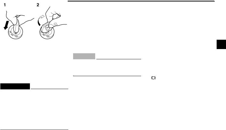
1.Turn the handlebars all the way to the left or right.
2.Push the key in from the “OFF” position, and then turn it to “LOCK” while still pushing it.
3.Remove the key.
3-2
INSTRUMENT AND CONTROL FUNCTIONS
To unlock the steering
1.Push.
2.Turn.
Push the key into the main switch, and then turn it to “OFF” while still pushing it.
EWA10060
 WARNING
Never turn the key to “OFF” or “LOCK” while the vehicle is moving, otherwise the electrical systems will be switched off, which may result in loss of control or an accident. Make sure that the vehicle is stopped before turning the key to “OFF” or “LOCK”.
EAU39460
 (Parking)
The steering is locked, and the taillights, license plate light and auxiliary lights are on. The hazard lights and turn signal lights can be turned on, but all other electrical systems are off. The key can be removed.
The steering must be locked before the key can be turned to “ ”.
”.
ECA11020
CAUTION:
Do not use the parking position for an extended length of time, otherwise the battery may discharge.
EAU11003
Indicator and warning lights
3
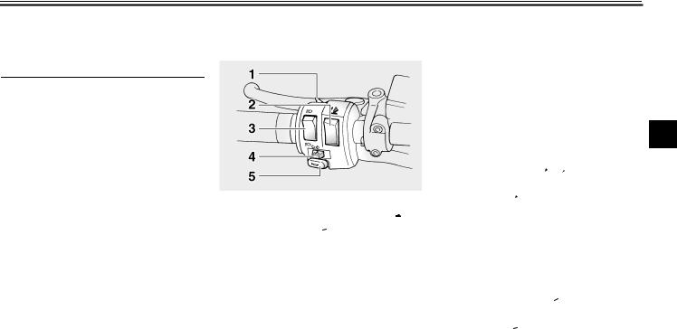
1.Left turn signal indicator light “ ”
”
2.Right turn signal indicator light “ ”
”
3.Engine trouble warning light “  ”
”
4.Anti-lock Brake System (ABS) warning light
“ ABS ”
5.Neutral indicator light “  ”
”
6.High beam indicator light “  ”
”
7.Oil level warning light “ 

 ”
”
8.Immobilizer system indicator light
EAU11030
Turn signal indicator lights “ ” and
” and
“ ”
”
The corresponding indicator light flashes when the turn signal switch is pushed to the left or right.
3-3
INSTRUMENT AND CONTROL FUNCTIONS
EAU11060
Neutral indicator light “  ”
”
This indicator light comes on when the transmission is in the neutral position.
EAU11080
High beam indicator light “ ”
”
This indicator light comes on when the high beam of the headlight is switched
3 on.
EAU11120
Oil level warning light “

 ”
”
This warning light comes on when the engine oil level is low.
The electrical circuit of the warning light can be checked by turning the key to “ON”.
If the warning light does not come on for a few seconds, then go off, have a Yamaha dealer check the electrical circuit.
NOTE:
Even if the oil level is sufficient, the warning light may flicker when riding on a slope or during sudden acceleration or deceleration, but this is not a malfunction.
EAU11530
Engine trouble warning light “  ”
”
This warning light comes on or flashes when an electrical circuit monitoring the engine is defective. When this occurs, have a Yamaha dealer check the selfdiagnosis system. (See page 3-6 for an explanation of the self-diagnosis device.)
The electrical circuit of the warning light can be checked by turning the key to “ON”. If the warning light does not come on for a few seconds, then go off, have a Yamaha dealer check the electrical circuit.
EAU39500
ABS warning light “ ABS ”
If this warning light comes on or flashes while riding, the ABS may be defective. If this occurs, have a Yamaha dealer check the system as soon as possible. (See page 3-14.)
EWA10081
 WARNING
If the ABS warning light comes on or flashes while riding, the brake system reverts to conventional braking. Therefore, be careful not to cause the wheels to lock during emergen-
cy braking. If the warning light comes on or flashes while riding, have a Yamaha dealer check the brake system as soon as possible.
The electrical circuit of the warning light can be checked by turning the key to “ON”.
If the warning light does not come on or remains on, have a Yamaha dealer check the electrical circuit.
EAU38620
Immobilizer system indicator light
The electrical circuit of the indicator light can be checked by turning the key to “ON”.
If the indicator light does not come on for a few seconds, then go off, have a Yamaha dealer check the electrical circuit.
When the key is turned to “OFF” and 30 seconds have passed, the indicator light will start flashing indicating the immobilizer system is enabled. After 24 hours have passed, the indicator light will stop flashing, however the immobilizer system is still enabled.
3-4
![]()
INSTRUMENT AND CONTROL FUNCTIONS
|
This model is also equipped with a self- |
EAU11601 |
EAU11872 |
|
diagnosis device for the immobilizer |
Speedometer |
Tachometer |
|
system. (See page 3-6 for an explana- |
||
|
tion of the self-diagnosis device.) |
3
1.Tachometer
2.Speedometer
3.Multi-function display
The speedometer shows the riding speed.
When the key is turned to “ON”, the speedometer needle will sweep once across the speed range and then return to zero in order to test the electrical circuit.
1.Tachometer
2.Tachometer red zone
The electric tachometer allows the rider to monitor the engine speed and keep it within the ideal power range.
When the key is turned to “ON”, the tachometer needle will sweep once across the r/min range and then return to zero r/min in order to test the electrical circuit.
ECA10031
CAUTION:
Do not operate the engine in the tachometer red zone.
Red zone: 9000 r/min and above
3-5
INSTRUMENT AND CONTROL FUNCTIONS
EAU40241
Multi-function display
3
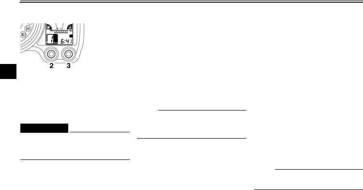
1.Multi-function display
2.“SELECT” button
3.“RESET” button
EWA14430
 WARNING
Be sure to stop the vehicle before making any setting changes to the multi-function display.
The multi-function display is equipped with the following:
●an odometer (which shows the total distance traveled)
●two tripmeters (which show the distance traveled since they were last set to zero)
●a fuel reserve tripmeter (which shows the distance traveled on the fuel reserve)
●a clock
●a fuel meter
●a coolant temperature meter
●a transmission gear display
●an ambient temperature display
●a fuel consumption display (instantaneous and average consumption functions)
●a self-diagnosis device
NOTE:
Be sure to turn the key to “ON” before using the “SELECT” and “RESET” buttons.
Odometer and tripmeter modes
1.Odometer/tripmeter/fuel reserve tripmeter
2.“SELECT” button
3.“RESET” button
Pushing the “SELECT” button switches the display between the odometer mode “ODO” and the tripmeter modes “TRIP 1” and “TRIP 2” in the following order:
ODO → TRIP 1 → TRIP 2 → ODO
NOTE:
When selecting “TRIP 1” or “TRIP 2”, the display flashes for five seconds.
When approximately 5.5 L (1.45 US gal) (1.21 Imp.gal) of fuel remains in the fuel tank, the display will automatically change to the fuel reserve tripmeter mode “F-TRIP” and start counting the
3-6

INSTRUMENT AND CONTROL FUNCTIONS
distance traveled from that point. In that case, pushing the “SELECT” button switches the display between the various tripmeter and odometer modes in the following order:
F-TRIP → TRIP 1 → TRIP 2 → ODO → F-TRIP
To reset a tripmeter, select it by pushing the “SELECT” button, and then push the “SELECT” button for at least one second. If you do not reset the fuel reserve tripmeter manually, it will reset itself automatically and the display will return to the prior mode after refueling and traveling 5 km (3 mi).
Clock
To set the clock:
1.Push the “SELECT” button and “RESET” button together for at least two seconds.
2.When the hour digits start flashing, push the “RESET” button to set the hours.
3.Push the “SELECT” button, and the minute digits will start flashing.
4.Push the “RESET” button to set the minutes.
5.Push the “SELECT” button and then release it to start the clock.
Fuel meter
wards “E” (Empty) as the fuel level decreases. When the last segment starts flashing, refuel as soon as possible. When the key is turned to “ON”, all of the display segments of the fuel meter will appear one after the other and then disappear in order to test the
electrical circuit.
3
NOTE:
This fuel meter is equipped with a selfdiagnosis system. If the electrical circuit is defective, all the display segments will start flashing. If this occurs, have a Yamaha dealer check the electrical circuit.
Coolant temperature meter
1.Clock
2.“SELECT” button
3.“RESET” button
1. Fuel meter
The fuel meter indicates the amount of
fuel in the fuel tank. The display seg-
1. Coolant temperature meter
ments of the fuel meter disappear to-
3-7
INSTRUMENT AND CONTROL FUNCTIONS
With the key in the “ON” position, the coolant temperature meter indicates the temperature of the coolant. When the key is turned to “ON”, all of the display segments of the coolant temperature meter will appear one after the other and then disappear in order to test the electrical circuit. The coolant
3temperature varies with changes in the weather and engine load. If the top segment flashes, stop the vehicle and let the engine cool. (See page 6-35.)
ECA10020
CAUTION:
Do not operate the engine if it is overheated.
Transmission gear display
1.Transmission gear display
2.Neutral indicator light “  ”
”
This display shows the selected gear. The neutral position, however, is not displayed, it is indicated by the neutral indicator light.
Ambient temperature, instantaneous fuel consumption and average fuel consumption modes
1.Ambient temperature/instantaneous fuel consumption/average fuel consumption
2.“SELECT” button
3.“RESET” button
Push the “RESET” button to switch the display between the ambient temperature mode “Air”, the instantaneous fuel consumption mode “km/L” or “L/100 km” and the average fuel consumption mode “AV_ _ km/L” or “AV_ _ L/100 km” in the following order:
Air → km/L or L/100 km → AV_ _ km/L or AV_ _ L/100 km → Air
3-8
INSTRUMENT AND CONTROL FUNCTIONS
Ambient temperature mode
1. Ambient temperature
This display shows the ambient temperature from –9 °C to 50 °C in 1 °C increments. The temperature displayed may vary from the ambient temperature.
NOTE:
●If the ambient temperature falls below –9 °C, a lower temperature than –9 °C will not be displayed.
●If the ambient temperature climbs above 50 °C, a higher temperature than 50 °C will not be displayed.
●The accuracy of the temperature reading may be affected when riding slowly (approximately under 20 km/h) or when stopped at traffic signals, railroad crossings, etc.
Instantaneous fuel consumption mode
●When the display is set to “L/100 km”, the amount of fuel necessary to travel 100 km under the current riding conditions is shown.
NOTE:
●To switch between the two instantaneous fuel consumption dis-
plays, push the “RESET” button for 3 1 second when either display is shown.
●If traveling at speeds under 10 km/h, “_ _” will be displayed.
Average fuel consumption mode
1. Instantaneous fuel consumption
The instantaneous fuel consumption display can be set to either “km/L” or “L/100 km”.
●When the display is set to “km/L”, the distance that can be traveled
|
on 1.0 L of fuel under the current |
|
|
riding conditions is shown. |
1. Average fuel consumption |
|
This display shows the average fuel |
|
|
consumption since it was last reset. |
3-9
INSTRUMENT AND CONTROL FUNCTIONS
The average fuel consumption display can be set to either “AV _ _ km/L” or “AV _ _ L/100 km”.
When the average fuel consumption mode is selected, the display flashes for five seconds, and then, depending on the unit set, “AV _ _ km/L” (average distance that can be traveled using 1.0
3L of fuel) or “AV _ _ L/100 km” (average amount of fuel necessary to travel 100 km) is displayed.
To reset the average fuel consumption display, push the “RESET” button to select the mode again, and then push the “RESET” button for 1 second while the display is flashing.
NOTE:
●To switch between the two average fuel consumption displays, push the “RESET” button for 1 second when either display is shown.
●After resetting an average fuel consumption display, “_ _” will be shown for that display until the vehicle has traveled 1 km.
ECA15471
CAUTION:
If there is a malfunction, “– –” will be displayed. Have a Yamaha dealer check the vehicle.
Self-diagnosis device
1.Error code display
2.Immobilizer system indicator light
This model is equipped with a self-diag- nosis device for various electrical circuits.
If any of those circuits are defective, the multi-function display will indicate a two-digit error code (e.g., 11, 12, 13).
If the multi-function display indicates such an error code, note the code number, and then have a Yamaha dealer check the vehicle.
ECA11790
CAUTION:
If the multi-function display indicates an error code, the vehicle should be checked as soon as possible in order to avoid engine damage.
This model is also equipped with a selfdiagnosis device for the immobilizer system.
If any of the immobilizer system circuits are defective, the immobilizer system indicator light will flash, and then the multi-function display will indicate a two-digit error code (e.g., 51, 52, 53) when the key is turned to “ON”.
NOTE:
If the multi-function display indicates error code 52, this could be caused by transponder interference. If this error appears, try the following.
1.Use the code re-registering key to start the engine.
NOTE:
Make sure there are no other immobilizer keys close to the main switch, and do not keep more than one immobilizer
3-10
INSTRUMENT AND CONTROL FUNCTIONS
key on the same key ring! Immobilizer system keys may cause signal interference, which may prevent the engine from starting.
2.If the engine starts, turn it off, and try starting the engine with the standard keys.
3.If one or both of the standard keys do not start the engine, take the
vehicle, the code re-registering key and both standard keys to a Yamaha dealer and have the standard keys re-registered.
If the multi-function display indicates any error codes, note the code number, and then have a Yamaha dealer check the vehicle.
EAU12344
Handlebar switches
Left
1.Pass switch “  ”
”
2.Windshield position adjusting switch “ ”
”
3.Dimmer switch “  /
/ ”
”
4.Turn signal switch “ /
/  ”
”
5.Horn switch “  ”
”
Right
3
1.Engine stop switch “ /
/ ”
”
2.Hazard switch “ ”
”
3.Start switch “ ”
”
EAU12380
Pass switch “ ”
”
Press this switch to flash the headlights.
EAU12400
Dimmer switch “ /
/ ”
”
Set this switch to “ ” for the high beam and to “
 ” for the low beam.
EAU12460
Turn signal switch “ /
/ ”
”
To signal a right-hand turn, push this switch to “ ”. To signal a left-hand turn, push this switch to “
 ”. When released, the switch returns to the center
3-11
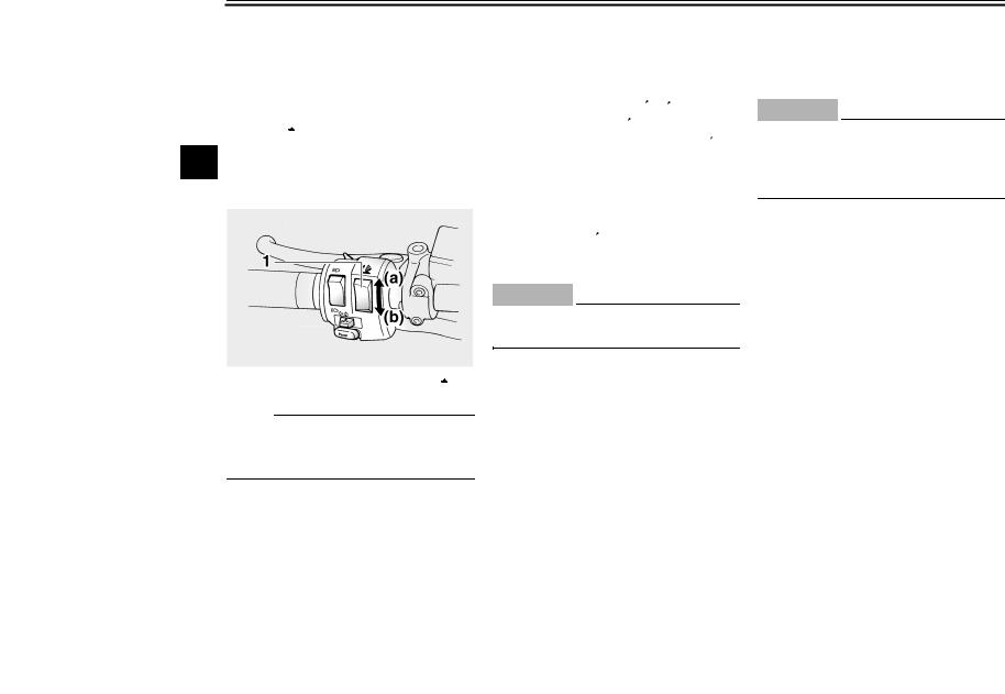
INSTRUMENT AND CONTROL FUNCTIONS
position. To cancel the turn signal lights, push the switch in after it has returned to the center position.
EAU12493
Windshield position adjusting switch “ ”
”
To move the windshield up, push this
3switch in direction (a). To move the windshield down, push the switch in direction (b).
1. Windshield position adjusting switch “ ”
”
NOTE:
When the key is turned to “OFF”, the windshield will automatically return to the lowest position.
EAU12500
Horn switch “  ”
”
Press this switch to sound the horn.
EAU12660
Engine stop switch “ /
/ ”
”
Set this switch to “ ” before starting the engine. Set this switch to “
 ” to stop the engine in case of an emergency, such as when the vehicle overturns or when the throttle cable is stuck.
EAU12710
Start switch “ ”
”
Push this switch to crank the engine with the starter.
ECA10050
CAUTION:
See page 5-1 for starting instructions prior to starting the engine.
EAU12733
Hazard switch “ ”
”
With the key in the “ON” or “ ” position, use this switch to turn on the hazard lights (simultaneous flashing of all turn signal lights).
The hazard lights are used in case of an emergency or to warn other drivers when your vehicle is stopped where it might be a traffic hazard.
ECA10061
CAUTION:
Do not use the hazard lights for an extended length of time with the engine not running, otherwise the battery may discharge.
3-12

INSTRUMENT AND CONTROL FUNCTIONS
|
Clutch lever |
EAU12830 |
Make sure that the appropriate setting |
Shift pedal |
on the adjusting dial is aligned with the arrow mark on the clutch lever.
The clutch lever is equipped with a clutch switch, which is part of the ignition circuit cut-off system. (See page 3-28.)
1.Clutch lever
2.Arrow mark
3.Clutch lever position adjusting dial
4.Distance between clutch lever and handlebar grip
The clutch lever is located at the left handlebar grip. To disengage the clutch, pull the lever toward the handlebar grip. To engage the clutch, release the lever. The lever should be pulled rapidly and released slowly for smooth clutch operation.
The clutch lever is equipped with a clutch lever position adjusting dial. To adjust the distance between the clutch lever and the handlebar grip, turn the adjusting dial while holding the lever pushed away from the handlebar grip.
1. Shift pedal
The shift pedal is located on the left side of the engine and is used in combination with the clutch lever when shifting the gears of the 5-speed con- stant-mesh transmission equipped on this motorcycle.
3-13
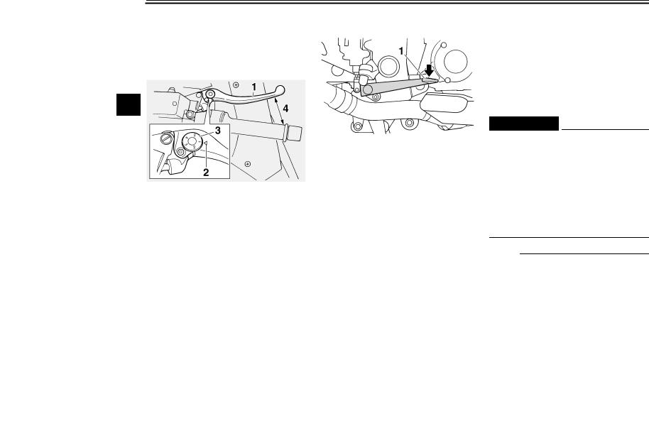
INSTRUMENT AND CONTROL FUNCTIONS
EAU26822
Brake lever
The brake lever is located at the right handlebar grip. To apply the front brake, pull the lever toward the handlebar grip.
3
1.Brake lever
2.“ ” mark
3.Brake lever position adjusting dial
4.Distance between brake lever and handlebar grip
The brake lever is equipped with a position adjusting dial. To adjust the distance between the brake lever and the handlebar grip, turn the adjusting dial while holding the lever pushed away from the handlebar grip. Make sure that the appropriate setting on the adjusting dial is aligned with the “ ” mark on the brake lever.
EAU39540
Brake pedal
1. Brake pedal
The brake pedal is on the right side of the vehicle.
This model is equipped with a unified brake system.
When pressing down on the brake pedal, the rear brake and a portion of the front brake are applied. For full braking performance, apply both the brake lever and the brake pedal simultaneously.
EAU39530
ABS
The Yamaha ABS (Anti-lock Brake System) features a dual electronic control system, which acts on the front and rear brakes independently. The ABS is monitored by an ECU (Electronic Control Unit), which will have recourse to manual braking if a malfunction occurs.
EWA10090
 WARNING
●The ABS performs best on long braking distances.
●On certain (rough or gravel) roads, the braking distance may be longer with than without the ABS. Therefore, always keep a sufficient distance to the vehicle ahead to match the riding speed.
NOTE:
●When the ABS is activated, the brakes are operated in the usual way. A pulsating action may be felt at the brake lever or brake pedal, but this does not indicate a malfunction.
3-14
![]()
INSTRUMENT AND CONTROL FUNCTIONS
●This ABS has a test mode which allows the owner to experience the pulsating at the brake lever or brake pedal when the ABS is operating. However, special tools are required, so please consult your Yamaha dealer when performing this test.
|
Fuel tank cap |
EAU13070 |
|
NOTE: |
The fuel tank cap cannot be closed unless the key is in the lock. In addition, the key cannot be removed if the cap is not properly closed and locked.
|
EWA11090 |
|||||
|
WARNING |
|||||
|
3 |
|||||
|
Make sure that the fuel tank cap is |
|||||
|
properly closed before riding. |
|||||
1.Fuel tank cap lock cover
2.Unlock.
To open the fuel tank cap
Open the fuel tank cap lock cover, insert the key into the lock, and then turn it 1/4 turn clockwise. The lock will be released and the fuel tank cap can be opened.
To close the fuel tank cap
1.Push the fuel tank cap into position with the key inserted in the lock.
2.Turn the key counterclockwise to the original position, remove it, and then close the lock cover.
3-15
 Loading…