Дорогие клиенты! Для вашего удобства мы разместили на этой странице инструкции по швейному оборудованию TYPICAL.
За более подробной информацией по интересующим позициям вы можете обратиться к нашим менеджерам.
| Инструкция | Скачать |
| 31030-12 | |
| GK360 | |
| BASS3200 | |
| GK361 | |
| CB-I, CB-II | |
| GK43001, GK43001M | |
| CH20NA | |
| GL13101-2 | |
| CZD ножи | |
| GL13101-6 | |
| CZD700 и 900 | |
| GL13101-8, GL13106-8 | |
| DB2-C101 | |
| GL-2000 А | |
| DF 8-1 | |
| DZ3-1D | |
| GN1-1D | |
| GN2000 | |
| GC 201, 202 | |
| GN33 | |
| GC0302 | |
| GN79 | |
| GC0302-D2 | |
| GP5 | |
| GC202-D2 | |
| GT 655, 656 | |
| GC203 | |
| GT 660 | |
| GC203-3,203-5 | |
| GT 670 | |
| GC20605, GC20615 | |
| GT 680 | |
| GC20606,20606-1 | |
| GС6842, 6845, 6872, 6875 | |
| GC20616 | |
| HVP-60 Series Servo Motor_1 | |
| GC20u33 | |
| HVP-90 Servo motor | |
| GC2301, 2603, 2605 | |
| KDX-1 | |
| GC24016, 24026 | |
| KS-105, 85, 65 | |
| GC24660, 24680 | |
| KS90 | |
| GC6-1 | |
| КТ-1 | |
| GC6100 | |
| GC6180-HE2 | |
| GC0303D-0303DCX | |
| Блок управления YCS-8330 | |
| Инструкция GK1500 | |
| Инструкция GK335 | |
| Инструкция GC6930A |
| Инструкция | Скачать |
| Servo Motor | |
| Серия GC6150 — GC6160 | |
| TB801 | |
| GC6160MD3 | |
| TC1-IA | |
| GC6170 | |
| TW1-0602 серия | |
| GC6180ME2 panel | |
| TW1-1245 | |
| GC6190 | |
| TW1-243,273 | |
|
GC6710MD_HD |
|
| TW2-B872, 875 | |
| GC6220 | |
| TW3_441,471 | |
| GC6240 | |
| TW3-341 | |
| GC6-5-2, 6-5 | |
| TW3-8-B | |
| GC6-6,6-7_6-7D | |
| TW3-S335V | |
| GC6850 | |
| TW5-810, 820 | |
| GD2308 | |
| TW5-8372 | |
| GE2108 | |
| TW6-690 | |
| GF11018 | |
| Typical GD2308 | |
| GK0022 | |
| YVC-8310 | |
| GK0056 | |
| ZN90 | |
| GK26-1A | |
| Инструкция по наладке выш. машины GG | |
| GK31030 | |
| Инструкция по обслуживанию выш. машины GG | |
| GK31030-11 | |
| Инструкция по эксплуатации выш. машины GG | |
| GK321 | |
| Макро электродвигатель МТ-700 LCD-V6 | |
| GK32500 | |
| Раскрой CZD1501 | |
| GK32500-1 | |
| Раскройный нож DJ4-1 | |
| GK32700 | |
| 8365 | |
| GC0617D | |
| GC 6716 MD3/HD3 | |
| GC 6716 MD3/HD3 | |
| GC 6150 MD/HD | |
| GC6890HD4/MD4 | |
-
Contents
-
Table of Contents
-
Bookmarks
Quick Links
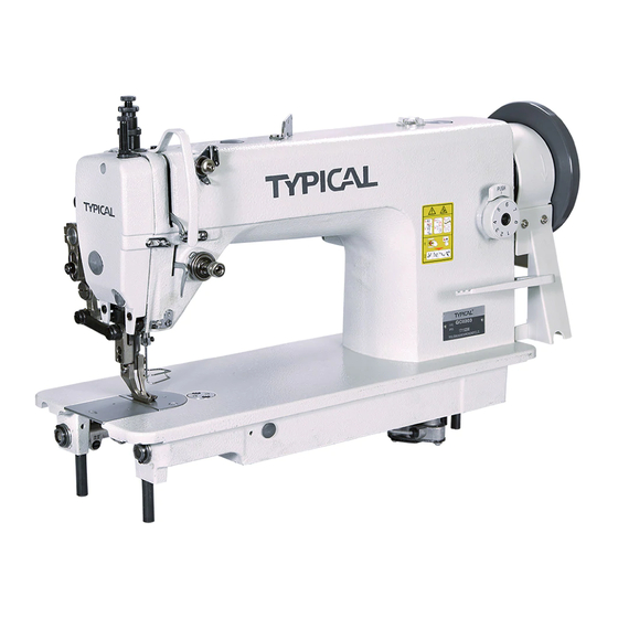
UPPER AND LOWER FEED LOCKSTITCH SEWING
MACHINE FOR MEDIUM AND HEAVY DUTY
UPPER AND LOWER FEED
LOCKSTITCH SEWING
MACHINE FOR HEAVY DUTY WITH THICK THREAD
Related Manuals for typical GC0303
Summary of Contents for typical GC0303
-
Page 1
UPPER AND LOWER FEED LOCKSTITCH SEWING MACHINE FOR MEDIUM AND HEAVY DUTY UPPER AND LOWER FEED LOCKSTITCH SEWING MACHINE FOR HEAVY DUTY WITH THICK THREAD OPERATION INSTRUCTION / PARTS MANUAL… -
Page 2
TYPICAL SEWING MACHINE WANPING MACHINERY CO.,LTD. -
Page 3
CONTENT Operation Instruction 1. Main technical specifications 2. Operation preparation 3. Installing the motor 4. Connecting the clutch lever to the pedal 5. Installing belt guard 6. Installing the bobbin winder 7. Lubrication 8. Trial run 9. Hook oil amount adjustment 10. -
Page 4
Operation instruction Notice: 1. Parts design is subject to change without notice. 2. Only the professional can adjust and repair the machine except adjusting stitch length. -
Page 5
(1)Cleaning machine GC0303 GC0303CX Model Clean off the grease and dusts on the Surface of ma- Application Medium and heavy duty chine with gasoline and soft cloth. Max. Sewing Speed 2000spm 1800spm (2)Inspection Max. Stitch length 12mm Before use a thorough inspection should be done upon Max. -
Page 6
The belt guard should be installed for safety. Align pulley (B) of the bobbin winder with the outside of the belt , and there should be a proper clearness between them , so that pulley (B) can be contacted with the belt when stop latch thumb le- ver (A) is depressed, thereby the belt drives prlley (B) white the machine running , the bobbin winder should be parallel with belt slit (E) of the table,… -
Page 7
When the machine left out of operation for a quite long time and used again, remove the red rubber plug on top of the machine head, oil it thoroughly, the lift the presser foot and run at a low speed of 1000 ~ 1500spm, observe the sparkling condition through oil window (c), as the lubrication is well, keep the running test at the low speed about 30 minutes, then increase the speed gradually,… -
Page 8
Adjusting plate Standard clearance 0.5-1.0 By-pass oil hole… -
Page 9
Turn the balance wheel to lift the needle bar to its highest point, loosen needle set screw l, making the needle groove turn to the left side of an opera- tor, fully insert the needle shank up to the bottom of needle socket, then tighten needle set screw l. -
Page 10
When threading the needle thread, raise the needle bar to its highest position, lead the thread from the spool and pass it in the order instructed. (1) Lead the thread down through the three-eye thread guide on the top. (2) Pass down thru the left hole of thread re- tainer , then down thru the lower hole of thread retainer . -
Page 11
Stitch length can be set by turning stitch length regulating dial(A). The figures on the stitch length regulation dial plate (B) indicate the stitch length. Reverse sewing can be obtained when feed re- verse lever (C) is depressed and forward sewing can be restored automatically when feed reverse lever (C) is released. -
Page 12
、 In general, the thread tension is to be adjusted in accordance with materials thread and others. In practice, the thread tension is adjusted ac- cording to the stitches resulted to get the normal stitches. When adjusting the bobbin thread tension, turn bobbin case tension spring screw (A) clock- wise for more tension or turn the screw counter clockwise for less tension. -
Page 13
thread take-up spring(C) to zero, and to turn ten- sion stud (B) clockwise until spring ( C ) just comes into contact with the stop slot on the thread take-up spring regulator, then to further turn tension stud (B) counter-clockwise by 1/2 turn After adjustment, tighten tension stud set screw (A). -
Page 14
(B) The needle thread tension is too weak or the bobbin thread is too strong, turn the tension regulating thumb nut clockwise to make the needle thread get more tension or turn the bobbin case ten- sion regulating screw counter clockwise with small plastic screw driver to make the bobbin thread get less tension (Fig.22) ( c) Other abrormal stitches as shown in Fig.20… -
Page 15
2. Adjusting rotating hook point timing with needle. The motive relation between rotating rotating and needle affects the sewing quality. Standard tim- ing relation is : turn the balance wheel to locate needle bar to its lowest position , and lift back 2.5 mm the rotating hook point(D) should be coin- cides with needle center line ( C ),and hook point ( D ) is 1.2mm above the upper edge(E)of needle eye. -
Page 16
To adjust the position of feed dog, move feed dog to the front end of throat plate, Loosen Screw A (See Fig 29b), move feed dog support B in the direction shown by arrow (Fig.29a) to adjust. After adjustment tighten Screw(A). Feed dog is 0.8~1.2mm above the surface of throat plate horizontally. -
Page 17
、 、 ) Turn balance wheel to lower Feed dog (A) till it is horizontal with the surface (B) of thrat plate, at the moment, the tip of needle ( ) shonld be horizontal with the surfaces of throat plate and feed dog. Adjustment cam be done by adjusting the position of feed cam and feed dog lift cam. -
Page 18
tension discs should be pushed apart to open when the presser foot is lifted. But the open timing of the tension discs can be adjusted as follows: Remove face plate and the rubber plug at rear side of arm and loosen screw (A) of the knee lifting lever (left), then the tension releasing cam can be moved leftward or rightward when the cam is moved rightward, it is later to open, otherwise… -
Page 19
The lift amount of walking presser foot together with presser foot can also be adjusted slightly. When adjusting, loosen screw (A) adjust its center distance B between the screw (A) and the presser foot lift shaft. The lift amount is increased as to shorten the center distance B, and the lift amount is decreased as to widen the center distance B. -
Page 20
Remove the throat plate, clean off all the dust and lint on the slit of the feed dog (A), the installing the throat plate. Clean off all the dust around the rotating hook (A), and clean the bobbin case with soft cloth. Take off the oil filter, clean off the dust of filter screen (A) with gasoline. -
Page 21
Parts Manual… -
Page 22
51 52 9 10… -
Page 23
No . Part number Name Remark 242WF1-001 7WF4-001 7WF4-005 Holder Screw 1WF3-025 Face plate 1KT1-002 Rear cover(small) 241WF1-005 Φ 22T1-003C Rubber Plug( Φ 22T1-003C Rubber plug( 11.8) Thread finger 22T1-003C Screw 22T1-003C Screw 7WF4-004 Oil screen complete 14WF4-005 Three-eye finger 36T2-004 Screw 36T2-005… -
Page 24
25 26 41 42… -
Page 25
No . Part number Name Remark Arm shaft 70WF1-001 Rubber plug 22T3-001A Collar 22T3-002B Screw 22T3-002B Front bushing 4WF1-006 Middle bushing 4WF1-002 J0.0.40 Screw Rear bushing 22T3-005 Oil seal complete 22T3-006F Screw 22T3-008 Screw 22T3-007C Feed dog lift cam 36T3-003D Screw 36T3-003D Seperating piece for cam… -
Page 26
14 15… -
Page 27
No . Part number Name Remark Feed dog 20 T3-008 Feed dog 75WF4-001 Feed dog support complet 36T4-001A 75WF4-005A Feed dog support complet 51T5-001A Washer 36T4-001A Eccentric shaft Screw J0.0.50 Feed dog support crank 4WF2-002 61-04-01/B504 Screw 22T2-019 Screw Feed shaft 7WF2-004 Stop ring GB894.1 15… -
Page 28
P U S H… -
Page 29
No . Part number Name Remark 4WF2-012 Link pin Stitch length bracket 7WF2-012 Stitch length bracket 75WF4-002 20T2-031 Screw Screw 22T5-010D Bushing 5WF1-003 Shaft for stitch length bracket 22T5-004 Rubber plug( 36T5-003 J0.0.5 Set screw 7WF2-009 Reverse feed lever crank Shaft for block 1KT3-002 Spring… -
Page 31
No . Part number Name Remark 33T3-003 Presser foot lift bar 22T1-011 Screw 1KT4-005 Presser bar lift cam O-type ring 4.5×1.8G GB3452.1-92 Oil seal 22T7-004B Knee lifter lever(left)complete 22T7-004B Lever(left) 22T7-004B Thread releasing cam 22T7-004B Screw 22T7-004B Screw 1KT4-004 Knee lifter drawing bar 22T7-005A Screw 35T3-305… -
Page 33
No . Part number Name Remark 7WF5-001 Shim 7WF5-002 7WF5-003 Washer G B / T 9 5 6 Guide shaft 7WF5-004 Needle of bearing 7WF5-005 Walking foot 7WF5-006 Walking foot 11WF5-001 61-04-01/B316 Screw Screw 7WF5-008 Washer G B 9 3 4 Holder for walking foot bar 7WF5-009 Link of walking foot… -
Page 34
7.Oil Pump -29-… -
Page 35
No . Part number Name Remark 15WF4-003 Oil pump 15WF4-006 Big gear for oil pump 15WF4-007 small gear for oil pump GB/T67 M3×10 Screw 15WF4-004 Cover for oil pump Adjusting plate for oil pump 22T8-007 Filter complete 22T8-008A Screw for oil pump 22T8-009 Shaft for oil pump 15WF4-005… -
Page 37
No . Part number Name Remark 4WF5-001 Oil reservoir 22T9-001A Screw 22T9-001A Washer 2KT9-008 Gasket 22T9-001A Hinge pin 22T9-001A Spring 22T9-001A Knee lifter stop bracket 22T9-001A Screw 22T9-001A 22T9-036 Screw 4WF5-002 Knee lifter prop bar 22T9-003B Connector GB/T5781 M6×12 /M6×20 Screw 22T9-003B Bent rod…
This manual is also suitable for:
Gc0303cx
Предложите, как улучшить StudyLib
(Для жалоб на нарушения авторских прав, используйте
другую форму
)
Ваш е-мэйл
Заполните, если хотите получить ответ
Оцените наш проект
1
2
3
4
5