Решил выложить всё что скопилось с разных источников, за почти 2 года эксплуатации своего авто, думаю будет полезно. Скажу заранее спасибо, если найдёте тут свои труды 
Всё на Яндекс.Диске
На русском:
Manual_Corolla_E12_Rus

Самое обычное руководство пользователя на русском, иногда полезно, чтобы не лазить в бардачок, PDF 2 части. yadi.sk/d/BOZDqBl-ntK9m
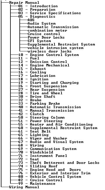
Corolla руководство по ремонту

Хорошая справка по ремонту и диагностике, судя по картинкам внутри — для дорестайла.
Внимание! Запускать по ярлычку «Запустить.bat» yadi.sk/d/BPQQr38FntK85
3zz-fe по русски

Очень годный мануал не только по 3zz, но и по подкапотке в целом, взят откуда-то с драйва.
yadi.sk/d/afrUWRKdntK69
На Английском:
2004 Corolla USA
Полное руководство по ремонту американской короллы, включая схемы эл. цепей
yadi.sk/d/d8pGQ_XVntKf6
SIL
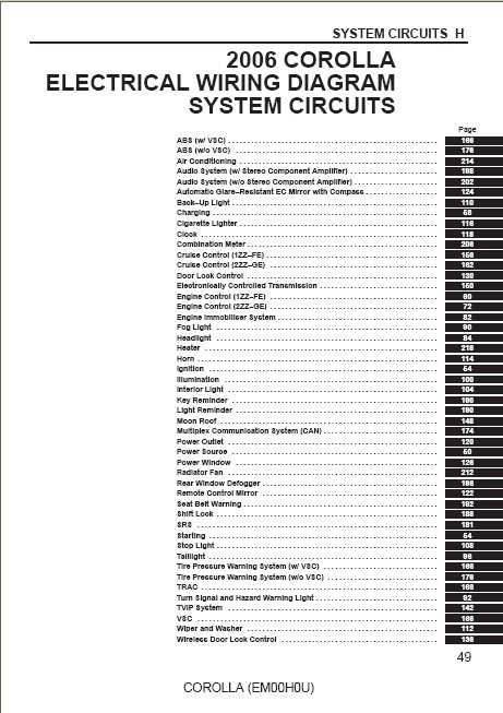
Схема электрики, pdf
yadi.sk/d/rTox__85ntKmw
Toyota Corolla models USA 2003 — 2008
Скан книги на английском, от весьма известного американского издателя книг по ремонту и обслуживанию (американская королла). yadi.sk/d/yBTIUaWUntL6n
Ссылки на каталоги з/ч
Удобно для поиска part-num. запчастей
www.japancats.ru/Toyota/
aes24.ru/?page=originalcats спасибо ssmitti
Если у кого-то есть что-то ещё — обязательно пишите, соберём всю коллекцию в одном месте!
Цена вопроса: 0 ₽
Пробег: 124 200 км
Toyota Corolla 2001 — 2006, кузов E120. Руководство пользователя
Время создания: 25.12.2015 11:12
Текстовые метки: Toyota Corolla, руководство, документация, пользователь, владелец, автомобиль
Раздел: Автомобиль — Toyota Corolla
Запись: xintrea/mytetra_syncro/master/base/1451031165atm7liw2wu/text.html на raw.github.com
|
|
Здесь размещена подготовленная мною к печати документация на Toyota Corolla 2001-2006 г. выпуска.
См. прикрепленный файл.
Полное название:
Руководство для владельца автомобиля
Toyota Corolla 2001-2006 г. E120 (седан и хетчбек)
с двигателем 3ZZ-FE и 4ZZ-FE
с автоматической и ручной коробкой передач — 320 стр.
Как делался этот вариант руководства: http://webhamster.ru/site/page/index/main/news/324

Руководство по эксплуатации
Индикация аремени с момента за
пуска деигателя
Показывает время работы двигателя с
момента запуска. При переводе ключа
в замке зажигания в положение «АСС»
или «LOCK» время останавливается.
Для обнуления значения нажмите и
удерживайте кнопку «DISP» более 1
секунды.
Предупреждающие индикации мно
гофункционального дисплея
Индикация наличия открытой или не
плотно закрытой боковой двери. Ин
дикация показывает с какой стороны
дверь открыта.
&
Индикация наличия открытой или не
плотно
закрытой
задней
двери
(хэтчбек, универсал)/крышки багажни
ка (седан).
Индикация низкого давления моторно
го масла.
Индикация неисправности системы
управления двигателем или АКПП.
l y f M H
Индикация неисправности в системе
зарядке.
Таблица. Индикаторы комбинации приборов и звуковые сигналы.
Индикация невыключенного стояноч
ного тормоза при движении автомоби
ля со скоростью 5 км/ч или выше.
Индикаторы
комбинации приборов
1. Индикатор состояния стояночной
тормозной системы и низкого уровня
тормозной жидкости,
а) Индикатор загорается, если:
— включен стояночный тормоз;
ЕЗ
О
В
‘В’
шо
<><>
»
А
ж
ю
Индикатор состояния стоя
ночной тормозной системы
и низкого уровня тормозной
жидкости
Индикатор антиблокировоч-
ной системы тормозов (ABS)
Индикатор зарядки аккумуля
торной батареи
Индикатор низкого давления
моторного масла
Индикатор «проверь двига
тель» (CHECK ENGINE)
Индикатор низкого
уровня топлива
Индикатор открытой или
неплотно закрытой двери
Индикатор включения
дальнего света фар
Индикаторы указателей
поворота
Индикатор системы подушек
безопасности (SRS)
Индикатор непристегнутого
ремня безопасности водителя
Индикатор
включения габаритов
Индикатор включения
противотуманных фар
01
P/S
PRN
D2L
0/D
OFF
TRC
OFF
VSC
0
г
м
звук.
сигнал
Индикатор включения задних
противотуманных фонарей
Индикатор неисправности
системы усилителя рулевого
управления
Индикаторы положения
селектора АКПП
Индикатор выключения
повышающей передачи
Индикатор отключения
противобуксовечной системы
Индикатор системы VSC
Индикатор скольжения
Индикатор давления в шинах
Индикатор системы
иммобилайзера
И нди катор^сисгемы
автоматической коррекции
положения фар
Индикатор
включенной передачи
Индикатор режима ручного
переключения передач
Оставленный в замке ключ
зажигания или невыключен-
ные осветительные приборы
Индикация низкого уровня топлива.
При нажатии на кнопку «DISP» индика
ция исчезает.
— низкий уровень тормозной жидко
сти:
— неисправна электрическая цепь
индикатора.
б) Если во время движения загорел
ся индикатор, то необходимо замед
лить скорость, съехать с дороги и ос
торожно остановить автомобиль, За
медлить скорость можно торможени
ем двигателя и применением стоя
ночного тормоза, но не забудьте при
этом нажать на тормозную педаль
для включения стоп-сигналов, чтобы
предупредить о торможении водите
лей, едущих сзади.
Проверьте стояночный тормоз, воз
можно он включен. Если стояночный
тормоз выключен, а индикатор горит
после его выключения, то возникла
неист1равность в тормозной системе.
Проверьте уровень тормозной жид
кости в бачке.
— Если уровень тормозной жидкости
низок, долейте жидкость и в безо
пасном месте проверьте эффектив
ность торможения автомобиля. Если
вы считаете, что тормоза все еще
работают достаточно эффективно,
то осторожно доведите автомобиль
до ближайшего места ремонта. Если
тормоза не работают, то автомо
биль необходимо отбуксировать или
эвакуировать для ремонта.
Внимание: движение в автомобиле с
низким уровнем тормозной жидкости
опасно.
— Если уровень тормозной жидко
сти в норме, то, возможно, неис
правна электрическая цепь инди
катора.
2. Индикатор антиблокировочной сис
темы тормозов (АВЗ).
После включения зажигания индика
тор загорается на несколько секунд, а
затем гаснет. Если во время движения
загорается индикатор или индикатор
не загорается, или не гаснет при вклю
чении двигателя, то возможно наличие
неисправности в антиблокировочной
системе.
Внимание: многократное нажатие на
педаль тормоза может привести к
включению индикатора на несколько
секунд.
3. Индикатор зарядки аккумуляторной
батареи.
а) Индикатор загорается при пово
роте ключа в замке зажигания в по
ложение «ОМ» и должен погаснуть
после пуска двигателя.
б) Если во время движения загорел
ся „индикатор, то неисправна система
зарядки или ослаблен (оборван) ре
мень привода генератора. Однако
двигатель будет продолжать рабо
тать, пока аккумуляторная батарея
полностью не разрядится. Выключи
те дополнительное оборудование
{кондиционер, вентилятор, радио
приемник и др.) и двигайтесь к месту
ремонта.

- Manuals
- Brands
- Toyota Manuals
- Automobile
- 2001-2004 Corolla
- Manual
-
Bookmarks
Quick Links
Toyota Corolla
Manual de taller
2001-2004
Related Manuals for Toyota 2001-2004 Corolla
Summary of Contents for Toyota 2001-2004 Corolla
-
Page 1
Toyota Corolla Manual de taller 2001-2004… -
Page 2
COMPONENTES DEL ARBOL DE LEVAS… -
Page 3
14–93 ENGINE MECHANICAL – CAMSHAFT CAMSHAFT 140OI–01 COMPONENTS Fan and Generator V Belt 7.0 (71, 62 in.⋅lbf) Clip Cylinder Head Cover No. 2 52 (530, 38) Engine Mounting Insulator RH 52 (530, 38) Clip Engine Under Cover RH N·m (kgf·cm, ft·lbf) : Specified torque A64044 2004 COROLLA (RM1037U) -
Page 4
14–94 ENGINE MECHANICAL – CAMSHAFT 9.0 (92, 80 in.⋅lbf) 9.0 (92, 80 in.⋅lbf) Engine Wire 9.0 (92, 80 in.⋅lbf) Ignition Coil Assy Ventilation Hose No. 2 9.0 (92, 80 in.⋅lbf) 11 (112, Seal Washer 11 (112, 11 (112, Clamp Bracket Clamp Bracket 11 (112,
 -
Page 5
14–95 ENGINE MECHANICAL – CAMSHAFT Camshaft Bearing Cap No. 3 13 (133, 10) 23 (235, 17) Camshaft Bearing Cap No. 1 Camshaft No. 2 Camshaft Timing Gear Camshaft or Sprocket 54 (551, 40) Camshaft Timing Gear Assy 54 (551, 40) 9.0 (92, 80 in.⋅lbf) Chain Tensioner Assy No. -
Page 6
14–96 ENGINE MECHANICAL – CAMSHAFT 140OJ–01 REEMPLAZO REPLACEMENT 1. QUITAR EL MOTOR BAJO CUBIERTA RH REMOVE ENGINE UNDER COVER RH REMOVE CYLINDER HEAD COVER NO.2 Remove the 2 screw, 3 clips and engine under cover. A65077 REMOVE FAN AND GENERATOR V BELT Turn the V–ribbed belt tensioner slowly clockwise and loosen it. -
Page 7
14–97 ENGINE MECHANICAL – CAMSHAFT DISCONNECT ENGINE WIRE Remove the 5 clamps from the 5 clamp brackets. Disconnect the 4 ignition coil connectors. A64021 Remove the bolt and nut installing the engine wire. A64022 REMOVE IGNITION COIL ASSY Remove the 4 bolts and 4 ignition coils. A64023 DISCONNECT VENTILATION HOSE Disconnect the ventilation hose from the cylinder head… -
Page 8
14–98 ENGINE MECHANICAL – CAMSHAFT REMOVE CYLINDER HEAD COVER SUB–ASSY Remove the 9 bolts, 2 seal washers, 2 nuts, 3 clamp brackets and cylinder head cover. A64856 SET NO. 1 CYLINDER TO TDC/COMPRESSION Turn the crankshaft pulley, and align its groove with timing Mark Mark mark ”0”… -
Page 9
14–99 ENGINE MECHANICAL – CAMSHAFT Remove the 2 nuts and chain tensioner. Push A62178 Fix the camshaft with a wrench and so on, then loosen the camshaft timing gear set bolt. Tighten NOTICE: Be careful not to damage the valve lifter. A62187 Loosen the camshaft bearing cap bolts on No. -
Page 10
14–100 ENGINE MECHANICAL – CAMSHAFT Remove the camshaft with holding the timing chain. A32125 Tie the timing chain with a string as shown in the illustra- tion. NOTICE: Be careful not to drop anything inside the timing chain cov- A32556 INSPECT CAMSHAFT TIMING GEAR ASSY Retard Side Check the lock of camshaft timing gear. -
Page 11
14–101 ENGINE MECHANICAL – CAMSHAFT Confirm if the camshaft timing gear assembly re- Retard Advanced volves in the timing advance direction when weak- Side Path Side Path ening the air pressure of the timing retard path. HINT: The lock pin is released, and camshaft timing gear, revolves in the advance direction. -
Page 12
14–102 ENGINE MECHANICAL – CAMSHAFT Put air pressure into two broken paths (the advance side Retard Advanced path and the retard side path) with about 150 kPa {1.5 Side Path Side Path kgf⋅cm}. CAUTION: Cover the pathes with shop rag to avoid oil splashing. A62191 Confirm if the camshaft timing gear assembly revolves in Retard… -
Page 13: Install Camshaft
14–103 ENGINE MECHANICAL – CAMSHAFT Check that the camshaft timing gear assembly can move to the retard angle side (the right angle), and is locked at the most retarded position. INSTALL CAMSHAFT Painted Link As shown in the illustration, install the timing chain on the camshaft timing gear, with the painted links aligned with the timing marks on the camshaft timing gear.
-
Page 14
14–104 ENGINE MECHANICAL – CAMSHAFT Examine the front marks and numbers and tighten the bolts in the order shown in the illustration. Torque: 13 N⋅m (133 kgf⋅cm, 10 ft⋅lbf) Install the bearing cap No. 1. Torque: 23 N⋅m (235 kgf⋅cm, 17 ft⋅lbf) A62198 Fix the camshaft with a wrench and so on, then tighten the camshaft timing gear set bolt. -
Page 15: Adjust Valve Clearance
14–105 ENGINE MECHANICAL – CAMSHAFT Apply engine oil to the chain tensioner and install it with the 2 nuts. Torque: 9.0 N⋅m (92 kgf⋅cm, 80 in⋅lbf) NOTICE: When installing the tensioner, set the hook again if the Push hook release the plunger. A62178 Turn the crankshaft counter clockwise, and discon- nect the plunger knock pin from the hook.
-
Page 16
14–106 ENGINE MECHANICAL – CAMSHAFT INSTALL CYLINDER HEAD COVER SUB–ASSY Seal Packing Remove any old packing (FIPG) material. Apply seal packing to 2 locations as shown in the illustra- tion. Seal packing: Part No. 08826–00080 or equivalent NOTICE: Remove any oil from the contact surface. Install the cylinder head cover within 3 minutes after applying seal packing. -
Page 17
14–107 ENGINE MECHANICAL – CAMSHAFT INSTALL ENGINE MOUNTING INSULATOR SUB–ASSY RH Install engine mounting insulator with the 4 bolts and 2 nuts. Torque: 52 N⋅m (530 kgf⋅cm, 38 ft⋅lbf) A64005 INSTALL CYLINDER HEAD COVER NO.2 Install the cylinder head cover with the 2 nuts and 2 clips. Torque: 7.0 N⋅m (71 kgf⋅cm, 62 in.⋅lbf) A65077 CHECK ENGINE OIL LEAK… -
Page 18
14–79 ENGINE MECHANICAL – CHAIN SUB–ASSY CHAIN SUB–ASSY 140OG–01 COMPONENTS Fan and Generator V Belt 54 (551, 40) 25 (255, 18) 37 (377, 27) Vane Pump Assy Terminal Cap No. 1 Generator Assy 9.8 (100, 7) 7.0 (71, 62 in.⋅lbf) Clip Cylinder Head Cover No. -
Page 19
14–80 ENGINE MECHANICAL – CHAIN SUB–ASSY 9.0 (92, 80 in.⋅lbf) 9.0 (92, 80 in.⋅lbf) Engine Wire 9.0 (92, 80 in.⋅lbf) Ignition Coil Assy Ventilation Hose No. 2 9.0 (92, 80 in.⋅lbf) 11 (112, Seal Washer 11 (112, 11 (112, Clamp Bracket Clamp Bracket 11 (112, -
Page 20
14–81 ENGINE MECHANICAL – CHAIN SUB–ASSY Transverse Engine Engine Mounting Bracket 47 (479, 35) Chain Tensioner Assy No. 1 29 (296, 21) 9.0 (92, 80 in.⋅lbf) Timing Chain or V–ribbed Belt Belt Cover Sub–assy Tensioner Assy 13 (133, 10) (M6) 19 (194, 14) (M8) 13 (133, 10) 69 (704, 51) -
Page 21
14–82 ENGINE MECHANICAL – CHAIN SUB–ASSY 140OH–01 REPLACEMENT REMOVE ENGINE UNDER COVER RH DRAIN COOLANT (See page 16–7) REMOVE FRONT WHEEL RH REMOVE CYLINDER HEAD COVER NO.2 Remove the 2 nuts, 2 clips and cylinder head cover. A65077 REMOVE FAN AND GENERATOR V BELT Turn the V–ribbed belt tensioner slowly clockwise and loosen it. -
Page 22
14–83 ENGINE MECHANICAL – CHAIN SUB–ASSY DISCONNECT ENGINE WIRE Remove the 5 clamps from the 5 clamp brackets. Disconnect the 4 ignition coil connectors. A64021 Remove the bolt and nut installing the engine wire. A64022 REMOVE IGNITION COIL ASSY Remove the 4 bolts and 4 ignition coils. A64023 DISCONNECT VENTILATION HOSE Disconnect the ventilation hose from the cylinder head… -
Page 23
14–84 ENGINE MECHANICAL – CHAIN SUB–ASSY REMOVE CYLINDER HEAD COVER SUB–ASSY Remove the 9 bolts, 2 seal washers, 2 nuts, 3 clamp brackets and cylinder head cover. A64856 SET NO. 1 CYLINDER TO TDC/COMPRESSION Turn the crankshaft pulley, and align its groove with timing Mark Mark mark ”0”… -
Page 24
14–85 ENGINE MECHANICAL – CHAIN SUB–ASSY REMOVE WATER PUMP ASSY (See page 16–8) REMOVE TRANSVERSE ENGINE ENGINE MOUNTING BRACKET Remove the 3 bolts and transverse engine engine mount- ing bracket. A12816 REMOVE CRANK POSITION SENSOR Remove the 2 bolts installing the crank position sensor. B00086 REMOVE CHAIN TENSIONER ASSY NO.1 Remove the 2 nuts and chain tensioner. -
Page 25
14–86 ENGINE MECHANICAL – CHAIN SUB–ASSY REMOVE TIMING GEAR COVER OIL SEAL Using a screwdriver, remove the oil seal. A30848 REMOVE CRANKSHAFT POSITION SENSOR PLATE NO.1 REMOVE CHAIN TENSIONER SLIPPER Remove the bolt and chain tensioner slipper. REMOVE CHAIN SUB–ASSY Remove the timing chain with the crankshaft timing gear plying screwdrivers as shown in the illustration. -
Page 26
14–87 ENGINE MECHANICAL – CHAIN SUB–ASSY Install the timing chain on the crankshaft timing sprocket Yellow with the yellow color link aligned with the timing mark on Color Line the crankshaft timing sprocket. HINT: Three yellow color links are on the chain. Timing Mark A62171 Using SST, install the crankshaft timing sprocket. -
Page 27
14–88 ENGINE MECHANICAL – CHAIN SUB–ASSY INSTALL TIMING GEAR COVER OIL SEAL Apply MP grease to a new oil seal lip. Using SST, tap in the oil seal until its surface is flush with the timing chain cover edge. 09223–22010 NOTICE: Keep the lip off foreign materials. -
Page 28
14–89 ENGINE MECHANICAL – CHAIN SUB–ASSY Install the timing chain cover with the 11 bolts and nut. Torque: A: 13 N⋅m (133 kgf⋅cm, 10 ft⋅lbf) B: 19 N⋅m (194 kgf⋅cm, 14 ft⋅lbf) Using a torx wrench socket (E8), install the stud bolt. Torque: 9.5 N⋅m (97 kgf⋅cm, 84 in.⋅lbf) A65677 INSTALL CHAIN TENSIONER ASSY NO.1… -
Page 29
14–90 ENGINE MECHANICAL – CHAIN SUB–ASSY INSTALL TRANSVERSE ENGINE ENGINE MOUNTING BRACKET Install the transverse engine engine mounting bracket with the 3 bolts. Torque: 47 N⋅m (479 kgf⋅cm, 35 ft⋅lbf) A12816 INSTALL WATER PUMP ASSY (See page 16–8) INSTALL V–RIBBED BELT TENSIONER ASSY Install the V–ribbed belt tensioner with the nut and bolt. -
Page 30
14–91 ENGINE MECHANICAL – CHAIN SUB–ASSY Turn the crankshaft clockwise, and check that the slipper is pushed by the plunger. HINT: If the plunger does not spring out, press the slipper into the chain tensioner with a screwdriver so that the hook is released from the knock pin and the plunger springs out. -
Page 31
14–92 ENGINE MECHANICAL – CHAIN SUB–ASSY INSTALL ENGINE WIRE Install the engine wire with the bolt and nut. Torque: 9.0 N⋅m (92 kgf⋅cm, 80 in.⋅lbf) A64022 INSTALL ENGINE MOUNTING INSULATOR SUB–ASSY RH Install the engine mounting insulator with the 4 bolts and 2 nuts. -
Page 32
14–146 ENGINE MECHANICAL – CYLINDER BLOCK ASSY (April, 2003) CYLINDER BLOCK ASSY (April, 2003) 140Q8–05 COMPONENTS Compression Ring No. 1 Compression Ring No. 2 Oil Ring (Side Rail) Oil Ring (Expander) z Snap Ring Piston z Snap Ring Piston Pin Connecting Rod 25 (255, 18) Cylinder Block Water Drain Cock Sub–assy… -
Page 33: Cylinder Head Gasket
14–108 ENGINE MECHANICAL – CYLINDER HEAD GASKET CYLINDER HEAD GASKET 140OK–05 COMPONENTS Fan and Generator V Belt 54 (551, 40) 25 (255, 18) 37 (377, 27) Vane Pump Assy Terminal Cap No. 1 Generator Assy 9.8 (100, 7) 7.0 (71, 62 in.⋅lbf) Clip Cylinder Head Cover No.
-
Page 34
14–109 ENGINE MECHANICAL – CYLINDER HEAD GASKET 9.0 (92, 80 in.⋅lbf) 9.0 (92, 80 in.⋅lbf) Engine Wire 9.0 (92, 80 in.⋅lbf) Ignition Coil Assy Ventilation Hose No. 2 9.0 (92, 80 in.⋅lbf) 11 (112, Seal Washer 11 (112, 11 (112, Clamp Bracket Clamp Bracket… -
Page 35
14–110 ENGINE MECHANICAL – CYLINDER HEAD GASKET Transverse Engine Engine Mounting Bracket 47 (479, 35) Chain Tensioner Assy No. 1 29 (296, 21) 9.0 (92, 80 in.⋅lbf) Timing Chain or V–ribbed Belt Belt Cover Sub–assy Tensioner Assy 13 (133, 10) (M6) 19 (194, 14) (M8) 13 (133, 10) 69 (704, 51) -
Page 36
14–111 ENGINE MECHANICAL – CYLINDER HEAD GASKET Camshaft Bearing Cap No. 1 13 (133, 10) 23 (235, 17) Camshaft Bearing Cap No. 3 Camshaft No. 2 Camshaft See page 14–112 1st 49 (500, 36) 2nd Turn 90_ Plate Washer Cylinder Head Sub–assy z O–ring z Gasket Camshaft Timing Oil Control Valve Assy… -
Page 37
14–112 ENGINE MECHANICAL – CYLINDER HEAD GASKET 140OL–01 REPLACEMENT WORK FOR PREVENTING GASOLINE FROM SPILLING OUT (See page 11–1) REMOVE ENGINE UNDER COVER RH DRAIN COOLANT (See page 16–7) REMOVE FRONT WHEEL RH REMOVE CYLINDER HEAD COVER NO.2 Remove the 2 nuts, 2 clips and cylinder head cover. A65077 REMOVE AIR CLEANER HOSE NO.1 Loosen the 2 air cleaner hose clamp bolts, and remove the air cleaner hose. -
Page 38
14–113 ENGINE MECHANICAL – CYLINDER HEAD GASKET SEPARATE VANE PUMP ASSY (See page 51–8) NOTICE: Do not disconnect the hose. REMOVE GENERATOR ASSY (See page 19–16) SEPARATE EXHAUST PIPE ASSY FRONT Remove the 2 bolts, 2 compression spring installing the front side of exhaust pipe. Remove the gasket. -
Page 39
14–114 ENGINE MECHANICAL – CYLINDER HEAD GASKET REMOVE IGNITION COIL ASSY Remove the 4 bolts and 4 ignition coils. A64023 DISCONNECT VENTILATION HOSE Disconnect the ventilation hose from the cylinder head cover. A65078 DISCONNECT VENTILATION HOSE NO.2 Disconnect the ventilation hose from the cylinder head cover. -
Page 40
14–115 ENGINE MECHANICAL – CYLINDER HEAD GASKET SET NO. 1 CYLINDER TO TDC/COMPRESSION Turn the crankshaft pulley, and align its groove with timing Mark Mark mark ”0” of the timing chain cover. Check that the point marks of the camshaft timing sprock- et and VVT timing sprocket are in straight line on the tim- ing chain cover surface as shown in the illustration. -
Page 41
14–116 ENGINE MECHANICAL – CYLINDER HEAD GASKET REMOVE TRANSVERSE ENGINE ENGINE MOUNTING BRACKET Remove the 3 bolts and transverse engine engine mount- ing bracket. A12816 REMOVE CRANK POSITION SENSOR Remove the 2 bolts installing the crank position sensor. B00086 REMOVE CHAIN TENSIONER ASSY NO.1 Remove the 2 nuts and chain tensioner. -
Page 42
14–117 ENGINE MECHANICAL – CYLINDER HEAD GASKET REMOVE CRANKSHAFT POSITION SENSOR PLATE NO.1 REMOVE CHAIN TENSIONER SLIPPER Remove the bolt and chain tensioner slipper. REMOVE CHAIN VIBRATION DAMPER NO.1 Remove the 2 bolt and chain vibration damper. REMOVE CHAIN SUB–ASSY Remove the timing chain with the crankshaft timing gear plying screwdrivers as shown in the illustration. -
Page 43
14–118 ENGINE MECHANICAL – CYLINDER HEAD GASKET REMOVE CAMSHAFT Uniformly loosen and remove the 19 bearing cap bolts, in several passes, in the sequence shown, and remove the 9 bearing caps, intake and exhaust camshafts. A62814 REMOVE CAMSHAFT TIMING OIL CONTROL VALVE ASSY Remove the bolt and camshaft timing oil control valve. -
Page 44
14–119 ENGINE MECHANICAL – CYLINDER HEAD GASKET INSTALL CYLINDER HEAD GASKET Lot No. Place a new cylinder head gasket on the cylinder block surface with the Lot No. stamp upward. NOTICE: Pay attention to the installation direction. Place the cylinder head quietly in order not to damage the gasket with the bottom part of the head. -
Page 45
14–120 ENGINE MECHANICAL – CYLINDER HEAD GASKET INSTALL CAMSHAFT TIMING OIL CONTROL VALVE ASSY Apply a light coat of engine oil on a new O–ring, and install it to the camshaft timing oil control valve. Install the camshaft timing oil control valve with the bolt. Torque: 9.0 N⋅m (92 kgf⋅cm, 80 in.⋅lbf) B06777 INSTALL CAMSHAFT… -
Page 46
14–121 ENGINE MECHANICAL – CYLINDER HEAD GASKET INSTALL INTAKE MANIFOLD Install a new gasket to the intake manifold. Install the intake manifold and throttle body assembly with the 2 brackets, 4 bolts and 2 nuts. Uniformly tighten the bolts and nuts in several passes. Torque: 30 N⋅m (306 kgf⋅cm, 22 ft⋅lbf) Connect the 2 vacuum hoses to the intake manifold. -
Page 47
14–122 ENGINE MECHANICAL – CYLINDER HEAD GASKET Install the timing chain on the camshaft timing sprockets Yellow Color Mark with the yellow color links aligned with the timing marks on the camshaft timing sprockets. Timing Mark A62173 INSTALL CHAIN VIBRATION DAMPER NO.1 Install the chain vibration damper with the 2 bolts. -
Page 48
14–123 ENGINE MECHANICAL – CYLINDER HEAD GASKET INSTALL TIMING CHAIN OR BELT COVER SUB–ASSY Seal Width Remove any old packing material from the contact sur- 4 – 5 mm face. Apply seal packing in the shape of bead (Diameter 3.5 mm –… -
Page 49
14–124 ENGINE MECHANICAL – CYLINDER HEAD GASKET INSTALL CHAIN TENSIONER ASSY NO.1 Check the O–ring is clean, and set the hook as shown in Raise the illustration. Push Hook A62177 Apply engine oil to the chain tensioner and install it withe 2 nuts. -
Page 50
14–125 ENGINE MECHANICAL – CYLINDER HEAD GASKET INSTALL V–RIBBED BELT TENSIONER ASSY Install the V–ribbed belt tensioner with the nut and bolt. Torque: Nut 29 N⋅m (296 kgf⋅cm, 21 ft⋅lbf) Bolt 69 N⋅m (704 kgf⋅cm, 51 ft⋅lbf) A11858 INSTALL CRANKSHAFT PULLEY Align the pulley set key with the key groove of the pulley, and slide on the pulley. -
Page 51
14–126 ENGINE MECHANICAL – CYLINDER HEAD GASKET Install the cylinder head cover and 3 cable brackets with the 9 bolts, 2 seal washers and 2 nuts. Uniformly tighten the bolts and nuts, in the several passes. Torque: A 11 N⋅m (112 kgf⋅cm, 8 ft⋅lbf) B 9.0 N⋅m (92 kgf⋅cm, 80 in.⋅lbf) A65687 INSTALL IGNITION COIL ASSY… -
Page 52
14–127 ENGINE MECHANICAL – CYLINDER HEAD GASKET INSTALL EXHAUST PIPE ASSY FRONT (See page 15–2) INSTALL VANE PUMP ASSY (See page 51–8) INSTALL GENERATOR ASSY (See page 19–16) INSTALL CYLINDER HEAD COVER NO.2 Install the cylinder head cover with the 2 nuts and 2 clips. Torque: 7.0 N⋅m (71 kgf⋅cm, 62 in.⋅lbf) A65077 INSTALL FRONT WHEEL RH… -
Page 53
14–133 ENGINE MECHANICAL – CYLINDER HEAD ASSY CYLINDER HEAD ASSY 140Q6–02 COMPONENTS Valve Lifter Valve Spring Retainer Lock Valve Spring Retainer Inner Compression Spring z Valve Stem Oil O Seal or Ring z Exhaust Valve Guide Bush Valve Spring Seat z Intake Valve Guide Bush W/ Head Taper Screw Plug No. -
Page 54
14–134 ENGINE MECHANICAL – CYLINDER HEAD ASSY 140Q7–04 OVERHAUL REMOVE W/HEAD TAPER SCREW PLUG NO.2 Using a socket hexagon wench 10, remove the taper screw plug and gasket. A62890 REMOVE VALVE LIFTER Remove the valve lifters from the cylinder head. A62891 REMOVE VALVE Place the cylinder head on wooden blocks. -
Page 55
14–135 ENGINE MECHANICAL – CYLINDER HEAD ASSY REMOVE VALVE SPRING SEAT Using a compressed air and a magnetic finger, remove the valve spring seats. A62894 REMOVE STUD BOLT Using torx socket wrench E5 and E7, remove the 11 stud bolts. Upper side: Front side: Exhaust side:… -
Page 56
14–136 ENGINE MECHANICAL – CYLINDER HEAD ASSY INSPECT CYLINDER HEAD FOR CRACKS Using a dye penetrate, check the combustion chamber, intake ports, exhaust ports and cylinder block surface for cracks. A62897 INSPECT VALVE SEATS Apply a light coat of prussian blue (or white lead) to the valve face. -
Page 57
14–137 ENGINE MECHANICAL – CYLINDER HEAD ASSY Intake: If the seating is too low on the valve face, use 60_ Intake: and 45_ cutters to correct the seat. Exhaust: If the seating is too low on the valve face, use 75_ and 45_ cutters to correct the seat. -
Page 58
14–138 ENGINE MECHANICAL – CYLINDER HEAD ASSY INSPECT VALVE LIFTER Using a micrometer, measure the valve lifter diameter. Lifter diameter: 30.966 – 30.976 mm (1.2191 – 1.2195 in.) P16860 INSPECT VALVE LIFTER OIL CLEARANCE Using a caliper gauge, measure the valve lifter bore diam- eter of the cylinder head. -
Page 59
14–139 ENGINE MECHANICAL – CYLINDER HEAD ASSY Using a spring tester, measure the tension of the inner compression spring at the specified installed length. Installed tension: 158.6 – 175.4 N (16.2 – 17.9 kgf, 35.7 – 39.5 lbf) at 33.6 mm (1.323 in.) Maximum working tension: 335.3 –… -
Page 60
14–140 ENGINE MECHANICAL – CYLINDER HEAD ASSY Subtract the valve stem diameter measurement from the guide bushing inside diameter measurement. Standard oil clearance: Intake 0.025 – 0.060 mm (0.0010 – 0.0024 in.) Exhaust 0.030 – 0.065 mm (0.0012 – 0.0026 in.) Maximum oil clearance: Intake 0.08 mm (0.0032 in.) Exhaust 0.10 mm (0.0039 in.) -
Page 61
14–141 ENGINE MECHANICAL – CYLINDER HEAD ASSY Heat the cylinder head to 80 – 100_C (176 – 212_F). A62906 Place the cylinder head on wooden blocks. Using SST, tap in a new valve guide bushing to the speci- fied protrusion height. 09201–10000, 09201–01055, 09950–70010 (09951–07100) Protrusion height: 8.7 –… -
Page 62
14–142 ENGINE MECHANICAL – CYLINDER HEAD ASSY INSTALL UNION 14 (0.551) Mark the standard position away from the edge, onto the water hose union as shown in the illustration. 23.2 (0.913) 9 (0.354) (mm (in.)) A62791 Apply adhesive to the water hose union hole of the cylin- Adhesive der head. -
Page 63
14–143 ENGINE MECHANICAL – CYLINDER HEAD ASSY INSTALL STUD BOLT Using torx socket wrench E5 and E7, install the 11 stud bolts, Torque: Stud bolt A, D and E 9.5 N⋅m (97 kgf⋅cm, 84 in.⋅lbf) Stud bolt B and C 5.0 N⋅m (51 kgf⋅cm, 44 in.⋅lbf) Upper side: Front side: Exhaust side:… -
Page 64
14–144 ENGINE MECHANICAL – CYLINDER HEAD ASSY INSTALL VALVE STEM OIL O SEAL OR RING Apply a light coat of engine oil to a new valve stem oil seals. NOTICE: Be very careful to assemble the oil seal for intake and ex- haust. -
Page 65
14–145 ENGINE MECHANICAL – CYLINDER HEAD ASSY INSTALL W/HEAD TAPER SCREW PLUG NO.2 Using a socket hexagon wrench 10, install the taper screw plug with a new gasket. Torque: 44 N⋅m (449 kgf⋅cm, 33 ft⋅lbf) A62890 2004 COROLLA (RM1037U) -
Page 66: Engine Assembly
14–1 ENGINE MECHANICAL – ENGINE ASSEMBLY ENGINE ASSEMBLY 140OC–03 INSPECTION INSPECT COOLANT (See page 16–1) INSPECT ENGINE OIL (See page 17–1) INSPECT BATTERY (See page 19–13) INSPECT AIR CLEANER FILTER ELEMENT SUB–ASSY INSPECT SPARK PLUG (See page 18–2) INSPECT FAN AND GENERATOR V BELT HINT: You don’t need to check the belt deflection because auto tensioner is adopted.
-
Page 67
14–2 ENGINE MECHANICAL – ENGINE ASSEMBLY Disconnect the terminal 13 (TC) and 4 (CG) of the DLC3. Inspect ignition timing at idle. Ignition timing: 10 – 18 _BTDC Confirm that ignition timing moves to advanced angle side when the engine rpm is increased. Remove the timing light. -
Page 68
14–3 ENGINE MECHANICAL – ENGINE ASSEMBLY If the cylinder compression in one more cylinders is low, pour a small amount of engine oil into the cylin- der through the spark plug hole and repeat steps (1) through (3) for cylinders with low compression. HINT: If adding oil helps the compression, it is likely that the pis- ton rings and/or cylinder bore are worn or damaged. -
Page 69: Engine Rear Oil Seal Replacement
14–130 ENGINE MECHANICAL – ENGINE REAR OIL SEAL ENGINE REAR OIL SEAL 140ON–01 REPLACEMENT REMOVE MANUAL TRANSAXLE ASSY (M/T TRANSAXLE) (See page 41–17) REMOVE AUTOMATIC TRANSAXLE ASSY (A/T TRANSAXLE) (See page 40–9) REMOVE CLUTCH COVER ASSY (M/T TRANSAXLE) (See page 42–18) Remove the 6 bolts and clutch cover.
-
Page 70
14–131 ENGINE MECHANICAL – ENGINE REAR OIL SEAL INSTALL FLYWHEEL SUB–ASSY (M/T TRANSAXLE) Fix the crankshaft with SST. 09960–10010 (09962–01000, 09963–01000) A62838 Clean the bolt and bolt hole. Apply adhesive to the bolts. Adhesive: Part No. 09330–00070, THREE BOND or equivalent. Install and uniformly tighten the 8 bolts, in several passes, in the sequence shown. -
Page 71
14–132 ENGINE MECHANICAL – ENGINE REAR OIL SEAL Clean the bolt and bolt hole. Apply adhesive to the bolts. Adhesive: Part No. 09330–00070, THREE BOND or equivalent. Install and uniformly tighten the 8 bolts, in several passes, in the sequence shown. Fix the crankshaft with SST. -
Page 72
14–4 ENGINE MECHANICAL – FAN AND GENERATOR V BELT FAN AND GENERATOR V BELT 140OD–01 REPLACEMENT REMOVE ENGINE UNDER COVER RH REMOVE FAN AND GENERATOR V BELT Turn the V–ribbed belt tensioner slowly clockwise and loosen it. Then, remove the fan and generator V belt and put back the V–ribbed belt tensioner little by little and fix it quietly. -
Page 73
14–16 ENGINE MECHANICAL – PARTIAL ENGINE ASSY (April, 2003) PARTIAL ENGINE ASSY (April, 2003) 140OF–03 COMPONENTS 7.0 (71, 62 in.⋅lbf) Cylinder Head Cover No. 2 Clip 19 (194, 14) w/ Air Conditioning: Radiator Support Upper 19 (194, 14) w/ Air Conditioning: Radiator Support Upper Radiator Hose Inlet w/ Air Conditioning:… -
Page 74
14–17 ENGINE MECHANICAL – PARTIAL ENGINE ASSY (April, 2003) w/ Cruise Control: Cruise Control Actuator Assy Heater Inlet Water Hose Heater Outlet Water Hose 6.0 (61, 53 in.⋅lbf) Fuel Tube Sub–assy Union to Connector Tube Hose Accelerator Control EFI Fuel Pipe Clamp Cable Assy 3.5 (36, 31 in.⋅lbf) 5.0 (51, 44 in.⋅lbf) -
Page 75
14–18 ENGINE MECHANICAL – PARTIAL ENGINE ASSY (April, 2003) A/T: Fan and Generator V Belt Clip Floor Shift Cable Transmission Control Shift 12 (122, 9) w/ Air Conditioning: Compressor and Magnetic Clutch 29 (296, 21) 5.0 (51, 44 in.⋅lbf) 7.8 (80, 69 in.⋅lbf) Return Tube Sub–assy 25 (255, 18) 25 (255, 18) -
Page 76
14–19 ENGINE MECHANICAL – PARTIAL ENGINE ASSY (April, 2003) Grove Compartment Door Assy Cowl Side Trim Board RH Front Door Scuff Plate RH Clip Steering Intermediate Shaft 35 (360, 26) Clip Column Hole Cover Silencer Sheet Front Stabilizer Link Assy LH 74 (755, 55) z Cotter Pin Front Drive Shaft Assy LH… -
Page 77
14–20 ENGINE MECHANICAL – PARTIAL ENGINE ASSY (April, 2003) 52 (530, 38) Engine Mounting Insulator RH Engine Assembly with Transaxle 52 (530, 38) 80 (816, 59) 157 (1,601, 116) 39 (398, 29) 113 (1,152, 83) TMMC, NUMMI Made: 65 (663, 48) 52 (530, 38) TAKAOKA, TAL Made: 87 (887, 64) -
Page 78
14–21 ENGINE MECHANICAL – PARTIAL ENGINE ASSY (April, 2003) M/T: Flywheel Sub–assy M/T: 47 (479, 35) Clutch Disk Assy M/T: Clutch Cover Assy 64 (653, 47) Starter Assy See page 14–27 9.8 (100, 7) 1st 49 (500, 36) 37 (377, 27) 2nd Turn 90_ 37 (377, 27) 19 (194, 14) -
Page 79
14–22 ENGINE MECHANICAL – PARTIAL ENGINE ASSY (April, 2003) 9.0 (92, 80 in.⋅lbf) 19 (194, 14) Fuel Delivery Pipe Sub–assy No. 1 Spacer Water By–pass Pipe No. 1 9.0 (92, 80 in.⋅lbf) Camshaft Position Sensor Ignition Coil Assy 9.0 (92, 80 in.⋅lbf) 29 (296, 21) 9.0 (92, 80 in.⋅lbf) z Gasket… -
Page 80
14–23 ENGINE MECHANICAL – PARTIAL ENGINE ASSY (April, 2003) Clamp Bracket 9.0 (92, 80 in.⋅lbf) Water By–pass Hose No. 2 Radiator Hose Inlet 20 (204, 15) z Gasket Engine Coolant Temperature Sensor 10 (102, 7) Radio Setting Condenser Heater Inlet Water Hose 37 (377, 27) z Gasket 18 (184, 13) -
Page 81
14–23 ENGINE MECHANICAL – PARTIAL ENGINE ASSY (April, 2003) Clamp Bracket 9.0 (92, 80 in.⋅lbf) Water By–pass Hose No. 2 Radiator Hose Inlet 20 (204, 15) z Gasket Engine Coolant Temperature Sensor 10 (102, 7) Radio Setting Condenser Heater Inlet Water Hose 37 (377, 27) z Gasket 18 (184, 13) -
Page 82
14–24 ENGINE MECHANICAL – PARTIAL ENGINE ASSY (April, 2003) Oil Filler Cap Sub–assy Gasket 9.0 (92, 80 in.⋅lbf) 11 (112, Seal Washer 30 (306, 22) Ventilation Valve Sub–assy 11 (112, 11 (112, Cylinder Head Cover Sub–assy Gasket Spark Plug 25 (255, 18) Transverse Engine… -
Page 83
14–25 ENGINE MECHANICAL – PARTIAL ENGINE ASSY (April, 2003) 13 (133, 10) 23 (235, 17) Camshaft Bearing Cap No. 3 Camshaft Bearing Cap No. 1 Camshaft No. 2 Camshaft Timing Gear or Sprocket Camshaft 54 (551, 40) 54 (551, 40) Camshaft Timing Gear Assy Chain Sub–assy Chain Tensioner… -
Page 84
14–26 ENGINE MECHANICAL – PARTIAL ENGINE ASSY (April, 2003) See page 14–45 1st 49 (500, 36) 2nd Turn 90_ Plate Washer Cylinder Head Sub–assy z O–ring Oil Control Valve Filter Camshaft Timing z Gasket Oil Control Valve Assy 30 (306, 22) 9.0 (92, 80 in.⋅lbf) z Gasket Cylinder Block Sub–assy… -
Page 85
14–134 ENGINE MECHANICAL – CYLINDER HEAD ASSY 140Q7–04 OVERHAUL REMOVE W/HEAD TAPER SCREW PLUG NO.2 Using a socket hexagon wench 10, remove the taper screw plug and gasket. A62890 REMOVE VALVE LIFTER Remove the valve lifters from the cylinder head. A62891 REMOVE VALVE Place the cylinder head on wooden blocks. -
Page 86
14–135 ENGINE MECHANICAL – CYLINDER HEAD ASSY REMOVE VALVE SPRING SEAT Using a compressed air and a magnetic finger, remove the valve spring seats. A62894 REMOVE STUD BOLT Using torx socket wrench E5 and E7, remove the 11 stud bolts. Upper side: Front side: Exhaust side:… -
Page 87
14–136 ENGINE MECHANICAL – CYLINDER HEAD ASSY INSPECT CYLINDER HEAD FOR CRACKS Using a dye penetrate, check the combustion chamber, intake ports, exhaust ports and cylinder block surface for cracks. A62897 INSPECT VALVE SEATS Apply a light coat of prussian blue (or white lead) to the valve face. -
Page 88
14–137 ENGINE MECHANICAL – CYLINDER HEAD ASSY Intake: If the seating is too low on the valve face, use 60_ Intake: and 45_ cutters to correct the seat. Exhaust: If the seating is too low on the valve face, use 75_ and 45_ cutters to correct the seat. -
Page 89
14–138 ENGINE MECHANICAL – CYLINDER HEAD ASSY INSPECT VALVE LIFTER Using a micrometer, measure the valve lifter diameter. Lifter diameter: 30.966 – 30.976 mm (1.2191 – 1.2195 in.) P16860 INSPECT VALVE LIFTER OIL CLEARANCE Using a caliper gauge, measure the valve lifter bore diam- eter of the cylinder head. -
Page 90
14–139 ENGINE MECHANICAL – CYLINDER HEAD ASSY Using a spring tester, measure the tension of the inner compression spring at the specified installed length. Installed tension: 158.6 – 175.4 N (16.2 – 17.9 kgf, 35.7 – 39.5 lbf) at 33.6 mm (1.323 in.) Maximum working tension: 335.3 –… -
Page 91
14–140 ENGINE MECHANICAL – CYLINDER HEAD ASSY Subtract the valve stem diameter measurement from the guide bushing inside diameter measurement. Standard oil clearance: Intake 0.025 – 0.060 mm (0.0010 – 0.0024 in.) Exhaust 0.030 – 0.065 mm (0.0012 – 0.0026 in.) Maximum oil clearance: Intake 0.08 mm (0.0032 in.) Exhaust 0.10 mm (0.0039 in.) -
Page 92
14–141 ENGINE MECHANICAL – CYLINDER HEAD ASSY Heat the cylinder head to 80 – 100_C (176 – 212_F). A62906 Place the cylinder head on wooden blocks. Using SST, tap in a new valve guide bushing to the speci- fied protrusion height. 09201–10000, 09201–01055, 09950–70010 (09951–07100) Protrusion height: 8.7 –… -
Page 93
14–142 ENGINE MECHANICAL – CYLINDER HEAD ASSY INSTALL UNION 14 (0.551) Mark the standard position away from the edge, onto the water hose union as shown in the illustration. 23.2 (0.913) 9 (0.354) (mm (in.)) A62791 Apply adhesive to the water hose union hole of the cylin- Adhesive der head. -
Page 94
14–143 ENGINE MECHANICAL – CYLINDER HEAD ASSY INSTALL STUD BOLT Using torx socket wrench E5 and E7, install the 11 stud bolts, Torque: Stud bolt A, D and E 9.5 N⋅m (97 kgf⋅cm, 84 in.⋅lbf) Stud bolt B and C 5.0 N⋅m (51 kgf⋅cm, 44 in.⋅lbf) Upper side: Front side: Exhaust side:… -
Page 95
14–144 ENGINE MECHANICAL – CYLINDER HEAD ASSY INSTALL VALVE STEM OIL O SEAL OR RING Apply a light coat of engine oil to a new valve stem oil seals. NOTICE: Be very careful to assemble the oil seal for intake and ex- haust. -
Page 96
14–145 ENGINE MECHANICAL – CYLINDER HEAD ASSY INSTALL W/HEAD TAPER SCREW PLUG NO.2 Using a socket hexagon wrench 10, install the taper screw plug with a new gasket. Torque: 44 N⋅m (449 kgf⋅cm, 33 ft⋅lbf) A62890 2004 COROLLA (RM1037U) -
Page 97
14–27 ENGINE MECHANICAL – PARTIAL ENGINE ASSY (April, 2003) 141GS–01 REPLACEMENT WORK FOR PREVENTING GASOLINE FROM SPILLING OUT (See page 11–1) REMOVE FRONT WHEELS REMOVE ENGINE UNDER COVER RH REMOVE ENGINE UNDER COVER LH DRAIN COOLANT (See page 16–7) REMOVE CYLINDER HEAD COVER NO.2 Remove the 2 nuts, 2 clips and cylinder head cover. -
Page 98
14–28 ENGINE MECHANICAL – PARTIAL ENGINE ASSY (April, 2003) Disconnect the 3 vacuum hoses, as shown in the illustra- tion. Loosen the air cleaner hose clamp and disconnect the air cleaner hose. Remove the air cleaner cap. Remove the air cleaner filter element. A65177 Disconnect the wire harness clamp, connector and hose. -
Page 99
14–29 ENGINE MECHANICAL – PARTIAL ENGINE ASSY (April, 2003) DISCONNECT HEATER OUTLET WATER HOSE Disconnect the heater outlet water hose from the air con- ditioner tube. A65833 SEPARATE FLOOR SHIFT CABLE TRANSMISSION CONTROL SELECT (M/T TRANSAXLE) (See page 41–17) SEPARATE FLOOR SHIFT CABLE TRANSMISSION CONTROL SHIFT (M/T TRANSAXLE) (See page 41–17) SEPARATE FLOOR SHIFT CABLE TRANSMISSION CONTROL SHIFT (A/T TRANSAXLE) (See page 40–9) -
Page 100
14–30 ENGINE MECHANICAL – PARTIAL ENGINE ASSY (April, 2003) SEPARATE RETURN TUBE SUB–ASSY Separate the vane pump oil reservoir from the oil reser- voir bracket. Remove the 2 bolts installing the return tube. A65809 REMOVE FRONT DOOR SCUFF PLATE RH (See page 76–21) REMOVE COWL SIDE TRIM BOARD RH (See page 71–10) REMOVE COLUMN HOLE COVER SILENCER SHEET Remove the 2 clips and column hole cover silencer sheet. -
Page 101
14–31 ENGINE MECHANICAL – PARTIAL ENGINE ASSY (April, 2003) Remove the through bolt and nut, then detach the engine mounting insulator from the vehicle. A55685 Remove the 6 bolts, as shown in the illustration. Carefully, remove the engine with transaxle from the ve- hicle. -
Page 102
14–32 ENGINE MECHANICAL – PARTIAL ENGINE ASSY (April, 2003) Remove the through bolt, then detach the engine mount- ing insulator RR from the suspension crossmember. Separate the engine and transaxle assembly from the suspension crossmember and engine mounting member. A61180 REMOVE STARTER ASSY (See page 19–4) REMOVE MANUAL TRANSAXLE ASSY (M/T TRANSAXLE) (See page 41–17) REMOVE AUTOMATIC TRANSAXLE ASSY (A/T TRANSAXLE) (See page 40–9) -
Page 103
14–33 ENGINE MECHANICAL – PARTIAL ENGINE ASSY (April, 2003) Remove the bolt and nut installing the engine wire. A64022 Remove the 4 bolts and 4 ignition coils. A64023 REMOVE FUEL DELIVERY PIPE SUB–ASSY (See page 11–10) REMOVE INTAKE MANIFOLD Disconnect the 2 water hoses from the throttle body. Disconnect the 2 vacuum hoses from the intake manifold. -
Page 104
14–34 ENGINE MECHANICAL – PARTIAL ENGINE ASSY (April, 2003) REMOVE WATER BY–PASS PIPE NO.1 Remove the 2 bolts, 2 nuts, water by–pass pipe and gas- ket. A64027 REMOVE WATER INLET Remove the 2 nuts and water inlet. A64028 REMOVE THERMOSTAT REMOVE ENGINE OIL PRESSURE SWITCH ASSY (See page 17–1) REMOVE CAMSHAFT POSITION SENSOR Remove the bolt and camshaft position sensor. -
Page 105
14–35 ENGINE MECHANICAL – PARTIAL ENGINE ASSY (April, 2003) REMOVE KNOCK SENSOR Remove the nut and knock sensor. A64029 REMOVE V–RIBBED BELT TENSIONER ASSY Remove the bolts, nut and V–ribbed belt tensioner. A64059 REMOVE MANIFOLD STAY Remove the 3 bolts and manifold stay. A64030 REMOVE EXHAUST MANIFOLD HEAT INSULATOR NO.1… -
Page 106
14–36 ENGINE MECHANICAL – PARTIAL ENGINE ASSY (April, 2003) REMOVE ENGINE COOLANT TEMPERATURE SENSOR Using SST, remove the engine coolant temperature sen- sor. 09817–33190 A64033 REMOVE RADIO SETTING CONDENSER Remove the bolt and condenser. A64034 REMOVE WATER BY–PASS HOSE NO.2 REMOVE RADIATOR HOSE INLET REMOVE HEATER INLET WATER HOSE REPLACE PARTIAL ENGINE ASSY… -
Page 107
14–37 ENGINE MECHANICAL – PARTIAL ENGINE ASSY (April, 2003) INSTALL EXHAUST MANIFOLD Install a new gasket and the exhaust manifold with the 5 nuts. Torque: 37 N⋅m (377 kgf⋅cm, 27 ft⋅lbf) A64032 INSTALL EXHAUST MANIFOLD HEAT INSULATOR NO.1 Install the exhaust manifold heat insulator with the 4 bolts. Torque: 18 N⋅m (184 kgf⋅cm, 13 ft⋅lbf) A64031 INSTALL MANIFOLD STAY… -
Page 108
14–38 ENGINE MECHANICAL – PARTIAL ENGINE ASSY (April, 2003) INSTALL CRANKSHAFT POSITION SENSOR Install the crankshaft position sensor with the 2 bolts. Torque: 9.0 N⋅m (92 kgf⋅cm, 80 in.⋅lbf) B00086 INSTALL CAMSHAFT POSITION SENSOR Install the camshaft position sensor with the bolt. Torque: 9.0 N⋅m (92 kgf⋅cm, 80 in.⋅lbf) B00084 INSTALL ENGINE OIL PRESSURE SWITCH ASSY (See page 17–1) -
Page 109
14–39 ENGINE MECHANICAL – PARTIAL ENGINE ASSY (April, 2003) INSTALL OIL LEVEL GAGE GUIDE Apply a light coat of a new O–ring, then install it to the oil level gage guide. Install the oil level gage guide with the bolt. Torque: 13 N⋅m (133 kgf⋅cm, 10 ft⋅lbf) A64026 INSTALL INTAKE MANIFOLD… -
Page 110
14–40 ENGINE MECHANICAL – PARTIAL ENGINE ASSY (April, 2003) INSTALL FLYWHEEL SUB–ASSY (M/T TRANSAXLE) Fix the crankshaft with SST. 09960–10010 (09962–01000, 09963–01000) A62838 Clean the bolt and bolt hole. Apply adhesive to the bolts. Adhesive: Part No. 09330–00070, THREE BOND or equivalent Install and uniformly tighten the 8 bolts, in several passes, in the sequence shown. -
Page 111
14–41 ENGINE MECHANICAL – PARTIAL ENGINE ASSY (April, 2003) 101. INSTALL CLUTCH DISC ASSY (M/T TRANSAXLE) (See page 42–18) 09301–00210 102. INSTALL CLUTCH COVER ASSY (M/T TRANSAXLE) (See page 42–18) 09301–00210 103. INSTALL MANUAL TRANSAXLE ASSY (M/T TRANSAXLE) (See page 41–17) 104. -
Page 112
14–42 ENGINE MECHANICAL – PARTIAL ENGINE ASSY (April, 2003) Insert SST to the positioning holes on the right handle crossmember and on the right–handle of the vehicle. 09670–00010 Temporarily tighten the bolt A first, then bolt B. A62831 Insert SST to the positioning holes on the left handle crossmember and on the left–handle of the vehicle. -
Page 113
14–43 ENGINE MECHANICAL – PARTIAL ENGINE ASSY (April, 2003) 120. INSTALL RETURN TUBE SUB–ASSY Install the return tube with 2 bolts. Torque: 5.0 N⋅m (51 kgf⋅cm, 44 in.⋅lbf) for bolt A 7.8 N⋅m (80 kgf⋅cm, 69 in.⋅lbf) for bolt B A65809 121. -
Page 114
14–44 ENGINE MECHANICAL – PARTIAL ENGINE ASSY (April, 2003) 125. INSTALL BATTERY CARRIER Install the battery carrier with the 4 bolts. Torque: 13 N⋅m (133 kgf⋅cm, 10 ft⋅lbf) C80159 126. INSTALL BATTERY Torque: 5.0 N⋅m (51 kgf⋅cm, 44 in.⋅lbf) for bolt 3.5 N⋅m (36 kgf⋅cm, 31 in.⋅lbf) for nut 127. -
Page 115
14–128 ENGINE MECHANICAL – TIMING CHAIN OR BELT COVER OIL SEAL TIMING GEAR COVER OIL SEAL 140OM–01 REPLACEMENT REMOVE ENGINE UNDER COVER RH REMOVE FRONT WHEEL RH REMOVE FAN AND GENERATOR V BELT Turn the V–ribbed belt tensioner slowly clockwise and loosen it. -
Page 116
14–129 ENGINE MECHANICAL – TIMING CHAIN OR BELT COVER OIL SEAL REMOVE TIMING GEAR COVER OIL SEAL Using a knife, cut off the oil seal lip. Cut Position Using a screwdriver with taping its tip, pry out the oil seal. NOTICE: After the removal, check if the crankshaft is not damaged. -
Page 117: Valve Clearance Adjustment
14–5 ENGINE MECHANICAL – VALVE CLEARANCE VALVE CLEARANCE 140OE–01 ADJUSTMENT REMOVE CYLINDER HEAD COVER NO.2 Remove the 2 nuts, 2 clips and cylinder head cover. A65077 DISCONNECT ENGINE WIRE Remove the 5 clamps from the 5 clamp brackets. Disconnect the 4 ignition coil connectors. A64021 Remove the bolt and nut installing the engine wire.
-
Page 118
ENGINE MECHANICAL DISCONNECT VENTILATION HOSE Disconnect the ventilation hose from the cylinder head cover. A65078 DISCONNECT VENTILATION HOSE NO.2 Disconnect the ventilation hose from the cylinder head cover. A64058 REMOVE CYLINDER HEAD COVER SUB–ASSY Remove the 9 bolts, 2 seal washers, 2 nuts, 3 clamp brackets and cylinder head cover. -
Page 119
14–7 ENGINE MECHANICAL – VALVE CLEARANCE SET NO. 1 CYLINDER TO TDC/COMPRESSION Turn the crankshaft pulley, and align its groove with timing Mark Mark mark ”0” of the timing chain cover. Check that the point marks of the camshaft timing sprock- et and VVT timing sprocket are in straight line on the tim- ing chain cover surface as shown in the illustration. -
Page 120
14–8 ENGINE MECHANICAL – VALVE CLEARANCE REMOVE FAN AND GENERATOR V BELT Turn the V–ribbed belt tensioner slowly clockwise and loosen it. Then, remove the fan and generator V belt and put back the V–ribbed belt tensioner little by little and fix it quietly. -
Page 121
14–9 ENGINE MECHANICAL – VALVE CLEARANCE Remove the 2 nuts and chain tensioner. Push A62178 Fix the camshaft with a spanner and so on, then loosen the camshaft timing gear set bolt. Tighten NOTICE: Be careful not to damage the valve lifter. A62187 Loosen the camshaft bearing cap bolts on No. -
Page 122
14–10 ENGINE MECHANICAL – VALVE CLEARANCE Remove the camshaft with holding the timing chain. A32125 Tie the timing chain with a string as shown in the illustra- tion. NOTICE: Be careful not to drop anything inside the timing chain cov- A32556 Remove the valve lifters. -
Page 123
14–11 ENGINE MECHANICAL – VALVE CLEARANCE Examine the front marks and numbers and tighten the bolts in the order shown in the illustration. Torque: 13 N⋅m (133 kgf⋅cm, 10 ft⋅lbf) A62196 Put the camshaft No.2 on the cylinder head with the Painted Link painted links of the chain aligned with the timing mark on the camshaft timing sprocket. -
Page 124
14–12 ENGINE MECHANICAL – VALVE CLEARANCE Check the match marks on the timing chain and camshaft timing sprockets, and then the alignment of the pulley Mark Mark groove with timing mark of the chain cover as shown in the illustration. Mark Timing Chain Cover Surface… -
Page 125
14–13 ENGINE MECHANICAL – VALVE CLEARANCE Turn the crankshaft clockwise, and check that the slipper is pushed by the plunger. HINT: If the plunger does not spring out, press the slipper into the chain tensioner with a screwdriver so that the hook is released from the knock pin and the plunger springs out. -
Page 126
14–14 ENGINE MECHANICAL – VALVE CLEARANCE Install the cylinder head cover and cable bracket with the 9 bolts, 2 seal washers and 2 nuts. Uniformly tighten the bolts and nuts, in the several passes. Torque: A 11 N⋅m (112 kgf⋅cm, 8 ft⋅lbf) B 9.0 N⋅m (92 kgf⋅cm, 80 in⋅lbf) A65687 INSTALL IGNITION COIL ASSY…
 Seal Washer 11 (112,
 Manufacturer: TOYOTA, Model Year: 2002,
Model line: COROLLA,
Model: TOYOTA COROLLA 2002 E120 / 9.G
Pages: 260, PDF Size: 4.76 MB
Trending: Ecu, low oil pressure, maintenance, turn signal bulb, head lights, aux, instrument panel
Page 1 of 260

i2002 Corolla_U (OM12743U)
Foreword
Welcome to the growing group of value�conscious people who drive Toyotas. We are proud of the advanced engineering and
quality construct")
Page 2 of 260

ii2002 Corolla_U (OM12743U)
Important information about this manual
Safety and vehicle damage warnings
Throughout this manual, you will see safety and vehicle dam-
age warni")
Page 3 of 260

Page 4 of 260

iv2002 Corolla_U (OM12743U)
Spark ignition system ofyour Toyota
The spark ignition system in your Toyota meets all require-
ments of the Canadian Interference�Causing Equip")
Page 5 of 260

12002 Corolla_U (OM12743U)
OPERATION OF INSTRUMENTS AND
CONTROLS
Overview of instruments and controls
Instrument panel overview2
. . . . . . . . . . . . . . . . . . . . . .")
Page 6 of 260

22002 Corolla_U (OM12743U)
1. Rear view mirror remote control levers
2. Side vents
3. Instrument cluster
4. Center vents
5. Electric moon roof switches
6. Personal light(wit")
Page 7 of 260

32002 Corolla_U (OM12743U)
1. Power rear view mirror control switches
2. Headlight, turn signal and front foglight switches
3. Wiper and washer switches
4. Emergency flasher")
Page 8 of 260

42002 Corolla_U (OM12743U)
1. Service reminder indicators andindicator lights
2. Engine coolant temperature gauge 3. Fuel gauge
4. Speedometer
5. Trip meter reset knob6. Odo")
Page 9 of 260

52002 Corolla_U (OM12743U)
1. Service reminder indicators andindicator lights
2. Tachometer 3. Speedometer
4. Fuel gauge
5. Trip meter reset knob6. Odometer and two trip met")
Page 10 of 260

62002 Corolla_U (OM12743U)
1. Service reminder indicators andindicator lights
2. Tachometer 3. Speedometer
4. Fuel gauge
5. Trip meter reset knob6. Odometer and two trip met")
- Load next 10 pages
Trending: oil viscosity, oil type, cd player, Ecu, relay, wheel, bulb
View, print and download for free: TOYOTA COROLLA 2002 E120 / 9.G Owners Manual, 260 Pages, PDF Size: 4.76 MB. Search in TOYOTA COROLLA 2002 E120 / 9.G Owners Manual online. CarManualsOnline.info is the largest online database of car user manuals. TOYOTA COROLLA 2002 E120 / 9.G Owners Manual PDF Download.
All product names, logos, and brands are property of their respective owners.
Privacy Policy | About Us & Contact