О компании
ООО «Синтез-электро»
Компания «Синтез-электро» работает на рынке электроники республики Беларусь и СНГ с 2005 года. Основное направление деятельности компании – импортозамещение устройств локальной автоматики. Нами были разработаны и внедрены ряд приборов автоматики и сигнализации для нужд энергетики, теплоснабжения и сельского хозяйства. На сегодняшний день в эксплуатации находятся около 30 тысяч приборов.
Среди наших потребителей целый ряд предприятий выпускающих ячейки КРУ, КСО и шкафы автоматики. Все они высоко оценивают качество нашей продукции.
Специалисты компании постоянно отслеживают все замечания и пожелания со стороны потребителей. Тщательно анализируются все зафиксированные случаи отказов. Оперативно вносятся все необходимые коррективы в конструкцию и производственный процесс, что позволило компании получить статус надёжного поставщика и партнёра.
-
Page 1
Trauma Recon System (TRS). Battery-driven Power System designed for traumatology and arthroplasty. Instructions for Use… -
Page 2: Table Of Contents
TRS Battery Modular Power Tool – Handpiece (05.001.201) – Lid (05.001.231) – Power module (05.001.202) Functions of the Lid for TRS Battery Modular – Mode switch Attachments for TRS Battery Modular – Important notes – Color marking on the attachments –…
-
Page 3
Power Tool – Handpiece (05.001.240) – Lid (05.001.241) – Power module (05.001.202) Functions of the Lid for TRS Recon Sagittal Saw – Mode switch Working with the TRS Recon Sagittal Saw – Starting the TRS Recon Sagittal Saw – Positioning the saw head –… -
Page 4
– TRS Battery Modular – TRS Recon Sagittal Saw – Battery Environmental Conditions Applicable Standards Electromagnetic Compatibility Accompanying documents in accordance with EN /IEC 60601-1-2, clause 5.2.2 Explanation of Symbols Used Ordering Information Synthes Trauma Recon System Instructions for Use… -
Page 5: Introduction
– The power module may never be sterilized, washed, nance”. Compliance with these specifications can consider- rinsed or dropped. This would destroy the power module ably extend the service life of the tool. Only use Synthes oil with possible secondary damage. to lubricate the tool.
-
Page 6: Accessories/Scope Of Delivery
Storage and transport Please use the original packaging for dispatch and transport. If this is no longer available, please contact the Synthes office. The same environmental conditions apply for transport as for storage, see page 57.
-
Page 7: General Information On Power Tools
2 Charge status display 3 Service indicator (when LED illuminates the power module must immediately be sent to the nearest Synthes service center) 4 Lever to remove the power module from the handpiece Trauma Recon System Instructions for Use…
-
Page 8: Starting The System
LOCK (Fig. 3 on the next page). 6. The desired mode can now be selected. Please find detailed information about the different modes in the chapters “TRS Battery Modular” and “TRS Recon Sagittal Saw”. Fig. 5 Fig. 6 Synthes Trauma Recon System Instructions for Use…
-
Page 9
If the power module does not function properly after the self-test has been carried out, it needs to be sent in to be Fig. 3 repaired. Trauma Recon System Instructions for Use Synthes… -
Page 10: Removing The Power Module
Caution: The power tool has to be kept upright (Fig. 2) so that the Power Module does not drop to the floor. Fig. 1 Fig. 2 Synthes Trauma Recon System Instructions for Use…
-
Page 11: Available Battery Capacity
– Do not use a faulty power module (service indicator illumi- nates). It should be sent in to the nearest Synthes service center for servicing. – To ensure aseptic conditions, the power module must not be removed from the handpiece until the end of surgery.
-
Page 12: Charging And Storing The Power Module
LED. For further information on the battery charger please consult the relevant instructions for use or your local Synthes office. Caution Do not –…
-
Page 13: State Of Charge And Service Indicator
The indicator lamp goes out after a few seconds to save the battery. Fig. 2 – If the service indicator does not illuminate this does not necessarily mean that the power module is fully func- tional. Trauma Recon System Instructions for Use Synthes…
-
Page 14: Cleaning, Care And Maintenance
Detailed cleaning instructions can be found from tears, cracks, etc. Damaged power modules must not be page 37 forward. used and have to be sent to the Synthes service center to be repaired. 2. Press the information button briefly to check the state of charge and the service indicator.
-
Page 15: Trs Battery Modular
TRS Battery Modular Power Tool Handpiece (05.001.201) 1 Release sleeve for attachment 2 Trigger for speed regulation 3 Trigger for switching to reverse (DRILL / REAM mode) or to oscillating drilling (OSC DRILL mode); the trigger has no function in the SAW mode.
-
Page 16: Power Module (05.001.202)
2 Charge status display 3 Service indicator (when LED illuminates the power module immediately must be sent to the nearest Synthes service center) 4 Lever to remove the power module from the handpiece Synthes Trauma Recon System Instructions for Use…
-
Page 17: Functions Of The Lid For Trs Battery Modular
Functions of the Lid for TRS Battery Modular Mode switch The mode switch on the lid for TRS Battery Modular (05.001.231) can be set to 5 different positions. 1 UNLOCK position 2 LOCK position 3 DRILL / REAM position 4 SAW position 5 OSC DRILL position The lid for TRS Battery Modular (05.001.231) only fits onto…
-
Page 18
The bottom trigger gradually controls the speed. The top trigger has no function in SAW mode, i.e. there is no effect if the top trigger is pressed. When the bottom trigger is released, the tool immediately stops. Synthes Trauma Recon System Instructions for Use… -
Page 19: Attachments For Trs Battery Modular
– After inserting a cutting tool, always check that it is properly seated by pulling it. – Only use original Synthes attachments and cutting tools. – Damage that arises from using attachments and cutting tools by other manufacturers is not covered by the warranty.
-
Page 20: Mounting The Attachments
Before working on the patient again, ensure that the correct mode has been selected, e.g. by operating the device in the air. Caution: Do not operate the mode switch when the device is running. Fig. 3 Synthes Trauma Recon System Instructions for Use…
-
Page 21: Removing The Attachments
Place the released attachment aside. Caution: To avoid injuries, the mode switch has to be in LOCK position when inserting / removing attachments or cutting tools and when placing the tool down. Fig. 4 Trauma Recon System Instructions for Use Synthes…
-
Page 22: Rotating Attachments
(Fig. 3). Insert / remove the cutting tool. Lock the chuck by turning the two moving parts counter- clockwise and tighten the chuck with the key. Synthes Trauma Recon System Instructions for Use…
-
Page 23
Caution: The attachment for acetabular and medullary reaming allows reverse mode. Only use reverse mode with tools that are approved for such use. The tool could other- wise break with consequential damage. Fig. 4 Trauma Recon System Instructions for Use Synthes… -
Page 24: Quick Couplings For Cutting Tools
Screws with a large diameter may not be able to be inserted with the AO / ASIF Quick Coupling as the torque may not suffice. Synthes Trauma Recon System Instructions for Use…
-
Page 25
(Fig. 1). These instructions apply for all attachments on this page. Caution: The Synthes warranty does not cover the function and results from using tools from other manufacturers. Trauma Recon System Instructions for Use… -
Page 26: Saw Attachments
Instructions for handling saw blades For best results, Synthes recommends using a new saw blade for each operation. This ensures that the saw blade is optimally sharp and clean. The following risks are associated with used blades: –…
-
Page 27
Deflection: approx. 4.5° (approx. 2.25° on each side) Changing the saw blades Only use original Synthes saw blades. These are optimized to meet the specific requirements of the tool. Generic products can considerably reduce the life time of the system. -
Page 28
Deflection: approx. 4.5° (approx. 2.25° on each side) Changing the saw blades Only use original Synthes saw blades. These are optimized to meet the specific requirements of the tool. Generic products Fig. 1 can considerably reduce the life time of the system. -
Page 29
11,000 osc / min Stroke: approx. 4 mm Changing the saw blades Only use original Synthes saw blades. These are optimized to meet the specific requirements of the tool. Generic products can considerably reduce the life time of the system. Fig. 1 1. -
Page 30
Slide the drive unit and coupling over the Kirschner wire. Grasp the wire by pulling the lever toward the handpiece and press both triggers (reverse) simultaneously to remove the wire from the bone. Fig. 3 Synthes Trauma Recon System Instructions for Use… -
Page 31: Radiolucent Drive
– Grip the coupled Radiolucent Drive tightly when the tool is held downward. – Only special 3-flute spiral drill bits can be used. Your Synthes representative will provide you with additional drill bit information. – Handle the Radiolucent Drive with great care. Do not al- Fig.
-
Page 32
(Fig. 3). The target rings also assist centring. The locking hole can now be drilled directly. Fig. 1 Fig. 2 Fig. 3 Synthes Trauma Recon System Instructions for Use… -
Page 33: Torque Limiters
– Observe the recommended torque of the screw. – The Torque Limiters must be annually serviced and recali- brated by Synthes. Observe the information on the test certificate in the packaging. The user is responsible for following the calibration schedule.
-
Page 34: Trs Recon Sagittal Saw
1 Mode switch 2 Safety button for mode switch (prevents inad vertent open- ing of the lid; only press to set to UNLOCK 3 UNLOCK position 4 LOCK position 5 SAW position Fig. 2 Synthes Trauma Recon System Instructions for Use…
-
Page 35: Power Module (05.001.202)
2 Charge status display 3 Service indicator (when LED illuminates the power module immediately must be sent to the nearest Synthes service center) 4 Lever to remove the power module from the handpiece Trauma Recon System Instructions for Use…
-
Page 36: Functions Of The Lid For Trs Recon Sagittal Saw
TRS Recon Sagittal Saw Functions of the Lid for TRS Recon Sagittal Saw Mode switch The mode switch on the lid for TRS Recon Sagittal Saw (05.001.241) can be set to 3 different positions. 1 UNLOCK position 2 LOCK position 3 SAW position The lid for TRS Recon Sagittal Saw (05.001.241) only fits…
-
Page 37: Working With The Trs Recon Sagittal Saw
Working with the TRS Recon Sagittal Saw Operating the TRS Recon Sagittal Saw Turn the mode switch to the SAW position. The single vari- able-speed trigger allows control of the oscillating frequency. When the trigger is released, the tool immediately stops.
-
Page 38: Changing The Saw Blades
TRS Recon Sagittal Saw Changing the saw blades Only use original Synthes saw blades. These are optimized to meet the specific requirements of the tool. Generic products can considerably reduce the life time of the system. 1. LOCK the machine.
-
Page 39: Care And Maintenance
The clinical processing instructions provided have been vali- dated by Synthes for preparing a non-sterile Synthes medical Synthes recommends annual servicing and inspection by the device; this instruction is provided in accordance with ISO original manufacturer or its exclusive sales outlets.
-
Page 40: Preparation Prior To Cleaning
Exception: Screw coupling of TRS Recon Sagittal Saw (05.001.240) and Sagittal Saw Attachment long for TRS Battery Modular (05.001.224) need to be removed for separate cleaning. Power tools and attachments may be processed using a) manual cleaning or b) automated cleaning with manual pre-cleaning.
-
Page 41: Manual Cleaning Instruction
Rinse with tap water Rinse device with cold tap water for a minimum of 2 minutes. Use a syringe, pipette or water jet to flush lumens, channels and other hard to reach areas. Trauma Recon System Instructions for Use Synthes…
-
Page 42: Clean With Detergent
Manipulate all moving parts under running water. Use a soft- bristled brush and / or soft lint-free cloth to remove all visible soil and debris. Clean screw coupling for TRS Recon Sagittal Saw (05.001.240) and Sagittal Saw Attachment long for TRS Battery Modular (05.001.224) ultrasonically for a minimum of 15 minutes at 40°C.
-
Page 43: Finale Rinse With De-Ionized/Purified Water
Finale rinse with de-ionized/purified water Finale rinse with de-ionized or purified water for a minimum of 2 minutes. Dry device using a soft lint-free cloth or clean compressed air. Trauma Recon System Instructions for Use Synthes…
-
Page 44: Mechanical /Automated Cleaning Instruction
– Alternative cleaning/disinfection procedures other than in the procedure described below (including manual pre- cleaning) have not been validated by Synthes. Remove debris Rinse device under running cold tap water for a minimum of 2 minutes.
-
Page 45: Clean With Detergent
Manipulate all moving parts under running water. Use a soft- bristled brush and/or soft lint-free cloth to remove all visible soil and debris. Clean screw coupling for TRS Recon Sagittal Saw (05.001.240) and Sagittal Saw Attachment long for TRS Battery Modular (05.001.224) ultrasonically for a minimum of 15 minutes at 40°C.
-
Page 46: Load Washing Basket
Mechanical cleaning/disinfection is an additional stress for power equipment, especially for seals and bearings. Espe- cially check sealings in the TRS lids 05.001.231 and 05.001.241 for damage after cleaning. Devices must be properly lubricated and regularly send to be serviced (at least once per year).
-
Page 47: Lubrication
Synthes special oil (519.970) and distribute the oil by moving the components. Wipe off excess oil with a cloth. The following individual parts must be lubricated: For detailed information please refer to the TRS Care and Maintenance Poster (038.000.010) Handpieces and lids –…
-
Page 48: Care And Maintenance
Storage Put cleaned, dry products into the proper places in the Storage conditions for products labeled “STERILE” are Synthes case or washing basket. Additionally, use an appro- printed on the packaging label. priate sterilization wrap or re-usable rigid container system…
-
Page 49: Repairs And Technical Service
Repairs and Technical Service The tool should be sent to the Synthes office for repair if it is faulty or malfunctions. If a device drops, it has to be sent in for service. Faulty devices may not be used. If it is no longer possible or feasible to repair the tool it should be disposed of, cf.
-
Page 50: Disposal
Please send tools that are no longer used to the local Synthes representative. This ensures that they are disposed of in accordance with the national application of the respective directive.
-
Page 51: Handpiece And Lid
The trigger is blocked by deposits Press trigger several times; clean and releasing the trigger. of blood, etc. oil according to instructions. Use only Synthes Special Oil (519.970). The power module is defective. Send power module to Synthes service center. Machine noticeably heats up.
-
Page 52
The wrong attachment is used Change attachment. (e.g. an attachment with reaming speed instead of drilling speed). TRS Battery Modular saws too fast / too Wrong mode set (DRILL / REAM instead Set correct mode (SAW) for saw attach- aggressively. -
Page 53
Check the form of the power module and the handpiece. Power module cannot be removed Power module is jammed in the Send machine to your Synthes service from the handpiece. handpiece. center. Trauma Recon System Instructions for Use… -
Page 54: Power Module
Power module casing is visibly faulty. The power module was exposed to Send power module to Synthes service excessively high temperatures. center. The power module was dropped. Send power module to Synthes service center. Synthes Trauma Recon System Instructions for Use…
-
Page 55: Attachments And Cutting Tools
The attachment or cutting tool is Replace the attachment or cutting tool, not be coupled to an attachment. deformed from wear. or send it to a Synthes service center. Attachment noticeably heats up. Attachment was under great strain. Allow attachment to cool.
-
Page 56
The cutting tool is blunt. Replace the cutting tool. surgery. For troubleshooting for the Universal Battery Charger II please consult the relevant instructions for use. If the recommended solutions do not work, please contact your Synthes affiliate. Synthes Trauma Recon System Instructions for Use… -
Page 57: Duty Cycle
Kirschner wire setting Reaming 30 sec 60 sec Sawing 30 sec 60 sec TRS Recon Sagittal Saw Cycles Sawing 60 sec 240 sec These recommendations for durations of use for the attach- ments for the Trauma Recon System have been determined under average load with an ambient air temperature of 20°C…
-
Page 58: Machine Specifications
BF, EN 60601-1 Degree of protection IPX4, EN 60529 Power supply Internally powered Battery Type Li-Ion Operating voltage (normal) 25.2 V Capacity 1.2 Ah Typical charging time <60 min Technical data is subject to tolerances. Synthes Trauma Recon System Instructions for Use…
-
Page 59: Environmental Conditions
Environmental Conditions Operation Transportation Storage Temperature 40°C 55°C 40°C –29 –29 Relative humidity Atmospheric pressure 1060 hPA 1060 hPA 1060 hPA Caution: The machine must not be stored or operated in explosive atmospheres. Trauma Recon System Instructions for Use Synthes…
-
Page 60: Applicable Standards
IEC 60601-1, 2nd Edition UL 60601-1, 1st Edition Trauma Recon System With respect to electrical shock, fire and mechanical hazards only in accordance with UL 60601-1 / CAN / CSA C22.2 No. 601.1 10PB Synthes Trauma Recon System Instructions for Use…
-
Page 61
2 h 32 min 05.002.105 Reciprocating Saw Saw blade Attachment 511.905 05.001.225 Saw blade 3 h 11 min 511.912 TRS Recon Sagittal Saw – > 8 h 05.001.240 Saw blade 519.115 Saw blade – > 8 h 519.170 Saw blade 5 h 3 min 05.002.105… -
Page 62
Handpiece 05.001.201 with Sagittal Saw Attachment, long 05.001.224 in SAW mode with 11,000 rpm Handpiece 05.001.201 with Reciprocating Saw Attachment 05.001.225 in SAW mode with 11,000 rpm Handpiece 05.001.240 in SAW mode with 11,000 rpm Technical data is subjet to tolerances. Synthes Trauma Recon System Instructions for Use… -
Page 63: Electromagnetic Compatibility Accompanying
Guidelines and manufacturer’s declaration – electromagnetic emissions The Synthes TRS handpiece is intended for use in the electromagnetic environment specified below. The customer or the user of the Synthes TRS handpiece should assure that it is used in such an environment.
-
Page 64
Guidelines and manufacturer’s declaration – electromagnetic immunity The Synthes TRS handpiece is intended for use in the electromagnetic environment specified below. The customer or the user of the Synthes TRS handpiece should assure that it is used in such an environment. -
Page 65
TV broadcast cannot be predicted theoretically with accuracy. To assess the electromagnetic environment due to fixed RF transmitters, an electromagnetic site survey should be considered. If the measured field strength in the location in which the Synthes TRS handpiece is used exceeds the applicable RF compliance level above, the Synthes TRS handpiece should be observed to verify normal operation. -
Page 66
Synthes TRS handpiece The Synthes TRS handpiece is intended for use in the electromagnetic environment in which radiated RF disturbances are con- trolled. The customer or the user of the Synthes TRS handpiece can help prevent electromagnetic interference by maintaining a minimum distance between portable and mobile RF communications equipment (transmitters) and the Synthes TRS hand- piece as recommended below, according to the maximum output power of the communication equipment. -
Page 67
UL 60601-1 / CAN / CSA C22.2 No. 601.1 10PB The device meets the requirements of directive 93/42/EEC for medical devices. It is authorized 0123 by an independent named site for which it bears the CE symbol. Trauma Recon System Instructions for Use Synthes… -
Page 68
100, calibrated 05.002.302 05.002.302S 19–12.5 1.19 511.433 511.433S 05.002.303 05.002.303S 19–12.5 1.27 05.002.304 05.002.304S 19–12.5 1.37 **Saw blade to be used with top of sternum 511.904 05.002.305 05.002.305S 19–12.5 1.47 **Teeth on both sides Synthes Trauma Recon System Instructions for Use… -
Page 69
Universal Battery Charger II 516.101 Cleaning brush 05.001.202 Power Module, for Trauma Recon System 519.970 Oil Dispenser with Synthes Special Oil, 50 ml 05.001.203 Sterile Cover, for Trauma Recon System 05.001.229 T-Handle for fixing of saw blades Trauma Recon System Instructions for Use… -
Page 70
Washing Basket, Full Size 1/1, for Trauma Recon System 68.001.602 Lid for Washing Basket, Full Size 1/1 68.001.603 Washing Basket, size 1/2, for Trauma Recon System 68.001.604 Lid for Washing Basket, size 1/2 Synthes Trauma Recon System Instructions for Use… -
Page 72
Ö036.000.505öAC0ä All technique guides are available as PDF files at 0123 www.synthes.com/lit…
- Manuals
- Brands
- Synthes Manuals
- Medical Equipment
- Anspach
- Instructions for use manual
-
Contents
-
Table of Contents
-
Troubleshooting
-
Bookmarks
Quick Links
Instructions for Use
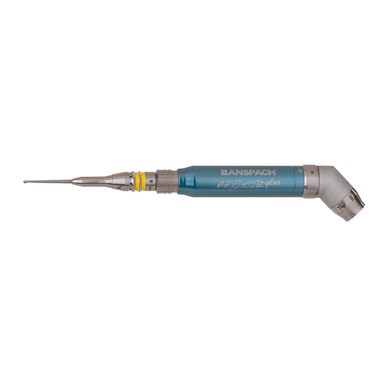
Anspach Electric Systems. High speed
performance and power in a variety of
applications.
High Speed
Power Tools
Related Manuals for Synthes Anspach
Summary of Contents for Synthes Anspach
-
Page 1
Anspach Electric Systems. High speed performance and power in a variety of applications. Instructions for Use High Speed Power Tools… -
Page 2: Table Of Contents
Micro Curved Attachment (MCA) and Curved Burr Support Sleeves (Curved Burr) microSaws and Small Attachments Assembly Sagittal Saw Compact SpeedReducer Care and Maintenance Inspection and Maintenance Manual Cleaning Procedure Sterilization Troubleshooting Ordering Information Anspach Electric Systems Instructions for Use Synthes…
-
Page 3: Synthes Anspach
The e12 is designed specifically to meet the demands of sur- gical applications requiring a low speed instrument at a high performance level that is the hallmark of Anspach systems. It Warning: Before using any of the Synthes Anspach High…
-
Page 4: Indications
Indications The Synthes Anspach High Speed Electric Systems are intended for cutting and shaping bone including spine and cranium. The Synthes Anspach High Speed Electric System is composed of Hand- piece models eMax2, eMax2 Plus, E12, and E-Saggital; Electric Consoles models SC2000, SC2000U, SC2100, SC2101, and SC2102;…
-
Page 5: Warnings And Cautions
Use caution to avoid cutting or tearing gloves while handling Use of accessories or cable other than those provided by dissection tools. Synthes Anspach, and specified for the electric system in use, may result in increased emissions or decreased immunity. Dissection tools must be adequately retained within attachment to prevent distal migration, which may cause injury.
-
Page 6: Technical Specifications
6.25 kg (13.77 lbs) Patent Information The device complies with the following standards: Synthes Anspach products are manufactured under one or IEC 60601-1 / IEC 60601-1-2 more of the following U.S. Patent Nos. RE 37,358; 5,405,348; 5,601,560; 5,630,818; 5,741,084; 5,904,687;…
-
Page 7
The Synthes Anspach High Speed Electric System is intended for use in the electromagnetic environment specified below. The customer or the user of the Synthes Anspach High Speed Electric System should assure that it is used in such an environment. -
Page 8
The Synthes Anspach High Speed Electric System is intended for use in the electromagnetic environment specified below. The customer or the user of Synthes Anspach High Speed Electric System should assure that it is used in such an environment. Immunity test… -
Page 9
TV broadcast cannot be predicted theoretically with accuracy. To assess the electromagnetic environment due to fixed RF transmitters, an electromagnetic site survey should be considered. If the measured field strength in the location in which the Synthes Anspach High Speed Electric System is used exceeds the applicable RF compliance level above, the Synthes Anspach High Speed Electric System, or the device which contains it, should be observed to verify normal operation. -
Page 10
Synthes Anspach High Speed Electric System The Synthes Anspach High Speed Electric System is intended for use in the electromagnetic environment in which radiated RF disturbances are controlled. The customer or the user of the Synthes Anspach High Speed Electric System can help prevent… -
Page 11: Glossary Of Symbols
Located on the Foot Pedal switch this Irrigation System indicates a change state (on/off) for the Console Irrigation System Located on the Console this indicates a change of irrigation rate for the Console Irrigation System Synthes Anspach Electric Systems Instructions for Use…
-
Page 12
2 and eMax 2 Plus Manufacturer Authorized European Union Representative Sterilized Using Irradiation Latex-free Certification There is no latex material in Synthes Anspach products or Single Use Only (A.K.A. Do Not Reuse) packaging. CAUTION: Refer to accompanying documentation Anspach Electric Systems… -
Page 13
Hose length is approximately 12 feet. *Power cord provides means to disconnect from the mains. *Position equipment in such a manner that provides access to the rear of the system in order to disconnect from mains. Synthes Anspach Electric Systems Instructions for Use… -
Page 14
Face Panel Light Emitting Diodes (LED) illuminate, and a beep sounds. 5. For operating instructions see Console Face Panel Opera- tion and Foot Control Operation below. Note: Handpiece is fully functional at this time. Anspach Electric Systems Instructions for Use Synthes… -
Page 15
For Example: XY this to be interpreted as Software Version X.Y. On Consoles with no Irrigation (SC2102) the buttons are not marked but are located in the same location which are de- tectable by feel. Synthes Anspach Electric Systems Instructions for Use… -
Page 16
Switch on top right of foot control for a minimum of one second and then step on center of foot control pedal. Directional Upon activation, LED on face panel illuminates; irrigation Control pump and handpiece start. Switch E-FP-DIR Foot Control Anspach Electric Systems Instructions for Use Synthes… -
Page 17
Note: Handpiece is fully functional at this time. 7. To deactivate Hand Control, depress “Foot” button on console face panel. To remove hand control from handpiece, slide towards distal end of handpiece and remove. Synthes Anspach Electric Systems Instructions for Use… -
Page 18
1. Lift top of pump head and insert large diameter tubing. Refer to diagram on irrigation pump housing to ensure tubing is routed properly (smaller diameter tubing flows towards Synthes Anspach handpiece housing). 2. Close lid on pump head. 3. Insert bayonet end of tubing into irrigation bag. -
Page 19
“HOSPITAL GRADE.” Note: If fuse replacement is necessary, use only Time Delay fuse rated 2.5 A, 250 V. Item to be replaced by Synthes Anspach repair facility ONLY. Synthes… -
Page 20
30 seconds after tone is heard and/or code is displayed. Handpiece type None Disconnect connector and reconnect to console. If fault does not not recognized clear, return handpiece and console to Synthes Anspach for service. None Handpiece set 3 beeps to reverse *Note: Consoles with Software Version 3.0 and higher do not generate an Audible Signal for Codes E1–… -
Page 21: E12 Small Bone System
3. When fully engaged, contours on e12 handpiece body, release ring, and small attachment will align. For specific attachment assembly, refer to “microSaws and Small Bone Attachments Assembly” section in this manual. Synthes Anspach Electric Systems Instructions for Use…
-
Page 22: Standard Attachments And Dissection Tool Assembly
An example follows: Dissection Tool Part Number: S-2B Dissection Tool Description: 2 mm Fluted Ball for Short attachment Each attachment is laser-marked with its corresponding part number. Anspach Electric Systems Instructions for Use Synthes…
-
Page 23
XL-HD 1. Move handpiece knurled knob to “SAFE” position. 2. Remove dissection tool from distal end of attachment. 3. Rotate attachment to left approximately one-quarter turn, and remove from distal end of handpiece. Synthes Anspach Electric Systems Instructions for Use… -
Page 24
1. Lift latch on the distal end of the attachment with your thumb. Remove dissection tool and release latch. 2. Move handpiece knurled knob to “SAFE” position. 3. Rotate attachment counterclockwise and remove from distal end of handpiece. Anspach Electric Systems Instructions for Use Synthes… -
Page 25
Disassembly 1. Move handpiece knurled knob to “SAFE” position. 2. Rotate attachment to left approximately one-quarter turn, and remove from distal end of handpiece. 3. Remove dissection tool from distal end of attachment. Synthes Anspach Electric Systems Instructions for Use… -
Page 26
2. Remove dissection tool from distal end of attachment. 3. Move handpiece knurled knob to “SAFE” position. 4. Rotate attachment to left approximately one-quarter turn, and remove from distal end of handpiece. Anspach Electric Systems Instructions for Use Synthes… -
Page 27
Warning: The Micro Dissection Attachment is to be used only for bone dissection applications. Excessive force or side loads during use can cause rapid temperature increase at the distal end of the attachment. Always use copious irrigation with this attachment. Synthes Anspach Electric Systems Instructions for Use… -
Page 28: Minimal Access Attachment And Dissection Tool Assembly
Listen for a click as handpiece knurled knob moves up to seat next to driver. 3. Gently twist back and forth to ensure driver is locked into position. Anspach Electric Systems Instructions for Use Synthes…
-
Page 29
3. Rotate knurled knob on driver to line up arrow with “RUN”. Bearing Sleeve Disassembly 1. Rotate knurled knob on driver to line up arrow with “TUBE”. Remove bearing sleeve distal end of driver. Synthes Anspach Electric Systems Instructions for Use… -
Page 30: Micro Curved Attachment (Mca) And Curved Burr Support Sleeves (Curved Burr)
Listen for a click as hand- piece knurled knob moves up to seat next to MCA. 3. Gently twist back and forth to ensure MCA is locked into position. Anspach Electric Systems Instructions for Use Synthes…
-
Page 31: Microsaws And Small Attachments Assembly
The microSaws were designed for small bone dissection. DRIVER The microSaw Driver provides direct connection to all Anspach electric handpiece systems. The Driver also enables rapid exchange of saw head styles through a unique quick- disconnect system. Keyless Driver Installation…
-
Page 32
3. If blade has a flat shank, insert blade into slots in chuck until it is fully inserted and tighten chuck knob clockwise until snug. Saw Blade Removal 1. Saw blade removal is reverse of installation. Anspach Electric Systems Instructions for Use Synthes… -
Page 33
Small Attachment, J-Latch SA-JACOBS Small Attachments, Jacobs Chuck SA-JACOBS Note: Anspach does not supply dissection tools for SA-JLATCH or SA-JACOBS small attachments. Keyless driver refers to DRIVER. 1. Insert attachment drive shaft into distal end of keyless driver or distal end of e12 handpiece. Rotate until three… -
Page 34: Sagittal Saw
4. Rotate the extension handle clockwise to secure the saw blade and lower the handle into its closed position. Note: Saw blades used must be Synthes Anspach blades. Warning: All microSaw blades are for single use only. Note: Electric High Power Sagittal Saw is now fully functional.
-
Page 35: Compact Speedreducer
– The red storage cap provided with the Compact SpeedReducer is to prevent damage to the shaft. – The cap is removed for cleaning and washing but replaced for sterilization. – The device may be sterilized without the red storage cap. Synthes Anspach Electric Systems Instructions for Use…
-
Page 36: Inspection And Maintenance
Inspection and Maintenance Perform these activities regularly as per institution policy. Warning: Do not use any damaged equipment. Return to Synthes Anspach repair facility. Attachments Straight Attachments Visually inspect for any damage to the tube. – LONG – LONG-S – LONG-01 –…
-
Page 37
– Visually inspect for damage to electrical cord or – E-FP connector. – E-FP-DIR – Visually inspect for damage or cracks to the housing – E-FP-DIR/IRR or pedal. – EMAX2-FP – EMAX2-FP-NS – EPLUS-FP – EPLUS-FP-NS E-FP Synthes Anspach Electric Systems Instructions for Use… -
Page 38
– Visually inspect for damage to the silicone hose or to the electrical connector. – Connect to console and operate. The handpiece should operate smoothly. – There is no requirement to operate with attachment or dissection tool. Anspach Electric Systems Instructions for Use Synthes… -
Page 39
– Power the system and inspect for illumination of the LEDs. – If there is an irrigation pump present check for proper function. If the irrigation flow LED display is not on, press the Drop button. Synthes Anspach Electric Systems Instructions for Use… -
Page 40: Manual Cleaning Procedure
Item Number 5. a. DO NOT rinse out instrument milk (lubricant). b. DO NOT apply mineral oil or other lubricants, which 3. Gently insert and remove Synthes Anspach Attachment may cause the attachment to overheat. Cleaning Brush (ACB) wetted with cleaning solution through the distal or proximal opening of the attachment as many times as necessary to remove any foreign debris.
-
Page 41
Warning: Transmissible Spongiform Encephalopathies (TSE). 2. Wipe with non-abrasive cloth and disinfectant or mild Synthes Anspach will not authorize or accept the return of deter gent and deionized, distilled, or purified water. products that directly contact patients or are contaminated 3. -
Page 42: Sterilization
Caution: Place attached protective cap over electrical con- nector on Synthes Anspach handpiece prior to sterilization. Before sterilizing: Ensure sterilization equipment is in proper working order as specified by the manufacturer.
-
Page 43: Troubleshooting
Problem Possible Cause Solution Excessive handpiece noise Faulty internal component Return to Synthes Anspach for service Lack of power to console Plug is not fully inserted/power switch Verify plugs to wall and back of console not turned on are pushed in completely and power switch is in “I”…
-
Page 44
Defective attachment Clean attachment or replace attachment. Inoperative Hand Control Defective internal component Return to Synthes Anspach for service. Hand Control Attachment may not be The circumferential groove on handpiece fully installed housing will be exposed when the Hand Control is fully installed. -
Page 45: Ordering Information
Oscillating microSaw Attachment R-SAW Reciprocating microSaw Attachment S-SAW Sagittal microSaw Attachment SA-JLATCH Small Attachment, J-Latch SA-JACOBS Small Attachment, Jacobs Chuck Warranty and Return Policy is available upon request. Please contact your local Sales Representative. Synthes Anspach Electric Systems Instructions for Use…
-
Page 46
Aston Court, Kingsmead Business Park Frederick Place, High Wycombe HP11 1LA, United Kingdom Ö036 001 507öACMä Manufacturer Distributor: The Anspach Effort, Inc. 4500 Riverside Drive All technique guides are available as PDF files at Palm Beach Gardens, FL 33410 0086 www.synthes.com/lit…

-
Уже зарегистрированы? Войти
Войти
-
Запомнить
Не рекомендуется для компьютеров с общим доступом -
Войти анонимно
-
Забыли пароль?
-
Регистрация
Изменение в правилах «Опознайки»
Один объект для опознания — одна тема.
Запрещается размещать групповые фотографии или несколько разных объектов для опознания.
Авторизация
Подписчики
1

Автор
METALLROAD
- Найти другие файлы
Информация о файле
Токарный станок Syntec серия 6D-H/7/21/21-H/22/220
Руководство по эксплуатации токарного станка с контроллером пошагового позиционирования через шину управления движением + G cod
0
Предыдущий файл
1М63Б, 1М63БФ101, 1М63БП, 1М63БПФ101 токарно-винторезный станок, Рязань. Паспорт, 1990г. (pdf)
Следующий файл
SMTCL CAK63 токарный станок. Паспорт (djvu)