-
Contents
-
Table of Contents
-
Troubleshooting
-
Bookmarks
Quick Links
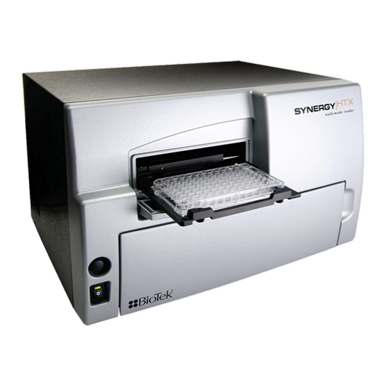
Multi-Mode Microplate Reader
Synergy
HTX
™
Operator’s Manual
Related Manuals for Biotek Synergy HTX
Summary of Contents for Biotek Synergy HTX
-
Page 1
Multi-Mode Microplate Reader Synergy ™ Operator’s Manual… -
Page 2
… -
Page 3
Synergy HTX Multi-Mode Microplate Reader Operator’s Guide July 2014 2014 Part Number 1341000 Revision A BioTek Instruments, Inc. -
Page 4
BioTek Instruments, Inc. Changes made to the information in this document will be incorporated in new editions of the publication. No responsibility is assumed by BioTek for the use or reliability of software or equipment that is not supplied by BioTek or its affiliated dealers. -
Page 5: Table Of Contents
Canadian Department of Communications Class A …. xiv User Safety …………..xv Safety Symbols …………… xvi Introduction …………….. 1 Synergy HTX Multi-Mode Microplate Reader ……2 Package Contents ………….. 3 Optional Accessories …………4 Product Support & Service ……….5 Technical Assistance Center (TAC) ……..
-
Page 6
Inspect/Clean Excitation and Emission Filters ……. 56 Flush/Purge the Fluid Path ……….57 Running a Dispense Protocol (Optional) ……58 Empty/Clean the Tip Priming Trough ……..59 Clean the Priming Plate …………. 59 Clean the Internal Components ………. 60 BioTek Instruments, Inc. -
Page 7
Absorbance Liquid Test 1 ……….110 Absorbance Liquid Test 2 ……….112 Absorbance Liquid Test 3 (optional) ……114 Fluorescence Tests …………116 Required Materials …………117 Test Solutions …………118 Procedure …………..119 Results Analysis …………119 Synergy HTX Operator’s Manual… -
Page 8
General Specifications …………. 144 Absorbance Specifications ……….145 Fluorescence Specifications ……….147 Luminescence Specifications ……….148 Models with Injectors …………149 Error Codes …………..151 Error Codes Overview …………152 Contact Info: BioTek Service/TAC ……… 152 Error Codes …………..153 BioTek Instruments, Inc. -
Page 9: Contact Information
Global Service and Support BioTek instrument service and repair is available worldwide at one of BioTek’s International Service Centers and in the field at your location. For technical assistance, contact the Technical Assistance Center (TAC) at BioTek World Headquarters US. To arrange for service or repair of your instrument, contact the office nearest you.
-
Page 10
Phone: +41 (41) 2504060 Fax: +82 (0) 2-562-4750 Fax: +41 (41) 2505064 Email: korea@biotek.com Email: info@biotek.ch Website: www.biotekinstruments.co.kr Website: www.biotek.ch BioTek United Kingdom (UK) 6 Bull Street Potton, Bedfordshire SG19 2NR United Kingdom Phone: +44 (1767) 262000 Fax: +44 (1767) 262330 Email: info@biotek.uk.com Website: www.biotek.uk.com… -
Page 11: Document Conventions
Bold Note: Topics that apply only to specific Synergy HTX models are preceded by a notice in italics, for example: Applies only to italic Synergy HTX models with injectors.
-
Page 12: Revision History
Preface Revision History Date Changes 7/2014 Initial release BioTek Instruments, Inc.
-
Page 13: Intended Use Statement
Warranty and Product Registration Take a moment to review the Warranty information that shipped with your product. Please also register your product with BioTek to ensure that you receive important information and updates about the product(s) you have purchased. You can register online through the Customer Resource Center at www.biotek.com or by calling 888/451-5171 or…
-
Page 14: Repackaging And Shipping
Preface Repackaging and Shipping If you need to ship the instrument to BioTek for service or repair, contact BioTek for a service authorization number, and be sure to use the original packing materials. Other forms of commercially available packaging are not recommended and can void the .
-
Page 15: Hazards
Some areas of the dispense module can present Warning! Pinch Hazard. pinch hazards when the instrument is operating. The module is marked with one of the symbols shown here. Keep hands/fingers clear of these areas when the instrument is operating. Synergy HTX Operator’s Manual…
-
Page 16: Precautions
Preface Precautions The following precautions are provided to help avoid damage to the instrument: The instrument should be serviced by BioTek authorized service Caution: Service. personnel. Only qualified technical personnel should perform troubleshooting and service procedures on internal components. Only approved spare parts should be used for maintenance.
-
Page 17: Ce Mark
EN 61010-1. “Safety requirement for electrical equipment for measurement, control and laboratory use. Part 1, General requirements.” EN 61010-2-081, “Particular requirements for automatic and semi-automatic laboratory equipment for analysis and other purposes.” Synergy HTX Operator’s Manual…
-
Page 18: Directive 2002/96/Ec: Waste Electrical And Electronic Equipment
Department of Communications. Le present appareil numerique n’emet pas de bruits radioelectriques depassant les limites applicables aux appareils numerique de la Class A prescrites dans le Reglement sur le brouillage radioelectrique edicte par le ministere des Communications du Canada. BioTek Instruments, Inc.
-
Page 19: User Safety
Part 1: General requirements.” • Canadian Standards Association CAN/CSA C22.2 No. 61010-1, “Safety requirements for electrical equipment for measurement, control and laboratory use; Part 1: General requirements.” • EN 61010 Standards, see starting on page xiii. CE Mark Synergy HTX Operator’s Manual…
-
Page 20: Safety Symbols
Attenzione, rischio di schiacciare ed elettrica intrappolarsi Warning, hot surface Warning, potential biohazards Attention, surface chaude Attention, risques biologiques potentiels Warnen, heiße Oberfläche Warnung! Moegliche biologische Giftstoffe Precaución, superficie caliente Atención, riesgos biológicos Attenzione, superficie calda Attenzione, rischio biologico BioTek Instruments, Inc.
-
Page 21
Recogida selectiva de aparatos eléctricos y electrónicos Dispositivo medico diagnostico in vitro Raccolta separata delle apparecchiature elettriche ed elettroniche Consult instructions for use Consulter la notice d’emploi Gebrauchsanweisung beachten Consultar las instrucciones de Consultare le istruzioni per Synergy HTX Operator’s Manual… -
Page 22
Preface BioTek Instruments, Inc. -
Page 23: Introduction
Chapter 1 Introduction This chapter introduces the Synergy HTX, describes its key features, lists its package contents, and provides contact information for technical assistance. Synergy HTX Multi-Mode Microplate Reader ……. 2 Package Contents …………..3 Optional Accessories …………… 4 Product Support & Service …………5 Technical Assistance Center (TAC) ……..
-
Page 24: Synergy Htx Multi-Mode Microplate Reader
Both Synergy HTX models support the reading of 6-, 12-, 24-, 48-, 96-, and 384-well microplates with standard 128 x 86 mm geometry, as well as the BioTek Take3 and Take3 Trio Micro-Volume Plates.
-
Page 25: Package Contents
Package Contents | Package Contents Part numbers and package contents are subject to change. Contact BioTek Customer Care with any questions. Item Part # Synergy HTX Operator’s Manual 1341000 Power supply 76061 Power cord set (specific to installation environment):…
-
Page 26: Optional Accessories
BioCell Quartz Vessel and Adapter Plate Additional Fluorescence Filters; contact BioTek for part numbers and availability The Synergy HTX is compatible with the BioStack Microplate Stacker. Contact BioTek or visit our website to learn more. For Use with Liquid Tests (see Chapter 5)
-
Page 27: Product Support & Service
If your instrument(s) or software fails to function properly, if you have questions about how to use or maintain our products, or if you need to send an instrument to BioTek for service or repair, please contact our Technical Assistance Center. BioTek’s “TAC” is open from 8:30 AM to 5:30 PM (EST), Monday through Friday, excluding standard U.S.
-
Page 28
Chapter 1: Introduction BioTek Instruments, Inc. -
Page 29: Installation
Chapter 2 Installation This chapter includes instructions for unpacking and setting up the Synergy HTX and, if applicable, the external dispense module. Instructions are also included for repackaging the reader and dispense module for shipment. Product Registration …………… 8 1: Unpack and Inspect the Reader ……….8 2: Remove the Shipping Panel ……….
-
Page 30: Product Registration
Use two people when lifting and carrying the instrument. The Synergy HTX is attached to a shipping panel that has two handles for lifting. Locate and grasp the handles. Carefully lift the reader out of the box and place it on a level surface.
-
Page 31
1: Unpack and Inspect the Reader | accessories box Figure 1: Unpacking the reader Synergy HTX Operator’s Manual… -
Page 32: 2: Remove The Shipping Panel
Do not block any air vents. See Figure 2 on the next page. Place the panel back into the inner shipping box for storage. Reattach the shipping panel before Important: repackaging the Synergy HTX for shipment. BioTek Instruments, Inc.
-
Page 33: 3: Remove The Microplate Carrier Shipping Screw
Remove the microplate carrier shipping bolt Important: before turning on the Synergy HTX. Pull down the microplate loading door on the front of the reader. Using the supplied wrench, remove the carrier shipping bolt with its o-ring and warning tag.
-
Page 34: 4: Install The Fluorescence Lamp Assembly
BioTek if you have misplaced the bolt (PN 1342008) and/or its o-ring (PN 49259). 4: Install the Fluorescence Lamp Assembly Applies only to Synergy HTX models with fluorescence capability. Do not touch the glass lenses! Fingerprints on Important: the condenser lens or heat absorber may negatively affect performance.
-
Page 35: 5: Select An Appropriate Location
Figure 4: Installing the fluorescence lamp assembly (replacement lamp PN 7080500) 5: Select an Appropriate Location Install the Synergy HTX on a level surface in an area where ambient temperatures between 18ºC (64ºF) and 40ºC (104ºF) can be maintained. The reader is sensitive to extreme environmental conditions. Avoid the following:…
-
Page 36: 6: Connect The Power Supply
A clean work area is necessary to ensure accurate readings. If you will be installing BioTek’s BioStack Microplate Stacker for operation with the Synergy HTX, you may wish to seat the BioStack and the reader in their aligning plates at this time. Refer to the BioStack Operator’s Manual for more information.
-
Page 37: 7: Unpack And Inspect The Dispense Module
Save all packaging materials. If you need to ship Important! the dispense module to BioTek for repair or replacement, you must use the original materials. Using other forms of commercially available packaging, or failing to follow the repackaging instructions, may…
-
Page 38
1 injector tip priming trough (small, plastic cup) • 1 plastic tool storage bag with fastener strips • • 2 metal thumbscrews • 1 stylus (wire) packaged in a small plastic cylinder • 1 dispense module cover 1 dispense module cable • BioTek Instruments, Inc. -
Page 39
7: Unpack and Inspect the Dispense Module | Dispense module Top foam cable end cap Dispense module cover Inlet tubes (2) Syringes (2) Outlet tubes (4) Bottom foam end cap (with cutouts) Accessories Figure 7: Unpacking the dispense module’s accessories Synergy HTX Operator’s Manual… -
Page 40: 8: Install The Dispense Module
If applicable, perform these steps to record calibration information and then install the dispenser. Record the syringe calibration values that were set at BioTek: a. On the back panel of the dispenser box, locate the two labels that show the six target volumes (200, 80, 40, 20, 10, and 5) and the six corresponding calibration values.
-
Page 41
Locate the dispenser cable. Plug one end into the port on the left side of the dispenser. Plug the other end into the dispenser port on the rear of the reader. Locate the injector-tip-cleaning stylus, packaged in a small cylinder. Attach the cylinder to the back of the dispenser for storage. Synergy HTX Operator’s Manual… -
Page 42: 9: Connect The Host Computer
Getting Started Guide to install the software. 11: Turn on the Reader Locate the power switch on the front panel and turn on the Synergy HTX. The reader will automatically initiate a System Test and eject the microplate carrier. BioTek Instruments, Inc.
-
Page 43: 12: Establish Communication
Panel, under Ports in the Hardware/Device Manager area of System Properties (e.g., USB Serial Port (COM5)). Click the button. Gen5 will attempt to communicate with the reader. If Test Comm the communication attempt is successful, return to Gen5’s main screen. Synergy HTX Operator’s Manual…
-
Page 44: 13: Set The Dispenser Calibration Values
BioTek’s Technical Assistance Center. 13: Set the Dispenser Calibration Values Applies only to Synergy HTX models with injectors. Before you use the dispenser with the Synergy HTX, you must set the calibration values in Gen5. Power on the instrument, and establish communication.
-
Page 45: 14: Run A System Test
If the problem is something you can fix, do so now and run another System Test. If the problem is something you cannot fix, or if the test continues to fail, contact BioTek’s Technical Assistance Center.
-
Page 46: 15: Test The Injector System
Operational/Performance Qualification 15: Test the Injector System Applies only to Synergy HTX models with injectors. If necessary, press the button above the power switch to eject the microplate carrier. Place the tip priming trough in the left-rear pocket of the carrier.
-
Page 47
15: Test the Injector System | The dispense module’s setup should resemble the photo in Figure 11. Make any final adjustments, if necessary. Figure 11: The fully assembled dispense module Select System > Instrument Control > Synergy HTX Click the tab. Prime With… -
Page 48: Operational/Performance Qualification
Chapter 2: Installation Operational/Performance Qualification Your Synergy HTX Multi-Detection Microplate Reader was fully tested at BioTek prior to shipment and should operate properly following the successful completion of the installation and setup procedures described throughout this chapter. If you suspect that problems occurred during shipment, if you received the reader back…
-
Page 49
Please contact BioTek if you have misplaced either of these items. If you need to ship the Synergy HTX and/or the dispense module to BioTek for service or repair, be sure to use the original packaging materials. -
Page 50
Perform these steps to prepare the dispense module for shipment: If you have not already done so: • Contact BioTek’s Technical Assistance Center for a service authorization number and shipping address before returning equipment for service. See page 6 for contact information. -
Page 51
Insert the accessories box alongside the dispense module box. Insert the top foam end cap. Close and seal the outer box with tape. Write the service authorization number in large, clear numbers on the outside of the box. Ship the box to BioTek. Synergy HTX Operator’s Manual… -
Page 52
Chapter 2: Installation BioTek Instruments, Inc. -
Page 53: Getting Started
Chapter 3 Getting Started This chapter describes some of the Synergy HTX’s key components and provides an introduction to using Gen5 to control the instrument. Key Components …………..32 Power Switch, Carrier Eject Button, Microplate Carrier … 32 Lamp Assembly and Filter Wheel Access ……33 Excitation and Emission Filter Wheels ………
-
Page 54: Key Components
X and Y axes to align each microwell with the top or bottom fluorescence probe, or bottom absorbance probe, as specified in the Gen5 procedure. When the read is complete, the plate carrier slides to its full-out position. BioTek Instruments, Inc.
-
Page 55: Lamp Assembly And Filter Wheel Access
In Gen5, this option is found in a Read step within a Procedure. Refer to the Gen5 Help for further instructions. Lamp Assembly and Filter Wheel Access Applies only to Synergy HTX models with fluorescence and luminescence capability. Excitation filter wheel (TRF…
-
Page 56: Excitation And Emission Filter Wheels
Chapter 3: Getting Started The Synergy HTX has two lamps: one for standard fluorescence, one for absorbance and time-resolved fluorescence: Standard Fluorescence: The 20-watt tungsten halogen lamp’s life is rated at an average of 1000 hours, and it is user-replaceable. The intensity of the bulb will slowly drop over time until the instrument’s…
-
Page 57
Figure 14: Profiles of the excitation and emission filter wheels, showing proper filter orientation The Synergy HTX is shipped with a set of excitation Important! and emission filters installed, and the Synergy HTX’s onboard software is preconfigured with the filter values and their locations. -
Page 58
Prepare a multi-layered “cushion” of lens paper. Using your finger covered with the lens paper, gently push against the filter and its C-clip retainer until they pop out. To replace a filter or plug: Hold the metal bracket with the filter wheel facing up. BioTek Instruments, Inc. -
Page 59: Installing The Time-Resolved Fluorescence Cartridge
Turn on the instrument. Installing the Time-Resolved Fluorescence Cartridge For Synergy HTX models that support time-resolved fluorescence, the “TR” cartridge must be installed in place of the excitation filter wheel before a TRF assay can be run. The TR cartridge allows light from the xenon flash bulb to be input to the fluorescence optical system within the Synergy HTX.
-
Page 60: Configuring The System For Luminescence Measurements
If you made any changes to either filter wheel, you must update Gen5’s filter table. Select “PLUG” to indicate the presence of a plug and “HOLE” to indicate an empty location. Click to download the information to the reader. Send Values Updating Gen5’s filter table; for complete instructions, see page 42. BioTek Instruments, Inc.
-
Page 61: The External Dispense Module
Read steps and procedures. The External Dispense Module Applies only to Synergy HTX models with injectors. The dispense module pumps fluid from the supply bottles to injector heads located inside the instrument. Fluid is injected into one well at a time.
-
Page 62
PTFE tubes with threaded fittings on each end that are used to deliver fluid from the syringes to the instrument. Inside the Synergy HTX, two Teflon tubes transport fluid from the tubing ports on the rear of the instrument to the two injectors. As shown below, both injectors are positioned directly above the bottom fluorescence optical probe. -
Page 63: Gen5 Software
Figure 18: Priming plate and tip priming trough Gen5 Software BioTek’s Gen5 software supports all Synergy HTX reader models. Use Gen5 to control the reader and the dispense module, perform data reduction and analysis on the measurement Synergy HTX Operator’s Manual…
-
Page 64: Viewing/Updating The Filter And Wavelengths Tables
Viewing/Updating the Filter and Wavelengths Tables If configured with fluorescence or luminescence capability, the Synergy HTX ships with a set of excitation and emission filters installed, and the reader’s onboard software is preconfigured with the filter values and their locations. When Gen5 establishes communication with the reader, it “asks”…
-
Page 65: Creating Protocols And Experiments
After creating a protocol, create an experiment that references the protocol. You’ll run the experiment to read plates and analyze the data. Figure 19: Defining the procedure within a Gen5 protocol Synergy HTX Operator’s Manual…
-
Page 66
. If prompted to select a reader, select the Protocol > Procedure and click Synergy HTX Select a plate type. The assay plate must match the plate type selected in Gen5. Otherwise, the results of the read may be invalid. -
Page 67: Controlling The Dispense Module
If you have not already done so, save the file with an identifying name. Controlling the Dispense Module Applies only to Synergy HTX models with injectors. Gen5 is used to perform several dispense module-specific functions, including initializing, priming, and purging. Gen5 also contains certain configuration items that must be set before using the dispense module.
-
Page 68
Insert the appropriate inlet tube into the bottle. Place the priming plate on the carrier. Important! In Gen5, select System > Instrument Control > Synergy HTX click the tab. Prime Select the Dispenser number (1 or 2) associated with the supply bottle. -
Page 69
If a syringe needs to be installed or replaced, it must first be moved to its “Maintenance Position.” To do this using Gen5: Select and click the System > Instrument Control > Synergy HTX tab. Prime Select the appropriate Dispenser number (1 or 2) associated with the syringe. -
Page 70: Recommendations For Optimum Performance
Gen5 protocol in advance as well, to ensure that the intended reading parameters are used and to avoid any last-minute corrections. Although the Synergy HTX supports standard flat, U-bottom, and V-bottom • microplates, the reader achieves optimum performance with optically clear, flat- bottomed wells.
-
Page 71: Incubation And Partial Plates
Cluster your sample wells rather than spacing them throughout the plate. • Place your sample wells in the center of the plate. This placement may lead to less • evaporation than if you place the samples in wells on the edge of the plate. Synergy HTX Operator’s Manual…
-
Page 72
Chapter 3: Getting Started BioTek Instruments, Inc. -
Page 73: Preventive Maintenance
Chapter 4 Preventive Maintenance This chapter provides step-by-step instructions for maintaining the Synergy HTX and external dispense module (if used) in top condition, to ensure that they continue to perform to specification. Recommended Maintenance Schedule ……..52 Overview ……………. 52 Daily Cleaning for the Dispense Module …….
-
Page 74: Recommended Maintenance Schedule
(review the reagent’s package insert for specific recommendations). A daily cleaning regimen is the best way to ensure accurate performance and a long life for your instrument and dispense module. BioTek also recommends flushing the module with DI water before conducting the decontamination procedure described in Chapter 5, As-Needed Maintenance BioTek Instruments, Inc.
-
Page 75: Recommended Maintenance Schedule
Models with injectors only: Flush/purge the fluid path (Optional) Run Dispense protocol Empty/clean tip prime trough Clean priming plate Clean internal components tubing and injector heads Clean optical probes Clean internal surfaces Synergy HTX Operator’s Manual…
-
Page 76: Warnings And Precautions
“wet” cloth on it. Do not allow water or other cleaning solution to run into the interior of the instrument. If this happens, contact BioTek’s Technical Assistance Center. Do not apply lubricants to the microplate carrier or Important! carrier track.
-
Page 77: Cleaning Exposed Surfaces
“wet” cloth. Do not allow the cleaning solution to run into the interior of the instrument. If this happens, contact BioTek’s Service Department. Exposed surfaces may be cleaned (not decontaminated) with a cloth moistened (not soaked) with water or water and a mild detergent. You will need: Deionized or distilled water •…
-
Page 78: Inspect/Clean Excitation And Emission Filters
Chapter 4: Preventive Maintenance Inspect/Clean Excitation and Emission Filters Applies only to Synergy HTX models with fluorescence and luminescence capability. Laboratory air is used to cool the lamp, and the filters can become dusty as a result. The filters should be inspected and cleaned at least every three months. You will need: Isopropyl, ethyl, or methyl alcohol •…
-
Page 79: Flush/Purge The Fluid Path
Flush/Purge the Fluid Path | Flush/Purge the Fluid Path Applies only to Synergy HTX models with injectors. At the end of each day that the dispense module is in use, flush the fluid path using Gen5’s priming utility. Leave the fluid to soak overnight or over a weekend, and then purge the fluid before using the instrument again.
-
Page 80: Running A Dispense Protocol (Optional)
Chapter 4: Preventive Maintenance Running a Dispense Protocol (Optional) Applies only to Synergy HTX models with injectors. After flushing/purging the system (page 57) and before running an assay that requires dispense, take a moment to visually inspect the dispensing accuracy.
-
Page 81: Empty/Clean The Tip Priming Trough
Components Empty/Clean the Tip Priming Trough Applies only to Synergy HTX models with injectors. The tip priming trough is a small, removable priming cup located in the left rear of the microplate carrier, used for performing the Tip Prime. The trough holds about 1.5 mL of liquid and must be periodically emptied and cleaned by the user.
-
Page 82: Clean The Internal Components
Chapter 4: Preventive Maintenance Clean the Internal Components Applies only to Synergy HTX models with injectors. The Synergy HTX’s internal components that require routine cleaning include: • Optical probes Surface beneath the microplate carrier • Internal dispense tubes and injector heads •…
-
Page 83: Required Materials
Deionized or distilled water Stylus (stored in a plastic cylinder affixed to the rear of the dispense • module or reader) (PN 2872304) For cleaning the optical probes: • Clean cotton swabs Isopropyl alcohol • Lens-cleaning tissue • Synergy HTX Operator’s Manual…
-
Page 84: Removing The Reader’s Shroud
Remove two screws from the top center of the rear panel Remove two side screws When reinstalling the shroud, press down firmly on the top to maintain a good seal while tightening the top screws. BioTek Instruments, Inc.
-
Page 85
Clean the Internal Components | Stand facing the front of the instrument. Grasp both sides of the shroud, slide it toward you, and pull it straight off the instrument. Set the shroud aside. Synergy HTX Operator’s Manual… -
Page 86: Removing The Internal Tubes And Injector Heads
When reinstalling the Important! internal dispense tubes, be sure to align the tubing ports with the injector heads as shown in this diagram. Look for the SYRINGE 1 SYRINGE 2 labels on the instrument’s rear panel. BioTek Instruments, Inc.
-
Page 87
Locate the tubing ports on the reader’s rear wall. Turn each tube’s thumbscrew counterclockwise and gently pull the tube from the port. Cable clamp Locate the injector heads. Turn each tube’s thumbscrew counterclockwise to disconnect the tube from the injector head. Synergy HTX Operator’s Manual… -
Page 88
Chapter 4: Preventive Maintenance Turn the injector heads counterclockwise and gently pull them out of their sockets. Be sure to seat the injector tips securely when reinstalling. See the photo on page 77. BioTek Instruments, Inc. -
Page 89: Cleaning The Internal Tubes And Injector Heads
Stream water from a faucet through the pipe to be sure it is clean. If the water does not stream out, try soaking the heads in hot soapy water and then reinserting the stylus. O-ring; do not remove Synergy HTX Operator’s Manual…
-
Page 90: Cleaning The Optical Probes
Instructions for removing and cleaning these components are provided on pages 64 through 67. Before starting this procedure, gather some supplies: • Small container of isopropyl alcohol Small container of deionized or distilled water Lens-cleaning tissue Cotton swabs BioTek Instruments, Inc.
-
Page 91
Screw for lowering Top optical probe and raising the top Incubator optical probe housing Top probe hanger, with two shoulder screws Figure 21: Internal components to be removed/adjusted for cleaning the optic probes Synergy HTX Operator’s Manual… -
Page 92
Disconnect the heater and thermistor wires. To do this, depress the small tab (pictured below) and separate the connectors. Depress tab to separate the connectors Remove the thumbscrew located in the left rear of the instrument and set it aside. This exposes the ground wire. BioTek Instruments, Inc. -
Page 93
Clean the Internal Components | Lift the ground wire and move it off to the side. Locate the two black thumbscrews that hold the incubator housing in place. Remove both of them and set them aside. Synergy HTX Operator’s Manual… -
Page 94
Gently lift the left side of the incubator housing and carefully slide it out. Note: When replacing the incubator housing, the two “forks” on its right side should wrap around the holding screws. The forks should not slide under the fixed foam housing. BioTek Instruments, Inc. -
Page 95
Use a 1/8″ hex key to remove the top optical probe’s holding screw. Gently pull the optical probe up and out of its socket to expose it for cleaning. Soak the end of the probe in alcohol for one minute maximum Wipe with lens-cleaning tissue and set aside. Synergy HTX Operator’s Manual… -
Page 96
(see instructions on the next page). Inspect the block Do not touch the lens with your fingers! for spills or other contamination. Carefully clean with mild detergent if necessary. BioTek Instruments, Inc. -
Page 97
Important! When cleaning the absorbance lens with the swab, apply very little pressure to the lens! Applying too much pressure can push the lens out of its holder; reinstallation must be performed by BioTek service personnel. If the lens does fall out, contact BioTek TAC. -
Page 98: Cleaning The Reader’s Internal Surface
(steps 1 through 6). Manually slide the microplate carrier to the left to engage the support pin, and then away from the center surface. Microplate carrier, fully extended BioTek Instruments, Inc.
-
Page 99: Reassembling The Components
Insert the two injector heads into their sockets in the top probe hanger. Ensure that the Do not touch the absorbance lens with your fingers! injector heads are properly seated in the hanger. The knurled plastic should sit flush against the hanger surface, as shown below. Synergy HTX Operator’s Manual…
-
Page 100
Do not overtighten the thumbscrews! Here is the top probe hanger ready for reinstallation, with injector heads and internal dispense tubes attached: Replace the top probe hanger and shoulder screws (using the 3/32″ hex key), page 74. BioTek Instruments, Inc. -
Page 101: Performance Check
After reassembling the instrument, perform the following to verify that the instrument is functioning properly: • Plug the instrument in and turn it on; allow its run-time system test to complete. Run a System Test through Gen5. Run any required OQ/PQ tests. • Synergy HTX Operator’s Manual…
-
Page 102
Chapter 4: Preventive Maintenance BioTek Instruments, Inc. -
Page 103: As-Needed Maintenance
Chapter 5 As-Needed Maintenance This appendix contains procedures for decontaminating all models of the Synergy HTX. Purpose …………….82 Required Materials …………..83 Procedure for Models without Injectors ……..84 Routine Procedure for Models with Injectors ……85 Clean Exposed Surfaces ………… 85 Decontaminate the Fluid Lines ………..
-
Page 104: Purpose
Centers for Disease Control and Prevention (CDC). Neither BioTek nor the CDC assumes any liability for the adequacy of these solutions and methods. Each laboratory must ensure that decontamination procedures are adequate for the Biohazard(s) they handle.
-
Page 105: Required Materials
Required Materials | 83 Required Materials For all Synergy HTX models: Sodium hypochlorite (NaClO, or bleach) • • 70% isopropyl alcohol (as an alternative to bleach) • Deionized or distilled water Safety glasses • Surgical mask • Protective gloves •…
-
Page 106: Procedure For Models Without Injectors
Do not immerse the instrument, spray it with liquid, or use a “wet” cloth. Do not allow the cleaning solution to run into the interior of the instrument. If this happens, contact the BioTek Service Department. …
-
Page 107: Routine Procedure For Models With Injectors
Routine Procedure for Models with Injectors Perform this Routine Procedure when all systems are functioning normally on the Synergy HTX with Injectors. If you are unable to prime the Synergy HTX due to a system failure, perform the Alternate Procedure described on page 89.
-
Page 108: Decontaminate The Fluid Lines
Empty the beaker containing the outlet tubes. Put the tubes back in. Important! If sodium hypochlorite (bleach) was used, perform Rinse the Fluid on the next page. Lines Otherwise, (or after performing the Rinse procedure), repeat steps 1–13 for SYRINGE 2 / Dispenser 2. BioTek Instruments, Inc.
-
Page 109: Rinse The Fluid Lines
Required Materials • Removing the Reader’s Shroud • Removing the Internal Tubes and Injector Heads • Cleaning the Internal Tubes and Injector Heads • When finished, replace the internal components and the reader’s shroud. Synergy HTX Operator’s Manual…
-
Page 110: Clean The Tip Priming Trough And Priming Plate
If decontaminating with alcohol, remove the trough and plate and let them air- dry. Discard the used gloves and cloths using a biohazard trash bag and an approved biohazard container. tip priming trough Figure 33: Tip priming trough and priming plate BioTek Instruments, Inc.
-
Page 111: Alternate Procedure For Models With Injectors
Alternate Procedure for Models with Injectors | 89 Alternate Procedure for Models with Injectors If you are unable to prime the Synergy HTX due to a system failure, decontaminate the instrument and the Dispense Module as follows: Turn to and perform the following…
-
Page 112
Use a clean, dry cloth to dry all wet surfaces on the instrument and the Dispense module. Reassemble the instrument and dispense module as necessary. Discard the used gloves and cloths using a biohazard trash bag and an approved biohazard container. BioTek Instruments, Inc. -
Page 113: Instrument Qualification
Chapter 6 Instrument Qualification This chapter contains procedures for qualifying the initial and ongoing performance of the Synergy HTX and the external dispense module (if used). Overview …………….92 IQ/OQ/PQ …………….92 Recommended Qualification Schedule ……..94 System Test …………….. 95 Absorbance Plate Test …………
-
Page 114: Overview
Operational Qualification (OQ), and Performance Qualification (PQ) procedures for all models of the Synergy HTX Multi-Mode Microplate Reader. Every Synergy HTX reader and external dispense module is fully tested at BioTek prior to shipment and they should operate properly upon initial setup. If you suspect that a…
-
Page 115
This frequency may be adjusted depending on the trends observed over time. • The successful completion of the PQ procedure confirms that the equipment is performing consistently under normal operating conditions. Synergy HTX Operator’s Manual… -
Page 116: Recommended Qualification Schedule
Liquid Test 3 is optional; it is provided for sites requiring verification at wavelengths lower than those attainable with the Absorbance Test Plate. The risk factors associated with your assays may Important! require that the Operational and Performance Qualification procedures be performed more frequently than shown above. BioTek Instruments, Inc.
-
Page 117: System Test
System Test | System Test Each time the Synergy HTX is turned on, it automatically performs a series of tests on the reader’s motors, lamp, the PMT, and various subsystems. The duration of this system test depends on the reader model, and can take a few minutes to complete. If all tests pass, the microplate carrier is ejected and the LED on the power switch remains on.
-
Page 118
If the test continues to fail, or if the cause is not something you can fix, contact BioTek’s Technical Assistance Center (see page 6 for contact information.) Turn off the incubator. -
Page 119
Delta 3103 29543 #5:860 1.51 Light 13001 39198 Dark 9871 9881 Delta 3130 29317 #6:962 1.88 Light 13099 39240 Dark 9869 9879 Delta 3230 29361 Noise Test Meas 9853 9901 9852 9900 Delta FLUORESCENCE/LUMINESCENCE Filter PCB Synergy HTX Operator’s Manual… -
Page 120
1044 y= 6904 Upper Right x= 1056 y= 1380 Delta 1 9744 — 9732= Delta 2 1056 — 1044= Delta 3 1380 — 1388= Delta 4 6904 — 6912= Carrier — Test Sensors Middle Sensor y=11968 BioTek Instruments, Inc. -
Page 121
Fax: 802 654 0638 In Europe: BioTek Instruments GmbH Tel: 49(0)7136-9680 Fax: 49(0)7136-968-111 All Others: Tel: 802 655 4040 Fax: 802 654 0638 email: TAC@biotek.com Product support center: www.biotek.com/service Figure 1: Sample output for the system test Synergy HTX Operator’s Manual… -
Page 122: Absorbance Plate Test
This test uses BioTek’s Absorbance Test Plate (PN 7260522) to confirm the mechanical alignment; optical density accuracy, linearity, and repeatability; and wavelength accuracy of the Synergy HTX. The Absorbance Plate Test compares the reader’s optical density and wavelength measurements to NIST-traceable values.
-
Page 123: Run The Absorbance Plate Test
Comments Click Start Test. Place the Test Plate in the microplate carrier so that well A1 is in the left rear corner of the carrier (as you are facing the carrier). Click to run the test. Synergy HTX Operator’s Manual…
-
Page 124
A sample test report is shown on page 104. • • Gen5 stores the results in a database; they can be retrieved and printed at any time. We recommend you print and save the report to document that the test was performed. BioTek Instruments, Inc. -
Page 125
0.568 1.040 1.560 1.865 2.400 Min Limit 0.113 0.537 0.999 1.509 1.808 2.284 Max Limit 0.159 0.599 1.081 1.611 1.922 2.516 Read 1 0.134 0.566 1.037 1.557 1.866 2.385 Result PASS PASS PASS PASS PASS PASS Synergy HTX Operator’s Manual… -
Page 126: Results And Troubleshooting Tips
Make sure the Test Plate is within its calibration certification period. The calibration sticker is affixed directly to the plate. If it is out of date, contact BioTek to schedule a recertification. Check the microplate carrier to ensure it is clear of debris.
-
Page 127
Check the four alignment holes (A1, A12, H1, H12) to ensure they are clear of debris. Check the microplate carrier to ensure it is clear of debris. If the problem continues to reoccur, contact BioTek TAC. Accuracy is a measure of the optical density of the neutral-density •… -
Page 128: Luminescence Tests
Chapter 6: Instrument Qualification Luminescence Tests For Synergy HTX models with luminescence capability, you can use a Harta Luminometer Reference Microplate, which is an LED-based test plate. Contact BioTek to purchase a plate, or go to www.hartainstruments.com for more information.
-
Page 129: Gen5 Protocol Reading Parameters
The information in the following tables represents the recommended reading parameters. Synergy HTX LumTest_Harta.prt Parameter Default Setting Plate Type: Harta plate (8030015) with adapter (8032028) Delay Step: 3 minutes Read Step 1: Read Wells: Label: Reference well A2 Detection Method: Luminescence Read Type: Endpoint Synergy HTX Operator’s Manual…
-
Page 130
Gain/Sensitivity: Read Height: 1.00 mm Read Step 3: Read Wells: A7–A8 Label: Battery Check Detection Method: Luminescence Read Type: Endpoint Integration Time: 0:01.00 MM:SS.ss Delay After Plate Movement: 100 msec Dynamic Range: Standard Filter Sets Excitation Plug BioTek Instruments, Inc. -
Page 131: Troubleshooting
Contact BioTek’s Technical Assistance Center for instructions. Absorbance Liquid Tests Conducting Liquid Tests confirms the Synergy HTX’s ability to perform to specification with liquid samples. Liquid testing differs from testing with the Absorbance Test Plate in that liquid in the wells has a meniscus, whereas the Test Plate’s neutral density glass filters do not.
-
Page 132: Absorbance Liquid Test 1
Stock Solution A or B, which may be formulated by diluting a dye solution • available from BioTek (A) or from the ingredients listed below (B). Solution A • BioTek QC Check Solution No. 1 (PN 7120779, 25 mL; PN 7120782, 125 mL) • Deionized water 5-mL Class A volumetric pipette •…
-
Page 133
Weigh out 0.092 g of FD&C Yellow No. 5 dye powder into a weigh boat. Rinse the contents into a 1-liter volumetric flask. Add 0.5 mL of Tween 20, or 5 mL of BioTek’s wetting agent. Fill to 1 liter with DI water; cap and shake well. The solution should measure approximately 2.000 OD when using 200 µL in a flat-bottom… -
Page 134: Absorbance Liquid Test 2
80% in the third tube, all the way to 10% in the tenth tube. Dilute using the 0.05% solution of deionized water and Tween 20. This solution can also be made by diluting the BioTek wetting agent 200:1. Test Tube Dilutions…
-
Page 135
Repeatability Specification: ± 1.0% ± 0.005 OD from 0.000 to 2.000 OD ± 3.0% ± 0.005 OD from 2.000 OD to 3.000 OD Synergy HTX Operator’s Manual… -
Page 136: Absorbance Liquid Test 3 (Optional)
If low, adjust up by adding β-NADH powder until the solution is at least at the lower end of this range. Do not adjust if slightly high. BioTek Instruments, Inc.
-
Page 137
(or equivalent) β-NADH Powder (β-Nicotinamide Adenine Dinucleotide, Reduced Form) • Sigma bulk catalog number N 8129, or preweighed 10-mg vials, Sigma number N6785-10VL (or BioTek PN 98233). Manufacturer part Note: numbers are subject to change. Store the β-NADH Powder according to the guidelines on its packaging. -
Page 138: Fluorescence Tests
• Linearity Test proportionally with changes in concentration. Proving that the system is linear allows the Sensitivity Test to be run on two points instead of using serial dilutions. BioTek Instruments, Inc.
-
Page 139: Required Materials
3. Be sure to document your new test procedure(s), and save all test results. Required Materials BioTek offers a liquid test kit (PN 7160013) containing the microplates and solutions used in this procedure. Microplates should be perfectly clean and free of dust or bottom scratches.
-
Page 140: Test Solutions
Synergy HTX FI_T.prt page 122. Test Solutions If using BioTek’s sodium fluorescein powder (PN 98155), be sure to hold the vial upright and open it carefully; the material may be concentrated at the top. If a centrifuge is available, spin down the tube before opening.
-
Page 141: Procedure
SF test solution 3.3 nM (A1-A3, A10-A12, H1-H3, H10-H12). 2. Calculate the Standard Deviation of the same twelve wells. 3. Calculate the % CV: (Standard Deviation/Mean) * 100 The % CV must be to pass. less than 3.0 Synergy HTX Operator’s Manual…
-
Page 142: Troubleshooting
Calculate the R-Square value; it must be ≥ 0.9500 to pass. Troubleshooting If any tests fail, please try the suggestions below. If the test(s) continue to fail, print the results and contact BioTek’s Technical Assistance Center. Are the solutions fresh? The open buffer and stock solutions should be •…
-
Page 143: Pipette Map
Before placing a plate in the instrument, blow the bottom of the plate with an aerosol. If the test fails again, the optical probe(s) may need to be cleaned. Contact BioTek TAC for instructions. • If the Corners Test continues to fail, the hardware may be misaligned. Contact BioTek TAC.
-
Page 144: Gen5 Protocol Reading Parameters
Plate Type or Gain (see “Troubleshooting” on page 120). Adjust the Plate Type setting to match the plate you are actually using, if different from shown here. BioTek Instruments, Inc.
-
Page 145
Fluorescence Tests | Protocol Name: Synergy HTX FI_B.prt Parameter Default Setting Plate Type: Greiner SensoPlate (Mfr. #655892) Read Step 1 Kinetic Loop: Run time :45 seconds Interval: 3 seconds Reads: 16 Read Step Label: “Sensitivity Read” Read Well: Filter Set:… -
Page 146
Chapter 6: Instrument Qualification Protocol Name: Synergy HTX FI_B.prt Parameter Default Setting Read Wells: A1–A3, A10–A12, H1–H3, H10–H12 Filter Set: EX 485/20 nm EM 528/20 nm Optics Position: Bottom Gain: Auto Scale to High Wells Scale Well: A3 Scale Value: 30000… -
Page 147
Fluorescence Tests | Protocol Name: Synergy HTX FI_T.prt Parameter Default Setting Read Well: Filter Set: EX 485/20 nm EM 528/20 nm Optics Position: Gain: Auto Scale to High Wells Scale Well: D7 Scale Value: 30000 Delay after Plate Movement: 100 msec… -
Page 148: Fluorescence Tests Using Methylumbelliferone
Required Materials BioTek offers a liquid test kit (PN 7160012) containing the microplate and solutions used in this procedure. Microplates should be perfectly clean and free of dust or bottom scratches. Use new microplates from sealed packages.
-
Page 149
Fluorescence Tests | Methylumbelliferone (“MUB”) (10-mg vial, BioTek PN 98156) • • Carbonate-Bicarbonate buffer (“CBB”) capsules (BioTek PN 98158) • 100% methanol (BioTek PN 98161) A new, clean, 96-well solid black plate, such as Corning Costar Mfr. #3915 or •… -
Page 150
Refer to the Pipette Map on page 128 and pipette the solutions into a clean, 96- well solid black plate. Create a Gen5 experiment based on the protocol Synergy HTX FI_MUB.prt and read the plate. Calculate and analyze the results as described below. Results Analysis… -
Page 151
Mix the wells using the pipette. Do not discard the tips. Aspirate 150 µL from wells C4-F4 and dispense into wells C5-F5. • Mix the wells using the pipette. • Aspirate 150 µL from wells C5-F5 and discard. Synergy HTX Operator’s Manual… -
Page 152
Plate Type setting should match the plate you are actually using. The following table contains the recommended settings for the Synergy HTX protocol. FI_MUB.prt Protocol Name: Synergy HTX FI_ MUB.prt Parameter Default Setting Plate Type: Costar 96 black opaque (Mfr. #3915) -
Page 153
Read Step Label: “Linearity Read” Read Wells: C1–F5 Filter Set: EX 360/40 nm EM 460/40 nm Optics Position: Gain: Auto Scale to High Wells Scale Well: C1 Scale Value: 30000 Delay after Plate Movement: 100 msec Synergy HTX Operator’s Manual… -
Page 154: Dispense Module Tests
Dispense Module Tests Applies only to Synergy HTX models with injectors. BioTek has developed a set of tests that you can perform to ensure that the dispense module performs to specification initially and over time. We recommend that you perform these tests before first use (e.g., during the Initial OQ), and then every three months.
-
Page 155: Required Materials
± 1.0% ± 0.010 OD or better and a repeatability specification of ± 1.0% ± 0.005 OD or better. The Synergy HTX may be used if it has passed the Absorbance Plate Test and the Absorbance Liquid Tests described earlier in this chapter.
-
Page 156
Deionized water Make to 1 liter Procedure for Models with Absorbance Capabilities If you have not already done so, create Gen5 protocols Synergy HTX Disp 1 Test.prt and Synergy HTX Disp 2 Test.prt. Instructions begin on page 137. Prime both dispensers with 4000 µL of deionized water or distilled water. -
Page 157: Procedure For Models Without Absorbance Capabilities
5000 µL of deionized water to flush out the green dye solution. Procedure for Models without Absorbance Capabilities If you will not be using a BioTek absorbance reader for this procedure, prepare your reader to perform two reads with the following characteristics: 80 µL Read…
-
Page 158
• Close the experiment without saving it. If you are not using a BioTek reader for taking the absorbance measurements, read the plate using the wavelengths shown in the table on the previous page, and then perform the Results Analysis as described on page 137. -
Page 159: Results Analysis
(see Preventive Maintenance If tests continue to fail, contact BioTek’s Technical Assistance Center. Gen5 Test Protocols for Models with Absorbance Capabilities Perform these steps to create a protocol to test Dispenser 1. Then, open a copy of the protocol and change the relevant parameters for Dispenser 2.
-
Page 160
Read Speed: Normal Two Wavelengths: 405 and 750 nm Read Step label: “20 and 5 uL Read_Disp 1” (or _Disp 2) Wells: A5..H12 Detection Method: Absorbance Read Type: Endpoint Read Speed: Normal Two Wavelengths: 630 and 750 nm BioTek Instruments, Inc. -
Page 161: Capabilities
After running the experiment, view the Statistics for each Delta OD Data Set to view the calculations. Save the protocols as Synergy HTX Disp 1 Test.prt Synergy HTX Disp 2 Test.prt Gen5 Test Protocols for Models without Absorbance Capabilities The test procedure on page 135 dispenses three volumes of fluid to a microplate and then reads the plate on an absorbance reader.
-
Page 162
Chapter 6: Instrument Qualification dispenser. You will create two Gen5 protocols to perform the dispense steps. If you will use a BioTek absorbance reader that is supposed by Gen5, you will create one additional protocol to perform the Read step. -
Page 163
Synergy HTX Disp 1 Test No Read.prt Synergy HTX Disp 2 Test No Read.prt Create the Read Protocol (if needed) In Gen5, create a new protocol for the BioTek reader. Define the with the steps and settings as described in this table: Procedure… -
Page 164
Assign Disp_5 to wells A9 to H12. • After running the experiment, view the Statistics for each Delta OD Data Set to view the calculations. Save the protocol as • Synergy HTX Disp Test Other Reader.prt BioTek Instruments, Inc. -
Page 166
… -
Page 167: Specifications
Appendix A Specifications This appendix contains BioTek’s published specifications for the Synergy HTX. General Specifications …………144 Absorbance Specifications ………… 145 Fluorescence Specifications ……….. 147 Luminescence Specifications ……….148 Models with Injectors …………149…
-
Page 168: General Specifications
Frequency: 18 Hz to 6 Hz Amplitude: 1 mm to 6 mm in 1 mm steps Orbital Slow: Frequency: 10 Hz to 3 Hz Amplitude: 1 mm to 6 mm in 1-mm steps Orbital Fast: Frequency: 14 Hz to 5 Hz BioTek Instruments, Inc.
-
Page 169
0.000 to 2.000 OD ±1.0% ±0.005 OD, Delay after plate movement: 100 ms 2.000 to 3.000 OD ±3.0% ±0.005 OD, Delay after plate movement: 100 ms 96-well and 384-well plate, sweep read speed: 0.000 to 1.000 OD ±2.0% ±0.010 OD Synergy HTX Operator’s Manual… -
Page 170
λ bandpass: 2.4 nm Resolution: 0.0001 OD Increment: 1 nm Minimum kinetic Sweep mode, < 20 seconds, 96-well plate interval (450 nm): Time elapse from plate Sweep mode, <35 seconds, 96-well plate in to plate out (450 nm): BioTek Instruments, Inc. -
Page 171: Fluorescence Specifications
<55 seconds 96-well Optical Probes The Synergy HTX is configured with two probe sizes: The 3 mm probes can be installed only in the top position, and the 5 mm probe can be installed only in the bottom position. Sensitivity…
-
Page 172: Luminescence Specifications
Appendix A: Specifications Luminescence Specifications Luminescence ≤ 60 amol/well DL ATP in a 96-well plate (low-noise PMT) , 20 amol typical ≤ 500 amol/well in a 96-well plate (red-shifted PMT) 10-second integration, PMT sensitivity 150, 16 blank wells BioTek Instruments, Inc.
-
Page 173
End of Top Filter Fluorescence: T ≤ 1 sec Dispense Process Bottom Filter Fluorescence: T ≤ 1 sec and Start of Read Luminescence: T ≤ 0.5 sec Process (96-/384- well plates, default probe heights only) Synergy HTX Operator’s Manual… -
Page 174
Appendix A: Specifications BioTek Instruments, Inc. -
Page 175: Error Codes
Appendix B Error Codes This appendix lists and describes Synergy HTX error codes that may appear in Gen5. Error Codes Overview …………152 Contact Info: BioTek Service/TAC ……..152 Error Codes ……………. 153…
-
Page 176: Error Codes Overview
Appendix B: Error Codes Error Codes Overview When a problem occurs during operation of the Synergy HTX, an error codes appears in Gen5. Error codes typically contain four characters, such as “2101,” and in most cases are accompanied by descriptive text. With many errors, the instrument will beep repeatedly;…
-
Page 177
If an error code appears in Gen5, look for it here. If you find the code, follow the suggestions provided for solving the problem. If you cannot find the code, of if you are unable to solve the problem, please contact BioTek’s Technical Assistance Center. The Gen5 Help system also provides troubleshooting tips. -
Page 178
Zones 1, 2, 3, and 4 • Turn the incubator on and wait at least 10 minutes for it to stabilize. Contact BioTek TAC. 2101 Plate dimensions incorrect. Row count < 1 or > 99. Review plate type defined in protocol. Ensure counts or dimensions do not exceed limits. -
Page 179
Volume calibration is needed to override defaults. 2C07 Verify that the dispenser calibration values have been loaded into Gen5. See the Installation chapter in the Synergy HTX Operator’s Manual. Contact BioTek TAC. 2D09 Tip prime volumes specified could overflow the tip priming trough. -
Page 180
Invalid rate selected for dispense. Select a valid rate. Call BioTek TAC. 2D28 Dispenser module not attached. Verify the cable is connected. Call BioTek TAC. 2D2A Dispense not primed successfully. Reinitialize the dispenser, then repeat the prime operation. Contact BioTek TAC. -
Page 181
Sensitivity too high. Chemistry too concentrated. Verify that the physical filter configuration matches the Gen5 Filter Table. 4810 PMT measurement offset test failure (offset is < 700 or > 2450 counts). Too much light in read chamber. Ensure the instrument enclosure is completely installed and secured. Synergy HTX Operator’s Manual… -
Page 182
Sensitivity set too high. Try adjusting sensitivity setting. Fluorescence standards dispensed to plate exceed value established by initial standard values recorded. Contamination within read chamber. Clean read chamber. Verify there is no filter wavelength overlaps between excitation and emission positions 2 and 3. BioTek Instruments, Inc. -
Page 183
Excitation filter wheel failed positional verify. 5403 Emission filter wheel failed positional verify. Ensure filter cartridge is fully inserted. 5700 Carrier x-axis obstructed. Carrier y-axis obstructed. 5701 Axis may have hit probe z-axis. Tip priming trough is not correctly inserted. Synergy HTX Operator’s Manual… -
Page 184
The read was aborted and “home all axes” not performed. • • The carrier is inside the reader and the newly defined plate height is different from the most recently specified plate height. To resolve this error, eject the carrier before running the experiment. BioTek Instruments, Inc.
Насосный агрегат СИН64.00.00.000
Синергия
Руководство по эксплуатации
Русский
Bilan mos
Ko’rsatish dan
1
ga
6
dan
57
buyumlar
Yuklab olish to’lov
Fayl nomi
Tovar belgisi
Sotuvchi kodi
Til
CHEKSIZ YUKLASH UCHUN TARIXNI TANLANING | Tariflar
Faylni yuklab olish uchun havola elektron pochta manzilingizga yuboriladi.
Bog’lanish 24 soat davomida faol bo’ladi
Sizning elektron pochta manzilingiz
TO‘LOV USULINI TANLASH

RO‘YXATDAN OLISH
Buyurtma berish uchun ro’yxatdan o’ting.
RO‘YXATDAN OLISH
Xavotir haqida xabar bering
Nega bu sharh sizni bezovta qilmoqda?
It contains offensive material
It’s off topicIt’s looks like spam
Something else
перейти к содержанию
Переключатель Synergy LVRS

ВАЖНЫЕ ИНСТРУКЦИИ ПО БЕЗОПАСНОСТИ
ПРЕДУПРЕЖДЕНИЕ
Для снижения риска смерти, травм или повреждения имущества в результате пожара, поражения электрическим током, порезов, ссадин, падающих частей и других опасностей.
- Обслуживание оборудования должно выполняться квалифицированным обслуживающим персоналом.
- Установка и техническое обслуживание должны выполняться лицом, знакомым с конструкцией и работой данного изделия и связанными с ним опасностями. Необходимо соблюдать все применимые кодексы и постановления.
- Прочтите этот документ перед установкой, обслуживанием или ремонтом данного оборудования. Эти инструкции не охватывают все ситуации, связанные с установкой, обслуживанием и техническим обслуживанием. Если ваша ситуация не охвачена, или если вы не понимаете эти инструкции или требуется дополнительная информация, свяжитесь с Synergy Lighting Controls.
ПРЕДУПРЕЖДЕНИЕ
Перед установкой, обслуживанием или обслуживанием этого оборудования соблюдайте следующие общие меры предосторожности.
Чтобы снизить риск поражения электрическим током
- Убедитесь, что оборудование правильно заземлено.
- Всегда обесточивайте любое оборудование перед подключением, отключением или обслуживанием оборудования.
Чтобы снизить риск возгорания
- Используйте провода питания с минимальной номинальной температурой установки, как указано.
Для снижения риска получения травм от порезов, ссадин
- Надевайте перчатки, чтобы предотвратить порезы или ссадины об острые края при извлечении из коробки, обращении с этим оборудованием и его обслуживании.
- Не устанавливайте поврежденное оборудование.
Инструкция по установке
Прежде чем ты начнешь
- Устанавливайте в соответствии с Национальным электротехническим кодексом и любыми другими применимыми нормами.
- Используйте только по назначению.
Важные примечания по подключению
- Коммутаторы являются устройствами класса 2. Установите в соответствии с местными стандартами и нормами.
- Не устанавливайте Class 2 и line vol.tage проводники в одних и тех же кабелепроводах или розетках.
- Для участков длиной до 500 футов можно использовать проводники №18 AWG. Для участков длиной до 1200 футов используйте проводники №16 AWG.
- При наличии чрезмерных электрических помех используйте экранированный кабель.
- Поместите перемычку на релейный модуль LK пилотного выхода vol.tagперемычку выбора в положение «LK3», которая выдает 20 В пост. тока на сигнальную лампу. Контрольный выход релейного модуля связан с состоянием РЕЛЕ, а не с состоянием входа. Подсоедините пилотный переключатель к реле, которое должно быть включено в управляемую группу.
- Запрограммируйте переключатели типов ввода как «ALTERNATE».
- Дополнительную информацию о программировании входов см. в Руководстве по эксплуатации Synergy.
- Обратитесь к производителю для подключения к системам, отличным от Synergy. Свяжитесь со службой технической поддержки Synergy Lighting Controls с 8:00 до 5:800 EST с понедельника по пятницу по телефону 533-2719-XNUMX.
Посетите Synergy Lighting Controls в Интернете по адресу http://www.synergylightingcontrols.com для получения дополнительной информации о продуктах, технических характеристиках или инструкциях по установке.
Гарантия
Synergy Lighting Controls гарантирует, что все оборудование не имеет производственных дефектов при нормальном и надлежащем хранении, установке и эксплуатации в течение одного (1) года. Наша гарантийная ответственность распространяется только на ремонт или замену дефектной детали, и компания Synergy Lighting Controls не оплачивает оплату труда по исправлению дефекта путем ремонта или замены, если только наш отдел обслуживания клиентов не предоставил предварительное письменное разрешение.
ПЕРЕКЛЮЧАТЕЛЬ LVRS

Synergy Lighting Controls Conyers Ga, 30012 ТЕЛ: (800)-533-2719 www.Synergylightingcontrols.com
Документы / Ресурсы