- Manuals
- Brands
- sennebogen Manuals
- Excavators
- 830 E
- Operating instructions manual
-
Contents
-
Table of Contents
-
Troubleshooting
-
Bookmarks
Quick Links
OPERATING INSTRUCTIONS
Model
830 E
Operating instructions
830.0.xxxx_us
Original operating instructions
As of 830.0.xxxx
830 / 07.2012
Summary of Contents for sennebogen 830 E
-
Page 1
OPERATING INSTRUCTIONS Model 830 E Operating instructions 830.0.xxxx_us Original operating instructions As of 830.0.xxxx 830 / 07.2012… -
Page 2
You have decided on a brand quality product from SENNEBOGEN. Thank you for your selection. It is very important to us that your SENNEBOGEN quality product performs its work reliably, continually, and with no faults. As you know, the reliability and durability of every machine is greatly influenced by the regular and specialist service and maintenance work performed on it. -
Page 3
In the event of sale, disposal or loan, the operating instructions must accompany the machine! Contact SENNEBOGEN immediately if there is anything in the operating instructions that you do not understand! Your comments will help us to make the operating instructions even more user-friendly. -
Page 4
Important notes about the operating instructions Symbols and These operating instructions contain safety instructions that highlight illustrations dangerous working practices. These safety instructions are marked with a warning symbol and a signal word. This warning symbol means: Attention — this concerns your safety and the safety of others. -
Page 5
Important notes about the operating instructions Glossary of terms Operator The operator (owner of the company/company) is whoever operates the product and uses it in accordance with its intended use or allows the product to be operated by suitable and instructed personnel. Operating personnel The operating personnel are those authorized by the operator to operate the product. -
Page 6
Important notes about the operating instructions Target group The machine has been developed for demanding work. Persons working on or with the machine must be trained or instructed for that purpose. Detailed information on the prior knowledge and qualifications required of the operator can be found in Chapter 1 SAFETY of these instructions. -
Page 7
Working loads. 4. Start-up Here instructions on daily start-up are provided. 5: SENNEBOGEN Control System Here you will find information on the SENNEBOGEN Control System. 6. Operation Here you will find information on operating elements and work deployment. -
Page 8
Email: doku@sennebogen.de Fax: +49 9421 540380 Note The addresses of the SENNEBOGEN sales and service partners can be found on our homepage on the Internet. Current when Ongoing development ensures advanced technology and a high level going to press of quality in our machines. This may result in variations between these instructions and your machine. -
Page 9: Table Of Contents
1.8 Supplementary and operational equipment ….1-14 1.8.1 SENNEBOGEN CONTROL System (SENCON) ..1-14 1.8.2 Oils and lubricants ……1-15 1.8.3…
-
Page 10
……..3-6 3.5.1 Lifting capacities 830 E ……3-7 3.5.2… -
Page 11
4.15 Disposal ……….4-42 SENCON — Sennebogen Control System ….. . 5-1 5.1 Start page… -
Page 12
Table of contents 5.3 Diagnostics ……… . . 5-5 5.3.1 Diesel Engine . -
Page 13
Table of contents 6.4.1 SENNEBOGEN Tool Control ….. . 6-35 6.4.2 Generator and magnet unit ….. . . 6-37 6.4.3… -
Page 14
Table of contents 8.6 Hose lines ……… . . 8-8 8.7 Cab . -
Page 15: Safety
Safety — General information Safety 1.1 General information The machine is built to state of the art standards. Nevertheless, there may be dangers during its use to persons, machines and other property, if the machine is not utilized in accordance with its intended use …
-
Page 16: Intended Use
The lifting cylinders must be fitted with cable break safety devices. Before commencing work in the hoisting operation, please check the equipment on your machine and consult SENNEBOGEN Customer Service if necessary. …
-
Page 17: Potential Instances Of Misuse
Safety — Potential instances of misuse Potential instances of misuse The following apply as potential instances of misuse, in particular: Exceeding the permitted lifting capacities. Using non-SENNEBOGEN parts. Use in unauthorized ambient conditions. Misuse by untrained and uninstructed personnel. …
-
Page 18: Misuse
The safety notes in these instructions are guidelines for the safe use of the machine by qualified machine operators. However, SENNEBOGEN cannot anticipate every situation, which may result in danger in practice. Consequently, the safety notes and warnings on the machine and in the instructions cannot be all inclusive.
-
Page 19: Machine Labeling
Clean labels with soap and water if necessary, not with fuel or solvents. Replace damaged, scratched or illegible signs with new ones. Note Signs are available from SENNEBOGEN (see Spare parts catalog). 1.6.1 USA identification plate Machine type Manufacturer’s No. (Facility No.) (*) Note…
-
Page 20
Safety — Machine labeling Explanations of the stickers used on the machine: Drilling and welding work is only to be done by authorized SENNEBOGEN partners Open flames prohibited! Smoking prohibited! Boarding prohibited! Access for unauthorized prohibited! Stay off! Warning, do not clean with steam cleaner. -
Page 21
Safety — Machine labeling Warning, crushing hazard! Warning, danger of amputation! (High pressure) Starter batteries, filled with corrosive and poisonous acid. Do not allow to drop and do not open with force Warning, rotating component! (drive shaft/universal joint) Warning, swiveling range! Warning, electric voltage! Before performing any maintenance work, switch the engine off and remove the ignition key! -
Page 22
Safety — Machine labeling Warning, danger of injury! Rotating fan baffles Maintain safety distance to overhead power lines in work application! Crushing hazard in the vicinity of the raising cab (between the cab and the upper structure) Note pertaining to emergency exit, in case of danger, smash the rear window with the emergency hammer and then leave the cab carefully The machine fulfills basic safety requirements. -
Page 23
Safety — Machine labeling Wear the optional seat belt during work application Read and understand the maintenance instructions before starting with any cleaning, service, maintenance, or repair work Before starting up the machine, carefully read the operating instructions and the accompanying technical information/additional documentation for attachments. -
Page 24: Responsibilities Of The Employer
through special instructions by SENNEBOGEN and can assess the safe working condition of the machine. Inspection by an inspector, only required for crane operation The following cranes must be tested by an inspector every 4 years: –…
-
Page 25
Genuine SENNEBOGEN replacement parts and accessories ensure the safety of personnel. Parts and fittings from other manufacturers are not tested by SENNEBOGEN and are not therefore approved. The use of other components can alter the machine’s characteristics and present a safety hazard. -
Page 26
Safety — Responsibilities of the employer Permissible ground The maximum permissible ground pressure of the subgrade is pressure authoritative for the secure operation of the machine. The guidelines in the following table must be taken into consideration for applications planning. WARNING If justified doubt exists as to the safe working load of the ground on location, a ground inspection must be carried out prior to start of… -
Page 27
The operator is obliged to equip the machine with these items. If necessary, obtain fire extinguishers and first-aid kits from SENNEBOGEN. Warranty conditions The warranty conditions of SENNEBOGEN Maschinenfabrik GmbH are summarized in the warranty manual. -
Page 28: Supplementary And Operational Equipment
Correct a minor fault condition (clogged air filter, empty fuel tank or the like) by yourself without delay. Contact SENNEBOGEN Customer Service to correct a more serious irregularity (one that you cannot correct yourself) SENNEBOGEN…
-
Page 29: Oils And Lubricants
II or IIIA and US EPA level 2 or 3. This however requires the use of engine oil with special properties matched to this requirement. Engine oil filled at the SENNEBOGEN factory is not suitable for this use and must be replaced.
-
Page 30: Engine Oil
Safety — Supplementary and operational equipment 1.8.4 Engine oil SENNEBOGEN factory filling for engine oil is selected for use with sulfur-free diesel fuel with a sulfur content of <15mg/kg. Note The use of low ash engine oils per specification ACEA E9-08 or API CJ-4 is strictly specified for engines of exhaust level EU stage IIIB and US EPA level 4 interim.
-
Page 31
the wear rate of components Recommended for the hydraulic system. Note More helpful information is available from SENNEBOGEN Customer Service. Biodegradable oils and The use of such substances is expressly required where the leakage of lubricants mineral-based oils and lubricants presents a danger to the environment. -
Page 32: Coolant
If the ambient temperature at the work-site is under this value (-36 °C (-34 °F)), observe the operating instructions of the motor manufacturer or contact SENNEBOGEN Customer Service before start-up. Note If only a small amount (up to max. 5 l/1.3 gal.) is required to fill the water-refrigerant circuit and no suitable refrigerant is available, you can add clean water in the mean time.
-
Page 33
Safety — Supplementary and operational equipment water Note SENNEBOGEN recommends distilled water as the best option. In exceptional cases, clean, neutral, filtered, fairly soft fresh water can be used. Please observe the engine manufacturer specifications! Do not use ditch water, industrial drain water, salt water, sea water or rain water. -
Page 34: Fuel (Not For Equipment With Electric Motors)
Safety — Supplementary and operational equipment Changing refrigerant WARNING Scalding hazard! Be careful when draining hot coolant! Allow the engine to cool first. Collect the refrigerant in a suitable container when draining and dispose of in accordance with regulations. – The cooling system is to be emptied completely before filling again.
-
Page 35: Safety Instructions
At working heights of 2.00 m or more, SENNEBOGEN recommends the use of a safety harness to prevent falling. At working heights above 3.00 m, using a safety harness is required legally.
-
Page 36
Safety — Safety instructions Minimizing noise Casings, coverings, cab doors and windows are to be kept closed during use to decrease noise levels (as long as this conforms with safety requirements). Operating instruments are to be used gently. Noise emissions Continuous sound pressure level (LpA) of the machine, measured at the driver´s seat with the cab closed, is below 80 dB. -
Page 37
Safety — Safety instructions Work underground and If the machines are implemented in enclosed spaces, the spaces are to in enclosed spaces be sufficiently ventilated and the respective regulations are to be followed. Stability Position the machine on a firm, even subgrade. … -
Page 38
Safety — Safety instructions Working near power Before starting work! Clearly mark power lines in the vicinity of lines construction site while under supervision. Always assume that overhead lines are live. Guide the machine so that neither parts of the machine nor attached loads extend into the danger area. -
Page 39: Cleaning Work
Safety — Safety instructions Lightning Cabs on construction equipment are equipped with protection against lightning strikes. The lightning current flows through the cab to ground. DANGER Do not touch any metal parts that make direct contact with the chassis during storms. …
-
Page 40
Safety — Safety instructions When cleaning swiveling connections a pressure washer must not be used. This can cause large quantities of water, cleaning agents and dirt particles that are placed under pressure, to penetrate the sealing grooves and enter the swiveling connection. These can no longer be removed by heavy greasing. -
Page 41: Safe Entry And Exit
When the cab is raised, entering and exiting the cab/gallery is not permitted. At working heights of 2.00 m or more, SENNEBOGEN recommends the use of a safety harness to prevent falling. At working heights above 3.00 m, using a safety harness is required legally.
-
Page 42
Safety — Safety instructions Cab with platform Hold onto the grip handles (2) and use your feet to step on the access ladders (4). Step onto the operator catwalk from the rear to the front and open the cab door/sliding door. Close the sliding door. -
Page 43
Safety — Safety instructions Gallery/operator catwalk DANGER Risk of falling! Assembly of the gallery/operator catwalk (1) is mandatory, since it is part of the safety concept. CAUTION Risk of falling! Gallery — access forbidden when the cab is raised! The max. load permitted on the gallery is 200 kg (440 lb) per gridiron segment. -
Page 44
Safety — Safety instructions upper structure Hand grips Access steps Mounting the upper carriage crawler Hand grips Access steps From the ground climb up the access steps (1). 1 — 30 Original operating instructions 07/2012… -
Page 45
Wear personal protection equipment (e.g. safety helmet, ear protection, protective gloves, safety boots) where working conditions require. At working heights of 2.00 m or more, SENNEBOGEN recommends the use of a safety harness to prevent falling. At working heights above 3.00 m, using a safety harness is required legally. -
Page 46: Emergency Exit
Safety — Safety instructions 1.9.4 Emergency exit Exiting the cab in a case of emergency can be done through the cab doors or the rear window. A safety hammer that can be used to knock out the rear window is located in the cab.
-
Page 47: Start-Up
Wear protective work clothing (e.g. protective helmet, protective glasses) if working conditions necessitate. At working heights of 2.00 m or more, SENNEBOGEN recommends the use of a safety harness to prevent falling. At working heights above 3.00 m, using a safety harness is required legally.
-
Page 48: Operation/Driving Operation
This can cause cracking and breaking of the tracking components (e.g. idlers). Driving over such hindrances e.g. ties, rails, curbs, etc. is not permitted! SENNEBOGEN accepts no liability for damages resulting from such unintended usage! Transit is only permitted on even, smooth and preferably concrete (concrete slabs) paths/streets! Pay attention to ground load capacities.
-
Page 49: Particle Filter Regeneration (Level 4I)
Safety — Safety instructions 1.9.8 Particle filter regeneration (level 4i) During regeneration, exhaust gas temperatures up to 850°C can be reached and the exhaust system surface temperature can exceed 740°C, which is hot enough to ignite or melt common materials and cause burns.
-
Page 50
Note When manual particle filter regeneration has been started, but the “High exhaust temperature” pilot lamp does not light up, contact SENNEBOGEN Customer Service immediately. Note If high exhaust temperatures pose a danger when using the machine, regeneration of the particle filter can be prevented. -
Page 51: Setup Work
At working heights of 2.00 m or more, SENNEBOGEN recommends the use of a safety harness to prevent falling. At working heights above 3.00 m, using a safety harness is required legally.
-
Page 52: Decommissioning
Safety — Safety instructions 1.9.10 Decommissioning Before leaving the cab: Lower cab completely Park the machine on a firm subgrade. If necessary, move back from the edge of the excavation Lower attached loads Secure attachments Pull the safety lever back …
-
Page 53
Wear personal protection equipment (e.g. safety helmet, ear protection, protective gloves, safety boots) where working conditions require. At working heights of 2.00 m or more, SENNEBOGEN recommends the use of a safety harness to prevent falling. At working heights above 3.00 m, using a safety harness is required legally. -
Page 54
Safety — Safety instructions When working on air conditioning systems, be aware that refrigerants and refrigerant vapors are hazardous to health. Wear the appropriate protective equipment. Replace all protective features after completing any work on the machine. Exchange damaged protective features for new ones. … -
Page 55: Transport
Ensure that the machine does not present any hazards to other road users. Wear personal protective equipment (e. g. protective helmet, protective gloves, safety shoes). Report any damage that occurred during shipping to SENNEBOGEN customer service immediately. 07/2012 Original operating instructions 1 — 41…
-
Page 56: Protective Features
Safety — Protective features 1.10 Protective features DANGER Do not remove protective features or coverings. Always check that protective features are complete and properly secured before starting the machine. Protective features include engine flaps, doors, guard grills, coverings, fire extinguishers and first aid kits. …
-
Page 57: Disposal
Safety — Disposal 1.11 Disposal Lubricating and Operational fluids CAUTION Observe environment protection! Handle and dispose of used items and materials correctly, especially when working on the cooling systems when working on lubrication systems and devices when working with solvents and …
-
Page 58: Hand Signals
Safety — Hand signals 1.12 Hand signals Driver and signaling individual communicate with each other using the following hand signals when vision is restricted in the driving and working range. The guide gives the necessary signals to ensure safe operation. Safety instructions Observe the safety instructions before starting work.
-
Page 59
Safety — Hand signals Hand signal Explanation Stop! Danger! Alternately stretch out both arms horizontally and bend at right angles. Drive off Move arm extended upwards back and forth with hand open. Drive slowly forwards Bend both arms and beckon forwards with palms of hands turned inwards. -
Page 60
Safety — Hand signals Hand signal Explanation Reverse slowly Bend both arms and wave away with palms of hands turned outward. Turn right Left thumb outwards Turn left Right thumb outwards. 1 — 46 Original operating instructions 07/2012… -
Page 61
Safety — Hand signals Hand signal Explanation Slew upper structure to the right Left thumb outwards to the left, rotate right index finger. Slew upper structure to the left Right thumb outwards to the right, rotate left index finger. Hoist equipment (load) Right extended index finger points upwards, left hand moves up and down. -
Page 62
Safety — Hand signals Hand signal Explanation Lower equipment (load) Right extended index finger points downwards, left hand moves up and down. Increase working radius Both thumbs point outwards. Decrease working radius Both thumbs point inwards. 1 — 48 Original operating instructions 07/2012… -
Page 63
Safety — Hand signals Hand signal Explanation Open grab Hold arm horizontal with half open hand to the side. Close grab Hold arm horizontal with closed hand to the side. 07/2012 Original operating instructions 1 — 49… -
Page 64
Safety — Hand signals 1 — 50 Original operating instructions 07/2012… -
Page 65: Overview
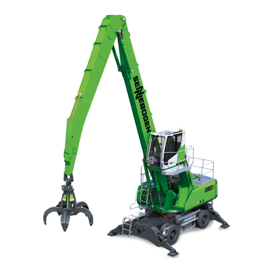
Overview — Overall machine Overview 2.1 Overall machine Attachment (example: grab) Grab stick Compact boom Operator’s station/cab with gallery, raising Undercarriage Upper structure Outrigger Counterweight 830 / 07.2012 Original operating instructions 2 — 1…
-
Page 66: Overall Machine — Crawler
Overview — Overall machine – crawler Overall machine – crawler Pos. Description Attachment (example: grab) Grabbing jib Compact boom Operator’s station/cab with gallery, can be elevated Undercarriage Upper carriage Counterweight 2 — 2 Original operating instructions 830 / 07.2012…
-
Page 67: Undercarriage
Overview — Undercarriage Undercarriage 2.3.1 4-point outrigger Rear outrigger Rear axle Flange ring Access ladder Extra storage space Front axle (floating axle) Outrigger, front Floating axle cylinder 830 / 07.2012 Original operating instructions 2 — 3…
-
Page 68: Outrigger Front/Rear
Overview — Undercarriage 2.3.2 Outrigger front/rear Access ladder Outrigger housing Outrigger foot Outrigger pad 2 — 4 Original operating instructions 830 / 07.2012…
-
Page 69: Undercarriage — Crawler
Overview — Undercarriage – crawler Undercarriage – crawler *: Optional model/special function Drive wheel (reverse Track roller direction of travel) Access ladder Crawler chain Telescoping – attachment Idler (forward direction of points travel) *: Optional model/special function Adjustment drive cover Telescoping –…
-
Page 70: Upper Structure
Overview — Upper structure Upper structure 2.5.1 Side view with diesel engine Service access doors for engine compartment Item Description Water separator — fuel Pump unit Hydraulic oil level display Driving engine Combination oil/water/charge air cooling system Air conditioning system Exhaust/exhaust gas treatment Expansion tank/refrigerant 2 — 6…
-
Page 71
Overview — Upper structure Service access doors for driver’s side Item Description Container for wiping-washing system Emergency lowering — cab Measurement ports — hydraulic system Central unit, hydraulic components Air filter — air intake Expansion tank/refrigerant Electric switch cabinet Generator 830 / 07.2012 Original operating instructions 2 — 7… -
Page 72
Overview — Upper structure View from above Item Description Hydraulic oil tank Swing gear Exhaust system/exhaust gas treatment Rotor (with slip ring assembly*) SENNEBOGEN Hydroclean Swing gear expansion tank Battery Optional 2 — 8 Original operating instructions 830 / 07.2012… -
Page 73: Central Electrical System
Overview — Upper structure 2.5.2 Central electrical system Item Description Fuses Relay Engine emergency speed – Position RIGHT: 50% – Position CENTER: idle – Position LEFT: 100% GLR emergency operation – Position RIGHT: emergency operation – Position LEFT: normal operation LMB X1001 plug (control system) –…
-
Page 74
Overview — Upper structure Swing brake emergency operation – Position RIGHT: emergency operation – Position LEFT: normal operation Replacement fuses 2 — 10 Original operating instructions 830 / 07.2012… -
Page 75: Equipment
Overview — Equipment Equipment 2.6.1 Compact boom With grab stick With reversing mechanism (optional) Item Description Compact boom Grab stick Grab stick with reversing mechanism Reversing mechanism Optional 830 / 07.2012 Original operating instructions 2 — 11…
-
Page 76: Pipe Fracture Safety Devices
Overview — Equipment 2.6.2 Pipe fracture safety devices Item Description Pipe fracture safety device — lifting cylinder Pipe fracture safety device — stick cylinder 2 — 12 Original operating instructions 830 / 07.2012…
-
Page 77: Attachments And Vario Tool (Option)
Overview — Equipment 2.6.3 Attachments and Vario Tool (option) Pos. Description Grab Scrap shears Jib base with Vario Tool 830 / 07.2012 Original operating instructions 2 — 13…
-
Page 78
Overview — Equipment 2 — 14 Original operating instructions 830 / 07.2012… -
Page 79: Technical Data
Note If a machine is to be run in ambient temperatures outside the specified temperature range, special temperature packages are available (option). Please contact SENNEBOGEN Customer Service if you have any other questions. Hydraulics Operating pressure, max. 350 bar Swing drive Swinging speed 0 —…
-
Page 80: Driving Engine
Technical data — General Limitations during wind Wind speed 25 m/s 90 km/h 10 Beaufort Note Machine operation is generally possible, without any attachments, at wind speeds of up to 25 m/second. The decision concerning when operation is to be shut down is to be made by the machine operator and depends on the attachment being used.
-
Page 81
Technical data — General Note regarding diesel engine exhaust emissions Quality is of the utmost importance at SENNEBOGEN. Installation of the engine and the cooling system for the engines is designed, tested and manufactured for the high demands associated with moving operations. -
Page 82: Machine
Technical data — Machine Machine Fuel tank Max. 500 l/max. 132,1 gal. (US) — Middle level sensor: Approx. 480 l/approx. 126,8 gal. (US) Hydraulic tank Max. 310 l/max. 81,9 gal. (US) — Middle inspection glass: Approx. 245 l/approx. 64,7 gal. (US) Hydraulic system, complete (*) Approx.
-
Page 83: Crawler
Technical data — Machine dimensions 3.2.1 Crawler Subassembly Quantity Fuel tank Max. 500 l/max. 132,1 gal. (US) — Middle level sensor: Approx. 480 l/approx. 126.8 gal. (US) Hydraulic tank Max. 310 l/max. 134.7 gal. (US) — Middle inspection glass: Approx. 245 l/approx. 81,9 gal. (US) Hydraulic system, complete Approx.
-
Page 84: Working Loads
Inexperience of operating personnel Driving with load Note Before changing the kinematic position please contact SENNEBOGEN! Setup conditions The machine has two setup conditions: – Without outrigger – With outrigger The load ratings apply to supported operation/setup condition. The load must be deposited when changing between the setup conditions.
-
Page 85: Lifting Capacities 830 E
Technical data — Working loads 3.5.1 Lifting capacities 830 E 3.5.2 Compact boom 8.5 m and 7.0 m Remarques : Toutes les valeurs sont indiquées en tonnes (t) et comprennent 75% de la charge de basculement statique ou 87% de la force de levage hydraulique conformément à…
-
Page 86: Compact Boom 8.5 M And 7.0 M
Technical data — Working loads 3.5.3 Compact boom 8.5 m and 7.0 m 830E KA8,5 Kin1 Mobil MP31E 9,7G 10,0 12,6 14,8 11,2 17,3 12,4 13,2 10,2 11,4 10,4 10,1 Alle Werte sind in Tonnen (t) angegeben und betragen 75 % der statischen Kipplast bzw. 87 % der hydraulischen Hubkraft gemäß ISO 10567. Sie gelten auf festem und ebenem Untergrund 360°…
-
Page 87: Compact Boom 8.5 M And 7.0 M
Technical data — Working loads 3.5.4 Compact boom 8.5 m and 7.0 m 830E KA8,5 Kin1 Mobil MP34E 9,7G 12,4 14,5 11,0 17,0 12,2 13,0 10,0 11,2 10,1 Alle Werte sind in Tonnen (t) angegeben und betragen 75 % der statischen Kipplast bzw. 87 % der hydraulischen Hubkraft gemäß ISO 10567. Sie gelten auf festem und ebenem Untergrund 360°…
-
Page 88: Compact Boom 8.5 M And 7.0 M
Technical data — Working loads 3.5.5 Compact boom 8.5 m and 7.0 m 830E KA8,5 Kin1 Raupe TL41_380 9,7G 11,5 10,6 16,2 11,8 12,8 13,1 10,1 10,0 Alle Werte sind in Tonnen (t) angegeben und betragen 75 % der statischen Kipplast bzw. 87 % der hydraulischen Hubkraft gemäß ISO 10567. Sie gelten auf festem und ebenem Untergrund 360°…
-
Page 89: Compact Boom 9.0 M And 7.5 M
Technical data — Working loads 3.5.6 Compact boom 9.0 m and 7.5 m Remarques : Toutes les valeurs sont indiquées en tonnes (t) et comprennent 75% de la charge de basculement statique ou 87% de la force de levage hydraulique conformément à ISO 10567. Elles sont applicables avec stabilisateur et sur un sol plan et résistant, pivotement sur 360°. Les valeurs entre parenthèses […] sont valables longitudinalement par rapport au châssis.
-
Page 90: Compact Boom 9.8 M And 7.5 M
Technical data — Working loads 3.5.7 Compact boom 9.8 m and 7.5 m Remarques : Toutes les valeurs sont indiquées en tonnes (t) et comprennent 75% de la charge de basculement statique ou 87% de la force de levage hydraulique conformément à ISO 10567. Elles sont applicables avec stabilisateur et sur un sol plan et résistant, pivotement sur 360°. Les valeurs entre parenthèses […] sont valables longitudinalement par rapport au châssis.
-
Page 91: Warning And Notice Labels
Technical data — Warning and notice labels Warning and notice labels Note More information can be found in Section . 830 / 07.2012 Original operating instructions 3 — 13…
-
Page 92
Technical data — Warning and notice labels www.sennebogen.de 103050 3 — 14 Original operating instructions 830 / 07.2012… -
Page 93
Technical data — Warning and notice labels 830 / 07.2012 Original operating instructions 3 — 15… -
Page 94
Technical data — Warning and notice labels 3 — 16 Original operating instructions 830 / 07.2012… -
Page 95: Wind Speed
Technical data — Wind speed Wind speed Wind Wind force speed Effect Beau- Description On shore fort scale Calm 0-0.2 Calm, smoke rises vertically Light draught 0.3-1.5 Direction of wind is displayed by the direction of the smoke, but not by a weather vane Light breeze 1.6-3.3 6-11…
-
Page 96: Conversion Factors
Technical data — Conversion factors Conversion factors Pressure 1 bar 100 Kpa 14.5 psi 10 psi 68.95 Kpa 0.6895 bar Flow rate 1 l/min 0.0353 cfm 0.2642 gal/min (US) 1 gal/min (Brit.) 0.1605 cfm 1 gal/min (US) 3.78541 l/min Length 1 mm 0.03934 in 39.34 in…
-
Page 97
Technical data — Conversion factors Volume 1000 l 35.31 ft 1.308 yd 1 ft 28.32 l 0.02832 m 1.728 inch 0.2642 gal. 0.2201 gal (US) (Brit.) 1 gal. (US) 3.785 l 231 inch 1 gal. (Brit.) 4.544 l 277 inch 1 yd 764.55 l 0.765 m… -
Page 98: Tightening Torques For Screws
Technical data — Tightening torques for screws Tightening torques for screws Note For certain mounting screws on the undercarriage, values differing from those listed in this table may apply. Please observe the notes in the respective sections. Strength class 8.8 Coarse thread Fine thread Screw…
-
Page 99
Technical data — Tightening torques for screws Strength class 10.9 Coarse thread Fine thread Screw Tightening torque Screw Tightening torque [Nm] [Nm] M8x1 M10x1 M10x1.25 M12x1.25 M12x1.5 M14x1.5 M16x1.5 M18x1.5 M20x1.5 M22x1.5 M24x2 1050 M27x2 1500 1400 M30x2 2100 1900 2600 3300 Note… -
Page 100
Technical data — Tightening torques for screws 3 — 22 Original operating instructions 830 / 07.2012… -
Page 101: Start-Up
Wear protective work clothing (e.g. protective helmet, protective glasses) if working conditions necessitate. At working heights of 2.00 m or more, SENNEBOGEN recommends the use of a safety harness to prevent falling. At working heights above 3.00 m, using a safety harness is required legally.
-
Page 102
Start-up — Safety instructions Do not operate the machine if a fault has been detected. Ensure that all actuating levers are in the neutral position. Start the machine only as described in the information in the instructions. 4 — 2 830 / 07.2012 Original operating instructions… -
Page 103: Cleaning Work
Start-up — Cleaning work 4.2 Cleaning work ATTENTION Comply with the safety instructions before starting tasks. CAUTION Clean the machine daily. For heavy contamination, clean the machine several times per day if necessary, especially in recycling applications. Ensure that the cleaning agents used do not damage the seals and components of the machine.
-
Page 104: Tests Before Start-Up
Start-up — Tests before start-up Tests before start-up 4.3.1 Service access door locking device Note The service access doors are protected from closing unintentionally by means of a locking device (1). CAUTION Before closing the service access door, the locking device (2) must be raised.
-
Page 105: Initial Commissioning
Initial commissioning The initial commissioning of the machine is carried out by SENNEBOGEN or by a trained and authorized specialist. If the machine is shut down for a prolonged period (> 6 months), it is essential to contact SENNEBOGEN Customer Service before recommissioning.
-
Page 106
Start-up — Inspections before daily start-up Functional checks Steps to take Is the stick end limitation set correctly? If necessary, adjust Is the hoisting limiter set correctly? If necessary, adjust Is the overload warning device activated? If necessary, activate … -
Page 107
Start-up — Inspections before daily start-up Visual checks Steps to take Is the undercarriage (e.g. tires, axles, drive If necessary, repair or replace shafts/universal joints) undamaged? Are the wheel nuts tight and the intermediate If necessary, retighten to the specified torque rings firmly seated? … -
Page 108
Start-up — Inspections before daily start-up Visual checks Steps to take Are all bolt/screw connections undamaged If necessary, retighten or replace and tight, particularly on the elevating cab? Have any possible cable connections to If necessary, disconnect external power sources been disconnected? … -
Page 109: Tests Before Start-Up
Start-up — Tests before start-up Tests before start-up 4.6.1 Checking the demister level Note The container (1) for the cleaning fluid for the washer system is located behind the left front service access door. Always fill the container with washer system antifreeze. Note Pay attention to the information in the maintenance instructions.
-
Page 110: Check Fuel Level
4.6.2 Check fuel level Note The fuel level can be determined as follows: by the SENNEBOGEN CONTROL system in the initial screen, see Section 5. Note Fill the tank with the specified grade of fuel. Clean fuel is essential for trouble-free operation of the diesel engine.
-
Page 111: Lubricating The Lubrication Points Manually
Start-up — Tests before start-up 4.6.4 Lubricating the lubrication points manually Note More information can be found in Section 3.5.3. 4.6.5 Checking the fill level in the central lubrication system The central lubrication system automatically lubricates the slewing track of the swiveling connection as well as the bearings of the equipment.
-
Page 112
Start-up — Tests before start-up Replenishing grease (2/3) Warning Insufficient lubrication can damage the components. Note Observe the notes in the maintenance instructions and in the lubrication table. 4 — 12 830 / 07.2012 Original operating instructions… -
Page 113: Checking The Fill Level In Live Ring Toothed Wheel
Start-up — Tests before start-up 4.6.6 Checking the fill level in live ring toothed wheel Replenishing grease Open the lubricant reservoir cap (1). Add lubricant (see lubricant table). Close the cap. Note Pay attention to the information in the maintenance instructions. 830 / 07.2012 Original operating instructions 4 — 13…
-
Page 114: Checking The Swing Gear Fill Level
Start-up — Checking the swing gear fill level Checking the swing gear fill level WARNING Mixing oils, lubricants or operational fluids of different types is not permitted! Only mix oils, lubricants and operational fluids that are of the same type or identical (same specifications) from one manufacturer! Note Depending on the machine type, multiple swing gears with the…
-
Page 115
Start-up — Checking the swing gear fill level 1 Swing gear 2 Fill level at 15°C–20°C oil temperature (approx. quarter full marking on the oil expansion tank) 3 Oil expansion tank for each swing gear Allow the oil in the swing gear to cool. Check the oil level: –… -
Page 116: Checking The Hydraulic Oil Level
Start-up — Checking the swing gear fill level 4.7.1 Checking the hydraulic oil level Lower attached loads and the boom to the ground. Put the machine in a level horizontal position. Retract all hydraulic cylinders completely. Put the machine in park position. Retract the support cylinders. Shut down the drive engine.
-
Page 117: Checking And Draining The Fuel System
Start-up — Checking the swing gear fill level Note Observe the notes in the maintenance instructions and in the lubrication table 4.7.2 Checking and draining the fuel system WARNING No open flames when working on the fuel system! No smoking! …
-
Page 118: Checking The Engine Oil Level
Start-up — Checking the swing gear fill level 4.7.3 Checking the engine oil level Note Observe the notes in the engine manufacturer’s operating instructions. Put the machine in a level horizontal position. Run the drive engine for approx. 2 minutes until the system is filled with oil.
-
Page 119
Start-up — Checking the swing gear fill level Note Observe the notes in the engine manufacturer operating instructions. Note Observe the notes in the maintenance instructions and in the lubrication table. 830 / 07.2012 Original operating instructions 4 — 19… -
Page 120: Checking The Refrigerant Level
Start-up — Checking the swing gear fill level 4.7.4 Checking the refrigerant level WARNING! Danger of injury from scalding! Inspect only when the cooling system has cooled. Checking the refrigerant level and antifreeze Allow the drive engine and cooler to cool down. Place large, thick cloths on the sealing cap (1) of the refrigerant expansion tank and open it carefully in order to equalize the pressure.
-
Page 121: Lubricating The Machine Automatically
Start-up — Lubricating the machine automatically Lubricating the machine automatically ATTENTION Comply with the safety instructions before you start with the tasks. 4.8.1 General CAUTION The reservoir for the central lubrication system must always be adequately filled in order to prevent damaging the bearings. Note The machine is equipped with a central lubrication system for the swivel and the equipment as standard equipment.
-
Page 122: Overview — Central Lubrication Points
Start-up — Lubricating the machine automatically 4.8.2 Overview – central lubrication points 4 — 22 830 / 07.2012 Original operating instructions…
-
Page 123
Start-up — Lubricating the machine automatically 830 / 07.2012 Original operating instructions 4 — 23… -
Page 124: Adjusting The Lubricating Cycle
Start-up — Lubricating the machine automatically 4.8.3 Adjusting the lubricating cycle Note The pre-set lubricating cycle can be shortened. See the documentation on the central lubrication system in Section 10 of the operating instruc- tions. 1 Grease reservoir – note MIN/MAX marking 2 Refill with grease **/*** 3 Refill with grease */** 4 Adjust the lubrication times…
-
Page 125
Start-up — Lubricating the machine automatically 1. Lock switch for adjusting the pump RPM – Factory setting: 110 revolutions 2. Click switch to set the cycle time – Factory setting: 1 hour 3. Green LED to indicate function 4. Red LED to indicate faults 5. -
Page 126: Lubricating The Machine Manually
Start-up — Lubricating the machine manually Lubricating the machine manually CAUTION Comply with the safety instructions before you start with the tasks. 4.9.1 General CAUTION The reservoir for the central lubrication system must always be adequately filled in order to prevent damaging the bearings. Note The machine is equipped with a central lubrication system for the swivel and the equipment as standard equipment.
-
Page 127: Central Manual Lubricating Strip — Mobile Undercarriage
Start-up — Lubricating the machine manually 4.9.2 Central manual lubricating strip – mobile undercarriage The mobile undercarriage has a central lubricating strip that must be lubricated manually. The central lubricating strip is on the front of the undercarriage. Pos. Description Recommended amount of grease (per lubricating nipple) Upper strip…
-
Page 128
Start-up — Lubricating the machine manually 4.9.3 Distributed manual lubricating points mobile undercarriage The mobile undercarriage has distributed lubricating points that must be lubricated manually: 12x undercarriage support. Undercarriage support Three grease nipples on each of the four supports must be lubricated manually. -
Page 129: Distributed Manual Lubricating Points Crawler Undercarriage
Start-up — Lubricating the machine manually 4.9.4 Distributed manual lubricating points crawler undercarriage Telescoping 8 grease nipples on the top side must be lubricated manually. top side Pos. Lubricating specification (per grease nipple) 1–8 3.0 – 5.0 ccm / 40 operating hours 830 / 07.2012 Original operating instructions 4 — 29…
-
Page 130
Start-up — Lubricating the machine manually Telescoping 8 grease nipples on the underside must be lubricated manually. underside Pos. Lubricating specification (per grease nipple) 1–8 3.0 – 5.0 ccm / 40 operating hours 4 — 30 830 / 07.2012 Original operating instructions… -
Page 131: Switching On Machine
Start-up — Switching on machine 4.10 Switching on machine 4.10.1 Safety instructions Observe the safety notes before starting machine. DANGER Danger of injury! Keep cab door and service access doors closed. Before starting the motor, ensure that there is no one within the danger area.
-
Page 132: Seat Belt / Eu
Start-up — Switching on machine 4.10.2 Seat belt / EU The machine is equipped with a lap belt. The belt complies with standards FMVSS 209 (EU). WARNING Check belt for signs of wear before machine start-up. Immediately exchange a damaged belt. …
-
Page 133: Seat Belt / Usa
Start-up — Switching on machine 4.10.3 Seat belt / USA The machine is equipped with a lap belt. The belt complies with standards SAE J 386 (USA). WARNING Check belt for signs of wear before machine start-up. Immediately exchange a damaged belt. …
-
Page 134: Starting The Engine
Start-up — Switching on machine 4.10.4 Starting the engine DANGER Danger of poisoning! Only run the engine outdoors or in well-ventilated areas. Inhaling exhaust gases is hazardous to your health. It may lead to loss of consciousness and death. Control panel, right Perform daily inspections in accordance with Section 4.5.
-
Page 135
Start-up — Switching on machine This makes starting the engine easier in low ambient temperatures. WARNING After the engine starts, the machine runs at idle speed with ECO mode activated. When activating a function, the speed changes immediately to the higher ECO Mode speed. CAUTION: Undesired jerky motions possible! Ignition key position Ignition key position… -
Page 136: Bringing The Machine To Operating Temperature
Start-up — Switching on machine 4.10.5 Bringing the machine to operating temperature Guidelines values for Ambient temperature Warm-up Max. engine speed warm-up period period Down to 0°C (32°F) Approx. Nominal speed — 15 min. 250 rpm (for nominal speed, see — 20°C (- 4°F) -…
-
Page 137: Jump Starting
Start-up — Switching on machine 4.10.6 Jump starting The machine is equipped with a 24 volt starting system. Ensure that the external power source has the same voltage. CAUTION If a power source with a higher voltage is used, this can cause serious damage to the machine’s electrical system.
-
Page 138: Switching The Machine Off
Start-up — Switching the machine off 4.11 Switching the machine off 4.11.1 Switching the engine off Note Switching off the driving engine without allowing a cooling down phase may cause heat storage and overheating of engine parts and especially the turbocharger. Therefore, allow the drive engine to cool down before switching off: …
-
Page 139: Disconnecting The Electrical System From The Battery
Start-up — Switching the machine off 4.11.2 Disconnecting the electrical system from the battery If the machine is idle for an extended period or for long transport distances, the electrical system must be isolated from the battery using the mechanical battery disconnecting switch. WARNING Do not switch off the mechanical battery isolating switch if: …
-
Page 140: Decommissioning
Start-up — Decommissioning 4.12 Decommissioning Proceed as follows if the machine is to be decommissioned for a prolonged period: Choose a dry and dust-free storage location. Position the machine on level ground. If the ground is not level, secure the machine using chocks. Switch off the machine as described in Section 4.11.
-
Page 141: Preservation And Storage
Start-up — Preservation and storage 4.13 Preservation and storage Proceed as follows if the machine is to be preserved or stored for a longer period of time: Select a storage location where no hazards are precluded. Place the attachment on wooden planks to prevent it from freezing.
-
Page 142: Starting Up Operating Again
Align the machine horizontally. Warm up the machine sufficiently before work application. See Chapter “Bringing the machine to operating temperature”: 4.15 Disposal Please contact SENNEBOGEN After Sales should you need to dispose of the machine. 4 — 42 830 / 07.2012…
-
Page 143: Sencon — Sennebogen Control System
SENCON — Sennebogen Control System — SENCON — Sennebogen Control System Note The SENCON machine diagnostic system can centrally determine the current operating data of the machine without additional measurement devices or other aids and evaluate this data statistically as needed.
-
Page 144: Start Page
SENCON — Sennebogen Control System — Start page Start page Upper quick selection buttons Display Lower quick selection buttons USB port for Save/Reset service use (SET button) (folding) Scroll wheel and pushbutton (SCROLL wheel) Cancel/Back (ESC button) Back to start page (HOME button)
-
Page 145
SENCON — Sennebogen Control System — Start page Additional functions Diagnostics Display settings Pressure load main boom RPM display (option) Green: 0 % – 90 % Yellow: 90 % – 100 % Red: >100 %; Cooling water Diesel fill level… -
Page 146: Overview Of Functions
SENCON — Sennebogen Control System — Overview of Functions Overview of Functions Below is a list of all SENCON functions. Diagnostics Diesel Engine (Section 5.3.1) Hydraulics (Section 5.3.2) Cooling (Section 5.3.3) Average Values (Section 5.3.4) …
-
Page 147: Diagnostics
SENCON — Sennebogen Control System — Diagnostics Diagnostics Note The diagnostics function of the SENCON clearly displays all important operating parameters of the machine. 5.3.1 Diesel Engine Next page (SCROLL right) Diesel tank fill level Diesel engine speed Cooling water…
-
Page 148: Hydraulics
SENCON — Sennebogen Control System — Diagnostics 5.3.2 Hydraulics Page back Next page (SCROLL left) (SCROLL right) Temperature of hydraulic oil in the tank Statistics Info/Process data Parameterization Error memory Network 5 — 6 SENCON / 01.2013…
-
Page 149: Cooling
SENCON — Sennebogen Control System — Diagnostics 5.3.3 Cooling Next page Page back (SCROLL left) (SCROLL right) Cooling water tem Hydraulic oil perature Engine temperature / Tank Water cooler* load Oil cooler* load Cooling water temperature Oil temperature after coole…
-
Page 150: Average Values
SENCON — Sennebogen Control System — Diagnostics 5.3.4 Average Values Next page Page back (SCROLL left) (SCROLL right) Average speed Average diesel consumption Time period of measured Average engine average values load Restart recording of the average values using the SET button…
-
Page 151: Service
SENCON — Sennebogen Control System — Diagnostics 5.3.5 Service Page back (SCROLL left) Operating hours counter Next service due in… Reset service interval display with the SET button (Reset*) Statistics Info/Process data Parameterization Error memory Network Note on Reset* 50 operating hours before a service deadline, the Reset button appears.
-
Page 152: Active Error/Error Memory
SENCON — Sennebogen Control System — Diagnostics 5.3.6 Active Error/Error Memory Next page (SCROLL right) Display all current errors with time, description, and error code Statistics Info/Process data Parameterization Error memory Network 5 — 10 SENCON / 01.2013…
-
Page 153
SENCON — Sennebogen Control System — Diagnostics Press the SCROLL wheel to activate the error list. 2 arrows (1) appear in the menu, indicating that the list can now be scrolled. The list can be scrolled by moving the SCROLL wheel up or down. -
Page 154
SENCON — Sennebogen Control System — Diagnostics Select the active error The active error messages can be selected directly on the start page on the start page using the SCROLL wheel. The error selected is framed in white. After pressing the SCROLL wheel, the detailed overview of the error appears. -
Page 155: Network
SENCON — Sennebogen Control System — Diagnostics Error memory The error memory saves all errors and associated information and displays it in a list. The error memory stores the complete error history of the machine. Page back (SCROLL left) Date and time of the…
-
Page 156
SENCON — Sennebogen Control System — Diagnostics 5.3.7 Network Representation of all network components Network error/no connection to network components Statistics Info/Process data Error memory Parameterization Network Note The scroll wheel is used to select the individual components of the network. -
Page 157
SENCON — Sennebogen Control System — Diagnostics Detailed view Display all inputs and outputs Type of sensor Supply voltage Information for each Control unit input and output Control device temperature Software version, operating system version, Sennebogen ESC button: return to… -
Page 158
SENCON — Sennebogen Control System — Diagnostics 5.3.8 Statistics Information about machine load: overview of speed Start of recording ranges. Restart recording using the SET button (Reset*) Statistics Info/Process data Error memory Parameterization Network Note on Reset* The SET button restarts recording. To do this, press and hold the SET button for 5 seconds. -
Page 159: Settings/Parameterization
SENCON — Sennebogen Control System — Settings/Parameterization Settings/Parameterization SENCON, in addition to diagnostics, also facilitates setting important parameters to optimize the operating state of the machine. Note All quick selection buttons are deactivated when processing parameters. 5.4.1 Diesel Engine Next page…
-
Page 160
SENCON — Sennebogen Control System — Settings/Parameterization Change parameters Note If the operator presses the SCROLL button, he enters selection mode and can switch between the functions. A white frame indicates a selected field. Switch between the various fields using the SCROLL wheel. If the SCROLL wheel is pressed again, the selected field becomes active and the value can be changed by turning the SCROLL wheel. -
Page 161: Hydraulics
SENCON — Sennebogen Control System — Settings/Parameterization 5.4.2 Hydraulics Next page Page back (SCROLL left) (SCROLL right) OptiMode: regulation of response (aggressiveness) of the hydraulic system ESC button: return to previous view Info/Process data Statistics Parameterization Error memory Network 5 — 19…
-
Page 162
SENCON — Sennebogen Control System — Settings/Parameterization Note If the operator presses the SCROLL button, he enters selection mode and can switch between the functions. A white frame indicates a selected field. Switch between the various fields using the SCROLL wheel. If the SCROLL wheel is pressed again, the selected field becomes active and the value can be changed by turning the SCROLL wheel. -
Page 163: Central Lubrication
SENCON — Sennebogen Control System — Settings/Parameterization 5.4.3 Central lubrication Next page Previous page (SCROLL right) (SCROLL left) Central lubrication: The preset lubrication cycle can be shortened or extended. Central lubrication system On / Off Info / process data Statistics…
-
Page 164
SENCON — Sennebogen Control System — Settings/Parameterization Note If the operator presses the SCROLL button, he is in selection mode and can switch between the functions. A white frame indicates a selected field. Switch between the various fields using the SCROLL wheel. If the SCROLL wheel is pressed again, the selected field becomes active and the value can be changed by turning the SCROLL wheel. -
Page 165: Calibration
WARNING Before starting calibration: deposit load, switch off engine, and put ignition key in position 1. Otherwise, serious damage to property or personal injury could result. Only specialist personnel authorized by Sennebogen may perform calibration! Page back (SCROLL left) List of calibratable…
-
Page 166
SENCON — Sennebogen Control System — Settings/Parameterization Note Calibration is only necessary when a component, a control unit, or the display has been changed, and after a software or parameter update has been performed. Note If the operator presses the SCROLL button, he enters selection mode in the list and can change between the sensors. -
Page 167: Daily Operating Hours Counter
SENCON — Sennebogen Control System — Settings/Parameterization 5.4.5 Daily Operating Hours Counter Note After activating the battery disconnection switch, or when the machine has been switched off for 18 hours, the daily operating hours counter resets automatically. It is also possible to reset the counter manually.
-
Page 168: Display
SENCON — Sennebogen Control System — Settings/Parameterization 5.4.6 Display Note In the display setting menu, the language, time, date, brightness, and units can be adjusted as required. Language settings Language currently used Selected new language Available languages Units Language Brightness…
-
Page 169
SENCON — Sennebogen Control System — Settings/Parameterization Note on Language Settings The operator can change between languages in the list directly using the SCROLL wheel. The selected field has a light green background. If the SCROLL wheel is pressed again, the language is saved. -
Page 170
SENCON — Sennebogen Control System — Settings/Parameterization Date/Time Selection frame Time Date Current time Current date Units Brightness Language Date/Time Note on Setting Date and Time The operator can switch between the individual values using the SCROLL wheel. The currently selected value is framed in white. If the SCROLL wheel is pressed, the field becomes active (green frame) and the value can be adjusted with the SCROLL wheel. -
Page 171
SENCON — Sennebogen Control System — Settings/Parameterization Brightness Display brightness Button brightness Brightness sensor* Brightness sensor on/off Units Language Brightness Date/Time Note on the Brightness Sensor* The brightness sensor controls brightness automatically as soon as it is switched on. If it is switched off, the brightness set by the operator is used. -
Page 172
SENCON — Sennebogen Control System — Settings/Parameterization Note on Setting Brightness The operator can use the SCROLL wheel to switch between the brightness of the display and the buttons. The currently selected value is framed in white. If the SCROLL wheel is pressed, the field becomes active and the value can be adjusted with the SCROLL wheel. -
Page 173
SENCON — Sennebogen Control System — Settings/Parameterization Units List of all available units Units Brightness Language Date/Time Note on Setting Units The SCROLL wheel can be used by the operator to switch between the various units in the list. The currently selected value has a dark green background. -
Page 174: Activate Automatic Idle
SENCON — Sennebogen Control System — Settings/Parameterization 5.4.7 Activate automatic idle Automatic idle helps to save resources by automatically lowering the engine speed during longer pauses while working. The automatic idle must be switched on via the quick-select button (1) on the start page.
-
Page 175: Eco Mode
SENCON — Sennebogen Control System — Settings/Parameterization 5.4.8 ECO mode ECO mode enables speed regulation, allowing you to operate the machine more economically, if required. When starting the machine ECO mode is activated. ECO mode can be switched off via the quick-select button on the start page.
-
Page 176: Manual Fan Reversal / Reverse
SENCON — Sennebogen Control System — Settings/Parameterization 5.4.9 Manual fan reversal / reverse Fan reversal or fan reverse is set automatically and is activated by the system every 30 minutes. Fan reversal can also be switched on manually. To do so, the operator must activate the respective quick selection button (1) on the start page.
-
Page 177: Overload Warning Device (Option)
SENCON — Sennebogen Control System — Settings/Parameterization 5.4.10 Overload warning device (option) The overload warning device is activated at start and is equipped with a two-stage warning tone (interval and continuous). The warning tone can be switched off. WARNING No automatic shut-off at overload! Owner and machine operator are responsible for proper operation.
-
Page 178: Grapple Rotational Speed (Option)
SENCON — Sennebogen Control System — Settings/Parameterization 5.4.11 Grapple rotational speed (Option) Adjustment of the grapple rotational speed enables high-precision operation when rotating the grapple. Previous page (SCROLL left) Grapple rotational speed: Regulation of the maximum rotational speed. 5 — 36…
-
Page 179
SENCON — Sennebogen Control System — Settings/Parameterization Note If the operator presses the SCROLL button, he is in selection mode and can switch between the functions. A white frame indicates a selected field. Switch between the various fields using the SCROLL wheel. If the SCROLL wheel is pressed again, the selected field becomes active and the value can be changed by turning the SCROLL wheel. -
Page 180: Indicator And Warning Lamps Overview
SENCON — Sennebogen Control System — Indicator and Warning Lamps Overview Indicator and Warning Lamps Overview Errors and Warnings Description Remedy Code Oil pressure too low – Switch off engine 00111 immediately Acknowledgment required! – Checking engine oil level – Add engine oil if…
-
Page 181
SENCON — Sennebogen Control System — Indicator and Warning Lamps Overview Description Remedy Code Air filter contaminated – Clean filter as 00151 described in the Acknowledgment required! maintenance instructions – Replace filter if necessary Hydraulic filter 1 (main filter) – Check filter, change if… -
Page 182
SENCON — Sennebogen Control System — Indicator and Warning Lamps Overview Description Remedy Code Wait to start lamp active 00241 Exhaust temperature high 00251 Acknowledgment required! Brake pressure low – Have system checked 00291 by hydraulics specialist Engine warning: switch off engine –… -
Page 183
SENCON — Sennebogen Control System — Indicator and Warning Lamps Overview Description Remedy Code Cable break – Notify Service 00351 Short circuit – Notify Service 00361 Service interval active – Notify Service 00371 5 — 41 SENCON / 01.2013… -
Page 184
SENCON — Sennebogen Control System — Indicator and Warning Lamps Overview Information Pictogram Meaning Explanation Automatic idle active The automatic idle helps to save resources by automatically lowering the engine speed during longer pauses while working. ECO Mode active ECO Mode enables active speed regulation, allowing you to operate the machine more economically as needed. -
Page 185
SENCON — Sennebogen Control System — Indicator and Warning Lamps Overview Pictogram Meaning Explanation Reverse airflow active Floating axle control active (optional) Swing bearing brake active Magnet unit loaded (Optional) Unload magnet unit (Optional) Automatic swing bearing brake active 5 — 43… -
Page 186
SENCON — Sennebogen Control System — Indicator and Warning Lamps Overview 5 — 44 SENCON / 01.2013… -
Page 187: Operation
If visibility is poor, ensure that a banksman is used for giving the required signs when reversing. Before moving onto ramps or inclines, make sure you obtain the maximum permitted values from SENNEBOGEN. Position the boom in the travel direction during long journeys. 830 / 07.2012…
-
Page 188: Operator’s Station/Cab With Gallery, Raising
Operation — Operator’s station/cab with gallery, raising Operator’s station/cab with gallery, raising Emergency exit *: Optional model/special function Item Description Work lighting Windscreen wiper, roof Windscreen wiper, top Front windshield, top, adjustable Front windshield, bottom Door lock and handle Windscreen wiper, lower 24 V plug socket (connection for beacon) Emergency exit —…
-
Page 189
(12) to break the window. Note The cab door is equipped with an emergency release. If necessary, consult SENNEBOGEN Customer Service! Sliding door The sliding door (1) can be locked in the open position on the side panel of the cab. -
Page 190
The radio (7) and the loudspeakers (8) are located behind the driver’s seat below the cab roof. Note More information can be obtained from the radio manufacturer. A SENNEBOGEN document case holding the machine documentation Document case is located in the cab. 6 — 4 830 / 07.2012… -
Page 191: Driver’s Seat
Operation — Operator’s station/cab with gallery, raising 6.2.1 Driver’s seat CAUTION In order to avoid risk of an accident, check that all the settings are properly locked in place before starting the vehicle. The driver’s seat adjustment mechanisms should not be actuated during operation.
-
Page 192
Operation — Operator’s station/cab with gallery, raising Air-suspended driver’s seat 1, 2 Item Description Weight adjustment Height adjustment Seat depth setting Seat tilt setting Length adjustment Head support Seat heater Spinal disk support Arm rests Backrest tilt Arm rest tilt Horizontal suspension Optional 6 — 6… -
Page 193: Operating Instruments
Operation — Operating instruments Operating instruments 6.3.1 Overview with joystick steering Joy stick steering Item Description Pedals Control lever, right Seat adjustment Control lever, left Lower air outlet vents Safety lever 830 / 07.2012 Original operating instructions 6 — 7…
-
Page 194
Operation — Operating instruments Pedals Item Description Footrest Release the brake pedal lock Brake pedal — driving action Drive pedal Drive — forwards Drive — backwards Optional 6 — 8 830 / 07.2012 Original operating instructions… -
Page 195
Operation — Operating instruments 6.3.2 Safety lever The safety lever (1) serves as a protective feature. Safety lever released (pushed forward) When the safety lever is released (see illustration) All hydraulic functions are available. All work maneuvers can be carried out. Note The swing bearing holding brake remains open after the safety lever is released (pushed forward) if the “right-hand”… -
Page 196
Operation — Operating instruments 6.3.3 Control lever, left Item Description Grab, swing left (proportional) Grab, swing right (proportional) Unused Horn Unused Boom shutdown bypass Directions of movement Direction Description Extend stick Retract stick Swing upper structure, right Swing upper structure, left Note The bypasses for the safety limit shutdown “Retract/extend stick”… -
Page 197
Operation — Operating instruments DANGER All safety cut-outs in the equipment are deactivated. DANGER Risk of fatal injury by bypassing the “Retract stick” safety limit shutdown! Attachments or parts of the load can strike and penetrate the cab. Proceed with extreme caution. Observe the attachments and load continuously. -
Page 198
Operation — Operating instruments 6.3.4 Control lever, right Pos. Description Steer left (proportional) Steer right (proportional) Magnet unit on Magnet unit off 5*** Drive forward preselection on/off 6*** Drive reverse preselection on/off Optional model/special function **: Optional model, only for joystick steering (mobile) ***: Optional model, only with drive pedal 6 — 12 830 / 07.2012… -
Page 199
Operation — Operating instruments Directions of movement Direction Description Open grab Close grab Compact boom up G**** Movement, right traveling gear back Compact boom down H**** Movement, right traveling gear forward ****:Optional model, only for crawler undercarriage 830 / 07.2012 Original operating instructions 6 — 13… -
Page 200: Overview For Steering Wheel Control (Optional)
Operation — Operating instruments 6.3.5 Overview for steering wheel control (optional) Steering wheel control Item Description Pedals Steering column Steering wheel Control lever, right Seat adjustment Control lever, left Lower air outlet vents Safety lever 6 — 14 830 / 07.2012 Original operating instructions…
-
Page 201
Operation — Operating instruments Pedals Item Description Footrest Steering column Release the steering column lock Release the brake pedal lock Brake pedal — driving action Drive pedal Drive — forwards Drive — backwards Optional Note The swing bearing holding brake is a holding brake for the upper structure but is not a service brake or a working brake. -
Page 202: Overview — Crawler Steering
Operation — Operating instruments 6.3.6 Overview – crawler steering Lever / pedals Pos. Description Footrest Movement, left traveling gear Movement, right traveling gear 6 — 16 830 / 07.2012 Original operating instructions…
-
Page 203: Additional Indicators
Operation — Operating instruments 6.3.7 Additional indicators Analog hour meter SENCON Generator and magnet unit Tool Control Auxiliary heating system Camera Note Further information can be found in Section 6.4 and Section 10. 830 / 07.2012 Original operating instructions 6 — 17…
-
Page 204: Overview Of The Control Panels
Operation — Operating instruments 6.3.8 Overview of the control panels Item Description Left control panel, next to driver’s seat Right control panel, next to driver’s seat Control panel, bottom right Control panel, top right 6 — 18 830 / 07.2012 Original operating instructions…
-
Page 205
Operation — Operating instruments 6.3.9 Left control panel, next to driver’s seat Item Description Lever for all supports Joystick, left Safety lever Lower/raise cab Optional 830 / 07.2012 Original operating instructions 6 — 19… -
Page 206
Operation — Operating instruments 6.3.10 Right control panel, next to driver’s seat Item Description Socket outlet 12 V Socket outlet 24 V Ignition — start the engine = Enable the refueling pump = Ignition OFF = Ignition ON (switches off after 20 minutes!) = Start the engine Storage compartment Ashtray… -
Page 207
Operation — Operating instruments 6.3.11 Control panel, bottom right Item Description Auxiliary heating system timer Swing the emergency operation grab Emergency operation steering Air-conditioning unit Start the engine Hand throttle Upper structure lighting Unused Unused Automatic floating axle Plow Drive slow —fast Swing bearing holding brake Unused Emergency stop… -
Page 208
Operation — Operating instruments Auxiliary heating system timer (optional) Item Description Reverse control button Forward control button Activation button OK button Display Note More information can be found in Chapter 10. 6 — 22 830 / 07.2012 Original operating instructions… -
Page 209
Operation — Operating instruments Air conditioning control Note panel The machine is equipped with an automatic climate control system that permits precise heating or cooling. Rotary selection switch: blower speeds Rotary selection switch: air distribution Temperature regulator Combination switch: outside temperature indicator, air conditioning on/off Outside/circulating air switch Temperature indication (°C or °F) -
Page 210
Operation — Operating instruments Outside air mode When windows are misted, to dehumidify the cab. Circulating air mode Faster warm-up of the cab and higher top temperature. The air in the cab interior is re-circulated, i.e. very little fresh air is drawn in from outside. -
Page 211
Operation — Operating instruments Floating axle control The front axle has oscillating suspension; the oscillating axle can be used to level out unevenness in the track. Note The floating axle control minimizes the danger of tipping. The boom can be found above both the front and rear axles (upper structure parallel to the undercarriage/0°… -
Page 212
Operation — Operating instruments Switch position Conditions Status – Symbol is Control displayed in illuminates SENCON – Floating axle always free Floating axle control deactivated, floating axle always free Swing bearing holding The swing bearing holding brake is a holding brake for the upper brake structure but is not a service brake or a working brake. -
Page 213
Operation — Operating instruments Preselection of the swing bearing brake, which engages at the end of an action: – When the upper structure is stationary, the swing bearing brake engages automatically. – The following symbol appears in SENCON: – To loosen the swing bearing brake, switch to –… -
Page 214
Operation — Operating instruments 6.3.12 Control panel, top right Item Description Start/cancel particulate filter regeneration Auxiliary limiting boom, extend stick Magnet unit Grab control Grab function Floating boom setting Diesel filter heating off/on Central lubrication Swing ring lubrication Direction indicator Flashing warning lamps Flashing alarm lamp Front window washer system, lower… -
Page 215
Operation — Operating instruments Item Description Boom headlight Roof work lighting Optional Emergency lowering, The emergency lowering feature still functions in the event of engine or hydraulic system failure. Auxiliary limiting boom, Use the Auxiliary limiting switch to activate/deactivate optional auxiliary extend stick limiting for “Hoist up”… -
Page 216
If necessary, consult SENNEBOGEN Customer Service! Grab function (optional) Accidental actuation of the “Open grab/Close grab” functions in magnetic plate mode is prevented when the grab function is switched off. -
Page 217
Operation — Operating instruments Boom floating The floating position function depends on the working tool. Floating position grab setting: When the “Close grab” function is actuated, the compact boom is simultaneously raised at low speed. This prevents the grab from scratching on the ground. Floating hammer setting: The full weight of the stick acts on the hammer. -
Page 218
– Pilot lamps flashing: – Start particulate filter regeneration IMMEDIATELY Level 4 – Pilot lamps flashing: – Deposit loads and turn off the engine immediately! – Contact SENNEBOGEN Customer Service immediately! 6 — 32 830 / 07.2012 Original operating instructions… -
Page 219
Operation — Operating instruments Note Observe the notes in the engine manufacturer’s operating instructions. DANGER High exhaust temperatures can occur! Non-observance of notes in the engine manufacturer’s operating instructions can lead to damage to property and personal injuries. Note If high exhaust temperatures pose a danger when using the machine, regeneration of the particulate filter can be prevented for a limited time period. -
Page 220
Operation — Operating instruments Note Particulate filter regeneration should be authorized at the next opportunity. The particulate filter can only be regenerated manually if the load status of the diesel particulate filter is adequate for the regeneration process. If the load status is adequate, the following pilot lamp appears in SENCON: To start the manual regeneration process, the engine must be run at an idle speed of 800 rpm. -
Page 221: Additional Displays (Optional Equipment)
Operation — Additional displays (optional equipment) Additional displays (optional equipment) 6.4.1 SENNEBOGEN Tool Control The SENNEBOGEN Tool Control enables operation of several attachment tools (e.g. grab, demolition hammer) with different requirements for maximum permissible flow volumes and pressures. The maximum permissible flow volume and pressure is adapted to the corresponding work tool by the SENNEBOGEN Tool Control.
-
Page 222
Operation — Additional displays (optional equipment) Note To change the setup parameters, use special tools and contact SENNEBOGEN customer service if necessary. Note If a button is pressed and held for a longer period of time, the button lock is activated. The button lock can be released by simultaneously pressing buttons (+) and (-). -
Page 223: Generator And Magnet Unit
Operation — Additional displays (optional equipment) 6.4.2 Generator and magnet unit Note The engine “start/stop” function remains deactivated as long as the magnet unit is switched on. Note Further information can be found in Section 6.5.2 Moving the cab and Chapter 10.
-
Page 224: Low-Temperature Package (Optional)
Operation — Additional displays (optional equipment) 6.4.4 Low-temperature package (optional) Auxiliary heating The machine is equipped with an engine-independent heater for (Optional) pre-heating the engine and cab. Note The battery capacity can be used by operating the heater. Item Description Reverse control button Forward control button Activation button…
-
Page 225
(3) is fused via the fuse box (4). Only the plug and not the cable for power supply to the socket is supplied by SENNEBOGEN! The cable must only be connected by a trained specialist! Set the temperature using the regulator (2) on the thermostat (pre-setting: 40°C [104°F]). -
Page 226
The socket (2) is fused via the fuse box (4). Only the plug and not the cable for power supply to the socket is supplied by SENNEBOGEN! The cable must only be connected by a trained specialist! Warning Maintenance and repair work must only be carried out by trained specialist personnel. -
Page 227
The socket (3) is fused via the fuse box (4). Only the plug and not the cable for power supply to the socket is supplied by SENNEBOGEN! The cable must only be connected by a trained specialist! Warning Maintenance and repair work must only be carried out by trained specialist personnel. -
Page 228
The socket (2) is fused via the fuse box (3). Only the plug and not the cable for power supply to the socket is supplied by SENNEBOGEN! The cable must only be connected by a trained specialist! Warning Maintenance and repair work must only be carried out by trained specialist personnel. -
Page 229
Operation — Additional displays (optional equipment) Heater for The machine is equipped with a heated water separator (1). water separator (optional) In order to activate the heating system for the water separator (1), activate the switch (2) in the right-hand control panel. Start the engine in accordance with Section 4.10.4. -
Page 230: Work Application
Operation — Work application Work application 6.5.1 Safety instructions DANGER Please read Chapter 1 Safety. Before start-up, carry out checks in accordance with Section 4.5. Persons working on or with the machine must be trained or instructed for that purpose. Operation and work application may only be carried out by trained personnel.
-
Page 231: Moving The Cab
Operation — Work application 6.5.2 Moving the cab Safety instructions DANGER Risk of accident from raised cab! Check the cab suspension, bolt, and screw connections daily! Move the machine only with the cab lowered and retracted and the swing bearing holding brake engaged. …
-
Page 232
Operation — Work application Moving the cab *: Optional model/special function Press the safety lever (see Section 6.3.2) forwards. Raising/lowering the cab Switch the machine on as described in Section 4.10.4. Push the rocker switch (1) forward. The cab is raised (cab up). Push the rocker switch (1) backward. -
Page 233
Operation — Work application Note Do not move the cab to the uppermost/foremost limit position. Stop the cab approx. 10 cm before the uppermost/foremost limit position. This provides optimum damping characteristics and pleasant working conditions in the cab. Press the safety lever (see Section 6.3.2) forwards. Extending/retracting the cab (optional) Switch the machine on as described in Section 4.10.4. -
Page 234: Emergency Lowering — Cab
Operation — Work application 6.5.3 Emergency lowering — cab Note The emergency lowering feature still functions in the event of engine or hydraulic system failure. The machine is equipped with the following feature to lower the cab in an emergency: …
-
Page 235
Operation — Work application Emergency lowering — outside the cab Illustrated = cab elevated Press lever (2) upwards. The cab lowers slowly. Pull lever (2) back again after reaching the lower limit position. Note The emergency lowering lever is located under the front left service access doors. -
Page 236: Moving The Machine
Operation — Work application 6.5.4 Moving the machine DANGER Risk of accident as a result of incorrect use! If the boom is positioned above the rear axle, the driving actions of the machine are reversed. Proceed with extreme caution whenever you wish to work or maneuver over the rear axle.
-
Page 237
Operation — Work application Moving Actuate and lock the service brake (1). Start the drive engine (2). Push the safety lever (3) forward. Retract outriggers (4) if necessary. Note Further information on steering can be found in Section 6.3.4. 830 / 07.2012 Original operating instructions 6 — 51… -
Page 238
Operation — Work application Select off-road or on-road operation (12). Release the floating axle (10) if necessary. 6 — 52 830 / 07.2012 Original operating instructions… -
Page 239
Operation — Work application Actuate the release lever (1) for the service brake (3). Select the direction of travel by operating the drive pedal (2). Decelerate the machine via the service brake (3). Always apply the service brake (3) when leaving! Pull back the safety lever (4). -
Page 240: Stabilizing The Machine
Operation — Work application 6.5.5 Stabilizing the machine The machine is stabilized on an uneven surface by using the claw outrigger. This increases the stability. For lifting capacities see Section 3.5 Working loads. CAUTION Extend the claw outrigger only when the machine is stationary and immediately before picking up a load.
-
Page 241
Operation — Work application Extending the full outriggers Item Description Total actuation Outrigger lever Forward = extend Back = retract (push lever as far as it will go) Individual actuation Outrigger Front left Front right Rear left Rear right 830 / 07.2012 Original operating instructions 6 — 55… -
Page 242
Operation — Work application Apply the parking and service brakes. Start the engine in accordance with Section 4.10.4. Release the safety lever (see Section 6.3.2). Lock the floating axle with the switch on the front right of the control panel (the lamp in the switch does not light up). Push the lever for actuating all supports (1) forward until the outriggers are extended completely. -
Page 243
Operation — Work application Retracting the outrigger Apply the parking and service brakes. Start the engine in accordance with Section 4.10.4. Release the safety lever (see Section 6.3.2). Press the lever completely and (1) pull back. Retract the outrigger up to 75% Fold in the fork hook manually (danger of collision with the upper structure) Retract the outrigger completely… -
Page 244: Swinging/Decelerating The Upper Structure
Operation — Work application NOTE To make sure the outrigger is retracted evenly, the lever (1) must be pulled back once briefly as far as it will go. Afterwards, the retraction speed can be selected as needed. 6.5.6 Swinging/decelerating the upper structure The upper structure is swung using the left control lever.
-
Page 245
Operation — Work application If only one of these criteria is not met, swinging is impossible. Swing speed The swing speed is dependent on the: Speed of the drive engine Deflection of the left control lever. DANGER No persons, buildings or machines may be within the swing range of the upper structure (danger area). -
Page 246
Irreparable damage to the swing bearing This damage is excluded from the terms of the warranty issued by SENNEBOGEN Maschinenfabrik GmbH. The operator of the machine alone is liable for such damage as well as any consequential damage — for instance, damage resulting from… -
Page 247
Operation — Work application Preselection of the swing bearing brake, which engages at the end of an action: – When the upper structure is stationary, the swing bearing brake engages automatically. – The following symbol appears in SENCON: – To release the swing bearing brake, switch to Switch position 0 = Automatic operation. -
Page 248: Moving The Machine (Crawler Undercarriage)
This can cause cracking and breaking of the tracking components (e.g. idlers). Driving over such hindrances e.g. ties, rails, curbs, etc. is not permitted! SENNEBOGEN accepts no liability for damage resulting from such non-intended use! Travel operation is only permitted on even, smooth and preferably concrete (concrete slabs) paths/streets! Pay attention to ground load capacities.
-
Page 249
Operation — Work application Note The normal function of the control lever (lift up/down and extend/retract jib) is switched off. DANGER Before beginning work, check which function of the control lever has been enabled. Crawler steering The machine is driven by manipulating the two hand levers attached to the two driving pedals. -
Page 250
Operation — Work application Reverse – drive in a straight line Travel gear movement: Setting Drive pedal/hand lever: Pull both drive pedals/hand levers back. Forwards – drive to the left Travel gear movement: Setting Drive pedal/hand lever: Leave left drive pedal/hand lever in middle position (neutral). Push right drive pedal/hand lever forward. -
Page 251
Operation — Work application Reverse – drive to the right Travel gear movement: Setting Drive pedal/hand lever: Push left drive pedal/hand lever back. Leave right drive pedal/hand lever in middle position (neutral). Slew left – at a standstill Setting Travel gear movement: Drive pedal/hand lever: Push left drive pedal/hand lever back. -
Page 252: Changing Crawler Track Width (Mechanical)
Operation — Work application 6.5.8 Changing crawler track width (mechanical) General information You can alter the track width of the machine: When deployed and during maintenance and servicing, always extend the running gear to the maximum track width and secure. …
-
Page 253
Operation — Work application Extending the running gear Unlock and remove the 4 locking bolts (1) on the telescoping running gear of the undercarriage. Fasten a sufficiently rated suspension gear (2) on the track wheel carrier. Pull the track wheel carrier out to the stop with a suitable towing machine. -
Page 254
Operation — Work application Retracting the running gear Unlock the 4 locking bolts (1) on the extension gear for the telescope of the undercarriage and remove. Push the track wheel carriers together. Reinsert the 4 locking bolts (1) and secure. DANGER Danger of accident through tipping of the machine! The machine is not operational with retracted running gear. -
Page 255: Changing The Crawler Track Width (Hydraulic — Optional)
Operation — Work application 6.5.9 Changing the crawler track width (hydraulic – 6.5.8 optional) General information You can alter the track width of the machine: When deployed and during maintenance and servicing, always extend the running gear to the maximum track width and secure. …
-
Page 256
Operation — Work application Extending the running gear Unlock and remove the 4 locking bolts (1) on the telescoping running gear of the undercarriage. Enable telescoping with switch (2). Use switch (3) to extend the undercarriage. Reinsert the 4 locking bolts (1) and secure. Disable the telescoping function with switch (2). -
Page 257
Operation — Work application Retracting the running gear Unlock the 4 locking bolts (1) on the extension gear for the telescope of the undercarriage and remove. Enable telescoping with switch (2). Use switch (3) to retract the undercarriage. Reinsert the 4 locking bolts (1) and secure. DANGER Danger of accident through tipping of the machine! The machine is not operational with retracted running gear. -
Page 258: Hoisting/Lowering Loads
Operation — Work application 6.5.10 Hoisting/lowering loads Follow the following safety instructions: DANGER Risk of accident as a result of suspended loads! Always lower the load when work is interrupted. Never leave the driver’s cab when a load is suspended. …
-
Page 259: Limit Shutdown Equipment
DANGER Never change the limit shutdown settings set at the factory! Adjustment to the setting may be carried out only by SENNEBOGEN Customer Service or an authorized SENNEBOGEN Service Partner! The following damage can occur if the operator adjusts the limit shutdown on his own: …
-
Page 260
In the vicinity of power lines (see In buildings with limited headroom Under bridges When working with attachments not supplied by SENNEBOGEN Note The following safety limit shutdowns can be used optionally: “Extend stick” “Boom up” (hoist up) … -
Page 261
DANGER Never change the limit shutdown (2, 4) setting set at the factory! Adjustment to the setting may be carried out only by SENNEBOGEN Customer Service or an authorized SENNEBOGEN Service Partner! With auxiliary limiting installation — set the hoist as follows: Raise the compact boom carefully to just below the maximum height/depth limit (maintain safety clearance!). -
Page 262
DANGER Never change the limit shutdown (6) setting set at the factory! Adjustment to the setting may be carried out only by SENNEBOGEN Customer Service or an authorized SENNEBOGEN Service Partner! With auxiliary limiting installation — set the stick as follows: Raise the stick carefully to just below the maximum height limit (maintain safety clearance!). -
Page 263: Bypassing The Safety Limit Shutdown
Operation — Work application 6.5.12 Bypassing the safety limit shutdown In exceptional circumstances, it may be necessary to move the stick beyond the safety limit shutdown (bypass safety limit shutdown). Note The optional auxiliary limiting cannot be bypassed. Joystick, left Item Description Boom shutdown bypass…
-
Page 264: Operation With The Grab
Operation — Work application 6.5.13 Operation with the grab Follow the following safety instructions: WARNING Risk of accident as a result of suspended loads! Always lower the load when work is interrupted. Never leave the driver’s cab when a load is suspended. …
-
Page 265: Operation With The Generator And Magnet Unit (Special Function)
Operation — Work application 6.5.14 Operation with the generator and magnet unit (special function) Follow the following safety instructions: WARNING Connection and assembly work on electrical installations must only be performed by trained specialists and must be performed in accordance with the applicable national regulations.
-
Page 266
Neither the system itself nor the individual system components may be modified. Any modification, incorrect repair or use of inappropriate third-party parts will invalidate any warranty claims. SENNEBOGEN Maschinenfabrik GmbH accepts no liability in this instance. Never expose the components of the generator system to high- pressure cleaning jets. -
Page 267
Operation — Work application Operation Start the engine in accordance with Section 4.10.4. Set the RPM adjustment (6) on the right rear control panel to maximum. Set the magnet according to the load material. WARNING Ensure that the permitted load limits are not exceeded. Switching on the magnet unit: –… -
Page 268
Operation — Work application Deposit the load: – Press the pushbutton (3) or *(4) (* customer-specific switch allocation) The following symbols appear in SenCon: Switch off the magnet unit. – Actuate the switch on the control panel. Note The engine “start/stop” function is deactivated for as long as the magnet unit is switched on. -
Page 269
Operation — Work application Control unit Overview of the control unit SENNEBOGEN generator (optional) Designation Function Graphic display (1) Displays system and operating data and error messages. “Magnet” button (2) Switches the magnet on and off. “Display” button (3) Adjusts the display brightness and the back lighting. -
Page 270
Operation — Work application Overview of the display Designation Function Speed (1) Displays the current drive speed of the generator. Magnetic voltage (2) Displays the magnetic voltage currently being applied. Magnetic current (3) Displays the present current measured on the magnetic plate. Power consumption (4) Displays the current power consumption on the magnetic plate. -
Page 271: Working With Scrap Metal Shears (Special Function)
Operation — Work application 6.5.15 Working with scrap metal shears (special function) Follow the following safety instructions: WARNING Risk of accident as a result of suspended loads! Always lower the load when work is interrupted. Never leave the driver’s cab when a load is suspended. …
-
Page 272: Refueling The Machine
Operation — Refueling the machine Refueling the machine The machine can be refueled in two ways: Manually Using a refueling pump/refueling pump (mast). DANGER Fuel is damaging to health and easily inflammable. Smoking or an open flame is strictly forbidden. …
-
Page 273
Operation — Refueling the machine Manually Swivel the upper structure 30 degrees to the left. Lower attached loads and the boom to the ground. Shut down the engine. Using the step (2), climb onto the step grid at the rear left. Open the filler strainer cap (1). -
Page 274
Operation — Refueling the machine DANGER If the cap is not open, excess pressure can build up in the tank while it is being filled. The tank can become deformed or can burst and potentially cause damage to property or injure personnel. Spilled fuel also causes environmental damage. -
Page 275
Operation — Refueling the machine Note Check the following points if the refueling pump does not start after approx. 5 seconds: Is the battery charged? Are all fuses in order? Is the suction side free of leaks? Is the maximum suction height 3 m or less? Using a refueling pump (mast) Lower attached loads and the boom to the ground. -
Page 276
Operation — Refueling the machine Note Risk of cavitation! Ensure that the maximum suction height of 3 m is not exceeded. Move the lever (3). Switch on the refueling pump with switch (4). The tank is filled automatically. CAUTION Ensure that the pump does not run dry (> 30 s). Switch off the refueling pump with the switch (4) if necessary to prevent damage. -
Page 277: Transport
Ensure that the machine does not present any hazards to other road users. Wear personal protective equipment (e. g. protective helmet, protective gloves, safety shoes). Report any damage that occurred during shipping to SENNEBOGEN customer service immediately. 830 / 07.2012 Original operating instructions 7 — 1…
-
Page 278: Machine Dimensions
Transport — Safety instructions 7.1.1 Machine dimensions Measurement information [mm] Load boom Grab stick Transport Transport length (L) height (H) 8,5 m 7,0 m 12,45 m 3,40 m 9,8 m 7,5 m 13,75 m 3,45 m 9,4 m Banana 7,0 m 13,40 m 3,50 m K14 Ulm…
-
Page 279: Dimensions — Crawler
Transport — Safety instructions 7.1.2 Dimensions – crawler Gesamtmaschine Load boom Grabbing Transport Transport Transport stick length (L) height (H) width (W) Mast (optional) Transport length (L) Transport height (H) 830 / 07.2012 Original operating instructions 7 — 3…
-
Page 280: Machine Weight
Transport — Safety instructions 7.1.3 Machine weight Note The machine weight may deviate from these figures due to optional attachments. The information includes the weight of the engine, the undercarriage and the compact loading equipment. Machine with Component Weight K 15 Machine Approx.
-
Page 281: Weight — Crawler
Transport — Safety instructions 7.1.4 Weight – crawler Machine with Components Weight 7.1.5 Locking the upper structure Move the upper structure in the direction of travel. Engage the swing bearing holding brake. Bolt and secure the locking rod (1) to the undercarriage and the upper structure.
-
Page 282: Raising The Upper Structure
Transport — Raising the upper structure Raising the upper structure Safety instructions Observe the safety instructions before starting work. DANGER Sling the upper structure only at the designated lifting points. The lifting points are marked yellow and have a green loading hook symbol.
-
Page 283
Transport — Raising the upper structure Lifting point weight Weight at lifting points F and F Approx. t Approx. t = 38 t Tot. 830 / 07.2012 Original operating instructions 7 — 7… -
Page 284: Tying Down The Machine
Transport — Tying down the machine Tying down the machine CAUTION Sling the machine at the designated tie-down points (1). The tie-down points are marked in green and are located on the undercarriage. Ensure that the sling devices have sufficient safe working load and are intact.
-
Page 285
Transport — Tying down the machine Rear view 830 / 07.2012 Original operating instructions 7 — 9… -
Page 286
Transport — Tying down the machine 7 — 10 830 / 07.2012 Original operating instructions… -
Page 287: Troubleshooting
HAPTER AFETY The personnel for maintenance, inspection and troubleshooting must have the appropriate qualifications for this work. For work not described in detail, please notify SENNEBOGEN Customer Service. 8.1 Driving engine Engine does not start Cause Remedy Battery power too –…
-
Page 288: Hydraulic System
Troubleshooting — Hydraulic system 8.2 Hydraulic system Oil leaks from hydraulic Cause Remedy system Hose connections loose – Tighten the hose connections. Hoses or seals – Replace the hoses or seals. damaged Hydraulic pump Cause Remedy not working Fault in the pump circuit –…
-
Page 289
Troubleshooting — Hydraulic system No or low Cause Remedy hydraulic system power Hose connections loose – Tighten the hose connections. Hoses or seals – Replace the hoses or seals. damaged Pressure relief valve – Have the fault corrected by a hydraulics opens too soon specialist. -
Page 290: Heating System
Troubleshooting — Heating system Heating system Fan not working Cause Remedy Fuse defective or loose – Check the fuse seating and insert correctly if necessary. Replace the defective fuse. If another defect occurs shortly, it indicates a short- circuit or a blockage. Check the fan for blockages or other defects and rectify the fault.
-
Page 291
Troubleshooting — Heating system No heat or insufficient heating power Cause Remedy Water intake temperature – Wait until the vehicle engine is too low warm Engine thermostat defective – Replace the thermostat Heat exchanger fins dirty – Check the heat exchanger and clean if necessary Water lines kinked or –… -
Page 292: Cooling Capacity Of The Air Conditioning
Troubleshooting — Heating system 8.3.1 Cooling capacity of the air conditioning Compressor not working Cause Remedy Open circuit in the solenoid – Check the current flow to the coil on the compressor coupling. V-belt loose or broken – Adjust the V-belt tension, replace the V-belt.
-
Page 293: System Extremely Loud
Troubleshooting — Heating system Cause Remedy Moisture in the system – Empty the air conditioning system, replace the collector drier, evacuate and fill (service engineer). Collector drier saturated – Empty the air conditioning system, replace the collector drier, evacuate and fill (service engineer). System cools intermittently Cause…
-
Page 294: Tires And Undercarriage
Troubleshooting — Tires and undercarriage Tires and undercarriage Oil leaks on the Cause Remedy differential, End plugs loose – Tighten the end plugs. hub, or axle distributor gearbox Seals damaged – Replace the seals. 8.5 Swing gear Oil leaks from the Cause Remedy swing bearing…
-
Page 295: Setup Work
Wear personal protective equipment (e.g.protective helmet, ear protection, protective gloves, safety shoes) where working conditions require. At working heights of 2.00 m or more, SENNEBOGEN recommends the use of a safety harness to prevent falling. The following applies for all setup work: Only carry out the work if the work area has a firm, even subgrade that is solid enough.
-
Page 296
The attachment tools attached do not comply with the relevant safety regulations The attachment tools have not been approved by SENNEBOGEN The attachment tools attached are found to be defective. The machine operator is wholly liable for any damage or consequential… -
Page 297: Fitting The Step Grip On The Cab
Components are to be tested by specialists before reusing and replaced if necessary. Use only original SENNEBOGEN spare parts. Carefully raise the step grip (1) to the cab using suitable equipment. Screw the step grip to the frame (2) (observe torques, see Kapitel 3.11 A…
-
Page 298: Mounting/Disassembling The Counterweight
Setup work — Mounting/disassembling the counterweight Mounting/disassembling the counterweight Note The mass of the counterweight is cast into its upper surface. The counterweight can be disassembled to transport the machine. Note The counterweight must be assembled/disassembled by trained and instructed technicians only! DANGER The machine can tip over.
-
Page 299: Disassembling The Counterweight
Setup work — Mounting/disassembling the counterweight Item Description Threaded attachment points for lifting eyes Rear hexagonal screw Lower hexagonal screw Taillight connector Taillight mounting screws Sling devices Counterweight Spacer packs Angle for sling devices: 90° 9.3.1 Disassembling the counterweight Move the upper structure in the direction of travel. Place the working tools/equipment on the ground.
-
Page 300: Mounting The Counterweight
Setup work — Mounting/disassembling the counterweight Danger Risk of being crushed or trapped. The area below a suspended load must be kept clear. Swivel the counterweight (7) to the rear slightly and lift away. Deposit the counterweight in a safe location and secure against tipping.
-
Page 301
Setup work — Mounting/disassembling the counterweight 830 / 07.2012 Original operating instructions 9 — 7… -
Page 302
Setup work — Mounting/disassembling the counterweight 9 — 8 830 / 07.2012 Original operating instructions… -
Page 303: Appendix
Continuous sound pressure level Sound power level max. Maximum min. Minimum Number Hours of operation SENCON SENNEBOGEN Diagnostic System StVO Federal Motor Vehicle Safety Standards Trade Union Regulations UCTU Underground Construction Trade Union 830 / 07.2012 Original operating instructions 10 — 1…
-
Page 304: Driver’s Seat
Appendix — Driver’s seat 10.2Driver’s seat 10.3Cleaning the cooling system 10.4Installing large roller bearings, swing gears, flange connections 10.5Central lubrication system 10.6Warranty conditions 10.7Tool Control 10.8Load moment indicator (LMI) 10.9Magnet unit 10.10Camera system/monitor 10.11Display/auxiliary heating system 10.12Lubricants table Note There are only references to the additional documentation in “Appendix —…
-
Page 305
Index Effect Abuse 1-4 wind 3-17 Adding hydraulic oil 4-16 Emergency exit 6-2 Adverse conditions 3-6 Emergency lowering Ambient temperature 3-1 in the storage space 6-48 6-49 Antifreeze 4-20 Emergency stop 6-27 Attachment tools 9-1 Environmental protection 1-43 Attachments 1-2 Environmental regulations 1-43 Axle distributor gearbox 3-4 Extending the outriggers 6-55… -
Page 306
Index Load ratings 3-6 Overload warning device 1-42 Loads Overview of the machine as a whole 2-1 hoisting 6-72 Outrigger 2-3 lowering 6-72 Outrigger housing 2-4 Locking rod 7-5 Outrigger pad 2-4 Locking the cab doors 6-3 Outside air mode 6-24 Locking the upper structure 7-5 Lowering/reducing load ratings 3-6 Lubricating cycle 4-11… -
Page 307
Index clean 1-5 warranty manual 1-13 Sling devices 7-6 Washer system 6-4 Spare parts catalog W-6 Water hardness 1-19 Spare parts depot W-8 Wheel nuts 3-4 Special dangers 1-11 Wind force 3-17 Stability 1-22 1-23 1-25 Wind forces 3-2 Stabilizing the machine 6-54 Wind speed 3-2 3-17 Starting the engine 4-34…
Sennebogen 613.0.783, 630 M, 640e, 650.5.319, 683, 730M-HD, 817E, 821, 825 M, 825m, 830, 830 E, 830 R-HD, 835.0.1126, 835D, 835e, 870, 870E, BS80.6.1049, Project 690.5.216, ZM15: owner’s, service and maintenance manuals, tech specs, spare parts manuals & catalogs, wiring diagrams, schematics free download PDF
| Title | File Size | Download Links |
| Sennebogen 613.0.783 Hydraulic Diagram [PDF] | 581.7kb | Download |
| Sennebogen 630 M Hydraulic Diagram [PDF] | 305.6kb | Download |
| Sennebogen 640e Heavy Duty Cycle Crawler Crane Technical Specifications [PDF] | 4.1Mb | Download |
| Sennebogen 650.5.319 Hydraulic Diagram [PDF] | 339.2kb | Download |
| Sennebogen 683 Telescopic Crane Technical Specifications [PDF] | 7Mb | Download |
| Sennebogen 730M-HD Materials Handler Technical Specifications [PDF] | 4Mb | Download |
| Sennebogen 817E Material Handler Technical Specifications [PDF] | 3.8Mb | Download |
| Sennebogen 821 Service Manual [PDF] | 21.1kb | Download |
| Sennebogen 825 M Service Manual [PDF] | 1Mb | Download |
| Sennebogen 825m Material Handling Technical Specifications [PDF] | 4.4Mb | Download |
| Sennebogen 830 Crawler material handling machine Technical Specifications [PDF] | 6.6Mb | Download |
| Sennebogen 830 E Crawler material handling machine Operating Maintenance Manual [PDF] | 5.7Mb | Download |
| Sennebogen 830 R-HD Material Handling Technical Specifications [PDF] | 4.8Mb | Download |
| Sennebogen 835.0.1126 Hydraulic Diagram [PDF] | 588.7kb | Download |
| Sennebogen 835D Hydraulic Diagram [PDF] | 588.7kb | Download |
| Sennebogen 835e Crawler material handling machine Technical Specifications [PDF] | 4.7Mb | Download |
| Sennebogen 870 Operating Maintenance Manual [PDF] | 22.1kb | Download |
| Sennebogen 870E Material Handler Technical Specifications [PDF] | 15.8Mb | Download |
| Sennebogen 870E Material Handling Technical Specifications [PDF] | 4.8Mb | Download |
| Sennebogen BS80.6.1049 Electrical Wiring Diagrams [PDF] | 2.1Mb | Download |
| Sennebogen Hydraulic Diagram [PDF] | 588.7kb | Download |
| Sennebogen Project 690.5.216 Spare Parts List [PDF] | 4.4Mb | Download |
| Sennebogen ZM15 Hydraulic and Electrical Schematic Diagrams [PDF] | 40kb | Download |
This content is a comprehensive collection of technical documents related to various SENNEBOGEN machines, including hydraulic diagrams, technical specifications, operating and maintenance manuals, electrical wiring diagrams, and schematic diagrams. The maintenance and service manuals cover a range of SENNEBOGEN models, such as material handlers, telescopic cranes, heavy-duty cycle crawler cranes, and more. These resources provide detailed information on machine components, specifications, maintenance procedures, and parts lists, making them invaluable for operators, technicians, and engineers working with SENNEBOGEN equipment.
Sennebogen Material Handlers and Cranes
SENNEBOGEN Maschinenfabrik GmbH is a German company specializing in the design and manufacture of material handling equipment, including cranes, telescopic handlers, and excavators. The company was founded in 1952 and is headquartered in Straubing, Germany.
SENNEBOGEN is known for its innovative and high-quality machines, which are used in a variety of industries, including construction, mining, waste management, and port operations. The company’s material handlers are particularly well-regarded, and they come in a range of sizes and configurations to suit different applications.
SENNEBOGEN’s material handlers include:
- Mobile material handlers 835 E, 840 E, 850 E, 860 E, 870 E, 880 E, 6130 E, 6140 E, 6150 E, 6210 E, 718 E, 723 E, 730 E, 735 E, 738 E, 750 E, 770 E, 825 E, 830 E: These machines are mounted on wheels or tracks and can move around a site easily. They are used for loading and unloading materials, sorting scrap metal, and other applications.
- Stationary material handlers 305 C, 305 E, 355 E, 355 H, 365 E, 365 H, 4200, 4400, 5500, 608, 643 R-HD, 683 R-HD, 850 E, 875 E, 880 EQ, 895 E, 6133 E, 6240 E, 8300 EQ, 8400 EQ: These machines are fixed in place and are used for applications such as waste handling, scrap metal processing, and loading and unloading ships.
- Crawler cranes 6100 E, 6113 E, 6130 E, 6140 E, 6300 E, 6333 E, 6400 E, 6433 E, 6600 E, 6635 E, 673 R, 683 R, 690 HD, 7700 EQ: SENNEBOGEN also manufactures crawler cranes, which are used for heavy lifting in construction and other industries.
Overall, SENNEBOGEN has a reputation for producing high-quality, reliable machines that are well-suited to a range of material handling applications.
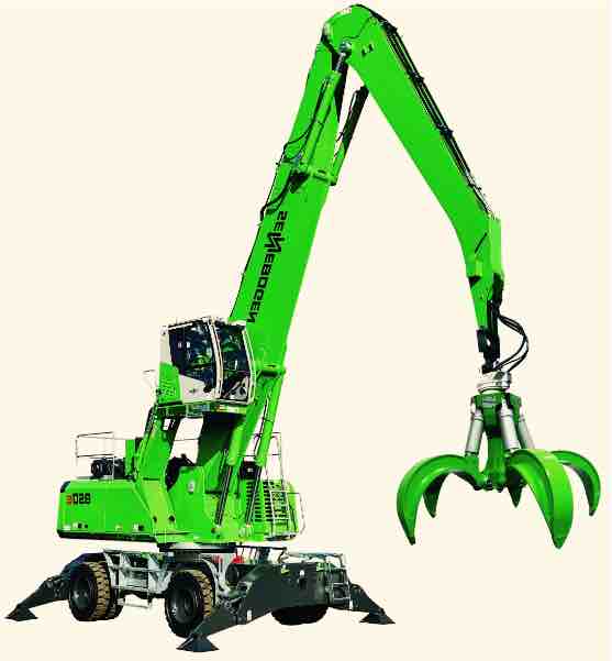
Sennebogen 850e

![]()
Sennebogen-S825M-Materials-Handling-Operators-Manual
Sennebogen-S825M-Materials-Handling-Operators-Manual
Sennebogen-S825M-Materials-Handling-Oper
Adobe Acrobat Document
1.1 MB
![]()
Sennebogen-Project-690.5.216-Crane-Spare-Parts-List
Sennebogen-Project-690.5.216-Crane-Spare-Parts-List
Sennebogen-Project-690.5.216-Crane-Spare
Adobe Acrobat Document
4.4 MB
History of Sennebogen Construction Equipment
Sennebogen is one of the best designers and manufacturers of agricultural, construction and port equipment in the world. The
company offers a full range of cranes and material handling machines, as well as developing individual concepts for special machines, taking into account the wishes of the customer.
Sennebogen is a machine built for continuous use in harsh conditions. It features extremely rugged drive, undercarriage and boom
designs, as well as heavy-duty engines and hydraulic systems for maximum efficiency. The equipment is produced at factories in Bavaria and Hungary, and the final assembly is carried out
exclusively in Germany, at factories in Straubing and Wackersdorf.
SENNEBOGEN telehandlers are the ideal machines for demanding applications. They feature a robust structure as well as strong
kinematics and hydraulics. Our machines are multifunctional tools that can handle both conventional telehandler tasks and complex material handling operations.
Lifting height up to 8.5 m, operating weight up to 5.5 t, turning radius 360°
All-round view and cab height of 4.25 m.
Air conditioning system and reversible fan as standard
High-strength solid steel frame meets the highest requirements
Powerful intelligent all-wheel drive including three steering options
Can be used in a variety of applications with an innovative hydraulic system and quick-change attachments.

Table of Contents for sennebogen 830 E:
-
Operation — Work application 6 — 61 830 / 07.2012 Original operating instructions Preselection of the swing bearing brake, which engages at the end of an action: – When the upper structure is stationary, the swing bearing brake engages automatically. – The following symbol appears in SENCON: – To release the swing bearing brake, switch to Switch position 0 = Automatic operation . Note If the safety lever is in its upper position, the swing bearing brake is activated. When the safety lever is in its lower position and Automatic operation is ac
-
Operation — Operating instruments 6 — 24 830 / 07.2012 Original operating instructions Outside air mode When windows are misted, to dehumidify the cab. Circulating air mode Faster warm-up of the cab and higher top temperature. The air in the cab interior is re-circulated, i.e. very little fresh air is drawn in from outside. Do not leave in this rating for longer than 15 minutes, as the air quality in the
-
Start-up — Safety instructions 4 — 2 830 / 07.2012 Original operating instructions Do not operate the machine if a fault has been detected. Ensure that all actuating levers are in the neutral position. Start the machine only as described in the information in the instructions.
-
Important notes about the operating instructions W — 6 830 / 07.2012Original operating instructions Target group The machine has been developed for demanding work. Persons working on or with the machine must be trained or instructed for that purpose. Detailed information on the prior knowledge and qualifications required of the operator can be found in Chapter 1 SAFETY of these instructions. Which documentation belongs with the machine? The following documentation belongs with
-
Operation — Work application 6 — 76 830 / 07.2012 Original operating instructions Auxiliary limiting — extend stick DANGER Never change the limit shutdown (6) setting set at the factory! Adjustment to the setting may be carried out only by SENNEBOGEN Customer Service or an authorized SENNEBOGEN Service Partner! With auxiliary limiting installation — set the stick as follows: Note The optional auxiliary limiting (5) cannot be bypassed. 5 Auxiliary limiting “Extend sti
-
Safety — Supplementary and operational equipment 1 — 18 07/2012Original operating instructions 1.8.5 coolant General WARNING Mixing coolants and adding cooling system sealing agents or anti-freeze that contains sealing agents is not permitted. By filling or mixing different types of cooling fluid or cooling agent additives, gelling, etc. can occur in the coolant leading to the cooler being plugged (build-up) and because of the engine overheating or if the cooling system fails for example, this can dama
-
Operation — Work application 6 — 45 830 / 07.2012 Original operating instructions 6.5.2 Moving the cab Safety instructions DANGER Risk of accident from raised cab! Check the cab suspension, bolt, and screw connections daily! Move the machine only with the cab lowered and retracted and the swing bearing holding brake engaged. Exit the cab only when it is in the completely lowered and retracted position. Move the cab only when the undercarriage supports are deployed! Keep the cab doors closed. Fasten the seat belt in accordance with
-
Important notes about the operating instructions W — 3 Original operating instructions 830 / 07.2012 Notes on the instructions Carefully read through the instructions, in particular Chapter 1 SAFETY, before beginning work with/on the machine. CAUTION Only work with/on the machine once you have read and completely understood theseoperating instructions. Refrain from operating and maintaining the machine in a
-
SENCON — Sennebogen Control System — Indicator and Warning Lamps Overview SENCON / 01.2013 5 — 39 Air filter contaminated Acknowledgment required! – Clean filter as described in the maintenance instructions – Replace filter if necessary 00151 Hydraulic filter 1 (main filter) contaminated Acknowledgment required! – Check filter, change if necessary 00161 Hydraulic filter 2 contaminated Acknowledgment required! – Check filter
-
Transport — Raising the upper structure 7 — 6 830 / 07.2012 Original operating instructions 7.2 Raising the upper structure Safety instructions Observe the safety instructions before starting work. DANGER Sling the upper structure only at the designated lifting points. The lifting points are marked yellow and have a green loading hook symbol. Ensure that the lifting equipment has a sufficient safe working load and stability is secure. The following is suitable li
Questions, Opinions and Exploitation Impressions:
You can ask a question, express your opinion or share our experience of sennebogen 830 E device using right now.
![]()
Sennebogen S825M Material Handling Operating Manual
Sennebogen S825M Material Handling Operating Manual
Sennebogen S825M Material Handling Opera
Adobe Acrobat Document
1.1 MB
![]()
Sennebogen Project 690.5.216 Crane Spare Part List
Sennebogen Project 690.5.216 Crane Spare Parts
Sennebogen Project 690.5.216 Crane Spare
Adobe Acrobat Document
2.4 MB
Above on the page there’re some Manuals PDF for SENNEBOGEN Excavator &
Crane.
The Sennebogen company was established in 1952. Its founder was Erich Sennebogen Sr.
The first idea of how to improve the coupling between the tractor and the trailer came to him when he was working in practice at the Porsche company, which at that time made not
only cars, but also tractors.
At the age of 21, he turned it into a farm, followed by development for agricultural work, and then he began to develop the construction sector, which is still served by this private company
owned by the SENNEBOGEN family, where all the successors of ideas are people with a technical mindset.
Any family business is distinguished from associations by the fact that they do not think about tomorrow, but about the next generation.
The first developments of the company were rope and cable excavators.
For 8 years, 1000 machines were produced, and the 1000th machine — an excavator with a bucket capacity of 0.3 m3 — was already a great achievement.
In the 60s, all components (for example, transmissions, winches) were produced by the company independently in its own factory.
And it should be noted that SENNEBOGEN has more than one interesting development.
In the 60s, a revolution took place, and cable excavators began to be supplanted by hydraulic ones.
1969 was the most fruitful year for SENNEBOGEN — they were the first in the world to produce a fully hydraulic rope shovel.
The company has the most extensive experience in the production of hydraulic rope shovels in the world.
In the 60s, they began to produce cranes with lattice boom on the chassis, which is now not practiced due to the severe pressure limitation on the axle.
In 1960, the first specific machine was produced — the universal loader.
1972 saw high sales of hydraulic excavators due to their popularity in Europe.
At the same time, SENNEBOGEN began using plexiglass for cab glazing (note that the automotive industry began using plexiglass 20 years
later).
1980 — World premiere: SENNEBOGEN brought the world a hydraulically adjustable boom, which reduced its transport dimensions.
They never patented it, but the arrow of this configuration was invented here.
In 1982, a material handling machine with a radius of 20 m was created, which was considered a very large machine at that time.
1987 — under the order of the US Army, an interesting machine was created in their parts to reload a large amount of scrap metal in their parts, where the boom consists of three sections.
1990 — completely know-how of the company — a unique tracked vehicle for handling scrap metal, which is currently being successfully implemented.
In the same year, a model of a crane on a pedestal and a crawler track was created for a specific customer, which then became very popular.
In 1992, SENNEBOGEN also introduced innovations such as the mass production of material handling machines, such as the 24 ton material
handling machine with a hydraulically raised cab.
In 1994, the development of a special material handling line, the so-called GREEN LINE, began.
Due to the demand for such products, many companies began developing them in an attempt to retrofit conventional excavators.
Erich Sennebogen had a different concept — that it is fundamentally wrong to do this, because the machine requires much more smoothness,
stronger hydraulics, a larger radius to transfer materials, and he created a machine with a different boom kinematics, and not just a modified excavator.
And today it is one of the best universal material handlers.
In 2000, the company began to develop completely unique cranes — crawler cranes with a telescopic boom.