Инструкции по ремонту авторефрижераторов (рефрижераторов) Thermo King (Термо Кинг) на нашем сайте нет.
Инструкции на пульты управления
![]() SR2 — пульт управления авторефрижераторов SLe и SLX
SR2 — пульт управления авторефрижераторов SLe и SLX
![]() ThermoGuard TG-VI
ThermoGuard TG-VI
![]() ThermoGuard uP-T
ThermoGuard uP-T
![]() Spectrum Multi-Temp
Spectrum Multi-Temp
Инструкции на авторефрижераторы
![]() SL-100e, SL-200e, SL-400e и SPECTRUM SL
SL-100e, SL-200e, SL-400e и SPECTRUM SL
![]() SLX-100, 200 и 400 с контроллером SR-2
SLX-100, 200 и 400 с контроллером SR-2
![]() TS-200, TS-300, TS-600, TS-500, SPECTRUM TS, XDS SR, RD-II, KD-II, MD-200, MD-300, MD-II, SDZ, CD-II MAX, UMD-II, URD-III, UTS, RD TLE, MD TLE, RD-MT, MD-MT, MD-200 MT
TS-200, TS-300, TS-600, TS-500, SPECTRUM TS, XDS SR, RD-II, KD-II, MD-200, MD-300, MD-II, SDZ, CD-II MAX, UMD-II, URD-III, UTS, RD TLE, MD TLE, RD-MT, MD-MT, MD-200 MT
![]() T-500R, T-600R, T-800R, T-1000R, T-1200R (1 часть), (2 часть).
T-500R, T-600R, T-800R, T-1000R, T-1200R (1 часть), (2 часть).
![]() UT-800, UT-1200
UT-800, UT-1200
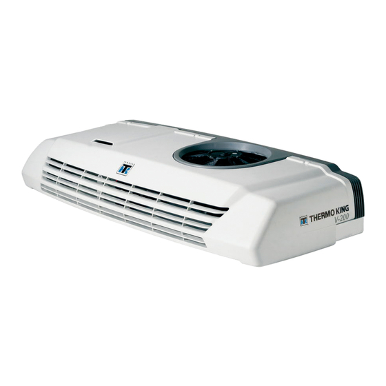
![]() Нового поколения B-100, V-100, V-200, V-300, V-400, V-500, V-700
Нового поколения B-100, V-100, V-200, V-300, V-400, V-500, V-700
![]() Серия — С
Серия — С
![]() Серия — V
Серия — V
Руководство пользователя Direct Smart Reefer Thermo King Серии V
Установки с приводом от двигателя автомобиля и контроллером Direct Smart Reefer Руководство по эксплуатации B-100, V-100, V-200, V-300, V-400, V-500, V-700
РУССКИЙ содержание
Введение………………………………………………………………………………………………………………………………………………………………………………………. 145
Основные понятия………………………………………………………………………………………………………………………………………………………………… 146
Меры безопасности…………………………………………………………………………………………………………………………………………………………………….. 147
Хладагент………………………………………………………………………………………………………………………………………………………………………………. 147
Первая помощь при поражении хладагентом……………………………………………………………………………………………………………………. 147
Масло для холодильных машин…………………………………………………………………………………………………………………………………………… 147
Первая помощь при поражении маслом для холодильных машин………………………………………………………………………………….. 148
Автоматический запуск…………………………………………………………………………………………………………………………………………………………. 148
Электробезопасность …………………………………………………………………………………………………………………………………………………………. 148
Установки c резервным электроприводом………………………………………………………………………………………………………………………….. 148
Электронная система контроля……………………………………………………………………………………………………………………………………………….. 149
Описание электронной системы управления…………………………………………………………………………………………………………………….. 149
Управление холодильной установкой…………………………………………………………………………………………………………………………………. 151
Инструкция по эксплуатации…………………………………………………………………………………………………………………………………………………….. 152
Еженедельная предрейсовая проверка……………………………………………………………………………………………………………………………… 152
Запуск холодильной установки…………………………………………………………………………………………………………………………………………….. 152
Стандартный экран………………………………………………………………………………………………………………………………………………………………. 153
Введение заданной температуры……………………………………………………………………………………………………………………………………….. 153
Ручной запуск цикла оттаивания испарителя……………………………………………………………………………………………………………………. 154
Ручной запуск цикла оттаивания конденсатора (только для устройств с обратным циклом)……………………………………….. 155
Сигнализация аварийного состояния…………………………………………………………………………………………………………………………………. 156
Описание кодов неисправностей………………………………………………………………………………………………………………………………………… 157
Cброс кодов неисправностей………………………………………………………………………………………………………………………………………………. 157
Просмотр информационных экранов………………………………………………………………………………………………………………………………….. 157
Осмотр после запуска установки…………………………………………………………………………………………………………………………………………. 158
Процедура загрузки………………………………………………………………………………………………………………………………………………………………. 158
Порядок действий после загрузки……………………………………………………………………………………………………………………………………….. 158
Еженедельная послерейсовая проверка……………………………………………………………………………………………………………………………. 158
РАСПИСАНИЕ ПРОФИЛАКТИЧЕСКОГО ОБСЛУЖИВАНИЯ УСТАНОВОК……………………………………………………………………………. 159
Гарантийное обслуживание………………………………………………………………………………………………………………………………………………………. 162
СИСТЕМА THERMO ASSISTANCE
Система Thermo Assistance — это средство многоязычного общения, обеспечивающее Вам, в случае необходимости, прямой контакт с официальным дилером по техническому обслуживанию транспортных холодильных систем Thermo King. Перед тем тем, как сделать звонок и воспользоваться услугами этой системы, подготовьте следующую информацию:
- номер Вашего контактного телефона;
- тип установки Thermo King;
- значение заданной температуры;
- значение текущей температуры груза;
- возможная причина неисправности;
- находится ли установка на гарантийном обслуживании;
- способ оплаты ремонтных работ. Обратитесь к каталогу пунктов технического обслуживания Thermo King (Thermo King Service Directory).
Cообщите оператору Thermo Assistance Вашу фамилию и номер контактного телефона, и попросите его перезвонить Вам. После того, как представитель Thermo Assistance перезвонит Вам, объясните ему подробно какой вид технического обслуживания требуется для холодильной установки. Лишь после этого будет организован ремонт.
Следует иметь в виду, что Thermo Assistance не может гарантировать за Вас оплату за оказанные услуги, и то, что эта служба создана для поддержки исключительно транспортных холодильных установок производства корпорации Thermo King.
ОТКАЗ ОТ ОБЯЗАТЕЛЬСТВ
Изготовитель, корпорация Thermo King, не несет ответственности за любой поступок, либо действия владельца или оператора по восстановлению холодильно-обогревательной установки, или по выполнению им каких-либо операций, которые упоминаются в настоящем руководстве и противоречат инструкциям, разработанным и отпечатанным изготовителем. Не принимаются во внимание никакие гарантии, выраженные явно или косвенно, в том числе и гарантии, якобы вытекающие из условий сделки, информации, рекомендаций и технических описаний, содержащихся в руководстве. Изготовитель не несет ответственности по условиям контракта или по закону о гражданских правонарушениях (включая ответственность за небрежность) за любые виды ущерба, включая повреждения и вред, причиненные транспортному средству, грузу или персоналу во время монтажа установки; механические неполадки или ошибки, произошедшие в результате вмешательства владельца или оператора установки и противоречащие предупреждениям и инструкциям схематически изображенным на табличках, которые размещены в установленных местах холодильной установки.
ВВЕДЕНИЕ
Thermo King — Испания разработал новый внутрикабинный цифровой блок управления с программируемым микропроцессором для управления работой холодильной установки и отображения текущей информации на экране.
Новые внутрикабинные пульты управления разработаны для использования в холодильных установках с приводом компрессора от двигателя автомобиля с электронной системой управления. Один и тот же пульт применяется для управления как одно-, так и двухтемпературных холодильных установок.
Нет ничего сложного в том, чтобы самостоятельно научиться пользоваться внутрикабинным пультом управления, разработанным Thermo King — Испания. Потратив несколько минут на изучение данного руководства, Вы поймете важность и необходимость овладения изложенной в нем информации. Внутрикабинный пульт управления выпускается для автомобилей с бортовым напряжением 12 и 24В. Температура индицируется как в градусах Цельсия, так и в градусах Фаренгейта. Настоящее руководство не претендует на роль источника исчерпывающей информации. Оно составлено с целью предоставления пользователю необходимых сведений о холодильно- обогревательной установке. Для получения дополнительной информации обращайтесь к вашему региональному дилеру Thermo King. Все виды обслуживания холодильно- обогревательных установок , как серьезные, так и мелкие, должны выполняться официальными сервисными центрами Thermo King, ввиду следующих четырех важных обстоятельств:
- Все технические операции выполняются только с использованием специального инструмента, рекомендованного корпорацией Thermo King.
- Все виды работ выполняются персоналом, имеющим высокую квалификацию и соответствующий сертификат от корпорации Thermo King.
- Используются только оригинальные запасные части Thermo King.
- Гарантия на приобретенную холодильно- обогревательную установку сохраняется только при условии, что ее ремонт производится уполномоченным официальным сервисным центром корпорации Thermo King.
При систематических осмотрах холодильной установки перед выходом в рейс и во время рейса, неполадки в работе установки снижаются до минимума. Для поддержания высокой работоспособности установки неукоснительно выполняйте график технического обслуживания. Если Вы правильно выполняете все рекомендации завода изготовителя, будьте уверены, что приобретенная Вами холодильная установка обеспечивает максимальную эффективность в работе и надежный температурный контроль.
ОСНОВНЫЕ ПОНЯТИЯ
В холодильно-обогревательных установках, работающих с приводом компрессора от двигателя автомобиля, контроль температуры груза основывается на сравнении двух значений температур: заданной температуры (Setpoint) и температуры возвратного воздуха в испарителе в кузове автомобиля. Разница между значениями этих температур определяет соответствующий режим работы холодильно-обогревательной установки: охлаждение, обогрев или нулевой режим. • Охлаждение: Когда температура груза внутри кузова автомобиля становится выше заданной температуры, установка работает в режиме охлаждения.
- Обогрев: Когда температура груза внутри кузова автомобиля становится ниже заданной температуры, установка переходит в режим обогрева.
- Нулевой режим: В случае когда температура груза достигла заданной температуры, и пока она остается в пределах Х°С выше или ниже заданной и нет необходимости перемещения теплоты для охлаждения или обогрева, установка работает в нулевом режиме.
- Оттаивание: После определенного периода работы холодильной установки в режиме охлаждения (1-8 часов) включается четвертый режим работы для удаления наледи на змеевике испарителя или конденсатора. Переключение
в режим оттаивания выполняется как автоматически, так и вручную.температуры
Заданная температура
Х°С ниже заданной температуры
Повышение температуры
Заводская настройка для Х составляет 3°С. В процессе монтажа холодильной установки на официальной сервисной станции Thermo King данное значение температуры можно изменить в диапозоне от 1 до 5°С с точностью 1°С.
Холодильные установки с хладагентом R-134a:
Эксплуатация данных холодильных установок обеспечивает поддержание температуры в диапозоне от -20°C до +22°С.
Холодильные установки с хладагентом R-404a:
Эксплуатация данных холодильных установок обеспечивает поддержание температуры в диапозоне от -32°C до +22°С.
Дата производства: Дата производства указывается на плате серийного номера установки. В ней также указывается завод- изготовитель.
Продажа и монтаж холодильной установки осуществляется авторизованным дилером Thermo King в строгом соответствии с требованиями Thermo King (данные дилера в плате не указываются).
МЕРЫ БЕЗОПАСНОСТИ
ПРЕДОСТЕРЕЖЕНИЕ:
Это устройство не предназначено для использования лицами (включая детей) с физическими или умственными отклонениями или лицами, не обладающими должными навыками или знаниями. Эксплуатация устройства такими людьми возможна только под контролем или после инструктирования по правилам использования оборудования лицом, ответственным за безопасность. Действия детей необходимо контролировать для предотвращения ненадлежащего использования оборудования.
Корпорация Thermo King настоятельно рекомендует своим пользователям производить все виды обслуживания холодильных уставновок на официальных сервисных станциях Thermo King. Существует несколько главных правил, которые необходимо неукоснительно выполнять:
- При выполнении профилактических или ремонтных работ с холодильными установками или вблизи их, а также при работе с аккумуляторной батареей, необходимо одевать защитные очки. Хладагент, также, как и электролит аккумуляторной батареи, при попадании в глаза может стать причиной
их тяжелого поражения.
- Нельзя допускать, чтобы холодильная установка работала при перекрытом сервисном вентеле нагнетания.
- Необходимо следить, чтобы во время работы холодильной установки, а также при открытии или закрытии сервисных вентелей компрессора, под лопасти вентиляторов, приводных ремней или других вращающихся частей, не попали руки или части одежды.
- Если по какой-либо причине возникает необходимость сверления отверстий в корпусе холодильной установки, необходимо отнестись к этому с особой осторожностью, так как это может стать причиной ослабления конструкции. Кроме того, может быть повреждена электропроводка или трубопровод с хладагентом, что может привести к пожару.
- Любые работы по обслуживанию испарителя
и конденсатора холодильной установки должны выполняться техническим персоналом официальной сервисной станции Thermo King. Однако, если возникает необходимость работать в непосредственной близости от змеевиков испарителя и конденсатора, необходимо выполнять все меры предосторожности, чтобы не получить травму об острые кромки пластин теплообменников.
ХЛАДАГЕНТ
Хотя фторуглеродные хладагенты считаются безопасными, необходимо соблюдать меры предосторожности при работе с хладагентами или вблизи мест, где они используются при обслуживании вашей холодильной установки. Фторуглеродные хладагенты при случайном вытекании в жидком виде быстро испаряются, замораживая все, с чем они соприкасаются.
Хладагенты, используемые в кондиционерах, при контакте с открытым пламенем или электрическим разрядом могут образовывать токсичные газы раздражающего действия, воздействие которых может стать причиной смерти.
ПЕРВАЯ ПОМОЩЬ ПРИ ПОРАЖЕНИИ ХЛАДАГЕНТОМ
ГЛАЗА: При попадании жидкого хладагента в глаза, необходимо тщательно промыть их водой и незамедлительно обратиться за медицинской помощью.
КОЖА: При поражении кожи хладагентом, тщательно промойте пораженную область прохладной водой, не прикладывая тепла. Оберните пораженное место сухим стерильным рыхлым перевязочным материалом для защиты от инфицирования. Обратитесь за медицинской помощью.
ДЫХАТЕЛЬНЫЕ ПУТИ: При поражении хладагентом дыхательных путей необходимо вывести пострадавшего на свежий воздух и восстановить его дыхание, если это необходимо. Оставайтесь с пострадавшим до прибытия скорой медицинской помощи.
МАСЛО ДЛЯ ХОЛОДИЛЬНЫХ МАШИН
При работе с маслом для холодильных машин выполняйте следующие указания:
ГЛАЗА:Не допускайте попадания масла для холодильных машин в глаза.
КОЖА:Не допускайте продолжительного или повторного контакта масла с кожей или одеждой.
РАЗДРАЖЕНИЕ :Для предотвращения раздражения необходимо тщательно вымыться сразу же после работы с маслом.
ПЕРВАЯ ПОМОЩЬ ПРИ ПОРАЖЕНИИ МАСЛОМ ДЛЯ ХОЛОДИЛЬНЫХ МАШИН
ГЛАЗА: Немедленно тщательно промойте глаза в течение, по меньшей мере 15 минут, держа веки открытыми. Быстро обратитесь за медицинской помощью.
КОЖА: Снимите загрязненную маслом одежду. Тщательно вымойтесь с мылом и водой. Если раздражение остается, то обратитесь за медицинской помощью.
ДЫХАТЕЛЬНЫЕ ПУТИ:Выведите пораженного на свежий воздух и восстановите его дыхание, если это необходимо. Оставайтесь с пораженным до прибытия скорой медицинской помощи.
ПИЩЕВАРИТЕЛЬНЫЙ ТРАКТ:Не пытайтесь вызвать рвоту. Немедленно свяжитесь с местным центром по борьбе с отравлениями или врачом. Фторуглеродные хладагенты стремятся вытеснить воздух и могут вызвать недостаток кислорода, который в свою очередь может привести к смерти в результате удушья. Постоянно соблюдайте меры предосторожности при работе с хладагентами или вблизи них, особенно в закрытых помещениях. Корпорация Thermo King рекомендует, чтобы все мероприятия по техническому обслуживанию выполнялись представителями Thermo King.
АВТОМАТИЧЕСКИЙ ЗАПУСК
Холодильные установки работают в автоматическом режиме и могут запускаться без предупреждения в любой момент времени при работе как от двигателя автомобиля, так и от резервного электродвигателя. Прежде чем снимать кожух холодильной установки и производить диагностику работы ее узлов и агрегатов, убедитесь, что установка находится в положении «Выкл» (Off).
ЭЛЕКТРОБЕЗОПАСНОСТЬ
Холодильные установки с блоком резервного электропривода являются устройствами повышенной опасности поражения электрическим током. Подача напряжения от источника внешнего электропитания должна осуществляться при выключенном переключателе системы управления холодильной установки. Перед проведением профилактических или ремонтных работ необходимо предварительно обесточить холодильную установку, отсоединив внешний кабель подачи напряжения.
УСТАНОВКИ C РЕЗЕРВНЫМ ЭЛЕКТРОПРИВОДОМ
В случае повреждения силового кабеля его должен заменить изготовитель, группа послепродажного обслуживания изготовителя или другой квалифицированный персонал, чтобы предотвратить возникновение опасной ситуации.
Подключите установку к линии электропитания с дифференциальной защитой и автоматическим выключателем, минимальное расстояние между контактами которого составляет 3 мм. Для этого воспользуйтесь соединительным разъёмом, поставляемым с установкой.
ПРЕДОСТЕРЕЖЕНИЕ Электрические сварочные аппараты генерируют высокоамперные токи, которые могут стать причиной пробоя электрических и электронных компонентов холодильной установки. Для минимизации или предотвращения такого риска, следите за тем, чтобы перед проведением сварочных работ на автомобиле микропроцессорный контроллер и аккумуляторная батарея были отключены от электроцепей автомобиля. Выключите переключатель «On/Off » микропроцессорного контроллера. Отсоедините кабель с отрицательного полюса аккумуляторной батареи. Отсоедините все клеммы от задней стороны микропроцессорного контроллера. Закройте контрольную панель. Заземлите сварочный аппарат кабелем как можно ближе к месту проведения сварочных работ. После завершения сварочных работ отсоедините кабель заземления сварочного аппарата. Вновь соедините все клеммы на задней стороне микропроцессорного контроллера. Присоедините отрицательный полюс аккумуляторной батареи. Включите микропроцессорный контроллер выключателем «On/Off». Восстановите все предыдущие коды и регулировки. Запустите холодильную установку в режиме «Pre-trip». Все инструкции описаны в сервисной процедуре Thermo King A26A.
ЭЛЕКТРОННАЯ СИСТЕМА
Холдильно-обогревательные установки Thermo King с приводом компрессора от двигателя автомобиля состоят из следующих основных элементов: конденсатора, испарителя (2 испарителей для двухтемпературных установок), компрессора (установки с резервным электроприводом от внешней электросети комплектуются вторым компрессором, который приводится в действие электродвигателем), панели управления внутрикабинного пульта, с которого осуществляется управление установкой. Электронная система управления состоит из электронного модуля, который расположен в конденсаторной части холодильной установки, и внутрикабинного пульта управления. Этот блок позволяет водителю обеспечивать постоянный контроль за работой холодильной установки.
ОПИСАНИЕ ЭЛЕКТРОННОЙ СИСТЕМЫ УПРАВЛЕНИЯ
Электронная система управления имеет
следующие особенности:
- автоматический старт;
- плавный старт;
- активный экран дисплея;
- подсвечивающиеся кнопки управления;
- счетчик общей наработки холодильной установки;
- счетчик наработки компрессора на двигателе автомобиля;
- счет наработки установки в режиме работы от внешней электросети;
- сигнал, предупреждающий о низкой зарядке аккумуляторной батареи;
- звукового сигнал;
- холодильная установка управляется автоматически при отключении внутрикабинного пульта управления;
- функция автоматического или ручного оттаивания;
- предупреждение о необходимости сервисного обслуживания;
- датчик температуры возвратного воздуха;
- отображение заданной температуры на дисплее;
- предупреждение о включении внешнего электропитания при работе установки от внешней электросети.
Автоматический старт: Если работа холодильной установки прекратилась из-за остановки двигателя автомобиля или прекращения подачи питания (в режиме питания от внешней электросети), установка запустится снова, как только включится привод.
Плавный старт: Выполнение всех команд в режиме «Автоматический старт» наступает с задержкой в несколько секунд.
Активный экран дисплея: Экран дисплея внутрикабиннго пульта контроля и управления всегда находится в активном состоянии и подсвечен, за исключением случаев, когда холодильная установка отключена от источника электропитания, или если она подключена, но вручную выключена клавишей «On/Off» на панели пульта управления (когда нет активных аварийных кодов).
Подсвечиваемые кнопки управления:
Кнопки управления на внутрикабинном пульте управления всегда находятся в подсвеченном состоянии, кроме случаев, когда холодильная установка отключена от источника электропитания, или если она подключена, но вручную выключена клавиша «On/Off» на панели блока контроля и управления (если нет активных аварийных кодов). Кнопка «On/Off» подсвечивается всегда, за исключением случаев, когда установка отсоединена от источника питания. Это также является индикатором подачи напряжения к системе управления установки.
Счетчик общей наработки холодильной установки: Данный счетчик показывает общее время в часах работы холодильной установки.
Счетчик наработки компрессора на двигателе автомобиля: Этот счетчик показывает время работы компрессора с приводом от двигателя автомобиля в часах.
Счетчик наработки холодильной установки в режиме работы от внешней электросети:
Данный счетчик показывает общее время в часах работы холодильной установки с питанием от источника внешней электросети.
Сигнал о низкой зарядке аккумуляторной батареи: Холодильная установка выключается, если напряжение аккумуляторной батареи падает ниже 10,5В на автомобилях с напряжением в цепях управления 12В, и ниже 21В при напряжении в цепях управления автомобиля 24В соответственно.
Звуковой сигнал: Звуковой сигнал (зуммер) оповещает водителя о возникновении ситуации, когда аккумуляторная батарея автомобиля и внешний источник электропитания подсоединены к питанию холодильной установки в одно и то же время. Также звуковой сигнал оповещает о работе холодильной установки при открытых дверях кузова автомобиля.
Контроль за работой холодильной установки без внутрикабинного пульта управления:
Установка может управляться электронной системой управления без кабинного пульта. Установка будет управляться в режиме, выбранном контроллером перед отсоединением кабинного пульта.
Функция ручного или автоматического оттаивания: Данная функция позволяет, в зависимости от условий, выбрать ручной или автоматический режим оттаивания.
Напоминание о сервисном обслуживании:
На экране дисплея высвечивается напоминание о необходимости сервисного обслуживания холодильной установки.
Датчик температуры возвратного воздуха:
Отображение на экране информации о фактической температуре перевозимого груза. В двухтемпературных холодильных установках, фактическая температура груза в обоих отсеках кузова отображается на одном экране дисплея.
Заданная температура: Заданная температура, которую ввел пользователь, отображается на экране дисплея. В двухтемпературных холодильных установках, заданная температура груза в обоих отсеках кузова отображается на одном экране дисплея.
Включение электропитания от внешнего источника: При подключении внешнего источника электропитания на экране дисплея появляется предупреждение о работе холодильной установки в данном режиме.
УПРАВЛЕНИЕ ХОЛОДИЛЬНОМ УСТАНОВКОЙ
ПРЕДОСТЕРЕЖЕНИЕ!
Никогда не включайте холодильную установку до тех пор, пока полностью не поймете назначение органов управления. В противном случае это может привести к нежелательным последствиям.
ВНУТРИКАБИННЫЙ ПУЛЬТ УПРАВЛЕНИЯ
Дисплей, клавиши управления и символы
1. Дисплей. Экран дисплея всегда находится в активном состоянии с подсветкой, независимо от режима работы холодильной установки, кроме тех случаев, когда холодильная установка отключена от источника энергообеспечения, или если она подключена, но вручную выключена клавиша «On/ Off’ на панели пульта управления. В нормальном состоянии экран показывает фактическую температуру возвратного воздуха в кузове автомобиля. Для двухтемпературных установок отображаются фактические температуры возвратного воздуха в обоих отделения кузова автомобиля.
- Клавиша «Вкл/Выкл» («On/Off»). Эта
клавиша используется для запуска и останова холодильной установки. Она всегда находится в подсвеченном состоянии, за исключением случаев, когда установка отключена от питания. Данная кнопка является своеобразным индикатором подключения установки к источнику питания.
- Клавиша выбора экрана. Данная клавиша позволяет выбрать информационный экран и представить информацию на экране.
- Клавиша «стрелка вверх». Эта клавиша используется для изменения заданной температуры в сторону увеличения.
- Клавиша «стрелка вниз». Эта клавиша используется для изменения заданной температуры в сторону уменьшения.
- Клавиша ввода. Данная клавиша используется для ввода каждой новой команды, например, оттаивания в ручном режиме и т. д.
- Звуковой сигнал. Звуковой сигнал (зуммер) подается в случае, когда питание на холодильную установку подается от аккумуляторной батареи автомобиля и от источника внешнего электропитания одновременно. Также звуковой сигнал подается, если во время работы холодильной установки происходит открывание дверей кузова автомобиля.
- Символ охлаждения. (Термометр со стрелкой, указывающей вниз). Установка работает в режиме охлаждения.
- Символ нагрева. (Термометр со стрелкой, указываюшей вверх). Установка работает в режиме обогрева.
- °C/°F Символ. Указывает на то, в каких температурных единицах (Цельсия или Фаренгейта) отображается температура на дисплее.
- Символ аварийной сигнализации.
Предупреждает, что в работе системы есть неполадки или сбои.
- Символ технического обслуживания.
Напоминает, что необходимо провести техническое обслуживание установки.
- Символ оттаивания. Показывает, что испаритель или конденсатор находятся в режиме оттаивания.
- Символ электропитания. Показывает, что установка находится в режиме электропитания от внешней электросети.
- Символ оттаивания конденсатора.
Показывает, что конденсатор находится в режиме оттаивания (включается одновременно с символом оттаивания 13).
ИНСТРУКЦИЯ ПО ЭКСПЛУАТАЦИИ
Обеспечьте выполнение следующих предрейсовых проверок до запуска холодильной установки.
ЕЖЕНЕДЕЛЬНАЯ ПРЕДРЕЙСОВАЯ ПРОВЕРКА
Представленная ниже процедура проведения предрейсовой проверки должна проводиться перед загрузкой кузова автомобиля. Еженедельная проверка не заменяет проведение регулярных технических осмотров (см. раздел, посвященный графику проведения технического обслуживания). Однако, она является важным элементом программы профилактического обслуживания, призванной предотвращать неисправности при эксплуатации холодильной установки до их проявления.
- Утечки. Проверьте отсутствие утечек хладагента и изношенность шлангов.
- Аккумуляторная батарея. Клеммы аккумуляторной батареи должны быть надежно затянуты, и на них не должно быть следов коррозии.
- Ремни. Проверьте отсутствие трещин, потертостей, а также проверьте натяжение ремней.
- Монтажный комплект. Убедитесь, что болты монтажного комплекта затянуты полностью.
- Электрическая схема. Электрические соединения должны быть надежно затянуты. Провода и клеммы не должны иметь признаков коррозии, не должны быть потрескавшимися или отсыревшими.
- Элементы рамы. Визуально осмотрите все несущие конструкции на предмет отсутствия механических повреждений.
- Змеевики. Конденсаторный и испарительный теплообменники холодильной установки должны быть чистыми и не иметь загнутых пластин.
- Кузов. Осмотрите внешнюю и внутреннюю поверхности грузовика на предмет отсутствия повреждений. Любые повреждения стен или изоляции должны быть устранены.
- Дренажное устройства для спуска талой воды. Проверьте шланги и арматуру дренажной системы для спуска талой воды, чтобы убедиться, что они ничем не заблокированы.
- Двери. Убедитесь, что двери и дверные уплотнения находятся в хорошем состоянии и обеспечивают герметичность.
- Смотровой глазок. Убедитесь в том, что смотровое стекло уровня хладагента на работающем устройстве полностью заполнено (температура грузового отделения должна составлять приблизительно 0°C).
ЗАПУСК ХОЛОДИЛЬНОЙ УСТАНОВКИ
Эксплуатация с приводом от двигателя автомобиля
1. Запустите двигатель автомобиля.
- Нажмите клавишу включения на внутрикабинном пульте управления. Дисплей пульта управления включится.
- Проверьте значение заданной температуры. При необходимости измените ее.
Эксплуатация с приводом от внешнего источника электропитания
- Подключите холодильную установку
к источнику внешнего электропитания. Убедитесь, что напряжение и фазность источника внешнего электропитания соответствуют требуемым условиям для электропитания установки.
- Нажмите клавишу включения на внутрикабинном пульте управления. Дисплей пульта управления включится и на экране появится символ электропитания.
- Проверьте значение заданной температуры. При необходимости измените ее.
Примечание: Рекомендуется регулярно выполнять мониторинг установки; частота мониторинга будет зависеть от типа груза.
Примечание: Режимы работы холодильной установки с приводом от двигателя автомобиля или от источника внешней электросети выбираются автоматически. Когда установка подключена к источнику внешнего электропитания, работа с приводом от двигателя автомобиля блокируется. Если двигатель автомобиля запущен, в то время, как силовой кабель установки подключен к источнику внешней электросети, то установка продолжит работать в режиме питания от внешней электросети и раздастся звуковой сигнал.
СТАНДАРТНЫЙ ЭКРАН
Такой экран отображается на дисплее после нажатия клавиши включения и запуска установки. Как правило на нем отображается температура возвратного воздуха (в том числе для обоих объемов кузова с случае двухтемпературной версии) и текуший режим работы с соответствующим символом. При возникновении неполадки или сбоя на экране появится символ аварийной ситуации. ОДНОТЕМПЕРАТУРНЫЙ РЕЖИМ РАБОТЫ ХОЛОДИЛЬНОЙ УСТАНОВКИ
Пример изображения на дисплее показывает, что температура в кузове автомобиля составляет 10,8°С, установка работает в режиме охлаждения от внешнего источника электропитания.
ДВУХТЕМПЕРАТУРНЫЙ РЕЖИМ РАБОТЫ ХОЛОДИЛЬНОЙ УСТАНОВКИ
Пример изображения на дисплее показывает, что температура в основном объеме кузова составляет -10°С и в нем поддерживается режим охлаждения, а температура в дальнем объеме составляет 2°С и в нем поддерживается режим обогрева. Установка работает с приводом от двигателя автомобиля.
ВВЕДЕНИЕ ЗАДАННОЙ ТЕМПЕРАТУРЫ
Изменение заданной температуры производится посредством клавиш пульта управления легко и быстро.
ДЛЯ ОДНОТЕМПЕРАТУРНЫХ УСТАНОВОК
1. Дважды нажмите и отпустите клавишу «Выбор экрана» (SELECT) (три раза в установках с обратным циклом), и на экране появится текущее значение заданной температуры и буквы SP.
- Нажимая клавиши увеличения или уменьшения температуры, выберите необходимое значение температуры. Каждый раз при нажатии или отпускании любой из этих клавиш значение заданной температуры будет изменяться на 1 градус.
- Нажмите и отпустите клавишу «Ввод» (ENTER), чтобы задать значение, или нажмите и отпустите клавишу «Выбор экрана» (SELECT), чтобы задать значение и вернуться к стандартному экрану.
ВНИМАНИЕ!
Если в течение 20 секунд не будет нажата клавиша «Выбор экрана» (SELECT) или клавиша «Ввод» (ENTER) для ввода нового значения заданной температуры, то холодильная установка будет продолжать работать при исходном значении заданной температуры.
ДЛЯ ДВУХТЕМПЕРАТУРНЫХ УСТАНОВОК
1. Для основного грузового объема кузова:
Дважды нажмите и отпустите клавишу «Выбор экрана» (SELECT), и на экране появится текущее значение заданной температуры и буквы SP.
- Нажимая клавиши увеличения или уменьшения температуры, выберите необходимое значение температуры. Каждый раз при нажатии или отпускании любой из этих клавиш значение заданной температуры будет изменяться на 1 градус.
- Нажмите и отпустите клавишу «Ввод» (ENTER), чтобы задать значение, или нажмите и отпустите клавишу «Выбор экрана» (SELECT), чтобы задать значение и вернуться к экрану настройки температуры отдаленного объема кузова.
ВНИМАНИЕ!
Если в течение 20 секунд не будет нажата клавиша «Выбор экрана» (SELECT) или клавиша «Ввод» (ENTER) для ввода нового значения заданной температуры, то холодильная установка будет продолжать работать при исходном значении заданной температуры.
4. Для отдаленного объема кузова: На экране появится текущее значение заданной температуры и буквы SP2.
- Нажимая клавиши увеличения или уменьшения температуры, выберите необходимое значение температуры. Каждый раз при нажатии или отпускании любой из этих клавиш значение заданной температуры будет изменяться на 1 градус.
- Нажмите и отпустите клавишу «Ввод» (ENTER), чтобы задать значение, или нажмите и отпустите клавишу «Выбор экрана» (SELECT), чтобы задать значение и вернуться к стандартному экрану.
ВНИМАНИЕ!
Если в течение 20 секунд не будет нажата клавиша «Выбор экрана» (SELECT) или клавиша «Ввод» (ENTER) для ввода нового значения заданной температуры, то холодильная установка будет продолжать работать при исходном значении заданной температуры.
РУЧНОЙ ЗАПУСК ЦИКЛА ОТТАИВАНИЯ ИСПАРИТЕЛЯ
ВНИМАНИЕ!
До включения принудительного цикла оттаивания убедитесь, что установка уже не находится в режиме оттаивания. Когда установка находится в режиме оттаивания, на дисплее отображается символ оттаивания.
1. Один раз нажмите и отпустите клавишу «Выбор экрана» (SELECT) и на экране появятся в пульсирующем режиме буквы dEF вместе с текущим статусом режима оттаивания OFF (выключен).
2. Для включения режима ручного оттаивания нажмите клавишу ввода (ENTER), а затем клавишу «вверх» или «вниз», и статус режима оттаивания изменится на ON (включено).
РУЧНОЙ ЗАПУСК ЦИКЛА ОТТАИВАНИЯ КОНДЕНСАТОРА (ТОЛЬКО ДЛЯ УСТРОЙСТВ С ОБРАТНЫМ ЦИКЛОМ)
ВНИМАНИЕ!
Перед ручным запуском режима оттаивания убедитесь в том, что установка не находится в режиме оттаивания. Если установка находится в режиме оттаивания, на экране появляется соответствующий символ оттаивания.
2. Чтобы вручную запустить цикл оттаивания, нажмите клавишу «Ввод» (ENTER), затем с помощью стрелок вверх/вниз выберите для состояния оттаивания режим «Вкл.» (ON).
3. Дважды нажмите клавишу «Выбор экрана» (SELECT) для возврата к стандартному экрану (три раза для двухтемпературных установок и установок с обратным циклом). С началом цикла оттаивания на экране появится символ оттаивания (температура в грузовом отделе должна быть ниже 0°C).
1. Дважды нажмите и отпустите клавишу «Выбор экрана» (SELECT), на экране появятся мигающие буквы dFC, а также отобразится текущее состояние цикла оттаивания «Выкл.» (OFF).
3. Дважды нажмите «Выбор экрана»
(SELECT), чтобы вернуться к стандартному экрану. Символ оттаивания появится на экране после запуска цикла оттаивания (внешняя температура должна быть ниже 0°C).
СИГНАЛИЗАЦИЯ АВАРИЙНОГО СОСТОЯНИЯ
При наличии сбоев или неполадок в работе установки микропроцессор записывает код сигнализации, предупреждает оператора отображением на дисплее символа аварийного состояния и, в зависимости от типа сбоя или неполадки, останавливает работу установки.
Существуют три категории аврийного состояния.
Ручной запуск
Сигнализация аврийного состояния прекращает работу холодильной установки, и на дисплее появляется символ аврийного состояния.
После исправления неполадки или сбоя для запуска установки необходимо нажать клавишу «Вкл/Выкл.» (On/Off).
Нажмите и отпустите клавишу «Выбор экрана» (SELECT) для отображения на экране текущего кода аварийного состояния. Если в это время имеется более одного активного аварийного состояния, то коды всех активных аврийных состояний установки можно просмотреть, последовательно нажимая и отпуская клавишу «Выбор экрана» (SELECT).
Автоматический запуск
Сигнализация аварийного состояния прекращает работу установки, на дисплее появляется символ аврийного состояния, а установка включается в работу автоматически после исправления неполадки или сбоя.
При возникновении неполадки P1E — неисправен датчик температуры возвратного воздуха — на экране вместо значения температуры возвратного воздуха появятся символы — вместе с символом аварийного состояния.
В двухтемпературной установке на экране вместо значения температуры возвратного воздуха в дальнем объеме кузова также появятся символы — вместе с символом аварийного состояния.
Для двухтемпературных установок: при возникновении неполадки P2E — неисправен датчик температуры возвратного воздуха в дальнем объеме кузова автомобиля — на экране вместо значения температуры возвратного воздуха в дальнем объеме кузова также появятся символы —вместе с символом аварийного состояния.
Нажмите и отпустите клавишу «Выбор экрана» (SELECT) для отображения на экране текущего кода аварийного состояния. Если в это время имеется более одного активного аварийного состояния, то коды всех активных аврийных состояний установки можно просмотреть, последовательно нажимая и отпуская клавишу «Выбор экрана» (SELECT).
Звуковой сигнал
Звуковой сигнал (зуммер) включается при одновременном подключении аккумуляторной батареи транспортного средства и внешнего источника электропитания (при этом установка продолжает работать в режиме электропитания от внешней электросети). Также звуковой сигнал срабатывает в том случае, если открываются двери при работающей холодильной установке (если выбрана такая опция).
ОПИСАНИЕ КОДОВ НЕИСПРАВНОСТЕЙ
|
Ручной запуск |
|
|
OL |
Перегрузка электродвигателя. Система защиты установки при работе от электропривода. Если проблема повторится после перезапуска установки обратитесь к Вашему Сервисному Дилеру. |
|
bAt |
Низкое Напряжение Батарей. Система защиты установки и батареи |
|
Автоматический запуск |
|
|
HP |
Сигнал о Превышении Давления. Указывает на то, что холодильный агрегат будет отключен по причине чрезмерно повышенного давления в холодильном контуре. Если проблема повторится после перезапуска установки, обратитесь к Вашему Сервисному Дилеру. |
|
LP |
Сигнал о Падении Давления. Указывает на то, что холодильный агрегат будет отключен по причине чрезмерно пониженного давления в холодильном контуре. Если проблема повторится после перезапуска установки, обратитесь к Вашему Сервисному Дилеру. |
|
PSE |
Неисправен датчик высокого давления. Датчик высокого давления вышел из строя или отсоединен. Обратитесь к Вашему Сервисному Дилеру. |
|
tEP, tP4 |
Сигнал тепловой защиты. Если проблема повторится после перезапуска установки обратитесь к Вашему Сервисному Дилеру.. |
|
drl, dr2 |
Открыты двери. Эта опция должна быть активирована. |
|
tCO |
Перегрев модуля управления. Если проблема повторится после перезапуска установки, обратитесь к Вашему Сервисному Дилеру. |
|
SOF |
Сбой программы. Обратитесь к Вашему Сервисному Дилеру. |
|
P1E |
Ошибка показаний датчика температуры возвратного воздуха в кузове или в основном отсеке (разрыв цепи или короткое замыкание). Обратитесь к Вашему Сервисному Дилеру. |
|
P2E |
Ошибка показаний датчика температуры возвратного воздуха в удаленном отсеке (разрыв цепи или короткое замыкание). Обратитесь к Вашему Сервисному Дилеру. |
|
C |
Сбой связи. Обратитесь к Вашему Сервисному Дилеру. |
CБРОС КОДОВ НЕИСПРАВНОСТЕЙ
Прежде всего необходимо устранить неисправность или причину сбоя в работе холодильной установки. После этого необходимо нажать и отпустить клавишу «Выбор экрана» (SELECT) для сброса имеющихся кодов неисправностей. После сброса кодов неисправностей на дисплее будет отображаться стандартный экран.
ПРОСМОТР ИНФОРМАЦИОННЫХ
ЭКРАНОВ
ГЛАВНОЕ МЕНЮ
Из состояния стандартного экрана при помощи клавиши «Выбор экрана» (SELECT) на дисплей можно вызвать:
- Сигнальные коды аварийного состояния (если таковые имеются).
- Ручное оттаивание испарителя.
- Ручное оттаивание конденсатора (только для установок с обратным циклом).
- Экран ввода заданной температуры.
МЕНЮ СЧЕТЧИКА МОТОЧАСОВ
Из состояния стандартного экрана нажмите и удерживайте клавишу «Выбор экрана» (SELECT) три секунды для перехода в меню счетчика моточасов, где при нажатии клавиши «Выбор экрана» (SELECT) на дисплей можно вызвать:
- HC: Оставшиеся до очередного технического обслуживания часы работы холодильной установки.
- tH: Суммарная продолжительность (в часах) включенного состояния установки в режиме поддержания заданной температуры перевозимого груза.
- CC: Продолжительность работы компрессора с приводом от двигателя автомобиля (в часах).
- EC: Продолжительность работы компрессора с приводом от внешнего источника электропитания (в часах).
- Возврат в Главное меню.
Примечание: Установки со встроенным программным обеспечением версии 380.03 или более ранней: единицей измерения являются десятки часов (например, 150 означает 1 500 часов) Установки со встроенным программным обеспечением версии 380.06 или более поздней: единицей измерения являются часы
ОСМОТР ПОСЛЕ ЗАПУСКА УСТАНОВКИ
Термостат. Установите заданное значение температуры выше или ниже температуры в грузовом объеме кузова автомобиля для проверки функционирования термостата.
Предварительное охлаждение. После установки на термостате требуемого значения заданной температуры дайте установке поработать от получаса до часа (если возможно, то дольше) перед загрузкой автомобиля. Предварительное охлаждение устраняет остаточное тепло и является хорошей проверкой работоспособности холодильной системы.
Режим оттаивания. После окончания предварительного охлаждения внутреннего объема кузова автомобиля — температура испарителя должна быть ниже 2°С — включите цикл принудительного (ручного) оттаивания. Цикл завершается автоматически.
ПРОЦЕДУРА ЗАГРУЗКИ
- Для сведения к минимуму нарастания инея в теплообменнике испарителя и попадания тепла внутрь грузового объема перед открытием дверей кузова автомобиля убедитесь, что установка выключена. (Установка может продолжать работать, если загрузка производится в закрытом охлажденном складе.)
- Тщательно проверьте и запишите температуру груза при загрузке. Отметьте, какие продукты имеют температуру, отличную от требуемой.
- Загрузку осуществляйте таким образом, чтобы обеспечить циркуляцию воздуха через и вокруг груза. НЕЛЬЗЯ блокировать входное или выходное окна испарителя.
4. Перед загрузкой продукты должны быть предварительно охлаждены и соответствовать температуре перевозки и хранения. Холодильные установки производства компании Thermo King предназначены только для поддержания температуры перевозимой продукции, а не для ее понижения в процессе перевозки.
ПОРЯДОК ДЕЙСТВИЙ ПОСЛЕ ЗАГРУЗКИ
- Убедитесь, что все двери плотно закрыты и заперты.
- Установите на термостате необходимое значение заданной температуры.
- Запустите установку.
- Через полчаса после загрузки кузова автомобиля перевозимой продукцией включите принудительный режим оттаивания. Если температура теплообменника испарителя понизится ниже 2°С, цикл оттаивания включится. Цикл оттаивания завершится автоматически.
ЕЖЕНЕДЕЛЬНАЯ ПОСЛЕРЕЙСОВАЯ ПРОВЕРКА
- Очистите внешний корпус установки. Используйте влажную ткань или нейтральное моющее средство. Не используйте агрессивные чистящие средства или растворители.
ВНИМАНИЕ!
Не используйте воду под давлением.
- Проверьте на наличие утечек.
- Проверьте на наличие незакрепленного или отсутствующего оборудования.
- Проверьте установку на предмет физических повреждений.
РАСПИСАНИЕ ПРОФИЛАКТИЧЕСКОГО ОБСЛУЖИВАНИЯ УСТАНОВОК
Осмотр ремня.Еженедельно Еженедельные проверки оператором/предрейсовые проверкиМОДЕЛИ УСТАНОВОК Модельный ряд VPНеукоснительное следование программе технического обслуживания также поможет поддержать работоспособность Вашей установки компании Thermo King на высшем уровне. Следующий типовой график поможет проконтролировать проведение такого обслуживания.
Проверка отсутствия аномальных шумов, вибраций и т. д.
Осмотр установки на наличие протечек жидкости (охлаждающей жидкости, масла и хладагента).
Осмотр установки на отсутствие поврежденных, незакрепленных или сломанных частей (включая воздуховоды и перегородки, если таковые имеются).
При чрезмерном количестве загрязнений или образовании препятствий выполните очистку установки, в том числе змеевиков конденсатора и испарителя.
|
МОДЕЛИ УСТАНОВОК Модельный ряд V |
|||
|
Технический специалист по обслуживанию несет ответственность за оценку состояния всех частей и компонентов, их пригодности для дальнейшей эксплуатации вплоть до следующего запланированного обслуживания. Если части пребывают в состоянии, непригодном для дальнейшей эксплуатации, они должны быть заменены. |
|||
|
A Через каждые 500 ч или 6 месяцев |
B Через каждые 1500 ч или 12 месяцев |
C Через каждые 3000 ч или 24 месяцев |
Проверка/инспекция/регулировка/изменение/замена |
|
Электрическая система |
|||
|
0 |
0 |
0 |
Проверка запуска и остановки оттайки, также нужно убедиться в работоспособности обогревателей шлангов оттайки (если используются). |
|
0 |
0 0 |
0 0 |
Проверка работоспособности термостата и изменения температуры во время циклов нагрева и охлаждения (где применимо — нагрева). Проверка защитных и предохранительных устройств. |
|
0 |
0 0 |
0 0 |
Проверка на отсутствие поврежденных или провисающих проводов и соединений. Проверка электропроводки и кабельных систем на наличие повреждений. |
|
0 |
0 |
0 |
Проверка работоспособности вентиляторов конденсатора и испарителя. |
|
0 |
0 |
0 |
Проверка работоспособности всего внешнего вспомогательного оборудования Thermo King. |
|
0 |
0 |
и |
Проверка работоспособности всего внешнего вспомогательного оборудования сторонних производителей. |
|
Конструкция |
|||
|
0 |
0 0 0 0 |
т и и и |
Осмотр установки на предмет поврежденных, незакрепленных или сломанных частей. Очистка шлангов оттайки. Очистка змеевиков испарителя и конденсатора, а также радиаторов мостового выпрямителя. Проверка всех крепежных болтов, кронштейнов, трубопроводов, шлангов и т. п. |
|
МОДЕЛИ УСТАНОВОК Модельный ряд V |
|||
|
A |
B |
C |
|
|
Через |
Через |
Через |
|
|
каждые 500 ч |
каждые 1500 ч |
каждые 3000 ч |
Проверка/инспекция/регулировка/изменение/замена |
|
или |
или |
или |
|
|
6 месяцев |
12 месяцев |
24 месяцев |
|
|
Холодильная установка |
|||
|
0 |
г |
0 |
Осмотр шлангов и фитингов хладагента на наличие протечек жидкости. |
|
Осмотр шлангов и фитингов хладагента на наличие повреждений. |
|||
|
и |
и |
и |
Проверка герметичности соединений шлангов хладагента с компрессором (привод от двигателя). |
|
и |
и и |
и и и |
Проверка количества хладагента. Проверка регулировки CPR и EPR. Замена фильтра-осушителя. |
|
и |
и и |
и и и |
Проверка сепаратора масла. Проверка входного фильтра компрессора (если установлен). Проверка работоспособности муфт компрессора. Проверка соответствия сертификата по топочным газам местным правилам [сертификация не |
|
г г |
и и и и и и |
и т т т т т |
является частью профилактического обслуживания]. Комплект привода (адаптер) Осмотр крепежного комплекта компрессора и сопутствующих компонентов. Проверка надлежащей степени затянутости всех болтов адаптера. Проверка оборотов компрессора и соответствия скорости рекомендациям Thermo King. Проверка на отсутствие ненормальных вибраций. Проверка состояния ремней и степени их натяжения. Замена ремня. Проверка натяжителя/шкива. Замена натяжителя/шкива/подшипников. |
гарантийное обслуживание
ГАРАНТИЙНОЕ ОБСЛУЖИВАНИЕ
Если Вам потребуется гарантийное обслуживание или ремонт во время действия гарантии, просто предъявите свой Гарантийный сертификат любому из дилеров по техническому обслуживанию холодильных установок Thermo King. Они будут рады помочь Вам в соответствии с приведенным ниже кратким описанием гарантийных обязательств.
КРАТКОЕ ОПИСАНИЕ ГАРАНТИЙНЫХ ОБЯЗАТЕЛЬСТВ
Полные условия гарантийных обязательств THERMO KING LIMITED Вы можете получить у официального Дилера Thermo King. Основной агрегат и его компоненты имеют гарантию на предмет отсутствия дефектов в материалах и дефектов изготовления с даты пуска в эксплуатацию в течении 12 месяцев.
Примечание: Замена деталей или ремонт по гарантии должны производиться авторизованным дилером компании Thermo King.
Примечание: Условия и сроки предоставления гарантии могут изменяться. Конкретные гарантийные обязательства, применимые к Вашей холодильной установке, можно выяснить у дилера компании Thermo King.
УТИЛИЗАЦИЯ ХЛАДАГЕНТА
Корпорация Thermo King осознает необходимость сохранения окружающей среды и ограничения потенциальной опасности для озонового слоя, которая может возникнуть вследствие утечки хладагента в атмосферу. Мы строго придерживаемся политики, способствующей снижению вероятности выброса хладагента в атмосферу.
- Manuals
- Brands
- Thermo King Manuals
- Refrigerator
- V-200
- Manual
-
Contents
-
Table of Contents
-
Troubleshooting
-
Bookmarks
Quick Links
V-200/V-300 Series
TK 50982-1-MM (Rev. 3, 02/03)
Copyright© 2003 Thermo King Corp., Minneapolis, MN, USA.
Printed in USA.
Related Manuals for Thermo King V-200 Series
Summary of Contents for Thermo King V-200 Series
-
Page 1
V-200/V-300 Series TK 50982-1-MM (Rev. 3, 02/03) Copyright© 2003 Thermo King Corp., Minneapolis, MN, USA. Printed in USA. -
Page 2
If further information is required, Thermo King Corporation should be consulted. Sale of product shown in this manual is subject to Thermo King’s terms and conditions including, but not limited to, the Thermo King Limited Express Warranty. Such terms and conditions are available upon request. -
Page 3
Keep Polyol Ester compressor oil in tightly sealed containers. If Polyol Ester oil becomes contaminated with moisture or standard oils, dispose of properly—DO NOT USE! WARNING: When servicing Thermo King R-404A and R-134a units, use only those service tools certified for and dedicated to R-404A or R-134a refrigerant and Polyol Ester compressor oils. -
Page 5: Table Of Contents
Table of Contents List of Figures …………….9 Safety Precautions .
-
Page 6
Table of Contents Electrical Maintenance …………..35 Trouble Shooting In-Cab Control Box M-13 and M-16 . -
Page 7
Table of Contents Clutch Maintenance …………..61 Clutch Test . -
Page 8
Table of Contents… -
Page 9: List Of Figures
List of Figures Figure 1: Typical P.C. Board …………..22 Figure 2: P.C.
-
Page 10
List of Figures Figure 50: Remove Shaft Seal Cover …………64 Figure 51: Remove Shaft Seal . -
Page 11: Safety Precautions
Safety Precautions General Practices Refrigerant 1. ALWAYS WEAR GOGGLES OR SAFETY Although fluorocarbon refrigerants are classified GLASSES. Refrigerant liquid, refrigeration as safe refrigerants, certain precautions must be oil, and battery acid can permanently damage observed when handling them or servicing a unit the eyes (see First Aid under Refrigeration in which they are used.
-
Page 12: Low Voltage
Safety Precautions when working with an operating refrigeration First Aid unit. Lethal voltage potentials can exist on IMMEDIATE action must be initiated after a connections in the high voltage tray of the control person has received an electrical shock. Obtain box.
-
Page 13: Specifications
Specifications GENERAL Compressor TK208R, or SELTEC TM-13XD or SELTEC TM-15XD Compressor Oil Charge 1 Compressor systems 12 oz. (354.8 ml) 2 Compressor systems 24 oz. (709.7 ml) Compressor Oil Type Polyol Ester P/N 203-413 Defrost Method: Hot gas Defrost Timer: Initiation Interval Adjustable, 1 hour to 10 hours Termination Interval…
-
Page 14: R-404A Refrigeration System
Specifications R-404A REFRIGERATION SYSTEM (V-200/V-300 Max-10, V-200/V-300 Max-20, V-200/V-300 Max TC-10, V200/300-Max TC-20) V-200 2.75 lbs. (1.25 Kg) Refrigerant Charge V-200TC 4.00 lbs. (1.81 Kg) V-300 4.00 lbs. (1.81 Kg) Defrost Termination Switch: Opens 48.0 ± 5.4 F (8.9 ± 3.0 C) Closes 36.0 ±…
-
Page 15: Electrical System
Specifications ELECTRICAL SYSTEM Fuses Fuse 1: Evaporator Fan Motor (EF1) 12V Units 15 amps, 24V Units 10 amps Fuse 2: Evaporator Fan Motor (EF2) 12V Units 15 amps, 24V Units 10 amps Fuse 3: 2A Circuits 12V Units 25 amps, 24V Units 20 amps Fuse 4: 2R1 Circuit 12V &…
-
Page 16
Specifications… -
Page 17: Maintenance Inspection Schedule
Maintenance Inspection Schedule Weekly Monthly Semi- Annual Inspect/Service These Items Annual ELECTRICAL • • Check defrost initiation and termination. • • Check thermostat cycle sequence. • • Check operation of protection shutdown circuits. • Check thermostat and thermometer calibration in 0 C (32 F) ice-water bath.
-
Page 18
Maintenance Inspection Schedule… -
Page 19: Unit Description
Unit Description Introduction Compressor The Thermo King V-200/V-300 and V-200/V-300 The compressor is mounted on and driven by the MAX truck refrigeration systems are designed for truck engine. Refrigeration hoses or lines are used low and medium temperature applications on vans to connect the condenser, the evaporator, the and small-sized trucks with one compartment.
-
Page 20: Control Circuits
Unit Description Control Circuits compressor. As the refrigerant passes through the metering orifice it expands and evaporates, The control circuits operate on 12V or 24V DC cooling the suction gas entering the compressor. supplied by the truck batteries for engine This cooling effect is transferred to the discharge operation.
-
Page 21: Unit Features
Unit Description Unit Features Protection Features • Condenser • High Pressure Cutout Switch — The High Pressure Cutout Switch is a pressure sensitive • ES200 Max Evaporator (V-200) switch. It is located in the discharge line near • ES300 Max Evaporator (V-300) the oil separator on Model 10 units.
-
Page 22: Control Box
Control Box Fuses P.C. Board All Printed Circuit Boards manufactured by Thermo King can be easily identified by the Part Number stamped on them. Even though that all P.C. Boards have a similar layout, there are some differences from one to another depending on the unit model and which functions they carry out.
-
Page 23: Common Relays
Unit Description The Defrost Relay will remain energized until the defrost cycle is terminated by the Defrost Termination Switch or the In-Cab Control Box ON/OFF Switch is pressed. Standby Relays The standby relays CR1, CR2 and ER are located on the P.C. Board in Model 20. AGA1234 Commutation Relays (CR1 and CR2) When the Commutation Relays are energized the…
-
Page 24: Defrost Timer
Unit Description Pilot Solenoid Relay 3 (PS3) The condenser fan is also controlled by the condenser fan pressure switch (CFPS) on R-134a When the Remote Fan Relay 3 is energized, units. This normally open switch monitors the battery voltage energizes the liquid line solenoid compressor discharge pressure.
-
Page 25: Serial Number Locations
Unit Description Defrost Serial Number Locations The defrost cycle can be initiated any time the Nameplate located on the front CONDENSER: evaporator coil temperature is below 36 F (2.2 C). inside edge of condenser frame. Defrost is initiated automatically by the defrost Nameplate located on the outside EVAPORATOR: timer, or manually by pressing the manual defrost…
-
Page 26: Figure 5: Condenser
Unit Description ARA047 Figure 5: Condenser ARA050 Figure 6: Evaporator…
-
Page 27: Figure 7: Control Box Side Of Model 20 Condenser
Unit Description AJA1800 Transformer Motor Contactor Overload Relay P.C. Board Figure 7: Control Box Side Of Model 20 Condenser…
-
Page 28: Figure 8: Refrigeration Component Side Of Model 20 Condenser
Unit Description AJA1801 Compressor Liquid Line Sight Glass Electric Motor Defrost Solenoid Valve Condenser Coil Discharge Check Valve Liquid Injection Valve Oil Separator Drier 10. Suction Pressure Regulator Valve Figure 8: Refrigeration Component Side of Model 20 Condenser…
-
Page 29: Operating Instructions
Operating Instructions Description 1. ON-OFF KEY (M-13, and M-16 only) It is used to start/stop the unit. The internal return air temperature will be automatically displayed. 2. ON LED Indicator (M-13, and M-16 only) AJA1772 When on, it indicates that the unit has been Figure 9: M13 &…
-
Page 30: Figure 13: Setpoint Key & Dial
Operating Instructions 6. Setpoint Adjust Dial (M-13, M-16, M-17) It is used to adjust the setpoint temperature. 7. Setpoint Key (M-13, M-16, M-17) It is used to display the setpoint temperature. AJA1806 Figure 15: Defrost Key & LED AJA1804 8. Power Cord LED (M-13, and M-16 only) When on, it indicates the unit is plugged to the A.C.
-
Page 31: In-Cab Control Box Operating Instructions (M-13, M-16, M-17)
Operating Instructions In-Cab Control Box Operating Instructions (M-13, M-16, M-17) Display Return Air (Box) Temperature During normal operation (unit is ON and cooling), the ON LED Indicator, the Unit Operation LED and Celsius/Fahrenheit LED Indicator should be AJA1808 ON; the return air (box) temperature should be displayed on the screen.
-
Page 32: Unit Operation
In-Cab 4. Products should be pre-cooled before loading. Control Box on TC units. Thermo King units are designed to maintain loads at the temperature at which they were Electric Standby Operation loaded. Transport refrigeration units are not 1.
-
Page 33: Post Load Procedure
Operating Instructions Post Load Procedure 1. Be sure all the doors are closed and locked. 2. Adjust the thermostat(s) to the desired temperature setpoint(s). 3. Start the unit. 4. Half an hour after loading, defrost the unit by momentarily pressing the Manual Defrost switch.
-
Page 34
Operating Instructions… -
Page 35: Electrical Maintenance
Electrical Maintenance Trouble Shooting In-Cab Control Box M-13 and M-16 Before starting this trouble shooting, verify that the In-Cab Control Box 12/24V selector is placed in the correct position and check the ground circuit through Pin 9 Connector C-9. AJA1775 Figure 19: BLOCK DIAGRAM M-13, M-16 IMPORTANT: This trouble shooting only covers In-Cab Control Box functions and should not be…
-
Page 36
Electrical Maintenance SYMPTOMS REMEDY Defrost cycle is not initiated when the Manual 1st. Box temperature must be higher than Setpoint Defrost Switch is pressed. temperature: unit must be in cool mode. 2nd. Evaporator coil temperature must be lower than 36.0 ± 5.4 F (2.2 ± 3.0 C) (defrost termination switch closed). -
Page 37: Trouble Shooting M-17 In-Cab Control Box (Tc Units Only)
Electrical Maintenance Trouble Shooting M-17 In-Cab Control Box (TC Units Only) Before starting this trouble shooting, verify that the In-Cab Control Box 12/24V selector is placed in the correct position and check the ground circuit through Pin 9 Connector C-11. AJA1810 Figure 20: BLOCK DIAGRAM M-17 IMPORTANT: This trouble shooting only covers…
-
Page 38: Defrost System
Electrical Maintenance Defrost System The factory setting for the defrost timer is four hours. Use the following information to change A defrost cycle can be started by pressing the the setting of the defrost timer. manual defrost switch or automatically by the defrost timer, when the defrost termination switch is closed and the unit is in cool mode.
-
Page 39: Manual Defrost Switch
Electrical Maintenance Manual Defrost Switch If the unit doesn’t shift to defrost cycle go to step A manual defrost switch is located in the In-Cab control box. Pressing the manual defrost switch 1. Check the evaporator temperature. initiates the defrost cycle if the defrost termination Be sure the evaporator temperature is actually switch is closed and the unit is in cool mode.
-
Page 40: Condenser Fan Pressure Switch (Cfps) R-134A Units Only
Electrical Maintenance Liquid Injection System 3. After approximately one minute, defrost should be initiated. The Defrost LED, defrost (R-404A Units Only) relay, and defrost solenoid valve must be This liquid injection switch is a temperature activated. sensitive switch located on the discharge fitting of the truck engine compressor.
-
Page 41: Electric Standby Circuits
Electrical Maintenance Electric Standby Circuits 2. Measure the transformer output voltage (AC) at the terminal board. Measure the voltage If the unit does not run in the electric standby between wires X1 and X4. The voltage mode use the following procedure. reading should be approximately 12/24V (depending on the unit voltage).
-
Page 42
Electrical Maintenance… -
Page 43: Refrigeration Maintenance
2000 microns to the manifold of an evacuation station. The within 5 minutes, look for a leak in the use of Thermo King Evacuation Station P/N system or in the evacuation and charging 204-725 is recommended.
-
Page 44: Checking The Refrigerant Charge
Refrigeration Maintenance 11. Start the unit on engine operation and run the 22. The above conditions MUST be established truck engine at approximately 1000 rpm. each time the refrigerant level is checked or if refrigerant needs to be added for any reason. 12.
-
Page 45: Checking Compressor Oil Charge
Refrigeration Maintenance Testing the Refrigerant Charge with a 1. Install a compressor on the system having a Loaded Box residual oil supply and self-lubricating system such as a TK 214 model. Connect an oil 1. Install a gauge manifold. separator on the discharge or suction line to 2.
-
Page 46: High Pressure Cutout Switch (Hpco)
Refrigeration Maintenance High Pressure Cutout Switch 9. Raise the discharge pressure of the compressor by blocking the condenser coil air (HPCO) flow. When the discharge pressure reaches The high pressure cutout switch is located on a 300 psi (2068 kPa) on R-134a units, or 450 psi discharge line inside the condenser unit.
-
Page 47: Cleanup Procedure For Small Truck Units
Refrigeration Maintenance Cleanup Procedure for Small Clean-up Procedure Truck Units 1. Make sure all hose routing is correct. 2. Make sure that the oil trap is correctly installed. 3. Recover contaminated refrigerant from system. 4. Remove lines from compressors (engine driven and standby).
-
Page 48
Refrigeration Maintenance Putting the Unit Back Into Operation 1. Replace check valve (or check valve seats). 2. Install new oil separator. 3. Install new liquid injection orifice. 4. Install new drier. 5. Install new expansion valve. 6. Install compressors and lines. 7. -
Page 49: Refrigeration Service Operations
Refrigeration Service Operations NOTE: It is generally good practice to replace 3. Disconnect the clutch wire and the discharge the filter drier whenever the high side is opened and suction lines (and liquid injection hose if or when the low side is opened for an extended necessary).
-
Page 50: Condenser Coil
Refrigeration Service Operations Condenser Coil 3. Install and tighten the ORS nuts. Hold the drier with a back-up wrench on the hex behind the ORS fitting. Removal 4. Pressurize the system and test for leaks. 1. Recover the refrigerant charge. 5.
-
Page 51: Oil Separator
Refrigeration Service Operations 5. Reinstall the condenser cover. CAUTION: Use a heat sink to prevent 6. Recharge the unit. damaging the valve when soldering. Liquid Injection Metering Installation Orifice 1. Clean the tubes for soldering if necessary. Removal 2. Remove the coil and disassemble the valve if soldering.
-
Page 52: Testing The Liquid Injection Solenoid Valve And Metering Orifice
Refrigeration Service Operations Testing the Liquid Injection Discharge Check Valve (Model Solenoid Valve and Metering Orifice 20 Only) 1. Disconnect the CLU and LIS wires from the Testing the Discharge Check Valve liquid injection switch. The discharge check valve is a very important part 2.
-
Page 53: Figure 28: Check Valve Assembly
Refrigeration Service Operations ARA054 Cover Nut Piston Spring Sealing Washer Sealing Washer Piston Screw/Piston Seat Cap Nut Piston Valve Body Figure 28: Check Valve Assembly 8. Observe the gauge manifold reading of the 11. Observe the gauge manifold readings of the engine driven compressor.
-
Page 54: Check Valve Repair
Refrigeration Service Operations Check Valve Repair 4. If no leaks are found, evacuate the system. 5. Recharge the unit with refrigerant and check Disassembly compressor oil. 1. Recover the refrigerant charge. Evaporator Coil 2. Loosen the cap nut and remove the cap nut, sealing washer, spring, and piston assembly.
-
Page 55: Expansion Valve Assembly
Refrigeration Service Operations Expansion Valve Assembly Removal 1. Recover the refrigerant charge. 2. Remove the evaporator cover. Disconnect the evaporator fan motor wires. 3. Remove the feeler bulb from the suction line clamps. Note the position of the feeler bulb on the suction line.
-
Page 56: Suction Receiver Tank (Heat Option Only)
Refrigeration Service Operations Suction Receiver Tank (Heat In-line Check Valves (TC Units Option Only) Only) TC units use in-line check valve in the hot gas Removal and/or liquid lines. These check valves are located 1. Recover the refrigerant charge. in the TC/heat kit. An in-line check valve is not repairable and must be replaced if it fails.
-
Page 57: Replacing Refrigerant Hoses (Speedy Clip System)
Use only one clip for hose #4. ASA127 Figure 32: Fitting The Clips 3. Lubricate the cylinder of the fitting to be inserted in the hose using Thermo King refrigerant oil. Figure 37: Tightening Both Clips ASA128 Figure 33: Lubricating The Cylinder Of The Fitting…
-
Page 58
Refrigeration Service Operations… -
Page 59: Structural Maintenance
Structural Maintenance Unit Inspection Inspect the unit during the pre-trip inspection and during scheduled maintenance inspections for loose or broken wires or hardware, compressor oil leaks, or other physical damage which might affect unit performance and require repair or replacement of parts. Evaporator Coil Clean the coils during scheduled maintenance inspections.
-
Page 60
Structural Maintenance… -
Page 61: Clutch Maintenance
Clutch Maintenance Clutch Test 1. If the field coil lead wire is broken, replace the field coil. 2. Check the amperage and voltage. The amperage range should be 3.6 to 4.2 amps at 12 volts or 1.8 to 2.1 amps at 24 volts. Note the following symptoms and conditions.
-
Page 62: Figure 42: Remove Snap Ring And Cover
Clutch Maintenance NOTE: DO NOT hold the coil by the lead wire. Figure 44: Remove Coil Snap Ring Cover Inspection Figure 42: Remove Snap Ring and Cover 1. Drive Plate 5. Remove the pulley assembly using the clutch If the contact surface is scorched, the drive remover (P/N 204-806) and the spacer plate and pulley should be replaced.
-
Page 63: Clutch Installation
Clutch Maintenance Clutch Installation 5. Install the cover and the snap ring using external ring pliers (P/N 204-808). NOTE: Before installation refer to “Inspection” NOTE: When installing the snap ring, the above. chamferred inner edge of the snap ring 1. Confirm that the felt is installed on the front of should face upward.
-
Page 64: Shaft Seal Cover And Shaft Seal: Removal And Installation
Clutch Maintenance NOTE: The shaft seal cover SHOULD NOT be reused. Always use a new shaft seal cover when reassembling a compressor. 8. Ensure that the clutch clearance is as specified. If necessary, adjust the clearance using shims. Adjusting shims are available in the following Shaft Seal Cover thicknesses: Shim P/N…
-
Page 65: Figure 52: Inspect Shaft Seal
Clutch Maintenance damaged in any way. Make sure the shaft seal is 4. Place the shaft seal on the seal guide and slide free from lint and dirt that could damage the shaft the seal into the cylinder head. seal surface. Figure 52: Inspect Shaft Seal Shaft Seal Installation Before installing a shaft seal inspect it carefully…
-
Page 66: Special Tools
Clutch Maintenance Special Tools 8. Place the shaft seal cover on the seal guide and slide the shaft seal cover into the cylinder head. 8932a Figure 56: Install Shaft Seal Cover Figure 58: Clutch Remover P/N 204-806 9. Use the seal installer (from the shaft seal kit P/N 204-805) to press the shaft seal cover into the cylinder.
-
Page 67: Figure 60: Clutch Installation Kit P/N 204-890
Clutch Maintenance 8932e 8932c Figure 62: Shaft Seal Kit P/N 204-805 Figure 60: Clutch Installation Kit P/N 204-890 8932d Figure 61: Snap Ring Pliers P/N 204-808…
-
Page 68: System Compressor And Oil
Clutch Maintenance During normal operation there is always a quantity of oil that travels around inside the system. This oil lubricates all the components, returns to the compressor for a while, and again travels around the system. Adding Extra Oil to the System The initial oil charge into a new system is based on the size of the system and the amount of oil, which remains in the compressor during…
-
Page 69: Belt Tensions
Clutch Maintenance Remove the compressor from the unit and drain CAUTION: Any extra or replacement oil the oil from the compressor drain plug and all should be placed into the system at the other ports. Turn the clutch (rotating the internal compressor parts) by hand and drain oil again.
-
Page 70
Clutch Maintenance… -
Page 71: Over-The-Road Mechanical Diagnosis
Over-the-Road Mechanical Diagnosis If desired box temperature cannot be obtained refrigerant, evacuate the system to 500 microns during engine driven compressor operation, any and recharge with the proper amount of of the following may be indicated: refrigerant. An excessive heat load During EXCESSIVE HEAT LOAD: TEMPERATURE OF THE LIQUID LINE:…
-
Page 72
Over-the-Road Mechanical Diagnosis… -
Page 73: Electric Standby Mechanical Diagnosis
Electric Standby Mechanical Diagnosis Condition Possible Cause Remedy Compressor does not run Improperly wired Check wiring against diagram Low line voltage Check line voltage, determine location of voltage drop Relay contacts not closing Check by operating manually. Replace relay if defective Fuses blown Replace fuses Open circuit in motor winding…
-
Page 74
Electric Standby Mechanical Diagnosis Condition Possible Cause Remedy Unit operates long or Shortage of refrigerant Repair leak and recharge continuously Discharge valve leaking Replace leak Thermostat faulty Repair or replace Dirty condenser Clean condenser Air in system Evacuate and recharge system Compressor inefficient Replace compressor Plugged expansion valve… -
Page 75
Electric Standby Mechanical Diagnosis Condition Possible Cause Remedy Head pressure too low Refrigerant shortage Repair leak and recharge Compressor suction or discharge Replace valve valve inefficient Noisy unit Insufficient compressor oil Add oil to proper level Mounting bolts loose Tighten Refrigerant flooding back Adjust oil level or refrigerant charge. -
Page 76: Electric Standby Service Checks
Electric Standby Mechanical Diagnosis Electric Standby Service Checks 1.Compressor does not run. a.Check for power at source. b.Check for power at plug. c.Check for power at compressor contactor. d.Check for power at overload terminals (contactor closed). e.Check for power at motor terminals. 2.Power at compressor terminals but motor does not a.Replace compressor.
-
Page 77: Refrigeration Diagnosis Chart
Refrigeration Diagnosis Chart POSSIBLE CAUSES • • Overcharge of refrigerant • • • • • • • Shortage of refrigerant • • • • • • • • No refrigerant • Air through condenser too hot (ambient) • Air flow through condenser restricted (dirty) •…
-
Page 78
Refrigeration Diagnosis Chart… -
Page 79: Index
Index Expansion Valve Assembly 55 After Start Inspection 32 Fuses 22 BELT 15 Belt Tensions 69 GENERAL 13 General 11 Check Valve Repair 54 Check Valve Replacement 54 Checking Compressor Oil Charge 45 High 11 Checking the Oil Level 68 High Pressure Cutout And Condenser Fan Pressure Checking the Refrigerant Charge 44 Switches 50…
-
Page 80
Index R 14 Refrigerant 11, 20 Refrigerant Charge 43 Refrigeration 11 Refrigeration Diagnosis Chart 77 Refrigeration Maintenance 43 Refrigeration Service Operations 49 Replacing Refrigerant Hoses (Speedy Clip System) 57 Safety 11 Safety Precautions 11 Serial Number Locations 25 Shaft Seal Cover and Shaft Seal Removal And Installation 64 Solenoid Valves 50 Special Tools 66… -
Page 81: Diagram Index
Diagram Index Dwg No. Drawing Title 1B20489 “V200-10/R134a Refrigeration Diagram” — Page 1 of 1 1B19462 “V-200/V-300 Condenser Outline Drawing” — Page 1 and 2 of 2 1B19463 “ES200 & ES200 MAX Evaporators Outline Drawing” — Page 1 and 2 of 2 1B21121 “V200-20/R134a Refrigeration Diagram”…
-
Page 82
Diagram Index… -
Page 83
V200-10/R134a Refrigeration Diagram… -
Page 84
V-200/V-300 Condenser Outline Drawing… -
Page 85
V-200/V-300 Condenser Outline Drawing… -
Page 86
ES200 & ES200 MAX Evaporators Outline Drawing… -
Page 87
ES200 & ES200 MAX Evaporators Outline Drawing… -
Page 88
V200-20/R134a Refrigeration Diagram… -
Page 89
V200 MAX-10/R404A Refrigeration Diagram… -
Page 90
V200-20MAX Jet Cool Installation… -
Page 91
V200 MAX-20/R404A Refrigeration Diagram… -
Page 92
Draining Tubes & Heaters Installation Drawing… -
Page 93
Draining Tubes & Heaters Installation Drawing… -
Page 94
V200 MAXTC-20 Refrigeration Diagram… -
Page 95
MTCH Kit Outline Drawing… -
Page 96
MTCH Kit Outline Drawing… -
Page 97
V-300-10/R134a Refrigeration Diagram… -
Page 98
V300-20/R134a Refrigeration Diagram… -
Page 99
V300 MAX-10/R404A Refrigeration Diagram… -
Page 100
V300 MAX-20/R404A Refrigeration Diagram… -
Page 101
ES300 Evaporator Outline Drawing… -
Page 102
ES300 Evaporator Outline Drawing… -
Page 103
ES150 Evaporator Outline Drawing… -
Page 104
ES150 Evaporator Outline Drawing… -
Page 105
V-200-10/AC V-300-10AC 12V; 24V 134a Wiring Diagram… -
Page 106
V-200-10/AC V-300-10/AC 12V; 24V Schematic Diagram… -
Page 107
V-200/V-300-20/AC V200/300 MAX-20/50/AC 1 PH 60Hz 12V; 24V Wiring Diagram… -
Page 108
V-200/V-300-20/AC 1PH 60 Hz 12V; 24V Schematic Diagram… -
Page 109
V-200 MAXTC-10/30 V-200 MAXTCI-10 12V/24V Wiring Diagram… -
Page 110
V-200 MAXTC-10/30 12V/24V Schematic Diagram… -
Page 111
V-200-20/AC V-300-20/AC 1 PH 60Hz 12V; 24V Wiring Diagram… -
Page 112
V-200-20/AC V-300-20/AC 1 PH 60Hz 12V; 24V Schematic Diagram… -
Page 113
V-200-20/AC V-300-20/AC 3PH 60Hz 12V; 24V Schematic Diagram… -
Page 114
V-200-20/AC V-300-20/AC 3PH 60Hz 12V; 24V Wiring Diagram… -
Page 115
V-200/V-300 MAXTC-20, 3PH 60Hz; 12V; 24V Wiring Diagram… -
Page 116
V-200/V-300 MAXTC-20, 3PH 60Hz; 12V/24V Schematic Diagram… -
Page 117
V-200 MAXTC-20 3PH 60Hz; 12V/24V (Safeway) Wiring Diagram… -
Page 118
V-200 MAXTC-20 3PH 60Hz 12V/24V (Safeway) Schematic Diagram…
Как включить рефрижератор Thermo King? Инструкция для разных серий холодильных установок Thermo King.
Thermo King серия Ce
- Включите двигатель грузовика. Символ точки будет светиться.
- Нажмите на кнопку включения/выключения на внутрикабинном блоке и удерживайте её не менее 1 секунды. Включится дисплей внутрикабинного блока управления. Установка начнёт работу в соответствии с имеющимися параметрами.
- Проверьте и при необходимости измените заданное значение set point.
Автоматический пуск. В случае отключения питания установка автоматически включается при повторном включении.

Thermo King серия V, серия E, серия B
А. Работа от дизельного двигателя
- Запустите транспортное средство.
- Нажмите кнопку включения/выключения, которая находится на контроллере (HMI). Включится дисплей HMI. Установка начнёт работу в соответствии с имеющимися параметрами.
- Проверьте и при необходимости измените заданное значение set point.
B. Режим работы от резервного электропривода
- Подключите внешний источник питания к гнезду для подключения источника питания. Убедитесь в том, что напряжение и число фаз источника питания соответствуют данной установке.
- Нажмите кнопку включения/выключения, которая находится на HMI. Включится дисплей HMI. На экране появится символ работы от резервного электропривода. Установка начнёт работу в соответствии с имеющимися параметрами.
- Проверьте и при необходимости измените заданное значение set point.
- Если установка подключена к внешнему источнику питания, то при запуске двигателя автомобиля установка будет продолжать работать от электросети.

Thermo King серия SLXe
Установка включается с помощью кнопки 1, «Включение установки» (см. изображение ниже);
Кнопка 2 — Выключение установки;
Кнопки 3 — Функциональные кнопки – их назначение подписано на экране;
Кнопка 4 — Переключение режима постоянной работы и старт-стоп;
Кнопка 5 — Включение режима оттайки;
Значение 6 — Заданная температура;
Значение 7 — Фактическая температура внутри полуприцепа/фургона.

Thermo King серия T, UT
Кнопка 1 — Включение установки (см. изображение ниже);
Кнопка 2 — Выключение установки;
Кнопки 3 — Функциональные кнопки: старт-стоп, блокировка высоких оборотов, оттайка, предрейсовая проверка;
Кнопка 4 — Изменение температуры;
Кнопка 5 — Подтверждение температуры;
Значение 6 — Наработка от дизеля и электрики;
Значения 7 — Заданная и фактическая температур.
 .
.
Как включить рефрижератор? Как включить реф? Как включить холодильную установку? Как включается рефрижератор? Как включить реф на охлаждение? Включение Thermo King. Инструкция Thermo King.
- Читайте также другие наши статьи, в которых мы даём ответ на часто задаваемые вопросы.
- Холодильные установки для автотранспорта.
- Аксессуары и дополнительное оборудование.
- Остались вопросы? Наши специалисты помогут вам по телефону: +7 (343) 343-05-08.
-
Page 1
TK 50824-4-MM (Rev. 6, 11/02) © Copyright 2002 Thermo King Corp., Minneapolis, MN, U.S.A. Printed in U.S.A. -
Page 2
If further information is required, Thermo King Corporation should be consulted. Sale of product shown in this manual is subject to Thermo King’s terms and conditions including, but not limited to, the Thermo King Limited Express Warranty. Such terms and conditions are available upon request. -
Page 3
Recover Refrigerant At Thermo King, we recognize the need to preserve the environment and limit the potential harm to the ozone layer that can result from allowing refrigerant to escape into the atmosphere. We strictly adhere to a policy that promotes the recovery and limits the loss of refrigerant into the atmosphere. -
Page 5: Table Of Contents
Table of Contents List of Figures …………….11 Safety Precautions .
-
Page 6
Table of Contents MP-3000 Controller …………..55 Controller Description . -
Page 7
Table of Contents MP-3000 Controller (continued) Datalogger Menu …………… . 95 Viewing the Datalogger Menu . -
Page 8
Table of Contents Refrigeration Maintenance and Service Operations (continued) Evacuation and Cleanup of the Refrigeration System ……….139 Compressor Oil Color Code . -
Page 9
Table of Contents Structural/Accessory Maintenance …………151 Mounting Bolts . -
Page 10
Table of Contents… -
Page 11: List Of Figures
List of Figures Figure 1:Nameplate and Warning Locations ……….. 16 Figure 2:Physical Specifications .
-
Page 12
List of Figures Figure 50:Evacuation Station and Unit Hook-up ……….141 Figure 51:Constant Pressure Rise After Evacuation Indicates System Leak . -
Page 13: Safety Precautions
Safety Precautions General Practices Refrigerant 1. Always wear goggles or safety glasses. When removing any refrigerant from a unit, use a Refrigerant liquid and battery acid can recovery process that prevents or absolutely permanently damage the eyes (see First Aid minimizes the refrigerant that can escape to the under Refrigerant Oil).
-
Page 14: Electrical
Safety Precautions Use the following First Aid practices if needed. • Never work alone on high voltage circuits on the refrigeration unit. Another person should Immediately flush eyes with large amounts Eyes: always be standing by in the event of an of water for at least 15 minutes while holding the accident to shut off the refrigeration unit and eyelids open.
-
Page 15: Servicing Units (Or Containers) Equipped With A Microprocessor Controller
Safety Precautions Low Voltage 5. Leave the circuit boards in their static proof packing materials until ready for installation. Control circuits are low voltage (24 Van and 12 Vdc). This voltage potential is not considered 6. If a defective controller is to be returned for dangerous, but the large amount of current repair, it should be returned in the same static available (over 30 amperes) can cause severe…
-
Page 16: Unit Decals
Serial number decals, refrigerant type decals and • Compressor: Nameplate on front of the ® warning decals appear on all Thermo King compressor. equipment. These decals provide information that may be needed to service or repair unit. Service •…
-
Page 17: Service Guide
Service Guide Every Annual/ Pre-trip 1,000 Inspect/Service These Items Yearly Hours Electrical • Perform a controller pre-trip inspection (PTI) check. • • • Visually check condenser fan and evaporator fan • • • Visually inspect electrical contacts for damage or loose connections. •…
-
Page 18
Service Guide… -
Page 19: Specifications
Specifications System Net Cooling Capacity— Full Cool CSR20SL Models — Air Cooled Condensing* 460/230V, 3 Phase, 60 Hz Power 380/190V, 3 Phase, 50 Hz Power Return air to Net Cooling Capacity Power Consp Net Cooling Capacity Power evaporator coil Consp inlet Watts Kcal/hr…
-
Page 20: Evaporator Airflow
Specifications Evaporator Airflow Model CSR20SL 460/230V, 3 Phase, 60 Hz Power 380/190V, 3 Phase, 50 Hz Power External Static High Speed Low Speed High Speed Low Speed Pressure (water column) /min /min /min /min 0 mm (0 in.) 4,000 2,350 2,000 1,180 3,300…
-
Page 21: Electrical System
Specifications Electrical System Compressor Motor: Type 460/380V, 60/50 Hz, 3 Phase Kilowatts 4.48 kW @ 460V, 60 Hz Horsepower 6.0 hp @ 460V, 60 Hz 3550 rpm @ 460V, 60 Hz Locked Rotor Amps 70 amps @ 460V, 60 Hz Condenser Fan Motor: Type 460/380V, 60/50 Hz, 3 Phase…
-
Page 22: Refrigeration System
Specifications Electrical System (Continued) Electrical Resistance Heater Rods: Type 460/380V, 60/50 Hz, 3 Phase Number Watts (Each) 680 Watts @ 460V, 60 Hz 5 amps total @ 460V across each phase at heater Current Draw (Amps) contractor Control Circuit Voltage: 29 Vac @ 60 Hz 24 Vac @ 50 Hz Evaporator Overheat Switch:…
-
Page 23: Normal R-404A System Operating Pressures (Scroll Compressor)
Specifications Refrigeration System (Continued) Liquid Injection Valve (Compressor): Voltage 24 Vac Current 0.85 amps Cold Resistance 5.6 ohms Warm Gas Bypass Solenoid Valve: Voltage 24 Vac Current 0.85 amps Cold Resistance 5.6 ohms Stepper Valve Regulating Motor: Voltage 12 Vdc Current Draw 0.13 to 0.21 amperes per winding 0.26 to 0.44 amperes with 2 windings energized…
-
Page 24: Mp-3000 Controller
Specifications MP-3000 Controller Temperature Controller: MP-3000 microprocessor with thermostat, digital thermometer, Type programming keypad, mode indicators, LED display and LCD display for displaying unit operating and cargo information Setpoint Range -30.0 to +30.0 C (-22.0 to +86.0 F) Digital Temperature Display -60.0 to +80.0 C (-76.0 to +176.0 F) Controller Software (Original Equipment): Version…
-
Page 25: Dehumidify And Humidify Systems (Options)
Specifications MP-3000 Controller (Continued) Compressor Shutdown Protection (Auto Reset): Stops Compressor 148 C (298 F) Allows Compressor Start 90 C (194 F) Bulb Mode (Option): Flow High: High speed only; Flow Low: Low speed only Evaporator Fan Speed Settings Flow Cycle: Fans will cycle between low and high speed every 60 minutes Defrost Termination Temperature Setting 4 to 30 C (40 to 86 F)
-
Page 26: Physical Specifications
Specifications Physical Specifications Fresh Air Exchange Venting System (Adjustable): 0 to 160 m /hr (0 to 96 ft /min.) @ 60 Hz CSR20SL 0 to 134 m /hr (0 to 79 ft /min.) @ 50 Hz 0 to 280 m /hr (0 to 165 ft /min.) @ 60 Hz CSR40SL and CSR40…
-
Page 27: Figure 2:Physical Specifications
Specifications AXA0220 Figure 2: Physical Specifications…
-
Page 28: Metric Hardware Torque Charts
Specifications Metric Hardware Torque Charts Bolt Size Bolt Type and Class* N.m (Ft.-lb.) N.m (Ft.-lb.) N.m (Ft.-lb.) N.m (Ft.-lb.) HH – CL 5.8 6-9 (4-7) 12-16 (9-12) 27-34 (20-25) 48-61 (35-40) HH – CL 8.8 10-13 (7-10) 20-27 (15-20) 41-47 (30-35) 75-88 (55-65) HH –…
-
Page 29: Unit Description
Unit Description General Description control sensor temperature (return or supply air temperature). A 4-line, 20-character LCD display Model CSR20SL, CSR40SL and CSR40 units are (bottom) display shows important data including all-electric, single-piece, refrigeration units with the setpoint temperature, controller main menu bottom air supply.
-
Page 30: Dual Speed Evaporator Fans
Unit Description A high speed serial communication port provides door control module to position to vent door to the data retrieval using a DRU-II hand-held data desired position. The controller can also be set to retriever or laptop computer with SmartSponge™ delay opening of the fresh air vent for up to 72 software, or a REFCON power line remote hours, in 1-hour increments.
-
Page 31: Dual Voltage
Unit Description Dual Voltage high ambient temperatures, salt water, humidity, fungus, industrial pollutants, dynamic loading, A dual voltage system includes a 15 KVA auto rain, sand and dust. transformer and an 18.3 m (60 ft.) power cable for operation on 230-190V/3 Ph/60-50 Hz power. The •…
-
Page 32: Water-Cooled Condenser/Receiver Tank
Unit Description When USDA sensors are installed, the controller be in by comparing the setpoint to the return or will automatically detect each sensor and activate supply air temperature. The unit operates in either data logging. However, the USDA Type screen in the Fresh (Chill) or Frozen mode.
-
Page 33: Figure 3:Typical Unit Front View
Unit Description AXA0221 CSR20SL & CSR40SL: Evaporator Access Door, 1399 mm (55.04 in.) Wide with three latches CSR40: Evaporator Access Door, 1018 mm (40.08 in.) Wide with two latches Heater Access Panel Location (CSR20SL-144 , CSR20SL-155 , CSR40-145 & CSR40SL-506 Models Only) Condenser Fan Compressor Compartment Supply Air Sensor Probe Holder, Left Hand (Behind Compressor)
-
Page 34: Figure 4:Evaporator Front View — Csr20Sl & Csr40Sl
Unit Description AXA0222 Evaporator Fan Blade (see “Physical Specifications” on page 26 for description) Evaporator Fan Motor Return Air Sensor Figure 4: Evaporator Front View — CSR20SL & CSR40SL…
-
Page 35: Figure 5:Evaporator Front View — Csr40
Unit Description AXA0224 Return Air Sensor Evaporator Fan Blade (see “Physical Specifications” on page 26 for description) Evaporate Fan Motor Figure 5: Evaporator Front View — CSR40…
-
Page 36: Figure 6:Options — Unit Front View
Unit Description AXA0226 Recording Thermometer Option Suction Pressure Gauge Option Discharge Pressure Gauge Option Dual Voltage Option TRANSFRESH Download Receptacle Option, see “TRANSFRESH System, Complete” on page 47 Remote Monitor Plug Option (4-Pin Connector on Side of Control Box) Thermistor Lead Option (Lead inside Control Box) Remote Monitor Modem for Power Line Communications (REFCON control modem inside Control Box) USDA Sensor Receptacle Option (Access from Inside Container) Advanced Fresh Air Management (see “Advanced Fresh Air Management (AFAM) Option”…
-
Page 37: Figure 7:Csr20Sl, Csr20Sl, Csr40Sl & Csr40Sl Options — Evaporator Front View
Unit Description AXA0227 Sensing Bulb Option for Recording Thermometer (Return Air) Gas Sensor Unit for AFAM+ Option, see page 45 Filter for Gas Sensor for AFAM+ Option Vent Loop for Gas Sensor for AFAM+ Option Air Compressor for Humidity System Option, see 43 Humidity Sensor for Dehumidify Option or Humidity Option Figure 7: CSR20SL, CSR20SL, CSR40SL &…
-
Page 38: Figure 8:Csr40 & Csr40 Options — Evaporator Front View
Unit Description AXA0228 Sensing Bulb Option for recording Thermometer (Return Air) Gas Sensor Unit for AFAM+ Option, see page 45 Vent Loop for Gas Sensor for AFAM+ Option Filter for Gas Sensor for AFAM+ Option Humidity Sensor for Dehumidify Option or Humidity Option Air Compressor for Humidity System Option, see page 43 Figure 8: CSR40 &…
-
Page 39: Figure 9:Refrigeration System
Unit Description AXA0229 Evaporator Coil Scroll Compressor (See page 40) Coil/Dehumidify Valve 10. Discharge Tube (After 7/00) Discharge Tube with High Pressure Cutout Expansion Valve (Before 8/00) Heat Exchanger 12. Condenser Coil One-piece Filter Drier/In-line Filter 13. High Pressure Relief Valve Stepper Motor Valve 14.
-
Page 40: Figure 10:Scroll Compressor
Unit Description AXA0230 Compressor Discharge Temperature Sensor Suction Service Valve (Option) with Service Fitting Compressor Oil Sight Glass Compressor Oil Fitting Discharge Service Valve (Option) with Service Fitting High Pressure Cutout Switch (Units After 7/00) Figure 10: Scroll Compressor…
-
Page 41: Figure 11:Mp-3000 Controller
Unit Description AXA0231 Remote Monitoring Modem (RMM) Option Cable No. 1 Connection to Controller Communication Cable for RMM Option Control Box Cover and Controller Keyboard Decal Control Circuit Fuses, 2 ampere (2) Special Function Keypad Battery Cable Connection to Controller General Purpose Keypad LCD Display (Setpoint Temperature, Message and Cable No.
-
Page 42: Figure 12:Unit Control Box
Unit Description AXA0232 Switch Main Relay Board Remote Monitor, 4-Pin (Option) 12 Vdc Battery Communications Connector for Data Retrieval Control Power Transformer Circuit Breaker 10. Compressor Contactors (2) Communications Cable for AFAM Option and 11. 25 Ampere Main Power Circuit Breaker AFAM+ Option Interface Board for AFAM Option and AFAM+ Option Figure 12: Unit Control Box…
-
Page 43: Figure 13:Humidify System Option
Unit Description AXA0233 Evaporator Drain Hose Water Tank Fill Cap Water Filter Water Tank Heater Water Supply Hose Tank Overflow Hose Air Compressor Drain Cock 10. Liquid Spray Nozzle Figure 13: Humidify System Option…
-
Page 44: Figure 14:Advanced Fresh Air Management (Afam) Option
Unit Description AXA0234 Gasket Interface Board and Cable (Mounts in Control Box), see page 42 Vent Door Assembly Stop Bracket, Vent Door Full Open Linkage Assembly Stop Bracket, Vent Door Closed Damper Motor Housing Grille Damper Motor Assembly Mounting Bracket Figure 14: Advanced Fresh Air Management (AFAM) Option…
-
Page 45: Figure 15:Advanced Fresh Air Management (Afam+) Option
Unit Description AXA0235 Gas Sensor Assembly (Mounts in Evaporator), Damper Motor Assembly Mounting Bracket see page 37 or 38 Gasket Interface Board and Cable (Mounts in Control Box), see page 42 Vent Door Assembly Stop Bracket, Vent Door Full Open Linkage Assembly Stop Bracket, Vent Door Closed Damper Motor Housing…
-
Page 46: Figure 16:Transfresh Provision Option
Unit Description AXA0236 TRANSFRESH Box in Evaporator Grille A2 Wire Harness to TRANSFRESH Transformer A3 Wire Harness to TRANSFRESH Download Port Purge Port Figure 16: TRANSFRESH Provision Option…
-
Page 47: Figure 17:Transfresh System, Complete
Unit Description AXA0237 TRANSFRESH Scrubber Connection and A5 Wire Harnesses Evaporator Grille TRANSFRESH Security Enclosure Transformer Assembly mounted in Control Box TRANSFRESH Download Port Purge Port Figure 17: TRANSFRESH System, Complete…
-
Page 48: Figure 18:Unit Back View — All Models Without Heater Access Door
Unit Description AXA0238 Evaporator Grille Air Channels Fresh Air Inlet Top Rear Plate Bottom Rear Plate Receptacle Panel: • Controller Communications and Data Download Port • USDA1/Spare 1 Sensor Connection • USDA2/Spare 2 Sensor Connection • USDA3/Spare 3 Sensor Connection Figure 18: Unit Back View —…
-
Page 49: Figure 19:Unit Back View — Models With Heater Access Door (Csr20Sl-144 , Csr40-145, Csr20Sl-155 And Csr40Sl-506)
Unit Description AXA0239 Evaporator Grille Air Channels Top Rear Plate Bottom Rear Plate Receptacle Panel: • Controller Communications and Data Download Port • USDA1/Spare 1 Sensor Connection • USDA2/Spare 2 Sensor Connection • USDA3/Spare 3 Sensor Connection Figure 19: Unit Back View — Models with Heater Access Door (CSR20SL-144 , CSR40-145, CSR20SL-155 and CSR40SL-506)
-
Page 50
Unit Description… -
Page 51: Operating Instructions
Operating Instructions Unit Controls 5. Status Indicator LEDs located in the large LED display signal: Unit Control Box • (Air Temperature) UPPLY Switch: • (Air Temperature) ETURN 1. O position. Unit will operate on Cool or Heat • (Humidification Option UMIDITY depending on the controller setpoint set to On…
-
Page 52: Other Unit Controls
Operating Instructions Other Unit Controls Unit Instruments 1. Evaporator Overheat Switch: A temperature 1. Compressor Oil Sight Glass: A compressor oil switch near the evaporator coil opens to sight glass indicates the relative level of de-energize the heater contactor if the compressor oil in the compressor sump.
-
Page 53: Unit Protection Devices
Operating Instructions Unit Protection Devices NOTE: Controller also energizes the liquid injection valve when cooling capacity is 83% 1. Main Circuit: A 25 ampere manual reset or less. Controller de-energizes the valve circuit breaker protects the 460/380V power when cooling capacity is 84% or more. supply circuit to the unit electric motors and b.
-
Page 54
Operating Instructions… -
Page 55: Mp-3000 Controller
MP-3000 Controller Controller Description The MPC-3000 is an advanced microprocessor controller that has been specially developed for the control and monitoring of refrigeration units. The controller contains the following basic features: 1. LED display for Temperature: • Five alpha numeric, 20.32 mm high characters: Numerical hundredths, tens, ones and tenths position, a C for Celsius or F for Fahrenheit for temperature display.
-
Page 56
MP-3000 Controller F3 key: Press the F3 key, then press • 4. Four special function keys (see illustration on another general purpose key to enter 55): the second letter shown on the key. • C/F key: Press to view alternate F4 key: Press the F4 key, then press •… -
Page 57
MP-3000 Controller • Control circuit fuse and circuit breaker 15. Power limit control (see “Power Limit Mode” protection: in this chapter). • 7 amp manual reset circuit breaker 16. Sequential component start-up control: A protects the 24 Vdc control circuit. sequence start of the required loads occurs during initial start-up of the controller and •… -
Page 58: Status Indicator Leds
MP-3000 Controller 21. Display menus: The MPC-3000 controller • Data logger Menu: Menu screens in this contains an extensive display menu that can be group display temperature log, event log, navigated via keypad. The display menu is set log time and PTI log. organized into eight main menus: •…
-
Page 59: Data Recording And Downloading Data
MP-3000 Controller Data Recording and contents, loading data, voyage no., ship, load port, discharge port and comments. The container ID Downloading Data number is stored in the Configuration submenu. The MP-3000 data logger can record sensor temperatures as well as loss of power, alarms, General Theory Of Operation sensor failure, setpoint change and unit shutdown events.
-
Page 60: Chill Loads: (Setpoint At -9.9 C [14.1 F] And Above)
MP-3000 Controller Chill Loads: (Setpoint at -9.9 C Supply Air Sensor Control [14.1 F] and Above) Temperature control accuracy and protection The unit operates on Cool with Modulation and against frost damage is provided by using two Heat to provide accurate control of chill loads. separate sensors (left hand and right hand) to During Cool with Modulation, the controller uses determine the supply temperature used to…
-
Page 61: Frozen Loads: (Setpoint At -10 C [14 F] And Below)
MP-3000 Controller Frozen Loads: (Setpoint at -10 C feature of the Commands menu. When the power [14 F] and Below) management time interval expires, the unit returns to the standard power limit control algorithm. The unit operates on Full Cool and Null to NOTE: Setting power management current at 13 provide accurate control of frozen cargo.
-
Page 62: Power Limit Mode
MP-3000 Controller Power Limit Mode state timer automatically re-starts the evaporator fans on low speed for 5 minutes The controller uses the total unit current and the every 45 minutes. condenser temperature to provide power limit control in both the Chill and Frozen modes. When The Economy mode also modifies the temperature the unit is on water-cooled operation, power limit control algorithm on frozen loads to extend the…
-
Page 63: Bulb Mode (Option)
MP-3000 Controller During a Probe test, the LCD display shows NOTE: The use of the Dehumidify mode should “PROBE TEST PLEASE WAIT”. The controller be established by the shipper. operates the unit on high speed evaporator fans Changing the Humidify/Dehumidify mode only for 5 minutes.
-
Page 64: Continuous Temperature Control Operation
MP-3000 Controller • Evaporator fans operate on high speed at • Heat mode (electric heaters pulse on and off setpoints of -9.9 C (14.1 F) and above. on a 60 second duty cycle). • Evaporator fans operate on low speed at •…
-
Page 65
MP-3000 Controller CSR Operating Mode Function Chart Chill Loads Frozen Loads Setpoints at -9.9 C Setpoints at -10 C (14.4 F) and Above (14 F) and Below Cool w/Mod Heat Defrost Cool Null Defrost Unit Function • • Evaporator Fans High Speed •… -
Page 66: Frozen Loads (Controller Setpoint At -10 C [14 F] And Below)
MP-3000 Controller • Controller pulses electric heaters on and off Dehumidification Option: When the Dehumidify for additional frost protection if the return air mode is set to On, the supply air temperature must temperature decreases to within 0.3 C (0.5 F) be In-range to close (energize) the of setpoint (see “Chill Loads”…
-
Page 67: Figure 23:Frozen Load Control Sequence (Setpoints At -10 C [14 F] And Below)
MP-3000 Controller The amount of on time depends on the • After initial pull-down to setpoint, controller condenser coil, ambient and compressor keeps the In-range LED on as long as the discharge temperatures. return air temperature remains less than 1.5 C (2.7 F) above setpoint.
-
Page 68: Changing The Setpoint
MP-3000 Controller log interval in which a Defrost cycle is • Interval timer: Controller terminates defrost pending or active (i.e. both the 8:00 and 9:00 after 90 minutes on 60 Hz power (120 on data logs on 1 hour logging interval). 50 Hz power).
-
Page 69: Initiating A Manual Defrost
MP-3000 Controller 4. Press and hold the F4 key until the cursor 2. To view the alternate (supply or return) air temperature, press and hold the S stops flashing. The new setpoint is recorded in key. the controller and appears in the LCD display. The controller will show the alternate sensor temperature as long as the S key is…
-
Page 70: General Operating Tips
MP-3000 Controller Setpoint Menu Moving through these eight menus and their submenus and entering commands requires the Pressing the S key displays a list of tasks ETPOINT use of four text keys: and values that can be activated or set: F1 key: Press the F1 key each time you •…
-
Page 71: Changing The Usda Trip Setting
MP-3000 Controller • “FLOW CYCLE”: Evaporator fans cycle 12. Enter (type) the new setpoint in the LCD between high and low speed every 60 display using the general purpose keypad. The minutes. cursor moves to the right of the screen as each key entry is acknowledged and displayed.
-
Page 72: Figure 24:Setpoint Menu Screen Flow Diagram
MP-3000 Controller 6. Press the F3 key to scroll to the “DEFROST 7. Press the F3 key to scroll to the “DEFROST TERM” line. TIME” line. a. To enter a new defrost termination a. To enter a new defrost time (interval), temperature, press the F4 key.
-
Page 73: Changing The Economy Mode Setting
MP-3000 Controller Changing the Economy Mode Changing the Humidity Setpoint Setting 1. Press the S key. The Setpoint menu ETPOINT NOTE: Enter Setpoint temperature before appears with the cursor in the “TEMP SETP” turning on the Economy mode. The controller line.
-
Page 74: Changing The Afam Delay
MP-3000 Controller AFAM+ Settings 3. To change the mode setting, press F4 key. Cursor moves to end of menu line and flashes. The AFAM option submenu is factory set to AFAM+. The controller then adds the AFAM, WARNING: The vent door and motor AFAM Delay, AFAM Rate, O Min and CO actuator arm move immediately when the…
-
Page 75: Changing The Afam Rate
MP-3000 Controller 2. Press F2 key to scroll to “AFAM DELAY” Units Rate Setting line. The current setting (“0”) appears in the 0 to 168 Cubic Feet Per Minute display. 0 to 280 Cubic Meters Per Hour 3. To enter a new time delay, press the F4 key. PERCENT 0 to 100 Percent An Enter Arrow appears in the menu line and…
-
Page 76: Changing The Co Maximum Setting
MP-3000 Controller Changing the CO Maximum Setting 2. Press the F3 key to scroll the cursor down through the menu list. The Data menu displays NOTE: The minimum CO rate should be the following functions: established by the shipper. • Supply Air Temperature, Right Hand The CO rate sets the desired CO…
-
Page 77: Alarms Menu
MP-3000 Controller NOTE: Press the 5 key to lock a Data screen in Alarms Menu the LCD display for 5 minutes. Press any key to The Alarm List menu displays alarm codes. unlock the display. Alarm codes are recorded in the controller NOTE: Controller returns to previous menu memory to simplify unit diagnosis procedures.
-
Page 78: Viewing The Alarm List Menu
MP-3000 Controller flashing but remain on. The alarm code NOTE: Alarm codes are displayed in state will change to Acknowledge in the sequential order, not in the order of alarm list. occurrence. • If the alarm condition no longer exists in 2.
-
Page 79: Commands Menu
MP-3000 Controller Alarm List (Continued) Alarm List (Continued) Alarm Alarm Type Description Type Description Code Code Check Condenser Fan Current Check Check Humidity Sensor Error Check Too High Check AFAM Gas Analyzer Error Check Condenser Fan Current Check Gas Analyzer Calibration Error Check Too Low Log Compressor Sensor Open…
-
Page 80
MP-3000 Controller 1. Press the F1 key to enter the Main menu. 5. Press F4 key to activate the command selected. 2. Press F2 key to scroll through Main menu until “COMMANDS” appears in LCD • “PTI (Pre-trip) TEST”: LCD display display. -
Page 81: Function Test
MP-3000 Controller Function Test compressors, etc. The test includes measurement of component power consumption and compares The MP-3000 controller contains a special test results to expected values. function test that automatically tests individual NOTE: The function test does not test the actual components including the controller display, performance of the complete system.
-
Page 82
MP-3000 Controller CSR & Function Test Procedure LCD Display Possible Duration Display (Shows Approx. Amps for Test Description Alarms (Time) (Test No.) 460V, 60 Hz Unit) Event Log for Function Test begins. Display Test All alarms are turned off. F1.00 Activated None 10 Seconds… -
Page 83
MP-3000 Controller CSR & Function Test Procedure (Continued) LCD Display Possible Duration Display (Shows Approx. Amps for Test Description Alarms (Time) (Test No.) 460V, 60 Hz Unit) Condenser fan and compressor remain on. Liquid injection valve is turned on. Amp draw is measured and verified to be Injection Valve Test a minimum of 0.1 amps higher that test F1.07… -
Page 84: Pre-Trip (Pti) Test
MP-3000 Controller Pre-trip (PTI) Test With the U switch O and the LCD display showing the standard display (setpoint): CAUTION: The PTI test should only be 1. Press F3 key to enter the menu list. performed on an empty container! Repeatedly press F2 key to scroll through NOTE: Units equipped with a water-cooled Main menu until “COMMANDS”…
-
Page 85
MP-3000 Controller CSR Pre-trip (PTI) Test Procedure (Continued) LCD Display Possible Duration Display (Shows Approx. Amps for Test Description Alarms (Time) (Test No.) 460V, 60 Hz Unit) Condenser fan and compressor are turned off. With evaporator fan on high speed, Amp draw is measured and compared to voltage and frequency: •… -
Page 86
MP-3000 Controller CSR Pre-trip (PTI) Test Procedure (Continued) LCD Display Possible Duration Display (Shows Approx. Amps for Test Description Alarms (Time) (Test No.) 460V, 60 Hz Unit) Condenser fan, compressor and liquid Low Pressure Test injection valve remain on. Stepper valve is P1.11 Activated 10 seconds… -
Page 87
MP-3000 Controller CSR Pre-trip (PTI) Test Procedure (Continued) LCD Display Possible Duration Display (Shows Approx. Amps for Test Description Alarms (Time) (Test No.) 460V, 60 Hz Unit) Stepper valve is almost closed (set to 250 value). With condenser fan on, compressor on liquid injection on, bypass Capacity Test 3 4 Minutes… -
Page 88: Manual Function Test
MP-3000 Controller CSR Pre-trip (PTI) Test Procedure (Continued) LCD Display Possible Duration Display (Shows Approx. Amps for Test Description Alarms (Time) (Test No.) 460V, 60 Hz Unit) Unit operates in Normal mode with -18 C (0 F) setpoint. When return air temperature decreases to setpoint, “Frozen Arrival”…
-
Page 89: Power Management
MP-3000 Controller f. Press F4 key again to turn off components • “DEHUMITY VALVE” individually. Or press ESC key to exit • “BYPASS VALVE” Manual Function Test menu and turn all • “CAPACITY 100%” components off. g. Press ESC key to exit the Manual •…
-
Page 90: Misc. Functions Menu
MP-3000 Controller 6. To change the length of time power limit is NOTE: The Controller Label on the side of the active (On): control box shows the controller serial number and the EPROM version. a. Press F2 key to scroll to Power Time menu line (standard setting = 48 hours).
-
Page 91: Setting The Date And Time
MP-3000 Controller Note: All screens are not present on all Standard Display units. The screens that display on the controller are determined by the Misc. Functions Controller Software setting and the options installed on the unit. Menu DATE TIME STATUS RUN TIME PROGRAM VERSION Misc Functions…
-
Page 92: Viewing Or Setting Run Time
MP-3000 Controller Setting Cargo Data 10. With the correct date entered in the menu line, press F4 key. Then press E key to enter 1. Press the F3 key to enter the menu list. Press date in controller memory. Cursor stops F2 key to scroll to “MISC.
-
Page 93: Changing The Temperature Display Value (C/F)
MP-3000 Controller Configuration Menu 6. When the desired text entry is complete, press F4 key. Then press E key. The cursor stops The Configuration menu displays a list of flashing and the new text appears in the menu functions that identifies unit operating features line.
-
Page 94: Mp-3000 Controller (Continued)
MP-3000 Controller • “LANGUAGE”: English is only setting • “EVAPORATOR TYPE”: Sets the currently available. evaporator fan value to VFD 2 fan, 3 fan or 2 fan. Must be manually set. • “ECONOMY MAX”: Sets the Economy mode maximum temperature limit (factory •…
-
Page 95: Datalogger Menu
MP-3000 Controller c. Use the general purpose keypad to enter 6. Repeat steps 4 and 5 to reset additional the desired value; or press the F3 key to configuration values. toggle the value to the desired setting. 7. Press ESC key to exit the Configurations d.
-
Page 96: Viewing The Datalogger Menu
MP-3000 Controller • Inspect Event Log: Displays important event • To scroll through previous logs of the logs by time and date for events such as unit sensor temperatures currently in the display, press F3 key. All temperature alarms, power On/Off, setpoint change, clock reset, trip start, defrost, etc.
-
Page 97: Inspect Event Log
MP-3000 Controller Inspect Event Log 5. Press F4 key to enter PTI log. LCD display shows the Start Time and PTI test results of With the U switch O and the LCD the most recent PTI log. display showing the standard display (setpoint): •…
-
Page 98: Set A Trip Start
MP-3000 Controller USDA temperature recording requirements. • The controller displays “OOR” in place of Calibrate the sensors in an ice bath. CSR units a temperature offset until the sensor comes equipped for NTC style USDA sensors require within 0.3 C (0.5 F) above or below 0 C USDA sensor P/N (refer to Tool Catalog).
-
Page 99: Set Log Time
MP-3000 Controller Set Log Time 3. Press F2 or F3 key to scroll through submenu until “ACTIVATE TRIPSTART” appears in With the U switch O and the LCD LCD display. display showing the standard display (setpoint): 4. Press F4 key to enter Tripstart function. The 1.
-
Page 100: Rmm State Menu
MP-3000 Controller • Change RH status (On/Off) Note: All screens are not Standard Display present on all units. The • Event log retrieval screens that display on the controller are determined by the Controller Software • Temperature log retrieval setting and the options installed on the unit.
-
Page 101: Figure 32:Manual Emergency Control Connections
MP-3000 Controller • Position 4: Not Used 3. Disconnect cable No. 2 from the controller and main relay board (see electrical • Position 5: Defrost: Heaters are activated schematic). The main relay board will now (evaporator fans off). control the unit based on the manual control •…
-
Page 102: Reversing Power Phase On Csr Units
MP-3000 Controller Reversing Power Phase on CSR WARNING: The unit will automatically Units start and operate if 460/380V power is present at the main relay board when the Use the incoming power cable leads to reverse the controller is disconnected. To prevent power phase.
-
Page 103: Automatic Configuration Of Spare Parts Controller
MP-3000 Controller NOTE: If a controller from another unit has • Position 3: All CRR40 DF units been installed, see “Controller Software • Position 4: All CSR40 Magnum units Selection” in this chapter to set software selection dial correctly. • Position 7: Unit testing and service only.
-
Page 104: Temperature Sensors
MP-3000 Controller 7. The controller then checks the new software and loads the new control program into memory. NOTE: If the flash load procedure is interrupted or fails, the controller will continue to use the previous control program. NOTE: Installing new software does not change any configuration settings or the AXA0172 setpoint setting, or erase the data log…
-
Page 105: Figure 35:Condenser Coil Sensor Location
MP-3000 Controller Resistance Values for Supply, Return, Evaporator Resistance Values for Compressor Coil, Condenser Coil and Ambient Air Sensors Discharge Sensors Temp. Temp. Temp. Temp. Temp. Temp. Temp. Temp Ohms Ohms Ohms Ohms 42618 53.6 3360 1,121,457 9,202 32198 57.2 3094 834,716 7,869…
-
Page 106: Diagnosis And Repair
MP-3000 Controller Diagnosis and Repair If the unit appears to be operating incorrectly, view any alarm codes that may be stored in the controller display memory. Diagnose and correct the problem associated with each alarm code (see “Alarm Codes, Alarm Types and Corrective Actions”…
-
Page 107: Error Messages And Controller Actions
MP-3000 Controller Error Messages and Controller than one error message may appear at a time. Press F2 or F3 key to scroll through message Actions displays. The controller displays error messages (In the Miscellaneous Function Menu under Status) on the LCD display for several general faults. More Error Messages and Controller Actions Message Error Message…
-
Page 108
MP-3000 Controller Error Messages and Controller Actions (Continued) Message Error Message Controller Action Running with High Supply Difference • Controller clears message during defrost and when U switch is turned O Indicates: • Temperature difference between the left hand and right hand Supply sensors is too large; even after Probe Test indicates no sensor errors. -
Page 109: Alarm Codes, Descriptions And Corrective Actions
MP-3000 Controller Alarm Codes, Descriptions and Corrective Actions NOTE: Sensors used with the MP-3000 • Check Alarm (Level 2 Alarm): Alarm light on controller do not require calibration. Check display flashes until alarm is acknowledged. sensor resistance with an ohmmeter. •…
-
Page 110
MP-3000 Controller Alarm Codes, Descriptions and Corrective Actions (Continued) Code Description Corrective Action Return Air Sensor Short Circuit • Check sensor resistance between pins 3 and (Check Alarm) 4 on plug J15. Resistance must be 2,000 ohms at 25 C (77 F). •… -
Page 111
MP-3000 Controller Alarm Codes, Descriptions and Corrective Actions (Continued) Code Description Corrective Action Compressor Current Too High • Check evaporator, condenser and ambient (Check Alarm) sensor temperatures for correct value (± 5 C [± 9 F]) by viewing Data menu. •… -
Page 112
MP-3000 Controller Alarm Codes, Descriptions and Corrective Actions (Continued) Code Description Corrective Action Heater Current Too High • Enter Manual Function Test and turn heaters (Check Alarm) on. Check current draw on each phase. Current draw should be about 4.4 amps on •… -
Page 113
MP-3000 Controller Alarm Codes, Descriptions and Corrective Actions (Continued) Code Description Corrective Action 13** Evaporator Fan High Speed Current Too Low • Open evaporator door and make sure all fans (Check Alarm) rotate freely. • Occurs during pre-trip (PTI), function test or probe •… -
Page 114
MP-3000 Controller Alarm Codes, Descriptions and Corrective Actions (Continued) Code Description Corrective Action Condenser Fan Current Too High • Enter Manual Function Test and start (Check Alarm) condenser fan. Make sure the fan starts. Check fan motor volts and amps. •… -
Page 115
MP-3000 Controller Alarm Codes, Descriptions and Corrective Actions (Continued) Code Description Corrective Action Temperature Too Far From Setpoint • Press S key to check supply and return (Check Alarm) air sensor temperatures. Compare temperatures to evaluate unit cooling capacity • After 75 minutes of operation, supply or return air and performance. -
Page 116
MP-3000 Controller Alarm Codes, Descriptions and Corrective Actions (Continued) Code Description Corrective Action Capacity Test 1 Error • Enter Manual Function Test and start (Check Alarm) evaporator fans on low speed. Then select Sensor Checks test and operate fans 2 to 5 •… -
Page 117
MP-3000 Controller Alarm Codes, Descriptions and Corrective Actions (Continued) Code Description Corrective Action Capacity Test 3 Error • Enter Manual Function Test and start the (Check Alarm) following components: Condenser fan, evaporator fan (high), compressor and • Occurs during pre-trip (PTI) test only. compressor 25%. -
Page 118
MP-3000 Controller Alarm Codes, Descriptions and Corrective Actions (Continued) Code Description Corrective Action Stepper Motor Valve Error • Check the wiring to stepper motor valve using unit wiring diagrams and a digital multimeter. • Stepper motor valve current too low or too high •… -
Page 119
MP-3000 Controller Alarm Codes, Descriptions and Corrective Actions (Continued) Code Description Corrective Action Low Pressure Cutout Error • Check discharge and suction pressure gauge (Check Alarm) readings: • Occurs any time. • If refrigerant pressures are low, check for a restriction and leak check the refrigeration •… -
Page 120
MP-3000 Controller Alarm Codes, Descriptions and Corrective Actions (Continued) Code Description Corrective Action Condenser Temperature Sensor Open Circuit • Check sensor resistance between pins 7 and (Check Alarm) 8 on plug J15. Resistance must be 2,000 ohms at 25 C (77 F). •… -
Page 121
MP-3000 Controller Alarm Codes, Descriptions and Corrective Actions (Continued) Code Description Corrective Action Total Current Too High • Enter Manual Function Test menu and test (Alarm) (operate) each component. Check volts and amps to determine which component has high • When the unit or component current draw is 25% amp draw. -
Page 122
MP-3000 Controller Alarm Codes, Descriptions and Corrective Actions (Continued) Code Description Corrective Action Supply Air Temperature Too Low • Check for sensor or evaporator fan alarm (Check Alarm) codes. • During Chill or Frozen Mode: Supply air • Open evaporator door. Inspect coil for ice or temperature is too low compared to return air frost and initiate manual defrost if necessary. -
Page 123
MP-3000 Controller Alarm Codes, Descriptions and Corrective Actions (Continued) Code Description Corrective Action Probe Error • Check sensor connections. Check sensor (Check Alarm) resistance of each sensor. Resistance must be 2,000 ohms at 25 C (77 F). • Occurs during pre-trip (PTI) test or probe test failed in Chilled mode. -
Page 124
MP-3000 Controller Alarm Codes, Descriptions and Corrective Actions (Continued) Code Description Corrective Action Compressor Temperature Too High • Operate unit on Cool and check discharge and (Shutdown Alarm) suction pressure gauge readings. • Compressor discharge line temperature is above • Enter Manual Function Test menu and test 148 C (298 F). -
Page 125
MP-3000 Controller Alarm Codes, Descriptions and Corrective Actions (Continued) Code Description Corrective Action Humidity Sensor Error • Check sensor connections. (Check Alarm) • Check controller configuration for correct • Occurs during pre-trip (PTI) test only. humidity setting. • Relative humidity reading is not between 20% and •… -
Page 126
MP-3000 Controller Alarm Codes, Descriptions and Corrective Actions (Continued) Code Description Corrective Action USDA 1 Sensor Open Circuit • Check USDA sensors and sensor (Check Alarm) connections. • Occurs during pre-trip (PTI) test only. • Check cable No. 3 between controller and relay board. -
Page 127: Electrical Maintenance
Electrical Maintenance High Pressure Cutout Switch High Pressure Cutout Switch: Opens: 3243 ± 7 kPa, 32.43 ± 0.48 bar, 470 ± 7 A high pressure cutout switch is located on the psig. compressor discharge service manifold of the compressor. If the discharge pressure becomes too Closes: 2758 kPa, 27.58 bar, 400 psig.
-
Page 128: Low Pressure Cutout Switch
Electrical Maintenance Condenser Fan and Evaporator 3. Raise the discharge pressure of the compressor by blocking the condenser coil Fan Rotation airflow. Temporarily cover the compressor NOTE: If both the condenser fan and compartment, control box and power cord evaporator fans are rotating backwards, storage compartment with cardboard to reduce diagnose the automatic phase selection system.
-
Page 129: Electric Heaters
Electrical Maintenance Electric Heaters Six electric heater elements are located underneath the evaporator coil. If a heater element is suspected of malfunctioning, check the resistance of each individual heater element: 1. Turn unit power supply off. 2. Remove unit power plug from power supply receptacle.
-
Page 130
Electrical Maintenance… -
Page 131: Refrigeration Maintenance And Service Operations
Operations Service Tools NOTE: The following procedures involve servicing the refrigeration system. Some of these CAUTION: When servicing Thermo King service procedures are regulated by Federal, and R-404A refrigeration systems, use only in some cases, by State and Local laws.
-
Page 132: Vacuum Pump
Refrigeration Maintenance and Service Operations Vacuum Pump • Back Seated: Normal operation position. A two-stage (refer to Tool Catalog), three-stage or • Open to Service Port: Position for servicing. five-stage pump is recommended for evacuation. • Front Seated: To check or remove compressor. Purging the system with dry nitrogen is recommended before evacuation.
-
Page 133: Gauge Manifold Valve Positions
Refrigeration Maintenance and Service Operations Gauge Manifold Valve Positions The gauges indicate low and high side pressures. Operate one or both hand valves to perform the different service operations. AXA0181 Close Hand Valves Figure 43: Gauge Manifold Closed to Center Port AXA0241 Quick Disconnect Access Valve Discharge Service Valve (DSV)
-
Page 134: Gauge Manifold Set (With Low Loss Fittings) Attachment And Purging
Purging 8. Attach high side hose (pressure gauge) to the discharge service line port. Thermo King recommends the use of access valves or self-sealing, quick disconnect fittings 9. Open discharge service manifold hand valve whenever possible to limit the loss of refrigerant fully.
-
Page 135: Gauge Manifold Set Removal
Refrigeration Maintenance and Service Operations Gauge Manifold Set Removal The compressor oil should be checked during pre-trip inspections and when there is evidence of NOTE: To ensure minimum refrigerant release oil loss (oil leaks) or when components in the to the atmosphere, THE SYSTEM SHOULD BE refrigeration system have been removed for RUNNING.
-
Page 136: Adding Compressor Oil
Refrigeration Maintenance and Service Operations Adding Compressor Oil A pre-trip test should be performed during pre-trip and routine maintenance inspections. A low 1. With the unit off, remove the cap from oil charge of refrigerant will cause the container pressure fitting. temperature to rise due to the lack of liquid 2.
-
Page 137: Using Pressurized Nitrogen
Refrigeration Maintenance and Service Operations Using Pressurized Nitrogen 3. Attach refrigerant bottle charging hose to center of gauge manifold and purge charging The improper use of high pressure cylinders can hose of air. cause physical damage to components, or 4. Pressurize the system with refrigerant (gas personal injury, or cause stress that would lead to only) until 345 kPa, 3.45 bar, 50 psig vapor failure of components.
-
Page 138: Procedure
Refrigeration Maintenance and Service Operations Procedure 1. Attach gauge manifold set (refer to “Gauge Manifold Set Attachment and Purging” for proper procedure for connecting to compressor). 2. Close both hand valves on the gauge manifold (front seated). 3. Connect charging hose to a source of nitrogen. Adjust pressure regulator to the proper pressure for the required procedure.
-
Page 139: Refrigeration Maintenance And Service Operations (Continued)
Refrigeration Maintenance and Service Operations Evacuation and Cleanup of the • Acid: Air and moisture cause a chemical breakdown of the oil and/or the refrigerant Refrigeration System itself. The acid will accelerate the Whenever contaminants have entered the system, deterioration of the softer metals (i.e., copper) a thorough clean up is required to prevent damage and cause metal plating as the softer material or loss of compressor.
-
Page 140: Unit Evacuation
The final equilibrium pressure is determined the operator can be confident that the pump with the Thermo King Evacuation Station and oil are in good condition. If the vacuum using the following procedure (called a…
-
Page 141: Figure 50:Evacuation Station And Unit Hook-Up
Refrigeration Maintenance and Service Operations AXA0246 Special, self-sealing quick disconnect couplers are required for R-404A units. Gas Ballast Valve Iso Valve Two-stage Vacuum Pump To 220/190 VAC Power Calibration Standard Micron Meter Sensor Figure 50: Evacuation Station and Unit Hook-up…
-
Page 142: Pressure Rise Test
Refrigeration Maintenance and Service Operations 2. If the vacuum level appears to stall above additional dehydration and pumping time. See 500 microns, back seat the discharge service Figure 52 “Pressure Rise Levels Off After valve and observe the micron meter. Evacuation Indicates Moisture in System”.
-
Page 143: Factors Affecting The Speed Of System Evacuation
Refrigeration Maintenance and Service Operations Factors Affecting the Speed of Charging the System with System Evacuation Refrigerant It is almost impossible to state the exact amount Unit Charging by weight (from an of time required to evacuate any system. Some Evacuated Condition) factors that can influence evacuation time are listed below.
-
Page 144: Stepper Motor Valve Replacement
Refrigeration Maintenance and Service Operations 6. Back seat the suction line access service 9. If no leaks are found, recover the refrigerant valve. used for the leak test (see “Refrigerant Recovery” in this chapter). 7. Stop the unit. 10. Evacuate the system (see “Evacuation and 8.
-
Page 145: Installation
Refrigeration Maintenance and Service Operations Installation Condenser Coil Replacement 1. Add new compressor oil to the new Removal compressor. Add an amount equal to the amount removed from the old compressor. 1. Recover the refrigerant charge from the unit (see “Refrigerant Recovery” in this chapter). CAUTION: Use ONLY Polyol Ester based 2.
-
Page 146: Filter Drier/In-Line Filter Replacement
Refrigeration Maintenance and Service Operations Filter Drier/In-line Filter 8. Evacuate the system (see “Evacuation and Cleanup of the Refrigeration System” in this Replacement chapter). Removal 9. Recharge the unit with R-404A (see “Charging the System with Refrigerant” in 1. Recover the refrigerant charge from the unit this chapter).
-
Page 147: Heat Exchanger Replacement
Refrigeration Maintenance and Service Operations 3. Solder liquid line inlet and outlet line connections to valve. NOTE: Thermo King strongly recommended that dry nitrogen be used to purge the system during any solder operations (see “Using Pressurized Nitrogen” in this chapter).
-
Page 148: Installation
Refrigeration Maintenance and Service Operations Installation Installation 1. Clean the tubes for soldering. 1. Install a new tank in the unit and tighten the mounting bolts. 2. Place the heat exchanger assembly in the unit and install the mounting hardware. 2.
-
Page 149: Installation
Refrigeration Maintenance and Service Operations Installation 2. Purge the high pressure from the compressor head through the service port on the discharge 1. Clean the tubes for soldering. line. 2. Place the new valve in position. and solder the 3. Disconnect the leads from the wire harness connections.
-
Page 150
Refrigeration Maintenance and Service Operations 6. Reconnect the electrical wires to the valve. 7. Recharge the unit with R-404A (see “Charging the System with Refrigerant” in this chapter). 8. Perform a controller pre-trip test to verify system operation. -
Page 151: Structural/Accessory Maintenance
Structural/Accessory Maintenance Mounting Bolts Condenser Coil Check and tighten all unit, compressor, and fan Clean the condenser coil by blowing low pressure motor mounting bolts during pre-trip inspections compressed air or a medium pressure warm water and every 1,000 operating hours. Unit mounting spray from the inside of the coil outward (opposite bolts should be tightened to a torque value of direction of normal airflow).
-
Page 152: Condenser Fan Location
Structural/Accessory Maintenance Condenser Fan Location Place fan blade on motor shaft with hub located on the outside of the blade for proper airflow direction. When mounting the fan blade and hub assembly on the fanshaft, center the assembly in the orifice. Position the front of the fan blade 10 mm (0.4 in.) in from the outer edge of the fan orifice.
-
Page 153: Handle Adjustment: High Ventilation Rates
Structural/Accessory Maintenance Advanced Fresh Air 3. Tighten the wing nut. Management (AFAM) or Handle Adjustment: High Ventilation Advanced Fresh Air Rates Management Plus (AFAM+) 1. Loosen wing nut on handle assembly until Door (Options) handle bracket will rotate over handle. A microprocessor controlled AFAM or AFAM+ 2.
-
Page 154: Humidify System (Option)
Structural/Accessory Maintenance AXA0249 Cotter Pins Shoulder Washer Rod End AXA0200 L-Rod Vent Motor Linkage Water Supply Hose and Atomizing Nozzle: Inspect every 1,000 hours and clean if Figure 58: AFAM System Linkage Adjustment necessary. Humidify System (Option) Filter: Inspect every 1,000 hours and clean if necessary.
-
Page 155: Pre-Trip Inspection
Structural/Accessory Maintenance Partlow (Model SR) Recording The evaporator drain hoses are routed to the water tank to replenish the water level during unit Thermometer (Option) operation. However, water usage will vary The 31-day Partlow Recorder is mechanically depending upon the load and ambient conditions. driven by a spring wound mechanism.
-
Page 156: Marking System Calibration
Structural/Accessory Maintenance Marking System Calibration 1. Visually inspect the recording thermometer sensing bulb located in the evaporator near the supply air grille. Make sure it is securely fastened and clear of debris. 2. Start the unit and adjust the temperature setpoint to 0 C (32 F).
-
Page 157: Element Replacement
Structural/Accessory Maintenance Element Replacement The thermal element is field replaceable. To replace the element: 1. Remove element flange screws (D) and withdraw the thermal element from the recorder case. Care must be taken not to bend the hex shaft which extends from the recorder case.
-
Page 158: Battery
Structural/Accessory Maintenance Battery 7. Check to see that the quartz motor is running. Look through the inspection window and The recording chart is driven by a make sure the internal flywheel on the quartz battery-powered quartz motor and reducing gear. motor is revolving.
-
Page 159: Power Element Assembly Replacement
Structural/Accessory Maintenance 3. Wait at least 5 minutes to allow the recording 3. Loosen five mounting screws that mount the thermometer sensing bulb temperature to capillary holding plate and element assembly stabilize. Then compare the “RET” in the recorder. Remove the power element temperature in the controller display with the assembly (includes recording pen assembly).
-
Page 160: Battery Voltage Indicator
Structural/Accessory Maintenance Battery Voltage Indicator The battery voltage indicator is field replaceable. If the indicator needle oscillates when the test button is depressed, or the needle remains in the red zone when a new battery is installed, replace the voltage indicator assembly: 1.
-
Page 161: Diagnosis
Diagnosis Mechanical Diagnosis Condition Possible Cause Remedy Compressor does not operate— Controller on; unit start sequence still Wait up to 2minutes for compressor no amperage draw timing start-up Locate fault and repair: power No power to unit (condenser and source, power plug, CB1 main evaporator fans do not operate) circuit breaker, motor contactor, motor terminals, motor…
-
Page 162
Diagnosis Condition Possible Cause Remedy Compressor contactor burned Increase line voltage to at least 90% Low line voltage of compressor motor rating Reduce line voltage to at least 110% Excessive line voltage of compressor motor rating Short cycling Eliminate cause of short cycling Unit short cycles Refrigerant overcharge causing Purge system… -
Page 163: Refrigeration Diagnosis
Diagnosis Condition Possible Cause Remedy Evaporator fan motor(s) does Check operating mode indicator Unit on defrost not operate LEDs Check setpoint, indicator lights and Unit in Economy mode (Frozen Load; Program menu of µP-D controller to Null mode only) verify that Economy mode is set to Loose line connection Tighten connections Check for seized bearings or…
-
Page 164
Diagnosis Condition Possible Cause Remedy Head pressure too low Shortage of refrigerant Repair leak and recharge Low ambient air temperature No remedy NOTE: This unit has a suction Service gauge out of calibration Replace gauge modulation capacity control system. Suction and discharge pressures may drop below expected normal readings when the unit is in Modulation… -
Page 165
Diagnosis Condition Possible Cause Remedy Unit in vacuum—frost on Apply hot wet cloth to expansion expansion valve only Ice plugging expansion valve screen valve. Moisture indicated by increase or orifice in suction pressure. Replace filter drier High suction pressure Overcharge of refrigerant Purge system Expansion valve open too much Adjust or replace valve… -
Page 166
Diagnosis… -
Page 167: Afam System & Afam
AFAM System & AFAM+ Advanced Fresh Air If the controller identifies a component failure during unit startup, an alarm is recorded in the Management (AFAM) System controller display and data-logger memory. If a An advanced microprocessor controlled fresh air power loss occurs after the AFAM system is management system provides programmable turned on, the controller automatically operates control of the air exchange rate, programmable…
-
Page 168: Starting The Afam System
AFAM System & AFAM+ Starting the AFAM System Changing the AFAM Delay NOTE: The fresh air exchange time delay 1. Press the S key. The Setpoint menu ETPOINT should be established by the shipper. appears with the cursor in the “TEMP SETP” line.
-
Page 169: Changing The Afam Rate
AFAM System & AFAM+ Standard Display Enter a Temperature Setpoint, Humidity Setpoint, Defrost Term. Temp., Defrost Time Setpoint Menu Setting or Delta T OPTI-SET • Press F4 key. TEMP SETP. • Type the new setpoint or setting. • Press and hold F4 key until cursor BULB MODE stops flashing.
-
Page 170: Setting Afam Units In The Configuration Menu
AFAM System & AFAM+ Setting AFAM Units in the 5. To set a new value, press F4 key. The Configuration Menu Password screen appears. With the U switch O and the LCD 6. Enter the password. Press F2 key, A key (password is “A”), F4 key and then E display showing the standard display (setpoint): key.
-
Page 171: Advanced Fresh Air Management Plus (Afam+) System
AFAM System & AFAM+ Advanced Fresh Air The default setting for AFAM in the Setpoint menu is the last value set (Off, Units or Demand). Management Plus (AFAM+) AFAM must be set to Demand to control the vent System door to the O and CO gas levels.
-
Page 172: Changing The Afam Delay
AFAM System & AFAM+ 4. Press F2 key to toggle between “OFF”, 4. Enter (type) the new time delay in the LCD “DEMAND” and “UNITS”. display using the general purpose keypad: 1 to 72 hours. The cursor moves to the right of the •…
-
Page 173: Changing The Co Maximum Setting
AFAM System & AFAM+ Changing the CO Maximum Setting NOTE: The minimum CO rate should be established by the shipper. The CO rate sets the desired CO level in the container when a gas sensor unit is installed. The actual AFAM door position is based on the CO level, O level and AFAM delay.
-
Page 174
AFAM System & AFAM+… -
Page 175: Index
Index Error Messages 107 Accessory Maintenance 151 Evacuation 139 Advanced Fresh Air Management (AFAM) 30, 153 Evaporator Airflow, Specifications 20 Advanced Fresh Air Management (AFAM) System 167 Evaporator Coil 151 Advanced Fresh Air Management Plus (AFAM+) 30, Evaporator Fan Location 152 Evaporator Fan Rotation 128 Advanced Fresh Air Management Plus (AFAM+) Sys- Evaporator Fans 30…
-
Page 176
Index Physical Specifications, Specifications 26 TRANSFRESH 31 Power Limit Management 61 Trip Start 98 Power Limit Mode 61, 62 Power Management 89 Pressure Cutout Switch Replacement 148 Unit Control Box 51 Pressure Gauge Options 31 Unit Controls 51 Pressure Rise Test 142 Unit Decals 16 Pressurized Nitrogen 137 Unit Description 29… -
Page 177: Wiring And Schematic Diagrams Index
Wiring and Schematic Diagrams Index Dwg No. Drawing Title Page 5D55643 CSR Wiring Schematic 5D55644 CSR Wiring Diagram 180-181 5D52861 MPC 2000ID/MP3000 Controller High Voltage Wiring Diagram 5D52862 MPC 2000ID/MP3000 Controller Low Voltage Wiring Diagram CSR Wiring Schematic MPC 2000ID/MP3000 Receiver 2 Fan 5D52863 Schematic Diagram CSR Refrigeration System Components…
-
Page 178
Wiring and Schematic Diagrams Index… -
Page 179: 5D55643 Csr Wiring Schematic
CSR Wiring Schematic…
-
Page 180: 5D55644 Csr Wiring Diagram
CSR Wiring Diagram–Page 1 of 2…
-
Page 181
CSR Wiring Diagram–Page 2 of 2… -
Page 182: 5D52861 Mpc 2000Id/Mp3000 Controller High Voltage Wiring Diagram
MPC2000ID/MP3000 Controller High Voltage Wiring Diagram…
-
Page 183: 5D52862 Mpc 2000Id/Mp3000 Controller Low Voltage Wiring Diagram
MPC2000ID/MP3000 Controller Low Voltage Wiring Diagram…
-
Page 184: Csr Wiring Schematic Mpc 2000Id/Mp3000 Receiver 2 Fan Schematic Diagram
CSR Wiring Schematic MPC 2000ID/MP3000 Receiver 2 Fan Schematic Diagram…
-
Page 185: Csr Refrigeration System Components
CSR Refrigeration System Components 1. Scroll Compressor 2. Sight Glass 3. Oil Fill / Drain Fitting 4. High Pressure Cutout Switch 5. Compressor Discharge Line Temperature Sensor 6. Discharge Service Valve (Option) 7. Condenser Coil (Circular) 8. Receiver Tank 9. Warm Gas Bypass Valve 10.
-
Page 186
Flow and Pressure Diagram, CSR, Full Cool 1. Scroll Compressor Compressor operation has a delay on initial start-up and when the unit shifts to a cooling mode requiring the compressor to start. 4. High Pressure Cutout Switch (HPCO) Is a normally closed switch. It opens at 3240 ±… -
Page 187: Flow And Pressure Diagram, Csr
Flow and Pressure Diagram, CSR, Cool with Modulation (or Power Limit) 9. Warm Gas Bypass Valve Is a normally closed solenoid. It opens when energized to reduce cooling capacity when the Cooling Capacity in the Data menu display is about 50% or less. 18.
-
Page 188: Flow And Pressure Diagram, Csr, Dehumidification
Flow and Pressure Diagram, CSR, Dehumidification NOTE: At setpoints below 5 C (41 F), the dehumidification is not energized. 29. Coil/Dehumidify Solenoid Valve (DSV) Is a normally open valve. If the container humidity is 2% or more above the humidity setpoint, the temperature is in-range and the Cooling Capacity in the Data menu display is 85% or less;…
-
Page 189: Mp-3000 Menu Flow Diagram
MP-3000 Menu Flow Diagram…