- Manuals
- Brands
- RAM Manuals
- Trucks
- 1500 2019
- User manual
-
Contents
-
Table of Contents
-
Troubleshooting
-
Bookmarks
Quick Links
Chapters
-
Getting to Know Your Vehicle
11 -
Getting to Know Your Instrument Panel
75 -
Safety
93 -
Starting and Operating
143 -
In Case of Emergency
197 -
Servicing and Maintenance
225 -
Technical Specifications
251 -
Multimedia
257
Related Manuals for RAM 1500 2019
Summary of Contents for RAM 1500 2019
-
Page 1
USER GUIDE… -
Page 2
IMPORTANT Get warranty and other information online – you can review and print or download a copy of the Owner’s Manual, Navigation/ Uconnect manuals and the limited warranties provided by FCA US LLC for your vehicle by visiting www.mopar.com (U.S.) or www.owners.mopar.ca (Canada). -
Page 3
Congratulations on selecting your new FCA ments to its products without imposing any This User Guide is not a replacement for the full Owner’s Manual, and does not fully cover every US LLC vehicle. Be assured that it represents obligation upon itself to install them on prod- operation and procedure possible with your ve- precision workmanship, distinctive styling, ucts previously manufactured. -
Page 4
HOW TO USE THIS MANUAL Chapters can be rapidly identified with dedi- ment installed by van conversion/camper cated graphic tabs, at the side of each odd manufacturers/body builders. U.S. residents Essential Information page. A few pages further there is a key for refer to the Warranty Information book, Sec- getting to know the chapter order and the tion 2.1.C. -
Page 5
GRAPHICAL TABLE OF CONTENTS GETTING TO KNOW YOUR VEHICLE GETTING TO KNOW YOUR INSTRUMENT PANEL SAFETY STARTING AND OPERATING IN CASE OF EMERGENCY SERVICING AND MAINTENANCE TECHNICAL SPECIFICATIONS MULTIMEDIA CUSTOMER ASSISTANCE INDEX… -
Page 7
GRAPHICAL TABLE OF CONTENTS GRAPHICAL TABLE OF CONTENTS INSTRUMENT PANEL … . .6 INTERIOR…..7… -
Page 8
INSTRUMENT PANEL Instrument Panel 1 — Air Vents 4 — Uconnect System 2 — Instrument Cluster Display Controls 5 — Climate Controls 3 — Instrument Cluster 6 — Switch Panel… -
Page 9
INTERIOR Interior 1 — Steering Wheel 3 — Gear Selector 2 — Seats 4 — Glove Compartment… -
Page 11: Table Of Contents
GETTING TO KNOW YOUR VEHICLE GETTING TO KNOW YOUR VEHICLE KEYS ….. .11 Ventilated Seats — If Equipped ..23 High/Low Beam Switch .
-
Page 12
Climate Controls With A Touchscreen GARAGE DOOR OPENER — RamBox Integrated Box Side Storage Overview ….38 Bins ….. . .64 IF EQUIPPED . -
Page 13: Keys
Ram- The key fob allows you to lock or unlock all Box (if equipped). The turn signal lights will doors, tailgate, and the RamBox (if equipped) flash to acknowledge the unlock signal.
-
Page 14
To Lock The Doors And Tailgate • You may need to be less than 35 ft (11 m) Canceling Remote Lowering from the vehicle when using the key fob to Vehicle lowering can be cancelled at any- Push and release the lock button on the key turn off the Panic Alarm due to the radio time. -
Page 15: Ignition Switch
General Information IGNITION SWITCH The following regulatory statement applies to Keyless Push Button Ignition all radio frequency (RF) devices equipped in this vehicle: This feature allows the driver to operate the ignition switch with the push of a button as This device complies with Part 15 of the FCC long as the Remote Keyless Entry key fob is in Rules and with Industry Canada license-…
-
Page 16
The push button ignition can be placed in the In case the ignition switch does not change WARNING! following modes: with the push of a button, the key fob may reasons. A child or others could be seri- have a low or dead battery. In this situation, a ously or fatally injured. -
Page 17: Remote Start — If Equipped
NOTE: NOTE: To Exit Remote Start Mode The key fob may not be able to be detected by Without Driving The Vehicle • If your power door locks were unlocked, the vehicle keyless-go system if it is located Remote Start will automatically lock the Push and release the remote start button one next to a mobile phone, laptop or other elec- doors.
-
Page 18: General Information
General Information VEHICLE SECURITY ALARM 2. Perform one of the following methods to lock the vehicle: The following regulatory statement applies to The vehicle security alarm monitors the ve- • Push lock button on the interior power all radio frequency (RF) devices equipped in hicle doors, tailgate, and ignition for unau- door lock switch with the driver and/or this vehicle:…
-
Page 19: To Disarm The System
To Disarm The System If the vehicle security alarm is armed and the the touchscreen. When configured for “Stow” battery becomes disconnected, the vehicle mode, the steps will stay in their position but The vehicle security alarm can be disarmed security alarm will remain armed when the can also be deployed manually through the using any of the following methods:…
-
Page 20
• If wearing gloves on your hands, or if it has To Unlock From The Passenger Side: been raining/snowing on the Passive Entry With a valid Passive Entry key fob within 5 ft door handle, the unlock sensitivity can be (1.5 m) of the passenger door handle, grab affected, resulting in a slower response time. -
Page 21
If one of the vehicle doors is open and the door panel switch is used to lock the vehicle, once all open doors have been closed the vehicle checks the inside and outside of the vehicle for any valid Passive Entry key fobs. If one of the vehicle’s Passive Entry key fobs is detected inside the vehicle, and no other valid Passive Entry key fobs are detected… -
Page 22: Seats
• The Passive Entry system will not operate if Driver Memory Seats — If the key fob battery is dead. Equipped The vehicle doors can also be locked by using This feature allows the driver to store up to the key fob lock button or the lock button two different memory profiles for easy recall located on the vehicle’s interior door panel.
-
Page 23
3. Push and release the set (S) button on the Refer to “Uconnect Settings” in “Multime- NOTE: memory switch. dia” in your Owner’s Manual for further infor- Your key fobs can be unlinked to your memory mation. settings by pushing the set (S) button, and 4. -
Page 24: Heated Seats — If Equipped
• To recall the memory settings for driver two • When you remove the key fob from the Heated Seats — If Equipped using the key fob, push the unlock button ignition, the driver’s seat will move to a On some models, the front and rear seats may on the key fob linked to memory position 2.
-
Page 25: Ventilated Seats — If Equipped
Front Heated Seats This feature can be programmed through the NOTE: Uconnect system. Refer to “Uconnect Set- • The level of heat selected will stay on until The heated seats control buttons are located tings” in “Multimedia” in your Owner’s the operator changes it.
-
Page 26: Head Restraints
• Press the ventilated seat button There are two ventilated seat switches that WARNING! second time to choose MED. allow the rear passengers to operate the seats independently. The fans operate at three • All occupants, including the driver, • Press the ventilated seat button a third speeds: HI, MED, and LO.
-
Page 27: Front Head Restraints
Front Head Restraints WARNING! Your vehicle is equipped with front four way • All occupants, including the driver, driver and passenger head restraints. should not operate a vehicle or sit in a To raise the head restraint, pull upward on the vehicle’s seat until the head restraints are placed in their proper positions in head restraint.
-
Page 28: Steering Wheel
The center head restraint is not adjustable or removable. NOTE: The head restraints should only be removed by qualified technicians, for service purposes only. If any of the head restraints require removal, see an authorized dealer. For child restraint tethering, refer to “Occu- pant Restraints”…
-
Page 29: Heated Steering Wheel — If Equipped
• Press the heated steering wheel button WARNING! WARNING! once to turn the heating element on. wheel heater. It may cause burns even at Do not adjust the steering column while • Press the heated steering wheel button low temperatures, especially if used for driving.
-
Page 30: Mirrors
The adjustable pedal switch is located on the is locked out: “Adjustable Pedal Disabled CAUTION! instrument panel, below the headlight switch. — Cruise Control Engaged” or “Adjustable Pedal Disabled — Vehicle In Reverse”. Do not place any article under the adjust- able pedals or impede its ability to move, NOTE: as it may cause damage to the pedal con-…
-
Page 31
If the mirror is manually folded after electri- Resetting The Power Folding Outside Mirrors NOTE: cally cycled, a potential extra button push is • The power fold mirrors are designed to You may need to reset the power folding required to get the mirrors back to the home operate while the vehicle is stationary or mirrors if the following occurs: position. -
Page 32: Trailer Towing Mirrors — If Equipped
Trailer Towing Mirrors — If NOTE: slightly downward from the present position Fold the trailer towing mirrors rearward prior when the vehicle is shifted into REVERSE. Equipped to entering an automated car wash. The outside mirrors will then return to the These mirrors are designed with an adjust- original position when the vehicle is shifted A small blindspot mirror is located next to…
-
Page 33: Exterior Lights
EXTERIOR LIGHTS Rotate the headlight switch clockwise to the first detent for parking light and instrument Headlight Switch panel light operation. Rotate the headlight switch to the second detent for headlight, The headlight switch is located on the left parking light, and instrument panel light op- side of the instrument panel.
-
Page 34: High/Low Beam Switch
Multifunction Lever Automatic High Beam Headlamp • Broken, muddy, or obstructed headlights and taillights of vehicles in the field of view Control — If Equipped The multifunction lever is located on the left will cause headlights to remain on longer side of the steering column.
-
Page 35: Flash-To-Pass
2. Turn the headlight switch to the AUTO Flash-To-Pass Parking Lights And Panel Lights headlight position. You can signal another vehicle with your To turn on the parking lights and 3. Push the multifunction lever away from instrument panel lights, from the headlights by lightly pulling the multifunc- you (toward front of vehicle) to engage the O (off) position, rotate the head-…
-
Page 36: Headlight Delay
Headlight Delay Front Fog Lights — If Equipped Turn Signals To aid in your exit, your vehicle is equipped To activate the front fog lights, turn on the Move the multifunction lever up or down and with a headlight delay that will leave the parking lights or low beam headlights and the arrows on each side of the instrument headlights on for approximately up to 90 sec-…
-
Page 37: Battery Saver
If the ignition is OFF and any door is left ajar for 10 minutes or the dimmer control is rotated all the way up to the dome on position for 10 minutes, the interior lights will auto- matically turn off. NOTE: Battery saver mode is canceled if the ignition is ON.
-
Page 38
pause between cycles, desirable. For maxi- To prevent freeze-up of your windshield mum delay between cycles, rotate the control washer system in cold weather, select a solu- knob upward to the first detent. tion or mixture that meets or exceeds the temperature range of your climate. -
Page 39: Rain Sensing Wipers — If Equipped
NOTE: NOTE: • Low Ambient Temperature — When the igni- tion is first turned ON, the Rain Sensing The mist feature does not activate the washer Position 3 should be used for normal rain system will not operate until the wiper pump;…
-
Page 40: Climate Controls
CLIMATE CONTROLS Climate Controls With A Touchscreen Overview Uconnect 4/4C/4C NAV With 8.4–inch Display Automatic Climate Controls…
-
Page 41
Uconnect 4C NAV With 12–inch Display Automatic Climate Controls… -
Page 42
Uconnect 4C/4C NAV With 8.4–inch Display Automatic Climate Control Knobs… -
Page 43
Control Descriptions NOTE: Icons and descriptions can vary based upon vehicle equipment. Icon Description MAX A/C Touchscreen: Press and release to change the current setting, the indicator illuminates when MAX A/C is on. Performing this function again will cause the MAX A/C operation to switch into manual mode and the MAX A/C indicator will turn off. -
Page 44
Icon Description AUTO Control Knob AUTO — If Equipped Automatically controls the interior cabin temperature by adjusting airflow distribution and amount. Toggling this func- tion will cause the system to switch between manual mode and automatic modes. AUTO Button Refer to “Automatic Operation” within this section for more information. Front Defrost Button Press and release the touchscreen button, or push and release the button on the faceplate, to change the current airflow setting to Defrost mode. -
Page 45
Icon Description Driver and Passenger Temperature Up and Down Buttons Faceplate or Touchscreen: Provides the driver and passenger with independent temperature control. Push the up arrow button on the faceplate, press the up arrow button on the touchscreen, or press and slide the temperature bar towards the red arrow button on the touchscreen for warmer temperature settings. -
Page 46
Icon Description Mode Control Knob Modes Control Control Knob: Push the Mode Control Knob to change the airflow distribution mode. The airflow distribution mode can be adjusted so air comes from the instrument panel outlets, floor outlets, defrost outlets and demist outlets. Touchscreen: Press the “MODE”… -
Page 47: Climate Control Functions
Icon Description Mix Mode Mix Mode Air is directed through the floor, defrost, and side window demister outlets. This setting works best in cold or snowy con- ditions that require extra heat to the windshield. This setting is good for maintaining comfort while reducing moisture on the windshield.
-
Page 48: Automatic Temperature Control (Atc) — If Equipped
Recirculation 2. Next, adjust the temperature you would warms up. The blower will increase in speed like the system to maintain by adjusting and transition into Auto mode. When outside air contains smoke, odors, or the driver and passenger temperature high humidity, or if rapid cooling is desired, Manual Operation Override control buttons.
-
Page 49: Power Sunroof — If Equipped
Vacation/Storage POWER SUNROOF — IF EQUIPPED CAUTION! Before you store your vehicle, or keep it out of mild washing solution, wiping parallel Single Pane Power Sunroof — If service (i.e., vacation) for two weeks or more, to the heating elements. Labels can be Equipped run the air conditioning system at idle for peeled off after soaking with warm…
-
Page 50
Opening Sunroof will close fully and stop automatically. This is WARNING! called “Express Close.” During Express Close Express operation, any other actuation of the switch • Never leave children unattended in a Push the switch rearward and release it will stop the sunroof. vehicle, or with access to an unlocked within one-half second. -
Page 51
If the buffeting occurs with the sunroof open, Venting Sunroof — Express Relearn Procedure adjust the sunroof opening to minimize the Push and release the Vent button within one For vehicles equipped with a sunroof, there is buffeting or open any window. half second and the sunroof will open to the a relearn procedure that allows you to cali- vent position. -
Page 52: Dual Pane Power Sunroof — If Equipped
6. Once the sunroof has stopped in the fully Opening Sunroof WARNING! closed position, release the close switch. The sunroof has two programmed open posi- The sunroof is now reset and ready to use. • Never leave children unattended in a tions, comfort stop position and full open po- Dual Pane Power Sunroof —…
-
Page 53
to the full open position and automatically Manual and stop automatically. This is called “Ex- stop. Any release of the switch will stop the press Open”. During Express Open operation, To close the sunroof, push and hold the switch sunroof movement. The sunroof will remain any movement of the sunshade switch will in the forward position. -
Page 54
Express Pinch Protect Feature If the buffeting occurs with the sunroof open, adjust the sunroof opening to minimize the Push the sunshade switch forward and re- This feature will detect an obstruction in the buffeting or open any window. lease it within one-half second. If the sunroof closing of the sunroof during the Express Sunroof Maintenance is in closed position the sunshade will full… -
Page 55: Hood
HOOD 2. Reach into the opening beneath the cen- WARNING! ter of the hood and push the safety latch To Open The Hood lever to the left to release it, before raising Be sure the hood is fully latched before the hood.
-
Page 56: Closing
Electronic Tailgate Release — If Equipped GARAGE DOOR OPENER — IF WARNING! EQUIPPED • Your motorized door or gate will open The key fob may be equipped and close while you are programming with an electronic release fea- HomeLink replaces up to three hand-held the universal transceiver.
-
Page 57: Before You Begin Programming Homelink
tures. Call toll-free 1-800-355-3515 or, on tion with the Engine ON. Make sure while NOTE: the Internet at HomeLink.com for safety in- programming HomeLink with the engine For vehicles equipped with Keyless Enter- ON that your vehicle is outside of your formation or assistance.
-
Page 58: Programming A Non-Rolling Code
5. At the garage door opener motor (in the To program the remaining two HomeLink 2. Place the hand-held transmitter 1 to garage), locate the “LEARN” or “TRAIN- buttons, repeat each step for each re- 3 inches (3 to 8 cm) away from the maining button.
-
Page 59: Canadian/Gate Operator Programming
Reprogramming A Single HomeLink Button signal during programming. Similar to this 3. Push and hold the HomeLink button while Canadian law, some U.S. gate operators are you push and release (“cycle”), your (Non-Rolling Code) designed to time-out in the same manner. hand-held transmitter every two seconds.
-
Page 60: Using Homelink
Reprogramming A Single HomeLink Button Using HomeLink Troubleshooting Tips (Canadian/Gate Operator) If you are having trouble programming To operate, push and release the pro- To reprogram a channel that has been previ- HomeLink, here are some of the most com- grammed HomeLink button.
-
Page 61: General Information
General Information INTERNAL EQUIPMENT CAUTION! The following regulatory statement applies to in the power outlets as this will damage Electrical Power Outlets all Radio Frequency (RF) devices equipped in the outlet and blow the fuse. Improper this vehicle: The auxiliary 12 Volt (13 Amp) power outlet use of the power outlet can cause dam- can provide power for in-cab accessories de- age not covered by your New Vehicle…
-
Page 62
Power Outlet Fuse Locations 1 — F54 Fuse 20 A Yellow Power Outlet Battery Fed Position 2 — F54 Fuse 20 A Yellow Power Outlet Ignition Fed Position 3 — F48 Fuse 10 A Red Port Power or Rear USB (Charge Only) -
Page 63: Power Inverter — If Equipped
When the vehicle is turned off, be sure to CAUTION! unplug any equipment as to not drain the to degrade battery life and/or prevent the battery of the vehicle. All accessories con- engine from starting. nected to the outlet(s) should be removed or •…
-
Page 64
If equipped, a 115 Volt (400 Watts Maxi- To turn on the power outlet, simply plug in mum) inverter may be located inside the ram the device. The outlet turns off when the box of your vehicle. This inverter can power device is unplugged. -
Page 65: Wireless Charging Pad — If Equipped
NOTE: Wireless Charging Pad — If NOTE: Avoid placing key fob within 6 in (15 cm) of Equipped • The Power Inverter only turns on if the the Wireless Charging Pad Module to prevent ignition is in the ACC or ON/RUN position. interference with key fob detection.
-
Page 66: Pickup Box
PICKUP BOX There are four tie-down cleats bolted to the WARNING! lower sides of the pickup box that can sustain reduced. Severe turns or rough roads The pickup box has many features designed loads up to 1000 lbs (450 kg) total. may cause shifting or bouncing of the for utility and convenience.
-
Page 67
The interior of the RamBox will automatically Locking And Unlocking RamBox CAUTION! illuminate when the lid is opened. The timing Push and release the lock or unlock button on can be adjusted through your touchscreen. Failure to follow the following items could the key fob to lock and unlock all doors, the cause damage to the vehicle: Refer to “Uconnect Settings”… -
Page 68: Rambox Safety Warning
Bed Extender — If Equipped CAUTION! WARNING! The bed extender has three functional posi- to minimize potential for damage, se- • Do not drive the vehicle with the storage tions: cure all cargo to prevent movement and bin covers open. •…
-
Page 69
3. Rotate the side gates closed allowing the 3. Rotate the side gates closed so that the 3. Fit the end of the side gate ends onto the pin and handle. outboard ends to be positioned in front of outboard ends are secured into the in- the cargo tie down loops. -
Page 70: Bed Rail Tie-Down System
Bed Rail Tie-Down System To remove the cleats from the utility rail, NOTE: When a cap or pickup camper is installed on remove the end cap screw located in the a vehicle, an alternate Center High-Mounted center of the end cap, using a #T30 Torx CAUTION! Stop Light (CHMSL) must be provided.
-
Page 71: Removing The Tailgate
4. Connect the chassis plug and bracket NOTE: TRI-FOLD TONNEAU COVER — IF (provided in the glove compartment) to EQUIPPED Make sure tailgate is supported when the chassis wiring harness and insert the removing support cables. bracket back into the sill. Your vehicle may be equipped with a Tri-Fold 3.
-
Page 72: Tri-Fold Tonneau Cover Installation
3. Push clamp wires up and under the flange both driver and passenger sides to the clamp up into the proper released of box (or flange of Ram Box rail, if semi clamped position. position. equipped) to the semi clamped position.
-
Page 73: Tri-Fold Tonneau Cover Cleaning
9. Push clamp wires up and under the flange Tri-Fold Tonneau Cover Cleaning of box (or flange of Ram Box rail, if For proper cleaning of the Tonneau Cover, use equipped) to the semi clamped position. Mopar Whitewall & Vinyl Top Cleaner and 10.
-
Page 75
GETTING TO KNOW YOUR INSTRUMENT PANEL GETTING TO KNOW YOUR INSTRUMENT PANEL INSTRUMENT CLUSTER DISPLAY ..74 WARNING LIGHTS AND MESSAGES ..77 Blue Indicator Lights … . .88 Red Warning Lights . -
Page 76: Instrument Cluster Display
INSTRUMENT CLUSTER DISPLAY Instrument Cluster Display The system allows the driver to select infor- mation by pushing the following instrument Controls Your vehicle will be equipped with an instru- cluster display control buttons located on the ment cluster display, which offers useful in- left side of the steering wheel: The instrument cluster display features a formation to the driver.
-
Page 77: Oil Life Reset
Left And Right Arrow Buttons: • Within each submenu layer, the up and NOTE: down arrows will allow the user to select the Use the steering wheel instrument cluster Using the left or right arrow button allows you item of interest. display controls for the following procedure: to cycle through the submenu items of the •…
-
Page 78: Battery Saver On/Battery Saver Mode Message — Electrical Load Reduction Actions — If Equipped
NOTE: When load reduction is activated, the mes- • 115V AC Power Inverter System If the indicator message illuminates when sage “Battery Saver On Some Systems May • Audio and Telematics System Have Reduced Power” will appear in the you start the vehicle, the Oil Life indicator Loss of the battery charge may indicate one system did not reset.
-
Page 79: Warning Lights And Messages
• The battery was discharged by an electrical review specifications if any (load and Igni- Red Warning Lights load left on when the vehicle was parked. tion Off Draw currents). — Seat Belt Reminder Warning Light • The battery was used for an extended pe- •…
-
Page 80
— Brake Warning Light the Brake Warning Light, which will turn on Operation of the Brake Warning Light can be checked by turning the ignition switch from when the brake fluid level in the master cylin- This light monitors various brake functions, the OFF position to the ON/RUN position. -
Page 81
— Vehicle Security Warning Light — If — Battery Charge Warning Light — Electronic Throttle Control (ETC) Equipped Warning Light This light illuminates when the battery is not charging properly. If it stays on while the This light will flash at a fast rate for approxi- This warning light will illuminate to inform of engine is running, there may be a malfunc- mately 15 seconds when the vehicle security… -
Page 82
remain on briefly as a bulb check. If the light — Tailgate Open Warning Light WARNING! does not come on during starting, have the This indicator will turn when the tailgate is fluid to boil over, come in contact with hot system checked by an authorized dealer. -
Page 83: Yellow Warning Lights
Yellow Warning Lights engine start. If the bulb does not come on WARNING! when turning the ignition switch from OFF to — Adaptive Cruise Control (ACC) Fault This could result in death or serious injury ON/RUN, have the condition checked to the driver, occupants or others.
-
Page 84
— Electronic Stability Control (ESC) • This light will come on when the vehicle is • Refer to “LaneSense – If Equipped» in “Starting And Operating” for further in an ESC event. Active Warning Light — If Equipped information. This light will indicate when the Electronic —… -
Page 85
— Tire Pressure Monitoring System vehicle placard or tire inflation pressure la- Your vehicle has also been equipped with a bel. (If your vehicle has tires of a different TPMS malfunction indicator to indicate when (TPMS) Warning Light size than the size indicated on the vehicle the system is not operating properly. -
Page 86
required as soon as possible. However, the — Service Stop/Start System Warning CAUTION! conventional brake system will continue to Light — If Equipped TPMS pressures and warning have been operate normally, assuming the Brake Warn- This warning light will illuminate when the established for the tire size equipped on ing Light is not also on. -
Page 87: Yellow Indicator Lights
Yellow Indicator Lights — TOW/HAUL Indicator Light — Air Suspension Normal Height Indicator Light— If Equipped This indicator light will illuminate when TOW/ — Forward Collision Warning Off Indi- HAUL mode is selected. This light will illuminate when the air suspen- cator Light —…
-
Page 88: Green Indicator Lights
— Air Suspension — 4WD Low Indicator Light — If — NEUTRAL Indicator Light — If Equipped Ride Height Raising Indicator Light— If Equipped Equipped This light alerts the driver that the 4WD This light alerts the driver that the vehicle is power transfer case is in the NEUTRAL mode This light will blink and alert the driver that the in the four-wheel drive LOW mode.
-
Page 89
Refer to «Adaptive Cruise Control (ACC) — If — Front Fog Indicator Light — If — Speed Control SET Indicator Light Equipped» in «Starting And Operating» for Equipped — If Equipped With 7 Inch Instrument Clus- ter Display further information. This indicator light will illuminate when the front fog lights are on. -
Page 90: White Indicator Lights
For further information on four-wheel drive Refer to “Speed Control” in “Starting And Refer to “LaneSense — If Equipped» in operation and proper use, refer to “Four- “Starting And Operating” for further informa- Operating” for further information. Wheel Drive Operation — If Equipped” in tion.
-
Page 91: Onboard Diagnostic System
ONBOARD DIAGNOSTIC SYSTEM — CAUTION! WARNING! OBD II • Prolonged driving with the MIL on could • ONLY an authorized service technician cause further damage to the emission should connect equipment to the OBD II Your vehicle is equipped with a sophisticated control system.
-
Page 93
SAFETY SAFETY AUXILIARY DRIVING SYSTEMS ..92 Occupant Restraint Systems SAFETY TIPS ….137 Features ….101 Blind Spot Monitoring (BSM) —… -
Page 94: Auxiliary Driving Systems
AUXILIARY DRIVING SYSTEMS When the vehicle is started, the BSM warning Refer to “Modes Of Operation” in this section light will momentarily illuminate in both out- for further information. Blind Spot Monitoring (BSM) — If side rearview mirrors to let the driver know that the system is operational.
-
Page 95
Rear Cross Path (RCP) When RCP is on and the vehicle is in RE- Blind Spot Alert Lights Only VERSE, the driver is alerted using both the When operating in Blind Spot Alert mode, the The Rear Cross Path (RCP) feature is in- visual and audible alarms, including reduc- tended to aid the driver when backing out of BSM system will provide a visual alert in the… -
Page 96: Forward Collision Warning (Fcw) — If Equipped
NOTE: This device complies with Part 15 of the FCC NOTE: Whenever an audible alert is requested by the Rules and with Industry Canada license- FCW monitors the information from the for- BSM system, the radio is also muted. exempt RSS standard(s). Operation is sub- ward looking sensors as well as the Electronic ject to the following two conditions: Brake Controller (EBC), to calculate the prob-…
-
Page 97
• Changing the FCW status to “off” prevents Medium autonomous braking, or additional brake sup- the system from warning you of a possible port if the driver is not braking adequately in The default status of FCW is the “Medium” collision with the vehicle in front of you. -
Page 98: Tire Pressure Monitoring System (Tpms)
General Information The tire pressure will vary with temperature pressure is at or above the recommended by about 1 psi (7 kPa) for every 12°F (6.5°C). cold placard pressure. Once the low tire pres- The following regulatory statement applies to This means that when the outside tempera- sure warning (Tire Pressure Monitoring [TPM] all Radio Frequency (RF) devices equipped in…
-
Page 99
mately 23 psi (158 kPa). This tire pressure is • The TPMS is not a substitute for proper tire CAUTION! sufficiently low enough to turn on the TPM maintenance, and it is the driver’s respon- your vehicle to an authorized dealership sibility to maintain correct tire pressure Telltale Light. -
Page 100
Premium System Tire Pressure Monitoring Low Pressure Warnings Should this occur, you should stop as soon as possible and inflate the tires with a low pres- The “Tire Pressure Monitoring The Tire Pressure Monitor System (TPMS) sure condition (those in a different color in Telltale Light”… -
Page 101
If the ignition switch is cycled, this sequence ing Telltale Light” will flash on and off for tion, the graphic in the instrument cluster 75 seconds and then remain on solid. The will repeat, providing the system fault still will still display a pressure value in a differ- system fault will also sound a chime. -
Page 102
pressure is below the low-pressure warning The system will be activated when there is • The horn will chirp once again when limit in any of the four active road tires. The over 1.5 psi (10 kPa) of change in tire pres- enough air is let out to reach proper infla- vehicle may need to be driven for up to tion level. -
Page 103: Occupant Restraint Systems
OCCUPANT RESTRAINT SYSTEMS 1. Children 12 years old and under should 7. The driver and front passenger seats always ride buckled up in the rear seat of should be moved back as far as practical Some of the most important safety features in a vehicle with a rear seat.
-
Page 104: Seat Belt Systems
Seat Belt Systems Initial Indication Belt Reminder Light will remain on until the seat belts are buckled. The BeltAlert warning If the driver is unbuckled when the ignition Buckle up even though you are an excellent sequence may repeat based on vehicle speed switch is first in the START or ON/RUN posi- driver, even on short trips.
-
Page 105
BeltAlert can be activated or deactivated by WARNING! WARNING! your authorized dealer. FCA US LLC does not • Be sure everyone in your vehicle is in a recommend deactivating BeltAlert. • Relying on the air bags alone could lead seat and using a seat belt properly. Oc- to more severe injuries in a collision. -
Page 106
Lap/Shoulder Belt Operating Instructions WARNING! WARNING! 1. Enter the vehicle and close the door. Sit • A seat belt that is worn under your arm is • A lap belt worn too high can increase the back and adjust the seat. dangerous. -
Page 107
3. When the seat belt is long enough to fit, Lap/Shoulder Belt Untwisting Procedure insert the latch plate into the buckle until Use the following procedure to untwist a you hear a “click.” twisted lap/shoulder belt. 1. Position the latch plate as close as pos- sible to the anchor point. -
Page 108
NOTE: Seat Belt Extender The adjustable upper shoulder belt anchor- If a seat belt is not long enough to fit properly, age is equipped with an Easy Up feature. This even when the webbing is fully extended and feature allows the shoulder belt anchorage to the adjustable upper shoulder belt anchorage be adjusted in the upward position without (if equipped) is in its lowest position, your… -
Page 109
Position the lap belt snug and low below the Energy Management Feature WARNING! abdomen and across the strong bones of the The front outboard seat belt system is is not long enough and only use in the hips. Place the shoulder belt across the chest equipped with an Energy Management fea- recommended seating positions. -
Page 110
the webbing to retract completely in this case How To Engage The Automatic Locking Mode and then carefully pull out only the amount of 1. Buckle the combination lap and shoulder webbing necessary to comfortably wrap belt. around the occupant’s mid-section. Slide the 2. -
Page 111: Supplemental Restraint Systems (Srs)
with the electrical Air Bag System Compo- ON/RUN position. If the ignition switch is in WARNING! nents. Your vehicle may be equipped with the the OFF position or in the ACC position, the • Failure to replace the seat belt assembly following Air Bag System Components: air bag system is not on and the air bags will could increase the risk of injury in colli-…
-
Page 112
designed to be maintenance free, if any of For additional information regarding the Re- WARNING! the following occurs, have an authorized dundant Air Bag Warning Light refer to “Get- have the air bag system to protect you in a dealer service the air bag system immedi- ting To Know Your Instrument Panel”… -
Page 113
The first stage inflator is triggered immedi- WARNING! ately during an impact that requires air bag including death. Air bags need room to deployment. A low energy output is used in inflate. Sit back, comfortably extending less severe collisions. A higher energy output your arms to reach the steering wheel or is used for more severe collisions. -
Page 114
Front Air Bag Operation A large quantity of non-toxic gas is generated WARNING! to inflate the front air bags. Front Air Bags are designed to provide addi- • No objects should be placed over or near tional protection by supplementing the seat The steering wheel hub trim cover and the the air bag on the instrument panel or upper passenger side of the instrument panel… -
Page 115
Occupant Classification Module (OCM) And • The front passenger seat is occupied by a seat and never install a child restraint sys- Sensor small passenger, including a child; or tem, including a rear-facing child restraint, in the front passenger seat. •… -
Page 116
In order for the OCS to operate as designed, it Lighter Weight Passengers (Including Small passenger’s seated weight on the front pas- is important for the front passenger to be Adults) senger seat may result in a full-power deploy- seated properly and properly wearing the seat ment of the Passenger Advanced Front Air When a lighter weight passenger, including a belt. -
Page 117
• Anything that may decrease or increase the front passenger’s seated weight. The OCS determines the front passenger’s most probable classification. If an occupant in the front passenger seat is seated improp- erly, the occupant may provide an output signal to the OCS that is different from the occupant’s properly seated weight input, for example: Not Seated Properly… -
Page 118
If the Air Bag Warning Light does not • Do not replace the seat cover or cushion WARNING! come on, or stays on after you start the with an aftermarket seat cover or cushion. the center of the seat, with your feet vehicle, or it comes on as you drive, take the •… -
Page 119
Knee Impact Bolsters Supplemental Side Air Bags The Knee Impact Bolsters help protect the Supplemental Seat-Mounted Side Air Bags knees of the driver and front passenger, and (SABs) position the front occupants for improved This vehicle is equipped with Supplemental interaction with the front air bags. -
Page 120
When the SAB deploys, it opens the seam on Supplemental Side Air Bag Inflatable Cur- The SABIC deploys downward, covering the the outboard side of the seatback’s trim tains (SABICs) are located above the side side windows. An inflating SABIC pushes the cover. -
Page 121
The Side Air Bags will not deploy in all side WARNING! WARNING! collisions, including some collisions at cer- the roof. Do not add an aftermarket from the Side Air Bags, occupants must tain angles, or some side collisions that do sunroof to your vehicle. -
Page 122
NOTE: The SABICs may help reduce the risk of If A Deployment Occurs Air bag covers may not be obvious in the partial or complete ejection of vehicle occu- The front air bags are designed to deflate interior trim, but they will open during air bag pants through side windows in certain roll- immediately after deployment. -
Page 123
have skin or eye irritation, rinse the area • After any collision, the vehicle should be Your vehicle may also be designed to perform with cool water. For nose or throat irritation, taken to an authorized dealer immediately. any of these other functions in response to move to fresh air. -
Page 124
electrical devices (e.g. headlights) after an Event Data Recorder (EDR) WARNING! accident, reset the system by following the This vehicle is equipped with an event data instrument panel. Do not modify the procedure described below. recorder (EDR). The main purpose of an EDR front bumper, vehicle body structure, or is to record, in certain crash or near crash- Enhanced Accident Response System Reset… -
Page 125: Child Restraints
NOTE: every Canadian province, requires that small belt. Always check the child seat Owner’s children ride in proper restraint systems. This EDR data are recorded by your vehicle only if Manual to make sure you have the correct is the law, and you can be prosecuted for a non-trivial crash situation occurs;…
-
Page 126
Summary Of Recommendations For Restraining Children In Vehicles Child Size, Height, Weight Or Age Recommended Type Of Child Restraint Children who are two years old or younger and Either an Infant Carrier or a Convertible Child Infants and Toddlers who have not reached the height or weight lim- Restraint, facing rearward in the rear seat of its of their child restraint the vehicle… -
Page 127
Older Children And Child Restraints WARNING! WARNING! Children who are two years old or who have Do not install a rear-facing car seat using a • Improper installation can lead to failure outgrown their rear-facing convertible child rear support leg in this vehicle. The floor of of an infant or child restraint. -
Page 128
Children Too Large For Booster Seats 3. Does the shoulder belt cross the child’s If the shoulder belt contacts the face or neck, shoulder between the neck and arm? move the child closer to the center of the Children who are large enough to wear the vehicle, or use a booster seat to position the 4. -
Page 129
Lower Anchors And Tethers For CHildren positions may have a top tether anchorage but no lower anchorages. In these seating (LATCH) Restraint System positions, the seat belt must be used with the top tether anchorage to install the child re- straint. -
Page 130
Frequently Asked Questions About Installing Child Restraints With LATCH Use the LATCH anchorage system until the combined What is the weight limit (child’s weight + weight of the weight of the child and the child restraint is 65 lbs child restraint) for using the LATCH anchorage system to 65 lbs (29.5 kg) (29.5 kg). -
Page 131
Locating The LATCH Anchorages Locating The Upper Tether Anchorages The lower anchorages are round bars There are tether strap anchorages located that are found at the rear of the seat cushion behind each of the rear seats. where it meets the seatback, below the an- chorage symbols on the seatback. -
Page 132
Center Seat LATCH Crew Cab Split Bench Rear Seat: Center LATCH To Install A LATCH-Compatible Child Re- Anchorages Available straint All Quad Cabs Or Crew Cab Full Bench Rear Seat: No Lower Center LATCH Anchorages Available If a child restraint installed in the center If the selected seating position has a Switch- position blocks the seat belt webbing or able Automatic Locking Retractor (ALR) seat… -
Page 133
3. Attach the lower hooks or connectors of How To Stow An Unused Switchable-ALR WARNING! the child restraint to the lower anchorages (ALR) Seat Belt: in the selected seating position. • Improper installation of a child restraint When using the LATCH attaching system to to the LATCH anchorages can lead to 4. -
Page 134
Installing Child Restraints Using The Ve- mode by pulling all of the webbing out of the Lap/Shoulder Belt Systems For Installing retractor and then letting the webbing retract Child Restraints In This Vehicle hicle Seat Belt back into the retractor. If it is locked, the ALR Child restraint systems are designed to be will make a clicking noise while the webbing secured in vehicle seats by lap belts or the… -
Page 135
Frequently Asked Questions About Installing Child Restraints With Seat Belts What is the weight limit (child’s weight + Always use the tether anchor when using the weight of the child restraint) for using the seat belt to install a forward facing child re- Weight limit of the Child Restraint Tether Anchor with the seat belt to attach a straint, up to the recommended weight limit of… -
Page 136
5. To lock the seat belt, pull down on the See the section “Installing Child Re- WARNING! shoulder part of the belt until you have straints Using the Top Tether Anchorage” position, located behind the top of the pulled all the seat belt webbing out of the for directions to attach a tether anchor. -
Page 137
Quad or Crew Cab Trucks: The top tether anchorages in this vehicle are tether strap loops located between the rear glass and the back of the rear seat. There is a tether strap loop located behind each seating position. Follow the steps below to attach the tether strap of the child restraint. -
Page 138
Center Seat: 3. Pass the tether strap hook over the head- rest behind the child seat, through the 1. Reach between the rear seat and rear tether strap loop behind the seat and over glass to access the tether strap loop. to the right or left outboard tether strap loop. -
Page 139: Transporting Pets
3. Place a child restraint on the center rear SAFETY TIPS WARNING! seat. Route the tether strap following the directions for the center seating position, • An incorrectly anchored tether strap Transporting Passengers above. could lead to increased head motion and possible injury to the child.
-
Page 140: Exhaust Gas
Exhaust Gas The best protection against carbon monoxide Front seat belt assemblies must be replaced after a collision. Rear seat belt assemblies entry into the vehicle body is a properly must be replaced after a collision if they have maintained engine exhaust system. WARNING! been damaged (i.e., bent retractor, torn web- Whenever a change is noticed in the sound of…
-
Page 141
Defroster WARNING! WARNING! Check operation by selecting the defrost control. To prevent SERIOUS INJURY or clutch pedal (if present) to check for mode and place the blower control on high DEATH: interference. If your floor mat interferes speed. You should be able to feel the air •… -
Page 142: Periodic Safety Checks You Should Make Outside The Vehicle
Lights WARNING! Have someone observe the operation of brake check for interference with the accelera- lights and exterior lights while you work the tor, brake, or clutch pedals then re- controls. Check turn signal and high beam install the floor mats. indicator lights on the instrument panel.
-
Page 143
STARTING AND OPERATING STARTING AND OPERATING STARTING THE ENGINE ..143 ACTIVE-LEVEL FOUR CORNER AIR To Manually Turn Off The Stop Start System ….165 SUSPENSION SYSTEM —… -
Page 144
Changing Modes ….172 LANESENSE ….177 Trailer Towing Weights (Maximum Trailer Weight Ratings) ….185 General Information. -
Page 145: Starting The Engine
STARTING THE ENGINE 4. If you wish to stop the cranking of the WARNING! engine prior to the engine starting, push children, and do not leave the ignition of Before starting your vehicle, adjust your seat, the button again. a vehicle equipped with Keyless Enter- adjust both inside and outside mirrors, and NOTE: N-Go in the ACC or ON/RUN mode.
-
Page 146
4. If the gear selector is not in PARK and the and use the accessories, follow these direc- The conditions under which AutoPark will ENGINE START/STOP button is pushed tions: engage are outlined on the following pages. once with the vehicle speed above 5 MPH 1. -
Page 147
If the vehicle is not in PARK and the driver turns • Vehicle is not in PARK WARNING! off the engine, the vehicle may AutoPark. • Vehicle speed is 1.2 MPH (1.9 km/h) or less If vehicle speed is above 1.2 MPH AutoPark will engage when all of these con- (1.9 km/h), the transmission will default to ditions are met:… -
Page 148: Engine Block Heater — If Equipped
ALWAYS DO A VISUAL CHECK that your vehicle The engine oil installed in the engine at the WARNING! is in PARK by looking for the «P» in the factory is a high-quality energy conserving Instrument Cluster Display and near the type lubricant.
-
Page 149: Parking Brake
PARKING BRAKE To apply the park brake manually, pull up on • The new Auto Park Brake feature can be used to apply the park brake automatically the switch momentarily. The BRAKE telltale every time you park the vehicle. Auto Park Electric Park Brake (EPB) light in the instrument cluster and an indica- Brake can be enabled and disabled in the…
-
Page 150
• Refer to the Starting And Operating section WARNING! CAUTION! Owner’s Manual further children), and do not leave the ignition brake system serviced by an authorized information. in the ACC or ON/RUN mode. A child dealer immediately. could operate power windows, other WARNING! Auto Park Brake controls, or move the vehicle. -
Page 151: Automatic Transmission
For automatic transmissions, the park brake the electric park brake system, this can only WARNING! will automatically engage if all of the follow- be done after retracting the Electric Park ing conditions are met: Brake actuator. Fortunately, actuator retrac- You can be badly injured working on or tion can be done easily by entering the Brake around a motor vehicle.
-
Page 152
WARNING! WARNING! WARNING! • The transmission may not engage PARK come to a complete stop, then apply the could operate power windows, other con- if the vehicle is moving. Always bring the parking brake, shift the transmission trols, or move the vehicle. vehicle to a complete stop before shift- into PARK, and turn the ignition OFF. -
Page 153: Ignition Park Interlock
Ignition Park Interlock The brake pedal must also be pressed to shift tinuously until the selector is returned to the from NEUTRAL into DRIVE or REVERSE proper position, or the requested shift can be This vehicle is equipped with an Ignition Park when the vehicle is stopped or moving at low completed.
-
Page 154
Refer to “Electronic Range Select (ERS) Op- may operate only in certain gears, or may not 4. Wait approximately 30 seconds. eration” in this section for further informa- shift at all. Vehicle performance may be se- 5. Restart the engine. tion. -
Page 155: Four-Wheel Drive Operation — If Equipped
You can switch between DRIVE and ERS To exit ERS mode, simply push and hold the Four-Position Electronically mode at any vehicle speed. When the trans- GEAR+ switch until the gear limit display Shifted Transfer Case (Eight mission gear selector is in DRIVE, the trans- disappears from the instrument cluster.
-
Page 156
This electronically shifted transfer case pro- the front and rear wheels to rotate at the WARNING! vides four mode positions: same speed. This range provides additional be applied when the driver is not in the traction and maximum pulling power for •… -
Page 157: Five-Position Electronically Shifted Transfer Case (Eight Speed Transmission Only) — If Equipped
wheels to rotate at the same speed. This is For additional information on the appropriate accomplished by pushing the desired posi- use of each transfer case mode position, see the information below: tion on the 4WD control switch. Refer to “Shifting Procedure” in the “Start- ing And Operating”…
-
Page 158: Active-Level Four Corner Air Suspension System — If Equipped
the front and rear wheels to rotate at the will be automatically engaged when the ve- WARNING! same speed. This range provides additional hicle senses a loss of traction. Because the be applied when the driver is not in the traction and maximum pulling power for front axle is engaged, this mode will result in vehicle.
-
Page 159
Automatic height changes will occur based Refer to “Instrument Cluster Display” in on vehicle speed and the current vehicle “Getting To Know Your Instrument Panel” in height. The indicator lamps and instrument the Owner’s Manual for further information. cluster messages will operate the same for •… -
Page 160: Air Suspension Modes
(106 km/h) for greater than 20 seconds or cargo. To enter Entry/Exit Mode, push the Automatic AERO Mode if the vehicle speed exceeds 66 mph height selector switch down once from the To improve aerodynamics, the air suspension (106 km/h). The vehicle will return to NRH NHR while the vehicle speed is below system has a feature which will put the ve- from Aero Mode if the vehicle speed re-…
-
Page 161: Active-Level Four Corner Air Suspension System (Rebel Models Only) — If Equipped
Transport Mode charge low, etc.). Load leveling will automati- cally resume as soon as system operation For towing your vehicle with four wheels off requirements are met. See your authorized the ground, the air suspension system has a dealer if system does not resume. feature which will put the vehicle into Entry/ Exit height and disable the automatic load NOTE:…
-
Page 162
NOTE: • Aero Mode (Lowers the vehicle approximately for easier loading and unloading of cargo. To enter Entry/Exit Mode, push the height selec- The vehicle will automatically enter Aero Mode .6 in (15 mm)) – This position provides tor switch down twice from the NRH while when the vehicle speed remains between improved aerodynamics by lowering the ve- the vehicle speed is below 33 mph… -
Page 163: Air Suspension Modes
Air Suspension Modes Transport Mode required (suspension overloaded, battery charge low, etc.). Load leveling will automati- For towing your vehicle with four wheels off The Air Suspension system has multiple cally resume as soon as system operation the ground, the air suspension system has a modes to protect the system in unique situa- requirements are met.
-
Page 164
25 mph (40 km/h), the locker will automati- CAUTION! cally disengage, but will automatically reen- nents. Lock the rear axle before attempt- gage at 20 mph (32 km/h). ing situations or navigating terrain, NOTE: which could possibly cause the vehicle Left to right wheel speed difference may be to become stuck. -
Page 165: Limited-Slip Differential — If Equipped
LIMITED-SLIP DIFFERENTIAL — IF Vehicles equipped with eTorque contain a WARNING! heavy duty motor generator and an additional EQUIPPED hybrid electric battery to store energy from When servicing vehicles equipped with a vehicle deceleration for use on engine startup limited-slip or locking differential never The limited-slip differential provides addi- run the engine with one rear wheel off the after a stop as well as providing launch torque…
-
Page 166: Possible Reasons The Engine Does Not Autostop
2. The vehicle must be completely stopped. • Cabin heating or cooling is in process and To Start The Engine While In an acceptable cabin temperature has not Autostop Mode 3. The transmission Gear Selector must be been achieved. in DRIVE and the brake pedal depressed. While in DRIVE, the engine will start when •…
-
Page 167: To Manually Turn Off The Stop Start System
Conditions That Force An Automatic Shift To 4. If the STOP/START system is manually Park While In Autostop Mode turned off, the engine can be started and stopped by cycling the ignition switch or The engine will not start automatically and pressing the STOP/START switch again.
-
Page 168: Speed Control
SPEED CONTROL NOTE: turn the system off, push the on/off button a In order to ensure proper operation, the second time. The cruise indicator light will When engaged, the Speed Control takes over Speed Control System has been designed to turn off.
-
Page 169: To Vary The Speed Setting
To Vary The Speed Setting Metric Speed (km/h) • If the button is continually pushed, the set speed will continue to decrease until the • Pushing the SET (+) button once will result To Increase Speed button is released, then the new set speed in a 1 km/h increase in set speed.
-
Page 170: To Deactivate
To Deactivate ADAPTIVE CRUISE CONTROL (ACC) If your vehicle is equipped with Adaptive Cruise Control, the controls operate exactly OPERATION A soft tap on the brake pedal, pushing the the same as Speed Control with only a couple CANC (cancel) button, or normal brake pres- of differences.
-
Page 171: To Set A Desired Acc Speed
To Set A Desired ACC Speed ahead. The vehicle speed will only be de- subsequent tap of the button results in an increase of 1 km/h. termined by the position of the accelerator When the vehicle reaches the speed desired, pedal.
-
Page 172: To Resume
Metric Speed (km/h) driver will either have to push the RES apply the accelerator pedal to reengage the (resume) button, or apply the accelerator ACC to the existing set speed. • Pushing the SET (-) button once will result pedal to reengage the ACC to the existing •…
-
Page 173: Setting The Following Distance In Acc
To decrease the distance setting, push the NOTE: WARNING! Distance Setting — Decrease button and re- The brake lights will illuminate whenever the lease. Each time the button is pushed, the ACC system applies the brakes. Leaving the ACC system on when not in distance setting decreases by one bar (shorter).
-
Page 174: Changing Modes
If the target vehicle does not start moving Changing Modes WARNING! within two seconds of your vehicle coming to If desired, the Adaptive Cruise Control mode driver’s responsibility to be attentive of a standstill, the driver will either have to push can be turned off and the system can be road, traffic, and weather conditions, ve- the RES (resume) button, or apply the accel-…
-
Page 175: General Information
This device complies with Part 15 of the FCC WARNING! WARNING! Rules and with Industry Canada license- the vehicle for 2 seconds in the stop • Adaptive Cruise Control mode for main- exempt RSS standard(s). Operation is sub- position. If the target vehicle does not taining an appropriate distance between ject to the following two conditions: start moving within two seconds the ACC…
-
Page 176: Parksense Sensors
Refer to “ParkSense System Usage Precau- obstacles from approximately 12 inches Enabling And Disabling Front tions” in this section for limitations of this (30 cm) up to 79 inches (200 cm) from the And/Or Rear ParkSense system and recommendations. rear fascia/bumper in the horizontal direc- Front ParkSense can be enabled and dis- tion, depending on the location, type and ParkSense will retain the last system state…
-
Page 177: Cleaning The Parksense System
NOTE: ParkSense System Usage • Clean the ParkSense sensors regularly, tak- Arc alerts from the enabled ParkSense sys- ing care not to scratch or damage them. The Precautions sensors must not be covered with ice, snow, tem, will interrupt the five second messages, slush, mud, dirt or debris.
-
Page 178: Parksense Active Park Assist System
of the accelerator, gear selector and brakes. WARNING! CAUTION! Depending on the driver’s parking maneuver selection, the ParkSense Active Park Assist • Drivers must be careful when backing up • ParkSense is only a parking aid and it is system is capable of maneuvering a vehicle even when using ParkSense.
-
Page 179: Lanesense
• New vehicles from the dealership must To disable the ParkSense Active Park Assist Sense system will also provide a visual warn- have at least 30 miles (48 km) accumu- system, push the ParkSense Active Park As- ing through the instrument cluster display to lated before the ParkSense Active Park As- sist switch again (LED turns off).
-
Page 180: Turning Lanesense On Or Off
Turning LaneSense On Or Off LaneSense Warning Message NOTE: The LaneSense system operates with the The LaneSense system will indicate the cur- similar behavior for a right lane departure The LaneSense button is located rent lane drift condition through the instru- when only the right lane marking has been on the switch panel below the ment cluster display.
-
Page 181: Changing Lanesense Status
• When the LaneSense system senses the NOTE: Manual Activation Of The Rear View Camera: lane has been approached and is in a lane • When enabled the system operates above 1. Press the «Controls» button located on the departure situation, the left lane line 37 mph (60 km/h) and below 112 mph bottom of the Uconnect display.
-
Page 182
(13 km/h), a display timer for the image is “Uconnect Settings ” in “Multimedia” in CAUTION! initiated. The image will continue to be dis- your Owner’s Manual for further information. that the driver look frequently over his/ played until the display timer exceeds her shoulder when using ParkView. -
Page 183: Surround View Camera System — If Equipped
standard Backup Camera view. If the vehicle show which doors are open. The image will be the ignition is switched to the OFF position. There is a touch screen button (X) to disable is then returned to REVERSE gear from NEU- displayed on the touchscreen display along the display of the camera image.
-
Page 184
Top View to four times the standard view. Pressing the Deactivation icon a second time will return the view to the The Top view will show in the Uconnect The system is deactivated in the following standard Backup Camera display. conditions if it was activated automatically: System with Rear View and Front View in a split view display. -
Page 185: Refueling The Vehicle
• Vehicle speed is over 8 mph (13 km/h) for REFUELING THE VEHICLE WARNING! 10 seconds vehicle, and be sure to check for pedestri- The fuel filler is located behind the fuel filler NOTE: ans, animals, other vehicles, obstructions, door, on the left side of the vehicle. If the Surround View Camera is activated or blind spots before backing up.
-
Page 186
1. Put the vehicle in park and switch the 5. Keep the nozzle in the filler for five sec- WARNING! ignition off. onds after nozzle clicks to allow fuel to • Use only approved containers for flam- drain from the nozzle. 2. -
Page 187: Materials Added To Fuel
Materials Added To Fuel TRAILER TOWING CAUTION! • Then, during the first 500 miles Trailer Towing Weights (Maximum Designated TOP TIER (805 km) that a trailer is towed, do not Trailer Weight Ratings) Detergent Gasoline drive over 50 mph (80 km/h) and do not contains a higher level make starts at full throttle.
-
Page 188
• Trailer brakes are recommended for trailers WARNING! WARNING! over 1,000 lbs (453 kg) and required for • Total weight must be distributed between control. You could lose control of your trailers in excess of 2,000 lbs (907 kg). vehicle and have a collision. the tow vehicle and the trailer such that the •… -
Page 189
The user interface consists of the following: If a fault is detected in the trailer wiring or the Integrated Trailer Brake Module — If Integrated Trailer Brake Module (ITBM), the Equipped Manual Brake Control Lever “Trailer Brake Status Indicator Light” will Your vehicle may have an Integrated Trailer Slide the manual brake control lever to the flash. -
Page 190
1. Make sure the trailer brakes are in good illuminate and the correct type of trailer 8. In a traffic-free environment, tow the trailer on a dry, level surface at a speed of working condition, functioning normally must be selected from the instrument 20–25 mph (30–40 km/h) and squeeze and properly adjusted. -
Page 191: Recreational Towing
NOTE: WARNING! CAUTION! • An aftermarket controller may be available Connecting a trailer that is not compatible Connecting a trailer that is not compatible for use with trailers with air or electric-over- with the ITBM system may result in re- with the ITBM system may result in re- hydraulic trailer brake systems.
-
Page 192: Vehicle
NOTE: Recreational Towing — 6. Install a suitable clamping device, de- signed for towing, to secure the front Two-Wheel Drive Models • When towing your vehicle, always follow wheels in the straight position. applicable state and provincial laws. Con- DO NOT flat tow this vehicle. Damage to the tact state and provincial Highway Safety drivetrain will result.
-
Page 193
CAUTION! CAUTION! WARNING! not covered under the New Vehicle Lim- should always be applied when the driver the ground (front or rear) will cause ited Warranty. is not in the vehicle. severe transmission and/or transfer case • Do not disconnect the rear driveshaft damage. -
Page 194
4. Using a ballpoint pen or similar object, 11. Attach the vehicle to the tow vehicle • A flashing NEUTRAL (N) position indicator push and hold the recessed transfer case using a suitable tow bar. light indicates that shift requirements have not been met. -
Page 195
5. When the NEUTRAL (N) indicator light NOTE: • The ignition must be in the ON/RUN mode turns off, release the NEUTRAL (N) for a shift to take place and for the position • Steps 3 and 4 are requirements that must button. -
Page 197
IN CASE OF EMERGENCY IN CASE OF EMERGENCY HAZARD WARNING FLASHERS ..196 Removal Of Jack And Tools ..209 MANUAL PARK RELEASE ..218 Removing The Spare Tire. -
Page 198: Hazard Warning Flashers
HAZARD WARNING FLASHERS NOTE: If equipped, the overhead console contains an ASSIST and a SOS button. With extended use the Hazard Warning flash- The Hazard Warning switch is located on the ers may wear down your battery. upper switch bank just below the radio. WARNING! ASSIST AND SOS SYSTEM —…
-
Page 199
ASSIST Call connection, push the SOS call button on WARNING! the overhead console or press the cancel- The ASSIST Button is used to automatically lation button on the Device Screen. Ter- ALWAYS obey traffic laws and pay atten- connect you to any one of the following sup- mination of the SOS Call will turn off the tion to the road. -
Page 200
to remain connected with the SOS op- SOS Call System Limitations WARNING! erator until the SOS operator termi- Vehicles sold in Mexico DO NOT have SOS Call add aftermarket electrical equipment to nates the connection. system capabilities. the vehicle’s electrical system. This may 5. -
Page 201
• The vehicle battery loses power or becomes NOTE: WARNING! disconnected during a vehicle crash. • Your vehicle may be transmitting data as services. If the overhead console light is • LTE (voice/data) or 4G (data) network authorized by the subscriber. illuminated, have your authorized dealer and/or Global Positioning Satellite signals •… -
Page 202: Bulb Replacement
BULB REPLACEMENT Exterior Bulbs Bulb Number Bulb Number Front Fog Lamps Replacement Bulbs (Halogen Reflector H11LL Low Beam (Halogen H11LL Headlamp) Reflector Headlamp) All of the inside bulbs are brass or glass- Front Fog Lamps LED (Serviced At An High Beam (Halogen 9005LL wedge base.
-
Page 203: Fuses
Power Distribution Center FUSES WARNING! The Power Distribution Center is located in • Before replacing a fuse, make sure that WARNING! the engine compartment near the battery. the ignition is off and that all the other This center contains cartridge fuses, micro services are switched off and/or disen- •…
-
Page 204
Cavity Cartridge Fuse Micro Fuse Description – 20 Amp Yellow Trailer Stop / Turn Lamp Right – – Spare 20 Amp Blue – Trailer Tow Park Lamp – – Spare – 10 Amp Red AC Clutch – 5 Amp Tan –… -
Page 205
Cavity Cartridge Fuse Micro Fuse Description 30 Amp Pink – Brake Vacuum Pump – – Spare – 10 Amp Red PCM / ECM / Power Pack Unit (PPU) Motor Generator Unit (MGU) Wake Up / EPS / Active Tuned Mass Module (ATMM) / ESP –… -
Page 206
Cavity Cartridge Fuse Micro Fuse Description – 10 Amp Red Supply / Purging Pump – If Equipped – 15 Amp Blue PCM – If Equipped – 15 Amp Blue Right HID Headlamp – – Spare – 20 Amp Yellow Horn –… -
Page 207: Internal Power Distribution Center
Internal Power Distribution Center The Power Distribution Center is located un- der the drivers side instrument panel. This center contains cartridge fuses, micro fuses, relays, and circuit breakers. A description of each fuse and component may be stamped on the inside cover, otherwise the cavity num- ber of each fuse is stamped on the inside cover that corresponds to the following chart.
-
Page 208
Cavity Cartridge Fuse Micro Fuse Description – 15 Amp Blue Mod Seat Heater Front (Steering Wheel) – – Spare – – Spare – 20 Amp Yellow Spare 30 Amp Pink – Motor Sunshade Sunroof – – Spare – 20 Amp Yellow Comfort Rear Seat Module (CRSM) (Heat Rear RT) –… -
Page 209
Cavity Cartridge Fuse Micro Fuse Description 40 Amp Green – Mod CBC 2 Exterior Light 1 – – Spare – – Spare – – Spare – – Spare F41 A&B – 15 Amp Blue Lumbar Support & Pass SW / Mod Cluster CCN –… -
Page 210
Cavity Cartridge Fuse Micro Fuse Description 25 Amp White – Upfitter 30 Amp Pink – Mod Network Interface 20 Amp Blue – Direct Battery Feed 20 Amp Blue – Direct Battery Feed 50 Amp Red – Mod Inverter – – Spare F62 A&B –… -
Page 211: Jacking And Tire Changing
JACKING AND TIRE CHANGING NOTE: the cover is loose, slide the cover toward the If your vehicle is equipped with an air sus- front of the seat until it is free from the seat pension system, there is a feature which frame.
-
Page 212: Removing The Spare Tire
Removing The Spare Tire CAUTION! 1. Remove the spare tire before attempting • The lug wrench can only be attached to to jack up the truck. Attach the lug extension 2. wrench to the extension tubes with the • When attaching the tool to the winch curved angle facing away from the mechanism be sure the large flared end vehicle.
-
Page 213: Preparations For Jacking
7. Pull the retainer through the center of the 3. Turn on the Hazard Warning flasher. Jacking Instructions wheel. 4. Apply the parking brake. WARNING! NOTE: 5. Turn the ignition OFF. The winch mechanism is designed for use Carefully follow these tire changing warn- 6.
-
Page 214
WARNING! CAUTION! • If working on or near a roadway, be Do not attempt to raise the vehicle by extremely careful of motor traffic. jacking on locations other than those indi- • To assure that spare tires, flat or in- cated in the Jacking Instructions for this flated, are securely stowed, spares must vehicle. -
Page 215
Rear Jacking Location 4. By rotating the lug wrench clockwise, raise the vehicle until the wheel just Operate the jack using the extension with clears the surface. jack hook and the lug wrench. The exten- sion tubes may be used but is not re- WARNING! quired. -
Page 216: To Stow The Flat Or Spare
NOTE: To Stow The Flat Or Spare 4. Rotate the lug wrench handle clockwise until the wheel is drawn into place against For the correct lug nut torque refer to the underside of the vehicle. Continue to WARNING! “Torque Specifications” in “Technical rotate until you feel the winch mechanism Specifications.”If in doubt about the A loose tire or jack thrown forward in a…
-
Page 217: Jump Starting
4. Place the jack and tools in the storage JUMP STARTING Preparations For Jump Start position holding the jack by the jack turn- The battery in your vehicle is located in the If your vehicle has a discharged battery, it can screw, slip the jack and tools under the front of the engine compartment, behind the be jump started using a set of jumper cables…
-
Page 218: Jump Starting Procedure
3. If using another vehicle to jump start the Connecting The Jumper Cables WARNING! battery, park the vehicle within the 1. Connect the positive (+) end of the jumper jumper cables’ reach, apply the parking • Take care to avoid the radiator cooling cable to the positive (+) post of the dis- brake and make sure the ignition is OFF.
-
Page 219: If Your Engine Overheats
3. Disconnect the positive (+) end of the IF YOUR ENGINE OVERHEATS WARNING! jumper cable from the positive (+) post of personal injury. Only use the specific In any of the following situations, you can the booster battery. ground point, do not use any other exposed reduce the potential for overheating by taking 4.
-
Page 220: Manual Park Release
MANUAL PARK RELEASE 2. Using a small screwdriver or similar tool, WARNING! remove the Manual Park Release access cover, which is just below the Electric You or others can be badly burned by hot WARNING! Park Brake switch, below and to the left of engine coolant (antifreeze) or steam from your radiator.
-
Page 221: Freeing A Stuck Vehicle
5. While holding the locking tab in the dis- FREEING A STUCK VEHICLE «ESC Off» switch again to restore «ESC On» engaged position, pull the tether strap to mode. Refer to “Electronic Brake Control” in If your vehicle becomes stuck in mud, sand, rotate the lever rearward, until it locks in “Safety”…
-
Page 222: Towing A Disabled Vehicle
NOTE: CAUTION! CAUTION! Vehicles equipped with the Active-Level Four above 30 mph (48 km/h) while in gear transmission failure during prolonged Corner Air Suspension System must be (no transmission shifting occurring). efforts to free a stuck vehicle. placed in Transport mode, before tying them •…
-
Page 223: Two-Wheel Drive Models
Proper towing or lifting equipment is required (48 km/h) or farther than 30 miles (48 km), CAUTION! to prevent damage to your vehicle. Use only tow with the rear wheels OFF the ground. pension components. Damage to your ve- tow bars and other equipment designed for Acceptable methods are to tow the vehicle on hicle may result from improper towing.
-
Page 224: Emergency Tow Hooks — If Equipped
towed (in the forward direction, with ALL Emergency Tow Hooks — If ENHANCED ACCIDENT RESPONSE wheels on the ground), IF the transfer case is Equipped SYSTEM (EARS) in NEUTRAL (N) and the transmission is in Your vehicle may be equipped with emer- PARK.
-
Page 225
SERVICING AND MAINTENANCE SERVICING AND MAINTENANCE SCHEDULED SERVICING ..224 Checking Oil Level … . .230 Wheel And Wheel Trim Care ..245 Maintenance Plan . -
Page 226: Scheduled Servicing
SCHEDULED SERVICING NOTE: • Check function of all interior and exterior lights. Under no circumstances should oil change Your vehicle is equipped with an automatic oil intervals exceed 10,000 miles (16,000 km), Maintenance Plan change indicator system. The oil change indica- twelve months or 350 hours of engine run tor system will remind you that it is time to take time, whichever comes first.
-
Page 227
Mileage or time passed (whichever comes first) Or Years: Or Kilometers: Additional Inspections Inspect the CV/Universal joints. Inspect front suspension, tie rod ends, and re- place if necessary. Inspect the front and rear axle surfaces. If gear oil leakage is suspected, check the fluid level. If using your vehicle for police, taxi, fleet, off-road or frequent trailer towing, change axle fluid. -
Page 228: Heavy Duty Use Of The Vehicle
Mileage or time passed (whichever comes first) Or Years: Or Kilometers: Change the transfer case fluid. Inspect and replace PCV valve if necessary. Heavy Duty Use Of The Vehicle ** The spark plug change interval is mile- WARNING! age based only, yearly intervals do not Change engine oil at 4,000 miles (6,500 km) •…
-
Page 229: Engine Compartment
ENGINE COMPARTMENT 3.6L Engine With Stop/Start 1 — Motor Generator Unit Coolant Reservoir Pressure Cap 6 — Battery 2 — Engine Coolant Reservoir Pressure Cap 7 — Auxiliary Power Distribution Center 3 — Engine Oil Dipstick 8 — Power Distribution Center (Fuses) 4 —…
-
Page 230: 5.7L Engine Without Stop/Start
5.7L Engine Without Stop/Start 1 — Air Cleaner Filter 6 — Auxiliary Power Distribution Center 2 — Engine Oil Fill 7 — Power Distribution Center (Fuses) 3 — Engine Oil Dipstick 8 — Washer Fluid Reservoir 4 — Brake Fluid Reservoir 9 —…
-
Page 231: 5.7L Engine With Stop/Start
5.7L Engine With Stop/Start 1 — Air Cleaner Filter 6 — Auxiliary Power Distribution Center 2 — Engine Oil Fill 7 — Power Distribution Center 3 — Engine Oil Dipstick 8 — Washer Fluid Reservoir 4 — Brake Fluid Reservoir 9 —…
-
Page 232: Checking Oil Level
Checking Oil Level HOISTING Tire Markings To assure proper lubrication of your vehicle’s A conventional floor jack may be used at the engine, the engine oil must be maintained at jacking locations. Refer to the graphics that the correct level. Check the oil level at regular show jacking locations.
-
Page 233
NOTE: • LT (Light Truck) — Metric tire sizing is • High flotation tire sizing is based on U.S. based on U.S. design standards. The size design standards and it begins with the tire • P (Passenger) — Metric tire sizing is based designation for LT-Metric tires is the same diameter molded into the sidewall. -
Page 234
EXAMPLE: R = Construction code • «R» means radial construction, or • «D» means diagonal or bias construction 15, 16, 18 = Rim diameter in inches (in) Service Description: 95 = Load Index • A numerical code associated with the maximum load a tire can carry H = Speed Symbol •… -
Page 235
Tire Identification Number (TIN) The TIN may be found on one or both sides of the tire; however, the date code may only be on one side. Tires with white sidewalls will have the full TIN, including the date code, located on the white sidewall side of the tire. -
Page 236
Tire Terminology And Definitions Term Definition B-Pillar The vehicle B-Pillar is the structural member of the body located behind the front door. Cold Tire Inflation Pressure Cold tire inflation pressure is defined as the tire pressure after the vehicle has not been driven for at least three hours, or driven less than 1 mile (1.6 km) after sitting for a minimum of three hours. -
Page 237
Tire Loading And Tire Pressure This placard tells you important information about the: NOTE: 1. Number of people that can be carried in The proper cold tire inflation pressure is the vehicle. listed on the driver’s side B-Pillar or the rear edge of the driver’s side door. -
Page 238
To determine the maximum loading condi- (4) The resulting figure equals the Metric Example For Load Limit tions of your vehicle, locate the statement available amount of cargo and luggage For example, if “XXX” amount equals 635 kg “The combined weight of occupants and load capacity. -
Page 240: Tires — General Information
Safety Both under-inflation and over-inflation affect WARNING! the stability of the vehicle and can produce a WARNING! feeling of sluggish response or over respon- Overloading of your tires is dangerous. siveness in the steering. Overloading can cause tire failure, affect •…
-
Page 241
Ride Comfort And Vehicle Stability Inflation pressures specified on the placard Tire pressure may increase from 2 to 6 psi are always “cold tire inflation pressure”. Cold (13 to 40 kPa) during operation. DO NOT Proper tire inflation contributes to a comfort- tire inflation pressure is defined as the tire reduce this normal pressure build up or your able ride. -
Page 242
Radial Ply Tires Damaged Run Flat tires, or Run Flat tires that Tire Spinning have experienced a loss of pressure should be When stuck in mud, sand, snow, or ice con- replaced immediately with another Run Flat WARNING! ditions, do not spin your vehicle’s wheels tire of identical size and service description above 30 mph (48 km/h) or for longer than Combining radial ply tires with other types… -
Page 243
Tread Wear Indicators Life Of Tire Keep dismounted tires in a cool, dry place with as little exposure to light as possible. Tread wear indicators are in the original The service life of a tire is dependent upon Protect tires from contact with oil, grease, equipment tires to help you in determining varying factors including, but not limited to: and gasoline. -
Page 244: Tire Types
It is recommended to replace the two front Tire Types WARNING! tires or two rear tires as a pair. Replacing just All Season Tires — If Equipped resulting in serious injury or death. Use one tire can seriously affect your vehicle’s only the tire and wheel sizes with load handling.
-
Page 245: Spare Tires — If Equipped
Summer tires do not contain the all season failure to do so may adversely affect the CAUTION! designation or mountain/snowflake symbol safety and handling of your vehicle. on the tire sidewall. Use Summer tires only in Because of the reduced ground clearance, Snow tires generally have lower speed ratings sets of four;…
-
Page 246
sidewall of the tire. Compact spare tire de- Do not install a wheel cover or attempt to WARNING! scriptions begin with the letter “T” or “S” mount a conventional tire on the collapsible your spare. Failure to do so could result in preceding the size designation. -
Page 247: Wheel And Wheel Trim Care
Full Size Spare — If Equipped Your wheels are susceptible to deterioration WARNING! caused by salt, sodium chloride, magnesium The full size spare is for temporary emer- chloride, calcium chloride, etc., and other Limited use spares are for emergency use gency use only.
-
Page 248: Department Of Transportation Uniform Tire Quality Grades
When cleaning extremely dirty wheels includ- activity will remove the red rust on the brake DEPARTMENT OF TRANSPORTATION rotors and prevent vehicle vibration when ing excessive brake dust, care must be taken UNIFORM TIRE QUALITY GRADES braking. in the selection of tire and wheel cleaning chemicals and equipment to prevent damage The following tire grading categories Dark Vapor Chrome, Black Satin Chrome, or Low…
-
Page 249: Treadwear
Treadwear fied government test surfaces of as- temperature can lead to sudden tire phalt and concrete. A tire marked C failure. The grade C corresponds to a The Treadwear grade is a comparative may have poor traction performance. level of performance, which all pas- rating, based on the wear rate of the senger vehicle tires must meet under tire when tested under controlled con-…
-
Page 251
TECHNICAL SPECIFICATIONS TECHNICAL SPECIFICATIONS WHEEL AND TIRE TORQUE FLUID CAPACITIES … . .251 Chassis ….253 SPECIFICATIONS . -
Page 252: Wheel And Tire Torque Specifications
WHEEL AND TIRE TORQUE NOTE: After 25 miles (40 km), check the lug nut/ Do not oil wheel studs. For chrome wheels, do bolt torque to be sure that all the lug nuts/ SPECIFICATIONS not substitute with chrome plated wheel bolts are properly seated against the wheel.
-
Page 253: Fluid Capacities
FLUID CAPACITIES U.S. Metric Fuel (Approximate) 1500 Regular Cab Shortbed/Crew Quad Cab Models 23 Gallons 87 Liters 1500 Regular Cab Shortbed/Crew Quad Cab Models 26 Gallons 98 Liters 1500 Regular Cab Longbed/Crew Quad Cab Models (Optional) 33 Gallons 121 Liters Engine Oil With Filter 3.6L Engine (We recommend you use SAE 0W-20, API Certified) 5 Quarts…
-
Page 254: Fluids And Lubricants
FLUIDS AND LUBRICANTS Engine Component Fluid, Lubricant, or Genuine Part Engine Coolant We recommend you use Mopar Antifreeze/Coolant 10 Year/150,000 Mile Formula OAT (Organic Additive Technology). Motor Generator Unit (If Equipped) We recommend you use Mopar Antifreeze/Coolant 10 Year/150,000 Mile Formula OAT (Organic Additive Technology). Engine Oil –…
-
Page 255: Chassis
Chassis Component Fluid, Lubricant, or Genuine Part Automatic Transmission Use only Mopar ZF 8&9 Speed ATF Automatic Transmission Fluid, or equivalent. Failure to use the correct fluid may affect the function or performance of your transmission. Transfer Case – 48-11 Active On-Demand 2–speed Transfer Case (With We recommend you use MOPAR Transfer Case Lubricant for Borg Warner 4WD AUTO) 44-44 and 44-45.
-
Page 256: Mopar Accessories
Ram. • In choosing Authentic Accessories you gain • For the full line of Authentic Ram Accesso- far more than expressive style, premium ries by Mopar, visit your local dealership or protection, or extreme entertainment, you online at mopar.com for U.S.
-
Page 257
MULTIMEDIA MULTIMEDIA CYBERSECURITY ….257 Radio …..265 Maintaining Your SiriusXM Guardian Account . -
Page 258
SiriusXM Travel Link (4C NAV With Changing The Volume… .307 Climate (4C/4C NAV) … .315 8.4–inch And 12–inch Display)..299 Using Do Not Disturb . -
Page 259: Cybersecurity
CYBERSECURITY • To help further improve vehicle security and WARNING! minimize the potential risk of a security Your vehicle may be a connected vehicle and breach, vehicle owners should: • It is not possible to know or to predict all may be equipped with both wired and wire- –…
-
Page 260: Tips Controls And General Information
TIPS CONTROLS AND GENERAL station that you have programmed in the • The display lens should not come into con- radio preset button. tact with pointed or rigid objects which INFORMATION could damage its surface; use a soft, dry CD Player anti-static cloth to clean and do not press.
-
Page 261: Uconnect 3 With 5-Inch Display — If Equipped
UCONNECT 3 WITH 5–INCH DISPLAY — IF EQUIPPED Uconnect 3 With 5–inch Display At A Glance Uconnect 3 With 5–inch Display Radio Buttons 1 — RADIO Button 6 — SCREEN OFF Button 2 — COMPASS Button 7 — MUTE Button 3 —…
-
Page 262: Clock Setting
NOTE: the front and rear or right and left side speak- CAUTION! In the Clock Setting Menu you can also select ers. Press the Center “C” button on the Display Clock. Display Clock turns the clock touchscreen to reset the balance and fade to Do NOT attach any object to the touchscreen, display in the status bar on or off.
-
Page 263: Radio Operation
Radio Operation USB/Audio Jack (AUX)/Bluetooth system, using a 3.5 mm audio cable, to amplify the source and play through the ve- Operation Store Radio Presets Manually hicle speakers. USB/AUX The Radio stores up to 12 presets in each of • Push the MEDIA button on the faceplate, The USB/AUX Jack is located in the center of the Radio modes.
-
Page 264: Voice Text Reply (Not Compatible With Iphone)
vehicle Bluetooth system, the system may then say “reply.” Uconnect gives the fol- PRE-DEFINED VOICE TEXT REPLY RESPONSES change the current playing track. lowing prompt: “Please say the message See you in I’ll call you I need you would like to send.” <5, 10, 15, later.
-
Page 265: Uconnect 4C/4C Nav With 8.4-Inch Display
UCONNECT 4C/4C NAV WITH 8.4-INCH • If the time is not displayed at the top of the WARNING! screen, press the “Settings” button on the DISPLAY Failure to do so may result in an accident touchscreen. In the Settings screen, press involving serious injury or death.
-
Page 266: Drag & Drop Menu Bar
Audio Settings 1. Press the “Apps ” button to open the Speed Adjusted Volume App screen. • Press the “Audio” button on the touch- • Press the “Speed Adjusted Volume” button 2. Press and hold, then drag the selected screen to activate the Audio settings screen on the touchscreen to activate the Speed App to replace an existing shortcut in the to adjust Balance\Fade, Equalizer, and…
-
Page 267: Radio
Radio Uconnect 4C NAV Radio 1 — Radio Station Presets 7 — Audio Settings 2 — Toggle Between Presets 8 — Seek Up 3 — Status Bar 9 — Direct Tune To A Radio Station 4 — View Small Navigation Map 10 —…
-
Page 268: Android Auto — If Equipped
will stop at the next listenable station once HD Radio — If Equipped WARNING! the arrow button on the touchscreen is • HD Radio (available on Uconnect 4C/4C released. ALWAYS drive safely with your hands on NAV) operates similar to conventional radio the wheel.
-
Page 269
and the radio display’s touchscreen to control and locate the Android Auto app; then many of your apps. To use Android Auto drag the selected App to replace an exist- follow these steps: ing shortcut in the main menu bar. 1. -
Page 270
While using Android Auto, Google Maps pro- attempt to launch a built-in Uconnect route. vides voice-guided: Selecting “Yes” switches the navigation type to the newly used method of navigation and a • Navigation route is planned for the new destination. If •… -
Page 271
Communication With Android Auto connected, press and hold the VR button on the steering wheel to acti- vate voice recognition specific to the Android Auto. This will allow you to send and reply to text messages, have incoming text messages read out loud, and place and receive hands- free calls. -
Page 272: Apple Carplay Integration — If Equipped
Apple CarPlay Integration — If enable the feature “AutoShow.” You can • Messages also launch it by pressing the CarPlay icon Equipped • Maps located in the “Apps” menu. If you use Apple CarPlay frequently you can move Uconnect works seamlessly with Apple Car- NOTE: the app to the menu bar at the bottom of Play, the smarter, more secure way to use…
-
Page 273
talking to Siri. This allows you to make calls Messages NOTE: or listen to voice mail as you normally would • If the VR button is not held, and is only Just like your iPhone, CarPlay allows you to using Siri on your iPhone. pushed, the built-in Uconnect VR prompts use Siri to send or reply to text messages. -
Page 274: Uconnect 4C Nav With 12-Inch Display
UCONNECT 4C NAV WITH 12-INCH DISPLAY WARNING! Uconnect 4C NAV At A Glance ALWAYS drive safely with your hands on the wheel. You have full responsibility and assume all risks related to the use of the Uconnect features, SiriusXM Guardian services, and applications in this vehicle.
-
Page 275
time manually, follow the instructions be- • Press the “Display” button on the touch- Equalizer low for Model 4C NAV. screen. • Press the “Equalizer” button on the touch- • For Model 4C, turn the unit on, and then • Then press “Set Theme” button on the screen to activate the Equalizer screen. -
Page 276: Drag & Drop Menu Bar
Drag & Drop Menu Bar 1. Press the “Apps ” button to open the App screen. The Uconnect features and services in the 2. Press and hold, then drag the selected main menu bar are easily changed for your App to replace an existing shortcut in the convenience.
-
Page 277: Radio
Radio Selecting Radio Stations 1 — Radio Station Presets • Press the desired radio band (AM, FM or 2 — Toggle Between Presets SXM) button on the touchscreen. 3 — View Small Navigation Map 4 — HD Radio Seek Up/Seek Down 5 —…
-
Page 278: Android Auto — If Equipped
right of the screen to toggle between the two tomatically brings you useful information, sets of six presets. and organizes it into simple cards that appear just when they are needed. Android Auto can To store a radio preset manually, follow the be used with Google’s best-in-class speech steps below: technology, the steering wheel controls, the…
-
Page 279
3. Once the device is connected, the system Once Android Auto is up and running on your displays the Android Auto home screen. Uconnect system, the following features can Android Auto should launch, but if not, be utilized using your smartphone’s data plan: refer to the Uconnect Owner’s Manual •… -
Page 280
Maps NOTE: If you are using the built-in Uconnect navi- Push and hold the VR button on the steering gation system, and you try and start a new wheel or tap the microphone icon to ask route using the Android Auto, via voice or any Google to take you to a desired destination by other method, a pop-up appears asking if you voice. -
Page 281
Music NOTE: To see the metadata for the music playing Android Auto allows you to access and stream through Android Auto, select the Uconnect your favorite music with apps like Google Play System’s media screen. Music, iHeartRadio, and Spotify. Using your smartphone’s data plan, you can stream end- further information… -
Page 282
Apps The Android Auto App will display all the compatible apps that are available to use with Android Auto, every time it is launched. You must have the compatible app down- loaded, and you must be signed in to the app for it to work with Android Auto. -
Page 283: Apple Carplay Integration — If Equipped
Apple CarPlay Integration — If 2. Once the device is connected, the system displays the CarPlay home screen. Apple Equipped CarPlay should launch, but if not, refer to Uconnect works seamlessly with Apple Car- the Uconnect Owner’s Manual Supple- Play, the smarter, more secure way to use ment for the procedure to enable the fea- your iPhone in the car, and stay focused on ture “AutoShow.”…
-
Page 284
Once CarPlay is up and running on your Phone Uconnect system, the following features can With CarPlay, press and hold the VR button be utilized using your iPhone’s data plan: on the steering wheel to activate a Siri voice • Phone recognition session. -
Page 285
Messages Just like Phone, CarPlay allows you to use Siri to send or reply to text messages. Siri can also read incoming text messages, but driver’s will not be able to read messages, as everything is done via voice. Maps To use your Apple Maps for navigation on your Uconnect system, launch CarPlay, and push and hold the VR button on the steering wheel… -
Page 286
NOTE: Apps • If the VR button is not held, and is only To use a compatible app with CarPlay, you must pushed, the built-in Uconnect VR prompts have the compatible app downloaded, and you you and any navigation command said must be signed in to the app. -
Page 287: Siriusxm Guardian — If Equipped
SIRIUSXM GUARDIAN — IF EQUIPPED • Place a SOS Call to a SiriusXM Guardian SiriusXM Guardian Care Agent, who can operator who can connect you to emergency connect you to emergency services. responders. SiriusXM Guardian — If Equipped 2. The Uconnect “Apps ”…
-
Page 288: Siriusxm Guardian Activation
SiriusXM Guardian Activation For further information:. To use the Uconnect App: • U.S. residents visit: www.siriusxm.com/ • Search for and download the Uconnect App To unlock the full potential of SiriusXM from the store on your compatible iPhone or guardian Guardian in your vehicle, you must activate Android powered device.
-
Page 289: Renewing Subscriptions (Uconnect 4C/4C Nav With 8.4-Inch Or 12-Inch Display)
Renewing Subscriptions Built-In Features WARNING! (Uconnect 4C/4C NAV With service the SOS Call system immedi- WARNING! 8.4-inch or 12-inch Display) ately. • The Occupant Restraint Controller ALWAYS drive safely with your hands on Subscriptions can be purchased online by (ORC) turns on the Air Bag Warning the wheel.
-
Page 290
• Vehicle Care — Total support for your WARNING! FCA US LLC vehicle. prevent your vehicle from sending a sig- NOTE: nal to initiate an emergency call. To In order to provide SiriusXM Guardian Ser- avoid interference that can cause the vices to you, we may record and monitor your SOS Call system to fail, never add after- conversations with Roadside Assistance,… -
Page 291
seconds to stop the call. To cancel, press factory-installed security alarm system connection and must be registered with SiriusXM Guardian with an active sub- the SOS Call button again or press the has been set-off. There are a number of scription that includes the applicable reasons why your alarm may have been “Cancel”… -
Page 292: Siriusxm Guardian Remote Features
c. Tap the Back Arrow to return to the SiriusXM Guardian Remote Remote Start (If Equipped) — This feature main Wi-Fi Hotspot page, then check provides the ability to start the engine on your Features the box to Enable Wi-Fi Hotspot. vehicle, without the keys and from virtually If you own a compatible iPhone or Android any distance.
-
Page 293
You can set-up notifications for your account You can set-up notifications for your account sent. Login to Mopar Owner Connect at mopar.com and click on Edit Profile to man- to receive an email or text (SMS) message to receive an email or text (SMS) message age SiriusXM Guardian Notifications. -
Page 294: Uconnect Settings
Send & Go UCONNECT SETTINGS • Language — If • Engine Off Options Equipped The Send & Go feature of the Uconnect The Uconnect system allows you to access • Display • Suspension Mobile App allows you to search for a desti- Customer Programmable feature settings •…
-
Page 295: Ipod/Usb/Media Player Control
IPOD/USB/MEDIA PLAYER CONTROL There are many ways to play music from MP3 players, or USB devices through your vehicle’s sound system. Press your Media button on the touchscreen to begin. Center Console USB Port Rear Center Console USB Ports 1 — Mini USB (Type C) Port #1 2 —…
-
Page 296: Audio Jack (Aux)
• Pressing the “AUX” button on the touch- screen will change the mode to auxiliary device if the audio jack is connected, allow- ing the music from your device to be heard through the vehicle’s speakers. To activate the AUX, plug in the audio jack. •…
-
Page 297: Bluetooth Streaming Audio
• To route the USB cable out of the center structions). You can access the music from 3. In the Guidance menu, adjust the Nav console, use the access cut out. your connected Bluetooth device by pressing Volume by pressing the “+” or “–” buttons the Bluetooth button on the touchscreen on the touchscreen.
-
Page 298: Finding Points Of Interest
• Enter the name of your destination. 1 — Search For A Destination In All Categories • Press the “List” button on the touchscreen. 2 — Navigation Settings 3 — Information • Select your destination and press the 4 — Find A Destination “GO!”…
-
Page 299: Setting Your Home Location
Setting Your Home Location • To delete a saved Home location (or other saved locations), so you can save a new • To add a Home location, press the “Nav” Home location, press the “Nav” button on button on the touchscreen in the menu bar the touchscreen, and in the “Where To”…
-
Page 300: Adding A Stop
• Press the “Where To?” button on the touch- 1 — Distance To Next Turn screen, then search for the extra stop. 2 — Next Turn Street When another location has been selected, 3 — Estimated Time Of Arrival you can choose to cancel your previous 4 —…
-
Page 301: Siriusxm Traffic Plus (4C Nav With 8.4-Inch And 12-Inch Display)
SiriusXM Traffic Plus (4C NAV • View conditions for points along your route • Sports Scores — In-game and final scores and beyond. Available in over 130 markets. as well as weekly schedules. With 8.4–inch And 12–inch Display) • Weather — Check variety of local and na- SiriusXM Travel Link (4C NAV tional weather information from radar maps With 8.4–inch And 12–inch…
-
Page 302: Uconnect Phone
UCONNECT PHONE Uconnect Phone (Bluetooth Hands Free Calling) Uconnect 3 With 5–inch Display Radio Phone Menu 1 — Call/Redial/Hold 7 — Uconnect Phone Settings Menu 2 — Mobile Phone Signal Strength 8 — Text Messaging 3 — Currently Paired Mobile Phone 9 —…
-
Page 303
Uconnect 4C/4C NAV With 8.4–inch Display Phone Menu 1 — Currently Paired Mobile Phone 11 — Recent Call Log 2 — Mobile Phone Signal Strength 12 — Favorite Contacts 3 — Do Not Disturb 13 — Mute Microphone 4 — Reply with Text Message 14 —… -
Page 304
The hands-free calling feature is made pos- 1 — Current Phone Contact’s Name sible through Bluetooth technology — the 2 — Conference Call* global standard that enables different elec- 3 — Phone Pairing tronic devices to connect to each other wire- 4 —… -
Page 305: Pairing (Wirelessly Connecting) Your Mobile Phone To The Uconnect System
Pairing (Wirelessly Connecting) Start Pairing Procedure On The Radio Uconnect 4C & 4C NAV With 8.4–inch Display: Your Mobile Phone To The Uconnect 3: Uconnect System Mobile phone pairing is the process of estab- lishing a wireless connection between a cel- lular phone and the Uconnect system.
-
Page 306
Uconnect 4C NAV With 12–inch Display: 1. Place the ignition in the ACC or ON To search for available devices on your position. Bluetooth enabled iPhone: 2. Press the “Phone” button in the Menu Bar 1. Press the Settings button. on the touchscreen. -
Page 307
1. When prompted on the mobile phone, Pair Your Android Device: 5. Once your mobile phone finds the accept the connection request from Uconnect system, select “Uconnect”. Uconnect Phone. • You may be prompted by your mobile NOTE: phone to download the phonebook, Some mobile phones will require you to check “Do Not Ask Again”… -
Page 308: Common Phone Commands (Examples)
1. Confirm the passkey shown on the mobile NOTE: Mute (Or Unmute) Microphone phone matches the passkey shown on the Software updates, either on your phone or During Call Uconnect system, may interfere with the Uconnect system then accept • During a call, press the “Mute” button on Bluetooth pairing request.
-
Page 309: Voice Command Tips
• Your phonebook can be browsed on the Changing The Volume there is a counter display to keep track of your Uconnect system touchscreen, but editing missed calls and text messages while you • Start a dialogue by pushing the VR button can only be done on your phone.
-
Page 310: Incoming Text Messages
Incoming Text Messages 4. Turn “Show Notifications” to on. 4. Turn “Show Notifications” to on. • A pop up will appear asking you to After pairing your Uconnect system with a accept a request for permission to con- Bluetooth enabled mobile device with the nect to your messages.
-
Page 311: Helpful Tips And Common Questions To Improve Bluetooth Performance With Your Uconnect System
NOTE: • Many mobile phones do not automatically • If your vehicle system generates a pin code the default is 0000. All incoming text messages received during reconnect after being restarted (hard re- boot). Your mobile phone can still be con- the current ignition cycle will be deleted from Mobile Phonebook didn’t download: nected manually.
-
Page 312: Uconnect 4C/4C Nav Voice Recognition Quick Tips
UCONNECT 4C/4C NAV VOICE 2. Reduce background noise. Wind noise and passenger conversations are ex- RECOGNITION QUICK TIPS amples of noise that may impact recognition. Introducing Uconnect 3. Speak clearly at a normal pace and vol- Start using Uconnect Voice Recognition with ume while facing straight ahead.
-
Page 313: Basic Voice Commands
Basic Voice Commands The basic Voice Commands below can be given at any point while using your Uconnect system. Push the VR button . After the beep, say: • “Cancel” to stop a current voice session • “Help” to hear a list of suggested Voice Uconnect 3 With 5–inch Display Radio Commands Visual Cues…
-
Page 314: Radio
Radio Use your voice to quickly get to the AM, FM or SiriusXM Satellite Radio stations you would like to hear. (Subscription or included SiriusXM Satellite Radio trial required.) Push the VR button . After the beep, say: • “Tune to ninety-five-point-five FM” Uconnect 4C/4C NAV With 8.4–inch •…
-
Page 315: Media
Media Uconnect offers connections via USB, Bluetooth and auxiliary ports (If Equipped). Voice operation is only available for con- nected USB and AUX devices. (Remote CD player optional and not available on all ve- hicles.) Push the VR button . After the beep, say one of the following commands and follow Uconnect 3 With 5–inch Display Media the prompts to switch your media source or…
-
Page 316: Phone
Phone Making and answering hands-free phone calls is easy with Uconnect. When the Phone- book button is illuminated on your touch- screen, your system ready. Check UconnectPhone.com for mobile phone com- patibility and pairing instructions. Push the Phone button . After the beep, say one of the following commands: Uconnect 3 With 5–inch Display Phone •…
-
Page 317: Voice Text Reply
Voice Text Reply TIP: Your mobile phone must have the full TIP: Voice Text Reply is not compatible with implementation of the Message Access Pro- iPhone, but if your vehicle is equipped with Uconnect announces incoming text mes- file (MAP) to take advantage of this feature. Siri Eyes Free, you can use your voice to send sages.
-
Page 318: Navigation (4C Nav)
Navigation (4C NAV) The Uconnect navigation feature helps you save time and become more productive when you know exactly how to get to where you want to go. 1. To enter a destination, push the VR button . After the beep, say: “Find address Chrysler Drive Auburn…
-
Page 319: Siriusxm Guardian (4C/4C Nav) — If Equipped
SiriusXM Guardian (4C/4C NAV) NOTE: SiriusXM Guardian is available only on — If Equipped equipped vehicles purchased within the con- tinental United States, Alaska, Hawaii, and CAUTION! Canada. Services can only be used where coverage is available; see coverage map for Some SiriusXM Guardian services, includ- details.
-
Page 320: Register (4C/4C Nav)
Register (4C/4C NAV) Mobile App (4C/4C NAV) To use the Uconnect App: • Download the Uconnect App to your mobile To unlock the full potential of SiriusXM You’re only a few steps away from using device. Guardian in your vehicle, you must activate remote commands and playing your favorite your SiriusXM Guardian services.
-
Page 321: Siriusxm Travel Link (4C Nav)
SiriusXM Travel Link (4C NAV) Need to find a gas station, view local movie listings, check a sports score or the 5 — day weather forecast? SiriusXM Travel Link is a suite of services that brings a wealth of infor- mation right to your Uconnect 4C NAV sys- tem.
-
Page 322: Siri Eyes Free — If Equipped
Siri Eyes Free — If Equipped Siri lets you use your voice to send text messages, select media, place phone calls and much more. Siri uses your natural lan- guage to understand what you mean and responds back to confirm your requests. The system is designed to keep your eyes on the road and your hands on the wheel by letting Siri help you perform useful tasks.
-
Page 323: Using Do Not Disturb
Using Do Not Disturb NOTE: phone” icon within Android Auto, to activate Android’s VR, which recognizes natural voice • Only the beginning of your custom message With Do Not Disturb, you can disable notifi- commands, to use a list of your smartphone’s will be seen on the touchscreen.
-
Page 324: Apple Carplay — If Equipped
Apple CarPlay — If Equipped Apple CarPlay allows you to use your voice to interact with Siri through your vehicle’s voice recognition system, and use your smart- phone’s data plan to project your iPhone and a number of its apps onto your Uconnect touchscreen.
-
Page 325: General Information
Refer to your Uconnect Owner’s Manual Additional Information Supplement for further information. © 2017 FCA US LLC. All rights reserved. General Information Mopar and Uconnect are registered trade- marks and Mopar Owner Connect is a trade- The following regulatory statement applies to mark of FCA US LLC.
-
Page 327
CUSTOMER ASSISTANCE CUSTOMER ASSISTANCE IF YOU NEED ASSISTANCE ..326 Customer Assistance For The Hearing In The 50 United States And Or Speech Impaired (TDD/TTY) ..327 Washington, D.C….328 FCA US LLC Customer Center. -
Page 328: If You Need Assistance
IF YOU NEED ASSISTANCE • If an authorized dealer is unable to resolve FCA Canada Inc. Customer Center the concern, you may contact the manufac- P.O. Box 1621 The manufacturer and its authorized dealer turer’s customer center. are vitally interested in your satisfaction. We Windsor, Ontario N9A 4H6 Any communication to the manufacturer’s want you to be happy with our products and…
-
Page 329: Customer Assistance For The Hearing Or Speech Impaired (Tdd/Tty)
Customer Assistance For The The manufacturer stands behind only the investment in facilities, tools, and training to assure that you are absolutely delighted with manufacturer’s service contracts. If you pur- Hearing Or Speech Impaired the ownership experience. You will be chased a manufacturer’s service contract, (TDD/TTY) pleased with their sincere efforts to resolve…
-
Page 330: Reporting Safety Defects
1-888-327-4236 (TTY: 1-800-424- Manual, United States customers may visit Washington, D.C. 9153); or go to http://www.safercar.gov; the Ram Truck Contact Us page at www.ramtrucks.com scroll to the bottom of or write to: Administrator, NHTSA, If you believe that your vehicle has a the page and select the “Contact Us”…
-
Page 331
INDEX Accessories ….254 Air Pressure Body Builders Guide ….2 Mopar ….254 Tires . -
Page 332
How To Stow An unused ALR Seat Defroster, Windshield… .139 Break-In Recommendations ..146 Belt ….131 Delay (Intermittent) Wipers . -
Page 333
Fluid, Brake ….253 Headlights Jump Starting ….215 Fluid Capacities ….251 High Beam . -
Page 334
Headlights ….31 Maintenance Schedule …224 Filter ….252 Headlights . -
Page 335
Sunroof ….47, 50 Panic Alarm ….12 Adjustable Upper Shoulder Power Steering Fluid … .253 Remote Starting Anchorage . -
Page 336
Ventilated ….20 Snow Tires ….243 Text Messaging … .262, 308 Security Alarm . -
Page 337
To Open Hood ….53 Turn Signals….34, 87 Utility Rails, Rear Cargo Area ..68 Towing . -
Page 339
This guide has been prepared to help you get quickly acquainted with your new RAM brand vehicle and to provide a convenient reference source for common questions. However, it is not a substitute for your Owner’s Manual. For complete operational instructions, maintenance procedures and important safety messages, please consult your Owner’s Manual, Navigation/Uconnect manuals found on the website on the back cover and other Warning Labels in your vehicle. -
Page 340
WWW.MOPAR.COM (U.S.) or WWW.OWNERS.MOPAR.CA (Canada) homepage and follow the instructions to select the applicable year, make and model WWW.OWNERS.MOPAR.CA (CANADIAN RESIDENTS). of your vehicle. RAMTRUCKS.COM (U.S.) RAMTRUCKS.CA (CANADA) ©2018 FCA US LLC. All Rights Reserved. RAM is a registered trademark of FCA US LLC.
Посмотреть инструкция для RAM 1500 (2021) бесплатно. Руководство относится к категории автомобили, 9 человек(а) дали ему среднюю оценку 8.8. Руководство доступно на следующих языках: английский. У вас есть вопрос о RAM 1500 (2021) или вам нужна помощь? Задайте свой вопрос здесь
Автомобиль RAM 1500 (2021) является полноразмерным пикапом, предлагающим комфорт и производительность. Он оснащен различными опциями и функциями, которые делают его привлекательным выбором для водителей, нуждающихся в универсальном и надежном автомобиле грузового класса.
RAM 1500 (2021) обладает мощным двигателем, который способен предложить достаточно мощности для наиболее тяжелых рабочих задач. Его грузоподъемность может составить значительные числа, позволяя перевозить большие грузы без усилий.
Кроме своих рабочих характеристик, RAM 1500 (2021) также предлагает просторный и комфортный салон. Водители и пассажиры получат достаточно места, чтобы расслабиться и насладиться поездкой. Дизайн интерьера стильный и эргономичный.
Важной особенностью RAM 1500 (2021) является его технологическое оборудование. Автомобиль оснащен системой информационно-развлекательного центра, которая предлагает широкий набор функций, включая поддержку Apple CarPlay и Android Auto, а также доступ к различным приложениям и системам навигации.
RAM 1500 (2021) также обладает улучшенными системами безопасности, которые помогают водителю оставаться внимательным и поддерживать контроль над автомобилем. Эти функции включают систему предупреждения о столкновении, систему предупреждения о выходе из полосы движения и систему контроля слепых зон.
В целом, RAM 1500 (2021) предлагает превосходную производительность, комфорт и надежность. Он является идеальным выбором для тех, кто ищет прочный и универсальный автомобиль грузового класса.
Главная
| RAM | |
| 1500 (2021) | |
| автомобиль | |
| английский | |
| Руководство пользователя (PDF), Сведения о гарантии (PDF) |
Не можете найти ответ на свой вопрос в руководстве? Вы можете найти ответ на свой вопрос ниже, в разделе часто задаваемых вопросов о RAM 1500 (2021).
Как перевести мили в километры?
1 миля равна 1,609344 километрам, а 1 километр — 0,62137119 милям.
Где я могу узнать идентификационный номер транспортного средства RAM?
Место размещения идентификационного номера транспортного средства зависит от марки и типа транспортного средства. Номер может быть выбит на раме транспортного средства или указан на номерном знаке. Чтобы узнать место расположения идентификационного номера транспортного средства лучше всего ознакомиться с руководством по эксплуатации RAM 1500 (2021).
Что такое идентификационный номер транспортного средства (VIN)?
Идентификационный номер транспортного средства — уникальный для каждого транспортного средства идентификационный номер. Аббревиатура VIN расшифровывается как «Vehicle Identification Number» (Идентификационный номер транспортного средства).
Когда транспортному средству RAM требуется техническое обслуживание?
Регулярное техническое обслуживание необходимо всем транспортным средствам. С информацией о том, как часто необходимо проходить техническое обслуживание и чему именно стоит уделять особое внимание можно ознакомиться в инструкции по техническому обслуживанию. Как правило, транспортное средство требует технического обслуживания каждые 2 года или 30 000 километров пробега.
Когда следует заменять тормозную жидкость на RAM?
Тормозную жидкость рекомендуется менять каждые два года.
В чем разница между топливом E10 и E5?
В топливе E10 содержится до десяти процентов этанола, в то время как в E5 содержится менее пяти процентов. Соответственно, топливо E10 менее вредит окружающей среде.
Одна или несколько дверей не открываются изнутри. Что мне делать?
Скорее всего, замок оснащен защитой от детей и поэтому не может быть открыт изнутри. Процедура открытия замка с защитой от детей зависит от марки и типа замка.
Автомобильный радиоприемник не включается, что делать?
Если автомобильный радиоприемник не включен, на него не будет подаваться питание. Убедитесь, что красный провод подключен к контактному источнику питания, а желтый провод — к источнику питания постоянной мощности.
Инструкция RAM 1500 (2021) доступно в русский?
К сожалению, у нас нет руководства для RAM 1500 (2021), доступного в русский. Это руководство доступно в английский.
Не нашли свой вопрос? Задайте свой вопрос здесь
Решил поделится мануалом для Dodge Ram 1500 02-09гг. Найден на просторах интернета.
Иногда бывает найти проблематично, особенно когда не знаешь где искать, а главное как искать.
Быть может кому-то это облегчит немножко жизнь.
Полный мануал для 1500 кузова 3 поколения с
двигателями —3,7l —4,7l —5,7l —5,9lDiesel
мкпп — NV3500, NV4500, NV5600
акпп — 48RE, 45RFE, 545RFE
раздатки — NV241 GENII, NV271, NV243, NV244 GENII, NV273
Dodge Ram 1500 02-09 Service Manual 89 Mb
Перевод раздела с двигателем 4.7
Dodge 4.7 Magnum RUS 4 Mb
Данную запись буду пополнять по возможности.
*информация для личного пользования
В свое время искал книгу — мануал по Додж Рам для общего развития об этой машине. Но еще бортовой компьютер у Dodge Ram достаточно умный. С помощью БК на Рэме можно много чего изменить. Но что там конкретно можно поменять я не совсем понимал. да и времени возить с этим на улице не находил, был занят другим ))) В файле руководство по эксплуатации для Додж РЭМ Модельного ряда 1500/2500/3500 с 2012г.в. Но IV поколение пошло с 2009г.в. сенсационных отличий как таковых нет. Разве что есть отличия в доп. функциях у Додж Рам в разных комплектациях. 1500 это самый легкий РЭМ который идет категории B и имеет независимую подвеску. на 2500 уже идет передний мост и категория С, 3500 так же категория С и идет со спаркой сзади (2 колеса на каждой стороне), ну и грузоподъемностью отличаются эти пикапы.
Открыв файл Вы сможете узнать наверное все возможности Додж Рам и за что отвечает каждая кнопка, рычажок, как обслуживать свой любимый пикап и многое другое :
1. ВВЕДЕНИЕ
2. ЧТО НЕОБХОДИМО ЗНАТЬ ПЕРЕД ЗАПУСКОМ
3. ОРГАНЫ УПРАВЛЕНИЯ. ОБОРУДОВАНИЕ САЛОНА
4. ПАНЕЛЬ УПРАВЛЕНИЯ
5. ЗАПУСК И ЭКСПЛУАТАЦИЯ
6. ЧТО ДЕЛАТЬ В АВАРИЙНЫХ СИТУАЦИЯХ
7. ТЕХНИЧЕСКОЕ ОБСЛУЖИВАНИЕ АВТОМОБИЛЯ
8. ГРАФИК ТЕХНИЧЕСКОГО ОБСЛУЖИВАНИЯ
9. СЕРВИСНЫЕ ЦЕНТРЫ И СЛУЖБА ПОДДЕРЖКИ
10. АЛФАВИТНЫЙ УКАЗАТЕЛЬ
Для себя много вычитал про сигнализацию, про доп функции которые устанавливаются в БК Додж Рам, достаточно поставить или снять галку… И наверное еще что то, но очень много букв в этом руководстве по эксплуатации Додж Рам (700 страниц ![]() ), рекомендую запастись ручкой-карандашом и делать нужные заметки для себя. В противном случаи можно будет перечитывать сначала.
), рекомендую запастись ручкой-карандашом и делать нужные заметки для себя. В противном случаи можно будет перечитывать сначала.
П.С. Выражаю благодарность человеку (нашему форумчанину), который предоставил данный файл. А то для многих простых пользователей Додж Рам заиметь такой файл не получится так просто ![]()
Ознакомительные картинки файла для Dodge Ram IV

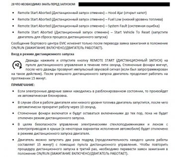

скачать инструкцию для Додж Рам можно кликнув ниже:
Dodge RAM +2009 инструкция пользователя авто.pdf
-
Страница 1
1500/2500/3500 Chrysler Group LLC OWNER’S MANUAL 2014 2014 RAM TRUCK 1500/2500/3500 14D241-126-AA First Edition Printed in U.S.A. RAM TRUCK[…]
-
Страница 2
VEHICLES SOLD IN CANADA With respect to any Vehicles Sold in Canada, the name Chrysler Group LLC shall be deemed to be deleted and the name Chrysler Canada Inc. used in substitution therefore. DRIVING AND ALCOHOL Drunken driving is one of the most frequent causes of accidents. Y our driving ability can be seriously impaired with blood alcohol level[…]
-
Страница 3
T ABLE OF CONTENTS SECTION P AGE 1 INTRODUCTION ……………………………………………………. 3 2 THINGS TO KNOW BEFORE ST AR TING YOUR VEHICLE ……………………….. 9 3 UNDERST ANDING THE FEA TURES OF YOUR VEHICLE ………………………. 1 2 9 4 UNDERST ANDING YOUR INSTRUMENT P ANEL ……………………………. 2[…]
-
Страница 4
[…]
-
Страница 5
INTRODUCTION CONTENTS 䡵 INTRODUCTION …………………… 4 䡵 HOW TO USE THIS MANUAL ………….. 4 䡵 W ARNINGS AND CAUTIONS ………….. 6 䡵 V AN CONVERSIONS/CAMPERS ………… 6 䡵 VEHICLE IDENTIFICA TION NUMBER …….. 6 䡵 VEHICLE MODIFICA TIONS/AL TERA TIONS …. 7 1[…]
-
Страница 6
INTRODUCTION Congratulations on selecting your new Chrysler Gr oup LLC vehicle. Be assured that it r epresents precision workmanship, distinctive styling, and high quality — all essentials that are traditional to our vehicles. This Owner’s Manual has been prepar ed with the assis- tance of service and engineering specialists to acquaint you with […]
-
Страница 7
1 INTRODUCTION 5[…]
-
Страница 8
W ARNINGS AND CAUTIONS This Owners Manual contains W ARNINGS against op- erating procedures that could result in a collision or bodily injury . It also contains CAUTIONS against proce- dures that could result in damage to your vehicle. If you do not r ead this entir e Owners Manual, you may miss important information. Observe all W arnings and Cau-[…]
-
Страница 9
frame and underbody as well as the Automobile Infor- mation Disclosure Label affixed to a window on your vehicle, the vehicle registration and title. NOTE: It is illegal to remove or alter the VIN. VEHICLE MODIFICA TIONS/AL TERA TIONS W ARNING! Any modifications or alterations to this vehicle could seriously affect its roadworthiness and safety and[…]
-
Страница 10
[…]
-
Страница 11
THINGS TO KNOW BEFORE ST ARTING YOUR VEHICLE CONTENTS 䡵 A WORD ABOUT YOUR KEYS …………. 1 2 ▫ Ignition Node Module (IGNM) — If Equipped . .12 ▫ Keyless Ignition Node (KIN) — If Equipped . . .13 ▫ K e y F o b ……………………….. 1 4 ▫ Removing Key Fob From Ignition ………. 1 6 ▫ Key-In-Ignition Reminder …………[…]
-
Страница 12
▫ Using The Panic Alarm ……………… 2 8 ▫ RKE Air Suspension (Remote Lowering Of The V ehicle) — If Equipped …………… 2 9 ▫ Programming Additional T ransmitters …….. 2 9 ▫ T ransmitter Battery Replacement ……….. 3 0 ▫ General Information ……………….. 3 3 䡵 REMOTE ST AR TING SYSTEM — IF EQUIPPED …….[…]
-
Страница 13
▫ Seat Belt Pretensioners ……………… 6 7 ▫ Enhanced Seat Belt Use Reminder System (BeltAlert®) …………………….. 6 7 ▫ Seat Belts And Pregnant W omen ……….. 6 8 ▫ Seat Belt Extender ………………… 6 9 ▫ Supplemental Restraint System (SRS) — Air Bags ………………………. 6 9 ▫ Air Bag System Compon[…]
-
Страница 14
A WORD ABOUT YOUR KEYS Y our vehicle uses either a key start ignition system or keyless ignition system. The key start ignition system consists of a either a bladed key with an immobilizer chip in it, or a Key Fob with Remote Keyless Entry (RKE) transmitter and an Ignition Node Module (IGNM). The keyless ignition system consists of a Key Fob with R[…]
-
Страница 15
Keyless Ignition Node (KIN) — If Equipped This feature allows the driver to operate the ignition switch with the push of a button, as long as the Remote Keyless Entry (RKE) transmitter is in the passenger compartment. The Keyless Ignition Node (KIN) has four operating positions, three of which are labeled and will illuminate when in position. The[…]
-
Страница 16
NOTE: For further information, refer to Starting Proce- dures in ”Starting And Operating”. Key Fob The Key Fob operates the ignition switch. Insert the square end of the key fob into the ignition switch located on the instrument panel and rotate to the desired posi- tion. It also contains the Remote Keyless Entry (RKE) transmitter and an emerge[…]
-
Страница 17
NOTE: Y ou can insert the double-sided emergency key into the lock cylinder with either side up. Emergency Key Removal (IGNM) Emergency Key Removal Keyless Enter-N-Go™ Fob (KIN) 2 THINGS TO KNOW BEFORE ST ARTING YOUR VEHICLE 15[…]
-
Страница 18
Removing Key Fob From Ignition Place the shift lever in P ARK (if equipped with an automatic transmission). T urn the Key Fob to the OFF position and then remove the Key Fob. NOTE: • For vehicles not equipped with the Electronic V ehicle Information Center (EVIC), the power window switches, radio, power sunroof (if equipped), and power outlets wi[…]
-
Страница 19
W ARNING! • Before exiting a vehicle, always apply the parking brake, shift the transmission into P ARK, and push ignition button to place ignition in OFF position. When leaving the vehicle, always lock your ve- hicle. • Never leave children alone in a vehicle, or with access to an unlocked vehicle. • Allowing children to be in a vehicle unat[…]
-
Страница 20
Key-In-Ignition Reminder Opening the driver’s door when the Key Fob is in the ignition and the ignition switch position is OFF or ACC, a chime will sound to remind you to remove the Key Fob. NOTE: • ⬙ Keyed ⬙ Ignition systems will chime in OFF or ACC when the driver door is open. • “Keyless ⬙ Ignition systems will chime in ACC or RUN […]
-
Страница 21
During normal operation, after turning on the ignition switch, the V ehicle Security Light will turn on for three seconds for a bulb check. If the light remains on after the bulb check, it indicates that there is a problem with the electronics. In addition, if the light begins to flash after the bulb check, it indicates that someone used an invalid[…]
-
Страница 22
CAUTION! • Always remove the Key Fobs from the vehicle and lock all doors when leaving the vehicle unat- tended. • For vehicles equipped with Keyless Enter-N-Go™, always remember to place the ignition in the OFF position. At the time of purchase, the original owner is provided with a four-digit Personal Identification Number (PIN). Keep the P[…]
-
Страница 23
VEHICLE SECURITY ALARM The V ehicle Security Alarm monitors the vehicle doors and ignition for unauthorized operation. When the V e- hicle Security Alarm is activated, interior switches for door locks ar e disabled. The system pr ovides both au- dible and visible signals, for the first three minutes the horn will sound and the headlights will turn […]
-
Страница 24
The V ehicle Security Alarm will also disarm if a pro- grammed Sentry Key® is inserted into the ignition switch. T o exit the alarming mode, press the RKE trans- mitter UNLOCK button, or insert a programmed Sentry Key® into the ignition switch. The V ehicle Security Alarm is designed to protect your vehicle; however , you can create conditions wh[…]
-
Страница 25
NOTE: • The front courtesy overhead console and door cour — tesy lights will not turn off if the dimmer control is in the “Dome ON” position (rotate horizontal thumb wheel on the bottom of the switch to the far right detent position). • The illuminated entry system will not operate if the dimmer control is in the “Dome OFF” position (ro[…]
-
Страница 26
Key Fob With Remote Keyless Entry (RKE) T ransmitter (IGNM) Key Fob With RKE T ransmitter Keyless Enter-N-Go™ Fob (KIN) 24 THINGS TO KNOW BEFORE ST ARTING YOUR VEHICLE[…]
-
Страница 27
Remote Unlock The Doors Press and release the UNLOCK button on the RKE trans- mitter once to unlock the driver ’s door (If EVIC is setup for driver door first, otherwise this will unlock all doors), or press the unlock button twice within five seconds to unlock all doors, the tailgate and the RamBox® (if equipped). The turn signal lights will fl[…]
-
Страница 28
NOTE: Pressing the LOCK button on the RKE transmit- ter while you are inside the vehicle will activate the V ehicle Security Alarm System. Opening a door with the V ehicle Security Alarm System activated will cause the alarm to sound. Press the UNLOCK button to deactivate the V ehicle Security Alarm System. Flash Lamps With Remote Key Lock This fea[…]
-
Страница 29
NOTE: Pressing the LOCK button on the RKE transmit- ter while you are in the vehicle will activate the V ehicle Security Alarm System. Opening a door with the V ehicle Security Alarm System activated will cause the alarm to sound. Press the UNLOCK button to deactivate the V ehicle Security Alarm System. T o Lock The Doors Press and release the LOCK[…]
-
Страница 30
2. Release both buttons at the same time. 3. T est the feature while outside of the vehicle by press- ing the LOCK button on the RKE transmitter with the ignition switch in the OFF position and the key removed. 4. Repeat these steps if you want to return this feature to its previous setting. NOTE: Pressing the LOCK button on the RKE transmit- ter w[…]
-
Страница 31
RKE Air Suspension (Remote Lowering Of The V ehicle) — If Equipped For easy entry and loading, your vehicle can be lowered by pressing the Key Fob air suspen- sion lowering button two times. When Remote key FOB lowering is requested, the vehicle will send a series of chirps and flashes to alert the customer that the operation has begun and will c[…]
-
Страница 32
T ransmitter Battery Replacement The recommended replacement battery is one CR2032 battery . NOTE: • Perchlorate Material — special handling may apply . See www .dtsc.ca.gov/hazardouswaste/per chlorate • Do not touch the battery terminals that are on the back housing or the printed circuit board. 1. Remove the emergency key by sliding the mec[…]
-
Страница 33
2. separating RKE halves requir es screw removal and gently prying the two halves of the RKE transmitter apart. Make sure not to damage the seal during removal. Keyless Ignition Node (KIN) Emergency Key Removal Remove Screw From T ransmitter Case 2 THINGS TO KNOW BEFORE ST ARTING YOUR VEHICLE 31[…]
-
Страница 34
Separating Ignition Node Module (IGNM) T ransmitter Case Separating Keyless Ignition Node (KIN) T ransmitter Case 32 THINGS TO KNOW BEFORE ST ARTING YOUR VEHICLE[…]
-
Страница 35
3. Remove the battery by turning the back cover over (battery facing downward) and tapping it lightly on a solid surface such as a table or similar , then replace the battery . When replacing the battery , match the + sign on the battery to the + sign on the inside of the battery clip, located on the back cover . A void touching the new battery wit[…]
-
Страница 36
2. Closeness to a radio transmitter such as a radio station tower , airport transmitter , and some mobile or CB radios. REMOTE ST ARTING SYSTEM — IF EQUIPPED This system uses the Remote Keyless Entry (RKE) transmitter to start the engine conve- niently from outside the vehicle while still maintaining security . The system has a range of approxima[…]
-
Страница 37
W ARNING! • Do not start or run an engine in a closed garage or confined area. Exhaust gas contains Carbon Mon- oxide (CO) which is odorless and colorless. Carbon Monoxide is poisonous and can cause serious in- jury or death when inhaled. • Keep Remote Keyless Entry (RKE) transmitters away from children. Operation of the Remote Start System, wi[…]
-
Страница 38
T o Enter Remote Start Mode Press and release the REMOTE ST AR T button on the RKE transmitter twice within five sec- onds. The parking lights will flash vehicle doors will lock, and the horn will chirp twice (if programmed). Once the vehicle has started, the engine will run for 15 minutes. NOTE: • If your power door locks were unlocked, Remote S[…]
-
Страница 39
T o Exit Remote Start Mode And Drive The V ehicle Before the end of the 15-minute cycle, press and release the UNLOCK button on the RKE transmitter to unlock the doors and disarm the V ehicle Security Alarm System (if equipped). Then, prior to the end of the 15 minute cycle, press and release the ST AR T/STOP button. NOTE: • The message “Push S[…]
-
Страница 40
DOOR LOCKS Manual Door Locks Front and rear doors may be locked by moving the lock knob down or unlocked by moving the lock knob up. Front doors may be opened with the inside door handle without lifting the lock knob. Doors locked before closing will remain locked when closed. The emergency key will unlock the driver door lock on your vehicle. W AR[…]
-
Страница 41
W ARNING! (Continued) • Before exiting a vehicle, always turn the vehicle OFF , apply the parking brake, shift the automatic transmission into P ARK or the manual transmis- sion into REVERSE, and remove the Key Fob from the ignition. When leaving the vehicle, always lock your vehicle. • Never leave children alone in a vehicle, or with access to[…]
-
Страница 42
If you press the power door LOCK switch while the Key Fob is in the ignition, and any front door is open, the power locks will not operate. This prevents you from accidentally locking your Key Fob in the vehicle. Remov- ing the Key Fob or closing the door will allow the locks to operate. A chime will sound if the Key Fob is in the ignition switch a[…]
-
Страница 43
Auto Unlock Doors Programming — If Equipped The Auto Unlock Doors feature can be enabled or dis- abled as follows: For vehicles equipped with the EVIC, refer to “Electronic V ehicle Information Center (EVIC)/Personal Settings (System Setup)” in “Understanding Y our Instrument Panel” for further information. NOTE: Use the Auto Unlock Doors[…]
-
Страница 44
W ARNING! A void trapping anyone in a vehicle in a collision. Remember that the rear doors can only be opened from the outside when the Child-Protection locks are engaged. NOTE: • After setting the Child-Protection Door Lock system, always test the door from the inside to make certain it is in the desired position. • For emergency exit with the[…]
-
Страница 45
NOTE: • Passive Entry may be programmed ON/OFF; refer to “Uconnect® settings” in “Understanding Y our Instru- ment Panel” for further information. • If wearing gloves on your hands, or if it has been raining on the Passive Entry door handle, the unlock sensitivity can be affected, r esulting in a slower re- sponse time. • If the vehi[…]
-
Страница 46
NOTE: If “Unlock All Doors 1st Press” is pr ogrammed all doors will unlock when you grab hold of the front driver ’s door handle. T o select between “Unlock Driver Door 1st Press” and “Unlock All Doors 1st Press”, refer to “Uconnect® Settings” in “Understanding Y our Instru- ment Panel” for further information. T o Unlock Fro[…]
-
Страница 47
T o Lock The V ehicle’ s Doors W ith one of the vehicle’s Passive Entry RKE transmitters within 5 ft (1.5 m) of the driver or passenger front door handles, press the door handle LOCK button to lock all doors. Press The Door Handle Button T o Lock Do NOT grab the door handle, when pressing the door handle lock button. This could unlock the door([…]
-
Страница 48
NOTE: • After pr essing the door handle LOCK button, you must wait two seconds before you can lock or unlock the doors, using either Passive Entry door handle. This is done to allow you to check if the vehicle is locked by pulling the door handle, without the vehicle reacting and unlocking. • The Passive Entry system will not operate if the RKE[…]
-
Страница 49
WINDOWS Power Windows – If Equipped The control on the left front door panel has UP-DOWN switches that give you fingertip contr ol of all power windows. Ther e is a single opening and closing switch on the front passenger door for passenger window control and on the r ear doors of the Quad Cab and Crew Cab models. The windows will operate when th[…]
-
Страница 50
W ARNING! • Never leave children alone in a vehicle, or with access to an unlocked vehicle. Allowing children to be in a vehicle unattended is dangerous for a number of reasons. A child or others could be seriously or fatally injured. Children should be warned not to touch the parking brake, brake pedal or the shift lever . • Do not leave the k[…]
-
Страница 51
Auto-Up Feature With Anti-Pinch Protection (4-Door Models Driver And Front Passenger Door Only) — If Equipped Lift the window switch fully upward to the second detent, release, and the window will go up automatically . T o stop the window fr om going all the way up during the Auto Up operation, push down on the switch briefly . T o close the wind[…]
-
Страница 52
Reset Auto-Up Should the Auto Up feature stop working, the window probably needs to be reset. T o reset Auto Up: 1. Make sure the door is fully closed. 2. Pull the window switch up to close the window completely and continue to hold the switch up for an additional two seconds after the window is closed. 3. Push the window switch down firmly to the […]
-
Страница 53
Wind Buffeting W ind buffeting can be described as the perception of pressur e on the ears or a helicopter-type sound in the ears. Y our vehicle may exhibit wind buf feting with the windows down, or the sunr oof (if equipped) in certain open or partially open positions. This is a normal occur- rence and can be minimized. If the buffeting occurs wit[…]
-
Страница 54
• Supplemental Seat-Mounted Side Air Bags (SAB) • An energy-absorbing steering column and steering wheel • Knee bolsters/blockers for front seat occupants • All seat belt systems (except driver ’s, front center and second row center position) include Automatic Lock- ing Retractors (ALRs), which lock the seat belt web- bing into position b[…]
-
Страница 55
Here are some simple steps you can take to minimize the risk of harm from a deploying air bag: 1. Children 12 years old and under should always ride buckled up in a rear seat. W ARNING! • Never place a rear facing infant seat in front of an air bag. A deploying passenger Advanced Front Air Bag can cause death or serious injury to a child 12 years[…]
-
Страница 56
4. Do not lean against the door or window . If your vehicle has side air bags, and deployment occurs, the side air bags will inflate forcefully into the space between you and the door . 5. If the air bag system in this vehicle needs to be modified to accommodate a disabled person, contact the Customer Center . Phone numbers are provided under ⴖ I[…]
-
Страница 57
W ARNING! (Continued) • In a collision, you and your passengers can suffer much greater injuries if you are not properly buck- led up. Y ou can strike the interior of your vehicle or other passengers, or you can be thrown out of the vehicle. Always be sure you and others in your vehicle are buckled up properly . • Being too close to the Supplem[…]
-
Страница 58
W ARNING! • It is dangerous to ride in a cargo area, inside or outside of a vehicle. In a collision, people riding in these areas are more likely to be seriously injured or killed. • Do not allow people to ride in any area of your vehicle that is not equipped with seats and seat belts. • Be sure everyone in your vehicle is in a seat using a s[…]
-
Страница 59
Lap/Shoulder Belt Operating Instructions 1. Enter the vehicle and close the door . Sit back and adjust the seat. 2. The seat belt latch plate is above the back of the front seat, next to your arm in the rear seat. Grasp the latch plate and pull out the belt. Slide the latch plate up the webbing as far as necessary to allow the belt to go around you[…]
-
Страница 60
W ARNING! • A belt buckled into the wrong buckle will not protect you properly . The lap portion could ride too high on your body , possibly causing internal inju- ries. Always buckle your belt into the buckle nearest you. • A belt that is too loose will not protect you prop- erly . In a sudden stop you could move too far forward, increasing th[…]
-
Страница 61
W ARNING! (Continued) • A belt that is worn under your arm is dangerous. Y our body could strike the inside surfaces of the vehicle in a collision, increasing head and neck injury . A belt worn under the arm can cause inter- nal injuries. Ribs aren’t as strong as shoulder bones. W ear the belt over your shoulder so that your strongest bones wil[…]
-
Страница 62
W ARNING! • A lap belt worn too high can increase the risk of internal injury in a collision. The belt forces won’t be at the strong hip and pelvic bones, but across your abdomen. Always wear the lap belt as low as possible and keep it snug. • A twisted belt may not protect you properly . In a collision, it could even cut into you. Be sure th[…]
-
Страница 63
Regular Cab Front Center Three Point Belt 1. The front center seat belt on the Regular Cab may be disconnected to open up utilization of the storage areas behind the front seats. The black latch plate can be detached from the black keyed seat belt buckle located on the inboard side of the passenger seat. Insert the seat belt tongue into the center […]
-
Страница 64
Inserting Latch Plate In Use Position 62 THINGS TO KNOW BEFORE ST ARTING YOUR VEHICLE[…]
-
Страница 65
W ARNING! • If the black latch and black buckle are not properly connected when the seat belt is used by an occu- pant, the seat belt will not be able to provide proper restraint and will increase the risk of injury in a collision. • When reattaching the black latch and black buckle, ensure the seat belt webbing is not twisted. If the webbing i[…]
-
Страница 66
As a guide, if you are shorter than average you will prefer a lower position, and if you are taller than average you will prefer a higher position. When you release the anchorage, try to move it up or down to make sure that it is locked in position. Center Lap Belts The center seating position for the Quad Cab®, Mega Cab® and Cr ew Cab fr ont sea[…]
-
Страница 67
Seat Belts In Passenger Seating Positions The seat belts in the passenger seating positions ar e equipped with either a switchable Automatic Locking Retractors (ALR) or with a Cinching Latchplate which is used to secure a child restraint system. For additional information, refer to “Installing Child Restraints Using The V ehicle Seat Belt” unde[…]
-
Страница 68
Automatic Locking Retractor (ALR) Mode – If Equipped In this mode, the shoulder belt is automatically pre- locked. The belt will still retract to remove any slack in the shoulder belt. When T o Use The Automatic Locking Mode Use the Automatic Locking Mode anytime a child safety seat is installed in a seating position that has a belt with this fea[…]
-
Страница 69
Energy Management Feature This vehicle has a safety belt system with an Ener gy Management featur e in the fr ont seating positions to help further reduce the risk of injury in the event of a head-on collision. This safety belt system has a retractor assembly that is designed to release webbing in a controlled manner . This feature is designed to h[…]
-
Страница 70
Reminder Light and sounding an intermittent chime. Once the sequence starts, it will continue for the entire duration or until the respective seatbelts are fastened. After the sequence completes, the Seat Belt Reminder Light remains illuminated until the respective seat belts are fastened. The driver should instruct all other occu- pants to fasten […]
-
Страница 71
Seat Belt Extender If a seat belt is too short even when fully extended and when the adjustable upper shoulder belt anchorage (if equipped) is in its lowest position, your authorized dealer can provide you with a seat belt extender . This extender should be used only if the existing belt is not long enough. When it is not required, remove the ex- t[…]
-
Страница 72
eb NOTE: The Driver and Front Passenger Advanced Front Air Bags are certified to the new Federal regulations for Advanced Air Bags. The Advanced Front Air Bags have a multistage inflator design. This allows the air bag to have differ ent rates of inflation based on several factors, including the severity and type of collision. This vehicle may be e[…]
-
Страница 73
This vehicle is equipped with Supplemental Seat- Mounted Side Air Bags (SAB) to provide enhanced protection for an occupant during a side impact. The Supplemental Seat-Mounted Side Air Bags they are lo- cated in the outboard side of the front seats. NOTE: • Air Bag covers may not be obvious in the interior trim, but they will open during air bag […]
-
Страница 74
Advanced Front Air Bag Features The Advanced Front Air Bag system has multistage driver and front passenger air bags. This system provides output appr opriate to the severity and type of collision as determined by the Occupant Restraint Controller (ORC), which may receive information fr om the front impact sensors (if equipped). The first stage inf[…]
-
Страница 75
Supplemental Seat-Mounted Side Air Bags (SAB) Supplemental Seat-Mounted Side Air Bags may provide enhanced pr otection to help pr otect an occupant during a side impact. The Supplemental Seat-Mounted Side Air Bag is marked with an air bag label sewn into the outboard side of the front seats. When the air bag deploys, it opens the seam between the f[…]
-
Страница 76
NOTE: • Air Bag covers may not be obvious in the interior trim, but they will open during air bag deployment. • Being too close to the SAB and SABIC air bags during deployment could cause you to be severely injured or killed. • Should a vehicle rollover occur , the pretensioners (if equipped) and/or SAB and SABIC air bags on both sides of the[…]
-
Страница 77
W ARNING! • If your vehicle is equipped with left and right Supplemental Side Air Bag Inflatable Curtain (SABIC), do not stack luggage or other cargo up high enough to block the location of the SABIC. The area where the SABIC is located should remain free from any obstructions. • Do not use accessory seat covers or place objects between you and[…]
-
Страница 78
Along with seat belts and pretensioners, Advanced Front Air Bags work with the knee impact bolsters to provide improved protection for the driver and front passenger . Air Bag Deployment Sensors And Controls Occupant Restraint Controller (ORC) The ORC is part of a Federally regulated safety system requir ed for this vehicle. The ORC determines if d[…]
-
Страница 79
Seat belts ar e necessary for your protection in all colli- sions, and also are needed to help keep you in position, away from an inflating air bag. The ORC monitors the r eadiness of the electronic parts of the air bag system whenever the ignition switch is in the ST AR T or ON/RUN position. If the key is in the LOCK position, in the ACC position,[…]
-
Страница 80
Driver And Passenger Advanced Front Air Bag Inflator Units The Driver and Passenger Advanced Front Air Bag Inflator Units ar e located in the center of the steering wheel and on the right side of the instrument panel. When the ORC detects a collision requiring the Ad- vanced Front Air Bags, it signals the inflator units. A large quantity of non-tox[…]
-
Страница 81
you if you ar e not seated properly , or if items are positioned in the area where the side air bag inflates. This especially applies to children. Supplemental Side Air Bag Inflatable Curtain (SABIC) Inflator Units — If Equipped During collisions where the impact is confined to a particular area of the side of the vehicle, the ORC may deploy the […]
-
Страница 82
Enhanced Accident Response System In the event of an impact causing air bag deployment, if the communication network remains intact, and the power remains intact, depending on the nature of the event the ORC will determine whether to have the Enhanced Accident Response System perform the follow- ing functions: • Cut off fuel to the engine. • Fl[…]
-
Страница 83
3. Once a connection between the vehicle and a 9-1-1 operator is made, the 9-1-1 Call system may transmit the following important vehicle information to a 9-1-1 operator: • indication that the occupant placed a 9-1-1 Call; • the vehicle brand; and • the last known GPS coordinates of the vehicle. 4. Y ou should be able to speak with the 9-1-1 […]
-
Страница 84
W ARNING! • If anyone in the vehicle could be in danger (e.g., fire or smoke is visible, dangerous road conditions or location), do not wait for voice contact from a 9-1-1 operator . All occupants should exit the vehicle immediately and move to a safe location. • The 9-1-1 Call system is embedded into the vehi- cle’ s electrical system. Do no[…]
-
Страница 85
• The Phone Screen will display the following message “V ehicle phone requir es service. Please contact your dealer .”; and, • An In-V ehicle Audio message will state “V ehicle phone requir es service. Please contact your dealer .” W ARNING! • Ignoring the Rearview Mirror light could mean you will not have 9-1-1 Call services. If the […]
-
Страница 86
• Equipment malfunction at the 9-1-1 operator facility; • Operator error by the 9-1-1 operator; • W ireless network congestion; • W eather; and • Buildings, structures, geographic terrain, or tunnels. NOTE: Never place anything on or near the vehicle’s wireless and GPS antennas. Y ou could prevent wireless and GPS signal reception, whic[…]
-
Страница 87
If you do have a collision which deploys the air bags, any or all of the following may occur: • The nylon air bag material may sometimes cause abrasions and/or skin reddening to the driver and front passenger as the air bags deploy and unfold. The abrasions are similar to friction rope burns or those you might get sliding along a carpet or gymnas[…]
-
Страница 88
Maintaining Y our Air Bag System W ARNING! • Modifications to any part of the air bag system could cause it to fail when you need it. Y ou could be injured if the air bag system is not there to protect you. Do not modify the components or wiring, including adding any kind of badges or stickers to the steering wheel hub trim cover or the upper rig[…]
-
Страница 89
Air Bag W arning Light Y ou will want to have the air bags ready to inflate for your protection in a collision. The Air Bag W arning Light monitors the internal circuits and interconnecting wiring associated with air bag system electrical components. While the air bag system is designed to be maintenance free, if any of the following occurs, have a[…]
-
Страница 90
Event Data Recorder (EDR) This vehicle is equipped with an event data recor der (EDR). The main purpose of an EDR is to record, in certain crash or near crash-like situations, such as an air bag deployment or hitting a road obstacle, data that will assist in understanding how a vehicle’s systems per- formed. The EDR is designed to r ecord data re[…]
-
Страница 91
Child Restraints Everyone in your vehicle needs to be buckled up at all times, including babies and children. Every state in the United States, and every Canadian province, requires that small children ride in proper restraint systems. This is the law , and you can be prosecuted for ignoring it. Children 12 years or younger should ride properly buc[…]
-
Страница 92
Summary Of Recommendations For Restraining Children In V ehicles Child Size, Height, W eight or Age Recommended T ype of Child Restraint Infants and T od- dlers Children who are two years old or younger and who have not reached the height or weight limits of their child re- straint Either an Infant Carrier or a Convertible Child Restraint, facing r[…]
-
Страница 93
Infants And Child Restraints Safety experts recommend that children ride rearward- facing in the vehicle until they are two years old or until they reach either the height or weight limit of their rear facing child safety seat. T wo types of child restraints can be used rearward-facing: infant carriers and convertible child seats. The infant carrie[…]
-
Страница 94
Older Children And Child Restraints Children who are two years old or who have outgrown their rear-facing convertible child seat can ride forward- facing in the vehicle. Forward-facing child seats and convertible child seats used in the forward-facing direc- tion are for children who are over two years old or who have outgrown the rear -facing weig[…]
-
Страница 95
Children T oo Large For Booster Seats Children who are large enough to wear the shoulder belt comfortably , and whose legs ar e long enough to bend over the front of the seat when their back is against the seatback, should use the seat belt in a rear seat. Use this simple 5-step test to decide whether the child can use the vehicle’s seat belt alo[…]
-
Страница 96
Recommendations For Attaching Child Restraints — Quad Cab®/Crew Cab Restraint T ype Combined W eight of the Child + Child Restraint Use any attachment method shown with an “X” Below LA TCH – Lower Anchors Only Seat Belt Only LA TCH – Lower Anchors + T op T ether Anchor Seat Belt + T op T ether Anchor Rear-Facing Child Restraint Up to 65 […]
-
Страница 97
Recommendations For Attaching Child Restraints — Standard Cab, Mega Cab® Restraint T ype Combined W eight of the Child + Child Restraint Use any attachment method shown with an “X” Below LA TCH – Lower Anchors Only Seat Belt Only LA TCH – Lower Anchors + T op T ether Anchor Seat Belt + T op T ether Anchor Rear-Facing Child Restraint Up t[…]
-
Страница 98
Lower Anchors and T ethers for Children (LA TCH) Restraint System Y our vehicle is equipped with the child restraint anchor- age system called LA TCH, which stands for Lower Anchors and T ethers for CHildren. The LA TCH system has three vehicle anchor points for installing LA TCH- equipped child seats. There are two lower anchorages located at the […]
-
Страница 99
seating position. These anchorages are used to install LA TCH-equipped child seats without using the vehicle’s seat belts. Some seating positions may have a top tether anchorage but no lower anchorages. In these seating positions, the seat belt must be used with the top tether anchorage to install the child restraint. Please see the following tab[…]
-
Страница 100
Quad Cab®/Crew Cab Full Bench Lower Anchorage Symbol 2 anchorages per seating position T op T ether Anchorage Symbol Quad Cab®/Mega Cab®/Crew Cab Split Bench Lower Anchorage Symbol 2 anchorages per seating position T op T ether Anchorage Symbol 98 THINGS TO KNOW BEFORE ST ARTING YOUR VEHICLE[…]
-
Страница 101
Quad Cab®/Crew Cab What is the weight limit (child’s weight + weight of the child re- straint) for using the LA TCH an- chorage system to attach the child restraint? 65 lbs (29.5 kg) Use the LA TCH anchorage system until the combined weight of the child and the child restraint is 65 lbs (29.5 kg). Use the seat belt and tether anchor instead of t[…]
-
Страница 102
Can two child restraints be at- tached using a common lower LA TCH anchorage? No Never “share” a LA TCH anchorage with two or more child restraints. If the center position does not have dedicated LA TCH lower anchor- ages, use the seat belt to install a child seat in the center position next to a child seat using the LA TCH anchorages in an out[…]
-
Страница 103
Mega Cab®/Standard Cab What is the weight limit (child’s weight + weight of the child re- straint) for using the LA TCH an- chorage system to attach the child restraint? 65 lbs (29.5 kg) Use the LA TCH anchorage system until the combined weight of the child and the child restraint is 65 lbs (29.5 kg). Use the seat belt alone instead of the LA TC[…]
-
Страница 104
Can two child restraints be at- tached using a common lower LA TCH anchorage? No Never “share” a LA TCH anchorage with two or more child restraints. If the center position does not have dedicated LA TCH lower anchor- ages, use the seat belt to install a child seat in the center position next to a child seat using the LA TCH anchorages in an out[…]
-
Страница 105
Locating The LA TCH Anchorages — Quad Cab®/Mega Cab®/Crew Cab The lower anchorages are round bars that are found at the rear of the seat cushion where it meets the seatback. They are just visible when you lean into the rear seat to install the child restraint. Y ou will easily feel them if you run your finger along the gap between the seatback […]
-
Страница 106
Locating The LA TCH Anchorages In addition, Regular Cab models have tether strap anchorages behind the fr ont center and right seats. Quad Cab®, Mega Cab® and Crew Cab models have tether strap anchorages lo- cated behind each of the rear seats. 1 — T ether Strap Hook 2 — T ether Strap to Child Restraint 3 — T ether Anchor Regular Cab T ethe[…]
-
Страница 107
LA TCH-compatible child restraint systems will be equipped with a rigid bar or a flexible strap on each side. Each will have a hook or connector to attach to the lower anchorage and a way to tighten the connection to the anchorage. Forwar d-facing child restraints and some rear -facing infant restraints will also be equipped with a tether strap. Th[…]
-
Страница 108
Center Seat LA TCH — Quad Cab®/Mega Cab®/Crew Cab Split Bench If a child restraint installed in the center position blocks the seat belt webbing or buckle for the outboard position, do not use that outboard position. If a child seat in the center position blocks the outboard LA TCH anchors or seat belt, do not install a child seat in that outbo[…]
-
Страница 109
4. Attach the lower hooks or connectors of the child restraint to the lower anchorages in the selected seat- ing position. 5. If the child restraint has a tether strap, connect it to the top tether anchorage. See the section “Installing Child Restraints Using the T op T ether Anchorage” for direc- tions to attach a tether anchor . 6. T ighten a[…]
-
Страница 110
W ARNING! Improper installation of a child restraint to the LA TCH anchorages can lead to failure of the re- straint. The child could be badly injured or killed. Follow the child restraint manufacturer ’ s directions exactly when installing an infant or child restraint. Installing Child Restraints Using The V ehicle Seat Belt The seat belts in th[…]
-
Страница 111
Lap/Shoulder Belt Systems for Installing Child Restraints in this V ehicle Standard Cab Quad Cab®/Mega Cab®/Crew Cab 2 THINGS TO KNOW BEFORE ST ARTING YOUR VEHICLE 109[…]
-
Страница 112
Quad Cab®/Crew Cab What is the weight limit (child’s weight + weight of the child re- straint) for using the T ether Anchor with the seat belt to attach a forward facing child restraint? W eight limit of the Child Restraint Always use the tether anchor when using the seat belt to install a for- ward facing child restraint, up to the recommended […]
-
Страница 113
Mega Cab®/Standard Cab What is the weight limit (child’s weight + weight of the child re- straint) for using the T ether Anchor with the seat belt to attach a forward facing child restraint? 65 lbs (29.5 kg) The T ether Anchor can be used with the seat belt until the combined weight of the child and the child restraint is 65 lbs (29.5 kg). Use t[…]
-
Страница 114
Installing A Child Restraint with a Switchable Automatic Locking Retractor (ALR) 1. Place the child seat in the center of the seating position. For some second row seats, you may need to recline the seat and/or raise the head restraint to get a better fit. 2. Pull enough of the seat belt webbing fr om the retractor to pass it through the belt path […]
-
Страница 115
8. If the child r estraint has a top tether strap and the seating position has a top tether anchorage, connect the tether strap to the anchorage and tighten the tether strap. Refer to “Lower Anchors and T ethers for Chil- dren (LA TCH) Restraint System” for directions to attach a tether anchor . 9. T est that the child restraint is installed ti[…]
-
Страница 116
5. If the child r estraint has a top tether strap and the seating position has a top tether anchorage, connect the tether strap to the anchorage and tighten the tether strap. Refer to “Lower Anchors and T ethers for Chil- dren (LA TCH) Restraint System” for directions to attach a tether anchor . 6. T est that the child restraint is installed ti[…]
-
Страница 117
Installing Child Restraints Using The T op T ether Anchorage Regular and Mega Cab® T rucks: In the regular cab truck, the top tether anchorages are located behind the center and right passenger seats. In the mega cab truck, the top tether anchorages are located behind each rear seating position. There is a plastic cover over each an- chorage. T o […]
-
Страница 118
2. Route the tether strap to provide the most direct path between the anchorage and the child seat. The tether strap should go between the head r estraint posts underneath the head restraint. Y ou may need to adjust the head restraint to the upward position to pass the tether strap underneath the head restraint and be- tween its posts. 3. Lift the […]
-
Страница 119
W ARNING! Never place a rear facing infant seat in front of an air bag. A deploying passenger Advanced Front Air Bag can cause death or serious injury to a child 12 years or younger , including a child in a rearward facing infant seat. Quad Cab® or Crew Cab T rucks: The top tether an- chorages in this vehicle are tether strap loops located between[…]
-
Страница 120
2. Place a child restraint on the seat and adjust the tether strap so that it will reach over the seat back, under the head r estraint, thr ough the tether strap loop behind the seat and over to the tether strap loop behind the center seat. 3. Pass the tether strap hook under the head restraint behind the child seat, though the tether strap loop be[…]
-
Страница 121
4. Attach the hook to the center tether strap loop (see diagram). T ighten the tether strap according to the child seat manufacturer ’s instructions. NOTE: If there are child seats in both of the outboard (left and right) seating positions, the tether strap hooks of both child seats should be connected to the center tether strap loop. This is the[…]
-
Страница 122
2. Place a child restraint on the seat and adjust the tether strap so that it will reach over the seat back, under the head r estraint, thr ough the tether strap loop behind the seat and over to the tether strap loop behind either the right or left outboard seat. 3. Pass the tether strap hook under the head restraint behind the child seat, though t[…]
-
Страница 123
4. Attach the hook to the outboard tether strap loop (see diagram). T ighten the tether strap according to the child seat manufacturer ’s instructions. Installing Three Child Restraints: 1. Place a child r estraint on each outboard rear seat. Route the tether straps following the directions for right and left seating positions, above. 2. Attach b[…]
-
Страница 124
W ARNING! • An incorrectly anchored tether strap could lead to increased head motion and possible injury to the child. Use only the anchorage position directly behind the child seat to secure a child restraint top tether strap. • If your vehicle is equipped with a split rear seat, make sure the tether strap does not slip into the opening betwee[…]
-
Страница 125
T ransporting Pets Air Bags deploying in the front seat could harm your pet. An unrestrained pet will be thrown about and possibly injured, or injure a passenger during panic braking or in a collision. Pets should be restrained in the rear seat in pet harnesses or pet carriers that are secured by seat belts. ENGINE BREAK-IN RECOMMENDA TIONS A long […]
-
Страница 126
NOTE: A new engine may consume some oil during its first few thousand miles (kilometers) of operation. This should be considered a normal part of the break-in and not interpreted as an indication of difficulty . SAFETY TIPS T ransporting Passengers NEVER TRANSPORT P ASSENGERS IN THE CARGO AREA. W ARNING! • Do not leave children or animals inside […]
-
Страница 127
Exhaust Gas W ARNING! Exhaust gases can injure or kill. They contain carbon monoxide (CO), which is colorless and odorless. Breathing it can make you unconscious and can eventually poison you. T o avoid breathing (CO), follow these safety tips: • Do not run the engine in a closed garage or in confined areas any longer than needed to move your veh[…]
-
Страница 128
Safety Checks Y ou Should Make Inside The V ehicle Seat Belts Inspect the belt system periodically , checking for cuts, frays, and loose parts. Damaged parts must be replaced immediately . Do not disassemble or modify the system. Front seat belt assemblies must be r eplaced after a collision. Rear seat belt assemblies must be replaced after a colli[…]
-
Страница 129
Floor Mat Safety Information Always use floor mats designed to fit the footwell of your vehicle. Use only floor mats that leave the pedal area unobstructed and that are firmly secured so that they cannot slip out of position and interfere with the pedals or impair safe operation of your vehicle in other ways. W ARNING! Pedals that cannot move freel[…]
-
Страница 130
W ARNING! (Continued) • Always make sure that objects cannot fall into the driver footwell while the vehicle is moving. Ob- jects can become trapped under the brake pedal and accelerator pedal causing a loss of vehicle control. • If required, mounting posts must be properly in- stalled, if not equipped from the factory . Failure to properly fol[…]
-
Страница 131
UNDERST ANDING THE FEA TURES OF YOUR VEHICLE CONTENTS 䡵 MIRRORS ……………………… .136 ▫ Inside Day/Night Mirror …………… .136 ▫ Automatic Dimming Mirror — If Equipped . . .137 ▫ Automatic Dimming Mirror W ith Rear V iew Camera Display — If Equipped ………. .139 ▫ Outside Mirrors ………………… .139 ▫ Outs[…]
-
Страница 132
▫ Power Lumbar — If Equipped ……….. .150 ▫ Heated Seats — If Equipped …………. .151 ▫ V entilated Seats — If Equipped ……….. .153 ▫ Manual Seat Adjuster — If Equipped ……. .154 ▫ 40-20-40 Front Bench Seat — If Equipped . . . .156 ▫ Mega Cab® Rear Seat Features ……….. .156 ▫ Head Restraints ………..[…]
-
Страница 133
▫ Lights-On Reminder ……………… .174 ▫ Battery Saver …………………… .174 ▫ Interior Lights …………………. .174 ▫ Cargo Light …………………… .177 ▫ Multifunction Lever ……………… .178 ▫ T urn Signals …………………… .178 ▫ Lane Change Assist ……………… .179 ▫ Flash-T o-Pass[…]
-
Страница 134
▫ T o V ary The Speed Setting ………….. .189 ▫ T o Accelerate For Passing …………… .190 䡵 P ARKSENSE® REAR P ARK ASSIST — IF EQUIPPED …………………… .191 ▫ ParkSense® Sensors ………………. .191 ▫ ParkSense® W arning Display ………… .192 ▫ ParkSense® Display ………………. .192 ▫ Enabling And[…]
-
Страница 135
▫ T urning ParkV iew® On Or Off — W ith Uconnect® 8.4A/8.4AN ……………. .210 ▫ T urning ParkV iew® Camera Delay On Or Off — W ith Uconnect® 8.4A/8.4AN …….. 2 1 1 䡵 OVERHEAD CONSOLE — IF EQUIPPED ….. 2 1 1 ▫ Courtesy/Reading Lights ………….. .212 䡵 GARAGE DOOR OPENER — IF EQUIPPED . . . .213 ▫ Before Y ou Beg[…]
-
Страница 136
䡵 ELECTRICAL POWER OUTLETS ………. .226 䡵 CIGAR LIGHTER AND ASH RECEIVER — IF EQUIPPED …………………… .230 䡵 POWER INVERTER — IF EQUIPPED ……. .231 䡵 CUPHOLDERS ………………….. .232 ▫ Front Seat Cupholders — (40–20–40 Seats) . . . .232 ▫ Front Instrument Panel Cupholders — Floor Mounted Shifter ……[…]
-
Страница 137
䡵 FOLD FLA T LOAD FLOOR — IF EQUIPPED …………………… .244 䡵 PICKUP BOX …………………… .246 䡵 RAMBOX® — IF EQUIPPED …………. .248 ▫ RamBox® Integrated Box Side Storage Bins . . .248 ▫ Locking And Unlocking RamBox® …….. .251 ▫ RamBox® Safety W arning …………… .252 ▫ Bed Extender — If Equippe[…]
-
Страница 138
MIRRORS Inside Day/Night Mirror A single ball joint mirror is provided in the vehicle. It is a twist on mirror that has a fixed position at the wind- shield. The mirror installs on the windshield button with a counterclockwise rotation and requir es no tools for mounting. The mirr or head can be adjusted up, down, left, and right for various driver[…]
-
Страница 139
Automatic Dimming Mirror — If Equipped A single ball joint mirror is provided in the vehicle. It is a twist on mirror that has a fixed position at the wind- shield. The mirror installs on the windshield button with a counterclockwise rotation and requir es no tools for mounting. The mirr or head can be adjusted up, down, left, and right for vario[…]
-
Страница 140
Assist Call The rear view mirror contains an ASSIST push button which automatically connects the vehicle occupants to one of several predefined locations for immediate support: • Roadside Assistance – If you get a flat tire, or need a tow , just press the Assist button and you’ll be con- nected to someone who can help. Roadside Assistance wil[…]
-
Страница 141
Automatic Dimming Mirror With Rear View Camera Display — If Equipped A single ball joint mirror is provided in the vehicle. It is a twist on mirror that has a fixed position at the wind- shield. The mirror installs on the windshield button with a counterclockwise rotation and requir es no tools for mounting. The mirr or head can be adjusted up, d[…]
-
Страница 142
W ARNING! V ehicles and other objects seen in the passenger side convex mirror will look smaller and farther away than they really are. Relying too much on your passenger side convex mirror could cause you to collide with another vehicle or other object. Use your inside mirror when judging the size or distance of a vehicle seen in the passenger sid[…]
-
Страница 143
Power Folding Outside Mirrors — If Equipped If equipped with power folding mirrors, they can be electrically folded rearward and unfolded into the drive position. The switch for the power folding mirrors is located between the power mirror switches L (left) and R (right). Press the switch once and the mirrors will fold in, press the switch a seco[…]
-
Страница 144
Resetting the Power Folding Outside Mirrors Y ou may need to reset the power folding mirrors if the following occurs: • The mirrors are accidentally blocked while folding. • The mirrors are accidentally manually folded/ unfolded. • The mirrors come out of the unfolded position. • The mirrors shake and vibrate at normal driving speeds. T o r[…]
-
Страница 145
T o adjust a mirr or , press either the L (left) or R (right) button to select the mirror that you want to adjust. Using the mirror control switch, press on any of the four arrows for the direction that you want the mirror to move Power Mirror Controls 1 — Mirror Select Buttons 2 — Four-W ay Mirror Control Switch Power Mirror Movement 3 UNDERST[…]
-
Страница 146
Heated Mirrors — If Equipped These mirrors are heated to melt frost or ice. This feature can be activated whenever you turn on the rear window defroster (if equipped). Some vehicles may not be equipped with rear window defroster , in this case the heated mirr ors will still function as intended. Refer to “Rear W indow Featur es” in “Underst[…]
-
Страница 147
“Slide-On-Rod” Features Of Sun Visor — If Equipped The sun visor “Slide-On-Rod” feature allows for addi- tional flexibility in positioning the visor to block out the sun. T o use the “Slide-On-Rod” feature, rotate the sun visor downward and unclip it. Pull the sun visor along the “Slide-On-Rod” until the sun visor is in the desire[…]
-
Страница 148
T railer T owing Mirrors — If Equipped These mirrors are designed with an adjustable mirr or head to provide a greater vision range when towing extra-wide loads. T o change position inboar d or out- board, the mirror head should be rotated (flipped in or out). NOTE: Fold the trailer towing mirrors rearward prior to entering an automated car wash.[…]
-
Страница 149
SEA TS Seats are a part of the Occupant Restraint System of the vehicle. W ARNING! • It is dangerous to ride in a cargo area, inside or outside of a vehicle. In a collision, people riding in these areas are more likely to be seriously injured or killed. • Do not allow people to ride in any area of your vehicle that is not equipped with seats an[…]
-
Страница 150
Adjusting The Seat Forward Or Rearward The seat can be adjusted both forward and rearwar d. Push the seat switch forward or rearwar d, the seat will move in the direction of the switch. Release the switch when the desired position has been reached. Adjusting The Seat Up Or Down The height of the seats can be adjusted up or down. Pull upward or push[…]
-
Страница 151
Reclining The Seatback The angle of the seatback can be adjusted forward or rearwar d. Push the seatback switch forward or rearwar d, the seat will move in the direction of the switch. Release the switch when the desired position is reached. W ARNING! • Adjusting a seat while driving may be dangerous. Moving a seat while driving could result in l[…]
-
Страница 152
Passenger ’ s Power Seat — If Equipped Some models are equipped with a six-way power pas- senger seat. The power seat switch is located on the outboard side of the seat. The switch is used to control the movement of the seat and seat cushion. Adjusting The Seat Forward Or Rearward The seat can be adjusted both forward and rearwar d. Push the se[…]
-
Страница 153
Heated Seats — If Equipped On some models, the front and rear seats may be equipped with heaters located in the seat cushions. W ARNING! • Persons who are unable to feel pain to the skin because of advanced age, chronic illness, diabetes, spinal cord injury , medication, alcohol use, exhaus- tion or other physical condition must exercise care w[…]
-
Страница 154
NOTE: • Once a heat setting is selected, heat will be felt within two to five minutes. • The engine must be running for the heated seats to operate. The heated seats switch from HIGH to LOW and fr om LOW to OFF automatically , based on time and tempera- ture of the seat. The heated seats can operate on HIGH heat for a maximum of 60 minutes befo[…]
-
Страница 155
There are two heated seat switches that allow the r ear passengers to operate the seats independently . Y ou can choose from HIGH, LOW or OFF heat settings. Amber indicator lights in each switch indicate the level of heat in use. T wo indicator lights will illuminate for HIGH, one for LOW and none for OFF . Press the switch once to select HIGH-leve[…]
-
Страница 156
below the climate controls as well as soft-keys located in the radio screen. The fans operate at two speeds, HIGH and LOW . Press the switch once to choose HIGH, press it a second time to choose LOW . Pressing the switch a third time will turn the ventilated seat OFF . When HIGH speed is selected both lights on the switch will be illuminated. When […]
-
Страница 157
While sitting in the seat, pull up on the handle and slide the seat forward or backward. Release the bar once you have reached the desired position. Then, using body pressur e, move forward and rearwar d on the seat to be sure that the seat adjusters have latched. W ARNING! • Adjusting a seat while driving may be dangerous. Moving a seat while dr[…]
-
Страница 158
Dump Feature — Manual Recline Seat Only — Standard Cab Actuating the recliner handle will allow the seatback to swing (dump) forward on manual recliner seats. This “dump” feature allows access to the storage bin behind the seat. W ARNING! • Do not stand or lean in front of the seat while actuating the handle. The seatback may swing forwar[…]
-
Страница 159
W ARNING! Do not ride with the seatback reclined so that the shoulder belt is no longer resting against your chest. In a collision you could slide under the seat belt, which could result in serious injury or death. Folding Rear Seat (T able Mode) — If Equipped Both the left and right rear seatbacks can be folded down and used as a table. T o fold[…]
-
Страница 160
2. Fold the seatback forward. 3. Lift the seatback, to return the seat to the upright position. Be sure the seatback is locked in place. Folding Rear Seat — If Equipped Both the outboard r ear seats will drop and move forward when the seatback is folded flat. W ARNING! • It is dangerous to ride in a cargo area, inside or outside of a vehicle. I[…]
-
Страница 161
W ARNING! (Continued) • Cargo must be securely tied down before driving your vehicle. Improperly secured cargo can fly around in a sudden stop or collision and strike someone in the vehicle, causing serious injury or death. T o fold either rear seat flat: 1. Lift the handle, located on the outboard side of either of the rear seats. 2. Fold the se[…]
-
Страница 162
3. Lift the seatback, to return the seat to the upright position. Be sure the seat is locked in place. W ARNING! An improperly latched seat could cause serious in- jury or death. Make sure that the seatback is securely locked into position. If the seatback in not securely locked into position the seat will not provide the proper stability for child[…]
-
Страница 163
W ARNING! The head restraints for all occupants must be prop- erly adjusted prior to operating the vehicle or occu- pying a seat. Head restraints should never be ad- justed while the vehicle is in motion. Driving a vehicle with the head restraints improperly adjusted or removed could cause serious injury or death in the event of a collision. Front […]
-
Страница 164
NOTE: • The rear center head restraint (Crew Cab and Quad Cab) has only one adjustment position that is used to aid in the routing of a tether . Refer to “Occupant Restraints” in “Things to Know Befor e Starting Y our V ehicle” for further information. • The head restraints should only be removed by quali- fied technicians, for service […]
-
Страница 165
The memory seat buttons are located on the outboard side of the drivers seat cushion. Programming The Memory Feature NOTE: T o create a new memory profile, perform the following: V ehicles Equipped W ith Keyless Enter-N-Go 1. W ithout pressing the brake pedal, push the ENGINE ST AR T/STOP button and cycle the ignition to the ON/RUN position (Do not[…]
-
Страница 166
V ehicles Not Equipped W ith Keyless Enter-N-Go 1. Insert the ignition key fob, and turn the ignition switch to the ON/RUN position. 2. Adjust all memory profile settings to desired prefer — ences (seat, side mirrors, adjustable pedals [if equipped], power tilt and telescopic steering column [if equipped], and radio station presets). 3. Press and r[…]
-
Страница 167
NOTE: Before programming your RKE transmitters you must select the “Remote Linked to Memory” featur e through the Electronic V ehicle Information Center (EVIC), refer to “Electronic V ehicle Information Center (EVIC)/Customer-Pr ogrammable Features” in “Under- standing Y our Instrument Panel” for further information. T o program your RK[…]
-
Страница 168
Driver One Memory Position Recall • T o recall the memory settings for driver one using the memory switch , press MEMOR Y button number 1 on the memory switch. • T o recall the memory settings for driver one using the RKE transmitter , press the UNLOCK button on the RKE transmitter linked to memory position 1. Driver T wo Memory Position Recall[…]
-
Страница 169
2. Reach into the opening beneath the center of the hood and push the safety latch lever to the left to release it, before raising the hood. CAUTION! T o prevent possible damage, do not slam the hood to close it. Use a firm downward push at the front center of the hood to ensure that both latches engage. Hood Release Safety Latch Location (1500 Ser[…]
-
Страница 170
W ARNING! Be sure the hood is fully latched before driving your vehicle. If the hood is not fully latched, it could open when the vehicle is in motion and block your vision. Failure to follow this warning could result in serious injury or death. LIGHTS The headlight switch is located on the left side of the instrument panel, next to the steering wh[…]
-
Страница 171
T o minimize the possibility of scratching the lenses and reducing light output, avoid wiping with a dry cloth. T o remove road dirt, wash with a mild soap solution fol- lowed by rinsing. CAUTION! Do not use abrasive cleaning components, solvents, steel wool or other abrasive materials to clean the lenses. Headlights T o turn on the headlights, rot[…]
-
Страница 172
90 seconds after you turn the ignition switch to the OFF position. T o turn the automatic headlights of f, turn the headlight switch out of the AUTO position. NOTE: The engine must be running before the head- lights will turn on in the Automatic Mode. Headlights On With Wipers (A vailable With Automatic Headlights Only) When this feature is active,[…]
-
Страница 173
delay can be cancelled by either turning the headlight switch on then off, or by turning the ignition ON. The headlight delay time is pr ogrammable on vehicles equipped with an Electronic V ehicle Information Center (EVIC) or a Uconnect® system screen. Refer to “Elec- tronic V ehicle Information Center (EVIC)/Customer- Programmable Featur es” […]
-
Страница 174
T o Activate 1. Select “Automatic High Beams — ON” through the EVIC. Refer to “Electronic V ehicle Information Center (EVIC)/Customer-Pr ogrammable Features” in “Un- derstanding Y our Instrument Panel” for further infor- mation. 2. Rotate the headlight switch counterclockwise to the AUTO (A) position. 3. Push the multifunction lever a[…]
-
Страница 175
Parking Lights And Panel Lights T o turn on the parking lights and instrument panel lights, r otate the headlight switch clockwise. T o turn off the parking lights, rotate the headlight switch back to the O (Off) position. Fog Lights — If Equipped The fog lights are turned on by rotating the headlight switch to the parking light or headlight posi[…]
-
Страница 176
turn off when the switch is pushed a second time, when the headlight switch is rotated to the off position, or the high beam is selected. Lights-On Reminder If the headlights, parking lights, or cargo lights ar e left on after the ignition is turned OFF , a chime will sound when the driver ’s door is opened. Battery Saver T o protect the life of […]
-
Страница 177
The brightness of the instrument panel as well as the ambient lighting can be r egulated by r otating the dimmer control right (brighter) or left (dimmer). When the head- lights are on you can supplement the brightness of the odometer , trip odometer , radio and overhead console by rotating the control to the right until you hear a click. This feat[…]
-
Страница 178
(RKE) transmitter , if equipped. These lights are also operated individually as reading lights by pr essing on the corresponding lens. NOTE: The courtesy/reading lights will remain on until the switch is pressed a second time, so be sure they have been turned off before leaving the vehicle. If the interior lights ar e left on after the ignition is […]
-
Страница 179
Ambient Light The overhead console is equipped with an ambient light feature. This light casts illumination for impr oved visibil- ity of the floor console area. Cargo Light The cargo lights are turned on by pressing on the cargo button. The cargo lights will also turn on for approximately 30 seconds when a RKE transmitter UNLOCK button is pressed,[…]
-
Страница 180
Multifunction Lever The multifunction lever is located on the left side of the steering column. T urn Signals Move the multifunction lever up or down and the arrows on each side of the instrument cluster flash to show proper operation of the front and rear turn signal lights. NOTE: If either light remains on and does not flash, or there is a very f[…]
-
Страница 181
Lane Change Assist T ap the lever up or down once, without moving beyond the detent, and the turn signal (right or left) will flash three times then automatically turn off. Flash-T o-Pass Y ou can signal another vehicle with your headlights by partially pulling the multifunction lever toward the steer — ing wheel. This will cause the high beam head[…]
-
Страница 182
WINDSHIELD WIPERS AND W ASHERS Windshield Wipers The wipers and washers are operated by a switch in the multifunction lever . T urn the end of the handle to select the desired wiper speed. Windshield Wiper Operation Rotate the end of the lever upwar d, to the first detent past the intermittent settings for low-speed wiper operation. Rotate the end […]
-
Страница 183
Windshield Washers T o use the windshield washer , push the washer knob, located on the end of the multifunction lever , inward to the second detent. W asher fluid will be sprayed and the wiper will operate for two to three cycles after the washer knob is released from this position. If the washer knob is depressed while in the delay range, the wip[…]
-
Страница 184
Rain Sensing Wipers — If Equipped This feature senses moisture on the windshield and automatically activates the wipers for the driver . The feature is especially useful for road splash or overspray from the windshield washers of the vehicle ahead. Rotate the end of the multifunction lever to one of five settings to activate this feature. The sen[…]
-
Страница 185
The Rain Sensing system has protection features for the wiper blades and arms, and will not operate under the following conditions: • Low Ambient T emperature — When the ignition is first turned ON, the Rain Sensing system will not operate until the wiper switch is moved, vehicle speed is greater than 0 mph (0 km/h), or the outside tem- peratur[…]
-
Страница 186
W ARNING! Do not adjust the steering column while driving. Adjusting the steering column while driving or driv- ing with the steering column unlocked, could cause (Continued) W ARNING! (Continued) the driver to lose control of the vehicle. Failure to follow this warning may result in serious injury or death. HEA TED STEERING WHEEL — IF EQUIPPED T[…]
-
Страница 187
The heated steering wheel switch is located on the switch bank below the climate controls. There are also soft-keys in the radio screen that will activate the heated steering wheel. Press the switch to turn on the heated steering wheel. The light on the switch will illuminate to indicate the steering wheel heater is on. Pressing the switch a second[…]
-
Страница 188
W ARNING! (Continued) • Do not place anything on the steering wheel that insulates against heat, such as a blanket or steering wheel covers of any type and material. This may cause the steering wheel heater to overheat. DRIVER ADJUST ABLE PEDALS — IF EQUIPPED The adjustable pedals system is designed to allow a greater range of driver comfort fo[…]
-
Страница 189
adjusted when the system is locked out (“Adjustable Pedal Disabled — Cruise Contr ol Engaged” or “Ad- justable Pedal Disabled — V ehicle In Reverse”. NOTE: • Always adjust the pedals to a position that allows full pedal travel. • Further small adjustments may be necessary to find the best possible seat/pedal position. • For vehicl[…]
-
Страница 190
The Electronic Speed Control buttons are located on the right side of the steering wheel. NOTE: In order to ensure proper operation, the Elec- tronic Speed Control System has been designed to shut down if multiple Speed Contr ol functions are operated at the same time. If this occurs, the Electronic Speed Control System can be reactivated by pushin[…]
-
Страница 191
W ARNING! Leaving the Electronic Speed Control system on when not in use is dangerous. Y ou could accidentally set the system or cause it to go faster than you want. Y ou could lose control and have an accident. Always leave the system OFF when you are not using it. T o Set A Desired Speed T urn the Electronic Speed Control ON. When the vehicle has[…]
-
Страница 192
Pressing the RES (+) button once will result i na1m p h (1.0 km/h) increase in set speed. Each subsequent tap of the button results in an increase of 1 mph (1.0 km/h). T o decrease speed while the Electronic Speed Control is set, push the SET (-) button. If the button is continually held in the SET (-) position, the set speed will continue to decre[…]
-
Страница 193
W ARNING! Electronic Speed Control can be dangerous where the system cannot maintain a constant speed. Y our ve- hicle could go too fast for the conditions, and you could lose control and have an accident. Do not use Electronic Speed Control in heavy traffic or on roads that are winding, icy , snow-covered or slippery . P ARKSENSE® REAR P ARK ASSI[…]
-
Страница 194
ParkSense® W arning Display The ParkSense® W arning screen will only be displayed if Sound and Display is selected from the Customer- Pro- grammable Features section of the Electronic V ehicle Information Center (EVIC) or from the Uconnect® Sys- tem (if available). Refer to “Electronic V ehicle Informa- tion Center (EVIC)/Personal Settings (Cu[…]
-
Страница 195
Single 1/2 Second T one Slow T one 3 UNDERST ANDING THE FEA TURES OF YOUR VEHICLE 193[…]
-
Страница 196
Fast T one Continuous T one 194 UNDERST ANDING THE FEA TURES OF YOUR VEHICLE[…]
-
Страница 197
The vehicle is close to the obstacle when the warning display shows one flashing arc and sounds a continuous tone. The following chart shows the warning alert operation when the system is detecting an obstacle: W ARNING ALER TS Rear Distance (in/cm) Greater than 79 in (200 cm) 79-45 in (200-1 15 cm) 45-31 in (1 15-80 cm) 31-18 in (80-45 cm) Less th[…]
-
Страница 198
Enabling And Disabling ParkSense® ParkSense® can be enabled and disabled with the ParkSense® switch. When the ParkSense switch is pressed to dis- able the system, the instrument cluster will display the “P ARKSENSE OFF” message for approximately five seconds. Refer to “Elec- tronic V ehicle Information Center (EVIC)” in “Under- standin[…]
-
Страница 199
REVERSE and the system has detected a faulted condi- tion, the EVIC will display the ⬙ P ARKSENSE UNA V AIL- ABLE WIPE REAR SENSORS ⬙ or the ⬙ P ARKSENSE UN- A V AILABLE SER VICE REQUIRED ⬙ message for as long as the vehicle is in REVERSE. Under this condition, ParkSense® will not operate. If ⬙ P ARKSENSE UNA V AILABLE WIPE REAR SENSORS […]
-
Страница 200
• When you move the shift lever to the REVERSE position and ParkSense® is turned off, the instrument cluster will display ⬙ P ARKSENSE OFF ⬙ message for as long as the vehicle is in REVERSE. • ParkSense® , when on, will reduce the volume of the radio when it is sounding a tone. • Clean the ParkSense® sensors regularly , taking care not[…]
-
Страница 201
CAUTION! (Continued) • The vehicle must be driven slowly when using ParkSense® in order to be able to stop in time when an obstacle is detected. It is recommended that the driver looks over his/her shoulder when using ParkSense®. W ARNING! • Drivers must be careful when backing up even when using ParkSense®. Always check carefully behind you[…]
-
Страница 202
up or moving forward, e.g. during a parking maneuver . Refer to ParkSense® System Usage Precautions for limi- tations of this system and recommendations. ParkSense® will retain the last system state (enabled or disabled) from the last ignition cycle when the ignition is changed to the ON/RUN position. ParkSense® can be active only when the shift[…]
-
Страница 203
ParkSense® W arning Display The ParkSense® W arning screen will only be displayed if Sound and Display is selected from the Customer — Programmable Features section of the Electronic V ehicle Information Center (EVIC) or from the Uconnect® Sys- tem (if equipped). Refer to “Electronic V ehicle Informa- tion Center (EVIC)/Personal Settings (Cust[…]
-
Страница 204
The vehicle is close to the obstacle when the EVIC display shows one flashing arc and sounds a continuous tone. The following chart shows the warning alert operation when the system is detecting an obstacle: W ARNING ALER TS Rear Distance (in/cm) Greater than 79 in (200 cm) 79-45 in (200-1 15 cm) 45-31 in (1 15-80 cm) 31-18 in (80-45 cm) Less than […]
-
Страница 205
Front Park Assist Audible Alerts ParkSense® will turn off the Front Park Assist audible alert (chime) after approximately 3 seconds when an obstacle has been detected, the vehicle is stationary , and brake pedal is applied. Adjustable Chime V olume Settings Front and Rear chime volume settings can be selected from the EVIC or Uconnect® System —[…]
-
Страница 206
⬙ OFF ⬙ in the corresponding side. This car graphic will be displayed for as long as the vehicle is in REVERSE. NOTE: Arc alerts from the enabled ParkSense® system, will interrupt the five second messages, and the EVIC will display the car graphic with the corresponding arcs and ⬙ OFF ⬙ message. The Front or Rear ParkSense® switch LED wil[…]
-
Страница 207
arc alerts will interrupt the ⬙ P ARKSENSE UNA V AIL- ABLE WIPE REAR SENSORS ⬙ , ⬙ P ARKSENSE UNA V AIL- ABLE WIPE FRONT SENSORS ⬙ ,o r ⬙ P ARKSENSE UN- A V AILABLE SER VICE REQUIRED ⬙ messages if an object is detected within the five second pop-up duration. The car graphic will remain displayed for as long as the vehicle is in REVERSE.[…]
-
Страница 208
• When you turn Front or Rear ParkSense® off, the instrument cluster will display “FRONT P ARKSENSE OFF” or “REAR P ARKSENSE OFF .” Furthermore, once you turn Fr ont or Rear ParkSense® off, it r emains off until you turn it on again, even if you cycle the ignition key . • When you move the shift lever to the REVERSE position and Front[…]
-
Страница 209
CAUTION! • ParkSense® is only a parking aid and it is unable to recognize every obstacle, including small obstacles. Parking curbs might be temporarily detected or not detected at all. Obstacles located above or below the sensors will not be detected when they are in close proximity . • The vehicle must be driven slowly when using ParkSense® […]
-
Страница 210
W ARNING! (Continued) • Before using ParkSense®, it is strongly recom- mended that the ball mount and hitch ball assem- bly is disconnected from the vehicle when the vehicle is not used for towing. Failure to do so can result in injury or damage to vehicles or obstacles because the hitch ball will be much closer to the obstacle than the rear fas[…]
-
Страница 211
When the vehicle is shifted out of REVERSE (with camera delay turned ON), The r ear camera image will be dis- played for up to 10 seconds after shifting out of ⬙ RE- VERSE ⬙ unless the forward vehicle speed exceeds 8 mph (13 km/h), the transmission is shifted into ⬙ P ARK ⬙ or the ignition is switched to the OFF position. When enabled, acti[…]
-
Страница 212
W ARNING! (Continued) must continue to pay attention while backing up. Failure to do so can result in serious injury or death. CAUTION! • T o avoid vehicle damage, ParkV iew® should only be used as a parking aid. The ParkV iew® camera is unable to view every obstacle or object in your drive path. • T o avoid vehicle damage, the vehicle must b[…]
-
Страница 213
T urning ParkView® Camera Delay On Or Off — With Uconnect® 8.4A/8.4AN 1. Press the “Controls” soft-key located on the bottom of the Uconnect® display . 2. Press the “Settings” soft-key . 3. Press the “Parkview Backup Camera Delay ” soft-key to turn the ParkV iew® Backup Camera Delay system ON or OFF . NOTE: A check mark will appea[…]
-
Страница 214
Courtesy/Reading Lights Both lights in the overhead console and rear passenger compartment will illuminate as courtesy lights when a door is opened, when the dimmer control is r otated to the courtesy light position (full right position), or when the UNLOCK button is pressed on the Remote Keyless Entry (RKE) transmitter , if equipped. These lights […]
-
Страница 215
NOTE: The courtesy/reading lights will remain on until the switch is pressed a second time, so be sure they have been turned off before leaving the vehicle. If the interior lights ar e left on after the ignition is turned OFF , they will automatically turn off after 15 minutes. GARAGE DOOR OPENER — IF EQUIPPED HomeLink® replaces up to three hand[…]
-
Страница 216
NOTE: HomeLink® is disabled when the V ehicle Secu- rity Alarm is active. Before Y ou Begin Programming HomeLink® Ensure your vehicle is parked outside of the garage before you begin programming. For efficient programming and accurate transmission of the radio-frequency signal it is recommended that a new battery be placed in the hand-held transm[…]
-
Страница 217
NOTE: • Erasing all channels should only be performed when programming HomeLink® for the first time. Do not erase channels when programming additional buttons. • If you have any problems, or requir e assistance, please call toll-free 1–800–355–3515 or , on the Internet at www .HomeLink.com for information or assistance. Programming A Rol[…]
-
Страница 218
2. Place the hand-held transmitter 1 to 3 inches (3 to 8 cm) away fr om the HomeLink® button you wish to program. 3. Simultaneously press and hold both the Homelink® button you want to program and the hand-held trans- mitter button. 4. Continue to hold buttons until the EVIC display changes from “CHANNEL # TRAINING” to “CHAN- NEL # TRAINED?[…]
-
Страница 219
NOTE: If the garage door opener/device does not acti- vate, press the button a third time (for two seconds) to complete the training. T o program the remaining two HomeLink® buttons, repeat each step for each remaining button. DO NOT erase the channels. Reprogramming A Single HomeLink® Button T o reprogram a channel that has been previously train[…]
-
Страница 220
NOTE: • It may take up to 30 seconds or longer in some cases for the channel to train. • If the EVIC displays “DID NOT TRAIN” repeat from Step 2. 5. Press and hold the programmed HomeLink® button. The EVIC will display “CHANNEL # TRANSMIT”. If the garage door opener/device activates, program- ming is complete. T o program the remaining[…]
-
Страница 221
Canadian radio frequency laws r equire transmitter sig- nals to time-out (or quit) after several seconds of trans- mission – which may not be long enough for HomeLink® to pick up the signal during pr ogramming. Similar to this Canadian law , some U.S. gate operators are designed to time-out in the same manner . It may be helpful to unplug the de[…]
-
Страница 222
Reprogramming A Single HomeLink® Button T o reprogram a channel that has been previously trained, follow these steps: 1. T urn the ignition switch to the ON/RUN position. 2. Press and hold the desir ed HomeLink® button until the EVIC displays “CHANNEL # TRAINING” Do not release the button. 3. Without releasing the button proceed with “Canad[…]
-
Страница 223
T roubleshooting Tips If you are having trouble programming HomeLink®, here are some of the most common solutions: • Replace the battery in the original hand-held transmit- ter . • Press the LEARN button on the Garage Door Opener to complete the training for a Rolling Code. • Did you unplug the device for programming and remember to plug it […]
-
Страница 224
General Information This device complies with FCC rules Part 15 and Industry Canada RSS-210. Operation is subject to the following two conditions: 1. This device may not cause harmful interference. 2. This device must accept any interference that may be received including interference that may cause unde- sired operation. NOTE: • The transmitter […]
-
Страница 225
W ARNING! • Never leave children unattended in a vehicle, and do not leave the key fob in or near the vehicle. Do not leave the ignition of a vehicle equipped with Keyless Enter-N-Go™ in the ACC or ON/Run mode. Occupants, particularly unattended chil- dren, can become entrapped by the power sunroof while operating the power sunroof switch. Such[…]
-
Страница 226
Opening Sunroof — Manual Mode T o open the sunroof, press and hold the switch rearwar d to full open. Any release of the switch will stop the movement. The sunroof and sunshade will remain in a partially opened condition until the switch is pushed and held rearwar d again. Closing Sunroof — Manual Mode T o close the sunroof, pr ess and hold the[…]
-
Страница 227
NOTE: If three consecutive sunroof close attempts result in Pinch Protect reversals, the fourth close attempt will be a Manual Close movement with Pinch Protect disabled. Press and hold close switch to fully close sunroof. V enting Sunroof — Express Press and release the V ent button within one half second and the sunroof will open to the vent po[…]
-
Страница 228
The power sunroof switch will remain active for 45 seconds after the ignition switch is turned to the LOCK position. Opening either front door will cancel this feature. For V ehicles Equipped W ith The EVIC The power sunr oof switch will remain active for up to approximately ten minutes after the ignition switch is turned to the LOCK position. Open[…]
-
Страница 229
The auxiliary power outlets can be found in the following locations: • Lower left and lower right of the center stack when equipped with a bench seat • Center console when equipped with bucket seats. • Inside the upper lid of the center storage compartment — if equipped. Power Outlets — Center Stack Power Outlet — Center Console 3 UNDER[…]
-
Страница 230
• Rear of the center console storage compartment — Quad Cab® or Crew Cab. The key symbol indicates that this outlet can supply power when the key is in the ON/RUN or ACC posi- tions. Power Outlet — Upper Lid Power Outlet — Rear Center Console 228 UNDERST ANDING THE FEA TURES OF YOUR VEHICLE[…]
-
Страница 231
All accessories connected to the outlet(s) should be removed or turned off when the vehicle is not in use to protect the battery against discharge. W ARNING! T o avoid serious injury or death: • Only devices designed for use in this type of outlet should be inserted into any 12 V olt outlet. • Do not touch with wet hands. • Close the lid when[…]
-
Страница 232
CIGAR LIGHTER AND ASH RECEIVER — IF EQUIPPED A removable ash receiver and cigar lighter are available. For vehicles with a bench seat the cupholder tray can be used to hold the ash receiver . Optional Floor Shifter 1 — Cigar Lighter 2 — Ash Receiver 230 UNDERST ANDING THE FEA TURES OF YOUR VEHICLE[…]
-
Страница 233
POWER INVERTER — IF EQUIPPED A 1 15 V olt (150 W atts Maximum) outlet is located on the center stack of the instrument panel, to the right of the radio. This outlet can power cellular phones, electronics and other low power devices requiring power up to 150 W atts. Certain high-end video games, such as Playsta- tion3 and XBox360 will exceed this […]
-
Страница 234
W ARNING! T o avoid serious injury or death: • Do not insert any objects into the receptacles. • Do not touch with wet hands. • Close the lid when not in use. • If this outlet is mishandled, it may cause an electric shock and failure. CUPHOLDERS Front Seat Cupholders — (40–20–40 Seats) The cupholders are located on the backside of the[…]
-
Страница 235
Rear Cupholder — Quad Cab® Quad Cab® vehicles may be equipped with a rear cupholder that consists of two cup wells for rear passen- ger convenience. Rear Cupholder — Crew Cab Crew Cab vehicles are equipped with rear cupholders located in the center armrest. Crew Cab vehicles may be equipped with a rear cup- holder that consists of two cup wel[…]
-
Страница 236
STORAGE Glove Box Storage The glove box is located on the passenger side of the instrument panel and features both an upper and lower storage area. T o open the upper glove box push upward on the handle release. The glove box door will automatically open. Rear Cup W ells Glove Box 1 — Upper Glove Box 2 — Lower Glove Box 234 UNDERST ANDING THE F[…]
-
Страница 237
T o open the lower glove box, pull on the handle to release the latch and lower the door . Upper Glove Box Lower Glove Box 3 UNDERST ANDING THE FEA TURES OF YOUR VEHICLE 235[…]
-
Страница 238
Door Storage Front Door Storage — If Equipped Storage areas and bottle holders (drivers side only) are located in the door trim panels. Rear Door Storage — Crew Cab Storage compartments are located in both the driver and passenger door trim panels. Front Door Storage Rear Door Storage 236 UNDERST ANDING THE FEA TURES OF YOUR VEHICLE[…]
-
Страница 239
Center Storage Compartment — If Equipped The center storage compartment is located between the driver and passenger seats. The storage compartment provides an armrest and contains both and upper and lower storage area. W ARNING! • This armrest is not a seat. Anyone seated on the armrest could be seriously injured during vehicle operation, or a […]
-
Страница 240
W ith the upper lid closed, pull on the lower handle to open the lower storage bin. W ARNING! Do not operate this vehicle with a console compart- ment lid in the open position. Cellular phones, music players, and other handheld electronic devices (Continued) Upper Storage Compartment Lower Storage Bin 238 UNDERST ANDING THE FEA TURES OF YOUR VEHICL[…]
-
Страница 241
W ARNING! (Continued) should be stowed while driving. Use of these devices while driving can cause an accident due to distrac- tion, resulting in death or injury . Second Row In-Floor Storage Bin — If Equipped In-floor storage bins ar e located in fr ont of the second row seats and can be used for extra storage. The storage bins have removable li[…]
-
Страница 242
Seatback Storage Located in the back of both the driver and passenger front seats are pockets that can be used for storage. Storage (Regular Cab) The storage bin is located behind the front seats and runs the length of the cab. Opened Storage Bin Drivers Side Seatback Storage 240 UNDERST ANDING THE FEA TURES OF YOUR VEHICLE[…]
-
Страница 243
Storage and Seats (Crew Cab) The Crew Cab models provide additional storage under the r ear seats. Lift the seats to access the storage com- partment. T o open the storage compartments, lift upward on the handle of the latch and open the lid. CAUTION! Always lift the storage compartment lids by using the handle. Failure to lift the lids by using th[…]
-
Страница 244
Plastic Grocery Bag Retainers (Regular Cab Models) Retainer hooks which will hold plastic grocery bag handles are built into the back panel of the cab, behind the rear seat. REAR WINDOW FEA TURES Rear Window Defroster The rear window defroster button is located on the climate control panel. Press this button to turn on the rear window defroster and[…]
-
Страница 245
CAUTION! Failure to follow these cautions can cause damage to the heating elements: • Use care when washing the inside of the rear window . Do not use abrasive window cleaners on the interior surface of the window . Use a soft cloth and a mild washing solution, wiping parallel to the heating elements. Labels can be peeled off after soaking with w[…]
-
Страница 246
Manual Sliding Rear Window — If Equipped A locking device in the center of the window helps to prevent entry fr om the r ear of the vehicle. Squeeze the lock to release the window . FOLD FLA T LOAD FLOOR — IF EQUIPPED Quad Cab® and Crew Cab models with a 60/40 rear seat may be equipped with a folding load floor . W ARNING! Do not operate the v[…]
-
Страница 247
3. Reverse the procedure to store the load floor . Positioning the Load Floor for Storage Access Under the Seat 1. Lift the 60/40 seat cushion(s) to the upward position. 2. Unsnap the securing snap located at either side of the load floor . 3. Lift the load floor up to access storage under the load floor . W ARNING! Do not drive with the load floor[…]
-
Страница 248
4. Reverse the procedure to put the load floor back in the secured down position before you operate the vehicle. PICKUP BOX The pickup box has many featur es designed for utility and convenience. Load Floor Securing Straps Pick Up Box Features 1 — Upper Load Floor Indents 2 — Bulk Head Dividers 3 — Cleats 246 UNDERST ANDING THE FEA TURES OF Y[…]
-
Страница 249
NOTE: If you are installing a T oolbox, Ladder Rack or Headache Rack at the front of the Pickup Box, you must use Mopar Box Reinforcement Brackets that are available from your authorized dealer . Y ou can carry wide building materials (sheets of ply- wood, etc.) by building a raised load floor . Place lumber across the box in the indentations provi[…]
-
Страница 250
There are stampings in the sheet metal on the inner side bulkheads of the box in front of and behind both wheel housings. Place wooden boards across the box from side to side to create separate load compartments in the pickup box. There are four tie-down cleats bolted to the lower sides of the pickup box that can sustain loads up to 1000 lbs (450 k[…]
-
Страница 251
CAUTION! Failure to follow the following items could cause damage to the vehicle: • Assure that all cargo inside the storage bins is properly secured. • Do not exceed cargo weight rating of 150 lb (68 kg) 1500 series vehicles or 300 lbs (136 kg) for 2500 and 3500 series vehicles per bin. T o open a storage bin with the RamBox® unlocked, press […]
-
Страница 252
The interior of the RamBox® will automatically illumi- nate when the lid is opened. In addition to the automatic illumination switch, there is a manual on/off switch located at the rear of each storage bin. Pushing the switch once will turn off the bin lights, pushing the switch again will turn the lights back on. CAUTION! Leaving the lid open for[…]
-
Страница 253
CAUTION! (Continued) it is recommended that the bin lights be turned off manually using the on/off switch. Cargo bins feature two removable drain plugs (to allow water to drain fr om bins). T o remove plug, pull up on the edge. T o install push plug downward into drain hole. NOTE: Provisions are provided in the bins for cargo dividers and shelf sup[…]
-
Страница 254
RamBox® Safety Warning Carefully follow these warnings to help prevent personal injury or damage to your vehicle: W ARNING! • Always close the storage bin covers when your vehicle is unattended. • Do not allow children to have access to the storage bins. Once in the storage bin, young children may not be able to escape. If trapped in the stora[…]
-
Страница 255
NOTE: In the event of an individual being locked inside the storage bin, the storage bin cover can be opened from inside of the bin by pulling on the glow-in-the-dark lever attached to the storage bin cover latching mechanism. Bed Extender — If Equipped The bed extender has three functional positions: • Storage Position • Divider Position •[…]
-
Страница 256
2. W ith the side gates open, position the extender fully forward in the bed against the front panel. 3. Rotate the side gates closed allowing the outboard ends to be positioned in front of the cargo tie down loops. Center Handle And Lock 1 — Center Handle Lock 2 — Handle Storage Position 254 UNDERST ANDING THE FEA TURES OF YOUR VEHICLE[…]
-
Страница 257
4. Rotate the center handle horizontally to secure the side gates in the closed position. 5. Lock the center handle using the vehicle key to secure the panel into place and assist against theft. Cargo T ie Down Loop Side Gates Closed 3 UNDERST ANDING THE FEA TURES OF YOUR VEHICLE 255[…]
-
Страница 258
Divider Position The divider position is intended for managing your cargo and assisting in keeping cargo from moving around the bed. There are 1 1 divider slots along the bed inner panels which allow for various positions to assist in managing your cargo. T o install the bed extender into a divider position per- form the following: 1. Make sure the[…]
-
Страница 259
3. Rotate the side gates closed so that the outboard ends are secured into the intended slots of the bed. 4. Rotate the center handle horizontally to secure the side gates in the closed position. 5. Lock the center handle to secure the panel into place and assist against theft. Aligning Gate T o Slots Side Gates Closed 3 UNDERST ANDING THE FEA TURE[…]
-
Страница 260
Extender Position The extender position allows you to load the bed of the truck beyond the tail gate. The bed extender will add an additional 15 in (38 cm) in the back of the truck when additional cargo room is needed. The extender position utilizes a locating pin and rotating handle located on both sides of the truck bed near the tailgate. T o ins[…]
-
Страница 261
2. Make sure the center handle is unlocked and r otate the center handle vertically in order to release the ex- tender side gates. 3. Fit the end of the side gate ends onto the pin and handle. 4. Rotate the handles to the horizontal position to secure into place. Extender Installation Locking T ab 3 UNDERST ANDING THE FEA TURES OF YOUR VEHICLE 259[…]
-
Страница 262
W ARNING! T o reduce the risk of potential injury or property damage: • Cargo must be secured. • Do not exceed cargo load rating of your vehicle. • Secure all loads to truck utilizing cargo tie downs. • Extender should not be used as cargo tie down. • When vehicle is in motion do not exceed 150 lbs (68 kg) load on the tailgate. • The be[…]
-
Страница 263
Each cleat must be located and tightened down in one of the detents, along either rail, in order to keep cargo properly secure. T o move the cleat to any position on the rail, turn the nut counterclockwise, approximately three turns. Then pull out on the cleat and slide it to the detent nearest the desired location. Make sure the cleat is seated in[…]
-
Страница 264
T o remove the cleats from the utility rail, remove the end cap by pushing up on the locking tab, located on the bottom of the end cap. Slide the cleat off the end of the rail. SLIDE-IN CAMPERS Camper Applications Certain truck models are not recommended for slide-in campers. T o determine if your vehicle is excluded, please refer to the “Consume[…]
-
Страница 265
EASY -OFF T AILGA TE T o simplify mounting of a camper unit with an over hang, the tailgate can be removed. NOTE: If your vehicle is equipped with a rear camera or RKE the electrical connector must be disconnected prior to removing the tailgate. Disconnecting the Rear Camera or Remote Keyless Entry — If Equipped 1. Open the tailgate to access the[…]
-
Страница 266
3. Disconnect the chassis wiring harness, ensuring the connector bracket does not fall into the sill. 4. Connect the chassis plug and bracket (provided in the glove box) to the chassis wiring harness and insert the bracket back into the sill. 5. Connect the tailgate plug (provided in the glove box) to the tailgate wiring harness to ensure that the […]
-
Страница 267
3. Raise the tailgate to a 45 degree angle. 4. Raise the right side of the tailgate until the right side pivot clears the hanger bracket. 5. Slide the entire tailgate to the right to free the left side pivot. 6. Remove the tailgate from the vehicle. NOTE: Do not carry the tailgate loose in the truck pickup box. W ARNING! T o avoid inhaling carbon m[…]
-
Страница 268
TRI-FOLD TONNEAU COVER-IF EQUIPPED T ri-Fold T onneau Cover — If Equipped Y our vehicle may be equipped with a T ri-Fold T onneau Cover which consists of different features: • Easy T ri-Fold cover • T onneau fore aft locator • Crosscar inside bed locator • Front and rear clamps • Stowage strap • Locking Capability NOTE: The T onneau C[…]
-
Страница 269
Clamped Position NOTE: If clamp wire is damaged replace immediately . Semi Clamped Position 3 UNDERST ANDING THE FEA TURES OF YOUR VEHICLE 267[…]
-
Страница 270
NOTE: Be sure the T onneau Cover has been folded completely before removing. Released Position Stowage Strap 268 UNDERST ANDING THE FEA TURES OF YOUR VEHICLE[…]
-
Страница 271
T ri-Fold T onneau Cover Installation And Cleaning Position the folded T onneau Cover on the truck bed and push the Cover forward against the front of the truck bed. The T onneau Cover centers itself when placed on the vehicle. Disengage the stowage straps and unfold the T onneau Cover then attach the rear clamps to the truck bed flange to secure t[…]
-
Страница 272
[…]
-
Страница 273
UNDERST ANDING YOUR INSTRUMENT P ANEL CONTENTS 䡵 INSTRUMENT P ANEL FEA TURES ……… .273 䡵 INSTRUMENT CLUSTER — PREMIUM …… .274 䡵 INSTRUMENT CLUSTER DESCRIPTIONS …. .275 䡵 ELECTRONIC VEHICLE INFORMA TION CENTER (EVIC) ………………….. .285 ▫ Electronic V ehicle Information Center (EVIC) Displays …………………….[…]
-
Страница 274
䡵 Uconnect® RADIOS — IF EQUIPPED ……. .335 䡵 iPod®/USB/MP3 CONTROL — IF EQUIPPED ……………………. .335 䡵 STEERING WHEEL AUDIO CONTROLS — IF EQUIPPED …………………… .335 ▫ Radio Operation ………………… .336 ▫ CD Player …………………….. .337 䡵 CD/DVD DISC MAINTENANCE ………. .337 䡵 RADI[…]
-
Страница 275
INSTRUMENT P ANEL FEA TURES 1 — Headlight Switch 7 — 1 15v Power Inverter Outlet 13 — Gear Selector/T ransfer Case Position Switch 2 — Instrument Cluster 8 — Power Outlet 14 — Ignition Switch 3 — Radio 9 — Lower Switch Bank 15 — Hood Release 4 — Hazard Switch 10 — Instrument Panel Drawer 16 — Parking Brake Release 5 — Uppe[…]
-
Страница 276
INSTRUMENT CLUSTER — PREMIUM 274 UNDERST ANDING YOUR INSTRUMENT P ANEL[…]
-
Страница 277
INSTRUMENT CLUSTER DESCRIPTIONS 1. T achometer The tachometer indicates engine speed in Revolutions Per Minute (RPM x 1000). CAUTION! Do not operate the engine with the tachometer pointer at high RPM for extended periods. Engine operation over 3200 RPM (Redline) can result in significant damage that will not be covered under warranty . 2. Anti-Lock[…]
-
Страница 278
3. Malfunction Indicator Light (MIL) The Malfunction Indicator Light (MIL) is part of an onboard diagnostic (OBDII) system which moni- tors the emissions and engine contr ol system. If the vehicle is ready for emissions testing, the light will come on when the ignition is first turned on and r emain on, as a bulb check, until the engine is started.[…]
-
Страница 279
4. T urn Signal Indicators The arrow will flash with the exterior turn signal when the turn signal lever is operated. NOTE: • A continuous chime will sound if the vehicle is driven more than 1 mile (1.6 km) with either turn signal on. • Check for an inoperative outside light bulb if either indicator remains on and does not flash, or flashes at […]
-
Страница 280
If the light remains on when the parking brake has been disengaged, and the fluid level is at the full mark on the master cylinder reservoir , it indicates a possible brake hydraulic system malfunction or that a problem with the Brake Booster has been detected by the Anti-Lock Brake System (ABS) / Electr onic Stability Control (ESC) system. In this[…]
-
Страница 281
Operation of the Brake W arning Light can be checked by turning the ignition switch from the OFF position to the ON/RUN position. The light should illuminate for ap- proximately two seconds. The light should then turn off unless the parking brake is applied or a brake fault is detected. If the light does not illuminate, have the light inspected by […]
-
Страница 282
dealer as soon as possible. Refer to “Occupant Restraints” in “Things T o Know Before Starting Y our V ehicle” for further information. 10. Oil Pressure Gauge — If Equipped The pointer should always indicate some oil pres- sure when the engine is running. A continuous high or low reading under normal driving conditions may indi- cate a lu[…]
-
Страница 283
16. T ir e Pressure Monitoring T elltale Light — If Equipped Each tire, including the spare (if provided), should be checked monthly when cold and inflated to the inflation pressur e recommended by the vehicle manufacturer on the vehicle placard or tire inflation pressure label. (If your vehicle has tires of a differ ent size than the size indica[…]
-
Страница 284
alternate tires or wheels on the vehicle that prevent the TPMS from functioning properly . Always check the TPMS malfunction telltale after replacing one or more tires or wheels on your vehicle, to ensure that the replacement or alternate tires and wheels allow the TPMS to continue to function properly . CAUTION! The TPMS has been optimized for the[…]
-
Страница 285
NOTE: The highest available transmission gear is dis- played in the lower right corner of the Electronic V ehicle Information Center (EVIC) whenever the Electr onic Range Select (ERS) feature is active. Use the +/- selector on the shift lever to activate ERS. Refer to “Automatic T ransmission” in “Starting And Operating” for further informa[…]
-
Страница 286
NOTE: • The “ESC Of f Indicator Light” and the “ESC Activation/Malfunction Indicator Light” come on mo- mentarily each time the ignition switch is turned to ON/RUN. • Each time the ignition is turned to ON/RUN, the ESC system will be ON, even if it was turned off previously . • The ESC system will make buzzing or clicking sounds when […]
-
Страница 287
W ARNING! A hot engine cooling system is dangerous. Y ou or others could be badly burned by steam or boiling coolant. Y ou may want to call an authorized dealer for service if your vehicle overheats. If you decide to look under the hood yourself, see “Maintaining Y our V ehicle.” Follow the warnings under the “Cooling System Pressure Cap” p[…]
-
Страница 288
This system allows the driver to select a variety of useful information by pressing the switches mounted on the steering wheel. The EVIC consists of the following: • Digital Speedometer • V ehicle Info • Fuel Economy Info • T rip A • T rip B • Stop/Start Info (If Equipped) • T railer T ow • Audio • Stored Messages • Screen Setup[…]
-
Страница 289
• UP Arrow Button Press and release the UP arrow button to scroll upward thr ough the main menu and sub- menus (Fuel Economy , T rip A, T rip B, Audio, Stored Messages, Screen Set Up). • DOWN Arrow Button Press and release the DOWN arrow button to scroll downward through the main menu and sub-menus (Fuel Economy , T rip A, T rip B, Audio, Store[…]
-
Страница 290
Electronic V ehicle Information Center (EVIC) Displays The EVIC displays ar e located in the center portion of the cluster and consists of eight sections: 1. Main Screen — The inner ring of the display will illuminate in grey under normal conditions, yellow for non critical warnings, red for critical warnings and white for on demand information. […]
-
Страница 291
6. Selectable Menu Icons 7. Air Suspension Status – If Equipped 8. 4WD Status 9. Selectable Gauge 2 10. Selectable Gauge 1 The main display area will normally display the main menu or the screens of a selected feature of the main menu. The main display ar ea also displays “pop up” messages that consist of appr oximately 60 possible warn- ing […]
-
Страница 292
• Five Second Unstored Messages When the appropriate conditions occur , this type of message takes control of the main display area for five seconds and then returns to the previous screen. An example of this message type is “Automatic High Beams On”. Engine Oil Change Indicator System Oil Change Required Y our vehicle is equipped with an eng[…]
-
Страница 293
V ehicles Not Equipped W ith Keyless Enter-N-Go™ 1. T urn the ignition switch to the ON/RUN position (Do not start the engine.) 2. Fully depress the accelerator pedal, slowly , thr ee times within 10 seconds. 3. T urn the ignition switch to the OFF/LOCK position. NOTE: If the indicator message illuminates when you start the vehicle, the oil chang[…]
-
Страница 294
• Service T ire Pressur e System • Parking Brake Engaged • Brake Fluid Low • Service Electronic Braking System • Engine T emperatur e Hot • Battery V oltage Low • Service Electronic Throttle Control • Lights On • Right T urn Signal Light Out • Left T urn Signal Light Out • T urn Signal On • V ehicle Not in Park • Key in Ig[…]
-
Страница 295
• Passenger Seatbelt Unbuckled • Front Seatbelts Unbuckled • Door Open • Doors Open • Gear Not A vailable • Shift Not Allowed • Shift to Neutral then Drive or Reverse • Autostick Unavailable Service Required • Automatic Unavailable Use Autostick Service Req. • T ransmission Getting Hot Press Brake • T rans. Hot Stop Safely Shi[…]
-
Страница 296
• Reduce Speed T o Maintain Selected Ride Height • Air Suspension System Cooling Down Please W ait • V ehicle Cannot Be Lowered Door Open • Off Road 2 W atch For Clearance • Entry/Exit W atch For Clearance • Air Suspension T emporarily Disabled For jacking And T ire Change • Battery Low Start Engine T o Change Ride Height • Stop/Sta[…]
-
Страница 297
• Stop/Start Not Ready Not Ready Max Cooling Or Heating – If Equipped • Stop/Start Not Ready Max Cooling Or Heating Selected – If Equipped • Stop/Start Not Ready Front Defrost Selected – If Equipped • Stop/Start Not Ready Steering Wheel T urned – If Equipped • Stop/Start Autostop Active – If Equipped • Stop/Start T o Restart P[…]
-
Страница 298
EVIC Red T elltales This area will show r econfigurable r ed telltales. These telltales include: • Door Ajar This light will turn on to indicate that one or more doors may be ajar . • Oil Pressure W arning Light This telltale indicates low engine oil pressure. If the light turns on while driving, stop the vehicle and shut off the engine as soon[…]
-
Страница 299
• Electronic Throttle Control (ETC) Light This light informs you of a problem with the Electronic Throttle Control (ETC) system. The light will come on when the ignition is first turned ON and remain on briefly as a bulb check. If the light does not come on during starting, have the system checked by an authorized dealer . If a problem is detecte[…]
-
Страница 300
• Electric Power Steering Malfunction W arning Light This telltale is on when the Electric Power Steering is not operating and needs service. • T railer Brake Disconnected W arning Light This telltale is on when the T railer Brake has been disconnected. EVIC Amber T elltales This area will show r econfigurable amber caution tell- tales. These t[…]
-
Страница 301
• Air Suspension Payload Protection T elltale — If Equipped This telltale will turn on to indicate that the maximum payload may have been exceeded or load leveling cannot be achieved at its current ride height. Protection Mode will automatically be selected in order to “protect” the air suspension system, air suspension adjustment is limite[…]
-
Страница 302
EVIC White T elltales • Electronic Speed Control Ready This light will turn on when the electronic speed control is ON. For further information, refer to “Electronic Speed Control” in “Under- standing The Features Of Y our V ehicle.” • Hill Descent Control Indicator Light — If Equipped The symbol indicates the status of the Hill Decen[…]
-
Страница 303
V ehicle Info (Customer Information Features) Press and r elease the UP or DOWN arrow button until the V ehicle Info icon is highlighted in the EVIC. Press and release the SELECT/ RIGHT arr ow button and Coolant T emp will be displayed. Press the LEFT or SELECT/RIGHT arrow button to scroll through the following information sub- menus: Air Suspensio[…]
-
Страница 304
If the T ire Pressur e system requir es service, “Service T ire Pressur e System” is displayed. T ire PSI is an information only function and cannot be reset. Press and release the LEFT arrow button to return to the main menu. Refer to the ⬙ T ire Pr essure Information System (TPIS) under ⬙ Starting and Operating ⬙ for further information[…]
-
Страница 305
T rip B Press and release Up & Down arrow button until the T rip B icon is highlighted in the EVIC. The T rip B information will display the following: • Distance • A verage Fuel Economy • A verage Speed • Elapsed T ime Hold the SELECT/RIGHT arrow button to reset all the information. Stop/Start – If Equipped Press and r elease the UP […]
-
Страница 306
Audio Press and r elease the UP or DOWN arrow button until the Audio display icon is high- lighted in the EVIC. Press and r elease the SELECT/RIGHT arrow button to display the active source. Stored Messages Press and release the UP arrow button until the Messages display icon is highlighted in the EVIC. This feature shows the number of stored warni[…]
-
Страница 307
For vehicles equipped with a 7” EVIC screen and not equipped with a Uconnect® 8.4 radio. Personal Settings allows the driver to set and recall features when the transmission is in P ARK. Use the UP or DOWN button until Personal Settings displays in the EVIC. Press and r elease the SELECT/RIGHT arr ow button to Enter V ehicle Settings Use the UP […]
-
Страница 308
the feature showing the system has been activated or the check-mark is r emoved showing the system has been deactivated. Park Assist System — If Equipped The Rear Park Assist system will scan for objects behind the vehicle when the transmission is in the REVERSE position and the vehicle speed is less than 1 1 mph (18 km/h). The system can be enab[…]
-
Страница 309
Operating” for system function and operating informa- tion. T o make your selection, press and r elease the SELECT button until a check-mark appears next to the feature showing the system has been activated or the check-mark is r emoved showing the system has been deactivated. Headlamp Off Delay When this featur e is selected, the driver can choo[…]
-
Страница 310
button until a check-mark appears next to the feature showing the system has been activated or the check-mark is removed showing the system has been deactivated. Refer to “Lights/SmartBeam™ — If Equipped” in “Un- derstanding The Features Of Y our V ehicle” for further information. Flash Lamps With Lock When this feature is selected, the[…]
-
Страница 311
SELECT button until a check-mark appears next to the feature showing the system has been activated or the check-mark is r emoved showing the system has been deactivated. Sound Horn With Remote Lock When this feature is selected, a short horn sound will occur when the RKE transmitter LOCK button is pressed. This feature may be selected with or witho[…]
-
Страница 312
Keyless Enter-N-Go™ (Passive Entry) This feature allows you to lock and unlock the vehicle’s door(s) without having to press the RKE transmitter lock or unlock buttons. T o make your selection, press and release the SELECT button until a check-mark appears next to the feature showing the system has been activated or the check-mark is removed sh[…]
-
Страница 313
selection, scroll up or down until the preferred setting is highlighted, then pr ess and r elease the SELECT button until a check-mark appears next to the setting, showing that the setting has been selected. Aero Ride Height Mode (1500 Only) – If Equipped When this feature is selected the Ride Height will auto- matically be adjusted depending on […]
-
Страница 314
the feature showing the system has been activated or the check-mark is r emoved showing the system has been deactivated. Lights with Remote Lower – If Equipped When this feature is selected, the fr ont and rear turn signals will flash when the RKE transmitter REMOTE LOWER button is pressed. This feature may be selected with or without the sound h[…]
-
Страница 315
Calibrate Compass Refer to “Compass Display” for more information. Compass V ariance Refer to “Compass Display” for more information. Screen Setup Driver Selectable Items Odometer • 000 • 000.0 Upper Left • None • Compass • Outside T emp (default setting) • T rans T emp • Oil T emp • T ime • Range T o Empty (R TE) • A ve[…]
-
Страница 316
• T rans T emp • Oil T emp • T ime • Range T o Empty (R TE) • A verage MPG • Current MPG • T rip A • T rip B • T railer T rip (distance only) • T railer Brake Gain Lower Left • None (default setting) • Compass • Outside T emp • T rans T emp • Oil T emp • T ime • Range • A VG MPG • Current MPG • T railer Brake[…]
-
Страница 317
• Oil T emp • T ime • Range • A VG MPG • Current MPG • T railer Brake Gain Restore T o Defaults (Restores All Settings T o Default Settings) • Cancel • Okay Uconnect® SETTINGS The Uconnect® system uses a combination of soft and hard keys located on the center of the instrument panel that allows you to access and change the custome[…]
-
Страница 318
Press the Screen Off hard-key to turn off the Uconnect® screen. Press the Screen Off har d-key a second time to turn the screen on. Press the Back hard-key to exit out of a Menu or certain option on the Uconnect® system. Soft-Keys Soft-Keys are accessible on the Uconnect® display . Customer Programmable Features — Uconnect® 8.4 Settings Press[…]
-
Страница 319
Display After pressing the Display soft-key the following settings will be available. • Display Mode When in this display you may select one of the auto display settings. T o change Mode status, touch and release the Day , Night or Auto soft-key . Then touch the arrow back soft-key . • Display Brightness With Headlights ON When in this display […]
-
Страница 320
• Units When in this display , you may select to have the EVIC, odometer , and navigation system (if equipped) changed between US and Metric units of measure. T ouch US or Metric until a check-mark appears next to the setting, showing that setting has been selected. T ouch the back arrow soft-key to return to the previous menu. • V oice Respons[…]
-
Страница 321
• Fuel Saver Display In Cluster The “ECO” message is located in the instrument cluster display , this message can be turned on or off. T o make your selection, touch the Fuel Saver Display soft-key , until a check-mark appears next to the setting, showing that setting has been selected. T ouch the back arr ow soft-key to return to the previou[…]
-
Страница 322
check-mark appears next to the 12hrs or 24hrs setting, showing that setting has been selected. T ouch the back arrow soft-key to return to the previous menu. Safety & Driving Assistance After pressing the Safety & Driving Assistance soft-key the following settings will be available. • Park Assist The Rear Park Assist system will scan for […]
-
Страница 323
disappear . The ParkV iew® camera is located on the rear of the vehicle above the rear License plate. T o make your selection, touch the ParkV iew® Backup Camera soft-key , until a check-mark appears next to setting, indicating that the setting had been selected. T ouch the back arrow soft-key to return to the previous menu. • ParkV iew® Camer[…]
-
Страница 324
display along with a caution note to “check entire sur- roundings” across the top of the screen. After five sec- onds, this note will disappear . T o make your selection, touch the ParkV iew® Backup Camera Fixed Guidelines soft-key , until a check-mark appears next to setting, indicating that the setting had been selected. T ouch the back arro[…]
-
Страница 325
Refer to “EVIC settings” or “Uconnect® Settings” in “Understanding Y our Instrument Panel” for further in- formation. • Rain Sensing Auto Wipers When this feature is selected, the system will automati- cally activate the windshield wipers if it senses moisture on the windshield. T o make your selection, touch the Rain Sensing soft-ke[…]
-
Страница 326
• Headlight Off Delay When this featur e is selected, the driver can choose to have the headlights remain on for 0, 30, 60, or 90 seconds when exiting the vehicle. T o make your selection, scroll up or down until the preferred setting is highlighted, then press and release the SELECT button until a check- mark appears next to the setting, showing[…]
-
Страница 327
SmartBeam™ — If Equipped” in “Understanding The Features Of Y our V ehicle” for further information. • Daytime Running Lights – If Equipped When this feature is selected, the headlights will turn on whenever the engine is running. T o make your selection, touch the Daytime Running Lights soft-key , until a check-mark appears next to s[…]
-
Страница 328
opened. T o make your selection, touch the Auto Unlock On Exit soft-key , until a check-mark appears next to setting, showing that setting has been selected. T ouch the back arrow soft-key to return to the previous menu. • Flash Lamps With Lock When this feature is selected, the fr ont and rear turn signals will flash when the doors are locked or[…]
-
Страница 329
passenger’s doors. When Unlock All Doors On 1st Press is selected, all of the doors will unlock on the first press of the RKE transmitter UNLOCK button. NOTE: If the vehicle is pr ogrammed 1st Press Of Key Fob Unlocks, all doors will unlock no matter which Passive Entry equipped door handle is grasped. If 1st Press Of Key Fob Unlocks is programme[…]
-
Страница 330
NOTE: The seat will return to the memorized seat location (if Recall Memory with Remote Key Unlock is set to ON) when the Remote Keyless Entry (RKE) transmitter is used to unlock the door . Refer to “Driver Memory Seat” in “Understanding The Features Of Y our V ehicle” for further information. Auto-On Comfort & Remote Start After pr ess[…]
-
Страница 331
T o make your selection, touch the Easy Exit Seats soft- key , until a check-mark appears next to setting, showing that setting has been selected. T ouch the back arr ow soft-key to return to the previous menu. • Engine Off Power Delay When this feature is selected, the power window switches, radio, Uconnect® phone system (if equipped), DVD vide[…]
-
Страница 332
NOTE: Keep magnetic materials away from the top of the instrument panel, such as iPod’s, Mobile Phones, Laptops and Radar Detectors. This is where the compass module is located, and it can cause interference with the compass sensor , and it may give false readings. • Perform Compass Calibration T ouch the Calibration soft-key to change this set[…]
-
Страница 333
• Equalizer When in this display you may adjust the Bass, Mid and T reble settings. Adjust the settings with the + and – setting soft-keys or by selecting any point on the scale between the + and – soft-keys. Then touch the arrow back soft-key . NOTE: Bass/Mid/T r eble allow you to simply slide your finger up or down to change the setting as […]
-
Страница 334
T railer Brake • T railer Select When this feature is selected, the T railer T ype can be selected between “T railer 1”, “T railer 2”, “T railer 3” and “T railer 4”. T o make your selection, scroll up or down until the preferr ed setting is highlighted, then press and release the SELECT button until a check-mark appears next to th[…]
-
Страница 335
Air Suspension – If Equipped After pressing the Suspension soft-key the following settings will be available. • Sound Horn with Remote Lower When this feature is selected, a short horn sound will occur when the RKE transmitter REMOTE LOWER but- ton is pressed. T ouch the box next to your selection and a check-mark appears next to the feature sh[…]
-
Страница 336
to the feature showing the system has been activated or the check-mark is removed showing the system has been deactivated. • T ransport Mode When this feature is selected the air suspension system is disabled to assist with flat bed towing. T ouch the box next to your selection and a check-mark appears next to the feature showing the system has b[…]
-
Страница 337
W rite down the SIRIUS ID numbers for your receiver . T o reactivate your service, either call the number listed on the screen or visit the provider online. NOTE: SiriusXM T ravel Link is a separate subscription and is available for U.S. residents only . Uconnect® RADIOS — IF EQUIPPED For detailed information about your Uconnect® radio refer to[…]
-
Страница 338
The right hand control is a rocker type switch with a pushbutton in the center . Pressing the top of the switch will increase the volume, and pressing the bottom of the switch will decrease the volume. The button located in the center of the right hand control will switch modes to Radio, CD or other valid audio source. The left hand control is a ro[…]
-
Страница 339
CD Player Pressing the top of the switch once will go to the next track on the CD. Pressing the bottom of the switch once will go to the beginning of the current track or to the beginning of the previous track if it is within one second after the current track begins to play . If you press the switch up or down twice it plays the second track, thre[…]
-
Страница 340
RADIO OPERA TION AND MOBILE PHONES Under certain conditions, the mobile phone being on in your vehicle can cause erratic or noisy performance from your radio. This condition may be lessened or eliminated by r elocating the mobile phone antenna. This condition is not harmful to the radio. If your radio performance does not satisfactorily “clear”[…]
-
Страница 341
Front Blower Control There are four blower speeds. Use this control to regulate the amount of air forced through the system in any mode you select. The blower speed increases as you move the control clockwise from the OFF position. 1 – Front Blower 4 – RECIRCULA TION Control 2 – T emperature Control 5 – Air Conditioning (A/C) 3 – MODE Con[…]
-
Страница 342
NOTE: For vehicles equipped with Remote Start, the climate controls will not function during Remote Start operation if the blower control is left in the OFF position. T emperature Control Use this control to regulate the tem- perature of the air inside the passenger compartment. Rotating the knob coun- terclockwise, from top center into the blue ar[…]
-
Страница 343
NOTE: A/C cannot be deselected when in MAX A/C position. The LED will blink thr ee times if the A/C button is pushed. If your air conditioning performance seems lower than expected, check the front of the A/C condenser (located in front of the radiator), for an accu- mulation of dirt or insects. Clean with a gentle water spray from behind the radia[…]
-
Страница 344
Mix Mode Air is directed through the floor , defrost and side window demist outlets. This setting works best in cold or snowy conditions that require extra heat at the windshield. This setting is good for maintaining comfort, while reducing moisture on the windshield. Defrost Mode Air is dir ected thr ough the windshield and side window demist outl[…]
-
Страница 345
• In cold or damp weather , the use of the Recirculation mode will cause windows to fog on the inside because of moisture buildup inside the vehicle. For maximum defogging, select the outside air position. • The A/C can be deselected manually without disturb- ing the mode control selection by pressing the A/C button. Air Outlets The airflow fro[…]
-
Страница 346
Manual Climate Controls With T ouch-Screen — If Equipped Hard-Keys The hard-keys are located below the radio touch-screen. Soft-Keys Soft-keys are accessible on the radio touch-screen. Climate Controls — Hard-keys T emperature Controls — Soft-keys 344 UNDERST ANDING YOUR INSTRUMENT P ANEL[…]
-
Страница 347
Button Descriptions (Applies T o Both Hard-keys And Soft-keys) 1. A/C Button Press and release to change the curr ent setting, the indicator illuminates when A/C is ON. Performing this function again will cause the A/C operation to switch into manual mode and the A/C indicator will turn off. 2. Recirculation Button Press and release to change the c[…]
-
Страница 348
CAUTION! Failure to follow these cautions can cause damage to the heating elements: • Use care when washing the inside of the rear window . Do not use abrasive window cleaners on the interior surface of the window . Use a soft cloth and a mild washing solution, wiping parallel to the heating elements. Labels can be peeled off after soaking with w[…]
-
Страница 349
NOTE: BI-LEVEL mode is designed under comfort con- ditions to provide cooler air out of the panel outlets and warmer air from the floor outlets. • Floor Mode Air comes from the floor outlets. A slight amount of air is directed through the defrost and side window demister outlets. • Mix Mode Air comes from the floor , defrost and side window dem[…]
-
Страница 350
7. Climate Control OFF Button Press and release this button to turn the Climate Control ON/OFF . 8. T emperature Control Down Button Push the button for cooler temperature settings. On the touch-screen, slide the temperature bar towards the blue arrow soft-key for cooler temperature settings. 9. T emperature Control Up Button Push the button for wa[…]
-
Страница 351
General Overview Hard-Keys The hard-keys located below the Uconnect® screen. Soft-Keys Soft-keys are accessible on the Uconnect® system screen. Automatic Climate Controls — Hard-keys Uconnect® 8.4 Automatic T emperature Controls — Soft-keys 4 UNDERST ANDING YOUR INSTRUMENT P ANEL 349[…]
-
Страница 352
Button Descriptions (Applies T o Both Hard-keys And Soft-keys) 1. MAX A/C Button Press and release to change the curr ent setting, the indicator illuminates when MAX A/C is ON. Performing this function again will cause the MAX A/C operation to switch into manual mode and the MAX A/C indicator will turn off. 2. A/C Button Press and release to change[…]
-
Страница 353
6. Rear Defrost Button Press and release this button to turn on the rear window defroster and the heated outside mirrors (if equipped). An indicator will illuminate when the rear window defroster is on. The rear window defroster automatically turns off after 10 minutes. CAUTION! Failure to follow these cautions can cause damage to the heating eleme[…]
-
Страница 354
8. Passenger T emperature Control Down Button Provides the passenger with independent temperature control. Push the hard-key button for cooler temperature settings or on the touch-screen, press and slide the soft-key temperatur e bar towar ds the blue arr ow soft-key for cooler temperature settings. NOTE: Pressing this button while in Sync mode wil[…]
-
Страница 355
1 1. Modes The airflow distribution mode can be adjusted so air comes from the instrument panel outlets, floor outlets, demist outlets and defrost outlets. The Mode settings are as follows: Panel Mode Air comes from the outlets in the instrument panel. Each of these outlets can be individu- ally adjusted to direct the flow of air . The air vanes of[…]
-
Страница 356
Defrost Mode Air comes from the windshield and side win- dow demist outlets. Use Defr ost mode with maximum temperatur e settings for best windshield and side window defr osting and defogging. When the defrost mode is selected, the blower level may will increase. 12. Climate Control OFF Button Press and release this button to turn the Climate Contr[…]
-
Страница 357
Automatic Operation 1. Press the AUTO har d-key or soft-key button on the Automatic T emperature Control (A TC) Panel. 2. Next, adjust the temperatur e you would like the system to maintain by adjusting the driver and pas- senger temperature hard or soft control buttons. Once the desired temperature is displayed, the system will achieve and automat[…]
-
Страница 358
NOTE: In cold weather , use of Recirculation mode may lead to excessive window fogging. The recir culation feature may be unavailable (soft-key button greyed out) if conditions exist that could create fogging on the inside of the windshield. On systems with Manual Climate Controls, the recir culation mode is not allowed in Defr ost mode to improve […]
-
Страница 359
V acation/Storage Any time you store your vehicle or keep it out of service (i.e., vacation) for two weeks or more, run the air conditioning system at idle for about five minutes in fresh air with the blower setting in high. This will ensure adequate system lubrication to minimize the possibility of compressor damage when the system is started agai[…]
-
Страница 360
Operating Tips Chart 358 UNDERST ANDING YOUR INSTRUMENT P ANEL[…]
-
Страница 361
ST ARTING AND OPERA TING CONTENTS 䡵 ST AR TING PROCEDURES …………… .366 ▫ Normal Starting …………………. .366 ▫ Automatic T ransmission …………… .366 ▫ Keyless Enter-N-Go™ …………….. .367 ▫ Normal Starting …………………. .367 ▫ Extreme Cold W eather (Below –20°F Or −29°C) ………………..[…]
-
Страница 362
䡵 AUTOMA TIC TRANSMISSION ……….. .376 ▫ Key Ignition Park Interlock ………….. .378 ▫ Brake/T ransmission Shift Interlock System . . .379 ▫ Eight-Speed Automatic T ransmission – If Equipped …………………… .379 ▫ Six-Speed Automatic T ransmission — 1500 Models Only ……………….. .389 ▫ Six-Speed Automatic T […]
-
Страница 363
▫ Electronic V ehicle Information Center (EVIC) Display Messages …………… .446 ▫ Operation …………………….. .446 䡵 AXLE LOCKER SYSTEM (POWER W AGON MODELS ONL Y) — IF EQUIPPED ………. .447 䡵 ST ABILIZER/SW A Y BAR SYSTEM — POWER W AGON ONL Y ……………. .450 䡵 SAFE OFF-ROAD DRIVING — POWER W AGON ONL Y …..[…]
-
Страница 364
䡵 WINCH USAGE (POWER W AGON ONL Y) — IF EQUIPPED …………………… .476 ▫ Things T o Know Before Using Y our W inch . . . .476 ▫ Understanding The Features Of Y our W inch . . .478 ▫ W inch Accessories ………………. .480 ▫ Operating Y our W inch …………….. .482 ▫ Rigging T echniques ………………. .494 䡵 POW[…]
-
Страница 365
▫ ESC Activation/Malfunction Indicator Light And ESC OFF Indicator Light ……….. .519 ▫ T railer Sway Control (TSC) – If Equipped . . . .520 䡵 TIRE SAFETY INFORMA TION ………… .521 ▫ T ire Markings ………………….. .521 ▫ T ire Identification Number (TIN) ………. .525 ▫ T ire T erminology And Definitions ……… .[…]
-
Страница 366
䡵 TIRE PRESSURE MONITOR SYSTEM (TPMS) . . .549 ▫ Base System …………………… .552 ▫ Premium System – If Equipped ……….. .554 ▫ T ire Pressur e Information System (TPIS) 3500 Series T rucks ……………….. .558 ▫ General Information ……………… .559 䡵 FUEL REQUIREMENTS …………….. .560 ▫ 3.6L/6.4L Engi[…]
-
Страница 367
▫ T owing Requirements …………….. .580 ▫ T owing T ips …………………… .590 䡵 SNOWPLOW …………………… .591 ▫ 1500 Models Only ……………….. .591 ▫ 2500/3500 Models Only ……………. .592 䡵 RECREA TIONAL TOWING (BEHIND MOTORHOME, ETC.) ……………… .596 ▫ T owing This V ehicle Behind Another V[…]
-
Страница 368
ST ARTING PROCEDURES Before starting your vehicle, adjust your seat, adjust both inside and outside mirrors, and fasten your seat belt. The starter should not be operated for more than 15- second intervals. W aiting a few seconds between such intervals will protect the starter from overheating. W ARNING! Never leave children alone in a vehicle, or […]
-
Страница 369
T ip Start Feature Do not press the accelerator . T urn the ignition switch briefly to the ST AR T position and release it. The starter motor will continue to run but will automatically disen- gage when the engine is running. Keyless Enter-N-Go™ This feature allows the driver to oper- ate the ignition switch with the push of a button, as long as […]
-
Страница 370
T o T urn Off The Engine Using ENGINE ST AR T/STOP Button 1. Place the shift lever/shift selector in P ARK, then press and release the ENGINE ST ART/ST OP button. 2. The ignition switch will return to the OFF position. 3. If the shift lever/shift selector is not in P ARK, the ENGINE ST AR T/STOP button must be held for two seconds and vehicle speed[…]
-
Страница 371
3. Press the ENGINE ST AR T/STOP button a second time to change the ignition switch to the RUN position (EVIC displays “RUN”), 4. Press the ENGINE ST AR T/STOP button a third time to r eturn the ignition switch to the OFF position (EVIC displays “OFF”). Extreme Cold Weather (Below –20°F Or −29°C) T o ensure reliable starting at these […]
-
Страница 372
W ARNING! (Continued) • If the vehicle has a discharged battery , booster cables may be used to obtain a start from a booster battery or the battery in another vehicle. This type of start can be dangerous if done improperly . Refer to “Jump Starting” in “What T o Do In Emergen- cies” for further information. If the engine has been flooded[…]
-
Страница 373
T o Activate The Autostop Mode, The Following Must Occur: 1. The system must be in STOP/ST ART READY state. A STOP/ST AR T READY message will be displayed in the Electronic V ehicle Information Center (EVIC) within the Stop/Start section. Refer to “Electronic V ehicle Information Center (EVIC)” in “Understand- ing Y our Instrument Panel” fo[…]
-
Страница 374
• Cabin heating or cooling is in process and an accept- able cabin temperature has not been achieved • HV AC is set to full defrost mode at a high blower speed • Engine has not reached normal operating temperature • Battery discharged • The transmission is not in DRIVE • Hood is open • V ehicle is in 4LO transfer case mode Other facto[…]
-
Страница 375
• Low brake vacuum (e.g. after several brake pedal applications) • STOP/ST AR T OFF switch is pressed • 4WD system is put into 4LO mode • The emissions system requir es it • A STOP/ST AR T system error occurs Conditions that force an automatic shift to P ARK while in Autostop mode: The Engine W ill Not Start Automatically and the T rans- […]
-
Страница 376
2. The STOP/ST AR T OFF message will appear in Elec- tronic V ehicle Information Center (EVIC). Refer to “Electronic V ehicle Information Center (EVIC)” in “Understanding Y our Instrument Panel” for further information. 3. At the next vehicle stop (after turning off the STOP/ ST AR T system) the engine will not be stopped. 4. If the STOP/ST[…]
-
Страница 377
T o Manually T urn On The Stop Start System 1. Press the STOP/ST AR T Off switch (located on the switch bank). 2. The light on the switch will turn off. System Malfunction If there is a malfunction in the STOP/ST ART system, the system will not shut down the engine. A SER VICE STOP/ST AR T SYSTEM message will appear in the Elec- tronic V ehicle Inf[…]
-
Страница 378
in use for the winter months. During winter months, remove the heater cord wiring assembly fr om itself on the c-clip. The engine block heater must be plugged in at least one hour to have an adequate warming effect on the engine. W ARNING! Remember to disconnect the engine block heater cord before driving. Damage to the 1 10-115 V olt electrical co[…]
-
Страница 379
W ARNING! • It is dangerous to shift out of P ARK or NEUTRAL if the engine speed is higher than idle speed. If your foot is not firmly pressing the brake pedal, the vehicle could accelerate quickly forward or in re- verse. Y ou could lose control of the vehicle and hit someone or something. Only shift into gear when the engine is idling normally […]
-
Страница 380
W ARNING! (Continued) • Never leave children alone in a vehicle, or with access to an unlocked vehicle. Allowing children to be in a vehicle unattended is dangerous for a number of reasons. A child or others could be seriously or fatally injured. Children should be warned not to touch the parking brake, brake pedal or the transmission shifter . ?[…]
-
Страница 381
Brake/T ransmission Shift Interlock System This vehicle is equipped with a Brake T ransmission Shift Interlock System (BTSI) that holds the shift lever in P ARK unless the brakes are applied. T o shift the transmission out of P ARK, the ignition switch must be turned to the ON/RUN position (engine running, for vehicles with eight-speed transmission[…]
-
Страница 382
The transmission shifter control has only P ARK, RE- VERSE, NEUTRAL, and DRIVE positions. Manual down- shifts can be made using the Electronic Range Select (ERS) switches (described later in this section). Pressing the GEAR-/GEAR+ switches (on the steering wheel) while in the DRIVE position will select the highest available transmission gear , and […]
-
Страница 383
P ARK This range supplements the parking brake by locking the transmission. The engine can be started in this range. Never attempt to use P ARK while the vehicle is in motion. Apply the parking brake when leaving the vehicle in this range. When parking on a level surface, you may shift the transmission into P ARK first, and then apply the parking b[…]
-
Страница 384
W ARNING! (Continued) • Unintended movement of a vehicle could injure those in or near the vehicle. As with all vehicles, you should never exit a vehicle while the engine is running. Before exiting a vehicle, always apply the parking brake, shift the transmission into P ARK, turn the engine OFF , and remove the key fob. When the ignition is in th[…]
-
Страница 385
W ARNING! (Continued) • Do not leave the key fob in or near the vehicle (or in a location accessible to children), and do not leave the ignition (of a vehicle equipped with Keyless Enter-N-Go™) in the ACC or ON/RUN position. A child could operate power windows, other controls, or move the vehicle. • Before moving the shift lever out of P ARK,[…]
-
Страница 386
REVERSE This range is for moving the vehicle backward. Shift into REVERSE only after the vehicle has come to a complete stop. NEUTRAL Use this range when the vehicle is standing for prolonged periods with the engine running. The engine may be started in this range. Apply the parking brake and shift the transmission into P ARK if you must leave the […]
-
Страница 387
When frequent transmission shifting occurs (such as when operating the vehicle under heavy loading condi- tions, in hilly terrain, traveling into strong head winds, or while towing heavy trailers), use the Electronic Range Select (ERS) switches (refer to ⬙ Electronic Range Select (ERS) Operation ⬙ in this section) to select a lower gear range. […]
-
Страница 388
In the event of a momentary problem, the transmission can be r eset to r egain all forward gears by performing the following steps: NOTE: In cases where the instrument cluster message indicates the transmission may not re-engage after en- gine shutdown, perform this procedure only in a desired location (preferably , at your authorized dealer). 1. S[…]
-
Страница 389
Electronic Range Select (ERS) Operation – Eight-Speed T ransmission The Electronic Range Select (ERS) switches allow the driver to limit the highest available gear when the transmission is in DRIVE. For example, if you shift the transmission into 3 (third gear), the transmission will not shift above third gear (except to prevent engine over- spee[…]
-
Страница 390
W ARNING! Do not downshift for additional engine braking on a slippery surface. The drive wheels could lose their grip and the vehicle could skid, causing a collision or personal injury . When to Use TOW/HAUL Mode When driving in hilly areas, towing a trailer , carrying a heavy load, etc., and fr equent transmission shifting oc- curs, press the TOW[…]
-
Страница 391
Six-Speed Automatic T ransmission — 1500 Models Only The transmission gear position display (located in the instrument cluster) indicates the transmission gear range. The shift lever is mounted either on the right side of the steering column (if equipped) or on the console (if equipped). Y ou must press the brake pedal to move the shift lever out[…]
-
Страница 392
Gear Ranges DO NOT race the engine when shifting from P ARK or NEUTRAL into another gear range. NOTE: After selecting any gear range, wait a moment to allow the selected gear to engage before accelerating. This is especially important when the engine is cold. P ARK This range supplements the parking brake by locking the transmission. The engine can[…]
-
Страница 393
W ARNING! (Continued) • Y our vehicle could move and injure you and others if it is not completely in P ARK. Check by trying to move the shift lever out of P ARK with the brake pedal released. Make sure the transmission is in P ARK before leaving the vehicle. • It is dangerous to shift out of P ARK or NEUTRAL if the engine speed is higher than […]
-
Страница 394
W ARNING! (Continued) • Never leave children alone in a vehicle, or with access to an unlocked vehicle. Allowing children to be in a vehicle unattended is dangerous for a number of reasons. A child or others could be seriously or fatally injured. Children should be warned not to touch the parking brake, brake pedal or the shift lever . Do not lea[…]
-
Страница 395
• Release the shift lever and make sure it is fully seated in the P ARK gate. • Look at the transmission gear position display and verify that it indicates the P ARK position. • W ith brake pedal released, verify that the shift lever will not move out of P ARK. REVERSE This range is for moving the vehicle backward. Shift into Reverse only aft[…]
-
Страница 396
DRIVE This range should be used for most city and highway driving. It provides the smoothest upshifts and down- shifts, and the best fuel economy . The transmission automatically upshifts through underdrive first and sec- ond gears, direct third gear and overdrive fourth and fifth gears. The DRIVE position provides optimum driv- ing characteristics[…]
-
Страница 397
NOTE: Use caution when operating a heavily loaded vehicle at low speeds (such as towing a trailer up a steep grade, or in stop-and-go traf fic) during hot weather . In these conditions, torque converter slip can impose a significant additional heat load on the cooling system. Downshifting the transmission to the lowest possible gear (when climbing […]
-
Страница 398
In the event of a momentary problem, the transmission can be r eset to r egain all forward gears by performing the following steps: 1. Stop the vehicle. 2. Shift the transmission into P ARK. 3. T urn the ignition switch to the OFF position. 4. W ait approximately 10 seconds. 5. Restart the engine. 6. Shift into the desired gear range. If the proble[…]
-
Страница 399
Y ou can switch between DRIVE and ERS mode at any vehicle speed. When the shift lever is in the DRIVE position, the transmission will operate automatically , shifting between all available gears. T apping the ERS (-) switch (column shift) or tapping the shift lever to the left (-) (console shift) will activate ERS mode, display the current gear in […]
-
Страница 400
T o exit ERS mode, simply press and hold the shift lever to the right (+) (console shift) or press the ERS (+) switch (column shift) until “D” is once again displayed in the instrument cluster . W ARNING! Do not downshift for additional engine braking on a slippery surface. The drive wheels could lose their grip and the vehicle could skid, caus[…]
-
Страница 401
CAUTION! When using ERS for engine braking while descend- ing steep grades, be careful not to overspeed the engine. Apply the brakes as needed to prevent en- gine overspeed. Overdrive Operation The automatic transmission includes an electr onically controlled Overdrive (fourth and fifth gears). The trans- mission will automatically shift into Overd[…]
-
Страница 402
The “TOW/HAUL Indicator Light” will illuminate in the instrument cluster to indicate that TOW/HAUL mode has been activated. Pressing the switch a second time restores normal operation. Normal operation is always the default at engine start-up. If TOW/HAUL mode is desired, the switch must be pressed each time the engine is started. W ARNING! Do […]
-
Страница 403
NOTE: • The torque converter clutch will not engage, and the transmission will not shift into the top overdrive gear , until the transmission fluid and engine coolant are warm [usually after 1 to 3 miles (2 to 5 km) of driving]. Because top gear is disabled, and the engine speed is higher when the torque converter clutch is not en- gaged, it may […]
-
Страница 404
vehicle may be somewhat abrupt. This is a normal condition, and precision shifts will develop within a few hundred miles (kilometers). Only shift from DRIVE to P ARK or REVERSE when the accelerator pedal is released and the vehicle is stopped. Be sure to keep your foot on the brake pedal when shifting between these gears. The transmission shift lev[…]
-
Страница 405
When parking on a hill, apply the parking brake before shifting the transmission to P ARK, otherwise the load on the transmission locking mechanism may make it diffi- cult to move the shift lever out of P ARK. As an added precaution, turn the front wheels toward the curb on a downhill grade and away from the curb on an uphill grade. On four-wheel d[…]
-
Страница 406
W ARNING! (Continued) • Unintended movement of a vehicle could injure those in and near the vehicle. As with all vehicles, you should never exit a vehicle while the engine is running. Before exiting a vehicle, always apply the parking brake, shift the transmission into P ARK, turn the engine OFF , and remove the key fob. When the ignition is in t[…]
-
Страница 407
CAUTION! • Before moving the shift lever out of P ARK, you must turn the ignition switch from the OFF posi- tion to the ON/RUN position, and also press the brake pedal. Otherwise, damage to the shift lever could result. • DO NOT race the engine when shifting from P ARK or NEUTRAL into another gear range, as this can damage the drivetrain. The f[…]
-
Страница 408
W ARNING! Do not coast in NEUTRAL and never turn off the ignition to coast down a hill. These are unsafe practices that limit your response to changing traffic or road conditions. Y ou might lose control of the vehicle and have a collision. CAUTION! T owing the vehicle, coasting, or driving for any other reason with the transmission in NEUTRAL can […]
-
Страница 409
If the transmission temperature exceeds normal operat- ing limits, the powertrain controller will modify the transmission shift schedule and expand the range of torque converter clutch engagement. This is done to prevent transmission damage due to overheating. If the transmission becomes extremely hot or is in danger of overheating, the “T ransmi[…]
-
Страница 410
selected. P ARK, REVERSE, and NEUTRAL will continue to operate. The Malfunction Indicator Light (MIL) may be illuminated. Limp Home Mode allows the vehicle to be driven to an authorized dealer for service without dam- aging the transmission. In the event of a momentary problem, the transmission can be r eset to r egain all forward gears by performi[…]
-
Страница 411
shifting between all available gears. T apping the ERS (-) switch will activate ERS mode, display the current gear in the instrument cluster , and maintain that gear as the top available gear . Once in ERS mode, tapping ERS (-) or (+) will change the top available gear . T o exit ERS mode, simply press and hold the ERS (+) switch until “D” is o[…]
-
Страница 412
CAUTION! When using ERS for engine braking while descend- ing steep grades, be careful not to overspeed the engine. Apply the brakes as needed to prevent en- gine overspeed. Overdrive Operation The automatic transmission includes an electr onically controlled Overdrive (fifth and sixth gears). The trans- mission will automatically shift into Overdr[…]
-
Страница 413
The “TOW/HAUL Indicator Light” will illuminate in the instrument cluster to indicate that TOW/HAUL mode has been activated. Pressing the switch a second time restores normal operation. Normal operation is always the default at engine start-up. If TOW/HAUL mode is desired, the switch must be pressed each time the engine is started. W ARNING! Do […]
-
Страница 414
NOTE: • The torque converter clutch will not engage, and the transmission will not shift to sixth gear , until the trans- mission fluid and engine coolant are warm [usually after 1 to 3 miles (2 to 5 km) of driving]. Because sixth gear is disabled, and engine speed is higher when the tor que converter clutch is not engaged, it may seem as if the […]
-
Страница 415
When additional traction is requir ed, the 4H and 4L positions can be used to lock the front and r ear drive- shafts together and force the front and rear wheels to rotate at the same speed. This is accomplished by simply moving the shift lever to the desired positions. The 4H and 4L positions are intended for loose, slippery road surfaces only . D[…]
-
Страница 416
NOTE: Delayed shifts out of four-wheel drive may be experienced due to uneven tire wear , low or uneven tire pressur es, excessive vehicle loading, or cold tempera- tures. W ARNING! Y ou or others could be injured or killed if you leave the vehicle unattended with the transfer case in the NEUTRAL position without first fully engaging the parking br[…]
-
Страница 417
4L Four-Wheel Drive Low Range — This range locks the front and rear driveshafts together forcing the front and rear wheels to rotate at the same speed. Additional traction and maximum pulling power for loose, slippery road surfaces only . Do not exceed 25 mph (40 km/h). CAUTION! Do not use 4L (Low) range when operating the vehicle on dry pavement. […]
-
Страница 418
• Shifting into or out of 4L is possible with the vehicle completely stopped, however difficulty may occur due to the mating clutch teeth not being properly aligned. Several attempts may be required for clutch teeth alignment and shift completion to occur . The preferr ed method is with the vehicle rolling 2 to 3 mph (3 to 5 km/h). A void attempt[…]
-
Страница 419
This electronically shifted transfer case provides four mode positions: • T wo-wheel drive high range (2WD) • Four-wheel drive lock range (4WD LOCK) • Four-wheel drive low range (4WD LOW) • Neutral (NEUTRAL) This electronically shifted transfer case is designed to be driven in the two-wheel drive position (2WD) for normal street and highway[…]
-
Страница 420
T ransfer Case Position Indicator Lights The T ransfer Case Position Indicator Lights (4WD and 4LOW) are located in the instrument cluster and indicate the current and desired transfer case selection. When you select a dif ferent transfer case position, the indicator lights will do the following: If All Shift Conditions Are Met: 1. The current posi[…]
-
Страница 421
The “SVC 4WD W arning Light” monitors the electronic shift four-wheel drive system. If this light remains on after engine start up or illuminates during driving, it means that the four-wheel drive system is not function- ing properly and that service is required. W ARNING! Always engage the parking brake when powering down the vehicle if the ?[…]
-
Страница 422
W ARNING! (Continued) disengages both the front and rear driveshafts from the powertrain and will allow the vehicle to move regardless of the transmission position. The parking brake should always be applied when the driver is not in the vehicle. For additional information on the appr opriate use of each transfer case mode position, see the informa[…]
-
Страница 423
Shifting Procedure NOTE: • If any of the requirements to select a new transfer case position have not been met, the transfer case will not shift. The position indicator light for the previous posi- tion will r emain ON and the newly selected position indicator light will continue to flash until all the require- ments for the selected position hav[…]
-
Страница 424
2WD Or 4WD LOCK T o 4WD LOW NOTE: When shifting into or out of 4WD LOW some gear noise may be heard. This noise is normal and is not detrimental to the vehicle or occupants. Shifting can be performed with the vehicle r olling 2 to 3 mph (3 to 5 km/h) or completely stopped. Y ou can use either of the following procedures: Preferred Procedure 1. W it[…]
-
Страница 425
NOTE: • If Steps 1 or 2 of either the Preferr ed or Alternate Procedur e are not satisfied prior to attempting the shift, then the desir ed position indicator light will flash continuously while the original position indicator light is ON, until all requirements have been met. • The ignition switch must be in the ON position for a shift to take[…]
-
Страница 426
This electronically shifted transfer case provides five mode positions: • T wo-wheel drive high range (2WD) • Four-wheel drive automatic range (4WD AUTO) • Four-wheel drive lock range (4WD LOCK) • Four-wheel drive low range (4WD LOW) • Neutral (NEUTRAL) This electronically shifted transfer case is designed to be driven in the two–wheel […]
-
Страница 427
NOTE: The transfer case NEUTRAL position is selected by depressing the recessed button located on the lower left hand corner of the 4WD Control Switch. The transfer case NEUTRAL position is to be used for recreational towing only . Refer to “Recreational T owing” in “Starting and Operating” for further information. T ransfer Case Position I[…]
-
Страница 428
after engine start up or illuminates during driving, it means that the four-wheel drive system is not function- ing properly and that service is required. W ARNING! Always engage the parking brake when powering down the vehicle if the “SVC 4WD W arning Light” is illuminated. Not engaging the parking brake may allow the vehicle to roll which may[…]
-
Страница 429
W ARNING! (Continued) disengages both the front and rear driveshafts from the powertrain and will allow the vehicle to move regardless of the transmission position. The parking brake should always be applied when the driver is not in the vehicle. For additional information on the appr opriate use of each transfer case mode position, see the informa[…]
-
Страница 430
Shifting Procedure NOTE: • If any of the requirements to select a new transfer case position have not been met, the transfer case will not shift. The position indicator light for the previous position will remain ON and the newly selected posi- tion indicator light will continue to flash until all the requir ements for the selected position have […]
-
Страница 431
This electronically shifted transfer case provides five mode positions: • T wo-wheel drive high range (2WD) • Four-wheel drive automatic range (4WD AUTO) • Four-wheel drive lock range (4WD LOCK) • Four-wheel drive low range (4WD LOW) • Neutral (NEUTRAL) This electronically shifted transfer case is designed to be driven in the two–wheel […]
-
Страница 432
and rear wheels to rotate at the same speed. This is accomplished by rotating the 4WD Control Switch to the desired position. Refer to “Shifting Pr ocedure” for spe- cific shifting instructions. The 4WD LOCK and 4WD LOW positions are designed for loose, slippery road surfaces only . Driving in the 4WD LOCK and 4WD LOW positions on dry hard surf[…]
-
Страница 433
If One Or More Shift Conditions Are Not Met: 1. The indicator light for the current position will remain ON. 2. The newly selected position indicator light will con- tinue to flash. 3. The transfer case will not shift. NOTE: Before retrying a selection, make certain that all the necessary requir ements for selecting a new transfer case position hav[…]
-
Страница 434
Proper operation of four-wheel drive vehicles depends on tires of equal size, type and circumfer ence on each wheel. Any difference in tir e size can cause damage to the drivetrain. Because four-wheel drive provides improved traction, there is a tendency to exceed safe turning and stopping speeds. Do not go faster than road conditions permit. W ARN[…]
-
Страница 435
4WD LOW Four-Wheel Drive Low Range — This range provides low speed four-wheel drive. It maximizes torque to the front driveshaft , forcing the front and rear wheels to rotate at the same speed. This range provides additional traction and maximum pulling power for loose, slippery road surfaces only . Do not exceed 25 mph (40 km/h). N Neutral — This […]
-
Страница 436
2WD T o 4WD AUTO Or 4WD LOCK Press the desired position on the 4WD Control Switch to shift the transfer case. Shifts between 2WD and 4WD AUTO and 4WD LOCK can be done with the vehicle stopped or in motion. W ith the vehicle in motion, the transfer case will engage/disengage faster if you momen- tarily r elease the accelerator pedal after turning th[…]
-
Страница 437
3. While still rolling, pr ess the desir ed position on the transfer case control switch. 4. After the desired position indicator light is ON (not flashing), shift the transmission back into gear . Alternate Procedure 1. Bring the vehicle to complete stop. 2. W ith the ignition switch in the ON position and the engine running, shift the transmissio[…]
-
Страница 438
AIR SUSPENSION SYSTEM (1500 MODELS ONL Y) — IF EQUIPPED Description The air suspension system provides full time load level- ing capability along with the benefit of being able to adjust vehicle height by the push of a button. 1 — Up Button 2 — Down Button 3 — Entry/Exit Mode Indicator Lamp (Customer se- lectable) Air Suspension Switch 436 […]
-
Страница 439
4 — Normal Ride Height Indicator Lamp (Customer selectable) 5 — Off-Road 1 Indicator Lamp (Customer selectable) 6 — Off-Road 2 Indicator Lamp (Customer selectable) NOTE: The vehicle will automatically enter Aero Mode when the vehicle speed remains between 62 mph (100 km/h) and 66 mph (106 km/h) for greater than 20 seconds or if the vehicle sp[…]
-
Страница 440
OR1. Off-Road 2 may not be available due to vehicle payload, an EVIC message will be displayed when this occurs. Refer to “Electronic V ehicle Information Center (EVIC)” in “Understanding Y our Instrument Panel” for further information. • If the vehicle is in OFFROAD1 or OFFROAD2 setting, be aware of your surroundings, you may not have th[…]
-
Страница 441
(24 km/h) and 25 mph (40 km/h) for greater than 60 seconds, or the vehicle speed exceeds 25 mph (40 km/h) the Entry/Exit change will be cancelled. T o return to Normal Height Mode, press the “Up” button once while in Entry/Exit or drive the vehicle over 15 mph (24 km/h). Entry/Exit mode may not be available due to vehicle payload, an EVIC messa[…]
-
Страница 442
to be disabled. Refer to “Electronic V ehicle Information Center (EVIC)” in “Understanding Y our Instrument Panel” for further information. NOTE: If equipped with a touch screen radio all enabling/disabling of air suspension features must be done through the radio. Refer to “Uconnect® Access Settings” in “Understanding Y our Instrume[…]
-
Страница 443
Wheel Alignment Mode Before performing a wheel alignment this mode must be enabled. Refer to “Electronic V ehicle Information Center (EVIC)” in “Understanding Y our Instrument Panel” for further information. NOTE: This mode is intended to be enabled with engine running. Protection Mode In order to “protect” the air suspension system, th[…]
-
Страница 444
Operation The indicator lamps 3 through 6 will illuminate to show the current position of the vehicle. Flashing indicator lamps will show a position which the system is working to achieve. When raising, if multiple indicator lamps are flashing, the highest flashing indicator lamp is the posi- tion the system is working to achieve. When lowering, if[…]
-
Страница 445
• Normal Ride Height (NRH)/Aero Mode – Indicator lamps 3 and 4 will be illuminated when the vehicle is in this position. • Entry/Exit Mode – Indicator lamp 3 will be illumi- nated when the vehicle is in Entry Exit Mode. Entry/ Exit mode can be requested up to 33 mph (53 km/h). If vehicle speed is reduced to, and kept below , 15 mph (24 km/h[…]
-
Страница 446
Normal Ride Height (NRH) – This is the standard position of the suspension and is meant for normal driving. T railer Mode (Lowers the vehicle approximately 1 in (25 mm) – This position will lower the suspension system to connect and level the trailer . The trailer button will blink continuously until trailer height has been achieved. The system[…]
-
Страница 447
NOTE: If equipped with a touch screen radio all enabling/disabling of air suspension features must be done through the radio. Refer to “Uconnect® Access Settings” in “Understanding Y our Instrument Panel” for further information. W ARNING! The air suspension system uses a high pressure volume of air to operate the system. T o avoid per- so[…]
-
Страница 448
Wheel Alignment Mode Before performing a wheel alignment this mode must be enabled. Refer to “Electronic V ehicle Information Center (EVIC)” in “Understanding Y our Instrument Panel” for further information. NOTE: This mode is intended to be enabled with engine running. Protection Mode In order to “protect” the air suspension system, th[…]
-
Страница 449
NOTE: The LED will continuously blink until vehicle trailer level that been achieved. Pushing the T railer Mode again will raise the vehicle to Normal Ride Height (NRH). NOTE: The LED will continuously blink until Normal Ride Height (NRH) has been achieved. • T ransport Mode – No indicator lamps will be illumi- nated. T ransport Mode is disable[…]
-
Страница 450
CAUTION! • Do not lock the front or rear axle on hard surfaced roads. The ability to steer the vehicle is reduced and damage to the drivetrain may occur when the axles are locked on hard surfaced roads. • Do not try to lock the rear axle if the vehicle is stuck and the tires are spinning. Y ou can damage drivetrain components. Lock the rear axl[…]
-
Страница 451
NOTE: Left to right wheel speed differ ence may be necessary to allow the axle to fully lock. If the indicator light is flashing after placing the switch in the REAR LOCK or FRONT/REAR LOCK position, drive the ve- hicle in a turn or on loose gravel to expedite the locking action. W ARNING! Do not use the locked axle position for normal driving. A l[…]
-
Страница 452
ST ABILIZER/SW A Y BAR SYSTEM — POWER W AGON ONL Y Y our vehicle is equipped with an electr onic disconnecting stabilizer/sway bar . This system allows greater front suspension travel in off-road situations. Due to the use of taller springs, this vehicle has an increased ride height of approximately 1.9 in (48.3 mm) in the front and 1.5 in (38.1 […]
-
Страница 453
W ARNING! Do not disconnect the stabilizer bar and drive on hard surfaced roads or at speeds above 18 mph (29 km/h), you may lose control of the vehicle, which could result in serious injury or death. The front stabilizer bar enhances vehicle stability and is nec- essary for maintaining control of the vehicle. The system monitors vehicle speed and […]
-
Страница 454
W ARNING! If the stabilizer/sway bar will not return to On-Road mode, vehicle stability is greatly reduced. Do not attempt to drive the vehicle over 18 mph (29 km/h). Driving faster than 18 mph (29 km/h) may cause loss of control of the vehicle, which could result in serious injury or death. Contact your local service center for assistance. SAFE OF[…]
-
Страница 455
ramp without lifting any other wheel of f the gr ound. This distance up the ramp divided by the wheelbase of the vehicle and multiplied by 1,000 is the RTI. This vehicle has an RTI of 655, which means you can articulate one front wheel 32 inches in the air while the other three wheels remain in contact with the ground. W ater Fording Characteristic[…]
-
Страница 456
mud, snow and ice. Every surface has a dif ferent ef fect on your vehicle’s steering, handling and traction. Control- ling your vehicle is one of the keys to successful off-r oad driving, so always keep a firm grip on the steering wheel and maintain a good driving postur e. A void sudden accelerations, turns or braking. In most cases there are no[…]
-
Страница 457
Driving In Snow, Mud And Sand There is a drastic reduction in traction when driving in snow , mud or sand. The vehicle will be less responsive to steering, acceleration and braking inputs. Therefor e you should accelerate slowly , leave greater stopping distances and avoid abrupt vehicle maneuvers. Y ou want to keep a slow constant steady pace. The[…]
-
Страница 458
• Sand – Soft sand is very difficult to travel through with full tire pressur e. When crossing soft sandy spots in a trail maintain your vehicle’s momentum and do not stop. The key to driving in soft sand using the appro- priate tire pressur e, accelerating slowly , avoiding abrupt maneuvers and maintaining the vehicle’s mo- mentum. If you […]
-
Страница 459
W ARNING! Crossing obstacles can cause abrupt steering system loading which could cause you to loose control of your vehicle. Using A Spotter There are many times where it is hard to see the obstacle or determine the correct path. Determining the correct path can be extremely difficult when you are confronting many obstacles. In these cases have so[…]
-
Страница 460
enough to put the vehicle at risk of a rollover . If you get caught in a rut, dig a small trench to the right or left at a 45-degree angle ahead of the front tir es. Use the removed dirt to fill the rut ahead of the turnout you just created. Y ou should now be able to drive out following the trench you just created at a 45-degree angle. W ARNING! T[…]
-
Страница 461
CAUTION! W inching or rocking the vehicle off hard objects increases the risk of underbody damage. Hill Climbing Hill climbing requir es good judgment and a good under- standing of your abilities and your vehicle’s limitations. Hills can cause serious problems. Some are just too steep to climb and should not be attempted. Y ou should always feel […]
-
Страница 462
fresh ⬙ bite ⬙ into the surface and will usually provide enough traction to complete the climb. If you do not make it to the top, place the vehicle in REVERSE and back straight down the grade using engine resistance along with the vehicle brakes. W ARNING! Never attempt to climb a hill at an angle or turn around on a steep grade. Driving across[…]
-
Страница 463
soils. If possible transverse the incline at an angle heading slightly up or down. W ARNING! Driving across an incline increases the risk of a rollover , which may result in severe injury . • If Y ou Stall Or Begin T o Lose Headway – If you stall or begin to lose headway while climbing a steep hill, allow your vehicle to come to a stop and imme[…]
-
Страница 464
avoid damage to the environment. Y ou should know your vehicle’s abilities and be able to recover it if something goes wrong. Y ou should never stop or shut a vehicle of f when cr ossing deep water unless you ingested water into the engine air intake. If the engine stalls do not attempt to restart it. Determine if it has ingested water first. The[…]
-
Страница 465
crossing is the water depth, current and bottom con- ditions. On soft bottoms the vehicle will sink in, effectively incr easing the water level on the vehicle. Be sure to consider this when determining the depth and the ability to safely cross. • Crossing Puddles, Pools, Flooded Areas Or Other Standing W ater – Puddles, pools, flooded or other […]
-
Страница 466
downstream out of control if the water is deep enough to push on the large surface area of the vehicle’s body . Before you pr oceed determine the speed of the curr ent, the water’s depth, approach angle, bottom condition and if there are any obstacles, then cross at an angle heading slightly upstream using the low and slow technique. W ARNING! […]
-
Страница 467
CAUTION! Reduced tire pressure increases the risk of tire dam- age and may cause tire unseating with total loss of air pressure. T o reduce the risk of tire unseating, while at a reduced tire pressure, drive at slower speeds and avoid sharp turns or abrupt maneuvers. V ehicle Recovery If you drive off-road, you may encounter a situation where you w[…]
-
Страница 468
CAUTION! Pulling the vehicle off an obstacle, without first clearing the object, may result in additional under- body damage. • Rock Cycling Y our V ehicle – Rock cycling your ve- hicle is one of the easiest, fastest and most commonly used methods. This simply involves shifting your vehicle from DRIVE to REVERSE, while applying throttle after e[…]
-
Страница 469
a safe recovery . First connect the tow strap to the correct attachment points on both vehicles. There should be a least 20 to 30 feet between the vehicles to allow for a safe recovery . If necessary join two tow straps together usin ga1½ inch hard wood dowel. This will keep the straps fr om becoming knotted and is safer than using a clevis pin if[…]
-
Страница 470
vehicle damage, or where nothing else seems to work. A winch can deliver a high pulling force with a great deal of control. It allows you to walk the vehicle out of the situation in a slow controlled manner . This control works well for avoiding further vehicle damage. Once you decide it is time to use the winch look for a good anchor point. It nee[…]
-
Страница 471
After Driving Off-Road Off-r oad operation puts more stress on your vehicle than does most on-road driving. After going off-road, it is always a good idea to check for damage. That way you can get any problems taken care of right away and have your vehicle ready when you need it. • Completely inspect the underbody of your vehicle. Check tires, bo[…]
-
Страница 472
• If you experience unusual vibration after driving in mud, slush or similar conditions, check the wheels for impacted material. Impacted material can cause a wheel imbalance and freeing the wheels of it will correct the situation. LIMITED-SLIP DIFFERENTIAL The limited-slip differ ential provides additional traction on snow , ice, mud, sand and g[…]
-
Страница 473
DRIVING ON SLIPPERY SURF ACES Acceleration Rapid acceleration on snow covered, wet, or other slip- pery surfaces may cause the driving wheels to pull erratically to the right or left. This phenomenon occurs when there is a difference in the surface traction under the rear (driving) wheels. W ARNING! Rapid acceleration on slippery surfaces is danger[…]
-
Страница 474
DRIVING THROUGH W A TER Driving thr ough water mor e than a few inches/ centimeters deep will require extra caution to ensure safety and prevent damage to your vehicle. Flowing/Rising W ater W ARNING! Do not drive on or across a road or path where water is flowing and/or rising (as in storm run-off). Flow- ing water can wear away the road or path?[…]
-
Страница 475
CAUTION! (Continued) • Driving through standing water may cause damage to your vehicle’ s drivetrain components. Always inspect your vehicle’ s fluids (i.e., engine oil, trans- mission, axle, etc.) for signs of contamination (i.e., fluid that is milky or foamy in appearance) after driving through standing water . Do not continue to operate th[…]
-
Страница 476
OFF-ROAD DRIVING TIPS Care should be taken when attempting to climb steep hills or driving diagonally across a hill or slope. If natural obstacles for ce you to travel diagonally up or down a hill, choose a mild angle and keep as little side tilt as possible. Keep the vehicle moving and make turns slowly and cautiously . If you must back down a hil[…]
-
Страница 477
• Check threaded fasteners for looseness, particularly on the chassis, drivetrain components, steering, and sus- pension. Retighten them, if required, and torque to the values specified in the Service Manual. • Check for accumulations of plants or brush. These things could be a fire hazard. They might hide damage to fuel lines, brake hoses, axl[…]
-
Страница 478
WINCH USAGE (POWER W AGON ONL Y) — IF EQUIPPED Things T o Know Before Using Y our Winch General W inch Information Y our vehicle is equipped with an electric vehicle recovery winch. This winch uses the electrical power from the vehicle charging system to power a motor that winds wire rope into the winch drum via planetary gear reduc- tion. By nat[…]
-
Страница 479
CAUTION! W ire rope must spool on the winch drum in the direction indicated on the drum rotation decal on the winch. Low V oltage Interrupt Y our winch is equipped with a device that will interrupt winch function if the vehicle charging system voltage drops to a low level. The winch will not power-in or out for 30 seconds if this device is tripped.[…]
-
Страница 480
Understanding The Features Of Y our Winch W inch Components 478 ST ARTING AND OPERA TING[…]
-
Страница 481
1. Motor: The winch motor is powered by the vehicle charging system and features a thermal protection switch that automatically stops motor function in the power-in direction if the motor gets too hot. 2. Remote Socket: The remote socket allows the remote control to be attached to the control pack to allow the winch to function. 3. Winch Drum With […]
-
Страница 482
Winch Accessories The following accessories are necessary to attach the winch to anchors, change direction of pull, and for safe winching. Gloves: W ire rope, through use, will develop ⬙ barbs ⬙ which can slice skin. It is ex- tremely important to wear protective gloves while oper- ating the winch or handling the wire rope. A void loose fit- ti[…]
-
Страница 483
Clevis/D-Shackles: The D-Shackle is a safe means of connecting the looped ends of cables, straps and snatch blocks. The shackle’s pin is threaded to allow easy removal. T ree T runk Protector: T ypi- cally made of tough, high- quality nylon, it provides the operator an attachment point for the winch rope to a wide variety of anchor points and obj[…]
-
Страница 484
Operating Y our Winch W ARNING! Failure to observe any of these warnings regarding proper winch usage may result in severe injury . • Always use supplied hook strap to hold the hook when spooling wire rope in or out. • Never use as a hoist. • Never use to move persons. • Never exceed winch or wire rope rated capacity . • Always wear heavy[…]
-
Страница 485
W ARNING! (Continued) • Always disconnect the remote control when not in use. • Never winch when there are less than five wraps of wire rope around the winch drum. • Always pass remote control through a window to avoid pinching lead in door , then using remote inside a vehicle. • Never leave the remote control plugged into the winch while f[…]
-
Страница 486
CAUTION! (Continued) • Always inspect winch installation and wire rope condition before operating the winch. Frayed, kinked or damaged wire rope must be replaced immediately . Loose or damaged winch installation must be corrected immediately . • Always be sure any element which can interfere with safe winching operations is removed prior to ini[…]
-
Страница 487
4. Free the winch hook and attach the hook strap. Free the winch hook from its anchor point. Attach the hook strap to the hook (if not attached). 5. Pull the wire to the anchor point. Pull out enough wir e rope to reach your anchor point. Be sure to keep a certain amount of tension on the wire as it can become twisted and over -wrapped when slacken[…]
-
Страница 488
6. Secure to the anchor point. Once you have established your anchor point, secure the tree-trunk protector or choker-chain around the object. CAUTION! Always be certain the anchor you select will with- stand the load. T ree T runk Protector 486 ST ARTING AND OPERA TING[…]
-
Страница 489
NOTE: How to choose an anchor point: A secure anchor is critical to winching operations. An anchor must be strong enough to hold while winching. Natural anchors include trees, stumps and rocks. Hook the cable as low as possible. If no natural anchors are available when recov- ering another vehicle, your vehicle becomes the anchor point. In this cas[…]
-
Страница 490
9. Connect the remote control to the winch control box, located behind the front bumper . Be careful not to let the remote contr ol cord dangle in fr ont of the winch. If you choose to control the winch from inside your vehicle, always pass the remote through a window to avoid pinching the cord in the door . Always discon- nect the remote control w[…]
-
Страница 491
12. Check wire r ope. The wire rope should be neatly wound around the spooling drum. Improper wind- ing can cause damage to the wire rope. In certain situations you may decide to thr ow a heavy blanket or similar object over the wire rope. A heavy blanket can absorb energy should the wir e r ope break. Place it on the wire rope midway between the w[…]
-
Страница 492
13. Establish ⴖ no people ⴖ zones: Make your intentions clear . Be sure that everyone in the immediate vicinity surrounding the winching operation is completely aware of your intentions before you pull. Declare where the spectators should not stand — never behind or in front of the vehicle and never near the wire rope or snatch block. Y our sit[…]
-
Страница 493
14. Begin winching. W ith the winching vehicles engine on and light tension already on the wire rope, begin winching slowly and steadily . Be sure that the wire rope is winding evenly and tightly around the spool- ing drum. For additional assistance, the winched vehicle can be slowly driven while being pulled by the winch. Continue pulling until th[…]
-
Страница 494
• What to look for under load: The wire rope must always spool onto the drum as indicated by the drum rotation decal on the winch. As you power-in, make sure the wire rope winds evenly and tightly on the drum. This prevents the outer wire wraps from draw- ing into the inner wraps, binding and damaging the wire rope. A void shock loads by using th[…]
-
Страница 495
W ARNING! T o prevent serious injury , NEVER put your fingers inside the hook area as you are powering-in. NOTE: How to spool under no load: Arrange the re- mote contr ol lead so it cannot be caught in the winch. Arrange the wire rope so it will not kink or tangle when spooled. Be sure any wire rope already on the spooling drum is wound tightly and[…]
-
Страница 496
19. Disconnect the remote control. Disconnect the remote control cord from the control box and store in a clean and dry place. W inching operations are now com- plete. Put the cap on the solenoid plug-in. NOTE: Always store the remote control in a protected, clean, dry area. Rigging T echniques V arious winching situations will requir e application[…]
-
Страница 497
How T o Change The Pulling Direction All winching operations should have a straight line from the winch to the object being pulled. This minimizes the wire r ope collecting on one side of the dr um af fecting pulling efficiency and damaging wire rope. A snatch block, secured to a point directly in front of the vehicle will enable you to change your[…]
-
Страница 498
Double Line Because pulling power decreases with the number of layers of wire rope on the winch drum, you can use a snatch block to double line out more wire rope. This decreases the number of layers of wire r ope on the drum, and increases pulling power . Start by feeding out enough wire rope to fr ee the winch hook. Attach the hook to your vehicl[…]
-
Страница 499
W ARNING! Continued operation with reduced or no power steer- ing assist could pose a safety risk to yourself and others. Service should be obtained as soon as pos- sible. If the Steering icon is flashing, it indicates that the vehicle needs to be taken to the dealer for service. It is likely the vehicle has lost power steering assistance. If the S[…]
-
Страница 500
POWER STEERING — 2500/3500 Models The standard power steering system will give you good vehicle response and increased ease of maneuverability in tight spaces. The system will provide mechanical steering capability if power assist is lost. If for some reason the power assist is interrupted, it will still be possible to steer your vehicle. Under t[…]
-
Страница 501
Power Steering Fluid Check– 2500/3500 Models Checking the power steering fluid level at a defined service interval is not requir ed. The fluid should only be checked if a leak is suspected, abnormal noises ar e apparent, and/or the system is not functioning as antici- pated. Coordinate inspection efforts thr ough an autho- rized dealer . CAUTION![…]
-
Страница 502
FUEL SA VER TECHNOLOGY 5.7L/6.4L ENGINES ONL Y – IF EQUIPPED This feature offers impr oved fuel economy by shutting off four of the engine’s eight cylinders during light load and cruise conditions. The system is automatic with no driver inputs or additional driving skills requir ed. NOTE: This system may take some time to return to full functio[…]
-
Страница 503
NOTE: • When the parking brake is applied and the transmis- sion is placed in gear , the “Brake W arning Light” will flash. If vehicle speed is detected, a chime will sound to alert the driver . Fully release the parking brake before attempting to move the vehicle. • This light only shows that the parking brake is ap- plied. It does not sho[…]
-
Страница 504
W ARNING! (Continued) • Be sure the parking brake is fully disengaged before driving; failure to do so can lead to brake failure and a collision. • Always fully apply the parking brake when leav- ing your vehicle or it may roll and cause damage or injury . Also, be certain to leave the transmission in P ARK. Failure to do so may cause the vehic[…]
-
Страница 505
Four-Wheel Anti-Lock Brake System W ARNING! The Four-Wheel Anti-Lock Brake System contains sophisticated electronic equipment. It may be sus- ceptible to interference caused by improperly in- stalled or high output radio transmitting equipment. This interference can cause possible loss of anti-lock braking capability . Installation of such equipmen[…]
-
Страница 506
ABS W arning Light The ABS includes an amber warning light. When the light is illuminated, the ABS is not functioning. The system reverts to standard, non-anti-lock brakes. W ARNING! • Pumping of the anti-lock brakes will diminish their effectiveness and may lead to a collision. Pumping makes the stopping distance longer . Just press firmly on yo[…]
-
Страница 507
NOTE: Under cold temperatures, pedal effort will be higher than normal until the power steering fluid reaches operating temperature. ELECTRONIC BRAKE CONTROL SYSTEM Y our vehicle is equipped with an advanced electronic brake control system that includes Anti-Lock Brake Sys- tem (ABS), T raction Control System (TCS), Brake Assist System (BAS), Elect[…]
-
Страница 508
T raction Control System (TCS) – If Equipped The TCS monitors the amount of wheel spin of each of the driven wheels. If wheel spin is detected, brake pressur e is applied to the slipping wheel(s), and engine power is reduced to provide enhanced acceleration and stability . A feature of the TCS functions similarly to a limited-slip differ ential a[…]
-
Страница 509
W ARNING! • The BAS cannot prevent the natural laws of phys- ics from acting on the vehicle, nor can it increase braking efficiency beyond that afforded by the condition of the vehicle brakes and tires or the traction afforded. • The BAS cannot prevent collisions, including those resulting from excessive speed in turns, following another vehicl[…]
-
Страница 510
HSA Activation Criteria The following criteria must be met in order for HSA to activate: • V ehicle must be stopped • V ehicle must be on an appr oximate 7% or greater incline • Gear selection matches vehicle uphill direction (i.e., vehicle facing uphill is in forward gear; vehicle back- ing uphill is in REVERSE gear). W ARNING! There may be […]
-
Страница 511
T owing And Hauling W ith HSA The HSA system does not know if your vehicle is loaded or towing a trailer unless the TOW/HAUL switch, lo- cated on the center stack, is selected. When activated, the “TOW/HAUL Indicator Light” will illuminate in the instrument cluster . Refer to “Automatic T ransmission” in “Starting and Operating” for fur[…]
-
Страница 512
W ARNING! (Continued) • HSA is not a parking brake. If you stop the vehicle on a hill without putting the transmission in P ARK or using the parking brake, it will roll down the incline and could collide with another vehicle, object or person, and cause serious or fatal injury . Always remember to use the parking brake while parking on a hill and[…]
-
Страница 513
EVIC Equipped V ehicles HSA is a Customer Programmable Featur e on a EVIC equipped vehicle. If you wish to turn off the HSA feature, refer to “Electronic V ehicle Information Center (EVIC)/ Customer Programmable Features” in “Understanding Y our Instrument Panel” for further information. Hill Descent Control (HDC) – If Equipped (Power W a[…]
-
Страница 514
selectable by the driver , and can be adjusted by using +/- gear shifter . The following summarizes the HDC set speeds: Gear Approximate HDC Set Speed 1st 0.8 mph (1.3 km/h) 2nd 2 mph (3.2 km/h) 3rd 3 mph (4.8 km/h) 4th 4 mph (6.4 km/h) 5th 5 mph (8 km/h) 6th 6 mph (9.6 km/h) D 6 mph (9.6 km/h) R 1 mph (1.6 km/h) N 1 mph (3.2 km/h) P Not Applicable[…]
-
Страница 515
Deactivating HDC HDC will be deactivated but remain available if any of the following conditions occur: • Driver overrides HDC set speed with throttle or brake application. • V ehicle speed exceeds 20 mph but remains below 40 mph. • V ehicle is on a downhill grade of insufficient magni- tude (less than approximately 8%), is on level ground, o[…]
-
Страница 516
Feedback to the driver: The instrument cluster has a HDC icon and a HDC switch which has an LED which offers feedback to the driver about the state HDC is in. • The cluster icon and switch lamp will illuminate and remain on solid when HDC is enabled or activated. This is the normal operating condition for HDC. • The cluster icon and switch lamp[…]
-
Страница 517
the intended path, ESC applies the brake of the appr o- priate wheel to assist in counteracting the oversteer or understeer condition. • Oversteer — when the vehicle is turning more than appropriate for the steering wheel position. • Understeer — when the vehicle is turning less than appropriate for the steering wheel position. All T wo-Wheel D[…]
-
Страница 518
ESC Partial Off This mode is entered by momentarily pressing the “ESC Off” switch. When in ⬙ Partial Off ⬙ mode, the TCS portion of ESC, except for the “limited slip” feature described in the TCS section, has been disabled and the ⬙ ESC Off Indicator Light ⬙ will be illuminated. All other stability features of ESC function normally […]
-
Страница 519
W ARNING! • When in “Partial Off” mode, the TCS functionality of ESC, (except for the limited slip feature de- scribed in the TCS section), has been disabled and the “ESC Off Indicator Light” will be illuminated. When in “Partial Off” mode, the engine power reduction feature of TCS is disabled, and the enhanced vehicle stability offer[…]
-
Страница 520
NOTE: The “ESC OFF” message will display and the audible chime will sound when the shift lever is placed into the P ARK position from any other position and then moved out of the P ARK position. This will occur even if the message was previously cleared. In this mode, ESC and TCS except for the “limited slip” feature described in the TCS se[…]
-
Страница 521
ESC Activation/Malfunction Indicator Light And ESC OFF Indicator Light The “ESC Activation/Malfunction Indicator Light” in the instrument cluster will come on when the ignition switch is turned to the ON position. It should go out with the engine running. If the “ESC Activation/Malfunction Indicator Light” comes on continuously with the eng[…]
-
Страница 522
NOTE: • The “ESC Activation/Malfunction Indicator Light” and the “ESC OFF Indicator Light” come on momen- tarily each time the ignition switch is turned ON. • Each time the ignition is turned ON, the ESC system will be ON even if it was turned off previously . • The ESC system will make buzzing or clicking sounds when it is active. Th[…]
-
Страница 523
TSC is only active in the default “ESC On” mode. TSC can be disabled by pressing the “ESC Of f” switch and entering “ESC Partial Off” mode. It is not active in the “ESC Partial Off” or “ESC Off” modes. Refer to the ESC portion of this section for an explanation of the differ ent ESC operating modes. W ARNING! If TSC activates wh[…]
-
Страница 524
NOTE: • P (Passenger) — Metric tir e sizing is based on U.S. design standards. P-Metric tires have the letter “P” molded into the sidewall preceding the size designa- tion. Example: P215/65R15 95H. • European-Metric tir e sizing is based on European design standards. T ires designed to this standard have the tire size molded into the sidewa[…]
-
Страница 525
T ire Sizing Chart EXAMPLE: Size Designation: P = Passenger car tire size based on U.S. design standards ⴖ ….blank…. ⴖ = Passenger car tire based on European design standards LT = Light truck tire based on U.S. design standards To rS = T emporary spare tire 31 = Overall diameter in inches (in) 215 = Section width in millimeters (mm) 65 = As[…]
-
Страница 526
EXAMPLE: Service Description: 95 = Load Index — A numerical code associated with the maximum load a tire can carry H = Speed Symbol — A symbol indicating the range of speeds at which a tire can carry a load corresponding to its load index under certain operating conditions — The maximum speed corresponding to the speed symbol should only be a[…]
-
Страница 527
Tire Identification Number (TIN) The TIN may be found on one or both sides of the tire, however , the date code may only be on one side. T ires with white sidewalls will have the full TIN, including the date code, located on the white sidewall side of the tire. Look for the TIN on the outboard side of black sidewall tires as mounted on the vehicle.[…]
-
Страница 528
EXAMPLE: DOT MA L9 ABCD 0301 ABCD = Code used by the tire manufacturer (one to four digits) 03 = Number representing the week in which the tire was manufactured (two digits) — 03 means the 3rd week 01 = Number representing the year in which the tire was manufactured (two digits) — 01 means the year 2001 — Prior to July 2000, tire manufacturer[…]
-
Страница 529
Tire T erminology And Definitions T erm Definition B-Pillar The vehicle B-Pillar is the structural member of the body located behind the front door . Cold T ire Inflation Pressure Cold tire inflation pressur e is defined as the tire pressur e after the vehicle has not been driven for at least 3 hours, or driven less than 1 mile (1.6 km) after sitti[…]
-
Страница 530
Tire Loading And Tire Pressure T ire And Loading Information Placard Location NOTE: The proper cold tire inflation pressur e is listed on the driver ’s side B-Pillar or the rear edge of the driver’s side door . B-Pillar Location for T ire And Loading Information Placard 528 ST ARTING AND OPERA TING[…]
-
Страница 531
T ire And Loading Information Placard This placard tells you important information about the: 1) number of people that can be carried in the vehicle 2) total weight your vehicle can carry 3) tire size designed for your vehicle 4) cold tire inflation pressur es for the front, rear , and spare tires. T ire and Loading Information Placard 5 ST ARTING […]
-
Страница 532
Loading The vehicle maximum load on the tire must not exceed the load carrying capacity of the tire on your vehicle. Y ou will not exceed the tire’s load carrying capacity if you adhere to the loading conditions, tire size, and cold tire inflation pressur es specified on the T ire and Loading Information placard and in the “V ehicle Loading” […]
-
Страница 533
4. The resulting figure equals the available amount of cargo and luggage load capacity . For example, if “XXX” amount equals 1,400 lbs (635 kg) and there will be five 150 lb (68 kg) passengers in your vehicle, the amount of available cargo and luggage load capacity is 650 lbs (295 kg) (since 5 x 150 = 750, and 1400 – 750 = 650 lbs [295 kg]). […]
-
Страница 534
532 ST ARTING AND OPERA TING[…]
-
Страница 535
W ARNING! Overloading of your tires is dangerous. Overloading can cause tire failure, affect vehicle handling, and increase your stopping distance. Use tires of the recommended load capacity for your vehicle. Never overload them. TIRES — GENERAL INFORMA TION Tire Pressure Proper tire inflation pressure is essential to the safe and satisfactory op[…]
-
Страница 536
W ARNING! (Continued) • Unequal tire pressures from one side of the vehicle to the other can cause the vehicle to drift to the right or left. • Always drive with each tire inflated to the recom- mended cold tire inflation pressure. Economy Improper inflation pressur es can cause uneven wear pat- terns to develop across the tire tr ead. These ab[…]
-
Страница 537
CAUTION! After inspecting or adjusting the tire pressure, al- ways reinstall the valve stem cap. This will prevent moisture and dirt from entering the valve stem, which could damage the valve stem. Inflation pressur es specified on the placar d ar e always “cold tire inflation pressur e.” Cold tire inflation pressure is defined as the tir e pr […]
-
Страница 538
Tire Pressures For High Speed Operation The manufacturer advocates driving at safe speeds and within posted speed limits. Where speed limits or condi- tions are such that the vehicle can be driven at high speeds, maintaining correct tire inflation pressur e is very important. Increased tir e pressur e and reduced vehicle loading may be requir ed fo[…]
-
Страница 539
Consult an authorized tire dealer for tire repairs and additional information. Damaged Run Flat tir es, or Run Flat tires that have experienced a loss of pressur e should be replaced imme- diately with another Run Flat tire of identical size and service description (Load Index and Speed Code). Tire T ypes All Season T ires – If Equipped All Seaso[…]
-
Страница 540
Snow tires generally have lower speed ratings than what was originally equipped with your vehicle and should not be operated at sustained speeds over 75 mph (120 km/h). For speeds above 75 mph (120 km/h) refer to original equipment or an authorized tire dealer for recommended safe operating speeds, loading and cold tire inflation pressur es. While […]
-
Страница 541
Spare Tires – If Equipped NOTE: For vehicles equipped with TIREFIT instead of a spare tire, please r efer to “TIREFIT KIT” in What T o Do In Emergencies for further information. CAUTION! Because of the reduced ground clearance, do not take your vehicle through an automatic car wash with a compact, full size or limited-use temporary spare inst[…]
-
Страница 542
Do not install a wheel cover or attempt to mount a conventional tire on the compact spare wheel, since the wheel is designed specifically for the compact spare tire. Do not install more than one compact spare tire and wheel on the vehicle at any given time. W ARNING! Compact spares are for temporary emergency use only . W ith these spares, do not d[…]
-
Страница 543
W ARNING! Limited-use spares are for emergency use only . In- stallation of this limited-use spare tire affects vehicle handling. W ith this tire, do not drive more than the speed listed on the limit-use spare wheel. Keep inflated to the cold tire inflation pressures listed on your T ire and Loading Information Placard located on the driver ’ s s[…]
-
Страница 544
T read Wear Indicators T read wear indicators are in the original equipment tires to help you in determining when your tires should be replaced. These indicators are molded into the bottom of the tread grooves. They will appear as bands when the tread depth becomes 1/16 in (2 mm). When the tr ead is worn to the tread wear indicators, the tire shoul[…]
-
Страница 545
W ARNING! T ires and the spare tire should be replaced after six years, regardless of the remaining tread. Failure to follow this warning can result in sudden tire failure. Y ou could lose control and have a collision resulting in serious injury or death. Keep dismounted tires in a cool, dry place with as little exposure to light as possible. Pr ot[…]
-
Страница 546
W ARNING! • Do not use a tire, wheel size or rating other than that specified for your vehicle. Some combinations of unapproved tires and wheels may change sus- pension dimensions and performance characteris- tics, resulting in changes to steering, handling, and braking of your vehicle. This can cause unpredict- able handling and stress to steeri[…]
-
Страница 547
TIRE CHAINS (TRACTION DEVICES) Use of traction devices requir e sufficient tire-to-body clearance. Follow these recommendations to guard against damage. • T raction device must be of proper size for the tire, as recommended by the traction device manufacturer . Please follow the table below for proper tire size, chain type, and axle recommendatio[…]
-
Страница 548
W ARNING! Using tires of different size and type (M+S, Snow) between front and rear axles can cause unpredictable handling. Y ou could lose control and have a collision. CAUTION! T o avoid damage to your vehicle or tires, observe the following precautions: • Because of restricted traction device clearance be- tween tires and other suspension comp[…]
-
Страница 549
TIRE ROT A TION RECOMMENDA TIONS T ires on the fr ont and r ear axles of vehicles operate at differ ent loads and perform differ ent steering, driving, and braking functions. For these r easons, they wear at unequal rates. These effects can be reduced by timely rotation of tires. The benefits of rotation are especially worthwhile with aggressive tr[…]
-
Страница 550
Directional Tires – If Equipped For the R/T package with 22” tir es and wheels, the rotational direction of the tire must be taken into consid- eration when rotating the tires. The recommended rota- tion pattern for directional tires is shown below . Dual Rear Wheels – If Equipped The tires used on dual wheel assemblies should be matched for […]
-
Страница 551
CAUTION! 3500 Dual Rear T ires may only have one approved direction of rotation. This is to accommodate the asymmetrical design (tread pattern) of the On/Off- Road tire and the use of Outline White Letter (OWL) tires. • When replacing a flat, the spare tire may have to be remounted on the rim, or installed at a different location, to maintain the[…]
-
Страница 552
also increase as the vehicle is driven — this is normal and there should be no adjustment for this increased pr es- sure. The TPMS will warn the driver of a low tire pressur e if the tire pressure falls below the low-pressure warning limit for any reason, including low temperature ef fects and natural pressure loss through the tire. The TPMS will c[…]
-
Страница 553
CAUTION! • The TPMS has been optimized for the original equipment tires and wheels. TPMS pressures and warning have been established for the tire size equipped on your vehicle. Undesirable system op- eration or sensor damage may result when using replacement equipment that is not of the same size, type, and/or style. Aftermarket wheels can cause […]
-
Страница 554
• The TPMS is not a substitute for pr oper tir e mainte- nance, and it is the driver ’s responsibility to maintain correct tire pr essure using an accurate tire pr essure gauge, even if under -inflation has not reached the level to trigger illumination of the “T ire Pressur e Monitor- ing T elltale Light.” • Seasonal temperature changes w[…]
-
Страница 555
T ire Pressure Monitoring Low Pressure W arnings The “T ire Pressur e Monitoring T elltale Light” will illuminate in the instrument cluster , a “LOW TIRE PRESSURE” message will display in the EVIC, and a chime will sound when tire pressur e is low in one or more of the four active road tires. An ⬙ Inflate to XX ⬙ message will also be di[…]
-
Страница 556
V ehicles with Full Size Spare 1. The matching full size spare wheel and tire assembly has a TPM sensor that can be monitored by the TPMS. 2. If you install the full size spare in place of a road tire that has a pr essure below the low-pr essure warning limit, upon the next ignition switch cycle, a chime will sound, a “LOW TIRE PRESSURE” messag[…]
-
Страница 557
The matching full size spare wheel and tire assembly (if equipped) has a TPM sensor . The full size spare can be used in place of any of the four road tires. A spar e with a pressur e below the low-pressur e limit will not cause the “T ire Pressur e Monitoring T elltale Light” to illuminate or the chime to sound. T ire Pressure Monitoring Low P[…]
-
Страница 558
EVIC will stop flashing or return to it’s original color , and the “T ire Pressure Monitoring T elltale Light” will turn off. The vehicle may need to be driven for up to 20 minutes above 15 mph (24 km/h) in order for the TPMS to receive this information. Service TPMS W arning If a system fault is detected, the “T ire Pressur e Monitor- ing […]
-
Страница 559
SYSTEM ⬙ message will no longer display , and a pressure value will display in place of the dashes. A system fault can occur due to any of the following: 1. Signal interference due to electronic devices or driving next to facilities emitting the same radio frequencies as the TPM sensors. 2. Installing aftermarket window tinting that contains mate[…]
-
Страница 560
Tire Pressure Information System (TPIS) 3500 Series T rucks Y our vehicle may be equipped with a T ire Pressur e Information System (TPIS). The T ire Pressur e Information System (TPIS) uses wire- less technology with wheel rim mounted electronic sen- sors to transmit tire pressure levels. Sensors mounted to each wheel as part of the valve stem tra[…]
-
Страница 561
If the ignition switch is cycled, this sequence will repeat, providing the system fault still exists. If the system fault no longer exists, the ⬙ SER VICE TPM SYSTEM ⬙ message will no longer be displayed, and a pressur e value will display in place of the dashes. A system fault can occur due to any of the following: • Signal interference due […]
-
Страница 562
FUEL REQUIREMENTS 3.6L/6.4L Engine These engines are designed to meet all emissions regulations and provide excel- lent fuel economy and performance when using high quality unleaded “r egular” gasoline having an octane rating of 87. The use of premium gasoline is not recommended, as it will not provide any benefit over r egular gasoline in thes[…]
-
Страница 563
Reformulated Gasoline Many areas of the country requir e the use of cleaner burning gasoline r eferred to as “Reformulated Gasoline.” Reformulated gasolines contain oxygenates and are spe- cifically blended to reduce vehicle emissions and im- prove air quality . The manufactur er supports the use of reformulated gaso- lines. Properly blended re[…]
-
Страница 564
If a Non-FFV vehicle is inadvertently fueled with E-85 fuel, the engine will have some or all of these symptoms: • operate in a lean mode • OBD II “Malfunction Indicator Light” on • poor engine performance • poor cold start and cold drivability • increased risk for fuel system component corrosion T o fix a Non-FFV vehicle inadvertentl[…]
-
Страница 565
conditions and they would result in additional cost. Therefor e, you should not have to add anything to the fuel. Fuel System Cautions CAUTION! Follow these guidelines to maintain your vehicle’s performance: • The use of leaded gas is prohibited by Federal law . Using leaded gasoline can impair engine perfor- mance and damage the emissions cont[…]
-
Страница 566
Carbon Monoxide Warnings W ARNING! Carbon monoxide (CO) in exhaust gases is deadly . Follow the precautions below to prevent carbon monoxide poisoning: • Do not inhale exhaust gases. They contain carbon monoxide, a colorless and odorless gas, which can kill. Never run the engine in a closed area, such as a garage, and never sit in a parked vehicl[…]
-
Страница 567
NOTE: When removing the fuel filler cap, lay the cap tether in the hook, located on the fuel filler door . CAUTION! • Damage to the fuel system or emissions control system could result from using an improper fuel tank filler tube cap (gas cap). • A poorly fitting gas cap could let impurities into the fuel system. • A poorly fitting gas cap ma[…]
-
Страница 568
W ARNING! (Continued) • Never add fuel to the vehicle when the engine is running. • A fire may result if gasoline is pumped into a portable container that is inside of a vehicle. Y ou could be burned. Always place gas containers on the ground while filling. NOTE: • T ighten the gas cap until you hear a “clicking” sound. This is an indicat[…]
-
Страница 569
Loose Fuel Filler Cap Message If the vehicle diagnostic system determines that the fuel filler cap is loose, improperly installed, or damaged, a loose gascap indicator will display in the EVIC telltale display area. Refer to “Electronic V ehicle Information Center (EVIC) in “Understanding Y our Instrument Panel” for further in- formation. T i[…]
-
Страница 570
Gross Axle W eight Rating (GA WR) The GA WR is the maximum permissible load on the fr ont and rear axles. The load must be distributed in the cargo area so that the GA WR of each axle is not exceeded. Each axle GA WR is determined by the components in the system with the lowest load carrying capacity (axle, springs, tires or wheels). Heavier axles […]
-
Страница 571
The weight on the front and rear of the vehicle should then be determined separately to be sure that the load is properly distributed over the front and rear axle. W eigh- ing the vehicle may show that the GA WR of either the front or rear axles has been exceeded but the total load is within the specified GVWR. If so, weight must be shifted from fr[…]
-
Страница 572
Common T owing Definitions The following trailer towing related definitions will assist you in understanding the following information: Gross V ehicle W eight Rating (GVWR) The GVWR is the total allowable weight of your vehicle. This includes driver , passengers, cargo and tongue weight. The total load must be limited so that you do not exceed the […]
-
Страница 573
W ARNING! It is important that you do not exceed the maximum front or rear GA WR. A dangerous driving condition can result if either rating is exceeded. Y ou could lose control of the vehicle and have an accident. T ongue W eight (TW) The tongue weight is the downward force exerted on the hitch ball by the trailer . In most cases it should not be l[…]
-
Страница 574
W eight-Distributing Hitch A weight-distributing system works by applying lever- age through spring (load) bars. They are typically used for heavier loads to distribute trailer tongue weight to the tow vehicle’s front axle and the trailer axle(s). When used in accordance with the manufacturer’s directions, it pro- vides for a mor e level ride, […]
-
Страница 575
EXAMPLE — Without W eight-Distributing Hitch (Incorrect) EXAMPLE — With W eight-Distributing Hitch (Correct) 5 ST ARTING AND OPERA TING 573[…]
-
Страница 576
Fifth-Wheel Hitch The fifth-wheel hitch is a special high platform with a coupling that mounts over the r ear axle of the tow vehicle in the truck bed. It connects a vehicle and fifth-wheel trailer with a coupling king pin. Gooseneck Hitch The gooseneck hitch employs a pivoted coupling arm which attaches to a ball mounted in the bed of a pickup tru[…]
-
Страница 577
T railer Hitch T ype and Maximum T railer Weight The following chart provides the maximum trailer weight a given factory equipped trailer hitch type can tow and should be used to assist you in selecting the correct trailer hitch for your intended towing condition. T railer Hitch T ype and Maximum T railer W eight Hitch T ype Max. T railer Hitch Max[…]
-
Страница 578
T railer T owing Weights (Maximum T railer Weight Ratings) The rear bumper is intended to tow trailers up to a 5,000 lbs (2 268 kg) without added equipment or alterations to the standard equipment. Ram 1500 4×2 ST SL T/Outdoorsman Sport/Laramie 3.6L V -6 8–Speed Auto- matic T ransmission Standard T owing: 5,000 lbs (2 268 kg) Max T owing: 6,500 l[…]
-
Страница 579
Ram 1500 4×4 ST SL T/Outdoorsman Sport/Laramie 3.6L V -6 8–Speed Auto- matic T ransmission Standard T owing: 5,000 lbs (2 268 kg) Max T owing: 6,300 lbs (2 857 kg) Max Payload: 1,930 lbs (875 kg) Standard T owing: 5,000 lbs (2 268 kg) Max T owing: 6,250 lbs (2 834 kg) Max Payload: 1,900 lbs (861 kg) – 5.7L HEMI® V -8 6–Speed Automatic T rans[…]
-
Страница 580
Ram 2500 And 3500 ST SL T/Outdoorsman/Sport Laramie 5.7L HEMI® V -8 6–Speed Automatic T ransmission Max T owing: 10,100 lbs (4 581 kg) Max Payload: 1,780 lbs (807 kg) Max T owing: 12,300 lbs (5 579 kg) Max Payload: 3,120 lbs (1 415 kg) – 6.4L HEMI® V -8 6–Speed Automatic T ransmission Max T owing: 10,100 lbs (4 581 kg) Max Payload: 1,780 lb[…]
-
Страница 581
the maximum tongue weight stamped on your trailer hitch. Consider the following items when computing the weight on the rear axle of the vehicle: • The tongue weight of the trailer • The weight of any other type of car go or equipment put in or on your vehicle • The weight of the driver and all passengers. NOTE: Remember that everything put in[…]
-
Страница 582
T owing Requirements T o promote proper break-in of your new vehicle drive- train components the following guidelines are recom- mended: CAUTION! • Do not tow a trailer at all during the first 500 miles (805 km) the new vehicle is driven. The engine, axle or other parts could be damaged. • Then, during the first 500 miles (805 km) that a traile[…]
-
Страница 583
W ARNING! (Continued) • Safety chains must always be used between your vehicle and trailer . Always connect the chains to the hook retainers of the vehicle hitch. Cross the chains under the trailer tongue and allow enough slack for turning corners. • V ehicles with trailers should not be parked on a grade. When parking, apply the parking brake […]
-
Страница 584
T owing Requirements – T ires • Do not attempt to tow a trailer while using a compact spare tire. • Proper tire inflation pressur es are essential to the safe and satisfactory operation of your vehicle. Refer to “T ires – General Information” in “Starting and Oper- ating” for proper tire inflation procedur es. • Check the trailer […]
-
Страница 585
CAUTION! If the trailer weighs more than 1,000 lbs (454 kg) loaded, it should have its own brakes and they should be of adequate capacity . Failure to do this could lead to accelerated brake lining wear , higher brake pedal effort, and longer stopping distances. W ARNING! • Do not connect trailer brakes to your vehicle’s hydraulic brake lines. […]
-
Страница 586
The user interface consists of the following: Manual Brake Control Lever Slide the manual brake control lever to the right to activate power to the trailer’s electric brakes independent of the tow vehicle’s brakes. If the manual brake control lever is activated while the brake is also applied, the greater of the two inputs determines the power […]
-
Страница 587
T railer Brake Status Indicator Light This light indicates the trailer electrical connection status. If no electrical connection is detected after the ignition is turned on, pressing the GAIN adjustment button or sliding the manual brake contr ol lever will display the GAIN setting for 10 seconds and the “T railer Brake Status Indicator Light” […]
-
Страница 588
3. When a trailer with electric/EOH brakes is plugged in, the trailer connected message should appear in the EVIC (if the connection is not recognized by the ITBM, braking functions will not be available), the GAIN setting will illuminate and the correct type of trailer must be selected from the EVIC options. 4. Press the UP or DOWN button on the s[…]
-
Страница 589
Repeat Steps 8 and 9 until the GAIN setting is at a point just below trailer wheel lockup. If towing a heavier trailer , trailer wheel lockup may not be attainable even with the maximum GAIN setting of 10. Light Electric Heavy Electric Light EOH Heavy EOH T ype of T railer Brakes Electric T railer Brakes Electric T railer Brakes Electric over Hy- d[…]
-
Страница 590
W ARNING! Connecting a trailer that is not compatible with the ITBM system may result in reduced or complete loss of trailer braking. There may be a increase in stop- ping distance or trailer instability which could result in personal injury . NOTE: • An aftermarket controller may be available for use with trailers with air or electric-over-hydra[…]
-
Страница 591
Four-Pin Connector 1 — Female Pins 4 — Park 2 — Male Pin 5 — Left Stop/T urn 3 — Ground 6 — Right Stop/T urn Seven-Pin Connector 1 — Battery 5 — Ground 2 — Backup Lamps 6 — Left Stop/T urn 3 — Right Stop/T urn 7 — Running Lamps 4 — Electric Brakes 5 ST ARTING AND OPERA TING 589[…]
-
Страница 592
T owing Tips Before setting out on a trip, practice turning, stopping and backing the trailer up in an area away from heavy traffic. Automatic T ransmission The “DRIVE” range can be selected when towing. The transmission contr ols include a drive strategy to avoid frequent shifting when towing. However , if frequent shifting does occur while in[…]
-
Страница 593
Electronic Speed Control – If Equipped • Do not use in hilly terrain or with heavy loads. • When using the speed control, if you experience speed drops greater than 10 mph (16 km/h), disengage until you can get back to cruising speed. • Use speed control in flat terrain and with light loads to maximize fuel efficiency . Cooling System T o r[…]
-
Страница 594
W ARNING! Snowplows and other aftermarket equipment should not be added to the front end of your vehicle. The airbag crash sensors may be affected by the change in the front end structure. The airbags could deploy unexpectedly or could fail to deploy during a colli- sion resulting in serious injury or death. CAUTION! Using this vehicle for snowplow[…]
-
Страница 595
W ARNING! Attaching a snowplow to this vehicle could adversely affect performance of the airbag system in a collision. Do not expect that the airbag will perform as de- scribed earlier in this manual. CAUTION! The “Lamp Out” indicator could illuminate if exte- rior lamps are not properly installed. Before Plowing • Check the hydraulic system […]
-
Страница 596
The loaded vehicle weight, including the snowplow system, all aftermarket accessories, driver , passengers, options, and cargo, must not exceed either the Gross V ehicle W eight (GVWR) or Gross Axle W eight (GA WR) ratings. These weights are specified on the Safety Com- pliance Certification Label on the driver’s side door opening. NOTE: Detach t[…]
-
Страница 597
Operating T ips Under ideal snow plowing conditions, 20 mph (32 km/h) should be maximum operating speed. The operator should be familiar with the area and surface to be cleaned. Reduce speed and use extreme caution when plowing unfamiliar areas or under poor visibility . General Maintenance Snowplows should be maintained in accor dance with the plo[…]
-
Страница 598
RECREA TIONAL TOWING (BEHIND MOTORHOME, ETC.) T owing This V ehicle Behind Another V ehicle T owing Condition Wheels OFF The Ground T wo-Wheel Drive Models Four-Wheel Drive Models Flat T ow NONE NOT AL- LOWED See Instructions • Automatic transmission in P ARK • Manual transmission in gear (NOT in NEUTRAL) • T ransfer case in NEUTRAL (N) • T[…]
-
Страница 599
NOTE: V ehicles equipped with air suspension must be lowered to the “Entry/Exit” (lowest) level, and have automatic leveling disabled, before tying them down (from the body) on a trailer or flatbed truck. Refer to “Air Suspension – If Equipped” for more information. If the vehicle cannot be lowered to the “Entry/Exit” level (for examp[…]
-
Страница 600
CAUTION! • T owing with the rear wheels on the ground will cause severe transmission damage. Damage from improper towing is not covered under the New V ehicle Limited W arranty . • Do not disconnect the driveshaft because fluid may leak from the transmission, causing damage to internal parts. Recreational T owing – Four-Wheel Drive Models NOT[…]
-
Страница 601
CAUTION! (Continued) • T ow only in the forward direction. T owing this vehicle backwards can cause severe damage to the transfer case. • Automatic transmissions must be placed in P ARK for recreational towing. • Manual transmissions must be placed in gear (not in Neutral) for recreational towing. • Before recreational towing, perform the p[…]
-
Страница 602
W ARNING! (Continued) the parking brake. The transfer case NEUTRAL (N) position disengages both the front and rear drive- shafts from the powertrain and will allow the vehicle to move, even if the transmission is in P ARK. The parking brake should always be applied when the driver is not in the vehicle. CAUTION! It is necessary to follow these step[…]
-
Страница 603
7. Shift the transmission into REVERSE. 8. Release the brake pedal (and clutch pedal on manual transmissions) for five seconds and ensur e that there is no vehicle movement. 9. Repeat steps 7 and 8 with automatic transmission in DRIVE or manual transmission in first gear . 10. Shift the transmission to NEUTRAL. Firmly apply the parking brake. T urn[…]
-
Страница 604
• The ignition switch must be in the ON/RUN position for a shift to take place and for the position indicator lights to be operable. If the ignition switch is not in the ON/RUN position, the shift will not take place and no position indicator lights will be on or flashing. • A flashing NEUTRAL (N) position indicator light indicates that shift r[…]
-
Страница 605
NOTE: When shifting out of transfer case NEUTRAL (N), turning the engine OFF is not requir ed, but may be helpful to avoid gear clash. W ith the 8-speed automatic transmission, the engine must remain running, since turning the engine OFF will shift the transmission to P ARK (and the transmission must be in NEUTRAL for the transfer case to shift out[…]
-
Страница 606
[…]
-
Страница 607
WHA T TO DO IN EMERGENCIES CONTENTS 䡵 HAZARD W ARNING FLASHERS ………. .607 䡵 IF YOUR ENGINE OVERHEA TS ……….. .607 䡵 JACKING AND TIRE CHANGING 1500 SERIES TRUCKS …………………. .608 ▫ Jack Location …………………… .609 ▫ Removal Of Jack And T ools (1500 Series) …. .609 ▫ Removing The Spare T ire ………….[…]
-
Страница 608
▫ Jack Instructions (2500, 3500 Series) …….. .635 ▫ T o Stow The Flat Or Spare ………….. .641 ▫ Reinstalling The Jack And T ools (2500 And 3500 Series) ……………………. .643 ▫ Hub Caps/Wheel Covers — If Equipped . . . .645 ▫ Wheel Nuts …………………… .646 䡵 HOISTING …………………….. .649 䡵 JUMP-[…]
-
Страница 609
HAZARD W ARNING FLASHERS The Hazard W arning flasher switch is located on the upper switch bank just below the radio. Press the switch to turn on the Hazard W arning flasher . When the switch is activated, all direc- tional turn signals will flash on and off to warn oncoming traffic of an emergency . Press the switch a second time to turn off the H[…]
-
Страница 610
CAUTION! Driving with a hot cooling system could damage your vehicle. If the temperature gauge reads HOT (H), pull over and stop the vehicle. Idle the vehicle with the air conditioner turned off until the pointer drops back into the normal range. If the pointer remains on HOT (H), and you hear continuous chimes, turn the engine off immediately and […]
-
Страница 611
W ARNING! (Continued) • The jack is designed to be used as a tool for changing tires only . The jack should not be used to lift the vehicle for service purposes. The vehicle should be jacked on a firm level surface only . A void ice or slippery areas. NOTE: T o assist with changing a spare tire, the air suspension system has a feature which allow[…]
-
Страница 612
Remove the jack and tools by turning the wing bolt counterclockwise, remove the wing bolt and then slide the assembly out from under the seat. Release the tool bag straps from the jack and r emove tools from bag. Jack Access Cover Jack And T ools (1500 Series) 610 WHA T TO DO IN EMERGENCIES[…]
-
Страница 613
W ARNING! After using the jack and tools, always reinstall them in the original carrier and location. While driving (Continued) W ARNING! (Continued) you may experience abrupt stopping, rapid accelera- tion or sharp turns. A loose jack, tools, bracket or other objects in the vehicle may move around with force, resulting in serious injury . Removing[…]
-
Страница 614
2. Rotate the wheel wrench handle counterclockwise until the spare tir e is on the ground with enough cable slack to allow you to pull it out fr om under the vehicle. 612 WHA T TO DO IN EMERGENCIES[…]
-
Страница 615
3. Pull the spare tire out from under the vehicle to gain access to the spare tire retainer . 4. Lift the spare tire with one hand to give clearance to tilt the retainer at the end of the cable. 6 WHA T TO DO IN EMERGENCIES 613[…]
-
Страница 616
5. Pull the retainer through the center of the wheel. NOTE: The winch mechanism is designed for use with the jack extension tube only . Use of an air wr ench or other power tools is not recommended and can damage the winch. 614 WHA T TO DO IN EMERGENCIES[…]
-
Страница 617
Preparations 1. Park the vehicle on a firm, level surface. A void ice or slippery areas. W ARNING! Do not attempt to change a tire on the side of the vehicle close to moving traffic, pull far enough off the road to avoid the danger of being hit when operating the jack or changing the wheel. 2. T urn on the Hazard W arning flasher . 3. Set the parki[…]
-
Страница 618
Jack Instructions (1500 Series) W ARNING! Carefully follow these tire changing warnings to help prevent personal injury or damage to your vehicle: • Always park on a firm, level surface as far from the edge of the roadway as possible before raising the vehicle. • T urn on the Hazard W arning flasher . • Block the wheel diagonally opposite the[…]
-
Страница 619
CAUTION! Do not attempt to raise the vehicle by jacking on locations other than those indicated in the Jacking Instructions for this vehicle. 1. Remove the spare wheel, jack, and tools from storage. 2. Using the wheel wrench, loosen, but do not remove, the wheel nuts by turning them counterclockwise one turn while the wheel is still on the ground. […]
-
Страница 620
When changing a front wheel, place the scissor jack under the rear portion of the lower control arm as shown below . 4×4 Series T rucks Front Jacking Location There is a jack location indicator on the rear portion of the lower control arm. 4X2 Front Jacking Location 4X4 Front Jacking Location Indicator 618 WHA T TO DO IN EMERGENCIES[…]
-
Страница 621
When changing a front wheel, place the scissor jack under the rear portion of the lower control arm as shown below . 4×2 and 4×4 Rear Jacking Location Operate the jack using the jack drive tube and the wheel wrench. The tube extension may be used but is not requir ed. For 4×2 and 4×4 trucks, when changing a rear wheel, assemble the jack drive tube […]
-
Страница 622
Connect the jack tube extension and wheel wrench. CAUTION! Before raising the wheel off the ground, make sure that the jack will not damage surrounding truck parts and adjust the jack position as required. 4. By rotating the lug wrench clockwise, raise the vehicle until the wheel just clears the surface. W ARNING! Raising the vehicle higher than ne[…]
-
Страница 623
5. Remove the wheel nuts and pull the wheel off. Install the spare wheel and wheel nuts with the cone shaped end of the wheel nuts toward the wheel. T o avoid the risk of forcing the vehicle off the jack, do not fully tighten the wheel nuts until the vehicle has been lowered. 6. Using the lug wrench, finish tightening the wheel nuts using a crisscr[…]
-
Страница 624
NOTE: Do not oil wheel studs. For chrome wheels, do not substitute with chrome plated wheel nuts. T o Stow The Flat Or Spare NOTE: V ehicles equipped with aluminum wheels can- not be stored under the vehicle because the wheel retainer will not fit through the wheel pilot hole. Secure the flat tire in the bed of the tr uck. Have the flat tire repair[…]
-
Страница 625
3. Attach the wheel wrench to the jack extension tube with the curved angle facing away from the vehicle. Insert the tube through the access hole between the lower tailgate and the top of the bumper and into the winch mechanism tube. 4. Rotate the lug wrench handle clockwise until the wheel is drawn into place against the underside of the vehicle. […]
-
Страница 626
NOTE: The winch mechanism is designed for use with the jack extension tube only . Use of an air wr ench or other power tools is not recommended and can damage the winch. Reinstalling The Jack And T ools (1500 Series) 1. T ighten the jack all the way down by turning the jack turn-screw counterclockwise until the jack is snug. 2. Position the jack an[…]
-
Страница 627
3. Secure the tool bag straps to the jack. 4. Place the jack and tools in the storage position holding the jack by the jack turn-screw , slip the jack and tools under the seat so that the bottom slot engages into the fastener on the floor . NOTE: Ensure that the jack slides into the front hold down location. 5. T urn the wing bolt clockwise to secu[…]
-
Страница 628
W ARNING! After using the jack and tools, always reinstall them in the original carrier and location. While driving (Continued) W ARNING! (Continued) you may experience abrupt stopping, rapid accelera- tion or sharp turns. A loose jack, tools, bracket or other objects in the vehicle may move around with force, resulting in serious injury . Hub Caps[…]
-
Страница 629
back-and-forth motion, loosen the wheel skin. Repeat this procedur e around the tire until the skin pops off. Replace the wheel skins first using a rubber mallet. When replacing the hub caps, tilt the cap retainer over the lug nut bolt circle and strike the high side down with a rubber mallet. Be sure that the hub caps and wheel skins are firmly se[…]
-
Страница 630
JACKING AND TIRE CHANGING 2500 AND 3500 SERIES TRUCKS W ARNING! • Do not attempt to change a tire on the side of the vehicle close to moving traffic. Pull far enough off the road to avoid the danger of being hit when operating the jack or changing the wheel. • Being under a jacked-up vehicle is dangerous. The vehicle could slip off the jack and[…]
-
Страница 631
Remove the jack and tools by turning the wing bolt counterclockwise, remove the wing bolt and then slide the assembly out from under the seat. Remove the jack and tools from the bracket assembly . T urn the jack-turn-screw counterclockwise to release jack from bracket assembly . Jack Access Cover Jack And T ools (2500/3500 Series) 6 WHA T TO DO IN […]
-
Страница 632
W ARNING! After using the jack and tools, always reinstall them in the original carrier and location. While driving (Continued) W ARNING! (Continued) you may experience abrupt stopping, rapid accelera- tion or sharp turns. A loose jack, tools, bracket or other objects in the vehicle may move around with force, resulting in serious injury . Removing[…]
-
Страница 633
2. Rotate the wheel wrench handle counterclockwise until the spare tir e is on the ground with enough cable slack to allow you to pull it out fr om under the vehicle. 6 WHA T TO DO IN EMERGENCIES 631[…]
-
Страница 634
3. Pull the spare tire out from under the vehicle to gain access to the spare tire retainer . 4. Lift the spare tire with one hand to give clearance to tilt the retainer at the end of the cable. 632 WHA T TO DO IN EMERGENCIES[…]
-
Страница 635
5. Pull the retainer through the center of the wheel. NOTE: The winch mechanism is designed for use with the jack extension tube only . Use of an air wr ench or other power tools is not recommended and can damage the winch. 6 WHA T TO DO IN EMERGENCIES 633[…]
-
Страница 636
Preparations 1. Park the vehicle on a firm, level surface. A void ice or slippery areas. W ARNING! Do not attempt to change a tire on the side of the vehicle close to moving traffic, pull far enough off the road to avoid the danger of being hit when operating the jack or changing the wheel. 2. T urn on the Hazard W arning flasher . 3. Set the parki[…]
-
Страница 637
Jack Instructions (2500, 3500 Series) W ARNING! Carefully follow these tire changing warnings to help prevent personal injury or damage to your vehicle: • Always park on a firm, level surface as far from the edge of the roadway as possible before raising the vehicle. • T urn on the Hazard W arning flasher . • Block the wheel diagonally opposi[…]
-
Страница 638
CAUTION! Do not attempt to raise the vehicle by jacking on locations other than those indicated in the Jacking Instructions for this vehicle. 1. Remove the spare wheel, jack, and tools from storage. 2. Using the lug wrench, loosen, but do not remove, the wheel nuts by turning them counterclockwise one turn while the wheel is still on the ground. 3.[…]
-
Страница 639
4×4 Series T rucks Front Jacking Location For 2500 and 3500 4×4 series trucks, when changing the front wheel, assemble the jack drive tube to the jack and connect the drive tube to the extension tube. Place the jack under the axle as close to the tir e as possible with the drive tubes extending to the front. Connect the jack tube extension and whee[…]
-
Страница 640
4×2 and 4×4 Rear Jacking Location For 4×2 and 4×4 trucks, when changing a rear wheel, assemble the jack drive tube to the jack and connect the drive tube to the extension tube. Place the jack under the axle between the spring and the shock absorber with the drive tubes extending to the rear . 4×4 Front Jacking Location Rear Jacking Location (All) 6[…]
-
Страница 641
Connect the jack tube extension and wheel wrench. CAUTION! Before raising the wheel off the ground, make sure that the jack will not damage surrounding truck parts and adjust the jack position as required. NOTE: If the bottle jack will not lower by turning the dial (thumbwheel) by hand, it may be necessary to use the jack drive tube in order to low[…]
-
Страница 642
6. Using the lug wrench, finish tightening the wheel nuts using a crisscross pattern. The correct wheel nut tightness for a cone type wheel nut is 120–140 ft lbs (160–190 N·m) torque, for a flanged type wheel nut is 130–160 ft lbs (175–215 N·m) torque. If in doubt about the correct tightness, have them checked with a torque wrench by your[…]
-
Страница 643
T o Stow The Flat Or Spare NOTE: Have the flat tire repaired or replaced immedi- ately . W ARNING! A loose tire thrown forward in a collision or hard stop could injure the occupants in the vehicle. Have the deflated (flat) tire repaired or replaced immedi- ately . 1. T urn the wheel so that the valve stem is facing the ground and toward the rear of[…]
-
Страница 644
3. Attach the wheel wrench to the jack extension tube with the curved angle facing away from the vehicle. Insert the tube through the access hole between the lower tailgate and the top of the bumper and into the winch mechanism tube. 4. Rotate the lug wrench handle clockwise until the wheel is drawn into place against the underside of the vehicle. […]
-
Страница 645
NOTE: The winch mechanism is designed for use with the jack extension tube only . Use of an air wr ench or other power tools is not recommended and can damage the winch. Reinstalling The Jack And T ools (2500 And 3500 Series) 1. T ighten the jack all the way down by turning the jack turn-screw counterclockwise until the jack is snug. 2. Position th[…]
-
Страница 646
3. Place the jack and tool bracket assembly in the storage position holding the jack by the jack turn-screw , slip the jack and tools under the seat so that the bottom slot engages into the fastener on the floor . NOTE: Ensure that the jack and tool bracket assembly slides into the front hold down location. 4. T urn the wing bolt clockwise to secur[…]
-
Страница 647
Hub Caps/Wheel Covers — If Equipped The hub caps must be removed before raising the vehicle off the ground. CAUTION! Use extreme caution when removing the front and rear center caps. Damage can occur to the center cap and/or the wheel if screwdriver type tools are used. A pulling motion, not a pry off motion, is recom- mended to remove the caps. […]
-
Страница 648
On 3500 models with dual rear wheels (DRW), you must first remove the hub caps. The jack handle driver has a hook at one end that will fit in the pry off notch of the rear hub caps. Position the hook and pull out on the ratchet firmly . The hub cap should pop of f. The wheel skins can now be removed. For the front hub cap on models use the blade on[…]
-
Страница 649
nuts to final tor que in incr ements. Pr ogress around the bolt cir cle, tightening the wheel nut opposite to the wheel nut just previously tightened until final torque is achieved. Recommended tor ques are shown in the fol- lowing chart. T ype Nut Stud Size Hex Size T orque Ft Lbs T orque Newton Meters Cone M14 x 1.5 22 mm 120-140 160-190 Flanged […]
-
Страница 650
Slots in the wheels will assist in properly orienting the inner and outer wheels. Align these slots when assem- bling the wheels for best access to the tire valve on the inner wheel. The tires of both dual wheels must be completely off the ground when tightening, to ensure wheel centering and maximum wheel clamping. Dual wheel models require a spec[…]
-
Страница 651
These dual rear wheels should be tightened as follows: 1. T ighten the wheel nuts in the numbered sequence to a snug fit. 2. Retighten the wheel nuts in the same sequence to the torques listed in the table. Go through the sequence a second time to verify that specific torque has been achieved. Retighten to specifications at 100 miles (160 km) and a[…]
-
Страница 652
CAUTION! Never use a floor jack directly under the differential housing of a loaded truck or damage to your vehicle may result. JUMP-ST ARTING PROCEDURES If your vehicle has a discharged battery it can be jump- started using a set of jumper cables and a battery in another vehicle or by using a portable battery booster pack. Jump-starting can be dan[…]
-
Страница 653
W ARNING! • T ake care to avoid the radiator cooling fan when- ever the hood is raised. It can start anytime the ignition switch is ON. Y ou can be injured by moving fan blades. • Remove any metal jewelry such as rings, watch bands and bracelets that could make an inadvertent electrical contact. Y ou could be seriously injured. • Batteries co[…]
-
Страница 654
3. If using another vehicle to jump-start the battery , park the vehicle within the jumper cables reach, set the parking brake and make sure the ignition is OFF . W ARNING! Do not allow vehicles to touch each other as this could establish a ground connection and personal injury could result. Jump-Starting Procedure W ARNING! Failure to follow this […]
-
Страница 655
W ARNING! Do not connect the cable to the negative post (-) of the discharged battery . The resulting electrical spark could cause the battery to explode and could result in personal injury . 5. Start the engine in the vehicle that has the booster battery , let the engine idle a few minutes, and then start the engine in the vehicle with the dischar[…]
-
Страница 656
FREEING A STUCK VEHICLE If your vehicle becomes stuck in mud, sand, or snow , it can often be moved using a rocking motion. T urn the steering wheel right and left to clear the area around the front wheels. Then shift back and forth between DRIVE and REVERSE (with automatic transmission) or 2nd gear and REVERSE (with manual transmission), while gen[…]
-
Страница 657
CAUTION! • When “rocking” a stuck vehicle by shifting be- tween DRIVE/2nd gear and REVERSE, do not spin the wheels faster than 15 mph (24 km/h), or drive- train damage may result. • Revving the engine or spinning the wheels too fast may lead to transmission overheating and failure. It can also damage the tires. Do not spin the wheels above […]
-
Страница 658
W ARNING! • Do not use a chain for freeing a stuck vehicle. Chains may break, causing serious injury or death. • Stand clear of vehicles when pulling with tow hooks. T ow straps may become disengaged, caus- ing serious injury . CAUTION! T ow hooks are for emergency use only to rescue a vehicle stranded off-road. Do not use tow hooks for tow tru[…]
-
Страница 659
6. Move the shift lever to the NEUTRAL position. 7. The vehicle may then be started in NEUTRAL. Center Console Shifter — If Equipped 1. T urn the engine off. 2. Firmly apply the parking brake. 3. Using a small screwdriver or similar tool, remove the shift lever override access cover (located to the right of the shift lever). 4. Press and maintain[…]
-
Страница 660
6. Move the shift lever to the NEUTRAL position. 7. The vehicle may then be started in NEUTRAL. 8. Reinstall the shift lever override access cover . MANUAL P ARK RELEASE — 8 SPEED TRANSMISSION W ARNING! Always secure your vehicle by fully applying the parking brake, before activating the Manual Park Release. Activating the Manual Park Release wil[…]
-
Страница 661
Follow these steps to use the Manual Park Release: 1. Firmly apply the parking brake. 2. Using a small screwdriver or similar tool, remove the Manual Park Release access cover , which is just above the parking brake release handle, below and to the left of the steering column. 3. Using the screwdriver or similar tool, push the Manual Park Release l[…]
-
Страница 662
T o Reset The Manual Park Release: 1. Push the locking tab to the right, to unlock the lever . 2. Rotate the Manual Park Release lever forwar d to its original position, until the locking tab snaps into place to secure the lever . 3. Pull gently on the tether strap to confirm that the lever is locked in its stowed position. 4. Re-install the access[…]
-
Страница 663
T owing Condition Wheels OFF the Ground 2WD Models 4WD Models Flat T ow NONE If transmission is operable: • T ransmission in NEUTRAL • 30 mph (48 km/h) max speed • 15 miles (24 km) max distance (6– speed transmission) • 30 miles (48 km) max distance (8– speed transmission) See instructions in “Recreational T ow- ing” under “Starti[…]
-
Страница 664
If you must use the accessories (wipers, defrosters, etc.) while being towed, the ignition must be in the ON/RUN position, not the ACC position. If the key fob is unavailable or the vehicle’s battery is discharged, see ”Manual Park Release” or “Shift Lever Override” in this section for instructions on shifting the automatic transmission o[…]
-
Страница 665
in the straight position) with the rear wheels raised and the front wheels on the ground. CAUTION! T owing this vehicle in violation of the above require- ments can cause severe engine and/or transmission damage. Damage from improper towing is not cov- ered under the New V ehicle Limited W arranty . Four-Wheel Drive Models The manufactur er recomme[…]
-
Страница 666
[…]
-
Страница 667
MAINT AINING YOUR VEHICLE CONTENTS 䡵 ENGINE COMP AR TMENT — 3.6L ……… .668 䡵 ENGINE COMP AR TMENT — 5.7L ……… .669 䡵 ENGINE COMP AR TMENT — 6.4L ……… .670 䡵 ONBOARD DIAGNOSTIC SYSTEM (OBD II) . . .671 ▫ Loose Fuel Filler Cap Message ……….. .671 䡵 EMISSIONS INSPECTION AND MAINTENANCE PROGRAMS ………… .672 ?[…]
-
Страница 668
▫ Body Lubrication ……………….. .682 ▫ W indshield W iper Blades ………….. .683 ▫ Adding W asher Fluid …………….. .683 ▫ Exhaust System ………………… .684 ▫ Cooling System ………………… .687 ▫ Brake System ………………….. .694 ▫ Rear Axle And 4×4 Front Driving Axle Fluid Level …………..[…]
-
Страница 669
▫ Cab T op Clearance Lamps – If Equipped . . . .729 ▫ Rear Lamp Bar ID Marker (Dual Rear Wheels) — If Equipped ……………. .730 ▫ Side Marker Lamps (Dual Rear Wheels) — If Equipped …………………… .731 䡵 FLUID CAP ACITIES ………………. .732 䡵 FLUIDS, LUBRICANTS AND GENUINE P A R T S ……………………….. […]
-
Страница 670
ENGINE COMP ARTMENT — 3.6L 1 — Air Cleaner Filter 5 — Battery 2 — Engine Oil Dipstick 6 — W asher Fluid Reservoir 3 — Engine Oil Fill 7 — Power Distribution Center (Fuses) 4 — Brake Fluid Reservoir 8 — Engine Coolant Reservoir 668 MAINT AINING YOUR VEHICLE[…]
-
Страница 671
ENGINE COMP ARTMENT — 5.7L 1 — Air Cleaner Filter 7 — W asher Fluid Reservoir 2 — Automatic T ransmission Dipstick (6-Speed T rans Only) 8 — Power Distribution Center (Fuses) 3 — Engine Oil Fill 9 — Power Steering Fluid Reservoir (2500/3500 Models Only) 4 — Engine Oil Dipstick 10 — Coolant Pressur e Cap 5 — Brake Fluid Reservoir[…]
-
Страница 672
ENGINE COMP ARTMENT — 6.4L 1 — Coolant Pressur e Bottle 6 — Battery 2 — T ransmission Dipstick 7 — Power Distribution Center (PDC) 3 — Engine Oil Fill 8 — W asher Solvent 4 — Engine Oil Dipstick 9 — Power Steering Fluid Reservoir 5 — Brake Fluid Reservoir 10 — Air Cleaner Filter 670 MAINT AINING YOUR VEHICLE[…]
-
Страница 673
ONBOARD DIAGNOSTIC SYSTEM (OBD II) Y our vehicle is equipped with a sophisticated onboard diagnostic system called OBD II. This system monitors the performance of the emissions, engine, and automatic transmission control systems. When these systems are operating properly , your vehicle will pr ovide excellent performance and fuel economy , as well […]
-
Страница 674
the SELECT button to turn off the message. If the problem continues, the message will appear the next time the vehicle is started. A loose, improperly installed, or damaged fuel filler cap may also turn on the Malfunction Indicator Light (MIL). EMISSIONS INSPECTION AND MAINTENANCE PROGRAMS In some localities, it may be a legal requir ement to pass […]
-
Страница 675
4. Approximately 15 seconds later , one of two things will happen: • The MIL will flash for about 10 seconds and then return to being fully illuminated until you turn OFF the ignition or start the engine. This means that your vehicle’s OBD II system is not ready and you should not proceed to the I/M station. • The MIL will not flash at all an[…]
-
Страница 676
available which include detailed service information for your vehicle. Refer to these Service Manuals before attempting any procedure yourself. NOTE: Intentional tampering with emissions control systems may void your warranty and could r esult in civil penalties being assessed against you. W ARNING! Y ou can be badly injured working on or around a […]
-
Страница 677
CAUTION! (Continued) • Y our vehicle has been built with improved fluids that protect the performance and durability of your vehicle and also allow extended maintenance inter- vals. Do not use chemical flushes in these compo- nents as the chemicals can damage your engine, transmission, power steering or air conditioning. Such damage is not covere[…]
-
Страница 678
Change Engine Oil The oil change indicator system will remind you that it is time to take your vehicle in for scheduled maintenance. Refer to the “Maintenance Schedule” for further informa- tion. NOTE: Under no circumstances should oil change in- tervals exceed 10,000 miles (16,000 km) or twelve months, whichever occurs first. Engine Oil Select[…]
-
Страница 679
Engine Oil V iscosity – 3.6L/5.7L Engines (1500 Models Only) MOP AR SAE 5W -20 engine oil or equivalent Pennzoil® or Shell Helix® is recommended for all operating tem- peratures. This engine oil improves low temperature starting and vehicle fuel economy . The engine oil filler cap also shows the recommended engine oil viscosity for your vehicle[…]
-
Страница 680
NOTE: For 2500/3500 trucks with a 5.7L engine operat- ing under a gross combined weight rating of 14,000 lbs (6 350 kg) or gr eater , SAE 5W -30 engine oil is r ecommended for all operating temperatures. Engine Oil V iscosity – 6.4L Engine Use Pennzoil UltraTM 0W40 engine or equivalent MOP AR oil meeting the Chrysler Material Standard MS-12633 fo[…]
-
Страница 681
quality filters should be used to assure most efficient service. MOP AR® engine oil filters are a high quality oil filter and are recommended. Engine Air Cleaner Filter Refer to the “Maintenance Schedule” for the pr oper maintenance intervals. W ARNING! The air induction system (air cleaner , hoses, etc.) can provide a measure of protection in[…]
-
Страница 682
W ARNING! • Battery fluid is a corrosive acid solution and can burn or even blind you. Do not allow battery fluid to contact your eyes, skin, or clothing. Do not lean over a battery when attaching clamps. If acid splashes in eyes or on skin, flush the area imme- diately with large amounts of water . Refer to “Jump-Starting Procedures” in “W[…]
-
Страница 683
Air Conditioner Maintenance For best possible performance, your air conditioner should be checked and serviced by an authorized dealer at the start of each warm season. This service should include cleaning of the condenser fins and a performance test. Drive belt tension should also be checked at this time. CAUTION! Do not use chemical flushes in yo[…]
-
Страница 684
Refrigerant Recovery And Recycling R-134a Air Conditioning Refrigerant is a hydrofluor o- carbon (HFC) that is endorsed by the Environmental Protection Agency and is an ozone-saving product. How- ever , the manufactur er recommends that air conditioning service be performed by authorized dealer or other service facilities using r ecovery and recycl[…]
-
Страница 685
Windshield Wiper Blades Clean the rubber edges of the wiper blades and the windshield periodically with a sponge or soft cloth and a mild nonabrasive cleaner . This will remove accumula- tions of salt or road film. Operation of the wipers on dry glass for long periods may cause deterioration of the wiper blades. Always use washer fluid when using t[…]
-
Страница 686
W ARNING! Commercially available windshield washer solvents are flammable. They could ignite and burn you. Care must be exercised when filling or working around the washer solution. After the engine has warmed up, operate the defroster for a few minutes to reduce the possibility of smearing or freezing the fluid on the cold windshield. W indshield […]
-
Страница 687
W ARNING! • Exhaust gases can injure or kill. They contain carbon monoxide (CO), which is colorless and odorless. Breathing it can make you unconscious and can eventually poison you. T o avoid breathing CO, refer to “Safety T ips/Exhaust Gas” in “Things T o Know Before Starting Y our V ehicle” for further information. • A hot exhaust sy[…]
-
Страница 688
Under normal operating conditions, the catalytic con- verter will not requir e maintenance. However , it is im- portant to keep the engine properly tuned to assure proper catalyst operation and pr event possible catalyst damage. NOTE: Intentional tampering with emissions control systems can result in civil penalties being assessed against you. In u[…]
-
Страница 689
Cooling System W ARNING! Y ou or others can be badly burned by hot engine coolant (antifreeze) or steam from your radiator . If you see or hear steam coming from under the hood, do not open the hood until the radiator has had time to cool. Never try to open a cooling system pressure cap when the radiator is hot. Engine Coolant Checks Check the engi[…]
-
Страница 690
Cooling System – Drain, Flush, And Refill If the engine coolant (antifreeze) is dirty or contains a considerable amount of sediment, clean and flush with a reliable cooling system cleaner . Follow with a thorough rinsing to r emove all deposits and chemicals. Pr operly dispose of old engine coolant (antifreeze). Refer to the “Maintenance Schedu[…]
-
Страница 691
CAUTION! (Continued) • Do not use water alone or alcohol-based engine coolant (antifreeze) products. Do not use additional rust inhibitors or antirust products, as they may not be compatible with the radiator engine coolant and may plug the radiator . • This vehicle has not been designed for use with propylene glycol-based engine coolant (antif[…]
-
Страница 692
(antifreeze) solution. The use of lower quality water will reduce the amount of corrosion protection in the engine cooling system. Please note that it is the owner’s responsibility to main- tain the pr oper level of protection against freezing ac- cording to the temperatures occurring in the area where the vehicle is operated. NOTE: Mixing engine[…]
-
Страница 693
Disposal Of Used Engine Coolant Used ethylene glycol-based engine coolant (antifreeze) is a regulated substance requiring proper disposal. Check with your local authorities to determine the disposal rules for your community . T o prevent ingestion by ani- mals or children, do not store ethylene glycol-based engine coolant (antifreeze) in open conta[…]
-
Страница 694
3. Check the coolant level on the dipstick. The radiator normally remains completely full, so there is no need to remove the radiator cap unless checking for engine coolant (antifreeze) freeze point or replacing engine coolant (antifreeze). Advise your service attendant of this. As long as the engine operating temperatur e is satisfactory , the coo[…]
-
Страница 695
Points T o Remember NOTE: When the vehicle is stopped after a few miles/ kilometers of operation, you may observe vapor coming from the fr ont of the engine compartment. This is nor- mally a result of moisture from rain, snow , or high humidity accumulating on the radiator and being vapor- ized when the thermostat opens, allowing hot engine coolant[…]
-
Страница 696
Brake System In order to assur e brake system performance, all brake system components should be inspected periodically . Refer to the “Maintenance Schedule” for the pr oper maintenance intervals. W ARNING! Riding the brakes can lead to brake failure and possibly a collision. Driving with your foot resting or riding on the brake pedal can resul[…]
-
Страница 697
W ARNING! • Use only manufacturer’s recommended brake fluid. Refer to “Fluids, Lubricants, and Genuine Parts” in “Maintaining Y our V ehicle” for further information. Using the wrong type of brake fluid can severely damage your brake system and/or impair its performance. The proper type of brake fluid for your vehicle is also identified[…]
-
Страница 698
W ARNING! (Continued) • Do not allow petroleum based fluid to contaminate the brake fluid. Brake seal components could be damaged, causing partial or complete brake failure. This could result in a collision. Rear Axle And 4×4 Front Driving Axle Fluid Level For normal service, periodic fluid level checks are not requir ed. When the vehicle is serv[…]
-
Страница 699
NOTE: The presence of water in the gear lubricant will result in corrosion and possible failur e of differential components. Operation of the vehicle in water , as may be encountered in some off-highway types of service, will requir e draining and refilling the axle to avoid damage. Limited-Slip Differentials 1500 Model rear axles equipped with a L[…]
-
Страница 700
Automatic T ransmission Selection Of Lubricant It is important to use the proper transmission fluid to ensure optimum transmission performance and life. Use only the manufacturer ’s specified transmission fluid. Refer to “Fluids, Lubricants, and Genuine Parts” in this section for fluid specifications. It is important to maintain the transmiss[…]
-
Страница 701
Fluid Level Check – Eight-Speed T ransmission The fluid level is preset at the factory and does not requir e adjustment under normal operating conditions. Routine fluid level checks are not required, therefor e the transmission has no dipstick. Y our authorized dealer can check your transmission fluid level using special service tools. If you not[…]
-
Страница 702
Use the following procedur e to check the transmission fluid level properly: 1. Monitor the transmission temperature using the EVIC display , and operate the vehicle as required to reach the normal operating temperature. 2. Park the vehicle on level ground. 3. Run the engine at normal idle speed for at least 60 seconds, and leave the engine running[…]
-
Страница 703
NOTE: If it is necessary to check the transmission below the operating temperature, the fluid level should be between the two “COLD” (lower) holes on the dipstick with the fluid at 60-70°F / 16-21°C. Only use the COLD region of the dipstick as a rough refer ence when setting the fluid level after a transmission service or fluid change. Re-che[…]
-
Страница 704
Fluid And Filter Changes – Six-Speed T ransmission Refer to the “Maintenance Schedule” for the pr oper maintenance intervals. In addition, change the fluid and filter(s) if the fluid becomes contaminated (with water , etc.), or if the trans- mission is disassembled for any reason. Appearance Care And Protection From Corrosion Protection Of Bo[…]
-
Страница 705
W ashing • W ash your vehicle regularly . Always wash your ve- hicle in the shade using MOP AR® Car W ash, or a mild car wash soap, and rinse the panels completely with clear water . • If insects, tar , or other similar deposits have accumu- lated on your vehicle, use MOP AR® Super Kleen Bug and T ar Remover to remove. • Use a high quality […]
-
Страница 706
• If you detect any stone chips or scratches in the paint, touch them up immediately . The cost of such repairs is considered the responsibility of the owner . • If your vehicle is damaged due to a collision or similar cause that destroys the paint and pr otective coating, have your vehicle repaired as soon as possible. The cost of such repairs[…]
-
Страница 707
Stain Repel Fabric Cleaning Procedure – If Equipped Stain Repel seats may be cleaned in the following man- ner: • Remove as much of the stain as possible by blotting with a clean, dry towel. • Blot any remaining stain with a clean, damp towel. • For tough stains, apply MOP AR® T otal Clean, or a mild soap solution to a clean, damp cloth an[…]
-
Страница 708
W ARNING! Do not use volatile solvents for cleaning purposes. Many are potentially flammable, and if used in closed areas they may cause respiratory harm. CAUTION! Do not use Alcohol and Alcohol-based and/or Keton based cleaning products to clean leather seats, as damage to the seat may result. Cleaning Headlights Y our vehicle is equipped with pla[…]
-
Страница 709
When cleaning the rear view mirror , spray cleaner on the towel or rag that you are using. Do not spray cleaner directly on the mirror . Cleaning Plastic Instrument Cluster Lenses The lenses in front of the instruments in this vehicle are molded in clear plastic. When cleaning the lenses, car e must be taken to avoid scratching the plastic. 1. Clea[…]
-
Страница 710
rinse all loose dirt from your truck bed and clean your truck at least twice per year using the MOP AR® Spray-On Bedliner Conditioner available at your local authorized dealer . T o Help Maintain The Appearance Of Y our Spray-On Bedliner , Follow The Steps Below: 1. Rinse your truck bed out with water to r emove any loose dirt and debris. 2. Mix a[…]
-
Страница 711
to cover the metal exposed by the scratch is requir ed. T o repair a tear or gouge, follow the directions provided in the MOP AR® Quick Repair Kit. FUSES POWER DISTRIBUTION CENTER The Power Distribution Center is located in the engine compartment near the battery . This center contains car- tridge fuses, micro fuses, relays, and circuit breakers. […]
-
Страница 712
Cavity Car — tridge Fuse Micro Fuse Description F01 80 Amp Red Rad Fan Control Module – If equipped F03 60 Amp Y ellow Rad Fan – If Equipped F05 40 Amp Green Compressor for Air Suspension – If Equipped F06 40 Amp Green Antilock Brakes/ Electronic Stability Control Pump F07 40 Amp Green Starter Solenoid Cavity Car — tridge Fuse Micro Fuse Desc[…]
-
Страница 713
Cavity Car — tridge Fuse Micro Fuse Description F09 40 Amp Green (Gas & Cum- mins Diesel) 30 Amp Pink (1500 LD Die- sel) Diesel Fuel Heater – If Equipped F10 40 Amp Green Body Controller / Exterior Lighting #2 Cavity Car — tridge Fuse Micro Fuse Description F10 50 Amp Red Body Controller / Exterior Lighting #2 – If Equipped with Stop/Start […]
-
Страница 714
Cavity Car — tridge Fuse Micro Fuse Description F15 30 Amp Pink Electric Park Brake Right Side – If Equipped F19 30 Amp Pink SCR – If Equipped F20 30 Amp Pink Passenger Door Module F21 30 Amp Pink Drive T rain Control Module F22 20 Amp Y ellow Engine Control Module F23 30 Amp Pink Body Controller #1 Cavity Car — tridge Fuse Micro Fuse Descripti[…]
-
Страница 715
Cavity Car — tridge Fuse Micro Fuse Description F29 20 Amp Y ellow T railer T ow Parking Lights – If Equipped F30 30 Amp Pink T railer T ow Recep- tacle F32 30 Amp Pink Drive T rain Control Module – If Equipped F33 20 Amp Y ellow Cummins Diesel Fuel Heater #1 – If Equipped / Rear Blower – If Equipped Cavity Car — tridge Fuse Micro Fuse Desc[…]
-
Страница 716
Cavity Car — tridge Fuse Micro Fuse Description F39 30 Amp Pink V ehicle System In- terface Module #1– If Equipped F41 10 Amp Red Active Grill Shutter F42 20 Amp Y ellow Horn F43 10 Amp Red Snow Plow (Left) – If Equipped F44 10 Amp Red Diagnostic Port F46 10 Amp Red T ire Pressur e Moni- tor Cavity Car — tridge Fuse Micro Fuse Description F47 1[…]
-
Страница 717
Cavity Car — tridge Fuse Micro Fuse Description F53 20 Amp Y ellow T railer T ow – Left T urn/Stop Lights F54 20 Amp Y ellow Adjustable Pedals F55 20 Amp Y ellow E38 Radio – If Equipped F56 15 Amp Blue Additional Diesel Content – If Equipped F57 20 Amp Y ellow T ransmission Cavity Car — tridge Fuse Micro Fuse Description F58 20 Amp Y ellow (G[…]
-
Страница 718
Cavity Car — tridge Fuse Micro Fuse Description F62 10 Amp Red Air Conditioning Clutch F63 20 Amp Y ellow IgnitionCoils (Gas), Urea Heater (Cum- mins Diesel) F64 25 Amp Natural Fuel Injectors / Powertrain F65 10 Amp Red USB interface F66 10 Amp Red Sunroof / Passen- ger W indow Switches / Rain Sensor Cavity Car — tridge Fuse Micro Fuse Description […]
-
Страница 719
Cavity Car — tridge Fuse Micro Fuse Description F74 20 Amp Y ellow (Gas Engine & 1500 LD Die- sel) / 10 Amp Red (Cum- mins Diesel Engine) Brake V acuum Pump Gas/Diesel – If Equipped F75 10 Amp Red Coolant T empera- ture V alve Actuator Cavity Car — tridge Fuse Micro Fuse Description F76 10 Amp Red Antilock Brakes/ Electronic Stability Control[…]
-
Страница 720
Cavity Car — tridge Fuse Micro Fuse Description F81 20 Amp Y ellow T railer T ow Right T urn/Stop Lights F82 10 Amp Red Steering Column Control Module/ Cruise Control F84 15 Amp Blue Switch Bank/ Instrument Cluster F85 10 Amp Red Airbag Module F86 10 Amp Red Airbag Module Cavity Car — tridge Fuse Micro Fuse Description F87 10 Amp Red Air Suspension[…]
-
Страница 721
Cavity Car — tridge Fuse Micro Fuse Description F95 10 Amp Red Rear Camera / Park Assist F96 10 Amp Red Rear Seat Heater Switch F97 25 Amp Natural Rear Heated Seats & Heated Steering Wheel – If Equipped F98 25 Amp Natural Front Heated Seats – If Equipped Cavity Car — tridge Fuse Micro Fuse Description F99 10 Amp Red Climate Control F101 15 […]
-
Страница 722
CAUTION! • When installing the power distribution center cover , it is important to ensure the cover is properly positioned and fully latched. Failure to do so may allow water to get into the power distribution center and possibly result in an electrical system failure. • When replacing a blown fuse, it is important to use only a fuse having th[…]
-
Страница 723
Interior Bulbs Bulb Number Overhead Console Lamps TS 212–9 Dome Lamp 7679 For lighted switches, see your authorized dealer for replacement instructions. Exterior Bulbs Bulb Number Base Quad Headlamp – Low Beam H1 1 Base Quad Headlamp – High Beam 9005 Front T urn Signal Lamp (Base Quad Headlamp) 3157NA Bulb Number Premium Bi Halogen Projector […]
-
Страница 724
Bulb Number LED Center High Mounted Stop Lamp (CHMSL)/Cargo Lamp LED (Serviced at Autho- rized Dealer) Cab Roof Marker Lamps 194NA Base Rear T ail/T urn and Stop Lamp 3157K Premium Rear T ail/T urn and Stop Lamp LED (Serviced at Autho- rized Dealer) Premium Backup Lamp T20 Rear Lamp Bar ID Marker Lamp 194 Side Marker Lamps (Dual Rear Wheels) 194 Ba[…]
-
Страница 725
5. Remove the upper radiator seal from the vehicle. 6. Remove the two headlamp assembly attachment screws. 7. Reach into the front wheel house ahead of the front wheel, remove the fastener , and lift the cover over the access hole in the front of the wheel house splash shield. Access to the r ear of the lamp can be gained through this access hole. […]
-
Страница 726
9. Remove the headlamp assembly . Grasp the outboard edge of the lamp and pull it straight forward to disengage the ball stud from the plastic grommet. 10. Disconnect the wiring harness connectors from the bulb socket. 1 1. Replace bulb(s) as necessary . CAUTION! • Do not contaminate the bulb glass by touching it with your fingers or by allowing […]
-
Страница 727
Fog Lamps – If Equipped 1. Reach under and behind the front bumper to access the back of the front fog lamp housing. 2. Disconnect the fog lamp wiring harness connector from the fog lamp bulb. 3. Rotate the bulb counterclockwise ¼ turn to unlock the bulb from the housing. 4. Pull the bulb straight out from the housing. CAUTION! Do not contaminat[…]
-
Страница 728
3. Disconnect the wiring harness connectors from the bulb socket. 4. Rotate the bulb socket counterclockwise 1/4 turn to unlock it from the housing. 5. Pull the bulb straight out of the socket. CAUTION! Do not contaminate the bulb glass by touching it with your fingers or by allowing it to contact other oily surfaces. Shortened bulb life will resul[…]
-
Страница 729
Center High-Mounted Stoplamp (CHMSL) With Cargo Lamp 1. Remove the two screws holding the housing/lens to the body as shown. 2. Separate the connector holding the housing and wir- ing harness to the body . 3. T urn the desired bulb socket ¼ turn and remove the socket and bulb from housing. 4. Pull the desired bulb straight from the socket. 7 MAINT[…]
-
Страница 730
CAUTION! Do not contaminate the bulb glass by touching it with your fingers or by allowing it to contact other oily surfaces. Shortened bulb life will result. • Outside Bulbs: Cargo Lamps • Inside Bulb: Center High-Mounted Stop Lamp 5. Reverse the procedure for installation of bulbs and housing. 728 MAINT AINING YOUR VEHICLE[…]
-
Страница 731
Cab T op Clearance Lamps – If Equipped 1. Remove the two screws from the top of the lamp. 2. Rotate the socket ¼ turn and pull it from the lamp assembly . 3. Pull the bulb straight from it’s socket and replace. 7 MAINT AINING YOUR VEHICLE 729[…]
-
Страница 732
Rear Lamp Bar ID Marker (Dual Rear Wheels) — If Equipped 1. Loosen the two screws and the housing to gain access to the bulb sockets. 2. T urn the socket ¼ turn counterclockwise to access the bulb. 3. Pull the bulb straight out from the socket. 4. Reverse the procedur e for installation of the bulbs and housing. 730 MAINT AINING YOUR VEHICLE[…]
-
Страница 733
Side Marker Lamps (Dual Rear Wheels) — If Equipped 1. Push rearward on the side marker lamp assembly . 2. Pull the entire assembly from the fender . 3. T urn the socket ¼ turn counterclockwise and remove from assembly to access the bulb. 4. Pull the bulb straight out from socket. 5. Reverse the procedur e for installation of the bulbs and housin[…]
-
Страница 734
FLUID CAP ACITIES U.S. Metric Fuel (Approximate) 1500 Regular Cab Shortbed/Crew Quad Cab Models 26 Gallons 98 Liters 1500 Regular Cab Longbed/Crew Quad Cab Models (Optional) 32 Gallons 121 Liters 2500/3500 Shortbed Models 34 Gallons 129 Liters 2500/3500 Longbed Models 35 Gallons 132 Liters Engine Oil With Filter 3.6L Engine (W e recommend you use S[…]
-
Страница 735
U.S. Metric Cooling System 3.6L Engine (W e recommend you use MOP AR® Antifreeze/ Coolant 10 Y ear/150,000 Mile Formula that meets the require- ments of Chrysler Material Standard MS-12106.) 14 Quarts 13 Liters 5.7L Engine – 1500 Models (W e recommend you use MOP AR® Antifreeze/Coolant 10 Y ear/150,000 Mile Formula that meets the requir ements […]
-
Страница 736
FLUIDS, LUBRICANTS AND GENUINE P ARTS Engine Component Fluid, Lubricant, or Genuine Part Engine Coolant W e recommend you use MOP AR® Antifreeze/Coolant 10 Y ear/150,000 Mile Formula OA T (Organic Additive T echnology). Engine Oil – 5.7 W e recommend you use API Certified SAE 5W -20 Engine Oil, meeting the requir ements of Chrysler Ma- terial St[…]
-
Страница 737
Component Fluid, Lubricant, or Genuine Part Engine Oil – 6.4L For best performance and maximum pr otection under all types of operating conditions, the manufacturer only recommends full synthetic engine oils that meet the American Petroleum Institute (API) categories of SN. The manufacturer recommends the use of Pennzoil UltraTM 0W -40 or equival[…]
-
Страница 738
Component Fluid, Lubricant, or Genuine Part Fuel Selection – 3.6L Engine 87 Octane Fuel Selection – 5.7L Engines 87 Octane Acceptable — 89 Octane Recommended Fuel Selection – 6.4L Engines 87 Octane Chassis Component Fluid, Lubricant, or Genuine Part Automatic T ransmission — Eight-Speed Automatic W e recommend you use only MOP AR® ZF 8&[…]
-
Страница 739
Component Fluid, Lubricant, or Genuine Part Front Axle – 1500 Four-Wheel Drive Models W e recommend you use MOP AR® GL-5 Synthetic Axle Lubricant SAE 75W -85. Rear Axle – 1500 Models W e recommend you use MOP AR® Synthetic Gear Lu- bricant SAE 75W -140 (MS-8985). Limited-Slip Rear Ax- les requir e the addition of 5 oz. (148 ml) MOP AR® Limit[…]
-
Страница 740
[…]
-
Страница 741
MAINTENANCE SCHEDULES CONTENTS 䡵 MAINTENANCE SCHEDULE ………… .740 ▫ Maintenance Chart ……………… .743 8 M A I N T E N A N C E S C H E D U L E S[…]
-
Страница 742
MAINTENANCE SCHEDULE Y our vehicle is equipped with an automatic oil change indicator system. The oil change indicator system will remind you that it is time to take your vehicle in for scheduled maintenance. Based on engine operation conditions, the oil change indicator message will illuminate. This means that ser — vice is requir ed for your vehi[…]
-
Страница 743
NOTE: 1500 Models Only • Under no cir cumstances should oil change intervals exceed 10,000 miles (16,000 km) or twelve months on 1500 trucks, whichever comes first. 2500 – 3500 Models • Under no cir cumstances should oil change intervals exceed 8,000 miles (13,000 km) or twelve months on 2500 – 3500 trucks, whichever comes first. Severe Dut[…]
-
Страница 744
Required Maintenance Refer to the Maintenance Schedules on the following pages for required maintenance. At Every Oil Change Interval As Indicated By Oil Change Indicator System: • Change oil and filter . • Rotate the tires. Rotate at the first sign of irregu- lar wear , even if it occurs before the oil indicator system turns on. • Inspect ba[…]
-
Страница 745
Maintenance Chart Mileage or time passed (whichever comes first) 20,000 30,000 40,000 50,000 60,000 70,000 80,000 90,000 100,000 1 10,000 120,000 130,000 140,000 150,000 Or Y ears: 2 3 4 5 6 7 8 9 10 1 1 12 13 14 15 Or Kilometers: 32,000 48,000 64,000 80,000 96,000 1 12,000 128,000 144,000 160,000 176,000 192,000 208,000 224,000 240,000 Additional […]
-
Страница 746
Mileage or time passed (whichever comes first) 20,000 30,000 40,000 50,000 60,000 70,000 80,000 90,000 100,000 1 10,000 120,000 130,000 140,000 150,000 Or Y ears: 2 3 4 5 6 7 8 9 10 1 1 12 13 14 15 Or Kilometers: 32,000 48,000 64,000 80,000 96,000 1 12,000 128,000 144,000 160,000 176,000 192,000 208,000 224,000 240,000 Inspect the brake linings, re[…]
-
Страница 747
Mileage or time passed (whichever comes first) 20,000 30,000 40,000 50,000 60,000 70,000 80,000 90,000 100,000 1 10,000 120,000 130,000 140,000 150,000 Or Y ears: 2 3 4 5 6 7 8 9 10 1 1 12 13 14 15 Or Kilometers: 32,000 48,000 64,000 80,000 96,000 1 12,000 128,000 144,000 160,000 176,000 192,000 208,000 224,000 240,000 Replace spark plugs (6.4L eng[…]
-
Страница 748
Mileage or time passed (whichever comes first) 20,000 30,000 40,000 50,000 60,000 70,000 80,000 90,000 100,000 1 10,000 120,000 130,000 140,000 150,000 Or Y ears: 2 3 4 5 6 7 8 9 10 1 1 12 13 14 15 Or Kilometers: 32,000 48,000 64,000 80,000 96,000 1 12,000 128,000 144,000 160,000 176,000 192,000 208,000 224,000 240,000 Change automatic transmission[…]
-
Страница 749
W ARNING! • Y ou can be badly injured working on or around a motor vehicle. Do only service work for which you have the knowledge and the right equipment. If you have any doubt about your ability to perform a service job, take your vehicle to a competent me- chanic. • Failure to properly inspect and maintain your ve- hicle could result in a com[…]
-
Страница 750
[…]
-
Страница 751
IF YOU NEED CONSUMER ASSIST ANCE CONTENTS 䡵 SUGGESTIONS FOR OBT AINING SER VICE FOR YOUR VEHICLE ……………… .751 ▫ Prepare For The Appointment ………… .751 ▫ Prepare A List ………………….. .751 ▫ Be Reasonable W ith Requests ………… .751 䡵 IF YOU NEED ASSIST ANCE …………. .752 ▫ Chrysler Group LLC Customer[…]
-
Страница 752
䡵 PUBLICA TION ORDER FORMS ……….. .756 䡵 DEP AR TMENT OF TRANSPOR T A TION UNIFORM TIRE QUALITY GRADES …….. .757 ▫ T r eadwear …………………….. .757 ▫ T raction Grades …………………. .758 ▫ T emperatur e Grades ………………. .758 750 IF YOU NEED CONSUMER ASSIST ANCE[…]
-
Страница 753
SUGGESTIONS FOR OBT AINING SERVICE FOR YOUR VEHICLE Prepare For The Appointment If you are having warranty work done, be sure to have the right papers with you. T ake your warranty folder . All work to be performed may not be covered by the warranty . Discuss additional charges with the service manager . Keep a maintenance log of your vehicle’s s[…]
-
Страница 754
IF YOU NEED ASSIST ANCE The manufacturer and its authorized dealer ar e vitally interested in your satisfaction. W e want you to be happy with our products and services. W arranty service must be done by an authorized dealer. W e strongly recommend that you take the vehicle to an authorized dealer. They know your vehicle the best, and are most conc[…]
-
Страница 755
Chrysler Group LLC Customer Center P .O. Box 21–8004 Auburn Hills, MI 48321–8004 Phone: (866) 726–4636 Chrysler Canada Inc. Customer Center P .O. Box 1621 W indsor , Ontario N9A 4H6 Phone: (800) 465–2001 English / (800) 387–9983 French In Mexico contact: A v . Prolongacion Paseo de la Reforma, 1240 Sante Fe C.P . 05109 Mexico, D. F . In M[…]
-
Страница 756
W arranty expires. The manufacturer stands behind only the manufacturer’s service contracts. If you purchased a manufacturer’s service contract, you will receive Plan Provisions and an Owner Identification Card in the mail within thr ee weeks of the vehicle delivery date. If you have any questions about the service contract, call the manufactur[…]
-
Страница 757
W ARRANTY INFORMA TION See the W arranty Information Booklet, located on the DVD, for the terms and provisions of Chrysler Group LLC warranties applicable to this vehicle and market. MOP AR® P ARTS MOP AR® fluids, lubricants, parts, and accessories are available from an authorized dealer . They are recom- mended for your vehicle in or der to help[…]
-
Страница 758
defect to the Canadian government should contact T rans- port Canada, Motor V ehicle Defect Investigations and Recalls at 1-800-333-0510 or go to http://www .tc.gc.ca/ roadsafety/ PUBLICA TION ORDER FORMS T o order the following manuals, you may use either the website or the phone numbers listed below . V isa, Mas- tercar d, American Expr ess, and […]
-
Страница 759
Owner’s Manuals These Owner’s Manuals have been prepared with the assistance of service and engineering specialists to ac- quaint you with specific Chrysler Group LLC vehicles. Included are starting, operating, emergency and mainte- nance procedures as well as specifications, capabilities and safety tips. Call toll free at: • 1–800–890–[…]
-
Страница 760
significantly from the norm due to variations in driving habits, service practices, and differences in road charac- teristics and climate. T raction Grades The T raction grades, fr om highest to lowest, are AA, A, B, and C. These grades represent the tire’s ability to stop on wet pavement, as measured under controlled conditions on specified gove[…]
-
Страница 761
W ARNING! The temperature grade for this tire is established for a tire that is properly inflated and not overloaded. Excessive speed, under -inflation, or excessive load- ing, either separately or in combination, can cause heat buildup and possible tire failure. 9 IF YOU NEED CONSUMER ASSIST ANCE 759[…]
-
Страница 762
[…]
-
Страница 763
INDEX 10[…]
-
Страница 764
Adding Engine Coolant (Antifreeze) ……….. .689 Adding Fuel ………………………. .564 Additives, Fuel …………………….. .562 Adjustable Pedals …………………… .186 Airbag ……………………………. 6 9 Airbag Deployment …………………… 8 4 Airbag Light ……………………….. 7 7 Airbag Maintenan[…]
-
Страница 765
Fluid Level Check …………………. .698 Fluid T ype ……………………… .698 Shifting ……………………….. .389 Special Additives …………………. .698 Axle Fluid ……………………….. .696 Axle Lubrication (Axle Fluid) ……………. .696 Back-Up Camera ……………………. .208 Bar , Stabilizer/Sway Sys[…]
-
Страница 766
Carbon Monoxide W arning …………….. .125 Cargo Light ………………………. .177 Car W ashes ………………………. .703 Cellular Phone …………………….. .338 Center High Mounted Stop Light …………. .727 Center Seat Storage Compartment ………… .237 Certification Label …………………… .567 Chart, T ire […]
-
Страница 767
Customer Assistance …………………. .752 Data Recorder , Event ………………….. 8 8 Daytime Running Lights ………………. .170 Dealer Service ……………………… .673 Defroster , Rear W indow ……………….. .242 Defroster , W indshield ………………… .126 Delay (Intermittent) W ipers …………….. .180 Di[…]
-
Страница 768
Jump Starting ……………………. .650 T ow Hooks ……………………… .655 Emission Control System Maintenance ……… .672 Engine ………………………….. .669 Air Cleaner …………………….. .679 Block Heater ……………………. .375 Break-In Recommendations …………… .123 Compartment ……………….[…]
-
Страница 769
Fluid, Brake ………………………. .736 Fluid Capacities ……………………. .732 Fluid Leaks ………………………. .128 Fluid Level Checks Brake …………………………. .694 Power Steering …………………… .499 Fluids, Lubricants and Genuine Parts ………. .734 Fog Lights ……………………….. .173 Fol[…]
-
Страница 770
Glass Cleaning …………………….. .706 Grocery Bag Retainer …………………. .242 Gross Axle W eight Rating ……………… .570 Gross V ehicle W eight Rating …………….. .570 Guide, Body Builders …………………… 6 GVWR ………………………….. .567 Hazard Driving Through Flowing, Rising, or Shallow Standing […]
-
Страница 771
Inside Rearview Mirror ……………….. .136 Instrument Cluster ………………….. .275 Instrument Panel and Controls …………… .273 Instrument Panel Lens Cleaning ………….. .707 Integrated T railer Brake Controls …………. .583 Interior Appearance Care ………………. .705 Interior Lights …………………….. .174[…]
-
Страница 772
Bulb Replacement …………………. .722 Cap T op Clearance ………………… .729 C a r g o ………………………… .177 Center Mounted Stop ………………. .727 Check Engine (Malfunction Indicator) …….. .276 Courtesy/Reading ………………… .175 Daytime Running …………………. .170 Electronic Stability Program […]
-
Страница 773
Locks ……………………………. 3 8 Automatic Door ……………………. 4 0 Child Protection ……………………. 4 1 Door …………………………… 3 8 Power Door ………………………. 3 9 Low T ire Pressur e System ……………… .549 Lubrication, Body …………………… .682 Maintenance Free Battery ..[…]
-
Страница 774
Octane Rating, Gasoline (Fuel) …………… .560 Off-Pavement Driving (Off-Road) …………. .452 Off-Road Driving (Off-Pavement) …………. .452 Oil, Engine ……………………….. .675 Capacity ………………………. .732 Change Interval ………………….. .676 Dipstick ……………………….. .675 Disposal ……..[…]
-
Страница 775
Power Distribution Center (Fuses) …………… .709 Door Locks ………………………. 3 9 Mirrors ……………………….. .142 Outlet (Auxiliary Electrical Outlet) ………. .226 Seats …………………………. .147 Sliding Rear W indow ………………. .243 Steering ……………………….. .496 Sunroof …………..[…]
-
Страница 776
Remote Keyless Entry (RKE) ……………… 2 3 Remote Sound System (Radio) Controls …….. .335 Remote Starting System …………………. 3 4 Replacement Bulbs ………………….. .720 Replacement Keys ……………………. 1 9 Replacement Parts …………………… .673 Replacement T ires …………………… .543 Reportin[…]
-
Страница 777
Power ………………………… .147 Rear Folding ……………………. .157 Reclining Rear …………………… .156 Security Alarm (Theft Alarm) ……………… 2 1 Selection of Coolant (Antifreeze) ………….. .734 Sentry Key (Immobilizer) ……………….. 1 8 Sentry Key Programming ……………….. 2 0 Sentry Key Repl[…]
-
Страница 778
Engine Fails to Start ……………….. .369 Remote …………………………. 3 4 Starting Procedur es (Gas Engines) ………… .366 Steering Power ………………………… .496 Wheel, Heated …………………… .184 Wheel, T ilt ……………………… .183 Steering Wheel Audio Controls ………….. .335 Steering Wheel […]
-
Страница 779
Pressur e W arning Light ……………… .281 Quality Grading ………………….. .757 Radial ………………………… .536 Replacement …………………….. .543 Rotation ……………………….. .547 Safety ………………………… .521 Sizes …………………………. .523 Snow T ires ………………………[…]
-
Страница 780
Fluid …………………………. .736 Maintenance …………………….. .698 Shifting ……………………….. .376 T ransmitter Battery Service (Remote Keyless Entry) . .30 T ransmitter Programming (Remote Keyless Entry) . . .23 T ransmitter , Remote Keyless Entry (RKE) ……… 2 3 T read W ear Indicators ………………… .54[…]
-
Страница 781
W ind Buffeting ………………………. 5 1 W indow Fogging …………………… .357 W indows ………………………….. 4 7 Power ………………………….. 4 7 Rear Sliding …………………….. .244 W indshield Defroster …………………. .126 W indshield W ashers …………………. .180 Fluid …………….[…]
-
Страница 782
780 INDEX[…]
-
Страница 783
INST ALLA TION OF RADIO TRANSMITTING EQUIPMENT Special design considerations are incorporated into this vehicle’ s electronic system to provide immunity to radio frequency signals. Mobile two-way radios and telephone equipment must be installed properly by trained personnel. The following must be observed during installation. The positive power c[…]
-
Страница 784
1500/2500/3500 Chrysler Group LLC OWNER’S MANUAL 2014 2014 RAM TRUCK 1500/2500/3500 14D241-126-AA First Edition Printed in U.S.A. RAM TRUCK[…]