Инструкция по эксплуатации плоттера
Раздел 1
Обслуживание
Перед началом эксплуатации оборудования внимательно изучите следующие требования:
- Запрещается размещать вблизи плоттера (особенно рядом с кареткой) магнитные устройства.
- Избегайте попадания внутрь плоттера инородных тел (болты, небольшие шурупы и т.п.)
- При длительном неиспользовании оборудования вилка питания должна быть отключена от розетки.
- Запрещается подключать и отключать последовательный/параллельный/usb кабель при включенном питании
- Запрещается оставлять прижимные ролики прижатыми, если устройство не используется.
- Разрешается подключение шнура питания только к заземленной розетке.
- Запрещается перемещение каретки вручную.
- Запрещается дотрагиваться до каретки, металлического ролика, резца и любых подвижных частей при работающем устройстве.
- Установка оборудования производится на устойчивой поверхности, не подверженной вибрации, электромагнитному излучению. Не устанавливайте устройство в пыльных, влажных помещениях. Избегайте попадания на него прямых солнечных лучей.
Запрещается давить на верхнюю перекладину и поднимать черную перекладину.
Раздел 2
Установка
2-1 Упаковка
Внимательно проверьте все изделия после вскрытия упаковки. Оборудование поставляется в следующей комплектности:
- Плоттер.
- Комплектующие (в пакете).
- Комплект деталей для стенда.
2-2 Комплектация
| № | Наименование | Количество |
|
1 |
Сетевой шнур |
1 |
|
2 |
Инструкция по эксплуатации (на диске) |
1 |
|
3 |
Держатель для ножа |
1 |
|
4 |
Нож |
3 |
|
5 |
Стержень |
1 |
|
6 |
Шестигранный ключ |
1 |
|
7 |
Последовательный кабель (COM) |
1 |
|
8 |
Параллельный кабель (опционально) |
1 |
|
9 |
USB-кабель (опционально) |
1 |
|
10 |
Защитный чехол для плоттера |
1 |
|
11 |
Диск с драйвером для CorelDraw и USB порта |
1 |
|
12 |
ПО «Artcut 2009», на диске (опционально) |
1 |
2-3 Комплектация стенда
| № |
Наименование |
Кол-во |
№ |
Наименование |
Кол-во |
|
1 |
Левая стойка |
1 |
6 |
Ролики для пленки |
2 |
|
2 |
Правая стойка |
1 |
7 |
Держатель для пленки |
2 |
|
3 |
Поперечная перекладина |
1 |
8 |
Плита для крепления |
2 |
|
4 |
Опора |
2 |
9 |
Винт M4×20 |
10/12 |
|
5 |
Колесики опоры |
4 |
10 |
Винт M4×8 |
8 |
2-4 Сборка стенда
Примечания по чертежу:
— Подходит лишь для моделей, имеющих ширину не менее 780 мм

Шаг 1: Прикрепите винтами опоры к левой и правой стойке.
Шаг 2: Соедините правую и левую стойки поперечной перекладиной при помощи винтов.
Шаг 3: Присоедините держатели для пленки с внешнней части левой и правой стоек при помощи винтов.
Шаг 4: Присоедините плиту для крепления к верхней части левой и правой стойки при помощи винтов.
Шаг 5: Поместите плоттер на плиту крепления и вставьте опоры в панель для присоединения плоттера.
Шаг 6: Поместите ролики для рулонов на держатель.
Раздел 3 Основные операции
3-1 Установка и подключение
1 Установите плоттер на ровную поверхность, в просторном месте
2 Подключите сигнальный кабель к порту COM1,COM2 или USB компьютера
3 Проверьте напряжение питания и наличие заземления и убедитесь в соблюдении всех условий
3-2 Установка ножа
3-2.1 Части держателя ножа и комплектующие

Поворотом установочного винта отрегулируйте длину ножа таким образом, чтобы он не прорезал нижний слой.
- Нож (диаметр – 2 мм)
- Кожух держателя ножа
- Установочный винт
- Корпус держателя ножа
3-2.2 Установка и регулировка лезвия
1.Перед установкой ножа тщательно протрите корпус держателя ножа и руки. Даже незначительное загрязнение может сказаться на работе ножа. Для удобства держания ножа в руках используйте захваты из мягкого пластика или резины. Аккуратно вставьте нож в корпус держателя. Он должен примагнититься к нему.
2 Поверните кожух держателя ножа и выставьте такую длину ножа, чтобы длина лезвия не превышала толщину клейкого слоя
3. Во избежание травмы запрещается касаться лезвия пальцами
 3-2.3 Компоненты и структура стержня
Закрепите шариковую ручку в стержне (см.рисунок).
- Поверните колпачок.
- Установите шариковую ручку на нужную длину.
- Закройте стержень при помощи колпачка. Вкрутите их в корпус
3-2.4 Установка
1. Отключите питание
2. Ослабьте крепежный болт суппорта, установите в него держатель ножа или стержень. По достижении нужного положения закрутите крепежный болт по часовой стрелке.
3-2.5 Максимальное использование ресурса ножа
Ресурс ножа ограничен, но его можно максимально использовать.
Примечание:
1. Выставление большей длины ножа приводит к сокращению его ресурса. В процессе резки избегайте прорезания нижнего слоя.
2. Большее усилие реза приводит к сокращению ресурса ножа.
3. Для разных материалов требуется разная степень остроты ножа.
4. Применяйте минимальное усилие реза, насколько это возможно; увеличение усилия необходимо лишь при затуплении ножа.
5. Ножи разных производителей имеют разный ресурс.
6. Производите своевременную замену ножа по мере его затупления или ухудшении производительности плоттера. При необходимости срочной замены для заточки ножа можно использовать кусочек кожи (аналогично тому, как затачивают бритву).
Раздел 4 Установка через USB-порт
Установка 340 USB драйвера
- Установка USB-порта:
Внимание: Перед установкой диска не подключайте плоттер к ПК
Вставьте установочный CD с драйвером в привод CD-ROM. На диске найдите данный файл. Выберите его двойным нажатием мыши

Выбрать «NEXT» (Далее) для автоматической установки драйвера.

Нажать «OK». Драйвер успешно установлен

Теперь подключите USB-кабель режущего плоттера к USB-порту ПК. В «диспетчере утройств» USB-устройство будет определено как «COM3». Это свидетельствует об успешном подключении плоттера к ПК

2. Установка порта в ПО «Artcut»

В окошке «Link to» выберите COM 3 для USB-порта

В “Sequential Control” отметьте DTR/DSR и RTS/CTS

3. По завершении настроек выполните перезагрузку компьютера
Раздел 5 Инструкция по эксплуатации
5-1 Названия и функции деталей
5-1.1 Составные части
Тип_0

1. Левая крышка
2. Металлический ролик
3. Скоба для ножа
4. Держатель ножа
5. Каретка
6. Крышка направляющей
7. Прижимной ролик
8. Ручка регулировки положения
9. Панель управления
10. Правая крышка
11. Опора
12. Параллельный порт (опция)
13. Последовательный порт
14. Разъем питания
15. Разъем с плавким предохранителем
16. Выключатель питания
Типы_1

1. Левая крышка
2. Металлический ролик
3. Скоба для ножа
4. Держатель ножа
5. Каретка
6. Крышка направляющей
7. Прижимной ролик
8. Панель управления
9. Ручка регулировки положения
10. Правая крышка
11. Опора
12. Разъем питания
13. Разъем с плавким предохранителем
14. Выключатель питания
15. Переходник USB/СОМ (опция)
16. Последовательный порт
17. Параллельный порт (опция)
5-1.2 Панель управления
Тип_0

Тип_1

1. ЖК-дисплей
2. Сброс параметров
3. Автономный режим /Пауза
4. Настройка
5. Тестирование
6. Кнопка установки исходной точки
7. Увеличение усилия
8. Уменьшение скорости реза
9. Увеличние скорости реза
10. Уменьшение усилия
5-2 Основные операции
5-2.1 Включение плоттера
1. Выключатель питания должен находиться в положении OFF (выкл.);
2. Подключите сетевой шнур к разъему питания плоттера, включите питание выключателем;
3. После включения ЖК-дисплея на нем отображается процесс подготовки и следующая информация:

4 По окончании подготовки загорается красная лампа. Плоттер находится в состоянии онлайн и может работать под управлением с ПК
5-2.2 Установка материалов
1 Загрузка материалов
1. Поднимите рукоятки прижимных роликов и уберите их с металлических роликов.
2. Вставьте рулон с виниловой пленкой между металлическими роликами и прижимными роликами по направлению от задней крышки плоттера к передней.
3. Перед началом работы внимательно проверьте правильность расположения пленки во избежание отклонений при резке. Если пленка расположена неровно, поднимите прижимные ролики с одной стороны, поправьте пленку и опустите ролики. Перед началом работы необходимо выполнить несколько пробных прогонов для минимизации отклонений.
2 Регулировка прижимных роликов по ширине пленки
Режущий плоттер имеет 2-4 прижимных ролика, которые можно передвигать по направляющей. Перед началом перемещения прижимных роликов поднимите их рукоятки, держа заднюю часть ролика потяните его вправо или влево. Во избежание ухудшения точности не тяните ролики вперед.
3 Требования к положению роликов:
1.Прижимные ролики не должны находиться в пределах области рисунка.
2.Прижимные ролики должны находиться на расстоянии 10-50 мм от краев бумаги.
3.Прижимные ролики не должны находиться в зоне сопряжения двух металлических роликов.
5.2.3 Пробный запуск (проверка усилия и ножа)
1 Пробная резка
По завершении установки ножа и пленки выполните предварительный пробный запуск для проверки усилия реза ножа. Для этого нажмите кнопку TEST. На дисплее отобразится следующая информация, после чего плоттер автоматически произведет резку.

2 Регулировка усилия реза
Снимите вырезанный рисунок. Если сделать это не получается, рисунок нуждается в дальнейшей резке из-за слишком низкого давления ножа или из-за слишком маленькой длины ножа. Прорезание основы говорит о слишком большой длине ножа и слишком большом давлении ножа. Длина выступающей части ножа должна составлять не более 0,5 мм или 2/3 толщины виниловой пленки. Отрегулируйте длину и давление ножа по результатам пробного реза. Давление ножа увеличивается/уменьшается на один уровень при помощи кнопок F+ или F-.
Внимание:
Выполняйте пробную резку каждый раз при использовании нового типа пленки, для проверки давления ножа.
5-3 Инструкция по эксплуатации
5-3.1 Функция «Сброс параметров» (Reset)
При включении плоттера происходит его автоматическое обнуление (сброс параметров). Загорается красный индикатор и плоттер переходит в режим готовности получения данных с ПК. При этом на ЖК-дисплее отображается следующее:

Заводские параметры:
·Скорость передачи данных: 9600
·Скорость резки: 350мм/сек
·Давление ножа: 100г
·Исходная точка резки – согласно заводским настройкам
Вышеуказанная информация может быть изменена в ходе работы.
При нажатии кнопки RESET в режиме работы плоттер отменяет текущее задание и выполняет переход к заводским настройкам.
5-3.2 Функция «Под управлением ПК» (Online)
После перезагрузки светится красный индикатор. Если плоттер получает данные с компьютера, он находится в онлайн режиме.
Теперь Вы можете изменить скорость резки при помощи кнопок V+ или V- и отрегулировать давление ножа кнопками F+ или F

При нажатии кнопки RESET в рабочем режиме, плоттер возвращается к заводским настройкам и переходит в режим сброса параметров (удаляет заданную информацию) и выполняет подготовку к новому заданию.

5-3.3 Функция «Автономный режим/Пауза» (Offline /Pause)
Для перехода в автономный режим нажмите кнопку OFFLINE. Включится желтый индикатор. При этом, на дисплее появится сообщение «Motion, X= xxx, Y= yyy», указывающее на текущее местоположение (координаты) ножа.

Перемещение каретки влево/вправо производится нажатием кнопок V+ или V-. Перемещение пленки вперед/назад выполняется кнопками F+ или F-. В данном режиме Вы можете выполнить перемещение ножа в исходную позицию. При этом будет пошагово изменяться значение координат «X, Y» на ЖК-дисплее.

При нажатии кнопки «Pause» в режиме работы происходит остановка плоттера. Для возобновления работы необходимо повторно нажать кнопку «Pause».
5-3.4 Установка исходной точки
При перемещении ножа в исходную позицию нажмите кнопку «Origin». Новая исходная точка задана – плоттер начнет построение с новой исходной точки.

5-3.5 Функция настройки (Setup)
В режиме «ONLINE» при нажатии кнопки «SETUP» загорается зеленый индикатор и Вы можете изменить скорость передачи через серийный порт. Повторное нажатие кнопки SETUP приводит к сохранению в онлайн-режиме.

Внимание:
Изменение данных настроек непрофессиональными техниками не рекомендуется.
5-3.6 Функция повторного резания (Copy)
При нажатии кнопок OFFLINE, SETUP и ORIGIN плоттер выполнит повторное резание последнего задания. При мигающем зеленом индикаторе RESET повторное резание невозможно, так как это свидетельствует о превышении емкости оперативной памяти. Для повторного запуска задания нажмите кнопку RESET.
Внимание:
При появлении признаков сбоя и невозможности отключения плоттера, выключите его питание или выдерните вилку из розетки
5-3.7 По завершении работы
По завершении работы:
1.Уберите бумагу
2.Снимите держатель ножа или стержень, протрите его мягкой тканью и поместите на хранение
3.Отключите питание и выдерните шнур питания (если не планируете использовать плоттер длительное время)
4.Накройте плоттер тканью или чехлом
5-4 Таблица параметров
|
Технические характеристики ( тип_0) |
|||||
|
Модель |
360 |
720 |
870 |
1100 |
1350 |
|
Макс.ширина материала |
365мм |
720мм |
870мм |
1100мм |
1350мм |
|
Макс.область резки |
275мм |
630мм |
780мм |
1010мм |
1260мм |
|
Скорость резки |
50-800мм/сек 50-800mm/s |
||||
|
Давление ножа |
50-500г 50-500g |
||||
|
Объем памяти |
1M 1M |
||||
|
ЖК-дисплей |
Опционально Optional |
||||
|
Процессор |
8-bit CPU |
||||
|
Полоска плоттера |
Пластиковый лист |
||||
|
Двигатель |
Шаговый |
||||
|
Мин.матрица знаков |
Высота ~5 мм [0.2»] |
||||
|
Тип лезвия |
Особая сталь [1,2 мм и 2,0 мм] |
||||
|
Материалы |
Самоклеящаяся виниловая пленка, флуоресцентная пленка, отражающая пленка, бумага |
||||
|
Панель дисплея |
8 символов X 2 строки, ЖК |
||||
|
Интерфейсы |
Параллельный, последовательный, USB (опционально) |
||||
|
Напряжение |
90-260В |
||||
|
Точность повтора |
0,0127мм |
||||
|
Разрешение |
0.0254мм/шаг |
||||
|
Набор команд |
DMPL / HPGL |
||||
|
Рабочая температура |
0-350С |
||||
|
Влажность |
5%-65%, без конденсации |
|
Технические характеристики ( тип_1 ) |
|||||
|
Модель |
361 |
721 |
871 |
1101 |
1351 |
|
Макс.ширина материала |
365мм |
720мм |
870мм |
1100мм |
1350мм |
|
Макс.область резки |
275мм |
630мм |
780мм |
1010мм |
1260мм |
|
Скорость резки |
50-800мм/сек |
||||
|
Давление ножа |
50-500г |
||||
|
Объем памяти |
1-4M |
||||
|
ЖК-дисплей |
Имеется |
||||
|
Процессор |
8-bit |
||||
|
Специальные настройки |
Двухпозиционное крепление ножа |
||||
|
Полоска плоттера |
Пластиковый лист |
||||
|
Двигатель |
Пошаговый |
||||
|
Мин.матрица знаков |
Примерно 5 мм [0.2»] в высоту |
||||
|
Тип лезвия |
Особая сталь [1,2мм и 2,0мм] |
||||
|
Материалы |
Самоклеящаяся виниловая пленка, флуоресцентная пленка, отражающая пленка, бумага |
||||
|
Панель дисплея |
8 символов X 2 строки, ЖК |
||||
|
Интерфейсы |
Параллельный, последовательный, USB |
||||
|
Напряжение |
90-260В |
||||
|
Точность повтора |
0.0127мм |
||||
|
Разрешение |
0.0254мм/шаг |
||||
|
Набор команд |
DMPL / HPGL |
||||
|
Рабочая температура |
0-350С |
Раздел 6 Неисправности и их устранение
Рисунок деформирован или незавершен
- Слишком высокое давление ножа, слишком большая длина лезвия, загрязненный стол, слишком мягкая пленка – все это может стать причиной сопротивляемости двух сторон пленки, вследствие чего она попадает за вращающийся ролик – это приводит к деформации рисунка.
- Неправильно установленное ПО.
- Ослаблен ремень каретки, или металлический ролик не совмещается с электрическим механизмом
- Двигатель не выполняет все шаги.
- Слишком малое значение коррекции может привести к незавершению резки при нормальном рисунке.
Плоттер вычерчивает несоответствующим образом
- Несовместимость программного обеспечения – необходимо установить верный набор команд или указать надлежащее значение коррекции на инструмент.
- Сбой в работе программного обеспечения плоттера.
- Повреждение ПО или наличие вирусов в ПК.
Отклонения материала
- Пленка установлена ненадлежащим образом.
- Слишком грязный стол – сопротивление с двух сторон не может быть сбалансировано при перемещении материала.
- Деформация или несоответствие прижимных роликов.
- Слишком низкое усилие прижима прижимных роликов, материал слишком чувствителен к прилагаемому усилию.
- Неуравновешенный вес пленки.
Пропуски при прорезании букв
- Слишком тяжелая виниловая пленка, слишком большое натяжение пленки. На металлический ролик попали инородные вещества или виниловые обрезки.
- Слишком высокая скорость резки, слишком высокое давление ножа, слишком большая длина лезвия.
- Слишком большое натяжение синхронизирующего ремня, или слишком высокое давление на прижимной ролик.
- Поломка металлического ролика. Обратитесь к местному дистрибьютору по вопросу ремонта и замены.
Разные буквы в одной строке имеют разную глубину реза
- Держатель ножа не закреплен. Необходимо закрепить его
- Лезвие ножа не закреплено в держателе.
Волнистость букв
- Слишком большая скорость резки. Скорость не должна превышать значения 480мм/сек (кроме случаев резки крупных букв и знаков)
- Низкое качество или повреждение лезвия ножа. Требуется замена
- Держатель ножа не закреплен. Требуется его затягивание
Резка букв малого размера
При резке букв небольшого размера установите скорость резки и давление ножа на минимальное значение. Аналогичным образом, длина лезвия ножа должна быть минимальной, насколько это возможно.
Резка букв большого размера
Чем больше размер букв, тем большее значение выставляют для давления ножа. При резке букв большого размера функцию Sharp Angle в программе «Artcut» можно не применять.
Инструкция по эксплуатации плоттера
Раздел 1
Обслуживание
Прежде чем начать пользоваться плоттером, необходимо знать следующие требования:
1. Недопустимо располагать рядом с плоттером любые магнитные устройства.
2. Недопустимо попадание в оборудование инородных тел (болты, шурупы и т.д.).
3. Если вы знаете, что не будете пользоваться аппаратом длительное время, вытащите вилку питания из сети.
4. Запрещено при включенном питании плоттера подключать или отключать дополнительные USB кабеля.
5. Прижимные ролики не должны оставаться прижатыми, когда устройство не находится в рабочем состоянии.
6. Шнур питания аппарата подключается к розетке с заземлением.
7. Недопустимо перемещать каретку ручным способом.
8. Запрещено любое прикосновение к любым подвижным частям плоттера (каретка, резец, металлический ролик) во время его работы.
9. Устанавливать плоттер следует на ровной, устойчивой, не подверженной электромагнитным излучениям и вибрациям поверхности. Помещение, в котором будет находиться плоттер, не должно быть перенасыщено влагой или пылью. Также нежелательно для устройства попадание на него прямых солнечных лучей.
10. Категорически запрещено оказывать любое давление на верхнюю перекладину и поднимать черную перекладину плоттера.
Раздел 2
Установка
2-1 Упаковка
Внимательно проверьте все изделия после вскрытия упаковки. Оборудование поставляется в следующей комплектности:
• Плоттер.
• Комплектующие (в пакете).
• Комплект деталей для стенда.
2-2 Комплектация
| Номер | Наименование | Количество |
| 1 | Сетевой шнур | 1 |
| 2 | Инструкция по эксплуатации (на диске) | 1 |
| 3 | Держатель для ножа | 1 |
| 4 | Нож | 3 |
| 5 | Стержень | 1 |
| 6 | Шестигранный ключ | 1 |
| 7 | Последовательный кабель (COM) | 1 |
| 8 | Параллельный кабель (опционально) | 1 |
| 9 | USB-кабель (опционально) | 1 |
| 10 | Защитный чехол для плоттера | 1 |
| 11 | Диск с драйвером для CorelDraw и USB порта | 1 |
| 12 | ПО «Artcut 2009», на диске (опционально) | 1 |
2-3 Комплектация стенда
| Номер | Наименование | Кол-во | Номер | Наименование | Кол-во |
| 1 | Левая стойка | 1 | 6 | Ролики для пленки | 2 |
| 2 | Правая стойка | 1 | 7 | Держатель для пленки | 2 |
| 3 | Поперечная перекладина | 1 | 8 | Плита для крепления | 2 |
| 4 | Опора | 2 | 9 | Винт M4х20 | 10/12 |
| 5 | Колесики опоры | 4 | 10 | Винт M4х8 | 8 |
2-4 Сборка стенда
Примечания по чертежу:
Подходит лишь для моделей, имеющих ширину не менее 780 мм

Шаг 1: Прикрепите винтами опоры к левой и правой стойке.
Шаг 2: Соедините правую и левую стойки поперечной перекладиной при помощи винтов.
Шаг 3: Присоедините держатели для пленки с внешнней части левой и правой стоек при помощи винтов.
Шаг 4: Присоедините плиту для крепления к верхней части левой и правой стойки при помощи винтов.
Шаг 5: Поместите плоттер на плиту крепления и вставьте опоры в панель для присоединения плоттера.
Шаг 6: Поместите ролики для рулонов на держатель.
Раздел 3 Основные операции
3-1 Установка и подключение
1. Установите плоттер на ровную поверхность, в просторном месте.
2. Подключите сигнальный кабель к порту COM1,COM2 или USB компьютера.
3. Проверьте напряжение питания и наличие заземления и убедитесь в соблюдении всех условий.
3-2 Установка ножа
3-2.1 Части держателя ножа и комплектующие

Поворотом установочного винта отрегулируйте длину ножа таким образом, чтобы он не прорезал нижний слой.
• Нож (диаметр — 2 мм)
• Кожух держателя ножа
• Установочный винт
• Корпус держателя ножа
3-2.2 Установка и регулировка лезвия
1. Перед установкой ножа тщательно протрите корпус держателя ножа и руки. Даже незначительное загрязнение может сказаться на работе ножа. Для удобства держания ножа в руках используйте захваты из мягкого пластика или резины. Аккуратно вставьте нож в корпус держателя. Он должен примагнититься к нему.
2. Поверните кожух держателя ножа и выставьте такую длину ножа, чтобы длина лезвия не превышала толщину клейкого слоя.
3. Во избежание травмы запрещается касаться лезвия пальцами.

3-2.3 Компоненты и структура стержня
Закрепите шариковую ручку в стержне (см.рисунок).
• Поверните колпачок.
• Установите шариковую ручку на нужную длину.
• Закройте стержень при помощи колпачка. Вкрутите их в корпус
3-2.4 Установка
1. Отключите питание
2. Ослабьте крепежный болт суппорта, установите в него держатель ножа или стержень. По достижении нужного положения закрутите крепежный болт по часовой стрелке.
3-2.5 Максимальное использование ресурса ножа
Ресурс ножа ограничен, но его можно максимально использовать.
Примечание:
1. Помните, что при повышенных усилиях реза сокращаются ресурсы ножа. В процессе резки избегайте прорезания нижнего слоя.
2. Исходя из вышеупомянутого, следует применять рез с минимально возможными усилиями. Только при затуплении ножа, увеличение усилия реза оправдано.
3. Нож нужно менять вовремя. Тогда когда он затупился или производительность оборудования упала. Если требуется срочная замена ножа, можно его заточить с помощью небольшого кусочка кожи (наподобие того, как затачивается бритва).
4. Выставляя большую длину ножа, вы значительно сокращаете его ресурс. По возможности в процессе резке не допускайте прорезывания нижних слоев.
5. Помните, что разные материалы требуют разной остроты ножа.
6. Ресурс ножей также зависит и от их производителя.
Раздел 4 Установка через USB-порт
Установка 340 USB драйвера
1. Установка USB-порта:
Внимание: Перед установкой диска не подключайте плоттер к ПК.
Вставьте установочный CD с драйвером в привод CD-ROM. На диске найдите данный файл. Выберите его двойным нажатием мыши.

Выбрать «NEXT» (Далее) для автоматической установки драйвера.

Нажать «OK». Драйвер успешно установлен.

Теперь подключите USB-кабель режущего плоттера к USB-порту ПК. В «диспетчере утройств» USB-устройство будет определено как «COM3». Это свидетельствует об успешном подключении плоттера к ПК.

2. Установка порта в ПО «Artcut»:

В окошке «Link to» выберите COM 3 для USB-порта.

В «Sequential Control» отметьте DTR/DSR и RTS/CTS.

3. По завершении настроек выполните перезагрузку компьютера.
Раздел 5 Инструкция по эксплуатации
5-1 Названия и функции деталей
5-1.1 Составные части
Тип_0

1. Левая крышка
2. Металлический ролик
3. Скоба для ножа
4. Держатель ножа
5. Каретка
6. Крышка направляющей
7. Прижимной ролик
8. Ручка регулировки положения
9. Панель управления
10. Правая крышка
11. Опора
12. Параллельный порт (опция)
13. Последовательный порт
14. Разъем питания
15. Разъем с плавким предохранителем
16. Выключатель питания
Типы_1

1. Левая крышка
2. Металлический ролик
3. Скоба для ножа
4. Держатель ножа
5. Каретка
6. Крышка направляющей
7. Прижимной ролик
8. Панель управления
9. Ручка регулировки положения
10. Правая крышка
11. Опора
12. Разъем питания
13. Разъем с плавким предохранителем
14. Выключатель питания
15. Переходник USB/СОМ (опция)
16. Последовательный порт
17. Параллельный порт (опция)
5-1.2 Панель управления
Тип_0

Тип_1

1. ЖК-дисплей
2. Сброс параметров
3. Автономный режим /Пауза
4. Настройка
5. Тестирование
6. Кнопка установки исходной точки
7. Увеличение усилия
8. Уменьшение скорости реза
9. Увеличние скорости реза
10. Уменьшение усилия
5-2 Основные операции
5-2.1 Включение плоттера
1. Выключатель питания должен находиться в положении OFF (выкл.);
2. Подключите сетевой шнур к разъему питания плоттера, включите питание выключателем;
3. После включения ЖК-дисплея на нем отображается процесс подготовки и следующая информация:

4. По окончании подготовки загорается красная лампа. Плоттер находится в состоянии онлайн и может работать под управлением с ПК.
5-2.2 Установка материалов
1 Загрузка материалов
1. Необходимо приподнять рукоять прижимных роликов. Затем убрать их с металлических роликов.
2. Взять рулон виниловой пленки и вставить его между прижимными и металлическими роликами. Направление пленки должно быть от задней части крышки плоттера к передней.
3. Прежде чем преступить к работе, еще раз тщательно осмотрите пленку на предмет ее правильного расположения в плоттере. В случае ошибочной установки произойдет отклонение в процессе резки. Если вы обнаружили, что виниловая пленка расположена неровно, плавно поднимите прижимный ролик и поправьте ее, отпустите ролик в начальное положение. Рекомендуется перед началом основной работы сделать несколько проверочных прогонов. Таким образом, вы минимизируете возможные неточности и отклонения.
2 Регулировка прижимных роликов по ширине пленки
Любой режущий плоттер укомплектован, как правило, 2-4 прижимными роликами. Такие ролики можно двигать по направляющей. Прежде чем вы начнете их двигать, поднимите рукоятки прижимных роликов. Затем возьмитесь за их заднюю часть и плавно потяните влево или вправо. Не следует тянуть ролики вперед, может ухудшиться точность.
3 Требования к положению роликов:
1. Прижимные ролики всегда должны быть расположены на расстоянии от 10 до 50 мм от краев бумажного полотна.
2. Недопустимо располагать прижимные ролики в одной зоне с сопряжением двух металлических роликов.
3. Не следует располагать прижимные ролики в области рисунка.
5.2.3 Пробный запуск (проверка усилия и ножа)
1. Пробная резка
После того, как вы установили нож и поместили в аппарат пленку, сделайте проверочный тест, с целью посмотреть, каким будет усилие реза ножа. Для этого нужно нажать кнопку, расположенную на корпусе прибора, ?TEST?. После, на дисплее плоттера отобразится следующая информация, и прибор начнет тестовую резку.

2. Регулировка усилия реза
Необходимо снять вырезанный рисунок. Если вы не можете его снять, значит нужно продолжить его резку. Судя по всему, длина или давление ножа были недостаточными. Если же повреждена (прорезана) основа, то наоборот давление и длинна ножа были избыточными. Нужно запомнить, что выступающая длина ножа должны быть не более 0,5 мм или две третьих от толщины пленки. Следует регулировать давление и длину ножа после тестового среза. Степень давления настраивается с помощью кнопок «F-«, «F+». Каждое нажатие той или иной кнопки увеличивает или уменьшает давление ножа на 1 уровень.
Внимание:
Обязательно выполняйте тестовую резку для проверки давления ножа при каждом использовании нового вида пленки.
5-3 Инструкция по эксплуатации
5-3.1 Функция «Сброс параметров» (Reset)
При включении плоттера происходит его автоматическое обнуление (сброс параметров). Загорается красный индикатор и плоттер переходит в режим готовности получения данных с ПК. При этом на ЖК-дисплее отображается следующее:

Заводские параметры:
• Скорость передачи данных: 9600
• Скорость резки: 350мм/сек
• Давление ножа: 100г
• Исходная точка резки — согласно заводским настройкам
Вышеуказанная информация может быть изменена в ходе работы.
При нажатии кнопки RESET в режиме работы плоттер отменяет текущее задание и выполняет переход к заводским настройкам.
5-3.2 Функция «Под управлением ПК» (Online)
После перезагрузки светится красный индикатор. Если плоттер получает данные с компьютера, он находится в онлайн режиме.
Теперь Вы можете изменить скорость резки при помощи кнопок V+ или V- и отрегулировать давление ножа кнопками F+ или F.

При нажатии кнопки RESET в рабочем режиме, плоттер возвращается к заводским настройкам и переходит в режим сброса параметров (удаляет заданную информацию) и выполняет подготовку к новому заданию.

5-3.3 Функция «Автономный режим/Пауза» (Offline/Pause)
Для перехода в автономный режим нажмите кнопку OFFLINE. Включится желтый индикатор. При этом, на дисплее появится сообщение «Motion, X= xxx, Y= yyy», указывающее на текущее местоположение (координаты) ножа.

Перемещение каретки влево/вправо производится нажатием кнопок V+ или V-. Перемещение пленки вперед/назад выполняется кнопками F+ или F-. В данном режиме Вы можете выполнить перемещение ножа в исходную позицию. При этом будет пошагово изменяться значение координат «X, Y» на ЖК-дисплее.

При нажатии кнопки «Pause» в режиме работы происходит остановка плоттера. Для возобновления работы необходимо повторно нажать кнопку «Pause».
5-3.4 Установка исходной точки
При перемещении ножа в исходную позицию нажмите кнопку «Origin». Новая исходная точка задана — плоттер начнет построение с новой исходной точки.

5-3.5 Функция настройки (Setup)
В режиме «ONLINE» при нажатии кнопки «SETUP» загорается зеленый индикатор и Вы можете изменить скорость передачи через серийный порт. Повторное нажатие кнопки SETUP приводит к сохранению в онлайн-режиме.

Внимание:
Изменение данных настроек непрофессиональными техниками не рекомендуется.
5-3.6 Функция повторного резания (Copy)
При нажатии кнопок OFFLINE, SETUP и ORIGIN плоттер выполнит повторное резание последнего задания. При мигающем зеленом индикаторе RESET повторное резание невозможно, так как это свидетельствует о превышении емкости оперативной памяти. Для повторного запуска задания нажмите кнопку RESET.
Внимание:
При появлении признаков сбоя и невозможности отключения плоттера, выключите его питание или выдерните вилку из розетки.
5-3.7 По завершении работы
1. Уберите бумагу.
2. Снимите держатель ножа или стержень, протрите его мягкой тканью и поместите на хранение.
3. Отключите питание и выдерните шнур питания (если не планируете использовать плоттер длительное время).
4. Накройте плоттер тканью или чехлом.
5-4 Таблица параметров
| Технические характеристики (тип_0) | |||||
| Модель | 360 | 720 | 870 | 1100 | 1350 |
| Макс.ширина материала | 365мм | 720мм | 870мм | 1100мм | 1350мм |
| Макс.область резки | 275мм | 630мм | 780мм | 1010мм | 1260мм |
| Скорость резки | 50-800мм/сек 50-800mm/s 50-800mm/s 50-800mm/s |
||||
| Давление ножа | 50-500г 50-500g 50-500g 50-500g |
||||
| Объем памяти | 1M 1M 1M 1M |
||||
| ЖК-дисплей | Опционально Optional Optional Optional |
||||
| Процессор | 8-bit CPU | ||||
| Полоска плоттера | Пластиковый лист | ||||
| Двигатель | Шаговый | ||||
| Мин.матрица знаков | Высота ~5мм [0.2»] | ||||
| Тип лезвия | Особая сталь [1,2 мм и 2,0 мм] | ||||
| Материалы | Самоклеящаяся виниловая пленка, флуоресцентная пленка, отражающая пленка, бумага | ||||
| Панель дисплея | 8 символов X 2 строки, ЖК | ||||
| Интерфейсы | Параллельный, последовательный, USB (опционально) | ||||
| Напряжение | 90-260В | ||||
| Точность повтора | 0,0127мм | ||||
| Разрешение | 0.0254мм/шаг | ||||
| Набор команд | DMPL / HPGL | ||||
| Рабочая температура | 0-350С | ||||
| Влажность | 5%-65%, без конденсации |
| Технические характеристики (тип_1 ) | |||||
| Модель | 361 | 721 | 871 | 1101 | 1351 |
| Макс.ширина материала | 365мм | 720мм | 870мм | 1100мм | 1350мм |
| Макс.область резки | 275мм | 630мм | 780мм | 1010мм | 1260мм |
| Скорость резки | 50-800мм/сек | ||||
| Давление ножа | 50-500г | ||||
| Объем памяти | 1-4M | ||||
| ЖК-дисплей | Имеется | ||||
| Процессор | 8-bit | ||||
| Специальные настройки | Двухпозиционное крепление ножа | ||||
| Полоска плоттера | Пластиковый лист | ||||
| Двигатель | Пошаговый | ||||
| Мин.матрица знаков | Примерно 5 мм [0.2»] в высоту | ||||
| Тип лезвия | Особая сталь [1,2мм и 2,0мм] | ||||
| Материалы | Самоклеящаяся виниловая пленка, флуоресцентная пленка, отражающая пленка, бумага | ||||
| Панель дисплея | 8 символов X 2 строки, ЖК | ||||
| Интерфейсы | Параллельный, последовательный, USB | ||||
| Напряжение | 90-260В | ||||
| Точность повтора | 0.0127мм | ||||
| Разрешение | 0.0254мм/шаг | ||||
| Набор команд | DMPL / HPGL | ||||
| Рабочая температура | 0-350С |
Раздел 6 Неисправности и их устранение
Если рисунок не завершен или деформирован:
1. Давление ножа не отрегулировано, чрезмерная длина лезвия, грязный стол, слишком мягкая пленка — все это влияет на сопротивляемость двух сторон пленки, поэтому она попадает за вращающийся ролик, что приводит к деформации рисунка.
2. Неправильно установлено программное обеспечение.
3. Ремень каретки ослаблен. Металлический ролик и электрический механизм не совмещаются.
4. Двигатель не делает все нужные шаги.
5. Установлено слишком маленькое значение коррекции, которое может привести к незавершению резки при нормальном рисунке.
Если плоттер вычерчивает неправильно:
1. Программное обеспечение несовместимо. Важно установить правильный набор команд. Указать соответствующее значение коррекции на инструмент.
2. Сбой программного обеспечения плоттера.
3. ПО повреждено либо ПК заражен вирусами.
Если происходят отклонения материала:
1. Неправильно установленная пленка.
2. Грязная рабочая поверхность (стол) — сопротивление с обеих сторон не может быть сбалансированным при перемещении материала.
3. Прижимные ролики деформированы, не соответствуют рабочим параметрам.
4. Недостаточно усилия прижима прижимных роликов, материал слишком чувствителен к прилагаемому усилию прижима.
5. Вес пленки неуравновешен.
Если происходят пропуски при прорезании букв:
1. Вероятно, пленка имеет чрезмерное натяжение, или она слишком тяжелая.
2. Металлический ролик засорен. На него попало какое-либо инородное вещество, например, виниловые обрезки.
3. Чрезмерная длина лезвия ножа, чрезмерное давление ножа, завышенная скорость резки.
4. Из-за высокого давления на прижимный ролик или сверхвысокого натяжения синхронизирующего ремня.
5. Металлический ролик сломан, неисправен. Для того чтобы отремонтировать или заменить вышедший из строя металлический ролик вам следует обратиться к местному поставщику по вопросу ремонта и замены.
Если буквы в одной строке имеют разную глубину реза:
1. Держатель ножа не закреплен. Требуется его закрепить.
2. Лезвие ножа не закреплено в держателе.
Если присутствует волнистость букв:
1. Чрезмерная скорость резки. Она не должна превышать 480мм/сек (за исключением случаев резки букв и знаков большого размера).
2. Нож поврежден, требует замены.
3. Держатель ножа не закреплен. Необходимо его затянуть.
Резка букв малого размера
Чем меньше буквы вам нужны, тем минимальней должны быть выставлены значения давления и длины лезвия ножа.
Резка букв большого размера
Для очень больших букв выбираем предельное значение давления ножа. При резке букв большого размера функцию Sharp Angle в программе «Artcut» можно не применять.
-
Contents
-
Table of Contents
-
Troubleshooting
-
Bookmarks
Quick Links
6000 SERIES
CE
CUTTING PLOTTER
USER’S MANUAL
MANUAL NO.CE6000U-UM-151
Related Manuals for GRAPHTEC CE6000 SERIES
Summary of Contents for GRAPHTEC CE6000 SERIES
-
Page 1
6000 SERIES CUTTING PLOTTER USER’S MANUAL MANUAL NO.CE6000U-UM-151… -
Page 2: To Ensure Safe And Correct Use
TO ENSURE SAFE AND CORRECT USE • To ensure the safe and correct use of your plotter, read this manual thoroughly prior to use. • After reading this manual, keep it in a handy location for quick reference as necessary. •…
-
Page 3
Use of the plotter in such a condition may result in a fire hazard or electric shock. • After confirming that smoke is no longer being emitted, contact your sales representative or nearest Graphtec vendor for repairs. • Never attempt to perform repairs yourself. -
Page 4
Use of a damaged cord may result in electric shock or a fire hazard due to current leakage. • Contact your sales representative or nearest Graphtec vendor for repairs. Unplug the power Prohibited cord from the socket… -
Page 5
Safety Precautions CAUTION Do not attempt to lubricate the cutting-plotter Do not clean the plotter using volatile solvents such mechanisms. as thinner or benzene. • • Such action may cause it to break down. Such action may impair its performance. Prohibited Prohibited Provide sufficient space around the plotter so that… -
Page 6: Preface
In addition to cutting marking film and other media, an CE6000 series plotter can also be used as a pen plotter. To ensure high cutting quality and optimal productivity, be sure to read this User’s Manual thoroughly prior to use.
-
Page 7: Special Precautions On Handling Blades
Special Precautions on Handling Blades Sharp cutter blades are used with this plotter. Handle the cutter blades and holders with care to prevent bodily injury. Cutter Blades Cutter blades are very sharp. While handling a cutter blade or cutter pen, be careful to avoid cutting your fingers or other parts of your body.
-
Page 8: After Turning On The Plotter
The machine’s Caution Label is located on the top cover. Be sure to observe all the cautions on the label. Notes on the Stand Be sure to use only the stand designed for the CE6000 Series with your CE6000 Series plotter. The use of a different stand may cause a plotter malfunction or bodily injury.
-
Page 9: About The Words And Phrases In This Text
Proper cables and connectors are available from GRAPHTEC’s authorized dealers or manufacturers of computers or peripherals. GRAPHTEC is not responsible for any interference caused by using cables and connectors other than those recommended or by unauthorized changes or modifications to this equipment.
-
Page 10: Selecting A Power Cable
Selecting a Power Cable Be sure to refer to the following tables if you wish to use a cable other than the one supplied as an accessory. Table 1. 100 V to 120 V Power Supply Voltage Range Supply Voltage Reference Plug Configuration Plug Type…
-
Page 11: Table Of Contents
CONTENTS TO ENSURE SAFE AND CORRECT USE……… . . Preface .
-
Page 12
2-27 Contents of Operation from Menu Screen……. . . 2-28 Contents of Operation from [COND/TEST] Key . -
Page 13
Positioning of the Media and the Registration Mark ……Position of the Origin Point and the Registration Mark ……Media That Registration Mark Cannot be Detected . -
Page 14
Chapter 9: Setting Regarding Interface Setting Interface…………USB Interface . -
Page 15: Chapter 1 Product Summary
Chapter 1 Product Summary This chapter explains how to connect this device your computer. PRODUCT SUMMARY Checking the Accessories Nomenclature Assembling Connecting to the Computer…
-
Page 16: Checking The Accessories
Checking the Accessories Accessories Item Q’ty Item Q’ty Power cable 1 pc USB cable 1 pc 1 pc SETUP MANUAL, 1 of TO ENSURE SAFE AND CORRECT USE each • Various software • User’s Manual (pdf) Cutter holder (PHP33-CB09N-HS) 1 pc Cutter blades (CB09UB-1) 1 pc Water-based fiber pen adapter (PHP31-FIBER)
-
Page 17: Nomenclature
Nomenclature Front View: CE6000-40 Tool carriage Control panel Tool holder Grit roller position guide Media set lever Cutting mat USB interface connector Cutting groove Push roller RS-232C interface connector Media sensor Grit roller Control panel ……Used to access various plotter functions. Push rollers ……Rollers that push the media against the grit rollers.
-
Page 18: Rear View: Ce6000-40
Rear View: CE6000-40 Power switch AC line inlet Roll-medium tray Roll-medium tray guide rail Roll-medium tray …..A tray to set media in. Roll-medium tray guide rail ..A rail to set the roll media tray in. Power switch ……Used to turn the plotter on and off. AC line inlet ……Inlet where the power cable is connected.
-
Page 19: Front View: Ce6000-60
Front View: CE6000-60 Tool holder Control panel Tool carriage Grit roller position guide Cutting mat Media set lever Cutting groove Media stopper Push roller USB interface connector Media sensor Grit roller RS-232C interface connector Control panel ……Used to access various plotter functions. Push rollers ……Rollers that push the media against the grit rollers.
-
Page 20: Rear View: Ce6000-60
Rear View: CE6000-60 Power switch Stopper AC line inlet Stock shaft Stopper Media stocker Stand Power switch ……Used to turn the plotter on and off. AC line inlet ……Inlet where the power cable is connected. Media stocker ……A stock to set roll media in. Stock shaft …….A roller that takes in roll media.
-
Page 21: Front View: Ce6000-120
Front View: CE6000-120 Grit roller position guide Tool holder Tool carriage Cutting mat Control panel Cutting groove Media set lever Media stopper Grit roller Push roller USB interface connector Media sensor Media guide bar RS-232C interface connector Control panel ……Used to access various plotter functions. Push rollers ……Rollers that push the media against the grit rollers.
-
Page 22: Rear View: Ce6000-120
Rear View: CE6000-120 Power switch AC line inlet Stock shaft Stopper Media stocker Stand Power switch ……Used to turn the plotter on and off. AC line inlet ……Inlet where the power cable is connected. Media stocker ……A stock to set roll media in. Stock shaft …….A roller that takes in roll media.
-
Page 23: Assembling
Assembling Assemble the stand. The stand is made up of the following parts. CE6000-60 Stand side bar × 2 Stand foot × 2 Center bar × 1 Allen wrench (for M5 Socket head cap screw screws) × 1 (M5) × 12 Stopper ×…
-
Page 24
Assembly (CE6000-60) CAUTION Please assemble with two or more people. People can be accidentally injured by the machine’s edges. Please be very careful. Please be careful not to get your hands pinched or stuck when you secure the machine. 1 Assemble the left and right stand sides. -
Page 25
3 Attach a media stocker to each of the left and right stand side bars with two socket head cap screws, using the Allen wrench. Mount the media stockers so that each one of media stockers of long side to be rear side. Socket head cap screw Media stocker Media stocker… -
Page 26
Assembly (CE6000-120) CAUTION Please assemble with two or more people. People can be accidentally injured by the machine’s edges. Please be very careful. Please be careful not to get your hands pinched or stuck when you secure the machine. 1 Assemble the left and right stand sides. -
Page 27
3 Attach a media stocker to each of the left and right stand sides with Five socket head cap screws, using the Allen wrench. Mount the media stockers so that each one protrudes directly above the longer of the two stand foot lengths. -
Page 28: Mounting The Roll-Medium Tray
Mounting the Roll-medium tray Mounting (CE6000-40 and the CE6000-60 without stand) 1 Set the roll media tray in using the roll media tray guide rail. Make sure the rollers on the roll media tray are on the outside on both sides. Roll-medium tray guide rail Roll-medium trays…
-
Page 29
Mounting (CE6000-120) 1 Set one stopper in the stock shaft. (Keep the stopper screws slightly loose.) Stock shafts Stoppers 2 Slide the stock shaft into the media stocker. Stock shafts Roller 1-15… -
Page 30: Connecting To The Computer
Please install driver software before connecting. Depending on the port used, use either the USB cable, the RS-232C cable (CB0023C-HS: sold separately) to connect. Use the cables specified by Graphtec, matching the computer that is to be connected. This will be explained in CE6000-120.
-
Page 31: Chapter 2: Preparing To Cut
Chapter 2: Preparing to Cut This chapter describes how to prepare to start the cutting. PRODUCT SUMMARY Preparation of Cutter Plunger Attaching a Tool Loading Media (Paper or Marking Film) Aligning the Push Rollers About the Default Screen Connecting to the Power How to Use Control Panel Setting Feeding Method Pre Feed of Media (Paper or Marking Film)
-
Page 32: Preparation Of Cutter Plunger
Preparation of Cutter Plunger This chapter describes the structures and types of the putter plungers (cutter pens). Cutter Plunger Nomenclature The plotter cuts using a cutter blade mounted in a plunger. There are two different plungers to suit the diameter of the cutter blade to be mounted (the φ0.9 mm cutter plunger is provided as a standard accessory).
-
Page 33: Blade Application And Features
Blade Application and Features Referring to the blade application and features in the table below, select the optimal cutter blade and medium to be cut. Blade part no. and type Diameter Plunger part no. Applications and features CB09UB Φ0.9mm PHP33-CB09N-HS Standard blade for cutting color adhesive media.
-
Page 34: Attaching A Tool
Attaching a Tool Attach a tool (cutter plunger, plotter pen) to the plotter. Attaching a Tool When mounting the tool in the tool holder, please note the following. • Push the tool all the way into the holder until its flange contacts the upper part of the holder and then tighten the screw firmly.
-
Page 35: Removing The Tool
3 Make sure that the tool bracket is engaged on the tool’s flange, and then tighten the screw. Flange Bracket to hold tool Removing the tool When removing the tool, turn it counterclockwise to remove the tool.
-
Page 36: Loading Media (Paper Or Marking Film)
Loading Media (Paper or Marking Film) Both roll media and sheet media can be used with the CE6000. Load the media according to the instructions given for each type. Use the grit roller on the right side of the media (looking from the front) as a guide when setting it in the media sensor.
-
Page 37
3 Pulled from the front, the roll media should be long enough so that its tip completely covers the sensor. If you pull it too long, wind the roll and adjust the length. Push roller Media sensor 4 Position the media and the push rollers to correspond with Supplement the width of the media. -
Page 38
5 Pull the media taut to make sure that there is no slack in the conveyance path, and then raise the media set lever to lower the push rollers. Media set lever Create the same amount of slack in the media as will be used for the back of the machine. -
Page 39: Loading Roll Media (Ce6000-60/120)
Loading Roll Media (CE6000-60/120) This will be explained in CE6000-120. Operation 1 Lower the media set lever to raise the push rollers. Push roller Media set lever Media sensor 2 Set the roll media on top of the stock shaft, and then insert the roll media into the stopper.
-
Page 40
3 Push the tip of the roll media forward from the back of the CE6000. Make sure to pull it so that there is no slackening across the roll media’s route. 4 Press the media lock to engage it, and then pull the leading Supplement edge out of the front of the plotter, making sure that it When actually cutting, please release the… -
Page 41
5 Position the media and the push rollers to correspond with the width of the media. When the CE6000-60 The push rollers push down on either side of the media. Use Supplement the grit roller position guide to make sure the push rollers are The media must always be positioned over set on top of the grit rollers. -
Page 42
When Feeding Long-axis Media (at exceeds 2 meters) Position the push rollers at least 15 mm inside the edges of the media. Push roller 15 mm 15 mm Media When Feeding Long-axis Media (at least 2 meters) Position the push rollers at least 5 mm inside the edges of the media. -
Page 43
8 When the set lever is up (and the media is held down by the Supplement push rollers) and the media stopper is unlocked, pull out the Dirt from the floor may stick to the media when roll media and give it slack. giving it slack, so please be careful. -
Page 44: Loading Sheet Media (Ce6000-40/60)
Loading Sheet Media (CE6000-40/60) This will be explained in CE6000-60. Operation 1 Lower the media set lever to raise the push rollers. Push roller Media set lever Media sensor 2 Set the sheet media so that the paper’s edges line up with the guideline on the front side.
-
Page 45
3 Position the media and the push rollers to correspond with Supplement the width of the media. The media must be at least 125 mm in length. The push rollers push down on either side of the media. Use The media must always be positioned over the grit roller position guide to make sure the push rollers are the media sensor. -
Page 46: Loading Sheet Media (Ce6000-120)
Loading Sheet Media (CE6000-120) Operation 1 Lower the media set lever to raise the push rollers. Push roller Media set lever Media sensor 2 Make sure that the sheet media completely covers the media sensor. Media sensor 2-16…
-
Page 47
3 Position the media and the push rollers to correspond with Supplement the width of the media. The media must always be positioned over Use the 3 push rollers to push down the sides and center of the media sensor. the media. -
Page 48
5 You can set the media straight by stacking media you pull out and matching the edges up together. After you check to make sure there’s no slack, raise the media set lever and fixate the sheet media in the push roller. Media set lever Line up Media guide bar… -
Page 49: Aligning The Push Rollers
Aligning the Push Rollers This section describes how to alignment of the push rollers. Aligning the Push Roller Position the left and right push rollers to correspond with the width of the media. Adjust the push rollers so that they are positioned above both the media and the grit rollers. Position the push rollers within the grit roller position guides ensures that they are above the grit rollers.
-
Page 50
When Feeding Long-axis Media (at least 2 meters) Position the push rollers at least 5 mm inside the edges of the media. Push roller 5 mm 5 mm Media For minimum width media Make sure that all push rollers are on the long right grit roller.Use the left side of the grit roller as a starting point and then set the push rollers so that they’re on both sides of the media. -
Page 51: Changing The Hold-Down Force
Changing the Hold-down Force The CE6000-120 requires the center push roller hold-down force to be set based on the media’s width and material type in order to keep the media in place. (This only applies to the CE6000-120) Switching (1) Lower the media set lever to raise the push rollers. (2) Use the push roller hold-down force switching lever on the back of the push roller to adjust the center push roller’s hold-down force.
-
Page 52: About The Default Screen
About the Default Screen The Initial Setup Screen appears only when powering up the machine for the first time after purchase. Here, you can set the display language and length unit. You can also enter the menu select from the READY status after a setup. P.10-2 Display Language Settings (LANGUAGE SELECTION) Display Length Unit Settings (LENGTH UNIT)
-
Page 53: Connecting To The Power
Connecting to the Power Turning on the power of the plotter. Operation 1 Check that the power switch is turned off. (the » » side is pressed down) 2 Connect one end of the provided power cord to the CE6000 AC line inlet and the other end to an electrical socket of the rated supply voltage.
-
Page 54: How To Use Control Panel
How to Use Control Panel This section explains the function of lamps and keys on the control panel. [2] key [1] key [SIMPLE] lamp [SIMPLE] key [MENU] lamp [PAUSE/MENU] key [ORIGIN] key [COPY] key [ENTER] key Screen (LCD) [3] key [4] key [FAST] key POSITION (…
-
Page 55: Indicator Lamp
Indicator Lamp SIMPLE lamp ….. A green light indicates Simple mode is on. MENU lamp ….A green light indicates MENU mode is on. Reading the Screen (LCD) Information reflecting the status will be displayed in the screen of the control panel. Name of the button and corresponding function is displayed on the screen when a function is allocated to the button on the control panel.
-
Page 56
Screen to set the corresponding conditions is displayed when the [PAUSE/MENU] key or [COND/TEST] key are pressed. [PAUSE/MENU] [COND/TEST] [PAUSE/MENU] [COND/TEST] It will return to default screen It will return to default screen It will return to default screen It will return to default screen when [PAUSE/MENU] key when [COND/TEST] key is when [PAUSE/MENU] key… -
Page 57: Contents Of Operation From Menu Screen
Contents of Operation from Menu Screen You can use the [SIMPLE] key on the default screen to switch between Simple mode and Normal mode. Switching will reset the CE6000. In Simple mode you can change easy settings from the menu screen. In Normal mode, you will be able to change more detailed settings.
-
Page 58: Contents Of Operation From [Cond/Test] Key
Contents of Operation from [COND/TEST] Key Simple mode CONDITION screen (1-5): (Simple mode) The [COND/TEST] key brings up the SETTING screens, where you can change the media type and tool conditions. The preset cutting condition is used when the media type is selected. [COND/TEST]: This will clear the CONDITION screen and return to default screen.
-
Page 59: Setting Feeding Method
Setting Feeding Method Feeding method for the loaded media is set. Operation 1 If you have already loaded the media, the MEDIA TYPE CAUTION menu appears. Select the media type to suit the loaded Before doing the media set selection, make sure media.
-
Page 60
2 After the media is detected, the plotter is ready to receive Supplement data for cutting or plotting. This status is called «READY The screen below shows a machine currently status» of the default screen. detecting media. When setting is finished, the tool carriage’s location will become the initial point. -
Page 61: Pre Feed Of Media (Paper Or Marking Film)
Pre Feed of Media (Paper or Marking Film) The PRE FEED function is used to prevent the loaded media from slipping by automatically advancing the media the specified length and imprinting it with grit roller marks. This function can also be used to acclimate long media lengths to the operating environment in order to minimize media expansion and contraction, and to ensure stable media feed operations.
-
Page 62: Selecting Tool Condition
2.10 Selecting Tool Condition In Simple mode, you can change tool conditions for five different types of media. Normal mode can remember up to 8 settings. Changing these settings allows you to make the proper settings for each different type of media. The [SIMPLE] key allows you to switch between Simple mode and Normal mode.
-
Page 63
Normal mode Operation 1 Press the [COND/TEST] key in the default screen. Supplement CONDITION setting screen (1/3) is displayed. Name of the media assigned in «Cutting Plotter controller» is displayed as the CONDITION No. name. CONDITION No. can also be changed from READY status. -
Page 64: Setting The Tool Condition
Setting the Tool Condition This section describes how to make the tool, speed, force, Supplement acceleration, and tool number settings. Before cutting media, the See the appropriate references for details following five cutter-pen conditions must be specified. about the «Setting the Tangential Emulation» (1) Cutter-blade length ..Adjust the blade length by referring to the , «Setting Length of the Overcut» P.7-3 media thickness table below. , «Setting the Distance Adjust» P.7-4 (2) FORCE …… Set the FORCE by referring to the table , and «Setting of the Initial Down P.7-14 Force» P.7-6 below. For method to manually adjust the blade (3) SPEED …… Set the SPEED by referring to the table length, see «Adjust the Blade Length below. Manually» and «Adjust the Blade P.2-44 (4) ACCELERATION .
-
Page 65
Reference Pen Conditions for Plotting Pen Pen type Part no. Force Speed (cm/s) Acceleration 10 to 12 Water-based fiber-tip pen KF700 series To prolong the pen life, set the FORCE to the lowest setting, and set the SPEED after checking to confirm that there are no faint lines or other problems during plotting. -
Page 66: Setting The Speed And Force (Simple Mode)
Setting the Speed and Force (Simple mode) In Simple mode, set the speed and force to be used with each tool condition. Setting range (SPEED) : 5 to 60 (in 5cm/s increment) Setting range (FORCE) : Standard Value + Adjusted Value When the value (standard value + adjusted value) is as follows;…
-
Page 67
5 When you want to change the force, press the [3] key (FORCE). The screen below will appear. 6 Press the POSITION ( ) keys to change the current value. Supplement The force setting can be modified with the ± adjusted value. Press the [ENTER] key (SET) to confirm the settings and return to the READY screen. -
Page 68: Setting The Tool
Setting the Tool Set the type and offset value of the tool that is used in each of the tool condition numbers. Operation 1 Press the [COND/TEST] key in the default screen. Supplement CONDITION setting screen (1/3) is displayed. Perform the settings in Normal mode. In Simple mode, CB09U is locked.
-
Page 69
7 Press the [3] key (OFFSET). Supplement OFFSET setting screen is displayed. What is Offset It will adjust the difference between the tip of the blade in the plunger and the center of the plunger. There are standard adjustment values for each cutter blades. Fine adjustment will be made to that standard values here. -
Page 70: Setting The Speed
Setting the Speed Set the speed of the tool that is used in each of the condition numbers. Setting range : CE6000-40 1 to10 (in 1 cm/s increment), 10 to 60 (in 5 cm/s increment) : CE6000-60 1 to10 (in 1 cm/s increment), 10 to 60 (in 5 cm/s increment), 64 : CE6000-120 1 to10 (in 1 cm/s increment), 10 to 70 (in 5 cm/s increment), 71 Supplement On the CE6000-60, if you set speed as 64 and acceleration as 3, they will both appear as «*».
-
Page 71: Setting The Force
Setting the Force Set the cutting force that is used in each of the condition numbers. Setting range : CE6000-40 : 1 to 31 : CE6000-60 : 1 to 31 : CE6000-120 : 1 to 38 Operation 1 Press the [COND/TEST] key in the default screen. Supplement CONDITION setting screen (1/3) is displayed.
-
Page 72: Setting The Acceleration
Setting the Acceleration Set the acceleration of the tool that is used in each of the tool condition numbers. Setting range : CE6000-40 : 1 to 3 : CE6000-60 : 1 to 3 : CE6000-120 : 1 to 2 Supplement On the CE6000-60, if you set speed as 64 and acceleration as 3, they will both appear as «*».
-
Page 73
5 Press the POSITION ( ) key and increase or decrease the Supplement setting value. Guideline to set acceleration See «Setting the Tool Condition» P.2-32 6 Confirm the setting and press the [ENTER] key (SET). Setting will be set, and it will return to CONDITION screen (2/3). 7 Press the [COND/TEST] key. -
Page 74: Adjust The Blade Length Manually
Adjust the Blade Length Manually Optimal cut is not achieved unless the blade length is adjusted in accordance to the used media and the cutter blade. Perform further adjustment by performing cutting test after adjusting the blade length manually. CAUTION To avoid bodily injury, handle cutter blades with care.
-
Page 75: Running Cutting Tests
2.11 Running Cutting Tests Test cutting can be performed after making the tool, speed, force, and acceleration settings to ensure that the selected cutting conditions actually produce the desired cutting results. Check how far the blade cuts into the media and how the corners are being cut. If the cutting results are not satisfactory, adjust the various settings and repeat the test cutting until the optimal settings are achieved.
-
Page 76
To make 3 cuts with set value and ±1 of set value Operation 1 Load the media for test cutting in the plotter. 2 Press the [COND/TEST] key in the default screen. In Normal mode, CONDITION screen (1/3) is displayed. In Simple mode, CONDITION screen (1/5) is displayed. -
Page 77: Confirm The Results Of The Cutting Test
Confirm the Results of the Cutting Test Confirm the cutting test results, and adjust to optimal setting. Repeat cutting test and adjustment until optimal cut is achieved. Adjustment of Offset Check the corners of the triangles and rectangles. See «Setting the Supplement Tool»…
-
Page 78: Adjust The Blade Length (Automatic Height Adjust)
Adjust the Blade Length (Automatic Height Adjust) Test cutting must be performed several times in order to confirm the optimal blade length setting. However, if the blade length adjustment function is used, the optimal length can be easily set. Operation 1 Load the media for test cutting in the plotter.
-
Page 79
7 Set the cutter Plunger in Tool Holder 1 (Backward). Supplement Adjustment is only possible for the cutter pen set in Tool Holder 1 (Backward). It does not apply to Tool Holder 2 (Forward) . See «Attaching a Tool» for instructions on P.2-2 setting. -
Page 80
Turn the blade-length adjustment knob and adjust the cutter CAUTION blade length. Depending on the loaded media, the blade [2] Current blade length is displayed by pressing the [2] key might sink in to the media, making accurate (CHECK) , so adjust the blade length until it matches the measurement impossible. -
Page 81: About Simple Mode
2.12 About Simple mode Simple settings can be made from the menu in Simple mode. Five different tool conditions can be switched on for different media. Copying can also be done from Simple mode. The green Simple Lamp will come on when Simple mode is activated. Simple mode and Normal mode are independent from each other.
-
Page 82
Changing Mode When pressing the [SIMPLE] key, the following screen appears. The [1] key (Yes) allows you to change the mode after resetting the CE6000. The [2] key (No) allows you to return to the previous screen without changing the mode. 2-52… -
Page 83
* Please be sure to use the basket (option) when cutting something over 2 m long. Page ejection quality assurance goes up to 2 m for the CE6000-40 and up to 5m for the CE6000-60/120. (It depends on the media specified by Graphtec and setting conditions.) • Use the basket (option). -
Page 84
4 Press the POSITION ( ) keys to change the current setting. Supplement Press the [FAST] key to change the setting digits. You can enter any digit between 20.0cm and 5000.0cm. 5 Confirm the setting and press the [ENTER] key (SET). Supplement Setting will be set, and it will return to MEDIA SETTING screen. -
Page 85
2.12.2 Origin Point Settings When configuring HP-GL (Simple mode) When using the HP-GL command, the origin point is set to either the lower left of the cutting area or the center. When using the GP-GL command, this setting does not affect the operation. Command settings are automatic in Simple mode. -
Page 86
2.12.3 GP-GL Step Size (Simple mode) Here you can change the distance of 1 Step. Match it to the software you are using. «Command setting» is only for GP-GL commands. Operation 1 In default screen, press [PAUSE/MENU] key. MENU screen is displayed. 2 Press [2] key (I/F) . -
Page 87
2.12.4 Display Language Settings (Language) (Simple mode) Here you can change the display language. You can choose from 10 languages: English, Japanese, German, French, Italian, Spanish, Portuguese, Russian, Korean, and Chinese. This can be changed in Normal mode. Operation 1 In default screen, press [PAUSE/MENU] key. -
Page 88
2.12.5 Display Length Unit Settings (Length Unit) (Simple mode) You can choose to have length units displayed in either meters or inches. This can be changed in Normal mode. Operation 1 In default screen, press [PAUSE/MENU] key. MENU screen is displayed. 2 Press [3] key (ADV.). -
Page 89: Chapter 3: Basic Operations
Chapter 3: Basic Operations This chapter describes the basic methods to operate the plotter manually. All the operations described in this chapter is to start from the READY status (media is set) as a general condition. Perform the operation described in this chapter after making the plotter in READY status referring to previous chapter.
-
Page 90: Raise Or Lower The Tool
Raise or Lower the Tool This is a function to raise or lower the tool (pen). Operation 1 Press the [PAUSE/MENU] key. Supplement MENU screen is displayed. Perform the settings in Normal mode. 2 Press the [1] key (TOOL). TOOL SETTING (1/3) screen is displayed. 3 Tool is raised or lowered every time the [1] key (TOOL UP/ DOWN) is pressed.
-
Page 91: Move The Tool Carriage And Media
Move the Tool Carriage and Media Tool carriage and media can be moved manually using the POSITION key. It also can move the tool carriage and media to the origin, or move it certain distance to keep it away. Move in Steps Manually It can manually move in steps when the screen is displaying «READY», or when the POSITION ( ) key is displayed.
-
Page 92: Setting Of Step Movement Distance
Setting of Step Movement Distance The parameters when setting the cutting direction are determined by the distance of the cutting direction. Operation 1 Press the [PAUSE/MENU] key. Supplement MENU screen is displayed. Perform the settings in Normal mode. 2 Press the POSITION ( ) key (ADV). ADV.
-
Page 93: Move Away The Tool Carriage
Move Away the Tool Carriage It is possible to move the tool carriage 100 mm toward upper right. It makes it easier to confirm the cutting results if you perform this operation after the cutting is completed. <When using Roll Media>: Seen from above Standby position of the pen carriage Position of the pen carriage before moving away To the bottom of the cutting area…
-
Page 94: Change The Cutting Condition (Condition No.)
Change the Cutting Condition (Condition No.) Go through the following steps to change the Cutting Condition (Condition No.): Operation 1 Press the [ENTER] key in READY status. Supplement CONDITION No. selection screen is displayed. Perform the settings in Normal mode. 2 Press the [1] key (No.1), the [2] key (No.2), the [3] key (No.3), Supplement…
-
Page 95: Setting The Origin Point
Setting the Origin Point Point where the cutting starts is called origin point. The origin point can be set at any location. New origin point Original origin point Operation 1 Move the tool to the new origin point by pressing the POSITION ( ) key when it is in READY status.
-
Page 96: When Coordinate Axes Rotation Are Set
When Coordinate Axes Rotation are Set If the origin point is moved while the coordinate axes are rotated, the origin point will move as shown below. Supplement See «Setting the Cutting Direction» about the rotation of the coordinate axes. P.3-10 Original origin point New origin point…
-
Page 97: Setting Origin Point When Hp-Gl Is Set
Setting Origin Point When HP-GL is Set When using the HP-GL command, the origin point is set to either the lower left of the cutting area or the center. Supplement When using the GP-GL command, this setting does not affect the operation. See «Settings of Controls from Computer»…
-
Page 98: Setting The Cutting Direction
Setting the Cutting Direction Rotate the coordinate axes to change the cutting direction. Reference The rotation settings will be saved even if the power is shut off. Coordinate axes rotation settings on Coordinate axes rotation settings off Operation 1 Press the [PAUSE/MENU] key. Supplement MENU screen is displayed.
-
Page 99
5 Confirm the setting and press the [ENTER] key (SET). Supplement Setting will be set, and it will return to AREA PARAMETERS screen (1/2). It will return to AREA PARAMETERS setting screen (1/2) without changing the settings when you press the POSITION ( ) key 6 Press the [PAUSE/MENU] key. -
Page 100: Stop Cutting
Stop Cutting It will stop cutting when the [PAUSE/MENU] key is pressed while cutting. Operation selection menu is displayed on the screen of the control panel while it is stopped. It is possible to choose either to continue or stop the operation.
-
Page 101
Stop Cutting Operation 1 Press the [PAUSE/MENU] key. Operation will stop and following screen is displayed. 2 Press the [2] key (QUIT JOB). Supplement Following screen is displayed. It will resume cutting by pressing [1] (CONTINUE JOB) key. See «Pause and Resume Cutting» P.3-12 3 Confirm if the data transfer from the computer is stopped and… -
Page 102: Chapter 4: Convenient Functions
Chapter 4: Convenient Functions This chapter describes about the convenient functions of the plotter. PRODUCT SUMMARY Settings for Cutting Copy (Duplicate Cutting) Panel Cutting…
-
Page 103: Settings For Cutting
Settings for Cutting Settings such as area and width of cutting, page length, mirrored, enlarged, shrunk, etc., can be set. Setting Cutting Area Origin point will be set at lower left of the AREA once the AREA is Supplement set. It is possible to set the origin point at the center when the HPGL See «Setting the Origin Point»…
-
Page 104
4 Press the [1] key (AREA). Supplement SET LOWER LEFT screen is displayed. Coordinate value displayed here is the distance to the tool carriage from the origin point. Press [1] key (DEFAULT) if the cutting are is not to change. 5 Press the POSITION ( ) key and move the tool carriage… -
Page 105: Setting Cutting Width (Expand)
Setting Cutting Width (EXPAND) Set the cutting width. It is possible to set that it will cut to the area outside of the push rollers, or not to cut at the ends of the media. Default setting is to the internal edge of the push rollers. It can be set up to 10 mm outside (positive value) or 10 mm inside (negative value) from the default position.
-
Page 106: Setting Length Of The Page
* Please be sure to use the basket (option) when cutting something over 2 m long. Page ejection quality assurance goes up to 2 m for the CE6000-40 and up to 5m for the CE6000-60/120. (It depends on the media specified by Graphtec and setting conditions.) • Use the basket (option).
-
Page 107
2 Press the [4] key (MEDIA) in Normal mode, or press the [1] key (MEDIA) in Simple mode. MEDIA SETTING screen is displayed. MEDIA SETTING screen MEDIA SETTING screen (Normal mode) (Simple mode) 3 Press the [3] key (PAGE LENGTH) in Normal mode, or press the [1] key (PAGE LENGTH) in Simple mode. -
Page 108: Setting Mirror
Setting Mirror There is a function to mirror the cutting by reversing the origin point and coordinate axes. Set the MIRROR setting on to do mirroring. Reference This setting will be saved even if the power is shut off. MIRROR mode on MIRROR mode off Operation 1…
-
Page 109: Set The Enlarge/Shrink Scale (Scale)
4 Press the [1] key (ON). Supplement Press the [2] key (OFF) to turn off the mirror. 5 Confirm the setting and press the [ENTER] key (SET). Supplement Setting will be set, and it will return to AREA PARAMETERS setting It will return to AREA PARAMETERS setting screen (1/2).
-
Page 110
4 Press the POSITION ( ) key and increase or decrease the Supplement setting value. Values that can be set are 1/8, 1/4, 1/2, 1, 2, 3, 4, 5, 6, 7, and 8 (multiplications). 5 Confirm the setting and press the [ENTER] key (SET). Supplement Setting will be set, and it will return to AREA PARAMETERS setting It will return to AREA PARAMETERS setting… -
Page 111: Copy (Duplicate Cutting)
Copy (Duplicate Cutting) The function to cut specified numbers of cutting data stored in the buffer memory is called COPY. Supplement Do not send new data to plotter while copying. Cutting data in the buffer memory will be cleared. Previous cutting data will be cleared and newly sent data will be stored as cutting data if you send new data with 10 seconds or more interval from the time it finished cutting.
-
Page 112
It will copy in following order when COORDINATE AXES ROTATION is set. Copy origin Second point copy Third First cut First copy Fourth copy copy Origin point Copy space Copy space Fifth copy Sixth copy Operation 1 Create one data you want to copy. Cutting data is stored in the buffer memory. -
Page 113
6 Press the [2] key (NUMBER OF COPIES). NUMBER OF COPIES setting screen is displayed. Supplement 7 Press the POSITION ( ) key and increase or decrease the Number of copies can be set from 1 to 100, setting value. as much as it can fit in the media set on the printer. -
Page 114
When Media Change mode is on The Change Media message appears each time when ending a single cut in Media Change mode. Choosing to change media will instantly detect the media and proceed to a copy area (cut). Media switch copies can be made up to the set copy number (designated number). Operation 1 Create one data you want to copy. -
Page 115
7 Confirm the setting and press the POSITION ( ) key Supplement (PREVIOUS). «CANNOT COPY CUT AREA TOO SMALL!» is Copy space will be selected, and it will return to COPY MODE screen. displayed if the cutting area is smaller than the copy data. -
Page 116: Panel Cutting
Panel Cutting To prevent long skew, utilize partition length when cutting. Supplement When Partition Pastern is on, the machine will begin by dividing up partition length and continue cutting until one of the following data breaks appears. When the first partitioned area cut is finished, the machine will move to the next area, and repeat this until all areas have been cut.
-
Page 117
3 Press the POSITION ( ) key MEDIA SETTING screen (2/2) is displayed. 4 Press the [2] key (PANEL CUTTING). PANEL CUTTING screen is displayed. 5 Press the [1] key (OFF). PANEL CUTTING setting screen is displayed. 6 Press the [1] key (ON), or the [2] key (OFF). Confirm the settings and return to the PANEL CUTTING screen. -
Page 118: Chapter 5: Arms
Chapter 5: ARMS (Advanced Registration Mark Sensing System) ARMS (Advanced Registration Mark Sensing System) is a function to scan the registration mark written on the media using sensors. Tilt of the axes and distance can be adjusted with 2POINTS or 3 POINTS. 2 axes warp adjustment can be adjusted in addition to axes adjustment (tilt) and distance adjustment with 4POINTS.
-
Page 119: Outline Of Arms
Outline of ARMS ARMS (Advanced Registration Mark Sensing System) will scan the registration mark (reference line) written on the media using sensors. Registration mark reading accuracy when a designated registration mark is being read by this machine is within 0.3 Please take note of the following when reading a registration mark.
-
Page 120: Scan Range Necessary To Detect The Registration Mark
MARK TYPE 2 MARK TYPE 2 is used when you would like to use as much area Supplement possible on the media as cutting area. The registration mark is inside Left figure is for 4POINTS. Number of the the cutting area, so set the MARK DISTANCE so plotted image will registration mark will be different for the not be mistaken as a registration mark.
-
Page 121: Positioning Of The Media And The Registration Mark
The area necessary to scan the registration mark when the mark distance is set is as following: Do not print in the shaded area shown in the Figure below. For 3POINTS For 4POINTS MARK TYPE 1 MARK TYPE 2 MARK TYPE 1 MARK TYPE 2 a=6mm a=6mm…
-
Page 122: Position Of The Origin Point And The Registration Mark
Position of the Origin Point and the Registration Mark The origin point after scanning the registration mark will be as shown below. MARK TYPE 1 MARK TYPE 2 Origin point Origin point Supplement Offset amount away from the registration mark will be the origin point for cutting if the registration offset is set. (See «Setting Offset Between the Registration Mark and Cutting Origin Points»…
-
Page 123: Media That Registration Mark Cannot Be Detected
Media That Registration Mark Cannot be Detected It may be hard to scan the registration mark as following, depending on the media conditions. Transparent media Registration mark cannot be scanned because the cutting mat surface is also read in. Registration mark other than black line on white background Sensitivity of the sensor is based on the registration mark written in black on white background.
-
Page 124: Setting And Adjustment Of Arms
Setting and Adjustment of ARMS This section describes the necessary adjustment and settings to correctly scan the registration mark with ARMS. Setting MARK SCAN Mode and Numbers P.5-7 Setting Shape (Pattern) of Registration Mark P.5-11 P.5-12 Setting Registration Mark Size P.5-14 Setting Mark Distance Setting Distance Adjustment Between the Registration Mark…
-
Page 125: Axis Adjustment (2Point Detection)
3POINTS MARK TYPE 1 MARK TYPE 2 4POINTS MARK TYPE 1 MARK TYPE 2 With more registration marks, precision of matching the printed image and the cutting will increase. But if there are many registration marks, it will take longer to detect, and the area that can be cut becomes smaller. 1 axis adjustment (2POINT detection) It will detect the tilt of the printing from 2 registration marks, and cut Supplement…
-
Page 126: Axes Adjustment (4Point Detection)
A function to continuously cut the print with same design aligned, Supplement using a plugin for the Illustrator. It is appropriate for cutting multiple Setting is only possible from the Graphtec numbers of stickers or similar. Studio. It cannot be set on the plotter.
-
Page 127
Operation 1 Press the [PAUSE/MENU] key. Supplement MENU screen is displayed. Perform the settings in Normal mode. 2 Press the [2] key (ARMS). ARMS SETTING screen (1/4) is displayed. 3 Press the [3] key (MARK SCAN MODE). MARK SCAN MODE screen is displayed. 4 Press the [1] key (MARK SCAN MODE). -
Page 128: Setting Shape (Pattern) Of Registration Mark
8 Confirm the setting and press the [ENTER] key (SET). Supplement Setting will be set, and it will return to ARMS SETTING screen (1/4). It will return to ARMS setting screen (1/4) without changing the settings when you press 9 Press the [PAUSE/MENU] key.
-
Page 129: Setting Registration Mark Size
5 Press the [1] key (TYPE1) or the [2] key (TYPE2). Supplement MARK TYPE 1 MARK TYPE 2 MARK TYPEs that the plotter can detect are 2 types shown in bottom left figures. 6 Confirm the setting and press the [ENTER] key (SET). Supplement Setting will be set, and it will return to ARMS SETTING screen (1/4).
-
Page 130
2 Press the [2] key (ARMS). ARMS SETTING screen (1/4) is displayed. 3 Press the POSITION ( ) key. ARMS SETTING screen (2/4) is displayed. 4 Press the [3] key (MARK SIZE). Supplement MARK SIZE setting screen is displayed. Push the [FAST] key to change the setting digits. -
Page 131: Setting Mark Distance
Setting Mark Distance Mark distance is set so it will not perform detection of the location where the registration marks are not present. This allows to scan the registration marks faster, and also prevents malfunction by the dirty media. You can write a comment (TYPE1), or write the cut data (TYPE2) in the area that the registration mark is not detected.
-
Page 132
4 Press the [1] key (X). X AXIS setting screen is displayed. 5 Press the POSITION ( ) key and increase or decrease the Supplement setting value. Digits of settings can be changed by pressing the [FAST] key. Setting range is from 0.0 to 50000.0 mm. 6 Confirm the setting and press the POSITION ( ) key (PREVIOUS). -
Page 133: Setting Distance Adjustment Between The Registration Mark
Setting Distance Adjustment Between the Registration Mark It will adjust the cutting if the distance between the registration marks are different from the original value on the data using the ratio calculated from the difference. This is called distance adjustment between registration marks.
-
Page 134: When User Or Standard Modes Are Selected
4 Press the [2] key (DISTANCE ADJUST). Supplement DISTANCE ADJUST setting screen is displayed. It will return to ARMS setting screen (2/4) without changing the settings when you press the POSITION ( ) key (CANCEL). 5 Press the [1] key (MODE). DISTANCE ADJUST MODE selection screen is displayed.
-
Page 135: Setting Offset Between The Registration Mark And Cutting Origin Points
Setting Offset Between the Registration Mark and Cutting Origin Points You can set the cutting point after the registration mark is read. The default offset for the registration mark is 0.0 mm on X and Y, and can be changed to any point from -1000.0 to +1000.0 mm.
-
Page 136
5 Press the [1] key (X). X AXIS setting screen is displayed. 6 Press the POSITION ( ) key and increase or decrease the Supplement setting value. Digits of settings can be changed by pressing the [FAST] key. Setting range is from -1000.0 to +1,000.0mm. 7 Confirm the setting and press the POSITION ( ) key (PREVIOUS). -
Page 137: Adjusting The Sensor Level
Adjusting the Sensor Level Scan level (threshold value between the media background color and registration mark) of the sensor scanning the registration mark is automatically adjusted. Sensor is adjusted to scan the registration mark written in black lines on white background. Readjust the scan level of the sensor depending on the color and gloss of the media.
-
Page 138
6 Press the [1] key (SCAN). Supplement Following message is displayed. It will return to ARMS SETTING screen (3/4) after setting the sensor level to default when you press the [2] key (DEFAULT). 7 Press the POSITION ( ) key and move the tool carriage Supplement to the area to start scanning of the registration mark. -
Page 139: Manually Adjusting The Sensor Level (Threshold Value)
Manually Adjusting the Sensor Level (Threshold Value) Scan level (threshold value between the media background color and registration mark) of the sensor scanning the registration mark is set. Sensor is adjusted to scan the registration mark written in black lines on white background. Adjust the scan level of the sensor depending on the color and gloss of the media.
-
Page 140
5 Press the [1] key (X). Supplement SENSING LEVEL X adjusting screen is displayed. Setting range is from 30 to 90. The tool carriage moves in the Y direction, while the media movies in the X direction. Raising the numerical value in the following situations will allow you to detect a registration mark. -
Page 141: Test The Registration Mark Sensor
Test the Registration Mark Sensor If there still is a difference in the cutting, even after performing an CAUTION adjustment using the registration mark, it is possible to check if there This function performs cutting after the is a problem with the registration mark itself or the application by registration mark is scanned.
-
Page 142
6 Press the [3] key (TEST ARMS SENSOR). Supplement TEST ARMS SENSOR screen is displayed. It will return to ARMS SETTING screen (4/4) without changing the settings when you press the [3] key (CANCEL). 7 Press either the [1] key (TYPE 1) or the [2] key (TYPE 2) Supplement depending on the type of the registration mark to be used. -
Page 143: Setting Speed Of The Registration Mark Scan
Setting Speed of the Registration Mark Scan Speed of the tool carriage and media to scan the registration mark is set. It may not scan the registration marks or the difference may become large when the speed is too high, but the cutting time becomes longer when the speed is too slow.
-
Page 144: Adjusting For The Registration Mark Scan Position
Adjusting for the Registration Mark Scan Position Sensor to scan the registration mark is positioned away from the tip of the tool (pen tip). Therefore, it is necessary to adjust the coordinate values of the scanned registration mark so it will match with the cutting position.
-
Page 145
5 Press the POSITION ( ) key twice. ARMS SETTING screen (3/4) is displayed. 6 Press the [1] key (SENSOR OFFSET ADJ.). Supplement SENSOR OFFSET ADJ. screen is displayed. It will return to ARMS setting screen (3/4) without changing the settings when you press the POSITION ( ) key (CANCEL). -
Page 146
Confirm that the tool is at the position shown in the left image (grey square area), and press the [ENTER] key. It will read the registration mark, and then plot the registration mark for comparison. It will return to SENSOR OFFSET ADJ. screen once the plotting is completed. -
Page 147: Detect The Registration Mark For Adjustment On The Media And Enter The Value
Press the POSITION ( ) key and increase or decrease the Supplement setting value. Set the Y value measured in step 12. Setting range is from -3.0mm to +3.0mm. Confirm the setting and press the POSITION ( ) key (PREVIOUS). SENSOR OFFSET is selected and it will return to SENSOR OFFSET ADJ.
-
Page 148
4 Press the POSITION ( ) key twice. ARMS SETTING screen (3/4) is displayed. 5 Press the [1] key (SENSOR OFFSET ADJ.). Supplement SENSOR OFFSET ADJ. screen is displayed. It will return to ARMS setting screen (3/4) without changing the settings when you press the POSITION ( ) key (CANCEL). -
Page 149
9 Using the scanned registration mark for adjusting, measure Supplement the distance of how much the comparison registration mark Position of the registration mark is measured needs to be moved so both will overlap, and record the at the center of the line. value. -
Page 150: Setting The Registration Mark Automatic Detection
Confirm the setting and press the [ENTER] key (SET). Supplement Setting will be set, and it will return to ARMS SETTING screen (3/4). It will return to ARMS setting screen (3/4) without changing the setting when you press Press the [PAUSE/MENU] key. the POSITION ( ) key (CANCEL).
-
Page 151
4 Press the [3] key (MARK AUTO SCAN). MARK AUTO SCAN setting screen is displayed. 5 Press the [1] key (On) or the [2] key (Off). 6 Confirm the setting and press the [ENTER] key (SET). Setting will be set, and it will return to ARMS SETTING screen (3/4). 7 Press the [PAUSE/MENU] key. -
Page 152: Setting The Position Using Arms
Setting the Position Using ARMS This section describes the method to adjust the position with the operation from control panel using ARMS. There are following 3 methods depending on the number of registration marks scanned. In general, the adjustment becomes more accurate with more registration marks scanned, but it will take longer to adjust. P.5-35 Adjust with 2POINTS Adjust with 3POINTS…
-
Page 153
Operation Supplement 1 Load the media with registration marks (2POINTS) plotted. See «Loading Media (Paper or Marking Film)» for loading the media. P.2-5 2 Set the MARK SCAN MODE to ARMS, and POINTS to 2POINTS. Setting MARK SCAN Mode and Numbers P.5-7 3 Set the shape and size of the registration mark, mark… -
Page 154: Adjust With 3Points
Adjust with 3POINTS 3POINTS adjustment will scan 3 registration marks as shown below, where the adjustment is done measuring the tilting of the X and Y axes and the distance between the registration marks (horizontal and vertical directions). This adjustment is called 2 axis adjustment (tilt adjustment). If the loaded media is tilted as shown below, position of the scanned registration mark is shifted from the position where it should be.
-
Page 155: Adjust With 4Points
X and Y axes and the distance between each of the registration marks. It will perform 2 axes warp adjustment in addition to the 2 axes (tilt) adjustment and distance adjustment, so it can adjust more precisely than other methods. Print Data Image is printed tilted and warped GRAPHTEC 2POINT adjusted cut General 1POINT adjusted cut 5-38…
-
Page 156
Operation 1 Load the media with registration marks (4POINTS) plotted. Supplement See «Loading Media (Paper or Marking Film)» for loading the media. P.2-5 2 Set the MARK SCAN MODE to ARMS, and POINTS to 2POINTS. Setting MARK SCAN Mode and Numbers P.5-7 3 Set the shape and size of the registration mark, mark… -
Page 157: Adjust Automatically
Adjust Automatically This section describes the operation to adjust with registration mark Supplement scan by moving to registration mark automatically after setting the See «Adjust Manually» if you are P.5-41 ARMS mode and POINTS. moving manually to registration mark for scanning.
-
Page 158: Adjust Manually
4 Press the POSITION ( ) key and increase or decrease the Supplement setting value. Measured distance is displayed in the top line in the DISTANCE input screen. Input value (initially same as measured value) is displayed under that. If the input value is not changed, it will assume that there is no difference between measured distance and the distance in the data.
-
Page 159
2 Press the POSITION ( ) key and move the tool carriage to the area to start scanning of the registration mark. Registration mark scan start area Supplement MARK TYPE 1 MARK TYPE 2 Left figure is for 4POINTS. Size and position of the registration scan start area is same for Point Point… -
Page 160
5 Confirm the position of the tool, and if it is OK, press the Supplement [ENTER] key. Repeat steps 4 and 5 if a message Registration marks are scanned. A message to move to next registration prompting to move to next registration mark mark position is displayed once the scanning is completed. -
Page 161: Chapter 6: Manual Position Adjust
Chapter 6: Manual Position Adjust Here, we will explain how to match up points while manually confirming the media and tool (cutter pen or plotting pen) points. The ARMS function cannot be used for accurately matching up points. PRODUCT SUMMARY Outline of Manual Position Adjust Manual Position Adjust…
-
Page 162: Outline Of Manual Position Adjust
Outline of Manual Position Adjust With manual position adjust, tilt of the axes are adjusted using the 2POINTS, 3POINTS, or 4POINTS adjustment marks (grits or registration marks) as a standard. The distance between each points can also be entered to adjust the distance.
-
Page 163: Manual Position Adjust
Manual Position Adjust Method of manual position adjust is described here. Supplement Adjustment will be cleared if following is done after setting the adjustment. • Set new origin point. • Set the media again. • Set rotation or mirror. (Set the rotation or mirror prior to the axis adjustment) Axis adjustment will convert in accordance with rotation or mirror in this case.
-
Page 164
6 Press the [1] key (MARK SCAN MODE). MARK SCAN MODE setting screen is displayed. 7 Press the [3] key (AXIS ALIGNMENT). Supplement Axis Adjustment Mode will be activated and it will return to the MARK It will return to ARMS setting screen without SCAN MODE setting screen. -
Page 165
Confirm the position of the tool, and if it is OK, press the Supplement [ENTER] key (SET). Repeat steps 12 and 13 if following message prompting to move to the adjustment mark is Once all the adjustment marks are specified, DISTANCE entry screen is displayed. -
Page 166: Chapter 7: Setting Regarding Cutting Quality
Chapter 7: Setting Regarding Cutting Quality There are times that ideal cutting may not be possible, such as the lines may shift, corners deform, or uncut sections occur, due to the characteristics of the media (thickness, how hard it is, etc.) or the shape of the blades, when the actual cutting is done.
-
Page 167: To Cut The Corner Of Thick Media Sharply
To cut the corner of thick media sharply Outline of Tangential Emulation The blade needs to be facing toward the direction of cut when cutting the media. The tip of the blade is shaped as shown so the blade is facing the cutting direction even when it is cutting curved lines or corners. The tip of the blade is off from the rotation axis of the blade (CUTTER OFFSET).
-
Page 168: Setting The Tangential Emulation
Setting the Tangential Emulation On/off and the mode of the tangential emulation can be set individually for each of 1-8 tool control numbers. Operation 1 Press the [COND/TEST] key. Supplement CONDITION setting screen (1/3) is displayed. Perform the settings in Normal mode. 2 Press the POSITION ( ) key.
-
Page 169: Setting Length Of The Overcut
Setting Length of the Overcut Set the length of overcut with tangential emulation. Operation 1 Press the [COND/TEST] key. Supplement CONDITION setting screen (1/3) is displayed. Perform the settings in Normal mode. 2 Press the POSITION ( ) key. CONDITION setting screen (2/3) is displayed. 3 Press the [3] key (OVERCUT).
-
Page 170
7 Press the [2] key (START). Overcut length for START setting screen is displayed. 8 Press the POSITION ( ) key and increase or decrease the Supplement setting value. Setting range is from 0.0 mm to 0.9 mm. 9 Confirm the setting value, and press the POSITION ( ) key (PREVIOUS). -
Page 171: Setting Of The Initial Down Force
Setting of the Initial Down Force The initial down-force setting is effective when tangential mode is selected. Tangential control is generally used for the cutting of thick media. With thick film, additional time is required for the cutter blade to penetrate the media fully, even when the necessary cutting force is applied. The cutting operation starts before the cutter blade has fully penetrated the media, causing uncut sections to be left.
-
Page 172: Setting The Step Pass
Setting the Step Pass It may not cut the curved line smoothly if there is very short lines in the curve. It will cut in the units of the specified value when the STEP PASS is used, which allows to control the short lines with certain length, resulting to stable rotation of the blade for higher cut quality.
-
Page 173: Setting The Offset Angle
Setting the Offset Angle The CE6000 analyzes the cutting data, and controls the angle of the cutter blade tip if the change in the angles of the corner is large. Angle control is applied if there is larger angle change than the angle specified as reference angle. The time to cut is shortened by setting large value for the reference angle, since it will only apply blade control when there are angles with large angle change, hence reducing the time to make the blade control.
-
Page 174: Setting The Distance Adjust
Setting the Distance Adjust DISTANCE ADJUST value corrects any deviation in the length of cut or plotted line segments, which occurs depending on the media being used. DISTANCE ADJUST value for the deviation is specified as a percentage of the total distance. For example, a setting of +0.05% adjusts a distance of 2 m (2,000 mm) by 2,000 x 0.05% = 1 mm, making 2,001 mm.
-
Page 175
6 Press the [3] key (X). X DISTANCE ADJUST setting screen is displayed. 7 Press the POSITION ( ) key and increase or decrease the Supplement setting value. Setting range for adjustment value is -2.00% to +2.00%. Press the [FAST] key to change the setting digits. -
Page 176: Setting Initial Blade Control Position Adjust
Setting Initial Blade Control Position Adjust After turning on the power or changing pen condition settings, touch the blade to the media and adjust the blade direction. The Initial Blade Control Position will need to be set in order to make sure the area is not damaged and that the blade properly makes contact with the media.
-
Page 177
4 Press the [4] key (INITIAL BLADE). INITIAL BLADE CONTROL POSITION setting screen is displayed. 5 Press the [1] key (OUTSIDE) or the [2] key (2mm BELOW). 6 Confirm the setting and press the [ENTER] key (SET). Supplement Setting will be set, and it will return to TOOLS SETTING screen (2/3). It will return to TOOLS setting screen (2/3) without changing the settings when you press the POSITION ( ) key (CANCEL). -
Page 178: Settings For Offset Force
Settings for OFFSET FORCE Slight cut operation is performed before the actual cut operation to align the blade toward the cutting direction. Lower FORCE is necessary compared with the normal cutting, so it is possible to set lower FORCE as an OFFSET FORCE.
-
Page 179: Setting Paper-Weight
Setting Paper-Weight Hold the media down against the cutting surface by turning on the PAPER-WEIGHT to prevent decrease of the quality by the media rising up during scanning of the registration marks. Turn it off when you need to prevent the smudging of the ink by the PAPER-WEIGHT. Paper-weight is located under the tool carriage.
-
Page 180
5 Press the [1] key (ON) or the [2] key (OFF). 6 Confirm the setting and press the [ENTER] key (SET). Supplement Setting will be set, and it will return to ARMS SETTING screen (3/4). It will return to ARMS setting screen (3/4) without changing the settings when you press the POSITION ( ) key (CANCEL). -
Page 181: Chapter 8: Settings Regarding Cutting Time
Chapter 8: Settings Regarding Cutting Time Time necessary for cutting depends on the speed to move the tool and media, and efficiency of the operation. It is best to cut slowly and carefully to cut precisely, but the speed is required to enhance the operational efficiency.
-
Page 182: Sorting The Cutting Data
Sorting the Cutting Data Sorting the cutting area parameter data will increase cut efficiency by minimizing time spent by media movement and by grouping cutting to happen all at once. Sorting data simply sorts the area parameter data so that media movement can be minimized. It is much more efficient than cutting at intervals with data that forces tools to jump from point to point.
-
Page 183
5 Press the [1] key (ON) or the [2] key (OFF). 6 Confirm the setting and press the [ENTER] key (SET). Supplement Setting will be set, and it will return to TOOLS SETTING screen (2/3). It will return to TOOLS setting screen (2/3) without changing the settings when you press the POSITION ( ) key (CANCEL). -
Page 184: Perform Automatic Pre Feed When Cut Data Is Received
Perform Automatic Pre Feed When Cut Data is Received It is possible to feed and reverse the media automatically for specified amount when the plotter receives the cutting data. «Pre feeding» to prevent the shifting of media can be done automatically. Also, the media will be unrolled from the roll before cutting when rolled media is to be used.
-
Page 185
5 Press the [1] key (ON) or the [2] key (OFF). Supplement AUTO PRE FEED is selected and return to AUTO PRE FEED screen. It will return to MEDIA SETTING screen (1/2) without changing the settings when you press the POSITION ( ) key (CANCEL). 6 Press the [2] key (FEED LENGTH). -
Page 186: Perform Automatic Pre Feed When Media Is Set (Initial Feed)
Perform Automatic Pre Feed When Media is Set (Initial Feed) It can be set to automatically feed and return the length of the page when the media is loaded and the media set lever is raised. This is equal to automatically perform the «Pre Feed» to prevent the shifting of the media. P.2-31 «Pre Feed of Media (Paper or Marking Film)»…
-
Page 187: Setting Feed Speed For Pre Feed
Setting Feed Speed for Pre Feed Sets the speed of media transfer during the feed (media carry) of auto media transfer of received cut data, leveling of the initial feed etc. Set the feed speed to «SLOW» if the media shifts during the pre feed if the media is heavy or slippery. It is normally set to «NORMAL».
-
Page 188
5 Press the [1] key (SLOW) or the [2] key (NORMAL). 6 Confirm the setting and press the [ENTER] key (SET). Supplement Setting will be set, and it will return to MEDIA SETTING screen (2/2). It will return to MEDIA SETTING screen (2/2) without changing the settings when you press the POSITION ( ) key (CANCEL). -
Page 189: Setting The Tool Up Speed
Setting the Tool Up Speed TOOL UP SPEED is the speed the tool moves when it is raised. The cutting time in total becomes short if you set the TOOL UP SPEED to fast speed even though the speed of the tool when it is cutting (lowered) is set to slow speed for the hard to cut media (hard or sticky).
-
Page 190
6 Confirm the setting and press the [ENTER] key (SET). Supplement Setting will be set, and it will return to TOOLS SETTING screen (2/3). It will return to TOOLS SETTING screen (2/3) without changing the settings when you press the POSITION ( ) key (CANCEL). 7 Press the [PAUSE/MENU] key. -
Page 191: Setting The Tool Up Move
Setting the Tool Up Move «Tool up movement» is when you continuously receive tool up movement coordinate news from the computer connected to the CE6000 and set whether to move to every coordinate in order or go directly to the last one. There are following 2 settings for «TOOL UP MOVE».
-
Page 192
5 Press the [1] key (ENABLED) or the [2] key (DISABLED). 6 Confirm the setting and press the [ENTER] key (SET). Supplement Setting will be set, and it will return to TOOLS SETTING screen (3/3). It will return to TOOLS SETTING screen (3/3) without changing the settings when you press the POSITION ( ) key (CANCEL). -
Page 193: Chapter 9: Setting Regarding Interface
Chapter 9: Setting Regarding Interface This chapter describes setting regarding interface. PRODUCT SUMMARY Setting Interface…
-
Page 194: Setting Interface
Setting Interface This section describes how to set the interface. The plotter has USB and RS-232C interfaces, and these interfaces are switched automatically. USB Interface To use the USB interface, a plotter driver must be installed in the computer. Please the SETUP MANUAL to install the plotter driver.
-
Page 195: Connecting With Rs-232C
Connecting with RS-232C In Normal mode only, the RS-232C settings can remember up to 4 different settings that can be switched if necessary. See «Switching Setting Numbers» to call out the settings to use, and see «Changing and Storing RS- P.9-3 232C Settings»…
-
Page 196
6 Press the POSITION ( ) key, and select the settings Supplement number. There are 4 different setting numbers. 7 Confirm the setting and press the POSITION ( ) key (CANCEL). Setting will be set, and it will return to RS-232C setting screen. 8 Press the [PAUSE/MENU] key. -
Page 197
5 Press the [1] key (BAUD RATE). Supplement BAUD RATE setting screen is displ ayed. Baud rate can be set to 19200, 9600, 4800, 2400, 1200, 600, and 300. 6 Press the POSITION ( ) key and increase or decrease the Supplement setting value. -
Page 198
Press the [4] key (HANDSHAKE). HANDSHAKE setting screen is displayed. Press the [1] key (HARDWIRE), the [2] key (Xon/off), or the [3] Supplement key (Enq/Ack). Match the setting value of the application to HANDSHAKE will be selected, and it will return to RS-232C setting be used. -
Page 199: Chapter 10: Settings Regarding Operation Environment
Chapter 10: Settings Regarding Operation Environment This chapter describes setting regarding the operation environment. 10-1…
-
Page 200: Related To Menu Display
Related to Menu Display Display Language Setting (LANGUAGE SELECTION) This function sets the language used on the display. One of ten languages can be selected: English, Japanese, German, French, Italian, Spanish, Portuguese, Russian, Korean, and Chinese. Operation 1 Press the [PAUSE/MENU] key in the default screen. MENU screen is displayed.
-
Page 201
Setting the Display Length Unit (LENGTH UNIT) The coordinate values that appear on the display and the other parameters for various settings can be changed to either meter or inch display. Operation 1 Press the [PAUSE/MENU] key in the default screen. MENU screen is displayed. -
Page 202: Related To Sensor
Related to Sensor Enabling/Disabling the Media Sensors (MEDIA SENSOR) This function enables or disables the media sensors that detect the size of the medium in the feed direction. CAUTION Normally, please use it while set to «ON». Turn it OFF when setting undetectable media with high transmittance. When set to «OFF», the cutting mat may be damaged.
-
Page 203
Enabling/Disabling the Push Roller Sensors (PUSH ROLLER SENSOR) This function enables or disables the push roller sensors that detect the width of the media. Operation 1 Press the [PAUSE/MENU] key in the default screen. Supplement MENU screen is displayed. Perform the settings in Normal mode. 2 Press the POSITION ( ) key (ADV.). -
Page 204: Related To Plotter Environment
Related to Plotter Environment Fan Suction Setting (FAN POWER) This function sets the suction force used to affix media to the plotter. It may not feed properly if the media is thin, so decrease the suction force. Operation 1 Press the [PAUSE/MENU] key in the default screen. Supplement MENU screen is displayed.
-
Page 205
Enabling/Disabling the Beep Setting (BEEP FOR KEY OPERATION) This function selects whether to enable or disable the beep that is emitted whenever a control panel key is pressed. Operation 1 Press the [PAUSE/MENU] key in the default screen. Supplement MENU screen is displayed. Perform the settings in Normal mode. -
Page 206: Chapter 11: Settings Of Controls From Computer
Chapter 11: Settings of Controls from Computer This chapter describes setting regarding the controls from the computer. 11-1…
-
Page 207: Related To Command Processing
Related to Command Processing Setting the Command (COMMAND) There are 2 types of commands, the GP-GL and the HP-GL, that the plotter can use. Match the setting to the used software, or set it to AUTO. Supplement Automatic detection of the command may make mistake depending on the data. It will give error or malfunction when it has made mistake.
-
Page 208
Priority of Tool Condition Selection (CONDITION PRIORITY) Select the priority of the setting created by different method when the tool condition is set. All the tool condition that is received from the computer will be ignored, and only the setting and change of the tool condition from the control panel is accepted when MANUAL is selected. -
Page 209: Related To Gp-Gl Command
Related to GP-GL Command A useful chapter when using the GP-GL command. Setting the Step Size (GP-GL STEP SIZE) The distance to travel with 1 step can be changed. Match the setting value of the application to be used. Operation 1 Press the [PAUSE/MENU] key in the default screen.
-
Page 210
Enabling/Disabling the «:» and «;» Commands (COMMAND «:»,»;») If the first part of the data is lost when the GP-GL command is set, these commands may be having an adverse effect. In this case, set the «:» and «;» commands to DISABLED. Operation 1 Press the [PAUSE/MENU] key in the default screen. -
Page 211
Moving the Pen While Raised or Lowered in Response to the «W» Command (COMMAND «W») Here, you can change the settings for the «W» command, which is a GP-GL arc cutting command. This function set the operation upon receipt of the «W» command for the drawing of arcs. The pen will move to the specified starting position in the raised status when it is set to TOOL UP, regardless of the pen’s conditions. -
Page 212: Related To Hp-Gl Command
Related to HP-GL Command A useful chapter when using the HP-GL command. Model ID Response (HP-GL MODEL EMULATED) This function set the operation upon receipt of the «OI» command requesting for the model ID. The reply will be 7550 when set to 7550, and 7586 when set to 7586. Operation 1 Press the [PAUSE/MENU] key in the default screen.
-
Page 213
Circle-Command Resolution Setting (CIRCLE RESOLUTION) This function set the sets the resolution upon receipt of the circle-command for the HP-GL pen plotter arc cutting command. Select either «AUTO» or «DEFAULT», which is 5 degrees. Operation 1 Press the [PAUSE/MENU] key in the default screen. Supplement MENU screen is displayed. -
Page 214: Chapter 12: Maintenance
Chapter 12: Maintenance This chapter describes the settings for the maintenance. PRODUCT SUMMARY 12.1 Daily Maintenance 12.2 Replacing Cutter Blade 12.3 Cleaning the Cutter Pen 12.4 Cutter Plunger Exchange 12-1…
-
Page 215: Daily Maintenance
12.1 Daily Maintenance Daily Maintenance During the course of daily plotter operation, be sure to observe the following precautions: (1) Never lubricate the mechanisms of the plotter. (2) Clean the plotter’s casing using a dry cloth that has been moistened in a neutral detergent diluted with water. Never use thinner, benzene, alcohol, or similar solvents to clean the casings;…
-
Page 216: Replacing Cutter Blade
12.2 Replacing Cutter Blade Replace the cutter blade by referring to the structure diagram of the cutter pen. Supplement Cutter Plunger Structure See «Structure of Cutter Plunger» P.2-2 Blade-length adjustment knob the structure of the cutter plunger. Plunger Cutter blade Plunger-cap Hole Operation…
-
Page 217: Cleaning The Cutter Pen
12.3 Cleaning the Cutter Pen Letting leftover media and paper dust build up on blades can dull them and cause them to deteriorate. Be sure to clean the cutter pen regularly and remove build up. CAUTION To avoid bodily injury, handle cutter blades with care. Cleaning 1 Please clean off paper dust and media build up from the…
-
Page 218: Cutter Plunger Exchange
12.4 Cutter Plunger Exchange The tip of the cutter plunger gets worn down due to friction with the media. When the tip of the cutter plunger gets worn down, cut quality suffers. When the tip of the plunger cap gets worn down, it is recommended that you exchange the cutter plunger. Plunger cap 12-5…
-
Page 219: Chapter 13: Troubleshooting
Chapter 13: Troubleshooting Refer to this chapter if you feel something is wrong, or it does not work right. It also describes the settings of the plotter, confirming the cutting data, and method to create test patterns. PRODUCT SUMMARY 13.1 Troubleshooting 13.2 Printing the Setting of the Plotter…
-
Page 220: Troubleshooting
AC line inlet and the electrical outlet. Check that the power is supplied to the electrical outlet. Contact your Graphtec customer center if the problem still exists. • Nothing is displayed on the LCD panel. The plotter is defective.
-
Page 221: When It Does Not Work Right
Media sensor may be Contact your sales representative Enabling/ P.10-4 defective. or the Graphtec call center. Set the Disabling the Media media sensor to DISABLED to use the Sensors (MEDIA SENSOR) plotter temporarily. • Media wobbles.
-
Page 222
Move the position of the light source. with strong scattered Make is so no direct sunlight shines. reflection. There may be defective in the Contact your sales representative or operation of the media set the Graphtec call center. lever sensor. 13-4… -
Page 223: When The Cutting Result Is Not Good
When the Cutting Result is Not Good Symptom Cause Solution • Corners are rounded. Blade and OFFSET does not match. Change the OFFSET. • Corners are too sharp. It is rounded: Increase the OFFSET It is too sharp: Decrease the OFFSET •…
-
Page 224: Error Messages In Gp-Gl Command Mode
Error Messages in GP-GL Command Mode Error LCD Display Cause Solution Displayed E02001 The plotter received an unrecognizable Press the [ENTER] key. command. Noise came in when the computer was Configure to drive the plotter from the menu turned on. of the software.
-
Page 225: Error Messages In Hp-Gl Command Mode
Error Messages in HP-GL Command Mode If any of the following command errors occur, they are nearly always caused by following 2 reasons. 1. The configuration regarding the output device in the application software has changed. 2. The plotter’s interface conditions have changed. Perform following if these are the cause of the problem.
-
Page 226
Error LCD Display Cause Solution Displayed E03014 Too many parameters in the I/O related Check the program. Error 14 command. E03015 Framing error, parity error, or overrun error Set the RS-232C transmission condition. Error 15 has occurred. E03016 Interface buffer memory has overflowed. Set the RS-232C transmission condition. -
Page 227: Arms Error Messages
ARMS Error Messages Symptom LCD Display Possible Cause Solution E04001 Tilt to adjust with AXIS ALIGNMENT is too Reload the media. large. E04002 It is over the setting range of the distance Reset to smaller value. adjust. E04003 Failed to adjust the sensor level. This media cannot be used.
-
Page 228
Symptom LCD Display Possible Cause Solution E04013 It has exceeded detection area while Check the media. Check the print position detecting the registration mark. of the registration mark. E04014 It has exceeded detection area while Check the media. Check the print position detecting the registration mark. -
Page 229: Other Error Messages
LCD Display Possible Cause Solution E01001 The plotter is defective. Contact your sales representative or the to E01005 Graphtec call center. E01006 The plotter is defective. Contact your sales representative or the Graphtec call center. E01007 The plotter is defective.
-
Page 230
Symptom LCD Display Possible Cause Solution E01019 The plotter is defective. Move the object disturbing the operation, Load on the motor was too large. and turn on the plotter after turning it off once. Do not use heavy media. E01021 The plotter is defective. -
Page 231: Caution Message
Caution Message Symptom LCD Display Description W06001 When command is set to auto, the DUMP mode is not available. W06002 When panel cutting is on, copy and origin point settings cannot be changed. 13-13…
-
Page 232: Printing The Setting Of The Plotter
13.2 Printing the Setting of the Plotter Condition setting list can be printed when you need to check the current setting of the plotter. CAUTION Do not place you hand around the moving areas. The tool carriage will start moving, so there is a chance of injury. Tool carriage will start to move immediately after selecting to print the CONDITION list.
-
Page 233
6 Press the [1] key (DONE 1/2) or the [2] key (DONE 2/2). Supplement Message to confirm tool position is displayed. Press the [3] key CANCEL CONDITION) to return to the TEST menu screen without printing the list. 7 Move the tool carriage to print start position by pressing the POSITION ( ) key. -
Page 234: Creating Test Pattern
13.3 Creating Test Pattern Create a self-test pattern to check the operation of the plotter. CAUTION Do not place your hand around the moving areas. The tool carriage will start moving, so there is a chance of injury. Tool carriage will start to move immediately after selecting to plot the test pattern.
-
Page 235
7 Confirm that operation area of tool and media is safe. CAUTION Do not place your hand around the moving areas. The tool carriage will start moving, so there is a chance of injury. 8 Press the [1] key (DONE). Supplement Plotting of the test pattern starts. -
Page 236: Confirm The Cutting Data
13.4 Confirm the Cutting Data Output of the dump list of the cutting data received by the plotter is possible. It is used to check if the transmission of cutting data is performed correctly. CAUTION Do not place your hand around the moving areas. The tool carriage will start moving, so there is a chance of injury. Tool carriage will start to move immediately after selecting to print the dump list.
-
Page 237
5 Press the [3] key (DATA DUMP). DATA DUMP start screen is displayed. 6 Confirm that the pen tool is set. 7 Confirm that operation area of tool and media is safe. CAUTION Do not place your hand around the moving areas. -
Page 238: Self Diagnostic Test
13.5 Self Diagnostic Test Operation status can be tested by self diagnostic test by operating the sensors and switches following the instruction on the screen. Supplement Diagnostic test can be performed only right after the power is turned on. DIAGNOSTICS cannot be selected from the menu once any operation, such as loading media, is performed.
-
Page 239: Reading The Error Message
7 Press the [1] key (DONE). Messages for testing are displayed on the screen. 8 Operate switches and sensors following the instructions on the screen. «NORMAL» will be displayed if the operation is detected correctly, and next test will start. It will return to TEST menu screen once all the test items are completed.
-
Page 240
3 Press the POSITION ( ) key. ADVANCE screen (2/2) is displayed. 4 Press the [4] key (ERROR MESSAGES). Supplement ERROR MESSAGES list screen is displayed. Left column is time «NO ERROR» will be displayed if there is no the error occurred, and right column is the type of the error. 4 error error. -
Page 241: Appendix
Appendix This chapter describes the specification of the plotter. PRODUCT SUMMARY Main Specifications Options and Supplies External Dimensions Menu Tree Initial Setting…
-
Page 242: A.1 Main Specifications
21 kg (Including stand) 40.5 kg (Including stand) *1: Varies depending on the type of Graphtec-authorized film and the cutting conditions. *2: The accuracy of minimum media width is when the push rollers are set to 5 mm from both edges of media.
-
Page 243: A.2 Options And Supplies
Options and Supplies Options Item Model Contents Quantity Basket PG0100 Cloth basket for CE6000-60 PG0101 Cloth basket for CE6000-120 Please check our company’s home page for the latest information on options. Supplies Item Model Contents Cutter plunger PHP33-CB09N-HS Used with φ0.9 mm diameter cutter blades PHP33-CB15N-HS Used with φ1.5 mm diameter cutter blades Cutter blade…
-
Page 244: External Dimensions
External Dimensions CE6000-40 Unit: mm Dimensional accuracy: ±5mm…
-
Page 245
CE6000-60 Unit: mm Dimensional accuracy: ±5mm… -
Page 246
CE6000-120 1541 Unit: mm Dimensional accuracy: ±5mm… -
Page 247: Menu Tree
Menu Tree Simple Menu Default screen CONDITION setting (1/3) [COND/TEST] CUT TESTS [COPY] CUT TESTS MENU screen MEDIA SETTING (1/1) [PAUSE/MENU] INTERFACE setting (1/1) ADVANCE setting (1/1)
-
Page 248
Normal Menu Default screen CONDITION setting (1/3) [COND/TEST] [ENTER] [COPY] CONDITION setting (2/3) CONDITION setting (3/3) Continued… -
Page 249
Default screen (Continued) TOOLS SETTING (1/3) MENU screen [PAUSE/MENU] TOOLS SETTING (2/3) TOOLS SETTING (3/3) ARMS SETTING (1/4) MENU screen [PAUSE/MENU] ARMS Continued SETTING (2/4) -
Page 250
Default screen ARMS (Continued) SETTING (1/4) ARMS SETTING (2/4) ARMS SETTING (3/4) ARMS SETTING (4/4) AREA PARAMETERS (1/2) MENU screen [PAUSE/MENU] ARMS Continued PARAMETERS (2/2) A-10… -
Page 251
Default screen ARMS (Continued) PARAMETERS (1/2) AREA PARAMETERS (2/2) MENU screen MEDIA SETTING (1/2) [PAUSE/MENU] MEDIA SETTING (2/2) INTERFACE SETTING (1/2) MENU screen [PAUSE/MENU] INTERFACE SETTING (2/2) Continued A-11… -
Page 252
Default screen (Continued) ADVANCE setting (1/2) MENU screen [PAUSE/MENU] ADVANCE setting (2/2) MENU screen TEST (1/2) [PAUSE/MENU] TEST (2/2) Default screen (Finish) A-12… -
Page 253: Initial Setting
Initial Setting Simple Menu Menu items Setting items Initial value MEDIA PAGE LENGTH 200.0 cm (CE6000-40) 500.0 cm (CE6000-60/120) INTERFACE HP-GL ORIGIN POINT LOWER LEFT GP-GL STEP SIZE 0.100mm ADVANCE LANGUAGE SELECTION Select when initially turning on power LENGTH UNIT Select when initially turning on power TOOLS CONDITION Media name…
-
Page 254
Menu items Setting items Initial value INTERFACE COMMAND AUTO HP-GL ORIGIN POINT LOWER LEFT HP-GL MODEL EMULATED 7586 GP-GL STEP SIZE 0.100 mm RS232C (SWITCHING SETTING NUMBERS) No.1 RS232C: FORWARDING CONDITION RS232C NO.1: 9600/8/NONE/HARD BAUD RATE/BIT LENGTH/PARITY/ RS232C NO.2: 9600/7/EVEN/HARD HANDSHAKE RS232C NO.3: 9600/8/EVEN/XONXOFF RS232C NO.4: 9600/8/EVEN/XONXOFF… -
Page 255: Index
INDEX Sign 11-8 CIRCLE RESOLUTION ……12-4 11-5 Cleaning the Cutter Pen ……»:»…
-
Page 256
2-14 DVD ……… Loading Sheet Media (CE6000-40/60) . -
Page 257
2-55 2-25 Origin Point Settings When configuring HP-GL ..Screen (LCD) ……. . . 13-20 Origin Point When HP-GL is Set . -
Page 258
Water-based fiber pen ……Water-based fiber pen adapter …. -
Page 259
Specifications are subject to change without notice. CE6000 Series User’s Manual CE6000U-UM-151 OCTOBER 10, 2012 1st edition-01 GRAPHTEC CORPORATION…
![]()
HP DesignJets 500, 510 and 800 Series Large-Format Printers
Service Manual

For HP Internal Use Only
©Copyright Hewlett-Packard Company 2000
This document contains proprietary information that is protected by copyright. All rights are reserved. No part of this document may be photocopied, reproduced, or translated to another language without the prior written consent of HewlettPackard Company.
First Edition, August 2000 Second Edition, November 2001 Third Edition, August 2008
Warranty
The information contained in this document is subject to change without notice.
Hewlett-Packard makes no warranty of any kind with regard to this material, including, but not limited to, the implied warranties of merchantability and fitness for a particular purpose.
Hewlett-Packard shall not be liable for errors contained herein or for incidental or consequential damages in connection with the furnishing, performance, or use of this material.
WARNING
The procedures described in this manual are to be performed by HP-qualified service personnel only.
Electrical Shock Hazard
Serious shock hazard leading to death or injury may result if you do not take the following precautions:
—Ensure that the ac power outlet (mains) has a protective earth (ground) terminal.
—Disconnect the Printer from the power source prior to performing any maintenance.
—Prevent water or any other liquids from running onto electrical components or circuits, or through openings in the enclosure.
Electrostatic Discharge
Refer to the beginning of Chapter 8 of this manual, for precautions you should take to prevent damage to the Printer circuits from electrostatic discharge.
Safety Symbols
General definitions of safety symbols are given immediately after the table of contents.
WARNING
The Warning symbol calls attention to a procedure, practice, or the like, which, if not correctly performed or adhered to, could result in personal injury. Do not proceed beyond a Warning symbol until the indicated conditions are fully understood and met.
CAUTION
The Caution symbol calls attention to an operating procedure, practice, or the like, which, if not correctly performed or adhered to, could result in damage to or destruction of part or all of the product. Do not proceed beyond a Caution symbol until the indicated conditions are fully understood and met.
Technical Marketing,
Barcelona Division, Hewlett-Packard Espanola, S.A. Avda. Graells, 501
08190 Sant Cugat del Valles Spain

HP DesignJets 500, 510 and 800 Series Large-Format Printers
Service Manual

Using this Manual
Purpose
This Service Manual contains information necessary to test, calibrate and service:
HP DesignJet 500 Printer — 24” Model (P/N C7769B)
HP DesignJet 500 Printer — 42” Model (P/N C7770B)
HP DesignJet 500PS Printer — 24” Model (P/N C7769C)
HP DesignJet 500PS Printer — 42” Model (P/N C7770C)
HP DesignJet 500Plus – 24” Model (P/N C7769F)
HP DesignJet 500Plus – 42” Model (P/N C7770F)
HP DesignJet 500Mono – 24” Model (P/N C7769E)
HP DesignJet 500Mono – 42” Model (P/N C7770E)
HP Designjet 510 – 24” Model (P/N CH336A)
HP Designjet 510 – 42” Model (P/N CH337A)
HP Designjet 510ps – 24” Model (P/N CJ996A)
HP Designjet 510ps – 42” Model (P/N CJ997A)
HP DesignJet 800 Printer — 24” Model (P/N C7779B)
HP DesignJet 800 Printer — 42” Model (P/N C7780B)
HP DesignJet 800PS Printer — 24” Model (P/N C7779C)
HP DesignJet 800PS Printer — 42” Model (P/N C7780C)
For information about using these printers, refer to the corresponding User and Quick Reference Guides.
Readership
The procedures described in this Service Manual are to be performed by HP Certified Service Personnel only.
Part Numbers
Part Numbers for Printer options, accessories and service parts are
|
2 |
HP DesignJets 500, 510 and 800 Series Printers Service Manual |

located in Chapter 7.
Conventions
A small arrow is used to indicate other parts of the Service Manual where you can find information related to the topic you are consulting.
|
HP DesignJets 500, 510 and 800 Series Printers Service Manual |
3 |

Table of Contents
Table of Contents
Troubleshooting 1-1
Introduction 1-2
Troubleshooting System Error Codes 1-2 Solving Print Quality Problems 1-3 Cover Sensors are not Working 1-3
The Line Sensor has Problems Detecting Media 1-3 Troubleshooting Paper-Axis Shutdowns 1-4 Problems with the Vacuum Fan 1-5
Vacuum suction much lower at high altitudes 1-5
HP-GL/2 color differences in different HP DesignJet Printers 1-6 Banding at variable extreme environmental conditions 1-6
The Priming Procedure Fails 1-7
Using the Power Switch LED to Troubleshoot 1-10 Using the Boot-Up Sequence to Troubleshoot 1-12
Using the Formatter/Accessory Card LEDs to Troubleshoot 1-14
System Error Codes 2-1
Introduction 2-2
Continuable and Non-Continuable Error Codes 2-2
System Error Codes — Explanation 2-2
Error Log Utility 2-5
Accessing the Error Log Utility 2-5
Ink Supplies Troubleshooting 3-1
What are the Ink Supplies? 3-2
Ink Cartridges 3-2
Printheads 3-3
Identifying the Components 3-3
General Information About the Ink Supplies 3-4
Some General Precautions When Handling the Ink Supplies 3-5
When Should You Replace the Ink Cartridges? 3-6
When Should You Replace the Printheads? 3-7
Obtaining Ink Cartridge Information 3-9
|
4 |
HP DesignJets 500, 510 and 800 Series Printers Service Manual |

Table of Contents
Obtaining Printhead Information 3-10
Ink Cartridge Status Messages 3-12
Ink Cartridge Status While Replacing 3-12 Printhead Status Messages 3-13
Printhead History Utility 3-14
Accessing the Printhead History Utility 3-14
Is the Printer Causing Repetitive Printhead Problems? 3-16 Is the User Replacing the Printheads too Early? 3-18 Troubleshooting Repetitive Ink Cartridge Messages 3-20 Troubleshooting Repetitive Printhead Error Messages 3-21 Printhead Error Codes 3-22
Summary of Solving Ink Supplies Problems 3-23
Service Tests and Utilities 4-1
Introduction 4-2
Phone Support 4-2
Diagnostics — Self Test 4-2
Service Tests (Diagnostics) 4-3
Entering the Service Tests Menu 4-4
Ink Supply Station 4-6
Carriage Movement 4-8
Paper Advance Test 4-10
Service Utilities 4-13
Entering the Service Utilities Menu 4-14
EEROM Setup 4-16
Turn Drive Roller 4-21
Unlock Carriage 4-22
Prime Tubes 4-23
Change Cutter 4-24
Change Ink Tubes 4-25
Printer Information 4-26
Service Calibrations 5-1
Entering the Service Calibrations Menu 5-3
Printhead Alignment (includes PPS Calibration) 5-5
Color Calibration 5-7
Advance Calibration 5-9
Factory Advance Calibration 5-11
|
HP DesignJets 500, 510 and 800 Series Printers Service Manual |
5 |

Table of Contents
Print Quality 6-1
Print Quality 6-2
Print Quality Troubleshooting Checklist 6-2 How to Use the Troubleshooting Procedure 6-4 What is the Troubleshooting Procedure? 6-4
Considerations for Using the Troubleshooting Procedure. 6-4 Performing the Troubleshooting Procedure 6-4 Troubleshooting Procedure Flowchart 6-7
No Printing Defects Found Using the Troubleshooting Procedure 6-8 Solving Color Accuracy problems 6-9
Color Consistency problems 6-9
Long Term Color Bleeding (Glossy Papers) 6-9 Media 6-10
There are Smears or Scratching on the Printed Media 6-10
Parts and Diagrams 7-1
Printer Support 7-2
Right Hand Cover 7-4
Left Hand Cover 7-6
Top Cover and Deflectors 7-8
Rollfeed Module 7-10
Back Platen Assembly 7-12
Electronics Module 7-14
Power Supply 7-16
Cutter Assemblies 7-18
Ink Delivery System 7-20
Service Station and Spittoon 7-22
Service Station Holder 7-24
Pinch-Wheel Assemblies 7-26
Scan-Axis Motor 7-28
Drive Roller Encoder Sensor 7-30
Print Platen Assembly 7-32
Carriage Assembly 7-34
Vacuum Fan 7-36
Interconnect Cable 7-38
Paper-Axis Motor 7-40
Drive Roller 7-42
Miscellaneous Items 7-44
|
6 |
HP DesignJets 500, 510 and 800 Series Printers Service Manual |

Table of Contents
Removal and Installation 8-1
Introduction 8-2
Safety Precautions 8-2
Electrostatic Discharge (ESD) Precautions 8-3
Required Tools 8-3
Screw Types 8-4
Left Hand Cover 8-5
Right Hand Cover 8-7
Front Panel 8-9
Window and Top Cover 8-10
Media Deflectors 8-11
Left End Roll-Feed 8-13
Right End Roll-Feed 8-15
Back Platen 8-17
Media Sensor 8-19
Formatter 8-20
LAN Card 8-21
Spittoon 8-23
Electronics Module 8-24
Power Supply 8-27
Scan-Axis Motor Assembly 8-29
Cutter Assembly 8-32
Left Encoder Holder 8-33
Cutter Bushing 8-35
Cutter Guide Bracket 8-36
Drive Roller Encoder Sensor 8-38
Trailing Cable 8-40
Ink Supply Station 8-48
Interconnect PCA 8-50
Service Station and Aerosol Fan 8-52
Cutter Guide 8-55
Print Platen 8-56
Service Station Holder 8-57
Interconnect Cable 8-59
Ink Supply Tubes 8-60
Vacuum Fan 8-64
Pinch-Arm 8-66
Pinch-Arm Mechanism 8-67
Pinch-Arm Lever 8-69
|
HP DesignJets 500, 510 and 800 Series Printers Service Manual |
7 |

Table of Contents
Pinch-Arm Sensor 8-71
Fork Idler, Tensioner and Idler Pulley 8-74
Encoder Strip 8-76
Carriage Assembly (Including Belt) 8-78
Paper-Axis Motor 8-84
Drive Roller 8-86
Gear Assemblies 8-92
Preventive Maintenance 9-1
Moisture on the Printer 9-2
Noisy Carriage Bushing 9-2
Belt Swelling 9-2
Cleaning the Printer 9-2
General Cleaning 9-2
Cleaning the Drive Roller/Print Platen 9-3
Scheduled Maintenance 9-3
Level of Printer Usage 9-3
Scan-Axis Maintenance 9-4
Functional Overview 10-1
Introduction 10-2
SKU Overview 10-2
Electrical System 10-3
Introduction 10-3
Hardware Description 10-3
Power Supply Unit (PSU) 10-5
Front Panel 10-6
Ink Delivery System (IDS) 10-7
Ink Supply Station (ISS) 10-7
Tubes Assembly 10-9
Service Station 10-10
Glossary
Index
|
8 |
HP DesignJets 500, 510 and 800 Series Printers Service Manual |
![]()
Troubleshooting 1
Introduction 1-2
Troubleshooting System Error Codes 1-3
Performing a Service Test on a Failed Assembly 1-3
Performing the Necessary Service Calibrations 1-3
Solving Print Quality Problems 1-4
The Printer does not Power ON 1-4
Cover Sensors are not Working 1-4
The Line Sensor has Problems Detecting Media 1-4
Troubleshooting Paper-Axis Shutdowns 1-5
Problems with the Vacuum Fan 1-6
Vacuum suction much lower at high altitudes 1-6
HP-GL/2 color differences in different HP DesignJet Printers 1-7
Banding at variable extreme environmental conditions 1-7
The Priming Procedure Fails 1-8
Using the Power Switch LED to Troubleshoot 1-11
Using the Boot-Up Sequence to Troubleshoot 1-13
How to Detect Problems Related to the Encoder Disk 1-17
|
HP DesignJets 500, 510 and 800 Series Printers Service Manual |
1-1 |
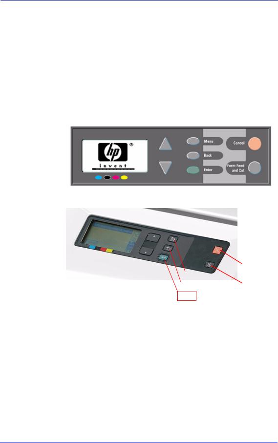
Troubleshooting
Guide to Troubleshooting the Printer
Introduction
This chapter will guide you through the relevant steps to take when troubleshooting the printer.
Front Panel Difference for the HP DesignJet 500, 510 and 800 Series Printers
Front Panel for the HP DesignJet 500 and 800 Series
Front Panel for the HP DesignJet 510 Series
|
Cancel |
|||||
|
Menu |
|||||
|
Form Feed |
|||||
|
Back |
and cut |
||||
Enter
|
1-2 |
HP DesignJets 500, 510 and 800 Series Printers Service Manual |

|
Troubleshooting |
|
|
The layout shown below will be used to refer to both types of |
|
|
NOTE |
|
|
front panels |
Troubleshooting System Error Codes
Chapter 2 — System Error Codes contains a list of system error codes and their respective descriptions and recommended corrective actions. Only try one recommended action at a time and check if the error code has disappeared.
Performing a Service Test on a Failed Assembly
If possible, always perform a Service Test on the component/ assembly that you are about to replace, just to make sure that is the component/assembly that has failed.
If the test on that component/assembly passes, you should NOT replace it.
For information on the Service Tests and how to use them see Chapter 4 — Service Tests and Utilities.
Performing the Necessary Service Calibrations
Is the printer calibrated correctly after replacing a component?
Remember that certain Calibrations are required even if an Assembly has been disassembled to gain access to another Assembly or Component.
For information on the Service Calibrations and how to use them see Chapter 5 — Service Calibrations.
|
HP DesignJets 500, 510 and 800 Series Printers Service Manual |
1-3 |

Troubleshooting
Solving Print Quality Problems
The Printer contains an internal Troubleshooting procedure which helps you to diagnose and resolve the possible source of any Image Quality or Line Quality defects. If Print Quality is poor before the minimum life expectancy of the Printhead has been reached, the Troubleshooting procedure should be performed which will determine whether the Printhead needs replacing or not after performing various levels of recovery actions.
For information on solving Print Quality problems see Chapter 6 —
Print Quality.
The Printer does not Power ON
1Check that the power cord is connected correctly to the Printer and to the Power Socket.
2Check that the Front-Panel Cable is correctly connected to the Interconnect PCA. Also make sure that the Front-Panel cable is not damaged.
3Check that the Interconnect Cable is properly connected at the both ends of the Printer.
Cover Sensors are not Working
1Check if the faulty sensor is installed correctly.
2Check if the cable for the faulty sensor is connected correctly.
3Replace the faulty Sensor (or the assembly that contains the Sensor).
The Line Sensor has Problems Detecting Media
1Check the type of media that is being used since the Line Sensor may have problems detecting transparent media or some types of Non-HP media. Try loading white HP media in to the Printer and check if the Line Sensor detects it.
2Excessive ink deposits on the Print Platen surface can fool the sensor by reflecting the light. Clean the Print Platen.
3The Line Sensor is damaged or faulty. Replace the Carriage Assembly Page 8-78.
|
1-4 |
HP DesignJets 500, 510 and 800 Series Printers Service Manual |

Troubleshooting
Troubleshooting Paper-Axis Shutdowns
A Paper-Axis shutdown can happen when the Printer detects that the Drive Roller is not moving but at the same time power is being supplied to the Paper-Axis Motor (which should be turning the Drive Roller).
The reasons for the Paper-Axis shutdown, and their solutions, are explained as follows:
1The Paper-Axis Motor does not respond to the electrical simulation.
It is possible to determine whether the Paper-Axis is faulty by performing the Paper Advance Test (Refer to Page 4-11). The Printer will move the Motor backwards and forwards and measure directly from the Motor Encoder whether the Paper-Axis Motor responded to the force. If the Paper-Axis Motor did not respond, the solution would be to replace the Paper-Axis Motor
Page 8-84.
2The Transmission Gears, which transmit the movement to the Drive Roller, are not turning. This problem could be caused either by blockage of the gears (caused by an obstacle) or by one of the gears being damaged. To solve the problem, try the following:
Remove the Back Platen Page 8-67 and check if there are any obstacles blocking the Gears. Remove the obstacles if necessary.
Remove the Back Platen Page 8-67 and check if the
Transmission Gears are damaged. If the Gears are damaged, replace the Gear Assemblies Page 8-92.
3The Drive Roller cannot move because of an obstacle or because it is damaged. To solve the problem, try the following:
Remove the Back Platen Page 8-67 and check if there are any obstacles blocking the Drive Roller. Remove the obstacles if necessary.
Remove the Back Platen Page 8-67 and check if the Drive
Roller is damaged. If the Drive Roller is damaged, replace the Drive Roller Page 8-86.
4The Drive Roller Encoder Sensor is faulty
It is possible to determine whether the Encoder Sensor is faulty by loading a sheet of paper from the front of the Printer. If the Drive Roller is working, the sheet will be loaded correctly, and the Printer will detect that media has been loaded (using the Media Sensor). Therefore the problem must be the Encoder Sensor and the solution would be to replace the Encoder Sensor
Page 8-38.
|
HP DesignJets 500, 510 and 800 Series Printers Service Manual |
1-5 |

Troubleshooting
Problems with the Vacuum Fan
If you have problems loading either Roll or Sheet Media, then there could be a problem with the Vacuum Fan. To verify if there really is a problem with the Vacuum Fan, try the following:
1With the Printer ON, open the Window of the Printer and place a sheet of HP High Gloss Photo Paper (must be D-Size), aligned with the blue lines on the Center Platen. If the Vacuum Fan holds the sheet in place, and then loads it correctly, then the Vacuum Fan functions correctly. If the Vacuum Fan does not hold the sheet in place (no suction), then try the following:
Check that the holes in the Center Platen are NOT blocked.
Check that the Vacuum Fan is installed correctly.
Replace the Vacuum Fan Page 8-64.
2If the Vacuum Fan held the sheet in place, but couldn’t correctly load it, then there could be a problem with the Drive Roller. In this case, replace the Drive Roller Page 8-86.
Vacuum suction much lower at high altitudes
Sometimes, at high altitudes, the vacuum force holding down the media will be lower, therefore the media will not be held in place properly causing:
Ink Smearing on the Media.
Printhead crashes against the Media.
Cut Sheet loading problems (high probability).
Roll Media loading problems (low probability).
The solution to this would be to change the Vacuum force by changing the Altitude setting. This can be done via the front panelSet-up Menu / Altitude.
|
1-6 |
HP DesignJets 500, 510 and 800 Series Printers Service Manual |

Troubleshooting
HP-GL/2 color differences in different HP DesignJet Printers
Color differences between one image printed on the HP DesignJet 500/510/800 Series and the rest of the DesignJet platforms are due to the different chemistry of the 500/510/800 series inks compared with the rest of the inks for other printers. This color variability among different HP DesignJet Series Printers has always been present. To solve the problem, try the following:
Perform the color calibration from the driver at the time of printing. However, that calibration is not very accurate but it may help in the most severe cases.
Some applications have color controls for the user to modify the image in order to obtain the desired colors.
Printing with PostScript reduces the problem significantly.
Avoid very long exposures to extreme environmental conditions after printing with glossy media (more than 12 hours at 80% humidity may result in severe changes in color).
Banding at variable extreme environmental conditions
Since the Accuracy Calibration has been done at normal environmental conditions, printing in extreme environmental conditions will cause banding because the advance of the Drive Roller does not correspond to the same conditions that the calibration was done in. To solve the problem, try the following:
Perform the Accuracy Calibration in the new environmental conditions (Refer to the User’s Guide).
|
HP DesignJets 500, 510 and 800 Series Printers Service Manual |
1-7 |

Troubleshooting
The Priming Procedure Fails
When the customer first receives the Printer, it is supplied with a set of four Start-up Printheads pre-installed in the Printhead Carriage. These Start-up Printheads are used for the priming of the tubes in the Ink Delivery System.
When the Printer is powered ON for the first time, the Printer will automatically perform the priming process. Without the priming process, the customer will NOT be able to use the Printer.
The initial startup assumes that the Start-up Printheads are installed, but the Printer cannot detect them because the Printer can only detect normal Printheads. If normal Printheads are installed during the initial startup, the Printer will request the User to remove them and check if they really have been removed. It will then request the User to install the Start-up Printheads.
Also the Printer will request the User to install the Ink Cartridges if they have not been installed already. If the Ink Cartridges contain less than 20cc of ink (the Ink Cartridges are encoded with the quantity of ink remaining) they will be rejected. Normally with a new Printer this should not be a problem since the Printer comes with Ink Cartridges that are full, but there maybe cases when the Ink Supply Tubes need to be replaced, in which case half empty Ink Cartridges may be used.
Once the Printer assumes that the Start-up Printheads and Ink Cartridges with enough ink are installed, the priming process will begin.
If the priming process is completed successfully, the Printer will directly proceed to the Printhead replacement procedure in order to replace the used Start-up Printheads with normal Printheads.
Once the priming process has started, it can fail due to 2 different problems:
The Ink Supply Tubes were not completely empty — This is the most common cause especially if the Printer has been powered ON and OFF several times with the Ink Cartridges installed since the initialization process performs at least one pumping cycle.
The Printer detects that one or more of the tubes cannot be detected as filled with ink — The most likely cause for this problem is Ink Cartridges with a faulty valve.
Even if the priming process fails, the Printer will try to verify whether the priming process has been completed by moving the Carriage to the access position and you will see the following
|
1-8 |
HP DesignJets 500, 510 and 800 Series Printers Service Manual |

Troubleshooting
message on the Front Panel:
Unable to prepare ink system.
Open window to check SETUP printheads
Open the Window and you will see the following message on the Front Panel:
1.Lift printhead cover
2.Check if there is ink inside printhead windows
3.Press ENTER to continue
Check for ink
Open the Carriage Cover and check if there is ink inside the Start-up Printheads. On the Front Panel you will see the following question and you will need to select the answer depending on whether the Start-up Printheads were filled with ink or not:
|
Are all printhead windows |
Menu |
||
|
filled with ink? |
Back |
||
|
ALL with some ink |
Enter |
||
|
NOT all with ink |
|||
If there is ink in all of the Start-up printheads, the Printer considers that the priming procedure has been completed successfully and will proceed to the Printhead replacement process.
If you select NOT all with ink the Printer will react differently depending on the source of the problem:
|
HP DesignJets 500, 510 and 800 Series Printers Service Manual |
1-9 |

Troubleshooting
If you need to reseat the Start-up Printheads, make sure you reinsert them in the same color slot in the Carriage.
The Printer will request you to reseat the Start-up Printheads (or in the case of missing Start-up Printheads you should install them or order new ones) and then retry the priming process (if the priming process fails 3 times because of the same problem, it will display a System Error). In this situation, the problem could be the following:
1The Start-up Printheads were not installed correctly or they are missing (one or all of them).
2The Start-up Printheads do not work properly and do not allow air to flow (one or all of them).
3The Ink Supply Station fails to pressurize the Ink Cartridges. To check this, perform the Ink Supply Station test Page 4-6.
4The Ink Supply Tubes are blocked, preventing the ink from flowing correctly.
If a System Error is displayed, try the following:
1The Ink Cartridge valve is broken so the Ink Cartridge should be replaced.
2The Start-up Printhead is not working properly and allows ink to flow outside.
3The Ink Supply Tube is leaking.
The last 2 cases will be more obvious because there will be a lot of ink in the Printer (around 20 cc of ink). Remove the Ink Cartridges and release the Tubes Bracket from the Ink Supply Station and check if there is ink in this area.
For more information on this problem, refer to System Error 93:10 on Page 2-19.
|
1-10 |
HP DesignJets 500, 510 and 800 Series Printers Service Manual |
![]()
Troubleshooting
Using the Power Switch LED to Troubleshoot |
|
|
In certain circumstances the LED located in the power switch |
|
|
(located on the left hand side of the Printer) can help to troubleshoot |
|
|
the Printer. The LED can be OFF, ON or flashing and using different |
|
|
combinations can indicate different problems. |
|
|
You should only use the LED to troubleshoot when the Printer |
|
|
NOTE |
|
|
does not Power up completely. The LED may flash in other |
|
|
circumstances which are completely normal and this does not |
|
|
mean that there is a problem with the Printer. |
LED is OFF — This indicates that the Power Supply Unit is completely dead. Try the following:
1Check that power cord is connected correctly to the Printer and to the Power Socket. Also make sure that you firmly press the Power Switch to the ON position.
2Replace the Power Supply Unit Page 8-27.
LED is ON (all the time) — This indicates that the Main PCA is completely dead. Replace the Electronics Module Page 8-24.
LED is Flashing continuously — A problem has been detected with the previous firmware upgrade. Try resending the firmware upgrade file.
LED Flashes twice every few seconds — The Printer cannot detect
|
HP DesignJets 500, 510 and 800 Series Printers Service Manual |
1-11 |

Troubleshooting
the Interconnect Cable. Try the following:
1Check that the Interconnect Cable is connected correctly to the Electronics Module and to the Interconnect PCA.
2If the Interconnect cable is connected correctly and the LED continues to flash twice then replace the Interconnect Cable Page 8-59.
LED Flashes 3 times every few seconds — The Printer cannot detect the Front Panel. Try the following:
1Check that the Front Panel is connected correctly to the Interconnect PCA.
2Check that the Interconnect Cable is properly connected at the both ends of the Printer.
3If the Front Panel is connected correctly and the LED continues to flash 3 times then replace the Front Panel Page 8-9.
4Replace the Interconnect Cable Page 8-59.
5Replace the Electronics Module Page 8-24.
LED Flashes 4 times every few seconds — This indicates that the Main PCA has failed. Replace the Electronics Module Page 8-24.
LED Flashes 5 times every few seconds — This indicates that the Main PCA has failed. Replace the Electronics Module Page 8-24.
|
1-12 |
HP DesignJets 500, 510 and 800 Series Printers Service Manual |

|
HP DesignJets 500, 510 and 800 Series Printers Service Manual |
1-13 |

|
1-14 |
HP DesignJets 500, 510 and 800 Series Printers Service Manual |

Troubleshooting
Using the Formatter/Accessory Card LEDs to Troubleshoot
In certain circumstances the LEDs located in the Formatter or HPGL/2 Accessory Card can help to highlight certain failures. There are 3 LEDs, Red, Yellow and Green and using different combinations can indicate different problems.
LED’s on the HP-GL/2
Accessory Card
The LED’s on the Formatter can be seen without having to remove the Left Hand Cover.
LED’s on the Formatter
The yellow LED (normally flashing) indicates that the Formatter/ Accessory Card is alive. If it stops flashing, it means that the Formatter/Accessory Card has failed and should be replaced.
The green LED indicates that there is power being supplied to the
|
HP DesignJets 500, 510 and 800 Series Printers Service Manual |
1-15 |

Troubleshooting
Formatter/Accessory Card. If the green LED is NOT lit and the LED in the Power Switch is ON, then it could mean that the Formatter/Accessory Card is badly connected or that the Printer if switched OFF. If after reseating the Formatter/Accessory Card, the problem persists, try the following:
1Switch the Printer OFF and remove the Formatter/Accessory Card BUT leaving the LAN Card installed (if available). Switch the Printer ON. If the Printer powers up correctly and the LAN Card works properly, then try step 2. If the LAN Card doesn’t work, then try step 3.
2Switch the Printer OFF and remove the LAN Card from the current slot and install the Formatter/Accessory Card in the same slot (that was previously used by the LAN Card). Switch the Printer ON and check if the green LED in the Formatter/Accessory Card is lit. If the green LED is NOT lit, it means that the Formatter/Accessory Card is faulty and should be replaced.
If the green LED is lit, then switch the Printer OFF and install the LAN Card in the vacant slot. Switch ON the Printer and check if the LAN Card works properly. If the LAN Card does NOT work, then
there is a problem with the Electronics Module and should be replaced Page 8-24.
3Switch the Printer OFF and remove the LAN Card. Switch ON the Printer and check if it initializes completely. If it initializes correctly
without any problems, then the problem could be with the Electronics Module and should be replaced Page 8-24.
4If the Printer does not even start to power up (i.e. nothing seen on the Front Panel and the LED in the Power Switch is NOT flashing) without the LAN Card nor the Formatter/Accessory Card, but the power switch LED is ON (all the time) the problem could be with the Electronics Module or the Power Supply Unit.
The red LED will flash a few times when the Printer is started up but if it stays lit (all the time) or flashes continuously, then this indicates that the Formatter/Accessory Card is faulty and should be replaced.
HP Designjet 510 Series printers will only include “HPGL/2 Accessory Card (Processor Card)” installed in the Left Slot of the Electronics Module.
|
1-16 |
HP DesignJets 500, 510 and 800 Series Printers Service Manual |
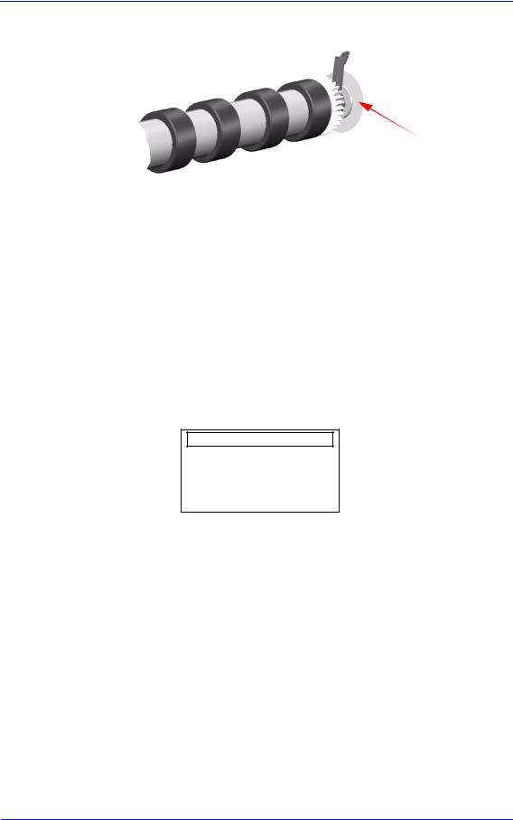
Troubleshooting
How to Detect Problems Related to the Encoder Disk
Encoder Disk
The following information will help you detect any problems related to the Encoder Disk:
Horizontal and periodic white lines, all of them with the same width depending on the failure mode. This is a clear indication that the Encoder Disk is damaged.
System Error 56:10 — This means that you have to replace the Drive Roller Encoder Sensor Page 8-38. But, if the problem persists, replace the Encoder Disk Assembly.
System Error 81:01 — This means a Paper-Axis shutdown. If this
error code appeared but was NOT caused by a paper jam, then perform the Paper Advance Test Page 4-11. If the Paper Advance Test fails during the third test, the Front Panel will display the following message:
Paper Advance test
System error 56:10
Roller encoder sensor failed
|
In this case, you should replace the Drive Roller Encoder Sensor |
|
|
Page 8-38. But, if the problem persists, replace the Encoder Disk |
|
|
Assembly. |
|
|
In order to remove the Encoder Disk, you must first remove the Drive |
|
|
NOTE |
|
|
Roller Page 8-86. |
|
|
Be very careful when assembling the Axle Spring because you could |
|
|
damage the Encoder Disk. |
|
|
Check that no air bubbles are trapped between the Encoder Disk and the |
|
|
hub once it is installed. |
|
HP DesignJets 500, 510 and 800 Series Printers Service Manual |
1-17 |

System Error Codes |
2 |
Introduction 2-2
Continuable and Non-Continuable Error Codes 2-2 System Error Codes — Explanation 2-2
Accessing the Error Log Utility 2-5 01:10 2-7 01:11 2-7 01:12 2-7 01:13 2-8 02:10 2-8 02:13 2-8 03:10 2-9 04:11 2-9
05:10 Warning (Only applicable to HP DesignJet 800 Series) 2-9 05:11 2-10 08:11 2-10 11:11 2-10 11:13 2-10 12:11 2-11 21:10 2-11 21:11 2-11 22:10 2-11 41:10 2-12 41:13 2-12 42:10 2-12 43:10 2-12 43:11 2-12 56:10 2-13 56:13 2-13 61:04 2-13 61:05 2-14 64:04 2-14 71:04 2-15 71:06 2-15 72:04 2-16 73:04 2-16 79:04 2-17 81:01 2-17 81:11 2-17 85:10 2-18 86:01 2-18 86:11 2-18 86:13 2-19 87:13 2-19 93:10 2-19
|
HP DesignJets 500, 510 and 800 Series Printers Service Manual |
2-1 |

System Error Codes
Introduction
System error codes are hexa-decimal based numbers generally caused by internal system errors. The following pages contain a list of system error codes and their respective descriptions and recommended corrective actions. Only try one recommended action at a time and check if the error code has disappeared.
Continuable and Non-Continuable Error Codes
Some of the Error Codes are continuable, which means you can press Enter on the front-panel and continue working with the Printer. Non-Continuable Error Codes do not allow you to continue working with the Printer, in this case power the Printer OFF and ON again and see if the System Error disappears. If the Error Code reappears, then the Printer requires an on-site visit in order to resolve the problem.
|
NOTE |
Even though the customer can continue working with a |
|
Continuable Error Code, an on-site visit should still be planned |
|
|
to troubleshoot the problem. |
System Error Codes — Explanation
System Error Codes consist of 4 digits which explain which component/system is failing and what action should be taken to resolve the problem.
The following table explains the first 2 digits of the System Error Code:
|
Code |
Component/System |
|
01 |
Main PCA/Electronics Module |
|
02 |
Carriage/Carriage PCA |
|
03 |
Power Supply Unit |
|
04 |
Network Card |
|
05 |
Formatter |
|
06 |
Hard Disk Drive |
|
07 |
Interconnect PCA |
|
08 |
Front Panel |
|
11 |
Trailing Cable |
|
12 |
Carriage Flex Circuit |
|
2-2 |
HP DesignJets 500, 510 and 800 Series Printers Service Manual |

|
System Error Codes |
||
|
Code |
Component/System |
|
|
17 |
Interconnect Cable |
|
|
21 |
Service Station |
|
|
22 |
Ink Supply Station |
|
|
23 |
Pressure System (APS) |
|
|
24 |
Ink Delivery System |
|
|
25 |
Spittoon |
|
|
31 |
Cutter |
|
|
32 |
Take-up Reel |
|
|
33 |
Sheet Feeder |
|
|
34 |
Dryer/Blower |
|
|
41 |
Paper-Axis Motor |
|
|
42 |
Scan-Axis Motor |
|
|
43 |
Vacuum Fan |
|
|
51 |
Window Sensor |
|
|
52 |
Drop Detector |
|
|
53 |
Media Sensor |
|
|
54 |
Pinch-Arm Sensor |
|
|
55 |
Line Sensor |
|
|
56 |
Drive Roller Encoder Sensor |
|
|
57 |
Ink Leak Detector |
|
|
58 |
Color Sensor |
|
|
59 |
Media Type Sensor |
|
|
61 |
Language Interpreting |
|
|
62 |
Input/Output through Parallel Port |
|
|
63 |
Input/Output through Network Card |
|
|
64 |
Input/Output through USB Port |
|
|
65 |
Input/Output |
|
|
71 |
Memory Management |
|
|
72 |
Generic Firmware |
|
|
73 |
Servo |
|
|
79 |
Assertion |
|
|
81 |
Media Advance |
|
|
82 |
Media Cut |
|
|
83 |
Single-Sheet Feeding |
|
|
84 |
Roll Feeding |
|
HP DesignJets 500, 510 and 800 Series Printers Service Manual |
2-3 |
![]()
System Error Codes
|
Code |
Component/System |
|
85 |
Media-Axis Encoder Reading |
|
86 |
Carriage Movement |
|
87 |
Scan-Axis Encoder Reading |
|
91 |
Printhead Firing |
|
92 |
Servicing |
|
93 |
Ink Pumping |
The following table explains the last 2 digits of the System Error Code:
|
Code |
Recovery Action |
Response |
|
|
00 |
Replace |
||
|
01 |
Reseat/Reconnect/Clean/Adjust (manually) |
Possiblefor |
|
|
02 |
Calibrate/Adjust (using Automatic Process) |
||
|
customer to |
|||
|
03 |
Power OFF |
||
|
perform |
|||
|
04 |
Upgrade System Firmware |
action |
|
|
05 |
Upgrade Driver |
||
|
06 |
Add Accessory |
||
|
07 |
Escalate |
||
|
08 |
Send Plot Again |
||
|
09 |
Wrong Part Installed |
||
|
10 |
Replace |
||
|
11 |
Reseat/Reconnect/Clean/Adjust (manually) |
||
|
12 |
Calibrate/Adjust (using Automatic Process) |
On-Site |
|
|
13 |
Power OFF |
||
|
visit |
|||
|
14 |
Upgrade System Firmware |
required |
|
|
15 |
Upgrade Driver |
||
|
16 |
Add Accessory |
||
|
17 |
Escalate |
||
|
18 |
Send Plot Again |
||
|
19 |
Wrong Part Installed |
|
2-4 |
HP DesignJets 500, 510 and 800 Series Printers Service Manual |

System Error Codes
Error Log Utility
The Error Log utility contains a record of the last 10 system error codes the Printer has experienced. The purpose of this information is to:
Determine whether the Printer is experiencing repetitive failures.
Determine whether the previous problems are causing the current failure in the printer.
Determine whether there are additional symptoms to the current system error code.
The information that is stored for each error code is:
The reported System error code.
The code line in the Firmware where the error was triggered.
The date when the error code was triggered.
Accessing the Error Log Utility
1Press the ↑or ↓key until the front panel displays the Setup Menu and then press Enter.
|
Menu |
||||
|
Set-up menu |
||||
|
Back |
||||
|
Press ENTER for |
||||
|
Set-up menu |
Enter |
2Press the ↑ or ↓ key until the front panel highlights Log. Press the
Enter key.
|
Set-up menu |
Menu |
||
|
Expansion cards |
|||
|
I/O set-up |
Back |
||
|
front panel |
|||
|
Altitude = 0-1000 m. |
|||
|
Log |
Enter |
||
|
HP DesignJets 500, 510 and 800 Series Printers Service Manual |
2-5 |

System Error Codes
3 Press the ↑ or ↓ key until the front panel highlights Errors. Press the Enter key.
|
Log |
Menu |
||
|
Back |
|||
|
Printheads |
|||
|
Errors |
Enter |
||
4 Press the ↑ or ↓ key until the front panel highlights the error code that you want to see information on. Press the Enter key.
|
Error log |
Menu |
||
|
Select for more info: |
|||
|
1 Error 21:10 |
Back |
||
|
2 Error 01:11 |
|||
|
3 Error 21:11 |
|||
|
4 Error 43:10 |
Enter |
||
|
5 The front panel displays information on the selected item. |
||||||
|
Error log |
||||||
|
Error code: 21:10 |
||||||
|
linefeed.c, 217 |
||||||
|
Date: 20-Sep-01 |
||||||
|
To view information on another Error Code, press BACK and |
||||||
|
NOTE |
||||||
|
the front panel will return to the previous screen |
|
2-6 |
HP DesignJets 500, 510 and 800 Series Printers Service Manual |

System Error:
Problem
Description:
Corrective Action:
System Error:
Problem
Description:
Corrective Action:
System Error:
Problem
Description:
Corrective Action:
System Error Codes
01:10
Electronics Module failure. The possible cause could be:
1.The Electronics Module is of the wrong type (a 16 MB Electronics Module will not work in a 24″ Model).
2.Reading, writing or initializing the EEROM failed.
3.One of the ASIC’s was not found within the Serial Bus that connects the Electronics Module to the Carriage Assembly.
4.One of the ASIC’s did not respond to the Serial Bus that connects the Electronics Module to the Carriage Assembly.
5.The Electronics Module is requesting a move to the Service Station while the previous move is still being completed.
6.The Electronics Module Cooling Fan has reached its current limit.
Replace the Electronics Module Page 8-24.
01:11
The Electronics Module Cooling Fan badly connected.
Reconnect the Cooling Fan (located on top of the Electronics Module). If the Cooling Fan continues to fail, check that the connector pins in the Electronics Module are NOT bent.
01:12
The EEROM is not configured correctly (the product number may be missing).
Configure the EEROM correctly using the EEROM setup utility Page 4-17.
|
HP DesignJets 500, 510 and 800 Series Printers Service Manual |
2-7 |

System Error Codes
System Error:
Problem
Description:
01:13
Electronics Module failure. The possible cause could be:
1.One of the ASIC’s in the Electronics Module is reporting that it is too hot.
2.The interruptions from the Scan-Axis servo or from the PaperAxis servo are not coming as regularly as they are expected or are coming too late.
Corrective Action: Try the following:
System Error:
Problem
Description:
Corrective Action:
System Error:
Problem
Description:
Corrective Action:
Switch the Printer Off and wait a few minutes. Switch the Printer On again and check if the Error Code has disappeared.
If the Error Code continues, replace the Electronics Module Page 8-24.
02:10
Carriage failure. The possible cause could be:
1. The Carriage PCA is not compatible with the rest of the Printer.
2.The Carriage ASIC has problems initializing.
3.The +2.5V reference voltage generated in the Carriage PCA is out of range.
4.One of the Carriage ASIC’s cannot be found within the Serial Bus that connects the Electronics Module to the Carriage.
5.One of the Carriage ASIC’s did not respond to the Serial Bus that connects the Electronics Module to the Carriage Assembly.
Replace the Carriage Assembly Page 8-78.
02:13
Carriage failure. The possible cause could be:
1. One of the ASIC’s in the Carriage is reporting that it is too hot.
Try the following:
Switch the Printer Off and wait a few minutes. Switch the Printer On again and check if the Error Code has disappeared.
If the Error Code continues, replace the Carriage Assembly Page 8-78.
|
2-8 |
HP DesignJets 500, 510 and 800 Series Printers Service Manual |

System Error:
Problem
Description:
Corrective Action:
System Error:
Problem
Description:
Corrective Action:
System Error:
Problem
Description:
Corrective Action:
System Error:
Problem
Description:
Corrective Action:
System Error:
Problem
Description:
Corrective Action:
System Error Codes
03:10
Power Supply failure.
Replace the Power Supply Unit Page 8-27.
04:11
LAN Card not detected.
Power OFF the Printer and reconnect the LAN Card.
05:09 Error (Only applicable to HP DesignJet 500 and 510 Series)
Formatter installed instead of HP-GL/2 Accessory Card.
Power OFF the Printer and remove the Formatter and install the HPGL/2 Accessory Card Page 8-20.
NOTE: If this Error Code appears on a DesignJet 800 Series Printer, then the model number configured in the Printer is incorrect (the Printer thinks it’s a DesignJet 500 Series Printer). In this case reconfigure the model number Page 4-17.
05:10 Warning (Only applicable to HP DesignJet 800 Series) Formatter not detected.
Power OFF the Printer and reseat the Formatter.
05:10 Error (Only applicable to HP DesignJet 800 Series) Formatter failure.
Power OFF the Printer and replace the Formatter Page 8-20.
|
HP DesignJets 500, 510 and 800 Series Printers Service Manual |
2-9 |

System Error Codes
System Error: |
05:10 Error (Only applicable to HP DesignJet 500 and 510 |
|
|
Series) |
||
|
Problem |
HP-GL/2 Accessory Card failure. |
|
|
Description: |
||
|
Corrective Action: |
Power OFF the Printer and replace the HP-GL/2 Accessory Card |
|
|
Page 8-20. |
||
System Error: |
05:11 |
|
|
Problem |
Formatter not detected. |
|
|
Description: |
||
|
Corrective Action: |
Power OFF the Printer and reconnect the Formatter. |
|
System Error: |
08:11 |
|
|
Problem |
Front Panel cannot be detected. |
|
|
Description: |
||
|
Corrective Action: |
Reconnect the Front Panel. |
|
System Error: |
11:11 |
|
|
Problem |
Trailing Cable badly connected. |
|
|
Description: |
||
|
Corrective Action: |
Reconnect the Trailing Cable correctly. |
|
System Error: |
11:13 |
|
|
Problem |
Problem with setting the voltage of the Printheads. |
|
|
Description: |
||
|
Corrective Action: |
Try the following: |
|
|
Check that the Trailing Cable is connected correctly at both ends. |
||
|
Replace the Trailing Cable Page 8-40. |
||
|
Replace the Carriage Assembly Page 8-78. |
|
2-10 |
HP DesignJets 500, 510 and 800 Series Printers Service Manual |

System Error Codes
System Error: |
12:11 |
|
Problem |
A short detected in the Carriage Assembly. |
|
Description: |
Corrective Action: Try the following:
Remove ALL the Printheads and clean the flex contacts on the Printheads and in the Carriage Assembly.
Replace ALL the Printheads.
Replace the Carriage Assembly Page 8-78.
System Error:
Problem
Description:
Corrective Action:
System Error:
Problem
Description:
Corrective Action:
21:10
Service Station failure. The possible cause could be:
1.The steps counted by the Service Station motor are not consistent with the expected length of the current movement.
2.The Aerosol Fan has reached its maximum current limit.
3.The Service Station motor has shutdown because of blockage.
Replace the Service Station/Aerosol Fan Assembly Page 8-52.
21:11
Service Station cannot be detected or the Service Station is badly adjusted.
Try the following:
Reconnect the Service Station Assembly.
Reposition the Service Station trip lever.
System Error:
Problem
Description:
Corrective Action:
22:10
Ink Supply Station failure. The possible cause could be:
1. Reading, writing or initializing the backup EEROM failed.
2.One of the out-of-ink sensors (located in the Ink Supply Station) is not reporting what it should during the initializing process while depressurizing.
Replace the Ink Supply Station Page 8-48.
|
HP DesignJets 500, 510 and 800 Series Printers Service Manual |
2-11 |

System Error Codes
System Error: |
41:10 |
|
|
Problem |
Paper-Axis Motor failure. |
|
|
Description: |
||
|
Corrective Action: |
Replace the Paper-Axis Motor Page 8-84. |
|
System Error: |
41:13 |
|
|
Problem |
Error in the Paper-Axis Motor Encoder quadrature. |
|
|
Description: |
||
|
Corrective Action: |
Try the following: |
System Error:
Problem
Description:
Corrective Action:
System Error:
Problem
Description:
Corrective Action:
System Error:
Problem
Description:
Corrective Action:
Switch the Printer Off and wait a few minutes. Switch the Printer On again and check if the Error Code has disappeared.
If the Error Code continues, replace the Paper-Axis Motor Page 8-84.
42:10
Scan-Axis Motor failure.
Replace the Scan-Axis Motor Page 8-29.
43:10
Vacuum Fan failure.
Replace the Vacuum Fan Page 8-64.
43:11
Vacuum Fan not detected.
Reconnect the Vacuum Fan.
|
2-12 |
HP DesignJets 500, 510 and 800 Series Printers Service Manual |

System Error Codes
System Error: |
56:10 |
|
|
Problem |
Drive Roller Encoder Sensor error. |
|
|
Description: |
||
|
Corrective Action: |
Try the following: |
|
|
Replace the Drive Roller Encoder Sensor Page 8-38. |
||
|
If the problem persists, replace the Encoder Disk Assembly. |
||
System Error: |
56:13 |
|
|
Problem |
Error in the Drive Roller Encoder Sensor quadrature. |
|
|
Description: |
||
|
Corrective Action: |
Try the following: |
|
|
Switch the Printer Off and wait a few minutes. Switch the Printer |
||
|
On again and check if the Error Code has disappeared. |
||
|
If the Error Code continues, replace the Drive Roller Encoder |
||
|
Sensor Page 8-38. |
||
System Error: |
61:04 |
|
|
Problem |
Firmware Error. |
|
|
Description: |
||
|
Corrective Action: |
Try the following: |
|
|
Switch the Printer Off and wait a few minutes. Switch the Printer |
||
|
On again and check if the Error Code has disappeared. |
||
|
If the Error Code reappears, check for a new Firmware release. |
||
|
If the new Firmware release does not solve the problem, or if new |
||
|
Firmware release was not available, then contact the HP |
||
|
Response Center (or directly to the Division) supplying the |
||
|
following information: |
||
|
– Model and Serial Number of the Printer. |
||
|
– Firmware release of the Printer (use the Printer Information |
||
|
utility Page 4-27). |
||
|
– The complete Error Code information, including the linefeed |
||
|
where the error occurred (use the Error Log utility to obtain this |
||
|
information Page 2-5). |
|
HP DesignJets 500, 510 and 800 Series Printers Service Manual |
2-13 |
![]()
System Error Codes
System Error: |
61:05 |
|
|
Problem |
Error Processing Job. This Error Code only appears in HP DesignJets |
|
|
Description: |
800 Series, or in the HP DesignJet 500 and 510 Series with an HP- |
|
|
GL/2 card installed, when processing either a PostScript or HP-GL/2 |
||
|
file. |
||
|
Corrective Action: |
Try the following: |
|
|
Switch the Printer Off and wait a few minutes. Switch the Printer |
||
|
On again and resend the file that you were trying to print. |
||
|
If the Error Code reappears after resending the file, then try |
||
|
generating the file again and try to print again. |
||
|
If the file that is causing this error is PostScript, check if it is |
||
|
Binary. If the file is Binary, use AppleTalk to send the file to the |
||
|
Printer. If AppleTalk is not being used to send the Binary file to |
||
|
the Printer, then change the PostScript settings to Binary through |
||
|
the Front Panel (Set-up menu / PS settings / Encoding / Binary). |
||
|
If the Error Code continues to reappear, check for a new release |
||
|
of the Driver. |
||
System Error: |
64:04 |
|
|
Problem |
Firmware Error (USB Port). |
Description:
Corrective Action: Try the following:
Switch the Printer Off and wait a few minutes. Switch the Printer On again and check if the Error Code has disappeared.
If the Error Code reappears, check for a new Firmware release.
If the new Firmware release does not solve the problem, or if new Firmware release was not available, then contact the HP Response Center (or directly to the Division) supplying the following information:
– Model and Serial Number of the Printer.
– Firmware release of the Printer (use the Printer Information utility Page 4-27).
– The complete Error Code information, including the linefeed where the error occurred (use the Error Log utility to obtain this information Page 2-5).
|
2-14 |
HP DesignJets 500, 510 and 800 Series Printers Service Manual |

|
System Error Codes |
||
System Error: |
71:04 |
|
|
Problem |
Problem allocating Memory. This Error Code only appears in HP |
|
|
Description: |
DesignJets 800 Series, or in the HP DesignJet 500 and 510 Series |
|
|
with an HP-GL/2 card installed. |
||
|
Corrective Action: |
Try the following: |
System Error:
Problem
Description:
Switch the Printer Off and wait a few minutes. Switch the Printer On again and check if the Error Code has disappeared.
If the Error Code reappears, check for a new Firmware release.
If the new Firmware release does not solve the problem, or if new Firmware release was not available, then contact the HP Response Center (or directly to the Division) supplying the following information:
–Model and Serial Number of the Printer.
–Firmware release of the Printer (use the Printer Information utility Page 4-27).
–The complete Error Code information, including the linefeed
where the error occurred (use the Error Log utility to obtain this information Page 2-5).
71:06
Out of Memory problem. This Error Code only appears in HP DesignJets 800 Series, or in the HP DesignJet 500 and 510 Series with an HP-GL/2 card installed, when processing either a PostScript or HP-GL/2 file.
Corrective Action: Try the following:
Look on your computer screen for error messages; some drivers allow you to choose a different printing mode and attempt to send the file again. If necessary, select Send Job as a Bitmap in the driver’s Troubleshooting menu (Services tab). This may slow down print speed.
If the problem persists, you can install extra memory on the HPGL/2 Accessory Card in your printer.
|
HP DesignJets 500, 510 and 800 Series Printers Service Manual |
2-15 |

System Error Codes
System Error: |
72:04 |
|
|
Problem |
Problem in the Scan-Axis (Firmware Error). |
|
|
Description: |
||
|
Corrective Action: Try the following: |
||
|
Switch the Printer Off and wait a few minutes. Switch the Printer |
||
|
On again and check if the Error Code has disappeared. |
||
|
If the Error Code reappears, check for a new Firmware release. |
||
|
If the new Firmware release does not solve the problem, or if new |
||
|
Firmware release was not available, then contact the HP |
||
|
Response Center (or directly to the Division) supplying the |
||
|
following information: |
||
|
– Model and Serial Number of the Printer. |
||
|
– Firmware release of the Printer (use the Printer Information |
||
|
utility Page 4-27). |
||
|
– The complete Error Code information, including the linefeed |
||
|
where the error occurred (use the Error Log utility to obtain this |
||
|
information Page 2-5). |
||
System Error: |
73:04 |
|
|
Problem |
Servo Error. |
Description:
Corrective Action: Try the following:
Switch the Printer Off and wait a few minutes. Switch the Printer On again and check if the Error Code has disappeared.
If the Error Code reappears, check for a new Firmware release.
If the new Firmware release does not solve the problem then replace the Electronics Module Page 8-24.
If the problem continues, contact the HP Response Center (or directly to the Division) supplying the following information:
– Model and Serial Number of the Printer.
– Firmware release of the Printer (use the Printer Information utility Page 4-27).
– The complete Error Code information, including the linefeed where the error occurred (use the Error Log utility to obtain this information Page 2-5).
|
2-16 |
HP DesignJets 500, 510 and 800 Series Printers Service Manual |

System Error Codes
System Error: |
79:04 |
|
|
Problem |
Firmware Error. |
|
|
Description: |
||
|
Corrective Action: |
Try the following: |
|
|
Switch the Printer Off and wait a few minutes. Switch the Printer |
||
|
On again and check if the Error Code has disappeared. |
||
|
If the Error Code reappears, check for a new Firmware release. |
||
|
If the new Firmware release does not solve the problem, or if new |
||
|
Firmware release was not available, then contact the HP |
||
|
Response Center (or directly to the Division) supplying the |
||
|
following information: |
||
|
– Model and Serial Number of the Printer. |
||
|
– Firmware release of the Printer (use the Printer Information |
||
|
utility Page 4-27). |
||
|
– The complete Error Code information, including the linefeed |
||
|
where the error occurred (use the Error Log utility to obtain this |
||
|
information Page 2-5). |
||
System Error: |
81:01 |
|
|
Problem |
Paper-Axis shutdown. |
|
|
Description: |
||
|
Corrective Action: |
If this error code appeared but was NOT caused by a paper jam, then |
|
|
try the following: |
||
|
Perform the Paper Advance Test Page 4-11. |
||
|
If the problem persists, replace the Encoder Disk Assembly. |
||
System Error: |
81:11 |
|
|
Problem |
Paper-Axis shutdown (during the Paper Advance test). |
|
|
Description: |
||
|
Corrective Action: |
Refer to Error Code 81:01. |
|
HP DesignJets 500, 510 and 800 Series Printers Service Manual |
2-17 |

System Error Codes
System Error: |
85:10 |
|
|
Problem |
Paper-Axis Encoder error. The Drive Roller Encoder Sensor cannot |
|
|
Description: |
find the zero position of the Encoder Disk. |
|
|
Corrective Action: |
Try the following: |
|
|
Replace the Drive Roller Encoder Sensor Page 8-38. |
||
|
If the Error Code continues, replace the Drive Roller Page 8- |
||
|
86. |
||
System Error: |
86:01 |
|
|
Problem |
Carriage-Axis shutdown. |
|
|
Description: |
||
|
Corrective Action: |
If this error code appeared but was NOT caused by a paper jam, then |
|
|
try the following: |
||
|
Too much friction in the Slider Rod. Enter the Printer Information |
||
|
utility ( Page 4-27) and check the Scan-Axis usage. If the |
||
|
percentage is close to 100%, then lubricate the Slider Rod. |
||
|
The Carriage is bumping into the Service Station. If the carriage |
||
|
is stuck at the right hand side of the Printer and cannot be moved |
||
|
out to the center of the Print Platen it is because the Service |
||
|
Station cannot uncap the Printheads. In this case replace the |
||
|
Service Station/Aerosol Fan Assembly Page 8-52. |
||
|
Perform the Carriage Movement test Page 4-8. |
||
System Error: |
86:11 |
|
|
Problem |
Carriage-Axis shutdown (during the Carriage Movement test). |
|
|
Description: |
||
|
Corrective Action: |
Refer to Error Code 86:01. |
|
2-18 |
HP DesignJets 500, 510 and 800 Series Printers Service Manual |

System Error Codes
System Error: |
86:13 |
|
Problem |
Carriage-Axis shutdown (Firmware Error). |
|
Description: |
Corrective Action: Try the following:
Switch the Printer Off and wait a few minutes. Switch the Printer On again and check if the Error Code has disappeared.
If the Error Code reappears, check for a new Firmware release.
If the new Firmware release does not solve the problem, or if new Firmware release was not available, contact the HP Response Center (or directly to the Division) supplying the following information:
–Model and Serial Number of the Printer.
–Firmware release of the Printer (use the Printer Information utility Page 4-27).
–The complete Error Code information, including the linefeed
where the error occurred (use the Error Log utility to obtain this information Page 2-5).
System Error: |
87:13 |
|
|
Problem |
Unable to read the Carriage Encoder Sensor. |
|
|
Description: |
||
|
Corrective Action: |
Try the following: |
|
|
Switch the Printer Off and wait a few minutes. Switch the Printer |
||
|
On again and check if the Error Code has disappeared. |
||
|
If the Error Code continues, replace the Carriage Assembly |
||
|
Page 8-78 or the Encoder Strip Page 8-76. |
||
System Error: |
93:10 |
|
|
Problem |
Ink System startup failed (also see Page 1-8 for more information). |
|
|
Description: |
||
|
Corrective Action: |
Try the following: |
|
|
Check for a leak in the Printer. If a leak is evident (there is ink on |
||
|
Printer components), replace the Ink Supply Tubes Page 8-60. |
||
|
Perform the Prime Tubes utility (Refer to Page 4-24) and check |
||
|
how long it takes to complete the procedure. If it takes too long to |
||
|
complete the procedure and there is no leak in the Printer, then |
||
|
replace the Ink Cartridges. If it takes a short time to complete the |
||
|
procedure, then replace the Ink Supply Tubes Page 8-60. |
|
HP DesignJets 500, 510 and 800 Series Printers Service Manual |
2-19 |

|
Ink Supplies |
3 |
|
Troubleshooting |
|
What are the Ink Supplies? 3-2
Ink Cartridges 3-2
Printheads 3-3
Identifying the Components 3-3
General Information About the Ink Supplies 3-4
Some General Precautions When Handling the Ink Supplies 3-5
When Should You Replace the Ink Cartridges? 3-6
When Should You Replace the Printheads? 3-7
Obtaining Ink Cartridge Information 3-9
Obtaining Printhead Information 3-10
Ink Cartridge Status Messages 3-13
Ink Cartridge Status While Replacing 3-13
Printhead Status Messages 3-14
Printhead History Utility 3-15
Accessing the Printhead History Utility 3-15
Is the Printer Causing Repetitive Printhead Problems? 3-17
Is the User Replacing the Printheads too Early? 3-19
Troubleshooting Repetitive Ink Cartridge Messages 3-21
Troubleshooting Repetitive Printhead Error Messages 3-22
Printhead Error Codes 3-23
Summary of Solving Ink Supplies Problems 3-24
|
HP DesignJets 500, 510 and 800 Series Printers Service Manual |
3-1 |

Ink Supplies Troubleshooting
What are the Ink Supplies?
For each of the four ink colors used in the Printer, there are two separate components: the Printhead and the Ink Cartridge. Both components are coded with an HP selection number to identify the correct replacement supplies.
|
Printhead |
Ink Cartridge |
|
69cc |
Ink Cartridges
The Ink Cartridges for the HP DesignJet 500, 510 and 800 Series
Printers require no maintenance or cleaning. As long as each Ink
Cartridge is inserted correctly into its slot, the ink will flow to the
Printheads.
The Ink Cartridges are number coded as follows:
HP No.10 for the Black Ink Cartridge (for the HP DesignJet 500 and 800 Series Printers only).
HP No.82 for the Black Ink Cartridge (for the HP DesignJet 510 Series Printers only).
HP No.82 for the Cyan, Magenta and Yellow Ink Cartridges.
|
NOTE |
It is also possible to use HP No.11 Ink Cartridges for the Cyan, |
|
Magenta and Yellow colors. The HP No.11 Ink Cartridges |
|
|
contain 33cc of ink. |
|
|
The front panel displays the status of the Ink Cartridge. With the |
|
|
front panel, detailed information can be checked on the Ink |
|
|
Cartridges, see page Page 3-9, Obtaining Ink Cartridge Information. |
|
3-2 |
HP DesignJets 500, 510 and 800 Series Printers Service Manual |

Ink Supplies Troubleshooting
Printheads
The Printheads are extremely durable and do not need to be replaced every time an Ink Cartridge is replaced. They are independent of the Ink Cartridges and will continue giving excellent image quality results even if the Ink Cartridges are low on ink. In order to know when to replace a Printhead, see page Page 3-7, When Should You Replace the Printheads?
The Printheads are number coded HP No.11 for ALL colors.
If you notice a decline in print quality such as lines or dots missing from text / graphics, go to page Page 6-4, Performing the Troubleshooting Procedure.
Identifying the Components
The following illustration will help you identify the components of the ink supplies.
|
HP DesignJets 500, 510 and 800 Series Printers Service Manual |
3-3 |

Ink Supplies Troubleshooting
General Information About the Ink Supplies
For optimum results from the printer and modular ink delivery system always follow these guidelines when handling the ink supplies:
Always install the Ink Cartridges and Printheads before the expiration date, which is on the packaging.
Install Ink Cartridges and Printheads in their color-coded slots.
Follow the instructions on the front panel of the Printer during installation.
Avoid unnecessary removal of the Ink Cartridges and Printheads.
When turning off the Printer always use the power Off button located on the left hand side of the Printer. The Printheads are then stored correctly which prevents them from drying out.
The Ink Cartridges should never be removed while the Printer is printing. They should only be removed when the Printer is ready for you to replace them. The front panel will guide you through the removal and installation procedure. See page Page 3-6, When Should You Replace the Ink Cartridges?
|
3-4 |
HP DesignJets 500, 510 and 800 Series Printers Service Manual |