ОТКРЫТОЕ АКЦИОНЕРНОЕ ОБЩЕСТВО
«ВОЛОГОДСКИЙ ОПТИКО-МЕХАНИЧЕСКИЙ ЗАВОД»
ПРИЦЕЛ ОПТИЧЕСКИЙ
P2,5X17, P4X32, P4X32L, Р8Х48, P8X48L, Р8Х56, P8X56L, P8X56Lf
РУКОВОДСТВО ПО ЭКСПЛУАТАЦИИ
МВЖИ.201331.001 РЭ
1. НАЗНАЧЕНИЕ
1.1. Оптический прицел Пилад — P2,5×17, P4x32 (Пилад 4х32), P4x32L (Пилад 4x32L), P8x48 (Пилад 8х48), P8x48L (Пилад 8x48L), P8x56 (Пилад 8х56), P8x56L (Пилад 8x56L), P8x56Lf (далее прицелы) обеспечивают прицельную наводку при стрельбе и предназначены для установки на охотничье оружие под патроны различного калибра. Прицелы P2,5×17, P4x32, P8x56 выпускаются в двух вариантах: как с правым, так и с левым расположением рукоятки выверки по горизонту.
Буквенные индексы в наименовании прицелов означают: «L» — модификации прицелов с подсветкой сетки для работы при рассветно-сумеречном освещении, «f» — наличие устройства перефокусировки объектива по дальности. Внешний вид прицелов приведен на рис. А.1, А. 2, А. 3, А. 4, А. 5, А. 6 в приложении А.
1.2. На оружие прицелы монтируются при помощи специальных кронштейнов, подбираемых в зависимости от типа оружия.
1.3. Прицелы позволяют осуществлять более точное прицеливание, так как они имеют увеличение, и при наводке на цель отсутствует параллакс, свойственный механическим прицелам.
1.4. С помощью прицела можно определить дистанцию до цели или размер цели.
1.5. Интервал рабочих температур прицела от минус 40 °С до плюс 50 °С.
ПРИМЕЧАНИЕ: Элементы питания в прицелах с подсветкой сетки рассчитаны на работу при температуре не ниже минус 1 °С, и при более низких температурах подсветка сетки работает нестабильно.
2. ТЕХНИЧЕСКИЕ ДАННЫЕ
2.1. Основные параметры и размеры должны соответствовать таблице 1.
Таблица 1
| Наименование | Значение параметра для прицела марки | |||||
| Р2,5х17 | Р4х32 | P4х32L | Р8х48 Р8х56 | P8х48L P8х56L | P8х56Lf | |
| 1. Увеличение, крат | 2,5 ±0,2 | 4 ±0,2 | 8 ±0,5 | |||
| 2. Угловое поле в пространстве предметов | 11°20′ ±20′ | 6°20′ ±20′ | 3°20′ ±20′ | |||
| 3. Диаметр выходного зрачка, мм., не менее | 6,7 | 7,6 | 6 | 7 | ||
| 4. Удаление выходного зрачка от последней линзы окуляра, мм., не менее | 80 | 75 | 74 | |||
| 5. Посадочный диаметр, мм.> | 25,4 | 25,4 | 25,4 | |||
| 6. Габаритные размеры, мм., не более: — диаметр объектива — диаметр окуляра — длина в рабочем положении |
25,4 41 230 |
38 41 270 |
56 41 307 |
64 41 307 |
66 41 310 |
|
| 7. Масса прицела, г. не более | 290 | 300 | 330 | 410 | 450 | 580 |
ПРИМЕЧАНИЕ: Возможны изменения, связанные с усовершенствованием конструкции изделия, не влияющие на основные технические характеристики.
2.2. В прицелах с подсветкой сетки применен источник питания — два элемента SR43P ТУ16-563.019-85 (ИКШЖ.563112.006ТУ). Допускается применение импортных элементов UKAR 386, VARTA 528, AG 12.
3. КОМПЛЕКТНОСТЬ
3.1. Прицелы должны быть укомплектованы позициями основного комплекта.
3.2. Предприятие-изготовитель по своему усмотрению или по особому заказу может комплектовать прицелы позициями дополнительного комплекта.
ОСНОВНОЙ КОМПЛЕКТ
Прицел 1
Крышка (на окуляре и объективе) 2
Руководство по эксплуатации прицела 1
Упаковка 1
ДОПОЛНИТЕЛЬНЫЙ КОМПЛЕКТ
Светофильтр 1
Бленда 1
Наглазник 1
Кронштейн 1 комплект (в зависимости от типа оружия)
Руководство по эксплуатации кронштейна
4. УСТРОЙСТВО И ПРИНЦИП РАБОТЫ
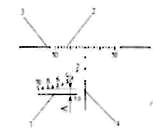
4.1. Оптический прицел представляет собой оптическую зрительную трубу постоянного увеличения с механизмом ввода углов прицеливания и углов боковых поправок. Устройство прицела приведено на рисунке 1.
4.2. Оптическая схема прицела состоит из объектива 1, линзовой оборачивающей системы 7 и окуляра 3.
4.3. Объектив дает обратное уменьшенное изображение цели в плоскости сетки. Линзовая оборачивающая система переносит изображение цели с сеткой в фокальную плоскость окуляра, одновременно оборачивая изображение. Стрелок видит в окуляр прямое увеличенное изображение цели и сетки, которые при перемещении глаза не смещаются друг относительно друга.
4.4. Для улучшения резкости изображения по глазу стрелка прицел имеет фокусировку окуляра в пределах ±5 диоптрий. Фокусировка производится вращением окуляра (при близорукости – по часовой стрелке, при дальнозоркости – против часовой стрелки) от нулевого деления, а необходимое положение фиксируется установочным кольцом 10.
4.5. В фокальной плоскости объектива расположена сетка. Вид и описание модификаций сеток приведены в приложении Б.
4.6. Сетка 6 расположена в оправе (рисунок 1), которую можно перемещать в вертикальном и горизонтальном направлениях для установки углов прицеливания и углов боковых поправок.
4.7. Перемещение сетки 6 производится двумя рукоятками 2.
4.8. Установка величин углов прицеливания и углов боковых поправок производится по шкалам, закрепленным рукоятками 2.
4.9. На шкалах углов прицеливания 9 и боковых поправок 8 нанесены равномерные деления. Цена деления шкал в зависимости от марки прицела представлена в таблице 2 в тысячных дистанции (далее по тексту т. д.), цена оцифрованного деления равна 1 т. д. = 3,6′ ≈ 0,00105, что соответствует на местности 10,5 см на каждые 100 м дистанции.
4.10. Углы прицеливания, соответствующие различным дистанциям до цели и зависящие от баллистики оружия, определяет стрелок в процессе пристрелки и эксплуатации. Для этого рекомендуется составить таблицу углов прицеливания (форма таблицы приведена в приложении В).
УСТРОЙСТВО ПРИЦЕЛА
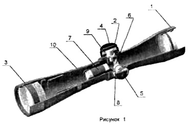
1 -объектив; 2-рукоятка; 3 — окуляр; 4 — крышка; 5 — винт; 6-сетка; 7-линзовая оборачивающая система; 8 — шкала углов боковых поправок; 9 — шкала углов прицеливания; 10 — установочное кольцо.
Таблица 2
|
Марка прицела |
Цена |
|
Р2,5х17 |
1/2 т.д. |
|
Р4х32, P4x32L |
1/3 т.д. |
|
Р8х48, P8x48L, Р8х56, P8x56L, P8x56Lf |
1/4 т.д. |
5. ПОРЯДОК РАБОТЫ
5.1. Установка прицела на оружие.
5.1.1. Прицел установить на оружие в специальном кронштейне, который поставляется отдельно от изделия в зависимости от типа оружия. Установка прицела на оружие производится индивидуально для каждого оружия.
5.1.2. Точность стрельбы с оптическим прицелом зависит от качества выверки прицела, т. е. от правильного положения оптической оси прицела по отношению к оси канала ствола оружия, а также от качества крепления прицела в кронштейне и устойчивости кронштейна при стрельбе.
5.2. Выверка прицела при стрельбе оружия.
5.2.1. Перед пристрелкой необходимо отвинтить крышки 4 (см. рисунок 1).
5.2.2. В процессе пристрелки при определении положения средней точки попадания (СТП) в зависимости от величины отклонения СТП положение прицельного пенька исправить вращением рукояток 2.
5.2.3. Произведя пристрелку и не меняя положения прицельных штрихов, следует шкалы углов прицеливания и углов боковых поправок установить на деления «0». Для этого необходимо осторожно ослабить два винта 5, крепящих шкалы, и, не трогая рукоятки 2, развернуть шкалы так, чтобы деления «0» совпали с неподвижными индексами, и вновь закрепить винты.
5.2.4. После пристрелки и установки шкал навинтить крышки 4. Оружие с прицелом готово к эксплуатации.
5.2.5. При прицеливании стрелок должен совместить зрачок глаза с выходным зрачком прицела, при правильном совмещении видно все поле зрения, и по его краям отсутствуют лунообразные тени. Для более быстрого совмещения выходного зрачка прицела со зрачком глаза на окуляр прицела следует надевать резиновый наглазник.
5.2.6. При стрельбе в условиях яркой освещенности при необходимости можно использовать светофильтр и бленду, входящие в комплект прицела.
ВНИМАНИЕ!
1. Окуляр, установленный по глазу стрелка, при стрельбе должен быть надежно зафиксирован установочным кольцом 10.
2. Диапазон вращения рукояток прицела в одном из направлений по каждой шкале может превышать полный оборот, т. е. на прицеле возможна установка ложного нуля. Прицельные штрихи при этом окажутся значительно смещенными от выверенного положения, и показания шкал не будут соответствовать результатам пристрелки. Во избежание этого не следует вращать без необходимости рукоятки прицела.
5.3. Стрельба по неподвижным целям.
5.3.1. В этом случае шкалу углов прицеливания установить на деление, соответствующее дистанции до цели, а шкалу боковых поправок на «0».
5.4. Стрельба по движущимся целям.
5.4.1. При стрельбе по движущимся целям необходимо учитывать движение цели и выносить точку прицеливания вперед по направлению движения цели.
5.4.2. Величину выноса точки прицеливания рассчитывают в фигурах цели, при этом должны быть учтены скорость движения цели и дистанция до нее. Чем больше скорость движения цели и дистанция до нее, тем больше должна быть вынесена точка прицеливания.
5.4.3. Необходимо обращать внимание на взаимное положение цели и боковых выравнивающих штрихов сетки.
6. ПРАВИЛА ХРАНЕНИЯ
6.1. Необходимо предохранять прицел от ударов и падения.
6.2. После работы с прицелом в сырую погоду тщательно протереть его и просушить при температуре, не превышающей +50°С. Протирать оптику следует чистой мягкой тканью, лучше фланелевой.
6.3. Для предохранения оптических деталей прицела от повреждений и загрязнения необходимо хранить прицел с надетыми на объектив и окуляр крышками.
6.4. Нельзя разбирать прицел, производить его ремонт собственными средствами.
6.5. Помещение, в котором хранится прицел, должно быть сухим, температура воздуха не ниже +5 °С, без резких колебаний, влажность воздуха не более 80%.
Адрес для предъявления претензий к качеству:
160001, Россия, г. Вологда, ул. Мальцева, 54. ОАО «ВОМЗ»
e-mail: vomz@vologda.ru
8. ГАРАНТИИ ИЗГОТОВИТЕЛЯ
8.1. Изготовитель гарантирует соответствие оптического прицела требованиям технических условий
ТУ3- МВЖИ.201331.001-93 при соблюдении условий эксплуатации и хранения.
8.2. Гарантийный срок эксплуатации — 24 месяца со дня продажи прицела через торговую сеть.
8.3. Прицелы могут храниться в торгующих организациях не более 3-х лет со дня отправки с завода-изготовителя.
8.4. По истечении установленных сроков хранения продажа прицелов торгующими организациями допускается только при наличии разрешения завода-изготовителя.
8.5. В случае неисправной работы прицела в период гарантийного срока эксплуатации владелец имеет право на его бесплатный ремонт. Гарантийный ремонт осуществляет завод-изготовитель. Расходы, связанные с пересылкой прицела на гарантийный ремонт, оплачивает владельцу
завод-изготовитель.
8.6. На завод-изготовитель прицел для ремонта следует направлять уложенным в тару, предохраняющую прицел от повреждений при транспортировании. В посылку необходимо вложить руководство по эксплуатации, краткое описание неисправности и четкий обратный адрес.
8.7. При отсутствии даты продажи и штампа магазина в гарантийном талоне, гарантийный срок исчисляется со дня изготовления прицела заводом-изготовителем.
8.8. Технически обоснованный ремонт после окончания гарантийного срока эксплуатации выполняет завод-изготовитель. Все расходы, связанные с ремонтом, несет потребитель.
ПРИЛОЖЕНИЕ Б
(обязательное)
СЕТКА С ПРИЦЕЛЬНЫМ ПЕНЬКОМ И БОКОВЫМИ ВЫРАВНИВАЮЩИМИ
Сетку составляют прицельные штрихи: вертикальный, называемый прицельным пеньком, и два горизонтальных, называемых боковыми выравнивающими.
Прицеливание осуществляется совмещением острия прицельного пенька с нужной точкой видимой цели, боковые выравнивающие при этом должны быть расположены горизонтально.
При известной длине (ширине) цели и ясно видимых контурах, можно определить дистанцию до цели, для чего используют разрыв между боковыми выравнивающими, равный 7 т. д. При дистанции 100 м просвет между боковыми выравнивающими соответствует на местности 70 см. Следовательно,
если размер цели 70 см и ее изображение укладывается между боковыми выравнивающими, то дистанция до цели будет равна 100 м. При произвольном размере цели дистанция до нее (в метрах) определяется по формуле: D = N х L/0,7, где N — число, указывающее сколько раз изображение цели укладывается в просвете между боковыми выравнивающими; L, см — действительный размер цели.
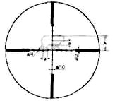
СЕТКА С ПЕРЕКРЕСТИЕМ

Сетка представляет собой перекрестие с утолщенными штрихами на концах. При прицеливании центр перекрестия сетки совмещается с нужной точкой видимой цели. Измерение дистанции до цели осуществляется по методике, приведенной в описании сетки с прицельным пеньком, но вместо разрыва между боковыми выравнивающими используют расстояние между утолщенными штрихами.
СЕТКИ С ДАЛЬНОМЕРНОЙ ШКАЛОЙ
Сетка с дальномерной шкалой позволяет оценивать примерное расстояние до цели, а также оперативно изменять углы прицеливания и боковых поправок. Для определения расстояния до цели необходимо расположить ее изображение между наклонной штриховой и горизонтальной линиями шкалы 1 до касания границ цели с этими линиями. Шкала имеет градуировку дальности (в сотнях
метров) для цели высотой 1,5 м. При измерении расстояния до цели с другой высотой необходимо полученное значение умножить на коэффициент, равный отношению высоты цели к величине 1,5 м.
Например, если высота цели составляет 1/3 от высоты 1,5 м, а ее изображение вписывается между наклонным штрихом 6 (600 м) и горизонтальной линией шкалы (размер А), то дистанция до цели 600×1/3 = 200 м. . Размер от горизонтальной линии шкалы 1 до бокового выравнивающего (линии 3) для цели высотой 1,5 м соответствует расстоянию 70 м для прицепов Р4х32 и P4х32L, 100 м — для Р8х48, Р8х56 и P8x56L. Шкала 2, расположенная между боковыми выравнивающими 3, имеет цену деления 1 т. д. и позволяет как вводить боковые поправки (смещение цели на одно деление соответствует смещению средней точки попадания на 10 см на каждые 100 м дистанции), так и определять расстояние (в километрах) до цели при известной ее длине или ширине (размер цели в метрах необходимо разделить на число укладывающихся на ней делений шкалы). Цена деления на
боковых выравнивающих составляет 10 т. д., что соответствует смещению цели на 1 м на каждые 100 м дистанции. Вверху прицельного пенька 4, под центральной «пикой», расположено три дополнительных «пики», позволяющих при стрельбе по удаленным целям оперативно изменять
прицеливания соответственно на 3,4 т. д., 7,2 т. д. и 11,4 т. д. Соответствие дистанции до цели и необходимого при этом угла прицеливания определяется при пристрелке в зависимости от типа оружия и патрона.
СЕТКА С ТОЧКАМИ
Расстояние между соседними точками а = 3 т. д. – для прицепов Р4х32 и P4x32L; а = 1 т. д. — для прицелов Р8х48, Р8х56 и P8x56L. Сетки с точками, как и сетки с дальномерной шкалой, позволяют оценивать примерное расстояние до цели, а также оперативно изменять углы прицеливания и боковых поправок.
Для определения расстояния до цели необходимо:
— оценить размер объекта L (в метрах), по которому будет определяться дистанция;
— измерить величину изображения объекта с помощью сетки;
— по формуле вычислить расстояние в метрах до объекта;
Lx1000/А = Дистанция (в метрах). (Б.2)
Например, высота объекта 1 м, и изображение объекта А занимает 3 деления а, тогда для прицела с увеличением 4 крата расчет будет таким:
![]()
![]()
Также расстояние до цели можно определить по таблице Б.1.
Таблица Б.1
|
Размер А, деления |
Р4х32, P4x32L | ||||||||||||||||
| Размер объекта в сантиметрах | |||||||||||||||||
| 15 | 20 | 25 | 30 | 35 | 40 | 45 | 50 | 60 | 70 | 80 | 90 | 100 | 120 | 140 | 160 | 180 | |
| 0,5 | 100 | 133 | 167 | 200 | 233 | 167 | 300 | 333 | 400 | 467 | 533 | 600 | 667 | 800 | 933 | 1067 | 1200 |
| 1 | 50 | 67 | 83 | 100 | 117 | 83 | 150 | 167 | 200 | 233 | 267 | 300 | 333 | 400 | 467 | 533 | 600 |
| 1,5 | 33 | 44 | 56 | 67 | 78 | 56 | 100 | 111 | 133 | 156 | 178 | 200 | 222 | 267 | 311 | 356 | 400 |
| 2 | 25 | 33 | 42 | 50 | 58 | 42 | 75 | 83 | 100 | 117 | 133 | 150 | 167 | 200 | 233 | 267 | 300 |
| 2,5 | 20 | 27 | 33 | 40 | 47 | 33 | 60 | 67 | 80 | 93 | 107 | 120 | 133 | 160 | 187 | 213 | 240 |
| 3 | 17 | 22 | 28 | 33 | 39 | 28 | 50 | 56 | 67 | 78 | 89 | 100 | 111 | 133 | 156 | 178 | 200 |
| 3,5 | 14 | 19 | 24 | 29 | 33 | 24 | 43 | 48 | 57 | 67 | 76 | 86 | 95 | 114 | 133 | 152 | 171 |
| 4 | 13 | 17 | 21 | 25 | 29 | 21 | 38 | 42 | 50 | 58 | 67 | 75 | 83 | 100 | 117 | 133 | 150 |
Продолжение таблицы Б.1
|
Размер А, деления |
Р8х48, P8x48L, P8х56, P8x56L, P8x56lf | ||||||||||||||||
| Размер объекта в сантиметрах | |||||||||||||||||
| 15 | 20 | 25 | 30 | 35 | 40 | 45 | 50 | 60 | 70 | 80 | 90 | 100 | 120 | 140 | 160 | 180 | |
| 0,5 | 300 | 400 | 500 | 600 | 700 | 800 | 900 | 1000 | 1200 | 1400 | 1600 | 1800 | 2000 | 2400 | 2800 | 3200 | 3600 |
| 1 | 150 | 200 | 250 | 300 | 350 | 400 | 450 | 500 | 600 | 700 | 800 | 900 | 1000 | 1200 | 1400 | 1600 | 1800 |
| 1,5 | 100 | 133 | 167 | 200 | 233 | 267 | 300 | 333 | 400 | 467 | 533 | 600 | 667 | 800 | 933 | 1067 | 1200 |
| 2 | 75 | 100 | 125 | 150 | 175 | 200 | 225 | 250 | 300 | 350 | 400 | 450 | 500 | 600 | 700 | 800 | 900 |
| 2,5 | 60 | 80 | 100 | 120 | 140 | 160 | 180 | 200 | 240 | 280 | 320 | 360 | 400 | 480 | 560 | 640 | 720 |
| 3 | 50 | 67 | 83 | 100 | 117 | 133 | 150 | 167 | 200 | 233 | 267 | 300 | 333 | 400 | 467 | 533 | 600 |
| 3,5 | 43 | 57 | 71 | 86 | 100 | 114 | 129 | 143 | 171 | 200 | 229 | 257 | 286 | 343 | 400 | 457 | 514 |
| 4 | 38 | 50 | 63 | 75 | 88 | 100 | 113 | 125 | 150 | 175 | 200 | 225 | 250 | 300 | 350 | 400 | 450 |
ОТКРЫТОЕ АКЦИОНЕРНОЕ ОБЩЕСТВО
«ВОЛОГОДСКИЙ ОПТИКО-МЕХАНИЧЕСКИЙ ЗАВОД»
ПРИЦЕЛ ОПТИЧЕСКИЙ
P2,5X17, P4X32, P4X32L, Р8Х48, P8X48L, Р8Х56, P8X56L, P8X56Lf
РУКОВОДСТВО ПО ЭКСПЛУАТАЦИИ
МВЖИ.201331.001 РЭ
1. НАЗНАЧЕНИЕ
1.1. Оптический прицел Пилад — P2,5×17, P4x32 (Пилад 4х32), P4x32L (Пилад 4x32L), P8x48 (Пилад 8х48), P8x48L (Пилад 8x48L), P8x56 (Пилад 8х56), P8x56L (Пилад 8x56L), P8x56Lf (далее прицелы) обеспечивают прицельную наводку при стрельбе и предназначены для установки на охотничье оружие под патроны различного калибра. Прицелы P2,5×17, P4x32, P8x56 выпускаются в двух вариантах: как с правым, так и с левым расположением рукоятки выверки по горизонту.
Буквенные индексы в наименовании прицелов означают: «L» — модификации прицелов с подсветкой сетки для работы при рассветно-сумеречном освещении, «f» — наличие устройства перефокусировки объектива по дальности. Внешний вид прицелов приведен на рис. А.1, А. 2, А. 3, А. 4, А. 5, А. 6 в приложении А.
1.2. На оружие прицелы монтируются при помощи специальных кронштейнов, подбираемых в зависимости от типа оружия.
1.3. Прицелы позволяют осуществлять более точное прицеливание, так как они имеют увеличение, и при наводке на цель отсутствует параллакс, свойственный механическим прицелам.
1.4. С помощью прицела можно определить дистанцию до цели или размер цели.
1.5. Интервал рабочих температур прицела от минус 40 °С до плюс 50 °С.
ПРИМЕЧАНИЕ: Элементы питания в прицелах с подсветкой сетки рассчитаны на работу при температуре не ниже минус 1 °С, и при более низких температурах подсветка сетки работает нестабильно.
2. ТЕХНИЧЕСКИЕ ДАННЫЕ
2.1. Основные параметры и размеры должны соответствовать таблице 1.
Таблица 1
| Наименование | Значение параметра для прицела марки | |||||
| Р2,5х17 | Р4х32 | P4х32L | Р8х48 Р8х56 | P8х48L P8х56L | P8х56Lf | |
| 1. Увеличение, крат | 2,5 ±0,2 | 4 ±0,2 | 8 ±0,5 | |||
| 2. Угловое поле в пространстве предметов | 11°20′ ±20′ | 6°20′ ±20′ | 3°20′ ±20′ | |||
| 3. Диаметр выходного зрачка, мм., не менее | 6,7 | 7,6 | 6 | 7 | ||
| 4. Удаление выходного зрачка от последней линзы окуляра, мм., не менее | 80 | 75 | 74 | |||
| 5. Посадочный диаметр, мм.> | 25,4 | 25,4 | 25,4 | |||
| 6. Габаритные размеры, мм., не более: — диаметр объектива — диаметр окуляра — длина в рабочем положении |
25,4 41 230 |
38 41 270 |
56 41 307 |
64 41 307 |
66 41 310 |
|
| 7. Масса прицела, г. не более | 290 | 300 | 330 | 410 | 450 | 580 |
ПРИМЕЧАНИЕ: Возможны изменения, связанные с усовершенствованием конструкции изделия, не влияющие на основные технические характеристики.
2.2. В прицелах с подсветкой сетки применен источник питания — два элемента SR43P ТУ16-563.019-85 (ИКШЖ.563112.006ТУ). Допускается применение импортных элементов UKAR 386, VARTA 528, AG 12.
3. КОМПЛЕКТНОСТЬ
3.1. Прицелы должны быть укомплектованы позициями основного комплекта.
3.2. Предприятие-изготовитель по своему усмотрению или по особому заказу может комплектовать прицелы позициями дополнительного комплекта.
ОСНОВНОЙ КОМПЛЕКТ
Прицел 1
Крышка (на окуляре и объективе) 2
Руководство по эксплуатации прицела 1
Упаковка 1
ДОПОЛНИТЕЛЬНЫЙ КОМПЛЕКТ
Светофильтр 1
Бленда 1
Наглазник 1
Кронштейн 1 комплект (в зависимости от типа оружия)
Руководство по эксплуатации кронштейна
4. УСТРОЙСТВО И ПРИНЦИП РАБОТЫ
4.1. Оптический прицел представляет собой оптическую зрительную трубу постоянного увеличения с механизмом ввода углов прицеливания и углов боковых поправок. Устройство прицела приведено на рисунке 1.
4.2. Оптическая схема прицела состоит из объектива 1, линзовой оборачивающей системы 7 и окуляра 3.
4.3. Объектив дает обратное уменьшенное изображение цели в плоскости сетки. Линзовая оборачивающая система переносит изображение цели с сеткой в фокальную плоскость окуляра, одновременно оборачивая изображение. Стрелок видит в окуляр прямое увеличенное изображение цели и сетки, которые при перемещении глаза не смещаются друг относительно друга.
4.4. Для улучшения резкости изображения по глазу стрелка прицел имеет фокусировку окуляра в пределах ±5 диоптрий. Фокусировка производится вращением окуляра (при близорукости – по часовой стрелке, при дальнозоркости – против часовой стрелки) от нулевого деления, а необходимое положение фиксируется установочным кольцом 10.
4.5. В фокальной плоскости объектива расположена сетка. Вид и описание модификаций сеток приведены в приложении Б.
4.6. Сетка 6 расположена в оправе (рисунок 1), которую можно перемещать в вертикальном и горизонтальном направлениях для установки углов прицеливания и углов боковых поправок.
4.7. Перемещение сетки 6 производится двумя рукоятками 2.
4.8. Установка величин углов прицеливания и углов боковых поправок производится по шкалам, закрепленным рукоятками 2.
4.9. На шкалах углов прицеливания 9 и боковых поправок 8 нанесены равномерные деления. Цена деления шкал в зависимости от марки прицела представлена в таблице 2 в тысячных дистанции (далее по тексту т. д.), цена оцифрованного деления равна 1 т. д. = 3,6′ ≈ 0,00105, что соответствует на местности 10,5 см на каждые 100 м дистанции.
4.10. Углы прицеливания, соответствующие различным дистанциям до цели и зависящие от баллистики оружия, определяет стрелок в процессе пристрелки и эксплуатации. Для этого рекомендуется составить таблицу углов прицеливания (форма таблицы приведена в приложении В).
УСТРОЙСТВО ПРИЦЕЛА
1 -объектив; 2-рукоятка; 3 — окуляр; 4 — крышка; 5 — винт; 6-сетка; 7-линзовая оборачивающая система; 8 — шкала углов боковых поправок; 9 — шкала углов прицеливания; 10 — установочное кольцо.
Таблица 2
|
Марка прицела |
Цена |
|
Р2,5х17 |
1/2 т.д. |
|
Р4х32, P4x32L |
1/3 т.д. |
|
Р8х48, P8x48L, Р8х56, P8x56L, P8x56Lf |
1/4 т.д. |
5. ПОРЯДОК РАБОТЫ
5.1. Установка прицела на оружие.
5.1.1. Прицел установить на оружие в специальном кронштейне, который поставляется отдельно от изделия в зависимости от типа оружия. Установка прицела на оружие производится индивидуально для каждого оружия.
5.1.2. Точность стрельбы с оптическим прицелом зависит от качества выверки прицела, т. е. от правильного положения оптической оси прицела по отношению к оси канала ствола оружия, а также от качества крепления прицела в кронштейне и устойчивости кронштейна при стрельбе.
5.2. Выверка прицела при стрельбе оружия.
5.2.1. Перед пристрелкой необходимо отвинтить крышки 4 (см. рисунок 1).
5.2.2. В процессе пристрелки при определении положения средней точки попадания (СТП) в зависимости от величины отклонения СТП положение прицельного пенька исправить вращением рукояток 2.
5.2.3. Произведя пристрелку и не меняя положения прицельных штрихов, следует шкалы углов прицеливания и углов боковых поправок установить на деления «0». Для этого необходимо осторожно ослабить два винта 5, крепящих шкалы, и, не трогая рукоятки 2, развернуть шкалы так, чтобы деления «0» совпали с неподвижными индексами, и вновь закрепить винты.
5.2.4. После пристрелки и установки шкал навинтить крышки 4. Оружие с прицелом готово к эксплуатации.
5.2.5. При прицеливании стрелок должен совместить зрачок глаза с выходным зрачком прицела, при правильном совмещении видно все поле зрения, и по его краям отсутствуют лунообразные тени. Для более быстрого совмещения выходного зрачка прицела со зрачком глаза на окуляр прицела следует надевать резиновый наглазник.
5.2.6. При стрельбе в условиях яркой освещенности при необходимости можно использовать светофильтр и бленду, входящие в комплект прицела.
ВНИМАНИЕ!
1. Окуляр, установленный по глазу стрелка, при стрельбе должен быть надежно зафиксирован установочным кольцом 10.
2. Диапазон вращения рукояток прицела в одном из направлений по каждой шкале может превышать полный оборот, т. е. на прицеле возможна установка ложного нуля. Прицельные штрихи при этом окажутся значительно смещенными от выверенного положения, и показания шкал не будут соответствовать результатам пристрелки. Во избежание этого не следует вращать без необходимости рукоятки прицела.
5.3. Стрельба по неподвижным целям.
5.3.1. В этом случае шкалу углов прицеливания установить на деление, соответствующее дистанции до цели, а шкалу боковых поправок на «0».
5.4. Стрельба по движущимся целям.
5.4.1. При стрельбе по движущимся целям необходимо учитывать движение цели и выносить точку прицеливания вперед по направлению движения цели.
5.4.2. Величину выноса точки прицеливания рассчитывают в фигурах цели, при этом должны быть учтены скорость движения цели и дистанция до нее. Чем больше скорость движения цели и дистанция до нее, тем больше должна быть вынесена точка прицеливания.
5.4.3. Необходимо обращать внимание на взаимное положение цели и боковых выравнивающих штрихов сетки.
6. ПРАВИЛА ХРАНЕНИЯ
6.1. Необходимо предохранять прицел от ударов и падения.
6.2. После работы с прицелом в сырую погоду тщательно протереть его и просушить при температуре, не превышающей +50°С. Протирать оптику следует чистой мягкой тканью, лучше фланелевой.
6.3. Для предохранения оптических деталей прицела от повреждений и загрязнения необходимо хранить прицел с надетыми на объектив и окуляр крышками.
6.4. Нельзя разбирать прицел, производить его ремонт собственными средствами.
6.5. Помещение, в котором хранится прицел, должно быть сухим, температура воздуха не ниже +5 °С, без резких колебаний, влажность воздуха не более 80%.
Адрес для предъявления претензий к качеству:
160001, Россия, г. Вологда, ул. Мальцева, 54. ОАО «ВОМЗ»
e-mail: vomz@vologda.ru
8. ГАРАНТИИ ИЗГОТОВИТЕЛЯ
8.1. Изготовитель гарантирует соответствие оптического прицела требованиям технических условий
ТУ3- МВЖИ.201331.001-93 при соблюдении условий эксплуатации и хранения.
8.2. Гарантийный срок эксплуатации — 24 месяца со дня продажи прицела через торговую сеть.
8.3. Прицелы могут храниться в торгующих организациях не более 3-х лет со дня отправки с завода-изготовителя.
8.4. По истечении установленных сроков хранения продажа прицелов торгующими организациями допускается только при наличии разрешения завода-изготовителя.
8.5. В случае неисправной работы прицела в период гарантийного срока эксплуатации владелец имеет право на его бесплатный ремонт. Гарантийный ремонт осуществляет завод-изготовитель. Расходы, связанные с пересылкой прицела на гарантийный ремонт, оплачивает владельцу
завод-изготовитель.
8.6. На завод-изготовитель прицел для ремонта следует направлять уложенным в тару, предохраняющую прицел от повреждений при транспортировании. В посылку необходимо вложить руководство по эксплуатации, краткое описание неисправности и четкий обратный адрес.
8.7. При отсутствии даты продажи и штампа магазина в гарантийном талоне, гарантийный срок исчисляется со дня изготовления прицела заводом-изготовителем.
8.8. Технически обоснованный ремонт после окончания гарантийного срока эксплуатации выполняет завод-изготовитель. Все расходы, связанные с ремонтом, несет потребитель.
ПРИЛОЖЕНИЕ Б
(обязательное)
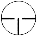
СЕТКА С ПРИЦЕЛЬНЫМ ПЕНЬКОМ И БОКОВЫМИ ВЫРАВНИВАЮЩИМИ
Сетку составляют прицельные штрихи: вертикальный, называемый прицельным пеньком, и два горизонтальных, называемых боковыми выравнивающими.
Прицеливание осуществляется совмещением острия прицельного пенька с нужной точкой видимой цели, боковые выравнивающие при этом должны быть расположены горизонтально.
При известной длине (ширине) цели и ясно видимых контурах, можно определить дистанцию до цели, для чего используют разрыв между боковыми выравнивающими, равный 7 т. д. При дистанции 100 м просвет между боковыми выравнивающими соответствует на местности 70 см. Следовательно,
если размер цели 70 см и ее изображение укладывается между боковыми выравнивающими, то дистанция до цели будет равна 100 м. При произвольном размере цели дистанция до нее (в метрах) определяется по формуле: D = N х L/0,7, где N — число, указывающее сколько раз изображение цели укладывается в просвете между боковыми выравнивающими; L, см — действительный размер цели.
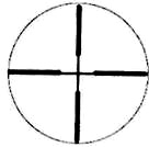
СЕТКА С ПЕРЕКРЕСТИЕМ
Сетка представляет собой перекрестие с утолщенными штрихами на концах. При прицеливании центр перекрестия сетки совмещается с нужной точкой видимой цели. Измерение дистанции до цели осуществляется по методике, приведенной в описании сетки с прицельным пеньком, но вместо разрыва между боковыми выравнивающими используют расстояние между утолщенными штрихами.
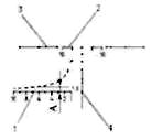
СЕТКИ С ДАЛЬНОМЕРНОЙ ШКАЛОЙ
Сетка с дальномерной шкалой позволяет оценивать примерное расстояние до цели, а также оперативно изменять углы прицеливания и боковых поправок. Для определения расстояния до цели необходимо расположить ее изображение между наклонной штриховой и горизонтальной линиями шкалы 1 до касания границ цели с этими линиями. Шкала имеет градуировку дальности (в сотнях
метров) для цели высотой 1,5 м. При измерении расстояния до цели с другой высотой необходимо полученное значение умножить на коэффициент, равный отношению высоты цели к величине 1,5 м.
Например, если высота цели составляет 1/3 от высоты 1,5 м, а ее изображение вписывается между наклонным штрихом 6 (600 м) и горизонтальной линией шкалы (размер А), то дистанция до цели 600×1/3 = 200 м. . Размер от горизонтальной линии шкалы 1 до бокового выравнивающего (линии 3) для цели высотой 1,5 м соответствует расстоянию 70 м для прицепов Р4х32 и P4х32L, 100 м — для Р8х48, Р8х56 и P8x56L. Шкала 2, расположенная между боковыми выравнивающими 3, имеет цену деления 1 т. д. и позволяет как вводить боковые поправки (смещение цели на одно деление соответствует смещению средней точки попадания на 10 см на каждые 100 м дистанции), так и определять расстояние (в километрах) до цели при известной ее длине или ширине (размер цели в метрах необходимо разделить на число укладывающихся на ней делений шкалы). Цена деления на
боковых выравнивающих составляет 10 т. д., что соответствует смещению цели на 1 м на каждые 100 м дистанции. Вверху прицельного пенька 4, под центральной «пикой», расположено три дополнительных «пики», позволяющих при стрельбе по удаленным целям оперативно изменять
прицеливания соответственно на 3,4 т. д., 7,2 т. д. и 11,4 т. д. Соответствие дистанции до цели и необходимого при этом угла прицеливания определяется при пристрелке в зависимости от типа оружия и патрона.
СЕТКА С ТОЧКАМИ
Расстояние между соседними точками а = 3 т. д. – для прицепов Р4х32 и P4x32L; а = 1 т. д. — для прицелов Р8х48, Р8х56 и P8x56L. Сетки с точками, как и сетки с дальномерной шкалой, позволяют оценивать примерное расстояние до цели, а также оперативно изменять углы прицеливания и боковых поправок.
Для определения расстояния до цели необходимо:
— оценить размер объекта L (в метрах), по которому будет определяться дистанция;
— измерить величину изображения объекта с помощью сетки;
— по формуле вычислить расстояние в метрах до объекта;
Lx1000/А = Дистанция (в метрах). (Б.2)
Например, высота объекта 1 м, и изображение объекта А занимает 3 деления а, тогда для прицела с увеличением 4 крата расчет будет таким:
![]()
![]()
Также расстояние до цели можно определить по таблице Б.1.
Таблица Б.1
|
Размер А, деления |
Р4х32, P4x32L | ||||||||||||||||
| Размер объекта в сантиметрах | |||||||||||||||||
| 15 | 20 | 25 | 30 | 35 | 40 | 45 | 50 | 60 | 70 | 80 | 90 | 100 | 120 | 140 | 160 | 180 | |
| 0,5 | 100 | 133 | 167 | 200 | 233 | 167 | 300 | 333 | 400 | 467 | 533 | 600 | 667 | 800 | 933 | 1067 | 1200 |
| 1 | 50 | 67 | 83 | 100 | 117 | 83 | 150 | 167 | 200 | 233 | 267 | 300 | 333 | 400 | 467 | 533 | 600 |
| 1,5 | 33 | 44 | 56 | 67 | 78 | 56 | 100 | 111 | 133 | 156 | 178 | 200 | 222 | 267 | 311 | 356 | 400 |
| 2 | 25 | 33 | 42 | 50 | 58 | 42 | 75 | 83 | 100 | 117 | 133 | 150 | 167 | 200 | 233 | 267 | 300 |
| 2,5 | 20 | 27 | 33 | 40 | 47 | 33 | 60 | 67 | 80 | 93 | 107 | 120 | 133 | 160 | 187 | 213 | 240 |
| 3 | 17 | 22 | 28 | 33 | 39 | 28 | 50 | 56 | 67 | 78 | 89 | 100 | 111 | 133 | 156 | 178 | 200 |
| 3,5 | 14 | 19 | 24 | 29 | 33 | 24 | 43 | 48 | 57 | 67 | 76 | 86 | 95 | 114 | 133 | 152 | 171 |
| 4 | 13 | 17 | 21 | 25 | 29 | 21 | 38 | 42 | 50 | 58 | 67 | 75 | 83 | 100 | 117 | 133 | 150 |
Продолжение таблицы Б.1
|
Размер А, деления |
Р8х48, P8x48L, P8х56, P8x56L, P8x56lf | ||||||||||||||||
| Размер объекта в сантиметрах | |||||||||||||||||
| 15 | 20 | 25 | 30 | 35 | 40 | 45 | 50 | 60 | 70 | 80 | 90 | 100 | 120 | 140 | 160 | 180 | |
| 0,5 | 300 | 400 | 500 | 600 | 700 | 800 | 900 | 1000 | 1200 | 1400 | 1600 | 1800 | 2000 | 2400 | 2800 | 3200 | 3600 |
| 1 | 150 | 200 | 250 | 300 | 350 | 400 | 450 | 500 | 600 | 700 | 800 | 900 | 1000 | 1200 | 1400 | 1600 | 1800 |
| 1,5 | 100 | 133 | 167 | 200 | 233 | 267 | 300 | 333 | 400 | 467 | 533 | 600 | 667 | 800 | 933 | 1067 | 1200 |
| 2 | 75 | 100 | 125 | 150 | 175 | 200 | 225 | 250 | 300 | 350 | 400 | 450 | 500 | 600 | 700 | 800 | 900 |
| 2,5 | 60 | 80 | 100 | 120 | 140 | 160 | 180 | 200 | 240 | 280 | 320 | 360 | 400 | 480 | 560 | 640 | 720 |
| 3 | 50 | 67 | 83 | 100 | 117 | 133 | 150 | 167 | 200 | 233 | 267 | 300 | 333 | 400 | 467 | 533 | 600 |
| 3,5 | 43 | 57 | 71 | 86 | 100 | 114 | 129 | 143 | 171 | 200 | 229 | 257 | 286 | 343 | 400 | 457 | 514 |
| 4 | 38 | 50 | 63 | 75 | 88 | 100 | 113 | 125 | 150 | 175 | 200 | 225 | 250 | 300 | 350 | 400 | 450 |
Содержание
- Требования к монтажу оптического кабеля Инкаб
- Инструкции по монтажу оптических кабелей производства завода «Инкаб»
- Общие требования к монтажу кабеля
- Кабель ОКГТ: обзор конструкций и инструкция по монтажу
- Виды кабеля ОКГТ
- ОКГТ-Ц
- ОКГТ-С
- ОКГТ-Ц-А
- Преимущества ОКГТ при построении ВОЛС на высоковольтных ВЛ
- В помощь проектировщику
- Монтаж ОКГТ: инструменты и комплектующие
- Инструкция по монтажу и вводу в эксплуатацию ОКГТ-Ц, ОКГТ-С и ОКГТ-Ц-А от Инкаб
- 1. Общие положения
- 2. Основные нормативные документы
- 3. Основные требования при транспортировке и хранении
- 4. Монтаж ОКГТ
- 5. Разделка ОКГТ
- 6. Ввод в эксплуатацию ОКГТ
- 7. Эксплуатация ОКГТ
- 8. Требования техники безопасности
- 9. Утилизация ОКГТ
- Оптические муфты для монтажа
- Муфты МОПГ-М-1 и МОПГ-М-2
- Муфты МОПГ-МП-1
- Видео разделки ОКГТ
- Мониторинг ЛЭП с помощью ОКГТ
- Заключение
Требования к монтажу оптического кабеля Инкаб
Инструкции по монтажу оптических кабелей производства завода «Инкаб»
Общие требования к монтажу кабеля
- Применяйте кабель только по назначению. Для правильного подбора кабеля и консультаций по техническим вопросам вы можете связаться с нами по e-mail: mail@incab.pro.
- Перед монтажом необходимо провести входной контроль, визуально проверить внешний вид кабеля на отсутствие дефектов, число оптических волокон, маркировку и т.д., согласно пункту “Входной контроль” из инструкции по монтажу (ссылки выше).
- Способ монтажа зависит от типа кабеля и описан в инструкциях Завода-изготовителя кабеля (ссылки выше).
- Монтаж кабеля должен производиться с применением муфт, зажимов и других аксессуаров, рекомендуемых Заводом-изготовителем кабеля. Рекомендации можно получить по e-mail: mail@incab.pro.
- Разделку кабеля и монтаж оптических муфт должен проводить обученный и аттестованный персонал в соответствии с инструкцией Завода-изготовителя кабеля (ссылки выше) и с применением прецизионного инструмента. Перед сваркой волокон необходимо использовать специальный скалыватель.
- При монтаже оптического кабеля для предотвращения различных повреждений кабеля и во избежание повышения затуханий в оптических волокнах важно исключить следующее:
- превышение максимально допустимой растягивающей нагрузки (указывается в маркировке и спецификации на кабель),
- резкое изменение растягивающей нагрузки,
- возможность перегибов с диаметром меньше допустимого (указывается в спецификации на кабель),
- осевое кручение свыше ±360° на длине до 4 м,
- раздавливающую нагрузку выше допустимой (указывается в спецификации на кабель),
- монтаж без предварительного прогрева магистральных кабелей при температуре ниже -30°С, локальных и огнестойких кабелей – ниже -10 °С.
Если у вас остались вопросы, всегда рады помочь!
Источник
Кабель ОКГТ: обзор конструкций и инструкция по монтажу

Согласно статистике аварий на энергосистемах, 75–80% аварийных отключений линий электропередач (ЛЭП) весной и летом — это грозы. Поэтому для сохранения линий в работоспособном состоянии, над проводами размещают стальные тросы. Тросы принимают на себя грозовой разряд и отводят его в землю.
Грозозащитный трос (грозотрос) — стальной трос, подвешиваемый в самой высокой точке линии электропередач над фазными проводами для защиты от ударов молний. Грозозащитный трос – это обязательный элемент ЛЭП напряжением 35 кВ при подведении к подстанциям и на линиях от 110 кВ на всём их протяжении. В обычном своём состоянии трос находится без напряжения, он начинает «работать» в тот момент, когда на него воздействует удар молнии или происходит короткое замыкание с фазным проводом. Так как оптическое волокно не подвержено воздействию электромагнитных полей и способно передавать на порядки большее количество информации, то он прекрасно «чувствует» себя внутри грозотроса. Это отличное решение двух задач – грозозащита и передача информации на инфраструктуре ЛЭП.
Завод Инкаб выпускает несколько конструкций ОКГТ, их наименование и расшифровка:
- ОКГТ-Ц — оптический кабель, встроенный в грозозащитный трос с центральной модульной трубкой;
- ОКГТ-С — оптический кабель, встроенный в грозозащитный трос с оптическим модулем в повиве;
- ОКГТ-Ц-А — оптический кабель, встроенный в грозозащитный трос с оптическим модулем, плакированным алюминием.
На сегодняшний день оптический кабель встроенный в грозотрос (ОКГТ) рекомендован ПАО «Россети» (и ПАО «ФСК ЕЭС») как первостепенный метод организации связи на линиях от 110 кв. Стандарт организации ОАО «ФСК ЕЭС» — СТО 56947007-33.180.10.174-2014.
Виды кабеля ОКГТ
ОКГТ-Ц
Центральный оптический модуль с несколькими повивами стальных плакированных алюминием проволок и/или проволок из алюминиевого сплава относится к третьему поколению ОКГТ. Центральный оптический модуль — это трубка из нержавеющей стали, она обладает высокой стойкостью к раздавливанию, долговечностью, позволяет делать грозотрос лёгким и тонким, что важно для подвеса на опоры. Максимальное количество оптических волокон – 96.

Рис. 1. Кабель ОКГТ-Ц
- Оптическое волокно.
- Стальной оптический модуль, заполненный гидрофобным гелем.
- Повив армирующих проволок (стальная проволока плакированная алюминием и/или проволока из алюминиевого сплава).
- Повив из армирующих проволок стальная проволока плакированная алюминием и/или проволока из алюминиевого сплава).
ОКГТ-С
В центре кабеля находится сердечник из стальной плакированной алюминием проволоки, на который навивается скрутка из проволок и модулей с волокном. Конструкция имеет не менее двух повивов проволок, наложенных друг на друга в противоположных направлениях. Максимальное количество оптических волокон — 432 (и это не предел).

Рис 2. Кабель ОКГТ-С
- Центральный силовой элемент (стальная проволока, плакированная алюминием или проволока из алюминиевого сплава).
- Оптическое волокно.
- Стальной оптический модуль заполненный гидрофобным гелем.
- Повив из армирующих проволок (стальная проволока, плакированная алюминием и/или проволока из алюминиевого сплава).
ОКГТ-Ц-А
В апреле 2016 года кабельный завод Инкаб освоил новое «четвертое поколение» ОКГТ (ОКГТ-Ц-А). Основным преимуществом конструкции является повышенная коррозионная стойкость за счет устранения контакта «стальной модуль — плакированная алюминием проволока» на воздухе. Для районов с высокой коррозионной активностью такое сочетание недопустимо. Стальной модуль защищен от внешней среды оболочкой из алюминия, тем самым полностью исключена любая коррозия. Максимальное количество оптических волокон – 96.

Рис. 3. Кабель ОКГТ-Ц-А
- Оптическое волокно.
- Стальной плакированный алюминием, оптический модуль, заполненный гидрофобным гелем.
- Повив из армирующих проволок (стальная проволока плакированная алюминием и/или проволока из алюминиевого сплава).
Преимущества ОКГТ при построении ВОЛС на высоковольтных ВЛ
- Увеличенный срок службы 50 лет;
- Высокая надёжность;
- Не чувствителен к наведенному электрическому потенциалу;
- Не оказывает дополнительных нагрузок на опору, часто позволяет их снизить;
- Уменьшает трудоёмкость работ при новом строительстве или реконструкции с заменой троса (один элемент вместо двух);
- Уменьшает стоимость и количество арматуры при новом строительстве или реконструкции с заменой троса (один комплект арматуры вместо двух);
- Легко соблюдаются допустимые стрелы провеса (как правило вытягивается меньше проводов);
- Улучшает грозоупорность ВЛ при реконструкции (соответствует последним требованиям ПАО «Россети»).
Недостаток, по сути, только один — чувствительность к воздействию токов КЗ. При детальном расчете термического воздействия токов КЗ на ОКГТ и этот недостаток устраняется. С примером расчета можно ознакомиться по ссылке: https://incab.ru/files/therm_kz_okgt.pdf. Для расчета токов КЗ заказчик заполняет опросные листы, внося исходные данные.
Сравнительная таблица марок грозотроса ОКГТ:
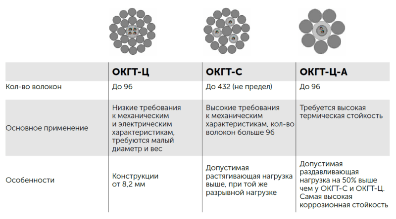
Таб. 1. Сравнение ОКГТ
В помощь проектировщику
- Конфигуратор ВОЛС на ВЛ с ОКГТ
Данный конфигуратор позволяет подсчитать необходимое количество комплектующих для проекта (грозозащитный трос, арматура, муфты) и составить сметы. - Конфигуратор подбора ОКГТ/ГТК
Используется для определения марки грозозащитного троса.
Монтаж ОКГТ: инструменты и комплектующие
Для работы с ОКГТ отлично подойдет стандартный набор инструментов НИМ-25 и специальный нож для резки модуля. Смотрите наш подробный материал про инструмент и правила разделки ВОК.
Инструкция по монтажу и вводу в эксплуатацию ОКГТ-Ц, ОКГТ-С и ОКГТ-Ц-А от Инкаб
1. Общие положения
1.1. Данная инструкция предназначена для обеспечения качественного выполнения процессов монтажа и ввода в эксплуатацию, а также самой эксплуатации оптических кабелей встроенных в грозозащитный трос типов ОКГТ-С, ОКГТ-Ц и ОКГТ-Ц-А производства ООО «Инкаб» (далее ОКГТ).
1.2. Целью данной инструкции является обеспечение условий в процессе монтажа, ввода в эксплуатации и эксплуатации для бесперебойной работы оптического кабеля в течение всего срока службы.
1.3. Инструкция обязательна для исполнения всеми организациями, осуществляющими монтаж и эксплуатацию ОКГТ.
1.4. Организации, осуществляющие монтаж и эксплуатацию оптических кабелей, должны иметь соответствующую лицензию.
1.5. Соединение строительных длин кабелей производится с использованием муфт типа МОПГ-М производства ЗАО «Связьстройдеталь».
1.6. Монтаж кабелей на опорах ВЛ рекомендуется производить в комплекте со следующей арматурой подвески производства фирмы ЗАО «Электросетьстройпроект» (ЗАО ЭССП):
- зажимы натяжные спиральные типа НСО (ТУ 3449-022-27560230-2010) для анкерного крепления ОКГТ к опоре;
- зажимы поддерживающие спиральные типа ПСО (ТУ 3449-023-27560230-2010) для поддерживающего крепления ОКГТ к опоре;
- протекторы защитные спиральные типа ПЗС (ТУ 3449-007-27560230-2006);
- гасители вибрации типа ГВ (ТУ 3449-081-27560230-2006).
2. Основные нормативные документы
2.1. При осуществлении монтажа, ввода в эксплуатацию и эксплуатации ОКГТ, организации должны руководствоваться следующими общими нормативными документами:
2.1.1. Руководство по строительству линейных сооружений магистральных и внутризоновых оптических линий связи 1993г.
2.1.2. Инструкция по проведению работ в охранных зонах магистральных и внутризоновых кабельных линий связи.
2.1.3. Руководство по строительству международных и национальных волоконно-оптических линий связи. М., 1995г.
2.1.4. Р 50-601-40-93. Рекомендации. Входной контроль. Основные положения. М. 1993.
2.1.5. Монтаж и электрические измерения линейно-кабельных сооружений связи. КТЕ 24-1-97. М., 1997г.
2.1.6. Правила ввода в эксплуатацию сооружений связи. Утв. Приказом Минсвязи 09.09.2002г. СПб.: 2002г.
2.1.7. РД 45.047-99. Линии передачи волоконно-оптические на магистральной и внутризоновых первичных сетях ВСС России. Техническая эксплуатация.
2.1.8. ПУЭ (Правила устройства электроустановок). Раздел 2. В 7-й редакции.
2.1.9. Стандарт организации ОАО «ФСК ЕЭС» СТО 56947007-33.180.10.172-2014 Технологическая связь. Правила проектирования, строительства и эксплуатации ВОЛС на воздушных линиях электропередачи напряжением 35 кВ и выше.
2.1.10. Стандарт организации ОАО «ФСК ЕЭС» СТО 56947007-33.180.10.171-2014 Технологическая связь. Эталон проектной документации на строительство ВОЛС-ВЛ с ОКСН и ОКГТ
2.1.11. Стандарт организации ОАО «ФСК ЕЭС» СТО 56947007-33.180.10.173-2014 Методические указанияпо расчету термического воздействия токов короткого замыкания и термической устойчивости грозозащитных тросов и оптических кабелей, встроенных в грозозащитный трос, подвешиваемых на воздушных линиях электропередачи
2.1.12. Стандарт организации ОАО «ФСК ЕЭС» СТО 56947007-33.180.10.174-2014 Оптический кабель, встроенный в грозозащитный трос, натяжные и поддерживающие зажимы, муфты для организации ВОЛС-ВЛ на линиях электропередачи напряжением 35 кВ и выше. Общие технические условия.
2.1.13. ФЗ 24.06.1998 N 89-ФЗ «Об отходах производства и потребления».
3. Основные требования при транспортировке и хранении
3.1. При транспортировке барабаны не должны лежать на щеке и должны быть надежно закреплены. При креплении барабанов запрещается пробивать доски щек и обшивки барабана гвоздями и скобами.
3.2. ОКГТ должен транспортироваться только на барабане завода-изготовителя.
3.3. При погрузке (разгрузке) барабанов необходимо пользоваться специальным оборудованием, исключающим удары и механическое повреждение барабанов. Запрещается скидывать барабаны с транспортного средства, скатывать с горок.
3.4. После транспортировки барабаны должны быть проверены на отсутствие повреждений и целостность защитных приспособлений.
3.4. При хранении барабаны должны быть защищены от механических воздействий, а также от солнечных лучей, атмосферных осадков и пыли.
3.5. При хранении барабаны не должны лежать на щеке.
3.6. При хранении не допускается установка барабанов друг на друга (рис. 1.):
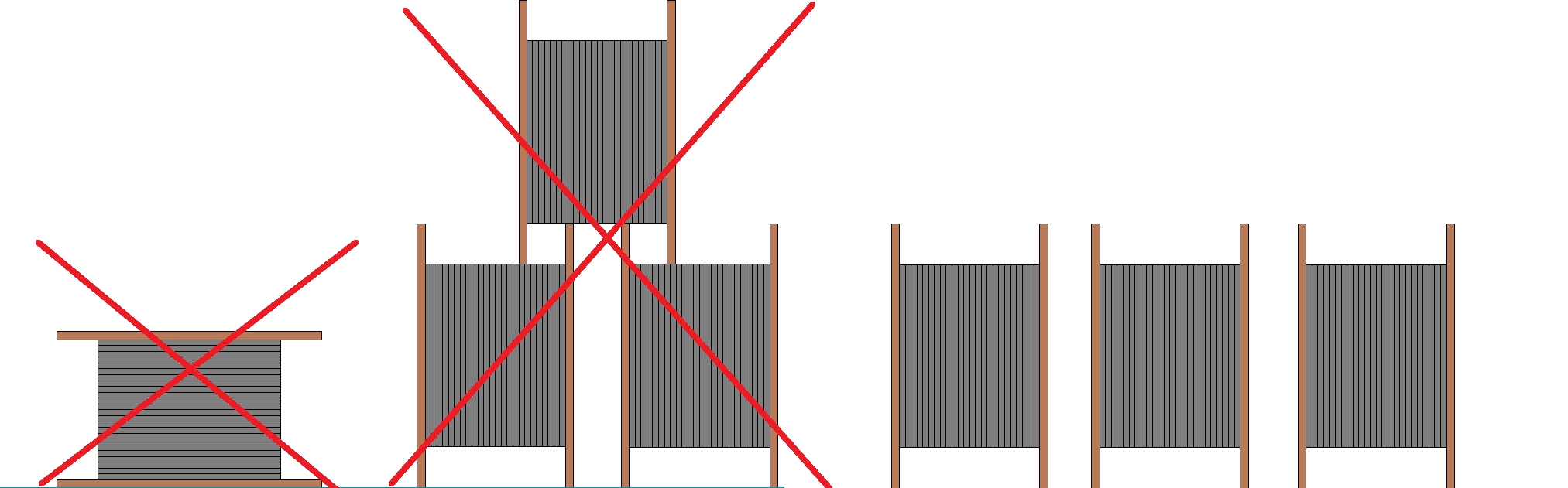
Рис. 1. Требования при транспортировке и хранении барабанов
3.7. Температура хранения: от минус 60 о С до 70 о С.
3.8. Концы ОКГТ при хранении должны быть защищены с помощью специальных герметизирующих термоусаживающихся колпачков.
3.9. Обшивка барабана снимается только после начала работ после установки барабана на козлы, с разрешения ответственного руководителя работ.
3.10. При сматывании ОКГТ с барабана обязательно должны использоваться козлы или другие раскаточные приспособления. Кабель с барабана должен сматываться с верхней его части (рис. 2.):
Рис. 2. Схема сматывания ОКГТ с барабана
4. Монтаж ОКГТ
4.1. Необходимо предпринимать меры предосторожности во избежание повреждения ОКГТ при выполнении операций по его монтажу. Критически важным является соблюдение указанного минимального радиуса изгиба и максимальных усилий натяжения для данного ОКГТ. Необходимо предпринимать меры по исключению резких изгибов или превышения рекомендуемых растягивающих усилий. Нельзя допускать осевых кручений кабеля.
4.2. Рекомендуемые диаметры и радиусы изгибов ОКГТ при монтаже:
4.2.1. В процессе монтажа не допускается изгибать ОКГТ на радиус изгиба меньше, чем 20 внешних диаметров ОКГТ.
4.2.2. Минимальный диаметр тормозного барабана должен быть не менее 70 внешних диаметров ОКГТ.
4.2.3. Диаметр раскаточного ролика (по желобу) — не менее 40 внешних диаметров ОКГТ (при угле перегиба ОКГТ на ролике не более 30°).
4.2.4. Минимальный диаметр промежуточного раскаточного ролика должен быть не менее 350 мм.
4.2.5. Для углов поворота трассы до 60° минимальный диаметр раскаточного ролика 60 внешних диаметров ОКГТ.
4.3. Запрещается проводить монтаж ОКГТ при температуре окружающей среды ниже минус 30 градусов по Цельсию.
4.4. Перед началом монтажных работ следует осмотреть маршрут прокладки ОКГТ, чтобы убедиться в отсутствии препятствий. Нельзя допускать волочения ОКГТ по земле или через препятствия.
4.5. Максимальное монтажное тяжение не должно превышать среднеэксплуатационную нагрузку более чем на 5%.
4.6. Монтажное оборудование.
В качестве лидер-троса может использоваться стальной трос (существующий грозозащитный трос), если он обладает достаточной прочностью, чтобы выдержать натяжение при раскатке ОКГТ. Если грозозащитный трос не имеет достаточной прочности, а также, если он отсутствует, то в качестве троса-лидера применяют специальный малокрутящийся многожильный плетеный трос (желательно крестовой свивки). Длина лидер-троса должна быть больше длины ОКГТ на величину равную высоте опоры, умноженной на шесть.
4.6.2 Монтажные ролики (рис. 3):
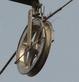
Рис. 3. Монтажный ролик
Раскаточные ролики должны иметь шлифованные или покрытые пластмассой (обрезиненные) желоба. Вкладыши должны быть гладкими и не иметь внешних признаков износа. Рекомендуется использовать ролики с желобами, покрытыми неопреном или полиуретаном. Глубина паза ролика должна быть минимум вдвое больше толщины кабеля. Малейшие неровности необходимо отшлифовать наждачной бумагой для обеспечения гладкой поверхности. Ролики в блоках должны легко вращаться.
Рекомендуемый диаметр раскаточного ролика на промежуточных и анкерно-угловых опорах с углом поворота менее 5 градусов должен составлять 40 наружных диаметров кабеля. На крайних опорах, а также на анкерно-угловых опорах с углом поворота более 5 градусов (но не более 60°), а также на высотных опорах, как правило, применяют ролики с диаметром по желобу не менее 60 диаметров кабеля. На угловых опорах с углом поворота более 60 градусов применяются ролики большего диаметра (1000 мм) или «тандемы» из двух и более роликов.
Недопустимо подвешивать два или более ролика независимо на опору. Система роликов должна объединяться общей рамой, вся система в целом должна крепиться к одной точке.
Ролики с опор разрешается спускать только при помощи веревки или в корзине телевышки.
Периодически ролики необходимо смазывать.
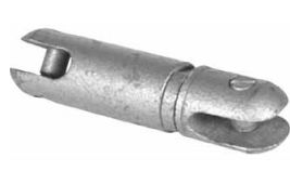
4.6.3. Устройство предотвращения скручивания.
Поскольку в процессе монтажа не допускается осевое кручение кабеля, на нем вблизи узла стыковки с тяговым тросом устанавливаются специальные устройства – противовесы, предотвращающие его кручение. Эти устройства представляют собой массивные гибкие шланги (например, в виде кусков троса) длиной 2–3 м с грузом на конце, подвешиваемые вертикально к кабелю с помощью специального шарнирного зажима, позволяющего им поворачиваться и располагаться вдоль кабеля при прохождении через раскаточные ролики. При этом ширина желоба роликов должна быть достаточной для свободного прохождения ОКГТ с этим устройством.
При монтаже ОКГТ методом «под тяжением» в результате трения лидер-троса (старого ОКГТ) о «щеки» роликов и иных механических воздействий в тросе возникает крутящий момент. Для компенсации крутящих усилий, передаваемых от тягового троса на ОКГТ, применяют устройство предотвращения скручивания в виде осевого шарнира — вертлюга. Он устанавливается между лидер-тросом и ОКГТ.
4.6.4. Устройство для смотки кабеля.
Устройство должно обеспечивать плавную смотку ОКГТ вращением барабана. Смотка тяжением не допустима. Возможное натяжение ОКГТ при размотке не должно превышать 70 кг для предотвращения провала витков внутрь намотки и дальнейшего заклинивания.
4.7. Подготовка к протяжке
4.7.1. Перекладка грозозащитного троса на промежуточных опорах
Перекладка грозозащитного на промежуточных опорах в ролики производится теми же способами, что и при монтаже грозозащитного троса на ВЛ.
Трос должен быть свободен от виброгасителей и другой арматуры, а также не иметь поврежденных проволок.
В случае наличия поврежденных проволок, необходимо наложить бондаж, препятствующий расплетению троса.
Если виброгаситель или место повреждения проволоки находится на удалении от опоры, то необходимо провести подтяжку к опоре и устранить дефект.
Перед перекладкой грозозащитного троса в ролик необходимо убедиться в исправности ролика, а после перекладки убедиться, что ролик висит свободно, и не препятствует его работе во время протяжки.
4.7.2. Перекладка грозозащитного троса на проходных анкерно-угловых опорах.
На анкерно-угловых опорах грозозащитный трос смежных пролетов соединяют и перекладывают в ролик.
- Закрепляется монтажный трап одним концом за тросостойку, а другим — за грозозащитный трос так, чтобы он располагался параллельно грозотросу;
- Устанавливается монтажный зажим (клиновой или болтовой) на грозозащитном тросе на таком расстоянии от натяжного зажима, чтобы освободившийся конец грозотроса был длиннее кабельного захвата (монтажного чулка);
- При помощи ручной лебедки, один конец которой через строп соединен с тросостойкой, а другой с монтажным зажимом, освобождается от тяжения натяжное крепление грозозащитного троса;
- Удаляется вся арматура, виброгасители. На освобожденный конец грозозащитного троса устанавливается монтажный чулок (рис. 5.):
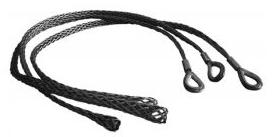
Рис. 5. Монтажный чулок
- Край чулка на кабеле фиксируется с помощью установки бандажей. Крайний проволочный бандаж и конец чулка покрывается двумя слоями изоляционной ленты с заходом на трос (рис. 6.):
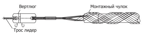
Рис.6. Схема установки монтажного чулка
- Чулок укладывается в раскаточный ролик, подвешенный к тросостойке на строп или дополнительную консоль;
- Данная операция проделывается с другой стороны опоры (рис. 7.):
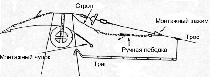
Рис. 7. Схема соединения грозозащитных тросов на анкерной опоре
- Чулки соединяются между собой при помощи специальной соединительной скобы, либо вставляется строп необходимой длины и необходимой прочности. Строп с чулком соединяется также соединительной скобой;
- Обе лебедки поочередно освобождаются, при этом грозозащитный трос направляется в середину канавки ролика. При ослаблении лебедок необходимо убедиться, что монтажные чулки затянулись и надежно держат грозозащитный трос, ролик свободно отклоняется от тросостойки. В некоторых случаях необходимо устанавливать подпорку, отклоняющую ролик от опоры или применять комбинацию роликов меньшего диаметра;
- Монтажные зажимы снимаются, с опоры убирается все, что может препятствовать раскатке троса.
4.7.3 Защита от падения грозозащитного троса
Защита выполняется в тех местах, где монтируемый ОКГТ проходит над ВЛ, кабелями и линиями связи, железными и автомобильными дорогами, фарватерами и другими сооружениями или территориями, где из-за возможного ослабления тяжения или падения ОКГТ может возникнуть опасная ситуация. Защита может быть выполнена из подходящих порталов, изготовленных из стальных труб, бревен, уголков, на которых натягивается сеть из капроновой веревки большего диаметра, и устанавливается в местах, где линия пересекает защищаемый объект. Такие защиты должны устанавливаться прочно, с оттяжками, чтобы выдержать горизонтальные усилия при раскатке.
Защита может быть выполнена в виде ролика-ловушки, подвешенного на фазные провода под монтируемым тросом.
О работе по установке защит необходимо заблаговременно известить владельцев пересекаемых объектов.
Если защита не может быть установлена безопасно, то с владельцами объектов необходимо согласовать меры, обеспечивающие безопасное производство работ.
4.7.4. Работа с натяжной и тормозной машиной.
Натяжная машина должна иметь лебедку с плавно изменяющейся скоростью протяжки с устройством реверса, прибор изменения тягового усилия, ограничитель заданного максимального тяжения (рис. 8.):
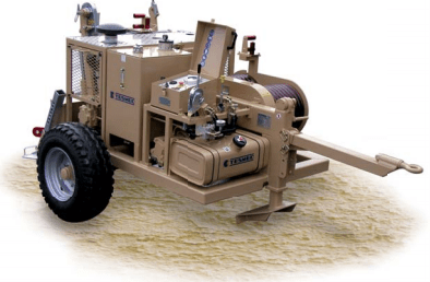
Рис. 8. Натяжная машина
Тормозная машина должна создавать плавно регулируемые усилия торможения и иметь прибор измерения натяжения ОКГТ.
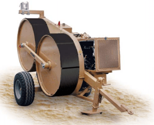
Рис. 9. Тормозная машина
Заправка витков ОКГТ на тормозные барабаны тормозной машины должно производиться таким образом, чтобы внешний повив кабеля подкручивался, а не раскручивался.
Тормозная и натяжная машины устанавливаются на спланированных площадках на расстоянии от концевых опор не менее двух их высот.
Тормозная и натяжная машины должны быть на одной линии с осевой линией проводов. Максимально возможное отклонение не должно превышать угол в 30 градусов
Расположение машин должно обеспечить отсутствие трения кабеля о реборды роликов, касания токоведущих частей ВЛ и элементов опоры.
На место установки тормозной машины доставляется барабан с кабелем.
Выгружается с помощью крана и устанавливается на раскаточные козлы, оборудованные механическим тормозом.
Барабан с кабелем должен иметь строительную длину, соответствующую длине монтируемого пролета.
После разрешения руководителя работ с барабана снимается обшивка. Обшивка с барабана снимается только после его установки на раскаточные козлы.
Тормозная машина устанавливается на 5–6 м от барабана и надежно закрепляется.
Барабан на козлах устанавливается таким образом, чтобы кабель сходил с верха барабана. Щеки были параллельны раскатываемому кабелю, а ось вращения горизонтальна. Из внутренней стороны щек барабана удаляют гвозди или другие предметы, способные повредить кабель.
Козлы с барабаном, тормозную машину необходимо заземлить. Также устанавливается скользящее заземление на ОКГТ вблизи машины.
Для тормозной машины:
Веревка заправляется в барабаны тормозной машины и соединяется с монтажным чулком, установленным на начало ОКГТ. Далее кабель втягивается в канавки кабестанов. Монтажный чулок через вертлюг соединяется с отрезком лидер-троса (длиной 2-3 высоты опоры). Второй конец поднимается на опору. далее отрезок лидер-троса соединяется с грозотросом как описано выше.
Для натяжной машины:
Вспомогательный лидер-трос закрепляется на приемном барабане, укладывается в канавки кабестанов лебедки, затем другой конец поднимается на опору и соединяется с грозотросом.
4.8. Протяжка ОКГТ
Перед протяжкой необходимо установить устойчивую двустороннюю радиосвязь между всеми участниками работ.
Начало протяжки осуществляется только после команды руководителя работ.
При прерывании радиосвязи работы немедленно прекращаются.
Типичная схема протяжки ОКГТ показана на рис. 10:
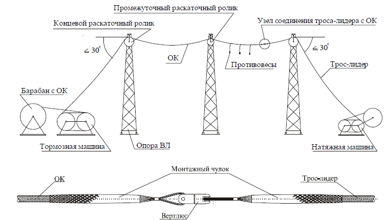
Рис. 10. Схема протяжки ОКГТ
Тормозной машиной медленно начать отпускать ОКГТ, увеличивая его стрелу провеса. После этого натяжной машиной начать вытягивать трос-лидер.
Начальная скорость протяжки 5 м/мин может быть увеличена после прохождения кабельного захвата первой опоры до 100 м/мин.
Тормозной машиной регулируется усилие торможения таким образом, чтобы обеспечить постоянное усилие и стрелу провеса. Стрела провеса при протяжке должна быть больше визируемой. Однако ОКГТ не должен провисать ниже нижних фазных проводов ВЛ, по которой ведется монтаж.
Не допускается волочение кабеля по земле и трения его о пересекаемые инженерные сооружения.
Механический тормоз на козлах должен быть отрегулирован таким образом, чтобы приостановках раскатки барабан сразу останавливался, но в то же время не создавал значительного растягивающего усилия кабеля между тормозной машиной и барабаном.
Во избежание рывков в начальный момент протяжки, необходимо следить за отсутствием провеса ОКГТ между тормозной машиной и барабаном. На натяжной машине необходимо установить ограничитель на значение равное или меньше максимально допустимого монтажного тяжения.
Необходимо следить за прохождением вертлюга через ролики по всему участку протяжки, контролировать прохождение кабеля по ролику.
Угол вертикального отклонения ролика должен соответствовать углу отклонения плоскости ОКГТ во избежание выхода кабеля или троса-лидера из ролика.
При остановке протяжки сначала останавливается натяжная машина, затем тормозная, возобновление протяжки происходит в обратном порядке. Во время остановок тормозная машина не блокируется – только увеличивается тормозное усилие.
Во время протяжки необходимо проверять целостность ОКГТ и его элементов.
Протяжка считается законченной, когда ОКГТ прошел раскаточный ролик на концевой опоре у натяжной машины на расстояние, равное высоте опоры плюс запас 15 -20 метров.
4.9. Установка стрел провеса и закрепление ОКГТ.
Стрелы провеса ОКГТ должны устанавливаться в строгом соответствии с проектной документацией.
Вытягивать ОКГТ на визируемую стрелу провеса необходимо медленно без рывков, не превышая среднеэксплуатационного тяжения более чем на 5%.
Если тормозная машина оборудована приводом, создающим достаточное усилие для визирования ОКГТ, то установку натяжных креплений можно начинать с какого-либо проходного анкера и затем продолжать в обе стороны от него.
В противном случае первое натяжное крепление устанавливается на опоре у тормозной машины, и визировка производится натяжной машиной.
Недопустимо производить регулировку стрел провеса ходовым усилием тракторов или автомобилей или тракторными (автомобильными) лебедками.
Визировку, по возможности, следует производить в самом длинном пролете анкерного участка.
- после монтажа первого натяжного зажима подвесить рейку на тросостойку опоры, а вторую рейку – на вторую опору, ограничивающие визируемый пролет. Установить на рейках стрелу провеса в соответствии с проектом для данного пролета и с учетом температуры воздуха на момент визировки;
- протянуть кабель до момента, когда нижняя точка провеса кабеля совпадет с линией визирования между рейками;
- закрепить монтажный трап параллельно ОКГТ одним концом на опоре, а другим концом при помощи захвата за ОКГТ;
- спроецировать на ОКГТ при помощи отвеса центр отверстия на опоре, к которому будет крепиться сцепная арматура, и отметить фломастером;
- от отметки отмерить длину сцепной арматуры минус расстояние, на которое защитная спираль (протектор) выступает за конец натяжной спирали и отметить фломастером. Это точка начала навивки защитной спирали;
- от отметки начала навивки защитной спирали отмерить длину защитной спирали и сделать отметку;
- совместить центр защитной спирали с отметкой на ОКГТ и начать навивку в обе стороны. Стержни спирали навивать плотно и без зазоров. Концы заправить при необходимости резиновым молотком. Отступить необходимое расстояние от начала защитной спирали и начать навивку натяжной спирали;
- вставить коуш в натяжную спираль, ручной лебедкой подтянуть его к опоре для соединения со сцепной арматурой. После фиксации отпустить ручную лебедку;
- ослабить тормоз на натяжной машине.
Если опора проходная, сделать крепление с другой стороны по аналогичной процедуре, учитывая длину шлейфа, который должен провисать от точки крепления на 0,4-0,5 м.
После закрепления ОКГТ в зажимах к опоре демонтировать ролик. Выполнить необходимые заземления шлейфов и спусков ОКГТ к опоре.
Если для пролета требуются виброгасители, они должны быть установлены на ОКГТ немедленно после закрепления.
Операция установки стрелы провеса и крепления ОКГТ должна быть завершена в течение того же дня.
Если эта операция не может быть завершена в тот же день, ОКГТ должен быть привязан нейлоновым канатом для ограничения его движения на роликах.
Не допускается оставлять ОКГТ в раскаточных роликах более чем на 48 часов.
4.10. Спуск ОКГТ к муфте по телу опоры (при необходимости).
ОКГТ спускается по телу опоры начиная с верхней секции, перепуская кабель со стороны натяжного зажима в сторону конца кабеля.
Необходимо следить за соблюдением минимального радиуса изгиба ОКГТ при протаскивании его через обрешетку тросостойки.
При помощи монтажной веревки аккуратно опустить конец ОКГТ.
Размещение спуска ОКГТ должно выполняться по обрешетке опоры вдоль пояса. ОКГТ в обрешетке крепится специальными плашечными шлейфовыми зажимами – струбцинами на расстоянии примерно 1,5–2 м друг от друга.
На опорах с муфтами кабель должен быть зафиксирован до места установки муфты сразу после протяжки.
Открытые концы ОКГТ должны быть загерметизированы.
Смотать остаток кабеля в бухту диаметром не менее 1 м, поднять на опору и надежно закрепить. После соединения кабеля в муфте, муфта поднимается и крепится к опоре, а оставшаяся длина ОКГТ сматывается в специальное устройство для хранения технологического запаса.
4.11. Перекладка ОКГТ на промежуточных опорах.
После установки натяжных креплений необходимо приступить к перекладке ОКГТ из роликов в поддерживающие крепления. На проходных анкерах, не имеющих угла поворота трассы, также можно выполнить поддерживающее крепление ОКГТ.
Перед началом перекладки центр крепления поддерживающего зажима проецируется на кабель и делается отметку фломастером. ОКГТ освобождается из ролика при помощи специальной балки и ручной лебедки (рис. 11):
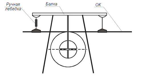
Рис. 11. Схема освобождения ОКГТ на промежуточной опоре
Необходимо учитывать следующее:
- захваты должны быть выполнены в виде «лодочки»;
- длина балки должна быть больше, чем длина спиралей оплетки поддерживающего крепления;
- длина сцепки захвата с балкой должна быть меньше длины сцепной арматуры поддерживающего крепления;
- корпус поддерживающего зажима (или ОКГТ вблизи зажима) должен быть соединен заземляющим тросом с заземленным элементом опоры.
4.12. Точки соединения строительных длин.
Перед началом монтажа муфты, уложенные на опоре после раскатки концы ОКГТ опускаются на землю. Запас длины в местах соединения строительных длин в муфтах должен быть выбран с учетом возможности выполнения сварки оптических волокон на земле в передвижной лаборатории и должен составлять не менее 15 м.
Порядок разделки ОКГТ и монтажа его в муфте должен соответствовать инструкции монтажа муфты МОПГ производства ЗАО «Связьстройдеталь».
После выполнения операции по соединению оптических волокон ОКГТ в муфте и размещению ее на опоре производится укладка избыточной длины (технологического запаса) в специальное устройство, например шлейфовый барабан (рис. 12 и 13):
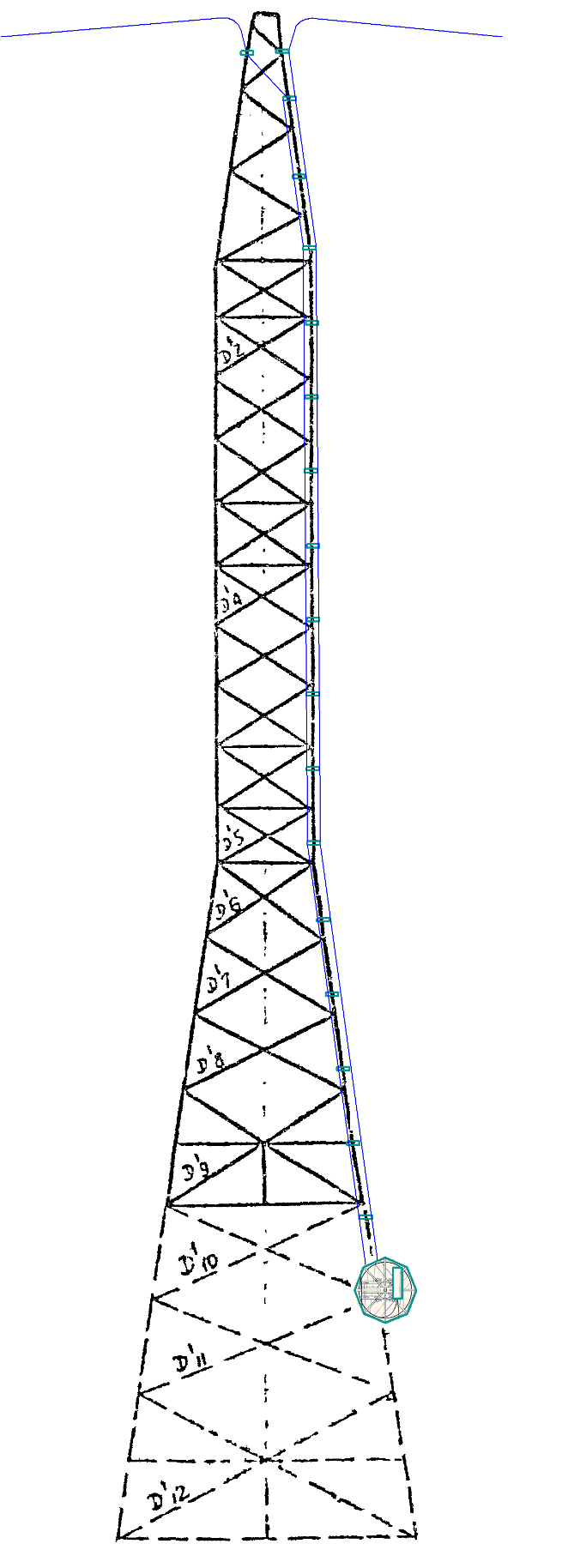
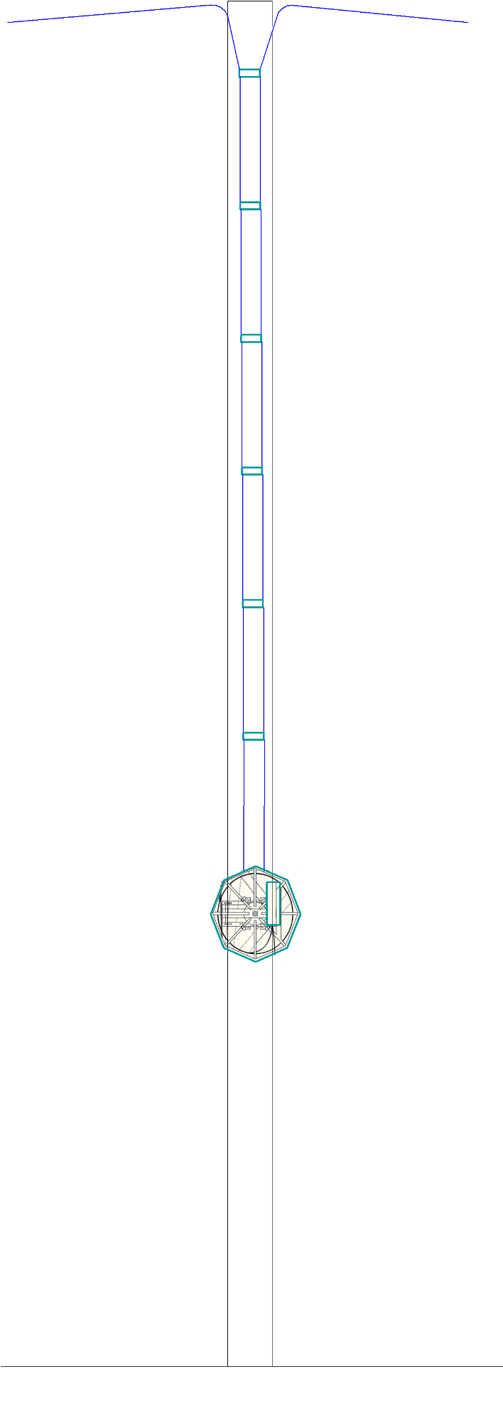
Рис. 12. Размещение ОКГТ на опорах
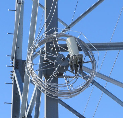

Рис. 13. Устройство для установки муфты и хранения технологического запаса ОКГТ
Соединительная муфта должна устанавливается на высоте не менее 5 м от уровня земли.
Нижняя точка спуска ОКГТ при входе в муфту должна располагаться на высоте не менее 5 м.
5. Разделка ОКГТ
5.1. Разделку кабеля должен проводить обученный и аттестованный персонал.
5.2. Необходимо пользоваться только специальным набором инструментов для монтажа оптического кабеля.
5.3. Длина разделки указывается в специальных инструкциях по монтажу муфт. Для проведения входного контроля, длина участка разделки составляет не более 300 мм.
5.4. Разделка кабеля для входного контроля или его соединения в муфтах должен осуществляться следующим образом:
5.4.1. Замерить рулеткой расстояние 2400 мм от конца кабеля и поставить метку маркером.
5.4.2. Отступить от метки 30 мм и поставить временный бандаж из проволоки, ленты ПВХ или стянуть проволоки нейлоновой стяжкой.
5.4.3. Осторожно подпилить проволоки наружного повива ножовкой, в первоначально отмеченном месте, стараясь не повредить стальной модуль.
5.4.4. Проволоки повива кабеля расплести по одной с конца кабеля, откусить болторезом частями по 70 см и осторожно отломить в месте надпила.
5.4.5. Поставить постоянный бандаж из медной проволоки или ленты ПВХ и удалить временный бандаж.
5.4.6. Промыть наружную поверхность стального модуля от гидрофобного заполнителя жидкостью «D-Gel».
5.4.7. Для конструкций типа ОКГТ-Ц-А алюминиевую часть оптического модуля пропилить трехгранным надфилем до стальной части модуля в плоскости разделки кабеля
5.4.8. Очистить наружную поверхность стального модуля. Обрезку модуля производить специальным устройством для резки стальной трубки или, при его отсутствии, трехгранным надфилем. При работе надфилем опилить модуль по окружности и осторожно отломить плоскогубцами. Во избежание повреждения волокон, трубку удалять отрезками около 70 см.
5.4.9. Удалить гидрофобный заполнитель безворсовыми салфетками и специальной жидкостью «D-Gel».
6. Ввод в эксплуатацию ОКГТ
6.1. При готовности волоконно-оптической линии связи к сдаче в эксплуатацию, заказчиком назначается рабочая комиссия.
6.2. При проверке качества выполненных работ по подвеске ОКГТ, рабочая комиссия проводит сплошной визуальный контроль подвешенного оптического кабеля, проверяет соответствие стрел провеса, качество крепления ОКГТ, правильность спусков кабеля.
6.3. Эксплуатация кабеля не принятого в эксплуатацию приемочной комиссией не допускается.
7. Эксплуатация ОКГТ
7.1. Эксплуатация ОКГТ, подвешенного на опорах, заключается в проведении технического обслуживания и ремонта, направленных на обеспечение его надежной работы.
7.2. При техническом обслуживании выполняются следующие виды работ:
7.2.1. Периодические осмотры в дневное время без подъема на опору (не реже 1 раза в 6 месяцев).
7.2.2. Выборочная проверка состояния ОКГТ в зажимах (1 раз в 3 месяца в первый год, далее 1 раз в год).
7.2.3. Внеочередной осмотр после образования гололеда на оптическом кабеле.
7.2.4. Проверка состояния оптического кабеля путем замера затухания и др. параметров. (не реже 1 раза в 6 месяцев).
7.2.5. Проверка стрел провиса ОКГТ после образования гололеда.
7.2.6. Наблюдение за образованием гололеда путем измерения толщины стенки гололеда, изменения стрелы провиса.
7.3. Результаты технического обслуживания должны быть зафиксированы в соответствующей документации.
7.4. В случае несоответствия стрел провиса допустимым значениям, необходимо провести перетяжку ОКГТ.
7.5. Определение места повреждения ОКГТ осуществляется путем измерения затухания с измерением расстояния до повреждения.
7.6. Повреждения ОКГТ устраняются с помощью монтажа временной вставки.
7.7. После восстановления связи с помощью временной вставки, производится подвеска и монтаж ОКГТ для организации связи по постоянной схеме. После чего временная вставка демонтируется.
8. Требования техники безопасности
8.1. Необходимо соблюдать все правила техники безопасности при работе с энергосистемами общего пользования. Эти правила техники безопасности имеют преимущество перед любой информацией, содержащейся в этом документе.
Важно, чтобы всё оборудование было надлежащим образом заземлено, заземление должно выполняться до начала производства работ.
Запрещается монтировать ОКГТ на находящихся под напряжением опорах линий электропередач.
8.2. При эксплуатации оптического кабеля персоналом следует соблюдать «Межотраслевые Правила по охране труда (правила безопасности) при эксплуатации электроустановок».
8.3. К монтажу и эксплуатации оптического кабеля допускается персонал, прошедший курс обучения технологическим правилам и приемам работ.
8.4. Весь персонал, участвующий в работах по монтажу ОКГТ должен быть проинструктирован об условиях обращения с кабелем и ознакомлен с данной инструкцией.
Ответственность за правильное инструктирование персонала, участвующего в монтажных работах, лежит на монтажной организации.
8.5. Монтаж оптического кабеля производится по Проектам производства работ, а обслуживание в эксплуатации — по технологическим картам.
8.6. При раскатке оптического кабеля операции по смене барабанов с “канатом-лидером” на натяжной машине должны выполняться только после временного закрепления кабеля.
8.7. При работе с кабелем во время монтажа соединительных муфт необходимо избегать прикосновений оптических волокон к незащищенному телу, чтобы предотвратить попадание стеклянных частиц волокон на кожу и в организм.
8.8. При выполнении ремонтных работ необходимо соблюдать меры безопасности, которые должны быть отражены в технологической карте.
8.9. Все виды работ на высоковольтной линии с ОКГТ должны выполняться только по нарядам или распоряжениям.
9. Утилизация ОКГТ
Обращение, размещение, хранение, переработка и захоронение ОКГТ, выведенного из эксплуатации и потерявшего свои эксплуатационные свойства производится в соответствии с федеральным законом от 24.06.1998 N 89-ФЗ «Об отходах производства и потребления».
Оптические муфты для монтажа
Предназначаются для соединения (прямого или разветвительного) строительных длин оптического кабеля встроенного в грозотрос (ОКГТ). Также есть возможность смонтировать «гибридную» муфту (ввод подвесного самонесущего кабеля (ДПТ) или кабеля с броней в виде стеклопластиковых прутков (ДПД)), используя комплект ввода типа КВСМ (КВСц) (рис. 4).
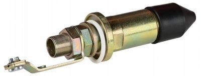
Рис. 4. Комплект для ввода ОК с модульной конструкцией (КВСм)
Муфты МОПГ-М-1 и МОПГ-М-2
В отличие от «обычных» муфт, корпус МОПГ изготовлен из металла. Герметизация муфты происходит за счёт эластичной прокладкой, а также четырьмя болтами затяжного типа. Для установки муфты используются специальные шлейфовые барабаны или кронштейны. При монтаже запасов кабеля на барабан (рис. 5), исключается возможность прокручивания кабеля на вводах в муфту.
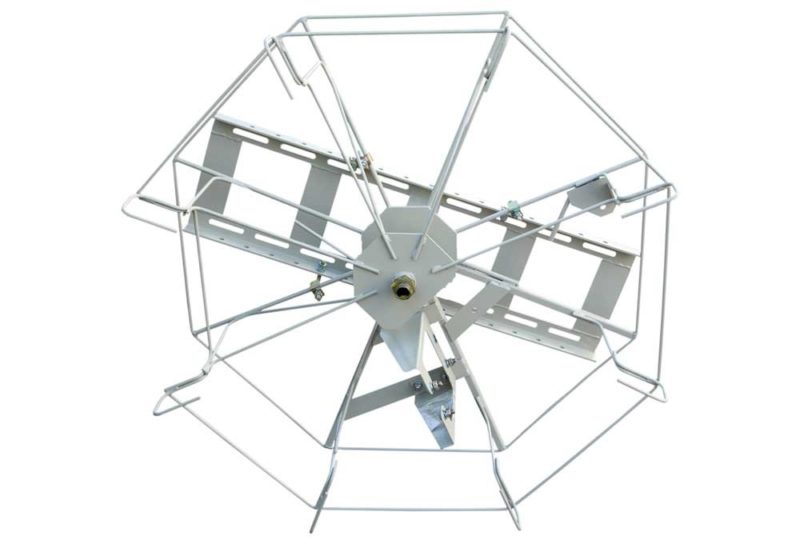
Рис. 5. Барабан БШ-3-3
МОПГ-М-2 (рис. 6) имеет меньшие габариты по сравнению с МОПГ-М-1 (рис. 7), максимальная ёмкость муфты 64 сварки ОВ. В муфту есть возможность ввести до трёх оптических кабелей с использованием специальных комплектов ввода, которые подбираются в зависимости от конструкции и диаметра монтируемых кабелей.
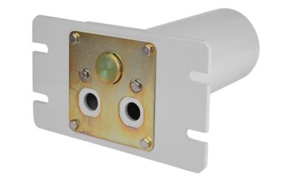
Рис. 6. Муфта МОПГ-М-2
МОПГ-М-1 (рис. 7) можно ввести до четырёх оптических кабелей с использованием специальных комплектов ввода, которые подбираются в зависимости от конструкции и диаметра монтируемых кабелей.
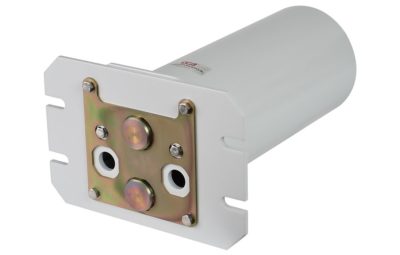
Рис. 7. Муфта МОПГ-М-1
Для ввода используются специальные кабельные вводы (рис. 8), которые подбираются строго в зависимости от конструкции и диаметра вводимого грозотроса (ОКГТ).
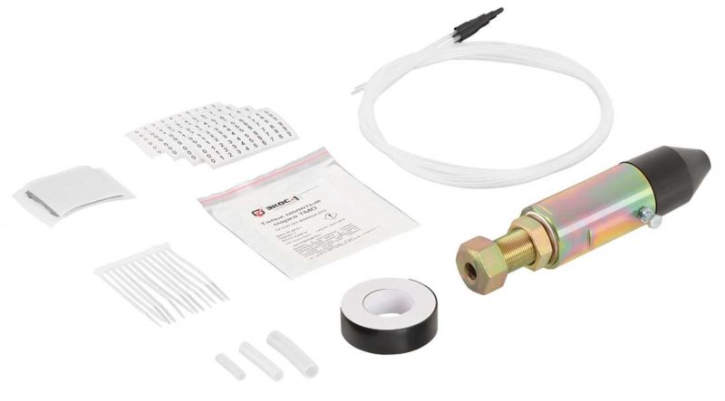
Рис. 8. Комплект для ввода кабеля ОКГТ в муфту МОПГ-М КВГ
Муфты МОПГ-МП-1
Муфта МОПГ-МП-1 (рис. 9) предназначена для кабелей ОКГТ, на которых используется функция плавки гололёд, имеет металлический корпус.
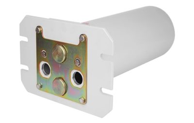
Рис. 9. Муфта МОПГ-МП-1
В комплекты для ввода ОКГТ с плавкой льда входят диэлектрические втулки, которые изолируют корпус муфты от грозотроса с электрической прочностью 1000 В (рис. 10).
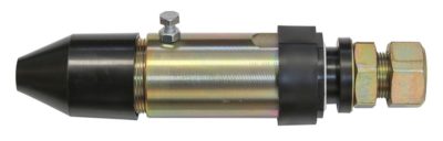
Рис. 10. Комплект для ввода грозотроса (ОКГТ) в муфту МОПГ-МП КВГП
Обзор арматуры для ОКГТ смотрите в отдельном материале.
Видео разделки ОКГТ
Инструкция по разделке оптического кабеля ОКГТ-Ц и ОКГТ-Ц-А:
Инструкция по разделке оптического кабеля ОКГТ-С:
Монтажные, ремонтные и другие работы на грозотросе ОКГТ, в отличии от подвесных ВОЛС на основе кабеля ОКСН, происходят только с обязательным отключением ЛЭП.
Подписывайтесь на канал ВОЛС.Эксперт
Показываем, как правильно выполнять монтаж оптических муфт и кроссов, разбираем частые ошибки, даем полезные советы специалистам.
Мониторинг ЛЭП с помощью ОКГТ
Оптическое волокно можно использовать в качестве непрерывного датчика, поэтому ОКГТ также используется как элемент системы мониторинга состояния линий электропередач.
Заключение
При работе с оптическим кабелем встроенным в грозозащитный трос (ОКГТ) есть свои тонкости и нюансы. От правильного монтажа комплектов ввода (КВСм, КВГ и др.) до проведения измерений для сдачи готового объекта в эксплуатацию. Как это делать без ошибок, расскажем и покажем в рамках специального курса в нашем учебном центре — Монтаж и измерения ВОЛС на ВЛ.
Источник
-
Bookmarks
Quick Links
MW9076 Series
Optical Time Domain Reflectometer
Operation Manual
19th Edition
For safety and warning information, please read this
manual before attempting to use the equipment.
Keep this manual with the equipment.
ANRITSU CORPORATION
Document No.: M-W1659AE-19.0
Related Manuals for Anritsu MW9076 Series
Summary of Contents for Anritsu MW9076 Series
-
Page 1
MW9076 Series Optical Time Domain Reflectometer Operation Manual 19th Edition For safety and warning information, please read this manual before attempting to use the equipment. Keep this manual with the equipment. ANRITSU CORPORATION Document No.: M-W1659AE-19.0… -
Page 2
Ensure that you clearly understand the meanings of the symbols BEFORE using the equipment. Some or all of the following symbols may be used on all Anritsu equipment. In addition, there may be other labels attached to products that are not shown in the diagrams in this manual. -
Page 3
For Safety DANGER NEVER touch parts where the label shown on the left is attached. Such parts have high voltages of at least 1 kV and there is a risk of receiving a fatal electric shock. WARNING 1. ALWAYS refer to the operation manual when working near locations at which the alert mark shown on the left is attached. -
Page 4
6. The performance-guarantee seal verifies the integrity of the equipment. Calibration To ensure the continued integrity of the equipment, only Anritsu service personnel, or service personnel of an Anritsu sales representative, should break this seal to repair or calibrate the equipment. -
Page 5
For Safety WARNING 9. DO NOT short the battery terminals and never attempt to disassemble the battery or dispose of it in a fire. If the battery is damaged by any of these actions, the battery fluid may leak. This fluid is poisonous. DO NOT touch the battery fluid, ingest it, or get in your eyes. -
Page 6
If this warning light does not turn on, the equipment may be faulty and for safety reasons should be returned to an Anritsu service center or representative for repair. Optical units for MW9076 Series Optical Time Domain Reflectometer have Class 1, 1M laser emitting parts as specified in IEC 60825-1, or Class I, II parts as specified in 21 CFR 1040.10 (Refer to Table 1). -
Page 7
For Safety Class 1, 1M indicate the danger degree of the laser radiation specified below according to IEC 60825-1. Class 1: Lasers that are safe under reasonably foreseeable conditions of operation, including the use of optical instruments for intrabeam viewing. Class 1M: Lasers emitting in the wavelength range from 302.5 to 4000 nm that are safe under reasonably foreseeable conditions of operation, but may be hazardous if the user employs optics… -
Page 8
For Safety Laser Radiation Markings FDA (Attached when visible LD light source installed and only for exportation to the United States of America) (Attached when visible LD light source installed) FDA (Attached when visible LD light source installed and only for exportation to the United States of America) FDA (Attached only for exportation to the… -
Page 9
Back-up Battery the memory. This battery must be replaced by service personnel when it has reached the end of its useful life; contact the Anritsu sales section or your nearest representative. Note: The battery used in this equipment has a maximum useful life of 7 years. -
Page 10
In addition, this warranty is valid only for the original equipment purchaser. It is not transferable if the equipment is resold. Anritsu Corporation shall assume no liability for injury or financial loss of the customer due to the use of or a failure to be able to use this equipment. -
Page 11
Notes On Export Management This product and its manuals may require an Export License/Approval by the Government of the product’s country of origin for re-export from your country. Before re-exporting the product or manuals, please contact us to confirm whether they are export-controlled items or not. When you dispose of export-controlled items, the products/manuals need to be broken/shredded so as not to be unlawfully used for military purpose. -
Page 12
2002/96/EC (the “WEEE Directive”) in European Union. For Products placed on the EU market after August 13, 2005, please contact your local Anritsu representative at the end of the product’s useful life to arrange disposal in accordance with your initial contract and the local law. -
Page 13
CE Conformity Marking Anritsu affixes the CE Conformity marking on the following product(s) in accordance with the Council Directive 93/68/EEC to indicate that they conform to the EMC and LVD directive of the European Union (EU). CE marking 1. Product Model… -
Page 14
4. Authorized representative Name: Loic Metais European Quality Manager ANRITSU S.A. France Address, city: 16/18 Avenue du Quebec SILIC 720 Zone de Courtaboeuf 91951 Les Ulis Cedex Country: France… -
Page 15
C-Tick Conformity Marking Anritsu affixes the C-Tick marking on the following product(s) in accordance with the regulation to indicate that they conform to the EMC framework of Australia/New Zealand. C-Tick marking 1. Product Model Model: MW9076xx Optical Time Domain Reflectometer 2. -
Page 17
About This Manual This operation manual explains the operation, calibration and maintenance of the MW9076 Series Optical Time Domain Reflectometer (OTDR). The features of the OTDR are described in “Section 1 Outline.” This equipment can be connected to an external computer, from which the equip- ment can be controlled and the measurement results can be read out. -
Page 18
Table of Contents For Safety …………About This Manual ……..Section 1 Outline………. 1.1 Overview of MW9076 Series Optical Time Domain Reflectometer ……….1.2 Features …………..1.3 Loss and Total Return Loss Measurement and Splice & Return Loss Measurement …… -
Page 19
Section 4 Operation (OTDR Measurement)..4.1 Turning on the Power ……….4.2 Setting the Measurement Conditions ……4.3 Starting a Measurement ……….4.4 Reading the Event Table ……….. 4-10 4.5 More …………….4-13 4.6 Auto Zoom …………..4-15 4.7 Editing the Events …………4-16 4.8 Moving to the Manual Measurement Screen ….. -
Page 20
Section 8 Performance Test and Calibration ……..8.1 Performance Test …………8.2 Calibration …………..8-19 8.3 Performance Test Result Record Form ….. 8-20 Section 9 Maintenance ……… 9.1 Optical Connector & Optical Adapter Cleaning….. 9.2 Cleaning the Floppy Disk Drive ……… 9.3 Self-Diagnosis ………… -
Page 21
Section 1 Outline This section explains the features of the MW9076 Series, equipment composi- tion, and the measurement principle. For the performance and function specifica- tions, refer to “Appendix A Specifications.” Overview of MW9076 Series Optical Time Domain Reflectometer …….. -
Page 22
The term “MW9076* OTDR” refers to the combination of an MW9076 Series OTDR main unit and an MU250000A/A1/A4 display unit, while the term “MW9076* OTDR main unit” refers to a single MW9076 Series OTDR main unit. -
Page 23
1.1 Overview of MW9076 Series Optical Time Domain Reflectometer 1.1.1 Measuring cable loss and distance When laser light of a specific wavelength is introduced into an optical fiber cable from the OTDR, it is scattered as it propagates towards the far end of the cable. -
Page 24
Section 1 Outline Features 1.2.1 Automatic search of faults · · · Full Auto Mode/Auto Mode This function is convenient to use when the user does not know the locations of the faults. In this mode, faults in the cable are detected and displayed by pressing the Start key. -
Page 25
1.2 Features 1.2.2 Detailed measurement: Manual Mode In this mode, any position on the fiber can be measured by moving the markers to it. Set the measurement mode to Manual in advance on the Setup screen and press Start key. In this mode, “Loss and Total Return Loss Measurement” for obtaining the loss and total return loss of the cable and “Splice &… -
Page 26
Section 1 Outline 1.2.3 Making the settings while checking the measured waveform Preview mode In the Preview mode, the trace waveform is refreshed almost in real time (in about 0.1 to 0.5 seconds), permitting the adjustment of the connector connections while checking the waveform. -
Page 27
1.2 Features 1.2.5 Reducing measurement errors The OTDR provides check functions for preventing an incorrect measurement due to simple errors such as incorrect fiber connection. Checking the communication light in the fiber under test Any communication light in the fiber under test may affect the communication itself and prevent the OTDR from performing an accurate measurement. -
Page 28
Section 1 Outline 1.2.8 Event functions The fault, the connecting point, and the far end of the fiber cable at the time of Full Auto mode/Auto mode measurement are known as events. Events can be easily measured using this event function. Editing the event points When performing an automatic fault search in Full Auto/Auto mode, the OTDR may misidentify normal points as faults or miss real faults due to noise. -
Page 29
1.2 Features 1.2.11 Waveform comparison function Reads the waveform that is saved in a file as the reference waveform for OTDR. The reference waveform remains displayed on the OTDR monitor during mea- surement. This function displays the difference between the measured and refer- ence waveforms, thus the difference in distance and level easily observable. -
Page 30
Section 1 Outline 1.2.16 Versatile measurement functions OLTS (Optical Loss Test Set) measurement function. The OLTS measurement is used for measuring the loss of the fiber under test by connecting the fiber under test between the light source and the optical power meter. -
Page 31
1.3 Loss and Total Return Loss Measurement and Splice & Return Loss Measurement Loss and Total Return Loss Measurement and Splice & Return Loss Measurement Either Loss and Total Return Loss Measurement or Splice & Return Loss Mea- surement can be selected in the Manual mode. (1) Loss and Total Return Measurement Using this measurement, the distance between the ×… -
Page 32
Section 1 Outline Reflection Height Measurement The reflection height measurement can be performed if “Height” is selected instead of “Return Loss” in the “Reflective type” of the Display Setting of Menu. If “Splice & Return Loss Measurement” is selected in the Manual mode, reflec- tion (Height), instead of the return loss, is measured. -
Page 33
1.5 Total Return Loss Measurement Total Return Loss Measurement This measurement calculates the total return loss and displays it on the screen. (a) Auto measurement mode The total return loss from 0 km to the far end of the fiber cable is measured. The backscattered level used as reference is in the location shown in the following figure. -
Page 34
Section 1 Outline Linear Approximation Methods LSA/2PA In the Loss Measurement and Splice Return & Loss Measurement, the loss is found by drawing an imaginary line between the two set markers. There are two methods for drawing the line. LSA (Least Square Approximation) Method In this method, the line is drawn by computing the least square of the distances from all the measured data between the two markers. -
Page 35
Section 2 Before Use This section provides important information that should be thoroughly under- stood before actually using the MW9076 Series. In particular, it explains how to charge the battery at first use after purchasing the OTDR. Equipment Composition …….. -
Page 36
The standard composition of MW9076 Series OTDR is listed in the following table. After unpacking, check the packing list and make sure that all the compo- nents are included. If any part is missing or damaged, contact Anritsu or your Anritsu sales agent immediately. -
Page 37
2.1 Equipment Composition OTDR main unit Battery pack Operation manual and Serial interface Packing list operation manual Included in the accessory box OTDR Main Unit and Accessories Power cord AC adapter Strap with hooks Display unit Included in the accessory box Protective cover Packing list Display Unit and Accessories… -
Page 38
2.1.2 Options The following optional parts can be chosen for the OTDR. Note that some may need to be installed in an Anritsu factory. For the specifications, refer to “Appen- dix A Specifications.” Visible LD (MW9076B/B1/C/D/D1/J/K-01) Fiber abnormalities can be visually detected using this light source. -
Page 39
2.2 Connecting the Power Supply Connecting the Power Supply Connecting the AC adapter Use the supplied accessory AC adapter. Using an AC adapter other than the supplied one may damage the battery and the OTDR. Connect the AC adapter as shown in the figure below. DC power connector AC adapter Power plug… -
Page 40
Section 2 Before Use Battery Pack 2.3.1 Installing the battery pack This section explains how to install/remove the battery pack to/from the OTDR. Read the following explanation when replacing the battery pack. Screw Attachment Battery pack Installing the battery pack (1) Insert the battery pack into the OTDR main unit. -
Page 41
2.3 Battery Pack 2.3.2 Charging the battery pack Charge the battery at an ambient temperature between 0 and 40 ˚C. Charging does not start if the battery residual capacity is more than 80%. The battery pack can be charged even when it is installed in the OTDR main unit. To charge the battery pack, connect the supplied accessory AC adapter to the DC power connector of the OTDR main unit, and then plug the cord into a receptacle. -
Page 42
Section 2 Before Use Names of Parts Check the name and function of each part. 2.4.1 Names of parts on the front, top, and left sides of the device OTDR I/O connector Light source output connector Visible LD output connector Floppy disk drive Optical power meter input connector Power lamp… -
Page 43
2.4 Names of Parts Status Display Lamp Power lamp It is illuminated when the power switch is turned on and power is supplied to the OTDR main unit. Battery lamp Indicates the status of the battery by its color or by blinking. For the details of the display, refer to “Section 2.3.2 Charging the battery pack.”… -
Page 44
Section 2 Before Use 2.4.2 Names of parts on the rear, bottom, and right sides of the device Printer port Stopper Serial port No. 2 (RS232C-2) Stand Nameplate Nameplate The serial number of the equipment and the option numbers of the installed op- tions are indicated on the nameplate. -
Page 45
2.4 Names of Parts What is a card? When the cursor keys are effective, cards explaining the operations that can be performed on this screen are displayed on the lower right-hand side of the screen. The card at the front of the pile explains the functions of the Cursor keys on the card. -
Page 46
Section 2 Before Use Replacing the Optical Connector To replace the optical connector, pull the lever towards you until the latch is re- leased. Then, remove the connector by lifting it. Lever Latch Connector types are shown below for reference. HMS-10/A interior of the MW9076B/B1/C/D… -
Page 47
2.6 Installing and Removing the OTDR Main Unit Installing and Removing the OTDR Main Unit This section explains how to install and remove the MW9076* OTDR main unit. Read the following explanation when replacing the OTDR main unit or installing a built-in optical channel selector. -
Page 48
Section 2 Before Use Connecting the Optical Fiber Cable Open the dust proof cover of the OTDR I/O connector and connect the optical cable as shown in the figure below. OTDR I/O connector Light source output connector Visible LD output connector Optical power meter input connector A common connector for OTDR I/O and light source output is provided if MW9076B/C is used as the main OTDR unit. -
Page 49
To prevent this chance occurrence, all important data and programs should be backed-up. Anritsu will not be held responsible for lost data. Pay careful attention to the following points. In particu- lar, never remove the ATA memory card from the pulse tester, while it is being accessed. -
Page 50
Section 2 Before Use 2.8.2 Inserting and removing a floppy disk A 2HD floppy disk can be used. A new floppy disk must be formatted before a file can be saved on it. In the IBM format, the capacity is 1.44 Mbytes (18 sectors/track). Refer to “Section 7.2.4 Initialize (Format).”… -
Page 51
2.8 Connecting Peripheral Units 2.8.3 Connecting an optical channel selector Either a built-in or external optical channel selector can be controlled. The fol- lowing channel selectors can be controlled. Model name Number of channels Built-in MU960001A Built-in MU960002A External MN9662A External MN9664A External… -
Page 52
Section 2 Before Use CAUTION • Before installing and removing the built-in optical channel selector, make sure to turn off the power. If turned on, the channel selector and the display unit may be damaged. • Perform the operation with the protective cover at- tached, or the display unit is damaged. -
Page 53
2.8 Connecting Peripheral Units After the completion of the installation of the built-in optical channel selector, connect the OTDR I/O connector and the Com connector of the built-in optical channel selector with an optical fiber as shown in the figure below. Com connector for optical channel selector Optical fiber OTDR I/O connector… -
Page 54
Section 2 Before Use Connecting an external optical channel selector An external optical channel selector can be controlled by using Serial Port No. 2 (RS-232C-2) of the OTDR. The procedure for connecting an external optical channel selector is as follows. (1) Turn off the power to the OTDR. -
Page 55
2.8 Connecting Peripheral Units 2.8.4 Connecting a printer The OTDR can be connected to a printer through a (D-sub 25-pin) printer port. Connect the OTDR to the printer as shown in the figure below. Refer to “Section 3.3.2 Setting the printer” for the printer settings. The pin arrangement of the printer port is shown below for reference. -
Page 56
Section 2 Before Use 2.8.5 Connecting a computer The OTDR can be connected to a computer through a (D-sub 9-pin) RS-232C-1 interface. Connect the OTDR to the computer as shown in the figure below. Computer Serial port No. 1 (RS-232C-1) RS-232C interface of the computer For the setting of Serial Port No. -
Page 57
2.8 Connecting Peripheral Units 2.8.6 Connecting an external monitor The OTDR can be connected to an external monitor through a (mini DIN 10-pin) VGA interface. The VGA conversion cable is required for the connection. (See Appendix A (14) Peripherals and Parts”) Connect the OTDR to the external monitor as shown in the figure below. -
Page 58
Section 2 Before Use 2.8.7 Connecting a keyboard The OTDR can be connected to a keyboard through a (mini DIN 6-pin) keyboard interface. Connect the OTDR to the keyboard as shown in the figure below. Keyboard interface Keyboard The pin arrangement of the keyboard interface is shown below for reference. Signal name KBDATA (O.D.) MSDATA (O.D.) -
Page 59
2.9 Precautions Precautions Connector cover The interface connector has a dust-proof cover. Do not remove the cover except when a cable is to be connected to the connector. Condensation If the OTDR is carried from a low-temperature environment to a warm room, there is danger of condensation in it. -
Page 60
Section 2 Before Use 2-26. -
Page 61
Section 3 Setup and Setting of Peripheral Units This section explains the items that can be set on the Setup screens and the method of setting these items. It also explains the method of setting peripheral units. in this section indicates a panel key. Setting Method ………. -
Page 62
Section 3 Setup and Setting of Peripheral Units The Setup screens are used to set and change the OTDR measurement parameters. They are composed of Setup screen 1 (Setup <1/3>), Setup screen 2 (Setup <2/ 3>), and Setup screen 3 (Setup <3/3>). Setup screen 1 is always displayed when the OTDR is switched on. -
Page 63
3.1 Setting Method Changing the measurement conditions (parameters) Some of the measurement conditions can be set by either selecting a parameter from several options (numeric values or words) and by entering a numeric value. Selecting a parameter When an item is selected, a window showing its options (numeric values or words) is opened. -
Page 64
Section 3 Setup and Setting of Peripheral Units Entering a value Some of the measurement conditions cable set either by only entering a numeric value or by entering ON/OFF and a numeric value. When entering only a numeric value After an item is selected, a window for entering numeric values is opened. In this state, the value can be changed by +1 (–1) by moving the rotary knob or by pressing the ) keys. -
Page 65
3.1 Setting Method When ON/OFF and a numeric value is entered. After an item is selected, a window for entering the numeric values is opened. is pressed in this state, ON is selected and the entry of a numeric value is enabled. -
Page 66
Section 3 Setup and Setting of Peripheral Units Explanation of Setup Screens This section explains each parameter in the Setup screens. The settings at the time of shipment from the factory are explained in “Appendix F Settings at Fac- tory Shipment.” 3.2.1 Setup screen 1 System… -
Page 67
3.2 Explanation of Setup Screens Measurement mode Mode Select the measurement mode (Full Auto/Auto/Manual). Full Auto The distance range (Distance), pulse width (Pulse Width), attenuator (Attenua- tor), averaging limit (Averaging Limit Item and Value) are set to Auto and auto search is performed. -
Page 68
Section 3 Setup and Setting of Peripheral Units Measurement Parameter Wavelength Switches the measurement wavelength. Select one, or multiple wavelengths at one time, from installed wavelengths. Settable wavelengths vary depending on the installed OTDR main unit. MW9076B/B1: 1310 nm/1550 nm MW9076C: 1310 nm/1550 nm/1625 nm MW9076D:… -
Page 69
3.2 Explanation of Setup Screens Attenuation Set the attenuator. It is necessary to increase the pulse width for performing measurements with a long fiber cable. However, the increase in pulse width may cause saturation of the near-end of the received wavelength. In this case, it is necessary to insert an attenuator. The available attenuator values depend on the pulse width. -
Page 70
Section 3 Setup and Setting of Peripheral Units Sample Information Data points Select the number of sampling points (Quick/Normal/High). The actual number of sampling points is determined by the settings of the distance range (Distance) and Quick/Normal/High. The relationships between them are explained in Sampling Resolution (Resolution). -
Page 71
3.2 Explanation of Setup Screens 3.2.2 Setup screen 2 Active fiber check Set whether to check for communication light in the fiber under test before the OTDR sends a light pulse. ON: Check is made. OFF: Check is not made. If communication light is detected as a result of the check, the OTDR displays a message, and then stops the measurement. -
Page 72
Section 3 Setup and Setting of Peripheral Units WARNING Never look into the optical connector of the OTDR nor the end of the cable connected to the OTDR. If you do so, the laser light may damage your eyes. Caution — use of controls or adjustment or performance of procedures other than those specified herein may result in hazardous radiation exposure. -
Page 73
3.2 Explanation of Setup Screens Event Threshold Splice Loss A point that indicates a splice loss greater than the set value is set as an event (fault). The set value is between 0.01 and 9.99 dB in steps of 0.01 dB. Return Loss A point that indicates a return loss greater than the set value is set as an event (fault). -
Page 74
Section 3 Setup and Setting of Peripheral Units 3.2.3 Setup screen 3 Title The title set here is displayed on the top of the screen displaying the trace wave- form. Up to 32 characters can be displayed. The string displayed in this title field is already entered. Method of entering a title The title input window is opened if Title is selected on the print setting screen. -
Page 75
3.2 Explanation of Setup Screens Header The headers entered here is printed or saved in a file. Up to 32 characters (one line) can be entered. For comments, up to 64 characters (32 characters × 2 lines) can be entered. Both the title and the header exceed the displaying if the wide characters are used and they cannot be displayed. -
Page 76
Section 3 Setup and Setting of Peripheral Units Setting of the Peripheral Units 3.3.1 Setting the system Set the OTDR system. Each setting is fixed when the System Setting Screen shown in the figure below is closed by pressing (Close). Note that pressing Start in the state shown in the figure below causes the screen to return to the state prior to modifi-… -
Page 77
3.3 Setting of the Peripheral Units Date Set whether to display the date, display format, and the date. On: The date is displayed at the upper right of the screen. The date is printed when printing is done. Off: The date is not displayed on the screen. The date is not printed when printing is done. -
Page 78
Section 3 Setup and Setting of Peripheral Units Auto Backlight Off Set the elapsed time of the auto backlight off function that turns off the backlight of the screen automatically if the specified time has elapsed after the last key input. 3min: The back-light becomes dark automatically if three minutes have elapsed after the last key input. -
Page 79
3.3 Setting of the Peripheral Units 3.3.2 Setting the printer Set the printer type connected to the OTDR. A printer can be connected only to the printer port of the OTDR. Press Menu and select Configuration by pressing . The following display appears. -
Page 80
Section 3 Setup and Setting of Peripheral Units When connecting the DPU-412 Thermal printer (Seiko Instruments), set the rear dip switches as shown below. When shipped from Anritsu, they are set as below and thus do not need to be changed. -
Page 81
3.3 Setting of the Peripheral Units 3.3.3 Setting the serial port Set the serial port (RS-232C) of the OTDR. The OTDR has two serial ports. Port No. 1 is used to control the OTDR externally by connecting to an external com- puter. -
Page 82
Direct: Only the data to be transferred is sent. Refer to “MW9076 Series Serial Interface Operation Manual” for the details. Serial Port No.2 is set whether it is used for the external channel selector. It is used for the external channel selector, match the setting of connected channel selector and the contents of the following items. -
Page 83
3.3 Setting of the Peripheral Units 3.3.4 Setting the optical channel selector When the external optical channel selector is used, Serial Port No.2 should be set previously. Refer to “3.3.3 Setting the serial port” how to set. Set the type of the optical channel selector as built-in or connected to the OTDR. Press Menu and select Configuration by pressing . -
Page 84
Section 3 Setup and Setting of Peripheral Units 3.3.5 Setting the display on the screen Set the data of the waveform to be displayed on the measurement screen. Press Menu and select Display by pressing . The following display appears. Press (Display Setting). -
Page 85
3.3 Setting of the Peripheral Units Distance Unit Set the unit displayed on the measurement screen. If the unit is set here, all units displayed on the screen are changed. m, km, feet, kfeet, or mile can be set. 1 feet = 0.3048 m 1 mile = 1609.3 m Reflective type Set whether the reflectance (Height) or the return loss is measured at the time of… -
Page 86
Section 3 Setup and Setting of Peripheral Units 3.3.6 Setting the color on the screen Set the screen color. Press Menu and select Display by pressing . The following display appears. Press (Color Palette). The color palette screen is displayed. (See the figure below.) Select the item to be set and select the color. -
Page 87
3.4 Reading, Saving, and Printing the Settings Reading, Saving, and Printing the Settings When the power is turned off, the settings are saved in the OTDR internal memory. When the power is turned on again, these saved settings are recalled. The settings can also be saved in the file of four types. -
Page 88
Section 3 Setup and Setting of Peripheral Units The function key label display on the left is in a state where the function names are not registered when the DFN file is saved. (For the registration of a function name, refer to “Section 3.4.2 Saving the DFN file.” If a function name is regis- tered, the function name is displayed on each function key label. -
Page 89
3.4 Reading, Saving, and Printing the Settings 3.4.2 Saving the DFN file This section explains the method of saving the DFN file. It can be saved from any of the Setup screens 1 to 3. The method of saving the DFN file from Setup screen 1 is as follows. -
Page 90
Section 3 Setup and Setting of Peripheral Units If the function key labels input screen is closed, the function keys on the left are displayed. When (Yes) is pressed, it is saved as a DFN file, and the function labels return to the state shown on the Setup screen. (No) is pressed in this state, the saving of DFN file is stopped and returns to the Setup screen. -
Page 91
3.4 Reading, Saving, and Printing the Settings 3.4.3 Printing the settings This section explains the method of printing the settings assuming that the printer is connected to the OTDR as described in “Section 3.3.2 Setting the printer.” Press Menu . The following display appears. Press (Print). -
Page 92
Section 3 Setup and Setting of Peripheral Units Format Set the data to be printed. Select Setup to print the settings. Waveform & Data: The waveform data and measurement results are printed. Data: Only the measurement results are printed. Setup: The settings on the setup screen are printed. -
Page 93
3.5 Preview Preview After setting the Setup screens and connecting the optical fiber cable, the setting and connection can be checked by pressing (Preview). Since the pre- view function updates the trace waveform about every 0.1 seconds, the connec- tion of connectors can be checked while checking the waveform. Even if the OTDR is set to Full Auto or Auto mode, markers can be used during measurement as in Manual mode. -
Page 94
Section 3 Setup and Setting of Peripheral Units (Setup) Stops the measurement and displays the Setup screen again. (Select λ) Switches the measurement wavelength each time it is pressed. The wavelength to be switched to varies the type of the OTDR main unit, as well as those specified in Setup. -
Page 95
Section 4 Operation (OTDR Measurement) This section explains how to operate the OTDR with the OTDR measurement as an example. in this section indicates a panel key. Turning on the Power ……..Setting the Measurement Conditions …. Starting a Measurement …….. Reading the Event Table ……. -
Page 96
If the OTDR is started normally, Setup screen 1 appears as shown below. There is a possibility of OTDR failure if Setup screen 1 does not appear after the power is turned on. In this case, turn off the power and contact Anritsu Corpora- tion or your nearest service representative. -
Page 97
4.1 Turning on the Power CAUTION If the OTDR power is turned on while the power of the printer connected to the OTDR is on, the OTDR may not start up correctly, and then the following message may be displayed. Non-system disk or disk error In this case, turn both the OTDR and printer power off, and then turn the OTDR power on, again. -
Page 98
Section 4 Operation (OTDR Measurement) Setting the Measurement Conditions The Setup screen is displayed after the power is turned on. Set the measurement conditions on this screen. Refer to “Section 3.2 Explanation of Setup Screens” for the meaning of each item on the Setup screen. Setting measurements OTDR is selected when MW9076B/B1/C/J/K is turned on. -
Page 99
4.2 Setting the Measurement Conditions Setting the Measurement Parameters First, set the Wavelength. (1) Place the cursor on Wavelength using the rotary knob or the keys. (2) After the cursor is positioned on Wavelength, press Select or press the rotary knob. A window indicating options is opened. (3) In the window, place the cursor on 1310 nm using the rotary knob or the keys. -
Page 100
Section 4 Operation (OTDR Measurement) Set sampling information Set data points. (1) Place the cursor on data points by using the rotary knob or the keys. (2) When you have placed the cursor, press Select or the rotary knob to open the window to set data points. -
Page 101
4.2 Setting the Measurement Conditions Setting the Active Fiber Check To make measurements on the actual communication line, set it to ON in order to check for communication light. If measurements are not made on an actual com- munication line, set it to OFF. (1) Put the cursor on Active fiber check using the rotary knob or the keys. -
Page 102
Section 4 Operation (OTDR Measurement) Setting the Event Threshold Set the level for detecting events. The OTDR detects and displays the events based on the value set here. First, set the threshold level of Splice Loss. (1) Place the cursor on Splice Loss using the rotary knob or the keys. -
Page 103
4.3 Starting a Measurement Starting a Measurement Start a measurement in Full Auto set in “Section 4.2 Setting the Measurement Conditions.” This explanation assumes that setting in Full Auto measurement has already been completed. First, connect the optical fiber to be tested. Refer to “Section 2.7 Connecting the Optical Fiber Cable “for the connection method. -
Page 104
Section 4 Operation (OTDR Measurement) Reading the Event Table After the fault search is completed in Full Auto measurement, the following mea- surement waveform and event table are displayed. Measurement conditions Search results Trace waveform Marker Event table Cursor The following items are displayed on the event table screen in the above figure. Measurement conditions λ: Optical channel selector… -
Page 105
4.4 Reading the Event Table Trace waveform The waveform is displayed with the attenuation on the vertical scale and the dis- tance on the horizontal scale. The scale of each axis is displayed at the bottom right of the screen. The symbol is displayed at each fault point. -
Page 106
Section 4 Operation (OTDR Measurement) Event selection change When the full automatic measurement is completed, No.1 of event table is se- lected where the cursor is placed. This cursor can be moved to change the selec- tion of the event on actual trace waveform to read each event information, to zoom in the view, to edit the event, etc. -
Page 107
4.5 More More The following screen is displayed by pressing (More) on the event table or the manual measurement result screen. Multi Trace When the measurement is performed using multiple wavelengths or all wave- lengths, the event table and trace waveform of only one kind of wavelength are selected first out of multiple trace waveforms. -
Page 108
Section 4 Operation (OTDR Measurement) Select Trace (F1) Press (Select Trace) to select event tables and trace waveforms of differ- ent wavelengths. Every time the button is pressed, the selected waveform is switched and the event table is also changed corresponding to the wavelength. Disp All Traces (F2) By pressing (Disp. -
Page 109
4.6 Auto Zoom Auto Zoom Press (Auto Zoom) on the Event Table to enlarge the section which is indicated by the marker and display information concerning this event at the bot- tom. Press to move to the enlarged view of the previous or following event when the Card is set at Event. See “4.7 Editing Events”… -
Page 110
Section 4 Operation (OTDR Measurement) Editing the Events Edit the events to save the data of splices that are not included in the event table or to delete points that are evaluated as faults because of noise. When (Event Edit) is pressed on the Event Table screen, the following Event Edit screen is displayed. -
Page 111
4.7 Editing the Events 4.7.1 Adding an event (Add) is pressed on the Event Edit screen, the * and ∇ markers are When displayed along with two × markers on each side of these markers as shown be- low. The cursor is set on the selected marker. -
Page 112
Section 4 Operation (OTDR Measurement) After the event type is selected, the Event Edit screen is displayed again. When (Add exec) is pressed, the Even Table screen is displayed again, and the event is added. An asterisk (*) is appended before the added event so that the added event is recognized. -
Page 113
4.7 Editing the Events 4.7.2 Moving an event Select the event to be moved by pressing the keys with the event card in the Event Edit screen selected. After the event is selected, press (Move). As shown in the following figure, the zoomed waveform with the selected event at the center of the screen is displayed. -
Page 114
Section 4 Operation (OTDR Measurement) 4.7.3 Deleting an event Select the event to be deleted by pressing the keys with the event card in the Event Edit screen selected. After the event is selected, press (Delete). As shown in the following figure, the zoomed waveform within the neighborhood of the selected event is displayed for confirmation. -
Page 115
4.7 Editing the Events 4.7.4 Fixing and researching an event When the event edit screen is displayed, «Fixed» or «ReAutoSearch» is displayed on the function key label. When «Fixed» is displayed on the key label, this instrument is set to «ReAutoSearch». When you press (Fixed), the setting is changed to «Fixed»… -
Page 116
Section 4 Operation (OTDR Measurement) 4.7.5 Entering an event comment A comment can be entered for each event displayed in the event table. The following screen is displayed when Menu is pressed on the Event Table screen. Select Event by pressing the keys. -
Page 117
4.7 Editing the Events Select an event by rotating the rotary knob or by pressing the keys. The page can be changed with the keys. Three events are displayed on one page. Press (Input Comment) after an event for which a comment is to be en- tered is selected. -
Page 118
Section 4 Operation (OTDR Measurement) 4.7.6 Input of landmark The landmark can be inputted for each event displayed in the event table. The following screen is displayed when Menu is clicked on the event table screen. Select the event to be moved by pressing the keys The following screen is displayed when (Landmark) is clicked. -
Page 119
4.7 Editing the Events Select the event using the rotary knob or the arrow keys. The pages can be changed using the arrow keys. Three events are displayed on one page. After the selection of an event for which a landmark is to be inputted, click the F4 (Input Landmark) key. -
Page 120
Section 4 Operation (OTDR Measurement) Moving to the Manual Measurement Screen When (Manual) is pressed on the Event Table screen, the manual screen can be displayed by using the data collected in Auto mode and various measure- ments can be made by using the markers as in the manual measurement. To return to the Event Table screen, press (Event Table) on the Manual Measurement screen. -
Page 121
4.8 Moving to the Manual Measurement Screen Measurement results In the case of [Splice & Return Loss] SPLICE LOSS (*): Splice loss at point * Return loss at point ∇ RETURN LOSS (∇): FIBER LOSS (X1-X2): Loss between points X1 and X2 FIBER LOSS (X3-X4): Loss between points X3 and X4 In the case of [Loss &… -
Page 122
Section 4 Operation (OTDR Measurement) (2PA) Select the linear approximation method. When 2PA is displayed at the function key label, the least square approximation is selected. When this key is selected in this state, the display is changed to LSA and the 2-point approximation is selected. (Event Table) Displays the Event Table screen again. -
Page 123
4.9 Using the Repeat Task Function 4.8.2 Returning to the Event Table screen When (Event Table) is pressed on the Manual Measurement screen, the event table can be displayed by using the data collected using the Manual Mea- surement screen and faults can be displayed by using event markers as in the result of Auto Measurement. -
Page 124
Section 4 Operation (OTDR Measurement) Using the Repeat Task Function The Repeat Task function is used to execute a series of operations from executing the measurement and recording the measurement results to printing the measure- ment screen while switching the optical channel selector and measurement wave- length. -
Page 125
4.9 Using the Repeat Task Function 4.9.2 Setting the measurement conditions Set the measurement conditions and events for continuous measurement. First, set the optimum measurement conditions. If the optimum measurement conditions are known, set them on the Setup screen. After the settings are completed, perform a trial measurement to confirm that these conditions are optimum. -
Page 126
Section 4 Operation (OTDR Measurement) 4.9.4 Moving to the Repeat task mode Repeat task is executed based on the currently set conditions. The procedures to move to the repeat task mode are as follows: Press Menu on the measurement completion screen to open the menu win- dow. -
Page 127
4.9 Using the Repeat Task Function 4.9.5 Setting the conditions for repeat task Select (Repeat task) in the Application menu and press (Repeat ON) to display the following screen (example MW9076D): Set the conditions of the Repeat task function on this screen. Repeat Channel Set the measuring channel when the optical channel selector is connected. -
Page 128
Section 4 Operation (OTDR Measurement) Pressing (Close) after completing channel setting confirms the channel settings and returns to the continuous measurement condition setting screen. * When (Close) is pressed with no channel set, “None” is displayed for the “Repeat Channel” item. In this case, measurement is performed with the lastly set channel. -
Page 129
4.9 Using the Repeat Task Function Figure Dialog Box Figure Dialog Box for Wavelength Selection Figure Error Message 4-35… -
Page 130
Section 4 Operation (OTDR Measurement) Event Displays the event point search method. Auto Search is set on the previous page. If Fixed is set, Fix is displayed. To fix an event point, select Fix. File Type Set the file format (Standard/Standard.V2/Analysis) of the file to be saved. File Compression Set whether to compress the file to be saved. -
Page 131
4.9 Using the Repeat Task Function 4.9.6 Reading the measurement result After the measurement is completed, the Measurement screen is changed to the Measurement Log Table screen (see the figure below). In the measurement log table, the measured data is controlled for each file name and the maximum value of each measurement result is displayed. -
Page 132
Section 4 Operation (OTDR Measurement) Print Files selected in the Measurement Log Table or the file name list are printed. By pressing (Print), the following function keys are displayed: Print Execute (F1) By pressing (Print Execute) after selecting the file with the (Select/Cancel), the screen is displayed to select print contents. -
Page 133
4.10 Relative Distance Measurement 4.10 Relative Distance Measurement In the relative distance measurement, data is calculated or displayed by setting the relative measurement cursor (zero cursor) to 0 km. This function is effective when a dummy fiber is used before the test fiber or when measurements are made from a specific event point. -
Page 134
Section 4 Operation (OTDR Measurement) When the zero cursor is set, the distance display of the marker is changed to that from the zero cursor. Distance from the zero cursor Constraints for relative distance measurement (1) The zero cursor cannot be set when the waveform is not displayed. (2) If the distance range is changed after the zero cursor is set and the cursor falls outside the distance range, relative measurement is canceled automati- cally. -
Page 135
4.11 Comparing Waveforms 4.11 Comparing Waveforms Waveform comparison function To monitor the aging of the fiber optic cable, waveforms at installation and those now measured are compared. This function is able to read the previously measured waveform as the reference waveform for MW9076. -
Page 136
Section 4 Operation (OTDR Measurement) When (Reference Recall Exec) is pressed, MW9076 displays the follow- ing message: To measure using the same conditions as the selected waveform, press (Yes). The selected file is read as the reference waveform and also the current waveform for MW9076. -
Page 137
4.11 Comparing Waveforms To turn off the waveform comparison function, press Menu to open the menu window. Select “Application” using keys. When “Applica- tion” is selected, “Compare off” is displayed on the F1 function key label. Press- (Compare off) turns off the waveform comparison function. When the waveform comparison function is quit, the vertical axis bar for the ref- erence waveform displayed on the right side of the screen is disappeared and exits from the waveform comparison function. -
Page 138
Section 4 Operation (OTDR Measurement) To return from the waveform difference screen to the waveform comparison screen, press (Exit). Note: To select one of the multiple current waveforms displayed, press (More) and then press (MultiTrace) on the next page to display the multiple waveforms operation function. Pressing (Select Trace) switches the selected waveform. -
Page 139
4.11 Comparing Waveforms In the waveform difference display, some functions are disabled. Such functions are listed below: Reading/writing initial conditions Setting measurement conditions on the Setup screen Preview Manual measurements (measurements on the manual screen) Event measurements (measurements in the event table and auto zoom screens) Saving waveforms Repeat Task function Reading the reference waveform… -
Page 140
Section 4 Operation (OTDR Measurement) When multiple current waveforms are displayed, press (More) to display the functions on the next page. Then press (Multi Trace operation) to display the multiple waveform operation function. For this function, (Reset Ref. V shift) is displayed. Displaying measurement conditions for the reference waveform To display the measurement conditions for the reference waveform, first press (More) on the waveform comparison screen to display the functions on… -
Page 141
4.12 Measurement Examples 4.12 Measurement Examples Before performing the measurements using the measurement examples explained in the following sections, it is necessary to set the OTDR as shown below. (1) Turn on the power switch and make sure that the Setup screen is correctly displayed. -
Page 142
Section 4 Operation (OTDR Measurement) 4.12.1 Measuring the absolute distance The distance from the OTDR to the marker is measured. Setup Connect the units as shown below. MW9076 Series Connector point Optical Fiber Optical Fiber more than 1 km more than 1 km The maximum cable length in this setup is 10 km. -
Page 143
4.12 Measurement Examples 4.12.2 Measuring the relative distance The distance between markers is measured. Setup Connect the units as shown below. MW9076 Series Connector point Optical Fiber Optical Fiber The maximum cable length in this setup is 10 km. Measurement procedure. -
Page 144
Section 4 Operation (OTDR Measurement) (7) Use the keys to position the * marker at the rising edge of the Fresnel reflection that appears at the end of the cable. × (8) Press Select to put the Zoom card at the front of the card pile and use the cursor keys to scale up the screen. -
Page 145
4.12.3 Measuring the connection loss (splice) The connection loss of a splice in the fiber is measured. Setup Connect the units as shown below. MW9076 Series Spliced point Optical fiber Optical fiber more than 1 km more than 1 km… -
Page 146
4.12.4 Measuring the connection loss (connector) The connection loss of a connector in the fiber is measured. Setup Connect the units as shown below. MW9076 Series Connector point Optical Fiber Optical Fiber more than 1 km more than 1 km… -
Page 147
4.12 Measurement Examples (3) Set “Averaging” to ON and start measurement again, then wait until a smooth trace is obtained. (4) Press (Splice & Return Loss) to enter the Splice & Return Loss mode. (5) Press (LSA) to set the linear approximation method to LSA. (6) The connector loss is displayed at the bottom left of the screen. -
Page 148
Section 4 Operation (OTDR Measurement) 4.12.5 Measuring the transmission loss The optical fiber transmission loss is measured. Setup Connect the units as shown below. MW9076 Series measured optical fiber less than10 km Measurement procedure (1) Press Start . (2) Press Select to put the Zoom card at the front of the card pile and use the cursor keys to scale up the screen so that the entire trace waveform is dis- played on the screen. -
Page 149
4.12 Measurement Examples 4.12.6 Measuring the return loss The return loss of the connector is measured. Setup Connect the units as shown below. MW9076 Series measuring point Optical fiber Optical fiber more than1 km more than1 km Measurement procedure Start . -
Page 150
Section 4 Operation (OTDR Measurement) 4-56. -
Page 151
Section 5 Operation (OLTS Measurement) This section explains how to operate the OTDR with the OLTS measurement as an example. in this section indicates a panel key. OLTS Function ……….Setup …………. 5.2.1 More (OLTS) ……..Loss Table …………. 5-10 Measurement Example (Optical Loss Measurement) …… -
Page 152
Section 5 Operation (OLTS Measurement) OLTS Function The OTDR can measure the loss of the fiber under test by using a light source and an optical power meter (optional). A measurement made by using the light source and the optical power meter in combination is called the Optical Loss Test Set (OLTS). -
Page 153
5.2 Setup Setup From the OTDR measurement to the OLTS measurement Display Setup screen 1 from the OTDR measurement. When System is selected on Setup screen 1, the following window is opened. When OLTS is selected and Select is pressed, the system enters the OLTS measurement mode. -
Page 154
Section 5 Operation (OLTS Measurement) Setting the OLTS measurement When moving from the OTDR measurement to the OLTS measurement, the fol- lowing screen is displayed: When the optional Optical Power Meter is not mounted, the screen is displayed to enable light source function operations only. MW9076B1 disables the transition to the OLTS measurement when the optical power meter is not mounted. -
Page 155
5.2 Setup Modulation Switch the modulation frequencies (CW/270 Hz/1 kHz/2 kHz) of the light source and optical power meter. The light source and the optical power meter are switched together. Switching is performed by adjusting the desired frequency using the keys with the cursor placed on «Modulation». -
Page 156
Section 5 Operation (OLTS Measurement) Visible LD When the optional visible light source is mounted, OFF/ON/Blink can be set. To set the visible light source, press Select or the rotary knob with the cursor placed on «Visible LD» to display the selection dialog box as shown below to enable selection. -
Page 157
5.2 Setup Each wavelength can be calibrated in the following wavelength ranges: 1250 to 1350 nm, 1450 to 1650 nm Reference Level The reference level for the relative power measurement is set. The reference level can be set at the 0.01 dBm units. To set the reference level, press the keys to change the value to the desired one with the cursor placed on «Reference Level». -
Page 158
Section 5 Operation (OLTS Measurement) Contents of function keys Light Source ON (F1) By pressing (Light Source ON), the light source set with «Waveform» illuminates. To stop the illumination, press (Light Source OFF) again. Only MW9076B/C supports this function. More (F2) By pressing (More), the following function keys are displayed. -
Page 159
5.2 Setup 5.2.1 More (OLTS) By pressing (More) in the OLTS measurement, the following function keys are displayed. Light Source ON (F1) By pressing (Light Source ON), the light source set with «waveform» illuminates. To stop the illumination, press (Light Source OFF) again. Only MW9076B/C supports this function. -
Page 160
Section 5 Operation (OLTS Measurement) Loss Table The loss table for OLTS measurement can be created. Display items of the table are measurement number, wavelength (nm), channel number, reference value (dBm), absolute value (dBm), and loss (dB). In addition, the created loss table can be saved to the file and printed. -
Page 161
5.3 Loss Table Delete By pressing (Delete), the function key is displayed that is used to delete a result from the loss table. Delete Execute (F1) After selecting the file to be deleted by using (Select/Cancel) or (Select All), delete the required result from the loss table by pressing (Delete Execute). -
Page 162
Section 5 Operation (OLTS Measurement) Condition By pressing (Condition), the Loss Table screen returns to the OLTS measurement condition setting screen. Comment input method Comments can be input for each measured result in the loss table. Use the keys or the rotary knob to select the result in the table and press Select to open the comment input window. -
Page 163
5.4 Measurement Example (Optical Loss Measurement) Measurement Example (Optical Loss Measurement) The method of optical loss measurement is explained below as an example of the OLTS measurement. The total loss of the fiber under test is measured. The optical power meter sup- ports only the single mode fiber. -
Page 164
Section 5 Operation (OLTS Measurement) Note: Be sure to cut off the optical input and perform offset adjustment of the optical power meter, in order to measure correctly. Unless performing offset adjustment of the optical power meter, the measurement result is not correct. 5-14. -
Page 165
Section 6 Operation (CD Measurement) MW9076D/D1 can measure chromatic dispersion (hereafter referred to as CD) of the optical fiber in the Full Auto mode from a single end, in addition to the OTDR function. Measurement Principles …….. Outline of Chromatic Dispersion Measurement ………. -
Page 166
Section 6 Operation (CD Measurement) Measurement Principles The following diagram shows the principles of chromatic dispersion measure- ment by MW9076D/D1. Fiber to be measured MW9076D/D1 Far end λ λ λ λ λ λ λ λ λ λ λ λ <1> Chromatic dispersion refers to a phenomenon of different optical propaga- tion speeds in the optical fiber caused by different wavelengths. -
Page 167
6.1 Measurement Principles <2> Perform fitting using the approximate formula shown below for the mea- sured value obtained in <1>. Approximate formula: –2 a + bλ + cλ ···Single model fiber aλ + bλ + c ···Dispersion-shifted fiber –2 –4 aλ… -
Page 168
Section 6 Operation (CD Measurement) Outline of Chromatic Dispersion Measurement The chromatic dispersion measurement is performed in the following two steps. • Step 1 End detection Roughly identifies the position of Fresnel reflection at the far end of the optical fiber for the chromatic dispersion is to be measured. -
Page 169
6.3 Measurement Procedures (Flow) Measurement Procedures (Flow) User operation is indicated in boxes. Internal processing of the equipment is indicated in brackets. Change “System” from OTDR to CD, then select “Mode” (Full Auto or Auto), Approximate formula (SMF, DSF or Any) and Reference wavelength (one of the four wavelength). -
Page 170
Section 6 Operation (CD Measurement) CD Calculation Selection of a reference wavelength to be used for CD Calculation Press F3 (CD Calculation) to move to the CD Calculation Setting Screen. Press F1 (Execute). (Delay screen indication) Saving and printing After pressing Menu, position the cursor on “File” and press F1 (Save) or F3 (Print). -
Page 171
6.4 Details of Measurement Procedures Details of Measurement Procedures 6.4.1 From OTDR to CD Select “System” on the Setup Screen 1 to open a window as shown in the figure below. Select CD to move to the chromatic dispersion (CD) measurement. A screen appears as shown in the figure below. -
Page 172
Section 6 Operation (CD Measurement) 6.4.2 Setup Setup 1/3 setting First, select a measurement mode. Three measurement modes are available. Normally, select Full Auto when you are measuring a fiber for the first time. Next, select an approximate formula and reference wavelength. When Auto is selected as the measurement mode, measurement parameters can also be set. -
Page 173
6.4 Details of Measurement Procedures <2> Approx. Formula Select an approximate formula to perform delay calculation in CD calcula- tion. An approximate formula can be selected from the three types listed below depending on the type of fiber. Select SMF and DSF when you are using a single mode fiber and a dispersion-shifted fiber, respectively. -
Page 174
Section 6 Operation (CD Measurement) Setting on Setup 2/3 Three items shown below can be set on Setup 2/3. Active Fiber Check Connection check Visible LD Each function is the same as OTDR setting. See “3.2.2 Setup Screen 2” for more information. -
Page 175
6.4 Details of Measurement Procedures 6.4.3 End detection Press Start after setting on the Setup screens is completed to start End detec- tion of the fiber to be measured. The measurement takes place by using a single wavelength (normally, the wavelength of 1550 nm). When the measurement ends and the far end are detected, a marker is positioned at the far end section of the fiber and a message prompting you to check the far end is displayed. -
Page 176
Section 6 Operation (CD Measurement) 6.4.4 CD Measurement Press (CD Measurement) after the completion of End detection to start a CD measurement. The measurement of the fresnel reflection position using four wavelengths conducted from the far end of the fiber features a high sampling resolution and short pulse width. -
Page 177
6.4 Details of Measurement Procedures Comment to be displayed when peak position detection fails Set position for the fresnel reflection peak (When operated manually) 6-13… -
Page 178
Section 6 Operation (CD Measurement) Detailed explanation of the function keys Setup (F1) Moves the screen back to the Setup Screen. Whether each measurement parameter can be selected or not during the CD mea- surement is shown below. means that the item can be selected, while means that the item cannot be selected. -
Page 179
6.4 Details of Measurement Procedures Manual Mode (F4) Press this key to continuously measure fibers of similar length. Press this key to fix the distance range and the sampling range within the value currently set during the CD measurement. Press Start to start a CD measurement. -
Page 180
Section 6 Operation (CD Measurement) Check the approximate formula and reference wavelength and press (Execute) if no problems are found. The display screen then appears. The horizontal scale represents the wavelength on all the screens showing delay, dispersion and slope. Approximate formula and reference wavelength Approximation curve of the delay… -
Page 181
6.4 Details of Measurement Procedures Dispersion: The dispersion value at the wavelength where the marker is currently located Slope: The dispersion slope at the wavelength where the marker is currently located. Zero-dispersion wavelength: The wavelength at which the dispersion ob- tained from the approximate formula becomes zero. -
Page 182
Section 6 Operation (CD Measurement) Example of Slope indication 6.4.6 Manual Mode How to shift to the manual mode 1. From the OTDR screen Press (Manual Mode) on the OTDR screen after the completion of the CD measurement to add the indication of “(Fixed)” alongside the title of “CD Measurement”… -
Page 183
Section 7 Operating the Functions Other Than Measurements This section explains the frequently used operations other than measurements such as printing and data saving. in this section indicates a panel key. Print …………… 7.1.1 Printing ……….7.1.2 Continuous Printing ……File Operation ………. -
Page 184
Section 7 Operating the Functions Other Than Measurements Print 7.1.1 Printing This section explains the printing operation using a printer connected to the paral- lel interface of the OTDR. This explanation is based on the assumption that the printer is connected and has been specified. -
Page 185
7.1 Print The printing procedure is described below. Press Menu after the measurement has been completed, the following menu window opens. When (Print) is pressed, the print setting screen is displayed. (See the figure below.) -
Page 186
Section 7 Operating the Functions Other Than Measurements Place the cursor on the desired item with the keys or the rotary knob, and then enter the selected item with Select or the keys. The following items can be set on the print setting screen. Format Select the data to be printed. -
Page 187
7.1 Print Header Set whether to print the entered header. (Header On/Off) When Header is selected, the following window is opened. Place the cursor on the option to be set using the keys. The entered header is printed. The entered header is not printed. After the cursor is put on the desired option, press Select to enter the option. -
Page 188
Section 7 Operating the Functions Other Than Measurements 7.1.2 Continuous Printing Outputs waveform data sequentially to the printer. Printing set up for each file is not required. For Continuous printing, file reading and printing are automatically repeated. The current waveform display is therefore lost. Execute “File write” to save a file beforehand, if required. -
Page 189
7.1 Print After setting print details, press (Print Execute) again to start sequential printing. Some files saved in the analysis format do not have waveform data. Such files are not printed. CD measurement files are not printed. -
Page 190
Section 7 Operating the Functions Other Than Measurements File Operation The OTDR can save the wavelength data to a file, recall the wavelength data from a file, delete a file, initialize the media, and copy a file. File operation can be performed for internal memory, memory cards, and floppy disks. -
Page 191
7.2 File Operation Place the cursor on the desired item with the keys or the rotary knob, and then select the item with Select or the keys. It is necessary to set the following items on the print setting screen for saving the data. File Type The following window is opened when File Type is selected. -
Page 192
Section 7 Operating the Functions Other Than Measurements This type is for chromatic dispersion measurement. The extension is .cdm. This format is for the OLTS measurement Loss Table. The extension is .csv. After the cursor is placed on the desired format, enter the format by pressing Select . -
Page 193
7.2 File Operation Number of files able to be The following tables indicate the number of waveforms that can be recorded. saved Please note that the file capacity varies to a certain extent by the version of the built-in program or the display area. OTDR Media Standard format… -
Page 194
Section 7 Operating the Functions Other Than Measurements Select the directory to save data with the keys. When the or Select keys are pressed, the selected directory is dis- played. At this time the display at Directory is changed to the selected directory name. -
Page 195
7.2 File Operation File name The following window is opened when File Name is selected. Using the keys, move the cursor to the position in which the characters are to be entered. Select the characters to be entered with the rotary knob. File name can be ex- pressed up to 32 characters. -
Page 196
Section 7 Operating the Functions Other Than Measurements CAUTION The File Access Mark is displayed on the top right- hand side of the screen while the file is being saved. Do not remove the media while the File File Access Mark Access Mark is displayed. -
Page 197
7.2 File Operation 7.2.2 Recall This section explains the method of recalling the file saved in the specified media. The following file is opened when Menu is pressed in the measurement end screen. Select File with the keys or the rotary knob. The following screen is displayed when (Recall) is pressed. -
Page 198
Section 7 Operating the Functions Other Than Measurements The number displayed in the right of Media is the capacity (remaining capacity/ all capacity) of the objective Media. The capacity is displayed in unit of 1k byte, and the capacity less than 1k byte is displayed as 0. -
Page 199
7.2 File Operation CAUTION The file access mark is displayed at the upper right of the screen while reading a file. Do not re- move the media while the File Access Mark is dis- played. The data may be destroyed or the media may be damaged. -
Page 200
MX3607B) Among the recalled files, only the analysis format and Standard format files measured using MW9076 Series and the analysis format files mea- sured using MW9070B can be used the event- point detection with re-auto search. Standard for- mat files which are measured using OTDRs pro-… -
Page 201
7.2 File Operation CAUTION The extension of the chromatic dispersion mea- surement data file of software version less than 1.3, is anyone of .CD1 to .CD4. It is .CDM for the software version 2.0 or more. The software version 2.0 or more can read the files with the extension .CD1 to .CD4. -
Page 202
Section 7 Operating the Functions Other Than Measurements Use the keys or the rotary knob to place the cursor on the file name you want to delete. When you select the file name by pressing (Select/Cancel), the selected file name is displayed in bold type. When you want to cancel the selection, place the cursor on it and press (Select/Cancel). -
Page 203
7.2 File Operation Back (F2) Pressing (Back) resumes the Delete function key. Select All (F3) Pressing (Select All) selects all the displayed files. Media (F4) After pressing (Media), change the media to one that stores files to de- lete. Exit (F5) The deletion is stopped. -
Page 204
Section 7 Operating the Functions Other Than Measurements 7.2.4 Initialize (Format) This section explains the method of initializing (formatting) the specified media so that it can be used in the OTDR. First, select File Utility by pressing Menu . Refer to “Section 7.2.3 Delete” for the method of setting File Utility. -
Page 205
7.2 File Operation 7.2.5 Copy The method to copy the specified file is explained. Select [F5] (File Utility) from Menu . For the utility selection method , see «7.2.3 Delete». When File Utility is selected, function key labels shown on the left are displayed. Press (Copy) to display the following copy screen: Specify the file to be copied on this screen. -
Page 206
Section 7 Operating the Functions Other Than Measurements Continue on to select the copy target. Pressing (Copy Target) determines the copy source file and the dis- played screen color becomes darker than that of the previous copy screen. Select the media of copy target by using (Media) and select the directory by using the keys. -
Page 207
7.3 Auto Increment Function Auto Increment Function As shown below, each time a waveform is saved, this function automatically in- crements the number by 1. This function is useful for repeated measurements and data saving such as the measurement on a multi-core fiber. The auto increment can be set from the file name input window or title input window. -
Page 208
Section 7 Operating the Functions Other Than Measurements Increment setting In the above example, the three numeric characters “007” are incremented. When the cursor is placed on the numeric characters for which auto-increment is set and is pressed, the auto-increment setting is canceled. File name input window Auto-increment can be set in the same way as the title input window. -
Page 209
7.3 Auto Increment Function Only numeric characters can be set using the auto-increment function. Up to four numeric characters can be set. When the increment step is 1, the numbers are incremented as shown below. 8 → 9 → 1 digit: 98 →… -
Page 210
Section 7 Operating the Functions Other Than Measurements 7-28. -
Page 211
(1) Model name, and instrument serial number affixed at the bottom of the ma- chine. (2) Failure details (3) Name and telephone number of the person in charge whom Anritsu can contact for the detail of the failure or report the completion of repair. Performance Test ………. -
Page 212
Section 8 Performance Test and Calibration Performance Test The following ten items should be tested to check the performance of the OTDR. (Items 6 and 8 can be tested only when option 01, 02, or 03 is installed.) Item 7 can be tested when MW9076B/C is used. -
Page 213
8.1 Performance Test When the MW9076B1 OTDR main unit is installed Item Standard value Remarks 1310/1550 ± 25 nm Center wavelength Pulse width: 1 µs Pulse width (ns) 1000 2000 4000 10000 20000 Dynamic range 8.9/ 10.9/ 12.9/ 14.4/ 22.4/ 24.4/ 25.9/ 29.9/… -
Page 214
Section 8 Performance Test and Calibration When the MW9076D OTDR main unit is installed Item Standard value Remarks 1310/1410 /1550/1625 ± 3 nm Center wavelength Pulse width: Spectrum width ≤1 nm 1 µs Pulse width (ns) 1000 2000 4000 10000 20000 Dynamic range —… -
Page 215
8.1 Performance Test When MW9076J OTDR is installed Item Standard value Remarks 850 ± 30 nm Center wavelength Pulse width: 100 ns Pulse width (ns) 11.3 Dynamic range 13.3 15.3 18.4 (dB) −5 ±1 m ± 3 × measured distance × 10 ±… -
Page 216
Section 8 Performance Test and Calibration 10. When an optical channel selector (MU960001A/2A) is installed Item Model Standard value Remarks Insertion loss MU960001A 2.5 dB or less 1.31/1.55 µm, CW MU960002A 4.5 dB or less Measuring Instruments and Optical Fibers Required in the Performance Test (for SM unit) Dynamic Hor. -
Page 217
8.1 Performance Test Measuring Instruments and Optical Fibers Required in the Performance Test (for GI unit) Dynamic Hor. Axis V. Axis Light Source Wavelength Test item Output Level Range Accuracy Accuracy OTDR Output, Measuring Instrument and Cable Option 01 Option 01 Optical Spectrum Analyzer MS9710B Wavelength: 0.6 to 1.75 µm Level: –65 to +20 dBm… -
Page 218
This test measures the center wavelength of the laser output light and checks that it meets the specification. Setup Connect the units as shown in the figure below. MW9076 Series Optical Spectrum Analyzer Optical fiber Test procedure (1) On the Setup screen, set the wavelength at which a measurement is to be performed. -
Page 219
8.1.2 Pulse width This test measures the pulse width of the outputted laser and checks that it con- forms to the specifications. Setup Connect the units as shown in the figure below. MW9076 Series Variable Optical Waveform Oscilloscope Attenuator Monitor… -
Page 220
This test checks if the dynamic range conforms to specifications. This test is performed for each wavelength and pulse width. Setup Connect the units as shown in the figure below. MW9076 Series SM optical fiber (75 km) or GI optical fiber (12 km) Matching Oil Test procedure (1) Set the parameters as shown below on Setup screen 1. -
Page 221
This test needs to be performed only at one distance range. Setup Connect the units as shown in the figure below. MW9076 Series SM or GI optical fiber (~4 km) Test procedure (1) Set the parameters as shown below on Setup screen 1. -
Page 222
This test checks the accuracy of the vertical scale, or the level measurement. Setup Connect the units as shown in the figure below. 3 m max. MW9076 Series Variable Optical SM Optical Fiber (25 km) or Attenuator GI Optical Fiber (4 km) -
Page 223
Connect the units as shown in the figure below. SM Optical Fiber (Length: 2 m max. Bending radius: 50 mm min.) MW9076 Series Optical Spectrum Analyzer Optical Power Meter Test procedure Set the Visible LD to ON in the Setup screen and measure the center wavelength with a spectrum analyzer and the optical output level with the optical power meter. -
Page 224
Section 8 Performance Test and Calibration 8.1.7 Optical output level and wavelength of the light source This test can be performed with the OTDR main unit equipped with a light source function (MW9076B/C). Setup Connect the units as shown in the figure below. SM Optical Fiber (Length: 2 m max. -
Page 225
8.1 Performance Test 8.1.8 Measurement range and accuracy of the power meter (options 02 and 03) This test can be performed when the power meter option is installed in MW9076B/B1/C. Setup (measurement range) Connect the units as shown in the figure below. Function Reference generator… -
Page 226
Section 8 Performance Test and Calibration Setup (accuracy) Connect the units as shown in the figure below. Reference optical Reference optical power meter detector ML9001A Optical variable LD Light Source attenuator MW9076B/B1/C-02, -03 Test procedure (accuracy) The accuracy of the reference optical power meter is within 2 % of the national standard. -
Page 227
8.1 Performance Test 8.1.9 Chromatic dispersion value (MW9076D/D1) This item should be tested to check the performance of the chromatic dispersion function is fixed. Set up Connect the unit as shown in the figure below. Chromatic dispersion value known SM Fiber (25 km) 4% fresnel refraction Test procedure… -
Page 228
Section 8 Performance Test and Calibration 8.1.10 Insertion loss of the optical channel selector (MU960001A/2A) This item should be tested to check the performance of the optical channel selec- tor (MU960001A/2A) is fixed. Set up Connect the unit as shown in the figure below. LD Light Source CH1 to 4 or 8 Optical detecter… -
Page 229
Setup Prepare an optical connector with a known return loss R dB and connect the units as shown in the figure below. Optical Connector MW9076 Series of Known Return Loss Optical Fiber Optical Fiber Calibration procedure (1) Display Setup screen 1 and set Backscatter Level to 0 dB. -
Page 230
Section 8 Performance Test and Calibration Performance Test Result Record Form Test location : Report No. Date Tested by Unit name Serial No. Ambient temperature : ˚C Power source frequency : Relative humidity Remarks 8-20… -
Page 231
8.3 Performance Test Result Record Form MW9076B OTDR main unit Test item Standard Result Remarks ±25 nm Pulse width : 1 µs Center 1310 nm ±25 nm Pulse width : 1 µs wavelength 1550 nm Pulse 10 ns 10 ns width 20 ns 20 ns… -
Page 232
Section 8 Performance Test and Calibration MW9076B1 OTDR main unit Test item Standard Result Remarks ±25 nm Pulse width : 1 µs Center 1310 nm ±25 nm Pulse width : 1 µs wavelength 1550 nm Pulse 10 ns 10 ns width 20 ns 20 ns… -
Page 233
8.3 Performance Test Result Record Form MW9076C OTDR main unit Test item Standard Result Remarks ±25 nm Pulse width : 1 µs Center 1310 nm ±25 nm Pulse width : 1 µs wavelength 1550 nm ±25 nm Pulse width : 1 µs 1625 nm Pulse 10 ns… -
Page 234
Section 8 Performance Test and Calibration MW9076D OTDR main unit Test item Standard Result Remarks ±3 nm Pulse width : 1 µs Center 1310 nm ±3 nm Pulse width : 1 µs wavelength 1410 nm ±3 nm Pulse width : 1 µs 1550 nm ±3 nm Pulse width : 1 µs… -
Page 235
8.3 Performance Test Result Record Form MW9076D1 OTDR main unit Test item Standard Result Remarks Pulse width : 1 µs Center 1310 nm –3 nm Pulse width : 1 µs wavelength 1450 nm –3 nm Pulse width : 1 µs 1550 nm –3 nm Pulse width : 1 µs… -
Page 236
Section 8 Performance Test and Calibration MW9076J OTDR main unit Test item Standard Result Remarks ±30 nm Center 850 nm Pulse width : 100 ns wavelength Dynamic 10 ns 11.3 dB range 20 ns 13.3 dB 50 ns 15.3 dB 100 ns 18.4 dB ±1 m ±3 ×… -
Page 237
8.3 Performance Test Result Record Form MU960001A Test item Standard Result Remarks Wavelength (nm) 1310 1550 1310 1550 CH 1 Insertion CH 2 ≤2.5 dB loss CH 3 CH 4 MU960002A Test item Standard Result Remarks Wavelength (nm) 1310 1550 1310 1550 CH 1… -
Page 238
Section 8 Performance Test and Calibration 8-28. -
Page 239
Section 9 Maintenance This section explains how to clean the OTDR to maintain its performance, as well as how to detect abnormalities using the self-diagnosis function. Optical Connector & Optical Adapter Cleaning …………Cleaning the Floppy Disk Drive ….. Self-Diagnosis ……….9.3.1 Self-diagnosis at power on …. -
Page 240
Section 9 Maintenance Optical Connector & Optical Adapter Cleaning Cleaning built-in ferrule end-face Use adapter cleaner supplies for this unit to clean the built-in optical I/O connec- tor ferrule. Clean the ferrule periodically. An example of the FC adapter is de- scribed below. -
Page 241
9.1 Optical Connector & Optical Adapter Cleaning (3) Finish by pressing the tip of a new adapter cleaner without any alcohol on it to the ferrule end-face and wipe in one direction 2 or 3 times. (4) Clean the adapter interior with adapter cleaner. (Refer to “Cleaning optical adapter”… -
Page 242
Section 9 Maintenance Cleaning the ferrule end-face of the fiber-optic cable Use ferrule cleaner supplies for this device to clean the ferrule of the cable end. An example of the FC connector is described below. Follow similar methods and steps for cleaning other connectors. (1) Lift the ferrule cleaner lever to access the cleaning face. -
Page 243
No particular disk is recommended by Anritsu. If you have any questions regard- ing the purchase of a cleaning disk, please feel free to contact Anritsu Corporation or your nearest service representative. If the floppy disk does not work properly even after cleaning, there is a possibility of its failure. -
Page 244
If an error occurs during this period, the OTDR stops without displaying a mes- sage. If the Setup screen does not appear even after a lapse of one or two minutes, there is a possibility of failure. In this case please contact Anritsu Corporation or your nearest service representative for repairs. -
Page 245
Execute self-diagnosis again when an error is occurred in Internal file System. The error may disappear if it is recovered. If NG is displayed even after self-diagnosis is executed again, there is a possibility of failure. In this case please contact Anritsu Corporation or your nearest service representative for repairs. -
Page 246
Section 9 Maintenance Suggestions for Storage The following points should be kept in mind if the equipment is not to be used for a long period of time. (1) Store the equipment after removing the dust on it. (2) Do not store the equipment at a place where the temperature in greater than 60˚C or less than –20˚C, or where the humidity is greater than 85 %. -
Page 247
9.5 Method of Transportation Method of Transportation To transport this equipment, repack it using the packing materials used at the time of purchasing. If the packing materials have not been kept, repack it as indicated in step (3) and (4) below. The repackaging procedure is as follows. -
Page 248
Section 9 Maintenance 9-10. -
Page 249
Appendix These appendixes contain the following reference information. Appendix A Specifications ……..(1) OTDR main unit (MW9076B/C) ….. (2) OTDR main unit (MW9076B1) ….(3) OTDR main unit (MW9076D) ….(4) OTDR main unit (MW9076D1) ….A-10 (5) OTDR main unit (MW9076J) ….A-13 (6) OTDR main unit (MW9076K) …. -
Page 250
Appendix App-2. -
Page 251
Appendix A Specifications (1) OTDR main unit (MW9076B/C) Item Standard Remarks MW9076B SMF 1.31/1.55 µm OTDR Model name, unit name MW9076C SMF 1.31/1.55/1.625 µm OTDR Wavelength 1310/1550 ± 25 nm At 25 °C MW9076B 1310/1550/1625 ± 25 nm Pulse width: 1 µs MW9076C Fiber under test 10/125 m single mode fiber (ITU-T G.652) -
Page 252
Appendix A Specifications Item Standard Remarks Distance range 1/2.5/5/10/25/50/100/200/250/400 km IOR = 1.500000 Pulse width 10/20/50/100/500/1000/2000/4000/10000/20000 ns Dynamic range (SNR=1) 42.5/40.5 dB (1.31/1.55 µm) At 25 °C, 20 µs MW9076B Typical 45.0/43.0 (1.31/1.55 µm) 41.5/39.5/37 dB (1.31/1.55/1.625 µm) MW9076C Dead zone Pulse width: 10 ns 1.31 µm : ≤8 m Back-scattered light… -
Page 253
(1) OTDR main unit (MW9076B/C) Item Standard Remarks • Waveform storage: Other functions Analysis format, Standard (GR-196-CORE) format, Standard.V2 (SR-4731) format • Printout: Centronics • Continuous measurement: Wavelength switching, waveform storage, and series of operations such as print-out can be performed with a single key stroke •… -
Page 254
Appendix A Specifications (2) OTDR main unit (MW9076B1) Item Standard Remarks MW9076B1 SMF 1.31/1.55 µm OTDR Model name, unit name 1310/1550 ± 25 nm At 25 °C Wavelength Pulse width: 1 µs 10/125 µm single mode fiber (ITU-T G.652) Fiber under test •… -
Page 255
(2) OTDR main unit (MW9076B1) Item Standard Remarks Distance range 1/2.5/5/10/25/50/100/200/250/400 km IOR = 1.500000 Pulse width 10/20/50/100/500/1000/2000/4000/10000/20000 ns 38/36 dB (1.31/1.55 µm) At 25 °C, 20 µs Dynamic range (SNR=1) Typical 40.5/38.5 dB (1.31/1.55 µm) Dead zone 1.31 µm : ≤8 m Back-scattered light Pulse width 10 ns 1.55 µm : ≤9 m… -
Page 256
Appendix A Specifications Item Standard Remarks Laser safety 21CFRClass 1, IEC Pub60825-1Class 1 Power supply Power is supplied from the MU250000A display unit. Refer to the specifications of MU250000A. Power consumption 35 W max. (when charged), Standard 4 W Including MU250000A power consumption Continuous battery 6 h (typical) (CGR-B/802D) -
Page 257
(3) OTDR main unit (MW9076D) (3) OTDR main unit (MW9076D) Item Standard Remarks Model name, unit name MW9076D SMF 1.31/1.41/1.55/1.625 mm OTDR 1310/1410/1550/1625 ±3 nm At 25 °C Pulse width : 1 µs Wavelength Fiber under test 10/125 mm single mode fiber (ITU-T G.652) •… -
Page 258
*3 Compared value with internal wavelength data at chromatic dispersion measurement *4 Measured with 25 km of 1.3 µm zero-dispension fiber. Not an error from absolute value but repeatability of measured results. Dispersion repeatability is the value of 1.55 µm wavelength. Contact Anritsu in case of measuring ITU-T G.655 fiber. -
Page 259
(3) OTDR main unit (MW9076D) Item Standard Remarks • Waveform storage: Other functions Analysis format, Standard (GR-196-CORE) format, Standard.V2 (SR-4731) format • Printout: Centronics • Continuous measurement: Wavelength switching, waveform storage A series of operations such as print-out can be performed with a single key stroke •… -
Page 260
Appendix A Specifications (4) OTDR main unit (MW9076D1) Item Standard Remarks MW9076D1 SMF 1.31/1.45/1.55/1.625 µm OTDR Model name, unit name 1310/1450/1550/1625 ±3 nm At 25 °C Pulse width : 1 µs Wavelength 10/125 µm single mode fiber (ITU-T G.652) Fiber under test •… -
Page 261
*3 Compared value with internal wavelength data at chromatic dispersion measurement *4 Measured with 25 km of 1.3 µm zero-dispension fiber. Not an error from absolute value but repeatability of measured results. Dispersion repeatability is the value of 1.55 µm wavelength. Contact Anritsu in case of measuring ITU-T G.655 fiber. -
Page 262
Appendix A Specifications Item Standard Remarks • Waveform storage: Other functions Analysis format, Standard (GR-196-CORE) format, Standard.V2 (SR-4731) format • Printout: Centronics • Continuous measurement: Wavelength switching, waveform storage A series of operations such as print-out can be performed with a single key stroke •… -
Page 263
(5) OTDR main unit (MW9076J) (5) OTDR main unit (MW9076J) Item Standard Remarks MW9076J GIF 0.85 µm OTDR Model name, unit name 850 ± 30 nm At 25 °C Wavelength Pulse width: 100 ns Fiber under test 62.5/125 m multi-mode fiber •… -
Page 264
Appendix A Specifications Item Standard Remarks Distance range 1/2.5/5/10/25/50/100 km IOR = 1.500000 Pulse width 10/20/50/100 ns Dynamic range (SNR=1) 21 dB At 25°C, 100 ns Dead zone ≤7 m Back-scattered light Pulse width: 10 ns Return loss: 30 dB Deviation: ±… -
Page 265
(5) OTDR main unit (MW9076J) Item Standard Remarks Laser safety 21CFRClass 1, IEC Pub60825-1Class 1 Power supply Power is supplied from the MU250000A display unit. Refer to the specifications of MU250000A. Power consumption 35 W max. (when charged), Standard 4 W Including MU250000A power consumption Continuous battery… -
Page 266
Appendix A Specifications (6) OTDR main unit (MW9076K) Item Standard Remarks MW9076K GIF 0.85/1.3 µm OTDR Model name, unit name 850/1300 ± 30 nm At 25 °C Wavelength Pulse width: 100 ns 62.5/125 µm multi-mode fiber Fiber under test • FC Optical connector : Option 37 Install one of them… -
Page 267
(6) OTDR main unit (MW9076K) Item Standard Remarks Distance range 1/2.5/5/10/25/50/100 km IOR = 1.500000 500 ns, 1 µs is only for Pulse width 10/20/50/100/500/1000 ns wavelength 1.3 µm 0.85 µm at 25 ºC Dynamic range 21/25 dB (SNR=1) Pulse width 100 ns Pulse width 1 µs at 1.3 µm Dead zone ≤7/10 m (850 nm/1300 nm) -
Page 268
Appendix A Specifications Item Standard Remarks Laser safety 21CFRClass 1, IEC Pub60825-1Class 1 Power supply Power is supplied from the MU250000A display unit. Refer to the specifications of MU250000A. Power consumption 35 W max. (when charged), Standard 4 W Including MU250000A power consumption Continuous battery 6 h (typical) (CGR-B/802D) -
Page 269
(7) Display unit (MU250000A, MU250000A1, MU250000A4) (7) Display unit (MU250000A, MU250000A1, MU250000A4) Item Standard Remarks Model name, unit name MU250000A/A1/A4 Display Unit Monitor 8.4-inch color TFT-LCD MU250000A (640 × 480, transmission type, with back light) 7.2-inch color STN-LCD MU250000A1 (640 × 480, semi-transmission type, with back light) 7.8-inch color STN-LCD MU250000A4 (640 ×… -
Page 270
Appendix A Specifications (8) Battery pack (CGR-B/802D, CGR-B/802E) Item Standard Remarks Battery type Li ion secondary battery Voltage, capacity 14.4 V, 2550 mAh (36.72 Wh) CGR-B/802D 14.4 V, 3400 mAh (48.96 Wh) CGR-B/802E Continuous operation time Refer to the specifications of the MW9076 OTDR main unit. -
Page 271
(13) Optical channel selector unit (MU960001A, MU960002A) (11) Optical power meter (MW9076B/B1/C-02) Item Standard Remarks Applicable optical fiber 10/125 mm single mode (ITU-T G.652) Optical connector FC/SC/ST/DIN/DIAMOND (HMS-10/A) Replaceable 1.2 to 1.7 µm Wavelength range +3 to −70 dBm (Continuous light) Measurement range 0 to −75 dBm (Modulated light) ±5 %… -
Page 272
Adapter for the car battery, DC 10 to 15 V SPC60-3020 Lithium ion battery pack Z0619 MW9076 Series Operation Manual W1659AE MW9076 Series Serial Interface Operation Manual W1660AE Thermal printer, AC100 V, 0 to 40 °C Printer DPU-414-31B Thermal Printer… -
Page 273
Appendix B Least Square Linear Approximation Method When splice loss is measured, assume two lines, L1 and L2, from the measure- ment data and obtain the loss as shown in the figure below. ×1 ×1 ×2 ×2 ×3 ×3 ×4 ×4 There are two methods for determining these lines: the LSA and 2PA methods. -
Page 274
Appendix B Least Square Linear Approximation Method B-2. -
Page 275
Appendix C Splice Loss Measurement Principle The trace waveform at the splice point should be displayed as indicated by the dotted line in the figure below, but is actually displayed as indicated by the solid line. The reason why section L is generated is because the waveform inputted to the OTDR shows a sharp falling edge at the splice point so that the circuit cannot respond correctly. -
Page 276
Appendix C Splice Loss Measurement Principle C-2. -
Page 277
Appendix D Return Loss Measurement Principle The return loss R is found from the following equation. R = – 10log bsl + 10log – 1 bsl = S · α · V · – N2 S = K · W (sec): Currently set pulse width L: Difference of levels between * and ∇… -
Page 278
Appendix D Return Loss Measurement Principle D-2. -
Page 279
Appendix E Total Return Loss Measurement Principle Use the following equation to obtain the total return loss, or TRL, in dB. TRL = – 10log ∞ ∫ P t dt = –10log ∞ bsl ∫ P′ t dt where, P’ t = = –10log ∞… -
Page 280
Appendix E Total Return Loss Measurement Principle E-2. -
Page 281
Fiber Loss 0.50 dB/km Total Loss 20.0 dB Total Return Loss 25.0 dB Average Loss 0.50 dB/km Connection check Visible LD Communication check Title Anritsu Header None V-Scale 10 dB/div H-Scale Full scale V-Shift 14 dB H-Shift 0 km Full View… -
Page 282
Appendix F Settings at Factory Shipment H-Offset 0 km File Type Standard File Compress Media INT Memory Directory Root Printer DPU-414 Print Format Printer Waveform & Data Date Date format Y-M-D Time Auto power off 15 minutes Auto backlight off 5 minutes Sound Distance unit… -
Page 283
Appendix G List of Recommended Printers The printers listed below have undergone a performance test by our company. Seiko Instruments DPU 412 Canon BJC50V and BJC400J Epson MJ-800C HP Deskjet 500/500C Sanei Electric Inc. BL-80R2… -
Page 284
Appendix G List of Recommended Printers G-2. -
Page 285
Appendix H Marker Resolution… -
Page 286
Appendix H Marker Resolution H-2. -
Page 287
Appendix I Simple OTDR Operation Method Connect the power cord, AC adapter and OTDR unit Or attach a charged battery. Power On Flip the switch located at the left-hand side of the main unit to | to turn on the unit and flip it to to turn off the unit. -
Page 288
Appendix I Simple OTDR Operation Method Operation for MW9076D/D1 Wavelength Dispersion Measurement (Quick Reference Chart) Connect the power cable, AC adapter and OTDR unit. Or attach a charged battery. Power switch is on the left of the main unit. Power on , OFF: Automatically displayed Setup screen (for various measurement conditions) -
Page 289
Index Index 21 CFR 1040.10 ………………..v 2PA (Two Point Approximation) Method ………… 1-14 Active fiber check ………………3-11 Adding an event ……………….. 4-17 adjustment ………………… 4-14 Analysis ………………….7-9 attenuator ………………..3-7, 3-8 Auto ……………………. 3-7 Auto Backlight Off ………………3-17 Auto Increment Function ……………. -
Page 290
Index Connecting a printer ………………2-21 Connecting an external monitor …………..2-23 Connecting an optical channel selector …………2-17 Connecting the AC adapter …………….2-5 Connecting the Optical Fiber Cable ………….. 2-14 Connecting the Power Supply …………….. 2-5 Connection ………………..3-21 Connection check ……………… -
Page 291
Index Fixed …………………… 3-7 Flow Control ………………..3-21 Format ………………….3-31 Full Auto ………………….3-7 Full Auto Mode ………………..1-4 Function Keys ………………..2-9 Header ………………….3-14 high resolution ………………..1-7 high speed ………………….1-7 How to perform an accurate measurement ………… 4-28 Initialize …………………. -
Page 292
Index Modulation …………………. 5-5 More ………………….4-13 Moving an event ……………….. 4-19 Moving to the Manual Measurement Screen ……….4-26 Nameplate …………………. 2-10 normal speed ………………..1-7 OLTS (Optical Loss Test Set) measurement ……….1-10 OLTS Function ………………..5-2 Operator ………………..3-14, 3-31 optical channel selector ………………. -
Page 293
Index Registering and researching an event …………4-16 Relative Distance Measurement …………..4-39 Removing the battery pack …………….2-6 Removing the OTDR Main Unit …………..2-13 Repeat Channel ………………… 4-33 Repeat Task Function ………………4-30 Repeat Wavelength ………………4-34 Replacing the Optical Connector …………..2-12 researching an event ……………… -
Page 294
Index Term Loc ………………..3-14, 3-31 Time …………………… 3-9 Title ………………….. 3-13 Total Loss …………………. 3-12 Total Return Loss …………….. 1-11, 3-12 total return loss ………………..3-9 Trace waveform ………………… 4-11 Visible LD ………………1-9, 3-11, 5-6 Warning Level ………………..3-12 warning level ………………..