- Manuals
- Brands
- Agilent Technologies Manuals
- Multimeter
- 34411A
Manuals and User Guides for Agilent Technologies 34411A. We have 4 Agilent Technologies 34411A manuals available for free PDF download: User Manual, Service Manual, Datasheet
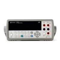
Agilent Technologies 34411A User Manual (152 pages)
6 1/2 Digit Multimeter
Brand: Agilent Technologies
|
Category: Multimeter
|
Size: 5.05 MB
Table of Contents
-
1 Quick Start
13
-
Restricted Rights Legend
2
-
Safety Information
3
-
In this Guide
11
-
Table of Contents
13
-
Quick Start
13
-
Basic Multimeter Operations
14
-
Preparing the Multimeter for Use
14
-
Using the Front Panel (34410A/11A)
15
-
Front-Panel Keys
15
-
Front-Panel Display Shortcuts
16
-
-
Making Basic Measurements (34410A/11A)
17
-
To Measure DC Voltage
18
-
To Measure AC Voltage
18
-
To Measure DC Current
19
-
To Measure AC Current
19
-
To Make a 2-Wire Resistance Measurement
20
-
To Make a 4-Wire Resistance Measurement
20
-
To Measure Frequency
21
-
To Measure Period
21
-
To Measure Capacitance
22
-
To Make a 2-Wire Temperature Measurement
23
-
To Make a 4-Wire Temperature Measurement
23
-
To Test Continuity
24
-
To Check Diodes
24
-
-
Other Basics of Operation
25
-
If the Multimeter Does Not Turn on
25
-
To Replace the Power-Line Fuse (34410A/11A)
26
-
To Adjust the Carrying Handle
27
-
To Rack Mount the Multimeter (34410A/11A)
28
-
-
Quick Start/Other Basics of Operation
29
-
Features and Functions
35
-
SCPI Commands
37
-
Front Panel Features (34410A/11A)
38
-
Front Panel Display
38
-
Displayed Messages
38
-
Self-Guiding Menus
38
-
Annunciators
40
-
Second Display Options
41
-
Turning the Display off
41
-
Front-Panel Display Shortcuts
42
-
Front Panel Alphanumeric Character Entry
43
-
-
Front Panel Measurement Configuration Menus
44
-
Configuring DC Voltage and DC Current Measurements
44
-
Configuring AC Voltage and Current Measurements
45
-
Configuring Resistance Measurements
45
-
Configuring Frequency and Period Measurements
46
-
Configuring Temperature Measurements
46
-
Configuring Capacitance Measurements
47
-
Continuity and Diode Tests
47
-
-
Advanced Configuration Options
48
-
Multimeter State Storage
48
-
Accessing Reading Memory
49
-
Front/Rear Input Terminal Switching (34410A/11A)
49
-
Multimeter Reset
50
-
DC Measurements
51
-
Integration Time and Resolution
51
-
DC Input Impedance
53
-
AC Measurements
54
-
AC Filter
54
-
Gate Time
55
-
-
Auto Zero
56
-
Ranging
57
-
Null Measurements
59
-
Miscellaneous Configuration Settings
60
-
Radix Character (34410A/11A)
60
-
Thousands Separator (34410A/11A)
60
-
Beeper (34410A/11A)
61
-
-
Math Functions
62
-
Db Measurements
63
-
Dbm Measurements
64
-
Using Statistics
65
-
Limit Testing
66
-
-
Triggering the Multimeter
67
-
Selecting a Trigger Source
67
-
Auto Triggering (34410A/11A)
68
-
Single Triggering (34410A/11A)
68
-
Reading Hold (34410A/11A)
69
-
Immediate Triggering
69
-
Software (Bus) Triggering
70
-
Internal (Level) Triggering (34411A/L4411A)
70
-
Number of Samples Per Trigger
71
-
Number of Pre-Trigger Samples (34411A/L4411A)
71
-
Trigger Delay
72
-
Automatic Trigger Delay
73
-
External Triggering
75
-
Trigger Slope
77
-
-
Data Logging
78
-
System-Related Operations
82
-
Self-Test
82
-
Error Conditions
83
-
Reading the Error Queue
84
-
NISPOM Memory Sanitization
84
-
Calibration
84
-
-
Power-On and Reset State
85
-
-
-
3 Remote Interface Configuration
87
-
Configuring the GPIB Interface
89
-
Configuring the USB Interface
90
-
Configuring the LAN Interface
91
-
Configuring LAN Parameters
92
-
Dhcp
92
-
Auto-IP
92
-
IP Address
93
-
Subnet Mask
93
-
Default Gateway
94
-
Host Name
94
-
DNS Server
95
-
Web Password
95
-
Instrument Unexpectedly Goes into Remote
95
-
-
Setting up a LAN Connection from the Front Panel
96
-
Setting up a LAN Connection from the Remote Interface
97
-
Agilent 34410A/11A Web Interface
98
-
-
4 Measurement Tutorial
99
-
DC Measurement Considerations
101
-
Thermal EMF Errors
101
-
Loading Errors (DC Volts)
101
-
-
Noise Rejection
102
-
Rejecting Power-Line Noise Voltages
102
-
Common Mode Rejection (CMR)
102
-
Noise Caused by Magnetic Loops
103
-
Noise Caused by Ground Loops
103
-
-
Resistance Measurement Considerations
104
-
4-Wire Ohms Measurements
104
-
Removing Test Lead Resistance Errors
105
-
Minimizing Power Dissipation Effects
105
-
Errors in High Resistance Measurements
105
-
-
True RMS AC Measurements
106
-
True RMS Accuracy and High-Frequency Signal Content
107
-
Estimating High-Frequency (Out-Of-Band) Error
110
-
-
Frequency and Period Measurement Errors
112
-
Other Primary Measurement Functions
112
-
DC Current Measurements
112
-
Capacitance Measurements
113
-
Temperature Measurements
115
-
Probe Type Choice
115
-
2-Wire Vs. 4-Wire Measurements
115
-
Auto Zero On/Off
116
-
Integration
116
-
Offset Compensation
116
-
NULL Reading
116
-
-
High-Speed Measurements
117
-
Making High-Speed AC Measurements
117
-
Making High-Speed DC and Resistance Measurements
118
-
-
Other Sources of Measurement Error
119
-
Settling Time Effects
119
-
Loading Errors (Ac Volts)
119
-
Measurements below Full Scale
120
-
High-Voltage Self-Heating Errors
120
-
AC Current Measurement Errors (Burden Voltage)
120
-
Low-Level Measurement Errors
120
-
Common Mode Errors
122
-
Leakage Current Errors
122
-
-
-
5 Specifications
123
-
DC Characteristics
125
-
AC Characteristics
128
-
Frequency and Period Characteristics
130
-
Capacitance Characteristics
132
-
Temperature Characteristics
132
-
Additional 34411A/L4411A Specifications
133
-
Measurement and System Speeds
134
-
System Speeds
135
-
Data from Memory
136
-
General Specifications (34410A/11A)
136
-
General Specifications (L4411A)
137
-
Triggering and Memory
137
-
Dimensions
138
-
-
To Calculate Total Measurement Error
139
-
Interpreting Accuracy Specifications
141
-
Transfer Accuracy
141
-
24-Hour Accuracy
141
-
90-Day and 1-Year Accuracy
141
-
Temperature Coefficients
141
-
-
Configuring for Highest Accuracy Measurements
142
-
DC Voltage, DC Current, and Resistance Measurements
142
-
AC Voltage and AC Current Measurements
142
-
Frequency and Period Measurements
142
-
-
-
A Appendix: Firmware and Driver Updates
143
-
Downloading the Update Utility and Firmware
144
-
Downloading IVI-COM Driver Updates
147
-
-
Advertisement

Agilent Technologies 34411A User Manual (144 pages)
6 1/2 Digit Multimeter
Brand: Agilent Technologies
|
Category: Multimeter
|
Size: 6.93 MB
Table of Contents
-
Restricted Rights Legend
2
-
Safety Information
3
-
The Front Panel at a Glance
8
-
The Rear Panel at a Glance
9
-
The Display at a Glance
10
-
In this Guide
11
-
Table of Contents
13
-
Quick Start
19
-
To Prepare the Multimeter for Use
20
-
Basic Measurement Operation
21
-
Test Lead Connections
21
-
Front Panel Keys
21
-
Front-Panel Display Shortcuts
22
-
-
To Measure DC Voltage
23
-
To Measure AC Voltage
23
-
-
To Measure DC Current
24
-
To Measure AC Current
24
-
To Make a 2-Wire Resistance Measurement
25
-
To Make a 4-Wire Resistance Measurement
25
-
To Measure Frequency
26
-
To Measure Period
26
-
To Measure Capacitance
27
-
To Make a 2-Wire Temperature Measurement
28
-
To Make a 4-Wire Temperature Measurement
28
-
To Test Continuity
29
-
To Check Diodes
29
-
Other Basics of Operation
30
-
If the Multimeter Does Not Turn on
30
-
To Replace the Power Line Fuse
31
-
To Adjust the Carrying Handle
32
-
To Rack-Mount the Multimeter
33
-
-
Features and Functions
35
-
SCPI Commands
38
-
SCPI Language Conventions
38
-
SCPI Language Version
38
-
-
Front Panel Features
39
-
Front Panel Display
39
-
Displayed Messages
39
-
Self-Guiding Menus
39
-
Annunciators
41
-
Second Display Options
42
-
Turning the Display off
42
-
Front-Panel Display Shortcuts
43
-
Ranging
43
-
Digit Masking
43
-
Integration Time (Bandwidth, Gate Time)
43
-
Front Panel Alphanumeric Character Entry
44
-
-
Front Panel Measurement Configuration Menus
45
-
Configuring DC Voltage and DC Current Measurements
45
-
Configuring AC Voltage and Current Measurements
46
-
Configuring Resistance Measurements
46
-
Configuring Frequency and Period Measurements
47
-
Configuring Temperature Measurements
47
-
Configuring Capacitance Measurements
48
-
-
Front/Rear Input Terminal Switching
48
-
-
Advanced Configuration Options
49
-
Power-On State
49
-
Multimeter State Storage
51
-
Multimeter Reset
52
-
Measurement Time and Resolution
53
-
DC, Resistance and Temperature Measurements
53
-
AC Measurements
55
-
-
AC Filter
56
-
DC Input Impedance
57
-
Autozero
58
-
Ranging
59
-
Null Measurements
61
-
-
-
Features and Functions (Continued)
61
-
Miscellaneous Configuration Settings
62
-
Radix Character
62
-
Thousands Separator
62
-
Beeper
63
-
Math Functions
64
-
Dbm Measurements
65
-
Db Measurements
65
-
Using Statistics
67
-
Limit Testing
68
-
-
-
Triggering the Multimeter
69
-
Selecting a Trigger Source
69
-
Auto Triggering
70
-
Single Triggering
70
-
Reading Hold
70
-
Internal Triggering
71
-
Software (Bus ) Triggering
71
-
Number of Samples Per Trigger
72
-
Trigger Delay
72
-
Automatic Trigger Delay
74
-
External Triggering
76
-
Trigger Slope
77
-
-
Reading Memory
78
-
Data Logging
79
-
Features and Functions
81
-
System-Related Operations
83
-
Self-Test
83
-
Error Conditions
84
-
Calibration
84
-
-
-
Remote Interface Configuration
85
-
Remote Interface Configuration Methods
86
-
Configuring a GPIB Interface
87
-
Configuring a USB Interface
88
-
Configuring a LAN Interface
89
-
LAN Configuration Parameters
89
-
Assigning the LAN IP Address Using Auto-IP
90
-
Setting the LAN IP Address Manually
90
-
Setting the LAN Subnet Mask
91
-
Setting the LAN Default Gateway
91
-
Setting the LAN Host Name
92
-
Setting the LAN DNS Server
92
-
Setting a Web Password
92
-
-
34410A/34411A Web Browser Interface
93
-
Setting up a LAN Connection from the Front Panel
94
-
Setting up a LAN Connection from the Remote Interface
95
-
-
-
Measurement Tutorial
97
-
DC Measurement Considerations
99
-
Thermal EMF Errors
99
-
Loading Errors (DC Volts)
99
-
-
Noise Rejection
100
-
Rejecting Power-Line Noise Voltages
100
-
Common Mode Rejection (CMR)
100
-
Noise Caused by Magnetic Loops
101
-
Noise Caused by Ground Loops
101
-
-
Resistance Measurement Considerations
102
-
4-Wire Ohms Measurements
102
-
Removing Test Lead Resistance Errors
103
-
Minimizing Power Dissipation Effects
103
-
Errors in High Resistance Measurements
103
-
-
-
Measurement Tutorial (Continued)
103
-
True RMS AC Measurements
104
-
True RMS Accuracy and High-Frequency Signal Content
105
-
Estimating High-Frequency (Out-Of-Band) Error
107
-
-
Other Primary Measurement Functions
109
-
Frequency and Period Measurement Errors
109
-
DC Current Measurements
109
-
Capacitance Measurements
110
-
Temperature Measurements
112
-
Probe Type Choice
112
-
2-Wire Vs. 4-Wire Measurements
112
-
Auto Zero On/Off
113
-
Integration
113
-
Offset Compensation
113
-
NULL Reading
113
-
-
-
High-Speed Measurements
114
-
Making High-Speed AC Measurements
114
-
Making High-Speed DC and Resistance Measurements
115
-
-
Other Sources of Measurement Error
116
-
Settling Time Effects
116
-
Loading Errors (Ac Volts)
116
-
Measurements below Full Scale
117
-
High-Voltage Self-Heating Errors
117
-
AC Current Measurement Errors (Burden Voltage)
117
-
Low-Level Measurement Errors
117
-
Common Mode Errors
119
-
Leakage Current Errors
119
-
-
-
Specifications
121
-
DC Characteristics
123
-
AC Characteristics
126
-
Frequency and Period Characteristics
128
-
Capacitance Characteristics
130
-
Temperature Characteristics
130
-
Measurement and System Speeds
131
-
Data from Memory
132
-
General Specifications
133
-
Dimensions
135
-
-
To Calculate Total Measurement Error
136
-
Accuracy Specifications
138
-
Transfer Accuracy
138
-
24-Hour Accuracy
138
-
90-Day and 1-Year Accuracy
138
-
Temperature Coefficients
138
-
-
Configuring for Highest Accuracy Measurements
139
-
DC Voltage, DC Current, and Resistance Measurements
139
-
AC Voltage and AC Current Measurements
139
-
-
-
Agilent Technologies 34411A Service Manual (126 pages)
6 1/2 Digit Multimeter
Brand: Agilent Technologies
|
Category: Multimeter
|
Size: 4.37 MB
Table of Contents
-
Restricted Rights Legend
2
-
Safety Information
3
-
The Front Panel at a Glance
8
-
The Rear Panel at a Glance
9
-
The Display at a Glance
10
-
In this Guide
12
-
Table of Contents
13
-
Specifications
17
-
DC Characteristics
19
-
AC Characteristics
22
-
Frequency and Period Characteristics
24
-
Capacitance Characteristics
26
-
Temperature Characteristics
26
-
Additional 34411A Specifications
27
-
Operating Characteristics — Maximum Readings/Second
27
-
Measurement and System Speeds
28
-
System Speeds
29
-
Data from Memory
30
-
-
General Specifications
30
-
-
General Specifications (34410A/11A)
30
-
Dimensions
32
-
To Calculate Total Measurement Error
33
-
Interpreting Accuracy Specifications
35
-
Transfer Accuracy
35
-
24-Hour Accuracy
35
-
90-Day and 1-Year Accuracy
35
-
Temperature Coefficients
35
-
-
Configuring for Highest Accuracy Measurements
36
-
DC Voltage, DC Current, and Resistance Measurements
36
-
AC Voltage and AC Current Measurements
36
-
Frequency and Period Measurements
36
-
-
-
-
Quick Start
37
-
Basic Multimeter Operations
38
-
Preparing the Multimeter for Use
38
-
Using the Front Panel
39
-
Front-Panel Keys
39
-
Front-Panel Display Shortcuts
40
-
-
Making Basic Measurements
41
-
To Measure DC Voltage
42
-
To Measure AC Voltage
42
-
To Measure DC Current
43
-
To Measure AC Current
43
-
To Make a 2-Wire Resistance Measurement
44
-
To Make a 4-Wire Resistance Measurement
44
-
To Measure Frequency
45
-
To Measure Period
45
-
To Measure Capacitance
46
-
To Make a 2-Wire Temperature Measurement
47
-
To Make a 4-Wire Temperature Measurement
47
-
To Test Continuity
48
-
To Check Diodes
48
-
-
-
Other Basics of Operation
49
-
If the Multimeter Does Not Turn on
49
-
To Replace the Power-Line Fuse (34410A/11A)
50
-
To Adjust the Carrying Handle (34410A/11A)
51
-
To Rack Mount the 34410A/11A Multimeter
51
-
To Rack Mount the L4411A Multimeter
52
-
-
Calibration Operation (34410A/11A)
53
-
To Read the Calibration Count
53
-
To Read the Calibration Message
54
-
To Store a Calibration Message
54
-
To Secure for Calibration
55
-
To Unsecure for Calibration
56
-
To Re-Secure
56
-
-
-
-
Calibration Procedures
57
-
Agilent Technologies Calibration Services
58
-
Calibration Interval
58
-
Adjustment Is Recommended
58
-
Time Required for Calibration
59
-
Automating Calibration Procedures
59
-
Recommended Test Equipment
60
-
Performance Verification Tests
60
-
Self-Test
61
-
Quick Performance Check
61
-
Performance Verification Tests
62
-
-
Input Connections
62
-
Test Considerations
63
-
Verification Tests
64
-
Zero Offset Verification
64
-
Gain Verification
66
-
Optional AC Voltage Performance Verification Tests
72
-
Optional AC Current Performance Verification Tests
73
-
Optional Capacitance Performance Verification Tests
74
-
-
Calibration Security
75
-
To Unsecure the Instrument Without the Security Code
75
-
-
Calibration Message
77
-
Calibration Count
77
-
Calibration Process
78
-
Using the Front Panel for Adjustments (34410A/11A Only)
78
-
Selecting the Adjustment Mode
78
-
Entering Adjustment Values
78
-
Storing the Calibration Constants
78
-
-
Using the Remote Interface for Adjustments
79
-
Selecting the Adjustment Mode
79
-
Entering Adjustment Values
79
-
Storing the Calibration Constants
79
-
-
Aborting a Calibration in Progress
79
-
Adjustments
80
-
ADC and Zero Adjustment
80
-
Gain Adjustments
82
-
Flatness Adjustments
93
-
Finishing Adjustments
102
-
-
-
Disassembly and Repair
103
-
Operating Checklist
104
-
Types of Service Available
105
-
Extended Service Contracts
105
-
Obtaining Repair Service (Worldwide)
105
-
-
Repackaging for Shipment
106
-
Cleaning
106
-
To Replace the 34410A/11A Power Line Fuse
106
-
To Replace the Current Input Fuse
107
-
Self Test Procedures
107
-
Power-On Self-Test
107
-
34410A/11A Complete Self-Test
107
-
L4411A Complete Self-Test
107
-
Self Test Error Numbers
108
-
-
Calibration Errors
109
-
34410A/11A Display and Keypad Tests
110
-
Electrostatic Discharge (ESD) Precautions
110
-
34410A/11A Mechanical Disassembly
111
-
General Disassembly
111
-
Front Panel Removal
113
-
Front Panel Disassembly
116
-
-
L4411A Mechanical Disassembly
117
-
General Disassembly
117
-
-
Replaceable Parts
122
-
To Order Replaceable Parts
122
-
Parts List 34410A/11A
123
-
Parts List L4411A
124
-
-
-
Backdating
125
Advertisement
Agilent Technologies 34411A Datasheet (7 pages)
Brand: Agilent Technologies
|
Category: Multimeter
|
Size: 0.18 MB
Advertisement
Related Products
-
Agilent Technologies 34401A
-
Agilent Technologies 34420A
-
Agilent Technologies 34405A
-
Agilent Technologies 34450A 5 Digit Multimeter
-
Agilent Technologies 34450A
-
Agilent Technologies 34410A
-
Agilent Technologies 3458A
-
Agilent Technologies 3457A
-
Agilent Technologies Truevolt 34460A
-
Agilent Technologies Truevolt 34461A
Agilent Technologies Categories
Measuring Instruments
Laboratory Equipment
Test Equipment
Water Pump
![]()
Power Supply
More Agilent Technologies Manuals
(Ocr-Read Summary of Contents of some pages of the Agilent Technologies 34410A Document (Main Content), UPD: 07 April 2023)
-
38, Agilent Technologies 34410A 38 34410A/11A/L4411A Service Guide 2Quick Start Basic Multimeter Operations This section introduces the basics of the 34410A/11A multimeter, and how to use it. Preparing the Multimeter for Use To verify that your 34410A or 34411A multimeter is ready for use: 1 Check the list of supplied items. Verify that you have received the following items with your multimeter. If anything is missing, contact your nearest Agilent Sales Office. • …
-
110, Agilent Technologies 34410A 110 34410A/11A/L4411A Service Guide 4 Disassembly and Repair 34410A/11A Display and Keypad Tests You can test the keypad and display. Hold down the key as you turn on the instrument. Hold the key for a little over 5 seconds, until you hear a relay click. When you release the key, the instrument begins the keypad test. The second display line shows the names of the keys. Press each key in turn, as shown. When all the keys have been pr…
-
78, 78 34410A/11A/L4411A Service Guide 3 Calibration Procedures Calibration Process The following general procedure is the recommended method to complete a full instrument calibration. 1 Read “Test Considerations” on page 63. 2 Perform the verification tests to characterize the instrument (incoming data). 3 Unsecure the instrument for calibration (“Calibration Security” on page 75). 4 Perform the adjustment…
-
43, 34410A/11A/L4411A Service Guide 43 Quick Start 2 To Measure DC Current Press to select the dc current function. • Ranges: 100 mA, 1 mA, 10 mA, 100 mA, 1 A, 3 A • Configurable parameters: INTEGRATION, RANGE, AUTO ZERO, NULL, and NULL VALUE To Measure AC Current Press to select the ac current function. • Ranges: 100 mA, 1 mA, 10 mA, 100 mA, 1 A, 3 A • AC Technique: true–RMS, ac–coupled • Configurable p…
-
28, 28 34410A/11A/L4411A Service Guide 1 Specifications Measurement and System Speeds DMM Measurements Speeds [1] Typical. Display off, ½ scale input signal, immediate trigger, trigger delay 0, autozero off, autorange off, no math, 60 Hz line, null off, sample count 1, trig count 1, one interface enabled. [2] 0.001 PLC applies to 34411A/L4411A only. Direct I/O Measurements [1] Single Reading – Measure and I/O Time Measurement Into Memory (Readings/Sec) (VM Complete) Function Resolution …
-
29, 34410A/11A/L4411A Service Guide 29 Specifications 1 Direct I/O Measurements [1] (any remote interface) Sustained maximum reading rate to I/O, 32 –bit BINARY data («SAMP:COUN 50000;:R?») [1] ½ scale input signal, immediate trigger, trigger delay 0, autozero off, autorange off, no math, 60 Hz line, null off, sample count 50000, trigger count INF System Speeds General [1] Time for configuration change from 2-wire oh…
-
93, 34410A/11A/L4411A Service Guide 93 Calibration Procedures 3 Flatness Adjustments The instrument stores new flatness correction constants each time this procedure is followed. Flatness constants adjust the DMM for AC Volts and AC current measurements across the usable input frequency band. The flatness constant is computed from the calibration value entered for the calibration command and from m…
-
74, 74 34410A/11A/L4411A Service Guide 3 Calibration Procedures Optional Capacitance Performance Verification Tests Configuration: Capacitance CONFigure:CAPacitance 1 Make sure you have read “Test Considerations” on page 63. 2 Set the Capacitance function. 3 Connect the calibrator to the input terminals. a For the 34410A/11A use the front panel input terminals and select the Front input terminals with the Front/Rear switch. 4 …
-
111, 34410A/11A/L4411A Service Guide 111 Disassembly and Repair 4 34410A/11A Mechanical Disassembly For procedures in this manual, the following tools are required for disassembly: • T20 Torx driver (most disassembly) • T15 Torx driver (fan removal) • Flat Blade screw driver The following tools may also be needed if further disassembly is required. • 9/32” nut driver (rear–panel GPIB connector) General Disassembly 1 Turn off the pow…
-
104, 104 34410A/11A/L4411A Service Guide 4 Disassembly and Repair Operating Checklist Before returning your multimeter to Agilent for service or repair check the following items: Is the multimeter inoperative? q Verify that the power cord is connected to the multimeter and to ac line power. q Verify the front panel power switch is depressed. q 34410A/11A Verify the power line fuse is installed. Use a 250 V 250 mA fu…
-
108, Agilent Technologies 34410A 108 34410A/11A/L4411A Service Guide 4 Disassembly and Repair Self Test Error Numbers NOTE On the remote interface, a self–test failure will generate SCPI error –330 and a supplemental message indicating one of the test numbers shown below. On the front panel, only the failing test is shown. Test # Tes t Na m e: 600 Front Panel Communications 601 Front Panel All On Test 602 A/D Feedback Test …
-
12, 12 34410A/11A/L4411A Service Guide In This Guide… 1 Specifications This chapter lists the multimeter’s specifications and describes how to interpret these specifications. 2Quick Start This chapter prepares the multimeter for use and helps you get familiar with a few of the front panel features. 3 Calibration This chapter provides calibration, verification, and adjustment procedures for the multimeter. 4 Disassembly and Repair This…
-
109, 34410A/11A/L4411A Service Guide 109 Disassembly and Repair 4 Calibration Errors The following errors indicate failures that may occur during a calibration. Error # Meaning 701 Calibration error; security defeated by hardware jumper 702 Calibration error; calibration memory is secured 703 Calibration error; secure code provided was invalid 704 Calibration error: secure code too long 705 Calibration error; calibration aborted 706 Calibratio…
Руководства Agilent 34410A Размер файлов: 3497 KB, Язык: English, Формат: pdf, Платформа: Windows/Linux, Дата: 2016-05-07
На данной странице вы можете скачать руководства Agilent 34410A. Мы предлагаем вам ознакомиться с руководством пользователя, инструкцией по сервисному обслуживанию и ремонту.
Также здесь вы найдете список заказных номеров на комплектующие Agilent 34410A.
Все файлы предоставляются исключительно в ознакомительных целях. И не являютя руководством по ремонту, а направлены лишь на то чтобы помочь вам более детально ознакомиться с принципом построения устройства.
Содержимое представленных здесь руководств требуют от вас знания технического английского языка.
Если вы собираетесь скачать руководство по сервисному обслуживанию Agilent 34410A, иными словами сервис мануал, вы дожны обладать хотя бы минимальными познаниями в области электроники и пониманием базовых принципов работы электромеханических устройств.
Для просмотра руководств вам понадобится Adobe Acrobat Reader версии 9 и выше либо другая программа для просмотра pdf файлов.
В связи с популярностью информации представленной на сайте и ее бесплатного предоставления конечному пользователю, убедительная просьба использовать специальные программные продукты для многопотокового скачивания файлов.
Руководства для Agilent 34410A
- Руководство пользователя (User manual)
- Руководство по сервисному обслуживанию (Service manual)
- Руководство по ремонту (Repair manual)
- Перечень комплектующих (PartList)
Скачать
Agilent Technologies
Agilent 34401A
6 ½ Digit Multimeter
User’s Guide
-
Page 1
Agilent 34410A/11A 6 ½ Digit Multimeter User’s Guide Agilent Technologies… -
Page 2: Restricted Rights Legend
Notices Warranty Technology Licenses © Agilent Technologies, Inc. 2005 No part of this manual may be reproduced in The material contained in this docu- The hardware and/or software described in any form or by any means (including elec- ment is provided “as is,” and is sub-…
-
Page 3: Safety Information
The switch is not intended as an active multiplexer. Switch- ing while high voltages or cur- rents are present may cause instrument damage and lead to the risk of electric shock. 34410A/11A User’s Guide…
-
Page 4
1500 Vpk relative to ground. other devices that plug into a branch outlet Current Input Terminal. The current input or socket. The 34410A/11A may be used to («I») terminal has a Protection Limit of 3A make measurements with the HI and LO… -
Page 5
This DoC applies to above-listed products placed on the EU market after: 20 October 2005 Date Ray Corson Product Regulations Program Manager For further information, please contact your local Agilent Technologies sales office, agent or distributor, or Agilent Technologies Deutschland GmbH, Herrenberger Straße 130, D 71034 Böblingen, Germany. 34410A/11A User’s Guide… -
Page 6
34410A/11A User’s Guide… -
Page 7
Note: This manual covers the operation of the Agilent 34410A and 34411A 6½ Digit Multimeters. The features described in this manual, except where otherwise stated, apply to both Models 34410A and 34411A. -
Page 8: The Front Panel At A Glance
This switch is not intended as an active multiplexer. Switching while high voltages or currents are present may cause instrument damage and lead to the risk of electric shock. 34410A/11A User’s Guide…
-
Page 9: The Rear Panel At A Glance
11 LO Input terminal 12 Current Input terminal 13 External Trigger terminal 14 VM Comp (reading complete) terminal WA R N I N G For protection from electrical shock, the power cord ground must not be defeated. 34410A/11A User’s Guide…
-
Page 10: The Display At A Glance
(diode check function enabled) Annunciator For a complete description of the front panel displays and annunciator indications, see “Front Panel Display» page 39, and“Annunciators» on page 41. The following key refers to the primary front- panel display. 34410A/11A User’s Guide…
-
Page 11: In This Guide
Measurement Tutorial This chapter discusses measurement techniques and considerations to help you obtain the best accuracies and reduce sources of measurement error. Specifications This chapter lists the multimeter’s specifications and describes how to interpret these specifications. 34410A/11A User’s Guide…
-
Page 12
34410A/11A User’s Guide… -
Page 13: Table Of Contents
To Make a 4-Wire Temperature Measurement To Test Continuity To Check Diodes Other Basics of Operation If the Multimeter Does Not Turn On To Replace the Power Line Fuse To Adjust the Carrying Handle To Rack-Mount the Multimeter 34410A/11A User’s Guide…
-
Page 14
Configuring Capacitance Measurements 48 Front/Rear Input Terminal Switching Advanced Configuration Options Power-On State Multimeter State Storage Multimeter Reset Measurement Time and Resolution DC, Resistance and Temperature Measurements 53 AC Measurements 55 AC Filter DC Input Impedance Autozero Ranging Null Measurements 34410A/11A User’s Guide… -
Page 15
Software (Bus ) Triggering 71 Number of Samples per Trigger 72 Trigger Delay 72 Automatic Trigger Delay 74 External Triggering 76 Trigger Slope 77 Reading Memory Data Logging System-Related Operations Self–Test 83 Error Conditions 84 Calibration 84 34410A/11A User’s Guide… -
Page 16
Setting the LAN Host Name 92 Setting the LAN DNS Server 92 Setting a Web Password 92 34410A/34411A Web Browser Interface Setting up a LAN connection from the Front Panel Setting up a LAN connection from the Remote Interface Measurement Tutorial… -
Page 17
Settling Time Effects 116 Loading Errors (ac volts) 116 Measurements Below Full Scale 117 High–Voltage Self–Heating Errors 117 AC Current Measurement Errors (Burden Voltage) 117 Low–Level Measurement Errors 117 Common Mode Errors 119 Leakage Current Errors 119 34410A/11A User’s Guide… -
Page 18
Transfer Accuracy 138 24–Hour Accuracy 138 90–Day and 1–Year Accuracy 138 Temperature Coefficients 138 Configuring for Highest Accuracy Measurements DC Voltage, DC Current, and Resistance Measurements: 139 AC Voltage and AC Current Measurements: 139 Frequency and Period Measurements: 139 34410A/11A User’s Guide… -
Page 19: Quick Start
To Make a 4-Wire Temperature Measurement To Measure Capacitance To Test Continuity To Check Diodes Other Basics of Operation If the Multimeter Does Not Turn On To Replace the Power Line Fuse To Adjust the Carrying Handle To Rack-Mount the Multimeter Agilent Technologies…
-
Page 20: To Prepare The Multimeter For Use
The front–panel display will light up while the multimeter performs its power–on self–test. The multimeter powers up in the dc voltage function with autoranging enabled (unless a previous user has configured power–up using a non–default stored state (see “Multimeter State Storage” on page 51). 34410A/11A User’s Guide…
-
Page 21: Basic Measurement Operation
Arrow annunciators on the second display line indicate additional selections to the left or right. To select a choice, press To set numeric parameters, use to select a digit, and to increase or decrease that digit. 34410A/11A User’s Guide…
-
Page 22: Front-Panel Display Shortcuts
• If either the ac voltage or ac current measurement function is selected, pressing during front panel measurement operations will increase or decrease the bandwidth setting. • If the frequency/period measurement function is selected, pressing during front panel measurement operations will increase or decrease the gate time setting. 34410A/11A User’s Guide…
-
Page 23: To Measure Dc Voltage
• Ranges: 100 mV, 1 V, 10 V, 100 V, 750 V • Maximum resolution: 100 nV (on 100 mV range) • Resolution: Fixed at 6 1/2 digits • AC Technique: true–RMS, ac–coupled • Configurable parameters: AC FILTER, RANGE, NULL and NULL VALUE 34410A/11A User’s Guide…
-
Page 24: To Measure Dc Current
• Ranges: 100 mA, 1 mA, 10 mA, 100 mA, 1A, 3A • Maximum resolution: 100 nV (on 100 mV range) • Resolution: Fixed at 6 1/2 digits • AC Technique: true–RMS, ac–coupled • Configurable parameters: AC FILTER, RANGE, NULL and NULL VALUE 34410A/11A User’s Guide…
-
Page 25: To Make A 2-Wire Resistance Measurement
To Make a 4-wire Resistance Measurement • Ranges: 100W, 1 kW, 10 kW, 100 kW, 1 MW, 10 MW, 100 MW • Maximum resolution: 100 mW (on 100W range) • Configurable parameters: INTEGRATION, RANGE, OFFSET COMP, AUTO ZERO, NULL, and NULL VALUE 34410A/11A User’s Guide…
-
Page 26: To Measure Frequency
1 ppm for 100 ms gate time • 10 ppm for 10 ms gate time • 100 ppm for 1 ms gate time • Technique: reciprocal counting • Configurable parameters: GATE TIME, RANGE, AC FILTER, NULL and NULL VALUE 34410A/11A User’s Guide…
-
Page 27: To Measure Capacitance
To null–out the test lead capacitance: 1 Disconnect the + lead’s probe end from the test circuit, and leave open. 2 Press null. 3 Reconnect the + lead’s probe end to the test circuit, and measure the corrected capacitance value. 34410A/11A User’s Guide…
-
Page 28: To Make A 2-Wire Temperature Measurement
• Probe types: 2.2 kW, 5 kW, 10 kW thermistors; 0.00385%/ºC RTD • Maximum resolution: 0.001 for RTDs; 0.01 for thermistors • Configurable parameters: PROBE TYPE, THERMISTOR or RTD value, OFFSET COMP (RTD probes only), INTEGRATION, NULL, NULL VALUE, and UNITS 34410A/11A User’s Guide…
-
Page 29: To Test Continuity
• Maximum resolution 100 mV (range is fixed at 1 VDC) • Beeper Threshold: 0.3V voltage 0.8V (not adjustable) measured • The diode check function is used to indicate correct diode operation; closed–circuit on forward bias and open–circuit on reverse–bias. 34410A/11A User’s Guide…
-
Page 30: Other Basics Of Operation
5x20mm fuse, Agilent part number 2110–0780, and is housed in a standard screw–in fuse holder on the left side of the rear panel. If you determine that the fuse is faulty, replace it with one of the same size and rating. 34410A/11A User’s Guide…
-
Page 31: To Replace The Power Line Fuse
To Replace the Power Line Fuse Verify that the correct line voltage is selected and the power line fuse is good. For multimeter operations with a 230 VAC supply, set the line–voltage selector to 220V. N O T E 34410A/11A User’s Guide…
-
Page 32: To Adjust The Carrying Handle
Quick Start To Adjust the Carrying Handle To adjust the position, grasp the handle by the sides and pull outward. Then, rotate the handle to the desired position. 34410A/11A User’s Guide…
-
Page 33: To Rack-Mount The Multimeter
Any Agilent System II instrument of the same size can be rack–mounted side–by–side with the 34410A/34411A. You must remove the carrying handle, and the front and rear rubber bumpers, before rack–mounting the multimeter. 34410A/11A User’s Guide…
-
Page 34
Quick Start 34410A/11A User’s Guide… -
Page 35: Features And Functions
Agilent 34410A/11A High Performance Digital Multimeter User’s Guide Features and Functions SCPI Commands SCPI Language Conventions SCPI Language Version Front Panel Features Front Panel Display Displayed Messages Self–Guiding Menus Annunciators Second Display Options Turning the Display Off Front–Panel Display Shortcuts…
-
Page 36
Limit Testing Triggering the Multimeter Selecting a Trigger Source Auto Triggering Single Triggering Reading Hold Internal Triggering Software (Bus ) Triggering Number of Samples per Trigger Trigger Delay Automatic Trigger Delay External Triggering Trigger Slope Data Logging 34410A/11A User’s Guide… -
Page 37
Features and Functions System-Related Operations Self–Test Error Conditions Calibration 34410A/11A User’s Guide… -
Page 38: Scpi Commands
The following command queries the multimeter’s SCPI language version: SYSTem:VERSion? • The SCPI version is returned in the form “YYYY.V”, where “YYYY” represents the year of the version, and “V” represents a version number for that year (for example, 1994.0). 34410A/11A User’s Guide…
-
Page 39: Front Panel Features
Features and Functions Front Panel Features Front Panel Display The 34410A and 34411A multimeters feature a dual–line, alphanumeric display, plus a set of text annunciators to indicate non–default operational states. Displayed Messages During menu–driven operations (e.g. measurement configuration), the primary display line indicates the configuration feature or menu, and the second display line indicates the submenu, configuration choices or parameters.
-
Page 40
(e.g. • To exit a menu before completing its sequence, press . If you have made changes, you will be prompted whether to save or discard them. 34410A/11A User’s Guide… -
Page 41: Annunciators
(the Front/Rear switch is set to Rear). • 4W — A 4–wire resistance or temperature measurement function mode is selected. • — The continuity test function is selected. • — The diode test function is selected. 34410A/11A User’s Guide…
-
Page 42: Second Display Options
The following query returns the currently selected <feed> parameter, as a quoted ASCII string: DISPlay:WINDow2: TEXT:FEED? Refer to the Agilent 34410A/34411A Programmer’s Reference for complete description and syntax for these commands. Turning the Display Off This feature is available from the remote interface only.
-
Page 43: Front-Panel Display Shortcuts
). Repeated use of will scroll through the entire range , 0.002 , 0.006, 0.02, 0.06, 0.2, 1, 2, 10 and 100 of integration time settings (0.001 NPLC). These additional two settings are provided on model 34411A only. 34410A/11A User’s Guide…
-
Page 44: Front Panel Alphanumeric Character Entry
(e.g. u, m, k, M), then use the keys to change the numerical entry. The left and right arrow annunciators on the second display line will indicate if there are editable characters left or right of the one selected. 34410A/11A User’s Guide…
-
Page 45: Front Panel Measurement Configuration Menus
• NULL: Allows you to enable (select ON) or disable (select OFF) the null measurement feature, which measures the difference between a stored null value and the input signal. • NULL VALUE: Allows you to view and edit the null value. 34410A/11A User’s Guide…
-
Page 46: Configuring Ac Voltage And Current Measurements
• NULL: Allows you to enable (select ON) or disable (select OFF) the null measurement feature, which measures the difference between a stored null value and the input signal. • NULL VALUE: Allows you to view and edit the null value. 34410A/11A User’s Guide…
-
Page 47: Configuring Frequency And Period Measurements
• AUTO ZERO (for 2–wire thermistor probes only): Allows you to enable (select ON) or disable (select OFF) the auto zero feature, which subtracts a subsequent zero reading from each measurement taken, to prevent offset voltages in the multimeter’s input circuitry from affecting measurement accuracy. 34410A/11A User’s Guide…
-
Page 48: Configuring Capacitance Measurements
The query: ROUTe:TERMinals? returns either “FRON” or “REAR” Refer to the Agilent 34410A/34411A Programmer’s Reference for complete description and syntax for this command. 34410A/11A User’s Guide…
-
Page 49: Advanced Configuration Options
Factory Setting Math State Math Registers Cleared (all registers) dB relative value dBm reference resistance 600W Triggering Operations Factory Setting Trigger Count Trigger Source Immediate Trigger Delay Auto Delay Sample Count Sample Source Auto Sample Timer 1 second 34410A/11A User’s Guide…
-
Page 50
During a measurement session, configuration settings may be saved in one of four Stored States, for recall after a power–on or reset operation. See “Multimeter State Storage” on page 51 for more information. 34410A/11A User’s Guide… -
Page 51: Multimeter State Storage
DELETE, and press . DELETE STATE will be displayed, along with any stored states, on the second display line. Press as needed to select a stored state, and . STATE DELETED will be displayed briefly. press 34410A/11A User’s Guide…
-
Page 52: Multimeter Reset
Select YES to enable the reset operation or NO to cancel it. • Remote Interface Operation: The following commands resets the multimeter to the instrument preset state: SYSTem:PRESet *RST Refer to the Agilent 34410A/34411A Programmer’s Reference for complete description and syntax for this command. 34410A/11A User’s Guide…
-
Page 53: Measurement Time And Resolution
0.06, 0.2, 1, 2, 10 or 100 (PLCs). These two additional settings are provided on Model 34411A only. • To allow for normal mode (line frequency noise) rejection, you must select an integral number of power line cycles (e.g. 1, 10 or 100 NPLC). 34410A/11A User’s Guide…
-
Page 54
Selectable values range from 300 3s to 1 second for the 34410A, and from 100 3s to 1 second for the 34411A. • To allow for normal mode (line frequency noise) rejection, select the NPLC option for INTEGRATION, with an integral number of NPLCs. -
Page 55: Ac Measurements
[SENSe:]VOLTage[:DC]:APERture:ENABled? This query returns a “0” (disabled) or “1” (enabled) Refer to the Agilent 34410A/34411A Programmer’s Reference for complete description and syntax for these commands. • The following table indicates the resulting resolution for each integration time value (in power–line cycles) selected.
-
Page 56: Ac Filter
• Remote Interface Operation: The following commands set the ac filter (3, 20 or 200 Hz) for ac measurements: [SENSe:]VOLTage:AC:BANDwidth {<filter>>MIN>MAX>DEF} [SENSe:]CURRent:AC:BANDwidth {<filter>>MIN>MAX>DEF} The following commands query the filter setting: [SENSe:]VOLTage:AC:BANDwidth? [{MIN>MAX}] [SENSe:]CURRent:AC:BANDwidth? [{MIN>MAX}] Refer to the Agilent 34410A/34411A Programmer’s Reference for complete description and syntax for these commands. 34410A/11A User’s Guide…
-
Page 57: Dc Input Impedance
100V and 1000V ranges, and >10 GW for all other ranges: [SENSe:]VOLTage:DC:IMPedance:AUTO {OFF>0>ON>1} The following command queries the auto impedance function setting: [SENSe:]VOLTage:DC:IMPedance:AUTO? This query returns a “0” (OFF) or “1” (ON). Refer to the Agilent 34410A/34411A Programmer’s Reference for complete description and syntax for these commands. 34410A/11A User’s Guide…
-
Page 58: Autozero
The following command queries the autozero feature status for the specified function: SENSe:<function>:ZERO:AUTO? This query command returns “0” (OFF) or “1” (ON). Refer to the Agilent 34410A/34411A Programmer’s Reference for complete description and syntax for these commands. 34410A/11A User’s Guide…
-
Page 59: Ranging
Manual ranging – If the input signal is greater than can be measured on the selected range, the multimeter provides these overload indications: OVLD from the front panel or “ 9.9E+37” from the remote interface. 34410A/11A User’s Guide…
-
Page 60
A manual range may also be set using the CONFigure or MEASure commands. The following command queries the multimeter range setting for the specified <function>: SENSe:<function>:RANGe[:UPPER]? [{MIN>MAX}] Refer to the Agilent 34410A/34411A Programmer’s Reference for complete description and syntax for all commands on this page. 34410A/11A User’s Guide… -
Page 61: Null Measurements
SENSe:<function>:NULL[:VALue] {<value>>MIN>MAX} The following command queries the null value stored for the specified function: SENSe:<function>:NULL[:VALue]? This query returns the stored null value. Refer to the Agilent 34410A/34411A Programmer’s Reference for complete description and syntax for these commands. 34410A/11A User’s Guide…
-
Page 62: Miscellaneous Configuration Settings
• Front Panel Operation: Press to display UTILITY MENU, and as needed until MISC SETTINGS is displayed. Press press needed to display THOUSAND SEP, press to select OFF or ON, and press . Then step through or exit the configuration menu. 34410A/11A User’s Guide…
-
Page 63: Beeper
SYSTem:BEEPer:STATe {OFF>0>ON>1} The following command queries the state of the beeper: SYSTem:BEEPer:STATe? This query returns a “0” (OFF) or “1” (ON). Refer to the Agilent 34410A/34411A Programmer’s Reference for complete description and syntax for these commands. 34410A/11A User’s Guide…
-
Page 64: Math Functions
CALCulate[:STATe] {OFF>ON} The following command queries the current calculation state: CALCulate:STATe? This query returns a “0” (OFF) or a “1” (ON). Refer to the Agilent 34410A/34411A Programmer’s Reference for complete description and syntax for these commands. 34410A/11A User’s Guide…
-
Page 65: Dbm Measurements
CALCulate:FUNCtion DBM CALCulate:STATe ON CALCulate:DBM:REFerence <value> Refer to the Agilent 34410A/34411A Programmer’s Reference for complete description and syntax for these commands. dB Measurements The dB math function applies to ac and dc voltage measurements only. The dB operation calculates the difference between the input voltage signal and a stored relative value, with both values converted to dBm.
-
Page 66
Relative Register. CALCulate:FUNCtion DB CALCulate:STATe ON CALCulate:DB:REFerence <value> Refer to the Agilent 34410A/34411A Programmer’s Reference for complete description and syntax for these commands. 34410A/11A User’s Guide… -
Page 67: Using Statistics
CALCulate:AVERage:AVERage? CALCulate:AVERage:MINimum? CALCulate:AVERage:MAXimum? CALCulate:AVERage:SDEViation? CALCulate:AVERage:PTPeak? CALCulate:AVERage:COUNt? Refer to the Agilent 34410A/34411A Programmer’s Reference for complete description and syntax for these commands. 34410A/11A User’s Guide…
-
Page 68: Limit Testing
You can assign a lower limit, an upper limit, or both. The following commands query the selected lower and upper limits. CALCulate:LIMit:LOWer? CALCulate:LIMit:UPPer? Refer to the Agilent 34410A/34411A Programmer’s Reference for complete description and syntax for these commands. 34410A/11A User’s Guide…
-
Page 69: Triggering The Multimeter
“Auto Triggering” on page 70). • Remote Interface Operation: The following command selects the trigger source from the remote interface: TRIGger:SOURce {BUS>IMMediate>EXTernal} Refer to the Agilent 34410A/34411A Programmer’s Reference for complete description and syntax for this command. 34410A/11A User’s Guide…
-
Page 70: Auto Triggering
The multimeter will capture and display a new value only after three consecutive readings are within this band. • With reading hold enabled, if you change to remote operation, reading hold is ignored; returning to local (front panel) operation disables reading hold. 34410A/11A User’s Guide…
-
Page 71: Internal Triggering
TRIGger:SOURce IMMediate The CONFigure and MEASure? commands automatically set the trigger source to IMMediate. Refer to the Agilent 34410A/34411A Programmer’s Reference for complete description and syntax for these commands. Software (Bus ) Triggering The bus trigger mode is available from the remote interface only.
-
Page 72: Number Of Samples Per Trigger
(see “Software (Bus ) Triggering” on page 71). Refer to the Agilent 34410A/34411A Programmer’s Reference for complete description and syntax for this command. Trigger Delay You can manually specify a delay between the trigger signal and the first sample that follows.
-
Page 73
(see “Software (Bus ) Triggering” on page 71). The MEASure? command sets the trigger delay to AUTO. Refer to the Agilent 34410A/34411A Programmer’s Reference for complete description and syntax for these command. 34410A/11A User’s Guide… -
Page 74: Automatic Trigger Delay
(for 0.06 or 0.2 PLC) (for 1 PLC) – 100W 100 kW 1.0 ms 1.0 ms 1.5 ms 1 MW 10 ms 10 ms 15 ms – 10 MW 1 GW 100 ms 100 ms 100 ms 34410A/11A User’s Guide…
-
Page 75
Use the TRIGger:DELay? command to show the actual trigger delay. Capacitance measurements have a trigger delay of zero, because discharging the capacitor is part of the measurement time. 34410A/11A User’s Guide… -
Page 76: External Triggering
Ext Trig terminal. • Remote Interface Operation: The following command selects the trigger source from the external terminal: TRIGger:SOURce EXTernal Refer to the Agilent 34410A/34411A Programmer’s Reference for complete description and syntax for this command. 34410A/11A User’s Guide…
-
Page 77: Trigger Slope
OUTPut:TRIGger:SLOPe {POSitive>NEGative} The following query returns the selected trigger slope for the external terminal: OUTPut:TRIGger:SLOPe? This query returns POS or NEG. Refer to the Agilent 34410A/34411A Programmer’s Reference for complete description and syntax for this command. 34410A/11A User’s Guide…
-
Page 78: Reading Memory
This feature is available from the remote interface only. The multimeter’s reading memory is a first–in, first out (FIFO) buffer holding up to 50,000 readings (model 34410A) or 1 million readings (model 34411A). The oldest readings are preserved. • Remote Interface Operation: The following command transfers readings stored in non–volatile memory into the multimeter’s output buffer, from…
-
Page 79: Data Logging
DURATION in hours, minutes and seconds, from 1 second to 100 hours, or a COUNT of total readings, settable from 1 to 50,000 readings (model 34410A) or up to 1 million readings (model 34411A). • Front Panel Operation: To set up a data logging event, press display DATA LOGGER.
-
Page 80
The following command deletes all readings stored in NVMEM. DATA:DELete NVMEM The following command returns the number of data points stored in NVMEM DATA:POINts? NVMEM Refer to the Agilent 34410A/34411A Programmer’s Reference for complete description and syntax for these commands. 34410A/11A User’s Guide… -
Page 81: Features And Functions
Features and Functions • Web Server Operation: To access the data in the multimeter’s non–volatile memory, launch the 34410A/11A web server as described in “34410A/34411A Web Browser Interface” on page 93. The following Welcome Screen will appear: Click on “Browser Web Control” to display the Control DMM dialog box:…
-
Page 82
Readings and then click on Get Data to view the logged data: From this window, you can select (click) and copy the data into another application such as a spreadsheet using the Windows® clipboard. Microsoft® and Windows® are U.S. registered trademarks of Microsoft Corporation. 34410A/11A User’s Guide… -
Page 83: System-Related Operations
5 seconds to execute. If the power–on or complete self–test fails, an error is stored in the error queue. See the Agilent 34410A/34411A Service Guide for more information on returning the instrument to Agilent for service. • Following the complete self–test, the instrument issues a Factory Reset (*RST) command.
-
Page 84: Error Conditions
Only service–qualified personnel should calibrate the multimeter. Improper N O T E use of the front–panel CALIBRATION procedure in the UTILITY menu could result in damage to the multimeter. Refer to the Agilent 34410A/34411A Service Guide for calibration procedures. 34410A/11A User’s Guide…
-
Page 85: Remote Interface Configuration
Agilent 34410A/11A High Performance Digital Multimeter User’s Guide Remote Interface Configuration Remote Interface Configuration Methods Configuring a GPIB Interface Configuring a USB Interface Configuring a LAN Interface LAN Configuration Parameters Assigning the LAN IP Address Using Auto–IP Setting the LAN IP Address Manually…
-
Page 86: Remote Interface Configuration Methods
(10BaseT/100BaseTx). You may need to set several configuration parameters as described in the LAN configuration sections that follow. To easily configure and verify an interface connection between the 34410A/34411A and N O T E your PC, you can use the Agilent IO Libraries Suite (E2094M Agilent IO Libraries for Windows) or an equivalent.
-
Page 87: Configuring A Gpib Interface
The following command sets the multimeter’s GPIB (IEEE–488) address: SYSTem:COMMunicate:GPIB:ADDRess {<address>} The following query returns the IP address, in the form “+XX”: SYSTem:COMMunicate:GPIB:ADDRess? Refer to the Agilent 34410A/34411A Programmer’s Reference for complete description and syntax for these commands. 34410A/11A User’s Guide…
-
Page 88: Configuring A Usb Interface
The following command queries the state of the USB interface: SYSTem:COMMunicate:ENABle? USB This query returns a “0” (OFF) or a “1” (ON). Refer to the Agilent 34410A/34411A Programmer’s Reference for complete description and syntax for these commands. 34410A/11A User’s Guide…
-
Page 89: Configuring A Lan Interface
• IP Address • Subnet Mask • Default Gateway • DNS Server • Host Name • LAN Services (Visa LAN, Sockets, Telnet, Agilent Web Server) • Web Password These four parameters use dot–notation addresses. See NOTE below. 34410A/11A User’s Guide…
-
Page 90: Assigning The Lan Ip Address Using Auto-Ip
• Changing the IP address will cause an automatic LAN reset. • The default IP Address for the multimeter is “169.254.4.10” for the 34410A, and “169.254.4.11” for the 34411A. • If you are planning to use a static IP address on a Corporate LAN, contact your network administrator to obtain a fixed IP address to be used exclusively for your instrument.
-
Page 91: Setting The Lan Subnet Mask
Subnet Mask. • Changing the Subnet Mask setting will cause an automatic LAN reset. • The default Subnet Mask for the 34410A multimeter is “255.255.0.0”. • A value of “0.0.0.0” or “255.255.255.255” indicates that subnetting is not being used.
-
Page 92: Setting The Lan Host Name
IP address. • Changing the Host Name will cause an automatic LAN reset. • The default Host Name for the multimeter is “A–34410A–nnn” for the 34410A, and “A–34411A–nnn” for the 34411A, where nnn is the last three digits of the instrument’s serial number representation.
-
Page 93: 34410A/34411A Web Browser Interface
1 Establish a LAN interface connection from your computer to the multimeter. 2 Open your computer’s Web browser. 3 Launch the 34410A/34411A Web Interface by entering the IP address of your multimeter, or its fully–qualified host name, in the browser address field. The following welcome screen appears: 4 Follow the instructions in the Web Interface’s on–line Help.
-
Page 94: Setting Up A Lan Connection From The Front Panel
Changing LAN services will require a computer reboot for the change to take effect. 10 WEB PASSWORD – Select ENABLE, and press . Then use the navigation keypad to enter the desired password, up to 12 alphanumeric digits in length. 34410A/11A User’s Guide…
-
Page 95: Setting Up A Lan Connection From The Remote Interface
• To assign the LAN a static DNS address: SYSTem:COMMunicate:LAN:DNS <address> • To assign a LAN Domain Name: SYSTem:COMMunicate:LAN:DOMain “<name>” Query forms of these commands are also available. Refer to the Agilent 34410A/34411A Programmer’s Reference for complete command description and syntax. 34410A/11A User’s Guide…
-
Page 96
Remote Interface Configuration 34410A/11A User’s Guide… -
Page 97: Measurement Tutorial
Agilent 34401A/11A High Performance Digital Multimeter User’s Guide Measurement Tutorial The Agilent 34410A and 34411A multimeters are capable of making highly accurate measurements. In order to achieve the greatest accuracy, you must take the necessary steps to eliminate potential measurement errors. This chapter describes common errors found in measurements and gives suggestions to help you avoid these errors.
-
Page 98
Making High–Speed AC Measurements Other Sources of Measurement Error Settling Time Effects Loading Errors (ac volts) Measurements Below Full Scale High–Voltage Self–Heating Errors AC Current Measurement Errors (Burden Voltage) Low–Level Measurement Errors Common Mode Errors Leakage Current Errors 34410A/11A User’s Guide… -
Page 99: Dc Measurement Considerations
>10 GW (the HI–Z setting) for the 100 mVdc, 1 Vdc, and 10 Vdc ranges. The input resistance is maintained at 10 MW for the 100 Vdc and 1000 Vdc ranges. 34410A/11A User’s Guide…
-
Page 100: Noise Rejection
Ideally, a multimeter is completely isolated from earth–referenced circuits. However, there is finite resistance between the multimeter’s input LO terminal and earth ground, as shown below. This can cause errors when measuring low voltages which are floating relative to earth ground. 34410A/11A User’s Guide…
-
Page 101: Noise Caused By Magnetic Loops
If the multimeter must be earth–referenced, connect it and the device–under–test to the same common ground point. Also connect the multimeter and device–under–test to the same electrical outlet whenever possible. 34410A/11A User’s Guide…
-
Page 102: Resistance Measurement Considerations
The recommended connections for 4–wire ohms measurements are shown below. See also “To Make a 4- wire Resistance Measurement” on page 25. 34410A/11A User’s Guide…
-
Page 103: Removing Test Lead Resistance Errors
«dirty» surface films. Nylon and PVC are relatively poor insulators (10 W) when compared to PTFE (Teflon) insulators W). Leakage from nylon or PVC insulators can easily contribute a 0.1% error when measuring a 1 MW resistance in humid conditions. 34410A/11A User’s Guide…
-
Page 104: True Rms Ac Measurements
Measurement Tutorial True RMS AC Measurements True RMS responding multimeters, like the Agilent 34410A/34411A, measure the «heating» potential of an applied voltage. Power dissipated in a resistor is proportional to the square of an applied voltage, independent of the waveshape of the signal. This multimeter accurately measures true RMS voltage or current, as long as the wave shape contains negligible energy above the meter’s effective bandwidth.
-
Page 105: True Rms Accuracy And High-Frequency Signal Content
(200ms), hence low prf; the other narrow (6.7ms), hence high prf. The second figure is an approximation of the shape of the input frequency response for the 34410A/34411A multimeters. Comparing these two figures along the time axis, notice that π…
-
Page 106
Measurement Tutorial 34410A/11A User’s Guide… -
Page 107: Estimating High-Frequency (Out-Of-Band) Error
Traditionally, DMMs include a crest factor derating table that applies at all frequencies. The measurement algorithm used in the 34410A/11A multimeters is not inherently sensitive to crest factor, so no such derating is necessary. With this multimeter, as discussed in the previous section, the focal issue is high–frequency signal content which exceeds the…
-
Page 108
100 kHz). This ac waveform can be measured without introducing error. However, had this signal level been much lower (e.g. in the range of 0.1 V , the 3V spike would represent a Crest Factor of 30 – out of the specified performance range of the meter. 34410A/11A User’s Guide… -
Page 109: Other Primary Measurement Functions
When you connect the multimeter in series with a test circuit to measure current, a measurement error is introduced. The error is caused by the multimeter’s series burden voltage. A voltage is developed across the wiring resistance and current shunt resistance of the multimeter, as shown below. 34410A/11A User’s Guide…
-
Page 110: Capacitance Measurements
“short aperture” time, (Dt). This measurement is repeated at two different times during the exponential rise that occurs. An algorithm takes the data from these four points, and by linearizing that exponential rise over these “short apertures”, accurately calculates the capacitance value. 34410A/11A User’s Guide…
-
Page 111
(0.4%)(5 nF) + (0.1%)(10 nF) = 30 pF total error possible. For the best accuracy, take a zero null measurement with open probes, to null out the test lead capacitance, before connecting the probes across the capacitor to be measured. 34410A/11A User’s Guide… -
Page 112: Temperature Measurements
As with resistance measurements, four–wire temperature measurement is more accurate, since it completely eliminates errors due to lead wire resistance. Alternately, you can use the multimeter’s Null function to remove the test lead resistance from the measurement (see “NULL Reading:” on page 113). 34410A/11A User’s Guide…
-
Page 113: Auto Zero On/Off
Selectable values range from 300 ms to 1s for the 34410A, and from 300 ms to 1s for the 34411A. Setting an aperture value provides no NMR.
-
Page 114: High-Speed Measurements
Medium Filter Performance Full Accuracy Reading Rate No DC Level Change Lowest Frequency Component 20 Hz 50 Hz 100 Hz 200 Hz AC Current (allowable rate rdgs/Sec) AC Voltage (allowable rate rdgs/Sec) 34410A/11A User’s Guide…
-
Page 115: Making High-Speed Dc And Resistance Measurements
This compensates for offset voltage changes due to temperature. For maximum reading speed, turn autozero off. This will more than double your reading speeds for dc voltage, resistance, and dc current functions. Autozero does not apply to other measurement functions. 34410A/11A User’s Guide…
-
Page 116: Other Sources Of Measurement Error
Input Frequency Input Resistance 100 Hz 1 MΩ 1 kHz 850 kΩ 10 kHz 160 kΩ 100 kHz 16 kΩ For low frequencies, the loading error is: At high frequencies, the additional loading error is: 34410A/11A User’s Guide…
-
Page 117: Measurements Below Full Scale
Circulating currents in the loop will create error voltages across any impedances in series with the multimeter’s input. For this reason, you should apply low–level ac voltages to the multimeter through shielded cables. You should connect the shield to the input LO terminal. 34410A/11A User’s Guide…
-
Page 118
Correlated noise, while rare, is especially detrimental. Correlated noise will always add directly to the input signal. Measuring a low–level signal with the same frequency as the local power line is a common situation that is prone to this error. 34410A/11A User’s Guide… -
Page 119: Common Mode Errors
30 °C. This current generates small voltage offsets dependent upon the source resistance of the device–under–test. This effect becomes evident for a source resistance of greater than 100 kW, or when the multimeter’s operating temperature is significantly greater than 30 °C. 34410A/11A User’s Guide…
-
Page 120
Measurement Tutorial 34410A/11A User’s Guide… -
Page 121: Specifications
Agilent 34401A/11A High Performance Digital Multimeter User’s Guide Specifications DC Characteristics AC Characteristics Frequency and Period Characteristics Capacitance Characteristics Temperature Characteristics Measurement and System Speeds General Specifications Dimensions To Calculate Total Measurement Error Accuracy Specifications Configuring for Highest Accuracy Measurements Agilent Technologies…
-
Page 122
Specifications These specifications apply when using the 34410A/34411A multimeter in an environment that is free of electromagnetic interference and electrostatic charge. When using the multimeter in an environment where electromagnetic interference or significant electrostatic charge is present, measurement accuracy may be reduced. Particularly note: •… -
Page 123: Dc Characteristics
[ 6 ] Accuracy specifications are for the voltage measured at the input terminals only. 1 mA test current is typical. Variation in the current source will create some variation in the voltage drop across a diode junction 34410A/11A User’s Guide…
-
Page 124
All other DC current and resistance: (24 hour % of range error + % of reading)/2 Conditions: — Within 10 minutes and ±0.5 °C — Within ±10% of initial value. — Following a 2–hour warm–up. — Fixed range. — Using >= 10. — Measurements are made using accepted metrology practices. 34410A/11A User’s Guide… -
Page 125
Reading settling times are affected by source impedance, cable dielectric characteristics, and input signal changes. Default delays are selected to give first reading right for most measurements. Measurement Considerations Agilent recommends the use of Teflon or other high–impedance, low–dielectric absorption wire insulation for these measurements. 34410A/11A User’s Guide… -
Page 126: Ac Characteristics
Frequencies greater than these filter settings are specified with no additional errors. AC Current Burden Voltage ACI Ranges Voltage 100.0000 uA <0.03 V 1.000000 mA <0.3 V 10.00000 mA <0.03 V 100.0000 mA <0.3 V 1.000000 A <0.8 V 3.00000 A <2.0 V 34410A/11A User’s Guide…
-
Page 127
Overload is reported in manual ranging. Settling Considerations Default delays are selected to give first reading right for most measurements. The input blocking RC time constant must be allowed to fully settle before the most accurate measurements are possible 34410A/11A User’s Guide… -
Page 128: Frequency And Period Characteristics
— Within ±10% of initial voltage and ± 1% of initial frequency. — Following a 2–hour warm–up. — For inputs > 1 kHz and > 100 mV — Using 1 second gate time — Measurements are made using accepted metrology practices. 34410A/11A User’s Guide…
-
Page 129
Errors will occur when attempting to measure the frequency or period of an input following a dc offset voltage change. The input blocking RC time constant must be allowed to fully settle ( up to 1 sec. ) before the most accurate measurements are possible. 34410A/11A User’s Guide… -
Page 130: Capacitance Characteristics
Temperature —80 C to 150 Coefficient Temperature from 49 W to 2.1 kW –200 C to 600 0.06 0.003 Thermistor –80 C to 150 0.08 0.002 [ 1 ] For total measurement accuracy, add temperature probe error 34410A/11A User’s Guide…
-
Page 131: Measurement And System Speeds
1 S Gate Capacitance (100 nF Rage) 0.0820 0.0820 0.0820 0.0820 [1] ½ scale input signal, immediate trigger, trigger delay 0, autozero off, autorange off, no math, 60 Hz line, null off, sample count 1, trig count 1 34410A/11A User’s Guide…
-
Page 132: Data From Memory
[2] Time for configuration change from 2W ohms to listed function (or from dc volts to 2W ohms) using appropriate FUNCtion command. [3] Time to change from one range to next higher range, <=10V, <=10Mohm. [4] Time to automatically change one range and be ready for new measurement, <=10V, <=10Mohm. 34410A/11A User’s Guide…
-
Page 133: General Specifications
State Storage Memory Power Off state automatically saved, 4 User Configurable Stored States Remote Interfaces GPIB IEEE–488, 10/100Mbit LAN, USB 2.0 Standard Language SCPI – 1999, IEEE–488.2 LXI Compliance Level C without auto–MDIX Warm–up Time 1 hour 34410A/11A User’s Guide…
-
Page 134
Min Pulsewidth 1 us Voltmeter Complete 3 V Logic output Polarity Programmable edge pulse Pulsewidth Approximately 2 ms Non–volatile Memory 50,000 reading Sample Timer Range Up to 3600 sec in 20 ms steps Jitter < 100 ns 34410A/11A User’s Guide… -
Page 135: Dimensions
Specifications Dimensions All dimensions are shown in millimeters 34410A/11A User’s Guide…
-
Page 136: To Calculate Total Measurement Error
– hour dc voltage specification. Range Input Level Reading Error Reading Error (% of reading) (Voltage) 10 VDC 10 VDC 0.0015 ±150 mV 10 VDC 1 VDC 0.0015 ±15 mV 10 VDC 0.1 VDC 0.0015 ±1.5 mV 34410A/11A User’s Guide…
-
Page 137
Reading Error = 0.0020% x 5 VDC = 100 mV Reading Error = 0.0020% x 5 VDC = 100 mV Total Error = 100 mV + 50 mV 150 mV 0.003% of 5 VDC 30 ppm of 5 VDC 34410A/11A User’s Guide… -
Page 138: Accuracy Specifications
You must add additional temperature coefficient errors to the accuracy specification if you are operating the multimeter outside a 23 °C ± 5 °C temperature range (the specification is per °C). 34410A/11A User’s Guide…
-
Page 139: Configuring For Highest Accuracy Measurements
– remove any interconnection offset for dc voltage measurements. AC Voltage and AC Current Measurements: • Set the AC FILTER to 3 Hz: SLOW. Frequency and Period Measurements: • Set the GATE TIME to 1 sec. 34410A/11A User’s Guide…
-
Page 140
Specifications 34410A/11A User’s Guide… -
Page 141
Auto Triggering, Auto Zero, 45, 46, 47, Data Logger, Error Conditions, Auto-IP, dB Measurements, EXT TRIG Terminal, Automatic Trigger Delay, dBm Measurements, External Triggering, Autoranging, DC Characteristics, Average Value, DC Current Measurements, Configuring, Configuring for Accuracy, Errors In, 34410A/11A User’s Guide… -
Page 142
Input Impedance, 45, NMR, Integration, 45, 46, Noise, 100, 101, INtegration Time, 22, Non-volatile Memory, Integration TIme, NPLC, Integration Time, Null, 45, 46, 47, 48, INternal Triggering, Null Measurements, IP Address, 89, Offset Compensation, 46, Keys, 8, 10, 34410A/11A User’s Guide… -
Page 143
Turn Off Display, State Storage, Rubber Bumper Removal, Statistics, 64, Store State, Subnet Mask, Safety Information, System II Rack Mounts, Safety Notices, System Memory, Safety Symbols, System Operations, Sample Count, System Specifications, Samples per Trigger, System Speeds, 34410A/11A User’s Guide… -
Page 144
Index USB Interface, 86, VM Complete, Waste Electrical and Electronic Equipment Directive, Web Browser, Web Password, 89, 34410A/11A User’s Guide…