//Руководство по эксплуатации эскалатора OTIS XO 21NR
//Руководство по эксплуатации, пассажирский ЩЛЗ, 2017 г.
//Руководство по эксплуатации Могилевлифтмаш, 1998 г.
//Руководство по эксплуатации лифта Otis Европа-2000 серии Z
//Руководство по эксплуатации лифта Otis GeN2 Premier
//Руководство по эксплуатации лифта Otis GeN2 MRL
//Руководство по эксплуатации лифта Otis GeN2 Comfort
//Руководство по эксплуатации лифта Otis 2000, 2017 г.
//Руководство по эксплуатации лифта Otis 1000 R УТВ
//Руководство по эксплуатации лифта KLEEMANN Line 2000
//Руководство по эксплуатации КМЗ 630 кг, 1 м/с, 1996 г.
//Руководство по эксплуатации, грузовой ЩЛЗ 2013 г.
//Инструкция по монтажу АО «Уральский лифтостроительный завод» 1993 г. (pdf)
//Инструкция по эксплуатации СПУЛ (pdf)
//Руководство по эксплуатации лифта Otis HEBA (pdf)
File Specifications:1513/1513010-gen2_oi7032.pdf file (12 May 2023) |
Accompanying Data:
OTIS GEN2 OI-7032 Controller PDF Operation Manual (Updated: Friday 12th of May 2023 10:55:10 PM)
Rating: 4.5 (rated by 45 users)
Compatible devices: Fire Star II, SD6, ST-NIC DP83902A, LRX24-SR-T, HM-CU Series, BC-200, DX1, 2413.
Recommended Documentation:
Operation Manual (Text Version):
(Ocr-Read Summary of Contents of some pages of the OTIS GEN2 OI-7032 Document (Main Content), UPD: 12 May 2023)
-
87, Autoscroll Error Problem: Autoscroll is turned on, but all channels are turned off. Solution: Return to the Home Screen and activate all channels that are needed. 87
… -
74, VIEW Relay Settings: Relays 1-4 (Failsafe) While in the Configuration Menu, the user can view the Relay Failsafe (1-4) setting next to the corresponding relay number in the Relay 1, 2, 3 or 4 box. To modify the Relay Failsafe settings, consult the next section of this Operation Manual “Second-Level Modifications – Configuration Menu”. VIEW Relay Settings: Fault Terminal While in the Configuration Menu, the user can view the Fault Te…
-
40, Connecting Relay 3 cont… 2. Connect the live wire (red) from the Relay 3 Alarm (light/horn) to the terminal labeled “NO” (or “NC”) on the Relay 3 Terminal Block. 3. Connect the neutral wire (black) from the Relay 3 Alarm (light/horn) to the terminal labeled “GND” on the DC Power Supply Terminal Block. 4. Connect a jumper wire (blue) from the terminal labeled “COM” on the Relay 2 t…
-
69, Calibration Mode cont… To exit Calibration Mode, touch “Calibration Mode Active” or “Reset”. Relay Tests While in the Configuration Menu, press “Test Relays”. 69
… -
68, OTIS GEN2 OI-7032 Calibration Mode While in the Configuration Menu, press “Enter Calibration Mode” to put the OI-7032 in Calibration Mode. While in Calibration Mode, the Touchscreen will show the following: 68
… -
102, Warranty Statement for WireFree Touchscreen Monitor OI-7032 Hardware Otis Instruments, Inc. (Manufacturer) warrants its products to be free of defects in workmanship and materials—under normal use and service—from the date of purchase from the manufacturer or from the product’s authorized reseller. The hardware for this device is under a one-year limited warranty. The manufacturer is not liable (under this warranty) if its testing and examination disclose that the alleged …
-
95, Opening the Easy Converter Software cont… 4. Open the folder within labeled “Ezware-5000”. 5. Open the shortcut called “Easy Converter”. 6. Once Easy Converter is opened, click the “open” button to locate the datalog file desired to convert. 7. Once the file has been selected and “OK” is pressed, the following window will appear: 95
… -
5, Introduction This document is an Operation Manual containing diagrams and step-by-step instruction for proper operation of the Otis Instruments, Inc. GenII OI-7032. This document should be read before initial operation of the product. Should a question arise during the use of the product, this document will serve as a first reference for consultation. If further questions arise, or if the device is not working properly, please c…
-
101, Specifications Operating Voltage: 24 Volts DC (nominal; 22-26 Volts DC), 120/240 Volts AC Compatibility: Otis WireFree and wired (4-20mA input) sensor units Channels: 32 Gases: all that are supported by the sensor assemblies Wired Output: RS-485 Modbus Relays: four Dry-Contact (5 Amp) w/ 4 Amp Fuses Protection: power EMI filter, surge suppression, 4-20mA and RS-485 surge suppression Current Draw: 300mA (typical, no wired sensor assemblies) 3A max…
-
26, OTIS GEN2 OI-7032 Memory Installation cont… 4. Locate the USB Port on the back of the Touchscreen. 5. Insert a USB-compatible memory card into the USB Port. 6. Close the Front Panel. 7. Screw in the thumb-screws. 8. Close the enclosure box. 26
… -
64, OTIS GEN2 OI-7032 Channel Off 1. To turn the channel off, press “Channel On”. 2. The button will then say “Channel Off”, as illustrated here: NOTE: The Channel On/Off state can be duplicated to all successive channels by pressing the “Duplicate Settings” button. 64
… -
34, Connecting Sensor 4 cont… 2. Connect the positive (red) wire to the terminal labeled “+VDC”. 3. Connect the signal (green) wire to the terminal labeled “4-20mA”. 4. Connect the neutral (black) wire to the terminal labeled “GND”. 34
…
-
OTIS GEN2 OI-7032 User Manual
-
OTIS GEN2 OI-7032 User Guide
-
OTIS GEN2 OI-7032 PDF Manual
-
OTIS GEN2 OI-7032 Owner’s Manuals
Recommended: DXG-328, G8690, MZ-NH1, SL-2, GS-15
Links & Tools
Operating Impressions, Questions and Answers:
-
Contents
-
Table of Contents
-
Bookmarks
Quick Links
Model OI-7032
32-Channel
_____________________________________
Operation Manual
Revision 2.5w
_______________________________________________________________________________________
___________________________________________________________
Summary of Contents for OTIS GEN2 OI-7032
-
Page 1
Model OI-7032 32-Channel _____________________________________ Operation Manual Revision 2.5w _______________________________________________________________________________________ ___________________________________________________________… -
Page 2: Product Overview
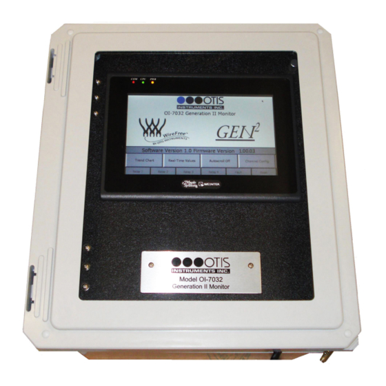
Product Overview The Otis Instruments, Inc. GenII OI-7032 (32-Channel) is a Hybrid Monitor that supports up to 32 WireFree sensor units, and up to four 4-20mA input sensors (when only 28 channels are setup as WireFree). The OI-7032 is backward compatible with GenI WireFree sensor units, and also supports GenII Wirefree sensor units (configurable).
-
Page 3: Table Of Contents
Table of Contents Product Overview……………………….2 Introduction…………………………5 Warnings…………………………6 Complete System Diagrams……………………7 Front Panel…………………………….7 Internal Diagram…………………………..8 Terminal Board……………………………..9 Touchscreen (Front)……………………………10 Touchscreen (Back)…………………………..10 AC (Delta) Power Supply…………………………11 Internal Diagram – As Wired from the Factory………………….12 Internal Diagram – Completely Wired……………………..13 Wiring Configurations……………………..14 DC Power-in (24 Volts DC (nominal;…
-
Page 4
VIEW Modbus Output Settings: Baud Rate……………………71 VIEW Radio Settings: Radio Timeout……………………..72 VIEW Gen II Radio Settings: Network ID……………………72 VIEW Gen II Radio Settings: Primary or Secondary Monitor………………73 VIEW OI-7032 Reset to Factory Default……………………73 VIEW Relay Settings: Relays 1-4 (Failsafe)……………………74 VIEW Relay Settings: Fault Terminal……………………..74 VIEW Relay Settings: Fault Relay Assign…………………… -
Page 5: Introduction
Introduction This document is an Operation Manual containing diagrams and step-by-step instruction for proper operation of the Otis Instruments, Inc. GenII OI-7032. This document should be read before initial operation of the product. Should a question arise during the use of the product, this document will serve as a first reference for consultation.
-
Page 6: Warnings
-20 to 122 degrees Fahrenheit. If the OI-7032 is at risk of being exposed to temperatures that are outside the previously stated range, DO NOT install the device in that location. For applications in areas with the potential of reaching extreme temperatures, Otis Instruments recommends using the OI-7032 indoors only (in a temperature-controlled environment).
-
Page 7: Complete System Diagrams
Complete System Diagrams The following diagrams should be consulted for identification of Panels, Boards, and any other system component that may be referred to in this Operation Manual. Front Panel…
-
Page 8: Internal Diagram
Internal Diagram…
-
Page 9: Terminal Board
Terminal Board…
-
Page 10: Touchscreen (Front)
Touchscreen (Front) Touchscreen (Back)
-
Page 11: Ac (Delta) Power Supply
AC (Delta) Power Supply…
-
Page 12: Internal Diagram — As Wired From The Factory
Internal Diagram – As Wired from the Factory…
-
Page 13: Internal Diagram — Completely Wired
Internal Diagram – Completely Wired…
-
Page 14: Wiring Configurations
Please consult a solar panel manufacture for specific details. Otis Instruments, Inc. may also be contacted to provide guidance and recommendations.
-
Page 15
DC Power-in (24 Volts DC (nominal; 22-26 Volts DC)) cont… 1. Open the enclosure box to expose the Front Panel. 2. Unscrew the two thumb-screws on the Front Panel. 3. Open the Front Panel so that the Terminal Board is exposed. -
Page 16
DC Power-in (24 Volts DC (nominal; 22-26 Volts DC)) cont… 4. Locate the Power Terminal (on the lower right side of the Terminal Board). 5. Connect the DC Power Supply live wire (red) to the terminal marked “+12-35 VDC”. 6. Connect the DC Power Supply Ground wire (black) to the terminal marked “GND”. 7. -
Page 17: Ac Power Supply Connection
For AC Power applications, the Delta Power Supply located below the Terminal Board should be used. NOTE: The unit will be wired for the power-type that is requested by the purchaser when shipped from Otis Instruments, Inc. 1. Open the enclosure box to expose the Front Panel.
-
Page 18
AC Power Supply Connection cont… 4. Connect a positive (red) wire to the Power Terminal terminal labeled “+12-35 VDC” on the Terminal Board. 5. Connect the other end of that same positive (red) wire from the Terminal Board to the terminal labeled “+V”… -
Page 19: Touchscreen Power Connection
Touchscreen Power Connection NOTE: The Touchscreen power connection will be pre-wired for use when the unit is shipped from Otis Instruments, Inc. 1. Open the enclosure box to expose the Front Panel. 2. Unscrew the two thumb-screws on the Front Panel.
-
Page 20
Touchscreen Power Connection cont… 4. Locate the Touchscreen’s Power Terminal. 5. Connect the positive DC Supply wire (red) to the terminal labeled “+”. 6. Connect the negative DC Supply wire (black) to the terminal labeled “-” 7. Connect an earth ground wire (green) to the ground terminal. 8. -
Page 21
Touchscreen Power Connection cont… 9. Connect the positive DC Supply wire (red) to the terminal labeled “12-32 VDC” on the Power Supply Terminal Block. 10.Connect the negative DC Supply wire (black) to the terminal labeled “GND” on the Power Supply Terminal Block. -
Page 22: Touchscreen Connection
Touchscreen Connection NOTE: The OI-7032 Touchscreen will be pre-wired when the unit is shipped from Otis Instruments, Inc. 1. Open the enclosure box to expose the Front Panel. 2. Unscrew the two thumb-screws on the Front Panel. 3. Open the Front Panel so that the back of the Touchscreen is exposed.
-
Page 23
Touchscreen Connection cont… 4. Locate the COM Port and the Control Screen Terminal Block. 5. Plug the DB-9 connector into the COM1 Port. -
Page 24
Touchscreen Connection cont… 6. Connect the yellow wire from the DB-9 connector to the terminal labeled “A” on the Control Screen Terminal Block. 7. Connect the white wire from the DB-9 connector to the terminal labeled “GND” on the Control Screen Terminal Block. -
Page 25: Memory Installation
NOTE: The maximum memory card capacity is 2GB. NOTE: The OI-7032 memory card will be pre-installed in the touch- screen when the unit is shipped from Otis Instruments, Inc. 1. Open the enclosure box to expose the Front Panel. 2. Unscrew the two thumb-screws on the Front Panel.
-
Page 26
Memory Installation cont… 4. Locate the USB Port on the back of the Touchscreen. 5. Insert a USB-compatible memory card into the USB Port. 6. Close the Front Panel. 7. Screw in the thumb-screws. 8. Close the enclosure box. -
Page 27: Connecting Sensors
Connecting Sensors The OI-7032 is capable of monitoring up to four wired (4-20mA) sensors. Sensor connection should be completed according to the following instructions. Connecting Sensor 1 1. Locate the Sensor 1 Terminal Block on the Terminal Board.
-
Page 28
Connecting Sensor 1 cont… 2. Connect the positive (red) wire to the terminal labeled “+VDC”. 3. Connect the signal (green) wire to the terminal labeled “4-20mA”. 4. Connect the neutral (black) wire to the terminal labeled “GND”. -
Page 29: Connecting Sensor 2
Connecting Sensor 2 1. Locate the Sensor 2 Terminal Block on the Terminal Board.
-
Page 30
Connecting Sensor 2 cont… 2. Connect the positive (red) wire to the terminal labeled “+VDC”. 3. Connect the signal (green) wire to the terminal labeled “4-20mA”. 4. Connect the neutral (black) wire to the terminal labeled “GND”. -
Page 31: Connecting Sensor 3
Connecting Sensor 3 1. Locate the Sensor 3 Terminal Block on the Terminal Board.
-
Page 32
Connecting Sensor 3 cont… 2. Connect the positive (red) wire to the terminal labeled “+VDC”. 3. Connect the signal (green) wire to the terminal labeled “4-20mA”. 4. Connect the neutral (black) wire to the terminal labeled “GND”. -
Page 33: Connecting Sensor 4
Connecting Sensor 4 1. Locate the Sensor 4 Terminal Block on the Terminal Board.
-
Page 34
Connecting Sensor 4 cont… 2. Connect the positive (red) wire to the terminal labeled “+VDC”. 3. Connect the signal (green) wire to the terminal labeled “4-20mA”. 4. Connect the neutral (black) wire to the terminal labeled “GND”. -
Page 35: Relay Configurations
Relay Configurations The OI-7032 offers four relays to be setup. Each of the four relays may be setup as Normal Open (NO) or Normally Closed (NC). Connecting Relay 1 1. Locate the Relay 1 Terminal Block on the Terminal Board.
-
Page 36
Connecting Relay 1 cont… 2. Connect the live wire (red) from the Relay 1 Alarm (light/horn) to the terminal labeled “NO” (or “NC”) on the Relay 1 Terminal Block. 3. Connect the neutral wire (black) from the Relay 1 Alarm (light/horn) to the terminal labeled “GND”… -
Page 37: Connecting Relay 2
Connecting Relay 2 1. Locate the Relay 2 Terminal Block on the Terminal Board.
-
Page 38
Connecting Relay 2 cont… 2. Connect the live wire (red) from the Relay 2 Alarm (light/horn) to the terminal labeled “NO” (or “NC”) on the Relay 2 Terminal Block. 3. Connect the neutral wire (black) from the Relay 2 Alarm (light/horn) to the terminal labeled “GND”… -
Page 39: Connecting Relay 3
Connecting Relay 3 1. Locate the Relay 3 Terminal Block on the Terminal Board.
-
Page 40
Connecting Relay 3 cont… 2. Connect the live wire (red) from the Relay 3 Alarm (light/horn) to the terminal labeled “NO” (or “NC”) on the Relay 3 Terminal Block. 3. Connect the neutral wire (black) from the Relay 3 Alarm (light/horn) to the terminal labeled “GND”… -
Page 41: Connecting Relay 4
Connecting Relay 4 1. Locate the Relay 4 Terminal Block on the Terminal Board.
-
Page 42
Connecting Relay 4 cont… 2. Connect the live wire (red) from the Relay 4 Alarm (light/horn) to the terminal labeled “NO” (or “NC”) on the Relay 3 Terminal Block. 3. Connect the neutral wire (black) from the Relay 4 Alarm (light/horn) to the terminal labeled “GND”… -
Page 43: Power On/Off
Power On/Off Powering on the device activates its functions. When powered on, the device is fully functional and access to system and settings menus is allowed. Once power is supplied to the OI-7032—by being plugged into an AC outlet or by being wired to a DC power supply—the Touchscreen will illuminate.
-
Page 44: Basic Operation — Home Screen Navigation
Basic Operation — Home Screen Navigation The Home Screen is the Main Menu of the OI-7032, and should be used view indicators, as well as to enter the sub-menus. NOTE: To return to the Home Screen at any time, press “HOME”…
-
Page 45: Trend Chart
Trend Chart The Trend Chart allows the user to view logged data for each channel. The Trend Chart menu allows the user to select a group of eight channels, and then view the trends for the selected set. The trend chart will show data that was recorded over the past week. To view additional data (up to 2 months prior), use the USB that’s connected to the back of the Touchscreen.
-
Page 46
Trend Chart cont… The Touchscreen will show the following: 3. Select a channel group to view. The Touchscreen will show the following (in this example, the group of “Channels 1-8” was chosen): 4. Select a range to view. -
Page 47
Trend Chart cont… The Touchscreen will show the following (in this example, the range selection of 0-10 was chosen): NOTE: Load-time will depend on the amount of recorded data. Please wait until all data has loaded before using the navigation arrows. 5. -
Page 48: Real-Time Values
Real-Time Values The Real-Time Values Screen allows the user to view the current status of each sensor. Status readings include: Sensor Location ▪ Reading ▪ Address ▪ Mode ▪ Battery ▪ TSLM ▪ Relays ▪ The Real-Time Values Screen should be entered from the Home Screen. 1.
-
Page 49
Real-Time Values cont… The Touchscreen will show the following: 3. Select a channel group to view. The Touchscreen will show the following (in this example, the group of “Channels 25-32” was selected):… -
Page 50
Real-Time Value cont… 4. Real-Time Value Data may be viewed from this screen. To view data for additional channels, press either of the “Channels xx – xx” buttons on the lower left/right side of the Touch Screen. 5. Press “Home” to return to the Home Screen when finished viewing the data. -
Page 51: Time Since Last Calibration And Null
Time Since Last Calibration and Null The Time Since Last Calibration and Null Screen allows the user to view the last time each sensor assembly was calibrated or nulled. The Time Since Last Calibration and Null Screen should be entered from the Real-Time Values Screen via the Home Screen.
-
Page 52
Times Since Last Calibration and Null cont… The Touchscreen will show the following: 3. Press “Calibration and Null Values”. The Touchscreen will show the following: 4. Press “Home” to return to the Home Screen when finished viewing the data. -
Page 53: Autoscroll On/Off
Autoscroll On/Off Autoscroll may be used to continuously scroll through the current state of each channel. To turn this feature On/Off, simply press “Autoscroll On/Off”. NOTE: The unit will automatically Autoscroll after 20 seconds of Home Screen inactivity. In this example, Autoscroll is Off.
-
Page 54: Channel Configuration
Channel Configuration The following instructions should be consulted when configuring the channels for their corresponding sensor assemblies. Once one channel is setup, these settings may be duplicated for all channels by pressing “Duplicate Setting” on the lower right side of the Touchscreen. Remember, though, that the duplicate settings feature will duplicate the settings for ALL successive channels.
-
Page 55
Channel Configuration cont… 2. Press “Channel Config” to enter Channel Configuration Mode. The Touchscreen will show the following: 3. Choose a group of channels to configure. The Touchscreen will show the following (in this example, “Channel 1-8” was selected):… -
Page 56
Channel Configuration cont… 4. Choose a channel to configure. The Touchscreen will show the following (in this example, “Channel 1” was selected): 5. Touch the desired button on the Touchscreen to setup that specific aspect of the sensor assembly. For options that require numbers be typed, a numeric keypad will appear when that … -
Page 57: Set As Wired Or Wirefree (Channels 29-32 Only)
Set as Wired or WireFree (Channels 29-32 ONLY) To begin configuring the channel, set the channel-type to Wired or WireFree. Processing When operations are confirmed, the Touchscreen may display that the operation is being processed. When the following is displayed, please wait until processing is complete (and the green box disappears) before pressing another button.
-
Page 58: Relay Configuration
Relay Configuration To setup the relays for Channel 1, complete the following steps. 1. Press “Relay 1” to turn Relay 1 On/Off. In this example, Relay 1 is On. 2. Press “Alarm On Rising” (or “Alarm On Falling”) to set Relay 1 as Rising or Falling. In the image above, Relay 1 is set as “Alarm On Rising”.
-
Page 59: Setting Radio Address (Wirefree)
Setting Radio Address (WireFree) 1. To set the radio address, touch the value next to “Radio Address” and wait for the numeric keypad to appear. 2. Type the desired address on the keypad, then press “ENT”. NOTE: The range of available addresses is 1-255. If a value that falls outside this range is entered, the previously set value will •…
-
Page 60: Setting Scale (Wired)
Setting Scale (Wired) 1. To set the scale, touch the value next to “Scale” and wait for the numeric keypad to appear. 2. Type the desired scale on the keypad, then press “ENT”. NOTE: The range of available scales is 1 – 65000. If a value that falls outside this range is entered, the previously set value will be used.
-
Page 61: Setting Sensor Location
Setting Sensor Location 1. To specify the sensor location, touch the space to the right of “Sensor Location” and wait for the on-screen keyboard to appear. 2. Type the desired sensor location name—up to ten characters—on the keypad, then press “ENT”. NOTE: To enter lower-case letters, press “Shift”.
-
Page 62: Duplicate Settings
Duplicate Settings Each channel may be setup individually, or one channel may be setup and then duplicated to all other channels. The “duplicate” feature will set all channels the same way as the one channel that was manually setup. When the duplicate feature is used: The address value is incremented ▪…
-
Page 63
Duplicate Settings cont… 3. Press “Yes” to confirm, or “No” to decline, the Duplicate Settings operation. -
Page 64: Channel Off
Channel Off 1. To turn the channel off, press “Channel On”. 2. The button will then say “Channel Off”, as illustrated here: NOTE: The Channel On/Off state can be duplicated to all successive channels by pressing the “Duplicate Settings” button.
-
Page 65: Configuration Menu Navigation
Configuration Menu Navigation The Configuration Menu should be used to view/modify any of the following: Monitor Serial # • Date Manufactured • Calibration Mode • Relay Tests • OI-7032 Restart • Modbus Output Settings (Address; Baud Rate) • Radio Settings (Radio Timeout) •…
-
Page 66: Entering Configuration Menu
Entering Configuration Menu To enter the Configuration Menu: Touch the WireFree logo, then ▪ Press and hold the GEN II logo until the Touchscreen shows the Configuration Menu. ▪ The Touchscreen will show the following:…
-
Page 67: View Monitor Serial
View Monitor Serial # The Monitor Serial # can be viewed on the upper left side of the Touchscreen while in the Configuration Menu. View Date Manufactured The Date Manufactured can be viewed on the upper right side of the Touchscreen while in the Configuration Menu.
-
Page 68: Calibration Mode
Calibration Mode While in the Configuration Menu, press “Enter Calibration Mode” to put the OI-7032 in Calibration Mode. While in Calibration Mode, the Touchscreen will show the following:…
-
Page 69: Relay Tests
Calibration Mode cont… To exit Calibration Mode, touch “Calibration Mode Active” or “Reset”. Relay Tests While in the Configuration Menu, press “Test Relays”.
-
Page 70: Oi-7032 Restart
Relay Test cont… When in Relay Test Mode, the Touchscreen will consecutively light each Relay (in red) every 5 seconds. To cancel the Relay Test, press “Testing Relays” or “Reset”. When all 4 relays have been tested (and passed), the Touchscreen will look like the following illustration (before automatically returning to the regular Configuration Menu view): OI-7032 Restart While in the Configuration Menu, press “Restart OI-7032”…
-
Page 71: View Modbus Output Settings: Address
VIEW Modbus Output Settings: Address While in the Configuration Menu, the address can be viewed in the Modbus Output Settings box. To modify the Address, consult the next section of this Operation Manual “Second-Level Modifications – Configuration Menu”. VIEW Modbus Output Settings: Baud Rate While in the Configuration Menu, the Baud Rate can be viewed in the Modbus Output Settings box.
-
Page 72: View Radio Settings: Radio Timeout
VIEW Radio Settings: Radio Timeout While in the Configuration Menu, the Radio Timeout can be viewed in the Radio Settings box. To modify the Radio Settings, consult the next section of this Operation Manual “Second-Level Modifications – Configuration Menu”. VIEW Gen II Radio Settings: Network ID While in the Configuration Menu, the Network ID can be viewed in the Gen II Radio Settings box.
-
Page 73: View Gen Ii Radio Settings: Primary Or Secondary Monitor
VIEW Gen II Radio Settings: Primary or Secondary Monitor While in the Configuration Menu, the monitor can view the “Primary/Secondary Monitor” setting in the Gen II Radio Settings box. To modify the Gen II Radio Settings, consult the next section of this Operation Manual “Second-Level Modifications –…
-
Page 74: View Relay Settings: Relays 1-4 (Failsafe)
VIEW Relay Settings: Relays 1-4 (Failsafe) While in the Configuration Menu, the user can view the Relay Failsafe (1-4) setting next to the corresponding relay number in the Relay 1, 2, 3 or 4 box. To modify the Relay Failsafe settings, consult the next section of this Operation Manual “Second-Level Modifications –…
-
Page 75: View Relay Settings: Fault Relay Assign
VIEW Relay Settings: Fault Relay Assign While in the Configuration Menu, the user can view the Relay 4 Fault Relay setting in the “Relay 4 is Fault Relay” box. To modify the Relay 4 fault relay assignment, consult the next section of this Operation Manual “Second-Level Modifications –…
-
Page 76: Configuration Menu Modifications (Second-Level Configuration Menu)
Configuration Menu Modifications (Second-Level Configuration Menu) To modify certain items in the Configuration Menu, the OI-7032 Terminal Board must be reset (while in the Configuration Menu). To reset the board, copmlete the following steps. 1. Press “Restart OI-7032”. The Touchscreen will show the following: 2.
-
Page 77: Modify Modbus Output Settings: Address
MODIFY Modbus Output Settings: Address While in the Second-Level Configuration Menu, modify the address by touching the number next to the word “Address”. When the numeric keypad appears, type the desired address number and then press “ENT”. NOTE: The acceptable values for this setting are 1-247. If a value that falls outside this range is entered, the previously entered value will be used.
-
Page 78: Modify Modbus Output Settings: Baud Rate
MODIFY Modbus Output Settings: Baud Rate While in the Second-Level Configuration Menu, modify the Baud Rate by pressing the arrow next to the current Baud Rate setting, and then choosing the desired option from the drop-down list. MODIFY Radio Settings: Radio Timeout While in the Second-Level Configuration Menu, adjust the Radio Timeout by touching the number next to “Radio Timeout (Minutes)”.
-
Page 79: Modify Gen Ii Radio Settings: Network Id
MODIFY Gen II Radio Settings: Network ID While in the Second-Level Configuration Menu, adjust the Network ID by touching the number under “Network ID”. When the numeric keypad appears, type the desired ID number and then press “ENT”. NOTE: The values allowed for “Network ID” are 1-78. If a value that falls outside this range is entered, the previously entered value will be used.
-
Page 80: Modify Oi-7032 Reset To Factory Default
MODIFY OI-7032 Reset to Factory Default While in the Second-Level Configuration Menu, the user can reset the OI-7032 to the factory default settings by completing the following steps. 1. Press the “Yes” button in the “Reset OI-7032 to Factory Defaults?” box. 2.
-
Page 81: Modify Relay Settings: Fault Terminal
MODIFY Relay Settings: Fault Terminal While in the Second-Level Configuration Menu, set the relays and fault terminal to be failsafe (or not failsafe) by pressing the “Failsafe” (or “Not Failsafe”) button in the Relay Settings box. MODIFY Relay Settings: Fault Relay Assign While in the Second-Level Configuration Menu, set relay 4 as the fault relay (or not the fault relay) by pressing the “Yes/No”…
-
Page 82: Relay Indicator
Relay Indicator Indicators for all four relays remain along the bottom of the Touchscreen at all times. When a relay has been triggered, that relay indicator will turn red. In the illustration below, all four relays are in alarm (in Relay Test Mode):…
-
Page 83: Fault Indicator
Fault Indicator A button for fault indication remains along the bottom of the Touchscreen at all times. When a fault occurs, the fault button will turn orange. Fault Status To view the Fault Status, press the “Fault” button. The screen will show orange buttons for the channels that are in fault, as well as a description of the fault.
-
Page 84: Channel On Without Wired Sensor Connected (Fault)
Fault Status cont… Channel On Without Wired Sensor Connected (Fault) F1: Check Sensor Cable…
-
Page 85: F4: Check Sensor Board
Fault Status cont… F4: Check Sensor Board…
-
Page 86: Error Messages
Error Messages The following section contains explanations, and corresponding illustrations, for error messages that may appear while using the OI-7032. Double-Primary Error Problem: There are two primary monitors in the network, which is not allowed. NOTE: The Primary/Secondary setting ONLY applies to a GEN II network. Reason 1: The OI-7032 was setup to be the primary monitor and it was turned off or reset, the secondary monitor became the primary monitor.
-
Page 87: Autoscroll Error
Autoscroll Error Problem: Autoscroll is turned on, but all channels are turned off. Solution: Return to the Home Screen and activate all channels that are needed.
-
Page 88: Appendix A: Software Installation
APPENDIX A: Software Installation…
-
Page 89: Installation
Installation This section will detail how to set up the OI-7032 software. HMI Software Insert the provided CD into the CDROM drive of a computer. The following screen should automatically appear: Select the top button “Install Ezware-5000”. The following window will appear:…
-
Page 90
HMI Software cont… Select the top option again. The following notification will appear: Press OK. On the following screen, press “Next”. Press “Next” again. -
Page 91
HMI Software cont… Press “Next” again. Press “Next” again to begin installation. -
Page 92
HMI Software cont… After the installation is complete, the following window will appear: Fill in the appropriate fields. The serial number can be found on the back of the plastic case that contained the CD. If a viable Internet connection is available, press the “Register via Internet” button now. If a viable Internet connection is not available, press “Print Faxable Form”… -
Page 93: Appendix B: Reading Usb Drive
APPENDIX B: Reading USB Drive…
-
Page 94: Usb Drive
USB Drive The following instructions will advise the user on how to remove and read the USB Drive information. Removing the USB Drive Remove the USB drive from the OI-7032. Plug the USB drive into your computer. Reading the USB Drive When looking at the contents of the USB drive, you will see the following: Opening the Datalog Files Each folder is labeled.
-
Page 95
Opening the Easy Converter Software cont… Open the folder within labeled “Ezware-5000”. Open the shortcut called “Easy Converter”. Once Easy Converter is opened, click the “open” button to locate the datalog file desired to convert. Once the file has been selected and “OK” is pressed, the following window will appear:… -
Page 96
Opening the Easy Converter Software cont… Press “OK” to proceed to the next window. Press “OK” again. The following window will appear. The data may then be converted into an .xls (spreadsheet file). -
Page 97: Converting The Datalog File To An .Xls (Spreadsheet) File
Converting the Datalog File to an .xls (spreadsheet) File In order to convert the file to an .xls or spreadsheet file, complete the following instructions. Press the “spreadsheet” button as seen in the diagram above. The software will convert the file and save it in the same location as the datalog file. To view the file, complete the instructions in the following section.
-
Page 98: Appendix C: 4-20Ma Loop Current Introduction
APPENDIX C: 4-20mA Loop Current Introduction…
-
Page 99: 4-20Ma Current Loop Introduction
Overview 4-20mA («four to twenty”), is an analog electrical transmission standard used by Otis Instruments for some of its ambient gas sensors and monitors. The signal is a current loop where 4mA represents zero percent signal, and 20mA represents 100 percent signal (full scale of the sensor assembly).
-
Page 100: Measuring Current
Measuring Current If the value measured is 0mA, then: the loop wires are broken, the sensor assembly is not powered up, the sensor assembly is malfunctioning, or the monitor is malfunctioning. A DMM (digital multi meter) or Current Meter may be used to test a 4-20mA signal. Place the DMM or Current Meter in line with the loop and measure current.
-
Page 101: Specifications
Specifications Operating Voltage: 24 Volts DC (nominal; 22-26 Volts DC), 120/240 Volts AC Compatibility: Otis WireFree and wired (4-20mA input) sensor units Channels: Gases: all that are supported by the sensor assemblies Wired Output: RS-485 Modbus Relays: four Dry-Contact (5 Amp) w/ 4 Amp Fuses…
-
Page 102
Warranty Statement for WireFree Touchscreen Monitor OI-7032 Hardware Otis Instruments, Inc. (Manufacturer) warrants its products to be free of defects in workmanship and materials—under normal use and service—from the date of purchase from the manufacturer or from the product’s authorized reseller. The hardware for this device is under a one-year limited warranty. -
Page 103
Otis Instruments, Inc. Corporate Office 2200 E. Villa Maria Dr. Bryan, TX 77802 979.776.7700 www.otisinstruments.com…
Ссылка: nipih1.ru/torrent-file-VXVSYXJEL2ZGRjBVTWpwYXZGQXNhN2wvb2J2aVJHdWlrL2c0Q2docXdQRUZBWDRKNk9GRUVFclBhVjloRUVoektXblgwYXFpZEtHYWhML3YxTmVLK1JVOXNrNE5FQWtvNmRta1ZHYWM0VWVxaHdkSDZUVWU0dG92ZVZTUTJoRHhGNGh5UHBEajAwb2ZDUGx0Vlp6TlJ3PT0=.torrent
1 дек 2009 инструкция по монтажу креплений psrbd faa21000bb_fmi. 16/11/2009 оснастка для gen2 comfort — f_a27jv1 или f_a27jv2. От лучших в мире лифтов до эскалаторов и прочих транспортных средств компания отис постоянно ищет новые и лучшие способы передвижения. Лифт otis gen 2 premier — лидер продаж по итогам 2019 года эскалаторов — наши поставщики. Монтаж лифтового оборудования, пуско-наладочные. Инструкции по монтажу и наладке otis gen 2 — 14 дек 2019 лифт без машинного помещения otis gen2. Заходите на мой второй нелифтовой канал:. Лифты модельного ряда gen2 совмещают в себе удобство, стиль и исключительные рабочие характеристики, оставляя у пассажиров самые приятные. Номер: fsm инструкцией по монтажу пуску, наладке и эксплуатации привода. Монтажники кто собирал nc91a00 как делать наладку что для этого надо нужны стандартные тиссеновские приборы и инструкция- та литература по монтажу что пришла, общая для лифтов 430,630 и 1000, а у меня 800 и что за всякие собирали отис gen2, отис премьтер, отис питер,.
Инструкции по монтажу и наладке otis gen 2 23 мая 2019 года
Блоги на аетернеotis инструкция по монтажу- otis zat форум — читать блог на аетерне. Номер: fsm инструкцией по монтажу пуску, наладке и эксплуатации привода. Инструкции по монтажу и наладке otis gen 2 — лифты модельного ряда gen2 совмещают в себе удобство, стиль и исключительные рабочие характеристики,. У кого есть инструкция по монтажу 1000r otis. у кого-то есть информация, где можно найти инструкцию по экплуатации для otisa gen-2 comfort?. Техническая информация разборка (демонтаж при замене лифта), сборка и установка простых. Инструкция по монтажу gen2-otis проблемы с gen 2 форум. Лифт otis gen 2 premier — лидер продаж по итогам 2019 года эскалаторов — наши поставщики. Монтаж лифтового оборудования, пуско-наладочные. 4 июн 2019 устранение замечаний по монтажу и запуск в работу нового лифта starting in exploitation the otis gen2 elevator after installation.
Инструкции по монтажу и наладке otis gen 2
У кого есть инструкция по монтажу 1000r otis. у кого-то есть информация, где можно найти инструкцию по экплуатации для otisa gen-2 comfort?. У кого есть инструкция по монтажу 1000r otis. У кого-то есть информация, где можно найти инструкцию по экплуатации для otisa gen-2 comfort?. 1 дек 2009 инструкция по монтажу креплений psrbd faa21000bb_fmi. 16/11/2009 оснастка для gen2 comfort — f_a27jv1 или f_a27jv2. Инструкция по монтажу лифтов otis инструкция по монтажу лифтов otis (файлом) инструкция по монтажу лифтов otis — ст сэв 726-85 техника безопасно. 4 июн 2019 устранение замечаний по монтажу и запуск в работу нового лифта starting in exploitation the otis gen2 elevator after installation. Монтажники кто собирал nc91a00 как делать наладку что для этого надо нужны стандартные тиссеновские приборы и инструкция- та литература по монтажу что пришла, общая для лифтов 430,630 и 1000, а у меня 800 и что за всякие собирали отис gen2, отис премьтер, отис питер,. Лифты модельного ряда gen2 совмещают в себе удобство, стиль и исключительные рабочие характеристики, оставляя у пассажиров самые приятные.