- Manuals
- Brands
- Jeep Manuals
- Automobile
- GRAND CHEROKEE 2023
- Owner’s manual
-
Contents
-
Table of Contents
-
Bookmarks
Quick Links
2023 GRAND C H E ROK E E
OWNE R ‘ S M A N UA L
Compass
O W N E R ‘ S M A N U A L
D I E S E L A N D P E T R O L
Related Manuals for Jeep GRAND CHEROKEE 2023
Summary of Contents for Jeep GRAND CHEROKEE 2023
-
Page 1
2023 GRAND C H E ROK E E OWNE R ’ S M A N UA L Compass O W N E R ’ S M A N U A L D I E S E L A N D P E T R O L… -
Page 2
TABLE OF CONTENTS INTRODUCTION ……………………..10 GETTING TO KNOW YOUR VEHICLE …………….. 19 GETTING TO KNOW YOUR INSTRUMENT PANEL …………83 STARTING AND OPERATING ………………..107 MULTIMEDIA ……………………..167 SAFETY ……………………….222 IN CASE OF EMERGENCY ………………..276… -
Page 3
SERVICING AND MAINTENANCE ………………301 TECHNICAL SPECIFICATIONS ……………….. 355 CUSTOMER ASSISTANCE …………………363 INDEX ………………………… 381… -
Page 4: Table Of Contents
INTRODUCTION DOORS ……………..26 SEATS………………. 35 Manual Door Locks…………26 Manual Adjustment Front Seats — If Equipped..36 IMPORTANT NOTICE …………11 Power Door Locks …………27 Manual Adjustment Rear Seats ……… 37 SYMBOLS KEY …………..11 Keyless Enter ‘n Go™ — Passive Entry ……28 Power Adjustment Front Seats ……..
-
Page 5
EXTERIOR LIGHTS……………48 WINDSHIELD WIPERS AND WASHERS ……53 WINDOWS …………….72 Headlight Switch …………48 Windshield Wiper Operation ……..53 Power Window Controls ……….72 Automatic Window Features……..72 Multifunction Lever …………. 49 Rain Sensing Wipers — If Equipped ……55 Daytime Running Lights (DRLs) — Rear Wiper And Washer ……….55 Reset Auto-Up …………. -
Page 6
GETTING TO KNOW YOUR STARTING AND OPERATING FOUR-WHEEL DRIVE OPERATION ……..119 Quadra-Trac I Operating Instructions/Precautions — INSTRUMENT PANEL STARTING THE ENGINE ……….107 If Equipped…………..119 Automatic Transmission……….. 107 INSTRUMENT CLUSTER ………….83 Quadra-Trac II Operating Instructions/Precautions — Keyless Enter ‘n Go™ — Ignition ……108 Instrument Cluster Descriptions …….. -
Page 7
MULTIMEDIA CRUISE CONTROL SYSTEMS ……… 129 SURROUND VIEW CAMERA SYSTEM — Adaptive Cruise Control (ACC) ……..130 IF EQUIPPED …………..152 UCONNECT SYSTEMS …………167 PARKSENSE FRONT/REAR PARK ASSIST Zoom View…………..155 CYBERSECURITY …………..167 SYSTEM — IF EQUIPPED……….139 Virtual Wall …………… 155 UCONNECT SETTINGS …………168 ParkSense Sensors……….. -
Page 8
SAFETY CONNECTED SERVICES FAQS ……..213 SAFETY TIPS …………..272 Connected Services SOS FAQs — Transporting Passengers ……….272 SAFETY FEATURES …………222 If Equipped …………… 214 Transporting Pets ………….272 Anti-Lock Brake System (ABS) …….. 222 Connected Services Remote Door Lock/Unlock Connected Vehicles………..272 Drowsy Driver Detection (DDD) —… -
Page 9
REFUELING IN EMERGENCY ………. 291 Air Conditioner Maintenance ……..307 INTERIORS …………….352 Accessory Drive Belt Inspection……. 307 Carpet Safety Information ……..352 IF YOUR ENGINE OVERHEATS ……..292 MANUAL PARK RELEASE ……….293 Body Lubrication…………308 Seats And Fabric Parts……….353 FREEING A STUCK VEHICLE ……….. 295 Windshield Wiper Blades ……… -
Page 10
CUSTOMER ASSISTANCE GERMANY…………..369 SERBIA ……………376 GREECE …………..370 SLOVAKIA …………..376 IF YOU NEED ASSISTANCE ……….363 SLOVENIA…………..377 GUATEMALA ………….. 370 ARGENTINA…………..364 HONDURAS…………..370 SOUTH AFRICA…………377 AUSTRALIA…………..364 HUNGARY …………..370 SPAIN ……………..377 AUSTRIA …………..364 INDIA…………….371 SWEDEN…………..378 BALANCE OF THE CARIBBEAN…….. -
Page 11
Jeep® brand, and unmistakably world class. The all-new Jeep® Grand Cherokee/Grand Cherokee L is a specialized utility vehicle. It can go places and perform tasks that are not intended for conventional passenger vehicles. -
Page 12: Important Notice
IMPORTANT NOTICE Your warranties do not cover any part that FCA did not supply. Nor do they cover the cost of any repairs or adjustments that might be caused or needed because of the installation or use of non-manufacturer parts, components, equipment, materials, or additives. ALL MATERIAL CONTAINED IN THIS PUBLICATION IS BASED ON THE LATEST INFORMATION Nor do your warranties cover the costs of repairing damage or conditions caused by any AVAILABLE AT THE TIME OF PUBLICATION APPROVAL.
-
Page 13: Rollover Warning
PAGE REFERENCE ARROW Follow this reference for additional information on a particular feature. FOOTNOTE Supplementary and relevant information pertaining to the topic. If you do not read the entire Owner’s Manual, you may miss important information. Rollover Warning Label Observe all Cautions and Warnings. Failure to use the driver and passenger seat belts provided is a major cause of severe or ROLLOVER WARNING fatal injury.
-
Page 14: Symbol Glossary
SYMBOL GLOSSARY Red Warning Lights Some car components have colored labels with symbols indicating precautions to be Electric Power Steering (EPS) Fault Warning Light observed when using this component. It is important to follow all warnings when operating page 96 Ú…
-
Page 15
Red Warning Lights Yellow Warning Lights Oil Temperature Warning Light Anti-Lock Brake System (ABS) Warning Light page 98 page 97 Ú Ú Electric Park Brake Warning Light Rear Seat Belt Reminder Warning Light page 98 page 97 Ú Ú Electronic Stability Control (ESC) Active Warning Light Seat Belt Reminder Warning Light page 97 Ú… -
Page 16
Yellow Warning Lights Yellow Warning Lights Active Lane Management Warning Light Service Stop/Start System Warning Light page 99 page 100 Ú Ú Low Fuel Warning Light Tire Pressure Monitoring System (TPMS) Warning Light page 99 page 101 Ú Ú Low Washer Fluid Warning Light Sway Bar Fault Warning Light page 99 page 100… -
Page 17
Yellow Indicator Lights Yellow Indicator Lights Air Suspension Active Indicator Light Auto HOLD! Fault Indicator Light page 102 page 102 Ú Ú Service Forward Collision (FCW) Or Pedestrian Emergency Braking (PEB) Off Maximum Payload Exceeded Indicator Light Indicator Light page 103 Ú… -
Page 18
Green Indicator Lights Green Indicator Lights Auto HOLD Indicator Light Sport Mode Indicator Light page 103 page 104 Ú Ú Cruise Control SET Indicator Light Stop/Start Active Indicator Light page 103 page 104 Ú Ú Front Fog Indicator Light Turn Signal Indicator Lights page 103 page 104 Ú… -
Page 19
White Indicator Lights White Indicator Lights Hill Descent Control (HDC) Indicator Light Speed Warning Indicator Light page 104 page 105 Ú Ú Active Lane Management Indicator Light Selec-Speed Control Indicator Light page 105 page 105 Ú Ú Rear Seat Unoccupied Indicator Light Blue Indicator Lights page 105 Ú… -
Page 20: Keys
GETTING TO KNOW YOUR VEHICLE KEYS In case the ignition switch does not change positions with the push of a button, the key fob may have a low or fully depleted battery. A low key fob battery can be verified by referring to the instrument cluster, which will display directions to follow.
-
Page 21
GETTING TO KNOW YOUR VEHICLE To Lock/Unlock The Doors And Liftgate Replacing The Battery In The Key Fob Remove the emergency key (2) by pushing the emergency key release button (1) on the side of the Push and release the unlock button on the key fob once to The replacement battery model is one CR2450 battery. -
Page 22: Getting To Know Your Vehicle
GETTING TO KNOW YOUR VEHICLE Remove the battery by using your thumb to slide the battery downward and back toward the key ring. Emergency Key Removed Pry Apart Key Fob Halves Hold the key fob with the button side facing down, Next, locate the gap on the right side of the key fob, and locate the small rectangular gap on the left side which is positioned farther to the edge than the left…
-
Page 23
GETTING TO KNOW YOUR VEHICLE NOTE: Replace the battery by using your thumb to push Reinsert the emergency key until it locks into place. down and slide the battery under the small lip on the You can also insert a screwdriver or similar tool into the NOTE: top edge of the opening. -
Page 24: Sentry Key
GETTING TO KNOW YOUR VEHICLE Programming And Requesting Additional NOTE: an invalid key fob. In the event that a valid key fob is used to start the engine but there is an issue with the Key Fobs When having the Sentry Key Immobilizer system vehicle electronics, the engine will start and shut off after serviced, bring all vehicle keys with you to an autho- Programming the key fob may be performed by an…
-
Page 25: Ignition Switch
GETTING TO KNOW YOUR VEHICLE IGNITION SWITCH The push button ignition can be placed in the following modes: ‘ ™ I EYLESS NTER GNITION The engine is stopped This feature allows the driver to operate the ignition switch Some electrical devices (e.g. power locks, alarm, etc.) with the push of a button as long as the key fob is in the are still available passenger compartment.
-
Page 26: Electronic Steering Wheel Lock — If Equipped
GETTING TO KNOW YOUR VEHICLE For more information on the engine starting procedure, If something triggers the alarm, the Vehicle Security WARNING! system will provide the following audible and visible page 107. Ú signals: When opening the driver’s door and the ignition is in …
-
Page 27: To Disarm The System
GETTING TO KNOW YOUR VEHICLE When the Vehicle Security system is armed, the Vehicle The Vehicle Security system remains armed when the EARMING YSTEM Security Light (located in the lower right portion of the power liftgate is opened using the liftgate button on the instrument cluster display) will begin to flash every two key fob.
-
Page 28: Power Door Locks
GETTING TO KNOW YOUR VEHICLE The rear doors can be manually unlocked with a double OWER OCKS WARNING! pull of the inside door handle. The power door lock buttons are located on each front Each door can be manually locked by inserting the …
-
Page 29: Keyless Enter ‘N Go™ — Passive Entry
GETTING TO KNOW YOUR VEHICLE NOTE: NOTE: If the vehicle is unlocked by Passive Entry and no door is opened within 60 seconds, the vehicle will relock and If the key fob is located next to a mobile phone, laptop, or …
-
Page 30
GETTING TO KNOW YOUR VEHICLE NOTE: A lock request is made by the door panel switch while To Lock The Vehicle’s Doors And Liftgate the door is open. With one of the vehicle’s Passive Entry key fobs within 5 ft … -
Page 31: Automatic Unlock Doors On Exit
GETTING TO KNOW YOUR VEHICLE To Unlock/Enter The Liftgate To Lock The Liftgate The liftgate Passive Entry unlock feature is built into the With a valid Passive Entry key fob within 5 ft (1.5 m) of the electronic liftgate release button. With a valid Passive liftgate, push the Passive Entry lock button located on the Entry key fob within 5 ft (1.5 m) of the liftgate, push the outside liftgate door handle.
-
Page 32: Automatic Door Locks
GETTING TO KNOW YOUR VEHICLE — UTOMATIC OCKS WARNING! QUIPPED Avoid trapping anyone in a vehicle in a collision. Remember that the rear doors can only be opened The auto door lock feature default condition is enabled. from the outside with the Child-Protection locks When enabled, the door locks will lock automatically when engaged (locked).
-
Page 33: Steering Wheel
GETTING TO KNOW YOUR VEHICLE STEERING WHEEL Use the four-way control to adjust the steering column. The heated steering wheel button is located on the center of the instrument panel below the radio screen, and within NOTE: the Comfort screen of the touchscreen. OWER ELESCOPING TEERING…
-
Page 34: Uconnect Voice Recognition Quick
“Wake Up” word, wait until And Send Or Receive A Text vehicle’s “Wake Up” word, “Hey Jeep®”. The factory after the beep, then say your Voice Command. 1 — For Vehicles Not Equipped With Navigation: Push The default “Wake Up”…
-
Page 35: Driver Memory Settings — If Equipped
GETTING TO KNOW YOUR VEHICLE DRIVER MEMORY SETTINGS — IF EQUIPPED ROGRAMMING EMORY EATURE To create a new memory profile, perform the following: This feature allows the driver to save up to two different memory profiles for easy recall through a memory switch. NOTE: Each memory profile saves desired position settings for Saving a new memory profile will erase the selected profile…
-
Page 36: Linking And Unlinking The Key Fob To Memory
GETTING TO KNOW YOUR VEHICLE SEATS NOTE: INKING NLINKING Your key fobs can be unlinked from your driver’s side EMORY Seats are a part of the Occupant Restraint system of the memory settings by pushing the set (S) button, and within vehicle.
-
Page 37: Manual Adjustment Front Seats — If Equipped
GETTING TO KNOW YOUR VEHICLE — Manual Front Passenger Seat Forward/ While sitting in the seat, lift up on the bar located under ANUAL DJUSTMENT RONT EATS the seat cushion and move the seat forward or rearward. Rearward Adjustment QUIPPED Release the bar once you have reached the desired Some models may be equipped with a manual front position.
-
Page 38: Manual Adjustment Rear Seats
GETTING TO KNOW YOUR VEHICLE Manual Front Passenger Seatback Second Row Bench Seat WARNING! Adjustment — Recline SECOND ROW BENCH SEAT FORWARD/REAR- Do not ride with the seatback reclined so that the To recline, lean forward slightly and lift the lever located on shoulder belt is no longer resting against your chest.
-
Page 39
GETTING TO KNOW YOUR VEHICLE SECOND ROW BENCH SEAT RECLINE ADJUST- WARNING! MENT Do not ride with the seatback reclined so that the To recline, lean forward slightly and lift the lever located on shoulder belt is no longer resting against your chest. In the outboard side of the seat. -
Page 40: Power Adjustment Front Seats
GETTING TO KNOW YOUR VEHICLE Adjusting The Seat Forward Or Rearward OWER DJUSTMENT RONT EATS WARNING! The seat can be adjusted both forward and rearward. Push This vehicle is equipped with eight-way power driver and Adjusting a seat while driving may be dangerous. the seat switch forward or rearward.
-
Page 41
GETTING TO KNOW YOUR VEHICLE Seatback Bolster Adjustment — Cushion Extender — If Equipped Easy Entry/Exit Seat — If Equipped If Equipped The cushion can be extended forward a few inches This feature provides automatic driver seat positioning to (centimeters) to increase thigh support. Push the cushion enhance driver mobility when entering and exiting the The front driver and passenger seatback bolsters can be extender switch forward or rearward to extend or retract… -
Page 42: Heated Seats — If Equipped
GETTING TO KNOW YOUR VEHICLE — I Front Heated Seats Rear Heated Seats EATED EATS QUIPPED The front heated seats control buttons are The two second row outboard seats may be WARNING! located on the center stack below the radio equipped with heated seats.
-
Page 43: Ventilated Seats — If Equipped
GETTING TO KNOW YOUR VEHICLE — I Front Head Restraints ENTILATED EATS QUIPPED ESTRAINTS Your vehicle is equipped with front four-way driver and Located in the seat cushion and seatback are fans that Head restraints are designed to reduce the risk of injury by passenger head restraints.
-
Page 44
GETTING TO KNOW YOUR VEHICLE To adjust the head restraint forward, pull the top of the WARNING! head restraint toward the front of the vehicle as desired and release. To adjust the head restraint rearward, pull All occupants, including the driver, should not the top of the head restraint to the forward most position operate a vehicle or sit in a vehicle’s seat until the and release. -
Page 45
GETTING TO KNOW YOUR VEHICLE Head Restraints — Second Row Bench NOTE: NOTE: The center head restraint is not removable. For information on child restraint tethering, see The head restraints on the outboard seats are not page 245. Ú adjustable or removable. They automatically fold forward when the seatback is folded, and do not return to their WARNING! normal position when the seatback is raised. -
Page 46: Mirrors
GETTING TO KNOW YOUR VEHICLE MIRRORS Digital Rearview Mirror — If Equipped Push the menu button next to the on/off control/toggle to access the following mirror options: The Digital Rearview Mirror provides a high definition, Brightness NSIDE EARVIEW IRROR wide and unobstructed view of the road behind while …
-
Page 47: Illuminated Vanity Mirrors
GETTING TO KNOW YOUR VEHICLE — Sun Visor Slide-On-Rod Feature — LLUMINATED ANITY IRRORS WARNING! If Equipped QUIPPED Vehicles and other objects seen in an outside convex The sun visor Slide-On-Rod feature allows for additional mirror will look smaller and farther away than they To access an illuminated vanity mirror, flip down one of flexibility in positioning the sun visor to block out the sun.
-
Page 48: Outside Mirrors With Turn
GETTING TO KNOW YOUR VEHICLE Power Folding — If Equipped UTSIDE IRRORS To fold the door mirrors in using the Power Folding Mirror — I IGNAL QUIPPED function, rotate the control switch to the power folding position. Rotating the control to the left, right, or neutral Driver and passenger outside mirrors with turn signal position will return the mirrors to the driving position.
-
Page 49: Automatic Power Folding
GETTING TO KNOW YOUR VEHICLE EXTERIOR LIGHTS — I UTOMATIC OWER OLDING EATED IRRORS QUIPPED — I IRRORS QUIPPED These mirrors are heated to melt frost or ice. EADLIGHT WITCH This feature will be activated whenever you When enabled within Uconnect Settings page 168, the Ú…
-
Page 50: Multifunction Lever
GETTING TO KNOW YOUR VEHICLE (DRL ) — Rotate the headlight switch clockwise from the parking AYTIME UNNING IGHTS CAUTION! lights and instrument panel lights position to the first QUIPPED detent to turn the headlight switch to the AUTO position. Do not use abrasive cleaning components, solvents, Rotate to the second detent to turn on headlights, parking steel wool or other abrasive materials to clean the…
-
Page 51: Automatic High Beams
GETTING TO KNOW YOUR VEHICLE — If the windshield or Automatic High Beam Headlight UTOMATIC EAMS ARKING IGHTS ANEL IGHTS Control mirror is replaced, the mirror must be re-aimed to QUIPPED ensure proper performance. See a local authorized dealer. To turn on the parking lights and instrument panel lights, rotate the headlight switch to the first position.
-
Page 52: Headlight Illumination On Approach
GETTING TO KNOW YOUR VEHICLE To activate the front fog lights, push the upper half of the EADLIGHT LLUMINATION IGHTS EMINDER headlight switch. To turn off the front fog lights, push the PPROACH If the headlights or parking lights are left on after the upper half of the headlight switch a second time.
-
Page 53: Turn Signals
GETTING TO KNOW YOUR VEHICLE Front Map/Reading Lights — If Equipped If the ignition is placed in the OFF position and any door is IGNALS left ajar for 10 minutes or the overhead console Dome On The overhead console lights can also be operated Move the multifunction lever up or down and the arrows switch is left on for 10 minutes, the interior lights will individually as reading lights by pushing the corresponding…
-
Page 54: Windshield Wipers And Washers
GETTING TO KNOW YOUR VEHICLE Rear Courtesy/Reading Lights With the parking lights or headlights on, rotating the NOTE: instrument panel dimmer control upward will increase the The dimming of lighting linked to the headlight status Located above the rear passenger seating in both second brightness of the instrument cluster lights.
-
Page 55
GETTING TO KNOW YOUR VEHICLE Intermittent Wiper System NOTE: As a protective measure, the pump will stop if the Use the intermittent wiper when weather conditions make switch is held for more than 20 seconds. Once the a single wiping cycle with a variable pause between cycles switch is released the pump will resume normal opera- desirable. -
Page 56: Rain Sensing Wipers — If Equipped
GETTING TO KNOW YOUR VEHICLE For information on wiper care and replacement, see Use of products containing wax or silicone may reduce IPER ASHER rain sensor performance. page 308. Ú The rear wiper/washer is operated by rotating a switch, …
-
Page 57: Climate Controls
GETTING TO KNOW YOUR VEHICLE CLIMATE CONTROLS Max A/C Button Recirculation may be unavailable if conditions exist that could create fogging on the inside of the windshield. The Press and release to change the current A/C can be deselected manually without disturbing the The Climate Control system allows you to regulate the setting.
-
Page 58
GETTING TO KNOW YOUR VEHICLE MAX Defrost Button Rear Defrost Button Rear Climate Control Button — If Equipped Push the MAX Defrost button to change the Press and release the button on the Press and release this button on the current airflow setting to Defrost mode. -
Page 59
GETTING TO KNOW YOUR VEHICLE SYNC Button Blower Control Panel Mode Press the SYNC button on the touchscreen to Blower Control is used to regulate the amount Air comes from the outlets in the instrument toggle the SYNC feature on/off. The SYNC of air forced through the Climate Control panel. -
Page 60
GETTING TO KNOW YOUR VEHICLE Mix Mode Climate Control OFF Button To change the rear system settings: Press the Rear button on the touchscreen to display Air is directed through the floor, defrost, and Press and release this button to turn the the rear climate controls. -
Page 61
GETTING TO KNOW YOUR VEHICLE FRONT CLIMATE BUTTON When SYNC is not active, the rear passenger climate REAR CLIMATE CONTROL OFF BUTTON control settings will need to be adjusted manually to Press and release to return to the Front Climate To manually set the rear blower controls to off, achieve desired comfort. -
Page 62
GETTING TO KNOW YOUR VEHICLE The rear system temperature control buttons are located REAR BLOWER CONTROL BI-LEVEL MODE on rear of the front center console. Use the blower button with the down arrow to Air comes from both the headliner outlets and NOTE: reduce the blower setting, and the blower the floor outlets. -
Page 63: Rear Air Conditioning Control I F Equipped
GETTING TO KNOW YOUR VEHICLE — Rear Lock The blower speed can be adjusted from blower speeds ONDITIONING ONTROL 1 (lowest speed) to 3 (maximum speed). When the control Pressing the Rear Temperature Lock button on the QUIPPED switch is placed in the OFF position, no air will be flowing Uconnect touchscreen will illuminate a lock symbol in the through the rear outlets.
-
Page 64: Climate Voice Recognition
GETTING TO KNOW YOUR VEHICLE — When the system is set up for your comfort level, it is NOTE: LIMATE OICE ECOGNITION not necessary to change the settings. You will Refer to the chart at the end of this section for suggested QUIPPED experience the greatest efficiency by simply allowing control settings for various weather conditions.
-
Page 65: Interior Storage And Equipment
GETTING TO KNOW YOUR VEHICLE INTERIOR STORAGE AND EQUIPMENT Outside Air Intake Operating Tips Chart Make sure the air intake, located directly in front of the WEATHER CONTROL SETTINGS TORAGE windshield, is free of obstructions, such as leaves. Leaves collected in the air intake may reduce airflow, and if they Set the mode control to Glove Compartment enter the air distribution box, they could plug the water…
-
Page 66
GETTING TO KNOW YOUR VEHICLE Front Center Console Sunglasses Bin Door Rear Full Center Console — If Equipped The front center console contains both an upper and a At the front of the console a compartment is provided for The rear full center console contains both an upper and a lower storage area. -
Page 67: Lighted Cupholders — If Equipped
GETTING TO KNOW YOUR VEHICLE To open the covered storage compartment, pull the upper The rear cupholders may also be equipped with a light ring CAUTION! paddle release lever on the front of the lid. that illuminates the cupholders for the rear passengers. The light ring is controlled by the Dimmer Controls The storage compartment may also be lifted forward.
-
Page 68: Usb/Aux Control
GETTING TO KNOW YOUR VEHICLE Connecting AUX Or The External USB Once the screen is completely to the top of the window, Plugging in a smartphone device to a USB port will activate extend the top bar of the sun screen over the two hooks Android Auto™…
-
Page 69
GETTING TO KNOW YOUR VEHICLE Once a device is connected to the USB port, it will begin By using an auxiliary cable to connect an external device: In the third row, a set of two USB ports can be used to charging and is ready for use with the system. -
Page 70: Electrical Power Outlets
GETTING TO KNOW YOUR VEHICLE Power outlets are designed for accessory plugs only. The rear cargo power outlet is located in the right rear LECTRICAL OWER UTLETS Do not insert any other object in the power outlets as cargo area. Your vehicle is equipped with 12 Volt (13 Amp) power this will damage the outlet and blow the fuse.
-
Page 71: Power Inverter — If Equipped
GETTING TO KNOW YOUR VEHICLE WARNING! CAUTION! To avoid serious injury or death: Accessories that draw higher power (i.e., coolers, vacuum cleaners, lights, etc.) will degrade the Only devices designed for use in this type of outlet battery even more quickly. Only use these intermit- should be inserted into any 12 Volt outlet.
-
Page 72: Wireless Charging Pad
GETTING TO KNOW YOUR VEHICLE Your vehicle may be equipped with a 15W 3A Qi wireless Wireless charging is not as fast as when the phone is WARNING! charging pad located inside of the storage area below the connected to a wired charger. climate controls.
-
Page 73: Windows
GETTING TO KNOW YOUR VEHICLE CAUTION! WARNING! The key fob should not be placed on the charging pad Never leave children unattended in a vehicle, and do or within 6 inches (15 cm) of it. Doing so can cause not let children play with power windows. Do not leave excessive heat buildup and damage to the fob.
-
Page 74: Reset Auto-Up
GETTING TO KNOW YOUR VEHICLE Auto-Up Feature With Anti-Pinch Protection ESET For windows equipped with the AUTO feature, lift the Should the Auto-Up feature stop working, the window may window switch up to the second detent, and release; the need to be reset. To reset Auto-Up: window will go up automatically.
-
Page 75: Power Sunroof — If Equipped
GETTING TO KNOW YOUR VEHICLE POWER SUNROOF — IF EQUIPPED Opening And Closing The Sunroof WARNING! The sunroof has two programmed automatic stops for the Never leave children unattended in a vehicle, or with OWER UNROOF sunroof open position: a comfort stop position and a full access to an unlocked vehicle.
-
Page 76
GETTING TO KNOW YOUR VEHICLE Pinch Protect Feature Any release of the switch during open or close operation and the sunshade is at half open position will first will stop the sunroof movement in a partially open automatically close the sunroof prior to the sunshade This feature will detect an obstruction in the opening of position. -
Page 77: Hood
GETTING TO KNOW YOUR VEHICLE HOOD WARNING! Be sure the hood is fully latched before driving your PENING vehicle. If the hood is not fully latched, it could open To open the hood, two latches must be released. when the vehicle is in motion and block your vision. Failure to follow this warning could result in serious Pull the release lever located at the bottom of the injury or death.
-
Page 78: To Lock/Close The Liftgate
GETTING TO KNOW YOUR VEHICLE NOTE: With a valid Passive Entry key fob within 5 ft (1.5 m) of the liftgate, pushing the Passive Entry button located to the Use the power door lock switch on either front door trim left of the electronic liftgate release button, will lock the panel or the key fob to lock and unlock the liftgate.
-
Page 79: Adjustable Power Liftgate Height
GETTING TO KNOW YOUR VEHICLE Power Liftgate Malfunction Procedure: DJUSTABLE OWER IFTGATE EIGHT ARGO EATURES In the event of a power malfunction to the liftgate, Cargo Storage The maximum height that the liftgate will open can be the liftgate can be released by accessing the service adjusted and saved so that the liftgate will only open to the release feature in the latch.
-
Page 80
GETTING TO KNOW YOUR VEHICLE Cargo Tie-Down Hooks WARNING! WARNING! The cargo tie-downs, located on the cargo area sides, Cargo tie-downs are not safe anchors for a child seat Always place cargo evenly on the cargo floor. Put should be used to safely secure loads when the vehicle is tether strap. -
Page 81
GETTING TO KNOW YOUR VEHICLE Retractable Cargo Area Cover — To cover the cargo area: WARNING! If Equipped Remove the folded cover from the storage pouch, In a collision, a loose cargo cover in the vehicle could and unfold using a twisting motion. The purpose of this cover is for privacy, not to secure cause injury. -
Page 82
GETTING TO KNOW YOUR VEHICLE Hook the straps to the outside post of the rear head To store the foldable cargo area cover, reverse the WARNING! restraint on each side. installation steps and replace the cover into its storage pouch. In a collision, a loose cargo cover in the vehicle could cause injury. -
Page 83: Roof Luggage Rack — If Equipped
GETTING TO KNOW YOUR VEHICLE ROOF LUGGAGE RACK — IF EQUIPPED NOTE: CAUTION! If any cargo (or any metallic object) is placed over the The crossbars and siderails are designed to carry loads on satellite radio antenna (if equipped), you may experience …
-
Page 84: Instrument Cluster
GETTING TO KNOW YOUR INSTRUMENT PANEL INSTRUMENT CLUSTER Holding the OK button on the instrument cluster display controls located on the steering wheel will allow you to change your display from Digital to Analog.
-
Page 85: Instrument Cluster Descriptions
GETTING TO KNOW YOUR INSTRUMENT PANEL Fuel Gauge NSTRUMENT LUSTER ESCRIPTIONS WARNING! The pointer shows the level of fuel in the fuel tank Speedometer A hot engine cooling system is dangerous. You or others when the Keyless Push Button Ignition is in the …
-
Page 86: Getting To Know Your Instrument Panel
GETTING TO KNOW YOUR INSTRUMENT PANEL The system allows the driver to select information by Up Arrow Button OCATION ONTROLS pushing the following buttons mounted on the steering Push and release the up arrow button to scroll up- wheel: ward through the main menu. OK Button Push the OK button to access/select the information screens or submenu screens of a main menu item.
-
Page 87
GETTING TO KNOW YOUR INSTRUMENT PANEL Display Options Push and release the left or right arrow button to Holding OK will also allow you to change your display to highlight the desired selection. Push and release the Digital or Analog. OK button to select. -
Page 88: Display And Messages
GETTING TO KNOW YOUR INSTRUMENT PANEL Navigation — If Equipped Off Road The instrument cluster display will normally display the main menu or the screens of a selected feature of the Map Display Selec-Terrain Status/ Air Suspension Status — main menu.
-
Page 89
GETTING TO KNOW YOUR INSTRUMENT PANEL Includes the following, but not limited to: Vehicle Speed is Too High to Shift to R Front Seat Belts Unbuckled Driver Seat Belt Unbuckled Doors Open Passenger Seat Belt Unbuckled Traction Control Off Vehicle Speed Too High To Shift to D Washer Fluid Low Oil Pressure Low Hood Open… -
Page 90: Engine Oil Life Reset
GETTING TO KNOW YOUR INSTRUMENT PANEL Without pushing the brake pedal, push the ENGINE NGINE ESET Push and release the right arrow button to access START/STOP button once to return the ignition to the the “Oil Life” screen. Oil Change Required OFF position.
-
Page 91
GETTING TO KNOW YOUR INSTRUMENT PANEL Driver Info Gauge Summary Stop/Start Status — If Equipped Coolant Temperature — If Equipped Display current status of Stop/Start system. Push and release the up or down arrow button until Displays the current temperature of the coolant. Trip the Driver Info menu title is displayed in the instrument … -
Page 92
GETTING TO KNOW YOUR INSTRUMENT PANEL Off Road Audio Settings Screen Setup Push and release the up or down arrow button until Push and release the up or down arrow button until the Audio Menu title is highlighted in the instrument Push and release the up or down arrow button until the the Off Road Menu title is highlighted. -
Page 93: Head Up Display (Hud)
GETTING TO KNOW YOUR INSTRUMENT PANEL Current Gear Defaults (Restores All Settings To Default Settings) ON/OFF On Restore Off Cancel NOTE: Odometer If the current theme is set to Digital, the tachometer will Show not display while in the Settings menu.
-
Page 94: Battery Saver On/Battery Saver Mode Message — Electrical Load Reduction Actions — If Equipped
GETTING TO KNOW YOUR INSTRUMENT PANEL Content and Layout • Custom 4: Speed, Speed Limit, Navigation, Driver Assist (ACC/Cruise, Active Lane Manage- Simple: Speed, Speed Limit ment, Active Driving Assist), Gear (only avail- Standard: Speed, Speed Limit, Navigation able in Sport mode) …
-
Page 95
GETTING TO KNOW YOUR INSTRUMENT PANEL Load reduction is only active when the engine is running. Loss of the battery charge may indicate one or more of the What to do when an electrical load reduction action It will display a message if there is a risk of battery following conditions: message is present (“Battery Saver On”… -
Page 96: Warning Lights And Messages
GETTING TO KNOW YOUR INSTRUMENT PANEL WARNING LIGHTS AND MESSAGES Brake Warning Light NOTE: The light may flash momentarily during sharp cornering This warning light monitors various brake The warning/indicator lights will illuminate in the maneuvers, which change fluid level conditions. The functions, including brake fluid level and instrument panel together with a dedicated message and/ vehicle should have service performed, and the brake…
-
Page 97
GETTING TO KNOW YOUR INSTRUMENT PANEL Electric Power Steering (EPS) Fault The light also will turn on when the parking brake is NOTE: applied with the ignition switch in the ON/RUN position. This light may turn on if the accelerator and brake pedals Warning Light are pressed at the same time. -
Page 98
GETTING TO KNOW YOUR INSTRUMENT PANEL Hood Open Warning Light Seat Belt Reminder Warning Light Do not operate the vehicle until the cause is corrected. This light does not indicate how much oil is in the engine. This warning light will illuminate when the hood This warning light indicates when the driver or The engine oil level must be checked under the hood. -
Page 99: Yellow Warning Lights
GETTING TO KNOW YOUR INSTRUMENT PANEL Transmission Temperature Warning Light Vehicle Security Warning Light — If the ABS light does not turn on when the ignition is placed in the ON/RUN position, have the brake system inspected If Equipped This warning light will illuminate to warn of a by an authorized dealer.
-
Page 100
GETTING TO KNOW YOUR INSTRUMENT PANEL Electronic Stability Control (ESC) Active Electronic Stability Control (ESC) OFF Active Lane Management Warning Light — Warning Light — If Equipped Warning Light — If Equipped If Equipped This warning light will indicate when the ESC This warning light indicates The Active Lane Management Warning Light system is Active. -
Page 101
GETTING TO KNOW YOUR INSTRUMENT PANEL Engine Check/Malfunction Indicator Service Adaptive Cruise Control (ACC) WARNING! Warning Light (MIL) Warning Light A malfunctioning catalytic converter can reach higher The Engine Check/Malfunction Indicator Light This light will turn on when the ACC is not temperatures than in normal operating conditions. -
Page 102
GETTING TO KNOW YOUR INSTRUMENT PANEL Tire Pressure Monitoring System (TPMS) on the vehicle placard or tire inflation pressure label, you When the malfunction indicator is illuminated, the system should determine the proper tire inflation pressure for may not be able to detect or signal low tire pressure as Warning Light those tires. -
Page 103: Yellow Indicator Lights
GETTING TO KNOW YOUR INSTRUMENT PANEL Active Speed Limiter Fault Indicator Air Suspension Off Road 2 Indicator ELLOW NDICATOR IGHTS Light — If Equipped Light — If Equipped Sway Bar Indicator Light — If Equipped This warning light will illuminate to signal when This light will illuminate when the air This indicator light will illuminate when the there is a fault detected with the Active Speed…
-
Page 104: Green Indicator Lights
GETTING TO KNOW YOUR INSTRUMENT PANEL NEUTRAL Indicator Light — Adaptive Cruise Control (ACC) Set With Front Fog Indicator Light — If Equipped No Target Detected Indicator Light — If Equipped If Equipped This light alerts the driver that the 4WD power This indicator light will illuminate when the transfer case is in the NEUTRAL mode and the front fog lights are on…
-
Page 105: White Indicator Lights
GETTING TO KNOW YOUR INSTRUMENT PANEL Rear Seat Belt Fastened Indicator Light — Turn Signal Indicator Lights HITE NDICATOR IGHTS If Equipped When the left or right turn signal is activated, Adaptive Cruise Control (ACC) Ready the turn signal indicator will flash This light indicates when a rear seat belt has Indicator Light —…
-
Page 106: Blue Indicator Lights
GETTING TO KNOW YOUR INSTRUMENT PANEL Active Lane Management Indicator Light — Active Driving Assist On Indicator Light — When the set speed is exceeded by 3 mph (5 km/h) or more, the indication will light up yellow and flash along If Equipped If Equipped with a continuous chime (up to 10 seconds or until the…
-
Page 107: Onboard Diagnostic System — Obd Ii
GETTING TO KNOW YOUR INSTRUMENT PANEL ONBOARD DIAGNOSTIC SYSTEM — OBD II CAUTION! WARNING! Your vehicle is equipped with a sophisticated Onboard Prolonged driving with the MIL on could cause further ONLY an authorized service technician should Diagnostic system called OBD II. This system monitors the damage to the emission control system.
-
Page 108: Starting And Operating
STARTING AND OPERATING STARTING THE ENGINE CAUTION! WARNING! Before starting your vehicle, adjust your seat, adjust the Damage to the transmission may occur if the following Do not leave the key fob in or near the vehicle, or in inside and outside mirrors, fasten your seat belt, and if precautions are not observed: a location accessible to children, and do not leave…
-
Page 109: Keyless Enter ‘N Go™ — Ignition
STARTING AND OPERATING ‘ ™ — I The ignition will return to the OFF position. ENGINE START/STOP Button Functions — With Driver’s EYLESS NTER GNITION Foot Off The Brake Pedal (In PARK Or NEUTRAL Position) If the gear selector is not in PARK, the ENGINE This feature allows the driver to operate the ignition switch START/STOP button must be held for two seconds or The ENGINE START/STOP button operates similar to an…
-
Page 110: Autopark
STARTING AND OPERATING If the vehicle is not in PARK and the driver turns off the The message “AutoPark Engaged Shift To P Then Shift To engine, the vehicle may AutoPark. Gear” will display in the instrument cluster. AutoPark is a supplemental feature to assist with placing NOTE: AutoPark will engage when all of these conditions are met: the vehicle in PARK (P) should the situations on the…
-
Page 111: Extended Park Starting
STARTING AND OPERATING 4WD LOW — If Equipped Press and hold the brake pedal while pushing the Once this occurs, release the accelerator pedal and brake ENGINE START/STOP button once. pedal, wait 10 to 15 seconds, then repeat the “Normal AutoPark will be disabled when operating the vehicle in Starting”…
-
Page 112: Cold Weather Operation (Below -22°F Or −30°C)
STARTING AND OPERATING The engine oil installed in the engine at the factory is a The parking brake is primarily intended to prevent the EATHER PERATION high-quality energy conserving type lubricant. Oil changes vehicle from rolling while parked. Before leaving the –22°F O −30°C) ELOW…
-
Page 113
STARTING AND OPERATING To apply the parking brake manually, pull up on the switch amount of movement in the brake pedal. Once the parking WARNING! momentarily. You may hear a sound from the back of the brake is fully disengaged, the BRAKE telltale light in the vehicle while the parking brake engages. -
Page 114: Auto Park Brake
STARTING AND OPERATING CAUTION! WARNING! SafeHold is a safety feature of the EPB system that will If the Brake System Warning Light remains on with the Driving the vehicle with the parking brake engaged, or place the transmission in PARK, and engage the parking parking brake released, a brake system malfunction is repeated use of the parking brake to slow the vehicle brake automatically if the vehicle is left unsecured while…
-
Page 115: Hold ‘N Go — If Equipped
STARTING AND OPERATING ‘N G — I Vehicle is at a standstill QUIPPED WARNING! Forward gear is selected Hold ‘N Go is a comfort feature that allows the driver to ACC is not engaged Your vehicle could move and injure you and others if remove their foot from the brake pedal once the vehicle …
-
Page 116: Ignition Park Interlock
STARTING AND OPERATING RAKE RANSMISSION HIFT CAUTION! WARNING! (BTSI) S NTERLOCK YSTEM Unintended movement of a vehicle could injure Damage to the transmission may occur if the following precautions are not observed: those in or near the vehicle. As with all vehicles, you This vehicle is equipped with a BTSI system that holds the should never exit a vehicle while the engine is transmission gear selector in PARK unless the brakes are…
-
Page 117
STARTING AND OPERATING NOTE: When parking on a hill, apply the parking brake before shifting the transmission to PARK. As an added In the event of a mismatch between the gear selector precaution, turn the front wheels toward the curb on a position and the actual transmission gear (for example, downhill grade and away from the curb on an uphill grade. -
Page 118
STARTING AND OPERATING The following indicators should be used to ensure that you Under these conditions, using a lower gear will improve WARNING! have properly engaged the transmission into the PARK performance and extend transmission life by reducing position: excessive shifting and heat buildup. Do not coast in NEUTRAL and never turn off the ignition … -
Page 119
STARTING AND OPERATING In the event of a momentary problem, the transmission If the transmission cannot be reset, authorized dealer Operation can be reset to regain all forward gears by performing the service is required. In AutoStick mode, the transmission will shift up or down following steps: AutoStick —… -
Page 120: Sport Mode — If Equipped
STARTING AND OPERATING Your vehicle is equipped with a Sport Mode feature. When Ambient temperature WARNING! activated, the engine and transmission, steering and Wipers suspension (if equipped with air suspension) are all set to Selec-Terrain Mode selection Do not downshift for additional engine braking on a their SPORT settings.
-
Page 121: If Equipped
STARTING AND OPERATING II O N (NEUTRAL) Any difference will adversely affect performance and UADRA PERATING function of the transfer case. — This range disengages the driveline from the powertrain. NSTRUCTIONS RECAUTIONS Because four-wheel drive provides improved traction, It is used for towing your vehicle behind another vehicle QUIPPED there is a tendency to exceed safe turning and stopping page 159.
-
Page 122: Shifting Procedures
STARTING AND OPERATING NOTE: Shifting into or out of 4WD LOW is possible with the HIFTING ROCEDURES vehicle completely stopped; however, difficulty may If shift conditions/interlocks are not met, a “To Complete 4WD HI To 4WD LOW occur due to the mating clutch teeth not being properly 4WD Shift Put Transmission In Neutral”…
-
Page 123: Electronic Sway Bar Disconnect — If Equipped
STARTING AND OPERATING — Indicator Light will flash during activation transition, or NOTE: LECTRONIC ISCONNECT when activation conditions are not met. The stabilizer/ The stabilizer/sway bar may be torque locked due to left QUIPPED sway bar should remain in on-road mode during normal and right suspension height differences.
-
Page 124: Selec-Terrain — If Equipped
STARTING AND OPERATING SELEC-TERRAIN — IF EQUIPPED Selec-Terrain consists of the following positions: AUTO – Fully automatic full-time four-wheel drive oper- ation can be used on and off-road. Balances traction ROCK – Off-road calibration is only available in with seamless steering feel to provide improved 4WD LOW.
-
Page 125: Instrument Cluster Display Messages
STARTING AND OPERATING Off-Road 2 (OR2) Ride Height (Non-TrailHawk raises NSTRUMENT LUSTER ISPLAY the vehicle approximately 2.4 inches (60 mm)) (Trail- ESSAGES Hawk raises the vehicle approximately 3.0 inches (75 mm)) – This position is intended for off-road use When the appropriate conditions exist, a message will only where maximum ground clearance is required.
-
Page 126
STARTING AND OPERATING Aero Ride Height (Lowers the vehicle approximately NOTE: The Quadra-Lift air suspension system uses a lifting and -0.8 inches (-21 mm) Front and -1.0 inches (-25 mm) lowering pattern which keeps the headlights from Automatic lowering of the vehicle into Entry/Exit Height Rear) –… -
Page 127: Air Suspension Modes
STARTING AND OPERATING If equipped with a touchscreen radio, all enabling/ Auto Entry/Exit Mode Wheel Alignment Mode disabling of air suspension features must be done through To assist in entering and exiting the vehicle, the air Before performing a wheel alignment this mode must be the radio page 168.
-
Page 128: Power Steering
STARTING AND OPERATING Toggle up once will move the suspension one position Entry/Exit Ride Height – Indicator lamp 5 will be illumi- NOTE: higher from the current position, assuming all conditions nated. Alternate electric power steering efforts can be selected are met (i.e.
-
Page 129: Stop/Start System — If Equipped
STARTING AND OPERATING STOP/START SYSTEM — IF EQUIPPED The engine will shut down, the tachometer will move to the Engine has not reached normal operating temperature. zero position and the Stop/Start telltale will illuminate The transmission is not in a forward gear. indicating you are in Autostop.
-
Page 130: To Manually Turn Off The Stop/Start System
STARTING AND OPERATING CRUISE CONTROL SYSTEMS Conditions That Will Cause The Engine To Start Push the Stop/Start OFF switch (located on the switch Automatically While In Autostop Mode: bank). The light on the switch will illuminate. The “STOP/ START OFF” message will appear in the instrument cluster Your vehicle is equipped with the Adaptive Cruise Control …
-
Page 131: Adaptive Cruise Control (Acc)
STARTING AND OPERATING (ACC) DAPTIVE RUISE ONTROL WARNING! WARNING! Adaptive Cruise Control (ACC) increases the driving Adaptive Cruise Control (ACC) is a convenience Will bring the vehicle to a complete stop and convenience provided by Cruise Control while traveling on system.
-
Page 132
STARTING AND OPERATING Adaptive Cruise Control (ACC) Operation Driving Assist Menu Adaptive Cruise Control Set When the SET (+) or the SET (-) button is pushed, the The buttons on the right side of the steering wheel operate The instrument cluster display will show the current display will read “ACC: XX mph (km/h)”. -
Page 133
STARTING AND OPERATING Activating Adaptive Cruise Control (ACC) To Activate/Deactivate NOTE: Fixed Speed Cruise Control is used without ACC enabled. The minimum set speed for the ACC system is 19 mph Push and release the Adaptive Cruise Control (ACC) on/off To change between Adaptive Cruise Control (ACC) and (30 km/h). -
Page 134
STARTING AND OPERATING If either system is set when the vehicle speed is above The following conditions will only cancel the ACC system: Resume can be used at any speed above 0 mph (0 km/h) 19 mph (30 km/h), the set speed shall be the current when ACC is active. -
Page 135
STARTING AND OPERATING To Vary The Speed Setting Setting The Following Distance In ACC NOTE: When you override and push the SET (+) button or SET (-) To Increase Or Decrease The Set Speed The specified following distance for ACC can be set by button, the new set speed will be the current speed of the varying the distance setting between four bars (longest), After setting a speed, you can increase the set speed by… -
Page 136
STARTING AND OPERATING ACC Operation At Stop To increase the distance setting, push the Distance A Proximity Warning will alert the driver if ACC predicts that Increase button and release. Each time the button is its maximum braking level is not sufficient to maintain the If the ACC system brings your vehicle to a standstill while pushed, the distance setting increases by one bar (longer). -
Page 137
STARTING AND OPERATING NOTE: When the condition that deactivated the system is no WARNING! longer present, the system will return to the “Adaptive If the “ACC Unavailable Wipe Front Radar Sensor” warning Cruise Control Off” state and will resume function by is active, Fixed Speed Cruise Control is still available. -
Page 138
STARTING AND OPERATING This message can sometimes be displayed while driving in SERVICE ACC WARNING OFFSET DRIVING adverse weather conditions. The ACC system will recover If the system turns off, and the instrument cluster ACC may not detect a vehicle in the same lane that is after the vehicle has left these areas. -
Page 139
STARTING AND OPERATING TURNS AND BENDS LANE CHANGING NARROW VEHICLES When driving on a curve with ACC engaged, the system ACC may not detect a vehicle until it is completely in the Some narrow vehicles traveling near the outer edges of may increase or decrease the vehicle speed for stability, lane in which you are traveling. -
Page 140: Parksense Front/Rear Park Assist
STARTING AND OPERATING PARKSENSE FRONT/REAR PARK ASSIST STATIONARY OBJECTS AND VEHICLES The automatic braking function may only be applied if the vehicle deceleration is not enough to avoid colliding ACC does not react to stationary objects or vehicles. For SYSTEM —…
-
Page 141: Parksense Sensors
STARTING AND OPERATING ParkSense will retain the last system state (enabled or ENSE ENSORS ENSE ISPLAY disabled) from the last ignition cycle when the ignition is changed to the ON/RUN position. The four ParkSense sensors located in the rear fascia/ The warning display will turn on indicating the system bumper, and the six ParkSense sensors located in the status when the vehicle is in REVERSE or when the vehicle…
-
Page 142
STARTING AND OPERATING Front/Rear/Side ParkSense Arcs 1 — No Tone/Solid Arc 6 — Fast Tone/Flashing Arc 2 — No Tone/Flashing Arc 7 — Fast Tone/Flashing Arc 3 — Fast Tone/Flashing Arc 8 — Slow Tone/Solid Arc 4 — Continuous Tone/Flashing Arc 9 —… -
Page 143
STARTING AND OPERATING The vehicle is close to the obstacle when the instrument cluster display shows one flashing arc and sounds a continuous tone. The following chart shows the warning alert operation when the system is detecting an obstacle: WARNING ALERTS FOR REAR Rear Distance Greater than 79-59 inches… -
Page 144: Parksense Warning Display
STARTING AND OPERATING NOTE: NABLING ISABLING ENSE ERVICE ENSE SSIST ParkSense will reduce the volume of the radio, if on, when YSTEM ParkSense can be enabled and disabled with the system is sounding an audio tone. the ParkSense switch located on the switch Front Park Assist Audible Alerts During vehicle start-up, when the ParkSense system has panel above the Uconnect display.
-
Page 145: Cleaning The Parksense System
STARTING AND OPERATING The vehicle graphic will remain displayed for as long as the Clean the ParkSense sensors regularly, taking care not ENSE YSTEM SAGE vehicle is in REVERSE. to scratch or damage them. The sensors must not be RECAUTIONS covered with ice, snow, slush, mud, dirt or debris.
-
Page 146: Active Lane Management System
STARTING AND OPERATING ACTIVE LANE MANAGEMENT SYSTEM WARNING! CAUTION! Drivers must be careful when backing up even when ParkSense is only a parking aid and it is unable to CTIVE ANAGEMENT PERATION using ParkSense. Always check carefully behind your recognize every obstacle, including small obstacles.
-
Page 147: Turning Active Lane Management On Or Off
STARTING AND OPERATING When both lane markings are detected, and the driver When only a single lane marking is detected and the driver URNING CTIVE ANAGEMENT uses the turn signal to indicate a lane change, and a drifts across the lane marking (no turn signal applied), the vehicle is detected in the BSM zone on that side of the Active Lane Management system provides a visual vehicle, the ALM system provides a warning in the form of…
-
Page 148: Active Lane Management Warning Message
STARTING AND OPERATING Left Lane Departure — Only Left Lane Detected NOTE: CTIVE ANAGEMENT ARNING The Active Lane Management system operates with When the system is on and only the left lane marking ESSAGE similar behavior for a right lane departure when only the has been detected, and the system is ready to provide right lane marking has been detected.
-
Page 149: Changing Active Lane Management Status
STARTING AND OPERATING When the system senses a lane drift situation, the left HANGING CTIVE ANAGEMENT lane line turns solid yellow. At this time, steering assist TATUS warning is applied to the steering wheel in the opposite direction of the lane boundary. Configurable settings for the Active Lane Management For example: If approaching the left side of the lane the system are available within the Uconnect system…
-
Page 150: Parkview Rear Back Up Camera
STARTING AND OPERATING PARKVIEW REAR BACK UP CAMERA When the vehicle is shifted out of REVERSE with camera The following table shows the approximate distances for delay turned off, the rear camera mode is exited and the each zone: previous screen appears. When the vehicle is shifted out Your vehicle is equipped with the ParkView Rear Back Up Distance To The Rear Of of REVERSE with camera delay turned on, the camera…
-
Page 151: Zoom View
STARTING AND OPERATING If the vehicle is in PARK, Zoom View is available until the CAUTION! gear selector is placed in DRIVE or REVERSE and speeds When the Rear View Camera image is being are at or above 8 mph (13 km/h). …
-
Page 152: Virtual Wall
STARTING AND OPERATING TRAILCAM SYSTEM — IF EQUIPPED IRTUAL When enabled within Uconnect Settings, a Virtual Wall The TrailCam system allows you to you see an on-screen overlay will display across the rear camera image while the image of the front view of your vehicle. The image will be vehicle is in REVERSE.
-
Page 153: Surround View Camera System
STARTING AND OPERATING SURROUND VIEW CAMERA SYSTEM — Manual Activation Of The TrailCam NOTE: TrailCam view can be activated via the following methods: If the vehicle speed remains below 8 mph (13 km/h) IF EQUIPPED while in 2WD or 4WD High, the TrailCam image will be …
-
Page 154
STARTING AND OPERATING When the vehicle is shifted out of REVERSE with camera The following table shows the approximate distances for delay turned on, the camera image will continue to be each zone: displayed for up to 10 seconds unless the vehicle speed Distance To The Rear Of exceeds 8 mph (13 km/h), the vehicle is shifted into PARK Zone… -
Page 155
STARTING AND OPERATING Rear View Plus Top View Back Up Camera View Front And Rear Camera Washers This is the default view of the system in The Back Up Camera will provide a full screen When the front windshield washer is activated by pulling REVERSE and is always paired with the rear view with Zoom View. -
Page 156: Zoom View
STARTING AND OPERATING When Zoom View is selected while the vehicle is in The Virtual Wall will move closer to the vehicle as the CAUTION! REVERSE, then shifted to DRIVE, the camera delay view vehicle moves closer to the detected obstacle. The wall will display the standard Back Up Camera view.
-
Page 157: Refueling The Vehicle
STARTING AND OPERATING REFUELING THE VEHICLE NOTE: Fill the vehicle with fuel – when the fuel nozzle “clicks” or shuts off the fuel tank is full. In certain cold conditions, ice may prevent the fuel Ensure that the vehicle doors are unlocked as this Wait five seconds before removing the fuel nozzle to door from opening.
-
Page 158: Emergency Fuel Filler Door Release
STARTING AND OPERATING CAUTION! To avoid fuel spillage and overfilling, do not “top off” the fuel tank after filling. MERGENCY ILLER ELEASE If you are unable to open the fuel filler door, use the fuel filler door emergency release. Rear Side Panel Grocery Hook Open the liftgate.
-
Page 159: Vehicle Loading
STARTING AND OPERATING VEHICLE LOADING (GAWR) ROSS EIGHT ATING OADING The GAWR is the maximum permissible load on the front The actual total weight and the weight of the front and rear ROSS EHICLE EIGHT ATING and rear axles. The load must be distributed in the cargo of your vehicle at the ground can best be determined by (GVWR) area so that the GAWR of each axle is not exceeded.
-
Page 160: Recreational Towing (Behind Motorhome)
STARTING AND OPERATING RECREATIONAL TOWING (BEHIND MOTORHOME) OWING EHICLE EHIND NOTHER EHICLE Four-Wheel Drive Models Four-Wheel Drive Models With Towing Condition Wheels OFF The Ground Two-Wheel Drive Models Without 4WD LOW 4WD LOW See Instructions Transmission in PARK Transfer case in N (NEUTRAL) Flat Tow NONE NOT ALLOWED…
-
Page 161: Recreational Towing — Two-Wheel Drive Models
STARTING AND OPERATING — T — — ECREATIONAL OWING HEEL ECREATIONAL OWING ECREATIONAL OWING I (S –T 4WD LOW RIVE ODELS UADRA INGLE PEED UADRA WITH 4WD LOW) RANSFER ASE WITHOUT DO NOT flat tow this vehicle. Damage to the drivetrain will The transfer case must be shifted into N (NEUTRAL) and result.
-
Page 162
STARTING AND OPERATING Shifting Into Transfer Case N (NEUTRAL) Shift the transmission into NEUTRAL. CAUTION! If vehicle is equipped with Quadra-Lift air suspension, WARNING! DO NOT dolly tow any 4WD vehicle. Towing with only ensure the vehicle is set to Normal Ride Height with one set of wheels on the ground (front or rear) will the Auto Entry/Exit setting deselected. -
Page 163
STARTING AND OPERATING If the vehicle is equipped with Quadra-Lift air 10. Apply the Electric Park Brake. suspension, the engine should be started and left 11. With the transmission and transfer case in N running for a minimum of 60 seconds (with all the (NEUTRAL), push and hold the ENGINE START/STOP doors closed) at least once every 24 hours. -
Page 164
STARTING AND OPERATING 18. Disconnect the negative battery cable, and secure it Start the engine. away from the negative battery post. NOTE: NOTE: Steps 1 through 5 are requirements that must be Disconnecting your vehicle battery will erase radio met before pushing the N (NEUTRAL) button, and presets and may affect other vehicle settings. -
Page 165: Driving Tips
STARTING AND OPERATING DRIVING TIPS Driving Through Water The Selec-Terrain switch will automatically change the vehicle to the optimized height based on the Selec-Terrain Although your vehicle is capable of driving through water, switch position. The vehicle height can be changed from RIVING there are a number of precautions that must be the default height for each Selec-Terrain mode by normal…
-
Page 166
STARTING AND OPERATING Hill Climbing Driving through water more than a few inches/ Maintenance centimeters deep will require extra caution to ensure After driving through deep water, inspect your vehicle NOTE: safety and prevent damage to your vehicle. If you must fluids and lubricants (engine oil, transmission oil, axle, Before attempting to climb a hill, determine the conditions drive through water, try to determine the depth and the… -
Page 167
STARTING AND OPERATING After Driving Off-Road Remember, never drive diagonally across a hill. Always After extended operation in mud, sand, water, or drive straight up or down. similar dirty conditions, have the radiator, fan, brake Off-road operation puts more stress on your vehicle than rotors, wheels, brake linings, and axle yokes inspected If the wheels start to slip as you approach the crest of a does most on-road driving. -
Page 168: Multimedia
MULTIMEDIA UCONNECT SYSTEMS CYBERSECURITY WARNING! For detailed information about your Uconnect 5/5 NAV Depending on applicability, your vehicle may be able to ONLY insert trusted devices/components into your With 10.1-inch Display system, refer to your Uconnect send or receive information from a wired or wireless vehicle.
-
Page 169: Uconnect Settings
MULTIMEDIA UCONNECT SETTINGS Press the Vehicle button, then press the Settings tab on USTOMER ROGRAMMABLE EATURES the top of the touchscreen. In this menu, the Uconnect system allows you to access all of the available The Uconnect system uses a combination of buttons on programmable features.
-
Page 170
MULTIMEDIA Display When the Display button is pressed on the touchscreen, the system will display the options related to the theme (if equipped), brightness, and color of the touchscreen. The available settings are: NOTE: Depending on the vehicle’s options, feature settings may vary. Setting Name Description This setting will change the language of the Uconnect system. -
Page 171
MULTIMEDIA Setting Name Description This setting will allow you to change the units. The available options are “Speed” (MPH or km/h), “Distance” (mi or km), “Current Consumption” (MPG [US], MPG [UK], Units L/100 km, or km/L), “Pressure” (psi, kPa, or bar), and “Temperature” (°C or °F) units of measurement independently. -
Page 172
MULTIMEDIA My Profile When the My Profile button is pressed on the touchscreen, the system displays options related to the vehicle’s profiles. NOTE: Depending on the vehicle’s options, feature settings may vary. Setting Name Description This setting will change the language of the Uconnect system. The available languages Language are Português Brasileiro, Deutsch, English, Español, Français, Italiano, Nederlands, Polski, Türk, Pусский, and Arabic. -
Page 173
This setting will allow you to set the system “Wake Up” word. The available options are Wake Up Word “Off”, “Hey, Uconnect”, and “Hey, Jeep®”. This setting will allow Voice Barge-in, which is a feature that will allow you to interrupt the Voice Barge-in help message or system prompts by speaking, to be turned on or off. -
Page 174
MULTIMEDIA Setting Name Description This setting will redirect to the list of Navigation settings. Refer to your Uconnect Radio Navigation Settings Instruction Manual for further information. This setting will redirect to a new menu that will allow you to change the ambient lighting Ambient Color Personalization color in the cabin. -
Page 175
MULTIMEDIA Setting Name Description App Drawer Unfavoritings Pop-ups This setting will allow you to unfavorite app drawer pop-ups with “On” and “Off” options. This setting will allow you to have pop-up notifications for new text messages. Setting New Text Message Pop-ups options are “On”… -
Page 176
MULTIMEDIA Safety & Driving Assistance When the Safety & Driving Assistance button is pressed on the touchscreen, the system displays the options related to the vehicle’s safety settings. These options will differ depending on the features equipped on the vehicle. The settings may display in list form or within subfolders on the screen. To access a subfolder, select the desired folder; the available options related to that feature will then display on the screen. -
Page 177
MULTIMEDIA Setting Name Description This setting will allow you to set the warning type related to the traffic sign. The available Traffic Sign Assist Warning options are “Off”, “Visual”, and “Visual + Chime”. This setting will change the Traffic Sign Assist Sensitivity. The available options are Traffic Sign Assist Sensitivity “+ 0”, “+ 5”, and “+ 10”. -
Page 178
MULTIMEDIA Setting Name Description This setting adjusts the volume of the Front ParkSense system. The available settings are Front ParkSense Volume “Low”, “Medium”, and “High”. This setting adjusts the volume of the Rear ParkSense system. The available settings are Rear ParkSense Volume “Low”, “Medium”, and “High”. -
Page 179
MULTIMEDIA Clock & Date When the Clock & Date button is pressed on the touchscreen, the system displays the different options related to the vehicle’s internal clock. NOTE: Depending on the vehicle’s options, feature settings may vary. Setting Name Description This setting will sync the time to the GPS receiver in the system. -
Page 180
MULTIMEDIA Phone/Bluetooth® When the Phone/Bluetooth® button is pressed on the touchscreen, the system displays the options related to Bluetooth® connectivity from an external audio device or smartphone. The list of paired audio devices or smartphones can be accessed from this menu. NOTE: Depending on the vehicle’s options, feature settings may vary. -
Page 181
This setting will allow you to set the system’s “Wake Up” word. The available options are Wake Up Word “Off”, “Hey, Uconnect”, and “Hey, Jeep®”. This setting allows you to respond to a Voice Response before the statement is Voice Barge-In completed by the system. -
Page 182
MULTIMEDIA Navigation When the Navigation button is pressed on the touchscreen, the system displays options related to the vehicle’s built-in Navigation system. These settings can change which icons display on the map, how “time to arrival is calculated”, and route types. For more information on Navigation and settings, refer to your Uconnect Radio Instruction Manual. -
Page 183
MULTIMEDIA Mirrors & Wipers When the Mirrors & Wipers button is pressed on the touchscreen, the system displays the options related to the vehicle’s mirrors and wipers. NOTE: Depending on the vehicle’s options, feature settings may vary. Setting Name Description This setting will tilt the outside side-view mirrors when the ignition is in the ON/RUN position and the transmission gear selector is in the REVERSE position. -
Page 184
MULTIMEDIA Lights When the Lights button is pressed on the touchscreen, the system displays the options related to the vehicle’s exterior and interior lights. NOTE: When the “Daytime Running Lights” feature is selected, the daytime running lights can be turned on or off. This feature is only allowed by law in the country of the vehicle purchase. … -
Page 185
MULTIMEDIA Setting Name Description This setting will allow you to turn on or off some exterior and interior lighting illumination when approaching the vehicle. Proximity Wake-Up NOTE: “Headlight Illumination On Approach” must be set to a value other than zero for “Proximity Wake-Up”… -
Page 186
MULTIMEDIA Brakes When the Brakes button is pressed on the touchscreen, the system will display settings related to the vehicle’s Brake system. NOTE: Depending on the vehicle’s options, feature settings may vary. Setting Name Description Auto Park Brake This setting will turn the Auto Park Brake on or off. This setting will allow you to set the brakes for service. -
Page 187
MULTIMEDIA Setting Name Description This setting will sound the horn when the Lock button is pushed on the key fob. The “Off” setting will not sound the horn when the Lock button is pushed. The “1st Press” setting Sound Horn With Lock will sound the horn when the Lock button is pushed once. -
Page 188
MULTIMEDIA Seats & Comfort When Seats & Comfort button is pressed on the touchscreen, the system displays the options related to the vehicle’s comfort systems when remote start has been activated or the vehicle has been started. NOTE: Depending on the vehicle’s options, feature settings may vary. Setting Name Description This setting will automatically move the driver seat rearward when the engine is shut off. -
Page 189
MULTIMEDIA Key Off Options When the Key Off Options button is pressed on the touchscreen, the system displays the options related to vehicle shutoff. These settings will only activate when the ignition is set to OFF. NOTE: Depending on the vehicle’s options, feature settings may vary. Setting Name Description Sound Horn With Lower… -
Page 190
MULTIMEDIA Suspension When the Suspension button is pressed on the touchscreen, the system will display settings related to the vehicle’s air suspension. NOTE: Depending on the vehicle’s options, feature settings may vary. Setting Name Description Auto Entry/Exit Suspension This setting will turn the Auto Entry/Exit Suspension system on or off. This setting will display suspension messages in the Instrument Cluster Display. -
Page 191
MULTIMEDIA Audio When the Audio button is pressed on the touchscreen, the system displays options related to the vehicle’s sound system. These settings can change the audio location within the vehicle, adjust the bass or treble levels, and auto-play settings from an audio device or smartphone. NOTE: Depending on the vehicle’s options, feature settings may vary. -
Page 192
MULTIMEDIA Setting Name Description This setting will allow you to set the audio volume levels for each option Volume Adjustment (Media, Phone, Navigation, etc.). You can set the volume between 0 and 38. Media Expander This setting will allow you to turn the Media Expander setting “On” or “Off”. Notifications When the Notifications button is pressed on the touchscreen, the system displays the options related to Notifications for the system. -
Page 193
MULTIMEDIA Accessibility — If Equipped After pressing the Accessibility button on the touchscreen, the following setting will be available: NOTE: Depending on the vehicle’s options, feature settings may vary. Setting Name Description Video Button Readback This setting will turn the Video Button Readback feature on or off. System Information After pressing the System Information button on the touchscreen, the following settings will be available: NOTE:… -
Page 194
MULTIMEDIA Reset When the Reset button is pressed on the touchscreen, the system displays the options related to resetting the Uconnect system back to its default settings. These settings can clear personal data and reset selected settings from other menus. NOTE: Depending on the vehicle’s options, feature settings may vary. -
Page 195: Steering Wheel Audio Controls
MULTIMEDIA STEERING WHEEL AUDIO CONTROLS PASSENGER SCREEN — IF EQUIPPED Pushing the right-hand control’s center button will make the radio switch between the various presets if the available mode supports presets. The remote sound system controls are located on the rear Your vehicle may be equipped with a Passenger Screen surface of the steering wheel at the three and nine o’clock located above the glove compartment on the passenger…
-
Page 196: Passenger Screen Permissions
MULTIMEDIA By default, the Passenger Screen Permissions setting is ASSENGER CREEN ERMISSIONS CREEN set to “Off”, and the driver will need to give permission for the different features. When Permissions is turned “On”, you can individually select the permissions for the followings: …
-
Page 197
MULTIMEDIA When the Passenger Screen is started up and no other Controls Screen The Power Off button will fully shut down the Passenger media was running during the last ignition cycle, the Home Screen. No audio or video will play from it. From the Controls Screen, you can adjust the daytime/ screen will display. -
Page 198: Audio And Video
MULTIMEDIA To change the media source, press the Source button and On the Preset menu, you will be able to listen to saved UDIO IDEO then press on the desired source. The available sources radio presets. Press the desired preset to begin listening. are: The Browse tab will let you browse through different radio …
-
Page 199: Hdmi Projecting
MULTIMEDIA HDMI P ROJECTING EVICE ANAGER HDMI lets you connect a device to the provided HDMI port, using an HDMI cable, and project the device directly to the Passenger Screen. To begin, plug a device into the HDMI port. Then, press the HDMI button on the touchscreen. HDMI will continue to show the menu bar and Headphone Paring button.
-
Page 200: Navigation
MULTIMEDIA Device Manager provides an easy place to view all the NOTE: NOTE: devices connected to the Uconnect system and lets you The Passenger Screen will connect to previously paired Using Navigation on the Passenger Screen will not affect pair the Driver’s smartphone to the Uconnect system. You Bluetooth®…
-
Page 201: 3Rd Party Apps
MULTIMEDIA 3RD PARTY APPS To launch the app, begin playing audio and follow these steps: If equipped, your vehicle may contain some 3rd party Press the Apps button. apps, which will further enhance your Uconnect system. Press the McIntosh app. McIntosh McIntosh is a 3rd party app that can enhance your Uconnect system’s media player.
-
Page 202: Connected Vehicle Services
MULTIMEDIA Menu Press to access McIntosh settings. About Press to learn more about McIntosh. Audio Press to open the audio settings page of the Uconnect media player. NOTE: NOTE: WARNING! To change the source within the app, press the source Theater Mode will engage after 10 seconds without input name.
-
Page 203
Uconnect Services/Care structures, buildings, tunnels, weather, damage to the If equipped, the ASSIST and SOS buttons are used for Visit: https://myuconnect.jeep.com/in/en/login (Indian electrical system or other important parts of your contacting Roadside Assistance, Vehicle Care, Uconnect residents) or call 1-800-419-2367 for RSA SOS, or vehicle, network congestion, civil disturbances, actions Care, and Uconnect Services Customer Care. -
Page 204: Getting Started With Connected Vehicle Services
To get started with your trial, enrollment Use your Owner Account login and password to open in Uconnect Services is required. Your Owner’s Site website https://myuconnect.jeep.com/ the app and then set up a PIN. in/en/login (Indian Residents) provides you with all the * Included trial applies to new vehicles only.
-
Page 205: Using Uconnect Services
Log on to your Owner’s Account at https:// collision, medical or any other emergency, press the SOS consent to being recorded. myuconnect.jeep.com/in/en/login (Indian residents) button to be connected to a call center agent who can and select “Dashboard”. send emergency assistance to your vehicle’s location.
-
Page 206
MULTIMEDIA Even if the SOS Call system is fully functional, factors Vehicle must have an operable LTE (voice/data) or 4G WARNING! beyond FCA India’s control may prevent or stop SOS Call (data) network connection compatible with your device. system operation. These include, but are not limited to, … -
Page 207
MULTIMEDIA Automatic SOS — If Equipped In the event vehicle occupants are unable to speak, Remote Commands lets you send a request to your emergency services will be dispatched based on the vehicle in one of three ways: Automatic SOS is a hands-free safety service that can last known GPS coordinates. -
Page 208
MULTIMEDIA Using A Remote Command Through Your Owner’s Site Contacting Uconnect Services Customer Care (for Requirements example, in case of an accidental lock-out) — If Equipped: Log on to your Owner’s Site using the username and Vehicle must be properly equipped with Uconnect password you used when activating your Uconnect Contact Uconnect Services Customer Care if you are Services. -
Page 209
MULTIMEDIA Remote Horn & Lights Assist — If Equipped Uconnect Services In-Vehicle Assistance Features — If Equipped Description Description With Uconnect Services, your vehicle has onboard It is easy to locate a vehicle in a dark, crowded or noisy Vehicles equipped with the Uconnect Services feature assistance features located in the Uconnect system parking area by activating the horn and lights. -
Page 210
MULTIMEDIA Disclaimers How It Works Requirements If Roadside Assistance Call is provided to your vehicle, you There are multiple ways to find a destination. After Vehicle must have an operable LTE (voice/data) or agree to be responsible for any additional roadside selecting the Location tab at the bottom of the App, 4G (data) network connection compatible with assistance service costs that you may incur. -
Page 211
MULTIMEDIA Real-Time Traffic How It Works How It Works Accurate time of arrival Select the Vehicle Finder function within the Vehicle If your vehicle is stolen, contact local law Branded App and select the Location tab at the bottom of enforcement as soon as possible. -
Page 212
Please see the Uconnect Privacy Policy for more you to access your notification settings related to the Description information, located at https://myuconnect.jeep.com/in/ Mobile app. In My Garage, an image of your vehicle en/privacy-policy. When your vehicle’s installed security (theft) alarm (correct, make, mode, and color) will display. -
Page 213
MULTIMEDIA Mobile App: Recall Alert Amazon — Home To Vehicle — If Equipped Next, link the Uconnect system on your vehicle to Amazon Alexa: Description Enjoy the convenience of using your voice to command Download the Amazon Alexa app on your mobile your vehicle with Amazon Alexa! The Mobile app can inform you of any recalls on your device (Apple®… -
Page 214: Manage My Uconnect Services Account
MULTIMEDIA Family Drive Alerts — If Equipped SmartWatch Extension — If Equipped ANAGE CONNECT ERVICES Description Description CCOUNT Family Drive Alerts help promote safer driving and give you SmartWatch Extension puts the app right on your Apple® To manage your Uconnect Services account, press the peace of mind when your loved ones are out on the road.
-
Page 215: Connected Services Sos Faqs — If Equipped
MULTIMEDIA SOS FAQ — Why is the Vehicle Branded App running slow? The ONNECTED ERVICES ONNECTED ERVICES EMOTE Vehicle Branded App relies on a mobile network QUIPPED NLOCK connection from your device to send commands to your vehicle which must have an operable LTE What happens if I accidentally press the ASSIST/SOS How long does it take to unlock or lock the door? (voice/data) or 4G (data) network connection.
-
Page 216: Connected Services Send & Go Faqs — If Equipped
MULTIMEDIA & G ONNECTED ERVICES ONNECTED ERVICES EHICLE INDER ONNECTED ERVICES TOLEN EHICLE — I — I QUIPPED SSISTANCE QUIPPED How long does it take to send the route and Can someone else locate my vehicle? Your vehicle Can someone locate my vehicle? To enhance your destination to my vehicle? Depending on various may be located by anyone who has your PIN and privacy, and the privacy of others using your vehicle,…
-
Page 217: Connected Services Remote Horn & Lights Faqs
MULTIMEDIA Why do I need an email address? Without an email ONNECTED ERVICES EMOTE ONNECTED ERVICES CCOUNT address, customers cannot register for Uconnect & L — I IGHTS QUIPPED Services. Customers need to register so they can subscribe to receive additional services and create a How long does it take to sound my horn and flash the How do I register for my Uconnect Services account? Uconnect Services Security PIN for remote command…
-
Page 218
Contact Uconnect Services Customer from the Uconnect system, contact Uconnect vehicle is in motion (e.g. key pad). Care, or at https://myuconnect.jeep.com/in/en/ Services Customer Care. What happens when my subscription comes up for login. -
Page 219: Data Collection & Privacy
Uconnect Privacy Policy, which can be repositioning the mobile phone, it is recommended that information to be collected, used, or shared, you must found at https://myuconnect.jeep.com/in/en/ the volume be turned down or off during mobile phone cancel your Uconnect services in their entirety by privacy-policy (Indian Residents).
-
Page 220: Off-Road Pages — If Equipped
MULTIMEDIA OFF-ROAD PAGES — IF EQUIPPED AGES TATUS The Off-Road Pages Status Bar is located along the bottom Your vehicle may be equipped with Off-Road Pages, which of Off-Road Pages and is present on each of the selectable provides the vehicle status information while operating on page options.
-
Page 221: Vehicle Dynamics
MULTIMEDIA EHICLE YNAMICS CCESSORY AUGES The Vehicle Dynamics page displays information The Accessory Gauges page displays the current status of concerning the vehicle’s drivetrain. the vehicle’s Coolant Temperature, Oil Temperature, Oil Pressure, Transmission Temperature, and Battery The following information is displayed: Voltage.
-
Page 222: Pitch & Roll
MULTIMEDIA & R — I Normal ITCH ELEC ERRAIN QUIPPED Aero The Pitch & Roll page displays the vehicle’s current pitch The Selec-Terrain page displays the current Selec-Terrain Entry/Exit (angle up and down) and roll (angle side to side) in Mode through a high resolution image.
-
Page 223: Safety Features
SAFETY SAFETY FEATURES You also may experience the following normal WARNING! characteristics when the ABS activates: (ABS) ABS motor noise or clicking sounds (you may continue RAKE YSTEM Pumping of the Anti-Lock Brakes will diminish their to hear for a short time after the stop) effectiveness and may lead to a collision.
-
Page 224: Drowsy Driver Detection (Ddd) — If Equipped
SAFETY Anti-Lock Brake System (ABS) Warning To Activate/Deactivate System Intervention Light DDD can be activated and deactivated through the Using feedback obtained from the driver’s steering Uconnect system by selecting the following in order: patterns, any buttons/switches that are pressed, and from The yellow ABS Warning Light will turn on when the ignition the front camera, the system implements two operating is placed in the ON/RUN mode and may stay on for as long…
-
Page 225: Audible Pedestrian Warning System — If Equipped
SAFETY (RSRA) If the driver accepts the suggestion provided by the UDIBLE EDESTRIAN ARNING EMINDER LERT system by pushing the “OK” button on the left side of the — I YSTEM QUIPPED steering wheel, the message will disappear from the RSRA alerts of the possible presence of an object, display.
-
Page 226: Electronic Brake Control (Ebc) System
SAFETY (EBC) Brake Assist System (BAS) LECTRONIC RAKE ONTROL WARNING! The BAS is designed to optimize the vehicle’s braking YSTEM Before exiting a vehicle, always come to a complete capability during emergency braking maneuvers. The stop, then shift the automatic transmission into Your vehicle is equipped with an advanced EBC system.
-
Page 227
SAFETY Brake System Warning Light Electronic Stability Control (ESC) ERM can only reduce the chance of wheel lift occurring during severe or evasive driving maneuvers; it cannot The red Brake System Warning Light will turn on when the ESC enhances directional control and stability of the prevent wheel lift due to other factors, such as road ignition is placed in the ON/RUN mode and may stay on for vehicle under various driving conditions. -
Page 228
SAFETY ESC Operating Modes WARNING! WARNING! Depending upon model and mode of operation, the ESC Electronic Stability Control (ESC) cannot prevent the When in “Partial Off” mode, the TCS functionality of system may have multiple operating modes. natural laws of physics from acting on the vehicle, nor ESC (except for the limited slip feature described in ESC On can it increase the traction afforded by prevailing road… -
Page 229
SAFETY Hill Descent Control (HDC) — If Equipped The ESC Activation/Malfunction Indicator Light starts to Activating HDC flash as soon as the tires lose traction and the ESC system Once HDC is enabled it will activate automatically if driven HDC is intended for low speed off-road driving becomes active. -
Page 230
SAFETY Hill Start Assist (HSA) Driver Override Feedback To The Driver The driver may override HDC activation with throttle or The instrument cluster has an HDC icon and the HDC HSA is designed to mitigate roll back from a complete stop brake application at any time. -
Page 231
SAFETY Towing With HSA Rain Brake Support (RBS)— If Equipped WARNING! HSA will also provide assistance to mitigate roll back while RBS may improve braking performance in wet conditions. There may be situations where the Hill Start Assist towing a trailer. It will periodically apply a small amount of brake pressure (HSA) will not activate and slight rolling may occur, such to remove any water buildup on the front brake rotors. -
Page 232
SAFETY SSC has three states: Activating SSC SSC Target Set Speeds Off (feature is not enabled and will not activate) Once SSC is enabled it will activate automatically once the 1st = 0.6 mph (1 km/h) following conditions are met: … -
Page 233
SAFETY SSC Target Set Speeds (If Equipped With Off Road+) Driver Override Feedback To The Driver 1st = 0.6 mph (1 km/h) The driver may override SSC activation with throttle or The instrument cluster has an SSC icon and the SSC brake application at any time. -
Page 234: Auxiliary Driving Systems
SAFETY Traction Control System (TCS) The BSM system monitors the detection zones on both sides of the vehicle when the vehicle speed reaches The TCS monitors the amount of wheel spin of each of the approximately 6 mph (10 km/h) or higher and will alert driven wheels.
-
Page 235
SAFETY The system will automatically recover and resume The BSM system notifies the driver of objects in the Entering From The Side function when the condition clears or when an ignition detection zones by illuminating the BSM Warning Light Vehicles that move into your adjacent lanes from either cycle occurs. -
Page 236
SAFETY Entering From The Rear Overtaking Traffic Vehicles that come up from behind your vehicle on either If you pass another vehicle slowly with a relative speed of side and enter the rear detection zone with a relative less than 15 mph (24 km/h) the warning light will be speed of less than 33 mph (54 km/h). -
Page 237
SAFETY Rear Cross Path (RCP) The BSM system will not alert you of objects that are RCP monitors the rear detection zones on both sides of traveling in the opposite direction of the vehicle in the vehicle, for objects that are moving toward the side of RCP is intended to aid the driver when backing out of adjacent lanes. -
Page 238: Forward Collision Warning (Fcw) With Mitigation
SAFETY (FCW) Blind Spot Modes NOTE: ORWARD OLLISION ARNING Whenever an audible alert is requested by the BSM Three selectable modes of operation are available in the ITIGATION system, the radio is also muted. Uconnect system page 168. Ú When the system is in RCP, the system shall respond with The FCW with Mitigation system provides the driver with Blind Spot Alert Lights Only both visual and audible alerts when a detected object is…
-
Page 239
SAFETY If the driver reacts to the warnings by braking and the When the system determines a collision with the vehicle in WARNING! system determines that the driver intends to avoid the front of you is no longer probable, the warning message collision by braking but has not applied sufficient brake will be deactivated. -
Page 240
SAFETY Pedestrian Emergency Braking (PEB) This provides the most reaction time to avoid a FCW may not react to irrelevant objects such as over- possible collision. The “Far” setting may result in a head objects, ground reflections, objects not in the PEB is a subsystem of the Forward Collision Warning greater number of FCW possible collision warnings path of the vehicle, stationary objects that are far away,… -
Page 241: Tire Pressure Monitoring System (Tpms) — If Equipped
SAFETY If a PEB event begins at a speed below 39 mph (62 km/h), To turn the PEB system off, push the Pedestrian The system will also provide audible warnings and visual the system may provide maximum braking to mitigate the Emergency Braking button.
-
Page 242
SAFETY The TPMS will continue to warn the driver of low tire In this situation, the TPMS Warning Light will turn off only CAUTION! pressure as long as the condition exists, and will not turn after the tires have been inflated to the vehicle’s off until the tire pressure is at or above recommended cold recommended cold tire pressure value. -
Page 243
SAFETY The Tire Pressure Monitoring System (TPMS) uses wireless The Tire Pressure Monitoring System (TPMS) consists of technology with wheel rim-mounted electronic sensors to the following components: monitor tire pressure levels. Sensors, mounted to each Receiver module wheel as part of the valve stem, transmit tire pressure … -
Page 244
SAFETY The system will automatically update, the graphic display of A system fault can occur by any of the following: In addition, the instrument cluster display will display a the pressure value(s) will return to its original color and the “SERVICE TPM SYSTEM»… -
Page 245
SAFETY TPMS Deactivation — If Equipped On the next ignition cycle the «SERVICE TPM SYSTEM» NOTE: message will no longer be displayed as long as no system It is not required to have the engine running to enter Tire The Tire Pressure Monitoring System (TPMS) can be fault exists. -
Page 246: Occupant Restraint Systems
SAFETY Selectable Tire Fill Alert (STFA) — NOTE: Horn chirps will indicate STFA status as tires are inflated/ deflated. The horn will chirp under the following STFA The STFA system will only support inflating or deflating one If Equipped states: tire at a time.
-
Page 247: Important Safety Precautions
SAFETY A child who is not big enough to wear the vehicle seat MPORTANT AFETY RECAUTIONS WARNING! belt properly must be secured in the appropriate child Please pay close attention to the information in this restraint or belt-positioning booster seat in a rear …
-
Page 248: Seat Belt Systems
SAFETY Enhanced Seat Belt Use Reminder System When the ignition is set to the ON/RUN position, the YSTEMS seatbelt indicator will be displayed in the upper right (BeltAlert) Buckle up even though you are an excellent driver, even corner of the instrument panel for about one minute. Front And Rear Seat BeltAlert —…
-
Page 249
SAFETY Lap/Shoulder Belts BeltAlert Warning Sequence It is recommended that pets be restrained in the rear seat (if equipped) in pet harnesses or pet carriers that are The BeltAlert warning sequence is activated when the All seating positions in your vehicle are equipped with lap/ secured by seat belts, and cargo is properly stowed. -
Page 250
SAFETY WARNING! WARNING! WARNING! It is dangerous to ride in a cargo area, inside or A lap belt worn too high can increase the risk of injury A seat belt that is worn under your arm is dangerous. in a collision. -
Page 251
SAFETY Lap/Shoulder Belt Operating Instructions When the seat belt is long enough to fit, insert the latch plate into the buckle until you hear a “click.” Enter the vehicle and close the door. Sit back and adjust the seat. The seat belt latch plate is above the back of the front seat, and next to your arm in the rear seat (for vehicles equipped with a rear seat). -
Page 252
SAFETY Lap/Shoulder Belt Untwisting Procedure NOTE: The adjustable upper shoulder belt anchorage is equipped Use the following procedure to untwist a twisted lap/ with an Easy Up feature. This feature allows the shoulder shoulder belt. belt anchorage to be adjusted in the upward position Position the latch plate as close as possible to the without pushing or squeezing the release button. -
Page 253: Supplemental Restraint Systems (Srs)
SAFETY Seat Belts And Pregnant Women Seat Belt Pretensioner UPPLEMENTAL ESTRAINT YSTEMS (SRS) The front and second row outboard seat belt systems are equipped with pretensioning devices that are designed to Some of the safety features described in this section may remove slack from the seat belt in the event of a collision.
-
Page 254
SAFETY Supplemental Knee Air Bags The ORC also includes diagnostics that will illuminate the WARNING! instrument panel Air Bag Warning Light if a malfunction is Front and Side Impact Sensors detected that could affect the air bag system. The … -
Page 255
SAFETY Front Air Bags Driver And Passenger Front Air Bag WARNING! Features This vehicle has front air bags and lap/shoulder belts for Being too close to the steering wheel or instrument both the driver and front passenger. The front air bags are The Advanced Front Air Bag system has multistage driver panel during front air bag deployment could cause a supplement to the seat belt restraint systems. -
Page 256
SAFETY Front Air Bag Operation When the Occupant Restraint Controller (ORC) detects a WARNING! collision requiring the front air bags, it signals the inflator Front Air Bags are designed to provide additional units. A large quantity of non-toxic gas is generated to … -
Page 257
SAFETY Supplemental Driver And Front Passenger The SAB moves at a very high speed and with such a high force that it could injure occupants if they are not seated Knee Air Bags properly, or if items are positioned in the area where the This vehicle is equipped with a Supplemental Driver Knee SAB inflates. -
Page 258
SAFETY Supplemental Side Air Bag Inflatable Curtains (SABICs) The SABIC deploys downward, covering the side windows. Side Impacts are located above the side windows. The trim covering the An inflating SABIC pushes the outside edge of the The Side Air Bags are designed to activate in certain side SABICs is labeled “SRS AIRBAG”… -
Page 259
SAFETY Side Air Bags are a supplement to the seat belt restraint Rollover Events — If Equipped With Rollover Sensing WARNING! system. Side Air Bags deploy in less time than it takes to Side Air Bags and seat belt pretensioners (if equipped) are blink your eyes. -
Page 260
SAFETY Air Bag System Components NOTE: Do not drive your vehicle after the air bags have deployed. If you are involved in another collision, the air bags will not Front and/or side air bags will not deploy in all collisions. NOTE: be in place to protect you. -
Page 261
SAFETY Enhanced Accident Response System Enhanced Accident Response System Cut off battery power to the: Engine Reset Procedure In the event of an impact, if the communication network remains intact, and the power remains intact, depending Electric Motor (if equipped) In order to reset the Enhanced Accident Response System on the nature of the event, the Occupant Restraint … -
Page 262
SAFETY Maintaining Your Air Bag System The EDR in this vehicle is designed to record such data as: WARNING! How various systems in your vehicle were operating; WARNING! Do not attempt to modify any part of your air bag … -
Page 263: Child Restraints — Carrying Children Safely
SAFETY — C There are different sizes and types of restraints for HILD ESTRAINTS ARRYING WARNING! children from newborn size to the child almost large HILDREN AFELY enough for an adult safety belt. Children should ride NEVER use a rearward facing child restraint on a seat rearward facing as long as possible;…
-
Page 264
Child restraint systems with ISOFIX anchorages are restraint systems for each weight group. These devices available for installing the child restraint system to the are recommended having been specifically designed for vehicle without using the vehicle’s seat belts. Jeep® vehicles. -
Page 265
SAFETY Group 1 Group 2 The rear-facing child restraint is restrained by the vehicle’s seat belts, as shown in fig. A. The child seat restrains the child with its own harness. WARNING! It is always recommended to install rear- and forward-facing child restraint systems on a rear outboard seat. -
Page 266
SAFETY Group 3 Seat Belts For Older Children WARNING! Children over 1.50 m in height can wear seat belts instead Improper installation can lead to failure of an infant of using child restraints. or child restraint. It could come loose in a collision. Use this simple 5-step test to decide whether the seat belt The child could be badly injured or killed. -
Page 267
SAFETY ISOFIX Restraint System Locating The ISOFIX Anchorages If the answer to any of these questions was “no,” then the child still needs to use a Group 2 or 3 child restraint in this The lower anchorages are round bars that are vehicle. -
Page 268
SAFETY Locating The Tether Anchorages To Install An ISOFIX Child Restraint ISOFIX child restraint systems will be equipped with a rigid bar on each side. Each will have a connector to attach to Five Passenger Vehicles: Second Row Upper Tether Before installing any child restraint in this vehicle, see the the lower anchorage and a way to tighten the connection Anchorage Locations… -
Page 269
SAFETY Attach the connectors of the child restraint to the Route the tether strap to provide the most direct path WARNING! lower anchorages in the selected seating position. for the strap between the anchor and the child seat. If your vehicle is equipped with adjustable rear head If the child restraint has a tether strap, connect it to … -
Page 270
SAFETY Efficiency in the choice of the child restraint system, WARNING! which isn’t made according to weight anymore but according to the child’s height, is increased; and The child restraint owner’s manual provides Compatibility between the vehicle seats and the child instructions for installing the child restraint using the restraint systems is better: the i-Size child restraint seat belt. -
Page 271
SAFETY Child Restraint Usage By Seating Position This table gives technical information specifically intended for the child restraint system. WL74 5 Passenger With 60/40 Second Row Bench Seat Seating Positions Seat Position Number Passenger Passenger Air Bag ON Air Bag OFF Seating Position Suitable For Forward Facing Universal Belted (yes/no) Seating Position Suitable For Rearward Facing Universal Belted (yes/no) i-Size Seating Position (yes/no) -
Page 272
SAFETY WARNING! -
Page 273: Safety Tips
SAFETY SAFETY TIPS RANSPORTING WARNING! Air Bags deploying in the front seat could harm your pet. It is not possible to know or to predict all of the possible RANSPORTING ASSENGERS An unrestrained pet will be thrown about and possibly outcomes if your vehicle’s systems are breached.
-
Page 274
SAFETY Air Bag Warning Light Defroster WARNING! The Air Bag Warning Light will turn on for four to Check operation by selecting the defrost mode and place An improperly attached, damaged, folded, or stacked eight seconds as a bulb check when the the blower control on high speed. -
Page 275: Periodic Safety Checks You Should Make Outside The Vehicle
SAFETY ERIODIC AFETY HECKS HOULD WARNING! WARNING! UTSIDE EHICLE ONLY install floor mats designed to fit your vehicle. ALWAYS make sure objects cannot fall or slide into NEVER install a floor mat that cannot be properly the driver’s side floor area when the vehicle is Tires attached and secured to your vehicle.
-
Page 276: Exhaust Gas
SAFETY Fluid Leaks ARBON ONOXIDE ARNINGS WARNING! Check area under the vehicle after overnight parking for If it is necessary to sit in a parked vehicle with the fuel, coolant, oil, or other fluid leaks. Also, if gasoline WARNING! engine running, adjust your heating or cooling fumes are detected or if fuel or brake fluid leaks are Carbon monoxide (CO) in exhaust gases is deadly.
-
Page 277: In Case Of Emergency
IN CASE OF EMERGENCY HAZARD WARNING FLASHERS This is an emergency warning system and it should not be How To Use used when the vehicle is in motion. Use only when your Turn the bottom part (opposite side of the flashing vehicle is disabled or signaling a safety hazard warning for The Hazard Warning Flashers button is located on the part) counterclockwise to flash the red light.
-
Page 278: Jacking And Tire Changing
IN CASE OF EMERGENCY JACKING AND TIRE CHANGING Park the vehicle on a firm, level surface as far from WARNING! the edge of the roadway as possible. Avoid icy or slippery areas. It is recommended that the wheels of the vehicle be WARNING! chocked, and that no person should remain in a WARNING!
-
Page 279: Jack Location
IN CASE OF EMERGENCY Block both the front and rear of the wheel diagonally Access the jack and tool storage. OCATION opposite of the jacking position. For example, if changing the driver’s front tire, block the passenger’s The scissor-type jack and tire changing tools are located in rear wheel.
-
Page 280
IN CASE OF EMERGENCY Remove the jack storage cover. To remove, firmly press the two side tabs inward while lifting up or out. Jack Storage Location Jack Removal (Third Row Seating Without Air Suspension) (Third Row Seating Without Air Suspension) Jack Storage Cover Tabs Release the Velcro straps and pull outward or up on the jack and tools to remove. -
Page 281: Spare Tire Stowage
IN CASE OF EMERGENCY Third Row Seating — If Equipped Jack And Tools Description PARE TOWAGE For vehicle’s equipped with third row seating, the spare Depending on the vehicle’s trim level, spare tire locations tire is stowed under the rear of the vehicle by means of a vary from second and third row seating.
-
Page 282: Spare Tire Removal
IN CASE OF EMERGENCY Third Row Seating — If Equipped Remove the spare tire fastener by rotating it counter- PARE EMOVAL clockwise. Lift up on the rear load floor to access the spare tire Remove the spare tire before attempting to jack up the winch plug.
-
Page 283
IN CASE OF EMERGENCY Fit the jack handle extension over the winch drive nut. Use the lug wrench handle and extension to completely lower the spare tire. Keep turning the handle counterclockwise until the winch stops. Wrench Rotation Spare Tire Retainer Slide the tire out from under the vehicle and rotate it Slide the retainer up the steel extension tube and vertically behind the rear fascia/bumper. -
Page 284: Jacking Instructions
IN CASE OF EMERGENCY WARNING! WARNING! Place the triangle stop signal plate (if equipped) To assure that spare tires, flat or inflated, are behind the vehicle. securely stowed, spares must be stowed with the valve stem facing the ground. …
-
Page 285
IN CASE OF EMERGENCY Assemble the jack and jacking tools page 278. Ú CAUTION! Do not attempt to raise the vehicle by jacking on locations other than those indicated in the Jacking Instructions for this vehicle. Loosen (but do not remove) the wheel lug nuts, using the lug wrench by turning them counter- clockwise, one turn, while the wheel is still on the ground. -
Page 286
IN CASE OF EMERGENCY Front Lifting Point Front Jacking Location Rear Lifting Point NOTE: For a rear tire, place the jack in the slot on the rear tie-down bracket, just forward of the rear tire (as The jack must be placed straight on with handle facing indicated by the triangular lift point symbol on the sill outwards. -
Page 287
IN CASE OF EMERGENCY Raise the vehicle by turning the jack screw clockwise. Finish tightening the lug nuts. Push on the end of the Raise the vehicle only until the tire just clears the wrench handle for increased leverage. Tighten the lug surface and enough clearance is obtained to install nuts in a star pattern until each nut has been the spare tire. -
Page 288
IN CASE OF EMERGENCY 11. Return the Jack and tools back into the jack storage Turn the fastener clockwise until secured. WARNING! bin. Reinstall the jack storage cover by firmly pushing down until the two side clips lock into position. A loose tire or jack thrown forward in a collision or hard 12. -
Page 289
IN CASE OF EMERGENCY Third Row Seating — If Equipped Slide the road wheel on the ground until it is directly CAUTION! under the winch and between the rear fascia/bumper Position the wheel behind the rear fascia/bumper and exhaust system heat shields. Raise the tire by The winch mechanism is designed for use with the jack facing outward. -
Page 290: Jump Starting
IN CASE OF EMERGENCY JUMP STARTING NOTE: When using a portable battery booster pack, follow the If your vehicle has a discharged battery, it can be jump manufacturer’s operating instructions and precautions. started using a set of jumper cables and a battery in REPARATIONS TART another vehicle, or by using a portable battery booster…
-
Page 291: Jump Starting Procedure
IN CASE OF EMERGENCY See the following steps to prepare for jump starting: NOTE: WARNING! Make sure at all times that unused ends of jumper cables Apply the parking brake, shift the automatic are not contacting each other or either vehicle while transmission into PARK (P) and turn the ignition OFF.
-
Page 292: Refueling In Emergency
IN CASE OF EMERGENCY REFUELING IN EMERGENCY Start the engine in the vehicle that has the booster Disconnect the positive (+) end of the jumper cable battery, let the engine idle a few minutes, and then from the positive (+) post of the booster battery. start the engine in the vehicle with the discharged The vehicle is equipped with a refueling funnel Disconnect the opposite end of the positive (+)
-
Page 293: If Your Engine Overheats
IN CASE OF EMERGENCY Emergency Gas Can Refueling: CAUTION! WARNING! Most gas cans will not open the flapper doors. A funnel is provided to allow emergency refueling with a gas can. To avoid fuel spillage and overfilling, do not “top off” the …
-
Page 294: Manual Park Release
IN CASE OF EMERGENCY MANUAL PARK RELEASE In the event it is observed that the temperature gauge is To use the Manual Park Release, see the following steps: moving towards or close to the HOT (H) position, you can Apply firm pressure to the brake pedal while seated reduce the potential for overheating by taking the in the driver’s seat.
-
Page 295
IN CASE OF EMERGENCY To reset the Manual Park Release: Apply firm pressure to the brake pedal while seated in the driver’s seat. Pull the lock plug out again, then release it. Allow the tether to retract with the lever back to its original position. -
Page 296: Freeing A Stuck Vehicle
IN CASE OF EMERGENCY FREEING A STUCK VEHICLE NOTE: CAUTION! Push the ESC OFF button to place the Electronic Stability If your vehicle becomes stuck in mud, sand or snow, it can Control (ESC) system in “Partial OFF” mode, before rocking …
-
Page 297: Towing A Disabled Vehicle
IN CASE OF EMERGENCY TOWING A DISABLED VEHICLE This section describes procedures for towing a disabled vehicle using a commercial towing service. If the transmission and drivetrain are operable, disabled 4×4 vehicles may also be towed as described in page 159. Ú…
-
Page 298: Four-Wheel Drive Models
IN CASE OF EMERGENCY NOTE: If the vehicle’s battery is discharged, instructions on If flatbed equipment is not available, and the transfer case shifting the automatic transmission out of PARK (P) in is operable, vehicles with a 2-speed transfer case may be …
-
Page 299: Tow Eye Usage — If Equipped
IN CASE OF EMERGENCY — I Tow Eye Usage Precautions SAGE QUIPPED WARNING! Your vehicle may come equipped with a front tow eye that can be used to move a disabled vehicle. Stand clear of vehicles when pulling with tow eyes. …
-
Page 300
IN CASE OF EMERGENCY Tow Eye Installation Front Tow Eye CAUTION! The front and rear tow eye receptacles are located behind The tow eye must only be used for roadside emergen- a small access door within the fascia/bumpers. cies. Use with an appropriate device in accordance To install the tow eye, open the door using the vehicle key with highway code (a rigid bar or rope) to maneuver or a small screwdriver. -
Page 301: Enhanced Accident Response System (Ears)
IN CASE OF EMERGENCY ENHANCED ACCIDENT RESPONSE SYSTEM Rear Tow Eye The tow eye must be securely seated to the attaching (EARS) bracket through the rear fascia/bumper. If the tow eye is not securely seated to the attaching bracket, the vehicle This vehicle is equipped with an Enhanced Accident should not be moved.
-
Page 302: Servicing And Maintenance
SERVICING AND MAINTENANCE SCHEDULED SERVICING Refer to the “Service And Warranty Handbook” for scheduled servicing.
-
Page 303: Engine Compartment
SERVICING AND MAINTENANCE ENGINE COMPARTMENT 2.0L E NGINE 1 — Washer Fluid Reservoir Cap 5 — Power Distribution Center (Fuses) 2 — Brake Fluid Reservoir Access 6 — Engine Coolant Pressure Cap 3 — Engine Oil Dipstick 7 — Intercooler Coolant Reservoir Cap 4 —…
-
Page 304: Checking Oil Level
SERVICING AND MAINTENANCE Adding 1 qt (1 L) of oil when the reading is at the low end The fluid reservoir for the windshield washers and the rear HECKING EVEL of the dipstick range will raise the oil level to the high end window washer is shared.
-
Page 305: Maintenance-Free Battery
SERVICING AND MAINTENANCE VEHICLE MAINTENANCE AINTENANCE ATTERY CAUTION! Your vehicle is equipped with a maintenance-free battery. An authorized dealer has the qualified service personnel, It is essential when replacing the cables on the Water will never have to be added, and periodic special tools, and equipment to perform all service battery that the positive cable is attached to the posi- maintenance is not required.
-
Page 306: Engine Oil
SERVICING AND MAINTENANCE Synthetic Engine Oils NGINE NGINE ILTER Your engine was designed for synthetic engine oils, only Engine Oil Selection The engine oil filter should be replaced with a new filter at use synthetic API approved engine oils. every engine oil change. Use only the manufacturer’s recommended fluid Synthetic engine oils which do not have both the correct Engine Oil Filter Selection…
-
Page 307
SERVICING AND MAINTENANCE Engine Air Cleaner Filter Selection Engine Air Cleaner Filter Installation The quality of replacement engine air cleaner filters varies NOTE: considerably. Only high quality Mopar® filters should be Inspect and clean the housing assembly only if significant used. -
Page 308: Air Conditioner Maintenance
SERVICING AND MAINTENANCE Cabin Air Filter Replacement ONDITIONER AINTENANCE CAUTION! Refer to the “Service And Warranty Handbook” for the For best possible performance, your air conditioner should Do not use chemical flushes in your air conditioning proper maintenance intervals. See an authorized dealer be checked and serviced by an authorized dealer at the system as the chemicals can damage your air for service.
-
Page 309: Body Lubrication
SERVICING AND MAINTENANCE When inspecting accessory drive belts, small cracks that Groove jumping (belt does not maintain correct posi- When performing other underhood services, the hood run across ribbed surface of belt from rib to rib, are tion on pulley) latch, release mechanism and safety catch should be considered normal.
-
Page 310
SERVICING AND MAINTENANCE The wiper blades and wiper arms should be inspected Lift the wiper arm to raise the wiper blade off of the To disengage the wiper blade from the wiper arm, flip periodically, not just when wiper performance problems glass, until the wiper arm is in the full up position. -
Page 311
SERVICING AND MAINTENANCE Rear Wiper Blade Removal/Installation With the wiper blade disengaged, remove the wiper Installing The Front Wipers blade from the wiper arm by holding the wiper arm Lift the wiper arm off of the glass, until the wiper arm Lift the rear wiper arm fully off the glass. -
Page 312: Exhaust System
SERVICING AND MAINTENANCE To remove the wiper blade from the wiper arm, grab Installing The Rear Wiper the bottom end of the wiper blade nearest to wiper Lift the rear wiper arm fully off the glass. arm with your left hand. With your right hand, hold the Insert the wiper blade pivot pin into the opening on wiper arm as you pull the wiper blade away from the the end of the wiper arm.
-
Page 313
SERVICING AND MAINTENANCE In unusual situations involving grossly malfunctioning WARNING! CAUTION! engine operation, a scorching odor may suggest severe and abnormal catalyst overheating. If this occurs, stop the Exhaust gases can injure or kill. They contain Carbon Damage to the catalytic converter can result if your vehicle, turn off the engine and allow it to cool. -
Page 314: Cooling System
SERVICING AND MAINTENANCE Check the front of the A/C condenser for any NOTE: OOLING YSTEM accumulation of bugs, leaves, etc. If dirty, clean by gently Mixing of engine coolant (antifreeze) other than speci- spraying water from a garden hose vertically down the fied Organic Additive Technology (OAT) engine coolant, WARNING! face of the condenser.
-
Page 315
SERVICING AND MAINTENANCE Adding Coolant Cooling System Pressure Cap Use only high purity water such as distilled or deionized water when mixing the water/engine coolant solution. Your vehicle has been built with an improved engine The cap must be fully tightened to prevent loss of engine The use of lower quality water will reduce the amount coolant (OAT coolant conforming to MS.90032) that coolant (antifreeze), and to ensure that engine coolant… -
Page 316
SERVICING AND MAINTENANCE Disposal Of Used Coolant Coolant Level With the engine OFF and cold, the level of the engine coolant should be within the OK range between the ADD Used ethylene glycol-based coolant (antifreeze) is a The coolant bottle provides a quick visual method for and FULL range on the dipstick. -
Page 317: Brake System
SERVICING AND MAINTENANCE Cooling System Notes Check the coolant freeze point in the radiator and in RAKE YSTEM the coolant expansion bottle. If engine coolant needs NOTE: to be added, the contents of the coolant expansion In order to ensure brake system performance, all brake When the vehicle is stopped after a few miles/kilometers bottle must also be protected against freezing.
-
Page 318: Automatic Transmission
SERVICING AND MAINTENANCE Fluid Level Check — Brake Master Cylinder UTOMATIC RANSMISSION WARNING! The fluid level of the master cylinder should be checked Special Additives To avoid contamination from foreign matter or mois- whenever the vehicle is serviced, or immediately if the ture, use only new brake fluid or fluid that has been Brake System Warning Light is on.
-
Page 319: Front/Rear Axle Fluid
SERVICING AND MAINTENANCE Fluid Level Check Selection Of Lubricant Front Axle Fluid Level Check The fluid level is preset at the factory and does not require It is important to use the proper transmission fluid to The front axle oil level needs to be no lower than 1/8 inch adjustment under normal operating conditions.
-
Page 320: Transfer Case
SERVICING AND MAINTENANCE Selection Of Lubricant Selection Of Lubricant WARNING! Use only the manufacturer’s recommended fluid Use only the manufacturer’s recommended fluid Before replacing a fuse, make sure that the ignition page 362. page 362. Ú Ú is off and that all the other services are switched off RANSFER USES and/or disengaged.
-
Page 321
SERVICING AND MAINTENANCE Underhood Fuses The fuses protect electrical systems against excessive current. The Power Distribution Center (PDC) is located on the When a device does not work, you must check the fuse passenger side of the engine compartment, behind the element inside the blade fuse for a break/melt. -
Page 322
SERVICING AND MAINTENANCE Power Distribution Center NOTE: Fuses for safety systems must be serviced by an authorized dealer. Cavity Cartridge Fuse Micro Fuse Description * If Equipped Shunt – Crank Batt – – Spare 500 Amp Gray – Starter 250 Amp Gray –… -
Page 323
SERVICING AND MAINTENANCE Cavity Cartridge Fuse Micro Fuse Description * If Equipped Shunt – Aux Battery Input 100 Amp Gray – Rad Fan 80 Amp Gray – Electrical Power Steering Module (EPS) #1 80 Amp Gray – Electrical Power Steering Module (EPS) #2 80 Amp Gray –… -
Page 324
SERVICING AND MAINTENANCE Cavity Cartridge Fuse Micro Fuse Description * If Equipped – – Not Populated F23A – 10 Amp Red ECM / EPS / SLM / GPF F23B – 10 Amp Red Air Suspension / ELSD RR – – Not Populated –… -
Page 325
SERVICING AND MAINTENANCE Cavity Cartridge Fuse Micro Fuse Description * If Equipped – – Not Populated – – Not Populated – 5 Amp Tan Battery Sensor #1 – 20 Amp Yellow CADM MAP* – – Not Populated – 10 Amp Red Engine Control Module (ECM) –… -
Page 326
SERVICING AND MAINTENANCE Cavity Cartridge Fuse Micro Fuse Description * If Equipped – – Not Populated – – Not Populated – – Not Populated – – Not Populated – – Not Populated – – Not Populated – – Not Populated –… -
Page 327
SERVICING AND MAINTENANCE Cavity Cartridge Fuse Micro Fuse Description * If Equipped – – Not Populated – – Not Populated – – Not Populated – – Not Populated – – Not Populated – 20 Amp Yellow TCM SBW – 20 Amp Yellow –… -
Page 328
SERVICING AND MAINTENANCE Cavity Cartridge Fuse Micro Fuse Description * If Equipped 50 Amp Red – BSM Feed #1 – – Not Populated 50 Amp Red – BSM Feed Motor #2 – – Not Populated – – Not Populated – –… -
Page 329
SERVICING AND MAINTENANCE Cavity Cartridge Fuse Micro Fuse Description * If Equipped F100B – – Not Populated F101 – – Not Populated F102 – – Not Populated F103 30 Amp Pink – Frt Wiper F104A – 15 Amp Blue PECP Low Temp Passive Pump * F104B –… -
Page 330
SERVICING AND MAINTENANCE Interior Power Distribution Center NOTE: Fuses for safety systems must be serviced by an The Interior Power Distribution Center is located authorized dealer. underneath the steering column on the driver’s side of the vehicle. This center contains cartridge fuses, micro fuses, relays, and circuit breakers. -
Page 331
SERVICING AND MAINTENANCE Cavity Cartridge Fuse Micro Fuse Description * If Equipped – – Spare 40 Amp Green – HVAC Blower Motor – – Spare – 20 Amp Yellow Assy Cigar Lighter Assy Mirror Inside Rearview / Digital TV (DTV) */ Sunroof Single — –… -
Page 332
SERVICING AND MAINTENANCE Cavity Cartridge Fuse Micro Fuse Description * If Equipped – – Spare – – Spare – – Spare – – Spare – – Spare – – Spare – – Spare – – Spare MOD ICS Switch Bank / SW Bank Upper / SW EPB / –… -
Page 333
SERVICING AND MAINTENANCE Cavity Cartridge Fuse Micro Fuse Description * If Equipped – – Spare F41A – 10 Amp Red MOD Occupant Class / Steering Column Lock F41B – 10 Amp Red Spare Parktronics System MOD (PTS) / MOD Haptic Lane Feedback / F42A –… -
Page 334
SERVICING AND MAINTENANCE Cavity Cartridge Fuse Micro Fuse Description * If Equipped F50B – 10 Amp Red Port Diagnostics 1 & 2 F51A – – Spare F51B – – Spare – – Spare – 20 Amp Yellow MOD CMCM (Radio) F54A –… -
Page 335
SERVICING AND MAINTENANCE Cavity Cartridge Fuse Micro Fuse Description * If Equipped F63B – 15 Amp Blue Spare F64A – 10 Amp Red MOD ORC F64B – 10 Amp Red Steering Column Control Module (SCCM) – 5 Amp Tan MOD SGW (Cybersecurity) –… -
Page 336
SERVICING AND MAINTENANCE Rear Power Distribution Center The Rear Power Distribution Center is located underneath the driver’s seat. This center contains cartridge fuses, micro fuses, relays, and circuit breakers. The following chart corresponds to the fuses inside. NOTE: Fuses for safety systems must be serviced by an authorized dealer. Cavity Cartridge Fuse Micro Fuse… -
Page 337
SERVICING AND MAINTENANCE Cavity Cartridge Fuse Micro Fuse Description * If Equipped – – Spare 40 Amp Green – Mod BCM Feed #3 30 Amp Pink – Power Liftgate Module F19A – – Spare F19B – – Spare F20A – 15 Amp Blue Central ADAS Decision Module (CADM) — LO F20B… -
Page 338
SERVICING AND MAINTENANCE Cavity Cartridge Fuse Micro Fuse Description * If Equipped F29B – – Spare 30 Amp Pink – MOD Memory / Power Seat (Driver Frt) – – Spare – – Spare – – Spare 30 Amp Pink – MOD Door MUX Driver 25 Amp Clear –… -
Page 339
SERVICING AND MAINTENANCE Cavity Cartridge Fuse Micro Fuse Description * If Equipped – – Spare F44A – 20 Amp Yellow 12 Volt Power Outlet Cargo Area (Ign) F44B – 20 Amp Yellow 12 Volt Power Outlet Cargo Area (Battery) – 20 Amp Yellow MOD CRSM (Heated Seat RR RT) 30 Amp Pink… -
Page 340
SERVICING AND MAINTENANCE Cavity Cartridge Fuse Micro Fuse Description * If Equipped 3rd Row Additional USB charge (Only LT — RT) / Port Pwr USB Console – 15 Amp Blue UBS (CH Only) – – Spare – – Spare – –… -
Page 341
SERVICING AND MAINTENANCE Cavity Cartridge Fuse Micro Fuse Description * If Equipped – – Spare – – Spare – – Spare 50 Amp Red – MOD IAir Suspension – – Spare – – Spare – 20 Amp Yellow Module Seat Heater Frt (PASS)* –… -
Page 342: Bulb Replacement
SERVICING AND MAINTENANCE Tire Markings Tire Loading And Tire Pressure EPLACEMENT NOTE: Replacement Bulbs, Names, And Part The proper cold tire inflation pressure is listed on the Numbers driver’s side B-pillar or the rear edge of the driver’s side door. In the instance a bulb needs to be replaced, this section includes bulb description and replacement part numbers.
-
Page 343: Tires — General Information
SERVICING AND MAINTENANCE This placard tells you important information about the: WARNING! Number of people that can be carried in the vehicle. Overloading of your tires is dangerous. Overloading can Total weight your vehicle can carry. cause tire failure, affect vehicle handling, and increase Tire size designed for your vehicle.
-
Page 344
SERVICING AND MAINTENANCE Safety Both underinflation and overinflation affect the stability of At least once a month: the vehicle and can produce a feeling of sluggish response Check and adjust tire pressure with a good quality WARNING! or over responsiveness in the steering. pocket-type pressure gauge. -
Page 345
SERVICING AND MAINTENANCE Tire pressures change by approximately 1 psi (7 kPa) per Consult an authorized tire dealer for tire repairs and WARNING! 12°F (7°C) of air temperature change. Keep this in mind additional information. when checking tire pressure inside a garage, especially in High speed driving with your vehicle under maximum Damaged Run Flat tires, or Run Flat tires that have the Winter. -
Page 346
SERVICING AND MAINTENANCE Tread Wear Indicators Life Of Tire It is not recommended to drive a vehicle loaded at full capacity or to tow a trailer while a tire is in the Run Flat Tread wear indicators are in the original equipment tires to The service life of a tire is dependent upon varying factors mode. -
Page 347: Tire Types
SERVICING AND MAINTENANCE NOTE: Failure to use equivalent replacement tires may adversely CAUTION! affect the safety, handling, and ride of your vehicle. Wheel valve stem must be replaced as well when installing new tires due to wear and tear in existing tires. Replacing original tires with tires of a different size may WARNING! result in false speedometer and odometer readings.
-
Page 348: Spare Tires — If Equipped
SERVICING AND MAINTENANCE Spare Tire Matching Original Equipped Tire Summer tires do not contain the all season designation or Snow tires generally have lower speed ratings than what mountain/snowflake symbol on the tire sidewall. Use was originally equipped with your vehicle and should not And Wheel —…
-
Page 349
SERVICING AND MAINTENANCE Do not install a wheel cover or attempt to mount a Since this tire has limited tread life, the original equipment When the tread is worn to the tread wear indicators, the conventional tire on the compact spare wheel, since the tire should be repaired (or replaced) and reinstalled on temporary use full size spare tire needs to be replaced. -
Page 350: Wheel And Wheel Trim Care
SERVICING AND MAINTENANCE When cleaning extremely dirty wheels including excessive Dark Vapor Chrome, Black Satin Chrome, or Low Gloss HEEL HEEL brake dust, care must be taken in the selection of tire and Clear Coat Wheels All wheels and wheel trim, especially aluminum and wheel cleaning chemicals and equipment to prevent CAUTION! chrome plated wheels, should be cleaned regularly using…
-
Page 351: Storing The Vehicle
SERVICING AND MAINTENANCE STORING THE VEHICLE Refer to the “Service and Warranty Handbook” for the CAUTION! proper maintenance intervals. More frequent rotation is permissible if desired. The reasons for any rapid or If the vehicle should remain stationary for more than a Before removal of the positive and negative terminals unusual wear should be corrected prior to rotation being month, observe the following precautions:…
-
Page 352: Body And Underbody Maintenance
SERVICING AND MAINTENANCE Outside parking, which exposes your vehicle to airborne NDERBODY AINTENANCE RESERVING ODYWORK contaminants, road surfaces on which the vehicle is Cleaning Headlights Washing operated, extreme hot or cold weather and other extreme conditions will have an adverse affect on paint, metal trim, Your vehicle is equipped with plastic headlights and fog …
-
Page 353: Interiors
SERVICING AND MAINTENANCE INTERIORS Special Care CAUTION! If you drive on salted or dusty roads or if you drive near Avoid washing with rollers and/or brushes in washing ARPET AFETY NFORMATION the ocean, hose off the undercarriage at least once a stations.
-
Page 354: Seats And Fabric Parts
SERVICING AND MAINTENANCE EATS ABRIC ARTS WARNING! WARNING! Use Mopar® Total Clean to clean fabric upholstery and NEVER place any objects under the carpet A frayed or torn seat belt could rip apart in a collision carpeting. and leave you with no protection. Inspect the seat belt (e.g., towels, keys, etc.).
-
Page 355: Leather Surfaces
SERVICING AND MAINTENANCE Cleaning Plastic Instrument Cluster The leather upholstery can be best preserved by regular LASS URFACES cleaning with a damp soft cloth. Small particles of dirt can Lenses act as an abrasive and damage the leather upholstery and All glass surfaces should be cleaned on a regular basis The lenses in front of the instruments in this vehicle are should be removed promptly with a damp cloth.
-
Page 356: Technical Specifications
TECHNICAL SPECIFICATIONS VEHICLE IDENTIFICATION NUMBER (VIN) BRAKE SYSTEM WHEEL AND TIRE TORQUE SPECIFICATIONS The VIN is found on a label located on the left front corner Your vehicle is equipped with dual hydraulic brake Proper lug nut/bolt torque is very important to ensure that of the instrument panel pad, visible from outside of the systems.
-
Page 357: Fuel Requirements
TECHNICAL SPECIFICATIONS FUEL REQUIREMENTS Inspect the wheel mounting surface prior to mounting the After 25 miles (40 km), check the lug nut/bolt torque to be tire and remove any corrosion or loose particles. sure that all the lug nuts/bolts are properly tightened. Light spark knock at low engine speeds is not harmful to your engine.
-
Page 358: Methanol
TECHNICAL SPECIFICATIONS E-85 I ETHANOL THANOL EHICLES (Methyl) is used in a variety of concentrations when CAUTION! blended with unleaded gasoline. You may find fuels Non-Flex Fuel Vehicles (FFV) are compatible with gasoline containing 3% or more methanol along with other alcohols Use of fuel with ethanol content higher than 15% may containing up to 15% ethanol (E-15).
-
Page 359: Cng And Lp Fuel System Modifications
TECHNICAL SPECIFICATIONS CNG A LP F The manufacturer recommends that gasoline without YSTEM CAUTION! MMT be used in your vehicle. The MMT content of gasoline ODIFICATIONS may not be indicated on the gasoline pump; therefore, you The use of fuel additives, which are now being sold should ask your gasoline retailer whether or not the as octane enhancers, is not recommended.
-
Page 360: Fluid Capacities
TECHNICAL SPECIFICATIONS FLUID CAPACITIES Metric Fuel (Approximate) 2.0L Engine 23 gal 87 L Engine Oil With Filter 2.0L Engine 5 qt 4.7 L Cooling System * 2.0L Engine 10.4 qt 9.8 L 2.0L Engine Intercooler 4.4 qt 4.2 L * Includes heater and coolant recovery bottle filled to MAX level.
-
Page 361: Engine Fluids And Lubricants
TECHNICAL SPECIFICATIONS ENGINE FLUIDS AND LUBRICANTS Component Fluid, Lubricant, or Genuine Part We recommend using Mopar® Antifreeze/Coolant 10 Year/150,000 Mile (240,000 km) Engine Coolant Formula OAT (Organic Additive Technology) or equivalent meeting the requirements of the manufacturer Material Standard MS.90032. We recommend using Mopar®…
-
Page 362
TECHNICAL SPECIFICATIONS Component Fluid, Lubricant, or Genuine Part We recommend using Mopar® API SP/GF-6A Certified SAE 5W-30 Full Synthetic Engine Oil which meets the requirements of the manufacturer Material Standard MS-13340. Equivalent full synthetic SAE 5W-30 API SP engine oil can be used but must have the Engine Oil —… -
Page 363: Chassis Fluids And Lubricants
TECHNICAL SPECIFICATIONS CHASSIS FLUIDS AND LUBRICANTS Component Fluid, Lubricant, or Genuine Part Use only Mopar® ZF 8 & 9 Speed ATF Automatic Transmission Fluid or equivalent. Failure Automatic Transmission to use the correct fluid may affect the function or performance of your transmission. Transfer Case –…
-
Page 364: Customer Assistance
CUSTOMER ASSISTANCE IF YOU NEED ASSISTANCE Discuss the problem at the authorized dealer with the When you contact the distributor please provide all of the dealer principal or the service manager. Management following information: personnel at the authorized dealer are in the best position FCA’s distributors are vitally interested in your satisfaction …
-
Page 365: Argentina
Tel: Not Available International Toll Number Customer Care: 800 333 7070 BALANCE OF THE CARIBBEAN Tel: + 39 02 444 12 045 For more information, visit: https://www.jeep.com.ar/ Chrysler Customer Service* Interamericana Trading Corporation AUSTRALIA Universal Toll Free Number Warrens, St.
-
Page 366: Belgium
CUSTOMER ASSISTANCE BELGIUM BRAZIL Dodge Customer Service* Universal Toll Free Number Jeep® Customer Service* FCA FIAT® CHRYSLER AUTOMÓVEIS BRASIL LTDA Tel: 00 800 36343 000 Universal Toll Free Number Avenida Engenheiro Luís Carlos Berrini, 105 –…
-
Page 367: Chile
CUSTOMER ASSISTANCE CHILE CHINA COLOMBIA Comercial Chrysler S.A. Chrysler Group (China) Sales Limited Chrysler Colombia S.A. Av. Americo Vespucio 1601, Quilicura No. 1509, Building #63, Dongsanhuan Middle Road Avenida Calle 26 #70A-25 Santiago, Chile Beijing Zip Code 110931 Zip Code 101931-7, 367-V PR.
-
Page 368: Croatia
Tel: 00 385 1 3869 001 International Toll Number DENMARK Fax: 00 385 1 3869 069 Tel: +39 02 444 12046 Jeep® Customer Service* CZECH REPUBLIC Dodge Customer Service* Universal Toll Free Number Universal Toll Free Number …
-
Page 369: Dominican Republic
Corporacian Maresa, Distrivehic Fax: +503 278 5731 FINLAND Avenida De los Granados E11-67 Quito, Ecuador Jeep® Customer Service* Universal Toll Free Number Tel.: +593 1800 627 372 Tel: 00 800 0 426 5337 International Toll Number Tel: +39 02 444 12 045 Customer Service offers information and assistance on products, services, dealerships and 24H Roadside Assistance.
-
Page 370: France
Dodge Customer Service* Chrysler Customer Service* Universal Toll Free Number Universal Toll Free Number Jeep® Customer Service* Tel: 00 800 36343 000 Tel: 00 800 1692 1692 Universal Toll Free Number Local Toll Free Number …
-
Page 371: Greece
CUSTOMER ASSISTANCE GREECE HONDURAS HUNGARY Chrysler Jeep® Dodge Hellas Grupo Q de Honduras Jeep® Customer Service* Universal Toll Free Number 240-242 Kifisias Avenue Blvd. Centro América frente a Plaza Miraflores, Tel: 80 10 10 80 15231 Halandri Athens, Greece Tegucigalpa, Honduras …
-
Page 372: India
INDIA IRELAND Chrysler Customer Service* Universal Toll Free Number FCA India Automobiles Private Limited Jeep® Customer Service* Tel: 00 800 1692 1692 Universal Toll Free Number Registered Office: Local Toll Free Number Tel: 00 800 0 426 5337…
-
Page 373: Italy
CUSTOMER ASSISTANCE ITALY LATVIA Dodge Customer Service* Universal Toll Free Number Jeep® Customer Service* TC MOTORS LTD. Tel: 00 800 36343 000 Universal Toll Free Number 41 Krasta Str. Local Toll Free Number Tel: 00 800 0 426 5337…
-
Page 374: Lithuania
LITHUANIA NETHERLANDS Chrysler Customer Service* Universal Toll Free Number Silberauto AS Jeep® Customer Service* Tel: 00 800 1692 1692 Universal Toll Free Number Pirklių g. 9 Local Toll Free Number Tel: 00 800 0 426 5337…
-
Page 375: New Zealand
Av. República de Argentina esq. Facundo Machain Urbanizacion El Crisol NORWAY Asuncion, Paraguay Panamá, Panamá Tel.: +595 21 664 580 Jeep® Customer Service* Tel.: +507 233 7222 Fax: +595 21 664 579 Universal Toll Free Number Fax: +507 233 2843 PERU Tel: 00 800 0 426 5337 …
-
Page 376: Poland
P.O. Box 191857 Not Available Tel: +48 (033) 813-21-00, 813-51-00 San Juan 00919-1857 PORTUGAL Jeep® Customer Service* Phone: (877) 426-5337 Universal Toll Free Number FIAT® Chrysler Automobiles Portugal, S.A. Fax: (787) 782-3345 Tel: 00 800 0 426 5337 Mopar®…
-
Page 377: Romania
ROMANIA SLOVAKIA Dodge Customer Service* Universal Toll Free Number AUTO ITALIA IMPEX SRL Jeep® Customer Service* Tel: 88 001 00 8182 Universal Toll Free Number Bd. Timisoara nr. 60/D International Toll Number Tel: 800 900 001…
-
Page 378: Slovenia
Tel: 01 5883 400 International Toll Number SPAIN Fax: 01 5883 487 Tel: +39 02 444 12046 Jeep® Customer Service* SOUTH AFRICA Dodge Customer Service* Universal Toll Free Number Universal Toll Free Number Jeep® Customer Service*…
-
Page 379: Sweden
Dodge Customer Service* Chrysler Customer Service* Universal Toll Free Number Universal Toll Free Number Jeep® Customer Service* Tel: 00 800 36343 000 Tel: 00 800 1692 1692 Universal Toll Free Number Local Toll Free Number …
-
Page 380: Taiwan
CUSTOMER ASSISTANCE TAIWAN TURKEY UKRAINE Chrysler Taiwan Co., LTD. Tofaş Türk Otomobil Fabrikasi A.S. PJSC “AUTOCAPITAL” 13th Floor Union Enterprise Plaza Büyükdere Cad, No:145 Tofaş Han Zincirlikuyu Chervonoarmiyska Str. 15/2 1109 Min Sheng East Road, Section 3 ISTANBUL 01004 Kyiv Taipei Taiwan R.O.C.
-
Page 381: United Kingdom
CUSTOMER ASSISTANCE UNITED KINGDOM VENEZUELA Dodge Customer Service* Universal Toll Free Number Jeep® Customer Service* FCA VENEZUELA, L.L.C. Tel: 00 800 36343 000 Universal Toll Free Number PANCHO PEPE CROQUER ZONA INDUSTRIAL NORTE Local Toll Free Number VALENCIA –…
-
Page 382: Index
INDEX If Deployment Occurs……….259 Alarm Knee Impact Bolsters……….255 Arm The System ……….25 About Your Brakes …………355 Maintaining Your Air Bag System ……261 Disarm The System……….. 26 Accessory Drive Belt Inspection……..307 Maintenance…………261 Rearm The System………… 26 Active Lane Management System ..99 Redundant Air Bag Warning Light ……253 Security Alarm …………
-
Page 383
Automatic Headlights ………….50 Body Mechanism Lubrication ……..308 Carbon Monoxide Warning ………. 275 Automatic High Beams ………..50 Bodywork……………350 Care And Maintenance ……….350 Automatic Temperature Control (ATC)……62 B-Pillar Location …………341 Cargo Area Cover…………80 Automatic Transmission ……..107 Brake Assist System ………….225 Cargo Area Storage ………… -
Page 384
Cooling System…………. 313 Door Ajar…………….96 Engine …………….302 Adding Coolant (Antifreeze) ……..314 Door Locks …………… 26 Air Cleaner …………… 305 Coolant Level …………315 Child-Protection Door Lock — Rear Doors….31 Break-In Recommendations……..111 Cooling Capacity …………. 359 Doors ……………. -
Page 385
Four Wheel Drive Operation………119 Four-Way Hazard Flasher ……….276 Family Alerts …………..213 Hazard Warning Flashers……….276 Freeing A Stuck Vehicle……….295 FAQ…………….213 Head Restraints………….. 42 Front And Rear ParkSense System ……139 Filters Headlights…………… 48 Front Axle (Differential) ……….318 Air Cleaner…………… 305 Automatic ………….. -
Page 386
Intermittent Wipers (Delay Wipers) ……. 54 Intersection Collision Assist ………240 Ignition …………….24 Lane Change Assist…………52 Inverter Key Fob Battery Low Or Dead ……..24 Lane Management System………. 145 Power …………….. 70 Key Fob Not Detected ……….24 Lap/Shoulder Belts …………248 iPod/USB/MP3 Control ………. -
Page 387
Exterior …………. 48 White Indicator Lights ……….104 Memory Seat …………..34 Fog …………..51 Yellow Indicator Lights ……….102 Memory Seats And Radio ……….34 Green Indicator Lights ……….103 LightsRedWarningLights ……….98 Methanol…………… 357 Hazard Warning Flasher……… 276 Load Shed Battery Saver Mode……..93 Methanol Fuel…………… -
Page 388
Recommendation………. 305 Outlet (Auxiliary Electrical Outlet)……69 Synthetic …………..305 Seats…………….39 Occupant Restraints ………… 245 Viscosity …………..359 Steering …………..127 Octane Rating, Gasoline (Fuel) ……..356 Onboard Diagnostic System………106 Sunroof …………..74 Off Road Pages …………219 Operating Precautions……….106 Tilt/Telescoping Steering Column……32 Accessory Gauges……….. -
Page 389
Reminder, Seat Belt ………….247 Safety, Exhaust Gas …………. 275 Remote Features, Door Lock/Unlock….207 Schedule, Maintenance……….301 Radial Ply Tires…………. 344 Remote Features, Horn And Lights ……208 Screen, Passenger …………194 Radiator Cap (Coolant Pressure Cap)……314 Remote Keyless Entry …………19 Seat Belts………….247 Radio Arm The Alarm ………… -
Page 390
Seats…………..35 Shifting Into NEUTRAL (N) ……….161 Stolen Vehicle Assistance……..210 Adjustment ………..35 Shifting Out Of NEUTRAL (N) ……..163 Stop/Start ……….100 Bolster Adjustment …………40 Shoulder Belts …………..248 Storage…………….64 Easy Entry…………..40 Signals, Turn …………104 Cargo Area …………..78 Extend……………..40 Smart Watch …………..213 Storage, Vehicle………… -
Page 391
Tires …………274 Snow Tires…………..347 Transmission …………..115 Aging (Life Of Tires)……….345 Spare Tires……….280 Automatic …………115 Air Pressure…………. 342 Spinning …………..345 Fluid …………….. 362 Changing …………..277 Tread Wear Indicators……….345 Maintenance …………317 Compact Spare …………347 Types …………….346 Shifting………….. -
Page 392
Windshield Defroster ……….. 273 Windshield Washers ……….54 Vanity Mirrors …………..46 Warning Flashers, Hazard ……….276 Fluid …………….. 303 Vehicle Finder…………210 Warning Lights (Instrument Cluster Descriptions) ..95 Windshield Wiper Blades……….308 Vehicle Health Alert …………. 211 Warning Lights And Messages……..95 Windshield Wipers………… -
Page 394
Jeep is a registered trademark of FCA US LLC. Printed in India ©2022 FCA US LLC. All Rights Reserved. Jeep is a registered trademark of FCA US LLC. Second Edition App Store is a registered trademark of Apple Inc. Google Play Store is a registered trademark of Google.
Подборка руководств на английском языке по техническому обслуживанию и ремонту автомобиля Jeep Grand Cherokee в кузове ZJ 1996-1998 годов выпуска.
- Автор: —
- Издательство: Chrysler International
- Год издания: —
- Страниц: 1551/2262/-
- Формат: PDF
- Размер: 114,7 Mb
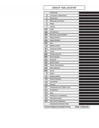
Подборка руководств на английском языке по техническому обслуживанию и ремонту автомобиля Jeep Grand Cherokee в кузове WJ 2000-2001 годов выпуска.
- Автор: —
- Издательство: Chrysler International
- Год издания: —
- Страниц: 2059
- Формат: PDF
- Размер: 187,8 Mb
Руководство на английском языке по техническому обслуживанию и ремонту автомобиля Jeep Grand Cherokee в кузове WK 2005 года выпуска.
- Автор: —
- Издательство: DaimlerChrysler Corporation
- Год издания: —
- Страниц: 7201
- Формат: PDF
- Размер: 81,3 Mb
Руководство по эксплуатации и техническому обслуживанию автомобиля Jeep Grand Cherokee 1999-2004 годов выпуска.
- Автор: —
- Издательство: Монолит
- Год издания: —
- Страниц: 150
- Формат: —
- Размер: —
Руководство по эксплуатации, техническому обслуживанию и ремонту автомобиля Jeep Grand Cherokee 1999-2004 годов выпуска с бензиновыми и дизельными двигателями.
- Автор: —
- Издательство: Автонавигатор
- Год издания: —
- Страниц: 528
- Формат: —
- Размер: —
Руководство по эксплуатации, техническому обслуживанию и ремонту автомобиля Jeep Grand Cherokee 2005-2009 годов выпуска с бензиновыми двигателями.
- Автор: —
- Издательство: Алфамер Паблишинг
- Год издания: —
- Страниц: 312
- Формат: —
- Размер: —

Руководство по техническому обслуживанию и ремонту автомобиля Jeep Grand Cherokee с 1993 года выпуска.
- Автор: —
- Издательство: —
- Год издания: —
- Страниц: 290
- Формат: PDF
- Размер: 124,0 Mb
Руководство по эксплуатации и ремонту автомобиля Jeep Grand Cherokee 1999-2004 годов выпуска с бензиновыми и дизельными двигателями.
- Автор: —
- Издательство: Монолит
- Год издания: —
- Страниц: 266
- Формат: —
- Размер: —
Руководство по эксплуатации и ремонту автомобиля Jeep Grand Cherokee с 2010 года выпуска с бензиновыми и дизельными двигателями.
- Автор: —
- Издательство: Монолит
- Год издания: —
- Страниц: 552
- Формат: —
- Размер: —

Руководство по эксплуатации и техническому обслуживанию автомобиля Jeep Grand Cherokee 2011 года выпуска.
- Автор: —
- Издательство: Chrysler International
- Год издания: 2010
- Страниц: 338
- Формат: PDF
- Размер: 5,5 Mb

Руководство по эксплуатации и техническому обслуживанию автомобиля Jeep Grand Cherokee 2014 года выпуска.
- Автор: —
- Издательство: Chrysler International
- Год издания: —
- Страниц: 372
- Формат: PDF
- Размер: 5,3 Mb
Руководство по эксплуатации, техническому обслуживанию и ремонту автомобиля Jeep Grand Cherokee.
- Автор: Б.У. Звонаревский
- Издательство: Арус
- Год издания: 2004
- Страниц: 279
- Формат: DjVu
- Размер: 16,8 Mb
Мультимедийное руководство по техническому обслуживанию и ремонту автомобиля Jeep Grand Cherokee 1993-1999 годов выпуска.
- Автор: —
- Издательство: —
- Год издания: —
- Страниц: —
- Формат: ISO
- Размер: 87,2 Mb

47 файлов
-
Сортировка
- Фильтрация
-

Бесплатный
-
Бесплатный
wk2 2011-2013 user manual
РУКОВОДСТВО ПО ЭКСПЛУАТАЦИИ WK2 2011-2013 (Рус)
Автор
Nidjat
в отличии от версии которая в сети здесь присуствуют все страницы и это не скан а сам оригинал с офф ресурса.
611 раз скачали
-
Бесплатный
wk2 2014-2018 user manual
Grand Cherokee 2014-2017 RUS Руководство по эксплуатации
Автор
demos_s
Руководство по эксплуатации Jeep Grand Cherokee 2014 (рестайл) в хорошем качестве
3 196 раз скачали
-
2011 wk2 parts
Автор
wsaiuz
Запчасти по VIN
1 234 раза скачали
-
Grand Cherokee 2011-2013 Инструкция к МАФОНУ (рус)
Автор
Danko
Руководство по эксплуатации мультимедийной системы Jeep Grand Cherokee WK2 на русском языке
2 867 раз скачали
-
MOPAR 2012 ACCESSORIES DATABOOK SEPTEMBER 2011 EDITION
Автор
GrandFa
Каталог аксессуаров Мопар к 2012 модельному году
выпуск сентябрь 2011684 раза скачали
-
Руководство по ремонту АКПП ZF
Автор
Giraffe
Во вложении файл по ремонту АКПП, в том числе гидроблок, пакеты и остальное.
30 раз скачали
-
SM_71 2016 Grand Cherokee – SYSTEM WIRING DIAGRAMS
Автор
ALISA1986
Wirning Diagrams SM 71 2016 GRAND CHEROKEE
130 раз скачали
0 комментариев
Отправлено
-
Допуски Fiat
Автор
srs3491
Допуски Fiat для масел в ДВС
138 раз скачали
-
Масла, которые производятся в России
Автор
srs3491
В этом файле указаны декларации соответствия масел различных брэндов, которые производятся на территории России. Так же указана ссылка, по которой можно проверить подлинность любой декларации соответствия ТР ТС
110 раз скачали
-
2011 ENGINE 3.0L Turbo Diesel — Service Information -инструкция по ремонту (англ.)
Автор
Гость
Это инструкция по ремонту дизельного двигателя, правда на английском языке, мне прислал дизелист Дариус из Литвы (спасибо ему за это!) , там очень много информации, в частности все размеры вкладышей, шеек , моменты и порядок затяжек валов. поддонов, крышек и т.д.
254 раза скачали
0 комментариев
Отправлено
-
Бесплатный
Инструкция и каталог по подбору фильтров-поддонов АКПП для замены масла.
Автор
Гость
Официальная инструкция по замене масла в акпп в 8-ступенчатых акпп ZF
949 раз скачали
-
Бесплатный
Снятие передней юбки бампера на WK2
Автор
sdolina
Как снять и поставить переднюю юбку бампера WK2 без снятия бампера
629 раз скачали
-
Бесплатный
Модуль отключения Start Stop
Автор
sdolina
Описание работы модуля SmartStopStart
Авто запоминает выбор пользователя. По умолчанию стоит включено с модулем при старте авто будет та настройка которую выбрал пользователь.
324 раза скачали
0 комментариев
Отправлено
-
РУКОВОДСТВО ПО ЭКСПЛУАТАЦИИ Uconnect2014-2018 (Рус)
Автор
Nidjat
здесь 6 файла на все версии Uconnect(2014-2018).radio.nav.
766 раз скачали
-
Бесплатный
-
0 комментариев
Отправлено
-
Бесплатный
0 комментариев
Обновлено
-
Джип не заводится
Автор
Цитрамон
Залип стартер
116 раз скачали
0 комментариев
Отправлено
-
JGC WK2 2014 Workshop Service & Repair Manual
Автор
xmo97
Не обращайте внимания, что в титуле 2014 Jeep Grand Cherokee SRT
На самом деле там все двигатели
3.0 бензин
3.0 дизель
3.6 бензин
5.7 бензин
6.4 бензин
5934 страниц
1 060 раз скачали
-
Jeep GC WK2 2011-2013 Service&Repair Manual (corrected) Part 2
Автор
CYREX
Jeep GC WK2 2011-2013 Service&Repair Manual (corrected) Part 2
2 508 раз скачали
0 комментариев
Отправлено
-
Jeep GC WK2 2011-2013 Service&Repair Manual (corrected) Part 1
Автор
CYREX
Jeep GC WK2 2011-2013 Service&Repair Manual (corrected) Part 1
1 239 раз скачали
-
JGC WK2 2011-2013 Workshop Service & Repair Manual
Автор
CYREX
JGC WK2 2011-2013 Workshop Service & Repair Manual
1 486 раз скачали
-
Мануал по апдэйту Uconnect до версии 14.25.5
Автор
Shadow_ridez
Мануал по апдэйту Uconnect 8.4AN и 8.4A на Grand Cherokee 2013 и 2014. Сам файл апдэйта занимает 1,3 Гб, сюда вывесить не могу (ограничение на файлы 146 Мб).
529 раз скачали

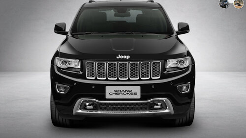


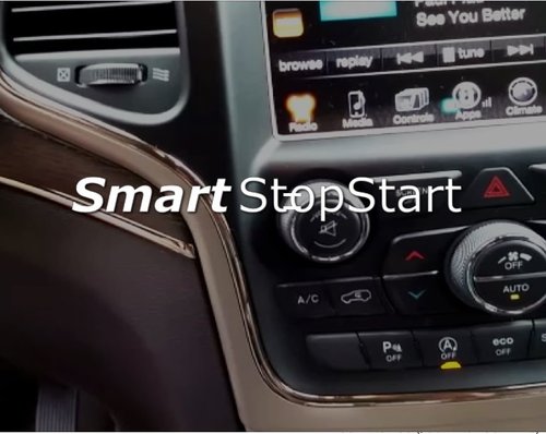


Jeep Grand Cherokee Jeep grand Cherokee WK2

Sabium
Был 2 дня назад
Андрей, 37 лет
Я езжу на Jeep Grand Cherokee Jeep grand Cherokee WK2, Subaru Legacy BL и Lada 4×4 3D Золотой зверь
Пангоды, Россия
Кому нужна книга Качайте на здоровье
yadi.sk/i/L0tXQw5u3QDtkQ
Цена вопроса: 0 ₽
Пробег: 205 000 км
13 апреля 2023
Метки: своими руками
29
6
Разместить рекламу
Реклама
Машины в продаже
Комментарии
6
Войдите или зарегистрируйтесь, чтобы писать комментарии, задавать вопросы и участвовать в обсуждении.
Войти
Зарегистрироваться

Valvet45
Я езжу на BMW 7 series (F01/02)
Спасибо
2 месяца

Vadimych97
Я езжу на Jeep Grand Cherokee (WK2)
Есть на бумаге такая)
5 месяцев

Talakanec
Я езжу на Nissan Murano II
Комментарий удалён
В ЛС написал вам. По почте такой объем не отправить.
5 месяцев
Talakanec
Я езжу на Nissan Murano II
Есть. Без проблем скину.
5 месяцев
Talakanec
Я езжу на Nissan Murano II
Только осторожно. В ней очень много неточностей. Сравнивали с оригиналом на английском языке. Лично я пожалел, что купил её.
5 месяцев

Sabium
Автор
Я езжу на Jeep Grand Cherokee (WK2)
На сегодняшний день альтернативы данной книги не нашёл. У вас есть оригинал на английском языке? Не желаете поделиться?
1
5 месяцев
Посмотреть инструкция для Jeep Grand Cherokee (2018) бесплатно. Руководство относится к категории автомобили, 12 человек(а) дали ему среднюю оценку 8.5. Руководство доступно на следующих языках: русский. У вас есть вопрос о Jeep Grand Cherokee (2018) или вам нужна помощь? Задайте свой вопрос здесь
Jeep Grand Cherokee (2018) — это автомобиль класса люкс, производства американской компании Jeep. Это большой внедорожник, который способен перемещаться по любому типу дорог, не теряя своих характеристик. Автомобиль представлен в нескольких комплектациях с разным типом двигателя.
Одна из главных особенностей этого автомобиля — это его мощность. Его двигатели способны развивать высокую скорость, что делает его желанным для любителей скорости. Кроме того, автомобиль оснащен различными видами технологий, таких как система контроля стабильности, система помощи при спуске и наборе скорости, а также система контроля трека. Автомобиль также имеет большой дисплей на приборной панели, который обладает высоким качеством картинки.
Кроме этого, Grand Cherokee имеет достаточно большой багажник, который позволяет перевозить большое количество груза. Он также имеет хорошую систему звука, что делает путешествия более приятными. Однако, за все эти удобства нужно заплатить — автомобиль затратен в обслуживании и топливе.
Главная
| Jeep | |
| Grand Cherokee (2018) | |
| автомобиль | |
| русский | |
| Руководство пользователя (PDF) |
Не можете найти ответ на свой вопрос в руководстве? Вы можете найти ответ на свой вопрос ниже, в разделе часто задаваемых вопросов о Jeep Grand Cherokee (2018).
Как перевести мили в километры?
1 миля равна 1,609344 километрам, а 1 километр — 0,62137119 милям.
Где я могу узнать идентификационный номер транспортного средства Jeep?
Место размещения идентификационного номера транспортного средства зависит от марки и типа транспортного средства. Номер может быть выбит на раме транспортного средства или указан на номерном знаке. Чтобы узнать место расположения идентификационного номера транспортного средства лучше всего ознакомиться с руководством по эксплуатации Jeep Grand Cherokee (2018).
Что такое идентификационный номер транспортного средства (VIN)?
Идентификационный номер транспортного средства — уникальный для каждого транспортного средства идентификационный номер. Аббревиатура VIN расшифровывается как «Vehicle Identification Number» (Идентификационный номер транспортного средства).
Когда транспортному средству Jeep требуется техническое обслуживание?
Регулярное техническое обслуживание необходимо всем транспортным средствам. С информацией о том, как часто необходимо проходить техническое обслуживание и чему именно стоит уделять особое внимание можно ознакомиться в инструкции по техническому обслуживанию. Как правило, транспортное средство требует технического обслуживания каждые 2 года или 30 000 километров пробега.
Когда следует заменять тормозную жидкость на Jeep?
Тормозную жидкость рекомендуется менять каждые два года.
В чем разница между топливом E10 и E5?
В топливе E10 содержится до десяти процентов этанола, в то время как в E5 содержится менее пяти процентов. Соответственно, топливо E10 менее вредит окружающей среде.
Одна или несколько дверей не открываются изнутри. Что мне делать?
Скорее всего, замок оснащен защитой от детей и поэтому не может быть открыт изнутри. Процедура открытия замка с защитой от детей зависит от марки и типа замка.
Автомобильный радиоприемник не включается, что делать?
Если автомобильный радиоприемник не включен, на него не будет подаваться питание. Убедитесь, что красный провод подключен к контактному источнику питания, а желтый провод — к источнику питания постоянной мощности.
Инструкция Jeep Grand Cherokee (2018) доступно в русский?
Да, руководствоJeep Grand Cherokee (2018) доступно врусский .
Не нашли свой вопрос? Задайте свой вопрос здесь