The A counter will be cleared when the malfunction is detected regardless of (1) — (4). The A counter will be counted up when (1) — (4) are satisfied without the same malfunction. The DTC will not be displayed after the A counter reaches 40.
Driving pattern B means the vehicle operation as follows: All components and systems should be monitored at least once by the OBD system. ● The B counter will be cleared when the malfunction is detected once regardless of the driving pattern. ● The B counter will be counted up when driving pattern B is satisfied without any malfunctions. ● The MI will go off when the B counter reaches 3 (*2 in OBD SYSTEM OPERATION CHART).
H
I
J
K
L
M
EC-65
BASIC SERVICE PROCEDURE [CR (WITH EURO-OBD)]
BASIC SERVICE PROCEDURE Basic Inspection
PFP:00018 BBS002U4
1. INSPECTION START 1. 2. – – – – – –
3. – – – –
4.
Check service records for any recent repairs that may indicate a related malfunction, or a current need for scheduled maintenance. Open engine hood and check the following: Harness connectors for improper connections Wiring harness for improper connections, pinches and cut Vacuum hoses for splits, kinks and improper connections Hoses and ducts for leaks Air cleaner clogging Gasket Confirm that electrical or mechanical loads are not applied. Headlamp switch is OFF. SEF983U Air conditioner switch is OFF. Rear window defogger switch is OFF. Steering wheel is in the straight-ahead position, etc. Start engine and warm it up until engine coolant temperature indicator points the middle of gauge. Ensure engine stays below 1,000 rpm.
SEF976U
5.
Run engine at about 2,000 rpm for about 2 minutes under no load. 6. Make sure that no DTC is displayed with CONSULT-II or GST. OK or NG OK >> GO TO 3. NG >> GO TO 2.
SEF977U
2. REPAIR OR REPLACE Repair or replace components as necessary according to corresponding Diagnostic Procedure. >> GO TO 3
EC-66
BASIC SERVICE PROCEDURE [CR (WITH EURO-OBD)]
3. CHECK TARGET IDLE SPEED 1. 2.
A
With CONSULT-II Run engine at about 2,000 rpm for about 2 minutes under no load. Rev engine (2,000 to 3,000 rpm) two or three times under no load, then run engine at idle speed for about 1 minute.
EC
C
D
E PBIA8513J
3.
Read idle speed in “DATA MONITOR” mode with CONSULT-II. Refer to EC-69, «IDLE SPEED» .
F
650 ± 50 rpm (in Neutral position) G
H SEF058Y
I
Without CONSULT-II 1. Run engine at about 2,000 rpm for about 2 minutes under no load. 2. Rev engine (2,000 to 3,000 rpm) two or three times under no load, then run engine at idle speed for about 1 minute. 3. Check idle speed. Refer to EC-69, «IDLE SPEED» .
K
650 ± 50 rpm (in Neutral position) OK or NG OK >> INSPECTION END NG >> GO TO 4.
L
4. PERFORM ACCELERATOR PEDAL RELEASED POSITION LEARNING 1. 2.
J
Stop engine. Perform EC-69, «Accelerator Pedal Released Position Learning» . >> GO TO 5.
5. PERFORM THROTTLE VALVE CLOSED POSITION LEARNING Perform EC-69, «Throttle Valve Closed Position Learning» . >> GO TO 6.
EC-67
M
BASIC SERVICE PROCEDURE [CR (WITH EURO-OBD)]
6. PERFORM IDLE AIR VOLUME LEARNING Refer to EC-69, «Idle Air Volume Learning» . Is Idle Air Volume Learning carried out successfully? Yes or No Yes >> GO TO 7. No >> 1. Follow the instruction of Idle Air Volume Learning. 2. GO TO 4.
7. CHECK TARGET IDLE SPEED AGAIN 1. 2.
With CONSULT-II Start engine and warm it up to normal operating temperature. Read idle speed in “DATA MONITOR” mode with CONSULT-II. Refer to EC-69, «IDLE SPEED» . 650 ± 50 rpm (in Neutral position)
Without CONSULT-II 1. Start engine and warm it up to normal operating temperature. 2. Check idle speed. Refer to EC-69, «IDLE SPEED» . 650 ± 50 rpm (in Neutral position) OK or NG OK >> INSPECTION END NG >> GO TO 8.
8. DETECT MALFUNCTIONING PART Check the following. ● Check camshaft position sensor (PHASE) and circuit. Refer to EC-257 . ● Check crankshaft position sensor (POS) and circuit. Refer to EC-250 . OK or NG OK >> GO TO 9. NG >> 1. Repair or replace. 2. GO TO 4.
9. CHECK ECM FUNCTION 1. 2.
Substitute another known-good ECM to check ECM function. (ECM may be the cause of an incident, but this is a rare case.) Perform initialization of NATS system and registration of all NATS ignition key IDs. Refer to BL-218, «ECM Re-communicating Function» . >> GO TO 4.
EC-68
BASIC SERVICE PROCEDURE [CR (WITH EURO-OBD)]
Idle Speed Check
BBS002TQ
A
IDLE SPEED With CONSULT-II Check idle speed in “DATA MONITOR” mode with CONSULT-II.
EC
C
D
SEF058Y
E
With GST Check idle speed with GST.
Accelerator Pedal Released Position Learning
BBS002TR
F
DESCRIPTION Accelerator Pedal Released Position Learning is an operation to learn the fully released position of the accelerator pedal by monitoring the accelerator pedal position sensor output signal. It must be performed each time harness connector of accelerator pedal position sensor or ECM is disconnected.
OPERATION PROCEDURE 1. 2. 3. 4. 5.
H
Make sure that accelerator pedal is fully released. Turn ignition switch ON and wait at least 2 seconds. Turn ignition switch OFF and wait at least 10 seconds. Turn ignition switch ON and wait at least 2 seconds. Turn ignition switch OFF and wait at least 10 seconds.
Throttle Valve Closed Position Learning
G
I
BBS002TS
J
DESCRIPTION Throttle Valve Closed Position Learning is an operation to learn the fully closed position of the throttle valve by monitoring the throttle position sensor output signal. It must be performed each time harness connector of electric throttle control actuator or ECM is disconnected.
OPERATION PROCEDURE 1. 2. 3.
L
Make sure that accelerator pedal is fully released. Turn ignition switch ON. Turn ignition switch OFF and wait at least 10 seconds. Make sure that throttle valve moves during above 10 seconds by confirming the operating sound.
Idle Air Volume Learning
M BBS002TT
DESCRIPTION Idle Air Volume Learning is an operation to learn the idle air volume that keeps each engine within the specific range. It must be performed under any of the following conditions: ● Each time electric throttle control actuator or ECM is replaced. ● Idle speed is out of specification.
PREPARATION Before performing Idle Air Volume Learning, make sure that all of the following conditions are satisfied. Learning will be cancelled if any of the following conditions are missed for even a moment. ● Battery voltage: More than 12.9V (At idle) ● Engine coolant temperature: 70 — 100°C (158 — 212°F) ● PNP switch: ON ● Electric load switch: OFF (Air conditioner, headlamp, rear window defogger)
EC-69
K
BASIC SERVICE PROCEDURE [CR (WITH EURO-OBD)] On vehicles equipped with daytime light systems, set lighting switch to the 1st position to light only small lamps. Steering wheel: Neutral (Straight-ahead position) Vehicle speed: Stopped Transmission: Warmed-up Drive vehicle for 10 minutes.
● ● ● –
OPERATION PROCEDURE With CONSULT-II 1. 2. 3. 4. 5.
Perform EC-69, «Accelerator Pedal Released Position Learning» . Perform EC-69, «Throttle Valve Closed Position Learning» . Start engine and warm it up to normal operating temperature. Check that all items listed under the topic PREPARATION (previously mentioned) are in good order. Select “IDLE AIR VOL LEARN” in “WORK SUPPORT” mode.
SEF217Z
6.
Touch “START” and wait 20 seconds.
SEF454Y
7.
8.
Make sure that “CMPLT” is displayed on CONSULT-II screen. If “CMPLT” is not displayed, Idle Air Volume Learning will not be carried out successfully. In this case, find the cause of the incident by referring to the Diagnostic Procedure below. Rev up the engine two or three times and make sure that idle speed is within the specification.
ITEM
SPECIFICATION
Idle speed
650 ± 50 rpm (in Neutral position) MBIB0238E
Without CONSULT-II NOTE: ● It is better to count the time accurately with a clock. ● It is impossible to switch the diagnostic mode when an accelerator pedal position sensor circuit has a malfunction. 1. Perform EC-69, «Accelerator Pedal Released Position Learning» . 2. Perform EC-69, «Throttle Valve Closed Position Learning» .
EC-70
BASIC SERVICE PROCEDURE [CR (WITH EURO-OBD)] 3. 4. 5. 6. 7. a. b. 8.
Start engine and warm it up to normal operating temperature. A Check that all items listed under the topic PREPARATION (previously mentioned) are in good order. Turn ignition switch OFF and wait at least 10 seconds. Confirm that accelerator pedal is fully released, turn ignition switch ON and wait 3 seconds. EC Repeat the following procedure quickly five times within 5 seconds. Fully depress the accelerator pedal. Fully release the accelerator pedal. C Wait 7 seconds, fully depress the accelerator pedal and keep it for approx. 20 seconds until the MI stops blinking and turned ON. 9. Fully release the accelerator pedal within 3 seconds after the MI turned ON. D 10. Start engine and let it idle. 11. Wait 20 seconds. E
F
G
PBIB0665E
H
12. Rev up the engine two or three times and make sure that idle speed is within the specification. ITEM
SPECIFICATION
Idle speed
650 ± 50 rpm (in Neutral position)
I
13. If idle speed is not within the specification, Idle Air Volume Learning will not be carried out successfully. In this case, find the cause of the incident by referring to the Diagnostic Procedure below.
J
DIAGNOSTIC PROCEDURE If idle air volume learning cannot be performed successfully, proceed as follows: 1. Check that throttle valve is fully closed. 2. Check PCV valve operation. 3. Check that downstream of throttle valve is free from air leakage. 4. When the above three items check out OK, engine component parts and their installation condition are questionable. Check and eliminate the cause of the incident. It is useful to perform EC-117, «TROUBLE DIAGNOSIS — SPECIFICATION VALUE» . 5. If any of the following conditions occur after the engine has started, eliminate the cause of the incident and perform Idle Air Volume Learning all over again: ● Engine stalls. ● Erroneous idle.
Fuel Pressure Check
BBS002TU
FUEL PRESSURE RELEASE With CONSULT-II 1.
Turn ignition switch ON.
EC-71
K
L
M
BASIC SERVICE PROCEDURE [CR (WITH EURO-OBD)] 2. 3. 4. 5.
Perform “FUEL PRESSURE RELEASE” in “WORK SUPPORT” mode with CONSULT-II. Start engine. After engine stalls, crank it 2 or 3 times to release all fuel pressure. Turn ignition switch OFF.
SEF214Y
Without CONSULT-II 1. 2. 3. 4. 5.
Remove fuel pump fuse located in IPDM E/R. Start engine. After engine stalls, crank it 2 or 3 times to release all fuel pressure. Turn ignition switch OFF. Reinstall fuel pump fuse after servicing fuel system.
MBIB0277E
FUEL PRESSURE CHECK CAUTION: ● Before disconnecting fuel line, release fuel pressure from fuel line to eliminate danger. ● The fuel hose connection method used when taking fuel pressure check must not be used for other purposes. ● Be careful not to scratch or put debris around connection area when servicing, so that the quick connector maintains sealability with O-rings inside. ● When installing fuel hose quick connector, refer to EM-18, «AIR CLEANER AND AIR DUCT» . NOTE: Prepare pans or saucers under the disconnected fuel line because the fuel may spill out. The fuel pressure cannot be completely released because E11 models do not have fuel return system. 1. Release fuel pressure to zero. Refer to EC-71, «FUEL PRESSURE RELEASE» . 2. Prepare fuel hose and fuel hose clamp for fuel pressure check, and connect fuel pressure gauge. ● Use suitable fuel hose for fuel pressure check (genuine NISSAN fuel hose without quick connector). ● To avoid unnecessary force or tension to hose, use moderately long fuel hose for fuel pressure check. ● Do not use the fuel hose for checking fuel pressure with damage or cracks on it. ● Use Pressure Gauge to check fuel pressure. 3. Remove fuel hose. Refer to EM-18, «AIR CLEANER AND AIR DUCT» . ● Do not twist or kink fuel hose because it is plastic hose. ● Do not remove fuel hose from quick connector. ● Keep the original fuel hose to be free from intrusion of dust or foreign substances with a suitable cover.
EC-72
BASIC SERVICE PROCEDURE [CR (WITH EURO-OBD)] 4.
Install the fuel pressure gauge as shown in the figure. ● Wipe off oil or dirt from hose insertion part using cloth moistened with gasoline. ● Apply proper amount of gasoline between top of the fuel tube and No.1 spool. ● Insert fuel hose for fuel pressure check until it touches the No.1 spool on fuel tube. ● Use NISSAN genuine hose clamp (part number: 16439 N4710 or 16439 40U00). ● When reconnecting fuel line, always use new clamps. ● When reconnecting fuel hose, check the original fuel hose for damage and abnormality. ● Use a torque driver to tighten clamps. ● Install hose clamp to the position within 1 — 2 mm (0.04 — 0.08 in). – A: Fuel pressure gauge Tightening torque:
6. 7. 8.
EC
C PBIB0669E
1 — 1.5 N·m (0.1 — 0.15 kg-m, 9 — 13 in-lb)
Make sure that clamp screw does not contact adjacent parts. After connecting fuel hose for fuel pressure check, pull the hose with a force of approximately 98 N (10 kg, 22 lb) to confirm fuel tube does not come off. MBIB1495E Turn ignition switch ON, and check for fuel leakage. Start engine and check for fuel leakage. Read the indication of fuel pressure gauge. ● Do not perform fuel pressure check with system operating. Fuel pressure gauge may indicate false readings. ● During fuel pressure check, confirm for fuel leakage from fuel connection every 3 minutes. ●
5.
A
At idling:
D
E
F
G
H
I
J
Approximately 350 kPa (3.5 bar, 3.57 kg/cm2 , 51 psi) K
9. If result is unsatisfactory, go to next step. 10. Check the following. ● Fuel hoses and fuel tubes for clogging ● Fuel filter for clogging ● Fuel pump ● Fuel pressure regulator for clogging If OK, replace fuel pressure regulator. If NG, repair or replace.
L
M
EC-73
TROUBLE DIAGNOSIS [CR (WITH EURO-OBD)]
TROUBLE DIAGNOSIS Trouble Diagnosis Introduction
PFP:00004 BBS002U1
INTRODUCTION The engine has an ECM to control major systems such as fuel control, ignition control, idle air control system, etc. The ECM accepts input signals from sensors and instantly drives actuators. It is essential that both input and output signals are proper and stable. At the same time, it is important that there are no malfunctions such as vacuum leaks, fouled spark plugs, or other malfunctions with the engine.
MEF036D
It is much more difficult to diagnose an incident that occurs intermittently rather than continuously. Most intermittent incidents are caused by poor electric connections or improper wiring. In this case, careful checking of suspected circuits may help prevent the replacement of good parts.
SEF233G
A visual check only may not find the cause of the incidents. A road test with CONSULT-II (or GST) or a circuit tester connected should be performed. Follow the Work Flow on EC-75 . Before undertaking actual checks, take a few minutes to talk with a customer who approaches with a driveability complaint. The customer can supply good information about such incidents, especially intermittent ones. Find out what symptoms are present and under what conditions they occur. A Diagnostic Worksheet like the example on EC-79 should be used. Start your diagnosis by looking for conventional malfunctions first. This will help troubleshoot driveability malfunctions on an electronically controlled engine vehicle.
EC-74
SEF234G
TROUBLE DIAGNOSIS [CR (WITH EURO-OBD)] WORK FLOW Overall Sequence
A
EC
C
D
E
F
G
H
I
J
K
L
M
PBIB2267E
EC-75
TROUBLE DIAGNOSIS [CR (WITH EURO-OBD)] Detailed Flow
1. GET INFORMATION FOR SYMPTOM Get the detailed information from the customer about the symptom (the condition and the environment when the incident/malfunction occurred) using the EC-78, «DIAGNOSTIC WORKSHEET» . >> GO TO 2.
2. CHECK DTC*1 1.
Check DTC*1 .
2.
Perform the following procedure if DTC*1 is displayed.
–
Record DTC*1 and freeze frame data*2 . (Print them out with CONSULT-II or GST.)
–
Erase DTC*1 . (Refer to EC-57, «HOW TO ERASE EMISSION-RELATED DIAGNOSTIC INFORMATION» .)
Study the relationship between the cause detected by DTC*1 and the symptom described by the customer. (Symptom Matrix Chart is useful. Refer to EC-82, «Symptom Matrix Chart» .) 3. Check related service bulletins for information. Is any symptom described and any DTC detected?
–
Symptom is described, DTC*1 is displayed>>GO TO 3. Symptom is described, DTC*1 is not displayed>>GO TO 4. Symptom is not described, DTC*1 is displayed>>GO TO 5.
3. CONFIRM THE SYMPTOM Try to confirm the symptom described by the customer (except MI ON). DIAGNOSIS WORK SHEET is useful to verify the incident. Connect CONSULT-II to the vehicle in “DATA MONITOR (AUTO TRIG)” mode and check real time diagnosis results. Verify relation between the symptom and the condition when the symptom is detected. >> GO TO 5.
4. CONFIRM THE SYMPTOM Try to confirm the symptom described by the customer. DIAGNOSIS WORK SHEET is useful to verify the incident. Connect CONSULT-II to the vehicle in “DATA MONITOR (AUTO TRIG)” mode and check real time diagnosis results. Verify relation between the symptom and the condition when the symptom is detected. >> GO TO 6.
EC-76
TROUBLE DIAGNOSIS [CR (WITH EURO-OBD)]
5. PERFORM DTC CONFIRMATION PROCEDURE
A 1
1
Perform DTC Confirmation Procedure for the displayed DTC* , and then make sure that DTC* is detected again. At this time, always connect CONSULT-II to the vehicle, and check diagnostic results in real time on “DATA EC MONITOR (AUTO TRIG)”. If two or more DTCs*1 are detected, refer to EC-80, «DTC Inspection Priority Chart» and determine trouble diagnosis order. C NOTE: ● Freeze frame data*2 is useful if the DTC*1 is not detected. ● Perform Overall Function Check if DTC Confirmation Procedure is not included on Service Manual. This D simplified check procedure is an effective alternative though DTC*1 cannot be detected during this check. If the result of Overall Function Check is NG, it is the same as the detection of DTC*1 by DTC ConfirmaE tion Procedure. Is DTC*1 detected? Yes >> GO TO 10. No >> Check according to EC-127, «TROUBLE DIAGNOSIS FOR INTERMITTENT INCIDENT» .
F
6. PERFORM BASIC INSPECTION G
Perform EC-66, «Basic Inspection» . With CONSULT-II>>GO TO 7. Without CONSULT-II>>GO TO 9.
H
7. PERFORM DATA MONITOR (SPEC) MODE
I
With CONSULT-II Make sure that “B/FUEL SCHDL”, and “A/F ALPHA-B1” are within the SP value using CONSULT-II “DATA MONITOR (SPEC)” mode. Refer to EC-118, «Diagnostic Procedure» . Are they within the SP value? Yes >> GO TO 9. No >> GO TO 8.
J
K
L
SEF601Z
8. DETECT MALFUNCTIONING PART BY TROUBLE DIAGNOSIS — SPECIFICATION VALUE Detect malfunctioning part according to EC-117, «TROUBLE DIAGNOSIS — SPECIFICATION VALUE» . Is malfunctioning part detected? Yes >> GO TO 11. No >> GO TO 9.
9. DETECT MALFUNCTIONING SYSTEM BY SYMPTOM MATRIX CHART Detect malfunctioning system according to EC-82, «Symptom Matrix Chart» based on the confirmed symptom in step 4, and determine the trouble diagnosis order based on possible causes and symptom. >> GO TO 10.
EC-77
M
TROUBLE DIAGNOSIS [CR (WITH EURO-OBD)]
10. DETECT MALFUNCTIONING PART BY DIAGNOSTIC PROCEDURE Inspect according to Diagnostic Procedure of the system. NOTE: The Diagnostic Procedure in EC section described based on open circuit inspection. A short circuit inspection is also required for the circuit check in the Diagnostic Procedure. For details, refer to Circuit Inspection in GI25, «How to Perform Efficient Diagnosis for an Electrical Incident» . Is malfunctioning part detected? Yes >> GO TO 11. No >> Monitor input data from related sensors or check voltage of related ECM terminals using CONSULT-II. Refer to EC-95, «ECM Terminals and Reference Value» , EC-112, «CONSULT-II Reference Value in Data Monitor Mode» .
11. REPAIR OR REPLACE THE MALFUNCTIONING PART 1. 2. 3.
Repair or replace the malfunctioning part. Reconnect parts or connectors disconnected during Diagnostic Procedure again after repair and replacement. Check DTC. If DTC is displayed, erase it, refer to EC-57, «HOW TO ERASE EMISSION-RELATED DIAGNOSTIC INFORMATION» . >> GO TO 12.
12. FINAL CHECK When DTC was detected in step 2, perform DTC Confirmation Procedure or Overall Function Check again, and then make sure that the malfunction have been repaired securely. When symptom was described from the customer, refer to confirmed symptom in step 3 or 4, and make sure that the symptom is not detected. OK or NG NG (DTC*1 is detected)>>GO TO 10. NG (Symptom remains)>>GO TO 6. OK >> 1. Before returning the vehicle to the customer, make sure to erase unnecessary DTC*1 in ECM. (Refer to EC-57, «HOW TO ERASE EMISSION-RELATED DIAGNOSTIC INFORMATION» .) 2. If the completion of SRT is needed, drive vehicle under the specific driving pattern. Refer to EC55, «Driving Pattern» . 3. INSPECTION END *1: Include 1st trip DTC. *2: Include 1st trip freeze frame data.
DIAGNOSTIC WORKSHEET Description There are many operating conditions that lead to the malfunction of engine components. A good grasp of such conditions can make troubleshooting faster and more accurate. In general, each customer feels differently about a incident. It is important to fully understand the symptoms or conditions for a customer complaint. Utilize a diagnostic worksheet like the one on the next page in order to organize all the information for troubleshooting. Some conditions may cause the MI to come on steady or blink and DTC to be detected. Examples: ● Vehicle ran out of fuel, which caused the engine to misfire.
EC-78
SEF907L
TROUBLE DIAGNOSIS [CR (WITH EURO-OBD)] Worksheet Sample A
EC
C
D
E
F
G
H
I
J
K
L
M
MTBL0017
EC-79
TROUBLE DIAGNOSIS [CR (WITH EURO-OBD)]
DTC Inspection Priority Chart
BBS002U2
If some DTCs are displayed at the same time, perform inspections one by one based on the following priority chart. NOTE: ● If DTC U1001 is displayed with other DTC, first perform the trouble diagnosis for DTC U1001. Refer to EC-134, «DTC U1001 CAN COMMUNICATION LINE» . ● If DTC U1010 is displayed with other DTC, first perform the trouble diagnosis for DTC U1010. Refer to EC-137, «DTC U1010 CAN COMMUNICATION» . Priority 1
2
3
Detected items (DTC) ●
U1001 CAN communication line
●
U1010 CAN communication
●
P0107 P0108 Manifold absolute pressure sensor
●
P0112 P0113 Intake air temperature sensor
●
P0117 P0118 Engine coolant temperature sensor
●
P0122 P0123 P0222 P0223 P1225 P1226 P2135 Throttle position sensor
●
P0327 P0328 Knock sensor
●
P0335 Crankshaft position sensor (POS)
●
P0340 Camshaft position sensor (PHASE)
●
P0500 Vehicle speed sensor
●
P0605 ECM
●
P1171 Intake error
●
P1229 Sensor power supply
●
P1610-P1615 NATS
●
P1706 Park/Neutral position (PNP) switch
●
P2122 P2123 P2127 P2128 P2138 Accelerator pedal position sensor
●
P0031 P0032 Heated oxygen sensor 1 heater
●
P0037 P0038 Heated oxygen sensor 2 heater
●
P0132 P0133 P0134 P1143 P1144 Heated oxygen sensor 1
●
P0138 P0139 P1146 P1147 Heated oxygen sensor 2
●
P0444 EVAP canister purge volume control solenoid valve
●
P1065 ECM power supply
●
P1111 Intake valve timing control solenoid valve
●
P1122 Electric throttle control function
●
P1124 P1126 Throttle control motor relay
●
P1128 Throttle control mother
●
P1805 Brake switch
●
P0011 Intake valve timing control
●
P0171 P0172 Fuel injection system function
●
P0300 — P0304 Misfire
●
P0420 Three way catalyst function
●
P1121 Electric throttle control actuator
●
P1211 ESP control unit
●
P1212 ESP communication line
●
P1217 Engine over temperature (OVERHEAT)
EC-80
TROUBLE DIAGNOSIS [CR (WITH EURO-OBD)]
Fail-Safe Chart
BBS002U3
When the DTC listed bellow is detected, the ECM enters fail-safe mode and the MI lights up. DTC No. P0117 P0118
Detected items
Engine operating condition in fail-safe mode
Engine coolant temperature sensor circuit
Engine coolant temperature will be determined by ECM based on the time after turning ignition switch ON or START. CONSULT-II displays the engine coolant temperature decided by ECM. Condition
Engine coolant temperature decided (CONSULT-II display)
Just as ignition switch is turned ON or START
40°C (104°F)
More than approx. 4 minutes after ignition ON or START
80°C (176°F)
Except as shown above
A
EC
C
D
40 — 80°C (104 — 176°F) (Depends on the time)
E
When the fail-safe system for engine coolant temperature sensor is activated, the cooling fan operates while engine is running. P0122 P0123 P0222 P0223 P2135
Throttle position sensor
P1121
Electric throttle control actuator
The ECM controls the electric throttle control actuator in regulating the throttle opening in order for the idle position to be within +10 degrees. The ECM regulates the opening speed of the throttle valve to be slower than the normal condition. So, the acceleration will be poor.
H
(When throttle valve opening angle in fail-safe mode is not in specified range:) ECM controls the electric throttle control actuator by regulating the throttle opening to 20 degrees or less.
I
P1122
Electric throttle control function
ECM stops the electric throttle control actuator control, throttle valve is maintained at a fixed opening (approx. 5 degrees) by the return spring.
P1124 P1126
Throttle control motor relay
ECM stops the electric throttle control actuator control, throttle valve is maintained at a fixed opening (approx. 5 degrees) by the return spring.
P1128
Throttle control motor
ECM stops the electric throttle control actuator control, throttle valve is maintained at a fixed opening (approx. 5 degrees) by the return spring.
P1171
Intake air system
P1229
Sensor power supply
ECM stops the electric throttle control actuator control, throttle valve is maintained at a fixed opening (approx. 5 degrees) by the return spring.
P2122 P2123 P2127 P2128 P2138
Accelerator pedal position sensor
The ECM controls the electric throttle control actuator in regulating the throttle opening in order for the idle position to be within +10 degrees. The ECM regulates the opening speed of the throttle valve to be slower than the normal condition. So, the acceleration will be poor.
When accelerator pedal is depressed, engine speed will not rise more than 2,500 rpm due to fuel cut.
When there is an open circuit on MI circuit, the ECM can not warn the driver by lighting up MI when there is a malfunction on engine control system. Therefore, when electrical controlled throttle and part of ECM related diagnoses is continuously detected as NG for 5 trips, ECM warns the driver that engine control system has a malfunction and MI circuit is open by means of operating fail-safe function. The fail-safe function also operate when above diagnoses except MI circuit are detected and demands the driver to repair the malfunction. Engine operating condition in fail-safe mode
G
(When electric throttle control actuator does not function properly due to the return spring malfunction:) ECM controls the electric throttle control actuator by regulating the throttle opening around the idle position. The engine speed will not rise more than 2,000 rpm.
(When ECM detects the throttle valve is stuck open:) While the vehicle is driving, it slows down gradually by fuel cut. After the vehicle stops, the engine stalls. The engine can restart in Neutral position, and engine speed will not exceed 1,000 rpm or more.
●
F
Engine speed will not rise more than 2,500 rpm due to the fuel cut
EC-81
J
K
L
M
TROUBLE DIAGNOSIS [CR (WITH EURO-OBD)]
Symptom Matrix Chart
BBS002U5
SYSTEM — BASIC ENGINE CONTROL SYSTEM
1
1
2
3
2
Fuel pressure regulator system
3
3
4
4
4
Fuel injector circuit
1
1
2
3
2
Evaporative emission system
3
3
4
4
4
Air
Positive crankcase ventilation system
3
3
4
4
4
Incorrect idle speed adjustment
3
3
Electric throttle control actuator
1
1
2
3
3
Incorrect ignition timing adjustment
3
3
1
1
Ignition circuit
1
1
2
Power supply and ground circuit
2
2
Manifold absolute pressure sensor circuit
1
Engine coolant temperature sensor circuit
1
Ignition
Throttle position sensor circuit
AG
AH
AJ
AK
AL
AM
HA
2
2
4
4
2
2
4
4
4
4
4
1
1
4
2
EC-427
4
EC-72
2
EC-421
4
4
EC-40
4
4
4
1
1
1
EC-66
2
EC-291, EC-293 , EC-299 , EC-305
EC-45
1
1
1
EC-66
2
2
2
2
2
EC-433
3
3
3
3
3
3
EC-128
1
2
2
2
2
2
2
EC-155
1
2
2
2
2
2
2
EC-166
2
EC-171, EC-233 , EC-359 , EC-361 , EC-402
3
1
Knock sensor circuit Crankshaft position sensor (POS) circuit
2
2
Camshaft position sensor (PHASE) circuit
2
2 2
2
2
2
3
2
2
1
2
3
2
2
2
2
2
1
1
2
2
3 4
2
Accelerator pedal position sensor circuit
Vehicle speed signal circuit
AF
Reference page
2
1
Heated oxygen sensor 1 circuit
BATTERY DEAD (UNDER CHARGE)
Fuel pump circuit
EXCESSIVE OIL CONSUMPTION
Fuel
EXCESSIVE FUEL CONSUMPTION
AE
OVERHEATS/WATER TEMPERATURE HIGH
LACK OF POWER/POOR ACCELERATION
AD
SLOW/NO RETURN TO IDLE
SPARK KNOCK/DETONATION
AC
IDLING VIBRATION
HESITATION/SURGING/FLAT SPOT
AB
ROUGH IDLE/HUNTING
ENGINE STALL
AA
Warranty symptom code
HIGH IDLE/LOW IDLE
HARD/NO START/RESTART (EXCP. HA)
SYMPTOM
2
3
2
1
EC-363, EC-383 , EC-392 , EC-409
2
2
2
2
2
EC-178, EC-185 , EC-195 , EC-310 , EC-316
3
EC-246 EC-250 EC-257
3
EC-82
3
3
EC-277
TROUBLE DIAGNOSIS [CR (WITH EURO-OBD)] SYMPTOM
HARD/NO START/RESTART (EXCP. HA)
ENGINE STALL
HESITATION/SURGING/FLAT SPOT
SPARK KNOCK/DETONATION
LACK OF POWER/POOR ACCELERATION
HIGH IDLE/LOW IDLE
ROUGH IDLE/HUNTING
IDLING VIBRATION
SLOW/NO RETURN TO IDLE
OVERHEATS/WATER TEMPERATURE HIGH
EXCESSIVE FUEL CONSUMPTION
EXCESSIVE OIL CONSUMPTION
BATTERY DEAD (UNDER CHARGE)
A
AA
AB
AC
AD
AE
AF
AG
AH
AJ
AK
AL
AM
HA
ECM
2
2
3
3
3
3
3
3
3
3
3
EC-279, EC-282
Intake valve timing control solenoid valve circuit
3
3
2
1
3
2
2
3
3
EC-286
3
3
Warranty symptom code
PNP switch circuit Refrigerant pressure sensor circuit
2
Electrical load signal circuit Air conditioner circuit
2
ABS actuator and electric unit (control unit)
2
3
3
4
1 — 6: The numbers refer to the order of inspection. (continued on next page)
3
EC
Reference page
C
D
E
3
3
3
3
3
EC-371
3
3
3
3
4
EC-443
3
3
3
3
3
3
3
3
F
G
H
EC-419 3
2
ATC-26, MTC-23
I
BRC-8 or BRC-49
J
K
L
M
EC-83
TROUBLE DIAGNOSIS [CR (WITH EURO-OBD)] SYSTEM — ENGINE MECHANICAL & OTHER
Fuel
ENGINE STALL
HESITATION/SURGING/FLAT SPOT
SPARK KNOCK/DETONATION
LACK OF POWER/POOR ACCELERATION
HIGH IDLE/LOW IDLE
ROUGH IDLE/HUNTING
IDLING VIBRATION
SLOW/NO RETURN TO IDLE
OVERHEATS/WATER TEMPERATURE HIGH
EXCESSIVE FUEL CONSUMPTION
EXCESSIVE OIL CONSUMPTION
BATTERY DEAD (UNDER CHARGE)
Warranty symptom code
HARD/NO START/RESTART (EXCP. HA)
SYMPTOM
AA
AB
AC
AD
AE
AF
AG
AH
AJ
AK
AL
AM
HA
Fuel tank
FL-8 5
Fuel piping
5
Vapor lock
5
5
5
5
FL-3, EM32
5
—
5
Valve deposit Poor fuel (Heavy weight gasoline, Low octane) Air
Reference page
— 5
5
5
5
5
5
5 —
Air duct Air cleaner Air leakage from air duct (Manifold absolute pressure sensor —electric throttle control actuator)
EM-18 5
5
5
5 5
5
5
5
5 5
Electric throttle control actuator Air leakage from intake manifold/ Collector/Gasket Cranking
Battery
EM-22 1
1
1
1
1
1
1
1
Alternator circuit
Engine
SC-5 SC-15
Starter circuit
3
SC-45
Signal plate/Flywheel/Drive plate
6
EM-74
PNP switch
4
AT-109, MT-16
Cylinder head Cylinder head gasket
5
5
5
5
5
5
5
4
5
3
EM-60
Cylinder block Piston
4
Piston ring Connecting rod
6
6
6
6
Bearing Crankshaft
EC-84
6
6
6
6
EM-74
TROUBLE DIAGNOSIS [CR (WITH EURO-OBD)] SYMPTOM
Valve mechanism
HARD/NO START/RESTART (EXCP. HA)
ENGINE STALL
HESITATION/SURGING/FLAT SPOT
SPARK KNOCK/DETONATION
LACK OF POWER/POOR ACCELERATION
HIGH IDLE/LOW IDLE
ROUGH IDLE/HUNTING
IDLING VIBRATION
SLOW/NO RETURN TO IDLE
OVERHEATS/WATER TEMPERATURE HIGH
EXCESSIVE FUEL CONSUMPTION
EXCESSIVE OIL CONSUMPTION
BATTERY DEAD (UNDER CHARGE)
Warranty symptom code
A
AA
AB
AC
AD
AE
AF
AG
AH
AJ
AK
AL
AM
HA
EC
Reference page
D
E
Timing chain
EM-50
Camshaft
EM-38
Intake valve timing control
5
5
5
5
5
5
5
5
C
EM-50
F
G
Intake valve 3
Exhaust valve Exhaust
Exhaust manifold/Tube/Muffler/ Gasket
H 5
5
5
5
5
5
5
EM-24, EX3
5
Three way catalyst Lubrication
Cooling
Oil pan/Oil strainer/Oil pump/Oil filter/Oil gallery
EM-60
5
5
5
5
5
5
5
5
2
EM-26, LU9 , LU-10 , LU-5
Oil level (Low)/Filthy oil
LU-6
Radiator/Hose/Radiator filler cap
CO-12
Thermostat
5
CO-19
Water pump Water gallery
CO-17 5
5
5
5
Cooling fan
5
5
2 5
Coolant level (low)/Contaminated coolant NATS (Nissan Anti-theft System)
5
5
I
J
K
CO-7 CO-12
L
CO-8 1
BL-215 or EC-44
1
1 — 6: The numbers refer to the order of inspection.
EC-85
M
TROUBLE DIAGNOSIS [CR (WITH EURO-OBD)]
Engine Control Component Parts Location
BBS002U6
MBIB1491E
1.
Intake valve timing control solenoid valve
2.
Fuel injector
3.
Refrigerant pressure sensor
4.
Ignition coil (with power transistor) and spark plug
5.
Heated oxygen sensor 1
6.
Crankshaft position sensor (POS)
7.
Cooling fan motor
8.
IPDM E/R
9.
ECM
10. Camshaft position sensor (PHASE)
11. EVAP canister purge volume control solenoid valve
12. Engine coolant temperature sensor
13. Manifold absolute pressure sensor (with intake air temperature sensor)
14. Knock sensor
15. Electric throttle control actuator
EC-86
TROUBLE DIAGNOSIS [CR (WITH EURO-OBD)] A
EC
C
D
E
F
G
H
I
J
K
L
M MBIB1498E
: Vehicle front 1.
Manifold absolute pressure sensor (with intake air temperature sensor)
2.
Crankshaft position sensor (POS)
3.
Engine coolant temperature sensor
6.
IPDM E/R
4.
Camshaft position sensor (PHASE)
5.
Battery
7.
Fuel injector
8.
Ignition coil (with power transistor)
EC-87
TROUBLE DIAGNOSIS [CR (WITH EURO-OBD)]
MBIB1499E
1.
Condenser
2.
Oil filter
3.
Refrigerant pressure sensor
4.
Intake manifold
5.
Knock sensor
6.
Electric throttle control actuator
7.
ECM
8.
Battery
9.
Data link connector
EC-88
TROUBLE DIAGNOSIS [CR (WITH EURO-OBD)] A
EC
C
D
E
F MBIB0320E
G
H
I
J
K
L
M
MBIB1460E
: Vehicle front 1.
Exhaust manifold cover
2.
Heated oxygen sensor 1
3.
Heated oxygen sensor 1 harness connector
4.
Heated oxygen sensor 2 harness connector
5.
Heated oxygen sensor 2
6.
Oil pan
EC-89
TROUBLE DIAGNOSIS [CR (WITH EURO-OBD)]
MBIB1500E
: Vehicle front 1.
Park/neutral position switch
2.
Cooling fan motor
4.
Fuel pump fuse (15A)
5.
Fuel level sensor unit and fuel pump 6. harness connector
Fuel level sensor unit
7.
Fuel pump and fuel filter
8.
Fuel pressure regulator
Intake valve timing control solenoid valve
10.
EVAP canister purge volume control solenoid valve
EC-90
3.
9.
IPDM E/R
TROUBLE DIAGNOSIS [CR (WITH EURO-OBD)] A
EC
C
D
E MBIB1501E
1.
Accelerator pedal position sensor
4.
Brake pedal
2.
Accelerator pedal
3.
Stop lamp switch
F
G
H
I
J
K
L
M
EC-91
TROUBLE DIAGNOSIS [CR (WITH EURO-OBD)]
Vacuum Hose Drawing
BBS002TJ
MBIB1440E
: Vehicle front 1.
EVAP canister purge volume control solenoid valve
2.
Intake manifold
NOTE: Do not use soapy water or any type of solvent while installing vacuum hose or purge hoses.
Refer to EC-33, «System Diagram» for Vacuum Control System.
EC-92
TROUBLE DIAGNOSIS [CR (WITH EURO-OBD)]
Circuit Diagram
BBS002U7
A
EC
C
D
E
F
G
H
I
J
K
L
M
MBWA1500E
EC-93
TROUBLE DIAGNOSIS [CR (WITH EURO-OBD)]
MBWA1501E
EC-94
TROUBLE DIAGNOSIS [CR (WITH EURO-OBD)]
ECM Harness Connector Terminal Layout
BBS002U8
A
EC
C
MBIB0045E
ECM Terminals and Reference Value
BBS002U9
PREPARATION 1. 2.
D
E
ECM is located left hand side of the engine room. Remove ECM harness protector.
F
G
H MBIB0274E
3. 4.
When disconnecting ECM harness connector, loosen it with levers as far as they will go as shown at right. Connect a break-out box (SST) and Y-cable adapter (SST) between the ECM and ECM harness connector. ● Use extreme care not to touch 2 pins at one time. ● Data is for comparison and may not be exact.
I
J
K
PBIB1512E
L
ECM INSPECTION TABLE Specification data are reference values and are measured between each terminal and ground. Pulse signal is measured by CONSULT-II. CAUTION: Do not use ECM ground terminals when measuring input/output voltage. Doing so may result in damage to the ECM’s transistor. Use a ground other than ECM terminals, such as the ground. TERMINAL NO. 1
WIRE COLOR B
ITEM
ECM ground
CONDITION [Engine is running] ●
Idle speed
EC-95
DATA (DC Voltage)
Body ground
M
TROUBLE DIAGNOSIS [CR (WITH EURO-OBD)] TERMINAL NO.
WIRE COLOR
ITEM
CONDITION
DATA (DC Voltage)
[Engine is running]
2
GR
●
Engine speed: Below 3,800 rpm after the following conditions are met.
–
Engine: After warming up
–
Keeping the engine speed between 3,500 and 4,000 rpm for 1 minute and at idle for 1 minute under no load.
Heated oxygen sensor 2 heater
0 — 1.0V
[Ignition switch: ON] ●
Engine stopped
[Engine is running] ●
3
LG
Throttle control motor relay power supply
BATTERY VOLTAGE (11 — 14V)
Engine speed: Above 3,800 rpm
[Ignition switch: ON]
BATTERY VOLTAGE (11 — 14V) 0 — 14V
[Ignition switch: ON] 4
L
Throttle control motor (Close)
●
Engine stopped
●
Shift lever position: 1st
●
Accelerator pedal: Fully released PBIB0534E
0 — 14V [Ignition switch: ON] 5
P
Throttle control motor (Open)
●
Engine stopped
●
Shift lever position: 1st
●
Accelerator pedal: Fully depressed PBIB0533E
[Engine is running] ●
Warm-up condition
●
Idle speed
Approximately 3.0V
NOTE: The pulse cycle changes depending on rpm at idle. 13
Y
PBIB0527E
Crankshaft position sensor (POS)
Approximately 3.0V
[Engine is running] ●
Engine speed: 2,000 rpm
PBIB0528E
EC-96
TROUBLE DIAGNOSIS [CR (WITH EURO-OBD)] TERMINAL NO.
WIRE COLOR
ITEM
CONDITION
[Engine is running] ●
Warm-up condition
●
Idle speed
DATA (DC Voltage)
1.0 — 4.0V
EC
NOTE: The pulse cycle changes depending on rpm at idle. 14
R
A
C PBIB0525E
Camshaft position sensor (PHASE)
D
1.0 — 4.0V
E
[Engine is running] ●
Engine speed: 2,000 rpm
F PBIB0526E
15
W
Knock sensor
[Engine is running] ●
Idle speed
Approximately 2.5V
G
[Engine is running] ●
16
LG
Heated oxygen sensor 2
Revving engine from idle to 3,000rpm quickly after the following conditions are met.
–
Engine: After warming up
–
Keeping the engine speed between 3,500 and 4,000 rpm for 1 minute and at idle for 1 minute under no load.
H 0 — Approximately 1.0V
I
BATTERY VOLTAGE
J
(11 — 14V) [Engine is running] ●
19
LG
K
Idle speed
L
EVAP canister purge volume control solenoid valve
PBIB0050E
Approximately 10V
M [Engine is running] ●
Engine speed: About 2,000 rpm (More than 100 seconds after starting engine)
PBIB0520E
EC-97
TROUBLE DIAGNOSIS [CR (WITH EURO-OBD)] TERMINAL NO.
WIRE COLOR
ITEM
CONDITION
DATA (DC Voltage) BATTERY VOLTAGE
[Engine is running]
22 23 41 42
O L R GR
●
Warm-up condition
●
Idle speed
(11 — 14V)
NOTE: The pulse cycle changes depending on rpm at idle.
Fuel injector No. 3 Fuel injector No. 1 Fuel injector No. 4 Fuel injector No. 2
PBIB0529E
BATTERY VOLTAGE (11 — 14V) [Engine is running] ●
Warm-up condition
●
Engine speed: 2,000 rpm
PBIB0530E
Approximately 7.0V [Engine is running] 24
Y
Heated oxygen sensor 1 heater
●
Warm-up condition
●
Engine speed: Below 3,600 rpm
PBIB0519E
[Engine is running] ●
29
30
B
L
Engine speed: Above 3,600 rpm
BATTERY VOLTAGE (11 — 14V)
[Engine is running]
Sensor ground (Camshaft position sensor)
●
Warm-up condition
●
Idle speed
Sensor ground (Crankshaft position sensor)
●
Warm-up condition
●
Idle speed
Approximately 0V
[Engine is running]
34
O
Intake air temperature sensor
[Engine is running]
35
BR
Heated oxygen sensor 1
●
Warm-up condition
●
Engine speed: 2,000 rpm
Approximately 0V
Approximately 0 — 4.8V Output voltage varies with intake air temperature.
[Engine is running]
45
0 — Approximately 1.0V (Periodically change)
L
Sensor power supply
[Ignition switch: ON]
Approximately 5V
46
W
Sensor power supply (Refrigerant pressure sensor)
[Ignition switch: ON]
Approximately 5V
47
L
Sensor power supply (Throttle position sensor)
[Ignition switch: ON]
Approximately 5V
EC-98
TROUBLE DIAGNOSIS [CR (WITH EURO-OBD)] TERMINAL NO.
WIRE COLOR
ITEM
CONDITION
DATA (DC Voltage)
A
[Ignition switch: ON]
49
Y
Throttle position sensor 1
●
Engine stopped
●
Shift lever position: 1st
●
Accelerator pedal: Fully released
EC
More than 0.36V
C
[Ignition switch: ON] ●
Engine stopped
●
Shift lever position: 1st
●
Accelerator pedal: Fully depressed
Less than 4.75V
D
[Engine is running]
51
W
Manifold absolute pressure sensor
●
Warm-up condition
●
Idle speed
Approximately 1.5V
E
Approximately 1.2V
F
Approximately 0V
G
[Engine is running] ●
Warm-up condition
●
Engine speed: 2,000 rpm
[Engine is running] 54
56
57
—
B
Y
Sensor ground (Knock sensor)
●
Warm-up condition
●
Idle speed
[Engine is running]
Sensor ground (Manifold absolute pressure sensor)
●
Warm-up condition
●
Idle speed
Sensor ground (Refrigerant pressure sensor)
●
Warm-up condition
●
Idle speed
[Engine is running]
[Engine is running]
60 61 79 80
Y V G BR
H
Approximately 0V
●
Warm-up condition
●
Idle speed
I Approximately 0V
J
0 — 0.1V
K
NOTE: The pulse cycle changes depending on rpm at idle.
Ignition signal No. 3 Ignition signal No. 1 Ignition signal No. 4 Ignition signal No. 2
PBIB0521E
L
0 — 0.2V
M
[Engine is running] ●
Warm-up condition
●
Engine speed: 2,000 rpm
PBIB0522E
EC-99
TROUBLE DIAGNOSIS [CR (WITH EURO-OBD)] TERMINAL NO.
WIRE COLOR
ITEM
CONDITION [Engine is running] ●
Warm-up condition
●
Idle speed
DATA (DC Voltage)
BATTERY VOLTAGE (11 — 14V) Approximately 4V — BATTERY
62
LG
Intake valve timing control solenoid valve
VOLTAGE (11 — 14V) [Engine is running] ●
Warm-up condition
●
Engine speed: 2,000 rpm
PBIB1790E
66
B
Sensor ground (Throttle position sensor)
[Engine is running] ●
Warm-up condition
●
Idle speed
Approximately 0V
[Ignition switch: ON]
68
R
Throttle position sensor 2
●
Engine stopped
●
Shift lever position: 1st
●
Accelerator pedal: Fully released
Less than 4.75V
[Ignition switch: ON] ●
Engine stopped
●
Shift lever position: 1st
●
Accelerator pedal: Fully depressed
More than 0.36V
[Engine is running] 69
BR
Refrigerant pressure sensor
●
Warm-up condition
●
Both A/C switch and blower fan switch: ON
1.0 — 4.0V
(Compressor operates.) 72
P
Engine coolant temperature sensor
73
B
Sensor ground (Engine coolant temperature sensor)
[Engine is running]
Approximately 0 — 4.8V Output voltage varies with engine coolant temperature.
[Engine is running] ●
Warm-up condition
●
Idle speed
Approximately 0V
[Engine is running] 74
B
Sensor ground (Heated oxygen sensor)
●
Warm-up condition
●
Idle speed
Approximately 0V
[Engine is running] 82
B
Sensor ground (APP sensor 1)
●
Warm-up condition
●
Idle speed
Approximately 0V
[Engine is running] 83
85
B
LG
Sensor ground (APP sensor 2)
DATA link connector
●
Warm-up condition
●
Idle speed
[Ignition switch: ON] ●
CONSULT-II or GST: Disconnected
Approximately 0V
BATTERY VOLTAGE (11 — 14V)
86
Y
CAN communication line
[Ignition switch: ON]
1.0 — 2.5V
90
O
Sensor power supply (APP sensor 1)
[Ignition switch: ON]
Approximately 5V
91
BR
Sensor power supply (APP sensor 2)
[Ignition switch: ON]
Approximately 5V
EC-100
TROUBLE DIAGNOSIS [CR (WITH EURO-OBD)] TERMINAL NO. 94
WIRE COLOR L
ITEM CAN communication line
CONDITION [Ignition switch: ON]
DATA (DC Voltage) 2.5 — 4.0V
EC
[Ignition switch: ON]
98
G
Accelerator pedal position sensor 2
●
Engine stopped
●
Accelerator pedal: Fully released
Engine stopped
●
Accelerator pedal: Fully depressed
[Ignition switch: OFF] ●
101
R
Stop lamp switch
Brake pedal: Fully released
[Ignition switch: OFF] ●
Brake pedal: Slightly depressed
[Ignition switch: ON] ●
102
GR
PNP switch
G
Throttle control motor relay
Gear position: Neutral
[Ignition switch: ON] ●
104
0.3 — 0.6V
C
[Ignition switch: ON] ●
Except the above gear position
1.95 — 2.4V
D Approximately 0V BATTERY VOLTAGE (11 — 14V) Approximately 0V
BATTERY VOLTAGE (11 — 14V)
[Ignition switch: ON]
0 — 1.0V
[Ignition switch: ON]
106
109
W
O
Accelerator pedal position sensor 1
Ignition switch
Engine stopped
●
Accelerator pedal: Fully released
●
Engine stopped
●
Accelerator pedal: Fully depressed
ECM relay (Self shut-off)
3.9 — 4.7V
J
[Ignition switch: ON]
BATTERY VOLTAGE (11 — 14V)
For a few seconds after turning ignition switch OFF
[Ignition switch: OFF] More than a few seconds passed after turning ignition switch OFF
0 — 1.0V
BATTERY VOLTAGE (11 — 14V)
[Ignition switch: ON] ●
R
Fuel pump relay
H
I
0V
●
113
G
0.6 — 0.9V
[Ignition switch: OFF]
●
P
F
[Ignition switch: ON]
[Engine is running] [Ignition switch: OFF] 111
E
BATTERY VOLTAGE (11 — 14V)
[Ignition switch: OFF]
●
A
For 1 second after turning ignition switch ON
0 — 1.0V
[Engine is running] [Ignition switch: ON] ●
More than 1 second after turning ignition switch ON
[Engine is running]
BATTERY VOLTAGE (11 — 14V)
115 116
B B
ECM ground
119 120
G G
Power supply for ECM
[Ignition switch: ON]
BATTERY VOLTAGE (11 — 14V)
121
BR
Power supply for ECM (Back-up)
[Ignition switch: OFF]
BATTERY VOLTAGE (11 — 14V)
●
Idle speed
: Average voltage for pulse signal (Actual pulse signal can be confirmed by oscilloscope.)
EC-101
Body ground
K
L
M
TROUBLE DIAGNOSIS [CR (WITH EURO-OBD)]
CONSULT-II Function (ENGINE)
BBS002UA
FUNCTION Diagnostic test mode
Function
Work support
This mode enables a technician to adjust some devices faster and more accurately by following the indications on the CONSULT-II unit.
Self-diagnostic results
Self-diagnostic results such as 1st trip DTC, DTCs and 1st trip freeze frame data or freeze frame data can be read and erased quickly.*
Data monitor
Input/Output data in the ECM can be read.
Data monitor (SPEC)
Input/Output of the specification for Basic fuel schedule, A/F feedback control value and the other data monitor items can be read.
CAN diagnostic support monitor
The results of transmit/receive diagnosis of CAN communication can be read.
Active test
Diagnostic Test Mode in which CONSULT-II drives some actuators apart from the ECMs and also shifts some parameters in a specified range.
Function test
This mode is used to inform customers when their vehicle condition requires periodic maintenance.
DTC & SRT confirmation
The status of system monitoring tests and the self-diagnosis status/result can be confirmed.
ECM part number
ECM part number can be read.
*: The following emission-related diagnostic information is cleared when the ECM memory is erased. ●
Diagnostic trouble codes
●
1st trip diagnostic trouble codes
●
Freeze frame data
●
1st trip freeze frame data
●
System readiness test (SRT) codes
●
Test values
EC-102
TROUBLE DIAGNOSIS [CR (WITH EURO-OBD)] ENGINE CONTROL COMPONENT PARTS/CONTROL SYSTEMS APPLICATION A
DIAGNOSTIC TEST MODE SELF-DIAGNOSTIC RESULTS
INPUT
WORK SUPPORT
DATA MONITOR
×
×
DTC & SRT CONFIRMATION ACTIVE TEST
DTC WORK SUPPORT
DTC*1
FREEZE FRAME DATA*2
Crankshaft position sensor (POS)
×
×
Camshaft position sensor (PHASE)
×
×
×
Manifold absolute pressure sensor
×
×
×
Engine coolant temperature sensor
×
×
×
Heated oxygen sensor 1
×
×
×
×
×
Heated oxygen sensor 2
×
×
×
×
×
Wheel sensor
×
×
×
Accelerator pedal position sensor
×
×
×
Throttle position sensor
×
×
×
Intake air temperature sensor
×
×
×
Knock sensor
×
Refrigerant pressure sensor
×
×
Closed throttle position switch (accelerator pedal position sensor signal)
×
×
×
×
×
C
D ×
E
F
G
×
×
Park/neutral position (PNP) switch
×
×
×
Stop lamp switch
×
×
×
EPS control unit
×
×
Battery voltage
×
×
Electrical load signal
×
×
Fuel injector
×
×
×
Power transistor (Ignition timing)
×
×
×
×
×
×
×
×
×
×
×
× ×
Throttle control motor relay
×
Throttle control motor
×
EVAP canister purge volume control solenoid valve
×
Air conditioner relay Fuel pump relay
SRT STATUS
EC
H
Air conditioner switch
OUTPUT
ENGINE CONTROL COMPONENT PARTS
ENGINE CONTROL COMPONENT PARTS
Item
DATA MONITOR (SPEC)
×
I
J
K
L
×
M
Cooling fan relay
×
×
×
Heated oxygen sensor 1 heater
×
×
×
×
Heated oxygen sensor 2 heater
×
×
×
×
Intake valve timing control solenoid valve
×
×
×
×
×
×
Calculated load value
×
X: Applicable *1: This item includes 1st trip DTCs. *2: This mode includes 1st trip freeze frame data or freeze frame data. The items appear on CONSULT-II screen in freeze frame data mode only if a 1st trip DTC or DTC is detected. For details, refer to EC-50 .
EC-103
TROUBLE DIAGNOSIS [CR (WITH EURO-OBD)] INSPECTION PROCEDURE Refer to GI-38, «CONSULT-II Data Link Connector (DLC) Circuit» .
WORK SUPPORT MODE Work Item WORK ITEM
CONDITION
USAGE
FUEL PRESSURE RELEASE
●
FUEL PUMP WILL STOP BY TOUCHING “START” DURING IDLING. CRANK A FEW TIMES AFTER ENGINE STALLS.
When releasing fuel pressure from fuel line
IDLE AIR VOL LEARN
●
THE IDLE AIR VOLUME THAT KEEPS THE ENGINE WITHIN THE SPECIFIED RANGE IS MEMORIZED IN ECM.
When learning the idle air volume
SELF-LEARNING CONT
●
THE COEFFICIENT OF SELF-LEARNING CONTROL MIXTURE RATIO RETURNS TO THE ORIGINAL COEFFICIENT.
When clearing the coefficient of self-learning control value
TARGET IGN TIM ADJ*
●
IDLE CONDITION
When adjusting target ignition timing
TARGET IDLE RPM ADJ*
●
IDLE CONDITION
When setting target idle speed
*: This function is not necessary in the usual service procedure.
SELF-DIAG RESULTS MODE Self Diagnostic Item Regarding items of DTC and 1st trip DTC, refer to EC-48, «EMISSION-RELATED DIAGNOSTIC INFORMATION ITEMS» .
Freeze Frame Data and 1st Trip Freeze Frame Data Freeze frame data item* DIAG TROUBLE CODE [PXXXX]
Description ●
The engine control component part/control system has a trouble code, it is displayed as PXXXX. (Refer to EC-22, «INDEX FOR DTC» .)
●
Fuel injection system status at the moment a malfunction is detected is displayed.
●
One mode in the following is displayed. Mode2: Open loop due to detected system malfunction Mode3: Open loop due to driving conditions (power enrichment, deceleration enleanment) Mode4: Closed loop — using oxygen sensor(s) as feedback for fuel control Mode5: Open loop — has not yet satisfied condition to go to closed loop
CAL/LD VALUE [%]
●
The calculated load value at the moment a malfunction is detected is displayed.
COOLANT TEMP [°C] or [°F]
●
The engine coolant temperature at the moment a malfunction is detected is displayed.
●
“Long-term fuel trim” at the moment a malfunction is detected is displayed.
●
The long-term fuel trim indicates much more gradual feedback compensation to the base fuel schedule than short-term fuel trim.
FUEL SYS-B1
L-FUEL TRM-B1 [%]
●
“Short-term fuel trim” at the moment a malfunction is detected is displayed.
S-FUEL TRM-B1 [%]
●
The short-term fuel trim indicates dynamic or instantaneous feedback compensation to the base fuel schedule.
ENGINE SPEED [rpm]
●
The engine speed at the moment a malfunction is detected is displayed.
VEHICL SPEED [km/h] or [mph]
●
The vehicle speed at the moment a malfunction is detected is displayed.
B/FUEL SCHDL [msec]
●
The base fuel schedule at the moment a malfunction is detected is displayed.
INT/A TEMP SE [°C] or [°F]
●
The intake air temperature at the moment a malfunction is detected is displayed.
*: The items are the same as those of 1st trip freeze frame data.
EC-104
TROUBLE DIAGNOSIS [CR (WITH EURO-OBD)] DATA MONITOR MODE Monitored Item
Monitored item [Unit]
ECM INPUT SIGNALS
A ×: Applicable MAIN SIGNALS
Description
●
ENG SPEED [rpm]
×
×
Indicates the engine speed computed from the signals of the crankshaft position sensor (POS) and camshaft position sensor (PHASE).
Remarks
●
Accuracy becomes poor if engine speed drops below the idle rpm.
●
If the signal is interrupted while the engine is running, an abnormal value may be indicated.
● ●
COOLAN TEMP/S [°C] or [°F]
×
×
HO2S1 (B1) [V]
×
×
HO2S2 (B1) [V]
×
HO2S1 MNTR (B1) [RICH/LEAN]
×
●
The signal voltage of the heated oxygen sensor 1 is displayed.
●
The signal voltage of the heated oxygen sensor 2 is displayed.
●
Display of heated oxygen sensor 1 signal during air-fuel ratio feedback control: RICH: means the mixture became “rich”, and control is being affected toward a leaner mixture. LEAN: means the mixture became “lean”, and control is being affected toward a rich mixture.
×
●
HO2S2 MNTR (B1) [RICH/LEAN]
×
×
A/F ALPHA-B1 [%]
The engine coolant temperature (determined by the signal voltage of the engine coolant temperature sensor) is displayed.
●
Display of heated oxygen sensor 2 signal: RICH: means the amount of oxygen after three way catalyst is relatively small. LEAN: means the amount of oxygen after three way catalyst is relatively large. The mean value of the air-fuel ratio feedback correction factor per cycle is indicated.
VHCL SPEED SE [km/h] or [mph]
×
×
●
The vehicle speed computed from the vehicle speed signal is displayed.
BATTERY VOLT [V]
×
×
●
The power supply voltage of ECM is displayed.
●
“Base fuel schedule” indicates the fuel injection pulse width programmed into ECM, prior to any learned on board correction.
●
The accelerator pedal position sensor signal voltage is displayed.
●
The throttle position sensor signal voltage is displayed.
●
The intake air temperature (determined by the signal voltage of the intake air temperature sensor) is indicated.
●
The signal voltage of the manifold absolute pressure sensor is displayed.
B/FUEL SCHDL [msec]
×
ACCEL SEN 1 [V]
×
ACCEL SEN 2 [V]
×
THRTL SEN 1 [V]
×
THRTL SEN 2 [V]
×
INT/A TEMP SE [°C] or [°F]
×
TURBO BST SEN [V]
×
×
×
×
EC-105
When the engine coolant temperature sensor is open or short-circuited, ECM enters fail-safe mode. The engine coolant temperature determined by the ECM is displayed.
EC
C
D
E
F
G ●
●
After turning ON the ignition switch, “RICH” is displayed until air-fuel mixture ratio feedback control begins.
H
When the air-fuel ratio feedback is clamped, the value just before the clamping is displayed continuously.
I
●
When the engine is stopped, a certain value is indicated.
●
When the engine is stopped, a certain value is indicated.
●
This data also includes the data for the air-fuel ratio learning control.
J
K
L
M
●
ACCEL SEN 2 signal is converted by ECM internally. Thus, it differs from ECM terminal voltage signal.
●
THRTL SEN 2 signal is converted by ECM internally. Thus, it differs from ECM terminal voltage signal.
TROUBLE DIAGNOSIS [CR (WITH EURO-OBD)] ECM INPUT SIGNALS
MAIN SIGNALS
START SIGNAL [ON/OFF]
×
×
CLSD THL POS [ON/OFF]
×
×
AIR COND SIG [ON/ OFF]
×
×
P/N POSI SW [ON/OFF]
×
×
PW/ST SIGNAL [ON/OFF]
×
×
Monitored item [Unit]
Description
●
Indicates start signal status [ON/OFF] computed by the ECM according to the signals of engine speed and battery voltage.
●
Indicates idle position [ON/OFF] computed by the ECM according to the accelerator pedal position sensor signal.
●
Indicates [ON/OFF] condition of the air conditioner switch as determined by the air conditioner signal.
●
Indicates [ON/OFF] condition from the park/ neutral position (PNP) switch signal.
●
[ON/OFF] condition of the power steering system (determined by the signal sent from EPS control unit) is indicated.
●
Indicates [ON/OFF] condition from the electrical load signal. ON: Rear window defogger switch is ON and/or lighting switch is in 2nd position. OFF: Both rear window defogger switch and lighting switch are OFF.
LOAD SIGNAL [ON/ OFF]
×
IGNITION SW [ON/OFF]
×
●
Indicates [ON/OFF] condition from ignition switch.
HEATER FAN SW [ON/OFF]
×
●
Indicates [ON/OFF] condition from the heater fan switch signal.
BRAKE SW [ON/OFF]
×
●
Indicates [ON/OFF] condition from the stop lamp switch signal.
●
Indicates the actual fuel injection pulse width compensated by ECM according to the input signals.
●
Indicates the ignition timing computed by ECM according to the input signals.
●
“Calculated load value” indicates the value of the current airflow divided by peak airflow.
●
Indicates the EVAP canister purge volume control solenoid valve control value computed by the ECM according to the input signals.
●
The opening becomes larger as the value increases.
●
Indicates [°CA] of intake camshaft advanced angle.
●
The control value of the intake valve timing control solenoid valve (determined by ECM according to the input signals) is indicated.
●
The advance angle becomes larger as the value increases.
●
The air conditioner relay control condition (determined by ECM according to the input signals) is indicated.
×
INJ PULSE-B1 [msec]
×
IGN TIMING [BTDC]
×
CAL/LD VALUE [%]
PURG VOL C/V [%]
INT/V TIM (B1) [°CA]
INT/V SOL (B1) [%]
AIR COND RLY [ON/ OFF]
×
EC-106
Remarks
●
After starting the engine, [OFF] is displayed regardless of the starter signal.
●
When the engine is stopped, a certain computed value is indicated.
●
When the engine is stopped, a certain value is indicated.
TROUBLE DIAGNOSIS [CR (WITH EURO-OBD)] Monitored item [Unit]
ECM INPUT SIGNALS
MAIN SIGNALS
FUEL PUMP RLY [ON/OFF]
×
THRTL RELAY [ON/ OFF]
×
COOLING FAN [HI/LOW/OFF]
Description
●
Indicates the fuel pump relay control condition determined by ECM according to the input signals.
●
Indicates the throttle control motor relay control condition determined by the ECM according to the input signals.
●
Indicates the condition of the cooling fan (determined by ECM according to the input signals). HI: High speed operation LOW: Low speed operation OFF: Stop
×
●
HO2S1 HTR (B1) [ON/OFF]
●
HO2S2 HTR (B1) [ON/OFF]
●
IDL A/V LEARN [YET/CMPLT]
TRVL AFTER MIL [km] or [mile] O2 SEN HTR DTY [%] AC PRESS SEN [V]
×
Remarks
EC
C
D
E
Indicates [ON/OFF] condition of heated oxygen sensor 1 heater determined by ECM according to the input signals.
F
Indicates [ON/OFF] condition of heated oxygen sensor 2 heater determined by ECM according to the input signals.
G
Display the condition of idle air volume learning YET: Idle air volume learning has not been performed yet. CMPLT: Idle air volume learning has already been performed successfully.
●
Distance traveled while MI is activated.
●
Indicates the heated oxygen sensor 1 heater control valve computed by the ECM according to the input signals.
●
The signal voltage from the refrigerant pressure sensor is displayed.
A
H
I
J
K
Voltage [V] Frequency [msec], [Hz] or [%] DUTY-HI DUTY-LOW
●
Voltage, frequency, duty cycle or pulse width measured by the probe.
PLS WIDTH-HI
●
Only “#” is displayed if item is unable to be measured.
L
●
Figures with “#”s are temporary ones. They are the same figures as an actual piece of data which was just previously measured.
M
PLS WIDTH-LOW NOTE: ● Any monitored item that does not match the vehicle being diagnosed is deleted from the display automatically.
EC-107
TROUBLE DIAGNOSIS [CR (WITH EURO-OBD)] DATA MONITOR (SPEC) MODE Monitored Item Monitored item [Unit]
ECM INPUT SIGNALS
MAIN SIGNALS
Description
●
Indicates the engine speed computed from the signal of the crankshaft position sensor (POS) and camshaft position sensor (PHASE).
●
“Base fuel schedule” indicates the fuel injection pulse width programmed into ECM, prior to any learned on board correction.
×
ENG SPEED [rpm]
B/FUEL SCHDL [msec]
●
×
A/F ALPHA-B1 [%]
The mean value of the air-fuel ratio feedback correction factor per cycle is indicated.
Remarks
●
When engine is running specification range is indicated.
●
When engine is running specification range is indicated.
●
This data also includes the data for the air-fuel ratio learning control.
NOTE: ● Any monitored item that does not match the vehicle being diagnosed is deleted from the display automatically.
ACTIVE TEST MODE Test Item TEST ITEM
CONDITION ●
FUEL INJECTION
IGNITION TIMING
POWER BALANCE
COOLING FAN*
ENG COOLANT TEMP
FUEL PUMP RELAY
●
Engine: Return to the original trouble condition Change the amount of fuel injection using CONSULT-II.
●
Engine: Return to the original trouble condition
●
Timing light: Set
●
Retard the ignition timing using CONSULT-II.
●
Engine: After warming up, idle the engine.
JUDGEMENT If trouble symptom disappears, see CHECK ITEM.
If trouble symptom disappears, see CHECK ITEM.
CHECK ITEM (REMEDY) ●
Harness and connectors
●
Fuel injector
●
Heated oxygen sensor 1
●
Perform Idle Air Volume Learning.
●
Harness and connectors
●
Compression
●
Fuel injector
●
Power transistor
●
A/C switch: OFF
●
Shift lever: Neutral
●
Cut off each fuel injector signal one at a time using CONSULT-II.
●
Spark plug
●
Ignition coil
●
Ignition switch: ON
●
Harness and connectors
●
Turn the cooling fan “HI”, “LOW” and “OFF” with CONSULT-II.
●
Cooling fan relay
●
Cooling fan motor
●
Harness and connectors
●
Engine coolant temperature sensor
●
Fuel injector
●
Harness and connectors
●
Fuel pump relay
●
Engine: Return to the original trouble condition
●
Change the engine coolant temperature using CONSULT-II.
●
Ignition switch: ON (Engine stopped)
●
Turn the fuel pump relay ON and OFF using CONSULT-II and listen to operating sound.
Engine runs rough or dies.
Cooling fan moves and stops.
If trouble symptom disappears, see CHECK ITEM.
Fuel pump relay makes the operating sound.
EC-108
TROUBLE DIAGNOSIS [CR (WITH EURO-OBD)] TEST ITEM
PURG VOL CONT/V
CONDITION ●
Engine: After warming up, run engine at 1,500 rpm.
●
Change the EVAP canister purge volume control solenoid valve opening percent using CONSULT-II.
●
V/T ASSIGN ANGLE
JUDGEMENT
●
Engine: Return to the original trouble condition Change intake valve timing using CONSULT-II.
CHECK ITEM (REMEDY)
A Engine speed changes according to the opening percent.
If trouble symptom disappears, see CHECK ITEM.
●
Harness and connectors
●
Solenoid valve
●
Harness and connectors
●
Intake valve timing control solenoid valve
EC
C
D
*: Leaving cooling fan OFF with CONSULT-II while engine is running may cause the engine to overheat.
DTC & SRT CONFIRMATION MODE SRT STATUS Mode
E
For details, refer to EC-51, «SYSTEM READINESS TEST (SRT) CODE» .
SRT Work Support Mode
F
This mode enables a technician to drive a vehicle to set the SRT while monitoring the SRT status.
DTC Work Support Mode Test mode
HO2S1
Test item
Condition
HO2S1 (B1) P0133
EC-185
HO2S1 (B1) P0134
EC-195
HO2S1 (B1) P1143
Refer to corresponding trouble diagnosis for DTC.
HO2S1 (B1) P1144 HO2S2 (B1) P0139 HO2S2
Reference page
H
EC-310 EC-316 EC-210
HO2S2 (B1) P1146
EC-322
HO2S2 (B1) P1147
EC-330
REAL TIME DIAGNOSIS IN DATA MONITOR MODE (RECORDING VEHICLE DATA) Description CONSULT-II has two kinds of triggers and they can be selected by touching “SETTING” in “DATA MONITOR” mode. 1. “AUTO TRIG” (Automatic trigger): ● The malfunction will be identified on the CONSULT-II screen in real time. In other words, DTC/1st trip DTC and malfunction item will be displayed if the malfunction is detected by ECM. At the moment a malfunction is detected by ECM, “MONITOR” in “DATA MONITOR” screen is changed to “Recording Data … xx%” as shown in the figure, and the data after the malfunction detection is recorded. Then when the percentage reached 100%, “REAL-TIME DIAG” screen is displayed. If “STOP” is touched on the screen during “Recording Data … xx%”, “REAL-TIME DIAG” screen is also displayed. MBIB0295E The recording time after the malfunction detection and the
EC-109
G
I
J
K
L
M
TROUBLE DIAGNOSIS [CR (WITH EURO-OBD)]
2.
recording speed can be changed by “TRIGGER POINT” and “Recording Speed”. Refer to CONSULT-II OPERATION MANUAL. “MANU TRIG” (Manual trigger): ● DTC/1st trip DTC and malfunction item will not be displayed automatically on CONSULT-II screen even though a malfunction is detected by ECM. DATA MONITOR can be performed continuously even though a malfunction is detected. SEF707X
Operation 1.
2.
“AUTO TRIG” ● While trying to detect the DTC/1st trip DTC by performing the DTC Confirmation Procedure, be sure to select to “DATA MONITOR (AUTO TRIG)” mode. You can confirm the malfunction at the moment it is detected. ● While narrowing down the possible causes, CONSULT-II should be set in “DATA MONITOR (AUTO TRIG)” mode, especially in case the incident is intermittent. When you are inspecting the circuit by gently shaking (or twisting) the suspicious connectors, components and harness in the DTC Confirmation Procedure, the moment a malfunction is found the DTC/1st trip DTC will be displayed. (Refer to Incident Simulation Tests in GI-25, «How to Perform Efficient Diagnosis for an Electrical Incident» .) “MANU TRIG” ● If the malfunction is displayed as soon as “DATA MONITOR” is selected, reset CONSULT-II to “MANU TRIG”. By selecting “MANU TRIG” you can monitor and store the data. The data can be utilized for further diagnosis, such as a comparison with the value for the normal operating condition.
PBIB0197E
EC-110
TROUBLE DIAGNOSIS [CR (WITH EURO-OBD)]
Generic Scan Tool (GST) Function
BBS002UB
A
DESCRIPTION Generic Scan Tool (OBDII scan tool) complying with ISO 15031 has 8 different functions explained below. ISO9141 is used as the protocol. The name GST or Generic Scan Tool is used in this service manual.
EC
C
D SEF139P
FUNCTION
E
Diagnostic test mode Service $01
Service $02
Service $03
Function
READINESS TESTS
This diagnostic service gains access to current emission-related data values, including analog inputs and outputs, digital inputs and outputs, and system status information.
(FREEZE DATA)
This diagnostic service gains access to emission-related data value which were stored by ECM during the freeze frame. For details, refer to EC-50, «FREEZE FRAME DATA AND 1ST TRIP FREEZE FRAME DATA» .
DTCs
This diagnostic service gains access to emission-related power train trouble codes which were stored by ECM. This diagnostic service can clear all emission-related diagnostic information. This includes:
Service $04
Service $06
Service $07 Service $08 Service $09
CLEAR DIAG INFO
●
Clear number of diagnostic trouble codes (Service $01)
●
Clear diagnostic trouble codes (Service $03)
●
Clear trouble code for freeze frame data (Service $01)
●
Clear freeze frame data (Service $02)
●
Reset status of system monitoring test (Service $01)
●
Clear on board monitoring test results (Service $06 and Service $07)
(ON BOARD TESTS)
This diagnostic service enables the off board test drive to obtain test results for emissionrelated powertrain components/systems that are continuously monitored during normal driving conditions.
3.
K
L
This diagnostic service is not applicable on this vehicle. This diagnostic service enables the off-board test device to request specific vehicle information such as Vehicle Identification Number (VIN) and Calibration IDs.
INSPECTION PROCEDURE 1. 2.
H
J
This diagnostic service accesses the results of on board diagnostic monitoring tests of specific components/systems that are not continuously monitored.
(CALIBRATION ID)
G
I
(ON BOARD TESTS)
—
F
Turn ignition switch OFF. Connect GST to data link connector, which is located under drivers side dash panel near the fuse box cover. Turn ignition switch ON.
MBIB0275E
EC-111
M
TROUBLE DIAGNOSIS [CR (WITH EURO-OBD)] 4.
Enter the program according to instruction on the screen or in the operation manual. (*: Regarding GST screens in this section, sample screens are shown.)
SEF398S
5.
Perform each diagnostic mode according to each service procedure. For further information, see the GST Operation Manual of the tool maker.
SEF416S
CONSULT-II Reference Value in Data Monitor Mode
BBS002UC
Remarks: ● Specification data are reference values. ● Specification data are output/input values which are detected or supplied by the ECM at the connector. * Specification data may not be directly related to their components signals/values/operations. MONITOR ITEM CONDITION
SPECIFICATION
●
Run engine and compare CONSULT-II value with the tachometer indication.
B/FUEL SCHDL
●
See EC-117, «TROUBLE DIAGNOSIS — SPECIFICATION VALUE» .
A/F ALPHA-B1
●
See EC-117, «TROUBLE DIAGNOSIS — SPECIFICATION VALUE» .
COOLAN TEMP/S
●
Engine: After warming up
HO2S1 (B1)
●
Engine: After warming up
●
Revving engine from idle to 3,000 rpm quickly after the following conditions are met.
–
Engine: After warming up
–
Keeping the engine speed between 3,500 and 4,000 rpm for 1 minute and at idle for 1 minute under no load.
●
Engine: After warming up
●
Revving engine from idle to 3,000 rpm quickly after the following conditions are met.
–
Engine: After warming up
–
Keeping the engine speed between 3,500 and 4,000 rpm for 1 minute and at idle for 1 minute under no load.
●
Turn drive wheels and compare CONSULT-II value with the speedometer indication.
Almost the same speed as the speedometer indication.
●
Ignition switch: ON (Engine stopped)
11 — 14V
●
Ignition switch: ON (Engine stopped)
ENG SPEED
HO2S2 (B1)
HO2S1 MNTR (B1)
HO2S2 MNTR (B1)
VHCL SPEED SE BATTERY VOLT ACCEL SEN 1
Almost the same speed as the tachometer indication.
More than 70°C (158°F) Maintaining engine speed at 2,000 rpm
0 — 0.3V ←→ Approx. 0.6 — 1.0V
0 — 0.3V ←→ Approx. 0.6 — 1.0V
Maintaining engine speed at 2,000 rpm
LEAN ←→ RICH Changes more than 5 times during 10 seconds.
LEAN ←→ RICH
Accelerator pedal: Fully released
0.6 — 0.9V
Accelerator pedal: Fully depressed
4.0 — 4.8V
EC-112
TROUBLE DIAGNOSIS [CR (WITH EURO-OBD)] MONITOR ITEM ACCEL SEN 2*1
CONDITION ●
AIR COND SIG
P/N POSI SW
PW/ST SIGNAL
LOAD SIGNAL
IGNITION SW HEATER FAN SW
BRAKE SW
Accelerator pedal: Fully depressed
3.9 — 4.8V More than 0.36V
Accelerator pedal: Fully released
●
Shift lever: 1st
Accelerator pedal: Fully depressed
Less than 4.75V
●
Engine: After warming up
Idle
Approximately 1.5V
●
Air conditioner switch: OFF
●
Shift lever: Neutral
2,500 rpm
Approximately 1.2V
●
No load
●
Ignition switch: ON → START → ON
TURBO BST SEN
CLSD THL POS
0.6 — 0.9V
Ignition switch: ON (Engine stopped)
1
START SIGNAL
Accelerator pedal: Fully released
●
THRTL SEN 1 THRTL SEN 2*
Ignition switch: ON (Engine stopped)
SPECIFICATION
●
●
●
●
●
● ●
●
Ignition switch: ON (Engine stopped) Engine: After warming up, idle the engine
Ignition switch: ON Engine: After warming up, idle the engine
Ignition switch: ON
Ignition switch: ON
●
Engine: After warming up
●
Shift lever: Neutral
●
Air conditioner switch: OFF
●
No load
●
Engine: After warming up
●
Shift lever: Neutral
●
Air conditioner switch: OFF
●
No load
●
Engine: After warming up
●
Shift lever: Neutral
●
Air conditioner switch: OFF
●
No load
●
Engine: After warming up
●
Shift lever: Neutral
●
Air conditioner switch: OFF
●
No load
INJ PULSE-B1
IGN TIMING
CAL/LD VALUE
PURG VOL C/V
EC
C
D OFF → ON → OFF
Accelerator pedal: Fully released
ON
Accelerator pedal: Slightly depressed
OFF
Air conditioner switch: OFF
OFF
Air conditioner switch: ON (Compressor operates.)
ON
Shift lever: Neutral
ON
Shift lever: Except above
OFF
Steering wheel: Not being turned.
OFF
Steering wheel: Being turned.
ON
Rear window defogger switch is ON and/or lighting switch is in 2nd.
ON
Rear window defogger switch is OFF and lighting switch is OFF.
OFF
Ignition switch: ON → OFF → ON Engine: After warming up, idle the engine
A
E
F
G
H
I
ON → OFF → ON Heater fan: Operating.
ON
Heater fan: Not operating
OFF
Brake pedal: Fully released
OFF
Brake pedal: Slightly depressed
ON
Idle
2.0 — 3.0 msec
2,000 rpm
1.9 — 2.9 msec
Idle
0° — 10° BTDC
2,000 rpm
25° — 45° BTDC
Idle
10% — 35%
2,500 rpm
10% — 35%
Idle
0%
2,000 rpm
20 — 30%
EC-113
J
K
L
M
TROUBLE DIAGNOSIS [CR (WITH EURO-OBD)] MONITOR ITEM
CONDITION ●
Engine: After warming up
●
Shift lever: Neutral
●
Air conditioner switch: OFF
●
No load
●
Engine: After warming up
●
Shift lever: Neutral
●
Air conditioner switch: OFF
●
No load
●
Engine: After warming up, idle the engine
INT/V TIM (B1)
INT/V SOL (B1)
AIR COND RLY
FUEL PUMP RLY
THRTL RELAY
TRVL AFTER MIL
2,000 rpm
Approx. 0° — 20°CA
Idle
0% — 2%
2,000 rpm
Approx. 0% — 50%
Air conditioner switch: OFF
OFF
Air conditioner switch: ON (Compressor operates)
ON
●
Engine running or cranking
●
Except above conditions
●
Ignition switch: ON
●
HO2S2 HTR (B1)
−5° — 5°CA
For 1 second after turning ignition switch ON
COOLING FAN
HO2S1 HTR (B1)
Idle
●
●
Engine: After warming up, idle the engine Air conditioner switch: OFF
ON Engine coolant temperature: 94°C (201°F) or less
OFF
Engine coolant temperature: Between 95°C (203°F) and 104°C (210°F)
LOW*2
Engine coolant temperature: 105°C (212°F) or more
HIGH*2
Engine: After warming up
●
Engine speed: Below 3,600 rpm
●
Engine speed: Above 3,600 rpm
●
Engine speed: Below 3,800 rpm after the following conditions are met.
–
Engine: After warming up
–
Keeping the engine speed between 3,500 and 4,000 rpm for 1 minute and at idle for 1 minute under no load.
●
Engine speed: Above 3,800 rpm
●
Ignition switch: ON
●
Engine coolant temperature when engine started: More than 80°C (176°F)
●
Engine speed: Below 3,600 rpm
●
Engine: Idle
●
Both A/C switch and blower fan switch: ON (Compressor operates)
AC PRESS SEN
ON OFF
●
O2SEN HTR DTY
SPECIFICATION
ON OFF
ON
OFF Vehicle has traveled after MI has turned ON.
0 — 65,535 km (0 — 40,723 mile) Approx. 50%
1.0 — 4.0V
*1 : Accelerator pedal position sensor 2 signal and throttle position sensor 2 signal are converted by ECM internally. Thus, they differ from ECM terminals voltage signal. *2: Models without air conditioner, cooling fan operates only ON and OFF operation, but CONSULT-II display will change OFF, LOW and HI depends on engine coolant temperature.
EC-114
TROUBLE DIAGNOSIS [CR (WITH EURO-OBD)]
Major Sensor Reference Graph in Data Monitor Mode
BBS002UD
A
The following are the major sensor reference graphs in “DATA MONITOR” mode.
CLSD THL POS, ACCEL SEN 1, THRTL SEN 1 Below is the data for “CLSD THL POS”, “ACCEL SEN 1” and “THRTL SEN 1” when depressing the accelera- EC tor pedal with the ignition switch ON and with shift lever in 1st position. The signal of “ACCEL SEN 1” and “THRTL SEN 1” should rise gradually without any intermittent drop or rise after “CLSD THL POS” is changed from “ON” to “OFF”. C
D
E
F PBIB0198E
ENG SPEED, THRTL SEN 1, HO2S2 (B1), HO2S1 (B1), INJ PULSE-B1 Below is the data for “ENG SPEED”, “THRTL SEN 1”, “HO2S2 (B1)”, “HO2S1 (B1)” and “INJ PULSE-B1” when revving engine quickly up to 4,800 rpm under no load after warming up engine sufficiently. Each value is for reference, the exact value may vary.
G
H
I
J
MBIB0545E
K
L
M
EC-115
TROUBLE DIAGNOSIS [CR (WITH EURO-OBD)]
PBIB0668E
EC-116
TROUBLE DIAGNOSIS — SPECIFICATION VALUE [CR (WITH EURO-OBD)]
TROUBLE DIAGNOSIS — SPECIFICATION VALUE Description
PFP:00031
A BBS002UE
The specification (SP) value indicates the tolerance of the value that is displayed in “DATA MONITOR (SPEC)” mode of CONSULT-II during normal operation of the Engine Control System. When the value in “DATA MONI- EC TOR (SPEC)” mode is within the SP value, the Engine Control System is confirmed OK. When the value in “DATA MONITOR (SPEC)” mode is NOT within the SP value, the Engine Control System may have one or more malfunctions. The SP value is used to detect malfunctions that may affect the Engine Control System, but will not light the C MI. The SP value will be displayed for the following three items: ● B/FUEL SCHDL (The fuel injection pulse width programmed into ECM prior to any learned on board cor- D rection) ● A/F ALPHA-B1 (The mean value of air-fuel ratio feedback correction factor per cycle) E
Testing Condition ● ● ● ● ● ● – ● –
BBS002UF
Vehicle driven distance: More than 5,000 km (3,107 miles) Barometric pressure: 98.3 — 104.3 kPa (0.983 — 1.043 bar, 1.003 — 1.064 kg/cm2 , 14.25 — 15.12 psi) Atmospheric temperature: 20 — 30°C (68 — 86°F) Engine coolant temperature: 75 — 95°C (167 — 203°F) Engine speed: Idle Transmission: Warmed-up After the engine is warmed up to normal operating temperature, drive vehicle for 5 minutes. Electrical load: Not applied Rear window defogger switch, air conditioner switch, lighting switch are OFF. Steering wheel is straight ahead.
Inspection Procedure
F
G
H
I
BBS002UG
NOTE: Perform “DATA MONITOR (SPEC)” mode in maximum scale display. 1. Perform EC-66, «Basic Inspection» . 2. Confirm that the testing conditions indicated above are met. 3. Select “B/FUEL SCHDL” and “A/F ALPHA-B1” in “DATA MONITOR (SPEC)” mode with CONSULT-II. 4. Make sure that monitor items are within the SP value. 5. If NG, go to EC-118, «Diagnostic Procedure» .
J
K
L
M SEF601Z
EC-117
TROUBLE DIAGNOSIS — SPECIFICATION VALUE [CR (WITH EURO-OBD)]
Diagnostic Procedure
BBS002UH
OVERALL SEQUENCE
PBIB2384E
EC-118
TROUBLE DIAGNOSIS — SPECIFICATION VALUE [CR (WITH EURO-OBD)] A
EC
C
D
E
F
G
H
I
J
K
L
M
MBIB1447E
EC-119
TROUBLE DIAGNOSIS — SPECIFICATION VALUE [CR (WITH EURO-OBD)] DETAILED PROCEDURE
1. CHECK “A/F ALPHA-B1” 1. 2. 3.
Start engine. Confirm that the testing conditions are met. Refer to EC-117, «Testing Condition» . Select “A/F ALPHA-B1” in “DATA MONITOR (SPEC)” mode, and make sure that the indication is within the SP value. NOTE: Check “A/F ALPHA-B1” for approximately 1 minute because they may fluctuate. It is NG if the indication is out of the SP value even a little. OK or NG OK >> GO TO 17. NG (Less than the SP value)>>GO TO 2. NG (More than the SP value)>>GO TO 3. PBIB2369E
2. CHECK “B/FUEL SCHDL” Select “B/FUEL SCHDL” in “DATA MONITOR (SPEC)” mode, and make sure that the indication is within the SP value. OK or NG OK >> GO TO 4. NG (More than the SP value)>>GO TO 19.
PBIB2332E
3. CHECK “B/FUEL SCHDL” Select “B/FUEL SCHDL” in “DATA MONITOR (SPEC)” mode, and make sure that the indication is within the SP value. OK or NG OK >> GO TO 6. NG (More than the SP value)>>GO TO 6. NG (Less than the SP value)>>GO TO 25.
PBIB2332E
4. CHECK “A/F ALPHA-B1” 1. 2. 3. 4.
Stop the engine. Disconnect PCV hose, and then plug it. Start engine. Select “A/F ALPHA-B1” in “DATA MONITOR (SPEC)” mode, and make sure that the indication is within the SP value. OK or NG OK >> GO TO 5. NG >> GO TO 6.
EC-120
TROUBLE DIAGNOSIS — SPECIFICATION VALUE [CR (WITH EURO-OBD)]
5. CHANGE ENGINE OIL 1. 2.
A Stop the engine. Change engine oil. EC NOTE: This symptom may occur when a large amount of gasoline is mixed with engine oil because of driving conditions (such as when engine oil temperature does not rise enough since a journey distance is too short during winter). The symptom will not be detected after changing engine oil or changing driving con- C dition.
>> INSPECTION END
D
6. CHECK FUEL PRESSURE Check fuel pressure. (Refer to EC-71, «Fuel Pressure Check» .) OK or NG OK >> GO TO 9. NG (Fuel pressure is too high)>>Replace fuel pressure regulator, refer to EC-71, «Fuel Pressure Check» . GO TO 8. NG (Fuel pressure is too low)>>GO TO 7.
E
7. DETECT MALFUNCTIONING PART
G
1. – – –
2.
Check the following. Clogged and bent fuel hose and fuel tube Clogged fuel filter Fuel pump and its circuit (Refer to EC-427, «FUEL PUMP» .) If NG, repair or replace the malfunctioning part. (Refer to EC-71, «Fuel Pressure Check» .) If OK, replace fuel pressure regulator.
F
H
I
J
>> GO TO 8.
8. CHECK “A/F ALPHA-B1”
K
1. 2.
Start engine. Select “A/F ALPHA-B1” in “DATA MONITOR (SPEC)” mode, and make sure that the indication is within the SP value. OK or NG OK >> INSPECTION END NG >> GO TO 9.
9. PERFORM POWER BALANCE TEST 1. 2.
Perform “POWER BALANCE” in “ACTIVE TEST” mode. Make sure that the each cylinder produces a momentary engine speed drop. OK or NG OK >> GO TO 12. NG >> GO TO 10.
PBIB0133E
EC-121
L
M
TROUBLE DIAGNOSIS — SPECIFICATION VALUE [CR (WITH EURO-OBD)]
10. DETECT MALFUNCTIONING PART 1. – – – –
2.
Check the following. Ignition coil and its circuit (Refer to EC-433, «IGNITION SIGNAL» .) Fuel injector and its circuit (Refer to EC-421, «FUEL INJECTOR» .) Intake air leakage Low compression pressure (Refer to EM-60, «COMPRESSION PRESSURE INSPECTION» .) If NG, repair or replace the malfunctioning part. If OK, replace fuel injector. (It may be caused by leakage from fuel injector or clogging.) >> GO TO 11.
11. CHECK “A/F ALPHA-B1” 1. 2.
Start engine. Select “A/F ALPHA-B1” in “DATA MONITOR (SPEC)” mode, and make sure that the indication is within the SP value. OK or NG OK >> INSPECTION END NG >> GO TO 12.
12. CHECK HEATED OXYGEN SENSOR 1 FUNCTION 1. 2. 3.
Run engine at about 2,000 rpm for about 2 minutes under no load. Select “HO2S1 MNTR (B1)”, in “DATA MONITOR” mode. Running engine at 2,000 rpm under no load (The engine is warmed up to normal operating temperature.), check that the monitor fluctuates between LEAN and RICH more than 5 times during 10 seconds. 1 time 2 times
: RICH → LEAN → RICH : RICH → LEAN → RICH → LEAN → RICH
OK or NG OK >> GO TO 15. NG >> GO TO 13. SEF820Y
13. CHECK HEATED OXYGEN SENSOR 1 CIRCUIT Check heated oxygen sensor 1 and its circuit. Refer to EC-178, «DTC P0132 HO2S1» . >> GO TO 14.
14. CHECK “A/F ALPHA-B1” 1. 2.
Start engine. Select “A/F ALPHA-B1” in “DATA MONITOR (SPEC)” mode, and make sure that the indication is within the SP value. OK or NG OK >> INSPECTION END NG >> GO TO 15.
EC-122
TROUBLE DIAGNOSIS — SPECIFICATION VALUE [CR (WITH EURO-OBD)]
15. DISCONNECT AND RECONNECT ECM HARNESS CONNECTOR 1. 2.
A
Stop the engine. Disconnect ECM harness connector. Check pin terminal and connector for damage, and then reconnect it. EC
>> GO TO 16.
16. CHECK “A/F ALPHA-B1”
C
1. 2.
D
Start engine. Select “A/F ALPHA-B1” in “DATA MONITOR (SPEC)” mode, and make sure that the indication is within the SP value. OK or NG OK >> INSPECTION END NG >> Detect malfunctioning part according to EC-82, «Symptom Matrix Chart» .
17. CHECK “B/FUEL SCHDL”
E
F
Select “B/FUEL SCHDL” in “DATA MONITOR (SPEC)” mode, and make sure that the indication is within the SP value. OK or NG OK >> INSPECTION END NG (More than the SP value)>>GO TO 18. NG (Less than the SP value)>>GO TO 27.
G
H
I PBIB2332E
18. DETECT MALFUNCTIONING PART 1. – – – – –
2. – – –
J
Check for the cause of large engine friction. Refer to the following. Engine oil level too high Engine oil viscosity Belt tension of power steering, alternator, A/C compressor, etc. is excessive Noise from engine Noise from transmission, etc. Check for the cause of insufficient combustion. Refer to the following. Valve clearance malfunction Intake valve timing control function malfunction Camshaft sprocket installation malfunction, etc. >> Repair or replace malfunctioning part, and then GO TO 32.
19. CHECK INTAKE SYSTEM Check for the cause of unsteady air flow passing through throttle body. Refer to the following. ● Crushed air ducts ● Malfunctioning seal of air cleaner element ● Uneven dirt of air cleaner element ● Improper specification of intake air system part OK or NG OK >> GO TO 21. NG >> Repair or replace malfunctioning part, and then GO TO 20.
EC-123
K
L
M
TROUBLE DIAGNOSIS — SPECIFICATION VALUE [CR (WITH EURO-OBD)]
20. CHECK “A/F ALPHA-B1”, AND “B/FUEL SCHDL” Select “A/F ALPHA-B1” and “B/FUEL SCHDL” in “DATA MONITOR (SPEC)” mode, and make sure that the indication is within the SP value. OK or NG OK >> INSPECTION END NG (“B/FUEL SCHDL” is more, “A/F ALPHA-B1” is less than the SP value)>>GO TO 21.
21. DISCONNECT AND RECONNECT MANIFOLD ABSOLUTE PRESSURE (MAP) SENSOR HARNESS CONNECTOR 1. 2.
Stop the engine. Disconnect manifold absolute pressure (MAP) sensor harness connector. Check pin terminal and connector for damage and then reconnect it again. >> GO TO 22.
22. CHECK “A/F ALPHA-B1” 1. 2.
Start engine. Select “A/F ALPHA-B1” in “DATA MONITOR (SPEC)” mode, and make sure that the indication is within the SP value. OK or NG OK >> 1. Detect malfunctioning part of manifold absolute pressure (MAP) sensor circuit and repair it. Refer to EC-155, «DTC P0107, P0108 MANIFOLD ABSOLUTE PRESSURE SENSOR» . 2. GO TO 26. NG >> GO TO 23.
23. CHECK “TURBO BST SEN” Select “TURBO BST SEN” in “DATA MONITOR” mode, and make sure that the indication is within the specified value as described below. Idle: 2,500 rpm:
Approximately 1.5V Approximately 1.2V
OK or NG OK >> GO TO 25. NG (More than the specified value)>>Replace manifold absolute pressure (MAP) sensor, and then GO TO 24. MBIB1448E
EC-124
TROUBLE DIAGNOSIS — SPECIFICATION VALUE [CR (WITH EURO-OBD)]
24. CHECK INTAKE SYSTEM
A Check for the cause of air suction at downstream of throttle body. Refer to the following. ● Disconnection looseness, or cracks of air duct EC ● Looseness of oil filler cap ● Disconnection of oil level gauge ● Open sticking, breakage, hose disconnection, or cracks of blow-by gas control valve C ● Disconnection or cracks of EVAP canister purge hose, open sticking of EVAP canister purge volume control valve ● Malfunctioning seal of rocker cover gasket D ● Disconnection, looseness, or cracks of hoses, such as vacuum hose, connecting to intake air system parts. ● Malfunctioning seal of intake air system, etc. E
>> GO TO 31.
25. REPLACE ECM
F
1. 2.
G
3. 4. 5.
Replace ECM. Perform initialization of NATS system and registration of all NATS ignition key IDs. Refer to BL-218, «ECM Re-communicating Function» . Perform EC-69, «Accelerator Pedal Released Position Learning» . Perform EC-69, «Throttle Valve Closed Position Learning» . Perform EC-69, «Idle Air Volume Learning» .
H
I
>> GO TO 31.
26. CHECK “TURBO BST SEN”
J
Select “TURBO BST SEN” in “DATA MONITOR” mode, and make sure that the indication is within the specified value as described below. Idle: 2,500 rpm:
K
Approximately 1.5V Approximately 1.2V L
OK or NG OK >> GO TO 31. NG (More than the specified value)>>Replace manifold absolute pressure (MAP) sensor, and then GO TO 32.
M MBIB1448E
27. CHECK INTAKE SYSTEM Check for the cause of uneven air flow passing through throttle body. Refer to the following. ● Crushed air ducts ● Malfunctioning seal of air cleaner element ● Uneven dirt of air cleaner element ● Improper specification of intake air system OK or NG OK >> GO TO 29. NG >> Repair or replace malfunctioning part, and then GO TO 28.
EC-125
TROUBLE DIAGNOSIS — SPECIFICATION VALUE [CR (WITH EURO-OBD)]
28. CHECK “B/FUEL SCHDL” Select “B/FUEL SCHDL” in “DATA MONITOR (SPEC)” mode, and make sure that the indication is within the SP value. OK or NG OK >> INSPECTION END NG (Less than the SP value)>>GO TO 29.
29. CHECK “TURBO BST SEN” Select “TURBO BST SEN” in “DATA MONITOR” mode, and make sure that the indication is within the specified value as described below. Idle: 2,500 rpm:
Approximately 1.5V Approximately 1.2V
OK or NG OK >> GO TO 30. NG (Less than the specified value)>>Replace manifold absolute pressure (MAP) sensor, and then GO TO 32. MBIB1448E
30. REPLACE ECM 1. 2. 3. 4. 5.
Replace ECM. Perform initialization of NATS system and registration of all NATS ignition key IDs. Refer to BL-218, «ECM Re-communicating Function» . Perform EC-69, «Accelerator Pedal Released Position Learning» . Perform EC-69, «Throttle Valve Closed Position Learning» . Perform EC-69, «Idle Air Volume Learning» . >> GO TO 32.
31. CHECK “A/F ALPHA-B1” AND “B/FUEL SCHDL” Select “A/F ALPHA-B1” and “B/FUEL SCHDL” in “DATA MONITOR (SPEC)” mode, and make sure that the indication is within the SP value. OK or NG OK >> INSPECTION END NG >> Detect malfunctioning part according to EC-82, «Symptom Matrix Chart» .
32. CHECK “B/FUEL SCHDL” Select “B/FUEL SCHDL” in “DATA MONITOR (SPEC)” mode, and then make sure that the indication is within the SP value. OK or NG OK >> INSPECTION END NG >> Detect malfunctioning part according to EC-82, «Symptom Matrix Chart» .
EC-126
TROUBLE DIAGNOSIS FOR INTERMITTENT INCIDENT [CR (WITH EURO-OBD)]
TROUBLE DIAGNOSIS FOR INTERMITTENT INCIDENT Description
PFP:00006
A BBS002UI
Intermittent incidents may occur. In many cases, the malfunction resolves itself (the part or circuit function returns to normal without intervention). It is important to realize that the symptoms described in the customer’s EC complaint often do not recur on (1st trip) DTC visits. Realize also that the most frequent cause of intermittent incident occurrences is poor electrical connections. Because of this, the conditions under which the incident occurred may not be clear. Therefore, circuit checks made as part of the standard diagnostic procedure may C not indicate the specific malfunctioning area. Common Intermittent Incident Report Situations STEP in Work Flow 2 3 or 4
Situation
D
The CONSULT-II is used. The SELF-DIAG RESULTS screen shows time data other than [0] or [1t]. The symptom described by the customer does not recur.
5
(1st trip) DTC does not appear during the DTC Confirmation Procedure.
10
The Diagnostic Procedure for PXXXX does not indicate the malfunctioning area.
Diagnostic Procedure
E
BBS002UJ
1. INSPECTION START Erase (1st trip) DTCs. Refer to EC-57, «HOW TO ERASE EMISSION-RELATED DIAGNOSTIC INFORMATION» . >> GO TO 2.
F
G
H
2. CHECK GROUND TERMINALS Check ground terminals for corroding or loose connection. Refer to EC-133, «Ground Inspection» . OK or NG OK >> GO TO 3. NG >> Repair or replace.
3. SEARCH FOR ELECTRICAL INCIDENT
I
J
K
Perform GI-25, «How to Perform Efficient Diagnosis for an Electrical Incident» , “Incident Simulation Tests”. OK or NG OK >> INSPECTION END NG >> Repair or replace.
L
M
EC-127
POWER SUPPLY AND GROUND CIRCUIT [CR (WITH EURO-OBD)]
POWER SUPPLY AND GROUND CIRCUIT Wiring Diagram
PFP:24110 BBS002UK
MBWA1502E
EC-128
POWER SUPPLY AND GROUND CIRCUIT [CR (WITH EURO-OBD)] Specification data are reference values and are measured between each terminal and ground. CAUTION: Do not use ECM ground terminals when measuring input/output voltage. Doing so may result in damage to the ECM’s transistor. Use a ground other than ECM terminals, such as the ground. TERMINAL NO. 1 115 116 109
EC
WIRE COLOR B B B O
ITEM
ECM ground
CONDITION
[Engine is running] ●
Ignition switch
Idle speed
ECM relay (Self shut-off)
[Ignition switch: ON]
BATTERY VOLTAGE (11 — 14V)
G G
Power supply for ECM
For a few seconds after turning ignition switch OFF
[Ignition switch: OFF] ●
119 120
C Body ground 0V
●
P
DATA (DC Voltage)
[Ignition switch: OFF]
[Engine is running] [Ignition switch: OFF] 111
A
More than a few seconds passed after turning ignition switch OFF
[Ignition switch: ON]
Diagnostic Procedure
D
E 0 — 1.0V
F BATTERY VOLTAGE (11 — 14V)
G
BATTERY VOLTAGE (11 — 14V) BBS002UL
H
1. INSPECTION START Start engine. Is engine running? Yes or No Yes >> GO TO 8. No >> GO TO 2.
I
J
2. CHECK ECM POWER SUPPLY CIRCUIT-I 1. 2.
K
Turn ignition switch OFF and then ON. Check voltage between ECM terminal 109 and ground with CONSULT-II or tester.
L
Voltage: Battery voltage OK or NG OK >> GO TO 4. NG >> GO TO 3.
M
MBIB0015E
3. DETECT MALFUNCTIONING PART Check the following. ● Harness connectors M1, E101 ● Fuse block (J/B) connector M7 ● 10A fuse ● Harness for open or short between ECM and fuse >> Repair harness or connectors.
EC-129
POWER SUPPLY AND GROUND CIRCUIT [CR (WITH EURO-OBD)]
4. CHECK GROUND CONNECTIONS-I 1. 2.
Turn ignition switch OFF. Loosen and retighten ground screws on the body. Refer to EC-133, «Ground Inspection» .
MBIB1502E
1.
Body ground E44
2.
Body ground E45
3.
Body ground E28
OK or NG OK >> GO TO 5. NG >> Repair or replace ground connections.
5. CHECK ECM GROUND CIRCUIT FOR OPEN AND SHORT-I 1. 2.
Disconnect ECM harness connector. Check harness continuity between ECM terminals 1, 115, 116 and ground. Refer to Wiring Diagram. Continuity should exist.
3. Also check harness for short to power. OK or NG OK >> GO TO 7. NG >> GO TO 6.
6. DETECT MALFUNCTIONING PART Check the following. ● Harness connectors F1, E48 ● Harness for open or short between ECM and ground >> Repair open circuit or short to power in harness or connectors.
7. CHECK ECM POWER SUPPLY CIRCUIT-II 1. 2. 3.
Reconnect ECM harness connector. Turn ignition switch ON. Check voltage between IPDM E/R harness connector E7 terminal 33 and ground with CONSULT-II or tester. Voltage: Battery voltage
OK or NG OK >> Go to EC-433, «IGNITION SIGNAL» . NG >> GO TO 8.
MBIB1441E
EC-130
POWER SUPPLY AND GROUND CIRCUIT [CR (WITH EURO-OBD)]
8. CHECK ECM POWER SUPPLY CIRCUIT-III 1. 2.
A
Turn ignition switch ON and then OFF. Check voltage between ECM terminals 119, 120 and ground with CONSULT-II or tester. Voltage:
EC
After turning ignition switch OFF, battery voltage will exist for a few seconds, then drop approximately 0V.
OK or NG OK >> GO TO 13. NG (Battery voltage does not exist.)>>GO TO 9. NG (Battery voltage exists for more than a few seconds.)>>GO TO 11.
C
D PBIB1630E
E
9. CHECK ECM POWER SUPPLY CIRCUIT-IV 1. 2.
Turn ignition switch OFF. Check voltage between ECM terminal 111 and ground with CONSULT-II or tester.
F
G
Voltage: Battery voltage OK or NG OK >> GO TO 10. NG >> GO TO 11.
H
I PBIB1191E
10. CHECK ECM POWER SUPPLY CIRCUIT-VI 1. 2. 3.
Disconnect ECM harness connector. Disconnect IPDM E/R harness connector. Check harness continuity between ECM terminals 119, 120 and IPDM E/R terminal 32. Refer to Wiring Diagram. Continuity should exist.
K
L
4. Also check harness for short to ground and short to power. OK or NG OK >> GO TO 13. NG >> Repair open circuit or short to ground or short to power in harness or connectors.
11. CHECK ECM POWER SUPPLY CIRCUIT-VII 1. 2. 3.
J
Disconnect ECM harness connector. Disconnect IPDM E/R harness connector. Check harness continuity between ECM terminal 111 and IPDM E/R terminal 29. Refer to Wiring Diagram. Continuity should exist.
4. Also check harness for short to ground and short to power. OK or NG OK >> GO TO 12. NG >> Repair open circuit or short to ground or short to power in harness or connectors.
EC-131
M
POWER SUPPLY AND GROUND CIRCUIT [CR (WITH EURO-OBD)]
12. CHECK 20A FUSE 1. Disconnect 20A fuse from IPDM E/R. 2. Check 20A fuse. OK or NG OK >> GO TO 16. NG >> Replace 20A fuse.
13. CHECK GROUND CONNECTIONS-II 1.
Loosen and retighten ground screws on the body. Refer to EC-133, «Ground Inspection» .
MBIB1502E
1.
Body ground E44
2.
Body ground E45
3.
Body ground E28
OK or NG OK >> GO TO 14. NG >> Repair or replace ground connections.
14. CHECK ECM GROUND CIRCUIT FOR OPEN AND SHORT-II 1. 2.
Disconnect ECM harness connector. Check harness continuity between ECM terminals 1, 115, 116 and ground. Refer to Wiring Diagram. Continuity should exist.
3. Also check harness for short to power. OK or NG OK >> GO TO 16. NG >> GO TO 15.
15. DETECT MALFUNCTIONING PART Check the following. ● Harness connectors F1, E48 ● Harness for open or short between ECM and ground >> Repair open circuit or short to power in harness or connectors.
16. CHECK INTERMITTENT INCIDENT Refer to EC-127, «TROUBLE DIAGNOSIS FOR INTERMITTENT INCIDENT» . OK or NG OK >> Replace IPDM E/R. PG-18, «IPDM E/R (INTELLIGENT POWER DISTRIBUTION MODULE ENGINE ROOM)» . NG >> Repair open circuit or short to power in harness or connectors.
EC-132
POWER SUPPLY AND GROUND CIRCUIT [CR (WITH EURO-OBD)]
Ground Inspection
BBS002UM
A Ground connections are very important to the proper operation of electrical and electronic circuits. Ground connections are often exposed to moisture, dirt and other corrosive elements. The corrosion (rust) can become an unwanted resistance. This unwanted resistance can change the way a circuit works. Electronically controlled circuits are very sensitive to proper grounding. A loose or corroded ground can drasti- EC cally affect an electronically controlled circuit. A poor or corroded ground can easily affect the circuit. Even when the ground connection looks clean, there can be a thin film of rust on the surface. When inspecting a ground connection follow these rules: C ● Remove the ground bolt or screw. ● Inspect all mating surfaces for tarnish, dirt, rust, etc. D ● Clean as required to assure good contact. ● Reinstall bolt or screw securely. ● Inspect for “add-on” accessories which may be interfering with the ground circuit. ● If several wires are crimped into one ground eyelet terminal, check for proper crimps. Make sure all of the E wires are clean, securely fastened and providing a good ground path. If multiple wires are cased in one eyelet make sure no ground wires have excess wire insulation. F For detailed ground distribution information, refer to PG-38, «Ground Distribution» .
G
H
I
J
K
PBIB1870E
L
M
EC-133
DTC U1001 CAN COMMUNICATION LINE [CR (WITH EURO-OBD)]
DTC U1001 CAN COMMUNICATION LINE Description
PFP:23710 BBS002UN
CAN (Controller Area Network) is a serial communication line for real time application. It is an on-vehicle multiplex communication line with high data communication speed and excellent error detection ability. Many electronic control units are equipped onto a vehicle, and each control unit shares information and links with other control units during operation (not independent). In CAN communication, control units are connected with 2 communication lines (CAN H line, CAN L line) allowing a high rate of information transmission with less wiring. Each control unit transmits/receives data but selectively reads required data only.
On Board Diagnosis Logic
BBS002UO
The MI will not light up for this self-diagnosis. DTC No.
Trouble diagnosis name
DTC detecting condition ●
U1001 1001
CAN communication line ●
ECM cannot communicate to other control units.
Possible cause ●
ECM cannot communicate for more than the specified time.
DTC Confirmation Procedure 1. 2. 3.
Harness or connectors (CAN communication line is open or shorted.)
BBS002UP
Turn ignition switch ON and wait at least 3 seconds. Select “DATA MONITOR” mode with CONSULT-II. If 1st trip DTC or DTC is detected, go to EC-136, «Diagnostic Procedure» .
EC-134
DTC U1001 CAN COMMUNICATION LINE [CR (WITH EURO-OBD)]
Wiring Diagram
BBS002UQ
A
EC
C
D
E
F
G
H
I
J
K
L
M
MBWA1503E
EC-135
DTC U1001 CAN COMMUNICATION LINE [CR (WITH EURO-OBD)]
Diagnostic Procedure
BBS002UR
Go to LAN-3, «Precautions When Using CONSULT-II» .
EC-136
DTC U1010 CAN COMMUNICATION [CR (WITH EURO-OBD)]
DTC U1010 CAN COMMUNICATION Description
PFP:23710
A BBS003ZI
CAN (Controller Area Network) is a serial communication line for real time application. It is an on-vehicle multiplex communication line with high data communication speed and excellent error detection ability. Many elec- EC tronic control units are equipped onto a vehicle, and each control unit shares information and links with other control units during operation (not independent). In CAN communication, control units are connected with 2 communication lines (CAN H line, CAN L line) allowing a high rate of information transmission with less wiring. C Each control unit transmits/receives data but selectively reads required data only.
On Board Diagnosis Logic
BBS003ZJ
D
The MI will not light up for this diagnosis. DTC No. U1010 1010
Trouble diagnosis name CAN communication bus
DTC detecting condition Initializing CAN communication bus is malfunctioning.
DTC Confirmation Procedure
Possible cause ●
E
ECM
BBS003ZK
WITH CONSULT-II 1. 2. 3.
F
Turn ignition switch ON. Select “DATA MONITOR” mode with CONSULT-II. If 1st trip DTC is detected, go to EC-138, «Diagnostic Procedure» .
G
H
I SEF058Y
J
WITH GST Follow the procedure “WITH CONSULT-II” above.
K
L
M
EC-137
DTC U1010 CAN COMMUNICATION [CR (WITH EURO-OBD)]
Diagnostic Procedure
BBS003ZL
1. INSPECTION START 1. 2. 3. 4. 5.
With CONSULT-II Turn ignition switch ON. Select “SELF-DIAG RESULTS” mode with CONSULT-II. Touch “ERASE”. Perform DTC Confirmation Procedure. See EC-137, «DTC Confirmation Procedure» . Is the DTC U1010 displayed again?
With GST 1. Turn ignition switch ON. 2. Select “Service $04” with GST. 3. Perform DTC Confirmation Procedure. See EC-137, «DTC Confirmation Procedure» . 4. Is the DTC U1010 displayed again? Yes or No Yes >> GO TO 2. No >> INSPECTION END
2. REPLACE ECM 1. 2. 3. 4. 5.
Replace ECM. Perform initialization of NATS system and registration of all NATS ignition key IDs. Refer to BL-218, «ECM Re-communicating Function» . Perform EC-69, «Accelerator Pedal Released Position Learning» . Perform EC-69, «Throttle Valve Closed Position Learning» . Perform EC-69, «Idle Air Volume Learning» . >> INSPECTION END
EC-138
DTC P0011 IVT CONTROL [CR (WITH EURO-OBD)]
DTC P0011 IVT CONTROL Description
PFP:23796
A BBS002US
SYSTEM DESCRIPTION Sensor Crankshaft position sensor (POS)
Input Signal to ECM
ECM Function
Actuator
EC
Engine speed and piston position
Camshaft position sensor (PHASE) Engine coolant temperature sensor
Engine coolant temperature
Wheel sensor
Vehicle speed*
Intake valve timing control
Intake valve timing control solenoid valve
*: This signal is sent to the ECM through CAN communication line.
C
D
E
F
G
H
I
PBIB0540E
This mechanism hydraulically controls cam phases continuously with the fixed operating angle of the intake valve. The ECM receives signals such as crankshaft position, camshaft position, engine speed, and engine coolant temperature. Then, the ECM sends ON/OFF pulse duty signals to the intake valve timing control solenoid valve depending on driving status. This makes it possible to control the shut/open timing of the intake valve to increase engine torque in low/mid speed range and output in high-speed range.
J
K
L
CONSULT-II Reference Value in Data Monitor Mode
BBS002UT
Specification data are reference values. MONITOR ITEM
CONDITION ●
Engine: After warming up
●
Shift lever: Neutral
●
Air conditioner switch: OFF
●
No load
●
Engine: After warming up
●
Shift lever: Neutral
●
Air conditioner switch: OFF
●
No load
INT/V TIM (B1)
INT/V SOL (B1)
SPECIFICATION
Idle
−5° — 5°CA
2,000 rpm
Approx. 0° — 20°CA
Idle
0% — 2%
2,000 rpm
Approx. 0% — 50%
EC-139
M
DTC P0011 IVT CONTROL [CR (WITH EURO-OBD)]
On Board Diagnosis Logic
BBS002UU
The MI will not light up for this self-diagnosis. DTC No.
P0011 0011
Trouble diagnosis name
Detecting condition
Intake valve timing control performance
There is a gap between angle of target and phase-control angle degree.
Possible cause ●
Crankshaft position sensor (POS)
●
Camshaft position sensor (PHASE)
●
Intake valve control solenoid valve
●
Accumulation of debris to the signal pickup portion of the camshaft
●
Timing chain installation
●
Foreign matter caught in the oil groove for intake valve timing control
FAIL-SAFE MODE When the malfunction is detected, the ECM enters fail-safe mode. Detected items
Engine operating condition in fail-safe mode
Intake valve timing control
The signal is not energized to the solenoid valve and the valve control does not function
DTC Confirmation Procedure
BBS002UV
CAUTION: Always drive at a safe speed. NOTE: ● If DTC P0011 is displayed with DTC P1111, first perform trouble diagnosis for DTC P1111. See EC286 . ● If DTC Confirmation Procedure has been previously conducted, always turn ignition switch OFF and wait at least 10 seconds before conducting the next test. TESTING CONDITION: Before performing the following procedure, confirm that battery voltage is between 10V and 16V at idle.
WITH CONSULT-II 1. 2. 3.
Turn ignition switch ON and select “DATA MONITOR” mode with CONSULT-II. Start engine and warm it up to the normal operating temperature. Maintain the following conditions from at least 6 consecutive seconds Hold the accelerator pedal as steady as possible
ENG SPEED
1,200 — 2,000 rpm (A constant rotation is maintained.)
COOLAN TEMP/S
60 — 120°C (140 — 248°F)
B/FUEL SCHDL
More than 3 msec
Shift lever
Neutral position
4. 5. 6.
PBIB0164E
Let engine idle for 10 seconds. If the 1st trip DTC is detected, go to EC-141, «Diagnostic Procedure» . If the 1st trip DTC is not detected, go to next step. Maintain the following conditions for at least 20 consecutive seconds.
ENG SPEED
1,700 — 3,175 rpm (A constant rotation is maintained.)
COOLAN TEMP/S
70 — 105°C (176 — 194°F)
Shift lever
1st or 2nd position
Driving location uphill
Driving vehicle uphill (Increased engine load will help maintain the driving conditions required for this test.)
EC-140
DTC P0011 IVT CONTROL [CR (WITH EURO-OBD)] 7.
If 1st trip DTC is detected, go to EC-141, «Diagnostic Procedure» . A
WITH GST Follow the procedure “WITH CONSULT-II” above.
Diagnostic Procedure
BBS002UW
EC
1. CHECK OIL PRESSURE WARNING LAMP 1. 2.
Start engine. Check oil pressure warning lamp and confirm it is not illuminated. OK or NG OK >> GO TO 2. KG >> Go to LU-6, «OIL PRESSURE CHECK» .
C
D
E
F PBIA8559J
2. CHECK INTAKE VALVE TIMING CONTROL SOLENOID VALVE
G
Refer to EC-142, «Component Inspection» . OK or NG OK >> GO TO 3. NG >> Replace intake valve timing control solenoid valve.
H
3. CHECK CRANKSHAFT POSITION SENSOR (POS)
I
Refer to EC-256, «Component Inspection» . OK or NG OK >> GO TO 4. NG >> Replace crankshaft position sensor (POS).
J
K
4. CHECK CAMSHAFT POSITION SENSOR (PHASE) Refer to EC-263, «Component Inspection» . OK or NG OK >> GO TO 5. NG >> Replace camshaft position sensor (PHASE).
L
M
5. CHECK CAMSHAFT (INTAKE) Check the following. ● Accumulation of debris to the signal plate of camshaft rear end ● Chipping signal plate of camshaft rear end OK or NG OK >> GO TO 6. NG >> Remove debris and clean the signal plate of camshaft rear end or replace camshaft.
PBIB0565E
EC-141
DTC P0011 IVT CONTROL [CR (WITH EURO-OBD)]
6. CHECK TIMING CHAIN INSTALLATION Check service records for any recent repairs that may cause timing chain misaligned. Are there any service records that may cause timing chain misaligned? Yes or No Yes >> Check timing chain installation. Refer to EM-50, «TIMING CHAIN» . No >> GO TO 7.
7. CHECK LUBRICATION CIRCUIT Refer to EM-47, «Inspection of Camshaft Sprocket (INT) Oil Groove» . OK or NG OK >> GO TO 8. NG >> Clean lubrication line.
8. CHECK INTERMITTENT INCIDENT Refer to EC-127, «TROUBLE DIAGNOSIS FOR INTERMITTENT INCIDENT» . For Wiring Diagram, refer to EC-252 for CKP sensor (POS), EC-259 for CMP sensor (PHASE). >> INSPECTION END
Component Inspection
BBS002UX
INTAKE VALVE TIMING CONTROL SOLENOID VALVE 1. 2.
3. 4.
Disconnect intake valve timing control solenoid valve harness connector. Check resistance between intake valve timing control solenoid valve as follows. Terminal
Resistance
1 and 2
6.7 — 7.7Ω at 20°C (68°F)
1 or 2 and ground
∞Ω (Continuity should not exist.)
If NG, replace intake valve timing control solenoid valve. If OK, go to next step. Remove intake valve timing control solenoid valve.
MBIB0027E
Provide 12V DC between intake valve timing control solenoid valve terminals and then interrupt it. Make sure that the plunger moves as shown in the figure. CAUTION: Do not apply 12V DC continuously for 5 seconds or more. Doing so may result in damage to the coil in intake valve timing control solenoid valve. If NG, replace intake valve timing control solenoid valve. NOTE: Always replace O-ring when intake valve timing control solenoid valve is removed.
PBIB2388E
Removal and Installation
BBS002UY
INTAKE VALVE TIMING CONTROL SOLENOID VALVE Refer to EM-35, «ROCKER COVER» .
EC-142
DTC P0031, P0032 HO2S1 HEATER [CR (WITH EURO-OBD)]
DTC P0031, P0032 HO2S1 HEATER Description
PFP:22690
A BBS002UZ
SYSTEM DESCRIPTION Sensor
Input Signal to ECM
Camshaft position sensor (PHASE) Crankshaft position sensor (POS)
Engine speed
Engine coolant temperature sensor
Engine coolant temperature
ECM Function
Actuator
Heated oxygen sensor 1 heater control
EC
Heated oxygen sensor 1 heater
The ECM performs ON/OFF duty control of the heated oxygen sensor 1 heater corresponding to the engine speed and engine coolant temperature. The duty percent varies with engine coolant temperature when engine is started.
C
D
OPERATION Engine speed
rpm
Heated oxygen sensor 1 heater
Above 3,600
OFF
Below 3,600 after warming up
ON
E
F
CONSULT-II Reference Value in Data Monitor Mode
BBS002V0
Specification data are reference values. MONITOR ITEM
HO2S1 HTR (B1)
CONDITION ●
Engine: After warming up
●
Engine speed: Below 3,600 rpm
●
Engine speed: Above 3,600 rpm
G
SPECIFICATION ON
H OFF
On Board Diagnosis Logic
BBS002V1
I DTC No. P0031 0031
P0032 0032
Trouble diagnosis name
DTC detecting condition ●
Heated oxygen sensor 1 heater control circuit low
The current amperage in the heated oxygen sensor 1 heater circuit is out of the normal range. (An excessively low voltage signal is sent to ECM through the heated oxygen sensor 1 heater.)
●
Heated oxygen sensor 1 heater
The current amperage in the heated oxygen sensor 1 heater circuit is out of the normal range. (An excessively high voltage signal is sent to ECM through the heated oxygen sensor 1 heater.)
●
Harness or connectors (The heated oxygen sensor 1 heater circuit is shorted.)
●
Heated oxygen sensor 1 heater
Heated oxygen sensor 1 heater control circuit high
Possible cause Harness or connectors (The heated oxygen sensor 1 heater circuit is open or shorted.)
J
K
L
M
EC-143
DTC P0031, P0032 HO2S1 HEATER [CR (WITH EURO-OBD)]
DTC Confirmation Procedure
BBS002V2
NOTE: If DTC Confirmation Procedure has been previously conducted, always turn ignition switch OFF and wait at least 10 seconds before conducting the next test. TESTING CONDITION: Before performing the following procedure, confirm that battery voltage is between 10.5V and 16V at idle.
WITH CONSULT-II 1. 2. 3. 4. 5.
Start engine and warm it up to normal operating temperature. Turn ignition switch OFF and wait at least 10 seconds. Turn ignition switch ON and select “DATA MONITOR” mode with CONSULT-II. Start engine and run it for at least 6 seconds at idle speed. If 1st trip DTC is detected, go to EC-146, «Diagnostic Procedure» .
SEF174Y
WITH GST Follow the procedure “WITH CONSULT-II” above.
EC-144
DTC P0031, P0032 HO2S1 HEATER [CR (WITH EURO-OBD)]
Wiring Diagram
BBS002V3
A
EC
C
D
E
F
G
H
I
J
K
L
M
MBWA1504E
EC-145
DTC P0031, P0032 HO2S1 HEATER [CR (WITH EURO-OBD)] Specification data are reference values and are measured between each terminal and ground. Pulse signal is measured by CONSULT-II. CAUTION: Do not use ECM ground terminals when measuring input/output voltage. Doing so may result in damage to the ECM’s transistor. Use a ground other than ECM terminals, such as the ground. TERMINAL NO.
WIRE COLOR
ITEM
CONDITION
DATA (DC Voltage)
Approximately 7.0V [Engine is running] 24
Y
Heated oxygen sensor 1 heater
●
Warm-up condition.
●
Engine speed: Below 3,600 rpm
PBIB0519E
[Engine is running] ●
BATTERY VOLTAGE (11 — 14V)
Engine speed: Above 3,600 rpm
[Engine is running] 35
BR
Heated oxygen sensor 1
●
Warm-up condition
●
Engine speed: 2,000 rpm
0 — Approximately 1.0V (Periodically change)
[Engine is running] 74
B
Sensor ground (Heated oxygen sensor)
●
Warm-up condition
●
Idle speed
Approximately 0V
: Average voltage for pulse signal (Actual pulse signal can be confirmed by oscilloscope.)
Diagnostic Procedure
BBS002V4
1. CHECK GROUND CONNECTIONS 1. 2.
Turn ignition switch OFF. Loosen and retighten ground screws on the body. Refer to EC-133, «Ground Inspection» .
MBIB1502E
1.
Body ground E44
2.
Body ground E45
OK or NG OK >> GO TO 2. NG >> Repair or replace ground connections.
EC-146
3.
Body ground E28
DTC P0031, P0032 HO2S1 HEATER [CR (WITH EURO-OBD)]
2. CHECK HO2S1 POWER SUPPLY CIRCUIT 1. 2.
A
Disconnect heated oxygen sensor 1 harness connector. Turn ignition switch ON. EC
C
D MBIB1073E
3.
E
Check voltage between HO2S1 terminal 2 and ground with CONSULT-II or tester. Voltage: Battery voltage
F
OK or NG OK >> GO TO 4. NG >> GO TO 3.
G
PBIA9576J
H
3. DETECT MALFUNCTIONING PART Check the following. ● Harness connectors E48, F1 ● IPDM E/R connector E10 ● 10A fuse ● Harness for open or short between heated oxygen sensor 1 and fuse
I
J
K
>> Repair harness or connectors.
4. CHECK HO2S1 OUTPUT SIGNAL CIRCUIT FOR OPEN AND SHORT
L
1. 2. 3.
M
Turn ignition switch OFF. Disconnect ECM harness connector. Check harness continuity between ECM terminal 24 and HO2S1 terminal 3. Refer to Wiring Diagram. Continuity should exist.
4. Also check harness for short to ground and short to power. OK or NG OK >> GO TO 5. NG >> Repair open circuit or short to ground or short to power in harness or connectors.
5. CHECK HEATED OXYGEN SENSOR 1 HEATER Refer to EC-148, «Component Inspection» . OK or NG OK >> GO TO 6. NG >> Replace heated oxygen sensor 1.
EC-147
DTC P0031, P0032 HO2S1 HEATER [CR (WITH EURO-OBD)]
6. CHECK INTERMITTENT INCIDENT Refer to EC-127, «TROUBLE DIAGNOSIS FOR INTERMITTENT INCIDENT» . >> INSPECTION END
Component Inspection
BBS002V5
HEATED OXYGEN SENSOR 1 HEATER 1.
Check resistance between HO2S1 terminals as follows. Terminal No.
Resistance
2 and 3
3.4 — 4.4 Ω at 25°C (77°F)
1 and 2, 3, 4
∞Ω (Continuity should not exist)
4 and 1, 2, 3
2. If NG, replace heated oxygen sensor 1. CAUTION: ● Discard any heated oxygen sensor which has been dropped from a height of more than 0.5 m (19.7 in) onto a hard surface such as a concrete floor; use a new one. ● Before installing new oxygen sensor, clean exhaust system threads using Oxygen Sensor Thread Cleaner and approved anti-seize lubricant.
MBIB1306E
Removal and Installation
BBS002V6
HEATED OXYGEN SENSOR 1 Refer to EM-24, «EXHAUST MANIFOLD AND THREE WAY CATALYST» .
EC-148
DTC P0037, P0038 HO2S2 HEATER [CR (WITH EURO-OBD)]
DTC P0037, P0038 HO2S2 HEATER Description
PFP:226A0
A BBS002V7
SYSTEM DESCRIPTION Sensor
Input Signal to ECM
Camshaft position sensor (PHASE)
ECM Function
Actuator
EC
Engine speed
Crankshaft position sensor (POS) Engine coolant temperature sensor
Engine coolant temperature
Manifold absolute pressure (MAP) sensor
Amount of intake air
Heated oxygen sensor 2 heater control
Heated oxygen sensor 2 heater
OPERATION
D Engine speed rpm
Heated oxygen sensor 2 heater
Above 3,800
OFF
E
Below 3,800 rpm after the following conditions are met. ●
Engine: After warming up
●
Keeping the engine speed between 3,500 and 4,000 rpm for 1 minute and at idle for 1 minute under no load
ON
F
CONSULT-II Reference Value in Data Monitor Mode
BBS002V8
G
Specification data are reference values. MONITOR ITEM
HO2S2 HTR (B1)
CONDITION
SPECIFICATION
●
Engine speed: Below 3,800 rpm after the following conditions are met.
–
Engine: After warming up
–
Keeping the engine speed at between 3,500 to 4,000 rpm for 1 minute and at idle for 1 minute under no load
●
Engine speed: Above 3,800 rpm
H ON
I OFF
On Board Diagnosis Logic DTC No. P0037 0037
P0038 0038
C
BBS002V9
J
Trouble diagnosis name
DTC detecting condition The current amperage in the heated oxygen sensor 2 heater circuit is out of the normal range. (An excessively low voltage signal is sent to ECM through the heated oxygen sensor 2 heater.)
●
Heated oxygen sensor 2 heater control circuit low
●
Heated oxygen sensor 2 heater
The current amperage in the heated oxygen sensor 2 heater circuit is out of the normal range. (An excessively high voltage signal is sent to ECM through the heated oxygen sensor 2 heater.)
●
Harness or connectors (The heated oxygen sensor 2 heater circuit is shorted.)
L
●
Heated oxygen sensor 2 heater
M
Heated oxygen sensor 2 heater control circuit high
DTC Confirmation Procedure
Possible cause Harness or connectors (The heated oxygen sensor 2 heater circuit is open or shorted.)
BBS002VA
NOTE: If DTC Confirmation Procedure has been previously conducted, always turn ignition switch OFF and wait at least 10 seconds before conducting the next test. TESTING CONDITION: Before performing the following procedure, confirm that battery voltage is between 10.5V and 16V at idle.
EC-149
K
DTC P0037, P0038 HO2S2 HEATER [CR (WITH EURO-OBD)] WITH CONSULT-II 1. 2. 3. 4. 5. 6.
Turn ignition switch ON and select “DATA MONITOR” mode with CONSULT-II. Start engine and warm it up to the normal operating temperature. Turn ignition switch OFF and wait at least 10 seconds. Start engine and keep the engine speed between 3,500 and 4,000 rpm for at least 1 minute under no load. Let engine idle for 1 minute. If 1st trip DTC is detected, go to EC-152, «Diagnostic Procedure» .
WITH GST Follow the procedure “WITH CONSULT-II” above.
EC-150
SEF058Y
DTC P0037, P0038 HO2S2 HEATER [CR (WITH EURO-OBD)]
Wiring Diagram
BBS002VB
A
EC
C
D
E
F
G
H
I
J
K
L
M
MBWA1505E
EC-151
DTC P0037, P0038 HO2S2 HEATER [CR (WITH EURO-OBD)] Specification data are reference values and are measured between each terminal and ground. CAUTION: Do not use ECM ground terminals when measuring input/output voltage. Doing so may result in damage to the ECM’s transistor. Use a ground other than ECM terminals, such as the ground. TERMINAL NO.
WIRE COLOR
ITEM
CONDITION
DATA (DC Voltage)
[Engine is running]
2
GR
●
Engine speed: Below 3,800 rpm after the following conditions are met.
–
Engine: After warming up
–
Keeping the engine speed between 3,500 and 4,000 rpm for 1 minute and at idle for 1 minute under no load.
Heated oxygen sensor 2 heater
0 — 1.0V
[Ignition switch: ON] ●
Engine stopped
BATTERY VOLTAGE (11 — 14V)
[Engine is running] ●
Engine speed: Above 3,800 rpm
[Engine is running]
16
LG
Heated oxygen sensor 2
●
Revving engine from idle to 3,000rpm quickly after the following conditions are met.
–
Engine: After warming up
–
Keeping the engine speed between 3,500 and 4,000 rpm for 1 minute and at idle for 1 minute under no load.
0 — Approximately 1.0V
[Engine is running] 74
B
Sensor ground (Heated oxygen sensor)
●
Warm-up condition
●
Idle speed
Approximately 0V
Diagnostic Procedure
BBS002VC
1. CHECK GROUND CONNECTIONS 1. 2.
Turn ignition switch OFF. Loosen and retighten ground screws on the body. Refer to EC-133, «Ground Inspection» .
MBIB1502E
1.
Body ground E44
2.
Body ground E45
OK or NG OK >> GO TO 2. NG >> Repair or replace ground connections.
EC-152
3.
Body ground E28
DTC P0037, P0038 HO2S2 HEATER [CR (WITH EURO-OBD)]
2. CHECK HO2S2 POWER SUPPLY CIRCUIT
A
1.
Disconnect heated oxygen sensor 2 harness connector (1).
–
: Vehicle front Heated oxygen sensor 2 (2) Oil pan (3) Turn ignition switch ON.
– –
2.
EC
C
D MBIB1459E
3.
E
Check voltage between HO2S2 terminal 2 and ground with CONSULT-II or tester. Voltage: Battery voltage
F
OK or NG OK >> GO TO 4. NG >> GO TO 3.
G
MBIB1442E
H
3. DETECT MALFUNCTIONING PART Check the following. ● Harness connectors E48, F1 ● IPDM E/R connector E10 ● 10A fuse ● Harness for open or short between heated oxygen sensor 2 and fuse
I
J
K
>> Repair harness or connectors.
4. CHECK HO2S2 OUTPUT SIGNAL CIRCUIT FOR OPEN AND SHORT
L
1. 2. 3.
M
Turn ignition switch OFF. Disconnect ECM harness connector. Check harness continuity between ECM terminal 2 and HO2S2 terminal 3. Refer to Wiring Diagram. Continuity should exist.
4. Also check harness for short to ground and short to power. OK or NG OK >> GO TO 5. NG >> Repair open circuit or short to ground or short to power in harness or connectors.
5. CHECK HEATED OXYGEN SENSOR 2 HEATER Refer to EC-154, «Component Inspection» . OK or NG OK >> GO TO 6. NG >> Replace heated oxygen sensor 2.
EC-153
DTC P0037, P0038 HO2S2 HEATER [CR (WITH EURO-OBD)]
6. CHECK INTERMITTENT INCIDENT Refer to EC-127, «TROUBLE DIAGNOSIS FOR INTERMITTENT INCIDENT» . >> INSPECTION END
Component Inspection
BBS002VD
HEATED OXYGEN SENSOR 2 HEATER 1.
Check resistance between HO2S2 terminals as follows. Terminal No.
Resistance
2 and 3
8.0 — 10.0 Ω at 25°C (77°F)
1 and 2, 3, 4
∞Ω (Continuity should not exist)
4 and 1, 2, 3
2. If NG, replace heated oxygen sensor 2. CAUTION: ● Discard any heated oxygen sensor which has been dropped from a height of more than 0.5 m (19.7 in) onto a hard surface such as a concrete floor; use a new one. ● Before installing new oxygen sensor, clean exhaust system threads using Oxygen Sensor Thread Cleaner and approved anti-seize lubricant.
SEF249Y
Removal and Installation
BBS002VE
HEATED OXYGEN SENSOR 2 Refer to EX-3, «EXHAUST SYSTEM» .
EC-154
DTC P0107, P0108 MANIFOLD ABSOLUTE PRESSURE SENSOR [CR (WITH EURO-OBD)]
DTC P0107, P0108 MANIFOLD ABSOLUTE PRESSURE SENSOR Component Description
PFP:22365
A BBS002VF
The manifold absolute pressure (MAP) sensor is placed intake manifold corrector. It detects intake manifold pressure and sends the voltage signal to the ECM, ECM uses the signal to compute intake air volume value. The sensor uses a silicon diaphragm which is sensitive to the change in pressure. As the pressure increase, the voltage rises.
EC
C
D MBIB0278E
E
On Board Diagnosis Logic
BBS002VG
If DTC P0107 or P0108 is displayed with DTC P1229, first perform the trouble diagnosis for DTC P1229. Refer to EC-363, «DTC P1229 SENSOR POWER SUPPLY» . DTC No.
Trouble diagnosis name
DTC detecting condition ●
P0107 0107
P0108 0108
Manifold absolute pressure sensor circuit low input
Manifold absolute pressure sensor circuit high input
An excessively low voltage from the sensor is sent to ECM.
An excessively high voltage from the sensor is sent to ECM.
F
Possible cause Harness or connectors (The sensor circuit is open or shorted.)
●
Manifold absolute pressure sensor
●
Harness or connectors (The sensor circuit is open or shorted)
●
Manifold absolute pressure sensor
●
Intake air leaks
G
H
I
FAIL-SAFE MODE When the malfunction is detected, the ECM enters fail-safe mode. Detected items Manifold absolute pressure sensor circuit
J
Engine operating condition in fail-safe mode Engine speed will not rise more than 2,500 rpm due to the fuel cut.
DTC Confirmation Procedure
BBS002VH
K
NOTE: If DTC Confirmation Procedure has been previously conducted, always turn ignition switch OFF and wait at least 10 seconds before conducting the next test.
L
WITH CONSULT-II 1. 2. 3. 4.
Turn ignition switch ON. Select “DATA MONITOR” mode with CONSULT-II. Wait at least 5 seconds. If 1st trip DTC is detected, go to EC-157, «Diagnostic Procedure» .
M
SEF058Y
WITH GST Follow the procedure “WITH CONSULT-II” above.
EC-155
DTC P0107, P0108 MANIFOLD ABSOLUTE PRESSURE SENSOR [CR (WITH EURO-OBD)]
Wiring Diagram
BBS002VI
MBWA1506E
EC-156
DTC P0107, P0108 MANIFOLD ABSOLUTE PRESSURE SENSOR [CR (WITH EURO-OBD)] Specification data are reference values and are measured between each terminal and ground. CAUTION: Do not use ECM ground terminals when measuring input/output voltage. Doing so may result in damage to the ECM’s transistor. Use a ground other than ECM terminals, such as the ground. TERMINAL NO. 45
WIRE COLOR
L
EC ITEM Sensor power supply (Manifold absolute pressure sensor)
CONDITION
DATA (DC Voltage)
C [Ignition switch: ON]
Approximately 5V
[Engine is running]
51
56
W
B
A
Manifold absolute pressure sensor
Sensor ground (Manifold absolute pressure sensor)
●
Warm-up condition
●
Idle speed
D Approximately 1.5V
[Engine is running] ●
Warm-up condition
●
Engine speed: 2,000 rpm
E Approximately 1.2V
F
[Engine is running] ●
Warm-up condition
●
Idle speed
Approximately 0V
G
Diagnostic Procedure
BBS002VJ
1. INSPECTION START Which malfunction (P0107 or P0108) is duplicated? P0107 or P0108 P0107 >> GO TO 3. P0108 >> GO TO 2.
2. CHECK INTAKE SYSTEM
H
I
J
Check the following for connection. ● Air duct ● Vacuum hoses ● Intake air passage between air duct to intake manifold OK or NG OK >> GO TO 3. NG >> Reconnect the parts.
K
L
M
EC-157
DTC P0107, P0108 MANIFOLD ABSOLUTE PRESSURE SENSOR [CR (WITH EURO-OBD)]
3. CHECK GROUND CONNECTIONS 1. 2.
Turn ignition switch OFF. Loosen and retighten ground screws on the body. Refer to EC-133, «Ground Inspection» .
MBIB1502E
1.
Body ground E44
2.
Body ground E45
3.
Body ground E28
OK or NG OK >> GO TO 4. NG >> Repair or replace ground connections.
4. CHECK MAP SENSOR POWER SUPPLY CIRCUIT 1. 2.
Disconnect manifold absolute pressure (MAP) sensor harness connector. Turn ignition switch ON.
MBIB0276E
3.
Check voltage between MAP sensor terminal 2 and ground with CONSULT-II or tester. Voltage: Approximately 5V
OK or NG OK >> GO TO 5. NG >> Repair harness or connectors.
MBIB0602E
EC-158
DTC P0107, P0108 MANIFOLD ABSOLUTE PRESSURE SENSOR [CR (WITH EURO-OBD)]
5. CHECK MAP SENSOR GROUND CIRCUIT FOR OPEN AND SHORT 1. 2. 3.
A
Turn ignition switch OFF. Disconnect ECM harness connector. Check harness continuity between MAP sensor terminal 4 and ECM terminal 56 Refer to Wiring Diagram.
EC
Continuity should exist.
C
4. Also check harness for short to ground and short to power. OK or NG OK >> GO TO 6. NG >> Repair open circuit or short to ground or short to power in harness or connectors.
D
6. CHECK MAP SENSOR INPUT SIGNAL CIRCUIT FOR OPEN AND SHORT 1.
E
Check harness continuity between MAP sensor terminal 1 and ECM terminal 51. Refer to Wiring Diagram F
Continuity should exist. 2. Also check harness for short to ground and short to power. OK or NG OK >> GO TO 7. NG >> Repair open circuit or short to ground or short to power in harness or connectors.
G
H
7. CHECK MAP SENSOR Refer to EC-159, «Component Inspection» . OK or NG OK >> GO TO 8. NG >> Replace manifold absolute pressure sensor.
I
J
8. CHECK INTERMITTENT INCIDENT Refer to EC-127, «TROUBLE DIAGNOSIS FOR INTERMITTENT INCIDENT» .
K
>> INSPECTION END L
Component Inspection
BBS002VK
MANIFOLD ABSOLUTE PRESSURE SENSOR 1. 2. 3. 4.
5.
Reconnect all harness connectors disconnected. Start engine and warm it up to normal operating temperature. Turn ignition switch OFF, wait at least 5 seconds and then turn ON. Check voltage between ECM terminal 51 (manifold absolute pressure sensor signal) and ground. NOTE: ● To avoid the affection of intake manifold vacuum, check the voltage 1 or more minutes past after engine is stopped. ● Because the sensor is absolute pressure sensor, output value may differ depends on atmospheric pressure and altitude. Measure the atmospheric pressure. NOTE: As atmospheric pressure describe on synoptic chart is value at sea level, please compensate the actual pressure with the following chart.
EC-159
M
SEF006P
DTC P0107, P0108 MANIFOLD ABSOLUTE PRESSURE SENSOR [CR (WITH EURO-OBD)]
6.
Altitude
Compensated pressure
0m
0hPa
200m
-24hPa
400m
-47hPa
600m
-70hPa
800m
-92hPa
1,000m
-114hPa
1,500m
-168hPa
2,000m
-218hPa
Check the manifold absolute pressure sensor value corresponds to the atmospheric pressure. Atmospheric pressure
Voltage
800hPa
3.2 — 3.6V
850hPa
3.4 — 3.8V
900hPa
3.7 — 4.1V
960hPa
3.9 — 4.3V
1,000hPa
4.1 — 4.5V
1,050hPa
4.3 — 4.7V
7.
Start engine and let it idle.
8.
Check the voltage between ECM terminal 51 and ground at idling and confirm the voltage difference between engine is stopped and at idling is within following chart.
MBIB0655E
Intake manifold vacuum
Voltage difference
-40kPa (-300mmHg)
1.6 — 2.0V
-53.3kPa (-400mmHg)
2.2 — 2.6V
-66.7kPa (-500mm)
2.8 — 3.2V
-80kPa (-600mmHg)
3.4 — 3.8V SEF487R
Removal and Installation
BBS002VL
MANIFOLD ABSOLUTE PRESSURE SENSOR Refer to EM-18, «AIR CLEANER AND AIR DUCT» .
EC-160
DTC P0112, P0113 IAT SENSOR [CR (WITH EURO-OBD)]
DTC P0112, P0113 IAT SENSOR Component Description
PFP:22630
A BBS002VM
The intake air temperature sensor is built into manifold absolute pressure sensor. The sensor detects intake air temperature and transmits a signal to the ECM. The temperature sensing unit uses a thermistor which is sensitive to the change in temperature. Electrical resistance of the thermistor decreases in response to the temperature rise.
EC
C
D MBIB0276E
E
Intake air temperature °C (°F)
Voltage*
V
Resistance
F
kΩ
25 (77)
3.32
1.9 — 2.1
80 (176)
1.23
0.31 — 0.37
G
*: This data is reference value and is measured between ECM terminal 34 (Intake air temperature sensor) and ground.
H
CAUTION: Do not use ECM ground terminals when measuring input/output voltage. Doing so may result in damage to the ECM’s transistor. Use a ground other than ECM terminals, such as the ground.
SEF012P
I
On Board Diagnosis Logic DTC No.
Trouble diagnosis name
BBS002VN
DTC detecting condition
Possible cause
P0112 0112
Intake air temperature sensor circuit low input
An excessively low voltage from the sensor is sent to ECM.
●
Harness or connectors (The sensor circuit is open or shorted.)
P0113 0113
Intake air temperature sensor circuit high input
An excessively high voltage from the sensor is sent to ECM.
●
Intake air temperature sensor
FAIL-SAFE MODE
J
K
L
When the malfunction is detected, the ECM enters fail-safe mode. Detected items Intake air temperature sensor circuit
Engine operating condition in fail-safe mode Intake air temperature is determined as 30°C (86°F).
EC-161
M
DTC P0112, P0113 IAT SENSOR [CR (WITH EURO-OBD)]
DTC Confirmation Procedure
BBS002VO
NOTE: If DTC Confirmation Procedure has been previously conducted, always turn ignition switch OFF and wait at least 10 seconds before conducting the next test.
WITH CONSULT-II 1. 2. 3. 4.
Turn ignition switch ON. Select “DATA MONITOR” mode with CONSULT-II. Wait at least 5 seconds. If 1st trip DTC is detected, go to EC-164, «Diagnostic Procedure» .
SEF058Y
WITH GST Follow the procedure “WITH CONSULT-II” above.
EC-162
DTC P0112, P0113 IAT SENSOR [CR (WITH EURO-OBD)]
Wiring Diagram
BBS002VP
A
EC
C
D
E
F
G
H
I
J
K
L
M
MBWA1507E
EC-163
DTC P0112, P0113 IAT SENSOR [CR (WITH EURO-OBD)]
Diagnostic Procedure
BBS002VQ
1. CHECK GROUND CONNECTIONS 1. 2.
Turn ignition switch OFF. Loosen and retighten ground screws on the body. Refer to EC-133, «Ground Inspection» .
MBIB1502E
1.
Body ground E44
2.
Body ground E45
3.
Body ground E28
OK or NG OK >> GO TO 2. NG >> Repair or replace ground connections.
2. CHECK INTAKE AIR TEMPERATURE SENSOR POWER SUPPLY CIRCUIT 1. 2.
Disconnect manifold absolute pressure (MAP) sensor (with intake air temperature sensor) harness connector. Turn ignition switch ON.
MBIB0276E
3.
Check voltage between MAP sensor terminal 3 and ground with CONSULT-II or tester. Voltage: Approximately 5V
OK or NG OK >> GO TO 3. NG >> Repair harness or connectors.
MBIB0300E
EC-164
DTC P0112, P0113 IAT SENSOR [CR (WITH EURO-OBD)]
3. CHECK INTAKE AIR TEMPERATURE SENSOR GROUND CIRCUIT FOR OPEN AND SHORT 1. 2. 3.
A
Turn ignition switch OFF. Disconnect ECM harness connector. Check harness continuity between MAP sensor terminal 4 and ECM terminal 56. Refer to Wiring Diagram.
EC
Continuity should exist.
C
4. Also check harness for short to ground and short to power. OK or NG OK >> GO TO 4. NG >> Repair open circuit or short to ground or short to power in harness or connectors.
D
4. CHECK INTAKE AIR TEMPERATURE SENSOR
E
Refer to EC-165, «Component Inspection» . OK or NG OK >> GO TO 5. NG >> Replace manifold absolute pressure sensor (with intake air temperature sensor).
F
5. CHECK INTERMITTENT INCIDENT
G
Refer to EC-127, «TROUBLE DIAGNOSIS FOR INTERMITTENT INCIDENT» . H
>> INSPECTION END
Component Inspection
BBS002VR
INTAKE AIR TEMPERATURE SENSOR 1.
2.
I
Check resistance between manifold absolute pressure sensor terminals 3 and 4 under the following conditions. J
Intake air temperature °C (°F)
Resistance kΩ
25 (77)
1.9 — 2.1
K
If NG, replace manifold absolute pressure sensor (with intake air temperature sensor).
L MBIB0276E
M
SEF012P
Removal and Installation
BBS002VS
MANIFOLD ABSOLUTE PRESSURE SENSOR Refer to EM-18, «AIR CLEANER AND AIR DUCT» .
EC-165
DTC P0117, P0118 ECT SENSOR [CR (WITH EURO-OBD)]
DTC P0117, P0118 ECT SENSOR Component Description
PFP:22630 BBS002VT
The engine coolant temperature sensor is used to detect the engine coolant temperature. The sensor modifies a voltage signal from the ECM. The modified signal returns to the ECM as the engine coolant temperature input. The sensor uses a thermistor which is sensitive to the change in temperature. The electrical resistance of the thermistor decreases as temperature increases.
SEF594K
Engine coolant temperature °C (°F) −10 (14)
Voltage*
V
Resistance
4.4
kΩ
7.0 — 11.4
20 (68)
3.5
2.1 — 2.9
50 (122)
2.2
0.68 — 1.00
90 (194)
0.9
0.236 — 0.260
*: This data is reference value and is measured between ECM terminal 72 (Engine coolant temperature sensor) and ground.
SEF012P
CAUTION: Do not use ECM ground terminals when measuring input/output voltage. Doing so may result in damage to the ECM’s transistor. Use a ground other than ECM terminals, such as the ground.
On Board Diagnosis Logic
BBS002VU
These self-diagnoses have the one trip detection logic. DTC No.
Trouble Diagnosis Name
DTC Detecting Condition
Possible Cause
P0117 0117
Engine coolant temperature sensor circuit low input
An excessively low voltage from the sensor is sent to ECM.
●
Harness or connectors (The sensor circuit is open or shorted.)
P0118 0118
Engine coolant temperature sensor circuit high input
An excessively high voltage from the sensor is sent to ECM.
●
Engine coolant temperature sensor
FAIL-SAFE MODE When this malfunction is detected, the ECM enters fail-safe mode and the MI lights up. Detected items
Engine operating condition in fail-safe mode Engine coolant temperature will be determined by ECM based on the time after turning ignition switch ON or START. CONSULT-II displays the engine coolant temperature decided by ECM. Engine coolant temperature decided (CONSULT-II display)
Condition Engine coolant temperature sensor circuit
Just as ignition switch is turned ON or START
40°C (104°F)
More than approx. 4 minutes after ignition ON or START
80°C (176°F) 40 — 80°C (104 — 176°F) (Depends on the time)
Except as shown above
When the fail-safe system for engine coolant temperature sensor is activated, the cooling fan operates while engine is running.
EC-166
DTC P0117, P0118 ECT SENSOR [CR (WITH EURO-OBD)]
DTC Confirmation Procedure
BBS002VV
NOTE: If DTC Confirmation Procedure has been previously conducted, always turn ignition switch OFF and wait at least 10 seconds before conducting the next test.
EC
WITH CONSULT-II 1. 2. 3. 4.
A
Turn ignition switch ON. Select “DATA MONITOR” mode with CONSULT-II. Wait at least 5 seconds. If DTC is detected, go to EC-169, «Diagnostic Procedure» .
C
D
E
SEF058Y
F
WITH GST Follow the procedure “WITH CONSULT-II” above. G
H
I
J
K
L
M
EC-167
DTC P0117, P0118 ECT SENSOR [CR (WITH EURO-OBD)]
Wiring Diagram
BBS002VW
MBWA1508E
EC-168
DTC P0117, P0118 ECT SENSOR [CR (WITH EURO-OBD)]
Diagnostic Procedure
BBS002VX
1. CHECK GROUND CONNECTIONS 1. 2.
A
Turn ignition switch OFF. Loosen and retighten ground screws on the body. Refer to EC-133, «Ground Inspection» .
EC
C
D
E MBIB1502E
1.
Body ground E44
2.
Body ground E45
3.
F
Body ground E28
OK or NG OK >> GO TO 2. NG >> Repair or replace ground connections.
G
2. CHECK ECT SENSOR POWER SUPPLY CIRCUIT 1. 2.
H
Disconnect engine coolant temperature (ECT) sensor harness connector. Turn ignition switch ON.
I
J
K MBIB0279E
3.
L
Check voltage between ECT sensor terminal 1 and ground with CONSULT-II or tester. Voltage: Approximately 5V
M
OK or NG OK >> GO TO 3. NG >> Repair open circuit or short to ground or short to power in harness or connectors.
PBIB0080E
EC-169
DTC P0117, P0118 ECT SENSOR [CR (WITH EURO-OBD)]
3. CHECK ECT SENSOR GROUND CIRCUIT FOR OPEN AND SHORT 1. 2. 3.
Turn ignition switch OFF. Disconnect ECM harness connector. Check harness continuity between ECT sensor terminal 2 and ECM terminal 73. Refer to Wiring Diagram. Continuity should exist.
4. Also check harness for short to ground and short to power. OK or NG OK >> GO TO 4. NG >> Repair open circuit or short to ground or short to power in harness or connectors.
4. CHECK ENGINE COOLANT TEMPERATURE SENSOR Refer to EC-170, «Component Inspection» . OK or NG OK >> GO TO 5. NG >> Replace engine coolant temperature sensor.
5. CHECK INTERMITTENT INCIDENT Refer to EC-127, «TROUBLE DIAGNOSIS FOR INTERMITTENT INCIDENT» . >> INSPECTION END
Component Inspection
BBS002VY
ENGINE COOLANT TEMPERATURE SENSOR 1.
Check resistance between engine coolant temperature sensor terminals 1 and 2 as shown in the figure.
PBIB2005E
Engine coolant temperature
2.
°C (°F)
Resistance
kΩ
20 (68)
2.1 — 2.9
50 (122)
0.68 — 1.00
90 (194)
0.236 — 0.260
If NG, replace engine coolant temperature sensor.
SEF012P
Removal and Installation
BBS002VZ
ENGINE COOLANT TEMPERATURE SENSOR Refer to CO-19, «THERMOSTAT» .
EC-170
DTC P0122, P0123 TP SENSOR [CR (WITH EURO-OBD)]
DTC P0122, P0123 TP SENSOR Component Description
PFP:16119
A BBS002W0
Electric throttle control actuator consists of throttle control motor, throttle position sensor, etc. The throttle position sensor responds to the throttle valve movement. The throttle position sensor has the two sensors. These sensors are a kind of potentiometers which transform the throttle valve position into output voltage, and emit the voltage signal to the ECM. In addition, these sensors detect the opening and closing speed of the throttle valve and feed the voltage signals to the ECM. The ECM judges the current opening angle of the throttle valve from these signals and the ECM controls the throttle control motor to make the throttle valve opening angle properly in response to driving condition.
EC
C
D PBIB0145E
E
CONSULT-II Reference Value in Data Monitor Mode
BBS002W1
Specification data are reference values. MONITOR ITEM
CONDITION ●
Ignition switch: ON (Engine stopped)
Accelerator pedal: Fully released
More than 0.36V
●
Shift lever: 1st
Accelerator pedal: Fully depressed
Less than 4.75V
THRTL SEN 1 THRTL SEN 2*
F
SPECIFICATION
G
*: Throttle position sensor 2 signal is converted by ECM internally. Thus, it differs from ECM terminal voltage signal.
On Board Diagnosis Logic
BBS002W2
H
These self-diagnoses have the one trip detection logic. DTC No. P0122 0122
P0123 0123
Trouble diagnosis name
DTC detecting condition
Throttle position sensor 2 circuit low input
An excessively low voltage from the TP sensor 2 is sent to ECM.
Throttle position sensor 2 circuit high input
An excessively high voltage from the TP sensor 2 is sent to ECM.
Possible cause ●
Harness or connectors (TP sensor 2 circuit is open or shorted.) (APP sensor 2 circuit is shorted.)
●
Electric throttle control actuator (TP sensor 2)
●
Accelerator pedal position sensor (APP sensor 2)
I
J
K
L
FAIL-SAFE MODE When the malfunction is detected, the ECM enters fail-safe mode and the MI lights up. Engine operation condition in fail-safe mode The ECM controls the electric throttle control actuator in regulating the throttle opening in order for the idle position to be within +10 degrees. The ECM regulates the opening speed of the throttle valve to be slower than the normal condition. So, the acceleration will be poor.
EC-171
M
DTC P0122, P0123 TP SENSOR [CR (WITH EURO-OBD)]
DTC Confirmation Procedure
BBS002W3
NOTE: If DTC Confirmation Procedure has been previously conducted, always turn ignition switch OFF and wait at least 10 seconds before conducting the next test. TESTING CONDITION: Before performing the following procedure, confirm that battery voltage is more than 10V at idle.
WITH CONSULT-II 1. 2. 3. 4.
Turn ignition switch ON. Select “DATA MONITOR” mode with CONSULT-II. Start engine and let it idle for 1 second. If DTC is detected, go to EC-174, «Diagnostic Procedure» .
SEF058Y
WITH GST Follow the procedure “WITH CONSULT-II” above.
EC-172
DTC P0122, P0123 TP SENSOR [CR (WITH EURO-OBD)]
Wiring Diagram
BBS002W4
A
EC
C
D
E
F
G
H
I
J
K
L
M
MBWA1509E
EC-173
DTC P0122, P0123 TP SENSOR [CR (WITH EURO-OBD)] Specification data are reference values and are measured between each terminal and ground. CAUTION: Do not use ECM ground terminals when measuring input/output voltage. Doing so may result in damage to the ECM’s transistor. Use a ground other than ECM terminals, such as the ground. TERMINAL NO. 47
WIRE COLOR L
ITEM
CONDITION
Sensor power supply (Throttle position sensor)
DATA (DC Voltage)
[Ignition switch: ON]
Approximately 5V
[Ignition switch: ON]
49
Y
●
Engine stopped
●
Shift lever position: 1st
●
Accelerator pedal: Fully released
Throttle position sensor 1
More than 0.36V
[Ignition switch: ON] ●
Engine stopped
●
Shift lever position: 1st
●
Accelerator pedal: Fully depressed
Less than 4.75V
[Engine is running] 66
B
Sensor ground (Throttle position sensor)
●
Warm-up condition
●
Idle speed
Approximately 0V
[Ignition switch: ON]
68
91
R
BR
Throttle position sensor 2
Sensor power supply (APP sensor 2)
●
Engine stopped
●
Shift lever position: 1st
●
Accelerator pedal: Fully released
Less than 4.75V
[Ignition switch: ON] ●
Engine stopped
●
Shift lever position: 1st
●
Accelerator pedal: Fully depressed
More than 0.36V
[Ignition switch: ON]
Approximately 5V
Diagnostic Procedure
BBS002W5
1. CHECK GROUND CONNECTIONS 1. 2.
Turn ignition switch OFF. Loosen and retighten ground screws on the body. Refer to EC-133, «Ground Inspection» .
MBIB1502E
1.
Body ground E44
2.
Body ground E45
OK or NG OK >> GO TO 2. NG >> Repair or replace ground connections.
EC-174
3.
Body ground E28
DTC P0122, P0123 TP SENSOR [CR (WITH EURO-OBD)]
2. CHECK THROTTLE POSITION SENSOR 2 POWER SUPPLY CIRCUIT-I 1. 2.
A
Disconnect electric throttle control actuator harness connector. Turn ignition switch ON. EC
C
D MBIB0308E
3.
Check voltage between electric throttle control actuator terminal 1 and ground with CONSULT-II or tester.
E
Voltage: Approximately 5V F
OK or NG OK >> GO TO 7. NG >> GO TO 3.
G
PBIB0082E
H
3. CHECK THROTTLE POSITION SENSOR 2 POWER SUPPLY CIRCUIT-II 1. 2. 3.
Turn ignition switch OFF. Disconnect ECM harness connector. Check harness continuity between electric throttle control actuator terminal 1 and ECM terminal 47. Refer to Wiring Diagram.
I
J
Continuity should exist. K
OK or NG OK >> GO TO 4. NG >> Repair open circuit.
4. CHECK THROTTLE POSITION SENSOR 2 POWER SUPPLY CIRCUIT-III Check harness for short to power and short to ground, between the following terminals. ECM terminal
Sensor terminal
Reference Wiring Diagram
47
Electric throttle control actuator terminal 1
EC-173
91
APP sensor terminal 5
EC-394
OK or NG OK >> GO TO 5. NG >> Repair short to ground or short to power in harness or connectors.
5. CHECK APP SENSOR Refer to EC-400, «Component Inspection» . OK or NG OK >> GO TO 11 NG >> GO TO 6.
EC-175
L
M
DTC P0122, P0123 TP SENSOR [CR (WITH EURO-OBD)]
6. REPLACE ACCELERATOR PEDAL ASSEMBLY 1. 2. 3. 4.
Replace accelerator pedal assembly. Perform EC-69, «Accelerator Pedal Released Position Learning» . Perform EC-69, «Throttle Valve Closed Position Learning» . Perform EC-69, «Idle Air Volume Learning» . >> INSPECTION END
7. CHECK THROTTLE POSITION SENSOR 2 GROUND CIRCUIT FOR OPEN AND SHORT 1. 2. 3.
Turn ignition switch OFF. Disconnect ECM harness connector. Check harness continuity between ECM terminal 66 and electric throttle control actuator terminal 5. Refer to Wiring Diagram. Continuity should exist.
4. Also check harness for short to ground and short to power. OK or NG OK >> GO TO 8. NG >> Repair open circuit or short to ground or short to power in harness or connectors.
8. CHECK THROTTLE POSITION SENSOR 2 INPUT SIGNAL CIRCUIT FOR OPEN AND SHORT 1.
Check harness continuity between ECM terminal 68 and electric throttle control actuator terminal 2. Refer to Wiring Diagram. Continuity should exist.
2. Also check harness for short to ground and short to power. OK or NG OK >> GO TO 9. NG >> Repair open circuit or short to ground or short to power in harness or connectors.
9. CHECK THROTTLE POSITION SENSOR Refer to EC-177, «Component Inspection» . OK or NG OK >> GO TO 11. NG >> GO TO 10.
10. REPLACE ELECTRIC THROTTLE CONTROL ACTUATOR 1. 2. 3.
Replace the electric throttle control actuator. Perform EC-69, «Throttle Valve Closed Position Learning» . Perform EC-69, «Idle Air Volume Learning» . >> INSPECTION END
11. CHECK INTERMITTENT INCIDENT Refer to EC-127, «TROUBLE DIAGNOSIS FOR INTERMITTENT INCIDENT» . >> INSPECTION END
EC-176
DTC P0122, P0123 TP SENSOR [CR (WITH EURO-OBD)]
Component Inspection
BBS002W6
A
THROTTLE POSITION SENSOR 1. 2. 3. 4. 5.
Reconnect all harness connectors disconnected. Perform EC-69, «Throttle Valve Closed Position Learning» . Turn ignition switch ON. Set shift lever to 1st position. Check voltage between ECM terminals 49 (TP sensor 1 signal), 68 (TP sensor 2 signal) and ground under the following conditions. Terminal
Accelerator pedal
Voltage
49 (Throttle position sensor 1)
Fully released
More than 0.36V
68 (Throttle position sensor 2)
6. 7. 8.
Fully depressed
Less than 4.75V
Fully released
Less than 4.75V
Fully depressed
More than 0.36V
If NG, replace electric throttle control actuator and go to the next step. Perform EC-69, «Throttle Valve Closed Position Learning» . Perform EC-69, «Idle Air Volume Learning» .
Removal and Installation
EC
C
D
E
MBIB1443E
F
G BBS002W7
ELECTRIC THROTTLE CONTROL ACTUATOR Refer to EM-18, «AIR CLEANER AND AIR DUCT» .
H
I
J
K
L
M
EC-177
DTC P0132 HO2S1 [CR (WITH EURO-OBD)]
DTC P0132 HO2S1 Component Description
PFP:22690 BBS002W8
The heated oxygen sensor 1 is placed into the exhaust manifold. It detects the amount of oxygen in the exhaust gas compared to the outside air. The heated oxygen sensor 1 has a closed-end tube made of ceramic zirconia. The zirconia generates voltage from approximately 1V in richer conditions to 0V in leaner conditions. The heated oxygen sensor 1 signal is sent to the ECM. The ECM adjusts the injection pulse duration to achieve the ideal air-fuel ratio. The ideal air-fuel ratio occurs near the radical change from 1V to 0V.
SEF463R
SEF288D
CONSULT-II Reference Value in Data Monitor Mode
BBS002W9
Specification data are reference values. MONITOR ITEM
CONDITION
SPECIFICATION 0 — 0.3V ←→ Approx. 0.6 — 1.0V
HO2S1 (B1) ●
HO2S1 MNTR (B1)
Engine: After warming up
Maintaining engine speed at 2,000 rpm
LEAN ←→ RICH Changes more than 5 times during 10 seconds.
On Board Diagnosis Logic
BBS002WA
To judge the malfunction, the diagnosis checks that the heated oxygen sensor 1 output is not inordinately high.
SEF301UA
DTC No. P0132 0132
Trouble diagnosis name Heated oxygen sensor 1 circuit high voltage
DTC detecting condition
Possible cause ●
Harness or connectors (The sensor circuit is open or shorted.)
●
Heated oxygen sensor 1
An excessively high voltage from the sensor is sent to ECM.
EC-178
DTC P0132 HO2S1 [CR (WITH EURO-OBD)]
DTC Confirmation Procedure
BBS002WB
NOTE: If DTC Confirmation Procedure has been previously conducted, always turn ignition switch OFF and wait at least 10 seconds before conducting the next test.
EC
WITH CONSULT-II 1. 2. 3. 4. 5. 6.
A
Start engine and warm it up to normal operating temperature. Turn ignition switch OFF and wait at least 10 seconds. Turn ignition switch ON. Select “DATA MONITOR” mode with CONSULT-II. Restart engine and let it idle for 2 minutes. If 1st trip DTC is detected, go to EC-181, «Diagnostic Procedure» .
C
D
E
F SEF174Y
G
WITH GST Follow the procedure “WITH CONSULT-II” above.
H
I
J
K
L
M
EC-179
DTC P0132 HO2S1 [CR (WITH EURO-OBD)]
Wiring Diagram
BBS002WC
MBWA1510E
EC-180
DTC P0132 HO2S1 [CR (WITH EURO-OBD)] Specification data are reference values and are measured between each terminal and ground. Pulse signal is measured by CONSULT-II. A CAUTION: Do not use ECM ground terminals when measuring input/output voltage. Doing so may result in damage to the ECM’s transistor. Use a ground other than ECM terminals, such as the ground. EC TERMINAL NO.
WIRE COLOR
ITEM
CONDITION
DATA (DC Voltage)
C Approximately 7.0V [Engine is running]
24
Y
Heated oxygen sensor 1 heater
●
Warm-up condition
●
Engine speed: Below 3,600 rpm
D
E PBIB0519E
[Engine is running] ●
BATTERY VOLTAGE (11 — 14V)
Engine speed: Above 3,600 rpm
F
[Engine is running] 35
BR
Heated oxygen sensor 1
●
Warm-up condition
●
Engine speed: 2,000 rpm
0 — Approximately 1.0V (Periodically change)
G
[Engine is running] 74
B
Sensor ground (Heated oxygen sensor)
●
Warm-up condition
●
Idle speed
Approximately 0V
H
: Average voltage for pulse signal (Actual pulse signal can be confirmed by oscilloscope.)
I
Diagnostic Procedure
BBS002WD
1. CHECK GROUND CONNECTIONS 1. 2.
J
Turn ignition switch OFF. Loosen and retighten ground screws on the body. Refer to EC-133, «Ground Inspection» .
K
L
M
MBIB1502E
1.
Body ground E44
2.
Body ground E45
OK or NG OK >> GO TO 2. NG >> Repair or replace ground connections.
EC-181
3.
Body ground E28
DTC P0132 HO2S1 [CR (WITH EURO-OBD)]
2. RETIGHTEN HEATED OXYGEN SENSOR 1 Loosen and retighten heated oxygen sensor 1 (2). ● ●
: Vehicle front Exhaust manifold cover (1) Tightening torque: 50 N·m (5.1 kg-m, 37 ft-lb) >> GO TO 3.
MBIB1493E
3. CHECK HO2S1 GROUND CIRCUIT FOR OPEN AND SHORT 1. 2. 3.
Disconnect heated oxygen sensor 1 harness connector (1). Disconnect ECM harness connector. Check harness continuity between ECM terminal 74 and HO2S1 terminal 1. Refer to Wiring Diagram. Continuity should exist.
4. Also check harness for short to ground and short to power. OK or NG OK >> GO TO 4. NG >> Repair open circuit or short to ground or short to power in harness or connectors.
4. CHECK HO2S1 INPUT SIGNAL CIRCUIT FOR OPEN AND SHORT 1.
Check harness continuity between ECM terminal 35 and HO2S1 terminal 4. Refer to Wiring Diagram. Continuity should exist.
2.
Check harness continuity between ECM terminal 35 or HO2S1 terminal 4 and ground. Refer to Wiring Diagram. Continuity should not exist.
3. Also check harness for short to power. OK or NG OK >> GO TO 5. NG >> Repair open circuit or short to ground or short to power in harness or connectors.
5. CHECK HO2S1 CONNECTOR FOR WATER Check connectors for water Water should not exist. OK or NG OK >> GO TO 6. NG >> Repair or replace harness or connectors.
EC-182
MBIB1494E
DTC P0132 HO2S1 [CR (WITH EURO-OBD)]
6. CHECK HEATED OXYGEN SENSOR 1
A
Refer to EC-183, «Component Inspection» . OK or NG OK >> GO TO 7. NG >> Replace heated oxygen sensor 1.
EC
7. CHECK INTERMITTENT INCIDENT
C
Refer to EC-127, «TROUBLE DIAGNOSIS FOR INTERMITTENT INCIDENT» . D
>> INSPECTION END
Component Inspection
BBS002WE
E
HEATED OXYGEN SENSOR 1 With CONSULT-II 1. 2. 3. 4. 5.
Start engine and warm it up to normal operating temperature. Select “MANU TRIG” and adjust “TRIGGER POINT” to 100% in “DATA MONITOR” mode with CONSULTII. Select “HO2S1 (B1)” and “HO2S1 MNTR (B1)”. Hold engine speed at 2,000 rpm under no load during the following steps. Touch “RECORD” on CONSULT-II screen.
F
G
H
I
MBIB0301E
6.
Check the following. ● “HO2S1 MNTR (B1)” in “DATA MONITOR” mode changes from “RICH” to “LEAN” to “RICH” more than 5 times in 10 seconds. 5 times (cycles) are counted as shown in the figure. ● “HO2S1 (B1)” voltage goes above 0.6V at least once. ● “HO2S1 (B1)” voltage goes below 0.3V at least once. ● “HO2S1 (B1)” voltage never exceeds 1.0V.
K
L
M SEF217YA
SEF648Y
CAUTION: Discard any heated oxygen sensor which has been dropped from a height of more than 0.5 m (19.7 in) onto a hard surface such as a concrete floor; use a new one.
●
EC-183
J
DTC P0132 HO2S1 [CR (WITH EURO-OBD)] ●
Before installing new oxygen sensor, clean exhaust system threads using Oxygen Sensor Thread Cleaner and approved anti-seize lubricant.
Without CONSULT-II 1. 2. 3.
Start engine and warm it up to normal operating temperature. Set voltmeter probes between ECM terminal 35 (HO2S1 signal) and ground. Check the following with engine speed held at 2,000 rpm constant under no load. ● The voltage fluctuates between 0 to 0.3V and 0.6 to 1.0V more than 5 times within 10 seconds. ● The maximum voltage is over 0.6V at least one time. ● The minimum voltage is below 0.3V at least one time. ● The voltage never exceeds 1.0V. 1 time: 0 — 0.3V → 0.6 — 1.0V → 0 — 0.3V 2 times: 0 — 0.3V → 0.6 — 1.0V → 0 — 0.3V → 0.6 — 1.0V → 0 0.3V MBIB0018E CAUTION: ● Discard any heated oxygen sensor which has been dropped from a height of more than 0.5 m (19.7 in) onto a hard surface such as a concrete floor; use a new one. ● Before installing new oxygen sensor, clean exhaust system threads using Oxygen Sensor Thread Cleaner and approved anti-seize lubricant.
Removal and Installation
BBS002WF
HEATED OXYGEN SENSOR 1 Refer to EM-24, «EXHAUST MANIFOLD AND THREE WAY CATALYST» .
EC-184
DTC P0133 HO2S1 [CR (WITH EURO-OBD)]
DTC P0133 HO2S1 Component Description
PFP:22690
A BBS002WG
The heated oxygen sensor 1 is placed into the exhaust manifold. It detects the amount of oxygen in the exhaust gas compared to the outside air. The heated oxygen sensor 1 has a closed-end tube made of ceramic zirconia. The zirconia generates voltage from approximately 1V in richer conditions to 0V in leaner conditions. The heated oxygen sensor 1 signal is sent to the ECM. The ECM adjusts the injection pulse duration to achieve the ideal air-fuel ratio. The ideal air-fuel ratio occurs near the radical change from 1V to 0V.
EC
C
D SEF463R
E
F
G
H SEF288D
CONSULT-II Reference Value in Data Monitor Mode
BBS002WH
I
Specification data are reference values. MONITOR ITEM
CONDITION
J
0 — 0.3V ←→ Approx. 0.6 — 1.0V
HO2S1 (B1) ●
HO2S1 MNTR (B1)
SPECIFICATION
Engine: After warming up
Maintaining engine speed at 2,000 rpm
On Board Diagnosis Logic
LEAN ←→ RICH Changes more than 5 times during 10 seconds.
K
BBS002WI
L
To judge the malfunction of heated oxygen sensor 1, this diagnosis measures response time of heated oxygen sensor 1 signal. The time is compensated by engine operating (speed and load), fuel feedback control constant, and heated oxygen sensor 1 temperature index. Judgment is based on whether the compensated time (heated oxygen sensor 1 cycling time index) is inordinately long or not.
M
PBIB2991E
EC-185
DTC P0133 HO2S1 [CR (WITH EURO-OBD)] DTC No.
P0133 0133
Trouble diagnosis name
Heated oxygen sensor 1 circuit slow response
DTC detecting condition
The response of the voltage signal from the sensor takes more than the specified time.
DTC Confirmation Procedure
Possible cause ●
Harness or connectors (The sensor circuit is open or shorted.)
●
Heated oxygen sensor 1
●
Fuel pressure
●
Fuel injector
●
Intake air leak
●
Exhaust gas leak
●
Manifold absolute pressure sensor BBS002WJ
CAUTION: Always drive vehicle at a safe speed. NOTE: If DTC Confirmation Procedure has been previously conducted, always turn ignition switch OFF and wait at least 10 seconds before conducting the next test. TESTING CONDITION: ● Always perform at a temperature above −10°C (14°F). ● Before performing the following procedure, confirm that battery voltage is more than 11V at idle.
WITH CONSULT-II 1. 2. 3. 4. 5.
Start engine and warm it up to normal operating temperature. Stop engine and wait at least 10 seconds. Turn ignition switch ON and select “HO2S1 (B1) P0133” of “HO2S1” in “DTC WORK SUPPORT” mode with CONSULT-II. Touch “START”. Start engine and let it idle for at least 3 minutes. NOTE: Never raise engine speed above 3,600 rpm after this step. If the engine speed limit is exceeded, return to step 5.
SEF338Z
6.
When the following conditions are met, “TESTING” will be displayed on the CONSULT-II screen. Maintain the conditions continuously until “TESTING” changes to “COMPLETED”. (It will take approximately 40 to 60 seconds.)
ENG SPEED
2,400 — 3,800 rpm
VHCL SPEED SE
More than 80 km/h (50 MPH)
B/FUEL SCHDL
2.8 — 7.0 msec
Shift lever
Suitable position
If “TESTING” is not displayed after 5 minutes, retry from step 2.
EC-186
SEF339Z
DTC P0133 HO2S1 [CR (WITH EURO-OBD)] 7.
Make sure that “OK” is displayed after touching “SELF-DIAG RESULTS”. If “NG” is displayed, refer to EC-189, «Diagnostic Procedure» .
A
EC
C SEF658Y
D
Overall Function Check
BBS002WK
Use this procedure to check the overall function of the heated oxygen sensor 1 circuit. During this check, a 1st trip DTC might not be confirmed.
E
WITH GST 1. 2. 3. ●
Start engine and warm it up to normal operating temperature. Set voltmeter probes between ECM terminal 35 (HO2S1 signal) and ground. Check the following with engine speed held at 2,000 rpm constant under no load. The voltage fluctuates between 0 to 0.3V and 0.6 to 1.0V more than 5 times within 10 seconds. 1 time: 2 times:
4.
F
G
0 — 0.3V → 0.6 — 1.0V → 0 — 0.3V 0 — 0.3V → 0.6 — 1.0V → 0 — 0.3V → 0.6 — 1.0V → 0 — 0.3V
H
I
If NG, go to EC-189, «Diagnostic Procedure» . MBIB0018E
J
K
L
M
EC-187
DTC P0133 HO2S1 [CR (WITH EURO-OBD)]
Wiring Diagram
BBS002WL
MBWA1510E
EC-188
DTC P0133 HO2S1 [CR (WITH EURO-OBD)] Specification data are reference values and are measured between each terminal and ground. Pulse signal is measured by CONSULT-II. A CAUTION: Do not use ECM ground terminals when measuring input/output voltage. Doing so may result in damage to the ECM’s transistor. Use a ground other than ECM terminals, such as the ground. EC TERMINAL NO.
WIRE COLOR
ITEM
CONDITION
DATA (DC Voltage)
C Approximately 7.0V [Engine is running]
24
Y
Heated oxygen sensor 1 heater
●
Warm-up condition
●
Engine speed: Below 3,600 rpm
D
E PBIB0519E
[Engine is running] ●
BATTERY VOLTAGE (11 — 14V)
Engine speed: Above 3,600 rpm
F
[Engine is running] 35
BR
Heated oxygen sensor 1
●
Warm-up condition
●
Engine speed: 2,000 rpm
0 — Approximately 1.0V (Periodically change)
G
[Engine is running] 74
B
Sensor ground (Heated oxygen sensor)
●
Warm-up condition
●
Idle speed
Approximately 0V
H
: Average voltage for pulse signal (Actual pulse signal can be confirmed by oscilloscope.)
I
Diagnostic Procedure
BBS002WM
1. CHECK GROUND CONNECTIONS 1. 2.
J
Turn ignition switch OFF. Loosen and retighten ground screws on the body. Refer to EC-133, «Ground Inspection» .
K
L
M
MBIB1502E
1.
Body ground E44
2.
Body ground E45
OK or NG OK >> GO TO 2. NG >> Repair or replace ground connections.
EC-189
3.
Body ground E28
DTC P0133 HO2S1 [CR (WITH EURO-OBD)]
2. RETIGHTEN HEATED OXYGEN SENSOR 1 Loosen and retighten heated oxygen sensor 1 (2). ● ●
: Vehicle front Exhaust manifold cover (1) Tightening torque: 50 N·m (5.1 kg-m, 37 ft-lb) >> GO TO 3.
MBIB1493E
3. CHECK FOR EXHAUST GAS LEAK 1. 2.
Start engine and run it at idle. Listen for an exhaust gas leak before three way catalyst (Manifold).
MBIB0649E
OK or NG OK >> GO TO 4. NG >> Repair or replace.
4. CHECK FOR INTAKE AIR LEAK Listen for an intake air leak after the manifold absolute pressure sensor. OK or NG OK >> GO TO 5. NG >> Repair or replace.
EC-190
DTC P0133 HO2S1 [CR (WITH EURO-OBD)]
5. CLEAR THE SELF-LEARNING DATA 1. 2. 3. 4.
A
With CONSULT-II Start engine and warm it up to normal operating temperature. Select “SELF-LEARNING CONT” in “WORK SUPPORT” mode with CONSULT-II. Clear the self-learning control coefficient by touching “CLEAR”. Run engine for at least 10 minutes at idle speed. Is the 1st trip DTC P0171 or P0172 detected? Is it difficult to start engine?
EC
C
D
E SEF215Z
Without CONSULT-II 1. Start engine and warm it up to normal operating temperature. 2. Turn ignition switch OFF. 3. Disconnect manifold absolute pressure sensor harness connector, and restart and run engine for at least 5 seconds at idle speed. 4. Stop engine and reconnect manifold absolute pressure sensor harness connector. 5. Make sure that DTC P0107 is displayed. 6. Erase the DTC memory. Refer to EC-57, «HOW TO ERASE EMISSION-RELATED DIAGNOSTIC INFORMATION» . 7. Make sure that DTC P0000 is displayed. 8. Run engine for at least 10 minutes at idle speed. Is the 1st trip DTC P0171 or P0172 detected? Is it difficult to start engine? Yes or No Yes >> Perform trouble diagnosis for DTC P0171 or DTC P0172 (Refer to EC-218 or EC-226 ). No >> GO TO 6.
F
G
H
I
J MBIB0276E
K
L
6. CHECK HO2S1 GROUND CIRCUIT FOR OPEN AND SHORT 1. 2. 3. 4.
Turn ignition switch OFF. Disconnect heated oxygen sensor 1 harness connector (1). Disconnect ECM harness connector. Check harness continuity between ECM terminal 74 and HO2S1 terminal 1. Refer to Wiring Diagram.
M
Continuity should exist. 5. Also check harness for short to ground and short to power. OK or NG OK >> GO TO 7. NG >> Repair open circuit or short to ground or short to power in harness or connectors.
EC-191
MBIB1494E
DTC P0133 HO2S1 [CR (WITH EURO-OBD)]
7. CHECK HO2S1 INPUT SIGNAL CIRCUIT FOR OPEN AND SHORT 1.
Check harness continuity between ECM terminal 35 and HO2S1 terminal 4. Refer to Wiring Diagram. Continuity should exist.
2.
Check harness continuity between ECM terminal 35 or HO2S1 terminal 4 and ground. Refer to Wiring Diagram. Continuity should not exist.
3. Also check harness for short to power. OK or NG OK >> GO TO 8. NG >> Repair open circuit or short to ground or short to power in harness or connectors.
8. CHECK MANIFOLD ABSOLUTE PRESSURE SENSOR Refer to EC-159, «Component Inspection» . OK or NG OK >> GO TO 9. NG >> Replace manifold absolute pressure sensor.
9. CHECK PCV VALVE Refer to EC-45, «Component Inspection» . OK or NG OK >> GO TO 10. NG >> Replace PCV valve.
10. CHECK HEATED OXYGEN SENSOR 1 Refer to EC-193, «Component Inspection» . OK or NG OK >> GO TO 11. NG >> Replace heated oxygen sensor 1.
11. CHECK INTERMITTENT INCIDENT Refer to EC-127, «TROUBLE DIAGNOSIS FOR INTERMITTENT INCIDENT» . >> INSPECTION END
EC-192
DTC P0133 HO2S1 [CR (WITH EURO-OBD)]
Component Inspection
BBS002WN
A
HEATED OXYGEN SENSOR 1 With CONSULT-II 1. 2. 3. 4. 5.
Start engine and warm it up to normal operating temperature. Select “MANU TRIG” and adjust “TRIGGER POINT” to 100% in “DATA MONITOR” mode with CONSULT- EC II. Select “HO2S1 (B1)” and “HO2S1 MNTR (B1)”. C Hold engine speed at 2,000 rpm under no load during the following steps. Touch “RECORD” on CONSULT-II screen. D
E
MBIB0301E
F
6.
Check the following. ● “HO2S1 MNTR (B1)” in “DATA MONITOR” mode changes from “RICH” to “LEAN” to “RICH” more than 5 times in 10 seconds. 5 times (cycles) are counted as shown in the figure. ● “HO2S1 (B1)” voltage goes above 0.6V at least once. ● “HO2S1 (B1)” voltage goes below 0.3V at least once. ● “HO2S1 (B1)” voltage never exceeds 1.0V.
G
H
I SEF217YA
J
K
L
SEF648Y
CAUTION: Discard any heated oxygen sensor which has been dropped from a height of more than 0.5 m (19.7 in) onto a hard surface such as a concrete floor; use a new one. ● Before installing new oxygen sensor, clean exhaust system threads using Oxygen Sensor Thread Cleaner and approved anti-seize lubricant. ●
EC-193
M
DTC P0133 HO2S1 [CR (WITH EURO-OBD)] Without CONSULT-II 1. 2. 3.
Start engine and warm it up to normal operating temperature. Set voltmeter probes between ECM terminal 35 (HO2S1 signal) and ground. Check the following with engine speed held at 2,000 rpm constant under no load. ● The voltage fluctuates between 0 to 0.3V and 0.6 to 1.0V more than 5 times within 10 seconds. ● The maximum voltage is over 0.6V at least one time. ● The minimum voltage is below 0.3V at least one time. ● The voltage never exceeds 1.0V. 1 time: 0 — 0.3V → 0.6 — 1.0V → 0 — 0.3V 2 times: 0 — 0.3V → 0.6 — 1.0V → 0 — 0.3V → 0.6 — 1.0V → 0 0.3V MBIB0018E CAUTION: ● Discard any heated oxygen sensor which has been dropped from a height of more than 0.5 m (19.7 in) onto a hard surface such as a concrete floor; use a new one. ● Before installing new oxygen sensor, clean exhaust system threads using Oxygen Sensor Thread Cleaner and approved anti-seize lubricant.
Removal and Installation
BBS002WO
HEATED OXYGEN SENSOR 1 Refer to EM-24, «EXHAUST MANIFOLD AND THREE WAY CATALYST» .
EC-194
DTC P0134 HO2S1 [CR (WITH EURO-OBD)]
DTC P0134 HO2S1 Component Description
PFP:22690
A BBS002WP
The heated oxygen sensor 1 is placed into the exhaust manifold. It detects the amount of oxygen in the exhaust gas compared to the outside air. The heated oxygen sensor 1 has a closed-end tube made of ceramic zirconia. The zirconia generates voltage from approximately 1V in richer conditions to 0V in leaner conditions. The heated oxygen sensor 1 signal is sent to the ECM. The ECM adjusts the injection pulse duration to achieve the ideal air-fuel ratio. The ideal air-fuel ratio occurs near the radical change from 1V to 0V.
EC
C
D SEF463R
E
F
G
H SEF288D
CONSULT-II Reference Value in Data Monitor Mode
BBS002WQ
I
Specification data are reference values. MONITOR ITEM
CONDITION
SPECIFICATION
J
0 — 0.3V ←→ Approx. 0.6 — 1.0V
HO2S1 (B1) ●
HO2S1 MNTR (B1)
Engine: After warming up
Maintaining engine speed at 2,000 rpm
LEAN ←→ RICH Changes more than 5 times during 10 seconds.
On Board Diagnosis Logic
BBS002WR
L
Under the condition in which the heated oxygen sensor 1 signal is not input, the ECM circuits will read a continuous approximately 0.3V. Therefore, for this diagnosis, the time that output voltage is within 200 to 400 mV range is monitored, and the diagnosis checks that this time is not inordinately long.
M
SEF237U
DTC No. P0134 0134
Trouble diagnosis name Heated oxygen sensor 1 circuit no activity detected
K
DTC detecting condition
Possible cause ●
Harness or connectors (The sensor circuit is open or shorted.)
●
Heated oxygen sensor 1
The voltage from the sensor is constantly approx. 0.3V.
EC-195
DTC P0134 HO2S1 [CR (WITH EURO-OBD)]
DTC Confirmation Procedure
BBS002WS
CAUTION: Always drive vehicle at a safe speed. NOTE: If DTC Confirmation Procedure has been previously conducted, always turn ignition switch OFF and wait at least 10 seconds before conducting the next test. TESTING CONDITION: Before performing the following procedure, confirm that battery voltage is more than 11V at idle.
WITH CONSULT-II 1. 2. 3. 4.
Start engine and warm it up to normal operating temperature. Select “HO2S1 (B1) P0134” of “HO2S1” in “DTC WORK SUPPORT” mode with CONSULT-II. Touch “START”. Let it idle for at least 3 minutes. NOTE: Never raise engine speed above 3,600 rpm after this step. If the engine speed limit is exceeded, return to step 4.
PBIB0544E
5.
When the following conditions are met, “TESTING” will be displayed on the CONSULT-II screen. Maintain the conditions continuously until “TESTING” changes to “COMPLETED”. (It will take approximately 10 to 60 seconds.)
ENG SPEED
2,100 — 4,100 rpm
VHCL SPEED SE
More than 64 km/h (40 MPH)
B/FUEL SCHDL
2.0 — 7.8 msec
Shift lever
Suitable position
6.
If “TESTING” is not displayed after 5 minutes, retry from step 2. Make sure that “OK” is displayed after touching “SELF-DIAG RESULTS”. If “NG” is displayed, refer to EC-199, «Diagnostic Procedure» .
PBIB0545E
SEC750C
EC-196
DTC P0134 HO2S1 [CR (WITH EURO-OBD)]
Overall Function Check
BBS002WT
Use this procedure to check the overall function of the heated oxygen sensor 1 circuit. During this check, a 1st trip DTC might not be confirmed.
WITH GST 1. 2. 3. ●
4.
A
EC
Start engine and warm it up to normal operating temperature. Set voltmeter probes between ECM terminal 35 (HO2S1 signal) and ground. Check the following with engine speed held at 2,000 rpm constant under no load. The voltage does not remain in the range of 0.2 to 0.4V. If NG, go to EC-199, «Diagnostic Procedure» .
C
D
E
MBIB0018E
F
G
H
I
J
K
L
M
EC-197
DTC P0134 HO2S1 [CR (WITH EURO-OBD)]
Wiring Diagram
BBS002WU
MBWA1510E
EC-198
DTC P0134 HO2S1 [CR (WITH EURO-OBD)] Specification data are reference values and are measured between each terminal and ground. Pulse signal is measured by CONSULT-II. A CAUTION: Do not use ECM ground terminals when measuring input/output voltage. Doing so may result in damage to the ECM’s transistor. Use a ground other than ECM terminals, such as the ground. EC TERMINAL NO.
WIRE COLOR
ITEM
CONDITION
DATA (DC Voltage)
C Approximately 7.0V [Engine is running]
24
Y
Heated oxygen sensor 1 heater
●
Warm-up condition
●
Engine speed: Below 3,600 rpm
D
E PBIB0519E
[Engine is running] ●
BATTERY VOLTAGE (11 — 14V)
Engine speed Above 3,600 rpm
F
[Engine is running] 35
BR
Heated oxygen sensor 1
●
Warm-up condition
●
Engine speed: 2,000 rpm
0 — Approximately 1.0V (Periodically change)
G
[Engine is running] 74
B
Sensor ground (Heated oxygen sensor)
●
Warm-up condition
●
Idle speed
Approximately 0V
H
: Average voltage for pulse signal (Actual pulse signal can be confirmed by oscilloscope.)
I
Diagnostic Procedure
BBS002WV
1. CHECK GROUND CONNECTIONS 1. 2.
J
Turn ignition switch OFF. Loosen and retighten ground screws on the body. Refer to EC-133, «Ground Inspection» .
K
L
M
MBIB1502E
1.
Body ground E44
2.
Body ground E45
OK or NG OK >> GO TO 2. NG >> Repair or replace ground connections.
EC-199
3.
Body ground E28
DTC P0134 HO2S1 [CR (WITH EURO-OBD)]
2. CHECK HO2S1 GROUND CIRCUIT FOR OPEN AND SHORT 1. 2. 3.
Disconnect heated oxygen sensor 1 harness connector (1). Disconnect ECM harness connector. Check harness continuity between ECM terminal 74 and HO2S1 terminal 1. Refer to Wiring Diagram. Continuity should exist.
4. Also check harness for short to ground and short to power. OK or NG OK >> GO TO 3. NG >> Repair open circuit or short to ground or short to power in harness or connectors.
3. CHECK HO2S1 INPUT SIGNAL CIRCUIT FOR OPEN AND SHORT 1.
Check harness continuity between ECM terminal 35 and HO2S1 terminal 4. Refer to Wiring Diagram. Continuity should exist.
2.
Check harness continuity between ECM terminal 35 or HO2S1 terminal 4 and ground. Refer to Wiring Diagram. Continuity should not exist.
3. Also check harness for short to power. OK or NG OK >> GO TO 4. NG >> Repair open circuit or short to ground or short to power in harness or connectors.
4. CHECK HEATED OXYGEN SENSOR 1 Refer to EC-201, «Component Inspection» . OK or NG OK >> GO TO 5. NG >> Replace heated oxygen sensor 1.
5. CHECK INTERMITTENT INCIDENT Refer to EC-127, «TROUBLE DIAGNOSIS FOR INTERMITTENT INCIDENT» . >> INSPECTION END
EC-200
MBIB1494E
DTC P0134 HO2S1 [CR (WITH EURO-OBD)]
Component Inspection
BBS002WW
A
HEATED OXYGEN SENSOR 1 With CONSULT-II 1. 2. 3. 4. 5.
Start engine and warm it up to normal operating temperature. Select “MANU TRIG” and adjust “TRIGGER POINT” to 100% in “DATA MONITOR” mode with CONSULT- EC II. Select “HO2S1 (B1)” and “HO2S1 MNTR (B1)”. C Hold engine speed at 2,000 rpm under no load during the following steps. Touch “RECORD” on CONSULT-II screen. D
E
MBIB0301E
F
6.
Check the following. ● “HO2S1 MNTR (B1)” in “DATA MONITOR” mode changes from “RICH” to “LEAN” to “RICH” more than 5 times in 10 seconds. 5 times (cycles) are counted as shown in the figure. ● “HO2S1 (B1)” voltage goes above 0.6V at least once. ● “HO2S1 (B1)” voltage goes below 0.3V at least once. ● “HO2S1 (B1)” voltage never exceeds 1.0V.
G
H
I SEF217YA
J
K
L
SEF648Y
CAUTION: Discard any heated oxygen sensor which has been dropped from a height of more than 0.5 m (19.7 in) onto a hard surface such as a concrete floor; use a new one. ● Before installing new oxygen sensor, clean exhaust system threads using Oxygen Sensor Thread Cleaner and approved anti-seize lubricant. ●
Without CONSULT-II 1. 2.
Start engine and warm it up to normal operating temperature. Set voltmeter probes between ECM terminal 35 (HO2S1 signal) and ground.
EC-201
M
DTC P0134 HO2S1 [CR (WITH EURO-OBD)] 3.
Check the following with engine speed held at 2,000 rpm constant under no load. ● The voltage fluctuates between 0 to 0.3V and 0.6 to 1.0V more than 5 times within 10 seconds. ● The maximum voltage is over 0.6V at least one time. ● The minimum voltage is below 0.3V at least one time. ● The voltage never exceeds 1.0V. 1 time: 0 — 0.3V → 0.6 — 1.0V → 0 — 0.3V 2 times: 0 — 0.3V → 0.6 — 1.0V → 0 — 0.3V → 0.6 — 1.0V → 0 0.3V MBIB0018E CAUTION: ● Discard any heated oxygen sensor which has been dropped from a height of more than 0.5 m (19.7 in) onto a hard surface such as a concrete floor; use a new one. ● Before installing new oxygen sensor, clean exhaust system threads using Oxygen Sensor Thread Cleaner and approved anti-seize lubricant.
Removal and Installation
BBS002WX
HEATED OXYGEN SENSOR 1 Refer to EM-24, «EXHAUST MANIFOLD AND THREE WAY CATALYST» .
EC-202
DTC P0138 HO2S2 [CR (WITH EURO-OBD)]
DTC P0138 HO2S2 Component Description
PFP:226A0
A BBS002WY
The heated oxygen sensor 2, after three way catalyst (manifold), monitors the oxygen level in the exhaust gas. Even if switching characteristics of the heated oxygen sensor 1 are shifted, the air-fuel ratio is controlled to stoichiometric, by the signal from the heated oxygen sensor 2. This sensor is made of ceramic zirconia. The zirconia generates voltage from approximately 1V in richer conditions to 0V in leaner conditions. Under normal conditions the heated oxygen sensor 2 is not used for engine control operation.
EC
C
D SEF327R
E
CONSULT-II Reference Value in Data Monitor Mode
BBS002WZ
Specification data are reference values. MONITOR ITEM HO2S2 (B1)
HO2S2 MNTR (B1)
F
CONDITION
SPECIFICATION
●
Revving engine from idle to 3,000 rpm quickly after the following conditions are met.
0 — 0.3V ←→ Approx. 0.6 — 1.0V
–
Engine: After warming up
–
Keeping the engine speed between 3,500 and 4,000 rpm for 1 minute and at idle for 1 minute under no load.
G
LEAN ←→ RICH
H
On Board Diagnosis Logic
BBS002X0
The heated oxygen sensor 2 has a much longer switching time between rich and lean than the heated oxygen sensor 1. The oxygen storage capacity before the three way catalyst (manifold) causes the longer switching time. To judge the malfunctions of heated oxygen sensor 2, ECM monitors whether the voltage is unusually high during the various driving condition such as fuel-cut.
I
J
K SEF305UA
L DTC No. P0138 0138
Trouble diagnosis name Heated oxygen sensor 2 circuit high voltage
DTC detecting condition
Possible cause ●
Harness or connectors (The sensor circuit is open or shorted.)
●
Heated oxygen sensor 2
An excessively high voltage from the sensor is sent to ECM.
EC-203
M
DTC P0138 HO2S2 [CR (WITH EURO-OBD)]
DTC Confirmation Procedure
BBS002X1
NOTE: If DTC Confirmation Procedure has been previously conducted, always turn ignition switch OFF and wait at least 10 seconds before conducting the next test.
WITH CONSULT-II 1. 2. 3. 4. 5. 6.
Turn ignition switch ON and select “DATA MONITOR” mode with CONSULT-II. Start engine and warm it up to the normal operating temperature. Turn ignition switch OFF and wait at least 10 seconds. Start engine and keep the engine speed between 3,500 and 4,000 rpm for at least 1 minute under no load. Let engine idle for 2 minutes. If 1st trip DTC is detected, go to EC-206, «Diagnostic Procedure» .
WITH GST Follow the procedure “WITH CONSULT-II” above.
EC-204
SEF189Y
DTC P0138 HO2S2 [CR (WITH EURO-OBD)]
Wiring Diagram
BBS002X2
A
EC
C
D
E
F
G
H
I
J
K
L
M
MBWA1511E
EC-205
DTC P0138 HO2S2 [CR (WITH EURO-OBD)] Specification data are reference values and are measured between each terminal and ground. CAUTION: Do not use ECM ground terminals when measuring input/output voltage. Doing so may result in damage to the ECM’s transistor. Use a ground other than ECM terminals, such as the ground. TERMINAL NO.
WIRE COLOR
ITEM
CONDITION
DATA (DC Voltage)
[Engine is running]
2
GR
●
Engine speed: Below 3,800 rpm after the following conditions are met.
–
Engine: After warming up
–
Keeping the engine speed between 3,500 and 4,000 rpm for 1 minute and at idle for 1 minute under no load.
Heated oxygen sensor 2 heater
0 — 1.0V
[Ignition switch ON] ●
Engine stopped
BATTERY VOLTAGE (11 — 14V)
[Engine is running] ●
Engine speed: Above 3,800 rpm
[Engine is running]
16
LG
Heated oxygen sensor 2
●
Revving engine from idle to 3,000rpm quickly after the following conditions are met.
–
Engine: After warming up
–
Keeping the engine speed between 3,500 and 4,000 rpm for 1 minute and at idle for 1 minute under no load.
0 — Approximately 1.0V
[Engine is running] 74
B
Sensor ground (Heated oxygen sensor)
●
Warm-up condition
●
Idle speed
Approximately 0V
Diagnostic Procedure
BBS002X3
1. CHECK GROUND CONNECTIONS 1. 2.
Turn ignition switch OFF. Loosen and retighten ground screws on the body. Refer to EC-133, «Ground Inspection» .
MBIB1502E
1.
Body ground E44
2.
Body ground E45
OK or NG OK >> GO TO 2. NG >> Repair or replace ground connections.
EC-206
3.
Body ground E28
DTC P0138 HO2S2 [CR (WITH EURO-OBD)]
2. CHECK HO2S2 GROUND CIRCUIT FOR OPEN AND SHORT 1.
Disconnect heated oxygen sensor 2 harness connector (1).
–
: Vehicle front Heated oxygen sensor 2 (2) Oil pan (3) Disconnect ECM harness connector. Check harness continuity between ECM terminal 74 and HO2S2 terminal 4. Refer to Wiring Diagram.
– –
2. 3.
Continuity should exist.
EC
C
D MBIB1459E
4. Also check harness for short to ground and short to power. OK or NG OK >> GO TO 3. NG >> Repair open circuit or short to ground or short to power in harness or connectors.
3. CHECK HO2S2 INPUT SIGNAL CIRCUIT FOR OPEN AND SHORT 1.
A
Check harness continuity between ECM terminal 16 and HO2S2 terminal 1. Refer to Wiring Diagram.
E
F
G
Continuity should exist. 2.
Check harness continuity between ECM terminal 16 or HO2S2 terminal 1 and ground. Refer to Wiring Diagram. Continuity should not exist.
H
I
3. Also check harness for short to power. OK or NG OK >> GO TO 4. NG >> Repair open circuit or short to ground or short to power in harness or connectors.
4. CHECK HO2S2 CONNECTOR FOR WATER
J
K
Check connectors for water. Water should not exist.
L
OK or NG OK >> GO TO 5. NG >> Repair or replace harness or connectors.
5. CHECK HEATED OXYGEN SENSOR 2 Refer to EC-208, «Component Inspection» . OK or NG OK >> GO TO 6. NG >> Replace heated oxygen sensor 2.
6. CHECK INTERMITTENT INCIDENT Refer to EC-127, «TROUBLE DIAGNOSIS FOR INTERMITTENT INCIDENT» . >> INSPECTION END
EC-207
M
DTC P0138 HO2S2 [CR (WITH EURO-OBD)]
Component Inspection
BBS002X4
HEATED OXYGEN SENSOR 2 With CONSULT-II 1. 2. 3. 4. 5.
Turn ignition switch ON and select “DATA MONITOR” mode with CONSULT-II. Start engine and warm it up to the normal operating temperature. Turn ignition switch OFF and wait at least 10 seconds. Start engine and keep the engine speed between 3,500 and 4,000 rpm for at least 1 minute under no load. Let engine idle for 1 minute. SEF174Y
6.
Select “FUEL INJECTION” in “ACTIVE TEST” mode, and select “HO2S2(B1)” as the monitor item with CONSULT-II.
SEF662Y
7.
Check “HO2S2 (B1)” at idle speed when adjusting “FUEL INJECTION” to ±25%.
MBIB1402E
“HO2S2 (B1)” should be above 0.61V at least once when the “FUEL INJECTION” is +25%. “HO2S2 (B1)” should be below 0.52V at least once when the “FUEL INJECTION” is −25%. CAUTION: ● Discard any heated oxygen sensor which has been dropped from a height of more than 0.5 m (19.7 in) onto a hard surface such as a concrete floor; use a new one. ● Before installing new oxygen sensor, clean exhaust system threads using Oxygen Sensor Thread Cleaner and approved anti-seize lubricant.
Without CONSULT-II 1. 2. 3. 4. 5.
Start engine and warm it up to the normal operating temperature. Turn ignition switch OFF and wait at least 10 seconds. Start engine and keep the engine speed between 3,500 and 4,000 rpm for at least 1 minute under no load. Let engine idle for 1 minute. Set voltmeter probes between ECM terminal 16 (HO2S2 signal) and ground.
EC-208
DTC P0138 HO2S2 [CR (WITH EURO-OBD)] 6.
Check the voltage when revving up to 4,000 rpm under no load at least 10 times. A (Depress and release accelerator pedal as soon as possible.) The voltage should be above 0.61V at least once during this procedure. EC If the voltage is above 0.61V at step 6, step 7 is not necessary. 7. Keep vehicle idling for 10 minutes, then check voltage. Or check C the voltage when coasting from 80 km/h (50 MPH) in 3rd gear position. The voltage should be below 0.52V at least once during this MBIB0020E procedure. D 8. If NG, replace heated oxygen sensor 2. CAUTION: ● Discard any heated oxygen sensor which has been dropped from a height of more than 0.5 m (19.7 E in) onto a hard surface such as a concrete floor; use a new one. ● Before installing new oxygen sensor, clean exhaust system threads using Oxygen Sensor Thread Cleaner and approved anti-seize lubricant. F
Removal and Installation
BBS002X5
HEATED OXYGEN SENSOR 2 G
Refer to EX-3, «EXHAUST SYSTEM» .
H
I
J
K
L
M
EC-209
DTC P0139 HO2S2 [CR (WITH EURO-OBD)]
DTC P0139 HO2S2 Component Description
PFP:226A0 BBS002X6
The heated oxygen sensor 2, after three way catalyst (manifold), monitors the oxygen level in the exhaust gas. Even if switching characteristics of the heated oxygen sensor 1 are shifted, the air-fuel ratio is controlled to stoichiometric, by the signal from the heated oxygen sensor 2. This sensor is made of ceramic zirconia. The zirconia generates voltage from approximately 1V in richer conditions to 0V in leaner conditions. Under normal conditions the heated oxygen sensor 2 is not used for engine control operation. SEF327R
CONSULT-II Reference Value in Data Monitor Mode
BBS002X7
Specification data are reference values. MONITOR ITEM HO2S2 (B1)
HO2S2 MNTR (B1)
CONDITION
SPECIFICATION
●
Revving engine from idle to 3,000 rpm quickly after the following conditions are met.
0 — 0.3V ←→ Approx. 0.6 — 1.0V
–
Engine: After warming up
–
Keeping the engine speed between 3,500 and 4,000 rpm for 1 minute and at idle for 1 minute under no load.
LEAN ←→ RICH
On Board Diagnosis Logic
BBS002X8
The heated oxygen sensor 2 has a much longer switching time between rich and lean than the heated oxygen sensor 1. The oxygen storage capacity before the three way catalyst (manifold) causes the longer switching time. To judge the malfunctions of heated oxygen sensor 2, ECM monitors whether the switching response of the sensor’s voltage is faster than specified during the various driving condition such as fuel-cut.
SEF302U
DTC No.
P0139 0139
Trouble diagnosis name
Heated oxygen sensor 2 circuit slow response
DTC detecting condition
It takes more time for the sensor to respond between rich and lean than the specified time.
EC-210
Possible cause ●
Harness or connectors (The sensor circuit is open or shorted.)
●
Heated oxygen sensor 2
●
Fuel pressure
●
Fuel injector
●
Intake air leak
DTC P0139 HO2S2 [CR (WITH EURO-OBD)]
DTC Confirmation Procedure
BBS002X9
A CAUTION: Always drive vehicle at a safe speed. NOTE: ● “COMPLETED” will appear on CONSULT-II screen when all tests “COND1”, “COND2” and EC “COND3” are completed. ● If DTC Confirmation Procedure has been previously conducted, always turn ignition switch OFF and wait C at least 10 seconds before conducting the next test. TESTING CONDITION: Never stop engine during this procedure. If the engine is stopped, retry this procedure from step 2 in D Procedure for COND1.
WITH CONSULT-II Procedure for COND1 For the best results, perform “DTC WORK SUPPORT” at a temperature of 0 to 30°(32 to 86°F). 1. Start engine and warm it up to normal operating temperature. 2. Turn ignition switch OFF and wait at least 10 seconds. 3. Start engine and keep the engine speed between 3,500 and 4,000 rpm for at least 1 minute under no load. 4. Let engine idle 1 minute. 5. Select “HO2S2 (B1) P0139” of “HO2S2” in “DTC WORK SUPPORT” mode with CONSULT-II. 6. Touch “START”. 7. Start engine and let it idle for at least 30 seconds. 8. Rev engine up to 2,000 rpm 2 or 3 times quickly under no load. If “COMPLETED” appears on CONSULT-II screen, go to step 2 in “Procedure for COND3”. If “COMPLETED” does not appear on CONSULT-II screen, go to the following step. 9. When the following conditions are met, “TESTING” will be displayed at “COND1” on the CONSULT-II screen. Maintain the conditions continuously until “TESTING” changes to “COMPLETED”. (It will take approximately 60 seconds.) ENG SPEED
More than 1.0 msec
COOLAN TEMP/S
70 — 105 °C (158 — 221°F)
Shift level
Suitable position
F
G
H
I
J
More than 1,500 rpm
B/FUEL SCHDL
E
K
L
M
PBIB0552E
NOTE: ● If “TESTING” is not displayed after 5 minutes, retry from step 2 in Procedure for COND1. ● If “COMPLETED” already appears at “COND2” on CONSULT-II screen before Procedure for COND2 is conducted, it is unnecessary to conduct step 1 in Procedure for COND2.
EC-211
DTC P0139 HO2S2 [CR (WITH EURO-OBD)] Procedure for COND2 1.
While driving, release accelerator pedal completely from the above condition [step 9] until “INCOMPLETE” at “COND2” on CONSULT-II screen has turned to “COMPLETED”. (It will take approximately 4 seconds.) NOTE: If “COMPLETED” already appears at “COND3” on CONSULT-II screen before Procedure for COND3 is conducted, it is unnecessary to conduct step 1 in Procedure for COND3.
PBIB0553E
Procedure for COND3 1.
2.
a. b. c. d.
Stop vehicle and let it idle until “INCOMPLETE” of “COND3” on CONSULT-II screen has turned to “COMPLETED”. (It will take a maximum of approximately 6 minutes.) Make sure that “OK” is displayed after touching “SELF-DIAG RESULTS”. If “NG” is displayed, refer to EC-214, «Diagnostic Procedure» . If “CAN NOT BE DIAGNOSED” is displayed, perform the following. Turn ignition switch OFF and leave the vehicle in a cool place (soak the vehicle). Turn ignition switch ON and select “COOLAN TEMP/S” in “DATA MONITOR” mode with CONSULT-II. Start engine and warm it up while monitoring “COOLAN TEMP/S” indication on CONSULT-II. When “COOLAN TEMP/S” indication reaches to 70°(158°F), go to procedure for COND1 step 3.
Overall Function Check
SEF668Y
BBS002XA
Use this procedure to check the overall function of the heated oxygen sensor 2 circuit. During this check, a 1st trip DTC might not be confirmed.
WITH GST 1. 2. 3. 4. 5. 6.
7.
8.
Start engine and warm it up to the normal operating temperature. Turn ignition switch OFF and wait at least 10 seconds. Start engine and keep the engine between 3,500 and 4,000 rpm for at least 1 minute under no load. Let engine idle for 1 minute. Set voltmeter probes between ECM terminal 16 (HO2S2 signal) and ground. Check the voltage when revving up to 4,000 rpm under no load at least 10 times. (Depress and release accelerator pedal as soon as possible.) A change of voltage should be more than 0.06V for 1 second during this procedure. If the voltage can be confirmed in step 6, step 7 is not necessary. Keep vehicle at idling for 10 minutes, then check the voltage. Or check the voltage when coasting from 80 km/h (50 MPH) in 3rd gear position. A change of voltage should be more than 0.06V for 1 secMBIB0020E ond during this procedure. If NG, go to EC-214, «Diagnostic Procedure» .
EC-212
DTC P0139 HO2S2 [CR (WITH EURO-OBD)]
Wiring Diagram
BBS002XB
A
EC
C
D
E
F
G
H
I
J
K
L
M
MBWA1511E
EC-213
DTC P0139 HO2S2 [CR (WITH EURO-OBD)] Specification data are reference values and are measured between each terminal and ground. CAUTION: Do not use ECM ground terminals when measuring input/output voltage. Doing so may result in damage to the ECM’s transistor. Use a ground other than ECM terminals, such as the ground. TERMINAL NO.
WIRE COLOR
ITEM
CONDITION
DATA (DC Voltage)
[Engine is running]
2
GR
●
Engine speed: Below 3,800 rpm after the following conditions are met.
–
Engine: After warming up
–
Keeping the engine speed between 3,500 and 4,000 rpm for 1 minute and at idle for 1 minute under no load.
Heated oxygen sensor 2 heater
0 — 1.0V
[Ignition switch ON] ●
Engine stopped
BATTERY VOLTAGE (11 — 14V)
[Engine is running] ●
Engine speed: Above 3,800 rpm
[Engine is running]
16
LG
Heated oxygen sensor 2
●
Revving engine from idle to 3,000rpm quickly after the following conditions are met.
–
Engine: After warming up
–
Keeping the engine speed between 3,500 and 4,000 rpm for 1 minute and at idle for 1 minute under no load.
0 — Approximately 1.0V
[Engine is running] 74
B
Sensor ground (Heated oxygen sensor)
●
Warm-up condition
●
Idle speed
Approximately 0V
Diagnostic Procedure
BBS002XC
1. CHECK GROUND CONNECTIONS 1. 2.
Turn ignition switch OFF. Loosen and retighten ground screws on the body. Refer to EC-133, «Ground Inspection» .
MBIB1502E
1.
Body ground E44
2.
Body ground E45
OK or NG OK >> GO TO 2. NG >> Repair or replace ground connections.
EC-214
3.
Body ground E28
DTC P0139 HO2S2 [CR (WITH EURO-OBD)]
2. CLEAR THE SELF-LEARNING DATA
A
With CONSULT-II Start engine and warm it up to normal operating temperature. Select “SELF-LEARNING CONT” in “WORK SUPPORT” mode with CONSULT-II. 3. Clear the self-learning control coefficient by touching “CLEAR”. 4. Run engine for at least 10 minutes at idle speed. Is the 1st trip DTC P0171 or P0172 detected? Is it difficult to start engine? 1. 2.
EC
C
D
E SEF215Z
Without CONSULT-II 1. Start engine and warm it up to normal operating temperature. 2. Turn ignition switch OFF. 3. Disconnect manifold absolute pressure sensor harness connector, and restart and run engine for at least 5 seconds at idle speed. 4. Stop engine and reconnect manifold absolute pressure sensor harness connector. 5. Make sure that DTC P0107 is displayed. 6. Erase the DTC memory. Refer to EC-57, «HOW TO ERASE EMISSION-RELATED DIAGNOSTIC INFORMATION» . 7. Make sure that DTC P0000 is displayed. 8. Run engine for at least 10 minutes at idle speed. Is the 1st trip DTC P0171 or P0172 detected? Is it difficult to start engine? Yes or No Yes >> Perform trouble diagnosis for DTC P0171 or P0172. Refer to EC-218 or EC-226 . No >> GO TO 3.
F
G
H
I
MBIB0276E
J
K
3. CHECK HO2S2 GROUND CIRCUIT FOR OPEN AND SHORT
L
1. 2.
Turn ignition switch OFF. Disconnect heated oxygen sensor 2 harness connector (1).
M
–
: Vehicle front Heated oxygen sensor 2 (2) Oil pan (3) Disconnect ECM harness connector. Check harness continuity between ECM terminal 74 and HO2S2 terminal 4. Refer to Wiring Diagram.
– –
3. 4.
Continuity should exist.
MBIB1459E
5. Also check harness for short to ground and short to power. OK or NG OK >> GO TO 4. NG >> Repair open circuit or short to ground or short to power in harness or connectors.
EC-215
DTC P0139 HO2S2 [CR (WITH EURO-OBD)]
4. CHECK HO2S2 INPUT SIGNAL CIRCUIT FOR OPEN AND SHORT 1.
Check harness continuity between ECM terminal 16 and HO2S2 terminal 1. Refer to Wiring Diagram. Continuity should exist.
2.
Check harness continuity between ECM terminal 16 or HO2S2 terminal 1 and ground. Refer to Wiring Diagram. Continuity should not exist.
3. Also check harness for short to power. OK or NG OK >> GO TO 5. NG >> Repair open circuit or short to ground or short to power in harness or connectors.
5. CHECK HEATED OXYGEN SENSOR 2 Refer to EC-216, «Component Inspection» . OK or NG OK >> GO TO 6. NG >> Replace heated oxygen sensor 2.
6. CHECK INTERMITTENT INCIDENT Refer to EC-127, «TROUBLE DIAGNOSIS FOR INTERMITTENT INCIDENT» . >> INSPECTION END
Component Inspection
BBS002XD
HEATED OXYGEN SENSOR 2 With CONSULT-II 1. 2. 3. 4. 5.
Turn ignition switch ON and select “DATA MONITOR” mode with CONSULT-II. Start engine and warm it up to the normal operating temperature. Turn ignition switch OFF and wait at least 10 seconds. Start engine and keep the engine speed between 3,500 and 4,000 rpm for at least 1 minute under no load. Let engine idle for 1 minute. SEF174Y
6.
Select “FUEL INJECTION” in “ACTIVE TEST” mode, and select “HO2S2 (B1)” as the monitor item with CONSULT-II.
SEF662Y
EC-216
DTC P0139 HO2S2 [CR (WITH EURO-OBD)] 7.
Check “HO2S2 (B1)” at idle speed when adjusting “FUEL INJECTION” to ±25%. A
EC
C
MBIB1402E
“HO2S2 (B1)” should be above 0.61V at least once when the “FUEL INJECTION” is +25%. “HO2S2 (B1)” should be below 0.52V at least once when the “FUEL INJECTION” is −25%. CAUTION: ● Discard any heated oxygen sensor which has been dropped from a height of more than 0.5 m (19.7 in) onto a hard surface such as a concrete floor; use a new one. ● Before installing new oxygen sensor, clean exhaust system threads using Oxygen Sensor Thread Cleaner and approved anti-seize lubricant.
D
E
F
Without CONSULT-II 1. 2. 3. 4. 5. 6.
Start engine and warm it up to the normal operating temperature. Turn ignition switch OFF and wait at least 10 seconds. Start engine and keep the engine speed between 3,500 and 4,000 rpm for at least 1 minute under no load. Let engine idle for 1 minute. Set voltmeter probes between ECM terminal 16 (HO2S2 signal) and ground. Check the voltage when revving up to 4,000 rpm under no load at least 10 times. (Depress and release accelerator pedal as soon as possible.) The voltage should be above 0.61V at least once during this procedure. If the voltage is above 0.61V at step 6, step 7 is not necessary. 7. Keep vehicle idling for 10 minutes, then check voltage. Or check the voltage when coasting from 80 km/h (50 MPH) in 3rd gear position. The voltage should be below 0.52V at least once during this MBIB0020E procedure. 8. If NG, replace heated oxygen sensor 2. CAUTION: ● Discard any heated oxygen sensor which has been dropped from a height of more than 0.5 m (19.7 in) onto a hard surface such as a concrete floor; use a new one. ● Before installing new oxygen sensor, clean exhaust system threads using Oxygen Sensor Thread Cleaner and approved anti-seize lubricant.
Removal and Installation
BBS002XE
HEATED OXYGEN SENSOR 2 Refer to EX-3, «EXHAUST SYSTEM» .
EC-217
G
H
I
J
K
L
M
DTC P0171 FUEL INJECTION SYSTEM FUNCTION [CR (WITH EURO-OBD)]
DTC P0171 FUEL INJECTION SYSTEM FUNCTION On Board Diagnosis Logic
PFP:16600 BBS002XF
With the Air/Fuel Mixture Ratio Self-Learning Control, the actual mixture ratio can be brought closely to the theoretical mixture ratio based on the mixture ratio feedback signal from the heated oxygen sensor 1. The ECM calculates the necessary compensation to correct the offset between the actual and the theoretical ratios. In case the amount of the compensation value is extremely large (The actual mixture ratio is too lean.), the ECM judges the condition as the fuel injection system malfunction and lights up the MI (2 trip detection logic). Sensor Heated oxygen sensors 1
DTC No.
Input Signal to ECM Density of oxygen in exhaust gas (Mixture ratio feedback signal)
Trouble diagnosis name
Fuel injection system too lean
Actuator
Fuel injection control
DTC detecting condition
●
P0171 0171
ECM function
●
Fuel injector
Possible cause ●
Intake air leaks
●
Heated oxygen sensor 1
Fuel injection system does not operate properly.
●
Fuel injector
The amount of mixture ratio compensation is too large. (The mixture ratio is too lean.)
●
Exhaust gas leak
●
Incorrect fuel pressure
●
Lack of fuel
●
Manifold absolute pressure sensor
●
Incorrect PCV hose connection
DTC Confirmation Procedure
BBS002XG
NOTE: If DTC Confirmation Procedure has been previously conducted, always turn ignition switch OFF and wait at least 10 seconds before conducting the next test.
WITH CONSULT-II 1. 2. 3. 4. 5. 6.
a. b.
Start engine and warm it up to normal operating temperature. Turn ignition switch OFF and wait at least 10 seconds. Turn ignition switch ON and select “SELF-LEARNING CONT” in “WORK SUPPORT” mode with CONSULT-II. Clear the self-learning control coefficient by touching “CLEAR”. Select “DATA MONITOR” mode with CONSULT-II. Start engine again and let it idle for at least 10 minutes. The 1st trip DTC P0171 should be detected at this stage, if a malfunction exists. If so, go to EC-222, «Diagnostic Procedure» . NOTE: If 1st trip DTC is not detected during above procedure, performing the following procedure is advised. Turn ignition switch OFF and wait at least 10 seconds. Start engine and drive the vehicle under the similar conditions to SEF215Z (1st trip) Freeze Frame Data for 10 minutes. Refer to the table below. Hold the accelerator pedal as steady as possible. The similar conditions to (1st trip) Freeze Frame Data means the vehicle operation that the following conditions should be satisfied at the same time.
Engine speed
Engine speed in the freeze frame data ± 400 rpm
Vehicle speed
Vehicle speed in the freeze frame data ± 10 km/h (6 MPH)
EC-218
DTC P0171 FUEL INJECTION SYSTEM FUNCTION [CR (WITH EURO-OBD)] Engine coolant temperature (T) condition
7. 8.
When the freeze frame data shows lower than 70 °C (158 °F), T should be lower than 70 °C (158 °F).
A
When the freeze frame data shows higher than or equal to 70 °C (158 °F), T should be higher than or equal to 70 °C (158 °F).
EC If it is difficult to start engine at step 6, the fuel injection system has a malfunction, too. Crank engine while depressing accelerator pedal. If engine starts, go to EC-222, «Diagnostic Procedure» . If engine does not start, check exhaust and intake air leak visually. C
WITH GST 1. 2. 3. 4. 5. 6. 7. 8. 9.
a. b.
Start engine and warm it up to normal operating temperature. Turn ignition switch OFF and wait at least 10 seconds. Disconnect manifold absolute pressure sensor harness connector. Restart engine and let it idle for at least 5 seconds. Stop engine and reconnect manifold absolute pressure sensor harness connector. Select Service $03 with GST. Make sure DTC P0107 is detected. Select Service $04 with GST and erase the DTC P0107. Start engine again and let it idle for at least 10 minutes. MBIB0276E Select Service $07 with GST. The 1st trip DTC P0171 should be detected at this stage, if a malfunction exists. If so, go to EC222, «Diagnostic Procedure» . NOTE: If 1st trip DTC is not detected during above procedure, performing the following procedure is advised. Turn ignition switch OFF and wait at least 10 seconds. Start engine and drive the vehicle under the similar conditions to (1st trip) Freeze Frame Data for 10 minutes. Refer to the table below. Hold the accelerator pedal as steady as possible. The similar conditions to (1st trip) Freeze Frame Data means the vehicle operation that the following conditions should be satisfied at the same time.
Engine speed
Engine speed in the freeze frame data ± 400 rpm
Vehicle speed
Vehicle speed in the freeze frame data ± 10 km/h (6 MPH)
Engine coolant temperature (T) condition
When the freeze frame data shows lower than 70 °C (158 °F), T should be lower than 70 °C (158 °F). When the freeze frame data shows higher than or equal to 70 °C (158 °F), T should be higher than or equal to 70 °C (158 °F).
10. If it is difficult to start engine at step 8, the fuel injection system has a malfunction. 11. Crank engine while depressing accelerator pedal. If engine starts, go to EC-222, «Diagnostic Procedure» . If engine does not start, check exhaust and intake air leak visually.
EC-219
D
E
F
G
H
I
J
K
L
M
DTC P0171 FUEL INJECTION SYSTEM FUNCTION [CR (WITH EURO-OBD)]
Wiring Diagram
BBS002XH
MBWA1512E
EC-220
DTC P0171 FUEL INJECTION SYSTEM FUNCTION [CR (WITH EURO-OBD)] Specification data are reference values and are measured between each terminal and ground. Pulse signal is measured by CONSULT-II. A CAUTION: Do not use ECM ground terminals when measuring input/output voltage. Doing so may result in damage to the ECM’s transistor. Use a ground other than ECM terminals, such as the ground. EC TERMINAL NO.
WIRE COLOR
ITEM
CONDITION
DATA (DC Voltage)
C BATTERY VOLTAGE [Engine is running]
22 23 41 42
O L R GR
●
Warm-up condition
●
Idle speed
(11 — 14V)
D
NOTE: The pulse cycle changes depending on rpm at idle.
Fuel injector No. 3 Fuel injector No. 1 Fuel injector No. 4 Fuel injector No. 2
E PBIB0529E
BATTERY VOLTAGE
F
(11 — 14V) [Engine is running] ●
Warm-up condition
●
Engine speed: 2,000 rpm
G
H PBIB0530E
Approximately 7.0V
I [Engine is running] 24
Y
Heated oxygen sensor 1 heater
●
Warm-up condition
●
Engine speed: Below 3,600 rpm
J
PBIB0519E
[Engine is running] ●
Engine speed: Above 3,600 rpm
BATTERY VOLTAGE (11 — 14V)
[Engine is running] 35
BR
Heated oxygen sensor 1
●
Warm-up condition
●
Engine speed: 2,000 rpm
0 — Approximately 1.0V (Periodically change)
[Engine is running] 74
B
Sensor ground (Heated oxygen sensor)
●
Warm-up condition
●
Idle speed
: Average voltage for pulse signal (Actual pulse signal can be confirmed by oscilloscope.)
EC-221
K
L
M Approximately 0V
DTC P0171 FUEL INJECTION SYSTEM FUNCTION [CR (WITH EURO-OBD)]
Diagnostic Procedure
BBS002XI
1. CHECK EXHAUST GAS LEAK 1. 2.
Start engine and run it at idle. Listen for an exhaust gas leak before three way catalyst (manifold).
MBIB0649E
OK or NG OK >> GO TO 2. NG >> Repair or replace.
2. CHECK FOR INTAKE AIR LEAK AND PCV HOSE 1. Listen for an intake air leak after the manifold absolute pressure sensor. 2. Check PCV hose connection. OK or NG OK >> GO TO 3. NG >> Repair or replace.
3. CHECK HEATED OXYGEN SENSOR 1 CIRCUIT FOR OPEN AND SHORT 1. 2. 3. 4.
Turn ignition switch OFF. Disconnect heated oxygen sensor 1 (HO2S1) harness connector (1). Disconnect ECM harness connector. Check harness continuity between ECM terminal 35 and HO2S1 terminal 4. Refer to Wiring Diagram. Continuity should exist.
5.
Check harness continuity between ECM terminal 35 or HO2S1 terminal 4 and ground. Refer to Wiring Diagram. Continuity should not exist.
6. Also check harness for short to power. OK or NG OK >> GO TO 4. NG >> Repair open circuit or short to ground or short to power in harness or connectors.
EC-222
MBIB1494E
DTC P0171 FUEL INJECTION SYSTEM FUNCTION [CR (WITH EURO-OBD)]
4. CHECK FUEL PRESSURE 1. 2.
A
Release fuel pressure to zero. Refer to EC-71, «FUEL PRESSURE RELEASE» . Install fuel pressure gauge and check fuel pressure. Refer to EC-72, «FUEL PRESSURE CHECK» . At idling: Approximately 350 kPa (3.5 bar, 3.57 kg/cm2 , 51 psi)
EC
OK or NG OK >> GO TO 6. NG >> GO TO 5.
C
5. DETECT MALFUNCTIONING PART
D
Check the following. ● Fuel pump and circuit (Refer to EC-427, «FUEL PUMP» .) ● Fuel pressure regulator (Refer to EC-71, «Fuel Pressure Check» .) ● Fuel lines (Refer to EM-32, «FUEL INJECTOR AND FUEL TUBE» .) ● Fuel filter for clogging
E
F
>> Repair or replace.
6. CHECK MANIFOLD ABSOLUTE PRESSUR SENSOR 1. 2.
With CONSULT-II Install all removed parts. Check manifold absolute pressure sensor signal with CONSULT-II. Approximately 1.5V: Approximately 1.2V:
1. 2.
H
I
at idling at 2,500 rpm
With GST Install all removed parts. Check manifold absolute pressure sensor signal in Service $01 with GST. Approximately 1.5V: Approximately 1.2V:
G
J
K
at idling at 2,500 rpm
OK or NG OK >> GO TO 7. NG >> Check connectors for rusted terminals or loose connections in the manifold absolute pressure sensor circuit or ground. Refer to EC-155, «DTC P0107, P0108 MANIFOLD ABSOLUTE PRESSURE SENSOR» .
EC-223
L
M
DTC P0171 FUEL INJECTION SYSTEM FUNCTION [CR (WITH EURO-OBD)]
7. CHECK FUNCTION OF FUEL INJECTORS With CONSULT-II Start engine. Perform “POWER BALANCE” in “ACTIVE TEST” mode with CONSULT-II. 3. Make sure that each fuel circuit produces a momentary engine speed drop. 1. 2.
MBIB0302E
Without CONSULT-II 1. Start engine. 2. Listen to each fuel injector operating sound. Clicking noise should be heard.
PBIB1986E
OK or NG OK >> GO TO 8. NG >> Perform trouble diagnosis for FUEL INJECTOR, EC-421, «FUEL INJECTOR» .
8. CHECK FUEL INJECTOR 1. 2. 3.
4. 5. 6.
Confirm that the engine is cooled down and there are no fire hazards near the vehicle. Turn ignition switch OFF. Remove fuel tube assembly. Refer to EM-32, «FUEL INJECTOR AND FUEL TUBE» . Keep fuel hose and all fuel injectors connected to fuel tube. The fuel injector harness connectors should remain connected. Disconnect all ignition coil harness connectors. Prepare pans or saucers under each fuel injector. Crank engine for about 3 seconds. Make sure that fuel sprays out from fuel injectors. Fuel should be sprayed evenly for each fuel injector.
OK or NG OK >> GO TO 9. NG >> Replace fuel injectors from which fuel does not spray out. Always replace O-ring with new ones.
PBIB1726E
EC-224
DTC P0171 FUEL INJECTION SYSTEM FUNCTION [CR (WITH EURO-OBD)]
9. CHECK INTERMITTENT INCIDENT
A
Refer to EC-127, «TROUBLE DIAGNOSIS FOR INTERMITTENT INCIDENT» . EC
>> INSPECTION END
C
D
E
F
G
H
I
J
K
L
M
EC-225
DTC P0172 FUEL INJECTION SYSTEM FUNCTION [CR (WITH EURO-OBD)]
DTC P0172 FUEL INJECTION SYSTEM FUNCTION On Board Diagnosis Logic
PFP:16600 BBS002XJ
With the Air/Fuel Mixture Ratio Self-Learning Control, the actual mixture ratio can be brought closely to the theoretical mixture ratio based on the mixture ratio feedback signal from the heated oxygen sensors 1. The ECM calculates the necessary compensation to correct the offset between the actual and the theoretical ratios. In case the amount of the compensation value is extremely large (The actual mixture ratio is too rich.), the ECM judges the condition as the fuel injection system malfunction and lights up the MI (2 trip detection logic). Sensor Heated oxygen sensors 1
DTC No.
P0172 0172
Input Signal to ECM Density of oxygen in exhaust gas (Mixture ratio feedback signal)
Trouble diagnosis name
Fuel injection system too rich
ECM function
Actuator
Fuel injection control
DTC detecting condition ●
Fuel injection system does not operate properly.
●
The amount of mixture ratio compensation is too large. (The mixture ratio is too rich.)
Fuel injector
Possible cause ●
Heated oxygen sensor 1
●
Fuel injector
●
Exhaust gas leak
●
Incorrect fuel pressure
●
Manifold absolute pressure sensor
DTC Confirmation Procedure
BBS002XK
NOTE: If DTC Confirmation Procedure has been previously conducted, always turn ignition switch OFF and wait at least 10 seconds before conducting the next test.
WITH CONSULT-II 1. 2. 3. 4. 5. 6.
a. b.
Start engine and warm it up to normal operating temperature. Turn ignition switch OFF and wait at least 10 seconds. Turn ignition switch ON and select “SELF-LEARNING CONT” in “WORK SUPPORT” mode with CONSULT-II. Clear the self-learning control coefficient by touching “CLEAR”. Select “DATA MONITOR” mode with CONSULT-II. Start engine again and let it idle for at least 10 minutes. The 1st trip DTC P0172 should be detected at this stage, if a malfunction exists. If so, go to EC-230, «Diagnostic Procedure» . NOTE: If 1st trip DTC is not detected during above procedure, performing the following procedure is advised. Turn ignition switch OFF and wait at least 10 seconds. Start engine and drive the vehicle under the similar conditions to SEF215Z (1st trip) Freeze Frame Data for a certain time. Refer to the table below. Hold the accelerator pedal as steady as possible. The similar conditions to (1st trip) Freeze Frame Data means the vehicle operation that the following conditions should be satisfied at the same time.
Engine speed
Engine speed in the freeze frame data ± 400 rpm
Vehicle speed
Vehicle speed in the freeze frame data ± 10 km/h (6 MPH)
Engine coolant temperature (T) condition
7. 8.
When the freeze frame data shows lower than 70 °C (158 °F), T should be lower than 70 °C (158 °F). When the freeze frame data shows higher than or equal to 70 °C (158 °F), T should be higher than or equal to 70 °C (158 °F).
If it is difficult to start engine at step 6, the fuel injection system has a malfunction, too. Crank engine while depressing accelerator pedal.
EC-226
DTC P0172 FUEL INJECTION SYSTEM FUNCTION [CR (WITH EURO-OBD)] If engine starts, go to EC-230, «Diagnostic Procedure» . If engine does not start, remove spark plugs and check for fouling, etc.
A
WITH GST 1. 2. 3.
4. 5. 6. 7. 8.
a. b.
Start engine and warm it up to normal operating temperature. EC Turn ignition switch OFF and wait at least 10 seconds. Disconnect manifold absolute pressure sensor harness connector. Then restart and run engine for at least 5 seconds at idle C speed. Stop engine and reconnect manifold absolute pressure sensor harness connector. D Select Service $03 with GST. Make sure DTC P0107 is detected. Select Service $04 with GST and erase the DTC P0107. E Start engine again and let it idle for at least 10 minutes. Select Service $07 with GST. The 1st trip DTC P0172 should be MBIB0276E detected at this stage, if a malfunction exists. If so, go to ECF 230, «Diagnostic Procedure» . NOTE: If 1st trip DTC is not detected during above procedure, performing the following procedure is advised. G Turn ignition switch OFF and wait at least 10 seconds. Start engine and drive the vehicle under the similar conditions to (1st trip) Freeze Frame Data for a certain time. Refer to the table below. H Hold the accelerator pedal as steady as possible. The similar conditions to (1st trip) Freeze Frame Data means the vehicle operation that the following conditions should be satisfied at the same time.
Engine speed
Engine speed in the freeze frame data ± 400 rpm
Vehicle speed
Vehicle speed in the freeze frame data ± 10 km/h (6 MPH)
Engine coolant temperature (T) condition
When the freeze frame data shows lower than 70 °C (158 °F), T should be lower than 70 °C (158 °F). When the freeze frame data shows higher than or equal to 70 °C (158 °F), T should be higher than or equal to 70 °C (158 °F).
9. If it is difficult to start engine at step 7, the fuel injection system has a malfunction. 10. Crank engine while depressing accelerator pedal. If engine starts, go to EC-230, «Diagnostic Procedure» . If engine does not start, remove ignition plugs and check for fouling, etc.
EC-227
I
J
K
L
M
DTC P0172 FUEL INJECTION SYSTEM FUNCTION [CR (WITH EURO-OBD)]
Wiring Diagram
BBS002XL
MBWA1512E
EC-228
DTC P0172 FUEL INJECTION SYSTEM FUNCTION [CR (WITH EURO-OBD)] Specification data are reference values and are measured between each terminal and ground. Pulse signal is measured by CONSULT-II. A CAUTION: Do not use ECM ground terminals when measuring input/output voltage. Doing so may result in damage to the ECM’s transistor. Use a ground other than ECM terminals, such as the ground. EC TERMINAL NO.
WIRE COLOR
ITEM
CONDITION
DATA (DC Voltage)
C BATTERY VOLTAGE [Engine is running]
22 23 41 42
O L R GR
●
Warm-up condition
●
Idle speed
(11 — 14V)
D
NOTE: The pulse cycle changes depending on rpm at idle.
Fuel injector No. 3 Fuel injector No. 1 Fuel injector No. 4 Fuel injector No. 2
E PBIB0529E
BATTERY VOLTAGE
F
(11 — 14V) [Engine is running] ●
Warm-up condition
●
Engine speed: 2,000 rpm
G
H PBIB0530E
Approximately 7.0V
I [Engine is running] 24
Y
Heated oxygen sensor 1 heater
●
Warm-up condition
●
Engine speed: Below 3,600 rpm
J
PBIB0519E
[Engine is running] ●
Engine speed: Above 3,600 rpm
BATTERY VOLTAGE (11 — 14V)
[Engine is running] 35
BR
Heated oxygen sensor 1
●
Warm-up condition
●
Engine speed: 2,000 rpm
0 — Approximately 1.0V (Periodically change)
[Engine is running] 74
B
Sensor ground (Heated oxygen sensor)
●
Warm-up condition
●
Idle speed
: Average voltage for pulse signal (Actual pulse signal can be confirmed by oscilloscope.)
EC-229
K
L
M Approximately 0V
DTC P0172 FUEL INJECTION SYSTEM FUNCTION [CR (WITH EURO-OBD)]
Diagnostic Procedure
BBS002XM
1. CHECK EXHAUST GAS LEAK 1. 2.
Start engine and run it at idle. Listen for an exhaust gas leak before three way catalyst (manifold).
MBIB0649E
OK or NG OK >> GO TO 2. NG >> Repair or replace.
2. CHECK FOR INTAKE AIR LEAK Listen for an intake air leak after the manifold absolute pressure sensor. OK or NG OK >> GO TO 3. NG >> Repair or replace.
3. CHECK HEATED OXYGEN SENSOR 1 CIRCUIT FOR OPEN AND SHORT 1. 2. 3. 4.
Turn ignition switch OFF. Disconnect heated oxygen sensor 1 (HO2S1) harness connector (1). Disconnect ECM harness connector. Check harness continuity between ECM terminal 35 and HO2S1 terminal 4. Refer to Wiring Diagram. Continuity should exist.
5.
Check harness continuity between ECM terminal 35 or HO2S1 terminal 4 and ground. Refer to Wiring Diagram.
MBIB1494E
Continuity should not exist. 6. Also check harness for short to power. OK or NG OK >> GO TO 4. NG >> Repair open circuit or short to ground or short to power in harness or connectors.
4. CHECK FUEL PRESSURE 1. 2.
Release fuel pressure to zero. Refer to EC-71, «FUEL PRESSURE RELEASE» . Install fuel pressure gauge and check fuel pressure. Refer to EC-72, «FUEL PRESSURE CHECK» . At idling: 350 kPa (3.5 bar, 3.57 kg/cm2, 51 psi)
OK or NG OK >> GO TO 6. NG >> GO TO 5.
EC-230
DTC P0172 FUEL INJECTION SYSTEM FUNCTION [CR (WITH EURO-OBD)]
5. DETECT MALFUNCTIONING PART
A
Check the following. ● Fuel pump and circuit (Refer to EC-427, «FUEL PUMP» .) ● Fuel pressure regulator (Refer to EC-71, «Fuel Pressure Check» .) ● Fuel lines (Refer to EM-32, «FUEL INJECTOR AND FUEL TUBE» .) ● Fuel filter for clogging
EC
C
>> Repair or replace.
6. CHECK MANIFOLD ABSOLUTE PRESSUR SENSOR 1. 2.
With CONSULT-II Install all removed parts. Check manifold absolute pressure sensor signal with CONSULT-II. Approximately 1.5V: Approximately 1.2V:
at idling at 2,500 rpm
E
F
With GST 1. Install all removed parts. 2. Check manifold absolute pressure sensor signal in Service $01 with GST. Approximately 1.5V: Approximately 1.2V:
D
G
H
at idling at 2,500 rpm
OK or NG OK >> GO TO 7. NG >> Check connectors for rusted terminals or loose connections in the manifold absolute pressure sensor circuit or ground. Refer to EC-155, «DTC P0107, P0108 MANIFOLD ABSOLUTE PRESSURE SENSOR» .
I
J
K
L
M
EC-231
DTC P0172 FUEL INJECTION SYSTEM FUNCTION [CR (WITH EURO-OBD)]
7. CHECK FUNCTION OF FUEL INJECTORS With CONSULT-II Start engine. Perform “POWER BALANCE” in “ACTIVE TEST” mode with CONSULT-II. 3. Make sure that each circuit produces a momentary engine speed drop. 1. 2.
MBIB0302E
Without CONSULT-II 1. Start engine. 2. Listen to each fuel injector operating sound. Clicking noise should be heard.
PBIB1986E
OK or NG OK >> GO TO 8. NG >> Perform trouble diagnosis for FUEL INJECTOR, refer to EC-421, «FUEL INJECTOR» .
8. CHECK FUEL INJECTOR Remove fuel injector assembly. Refer to EM-32, «FUEL INJECTOR AND FUEL TUBE» . Keep fuel hose and all fuel injectors connected to fuel tube. 2. Confirm that the engine is cooled down and there are no fire hazards near the vehicle. 3. Disconnect fuel injector harness connectors. 4. Disconnect all ignition coil harness connectors. 5. Prepare pans or saucers under each fuel injectors. 6. Crank engine for about 3 seconds. Make sure fuel does not drip from fuel injector. OK or NG OK (Does not drip.)>>GO TO 9. NG (Drips.)>>Replace the fuel injectors from which fuel is dripping. Always replace O-ring with new one. 1.
9. CHECK INTERMITTENT INCIDENT Refer to EC-127, «TROUBLE DIAGNOSIS FOR INTERMITTENT INCIDENT» . >> INSPECTION END
EC-232
DTC P0222, P0223 TP SENSOR [CR (WITH EURO-OBD)]
DTC P0222, P0223 TP SENSOR Component Description
PFP:16119
A BBS002XN
Electric throttle control actuator consists of throttle control motor, throttle position sensor, etc. The throttle position sensor responds to the throttle valve movement. The throttle position sensor has the two sensors. These sensors are a kind of potentiometers which transform the throttle valve position into output voltage, and emit the voltage signal to the ECM. In addition, these sensors detect the opening and closing speed of the throttle valve and feed the voltage signals to the ECM. The ECM judges the current opening angle of the throttle valve from these signals and the ECM controls the throttle control motor to make the throttle valve opening angle properly in response to driving condition.
EC
C
D PBIB0145E
E
CONSULT-II Reference Value in Data Monitor Mode
BBS002XO
Specification data are reference values. MONITOR ITEM
CONDITION ●
Ignition switch: ON (Engine stopped)
Accelerator pedal: Fully released
More than 0.36V
●
Shift lever: 1st
Accelerator pedal: Fully depressed
Less than 4.75V
THRTL SEN 1 THRTL SEN 2*
F
SPECIFICATION
G
*: Throttle position sensor 2 signal is converted by ECM internally. Thus, it differs from ECM terminal voltage signal.
On Board Diagnosis Logic
BBS002XP
H
These self-diagnoses have the one trip detection logic. DTC No. P0222 0222
P0223 0223
Trouble diagnosis name
DTC detecting condition
Throttle position sensor 1 circuit low input
An excessively low voltage from the TP sensor 1 is sent to ECM.
Throttle position sensor 1 circuit high input
Possible cause ●
Harness or connectors (TP sensor 1 circuit is open or shorted.) (APP sensor 2 circuit is shorted.)
●
Electric throttle control actuator (TP sensor 1)
●
Accelerator pedal position sensor (APP sensor 2)
An excessively high voltage from the TP sensor 1 is sent to ECM.
FAIL-SAFE MODE
I
J
K
L
When the malfunction is detected, the ECM enters fail-safe mode and the MI lights up. Engine operation condition in fail-safe mode The ECM controls the electric throttle control actuator in regulating the throttle opening in order for the idle position to be within +10 degrees. The ECM regulates the opening speed of the throttle valve to be slower than the normal condition. So, the acceleration will be poor.
EC-233
M
DTC P0222, P0223 TP SENSOR [CR (WITH EURO-OBD)]
DTC Confirmation Procedure
BBS002XQ
NOTE: If DTC Confirmation Procedure has been previously conducted, always turn ignition switch OFF and wait at least 10 seconds before conducting the next test. TESTING CONDITION: Before performing the following procedure, confirm that battery voltage is more than 10V at idle.
WITH CONSULT-II 1. 2. 3. 4.
Turn ignition switch ON. Select “DATA MONITOR” mode with CONSULT-II. Start engine and let it idle for 1 second. If DTC is detected, go to EC-236, «Diagnostic Procedure» .
SEF058Y
WITH GST Follow the procedure “WITH CONSULT-II” above.
EC-234
DTC P0222, P0223 TP SENSOR [CR (WITH EURO-OBD)]
Wiring Diagram
BBS002XR
A
EC
C
D
E
F
G
H
I
J
K
L
M
MBWA1513E
EC-235
DTC P0222, P0223 TP SENSOR [CR (WITH EURO-OBD)] Specification data are reference values and are measured between each terminal and ground. CAUTION: Do not use ECM ground terminals when measuring input/output voltage. Doing so may result in damage to the ECM’s transistor. Use a ground other than ECM terminals, such as the ground. TERMINAL NO. 47
WIRE COLOR L
ITEM
CONDITION
Sensor power supply (Throttle position sensor)
DATA (DC Voltage)
[Ignition switch: ON]
Approximately 5V
[Ignition switch: ON]
49
Y
●
Engine stopped
●
Shift lever position: 1st
●
Accelerator pedal: Fully released
Throttle position sensor 1
More than 0.36V
[Ignition switch: ON] ●
Engine stopped
●
Shift lever position: 1st
●
Accelerator pedal: Fully depressed
Less than 4.75V
[Engine is running] 66
B
Sensor ground (Throttle position sensor)
●
Warm-up condition
●
Idle speed
Approximately 0V
[Ignition switch: ON]
68
91
R
BR
Throttle position sensor 2
Sensor power supply (APP sensor 2)
●
Engine stopped
●
Shift lever position: 1st
●
Accelerator pedal: Fully released
Less than 4.75V
[Ignition switch: ON] ●
Engine stopped
●
Shift lever position: 1st
●
Accelerator pedal: Fully depressed
More than 0.36V
[Ignition switch ON]
Approximately 5V
Diagnostic Procedure
BBS002XS
1. RETIGHTEN GROUND CONNECTIONS 1. 2.
Turn ignition switch OFF. Loosen and retighten ground screws on the body. Refer to EC-133, «Ground Inspection» .
MBIB1502E
1.
Body ground E44
2.
Body ground E45
OK or NG OK >> GO TO 2. NG >> Repair or replace ground connections.
EC-236
3.
Body ground E28
DTC P0222, P0223 TP SENSOR [CR (WITH EURO-OBD)]
2. CHECK THROTTLE POSITION SENSOR 1 POWER SUPPLY CIRCUIT-I 1. 2.
A
Disconnect electric throttle control actuator harness connector. Turn ignition switch ON. EC
C
D MBIB0308E
3.
Check voltage between electric throttle control actuator terminal 1 and ground with CONSULT-II or tester.
E
Voltage: Approximately 5V F
OK or NG OK >> GO TO 7. NG >> GO TO 3.
G
PBIB0082E
H
3. CHECK THROTTLE POSITION SENSOR 1 POWER SUPPLY CIRCUIT-II 1. 2. 3.
Turn ignition switch OFF. Disconnect ECM harness connector. Check harness continuity between electric throttle control actuator terminal 1 and ECM terminal 47. Refer to Wiring Diagram.
I
J
Continuity should exist. K
OK or NG OK >> GO TO 4. NG >> Repair open circuit.
4. CHECK THROTTLE POSITION SENSOR 1 POWER SUPPLY CIRCUIT-III Check harness for short to power and short to ground, between the following terminals. ECM terminal
Sensor terminal
Reference Wiring Diagram
47
Electric throttle control actuator terminal 1
EC-235
91
APP sensor terminal 5
EC-394
OK or NG OK >> GO TO 5. NG >> Repair short to ground or short to power in harness or connectors.
5. CHECK APP SENSOR Refer to EC-400, «Component Inspection» . OK or NG OK >> GO TO 11 NG >> GO TO 6.
EC-237
L
M
DTC P0222, P0223 TP SENSOR [CR (WITH EURO-OBD)]
6. REPLACE ACCELERATOR PEDAL ASSEMBLY 1. 2. 3. 4.
Replace accelerator pedal assembly. Perform EC-69, «Accelerator Pedal Released Position Learning» . Perform EC-69, «Throttle Valve Closed Position Learning» . Perform EC-69, «Idle Air Volume Learning» . >> INSPECTION END
7. CHECK THROTTLE POSITION SENSOR 1 GROUND CIRCUIT FOR OPEN AND SHORT 1. 2. 3.
Turn ignition switch OFF. Disconnect ECM harness connector. Check harness continuity between ECM terminal 66 and electric throttle control actuator terminal 5. Refer to Wiring Diagram. Continuity should exist.
4. Also check harness for short to ground and short to power. OK or NG OK >> GO TO 8. NG >> Repair open circuit or short to ground or short to power in harness or connectors.
8. CHECK THROTTLE POSITION SENSOR 1 INPUT SIGNAL CIRCUIT FOR OPEN AND SHORT 1.
Check harness continuity between ECM terminal 49 and electric throttle control actuator terminal 4. Refer to Wiring Diagram. Continuity should exist.
2. Also check harness for short to ground and short to power. OK or NG OK >> GO TO 9. NG >> Repair open circuit or short to ground or short to power in harness or connectors.
9. CHECK THROTTLE POSITION SENSOR Refer to EC-239, «Component Inspection» . OK or NG OK >> GO TO 11. NG >> GO TO 10.
10. REPLACE ELECTRIC THROTTLE CONTROL ACTUATOR 1. 2. 3.
Replace the electric throttle control actuator. Perform EC-69, «Throttle Valve Closed Position Learning» . Perform EC-69, «Idle Air Volume Learning» . >> INSPECTION END
11. CHECK INTERMITTENT INCIDENT Refer to EC-127, «TROUBLE DIAGNOSIS FOR INTERMITTENT INCIDENT» . >> INSPECTION END
EC-238
DTC P0222, P0223 TP SENSOR [CR (WITH EURO-OBD)]
Component Inspection
BBS002XT
A
THROTTLE POSITION SENSOR 1. 2. 3. 4. 5.
Reconnect all harness connectors disconnected. Perform EC-69, «Throttle Valve Closed Position Learning» . Turn ignition switch ON. Set shift lever to 1st position. Check voltage between ECM terminals 49 (TP sensor 1 signal), 68 (TP sensor 2 signal) and ground under the following conditions. Terminal
Accelerator pedal
Voltage
49 (Throttle position sensor 1)
Fully released
More than 0.36V
68 (Throttle position sensor 2)
6. 7. 8.
Fully depressed
Less than 4.75V
Fully released
Less than 4.75V
Fully depressed
More than 0.36V
If NG, replace electric throttle control actuator and go to the next step. Perform EC-69, «Throttle Valve Closed Position Learning» . Perform EC-69, «Idle Air Volume Learning» .
Removal and Installation
EC
C
D
E
MBIB1443E
F
G BBS002XU
ELECTRIC THROTTLE CONTROL ACTUATOR Refer to EM-18, «AIR CLEANER AND AIR DUCT» .
H
I
J
K
L
M
EC-239
DTC P0300 — P0304 MULTIPLE CYLINDER MISFIRE, NO. 1 — 4 CYLINDER MISFIRE [CR (WITH EURO-OBD)]
DTC P0300 — P0304 MULTIPLE CYLINDER MISFIRE, NO. 1 — 4 CYLINDER MISFIRE PFP:00000 On Board Diagnosis Logic
BBS002XV
When a misfire occurs, engine speed will fluctuate. If the engine speed fluctuates enough to cause the crankshaft position (CKP) sensor (POS) signal to vary, ECM can determine that a misfire is occurring. Sensor Crankshaft position sensor (POS)
Input Signal to ECM Engine speed
ECM Function On board diagnosis of misfire
The misfire detection logic consists of the following two conditions. 1. One Trip Detection Logic (Three Way Catalyst Damage) On the first trip that a misfire condition occurs that can damage the three way catalyst (TWC) due to overheating, the MI will blink. When a misfire condition occurs, the ECM monitors the CKP sensor (POS) signal every 200 engine revolutions for a change. When the misfire condition decreases to a level that will not damage the TWC, the MI will turn off. If another misfire condition occurs that can damage the TWC on a second trip, the MI will blink. When the misfire condition decreases to a level that will not damage the TWC, the MI will remain on. If another misfire condition occurs that can damage the TWC, the MI will begin to blink again. 2. Two Trip Detection Logic (Exhaust quality deterioration) For misfire conditions that will not damage the TWC (but will affect vehicle emissions), the MI will only light when the misfire is detected on a second trip. During this condition, the ECM monitors the CKP sensor signal every 1,000 engine revolutions. A misfire malfunction can be detected on any one cylinder or on multiple cylinders. DTC No.
Trouble diagnosis name
DTC detecting condition
P0300 0300
Multiple cylinder misfire detected
Multiple cylinder misfire.
P0301 0301
No.1 cylinder misfire detected
No. 1 cylinder misfires.
P0302 0302
No. 2 cylinder misfire detected
No. 2 cylinder misfires.
P0303 0303
No. 3 cylinder misfire detected
P0304 0304
No. 4 cylinder misfire detected
No. 3 cylinder misfires.
No. 4 cylinder misfires.
DTC Confirmation Procedure
Possible cause ●
Improper spark plug
●
Insufficient compression
●
Incorrect fuel pressure
●
The fuel injector circuit is open or shorted
●
Fuel injector
●
Intake air leak
●
The ignition signal circuit is open or shorted
●
Lack of fuel
●
Drive plate or flywheel
●
Heated oxygen sensor 1
●
Incorrect PCV hose connection BBS002XW
CAUTION: Always drive vehicle in safe manner according to traffic conditions and obey all traffic laws when driving. NOTE: If DTC Confirmation Procedure has been previously conducted, always turn ignition switch OFF and wait at least 10 seconds before conducting the next test.
EC-240
DTC P0300 — P0304 MULTIPLE CYLINDER MISFIRE, NO. 1 — 4 CYLINDER MISFIRE [CR (WITH EURO-OBD)] WITH CONSULT-II 1. 2. 3. 4. 5.
a. b.
A Turn ignition switch ON, and select “DATA MONITOR” mode with CONSULT-II. Start engine and warm it up to normal operating temperature. EC Turn ignition switch OFF and wait at least 10 seconds. Restart engine and let it idle for about 15 minutes. If 1st trip DTC is detected, go to EC-241, «Diagnostic Procedure» C . NOTE: If 1st trip DTC is not detected during above procedure, performD ing the following procedure is advised. PBIB0164E Turn ignition switch OFF and wait at least 10 seconds. Start engine and drive the vehicle under the similar conditions to (1st trip) Freeze Frame Data for a certain E time. Refer to the table below. Hold the accelerator pedal as steady as possible.
The similar conditions to (1st trip) Freeze Frame Data means the vehicle operation that the following conditions should be satisfied at the same time. Engine speed
Engine speed in the freeze frame data ± 400 rpm
Vehicle speed
Vehicle speed in the feaze frame data ± 10 km/h (6 MPH)
Engine coolant temperature (T) condition
F
G
When the freeze frame data shows lower than 70 °C (158 °F), T should be lower than 70 °C (158 °F).
H
When the freeze frame data shows higher than or equal to 70 °C (158 °F), T should be higher than or equal to 70 °C (158 °F).
I
The time to driving varies according to the engine speed in the freeze frame data. Engine speed
Time
J
Around 1,000 rpm
Approximately 10 minutes
Around 2,000 rpm
Approximately 5 minutes
More than 3,000 rpm
Approximately 3.5 minutes
K
WITH GST Follow the procedure “WITH CONSULT-II” above. L
Diagnostic Procedure
BBS002XX
1. CHECK FOR INTAKE AIR LEAK AND PCV HOSE M
1. Start engine and run it at idle speed. 2. Listen for the sound of the intake air leak. 3. Check PCV hose connection. OK or NG OK >> GO TO 2. NG >> Repair or replace.
2. CHECK FOR EXHAUST SYSTEM CLOGGING Stop engine and visually check exhaust tube, three way catalyst and muffler for dents. OK or NG OK >> GO TO 3. NG >> Repair or replace.
EC-241
DTC P0300 — P0304 MULTIPLE CYLINDER MISFIRE, NO. 1 — 4 CYLINDER MISFIRE [CR (WITH EURO-OBD)]
3. PERFORM POWER BALANCE TEST 1. 2.
With CONSULT-II Perform “POWER BALANCE” in “ACTIVE TEST” mode. Is there any cylinder which does not produce a momentary engine speed drop?
MBIB0302E
Without CONSULT-II When disconnecting each fuel injector harness connector (1) one at a time, is there any cylinder which does not produce a momentary engine speed drop? ●
: Vehicle front
MBIB1458E
Yes or No Yes >> GO TO 4. No >> GO TO 9.
4. CHECK FUEL INJECTOR Does each fuel injector make an operating sound at idle? Yes or No Yes >> GO TO 5. No >> Check fuel injector(s) and circuit(s). Refer to EC-421, «FUEL INJECTOR» .
PBIB1986E
EC-242
DTC P0300 — P0304 MULTIPLE CYLINDER MISFIRE, NO. 1 — 4 CYLINDER MISFIRE [CR (WITH EURO-OBD)]
5. CHECK FUNCTION OF IGNITION COIL-I
A
CAUTION: Do the following procedure in the place where ventilation is good without the combustibles. 1. Turn ignition switch OFF. 2. Remove fuel pump fuse in IPDM E/R to release fuel pressure. NOTE: Do not use CONSULT-II to release fuel pressure, or fuel pressure applies again during the following procedure. 3. Start engine. 4. After engine stalls, crank it two or three times to release all fuel pressure. 5. Turn ignition switch ON. 6. Remove all ignition coil harness connectors to avoid the electrical discharge from the ignition coils. 7. Remove ignition coil and spark plug of the cylinder to be checked. 8. Crank engine for five seconds or more to remove combustion gas in the cylinder. 9. Connect spark plug and harness connector to ignition coil. 10. Fix ignition coil using a rope etc. with gap of 13 — 17 mm between the edge of the spark plug and grounded metal portion as shown in the figure. 11. Crank engine for about three seconds, and check whether spark is generated between the spark plug and the grounded metal portion.
EC
C
D
E MBIB0277E
G
H
I
Spark should be generated. CAUTION: ● Do not approach to the spark plug and the ignition coil within 50cm. Be careful not to get an electrical shock PBIB2325E while checking, because the electrical discharge voltage becomes 20kV or more. ● It might cause to damage the ignition coil if the gap of more than 17 mm is taken. NOTE: When the gap is less than 13 mm, the spark might be generated even if the coil is malfunctioning. OK or NG OK >> GO TO 9. NG >> GO TO 6.
J
K
L
M
6. CHECK FUNCTION OF IGNITION COIL-II 1. 2. 3.
F
Turn ignition switch OFF. Disconnect spark plug and connect a known-good spark plug. Crank engine for about three seconds, and recheck whether spark is generated between the spark plug and the grounded metal portion. Spark should be generated.
OK or NG OK >> GO TO 7. NG >> Check ignition coil, power transistor and their circuits, Refer to EC-433, «IGNITION SIGNAL» .
EC-243
DTC P0300 — P0304 MULTIPLE CYLINDER MISFIRE, NO. 1 — 4 CYLINDER MISFIRE [CR (WITH EURO-OBD)]
7. CHECK SPARK PLUGS Check the initial spark plug for fouling, etc. OK or NG OK >> Replace spark plug(s) with standard type one(s). For spark plug type, refer to MA-36, «Changing Spark Plugs» . NG >> 1. Repair or clean spark plug. 2. GO TO 8.
SEF156I
8. CHECK FUNCTION OF IGNITION COIL-III 1. 2.
Reconnect the initial spark plugs. Crank engine for about three seconds, and recheck whether spark is generated between the spark plug and the grounded portion. Spark should be generated.
OK or NG OK >> INSPECTION END NG >> Replace spark plug(s) with standard type one(s). For spark plug type, refer to MA-36, «Changing Spark Plugs» .
9. CHECK COMPRESSION PRESSURE Check compression pressure. Refer to EM-60, «COMPRESSION PRESSURE INSPECTION» . OK or NG OK >> GO TO 10. NG >> Check pistons, piston rings, valves, valve seats and cylinder head gaskets.
10. CHECK FUEL PRESSURE 1. 2. 3.
Install all removed parts. Release fuel pressure to zero. Refer to EC-71, «FUEL PRESSURE RELEASE» . Install fuel pressure gauge and check fuel pressure. Refer to EC-72, «FUEL PRESSURE CHECK» . At idle: Approx. 350 kPa (3.5 bar, 3.57 kg/cm2 , 51 psi)
OK or NG OK >> GO TO 12. NG >> GO TO 11.
11. DETECT MALFUNCTIONING PART Check the following. Fuel pump and circuit (Refer to EC-427, «FUEL PUMP» .) ● Fuel pressure regulator (Refer to EC-71, «Fuel Pressure Check» .) ● Fuel lines (Refer to EM-32, «FUEL INJECTOR AND FUEL TUBE» .) ● Fuel filter for clogging ●
>> Repair or replace.
EC-244
DTC P0300 — P0304 MULTIPLE CYLINDER MISFIRE, NO. 1 — 4 CYLINDER MISFIRE [CR (WITH EURO-OBD)]
12. CHECK HEATED OXYGEN SENSOR 1
A
Refer to EC-183, «Component Inspection» . OK or NG OK >> GO TO 13. NG >> Replace heated oxygen sensor 1.
EC
13. CHECK MANIFOLD ABSOLUTE PRESSUR SENSOR With CONSULT-II Check manifold absolute pressure sensor signal in “DATA MONITOR” mode with CONSULT-II. Approximately 1.5V: Approximately 1.2V:
D
at idling at 2,500 rpm
With GST Check manifold absolute pressure sensor signal in Service $01 with GST. Approximately 1.5V: Approximately 1.2V:
C
at idling at 2,500 rpm
E
F
OK or NG OK >> GO TO 14. NG >> Check connectors for rusted terminals or loose connections in the manifold absolute pressure sensor circuit or ground. Refer to EC-155, «DTC P0107, P0108 MANIFOLD ABSOLUTE PRESSURE SENSOR» .
G
H
14. CHECK SYMPTOM MATRIX CHART Check items on the rough idle symptom in EC-82, «Symptom Matrix Chart» . OK or NG OK >> GO TO 15. NG >> Repair or replace.
I
J
15. ERASE THE 1ST TRIP DTC Some tests may cause a 1st trip DTC to be set. Erase the 1st trip DTC from the ECM memory after performing the tests. Refer to EC-57, «HOW TO ERASE EMISSION-RELATED DIAGNOSTIC INFORMATION» .
K
L
>> GO TO 16.
16. CHECK INTERMITTENT INCIDENT
M
Refer to EC-127, «TROUBLE DIAGNOSIS FOR INTERMITTENT INCIDENT» . >> INSPECTION END
EC-245
DTC P0327, P0328 KS [CR (WITH EURO-OBD)]
DTC P0327, P0328 KS Component Description
PFP:22060 BBS002XY
The knock sensor is attached to the cylinder block. It senses engine knocking using a piezoelectric element. A knocking vibration from the cylinder block is sensed as vibrational pressure. This pressure is converted into a voltage signal and sent to the ECM.
MBIB0306E
On Board Diagnosis Logic
BBS002XZ
The MI will not light up for these self-diagnoses. DTC No.
Trouble Diagnosis Name
DTC Detected Condition
Possible Cause
P0327 0327
Knock sensor circuit low input
An excessively low voltage from the sensor is sent to ECM.
●
Harness or connectors (The sensor circuit is open or shorted.)
P0328 0328
Knock sensor circuit high input
An excessively high voltage from the sensor is sent to ECM.
●
Knock sensor
DTC Confirmation Procedure
BBS002Y0
NOTE: If DTC Confirmation Procedure has been previously conducted, always turn ignition switch OFF and wait at least 10 seconds before conducting the next test. TESTING CONDITION: Before performing the following procedure, confirm that battery voltage is more than 10V at idle.
WITH CONSULT-II 1. 2. 3.
Turn ignition switch ON and select “DATA MONITOR” mode with CONSULT-II. Start engine and run it for at least 5 seconds at idle speed. If 1st trip DTC is detected, go to EC-248, «Diagnostic Procedure» .
SEF058Y
WITH GST Follow the procedure “WITH CONSULT-II” above.
EC-246
DTC P0327, P0328 KS [CR (WITH EURO-OBD)]
Wiring Diagram
BBS002Y1
A
EC
C
D
E
F
G
H
I
J
K
L
M
MBWA0571E
EC-247
DTC P0327, P0328 KS [CR (WITH EURO-OBD)] Specification data are reference values and are measured between each terminal and ground. CAUTION: Do not use ECM ground terminals when measuring input/output voltage. Doing so may result in damage to the ECM’s transistor. Use a ground other than ECM terminals, such as the ground. TERMINAL NO. 15
WIRE COLOR W
ITEM
Knock sensor
CONDITION [Engine is running] ●
Idle speed
DATA (DC Voltage)
Approximately 2.5V
[Engine is running] 54
—
Sensor ground (Knock sensor)
●
Warm-up condition
●
Idle speed
Approximately 0V
Diagnostic Procedure
BBS002Y2
1. CHECK KNOCK SENSOR INPUT SIGNAL CIRCUIT-I 1. 2. 3.
Turn ignition switch OFF. Disconnect ECM harness connector. Check resistance between ECM terminal 15 and ground. Refer to Wiring Diagram. NOTE: It is necessary to use an ohmmeter which can measure more than 10 MΩ. Resistance: Approximately 530 — 590kΩ [at 20°C (68°F)]
4. Also check harness for short to ground and short to power. OK or NG OK >> GO TO 4. NG >> GO TO 2.
2. CHECK KNOCK SENSOR INPUT SIGNAL CIRCUIT-II 1. 2.
Disconnect knock sensor harness connector. Check harness continuity between ECM terminal 15 and knock sensor terminal 2. Refer to Wiring Diagram. Continuity should exist.
3. Also check harness for short to ground and short to power. OK or NG OK >> GO TO 3. NG >> Repair open circuit or short to ground or short to power in harness or connectors.
3. CHECK KNOCK SENSOR Refer to EC-249, «Component Inspection» . OK or NG OK >> GO TO 6. NG >> Replace knock sensor.
EC-248
MBIB0306E
DTC P0327, P0328 KS [CR (WITH EURO-OBD)]
4. CHECK GROUND CONNECTIONS 1.
A
Loosen and retighten ground screws on the body. Refer to EC-133, «Ground Inspection» . EC
C
D
MBIB1502E
1.
Body ground E44
2.
Body ground E45
3.
E
Body ground E28
OK or NG OK >> GO TO 5. NG >> Repair or replace ground connections.
F
5. CHECK KNOCK SENSOR SHIELD CIRCUIT FOR OPEN AND SHORT
G
1.
Check harness continuity between ECM terminal 54 and knock sensor terminal 1. Refer to Wiring Diagram.
H
Continuity should exist 2. Also check harness for short to ground and short to power. OK or NG OK >> GO TO 6. NG >> Repair open circuit or short to ground or short to power in harness or connectors.
I
J
6. CHECK INTERMITTENT INCIDENT K
Refer to EC-127, «TROUBLE DIAGNOSIS FOR INTERMITTENT INCIDENT» . >> INSPECTION END
L
Component Inspection
BBS002Y3
KNOCK SENSOR Check resistance between knock sensor terminal 2 and ground. NOTE: It is necessary to use an ohmmeter which can measure more than 10 MΩ.
M
Resistance: Approximately 530 — 590kΩ [at 20°C (68°F)] CAUTION: Do not use any knock sensors that have been dropped or physically damaged. Use only new ones. PBIB0253E
Removal and Installation
BBS002Y4
KNOCK SENSOR Refer to EM-74, «CYLINDER BLOCK» .
EC-249
DTC P0335 CKP SENSOR (POS) [CR (WITH EURO-OBD)]
DTC P0335 CKP SENSOR (POS) Component Description
PFP:23731 BBS002Y5
The crankshaft position sensor (POS) is located on the cylinder block rear housing facing the gear teeth (cogs) of the signal plate at the end of the crankshaft. It detects the fluctuation of the engine revolution. The sensor consists of a permanent magnet and Hall IC. When the engine is running, the high and low parts of the teeth cause the gap with the sensor to change. The changing gap causes the magnetic field near the sensor to change. Due to the changing magnetic field, the voltage from the sensor changes. The ECM receives the voltage signal and detects the fluctuation of the engine revolution. ECM receives the signals as shown in the figure.
PBIB0562E
PBIB2382E
CONSULT-II Reference Value in Data Monitor Mode
BBS002Y6
Specification data are reference values. MONITOR ITEM ENG SPEED
CONDITION ●
SPECIFICATION
Run engine and compare CONSULT-II value with the tachometer indication.
Almost the same speed as the tachometer indication.
On Board Diagnosis Logic DTC No.
Trouble diagnosis name
DTC detecting condition ●
P0335 0335
Crankshaft position sensor (POS) circuit
BBS002Y7
●
●
The crankshaft position sensor (POS) signal is not detected by the ECM during the first few seconds of engine cranking. The proper pulse signal from the crankshaft position sensor (POS) is not sent to ECM while the engine is running. The crankshaft position sensor (POS) signal is not in the normal pattern during engine running.
DTC Confirmation Procedure
Possible cause
●
Harness or connectors (The sensor circuit is open or shorted.)
●
Crankshaft position sensor (POS)
●
Signal plate
BBS002Y8
NOTE: If DTC Confirmation Procedure has been previously conducted, always turn ignition switch OFF and wait at least 10 seconds before conducting the next test. TESTING CONDITION: Before performing the following procedure, confirm that battery voltage is more than 10.5V with ignition switch ON.
EC-250
DTC P0335 CKP SENSOR (POS) [CR (WITH EURO-OBD)] WITH CONSULT-II 1. 2. 3.
A
Turn ignition switch ON and select “DATA MONITOR” mode with CONSULT-II. Crank engine for at least 2 seconds and run it for at least 5 seconds at idle speed. If 1st trip DTC is detected, go to EC-254, «Diagnostic Procedure» .
EC
C
SEF058Y
D
WITH GST Follow the procedure “WITH CONSULT-II” above.
E
F
G
H
I
J
K
L
M
EC-251
DTC P0335 CKP SENSOR (POS) [CR (WITH EURO-OBD)]
Wiring Diagram
BBS002Y9
MBWA1515E
EC-252
DTC P0335 CKP SENSOR (POS) [CR (WITH EURO-OBD)] Specification data are reference values and are measured between each terminal and ground. Pulse signal is measured by CONSULT-II. A CAUTION: Do not use ECM ground terminals when measuring input/output voltage. Doing so may result in damage to the ECM’s transistor. Use a ground other than ECM terminals, such as the ground. EC TERMINAL NO.
WIRE COLOR
ITEM
CONDITION
DATA (DC Voltage)
C [Engine is running] ●
Warm-up condition
●
Idle speed
Approximately 3.0V
D
NOTE: The pulse cycle changes depending on rpm at idle. 13
Y
E PBIB0527E
Crankshaft position sensor (POS)
Approximately 3.0V
F [Engine is running] ●
Engine speed: 2,000 rpm
G PBIB0528E
30
L
Sensor ground (Crankshaft position sensor)
●
Warm-up condition
●
Idle speed
●
P
ECM relay (Self shut-off)
For a few seconds after turning ignition switch OFF
[Ignition switch: OFF] ●
119 120
G G
Power supply for ECM
Approximately 0V
I
[Engine is running] [Ignition switch: OFF] 111
H
[Engine is running]
More than a few seconds passed after turning ignition switch OFF
[Ignition switch: ON]
0 — 1.0V
J BATTERY VOLTAGE (11 — 14V) BATTERY VOLTAGE (11 — 14V)
K
L
: Average voltage for pulse signal (Actual pulse signal can be confirmed by oscilloscope.)
M
EC-253
DTC P0335 CKP SENSOR (POS) [CR (WITH EURO-OBD)]
Diagnostic Procedure
BBS002YA
1. CHECK GROUND CONNECTIONS 1. 2.
Turn ignition switch OFF. Loosen and retighten ground screws on the body. Refer to EC-133, «Ground Inspection» .
MBIB1502E
1.
Body ground E44
2.
Body ground E45
3.
Body ground E28
OK or NG OK >> GO TO 2. NG >> Repair or replace ground connections.
2. CHECK CRANKSHAFT POSITION (CKP) SENSOR (POS) POWER SUPPLY CIRCUIT 1. 2.
Disconnect crankshaft position (CKP) sensor (POS) harness connector. Turn ignition switch ON.
MBIB1078E
3.
Check voltage between CKP sensor (POS) terminal 3 and ground with CONSULT-II or tester. Voltage: Battery voltage
OK or NG OK >> GO TO 4. NG >> GO TO 3.
SEF479Y
3. DETECT MALFUNCTIONING PART Check the following. ● Harness connectors F1, E48 ● Harness for open or short between crankshaft position sensor (POS) and ECM ● Harness for open or short between crankshaft position sensor (POS) and IPDM E/R >> Repair open circuit or short to ground or short to power in harness or connectors.
EC-254
DTC P0335 CKP SENSOR (POS) [CR (WITH EURO-OBD)]
4. CHECK CKP SENSOR (POS) GROUND CIRCUIT FOR OPEN AND SHORT 1. 2. 3.
Turn ignition switch OFF. Disconnect ECM harness connector. Check harness continuity between ECM terminal 30 and CKP sensor (POS) terminal 1. Refer to Wiring Diagram. Continuity should exist.
EC
C
4. Also check harness for short to ground and short to power. OK or NG OK >> GO TO 5. NG >> Repair open circuit or short to ground or short to power in harness or connectors.
5. CHECK CKP SENSOR (POS) INPUT SIGNAL CIRCUIT FOR OPEN AND SHORT 1.
A
D
E
Check harness continuity between ECM terminal 13 and CKP sensor (POS) terminal 2. Refer to Wiring Diagram. F
Continuity should exist. 2. Also check harness for short to ground and short to power. OK or NG OK >> GO TO 6. NG >> Repair open circuit or short to ground or short to power in harness or connectors.
6. CHECK CRANKSHAFT POSITION SENSOR (POS) Refer to EC-256, «Component Inspection» . OK or NG OK >> GO TO 7. NG >> Replace crankshaft position sensor (POS).
G
H
I
J
7. CHECK GEAR TOOTH Visually check for chipping signal plate gear tooth. OK or NG OK >> GO TO 8. NG >> Replace the signal plate.
K
L
8. CHECK INTERMITTENT INCIDENT Refer to EC-127, «TROUBLE DIAGNOSIS FOR INTERMITTENT INCIDENT» . >> INSPECTION END
EC-255
M
DTC P0335 CKP SENSOR (POS) [CR (WITH EURO-OBD)]
Component Inspection
BBS002YB
CRANKSHAFT POSITION SENSOR (POS) 1. 2. 3. 4.
Loosen the fixing bolt of the sensor. Disconnect crankshaft position sensor (POS) harness connector. Remove the sensor. Visually check the sensor for chipping.
PBIB0563E
5.
Check resistance as shown in the figure. Terminal No. (Polarity)
Resistance Ω [at 25°C (77°F)]
3 (+) — 1 (-) 3 (+) — 2 (-)
Except 0 or ∞
2 (+) — 1 (-)
6.
If NG, replace crankshaft position sensor (POS).
MBIB0024E
Removal and Installation
BBS002YC
CRANKSHAFT POSITION SENSOR (POS) Refer to EM-74, «CYLINDER BLOCK» .
EC-256
DTC P0340 CMP SENSOR (PHASE) [CR (WITH EURO-OBD)]
DTC P0340 CMP SENSOR (PHASE) Component Description
PFP:23731
A BBS002YD
The camshaft position sensor (PHASE) senses the retraction of camshaft (intake) to identify a particular cylinder. The camshaft position sensor (PHASE) senses the piston position. When the crankshaft position sensor (POS) system becomes inoperative, the camshaft position sensor (PHASE) provides various controls of engine parts instead, utilizing timing of cylinder identification signals. The sensor consists of a permanent magnet and Hall IC. When engine is running, the high and low parts of the teeth cause the gap with the sensor to change. The changing gap causes the magnetic field near the sensor to change. Due to the changing magnetic field, the voltage from the sensor changes. ECM receives the signals as shown in the figure.
EC
C
D PBIB0562E
E
F
G
H
PBIB2382E
I
On Board Diagnosis Logic DTC No.
Trouble diagnosis name
DTC detecting condition ●
P0340 0340
Camshaft position sensor (PHASE) circuit
BBS002YE
The cylinder No. signal is not sent to ECM for the first few seconds during engine cranking.
Possible cause
J
●
Harness or connectors (The sensor circuit is open or shorted.)
●
Camshaft position sensor (PHASE) Camshaft (Intake)
●
The cylinder No. signal is not set to ECM during engine running.
● ●
Starter motor (Refer to SC-45 .)
●
The cylinder No. signal is not in the normal pattern during engine running.
●
Starting system circuit (Refer to SC-45 .)
●
Dead (Weak) battery
DTC Confirmation Procedure
BBS002YF
NOTE: If DTC Confirmation Procedure has been previously conducted, always turn ignition switch OFF and wait at least 10 seconds before conducting the next test. TESTING CONDITION: Before performing the following procedure, confirm that battery voltage is more than 10.5V with ignition switch ON.
WITH CONSULT-II 1.
Turn ignition switch ON.
EC-257
K
L
M
DTC P0340 CMP SENSOR (PHASE) [CR (WITH EURO-OBD)] 2. 3. 4.
5. 6.
Select “DATA MONITOR” mode with CONSULT-II. Crank engine for at least 2 seconds and run it for at least 5 seconds at idle speed. If 1st trip DTC is detected, go to EC-260, «Diagnostic Procedure» . If 1st trip DTC is not detected, go to next step. Maintain engine speed at more than 800 rpm for at least 5 seconds. If 1st trip DTC is detected, go to EC-260, «Diagnostic Procedure» .
WITH GST Follow the procedure “WITH CONSULT-II” above.
EC-258
SEF058Y
DTC P0340 CMP SENSOR (PHASE) [CR (WITH EURO-OBD)]
Wiring Diagram
BBS002YG
A
EC
C
D
E
F
G
H
I
J
K
L
M
MBWA1516E
EC-259
DTC P0340 CMP SENSOR (PHASE) [CR (WITH EURO-OBD)] Specification data are reference values and are measured between each terminal and ground. Pulse signal is measured by CONSULT-II. CAUTION: Do not use ECM ground terminals when measuring input/output voltage. Doing so may result in damage to the ECM’s transistor. Use a ground other than ECM terminals, such as the ground. TERMINAL NO.
WIRE COLOR
ITEM
CONDITION
[Engine is running] ●
Warm-up condition
●
Idle speed
DATA (DC Voltage)
1.0 — 4.0V
NOTE: The pulse cycle changes depending on rpm at idle. 14
R
PBIB0525E
Camshaft position sensor (PHASE)
1.0 — 4.0V
[Engine is running] ●
Engine speed: 2,000 rpm
PBIB0526E
29
B
Sensor ground (Camshaft position sensor)
[Engine is running] ●
Warm-up condition
●
Idle speed
[Engine is running] [Ignition switch: OFF] ●
111
P
ECM relay (Self shut-off)
For a few seconds after turning ignition switch OFF
[Ignition switch: OFF] ●
119 120
G G
Power supply for ECM
More than a few seconds passed after turning ignition switch OFF
[Ignition switch: ON]
Approximately 0V
0 — 1.0V
BATTERY VOLTAGE (11 — 14V) BATTERY VOLTAGE (11 — 14V)
: Average voltage for pulse signal (Actual pulse signal can be confirmed by oscilloscope.)
Diagnostic Procedure
BBS002YH
1. CHECK STARTING SYSTEM Turn ignition switch to START position. Does the engine turn over? Does the starter motor operate? Yes or No Yes >> GO TO 2. No >> Check starting system. (Refer to SC-45, «STARTING SYSTEM» .)
EC-260
DTC P0340 CMP SENSOR (PHASE) [CR (WITH EURO-OBD)]
2. CHECK GROUND CONNECTIONS 1. 2.
A
Turn ignition switch OFF. Loosen and retighten ground screws on the body. Refer to EC-133, «Ground Inspection» .
EC
C
D
E MBIB1502E
1.
Body ground E44
2.
Body ground E45
3.
Body ground E28
F
OK or NG OK >> GO TO 3. NG >> Repair or replace ground connections.
G
3. CHECK CAMSHAFT POSITION (CMP) SENSOR (PHASE) POWER SUPPLY CIRCUIT 1. 2.
H
Disconnect camshaft position (CMP) sensor (PHASE) harness connector. Turn ignition switch ON.
I
J
MBIB0279E
3.
Check voltage between CMP sensor (PHASE) terminal 3 and ground with CONSULT-II or tester.
K
L
Voltage: Battery voltage OK or NG OK >> GO TO 5. NG >> GO TO 4.
M
SEF479Y
4. DETECT MALFUNCTIONING PART Check the following. ● Harness connectors F1, E48 ● Harness for open or short between camshaft position sensor (PHASE) and ECM ● Harness for open or short between camshaft position sensor (PHASE) and IPDM E/R >> Repair open circuit or short to ground or short to power in harness or connectors.
EC-261
DTC P0340 CMP SENSOR (PHASE) [CR (WITH EURO-OBD)]
5. CHECK CMP SENSOR (PHASE) GROUND CIRCUIT FOR OPEN AND SHORT 1. 2. 3.
Turn ignition switch OFF. Disconnect ECM harness connector. Check harness continuity between ECM terminal 29 and CMP sensor (PHASE) terminal 1. Refer to Wiring Diagram. Continuity should exist.
4. Also check harness for short to ground and short to power. OK or NG OK >> GO TO 6. NG >> Repair open circuit or short to ground or short to power in harness or connectors.
6. CHECK CMP SENSOR (PHASE) INPUT SIGNAL CIRCUIT FOR OPEN AND SHORT 1.
Check harness continuity between ECM terminal 14 and CMP sensor (PHASE) terminal 2. Refer to Wiring Diagram. Continuity should exist.
2. Also check harness for short to ground and short to power. OK or NG OK >> GO TO 7. NG >> Repair open circuit or short to ground or short to power in harness or connectors.
7. CHECK CAMSHAFT POSITION SENSOR (PHASE) Refer to EC-263, «Component Inspection» . OK or NG OK >> GO TO 8. NG >> Replace camshaft position sensor (PHASE).
8. CHECK CAMSHAFT (INTAKE) Check the following. Accumulation of debris to the signal plate of camshaft rear end ● Chipping signal plate of camshaft rear end OK or NG OK >> GO TO 9. NG >> Remove debris and clean the signal plate of camshaft rear end or replace camshaft. ●
PBIB0565E
9. CHECK INTERMITTENT INCIDENT Refer to EC-127, «TROUBLE DIAGNOSIS FOR INTERMITTENT INCIDENT» . >> INSPECTION END
EC-262
DTC P0340 CMP SENSOR (PHASE) [CR (WITH EURO-OBD)]
Component Inspection
BBS002YI
A
CAMSHAFT POSITION SENSOR (PHASE) 1. 2. 3. 4.
Loosen the fixing bolt of the sensor. Disconnect camshaft position sensor (PHASE) harness connector. Remove the sensor. Visually check the sensor for chipping.
EC
C
D
E PBIB0563E
5.
F
Check resistance as shown in the figure. Terminal No. (Polarity)
Resistance Ω [at 25°C (77°F)]
G
3 (+) — 1 (-) 3 (+) — 2 (-)
Except 0 or ∞
2 (+) — 1 (-)
H
I MBIB0024E
Removal and Installation
BBS002YJ
CAMSHAFT POSITION SENSOR (PHASE)
J
Refer to EM-38, «CAMSHAFT» . K
L
M
EC-263
DTC P0420 THREE WAY CATALYST FUNCTION [CR (WITH EURO-OBD)]
DTC P0420 THREE WAY CATALYST FUNCTION On Board Diagnosis Logic
PFP:20905 BBS002YK
The ECM monitors the switching frequency ratio of heated oxygen sensors 1 and 2. A three way catalyst (Manifold) with high oxygen storage capacity will indicate a low switching frequency of heated oxygen sensor 2. As oxygen storage capacity decreases, the heated oxygen sensor 2 switching frequency will increase. When the frequency ratio of heated oxygen sensors 1 and 2 approaches a specified limit value, the three way catalyst (Manifold) malfunction is diagnosed. SEF484YF
DTC No.
P0420 0420
Trouble diagnosis name
Catalyst system efficiency below threshold
DTC detecting condition
●
Three way catalyst (Manifold) does not operate properly.
●
Three way catalyst (Manifold) does not have enough oxygen storage capacity.
DTC Confirmation Procedure
Possible cause ●
Three way catalyst (Manifold)
●
Exhaust tube
●
Intake air leak
●
Fuel injector
●
Fuel injector leak
●
Spark plug
●
Improper ignition timing BBS002YL
NOTE: If DTC Confirmation Procedure has been previously conducted, always turn ignition switch OFF and wait at least 10 seconds before conducting the next test.
WITH CONSULT-II TESTING CONDITION: ● Open engine hood before conducting the following procedure. ● Do not hold engine speed for more than the specified minutes below. 1. Start engine and warm it up to the normal operating temperature. 2. Turn ignition switch OFF and wait at least 10 seconds. 3. Start engine and keep the engine speed between 3,500 and 4,000 rpm for at least 1 minute under no load. 4. Let engine idle for 1 minute. 5. Select “DTC & SRT CONFIRMATION” then “SRT WORK SUPPORT” mode with CONSULT-II. 6. Rev engine up to 2,000 to 3,000 rpm and hold it for 3 consecutive minutes then release the accelerator pedal completely. If “INCMP” of “CATALYST” changed to “COMPLT”, go to step 10 7. Wait 5 seconds at idle.
PBIB0566E
EC-264
DTC P0420 THREE WAY CATALYST FUNCTION [CR (WITH EURO-OBD)] 8.
Rev engine up to 2,000 to 3,000 rpm and maintain it until “INCMP” of “CATALYST” changes to “CMPLT” (It will take approximately 5 minutes). If not “CMPLT”, stop engine and cool it down to less than 70°C (158 °F) and then retest from step 1.
A
EC
C PBIB0567E
D
a. b. c. d.
Turn ignition switch OFF and leave the vehicle in a cool place (soak the vehicle) Turn ignition switch ON and select “COOLAN TEMP/S” in “DATA MONITOR” mode with CONSULT-II. Start engine and warm it up while monitoring “COOLAN TEMP/ S” indication on CONSULT-II. When “COOLAN TEMP/S” indication reaches to 70°(158°F), go to step 3.
E
F
G SEF013Y
9. Select “SELF-DIAG RESULTS” mode with CONSULT-II. 10. Confirm that the 1st trip DTC is not detected. If the 1st trip DTC is detected, go to EC-266, «Diagnostic Procedure» .
H
I
J
SEF535Z
Overall Function Check
K
BBS002YM
Use this procedure to check the overall function of the three way catalyst (Manifold). During this check, a 1st trip DTC might not be confirmed.
L
WITH GST 1. 2. 3. 4. 5. 6.
7.
Start engine and warm it up to the normal operating temperature. Turn ignition switch OFF and wait at least 10 seconds. Start engine and keep the engine speed between 3,500 and 4,000 rpm for at least 1 minute under no load. Let engine idle for 1 minute. Open engine hood. Set voltmeters probes between ECM terminal 35 (HO2S1 signal) and ground, and ECM terminal 16 (HO2S2 signal) and ground. Keep engine speed at 2,000 rpm constant under no load.
MBIB0018E
EC-265
M
DTC P0420 THREE WAY CATALYST FUNCTION [CR (WITH EURO-OBD)] 8.
Make sure that the voltage switching frequency (high & low) between ECM terminal 16 and ground is very less than that of ECM terminal 35 and ground. Switching frequency ratio = A/B A: Heated oxygen sensor 2 voltage switching frequency B: Heated oxygen sensor 1 voltage switching frequency This ratio should be less than 0.75. If the ratio is greater than above, it means three way catalyst (manifold) does not operate properly. Go to EC-266, «Diagnostic Procedure» . NOTE: If the voltage at terminal 35 does not switch periodically more than 5 times within 10 seconds at step 8, perform trouble diagnosis for DTC P0133 first. (See EC-189 .)
Diagnostic Procedure
MBIB0124E
BBS002YN
1. CHECK EXHAUST SYSTEM Visually check exhaust tubes and muffler for dent. OK or NG OK >> GO TO 2. NG >> Repair or replace.
2. CHECK EXHAUST GAS LEAK 1. 2.
Start engine and run it at idle. Listen for an exhaust gas leak before the three way catalyst (Manifold).
MBIB0649E
OK or NG OK >> GO TO 3. NG >> Repair or replace.
3. CHECK INTAKE AIR LEAK Listen for an intake air leak after the manifold absolute pressure sensor. OK or NG OK >> GO TO 4. NG >> Repair or replace.
EC-266
DTC P0420 THREE WAY CATALYST FUNCTION [CR (WITH EURO-OBD)]
4. CHECK FUEL INJECTORS 1. 2. 3.
A
Stop engine and then turn ignition switch ON. Refer to Wiring Diagram for FUEL INJECTOR, EC-422 . Check voltage between ECM terminals 22, 23, 41, 42 and ground with CONSULT-II or tester. Voltage
EC
: Battery voltage
C
OK or NG OK >> GO TO 5. NG >> Perform EC-423, «Diagnostic Procedure» .
D
MBIB0030E
E
5. CHECK FUNCTION OF IGNITION COIL-I CAUTION: Do the following procedure in the place where ventilation is good without the combustibles. 1. Turn ignition switch OFF. 2. Remove fuel pump fuse in IPDM E/R to release fuel pressure. NOTE: Do not use CONSULT-II to release fuel pressure, or fuel pressure applies again during the following procedure. 3. Start engine. 4. After engine stalls, crank it two or three times to release all fuel pressure. 5. Turn ignition switch ON. 6. Remove all ignition coil harness connectors to avoid the electrical discharge from the ignition coils. 7. Remove ignition coil and spark plug of the cylinder to be checked. 8. Crank engine for five seconds or more to remove combustion gas in the cylinder. 9. Connect spark plug and harness connector to ignition coil. 10. Fix ignition coil using a rope etc. with gap of 13 — 17 mm between the edge of the spark plug and grounded metal portion as shown in the figure. 11. Crank engine for about three seconds, and check whether spark is generated between the spark plug and the grounded metal portion.
F
G
H
I
J MBIB0277E
Spark should be generated. CAUTION: ● Do not approach to the spark plug and the ignition coil within 50cm. Be careful not to get an electrical shock PBIB2325E while checking, because the electrical discharge voltage becomes 20kV or more. ● It might cause to damage the ignition coil if the gap of more than 17 mm is taken. NOTE: When the gap is less than 13 mm, the spark might be generated even if the coil is malfunctioning. OK or NG OK >> GO TO 9. NG >> GO TO 6.
EC-267
K
L
M
DTC P0420 THREE WAY CATALYST FUNCTION [CR (WITH EURO-OBD)]
6. CHECK FUNCTION OF IGNITION COIL-II 1. 2. 3.
Turn ignition switch OFF. Disconnect spark plug and connect a known-good spark plug. Crank engine for about three seconds, and recheck whether spark is generated between the spark plug and the grounded metal portion. Spark should be generated.
OK or NG OK >> GO TO 7. NG >> Check ignition coil, power transistor and their circuits, Refer to EC-433, «IGNITION SIGNAL» .
7. CHECK SPARK PLUGS Check the initial spark plug for fouling, etc. OK or NG OK >> Replace spark plug(s) with standard type one(s). For spark plug type, refer to MA-36, «Changing Spark Plugs» . NG >> 1. Repair or clean spark plug. 2. GO TO 8.
SEF156I
8. CHECK FUNCTION OF IGNITION COIL-III 1. 2.
Reconnect the initial spark plugs. Crank engine for about three seconds, and recheck whether spark is generated between the spark plug and the grounded portion. Spark should be generated.
OK or NG OK >> INSPECTION END NG >> Replace spark plug(s) with standard type one(s). For spark plug type, refer to MA-36, «Changing Spark Plugs» .
9. CHECK FUEL INJECTOR 1. 2.
Turn ignition switch OFF. Remove fuel injector assembly. Refer to EM-32, «FUEL INJECTOR AND FUEL TUBE» . Keep fuel hose and all fuel injectors connected to fuel tube. 3. Reconnect all fuel injector harness connectors. 4. Disconnect all ignition coil harness connectors. 5. Turn ignition switch ON. Make sure fuel does not drip from fuel injector. OK or NG OK (Does not drip.)>>GO TO 10. NG (Drips.)>>Replace the fuel injector(s) from which fuel is dripping.
EC-268
DTC P0420 THREE WAY CATALYST FUNCTION [CR (WITH EURO-OBD)]
10. CHECK INTERMITTENT INCIDENT
A
Refer to EC-127, «TROUBLE DIAGNOSIS FOR INTERMITTENT INCIDENT» . Trouble is fixed.>>INSPECTION END Trouble is not fixed.>>Replace three way catalyst (Manifold).
EC
C
D
E
F
G
H
I
J
K
L
M
EC-269
DTC P0444 EVAP CANISTER PURGE VOLUME CONTROL SOLENOID VALVE [CR (WITH EURO-OBD)]
DTC P0444 EVAP CANISTER PURGE VOLUME CONTROL SOLENOID VALVE PFP:14920
Description
BBS002YO
SYSTEM DESCRIPTION Sensor
Input Signal to ECM
Crankshaft position sensor (POS) Camshaft position sensor (PHASE)
ECM Function
Actuator
Engine speed*1
Manifold absolute pressure sensor
Amount of intake air
Engine coolant temperature sensor
Engine coolant temperature
Battery
Battery voltage*1
Throttle position sensor
Throttle position
Accelerator pedal position sensor
Accelerator pedal position
Heated oxygen sensor 1
Density of oxygen in exhaust gas (Mixture ratio feedback signal)
Wheel sensor
Vehicle speed*2
EVAP canister purge flow control
EVAP canister purge volume control solenoid valve
*1: ECM determines the start signal status by the signals of engine speed and battery voltage. *2: This signal is sent to the ECM through CAN communication line.
This system controls flow rate of fuel vapor from the EVAP canister. The opening of the vapor by-pass passage in the EVAP canister purge volume control solenoid valve changes to control the flow rate. The EVAP canister purge volume control solenoid valve repeats ON/OFF operation according to the signal sent from the ECM. The opening of the valve varies for optimum engine control. The optimum value stored in the ECM is determined by considering various engine conditions. When the engine is operating, the flow rate of fuel vapor from the EVAP canister is regulated as the air flow changes.
COMPONENT DESCRIPTION The EVAP canister purge volume control solenoid valve uses a ON/ OFF duty to control the flow rate of fuel vapor from the EVAP canister. The EVAP canister purge volume control solenoid valve is moved by ON/OFF pulses from the ECM. The longer the ON pulse, the greater the amount of fuel vapor that will flow through the valve.
SEF337U
CONSULT-II Reference Value in Data Monitor Mode
BBS002YP
Specification data are reference values. MONITOR ITEM
CONDITION ●
Engine: After warming up
●
Shift lever: Neutral
●
Air conditioner switch: OFF
●
No load
PURG VOL C/V
SPECIFICATION
Idle
0%
2,000 rpm
20 — 30%
On Board Diagnosis Logic DTC No.
P0444 0444
Trouble diagnosis name EVAP canister purge volume control solenoid valve circuit open
BBS002YQ
DTC detecting condition
Possible cause ●
Harness or connectors (The solenoid valve circuit is open or shorted.)
●
EVAP canister purge volume control solenoid valve
An excessively low voltage signal is sent to ECM through the valve
EC-270
DTC P0444 EVAP CANISTER PURGE VOLUME CONTROL SOLENOID VALVE [CR (WITH EURO-OBD)]
DTC Confirmation Procedure
BBS002YR
A NOTE: If DTC Confirmation Procedure has been previously conducted, always turn ignition switch OFF and wait at least 10 seconds before conducting the next test. EC TESTING CONDITION: Before performing the following procedure, confirm battery voltage is more than 11V at idle.
WITH CONSULT-II 1. 2. 3. 4.
C
Turn ignition switch ON. Select “DATA MONITOR” mode with CONSULT-II. Start engine and let it idle for at least 13 seconds. If 1st trip DTC is detected, go to EC-274, «Diagnostic Procedure» .
D
E
F
SEF058Y
G
WITH GST Follow the procedure “WITH CONSULT-II” above. H
I
J
K
L
M
EC-271
DTC P0444 EVAP CANISTER PURGE VOLUME CONTROL SOLENOID VALVE [CR (WITH EURO-OBD)]
Wiring Diagram
BBS002YS
MBWA1517E
EC-272
DTC P0444 EVAP CANISTER PURGE VOLUME CONTROL SOLENOID VALVE [CR (WITH EURO-OBD)] Specification data are reference values and are measured between each terminal and ground. Pulse signal is measured by CONSULT-II. A CAUTION: Do not use ECM ground terminals when measuring input/output voltage. Doing so may result in damage to the ECM’s transistor. Use a ground other than ECM terminals, such as the ground. EC TERMINAL NO.
WIRE COLOR
ITEM
CONDITION
DATA (DC Voltage)
C BATTERY VOLTAGE (11 — 14V)
D [Engine is running] ●
Idle speed
E 19
LG
EVAP canister purge volume control solenoid valve
PBIB0050E
F
Approximately 10V [Engine is running] ●
G
Engine speed: About 2,000 rpm (More than 100 seconds after starting engine)
PBIB0520E
[Engine is running] [Ignition switch: OFF] ●
111
P
ECM relay (Self shut-off)
[Ignition switch: OFF] ●
119 120
G G
Power supply for ECM
For a few seconds after turning ignition switch OFF
More than a few seconds passed after turning ignition switch OFF
[Ignition switch: ON]
0 — 1.0V
BATTERY VOLTAGE (11 — 14V) BATTERY VOLTAGE (11 — 14V)
H
I
J
K
: Average voltage for pulse signal (Actual pulse signal can be confirmed by oscilloscope.)
L
M
EC-273
DTC P0444 EVAP CANISTER PURGE VOLUME CONTROL SOLENOID VALVE [CR (WITH EURO-OBD)]
Diagnostic Procedure
BBS002YT
1. CHECK EVAP CANISTER PURGE VOLUME CONTROL SOLENOID VALVE POWER SUPPLY CIRCUIT 1. 2. 3.
Turn ignition switch OFF. Disconnect EVAP canister purge volume control solenoid valve harness connector. Turn ignition switch ON.
MBIB1076E
4.
Check voltage between EVAP canister purge volume control solenoid valve terminal 1 and ground with CONSULT-II or tester. Voltage: Battery voltage
OK or NG OK >> GO TO 3. NG >> GO TO 2.
PBIB0148E
2. DETECT MALFUNCTIONING PART Check the following. ● Harness connectors E48, F1 ● Harness for open or short between EVAP canister purge volume control solenoid valve and IPDM E/R ● Harness for open or short between EVAP canister purge volume control solenoid valve and ECM >> Repair harness or connectors.
3. CHECK EVAP CANISTER PURGE VOLUME CONTROL SOLENOID VALVE OUTPUT SIGNAL CIRCUIT FOR OPEN AND SHORT 1. 2. 3.
Turn ignition switch OFF. Disconnect ECM harness connector. Check harness continuity between ECM terminal 19 and EVAP canister purge volume control solenoid valve terminal 2. Refer to Wiring Diagram. Continuity should exist.
4. Also check harness for short to ground and short to power. OK or NG OK (With CONSULT-II)>>GO TO 4. OK (Without CONSULT-II)>>GO TO 5. NG >> Repair open circuit or short to ground and short to power in harness or connectors.
EC-274
DTC P0444 EVAP CANISTER PURGE VOLUME CONTROL SOLENOID VALVE [CR (WITH EURO-OBD)]
4. CHECK EVAP CANISTER PURGE VOLUME CONTROL SOLENOID VALVE OPERATION
A
With CONSULT-II Reconnect all harness connectors disconnected. Start engine. Perform “PURG VOL CONT/V” in “ACTIVE TEST” mode with CONSULT-II. Check that engine speed varies according to the valve opening. OK or NG OK >> GO TO 6. NG >> GO TO 5. 1. 2. 3.
EC
C
D
E PBIB0569E
5. CHECK EVAP CANISTER PURGE VOLUME CONTROL SOLENOID VALVE
F
Refer to EC-275, «Component Inspection» . OK or NG OK >> GO TO 6. NG >> Replace EVAP canister purge volume control solenoid valve.
G
H
6. CHECK INTERMITTENT INCIDENT Refer to EC-127, «TROUBLE DIAGNOSIS FOR INTERMITTENT INCIDENT» .
I
>> INSPECTION END
Component Inspection
BBS002YU
J
EVAP CANISTER PURGE VOLUME CONTROL SOLENOID VALVE With CONSULT-II K
Check air passage continuity of EVAP canister purge volume control solenoid valve under the following conditions. Condition (PURG VOL CONT/V value)
Air passage continuity between A and B
100%
Yes
0%
No
L
M
PBIB0149E
Without CONSULT-II Check air passage continuity of EVAP canister purge volume control solenoid valve under the following conditions. Condition
Air passage continuity between A and B
12V direct current supply between terminals 1 and 2
Yes
No supply
No
PBIB0150E
EC-275
DTC P0444 EVAP CANISTER PURGE VOLUME CONTROL SOLENOID VALVE [CR (WITH EURO-OBD)]
Removal and Installation
BBS002YV
EVAP CANISTER PURGE VOLUME CONTROL SOLENOID VALVE Refer to EM-18, «AIR CLEANER AND AIR DUCT» .
EC-276
DTC P0500 VSS [CR (WITH EURO-OBD)]
DTC P0500 VSS Description
PFP:32702
A BBS002YW
NOTE: ● If DTC P0500 is displayed with DTC U1001, first perform the trouble diagnosis for DTC U1001. EC Refer to EC-134, «DTC U1001 CAN COMMUNICATION LINE» . ● If DTC P0500 is displayed with DTC U1010, first perform the trouble diagnosis for DTC U1010. Refer to EC-137, «DTC U1010 CAN COMMUNICATION» . C The vehicle speed signal is sent to the combination meter from the “ABS actuator and electric unit (control unit)” through CAN communication line. The combination meter then sends a signal to the ECM through CAN communication line. D
On Board Diagnosis Logic DTC No.
P0500 0500
Trouble diagnosis name
Vehicle speed sensor
BBS002YX
DTC detecting condition
The almost 0 km/h (0 MPH) signal from vehicle speed sensor is sent to ECM even when vehicle is being driven.
Possible cause
E
●
Harness or connectors (The CAN communication line is open or shorted.)
●
ABS actuator and electric unit (control unit)
●
Wheel sensor
●
Combination meter
DTC Confirmation Procedure
F
G BBS002YY
CAUTION: Always drive vehicle at a safe speed. NOTE: If DTC Confirmation Procedure has been previously conducted, always turn ignition switch OFF and wait at least 10 seconds before conducting the next test. TESTING CONDITION: Steps 1 and 2 may be conducted with the drive wheels lifted in the shop or by driving the vehicle. If a road test is expected to be easier, it is unnecessary to lift the vehicle.
H
I
J
WITH CONSULT-II 1. 2.
3. 4. 5.
Start engine. Read “VHCL SPEED SE” in “DATA MONITOR” mode with CONSULT-II. The vehicle speed on CONSULTII should exceed 10 km/h (6 MPH) when rotating wheels with suitable gear position. If NG, go to EC-278, «Diagnostic Procedure» . If OK, go to following step. Select “DATA MONITOR” mode with CONSULT-II. Warm engine up to normal operating temperature. Maintain the following conditions for at least 60 consecutive seconds.
ENG SPEED
2,400 — 6,000 rpm
COOLAN TEMP/S
More than 70°C (158°F)
B/FUEL SCHDL
4.3 — 31.8 msec
Shift lever
Suitable position
PW/ST SIGNAL
OFF
6.
SEF196Y
If 1st trip DTC is detected, go to EC-278, «Diagnostic Procedure» .
EC-277
K
L
M
DTC P0500 VSS [CR (WITH EURO-OBD)]
Overall Function Check
BBS002YZ
Use this procedure to check the overall function of the vehicle speed signal circuit. During this check, a 1st trip DTC might not be confirmed.
WITH GST 1. 2. 3.
4.
Lift up drive wheels. Start engine. Read vehicle speed signal in Service $01 with GST. The vehicle speed signal on GST should be able to exceed 10 km/h (6 MPH) when rotating wheels with suitable gear position. If NG, go to EC-278, «Diagnostic Procedure» .
Diagnostic Procedure
BBS002Z0
1. CHECK DTC WITH ABS ACTUATOR AND ELECTRIC UNIT (CONTROL UNIT) Refer to BRC-8, «TROUBLE DIAGNOSIS» (models with ESP). OK or NG OK >> GO TO 2. NG >> Repair or replace.
(models without ESP) or BRC-49, «TROUBLE DIAGNOSIS»
2. CHECK COMBINATION METER Check combination meter function. Refer to DI-4, «COMBINATION METERS» . >> INSPECTION END
EC-278
DTC P0605 ECM [CR (WITH EURO-OBD)]
DTC P0605 ECM Component Description
PFP:23710
A BBS002Z1
The ECM consists of a microcomputer and connectors for signal input and output and for power supply. The ECM controls the engine.
EC
C
D PBIB1164E
E
On Board Diagnosis Logic
BBS002Z2
This self-diagnosis has one or two trip detection logic. DTC No. P0605 0605
Trouble diagnosis name
Engine control module
DTC detecting condition A)
ECM calculation function is malfunctioning.
B)
ECM EEP-ROM system is malfunctioning.
C)
ECM self shut-off function is malfunctioning.
F
Possible cause
●
ECM
G
FAIL-SAFE MODE
H
ECM enters fail-safe mode when malfunction A is detected. Detected items Malfunction A
Engine operation condition in fail-safe mode ECM stops the electric throttle control actuator control, throttle valve is maintained at a fixed opening (approx. 5 degrees) by the return spring.
DTC Confirmation Procedure
BBS002Z3
Perform PROCEDURE FOR MALFUNCTION A first. If the DTC cannot be confirmed, perform PROCEDURE FOR MALFUNCTION B. If there is no malfunction on PROCEDURE FOR MALFUNCTION B, perform PROCEDURE FOR MALFUNCTION C. NOTE: If DTC Confirmation Procedure has been previously conducted, always turn ignition switch OFF and wait at least 10 seconds before conducting the next test.
PROCEDURE FOR MALFUNCTION A With CONSULT-II 1. 2. 3.
SEF058Y
Follow the procedure “With CONSULT-II” above.
EC-279
J
K
L
M
Turn ignition switch ON. Select “DATA MONITOR” mode with CONSULT-II. If 1st trip DTC is detected, go to EC-280, «Diagnostic Procedure» .
With GST
I
DTC P0605 ECM [CR (WITH EURO-OBD)] PROCEDURE FOR MALFUNCTION B With CONSULT-II 1. 2. 3. 4.
Turn ignition switch ON and wait at least 1 second. Select “DATA MONITOR” mode with CONSULT-II. Turn ignition switch OFF, wait at least 10 seconds and then turn ON. If 1st trip DTC is detected, go to EC-280, «Diagnostic Procedure» .
SEF058Y
With GST Follow the procedure “With CONSULT-II” above.
PROCEDURE FOR MALFUNCTION C With CONSULT-II 1. 2. 3. 4. 5.
Turn ignition switch ON and wait at least 1 second. Select “DATA MONITOR” mode with CONSULT-II. Turn ignition switch OFF, wait at least 10 seconds and then turn ON. Repeat step 3 for 32 times. If 1st trip DTC is detected, go to EC-280, «Diagnostic Procedure» .
SEF058Y
With GST Follow the procedure “With CONSULT-II” above.
Diagnostic Procedure
BBS002Z4
1. INSPECTION START With CONSULT-II Turn ignition switch ON. Select “SELF DIAG RESULTS” mode with CONSULT-II. Touch “ERASE”. Perform DTC Confirmation Procedure. See EC-279, «DTC Confirmation Procedure» . 5. Is the 1st trip DTC P0605 displayed again? 1. 2. 3. 4.
With GST Turn ignition switch ON. Select Service $04 with GST. Perform DTC Confirmation Procedure. See EC-279, «DTC Confirmation Procedure» . 4. Is the 1st trip DTC P0605 displayed again? Yes or No Yes >> GO TO 2. No >> INSPECTION END 1. 2. 3.
EC-280
DTC P0605 ECM [CR (WITH EURO-OBD)]
2. REPLACE ECM 1. 2. 3. 4. 5.
A Replace ECM. Perform initialization of NATS system and registration of all NATS ignition key IDs. Refer to BL-218, «ECM EC Re-communicating Function» . Perform EC-69, «Accelerator Pedal Released Position Learning» . Perform EC-69, «Throttle Valve Closed Position Learning» . C Perform EC-69, «Idle Air Volume Learning» .
>> INSPECTION END
D
E
F
G
H
I
J
K
L
M
EC-281
DTC P1065 ECM POWER SUPPLY [CR (WITH EURO-OBD)]
DTC P1065 ECM POWER SUPPLY Component Description
PFP:23710 BBS002Z5
Battery voltage is supplied to the ECM even when the ignition switch is turned OFF for the ECM memory function of the DTC memory, the air-fuel ratio feedback compensation value memory, the idle air volume learning value memory, etc.
PBIB1164E
On Board Diagnosis Logic DTC No. P1065 1065
Trouble diagnosis name
ECM power supply circuit
BBS002Z6
DTC detecting condition
Possible cause ●
Harness or connectors [ECM power supply (back-up) circuit is open or shorted.]
●
ECM
ECM back-up RAM system does not function properly.
DTC Confirmation Procedure
BBS002Z7
NOTE: If DTC Confirmation Procedure has been previously conducted, always turn ignition switch OFF and wait at least 10 seconds before conducting the next test.
WITH CONSULT-II 1. 2. 3. 4. 5. 6.
Turn ignition switch ON and wait at least 1 second. Select “DATA MONITOR” mode with CONSULT-II. Start engine and let it idle for 1 second. Turn ignition switch OFF, wait at least 10 seconds and then turn ON. Repeat steps 3 and 4 for 4 times. If 1st trip DTC is detected, go to EC-284, «Diagnostic Procedure» .
SEF058Y
WITH GST Follow the procedure “WITH CONSULT-II” above.
EC-282
DTC P1065 ECM POWER SUPPLY [CR (WITH EURO-OBD)]
Wiring Diagram
BBS002Z8
A
EC
C
D
E
F
G
H
I
J
K
L
M
MBWA1518E
EC-283
DTC P1065 ECM POWER SUPPLY [CR (WITH EURO-OBD)] Specification data are reference values and are measured between each terminal and ground. CAUTION: Do not use ECM ground terminals when measuring input/output voltage. Doing so may result in damage to the ECM’s transistor. Use a ground other than ECM terminals, such as the ground. TERMINAL NO. 121
WIRE COLOR BR
ITEM Power supply for ECM (Back-up)
CONDITION
[Ignition switch: OFF]
Diagnostic Procedure
DATA (DC Voltage) BATTERY VOLTAGE (11 — 14V) BBS002Z9
1. CHECK ECM POWER SUPPLY 1. 2. 3.
Turn ignition switch OFF. Disconnect ECM harness connector. Check voltage between ECM terminal 121 and ground with CONSULT-II or tester. Voltage: Battery voltage
OK or NG OK >> GO TO 3. NG >> GO TO 2.
MBIB0026E
2. DETECT MALFUNCTIONING PART Check the following. ● 20A fuse ● IPDM E/R harness connector E7 ● Harness for open or short between ECM and IPDM E/R >> Repair or replace harness or connectors.
3. CHECK INTERMITTENT INCIDENT Refer to EC-127, «TROUBLE DIAGNOSIS FOR INTERMITTENT INCIDENT» . OK or NG OK >> GO TO 4. NG >> Repair or replace harness or connectors.
EC-284
DTC P1065 ECM POWER SUPPLY [CR (WITH EURO-OBD)]
4. PERFORM DTC CONFIRMATION PROCEDURE With CONSULT-II Turn ignition switch ON. Select “SELF DIAG RESULTS” mode with CONSULT-II. Touch “ERASE”. Perform DTC Confirmation Procedure. See EC-282, «DTC Confirmation Procedure» . 5. Is the 1st trip DTC P1065 displayed again? 1. 2. 3. 4.
A
EC
C
With GST Turn ignition switch ON. Select Service $04 with GST. Perform DTC Confirmation Procedure. See EC-282, «DTC Confirmation Procedure» . 4. Is the 1st trip DTC P1065 displayed again? Yes or No Yes >> GO TO 5. No >> INSPECTION END
D
5. REPLACE ECM
G
1. 2. 3.
1. 2. 3. 4. 5.
Replace ECM. Perform initialization of NATS system and registration of all NATS ignition key IDs. Refer to BL-218, «ECM Re-communicating Function» . Perform EC-69, «Accelerator Pedal Released Position Learning» . Perform EC-69, «Throttle Valve Closed Position Learning» . Perform EC-69, «Idle Air Volume Learning» .
E
F
H
I
J
>> INSPECTION END K
L
M
EC-285
DTC P1111 IVT CONTROL SOLENOID VALVE [CR (WITH EURO-OBD)]
DTC P1111 IVT CONTROL SOLENOID VALVE Component Description
PFP:23796 BBS002ZA
Intake valve timing control solenoid valve is activated by ON/OFF pulse duty (ratio) signals from the ECM. The intake valve timing control solenoid valve changes the oil amount and direction of flow through intake valve timing control unit or stops oil flow. The longer pulse width advances valve angle. The shorter pulse width retards valve angle. When ON and OFF pulse widths become equal, the solenoid valve stops oil pressure flow to fix the intake valve angle at the control position. PBIB1842E
CONSULT-II Reference Value in Data Monitor Mode
BBS002ZB
Specification data are reference values. MONITOR ITEM
CONDITION ●
Engine: After warming up
●
Shift lever: Neutral
●
Air conditioner switch: OFF
●
No load
INT/V SOL (B1)
SPECIFICATION
Idle
0% — 2%
2,000 rpm
Approx. 0% — 50%
On Board Diagnosis Logic DTC No. P1111 1111
Trouble diagnosis name Intake valve timing control solenoid valve circuit
BBS002ZC
DTC detecting condition
Possible cause ●
Harness or connectors (Intake valve timing control solenoid valve circuit is open or shorted.)
●
Intake valve timing control solenoid valve
An improper voltage is sent to the ECM through intake valve timing control solenoid valve.
DTC Confirmation Procedure
BBS002ZD
NOTE: If DTC Confirmation Procedure has been previously conducted, always turn ignition switch OFF and wait at least 10 seconds before conducting the next test.
WITH CONSULT-II 1. 2. 3. 4.
Turn ignition switch ON. Select “DATA MONITOR” mode with CONSULT-II. Start engine and let it idle for 5 seconds. If 1st trip DTC is detected, go to EC-289, «Diagnostic Procedure» .
SEF058Y
WITH GST Following the procedure “WITH CONSULT-II” above.
EC-286
DTC P1111 IVT CONTROL SOLENOID VALVE [CR (WITH EURO-OBD)]
Wiring Diagram
BBS002ZE
A
EC
C
D
E
F
G
H
I
J
K
L
M
MBWA1519E
EC-287
DTC P1111 IVT CONTROL SOLENOID VALVE [CR (WITH EURO-OBD)] Specification data are reference values and are measured between each terminal and ground. Pulse signal is measured by CONSULT-II. CAUTION: Do not use ECM ground terminals when measuring input/output voltage. Doing so may result in damage to the ECM’s transistor. Use a ground other than ECM terminals, such as the ground. TERMINAL NO.
WIRE COLOR
ITEM
CONDITION
DATA (DC Voltage)
[Engine is running] ●
Warm-up condition
●
Idle speed
BATTERY VOLTAGE (11 — 14V) Approximately 4V — BATTERY
62
LG
Intake valve timing control solenoid valve
VOLTAGE (11 — 14V) [Engine is running] ●
Warm-up condition
●
Engine speed: 2,000 rpm
PBIB1790E
[Engine is running] [Ignition switch: OFF] ●
111
P
ECM relay (Self shut-off)
[Ignition switch: OFF] ●
119 120
G G
Power supply for ECM
For a few seconds after turning ignition switch OFF
More than a few seconds passed after turning ignition switch OFF
[Ignition switch: ON]
: Average voltage for pulse signal (Actual pulse signal can be confirmed by oscilloscope.)
EC-288
0 — 1.0V
BATTERY VOLTAGE (11 — 14V) BATTERY VOLTAGE (11 — 14V)
DTC P1111 IVT CONTROL SOLENOID VALVE [CR (WITH EURO-OBD)]
Diagnostic Procedure
BBS002ZF
1. CHECK INTAKE VALVE TIMING CONTROL SOLENOID VALVE POWER SUPPLY CIRCUIT 1. 2. 3.
A
Turn ignition switch OFF. Disconnect intake valve timing control solenoid valve harness connector. Turn ignition switch ON.
EC
C
D
MBIB0284E
4.
Check voltage between intake valve timing control solenoid valve terminal 1 and ground with CONSULT-II or tester.
E
F
Voltage: Battery voltage OK or NG OK >> GO TO 3. NG >> GO TO 2.
G
H
PBIB0285E
2. DETECT MALFUNCTION PART Check the following. ● Harness connectors E48, F1 ● Harness for open or short between intake valve timing control solenoid valve and IPDM E/R
I
J
K
>> Repair or replace harness or connectors.
3. CHECK INTAKE VALVE TIMING CONTROL SOLENOID VALVE OUTPUT SIGNAL CIRCUIT FOR
L
OPEN AND SHORT 1. 2. 3.
Turn ignition switch OFF. Disconnect ECM harness connector. Check harness continuity between ECM terminal 62 and intake valve timing control solenoid valve terminal 2. Refer to Wiring Diagram. Continuity should exist.
4. Also check harness for short to ground and short to power. OK or NG OK >> GO TO 4. NG >> Repair open circuit or short to ground or short to power in harness or connectors.
4. CHECK INTAKE VALVE TIMING CONTROL SOLENOID VALVE Refer to EC-290, «Component Inspection» . OK or NG OK >> GO TO 5. NG >> Replace intake valve timing control solenoid valve.
EC-289
M
DTC P1111 IVT CONTROL SOLENOID VALVE [CR (WITH EURO-OBD)]
5. CHECK INTERMITTENT INCIDENT Refer to EC-127, «TROUBLE DIAGNOSIS FOR INTERMITTENT INCIDENT» . >> INSPECTION END
Component Inspection
BBS002ZG
INTAKE VALVE TIMING CONTROL SOLENOID VALVE 1. 2.
3. 4.
Disconnect intake valve timing control solenoid valve harness connector. Check resistance between intake valve timing control solenoid valve as follows. Terminal
Resistance
1 and 2
6.7 — 7.7Ω at 20°C (68°F)
1 or 2 and ground
∞Ω (Continuity should not exist.)
If NG, replace intake valve timing control solenoid valve. If OK, go to next step. Remove intake valve timing control solenoid valve.
MBIB0027E
Provide 12V DC between intake valve timing control solenoid valve terminals and then interrupt it. Make sure that the plunger moves as shown in the figure. CAUTION: Do not apply 12V DC continuously for 5 seconds or more. Doing so may result in damage to the coil in intake valve timing control solenoid valve. If NG, replace intake valve timing control solenoid valve. NOTE: Always replace O-ring when intake valve timing control solenoid valve is removed.
PBIB2388E
Removal and Installation
BBS002ZH
INTAKE VALVE TIMING CONTROL SOLENOID VALVE Refer to EM-35, «ROCKER COVER» .
EC-290
DTC P1121 ELECTRIC THROTTLE CONTROL ACTUATOR [CR (WITH EURO-OBD)]
DTC P1121 ELECTRIC THROTTLE CONTROL ACTUATOR Component Description
PFP:16119
A BBS002ZI
Electric throttle control actuator consists of throttle control motor, throttle position sensor, etc. The throttle control motor is operated by the ECM and it opens and closes the throttle valve. EC The throttle position sensor detects the throttle valve position, and the opening and closing speed of the throttle valve and feeds the voltage signals to the ECM. The ECM judges the current opening angle of the throttle valve from these signals and the ECM controls the throttle control motor to make the throttle valve opening C angle properly in response to driving condition.
On Board Diagnosis Logic
BBS002ZJ
D
This self-diagnosis has the one trip detection logic. DTC No.
P1121 1121
Trouble diagnosis name
Electric throttle control actuator
DTC detecting condition A)
Electric throttle control actuator does not function properly due to the return spring malfunction.
B)
Throttle valve opening angle in fail-safe mode is not in specified range.
C)
ECM detect the throttle valve is stuck open.
Possible cause
E ●
Electric throttle control actuator
F
FAIL-SAFE MODE
G
When the malfunction is detected, the ECM enters fail-safe mode and the MI lights up. Detected items
Engine operating condition in fail-safe mode
Malfunction A
The ECM controls the electric throttle actuator by regulating the throttle opening around the idle position. The engine speed will not rise more than 2,000 rpm.
Malfunction B
ECM controls the electric throttle control actuator by regulating the throttle opening to 20 degrees or less.
Malfunction C
While the vehicle is driving, it slows down gradually by fuel cut. After the vehicle stops, the engine stalls. The engine can restart in Neutral position, and engine speed will not exceed 1,000 rpm or more.
DTC Confirmation Procedure
H
I
BBS002ZK
J
NOTE: ● Perform PROCEDURE FOR MALFUNCTION A AND B first. If the DTC cannot be confirmed, perform PROCEDURE FOR MALFUNCTION C. ● If DTC Confirmation Procedure has been previously conducted, always turn ignition switch OFF and wait at least 10 seconds before conducting the next test.
K
L
PROCEDURE FOR MALFUNCTION A AND B With CONSULT-II 1. 2. 3. 4. 5. 6. 7. 8. 9.
Turn ignition witch ON and wait at least 1 second. Select “DATA MONITOR” mode with CONSULT-II. Set shift lever to 1st position and wait at least 2 seconds. Set shift lever to Neutral position. Turn ignition switch OFF and wait at least 10 seconds. Turn ignition switch ON and wait at least 1 second. Set shift lever to 1st position and wait at least 2 seconds. Set shift lever to Neutral position. Turn ignition switch OFF, wait at least 10 seconds and then turn ON. 10. If DTC is detected, go to EC-292, «Diagnostic Procedure» .
EC-291
M
SEF058Y
DTC P1121 ELECTRIC THROTTLE CONTROL ACTUATOR [CR (WITH EURO-OBD)] With GST Follow the procedure “With CONSULT-II” above.
PROCEDURE FOR MALFUNCTION C With CONSULT-II 1. 2. 3. 4. 5. 6.
Turn ignition switch ON and wait at least 1 second. Select “DATA MONITOR” mode with CONSULT-II. Set shift lever to 1st position and wait at least 2 seconds. Set shift lever to Neutral position. Start engine and let it idle for 3 seconds. If DTC is detected, go to EC-292, «Diagnostic Procedure» .
SEF058Y
With GST Follow the procedure “With CONSULT-II” above.
Diagnostic Procedure
BBS002ZL
1. CHECK ELECTRIC THROTTLE CONTROL ACTUATOR VISUALLY 1. 2.
Remove the intake air duct. Check if a foreign matter is caught between the throttle valve and the housing. OK or NG OK >> GO TO 2. NG >> Remove the foreign matter and clean the electric throttle control actuator inside.
MBIB0307E
2. REPLACE ELECTRIC THROTTLE CONTROL ACTUATOR 1. 2. 3.
Replace the electric throttle control actuator. Perform EC-69, «Throttle Valve Closed Position Learning» . Perform EC-69, «Idle Air Volume Learning» . >> INSPECTION END
EC-292
DTC P1122 ELECTRIC THROTTLE CONTROL FUNCTION [CR (WITH EURO-OBD)]
DTC P1122 ELECTRIC THROTTLE CONTROL FUNCTION Description
PFP:16119
A BBS002ZM
NOTE: If DTC P1122 is displayed with DTC P1121 or P1126, first perform the trouble diagnosis for DTC P1121 EC or P1126. Refer to EC-291 or EC-299 . Electric throttle control actuator consists of throttle control motor, throttle position sensor, etc. The throttle control motor is operated by the ECM and it opens and closes the throttle valve. The current opening angle of the throttle valve is detected by the throttle position sensor and it provides feed- C back to the ECM to control the throttle control motor to make the throttle valve opening angle properly in response to driving condition. D
On Board Diagnosis Logic
BBS002ZN
This self-diagnosis has the one trip detection logic. DTC No.
Trouble diagnosis name
P1122 1122
Electric throttle control performance
DTC detecting condition
E
Possible cause ●
Electric throttle control function does not operate properly. ●
Harness or connectors (Throttle control motor circuit is open or shorted.)
F
Electric throttle control actuator
G
FAIL-SAFE MODE When the malfunction is detected, the ECM enters fail-safe mode and the MI lights up. Engine operating condition in fail-safe mode
H
ECM stops the electric throttle control actuator control, throttle valve is maintained at a fixed opening (approx. 5 degrees) by the return spring.
DTC Confirmation Procedure
BBS002ZO
NOTE: If DTC Confirmation Procedure has been previously conducted, always turn ignition switch OFF and wait at least 10 seconds before conducting the next test. TESTING CONDITION: Before performing the following procedure, confirm that battery voltage is more than 11V when engine is running.
I
J
K
WITH CONSULT-II 1. 2. 3. 4.
Turn ignition switch ON and wait at least 2 seconds. Select “DATA MONITOR” mode with CONSULT-II. Start engine and let it idle for 5 seconds. If DTC is detected, go to EC-295, «Diagnostic Procedure» .
L
M
SEF058Y
WITH GST Follow the procedure “WITH CONSULT-II” above.
EC-293
DTC P1122 ELECTRIC THROTTLE CONTROL FUNCTION [CR (WITH EURO-OBD)]
Wiring Diagram
BBS002ZP
MBWA1520E
EC-294
DTC P1122 ELECTRIC THROTTLE CONTROL FUNCTION [CR (WITH EURO-OBD)] Specification data are reference values and are measured between each terminal and ground. Pulse signal is measured by CONSULT-II. A CAUTION: Do not use ECM ground terminals when measuring input/output voltage. Doing so may result in damage to the ECM’s transistor. Use a ground other than ECM terminals, such as the ground. EC TERMINAL NO. 3
WIRE COLOR
ITEM
CONDITION
DATA (DC Voltage)
C LG
Throttle control motor relay power supply
BATTERY VOLTAGE (11 — 14V)
[Ignition switch: ON]
0 — 14V
D
[Ignition switch: ON] 4
L
Throttle control motor (Close)
●
Engine stopped
●
Shift lever position: 1st
●
Accelerator pedal: Fully released
E
PBIB0534E
F
0 — 14V [Ignition switch: ON] 5
P
Throttle control motor (Open)
●
Engine stopped
●
Shift lever position: 1st
●
Accelerator pedal: Fully depressed
G
H PBIB0533E
104
G
Throttle control motor relay
[Ignition switch: OFF]
BATTERY VOLTAGE (11 — 14V)
[Ignition switch: ON]
0 — 1.0V
I
: Average voltage for pulse signal (Actual pulse signal can be confirmed by oscilloscope.)
J
Diagnostic Procedure
BBS002ZQ
1. CHECK GROUND CONNECTIONS 1. 2.
K
Turn ignition switch OFF. Loosen and retighten ground screws on the body. Refer to EC-133, «Ground Inspection» .
L
M
MBIB1502E
1.
Body ground E44
2.
Body ground E45
OK or NG OK >> GO TO 2. NG >> Repair or replace ground connections.
EC-295
3.
Body ground E28
DTC P1122 ELECTRIC THROTTLE CONTROL FUNCTION [CR (WITH EURO-OBD)]
2. CHECK THROTTLE CONTROL MOTOR RELAY SIGNAL CIRCUIT-I Check voltage between ECM terminal 3 and ground under the following conditions with CONSULT-II or tester. Ignition switch
Voltage
OFF
Approximately 0V
ON
Battery voltage (11 — 14V)
OK or NG OK >> GO TO 9. NG >> GO TO 3.
MBIB0028E
3. CHECK THROTTLE CONTROL MOTOR RELAY POWER SUPPLY CIRCUIT-I 1. 2.
Turn ignition switch OFF. Check voltage between ECM terminal 104 and ground with CONSULT-II or tester. Voltage: Battery voltage
OK or NG OK >> GO TO 6. NG >> GO TO 4.
PBIB1171E
4. CHECK THROTTLE CONTROL MOTOR RELAY POWER SUPPLY CIRCUIT-II 1. 2. 3.
Disconnect ECM harness connector. Disconnect IPDM E/R harness connector E5. Check continuity between ECM terminal 104 and IPDM E/R terminal 70. Refer to Wiring Diagram. Continuity should exist.
4. Also check harness for short to ground and short to power. OK or NG OK >> GO TO 5. NG >> Repair open circuit or short to ground or short to power in harness or connectors.
5. CHECK FUSE 1. Disconnect 20A fuse. 2. Check 20A fuse for blown. OK or NG OK >> GO TO 8. NG >> Replace 20A fuse.
EC-296
DTC P1122 ELECTRIC THROTTLE CONTROL FUNCTION [CR (WITH EURO-OBD)]
6. CHECK THROTTLE CONTROL MOTOR RELAY INPUT SIGNAL CIRCUIT-II 1. 2. 3.
A
Disconnect ECM harness connector. Disconnect IPDM E/R harness connector E7. Check harness continuity between ECM terminal 3 and IPDM E/R terminal 28. Refer to Wiring Diagram.
EC
Continuity should exist.
C
4. Also check harness for short to ground and short to power. OK or NG OK >> GO TO 8. NG >> GO TO 7.
D
7. DETECT MALFUNCTIONING PART
E
Check the following. ● Harness connectors E48, F1 ● Harness for open or short between ECM and IPDM E/R
F
>> Repair open circuit or short to ground or short to power in harness or connectors.
G
8. CHECK INTERMITTENT INCIDENT Refer to EC-127, «TROUBLE DIAGNOSIS FOR INTERMITTENT INCIDENT» . OK or NG OK >> Replace IPDM E/R. Refer to PG-18, «IPDM E/R (INTELLIGENT POWER DISTRIBUTION MODULE ENGINE ROOM)» . NG >> Repair or replace harness or connectors.
9. CHECK THROTTLE CONTROL MOTOR OUTPUT SIGNAL CIRCUIT FOR OPEN OR SHORT 1. 2. 3. 4.
3
6
ECM terminal
I
J
Turn ignition switch OFF. Disconnect electric throttle control actuator harness connector. Disconnect ECM harness connector. Check harness continuity between the following terminals. Refer to Wiring Diagram. Electric throttle control actuator terminal
H
K
L
Continuity
5
Should not exist
4
Should exist
5
Should exist
4
Should not exist
5. Also check harness for short to ground and short to power. OK or NG OK >> GO TO 10. NG >> Repair or replace.
EC-297
M
MBIB0308E
DTC P1122 ELECTRIC THROTTLE CONTROL FUNCTION [CR (WITH EURO-OBD)]
10. CHECK ELECTRIC THROTTLE CONTROL ACTUATOR VISUALLY 1. 2.
Remove the intake air duct. Check if foreign matter is caught between the throttle valve and the housing. OK or NG OK >> GO TO 11. NG >> Remove the foreign matter and clean the electric throttle control actuator inside.
MBIB0307E
11. CHECK THROTTLE CONTROL MOTOR Refer to EC-298, «Component Inspection» . OK or NG OK >> GO TO 12. NG >> GO TO 13.
12. CHECK INTERMITTENT INCIDENT Refer to EC-127, «TROUBLE DIAGNOSIS FOR INTERMITTENT INCIDENT» . OK or NG OK >> GO TO 13. NG >> Repair or replace harness or connectors.
13. REPLACE ELECTRIC THROTTLE CONTROL ACTUATOR 1. 2. 3.
Replace the electric throttle control actuator. Perform EC-69, «Throttle Valve Closed Position Learning» . Perform EC-69, «Idle Air Volume Learning» . >> INSPECTION END
Component Inspection
BBS002ZR
THROTTLE CONTROL MOTOR 1. 2.
Disconnect electric throttle control actuator harness connector. Check resistance between terminals 3 and 6. Resistance: Approximately 1 — 15 Ω [at 25 °C (77°F)]
3. 4. 5.
If NG, replace electric throttle control actuator and go to next step. Perform EC-69, «Throttle Valve Closed Position Learning» . Perform EC-69, «Idle Air Volume Learning» .
PBIB0095E
Removal and Installation
BBS002ZS
ELECTRIC THROTTLE CONTROL ACTUATOR Refer to EM-18, «AIR CLEANER AND AIR DUCT» .
EC-298
DTC P1124, P1126 THROTTLE CONTROL MOTOR RELAY [CR (WITH EURO-OBD)]
DTC P1124, P1126 THROTTLE CONTROL MOTOR RELAY Component Description
PFP:16119
A BBS002ZT
Power supply for the throttle control motor is provided to the ECM via throttle control motor relay. The throttle control motor relay is ON/OFF controlled by the ECM. When the ignition switch is turned ON, the ECM sends EC an ON signal to throttle control motor relay and battery voltage is provided to the ECM. When the ignition switch is turned OFF, the ECM sends an OFF signal to throttle control motor relay and battery voltage is not provided to the ECM. C
CONSULT-II Reference Value in Data Monitor Mode
BBS002ZU
Specification data are reference values. MONITOR ITEM THRTL RELAY
CONDITION ●
D
SPECIFICATION
Ignition switch: ON
ON
On Board Diagnosis Logic
BBS002ZV
E
These self-diagnoses have the one trip detection logic. DTC No. P1124 1124
P1126 1126
Trouble diagnosis name Throttle control motor relay circuit short
Throttle control motor relay circuit open
DTC detecting condition
F
Possible cause ●
Harness or connectors (Throttle control motor relay circuit is shorted.)
●
Throttle control motor relay
●
Harness or connectors (Throttle control motor relay circuit is open.)
●
Throttle control motor relay
ECM detects the throttle control motor relay is stuck ON.
ECM detects a voltage of power source for throttle control motor is excessively low.
G
H
FAIL-SAFE MODE I
When the malfunction is detected, the ECM enters fail-safe mode and the MI lights up. Engine operating condition in fail-safe mode ECM stops the electric throttle control actuator control, throttle valve is maintained at a fixed opening (approx. 5 degrees) by the return spring.
DTC Confirmation Procedure
BBS002ZW
NOTE: If DTC Confirmation Procedure has been previously conducted, always turn ignition switch OFF and wait at least 10 seconds before conducting the next test.
PROCEDURE FOR DTC P1124 TESTING CONDITION: Before performing the following procedure, confirm that battery voltage is more than 8V. Turn ignition switch ON and wait at least 1 second. Select “DATA MONITOR” mode with CONSULT-II. If DTC is detected, go to EC-302, «Diagnostic Procedure» .
SEF058Y
With GST Follow the procedure “With CONSULT-II” above.
EC-299
K
L
M
With CONSULT-II 1. 2. 3.
J
DTC P1124, P1126 THROTTLE CONTROL MOTOR RELAY [CR (WITH EURO-OBD)] PROCEDURE FOR DTC P1126 With CONSULT-II 1. 2. 3. 4.
Turn ignition switch ON and wait at least 2 seconds. Select “DATA MONITOR” mode with CONSULT-II. Start engine and let it idle for 5 seconds. If DTC is detected, go to EC-302, «Diagnostic Procedure» .
SEF058Y
With GST Follow the procedure “With CONSULT-II” above.
EC-300
DTC P1124, P1126 THROTTLE CONTROL MOTOR RELAY [CR (WITH EURO-OBD)]
Wiring Diagram
BBS002ZX
A
EC
C
D
E
F
G
H
I
J
K
L
M
MBWA1521E
EC-301
DTC P1124, P1126 THROTTLE CONTROL MOTOR RELAY [CR (WITH EURO-OBD)] Specification data are reference values and are measured between each terminal and ground. Pulse signal is measured by CONSULT-II. CAUTION: Do not use ECM ground terminals when measuring input/output voltage. Doing so may result in damage to the ECM’s transistor. Use a ground other than ECM terminals, such as the ground. TERMINAL NO. 3
WIRE COLOR LG
ITEM Throttle control motor relay power supply
CONDITION
[Ignition switch: ON]
DATA (DC Voltage) BATTERY VOLTAGE (11 — 14V) 0 — 14V
[Ignition switch: ON] 4
L
Throttle control motor (Close)
●
Engine stopped
●
Shift lever position: 1st
●
Accelerator pedal: Fully released PBIB0534E
0 — 14V [Ignition switch: ON] 5
P
Throttle control motor (Open)
●
Engine stopped
●
Shift lever position: 1st
●
Accelerator pedal: Fully depressed PBIB0533E
104
G
Throttle control motor relay
[Ignition switch: OFF]
BATTERY VOLTAGE (11 — 14V)
[Ignition switch: ON]
0 — 1.0V
: Average voltage for pulse signal (Actual pulse signal can be confirmed by oscilloscope.)
Diagnostic Procedure
BBS002ZY
1. CHECK THROTTLE CONTROL MOTOR RELAY POWER SUPPLY CIRCUIT-I 1. 2.
Turn ignition switch OFF. Check voltage between ECM terminal 104 and ground with CONSULT-II or tester. Voltage: Battery voltage.
OK or NG OK >> GO TO 4. NG >> GO TO 2.
PBIB1171E
EC-302
DTC P1124, P1126 THROTTLE CONTROL MOTOR RELAY [CR (WITH EURO-OBD)]
2. CHECK THROTTLE CONTROL MOTOR RELAY POWER SUPPLY CIRCUIT-II 1. 2. 3.
A
Disconnect ECM harness connector. Disconnect IPDM E/R harness connector E5. Check continuity between ECM terminal 104 and IPDM E/R terminal 70.
EC
Continuity should exist. C
4. Also check harness for short to ground and short to power. OK or NG OK >> GO TO 3. NG >> Repair open circuit or short to ground or short to power in harness or connectors.
D
3. CHECK FUSE E
1. Disconnect 20A fuse. 2. Check 20A fuse for blown. OK or NG OK >> GO TO 7. NG >> Replace 20A fuse.
F
4. CHECK THROTTLE CONTROL MOTOR RELAY INPUT SIGNAL CIRCUIT-I 1. 2.
G
Reconnect all disconnected connectors. Check voltage between ECM terminal 3 and ground under the following conditions with CONSULT-II or tester. Ignition switch
Voltage
OFF
Approximately 0V
ON
Battery voltage (11 — 14V)
OK or NG OK >> GO TO 7. NG >> GO TO 5.
H
I
J
MBIB0028E
K
5. CHECK THROTTLE CONTROL MOTOR RELAY INPUT SIGNAL CIRCUIT-II 1. 2. 3. 4.
Turn ignition switch OFF. Disconnect ECM harness connector. Disconnect IPDM E/R harness connector E7. Check continuity between ECM terminal 3 and IPDM E/R terminal 28. Refer to Wiring Diagram. Continuity should exist.
5. Also check harness for short to ground and short to power. OK or NG OK >> GO TO 7. NG >> GO TO 6.
6. DETECT MALFUNCTIONING PART Check the following. ● Harness connectors E48, F1 ● Harness for open or short between ECM and IPDM E/R >> Repair open circuit or short to ground or short to power in harness or connectors.
EC-303
L
M
DTC P1124, P1126 THROTTLE CONTROL MOTOR RELAY [CR (WITH EURO-OBD)]
7. CHECK INTERMITTENT INCIDENT Refer to EC-127, «TROUBLE DIAGNOSIS FOR INTERMITTENT INCIDENT» . OK or NG OK >> Replace IPDM E/R. Refer to PG-18, «IPDM E/R (INTELLIGENT POWER DISTRIBUTION MODULE ENGINE ROOM)» . NG >> Repair or replace harness or connectors.
EC-304
DTC P1128 THROTTLE CONTROL MOTOR [CR (WITH EURO-OBD)]
DTC P1128 THROTTLE CONTROL MOTOR Component Description
PFP:16119
A BBS002ZZ
The throttle control motor is operated by the ECM and it opens and closes the throttle valve. The current opening angle of the throttle valve is detected by the throttle position sensor and it provides feed- EC back to the ECM to control the throttle control motor to make the throttle valve opening angle properly in response to driving condition.
On Board Diagnosis Logic
BBS00300
C
This self-diagnosis has the one trip detection logic. DTC No. P1128 1128
Trouble diagnosis name Throttle control motor circuit short
DTC detecting condition ECM detects short in both circuits between ECM and throttle control motor.
Possible cause
D
●
Harness or connectors (Throttle control motor circuit is shorted.)
●
Electric throttle control actuator (Throttle control motor)
E
FAIL-SAFE MODE
F
When the malfunction is detected, the ECM enters fail-safe mode and the MI lights up. Engine operating condition in fail-safe mode ECM stops the electric throttle control actuator control, throttle valve is maintained at a fixed opening (approx. 5 degrees) by the return spring.
DTC Confirmation Procedure
BBS00301
NOTE: If DTC Confirmation Procedure has been previously conducted, always turn ignition switch OFF and wait at least 10 seconds before conducting the next test.
G
H
I
WITH CONSULT-II 1. 2. 3. 4.
Turn ignition switch ON and wait at least 2 seconds. Select “DATA MONITOR” mode with CONSULT-II. Start engine and let it idle for 5 seconds. If DTC is detected, go to EC-307, «Diagnostic Procedure» .
J
K
L
SEF058Y
WITH GST Follow the procedure “WITH CONSULT-II” above.
EC-305
M
DTC P1128 THROTTLE CONTROL MOTOR [CR (WITH EURO-OBD)]
Wiring Diagram
BBS00302
MBWA1522E
EC-306
DTC P1128 THROTTLE CONTROL MOTOR [CR (WITH EURO-OBD)] Specification data are reference values and are measured between each terminal and ground. Pulse signal is measured by CONSULT-II. A CAUTION: Do not use ECM ground terminals when measuring input/output voltage. Doing so may result in damage to the ECM’s transistor. Use a ground other than ECM terminals, such as the ground. EC TERMINAL NO. 3
WIRE COLOR
ITEM
CONDITION
DATA (DC Voltage)
C LG
Throttle control motor relay power supply
BATTERY VOLTAGE (11 — 14V)
[Ignition switch: ON]
0 — 14V
D
[Ignition switch: ON] 4
L
Throttle control motor (Close)
●
Engine stopped
●
Shift lever position: 1st
●
Accelerator pedal: Fully released
E
PBIB0534E
F
0 — 14V [Ignition switch: ON] 5
P
Throttle control motor (Open)
●
Engine stopped
●
Shift lever position: 1st
●
Accelerator pedal: Fully depressed
G
H PBIB0533E
104
G
Throttle control motor relay
[Ignition switch: OFF]
BATTERY VOLTAGE (11 — 14V)
[Ignition switch: ON]
0 — 1.0V
I
: Average voltage for pulse signal (Actual pulse signal can be confirmed by oscilloscope.)
J
Diagnostic Procedure
BBS00303
1. CHECK GROUND CONNECTIONS 1. 2.
K
Turn ignition switch OFF. Loosen and retighten ground screws on the body. Refer to EC-133, «Ground Inspection» .
L
M
MBIB1502E
1.
Body ground E44
2.
Body ground E45
OK or NG OK >> GO TO 2. NG >> Repair or replace ground connections.
EC-307
3.
Body ground E28
DTC P1128 THROTTLE CONTROL MOTOR [CR (WITH EURO-OBD)]
2. CHECK THROTTLE CONTROL MOTOR OUTPUT SIGNAL CIRCUIT FOR OPEN OR SHORT 1. 2. 3.
Disconnect electric throttle control actuator harness connector. Disconnect ECM harness connector. Check harness continuity between the following terminals. Refer to Wiring Diagram. Electric throttle control actuator terminal
ECM terminal
3
6
Continuity
4
Should exist
5
Should not exist
4
Should not exist
5
Should exist
MBIB0308E
4. Also check harness for short to ground and short to power. OK or NG OK >> GO TO 3. NG >> Repair or replace.
3. CHECK THROTTLE CONTROL MOTOR Refer to EC-308, «Component Inspection» . OK or NG OK >> GO TO 4. NG >> GO TO 5.
4. CHECK INTERMITTENT INCIDENT Refer to EC-127, «TROUBLE DIAGNOSIS FOR INTERMITTENT INCIDENT» . OK or NG OK >> GO TO 5. NG >> Repair or replace harness or connectors.
5. REPLACE ELECTRIC THROTTLE CONTROL ACTUATOR 1. 2. 3.
Replace the electric throttle control actuator. Perform EC-69, «Throttle Valve Closed Position Learning» . Perform EC-69, «Idle Air Volume Learning» . >> INSPECTION END
Component Inspection
BBS00304
THROTTLE CONTROL MOTOR 1. 2.
Disconnect electric throttle control actuator harness connector. Check resistance between terminals 3 and 6. Resistance: Approximately 1 — 15 Ω [at 25 °C (77°F)]
3. 4. 5.
If NG, replace electric throttle control actuator and go to next step. Perform EC-69, «Throttle Valve Closed Position Learning» . Perform EC-69, «Idle Air Volume Learning» .
PBIB0095E
EC-308
DTC P1128 THROTTLE CONTROL MOTOR [CR (WITH EURO-OBD)]
Removal and Installation
BBS00305
ELECTRIC THROTTLE CONTROL ACTUATOR
A
Refer to EM-18, «AIR CLEANER AND AIR DUCT» . EC
C
D
E
F
G
H
I
J
K
L
M
EC-309
DTC P1143 HO2S1 [CR (WITH EURO-OBD)]
DTC P1143 HO2S1 Component Description
PFP:22690 BBS00306
The heated oxygen sensor 1 is placed into the exhaust manifold. It detects the amount of oxygen in the exhaust gas compared to the outside air. The heated oxygen sensor 1 has a closed-end tube made of ceramic zirconia. The zirconia generates voltage from approximately 1V in richer conditions to 0V in leaner conditions. The heated oxygen sensor 1 signal is sent to the ECM. The ECM adjusts the injection pulse duration to achieve the ideal air-fuel ratio. The ideal air-fuel ratio occurs near the radical change from 1V to 0V.
SEF463R
SEF288D
CONSULT-II Reference Value in Data Monitor Mode
BBS00307
Specification data are reference values. MONITOR ITEM
CONDITION
SPECIFICATION 0 — 0.3V ←→ Approx. 0.6 — 1.0V
HO2S1 (B1) ●
HO2S1 MNTR (B1)
Engine: After warming up
Maintaining engine speed at 2,000 rpm
LEAN ←→ RICH Changes more than 5 times during 10 seconds.
On Board Diagnosis Logic
BBS00308
To judge the malfunction, the output from the heated oxygen sensor 1 is monitored to determine whether the “rich” output is sufficiently high and whether the “lean” output is sufficiently low. When both the outputs are shifting to the lean side, the malfunction will be detected.
SEF300U
DTC No.
P1143 1143
Trouble diagnosis name
Heated oxygen sensor 1 lean shift monitoring
DTC detecting condition
The maximum and minimum voltage from the sensor are not reached to the specified voltages.
EC-310
Possible cause ●
Heated oxygen sensor 1
●
Heated oxygen sensor 1 heater
●
Fuel pressure
●
Fuel injector
●
Intake air leak
DTC P1143 HO2S1 [CR (WITH EURO-OBD)]
DTC Confirmation Procedure
BBS00309
A CAUTION: Always drive vehicle at a safe speed. NOTE: If DTC Confirmation Procedure has been previously conducted, always turn ignition switch OFF and wait at EC least 10 seconds before conducting the next test. TESTING CONDITION: C ● Always perform at a temperature above −10°C (14°F). ● Before performing following procedure, confirm that battery voltage is more than 11V at idle.
WITH CONSULT-II 1. 2. 3. 4. 5.
D
Start engine and warm it up to normal operating temperature. Stop engine and wait at least 10 seconds. Turn ignition switch ON and select “HO2S1 (B1) P1143” of “HO2S1” in “DTC WORK SUPPORT” mode with CONSULT-II. Touch “START”. Start engine and let it idle for at least 3 minutes. NOTE: Never raise engine speed above 3,600 rpm after this step. If the engine speed limit is exceeded, return to step 5.
E
F
G
H PBIB0546E
I
6.
When the following conditions are met, “TESTING” will be displayed on the CONSULT-II screen. Maintain the conditions continuously until “TESTING” changes to “COMPLETED”. (It will take approximately 50 seconds or more.)
ENG SPEED
1,500 — 3,200 rpm
VHCL SPEED SE
50 — 100 km/h (31 — 62 MPH)
B/FUEL SCHDL
1.8 — 5.5 msec
Shift lever
Suitable position
7.
J
K
L
If “TESTING” is not displayed after 5 minutes, retry from step 2. Make sure that “OK” is displayed after touching “SELF-DIAG RESULTS”. If “NG” is displayed, refer to EC-312, «Diagnostic Procedure» .
PBIB0547E
M
SEC769C
EC-311
DTC P1143 HO2S1 [CR (WITH EURO-OBD)]
Overall Function Check
BBS0030A
Use this procedure to check the overall function of the heated oxygen sensor 1 circuit. During this check, a 1st trip DTC might not be confirmed.
WITH GST 1. 2. 3. ● ●
4.
Start engine and warm it up to normal operating temperature. Set voltmeter probes between ECM terminal 35 (HO2S1 signal) and ground. Check one of the following with engine speed held at 2,000 rpm constant under no load. The maximum voltage is over 0.6V at least one time. The minimum voltage is over 0.1V at least one time. If NG, go to EC-312, «Diagnostic Procedure» .
MBIB0018E
Diagnostic Procedure
BBS0030B
1. CHECK GROUND CONNECTIONS 1. 2.
Turn ignition switch OFF. Loosen and retighten ground screws on the body. Refer to EC-133, «Ground Inspection» .
MBIB1502E
1.
Body ground E44
2.
Body ground E45
3.
Body ground E28
OK or NG OK >> GO TO 2. NG >> Repair or replace ground connections.
2. RETIGHTEN HEATED OXYGEN SENSOR 1 Loosen and retighten heated oxygen sensor 1 (2). ● ●
: Vehicle front Exhaust manifold cover (1) Tightening torque: 50 N·m (5.1 kg-m, 37 ft-lb) >> GO TO 3.
MBIB1493E
EC-312
DTC P1143 HO2S1 [CR (WITH EURO-OBD)]
3. CHECK FOR INTAKE AIR LEAK
A
Listen for an intake air leak after the manifold absolute pressure sensor. OK or NG OK >> GO TO 4. NG >> Repair or replace.
EC
4. CLEAR THE SELF-LEARNING DATA 1. 2. 3. 4.
C
With CONSULT-II Start engine and warm it up to normal operating temperature. Select “SELF-LEARNING CONT” in “WORK SUPPORT” mode with CONSULT-II. Clear the self-learning control coefficient by touching “CLEAR”. Run engine for at least 10 minutes at idle speed. Is the 1st trip DTC P0171 detected? Is it difficult to start engine?
D
E
F
G SEF215Z
H
Without CONSULT-II 1. Start engine and warm it up to normal operating temperature. 2. Turn ignition switch OFF. 3. Disconnect manifold absolute pressure sensor harness connector, and restart and run engine for at least 5 seconds at idle speed. 4. Stop engine and reconnect manifold absolute pressure sensor harness connector. 5. Make sure that DTC P0107 is displayed. 6. Erase the DTC memory. Refer to EC-57, «HOW TO ERASE EMISSION-RELATED DIAGNOSTIC INFORMATION» . 7. Make sure that DTC P0000 is displayed. 8. Run engine for at least 10 minutes at idle speed. Is the 1st trip DTC P0171 detected? Is it difficult to start engine? Yes or No Yes >> Perform trouble diagnosis for DTC P0171. Refer to EC-218 . No >> GO TO 5.
5. CHECK HEATED OXYGEN SENSOR 1 HEATER Refer to EC-148, «Component Inspection» . OK or NG OK >> GO TO 6. NG >> Replace heated oxygen sensor 1.
6. CHECK HEATED OXYGEN SENSOR 1 Refer to EC-314, «Component Inspection» . OK or NG OK >> GO TO 7. NG >> Replace heated oxygen sensor 1.
EC-313
I
J
K
L MBIB0276E
M
DTC P1143 HO2S1 [CR (WITH EURO-OBD)]
7. CHECK INTERMITTENT INCIDENT Refer to EC-127, «TROUBLE DIAGNOSIS FOR INTERMITTENT INCIDENT» . For circuit, refer to EC-180, «Wiring Diagram» . >> INSPECTION END
Component Inspection
BBS0030C
HEATED OXYGEN SENSOR 1 With CONSULT-II 1. 2. 3. 4. 5.
Start engine and warm it up to normal operating temperature. Select “MANU TRIG” and adjust “TRIGGER POINT” to 100% in “DATA MONITOR” mode with CONSULTII. Select “HO2S1 (B1)” and “HO2S1 MNTR (B1)”. Hold engine speed at 2,000 rpm under no load during the following steps. Touch “RECORD” on CONSULT-II screen.
MBIB0301E
6.
Check the following. ● “HO2S1 MNTR (B1)” in “DATA MONITOR” mode changes from “RICH” to “LEAN” to “RICH” more than 5 times in 10 seconds. 5 times (cycles) are counted as shown in the figure. ● “HO2S1 (B1)” voltage goes above 0.6V at least once. ● “HO2S1 (B1)” voltage goes below 0.3V at least once. ● “HO2S1 (B1)” voltage never exceeds 1.0V. SEF217YA
SEF648Y
CAUTION: ● Discard any heated oxygen sensor which has been dropped from a height of more than 0.5 m (19.7 in) onto a hard surface such as a concrete floor; use a new one. ● Before installing new oxygen sensor, clean exhaust system threads using Oxygen Sensor Thread Cleaner and approved anti-seize lubricant.
EC-314
DTC P1143 HO2S1 [CR (WITH EURO-OBD)] Without CONSULT-II A Start engine and warm it up to normal operating temperature. Set voltmeter probes between ECM terminal 35 (HO2S1 signal) and ground. Check the following with engine speed held at 2,000 rpm conEC stant under no load. ● The voltage fluctuates between 0 to 0.3V and 0.6 to 1.0V more than 5 times within 10 seconds. C ● The maximum voltage is over 0.6V at least one time. ● The minimum voltage is below 0.3V at least one time. ● The voltage never exceeds 1.0V. D 1 time: 0 — 0.3V → 0.6 — 1.0V → 0 — 0.3V 2 times: 0 — 0.3V → 0.6 — 1.0V → 0 — 0.3V → 0.6 — 1.0V → 0 0.3V MBIB0018E E CAUTION: ● Discard any heated oxygen sensor which has been dropped from a height of more than 0.5 m (19.7 in) onto a hard surface such as a concrete floor; use a new one. ● Before installing new oxygen sensor, clean exhaust system threads using Oxygen Sensor Thread F Cleaner and approved anti-seize lubricant.
1. 2. 3.
Removal and Installation
BBS0030D
HEATED OXYGEN SENSOR 1
G
Refer to EM-24, «EXHAUST MANIFOLD AND THREE WAY CATALYST» . H
I
J
K
L
M
EC-315
DTC P1144 HO2S1 [CR (WITH EURO-OBD)]
DTC P1144 HO2S1 Component Description
PFP:22690 BBS0030E
The heated oxygen sensor 1 is placed into the exhaust manifold. It detects the amount of oxygen in the exhaust gas compared to the outside air. The heated oxygen sensor 1 has a closed-end tube made of ceramic zirconia. The zirconia generates voltage from approximately 1V in richer conditions to 0V in leaner conditions. The heated oxygen sensor 1 signal is sent to the ECM. The ECM adjusts the injection pulse duration to achieve the ideal air-fuel ratio. The ideal air-fuel ratio occurs near the radical change from 1V to 0V.
SEF463R
SEF288D
CONSULT-II Reference Value in Data Monitor Mode
BBS0030F
Specification data are reference values. MONITOR ITEM
CONDITION
SPECIFICATION 0 — 0.3V ←→ Approx. 0.6 — 1.0V
HO2S1 (B1) ●
HO2S1 MNTR (B1)
Engine: After warming up
Maintaining engine speed at 2,000 rpm
LEAN ←→ RICH Changes more than 5 times during 10 seconds.
On Board Diagnosis Logic
BBS0030G
To judge the malfunction, the output from the heated oxygen sensor 1 is monitored to determine whether the “rich” output is sufficiently high and whether the “lean” output is sufficiently low. When both the outputs are shifting to the rich side, the malfunction will be detected.
SEF299U
DTC No.
P1144 1144
Trouble diagnosis name
DTC detecting condition
Heated oxygen sensor 1 rich shift monitoring
The maximum and minimum voltages from the sensor are beyond the specified voltages.
EC-316
Possible cause ●
Heated oxygen sensor 1
●
Heated oxygen sensor 1 heater
●
Fuel pressure
●
Fuel injector
DTC P1144 HO2S1 [CR (WITH EURO-OBD)]
DTC Confirmation Procedure
BBS0030H
A CAUTION: Always drive vehicle at a safe speed. NOTE: If DTC Confirmation Procedure has been previously conducted, always turn ignition switch OFF and wait at EC least 10 seconds before conducting the next test. TESTING CONDITION: C ● Always perform at a temperature above −10°C (14°F). ● Before performing the following procedure, confirm that battery voltage is more than 11V at idle.
WITH CONSULT-II 1. 2. 3. 4. 5.
D
Start engine and warm it up to normal operating temperature. Stop engine and wait at least 5 seconds. Turn ignition switch ON and select “HO2S1 (B1) P1144” of “HO2S1” in “DTC WORK SUPPORT” mode with CONSULT-II. Touch “START”. Start engine and let it idle for at least 3 minutes. NOTE: Never raise engine speed above 3,600 rpm after this step. If the engine speed limit is exceeded, return to step 5.
E
F
G
H PBIB0548E
I
6.
When the following conditions are met, “TESTING” will be displayed on the CONSULT-II screen. Maintain the conditions continuously until “TESTING” changes to “COMPLETED”. (It will take approximately 50 seconds or more.)
ENG SPEED
1,500 — 3,200 rpm
VHCL SPEED SE
50 — 100 km/h (31 — 62 MPH)
B/FUEL SCHDL
1.8 — 5.5 msec
Shift lever
Suitable position
7.
J
K
L
If “TESTING” is not displayed after 5 minutes, retry from step 2. Make sure that “OK” is displayed after touching “SELF-DIAG RESULTS”. If “NG” is displayed, refer to EC-318, «Diagnostic Procedure» .
PBIB0549E
M
SEC772C
EC-317
DTC P1144 HO2S1 [CR (WITH EURO-OBD)]
Overall Function Check
BBS0030I
Use this procedure to check the overall function of the heated oxygen sensor 1 circuit. During this check, a 1st trip DTC might not be confirmed.
WITH GST 1. 2. 3. ● ●
4.
Start engine and warm it up to normal operating temperature. Set voltmeter probes between ECM terminal 35 (HO2S1 signal) and ground. Check one of the following with engine speed held at 2,000 rpm constant under no load. The maximum voltage is below 0.8V at least one time. The minimum voltage is below 0.35V at least one time. If NG, go to EC-318, «Diagnostic Procedure» .
MBIB0018E
Diagnostic Procedure
BBS0030J
1. CHECK GROUND CONNECTIONS 1. 2.
Turn ignition switch OFF. Loosen and retighten ground screws on the body. Refer to EC-133, «Ground Inspection» .
MBIB1502E
1.
Body ground E44
2.
Body ground E45
3.
Body ground E28
OK or NG OK >> GO TO 2. NG >> Repair or replace ground connections.
2. RETIGHTEN HEATED OXYGEN SENSOR 1 Loosen and retighten heated oxygen sensor 1 (2). ● ●
: Vehicle front Exhaust manifold cover (1) Tightening torque: 50 N·m (5.1 kg-m, 37 ft-lb) >> GO TO 3.
MBIB1493E
EC-318
DTC P1144 HO2S1 [CR (WITH EURO-OBD)]
3. CLEAR THE SELF-LEARNING DATA 1. 2. 3. 4.
A
With CONSULT-II Start engine and warm it up to normal operating temperature. Select “SELF-LEARNING CONT” in “WORK SUPPORT” mode with CONSULT-II. Clear the self-learning control coefficient by touching “CLEAR”. Run engine for at least 10 minutes at idle speed. Is the 1st trip DTC P0172 detected? Is it difficult to start engine?
EC
C
D
E SEF215Z
Without CONSULT-II 1. Start engine and warm it up to normal operating temperature. 2. Turn ignition switch OFF. 3. Disconnect manifold absolute pressure sensor harness connector, and restart and run engine for at least 5 seconds at idle speed. 4. Stop engine and reconnect manifold absolute pressure sensor harness connector. 5. Make sure that DTC P0107 is displayed. 6. Erase the DTC memory. Refer to EC-57, «HOW TO ERASE EMISSION-RELATED DIAGNOSTIC INFORMATION» . 7. Make sure that DTC P0000 is displayed. 8. Run engine for at least 10 minutes at idle speed. Is the 1st trip DTC P0172 detected? Is it difficult to start engine? Yes or No Yes >> Perform trouble diagnosis for DTC P0172. Refer to EC-226 . No >> GO TO 4.
F
G
H
I
J MBIB0276E
K
L
4. CHECK HO2S1 CONNECTOR FOR WATER 1. 2. 3.
Turn ignition switch OFF. Disconnect heated oxygen sensor 1 harness connector (1). Check connectors for water.
M
Water should not exist. OK or NG OK >> GO TO 5. NG >> Repair or replace harness or connectors.
MBIB1494E
EC-319
DTC P1144 HO2S1 [CR (WITH EURO-OBD)]
5. CHECK HEATED OXYGEN SENSOR 1 HEATER Refer to EC-148, «Component Inspection» . OK or NG OK >> GO TO 6. NG >> Replace heated oxygen sensor 1.
6. CHECK HEATED OXYGEN SENSOR 1 Refer to EC-320, «Component Inspection» . OK or NG OK >> GO TO 7. NG >> Replace heated oxygen sensor 1.
7. CHECK INTERMITTENT INCIDENT Refer to EC-127, «TROUBLE DIAGNOSIS FOR INTERMITTENT INCIDENT» . For circuit, refer to EC-180, «Wiring Diagram» . >> INSPECTION END
Component Inspection
BBS0030K
HEATED OXYGEN SENSOR 1 With CONSULT-II 1. 2. 3. 4. 5.
Start engine and warm it up to normal operating temperature. Select “MANU TRIG” and adjust “TRIGGER POINT” to 100% in “DATA MONITOR” mode with CONSULTII. Select “HO2S1 (B1)” and “HO2S1 MNTR (B1)”. Hold engine speed at 2,000 rpm under no load during the following steps. Touch “RECORD” on CONSULT-II screen.
MBIB0301E
6.
Check the following. ● “HO2S1 MNTR (B1)” in “DATA MONITOR” mode changes from “RICH” to “LEAN” to “RICH” more than 5 times in 10 seconds. 5 times (cycles) are counted as shown in the figure. ● “HO2S1 (B1)” voltage goes above 0.6V at least once. ● “HO2S1 (B1)” voltage goes below 0.3V at least once. ● “HO2S1 (B1)” voltage never exceeds 1.0V. SEF217YA
EC-320
DTC P1144 HO2S1 [CR (WITH EURO-OBD)] A
EC
C SEF648Y
CAUTION: ● Discard any heated oxygen sensor which has been dropped from a height of more than 0.5 m (19.7 in) onto a hard surface such as a concrete floor; use a new one. ● Before installing new oxygen sensor, clean exhaust system threads using Oxygen Sensor Thread Cleaner and approved anti-seize lubricant.
Without CONSULT-II 1. 2. 3.
Start engine and warm it up to normal operating temperature. Set voltmeter probes between ECM terminal 35 (HO2S1 signal) and ground. Check the following with engine speed held at 2,000 rpm constant under no load. ● The voltage fluctuates between 0 to 0.3V and 0.6 to 1.0V more than 5 times within 10 seconds. ● The maximum voltage is over 0.6V at least one time. ● The minimum voltage is below 0.3V at least one time. ● The voltage never exceeds 1.0V. 1 time: 0 — 0.3V → 0.6 — 1.0V → 0 — 0.3V 2 times: 0 — 0.3V → 0.6 — 1.0V → 0 — 0.3V → 0.6 — 1.0V → 0 0.3V MBIB0018E CAUTION: ● Discard any heated oxygen sensor which has been dropped from a height of more than 0.5 m (19.7 in) onto a hard surface such as a concrete floor; use a new one. ● Before installing new oxygen sensor, clean exhaust system threads using Oxygen Sensor Thread Cleaner and approved anti-seize lubricant.
Removal and Installation
BBS0030L
D
E
F
G
H
I
J
K
L
HEATED OXYGEN SENSOR 1 Refer to EM-24, «EXHAUST MANIFOLD AND THREE WAY CATALYST» . M
EC-321
DTC P1146 HO2S2 [CR (WITH EURO-OBD)]
DTC P1146 HO2S2 Component Description
PFP:226A0 BBS0030M
The heated oxygen sensor 2, after three way catalyst (manifold), monitors the oxygen level in the exhaust gas on each bank. Even if switching characteristics of the heated oxygen sensor 1 are shifted, the air-fuel ratio is controlled to stoichiometric, by the signal from the heated oxygen sensor 2. This sensor is made of ceramic zirconia. The zirconia generates voltage from approximately 1V in richer conditions to 0V in leaner conditions. Under normal conditions the heated oxygen sensor 2 is not used for engine control operation. SEF327R
CONSULT-II Reference Value in Data Monitor Mode
BBS0030N
Specification data are reference values. MONITOR ITEM HO2S2 (B1)
HO2S2 MNTR (B1)
CONDITION
SPECIFICATION
●
Revving engine from idle to 3,000 rpm quickly after the following conditions are met.
0 — 0.3V ←→ Approx. 0.6 — 1.0V
–
Engine: After warming up
–
Keeping the engine speed between 3,500 and 4,000 rpm for 1 minute and at idle for 1 minute under no load.
LEAN ←→ RICH
On Board Diagnosis Logic
BBS0030O
The heated oxygen sensor 2 has a much longer switching time between rich and lean than the heated oxygen sensor 1. The oxygen storage capacity of the three way catalyst (manifold) causes the longer switching time. To judge the malfunctions of heated oxygen sensor 2, ECM monitors whether the minimum voltage of sensor is sufficiently low during the various driving condition such as fuel-cut.
PBIB1201E
DTC No.
P1146 1146
Trouble diagnosis name
Heated oxygen sensor 2 minimum voltage monitoring
DTC detecting condition
The minimum voltage from the sensor is not reached to the specified voltage.
DTC Confirmation Procedure
Possible cause ●
Harness or connectors (The sensor circuit is open or shorted.)
●
Heated oxygen sensor 2
●
Fuel pressure
●
Fuel Injector BBS0030P
CAUTION: Always drive vehicle at a safe speed. NOTE: ● “COMPLETED” will appear on CONSULT-II screen when all tests “COND1”, “COND2” and “COND3” are completed. ● If DTC confirmation Procedure has been previously conducted, always turn ignition switch OFF and wait at least 10 seconds before conducting the next test. TESTING CONDITION: Never stop engine during this procedure. If the engine is stopped, retry procedure from step 2 in Procedure for COND1.
EC-322
DTC P1146 HO2S2 [CR (WITH EURO-OBD)] WITH CONSULT-II Procedure for COND1
A
For the best results, perform “DTC WORK SUPPORT” at a temperature of 0 to 30°C(32 to 86°F). 1. Start engine and warm it up to normal operating temperature. EC 2. Turn ignition switch OFF and wait at least 10 seconds. 3. Start engine and keep the engine speed between 3,500 and 4,000 rpm for at least 1 minute under no load. 4. Let engine idle 1 minute. C 5. Select “HO2S2 (B1) P1146” of “HO2S2” in “DTC WORK SUPPORT” mode with CONSULT-II. 6. Touch “START”. 7. Start engine and let it idle for at least 30 seconds. D 8. Rev engine up to 2,000 rpm 2 or 3 times quickly under no load. If “COMPLETED” appears on CONSULT-II screen, go to step 2 in Procedure for COND3”. If “COMPLETED” does not appear on CONSULT-II screen, go to the following step. E 9. When the following conditions are met, “TESTING” will be displayed at “COND1” on the CONSULT-II screen. Maintain the conditions continuously until “TESTING” changes to “COMPLETED”. (It will take approximately 60 seconds.) F ENG SPEED
More than 1,500 rpm
B/FUEL SCHDL
More than 1.0 msec
COOLAN TEMP/S
70 — 105°C
Shift lever
Suitable position
G
H
I
J
PBIB0555E
NOTE: ● If “TESTING” is not displayed after 5 minutes, retry from step 2 in Procedure for COND1. ● If “COMPLETED” already appears at “COND2” on CONSULT-II screen before Procedure for COND2 is conducted, it is unnecessary to conduct step 1 in Procedure for COND2.
Procedure for COND2 1.
L
M
While driving, release accelerator pedal completed from the above condition [step 9] until “INCOMPLETE” at “COND2” on CONSULT-II screen has turned to “COMPLETED” (It will take approximately 4 seconds.) NOTE: If “COMPLETE” already appears at “COND3” on CONSULTII screen before Procedure for COND3 is conducted, it is unnecessary to conduct step 1 in Procedure for COND3.
PBIB0556E
EC-323
K
DTC P1146 HO2S2 [CR (WITH EURO-OBD)] Procedure for COND3 1.
2.
a. b. c. d.
Stop vehicle and let it idle until “INCOMPLETE” of “COND3” on CONSULT-II screen has turned to “COMPLETED”. (It will take a maximum of approximately 6 minutes.) Make sure that “OK” is displayed after touching “SELF-DIAG RESULTS”. If “NG” is displayed, refer to EC-326, «Diagnostic Procedure» . If “CAN NOT BE DIAGNOSED” is displayed, performed the following. Turn ignition switch OFF and leave the vehicle in a cool place (soak the vehicle). SEC775C Turn ignition switch ON and select “COOLAN TEMP/S” in “DATA MONITOR” mode with CONSULT-II. Start engine and warm it up while monitoring “COOLAN TEMP/S” indication on CONSULT-II. When “COOLAN TEMP/S” indication reaches to 70°C(158°F), go to procedure for COND1 step 3.
Overall Function Check
BBS0030Q
Use this procedure to check the overall function of the heated oxygen sensor 2 circuit. During this check, a 1st trip DTC might not be confirmed.
WITH GST 1. 2. 3. 4. 5. 6.
7.
8.
Start engine and warm it up to the operating temperature. Turn ignition switch OFF and wait at least 10 seconds. Start engine and keep the engine speed between 3,500 and 4,000 rpm for at least 1 minute under no load. Let engine idle for 1 minute. Set voltmeter probes between ECM terminal 16 (HO2S2 signal) and ground. Check the voltage when revving up to 4,000 rpm under no load at least 10 times. (Depress and release accelerator pedal as soon as possible.) The voltage should be below 0.52V at least once during this procedure. If the voltage can be confirmed in step 6, step 7 is not necessary. Keep vehicle at idling for 10 minutes, then check the voltage. Or check the voltage when coasting from 80 km/h (50 MPH) in 3rd gear position. The voltage should be below 0.52V at least once during this MBIB0020E procedure. If NG, go to EC-326, «Diagnostic Procedure» .
EC-324
DTC P1146 HO2S2 [CR (WITH EURO-OBD)]
Wiring Diagram
BBS0030R
A
EC
C
D
E
F
G
H
I
J
K
L
M
MBWA1511E
EC-325
DTC P1146 HO2S2 [CR (WITH EURO-OBD)] Specification data are reference values and are measured between each terminal and ground. CAUTION: Do not use ECM ground terminals when measuring input/output voltage. Doing so may result in damage to the ECM’s transistor. Use a ground other than ECM terminals, such as the ground. TERMINAL NO.
WIRE COLOR
ITEM
CONDITION
DATA (DC Voltage)
[Engine is running]
2
GR
●
Engine speed: Below 3,800 rpm after the following conditions are met.
–
Engine: After warming up
–
Keeping the engine speed between 3,500 and 4,000 rpm for 1 minute and at idle for 1 minute under no load.
Heated oxygen sensor 2 heater
0 — 1.0V
[Ignition switch: ON] ●
Engine stopped
BATTERY VOLTAGE (11 — 14V)
[Engine is running] ●
Engine speed: Above 3,800 rpm
[Engine is running]
16
LG
Heated oxygen sensor 2
●
Revving engine from idle to 3,000rpm quickly after the following conditions are met.
–
Engine: After warming up
–
Keeping the engine speed between 3,500 and 4,000 rpm for 1 minute and at idle for 1 minute under no load.
0 — Approximately 1.0V
[Engine is running] 74
B
Sensor ground (Heated oxygen sensor)
●
Warm-up condition
●
Idle speed
Approximately 0V
Diagnostic Procedure
BBS0030S
1. CHECK GROUND CONNECTIONS 1. 2.
Turn ignition switch OFF. Loosen and retighten ground screws on the body. Refer to EC-133, «Ground Inspection» .
MBIB1502E
1.
Body ground E44
2.
Body ground E45
OK or NG OK >> GO TO 2. NG >> Repair or replace ground connections.
EC-326
3.
Body ground E28
DTC P1146 HO2S2 [CR (WITH EURO-OBD)]
2. CLEAR THE SELF-LEARNING DATA
A
With CONSULT-II Start engine and warm it up to normal operating temperature. Select “SELF-LEARNING CONT” in “WORK SUPPORT” mode with CONSULT-II. 3. Clear the self-learning control coefficient by touching “CLEAR”. 4. Run engine for at least 10 minutes at idle speed. Is the 1st trip DTC P0172 detected? Is it difficult to start engine? 1. 2.
EC
C
D
E SEF215Z
Without CONSULT-II 1. Start engine and warm it up to normal operating temperature. 2. Turn ignition switch OFF. 3. Disconnect manifold absolute pressure sensor harness connector, and restart and run engine for at least 5 seconds at idle speed. 4. Stop engine and reconnect manifold absolute pressure sensor harness connector. 5. Make sure that DTC P0107 is displayed. 6. Erase the DTC memory. Refer to EC-57, «HOW TO ERASE EMISSION-RELATED DIAGNOSTIC INFORMATION» . 7. Make sure that DTC P0000 is displayed. 8. Run engine for at least 10 minutes at idle speed. Is the 1st trip DTC P0172 detected? Is it difficult to start engine? Yes or No Yes >> Perform trouble diagnosis for DTC P0172. Refer to EC-226 . No >> GO TO 3.
F
G
H
I
MBIB0276E
J
K
3. CHECK HO2S2 GROUND CIRCUIT FOR OPEN AND SHORT
L
1. 2. 3. 4.
M
Turn ignition switch OFF. Disconnect heated oxygen sensor 2 harness connector. Disconnect ECM harness connector. Check harness continuity between ECM terminal 74 and HO2S2 terminal 4. Refer to Wiring Diagram. Continuity should exist.
5. Also check harness for short to ground and short to power. OK or NG OK >> GO TO 4. NG >> Repair open circuit or short to ground or short to power in harness or connectors.
EC-327
MBIB0282E
DTC P1146 HO2S2 [CR (WITH EURO-OBD)]
4. CHECK HO2S2 INPUT SIGNAL CIRCUIT FOR OPEN AND SHORT 1.
Check harness continuity between ECM terminal 16 and HO2S2 terminal 1. Refer to Wiring Diagram. Continuity should exist.
2.
Check harness continuity between ECM terminal 16 or HO2S2 terminal 1 and ground. Refer to Wiring Diagram. Continuity should not exist.
3. Also check harness for short to power. OK or NG OK >> GO TO 5. NG >> Repair open circuit or short to ground or short to power in harness or connectors.
5. CHECK HEATED OXYGEN SENSOR 2 Refer to EC-328, «Component Inspection» . OK or NG OK >> GO TO 6. NG >> Replace heated oxygen sensor 2.
6. CHECK INTERMITTENT INCIDENT Refer to EC-127, «TROUBLE DIAGNOSIS FOR INTERMITTENT INCIDENT» . >> INSPECTION END
Component Inspection
BBS0030T
HEATED OXYGEN SENSOR 2 With CONSULT-II 1. 2. 3. 4. 5.
Turn ignition switch ON and select “DATA MONITOR” mode with CONSULT-II. Start engine and warm it up to the normal operating temperature. Turn ignition switch OFF and wait at least 10 seconds. Start engine and keep the engine speed between 3,500 and 4,000 rpm for at least 1 minute under no load. Let engine idle for 1 minute. SEF174Y
6.
Select “FUEL INJECTION” in “ACTIVE TEST” mode, and select “HO2S2 (B1)” as the monitor item with CONSULT-II.
SEF662Y
EC-328
DTC P1146 HO2S2 [CR (WITH EURO-OBD)] 7.
Check “HO2S2 (B1)” at idle speed when adjusting “FUEL INJECTION” to ±25%. A
EC
C
MBIB1402E
“HO2S2 (B1)” should be above 0.61V at least once when the “FUEL INJECTION” is +25%. “HO2S2 (B1)” should be below 0.52V at least once when the “FUEL INJECTION” is −25%. CAUTION: ● Discard any heated oxygen sensor which has been dropped from a height of more than 0.5 m (19.7 in) onto a hard surface such as a concrete floor; use a new one. ● Before installing new oxygen sensor, clean exhaust system threads using Oxygen Sensor Thread Cleaner and approved anti-seize lubricant.
D
E
F
Without CONSULT-II 1. 2. 3. 4. 5. 6.
Start engine and warm it up to the normal operating temperature. Turn ignition switch OFF and wait at least 10 seconds. Start engine and keep the engine speed between 3,500 and 4,000 rpm for at least 1 minute under no load. Let engine idle for 1 minute. Set voltmeter probes between ECM terminal 16 (HO2S2 signal) and ground. Check the voltage when revving up to 4,000 rpm under no load at least 10 times. (Depress and release accelerator pedal as soon as possible.) The voltage should be above 0.61V at least once during this procedure. If the voltage is above 0.61V at step 6, step 7 is not necessary. 7. Keep vehicle at idling for 10 minutes, then check voltage. Or check the voltage when coasting from 80 km/h (50 MPH) in 3rd gear position. The voltage should be below 0.52V at least once during this MBIB0020E procedure. 8. If NG, replace heated oxygen sensor 2. CAUTION: ● Discard any heated oxygen sensor which has been dropped from a height of more than 0.5 m (19.7 in) onto a hard surface such as a concrete floor; use a new one. ● Before installing new oxygen sensor, clean exhaust system threads using Oxygen Sensor Thread Cleaner and approved anti-seize lubricant.
Removal and Installation
BBS0030U
HEATED OXYGEN SENSOR 2 Refer to EX-3, «EXHAUST SYSTEM» .
EC-329
G
H
I
J
K
L
M
DTC P1147 HO2S2 [CR (WITH EURO-OBD)]
DTC P1147 HO2S2 Component Description
PFP:226A0 BBS0030V
The heated oxygen sensor 2, after three way catalyst (manifold), monitors the oxygen level in the exhaust gas on each bank. Even if switching characteristics of the heated oxygen sensor 1 are shifted, the air-fuel ratio is controlled to stoichiometric, by the signal from the heated oxygen sensor 2. This sensor is made of ceramic zirconia. The zirconia generates voltage from approximately 1V in richer conditions to 0V in leaner conditions. Under normal conditions the heated oxygen sensor 2 is not used for engine control operation. SEF327R
CONSULT-II Reference Value in Data Monitor Mode
BBS0030W
Specification data are reference values. MONITOR ITEM HO2S2 (B1)
HO2S2 MNTR (B1)
CONDITION
SPECIFICATION
●
Revving engine from idle to 3,000 rpm quickly after the following conditions are met.
0 — 0.3V ←→ Approx. 0.6 — 1.0V
–
Engine: After warming up
–
Keeping the engine speed between 3,500 and 4,000 rpm for 1 minute and at idle for 1 minute under no load.
LEAN ←→ RICH
On Board Diagnosis Logic
BBS0030X
The heated oxygen sensor 2 has a much longer switching time between rich and lean than the heated oxygen sensor 1. The oxygen storage capacity of the three way catalyst (manifold) causes the longer switching time. To judge the malfunctions of heated oxygen sensor 2, ECM monitors whether the maximum voltage of the sensor is sufficiently high during the various driving condition such as fuelcut.
SEF560Z
DTC No.
P1147 1147
Trouble diagnosis name
Heated oxygen sensor 2 maximum voltage monitoring
DTC detecting condition
The maximum voltage from the sensor is not reached to the specified voltage.
EC-330
Possible cause ●
Harness or connectors (The sensor circuit open or shorted.)
●
Heated oxygen sensor 2
●
Fuel pressure
●
Fuel injector
●
Intake air leak
DTC P1147 HO2S2 [CR (WITH EURO-OBD)]
DTC Confirmation Procedure
BBS0030Y
A CAUTION: Always drive vehicle at a safe speed. NOTE: ● “COMPLETED” will appear on CONSULT-II screen when all tests “COND1”, “COND2” and EC “COND3” are completed. ● If DTC confirmation Procedure has been previously conducted, always turn ignition switch OFF and wait C at least 10 seconds before conducting the next test. TESTING CONDITION: Never stop engine during this procedure. If the engine is stopped, retry procedure from step 2 in ProD cedure for COND1.
WITH CONSULT-II Procedure for COND1 For the best results, perform “DTC WORK SUPPORT” at a temperature of 0 to 30°C(32 to 86°F). 1. Start engine and warm it up to normal operating temperature. 2. Turn ignition switch OFF and wait at least 10 seconds. 3. Start engine and keep the engine speed between 3,500 and 4,000 rpm for at least 1 minute under no load. 4. Let engine idle 1 minute. 5. Select “HO2S2 (B1) P1147” of “HO2S2” in “DTC WORK SUPPORT” mode with CONSULT-II. 6. Touch “START”. 7. Start engine and let it idle for at least 30 seconds. 8. Rev engine up to 2,000 rpm 2 or 3 times quickly under no load. If “COMPLETED” appears on CONSULT-II screen, go to step 2 in Procedure for COND3. If “COMPLETED” does not appear on CONSULT-II screen, go to the following step. 9. When the following conditions are met, “TESTING” will be displayed at “COND1” on the CONSULT-II screen. Maintain the conditions continuously until “TESTING” changes to “COMPLETED”. (It will take approximately 60 seconds.) ENG SPEED
More than 1.0 msec
COOLAN TEMP/S
70 — 105°C
Shift lever
Suitable position
F
G
H
I
J
More than 1,500 rpm
B/FUEL SCHDL
E
K
L
M
PBIB0557E
NOTE: ● If “TESTING” is not displayed after 5 minutes, retry from step 2 in Procedure for COND1. ● If “COMPLETED” already appears at “COND2” on CONSULT-II screen before Procedure for COND2 is conducted, it is unnecessary to conduct step 1 in Procedure for COND2.
EC-331
DTC P1147 HO2S2 [CR (WITH EURO-OBD)] Procedure for COND2 1.
While driving, release accelerator pedal completed from the above condition [step 9] until “INCOMPLETE” at “COND2” on CONSULT-II screen has turned to “COMPLETED” (It will take approximately 4 seconds.) NOTE: If “COMPLETE” already appears at “COND3” on CONSULTII screen before Procedure for COND3 is conducted, it is unnecessary to conduct step 1 in Procedure for COND3.
PBIB0558E
Procedure for COND3 1.
2.
a. b. c. d.
Stop vehicle and let it idle until “INCOMPLETE” of “COND3” on CONSULT-II screen has turned to “COMPLETED”. (It will take a maximum of approximately 6 minutes.) Make sure that “OK” is displayed after touching “SELF-DIAG RESULTS”. If “NG” is displayed, refer to EC-334, «Diagnostic Procedure» . If “CAN NOT BE DIAGNOSED” is displayed, perform the following. Turn ignition switch OFF and leave the vehicle in a cool place (soak the vehicle). SEC778C Turn ignition switch ON and select “COOLAN TEMP/S” in “DATA MONITOR” mode with CONSULT-II. Start engine and warm it up while monitoring “COOLAN TEMP/S” indication on CONSULT-II. When “COOLAN TEMP/S” indication reaches to 70°C(158°F), go to procedure for COND1 step 3.
Overall Function Check
BBS0030Z
Use this procedure to check the overall function of the heated oxygen sensor 2 circuit. During this check, a 1st trip DTC might not be confirmed.
WITH GST 1. 2. 3. 4. 5. 6.
7.
8.
Start engine and warm it up to the normal operating temperature. Turn ignition switch OFF and wait at least 10 seconds. Start engine and keep the engine speed between 3,500 and 4,000 rpm for at least 1 minute under no load. Let engine idle for 1 minute. Set voltmeter probes between ECM terminal 16 (HO2S2 signal) and ground. Check the voltage when revving up to 4,000 rpm under no load at least 10 times. (Depress and release accelerator pedal as soon as possible.) The voltage should be above 0.61V at least once during this procedure. If the voltage can be confirmed in step 6, step 7 is not necessary. Keep vehicle idling for 10 minutes, then check the voltage. Or check the voltage when coasting from 80 km/h (50 MPH) in 3rd gear position. The voltage should be above 0.61V at least once during this MBIB0020E procedure. If NG, go to EC-334, «Diagnostic Procedure» .
EC-332
DTC P1147 HO2S2 [CR (WITH EURO-OBD)]
Wiring Diagram
BBS00310
A
EC
C
D
E
F
G
H
I
J
K
L
M
MBWA1511E
EC-333
DTC P1147 HO2S2 [CR (WITH EURO-OBD)] Specification data are reference values and are measured between each terminal and ground. CAUTION: Do not use ECM ground terminals when measuring input/output voltage. Doing so may result in damage to the ECM’s transistor. Use a ground other than ECM terminals, such as the ground. TERMINAL NO.
WIRE COLOR
ITEM
CONDITION
DATA (DC Voltage)
[Engine is running]
2
GR
●
Engine speed: Below 3,800 rpm after the following conditions are met.
–
Engine: After warming up
–
Keeping the engine speed between 3,500 and 4,000 rpm for 1 minute and at idle for 1 minute under no load.
Heated oxygen sensor 2 heater
0 — 1.0V
[Ignition switch: ON] ●
Engine stopped
BATTERY VOLTAGE (11 — 14V)
[Engine is running] ●
Engine speed: Above 3,800 rpm
[Engine is running]
16
LG
Heated oxygen sensor 2
●
Revving engine from idle to 3,000rpm quickly after the following conditions are met.
–
Engine: After warming up
–
Keeping the engine speed between 3,500 and 4,000 rpm for 1 minute and at idle for 1 minute under no load.
0 — Approximately 1.0V
[Engine is running] 74
B
Sensor ground (Heated oxygen sensor)
●
Warm-up condition
●
Idle speed
Approximately 0V
Diagnostic Procedure
BBS00311
1. CHECK GROUND CONNECTIONS 1. 2.
Turn ignition switch OFF. Loosen and retighten ground screws on the body. Refer to EC-133, «Ground Inspection» .
MBIB1502E
1.
Body ground E44
2.
Body ground E45
OK or NG OK >> GO TO 2. NG >> Repair or replace ground connections.
EC-334
3.
Body ground E28
DTC P1147 HO2S2 [CR (WITH EURO-OBD)]
2. CLEAR THE SELF-LEARNING DATA
A
With CONSULT-II Start engine and warm it up to normal operating temperature. Select “SELF-LEARNING CONT” in “WORK SUPPORT” mode with CONSULT-II. 3. Clear the self-learning control coefficient by touching “CLEAR”. 4. Run engine for at least 10 minutes at idle speed. Is the 1st trip DTC P0171 detected? Is it difficult to start engine? 1. 2.
EC
C
D
E SEF215Z
Without CONSULT-II 1. Start engine and warm it up to normal operating temperature. 2. Turn ignition switch OFF. 3. Disconnect manifold absolute pressure sensor harness connector, and restart and run engine for at least 5 seconds at idle speed. 4. Stop engine and reconnect manifold absolute pressure sensor harness connector. 5. Make sure that DTC P0107 is displayed. 6. Erase the DTC memory. Refer to EC-57, «HOW TO ERASE EMISSION-RELATED DIAGNOSTIC INFORMATION» . 7. Make sure that DTC P0000 is displayed. 8. Run engine for at least 10 minutes at idle speed. Is the 1st trip DTC P0171 detected? Is it difficult to start engine? Yes or No Yes >> Perform trouble diagnosis for DTC P0171. Refer to EC-218 . No >> GO TO 3.
F
G
H
I
MBIB0276E
J
K
3. CHECK HO2S2 GROUND CIRCUIT FOR OPEN AND SHORT
L
1. 2. 3. 4.
M
Turn ignition switch OFF. Disconnect heated oxygen sensor 2 harness connector. Disconnect ECM harness connector. Check harness continuity between ECM terminal 74 and HO2S2 terminal 4. Refer to Wiring Diagram. Continuity should exist.
5. Also check harness for short to ground and short to power. OK or NG OK >> GO TO 4. NG >> Repair open circuit or short to ground or short to power in harness or connectors.
EC-335
MBIB0282E
DTC P1147 HO2S2 [CR (WITH EURO-OBD)]
4. CHECK HO2S2 INPUT SIGNAL CIRCUIT FOR OPEN AND SHORT 1.
Check harness continuity between ECM terminal 16 and HO2S2 terminal 1. Refer to Wiring Diagram. Continuity should exist.
2.
Check harness continuity between ECM terminal 16 or HO2S2 terminal 1 and ground. Refer to Wiring Diagram. Continuity should not exist.
3. Also check harness for short to power. OK or NG OK >> GO TO 5. NG >> Repair open circuit or short to ground or short to power in harness or connectors.
5. CHECK HEATED OXYGEN SENSOR 2 Refer to EC-336, «Component Inspection» . OK or NG OK >> GO TO 6. NG >> Replace heated oxygen sensor 2.
6. CHECK INTERMITTENT INCIDENT Refer to EC-127, «TROUBLE DIAGNOSIS FOR INTERMITTENT INCIDENT» . >> INSPECTION END
Component Inspection
BBS00312
HEATED OXYGEN SENSOR 2 With CONSULT-II 1. 2. 3. 4. 5.
Turn ignition switch ON and select “DATA MONITOR” mode with CONSULT-II. Start engine and warm it up to the normal operating temperature. Turn ignition switch OFF and wait at least 10 seconds. Start engine and keep the engine speed between 3,500 and 4,000 rpm for at least 1 minute under no load. Let engine idle for 1 minute. SEF174Y
6.
Select “FUEL INJECTION” in “ACTIVE TEST” mode, and select “HO2S2 (B1)” as the monitor item with CONSULT-II.
SEF662Y
EC-336
DTC P1147 HO2S2 [CR (WITH EURO-OBD)] 7.
Check “HO2S2 (B1)” at idle speed when adjusting “FUEL INJECTION” to ±25%. A
EC
C
MBIB1402E
“HO2S2 (B1)” should be above 0.61V at least once when the “FUEL INJECTION” is +25%. “HO2S2 (B1)” should be below 0.52V at least once when the “FUEL INJECTION” is −25%. CAUTION: ● Discard any heated oxygen sensor which has been dropped from a height of more than 0.5 m (19.7 in) onto a hard surface such as a concrete floor; use a new one. ● Before installing new oxygen sensor, clean exhaust system threads using Oxygen Sensor Thread Cleaner and approved anti-seize lubricant.
D
E
F
Without CONSULT-II 1. 2. 3. 4. 5. 6.
Start engine and warm it up to the normal operating temperature. Turn ignition switch OFF and wait at least 10 seconds. Start engine and keep the engine speed between 3,500 and 4,000 rpm for at least 1 minute under no load. Let engine idle for 1 minute. Set voltmeter probes between ECM terminal 16 (HO2S2 signal) and ground. Check the voltage when revving up to 4,000 rpm under no load at least 10 times. (Depress and release accelerator pedal as soon as possible.) The voltage should be above 0.61V at least once during this procedure. If the voltage is above 0.61V at step 6, step 7 is not necessary. 7. Keep vehicle idling for 10 minutes, then check voltage. Or check the voltage when coasting from 80 km/h (50 MPH) in 3rd gear position. The voltage should be below 0.52V at least once during this MBIB0020E procedure. 8. If NG, replace heated oxygen sensor 2. CAUTION: ● Discard any heated oxygen sensor which has been dropped from a height of more than 0.5 m (19.7 in) onto a hard surface such as a concrete floor; use a new one. ● Before installing new oxygen sensor, clean exhaust system threads using Oxygen Sensor Thread Cleaner and approved anti-seize lubricant.
Removal and Installation
BBS00313
HEATED OXYGEN SENSOR 2 Refer to EX-3, «EXHAUST SYSTEM» .
EC-337
G
H
I
J
K
L
M
DTC P1171 INTAKE ERROR [CR (WITH EURO-OBD)]
DTC P1171 INTAKE ERROR On Board Diagnosis Logic
PFP:22365 BBS00314
NOTE: ● If DTC P1171 is displayed with DTC P0108, first perform the trouble diagnosis for DTC P0108. Refer to EC-155, «DTC P0107, P0108 MANIFOLD ABSOLUTE PRESSURE SENSOR» ● If DTC P1171 is displayed with DTC P1229, first perform the trouble diagnosis for DTC P1229. Refer to EC-363, «DTC P1229 SENSOR POWER SUPPLY» . ECM computes two intake air volume values. 1: Computed from manifold absolute pressure signal and intake air temperature signal. 2: Computed from engine revolution signal and throttle position signal. In normal condition, value 1 is used for engine control. If intake air leak occurred between throttle valve and intake air port, manifold absolute pressure sensor signal might increase, and then ECM increases amount of fuel injected. In this case, ECM uses value 2 for engine control instead of value1. ECM monitors the difference between value 1 and value 2. If the difference is extremely large, ECM judges intake air leak occurs and light up the MI This diagnosis has one trip detection logic. DTC No.
P1171 1171
Trouble diagnosis name
Intake error
DTC detecting condition
A high voltage from the sensor is sent to ECM under light load driving condition.
Possible cause ●
Harness or connectors (The manifold absolute pressure sensor circuit is open or shorted.)
●
Manifold absolute pressure
●
Intake air leaks
●
Vacuum hoses
FAIL-SAFE MODE When the malfunction is detected, the ECM enters fail-safe mode and MI lights up. Detected items Intake air system
Engine operating condition in fail-safe mode When accelerator pedal is depressed, engine speed will not rise more than 2,500 rpm due to fuel cut.
DTC Confirmation Procedure
BBS00315
NOTE: If DTC Confirmation Procedure has been previously conducted, always turn ignition switch OFF and wait at least 10 seconds before conducting the next test.
WITH CONSULT-II 1. 2. 3. 4.
Turn ignition switch ON. Select “DATA MONITOR” mode with CONSULT-II. Start engine and wait at least 5 seconds. If DTC is detected, go to EC-340, «Diagnostic Procedure» .
SEF058Y
WITH GST Follow the procedure “WITH CONSULT-II” above.
EC-338
DTC P1171 INTAKE ERROR [CR (WITH EURO-OBD)]
Wiring Diagram
BBS00316
A
EC
C
D
E
F
G
H
I
J
K
L
M
MBWA1506E
EC-339
DTC P1171 INTAKE ERROR [CR (WITH EURO-OBD)] Specification data are reference values and are measured between each terminal and ground. CAUTION: Do not use ECM ground terminals when measuring input/output voltage. Doing so may result in damage to the ECM’s transistor. Use a ground other than ECM terminals, such as the ground. TERMINAL NO. 45
WIRE COLOR
L
ITEM Sensor power supply (Manifold absolute pressure sensor)
CONDITION
[Ignition switch: ON]
DATA (DC Voltage)
Approximately 5V
[Engine is running]
51
56
W
B
Manifold absolute pressure sensor
Sensor ground (Manifold absolute pressure sensor)
●
Warm-up condition
●
Idle speed
Approximately 1.5V
[Engine is running] ●
Warm-up condition
●
Engine speed: 2,000 rpm
Approximately 1.2V
[Engine is running] ●
Warm-up condition
●
Idle speed
Diagnostic Procedure
Approximately 0V
BBS00317
1. CHECK INTAKE AIR LEAK Listen for an intake air leak after the air cleaner element. OK or NG OK >> GO TO 2. NG >> Repair or replace.
2. CHECK VACUUM HOSE Check intake manifold vacuum hoses for clogging or disconnection. Refer to EC-92, «Vacuum Hose Drawing» . OK or NG OK >> GO TO 3. NG >> Repair or replace. 1.
EC-340
DTC P1171 INTAKE ERROR [CR (WITH EURO-OBD)]
3. CHECK GROUND CONNECTIONS 1. 2.
A
Turn ignition switch OFF. Loosen and retighten ground screws on the body. Refer to EC-133, «Ground Inspection» .
EC
C
D
E MBIB1502E
1.
Body ground E44
2.
Body ground E45
3.
Body ground E28
F
OK or NG OK >> GO TO 4. NG >> Repair or replace ground connections.
G
4. CHECK MAP SENSOR POWER SUPPLY CIRCUIT 1. 2.
H
Disconnect manifold absolute pressure sensor harness connector. Turn ignition switch ON.
I
J
MBIB0276E
3.
Check voltage between manifold absolute pressure sensor terminal 2 and ground with CONSULT-II or tester.
K
L
Voltage: Approximately 5V OK or NG OK >> GO TO 5. NG >> Repair harness or connectors.
M
MBIB0602E
EC-341
DTC P1171 INTAKE ERROR [CR (WITH EURO-OBD)]
5. CHECK MAP SENSOR GROUND CIRCUIT FOR OPEN AND SHORT 1. 2. 3.
Turn ignition switch OFF. Disconnect ECM harness connector. Check harness continuity between manifold absolute pressure sensor terminal 4 and ECM terminal 56. Refer to Wiring Diagram. Continuity should exist.
4. Also check harness for short to ground and short to power. OK or NG OK >> GO TO 6. NG >> Repair open circuit or short to ground or short to power in harness or connectors.
6. CHECK MAP SENSOR INPUT SIGNAL CIRCUIT FOR OPEN AND SHORT 1.
Check harness continuity between manifold absolute pressure sensor terminal 1 and ECM terminal 51. Refer to Wiring Diagram. Continuity should exist.
2. Also check harness for short to ground and short to power. OK or NG OK >> GO TO 7. NG >> Repair open circuit or short to ground or short to power in harness or connectors.
7. CHECK MAP SENSOR Refer to EC-159, «Component Inspection» . OK or NG OK >> GO TO 8. NG >> Replace manifold absolute pressure sensor.
8. CHECK INTERMITTENT INCIDENT Refer to EC-127, «TROUBLE DIAGNOSIS FOR INTERMITTENT INCIDENT» . >> INSPECTION END
EC-342
DTC P1211 TCS CONTROL UNIT [CR (WITH EURO-OBD)]
DTC P1211 TCS CONTROL UNIT Description
PFP:47850
A BBS00318
The malfunction information related to TCS is transferred through the CAN communication line from “ABS actuator and electric unit (control unit)” to ECM. EC Be sure to erase the malfunction information such as DTC not only for “ABS actuator and electric unit (control unit)” but also for ECM after TCS related repair.
On Board Diagnosis Logic
BBS00319
C
Freeze frame data is not stored in the ECM for this self-diagnosis. The MI will not light up for this self-diagnosis. D DTC No. P1211 1211
Trouble diagnosis name TCS control unit
DTC detecting condition
Possible cause ●
ABS actuator and electric unit (control unit)
●
TCS related parts
ECM receives a malfunction information from “ABS actuator and electric unit (control unit)”.
DTC Confirmation Procedure
BBS0031A
TESTING CONDITION: Before performing the following procedure, confirm that battery voltage is more than 10.5V at idle.
WITH CONSULT-II 1. 2. 3. 4.
E
F
G
Turn ignition switch ON. Select “DATA MONITOR” mode with CONSULT-II. Start engine and let it idle for at least 60 seconds. If 1st trip DTC is detected, go to EC-343, «Diagnostic Procedure» .
H
I
J
SEF058Y
K
WITH GST Follow the procedure “WITH CONSULT-II” above.
L
Diagnostic Procedure
BBS0031B
Go to BRC-49, «TROUBLE DIAGNOSIS» .
M
EC-343
DTC P1212 TCS COMMUNICATION LINE [CR (WITH EURO-OBD)]
DTC P1212 TCS COMMUNICATION LINE Description
PFP:47850 BBS0031C
NOTE: ● If DTC P1212 is displayed with DTC U1001, first perform the trouble diagnosis for DTC U1001. Refer to EC-134, «DTC U1001 CAN COMMUNICATION LINE» . ● If DTC P1212 is displayed with DTC U1010, first perform the trouble diagnosis for DTC U1010. Refer to EC-137, «DTC U1010 CAN COMMUNICATION» . This CAN communication line is used to control the smooth engine operation during the TCS operation. Pulse signals are exchanged between ECM and “ABS actuator and electric unit (control unit)”. Be sure to erase the malfunction information such as DTC not only for “ABS actuator and electric unit (control unit)” but also for ECM after TCS related repair.
On Board Diagnosis Logic
BBS0031D
The MI will not light up for this self-diagnosis. Freeze frame data is not stored in the ECM for this self-diagnosis. DTC No.
P1212 1212
Trouble diagnosis name
TCS communication line
DTC detecting condition
ECM can not receive the information from “ABS actuator and electric unit (control unit)” continuously.
DTC Confirmation Procedure
Possible cause ●
Harness or connectors (The CAN communication line is open or shorted.)
●
ABS actuator and electric unit (control unit).
●
Dead (Weak) battery BBS0031E
TESTING CONDITION: Before performing the following procedure, confirm that battery voltage is more than 10.5V at idle.
WITH CONSULT-II 1. 2. 3. 4.
Turn ignition switch ON. Select “DATA MONITOR” mode with CONSULT-II. Start engine and let it idle for at least 10 seconds. If 1st trip DTC is detected, go to EC-344, «Diagnostic Procedure» .
SEF058Y
WITH GST Follow the procedure “WITH CONSULT-II” above.
Diagnostic Procedure
BBS0031F
Refer to BRC-49, «TROUBLE DIAGNOSIS» .
EC-344
DTC P1217 ENGINE OVER TEMPERATURE [CR (WITH EURO-OBD)]
DTC P1217 ENGINE OVER TEMPERATURE System Description
PFP:00000
A BBS0031G
NOTE: ● If DTC P1217 is displayed with DTC U1001, first perform the trouble diagnosis for DTC U1001. EC Refer to EC-134, «DTC U1001 CAN COMMUNICATION LINE» . ● If DTC P1217 is displayed with DTC U1010, first perform the trouble diagnosis for DTC U1010. Refer to EC-137, «DTC U1010 CAN COMMUNICATION» . C
COOLING FAN CONTROL Sensor
Input Signal to ECM
ECM Function
Actuator
D
Crankshaft position sensor (POS) Camshaft position sensor (PHASE)
Engine speed*1
Battery
Battery voltage*1 2
Wheel sensor
Vehicle speed*
Engine coolant temperature sensor
Engine coolant temperature
Air conditioner switch*3
Air conditioner ON signal*2
Refrigerant pressure sensor*3
Refrigerant pressure
E Cooling fan control
IPDM E/R (Cooling fan relay)
F
*1: ECM determines the start signal status by the signals of engine speed and battery voltage. *2: This signal is sent to ECM through CAN communication line. *3: Models with air conditioner.
G
The ECM controls the cooling fan corresponding to the vehicle speed, engine coolant temperature, refrigerant pressure, and air conditioner ON signal. The control system has 3-step control [HIGH/LOW/OFF] (models with A/C) or 2 step control [ON/OFF] (models without A/C). The ECM controls cooling fan relays through CAN communication line.
H
I
OPERATION Models with A/C J
K
L
M
MBIB0650E
EC-345
DTC P1217 ENGINE OVER TEMPERATURE [CR (WITH EURO-OBD)] Models without A/C
MBIB0656E
CONSULT-II Reference Value in Data Monitor Mode
BBS0031H
Specification data are reference values. MONITOR ITEM AIR COND SIG
CONDITION ●
●
COOLING FAN ●
Engine: After warming up, idle the engine
Engine: After warming up, idle the engine Air conditioner switch: OFF
SPECIFICATION
Air conditioner switch: OFF
OFF
Air conditioner switch: ON (Compressor operates.)
ON
Engine coolant temperature: 94°C (201°F) or less
OFF
Engine coolant temperature: Between 95°C (203°F) and 104°C (210°F)
LOW*
Engine coolant temperature: 105°C (212°F) or more
HI*
*: Models without air conditioner, cooling fan operates only ON and OFF operation, but CONSULT-II display will change OFF, LOW and HI depends on engine coolant temperature.
On Board Diagnosis Logic
BBS0031I
If the cooling fan or another component in the cooling system malfunctions, engine coolant temperature will rise. When the engine coolant temperature reaches an abnormally high temperature condition, a malfunction is indicated. This self-diagnosis has the one trip detection logic. DTC No.
Trouble diagnosis name
DTC detecting condition
●
●
P1217 1217
Engine over temperature (Overheat)
Possible cause ●
Harness or connectors (The cooling fan circuit is open or shorted.)
●
Cooling fan
Cooling fan does not operate properly (Overheat).
●
IPDM E/R (Cooling fan relay)
●
Radiator hose
Cooling fan system does not operate properly (Overheat).
●
Radiator
●
Reservoir tank cap (Models with A/C)
●
Radiator cap (Models without A/C)
●
Water pump
●
Thermostat
●
Engine coolant was not added to the system using the proper filling method.
●
Engine coolant is not within the specified range.
For more information, refer to EC-357, «Main 12 Causes of Overheating» .
CAUTION: When a malfunction is indicated, be sure to replace the coolant. Refer to CO-9, «Changing Engine coolant» . Also, replace the engine oil. Refer to LU-7, «Changing Engine Oil» . 1. Fill radiator with coolant up to specified level with a filling speed of 2 liters per minute. Be sure to use coolant with the proper mixture ratio. Refer to MA-26, «Engine Coolant Mixture Ratio» .
EC-346
DTC P1217 ENGINE OVER TEMPERATURE [CR (WITH EURO-OBD)] 2.
After refilling coolant, run engine to ensure that no water-flow noise is emitted. A
Overall Function Check
BBS0031J
Use this procedure to check the overall function of the cooling fan. During this check, a DTC might not be confirmed. EC WARNING: Never remove the radiator cap (Models without A/C) or reservoir tank cap (Models with A/C) when the engine is hot. Serious burns could be caused by high pressure fluid escaping from the radiator (ModC els without A/C) or reservoir tank (Models with A/C). Wrap a thick cloth around cap. Carefully remove the cap by turning it a quarter turn to allow built-up pressure to escape. Then turn the cap all the way off. D
WITH CONSULT-II
1.
2.
3.
Check the coolant level in the reservoir tank and radiator. Allow engine to cool before checking coolant level. If the coolant level in the reservoir tank and/or radiator is below the proper range, skip the following steps and go to EC-351, «Diagnostic Procedure» . Confirm whether customer filled the coolant or not. If customer filled the coolant, skip the following steps and go to EC-351, «Diagnostic Procedure» . Turn ignition switch ON.
E
F
G SEF621W
4. 5.
H
Perform “COOLING FAN” in “ACTIVE TEST” mode with CONSULT-II. If the results are NG, go to EC-351, «Diagnostic Procedure» .
I
J
K SEF784Z
WITH GST Models with Air Conditioner 1.
2.
3.
4. 5. 6. 7.
L
Check the coolant level in the reservoir tank and radiator. Allow engine to cool before checking coolant level. If the coolant level in the reservoir tank and/or radiator is below the proper range, skip the following steps and go to EC-351, «Diagnostic Procedure» . Confirm whether customer filled the coolant or not. If customer filled the coolant, skip the following steps and go to EC-351, «Diagnostic Procedure» . Start engine. CAUTION: Be careful not to overheat engine. Set temperature control lever to full cold position. Turn air conditioner switch ON. Turn blower fan switch ON. Run engine at idle for a few minutes with air conditioner operating. CAUTION: Be careful not to overheat engine.
EC-347
M
SEF621W
DTC P1217 ENGINE OVER TEMPERATURE [CR (WITH EURO-OBD)] 8.
Make sure that cooling fans operates at low speed. If NG, go to EC-351, «Diagnostic Procedure» . If OK, go to the following step. 9. Turn ignition switch OFF. 10. Turn air conditioner switch and blower fan switch OFF. 11. Disconnect engine coolant temperature sensor harness connector. 12. Connect 150Ω resistor to engine coolant temperature sensor harness connector. MBIB0651E
13. Restart engine and make sure that cooling fan operates at higher speed than low speed. CAUTION: Be careful not to overheat engine. 14. If NG, go to EC-351, «Diagnostic Procedure» .
SEF023R
Models without Air Conditioner 1.
2.
3. 4. 5. 6.
Check the coolant level in the reservoir tank and radiator. Allow engine to cool before checking coolant level. If the coolant level in the reservoir tank and/or radiator is below the proper range, skip the following steps and go to EC-351, «Diagnostic Procedure» . Confirm whether customer filled the coolant or not. If customer filled the coolant, skip the following steps and go to EC-351, «Diagnostic Procedure» . Disconnect engine coolant temperature sensor harness connector. Connect 150Ω resistor to engine coolant temperature sensor harness connector. Start engine and make that cooling fan operates. Be careful not to overheat engine. If NG, go to EC-351, «Diagnostic Procedure» .
SEF621W
SEF023R
EC-348
DTC P1217 ENGINE OVER TEMPERATURE [CR (WITH EURO-OBD)]
Wiring Diagram
BBS0031K
A
MODELS WITH AIR CONDITIONER
EC
C
D
E
F
G
H
I
J
K
L
M
MBWA1523E
EC-349
DTC P1217 ENGINE OVER TEMPERATURE [CR (WITH EURO-OBD)] MODELS WITHOUT AIR CONDITIONER
MBWA1524E
EC-350
DTC P1217 ENGINE OVER TEMPERATURE [CR (WITH EURO-OBD)]
Diagnostic Procedure
BBS0031L
A
PROCEDURE FOR MODELS WITH AIR CONDITIONER
1. INSPECTION START EC
Do you have CONSULT-II? Yes or No Yes >> GO TO 2. No >> GO TO 4.
C
2. CHECK COOLING FAN LOW SPEED OPERATION D
With CONSULT-II 1. Turn ignition switch ON. 2. Perform “COOLING FAN” in “ACTIVE TEST” mode with CONSULT-II and touch “LOW” on the CONSULT-II screen. 3. Make sure that cooling fan operates at low speed. OK or NG OK >> GO TO 3. NG >> Check cooling fan low speed control circuit. (Go to EC353, «Procedure A» .)
E
F
G
SEF784Z
H
3. CHECK COOLING FAN HIGH SPEED OPERATION I
With CONSULT-II 1. Touch “HIGH” on the CONSULT-II screen. 2. Make sure that cooling fan operate at higher speed than low speed. OK or NG OK >> GO TO 6. NG >> Check cooling fan high speed control circuit. (Go to EC354, «Procedure B» .)
J
K
L SEF785Z
M
4. CHECK COOLING FAN LOW SPEED OPERATION Without CONSULT-II 1. Start engine and let it idle. 2. Turn air conditioner switch ON. 3. Turn blower fan switch ON. 4. Make sure that cooling fan operates at low speed. OK or NG OK >> GO TO 5. NG >> Check cooling fan low speed control circuit. (Go to EC353, «Procedure A» .)
MBIB0651E
EC-351
DTC P1217 ENGINE OVER TEMPERATURE [CR (WITH EURO-OBD)]
5. CHECK COOLING FAN HIGH SPEED OPERATION Without CONSULT-II Turn ignition switch OFF. Turn air conditioner switch and blower fan switch OFF. Disconnect engine coolant temperature sensor harness connector. Connect 150Ω resistor to engine coolant temperature sensor harness connector. Restart engine and make sure that cooling fan operate at higher speed than low speed. OK or NG OK >> GO TO 6. NG >> Check cooling fan high speed control circuit. (Go to EC354, «Procedure B» .)
1. 2. 3. 4. 5.
SEF023R
6. CHECK COOLING SYSTEM FOR LEAK Refer to CO-8, «ENGINE COOLANT» . OK or NG OK >> GO TO 8. NG >> GO TO 7.
7. DETECT MALFUNCTIONING PART Check the following for leak. ● Hose ● Radiator ● Water pump (Refer to CO-17, «WATER PUMP» .) >> Repair or replace.
8. CHECK RESERVOIR TANK CAP Refer to CO-16, «Checking Reservoir Tank Cap (Models with A/C)» . OK or NG OK >> GO TO 9. NG >> Replace reservoir tank cap.
9. CHECK COMPONENT PARTS Check the following. Thermostat. Refer to CO-19, «THERMOSTAT» . ● Engine coolant temperature sensor. Refer to EC-170, «Component Inspection» . OK or NG OK >> GO TO 10. NG >> Replace malfunctioning component. ●
10. CHECK MAIN 12 CAUSES If the cause cannot be isolated, go to EC-357, «Main 12 Causes of Overheating» . >> INSPECTION END
EC-352
DTC P1217 ENGINE OVER TEMPERATURE [CR (WITH EURO-OBD)] Procedure A A
1. CHECK POWER SUPPLY CIRCUIT 1. 2. 3.
Turn ignition switch OFF. Disconnect IPDM E/R harness connector E6. Check voltage between IPDM E/R terminal 14 and ground with CONSULT-II or tester.
EC
C
Voltage: Battery voltage OK or NG OK >> GO TO 3. NG >> GO TO 2.
D
E MBIB1307E
2. DETECT MALFUNCTIONING PART
F
Check the following. ● 40A fusible link ● Harness for open or short between IPDM E/R and battery
G
H
>> Repair open circuit or short to ground or short to power in harness or connectors.
3. CHECK COOLING FAN MOTORS CIRCUIT 1. 2.
I
Disconnect cooling fan motor harness connector. Check harness continuity between cooling fan motor terminal 1 and IPDM E/R terminal 10, cooling fan motor terminal 2 and ground. Refer to Wiring Diagram.
J
Continuity should exist. 3. Also check harness for short to ground and short to power. OK or NG OK >> GO TO 5. NG >> GO TO 4.
4. DETECT MALFUNCTIONING PART
K
L MBIB1074E
M
Check the following. ● Harness for open or short between cooling fan motor and IPDM E/R ● Harness for open or short between cooling fan motor and ground ● Harness for open or short between resistor and IPDM E/R ● Harness for open or short between resistor and cooling fan motor ● Resistor E62 >> Repair open circuit or short to ground or short to power in harness or connectors.
5. CHECK COOLING FAN MOTOR Refer to EC-358, «Component Inspection» . OK or NG OK >> GO TO 6. NG >> Replace cooling fan motor.
EC-353
DTC P1217 ENGINE OVER TEMPERATURE [CR (WITH EURO-OBD)]
6. CHECK INTERMITTENT INCIDENT Perform EC-127, «TROUBLE DIAGNOSIS FOR INTERMITTENT INCIDENT» . OK or NG OK >> Replace IPDM E/R. Refer to PG-18, «IPDM E/R (INTELLIGENT POWER DISTRIBUTION MODULE ENGINE ROOM)» . NG >> Repair or replace harness or connector.
Procedure B
1. CHECK COOLING FAN MOTORS CIRCUIT 1. 2. 3. 4.
Turn ignition switch OFF. Disconnect IPDM E/R harness connector E6. Disconnect cooling fan motor harness connector. Check harness continuity between IPDM E/R terminal 12 and cooling fan motor terminal 1, cooling fan motor terminal 2 and ground. Refer to Wiring Diagram. Continuity should exist.
5. Also check harness for short to ground and short to power. OK or NG OK >> GO TO 3. NG >> GO TO 2.
MBIB1074E
2. DETECT MALFUNCTIONING PART Check the following. ● Harness for open or short between cooling fan motor and IPDM E/R ● Harness for open or short between cooling fan motor and ground >> Repair open circuit or short to ground or short to power in harness or connectors.
3. CHECK COOLING FAN MOTOR Refer to EC-358, «Component Inspection» . OK or NG OK >> GO TO 4. NG >> Replace cooling fan motor.
4. CHECK INTERMITTENT INCIDENT Perform EC-127, «TROUBLE DIAGNOSIS FOR INTERMITTENT INCIDENT» . OK or NG OK >> Replace IPDM E/R. Refer to PG-18, «IPDM E/R (INTELLIGENT POWER DISTRIBUTION MODULE ENGINE ROOM)» . NG >> Repair or replace harness or connector.
EC-354
DTC P1217 ENGINE OVER TEMPERATURE [CR (WITH EURO-OBD)] PROCEDURE FOR MODELS WITHOUT AIR CONDITIONER A
1. INSPECTION START Do you have CONSULT-II? Yes or No Yes >> GO TO 2. No >> GO TO 3.
EC
C
2. CHECK COOLING FAN OPERATION With CONSULT-II 1. Turn ignition switch ON. 2. Perform “COOLING FAN” in “ACTIVE TEST” mode with CONSULT-II and touch “LOW” on the CONSULT-II screen. 3. Make sure that cooling fan operates. OK or NG OK >> GO TO4. NG >> Check cooling fan control circuit. (Go to EC-356, «Procedure A» .)
D
E
F
G SEF784Z
H
3. CHECK COOLING FAN OPERATION Without CONSULT-II 1. Turn ignition switch OFF. 2. Disconnect engine coolant temperature sensor harness connector. 3. Connect 150Ω resistor to engine coolant temperature sensor harness connector. 4. Restart engine and make sure that cooling fan operates. OK or NG OK >> GO TO 4. NG >> Check cooling fan control circuit. (Go to EC-356, «Procedure A» .)
I
J
K
L
M SEF023R
4. CHECK COOLING SYSTEM FOR LEAK Refer to CO-8, «ENGINE COOLANT» . OK or NG OK >> GO TO 6. NG >> GO TO 5.
EC-355
DTC P1217 ENGINE OVER TEMPERATURE [CR (WITH EURO-OBD)]
5. DETECT MALFUNCTIONING PART Check the following for leak. ● Hose ● Radiator ● Water pump (Refer to CO-17, «WATER PUMP» .) >> Repair or replace.
6. CHECK RADIATOR CAP Refer to CO-15, «Checking Radiator Cap (Models without A/C)» . OK or NG OK >> GO TO 7. NG >> Replace radiator cap.
7. CHECK THERMOSTAT Check the following. Thermostat. Refer to CO-19, «THERMOSTAT» . ● Engine coolant temperature sensor. Refer to EC-170, «Component Inspection» . OK or NG OK >> GO TO 8. NG >> Replace malfunctioning component. ●
8. CHECK MAIN 12 CAUSES If the cause cannot be isolated, go to EC-357, «Main 12 Causes of Overheating» . >> INSPECTION END
Procedure A
1. CHECK POWER SUPPLY CIRCUIT 1. 2. 3.
Turn ignition switch OFF. Disconnect IPDM E/R harness connector E6. Check voltage between IPDM E/R terminal 14 and ground with CONSULT-II or tester. Voltage: Battery voltage
OK or NG OK >> GO TO 3. NG >> GO TO 2.
MBIB1307E
2. DETECT MALFUNCTIONING PART Check the following. 40A fusible link ● Harness for open or short between IPDM E/R and battery ●
>> Repair open circuit or short to ground or short to power in harness or connectors.
EC-356
DTC P1217 ENGINE OVER TEMPERATURE [CR (WITH EURO-OBD)]
3. CHECK COOLING FAN MOTORS CIRCUIT 1. 2.
A
Disconnect cooling fan motor harness connector. Check harness continuity between cooling fan motor terminal 1 and IPDM E/R terminal 10, cooling fan motor terminal 2 and ground. Refer to wiring diagram.
EC
C
Continuity should exist. 3. Also check harness for short to ground and short to power. OK or NG OK >> GO TO 5. NG >> GO TO 4.
D MBIB1074E
4. DETECT MALFUNCTIONING PART
E
Check the following. ● Harness for open or short between cooling fan motor and IPDM E/R ● Harness for open or short between cooling fan motor and ground
F
G
>> Repair open circuit or short to ground or short to power in harness or connectors.
5. CHECK COOLING FAN MOTOR H
Refer to EC-358, «Component Inspection» . OK or NG OK >> GO TO 6. NG >> Replace cooling fan motor.
I
6. CHECK INTERMITTENT INCIDENT
J
Perform EC-127, «TROUBLE DIAGNOSIS FOR INTERMITTENT INCIDENT» . OK or NG OK >> Replace IPDM E/R. Refer to PG-18, «IPDM E/R (INTELLIGENT POWER DISTRIBUTION MODULE ENGINE ROOM)» . NG >> Repair or replace harness or connector.
L
Main 12 Causes of Overheating Engine
Step
OFF
1
Inspection item ●
Blocked radiator
●
Blocked condenser
●
Blocked radiator grille
●
Blocked bumper
2
●
3
4*5
BBS0031M
Equipment
Standard
Reference page
●
Visual
No blocking
Coolant mixture
●
Coolant tester
50 — 50% coolant mixture
See MA-26, «Engine Coolant Mixture Ratio» .
●
Coolant level
●
Visual
Coolant up to MAX level in reservoir tank and radiator filler neck
See CO-8, «LEVEL CHECK» .
●
Radiator cap
●
Pressure tester
59 — 98 kPa (0.59 — 0.98 bar, 0.6 — 1.0
See CO-15, «Checking Radiator Cap (Models without A/C)» .
kg/cm2 , 9 — 14 psi) (Limit) 4*6
●
Reservoir tank cap
●
K
Pressure tester
EC-357
88 kPa (0.88 bar, 0.90 kg/ 2
cm , 12.8psi)
—
See CO-16, «Checking Reservoir Tank Cap (Models with A/C)» .
M
DTC P1217 ENGINE OVER TEMPERATURE [CR (WITH EURO-OBD)] Engine
Step
Inspection item
Equipment
Standard
Reference page
ON*2
5
●
Coolant leaks
●
Visual
No leaks
See CO-8, «LEAK CHECK» .
ON*2
6
●
Thermostat
●
Touch the upper and lower radiator hoses
Both hoses should be hot
See CO-19, «THERMOSTAT» , and CO-12, «RADIATOR» .
ON*1
7
●
Cooling fan
●
CONSULT-II
Operating
See trouble diagnosis for DTC P1217 (EC-351 ).
OFF
8
●
Combustion gas leak
●
Color checker chemical tester 4 Gas analyzer
Negative
—
ON*3
9
●
Coolant temperature gauge
●
Visual
Gauge less than 3/4 when driving
—
●
Coolant overflow to reservoir tank
●
Visual
No overflow during driving and idling
See CO-9, «Changing Engine coolant» .
OFF*4
10
●
Coolant return from reservoir tank to radiator
●
Visual
Should be initial level in reservoir tank
See CO-8, «LEVEL CHECK» .
OFF
11
●
Cylinder head
●
Straight gauge feeler gauge
0.1 mm (0.004 in) Maximum distortion (warping)
See EM-60, «CYLINDER HEAD» .
12
●
Cylinder block and pistons
●
Visual
No scuffing on cylinder walls or piston
See EM-74, «CYLINDER BLOCK» .
*1: Turn the ignition switch ON. *2: Engine running at 3,000 rpm for 10 minutes. *3: Drive at 90 km/h (55 MPH) for 30 minutes and then let idle for 10 minutes. *4: After 60 minutes of cool down time. *5: Models without A/C. *6: Models with A/C. For more information, refer to CO-5, «OVERHEATING CAUSE ANALYSIS» .
Component Inspection
BBS0031N
COOLING FAN MOTOR 1. 2.
Disconnect cooling fan motor harness connector. Supply cooling fan motor terminals with battery voltage and check operation. Terminals
Cooling fan motor
(+)
(-)
1
2
MBIB0607E
EC-358
DTC P1225 TP SENSOR [CR (WITH EURO-OBD)]
DTC P1225 TP SENSOR Component Description
PFP:16119
A BBS0031O
Electric throttle control actuator consists of throttle control motor, throttle position sensor, etc. The throttle position sensor responds to the throttle valve movement. The throttle position sensor has the two sensors. These sensors are a kind of potentiometers which transform the throttle valve position into output voltage, and emit the voltage signal to the ECM. In addition, these sensors detect the opening and closing speed of the throttle valve and feed the voltage signals to the ECM. The ECM judges the current opening angle of the throttle valve from these signals and the ECM controls the throttle control motor to make the throttle valve opening angle properly in response to driving condition.
EC
C
D PBIB0145E
E
On Board Diagnosis Logic
BBS0031P
The MI will not light up for this self-diagnosis. F DTC No.
Trouble diagnosis name
DTC detecting condition
P1225 1225
Closed throttle position learning performance
Closed throttle position learning value is excessively low.
DTC Confirmation Procedure
Possible cause ●
Electric throttle control actuator (TP sensor 1 and 2)
G BBS0031Q
NOTE: If DTC Confirmation Procedure has been previously conducted, always turn ignition switch OFF and wait at least 10 seconds before conducting the next test. TESTING CONDITION: Before performing the following procedure, confirm that battery voltage is more than 10V at idle.
H
I
WITH CONSULT-II 1. 2. 3. 4. 5.
Turn ignition switch ON. Select “DATA MONITOR” mode with CONSULT-II. Turn ignition switch OFF and wait at least 10 seconds. Turn ignition switch ON. If 1st trip DTC is detected, go to EC-360, «Diagnostic Procedure» .
J
K
L
M SEF058Y
WITH GST Follow the procedure “WITH CONSULT-II” above.
EC-359
DTC P1225 TP SENSOR [CR (WITH EURO-OBD)]
Diagnostic Procedure
BBS0031R
1. CHECK ELECTRIC THROTTLE CONTROL ACTUATOR VISUALLY 1. 2. 3.
Turn ignition switch OFF. Remove the intake air duct. Check if foreign matter is caught between the throttle valve and the housing. OK or NG OK >> GO TO 2. NG >> Remove the foreign matter and clean the electric throttle control actuator inside.
MBIB0307E
2. REPLACE ELECTRIC THROTTLE CONTROL ACTUATOR 1. 2. 3.
Replace the electric throttle control actuator. Perform EC-69, «Throttle Valve Closed Position Learning» . Perform EC-69, «Idle Air Volume Learning» . >> INSPECTION END
Removal and Installation
BBS0031S
ELECTRIC THROTTLE CONTROL ACTUATOR Refer to EM-18, «AIR CLEANER AND AIR DUCT» .
EC-360
DTC P1226 TP SENSOR [CR (WITH EURO-OBD)]
DTC P1226 TP SENSOR Component Description
PFP:16119
A BBS0031T
Electric throttle control actuator consists of throttle control motor, throttle position sensor, etc. The throttle position sensor responds to the throttle valve movement. The throttle position sensor has the two sensors. These sensors are a kind of potentiometers which transform the throttle valve position into output voltage, and emit the voltage signal to the ECM. In addition, these sensors detect the opening and closing speed of the throttle valve and feed the voltage signals to the ECM. The ECM judges the current opening angle of the throttle valve from these signals and the ECM controls the throttle control motor to make the throttle valve opening angle properly in response to driving condition.
EC
C
D PBIB0145E
E
On Board Diagnosis Logic
BBS0031U
The MI will not light up for this self-diagnosis. F DTC No.
Trouble diagnosis name
DTC detecting condition
P1226 1226
Closed throttle position learning performance
Closed throttle position learning is not performed successfully, repeatedly.
DTC Confirmation Procedure
Possible cause ●
Electric throttle control actuator (TP sensor 1 and 2)
G BBS0031V
NOTE: If DTC Confirmation Procedure has been previously conducted, always turn ignition switch OFF and wait at least 10 seconds before conducting the next test. TESTING CONDITION: Before performing the following procedure, confirm that battery voltage is more than 10V at idle.
H
I
WITH CONSULT-II 1. 2. 3. 4. 5. 6.
Turn ignition switch ON. Select “DATA MONITOR” mode with CONSULT-II. Turn ignition switch OFF and wait at least 10 seconds. Turn ignition switch ON. Repeat steps 3 and 4 for 32 times. If 1st trip DTC is detected, go to EC-362, «Diagnostic Procedure» .
J
K
L
M SEF058Y
WITH GST Follow the procedure “WITH CONSULT-II” above.
EC-361
DTC P1226 TP SENSOR [CR (WITH EURO-OBD)]
Diagnostic Procedure
BBS0031W
1. CHECK ELECTRIC THROTTLE CONTROL ACTUATOR VISUALLY 1. 2. 3.
Turn ignition switch OFF. Remove the intake air duct. Check if foreign matter is caught between the throttle valve and the housing. OK or NG OK >> GO TO 2. NG >> Remove the foreign matter and clean the electric throttle control actuator inside.
MBIB0307E
2. REPLACE ELECTRIC THROTTLE CONTROL ACTUATOR 1. 2. 3.
Replace the electric throttle control actuator. Perform EC-69, «Throttle Valve Closed Position Learning» . Perform EC-69, «Idle Air Volume Learning» . >> INSPECTION END
Removal and Installation
BBS0031X
ELECTRIC THROTTLE CONTROL ACTUATOR Refer to EM-18, «AIR CLEANER AND AIR DUCT» .
EC-362
DTC P1229 SENSOR POWER SUPPLY [CR (WITH EURO-OBD)]
DTC P1229 SENSOR POWER SUPPLY On Board Diagnosis Logic
PFP:16119
A BBS0031Y
This self-diagnosis has the one trip detection logic. DTC No.
Trouble diagnosis name
DTC detecting condition ●
P1229 1229
Sensor power supply circuit short
EC
Possible cause
ECM detects a voltage of power source for sensor is excessively low or high.
Harness or connectors (APP sensor 1 circuit is shorted.) (Manifold absolute pressure sensor is shorted.) (Refrigerant pressure sensor circuit is shorted.)
●
Accelerator pedal position sensor (APP sensor 1)
●
Manifold absolute pressure sensor
●
Refrigerant pressure sensor
C
D
E
FAIL-SAFE MODE
F
When the malfunction is detected, the ECM enters fail-safe mode and the MI lights up. Engine operation condition in fail-safe mode ECM stops the electric throttle control actuator control, throttle valve is maintained at a fixed opening (approx. 5 degrees) by the return spring.
DTC Confirmation Procedure
BBS0031Z
NOTE: If DTC Confirmation Procedure has been previously conducted, always turn ignition switch OFF and wait at least 10 seconds before conducting the next test. TESTING CONDITION: Before performing the following procedure, confirm that battery voltage is more than 10V at idle.
H
I
J
WITH CONSULT-II 1. 2. 3. 4.
G
Turn ignition switch ON. Select “DATA MONITOR” mode with CONSULT-II. Start engine and let it idle for 1 second. If DTC is detected, go to EC-368, «Diagnostic Procedure» .
K
L
M SEF058Y
WITH GST Follow the procedure “WITH CONSULT-II” above.
EC-363
DTC P1229 SENSOR POWER SUPPLY [CR (WITH EURO-OBD)]
Wiring Diagram
BBS00320
LHD MODELS
MBWA1525E
EC-364
DTC P1229 SENSOR POWER SUPPLY [CR (WITH EURO-OBD)] Specification data are reference values and are measured between each terminal and ground. CAUTION: Do not use ECM ground terminals when measuring input/output voltage. Doing so may result in damage to the ECM’s transistor. Use a ground other than ECM terminals, such as the ground. TERMINAL NO.
WIRE COLOR
EC ITEM
CONDITION
DATA (DC Voltage)
45
L
Sensor power supply (Manifold absolute pressure sensor)
[Ignition switch: ON]
Approximately 5V
46
W
Sensor power supply (Refrigerant pressure sensor)
[Ignition switch: ON]
Approximately 5V
B
Sensor ground (APP sensor 1)
C
[Engine is running] 82
●
Warm-up condition
●
Idle speed
Approximately 0V
[Engine is running] 83
B
A
Sensor ground (APP sensor 2)
●
Warm-up condition
●
Idle speed
D
E
F Approximately 0V
90
O
Sensor power supply (APP sensor 1)
[Ignition switch: ON]
Approximately 5V
91
BR
Sensor power supply (APP sensor 2)
[Ignition switch: ON]
Approximately 5V
G
H [Ignition switch: ON]
98
G
Accelerator pedal position sensor 2
●
Engine stopped
●
Accelerator pedal: Fully released
0.3 — 0.6V
I
[Ignition switch: ON] ●
Engine stopped
●
Accelerator pedal: Fully depressed
1.95 — 2.4V
J
[Ignition switch: ON]
106
W
Accelerator pedal position sensor 1
●
Engine stopped
●
Accelerator pedal: Fully released
0.6 — 0.9V
K
[Ignition switch: ON] ●
Engine stopped
●
Accelerator pedal: Fully depressed
3.9 — 4.7V
L
M
EC-365
DTC P1229 SENSOR POWER SUPPLY [CR (WITH EURO-OBD)] RHD MODELS
MBWA1526E
EC-366
DTC P1229 SENSOR POWER SUPPLY [CR (WITH EURO-OBD)] Specification data are reference values and are measured between each terminal and ground. CAUTION: Do not use ECM ground terminals when measuring input/output voltage. Doing so may result in damage to the ECM’s transistor. Use a ground other than ECM terminals, such as the ground. TERMINAL NO.
WIRE COLOR
EC ITEM
CONDITION
DATA (DC Voltage)
45
L
Sensor power supply (Manifold absolute pressure sensor)
[Ignition switch: ON]
Approximately 5V
46
W
Sensor power supply (Refrigerant pressure sensor)
[Ignition switch: ON]
Approximately 5V
B
Sensor ground (APP sensor 1)
C
[Engine is running] 82
●
Warm-up condition
●
Idle speed
Approximately 0V
[Engine is running] 83
B
A
Sensor ground (APP sensor 2)
●
Warm-up condition
●
Idle speed
D
E
F Approximately 0V
90
O
Sensor power supply (APP sensor 1)
[Ignition switch: ON]
Approximately 5V
91
BR
Sensor power supply (APP sensor 2)
[Ignition switch: ON]
Approximately 5V
G
H [Ignition switch: ON]
98
G
Accelerator pedal position sensor 2
●
Engine stopped
●
Accelerator pedal: Fully released
0.3 — 0.6V
I
[Ignition switch: ON] ●
Engine stopped
●
Accelerator pedal: Fully depressed
1.95 — 2.4V
J
[Ignition switch: ON]
106
W
Accelerator pedal position sensor 1
●
Engine stopped
●
Accelerator pedal: Fully released
0.6 — 0.9V
K
[Ignition switch: ON] ●
Engine stopped
●
Accelerator pedal: Fully depressed
3.9 — 4.7V
L
M
EC-367
DTC P1229 SENSOR POWER SUPPLY [CR (WITH EURO-OBD)]
Diagnostic Procedure
BBS00321
1. CHECK GROUND CONNECTIONS 1. 2.
Turn ignition switch OFF. Loosen and retighten ground screws on the body. Refer to EC-133, «Ground Inspection» .
MBIB1502E
1.
Body ground E44
2.
Body ground E45
3.
Body ground E28
OK or NG OK >> GO TO 2. NG >> Repair or replace ground connections.
2. CHECK ACCELERATOR PEDAL POSITION SENSOR 1 POWER SUPPLY CIRCUIT-I 1. 2.
Disconnect accelerator pedal position sensor (APP) sensor harness connector. Turn ignition switch ON.
MBIB0285E
3.
Check voltage between APP sensor terminal 4 and ground with CONSULT-II or tester. Voltage: Approximately 5V
OK or NG OK >> GO TO 7. NG >> GO TO 3.
MBIB0304E
EC-368
DTC P1229 SENSOR POWER SUPPLY [CR (WITH EURO-OBD)]
3. CHECK ACCELERATOR PEDAL POSITION SENSOR 1 POWER SUPPLY CIRCUIT-II 1. 2. 3.
Turn ignition switch OFF. Disconnect ECM harness connector. Check harness continuity between APP sensor terminal 4 and ECM terminal 90. Refer to Wiring Diagram.
A
EC
Continuity should exist.
C
OK or NG OK >> GO TO 5. NG (LHD models)>>Repair open circuit. NG (RHD models)>>GO TO 4.
D
4. DETECT MALFUNCTIONING PART
E
Check the following. ● Harness connectors M201, M8 ● Harness connectors M1, E101 ● Harness for open or short between APP sensor and ECM
F
G
>> Repair open circuit.
5. CHECK SENSOR POWER SUPPLY CIRCUIT
H
Check harness for short to power and short to ground, between the following terminals ECM terminal
Sensor terminal
Reference Wiring Diagram
90
APP sensor terminal 4
EC-364
45
Manifold absolute pressure sensor terminal 2
EC-156
46
Refrigerant pressure sensor terminal 3
EC-444
I
J
OK or NG OK >> GO TO 6. NG >> Repair short to ground or short to power in harness or connectors.
K
6. CHECK COMPONENTS Check the following. ● Manifold absolute pressure sensor (Refer to EC-159, «Component Inspection» .) ● Refrigerant pressure sensor (Refer to ATC-85, «COMPONENT INSPECTION» NENT INSPECTION» .) OK or NG OK >> GO TO 9. NG >> Replace malfunctioning component.
7. CHECK APP SENSOR Refer to EC-400, «Component Inspection» . OK or NG OK >> GO TO 9. NG >> GO TO 8.
EC-369
L
or MTC-51, «COMPO-
M
DTC P1229 SENSOR POWER SUPPLY [CR (WITH EURO-OBD)]
8. REPLACE ACCELERATOR PEDAL ASSEMBLY 1. 2. 3. 4.
Replace accelerator pedal assembly. Perform EC-69, «Accelerator Pedal Released Position Learning» . Perform EC-69, «Throttle Valve Closed Position Learning» . Perform EC-69, «Idle Air Volume Learning» . >> INSPECTION END
9. CHECK INTERMITTENT INCIDENT Refer to EC-127, «TROUBLE DIAGNOSIS FOR INTERMITTENT INCIDENT» . >> INSPECTION END
EC-370
DTC P1706 PNP SWITCH [CR (WITH EURO-OBD)]
DTC P1706 PNP SWITCH Component Description
PFP:32006
A BBS00322
When the shift lever position is Neutral, park/neutral position (PNP) switch is ON. ECM detects the position because the continuity of the line (the ON signal) exists.
EC
CONSULT-II Reference Value in Data Monitor Mode
BBS00323
Specification data are reference values. MONITOR ITEM P/N POSI SW
C CONDITION
●
Ignition switch: ON
SPECIFICATION
Shift lever: Neutral
ON
Shift lever: Except above
OFF
D
On Board Diagnosis Logic DTC No.
BBS00324
Trouble diagnosis name
DTC detecting condition
Park/neutral position switch
The signal of the park/neutral position (PNP) switch is not changed in the process of engine starting and driving.
●
P1706 1706
●
DTC Confirmation Procedure
E
Possible cause Harness or connectors [The park/neutral position (PNP) switch circuit is open or shorted.]
F
Park/neutral position (PNP) switch BBS00325
G
CAUTION: Always drive vehicle at a safe speed. NOTE: If DTC Confirmation Procedure has been previously conducted, always turn ignition switch OFF and wait at least 10 seconds before conducting the next test.
H
I
WITH CONSULT-II 1. 2.
Turn ignition switch ON. Select “P/N POSI SW” in “DATA MONITOR” mode with CONSULT-II. Then check the “P/N POSI SW” signal under the following conditions. Position (Shift lever)
Known-good signal
Neutral position
ON
Except the above position
OFF
3. 4. 5.
If NG, go to EC-374, «Diagnostic Procedure» . If OK, go to following step. Select “DATA MONITOR” mode with CONSULT-II. Start engine and warm it up to normal operating temperature. Maintain the following conditions for at least 60 consecutive seconds.
ENG SPEED
1,500 — 4,400 rpm
COOLAN TEMP/S
More than 70°C (158°F)
B/FUEL SCHDL
1.8 — 6.7 msec
VHCL SPEED SE
More than 46 km/h (29 MPH)
Shift lever
Suitable position
6.
J
If 1st trip DTC is detected, go to EC-374, «Diagnostic Procedure» .
EC-371
K
L
SEF212Y
SEF213Y
M
DTC P1706 PNP SWITCH [CR (WITH EURO-OBD)]
Overall Function Check
BBS00326
Use this procedure to check the overall function of the park/neutral position (PNP) switch circuit. During this check, a 1st trip DTC might not be confirmed.
WITH GST 1. 2.
Turn ignition switch ON. Check voltage between ECM terminal 102 (PNP switch signal) and ground under the following conditions. Condition (Gear position)
Neutral position Except the above position
3.
Voltage V (Known-good data) Approx. 0 BATTERY VOLTAGE (11 — 14V)
If NG, go to EC-374, «Diagnostic Procedure» . MBIB0029E
EC-372
DTC P1706 PNP SWITCH [CR (WITH EURO-OBD)]
Wiring Diagram
BBS00327
A
EC
C
D
E
F
G
H
I
J
K
L
M
MBWA1527E
EC-373
DTC P1706 PNP SWITCH [CR (WITH EURO-OBD)] Specification data are reference values and are measured between each terminal and ground. CAUTION: Do not use ECM ground terminals when measuring input/output voltage. Doing so may result in damage to the ECM’s transistor. Use a ground other than ECM terminals, such as the ground. TERMINAL NO.
WIRE COLOR
ITEM
CONDITION [Ignition switch: ON] ●
102
GR
PNP switch
Shift lever position: Neutral
[Ignition switch: ON] ●
Except the above gear position
Diagnostic Procedure
DATA (DC Voltage)
Approximately 0V BATTERY VOLTAGE (11 — 14V) BBS00328
1. CHECK PNP SWITCH CIRCUIT 1. 2.
Turn ignition switch ON. Check voltage between IPDM E/R terminal 31 and ground under following condition. Shift lever position
Voltage
Neutral
Battery voltage (11- 14V)
Except above position
Approximately 0V
OK or NG OK >> GO TO 8. NG >> GO TO 2. MBIB0652E
2. CHECK PNP SWITCH POWER SUPPLY CIRCUIT 1. 2. 3. 4.
Turn ignition switch OFF. Disconnect PNP switch harness connector. Turn ignition switch ON. Check voltage between PNP switch terminal 2 and ground with CONSULT-II or tester. Voltage: Battery voltage
OK or NG OK >> GO TO 4. NG >> GO TO 3.
MBIB1444E
3. DETECT MALFUNCTIONING PARTS Check the following. ● 10A fuse ● Harness connectors E48, F1 ● IPDM E/R connector E7 ● Harness for short or open between PNP switch and fuse >> Repair or replace harness or connectors.
EC-374
DTC P1706 PNP SWITCH [CR (WITH EURO-OBD)]
4. CHECK HARNESS CONTINUTY BETWEEN PNP SWITCH AND IPDM E/R 1. 2. 3.
Turn ignition switch OFF. Disconnect IPDM E/R harness connector E7. Check harness continuity between IPDM E/R terminal 31 and PNP switch terminal 3. Refer to Wiring Diagram. Continuity should exist.
A
EC
C
4. Also check harness for short to ground and short to power. OK or NG OK >> GO TO 6. NG >> GO TO 5.
5. DETECT MALFUNCTIONING PARTS
D
E
Check the following. ● Harness connectors E48, F1 ● Harness for short or open between PNP switch and IPDM E/R >> Repair open circuit or short to ground or short to power in harness or connectors.
F
G
6. CHECK PNP SWITCH H
Refer to MT-16, «Park/Neutral Position Switch» . OK or NG OK >> GO TO 7. NG >> Replace PNP switch.
I
7. CHECK INTERMITTENT INCIDENT Refer to EC-127, «TROUBLE DIAGNOSIS FOR INTERMITTENT INCIDENT» . >> INSPECTION END
J
K
8. CHECK PNP SWITCH GROUND CIRCUIT FOR OPEN AND SHORT 1. 2. 3.
Turn ignition switch OFF. Disconnect IPDM E/R harness connectors E11 and E12. Check harness continuity between IPDM E/R terminal 3, 54 and ground. Refer to Wiring Diagram. Continuity should exist.
4. Also check harness for short to power. OK or NG OK >> GO TO 9. NG >> Repair open circuit or short to power in harness or connectors.
EC-375
L
M
DTC P1706 PNP SWITCH [CR (WITH EURO-OBD)]
9. CHECK PNP SWITCH INPUT SIGNAL CIRCUIT FOR OPEN AND SHORT 1. 2. 3.
Disconnect IPDM E/R harness connector E5 Disconnect ECM harness connector. Check harness continuity between ECM terminal 102 and IPDM E/R terminal 64. Refer to Wiring Diagram. Continuity should exist.
4. Also check harness for short to ground and short to power. OK or NG OK >> GO TO 10. NG >> Repair open circuit or short to ground or short to power in harness or connectors.
10. CHECK INTERMITTENT INCIDENT Refer to EC-127, «TROUBLE DIAGNOSIS FOR INTERMITTENT INCIDENT» . OK or NG OK >> Replace IPDM E/R. Refer to PG-18, «IPDM E/R (INTELLIGENT POWER DISTRIBUTION MODULE ENGINE ROOM)» . NG >> Repair or replace.
EC-376
DTC P1805 BRAKE SWITCH [CR (WITH EURO-OBD)]
DTC P1805 BRAKE SWITCH Description
PFP:25320
A BBS00329
Brake switch signal is applied to the ECM through the stop lamp switch when the brake pedal is depressed. This signal is used mainly to decrease the engine speed when the vehicle is driving.
EC
C
D MBIB0286E
E
CONSULT-II Reference Value in Data Monitor Mode
BBS0032A
Specification data are reference values. MONITOR ITEM BRAKE SW
CONDITION ●
Ignition switch: ON
F
SPECIFICATION
Brake pedal: Fully released
OFF
Brake pedal: Slightly depressed
ON
On Board Diagnosis Logic
G BBS0032B
The MI will not light up for this self-diagnosis. DTC No.
Trouble diagnosis name
P1805 1805
Brake switch
H
DTC detecting condition A brake switch signal is not sent to ECM for extremely long time while the vehicle is driving.
Possible cause ●
Harness or connectors (Stop lamp switch circuit is open or shorted.)
●
Stop lamp switch
FAIL-SAFE MODE
I
J
When the malfunction is detected, the ECM enters fail-safe mode. Engine operation condition in fail-fail safe mode ECM controls the electric throttle control actuator by regulating the throttle opening to a small range.Therefore,acceleration will be poor. Vehicle condition
Driving condition
When engine is idling
Normal
When accelerating
Poor acceleration
L
M
DTC Confirmation Procedure
BBS0032D
WITH CONSULT-II 1. 2. 3. 4. 5.
K
Turn ignition switch ON. Fully depress the brake pedal for at least 5 seconds. Erase the DTC with CONSULT-II. Select “DATA MONITOR” mode with CONSULT-II. If 1st trip DTC is detected, go to EC-380, «Diagnostic Procedure» .
SEF058Y
EC-377
DTC P1805 BRAKE SWITCH [CR (WITH EURO-OBD)] WITH GST Follow the procedure “WITH CONSULT-II” above.
EC-378
DTC P1805 BRAKE SWITCH [CR (WITH EURO-OBD)]
Wiring Diagram
BBS0032E
A
EC
C
D
E
F
G
H
I
J
K
L
M
MBWA1528E
EC-379
DTC P1805 BRAKE SWITCH [CR (WITH EURO-OBD)] Specification data are reference values and are measured between each terminal and ground. CAUTION: Do not use ECM ground terminals when measuring input/output voltage. Doing so may result in damage to the ECM’s transistor. Use a ground other than ECM terminals, such as the ground. TERMINAL NO.
WIRE COLOR
ITEM
CONDITION [Ignition switch: OFF] ●
101
R
Stop lamp switch
Brake pedal: Fully released
[Ignition switch: OFF] ●
Brake pedal: Slightly depressed
Diagnostic Procedure
DATA (DC Voltage)
Approximately 0V BATTERY VOLTAGE (11 — 14V) BBS0032F
1. CHECK STOP LAMP SWITCH CIRCUIT 1. 2.
Turn ignition switch OFF. Check the stop lamp when depressing and releasing the brake pedal. Brake pedal
Stop lamp
Fully released
Not illuminated
Slightly depressed
Illuminated
OK or NG OK >> GO TO 4. NG >> GO TO 2.
2. CHECK STOP LAMP SWITCH POWER SUPPLY CIRCUIT 1.
Disconnect stop lamp switch harness connector.
MBIB0286E
2.
Check voltage between stop lamp switch terminal 1 and ground with CONSULT-II or tester. Voltage: Battery voltage
OK or NG OK >> GO TO 4. NG >> GO TO 3.
PBIB0117E
EC-380
DTC P1805 BRAKE SWITCH [CR (WITH EURO-OBD)]
3. DETECT MALFUNCTIONING PART
A
Check the following. ● 10A fuse ● Fuse block (J/B) connector M7 ● Harness connectors M1, E101 (LHD models) ● Harness connectors M8, M201 (RHD models) ● Harness for open and short between stop lamp switch and battery >> Repair open circuit or short to ground or short to power in harness or connectors.
EC
C
D
4. CHECK STOP LAMP SWITCH INPUT SIGNAL CIRCUIT FOR OPEN AND SHORT 1. 2. 3.
Disconnect ECM harness connector. Disconnect stop lamp switch harness connector. Check harness continuity between ECM terminal 101 and stop lamp switch terminal 2. Refer to Wiring Diagram.
E
F
Continuity should exist. 4. Also check harness for short to ground and short to power. OK or NG OK >> GO TO 6. NG (LHD models)>>Repair open circuit or short to ground or short to power in harness or connectors. NG (RHD models)>>GO TO 5.
5. DETECT MALFUNCTIONING PART
G
H
I
Check the following. ● Harness connectors M8, M201 ● Harness connectors M1, E101 ● Harness for open or short between ECM and stop lamp switch >> Repair open circuit or short to ground or short to power in harness or connectors.
6. CHECK STOP LAMP SWITCH
J
K
L
Refer to EC-382, «Component Inspection» . OK or NG OK >> GO TO 7. NG >> Replace stop lamp switch.
M
7. CHECK INTERMITTENT INCIDENT Refer to EC-127, «TROUBLE DIAGNOSIS FOR INTERMITTENT INCIDENT» . >> INSPECTION END
EC-381
DTC P1805 BRAKE SWITCH [CR (WITH EURO-OBD)]
Component Inspection
BBS0032G
STOP LAMP SWITCH 1.
Disconnect stop lamp switch harness connector.
MBIB0286E
2.
Check continuity between stop lamp switch terminals 1 and 2 under the following conditions. Conditions
Brake pedal: Fully released Brake pedal: Slightly depressed
Continuity Should not exist. Should exist.
If NG, adjust brake pedal installation, refer to BR-6, «BRAKE PEDAL» , and perform step 2 again. PBIB0118E
EC-382
DTC P2122, P2123 APP SENSOR [CR (WITH EURO-OBD)]
DTC P2122, P2123 APP SENSOR Component Description
PFP:18002
A BBS0032H
The accelerator pedal position sensor is installed on the upper end of the accelerator pedal assembly. The sensor detects the acceleraEC tor position and sends a signal to the ECM. Accelerator pedal position sensor has two sensors. These sensors are a kind of potentiometers which transform the accelerator pedal C position into output voltage, and emit the voltage signal to the ECM. In addition, these sensors detect the opening and closing speed of the accelerator pedal and feed the voltage signals to the ECM. The ECM judges the current opening angle of the accelerator pedal from D these signals and controls the throttle control motor based on these signals. PBIB1741E Idle position of the accelerator pedal is determined by the ECM E receiving the signal from the accelerator pedal position sensor. The ECM uses this signal for the engine operation such as fuel cut.
CONSULT-II Reference Value in Data Monitor Mode
BBS0032I
F
Specification data are reference values. MONITOR ITEM ACCEL SEN 1
ACCEL SEN 2*
CLSD THL POS
CONDITION ●
●
●
SPECIFICATION
Ignition switch: ON (Engine stopped)
Accelerator pedal: Fully released
0.6 — 0.9V
Accelerator pedal: Fully depressed
4.0 — 4.8V
Ignition switch: ON (Engine stopped)
Accelerator pedal: Fully released
0.6 — 0.9V
Accelerator pedal: Fully depressed
3.9 — 4.8V
Ignition switch: ON (Engine stopped)
Accelerator pedal: Fully released
ON
Accelerator pedal: Slightly depressed
OFF
G
H
I
*: Accelerator pedal position sensor 2 signal is converted by ECM internally. Thus, it differs from ECM terminal voltage.
On Board Diagnosis Logic
BBS0032J
These self-diagnoses have the one trip detection logic. NOTE: If DTC P2122 or P2123 is displayed with DTC P1229, first perform the trouble diagnosis for DTC P1229. Refer to EC-363, «DTC P1229 SENSOR POWER SUPPLY» . DTC No.
Trouble diagnosis name
DTC detecting condition
P2122 2122
Accelerator pedal position sensor 1 circuit low input
An excessively low voltage from the APP sensor 1 is sent to ECM.
P2123 2123
Accelerator pedal position sensor 1 circuit high input
An excessively high voltage from the APP sensor 1 is sent to ECM.
Possible cause ●
Harness or connectors (APP sensor 1 circuit is open or shorted.)
●
Accelerator pedal position sensor (APP sensor 1)
FAIL-SAFE MODE When the malfunction is detected, the ECM enters fail-safe mode and the MI lights up. Engine operating condition in fail-safe mode The ECM controls the electric throttle control actuator in regulating the throttle opening in order for the idle position to be within +10 degrees. The ECM regulates the opening speed of the throttle valve to be slower than the normal condition. So, the acceleration will be poor.
EC-383
J
K
L
M
DTC P2122, P2123 APP SENSOR [CR (WITH EURO-OBD)]
DTC Confirmation Procedure
BBS0032K
NOTE: If DTC Confirmation Procedure has been previously conducted, always turn ignition switch OFF and wait at least 10 seconds before conducting the next test. TESTING CONDITION: Before performing the following procedure, confirm that battery voltage is more than 10V at idle.
WITH CONSULT-II 1. 2. 3. 4.
Turn ignition switch ON. Select “DATA MONITOR” mode with CONSULT-II. Start engine and let it idle for 1 second. If DTC is detected, go to EC-388, «Diagnostic Procedure» .
SEF058Y
WITH GST Follow the procedure “WITH CONSULT-II” above.
EC-384
DTC P2122, P2123 APP SENSOR [CR (WITH EURO-OBD)]
Wiring Diagram
BBS0032L
A
LHD MODELS
EC
C
D
E
F
G
H
I
J
K
L
M
MBWA1529E
EC-385
DTC P2122, P2123 APP SENSOR [CR (WITH EURO-OBD)] Specification data are reference values and are measured between each terminal and ground. CAUTION: Do not use ECM ground terminals when measuring input/output voltage. Doing so may result in damage to the ECM’s transistor. Use a ground other than ECM terminals, such as the ground. TERMINAL NO.
WIRE COLOR
ITEM
CONDITION
DATA (DC Voltage)
[Engine is running] 82
B
Sensor ground (APP sensor 1)
●
Warm-up condition
●
Idle speed
Approximately 0V
[Ignition switch: ON] 83
B
Sensor ground (APP sensor 2)
●
Warm-up condition
●
Idle speed
Approximately 0V
90
O
Sensor power supply (APP sensor 1)
[Ignition switch: ON]
Approximately 5V
91
BR
Sensor power supply (APP sensor 2)
[Ignition switch: ON]
Approximately 5V
[Ignition switch: ON]
98
G
Accelerator pedal position sensor 2
●
Engine stopped
●
Accelerator pedal: Fully released
0.3 — 0.6V
[Ignition switch: ON] ●
Engine stopped
●
Accelerator pedal: Fully depressed
1.95 — 2.4V
[Ignition switch: ON]
106
W
Accelerator pedal position sensor 1
●
Engine stopped
●
Accelerator pedal: Fully released
0.6 — 0.9V
[Ignition switch: ON] ●
Engine stopped
●
Accelerator pedal: Fully depressed
EC-386
3.9 — 4.7V
DTC P2122, P2123 APP SENSOR [CR (WITH EURO-OBD)] RHD MODELS A
EC
C
D
E
F
G
H
I
J
K
L
M
MBWA1530E
EC-387
DTC P2122, P2123 APP SENSOR [CR (WITH EURO-OBD)] Specification data are reference values and are measured between each terminal and ground. CAUTION: Do not use ECM ground terminals when measuring input/output voltage. Doing so may result in damage to the ECM’s transistor. Use a ground other than ECM terminals, such as the ground. TERMINAL NO.
WIRE COLOR
ITEM
CONDITION
DATA (DC Voltage)
[Engine is running] 82
B
Sensor ground (APP sensor 1)
●
Warm-up condition
●
Idle speed
Approximately 0V
[Ignition switch: ON] 83
B
Sensor ground (APP sensor 2)
●
Warm-up condition
●
Idle speed
Approximately 0V
90
O
Sensor power supply (APP sensor 1)
[Ignition switch: ON]
Approximately 5V
91
BR
Sensor power supply (APP sensor 2)
[Ignition switch: ON]
Approximately 5V
[Ignition switch: ON]
98
G
Accelerator pedal position sensor 2
●
Engine stopped
●
Accelerator pedal: Fully released
0.3 — 0.6V
[Ignition switch: ON] ●
Engine stopped
●
Accelerator pedal: Fully depressed
1.95 — 2.4V
[Ignition switch: ON]
106
W
Accelerator pedal position sensor 1
●
Engine stopped
●
Accelerator pedal: Fully released
0.6 — 0.9V
[Ignition switch: ON] ●
Engine stopped
●
Accelerator pedal: Fully depressed
3.9 — 4.7V
Diagnostic Procedure
BBS0032M
1. CHECK GROUND CONNECTIONS 1. 2.
Turn ignition switch OFF. Loosen and retighten ground screws on the body. Refer to EC-133, «Ground Inspection» .
MBIB1502E
1.
Body ground E44
2.
Body ground E45
OK or NG OK >> GO TO 2. NG >> Repair or replace ground connections.
EC-388
3.
Body ground E28
DTC P2122, P2123 APP SENSOR [CR (WITH EURO-OBD)]
2. CHECK APP SENSOR 1 POWER SUPPLY CIRCUIT 1. 2.
A
Disconnect accelerator pedal position (APP) sensor harness connector. Turn ignition switch ON.
EC
C
D MBIB0285E
3.
Check voltage between APP sensor terminal 4 and ground with CONSULT-II or tester.
E
Voltage: Approximately 5V F
G
MBIB0304E
H
OK or NG OK >> GO TO 4. NG (LHD models)>>Repair open circuit or short to ground or short to power in harness or connectors. NG (RHD models)>>GO TO 3.
I
3. DETECT MALFUNCTIONING PART
J
Check the following. ● Harness connectors M1, E101 ● Harness connectors M8, M201 ● Harness for open or short between ECM and accelerator pedal position sensor
K
L
>> Repair open circuit or short to ground or short to power in harness or connectors.
4. CHECK APP SENSOR 1 GROUND CIRCUIT FOR OPEN AND SHORT 1. 2. 3.
Turn ignition switch OFF. Disconnect ECM harness connector. Check harness continuity between ECM terminal 82 and APP sensor terminal 2. Refer to Wiring Diagram. Continuity should exist.
4. Also check harness for short to ground and short to power. OK or NG OK >> GO TO 6. NG (LHD models)>>Repair open circuit or short to ground or short to power in harness or connectors. NG (RHD models)>>GO TO 5.
EC-389
M
DTC P2122, P2123 APP SENSOR [CR (WITH EURO-OBD)]
5. DETECT MALFUNCTIONING PART Check the following. ● Harness connectors M1, E101 ● Harness connectors M8, M201 ● Harness for open or short between ECM and accelerator pedal position sensor >> Repair open circuit or short to ground or short to power in harness or connectors.
6. CHECK APP SENSOR 1 INPUT SIGNAL CIRCUIT FOR OPEN AND SHORT 1.
Check harness continuity between ECM terminal 106 and APP sensor terminal 3. Refer to Wiring Diagram. Continuity should exist.
2. Also check harness for short to ground and short to power. OK or NG OK >> GO TO 8. NG (LHD models)>>Repair open circuit or short to ground or short to power in harness or connectors. NG (RHD models)>>GO TO 7.
7. DETECT MALFUNCTIONING PART Check the following. Harness connectors M1, E101 ● Harness connectors M8, M201 ● Harness for open or short between ECM and accelerator pedal position sensor ●
>> Repair open circuit or short to ground or short to power in harness or connectors.
8. CHECK APP SENSOR Refer to EC-390, «Component Inspection» . OK or NG OK >> GO TO 10. NG >> GO TO 9.
9. REPLACE ACCELERATOR PEDAL ASSEMBLY 1. 2. 3. 4.
Replace the accelerator pedal assembly. Perform EC-69, «Accelerator Pedal Released Position Learning» . Perform EC-69, «Throttle Valve Closed Position Learning» . Perform EC-69, «Idle Air Volume Learning» . >> INSPECTION END
10. CHECK INTERMITTENT INCIDENT Refer to EC-127, «TROUBLE DIAGNOSIS FOR INTERMITTENT INCIDENT» . >> INSPECTION END
Component Inspection
BBS0032N
ACCELERATOR PEDAL POSITION SENSOR 1. 2.
Reconnect all harness connectors disconnected. Turn ignition switch ON.
EC-390
DTC P2122, P2123 APP SENSOR [CR (WITH EURO-OBD)] 3.
Check voltage between ECM terminals 106 (APP sensor 1 signal), 98 (APP sensor 2 signal) and ground under the following conditions. Terminal
Accelerator pedal
Voltage
106 (Accelerator pedal position sensor 1)
Fully released
0.6 — 0.9V
Fully depressed
3.9 — 4.7V
Fully released
0.3 — 0.6V
Fully depressed
1.95 — 2.4V
98 (Accelerator pedal position sensor 2)
4. 5. 6. 7.
A
EC
C MBIB0023E
D
If NG, replace accelerator pedal assembly and go to the next step. Perform EC-69, «Accelerator Pedal Released Position Learning» . Perform EC-69, «Throttle Valve Closed Position Learning» . Perform EC-69, «Idle Air Volume Learning» .
Removal and Installation
E
BBS0032O
ACCELERATOR PEDAL
F
Refer to ACC-2, «ACCELERATOR CONTROL SYSTEM» . G
H
I
J
K
L
M
EC-391
DTC P2127, P2128 APP SENSOR [CR (WITH EURO-OBD)]
DTC P2127, P2128 APP SENSOR Component Description
PFP:18002 BBS0032P
The accelerator pedal position sensor is installed on the upper end of the accelerator pedal assembly. The sensor detects the accelerator position and sends a signal to the ECM. Accelerator pedal position sensor has two sensors. These sensors are a kind of potentiometers which transform the accelerator pedal position into output voltage, and emit the voltage signal to the ECM. In addition, these sensors detect the opening and closing speed of the accelerator pedal and feed the voltage signals to the ECM. The ECM judges the current opening angle of the accelerator pedal from these signals and controls the throttle control motor based on these signals. PBIB1741E Idle position of the accelerator pedal is determined by the ECM receiving the signal from the accelerator pedal position sensor. The ECM uses this signal for the engine operation such as fuel cut.
CONSULT-II Reference Value in Data Monitor Mode
BBS0032Q
Specification data are reference values. MONITOR ITEM ACCEL SEN 1
ACCEL SEN 2*
CLSD THL POS
CONDITION ●
●
●
SPECIFICATION
Ignition switch: ON (Engine stopped)
Accelerator pedal: Fully released
0.6 — 0.9V
Accelerator pedal: Fully depressed
4.0 — 4.8V
Ignition switch: ON (Engine stopped)
Accelerator pedal: Fully released
0.6 — 0.9V
Accelerator pedal: Fully depressed
3.9 — 4.8V
Ignition switch: ON (Engine stopped)
Accelerator pedal: Fully released
ON
Accelerator pedal: Slightly depressed
OFF
*: Accelerator pedal position sensor 2 signal is converted by ECM internally. Thus, it differ from ECM terminal voltage signal.
On Board Diagnosis Logic
BBS0032R
These self-diagnoses have the one trip detection logic. DTC No.
Trouble diagnosis name
DTC detecting condition
Possible cause
P2127 2127
Accelerator pedal position sensor 2 circuit low input
An excessively low voltage from the APP sensor 2 is sent to ECM.
●
Harness or connectors (APP sensor 2 circuit is open or shorted.) (TP sensor circuit is shorted.)
P2128 2128
Accelerator pedal position sensor 2 circuit high input
An excessively high voltage from the APP sensor 2 is sent to ECM.
●
Accelerator pedal position sensor (APP sensor 2)
●
Electric throttle control actuator (TP sensor 1 and 2)
FAIL-SAFE MODE When the malfunction is detected, the ECM enters fail-safe mode and the MI lights up. Engine operating condition in fail-safe mode The ECM controls the electric throttle control actuator in regulating the throttle opening in order for the idle position to be within +10 degrees. The ECM regulates the opening speed of throttle valve to be slower than the normal condition. So, the acceleration will be poor.
EC-392
DTC P2127, P2128 APP SENSOR [CR (WITH EURO-OBD)]
DTC Confirmation Procedure
BBS0032S
A NOTE: If DTC Confirmation Procedure has been previously conducted, always turn ignition switch OFF and wait at least 10 seconds before conducting the next test. EC TESTING CONDITION: Before performing the following procedure, confirm that battery voltage is more than 10V at idle.
WITH CONSULT-II 1. 2. 3. 4.
C
Turn ignition switch ON. Select “DATA MONITOR” mode with CONSULT-II. Start engine and let it idle for 1 second. If DTC is detected, go to EC-397, «Diagnostic Procedure» .
D
E
F SEF058Y
WITH GST
G
Follow the procedure “WITH CONSULT-II” above. H
I
J
K
L
M
EC-393
DTC P2127, P2128 APP SENSOR [CR (WITH EURO-OBD)]
Wiring Diagram
BBS0032T
LHD MODELS
MBWA1531E
EC-394
DTC P2127, P2128 APP SENSOR [CR (WITH EURO-OBD)] Specification data are reference values and are measured between each terminal and ground. CAUTION: Do not use ECM ground terminals when measuring input/output voltage. Doing so may result in damage to the ECM’s transistor. Use a ground other than ECM terminals, such as the ground. TERMINAL NO.
WIRE COLOR
A
EC ITEM
47
G
Sensor power supply (Throttle position sensor)
82
B
Sensor ground (APP sensor 1)
CONDITION
[Ignition switch: ON]
DATA (DC Voltage)
Approximately 5V
C
Approximately 0V
D
Approximately 0V
E
F
[Engine is running] ●
Warm-up condition
●
Idle speed
[Ignition switch: ON] 83
B
Sensor ground (APP sensor 2)
●
Warm-up condition
●
Idle speed
90
O
Sensor power supply (APP sensor 1)
[Ignition switch: ON]
Approximately 5V
91
BR
Sensor power supply (APP sensor 2)
[Ignition switch: ON]
Approximately 5V
G
[Ignition switch: ON]
98
G
Accelerator pedal position sensor 2
●
Engine stopped
●
Accelerator pedal: Fully released
0.3 — 0.6V
H
[Ignition switch: ON] ●
Engine stopped
●
Accelerator pedal: Fully depressed
1.95 — 2.4V
I
[Ignition switch: ON]
106
W
Accelerator pedal position sensor 1
●
Engine stopped
●
Accelerator pedal: Fully released
0.6 — 0.9V
J
[Ignition switch: ON] ●
Engine stopped
●
Accelerator pedal: Fully depressed
3.9 — 4.7V
K
L
M
EC-395
DTC P2127, P2128 APP SENSOR [CR (WITH EURO-OBD)] RHD MODELS
MBWA1532E
EC-396
DTC P2127, P2128 APP SENSOR [CR (WITH EURO-OBD)] Specification data are reference values and are measured between each terminal and ground. CAUTION: Do not use ECM ground terminals when measuring input/output voltage. Doing so may result in damage to the ECM’s transistor. Use a ground other than ECM terminals, such as the ground. TERMINAL NO.
A
EC
WIRE COLOR
ITEM
CONDITION
47
G
Sensor power supply (Throttle position sensor)
82
B
Sensor ground (APP sensor 1)
DATA (DC Voltage)
[Ignition switch: ON]
Approximately 5V
C
Approximately 0V
D
Approximately 0V
E
F
[Engine is running] ●
Warm-up condition
●
Idle speed
[Ignition switch: ON] 83
B
Sensor ground (APP sensor 2)
●
Warm-up condition
●
Idle speed
90
O
Sensor power supply (APP sensor 1)
[Ignition switch: ON]
Approximately 5V
91
BR
Sensor power supply (APP sensor 2)
[Ignition switch: ON]
Approximately 5V
G
[Ignition switch: ON]
98
G
Accelerator pedal position sensor 2
●
Engine stopped
●
Accelerator pedal: Fully released
0.3 — 0.6V
H
[Ignition switch: ON] ●
Engine stopped
●
Accelerator pedal: Fully depressed
1.95 — 2.4V
I
[Ignition switch: ON]
106
W
Accelerator pedal position sensor 1
●
Engine stopped
●
Accelerator pedal: Fully released
0.6 — 0.9V
J
[Ignition switch: ON] ●
Engine stopped
●
Accelerator pedal: Fully depressed
3.9 — 4.7V
K
Diagnostic Procedure
BBS0032U
1. CHECK GROUND CONNECTIONS 1. 2.
L
Turn ignition switch OFF. Loosen and retighten ground screws on the body. Refer to EC-133, «Ground Inspection» .
M
MBIB1502E
1.
Body ground E44
2.
Body ground E45
OK or NG OK >> GO TO 2. NG >> Repair or replace ground connections.
EC-397
3.
Body ground E28
DTC P2127, P2128 APP SENSOR [CR (WITH EURO-OBD)]
2. CHECK APP SENSOR 2 POWER SUPPLY CIRCUIT-I 1. 2.
Disconnect accelerator pedal position (APP) sensor harness connector. Turn ignition switch ON.
MBIB0285E
3.
Check voltage between APP sensor terminal 5 and ground with CONSULT-II or tester. Voltage: Approximately 5V
OK or NG OK >> GO TO 8. NG >> GO TO 3.
MBIB0309E
3. CHECK APP SENSOR 2 POWER SUPPLY CIRCUIT-II 1. 2. 3.
Turn ignition switch OFF. Disconnect ECM harness connector. Check harness continuity between APP sensor terminal 5 and ECM terminal 91. Refer to Wiring Diagram. Continuity should exist.
OK or NG OK >> GO TO 5. NG (LHD models)>>Repair open circuit. NG (RHD models)>>GO TO 4.
4. DETECT MALFUNCTIONING PART Check the following. ● Harness connectors M201, M8 ● Harness connectors M1, E101 ● Harness for open or short between accelerator pedal position sensor and ECM >> Repair open circuit.
EC-398
DTC P2127, P2128 APP SENSOR [CR (WITH EURO-OBD)]
5. CHECK APP SENSOR 2 POWER SUPPLY CIRCUIT-III
A
Check harness for short to power and short to ground, between the following terminals. ECM terminal
Sensor terminal
Reference Wiring Diagram
91
APP sensor terminal 5
EC-394
47
Electric throttle control actuator terminal 1
EC-404
OK or NG OK >> GO TO 6. NG >> Repair short to ground or short to power in harness or connectors.
EC
C
D
6. CHECK THROTTLE POSITION SENSOR Refer to EC-408, «Component Inspection» . OK or NG OK >> GO TO 14. NG >> GO TO 7.
E
F
7. REPLACE ELECTRIC THROTTLE CONTROL ACTUATOR 1. 2. 3.
Replace the electric throttle control actuator. Perform EC-69, «Throttle Valve Closed Position Learning» . Perform EC-69, «Idle Air Volume Learning» .
G
H
>> INSPECTION END
8. CHECK APP SENSOR 2 GROUND CIRCUIT FOR OPEN AND SHORT
I
1. 2. 3.
J
Turn ignition switch OFF. Disconnect ECM harness connector. Check harness continuity between ECM terminal 83 and APP sensor terminal 1. Refer to Wiring Diagram.
K
Continuity should exist. 4. Also check harness for short to ground and short to power. OK or NG OK >> GO TO 10. NG (LHD models)>>Repair open circuit or short to ground or short to power in harness or connectors. NG (RHD models)>>GO TO 9.
9. DETECT MALFUNCTIONING PART Check the following. ● Harness connectors M8, M201 ● Harness connectors M1, E101 ● Harness for open or short between accelerator pedal position sensor and ECM >> Repair open circuit or short to ground or short to power in harness or connectors.
EC-399
L
M
DTC P2127, P2128 APP SENSOR [CR (WITH EURO-OBD)]
10. CHECK APP SENSOR 2 INPUT SIGNAL CIRCUIT FOR OPEN AND SHORT 1.
Check harness continuity between ECM terminal 98 and APP sensor terminal 6. Refer to Wiring Diagram. Continuity should exist.
2. Also check harness for short to ground and short to power. OK or NG OK >> GO TO 12. NG (LHD models)>>Repair open circuit or short to ground or short to power in harness or connectors. NG (RHD models)>>GO TO 11.
11. DETECT MALFUNCTIONING PART Check the following. Harness connectors M8, M201 ● Harness connectors M1, E101 ● Harness for open or short between ECM and accelerator pedal position sensor ●
>> Repair open circuit or short to ground or short to power in harness or connectors.
12. CHECK APP SENSOR Refer to EC-400, «Component Inspection» . OK or NG OK >> GO TO 14. NG >> GO TO 13.
13. REPLACE ACCELERATOR PEDAL ASSEMBLY 1. 2. 3. 4.
Replace the accelerator pedal assembly. Perform EC-69, «Accelerator Pedal Released Position Learning» . Perform EC-69, «Throttle Valve Closed Position Learning» . Perform EC-69, «Idle Air Volume Learning» . >> INSPECTION END
14. CHECK INTERMITTENT INCIDENT Refer to EC-127, «TROUBLE DIAGNOSIS FOR INTERMITTENT INCIDENT» . >> INSPECTION END
Component Inspection
BBS0032V
ACCELERATOR PEDAL POSITION SENSOR 1. 2.
Reconnect all harness connectors disconnected. Turn ignition switch ON.
EC-400
DTC P2127, P2128 APP SENSOR [CR (WITH EURO-OBD)] 3.
Check voltage between ECM terminals 106 (APP sensor 1 signal), 98 (APP sensor 2 signal) and ground under the following conditions. Terminal
Accelerator pedal
Voltage
106 (Accelerator pedal position sensor 1)
Fully released
0.6 — 0.9V
Fully depressed
3.9 — 4.7V
Fully released
0.3 — 0.6V
Fully depressed
1.95 — 2.4V
98 (Accelerator pedal position sensor 2)
4. 5. 6. 7.
A
EC
C MBIB0023E
D
If NG, replace accelerator pedal assembly and go to the next step. Perform EC-69, «Accelerator Pedal Released Position Learning» . Perform EC-69, «Throttle Valve Closed Position Learning» . Perform EC-69, «Idle Air Volume Learning» .
Removal and Installation
E
BBS0032W
ACCELERATOR PEDAL
F
Refer to ACC-2, «ACCELERATOR CONTROL SYSTEM» . G
H
I
J
K
L
M
EC-401
DTC P2135 TP SENSOR [CR (WITH EURO-OBD)]
DTC P2135 TP SENSOR Component Description
PFP:16119 BBS0032X
Electric throttle control actuator consists of throttle control motor, throttle position sensor, etc. The throttle position sensor responds to the throttle valve movement. The throttle position sensor has the two sensors. These sensors are a kind of potentiometers which transform the throttle valve position into output voltage, and emit the voltage signal to the ECM. In addition, these sensors detect the opening and closing speed of the throttle valve and feed the voltage signals to the ECM. The ECM judges the current opening angle of the throttle valve from these signals and the ECM controls the throttle control motor to make the throttle valve opening angle properly in response to driving condition.
PBIB0145E
CONSULT-II Reference Value in Data Monitor Mode
BBS0032Y
Specification data are reference values. MONITOR ITEM
CONDITION
SPECIFICATION
●
Ignition switch: ON (Engine stopped)
Accelerator pedal: Fully released
More than 0.36V
●
Shift lever: 1st
Accelerator pedal: Fully depressed
Less than 4.75V
THRTL SEN 1 THRTL SEN 2*
*: Throttle position sensor 2 signal is converted by ECM internally. Thus, it differs from ECM terminal voltage signal.
On Board Diagnosis Logic
BBS0032Z
This self-diagnosis has the one trip detection logic. DTC No.
P2135 2135
Trouble diagnosis name
Throttle position sensor circuit range/performance
DTC detecting condition
Rationally incorrect voltage is sent to ECM compared with the signals from TP sensor 1 and TP sensor 2.
Possible cause ●
Harness or connector (TP sensor 1 and 2 circuit is open or shorted.) (APP sensor 2 circuit is shorted.)
●
Electric throttle control actuator (TP sensor 1 and 2)
●
Accelerator pedal position sensor (APP sensor 2)
FAIL-SAFE MODE When the malfunction is detected, the ECM enters fail-safe mode and the MI lights up. Engine operation condition in fail-safe mode The ECM controls the electric throttle control actuator in regulating the throttle opening in order for the idle position to be within +10 degrees. The ECM regulates the opening speed of the throttle valve to be slower than the normal condition. So, the acceleration will be poor.
EC-402
DTC P2135 TP SENSOR [CR (WITH EURO-OBD)]
DTC Confirmation Procedure
BBS00330
A NOTE: If DTC Confirmation Procedure has been previously conducted, always turn ignition switch OFF and wait at least 10 seconds before conducting the next test. EC TESTING CONDITION: Before performing the following procedure, confirm that battery voltage is more than 10V at idle.
WITH CONSULT-II 1. 2. 3. 4.
C
Turn ignition switch ON. Select “DATA MONITOR” mode with CONSULT-II. Start engine and let it idle for 1 second. If DTC is detected, go to EC-405, «Diagnostic Procedure» .
D
E
F SEF058Y
WITH GST
G
Follow the procedure “WITH CONSULT-II” above. H
I
J
K
L
M
EC-403
DTC P2135 TP SENSOR [CR (WITH EURO-OBD)]
Wiring Diagram
BBS00331
MBWA1533E
EC-404
DTC P2135 TP SENSOR [CR (WITH EURO-OBD)] Specification data are reference values and are measured between each terminal and ground. CAUTION: Do not use ECM ground terminals when measuring input/output voltage. Doing so may result in damage to the ECM’s transistor. Use a ground other than ECM terminals, such as the ground. TERMINAL NO. 47
WIRE COLOR L
ITEM
CONDITION
Sensor power supply (Throttle position sensor)
EC
DATA (DC Voltage)
[Ignition switch: ON]
A
Approximately 5V
C
[Ignition switch: ON]
49
Y
●
Engine stopped
●
Shift lever position: 1st
●
Accelerator pedal: Fully released
Throttle position sensor 1
More than 0.36V
D
[Ignition switch: ON] ●
E
Engine stopped
●
Shift lever position: 1st
●
Accelerator pedal: Fully depressed
Less than 4.75V
F
[Engine is running] 66
B
Sensor ground (Throttle position sensor)
●
Warm-up condition
●
Idle speed
Approximately 0V
G
[Ignition switch: ON]
68
R
Throttle position sensor 2
●
Engine stopped
●
Shift lever position: 1st
●
Accelerator pedal: Fully released
BR
Sensor power supply (APP sensor 2)
H
[Ignition switch: ON] ●
91
Less than 4.75V
I
Engine stopped
●
Shift lever position: 1st
●
Accelerator pedal: Fully depressed
More than 0.36V
J
[Ignition switch: ON]
Approximately 5V
Diagnostic Procedure
BBS00332
1. CHECK GROUND CONNECTIONS 1. 2.
Turn ignition switch OFF. Loosen and retighten ground screws on the body. Refer to EC-133, «Ground Inspection» .
K
L
M
MBIB1502E
1.
Body ground E44
2.
Body ground E45
OK or NG OK >> GO TO 2. NG >> Repair or replace ground connections.
EC-405
3.
Body ground E28
DTC P2135 TP SENSOR [CR (WITH EURO-OBD)]
2. CHECK THROTTLE POSITION SENSOR POWER SUPPLY CIRCUIT 1. 2.
Disconnect electric throttle control actuator harness connector. Turn ignition switch ON.
MBIB0308E
3.
Check voltage between electric throttle control actuator terminal 1 and ground with CONSULT-II or tester. Voltage: Approximately 5V
OK or NG OK >> GO TO 7. NG >> GO TO 3.
PBIB0082E
3. CHECK THROTTLE POSITION SENSOR POWER SUPPLY CIRCUIT-II 1. 2. 3.
Turn ignition switch OFF. Disconnect ECM harness connector. Check harness continuity between electric throttle control actuator terminal 1 and ECM terminal 47. Refer to Wiring Diagram. Continuity should exist.
OK or NG OK >> GO TO 4. NG >> Repair open circuit.
4. CHECK THROTTLE POSITION SENSOR POWER SUPPLY CIRCUIT-III Check harness for short to power and short to ground, between the following terminals. ECM terminal
Sensor terminal
Reference Wiring Diagram
47
Electric throttle control actuator terminal 1
EC-404
91
APP sensor terminal 5
EC-394
OK or NG OK >> GO TO 5. NG >> Repair short to ground or short to power in harness or connectors.
5. CHECK APP SENSOR Refer to EC-400, «Component Inspection» . OK or NG OK >> GO TO 11 NG >> GO TO 6.
EC-406
DTC P2135 TP SENSOR [CR (WITH EURO-OBD)]
6. REPLACE ACCELERATOR PEDAL ASSEMBLY 1. 2. 3. 4.
Replace accelerator pedal assembly. Perform EC-69, «Accelerator Pedal Released Position Learning» . Perform EC-69, «Throttle Valve Closed Position Learning» . Perform EC-69, «Idle Air Volume Learning» .
7. CHECK THROTTLE POSITION SENSOR GROUND CIRCUIT FOR OPEN AND SHORT Turn ignition switch OFF. Disconnect ECM harness connector. Check harness continuity between ECM terminal 66 and electric throttle control actuator terminal 5. Refer to Wiring Diagram. Continuity should exist.
D
E
F
4. Also check harness for short to ground and short to power. OK or NG OK >> GO TO 8. NG >> Repair open circuit or short to ground or short to power in harness or connectors.
8. CHECK THROTTLE POSITION SENSOR INPUT SIGNAL CIRCUIT FOR OPEN AND SHORT 1.
EC
C
>> INSPECTION END
1. 2. 3.
A
Check harness continuity between ECM terminal 49 and electric throttle control actuator terminal 4, ECM terminal 68 and electric throttle control actuator terminal 2. Refer to Wiring Diagram.
G
H
I
Continuity should exist. 2. Also check harness for short to ground and short to power. OK or NG OK >> GO TO 9. NG >> Repair open circuit or short to ground or short to power in harness or connectors.
J
K
9. CHECK THROTTLE POSITION SENSOR L
Refer to EC-408, «Component Inspection» . OK or NG OK >> GO TO 11. NG >> GO TO 10.
M
10. REPLACE ELECTRIC THROTTLE CONTROL ACTUATOR 1. 2. 3.
Replace the electric throttle control actuator. Perform EC-69, «Throttle Valve Closed Position Learning» . Perform EC-69, «Idle Air Volume Learning» . >> INSPECTION END
11. CHECK INTERMITTENT INCIDENT Refer to EC-127, «TROUBLE DIAGNOSIS FOR INTERMITTENT INCIDENT» . >> INSPECTION END
EC-407
DTC P2135 TP SENSOR [CR (WITH EURO-OBD)]
Component Inspection
BBS00333
THROTTLE POSITION SENSOR 1. 2. 3. 4. 5.
Reconnect all harness connectors disconnected. Perform EC-69, «Throttle Valve Closed Position Learning» . Turn ignition switch ON. Set shift lever to 1st position. Check voltage between ECM terminals 49 (TP sensor 1 signal), 68 (TP sensor 2 signal) and ground under the following conditions. Terminal
Accelerator pedal
Voltage
49 (Throttle position sensor 1)
Fully released
More than 0.36V
Fully depressed
Less than 4.75V
Fully released
Less than 4.75V
Fully depressed
More than 0.36V
68 (Throttle position sensor 2)
6. 7. 8.
If NG, replace electric throttle control actuator and go to the next step. Perform EC-69, «Throttle Valve Closed Position Learning» . Perform EC-69, «Idle Air Volume Learning» .
Removal and Installation
MBIB1443E
BBS00334
ELECTRIC THROTTLE CONTROL ACTUATOR Refer to EM-18, «AIR CLEANER AND AIR DUCT» .
EC-408
DTC P2138 APP SENSOR [CR (WITH EURO-OBD)]
DTC P2138 APP SENSOR Component Description
PFP:18002
A BBS00335
The accelerator pedal position sensor is installed on the upper end of the accelerator pedal assembly. The sensor detects the acceleraEC tor position and sends a signal to the ECM. Accelerator pedal position sensor has two sensors. These sensors are a kind of potentiometers which transform the accelerator pedal C position into output voltage, and emit the voltage signal to the ECM. In addition, these sensors detect the opening and closing speed of the accelerator pedal and feed the voltage signals to the ECM. The ECM judges the current opening angle of the accelerator pedal from D these signals and controls the throttle control motor based on these signals. PBIB1741E Idle position of the accelerator pedal is determined by the ECM E receiving the signal from the accelerator pedal position sensor. The ECM uses this signal for the engine operation such as fuel cut.
CONSULT-II Reference Value in Data Monitor Mode
BBS00336
F
Specification data are reference values. MONITOR ITEM ACCEL SEN 1
ACCEL SEN 2*
CLSD THL POS
CONDITION ●
●
●
SPECIFICATION
Ignition switch: ON (Engine stopped)
Accelerator pedal: Fully released
0.6 — 0.9V
Accelerator pedal: Fully depressed
4.0 — 4.8V
Ignition switch: ON (Engine stopped)
Accelerator pedal: Fully released
0.6 — 0.9V
Accelerator pedal: Fully depressed
3.9 — 4.8V
Ignition switch: ON (Engine stopped)
Accelerator pedal: Fully released
ON
Accelerator pedal: Slightly depressed
OFF
G
H
I
*: Accelerator pedal position sensor 2 signal is converted by ECM internally. Thus, it differs from ECM terminal voltage.
On Board Diagnosis Logic
BBS00337
This self-diagnosis has the one trip detection logic. NOTE: If DTC P2138 is displayed with DTC P1229, first perform trouble diagnosis for DTC P1229. Refer to EC-363, «DTC P1229 SENSOR POWER SUPPLY» . DTC No.
Trouble diagnosis name
DTC detecting condition
Possible cause ●
P2138 2138
Accelerator pedal position sensor circuit range/performance
Rationally incorrect voltage is sent to ECM compared with the signals from APP sensor 1 and APP sensor 2.
Harness or connector (APP sensor 1 and 2 circuit is open or shorted.) (TP sensor circuit is shorted.)
●
Accelerator pedal position sensor (APP sensor 1 and 2)
●
Electric throttle control actuator (TP sensor 1 and 2)
FAIL-SAFE MODE When the malfunction is detected, the ECM enters fail-safe mode and the MI lights up. Engine operating condition in fail-safe mode The ECM controls the electric throttle control actuator in regulating the throttle opening in order for the idle position to be within +10 degrees. The ECM regulates the opening speed of the throttle valve to be slower than the normal condition. So, the acceleration will be poor.
EC-409
J
K
L
M
DTC P2138 APP SENSOR [CR (WITH EURO-OBD)]
DTC Confirmation Procedure
BBS00338
NOTE: If DTC Confirmation Procedure has been previously conducted, always turn ignition switch OFF and wait at least 10 seconds before conducting the next test. TESTING CONDITION: Before performing the following procedure, confirm that battery voltage is more than 10V at idle.
WITH CONSULT-II 1. 2. 3. 4.
Turn ignition switch ON. Select “DATA MONITOR” mode with CONSULT-II. Start engine and let it idle for 1 second. If DTC is detected, go to EC-414, «Diagnostic Procedure» .
SEF058Y
WITH GST Follow the procedure “WITH CONSULT-II” above.
EC-410
DTC P2138 APP SENSOR [CR (WITH EURO-OBD)]
Wiring Diagram
BBS00339
A
LHD MODELS
EC
C
D
E
F
G
H
I
J
K
L
M
MBWA1534E
EC-411
DTC P2138 APP SENSOR [CR (WITH EURO-OBD)] Specification data are reference values and are measured between each terminal and ground. CAUTION: Do not use ECM ground terminals when measuring input/output voltage. Doing so may result in damage to the ECM’s transistor. Use a ground other than ECM terminals, such as the ground. TERMINAL NO.
WIRE COLOR
ITEM
CONDITION
47
G
Sensor power supply (Throttle position sensor)
[Ignition switch: ON]
82
B
Sensor ground (APP sensor 1)
●
Warm-up condition
●
Idle speed
DATA (DC Voltage)
Approximately 5V
[Engine is running] Approximately 0V
[Ignition switch: ON] 83
B
Sensor ground (APP sensor 2)
●
Warm-up condition
●
Idle speed
Approximately 0V
90
O
Sensor power supply (APP sensor 1)
[Ignition switch: ON]
Approximately 5V
91
BR
Sensor power supply (APP sensor 2)
[Ignition switch: ON]
Approximately 5V
[Ignition switch: ON]
98
G
Accelerator pedal position sensor 2
●
Engine stopped
●
Accelerator pedal: Fully released
0.3 — 0.6V
[Ignition switch: ON] ●
Engine stopped
●
Accelerator pedal: Fully depressed
1.95 — 2.4V
[Ignition switch: ON]
106
W
Accelerator pedal position sensor 1
●
Engine stopped
●
Accelerator pedal: Fully released
0.6 — 0.9V
[Ignition switch: ON] ●
Engine stopped
●
Accelerator pedal: Fully depressed
EC-412
3.9 — 4.7V
DTC P2138 APP SENSOR [CR (WITH EURO-OBD)] RHD MODELS A
EC
C
D
E
F
G
H
I
J
K
L
M
MBWA1535E
EC-413
DTC P2138 APP SENSOR [CR (WITH EURO-OBD)] Specification data are reference values and are measured between each terminal and ground. CAUTION: Do not use ECM ground terminals when measuring input/output voltage. Doing so may result in damage to the ECM’s transistor. Use a ground other than ECM terminals, such as the ground. TERMINAL NO.
WIRE COLOR
ITEM
CONDITION
47
G
Sensor power supply (Throttle position sensor)
[Ignition switch: ON]
82
B
Sensor ground (APP sensor 1)
●
Warm-up condition
●
Idle speed
DATA (DC Voltage)
Approximately 5V
[Engine is running] Approximately 0V
[Ignition switch: ON] 83
B
Sensor ground (APP sensor 2)
●
Warm-up condition
●
Idle speed
Approximately 0V
90
O
Sensor power supply (APP sensor 1)
[Ignition switch: ON]
Approximately 5V
91
BR
Sensor power supply (APP sensor 2)
[Ignition switch: ON]
Approximately 5V
[Ignition switch: ON]
98
G
Accelerator pedal position sensor 2
●
Engine stopped
●
Accelerator pedal: Fully released
0.3 — 0.6V
[Ignition switch: ON] ●
Engine stopped
●
Accelerator pedal: Fully depressed
1.95 — 2.4V
[Ignition switch: ON]
106
W
Accelerator pedal position sensor 1
●
Engine stopped
●
Accelerator pedal: Fully released
0.6 — 0.9V
[Ignition switch: ON] ●
Engine stopped
●
Accelerator pedal: Fully depressed
3.9 — 4.7V
Diagnostic Procedure
BBS0033A
1. CHECK GROUND CONNECTIONS 1. 2.
Turn ignition switch OFF. Loosen and retighten ground screws on the body. Refer to EC-133, «Ground Inspection» .
MBIB1502E
1.
Body ground E44
2.
Body ground E45
OK or NG OK >> GO TO 2. NG >> Repair or replace ground connections.
EC-414
3.
Body ground E28
DTC P2138 APP SENSOR [CR (WITH EURO-OBD)]
2. CHECK APP SENSOR 1 POWER SUPPLY CIRCUIT 1. 2.
A
Disconnect accelerator pedal position (APP) sensor harness connector. Turn ignition switch ON.
EC
C
D MBIB0285E
3.
Check voltage between APP sensor terminal 4 and ground with CONSULT-II or tester.
E
Voltage: Approximately 5V F
G
MBIB0304E
H
OK or NG OK >> GO TO 4. NG (LHD models)>>Repair open circuit or short to ground or short to power in harness or connectors. NG (RHD models)>>GO TO 3.
I
3. DETECT MALFUNCTIONING PART
J
Check the following. ● Harness connectors M1, E101 ● Harness connectors M8, M201 ● Harness for open or short between ECM and accelerator pedal position sensor
K
L
>> Repair open circuit or short to ground or short to power in harness or connectors.
4. CHECK APP SENSOR 2 POWER SUPPLY CIRCUIT-I
M
Check voltage between APP sensor terminal 5 and ground with CONSULT-II or tester. Voltage: Approximately 5V OK or NG OK >> GO TO 10. NG >> GO TO 5.
MBIB0309E
EC-415
DTC P2138 APP SENSOR [CR (WITH EURO-OBD)]
5. CHECK APP SENSOR 2 POWER SUPPLY CIRCUIT-II 1. 2. 3.
Turn ignition switch OFF. Disconnect ECM harness connector. Check harness continuity between APP sensor terminal 5 and ECM terminal 91. Refer to Wiring Diagram. Continuity should exist.
OK or NG OK >> GO TO 7. NG (LHD models)>>Repair open circuit. NG (RHD models)>>GO TO 6.
6. DETECT MALFUNCTIONING PART Check the following. ● Harness connectors M1, E101 ● Harness connectors M8, M201 ● Harness for open or short between accelerator pedal position sensor and ECM >> Repair open circuit.
7. CHECK APP SENSOR 2 POWER SUPPLY CIRCUIT-III Check harness for short to power and short to ground, between the following terminals. ECM terminal
Sensor terminal
Reference Wiring Diagram
91
APP sensor terminal 5
EC-411
47
Electric throttle control actuator terminal 1
EC-404
OK or NG OK >> GO TO 8. NG >> Repair short to ground or short to power in harness or connectors.
8. CHECK THROTTLE POSITION SENSOR Refer to EC-408, «Component Inspection» . OK or NG OK >> GO TO 16. NG >> GO TO 9.
9. REPLACE ELECTRIC THROTTLE CONTROL ACTUATOR 1. 2. 3.
Replace the electric throttle control actuator. Perform EC-69, «Throttle Valve Closed Position Learning» . Perform EC-69, «Idle Air Volume Learning» . >> INSPECTION END
EC-416
DTC P2138 APP SENSOR [CR (WITH EURO-OBD)]
10. CHECK APP SENSOR GROUND CIRCUIT FOR OPEN AND SHORT 1. 2. 3.
A Turn ignition switch OFF. Disconnect ECM harness connector. Check harness continuity between ECM terminal 82 and APP sensor terminal 2, ECM terminal 83 and EC APP sensor terminal 1. Refer to Wiring Diagram. C Continuity should exist.
4. Also check harness for short to ground and short to power. OK or NG OK >> GO TO 12. NG (LHD models)>>Repair open circuit or short to ground or short to power in harness or connectors. NG (RHD models)>>GO TO 11.
D
E
11. DETECT MALFUNCTIONING PART Check the following. ● Harness connectors M1, E101 ● Harness connectors M8, M201 ● Harness for open or short between ECM and accelerator pedal position sensor >> Repair open circuit or short to ground or short to power in harness or connectors.
F
G
H
12. CHECK APP SENSOR INPUT SIGNAL CIRCUIT FOR OPEN AND SHORT 1.
Check harness continuity between ECM terminal 106 and APP sensor terminal 3, ECM terminal 98 and APP sensor terminal 6. Refer to Wiring Diagram.
I
J
Continuity should exist. 2. Also check harness for short to ground and short to power. OK or NG OK >> GO TO 14. NG (LHD models)>>Repair open circuit or short to ground or short to power in harness or connectors. NG (RHD models)>>GO TO 13.
13. DETECT MALFUNCTIONING PART Check the following. ● Harness connectors M1, E101 ● Harness connectors M8, M201 ● Harness for open or short between ECM and accelerator pedal position sensor >> Repair open circuit or short to ground or short to power in harness or connectors.
14. CHECK APP SENSOR Refer to EC-418, «Component Inspection» . OK or NG OK >> GO TO 16. NG >> GO TO 15.
EC-417
K
L
M
DTC P2138 APP SENSOR [CR (WITH EURO-OBD)]
15. REPLACE ACCELERATOR PEDAL ASSEMBLY 1. 2. 3. 4.
Replace the accelerator pedal assembly. Perform EC-69, «Accelerator Pedal Released Position Learning» . Perform EC-69, «Throttle Valve Closed Position Learning» . Perform EC-69, «Idle Air Volume Learning» . >> INSPECTION END
16. CHECK INTERMITTENT INCIDENT Refer to EC-127, «TROUBLE DIAGNOSIS FOR INTERMITTENT INCIDENT» . >> INSPECTION END
Component Inspection
BBS0033B
ACCELERATOR PEDAL POSITION SENSOR 1. 2. 3.
Reconnect all harness connectors disconnected. Turn ignition switch ON. Check voltage between ECM terminals 106 (APP sensor 1 signal), 98 (APP sensor 2 signal) and ground under the following conditions. Terminal
Accelerator pedal
Voltage
106 (Accelerator pedal position sensor 1)
Fully released
0.6 — 0.9V
Fully depressed
3.9 — 4.7V
Fully released
0.3 — 0.6V
Fully depressed
1.95 — 2.4V
98 (Accelerator pedal position sensor 2)
4. 5. 6. 7.
MBIB0023E
If NG, replace accelerator pedal assembly and go to the next step. Perform EC-69, «Accelerator Pedal Released Position Learning» . Perform EC-69, «Throttle Valve Closed Position Learning» . Perform EC-69, «Idle Air Volume Learning» .
Removal and Installation
BBS0033C
ACCELERATOR PEDAL Refer to ACC-2, «ACCELERATOR CONTROL SYSTEM» .
EC-418
ELECTRICAL LOAD SIGNAL [CR (WITH EURO-OBD)]
ELECTRICAL LOAD SIGNAL Description
PFP:25350
A BBS0033Y
The electrical load signal (Headlamp switch signal, rear window defogger switch signal, etc.) is transferred through the CAN communication line from IPDM E/R to ECM. EC
CONSULT-II Reference Value in Data Monitor Mode
BBS0033Z
Specification data are reference values. MONITOR ITEM
LOAD SIGNAL
C CONDITION
●
●
HEATER FAN SW
Ignition switch: ON
Engine: After warming up, idle the engine
SPECIFICATION
Rear window defogger switch is ON and/or lighting switch is 2nd.
ON
Rear window defogger switch is OFF and lighting switch is OFF.
OFF
Heater fan: Operating
ON
Heater fan: Not operating
OFF
Diagnostic Procedure
D
E
BBS00340
F
1. CHECK LOAD SIGNAL CIRCUIT OVERALL FUNCTION-I 1. 2. 3.
Turn ignition switch ON. Connect CONSULT-II and select “DATA MONITOR” mode. Select “LOAD SIGNAL” and check indication under the following conditions. Condition
G
H
Indication
Rear window defogger switch: ON
ON
Rear window defogger switch: OFF
OFF
I
OK or NG OK >> GO TO 2. NG >> GO TO 4.
J
PBIB0103E
K
2. CHECK LOAD SIGNAL CIRCUIT OVERALL FUNCTION-II Check “LOAD SIGNAL” indication under the following conditions. Condition
L
Indication
Lighting switch: 2nd position
ON
Lighting switch: OFF
OFF
M
OK or NG OK >> GO TO 3. NG >> GO TO 5. PBIB0103E
EC-419
ELECTRICAL LOAD SIGNAL [CR (WITH EURO-OBD)]
3. CHECK HEATER FAN SIGNAL CIRCUIT OVERALL FUNCTION With CONSULT-II Check “HEATER FAN SW” in “DATA MONITOR” mode with CONSULT-II under the following conditions. Condition
HEATER FAN SW
Heater fan control switch: ON
ON
Heater fan control switch: OFF
OFF
OK or NG OK >> INSPECTION END NG >> GO TO 6.
PBIB1995E
4. CHECK REAR WINDOW DEFOGGER SYSTEM Refer to GW-12, «REAR WINDOW DEFOGGER» . >> INSPECTION END
5. CHECK HEADLAMP SYSTEM Refer to LT-7, «HEADLAMP -CONVENTIONAL TYPE-» or LT-35, «HEADLAMP — DAYTIME LIGHT SYSTEM «. >> INSPECTION END
6. CHECK HEATER FAN CONTROL SYSTEM Refer to ATC-26, «TROUBLE DIAGNOSIS» or MTC-23, «TROUBLE DIAGNOSIS» . >> INSPECTION END
EC-420
FUEL INJECTOR [CR (WITH EURO-OBD)]
FUEL INJECTOR Component Description
PFP:16600
A BBS0033I
The fuel injector is a small, precise solenoid valve. When the ECM supplies a ground to the fuel injector circuit, the coil in the fuel injector is energized. The energized coil pulls the ball valve back and allows fuel to flow through the fuel injector into the intake manifold. The amount of fuel injected depends upon the injection pulse duration. Pulse duration is the length of time the fuel injector remains open. The ECM controls the injection pulse duration based on engine fuel needs.
EC
C
D SEF375Z
E
CONSULT-II Reference Value in Data Monitor Mode
BBS0033J
Specification data are reference values. MONITOR ITEM B/FUEL SCHDL
CONDITION ●
See EC-117, «TROUBLE DIAGNOSIS — SPECIFICATION VALUE» .
●
Engine: After warming up
●
Shift lever: Neutral
●
Air conditioner switch: OFF
●
No load
INJ PULSE-B1
SPECIFICATION
Idle
2.0 — 3.0 msec
2,000 rpm
1.9 — 2.9 msec
F
G
H
I
J
K
L
M
EC-421
FUEL INJECTOR [CR (WITH EURO-OBD)]
Wiring Diagram
BBS0033K
MBWA1538E
EC-422
FUEL INJECTOR [CR (WITH EURO-OBD)] Specification data are reference values and are measured between each terminal and ground. Pulse signal is measured by CONSULT-II. A CAUTION: Do not use ECM ground terminals when measuring input/output voltage. Doing so may result in damage to the ECM’s transistor. Use a ground other than ECM terminals, such as the ground. EC TERMINAL NO.
WIRE COLOR
ITEM
CONDITION
DATA (DC Voltage)
C BATTERY VOLTAGE [Engine is running]
22 23 41 42
O L R GR
●
Warm-up condition
●
Idle speed
(11 — 14V)
D
NOTE: The pulse cycle changes depending on rpm at idle.
Fuel injector No. 3 Fuel injector No. 1 Fuel injector No. 4 Fuel injector No. 2
E PBIB0529E
BATTERY VOLTAGE
F
(11 — 14V) [Engine is running] ●
Warm-up condition
●
Engine speed: 2,000 rpm
G
H PBIB0530E
: Average voltage for pulse signal (Actual pulse signal can be confirmed by oscilloscope.)
I
Diagnostic Procedure
BBS0033L
1. INSPECTION START J
Turn ignition switch to START. Is any cylinder ignited? Yes or No Yes >> GO TO 2. No >> GO TO 3.
K
L
M
EC-423
FUEL INJECTOR [CR (WITH EURO-OBD)]
2. CHECK OVERALL FUNCTION With CONSULT-II Start engine. Perform “POWER BALANCE” in “ACTIVE TEST” mode with CONSULT-II. 3. Make sure that each circuit produces a momentary engine speed drop. 1. 2.
MBIB0302E
Without CONSULT-II 1. Start engine. 2. Listen to each fuel injector operating sound. Clicking noise should be heard.
PBIB1986E
OK or NG OK >> INSPECTION END NG >> GO TO 3.
EC-424
FUEL INJECTOR [CR (WITH EURO-OBD)]
3. CHECK FUEL INJECTOR POWER SUPPLY CIRCUIT 1. 2.
Turn ignition switch OFF. Disconnect fuel injector harness connector (1).
–
: Vehicle front Turn ignition switch ON.
3.
A
EC
C
D MBIB1458E
E
4.
Check voltage between fuel injector terminal 1 and ground with CONSULT-II or tester. F
Voltage: Battery voltage OK or NG OK >> GO TO 5. NG >> GO TO 4.
G
H PBIB0582E
4. DETECT MALFUNCTIONING PART
I
Check the following. ● Harness connectors E48, F1 ● 10A fuse ● Harness for open or short between fuel injector and fuse
J
K
>> Repair harness or connectors.
5. CHECK FUEL INJECTOR OUTPUT SIGNAL CIRCUIT FOR OPEN AND SHORT 1. 2. 3.
Turn ignition switch OFF. Disconnect ECM harness connector. Check harness continuity between fuel injector terminal 2 and ECM terminals 22, 23, 41, 42. Refer to Wiring Diagram. Continuity should exist.
4. Also check harness for short to ground and short to power. OK or NG OK >> GO TO 6. NG >> Repair open circuit or short to ground or short to power in harness or connectors.
6. CHECK FUEL INJECTOR Refer to EC-426, «Component Inspection» . OK or NG OK >> GO TO 7. NG >> Replace fuel injector.
EC-425
L
M
FUEL INJECTOR [CR (WITH EURO-OBD)]
7. CHECK INTERMITTENT INCIDENT Refer to EC-127, «TROUBLE DIAGNOSIS FOR INTERMITTENT INCIDENT» . >> INSPECTION END
Component Inspection
BBS0033M
FUEL INJECTOR 1. 2.
Disconnect fuel injector harness connector. Check resistance between terminals as shown in the figure. Resistance: 10.4 — 15.3Ω [at 10 — 60°C (50 — 140°F)]
PBIB1727E
Removal and Installation
BBS0033N
FUEL INJECTOR Refer to EM-32, «FUEL INJECTOR AND FUEL TUBE» .
EC-426
FUEL PUMP [CR (WITH EURO-OBD)]
FUEL PUMP Description
PFP:17042
A BBS0033O
SYSTEM DESCRIPTION Sensor
Input Signal to ECM
Crankshaft position sensor (POS) Camshaft position sensor (PHASE)
Engine speed*
Battery
Battery voltage*
ECM Function
Actuator
Fuel pump control
EC
Fuel pump relay
C
*: ECM determines the start signal status by the signals of engine speed and battery voltage.
The ECM activates the fuel pump for several seconds after the ignition switch is turned ON to improve engine startability. If the ECM receives a engine speed signal from the crankshaft position sensor (POS) and camshaft position sensor (PHASE), it knows that the engine is rotating, and causes the pump to operate. If the engine speed signal is not received when the ignition switch is ON, the engine stalls. The ECM stops pump operation and prevents battery discharging, thereby improving safety. The ECM does not directly drive the fuel pump. It controls the ON/OFF fuel pump relay, which in turn controls the fuel pump. Condition
D
E
Fuel pump operation
Ignition switch is turned to ON.
F
Operates for 1 second.
Engine running and cranking
Operates.
When engine is stopped
Stops in 1.5 seconds.
Except as shown above
Stops.
G
COMPONENT DESCRIPTION
H
A turbine type design fuel pump is used in the fuel tank.
I
J
K MBIB0291E
CONSULT-II Reference Value in Data Monitor Mode
BBS0033P
L
Specification data are reference values. MONITOR ITEM
FUEL PUMP RLY
CONDITION ●
For 1 second after turning ignition switch ON
●
Engine running or cranking
●
Except above conditions
SPECIFICATION ON OFF
EC-427
M
FUEL PUMP [CR (WITH EURO-OBD)]
Wiring Diagram
BBS0033Q
MBWA1539E
EC-428
FUEL PUMP [CR (WITH EURO-OBD)] Specification data are reference values and are measured between each terminal and ground. CAUTION: Do not use ECM ground terminals when measuring input/output voltage. Doing so may result in damage to the ECM’s transistor. Use a ground other than ECM terminals, such as the ground. TERMINAL NO.
EC
WIRE COLOR
ITEM
CONDITION
DATA (DC Voltage)
[Ignition switch: ON] ●
113
R
A
Fuel pump relay
For 1 second after turning ignition switch ON
C 0 — 1.0V
[Engine is running] [Ignition switch: ON] ●
More than 1 second after turning ignition switch ON
D BATTERY VOLTAGE (11 — 14V)
E
Diagnostic Procedure
BBS0033R
1. CHECK OVERALL FUNCTION F
1. 2.
Turn ignition switch ON. Pinch fuel feed hose (1) with two fingers. Fuel pressure pulsation should be felt on the fuel hose for 1 second after ignition switch is turned ON. OK or NG OK >> INSPECTION END NG >> GO TO 2.
G
H
I MBIB1496E
2. CHECK FUEL PUMP RELAY POWER SUPPLY CIRCUIT 1. 2. 3. 4.
J
Turn ignition switch OFF. Disconnect ECM harness connector. Turn ignition switch ON. Check voltage between ECM terminals 113 and ground with CONSULT-II or tester.
K
L
Voltage: Battery voltage OK or NG OK >> GO TO 5. NG >> GO TO 3.
M
PBIB1187E
EC-429
FUEL PUMP [CR (WITH EURO-OBD)]
3. CHECK FUEL PUMP POWER SUPPLY CIRCUIT-I Check voltage between IPDM E/R terminal 69 and ground with CONSULT-II or tester. Voltage: Battery voltage OK or NG OK >> GO TO 4. NG >> GO TO 11.
MBIB1445E
4. DETECT MALFUNCTIONING PART Check harness for open or short between IPDM E/R and ECM >> Repair harness or connectors.
5. CHECK FUEL PUMP POWER SUPPLY CIRCUIT-I 1. 2. 3. 4.
Turn ignition switch OFF. Reconnect all harness connectors disconnected. Disconnect “fuel level sensor unit and fuel pump” harness connector. Turn ignition switch ON.
MBIB0288E
5.
Check voltage between “Fuel level sensor unit and fuel pump” terminal 1 and ground with CONSULT-II or tester. Voltage:
Battery voltage should exist for 1 second after ignition switch is turned ON.
OK or NG OK >> GO TO 9. NG >> GO TO 6.
MBIB1446E
6. CHECK 15A FUSE 1. Turn ignition switch OFF. 2. Disconnect 15A fuse. 3. Check 15A fuse. OK or NG OK >> GO TO 7. NG >> Replace fuse.
EC-430
FUEL PUMP [CR (WITH EURO-OBD)]
7. CHECK FUEL PUMP POWER SUPPLY CIRCUIT-II 1. 2.
A Disconnect IPDM E/R harness connector E10. Check harness continuity between IPDM E/R terminal 20 and “fuel level sensor unit and fuel pump” termiEC nal 1. Refer to Wiring Diagram.
Continuity should exist. 3. Also check harness for short to ground and short to power. OK or NG OK >> GO TO 11. NG >> GO TO 8.
C
D
8. DETECT MALFUNCTIONING PART E
Check the following. ● Harness connectors E101, M1 ● Harness connectors M72, B21 ● Harness for open or short between “fuel level sensor unit and fuel pump” and IPDM E/R
F
>> Repair open circuit or short to ground or short to power in harness or connectors.
G
9. CHECK FUEL PUMP GROUND CIRCUIT FOR OPEN AND SHORT 1. 2.
H
Turn ignition switch OFF. Check harness continuity between “fuel level sensor unit and fuel pump” terminal 3 and ground. Refer to Wiring Diagram.
I
Continuity should exist. 3. Also check harness for short to power. OK or NG OK >> GO TO 10. NG >> Repair open circuit or short to power in harness or connectors.
J
K
10. CHECK FUEL PUMP Refer to EC-431, «Component Inspection» . OK or NG OK >> GO TO 11. NG >> Replace “fuel level sensor unit and fuel pump”.
L
M
11. CHECK INTERMITTENT INCIDENT Refer to EC-127, «TROUBLE DIAGNOSIS FOR INTERMITTENT INCIDENT» . OK or NG OK >> Replace IPDM E/R. Refer to PG-18, «IPDM E/R (INTELLIGENT POWER DISTRIBUTION MODULE ENGINE ROOM)» . NG >> Repair or replace harness or connector >> INSPECTION END
Component Inspection
BBS0033S
FUEL PUMP 1.
Disconnect “fuel level sensor unit and fuel pump” harness connector.
EC-431
FUEL PUMP [CR (WITH EURO-OBD)] 2.
Check resistance between “fuel level sensor unit and fuel pump” terminals 1 and 3. Resistance: Approximately 0.2 — 5.0Ω [at 25°C (77°F)]
MBIB0311E
Removal and Installation
BBS0033T
FUEL PUMP Refer to FL-4, «FUEL LEVEL SENSOR UNIT, FUEL FILTER AND FUEL PUMP ASSEMBLY» .
EC-432
IGNITION SIGNAL [CR (WITH EURO-OBD)]
IGNITION SIGNAL Component Description
PFP:22448
A BBS0033D
IGNITION COIL & POWER TRANSISTOR The ignition signal from the ECM is sent to and amplified by the power transistor. The power transistor turns ON and OFF the ignition coil primary circuit. This ON-OFF operation induces the proper high voltage in the coil secondary circuit.
EC
C
D
MBIB0272E
E
F
G
H
I
J
K
L
M
EC-433
IGNITION SIGNAL [CR (WITH EURO-OBD)]
Wiring Diagram
BBS0033E
MBWA1536E
EC-434
IGNITION SIGNAL [CR (WITH EURO-OBD)] Specification data are reference values and are measured between each terminal and ground. CAUTION: Do not use ECM ground terminals when measuring input/output voltage. Doing so may result in damage to the ECM’s transistor. Use a ground other than ECM terminals, such as the ground. TERMINAL NO.
WIRE COLOR
EC ITEM
CONDITION [Engine is running] [Ignition switch: OFF] ●
111
P
ECM relay (Self shut-off)
G G
Power supply for ECM
For a few seconds after turning ignition switch OFF
[Ignition switch: OFF] ●
119 120
A
More than a few seconds passed after turning ignition switch OFF
[Ignition switch: ON]
DATA (DC Voltage)
C 0 — 1.0V
D BATTERY VOLTAGE (11 — 14V)
E BATTERY VOLTAGE (11 — 14V)
F
G
H
I
J
K
L
M
EC-435
IGNITION SIGNAL [CR (WITH EURO-OBD)]
MBWA1537E
EC-436
IGNITION SIGNAL [CR (WITH EURO-OBD)] Specification data are reference values and are measured between each terminal and ground. Pulse signal is measured by CONSULT-II. A CAUTION: Do not use ECM ground terminals when measuring input/output voltage. Doing so may result in damage to the ECM’s transistor. Use a ground other than ECM terminals, such as the ground. EC TERMINAL NO.
WIRE COLOR
ITEM
CONDITION
C [Engine is running]
60 61 79 80
DATA (DC Voltage)
Y V G BR
●
Warm-up condition
●
Idle speed
0 — 0.1V
D
NOTE: The pulse cycle changes depending on rpm at idle.
Ignition signal No. 3 Ignition signal No. 1 Ignition signal No. 4 Ignition signal No. 2
E PBIB0521E
0 — 0.2V
F [Engine is running] ●
Warm-up condition
●
Engine speed: 2,000 rpm
G PBIB0522E
H : Average voltage for pulse signal (Actual pulse signal can be confirmed by oscilloscope.)
Diagnostic Procedure
BBS0033F
I
1. CHECK ENGINE START Turn ignition switch OFF and restart engine. Is engine running? Yes or No Yes (With CONSULT-II)>>GO TO 2. Yes (Without CONSULT-II)>>GO TO 3. No >> GO TO 4.
J
K
2. CHECK OVERALL FUNCTION
L
With CONSULT-II Perform “POWER BALANCE” in “ACTIVE TEST” mode with CONSULT-II. Make sure that each circuit produces a momentary engine speed drop. OK or NG OK >> INSPECTION END NG >> GO TO 10. 1. 2.
M
MBIB0302E
EC-437
IGNITION SIGNAL [CR (WITH EURO-OBD)]
3. CHECK OVERALL FUNCTION Without CONSULT-II Let engine idle. Read the voltage signal between ECM terminals 60, 61, 79, 80 and ground with an oscilloscope. 3. Verify that the oscilloscope screen shows the signal wave as shown in the figure. NOTE: The pulse cycle changes depending on rpm at idle. 1. 2.
MBIB0033E
PBIB0521E
OK or NG OK >> INSPECTION END NG >> GO TO 10.
4. CHECK IGNITION COIL POWER SUPPLY CIRCUIT-I 1. 2.
Turn ignition switch OFF, wait at least 10 seconds and then turn ON. Check voltage between ECM terminals 119, 120 and ground with CONSULT-II or tester. Voltage: Battery voltage
OK or NG OK >> GO TO 5. NG >> Go to EC-128, «POWER SUPPLY AND GROUND CIRCUIT» .
MBIB0034E
5. CHECK IGNITION COIL POWER SUPPLY CIRCUIT-II 1. 2. 3. 4.
Turn ignition switch OFF. Disconnect condenser harness connector. Turn ignition switch ON. Check voltage between condenser terminal 1 and ground with CONSULT-II or tester. Voltage: Battery voltage
OK or NG OK >> GO TO 8. NG >> GO TO 6.
PBIB0624E
EC-438
IGNITION SIGNAL [CR (WITH EURO-OBD)]
6. CHECK IGNITION COIL POWER SUPPLY CIRCUIT-III 1. 2. 3.
Turn ignition switch OFF. Disconnect IPDM E/R harness connector. Check harness continuity between condenser terminal 1 and IPDM terminal 33. Refer to Wiring Diagram. Continuity should exist.
A
EC
C
4. Also check harness for short to power and short to ground. OK or NG OK >> GO TO 15. NG >> GO TO 7.
7. DETECT MALFUNCTION PART
D
E
Check the following. ● Harness connectors E48, F1 ● Harness for open or short between IPDM E/R and condenser >> Repair open circuit or short to ground or short to power in harness or connectors.
F
G
8. CHECK CONDENSER GROUND CIRCUIT FOR OPEN AND SHORT 1. 2.
Turn ignition switch OFF. Check harness continuity between condenser terminal 2 and ground. Refer to Wiring Diagram.
H
I
Continuity should exist. 3. Also check harness for short to power. OK or NG OK >> GO TO 9. NG >> Repair open circuit or short to power in harness or connector.
J
K
9. CHECK CONDENSER Refer to EC-441, «Component Inspection» . OK or NG OK >> GO TO 10. NG >> Replace condenser.
L
M
EC-439
IGNITION SIGNAL [CR (WITH EURO-OBD)]
10. CHECK IGNITION COIL POWER SUPPLY CIRCUIT-V 1. 2. 3. 4.
Turn ignition switch OFF. Reconnect all harness connectors disconnected. Disconnect ignition coil harness connector. Turn ignition switch ON.
MBIB0272E
5.
Check voltage between ignition coil terminal 1 and ground with CONSULT-II or tester. Voltage: Battery voltage
OK or NG OK >> GO TO 12. NG >> GO TO 11.
SEF107S
11. DETECT MALFUNCTIONING PART Check harness for open or short between ignition coil and harness connector F1. >> Repair open circuit or short to ground or short to power in harness or connectors.
12. CHECK IGNITION COIL GROUND CIRCUIT FOR OPEN AND SHORT 1. 2.
Turn ignition switch OFF. Check harness continuity between ignition coil terminal 2 and ground. Refer to Wiring Diagram. Continuity should exist.
3. Also check harness for short to power. OK or NG OK >> GO TO 13. NG >> Repair open circuit or short to power in harness or connectors.
13. CHECK IGNITION COIL OUTPUT SIGNAL CIRCUIT FOR OPEN AND SHORT 1. 2.
Disconnect ECM harness connector. Check harness continuity between ECM terminals 60, 61, 79, 80 and ignition coil terminal 3. Refer to Wiring Diagram. Continuity should exist.
3. Also check harness for short to ground and short to power. OK or NG OK >> GO TO 14. NG >> Repair open circuit or short to ground or short to power in harness or connectors.
EC-440
IGNITION SIGNAL [CR (WITH EURO-OBD)]
14. CHECK IGNITION COIL WITH POWER TRANSISTOR
A
Refer to EC-441, «Component Inspection» . OK or NG OK >> GO TO 15. NG >> Replace malfunctioning ignition coil with power transistor.
EC
15. CHECK INTERMITTENT INCIDENT
C
Refer to EC-127, «TROUBLE DIAGNOSIS FOR INTERMITTENT INCIDENT» . OK or NG OK >> Replace IPDM E/R. Refer to PG-18, «IPDM E/R (INTELLIGENT POWER DISTRIBUTION MODULE ENGINE ROOM)» . NG >> Repair or replace
Component Inspection
D
E
BBS0033G
IGNITION COIL WITH POWER TRANSISTOR CAUTION: Do the following procedure in the place where ventilation is good without the combustible. 1. Turn ignition switch OFF. 2. Disconnect ignition coil harness connector. 3. Check resistance between ignition coil terminals as follows. Terminal No.
Resistance Ω [at 25°C (77°F)]
2 and 3
Except 0 or ∞
F
G
H
1 and 2 1 and 3
4. 5. 6. 7.
8. 9. 10. 11. 12. 13. 14.
Except 0
If NG, replace ignition coil with power transistor. If OK, go to next step. Turn ignition switch OFF. Reconnect all harness connectors disconnected. Remove fuel pump fuse in IPDM E/R to release fuel pressure. NOTE: Do not use CONSULT-II to release fuel pressure, or fuel pressure applies again during the following procedure. Start engine. After engine stalls, crank it two or three times to release all fuel pressure. Turn ignition switch OFF. Remove ignition coil harness connectors to avoid the electrical discharge from the ignition coils. Remove ignition coil and spark plug of the cylinder to be checked. Crank engine for 5 seconds or more to remove combustion gas in the cylinder. Connect spark plug and harness connector to ignition coil.
EC-441
I
J MBIB0032E
K
L
M
MBIB0277E
IGNITION SIGNAL [CR (WITH EURO-OBD)] 15. Fix ignition coil using a rope etc. with gap of 13 — 17 mm between the edge of the spark plug and grounded metal portion as shown in the figure. 16. Crank engine for about 3 seconds, and check whether spark is generated between the spark plug and the grounded part. Spark should be generated. CAUTION: Do not approach to the spark plug and the ignition coil within 50cm. Be careful not to get an electrical shock while checking, because the electrical discharge voltage PBIB2325E becomes 20kV or more. ● If might cause to damage the ignition coil if the gap of more than 17 mm is taken. NOTE: When the gap is less than 13 mm, the spark might be generated even if the coil is malfunctioning. 17. If NG, replace ignition coil with power transistor. ●
CONDENSER 1. 2. 3.
Turn ignition switch OFF. Disconnect condenser harness connector. Check resistance between condenser terminals 1 and 2. Resistance: Above 1 MΩ at 25°C (77°F)
MBIB0031E
Removal and Installation
BBS0033H
IGNITION COIL WITH POWER TRANSISTOR Refer to EM-29, «IGNITION COIL» .
EC-442
REFRIGERANT PRESSURE SENSOR [CR (WITH EURO-OBD)]
REFRIGERANT PRESSURE SENSOR Component Description
PFP:92136
A BBS0033U
The refrigerant pressure sensor (1) is installed at the condenser of the air conditioner system. The sensor uses an electrostatic volume pressure transducer to convert refrigerant pressure to voltage. The voltage signal is sent to ECM, and ECM controls cooling fan system.
EC
C
D MBIB1492E
E
F
G
H PBIB2657E
I
J
K
L
M
EC-443
REFRIGERANT PRESSURE SENSOR [CR (WITH EURO-OBD)]
Wiring Diagram
BBS0033V
MBWA1540E
EC-444
REFRIGERANT PRESSURE SENSOR [CR (WITH EURO-OBD)] Specification data are reference values and are measured between each terminal and ground. CAUTION: Do not use ECM ground terminals when measuring input/output voltage. Doing so may result in damage to the ECM’s transistor. Use a ground other than ECM terminals, such as the ground. TERMINAL NO.
A
EC
WIRE COLOR
ITEM
CONDITION
46
W
Sensor power supply (Refrigerant pressure sensor)
57
Y
Sensor ground (Refrigerant pressure sensor)
DATA (DC Voltage)
[Ignition switch: ON]
Approximately 5V
C
Approximately 0V
D
[Engine is running] ●
Warm-up condition
●
Idle speed
[Engine is running] ●
69
BR
Refrigerant pressure sensor ●
E
Warm-up condition Both A/C switch and blower fan switch: ON.
1.0 — 4.0V
(Compressor operates.)
F
Diagnostic Procedure
BBS0033W
1. CHECK REFRIGERANT PRESSURE SENSOR OVERALL FUNCTION 1. 2. 3.
G
Start engine and warm it up to normal operating temperature. Turn A/C switch and blower fan switch ON. Check voltage between ECM terminal 69 and ground with CONSULT-II or tester.
H
Voltage: 1.0 — 4.0V I
OK or NG OK >> INSPECTION END NG >> GO TO 2.
J
MBIB0035E
K
2. CHECK GROUND CONNECTIONS 1. 2. 3.
L
Turn A/C switch and blower fan switch OFF. Turn ignition switch OFF. Loosen and retighten ground screws on the body. Refer to EC-133, «Ground Inspection» .
M
MBIB1502E
1.
Body ground E44
2.
Body ground E45
OK or NG OK >> GO TO 3. NG >> Repair or replace ground connections.
EC-445
3.
Body ground E28
REFRIGERANT PRESSURE SENSOR [CR (WITH EURO-OBD)]
3. CHECK REFRIGERANT PRESSURE SENSOR POWER SUPPLY CIRCUIT 1. 2.
Disconnect refrigerant pressure sensor (1) harness connector. Turn ignition switch ON.
MBIB1492E
3.
Check voltage between refrigerant pressure sensor terminal 3 and ground with CONSULT-II or tester. Voltage: Approximately 5V
OK or NG OK >> GO TO 5. NG >> GO TO 4.
SEF479Y
4. DETECT MALFUNCTIONING PART Check the following. ● Harness connectors E48, F1 ● Harness for open or short between ECM and refrigerant pressure sensor >> Repair harness or connectors.
5. CHECK REFRIGERANT PRESSURE SENSOR GROUND CIRCUIT FOR OPEN AND SHORT 1. 2. 3.
Turn ignition switch OFF. Disconnect ECM harness connector. Check harness continuity between ECM terminal 57 and refrigerant pressure sensor terminal 1. Refer to Wiring Diagram. Continuity should exist.
4. Also check harness for short to ground and short to power. OK or NG OK >> GO TO 7. NG >> GO TO 6.
6. DETECT MALFUNCTIONING PART Check the following. ● Harness connectors E48, F1 ● Harness for open or short between ECM and refrigerant pressure sensor >> Repair open circuit or short to ground or short to power in harness or connectors.
EC-446
REFRIGERANT PRESSURE SENSOR [CR (WITH EURO-OBD)]
7. CHECK REFRIGERANT PRESSURE SENSOR INPUT SIGNAL CIRCUIT FOR OPEN AND SHORT 1.
A
Check harness continuity between ECM terminal 69 and refrigerant pressure sensor terminal 2. Refer to Wiring Diagram. EC
Continuity should exist. 2. Also check harness for short to ground and short to power. OK or NG OK >> GO TO 9. NG >> GO TO 8.
C
8. DETECT MALFUNCTIONING PART
D
Check the following. ● Harness connectors E48, F1 ● Harness for open or short between ECM and refrigerant pressure sensor
E
F
>> Repair open circuit or short to ground or short to power in harness or connectors.
9. CHECK INTERMITTENT INCIDENT
G
Refer to EC-127, «TROUBLE DIAGNOSIS FOR INTERMITTENT INCIDENT» . OK or NG OK >> Replace refrigerant pressure sensor. NG >> Repair or replace.
Removal and Installation
H
BBS0033X
REFRIGERANT PRESSURE SENSOR Refer to ATC-142, «Removal and Installation for Refrigerant Pressure Sensor» (Models with A/C) or MTC-88, «Removal and Installation for Refrigerant Pressure Sensor» (Models without A/C).
I
J
K
L
M
EC-447
MI & DATA LINK CONNECTORS [CR (WITH EURO-OBD)]
MI & DATA LINK CONNECTORS Wiring Diagram
PFP:24814 BBS00341
MBWA1541E
EC-448
SERVICE DATA AND SPECIFICATIONS (SDS) [CR (WITH EURO-OBD)]
SERVICE DATA AND SPECIFICATIONS (SDS) Fuel Pressure
PFP:00030
A BBS00347
Approximately 350 kPa (3.5bar, 3.57kg/cm2 , 51psi)
Fuel pressure at idle
EC
Idle Speed
BBS00348
Target idle speed
No load* (in Neutral position)
Air conditioner: ON
In Neutral position
650 ± 50 rpm
C
900 rpm or more
*: Under the following conditions: ●
Air conditioner switch: OFF
●
Electric load: OFF (Lights, heater fan & rear window defogger)
●
Steering wheel: Kept in straight-ahead position
D
Calculated Load Value
BBS00349
Condition
E
Calculated load value% (Using CONSULT-II or GST)
At idle
10 – 35
At 2,500 rpm
10 – 35
Manifold Absolute Pressure Sensor
F
BBS0034A
Supply voltage
G
Approximately 5.0V
Output voltage at idle
1.4 – 1.5 V*
H
*: Engine is warmed up to normal operating temperature and running under no load.
Intake Air Temperature Sensor
BBS00487
Temperature °C (°F)
I
Resistance kΩ
25 (77)
1.9 – 2.1
Engine Coolant Temperature Sensor Temperature °C (°F)
BBS00488
J
Resistance kΩ
20 (68)
2.1 – 2.9
50 (122)
0.68 – 1.00
90 (194)
0.236 – 0.260
K
L
Knock Sensor
BBS00489
Resistance [at 20°C (68°F)]
Approximately 530 – 590kΩ
M
Crankshaft Position Sensor (POS)
BBS0034F
Refer to EC-256, «Component Inspection» .
Camshaft Position Sensor (PHASE)
BBS0034G
Refer to EC-263, «Component Inspection» .
Heated Oxygen Sensor 1 Heater
BBS0034D
Resistance [at 25°C (77°F)]
3.4 – 4.4Ω
Heated Oxygen Sensor 2 Heater
BBS0034E
Resistance [at 25°C (77°F)]
8.0 – 10.0Ω
Intake Valve Timing Control Solenoid Valve Resistance [at 20°C (68°F)]
BBS0048A
6.7 – 7.7Ω
EC-449
SERVICE DATA AND SPECIFICATIONS (SDS) [CR (WITH EURO-OBD)]
Throttle Control Motor
BBS0034H
Resistance [at 25°C (77°F)]
Approximately 1 – 15Ω
Fuel Injector
BBS0034I
Resistance [at 10 — 60°C (50 — 140°F)]
10.4 – 15.3Ω
Fuel Pump
BBS0034J
Resistance [at 25°C (77°F)]
Approximately 0.2 – 5.0Ω
EC-450
INDEX FOR DTC [CR (WITHOUT EURO-OBD)]
INDEX FOR DTC DTC No. Index
[CR (WITHOUT EURO-OBD)]
PFP:00024
A BBS0034L
NOTE: ● If DTC U1001 is displayed with other DTC, first perform the trouble diagnosis for DTC U1001. Refer EC to EC-549, «DTC U1001 CAN COMMUNICATION LINE» . ● If DTC U1010 is displayed with other DTC, first perform the trouble diagnosis for DTC U1010. Refer to EC-552, «DTC U1010 CAN COMMUNICATION» . C DTC*1 CONSULT-II
Items (CONSULT-II screen terms)
ECM*2
Reference page
D NO DTC IS DETECTED. FURTHER TESTING MAY BE REQUIRED.
EC-480
No DTC
Flashing*3
U1001
1001*4
CAN COMM CIRCUIT
EC-549
U1010
1010
CONTROL UNIT(CAN)
EC-552
P0000
0000
NO DTC IS DETECTED. FURTHER TESTING MAY BE REQUIRED.
P0011
0011
INT/V TIM CONT-B1
EC-554
P0107
0107
ABSL PRES SEN/CIRC
EC-559
P0108
0108
ABSL PRES SEN/CIRC
EC-559
P0117
0117
ECT SEN/CIRC
EC-565
P0118
0118
ECT SEN/CIRC
EC-565
P0122
0122
TP SEN 2/CIRC
EC-570
P0123
0123
TP SEN 2/CIRC
EC-570
P0132
0132
HO2S1 (B1)
EC-577
P0134
0134
HO2S1 (B1)
EC-584
P0138
0138
HO2S2 (B1)
EC-591
P0222
0222
TP SEN 1/CIRC
EC-598
P0223
0223
TP SEN 1/CIRC
EC-598
P0327
0327
KNOCK SEN/CIRC-B1
EC-605
P0328
0328
KNOCK SEN/CIRC-B1
EC-605
P0335
0335
CKP SEN/CIRCUIT
EC-609
P0340
0340
CMP SEN/CIRC-B1
EC-616
P0605
0605
ECM
EC-623
P1065
1065
ECM BACK UP/CIRCUIT
EC-626
P1111
1111
INT/V TIM V/CIR-B1
EC-630
P1121
1121
ETC ACTR
EC-635
P1122
1122
ETC FUNCTION/CIRC
EC-637
P1124
1124
ETC MOT PWR
EC-643
P1126
1126
ETC MOT PWR
EC-643
P1128
1128
ETC MOT
EC-649
E
F —
P1171
1171
INTAKE ERROR
EC-654
P1211
1211
TCS C/U FUNTN
EC-660
P1212
1212
TCS/CIRC
EC-661
P1217
1217
ENG OVER TEMP
EC-662
P1225
1225
CTP LEARNING
EC-676
EC-451
G
H
I
J
K
L
M
INDEX FOR DTC [CR (WITHOUT EURO-OBD)] DTC*1
Items (CONSULT-II screen terms)
Reference page
CONSULT-II
ECM*2
P1226
1226
CTP LEARNING
EC-678
P1229
1229
SENSOR POWER/CIRC
EC-680
P1610 — P1615
1610 — 1615
NATS MALFUNCTION
EC-473
P1706
1706
P-N POS SW/CIRCUIT
EC-688
P1805
1805
BRAKE SW/CIRCUIT
EC-693
P2122
2122
APP SEN 1/CIRC
EC-699
P2123
2123
APP SEN 1/CIRC
EC-699
P2127
2127
APP SEN 2/CIRC
EC-708
P2128
2128
APP SEN 2/CIRC
EC-708
P2135
2135
TP SENSOR
EC-718
P2138
2138
APP SENSOR
EC-725
*1: 1st trip DTC No. is the same as DTC No. *2: In Diagnostic Test Mode II (Self-diagnostic results), this number is controlled by NISSAN. *3: When engine is running. *4: The troubleshooting for this DTC needs CONSULT-II.
EC-452
INDEX FOR DTC [CR (WITHOUT EURO-OBD)]
Alphabetical Index
BBS0034K
A NOTE: ● If DTC U1001 is displayed with other DTC, first perform the trouble diagnosis for DTC U1001. Refer to EC-549, «DTC U1001 CAN COMMUNICATION LINE» . ● If DTC U1010 is displayed with other DTC, first perform the trouble diagnosis for DTC U1010. Refer EC to EC-552, «DTC U1010 CAN COMMUNICATION» . Items (CONSULT-II screen terms)
DTC*1
Reference page ECM*
ABSL PRES SEN/CIRC
P0107
0107
EC-559
ABSL PRES SEN/CIRC
P0108
0108
EC-559
APP SEN 1/CIRC
P2122
2122
EC-699
APP SEN 1/CIRC
P2123
2123
EC-699
APP SEN 2/CIRC
P2127
2127
EC-708
APP SEN 2/CIRC
P2128
2128
EC-708
APP SENSOR
P2138
2138
EC-725
BRAKE SW/CIRCUIT
P1805
1805
EC-693
4
CAN COMM CIRCUIT
U1001
1001*
EC-549
CKP SEN/CIRCUIT
P0335
0335
EC-609
CMP SEN/CIRC-B1
P0340
0340
EC-616
CONTROL UNIT(CAN)
U1010
1010
EC-552
CTP LEARNING
P1225
1225
EC-676
CTP LEARNING
P1226
1226
EC-678
ECM
P0605
0605
EC-623
ECM BACK UP/CIRCUIT
P1065
1065
EC-626
ECT SEN/CIRC
P0117
0117
EC-565
ECT SEN/CIRC
P0118
0118
EC-565
ENG OVER TEMP
P1217
1217
EC-662
ETC ACTR
P1121
1121
EC-635
ETC FUNCTION/CIRC
P1122
1122
EC-637
ETC MOT
P1128
1128
EC-649
ETC MOT PWR
P1124
1124
EC-643
ETC MOT PWR
P1126
1126
EC-643
HO2S1 (B1)
P0132
0132
EC-577
HO2S1 (B1)
P0134
0134
EC-584
HO2S2 (B1)
P0138
0138
EC-591
INT/V TIM CONT-B1
P0011
0011
EC-554
INT/V TIM V/CIR-B1
P1111
1111
EC-630
INTAKE ERROR
P1171
1171
EC-654
KNOCK SEN/CIRC-B1
P0327
0327
EC-605
KNOCK SEN/CIRC-B1
P0328
0328
EC-605
NATS MALFUNCTION
P1610 — P1615
1610 — 1615
EC-473
NO DTC IS DETECTED. FURTHER TESTING MAY BE REQUIRED.
No DTC
Flashing*3
EC-480
NO DTC IS DETECTED. FURTHER TESTING MAY BE REQUIRED.
P0000
0000
—
EC-453
C
2
CONSULT-II
D
E
F
G
H
I
J
K
L
M
INDEX FOR DTC [CR (WITHOUT EURO-OBD)] Items (CONSULT-II screen terms)
DTC*1 Reference page CONSULT-II
ECM*2
P-N POS SW/CIRCUIT
P1706
1706
EC-688
SENSOR POWER/CIRC
P1229
1229
EC-680
TCS C/U FUNCTN
P1211
1211
EC-660
TCS/CIRC
P1212
1212
EC-661
TP SEN 1/CIRC
P0222
0222
EC-598
TP SEN 1/CIRC
P0223
0223
EC-598
TP SEN 2/CIRC
P0122
0122
EC-570
TP SEN 2/CIRC
P0123
0123
EC-570
TP SENSOR
P2135
2135
EC-718
*1: 1st trip DTC No. is the same as DTC No. *2: In Diagnostic Test Mode II (Self-diagnostic results), this number is controlled by NISSAN. *3: When engine is running. *4: The troubleshooting for this DTC needs CONSULT-II.
EC-454
PRECAUTIONS [CR (WITHOUT EURO-OBD)]
PRECAUTIONS PFP:00001 Precautions for Supplemental Restraint System (SRS) “AIR BAG” and “SEAT BELT PRE-TENSIONER”
A
BBS0047X
The Supplemental Restraint System such as “AIR BAG” and “SEAT BELT PRE-TENSIONER”, used along EC with a front seat belt, helps to reduce the risk or severity of injury to the driver and front passenger for certain types of collision. Information necessary to service the system safely is included in the SRS and SB section of this Service Manual. C WARNING: ● To avoid rendering the SRS inoperative, which could increase the risk of personal injury or death in the event of a collision which would result in air bag inflation, all maintenance must be perD formed by an authorized NISSAN/INFINITI dealer. ● Improper maintenance, including incorrect removal and installation of the SRS, can lead to personal injury caused by unintentional activation of the system. For removal of Spiral Cable and Air E Bag Module, see the SRS section. ● Do not use electrical test equipment on any circuit related to the SRS unless instructed to in this Service Manual. SRS wiring harnesses can be identified by yellow and/or orange harnesses or harness connectors. F
Maintenance Information
BBS005AR
If any of following part is replaced, always replace with new* one. If it’s not (or fail to do so), the electrical system may not be operated properly. *: New one means a virgin control unit that has never been energized on-board.
G
RHD MODELS
H
● ● ● ● ● ●
BCM (Models without Intelligent Key system) Intelligent Key unit (Models with Intelligent Key system) ECM IPDM E/R Combination meter EPS control unit
I
J
LHD MODELS ● ● ●
BCM (Models without Intelligent Key system) Intelligent Key unit (Models with Intelligent Key system) ECM
Precautions for Procedures without Cowl Top Cover
K
L BBS0047Y
When performing the procedure after removing cowl top cover, cover the lower end of windshield with urethane, etc.
M
PIIB3706J
On Board Diagnostic (OBD) System of Engine
BBS0034O
The ECM has an on board diagnostic system. It will light up the malfunction indicator (MI) to warn the driver of a malfunction causing emission deterioration. CAUTION: ● Be sure to turn the ignition switch OFF and disconnect the battery ground cable before any repair or inspection work. The open/short circuit of related switches, sensors, solenoid valves, etc. will cause the MI to light up.
EC-455
PRECAUTIONS [CR (WITHOUT EURO-OBD)] ●
●
●
●
Be sure to connect and lock the connectors securely after work. A loose (unlocked) connector will cause the MI to light up due to the open circuit. (Be sure the connector is free from water, grease, dirt, bent terminals, etc.) Certain systems and components, especially those related to OBD, may use a new style slidelocking type harness connector. For description and how to disconnect, refer to PG-88, «HARNESS CONNECTOR» . Be sure to route and secure the harnesses properly after work. The interference of the harness with a bracket, etc. may cause the MI to light up due to the short circuit. Be sure to erase the unnecessary malfunction information (repairs completed) from the ECM.
Precaution ● ●
●
●
BBS0034P
Always use a 12 volt battery as power source. Do not attempt to disconnect battery cables while engine is running. Before connecting or disconnecting the ECM harness connector, turn ignition switch OFF and disconnect negative battery cable. Failure to do so may damage the ECM because battery voltage is applied to ECM even if ignition switch is turned off. Before removing parts, turn ignition switch OFF and then disconnect negative battery cable. SEF289H
● ●
●
– – – –
●
Do not disassemble ECM. If battery cable is disconnected, the memory will return to the initial ECM values. The ECM will now start to self-control at its initial values. Engine operation can vary slightly when the cable is disconnected. However, this is not an indication of a malfunction. Do not replace parts because of a slight variation. If the battery is disconnected, the following emission related diagnostic information will be lost within 24 hours. Diagnostic trouble codes 1st trip diagnostic trouble codes Freeze frame data 1st freeze frame data
PBIB1164E
When connecting ECM harness connector, fasten it securely with levers as far as they will go as shown in the figure.
PBIB1512E
EC-456
PRECAUTIONS [CR (WITHOUT EURO-OBD)] ●
●
●
● ●
●
● ● ●
●
●
When connecting or disconnecting pin connectors into or from ECM, take care not to damage pin terminals (bend or break). Make sure that there are not any bends or breaks on ECM pin terminal, when connecting pin connectors. Securely connect ECM harness connectors. A poor connection can cause an extremely high (surge) voltage to develop in coil and condenser, thus resulting in damage to ICs. Keep engine control system harness at least 10 cm (4 in) away from adjacent harness, to prevent engine control system malfunctions due to receiving external noise, degraded operation of ICs, etc. Keep engine control system parts and harness dry. Before replacing ECM, perform ECM Terminals and Reference Value inspection and make sure ECM functions properly. Refer to EC-512, «ECM Terminals and Reference Value» . Handle manifold absolute pressure sensor carefully to avoid damage. Do not clean air clear element with any type of detergent. Do not disassemble electric throttle control actuator. Even a slight leak in the air intake system can cause serious incidents. Do not shock or jar the camshaft position sensor (PHASE), crankshaft position sensor (POS). After performing each TROUBLE DIAGNOSIS, perform DTC Confirmation Procedure or Overall Function Check. The DTC should not be displayed in the DTC Confirmation Procedure if the repair is completed. The Overall Function Check should be a good result if the repair is completed.
A
EC
C PBIB0090E
D
E
F
G
MEF040D
H
I
J
K
SAT652J
L
M
EC-457
PRECAUTIONS [CR (WITHOUT EURO-OBD)] ●
●
●
When measuring ECM signals with a circuit tester, connect a break-out box (SST) and Y-cable adapter (SST) between the ECM and ECM harness connector. When measuring ECM signals with a circuit tester, never allow the two tester probes to contact. Accidental contact of probes will cause a short circuit and damage the ECM power transistor. Do not use ECM ground terminals when measuring input/ output voltage. Doing so may result in damage to the ECM’s transistor. Use a ground other than ECM terminals, such as the ground.
SEF348N
● ●
Do not operate fuel pump when there is no fuel in lines. Tighten fuel hose clamps to the specified torque.
MBIB0291E
● ●
●
Do not depress accelerator pedal when starting. Immediately after starting, do not rev up engine unnecessarily. Do not rev up engine just prior to shutdown.
SEF709Y
EC-458
PRECAUTIONS [CR (WITHOUT EURO-OBD)] ●
–
–
–
–
When installing C.B. ham radio or a mobile phone, be sure to observe the following as it may adversely affect electronic control systems depending on installation location. Keep the antenna as far as possible from the electronic control units. Keep the antenna feeder line more than 20 cm (8 in) away from the harness of electronic controls. Do not let them run parallel for a long distance. Adjust the antenna and feeder line so that the standingwave radio can be kept smaller. Be sure to ground the radio to vehicle body.
A
EC
C SEF708Y
D
E
F
G
H
I
J
K
L
M
EC-459
PREPARATION [CR (WITHOUT EURO-OBD)]
PREPARATION Special Service Tools
PFP:00002 BBS0034R
Tool number Tool name
Description
EG17650301 Radiator cap tester adapter
Adapting radiator cap tester to radiator cap and radiator filler neck a: 28 (1.10) dia. b: 31.4 (1.236) dia. c: 41.3 (1.626) dia. Unit: mm (in) S-NT564
KV10117100 Heated oxygen sensor wrench
Loosening or tightening heated oxygen sensors with 22 mm (0.87 in) hexagon nut
S-NT379
KV10114400 Heated oxygen sensor wrench
Loosening or tightening heated oxygen sensors a: 22 mm (0.87 in)
S-NT636
KV109E0010 Break-out box
Measuring ECM signals with a circuit tester
NT825
KV109E0080 Y-cable adapter
Measuring ECM signals with a circuit tester
NT826
EC-460
PREPARATION [CR (WITHOUT EURO-OBD)]
Commercial Service Tools
BBS0034S
A Tool name
Description
Quick connector release
Removing fuel tube quick connectors in engine room (Available in SEC. 164 of PARTS CATALOG: Part No. 16441 6N210)
EC
C PBIC0198E
Fuel filler cap adapter
Checking fuel tank vacuum relief valve opening pressure
D
E
S-NT653
Socket wrench
Removing and installing engine coolant temperature sensor
F
G
H
S-NT705
Oxygen sensor thread cleaner
Reconditioning the exhaust system threads before installing a new oxygen sensor. Use with anti-seize lubricant shown below. a: 18 mm diameter with pitch 1.5 mm for Zirconia Oxygen Sensor b: 12 mm diameter with pitch 1.25 mm for Titania Oxygen Sensor
J
Lubricating oxygen sensor thread cleaning tool when reconditioning exhaust system threads.
K
I
AEM488
Anti-seize lubricant i.e.: (PermatexTM 133AR or equivalent meeting MIL specification MIL-A907)
L S-NT779
M
EC-461
ENGINE CONTROL SYSTEM [CR (WITHOUT EURO-OBD)]
ENGINE CONTROL SYSTEM System Diagram
PFP:23710 BBS0034T
MBIB1551E
EC-462
ENGINE CONTROL SYSTEM [CR (WITHOUT EURO-OBD)]
Multiport Fuel Injection (MFI) System
BBS0034W
A
INPUT/OUTPUT SIGNAL CHART Sensor
Input Signal to ECM
Crankshaft position sensor (POS) Camshaft position sensor (PHASE)
Engine speed*3 Piston position
Manifold absolute pressure sensor
Amount of intake air
Engine coolant temperature sensor
Engine coolant temperature
Heated oxygen sensor 1
Density of oxygen in exhaust gas
Throttle position sensor
Throttle position
Accelerator pedal position sensor
Accelerator pedal position
Park/neutral position (PNP) switch
Gear position
Knock sensor
Engine knocking condition
ECM Function
Actuator
EC
C
D Fuel injection & mixture ratio control
Fuel injector
E
voltage*3
Battery
Battery
EPS control unit
Power steering operation*2
Heated oxygen sensor 2*1
Density of oxygen in exhaust gas
Wheel sensor
Vehicle speed*2
Air conditioner switch
Air conditioner operation*2
F
G
*1: This sensor is not used to control the engine system under normal conditions. *2: This signal is sent to the ECM through CAN communication line. *3: ECM determines the start signal status by the signals of engine speed and battery voltage.
H
SYSTEM DESCRIPTION The amount of fuel injected from the fuel injector is determined by the ECM. The ECM controls the length of time the valve remains open (injection pulse duration). The amount of fuel injected is a program value in the ECM memory. The program value is preset by engine operating conditions. These conditions are determined by input signals (for engine speed and intake air volume) from the crankshaft position sensor (POS), camshaft position sensor (PHASE) and the manifold absolute pressure sensor.
I
J
VARIOUS FUEL INJECTION INCREASE/DECREASE COMPENSATION In addition, the amount of fuel injected is compensated to improve engine performance under various operating conditions as listed below.
● During warm-up ● When starting the engine ● During acceleration ● Hot-engine operation ● High-load, high-speed operation ● During deceleration ● During high engine speed operation
MIXTURE RATIO FEEDBACK CONTROL (CLOSED LOOP CONTROL)
PBIB2938E
EC-463
K
L
M
ENGINE CONTROL SYSTEM [CR (WITHOUT EURO-OBD)] The mixture ratio feedback system provides the best air-fuel mixture ratio for driveability and emission control. The three way catalyst (manifold) can then better reduce CO, HC and NOx emissions. This system uses heated oxygen sensor 1 in the exhaust manifold to monitor whether the engine operation is rich or lean. The ECM adjusts the injection pulse width according to the sensor voltage signal. For more information about heated oxygen sensor 1, refer to EC-577 . This maintains the mixture ratio within the range of stoichiometric (ideal air-fuel mixture). This stage is referred to as the closed loop control condition. Heated oxygen sensor 2 is located downstream of the three way catalyst (manifold). Even if the switching characteristics of heated oxygen sensor 1 shift, the air-fuel ratio is controlled to stoichiometric by the signal from heated oxygen sensor 2.
Open Loop Control The open loop system condition refers to when the ECM detects any of the following conditions. Feedback control stops in order to maintain stabilized fuel combustion. ● Deceleration and acceleration ● High-load, high-speed operation ● Malfunction of heated oxygen sensor 1 or its circuit ● Insufficient activation of heated oxygen sensor 1 at low engine coolant temperature ● High engine coolant temperature ● During warm-up ● When starting the engine
MIXTURE RATIO SELF-LEARNING CONTROL The mixture ratio feedback control system monitors the mixture ratio signal transmitted from heated oxygen sensor 1. This feedback signal is then sent to the ECM. The ECM controls the basic mixture ratio as close to the theoretical mixture ratio as possible. However, the basic mixture ratio is not necessarily controlled as originally designed. Both manufacturing differences (i.e., manifold absolute pressure sensor silicon diaphragm) and characteristic changes during operation (i.e., fuel injector clogging) directly affect mixture ratio. Accordingly, the difference between the basic and theoretical mixture ratios is monitored in this system. This is then computed in terms of “injection pulse duration” to automatically compensate for the difference between the two ratios. “Fuel trim” refers to the feedback compensation value compared against the basic injection duration. Fuel trim includes short term fuel trim and long term fuel trim. “Short term fuel trim” is the short-term fuel compensation used to maintain the mixture ratio at its theoretical value. The signal from heated oxygen sensor 1 indicates whether the mixture ratio is RICH or LEAN compared to the theoretical value. The signal then triggers a reduction in fuel volume if the mixture ratio is rich, and an increase in fuel volume if it is lean. “Long term fuel trim” is overall fuel compensation carried out long-term to compensate for continual deviation of the short term fuel trim from the central value. Such deviation will occur due to individual engine differences, wear over time and changes in the usage environment.
FUEL INJECTION TIMING
SEF337W
Two types of systems are used.
Sequential Multiport Fuel Injection System Fuel is injected into each cylinder during each engine cycle according to the firing order. This system is used when the engine is running.
EC-464
ENGINE CONTROL SYSTEM [CR (WITHOUT EURO-OBD)] Simultaneous Multiport Fuel Injection System Fuel is injected simultaneously into all four cylinders twice each engine cycle. In other words, pulse signals of A the same width are simultaneously transmitted from the ECM. The four fuel injectors will then receive the signals two times for each engine cycle. This system is used when the engine is being started and/or if the fail-safe system (CPU) is operating. EC
FUEL SHUT-OFF Fuel to each cylinder is cut off during deceleration or operation of the engine at excessively high speeds or operation of the vehicle at excessively high speeds.
Electronic Ignition (EI) System
BBS0034X
INPUT/OUTPUT SIGNAL CHART Sensor
C
D Input Signal to ECM
Crankshaft position sensor (POS) Camshaft position sensor (PHASE)
Engine speed*2 Piston position
Manifold absolute pressure sensor
Amount of intake air
Engine coolant temperature sensor
Engine coolant temperature
Throttle position sensor
Throttle position
Accelerator pedal position sensor
Accelerator pedal position
Knock sensor
Engine knocking
Park/neutral position (PNP) switch
Gear position
Battery
Battery voltage*2
Wheel sensor
Vehicle speed*1
ECM Function
Actuator
E
F Ignition timing control
Power transistor
G
H
*1: This signal is sent to the ECM through CAN communication line. *2: ECM determines the start signal status by the signals of engine speed and battery voltage.
I
SYSTEM DESCRIPTION Firing order: 1 — 3 — 4 — 2 The ignition timing is controlled by the ECM to maintain the best air-fuel ratio for every running condition of the engine. The ignition timing data is stored in the ECM. The ECM receives information such as the injection pulse width and camshaft position sensor signal. Computing this information, ignition signals are transmitted to the power transistor. During the following conditions, the ignition timing is revised by the ECM according to the other data stored in the ECM. ● At starting ● During warm-up ● At idle ● At low battery voltage ● During acceleration The knock sensor retard system is designed only for emergencies. The basic ignition timing is programmed within the anti-knocking zone, if recommended fuel is used under dry conditions. The retard system does not operate under normal driving conditions. If engine knocking occurs, the knock sensor monitors the condition. The signal is transmitted to the ECM. The ECM retards the ignition timing to eliminate the knocking condition.
Fuel Cut Control (at No Load and High Engine Speed)
BBS0034Z
INPUT/OUTPUT SIGNAL CHART Sensor
Input Signal to ECM
Park/neutral position (PNP) switch
Neutral position
Accelerator pedal position sensor
Accelerator pedal position
Engine coolant temperature sensor
Engine coolant temperature
Crankshaft position sensor (POS) Camshaft position sensor (PHASE)
Engine speed
Wheel sensor
Vehicle speed*
EC-465
ECM Function
Fuel cut control
Actuator
Fuel injector
J
K
L
M
ENGINE CONTROL SYSTEM [CR (WITHOUT EURO-OBD)] *: This signal is sent to the ECM through CAN communication line.
SYSTEM DESCRIPTION If the engine speed is above 2,500 rpm with no load (for example, the shift position is neutral and engine speed is over 2,500 rpm) fuel will be cut off after some time. The exact time when the fuel is cut off varies based on engine speed. Fuel cut will operate until the engine speed reaches 2,000 rpm, then fuel cut is cancelled. NOTE: This function is different from deceleration control listed under EC-463, «Multiport Fuel Injection (MFI) System» .
EC-466
AIR CONDITIONING CUT CONTROL [CR (WITHOUT EURO-OBD)]
AIR CONDITIONING CUT CONTROL Input/Output Signal Chart Sensor
PFP:23710
A BBS003ZG
Input Signal to ECM
Air conditioner switch
Air conditioner ON signal*
Accelerator pedal position sensor
Accelerator pedal position
Crankshaft position sensor (POS) Camshaft position sensor (PHASE)
Engine speed*2
Engine coolant temperature sensor
Engine coolant temperature
Refrigerant pressure sensor
Refrigerant pressure
Actuator
EC
C Air conditioner cut control
Air conditioner relay
D
1
Wheel sensor
Vehicle speed*
EPS control unit
Power steering operation*1
Battery
ECM Function
1
E
2
Battery voltage*
*1: This signal is sent to the ECM through CAN communication line. *2: ECM determines the start signal status by the signals of engine speed and battery voltage.
F
SYSTEM DESCRIPTION This system improves engine operation when the air conditioner is used. Under the following conditions, the air conditioner is turned OFF. ● When the accelerator pedal is fully depressed. ● When cranking the engine. ● At high engine speeds. ● When the engine coolant temperature becomes excessively high. ● When operating power steering during low engine speed or low vehicle speed. ● When engine speed is excessively low. ● When refrigerant pressure is excessively low or high.
G
H
I
J
K
L
M
EC-467
CAN COMMUNICATION [CR (WITHOUT EURO-OBD)]
CAN COMMUNICATION System Description
PFP:23710 BBS003ZH
CAN (Controller Area Network) is a serial communication line for real time application. It is an on-vehicle multiplex communication line with high data communication speed and excellent error detection ability. Many electronic control units are equipped onto a vehicle, and each control unit shares information and links with other control units during operation (not independent). In CAN communication, control units are connected with 2 communication lines (CAN H line, CAN L line) allowing a high rate of information transmission with less wiring. Each control unit transmits/receives data but selectively reads required data only. Refer to LAN-21, «CAN COMMUNICATION» , about CAN communication for detail.
EC-468
EVAPORATIVE EMISSION SYSTEM [CR (WITHOUT EURO-OBD)]
EVAPORATIVE EMISSION SYSTEM Description
PFP:14950
A BBS003DD
SYSTEM DESCRIPTION EC
C
D
E
F
G PBIB0491E
The evaporative emission system is used to reduce hydrocarbons emitted into the atmosphere from the fuel system. This reduction of hydrocarbons is accomplished by activated charcoals in the EVAP canister. The fuel vapor in the sealed fuel tank is led into the EVAP canister which contains activated carbon and the vapor is stored there when the engine is not operating or when refueling to the fuel tank. The vapor in the EVAP canister is purged by the air through the purge line to the intake manifold when the engine is operating. EVAP canister purge volume control solenoid valve is controlled by ECM. When the engine operates, the flow rate of vapor controlled by EVAP canister purge volume control solenoid valve is proportionally regulated as the air flow increases. EVAP canister purge volume control solenoid valve also shuts off the vapor purge line during decelerating and idling.
H
I
J
K
L
M
EC-469
EVAPORATIVE EMISSION SYSTEM [CR (WITHOUT EURO-OBD)] EVAPORATIVE EMISSION LINE DRAWING
MBIB0544E
EC-470
EVAPORATIVE EMISSION SYSTEM [CR (WITHOUT EURO-OBD)] A
EC
C
D
E
F
G
H
MBIB1450E
: Vehicle front 1.
: To previous page
I
EVAP canister
J
K
L
M
EC-471
EVAPORATIVE EMISSION SYSTEM [CR (WITHOUT EURO-OBD)]
Component Inspection
BBS003DE
EVAP CANISTER Check EVAP canister as follows: 1. Block port (B). 2. Blow air into port (A) and check that it flows freely out of port (C). 3. Release blocked port (B). 4. Apply vacuum pressure to port (B) and check that vacuum pressure exists at the ports (A) and (C). 5. Block port (A) and (B). 6. Apply pressure to port (C) and check that there is no leakage. PBIB2961E
FUEL CHECK VALVE 1.
2. 3.
Blow air through connector on fuel tank side. A considerable resistance should be felt and a portion of air flow should be directed toward the EVAP canister side. Blow air through connector on EVAP canister side. Air flow should be smoothly directed toward fuel tank side. If fuel check valve is suspected of not properly functioning in steps 1 and 2 above, replace it.
SEF552Y
FUEL TANK VACUUM RELIEF VALVE (BUILT INTO FUEL FILLER CAP) 1.
Wipe clean valve housing.
SEF989X
2.
Check valve opening pressure and vacuum. Pressure: Vacuum:
3.
15.3 — 20.0 kPa (0.153 — 0.200 bar, 0.156 — 0.204 kg/cm2 , 2.22 — 2.90 psi) −6.0 to −3.4 kPa (−0.060 to −0.034 bar, −0.061 to −0.035 kg/cm2 , −0.87 to −0.49 psi)
If out of specification, replace fuel filler cap as an assembly.
SEF943S
EVAP CANISTER PURGE VOLUME CONTROL SOLENOID VALVE Refer to EC-743, «Component Inspection» .
EC-472
NATS (NISSAN ANTI-THEFT SYSTEM) [CR (WITHOUT EURO-OBD)]
NATS (NISSAN ANTI-THEFT SYSTEM) Description ●
●
●
PFP:25386
A BBS00359
If the security indicator lights up with the ignition switch in the ON position or “NATS MALFUNCTION” is displayed on EC “SELF-DIAG RESULTS” screen, perform self-diagnostic results mode with CONSULT-II using NATS program card. Refer to BL-215, «NATS (Nissan Anti-Theft System)» . C Confirm no self-diagnostic results of NATS is displayed before touching “ERASE” in “SELF-DIAG RESULTS” mode with CONSULT-II. D When replacing ECM, initialization of NATS system and registration of all NATS ignition key IDs must be carried out SEF515Y with CONSULT-II using NATS program card. Therefore, be sure to receive all keys from vehicle owner. E Regarding the procedures of NATS initialization and all NATS ignition key ID registration, refer to CONSULT-II Operation Manual, NATS. F
G
H
I
J
K
L
M
EC-473
POSITIVE CRANKCASE VENTILATION [CR (WITHOUT EURO-OBD)]
POSITIVE CRANKCASE VENTILATION Description
PFP:11810 BBS003DF
SYSTEM DESCRIPTION
PBIB0492E
This system returns blow-by gas to the intake manifold. The positive crankcase ventilation (PCV) valve is provided to conduct crankcase blow-by gas to the intake manifold. During partial throttle operation of the engine, the intake manifold sucks the blow-by gas through the PCV valve. Normally, the capacity of the valve is sufficient to handle any blow-by and a small amount of ventilating air. The ventilating air is then drawn from the air inlet tubes into the crankcase. In this process the air passes through the hose connecting air inlet tubes to rocker cover. Under full-throttle condition, the manifold vacuum is insufficient to draw the blow-by flow through the valve. The flow goes through the hose connection in the reverse direction. On vehicles with an excessively high blow-by, the valve does not meet the requirement. This is because some of the flow will go through the hose connection to the air inlet tubes under all conditions.
PBIB1588E
Component Inspection
BBS003DG
PCV (POSITIVE CRANKCASE VENTILATION) VALVE With engine running at idle, remove PCV valve from rocker cover. A properly working valve makes a hissing noise as air passes through it. A strong vacuum should be felt immediately when a finger is placed over valve inlet.
PBIB1589E
EC-474
POSITIVE CRANKCASE VENTILATION [CR (WITHOUT EURO-OBD)] PCV VALVE VENTILATION HOSE 1. 2.
A
Check hoses and hose connections for leaks. Disconnect all hoses and clean with compressed air. If any hose cannot be freed of obstructions, replace.
EC
C
S-ET277
D
E
F
G
H
I
J
K
L
M
EC-475
ON BOARD DIAGNOSTIC (OBD) SYSTEM [CR (WITHOUT EURO-OBD)]
ON BOARD DIAGNOSTIC (OBD) SYSTEM Introduction
PFP:00028 BBS00356
The ECM has an on board diagnostic system, which detects malfunctions related to engine sensors or actuators. The ECM also records various emission-related diagnostic information including: Emission-related diagnostic information Diagnostic Trouble Code (DTC) Freeze Frame data 1st Trip Diagnostic Trouble Code (1st Trip DTC) 1st Trip Freeze Frame data
The above information can be checked using procedures listed in the table below.
×: Applicable
—: Not applicable
DTC
1st trip DTC
Freeze Frame data
1st trip Freeze Frame data
CONSULT-II
×
×
×
×
ECM
×
×*
—
—
*: When DTC and 1st trip DTC simultaneously appear on the display, they cannot be clearly distinguished from each other.
The malfunction indicator (MI) on the instrument panel lights up when the same malfunction is detected in two consecutive trips (Two trip detection logic), or when the ECM enters fail-safe mode. (Refer to EC-498 .)
Two Trip Detection Logic
BBS00357
When a malfunction is detected for the first time, 1st trip DTC and 1st trip Freeze Frame data are stored in the ECM memory. The MI will not light up at this stage. <1st trip> If the same malfunction is detected again during the next drive, the DTC and Freeze Frame data are stored in the ECM memory, and the MI lights up. The MI lights up at the same time when the DTC is stored. <2nd trip> The “trip” in the “Two Trip Detection Logic” means a driving mode in which self-diagnosis is performed during vehicle operation. When there is an open circuit on MI circuit, the ECM can not warn the driver by lighting up MI when there is a malfunction on engine control system. Therefore, when electrical controlled throttle and part of ECM related diagnoses are continuously detected as NG for 5 trips, ECM warns the driver that engine control system has malfunction and MI circuit is open by means of operating fail-safe function. The fail-safe function also operate when above diagnoses except MI circuit are detected and demands the driver to repair the malfunction. Engine operating condition in fail-safe mode
Engine speed will not rise more than 2,500 rpm due to the fuel cut
Emission-related Diagnostic Information
BBS00358
EMISSION-RELATED DIAGNOSTIC INFORMATION ITEMS Items (CONSULT-II screen terms)
×: Applicable —: Not applicable
DTC*1 Trip
MI lighting up
Reference page
1001*3
2
—
EC-549
U1010
1010
2
—
EC-552
NO DTC IS DETECTED. FURTHER TESTING MAY BE REQUIRED.
P0000
0000
—
—
—
INT/V TIM CONT-B1
P0011
0011
2
—
EC-554
ABSL PRES SEN/CIRC
P0107
0107
2
×
EC-559
ABSL PRES SEN/CIRC
P0108
0108
2
×
EC-559
ECT SEN/CIRC
P0117
0117
2
×
EC-565
ECT SEN/CIRC
P0118
0118
2
×
EC-565
TP SEN 2/CIRC
P0122
0122
1
×
EC-570
CONSULT-II
ECM*2
CAN COMM CIRCUIT
U1001
CONTROL UNIT(CAN)
EC-476
ON BOARD DIAGNOSTIC (OBD) SYSTEM [CR (WITHOUT EURO-OBD)] Items (CONSULT-II screen terms)
DTC*1 Trip
MI lighting up
Reference page
0123
1
×
EC-570
P0132
0132
2
×
EC-577
HO2S1 (B1)
P0134
0134
2
×
EC-584
HO2S2 (B1)
P0138
0138
2
×
EC-591
TP SEN 1/CIRC
P0222
0222
1
×
EC-598
CONSULT-II
ECM*2
TP SEN 2/CIRC
P0123
HO2S1 (B1)
TP SEN 1/CIRC
P0223
0223
1
×
EC-598
KNOCK SEN/CIRC-B1
P0327
0327
2
—
EC-605
KNOCK SEN/CIRC-B1
P0328
0328
2
—
EC-605
CKP SEN/CIRCUIT
P0335
0335
2
×
EC-609
CMP SEN/CIRC-B1
P0340
0340
2
×
EC-616
ECM
P0605
0605
1 or 2
× or —
EC-623
ECM BACK UP/CIRCUIT
P1065
1065
2
×
EC-626
INT/V TIM V/CIR-B1
P1111
1111
2
×
EC-630
ETC ACTR
P1121
1121
1
×
EC-635
ETC FUNCTION/CIRC
P1122
1122
1
×
EC-637
ETC MOT PWR
P1124
1124
1
×
EC-643
ETC MOT PWR
P1126
1126
1
×
EC-643
ETC MOT
P1128
1128
1
×
EC-649
INTAKE ERROR
P1171
1171
1
×
EC-654
TCS C/U FUNCTN
P1211
1211
2
—
EC-660
TCS/CIRC
P1212
1212
2
—
EC-661
ENG OVER TEMP
P1217
1217
1
×
EC-662
CTP LEARNING
P1225
1225
2
—
EC-676
CTP LEARNING
P1226
1226
2
—
EC-678
SENSOR POWER/CIRC
P1229
1229
1
×
EC-680
NATS MALFUNCTION
P1610 — P1615
1610 — 1615
2
—
BL-215
P-N POS SW/CIRCUIT
P1706
1706
2
×
EC-688
BRAKE SW/CIRCUIT
P1805
1805
1
×
EC-693
APP SEN 1/CIRC
P2122
2122
1
×
EC-699
APP SEN 1/CIRC
P2123
2123
1
×
EC-699
APP SEN 2/CIRC
P2127
2127
1
×
EC-708
APP SEN 2/CIRC
P2128
2128
1
×
EC-708
TP SENSOR
P2135
2135
1
×
EC-718
APP SENSOR
P2138
2138
1
×
EC-725
*1: 1st trip DTC No. is the same as DTC No. *2: In Diagnostic Test Mode II (Self-diagnostic results), this number is controlled by NISSAN. *3: The troubleshooting for this DTC needs CONSULT-II.
DTC AND 1ST TRIP DTC The 1st trip DTC (whose number is the same as the DTC number) is displayed for the latest self-diagnostic result obtained. If the ECM memory was cleared previously, and the 1st trip DTC did not reoccur, the 1st trip DTC will not be displayed. If a malfunction is detected during the 1st trip, the 1st trip DTC is stored in the ECM memory. The MI will not light up (two trip detection logic). If the same malfunction is not detected in the 2nd trip (meeting the required driving pattern), the 1st trip DTC is cleared from the ECM memory. If the same malfunction is detected in the 2nd trip, both the 1st trip DTC and DTC are stored in the ECM memory and the MI lights up. In other words,
EC-477
A
EC
C
D
E
F
G
H
I
J
K
L
M
ON BOARD DIAGNOSTIC (OBD) SYSTEM [CR (WITHOUT EURO-OBD)] the DTC is stored in the ECM memory and the MI lights up when the same malfunction occurs in two consecutive trips. If a 1st trip DTC is stored and a non-diagnostic operation is performed between the 1st and 2nd trips, only the 1st trip DTC will continue to be stored. For fail-safe items, DTC is stored in the ECM memory even in the 1st trip. Procedures for clearing the DTC and the 1st trip DTC from the ECM memory are described in EC-478, «HOW TO ERASE EMISSION-RELATED DIAGNOSTIC INFORMATION» When a 1st trip DTC is detected, check, print out or write down and erase (1st trip) DTC and Freeze Frame data as specified in Work Flow procedure Step 2, refer to EC-492, «WORK FLOW» . Then perform DTC Confirmation Procedure or Overall Function Check to try to duplicate the malfunction. If the malfunction is duplicated, the item requires repair.
How to Read DTC and 1st Trip DTC DTC and 1st trip DTC can be read by the following methods. With CONSULT-II CONSULT-II displays the DTC in “SEFL-DIAG RESULTS” mode. Examples: P0117, P0340, P1065, etc. (CONSULT-II also displays the malfunctioning component or system.) Without CONSULT-II The number of blinks of the MI in the Diagnostic Test Mode II (Self-Diagnostic Results) indicates the DTC. Example: 0107, 0340, 1065 etc. ● 1st trip DTC No. is the same as DTC No. ● Output of a DTC indicates a malfunction. However, the Diagnostic Test Mode II do not indicate whether the malfunction is still occurring or has occurred in the past and has returned to normal. CONSULT-II can identify malfunction status as shown below. Therefore, using CONSULT-II (if available) is recommended. A sample of CONSULT-II display for DTC and 1st trip DTC is shown below. DTC or 1st trip DTC of a malfunction is displayed in SELF-DIAGNOSTIC RESULTS mode of CONSULT-II. Time data indicates how many times the vehicle was driven after the last detection of a DTC. If the DTC is being detected currently, the time data will be [0]. If a 1st trip DTC is stored in the ECM, the time data will be [1t].
PBIB0911E
FREEZE FRAME DATA AND 1ST TRIP FREEZE FRAME DATA The ECM records the driving conditions such as fuel system status, calculated load value, engine coolant temperature, short term fuel trim, long term fuel trim, engine speed, vehicle speed, base fuel schedule and intake air temperature at the moment a malfunction is detected. Data which are stored in the ECM memory, along with the 1st trip DTC, are called 1st trip freeze frame data. The data, stored together with the DTC data, are called freeze frame data and displayed on CONSULT-II. For details, see EC-521, «Freeze Frame Data and 1st Trip Freeze Frame Data» . Only one set of freeze frame data (either 1st trip freeze frame data or freeze frame data) can be stored in the ECM. 1st trip freeze frame data is stored in the ECM memory along with the 1st trip DTC. There is no priority for 1st trip freeze frame data and it is updated each time a different 1st trip DTC is detected. However, once freeze frame data (2nd trip detection/MI on) is stored in the ECM memory, 1st trip freeze frame data is no longer stored. Remember, only one set of freeze frame data can be stored in the ECM. Both 1st trip freeze frame data and freeze frame data (along with the DTCs) are cleared when the ECM memory is erased. Procedures for clearing the ECM memory are described in EC-478, «HOW TO ERASE EMISSION-RELATED DIAGNOSTIC INFORMATION» .
HOW TO ERASE EMISSION-RELATED DIAGNOSTIC INFORMATION How to Erase DTC With CONSULT-II
EC-478
ON BOARD DIAGNOSTIC (OBD) SYSTEM [CR (WITHOUT EURO-OBD)] The emission related diagnostic information in the ECM can be erased by selecting “ERASE” in the “SELFDIAG RESULTS” mode with CONSULT-II. A 1. If the ignition switch stays ON after repair work, be sure to turn ignition switch OFF once. Wait at least 10 seconds and then turn it ON (engine stopped) again. 2. Touch “ENGINE”. EC 3. Touch “SELF-DIAG RESULTS”. 4. Touch “ERASE”. (The DTC in the ECM will be erased.) C
D
E
F
G
H MBIB1303E
Without CONSULT-II 1. If the ignition switch stays ON after repair work, be sure to turn ignition switch OFF once. 2. Wait at least 10 seconds and then turn it ON (engine stopped) again. 3. Change the diagnostic test mode from Mode II to Mode I by depressing the accelerator pedal. Refer to EC-480, «HOW TO SWITCH DIAGNOSTIC TEST MODE» . ● If the battery is disconnected, the emission-related diagnostic information will be lost within 24 hours. ● The following data are cleared when the ECM memory is erased. – Diagnostic trouble codes – 1st trip diagnostic trouble codes – Freeze frame data – 1st trip freeze frame data Actual work procedures are explained using a DTC as an example. Be careful so that not only the DTC, but all of the data listed above, are cleared from the ECM memory during work procedures.
Malfunction Indicator (MI)
BBS0035A
DESCRIPTION The MI is located on the instrument panel. 1. The MI will light up when the ignition switch is turned ON without the engine running. This is a bulb check. If the MI does not light up, refer to DI-32, «WARNING LAMPS» or see EC-800 . 2. When the engine is started, the MI should go off. If the MI remains on, the on board diagnostic system has detected an engine system malfunction.
SAT652J
EC-479
I
J
K
L
M
ON BOARD DIAGNOSTIC (OBD) SYSTEM [CR (WITHOUT EURO-OBD)] ON BOARD DIAGNOSTIC SYSTEM FUNCTION The on board diagnostic system has the following four functions. Diagnostic Test Mode
KEY and ENG. Status
Function
Explanation of Function
Mode I
Ignition switch in ON position
BULB CHECK
This function checks the MI bulb for damage (blown, open circuit, etc.). If the MI does not come on, check MI circuit.
Engine running
MALFUNCTION WARNING
This is a usual driving condition. When a malfunction is detected twice in two consecutive driving cycles (two trip detection logic), the MI will light up to inform the driver that a malfunction has been detected. One trip detection diagnosis will light up or blink the MI in the 1st trip.
Ignition switch in ON position
SELF-DIAGNOSTIC RESULTS
This function allows DTCs and 1st trip DTCs to be read.
HEATED OXYGEN SENSOR 1 MONITOR
This function allows the fuel mixture condition (lean or rich), monitored by heated oxygen sensor 1, to be read.
Engine stopped
Mode II
Engine stopped
Engine running
When there is an open circuit on MI circuit, the ECM can not warn the driver by lighting up MI when there is malfunction on engine control system. Therefore, when electrical controlled throttle and part of ECM related diagnoses are continuously detected as NG for 5 trips, ECM warns the driver that engine control system has a malfunction and MI circuit is open by means of operating fail-safe function. The fail-safe function also operate when above diagnoses except MI circuit are detected and demands the driver to repair the a malfunction. Engine operating condition in fail-safe mode
Engine speed will not rise more than 2,500 rpm due to the fuel cut
MI Flashing without DTC If the ECM is in Diagnostic Test Mode II, MI may flash when engine is running. In this case, check ECM diagnostic test mode. EC-480, «HOW TO SWITCH DIAGNOSTIC TEST MODE» . How to switch the diagnostic test (function) modes, and details of the above functions are described later, EC480, «HOW TO SWITCH DIAGNOSTIC TEST MODE» . The following emission-related diagnostic information is cleared when the ECM memory is erased. ● Diagnostic trouble codes ● 1st trip diagnostic trouble codes ● Freeze frame data ● 1st trip freeze frame data
HOW TO SWITCH DIAGNOSTIC TEST MODE NOTE: ● It is better to count the time accurately with a clock. ● It is impossible to switch the diagnostic mode when an accelerator pedal position sensor circuit has a malfunction.
EC-480
ON BOARD DIAGNOSTIC (OBD) SYSTEM [CR (WITHOUT EURO-OBD)] ●
Always ECM returns to Diagnostic Test Mode I after ignition switch is turned OFF. A
How to Set Diagnostic Test Mode II (Self-diagnostic Results) 1. 2. a. b. 3. 4.
Confirm that accelerator pedal is fully released, turn ignition switch ON and wait 3 seconds. Repeat the following procedure quickly five times within 5 seconds. EC Fully depress the accelerator pedal. Fully release the accelerator pedal. Wait 7 seconds, fully depress the accelerator pedal and keep it for approx. 10 seconds until the MI starts C blinking. Fully release the accelerator pedal. ECM has entered to Diagnostic Test Mode II (Self-diagnostic results). D
E
F
G PBIB0092E
How to Set Diagnostic Test Mode II (Heated Oxygen Sensor 1 Monitor) 1. 2.
Set the ECM in Diagnostic Test Mode II (Self-diagnostic results). Refer to EC-481, «How to Set Diagnostic Test Mode II (Self-diagnostic Results)» . Start Engine. ECM has entered to Diagnostic Test Mode II (Heated oxygen sensor 1 monitor).
H
I
How to Erase Diagnostic Test Mode II (Self-diagnostic Results) 1. 2. 3.
Set ECM in Diagnostic Test Mode II (Self-diagnostic results). Refer to EC-481, «How to Set Diagnostic Test Mode II (Self-diagnostic Results)» . Fully depress the accelerator pedal and keep it for more than 10 seconds. The emission-related diagnostic information has been erased from the backup memory in the ECM. Fully release the accelerator pedal, and confirm the DTC 0000 is displayed.
J
K
DIAGNOSTIC TEST MODE I — BULB CHECK In this mode, the MI on the instrument panel should stay ON. If it remains OFF, check the bulb. Refer to DI-32, «WARNING LAMPS» or see EC-800 .
L
DIAGNOSTIC TEST MODE I — MALFUNCTION WARNING MI
●
Condition
ON
When the malfunction is detected.
OFF
No malfunction.
These DTC numbers are clarified in Diagnostic Test Mode II (SELF-DIAGNOSTIC RESULTS)
DIAGNOSTIC TEST MODE II — SELF-DIAGNOSTIC RESULTS In this mode, the DTC and 1st trip DTC are indicated by the number of blinks of the MI as shown below. The DTC and 1st trip DTC are displayed at the same time. If the MI does not illuminate in diagnostic test mode I (Malfunction warning), all displayed items are 1st trip DTCs. If only one code is displayed when the MI illuminates in diagnostic test mode II (SELF-DIAGNOSTIC RESULTS), it is a DTC; if two or more codes are dis-
EC-481
M
ON BOARD DIAGNOSTIC (OBD) SYSTEM [CR (WITHOUT EURO-OBD)] played, they may be either DTCs or 1st trip DTCs. DTC No. is same as that of 1st trip DTC. These unidentified codes can be identified by using the CONSULT-II. A DTC will be used as an example for how to read a code.
PBIA3905E
A particular trouble code can be identified by the number of four-digit numeral flashes. The “zero” is indicated by the number of ten flashes. The length of time the 1,000th-digit numeral flashes on and off is 1.2 seconds consisting of an ON (0.6-second) — OFF (0.6-second) cycle. The 100th-digit numeral and lower digit numerals consist of a 0.3-second ON and 0.3-second OFF cycle. A change from one digit numeral to another occurs at an interval of 1.0-second OFF. In other words, the later numeral appears on the display 1.3 seconds after the former numeral has disappeared. A change from one trouble code to another occurs at an interval of 1.8-second OFF. In this way, all the detected malfunctions are classified by their DTC numbers. The DTC 0000 refers to no malfunction. (See EC-451, «INDEX FOR DTC» )
How to Erase Diagnostic Test Mode II (Self-diagnostic Results) The DTC can be erased from the back up memory in the ECM by depressing accelerator pedal. Refer to EC480, «HOW TO SWITCH DIAGNOSTIC TEST MODE» . ● If the battery is disconnected, the DTC will be lost from the backup memory within 24 hours. ● Be careful not to erase the stored memory before starting trouble diagnoses.
DIAGNOSTIC TEST MODE II — HEATED OXYGEN SENSOR 1 MONITOR In this mode, the MI displays the condition of the fuel mixture (lean or rich) which is monitored by the heated oxygen sensor 1. MI
Fuel mixture condition in the exhaust gas
ON
Lean
OFF
Rich
*Remains ON or OFF
Any condition
Air-fuel ratio feedback control condition Closed loop system Open loop system
*: Maintains conditions just before switching to open loop.
To check the heated oxygen sensor 1 function, start engine in the Diagnostic Test Mode II and warm it up until engine coolant temperature indicator points to the middle of the gauge. Next run engine at about 2,000 rpm for about 2 minutes under no load conditions. Then make sure that the MI comes ON more than 5 times within 10 seconds with engine running at 2,000 rpm under no load.
EC-482
BASIC SERVICE PROCEDURE [CR (WITHOUT EURO-OBD)]
BASIC SERVICE PROCEDURE Basic Inspection
PFP:00018
A BBS0035E
1. INSPECTION START 1. 2. – – – – – –
3. – – – –
4.
Check service records for any recent repairs that may indicate a related malfunction, or a current need for scheduled maintenance. Open engine hood and check the following: Harness connectors for improper connections Wiring harness for improper connections, pinches and cut Vacuum hoses for splits, kinks and improper connections Hoses and ducts for leaks Air cleaner clogging Gasket Confirm that electrical or mechanical loads are not applied. Headlamp switch is OFF. SEF983U Air conditioner switch is OFF. Rear window defogger switch is OFF. Steering wheel is in the straight-ahead position, etc. Start engine and warm it up until engine coolant temperature indicator points the middle of gauge. Ensure engine stays below 1,000 rpm.
EC
C
D
E
F
G
H
I
J SEF976U
5.
Run engine at about 2,000 rpm for about 2 minutes under no load. 6. Make sure that no DTC is displayed with CONSULT-II. OK or NG OK >> GO TO 3. NG >> GO TO 2.
K
L
M
SEF977U
2. REPAIR OR REPLACE Repair or replace components as necessary according to corresponding Diagnostic Procedure. >> GO TO 3
EC-483
BASIC SERVICE PROCEDURE [CR (WITHOUT EURO-OBD)]
3. CHECK TARGET IDLE SPEED 1. 2.
With CONSULT-II Run engine at about 2,000 rpm for about 2 minutes under no load. Rev engine (2,000 to 3,000 rpm) two or three times under no load, then run engine at idle speed for about 1 minute.
PBIA8513J
3.
Read idle speed in “DATA MONITOR” mode with CONSULT-II. Refer to EC-486, «IDLE SPEED» . 650 ± 50 rpm (in Neutral position)
SEF058Y
Without CONSULT-II Run engine at about 2,000 rpm for about 2 minutes under no load. Rev engine (2,000 to 3,000 rpm) two or three times under no load, then run engine at idle speed for about 1 minute. 3. Check idle speed. Refer to EC-486, «IDLE SPEED» . 1. 2.
650 ± 50 rpm (in Neutral position) OK or NG OK >> INSPECTION END NG >> GO TO 4.
4. PERFORM ACCELERATOR PEDAL RELEASED POSITION LEARNING 1. 2.
Stop engine. Perform EC-486, «Accelerator Pedal Released Position Learning» . >> GO TO 5.
5. PERFORM THROTTLE VALVE CLOSED POSITION LEARNING Perform EC-486, «Throttle Valve Closed Position Learning» . >> GO TO 6.
EC-484
BASIC SERVICE PROCEDURE [CR (WITHOUT EURO-OBD)]
6. PERFORM IDLE AIR VOLUME LEARNING
A
Refer to EC-486, «Idle Air Volume Learning» . Is Idle Air Volume Learning carried out successfully? Yes or No Yes >> GO TO 7. No >> 1. Follow the instruction of Idle Air Volume Learning. 2. GO TO 4.
EC
C
7. CHECK TARGET IDLE SPEED AGAIN With CONSULT-II 1. Start engine and warm it up to normal operating temperature. 2. Read idle speed in “DATA MONITOR” mode with CONSULT-II. Refer to EC-486, «IDLE SPEED» .
D
E
650 ± 50 rpm (in Neutral position) Without CONSULT-II 1. Start engine and warm it up to normal operating temperature. 2. Check idle speed. Refer to EC-486, «IDLE SPEED» .
F
G
650 ± 50 rpm (in Neutral position) OK or NG OK >> INSPECTION END NG >> GO TO 8.
H
8. DETECT MALFUNCTIONING PART
I
Check the following. ● Check camshaft position sensor (PHASE) and circuit. Refer to EC-616 . ● Check crankshaft position sensor (POS) and circuit. Refer to EC-609 . OK or NG OK >> GO TO 9. NG >> 1. Repair or replace. 2. GO TO 4.
2.
K
L
9. CHECK ECM FUNCTION 1.
J
Substitute another known-good ECM to check ECM function. (ECM may be the cause of an incident, but this is a rare case.) Perform initialization of NATS system and registration of all NATS ignition key IDs. Refer to EC-473, «Description» . >> GO TO 4.
EC-485
M
BASIC SERVICE PROCEDURE [CR (WITHOUT EURO-OBD)]
Idle Speed Check
BBS00351
IDLE SPEED With CONSULT-II Check idle speed in “DATA MONITOR” mode with CONSULT-II.
SEF058Y
Without CONSULT-II Check idle speed by installing the pulse type tachometer clamp on the loop wire or on suitable high-tension wire which installed between No. 1 ignition coil and No. 1 spark plug.
Accelerator Pedal Released Position Learning
BBS00352
DESCRIPTION Accelerator Pedal Released Position Learning is an operation to learn the fully released position of the accelerator pedal by monitoring the accelerator pedal position sensor output signal. It must be performed each time harness connector of accelerator pedal position sensor or ECM is disconnected.
OPERATION PROCEDURE 1. 2. 3. 4. 5.
Make sure that accelerator pedal is fully released. Turn ignition switch ON and wait at least 2 seconds. Turn ignition switch OFF and wait at least 10 seconds. Turn ignition switch ON and wait at least 2 seconds. Turn ignition switch OFF and wait at least 10 seconds.
Throttle Valve Closed Position Learning
BBS00353
DESCRIPTION Throttle Valve Closed Position Learning is an operation to learn the fully closed position of the throttle valve by monitoring the throttle position sensor output signal. It must be performed each time harness connector of electric throttle control actuator or ECM is disconnected.
OPERATION PROCEDURE 1. 2. 3.
Make sure that accelerator pedal is fully released. Turn ignition switch ON. Turn ignition switch OFF and wait at least 10 seconds. Make sure that throttle valve moves during above 10 seconds by confirming the operating sound.
Idle Air Volume Learning
BBS00354
DESCRIPTION Idle Air Volume Learning is an operation to learn the idle air volume that keeps each engine within the specific range. It must be performed under any of the following conditions: ● Each time electric throttle control actuator or ECM is replaced. ● Idle speed is out of specification.
PREPARATION Before performing Idle Air Volume Learning, make sure that all of the following conditions are satisfied. Learning will be cancelled if any of the following conditions are missed for even a moment. ● Battery voltage: More than 12.9V (At idle) ● Engine coolant temperature: 70 — 100°C (158 — 212°F) ● PNP switch: ON ● Electric load switch: OFF
EC-486
BASIC SERVICE PROCEDURE [CR (WITHOUT EURO-OBD)] (Air conditioner, headlamp, rear window defogger) On vehicles equipped with daytime light systems, set lighting switch to the 1st position to light A only small lamps. Steering wheel: Neutral (Straight-ahead position) Vehicle speed: Stopped EC Transmission: Warmed-up Drive vehicle for 10 minutes. C
● ● ● –
OPERATION PROCEDURE With CONSULT-II 1. 2. 3. 4. 5.
Perform EC-486, «Accelerator Pedal Released Position Learning» . Perform EC-486, «Throttle Valve Closed Position Learning» . Start engine and warm it up to normal operating temperature. Check that all items listed under the topic PREPARATION (previously mentioned) are in good order. Select “IDLE AIR VOL LEARN” in “WORK SUPPORT” mode.
D
E
F
G
H SEF217Z
6.
I
Touch “START” and wait 20 seconds.
J
K
SEF454Y
7.
8.
Make sure that “CMPLT” is displayed on CONSULT-II screen. If “CMPLT” is not displayed, Idle Air Volume Learning will not be carried out successfully. In this case, find the cause of the incident by referring to the Diagnostic Procedure below. Rev up the engine two or three times and make sure that idle speed is within the specifications.
ITEM
SPECIFICATION
Idle speed
650 ± 50 rpm (in Neutral position)
M
MBIB0238E
Without CONSULT-II NOTE: ● It is better to count the time accurately with a clock. ● It is impossible to switch the diagnostic mode when an accelerator pedal position sensor circuit has a malfunction. 1. Perform EC-486, «Accelerator Pedal Released Position Learning» . 2. Perform EC-486, «Throttle Valve Closed Position Learning» .
EC-487
L
BASIC SERVICE PROCEDURE [CR (WITHOUT EURO-OBD)] 3. 4. 5. 6. 7. a. b. 8.
Start engine and warm it up to normal operating temperature. Check that all items listed under the topic PREPARATION (previously mentioned) are in good order. Turn ignition switch OFF and wait at least 10 seconds. Confirm that accelerator pedal is fully released, turn ignition switch ON and wait 3 seconds. Repeat the following procedure quickly five times within 5 seconds. Fully depress the accelerator pedal. Fully release the accelerator pedal. Wait 7 seconds, fully depress the accelerator pedal and keep it for approx. 20 seconds until the MI stops blinking and turned ON. 9. Fully release the accelerator pedal within 3 seconds after the MI turned ON. 10. Start engine and let it idle. 11. Wait 20 seconds.
PBIB0665E
12. Rev up the engine two or three times and make sure that idle speed is within the specifications. ITEM
SPECIFICATION
Idle speed
650 ± 50 rpm (in Neutral position)
13. If idle speed is not within the specification, Idle Air Volume Learning will not be carried out successfully. In this case, find the cause of the incident by referring to the Diagnostic Procedure below.
DIAGNOSTIC PROCEDURE If idle air volume learning cannot be performed successfully, proceed as follows: 1. Check that throttle valve is fully closed. 2. Check PCV valve operation. 3. Check that downstream of throttle valve is free from air leakage. 4. When the above three items check out OK, engine component parts and their installation condition are questionable. Check and eliminate the cause of the incident. It is useful to perform EC-532, «TROUBLE DIAGNOSIS — SPECIFICATION VALUE» . 5. If any of the following conditions occur after the engine has started, eliminate the cause of the incident and perform Idle Air Volume Learning all over again: ● Engine stalls. ● Erroneous idle.
Fuel Pressure Check
BBS00355
FUEL PRESSURE RELEASE With CONSULT-II 1.
Turn ignition switch ON.
EC-488
BASIC SERVICE PROCEDURE [CR (WITHOUT EURO-OBD)] 2. 3. 4. 5.
Perform “FUEL PRESSURE RELEASE” in “WORK SUPPORT” mode with CONSULT-II. Start engine. After engine stalls, crank it two or three times to release all fuel pressure. Turn ignition switch OFF.
A
EC
C SEF214Y
D
Without CONSULT-II 1. 2. 3. 4. 5.
Remove fuel pump fuse located in IPDM E/R. Start engine. After engine stalls, crank it two or three times to release all fuel pressure. Turn ignition switch OFF. Reinstall fuel pump fuse after servicing fuel system.
E
F
G MBIB0277E
FUEL PRESSURE CHECK
H
CAUTION: ● Before disconnecting fuel line, release fuel pressure from fuel line to eliminate danger. ● The fuel hose connection method used when taking fuel pressure check must not be used for other purposes. ● Be careful not to scratch or put debris around connection area when servicing, so that the quick connector maintains sealability with O-rings inside. ● When installing fuel hose quick connector, refer to EM-18, «AIR CLEANER AND AIR DUCT» . NOTE: Prepare pans or saucers under the disconnected fuel line because the fuel may spill out. The fuel pressure cannot be completely released because E11 models do not have fuel return system. 1. Release fuel pressure to zero. Refer to EC-488, «FUEL PRESSURE RELEASE» . 2. Prepare fuel hose and fuel hose clamp for fuel pressure check, and connect fuel pressure gauge. ● Use suitable fuel hose for fuel pressure check (genuine NISSAN fuel hose without quick connector). ● To avoid unnecessary force or tension to hose, use moderately long fuel hose for fuel pressure check. ● Do not use the fuel hose for checking fuel pressure with damage or cracks on it. ● Use Pressure Gauge to check fuel pressure. 3. Remove fuel hose. Refer to EM-18, «AIR CLEANER AND AIR DUCT» . ● Do not twist or kink fuel hose because it is plastic hose. ● Do not remove fuel hose from quick connector. ● Keep the original fuel hose to be free from intrusion of dust or foreign substances with a suitable cover.
EC-489
I
J
K
L
M
BASIC SERVICE PROCEDURE [CR (WITHOUT EURO-OBD)] 4.
Install the fuel pressure gauge as shown in the figure. ● Wipe off oil or dirt from hose insertion part using cloth moistened with gasoline. ● Apply proper amount of gasoline between top of the fuel tube and No.1 spool. ● Insert fuel hose for fuel pressure check until it touches the No.1 spool on fuel tube. ● Use NISSAN genuine hose clamp (part number: 16439 N4710 or 16439 40U00). ● When reconnecting fuel line, always use new clamps. ● When reconnecting fuel hose, check the original fuel hose for damage and abnormality. ● Use a torque driver to tighten clamps. ● Install hose clamp to the position within 1 — 2 mm (0.04 — 0.08 in). – A: Fuel pressure gauge Tightening torque:
1 — 1.5 N·m (0.1 — 0.15 kg-m, 9 — 13 in-lb)
Make sure that clamp screw does not contact adjacent parts. After connecting fuel hose for fuel pressure check, pull the hose with a force of approximately 98 N (10 kg, 22 lb) to confirm fuel tube does not come off. MBIB1495E Turn ignition switch ON, and check for fuel leakage. Start engine and check for fuel leakage. Read the indication of fuel pressure gauge. ● Do not perform fuel pressure check with system operating. Fuel pressure gauge may indicate false readings. ● During fuel pressure check, confirm for fuel leakage from fuel connection every 3 minutes. ●
5.
6. 7. 8.
PBIB0669E
At idling:
Approximately 350 kPa (3.5 bar, 3.57 kg/cm2 , 51 psi)
9. If result is unsatisfactory, go to next step. 10. Check the following. ● Fuel hoses and fuel tubes for clogging ● Fuel filter for clogging ● Fuel pump ● Fuel pressure regulator for clogging If OK, replace fuel pressure regulator. If NG, repair or replace.
EC-490
TROUBLE DIAGNOSIS [CR (WITHOUT EURO-OBD)]
TROUBLE DIAGNOSIS Trouble Diagnosis Introduction
PFP:00004
A BBS0035B
INTRODUCTION The engine has an ECM to control major systems such as fuel control, ignition control, idle air control system, etc. The ECM accepts input signals from sensors and instantly drives actuators. It is essential that both input and output signals are proper and stable. At the same time, it is important that there are no malfunctions such as vacuum leaks, fouled spark plugs, or other malfunctions with the engine.
EC
C
D
MEF036D
It is much more difficult to diagnose an incident that occurs intermittently rather than continuously. Most intermittent incidents are caused by poor electric connections or improper wiring. In this case, careful checking of suspected circuits may help prevent the replacement of good parts.
E
F
G
H SEF233G
I
A visual check only may not find the cause of the incidents. A road test with CONSULT-II or a circuit tester connected should be performed. Follow the Work Flow on EC-492 . Before undertaking actual checks, take a few minutes to talk with a customer who approaches with a driveability complaint. The customer can supply good information about such incidents, especially intermittent ones. Find out what symptoms are present and under what conditions they occur. A Diagnostic Worksheet like the example on EC-496 should be used. Start your diagnosis by looking for conventional malfunctions first. This will help troubleshoot driveability malfunctions on an electronically controlled engine vehicle.
J
K
L SEF234G
M
EC-491
TROUBLE DIAGNOSIS [CR (WITHOUT EURO-OBD)] WORK FLOW Overall Sequence
PBIB2267E
EC-492
TROUBLE DIAGNOSIS [CR (WITHOUT EURO-OBD)] Detailed Flow A
1. GET INFORMATION FOR SYMPTOM
Get the detailed information from the customer about the symptom (the condition and the environment when EC the incident/malfunction occurred) using the EC-495, «DIAGNOSTIC WORKSHEET» . >> GO TO 2. C
2. CHECK DTC*1 1.
Check DTC*1 .
2.
Perform the following procedure if DTC*1 is displayed.
–
Record DTC*1 and freeze frame data*2 . (Print them out with CONSULT-II.)
–
D
Erase DTC*1 . (Refer to EC-478, «HOW TO ERASE EMISSION-RELATED DIAGNOSTIC INFORMATION» .)
Study the relationship between the cause detected by DTC*1 and the symptom described by the customer. (Symptom Matrix Chart is useful. Refer to EC-499, «Symptom Matrix Chart» .) 3. Check related service bulletins for information. Is any symptom described and any DTC detected?
–
Symptom is described, DTC*1 is displayed>>GO TO 3. Symptom is described, DTC*1 is not displayed>>GO TO 4. Symptom is not described, DTC*1 is displayed>>GO TO 5.
E
F
G
H
3. CONFIRM THE SYMPTOM I
Try to confirm the symptom described by the customer (except MI ON). DIAGNOSIS WORK SHEET is useful to verify the incident. Connect CONSULT-II to the vehicle in “DATA MONITOR (AUTO TRIG)” mode and check real time diagnosis results. Verify relation between the symptom and the condition when the symptom is detected.
J
K
>> GO TO 5.
4. CONFIRM THE SYMPTOM
L
Try to confirm the symptom described by the customer. DIAGNOSIS WORK SHEET is useful to verify the incident. Connect CONSULT-II to the vehicle in “DATA MONITOR (AUTO TRIG)” mode and check real time diagnosis results. Verify relation between the symptom and the condition when the symptom is detected. >> GO TO 6.
EC-493
M
TROUBLE DIAGNOSIS [CR (WITHOUT EURO-OBD)]
5. PERFORM DTC CONFIRMATION PROCEDURE Perform DTC Confirmation Procedure for the displayed DTC*1 , and then make sure that DTC*1 is detected again. At this time, always connect CONSULT-II to the vehicle, and check diagnostic results in real time on “DATA MONITOR (AUTO TRIG)”. If two or more DTCs*1 are detected, refer to EC-497, «DTC Inspection Priority Chart» and determine trouble diagnosis order. NOTE: ● Freeze frame data*2 is useful if the DTC*1 is not detected. ● Perform Overall Function Check if DTC Confirmation Procedure is not included on Service Manual. This simplified check procedure is an effective alternative though DTC*1 cannot be detected during this check. If the result of Overall Function Check is NG, it is the same as the detection of DTC*1 by DTC Confirmation Procedure. Is DTC*1 detected? Yes >> GO TO 10. No >> Check according to EC-542, «TROUBLE DIAGNOSIS FOR INTERMITTENT INCIDENT» .
6. PERFORM BASIC INSPECTION Perform EC-483, «Basic Inspection» . With CONSULT-II>>GO TO 7. Without CONSULT-II>>GO TO 9.
7. PERFORM DATA MONITOR (SPEC) MODE With CONSULT-II Make sure that “B/FUEL SCHDL”, and “A/F ALPHA-B1” are within the SP value using CONSULT-II “DATA MONITOR (SPEC)” mode. Refer to EC-533, «Diagnostic Procedure» . Are they within the SP value? Yes >> GO TO 9. No >> GO TO 8.
SEF601Z
8. DETECT MALFUNCTIONING PART BY TROUBLE DIAGNOSIS — SPECIFICATION VALUE Detect malfunctioning part according to EC-532, «TROUBLE DIAGNOSIS — SPECIFICATION VALUE» . Is malfunctioning part detected? Yes >> GO TO 11. No >> GO TO 9.
9. DETECT MALFUNCTIONING SYSTEM BY SYMPTOM MATRIX CHART Detect malfunctioning system according to EC-499, «Symptom Matrix Chart» based on the confirmed symptom in step 4, and determine the trouble diagnosis order based on possible causes and symptom. >> GO TO 10.
EC-494
TROUBLE DIAGNOSIS [CR (WITHOUT EURO-OBD)]
10. DETECT MALFUNCTIONING PART BY DIAGNOSTIC PROCEDURE
A Inspect according to Diagnostic Procedure of the system. NOTE: The Diagnostic Procedure in EC section described based on open circuit inspection. A short circuit inspection EC is also required for the circuit check in the Diagnostic Procedure. For details, refer to Circuit Inspection in GI25, «How to Perform Efficient Diagnosis for an Electrical Incident» . Is malfunctioning part detected? C Yes >> GO TO 11. No >> Monitor input data from related sensors or check voltage of related ECM terminals using CONSULT-II. Refer to EC-512, «ECM Terminals and Reference Value» , EC-527, «CONSULT-II Refer- D ence Value in Data Monitor Mode» .
11. REPAIR OR REPLACE THE MALFUNCTIONING PART 1. 2. 3.
E
Repair or replace the malfunctioning part. Reconnect parts or connectors disconnected during Diagnostic Procedure again after repair and replacement. Check DTC. If DTC is displayed, erase it, refer to EC-478, «HOW TO ERASE EMISSION-RELATED DIAGNOSTIC INFORMATION» .
F
G
>> GO TO 12.
12. FINAL CHECK
H
When DTC was detected in step 2, perform DTC Confirmation Procedure or Overall Function Check again, and then make sure that the malfunction have been repaired securely. When symptom was described from the customer, refer to confirmed symptom in step 3 or 4, and make sure that the symptom is not detected. OK or NG
I
NG (DTC*1 is detected)>>GO TO 10. NG (Symptom remains)>>GO TO 6. OK >> 1. Before returning the vehicle to the customer, make sure to erase unnecessary DTC*1 in ECM. (Refer to EC-478, «HOW TO ERASE EMISSION-RELATED DIAGNOSTIC INFORMATION» .) 2. INSPECTION END *1: Include 1st trip DTC. *2: Include 1st trip freeze frame data.
DIAGNOSTIC WORKSHEET Description
K
L
M
There are many operating conditions that lead to the malfunction of engine components. A good grasp of such conditions can make troubleshooting faster and more accurate. In general, each customer feels differently about an incident. It is important to fully understand the symptoms or conditions for a customer complaint. Utilize a diagnostic worksheet like the one on the next page in order to organize all the information for troubleshooting.
SEF907L
EC-495
J
TROUBLE DIAGNOSIS [CR (WITHOUT EURO-OBD)] Worksheet Sample
MTBL0017
EC-496
TROUBLE DIAGNOSIS [CR (WITHOUT EURO-OBD)]
DTC Inspection Priority Chart
BBS0035C
A If some DTCs are displayed at the same time, perform inspections one by one based on the following priority chart. NOTE: ● If DTC U1001 is displayed with other DTC, first perform the trouble diagnosis for DTC U1001. Refer EC to EC-549, «DTC U1001 CAN COMMUNICATION LINE» . ● If DTC U1010 is displayed with other DTC, first perform the trouble diagnosis for DTC U1010. Refer C to EC-552, «DTC U1010 CAN COMMUNICATION» . Priority 1
2
3
Detected items (DTC) ●
U1001 CAN communication line
●
U1010 CAN communication
●
P0107 P0108 Manifold absolute pressure sensor
●
P0117 P0118 Engine coolant temperature sensor
●
P0122 P0123 P0222 P0223 P1225 P1226 P2135 Throttle position sensor
●
P0327 P0328 Knock sensor
●
P0335 Crankshaft position sensor (POS)
●
P0340 Camshaft position sensor (PHASE)
●
P0605 ECM
●
P1171 Intake error
●
P1229 Sensor power supply
●
P1610-P1615 NATS
●
P1706 Park/Neutral position (PNP) switch
●
P2122 P2123 P2127 P2128 P2138 Accelerator pedal position sensor
●
P0132 P0134 Heated oxygen sensor 1
●
P0138 Heated oxygen sensor 2
●
P1065 ECM power supply
●
P1111 Intake valve timing control solenoid valve
●
P1122 Electric throttle control function
●
P1124 P1126 Throttle control motor relay
●
P1128 Throttle control mother
●
P1805 Brake switch
●
P0011 Intake valve timing control
●
P1121 Electric throttle control actuator
●
P1211 ESP control unit
●
P1212 ESP communication line
●
P1217 Engine over temperature (OVERHEAT)
D
E
F
G
H
I
J
K
L
EC-497
M
TROUBLE DIAGNOSIS [CR (WITHOUT EURO-OBD)]
Fail-Safe Chart
BBS0035D
When the DTC listed bellow is detected, the ECM enters fail-safe mode and the MI lights up. DTC No.
Detected items
Engine operating condition in fail-safe mode
P0122 P0123 P0222 P0223 P2135
Throttle position sensor
The ECM controls the electric throttle control actuator in regulating the throttle opening in order for the idle position to be within +10 degrees. The ECM regulates the opening speed of the throttle valve to be slower than the normal condition. So, the acceleration will be poor.
P1121
Electric throttle control actuator
(When electric throttle control actuator does not function properly due to the return spring malfunction:) ECM controls the electric throttle control actuator by regulating the throttle opening around the idle position. The engine speed will not rise more than 2,000 rpm. (When throttle valve opening angle in fail-safe mode is not in specified range:) ECM controls the electric throttle control actuator by regulating the throttle opening to 20 degrees or less. (When ECM detects the throttle valve is stuck open:) While the vehicle is driving, it slows down gradually by fuel cut. After the vehicle stops, the engine stalls. The engine can restart in Neutral position and engine speed will not exceed 1,000 rpm or more.
P1122
Electric throttle control function
ECM stops the electric throttle control actuator control, throttle valve is maintained at a fixed opening (approx. 5 degrees) by the return spring.
P1124 P1126
Throttle control motor relay
ECM stops the electric throttle control actuator control, throttle valve is maintained at a fixed opening (approx. 5 degrees) by the return spring.
P1128
Throttle control motor
ECM stops the electric throttle control actuator control, throttle valve is maintained at a fixed opening (approx. 5 degrees) by the return spring.
P1171 P1229 P1805
P2122 P2123 P2127 P2128 P2138 ●
Intake air system Sensor power supply Brake switch
Accelerator pedal position sensor
When accelerator pedal is depressed, engine speed will not rise more than 2,500 rpm due to fuel cut. ECM stops the electric throttle control actuator control, throttle valve is maintained at a fixed opening (approx. 5 degrees) by the return spring. ECM controls the electric throttle control actuator by regulating the throttle opening to a small range. Therefore, acceleration will be poor. Vehicle condition
Driving condition
When engine is idling
Normal
When accelerating
Poor acceleration
The ECM controls the electric throttle control actuator in regulating the throttle opening in order for the idle position to be within +10 degrees. The ECM regulates the opening speed of the throttle valve to be slower than the normal condition. So, the acceleration will be poor.
When there is an open circuit on MI circuit, the ECM can not warn the driver by lighting up MI when there is a malfunction on engine control system. Therefore, when electrical controlled throttle and part of ECM related diagnoses is continuously detected as NG for 5 trips, ECM warns the driver that engine control system has a malfunction and MI circuit is open by means of operating fail-safe function. The fail-safe function also operate when above diagnoses except MI circuit are detected and demands the driver to repair the malfunction. Engine operating condition in fail-safe mode
Engine speed will not rise more than 2,500 rpm due to the fuel cut
EC-498
TROUBLE DIAGNOSIS [CR (WITHOUT EURO-OBD)]
Symptom Matrix Chart
BBS0035F
A
SYSTEM — BASIC ENGINE CONTROL SYSTEM
1
1
2
3
2
Fuel pressure regulator system
3
3
4
4
4
Fuel injector circuit
1
1
2
3
2
Evaporative emission system
3
3
4
4
4
Air
Positive crankcase ventilation system
3
3
4
4
4
Incorrect idle speed adjustment
3
3
Electric throttle control actuator
1
1
2
3
3
Incorrect ignition timing adjustment
3
3
1
1
Ignition circuit
1
1
2
Main power supply and ground circuit
2
2
Manifold absolute pressure sensor circuit
1
Engine coolant temperature sensor circuit
1
Ignition
Throttle position sensor circuit
AF
AG
AH
AJ
AK
AL
AM
HA
2
2
4
4
2
2
4
4
4
4
4
1
1
4
3 4
2
C Reference page
F EC-750
4
EC-488
2
EC-744
4
4
EC-469
4
4
4
1
1
1
EC-483
2
EC-635, EC-637 , EC-643 , EC-649
1
1
1
EC-483
2
2
2
2
2
EC-784
3
3
3
3
3
3
EC-543
1
2
2
2
2
2
2
EC-559
1
2
2
2
2
2
2
EC-565
2
EC-570, EC-598 , EC-676 , EC-678 , EC-718
Accelerator pedal position sensor circuit
1
Knock sensor circuit
2
3
2
1
2
3
2
2
2
2
2
2
2
2
3
1
2
2
2
EC-680, EC-699 , EC-708 , EC-725
2
2
2
EC-577, EC-584 , EC-756
3
EC-605
Crankshaft position sensor (POS) circuit
2
2
EC-609
Camshaft position sensor (PHASE) circuit
2
2
EC-616
Vehicle speed signal circuit ECM
2
2
3
2
3
3 3
3
EC-499
3
3
3
3
3
G
H
EC-474
1
3
2
1
D
E
2
2
2
EC
2
1
Heated oxygen sensor 1 circuit
BATTERY DEAD (UNDER CHARGE)
Fuel pump circuit
EXCESSIVE OIL CONSUMPTION
Fuel
EXCESSIVE FUEL CONSUMPTION
AE
OVERHEATS/WATER TEMPERATURE HIGH
LACK OF POWER/POOR ACCELERATION
AD
SLOW/NO RETURN TO IDLE
SPARK KNOCK/DETONATION
AC
IDLING VIBRATION
HESITATION/SURGING/FLAT SPOT
AB
ROUGH IDLE/HUNTING
ENGINE STALL
AA
Warranty symptom code
HIGH IDLE/LOW IDLE
HARD/NO START/RESTART (EXCP. HA)
SYMPTOM
3
EC-799
3
EC-623, EC-626
I
J
K
L
M
TROUBLE DIAGNOSIS [CR (WITHOUT EURO-OBD)]
LACK OF POWER/POOR ACCELERATION
HIGH IDLE/LOW IDLE
ROUGH IDLE/HUNTING
IDLING VIBRATION
SLOW/NO RETURN TO IDLE
OVERHEATS/WATER TEMPERATURE HIGH
EXCESSIVE FUEL CONSUMPTION
EXCESSIVE OIL CONSUMPTION
BATTERY DEAD (UNDER CHARGE)
AF
AG
AH
AJ
AK
AL
AM
HA
2
1
3
2
2
3
3
EC-554
3
3
3
3
3
3
3
EC-688
3
3
3
3
4
EC-794
3
3
3
3
3
3
3
3
HESITATION/SURGING/FLAT SPOT
AE
ENGINE STALL
AD
HARD/NO START/RESTART (EXCP. HA) Warranty symptom code
SPARK KNOCK/DETONATION
SYMPTOM
AA
AB
AC
3
3
Intake valve timing control solenoid valve circuit PNP switch circuit Refrigerant pressure sensor circuit
2
Electrical load signal circuit Air conditioner circuit
2
2
ABS actuator and electric unit (control unit)
3
3
3
Reference page
EC-735 3
2
ATC-26 or MTC-23 BRC-8 or BRC-49
4
1 — 6: The numbers refer to the order of inspection. (continued on next page)
SYSTEM — ENGINE MECHANICAL & OTHER
Fuel
ENGINE STALL
HESITATION/SURGING/FLAT SPOT
SPARK KNOCK/DETONATION
LACK OF POWER/POOR ACCELERATION
HIGH IDLE/LOW IDLE
ROUGH IDLE/HUNTING
IDLING VIBRATION
SLOW/NO RETURN TO IDLE
OVERHEATS/WATER TEMPERATURE HIGH
EXCESSIVE FUEL CONSUMPTION
EXCESSIVE OIL CONSUMPTION
BATTERY DEAD (UNDER CHARGE)
Warranty symptom code
HARD/NO START/RESTART (EXCP. HA)
SYMPTOM
AA
AB
AC
AD
AE
AF
AG
AH
AJ
AK
AL
AM
HA
Fuel tank
FL-8 5
Fuel piping
5
Vapor lock
5
5
5
5
5
FL-3, EM32 —
5
Valve deposit Poor fuel (Heavy weight gasoline, Low octane)
Reference page
— 5
5
5
5
EC-500
5
5
5
—
TROUBLE DIAGNOSIS [CR (WITHOUT EURO-OBD)] SYMPTOM
Air
HARD/NO START/RESTART (EXCP. HA)
ENGINE STALL
HESITATION/SURGING/FLAT SPOT
SPARK KNOCK/DETONATION
LACK OF POWER/POOR ACCELERATION
HIGH IDLE/LOW IDLE
ROUGH IDLE/HUNTING
IDLING VIBRATION
SLOW/NO RETURN TO IDLE
OVERHEATS/WATER TEMPERATURE HIGH
EXCESSIVE FUEL CONSUMPTION
EXCESSIVE OIL CONSUMPTION
BATTERY DEAD (UNDER CHARGE)
Warranty symptom code
A
AA
AB
AC
AD
AE
AF
AG
AH
AJ
AK
AL
AM
HA
EC
Reference page
C
D
E
F
Air duct Air cleaner Air leakage from air duct (Manifold absolute pressure sensor —electric throttle control actuator)
EM-18 5
5
5
5 5
5
5
5
5 5
H
Electric throttle control actuator Air leakage from intake manifold/ Collector/Gasket Cranking
Engine
EM-22
Battery Alternator circuit
SC-5 1
1
1
1
1
1
1
1
3
SC-45
Signal plate/Flywheel/Drive plate
6
EM-74
PNP switch
4
AT-293, MT-16
5
5
5
5
5
5
5
Cylinder head gasket
5 4
EM-60
4 6
6
6
6
6
6
6
6
EM-74
Connecting rod Bearing Crankshaft Timing chain
EM-50
Camshaft
EM-38
Intake valve timing control
5
5
5
5
5
5
5
EM-50
5
Intake valve
3
EM-60
Exhaust valve Exhaust
Exhaust manifold/Tube/Muffler/ Gasket
K
L
Piston
Valve mechanism
J
3
Cylinder block
Piston ring
I
SC-15
Starter circuit
Cylinder head
G
5
5
5
5
5
Three way catalyst
EC-501
5
5
5
EM-24, EX3
M
TROUBLE DIAGNOSIS [CR (WITHOUT EURO-OBD)]
Lubrication
ENGINE STALL
HESITATION/SURGING/FLAT SPOT
SPARK KNOCK/DETONATION
LACK OF POWER/POOR ACCELERATION
HIGH IDLE/LOW IDLE
ROUGH IDLE/HUNTING
IDLING VIBRATION
SLOW/NO RETURN TO IDLE
OVERHEATS/WATER TEMPERATURE HIGH
EXCESSIVE FUEL CONSUMPTION
EXCESSIVE OIL CONSUMPTION
BATTERY DEAD (UNDER CHARGE)
Warranty symptom code
HARD/NO START/RESTART (EXCP. HA)
SYMPTOM
AA
AB
AC
AD
AE
AF
AG
AH
AJ
AK
AL
AM
HA
Oil pan/Oil strainer/Oil pump/Oil filter/Oil gallery
5
5
5
5
5
5
5
5
Oil level (Low)/Filthy oil Cooling
CO-12
Thermostat
5
CO-19
Water pump
CO-17 5
5
5
5
5
Cooling fan
5
5
2 5
Coolant level (low)/Contaminated coolant NATS (Nissan Anti-theft System)
EM-26, LU9 , LU-10 , LU-5 LU-6
Radiator/Hose/Radiator filler cap
Water gallery
2
Reference page
5
CO-7 CO-12 CO-8
1
EC-473 or BL-215
1
1 — 6: The numbers refer to the order of inspection.
EC-502
TROUBLE DIAGNOSIS [CR (WITHOUT EURO-OBD)]
Engine Control Component Parts Location
BBS0035G
A
EC
C
D
E
F
G
H
I
J
K
L
M
MBIB1491E
1.
Intake valve timing control solenoid valve
2.
Fuel injector
3.
Refrigerant pressure sensor
4.
Ignition coil (with power transistor) and spark plug
5.
Heated oxygen sensor 1
6.
Crankshaft position sensor (POS)
7.
Cooling fan motor
8.
IPDM E/R
9.
ECM
10. Camshaft position sensor (PHASE)
11. EVAP canister purge volume control solenoid valve
12. Engine coolant temperature sensor
13. Manifold absolute pressure sensor (with intake air temperature sensor)
14. Knock sensor
15. Electric throttle control actuator
EC-503
TROUBLE DIAGNOSIS [CR (WITHOUT EURO-OBD)]
MBIB1498E
: Vehicle front 1.
Manifold absolute pressure sensor (with intake air temperature sensor)
2.
Crankshaft position sensor (POS)
3.
Engine coolant temperature sensor
6.
IPDM E/R
4.
Camshaft position sensor (PHASE)
5.
Battery
7.
Fuel injector
8.
Ignition coil (with power transistor)
EC-504
TROUBLE DIAGNOSIS [CR (WITHOUT EURO-OBD)] A
EC
C
D
E
F
G
H
I
J
K
L
M MBIB1499E
1.
Condenser
2.
Oil filter
3.
Refrigerant pressure sensor
4.
Intake manifold
5.
Knock sensor
6.
Electric throttle control actuator
7.
ECM
8.
Battery
9.
Data link connector
EC-505
TROUBLE DIAGNOSIS [CR (WITHOUT EURO-OBD)]
MBIB0320E
MBIB1460E
: Vehicle front 1.
Exhaust manifold cover
2.
Heated oxygen sensor 1
3.
Heated oxygen sensor 1 harness connector
4.
Heated oxygen sensor 2 harness connector
5.
Heated oxygen sensor 2
6.
Oil pan
EC-506
TROUBLE DIAGNOSIS [CR (WITHOUT EURO-OBD)] A
EC
C
D
E
F
G
H
I
J
K
L
M MBIB1500E
: Vehicle front 1.
Park/neutral position switch
2.
Cooling fan motor
3.
IPDM E/R
4.
Fuel pump fuse (15A)
5.
Fuel level sensor unit and fuel pump harness connector
6.
Fuel level sensor unit
7.
Fuel pump and fuel filter
8.
Fuel pressure regulator
9.
Intake valve timing control solenoid valve
10.
EVAP canister purge volume control solenoid valve
EC-507
TROUBLE DIAGNOSIS [CR (WITHOUT EURO-OBD)]
MBIB1501E
1.
Accelerator pedal position sensor
4.
Brake pedal
2.
Accelerator pedal
EC-508
3.
Stop lamp switch
TROUBLE DIAGNOSIS [CR (WITHOUT EURO-OBD)]
Vacuum Hose Drawing
BBS0034U
A
EC
C
D
E
F
G
H
I
J
K
L
M
MBIB1440E
: Vehicle front 1.
EVAP canister purge volume control solenoid valve
2. Intake manifold
NOTE: Do not use soapy water or any type of solvent while installing vacuum hose or purge hoses.
Refer to EC-462, «System Diagram» for Vacuum Control System.
EC-509
TROUBLE DIAGNOSIS [CR (WITHOUT EURO-OBD)]
Circuit Diagram
BBS0035H
MBWA1500E
EC-510
TROUBLE DIAGNOSIS [CR (WITHOUT EURO-OBD)] A
EC
C
D
E
F
G
H
I
J
K
L
M
MBWA1501E
EC-511
TROUBLE DIAGNOSIS [CR (WITHOUT EURO-OBD)]
ECM Harness Connector Terminal Layout
BBS0035I
MBIB0045E
ECM Terminals and Reference Value
BBS0035J
PREPARATION 1. 2.
ECM is located left hand side of the engine room. Remove ECM harness protector.
MBIB0274E
3. 4.
When disconnecting ECM harness connector, loosen it with levers as far as they will go as shown in the figure. Connect a break-out box (SST) and Y-cable adapter (SST) between the ECM and ECM harness connector. ● Use extreme care not to touch 2 pins at one time. ● Data is for comparison and may not be exact.
PBIB1512E
ECM INSPECTION TABLE Specification data are reference values and are measured between each terminal and ground. Pulse signal is measured by CONSULT-II. CAUTION: Do not use ECM ground terminals when measuring input/output voltage. Doing so may result in damage to the ECM’s transistor. Use a ground other than ECM terminals, such as the ground. TERMINAL NO. 1
WIRE COLOR B
ITEM
ECM ground
CONDITION [Engine is running] ●
Idle speed
EC-512
DATA (DC Voltage)
Body ground
TROUBLE DIAGNOSIS [CR (WITHOUT EURO-OBD)] TERMINAL NO.
WIRE COLOR
ITEM
CONDITION
DATA (DC Voltage)
A
[Engine is running]
2
GR
●
Engine speed: Below 3,800 rpm after the following conditions are met.
–
Engine: After warming up
–
Keeping the engine speed between 3,500 and 4,000 rpm for 1 minute and at idle for 1 minute under no load.
Heated oxygen sensor 2 heater
EC 0 — 1.0V
C
[Ignition switch: ON] ●
Engine stopped
[Engine is running] ●
3
LG
Throttle control motor relay power supply
D BATTERY VOLTAGE (11 — 14V)
E
Engine speed: Above 3,800 rpm
[Ignition switch: ON]
BATTERY VOLTAGE (11 — 14V)
F
0 — 14V [Ignition switch: ON] 4
L
Throttle control motor (Close)
●
Engine stopped
●
Shift lever position: 1st
●
Accelerator pedal: Fully released
G
PBIB0534E
H
0 — 14V
I
[Ignition switch: ON] 5
P
Throttle control motor (Open)
●
Engine stopped
●
Shift lever position: 1st
●
Accelerator pedal: Fully depressed
J PBIB0533E
[Engine is running] ●
Warm-up condition
●
Idle speed
K
Approximately 3.0V
L
NOTE: The pulse cycle changes depending on rpm at idle. 13
Y
PBIB0527E
Crankshaft position sensor (POS)
Approximately 3.0V
[Engine is running] ●
Engine speed: 2,000 rpm
PBIB0528E
EC-513
M
TROUBLE DIAGNOSIS [CR (WITHOUT EURO-OBD)] TERMINAL NO.
WIRE COLOR
ITEM
CONDITION
[Engine is running] ●
Warm-up condition
●
Idle speed
DATA (DC Voltage)
1.0 — 4.0V
NOTE: The pulse cycle changes depending on rpm at idle. 14
R
PBIB0525E
Camshaft position sensor (PHASE)
1.0 — 4.0V
[Engine is running] ●
Engine speed: 2,000 rpm
PBIB0526E
15
W
Knock sensor
[Engine is running] ●
Idle speed
Approximately 2.5V
[Engine is running]
16
LG
Heated oxygen sensor 2
●
Revving engine from idle to 3,000rpm quickly after the following conditions are met.
–
Engine: After warming up
–
Keeping the engine speed between 3,500 and 4,000 rpm for 1 minute and at idle for 1 minute under no load.
0 — Approximately 1.0V
BATTERY VOLTAGE (11 — 14V) [Engine is running] ●
19
LG
Idle speed
EVAP canister purge volume control solenoid valve
PBIB0050E
Approximately 10V [Engine is running] ●
Engine speed: About 2,000 rpm (More than 100 seconds after starting engine)
PBIB0520E
EC-514
TROUBLE DIAGNOSIS [CR (WITHOUT EURO-OBD)] TERMINAL NO.
WIRE COLOR
ITEM
CONDITION
DATA (DC Voltage)
A
BATTERY VOLTAGE [Engine is running]
22 23 41 42
O L R GR
●
Warm-up condition
●
Idle speed
EC
(11 — 14V)
C
NOTE: The pulse cycle changes depending on rpm at idle.
Fuel injector No. 3 Fuel injector No. 1 Fuel injector No. 4 Fuel injector No. 2
PBIB0529E
D
BATTERY VOLTAGE (11 — 14V)
E [Engine is running] ●
Warm-up condition
●
Engine speed: 2,000 rpm
F PBIB0530E
G
Approximately 7.0V [Engine is running] 24
Y
Heated oxygen sensor 1 heater
●
Warm-up condition
●
Engine speed: Below 3,600 rpm
H
I PBIB0519E
[Engine is running] ●
29
30
34
B
L
O
Engine speed: Above 3,600 rpm
BATTERY VOLTAGE (11 — 14V)
Sensor ground (Camshaft position sensor)
●
Warm-up condition
●
Idle speed
Sensor ground (Crankshaft position sensor)
●
Warm-up condition
●
Idle speed
Intake air temperature sensor
[Engine is running]
Approximately 0V
K
[Engine is running] Approximately 0V
L Approximately 0 — 4.8V Output voltage varies with intake air temperature.
[Engine is running] 35
45
BR
Heated oxygen sensor 1
J
[Engine is running]
●
Warm-up condition
●
Engine speed: 2,000 rpm
0 — Approximately 1.0V (Periodically change)
L
Sensor power supply
[Ignition switch: ON]
Approximately 5V
46
W
Sensor power supply (Refrigerant pressure sensor)
[Ignition switch: ON]
Approximately 5V
47
L
Sensor power supply (Throttle position sensor)
[Ignition switch: ON]
Approximately 5V
EC-515
M
TROUBLE DIAGNOSIS [CR (WITHOUT EURO-OBD)] TERMINAL NO.
WIRE COLOR
ITEM
CONDITION
DATA (DC Voltage)
[Ignition switch: ON]
49
Y
Throttle position sensor 1
●
Engine stopped
●
Shift lever position: 1st
●
Accelerator pedal: Fully released
More than 0.36V
[Ignition switch: ON] ●
Engine stopped
●
Shift lever position: 1st
●
Accelerator pedal: Fully depressed
Less than 4.75V
[Engine is running]
51
W
Manifold absolute pressure sensor
●
Warm-up condition
●
Idle speed
Approximately 1.5V
[Engine is running] ●
Warm-up condition
●
Engine speed: 2,000 rpm
Approximately 1.2V
[Engine is running] 54
56
57
—
B
Y
Sensor ground (Knock sensor)
●
Warm-up condition
●
Idle speed
Sensor ground (Manifold absolute pressure sensor)
[Engine is running]
Sensor ground (Refrigerant pressure sensor)
[Engine is running]
●
Warm-up condition
●
Idle speed
●
Warm-up condition
●
Idle speed
[Engine is running]
60 61 79 80
Y V G BR
●
Warm-up condition
●
Idle speed
Approximately 0V
Approximately 0V
Approximately 0V
0 — 0.1V
NOTE: The pulse cycle changes depending on rpm at idle.
Ignition signal No. 3 Ignition signal No. 1 Ignition signal No. 4 Ignition signal No. 2
PBIB0521E
0 — 0.2V [Engine is running] ●
Warm-up condition
●
Engine speed: 2,000 rpm
PBIB0522E
EC-516
TROUBLE DIAGNOSIS [CR (WITHOUT EURO-OBD)] TERMINAL NO.
WIRE COLOR
ITEM
CONDITION
DATA (DC Voltage)
A
[Engine is running] ●
Warm-up condition
●
Idle speed
BATTERY VOLTAGE (11 — 14V)
EC
Approximately 4V — BATTERY 62
LG
Intake valve timing control solenoid valve
C
VOLTAGE (11 — 14V) [Engine is running] ●
Warm-up condition
●
Engine speed: 2,000 rpm
D
PBIB1790E
66
B
Sensor ground (Throttle position sensor)
E
[Engine is running] ●
Warm-up condition
●
Idle speed
Approximately 0V
F
[Ignition switch: ON]
68
R
Throttle position sensor 2
●
Engine stopped
●
Shift lever position: 1st
●
Accelerator pedal: Fully released
Less than 4.75V
H
[Ignition switch: ON] ●
Engine stopped
●
Shift lever position: 1st
●
Accelerator pedal: Fully depressed
G
More than 0.36V
I
[Engine is running] 69
BR
Refrigerant pressure sensor
●
Warm-up condition
●
Both A/C switch and blower fan switch: ON
1.0 — 4.0V
J
(Compressor operates.) 72
P
Engine coolant temperature sensor
73
B
Sensor ground (Engine coolant temperature sensor)
[Engine is running]
Approximately 0 — 4.8V Output voltage varies with engine coolant temperature.
[Engine is running] ●
Warm-up condition
●
Idle speed
Approximately 0V
[Engine is running] 74
B
Sensor ground (Heated oxygen sensor)
●
Warm-up condition
●
Idle speed
82
B
●
Warm-up condition
●
Idle speed
Approximately 0V
[Engine is running] 83
85
B
LG
Sensor ground (APP sensor 2)
DATA link connector
●
Warm-up condition
●
Idle speed
[Ignition switch: ON] ●
CONSULT-II: Disconnected
Approximately 0V
BATTERY VOLTAGE (11 — 14V)
86
Y
CAN communication line
[Ignition switch: ON]
1.0 — 2.5V
90
O
Sensor power supply (APP sensor 1)
[Ignition switch: ON]
Approximately 5V
91
BR
Sensor power supply (APP sensor 2)
[Ignition switch: ON]
Approximately 5V
EC-517
L
M Approximately 0V
[Engine is running] Sensor ground (APP sensor 1)
K
TROUBLE DIAGNOSIS [CR (WITHOUT EURO-OBD)] TERMINAL NO. 94
WIRE COLOR L
ITEM CAN communication line
CONDITION [Ignition switch: ON]
DATA (DC Voltage) 2.5 — 4.0V
[Ignition switch: ON]
98
G
Accelerator pedal position sensor 2
●
Engine stopped
●
Accelerator pedal: Fully released
[Ignition switch: ON] ●
Engine stopped
●
Accelerator pedal: Fully depressed
[Ignition switch: OFF] ●
101
R
Stop lamp switch
Brake pedal: Fully released
[Ignition switch: OFF] ●
Brake pedal: Slightly depressed
[Ignition switch: ON] ●
102
GR
PNP switch
G
Throttle control motor relay
Gear position: Neutral
[Ignition switch: ON] ●
104
0.3 — 0.6V
Except the above gear position
1.95 — 2.4V
Approximately 0V BATTERY VOLTAGE (11 — 14V) Approximately 0V BATTERY VOLTAGE (11 — 14V)
[Ignition switch: OFF]
BATTERY VOLTAGE (11 — 14V)
[Ignition switch: ON]
0 — 1.0V
[Ignition switch: ON]
106
109
W
O
Accelerator pedal position sensor 1
Ignition switch
●
Engine stopped
●
Accelerator pedal: Fully released
[Ignition switch: ON] ●
Engine stopped
●
Accelerator pedal: Fully depressed 0V
[Ignition switch: ON]
BATTERY VOLTAGE (11 — 14V)
●
P
ECM relay (Self shut-off)
3.9 — 4.7V
[Ignition switch: OFF]
[Engine is running] [Ignition switch: OFF] 111
0.6 — 0.9V
For a few seconds after turning ignition switch OFF
[Ignition switch: OFF] ●
More than a few seconds passed after turning ignition switch OFF
0 — 1.0V
BATTERY VOLTAGE (11 — 14V)
[Ignition switch: ON] ●
113
R
Fuel pump relay
For 1 second after turning ignition switch ON
0 — 1.0V
[Engine is running] [Ignition switch: ON] ●
More than 1 second after turning ignition switch ON
[Engine is running]
BATTERY VOLTAGE (11 — 14V)
115 116
B B
ECM ground
119 120
G G
Power supply for ECM
[Ignition switch: ON]
BATTERY VOLTAGE (11 — 14V)
121
BR
Power supply for ECM (Back-up)
[Ignition switch: OFF]
BATTERY VOLTAGE (11 — 14V)
●
Idle speed
: Average voltage for pulse signal (Actual pulse signal can be confirmed by oscilloscope.)
EC-518
Body ground
TROUBLE DIAGNOSIS [CR (WITHOUT EURO-OBD)]
CONSULT-II Function (ENGINE)
BBS0035K
A
FUNCTION Diagnostic test mode
Function
Work support
This mode enables a technician to adjust some devices faster and more accurately by following the indications on the CONSULT-II unit.
Self-diagnostic results
Self-diagnostic results such as 1st trip DTC, DTCs and 1st trip freeze frame data or freeze frame data can be read and erased quickly.*
Data monitor
Input/Output data in the ECM can be read.
Data monitor (SPEC)
Input/Output of the specification for Basic fuel schedule, A/F feedback control value and the other data monitor items can be read.
CAN diagnostic support monitor
The results of transmit/receive diagnosis of CAN communication can be read.
Active test
Diagnostic Test Mode in which CONSULT-II drives some actuators apart from the ECMs and also shifts some parameters in a specified range.
Function test
This mode is used to inform customers when their vehicle condition requires periodic maintenance.
ECM part number
ECM part number can be read.
EC
C
D
E
F
*: The following emission-related diagnostic information is cleared when the ECM memory is erased. ●
Diagnostic trouble codes
●
1st trip diagnostic trouble codes
●
Freeze frame data
●
1st trip freeze frame data
G
H
ENGINE CONTROL COMPONENT PARTS/CONTROL SYSTEMS APPLICATION DIAGNOSTIC TEST MODE
WORK SUPPORT
I DATA MONITOR
DATA MONITOR (SPEC)
DTC*1
FREEZE FRAME DATA*2
Crankshaft position sensor (POS)
×
×
×
×
Camshaft position sensor (PHASE)
×
×
×
Manifold absolute pressure sensor
×
×
×
Engine coolant temperature sensor
×
×
×
Heated oxygen sensor 1
×
×
×
Heated oxygen sensor 2
×
×
×
×
×
×
×
Wheel sensor
INPUT
ENGINE CONTROL COMPONENT PARTS
Item
SELF-DIAGNOSTIC RESULTS
Accelerator pedal position sensor
×
×
×
Throttle position sensor
×
×
×
×
×
Refrigerant pressure sensor
×
×
Closed throttle position switch (accelerator pedal position sensor signal)
×
×
Air conditioner switch
×
×
×
Intake air temperature sensor Knock sensor
×
Park/neutral position (PNP) switch
×
×
×
Stop lamp switch
×
×
×
EPS control unit
×
×
Battery voltage
×
×
Electrical load signal
×
×
EC-519
ACTIVE TEST
J
K ×
L
M
TROUBLE DIAGNOSIS [CR (WITHOUT EURO-OBD)] DIAGNOSTIC TEST MODE SELF-DIAGNOSTIC RESULTS
DATA MONITOR
DATA MONITOR (SPEC)
ACTIVE TEST
Fuel injector
×
×
×
Power transistor (Ignition timing)
×
×
×
×
×
EVAP canister purge volume control solenoid valve
×
×
Air conditioner relay
×
×
×
×
× ×
Item
WORK SUPPORT
OUTPUT
ENGINE CONTROL COMPONENT PARTS
DTC*1
Throttle control motor relay
×
Throttle control motor
×
Fuel pump relay
×
×
×
Heated oxygen sensor 1 heater
×
×
Heated oxygen sensor 2 heater
×
×
×
×
Cooling fan relay
Intake valve timing control solenoid valve
×
FREEZE FRAME DATA*2
×
×
×
X: Applicable *1: This item includes 1st trip DTCs. *2: This mode includes 1st trip freeze frame data or freeze frame data. The items appear on CONSULT-II screen in freeze frame data mode only if a 1st trip DTC or DTC is detected. For details, refer to EC-478 .
EC-520
TROUBLE DIAGNOSIS [CR (WITHOUT EURO-OBD)] INSPECTION PROCEDURE A
Refer to GI-38, «CONSULT-II Data Link Connector (DLC) Circuit» .
WORK SUPPORT MODE Work Item
EC
WORK ITEM
CONDITION
FUEL PRESSURE RELEASE
IDLE AIR VOL LEARN
●
●
SELF-LEARNING CONT
●
USAGE
FUEL PUMP WILL STOP BY TOUCHING START DURING IDLING. CRANK A FEW TIMES AFTER ENGINE STALLS.
When releasing fuel pressure from fuel line
THE IDLE AIR VOLUME THAT KEEPS THE ENGINE WITHIN THE SPECIFIED RANGE IS MEMORIZED IN ECM.
When learning the idle air volume
THE COEFFICIENT OF SELF-LEARNING CONTROL MIXTURE RATIO RETURNS TO THE ORIGINAL COEFFICIENT.
When clearing the coefficient of self-learning control value
C
D
TARGET IGN TIM ADJ*
●
IDLE CONDITION
When adjusting target ignition timing
TARGET IDLE RPM ADJ*
●
IDLE CONDITION
When setting target idle speed
E
F
*: This function is not necessary in the usual service procedure.
G
SELF-DIAG RESULTS MODE Self Diagnostic Item Regarding items of DTC and 1st trip DTC, refer to EC-476, «EMISSION-RELATED DIAGNOSTIC INFORMATION ITEMS» .
H
Freeze Frame Data and 1st Trip Freeze Frame Data Freeze frame data item* DIAG TROUBLE CODE [PXXXX]
Description ●
The engine control component part/control system has a trouble code, it is displayed as PXXXX. (Refer to EC-451, «INDEX FOR DTC» .)
●
Fuel injection system status at the moment a malfunction is detected is displayed.
●
One mode in the following is displayed. Mode2: Open loop due to detected system malfunction Mode3: Open loop due to driving conditions (power enrichment, deceleration enleanment) Mode4: Closed loop — using oxygen sensor(s) as feedback for fuel control Mode5: Open loop — has not yet satisfied condition to go to closed loop
FUEL SYS-B1
CAL/LD VALUE [%]
●
The calculated load value at the moment a malfunction is detected is displayed.
COOLANT TEMP [°C] or [°F]
●
The engine coolant temperature at the moment a malfunction is detected is displayed.
●
“Long-term fuel trim” at the moment a malfunction is detected is displayed.
●
The long-term fuel trim indicates much more gradual feedback compensation to the base fuel schedule than short-term fuel trim.
L-FUEL TRM-B1 [%]
●
“Short-term fuel trim” at the moment a malfunction is detected is displayed.
S-FUEL TRM-B1 [%]
●
The short-term fuel trim indicates dynamic or instantaneous feedback compensation to the base fuel schedule.
ENGINE SPEED [rpm]
●
The engine speed at the moment a malfunction is detected is displayed.
VEHICL SPEED [km/h] or [mph]
●
The vehicle speed at the moment a malfunction is detected is displayed.
B/FUEL SCHDL [msec]
●
The base fuel schedule at the moment a malfunction is detected is displayed.
INT/A TEMP SE [°C] or [°F]
●
The intake air temperature at the moment a malfunction is detected is displayed.
*: The items are the same as those of 1st trip freeze frame data.
EC-521
I
J
K
L
M
TROUBLE DIAGNOSIS [CR (WITHOUT EURO-OBD)] DATA MONITOR MODE Monitored Item
Monitored item [Unit]
ECM INPUT SIGNALS
×: Applicable MAIN SIGNALS
Description
●
ENG SPEED [rpm]
×
×
COOLAN TEMP/S [°C] or [°F]
×
×
HO2S1 (B1) [V]
×
×
HO2S2 (B1) [V]
×
HO2S1 MNTR (B1) [RICH/LEAN]
×
●
The engine coolant temperature (determined by the signal voltage of the engine coolant temperature sensor) is displayed.
●
The signal voltage of the heated oxygen sensor 1 is displayed.
●
The signal voltage of the heated oxygen sensor 2 is displayed.
●
Display of heated oxygen sensor 1 signal during air-fuel ratio feedback control: RICH: means the mixture became “rich”, and control is being affected toward a leaner mixture. LEAN: means the mixture became “lean”, and control is being affected toward a rich mixture.
×
●
HO2S2 MNTR (B1) [RICH/LEAN]
×
A/F ALPHA-B1 [%]
Indicates the engine speed computed from the signals of the crankshaft position sensor (POS) and camshaft position sensor (PHASE).
×
●
Display of heated oxygen sensor 2 signal: RICH: means the amount of oxygen after three way catalyst is relatively small. LEAN: means the amount of oxygen after three way catalyst is relatively large. The mean value of the air-fuel ratio feedback correction factor per cycle is indicated.
VHCL SPEED SE [km/h] or [mph]
×
×
●
The vehicle speed computed from the vehicle speed signal is displayed.
BATTERY VOLT [V]
×
×
●
The power supply voltage of ECM is displayed.
●
“Base fuel schedule” indicates the fuel injection pulse width programmed into ECM, prior to any learned on board correction.
●
The accelerator pedal position sensor signal voltage is displayed.
●
The throttle position sensor signal voltage is displayed.
●
The intake air temperature (determined by the signal voltage of the intake air temperature sensor) is indicated.
●
The signal voltage of the manifold absolute pressure sensor is displayed.
B/FUEL SCHDL [msec]
×
ACCEL SEN 1 [V]
×
ACCEL SEN 2 [V]
×
THRTL SEN 1 [V]
×
THRTL SEN 2 [V]
×
INT/A TEMP SE [°C] or [°F]
×
TURBO BST SEN [V]
×
×
×
×
EC-522
Remarks
●
Accuracy becomes poor if engine speed drops below the idle rpm.
●
If the signal is interrupted while the engine is running, an abnormal value may be indicated.
●
When the engine coolant temperature sensor is open or short-circuited, ECM enters fail-safe mode. The engine coolant temperature determined by the ECM is displayed.
●
After turning ON the ignition switch, “RICH” is displayed until air-fuel mixture ratio feedback control begins.
●
When the air-fuel ratio feedback is clamped, the value just before the clamping is displayed continuously.
●
When the engine is stopped, a certain value is indicated.
●
When the engine is stopped, a certain value is indicated.
●
This data also includes the data for the air-fuel ratio learning control.
●
ACCEL SEN 2 signal is converted by ECM internally. Thus, it differs from ECM terminal voltage signal.
●
THRTL SEN 2 signal is converted by ECM internally. Thus, it differs from ECM terminal voltage signal.
TROUBLE DIAGNOSIS [CR (WITHOUT EURO-OBD)] ECM INPUT SIGNALS
MAIN SIGNALS
START SIGNAL [ON/OFF]
×
×
CLSD THL POS [ON/OFF]
×
×
AIR COND SIG [ON/ OFF]
×
×
P/N POSI SW [ON/OFF]
×
×
PW/ST SIGNAL [ON/OFF]
×
×
Monitored item [Unit]
Description
Indicates start signal status [ON/OFF] computed by the ECM according to the signals of engine speed and battery voltage.
●
Indicates idle position [ON/OFF] computed by the ECM according to the accelerator pedal position sensor signal.
●
Indicates [ON/OFF] condition of the air conditioner switch as determined by the air conditioner signal.
●
Indicates [ON/OFF] condition from the park/ neutral position (PNP) switch signal.
E
●
[ON/OFF] condition of the power steering system (determined by the signal sent from EPS control unit) is indicated.
F
●
Indicates [ON/OFF] condition from the electrical load signal. ON: Rear window defogger switch is ON and/or lighting switch is in 2nd position. OFF: Both rear window defogger switch and lighting switch are OFF.
×
IGNITION SW [ON/OFF]
×
●
Indicates [ON/OFF] condition from ignition switch.
HEATER FAN SW [ON/OFF]
×
●
Indicates [ON/OFF] condition from the heater fan switch signal.
BRAKE SW [ON/OFF]
×
●
Indicates [ON/OFF] condition from the stop lamp switch signal.
●
Indicates the actual fuel injection pulse width compensated by ECM according to the input signals.
●
Indicates the ignition timing computed by ECM according to the input signals.
●
Indicates the EVAP canister purge volume control solenoid valve control value computed by the ECM according to the input signals.
×
×
IGN TIMING [BTDC]
×
PURG VOL C/V [%]
INT/V TIM (B1) [°CA]
●
The opening becomes larger as the value increases.
●
Indicates [°CA] of intake camshaft advanced angle.
●
The control value of the intake valve timing control solenoid valve (determined by ECM according to the input signals) is indicated.
●
The advance angle becomes larger as the value increases.
●
The air conditioner relay control condition (determined by ECM according to the input signals) is indicated.
●
Indicates the fuel pump relay control condition determined by ECM according to the input signals.
INT/V SOL (B1) [%]
AIR COND RLY [ON/ OFF]
×
FUEL PUMP RLY [ON/OFF]
×
EC-523
●
After starting the engine, [OFF] is displayed regardless of the starter signal.
A
●
LOAD SIGNAL [ON/ OFF]
INJ PULSE-B1 [msec]
Remarks
EC
C
D
G
H
I
J ●
When the engine is stopped, a certain computed value is indicated.
●
When the engine is stopped, a certain value is indicated.
K
L
M
TROUBLE DIAGNOSIS [CR (WITHOUT EURO-OBD)] Monitored item [Unit]
ECM INPUT SIGNALS
THRTL RELAY [ON/ OFF]
MAIN SIGNALS
Description
●
Indicates the throttle control motor relay control condition determined by the ECM according to the input signals.
●
Indicates the condition of the cooling fan (determined by ECM according to the input signals). HI: High speed operation LOW: Low speed operation OFF: Stop
●
Indicates [ON/OFF] condition of heated oxygen sensor 1 heater determined by ECM according to the input signals.
●
Indicates [ON/OFF] condition of heated oxygen sensor 2 heater determined by ECM according to the input signals.
●
Display the condition of idle air volume learning YET: Idle air volume learning has not been performed yet. CMPLT: Idle air volume learning has already been performed successfully.
●
Distance traveled while MI is activated.
●
Indicates the heated oxygen sensor 1 heater control valve computed by the ECM according to the input signals.
●
The signal voltage from the refrigerant pressure sensor is displayed.
×
COOLING FAN [HI/LOW/OFF]
×
HO2S1 HTR (B1) [ON/OFF] HO2S2 HTR (B1) [ON/OFF]
IDL A/V LEARN [YET/CMPLT]
TRVL AFTER MIL [km] or [mile] O2 SEN HTR DTY [%] AC PRESS SEN [V]
×
Remarks
Voltage [V] Frequency [msec], [Hz] or [%] DUTY-HI DUTY-LOW
●
Voltage, frequency, duty cycle or pulse width measured by the probe.
PLS WIDTH-HI
●
Only “#” is displayed if item is unable to be measured.
●
Figures with “#”s are temporary ones. They are the same figures as an actual piece of data which was just previously measured.
PLS WIDTH-LOW NOTE: ● Any monitored item that does not match the vehicle being diagnosed is deleted from the display automatically.
EC-524
TROUBLE DIAGNOSIS [CR (WITHOUT EURO-OBD)] DATA MONITOR (SPEC) MODE Monitored Item Monitored item [Unit]
ECM INPUT SIGNALS
A
MAIN SIGNALS
Description
●
×
ENG SPEED [rpm]
●
B/FUEL SCHDL [msec]
●
×
A/F ALPHA-B1 [%]
Remarks
Indicates the engine speed computed from the signal of the crankshaft position sensor (POS) and camshaft position sensor (PHASE). “Base fuel schedule” indicates the fuel injection pulse width programmed into ECM, prior to any learned on board correction. The mean value of the air-fuel ratio feedback correction factor per cycle is indicated.
EC
C
●
When engine is running specification range is indicated.
●
When engine is running specification range is indicated.
●
This data also includes the data for the air-fuel ratio learning control.
D
E
F
NOTE: ● Any monitored item that does not match the vehicle being diagnosed is deleted from the display automatically.
G
ACTIVE TEST MODE Test Item TEST ITEM
CONDITION ●
FUEL INJECTION
IGNITION TIMING
●
COOLING FAN*
ENG COOLANT TEMP
FUEL PUMP RELAY
Change the amount of fuel injection using CONSULT-II.
●
Engine: Return to the original trouble condition
●
Timing light: Set
●
Retard the ignition timing using CONSULT-II.
●
POWER BALANCE
Engine: Return to the original trouble condition
JUDGEMENT If trouble symptom disappears, see CHECK ITEM.
If trouble symptom disappears, see CHECK ITEM.
CHECK ITEM (REMEDY) ●
Harness and connectors
●
Fuel injector
●
Heated oxygen sensor 1
●
Perform Idle Air Volume Learning.
●
Harness and connectors
●
Compression
●
Fuel injector
●
Power transistor
J
●
A/C switch: OFF
●
Shift lever: Neutral
●
Cut off each fuel injector signal one at a time using CONSULT-II.
●
Spark plug
●
Ignition coil
●
Ignition switch: ON
●
Harness and connectors
●
Turn the cooling fan “HI”, “LOW” and “OFF” with CONSULT-II.
●
Cooling fan relay
●
Cooling fan motor
●
Harness and connectors
●
Engine coolant temperature sensor
●
Fuel injector
●
Harness and connectors
●
Fuel pump relay
Engine: Return to the original trouble condition
●
Change the engine coolant temperature using CONSULT-II.
●
Ignition switch: ON (Engine stopped)
●
Turn the fuel pump relay ON and OFF using CONSULT-II and listen to operating sound.
I
K
Engine: After warming up, idle the engine.
●
H
Engine runs rough or dies.
Cooling fan moves and stops.
If trouble symptom disappears, see CHECK ITEM.
Fuel pump relay makes the operating sound.
EC-525
L
M
TROUBLE DIAGNOSIS [CR (WITHOUT EURO-OBD)] TEST ITEM
PURG VOL CONT/V
CONDITION ●
Engine: After warming up, run engine at 1,500 rpm.
●
Change the EVAP canister purge volume control solenoid valve opening percent using CONSULT-II.
●
V/T ASSIGN ANGLE
●
Engine: Return to the original trouble condition Change intake valve timing using CONSULT-II.
JUDGEMENT
Engine speed changes according to the opening percent.
If trouble symptom disappears, see CHECK ITEM.
CHECK ITEM (REMEDY)
●
Harness and connectors
●
Solenoid valve
●
Harness and connectors
●
Intake valve timing control solenoid valve
*: Leaving cooling fan OFF with CONSULT-II while engine is running may cause the engine to overheat.
REAL TIME DIAGNOSIS IN DATA MONITOR MODE (RECORDING VEHICLE DATA) Description CONSULT-II has two kinds of triggers and they can be selected by touching “SETTING” in “DATA MONITOR” mode. 1. “AUTO TRIG” (Automatic trigger): ● The malfunction will be identified on the CONSULT-II screen in real time. In other words, DTC/1st trip DTC and malfunction item will be displayed if the malfunction is detected by ECM. At the moment a malfunction is detected by ECM, “MONITOR” in “DATA MONITOR” screen is changed to “Recording Data … xx%” as shown in the figure, and the data after the malfunction detection is recorded. Then when the percentage reached 100%, “REAL-TIME DIAG” screen is displayed. If “STOP” is touched on the screen during “Recording Data … xx%”, “REAL-TIME DIAG” screen is also displayed. MBIB0295E The recording time after the malfunction detection and the recording speed can be changed by “TRIGGER POINT” and “Recording Speed”. Refer to CONSULT-II OPERATION MANUAL. 2. “MANU TRIG” (Manual trigger): ● DTC/1st trip DTC and malfunction item will not be displayed automatically on CONSULT-II screen even though a malfunction is detected by ECM. DATA MONITOR can be performed continuously even though a malfunction is detected. SEF707X
Operation 1.
2.
“AUTO TRIG” ● While trying to detect the DTC/1st trip DTC by performing the DTC Confirmation Procedure, be sure to select to “DATA MONITOR (AUTO TRIG)” mode. You can confirm the malfunction at the moment it is detected. ● While narrowing down the possible causes, CONSULT-II should be set in “DATA MONITOR (AUTO TRIG)” mode, especially in case the incident is intermittent. When you are inspecting the circuit by gently shaking (or twisting) the suspicious connectors, components and harness in the DTC Confirmation Procedure, the moment a malfunction is found the DTC/1st trip DTC will be displayed. (Refer to Incident Simulation Tests in GI-25, «How to Perform Efficient Diagnosis for an Electrical Incident» .) “MANU TRIG” ● If the malfunction is displayed as soon as “DATA MONITOR” is selected, reset CONSULT-II to “MANU TRIG”. By selecting “MANU TRIG” you can monitor and store the data. The data can be utilized for further diagnosis, such as a comparison with the value for the normal operating condition.
EC-526
TROUBLE DIAGNOSIS [CR (WITHOUT EURO-OBD)] A
EC
C
D
E
F
G
H
PBIB0197E
I
CONSULT-II Reference Value in Data Monitor Mode
BBS0035L
Remarks: ● Specification data are reference values. ● Specification data are output/input values which are detected or supplied by the ECM at the connector. * Specification data may not be directly related to their components signals/values/operations. MONITOR ITEM CONDITION ENG SPEED
●
Run engine and compare CONSULT-II value with the tachometer indication.
B/FUEL SCHDL
See EC-EC-532, «TROUBLE DIAGNOSIS — SPECIFICATION VALUE» .
A/F ALPHA-B1
See EC-EC-532, «TROUBLE DIAGNOSIS — SPECIFICATION VALUE» .
COOLAN TEMP/S
●
Engine: After warming up
HO2S1 (B1)
●
Engine: After warming up
●
Revving engine from idle to 3,000 rpm quickly after the following conditions are met.
–
Engine: After warning up
–
Keeping the engine speed between 3,500 and 4,000 rpm for 1 minute and at idle for 1 minute under no load.
●
Engine: After warming up
●
Revving engine from idle to 3,000 rpm quickly after the following conditions are met.
–
Engine: After warning up
–
Keeping the engine speed between 3,500 and 4,000 rpm for 1 minute and at idle for 1 minute under no load.
●
Turn drive wheels and compare CONSULT-II value with the speedometer indication.
HO2S2 (B1)
HO2S1 MNTR (B1)
HO2S2 MNTR (B1)
VHCL SPEED SE
J SPECIFICATION
Almost the same speed as the tachometer indication.
K
L More than 70°C (158°F)
Maintaining engine speed at 2,000 rpm
0 — 0.3V ←→ Approx. 0.6 — 1.0V
0 — 0.3V ←→ Approx. 0.6 — 1.0V
Maintaining engine speed at 2,000 rpm
LEAN ←→ RICH Changes more than 5 times during 10 seconds.
LEAN ←→ RICH
EC-527
Almost the same speed as the speedometer indication.
M
TROUBLE DIAGNOSIS [CR (WITHOUT EURO-OBD)] MONITOR ITEM BATTERY VOLT ACCEL SEN 1
ACCEL SEN 2*1
CONDITION ●
Ignition switch: ON (Engine stopped)
●
Ignition switch: ON (Engine stopped)
Accelerator pedal: Fully released
0.6 — 0.9V
Accelerator pedal: Fully depressed
4.0 — 4.8V
Ignition switch: ON (Engine stopped)
Accelerator pedal: Fully released
0.6 — 0.9V
Accelerator pedal: Fully depressed
3.9 — 4.8V
●
Ignition switch: ON (Engine stopped)
Accelerator pedal: Fully released
More than 0.36V
●
Shift lever: 1st
Accelerator pedal: Fully depressed
Less than 4.75V
●
Engine: After warming up
Idle
Approximately 1.5V
●
Air conditioner switch: OFF
●
Shift lever: Neutral
2,500 rpm
Approximately 1.2V
●
No load
●
Ignition switch: ON → START → ON
THRTL SEN 2*1
TURBO BST SEN
CLSD THL POS
AIR COND SIG
P/N POSI SW
PW/ST SIGNAL
LOAD SIGNAL
IGNITION SW HEATER FAN SW
BRAKE SW
11 — 14V
●
THRTL SEN 1
START SIGNAL
SPECIFICATION
●
●
●
●
●
● ●
●
Ignition switch: ON (Engine stopped) Engine: After warming up, idle the engine
Ignition switch: ON Engine: After warming up, idle the engine
Ignition switch: ON
Ignition switch: ON
●
Engine: After warming up
●
Air conditioner switch: OFF
●
Shift lever: Neutral
●
No load
●
Engine: After warming up
●
Air conditioner switch: OFF
●
Shift lever: Neutral
●
No load
●
Engine: After warming up
●
Shift lever: Neutral
●
Air conditioner switch: OFF
●
No load
●
Engine: After warming up
●
Air conditioner switch: OFF
●
Shift lever: Neutral
●
No load
INJ PULSE-B1
IGN TIMING
PURG VOL C/V
INT/V TIM (B1)
Accelerator pedal: Fully released
ON
Accelerator pedal: Slightly depressed
OFF
Air conditioner switch: OFF
OFF
Air conditioner switch: ON (Compressor operates.)
ON
Shift lever: Neutral
ON
Shift lever: Except above
OFF
Steering wheel: Not being turned.
OFF
Steering wheel: Being turned.
ON
Rear window defogger switch is ON and/or lighting switch is in 2nd.
ON
Rear window defogger switch is OFF and lighting switch is OFF.
OFF
Ignition switch: ON → OFF → ON Engine: After warming up, idle the engine
OFF → ON → OFF
ON → OFF → ON Heater fan: Operating.
ON
Heater fan: Not operating
OFF
Brake pedal: Fully released
OFF
Brake pedal: Slightly depressed
ON
Idle
2.0 — 3.0 msec
2,000 rpm
1.9 — 2.9 msec
Idle
0° — 10° BTDC
2,000 rpm
25° — 45° BTDC
Idle
0%
2,000 rpm
20 — 30%
Idle
−5° — 5°CA
2,000 rpm
Approx. 0° — 20°CA
EC-528
TROUBLE DIAGNOSIS [CR (WITHOUT EURO-OBD)] MONITOR ITEM
CONDITION ●
Engine: After warming up
●
Air conditioner switch: OFF
●
Shift lever: Neutral
●
No load
●
Engine: After warming up, idle the engine
INT/V SOL (B1)
AIR COND RLY
FUEL PUMP RLY
THRTL RELAY
Approx. 0% — 50%
Air conditioner switch: OFF
OFF
Air conditioner switch: ON (Compressor operates)
ON
Engine running or cranking
●
Except above conditions
OFF
●
Ignition switch: ON
ON
●
Engine: After warming up, idle the engine Air conditioner switch: OFF
A
EC
C
D
E OFF
Engine coolant temperature: Between 95°C (203°F) and 104°C (210°F)
LOW*2
Engine coolant temperature: 105°C (212°F) or more
HIGH*2
F
G
Engine: After warming up
ON
Engine speed: Below 3,600 rpm
●
Engine speed: Above 3,600 rpm
●
Engine speed: Below 3,800 rpm after the following conditions are met.
–
Engine: After warming up
–
Keeping the engine speed at between 3,500 to 4,000 rpm for 1 minute and at idle for 1 minute under no load
●
Engine speed: Above 3,800 rpm
●
Ignition switch: ON
●
Engine coolant temperature when engine started: More than 80°C (176°F)
●
Engine speed: Below 3,600 rpm
●
Ignition switch: ON (Engine stopped)
●
Engine: Idle
●
ON
Engine coolant temperature: 94°C (201°F) or less
●
O2SEN HTR DTY
AC PRESS SEN
2,000 rpm
For 1 second after turning ignition switch ON
●
TRVL AFTER MIL
0% — 2%
●
●
HO2S2 HTR (B1)
Idle
●
COOLING FAN
HO2S1 HTR (B1)
SPECIFICATION
OFF
H
ON
I OFF
Vehicle has traveled after MI has turned ON.
0 — 65,535 km (0 — 40,723 mile)
J
Approx. 50%
K
Approx. 0V
L
Both A/C switch and blower fan switch: ON (Compressor operates)
1.0 — 4.0V
*1: Accelerator pedal position sensor 2 signal and throttle position sensor 2 signal are converted by ECM internally. Thus, they differ from ECM terminals voltage signal. *2: Models without air conditioner, cooling fan operates only ON and OFF operation, but CONSULT-II display will change OFF, LOW and HI depends on engine coolant temperature.
EC-529
M
TROUBLE DIAGNOSIS [CR (WITHOUT EURO-OBD)]
Major Sensor Reference Graph in Data Monitor Mode
BBS0035M
The following are the major sensor reference graphs in “DATA MONITOR” mode.
CLSD THL POS, ACCEL SEN 1, THRTL SEN 1 Below is the data for “CLSD THL POS”, “ACCEL SEN 1” and “THRTL SEN 1” when depressing the accelerator pedal with the ignition switch ON and with shift lever in 1st position. The signal of “ACCEL SEN 1” and “THRTL SEN 1” should rise gradually without any intermittent drop or rise after “CLSD THL POS” is changed from “ON” to “OFF”.
PBIB0198E
ENG SPEED, THRTL SEN 1, HO2S2 (B1), HO2S1 (B1), INJ PULSE-B1 Below is the data for “ENG SPEED”, “THRTL SEN 1”, “HO2S2 (B1)”, “HO2S1 (B1)” and “INJ PULSE-B1” when revving engine quickly up to 4,800 rpm under no load after warming up engine sufficiently. Each value is for reference, the exact value may vary.
MBIB0545E
EC-530
TROUBLE DIAGNOSIS [CR (WITHOUT EURO-OBD)] A
EC
C
D
E
F
G
H
I
J
K
L
M
PBIB0668E
EC-531
TROUBLE DIAGNOSIS — SPECIFICATION VALUE [CR (WITHOUT EURO-OBD)]
TROUBLE DIAGNOSIS — SPECIFICATION VALUE Description
PFP:00031 BBS0035N
The specification (SP) value indicates the tolerance of the value that is displayed in “DATA MONITOR (SPEC)” mode of CONSULT-II during normal operation of the Engine Control System. When the value in “DATA MONITOR (SPEC)” mode is within the SP value, the Engine Control System is confirmed OK. When the value in “DATA MONITOR (SPEC)” mode is NOT within the SP value, the Engine Control System may have one or more malfunctions. The SP value is used to detect malfunctions that may affect the Engine Control System, but will not light the MI. The SP value will be displayed for the following three items: ● B/FUEL SCHDL (The fuel injection pulse width programmed into ECM prior to any learned on board correction) ● A/F ALPHA-B1 (The mean value of air-fuel ratio feedback correction factor per cycle)
Testing Condition ● ● ● ● ● ● – ● –
BBS0035O
Vehicle driven distance: More than 5,000 km (3,107 miles) Barometric pressure: 98.3 — 104.3 kPa (0.983 — 1.043 bar, 1.003 — 1.064 kg/cm2 , 14.25 — 15.12 psi) Atmospheric temperature: 20 — 30°C (68 — 86°F) Engine coolant temperature: 75 — 95°C (167 — 203°F) Engine speed: Idle Transmission: Warmed-up After the engine is warmed up to normal operating temperature, drive vehicle for 5 minutes. Electrical load: Not applied Rear window defogger switch, air conditioner switch, lighting switch are OFF. Steering wheel is straight ahead.
Inspection Procedure
BBS0035P
NOTE: Perform “DATA MONITOR (SPEC)” mode in maximum scale display. 1. Perform EC-483, «Basic Inspection» . 2. Confirm that the testing conditions indicated above are met. 3. Select “B/FUEL SCHDL” and “A/F ALPHA-B1” in “DATA MONITOR (SPEC)” mode with CONSULT-II. 4. Make sure that monitor items are within the SP value. 5. If NG, go to EC-533, «Diagnostic Procedure» .
SEF601Z
EC-532
TROUBLE DIAGNOSIS — SPECIFICATION VALUE [CR (WITHOUT EURO-OBD)]
Diagnostic Procedure
BBS0035Q
A
OVERALL SEQUENCE
EC
C
D
E
F
G
H
I
J
K
L
M
PBIB2384E
EC-533
TROUBLE DIAGNOSIS — SPECIFICATION VALUE [CR (WITHOUT EURO-OBD)]
MBIB1447E
EC-534
TROUBLE DIAGNOSIS — SPECIFICATION VALUE [CR (WITHOUT EURO-OBD)] DETAILED PROCEDURE A
1. CHECK “A/F ALPHA-B1” 1. 2. 3.
Start engine. Confirm that the testing conditions are met. Refer to EC-532, «Testing Condition» . Select “A/F ALPHA-B1” in “DATA MONITOR (SPEC)” mode, and make sure that the indication is within the SP value. NOTE: Check “A/F ALPHA-B1” for approximately 1 minute because they may fluctuate. It is NG if the indication is out of the SP value even a little. OK or NG OK >> GO TO 17. NG (Less than the SP value)>>GO TO 2. NG (More than the SP value)>>GO TO 3.
EC
C
D
E PBIB2369E
2. CHECK “B/FUEL SCHDL”
F
Select “B/FUEL SCHDL” in “DATA MONITOR (SPEC)” mode, and make sure that the indication is within the SP value. OK or NG OK >> GO TO 4. NG (More than the SP value)>>GO TO 19.
G
H
I PBIB2332E
J
3. CHECK “B/FUEL SCHDL” Select “B/FUEL SCHDL” in “DATA MONITOR (SPEC)” mode, and make sure that the indication is within the SP value. OK or NG OK >> GO TO 6. NG (More than the SP value)>>GO TO 6. NG (Less than the SP value)>>GO TO 25.
K
L
M
PBIB2332E
4. CHECK “A/F ALPHA-B1” 1. 2. 3. 4.
Stop the engine. Disconnect PCV hose, and then plug it. Start engine. Select “A/F ALPHA-B1” in “DATA MONITOR (SPEC)” mode, and make sure that the indication is within the SP value. OK or NG OK >> GO TO 5. NG >> GO TO 6.
EC-535
TROUBLE DIAGNOSIS — SPECIFICATION VALUE [CR (WITHOUT EURO-OBD)]
5. CHANGE ENGINE OIL 1. 2.
Stop the engine. Change engine oil. NOTE: This symptom may occur when a large amount of gasoline is mixed with engine oil because of driving conditions (such as when engine oil temperature does not rise enough since a journey distance is too short during winter). The symptom will not be detected after changing engine oil or changing driving condition. >> INSPECTION END
6. CHECK FUEL PRESSURE Check fuel pressure. (Refer to EC-488, «Fuel Pressure Check» .) OK or NG OK >> GO TO 9. NG (Fuel pressure is too high)>>Replace fuel pressure regulator, refer to EC-488, «Fuel Pressure Check» . GO TO 8. NG (Fuel pressure is too low)>>GO TO 7.
7. DETECT MALFUNCTIONING PART 1. – – –
2.
Check the following. Clogged and bent fuel hose and fuel tube Clogged fuel filter Fuel pump and its circuit (Refer to EC-750, «FUEL PUMP» .) If NG, repair or replace the malfunctioning part. (Refer to EC-488, «Fuel Pressure Check» .) If OK, replace fuel pressure regulator. >> GO TO 8.
8. CHECK “A/F ALPHA-B1” 1. 2.
Start engine. Select “A/F ALPHA-B1” in “DATA MONITOR (SPEC)” mode, and make sure that the indication is within the SP value. OK or NG OK >> INSPECTION END NG >> GO TO 9.
9. PERFORM POWER BALANCE TEST 1. 2.
Perform “POWER BALANCE” in “ACTIVE TEST” mode. Make sure that the each cylinder produces a momentary engine speed drop. OK or NG OK >> GO TO 12. NG >> GO TO 10.
PBIB0133E
EC-536
TROUBLE DIAGNOSIS — SPECIFICATION VALUE [CR (WITHOUT EURO-OBD)]
10. DETECT MALFUNCTIONING PART 1. – – – –
2.
A
Check the following. Ignition coil and its circuit (Refer to EC-784, «IGNITION SIGNAL» .) Fuel injector and its circuit (Refer to EC-744, «FUEL INJECTOR» .) Intake air leakage Low compression pressure (Refer to EM-60, «COMPRESSION PRESSURE INSPECTION» .) If NG, repair or replace the malfunctioning part. If OK, replace fuel injector. (It may be caused by leakage from fuel injector or clogging.)
EC
C
D
>> GO TO 11.
11. CHECK “A/F ALPHA-B1”
E
1. 2.
Start engine. Select “A/F ALPHA-B1” in “DATA MONITOR (SPEC)” mode, and make sure that the indication is within the SP value. OK or NG OK >> INSPECTION END NG >> GO TO 12.
F
G
12. CHECK HEATED OXYGEN SENSOR 1 FUNCTION 1. 2. 3.
H
Run engine at about 2,000 rpm for about 2 minutes under no load. Select “HO2S1 MNTR (B1)”, in “DATA MONITOR” mode. Running engine at 2,000 rpm under no load (The engine is warmed up to normal operating temperature.), check that the monitor fluctuates between LEAN and RICH more than 5 times during 10 seconds. 1 time 2 times
I
J
: RICH → LEAN → RICH : RICH → LEAN → RICH → LEAN → RICH
K
OK or NG OK >> GO TO 15. NG >> GO TO 13. SEF820Y
L
13. CHECK HEATED OXYGEN SENSOR 1 CIRCUIT Check heated oxygen sensor 1 and its circuit. Refer to EC-577, «DTC P0132 HO2S1» . >> GO TO 14.
14. CHECK “A/F ALPHA-B1” 1. 2.
Start engine. Select “A/F ALPHA-B1” in “DATA MONITOR (SPEC)” mode, and make sure that the indication is within the SP value. OK or NG OK >> INSPECTION END NG >> GO TO 15.
EC-537
M
TROUBLE DIAGNOSIS — SPECIFICATION VALUE [CR (WITHOUT EURO-OBD)]
15. DISCONNECT AND RECONNECT ECM HARNESS CONNECTOR 1. 2.
Stop the engine. Disconnect ECM harness connector. Check pin terminal and connector for damage, and then reconnect it. >> GO TO 16.
16. CHECK “A/F ALPHA-B1” 1. 2.
Start engine. Select “A/F ALPHA-B1” in “DATA MONITOR (SPEC)” mode, and make sure that the indication is within the SP value. OK or NG OK >> INSPECTION END NG >> Detect malfunctioning part according to EC-499, «Symptom Matrix Chart» .
17. CHECK “B/FUEL SCHDL” Select “B/FUEL SCHDL” in “DATA MONITOR (SPEC)” mode, and make sure that the indication is within the SP value. OK or NG OK >> INSPECTION END NG (More than the SP value)>>GO TO 18. NG (Less than the SP value)>>GO TO 27.
PBIB2332E
18. DETECT MALFUNCTIONING PART 1. – – – – –
2. – – –
Check for the cause of large engine friction. Refer to the following. Engine oil level too high Engine oil viscosity Belt tension of power steering, alternator, A/C compressor, etc. is excessive Noise from engine Noise from transmission, etc. Check for the cause of insufficient combustion. Refer to the following. Valve clearance malfunction Intake valve timing control function malfunction Camshaft sprocket installation malfunction, etc. >> Repair or replace malfunctioning part, and then GO TO 32.
19. CHECK INTAKE SYSTEM Check for the cause of unsteady air flow passing through throttle body. Refer to the following. ● Crushed air ducts ● Malfunctioning seal of air cleaner element ● Uneven dirt of air cleaner element ● Improper specification of intake air system part OK or NG OK >> GO TO 21. NG >> Repair or replace malfunctioning part, and then GO TO 20.
EC-538
TROUBLE DIAGNOSIS — SPECIFICATION VALUE [CR (WITHOUT EURO-OBD)]
20. CHECK “A/F ALPHA-B1”, AND “B/FUEL SCHDL”
A Select “A/F ALPHA-B1” and “B/FUEL SCHDL” in “DATA MONITOR (SPEC)” mode, and make sure that the indication is within the SP value. EC OK or NG OK >> INSPECTION END NG (“B/FUEL SCHDL” is more, “A/F ALPHA-B1” is less than the SP value)>>GO TO 21. C DISCONNECT AND RECONNECT MANIFOLD ABSOLUTE PRESSURE (MAP) SENSOR HARNESS CONNECTOR
21. 1. 2.
Stop the engine. Disconnect manifold absolute pressure (MAP) sensor harness connector. Check pin terminal and connector for damage and then reconnect it again.
D
E
>> GO TO 22.
22. CHECK “A/F ALPHA-B1”
F
1. 2.
G
Start engine. Select “A/F ALPHA-B1” in “DATA MONITOR (SPEC)” mode, and make sure that the indication is within the SP value. OK or NG OK >> 1. Detect malfunctioning part of manifold absolute pressure (MAP) sensor circuit and repair it. Refer to EC-559, «DTC P0107, P0108 MANIFOLD ABSOLUTE PRESSURE SENSOR» . 2. GO TO 26. NG >> GO TO 23.
H
I
23. CHECK “TURBO BST SEN” J
Select “TURBO BST SEN” in “DATA MONITOR” mode, and make sure that the indication is within the specified value as described below. Idle: 2,500 rpm:
K
Approximately 1.5V Approximately 1.2V
OK or NG OK >> GO TO 25. NG (More than the specified value)>>Replace manifold absolute pressure (MAP) sensor, and then GO TO 24.
L
M MBIB1448E
EC-539
TROUBLE DIAGNOSIS — SPECIFICATION VALUE [CR (WITHOUT EURO-OBD)]
24. CHECK INTAKE SYSTEM Check for the cause of air suction at downstream of throttle body. Refer to the following. ● Disconnection looseness, or cracks of air duct ● Looseness of oil filler cap ● Disconnection of oil level gauge ● Open sticking, breakage, hose disconnection, or cracks of blow-by gas control valve ● Disconnection or cracks of EVAP canister purge hose, open sticking of EVAP canister purge volume control valve ● Malfunctioning sealing of rocker cover gasket ● Disconnection, looseness, or cracks of hoses, such as vacuum hose, connecting to intake air system parts. ● Malfunctioning sealing of intake air system, etc. >> GO TO 31.
25. REPLACE ECM 1. 2. 3. 4. 5.
Replace ECM. Perform initialization of NATS system and registration of all NATS ignition key IDs. Refer to BL-218, «ECM Re-communicating Function» . Perform EC-486, «Accelerator Pedal Released Position Learning» . Perform EC-486, «Throttle Valve Closed Position Learning» . Perform EC-486, «Idle Air Volume Learning» . >> GO TO 31.
26. CHECK “TURBO BST SEN” Select “TURBO BST SEN” in “DATA MONITOR” mode, and make sure that the indication is within the specified value as described below. Idle: 2,500 rpm:
Approximately 1.5V Approximately 1.2V
OK or NG OK >> GO TO 31. NG (More than the specified value)>>Replace manifold absolute pressure (MAP) sensor, and then GO TO 32. MBIB1448E
27. CHECK INTAKE SYSTEM Check for the cause of uneven air flow passing through throttle body. Refer to the following. ● Crushed air ducts ● Malfunctioning seal of air cleaner element ● Uneven dirt of air cleaner element ● Improper specification of intake air system OK or NG OK >> GO TO 29. NG >> Repair or replace malfunctioning part, and then GO TO 28.
EC-540
TROUBLE DIAGNOSIS — SPECIFICATION VALUE [CR (WITHOUT EURO-OBD)]
28. CHECK “B/FUEL SCHDL”
A Select “B/FUEL SCHDL” in “DATA MONITOR (SPEC)” mode, and make sure that the indication is within the SP value. EC OK or NG OK >> INSPECTION END NG (Less than the SP value)>>GO TO 29. C CHECK “TURBO BST SEN”
29.
Select “TURBO BST SEN” in “DATA MONITOR” mode, and make sure that the indication is within the specified value as described below. Idle: 2,500 rpm:
D
Approximately 1.5V Approximately 1.2V
E
OK or NG OK >> GO TO 30. NG (Less than the specified value)>>Replace manifold absolute pressure (MAP) sensor, and then GO TO 32.
F
MBIB1448E
30. REPLACE ECM 1. 2. 3. 4. 5.
Replace ECM. Perform initialization of NATS system and registration of all NATS ignition key IDs. Refer to BL-218, «ECM Re-communicating Function» . Perform EC-486, «Accelerator Pedal Released Position Learning» . Perform EC-486, «Throttle Valve Closed Position Learning» . Perform EC-486, «Idle Air Volume Learning» .
G
H
I
J
>> GO TO 32.
31. CHECK “A/F ALPHA-B1” AND “B/FUEL SCHDL” Select “A/F ALPHA-B1” and “B/FUEL SCHDL” in “DATA MONITOR (SPEC)” mode, and make sure that the indication is within the SP value. OK or NG OK >> INSPECTION END NG >> Detect malfunctioning part according to EC-499, «Symptom Matrix Chart» .
32. CHECK “B/FUEL SCHDL” Select “B/FUEL SCHDL” in “DATA MONITOR (SPEC)” mode, and then make sure that the indication is within the SP value. OK or NG OK >> INSPECTION END NG >> Detect malfunctioning part according to EC-499, «Symptom Matrix Chart» .
EC-541
K
L
M
TROUBLE DIAGNOSIS FOR INTERMITTENT INCIDENT [CR (WITHOUT EURO-OBD)]
TROUBLE DIAGNOSIS FOR INTERMITTENT INCIDENT Description
PFP:00006 BBS0035R
Intermittent incidents may occur. In many cases, the malfunction resolves itself (the part or circuit function returns to normal without intervention). It is important to realize that the symptoms described in the customer’s complaint often do not recur on (1st trip) DTC visits. Realize also that the most frequent cause of intermittent incident occurrences is poor electrical connections. Because of this, the conditions under which the incident occurred may not be clear. Therefore, circuit checks made as part of the standard diagnostic procedure may not indicate the specific malfunctioning area. Common Intermittent Incident Report Situations STEP in Work Flow 2 3 or 4
Situation The CONSULT-II is used. The SELF-DIAG RESULTS screen shows time data other than [0] or [1t]. The symptom described by the customer does not recur.
5
(1st trip) DTC does not appear during the DTC Confirmation Procedure.
10
The Diagnostic Procedure for PXXXX does not indicate the malfunctioning area.
Diagnostic Procedure
BBS0035S
1. INSPECTION START Erase (1st trip) DTCs. Refer to EC-478, «HOW TO ERASE EMISSION-RELATED DIAGNOSTIC INFORMATION» . >> GO TO 2.
2. CHECK GROUND TERMINALS Check ground terminals for corroding or loose connection. Refer to EC-EC-548, «Ground Inspection» . OK or NG OK >> GO TO 3. NG >> Repair or replace.
3. SEARCH FOR ELECTRICAL INCIDENT Perform GI-25, «How to Perform Efficient Diagnosis for an Electrical Incident» , “Incident Simulation Tests”. OK or NG OK >> INSPECTION END NG >> Repair or replace.
EC-542
POWER SUPPLY AND GROUND CIRCUIT [CR (WITHOUT EURO-OBD)]
POWER SUPPLY AND GROUND CIRCUIT Wiring Diagram
PFP:24110
A BBS0035T
EC
C
D
E
F
G
H
I
J
K
L
M
MBWA1502E
EC-543
POWER SUPPLY AND GROUND CIRCUIT [CR (WITHOUT EURO-OBD)] Specification data are reference values and are measured between each terminal and ground. CAUTION: Do not use ECM ground terminals when measuring input/output voltage. Doing so may result in damage to the ECM’s transistor. Use a ground other than ECM terminals, such as the ground. TERMINAL NO. 1 115 116 109
WIRE COLOR B B B O
ITEM
ECM ground
CONDITION
[Engine is running] ●
Ignition switch
Idle speed
0V
[Ignition switch: ON]
BATTERY VOLTAGE (11 — 14V)
●
P
ECM relay (Self shut-off)
G G
Power supply for ECM
For a few seconds after turning ignition switch OFF
[Ignition switch: OFF] ●
119 120
Body ground
[Ignition switch: OFF]
[Engine is running] [Ignition switch: OFF] 111
DATA (DC Voltage)
More than a few seconds passed after turning ignition switch OFF
[Ignition switch: ON]
Diagnostic Procedure
0 — 1.0V
BATTERY VOLTAGE (11 — 14V) BATTERY VOLTAGE (11 — 14V) BBS0035U
1. INSPECTION START Start engine. Is engine running? Yes or No Yes >> GO TO 8. No >> GO TO 2.
2. CHECK ECM POWER SUPPLY CIRCUIT-I 1. 2.
Turn ignition switch OFF and then ON. Check voltage between ECM terminal 109 and ground with CONSULT-II or tester. Voltage: Battery voltage
OK or NG OK >> GO TO 4. NG >> GO TO 3.
MBIB0015E
3. DETECT MALFUNCTIONING PART Check the following. Harness connectors M1, E101 ● Fuse block (J/B) connector M7 ● 10A fuse ● Harness for open or short between ECM and fuse ●
>> Repair harness or connectors.
EC-544
POWER SUPPLY AND GROUND CIRCUIT [CR (WITHOUT EURO-OBD)]
4. CHECK GROUND CONNECTIONS-I 1. 2.
A
Turn ignition switch OFF. Loosen and retighten ground screws on the body. Refer to EC-548, «Ground Inspection» . EC
C
D
MBIB1502E
1.
Body ground E44
2.
Body ground E45
3.
E
Body ground E28
OK or NG OK >> GO TO 5. NG >> Repair or replace ground connections.
F
5. CHECK ECM GROUND CIRCUIT FOR OPEN AND SHORT-I
G
1. 2.
Disconnect ECM harness connector. Check harness continuity between ECM terminals 1, 115, 116 and ground. Refer to Wiring Diagram.
H
Continuity should exist.
I
3. Also check harness for short to power. OK or NG OK >> GO TO 7. NG >> GO TO 6.
J
6. DETECT MALFUNCTIONING PART
K
Check the following. ● Harness connectors F1, E48 ● Harness for open or short between ECM and ground
L
>> Repair open circuit or short to power in harness or connectors.
M
7. CHECK ECM POWER SUPPLY CIRCUIT-II 1. 2. 3.
Reconnect ECM harness connector. Turn ignition switch ON. Check voltage between IPDM E/R harness connector E7 terminal 33 and ground with CONSULT-II or tester. Voltage: Battery voltage
OK or NG OK >> Go to EC-433, «IGNITION SIGNAL» . NG >> GO TO 8.
MBIB1441E
EC-545
POWER SUPPLY AND GROUND CIRCUIT [CR (WITHOUT EURO-OBD)]
8. CHECK ECM POWER SUPPLY CIRCUIT-III 1. 2.
Turn ignition switch ON and then OFF. Check voltage between ECM terminals 119, 120 and ground with CONSULT-II or tester. Voltage:
After turning ignition switch OFF, battery voltage will exist for a few seconds, then drop approximately 0V.
OK or NG OK >> GO TO 13. NG (Battery voltage does not exist.)>>GO TO 9. NG (Battery voltage exists for more than a few seconds.)>>GO TO 11.
PBIB1630E
9. CHECK ECM POWER SUPPLY CIRCUIT-IV 1. 2.
Turn ignition switch OFF. Check voltage between ECM terminal 111 and ground with CONSULT-II or tester. Voltage: Battery voltage
OK or NG OK >> GO TO 10. NG >> GO TO 11.
PBIB1191E
10. CHECK ECM POWER SUPPLY CIRCUIT-VI 1. 2. 3.
Disconnect ECM harness connector. Disconnect IPDM E/R harness connector. Check harness continuity between ECM terminals 119, 120 and IPDM E/R terminal 32. Refer to Wiring Diagram. Continuity should exist.
4. Also check harness for short to ground and short to power. OK or NG OK >> GO TO 13. NG >> Repair open circuit or short to ground or short to power in harness or connectors.
11. CHECK ECM POWER SUPPLY CIRCUIT-VII 1. 2. 3.
Disconnect ECM harness connector. Disconnect IPDM E/R harness connector. Check harness continuity between ECM terminal 111 and IPDM E/R terminal 29. Refer to Wiring Diagram. Continuity should exist.
4. Also check harness for short to ground and short to power. OK or NG OK >> GO TO 12. NG >> Repair open circuit or short to ground or short to power in harness or connectors.
EC-546
POWER SUPPLY AND GROUND CIRCUIT [CR (WITHOUT EURO-OBD)]
12. CHECK 20A FUSE
A
1. Disconnect 20A fuse from IPDM E/R. 2. Check 20A fuse. OK or NG OK >> GO TO 16. NG >> Replace 20A fuse.
EC
C
13. CHECK GROUND CONNECTIONS-II 1.
Loosen and retighten ground screws on the body. Refer to EC-548, «Ground Inspection» .
D
E
F
G MBIB1502E
1.
Body ground E44
2.
Body ground E45
3.
Body ground E28
OK or NG OK >> GO TO 14. NG >> Repair or replace ground connections.
14. CHECK ECM GROUND CIRCUIT FOR OPEN AND SHORT-II 1. 2.
Disconnect ECM harness connector. Check harness continuity between ECM terminals 1, 115, 116 and ground. Refer to Wiring Diagram.
H
I
J
K
Continuity should exist. 3. Also check harness for short to power. OK or NG OK >> GO TO 16. NG >> GO TO 15.
L
15. DETECT MALFUNCTIONING PART
M
Check the following. ● Harness connectors F1, E48 ● Harness for open or short between ECM and ground >> Repair open circuit or short to power in harness or connectors.
16. CHECK INTERMITTENT INCIDENT Refer to EC-542, «TROUBLE DIAGNOSIS FOR INTERMITTENT INCIDENT» . OK or NG OK >> Replace IPDM E/R. PG-18, «IPDM E/R (INTELLIGENT POWER DISTRIBUTION MODULE ENGINE ROOM)» . NG >> Repair open circuit or short to power in harness or connectors.
EC-547
POWER SUPPLY AND GROUND CIRCUIT [CR (WITHOUT EURO-OBD)]
Ground Inspection
BBS0035V
Ground connections are very important to the proper operation of electrical and electronic circuits. Ground connections are often exposed to moisture, dirt and other corrosive elements. The corrosion (rust) can become an unwanted resistance. This unwanted resistance can change the way a circuit works. Electronically controlled circuits are very sensitive to proper grounding. A loose or corroded ground can drastically affect an electronically controlled circuit. A poor or corroded ground can easily affect the circuit. Even when the ground connection looks clean, there can be a thin film of rust on the surface. When inspecting a ground connection follow these rules: ● Remove the ground bolt or screw. ● Inspect all mating surfaces for tarnish, dirt, rust, etc. ● Clean as required to assure good contact. ● Reinstall bolt or screw securely. ● Inspect for “add-on” accessories which may be interfering with the ground circuit. ● If several wires are crimped into one ground eyelet terminal, check for proper crimps. Make sure all of the wires are clean, securely fastened and providing a good ground path. If multiple wires are cased in one eyelet make sure no ground wires have excess wire insulation. For detailed ground distribution information, refer to PG-38, «Ground Distribution» .
PBIB1870E
EC-548
DTC U1001 CAN COMMUNICATION LINE [CR (WITHOUT EURO-OBD)]
DTC U1001 CAN COMMUNICATION LINE Description
PFP:23710
A BBS0035W
CAN (Controller Area Network) is a serial communication line for real time application. It is an on-vehicle multiplex communication line with high data communication speed and excellent error detection ability. Many elec- EC tronic control units are equipped onto a vehicle, and each control unit shares information and links with other control units during operation (not independent). In CAN communication, control units are connected with 2 communication lines (CAN H line, CAN L line) allowing a high rate of information transmission with less wiring. C Each control unit transmits/receives data but selectively reads required data only.
On Board Diagnosis Logic
BBS0035X
D
The MI will not light up for these self-diagnoses. DTC No.
Trouble diagnosis name
DTC detecting condition ●
U1001 1001
CAN communication line ●
ECM cannot communicate to other control units. ECM cannot communicate for more than the specified time.
DTC Confirmation Procedure 1. 2. 3.
Possible cause ●
Harness or connectors (CAN communication line is open or shorted.)
E
F BBS0035Y
Turn ignition switch ON and wait at least 3 seconds. Select “DATA MONITOR” mode with CONSULT-II. If 1st trip DTC is detected, go to EC-551, «Diagnostic Procedure» .
G
H
I
J
K
L
M
EC-549
DTC U1001 CAN COMMUNICATION LINE [CR (WITHOUT EURO-OBD)]
Wiring Diagram
BBS0035Z
MBWA1503E
EC-550
DTC U1001 CAN COMMUNICATION LINE [CR (WITHOUT EURO-OBD)]
Diagnostic Procedure
BBS00360
Go to LAN-3, «Precautions When Using CONSULT-II» .
A
EC
C
D
E
F
G
H
I
J
K
L
M
EC-551
DTC U1010 CAN COMMUNICATION [CR (WITHOUT EURO-OBD)]
DTC U1010 CAN COMMUNICATION Description
PFP:23710 BBS003ZM
CAN (Controller Area Network) is a serial communication line for real time application. It is an on-vehicle multiplex communication line with high data communication speed and excellent error detection ability. Many electronic control units are equipped onto a vehicle, and each control unit shares information and links with other control units during operation (not independent). In CAN communication, control units are connected with 2 communication lines (CAN H line, CAN L line) allowing a high rate of information transmission with less wiring. Each control unit transmits/receives data but selectively reads required data only.
On Board Diagnosis Logic
BBS003ZN
The MI will not light up for this diagnosis. DTC No. U1010 1010
Trouble diagnosis name CAN communication bus
DTC detecting condition Initializing CAN communication bus is malfunctioning.
DTC Confirmation Procedure
Possible cause ●
ECM
BBS003ZO
WITH CONSULT-II 1. 2. 3.
Turn ignition switch ON. Select “DATA MONITOR” mode with CONSULT-II. If 1st trip DTC is detected, go to EC-553, «Diagnostic Procedure» .
SEF058Y
WITHOUT CONSULT-II 1. 2. 3. 4.
Turn ignition switch ON. Turn ignition switch OFF, wait at least 10 seconds and then turn ON. Perform Diagnostic Test Mode II (Self-diagnostic results) with ECM. If 1st trip DTC is detected, go to EC-553, «Diagnostic Procedure» .
EC-552
DTC U1010 CAN COMMUNICATION [CR (WITHOUT EURO-OBD)]
Diagnostic Procedure
BBS003ZP
1. INSPECTION START 1. 2. 3. 4. 5.
A
With CONSULT-II Turn ignition switch ON. Select “SELF-DIAG RESULTS” mode with CONSULT-II. Touch “ERASE”. Perform DTC Confirmation Procedure. See EC-552, «DTC Confirmation Procedure» . Is the DTC U1010 displayed again?
Without CONSULT-II 1. Turn ignition switch ON. 2. Erase the Diagnostic Test Mode II (Self-diagnostic results) memory. Refer to EC-481, «DIAGNOSTIC TEST MODE II — SELF-DIAGNOSTIC RESULTS» . 3. Perform DTC Confirmation Procedure. See EC-552, «DTC Confirmation Procedure» . 4. Is the DTC 1010 displayed again? Yes or No Yes >> GO TO 2. No >> INSPECTION END
2. REPLACE ECM 1. 2. 3. 4. 5.
EC
C
D
E
F
G
H
Replace ECM. Perform initialization of NATS system and registration of all NATS ignition key IDs. Refer to BL-218, «ECM Re-communicating Function» . Perform EC-486, «Accelerator Pedal Released Position Learning» . Perform EC-486, «Throttle Valve Closed Position Learning» . Perform EC-486, «Idle Air Volume Learning» . >> INSPECTION END
I
J
K
L
M
EC-553
DTC P0011 IVT CONTROL [CR (WITHOUT EURO-OBD)]
DTC P0011 IVT CONTROL Description
PFP:23796 BBS00361
SYSTEM DESCRIPTION Sensor Crankshaft position sensor (POS)
Input Signal to ECM
ECM Function
Actuator
Engine speed and piston position
Camshaft position sensor (PHASE) Engine coolant temperature sensor
Engine coolant temperature
Wheel sensor
Vehicle speed*
Intake valve timing control
Intake valve timing control solenoid valve
*: This signal is sent to the ECM through CAN communication line.
PBIB0540E
This mechanism hydraulically controls cam phases continuously with the fixed operating angle of the intake valve. The ECM receives signals such as crankshaft position, camshaft position, engine speed, and engine coolant temperature. Then, the ECM sends ON/OFF pulse duty signals to the intake valve timing control solenoid valve depending on driving status. This makes it possible to control the shut/open timing of the intake valve to increase engine torque in low/mid speed range and output in high-speed range.
CONSULT-II Reference Value in Data Monitor Mode
BBS00362
Specification data are reference values. MONITOR ITEM
CONDITION ●
Engine: After warming up
●
Shift lever: Neutral
●
Air conditioner switch: OFF
●
No load
●
Engine: After warming up
●
Shift lever: Neutral
●
Air conditioner switch: OFF
●
No load
INT/V TIM (B1)
INT/V SOL (B1)
SPECIFICATION
Idle
−5° — 5°CA
2,000 rpm
Approx. 0° — 20°CA
Idle
0% — 2%
2,000 rpm
Approx. 0% — 50%
EC-554
DTC P0011 IVT CONTROL [CR (WITHOUT EURO-OBD)]
On Board Diagnosis Logic
BBS00363
A
The MI will not light up for this self-diagnosis. DTC No.
P0011 0011
Trouble diagnosis name
Detecting condition
Intake valve timing control performance
There is a gap between angle of target and phase-control angle degree.
Possible cause
EC
●
Crankshaft position sensor (POS)
●
Camshaft position sensor (PHASE)
●
Intake valve control solenoid valve
●
Accumulation of debris to the signal pickup portion of the camshaft
●
Timing chain installation
●
Foreign matter caught in the oil groove for intake valve timing control
C
D
E
FAIL-SAFE MODE When the malfunction is detected, the ECM enters fail-safe mode. Detected items
Engine operating condition in fail-safe mode
Intake valve timing control
The signal is not energized to the solenoid valve and the valve control does not function
DTC Confirmation Procedure
F
BBS00364
CAUTION: Always drive at a safe speed. NOTE: ● If DTC P0011 is displayed with DTC P1111, first perform trouble diagnosis for DTC P1111. See EC630 . ● If DTC Confirmation Procedure has been previously conducted, always turn ignition switch OFF and wait at least 10 seconds before conducting the next test. TESTING CONDITION: Before performing the following procedure, confirm that battery voltage is between 10V and 16V at idle.
G
H
I
J
WITH CONSULT-II 1. 2. 3.
Turn ignition switch ON and select “DATA MONITOR” mode with CONSULT-II. Start engine and warm it up to the normal operating temperature. Maintain the following conditions from at least 6 consecutive seconds Hold the accelerator pedal as steady as possible
ENG SPEED
1,200 — 2,000 rpm (A constant rotation is maintained.)
COOLAN TEMP/S
60 — 120°C (140 — 248°F)
B/FUEL SCHDL
More than 3 msec
Shift lever
Neutral position
4. 5. 6.
K
L
M
PBIB0164E
Let engine idle for 10 seconds. If the 1st trip DTC is detected, go to EC-556, «Diagnostic Procedure» . If the 1st trip DTC is not detected, go to next step. Maintain the following conditions for at least 20 consecutive seconds.
ENG SPEED
1,700 — 3,175 rpm (A constant rotation is maintained.)
COOLAN TEMP/S
70 — 105°C (176 — 194°F)
Shift lever
1st or 2nd position
Driving location uphill
Driving vehicle uphill (Increased engine load will help maintain the driving conditions required for this test.)
EC-555
DTC P0011 IVT CONTROL [CR (WITHOUT EURO-OBD)] 7.
If 1st trip DTC is detected, go to EC-556, «Diagnostic Procedure» .
Overall Function Check
BBS00365
Use this procedure to check the overall function of the intake valve timing control system. During this check, a 1st trip DTC might not be confirmed.
WITHOUT CONSULT-II 1. 2. 3. 4. 5. 6.
Start engine and warm it up to normal operating temperature. Turn ignition switch OFF and wait at least 10 seconds. Turn ignition switch ON. Set the tester probe between ECM terminal 62 (IVT control solenoid valve signal) and ground. Start engine and let it idle. Check the voltage under the following conditions. Verify that the oscilloscope screen shows the signal wave as shown below. Conditions
Voltage BATTERY VOLTAGE (11 — 14V)
At idle
Approximately 4V — BATTERY VOLTAGE(11 — 14V)
2,000 rpm SEF955V
PBIB1790E
: Average voltage for pulse signal (Actual pulse signal can be confirmed by oscilloscope.)
7.
If NG, go to EC-556, «Diagnostic Procedure» .
Diagnostic Procedure
BBS00366
1. CHECK OIL PRESSURE WARNING LAMP 1. 2.
Start engine. Check oil pressure warning lamp and confirm it is not illuminated. OK or NG OK >> GO TO 2. KG >> Go to LU-6, «OIL PRESSURE CHECK» .
PBIA8559J
2. CHECK INTAKE VALVE TIMING CONTROL SOLENOID VALVE Refer to EC-557, «Component Inspection» . OK or NG OK >> GO TO 3. NG >> Replace intake valve timing control solenoid valve.
EC-556
DTC P0011 IVT CONTROL [CR (WITHOUT EURO-OBD)]
3. CHECK CRANKSHAFT POSITION SENSOR (POS)
A
Refer to EC-615, «Component Inspection» . OK or NG OK >> GO TO 4. NG >> Replace crankshaft position sensor (POS).
EC
4. CHECK CAMSHAFT POSITION SENSOR (PHASE)
C
Refer to EC-622, «Component Inspection» . OK or NG OK >> GO TO 5. NG >> Replace camshaft position sensor (PHASE).
D
5. CHECK CAMSHAFT (INTAKE)
E
Check the following. ● Accumulation of debris to the signal plate of camshaft rear end ● Chipping signal plate of camshaft rear end OK or NG OK >> GO TO 6. NG >> Remove debris and clean the signal plate of camshaft rear end or replace camshaft.
F
G
H
PBIB0565E
I
6. CHECK TIMING CHAIN INSTALLATION J
Check service records for any recent repairs that may cause timing chain misaligned. Are there any service records that may cause timing chain misaligned? Yes or No Yes >> Check timing chain installation. Refer to EM-50, «TIMING CHAIN» . No >> GO TO 7.
K
7. CHECK LUBRICATION CIRCUIT
L
Refer to EM-47, «Inspection of Camshaft Sprocket (INT) Oil Groove» . OK or NG OK >> GO TO 8. NG >> Clean lubrication line.
M
8. CHECK INTERMITTENT INCIDENT Refer to EC-542, «TROUBLE DIAGNOSIS FOR INTERMITTENT INCIDENT» . For Wiring Diagram, refer to EC-611 for CKP sensor (POS), EC-618 for CMP sensor (PHASE). >> INSPECTION END
Component Inspection
BBS00367
INTAKE VALVE TIMING CONTROL SOLENOID VALVE 1.
Disconnect intake valve timing control solenoid valve harness connector.
EC-557
DTC P0011 IVT CONTROL [CR (WITHOUT EURO-OBD)] 2.
3. 4.
Check resistance between intake valve timing control solenoid valve as follows. Terminal
Resistance
1 and 2
6.7 — 7.7Ω at 20°C (68°F)
1 or 2 and ground
∞Ω (Continuity should not exist.)
If NG, replace intake valve timing control solenoid valve. If OK, go to next step. Remove intake valve timing control solenoid valve.
MBIB0027E
Provide 12V DC between intake valve timing control solenoid valve terminals and then interrupt it. Make sure that the plunger moves as shown in the figure. CAUTION: Do not apply 12V DC continuously for 5 seconds or more. Doing so may result in damage to the coil in intake valve timing control solenoid valve. If NG, replace intake valve timing control solenoid valve. NOTE: Always replace O-ring when intake valve timing control solenoid valve is removed.
PBIB2388E
Removal and Installation
BBS00368
INTAKE VALVE TIMING CONTROL SOLENOID VALVE Refer to EM-35, «ROCKER COVER» .
EC-558
DTC P0107, P0108 MANIFOLD ABSOLUTE PRESSURE SENSOR [CR (WITHOUT EURO-OBD)]
DTC P0107, P0108 MANIFOLD ABSOLUTE PRESSURE SENSOR Component Description
PFP:22365
A BBS00369
The manifold absolute pressure (MAP) sensor is placed intake manifold corrector. It detects intake manifold pressure and sends the voltage signal to the ECM, ECM uses the signal to compute intake air volume value. The sensor uses a silicon diaphragm which is sensitive to the change in pressure. As the pressure increase, the voltage rises.
EC
C
D MBIB0278E
E
On Board Diagnosis Logic
BBS0036A
If DTC P0107 or P0108 is displayed with DTC P1229, first perform the trouble diagnosis for DTC P1229. Refer to EC-680, «DTC P1229 SENSOR POWER SUPPLY» . DTC No.
Trouble diagnosis name
DTC detecting condition
Manifold absolute pressure sensor circuit low input
An excessively low voltage from the sensor is sent to ECM.
●
P0107 0107
P0108 0108
Manifold absolute pressure sensor circuit high input
An excessively high voltage from the sensor is sent to ECM.
F
Possible cause Harness or connectors (The sensor circuit is open or shorted.)
●
Manifold absolute pressure sensor
●
Harness or connectors (The sensor circuit is open or shorted)
●
Manifold absolute pressure sensor
●
Intake air leaks
G
H
I
FAIL-SAFE MODE When the malfunction is detected, the ECM enters fail-safe mode. Detected items Manifold absolute pressure sensor circuit
J
Engine operating condition in fail-safe mode Engine speed will not rise more than 2,500 rpm due to the fuel cut.
DTC Confirmation Procedure
BBS0036B
K
NOTE: If DTC Confirmation Procedure has been previously conducted, always turn ignition switch OFF and wait at least 10 seconds before conducting the next test.
L
WITH CONSULT-II 1. 2. 3. 4.
Turn ignition switch ON. Select “DATA MONITOR” mode with CONSULT-II. Wait at least 5 seconds. If 1st trip DTC is detected, go to EC-561, «Diagnostic Procedure» .
M
SEF058Y
WITHOUT CONSULT-II 1. 2. 3. 4.
Turn ignition switch ON and wait at least 5 seconds. Turn ignition switch OFF, wait at least 10 seconds and then turn ON. Perform Diagnostic Test Mode II (Self-diagnostic results) with ECM. If 1st trip DTC is detected, go to EC-561, «Diagnostic Procedure» .
EC-559
DTC P0107, P0108 MANIFOLD ABSOLUTE PRESSURE SENSOR [CR (WITHOUT EURO-OBD)]
Wiring Diagram
BBS0036C
MBWA1506E
EC-560
DTC P0107, P0108 MANIFOLD ABSOLUTE PRESSURE SENSOR [CR (WITHOUT EURO-OBD)] Specification data are reference values and are measured between each terminal and ground. CAUTION: Do not use ECM ground terminals when measuring input/output voltage. Doing so may result in damage to the ECM’s transistor. Use a ground other than ECM terminals, such as the ground. TERMINAL NO. 45
WIRE COLOR L
A
EC ITEM Sensor power supply
CONDITION [Ignition switch: ON]
DATA (DC Voltage) Approximately 5V
C
[Engine is running]
51
56
W
B
Manifold absolute pressure sensor
Sensor ground (Manifold absolute pressure sensor)
●
Warm-up condition
●
Idle speed
Approximately 1.5V
D
[Engine is running] ●
Warm-up condition
●
Engine speed: 2,000 rpm
Approximately 1.2V
E
[Engine is running] ●
Warm-up condition
●
Idle speed
Diagnostic Procedure
Approximately 0V
F BBS0036D
1. INSPECTION START
G
Which malfunction (P0107 or P0108) is duplicated? P0107 or P0108 P0107 >> GO TO 3. P0108 >> GO TO 2.
H
I
2. CHECK INTAKE SYSTEM Check the following for connection. ● Air duct ● Vacuum hoses ● Intake air passage between air duct and intake manifold OK or NG OK >> GO TO 3. NG >> Reconnect the parts.
J
K
L
M
EC-561
DTC P0107, P0108 MANIFOLD ABSOLUTE PRESSURE SENSOR [CR (WITHOUT EURO-OBD)]
3. CHECK GROUND CONNECTIONS 1. 2.
Turn ignition switch OFF. Loosen and retighten ground screws on the body. Refer to EC-548, «Ground Inspection» .
MBIB1502E
1.
Body ground E44
2.
Body ground E45
3.
Body ground E28
OK or NG OK >> GO TO 4. NG >> Repair or replace ground connections.
4. CHECK MAP SENSOR POWER SUPPLY CIRCUIT 1. 2.
Disconnect manifold absolute pressure (MAP) sensor harness connector. Turn ignition switch ON.
MBIB0276E
3.
Check voltage between MAP sensor terminal 2 and ground with CONSULT-II or tester. Voltage: Approximately 5V
OK or NG OK >> GO TO 5. NG >> Repair harness or connectors.
MBIB0602E
EC-562
DTC P0107, P0108 MANIFOLD ABSOLUTE PRESSURE SENSOR [CR (WITHOUT EURO-OBD)]
5. CHECK MAP SENSOR GROUND CIRCUIT FOR OPEN AND SHORT 1. 2. 3.
A
Turn ignition switch OFF. Disconnect ECM harness connector. Check harness continuity between MAP sensor terminal 4 and ECM terminal 56 Refer to Wiring Diagram.
EC
Continuity should exist.
C
4. Also check harness for short to ground and short to power. OK or NG OK >> GO TO 6. NG >> Repair open circuit or short to ground or short to power in harness or connectors.
D
6. CHECK MAP SENSOR INPUT SIGNAL CIRCUIT FOR OPEN AND SHORT 1.
E
Check harness continuity between MAP sensor terminal 1 and ECM terminal 51. Refer to Wiring Diagram F
Continuity should exist. 2. Also check harness for short to ground and short to power. OK or NG OK >> GO TO 7. NG >> Repair open circuit or short to ground or short to power in harness or connectors.
G
H
7. CHECK MAP SENSOR Refer to EC-563, «Component Inspection» . OK or NG OK >> GO TO 8. NG >> Replace manifold absolute pressure sensor.
I
J
8. CHECK INTERMITTENT INCIDENT Refer to EC-542, «TROUBLE DIAGNOSIS FOR INTERMITTENT INCIDENT» .
K
>> INSPECTION END L
Component Inspection
BBS0036E
MANIFOLD ABSOLUTE PRESSURE SENSOR 1. 2. 3. 4.
5.
Reconnect all harness connectors disconnected. Start engine and warm it up to normal operating temperature. Turn ignition switch OFF, wait at least 5 seconds and then turn ON. Check voltage between ECM terminal 51 (manifold absolute pressure sensor signal) and ground. NOTE: ● To avoid the affection of intake manifold vacuum, check the voltage 1 or more minutes past after engine is stopped. ● Because the sensor is absolute pressure sensor, output value may differ depends on atmospheric pressure and altitude. Measure the atmospheric pressure. NOTE: As atmospheric pressure describe on synoptic chart is value at sea level, please compensate the actual pressure with the following chart.
EC-563
M
SEF006P
DTC P0107, P0108 MANIFOLD ABSOLUTE PRESSURE SENSOR [CR (WITHOUT EURO-OBD)]
6.
Altitude
Compensated pressure
0m
0hPa
200m
-24hPa
400m
-47hPa
600m
-70hPa
800m
-92hPa
1,000m
-114hPa
1,500m
-168hPa
2,000m
-218hPa
Check the manifold absolute pressure sensor value corresponds to the atmospheric pressure. Atmospheric pressure
Voltage
800hPa
3.2 — 3.6V
850hPa
3.4 — 3.8V
900hPa
3.7 — 4.1V
960hPa
3.9 — 4.3V
1,000hPa
4.1 — 4.5V
1,050hPa
4.3 — 4.7V
7.
Start engine and let it idle.
8.
Check the voltage between ECM terminal 51 and ground at idling and confirm the voltage difference between engine is stopped and at idling is within following chart.
MBIB0655E
Intake manifold vacuum
Voltage difference
-40kPa (-300mmHg)
1.6 — 2.0V
-53.3kPa (-400mmHg)
2.2 — 2.6V
-66.7kPa (-500mm)
2.8 — 3.2V
-80kPa (-600mmHg)
3.4 — 3.8V SEF487R
Removal and Installation
BBS0036F
MANIFOLD ABSOLUTE PRESSURE SENSOR Refer to EM-18, «AIR CLEANER AND AIR DUCT» .
EC-564
DTC P0117, P0118 ECT SENSOR [CR (WITHOUT EURO-OBD)]
DTC P0117, P0118 ECT SENSOR Component Description
PFP:22630
A BBS0036G
The engine coolant temperature sensor is used to detect the engine coolant temperature. The sensor modifies a voltage signal from the ECM. The modified signal returns to the ECM as the engine coolant temperature input. The sensor uses a thermistor which is sensitive to the change in temperature. The electrical resistance of the thermistor decreases as temperature increases.
EC
C
D SEF594K
E
Engine coolant temperature °C (°F)
Voltage* V
−10 (14)
4.4
Resistance
F
kΩ
7.0 — 11.4
20 (68)
3.5
2.1 — 2.9
50 (122)
2.2
0.68 — 1.00
90 (194)
0.9
0.236 — 0.260
G
H
*: This data is reference value and is measured between ECM terminal 72 (Engine coolant temperature sensor) and ground.
SEF012P
CAUTION: Do not use ECM ground terminals when measuring input/output voltage. Doing so may result in damage to the ECM’s transistor. Use a ground other than ECM terminals, such as the ground.
On Board Diagnosis Logic DTC No.
BBS0036H
Trouble Diagnosis Name
DTC Detecting Condition
I
J
Possible Cause
P0117 0117
Engine coolant temperature sensor circuit low input
An excessively low voltage from the sensor is sent to ECM.
●
Harness or connectors (The sensor circuit is open or shorted.)
P0118 0118
Engine coolant temperature sensor circuit high input
An excessively high voltage from the sensor is sent to ECM.
●
Engine coolant temperature sensor
K
L
FAIL-SAFE MODE When the malfunction is detected, the ECM enters fail-safe mode. Detected items
Engine operating condition in fail-safe mode Engine coolant temperature will be determined by ECM based on the time after turning ignition switch ON or START. CONSULT-II displays the engine coolant temperature decided by ECM. Engine coolant temperature decided (CONSULT-II display)
Condition Engine coolant temperature sensor circuit
Just as ignition switch is turned ON or START
40°C (104°F)
More than approx. 4 minutes after ignition ON or START
80°C (176°F) 40 — 80°C (104 — 176°F) (Depends on the time)
Except as shown above
When the fail-safe system for engine coolant temperature sensor is activated, the cooling fan operates while engine is running.
EC-565
M
DTC P0117, P0118 ECT SENSOR [CR (WITHOUT EURO-OBD)]
DTC Confirmation Procedure
BBS0036I
NOTE: If DTC Confirmation Procedure has been previously conducted, always turn ignition switch OFF and wait at least 10 seconds before conducting the next test.
WITH CONSULT-II 1. 2. 3. 4.
Turn ignition switch ON. Select “DATA MONITOR” mode with CONSULT-II. Wait at least 5 seconds. If 1st trip DTC is detected, go to EC-568, «Diagnostic Procedure» .
SEF058Y
WITHOUT CONSULT-II 1. 2. 3. 4.
Turn ignition switch ON and wait at least 5 seconds. Turn ignition switch OFF, wait at least 10 seconds and then turn ON. Perform Diagnostic Test Mode II (Self-diagnostic results) with ECM. If 1st trip DTC is detected, go to EC-568, «Diagnostic Procedure» .
EC-566
DTC P0117, P0118 ECT SENSOR [CR (WITHOUT EURO-OBD)]
Wiring Diagram
BBS0036J
A
EC
C
D
E
F
G
H
I
J
K
L
M
MBWA1508E
EC-567
DTC P0117, P0118 ECT SENSOR [CR (WITHOUT EURO-OBD)]
Diagnostic Procedure
BBS0036K
1. CHECK GROUND CONNECTIONS 1. 2.
Turn ignition switch OFF. Loosen and retighten ground screws on the body. Refer to EC-548, «Ground Inspection» .
MBIB1502E
1.
Body ground E44
2.
Body ground E45
3.
Body ground E28
OK or NG OK >> GO TO 2. NG >> Repair or replace ground connections.
2. CHECK ECT SENSOR POWER SUPPLY CIRCUIT 1. 2.
Disconnect engine coolant temperature (ECT) sensor harness connector. Turn ignition switch ON.
MBIB0279E
3.
Check voltage between ECT sensor terminal 1 and ground with CONSULT-II or tester. Voltage: Approximately 5V
OK or NG OK >> GO TO 3. NG >> Repair open circuit or short to ground or short to power in harness or connectors.
PBIB0080E
EC-568
DTC P0117, P0118 ECT SENSOR [CR (WITHOUT EURO-OBD)]
3. CHECK ECT SENSOR GROUND CIRCUIT FOR OPEN AND SHORT 1. 2. 3.
A
Turn ignition switch OFF. Disconnect ECM harness connector. Check harness continuity between ECT sensor terminal 2 and ECM terminal 73. Refer to Wiring Diagram.
EC
Continuity should exist.
C
4. Also check harness for short to ground and short to power. OK or NG OK >> GO TO 4. NG >> Repair open circuit or short to ground or short to power in harness or connectors.
D
4. CHECK ENGINE COOLANT TEMPERATURE SENSOR
E
Refer to EC-569, «Component Inspection» . OK or NG OK >> GO TO 5. NG >> Replace engine coolant temperature sensor.
F
5. CHECK INTERMITTENT INCIDENT
G
Refer to EC-542, «TROUBLE DIAGNOSIS FOR INTERMITTENT INCIDENT» . H
>> INSPECTION END
Component Inspection
BBS0036L
ENGINE COOLANT TEMPERATURE SENSOR 1.
I
Check resistance between engine coolant temperature sensor terminals 1 and 2 as shown in the figure. J
K
L PBIB2005E
M
Engine coolant temperature
2.
°C (°F)
Resistance
kΩ
20 (68)
2.1 — 2.9
50 (122)
0.68 — 1.00
90 (194)
0.236 — 0.260
If NG, replace engine coolant temperature sensor.
SEF012P
Removal and Installation
BBS0036M
ENGINE COOLANT TEMPERATURE SENSOR Refer to CO-19, «THERMOSTAT» .
EC-569
DTC P0122, P0123 TP SENSOR [CR (WITHOUT EURO-OBD)]
DTC P0122, P0123 TP SENSOR Component Description
PFP:16119 BBS0036N
Electric throttle control actuator consists of throttle control motor, throttle position sensor, etc. The throttle position sensor responds to the throttle valve movement. The throttle position sensor has the two sensors. These sensors are a kind of potentiometers which transform the throttle valve position into output voltage, and emit the voltage signal to the ECM. In addition, these sensors detect the opening and closing speed of the throttle valve and feed the voltage signals to the ECM. The ECM judges the current opening angle of the throttle valve from these signals and the ECM controls the throttle control motor to make the throttle valve opening angle properly in response to driving condition.
PBIB0145E
CONSULT-II Reference Value in Data Monitor Mode
BBS0036O
Specification data are reference values. MONITOR ITEM
CONDITION
SPECIFICATION
●
Ignition switch: ON (Engine stopped)
Accelerator pedal: Fully released
More than 0.36V
●
Shift lever: 1st
Accelerator pedal: Fully depressed
Less than 4.75V
THRTL SEN 1 THRTL SEN 2*
*: Throttle position sensor 2 signal is converted by ECM internally. Thus, it differs from ECM terminal voltage signal.
On Board Diagnosis Logic
BBS0036P
These self-diagnoses have the one trip detection logic. DTC No.
Trouble diagnosis name
DTC detecting condition
Possible cause
P0122 0122
Throttle position sensor 2 circuit low input
An excessively low voltage from the TP sensor 2 is sent to ECM.
●
Harness or connectors (TP sensor 2 circuit is open or shorted.) (APP sensor 2 circuit is shorted.)
P0123 0123
Throttle position sensor 2 circuit high input
An excessively high voltage from the TP sensor 2 is sent to ECM.
●
Electric throttle control actuator (TP sensor 2)
●
Accelerator pedal position sensor (APP sensor 2)
FAIL-SAFE MODE When the malfunction is detected, the ECM enters fail-safe mode and the MI lights up. Engine operation condition in fail-safe mode The ECM controls the electric throttle control actuator in regulating the throttle opening in order for the idle position to be within +10 degrees. The ECM regulates the opening speed of the throttle valve to be slower than the normal condition. So, the acceleration will be poor.
EC-570
DTC P0122, P0123 TP SENSOR [CR (WITHOUT EURO-OBD)]
DTC Confirmation Procedure
BBS0036Q
A NOTE: If DTC Confirmation Procedure has been previously conducted, always turn ignition switch OFF and wait at least 10 seconds before conducting the next test. EC TESTING CONDITION: Before performing the following procedure, confirm that battery voltage is more than 10V at idle.
WITH CONSULT-II 1. 2. 3. 4.
C
Turn ignition switch ON. Select “DATA MONITOR” mode with CONSULT-II. Start engine and let it idle for 1 second. If DTC is detected, go to EC-573, «Diagnostic Procedure» .
D
E
F SEF058Y
WITHOUT CONSULT-II 1. 2. 3. 4.
G
Start engine and let it idle for 1 second. Turn ignition switch OFF, wait at least 10 seconds and then turn ON. Perform Diagnostic Test Mode II (Self-diagnostic results) with ECM. If DTC is detected, go to EC-573, «Diagnostic Procedure» .
H
I
J
K
L
M
EC-571
DTC P0122, P0123 TP SENSOR [CR (WITHOUT EURO-OBD)]
Wiring Diagram
BBS0036R
MBWA1509E
EC-572
DTC P0122, P0123 TP SENSOR [CR (WITHOUT EURO-OBD)] Specification data are reference values and are measured between each terminal and ground. CAUTION: Do not use ECM ground terminals when measuring input/output voltage. Doing so may result in damage to the ECM’s transistor. Use a ground other than ECM terminals, such as the ground. TERMINAL NO. 47
WIRE COLOR L
ITEM
CONDITION
Sensor power supply (Throttle position sensor)
EC
DATA (DC Voltage)
[Ignition switch: ON]
A
Approximately 5V
C
[Ignition switch: ON]
49
Y
●
Engine stopped
●
Shift lever position: 1st
●
Accelerator pedal: Fully released
Throttle position sensor 1
More than 0.36V
D
[Ignition switch: ON] ●
E
Engine stopped
●
Shift lever position: 1st
●
Accelerator pedal: Fully depressed
Less than 4.75V
F
[Engine is running] 66
B
Sensor ground (Throttle position sensor)
●
Warm-up condition
●
Idle speed
Approximately 0V
G
[Ignition switch: ON]
68
R
Throttle position sensor 2
●
Engine stopped
●
Shift lever position: 1st
●
Accelerator pedal: Fully released
BR
Sensor power supply (APP sensor 2)
H
[Ignition switch: ON] ●
91
Less than 4.75V
I
Engine stopped
●
Shift lever position: 1st
●
Accelerator pedal: Fully depressed
More than 0.36V
J
[Ignition switch: ON]
Approximately 5V
Diagnostic Procedure
BBS0036S
1. CHECK GROUND CONNECTIONS 1. 2.
Turn ignition switch OFF. Loosen and retighten ground screws on the body. Refer to EC-548, «Ground Inspection» .
K
L
M
MBIB1502E
1.
Body ground E44
2.
Body ground E45
OK or NG OK >> GO TO 2. NG >> Repair or replace ground connections.
EC-573
3.
Body ground E28
DTC P0122, P0123 TP SENSOR [CR (WITHOUT EURO-OBD)]
2. CHECK THROTTLE POSITION SENSOR 2 POWER SUPPLY CIRCUIT-I 1. 2.
Disconnect electric throttle control actuator harness connector. Turn ignition switch ON.
MBIB0308E
3.
Check voltage between electric throttle control actuator terminal 1 and ground with CONSULT-II or tester. Voltage: Approximately 5V
OK or NG OK >> GO TO 7. NG >> GO TO 3.
PBIB0082E
3. CHECK THROTTLE POSITION SENSOR 2 POWER SUPPLY CIRCUIT-II 1. 2. 3.
Turn ignition switch OFF. Disconnect ECM harness connector. Check harness continuity between electric throttle control actuator terminal 1 and ECM terminal 47. Refer to Wiring Diagram. Continuity should exist.
OK or NG OK >> GO TO 4. NG >> Repair open circuit.
4. CHECK THROTTLE POSITION SENSOR 2 POWER SUPPLY CIRCUIT-III Check harness for short to power and short to ground, between the following terminals. ECM terminal
Sensor terminal
Reference Wiring Diagram
47
Electric throttle control actuator terminal 1
EC-572
91
APP sensor terminal 5
EC-710
OK or NG OK >> GO TO 5. NG >> Repair short to ground or short to power in harness or connectors.
5. CHECK APP SENSOR Refer to EC-716, «Component Inspection» . OK or NG OK >> GO TO 11 NG >> GO TO 6.
EC-574
DTC P0122, P0123 TP SENSOR [CR (WITHOUT EURO-OBD)]
6. REPLACE ACCELERATOR PEDAL ASSEMBLY 1. 2. 3. 4.
Replace accelerator pedal assembly. Perform EC-486, «Accelerator Pedal Released Position Learning» . Perform EC-486, «Throttle Valve Closed Position Learning» . Perform EC-486, «Idle Air Volume Learning» .
7. CHECK THROTTLE POSITION SENSOR 2 GROUND CIRCUIT FOR OPEN AND SHORT Turn ignition switch OFF. Disconnect ECM harness connector. Check harness continuity between ECM terminal 66 and electric throttle control actuator terminal 5. Refer to Wiring Diagram. Continuity should exist.
8. CHECK THROTTLE POSITION SENSOR 2 INPUT SIGNAL CIRCUIT FOR OPEN AND SHORT
E
G
H
Check harness continuity between ECM terminal 68 and electric throttle control actuator terminal 2. Refer to Wiring Diagram. I
Continuity should exist. 2. Also check harness for short to ground and short to power. OK or NG OK >> GO TO 9. NG >> Repair open circuit or short to ground or short to power in harness or connectors.
J
K
9. CHECK THROTTLE POSITION SENSOR Refer to EC-576, «Component Inspection» . OK or NG OK >> GO TO 11. NG >> GO TO 10.
L
10. REPLACE ELECTRIC THROTTLE CONTROL ACTUATOR 1. 2. 3.
D
F
4. Also check harness for short to ground and short to power. OK or NG OK >> GO TO 8. NG >> Repair open circuit or short to ground or short to power in harness or connectors.
1.
EC
C
>> INSPECTION END
1. 2. 3.
A
Replace the electric throttle control actuator. Perform EC-486, «Throttle Valve Closed Position Learning» . Perform EC-486, «Idle Air Volume Learning» . >> INSPECTION END
11. CHECK INTERMITTENT INCIDENT Refer to EC-542, «TROUBLE DIAGNOSIS FOR INTERMITTENT INCIDENT» . >> INSPECTION END
EC-575
M
DTC P0122, P0123 TP SENSOR [CR (WITHOUT EURO-OBD)]
Component Inspection
BBS0036T
THROTTLE POSITION SENSOR 1. 2. 3. 4. 5.
Reconnect all harness connectors disconnected. Perform EC-486, «Throttle Valve Closed Position Learning» . Turn ignition switch ON. Set shift lever to 1st position. Check voltage between ECM terminals 49 (TP sensor 1 signal), 68 (TP sensor 2 signal) and ground under the following conditions. Terminal
Accelerator pedal
Voltage
49 (Throttle position sensor 1)
Fully released
More than 0.36V
Fully depressed
Less than 4.75V
Fully released
Less than 4.75V
Fully depressed
More than 0.36V
68 (Throttle position sensor 2)
6. 7. 8.
If NG, replace electric throttle control actuator and go to the next step. Perform EC-486, «Throttle Valve Closed Position Learning» . Perform EC-486, «Idle Air Volume Learning» .
Removal and Installation
MBIB1443E
BBS0036U
ELECTRIC THROTTLE CONTROL ACTUATOR Refer to EM-18, «AIR CLEANER AND AIR DUCT» .
EC-576
DTC P0132 HO2S1 [CR (WITHOUT EURO-OBD)]
DTC P0132 HO2S1 Component Description
PFP:22690
A BBS0036V
The heated oxygen sensor 1 is placed into the exhaust manifold. It detects the amount of oxygen in the exhaust gas compared to the outside air. The heated oxygen sensor 1 has a closed-end tube made of ceramic zirconia. The zirconia generates voltage from approximately 1V in richer conditions to 0V in leaner conditions. The heated oxygen sensor 1 signal is sent to the ECM. The ECM adjusts the injection pulse duration to achieve the ideal air-fuel ratio. The ideal air-fuel ratio occurs near the radical change from 1V to 0V.
EC
C
D SEF463R
E
F
G
H SEF288D
CONSULT-II Reference Value in Data Monitor Mode
BBS0036W
I
Specification data are reference values. MONITOR ITEM
CONDITION
SPECIFICATION
J
0 — 0.3V ←→ Approx. 0.6 — 1.0V
HO2S1 (B1) ●
HO2S1 MNTR (B1)
Engine: After warming up
Maintaining engine speed at 2,000 rpm
LEAN ←→ RICH Changes more than 5 times during 10 seconds.
On Board Diagnosis Logic
K
BBS0036X
L
To judge the malfunction, the diagnosis checks that the heated oxygen sensor 1 output is not inordinately high.
M
SEF301UA
DTC No. P0132 0132
Trouble diagnosis name Heated oxygen sensor 1 circuit high voltage
DTC detecting condition
Possible cause ●
Harness or connectors (The sensor circuit is open or shorted.)
●
Heated oxygen sensor 1
An excessively high voltage from the sensor is sent to ECM.
EC-577
DTC P0132 HO2S1 [CR (WITHOUT EURO-OBD)]
DTC Confirmation Procedure
BBS0036Y
NOTE: If DTC Confirmation Procedure has been previously conducted, always turn ignition switch OFF and wait at least 10 seconds before conducting the next test.
WITH CONSULT-II 1. 2. 3. 4. 5. 6.
Start engine and warm it up to normal operating temperature. Turn ignition switch OFF and wait at least 10 seconds. Turn ignition switch ON. Select “DATA MONITOR” mode with CONSULT-II. Restart engine and let it idle for 2 minutes. If 1st trip DTC is detected, go to EC-580, «Diagnostic Procedure» .
SEF174Y
WITHOUT CONSULT-II 1. 2. 3. 4. 5. 6.
Start engine and warm it up to normal operating temperature. Turn ignition switch OFF and wait at least 10 seconds. Restart engine and let it idle for 2 minutes. Turn ignition switch OFF and wait at least 10 seconds. Perform Diagnostic Test Mode II (Self-diagnostic results) with ECM. If 1st trip DTC is detected, go to EC-580, «Diagnostic Procedure» .
EC-578
DTC P0132 HO2S1 [CR (WITHOUT EURO-OBD)]
Wiring Diagram
BBS0036Z
A
EC
C
D
E
F
G
H
I
J
K
L
M
MBWA1510E
EC-579
DTC P0132 HO2S1 [CR (WITHOUT EURO-OBD)] Specification data are reference values and are measured between each terminal and ground. Pulse signal is measured by CONSULT-II. CAUTION: Do not use ECM ground terminals when measuring input/output voltage. Doing so may result in damage to the ECM’s transistor. Use a ground other than ECM terminals, such as the ground. TERMINAL NO.
WIRE COLOR
ITEM
CONDITION
DATA (DC Voltage)
Approximately 7.0V [Engine is running] 24
Y
Heated oxygen sensor 1 heater
●
Warm-up condition
●
Engine speed: Below 3,600 rpm
PBIB0519E
[Engine is running] ●
BATTERY VOLTAGE (11 — 14V)
Engine speed: Above 3,600 rpm
[Engine is running] 35
BR
Heated oxygen sensor 1
●
Warm-up condition
●
Engine speed: 2,000 rpm
0 — Approximately 1.0V (Periodically change)
[Engine is running] 74
B
Sensor ground (Heated oxygen sensor)
●
Warm-up condition
●
Idle speed
Approximately 0V
: Average voltage for pulse signal (Actual pulse signal can be confirmed by oscilloscope.)
Diagnostic Procedure
BBS00370
1. CHECK GROUND CONNECTIONS 1. 2.
Turn ignition switch OFF. Loosen and retighten ground screws on the body. Refer to EC-548, «Ground Inspection» .
MBIB1502E
1.
Body ground E44
2.
Body ground E45
OK or NG OK >> GO TO 2. NG >> Repair or replace ground connections.
EC-580
3.
Body ground E28
DTC P0132 HO2S1 [CR (WITHOUT EURO-OBD)]
2. RETIGHTEN HEATED OXYGEN SENSOR 1
A
Loosen and retighten heated oxygen sensor 1 (2). ● ●
: Vehicle front Exhaust manifold cover (1)
EC
Tightening torque: 50 N·m (5.1 kg-m, 37 ft-lb) C
>> GO TO 3. D
E MBIB1493E
3. CHECK HO2S1 GROUND CIRCUIT FOR OPEN AND SHORT F
1. 2. 3.
Disconnect heated oxygen sensor 1 harness connector (1). Disconnect ECM harness connector. Check harness continuity between ECM terminal 74 and HO2S1 terminal 1. Refer to Wiring Diagram.
G
H
Continuity should exist. 4. Also check harness for short to ground and short to power. OK or NG OK >> GO TO 4. NG >> Repair open circuit or short to ground or short to power in harness or connectors.
I MBIB1494E
J
4. CHECK HO2S1 INPUT SIGNAL CIRCUIT FOR OPEN AND SHORT 1.
Check harness continuity between ECM terminal 35 and HO2S1 terminal 4. Refer to Wiring Diagram.
K
Continuity should exist. 2.
Check harness continuity between ECM terminal 35 or HO2S1 terminal 4 and ground. Refer to Wiring Diagram. Continuity should not exist.
L
M
3. Also check harness for short to power. OK or NG OK >> GO TO 5. NG >> Repair open circuit or short to ground or short to power in harness or connectors.
5. CHECK HO2S1 CONNECTOR FOR WATER Check connectors for water Water should not exist. OK or NG OK >> GO TO 6. NG >> Repair or replace harness or connectors.
EC-581
DTC P0132 HO2S1 [CR (WITHOUT EURO-OBD)]
6. CHECK HEATED OXYGEN SENSOR 1 Refer to EC-582, «Component Inspection» . OK or NG OK >> GO TO 7. NG >> Replace heated oxygen sensor 1.
7. CHECK INTERMITTENT INCIDENT Refer to EC-542, «TROUBLE DIAGNOSIS FOR INTERMITTENT INCIDENT» . >> INSPECTION END
Component Inspection
BBS00371
HEATED OXYGEN SENSOR 1 With CONSULT-II 1. 2. 3. 4. 5.
Start engine and warm it up to normal operating temperature. Select “MANU TRIG” and adjust “TRIGGER POINT” to 100% in “DATA MONITOR” mode with CONSULTII. Select “HO2S1 (B1)” and “HO2S1 MNTR (B1)”. Hold engine speed at 2,000 rpm under no load during the following steps. Touch “RECORD” on CONSULT-II screen.
MBIB0301E
6.
Check the following. ● “HO2S1 MNTR (B1)” in “DATA MONITOR” mode changes from “RICH” to “LEAN” to “RICH” more than 5 times in 10 seconds. 5 times (cycles) are counted as shown in the figure. ● “HO2S1 (B1)” voltage goes above 0.6V at least once. ● “HO2S1 (B1)” voltage goes below 0.3V at least once. ● “HO2S1 (B1)” voltage never exceeds 1.0V. SEF217YA
SEF648Y
CAUTION: Discard any heated oxygen sensor which has been dropped from a height of more than 0.5 m (19.7 in) onto a hard surface such as a concrete floor; use a new one.
●
EC-582
DTC P0132 HO2S1 [CR (WITHOUT EURO-OBD)] ●
Before installing new oxygen sensor, clean exhaust system threads using Oxygen Sensor Thread Cleaner and approved anti-seize lubricant.
A
Without CONSULT-II 1. 2. 3.
Start engine and warm it up to normal operating temperature. EC Set voltmeter probes between ECM terminal 35 (HO2S1 signal) and ground. Check the following with engine speed held at 2,000 rpm constant under no load. C ● The voltage fluctuates between 0 to 0.3V and 0.6 to 1.0V more than 5 times within 10 seconds. ● The maximum voltage is over 0.6V at least one time. D ● The minimum voltage is below 0.3V at least one time. ● The voltage never exceeds 1.0V. 1 time: 0 — 0.3V → 0.6 — 1.0V → 0 — 0.3V E 2 times: 0 — 0.3V → 0.6 — 1.0V → 0 — 0.3V → 0.6 — 1.0V → 0 0.3V MBIB0018E CAUTION: ● Discard any heated oxygen sensor which has been dropped from a height of more than 0.5 m (19.7 F in) onto a hard surface such as a concrete floor; use a new one. ● Before installing new oxygen sensor, clean exhaust system threads using Oxygen Sensor Thread G Cleaner and approved anti-seize lubricant.
Removal and Installation
BBS00372
HEATED OXYGEN SENSOR 1
H
Refer to EM-24, «EXHAUST MANIFOLD AND THREE WAY CATALYST» . I
J
K
L
M
EC-583
DTC P0134 HO2S1 [CR (WITHOUT EURO-OBD)]
DTC P0134 HO2S1 Component Description
PFP:22690 BBS00373
The heated oxygen sensor 1 is placed into the exhaust manifold. It detects the amount of oxygen in the exhaust gas compared to the outside air. The heated oxygen sensor 1 has a closed-end tube made of ceramic zirconia. The zirconia generates voltage from approximately 1V in richer conditions to 0V in leaner conditions. The heated oxygen sensor 1 signal is sent to the ECM. The ECM adjusts the injection pulse duration to achieve the ideal air-fuel ratio. The ideal air-fuel ratio occurs near the radical change from 1V to 0V.
SEF463R
SEF288D
CONSULT-II Reference Value in Data Monitor Mode
BBS00374
Specification data are reference values. MONITOR ITEM
CONDITION
SPECIFICATION 0 — 0.3V ←→ Approx. 0.6 — 1.0V
HO2S1 (B1) ●
HO2S1 MNTR (B1)
Engine: After warming up
Maintaining engine speed at 2,000 rpm
LEAN ←→ RICH Changes more than 5 times during 10 seconds.
On Board Diagnosis Logic
BBS00375
Under the condition in which the heated oxygen sensor 1 signal is not input, the ECM circuits will read a continuous approximately 0.3V. Therefore, for this diagnosis, the time that output voltage is within 200 to 400 mV range is monitored, and the diagnosis checks that this time is not inordinately long.
SEF237U
DTC No. P0134 0134
Trouble diagnosis name Heated oxygen sensor 1 circuit no activity detected
DTC detecting condition
Possible cause ●
Harness or connectors (The sensor circuit is open or shorted.)
●
Heated oxygen sensor 1
The voltage from the sensor is constantly approx. 0.3V.
EC-584
DTC P0134 HO2S1 [CR (WITHOUT EURO-OBD)]
Overall Function Check
BBS00376
Use this procedure to check the overall function of the heated oxygen sensor 1 circuit. During this check, a 1st trip DTC might not be confirmed.
WITH CONSULT-II 1. 2. 3. 4. 5.
A
EC
Start engine and warm it up to normal operating temperature. Select “MANU TRIG” in “DATA MONITOR” mode with CONSULT-II, and select “HO2S1 (B1)”. Hold engine speed at 2,000 rpm under no load. Make sure that the indications do not remain in the range between 0.2V to 0.4V. If NG, go to EC-587, «Diagnostic Procedure» .
C
D
E SEF646Y
F
WITHOUT CONSULT-II 1. 2. 3. ●
4.
Start engine and warm it up to normal operating temperature. Set voltmeter probes between ECM terminal 35 (HO2S1 signal) and ground. Check the following with engine speed held at 2,000 rpm constant under no load. The voltage does not remain in the range of 0.2 — 0.4V. If NG, go to EC-587, «Diagnostic Procedure» .
G
H
I
J MBIB0018E
K
L
M
EC-585
DTC P0134 HO2S1 [CR (WITHOUT EURO-OBD)]
Wiring Diagram
BBS00377
MBWA1510E
EC-586
DTC P0134 HO2S1 [CR (WITHOUT EURO-OBD)] Specification data are reference values and are measured between each terminal and ground. Pulse signal is measured by CONSULT-II. A CAUTION: Do not use ECM ground terminals when measuring input/output voltage. Doing so may result in damage to the ECM’s transistor. Use a ground other than ECM terminals, such as the ground. EC TERMINAL NO.
WIRE COLOR
ITEM
CONDITION
DATA (DC Voltage)
C Approximately 7.0V [Engine is running]
24
Y
Heated oxygen sensor 1 heater
●
Warm-up condition
●
Engine speed: Below 3,600 rpm
D
E PBIB0519E
[Engine is running] ●
BATTERY VOLTAGE (11 — 14V)
Engine speed Above 3,600 rpm
F
[Engine is running] 35
BR
Heated oxygen sensor 1
●
Warm-up condition
●
Engine speed: 2,000 rpm
0 — Approximately 1.0V (Periodically change)
G
[Engine is running] 74
B
Sensor ground (Heated oxygen sensor)
●
Warm-up condition
●
Idle speed
Approximately 0V
H
: Average voltage for pulse signal (Actual pulse signal can be confirmed by oscilloscope.)
I
Diagnostic Procedure
BBS00378
1. CHECK GROUND CONNECTIONS 1. 2.
J
Turn ignition switch OFF. Loosen and retighten ground screws on the body. Refer to EC-548, «Ground Inspection» .
K
L
M
MBIB1502E
1.
Body ground E44
2.
Body ground E45
OK or NG OK >> GO TO 2. NG >> Repair or replace ground connections.
EC-587
3.
Body ground E28
DTC P0134 HO2S1 [CR (WITHOUT EURO-OBD)]
2. CHECK HO2S1 GROUND CIRCUIT FOR OPEN AND SHORT 1. 2. 3.
Disconnect heated oxygen sensor 1 harness connector (1). Disconnect ECM harness connector. Check harness continuity between ECM terminal 74 and HO2S1 terminal 1. Refer to Wiring Diagram. Continuity should exist.
4. Also check harness for short to ground and short to power. OK or NG OK >> GO TO 3. NG >> Repair open circuit or short to ground or short to power in harness or connectors.
3. CHECK HO2S1 INPUT SIGNAL CIRCUIT FOR OPEN AND SHORT 1.
Check harness continuity between ECM terminal 35 and HO2S1 terminal 4. Refer to Wiring Diagram. Continuity should exist.
2.
Check harness continuity between ECM terminal 35 or HO2S1 terminal 4 and ground. Refer to Wiring Diagram. Continuity should not exist.
3. Also check harness for short to power. OK or NG OK >> GO TO 4. NG >> Repair open circuit or short to ground or short to power in harness or connectors.
4. CHECK HEATED OXYGEN SENSOR 1 Refer to EC-589, «Component Inspection» . OK or NG OK >> GO TO 5. NG >> Replace heated oxygen sensor 1.
5. CHECK INTERMITTENT INCIDENT Refer to EC-542, «TROUBLE DIAGNOSIS FOR INTERMITTENT INCIDENT» . >> INSPECTION END
EC-588
MBIB1494E
DTC P0134 HO2S1 [CR (WITHOUT EURO-OBD)]
Component Inspection
BBS00379
A
HEATED OXYGEN SENSOR 1 With CONSULT-II 1. 2. 3. 4. 5.
Start engine and warm it up to normal operating temperature. Select “MANU TRIG” and adjust “TRIGGER POINT” to 100% in “DATA MONITOR” mode with CONSULT- EC II. Select “HO2S1 (B1)” and “HO2S1 MNTR (B1)”. C Hold engine speed at 2,000 rpm under no load during the following steps. Touch “RECORD” on CONSULT-II screen. D
E
MBIB0301E
F
6.
Check the following. ● “HO2S1 MNTR (B1)” in “DATA MONITOR” mode changes from “RICH” to “LEAN” to “RICH” more than 5 times in 10 seconds. 5 times (cycles) are counted as shown in the figure. ● “HO2S1 (B1)” voltage goes above 0.6V at least once. ● “HO2S1 (B1)” voltage goes below 0.3V at least once. ● “HO2S1 (B1)” voltage never exceeds 1.0V.
G
H
I SEF217YA
J
K
L
SEF648Y
CAUTION: Discard any heated oxygen sensor which has been dropped from a height of more than 0.5 m (19.7 in) onto a hard surface such as a concrete floor; use a new one. ● Before installing new oxygen sensor, clean exhaust system threads using Oxygen Sensor Thread Cleaner and approved anti-seize lubricant. ●
Without CONSULT-II 1. 2.
Start engine and warm it up to normal operating temperature. Set voltmeter probes between ECM terminal 35 (HO2S1 signal) and ground.
EC-589
M
DTC P0134 HO2S1 [CR (WITHOUT EURO-OBD)] 3.
Check the following with engine speed held at 2,000 rpm constant under no load. ● The voltage fluctuates between 0 to 0.3V and 0.6 to 1.0V more than 5 times within 10 seconds. ● The maximum voltage is over 0.6V at least one time. ● The minimum voltage is below 0.3V at least one time. ● The voltage never exceeds 1.0V. 1 time: 0 — 0.3V → 0.6 — 1.0V → 0 — 0.3V 2 times: 0 — 0.3V → 0.6 — 1.0V → 0 — 0.3V → 0.6 — 1.0V → 0 0.3V MBIB0018E CAUTION: ● Discard any heated oxygen sensor which has been dropped from a height of more than 0.5 m (19.7 in) onto a hard surface such as a concrete floor; use a new one. ● Before installing new oxygen sensor, clean exhaust system threads using Oxygen Sensor Thread Cleaner and approved anti-seize lubricant.
Removal and Installation
BBS0037A
HEATED OXYGEN SENSOR 1 Refer to EM-24, «EXHAUST MANIFOLD AND THREE WAY CATALYST» .
EC-590
DTC P0138 HO2S2 [CR (WITHOUT EURO-OBD)]
DTC P0138 HO2S2 Component Description
PFP:226A0
A BBS0037B
The heated oxygen sensor 2, after three way catalyst (manifold), monitors the oxygen level in the exhaust gas. Even if switching characteristics of the heated oxygen sensor 1 are shifted, the air-fuel ratio is controlled to stoichiometric, by the signal from the heated oxygen sensor 2. This sensor is made of ceramic zirconia. The zirconia generates voltage from approximately 1V in richer conditions to 0V in leaner conditions. Under normal conditions the heated oxygen sensor 2 is not used for engine control operation.
EC
C
D SEF327R
E
CONSULT-II Reference Value in Data Monitor Mode
BBS0037C
Specification data are reference values. MONITOR ITEM HO2S2 (B1)
HO2S2 MNTR (B1)
F
CONDITION
SPECIFICATION
●
Revving engine from idle to 3,000 rpm quickly after the following conditions are met.
0 — 0.3V ←→ Approx. 0.6 — 1.0V
–
Engine: After warning up
–
Keeping the engine speed between 3,500 and 4,000 rpm for 1 minute and at idle for 1 minute under no load.
G
LEAN ←→ RICH
H
On Board Diagnosis Logic
BBS0037D
The heated oxygen sensor 2 has a much longer switching time between rich and lean than the heated oxygen sensor 1. The oxygen storage capacity before the three way catalyst (manifold) causes the longer switching time. To judge the malfunctions of heated oxygen sensor 2, ECM monitors whether the voltage is unusually high during the various driving condition such as fuel-cut.
I
J
K SEF305UA
L DTC No. P0138 0138
Trouble diagnosis name Heated oxygen sensor 2 circuit high voltage
DTC detecting condition
Possible cause ●
Harness or connectors (The sensor circuit is open or shorted.)
●
Heated oxygen sensor 2
An excessively high voltage from the sensor is sent to ECM.
DTC Confirmation Procedure
BBS0037E
NOTE: If DTC Confirmation Procedure has been previously conducted, always turn ignition switch OFF and wait at least 10 seconds before conducting the next test.
EC-591
M
DTC P0138 HO2S2 [CR (WITHOUT EURO-OBD)] WITH CONSULT-II 1. 2. 3. 4. 5. 6.
Turn ignition switch ON and select “DATA MONITOR” mode with CONSULT-II. Start engine and warm it up to the normal operating temperature. Turn ignition switch OFF and wait at least 10 seconds. Start engine and keep the engine speed between 3,500 and 4,000 rpm for at least 1 minute under no load. Let engine idle for 2 minutes. If 1st trip DTC is detected, go to EC-594, «Diagnostic Procedure» .
SEF189Y
WITHOUT CONSULT-II 1. 2. 3. 4. 5. 6. 7.
Start engine and warm it up to the normal operating temperature. Turn ignition switch OFF and wait at least 10 seconds. Start engine and keep the engine speed between 3,500 and 4,000 rpm for at least 1 minute under no load. Let engine idle for 2 minutes. Turn ignition switch OFF and wait at least 10 seconds and then turn ON. Perform Diagnostic Test Mode II (Self-diagnostic results) with ECM. If 1st trip DTC is detected, go to EC-594, «Diagnostic Procedure» .
EC-592
DTC P0138 HO2S2 [CR (WITHOUT EURO-OBD)]
Wiring Diagram
BBS0037F
A
EC
C
D
E
F
G
H
I
J
K
L
M
MBWA1511E
EC-593
DTC P0138 HO2S2 [CR (WITHOUT EURO-OBD)] Specification data are reference values and are measured between each terminal and ground. CAUTION: Do not use ECM ground terminals when measuring input/output voltage. Doing so may result in damage to the ECM’s transistor. Use a ground other than ECM terminals, such as the ground. TERMINAL NO.
WIRE COLOR
ITEM
CONDITION
DATA (DC Voltage)
[Engine is running]
2
GR
●
Engine speed: Below 3,800 rpm after the following conditions are met.
–
Engine: After warming up
–
Keeping the engine speed between 3,500 and 4,000 rpm for 1 minute and at idle for 1 minute under no load.
Heated oxygen sensor 2 heater
0 — 1.0V
[Ignition switch ON] ●
Engine stopped
BATTERY VOLTAGE (11 — 14V)
[Engine is running] ●
Engine speed: Above 3,800 rpm
[Engine is running]
16
LG
Heated oxygen sensor 2
●
Revving engine from idle to 3,000rpm quickly after the following conditions are met.
–
Engine: After warming up
–
Keeping the engine speed between 3,500 and 4,000 rpm for 1 minute and at idle for 1 minute under no load.
0 — Approximately 1.0V
[Engine is running] 74
B
Sensor ground (Heated oxygen sensor)
●
Warm-up condition
●
Idle speed
Approximately 0V
Diagnostic Procedure
BBS0037G
1. CHECK GROUND CONNECTIONS 1. 2.
Turn ignition switch OFF. Loosen and retighten ground screws on the body. Refer to EC-548, «Ground Inspection» .
MBIB1502E
1.
Body ground E44
2.
Body ground E45
OK or NG OK >> GO TO 2. NG >> Repair or replace ground connections.
EC-594
3.
Body ground E28
DTC P0138 HO2S2 [CR (WITHOUT EURO-OBD)]
2. CHECK HO2S2 GROUND CIRCUIT FOR OPEN AND SHORT 1.
Disconnect heated oxygen sensor 2 harness connector (1).
–
: Vehicle front Heated oxygen sensor 2 (2) Oil pan (3) Disconnect ECM harness connector. Check harness continuity between ECM terminal 74 and HO2S2 terminal 4. Refer to Wiring Diagram.
– –
2. 3.
Continuity should exist.
EC
C
D MBIB1459E
4. Also check harness for short to ground and short to power. OK or NG OK >> GO TO 3. NG >> Repair open circuit or short to ground or short to power in harness or connectors.
3. CHECK HO2S2 INPUT SIGNAL CIRCUIT FOR OPEN AND SHORT 1.
A
Check harness continuity between ECM terminal 16 and HO2S2 terminal 1. Refer to Wiring Diagram.
E
F
G
Continuity should exist. 2.
Check harness continuity between ECM terminal 16 or HO2S2 terminal 1 and ground. Refer to Wiring Diagram. Continuity should not exist.
H
I
3. Also check harness for short to power. OK or NG OK >> GO TO 4. NG >> Repair open circuit or short to ground or short to power in harness or connectors.
4. CHECK HO2S2 CONNECTOR FOR WATER
J
K
Check connectors for water. Water should not exist.
L
OK or NG OK >> GO TO 5. NG >> Repair or replace harness or connectors.
5. CHECK HEATED OXYGEN SENSOR 2 Refer to EC-596, «Component Inspection» . OK or NG OK >> GO TO 6. NG >> Replace heated oxygen sensor 2.
6. CHECK INTERMITTENT INCIDENT Refer to EC-542, «TROUBLE DIAGNOSIS FOR INTERMITTENT INCIDENT» . >> INSPECTION END
EC-595
M
DTC P0138 HO2S2 [CR (WITHOUT EURO-OBD)]
Component Inspection
BBS0037H
HEATED OXYGEN SENSOR 2 With CONSULT-II 1. 2. 3. 4. 5.
Turn ignition switch ON and select “DATA MONITOR” mode with CONSULT-II. Start engine and warm it up to the normal operating temperature. Turn ignition switch OFF and wait at least 10 seconds. Start engine and keep the engine speed between 3,500 and 4,000 rpm for at least 1 minute under no load. Let engine idle for 1 minute. SEF174Y
6.
Select “FUEL INJECTION” in “ACTIVE TEST” mode, and select “HO2S2(B1)” as the monitor item with CONSULT-II.
SEF662Y
7.
Check “HO2S2 (B1)” at idle speed when adjusting “FUEL INJECTION” to ±25%.
MBIB1402E
“HO2S2 (B1)” should be above 0.61V at least once when the “FUEL INJECTION” is +25%. “HO2S2 (B1)” should be below 0.52V at least once when the “FUEL INJECTION” is −25%. CAUTION: ● Discard any heated oxygen sensor which has been dropped from a height of more than 0.5 m (19.7 in) onto a hard surface such as a concrete floor; use a new one. ● Before installing new oxygen sensor, clean exhaust system threads using Oxygen Sensor Thread Cleaner and approved anti-seize lubricant.
Without CONSULT-II 1. 2. 3. 4. 5.
Start engine and warm it up to the normal operating temperature. Turn ignition switch OFF and wait at least 10 seconds. Start engine and keep the engine speed between 3,500 and 4,000 rpm for at least 1 minute under no load. Let engine idle for 1 minute. Set voltmeter probes between ECM terminal 16 (HO2S2 signal) and ground.
EC-596
DTC P0138 HO2S2 [CR (WITHOUT EURO-OBD)] 6.
Check the voltage when revving up to 4,000 rpm under no load at least 10 times. A (Depress and release accelerator pedal as soon as possible.) The voltage should be above 0.61V at least once during this procedure. EC If the voltage is above 0.61V at step 6, step 7 is not necessary. 7. Keep vehicle idling for 10 minutes, then check voltage. Or check C the voltage when coasting from 80 km/h (50 MPH) in 3rd gear position. The voltage should be below 0.52V at least once during this MBIB0020E procedure. D 8. If NG, replace heated oxygen sensor 2. CAUTION: ● Discard any heated oxygen sensor which has been dropped from a height of more than 0.5 m (19.7 E in) onto a hard surface such as a concrete floor; use a new one. ● Before installing new oxygen sensor, clean exhaust system threads using Oxygen Sensor Thread Cleaner and approved anti-seize lubricant. F
Removal and Installation
BBS0037I
HEATED OXYGEN SENSOR 2 G
Refer to EX-3, «EXHAUST SYSTEM» .
H
I
J
K
L
M
EC-597
DTC P0222, P0223 TP SENSOR [CR (WITHOUT EURO-OBD)]
DTC P0222, P0223 TP SENSOR Component Description
PFP:16119 BBS0037J
Electric throttle control actuator consists of throttle control motor, throttle position sensor, etc. the throttle position sensor responds to the throttle valve movement. The throttle position sensor has the two sensors. These sensors are a kind of potentiometers which transform the throttle valve position into output voltage, and emit the voltage signal to the ECM. In addition, these sensors detect the opening and closing speed of the throttle valve and feed the voltage signals to the ECM. The ECM judges the current opening angle of the throttle valve from these signals and the ECM controls the throttle control motor to make the throttle valve opening angle properly in response to driving condition.
PBIB0145E
CONSULT-II Reference Value in Data Monitor Mode
BBS0037K
Specification data are reference values. MONITOR ITEM
CONDITION
SPECIFICATION
●
Ignition switch: ON (Engine stopped)
Accelerator pedal: Fully released
More than 0.36V
●
Shift lever: 1st
Accelerator pedal: Fully depressed
Less than 4.75V
THRTL SEN 1 THRTL SEN 2*
*: Throttle position sensor 2 signal is converted by ECM internally. Thus, it differs from ECM terminal voltage signal.
On Board Diagnosis Logic
BBS0037L
These self-diagnoses have the one trip detection logic. DTC No.
Trouble diagnosis name
DTC detecting condition
P0222 0222
Throttle position sensor 1 circuit low input
An excessively low voltage from the TP sensor 1 is sent to ECM.
P0223 0223
Throttle position sensor 1 circuit high input
An excessively high voltage from the TP sensor 1 is sent to ECM.
Possible cause ●
Harness or connectors (TP sensor 1 circuit is open or shorted.) (APP sensor 2 circuit is shorted.)
●
Electric throttle control actuator (TP sensor 1)
●
Accelerator pedal position sensor (APP sensor 2)
FAIL-SAFE MODE When the malfunction is detected, the ECM enters fail-safe mode and the MI lights up. Engine operation condition in fail-safe mode The ECM controls the electric throttle control actuator in regulating the throttle opening in order for the idle position to be within +10 degrees. The ECM regulates the opening speed of the throttle valve to be slower than the normal condition. So, the acceleration will be poor.
DTC Confirmation Procedure
BBS0037M
NOTE: If DTC Confirmation Procedure has been previously conducted, always turn ignition switch OFF and wait at least 10 seconds before conducting the next test. TESTING CONDITION: Before performing the following procedure, confirm that battery voltage is more than 10V at idle.
EC-598
DTC P0222, P0223 TP SENSOR [CR (WITHOUT EURO-OBD)] WITH CONSULT-II 1. 2. 3. 4.
A
Turn ignition switch ON. Select “DATA MONITOR” mode with CONSULT-II. Start engine and let it idle for 1 second. If DTC is detected, go to EC-601, «Diagnostic Procedure» .
EC
C
D SEF058Y
WITHOUT CONSULT-II 1. 2. 3. 4.
Start engine and let it idle for 1 second. Turn ignition switch OFF, wait at least 10 seconds and then turn ON. Perform Diagnostic Test Mode II (Self-diagnostic results) with ECM. If DTC is detected, go to EC-601, «Diagnostic Procedure» .
E
F
G
H
I
J
K
L
M
EC-599
DTC P0222, P0223 TP SENSOR [CR (WITHOUT EURO-OBD)]
Wiring Diagram
BBS0037N
MBWA1513E
EC-600
DTC P0222, P0223 TP SENSOR [CR (WITHOUT EURO-OBD)] Specification data are reference values and are measured between each terminal and ground. CAUTION: Do not use ECM ground terminals when measuring input/output voltage. Doing so may result in damage to the ECM’s transistor. Use a ground other than ECM terminals, such as the ground. TERMINAL NO. 47
EC
WIRE COLOR L
A
ITEM
CONDITION
Sensor power supply (Throttle position sensor)
DATA (DC Voltage)
[Ignition switch: ON]
C
Approximately 5V
[Ignition switch: ON]
49
Y
●
Engine stopped
●
Shift lever position: 1st
●
Accelerator pedal: Fully released
Throttle position sensor 1
D
More than 0.36V
E
[Ignition switch: ON] ●
Engine stopped
●
Shift lever position: 1st
●
Accelerator pedal: Fully depressed
Less than 4.75V
F
[Engine is running] 66
B
Sensor ground (Throttle position sensor)
●
Warm-up condition
●
Idle speed
Approximately 0V
G
[Ignition switch: ON]
68
91
R
BR
Throttle position sensor 2
Sensor power supply (APP sensor 2)
●
Engine stopped
●
Shift lever position: 1st
●
Accelerator pedal: Fully released
H
Less than 4.75V
I
[Ignition switch: ON] ●
Engine stopped
●
Shift lever position: 1st
●
Accelerator pedal: Fully depressed
More than 0.36V
J
[Ignition switch ON]
Approximately 5V
K
Diagnostic Procedure
BBS0037O
1. RETIGHTEN GROUND CONNECTIONS 1. 2.
L
Turn ignition switch OFF. Loosen and retighten ground screws on the body. Refer to EC-548, «Ground Inspection» .
M
MBIB1502E
1.
Body ground E44
2.
Body ground E45
OK or NG OK >> GO TO 2. NG >> Repair or replace ground connections.
EC-601
3.
Body ground E28
DTC P0222, P0223 TP SENSOR [CR (WITHOUT EURO-OBD)]
2. CHECK THROTTLE POSITION SENSOR 1 POWER SUPPLY CIRCUIT-I 1. 2.
Disconnect electric throttle control actuator harness connector. Turn ignition switch ON.
MBIB0308E
3.
Check voltage between electric throttle control actuator terminal 1 and ground with CONSULT-II or tester. Voltage: Approximately 5V
OK or NG OK >> GO TO 7. NG >> GO TO 3.
PBIB0082E
3. CHECK THROTTLE POSITION SENSOR 1 POWER SUPPLY CIRCUIT-II 1. 2. 3.
Turn ignition switch OFF. Disconnect ECM harness connector. Check harness continuity between electric throttle control actuator terminal 1 and ECM terminal 47. Refer to Wiring Diagram. Continuity should exist.
OK or NG OK >> GO TO 4. NG >> Repair open circuit.
4. CHECK THROTTLE POSITION SENSOR 1 POWER SUPPLY CIRCUIT-III Check harness for short to power and short to ground, between the following terminals. ECM terminal
Sensor terminal
Reference Wiring Diagram
47
Electric throttle control actuator terminal 1
EC-600
91
APP sensor terminal 5
EC-710
OK or NG OK >> GO TO 5. NG >> Repair short to ground or short to power in harness or connectors.
5. CHECK APP SENSOR Refer to EC-716, «Component Inspection» . OK or NG OK >> GO TO 11. NG >> GO TO 6.
EC-602
DTC P0222, P0223 TP SENSOR [CR (WITHOUT EURO-OBD)]
6. REPLACE ACCELERATOR PEDAL ASSEMBLY 1. 2. 3. 4.
Replace accelerator pedal assembly. Perform EC-486, «Accelerator Pedal Released Position Learning» . Perform EC-486, «Throttle Valve Closed Position Learning» . Perform EC-486, «Idle Air Volume Learning» .
7. CHECK THROTTLE POSITION SENSOR 1 GROUND CIRCUIT FOR OPEN AND SHORT Turn ignition switch OFF. Disconnect ECM harness connector. Check harness continuity between ECM terminal 66 and electric throttle control actuator terminal 5. Refer to Wiring Diagram. Continuity should exist.
8. CHECK THROTTLE POSITION SENSOR 1 INPUT SIGNAL CIRCUIT FOR OPEN AND SHORT
E
G
H
Check harness continuity between ECM terminal 49 and electric throttle control actuator terminal 4. Refer to Wiring Diagram. I
Continuity should exist. 2. Also check harness for short to ground and short to power. OK or NG OK >> GO TO 9. NG >> Repair open circuit or short to ground or short to power in harness or connectors.
J
K
9. CHECK THROTTLE POSITION SENSOR Refer to EC-604, «Component Inspection» . OK or NG OK >> GO TO 11. NG >> GO TO 10.
L
10. REPLACE ELECTRIC THROTTLE CONTROL ACTUATOR 1. 2. 3.
D
F
4. Also check harness for short to ground and short to power. OK or NG OK >> GO TO 8. NG >> Repair open circuit or short to ground or short to power in harness or connectors.
1.
EC
C
>> INSPECTION END
1. 2. 3.
A
Replace the electric throttle control actuator. Perform EC-486, «Throttle Valve Closed Position Learning» . Perform EC-486, «Idle Air Volume Learning» . >> INSPECTION END
11. CHECK INTERMITTENT INCIDENT Refer to EC-542, «TROUBLE DIAGNOSIS FOR INTERMITTENT INCIDENT» . >> INSPECTION END
EC-603
M
DTC P0222, P0223 TP SENSOR [CR (WITHOUT EURO-OBD)]
Component Inspection
BBS0037P
THROTTLE POSITION SENSOR 1. 2. 3. 4. 5.
Reconnect all harness connectors disconnected. Perform EC-486, «Throttle Valve Closed Position Learning» . Turn ignition switch ON. Set shift lever to 1st position. Check voltage between ECM terminals 49 (TP sensor 1 signal), 68 (TP sensor 2 signal) and ground under the following conditions. Terminal
Accelerator pedal
Voltage
49 (Throttle position sensor 1)
Fully released
More than 0.36V
Fully depressed
Less than 4.75V
Fully released
Less than 4.75V
Fully depressed
More than 0.36V
68 (Throttle position sensor 2)
6. 7. 8.
If NG, replace electric throttle control actuator and go to the next step. Perform EC-486, «Throttle Valve Closed Position Learning» . Perform EC-486, «Idle Air Volume Learning» .
Removal and Installation
MBIB1443E
BBS0037Q
ELECTRIC THROTTLE CONTROL ACTUATOR Refer to EM-18, «AIR CLEANER AND AIR DUCT» .
EC-604
DTC P0327, P0328 KS [CR (WITHOUT EURO-OBD)]
DTC P0327, P0328 KS Component Description
PFP:22060
A BBS0037R
The knock sensor is attached to the cylinder block. It senses engine knocking using a piezoelectric element. A knocking vibration from the cylinder block is sensed as vibrational pressure. This pressure is converted into a voltage signal and sent to the ECM.
EC
C
D MBIB0306E
E
On Board Diagnosis Logic
BBS0037S
The MI will not light up for these self-diagnoses. DTC No.
Trouble Diagnosis Name
DTC Detected Condition
F
Possible Cause
P0327 0327
Knock sensor circuit low input
An excessively low voltage from the sensor is sent to ECM.
●
Harness or connectors (The sensor circuit is open or shorted.)
P0328 0328
Knock sensor circuit high input
An excessively high voltage from the sensor is sent to ECM.
●
Knock sensor
DTC Confirmation Procedure
BBS0037T
NOTE: If DTC Confirmation Procedure has been previously conducted, always turn ignition switch OFF and wait at least 10 seconds before conducting the next test. TESTING CONDITION: Before performing the following procedure, confirm that battery voltage is more than 10V at idle.
WITH CONSULT-II 1. 2. 3.
G
H
I
J
Turn ignition switch ON and select “DATA MONITOR” mode with CONSULT-II. Start engine and run it for at least 5 seconds at idle speed. If 1st trip DTC is detected, go to EC-607, «Diagnostic Procedure» .
K
L
M SEF058Y
WITHOUT CONSULT-II 1. 2. 3. 4.
Start engine and run it for at least 5 seconds at idle speed. Turn ignition switch OFF, wait at least 10 seconds and then turn ON. Perform Diagnostic Test Mode II (Self-diagnostic results) with ECM. If 1st trip DTC is detected, go to EC-607, «Diagnostic Procedure» .
EC-605
DTC P0327, P0328 KS [CR (WITHOUT EURO-OBD)]
Wiring Diagram
BBS0037U
MBWA0571E
EC-606
DTC P0327, P0328 KS [CR (WITHOUT EURO-OBD)] Specification data are reference values and are measured between each terminal and ground. CAUTION: Do not use ECM ground terminals when measuring input/output voltage. Doing so may result in damage to the ECM’s transistor. Use a ground other than ECM terminals, such as the ground. TERMINAL NO. 15
WIRE COLOR W
A
EC ITEM
Knock sensor
CONDITION [Engine is running] ●
Idle speed
DATA (DC Voltage)
C
Approximately 2.5V
[Engine is running] 54
—
Sensor ground (Knock sensor)
●
Warm-up condition
●
Idle speed
D
Approximately 0V
Diagnostic Procedure
BBS0037V
1. CHECK KNOCK SENSOR INPUT SIGNAL CIRCUIT-I 1. 2. 3.
Turn ignition switch OFF. Disconnect ECM harness connector. Check resistance between ECM terminal 15 and ground. Refer to Wiring Diagram. NOTE: It is necessary to use an ohmmeter which can measure more than 10 MΩ.
E
F
G
Resistance: Approximately 530 — 590kΩ [at 20°C (68°F)] H
4. Also check harness for short to ground and short to power. OK or NG OK >> GO TO 4. NG >> GO TO 2.
I
2. CHECK KNOCK SENSOR INPUT SIGNAL CIRCUIT-II 1. 2.
J
Disconnect knock sensor harness connector. Check harness continuity between ECM terminal 15 and knock sensor terminal 2. Refer to Wiring Diagram.
K
Continuity should exist. 3. Also check harness for short to ground and short to power. OK or NG OK >> GO TO 3. NG >> Repair open circuit or short to ground or short to power in harness or connectors.
3. CHECK KNOCK SENSOR Refer to EC-608, «Component Inspection» . OK or NG OK >> GO TO 6. NG >> Replace knock sensor.
EC-607
L
M MBIB0306E
DTC P0327, P0328 KS [CR (WITHOUT EURO-OBD)]
4. CHECK GROUND CONNECTIONS 1.
Loosen and retighten ground screws on the body. Refer to EC-548, «Ground Inspection» .
MBIB1502E
1.
Body ground E44
2.
Body ground E45
3.
Body ground E28
OK or NG OK >> GO TO 5. NG >> Repair or replace ground connections.
5. CHECK KNOCK SENSOR SHIELD CIRCUIT FOR OPEN AND SHORT 1.
Check harness continuity between ECM terminal 54 and knock sensor terminal 1. Refer to Wiring Diagram. Continuity should exist
2. Also check harness for short to ground and short to power. OK or NG OK >> GO TO 6. NG >> Repair open circuit or short to ground or short to power in harness or connectors.
6. CHECK INTERMITTENT INCIDENT Refer to EC-542, «TROUBLE DIAGNOSIS FOR INTERMITTENT INCIDENT» . >> INSPECTION END
Component Inspection
BBS0037W
KNOCK SENSOR Check resistance between knock sensor terminal 2 and ground. NOTE: It is necessary to use an ohmmeter which can measure more than 10 MΩ. Resistance: Approximately 530 — 590kΩ [at 20°C (68°F)] CAUTION: Do not use any knock sensors that have been dropped or physically damaged. Use only new ones. PBIB0253E
Removal and Installation
BBS0037X
KNOCK SENSOR Refer to EM-74, «CYLINDER BLOCK» .
EC-608
DTC P0335 CKP SENSOR (POS) [CR (WITHOUT EURO-OBD)]
DTC P0335 CKP SENSOR (POS) Component Description
PFP:23731
A BBS0037Y
The crankshaft position sensor (POS) is located on the cylinder block rear housing facing the gear teeth (cogs) of the signal plate at the end of the crankshaft. It detects the fluctuation of the engine revolution. The sensor consists of a permanent magnet and Hall IC. When the engine is running, the high and low parts of the teeth cause the gap with the sensor to change. The changing gap causes the magnetic field near the sensor to change. Due to the changing magnetic field, the voltage from the sensor changes. The ECM receives the voltage signal and detects the fluctuation of the engine revolution. ECM receives the signals as shown in the figure.
EC
C
D PBIB0562E
E
F
G
H
PBIB2382E
I
CONSULT-II Reference Value in Data Monitor Mode
BBS0037Z
Specification data are reference values. MONITOR ITEM ENG SPEED
CONDITION ●
J
SPECIFICATION
Run engine and compare CONSULT-II value with the tachometer indication.
Almost the same speed as the tachometer indication.
K
On Board Diagnosis Logic DTC No.
Trouble diagnosis name
DTC detecting condition ●
P0335 0335
Crankshaft position sensor (POS) circuit
BBS00380
●
●
The crankshaft position sensor (POS) signal is not detected by the ECM during the first few seconds of engine cranking. The proper pulse signal from the crankshaft position sensor (POS) is not sent to ECM while the engine is running. The crankshaft position sensor (POS) signal is not in the normal pattern during engine running.
DTC Confirmation Procedure
Possible cause
●
L
Harness or connectors (The sensor circuit is open or shorted.)
M
●
Crankshaft position sensor (POS)
●
Signal plate
BBS00381
NOTE: If DTC Confirmation Procedure has been previously conducted, always turn ignition switch OFF and wait at least 10 seconds before conducting the next test. TESTING CONDITION: Before performing the following procedure, confirm that battery voltage is more than 10.5V with ignition switch ON.
EC-609
DTC P0335 CKP SENSOR (POS) [CR (WITHOUT EURO-OBD)] WITH CONSULT-II 1. 2. 3.
Turn ignition switch ON and select “DATA MONITOR” mode with CONSULT-II. Crank engine for at least 2 seconds and run it for at least 5 seconds at idle speed. If 1st trip DTC is detected, go to EC-613, «Diagnostic Procedure» .
SEF058Y
WITHOUT CONSULT-II 1. 2. 3. 4.
Crank engine for at least 2 seconds and run it for at least 5 seconds at idle speed. Turn ignition switch OFF, wait at least 10 seconds and then turn ON. Perform Diagnostic Test Mode II (Self-diagnostic results) with ECM. If 1st trip DTC is detected, go to EC-613, «Diagnostic Procedure» .
EC-610
DTC P0335 CKP SENSOR (POS) [CR (WITHOUT EURO-OBD)]
Wiring Diagram
BBS00382
A
EC
C
D
E
F
G
H
I
J
K
L
M
MBWA1515E
EC-611
DTC P0335 CKP SENSOR (POS) [CR (WITHOUT EURO-OBD)] Specification data are reference values and are measured between each terminal and ground. Pulse signal is measured by CONSULT-II. CAUTION: Do not use ECM ground terminals when measuring input/output voltage. Doing so may result in damage to the ECM’s transistor. Use a ground other than ECM terminals, such as the ground. TERMINAL NO.
WIRE COLOR
ITEM
CONDITION
[Engine is running] ●
Warm-up condition
●
Idle speed
DATA (DC Voltage)
Approximately 3.0V
NOTE: The pulse cycle changes depending on rpm at idle. 13
Y
PBIB0527E
Crankshaft position sensor (POS)
Approximately 3.0V
[Engine is running] ●
Engine speed: 2,000 rpm
PBIB0528E
30
L
Sensor ground (Crankshaft position sensor)
[Engine is running] ●
Warm-up condition
●
Idle speed
[Engine is running] [Ignition switch: OFF] ●
111
P
ECM relay (Self shut-off)
For a few seconds after turning ignition switch OFF
[Ignition switch: OFF] ●
119 120
G G
Power supply for ECM
More than a few seconds passed after turning ignition switch OFF
[Ignition switch: ON]
: Average voltage for pulse signal (Actual pulse signal can be confirmed by oscilloscope.)
EC-612
Approximately 0V
0 — 1.0V
BATTERY VOLTAGE (11 — 14V) BATTERY VOLTAGE (11 — 14V)
DTC P0335 CKP SENSOR (POS) [CR (WITHOUT EURO-OBD)]
Diagnostic Procedure
BBS00383
1. CHECK GROUND CONNECTIONS 1. 2.
A
Turn ignition switch OFF. Loosen and retighten ground screws on the body. Refer to EC-548, «Ground Inspection» .
EC
C
D
E MBIB1502E
1.
Body ground E44
2.
Body ground E45
3.
F
Body ground E28
OK or NG OK >> GO TO 2. NG >> Repair or replace ground connections.
G
2. CHECK CRANKSHAFT POSITION (CKP) SENSOR (POS) POWER SUPPLY CIRCUIT 1. 2.
H
Disconnect crankshaft position (CKP) sensor (POS) harness connector. Turn ignition switch ON.
I
J
K MBIB1078E
3.
L
Check voltage between CKP sensor (POS) terminal 3 and ground with CONSULT-II or tester. Voltage: Battery voltage
M
OK or NG OK >> GO TO 4. NG >> GO TO 3.
SEF479Y
3. DETECT MALFUNCTIONING PART Check the following. ● Harness connectors F1, E48 ● Harness for open or short between crankshaft position sensor (POS) and ECM ● Harness for open or short between crankshaft position sensor (POS) and IPDM E/R >> Repair open circuit or short to ground or short to power in harness or connectors.
EC-613
DTC P0335 CKP SENSOR (POS) [CR (WITHOUT EURO-OBD)]
4. CHECK CKP SENSOR (POS) GROUND CIRCUIT FOR OPEN AND SHORT 1. 2. 3.
Turn ignition switch OFF. Disconnect ECM harness connector. Check harness continuity between ECM terminal 30 and CKP sensor (POS) terminal 1. Refer to Wiring Diagram. Continuity should exist.
4. Also check harness for short to ground and short to power. OK or NG OK >> GO TO 5. NG >> Repair open circuit or short to ground or short to power in harness or connectors.
5. CHECK CKP SENSOR (POS) INPUT SIGNAL CIRCUIT FOR OPEN AND SHORT 1.
Check harness continuity between ECM terminal 13 and CKP sensor (POS) terminal 2. Refer to Wiring Diagram. Continuity should exist.
2. Also check harness for short to ground and short to power. OK or NG OK >> GO TO 6. NG >> Repair open circuit or short to ground or short to power in harness or connectors.
6. CHECK CRANKSHAFT POSITION SENSOR (POS) Refer to EC-615, «Component Inspection» . OK or NG OK >> GO TO 7. NG >> Replace crankshaft position sensor (POS).
7. CHECK GEAR TOOTH Visually check for chipping signal plate gear tooth. OK or NG OK >> GO TO 8. NG >> Replace the signal plate.
8. CHECK INTERMITTENT INCIDENT Refer to EC-542, «TROUBLE DIAGNOSIS FOR INTERMITTENT INCIDENT» . >> INSPECTION END
EC-614
DTC P0335 CKP SENSOR (POS) [CR (WITHOUT EURO-OBD)]
Component Inspection
BBS00384
A
CRANKSHAFT POSITION SENSOR (POS) 1. 2. 3. 4.
Loosen the fixing bolt of the sensor. Disconnect crankshaft position sensor (POS) harness connector. Remove the sensor. Visually check the sensor for chipping.
EC
C
D
E PBIB0563E
5.
F
Check resistance as shown in the figure. Terminal No. (Polarity)
Resistance Ω [at 25°C (77°F)]
3 (+) — 1 (-) 3 (+) — 2 (-)
G Except 0 or ∞
2 (+) — 1 (-)
6.
H
If NG, replace crankshaft position sensor (POS).
MBIB0024E
Removal and Installation
I
BBS00385
CRANKSHAFT POSITION SENSOR (POS)
J
Refer to EM-74, «CYLINDER BLOCK» .
K
L
M
EC-615
DTC P0340 CMP SENSOR (PHASE) [CR (WITHOUT EURO-OBD)]
DTC P0340 CMP SENSOR (PHASE) Component Description
PFP:23731 BBS00386
The camshaft position sensor (PHASE) senses the retraction with camshaft (intake) to identify a particular cylinder. The camshaft position sensor (PHASE) senses the piston position. When the crankshaft position sensor (POS) system becomes inoperative, the camshaft position sensor (PHASE) provides various controls of engine parts instead, utilizing timing of cylinder identification signals. The sensor consists of a permanent magnet and Hall IC. When engine is running, the high and low parts of the teeth cause the gap with the sensor to change. The changing gap causes the magnetic field near the sensor to change. Due to the changing magnetic field, the voltage from the sensor changes. ECM receives the signals as shown in the figure.
PBIB0562E
PBIB2382E
On Board Diagnosis Logic DTC No.
Trouble diagnosis name
DTC detecting condition ●
P0340 0340
Camshaft position sensor (PHASE) circuit
BBS00387
The cylinder No. signal is not sent to ECM for the first few seconds during engine cranking.
Possible cause ●
Harness or connectors (The sensor circuit is open or shorted.)
●
Camshaft position sensor (PHASE) Camshaft (Intake)
●
The cylinder No. signal is not set to ECM during engine running.
● ●
Starter motor (Refer to SC-45 .)
●
The cylinder No. signal is not in the normal pattern during engine running.
●
Starting system circuit (Refer to SC-45 .)
●
Dead (Weak) battery
DTC Confirmation Procedure
BBS00388
NOTE: If DTC Confirmation Procedure has been previously conducted, always turn ignition switch OFF and wait at least 10 seconds before conducting the next test. TESTING CONDITION: Before performing the following procedure, confirm that battery voltage is more than 10.5V with ignition switch ON.
WITH CONSULT-II 1.
Turn ignition switch ON.
EC-616
DTC P0340 CMP SENSOR (PHASE) [CR (WITHOUT EURO-OBD)] 2. 3. 4.
5. 6.
Select “DATA MONITOR” mode with CONSULT-II. Crank engine for at least 2 seconds and run it for at least 5 seconds at idle speed. If 1st trip DTC is detected, go to EC-619, «Diagnostic Procedure» . If 1st trip DTC is not detected, go to next step. Maintain engine speed at more than 800 rpm for at least 5 seconds. If 1st trip DTC is detected, go to EC-619, «Diagnostic Procedure» .
5. 6. 7. 8. 9.
EC
C SEF058Y
D
WITHOUT CONSULT-II 1. 2. 3. 4.
A
Crank engine for at least 2 seconds and run it for at least 5 seconds at idle speed. Turn ignition switch OFF, wait at least 10 seconds and then turn ON. Perform Diagnostic Test Mode II (Self-diagnostic results) with ECM. If 1st trip DTC is detected, go to EC-619, «Diagnostic Procedure» . If 1st trip DTC is not detected, go to next step. Turn ignition switch OFF and wait at least 10 seconds. Start engine and maintain engine speed at more than 800 rpm for at least 5 seconds. Turn ignition switch OFF, wait at least 10 seconds and then turn ON. Perform Diagnostic Test Mode II (Self-diagnostic results) with ECM. If 1st trip DTC is detected, go to EC-619, «Diagnostic Procedure» .
E
F
G
H
I
J
K
L
M
EC-617
DTC P0340 CMP SENSOR (PHASE) [CR (WITHOUT EURO-OBD)]
Wiring Diagram
BBS00389
MBWA1516E
EC-618
DTC P0340 CMP SENSOR (PHASE) [CR (WITHOUT EURO-OBD)] Specification data are reference values and are measured between each terminal and ground. Pulse signal is measured by CONSULT-II. A CAUTION: Do not use ECM ground terminals when measuring input/output voltage. Doing so may result in damage to the ECM’s transistor. Use a ground other than ECM terminals, such as the ground. EC TERMINAL NO.
WIRE COLOR
ITEM
CONDITION
DATA (DC Voltage)
C [Engine is running] ●
Warm-up condition
●
Idle speed
1.0 — 4.0V
D
NOTE: The pulse cycle changes depending on rpm at idle. 14
R
E PBIB0525E
Camshaft position sensor (PHASE)
1.0 — 4.0V
F [Engine is running] ●
Engine speed: 2,000 rpm
G PBIB0526E
29
B
Sensor ground (Camshaft position sensor)
●
Warm-up condition
●
Idle speed
●
P
ECM relay (Self shut-off)
For a few seconds after turning ignition switch OFF
[Ignition switch: OFF] ●
119 120
G G
Power supply for ECM
Approximately 0V
I
[Engine is running] [Ignition switch: OFF] 111
H
[Engine is running]
More than a few seconds passed after turning ignition switch OFF
[Ignition switch: ON]
0 — 1.0V
J BATTERY VOLTAGE (11 — 14V)
K
BATTERY VOLTAGE (11 — 14V)
L
: Average voltage for pulse signal (Actual pulse signal can be confirmed by oscilloscope.)
Diagnostic Procedure
BBS0038A
M
1. CHECK STARTING SYSTEM Turn ignition switch to START position. Does the engine turn over? Does the starter motor operate? Yes or No Yes >> GO TO 2. No >> Check starting system. (Refer to SC-45, «STARTING SYSTEM» .)
EC-619
DTC P0340 CMP SENSOR (PHASE) [CR (WITHOUT EURO-OBD)]
2. CHECK GROUND CONNECTIONS 1. 2.
Turn ignition switch OFF. Loosen and retighten ground screws on the body. Refer to EC-548, «Ground Inspection» .
MBIB1502E
1.
Body ground E44
2.
Body ground E45
3.
Body ground E28
OK or NG OK >> GO TO 3. NG >> Repair or replace ground connections.
3. CHECK CAMSHAFT POSITION (CMP) SENSOR (PHASE) POWER SUPPLY CIRCUIT 1. 2.
Disconnect camshaft position (CMP) sensor (PHASE) harness connector. Turn ignition switch ON.
MBIB0279E
3.
Check voltage between CMP sensor (PHASE) terminal 3 and ground with CONSULT-II or tester. Voltage: Battery voltage
OK or NG OK >> GO TO 5. NG >> GO TO 4.
SEF479Y
4. DETECT MALFUNCTIONING PART Check the following. Harness connectors F1, E48 ● Harness for open or short between camshaft position sensor (PHASE) and ECM ● Harness for open or short between camshaft position sensor (PHASE) and IPDM E/R ●
>> Repair open circuit or short to ground or short to power in harness or connectors.
EC-620
DTC P0340 CMP SENSOR (PHASE) [CR (WITHOUT EURO-OBD)]
5. CHECK CMP SENSOR (PHASE) GROUND CIRCUIT FOR OPEN AND SHORT 1. 2. 3.
A
Turn ignition switch OFF. Disconnect ECM harness connector. Check harness continuity between ECM terminal 29 and CMP sensor (PHASE) terminal 1. Refer to Wiring Diagram.
EC
Continuity should exist.
C
4. Also check harness for short to ground and short to power. OK or NG OK >> GO TO 6. NG >> Repair open circuit or short to ground or short to power in harness or connectors.
D
6. CHECK CMP SENSOR (PHASE) INPUT SIGNAL CIRCUIT FOR OPEN AND SHORT 1.
E
Check harness continuity between ECM terminal 14 and CMP sensor (PHASE) terminal 2. Refer to Wiring Diagram. F
Continuity should exist. 2. Also check harness for short to ground and short to power. OK or NG OK >> GO TO 7. NG >> Repair open circuit or short to ground or short to power in harness or connectors.
G
H
7. CHECK CAMSHAFT POSITION SENSOR (PHASE) Refer to EC-622, «Component Inspection» . OK or NG OK >> GO TO 8. NG >> Replace camshaft position sensor (PHASE).
I
J
8. CHECK CAMSHAFT (INTAKE) Check the following. ● Accumulation of debris to the signal plate of camshaft rear end ● Chipping signal plate of camshaft rear end OK or NG OK >> GO TO 9. NG >> Remove debris and clean the signal plate of camshaft rear end or replace camshaft.
K
L
M
PBIB0565E
9. CHECK INTERMITTENT INCIDENT Refer to EC-542, «TROUBLE DIAGNOSIS FOR INTERMITTENT INCIDENT» . >> INSPECTION END
EC-621
DTC P0340 CMP SENSOR (PHASE) [CR (WITHOUT EURO-OBD)]
Component Inspection
BBS0038B
CAMSHAFT POSITION SENSOR (PHASE) 1. 2. 3. 4.
Loosen the fixing bolt of the sensor. Disconnect camshaft position sensor (PHASE) harness connector. Remove the sensor. Visually check the sensor for chipping.
PBIB0563E
5.
Check resistance as shown in the figure. Terminal No. (Polarity)
Resistance Ω [at 25°C (77°F)]
3 (+) — 1 (-) 3 (+) — 2 (-)
Except 0 or ∞
2 (+) — 1 (-)
MBIB0024E
Removal and Installation
BBS0038C
CAMSHAFT POSITION SENSOR (PHASE) Refer to EM-38, «CAMSHAFT» .
EC-622
DTC P0605 ECM [CR (WITHOUT EURO-OBD)]
DTC P0605 ECM Component Description
PFP:23710
A BBS0038D
The ECM consists of a microcomputer and connectors for signal input and output and for power supply. The ECM controls the engine.
EC
C
D PBIB1164E
E
On Board Diagnosis Logic
BBS0038E
This self-diagnosis has one or two trip detection logic. DTC No. P0605 0605
Trouble diagnosis name
Engine control module
DTC detecting condition A)
ECM calculation function is malfunctioning.
B)
ECM EEP-ROM system is malfunctioning.
C)
ECM self shut-off function is malfunctioning.
F
Possible cause
●
ECM
G
FAIL-SAFE MODE
H
ECM enters fail-safe mode when malfunction A is detected. Detected items Malfunction A
Engine operation condition in fail-safe mode ECM stops the electric throttle control actuator control, throttle valve is maintained at a fixed opening (approx. 5 degrees) by the return spring.
DTC Confirmation Procedure
BBS0038F
Perform PROCEDURE FOR MALFUNCTION A first. If the DTC cannot be confirmed, perform PROCEDURE FOR MALFUNCTION B. If there is no malfunction on PROCEDURE FOR MALFUNCTION B, perform PROCEDURE FOR MALFUNCTION C. NOTE: If DTC Confirmation Procedure has been previously conducted, always turn ignition switch OFF and wait at least 10 seconds before conducting the next test.
PROCEDURE FOR MALFUNCTION A With CONSULT-II 1. 2. 3.
Without CONSULT-II Turn ignition switch ON. Turn ignition switch OFF, wait at least 10 seconds and then turn ON. Perform Diagnostic Test Mode II (Self-diagnostic results) with ECM.
EC-623
J
K
L
M
Turn ignition switch ON. Select “DATA MONITOR” mode with CONSULT-II. If 1st DTC is detected, go to EC-625, «Diagnostic Procedure» .
SEF058Y
1. 2. 3.
I
DTC P0605 ECM [CR (WITHOUT EURO-OBD)] 4.
If DTC is detected, go to EC-625, «Diagnostic Procedure» .
PROCEDURE FOR MALFUNCTION B With CONSULT-II 1. 2. 3. 4.
Turn ignition switch ON and wait at least 1 second. Select “DATA MONITOR” mode with CONSULT-II. Turn ignition switch OFF, wait at least 10 seconds, and then turn ON. If 1st trip DTC is detected, go to EC-625, «Diagnostic Procedure» .
SEF058Y
Without CONSULT-II 1. 2. 3. 4.
Turn ignition switch ON and wait at least 1 second. Turn ignition switch OFF, wait at least 10 seconds and then turn ON. Perform Diagnostic Test Mode II (Self-diagnostic results) with ECM. If 1st trip DTC is detected, go to EC-625, «Diagnostic Procedure» .
PROCEDURE FOR MALFUNCTION C With CONSULT-II 1. 2. 3. 4. 5.
Turn ignition switch ON and wait at least 1 second. Select “DATA MONITOR” mode with CONSULT-II. Turn ignition switch OFF, wait at least 10 seconds, and then turn ON. Repeat step 3 for 32 times. If 1st trip DTC is detected, go to EC-625, «Diagnostic Procedure» .
SEF058Y
Without CONSULT-II 1. 2. 3. 4. 5.
Turn ignition switch ON and wait at least 1 second. Turn ignition switch OFF, wait at least 10 seconds and then turn ON. Repeat step 2 for 32 times. Perform Diagnostic Test Mode II (Self-diagnostic results) with ECM. If 1st trip DTC is detected, go to EC-625, «Diagnostic Procedure» .
EC-624
DTC P0605 ECM [CR (WITHOUT EURO-OBD)]
Diagnostic Procedure
BBS0038G
1. INSPECTION START 1. 2. 3. 4. 5.
A
With CONSULT-II Turn ignition switch ON. Select “SELF DIAG RESULTS” mode with CONSULT-II. Touch “ERASE”. Perform DTC Confirmation Procedure. See EC-623, «DTC Confirmation Procedure» . Is the 1st trip DTC P0605 displayed again?
Without CONSULT-II 1. Turn ignition switch ON. 2. Erase the Diagnostic Test Mode II (Self-diagnostic results) memory. Refer to EC-478, «HOW TO ERASE EMISSION-RELATED DIAGNOSTIC INFORMATION» . 3. Perform DTC Confirmation Procedure. See EC-623, «DTC Confirmation Procedure» . 4. Is the 1st trip DTC 0605 displayed again? Yes or No Yes >> GO TO 2. No >> INSPECTION END
2. REPLACE ECM 1. 2. 3. 4. 5.
EC
C
D
E
F
G
H
Replace ECM. Perform initialization of NATS system and registration of all NATS ignition key IDs. Refer to BL-218, «ECM Re-communicating Function» . Perform EC-486, «Accelerator Pedal Released Position Learning» . Perform EC-486, «Throttle Valve Closed Position Learning» . Perform EC-486, «Idle Air Volume Learning» . >> INSPECTION END
I
J
K
L
M
EC-625
DTC P1065 ECM POWER SUPPLY [CR (WITHOUT EURO-OBD)]
DTC P1065 ECM POWER SUPPLY Component Description
PFP:23710 BBS0038H
Battery voltage is supplied to the ECM even when the ignition switch is turned OFF for the ECM memory function of the DTC memory, the air-fuel ratio feedback compensation value memory, the idle air volume learning value memory, etc.
PBIB1164E
On Board Diagnosis Logic DTC No. P1065 1065
Trouble diagnosis name
ECM power supply circuit
BBS0038I
DTC detecting condition
Possible cause ●
Harness or connectors [ECM power supply (back-up) circuit is open or shorted.]
●
ECM
ECM back-up RAM system does not function properly.
DTC Confirmation Procedure
BBS0038J
NOTE: If DTC Confirmation Procedure has been previously conducted, always turn ignition switch OFF and wait at least 10 seconds before conducting the next test.
WITH CONSULT-II 1. 2. 3. 4. 5. 6.
Turn ignition switch ON and wait at least 1 second. Select “DATA MONITOR” mode with CONSULT-II. Start engine and let it idle for 1 second. Turn ignition switch OFF, wait at least 10 seconds and then turn ON. Repeat steps 3 and 4 for 4 times. If 1st trip DTC is detected, go to EC-628, «Diagnostic Procedure» .
SEF058Y
WITHOUT CONSULT-II 1. 2. 3. 4. 5. 6. 7.
Turn ignition switch ON and wait at least 1 second. Start engine and let it idle for 1 second. Turn ignition switch OFF, wait at least 10 seconds and then turn ON. Repeat steps 2 and 3 for 4 times. Turn ignition switch OFF, wait at least 10 seconds and then turn ON. Perform Diagnostic Test Mode II (Self-diagnostic results) with ECM. If 1st trip DTC is detected, go to EC-628, «Diagnostic Procedure» .
EC-626
DTC P1065 ECM POWER SUPPLY [CR (WITHOUT EURO-OBD)]
Wiring Diagram
BBS0038K
A
EC
C
D
E
F
G
H
I
J
K
L
M
MBWA1518E
EC-627
DTC P1065 ECM POWER SUPPLY [CR (WITHOUT EURO-OBD)] Specification data are reference values and are measured between each terminal and ground. CAUTION: Do not use ECM ground terminals when measuring input/output voltage. Doing so may result in damage to the ECM’s transistor. Use a ground other than ECM terminals, such as the ground. TERMINAL NO. 121
WIRE COLOR BR
ITEM Power supply for ECM (Back-up)
CONDITION
[Ignition switch: OFF]
Diagnostic Procedure
DATA (DC Voltage) BATTERY VOLTAGE (11 — 14V) BBS0038L
1. CHECK ECM POWER SUPPLY 1. 2. 3.
Turn ignition switch OFF. Disconnect ECM harness connector. Check voltage between ECM terminal 121 and ground with CONSULT-II or tester. Voltage: Battery voltage
OK or NG OK >> GO TO 3. NG >> GO TO 2.
MBIB0026E
2. DETECT MALFUNCTIONING PART Check the following. ● 20A fuse ● IPDM E/R harness connector E7 ● Harness for open or short between ECM and IPDM E/R >> Repair or replace harness or connectors.
3. CHECK INTERMITTENT INCIDENT Refer to EC-542, «TROUBLE DIAGNOSIS FOR INTERMITTENT INCIDENT» . OK or NG OK >> GO TO 4. NG >> Repair or replace harness or connectors.
EC-628
DTC P1065 ECM POWER SUPPLY [CR (WITHOUT EURO-OBD)]
4. PERFORM DTC CONFIRMATION PROCEDURE With CONSULT-II Turn ignition switch ON. Select “SELF DIAG RESULTS” mode with CONSULT-II. Touch “ERASE”. Perform DTC Confirmation Procedure. See EC-626, «DTC Confirmation Procedure» . 5. Is the 1st trip DTC P1065 displayed again? 1. 2. 3. 4.
Without CONSULT-II Turn ignition switch ON. Erase the Diagnostic Test Mode II (Self-diagnostic results) memory. Refer to EC-478, «HOW TO ERASE EMISSION-RELATED DIAGNOSTIC INFORMATION» . 3. Perform DTC Confirmation Procedure. See EC-626, «DTC Confirmation Procedure» . 4. Is the 1st trip DTC 1065 displayed again? Yes or No Yes >> GO TO 5. No >> INSPECTION END
A
EC
C
D
1. 2.
E
F
G
5. REPLACE ECM 1. 2. 3. 4. 5.
Replace ECM. Perform initialization of NATS system and registration of all NATS ignition key IDs. Refer to EC-473, «Description» . Perform EC-486, «Accelerator Pedal Released Position Learning» . Perform EC-486, «Throttle Valve Closed Position Learning» . Perform EC-486, «Idle Air Volume Learning» .
H
I
J
>> INSPECTION END K
L
M
EC-629
DTC P1111 IVT CONTROL SOLENOID VALVE [CR (WITHOUT EURO-OBD)]
DTC P1111 IVT CONTROL SOLENOID VALVE Component Description
PFP:23796 BBS0038M
Intake valve timing control solenoid valve is activated by ON/OFF pulse duty (ratio) signals from the ECM. The intake valve timing control solenoid valve changes the oil amount and direction of flow through intake valve timing control unit or stops oil flow. The longer pulse width advances valve angle. The shorter pulse width retards valve angle. When ON and OFF pulse widths become equal, the solenoid valve stops oil pressure flow to fix the intake valve angle at the control position. PBIB1842E
CONSULT-II Reference Value in Data Monitor Mode
BBS0038N
Specification data are reference values. MONITOR ITEM
CONDITION ●
Engine: After warming up
●
Shift lever: Neutral
●
Air conditioner switch: OFF
●
No load
INT/V SOL (B1)
SPECIFICATION
Idle
0% — 2%
2,000 rpm
Approx. 0% — 50%
On Board Diagnosis Logic DTC No. P1111 1111
Trouble diagnosis name Intake valve timing control solenoid valve circuit
BBS0038O
DTC detecting condition
Possible cause ●
Harness or connectors (Intake valve timing control solenoid valve circuit is open or shorted.)
●
Intake valve timing control solenoid valve
An improper voltage is sent to the ECM through intake valve timing control solenoid valve.
DTC Confirmation Procedure
BBS0038P
NOTE: If DTC Confirmation Procedure has been previously conducted, always turn ignition switch OFF and wait at least 10 seconds before conducting the next test.
WITH CONSULT-II 1. 2. 3. 4.
Turn ignition switch ON. Select “DATA MONITOR” mode with CONSULT-II. Start engine and let it idle for 5 seconds. If 1st trip DTC is detected, go to EC-633, «Diagnostic Procedure» .
SEF058Y
WITHOUT CONSULT-II 1. 2. 3. 4.
Start engine and let it idle for 5 seconds. Turn ignition switch OFF and wait at least 10 seconds and then turn ON. Perform Diagnostic Test Mode II (Self-diagnostic results) with ECM. If 1st trip DTC is detected, go to EC-633, «Diagnostic Procedure» .
EC-630
DTC P1111 IVT CONTROL SOLENOID VALVE [CR (WITHOUT EURO-OBD)]
Wiring Diagram
BBS0038Q
A
EC
C
D
E
F
G
H
I
J
K
L
M
MBWA1519E
EC-631
DTC P1111 IVT CONTROL SOLENOID VALVE [CR (WITHOUT EURO-OBD)] Specification data are reference values and are measured between each terminal and ground. CAUTION: Do not use ECM ground terminals when measuring input/output voltage. Doing so may result in damage to the ECM’s transistor. Use a ground other than ECM terminals, such as the ground. TERMINAL NO.
WIRE COLOR
ITEM
CONDITION
DATA (DC Voltage)
[Engine is running] ●
Warm-up condition
●
Idle speed
BATTERY VOLTAGE (11 — 14V) Approximately 4V — BATTERY
62
LG
Intake valve timing control solenoid valve
VOLTAGE (11 — 14V) [Engine is running] ●
Warm-up condition
●
Engine speed: 2,000 rpm
PBIB1790E
[Engine is running] [Ignition switch: OFF] ●
111
P
ECM relay (Self shut-off)
For a few seconds after turning ignition switch OFF
[Ignition switch: OFF] ●
119 120
G G
Power supply for ECM
More than a few seconds passed after turning ignition switch OFF
[Ignition switch: ON]
: Average voltage for pulse signal (Actual pulse signal can be confirmed by oscilloscope.)
EC-632
0 — 1.0V
BATTERY VOLTAGE (11 — 14V) BATTERY VOLTAGE (11 — 14V)
DTC P1111 IVT CONTROL SOLENOID VALVE [CR (WITHOUT EURO-OBD)]
Diagnostic Procedure
BBS0038R
1. CHECK INTAKE VALVE TIMING CONTROL SOLENOID VALVE POWER SUPPLY CIRCUIT 1. 2. 3.
A
Turn ignition switch OFF. Disconnect intake valve timing control solenoid valve harness connector. Turn ignition switch ON.
EC
C
D
MBIB0284E
4.
Check voltage between intake valve timing control solenoid valve terminal 1 and ground with CONSULT-II or tester.
E
F
Voltage: Battery voltage OK or NG OK >> GO TO 3. NG >> GO TO 2.
G
H
PBIB0285E
2. DETECT MALFUNCTION PART Check the following. ● Harness connectors E48, F1 ● Harness for open or short between intake valve timing control solenoid valve and IPDM E/R
I
J
K
>> Repair or replace harness or connectors.
3. CHECK INTAKE VALVE TIMING CONTROL SOLENOID VALVE OUTPUT SIGNAL CIRCUIT FOR
L
OPEN AND SHORT 1. 2. 3.
Turn ignition switch OFF. Disconnect ECM harness connector. Check harness continuity between ECM terminal 62 and intake valve timing control solenoid valve terminal 2. Refer to Wiring Diagram. Continuity should exist.
4. Also check harness for short to ground and short to power. OK or NG OK >> GO TO 4. NG >> Repair open circuit or short to ground or short to power in harness or connectors.
4. CHECK INTAKE VALVE TIMING CONTROL SOLENOID VALVE Refer to EC-634, «Component Inspection» . OK or NG OK >> GO TO 5. NG >> Replace intake valve timing control solenoid valve.
EC-633
M
DTC P1111 IVT CONTROL SOLENOID VALVE [CR (WITHOUT EURO-OBD)]
5. CHECK INTERMITTENT INCIDENT Refer to EC-542, «TROUBLE DIAGNOSIS FOR INTERMITTENT INCIDENT» . >> INSPECTION END
Component Inspection
BBS0038S
INTAKE VALVE TIMING CONTROL SOLENOID VALVE 1. 2.
3. 4.
Disconnect intake valve timing control solenoid valve harness connector. Check resistance between intake valve timing control solenoid valve as follows. Terminal
Resistance
1 and 2
6.7 — 7.7Ω at 20°C (68°F)
1 or 2 and ground
∞Ω (Continuity should not exist.)
If NG, replace intake valve timing control solenoid valve. If OK, go to next step. Remove intake valve timing control solenoid valve.
MBIB0027E
Provide 12V DC between intake valve timing control solenoid valve terminals and then interrupt it. Make sure that the plunger moves as shown in the figure. CAUTION: Do not apply 12V DC continuously for 5 seconds or more. Doing so may result in damage to the coil in intake valve timing control solenoid valve. If NG, replace intake valve timing control solenoid valve. NOTE: Always replace O-ring when intake valve timing control solenoid valve is removed.
PBIB2388E
Removal and Installation
BBS0038T
INTAKE VALVE TIMING CONTROL SOLENOID VALVE Refer to EM-35, «ROCKER COVER» .
EC-634
DTC P1121 ELECTRIC THROTTLE CONTROL ACTUATOR [CR (WITHOUT EURO-OBD)]
DTC P1121 ELECTRIC THROTTLE CONTROL ACTUATOR Component Description
PFP:16119
A BBS0038U
Electric throttle control actuator consists of throttle control motor, throttle position sensor, etc. The throttle control motor is operated by the ECM and it opens and closes the throttle valve. EC The throttle position sensor detects the throttle valve position, and the opening and closing speed of the throttle valve and feeds the voltage signals to the ECM. The ECM judges the current opening angle of the throttle valve from these signals and the ECM controls the throttle control motor to make the throttle valve opening C angle properly in response to driving condition.
On Board Diagnosis Logic
BBS0038V
D
This self-diagnosis has the one trip detection logic. DTC No.
P1121 1121
Trouble diagnosis name
Electric throttle control actuator
DTC detecting condition A)
Electric throttle control actuator does not function properly due to the return spring malfunction.
B)
Throttle valve opening angle in fail-safe mode is not in specified range.
C)
ECM detect the throttle valve is stuck open.
Possible cause
E ●
Electric throttle control actuator
F
FAIL-SAFE MODE
G
When the malfunction is detected, the ECM enters fail-safe mode and the MI lights up. Detected items
Engine operating condition in fail-safe mode
Malfunction A
The ECM controls the electric throttle actuator by regulating the throttle opening around the idle position. The engine speed will not rise more than 2,000 rpm.
Malfunction B
ECM controls the electric throttle control actuator by regulating the throttle opening to 20 degrees or less.
Malfunction C
While the vehicle is driving, it slows down gradually by fuel cut. After the vehicle stops, the engine stalls. The engine can restart in Neutral position, and engine speed will not exceed 1,000 rpm or more.
DTC Confirmation Procedure
H
I
BBS0038W
J
NOTE: ● Perform PROCEDURE FOR MALFUNCTION A AND B first. If the DTC cannot be confirmed, perform PROCEDURE FOR MALFUNCTION C. ● If DTC Confirmation Procedure has been previously conducted, always turn ignition switch OFF and wait at least 10 seconds before conducting the next test.
K
L
PROCEDURE FOR MALFUNCTION A AND B With CONSULT-II 1. 2. 3. 4. 5. 6. 7. 8. 9.
Turn ignition witch ON and wait at least 1 second. Select “DATA MONITOR” mode with CONSULT-II. Set shift lever to 1st position and wait at least 2 seconds. Set shift lever to Neutral position. Turn ignition switch OFF and wait at least 10 seconds. Turn ignition witch ON and wait at least 1 second. Set shift lever to 1st position and wait at least 2 seconds. Set shift lever to Neutral position. Turn ignition switch OFF, wait at least 10 seconds, and then turn ON. 10. If DTC is detected, go to EC-636, «Diagnostic Procedure» .
Without CONSULT-II 1. 2. 3.
Turn ignition switch ON and wait at least 1 second. Set shift lever to 1st position and wait at least 2 seconds. Set shift lever to Neutral position.
EC-635
M
SEF058Y
DTC P1121 ELECTRIC THROTTLE CONTROL ACTUATOR [CR (WITHOUT EURO-OBD)] 4. 5. 6. 7. 8. 9. 10.
Turn ignition switch OFF and wait at least 10 seconds. Turn ignition witch ON and wait at least 1 second. Set shift lever to 1st position and wait at least 2 seconds. Set shift lever to Neutral position. Turn ignition switch OFF, wait at least 10 seconds and then turn ON. Perform Diagnostic Test Mode II (Self-diagnostic results) with ECM. If DTC is detected, go to EC-636, «Diagnostic Procedure» .
PROCEDURE FOR MALFUNCTION C With CONSULT-II 1. 2. 3. 4. 5. 6.
Turn ignition switch ON and wait at least 1 second. Select “DATA MONITOR” mode with CONSULT-II. Set shift lever to 1st position and wait at least 2 seconds. Set shift lever to Neutral position. Start engine and let it idle for 3 seconds. If DTC is detected, go to EC-636, «Diagnostic Procedure» .
SEF058Y
Without CONSULT-II 1. 2. 3. 4. 5. 6. 7.
Turn ignition switch ON and wait at least 1 second. Set shift lever to 1st position and wait at least 2 seconds. Set shift lever to Neutral position. Start engine and let it idle for the 3 seconds. Turn ignition switch OFF, wait at least 10 seconds and then turn ON. Perform Diagnostic Test Mode II (Self-diagnostic results) with ECM. If DTC is detected, go to EC-636, «Diagnostic Procedure» .
Diagnostic Procedure
BBS0038X
1. CHECK ELECTRIC THROTTLE CONTROL ACTUATOR VISUALLY 1. 2.
Remove the intake air duct. Check if a foreign matter is caught between the throttle valve and the housing. OK or NG OK >> GO TO 2. NG >> Remove the foreign matter and clean the electric throttle control actuator inside.
MBIB0307E
2. REPLACE ELECTRIC THROTTLE CONTROL ACTUATOR 1. 2. 3.
Replace the electric throttle control actuator. Perform EC-486, «Throttle Valve Closed Position Learning» . Perform EC-486, «Idle Air Volume Learning» . >> INSPECTION END
EC-636
DTC P1122 ELECTRIC THROTTLE CONTROL FUNCTION [CR (WITHOUT EURO-OBD)]
DTC P1122 ELECTRIC THROTTLE CONTROL FUNCTION Description
PFP:16119
A BBS0038Y
NOTE: If DTC P1122 is displayed with DTC P1121 or P1126, first perform the trouble diagnosis for DTC P1121 EC or P1126. Refer to EC-635 or EC-643 . Electric throttle control actuator consists of throttle control motor, throttle position sensor, etc. The throttle control motor is operated by the ECM and it opens and closes the throttle valve. The current opening angle of the throttle valve is detected by the throttle position sensor and it provides feed- C back to the ECM to control the throttle control motor to make the throttle valve opening angle properly in response to driving condition. D
On Board Diagnosis Logic
BBS0038Z
This self-diagnosis has the one trip detection logic. DTC No.
Trouble diagnosis name
P1122 1122
Electric throttle control performance
DTC detecting condition
E
Possible cause ●
Electric throttle control function does not operate properly. ●
Harness or connectors (Throttle control motor circuit is open or shorted.)
F
Electric throttle control actuator
G
FAIL-SAFE MODE When the malfunction is detected, the ECM enters fail-safe mode and the MI lights up. Engine operating condition in fail-safe mode
H
ECM stops the electric throttle control actuator control, throttle valve is maintained at a fixed opening (approx. 5 degrees) by the return spring.
DTC Confirmation Procedure
BBS00390
NOTE: If DTC Confirmation Procedure has been previously conducted, always turn ignition switch OFF and wait at least 10 seconds before conducting the next test. TESTING CONDITION: Before performing the following procedure, confirm that battery voltage is more than 11V when engine is running.
I
J
K
WITH CONSULT-II 1. 2. 3. 4.
Turn ignition switch ON and wait at least 2 seconds. Select “DATA MONITOR” mode with CONSULT-II. Start engine and let it idle for 5 seconds. If DTC is detected, go to EC-639, «Diagnostic Procedure» .
L
M
SEF058Y
WITHOUT CONSULT-II 1. 2. 3. 4. 5.
Turn ignition switch ON and wait at least 2 seconds. Start engine and let it idle for 5 seconds. Turn ignition switch OFF, wait at least 10 seconds and then turn ON. Perform Diagnostic Test Mode II (Self-diagnostic results) with ECM. If DTC is detected, go to EC-639, «Diagnostic Procedure» .
EC-637
DTC P1122 ELECTRIC THROTTLE CONTROL FUNCTION [CR (WITHOUT EURO-OBD)]
Wiring Diagram
BBS00391
MBWA1520E
EC-638
DTC P1122 ELECTRIC THROTTLE CONTROL FUNCTION [CR (WITHOUT EURO-OBD)] Specification data are reference values and are measured between each terminal and ground. Pulse signal is measured by CONSULT-II. A CAUTION: Do not use ECM ground terminals when measuring input/output voltage. Doing so may result in damage to the ECM’s transistor. Use a ground other than ECM terminals, such as the ground. EC TERMINAL NO. 3
WIRE COLOR
ITEM
CONDITION
DATA (DC Voltage)
C LG
Throttle control motor relay power supply
BATTERY VOLTAGE (11 — 14V)
[Ignition switch: ON]
0 — 14V
D
[Ignition switch: ON] 4
L
Throttle control motor (Close)
●
Engine stopped
●
Shift lever position: 1st
●
Accelerator pedal: Fully released
E
PBIB0534E
F
0 — 14V [Ignition switch: ON] 5
P
Throttle control motor (Open)
●
Engine stopped
●
Shift lever position: 1st
●
Accelerator pedal: Fully depressed
G
H PBIB0533E
104
G
Throttle control motor relay
[Ignition switch: OFF]
BATTERY VOLTAGE (11 — 14V)
[Ignition switch: ON]
0 — 1.0V
I
: Average voltage for pulse signal (Actual pulse signal can be confirmed by oscilloscope.)
J
Diagnostic Procedure
BBS00392
1. CHECK GROUND CONNECTIONS 1. 2.
K
Turn ignition switch OFF. Loosen and retighten ground screws on the body. Refer to EC-548, «Ground Inspection» .
L
M
MBIB1502E
1.
Body ground E44
2.
Body ground E45
OK or NG OK >> GO TO 2. NG >> Repair or replace ground connections.
EC-639
3.
Body ground E28
DTC P1122 ELECTRIC THROTTLE CONTROL FUNCTION [CR (WITHOUT EURO-OBD)]
2. CHECK THROTTLE CONTROL MOTOR RELAY SIGNAL CIRCUIT-I Check voltage between ECM terminal 3 and ground under the following conditions with CONSULT-II or tester. Ignition switch
Voltage
OFF
Approximately 0V
ON
Battery voltage (11 — 14V)
OK or NG OK >> GO TO 9. NG >> GO TO 3.
MBIB0028E
3. CHECK THROTTLE CONTROL MOTOR RELAY POWER SUPPLY CIRCUIT-I 1. 2.
Turn ignition switch OFF. Check voltage between ECM terminal 104 and ground with CONSULT-II or tester. Voltage: Battery voltage
OK or NG OK >> GO TO 6. NG >> GO TO 4.
PBIB1171E
4. CHECK THROTTLE CONTROL MOTOR RELAY POWER SUPPLY CIRCUIT-II 1. 2. 3.
Disconnect ECM harness connector. Disconnect IPDM E/R harness connector E5. Check continuity between ECM terminal 104 and IPDM E/R terminal 70. Refer to Wiring Diagram. Continuity should exist.
4. Also check harness for short to ground and short to power. OK or NG OK >> GO TO 5. NG >> Repair open circuit or short to ground or short to power in harness or connectors.
5. CHECK FUSE 1. Disconnect 20A fuse. 2. Check 20A fuse for blown. OK or NG OK >> GO TO 8. NG >> Replace 20A fuse.
EC-640
DTC P1122 ELECTRIC THROTTLE CONTROL FUNCTION [CR (WITHOUT EURO-OBD)]
6. CHECK THROTTLE CONTROL MOTOR RELAY INPUT SIGNAL CIRCUIT-II 1. 2. 3.
A
Disconnect ECM harness connector. Disconnect IPDM E/R harness connector E7. Check harness continuity between ECM terminal 3 and IPDM E/R terminal 28. Refer to Wiring Diagram.
EC
Continuity should exist.
C
4. Also check harness for short to ground and short to power. OK or NG OK >> GO TO 8. NG >> GO TO 7.
D
7. DETECT MALFUNCTIONING PART
E
Check the following. ● Harness connectors E48, F1 ● Harness for open or short between ECM and IPDM E/R
F
>> Repair open circuit or short to ground or short to power in harness or connectors.
G
8. CHECK INTERMITTENT INCIDENT Refer to EC-542, «TROUBLE DIAGNOSIS FOR INTERMITTENT INCIDENT» . OK or NG OK >> Replace IPDM E/R. Refer to PG-18, «IPDM E/R (INTELLIGENT POWER DISTRIBUTION MODULE ENGINE ROOM)» . NG >> Repair or replace harness or connectors.
9. CHECK THROTTLE CONTROL MOTOR OUTPUT SIGNAL CIRCUIT FOR OPEN OR SHORT 1. 2. 3. 4.
3
6
ECM terminal
I
J
Turn ignition switch OFF. Disconnect electric throttle control actuator harness connector. Disconnect ECM harness connector. Check harness continuity between the following terminals. Refer to Wiring Diagram. Electric throttle control actuator terminal
H
K
L
Continuity
5
Should not exist
4
Should exist
5
Should exist
4
Should not exist
5. Also check harness for short to ground and short to power. OK or NG OK >> GO TO 10. NG >> Repair or replace.
EC-641
M
MBIB0308E
DTC P1122 ELECTRIC THROTTLE CONTROL FUNCTION [CR (WITHOUT EURO-OBD)]
10. CHECK ELECTRIC THROTTLE CONTROL ACTUATOR VISUALLY 1. 2.
Remove the intake air duct. Check if foreign matter is caught between the throttle valve and the housing. OK or NG OK >> GO TO 11. NG >> Remove the foreign matter and clean the electric throttle control actuator inside.
MBIB0307E
11. CHECK THROTTLE CONTROL MOTOR Refer to EC-642, «Component Inspection» . OK or NG OK >> GO TO 12. NG >> GO TO 13.
12. CHECK INTERMITTENT INCIDENT Refer to EC-542, «TROUBLE DIAGNOSIS FOR INTERMITTENT INCIDENT» . OK or NG OK >> GO TO 13. NG >> Repair or replace harness or connectors.
13. REPLACE ELECTRIC THROTTLE CONTROL ACTUATOR 1. 2. 3.
Replace the electric throttle control actuator. Perform EC-486, «Throttle Valve Closed Position Learning» . Perform EC-486, «Idle Air Volume Learning» . >> INSPECTION END
Component Inspection
BBS00393
THROTTLE CONTROL MOTOR 1. 2.
Disconnect electric throttle control actuator harness connector. Check resistance between terminals 3 and 6. Resistance: Approximately 1 — 15 Ω [at 25 °C (77°F)]
3. 4. 5.
If NG, replace electric throttle control actuator and go to next step. Perform EC-486, «Throttle Valve Closed Position Learning» . Perform EC-486, «Idle Air Volume Learning» .
PBIB0095E
Removal and Installation
BBS00394
ELECTRIC THROTTLE CONTROL ACTUATOR Refer to EM-18, «AIR CLEANER AND AIR DUCT» .
EC-642
DTC P1124, P1126 THROTTLE CONTROL MOTOR RELAY [CR (WITHOUT EURO-OBD)]
DTC P1124, P1126 THROTTLE CONTROL MOTOR RELAY Component Description
PFP:16119
A BBS00395
Power supply for the throttle control motor is provided to the ECM via throttle control motor relay. The throttle control motor relay is ON/OFF controlled by the ECM. When the ignition switch is turned ON, the ECM sends EC an ON signal to throttle control motor relay and battery voltage is provided to the ECM. When the ignition switch is turned OFF, the ECM sends an OFF signal to throttle control motor relay and battery voltage is not provided to the ECM. C
CONSULT-II Reference Value in Data Monitor Mode
BBS00396
Specification data are reference values. MONITOR ITEM THRTL RELAY
CONDITION ●
D
SPECIFICATION
Ignition switch: ON
ON
On Board Diagnosis Logic
BBS00397
E
These self-diagnoses have the one trip detection logic. DTC No. P1124 1124
P1126 1126
Trouble diagnosis name Throttle control motor relay circuit short
Throttle control motor relay circuit open
DTC detecting condition
F
Possible cause ●
Harness or connectors (Throttle control motor relay circuit is shorted.)
●
Throttle control motor relay
●
Harness or connectors (Throttle control motor relay circuit is open.)
●
Throttle control motor relay
ECM detects the throttle control motor relay is stuck ON.
ECM detects a voltage of power source for throttle control motor is excessively low.
G
H
FAIL-SAFE MODE I
When the malfunction is detected, the ECM enters fail-safe mode and the MI lights up. Engine operating condition in fail-safe mode ECM stops the electric throttle control actuator control, throttle valve is maintained at a fixed opening (approx. 5 degrees) by the return spring.
DTC Confirmation Procedure
BBS00398
NOTE: If DTC Confirmation Procedure has been previously conducted, always turn ignition switch OFF and wait at least 10 seconds before conducting the next test.
PROCEDURE FOR DTC P1124 TESTING CONDITION: Before performing the following procedure, confirm that battery voltage is more than 8V. Turn ignition switch ON and wait at least 1 second. Select “DATA MONITOR” mode with CONSULT-II. If DTC is detected, go to EC-646, «Diagnostic Procedure» .
SEF058Y
EC-643
K
L
M
With CONSULT-II 1. 2. 3.
J
DTC P1124, P1126 THROTTLE CONTROL MOTOR RELAY [CR (WITHOUT EURO-OBD)] Without CONSULT-II 1. 2. 3.
Turn ignition switch ON and wait at least 1 second. Turn ignition switch OFF, wait at least 10 seconds and then turn ON. If DTC is detected, go to EC-646, «Diagnostic Procedure» .
PROCEDURE FOR DTC P1126 With CONSULT-II 1. 2. 3. 4.
Turn ignition switch ON and wait at least 2 seconds. Select “DATA MONITOR” mode with CONSULT-II. Start engine and let it idle for 5 seconds. If DTC is detected, go to EC-646, «Diagnostic Procedure» .
SEF058Y
Without CONSULT-II 1. 2. 3. 4. 5.
Turn ignition switch ON and wait at least 2 second. Start engine and let it idle for 5 seconds. Turn ignition switch OFF, wait at least 10 seconds and then turn ON. Perform Diagnostic Test Mode II (Self-diagnostic results) with ECM. If DTC is detected, go to EC-646, «Diagnostic Procedure» .
EC-644
DTC P1124, P1126 THROTTLE CONTROL MOTOR RELAY [CR (WITHOUT EURO-OBD)]
Wiring Diagram
BBS00399
A
EC
C
D
E
F
G
H
I
J
K
L
M
MBWA1521E
EC-645
DTC P1124, P1126 THROTTLE CONTROL MOTOR RELAY [CR (WITHOUT EURO-OBD)] Specification data are reference values and are measured between each terminal and ground. Pulse signal is measured by CONSULT-II. CAUTION: Do not use ECM ground terminals when measuring input/output voltage. Doing so may result in damage to the ECM’s transistor. Use a ground other than ECM terminals, such as the ground. TERMINAL NO. 3
WIRE COLOR LG
ITEM Throttle control motor relay power supply
CONDITION
[Ignition switch: ON]
DATA (DC Voltage) BATTERY VOLTAGE (11 — 14V) 0 — 14V
[Ignition switch: ON] 4
L
Throttle control motor (Close)
●
Engine stopped
●
Shift lever position: 1st
●
Accelerator pedal: Fully released PBIB0534E
0 — 14V [Ignition switch: ON] 5
P
Throttle control motor (Open)
●
Engine stopped
●
Shift lever position: 1st
●
Accelerator pedal: Fully depressed PBIB0533E
104
G
Throttle control motor relay
[Ignition switch: OFF]
BATTERY VOLTAGE (11 — 14V)
[Ignition switch: ON]
0 — 1.0V
: Average voltage for pulse signal (Actual pulse signal can be confirmed by oscilloscope.)
Diagnostic Procedure
BBS0039A
1. CHECK THROTTLE CONTROL MOTOR RELAY POWER SUPPLY CIRCUIT-I 1. 2.
Turn ignition switch OFF. Check voltage between ECM terminal 104 and ground with CONSULT-II or tester. Voltage: Battery voltage.
OK or NG OK >> GO TO 4. NG >> GO TO 2.
PBIB1171E
EC-646
DTC P1124, P1126 THROTTLE CONTROL MOTOR RELAY [CR (WITHOUT EURO-OBD)]
2. CHECK THROTTLE CONTROL MOTOR RELAY POWER SUPPLY CIRCUIT-II 1. 2. 3.
A
Disconnect ECM harness connector. Disconnect IPDM E/R harness connector E5. Check continuity between ECM terminal 104 and IPDM E/R terminal 70.
EC
Continuity should exist. C
4. Also check harness for short to ground and short to power. OK or NG OK >> GO TO 3. NG >> Repair open circuit or short to ground or short to power in harness or connectors.
D
3. CHECK FUSE E
1. Disconnect 20A fuse. 2. Check 20A fuse for blown. OK or NG OK >> GO TO 7. NG >> Replace 20A fuse.
F
4. CHECK THROTTLE CONTROL MOTOR RELAY INPUT SIGNAL CIRCUIT-I 1. 2.
G
Reconnect all disconnected connectors. Check voltage between ECM terminal 3 and ground under the following conditions with CONSULT-II or tester. Ignition switch
Voltage
OFF
Approximately 0V
ON
Battery voltage (11 — 14V)
OK or NG OK >> GO TO 7. NG >> GO TO 5.
H
I
J
MBIB0028E
K
5. CHECK THROTTLE CONTROL MOTOR RELAY INPUT SIGNAL CIRCUIT-II 1. 2. 3. 4.
Turn ignition switch OFF. Disconnect ECM harness connector. Disconnect IPDM E/R harness connector E7. Check continuity between ECM terminal 3 and IPDM E/R terminal 28. Refer to Wiring Diagram. Continuity should exist.
5. Also check harness for short to ground and short to power. OK or NG OK >> GO TO 7. NG >> GO TO 6.
6. DETECT MALFUNCTIONING PART Check the following. ● Harness connectors E48, F1 ● Harness for open or short between ECM and IPDM E/R >> Repair open circuit or short to ground or short to power in harness or connectors.
EC-647
L
M
DTC P1124, P1126 THROTTLE CONTROL MOTOR RELAY [CR (WITHOUT EURO-OBD)]
7. CHECK INTERMITTENT INCIDENT Refer to EC-542, «TROUBLE DIAGNOSIS FOR INTERMITTENT INCIDENT» . OK or NG OK >> Replace IPDM E/R. Refer to PG-18, «IPDM E/R (INTELLIGENT POWER DISTRIBUTION MODULE ENGINE ROOM)» . NG >> Repair or replace harness or connectors.
EC-648
DTC P1128 THROTTLE CONTROL MOTOR [CR (WITHOUT EURO-OBD)]
DTC P1128 THROTTLE CONTROL MOTOR Component Description
PFP:16119
A BBS0039B
The throttle control motor is operated by the ECM and it opens and closes the throttle valve. The current opening angle of the throttle valve is detected by the throttle position sensor and it provides feed- EC back to the ECM to control the throttle control motor to make the throttle valve opening angle properly in response to driving condition.
On Board Diagnosis Logic
BBS0039C
C
This self-diagnosis has the one trip detection logic. DTC No. P1128 1128
Trouble diagnosis name Throttle control motor circuit short
DTC detecting condition ECM detects short in both circuits between ECM and throttle control motor.
Possible cause
D
●
Harness or connectors (Throttle control motor circuit is shorted.)
●
Electric throttle control actuator (Throttle control motor)
E
FAIL-SAFE MODE
F
When the malfunction is detected, the ECM enters fail-safe mode and the MI lights up. Engine operating condition in fail-safe mode ECM stops the electric throttle control actuator control, throttle valve is maintained at a fixed opening (approx. 5 degrees) by the return spring.
DTC Confirmation Procedure
BBS0039D
NOTE: If DTC Confirmation Procedure has been previously conducted, always turn ignition switch OFF and wait at least 10 seconds before conducting the next test.
G
H
I
WITH CONSULT-II 1. 2. 3. 4.
Turn ignition switch ON and wait at least 2 seconds. Select “DATA MONITOR” mode with CONSULT-II. Start engine and let it idle for 5 seconds. If DTC is detected, go to EC-651, «Diagnostic Procedure» .
J
K
L
SEF058Y
WITHOUT CONSULT-II 1. 2. 3. 4. 5.
Turn ignition switch ON and wait at least 2 second. Start engine and let it idle for 5 seconds. Turn ignition switch OFF, wait at least 10 seconds and then turn ON. Perform Diagnostic Test Mode II (Self-diagnostic results) with ECM. If DTC is detected, go to EC-651, «Diagnostic Procedure» .
EC-649
M
DTC P1128 THROTTLE CONTROL MOTOR [CR (WITHOUT EURO-OBD)]
Wiring Diagram
BBS0039E
MBWA1522E
EC-650
DTC P1128 THROTTLE CONTROL MOTOR [CR (WITHOUT EURO-OBD)] Specification data are reference values and are measured between each terminal and ground. Pulse signal is measured by CONSULT-II. A CAUTION: Do not use ECM ground terminals when measuring input/output voltage. Doing so may result in damage to the ECM’s transistor. Use a ground other than ECM terminals, such as the ground. EC TERMINAL NO. 3
WIRE COLOR
ITEM
CONDITION
DATA (DC Voltage)
C LG
Throttle control motor relay power supply
BATTERY VOLTAGE (11 — 14V)
[Ignition switch: ON]
0 — 14V
D
[Ignition switch: ON] 4
L
Throttle control motor (Close)
●
Engine stopped
●
Shift lever position: 1st
●
Accelerator pedal: Fully released
E
PBIB0534E
F
0 — 14V [Ignition switch: ON] 5
P
Throttle control motor (Open)
●
Engine stopped
●
Shift lever position: 1st
●
Accelerator pedal: Fully depressed
G
H PBIB0533E
104
G
Throttle control motor relay
[Ignition switch: OFF]
BATTERY VOLTAGE (11 — 14V)
[Ignition switch: ON]
0 — 1.0V
I
: Average voltage for pulse signal (Actual pulse signal can be confirmed by oscilloscope.)
J
Diagnostic Procedure
BBS0039F
1. CHECK GROUND CONNECTIONS 1. 2.
K
Turn ignition switch OFF. Loosen and retighten ground screws on the body. Refer to EC-548, «Ground Inspection» .
L
M
MBIB1502E
1.
Body ground E44
2.
Body ground E45
OK or NG OK >> GO TO 2. NG >> Repair or replace ground connections.
EC-651
3.
Body ground E28
DTC P1128 THROTTLE CONTROL MOTOR [CR (WITHOUT EURO-OBD)]
2. CHECK THROTTLE CONTROL MOTOR OUTPUT SIGNAL CIRCUIT FOR OPEN OR SHORT 1. 2. 3.
Disconnect electric throttle control actuator harness connector. Disconnect ECM harness connector. Check harness continuity between the following terminals. Refer to Wiring Diagram. Electric throttle control actuator terminal
ECM terminal
3
6
Continuity
4
Should exist
5
Should not exist
4
Should not exist
5
Should exist
MBIB0308E
4. Also check harness for short to ground and short to power. OK or NG OK >> GO TO 3. NG >> Repair or replace.
3. CHECK THROTTLE CONTROL MOTOR Refer to EC-652, «Component Inspection» . OK or NG OK >> GO TO 4. NG >> GO TO 5.
4. CHECK INTERMITTENT INCIDENT Refer to EC-542, «TROUBLE DIAGNOSIS FOR INTERMITTENT INCIDENT» . OK or NG OK >> GO TO 5. NG >> Repair or replace harness or connectors.
5. REPLACE ELECTRIC THROTTLE CONTROL ACTUATOR 1. 2. 3.
Replace the electric throttle control actuator. Perform EC-486, «Throttle Valve Closed Position Learning» . Perform EC-486, «Idle Air Volume Learning» . >> INSPECTION END
Component Inspection
BBS0039G
THROTTLE CONTROL MOTOR 1. 2.
Disconnect electric throttle control actuator harness connector. Check resistance between terminals 3 and 6. Resistance: Approximately 1 — 15 Ω [at 25 °C (77°F)]
3. 4. 5.
If NG, replace electric throttle control actuator and go to next step. Perform EC-486, «Throttle Valve Closed Position Learning» . Perform EC-486, «Idle Air Volume Learning» .
PBIB0095E
EC-652
DTC P1128 THROTTLE CONTROL MOTOR [CR (WITHOUT EURO-OBD)]
Removal and Installation
BBS0039H
ELECTRIC THROTTLE CONTROL ACTUATOR
A
Refer to EM-18, «AIR CLEANER AND AIR DUCT» . EC
C
D
E
F
G
H
I
J
K
L
M
EC-653
DTC P1171 INTAKE ERROR [CR (WITHOUT EURO-OBD)]
DTC P1171 INTAKE ERROR On Board Diagnosis Logic
PFP:22365 BBS0039I
NOTE: ● If DTC P1171 is displayed with DTC P0108, first perform the trouble diagnosis for DTC P0108. Refer to EC-559, «DTC P0107, P0108 MANIFOLD ABSOLUTE PRESSURE SENSOR» . ● If DTC P1171 is displayed with DTC P1229, first perform the trouble diagnosis for DTC P1229. Refer to EC-680, «DTC P1229 SENSOR POWER SUPPLY» . ECM computes two intake air volume values. 1: Computed from manifold absolute pressure signal and intake air temperature signal. 2: Computed from engine revolution signal and throttle position signal. In normal condition, value 1 is used for engine control. If intake air leak occurred between throttle valve and intake air port, manifold absolute pressure sensor signal might increase, and then ECM increases amount of fuel injected. In this case, ECM uses value 2 for engine control instead of value1. ECM monitors the difference between value 1 and value 2. If the difference is extremely large, ECM judges intake air leak occurs and light up the MI This diagnosis has one trip detection logic. DTC No.
P1171 1171
Trouble diagnosis name
Intake error
DTC detecting condition
A high voltage from the sensor is sent to ECM under light load driving condition.
Possible cause ●
Harness or connectors (The manifold absolute pressure sensor circuit is open or shorted.)
●
Manifold absolute pressure
●
Intake air leaks
●
Vacuum hoses
FAIL-SAFE MODE When the malfunction is detected, the ECM enters fail-safe mode and MI lights up. Detected items Intake air system
Engine operating condition in fail-safe mode When accelerator pedal is depressed, engine speed will not rise more than 2,500 rpm due to fuel cut.
DTC Confirmation Procedure
BBS0039J
NOTE: If DTC Confirmation Procedure has been previously conducted, always turn ignition switch OFF and wait at least 10 seconds before conducting the next test.
WITH CONSULT-II 1. 2. 3. 4.
Turn ignition switch ON. Select “DATA MONITOR” mode with CONSULT-II. Start engine and wait at least 5 seconds. If DTC is detected, go to EC-657, «Diagnostic Procedure» .
SEF058Y
EC-654
DTC P1171 INTAKE ERROR [CR (WITHOUT EURO-OBD)] WITHOUT CONSULT-II 1. 2. 3. 4.
Turn ignition switch ON and wait at least 5 seconds. Turn ignition switch OFF, wait at least 10 seconds and then turn ON. Perform Diagnostic Test Mode II (Self-diagnostic results) with ECM. If DTC is detected, go to EC-657, «Diagnostic Procedure» .
A
EC
C
D
E
F
G
H
I
J
K
L
M
EC-655
DTC P1171 INTAKE ERROR [CR (WITHOUT EURO-OBD)]
Wiring Diagram
BBS0039K
MBWA1506E
EC-656
DTC P1171 INTAKE ERROR [CR (WITHOUT EURO-OBD)] Specification data are reference values and are measured between each terminal and ground. CAUTION: Do not use ECM ground terminals when measuring input/output voltage. Doing so may result in damage to the ECM’s transistor. Use a ground other than ECM terminals, such as the ground. TERMINAL NO. 45
WIRE COLOR
L
EC ITEM Sensor power supply (Manifold absolute pressure sensor)
CONDITION
DATA (DC Voltage)
C [Ignition switch: ON]
Approximately 5V
[Engine is running]
51
56
W
B
A
Manifold absolute pressure sensor
Sensor ground (Manifold absolute pressure sensor)
●
Warm-up condition
●
Idle speed
D Approximately 1.5V
[Engine is running] ●
Warm-up condition
●
Engine speed: 2,000 rpm
E Approximately 1.2V
F
[Engine is running] ●
Warm-up condition
●
Idle speed
Approximately 0V
G
Diagnostic Procedure
BBS0039L
1. CHECK INTAKE AIR LEAK Listen for an intake air leak after the air cleaner element. OK or NG OK >> GO TO 2. NG >> Repair or replace.
2. CHECK VACUUM HOSE
H
I
J
Check intake manifold vacuum hoses for clogging or disconnection. Refer to EC-509, «Vacuum Hose Drawing» . OK or NG OK >> GO TO 3. NG >> Repair or replace.
1.
K
L
M
EC-657
DTC P1171 INTAKE ERROR [CR (WITHOUT EURO-OBD)]
3. CHECK GROUND CONNECTIONS 1. 2.
Turn ignition switch OFF. Loosen and retighten ground screws on the body. Refer to EC-548, «Ground Inspection» .
MBIB1502E
1.
Body ground E44
2.
Body ground E45
3.
Body ground E28
OK or NG OK >> GO TO 4. NG >> Repair or replace ground connections.
4. CHECK MAP SENSOR POWER SUPPLY CIRCUIT 1. 2.
Disconnect manifold absolute pressure sensor harness connector. Turn ignition switch ON.
MBIB0276E
3.
Check voltage between manifold absolute pressure sensor terminal 2 and ground with CONSULT-II or tester. Voltage: Approximately 5V
OK or NG OK >> GO TO 5. NG >> Repair harness or connectors.
MBIB0602E
EC-658
DTC P1171 INTAKE ERROR [CR (WITHOUT EURO-OBD)]
5. CHECK MAP SENSOR GROUND CIRCUIT FOR OPEN AND SHORT 1. 2. 3.
Turn ignition switch OFF. Disconnect ECM harness connector. Check harness continuity between manifold absolute pressure sensor terminal 4 and ECM terminal 56. Refer to Wiring Diagram. Continuity should exist.
EC
C
4. Also check harness for short to ground and short to power. OK or NG OK >> GO TO 6. NG >> Repair open circuit or short to ground or short to power in harness or connectors.
6. CHECK MAP SENSOR INPUT SIGNAL CIRCUIT FOR OPEN AND SHORT 1.
A
D
E
Check harness continuity between manifold absolute pressure sensor terminal 1 and ECM terminal 51. Refer to Wiring Diagram. F
Continuity should exist. 2. Also check harness for short to ground and short to power. OK or NG OK >> GO TO 7. NG >> Repair open circuit or short to ground or short to power in harness or connectors.
G
H
7. CHECK MAP SENSOR Refer to EC-563, «Component Inspection» . OK or NG OK >> GO TO 8. NG >> Replace manifold absolute pressure sensor.
I
J
8. CHECK INTERMITTENT INCIDENT Refer to EC-542, «TROUBLE DIAGNOSIS FOR INTERMITTENT INCIDENT» .
K
>> INSPECTION END L
M
EC-659
DTC P1211 TCS CONTROL UNIT [CR (WITHOUT EURO-OBD)]
DTC P1211 TCS CONTROL UNIT Description
PFP:47850 BBS003ZQ
The malfunction information related to TCS is transferred through the CAN communication line from “ABS actuator and electric unit (control unit)” to ECM. Be sure to erase the malfunction information such as DTC not only for “ABS actuator and electric unit (control unit)” but also for ECM after TCS related repair.
On Board Diagnosis Logic
BBS003ZR
Freeze frame data is not stored in the ECM for this self-diagnosis. The MI will not light up for this selfdiagnosis. DTC No. P1211 1211
Trouble diagnosis name TCS control unit
DTC detecting condition
Possible cause ●
ABS actuator and electric unit (control unit)
●
TCS related parts
ECM receives a malfunction information from “ABS actuator and electric unit (Control unit)”.
DTC Confirmation Procedure
BBS003ZS
TESTING CONDITION: Before performing the following procedure, confirm that battery voltage is more than 10.5V at idle.
WITH CONSULT-II 1. 2. 3. 4.
Turn ignition switch ON. Select “DATA MONITOR” mode with CONSULT-II. Start engine and let it idle for at least 60 seconds. If 1st trip DTC is detected, go to EC-660, «Diagnostic Procedure» .
SEF058Y
WITHOUT CONSULT-II 1. 2. 3. 4.
Start engine and let it idle for at least 60 seconds. Turn ignition switch OFF, wait at least 10 seconds and turn ON. Perform Diagnostic Test Mode II (Self-diagnostic results) with ECM. If 1st trip DTC is detected, go to EC-660, «Diagnostic Procedure» .
Diagnostic Procedure
BBS003ZT
Go to BRC-49, «TROUBLE DIAGNOSIS» .
EC-660
DTC P1212 TCS COMMUNICATION LINE [CR (WITHOUT EURO-OBD)]
DTC P1212 TCS COMMUNICATION LINE Description
PFP:47850
A BBS0039M
NOTE: ● If DTC P1212 is displayed with DTC U1001, first perform the trouble diagnosis for DTC U1001. EC Refer to EC-549, «DTC U1001 CAN COMMUNICATION LINE» . ● If DTC P1212 is displayed with DTC U1010, first perform the trouble diagnosis for DTC U1010. Refer to EC-552, «DTC U1010 CAN COMMUNICATION» . C This CAN communication line is used to control the smooth engine operation during the TCS operation. Pulse signals are exchanged between ECM and “ABS actuator and electric unit (control unit)”. Be sure to erase the malfunction information such as DTC not only for “ABS actuator and electric unit D (control unit)” but also for ECM after TCS related repair.
On Board Diagnosis Logic
BBS0039N
E
The MI will not light up for this self-diagnosis. Freeze frame data is not stored in the ECM for this self-diagnosis. DTC No.
P1212 1212
Trouble diagnosis name
TCS communication line
DTC detecting condition
ECM can not receive the information from “ABS actuator and electric unit (control unit)” continuously.
Possible cause
F
●
Harness or connectors (The CAN communication line is open or shorted.)
●
ABS actuator and electric unit (control unit).
●
Dead (Weak) battery
DTC Confirmation Procedure
BBS0039O
G
H
TESTING CONDITION: Before performing the following procedure, confirm that battery voltage is more than 10.5V at idle. I
WITH CONSULT-II 1. 2. 3. 4.
Turn ignition switch ON. Select “DATA MONITOR” mode with CONSULT-II. Start engine and let it idle for at least 10 seconds. If 1st trip DTC is detected, go to EC-661, «Diagnostic Procedure» .
J
K
L
SEF058Y
WITHOUT CONSULT-II 1. 2. 3. 4.
Start engine and let it idle for at least 10 seconds. Turn ignition switch OFF, wait at least 10 seconds and then turn ON. Perform Diagnostic Test Mode II (Self-diagnostic results) with ECM. If 1st trip DTC is detected, go to EC-661, «Diagnostic Procedure» .
Diagnostic Procedure
BBS0039P
Refer to BRC-49, «TROUBLE DIAGNOSIS» .
EC-661
M
DTC P1217 ENGINE OVER TEMPERATURE [CR (WITHOUT EURO-OBD)]
DTC P1217 ENGINE OVER TEMPERATURE System Description
PFP:00000 BBS0047Z
NOTE: ● If DTC P1217 is displayed with DTC U1001, first perform the trouble diagnosis for DTC U1001. Refer to EC-549, «DTC U1001 CAN COMMUNICATION LINE» . ● If DTC P1217 is displayed with DTC U1010, first perform the trouble diagnosis for DTC U1010. Refer to EC-552, «DTC U1010 CAN COMMUNICATION» .
COOLING FAN CONTROL Sensor
Input Signal to ECM
Crankshaft position sensor (POS) Camshaft position sensor (PHASE)
Engine speed*1
Battery
Battery voltage*1
Wheel sensor
Vehicle speed*2
Engine coolant temperature sensor
Engine coolant temperature
Air conditioner switch*3
Air conditioner ON signal*2
Refrigerant pressure sensor*3
Refrigerant pressure
ECM Function
Cooling fan control
Actuator
IPDM E/R (Cooling fan relay)
*1: ECM determines the start signal status by the signals of engine speed and battery voltage. *2: This signal is sent to ECM through CAN communication line. *3: Models with air conditioner.
The ECM controls the cooling fan corresponding to the vehicle speed, engine coolant temperature, refrigerant pressure, and air conditioner ON signal. The control system has 3-step control [HIGH/LOW/OFF] (models with A/C) or 2 step control [ON/OFF] (models without A/C). The ECM controls cooling fan relays through CAN communication line.
OPERATION Models with A/C
MBIB0650E
EC-662
DTC P1217 ENGINE OVER TEMPERATURE [CR (WITHOUT EURO-OBD)] Models without A/C A
EC
C
MBIB0656E
CONSULT-II Reference Value in Data Monitor Mode
BBS00480
Specification data are reference values.
E
MONITOR ITEM AIR COND SIG
CONDITION ●
●
COOLING FAN ●
Engine: After warming up, idle the engine
Engine: After warming up, idle the engine Air conditioner switch: OFF
SPECIFICATION
Air conditioner switch: OFF
OFF
Air conditioner switch: ON (Compressor operates.)
ON
Engine coolant temperature: 94°C (201°F) or less
OFF
Engine coolant temperature: Between 95°C (203°F) and 104°C (210°F)
LOW*
Engine coolant temperature: 105°C (212°F) or more
HI*
F
G
H
*: Models without air conditioner, cooling fan operates only ON and OFF operation, but CONSULT-II display will change OFF, LOW and HI depends on engine coolant temperature.
On Board Diagnosis Logic
Trouble diagnosis name
DTC detecting condition
●
P1217 1217
Engine over temperature (Overheat)
Harness or connectors (The cooling fan circuit is open or shorted.)
●
Cooling fan
Cooling fan does not operate properly (Overheat).
●
IPDM E/R (Cooling fan relay)
●
Radiator hose
Cooling fan system does not operate properly (Overheat).
●
Radiator
●
Reservoir tank cap (Models with A/C)
●
Radiator cap (Models without A/C)
●
Water pump
●
Thermostat
●
Engine coolant was not added to the system using the proper filling method.
●
Engine coolant is not within the specified range.
For more information, refer to EC-674, «Main 12 Causes of Overheating» .
CAUTION: When a malfunction is indicated, be sure to replace the coolant. Refer to CO-9, «Changing Engine coolant» . Also, replace the engine oil. Refer to LU-7, «Changing Engine Oil» . 1. Fill radiator with coolant up to specified level with a filling speed of 2 liters per minute. Be sure to use coolant with the proper mixture ratio. Refer to MA-26, «Engine Coolant Mixture Ratio» .
EC-663
J
K
Possible cause ●
●
I
BBS00481
If the cooling fan or another component in the cooling system malfunctions, engine coolant temperature will rise. When the engine coolant temperature reaches an abnormally high temperature condition, a malfunction is indicated. This self-diagnosis has the one trip detection logic. DTC No.
D
L
M
DTC P1217 ENGINE OVER TEMPERATURE [CR (WITHOUT EURO-OBD)] 2.
After refilling coolant, run engine to ensure that no water-flow noise is emitted.
Overall Function Check
BBS00482
Use this procedure to check the overall function of the cooling fan. During this check, a DTC might not be confirmed. WARNING: Never remove the radiator cap (Models without A/C) or reservoir tank cap (Models with A/C) when the engine is hot. Serious burns could be caused by high pressure fluid escaping from the radiator (Models without A/C) or reservoir tank (Models with A/C). Wrap a thick cloth around cap. Carefully remove the cap by turning it a quarter turn to allow built-up pressure to escape. Then turn the cap all the way off.
WITH CONSULT-II 1.
2.
3.
Check the coolant level in the reservoir tank and radiator. Allow engine to cool before checking coolant level. If the coolant level in the reservoir tank and/or radiator is below the proper range, skip the following steps and go to EC-668, «Diagnostic Procedure» . Confirm whether customer filled the coolant or not. If customer filled the coolant, skip the following steps and go to EC-668, «Diagnostic Procedure» . Turn ignition switch ON. SEF621W
4. 5.
Perform “COOLING FAN” in “ACTIVE TEST” mode with CONSULT-II. If the results are NG, go to EC-668, «Diagnostic Procedure» .
SEF784Z
WITHOUT CONSULT-II Models with Air Conditioner 1.
2.
3.
4. 5. 6. 7.
Check the coolant level in the reservoir tank and radiator. Allow engine to cool before checking coolant level. If the coolant level in the reservoir tank and/or radiator is below the proper range, skip the following steps and go to EC-668, «Diagnostic Procedure» . Confirm whether customer filled the coolant or not. If customer filled the coolant, skip the following steps and go to EC-668, «Diagnostic Procedure» . Start engine. CAUTION: Be careful not to overheat engine. Set temperature control lever to full cold position. Turn air conditioner switch ON. Turn blower fan switch ON. Run engine at idle for a few minutes with air conditioner operating. CAUTION: Be careful not to overheat engine.
EC-664
SEF621W
DTC P1217 ENGINE OVER TEMPERATURE [CR (WITHOUT EURO-OBD)] 8.
Make sure that cooling fans operates at low speed. If NG, go to EC-668, «Diagnostic Procedure» . If OK, go to the following step. 9. Turn ignition switch OFF. 10. Turn air conditioner switch and blower fan switch OFF. 11. Disconnect engine coolant temperature sensor harness connector. 12. Connect 150Ω resistor to engine coolant temperature sensor harness connector.
A
EC
C MBIB0651E
D
13. Restart engine and make sure that cooling fan operates at higher speed than low speed. CAUTION: Be careful not to overheat engine. 14. If NG, go to EC-668, «Diagnostic Procedure» .
E
F
G SEF023R
Models without Air Conditioner 1.
2.
3. 4. 5. 6.
Check the coolant level in the reservoir tank and radiator. Allow engine to cool before checking coolant level. If the coolant level in the reservoir tank and/or radiator is below the proper range, skip the following steps and go to EC-668, «Diagnostic Procedure» . Confirm whether customer filled the coolant or not. If customer filled the coolant, skip the following steps and go to EC-668, «Diagnostic Procedure» . Disconnect engine coolant temperature sensor harness connector. Connect 150Ω resistor to engine coolant temperature sensor harness connector. Start engine and make that cooling fan operates. Be careful not to overheat engine. If NG, go to EC-668, «Diagnostic Procedure» .
H
I
J
K SEF621W
L
M
SEF023R
EC-665
DTC P1217 ENGINE OVER TEMPERATURE [CR (WITHOUT EURO-OBD)]
Wiring Diagram
BBS00483
MODELS WITH AIR CONDITIONER
MBWA1523E
EC-666
DTC P1217 ENGINE OVER TEMPERATURE [CR (WITHOUT EURO-OBD)] MODELS WITHOUT AIR CONDITIONER A
EC
C
D
E
F
G
H
I
J
K
L
M
MBWA1524E
EC-667
DTC P1217 ENGINE OVER TEMPERATURE [CR (WITHOUT EURO-OBD)]
Diagnostic Procedure
BBS00484
PROCEDURE FOR MODELS WITH AIR CONDITIONER
1. INSPECTION START Do you have CONSULT-II? Yes or No Yes >> GO TO 2. No >> GO TO 4.
2. CHECK COOLING FAN LOW SPEED OPERATION With CONSULT-II Turn ignition switch ON. Perform “COOLING FAN” in “ACTIVE TEST” mode with CONSULT-II and touch “LOW” on the CONSULT-II screen. 3. Make sure that cooling fan operates at low speed. OK or NG OK >> GO TO 3. NG >> Check cooling fan low speed control circuit. (Go to EC670, «Procedure A» .) 1. 2.
SEF784Z
3. CHECK COOLING FAN HIGH SPEED OPERATION With CONSULT-II 1. Touch “HIGH” on the CONSULT-II screen. 2. Make sure that cooling fan operate at higher speed than low speed. OK or NG OK >> GO TO 6. NG >> Check cooling fan high speed control circuit. (Go to EC671, «Procedure B» .)
SEF785Z
4. CHECK COOLING FAN LOW SPEED OPERATION Without CONSULT-II 1. Start engine and let it idle. 2. Turn air conditioner switch ON. 3. Turn blower fan switch ON. 4. Make sure that cooling fan operates at low speed. OK or NG OK >> GO TO 5. NG >> Check cooling fan low speed control circuit. (Go to EC670, «Procedure A» .)
MBIB0651E
EC-668
DTC P1217 ENGINE OVER TEMPERATURE [CR (WITHOUT EURO-OBD)]
5. CHECK COOLING FAN HIGH SPEED OPERATION
A
Without CONSULT-II Turn ignition switch OFF. Turn air conditioner switch and blower fan switch OFF. Disconnect engine coolant temperature sensor harness connector. Connect 150Ω resistor to engine coolant temperature sensor harness connector. Restart engine and make sure that cooling fan operate at higher speed than low speed. OK or NG OK >> GO TO 6. NG >> Check cooling fan high speed control circuit. (Go to EC671, «Procedure B» .)
1. 2. 3. 4. 5.
EC
C
D
E
F SEF023R
6. CHECK COOLING SYSTEM FOR LEAK
G
Refer to CO-8, «ENGINE COOLANT» . OK or NG OK >> GO TO 8. NG >> GO TO 7.
H
7. DETECT MALFUNCTIONING PART
I
Check the following for leak. ● Hose ● Radiator ● Water pump (Refer to CO-17, «WATER PUMP» .)
J
K
>> Repair or replace.
8. CHECK RESERVOIR TANK CAP
L
Refer to CO-16, «Checking Reservoir Tank Cap (Models with A/C)» . OK or NG OK >> GO TO 9. NG >> Replace reservoir tank cap.
9. CHECK COMPONENT PARTS Check the following. ● Thermostat. Refer to CO-19, «THERMOSTAT» . ● Engine coolant temperature sensor. Refer to EC-569, «Component Inspection» . OK or NG OK >> GO TO 10. NG >> Replace malfunctioning component.
10. CHECK MAIN 12 CAUSES If the cause cannot be isolated, go to EC-674, «Main 12 Causes of Overheating» . >> INSPECTION END
EC-669
M
DTC P1217 ENGINE OVER TEMPERATURE [CR (WITHOUT EURO-OBD)] Procedure A
1. CHECK POWER SUPPLY CIRCUIT 1. 2. 3.
Turn ignition switch OFF. Disconnect IPDM E/R harness connector E6. Check voltage between IPDM E/R terminal 14 and ground with CONSULT-II or tester. Voltage: Battery voltage
OK or NG OK >> GO TO 3. NG >> GO TO 2.
MBIB1307E
2. DETECT MALFUNCTIONING PART Check the following. ● 40A fusible link ● Harness for open or short between IPDM E/R and battery >> Repair open circuit or short to ground or short to power in harness or connectors.
3. CHECK COOLING FAN MOTORS CIRCUIT 1. 2.
Disconnect cooling fan motor harness connector. Check harness continuity between cooling fan motor terminal 1 and IPDM E/R terminal 10, cooling fan motor terminal 2 and ground. Refer to Wiring Diagram. Continuity should exist.
3. Also check harness for short to ground and short to power. OK or NG OK >> GO TO 5. NG >> GO TO 4.
4. DETECT MALFUNCTIONING PART Check the following. ● Harness for open or short between cooling fan motor and IPDM E/R ● Harness for open or short between cooling fan motor and ground ● Harness for open or short between resistor and IPDM E/R ● Harness for open or short between resistor and cooling fan motor ● Resistor E62 >> Repair open circuit or short to ground or short to power in harness or connectors.
5. CHECK COOLING FAN MOTOR Refer to EC-675, «Component Inspection» . OK or NG OK >> GO TO 6. NG >> Replace cooling fan motor.
EC-670
MBIB1074E
DTC P1217 ENGINE OVER TEMPERATURE [CR (WITHOUT EURO-OBD)]
6. CHECK INTERMITTENT INCIDENT
A Perform EC-542, «TROUBLE DIAGNOSIS FOR INTERMITTENT INCIDENT» . OK or NG OK >> Replace IPDM E/R. Refer to PG-18, «IPDM E/R (INTELLIGENT POWER DISTRIBUTION MOD- EC ULE ENGINE ROOM)» . NG >> Repair or replace harness or connector. C Procedure B
1. CHECK COOLING FAN MOTORS CIRCUIT 1. 2. 3. 4.
D
Turn ignition switch OFF. Disconnect IPDM E/R harness connector E6. Disconnect cooling fan motor harness connector. Check harness continuity between IPDM E/R terminal 12 and cooling fan motor terminal 1, cooling fan motor terminal 2 and ground. Refer to Wiring Diagram.
E
F
Continuity should exist. 5. Also check harness for short to ground and short to power. OK or NG OK >> GO TO 3. NG >> GO TO 2.
G
MBIB1074E
H
2. DETECT MALFUNCTIONING PART Check the following. ● Harness for open or short between cooling fan motor and IPDM E/R ● Harness for open or short between cooling fan motor and ground
I
J
>> Repair open circuit or short to ground or short to power in harness or connectors.
3. CHECK COOLING FAN MOTOR
K
Refer to EC-675, «Component Inspection» . OK or NG OK >> GO TO 4. NG >> Replace cooling fan motor.
L
M
4. CHECK INTERMITTENT INCIDENT Perform EC-542, «TROUBLE DIAGNOSIS FOR INTERMITTENT INCIDENT» . OK or NG OK >> Replace IPDM E/R. Refer to PG-18, «IPDM E/R (INTELLIGENT POWER DISTRIBUTION MODULE ENGINE ROOM)» . NG >> Repair or replace harness or connector.
EC-671
DTC P1217 ENGINE OVER TEMPERATURE [CR (WITHOUT EURO-OBD)] PROCEDURE FOR MODELS WITHOUT AIR CONDITIONER
1. INSPECTION START Do you have CONSULT-II? Yes or No Yes >> GO TO 2. No >> GO TO 3.
2. CHECK COOLING FAN OPERATION With CONSULT-II 1. Turn ignition switch ON. 2. Perform “COOLING FAN” in “ACTIVE TEST” mode with CONSULT-II and touch “LOW” on the CONSULT-II screen. 3. Make sure that cooling fan operates. OK or NG OK >> GO TO4. NG >> Check cooling fan control circuit. (Go to EC-673, «Procedure A» .)
SEF784Z
3. CHECK COOLING FAN OPERATION Without CONSULT-II 1. Turn ignition switch OFF. 2. Disconnect engine coolant temperature sensor harness connector. 3. Connect 150Ω resistor to engine coolant temperature sensor harness connector. 4. Restart engine and make sure that cooling fan operates. OK or NG OK >> GO TO 4. NG >> Check cooling fan control circuit. (Go to EC-673, «Procedure A» .)
SEF023R
4. CHECK COOLING SYSTEM FOR LEAK Refer to CO-8, «ENGINE COOLANT» . OK or NG OK >> GO TO 6. NG >> GO TO 5.
EC-672
DTC P1217 ENGINE OVER TEMPERATURE [CR (WITHOUT EURO-OBD)]
5. DETECT MALFUNCTIONING PART
A
Check the following for leak. ● Hose ● Radiator ● Water pump (Refer to CO-17, «WATER PUMP» .)
EC
C
>> Repair or replace.
6. CHECK RADIATOR CAP
D
Refer to CO-15, «Checking Radiator Cap (Models without A/C)» . OK or NG OK >> GO TO 7. NG >> Replace radiator cap.
E
7. CHECK THERMOSTAT
F
Check the following. ● Thermostat. Refer to CO-19, «THERMOSTAT» . ● Engine coolant temperature sensor. Refer to EC-569, «Component Inspection» . OK or NG OK >> GO TO 8. NG >> Replace malfunctioning component.
G
H
8. CHECK MAIN 12 CAUSES
I
If the cause cannot be isolated, go to EC-674, «Main 12 Causes of Overheating» . J
>> INSPECTION END
Procedure A
1. CHECK POWER SUPPLY CIRCUIT
K
1. 2. 3.
L
Turn ignition switch OFF. Disconnect IPDM E/R harness connector E6. Check voltage between IPDM E/R terminal 14 and ground with CONSULT-II or tester.
M
Voltage: Battery voltage OK or NG OK >> GO TO 3. NG >> GO TO 2.
MBIB1307E
2. DETECT MALFUNCTIONING PART Check the following. ● 40A fusible link ● Harness for open or short between IPDM E/R and battery >> Repair open circuit or short to ground or short to power in harness or connectors.
EC-673
DTC P1217 ENGINE OVER TEMPERATURE [CR (WITHOUT EURO-OBD)]
3. CHECK COOLING FAN MOTORS CIRCUIT 1. 2.
Disconnect cooling fan motor harness connector. Check harness continuity between cooling fan motor terminal 1 and IPDM E/R terminal 10, cooling fan motor terminal 2 and ground. Refer to wiring diagram. Continuity should exist.
3. Also check harness for short to ground and short to power. OK or NG OK >> GO TO 5. NG >> GO TO 4.
MBIB1074E
4. DETECT MALFUNCTIONING PART Check the following. ● Harness for open or short between cooling fan motor and IPDM E/R ● Harness for open or short between cooling fan motor and ground >> Repair open circuit or short to ground or short to power in harness or connectors.
5. CHECK COOLING FAN MOTOR Refer to EC-675, «Component Inspection» . OK or NG OK >> GO TO 6. NG >> Replace cooling fan motor.
6. CHECK INTERMITTENT INCIDENT Perform EC-542, «TROUBLE DIAGNOSIS FOR INTERMITTENT INCIDENT» . OK or NG OK >> Replace IPDM E/R. Refer to PG-18, «IPDM E/R (INTELLIGENT POWER DISTRIBUTION MODULE ENGINE ROOM)» . NG >> Repair or replace harness or connector.
Main 12 Causes of Overheating Engine
Step
OFF
1
Inspection item ●
Blocked radiator
●
Blocked condenser
●
Blocked radiator grille
●
Blocked bumper
2
●
3
4*5
BBS00485
Equipment
Standard
Visual
No blocking
Coolant mixture
●
Coolant tester
50 — 50% coolant mixture
See MA-26, «Engine Coolant Mixture Ratio» .
●
Coolant level
●
Visual
Coolant up to MAX level in reservoir tank and radiator filler neck
See CO-8, «LEVEL CHECK» .
●
Radiator cap
●
Pressure tester
59 — 98 kPa (0.59 — 0.98 bar, 0.6 — 1.0
See CO-15, «Checking Radiator Cap (Models without A/C)» .
kg/cm2 , 9 — 14 psi) (Limit) 4*6
Reference page
●
●
Reservoir tank cap
●
Pressure tester
EC-674
88 kPa (0.88 bar, 0.90 kg/ 2
cm , 12.8psi)
—
See CO-16, «Checking Reservoir Tank Cap (Models with A/C)» .
DTC P1217 ENGINE OVER TEMPERATURE [CR (WITHOUT EURO-OBD)] Engine
Step
Inspection item
Equipment
Standard
Reference page
ON*2
5
●
Coolant leaks
●
Visual
No leaks
See CO-8, «LEAK CHECK» .
ON*2
6
●
Thermostat
●
Touch the upper and lower radiator hoses
Both hoses should be hot
See CO-19, «THERMOSTAT» , and CO-12, «RADIATOR» .
ON*1
7
●
Cooling fan
●
CONSULT-II
Operating
See trouble diagnosis for DTC P1217 (EC-662 ).
OFF
8
●
Combustion gas leak
●
Color checker chemical tester 4 Gas analyzer
Negative
—
ON*3
9
●
Coolant temperature gauge
●
Visual
Gauge less than 3/4 when driving
—
●
Coolant overflow to reservoir tank
●
Visual
No overflow during driving and idling
See CO-9, «Changing Engine coolant» .
A
C
D
OFF*4
10
●
Coolant return from reservoir tank to radiator
●
Visual
Should be initial level in reservoir tank
See CO-8, «LEVEL CHECK» .
OFF
11
●
Cylinder head
●
Straight gauge feeler gauge
0.1 mm (0.004 in) Maximum distortion (warping)
See EM-60, «CYLINDER HEAD» .
12
●
Cylinder block and pistons
●
Visual
No scuffing on cylinder walls or piston
See EM-74, «CYLINDER BLOCK» .
E
F
*1: Turn the ignition switch ON. *2: Engine running at 3,000 rpm for 10 minutes. *3: Drive at 90 km/h (55 MPH) for 30 minutes and then let idle for 10 minutes. *4: After 60 minutes of cool down time. *5: Models without A/C. *6: Models with A/C. For more information, refer to CO-5, «OVERHEATING CAUSE ANALYSIS» .
Component Inspection
G
H
I
BBS00486
COOLING FAN MOTOR 1. 2.
EC
Disconnect cooling fan motor harness connector. Supply cooling fan motor terminals with battery voltage and check operation.
J
K
Terminals
Cooling fan motor
(+)
(-)
1
2
L
M MBIB0607E
EC-675
DTC P1225 TP SENSOR [CR (WITHOUT EURO-OBD)]
DTC P1225 TP SENSOR Component Description
PFP:16119 BBS0039Y
Electric throttle control actuator consists of throttle control motor, throttle position sensor, etc. The throttle position sensor responds to the throttle valve movement. The throttle position sensor has the two sensors. These sensors are a kind of potentiometers which transform the throttle valve position into output voltage, and emit the voltage signal to the ECM. In addition, these sensors detect the opening and closing speed of the throttle valve and feed the voltage signals to the ECM. The ECM judges the current opening angle of the throttle valve from these signals and the ECM controls the throttle control motor to make the throttle valve opening angle properly in response to driving condition.
PBIB0145E
On Board Diagnosis Logic
BBS0039Z
The MI will not light up for this self-diagnosis. DTC No. P1225 1225
Trouble diagnosis name Closed throttle position learning performance
DTC detecting condition Closed throttle position learning value is excessively low.
DTC Confirmation Procedure
Possible cause ●
Electric throttle control actuator (TP sensor 1 and 2) BBS003A0
NOTE: If DTC Confirmation Procedure has been previously conducted, always turn ignition switch OFF and wait at least 10 seconds before conducting the next test. TESTING CONDITION: Before performing the following procedure, confirm that battery voltage is more than 10V at idle.
WITH CONSULT-II 1. 2. 3. 4. 5.
Turn ignition switch ON. Select “DATA MONITOR” mode with CONSULT-II. Turn ignition switch OFF and wait at least 10 seconds. Turn ignition switch ON. If 1st trip DTC is detected, go to EC-677, «Diagnostic Procedure» .
SEF058Y
WITHOUT CONSULT-II 1. 2. 3. 4.
Turn ignition switch ON. Turn ignition switch OFF, wait at least 10 seconds and then turn ON. Perform Diagnostic Test Mode II (Self-diagnostic results) with ECM. If 1st trip DTC is detected, go to EC-677, «Diagnostic Procedure» .
EC-676
DTC P1225 TP SENSOR [CR (WITHOUT EURO-OBD)]
Diagnostic Procedure
BBS003A1
1. CHECK ELECTRIC THROTTLE CONTROL ACTUATOR VISUALLY
A
1. 2. 3.
Turn ignition switch OFF. Remove the intake air duct. Check if foreign matter is caught between the throttle valve and the housing. OK or NG OK >> GO TO 2. NG >> Remove the foreign matter and clean the electric throttle control actuator inside.
EC
C
D
E MBIB0307E
2. REPLACE ELECTRIC THROTTLE CONTROL ACTUATOR
F
1. 2. 3.
G
Replace the electric throttle control actuator. Perform EC-486, «Throttle Valve Closed Position Learning» . Perform EC-486, «Idle Air Volume Learning» .
H
>> INSPECTION END
Removal and Installation
BBS003A2
ELECTRIC THROTTLE CONTROL ACTUATOR Refer to EM-18, «AIR CLEANER AND AIR DUCT» .
I
J
K
L
M
EC-677
DTC P1226 TP SENSOR [CR (WITHOUT EURO-OBD)]
DTC P1226 TP SENSOR Component Description
PFP:16119 BBS003A3
Electric throttle control actuator consists of throttle control motor, throttle position sensor, etc. The throttle position sensor responds to the throttle valve movement. The throttle position sensor has the two sensors. These sensors are a kind of potentiometers which transform the throttle valve position into output voltage, and emit the voltage signal to the ECM. In addition, these sensors detect the opening and closing speed of the throttle valve and feed the voltage signals to the ECM. The ECM judges the current opening angle of the throttle valve from these signals and the ECM controls the throttle control motor to make the throttle valve opening angle properly in response to driving condition.
PBIB0145E
On Board Diagnosis Logic
BBS003A4
The MI will not light up for this self-diagnosis. DTC No. P1226 1226
Trouble diagnosis name Closed throttle position learning performance
DTC detecting condition Closed throttle position learning is not performed successfully, repeatedly.
DTC Confirmation Procedure
Possible cause ●
Electric throttle control actuator (TP sensor 1 and 2) BBS003A5
NOTE: If DTC Confirmation Procedure has been previously conducted, always turn ignition switch OFF and wait at least 10 seconds before conducting the next test. TESTING CONDITION: Before performing the following procedure, confirm that battery voltage is more than 10V at idle.
WITH CONSULT-II 1. 2. 3. 4. 5. 6.
Turn ignition switch ON. Select “DATA MONITOR” mode with CONSULT-II. Turn ignition switch OFF and wait at least 10 seconds. Turn ignition switch ON. Repeat steps 3 and 4 for 32 times. If 1st trip DTC is detected, go to EC-679, «Diagnostic Procedure» .
SEF058Y
WITHOUT CONSULT-II 1. 2. 3. 4. 5.
Turn ignition switch ON. Turn ignition switch OFF, wait at least 10 seconds and then turn ON. Repeat step 2 for 32 times. Perform Diagnostic Test Mode II (Self-diagnostic results) with ECM. If 1st trip DTC is detected, go to EC-679, «Diagnostic Procedure» .
EC-678
DTC P1226 TP SENSOR [CR (WITHOUT EURO-OBD)]
Diagnostic Procedure
BBS003A6
1. CHECK ELECTRIC THROTTLE CONTROL ACTUATOR VISUALLY
A
1. 2. 3.
Turn ignition switch OFF. Remove the intake air duct. Check if foreign matter is caught between the throttle valve and the housing. OK or NG OK >> GO TO 2. NG >> Remove the foreign matter and clean the electric throttle control actuator inside.
EC
C
D
E MBIB0307E
2. REPLACE ELECTRIC THROTTLE CONTROL ACTUATOR
F
1. 2. 3.
G
Replace the electric throttle control actuator. Perform EC-486, «Throttle Valve Closed Position Learning» . Perform EC-486, «Idle Air Volume Learning» .
H
>> INSPECTION END
Removal and Installation
BBS003A7
ELECTRIC THROTTLE CONTROL ACTUATOR Refer to EM-18, «AIR CLEANER AND AIR DUCT» .
I
J
K
L
M
EC-679
DTC P1229 SENSOR POWER SUPPLY [CR (WITHOUT EURO-OBD)]
DTC P1229 SENSOR POWER SUPPLY On Board Diagnosis Logic
PFP:16119 BBS003A8
This self-diagnosis has the one trip detection logic. DTC No.
P1229 1229
Trouble diagnosis name
Sensor power supply circuit short
DTC detecting condition
Possible cause ●
Harness or connectors (APP sensor 1 circuit is shorted.) (Manifold absolute pressure sensor is shorted.) (Refrigerant pressure sensor circuit is shorted.)
●
Accelerator pedal position sensor (APP sensor 1)
●
Manifold absolute pressure sensor
●
Refrigerant pressure sensor
ECM detects a voltage of power source for sensor is excessively low or high.
FAIL-SAFE MODE When the malfunction is detected, the ECM enters fail-safe mode and the MI lights up. Engine operation condition in fail-safe mode ECM stops the electric throttle control actuator control, throttle valve is maintained at a fixed opening (approx. 5 degrees) by the return spring.
DTC Confirmation Procedure
BBS003A9
NOTE: If DTC Confirmation Procedure has been previously conducted, always turn ignition switch OFF and wait at least 10 seconds before conducting the next test. TESTING CONDITION: Before performing the following procedure, confirm that battery voltage is more than 10V at idle.
WITH CONSULT-II 1. 2. 3. 4.
Turn ignition switch ON. Select “DATA MONITOR” mode with CONSULT-II. Start engine and let it idle for 1 second. If DTC is detected, go to EC-685, «Diagnostic Procedure» .
SEF058Y
WITHOUT CONSULT-II 1. 2. 3. 4.
Start engine and let it idle for 1 seconds. Turn ignition switch OFF, wait at least 10 seconds and then turn ON. Perform Diagnostic Test Mode II (Self-diagnostic results) with ECM. If DTC is detected, go to EC-685, «Diagnostic Procedure» .
EC-680
DTC P1229 SENSOR POWER SUPPLY [CR (WITHOUT EURO-OBD)]
Wiring Diagram
BBS003AA
A
LHD MODELS
EC
C
D
E
F
G
H
I
J
K
L
M
MBWA1525E
EC-681
DTC P1229 SENSOR POWER SUPPLY [CR (WITHOUT EURO-OBD)] Specification data are reference values and are measured between each terminal and ground. CAUTION: Do not use ECM ground terminals when measuring input/output voltage. Doing so may result in damage to the ECM’s transistor. Use a ground other than ECM terminals, such as the ground. TERMINAL NO.
WIRE COLOR
ITEM
CONDITION
DATA (DC Voltage)
45
L
Sensor power supply (Manifold absolute pressure sensor)
[Ignition switch: ON]
Approximately 5V
46
W
Sensor power supply (Refrigerant pressure sensor)
[Ignition switch: ON]
Approximately 5V
B
Sensor ground (APP sensor 1)
[Engine is running] 82
●
Warm-up condition
●
Idle speed
Approximately 0V
[Engine is running] 83
B
Sensor ground (APP sensor 2)
●
Warm-up condition
●
Idle speed
Approximately 0V
90
O
Sensor power supply (APP sensor 1)
[Ignition switch: ON]
Approximately 5V
91
BR
Sensor power supply (APP sensor 2)
[Ignition switch: ON]
Approximately 5V
[Ignition switch: ON]
98
G
Accelerator pedal position sensor 2
●
Engine stopped
●
Accelerator pedal: Fully released
0.3 — 0.6V
[Ignition switch: ON] ●
Engine stopped
●
Accelerator pedal: Fully depressed
1.95 — 2.4V
[Ignition switch: ON]
106
W
Accelerator pedal position sensor 1
●
Engine stopped
●
Accelerator pedal: Fully released
0.6 — 0.9V
[Ignition switch: ON] ●
Engine stopped
●
Accelerator pedal: Fully depressed
EC-682
3.9 — 4.7V
DTC P1229 SENSOR POWER SUPPLY [CR (WITHOUT EURO-OBD)] RHD MODELS A
EC
C
D
E
F
G
H
I
J
K
L
M
MBWA1526E
EC-683
DTC P1229 SENSOR POWER SUPPLY [CR (WITHOUT EURO-OBD)] Specification data are reference values and are measured between each terminal and ground. CAUTION: Do not use ECM ground terminals when measuring input/output voltage. Doing so may result in damage to the ECM’s transistor. Use a ground other than ECM terminals, such as the ground. TERMINAL NO.
WIRE COLOR
ITEM
CONDITION
DATA (DC Voltage)
45
L
Sensor power supply (Manifold absolute pressure sensor)
[Ignition switch: ON]
Approximately 5V
46
W
Sensor power supply (Refrigerant pressure sensor)
[Ignition switch: ON]
Approximately 5V
B
Sensor ground (APP sensor 1)
[Engine is running] 82
●
Warm-up condition
●
Idle speed
Approximately 0V
[Engine is running] 83
B
Sensor ground (APP sensor 2)
●
Warm-up condition
●
Idle speed
Approximately 0V
90
O
Sensor power supply (APP sensor 1)
[Ignition switch: ON]
Approximately 5V
91
BR
Sensor power supply (APP sensor 2)
[Ignition switch: ON]
Approximately 5V
[Ignition switch: ON]
98
G
Accelerator pedal position sensor 2
●
Engine stopped
●
Accelerator pedal: Fully released
0.3 — 0.6V
[Ignition switch: ON] ●
Engine stopped
●
Accelerator pedal: Fully depressed
1.95 — 2.4V
[Ignition switch: ON]
106
W
Accelerator pedal position sensor 1
●
Engine stopped
●
Accelerator pedal: Fully released
0.6 — 0.9V
[Ignition switch: ON] ●
Engine stopped
●
Accelerator pedal: Fully depressed
EC-684
3.9 — 4.7V
DTC P1229 SENSOR POWER SUPPLY [CR (WITHOUT EURO-OBD)]
Diagnostic Procedure
BBS003AB
1. CHECK GROUND CONNECTIONS 1. 2.
A
Turn ignition switch OFF. Loosen and retighten ground screws on the body. Refer to EC-548, «Ground Inspection» .
EC
C
D
E MBIB1502E
1.
Body ground E44
2.
Body ground E45
3.
F
Body ground E28
OK or NG OK >> GO TO 2. NG >> Repair or replace ground connections.
G
2. CHECK ACCELERATOR PEDAL POSITION SENSOR 1 POWER SUPPLY CIRCUIT-I 1. 2.
H
Disconnect accelerator pedal position sensor (APP) sensor harness connector. Turn ignition switch ON.
I
J
K MBIB0285E
3.
L
Check voltage between APP sensor terminal 4 and ground with CONSULT-II or tester. Voltage: Approximately 5V
M
OK or NG OK >> GO TO 7. NG >> GO TO 3.
MBIB0304E
EC-685
DTC P1229 SENSOR POWER SUPPLY [CR (WITHOUT EURO-OBD)]
3. CHECK ACCELERATOR PEDAL POSITION SENSOR 1 POWER SUPPLY CIRCUIT-II 1. 2. 3.
Turn ignition switch OFF. Disconnect ECM harness connector. Check harness continuity between APP sensor terminal 4 and ECM terminal 90. Refer to Wiring Diagram. Continuity should exist.
OK or NG OK >> GO TO 5. NG (LHD models)>>Repair open circuit. NG (RHD models)>>GO TO 4.
4. DETECT MALFUNCTIONING PART Check the following. ● Harness connectors M201, M8 ● Harness connectors M1, E101 ● Harness for open or short between APP sensor and ECM >> Repair open circuit.
5. CHECK SENSOR POWER SUPPLY CIRCUIT Check harness for short to power and short to ground, between the following terminals ECM terminal
Sensor terminal
Reference Wiring Diagram
90
APP sensor terminal 4
EC-681
45
Manifold absolute pressure sensor terminal 2
EC-560
46
Refrigerant pressure sensor terminal 3
EC-795
OK or NG OK >> GO TO 6. NG >> Repair short to ground or short to power in harness or connectors.
6. CHECK COMPONENTS Check the following. ● Manifold absolute pressure sensor (Refer to EC-563, «Component Inspection» .) ● Refrigerant pressure sensor (Refer to ATC-85, «COMPONENT INSPECTION» or MTC-51, «COMPONENT INSPECTION» .) OK or NG OK >> GO TO 9. NG >> Replace malfunctioning component.
7. CHECK APP SENSOR Refer to EC-716, «Component Inspection» . OK or NG OK >> GO TO 9. NG >> GO TO 8.
EC-686
DTC P1229 SENSOR POWER SUPPLY [CR (WITHOUT EURO-OBD)]
8. REPLACE ACCELERATOR PEDAL ASSEMBLY 1. 2. 3. 4.
Replace accelerator pedal assembly. Perform EC-486, «Accelerator Pedal Released Position Learning» . Perform EC-486, «Throttle Valve Closed Position Learning» . Perform EC-486, «Idle Air Volume Learning» .
A
EC
C
>> INSPECTION END
9. CHECK INTERMITTENT INCIDENT
D
Refer to EC-542, «TROUBLE DIAGNOSIS FOR INTERMITTENT INCIDENT» . E
>> INSPECTION END
F
G
H
I
J
K
L
M
EC-687
DTC P1706 PNP SWITCH [CR (WITHOUT EURO-OBD)]
DTC P1706 PNP SWITCH Component Description
PFP:32006 BBS003AC
When the shift lever position is Neutral, park/neutral position (PNP) switch is ON. ECM detects the position because the continuity of the line (the ON signal) exists.
CONSULT-II Reference Value in Data Monitor Mode
BBS003AD
Specification data are reference values. MONITOR ITEM P/N POSI SW
CONDITION ●
Ignition switch: ON
SPECIFICATION
Shift lever: Neutral
ON
Shift lever: Except above
OFF
On Board Diagnosis Logic DTC No. P1706 1706
BBS003AE
Trouble diagnosis name
DTC detecting condition
Park/neutral position switch
The signal of the park/neutral position (PNP) switch is not changed in the process of engine starting and driving.
Overall Function Check
Possible cause ●
Harness or connectors [The park/neutral position (PNP) switch circuit is open or shorted.]
●
Park/neutral position (PNP) switch BBS003AF
Use this procedure to check the overall function of the park/neutral position (PNP) switch circuit. During this check, a 1st trip DTC might not be confirmed.
WITH CONSULT-II 1. 2.
Turn ignition switch ON. Select “P/N POSI SW” in “DATA MONITOR” mode with CONSULT-II. Then check the “P/N POSI SW” signal under the following conditions. Position (Shift lever)
Known-good signal
Neutral position
ON
Except the above position
OFF
If NG, go to EC-690, «Diagnostic Procedure» . SEF212Y
WITHOUT CONSULT-II 1. 2.
Turn ignition switch ON. Check voltage between ECM terminal 102 (PNP switch signal) and ground under the following conditions. Condition (Gear position)
Neutral position Except the above position
3.
Voltage V (Known-good data) Approx. 0 BATTERY VOLTAGE (11 — 14V)
If NG, go to EC-690, «Diagnostic Procedure» . MBIB0043E
EC-688
DTC P1706 PNP SWITCH [CR (WITHOUT EURO-OBD)]
Wiring Diagram
BBS003AG
A
EC
C
D
E
F
G
H
I
J
K
L
M
MBWA1527E
EC-689
DTC P1706 PNP SWITCH [CR (WITHOUT EURO-OBD)] Specification data are reference values and are measured between each terminal and ground. CAUTION: Do not use ECM ground terminals when measuring input/output voltage. Doing so may result in damage to the ECM’s transistor. Use a ground other than ECM terminals, such as the ground. TERMINAL NO.
WIRE COLOR
ITEM
CONDITION [Ignition switch: ON] ●
102
GR
PNP switch
Shift lever position: Neutral
[Ignition switch: ON] ●
Except the above gear position
Diagnostic Procedure
DATA (DC Voltage)
Approximately 0V BATTERY VOLTAGE (11 — 14V) BBS003AH
1. CHECK PNP SWITCH CIRCUIT 1. 2.
Turn ignition switch ON. Check voltage between IPDM E/R terminal 31 and ground under following condition. Shift lever position
Voltage
Neutral
Battery voltage (11- 14V)
Except above position
Approximately 0V
OK or NG OK >> GO TO 8. NG >> GO TO 2. MBIB0652E
2. CHECK PNP SWITCH POWER SUPPLY CIRCUIT 1. 2. 3. 4.
Turn ignition switch OFF. Disconnect PNP switch harness connector. Turn ignition switch ON. Check voltage between PNP switch terminal 2 and ground with CONSULT-II or tester. Voltage: Battery voltage
OK or NG OK >> GO TO 4. NG >> GO TO 3.
MBIB1444E
3. DETECT MALFUNCTIONING PARTS Check the following. ● 10A fuse ● Harness connectors E48, F1 ● IPDM E/R connector E7 ● Harness for short or open between PNP switch and fuse >> Repair or replace harness or connectors.
EC-690
DTC P1706 PNP SWITCH [CR (WITHOUT EURO-OBD)]
4. CHECK HARNESS CONTINUTY BETWEEN PNP SWITCH AND IPDM E/R 1. 2. 3.
Turn ignition switch OFF. Disconnect IPDM E/R harness connector E7. Check harness continuity between IPDM E/R terminal 31 and PNP switch terminal 3. Refer to Wiring Diagram. Continuity should exist.
A
EC
C
4. Also check harness for short to ground and short to power. OK or NG OK >> GO TO 6. NG >> GO TO 5.
5. DETECT MALFUNCTIONING PARTS
D
E
Check the following. ● Harness connectors E48, F1 ● Harness for short or open between PNP switch and IPDM E/R >> Repair open circuit or short to ground or short to power in harness or connectors.
F
G
6. CHECK PNP SWITCH H
Refer to MT-16, «Park/Neutral Position Switch» . OK or NG OK >> GO TO 7. NG >> Replace PNP switch.
I
7. CHECK INTERMITTENT INCIDENT Refer to EC-542, «TROUBLE DIAGNOSIS FOR INTERMITTENT INCIDENT» . >> INSPECTION END
J
K
8. CHECK PNP SWITCH GROUND CIRCUIT FOR OPEN AND SHORT 1. 2. 3.
Turn ignition switch OFF. Disconnect IPDM E/R harness connectors E11 and E12. Check harness continuity between IPDM E/R terminal 3, 54 and ground. Refer to Wiring Diagram. Continuity should exist.
4. Also check harness for short to power. OK or NG OK >> GO TO 9. NG >> Repair open circuit or short to power in harness or connectors.
EC-691
L
M
DTC P1706 PNP SWITCH [CR (WITHOUT EURO-OBD)]
9. CHECK PNP SWITCH INPUT SIGNAL CIRCUIT FOR OPEN AND SHORT 1. 2. 3.
Disconnect IPDM E/R harness connector E5 Disconnect ECM harness connector. Check harness continuity between ECM terminal 102 and IPDM E/R terminal 64. Refer to Wiring Diagram. Continuity should exist.
4. Also check harness for short to ground and short to power. OK or NG OK >> GO TO 10. NG >> Repair open circuit or short to ground or short to power in harness or connectors.
10. CHECK INTERMITTENT INCIDENT Refer to EC-542, «TROUBLE DIAGNOSIS FOR INTERMITTENT INCIDENT» . OK or NG OK >> Replace IPDM E/R. Refer to PG-18, «IPDM E/R (INTELLIGENT POWER DISTRIBUTION MODULE ENGINE ROOM)» . NG >> Repair or replace.
EC-692
DTC P1805 BRAKE SWITCH [CR (WITHOUT EURO-OBD)]
DTC P1805 BRAKE SWITCH Description
PFP:25320
A BBS003AI
Brake switch signal is applied to the ECM through the stop lamp switch when the brake pedal is depressed. This signal is used mainly to decrease the engine speed when the vehicle is driving.
EC
C
D MBIB0286E
E
CONSULT-II Reference Value in Data Monitor Mode
BBS003AJ
Specification data are reference values. MONITOR ITEM BRAKE SW
CONDITION ●
Ignition switch: ON
F
SPECIFICATION
Brake pedal: Fully released
OFF
Brake pedal: Slightly depressed
ON
On Board Diagnosis Logic
G BBS003AK
This self-diagnosis has the one trip detection logic. DTC No.
Trouble diagnosis name
P1805 1805
Brake switch
H
DTC detecting condition A brake switch signal is not sent to ECM for extremely long time while the vehicle is driving.
Possible cause ●
Harness or connectors (Stop lamp switch circuit is open or shorted.)
●
Stop lamp switch
FAIL-SAFE MODE
I
J
When the malfunction is detected, the ECM enters fail-safe mode and the MI light up. Engine operating condition in fail-safe mode
K
ECM controls the electric throttle control actuator by regulating the throttle opening to a small range. Therefore, acceleration will be poor. Vehicle condition
Driving condition
When engine is idling
Normal
When accelerating
Poor acceleration
DTC Confirmation Procedure
L
BBS003AM
WITH CONSULT-II 1. 2. 3. 4. 5.
Turn ignition switch ON. Fully depress the brake pedal for at least 5 seconds. Erase the DTC with CONSULT-II. Select “DATA MONITOR” mode with CONSULT-II. If DTC is detected, go to EC-696, «Diagnostic Procedure» .
SEF058Y
EC-693
M
DTC P1805 BRAKE SWITCH [CR (WITHOUT EURO-OBD)] WITHOUT CONSULT-II 1. 2. 3. 4. 5. 6.
Turn ignition switch ON. Fully depress the brake pedal at least 5 seconds. Erase the Diagnostic Test Mode II (Self-diagnostic results) memory. Refer to EC-478 . Turn ignition switch OFF, wait at least 10 seconds and then turn ON. Perform Diagnostic Test Mode II (Self-diagnostic results) with ECM. If DTC is detected, go to EC-696, «Diagnostic Procedure» .
EC-694
DTC P1805 BRAKE SWITCH [CR (WITHOUT EURO-OBD)]
Wiring Diagram
BBS003AN
A
EC
C
D
E
F
G
H
I
J
K
L
M
MBWA1528E
EC-695
DTC P1805 BRAKE SWITCH [CR (WITHOUT EURO-OBD)] Specification data are reference values and are measured between each terminal and ground. CAUTION: Do not use ECM ground terminals when measuring input/output voltage. Doing so may result in damage to the ECM’s transistor. Use a ground other than ECM terminals, such as the ground. TERMINAL NO.
WIRE COLOR
ITEM
CONDITION [Ignition switch: OFF] ●
101
R
Stop lamp switch
Brake pedal: Fully released
[Ignition switch: OFF] ●
Brake pedal: Slightly depressed
Diagnostic Procedure
DATA (DC Voltage)
Approximately 0V BATTERY VOLTAGE (11 — 14V) BBS003AO
1. CHECK STOP LAMP SWITCH CIRCUIT 1. 2.
Turn ignition switch OFF. Check the stop lamp when depressing and releasing the brake pedal. Brake pedal
Stop lamp
Fully released
Not illuminated
Slightly depressed
Illuminated
OK or NG OK >> GO TO 4. NG >> GO TO 2.
2. CHECK STOP LAMP SWITCH POWER SUPPLY CIRCUIT 1.
Disconnect stop lamp switch harness connector.
MBIB0286E
2.
Check voltage between stop lamp switch terminal 1 and ground with CONSULT-II or tester. Voltage: Battery voltage
OK or NG OK >> GO TO 4. NG >> GO TO 3.
PBIB0117E
EC-696
DTC P1805 BRAKE SWITCH [CR (WITHOUT EURO-OBD)]
3. DETECT MALFUNCTIONING PART
A
Check the following. ● 10A fuse ● Fuse block (J/B) connector M7 ● Harness connectors M1, E101 (LHD models) ● Harness connectors M8, M201 (RHD models) ● Harness for open and short between stop lamp switch and battery >> Repair open circuit or short to ground or short to power in harness or connectors.
EC
C
D
4. CHECK STOP LAMP SWITCH INPUT SIGNAL CIRCUIT FOR OPEN AND SHORT 1. 2. 3.
Disconnect ECM harness connector. Disconnect stop lamp switch harness connector. Check harness continuity between ECM terminal 101 and stop lamp switch terminal 2. Refer to Wiring Diagram.
E
F
Continuity should exist. 4. Also check harness for short to ground and short to power. OK or NG OK >> GO TO 6. NG (LHD models)>>Repair open circuit or short to ground or short to power in harness or connectors. NG (RHD models)>>GO TO 5.
5. DETECT MALFUNCTIONING PART
G
H
I
Check the following. ● Harness connectors M8, M201 ● Harness connectors M1, E101 ● Harness for open or short between ECM and stop lamp switch >> Repair open circuit or short to ground or short to power in harness or connectors.
6. CHECK STOP LAMP SWITCH
J
K
L
Refer to EC-698, «Component Inspection» . OK or NG OK >> GO TO 7. NG >> Replace stop lamp switch.
M
7. CHECK INTERMITTENT INCIDENT Refer to EC-542, «TROUBLE DIAGNOSIS FOR INTERMITTENT INCIDENT» . >> INSPECTION END
EC-697
DTC P1805 BRAKE SWITCH [CR (WITHOUT EURO-OBD)]
Component Inspection
BBS003AP
STOP LAMP SWITCH 1.
Disconnect stop lamp switch harness connector.
MBIB0286E
2.
Check continuity between stop lamp switch terminals 1 and 2 under the following conditions. Conditions
Brake pedal: Fully released Brake pedal: Slightly depressed
Continuity Should not exist. Should exist.
If NG, adjust brake pedal installation, refer to BR-6, «BRAKE PEDAL» , and perform step 2 again. PBIB0118E
EC-698
DTC P2122, P2123 APP SENSOR [CR (WITHOUT EURO-OBD)]
DTC P2122, P2123 APP SENSOR Component Description
PFP:18002
A BBS003AQ
The accelerator pedal position sensor is installed on the upper end of the accelerator pedal assembly. The sensor detects the acceleraEC tor position and sends a signal to the ECM. Accelerator pedal position sensor has two sensors. These sensors are a kind of potentiometers which transform the accelerator pedal C position into output voltage, and emit the voltage signal to the ECM. In addition, these sensors detect the opening and closing speed of the accelerator pedal and feed the voltage signals to the ECM. The ECM judges the current opening angle of the accelerator pedal from D these signals and controls the throttle control motor based on these signals. PBIB1741E Idle position of the accelerator pedal is determined by the ECM E receiving the signal from the accelerator pedal position sensor. The ECM uses this signal for the engine operation such as fuel cut.
CONSULT-II Reference Value in Data Monitor Mode
BBS003AR
F
Specification data are reference values. MONITOR ITEM ACCEL SEN 1
ACCEL SEN 2*
CLSD THL POS
CONDITION ●
●
●
SPECIFICATION
Ignition switch: ON (Engine stopped)
Accelerator pedal: Fully released
0.6 — 0.9V
Accelerator pedal: Fully depressed
4.0 — 4.8V
Ignition switch: ON (Engine stopped)
Accelerator pedal: Fully released
0.6 — 0.9V
Accelerator pedal: Fully depressed
3.9 — 4.8V
Ignition switch: ON (Engine stopped)
Accelerator pedal: Fully released
ON
Accelerator pedal: Slightly depressed
OFF
G
H
I
*: Accelerator pedal position sensor 2 signal is converted by ECM internally. Thus, it differs from ECM terminal voltage.
On Board Diagnosis Logic
BBS003AS
These self-diagnoses have the one trip detection logic. NOTE: If DTC P2122 or P2123 is displayed with DTC P1229, first perform the trouble diagnosis for DTC P1229. Refer to EC-680, «DTC P1229 SENSOR POWER SUPPLY» . DTC No.
Trouble diagnosis name
DTC detecting condition
P2122 2122
Accelerator pedal position sensor 1 circuit low input
An excessively low voltage from the APP sensor 1 is sent to ECM.
P2123 2123
Accelerator pedal position sensor 1 circuit high input
An excessively high voltage from the APP sensor 1 is sent to ECM.
Possible cause Harness or connectors (APP sensor 1 circuit is open or shorted.)
●
Accelerator pedal position sensor (APP sensor 1)
When the malfunction is detected, the ECM enters fail-safe mode and the MI lights up. Engine operating condition in fail-safe mode The ECM controls the electric throttle control actuator in regulating the throttle opening in order for the idle position to be within +10 degrees. The ECM regulates the opening speed of the throttle valve to be slower than the normal condition. So, the acceleration will be poor. BBS003AT
NOTE: If DTC Confirmation Procedure has been previously conducted, always turn ignition switch OFF and wait at least 10 seconds before conducting the next test. TESTING CONDITION:
EC-699
K
L
●
FAIL-SAFE MODE
DTC Confirmation Procedure
J
M
DTC P2122, P2123 APP SENSOR [CR (WITHOUT EURO-OBD)] Before performing the following procedure, confirm that battery voltage is more than 10V at idle.
WITH CONSULT-II 1. 2. 3. 4.
Turn ignition switch ON. Select “DATA MONITOR” mode with CONSULT-II. Start engine and let it idle for 1 second. If DTC is detected, go to EC-704, «Diagnostic Procedure» .
SEF058Y
WITHOUT CONSULT-II 1. 2. 3. 4.
Start engine and let it idle for 1 second. Turn ignition switch OFF, wait at least 10 seconds and then turn ON. Perform Diagnostic Test Mode II (Self-diagnostic results) with ECM. If DTC is detected, go to EC-704, «Diagnostic Procedure» .
EC-700
DTC P2122, P2123 APP SENSOR [CR (WITHOUT EURO-OBD)]
Wiring Diagram
BBS003AU
A
LHD MODELS
EC
C
D
E
F
G
H
I
J
K
L
M
MBWA1529E
EC-701
DTC P2122, P2123 APP SENSOR [CR (WITHOUT EURO-OBD)] Specification data are reference values and are measured between each terminal and ground. CAUTION: Do not use ECM ground terminals when measuring input/output voltage. Doing so may result in damage to the ECM’s transistor. Use a ground other than ECM terminals, such as the ground. TERMINAL NO.
WIRE COLOR
ITEM
CONDITION
DATA (DC Voltage)
[Engine is running] 82
B
Sensor ground (APP sensor 1)
●
Warm-up condition
●
Idle speed
Approximately 0V
[Ignition switch: ON] 83
B
Sensor ground (APP sensor 2)
●
Warm-up condition
●
Idle speed
Approximately 0V
90
O
Sensor power supply (APP sensor 1)
[Ignition switch: ON]
Approximately 5V
91
BR
Sensor power supply (APP sensor 2)
[Ignition switch: ON]
Approximately 5V
[Ignition switch: ON]
98
G
Accelerator pedal position sensor 2
●
Engine stopped
●
Accelerator pedal: Fully released
0.3 — 0.6V
[Ignition switch: ON] ●
Engine stopped
●
Accelerator pedal: Fully depressed
1.95 — 2.4V
[Ignition switch: ON]
106
W
Accelerator pedal position sensor 1
●
Engine stopped
●
Accelerator pedal: Fully released
0.6 — 0.9V
[Ignition switch: ON] ●
Engine stopped
●
Accelerator pedal: Fully depressed
EC-702
3.9 — 4.7V
DTC P2122, P2123 APP SENSOR [CR (WITHOUT EURO-OBD)] RHD MODELS A
EC
C
D
E
F
G
H
I
J
K
L
M
MBWA1530E
EC-703
DTC P2122, P2123 APP SENSOR [CR (WITHOUT EURO-OBD)] Specification data are reference values and are measured between each terminal and ground. CAUTION: Do not use ECM ground terminals when measuring input/output voltage. Doing so may result in damage to the ECM’s transistor. Use a ground other than ECM terminals, such as the ground. TERMINAL NO.
WIRE COLOR
ITEM
CONDITION
DATA (DC Voltage)
[Engine is running] 82
B
Sensor ground (APP sensor 1)
●
Warm-up condition
●
Idle speed
Approximately 0V
[Ignition switch: ON] 83
B
Sensor ground (APP sensor 2)
●
Warm-up condition
●
Idle speed
Approximately 0V
90
O
Sensor power supply (APP sensor 1)
[Ignition switch: ON]
Approximately 5V
91
BR
Sensor power supply (APP sensor 2)
[Ignition switch: ON]
Approximately 5V
[Ignition switch: ON]
98
G
Accelerator pedal position sensor 2
●
Engine stopped
●
Accelerator pedal: Fully released
0.3 — 0.6V
[Ignition switch: ON] ●
Engine stopped
●
Accelerator pedal: Fully depressed
1.95 — 2.4V
[Ignition switch: ON]
106
W
Accelerator pedal position sensor 1
●
Engine stopped
●
Accelerator pedal: Fully released
0.6 — 0.9V
[Ignition switch: ON] ●
Engine stopped
●
Accelerator pedal: Fully depressed
3.9 — 4.7V
Diagnostic Procedure
BBS003AV
1. CHECK GROUND CONNECTIONS 1. 2.
Turn ignition switch OFF. Loosen and retighten ground screws on the body. Refer to EC-548, «Ground Inspection» .
MBIB1502E
1.
Body ground E44
2.
Body ground E45
OK or NG OK >> GO TO 2. NG >> Repair or replace ground connections.
EC-704
3.
Body ground E28
DTC P2122, P2123 APP SENSOR [CR (WITHOUT EURO-OBD)]
2. CHECK APP SENSOR 1 POWER SUPPLY CIRCUIT 1. 2.
A
Disconnect accelerator pedal position (APP) sensor harness connector. Turn ignition switch ON.
EC
C
D MBIB0285E
3.
Check voltage between APP sensor terminal 4 and ground with CONSULT-II or tester.
E
Voltage: Approximately 5V F
G
MBIB0304E
H
OK or NG OK >> GO TO 4. NG (LHD models)>>Repair open circuit or short to ground or short to power in harness or connectors. NG (RHD models)>>GO TO 3.
I
3. DETECT MALFUNCTIONING PART
J
Check the following. ● Harness connectors M1, E101 ● Harness connectors M8, M201 ● Harness for open or short between ECM and accelerator pedal position sensor
K
L
>> Repair open circuit or short to ground or short to power in harness or connectors.
4. CHECK APP SENSOR 1 GROUND CIRCUIT FOR OPEN AND SHORT 1. 2. 3.
Turn ignition switch OFF. Disconnect ECM harness connector. Check harness continuity between ECM terminal 82 and APP sensor terminal 2. Refer to Wiring Diagram. Continuity should exist.
4. Also check harness for short to ground and short to power. OK or NG OK >> GO TO 6. NG (LHD models)>>Repair open circuit or short to ground or short to power in harness or connectors. NG (RHD models)>>GO TO 5.
EC-705
M
DTC P2122, P2123 APP SENSOR [CR (WITHOUT EURO-OBD)]
5. DETECT MALFUNCTIONING PART Check the following. ● Harness connectors M1, E101 ● Harness connectors M8, M201 ● Harness for open or short between ECM and accelerator pedal position sensor >> Repair open circuit or short to ground or short to power in harness or connectors.
6. CHECK APP SENSOR 1 INPUT SIGNAL CIRCUIT FOR OPEN AND SHORT 1.
Check harness continuity between ECM terminal 106 and APP sensor terminal 3. Refer to Wiring Diagram. Continuity should exist.
2. Also check harness for short to ground and short to power. OK or NG OK >> GO TO 8. NG (LHD models)>>Repair open circuit or short to ground or short to power in harness or connectors. NG (RHD models)>>GO TO 7.
7. DETECT MALFUNCTIONING PART Check the following. Harness connectors M1, E101 ● Harness connectors M8, M201 ● Harness for open or short between ECM and accelerator pedal position sensor ●
>> Repair open circuit or short to ground or short to power in harness or connectors.
8. CHECK APP SENSOR Refer to EC-706, «Component Inspection» . OK or NG OK >> GO TO 10. NG >> GO TO 9.
9. REPLACE ACCELERATOR PEDAL ASSEMBLY 1. 2. 3. 4.
Replace the accelerator pedal assembly. Perform EC-486, «Accelerator Pedal Released Position Learning» . Perform EC-486, «Throttle Valve Closed Position Learning» . Perform EC-486, «Idle Air Volume Learning» . >> INSPECTION END
10. CHECK INTERMITTENT INCIDENT Refer to EC-542, «TROUBLE DIAGNOSIS FOR INTERMITTENT INCIDENT» . >> INSPECTION END
Component Inspection
BBS003AW
ACCELERATOR PEDAL POSITION SENSOR 1. 2.
Reconnect all harness connectors disconnected. Turn ignition switch ON.
EC-706
DTC P2122, P2123 APP SENSOR [CR (WITHOUT EURO-OBD)] 3.
Check voltage between ECM terminals 106 (APP sensor 1 signal), 98 (APP sensor 2 signal) and ground under the following conditions. Terminal
Accelerator pedal
Voltage
106 (Accelerator pedal position sensor 1)
Fully released
0.6 — 0.9V
Fully depressed
3.9 — 4.7V
Fully released
0.3 — 0.6V
Fully depressed
1.95 — 2.4V
98 (Accelerator pedal position sensor 2)
4. 5. 6. 7.
A
EC
C MBIB0023E
D
If NG, replace accelerator pedal assembly and go to the next step. Perform EC-486, «Accelerator Pedal Released Position Learning» . Perform EC-486, «Throttle Valve Closed Position Learning» . Perform EC-486, «Idle Air Volume Learning» .
Removal and Installation
E
BBS003AX
ACCELERATOR PEDAL
F
Refer to ACC-2, «ACCELERATOR CONTROL SYSTEM» . G
H
I
J
K
L
M
EC-707
DTC P2127, P2128 APP SENSOR [CR (WITHOUT EURO-OBD)]
DTC P2127, P2128 APP SENSOR Component Description
PFP:18002 BBS003AY
The accelerator pedal position sensor is installed on the upper end of the accelerator pedal assembly. The sensor detects the accelerator position and sends a signal to the ECM. Accelerator pedal position sensor has two sensors. These sensors are a kind of potentiometers which transform the accelerator pedal position into output voltage, and emit the voltage signal to the ECM. In addition, these sensors detect the opening and closing speed of the accelerator pedal and feed the voltage signals to the ECM. The ECM judges the current opening angle of the accelerator pedal from these signals and controls the throttle control motor based on these signals. PBIB1741E Idle position of the accelerator pedal is determined by the ECM receiving the signal from the accelerator pedal position sensor. The ECM uses this signal for the engine operation such as fuel cut.
CONSULT-II Reference Value in Data Monitor Mode
BBS003AZ
Specification data are reference values. MONITOR ITEM ACCEL SEN 1
ACCEL SEN 2*
CLSD THL POS
CONDITION ●
●
●
SPECIFICATION
Ignition switch: ON (Engine stopped)
Accelerator pedal: Fully released
0.6 — 0.9V
Accelerator pedal: Fully depressed
4.0 — 4.8V
Ignition switch: ON (Engine stopped)
Accelerator pedal: Fully released
0.6 — 0.9V
Accelerator pedal: Fully depressed
3.9 — 4.8V
Ignition switch: ON (Engine stopped)
Accelerator pedal: Fully released
ON
Accelerator pedal: Slightly depressed
OFF
*: Accelerator pedal position sensor 2 signal is converted by ECM internally. Thus, it differ from ECM terminal voltage signal.
On Board Diagnosis Logic
BBS003B0
These self-diagnoses have the one trip detection logic. DTC No.
Trouble diagnosis name
DTC detecting condition
Possible cause
P2127 2127
Accelerator pedal position sensor 2 circuit low input
An excessively low voltage from the APP sensor 2 is sent to ECM.
●
Harness or connectors (APP sensor 2 circuit is open or shorted.) (TP sensor circuit is shorted.)
P2128 2128
Accelerator pedal position sensor 2 circuit high input
An excessively high voltage from the APP sensor 2 is sent to ECM.
●
Accelerator pedal position sensor (APP sensor 2)
●
Electric throttle control actuator (TP sensor 1 and 2)
FAIL-SAFE MODE When the malfunction is detected, the ECM enters fail-safe mode and the MI lights up. Engine operating condition in fail-safe mode The ECM controls the electric throttle control actuator in regulating the throttle opening in order for the idle position to be within +10 degrees. The ECM regulates the opening speed of throttle valve to be slower than the normal condition. So, the acceleration will be poor.
DTC Confirmation Procedure
BBS003B1
NOTE: If DTC Confirmation Procedure has been previously conducted, always turn ignition switch OFF and wait at least 10 seconds before conducting the next test. TESTING CONDITION: Before performing the following procedure, confirm that battery voltage is more than 10V at idle.
EC-708
DTC P2127, P2128 APP SENSOR [CR (WITHOUT EURO-OBD)] WITH CONSULT-II 1. 2. 3. 4.
A
Turn ignition switch ON. Select “DATA MONITOR” mode with CONSULT-II. Start engine and let it idle for 1 second. If DTC is detected, go to EC-713, «Diagnostic Procedure» .
EC
C
D SEF058Y
WITHOUT CONSULT-II 1. 2. 3. 4.
Start engine and let it idle for 1 seconds. Turn ignition switch OFF, wait at least 10 seconds and then turn ON. Perform Diagnostic Test Mode II (Self-diagnostic results) with ECM. If DTC is detected, go to EC-713, «Diagnostic Procedure» .
E
F
G
H
I
J
K
L
M
EC-709
DTC P2127, P2128 APP SENSOR [CR (WITHOUT EURO-OBD)]
Wiring Diagram
BBS003B2
LHD MODELS
MBWA1531E
EC-710
DTC P2127, P2128 APP SENSOR [CR (WITHOUT EURO-OBD)] Specification data are reference values and are measured between each terminal and ground. CAUTION: Do not use ECM ground terminals when measuring input/output voltage. Doing so may result in damage to the ECM’s transistor. Use a ground other than ECM terminals, such as the ground. TERMINAL NO.
WIRE COLOR
A
EC ITEM
47
G
Sensor power supply (Throttle position sensor)
82
B
Sensor ground (APP sensor 1)
CONDITION
[Ignition switch: ON]
DATA (DC Voltage)
Approximately 5V
C
Approximately 0V
D
Approximately 0V
E
F
[Engine is running] ●
Warm-up condition
●
Idle speed
[Ignition switch: ON] 83
B
Sensor ground (APP sensor 2)
●
Warm-up condition
●
Idle speed
90
O
Sensor power supply (APP sensor 1)
[Ignition switch: ON]
Approximately 5V
91
BR
Sensor power supply (APP sensor 2)
[Ignition switch: ON]
Approximately 5V
G
[Ignition switch: ON]
98
G
Accelerator pedal position sensor 2
●
Engine stopped
●
Accelerator pedal: Fully released
0.3 — 0.6V
H
[Ignition switch: ON] ●
Engine stopped
●
Accelerator pedal: Fully depressed
1.95 — 2.4V
I
[Ignition switch: ON]
106
W
Accelerator pedal position sensor 1
●
Engine stopped
●
Accelerator pedal: Fully released
0.6 — 0.9V
J
[Ignition switch: ON] ●
Engine stopped
●
Accelerator pedal: Fully depressed
3.9 — 4.7V
K
L
M
EC-711
DTC P2127, P2128 APP SENSOR [CR (WITHOUT EURO-OBD)] RHD MODELS
MBWA1532E
EC-712
DTC P2127, P2128 APP SENSOR [CR (WITHOUT EURO-OBD)] Specification data are reference values and are measured between each terminal and ground. CAUTION: Do not use ECM ground terminals when measuring input/output voltage. Doing so may result in damage to the ECM’s transistor. Use a ground other than ECM terminals, such as the ground. TERMINAL NO.
A
EC
WIRE COLOR
ITEM
CONDITION
47
G
Sensor power supply (Throttle position sensor)
82
B
Sensor ground (APP sensor 1)
DATA (DC Voltage)
[Ignition switch: ON]
Approximately 5V
C
Approximately 0V
D
Approximately 0V
E
F
[Engine is running] ●
Warm-up condition
●
Idle speed
[Ignition switch: ON] 83
B
Sensor ground (APP sensor 2)
●
Warm-up condition
●
Idle speed
90
O
Sensor power supply (APP sensor 1)
[Ignition switch: ON]
Approximately 5V
91
BR
Sensor power supply (APP sensor 2)
[Ignition switch: ON]
Approximately 5V
G
[Ignition switch: ON]
98
G
Accelerator pedal position sensor 2
●
Engine stopped
●
Accelerator pedal: Fully released
0.3 — 0.6V
H
[Ignition switch: ON] ●
Engine stopped
●
Accelerator pedal: Fully depressed
1.95 — 2.4V
I
[Ignition switch: ON]
106
W
Accelerator pedal position sensor 1
●
Engine stopped
●
Accelerator pedal: Fully released
0.6 — 0.9V
J
[Ignition switch: ON] ●
Engine stopped
●
Accelerator pedal: Fully depressed
3.9 — 4.7V
K
Diagnostic Procedure
BBS003B3
1. CHECK GROUND CONNECTIONS 1. 2.
L
Turn ignition switch OFF. Loosen and retighten ground screws on the body. Refer to EC-548, «Ground Inspection» .
M
MBIB1502E
1.
Body ground E44
2.
Body ground E45
OK or NG OK >> GO TO 2. NG >> Repair or replace ground connections.
EC-713
3.
Body ground E28
DTC P2127, P2128 APP SENSOR [CR (WITHOUT EURO-OBD)]
2. CHECK APP SENSOR 2 POWER SUPPLY CIRCUIT-I 1. 2.
Disconnect accelerator pedal position (APP) sensor harness connector. Turn ignition switch ON.
MBIB0285E
3.
Check voltage between APP sensor terminal 5 and ground with CONSULT-II or tester. Voltage: Approximately 5V
OK or NG OK >> GO TO 8. NG >> GO TO 3.
MBIB0309E
3. CHECK APP SENSOR 2 POWER SUPPLY CIRCUIT-II 1. 2. 3.
Turn ignition switch OFF. Disconnect ECM harness connector. Check harness continuity between APP sensor terminal 5 and ECM terminal 91. Refer to Wiring Diagram. Continuity should exist.
OK or NG OK >> GO TO 5. NG (LHD models)>>Repair open circuit. NG (RHD models)>>GO TO 4.
4. DETECT MALFUNCTIONING PART Check the following. ● Harness connectors M201, M8 ● Harness connectors M1, E101 ● Harness for open or short between accelerator pedal position sensor and ECM >> Repair open circuit.
EC-714
DTC P2127, P2128 APP SENSOR [CR (WITHOUT EURO-OBD)]
5. CHECK APP SENSOR 2 POWER SUPPLY CIRCUIT-III
A
Check harness for short to power and short to ground, between the following terminals. ECM terminal
Sensor terminal
Reference Wiring Diagram
91
APP sensor terminal 5
EC-710
47
Electric throttle control actuator terminal 1
EC-720
OK or NG OK >> GO TO 6. NG >> Repair short to ground or short to power in harness or connectors.
EC
C
D
6. CHECK THROTTLE POSITION SENSOR Refer to EC-724, «Component Inspection» . OK or NG OK >> GO TO 14. NG >> GO TO 7.
E
F
7. REPLACE ELECTRIC THROTTLE CONTROL ACTUATOR 1. 2. 3.
Replace the electric throttle control actuator. Perform EC-486, «Throttle Valve Closed Position Learning» . Perform EC-486, «Idle Air Volume Learning» .
G
H
>> INSPECTION END
8. CHECK APP SENSOR 2 GROUND CIRCUIT FOR OPEN AND SHORT
I
1. 2. 3.
J
Turn ignition switch OFF. Disconnect ECM harness connector. Check harness continuity between ECM terminal 83 and APP sensor terminal 1. Refer to Wiring Diagram.
K
Continuity should exist. 4. Also check harness for short to ground and short to power. OK or NG OK >> GO TO 10. NG (LHD models)>>Repair open circuit or short to ground or short to power in harness or connectors. NG (RHD models)>>GO TO 9.
9. DETECT MALFUNCTIONING PART Check the following. ● Harness connectors M8, M201 ● Harness connectors M1, E101 ● Harness for open or short between accelerator pedal position sensor and ECM >> Repair open circuit or short to ground or short to power in harness or connectors.
EC-715
L
M
DTC P2127, P2128 APP SENSOR [CR (WITHOUT EURO-OBD)]
10. CHECK APP SENSOR 2 INPUT SIGNAL CIRCUIT FOR OPEN AND SHORT 1.
Check harness continuity between ECM terminal 98 and APP sensor terminal 6. Refer to Wiring Diagram. Continuity should exist.
2. Also check harness for short to ground and short to power. OK or NG OK >> GO TO 12. NG (LHD models)>>Repair open circuit or short to ground or short to power in harness or connectors. NG (RHD models)>>GO TO 11.
11. DETECT MALFUNCTIONING PART Check the following. Harness connectors M8, M201 ● Harness connectors M1, E101 ● Harness for open or short between ECM and accelerator pedal position sensor ●
>> Repair open circuit or short to ground or short to power in harness or connectors.
12. CHECK APP SENSOR Refer to EC-716, «Component Inspection» . OK or NG OK >> GO TO 14. NG >> GO TO 13.
13. REPLACE ACCELERATOR PEDAL ASSEMBLY 1. 2. 3. 4.
Replace the accelerator pedal assembly. Perform EC-486, «Accelerator Pedal Released Position Learning» . Perform EC-486, «Throttle Valve Closed Position Learning» . Perform EC-486, «Idle Air Volume Learning» . >> INSPECTION END
14. CHECK INTERMITTENT INCIDENT Refer to EC-542, «TROUBLE DIAGNOSIS FOR INTERMITTENT INCIDENT» . >> INSPECTION END
Component Inspection
BBS003B4
ACCELERATOR PEDAL POSITION SENSOR 1. 2.
Reconnect all harness connectors disconnected. Turn ignition switch ON.
EC-716
DTC P2127, P2128 APP SENSOR [CR (WITHOUT EURO-OBD)] 3.
Check voltage between ECM terminals 106 (APP sensor 1 signal), 98 (APP sensor 2 signal) and ground under the following conditions. Terminal
Accelerator pedal
Voltage
106 (Accelerator pedal position sensor 1)
Fully released
0.6 — 0.9V
Fully depressed
3.9 — 4.7V
Fully released
0.3 — 0.6V
Fully depressed
1.95 — 2.4V
98 (Accelerator pedal position sensor 2)
4. 5. 6. 7.
A
EC
C MBIB0023E
D
If NG, replace accelerator pedal assembly and go to the next step. Perform EC-486, «Accelerator Pedal Released Position Learning» . Perform EC-486, «Throttle Valve Closed Position Learning» . Perform EC-486, «Idle Air Volume Learning» .
Removal and Installation
E
BBS003B5
ACCELERATOR PEDAL
F
Refer to ACC-2, «ACCELERATOR CONTROL SYSTEM» . G
H
I
J
K
L
M
EC-717
DTC P2135 TP SENSOR [CR (WITHOUT EURO-OBD)]
DTC P2135 TP SENSOR Component Description
PFP:16119 BBS003B6
Electric throttle control actuator consists of throttle control motor, throttle position sensor, etc. The throttle position sensor responds to the throttle valve movement. The throttle position sensor has the two sensors. These sensors are a kind of potentiometers which transform the throttle valve position into output voltage, and emit the voltage signal to the ECM. In addition, these sensors detect the opening and closing speed of the throttle valve and feed the voltage signals to the ECM. The ECM judges the current opening angle of the throttle valve from these signals and the ECM controls the throttle control motor to make the throttle valve opening angle properly in response to driving condition.
PBIB0145E
CONSULT-II Reference Value in Data Monitor Mode
BBS003B7
Specification data are reference values. MONITOR ITEM
CONDITION
SPECIFICATION
●
Ignition switch: ON (Engine stopped)
Accelerator pedal: Fully released
More than 0.36V
●
Shift lever: 1st
Accelerator pedal: Fully depressed
Less than 4.75V
THRTL SEN 1 THRTL SEN 2*
*: Throttle position sensor 2 signal is converted by ECM internally. Thus, it differs from ECM terminal voltage signal.
On Board Diagnosis Logic
BBS003B8
This self-diagnosis has the one trip detection logic. DTC No.
P2135 2135
Trouble diagnosis name
Throttle position sensor circuit range/performance
DTC detecting condition
Rationally incorrect voltage is sent to ECM compared with the signals from TP sensor 1 and TP sensor 2.
Possible cause ●
Harness or connector (TP sensor 1 and 2 circuit is open or shorted.) (APP sensor 2 circuit is shorted.)
●
Electric throttle control actuator (TP sensor 1 and 2)
●
Accelerator pedal position sensor (APP sensor 2)
FAIL-SAFE MODE When the malfunction is detected, the ECM enters fail-safe mode and the MI lights up. Engine operation condition in fail-safe mode The ECM controls the electric throttle control actuator in regulating the throttle opening in order for the idle position to be within +10 degrees. The ECM regulates the opening speed of the throttle valve to be slower than the normal condition. So, the acceleration will be poor.
DTC Confirmation Procedure
BBS003B9
NOTE: If DTC Confirmation Procedure has been previously conducted, always turn ignition switch OFF and wait at least 10 seconds before conducting the next test. TESTING CONDITION: Before performing the following procedure, confirm that battery voltage is more than 10V at idle.
EC-718
DTC P2135 TP SENSOR [CR (WITHOUT EURO-OBD)] WITH CONSULT-II 1. 2. 3. 4.
A
Turn ignition switch ON. Select “DATA MONITOR” mode with CONSULT-II. Start engine and let it idle for 1 second. If DTC is detected, go to EC-721, «Diagnostic Procedure» .
EC
C
D SEF058Y
WITHOUT CONSULT-II 1. 2. 3. 4.
Start engine and let it idle for 1 second. Turn ignition switch OFF, wait at least 10 seconds and then turn ON. Perform Diagnostic Test Mode II (Self-diagnostic results) with ECM. If DTC is detected, go to EC-721, «Diagnostic Procedure» .
E
F
G
H
I
J
K
L
M
EC-719
DTC P2135 TP SENSOR [CR (WITHOUT EURO-OBD)]
Wiring Diagram
BBS003BA
MBWA1533E
EC-720
DTC P2135 TP SENSOR [CR (WITHOUT EURO-OBD)] Specification data are reference values and are measured between each terminal and ground. CAUTION: Do not use ECM ground terminals when measuring input/output voltage. Doing so may result in damage to the ECM’s transistor. Use a ground other than ECM terminals, such as the ground. TERMINAL NO. 47
WIRE COLOR L
ITEM
CONDITION
Sensor power supply (Throttle position sensor)
EC
DATA (DC Voltage)
[Ignition switch: ON]
A
Approximately 5V
C
[Ignition switch: ON]
49
Y
●
Engine stopped
●
Shift lever position: 1st
●
Accelerator pedal: Fully released
Throttle position sensor 1
More than 0.36V
D
[Ignition switch: ON] ●
E
Engine stopped
●
Shift lever position: 1st
●
Accelerator pedal: Fully depressed
Less than 4.75V
F
[Engine is running] 66
B
Sensor ground (Throttle position sensor)
●
Warm-up condition
●
Idle speed
Approximately 0V
G
[Ignition switch: ON]
68
R
Throttle position sensor 2
●
Engine stopped
●
Shift lever position: 1st
●
Accelerator pedal: Fully released
BR
Sensor power supply (APP sensor 2)
H
[Ignition switch: ON] ●
91
Less than 4.75V
I
Engine stopped
●
Shift lever position: 1st
●
Accelerator pedal: Fully depressed
More than 0.36V
J
[Ignition switch: ON]
Approximately 5V
Diagnostic Procedure
BBS003BB
1. CHECK GROUND CONNECTIONS 1. 2.
Turn ignition switch OFF. Loosen and retighten ground screws on the body. Refer to EC-548, «Ground Inspection» .
K
L
M
MBIB1502E
1.
Body ground E44
2.
Body ground E45
OK or NG OK >> GO TO 2. NG >> Repair or replace ground connections.
EC-721
3.
Body ground E28
DTC P2135 TP SENSOR [CR (WITHOUT EURO-OBD)]
2. CHECK THROTTLE POSITION SENSOR POWER SUPPLY CIRCUIT 1. 2.
Disconnect electric throttle control actuator harness connector. Turn ignition switch ON.
MBIB0308E
3.
Check voltage between electric throttle control actuator terminal 1 and ground with CONSULT-II or tester. Voltage: Approximately 5V
OK or NG OK >> GO TO 7. NG >> GO TO 3.
PBIB0082E
3. CHECK THROTTLE POSITION SENSOR POWER SUPPLY CIRCUIT-II 1. 2. 3.
Turn ignition switch OFF. Disconnect ECM harness connector. Check harness continuity between electric throttle control actuator terminal 1 and ECM terminal 47. Refer to Wiring Diagram. Continuity should exist.
OK or NG OK >> GO TO 4. NG >> Repair open circuit.
4. CHECK THROTTLE POSITION SENSOR POWER SUPPLY CIRCUIT-III Check harness for short to power and short to ground, between the following terminals. ECM terminal
Sensor terminal
Reference Wiring Diagram
47
Electric throttle control actuator terminal 1
EC-720
91
APP sensor terminal 5
EC-710
OK or NG OK >> GO TO 5. NG >> Repair short to ground or short to power in harness or connectors.
5. CHECK APP SENSOR Refer to EC-716, «Component Inspection» . OK or NG OK >> GO TO 11 NG >> GO TO 6.
EC-722
DTC P2135 TP SENSOR [CR (WITHOUT EURO-OBD)]
6. REPLACE ACCELERATOR PEDAL ASSEMBLY 1. 2. 3. 4.
Replace accelerator pedal assembly. Perform EC-486, «Accelerator Pedal Released Position Learning» . Perform EC-486, «Throttle Valve Closed Position Learning» . Perform EC-486, «Idle Air Volume Learning» .
7. CHECK THROTTLE POSITION SENSOR GROUND CIRCUIT FOR OPEN AND SHORT Turn ignition switch OFF. Disconnect ECM harness connector. Check harness continuity between ECM terminal 66 and electric throttle control actuator terminal 5. Refer to Wiring Diagram. Continuity should exist.
D
E
F
4. Also check harness for short to ground and short to power. OK or NG OK >> GO TO 8. NG >> Repair open circuit or short to ground or short to power in harness or connectors.
8. CHECK THROTTLE POSITION SENSOR INPUT SIGNAL CIRCUIT FOR OPEN AND SHORT 1.
EC
C
>> INSPECTION END
1. 2. 3.
A
Check harness continuity between ECM terminal 49 and electric throttle control actuator terminal 4, ECM terminal 68 and electric throttle control actuator terminal 2. Refer to Wiring Diagram.
G
H
I
Continuity should exist. 2. Also check harness for short to ground and short to power. OK or NG OK >> GO TO 9. NG >> Repair open circuit or short to ground or short to power in harness or connectors.
J
K
9. CHECK THROTTLE POSITION SENSOR L
Refer to EC-724, «Component Inspection» . OK or NG OK >> GO TO 11. NG >> GO TO 10.
M
10. REPLACE ELECTRIC THROTTLE CONTROL ACTUATOR 1. 2. 3.
Replace the electric throttle control actuator. Perform EC-486, «Throttle Valve Closed Position Learning» . Perform EC-486, «Idle Air Volume Learning» . >> INSPECTION END
11. CHECK INTERMITTENT INCIDENT Refer to EC-542, «TROUBLE DIAGNOSIS FOR INTERMITTENT INCIDENT» . >> INSPECTION END
EC-723
DTC P2135 TP SENSOR [CR (WITHOUT EURO-OBD)]
Component Inspection
BBS003BC
THROTTLE POSITION SENSOR 1. 2. 3. 4. 5.
Reconnect all harness connectors disconnected. Perform EC-486, «Throttle Valve Closed Position Learning» . Turn ignition switch ON. Set shift lever to 1st position. Check voltage between ECM terminals 49 (TP sensor 1 signal), 68 (TP sensor 2 signal) and ground under the following conditions. Terminal
Accelerator pedal
Voltage
49 (Throttle position sensor 1)
Fully released
More than 0.36V
Fully depressed
Less than 4.75V
Fully released
Less than 4.75V
Fully depressed
More than 0.36V
68 (Throttle position sensor 2)
6. 7. 8.
If NG, replace electric throttle control actuator and go to the next step. Perform EC-486, «Throttle Valve Closed Position Learning» . Perform EC-486, «Idle Air Volume Learning» .
Removal and Installation
MBIB1443E
BBS003BD
ELECTRIC THROTTLE CONTROL ACTUATOR Refer to EM-18, «AIR CLEANER AND AIR DUCT» .
EC-724
DTC P2138 APP SENSOR [CR (WITHOUT EURO-OBD)]
DTC P2138 APP SENSOR Component Description
PFP:18002
A BBS003BE
The accelerator pedal position sensor is installed on the upper end of the accelerator pedal assembly. The sensor detects the acceleraEC tor position and sends a signal to the ECM. Accelerator pedal position sensor has two sensors. These sensors are a kind of potentiometers which transform the accelerator pedal C position into output voltage, and emit the voltage signal to the ECM. In addition, these sensors detect the opening and closing speed of the accelerator pedal and feed the voltage signals to the ECM. The ECM judges the current opening angle of the accelerator pedal from D these signals and controls the throttle control motor based on these signals. PBIB1741E Idle position of the accelerator pedal is determined by the ECM E receiving the signal from the accelerator pedal position sensor. The ECM uses this signal for the engine operation such as fuel cut.
CONSULT-II Reference Value in Data Monitor Mode
BBS003BF
F
Specification data are reference values. MONITOR ITEM ACCEL SEN 1
ACCEL SEN 2*
CLSD THL POS
CONDITION ●
●
●
SPECIFICATION
Ignition switch: ON (Engine stopped)
Accelerator pedal: Fully released
0.6 — 0.9V
Accelerator pedal: Fully depressed
4.0 — 4.8V
Ignition switch: ON (Engine stopped)
Accelerator pedal: Fully released
0.6 — 0.9V
Accelerator pedal: Fully depressed
3.9 — 4.8V
Ignition switch: ON (Engine stopped)
Accelerator pedal: Fully released
ON
Accelerator pedal: Slightly depressed
OFF
G
H
I
*: Accelerator pedal position sensor 2 signal is converted by ECM internally. Thus, it differs from ECM terminal voltage.
On Board Diagnosis Logic
BBS003BG
This self-diagnosis has the one trip detection logic. NOTE: If DTC P2138 is displayed with DTC P1229, first perform trouble diagnosis for DTC P1229. Refer to EC680, «DTC P1229 SENSOR POWER SUPPLY» . DTC No.
Trouble diagnosis name
DTC detecting condition
Possible cause ●
P2138 2138
Accelerator pedal position sensor circuit range/performance
Rationally incorrect voltage is sent to ECM compared with the signals from APP sensor 1 and APP sensor 2.
Harness or connector (APP sensor 1 and 2 circuit is open or shorted.) (TP sensor circuit is shorted.)
●
Accelerator pedal position sensor (APP sensor 1 and 2)
●
Electric throttle control actuator (TP sensor 1 and 2)
FAIL-SAFE MODE When the malfunction is detected, the ECM enters fail-safe mode and the MI lights up. Engine operating condition in fail-safe mode The ECM controls the electric throttle control actuator in regulating the throttle opening in order for the idle position to be within +10 degrees. The ECM regulates the opening speed of the throttle valve to be slower than the normal condition. So, the acceleration will be poor.
EC-725
J
K
L
M
DTC P2138 APP SENSOR [CR (WITHOUT EURO-OBD)]
DTC Confirmation Procedure
BBS003BH
NOTE: If DTC Confirmation Procedure has been previously conducted, always turn ignition switch OFF and wait at least 10 seconds before conducting the next test. TESTING CONDITION: Before performing the following procedure, confirm that battery voltage is more than 10V at idle.
WITH CONSULT-II 1. 2. 3. 4.
Turn ignition switch ON. Select “DATA MONITOR” mode with CONSULT-II. Start engine and let it idle for 1 second. If DTC is detected, go to EC-730, «Diagnostic Procedure» .
SEF058Y
WITHOUT CONSULT-II 1. 2. 3. 4.
Start engine and let it idle for 1 second. Turn ignition switch OFF, wait at least 10 seconds and then turn ON. Perform Diagnostic Test Mode II (Self-diagnostic results) with ECM. If DTC is detected, go to EC-730, «Diagnostic Procedure» .
EC-726
DTC P2138 APP SENSOR [CR (WITHOUT EURO-OBD)]
Wiring Diagram
BBS003BI
A
LHD MODELS
EC
C
D
E
F
G
H
I
J
K
L
M
MBWA1534E
EC-727
DTC P2138 APP SENSOR [CR (WITHOUT EURO-OBD)] Specification data are reference values and are measured between each terminal and ground. CAUTION: Do not use ECM ground terminals when measuring input/output voltage. Doing so may result in damage to the ECM’s transistor. Use a ground other than ECM terminals, such as the ground. TERMINAL NO.
WIRE COLOR
ITEM
CONDITION
47
G
Sensor power supply (Throttle position sensor)
[Ignition switch: ON]
82
B
Sensor ground (APP sensor 1)
●
Warm-up condition
●
Idle speed
DATA (DC Voltage)
Approximately 5V
[Engine is running] Approximately 0V
[Ignition switch: ON] 83
B
Sensor ground (APP sensor 2)
●
Warm-up condition
●
Idle speed
Approximately 0V
90
O
Sensor power supply (APP sensor 1)
[Ignition switch: ON]
Approximately 5V
91
BR
Sensor power supply (APP sensor 2)
[Ignition switch: ON]
Approximately 5V
[Ignition switch: ON]
98
G
Accelerator pedal position sensor 2
●
Engine stopped
●
Accelerator pedal: Fully released
0.3 — 0.6V
[Ignition switch: ON] ●
Engine stopped
●
Accelerator pedal: Fully depressed
1.95 — 2.4V
[Ignition switch: ON]
106
W
Accelerator pedal position sensor 1
●
Engine stopped
●
Accelerator pedal: Fully released
0.6 — 0.9V
[Ignition switch: ON] ●
Engine stopped
●
Accelerator pedal: Fully depressed
EC-728
3.9 — 4.7V
DTC P2138 APP SENSOR [CR (WITHOUT EURO-OBD)] RHD MODELS A
EC
C
D
E
F
G
H
I
J
K
L
M
MBWA1535E
EC-729
DTC P2138 APP SENSOR [CR (WITHOUT EURO-OBD)] Specification data are reference values and are measured between each terminal and ground. CAUTION: Do not use ECM ground terminals when measuring input/output voltage. Doing so may result in damage to the ECM’s transistor. Use a ground other than ECM terminals, such as the ground. TERMINAL NO.
WIRE COLOR
ITEM
CONDITION
47
G
Sensor power supply (Throttle position sensor)
[Ignition switch: ON]
82
B
Sensor ground (APP sensor 1)
●
Warm-up condition
●
Idle speed
DATA (DC Voltage)
Approximately 5V
[Engine is running] Approximately 0V
[Ignition switch: ON] 83
B
Sensor ground (APP sensor 2)
●
Warm-up condition
●
Idle speed
Approximately 0V
90
O
Sensor power supply (APP sensor 1)
[Ignition switch: ON]
Approximately 5V
91
BR
Sensor power supply (APP sensor 2)
[Ignition switch: ON]
Approximately 5V
[Ignition switch: ON]
98
G
Accelerator pedal position sensor 2
●
Engine stopped
●
Accelerator pedal: Fully released
0.3 — 0.6V
[Ignition switch: ON] ●
Engine stopped
●
Accelerator pedal: Fully depressed
1.95 — 2.4V
[Ignition switch: ON]
106
W
Accelerator pedal position sensor 1
●
Engine stopped
●
Accelerator pedal: Fully released
0.6 — 0.9V
[Ignition switch: ON] ●
Engine stopped
●
Accelerator pedal: Fully depressed
3.9 — 4.7V
Diagnostic Procedure
BBS003BJ
1. CHECK GROUND CONNECTIONS 1. 2.
Turn ignition switch OFF. Loosen and retighten ground screws on the body. Refer to EC-548, «Ground Inspection» .
MBIB1502E
1.
Body ground E44
2.
Body ground E45
OK or NG OK >> GO TO 2. NG >> Repair or replace ground connections.
EC-730
3.
Body ground E28
DTC P2138 APP SENSOR [CR (WITHOUT EURO-OBD)]
2. CHECK APP SENSOR 1 POWER SUPPLY CIRCUIT 1. 2.
A
Disconnect accelerator pedal position (APP) sensor harness connector. Turn ignition switch ON.
EC
C
D MBIB0285E
3.
Check voltage between APP sensor terminal 4 and ground with CONSULT-II or tester.
E
Voltage: Approximately 5V F
G
MBIB0304E
H
OK or NG OK >> GO TO 4. NG (LHD models)>>Repair open circuit or short to ground or short to power in harness or connectors. NG (RHD models)>>GO TO 3.
I
3. DETECT MALFUNCTIONING PART
J
Check the following. ● Harness connectors M1, E101 ● Harness connectors M8, M201 ● Harness for open or short between ECM and accelerator pedal position sensor
K
L
>> Repair open circuit or short to ground or short to power in harness or connectors.
4. CHECK APP SENSOR 2 POWER SUPPLY CIRCUIT-I
M
Check voltage between APP sensor terminal 5 and ground with CONSULT-II or tester. Voltage: Approximately 5V OK or NG OK >> GO TO 10. NG >> GO TO 5.
MBIB0309E
EC-731
DTC P2138 APP SENSOR [CR (WITHOUT EURO-OBD)]
5. CHECK APP SENSOR 2 POWER SUPPLY CIRCUIT-II 1. 2. 3.
Turn ignition switch OFF. Disconnect ECM harness connector. Check harness continuity between APP sensor terminal 5 and ECM terminal 91. Refer to Wiring Diagram. Continuity should exist.
OK or NG OK >> GO TO 7. NG (LHD models)>>Repair open circuit. NG (RHD models)>>GO TO 6.
6. DETECT MALFUNCTIONING PART Check the following. ● Harness connectors M1, E101 ● Harness connectors M8, M201 ● Harness for open or short between accelerator pedal position sensor and ECM >> Repair open circuit.
7. CHECK APP SENSOR 2 POWER SUPPLY CIRCUIT-III Check harness for short to power and short to ground, between the following terminals. ECM terminal
Sensor terminal
Reference Wiring Diagram
91
APP sensor terminal 5
EC-727
47
Electric throttle control actuator terminal 1
EC-720
OK or NG OK >> GO TO 8. NG >> Repair short to ground or short to power in harness or connectors.
8. CHECK THROTTLE POSITION SENSOR Refer to EC-724, «Component Inspection» . OK or NG OK >> GO TO 16. NG >> GO TO 9.
9. REPLACE ELECTRIC THROTTLE CONTROL ACTUATOR 1. 2. 3.
Replace the electric throttle control actuator. Perform EC-486, «Throttle Valve Closed Position Learning» . Perform EC-486, «Idle Air Volume Learning» . >> INSPECTION END
EC-732
DTC P2138 APP SENSOR [CR (WITHOUT EURO-OBD)]
10. CHECK APP SENSOR GROUND CIRCUIT FOR OPEN AND SHORT 1. 2. 3.
A Turn ignition switch OFF. Disconnect ECM harness connector. Check harness continuity between ECM terminal 82 and APP sensor terminal 2, ECM terminal 83 and EC APP sensor terminal 1. Refer to Wiring Diagram. C Continuity should exist.
4. Also check harness for short to ground and short to power. OK or NG OK >> GO TO 12. NG (LHD models)>>Repair open circuit or short to ground or short to power in harness or connectors. NG (RHD models)>>GO TO 11.
D
E
11. DETECT MALFUNCTIONING PART Check the following. ● Harness connectors M1, E101 ● Harness connectors M8, M201 ● Harness for open or short between ECM and accelerator pedal position sensor >> Repair open circuit or short to ground or short to power in harness or connectors.
F
G
H
12. CHECK APP SENSOR INPUT SIGNAL CIRCUIT FOR OPEN AND SHORT 1.
Check harness continuity between ECM terminal 106 and APP sensor terminal 3, ECM terminal 98 and APP sensor terminal 6. Refer to Wiring Diagram.
I
J
Continuity should exist. 2. Also check harness for short to ground and short to power. OK or NG OK >> GO TO 14. NG (LHD models)>>Repair open circuit or short to ground or short to power in harness or connectors. NG (RHD models)>>GO TO 13.
13. DETECT MALFUNCTIONING PART Check the following. ● Harness connectors M1, E101 ● Harness connectors M8, M201 ● Harness for open or short between ECM and accelerator pedal position sensor >> Repair open circuit or short to ground or short to power in harness or connectors.
14. CHECK APP SENSOR Refer to EC-734, «Component Inspection» . OK or NG OK >> GO TO 16. NG >> GO TO 15.
EC-733
K
L
M
DTC P2138 APP SENSOR [CR (WITHOUT EURO-OBD)]
15. REPLACE ACCELERATOR PEDAL ASSEMBLY 1. 2. 3. 4.
Replace the accelerator pedal assembly. Perform EC-486, «Accelerator Pedal Released Position Learning» . Perform EC-486, «Throttle Valve Closed Position Learning» . Perform EC-486, «Idle Air Volume Learning» . >> INSPECTION END
16. CHECK INTERMITTENT INCIDENT Refer to EC-542, «TROUBLE DIAGNOSIS FOR INTERMITTENT INCIDENT» . >> INSPECTION END
Component Inspection
BBS003BK
ACCELERATOR PEDAL POSITION SENSOR 1. 2. 3.
Reconnect all harness connectors disconnected. Turn ignition switch ON. Check voltage between ECM terminals 106 (APP sensor 1 signal), 98 (APP sensor 2 signal) and ground under the following conditions. Terminal
Accelerator pedal
Voltage
106 (Accelerator pedal position sensor 1)
Fully released
0.6 — 0.9V
Fully depressed
3.9 — 4.7V
Fully released
0.3 — 0.6V
Fully depressed
1.95 — 2.4V
98 (Accelerator pedal position sensor 2)
4. 5. 6. 7.
MBIB0023E
If NG, replace accelerator pedal assembly and go to the next step. Perform EC-486, «Accelerator Pedal Released Position Learning» . Perform EC-486, «Throttle Valve Closed Position Learning» . Perform EC-486, «Idle Air Volume Learning» .
Removal and Installation
BBS003BL
ACCELERATOR PEDAL Refer to EM-18, «AIR CLEANER AND AIR DUCT» .
EC-734
ELECTRICAL LOAD SIGNAL [CR (WITHOUT EURO-OBD)]
ELECTRICAL LOAD SIGNAL Description
PFP:25350
A BBS003D8
The electrical load signal (Headlamp switch signal, rear window defogger switch signal, etc.) is transferred through the CAN communication line from IPDM E/R to ECM. EC
CONSULT-II Reference Value in Data Monitor Mode
BBS003D9
Specification data are reference values. MONITOR ITEM
LOAD SIGNAL
C CONDITION
●
●
HEATER FAN SW
Ignition switch: ON
Engine: After warming up, idle the engine
SPECIFICATION
Rear window defogger switch is ON and/or lighting switch is 2nd.
ON
Rear window defogger switch is OFF and lighting switch is OFF.
OFF
Heater fan: Operating
ON
Heater fan: Not operating
OFF
Diagnostic Procedure
D
E
BBS003DA
F
1. CHECK LOAD SIGNAL CIRCUIT OVERALL FUNCTION-I 1. 2. 3.
Turn ignition switch ON. Connect CONSULT-II and select “DATA MONITOR” mode. Select “LOAD SIGNAL” and check indication under the following conditions. Condition
G
H
Indication
Rear window defogger switch: ON
ON
Rear window defogger switch: OFF
OFF
I
OK or NG OK >> GO TO 2. NG >> GO TO 4.
J
PBIB0103E
K
2. CHECK LOAD SIGNAL CIRCUIT OVERALL FUNCTION-II Check “LOAD SIGNAL” indication under the following conditions. Condition
L
Indication
Lighting switch: 2nd position
ON
Lighting switch: OFF
OFF
M
OK or NG OK >> GO TO 3. NG >> GO TO 5. PBIB0103E
EC-735
ELECTRICAL LOAD SIGNAL [CR (WITHOUT EURO-OBD)]
3. CHECK HEATER FAN SIGNAL CIRCUIT OVERALL FUNCTION With CONSULT-II Check “HEATER FAN SW” in “DATA MONITOR” mode with CONSULT-II under the following conditions. Condition
HEATER FAN SW
Heater fan control switch: ON
ON
Heater fan control switch: OFF
OFF
OK or NG OK >> INSPECTION END NG >> GO TO 6.
PBIB1995E
4. CHECK REAR WINDOW DEFOGGER SYSTEM Refer to GW-12, «REAR WINDOW DEFOGGER» . >> INSPECTION END
5. CHECK HEADLAMP SYSTEM Refer to LT-7, «HEADLAMP -CONVENTIONAL TYPE-» or LT-35, «HEADLAMP — DAYTIME LIGHT SYSTEM «. >> INSPECTION END
6. CHECK HEATER FAN CONTROL SYSTEM Refer to ATC-26, «TROUBLE DIAGNOSIS» or MTC-23, «TROUBLE DIAGNOSIS» . >> INSPECTION END
EC-736
EVAP CANISTER PURGE VOLUME CONTROL SOLENOID VALVE [CR (WITHOUT EURO-OBD)]
EVAP CANISTER PURGE VOLUME CONTROL SOLENOID VALVE Description
PFP:14920
A BBS003CK
SYSTEM DESCRIPTION Sensor
Input Signal to ECM
Crankshaft position sensor (POS) Camshaft position sensor (PHASE)
Engine speed*1
Manifold absolute pressure sensor
Amount of intake air
Engine coolant temperature sensor
Engine coolant temperature
Battery
Battery voltage*1
Throttle position sensor
Throttle position
Accelerator pedal position sensor
Accelerator pedal position
Heated oxygen sensors 1
Density of oxygen in exhaust gas (Mixture ratio feedback signal)
Wheel sensor
Vehicle speed*2
ECM Function
Actuator
EC
C
EVAP canister purge flow control
EVAP canister purge volume control solenoid valve
D
E
F
*1: ECM determines the start signal status by the signals of engine speed and battery voltage. *2: This signal is sent to the ECM through CAN communication line.
This system controls flow rate of fuel vapor from the EVAP canister. The opening of the vapor by-pass passage in the EVAP canister purge volume control solenoid valve changes to control the flow rate. The EVAP canister purge volume control solenoid valve repeats ON/OFF operation according to the signal sent from the ECM. The opening of the valve varies for optimum engine control. The optimum value stored in the ECM is determined by considering various engine conditions. When the engine is operating, the flow rate of fuel vapor from the EVAP canister is regulated as the air flow changes.
G
H
COMPONENT DESCRIPTION I
The EVAP canister purge volume control solenoid valve uses a ON/ OFF duty to control the flow rate of fuel vapor from the EVAP canister. The EVAP canister purge volume control solenoid valve is moved by ON/OFF pulses from the ECM. The longer the ON pulse, the greater the amount of fuel vapor that will flow through the valve.
J
K
L SEF337U
CONSULT-II Reference Value in Data Monitor Mode
BBS003CL
M
Specification data are reference values. MONITOR ITEM
CONDITION ●
Engine: After warming up
●
Shift lever: Neutral
●
Air conditioner switch: OFF
●
No load
PURG VOL C/V
SPECIFICATION
Idle
0%
2,000 rpm
20 — 30%
EC-737
EVAP CANISTER PURGE VOLUME CONTROL SOLENOID VALVE [CR (WITHOUT EURO-OBD)]
Wiring Diagram
BBS003CM
MBWA1545E
EC-738
EVAP CANISTER PURGE VOLUME CONTROL SOLENOID VALVE [CR (WITHOUT EURO-OBD)] Specification data are reference values and are measured between each terminal and ground. Pulse signal is measured by CONSULT-II. A CAUTION: Do not use ECM ground terminals when measuring input/output voltage. Doing so may result in damage to the ECM’s transistor. Use a ground other than ECM terminals, such as the ground. EC TERMINAL NO.
WIRE COLOR
ITEM
CONDITION
DATA (DC Voltage)
C BATTERY VOLTAGE (11 — 14V)
D [Engine is running] ●
Idle speed
E 19
LG
EVAP canister purge volume control solenoid valve
PBIB0050E
F
Approximately 10V [Engine is running] ●
G
Engine speed: About 2,000 rpm (More than 100 seconds after starting engine)
PBIB0520E
[Engine is running] [Ignition switch: OFF] ●
111
P
ECM relay (Self shut-off)
[Ignition switch: OFF] ●
119 120
G G
Power supply for ECM
For a few seconds after turning ignition switch OFF
More than a few seconds passed after turning ignition switch OFF
[Ignition switch: ON]
0 — 1.0V
BATTERY VOLTAGE (11 — 14V) BATTERY VOLTAGE (11 — 14V)
H
I
J
K
: Average voltage for pulse signal (Actual pulse signal can be confirmed by oscilloscope.)
L
M
EC-739
EVAP CANISTER PURGE VOLUME CONTROL SOLENOID VALVE [CR (WITHOUT EURO-OBD)]
Diagnostic Procedure
BBS003CN
1. CHECK OVERALL FUNCTION 1. 2. 3. 4.
With CONSULT-II Turn ignition switch OFF. Disconnect the EVAP purge hose connected to the EVAP canister. Turn ignition switch ON, and select “PURG VOL CONT/V” in “ACTIVE TEST” mode with CONSULT-II. Start engine and let it idle.
PBIB0569E
5.
Change the valve opening percentage with touching “Qu” or “Qd” on CONSULT-II screen, and check for vacuum existence at the EVAP purge hose (2) under the following conditions.
–
: Vehicle front EVAP canister (1)
–
Conditions (PURG VOL CONT/V value) 0%
Vacuum Should not exist
100%
Should exist MBIB1497E
1. 2. 3. 4. – –
Without CONSULT-II Turn ignition switch OFF. Disconnect the EVAP purge hose connected to the EVAP canister. Start engine and let it idle for at least 80 seconds. Check for vacuum existence at the EVAP purge hose (2) under the following conditions. : Vehicle front EVAP canister (1) Conditions
At idle Engine speed: About 2,000 rpm
Vacuum Should not exist Should exist
OK or NG OK >> GO TO 2. NG >> GO TO 3.
MBIB1497E
2. CHECK EVAP CANISTER Refer to EC-472, «Component Inspection» . OK or NG OK >> INSPECTION END NG >> Replace EVAP canister.
EC-740
EVAP CANISTER PURGE VOLUME CONTROL SOLENOID VALVE [CR (WITHOUT EURO-OBD)]
3. CHECK EVAP PURGE LINE
A
Check EVAP purge line (pipe, rubber tube, fuel tank and EVAP canister) for cracks or improper connection. Refer to EC-469, «EVAPORATIVE EMISSION SYSTEM» . OK or NG OK >> GO TO 4. NG >> Repair or reconnect the hose.
4. CHECK EVAP CANISTER PURGE VOLUME CONTROL SOLENOID VALVE POWER SUPPLY CIR-
EC
C
CUIT 1. 2. 3.
D
Turn ignition switch OFF. Disconnect EVAP canister purge volume control solenoid valve harness connector. Turn ignition switch ON.
E
F
G MBIB1076E
4.
H
Check voltage between EVAP canister purge volume control solenoid valve terminal 1 and ground with CONSULT-II or tester. Voltage: Battery voltage
I
OK or NG OK >> GO TO 6. NG >> GO TO 5.
J
K PBIB0148E
5. DETECT MALFUNCTIONING PART
L
Check the following. ● Harness connectors E48, F1 ● Harness for open or short between EVAP canister purge volume control solenoid valve and IPDM E/R ● Harness for open or short between EVAP canister purge volume control solenoid valve and ECM >> Repair harness or connectors.
EC-741
M
EVAP CANISTER PURGE VOLUME CONTROL SOLENOID VALVE [CR (WITHOUT EURO-OBD)]
6. CHECK EVAP CANISTER PURGE VOLUME CONTROL SOLENOID VALVE OUTPUT SIGNAL CIRCUIT FOR OPEN AND SHORT 1. 2. 3.
Turn ignition switch OFF. Disconnect ECM harness connector. Check harness continuity between ECM terminal 19 and EVAP canister purge volume control solenoid valve terminal 2. Refer to Wiring Diagram. Continuity should exist.
4. Also check harness for short to ground and short to power. OK or NG OK (With CONSULT-II)>>GO TO 7. OK (Without CONSULT-II)>>GO TO 8. NG >> Repair open circuit or short to ground and short to power in harness or connectors.
7. CHECK EVAP CANISTER PURGE VOLUME CONTROL SOLENOID VALVE OPERATION With CONSULT-II 1. Reconnect all harness connectors disconnected. 2. Start engine. 3. Perform “PURG VOL CONT/V” in “ACTIVE TEST” mode with CONSULT-II. Check that engine speed varies according to the valve opening. OK or NG OK >> GO TO 9. NG >> GO TO 8.
PBIB0569E
8. CHECK EVAP CANISTER PURGE VOLUME CONTROL SOLENOID VALVE Refer to EC-743, «Component Inspection» . OK or NG OK >> GO TO 9. NG >> Replace EVAP canister purge volume control solenoid valve.
9. CHECK INTERMITTENT INCIDENT Refer to EC-542, «TROUBLE DIAGNOSIS FOR INTERMITTENT INCIDENT» . >> INSPECTION END
EC-742
EVAP CANISTER PURGE VOLUME CONTROL SOLENOID VALVE [CR (WITHOUT EURO-OBD)]
Component Inspection
BBS003CO
A
EVAP CANISTER PURGE VOLUME CONTROL SOLENOID VALVE With CONSULT-II Check air passage continuity of EVAP canister purge volume control solenoid valve under the following conditions. Condition (PURG VOL CONT/V value)
EC
Air passage continuity between A and B
100%
Yes
0%
No
C
D
PBIB0149E
Without CONSULT-II Check air passage continuity of EVAP canister purge volume control solenoid valve under the following conditions. Condition
Air passage continuity between A and B
12V direct current supply between terminals 1 and 2
Yes
No supply
No
E
F
G
H PBIB0150E
Removal and Installation
BBS003CP
I
EVAP CANISTER PURGE VOLUME CONTROL SOLENOID VALVE Refer to EM-18, «AIR CLEANER AND AIR DUCT» .
J
K
L
M
EC-743
FUEL INJECTOR [CR (WITHOUT EURO-OBD)]
FUEL INJECTOR Component Description
PFP:16600 BBS003CS
The fuel injector is a small, precise solenoid valve. When the ECM supplies a ground to the fuel injector circuit, the coil in the fuel injector is energized. The energized coil pulls the ball valve back and allows fuel to flow through the fuel injector into the intake manifold. The amount of fuel injected depends upon the injection pulse duration. Pulse duration is the length of time the fuel injector remains open. The ECM controls the injection pulse duration based on engine fuel needs.
SEF375Z
CONSULT-II Reference Value in Data Monitor Mode
BBS003CT
Specification data are reference values. MONITOR ITEM B/FUEL SCHDL
CONDITION ●
See EC-532, «TROUBLE DIAGNOSIS — SPECIFICATION VALUE» .
●
Engine: After warming up
●
Shift lever: Neutral
●
Air conditioner switch: OFF
●
No load
INJ PULSE-B1
SPECIFICATION
Idle
2.0 — 3.0 msec
2,000 rpm
1.9 — 2.9 msec
EC-744
FUEL INJECTOR [CR (WITHOUT EURO-OBD)]
Wiring Diagram
BBS003CU
A
EC
C
D
E
F
G
H
I
J
K
L
M
MBWA1538E
EC-745
FUEL INJECTOR [CR (WITHOUT EURO-OBD)] Specification data are reference values and are measured between each terminal and ground. Pulse signal is measured by CONSULT-II. CAUTION: Do not use ECM ground terminals when measuring input/output voltage. Doing so may result in damage to the ECM’s transistor. Use a ground other than ECM terminals, such as the ground. TERMINAL NO.
WIRE COLOR
ITEM
CONDITION
DATA (DC Voltage) BATTERY VOLTAGE
[Engine is running]
22 23 41 42
O L R GR
●
Warm-up condition
●
Idle speed
(11 — 14V)
NOTE: The pulse cycle changes depending on rpm at idle.
Fuel injector No. 3 Fuel injector No. 1 Fuel injector No. 4 Fuel injector No. 2
PBIB0529E
BATTERY VOLTAGE (11 — 14V) [Engine is running] ●
Warm-up condition
●
Engine speed: 2,000 rpm
PBIB0530E
: Average voltage for pulse signal (Actual pulse signal can be confirmed by oscilloscope.)
Diagnostic Procedure
BBS003CV
1. INSPECTION START Turn ignition switch to START. Is any cylinder ignited? Yes or No Yes >> GO TO 2. No >> GO TO 3.
EC-746
FUEL INJECTOR [CR (WITHOUT EURO-OBD)]
2. CHECK OVERALL FUNCTION
A
With CONSULT-II Start engine. Perform “POWER BALANCE” in “ACTIVE TEST” mode with CONSULT-II. 3. Make sure that each circuit produces a momentary engine speed drop. 1. 2.
EC
C
D
E MBIB0302E
Without CONSULT-II 1. Start engine. 2. Listen to each fuel injector operating sound. Clicking noise should be heard.
F
G
H
I PBIB1986E
J
OK or NG OK >> INSPECTION END NG >> GO TO 3.
K
L
M
EC-747
FUEL INJECTOR [CR (WITHOUT EURO-OBD)]
3. CHECK FUEL INJECTOR POWER SUPPLY CIRCUIT 1. 2.
Turn ignition switch OFF. Disconnect fuel injector harness connector (1).
–
: Vehicle front Turn ignition switch ON.
3.
MBIB1458E
4.
Check voltage between fuel injector terminal 1 and ground with CONSULT-II or tester. Voltage: Battery voltage
OK or NG OK >> GO TO 5. NG >> GO TO 4.
PBIB0582E
4. DETECT MALFUNCTIONING PART Check the following. Harness connectors E48, F1 ● 10A fuse ● Harness for open or short between fuel injector and fuse ●
>> Repair harness or connectors.
5. CHECK FUEL INJECTOR OUTPUT SIGNAL CIRCUIT FOR OPEN AND SHORT 1. 2. 3.
Turn ignition switch OFF. Disconnect ECM harness connector. Check harness continuity between fuel injector terminal 2 and ECM terminals 22, 23, 41, 42. Refer to Wiring Diagram. Continuity should exist.
4. Also check harness for short to ground and short to power. OK or NG OK >> GO TO 6. NG >> Repair open circuit or short to ground or short to power in harness or connectors.
6. CHECK FUEL INJECTOR Refer to EC-749, «Component Inspection» . OK or NG OK >> GO TO 7. NG >> Replace fuel injector.
EC-748
FUEL INJECTOR [CR (WITHOUT EURO-OBD)]
7. CHECK INTERMITTENT INCIDENT
A
Refer to EC-542, «TROUBLE DIAGNOSIS FOR INTERMITTENT INCIDENT» . EC
>> INSPECTION END
Component Inspection
BBS003CW
FUEL INJECTOR 1. 2.
C
Disconnect fuel injector harness connector. Check resistance between terminals as shown in the figure. Resistance: 10.4 — 15.3Ω [at 10 — 60°C (50 — 140°F)]
D
E
F PBIB1727E
Removal and Installation
BBS003CX
G
FUEL INJECTOR Refer to EM-32, «FUEL INJECTOR AND FUEL TUBE» . H
I
J
K
L
M
EC-749
FUEL PUMP [CR (WITHOUT EURO-OBD)]
FUEL PUMP Description
PFP:17042 BBS003CY
SYSTEM DESCRIPTION Sensor
Input Signal to ECM
Crankshaft position sensor (POS) Camshaft position sensor (PHASE)
Engine speed*
Battery
Battery voltage*
ECM Function
Actuator
Fuel pump control
Fuel pump relay
*: ECM determines the start signal status by the signals of engine speed and battery voltage.
The ECM activates the fuel pump for several seconds after the ignition switch is turned on to improve engine startability. If the ECM receives a engine speed signal from the crankshaft position sensor (POS) and camshaft position sensor (PHASE), it knows that the engine is rotating, and causes the pump to operate. If the engine speed signal is not received when the ignition switch is ON, the engine stalls. The ECM stops pump operation and prevents battery discharging, thereby improving safety. The ECM does not directly drive the fuel pump. It controls the ON/OFF fuel pump relay, which in turn controls the fuel pump. Condition
Fuel pump operation
Ignition switch is turned to ON.
Operates for 1 second.
Engine running and cranking
Operates.
When engine is stopped
Stops in 1.5 seconds.
Except as shown above
Stops.
COMPONENT DESCRIPTION A turbine type design fuel pump is used in the fuel tank.
MBIB0291E
CONSULT-II Reference Value in Data Monitor Mode
BBS003CZ
Specification data are reference values. MONITOR ITEM
FUEL PUMP RLY
CONDITION ●
For 1 second after turning ignition switch ON
●
Engine running or cranking
●
Except above conditions
SPECIFICATION ON OFF
EC-750
FUEL PUMP [CR (WITHOUT EURO-OBD)]
Wiring Diagram
BBS003D0
A
EC
C
D
E
F
G
H
I
J
K
L
M
MBWA1539E
EC-751
FUEL PUMP [CR (WITHOUT EURO-OBD)] Specification data are reference values and are measured between each terminal and ground. CAUTION: Do not use ECM ground terminals when measuring input/output voltage. Doing so may result in damage to the ECM’s transistor. Use a ground other than ECM terminals, such as the ground. TERMINAL NO.
WIRE COLOR
ITEM
CONDITION
DATA (DC Voltage)
[Ignition switch: ON] ●
113
R
Fuel pump relay
For 1 second after turning ignition switch ON
0 — 1.0V
[Engine is running] [Ignition switch: ON] ●
More than 1 second after turning ignition switch ON
Diagnostic Procedure
BATTERY VOLTAGE (11 — 14V)
BBS003D1
1. CHECK OVERALL FUNCTION 1. 2.
Turn ignition switch ON. Pinch fuel feed hose (1) with two fingers. Fuel pressure pulsation should be felt on the fuel hose for 1 second after ignition switch is turned ON. OK or NG OK >> INSPECTION END NG >> GO TO 2.
MBIB1496E
2. CHECK FUEL PUMP RELAY POWER SUPPLY CIRCUIT 1. 2. 3. 4.
Turn ignition switch OFF. Disconnect ECM harness connector. Turn ignition switch ON. Check voltage between ECM terminals 113 and ground with CONSULT-II or tester. Voltage: Battery voltage
OK or NG OK >> GO TO 5. NG >> GO TO 3.
PBIB1187E
EC-752
FUEL PUMP [CR (WITHOUT EURO-OBD)]
3. CHECK FUEL PUMP POWER SUPPLY CIRCUIT-I
A
Check voltage between IPDM E/R terminal 69 and ground with CONSULT-II or tester. EC
Voltage: Battery voltage OK or NG OK >> GO TO 4. NG >> GO TO 11.
C
D MBIB1445E
4. DETECT MALFUNCTIONING PART
E
Check harness for open or short between IPDM E/R and ECM F
>> Repair harness or connectors.
5. CHECK FUEL PUMP POWER SUPPLY CIRCUIT-I 1. 2. 3. 4.
G
Turn ignition switch OFF. Reconnect all harness connectors disconnected. Disconnect “fuel level sensor unit and fuel pump” harness connector. Turn ignition switch ON.
H
I
J
MBIB0288E
5.
Check voltage between “Fuel level sensor unit and fuel pump” terminal 1 and ground with CONSULT-II or tester. Voltage:
L
Battery voltage should exist for 1 second after ignition switch is turned ON.
M
OK or NG OK >> GO TO 9. NG >> GO TO 6.
MBIB1446E
6. CHECK 15A FUSE 1. Turn ignition switch OFF. 2. Disconnect 15A fuse. 3. Check 15A fuse. OK or NG OK >> GO TO 7. NG >> Replace fuse.
EC-753
K
FUEL PUMP [CR (WITHOUT EURO-OBD)]
7. CHECK FUEL PUMP POWER SUPPLY CIRCUIT-II 1. 2.
Disconnect IPDM E/R harness connector E10. Check harness continuity between IPDM E/R terminal 20 and “fuel level sensor unit and fuel pump” terminal 1. Refer to Wiring Diagram. Continuity should exist.
3. Also check harness for short to ground and short to power. OK or NG OK >> GO TO 11. NG >> GO TO 8.
8. DETECT MALFUNCTIONING PART Check the following. ● Harness connectors E101, M1 ● Harness connectors M72, B21 ● Harness for open or short between “fuel level sensor unit and fuel pump” and IPDM E/R >> Repair open circuit or short to ground or short to power in harness or connectors.
9. CHECK FUEL PUMP GROUND CIRCUIT FOR OPEN AND SHORT 1. 2.
Turn ignition switch OFF. Check harness continuity between “fuel level sensor unit and fuel pump” terminal 3 and ground. Refer to Wiring Diagram. Continuity should exist.
3. Also check harness for short to power. OK or NG OK >> GO TO 10. NG >> Repair open circuit or short to power in harness or connectors.
10. CHECK FUEL PUMP Refer to EC-754, «Component Inspection» . OK or NG OK >> GO TO 11. NG >> Replace “fuel level sensor unit and fuel pump”.
11. CHECK INTERMITTENT INCIDENT Refer to EC-542, «TROUBLE DIAGNOSIS FOR INTERMITTENT INCIDENT» . OK or NG OK >> Replace IPDM E/R. Refer to PG-18, «IPDM E/R (INTELLIGENT POWER DISTRIBUTION MODULE ENGINE ROOM)» . NG >> Repair or replace harness or connector. >> INSPECTION END
Component Inspection
BBS003D2
FUEL PUMP 1.
Disconnect “fuel level sensor unit and fuel pump” harness connector.
EC-754
FUEL PUMP [CR (WITHOUT EURO-OBD)] 2.
Check resistance between “fuel level sensor unit and fuel pump” terminals 1 and 3.
A
Resistance: Approximately 0.2 — 5.0Ω [at 25°C (77°F)] EC
C MBIB0311E
D
Removal and Installation
BBS003D3
FUEL PUMP Refer to FL-4, «FUEL LEVEL SENSOR UNIT, FUEL FILTER AND FUEL PUMP ASSEMBLY» .
E
F
G
H
I
J
K
L
M
EC-755
HO2S1 [CR (WITHOUT EURO-OBD)]
HO2S1 Component Description
PFP:22690 BBS003C3
The heated oxygen sensor 1 is placed into the exhaust manifold. It detects the amount of oxygen in the exhaust gas compared to the outside air. The heated oxygen sensor 1 has a closed-end tube made of ceramic zirconia. The zirconia generates voltage from approximately 1V in richer conditions to 0V in leaner conditions. The heated oxygen sensor 1 signal is sent to the ECM. The ECM adjusts the injection pulse duration to achieve the ideal air-fuel ratio. The ideal air-fuel ratio occurs near the radical change from 1V to 0V.
SEF463R
SEF288D
CONSULT-II Reference Value in Data Monitor Mode
BBS003C4
Specification data are reference values. MONITOR ITEM
CONDITION
0 — 0.3V ←→ Approx. 0.6 — 1.0V
HO2S1 (B1) ●
HO2S1 MNTR (B1)
SPECIFICATION
Engine: After warming up
Maintaining engine speed at 2,000 rpm
EC-756
LEAN ←→ RICH Changes more than 5 times during 10 seconds.
HO2S1 [CR (WITHOUT EURO-OBD)]
Wiring Diagram
BBS003C5
A
EC
C
D
E
F
G
H
I
J
K
L
M
MBWA1542E
EC-757
HO2S1 [CR (WITHOUT EURO-OBD)] Specification data are reference values and are measured between each terminal and ground. Pulse signal is measured by CONSULT-II. CAUTION: Do not use ECM ground terminals when measuring input/output voltage. Doing so may result in damage to the ECM’s transistor. Use a ground other than ECM terminals, such as the ground. TERMINAL NO.
WIRE COLOR
ITEM
CONDITION
DATA (DC Voltage)
Approximately 7.0V [Engine is running] 24
Y
Heated oxygen sensor 1 heater
●
Warm-up condition
●
Engine speed: Below 3,600 rpm
PBIB0519E
[Engine is running] ●
Engine speed: Above 3,600 rpm
BATTERY VOLTAGE (11 — 14V)
[Engine is running] 35
BR
Heated oxygen sensor 1
●
Warm-up condition
●
Engine speed: 2,000 rpm
0 — Approximately 1.0V (Periodically change)
[Engine is running] 74
B
Sensor ground (Heated oxygen sensor)
●
Warm-up condition
●
Idle speed
: Average voltage for pulse signal (Actual pulse signal can be confirmed by oscilloscope.)
EC-758
Approximately 0V
HO2S1 [CR (WITHOUT EURO-OBD)]
Diagnostic Procedure
BBS003C6
1. CHECK OVERALL FUNCTION
A
With CONSULT-II 1. Start engine and warm it up to normal operating temperature. 2. Select “HO2S1 MNTR (B1)” in “DATA MONITOR” mode with CONSULT-II. 3. Keep the engine speed at 2,000 rpm under no load, and make sure that the monitors fluctuates between LEAN and RICH more than 5 times in 10 seconds.
EC
C
1 time: RICH → LEAN → RICH 2 times: RICH → LEAN → RICH → LEAN →RICH
D
E
SEF820Y
Without CONSULT-II 1. Start engine and warm it up to normal operating temperature. 2. Stop engine and wait at least 10 seconds. 3. Set ECM in Diagnostic test mode — II (Heated oxygen sensor 1 monitor). Refer to EC-480, «HOW TO SWITCH DIAGNOSTIC TEST MODE» . 4. Keep the engine speed at 2,000 rpm under no load, and make sure that the MI comes ON more than 5 times in 10 seconds. OK or NG OK >> INSPECTION END NG >> GO TO 2.
F
G
H
I
J
K SAT652J
2. CHECK GROUND CONNECTIONS 1. 2.
L
Turn ignition switch OFF. Loosen and retighten ground screws on the body. Refer to EC-548, «Ground Inspection» .
M
MBIB1502E
1.
Body ground E44
2.
Body ground E45
OK or NG OK >> GO TO 3. NG >> Repair or replace ground connections.
EC-759
3.
Body ground E28
HO2S1 [CR (WITHOUT EURO-OBD)]
3. CHECK HO2S1 GROUND CIRCUIT FOR OPEN AND SHORT 1. 2. 3.
Disconnect heated oxygen sensor 1 harness connector (1). Disconnect ECM harness connector. Check harness continuity between ECM terminal 74 and HO2S1 terminal 1. Refer to Wiring Diagram. Continuity should exist.
4. Also check harness for short to ground and short to power. OK or NG OK >> GO TO 4. NG >> Repair open circuit or short to ground or short to power in harness or connectors.
MBIB1494E
4. CHECK HO2S1 INPUT SIGNAL CIRCUIT FOR OPEN AND SHORT 1.
Check harness continuity between ECM terminal 35 and HO2S1 terminal 4. Refer to Wiring Diagram. Continuity should exist.
2.
Check harness continuity between ECM terminal 35 or HO2S1 terminal 4 and ground. Refer to Wiring Diagram. Continuity should not exist.
3. Also check harness for short to power. OK or NG OK >> GO TO 5. NG >> Repair open circuit or short to ground or short to power in harness or connectors.
5. CHECK HEATED OXYGEN SENSOR 1 Refer to EC-760, «Component Inspection» . OK or NG OK >> GO TO 6. NG >> Replace heated oxygen sensor 1.
6. CHECK INTERMITTENT INCIDENT Refer to EC-542, «TROUBLE DIAGNOSIS FOR INTERMITTENT INCIDENT» . >> INSPECTION END
Component Inspection
BBS003C7
HEATED OXYGEN SENSOR 1 With CONSULT-II 1. 2.
Start engine and warm it up to normal operating temperature. Select “MANU TRIG” and adjust “TRIGGER POINT” to 100% in “DATA MONITOR” mode with CONSULTII.
EC-760
HO2S1 [CR (WITHOUT EURO-OBD)] 3. 4. 5.
Select “HO2S1 (B1)” and “HO2S1 MNTR (B1)”. Hold engine speed at 2,000 rpm under no load during the following steps. Touch “RECORD” on CONSULT-II screen.
A
EC
C MBIB0301E
D
6.
Check the following. ● “HO2S1 MNTR (B1)” in “DATA MONITOR” mode changes from “RICH” to “LEAN” to “RICH” more than 5 times in 10 seconds. 5 times (cycles) are counted as shown in the figure. ● “HO2S1 (B1)” voltage goes above 0.6V at least once. ● “HO2S1 (B1)” voltage goes below 0.3V at least once. ● “HO2S1 (B1)” voltage never exceeds 1.0V.
E
F
G SEF217YA
H
I
J
SEF648Y
CAUTION: ● Discard any heated oxygen sensor which has been dropped from a height of more than 0.5 m (19.7 in) onto a hard surface such as a concrete floor; use a new one. ● Before installing new oxygen sensor, clean exhaust system threads using Oxygen Sensor Thread Cleaner and approved anti-seize lubricant.
K
L
M
Without CONSULT-II 1. 2. 3.
Start engine and warm it up to normal operating temperature. Set voltmeter probes between ECM terminal 35 [HO2S1 (B1) signal] and ground. Check the following with engine speed held at 2,000 rpm constant under no load. ● The voltage fluctuates between 0 to 0.3V and 0.6 to 1.0V more than 5 times within 10 seconds. ● The maximum voltage is over 0.6V at least one time. ● The minimum voltage is below 0.3V at least one time. ● The voltage never exceeds 1.0V. 1 time: 0 — 0.3V → 0.6 — 1.0V → 0 — 0.3V 2 times: 0 — 0.3V → 0.6 — 1.0V → 0 — 0.3V → 0.6 — 1.0V → 0 0.3V MBIB0018E CAUTION: ● Discard any heated oxygen sensor which has been dropped from a height of more than 0.5 m (19.7 in) onto a hard surface such as a concrete floor; use a new one.
EC-761
HO2S1 [CR (WITHOUT EURO-OBD)] ●
Before installing new oxygen sensor, clean exhaust system threads using Oxygen Sensor Thread Cleaner and approved anti-seize lubricant.
Removal and Installation
BBS003C8
HEATED OXYGEN SENSOR 1 Refer to EM-24, «EXHAUST MANIFOLD AND THREE WAY CATALYST» .
EC-762
HO2S1 HEATER [CR (WITHOUT EURO-OBD)]
HO2S1 HEATER Description
PFP:22690
A BBS003BM
SYSTEM DESCRIPTION Sensor
Input Signal to ECM
Camshaft position sensor (PHASE) Crankshaft position sensor (POS)
Engine speed
Engine coolant temperature sensor
Engine coolant temperature
ECM Function
Actuator
Heated oxygen sensor 1 heater control
EC
Heated oxygen sensor 1 heater
The ECM performs ON/OFF duty control of the heated oxygen sensor 1 heater corresponding to the engine speed and engine coolant temperature. The duty percent varies with engine coolant temperature when engine is started.
C
D
OPERATION Engine speed rpm
Heated oxygen sensor 1 heater
Above 3,600
OFF
Below 3,600 after warming up
ON
E
F
CONSULT-II Reference Value in Data Monitor Mode
BBS003BN
Specification data are reference values. MONITOR ITEM
HO2S1 HTR (B1)
CONDITION ●
Engine: After warming up
●
Engine speed: Below 3,600 rpm
●
Engine speed: Above 3,600 rpm
SPECIFICATION
G
ON
H OFF
I
J
K
L
M
EC-763
HO2S1 HEATER [CR (WITHOUT EURO-OBD)]
Wiring Diagram
BBS003BO
MBWA1542E
EC-764
HO2S1 HEATER [CR (WITHOUT EURO-OBD)] Specification data are reference values and are measured between each terminal and ground. Pulse signal is measured by CONSULT-II. A CAUTION: Do not use ECM ground terminals when measuring input/output voltage. Doing so may result in damage to the ECM’s transistor. Use a ground other than ECM terminals, such as the ground. EC TERMINAL NO.
WIRE COLOR
ITEM
CONDITION
DATA (DC Voltage)
C Approximately 7.0V [Engine is running]
24
Y
Heated oxygen sensor 1 heater
D
●
Warm-up condition
●
Engine speed: Below 3,600 rpm
E PBIB0519E
[Engine is running] ●
Engine speed: Above 3,600 rpm
BATTERY VOLTAGE (11 — 14V)
F
[Engine is running] 35
BR
74
B
Heated oxygen sensor 1 Sensor ground (Heated oxygen sensor)
●
Warm-up condition
●
Engine speed: 2,000 rpm
0 — Approximately 1.0V (Periodically change)
G
[Engine is running] ●
Warm-up condition
●
Idle speed
Approximately 0V
H
: Average voltage for pulse signal (Actual pulse signal can be confirmed by oscilloscope.)
I
Diagnostic Procedure
BBS003BP
1. CHECK OVERALL FUNCTION 1. 2. 3. 4. 5. 6.
J
Start engine and warm it up to normal operating temperature. Turn ignition switch OFF and wait at least 10 seconds. Turn ignition switch ON. Set tester prove between ECM terminal 24 (HO2S1 heater signal) and ground. Start engine and let it idle. Check the voltage under the following conditions. Verify that the oscilloscope screen shows the signal waves as shown below. Conditions
K
L
M
Voltage Approximately 7.0V
At idle
MBIB0038E PBIB0519E
Engine speed: Above 3,600 rpm
BATTERY VOLTAGE (11 — 14V)
: Average voltage for pulse signal (Actual pulse signal can be confirmed by oscilloscope.)
OK or NG OK >> INSPECTION END NG >> GO TO 2.
EC-765
HO2S1 HEATER [CR (WITHOUT EURO-OBD)]
2. CHECK GROUND CONNECTIONS 1. 2.
Turn ignition switch OFF. Loosen and retighten ground screws on the body. Refer to EC-548, «Ground Inspection» .
MBIB1502E
1.
Body ground E44
2.
Body ground E45
3.
Body ground E28
OK or NG OK >> GO TO 3. NG >> Repair or replace ground connections.
3. CHECK HO2S1 POWER SUPPLY CIRCUIT 1. 2.
Disconnect heated oxygen sensor 1 harness connector (1). Turn ignition switch ON.
MBIB1494E
3.
Check voltage between HO2S1 terminal 2 and ground with CONSULT-II or tester. Voltage: Battery voltage
OK or NG OK >> GO TO 5. NG >> GO TO 4.
PBIA9576J
4. DETECT MALFUNCTIONING PART Check the following. Harness connectors E48, F1 ● IPDM E/R connector E10 ● 10A fuse ● Harness for open or short between heated oxygen sensor 1 and fuse ●
>> Repair harness or connectors.
EC-766
HO2S1 HEATER [CR (WITHOUT EURO-OBD)]
5. CHECK HO2S1 OUTPUT SIGNAL CIRCUIT FOR OPEN AND SHORT 1. 2. 3.
A
Turn ignition switch OFF. Disconnect ECM harness connector. Check harness continuity between ECM terminal 24 and HO2S1 terminal 3. Refer to Wiring Diagram.
EC
Continuity should exist.
C
4. Also check harness for short to ground and short to power. OK or NG OK >> GO TO 6. NG >> Repair open circuit or short to ground or short to power in harness or connectors.
D
6. CHECK HEATED OXYGEN SENSOR 1 HEATER
E
Refer to EC-767, «Component Inspection» . OK or NG OK >> GO TO 7. NG >> Replace heated oxygen sensor 1.
F
7. CHECK INTERMITTENT INCIDENT
G
Refer to EC-542, «TROUBLE DIAGNOSIS FOR INTERMITTENT INCIDENT» . H
>> INSPECTION END
Component Inspection
BBS003BQ
HEATED OXYGEN SENSOR 1 HEATER 1.
I
Check resistance between HO2S1 terminals as follows. Terminal No.
Resistance
2 and 3
3.3 — 4.4 Ω at 25°C (77°F)
1 and 2, 3, 4
∞Ω (Continuity should not exist)
4 and 1, 2, 3
J
K
2. If NG, replace heated oxygen sensor 1. CAUTION: ● Discard any heated oxygen sensor which has been dropped from a height of more than 0.5 m (19.7 in) onto a hard surface such as a concrete floor; use a new one. ● Before installing new oxygen sensor, clean exhaust system threads using Oxygen Sensor Thread Cleaner and approved anti-seize lubricant.
L
M
MBIB1306E
Removal and Installation
BBS003BR
HEATED OXYGEN SENSOR 1 Refer to EM-24, «EXHAUST MANIFOLD AND THREE WAY CATALYST» .
EC-767
HO2S2 [CR (WITHOUT EURO-OBD)]
HO2S2 Component Description
PFP:226A0 BBS003C9
The heated oxygen sensor 2, after three way catalyst (manifold), monitors the oxygen level in the exhaust gas on each bank. Even if switching characteristics of the heated oxygen sensor 1 are shifted, the air fuel ratio is controlled to stoichiometric, by the signal from the heated oxygen sensor 2. This sensor is made of ceramic zirconia. The zirconia generates voltage from approximately 1V in richer conditions to 0V in leaner conditions. Under normal conditions the heated oxygen sensor 2 is not used for engine control operation. SEF327R
CONSULT-II Reference Value in Data Monitor Mode
BBS003CA
Specification data are reference values. MONITOR ITEM HO2S2 (B1)
HO2S2 MNTR (B1)
CONDITION
SPECIFICATION
●
Revving engine from idle to 3,000 rpm quickly after the following conditions are met.
0 — 0.3V ←→ Approx. 0.6 — 1.0V
–
Engine: After warning up
–
Keeping the engine speed between 3,500 and 4,000 rpm for 1 minute and at idle for 1 minute under no load.
EC-768
LEAN ←→ RICH
HO2S2 [CR (WITHOUT EURO-OBD)]
Wiring Diagram
BBS003CB
A
EC
C
D
E
F
G
H
I
J
K
L
M
MBWA1543E
EC-769
HO2S2 [CR (WITHOUT EURO-OBD)] Specification data are reference values and are measured between each terminal and ground. CAUTION: Do not use ECM ground terminals when measuring input/output voltage. Doing so may result in damage to the ECM’s transistor. Use a ground other than ECM terminals, such as the ground. TERMINAL NO.
WIRE COLOR
ITEM
CONDITION
DATA (DC Voltage)
[Engine is running]
2
GR
●
Engine speed: Below 3,800 rpm after the following conditions are met.
–
Engine: After warming up
–
Keeping the engine speed between 3,500 and 4,000 rpm for 1 minute and at idle for 1 minute under no load.
Heated oxygen sensor 2 heater
0 — 1.0V
[Ignition switch: ON] ●
Engine stopped
[Engine is running] ●
BATTERY VOLTAGE (11 — 14V)
Engine speed: Above 3,800 rpm
[Engine is running]
16
LG
Heated oxygen sensor 2
●
Revving engine from idle to 3,000rpm quickly after the following conditions are met.
–
Engine: After warming up
–
Keeping the engine speed between 3,500 and 4,000 rpm for 1 minute and at idle for 1 minute under no load.
0 — Approximately 1.0V
[Engine is running] 74
B
Sensor ground (Heated oxygen sensor)
●
Warm-up condition
●
Idle speed
Diagnostic Procedure
Approximately 0V
BBS003CC
1. CHECK OVERALL FUNCTION-I 1. 2. 3. 4. 5. 6.
Start engine and warm it up to the normal operating temperature. Turn ignition switch OFF and wait at least 10 seconds. Start engine and keep the engine speed between 3,500 and 4,000 rpm for at least 1 minute under no load. Let engine idle for 1 minute. Set voltmeter probes between ECM terminal 16 (HO2S2 signal) and ground. Check the voltage while revving up to 4,000 rpm under no load at least 10 times. (Depress and release the accelerator pedal as quickly as possible.) The voltage does not remain in the range of 0.2 — 0.4V
OK or NG OK >> INSPECTION END NG >> GO TO 2.
MBIB0020E
EC-770
HO2S2 [CR (WITHOUT EURO-OBD)]
2. CHECK OVERALL FUNCTION-II
A
Keep engine at idle for 10 minutes, then check the voltage between ECM terminal 16 and ground, or check voltage when coasting 80 km/h (50 MPH) in 3rd gear position. EC
The voltage does not remain in the range of 0.2 — 0.4V OK or NG OK >> INSPECTION END NG >> GO TO 3.
C
3. CHECK GROUND CONNECTIONS 1. 2.
D
Turn ignition switch OFF. Loosen and retighten ground screws on the body. Refer to EC-548, «Ground Inspection» .
E
F
G
H MBIB1502E
1.
Body ground E44
2.
Body ground E45
3.
Body ground E28
I
OK or NG OK >> GO TO 4. NG >> Repair or replace ground connections.
J
4. CHECK HO2S2 GROUND CIRCUIT FOR OPEN AND SHORT 1.
Disconnect heated oxygen sensor 2 harness connector (1).
–
: Vehicle front Heated oxygen sensor 2 (2) Oil pan (3) Disconnect ECM harness connector. Check harness continuity between ECM terminal 74 and HO2S2 terminal 4. Refer to Wiring Diagram.
– –
2. 3.
K
L
M
Continuity should exist. 4. Also check harness for short to ground and short to power. OK or NG OK >> GO TO 5. NG >> Repair open circuit or short to ground or short to power in harness or connectors.
EC-771
MBIB1459E
HO2S2 [CR (WITHOUT EURO-OBD)]
5. CHECK HO2S2 INPUT SIGNAL CIRCUIT FOR OPEN AND SHORT 1.
Check harness continuity between ECM terminal 16 and HO2S2 terminal 1. Refer to Wiring Diagram. Continuity should exist.
2.
Check harness continuity between ECM terminal 16 or HO2S2 terminal 1 and ground. Refer to Wiring Diagram. Continuity should not exist.
3. Also check harness for short to power. OK or NG OK >> GO TO 6. NG >> Repair open circuit or short to ground or short to power in harness or connectors.
6. CHECK HEATED OXYGEN SENSOR 2 Refer to EC-772, «Component Inspection» . OK or NG OK >> GO TO 7. NG >> Replace heated oxygen sensor 2.
7. CHECK INTERMITTENT INCIDENT Refer to EC-542, «TROUBLE DIAGNOSIS FOR INTERMITTENT INCIDENT» . >> INSPECTION END
Component Inspection
BBS003CD
HEATED OXYGEN SENSOR 2 With CONSULT-II 1. 2. 3. 4. 5.
Turn ignition switch ON and select “DATA MONITOR” mode with CONSULT-II. Start engine and warm it up to the normal operating temperature. Turn ignition switch OFF and wait at least 10 seconds. Start engine and keep the engine speed between 3,500 and 4,000 rpm for at least 1 minute under no load. Let engine idle for 1 minute. SEF174Y
6.
Select “FUEL INJECTION” in “ACTIVE TEST” mode, and select “HO2S2 (B1)” as the monitor item with CONSULT-II.
SEF662Y
EC-772
HO2S2 [CR (WITHOUT EURO-OBD)] 7.
Check “HO2S2 (B1)” at idle speed when adjusting “FUEL INJECTION” to ±25%. A
EC
C
MBIB1402E
“HO2S2 (B1)” should be above 0.61V at least once when the “FUEL INJECTION” is +25%. “HO2S2 (B1)” should be below 0.52V at least once when the “FUEL INJECTION” is −25%. CAUTION: ● Discard any heated oxygen sensor which has been dropped from a height of more than 0.5 m (19.7 in) onto a hard surface such as a concrete floor; use a new one. ● Before installing new oxygen sensor, clean exhaust system threads using Oxygen Sensor Thread Cleaner and approved anti-seize lubricant.
D
E
F
Without CONSULT-II 1. 2. 3. 4. 5. 6.
Start engine and warm it up to the normal operating temperature. Turn ignition switch OFF and wait at least 10 seconds. Start engine and keep the engine speed between 3,500 and 4,000 rpm for at least 1 minute under no load. Let engine idle for 1 minute. Set voltmeter probes between ECM terminal 16 (HO2S2 signal) and ground. Check the voltage when revving up to 4,000 rpm under no load at least 10 times. (Depress and release accelerator pedal as soon as possible.) The voltage should be above 0.61V at least once during this procedure. If the voltage is above 0.61V at step 6, step 7 is not necessary. 7. Keep vehicle idling for 10 minutes, then check voltage. Or check the voltage when coasting from 80 km/h (50 MPH) in 3rd gear position. The voltage should be below 0.52V at least once during this MBIB0020E procedure. 8. If NG, replace heated oxygen sensor 2. CAUTION: ● Discard any heated oxygen sensor which has been dropped from a height of more than 0.5 m (19.7 in) onto a hard surface such as a concrete floor; use a new one. ● Before installing new oxygen sensor, clean exhaust system threads using Oxygen Sensor Thread Cleaner and approved anti-seize lubricant.
Removal and Installation
BBS003CE
HEATED OXYGEN SENSOR 2 Refer to EX-3, «EXHAUST SYSTEM» .
EC-773
G
H
I
J
K
L
M
HO2S2 HEATER [CR (WITHOUT EURO-OBD)]
HO2S2 HEATER Description
PFP:226A0 BBS003BS
SYSTEM DESCRIPTION Sensor Camshaft position sensor (PHASE)
Input Signal to ECM
ECM Function
Actuator
Engine speed
Crankshaft position sensor (POS) Engine coolant temperature sensor
Engine coolant temperature
Manifold absolute pressure (MAP) sensor
Amount of intake air
Heated oxygen sensor 2 heater control
Heated oxygen sensor 2 heater
The ECM performs ON/OFF control of the heated oxygen sensor 2 heater corresponding to the engine speed, amount of intake air and engine coolant temperature.
OPERATION Engine speed rpm
Heated oxygen sensor 2 heater
Above 3,800
OFF
●
Below 3,800 rpm after the following conditions are met.
●
Engine: After warming up
●
Keeping the engine speed between 3,500 and 4,000 rpm for 1 minute and at idle for 1 minute under no load
ON
CONSULT-II Reference Value in Data Monitor Mode
BBS003BT
Specification data are reference values. MONITOR ITEM
HO2S2 HTR (B1)
CONDITION ●
Engine speed: Below 3,800 rpm after the following conditions are met.
–
Engine: After warming up
–
Keeping the engine speed at between 3,500 to 4,000 rpm for 1 minute and at idle for 1 minute under no load
●
Engine speed: Above 3,800 rpm
SPECIFICATION
ON
OFF
EC-774
HO2S2 HEATER [CR (WITHOUT EURO-OBD)]
Wiring Diagram
BBS003BU
A
EC
C
D
E
F
G
H
I
J
K
L
M
MBWA1543E
EC-775
HO2S2 HEATER [CR (WITHOUT EURO-OBD)] Specification data are reference values and are measured between each terminal and ground. CAUTION: Do not use ECM ground terminals when measuring input/output voltage. Doing so may result in damage to the ECM’s transistor. Use a ground other than ECM terminals, such as the ground. TERMINAL NO.
WIRE COLOR
ITEM
CONDITION
DATA (DC Voltage)
[Engine is running]
2
GR
●
Engine speed: Below 3,800 rpm after the following conditions are met.
–
Engine: After warming up
–
Keeping the engine speed between 3,500 and 4,000 rpm for 1 minute and at idle for 1 minute under no load.
Heated oxygen sensor 2 heater
0 — 1.0V
[Ignition switch: ON] ●
Engine stopped
[Engine is running] ●
BATTERY VOLTAGE (11 — 14V)
Engine speed: Above 3,800 rpm
[Engine is running]
16
LG
Heated oxygen sensor 2
●
Revving engine from idle to 3,000rpm quickly after the following conditions are met.
–
Engine: After warming up
–
Keeping the engine speed between 3,500 and 4,000 rpm for 1 minute and at idle for 1 minute under no load.
0 — Approximately 1.0V
[Engine is running] 74
B
Sensor ground (Heated oxygen sensor)
●
Warm-up condition
●
Idle speed
Diagnostic Procedure
Approximately 0V
BBS003BV
1. CHECK OVERALL FUNCTION 1. 2. 3. 4. 5. 6.
Start engine and warm it up to the normal operating temperature. Turn ignition switch OFF and wait at least 10 seconds. Start engine and keep the engine speed between 3,500 and 4,000 rpm for at least 1 minute under no load. Let engine idle for 1 minute. Set voltmeter proves between ECM terminal 2 (HO2S2 heater signal) and ground. Check the voltage under the following conditions. Conditions
At idle Engine speed: Above 3,800 rpm
Voltage 0 — 1V Battery voltage
OK or NG OK >> INSPECTION END NG >> GO TO 2. PBIB0673E
EC-776
HO2S2 HEATER [CR (WITHOUT EURO-OBD)]
2. CHECK GROUND CONNECTIONS 1. 2.
A
Turn ignition switch OFF. Loosen and retighten ground screws on the body. Refer to EC-548, «Ground Inspection» .
EC
C
D
E MBIB1502E
1.
Body ground E44
2.
Body ground E45
3.
Body ground E28
F
OK or NG OK >> GO TO 3. NG >> Repair or replace ground connections.
G
3. CHECK HO2S2 POWER SUPPLY CIRCUIT 1.
Disconnect heated oxygen sensor 2 harness connector (1).
H
–
: Vehicle front Heated oxygen sensor 2 (2) Oil pan (3) Turn ignition switch ON.
I
– –
2.
J
MBIB1459E
3.
Check voltage between HO2S2 terminal 2 and ground with CONSULT-II or tester.
K
L
Voltage: Battery voltage OK or NG OK >> GO TO 5. NG >> GO TO 4.
M
MBIB1442E
4. DETECT MALFUNCTIONING PART Check the following. ● Harness connectors E48, F1 ● IPDM E/R connector E10 ● 10A fuse ● Harness for open or short between heated oxygen sensor 2 and fuse >> Repair harness or connectors.
EC-777
HO2S2 HEATER [CR (WITHOUT EURO-OBD)]
5. CHECK HO2S2 OUTPUT SIGNAL CIRCUIT FOR OPEN AND SHORT 1. 2. 3.
Turn ignition switch OFF. Disconnect ECM harness connector. Check harness continuity between ECM terminal 2 and HO2S2 terminal 3. Refer to Wiring Diagram. Continuity should exist.
4. Also check harness for short to ground and short to power. OK or NG OK >> GO TO 6. NG >> Repair open circuit or short to ground or short to power in harness or connectors.
6. CHECK HEATED OXYGEN SENSOR 2 HEATER Refer to EC-778, «Component Inspection» . OK or NG OK >> GO TO 7. NG >> Replace heated oxygen sensor 2.
7. CHECK INTERMITTENT INCIDENT Refer to EC-542, «TROUBLE DIAGNOSIS FOR INTERMITTENT INCIDENT» . >> INSPECTION END
Component Inspection
BBS003BW
HEATED OXYGEN SENSOR 2 HEATER 1.
Check resistance between HO2S2 terminals as follows. Terminal No.
Resistance
2 and 3
8.0 — 10.0 Ω at 25°C (77°F)
1 and 2, 3, 4
∞Ω (Continuity should not exist)
4 and 1, 2, 3
2. If NG, replace heated oxygen sensor 2. CAUTION: ● Discard any heated oxygen sensor which has been dropped from a height of more than 0.5 m (19.7 in) onto a hard surface such as a concrete floor; use a new one. ● Before installing new oxygen sensor, clean exhaust system threads using Oxygen Sensor Thread Cleaner and approved anti-seize lubricant.
SEF249Y
Removal and Installation
BBS003BX
HEATED OXYGEN SENSOR 2 Refer to EX-3, «EXHAUST SYSTEM» .
EC-778
IAT SENSOR [CR (WITHOUT EURO-OBD)]
IAT SENSOR Component Description
PFP:22630
A BBS003BY
The intake air temperature sensor is built into manifold absolute pressure sensor. The sensor detects intake air temperature and transmits a signal to the ECM. The temperature sensing unit uses a thermistor which is sensitive to the change in temperature. Electrical resistance of the thermistor decreases in response to the temperature rise.
EC
C
D MBIB0276E
E
Intake air temperature °C (°F)
Voltage*
V
Resistance
F
kΩ
25 (77)
3.32
1.9 — 2.1
80 (176)
1.23
0.31 — 0.37
G
*: This data is reference value and is measured between ECM terminal 34 (Intake air temperature sensor) and ground.
CAUTION: Do not use ECM ground terminals when measuring input/output voltage. Doing so may result in damage to the ECM’s transistor. Use a ground other than ECM terminals, such as the ground.
H SEF012P
I
J
K
L
M
EC-779
IAT SENSOR [CR (WITHOUT EURO-OBD)]
Wiring Diagram
BBS003BZ
MBWA1544E
EC-780
IAT SENSOR [CR (WITHOUT EURO-OBD)]
Diagnostic Procedure
BBS003C0
1. CHECK OVERALL FUNCTION 1. 2.
A
Turn ignition switch ON. Check voltage between ECM terminal 34 and ground with CONSULT-II or tester.
EC
Voltage: Approximately 0 — 4.8V
C
OK or NG OK >> INSPECTION END NG >> GO TO 2.
D
MBIB0041E
E
2. CHECK GROUND CONNECTIONS 1. 2.
F
Turn ignition switch OFF. Loosen and retighten ground screws on the body. Refer to EC-548, «Ground Inspection» .
G
H
I
J MBIB1502E
1.
Body ground E44
2.
Body ground E45
OK or NG OK >> GO TO 3. NG >> Repair or replace ground connections.
3.
Body ground E28
K
L
M
EC-781
IAT SENSOR [CR (WITHOUT EURO-OBD)]
3. CHECK INTAKE AIR TEMPERATURE SENSOR POWER SUPPLY CIRCUIT 1. 2.
Disconnect manifold absolute pressure (MAP) sensor (with intake air temperature sensor) harness connector. Turn ignition switch ON.
MBIB0276E
3.
Check voltage between MAP sensor terminal 3 and ground with CONSULT-II or tester. Voltage: Approximately 5V
OK or NG OK >> GO TO 4. NG >> Repair harness or connectors.
MBIB0300E
4. CHECK INTAKE AIR TEMPERATURE SENSOR GROUND CIRCUIT FOR OPEN AND SHORT 1. 2. 3.
Turn ignition switch OFF. Disconnect ECM harness connector. Check harness continuity between MAP sensor terminal 4 and ECM terminal 56. Refer to Wiring Diagram. Continuity should exist.
4. Also check harness for short to ground and short to power. OK or NG OK >> GO TO 5. NG >> Repair open circuit or short to ground or short to power in harness or connectors.
5. CHECK INTAKE AIR TEMPERATURE SENSOR Refer to EC-783, «Component Inspection» . OK or NG OK >> GO TO 6. NG >> Replace manifold absolute pressure sensor (with intake air temperature sensor).
6. CHECK INTERMITTENT INCIDENT Refer to EC-542, «TROUBLE DIAGNOSIS FOR INTERMITTENT INCIDENT» . >> INSPECTION END
EC-782
IAT SENSOR [CR (WITHOUT EURO-OBD)]
Component Inspection
BBS003C1
A
INTAKE AIR TEMPERATURE SENSOR 1.
2.
Check resistance between manifold absolute pressure sensor terminals 3 and 4 under the following conditions. Intake air temperature °C (°F)
Resistance kΩ
25 (77)
1.9 — 2.1
EC
If NG, replace manifold absolute pressure sensor (with intake air temperature sensor).
C
D MBIB0276E
E
F
G
SEF012P
Removal and Installation
H
BBS003C2
MANIFOLD ABSOLUTE PRESSURE SENSOR Refer to EM-18, «AIR CLEANER AND AIR DUCT» .
I
J
K
L
M
EC-783
IGNITION SIGNAL [CR (WITHOUT EURO-OBD)]
IGNITION SIGNAL Component Description
PFP:22448 BBS003CF
IGNITION COIL & POWER TRANSISTOR The ignition signal from the ECM is sent to and amplified by the power transistor. The power transistor turns ON and OFF the ignition coil primary circuit. This ON-OFF operation induces the proper high voltage in the coil secondary circuit.
MBIB0272E
EC-784
IGNITION SIGNAL [CR (WITHOUT EURO-OBD)]
Wiring Diagram
BBS003CG
A
EC
C
D
E
F
G
H
I
J
K
L
M
MBWA1536E
EC-785
IGNITION SIGNAL [CR (WITHOUT EURO-OBD)] Specification data are reference values and are measured between each terminal and ground. CAUTION: Do not use ECM ground terminals when measuring input/output voltage. Doing so may result in damage to the ECM’s transistor. Use a ground other than ECM terminals, such as the ground. TERMINAL NO.
WIRE COLOR
ITEM
CONDITION [Engine is running] [Ignition switch: OFF] ●
111
P
ECM relay (Self shut-off)
[Ignition switch: OFF] ●
119 120
G G
Power supply for ECM
For a few seconds after turning ignition switch OFF
More than a few seconds passed after turning ignition switch OFF
[Ignition switch: ON]
EC-786
DATA (DC Voltage)
0 — 1.0V
BATTERY VOLTAGE (11 — 14V) BATTERY VOLTAGE (11 — 14V)
IGNITION SIGNAL [CR (WITHOUT EURO-OBD)] A
EC
C
D
E
F
G
H
I
J
K
L
M
MBWA1537E
EC-787
IGNITION SIGNAL [CR (WITHOUT EURO-OBD)] Specification data are reference values and are measured between each terminal and ground. Pulse signal is measured by CONSULT-II. CAUTION: Do not use ECM ground terminals when measuring input/output voltage. Doing so may result in damage to the ECM’s transistor. Use a ground other than ECM terminals, such as the ground. TERMINAL NO.
WIRE COLOR
ITEM
CONDITION
[Engine is running]
60 61 79 80
Y V G BR
●
Warm-up condition
●
Idle speed
DATA (DC Voltage)
0 — 0.1V
NOTE: The pulse cycle changes depending on rpm at idle.
Ignition signal No. 3 Ignition signal No. 1 Ignition signal No. 4 Ignition signal No. 2
PBIB0521E
0 — 0.2V [Engine is running] ●
Warm-up condition
●
Engine speed: 2,000 rpm
PBIB0522E
: Average voltage for pulse signal (Actual pulse signal can be confirmed by oscilloscope.)
Diagnostic Procedure
BBS003CH
1. CHECK ENGINE START Turn ignition switch OFF and restart engine. Is engine running? Yes or No Yes (With CONSULT-II)>>GO TO 2. Yes (Without CONSULT-II)>>GO TO 3. No >> GO TO 4.
2. CHECK OVERALL FUNCTION With CONSULT-II Perform “POWER BALANCE” in “ACTIVE TEST” mode with CONSULT-II. Make sure that each circuit produces a momentary engine speed drop. OK or NG OK >> INSPECTION END NG >> GO TO 10. 1. 2.
MBIB0302E
EC-788
IGNITION SIGNAL [CR (WITHOUT EURO-OBD)]
3. CHECK OVERALL FUNCTION
A
Without CONSULT-II Let engine idle. Read the voltage signal between ECM terminals 60, 61, 79, 80 and ground with an oscilloscope. 3. Verify that the oscilloscope screen shows the signal wave as shown in the figure. NOTE: The pulse cycle changes depending on rpm at idle. 1. 2.
EC
C
D
E MBIB0033E
PBIB0521E
F
OK or NG OK >> INSPECTION END NG >> GO TO 10.
G
4. CHECK IGNITION COIL POWER SUPPLY CIRCUIT-I 1. 2.
Turn ignition switch OFF, wait at least 10 seconds and then turn ON. Check voltage between ECM terminals 119, 120 and ground with CONSULT-II or tester.
H
Voltage: Battery voltage
I
OK or NG OK >> GO TO 5. NG >> Go to EC-543, «POWER SUPPLY AND GROUND CIRCUIT» .
J
K MBIB0034E
5. CHECK IGNITION COIL POWER SUPPLY CIRCUIT-II 1. 2. 3. 4.
L
Turn ignition switch OFF. Disconnect condenser harness connector. Turn ignition switch ON. Check voltage between condenser terminal 1 and ground with CONSULT-II or tester.
M
Voltage: Battery voltage OK or NG OK >> GO TO 8. NG >> GO TO 6.
PBIB0624E
EC-789
IGNITION SIGNAL [CR (WITHOUT EURO-OBD)]
6. CHECK IGNITION COIL POWER SUPPLY CIRCUIT-III 1. 2. 3.
Turn ignition switch OFF. Disconnect IPDM E/R harness connector. Check harness continuity between condenser terminal 1 and IPDM terminal 33. Refer to Wiring Diagram. Continuity should exist.
4. Also check harness for short to power and short to ground. OK or NG OK >> GO TO 15. NG >> GO TO 7.
7. DETECT MALFUNCTION PART Check the following. ● Harness connectors E48, F1 ● Harness for open or short between IPDM E/R and condenser >> Repair open circuit or short to ground or short to power in harness or connectors.
8. CHECK CONDENSER GROUND CIRCUIT FOR OPEN AND SHORT 1. 2.
Turn ignition switch OFF. Check harness continuity between condenser terminal 2 and ground. Refer to Wiring Diagram. Continuity should exist.
3. Also check harness for short to power. OK or NG OK >> GO TO 9. NG >> Repair open circuit or short to power in harness or connector.
9. CHECK CONDENSER Refer to EC-792, «Component Inspection» . OK or NG OK >> GO TO 10. NG >> Replace condenser.
EC-790
IGNITION SIGNAL [CR (WITHOUT EURO-OBD)]
10. CHECK IGNITION COIL POWER SUPPLY CIRCUIT-V 1. 2. 3. 4.
A
Turn ignition switch OFF. Reconnect all harness connectors disconnected. Disconnect ignition coil harness connector. Turn ignition switch ON.
EC
C
D
MBIB0272E
5.
Check voltage between ignition coil terminal 1 and ground with CONSULT-II or tester.
E
F
Voltage: Battery voltage OK or NG OK >> GO TO 12. NG >> GO TO 11.
G
H SEF107S
I
11. DETECT MALFUNCTIONING PART Check harness for open or short between ignition coil and harness connector F1.
J
>> Repair open circuit or short to ground or short to power in harness or connectors.
12. CHECK IGNITION COIL GROUND CIRCUIT FOR OPEN AND SHORT 1. 2.
Turn ignition switch OFF. Check harness continuity between ignition coil terminal 2 and ground. Refer to Wiring Diagram. Continuity should exist.
L
M
3. Also check harness for short to power. OK or NG OK >> GO TO 13. NG >> Repair open circuit or short to power in harness or connectors.
13. CHECK IGNITION COIL OUTPUT SIGNAL CIRCUIT FOR OPEN AND SHORT 1. 2.
K
Disconnect ECM harness connector. Check harness continuity between ECM terminals 60, 61, 79, 80 and ignition coil terminal 3. Refer to Wiring Diagram. Continuity should exist.
3. Also check harness for short to ground and short to power. OK or NG OK >> GO TO 14. NG >> Repair open circuit or short to ground or short to power in harness or connectors.
EC-791
IGNITION SIGNAL [CR (WITHOUT EURO-OBD)]
14. CHECK IGNITION COIL WITH POWER TRANSISTOR Refer to EC-792, «Component Inspection» . OK or NG OK >> GO TO 15. NG >> Replace malfunctioning ignition coil with power transistor.
15. CHECK INTERMITTENT INCIDENT Refer to EC-542, «TROUBLE DIAGNOSIS FOR INTERMITTENT INCIDENT» . OK or NG OK >> Replace IPDM E/R. Refer to PG-18, «IPDM E/R (INTELLIGENT POWER DISTRIBUTION MODULE ENGINE ROOM)» . NG >> Repair or replace.
Component Inspection
BBS003CI
IGNITION COIL WITH POWER TRANSISTOR CAUTION: Do the following procedure in the place where ventilation is good without the combustible. 1. Turn ignition switch OFF. 2. Disconnect ignition coil harness connector. 3. Check resistance between ignition coil terminals as follows. Terminal No.
Resistance Ω [at 25°C (77°F)]
2 and 3
Except 0 or ∞
1 and 2 1 and 3
4. 5. 6. 7.
8. 9. 10. 11. 12. 13. 14.
Except 0
If NG, replace ignition coil with power transistor. If OK, go to next step. Turn ignition switch OFF. Reconnect all harness connectors disconnected. Remove fuel pump fuse in IPDM E/R to release fuel pressure. NOTE: Do not use CONSULT-II to release fuel pressure, or fuel pressure applies again during the following procedure. Start engine. After engine stalls, crank it two or three times to release all fuel pressure. Turn ignition switch OFF. Remove ignition coil harness connectors to avoid the electrical discharge from the ignition coils. Remove ignition coil and spark plug of the cylinder to be checked. Crank engine for 5 seconds or more to remove combustion gas in the cylinder. Connect spark plug and harness connector to ignition coil.
EC-792
MBIB0032E
MBIB0277E
IGNITION SIGNAL [CR (WITHOUT EURO-OBD)] 15. Fix ignition coil using a rope etc. with gap of 13 — 17 mm between the edge of the spark plug and grounded metal portion as shown in the figure. 16. Crank engine for about 3 seconds, and check whether spark is generated between the spark plug and the grounded part.
A
EC
Spark should be generated. CAUTION: ● Do not approach to the spark plug and the ignition coil within 50cm. Be careful not to get an electrical shock while checking, because the electrical discharge voltage PBIB2325E becomes 20kV or more. ● If might cause to damage the ignition coil if the gap of more than 17 mm is taken. NOTE: When the gap is less than 13 mm, the spark might be generated even if the coil is malfunctioning. 17. If NG, replace ignition coil with power transistor.
CONDENSER 1. 2. 3.
C
D
E
F
Turn ignition switch OFF. Disconnect condenser harness connector. Check resistance between condenser terminals 1 and 2.
G
Resistance: Above 1 MΩ at 25°C (77°F) H
I
MBIB0031E
Removal and Installation
J
BBS003CJ
IGNITION COIL WITH POWER TRANSISTOR Refer to EM-29, «IGNITION COIL» .
K
L
M
EC-793
REFRIGERANT PRESSURE SENSOR [CR (WITHOUT EURO-OBD)]
REFRIGERANT PRESSURE SENSOR Component Description
PFP:92136 BBS003D4
The refrigerant pressure sensor (1) is installed at the condenser of the air conditioner system. The sensor uses an electrostatic volume pressure transducer to convert refrigerant pressure to voltage. The voltage signal is sent to ECM, and ECM controls cooling fan system.
MBIB1492E
PBIB2657E
EC-794
REFRIGERANT PRESSURE SENSOR [CR (WITHOUT EURO-OBD)]
Wiring Diagram
BBS003D5
A
EC
C
D
E
F
G
H
I
J
K
L
M
MBWA1540E
EC-795
REFRIGERANT PRESSURE SENSOR [CR (WITHOUT EURO-OBD)] Specification data are reference values and are measured between each terminal and ground. CAUTION: Do not use ECM ground terminals when measuring input/output voltage. Doing so may result in damage to the ECM’s transistor. Use a ground other than ECM terminals, such as the ground. TERMINAL NO.
WIRE COLOR
ITEM
CONDITION
46
W
Sensor power supply (Refrigerant pressure sensor)
57
Y
Sensor ground (Refrigerant pressure sensor)
DATA (DC Voltage)
[Ignition switch: ON]
Approximately 5V
[Engine is running] ●
Warm-up condition
●
Idle speed
Approximately 0V
[Engine is running] 69
BR
●
Warm-up condition
●
Both A/C switch and blower fan switch: ON.
Refrigerant pressure sensor
1.0 — 4.0V
(Compressor operates.)
Diagnostic Procedure
BBS003D6
1. CHECK REFRIGERANT PRESSURE SENSOR OVERALL FUNCTION 1. 2. 3.
Start engine and warm it up to normal operating temperature. Turn A/C switch and blower fan switch ON. Check voltage between ECM terminal 69 and ground with CONSULT-II or tester. Voltage: 1.0 — 4.0V
OK or NG OK >> INSPECTION END NG >> GO TO 2.
MBIB0035E
2. CHECK GROUND CONNECTIONS 1. 2. 3.
Turn A/C switch and blower fan switch OFF. Turn ignition switch OFF. Loosen and retighten ground screws on the body. Refer to EC-548, «Ground Inspection» .
MBIB1502E
1.
Body ground E44
2.
Body ground E45
OK or NG OK >> GO TO 3. NG >> Repair or replace ground connections.
EC-796
3.
Body ground E28
REFRIGERANT PRESSURE SENSOR [CR (WITHOUT EURO-OBD)]
3. CHECK REFRIGERANT PRESSURE SENSOR POWER SUPPLY CIRCUIT 1. 2.
A
Disconnect refrigerant pressure sensor (1) harness connector. Turn ignition switch ON. EC
C
D MBIB1492E
3.
E
Check voltage between refrigerant pressure sensor terminal 3 and ground with CONSULT-II or tester. Voltage: Approximately 5V
F
OK or NG OK >> GO TO 5. NG >> GO TO 4.
G
SEF479Y
H
4. DETECT MALFUNCTIONING PART Check the following. ● Harness connectors E48, F1 ● Harness for open or short between ECM and refrigerant pressure sensor
I
J
>> Repair harness or connectors.
5. CHECK REFRIGERANT PRESSURE SENSOR GROUND CIRCUIT FOR OPEN AND SHORT 1. 2. 3.
Turn ignition switch OFF. Disconnect ECM harness connector. Check harness continuity between ECM terminal 57 and refrigerant pressure sensor terminal 1. Refer to Wiring Diagram. Continuity should exist.
4. Also check harness for short to ground and short to power. OK or NG OK >> GO TO 7. NG >> GO TO 6.
6. DETECT MALFUNCTIONING PART Check the following. ● Harness connectors E48, F1 ● Harness for open or short between ECM and refrigerant pressure sensor >> Repair open circuit or short to ground or short to power in harness or connectors.
EC-797
K
L
M
REFRIGERANT PRESSURE SENSOR [CR (WITHOUT EURO-OBD)]
7. CHECK REFRIGERANT PRESSURE SENSOR INPUT SIGNAL CIRCUIT FOR OPEN AND SHORT 1.
Check harness continuity between ECM terminal 69 and refrigerant pressure sensor terminal 2. Refer to Wiring Diagram. Continuity should exist.
2. Also check harness for short to ground and short to power. OK or NG OK >> GO TO 9. NG >> GO TO 8.
8. DETECT MALFUNCTIONING PART Check the following. Harness connectors E48, F1 ● Harness for open or short between ECM and refrigerant pressure sensor ●
>> Repair open circuit or short to ground or short to power in harness or connectors.
9. CHECK INTERMITTENT INCIDENT Refer to EC-542, «TROUBLE DIAGNOSIS FOR INTERMITTENT INCIDENT» . OK or NG OK >> Replace refrigerant pressure sensor. NG >> Repair or replace.
Removal and Installation
BBS003D7
REFRIGERANT PRESSURE SENSOR Refer to ATC-142, «Removal and Installation for Refrigerant Pressure Sensor» (Models with A/C) or MTC-88, «Removal and Installation for Refrigerant Pressure Sensor» .
EC-798
VSS [CR (WITHOUT EURO-OBD)]
VSS Description
PFP:32702
A BBS003CQ
The vehicle speed signal is sent to the combination meter from the “ABS actuator and electric unit (control unit)” through CAN communication line. The combination meter then sends a signal to the ECM through CAN EC communication line.
Diagnostic Procedure
BBS003CR
1. INSPECTION START
C
Do you have CONSULT-II? Yes or No Yes >> GO TO 2. No >> GO TO 3.
D
E
2. CHECK OVERRALL FUNCTION 1. 2. 3. 4. 5.
Turn ignition switch OFF. Lift up the vehicle. Start engine and let it idle Select “VHCL SPEED SE” in“DATA MONITOR” mode with CONSULT-II. Select “VHCL SPEED SE” indication when rotating wheels with suitable gear position.
F
G
H
“VHCL SPEED SE” indication should exceed 10km/h (6MPH). I
OK or NG OK >> INSPECTION END. NG >> GO TO 3. PBIB0164E
J
3. CHECK DTC WITH “ABS ACTUATOR AND ELECTRIC UNIT (CONTROL UNIT)” Refer to BRC-8, «TROUBLE DIAGNOSIS» (models with ESP). OK or NG OK >> GO TO 4. NG >> Repair or replace.
(models without ESP) or BRC-49, «TROUBLE DIAGNOSIS»
K
L
4. CHECK COMBINATION METER
M
Check combination meter function. Refer to DI-4, «COMBINATION METERS» . >> INSPECTION END
EC-799
MI & DATA LINK CONNECTORS [CR (WITHOUT EURO-OBD)]
MI & DATA LINK CONNECTORS Wiring Diagram
PFP:24814 BBS003DB
MBWA1541E
EC-800
SERVICE DATA AND SPECIFICATIONS (SDS) [CR (WITHOUT EURO-OBD)]
SERVICE DATA AND SPECIFICATIONS (SDS) Fuel Pressure
PFP:00030
A BBS0048B
Approximately 350 kPa (3.5bar, 3.57kg/cm2 , 51psi)
Fuel pressure at idle
EC
Idle Speed
BBS0048C
Target idle speed
No load* (in Neutral position)
Air conditioner: ON
In Neutral position
650 ± 50 rpm
C
900 rpm or more
*: Under the following conditions: ●
Air conditioner switch: OFF
●
Electric load: OFF (Lights, heater fan & rear window defogger)
●
Steering wheel: Kept in straight-ahead position
D
Manifold Absolute Pressure Sensor
BBS0048E
Supply voltage
E
Approximately 5.0V
Output voltage at idle
F
1.4 – 1.5 V*
*: Engine is warmed up to normal operating temperature and running under no load.
Intake Air Temperature Sensor
BBS0048F
Temperature °C (°F)
G
Resistance kΩ
25 (77)
1.9 – 2.1
H
Engine Coolant Temperature Sensor Temperature °C (°F)
BBS0048G
Resistance kΩ
20 (68)
2.1 – 2.9
50 (122)
0.68 – 1.00
90 (194)
0.236 – 0.260
Knock Sensor
I
J BBS0048H
Resistance [at 20°C (68°F)]
Approximately 530 – 590kΩ
Crankshaft Position Sensor (POS)
K BBS0048I
Refer to EC-615, «Component Inspection» .
L
Camshaft Position Sensor (PHASE)
BBS0048J
Refer to EC-622, «Component Inspection» .
M
Heated Oxygen Sensor 1 Heater
BBS0048K
Resistance [at 25°C (77°F)]
3.4 – 4.4Ω
Heated Oxygen Sensor 2 Heater
BBS0048L
Resistance [at 25°C (77°F)]
8.0 – 10.0Ω
Intake Valve Timing Control Solenoid Valve Resistance [at 20°C (68°F)]
BBS0048M
6.7 – 7.7Ω
Throttle Control Motor
BBS0048N
Resistance [at 25°C (77°F)]
Approximately 1 – 15Ω
Fuel Injector
BBS0048O
Resistance [at 10 — 60°C (50 — 140°F)]
10.4 – 15.3Ω
EC-801
SERVICE DATA AND SPECIFICATIONS (SDS) [CR (WITHOUT EURO-OBD)]
Fuel Pump
BBS0048P
Resistance [at 25°C (77°F)]
Approximately 0.2 – 5.0Ω
EC-802
INDEX FOR DTC [HR (WITH EURO-OBD)]
INDEX FOR DTC DTC No. Index [HR (WITH EURO-OBD)]
PFP:00024
A BBS0048Q
NOTE: ● If DTC U1000 or U1001 is displayed with other DTC, first perform the trouble diagnosis for DTC EC U1000, U1001. Refer to EC-925, «DTC U1000, U1001 CAN COMMUNICATION LINE» . ● If DTC U1010 is displayed with other DTC, first perform the trouble diagnosis for DTC U1010. Refer to EC-928, «DTC U1010 CAN COMMUNICATION» . C DTC*1 CONSULT-II
Items (CONSULT-II screen terms)
Reference page
2
ECM*3
U1000
1000*4
CAN COMM CIRCUIT
EC-925
U1001
1001*4
CAN COMM CIRCUIT
EC-925
U1010
1010
CONTROL UNIT(CAN)
EC-928
P0000
Flashing*5
NO DTC IS DETECTED. FURTHER TESTING MAY BE REQUIRED.
EC-844
F
P0000
0000
NO DTC IS DETECTED. FURTHER TESTING MAY BE REQUIRED.
—
G
P0011
0011
INT/V TIM CONT-B1
EC-930
P0102
0102
MAF SEN/CIRCUIT
EC-935
P0103
0103
MAF SEN/CIRCUIT
EC-935
P0112
0112
IAT SEN/CIRCUIT
EC-942
P0113
0113
IAT SEN/CIRCUIT
EC-942
P0117
0117
ECT SEN/CIRC
EC-947
P0118
0118
ECT SEN/CIRC
EC-947
P0122
0122
TP SEN 2/CIRC
EC-953
P0123
0123
TP SEN 2/CIRC
EC-953
P0132
0132
HO2S1 (B1)
EC-959
P0133
0133
HO2S1 (B1)
EC-967
P0134
0134
HO2S1 (B1)
EC-977
P0135
0135
HO2S1 HTR (B1)
EC-985
P0138
0138
HO2S2 (B1)
EC-991
P0139
0139
HO2S2 (B1)
EC-998
P0141
0141
HO2S2 HTR (B1)
EC-1006
P0171
0171
FUEL SYS-LEAN-B1
EC-1012
GST*
D
P0172
0172
FUEL SYS-RICH-B1
EC-1019
P0222
0222
TP SEN 1/CIRC
EC-1026
P0223
0223
TP SEN 1/CIRC
EC-1026
P0300
0300
MULTI CYL MISFIRE
EC-1032
P0301
0301
CYL 1 MISFIRE
EC-1032
P0302
0302
CYL 2 MISFIRE
EC-1032
P0303
0303
CYL 3 MISFIRE
EC-1032
P0304
0304
CYL 4 MISFIRE
EC-1032
P0327
0327
KNOCK SEN/CIRC-B1
EC-1038
P0328
0328
KNOCK SEN/CIRC-B1
EC-1038
P0335
0335
CKP SEN/CIRCUIT
EC-1042
EC-803
E
H
I
J
K
L
M
INDEX FOR DTC [HR (WITH EURO-OBD)] DTC*1 CONSULT-II
Items (CONSULT-II screen terms)
3
Reference page
2
ECM*
P0340
0340
CMP SEN/CIRC-B1
EC-1049
P0420
0420
TW CATALYST SYS-B1
EC-1056
P0444
0444
PURG VOLUME CONT/V
EC-1063
P0500
0500
VEH SPEED SEN/CIRC*
6
EC-1070
P0605
0605
ECM
P0705
0705
PNP SW/CIRC
P0710
0710
ATF TEMP SEN/CIRC
GST*
EC-1072 AT-105 AT-110 6
P0720
0720
VEH SPD SEN/CIR AT*
AT-115
P0725
0725
ENGINE SPEED SIG
AT-121
P0731
0731
A/T 1ST GR FNCTN
AT-125
P0732
0732
A/T 2ND GR FNCTN
AT-129
P0733
0733
A/T 3RD GR FNCTN
AT-132
P0734
0734
A/T 4TH GR FNCTN
AT-136
P0740
0740
TCC SOLENOID/CIRC
AT-142
P0744
0744
A/T TCC S/V FNCTN
AT-147
P0745
0745
L/PRESS SOL/CIRC
AT-153
P0750
0750
SFT SOL A/CIRC
AT-159
P0755
0755
SFT SOL B/CIRC
AT-164 *7
P1065
1065
ECM BACK UP/CIRCUIT
EC-1075
P1111
1111
INT/V TIM V/CIR-B1
EC-1077
P1121
1121
ETC ACTR
EC-1082
P1122
1122
ETC FUNCTION/CIRC
EC-1084
P1124
1124
ETC MOT PWR
EC-1090
P1126
1126
ETC MOT PWR
EC-1090
P1128
1128
ETC MOT
EC-1096
P1143
1143
HO2S1 (B1)
EC-1101
P1144
1144
HO2S1 (B1)
EC-1107
P1146
1146
HO2S2 (B1)
EC-1113
P1147
1147
HO2S2 (B1)
EC-1121
P1212
1212
TCS/CIRC
EC-1129
P1217
1217
ENG OVER TEMP
EC-1130
P1225
1225
CTP LEARNING
EC-1146
P1226
1226
CTP LEARNING
EC-1148
P1229
1229
SENSOR POWER/CIRC
EC-1150
P1610 — P1615
1610 — 1615
P1705
NATS MALFUNCTION
BL-215
1705
TP SEN/CIRC A/T
AT-169
P1706
1706
P-N POS SW/CIRCUIT
EC-1158
P1760
1760
O/R CLTCH SOL/CIRC
AT-171
P1805
1805
BRAKE SW/CIRCUIT
EC-1167
P2122
2122
APP SEN 1/CIRC
EC-1172
P2123
2123
APP SEN 1/CIRC
EC-1172
P2127
2127
APP SEN 2/CIRC
EC-1181
EC-804
INDEX FOR DTC [HR (WITH EURO-OBD)] DTC*1 CONSULT-II
3
Items (CONSULT-II screen terms)
Reference page
GST*2
ECM*
P2128
2128
APP SEN 2/CIRC
EC-1181
P2135
2135
TP SENSOR
EC-1191
P2138
2138
APP SENSOR
EC-1197
*1: 1st trip DTC No. is the same as DTC No. *2: This number is prescribed by ISO 15031-5. *3: In Diagnostic Test Mode II (Self-diagnostic results), this number is controlled by NISSAN. *4: The troubleshooting for this DTC needs CONSULT-II. *5: When engine is running, MI may flash. For details, refer to EC-844, «MI Flashing Without DTC» . *6: When the fail-safe operations for both self-diagnoses occur, the MI illuminates. *7:This self-diagnosis is not for ECM power supply circuit, even though “ECM BACK UP/CIRCUIT” is displayed on CONSULT-II screen.
A
EC
C
D
E
F
G
H
I
J
K
L
M
EC-805
INDEX FOR DTC [HR (WITH EURO-OBD)]
Alphabetical Index
BBS0048R
NOTE: ● If DTC U1000 or U1001 is displayed with other DTC, first perform the trouble diagnosis for DTC U1000, U1001. Refer to EC-925, «DTC U1000, U1001 CAN COMMUNICATION LINE» . ● If DTC U1010 is displayed with other DTC, first perform the trouble diagnosis for DTC U1010. Refer to EC-928, «DTC U1010 CAN COMMUNICATION» . Items (CONSULT-II screen terms)
DTC*1 CONSULT-II 2
GST*
Reference page ECM*3
A/T 1ST GR FNCTN
P0731
0731
AT-125
A/T 2ND GR FNCTN
P0732
0732
AT-129
A/T 3RD GR FNCTN
P0733
0733
AT-132
A/T 4TH GR FNCTN
P0734
0734
AT-136
A/T TCC S/V FNCTN
P0744
0744
AT-147
APP SEN 1/CIRC
P2122
2122
EC-1172
APP SEN 1/CIRC
P2123
2123
EC-1172
APP SEN 2/CIRC
P2127
2127
EC-1181
APP SEN 2/CIRC
P2128
2128
EC-1181
APP SENSOR
P2138
2138
EC-1197
ATF TEMP SEN/CIRC
P0710
0710
AT-110
BRAKE SW/CIRCUIT
P1805
1805
EC-1167
4
CAN COMM CIRCUIT
U1000
1000*
EC-925
CAN COMM CIRCUIT
U1001
1001*4
EC-925
CONTROL UNIT(CAN)
U1010
1010
EC-928
CKP SEN/CIRCUIT
P0335
0335
EC-1042
CMP SEN/CIRC-B1
P0340
0340
EC-1049
CTP LEARNING
P1225
1225
EC-1146
CTP LEARNING
P1226
1226
EC-1148
CYL 1 MISFIRE
P0301
0301
EC-1032
CYL 2 MISFIRE
P0302
0302
EC-1032
CYL 3 MISFIRE
P0303
0303
EC-1032
CYL 4 MISFIRE
P0304
0304
EC-1032
ECM
P0605
0605
EC-1072
ECM BACK UP/CIRCUIT*7
P1065
1065
EC-1075
ECT SEN/CIRC
P0117
0117
EC-947
ECT SEN/CIRC
P0118
0118
EC-947
ENG OVER TEMP
P1217
1217
EC-1130
ENGINE SPEED SIG
P0725
0725
AT-121
ETC ACTR
P1121
1121
EC-1082
ETC FUNCTION/CIRC
P1122
1122
EC-1084
ETC MOT
P1128
1128
EC-1096
ETC MOT PWR
P1124
1124
EC-1090
ETC MOT PWR
P1126
1126
EC-1090
FUEL SYS-LEAN-B1
P0171
0171
EC-1012
FUEL SYS-RICH-B1
P0172
0172
EC-1019
EC-806
INDEX FOR DTC [HR (WITH EURO-OBD)] DTC*1 Items (CONSULT-II screen terms)
CONSULT-II
Reference page
GST*2
ECM*
HO2S1 (B1)
P0132
0132
EC-959
HO2S1 (B1)
P0133
0133
EC-967
HO2S1 (B1)
P0134
0134
EC-977
HO2S1 (B1)
P1143
1143
EC-1101
HO2S1 (B1)
P1144
1144
EC-1107
HO2S1 HTR (B1)
P0135
0135
EC-985
HO2S2 (B1)
P0138
0138
EC-991
HO2S2 (B1)
P0139
0139
EC-998
HO2S2 (B1)
P1146
1146
EC-1113
HO2S2 (B1)
P1147
1147
EC-1121
HO2S2 HTR (B1)
P0141
0141
EC-1006
IAT SEN/CIRCUIT
P0112
0112
EC-942
IAT SEN/CIRCUIT
P0113
0113
EC-942
INT/V TIM CONT-B1
P0011
0011
EC-930
INT/V TIM V/CIR-B1
P1111
1111
EC-1077
KNOCK SEN/CIRC-B1
P0327
0327
EC-1038
KNOCK SEN/CIRC-B1
P0328
0328
EC-1038
L/PRESS SOL/CIRC
P0745
0745
AT-153
MAF SEN/CIRCUIT
P0102
0102
EC-935
MAF SEN/CIRCUIT
P0103
0103
EC-935
MULTI CYL MISFIRE
P0300
0300
EC-1032
P1610 — P1615
1610 — 1615
BL-215
NO DTC IS DETECTED. FURTHER TESTING MAY BE REQUIRED.
No DTC
Flashing*5
EC-844
NO DTC IS DETECTED. FURTHER TESTING MAY BE REQUIRED.
P0000
0000
—
O/R CLTCH SOL/CIRC
P1760
1760
AT-171
P-N POS SW/CIRCUIT
P1706
1706
EC-1158
PNP SW/CIRC
P0705
0705
AT-105
PURG VOLUME CONT/V
P0444
0444
EC-1063
SENSOR POWER/CIRC
P1229
1229
EC-1150
SFT SOL A/CIRC
P0750
0750
AT-159
SFT SOL B/CIRC
P0755
0755
AT-164
TCC SOLENOID/CIRC
P0740
0740
AT-142
TCS/CIRC
P1212
1212
EC-1129
TP SEN 1/CIRC
P0222
0222
EC-1026
TP SEN 1/CIRC
P0223
0223
EC-1026
TP SEN 2/CIRC
P0122
0122
EC-953
TP SEN 2/CIRC
P0123
0123
EC-953
TP SENSOR
P2135
2135
EC-1191
TP SEN/CIRC A/T
P1705
1705
AT-169
TW CATALYST SYS-B1
P0420
0420
EC-1056
NATS MALFUNCTION
A
3
EC
C
D
E
F
G
H
I
J
K
L
EC-807
M
INDEX FOR DTC [HR (WITH EURO-OBD)] DTC*1 Items (CONSULT-II screen terms)
CONSULT-II 2
GST*
Reference page ECM*3
VEH SPD SEN/CIR AT*6
P0720
0720
AT-115
VEH SPEED SEN/CIRC*6
P0500
0500
EC-1070
*1: 1st trip DTC No. is the same as DTC No. *2: This number is prescribed by ISO 15031-5. *3: In Diagnostic Test Mode II (Self-diagnostic results), this number is controlled by NISSAN. *4: The troubleshooting for this DTC needs CONSULT-II. *5: When engine is running, MI may flash. For details, refer to EC-844, «MI Flashing Without DTC» . *6: When the fail-safe operation for both self-diagnoses occur, the MI illuminates. *7:This self-diagnosis is not for ECM power supply circuit, even though “ECM BACK UP/CIRCUIT” is displayed on CONSULT-II screen.
EC-808
PRECAUTIONS [HR (WITH EURO-OBD)]
PRECAUTIONS PFP:00001 Precautions for Supplemental Restraint System (SRS) “AIR BAG” and “SEAT BELT PRE-TENSIONER”
A
BBS0048S
The Supplemental Restraint System such as “AIR BAG” and “SEAT BELT PRE-TENSIONER”, used along EC with a front seat belt, helps to reduce the risk or severity of injury to the driver and front passenger for certain types of collision. Information necessary to service the system safely is included in the SRS and SB section of this Service Manual. C WARNING: ● To avoid rendering the SRS inoperative, which could increase the risk of personal injury or death in the event of a collision which would result in air bag inflation, all maintenance must be perD formed by an authorized NISSAN/INFINITI dealer. ● Improper maintenance, including incorrect removal and installation of the SRS, can lead to personal injury caused by unintentional activation of the system. For removal of Spiral Cable and Air E Bag Module, see the SRS section. ● Do not use electrical test equipment on any circuit related to the SRS unless instructed to in this Service Manual. SRS wiring harnesses can be identified by yellow and/or orange harnesses or harness connectors. F
Maintenance Information
BBS005AS
If any of following part is replaced, always replace with new* one. If it’s not (or fail to do so), the electrical system may not be operated properly. *: New one means a virgin control unit that has never been energized on-board.
G
RHD MODELS
H
● ● ● ● ● ●
BCM (Models without Intelligent Key system) Intelligent Key unit (Models with Intelligent Key system) ECM IPDM E/R Combination meter EPS control unit
I
J
LHD MODELS ● ● ●
BCM (Models without Intelligent Key system) Intelligent Key unit (Models with Intelligent Key system) ECM
Precautions for Procedures without Cowl Top Cover
K
L BBS00583
When performing the procedure after removing cowl top cover, cover the lower end of windshield with urethane, etc.
M
PIIB3706J
On Board Diagnostic (OBD) System of Engine and A/T
BBS0048U
The ECM has an on board diagnostic system. It will light up the malfunction indicator (MI) to warn the driver of a malfunction causing emission deterioration. CAUTION: ● Be sure to turn the ignition switch OFF and disconnect the negative battery cable before any repair or inspection work. The open/short circuit of related switches, sensors, solenoid valves, etc. will cause the MI to light up.
EC-809
PRECAUTIONS [HR (WITH EURO-OBD)] ●
●
●
●
●
Be sure to connect and lock the connectors securely after work. A loose (unlocked) connector will cause the MI to light up due to the open circuit. (Be sure the connector is free from water, grease, dirt, bent terminals, etc.) Certain systems and components, especially those related to OBD, may use a new style slidelocking type harness connector. For description and how to disconnect, refer to PG-88, «HARNESS CONNECTOR» . Be sure to route and secure the harnesses properly after work. The interference of the harness with a bracket, etc. may cause the MI to light up due to the short circuit. Be sure to connect rubber tubes properly after work. A misconnected or disconnected rubber tube may cause the MI to light up due to the malfunction of the fuel injection system, etc. Be sure to erase the unnecessary malfunction information (repairs completed) from the ECM and TCM (Transmission control module) before returning the vehicle to the customer.
Precaution ● ●
●
●
BBS0048V
Always use a 12 volt battery as power source. Do not attempt to disconnect battery cables while engine is running. Before connecting or disconnecting the ECM harness connector, turn ignition switch OFF and disconnect negative battery cable. Failure to do so may damage the ECM because battery voltage is applied to ECM even if ignition switch is turned OFF. Before removing parts, turn ignition switch OFF and then disconnect negative battery cable. SEF289H
● ●
●
– – – – – – ●
– –
Do not disassemble ECM. If a battery cable is disconnected, the memory will return to the ECM value. The ECM will now start to self-control at its initial value. Engine operation can vary slightly when the terminal is disconnected. However, this is not an indication of a malfunction. Do not replace parts because of a slight variation. If the battery is disconnected, the following emissionrelated diagnostic information will be lost within 24 hours. Diagnostic trouble codes 1st trip diagnostic trouble codes Freeze frame data 1st trip freeze frame data System readiness test (SRT) codes Test values When connecting ECM harness connector, fasten (B) it securely with a lever (1) as far as it will go as shown in the figure. ECM (2) Loosen (A)
PBIA9222J
PBIB2947E
EC-810
PRECAUTIONS [HR (WITH EURO-OBD)] ●
●
●
● ●
● ●
● ●
●
●
When connecting or disconnecting pin connectors into or from ECM, take care not to damage pin terminals (bend or break). Make sure that there are not any bends or breaks on ECM pin terminal, when connecting pin connectors. Securely connect ECM harness connectors. A poor connection can cause an extremely high (surge) voltage to develop in coil and condenser, thus resulting in damage to ICs. Keep engine control system harness at least 10 cm (4 in) away from adjacent harness, to prevent engine control system malfunctions due to receiving external noise, degraded operation of ICs, etc. Keep engine control system parts and harness dry. Before replacing ECM, perform ECM Terminals and Reference Value inspection and make sure ECM functions properly. Refer to EC-883, «ECM Terminals and Reference Value» . Handle mass air flow sensor carefully to avoid damage. Do not clean mass air flow sensor with any type of detergent. Do not disassemble electric throttle control actuator. Even a slight leak in the air intake system can cause serious incidents. Do not shock or jar the camshaft position sensor (PHASE), crankshaft position sensor (POS). After performing each TROUBLE DIAGNOSIS, perform DTC Confirmation Procedure or Overall Function Check. The DTC should not be displayed in the DTC Confirmation Procedure if the repair is completed. The Overall Function Check should be a good result if the repair is completed.
A
EC
C PBIB0090E
D
E
F
G
MEF040D
H
I
J
K
SAT652J
L
M
EC-811
PRECAUTIONS [HR (WITH EURO-OBD)] ●
●
When measuring ECM signals with a circuit tester, never allow the two tester probes to contact. Accidental contact of probes will cause a short circuit and damage the ECM power transistor. Do not use ECM ground terminals when measuring input/ output voltage. Doing so may result in damage to the ECM’s transistor. Use a ground other than ECM terminals, such as the ground.
SEF348N
● ●
Do not operate fuel pump when there is no fuel in lines. Tighten fuel hose clamps to the specified torque.
MBIB0291E
● ●
●
Do not depress accelerator pedal when starting. Immediately after starting, do not rev up engine unnecessarily. Do not rev up engine just prior to shutdown.
SEF709Y
●
–
–
–
When installing C.B. ham radio or a mobile phone, be sure to observe the following as it may adversely affect electronic control systems depending on installation location. Keep the antenna as far as possible from the electronic control units. Keep the antenna feeder line more than 20 cm (8 in) away from the harness of electronic controls. Do not let them run parallel for a long distance. Adjust the antenna and feeder line so that the standingwave radio can be kept smaller. SEF708Y
EC-812
PRECAUTIONS [HR (WITH EURO-OBD)] –
Be sure to ground the radio to vehicle body. A
EC
C
D
E
F
G
H
I
J
K
L
M
EC-813
PREPARATION [HR (WITH EURO-OBD)]
PREPARATION Special Service Tools
PFP:00002 BBS0048W
Tool number Tool name
Description
KV10117100 Heated oxygen sensor wrench
Loosening or tightening heated oxygen sensor with 22 mm (0.87 in) hexagon nut
S-NT379
KV10114400 Heated oxygen sensor wrench
Loosening or tightening heated oxygen sensor a: 22 mm (0.87 in)
S-NT636
EG17650301 Radiator cap tester adapter
Adapting radiator cap tester to radiator cap and radiator filler neck a: 28 (1.10) dia. b: 31.4 (1.236) dia. c: 41.3 (1.626) dia. Unit: mm (in) S-NT564
EG17550000 Break-out box
Measuring ECM signals with a circuit tester
ZZA1194D
EG17680000 Y-cable adapter
Measuring ECM signals with a circuit tester
PBIA9379J
KV10118400 Fuel tube adapter
Measuring fuel pressure
PBIB3043E
EC-814
PREPARATION [HR (WITH EURO-OBD)]
Commercial Service Tools
BBS0048X
A Tool name
Description
Quick connector release
Removing fuel tube quick connectors in engine room (Available in SEC. 164 of PARTS CATALOG: Part No. 16441 6N210)
EC
C PBIC0198E
Fuel filler cap adapter
Checking fuel tank vacuum relief valve opening pressure
D
E
S-NT653
Socket wrench
Removing and installing engine coolant temperature sensor
F
G
H
S-NT705
Oxygen sensor thread cleaner
Reconditioning the exhaust system threads before installing a new oxygen sensor. Use with anti-seize lubricant shown below. a: 18 mm diameter with pitch 1.5 mm for Zirconia Oxygen Sensor b: 12 mm diameter with pitch 1.25 mm for Titania Oxygen Sensor
J
Lubricating oxygen sensor thread cleaning tool when reconditioning exhaust system threads.
K
I
AEM488
Anti-seize lubricant i.e.: (PermatexTM 133AR or equivalent meeting MIL specification MIL-A907)
L S-NT779
M
EC-815
ENGINE CONTROL SYSTEM [HR (WITH EURO-OBD)]
ENGINE CONTROL SYSTEM System Diagram
PFP:23710 BBS0048Y
MBIB1449E
EC-816
ENGINE CONTROL SYSTEM [HR (WITH EURO-OBD)]
Multiport Fuel Injection (MFI) System
BBS0048Z
A
INPUT/OUTPUT SIGNAL CHART Sensor Crankshaft position sensor (POS)
Input Signal to ECM
Camshaft position sensor (PHASE)
Engine speed*3 Piston position
Mass air flow sensor
Amount of intake air
Engine coolant temperature sensor
Engine coolant temperature
Heated oxygen sensor 1
Density of oxygen in exhaust gas
Throttle position sensor
Throttle position
Accelerator pedal position sensor
Accelerator pedal position
Park/neutral position (PNP) switch
Gear position
Battery
Battery voltage*3
Knock sensor
Engine knocking condition
EPS control unit
Power steering operation*2
Heated oxygen sensor 2*1
Density of oxygen in exhaust gas
Air conditioner switch
Air conditioner operation*2
Wheel sensor
Vehicle speed*2
ECM function
Actuator
EC
C
D Fuel injection & mixture ratio control
Fuel injector
*1: This sensor is not used to control the engine system under normal conditions. *2: This signal is sent to the ECM through CAN communication line. *3: ECM determines the start signal status by the signals of engine speed and battery voltage.
E
F
G
H
SYSTEM DESCRIPTION The amount of fuel injected from the fuel injector is determined by the ECM. The ECM controls the length of time the valve remains open (injection pulse duration). The amount of fuel injected is a program value in the ECM memory. The program value is preset by engine operating conditions. These conditions are determined by input signals (for engine speed and intake air) from the crankshaft position sensor (POS), camshaft position sensor (PHASE) and the mass air flow sensor.
I
J
VARIOUS FUEL INJECTION INCREASE/DECREASE COMPENSATION In addition, the amount of fuel injected is compensated to improve engine performance under various operating conditions as listed below.
● During warm-up ● When starting the engine ● During acceleration ● Hot-engine operation ● When shift lever is changed from N to D (A/T models) ● High-load, high-speed operation ● During deceleration ● During high engine speed operation
EC-817
K
L
M
ENGINE CONTROL SYSTEM [HR (WITH EURO-OBD)] MIXTURE RATIO FEEDBACK CONTROL (CLOSED LOOP CONTROL)
PBIB2953E
The mixture ratio feedback system provides the best air-fuel mixture ratio for driveability and emission control. The three way catalyst (manifold) can then better reduce CO, HC and NOx emissions. This system uses heated oxygen sensor 1 in the exhaust manifold to monitor whether the engine operation is rich or lean. The ECM adjusts the injection pulse width according to the sensor voltage signal. For more information about heated oxygen sensor 1, refer to EC-967, «DTC P0133 HO2S1» . This maintains the mixture ratio within the range of stoichiometric (ideal air-fuel mixture). This stage is referred to as the closed loop control condition. Heated oxygen sensor 2 is located downstream of the three way catalyst (manifold). Even if the switching characteristics of heated oxygen sensor 1 shift, the air-fuel ratio is controlled to stoichiometric by the signal from heated oxygen sensor 2.
Open Loop Control The open loop system condition refers to when the ECM detects any of the following conditions. Feedback control stops in order to maintain stabilized fuel combustion. ● Deceleration and acceleration ● High-load, high-speed operation ● Malfunction of heated oxygen sensor 1 or its circuit ● Insufficient activation of heated oxygen sensor 1 at low engine coolant temperature ● High engine coolant temperature ● During warm-up ● After shifting from N to D (A/T models) ● When starting the engine
MIXTURE RATIO SELF-LEARNING CONTROL The mixture ratio feedback control system monitors the mixture ratio signal transmitted from heated oxygen sensor 1. This feedback signal is then sent to the ECM. The ECM controls the basic mixture ratio as close to the theoretical mixture ratio as possible. However, the basic mixture ratio is not necessarily controlled as originally designed. Both manufacturing differences (i.e., mass air flow sensor hot wire) and characteristic changes during operation (i.e., fuel injector clogging) directly affect mixture ratio. Accordingly, the difference between the basic and theoretical mixture ratios is monitored in this system. This is then computed in terms of “injection pulse duration” to automatically compensate for the difference between the two ratios. “Fuel trim” refers to the feedback compensation value compared against the basic injection duration. Fuel trim includes short term fuel trim and long term fuel trim. “Short term fuel trim” is the short-term fuel compensation used to maintain the mixture ratio at its theoretical value. The signal from heated oxygen sensor 1 indicates whether the mixture ratio is RICH or LEAN compared to the theoretical value. The signal then triggers a reduction in fuel volume if the mixture ratio is rich, and an increase in fuel volume if it is lean. “Long term fuel trim” is overall fuel compensation carried out long-term to compensate for continual deviation of the short term fuel trim from the central value. Such deviation will occur due to individual engine differences, wear over time and changes in the usage environment.
EC-818
ENGINE CONTROL SYSTEM [HR (WITH EURO-OBD)] FUEL INJECTION TIMING A
EC
C
SEF337W
D
Two types of systems are used.
Sequential Multiport Fuel Injection System Fuel is injected into each cylinder during each engine cycle according to the firing order. This system is used when the engine is running.
Simultaneous Multiport Fuel Injection System Fuel is injected simultaneously into all four cylinders twice each engine cycle. In other words, pulse signals of the same width are simultaneously transmitted from the ECM. The four fuel injectors will then receive the signals two times for each engine cycle. This system is used when the engine is being started and/or if the fail-safe system (CPU) is operating.
E
F
G
FUEL SHUT-OFF Fuel to each cylinder is cut off during deceleration, operation of the engine at excessively high speeds or operation of the vehicle at excessively high speeds.
Electronic Ignition (EI) System
BBS00490
INPUT/OUTPUT SIGNAL CHART Sensor Crankshaft position sensor (POS)
I Input Signal to ECM
Camshaft position sensor (PHASE)
Engine speed*2 Piston position
Mass air flow sensor
Amount of intake air
Engine coolant temperature sensor
Engine coolant temperature
Throttle position sensor
Throttle position
Accelerator pedal position sensor
Accelerator pedal position
Battery
Battery voltage*2
Knock sensor
Engine knocking
Park/neutral position (PNP) switch
Gear position
Wheel sensor
H
ECM function
Actuator
J
K Ignition timing control
Power transistor
L
M 1
Vehicle speed*
*1: This signal is sent to the ECM through CAN communication line. *2: ECM determines the start signal status by the signals of engine speed and battery voltage.
SYSTEM DESCRIPTION Firing order: 1 — 3 — 4 — 2 The ignition timing is controlled by the ECM to maintain the best air-fuel ratio for every running condition of the engine. The ignition timing data is stored in the ECM. The ECM receives information such as the injection pulse width and camshaft position sensor (PHASE) signal. Computing this information, ignition signals are transmitted to the power transistor. During the following conditions, the ignition timing is revised by the ECM according to the other data stored in the ECM. ● At starting ● During warm-up ● At idle ● At low battery voltage
EC-819
ENGINE CONTROL SYSTEM [HR (WITH EURO-OBD)] ● During acceleration The knock sensor retard system is designed only for emergencies. The basic ignition timing is programmed within the anti-knocking zone, if recommended fuel is used under dry conditions. The retard system does not operate under normal driving conditions. If engine knocking occurs, the knock sensor monitors the condition. The signal is transmitted to the ECM. The ECM retards the ignition timing to eliminate the knocking condition.
Fuel Cut Control (at No Load and High Engine Speed)
BBS00491
INPUT/OUTPUT SIGNAL CHART Sensor
Input Signal to ECM
Park/neutral position (PNP) switch
Neutral position
Accelerator pedal position sensor
Accelerator pedal position
Engine coolant temperature sensor
Engine coolant temperature
Crankshaft position sensor (POS) Camshaft position sensor (PHASE)
Engine speed
Wheel sensor
Vehicle speed*
ECM function
Fuel cut control
Actuator
Fuel injector
*: This signal is sent to the ECM through CAN communication line.
SYSTEM DESCRIPTION If the engine speed is above 2,500 rpm under no load (for example, the shift lever position is neutral and engine speed is over 2,500 rpm) fuel will be cut off after some time. The exact time when the fuel is cut off varies based on engine speed. Fuel cut will be operated until the engine speed reaches 2,000 rpm, then fuel cut will be cancelled. NOTE: This function is different from deceleration control listed under EC-817, «Multiport Fuel Injection (MFI) System» .
EC-820
AIR CONDITIONING CUT CONTROL [HR (WITH EURO-OBD)]
AIR CONDITIONING CUT CONTROL Input/Output Signal Chart Sensor
PFP:23710
A BBS00492
Input Signal to ECM
Air conditioner switch
Air conditioner ON signal*
Accelerator pedal position sensor
Accelerator pedal position
Crankshaft position sensor (POS) Camshaft position sensor (PHASE)
Engine speed*2
Engine coolant temperature sensor
Engine coolant temperature
Battery
Battery voltage*2
Refrigerant pressure sensor
Refrigerant pressure
EPS control unit
Power steering operation*1
Wheel sensor
ECM function
Actuator
EC
1
C Air conditioner cut control
Air conditioner relay
D
E
1
Vehicle speed*
*1: This signal is sent to the ECM through CAN communication line. *2: ECM determines the start signal status by the signals of engine speed and battery voltage.
System Description
F BBS00493
This system improves engine operation when the air conditioner is used. Under the following conditions, the air conditioner is turned OFF. ● When the accelerator pedal is fully depressed. ● When cranking the engine. ● At high engine speeds. ● When the engine coolant temperature becomes excessively high. ● When operating power steering during low engine speed or low vehicle speed. ● When engine speed is excessively low. ● When refrigerant pressure is excessively low or high.
G
H
I
J
K
L
M
EC-821
CAN COMMUNICATION [HR (WITH EURO-OBD)]
CAN COMMUNICATION System Description
PFP:23710 BBS00494
CAN (Controller Area Network) is a serial communication line for real time application. It is an on-vehicle multiplex communication line with high data communication speed and excellent error detection ability. Many electronic control units are equipped onto a vehicle, and each control unit shares information and links with other control units during operation (not independent). In CAN communication, control units are connected with 2 communication lines (CAN H line, CAN L line) allowing a high rate of information transmission with less wiring. Each control unit transmits/receives data but selectively reads required data only. Refer to LAN-21, «CAN COMMUNICATION» , about CAN communication for detail.
EC-822
EVAPORATIVE EMISSION SYSTEM [HR (WITH EURO-OBD)]
EVAPORATIVE EMISSION SYSTEM Description
PFP:14950
A BBS00495
SYSTEM DESCRIPTION EC
C
D
E
F
G PBIB3039E
The evaporative emission system is used to reduce hydrocarbons emitted into the atmosphere from the fuel system. This reduction of hydrocarbons is accomplished by activated charcoals in the EVAP canister. The fuel vapor in the sealed fuel tank is led into the EVAP canister which contains activated carbon and the vapor is stored there when the engine is not operating or when refueling to the fuel tank. The vapor in the EVAP canister is purged by the air through the purge line to the intake manifold when the engine is operating. EVAP canister purge volume control solenoid valve is controlled by ECM. When the engine operates, the flow rate of vapor controlled by EVAP canister purge volume control solenoid valve is proportionally regulated as the air flow increases. EVAP canister purge volume control solenoid valve also shuts off the vapor purge line during decelerating.
H
I
J
K
L
M
EC-823
EVAPORATIVE EMISSION SYSTEM [HR (WITH EURO-OBD)] EVAPORATIVE EMISSION LINE DRAWING
PBIB2946E
: Vehicle front 1.
Intake manifold
: From next page 2.
EVAP canister purge volume control solenoid valve
3.
EVAP purge resonator
NOTE: Do not use soapy water or any type of solvent while installing vacuum hose or purge hoses.
EC-824
EVAPORATIVE EMISSION SYSTEM [HR (WITH EURO-OBD)] A
EC
C
D
E
F
G
H
MBIB1450E
: Vehicle front 1.
: To previous page
I
EVAP canister
J
K
L
M
EC-825
EVAPORATIVE EMISSION SYSTEM [HR (WITH EURO-OBD)]
Component Inspection
BBS00496
EVAP CANISTER Check EVAP canister as follows: 1. Block port (B). 2. Blow air into port (A) and check that it flows freely out of port (C). 3. Release blocked port (B). 4. Apply vacuum pressure to port (B) and check that vacuum pressure exists at the ports (A) and (C). 5. Block port (A) and (B). 6. Apply pressure to port (C) and check that there is no leakage. PBIB2961E
FUEL TANK VACUUM RELIEF VALVE (BUILT INTO FUEL FILLER CAP) 1.
Wipe clean valve housing.
SEF989X
2.
Check valve opening pressure and vacuum. Pressure: Vacuum:
3.
15.3 — 20.0 kPa (0.153 — 0.200 bar, 0.156 — 0.204 kg/cm2 , 2.22 — 2.90 psi) −6.0 to −3.3 kPa (−0.060 to −0.034 bar, −0.061 to −0.035 kg/cm2 , −0.87 to −0.49 psi)
If out of specification, replace fuel filler cap as an assembly.
SEF943S
EVAP CANISTER PURGE VOLUME CONTROL SOLENOID VALVE Refer to EC-1063, «DTC P0444 EVAP CANISTER PURGE VOLUME CONTROL SOLENOID VALVE» .
EC-826
NATS (NISSAN ANTI-THEFT SYSTEM) [HR (WITH EURO-OBD)]
NATS (NISSAN ANTI-THEFT SYSTEM) Description ●
●
●
PFP:25386
A BBS00497
If the security indicator lights up with the ignition switch in the ON position or “NATS MALFUNCTION” is displayed on EC “SELF-DIAG RESULTS” screen, perform self-diagnostic results mode with CONSULT-II using NATS program card. Refer to BL-215, «NATS (Nissan Anti-Theft System)» . C Confirm no self-diagnostic results of NATS is displayed before touching “ERASE” in “SELF-DIAG RESULTS” mode with CONSULT-II. D When replacing ECM, initialization of NATS system and registration of all NATS ignition key IDs must be carried out SEF515Y with CONSULT-II using NATS program card. Therefore, be sure to receive all keys from vehicle owner. E Regarding the procedures of NATS initialization and all NATS ignition key ID registration, refer to CONSULT-II operation manual, NATS. F
G
H
I
J
K
L
M
EC-827
POSITIVE CRANKCASE VENTILATION [HR (WITH EURO-OBD)]
POSITIVE CRANKCASE VENTILATION Description
PFP:11810 BBS00498
SYSTEM DESCRIPTION
PBIB2962E
This system returns blow-by gas to the intake manifold. The positive crankcase ventilation (PCV) valve is provided to conduct crankcase blow-by gas to the intake manifold. During partial throttle operation of the engine, the intake manifold sucks the blow-by gas through the PCV valve. Normally, the capacity of the valve is sufficient to handle any blow-by and a small amount of ventilating air. The ventilating air is then drawn from the air inlet tubes into the crankcase. In this process the air passes through the hose connecting air inlet tubes to rocker cover. Under full-throttle condition, the manifold vacuum is insufficient to draw the blow-by flow through the valve. The flow goes through the hose connection in the reverse direction. On vehicles with an excessively high blow-by, the valve does not meet the requirement. This is because some of the flow will go through the hose connection to the air inlet tubes under all conditions.
PBIB1588E
Component Inspection
BBS00499
PCV (POSITIVE CRANKCASE VENTILATION) VALVE With engine running at idle, remove PCV valve from rocker cover. A properly working valve makes a hissing noise as air passes through it. A strong vacuum should be felt immediately when a finger is placed over valve inlet.
PBIB1589E
EC-828
POSITIVE CRANKCASE VENTILATION [HR (WITH EURO-OBD)] PCV VALVE VENTILATION HOSE 1. 2.
A
Check hoses and hose connections for leaks. Disconnect all hoses and clean with compressed air. If any hose cannot be freed of obstructions, replace.
EC
C
S-ET277
D
E
F
G
H
I
J
K
L
M
EC-829
ON BOARD DIAGNOSTIC (OBD) SYSTEM [HR (WITH EURO-OBD)]
ON BOARD DIAGNOSTIC (OBD) SYSTEM Introduction
PFP:00028 BBS0049A
The ECM has an on board diagnostic system, which detects malfunctions related to engine sensors or actuators. The ECM also records various emission-related diagnostic information including: Emission-related diagnostic information
Diagnostic service
Diagnostic Trouble Code (DTC)
Service $03 of ISO 15031-5
Freeze Frame data
Service $02 of ISO 15031-5
System Readiness Test (SRT) code
Service $01 of ISO 15031-5
1st Trip Diagnostic Trouble Code (1st Trip DTC)
Service $07 of ISO 15031-5
1st Trip Freeze Frame data Test values and Test limits
Service $06 of ISO 15031-5
The above information can be checked using procedures listed in the table below.
×: Applicable
—: Not applicable
DTC
1st trip DTC
Freeze Frame data
1st trip Freeze Frame data
SRT code
Test value
CONSULT-II
×
×
×
×
×
—
GST
×
×
×
—
×
×
ECM
×
×*
—
—
—
—
*: When DTC and 1st trip DTC simultaneously appear on the display, they cannot be clearly distinguished from each other.
The malfunction indicator (MI) on the instrument panel lights up when the same malfunction is detected in two consecutive trips (Two trip detection logic), or when the ECM enters fail-safe mode. (Refer to EC-870, «FailSafe Chart» .)
Two Trip Detection Logic
BBS0049B
When a malfunction is detected for the first time, 1st trip DTC and 1st trip Freeze Frame data are stored in the ECM memory. The MI will not light up at this stage. <1st trip> If the same malfunction is detected again during the next drive, the DTC and Freeze Frame data are stored in the ECM memory, and the MI lights up. The MI lights up at the same time when the DTC is stored. <2nd trip> The “trip” in the “Two Trip Detection Logic” means a driving mode in which self-diagnosis is performed during vehicle operation. Specific on board diagnostic items will cause the ECM to light up or blink the MI, and store DTC and Freeze Frame data, even in the 1st trip, as shown below. ×: Applicable
MI
DTC
1st trip
Items
2nd trip
—: Not applicable 1st trip DTC
1st trip displaying
2nd trip displaying
1st trip displaying
2nd trip displaying
—
—
—
×
—
×
—
—
×
—
—
×
—
—
×
—
—
—
—
—
×
—
×
×
—
Blinking
Lighting up
Blinking
Lighting up
Misfire (Possible three way catalyst damage) — DTC: P0300 P0304 is being detected
×
—
—
Misfire (Possible three way catalyst damage) — DTC: P0300 P0304 is being detected
—
—
One trip detection diagnoses (Refer to EC-831, «EMISSIONRELATED DIAGNOSTIC INFORMATION ITEMS» .)
—
Except above
—
When there is an open circuit on MI circuit, the ECM cannot warn the driver by lighting up MI when there is malfunction on engine control system. Therefore, when electrical controlled throttle and part of ECM related diagnoses are continuously detected as NG for 5 trips, ECM warns the driver that engine control system malfunctions and MI circuit is open by means of operating fail-safe function.
EC-830
ON BOARD DIAGNOSTIC (OBD) SYSTEM [HR (WITH EURO-OBD)] The fail-safe function also operates when above diagnoses except MI circuit are detected and demands the driver to repair the malfunction. Engine operating condition in fail-safe mode
Engine speed will not rise more than 2,500 rpm due to the fuel cut
Emission-related Diagnostic Information
BBS0049C
EMISSION-RELATED DIAGNOSTIC INFORMATION ITEMS DTC* Items (CONSULT-II screen terms)
CONSULT-II GST*2
1
EC
×:Applicable —: Not applicable
SRT code
Test value/ Test limit (GST only)
Trip
MI
Reference page
C
D
ECM*3
U1000
1000*4
—
—
1
×
EC-925
CAN COMM CIRCUIT
U1001
4
1001*
—
—
2
—
EC-925
CONTROL UNIT(CAN)
U1010
1010
—
—
1 (A/T) 2 (M/T)
× (A/T) — (M/T)
EC-928
NO DTC IS DETECTED. FURTHER TESTING MAY BE REQUIRED.
P0000
0000
—
—
—
Flashing*5
EC-844
INT/V TIM CONT-B1
P0011
0011
—
—
2
—
EC-930
MAF SEN/CIRCUIT
P0102
0102
—
—
1
×
EC-935
MAF SEN/CIRCUIT
P0103
0103
—
—
1
×
EC-935
IAT SEN/CIRCUIT
P0112
0112
—
—
2
×
EC-942
IAT SEN/CIRCUIT
P0113
0113
—
—
2
×
EC-942
ECT SEN/CIRC
P0117
0117
—
—
1
×
EC-947
ECT SEN/CIRC
P0118
0118
—
—
1
×
EC-947
TP SEN 2/CIRC
P0122
0122
—
—
1
×
EC-953
TP SEN 2/CIRC
P0123
0123
—
—
1
×
EC-953
HO2S1 (B1)
P0132
0132
—
×
2
×
EC-959
HO2S1 (B1)
P0133
0133
×
×
2
×
EC-967
HO2S1 (B1)
P0134
0134
—
×
2
×
EC-977
HO2S1 HTR (B1)
P0135
0135
×
×
2
×
EC-985
HO2S2 (B1)
P0138
0138
—
×
2
×
EC-991
HO2S2 (B1)
P0139
0139
×
×
2
×
EC-998
HO2S2 HTR (B1)
P0141
0141
×
×
2
×
EC-1006
FUEL SYS-LEAN-B1
P0171
0171
—
—
2
×
EC-1012
FUEL SYS-RICH-B1
P0172
0172
—
—
2
×
EC-1019
TP SEN 1/CIRC
P0222
0222
—
—
1
×
EC-1026
TP SEN 1/CIRC
P0223
0223
—
—
1
×
EC-1026
MULTI CYL MISFIRE
P0300
0300
—
—
2
×
EC-1032
CYL 1 MISFIRE
P0301
0301
—
—
2
×
EC-1032
CYL 2 MISFIRE
P0302
0302
—
—
2
×
EC-1032
CYL 3 MISFIRE
P0303
0303
—
—
2
×
EC-1032
CAN COMM CIRCUIT
A
F
CYL 4 MISFIRE
P0304
0304
—
—
2
×
EC-1032
KNOCK SEN/CIRC-B1
P0327
0327
—
—
2
—
EC-1038
KNOCK SEN/CIRC-B1
P0328
0328
—
—
2
—
EC-1038
CKP SEN/CIRCUIT
P0335
0335
—
—
2
×
EC-1042
CMP SEN/CIRC-B1
P0340
0340
—
—
2
×
EC-1049
TW CATALYST SYS-B1
P0420
0420
×
×
2
×
EC-1056
PURG VOLUME CONT/V
P0444
0444
—
—
2
×
EC-1063
EC-831
E
G
H
I
J
K
L
M
ON BOARD DIAGNOSTIC (OBD) SYSTEM [HR (WITH EURO-OBD)] DTC*1 Items (CONSULT-II screen terms)
CONSULT-II
SRT code
Test value/ Test limit (GST only)
Trip
MI
Reference page
3
GST*2
ECM*
VEH SPEED SEN/CIRC*6
P0500
0500
—
—
2
×
EC-1070
ECM
P0605
0605
—
—
1 or 2
× or —
EC-1072
PNP SW/CIRC
P0705
0705
—
—
2
×
AT-105
ATF TEMP SEN/CIRC
P0710
0710
—
—
2
×
AT-110
VEH SPD SEN/CIR AT*6
P0720
0720
—
—
2
×
AT-115
ENGINE SPEED SIG
P0725
0725
—
—
2
×
AT-121
A/T 1ST GR FNCTN
P0731
0731
—
—
2
×
AT-125
A/T 2ND GR FNCTN
P0732
0732
—
—
2
×
AT-129
A/T 3RD GR FNCTN
P0733
0733
—
—
2
×
AT-132
A/T 4TH GR FNCTN
P0734
0734
—
—
2
×
AT-136
TCC SOLENOID/CIRC
P0740
0740
—
—
2
×
AT-142
A/T TCC S/V FNCTN
P0744
0744
—
—
2
×
AT-147
L/PRESS SOL/CIRC
P0745
0745
—
—
2
×
AT-153
SHIFT SOL A/CIRC
P0750
0750
—
—
1
×
AT-159
SHIFT SOL B/CIRC
P0755
0755
—
—
1
×
AT-164
ECM BACK UP/CIRCUIT*7
P1065
1065
—
—
2
×
EC-1075
INT/V TIM V/CIR-B1
P1111
1111
—
—
2
×
EC-1077
ETC ACTR
P1121
1121
—
—
1
×
EC-1082
ETC FUNCTION/CIRC
P1122
1122
—
—
1
×
EC-1084
ETC MOT PWR
P1124
1124
—
—
1
×
EC-1090
ETC MOT PWR
P1126
1126
—
—
1
×
EC-1090
ETC MOT
P1128
1128
—
—
1
×
EC-1096
HO2S1 (B1)
P1143
1143
×
×
2
×
EC-1101
HO2S1 (B1)
P1144
1144
×
×
2
×
EC-1107
HO2S2 (B1)
P1146
1146
×
×
2
×
EC-1113
HO2S2 (B1)
P1147
1147
×
×
2
×
EC-1121
TCS/CIRC
P1212
1212
—
—
2
—
EC-1129
ENG OVER TEMP
P1217
1217
—
—
1
×
EC-1130
CTP LEARNING
P1225
1225
—
—
2
—
EC-1146
CTP LEARNING
P1226
1226
—
—
2
—
EC-1148
SENSOR POWER/CIRC
P1229
1229
—
—
1
×
EC-1150
NATS MALFUNCTION
P1610 — P1615
1610 — 1615
—
—
2
—
BL-215
TP SEN/CIRC A/T
P1705
1705
—
—
1
×
AT-169
P-N POS SW/CIRCUIT
P1706
1706
—
—
2
×
EC-1158
O/R CLTCH SOL/CIRC
P1760
1760
—
—
2
×
AT-171
BRAKE SW/CIRCUIT
P1805
1805
—
—
2
—
EC-1167
APP SEN 1/CIRC
P2122
2122
—
—
1
×
EC-1172
APP SEN 1/CIRC
P2123
2123
—
—
1
×
EC-1172
APP SEN 2/CIRC
P2127
2127
—
—
1
×
EC-1181
APP SEN 2/CIRC
P2128
2128
—
—
1
×
EC-1181
TP SENSOR
P2135
2135
—
—
1
×
EC-1191
APP SENSOR
P2138
2138
—
—
1
×
EC-1197
EC-832
ON BOARD DIAGNOSTIC (OBD) SYSTEM [HR (WITH EURO-OBD)] *1: 1st trip DTC No. is the same as DTC No. *2: This number is prescribed by ISO 15031-5. *3: In Diagnostic Test Mode II (Self-diagnostic results), this number is controlled by NISSAN. *4: The troubleshooting for this DTC needs CONSULT-II. *5: When engine is running, MI may flash. For details, refer to EC-844, «MI Flashing Without DTC» . *6: When the fail-safe operations for both self-diagnoses occur at the same time, the MI illuminates. *7:This self-diagnosis is not for ECM power supply circuit, even though “ECM BACK UP/CIRCUIT” is displayed on CONSULT-II screen.
DTC AND 1ST TRIP DTC The 1st trip DTC (whose number is the same as the DTC number) is displayed for the latest self-diagnostic result obtained. If the ECM memory was cleared previously, and the 1st trip DTC did not reoccur, the 1st trip DTC will not be displayed. If a malfunction is detected during the 1st trip, the 1st trip DTC is stored in the ECM memory. The MI will not light up (two trip detection logic). If the same malfunction is not detected in the 2nd trip (meeting the required driving pattern), the 1st trip DTC is cleared from the ECM memory. If the same malfunction is detected in the 2nd trip, both the 1st trip DTC and DTC are stored in the ECM memory and the MI lights up. In other words, the DTC is stored in the ECM memory and the MI lights up when the same malfunction occurs in two consecutive trips. If a 1st trip DTC is stored and a non-diagnostic operation is performed between the 1st and 2nd trips, only the 1st trip DTC will continue to be stored. For malfunctions that blink or light up the MI during the 1st trip, the DTC and 1st trip DTC are stored in the ECM memory. Procedures for clearing the DTC and the 1st trip DTC from the ECM memory are described in EC-841, «HOW TO ERASE EMISSION-RELATED DIAGNOSTIC INFORMATION» . For malfunctions in which 1st trip DTCs are displayed, refer to EC-831, «EMISSION-RELATED DIAGNOSTIC INFORMATION ITEMS» . These items are required by legal regulations to continuously monitor the system/ component. In addition, the items monitored non-continuously are also displayed on CONSULT-II. 1st trip DTC is specified in Service $07 of ISO 15031-5. 1st trip DTC detection occurs without lighting up the MI and therefore does not warn the driver of a malfunction. However, 1st trip DTC detection will not prevent the vehicle from being tested, for example during Inspection/Maintenance (I/M) tests. When a 1st trip DTC is detected, check, print out or write down and erase (1st trip) DTC and Freeze Frame data as specified in Work Flow procedure Step 2, refer to EC-864, «WORK FLOW» . Then perform DTC Confirmation Procedure or Overall Function Check to try to duplicate the malfunction. If the malfunction is duplicated, the item requires repair.
How to Read DTC and 1st Trip DTC
A
EC
C
D
E
F
G
H
I
J
DTC and 1st trip DTC can be read by the following methods. With CONSULT-II With GST CONSULT-II or GST (Generic Scan Tool) Examples: P0340, P0740, P1217, etc. These DTCs are prescribed by ISO 15031-5. (CONSULT-II also displays the malfunctioning component or system.) No Tools The number of blinks of the MI in the Diagnostic Test Mode II (Self-Diagnostic Results) indicates the DTC. Example: 0340, 0740, 1217, etc. These DTCs are controlled by NISSAN. ● 1st trip DTC No. is the same as DTC No. ● Output of a DTC indicates a malfunction. However, GST or the Diagnostic Test Mode II do not indicate whether the malfunction is still occurring or has occurred in the past and has returned to normal. CONSULT-II can identify malfunction status as shown below. Therefore, using CONSULT-II (if available) is recommended. A sample of CONSULT-II display for DTC and 1st trip DTC is shown below. DTC or 1st trip DTC of a malfunction is displayed in SELF-DIAGNOSTIC RESULTS mode of CONSULT-II. Time data indicates how many times the vehicle was driven after the last detection of a DTC. If the DTC is being detected currently, the time data will be [0].
EC-833
K
L
M
ON BOARD DIAGNOSTIC (OBD) SYSTEM [HR (WITH EURO-OBD)] If a 1st trip DTC is stored in the ECM, the time data will be [1t].
PBIB0911E
FREEZE FRAME DATA AND 1ST TRIP FREEZE FRAME DATA The ECM records the driving conditions such as fuel system status, calculated load value, engine coolant temperature, short term fuel trim, long term fuel trim, engine speed, vehicle speed, base fuel schedule and intake air temperature at the moment a malfunction is detected. Data which are stored in the ECM memory, along with the 1st trip DTC, are called 1st trip freeze frame data. The data, stored together with the DTC data, are called freeze frame data and displayed on CONSULT-II or GST. The 1st trip freeze frame data can only be displayed on the CONSULT-II screen, not on the GST. For details, see EC-893, «Freeze Frame Data and 1st Trip Freeze Frame Data» . Only one set of freeze frame data (either 1st trip freeze frame data or freeze frame data) can be stored in the ECM. 1st trip freeze frame data is stored in the ECM memory along with the 1st trip DTC. There is no priority for 1st trip freeze frame data and it is updated each time a different 1st trip DTC is detected. However, once freeze frame data (2nd trip detection/MI on) is stored in the ECM memory, 1st trip freeze frame data is no longer stored. Remember, only one set of freeze frame data can be stored in the ECM. The ECM has the following priorities to update the data. Priority 1 2 3
Items Freeze frame data
Misfire — DTC: P0300 — P0304 Fuel Injection System Function — DTC: P0171, P0172 Except the above items (Includes A/T related items)
1st trip freeze frame data
For example, the EGR malfunction (Priority: 2) was detected and the freeze frame data was stored in the 2nd trip. After that when the misfire (Priority: 1) is detected in another trip, the freeze frame data will be updated from the EGR malfunction to the misfire. The 1st trip freeze frame data is updated each time a different malfunction is detected. There is no priority for 1st trip freeze frame data. However, once freeze frame data is stored in the ECM memory, 1st trip freeze data is no longer stored (because only one freeze frame data or 1st trip freeze frame data can be stored in the ECM). If freeze frame data is stored in the ECM memory and freeze frame data with the same priority occurs later, the first (original) freeze frame data remains unchanged in the ECM memory. Both 1st trip freeze frame data and freeze frame data (along with the DTCs) are cleared when the ECM memory is erased. Procedures for clearing the ECM memory are described in EC-841, «HOW TO ERASE EMISSION-RELATED DIAGNOSTIC INFORMATION» .
SYSTEM READINESS TEST (SRT) CODE System Readiness Test (SRT) code is specified in Service $01 of ISO 15031-5. As part of an enhanced emissions test for Inspection & Maintenance (I/M), certain states require the status of SRT be used to indicate whether the ECM has completed self-diagnosis of major emission systems and components. Completion must be verified in order for the emissions inspection to proceed. If a vehicle is rejected for a State emissions inspection due to one or more SRT items indicating “INCMP”, use the information in this Service Manual to set the SRT to “CMPLT”. In most cases the ECM will automatically complete its self-diagnosis cycle during normal usage, and the SRT status will indicate “CMPLT” for each application system. Once set as “CMPLT”, the SRT status remains “CMPLT” until the self-diagnosis memory is erased. Occasionally, certain portions of the self-diagnostic test may not be completed as a result of the customer’s normal driving pattern; the SRT will indicate “INCMP” for these items. NOTE: The SRT will also indicate “INCMP” if the self-diagnosis memory is erased for any reason or if the ECM memory power supply is interrupted for several hours.
EC-834
ON BOARD DIAGNOSTIC (OBD) SYSTEM [HR (WITH EURO-OBD)] If, during the state emissions inspection, the SRT indicates “CMPLT” for all test items, the inspector will continue with the emissions test. However, if the SRT indicates “INCMP” for one or more of the SRT items the A vehicle is returned to the customer untested. NOTE: If MI is ON during the state emissions inspection, the vehicle is also returned to the customer untested even EC though the SRT indicates “CMPLT” for all test items. Therefore, it is important to check SRT (“CMPLT”) and DTC (No DTCs) before the inspection.
SRT Item
C
The table below shows required self-diagnostic items to set the SRT to “CMPLT”. SRT item (CONSULT-II indication)
Performance Priority*
Required self-diagnostic items to set the SRT to “CMPLT”
Corresponding DTC No.
CATALYST
2
Three way catalyst function
P0420
HO2S
1
Heated oxygen sensor 1
P0133
Heated oxygen sensor 1
P1143
Heated oxygen sensor 1
P1144
Heated oxygen sensor 2
P0139
Heated oxygen sensor 2
P1146
Heated oxygen sensor 2
P1147
Heated oxygen sensor 1 heater
P0135
Heated oxygen sensor 2 heater
P0141
HO2S HTR
1
D
E
F
G
*: If completion of several SRTs is required, perform driving patterns (DTC confirmation procedure), one by one based on the priority for models with CONSULT-II.
H
SRT Set Timing SRT is set as “CMPLT” after self-diagnosis has been performed one or more times. Completion of SRT is done regardless of whether the result is OK or NG. The set timing is different between OK and NG results and is shown in the table below.
J
Example Self-diagnosis result All OK
Case 1
Case 2
NG exists
Case 3
Ignition cycle ← ON → OFF ← ON →
Diagnosis
← ON →
P0400
OK (1)
— (1)
OK (2)
— (2)
P0402
OK (1)
— (1)
— (1)
OK (2)
P1402
OK (1)
OK (2)
— (2)
— (2)
SRT of EGR
“CMPLT”
“CMPLT”
“CMPLT”
“CMPLT”
P0400
OK (1)
— (1)
— (1)
— (1)
P0402
— (0)
— (0)
OK (1)
— (1)
P1402
OK (1)
OK (2)
— (2)
— (2)
SRT of EGR
“INCMP”
“INCMP”
“CMPLT”
“CMPLT”
P0400
OK
OK
—
—
P0402
—
—
—
—
P1402
NG
—
NG
NG (Consecutive NG)
(1st trip) DTC
1st trip DTC
—
1st trip DTC
DTC (= MI ON)
SRT of EGR
“INCMP”
“INCMP”
“INCMP”
“CMPLT”
OFF
OFF
← ON →
OK: Self-diagnosis is carried out and the result is OK. NG: Self-diagnosis is carried out and the result is NG. —: Self-diagnosis is not carried out.
When all SRT related self-diagnoses showed OK results in a single cycle (Ignition OFF-ON-OFF), the SRT will indicate “CMPLT”. → Case 1 above
EC-835
I
K
L
M
ON BOARD DIAGNOSTIC (OBD) SYSTEM [HR (WITH EURO-OBD)] When all SRT related self-diagnoses showed OK results through several different cycles, the SRT will indicate “CMPLT” at the time the respective self-diagnoses have at least one OK result. → Case 2 above If one or more SRT related self-diagnoses showed NG results in 2 consecutive cycles, the SRT will also indicate “CMPLT”. → Case 3 above The table above shows that the minimum number of cycles for setting SRT as “INCMP” is one (1) for each self-diagnosis (Case 1 & 2) or two (2) for one of self-diagnoses (Case 3). However, in preparation for the state emissions inspection, it is unnecessary for each self-diagnosis to be executed twice (Case 3) for the following reasons: ● The SRT will indicate “CMPLT” at the time the respective self-diagnoses have one (1) OK result. ● The emissions inspection requires “CMPLT” of the SRT only with OK self-diagnosis results. ● When, during SRT driving pattern, 1st trip DTC (NG) is detected prior to “CMPLT” of SRT, the self-diagnosis memory must be erased from ECM after repair. ● If the 1st trip DTC is erased, all the SRT will indicate “INCMP”. NOTE: SRT can be set as “CMPLT” together with the DTC(s). Therefore, DTC check must always be carried out prior to the state emission inspection even though the SRT indicates “CMPLT”.
SRT Service Procedure If a vehicle has failed the state emissions inspection due to one or more SRT items indicating “INCMP”, review the flowchart diagnostic sequence on the next page.
EC-836
ON BOARD DIAGNOSTIC (OBD) SYSTEM [HR (WITH EURO-OBD)] A
EC
C
D
E
F
G
H
I
J
K
L
M SEF573XB
*1
EC-833, «How to Read DTC and 1st Trip DTC»
*2
EC-837, «How to Display SRT Code» *3
EC-838, «How to Set SRT Code»
How to Display SRT Code WITH CONSULT-II Selecting “SRT STATUS” in “DTC & SRT CONFIRMATION” mode with CONSULT-II. For items whose SRT codes are set, a “CMPLT” is displayed on the CONSULT-II screen; for items whose SRT codes are not set, “INCMP” is displayed. A sample of CONSULT-II display for SRT code is shown in the figure. “INCMP” means the self-diagnosis is incomplete and SRT is not set. “CMPLT” means the self-diagnosis is complete and SRT is set. PBIB0666E
EC-837
ON BOARD DIAGNOSTIC (OBD) SYSTEM [HR (WITH EURO-OBD)] WITH GST Selecting Service $01 with GST (Generic Scan Tool)
How to Set SRT Code To set all SRT codes, self-diagnosis for the items indicated above must be performed one or more times. Each diagnosis may require a long period of actual driving under various conditions. WITH CONSULT-II Perform corresponding DTC Confirmation Procedure one by one based on Performance Priority in the table on EC-835, «SRT Item» . WITHOUT CONSULT-II The most efficient driving pattern in which SRT codes can be properly set is explained on the next page. The driving pattern should be performed one or more times to set all SRT codes.
EC-838
ON BOARD DIAGNOSTIC (OBD) SYSTEM [HR (WITH EURO-OBD)] Driving Pattern A
EC
C
D
E
F
G
H
I
J
K
L
M
PBIB2451E
EC-839
ON BOARD DIAGNOSTIC (OBD) SYSTEM [HR (WITH EURO-OBD)] The time required for each diagnosis varies with road surface conditions, weather, altitude, individual driving habits, etc. Zone A refers to the range where the time, required for the diagnosis under normal conditions*, is the shortest. Zone B refers to the range where the diagnosis can still be performed if the diagnosis is not completed within zone A. *: Normal conditions refer to the following: ● Sea level ● Flat road ● Ambient air temperature: 20 — 30°C (68 — 86°F) ● Diagnosis is performed as quickly as possible under normal conditions. Under different conditions [For example: ambient air temperature other than 20 — 30°C (68 — 86°F)], diagnosis may also be performed. Pattern 1: ● The engine is started at the engine coolant temperature of −10 to 35°C (14 to 95°F) (where the voltage between the ECM terminal 38 and ground is 3.0 — 4.3V). ● The engine must be operated at idle speed until the engine coolant temperature is greater than 70°C (158°F) (where the voltage between the ECM terminal 38 and ground is lower than 1.4V). Pattern 2: ● When steady-state driving is performed again even after it is interrupted, each diagnosis can be conducted. In this case, the time required for diagnosis may be extended. *1: Depress the accelerator pedal until vehicle speed is 90 km/h (56 MPH), then release the accelerator pedal and keep it released for more than 10 seconds. Depress the accelerator pedal until vehicle speed is 90 km/h (56 MPH) again. *2: Checking the vehicle speed with GST is advised. ●
Suggested Transmission Gear Position Set the shift lever in the D position with the overdrive switch turned ON.
EC-840
ON BOARD DIAGNOSTIC (OBD) SYSTEM [HR (WITH EURO-OBD)] TEST VALUE AND TEST LIMIT (GST ONLY — NOT APPLICABLE TO CONSULT-II) A The following is the information specified in Service $06 of ISO 15031-5. The test value is a parameter used to determine whether a system/circuit diagnostic test is OK or NG while being monitored by the ECM during self-diagnosis. The test limit is a reference value which is specified as the maximum or minimum value and is compared with the test value being monitored. EC These data (test value and test limit) are specified by Test ID (TID) and Component ID (CID) and can be displayed on the GST screen. SRT item
CATALYST
Self-diagnostic test item
Three way catalyst function
Heated oxygen sensor 1
HO2S
Heated oxygen sensor 2
Test value (GST display)
DTC
C Test limit
TID
CID
P0420
01H
01H
Max.
P0420
02H
81H
Min.
P0133
09H
04H
Max.
P1143
0AH
84H
Min.
P1144
0BH
04H
Max.
P0132
0CH
04H
Max.
P0134
0DH
04H
Max.
P0139
19H
86H
Min.
P1147
1AH
86H
Min.
P1146
1BH
06H
Max.
P0138
1CH
06H
Max.
29H
08H
Max.
2AH
88H
Min.
2DH
0AH
Max.
2EH
8AH
Min.
Heated oxygen sensor 1 heater
P0135
Heated oxygen sensor 2 heater
P0141
HO2S HTR
HOW TO ERASE EMISSION-RELATED DIAGNOSTIC INFORMATION How to Erase DTC WITH CONSULT-II The emission related diagnostic information in the ECM can be erased by selecting “ERASE” in the “SELFDIAG RESULTS” mode with CONSULT-II. If DTCs are displayed for both ECM and TCM (Transmission control module), they need to be erased individually from the ECM and TCM (Transmission control module). NOTE: If the DTC is not for A/T related items (see EC-803, «INDEX FOR DTC» ), skip steps 2 through 4. 1. If the ignition switch stays ON after repair work, be sure to turn ignition switch OFF once. Wait at least 10 seconds and then turn it ON (engine stopped) again. 2. Turn CONSULT-II ON and touch “A/T”. 3. Touch “SELF-DIAG RESULTS”. 4. Touch “ERASE”. [The DTC in the TCM (Transmission control module) will be erased.] Then touch “BACK” twice. 5. Touch “ENGINE”. 6. Touch “SELF-DIAG RESULTS”. 7. Touch “ERASE”. (The DTC in the ECM will be erased.)
EC-841
D
E
F
G
H
I
J
K
L
M
ON BOARD DIAGNOSTIC (OBD) SYSTEM [HR (WITH EURO-OBD)]
SCIA5680E
WITH GST The emission related diagnostic information in the ECM can be erased by selecting Service $04 with GST. NOTE: If the DTC is not for A/T related items (see EC-803, «INDEX FOR DTC» ), skip step 2. 1. If the ignition switch stays ON after repair work, be sure to turn ignition switch OFF once. Wait at least 10 seconds and then turn it ON (engine stopped) again. 2. Perform AT-98, «OBD Diagnostic Trouble Code (DTC)» . (The DTC in TCM will be erased) 3. Select Service $04 with GST (Generic Scan Tool). No Tools NOTE: If the DTC is not for AT related items (see EC-803, «INDEX FOR DTC» ), skip step 2. 1. If the ignition switch stays ON after repair work, be sure to turn ignition switch OFF once. Wait at least 10 seconds and then turn it ON (engine stopped) again. 2. Perform AT-98, «OBD Diagnostic Trouble Code (DTC)» . (The DTC in the TCM will be erased.) 3. Change the diagnostic test mode from Mode II to Mode I by depressing the accelerator pedal. Refer to EC-1269, «HOW TO SWITCH DIAGNOSTIC TEST MODE» . ● If the battery is disconnected, the emission-related diagnostic information will be lost within 24 hours. ● The following data are cleared when the ECM memory is erased. – Diagnostic trouble codes – 1st trip diagnostic trouble codes – Freeze frame data – 1st trip freeze frame data – System readiness test (SRT) codes
EC-842
ON BOARD DIAGNOSTIC (OBD) SYSTEM [HR (WITH EURO-OBD)] Test values Actual work procedures are explained using a DTC as an example. Be careful so that not only the DTC, but all of the data listed above, are cleared from the ECM memory during work procedures.
–
Malfunction Indicator (MI)
BBS0049D
DESCRIPTION The MI is located on the instrument panel. 1. The MI will light up when the ignition switch is turned ON without the engine running. This is a bulb check. If the MI does not light up, check MI circuit. Refer to DI-32, «WARNING LAMPS» , or see EC-1236, «MI & DATA LINK CONNECTORS» . 2. When the engine is started, the MI should go off. If the MI remains on, the on board diagnostic system has detected an engine system malfunction.
A
EC
C
D
E SAT652J
ON BOARD DIAGNOSTIC SYSTEM FUNCTION
F
The on board diagnostic system has the following four functions. Diagnostic Test Mode
KEY and ENG. Status
Function
Mode I
Ignition switch in ON position
BULB CHECK
Explanation of Function
G This function checks the MI bulb for damage (blown, open circuit, etc.). If the MI does not come on, check MI circuit.
Engine stopped
Engine running
Mode II
Ignition switch in ON position
H
I
MALFUNCTION WARNING
This is a usual driving condition. When a malfunction is detected twice in two consecutive driving cycles (two trip detection logic), the MI will light up to inform the driver that a malfunction has been detected. The following malfunctions will light up or blink the MI in the 1st trip.
SELF-DIAGNOSTIC RESULTS
●
Misfire (Possible three way catalyst damage)
●
One trip detection diagnoses
J
K
L
This function allows DTCs and 1st trip DTCs to be read.
M
Engine stopped
Engine running
HEATED OXYGEN SENSOR 1 MONITOR
This function allows the fuel mixture condition (lean or rich), monitored by heated oxygen sensor 1, to be read.
When there is an open circuit on MI circuit, the ECM cannot warn the driver by lighting up MI when there is malfunction on engine control system. Therefore, when electrical controlled throttle and part of ECM related diagnoses are continuously detected as NG for 5 trips, ECM warns the driver that engine control system malfunctions and MI circuit is open by means of operating fail-safe function.
EC-843
ON BOARD DIAGNOSTIC (OBD) SYSTEM [HR (WITH EURO-OBD)] The fail-safe function also operates when above diagnoses except MI circuit are detected and demands the driver to repair the malfunction. Engine operating condition in fail-safe mode
Engine speed will not rise more than 2,500 rpm due to the fuel cut
MI Flashing Without DTC If the ECM is in Diagnostic Test Mode II, MI may flash when engine is running. In this case, check ECM diagnostic test mode. How to switch the diagnostic test (function) modes, and details of the above functions are described later. Refer to EC-1269, «HOW TO SWITCH DIAGNOSTIC TEST MODE» . The following emission-related diagnostic information is cleared when the ECM memory is erased. ● Diagnostic trouble codes ● 1st trip diagnostic trouble codes ● Freeze frame data ● 1st trip freeze frame data ● System readiness test (SRT) codes ● Test values
HOW TO SWITCH DIAGNOSTIC TEST MODE NOTE: ● It is better to count the time accurately with a clock. ● It is impossible to switch the diagnostic mode when an accelerator pedal position sensor circuit has a malfunction. ● Always ECM returns to Diagnostic Test Mode I after ignition switch is turned OFF.
How to Set Diagnostic Test Mode II (Self-diagnostic Results) 1. 2. a. b. 3. 4.
Confirm that accelerator pedal is fully released, turn ignition switch ON and wait 3 seconds. Repeat the following procedure quickly five times within 5 seconds. Fully depress the accelerator pedal. Fully release the accelerator pedal. Wait 7 seconds, fully depress the accelerator pedal and keep it for approx. 10 seconds until the MI starts blinking. Fully release the accelerator pedal. ECM has entered to Diagnostic Test Mode II (Self-diagnostic results). NOTE: Wait until the same DTC (or 1st trip DTC) appears to confirm all DTCs certainly.
PBIB0092E
How to Set Diagnostic Test Mode II (Heated Oxygen Sensor 1 Monitor) 1. 2.
Set the ECM in Diagnostic Test Mode II (Self-diagnostic results). Refer to EC-1269, «How to Set Diagnostic Test Mode II (Self-diagnostic Results)» . Start Engine. ECM has entered to Diagnostic Test Mode II (Heated oxygen sensor 1 monitor).
How to Erase Diagnostic Test Mode II (Self-diagnostic Results) 1. 2.
Set ECM in Diagnostic Test Mode II (Self-diagnostic results). Refer to EC-1269, «How to Set Diagnostic Test Mode II (Self-diagnostic Results)» . Fully depress the accelerator pedal and keep it for more than 10 seconds. The emission-related diagnostic information has been erased from the backup memory in the ECM.
EC-844
ON BOARD DIAGNOSTIC (OBD) SYSTEM [HR (WITH EURO-OBD)] 3.
Fully release the accelerator pedal, and confirm the DTC 0000 is displayed. A
DIAGNOSTIC TEST MODE I — BULB CHECK In this mode, the MI on the instrument panel should stay ON. If it remains OFF, check MI circuit. Refer to DI32, «WARNING LAMPS» or see EC-1236, «MI & DATA LINK CONNECTORS» .
EC
DIAGNOSTIC TEST MODE I — MALFUNCTION WARNING MI
Condition
ON
When the malfunction is detected.
OFF
No malfunction.
C
This DTC number is clarified in Diagnostic Test Mode II (SELF-DIAGNOSTIC RESULTS)
D
DIAGNOSTIC TEST MODE II — SELF-DIAGNOSTIC RESULTS In this mode, the DTC and 1st trip DTC are indicated by the number of blinks of the MI as shown below. The DTC and 1st trip DTC are displayed at the same time. If the MI does not illuminate in diagnostic test mode I (Malfunction warning), all displayed items are 1st trip DTCs. If only one code is displayed when the MI illuminates in diagnostic test mode II (SELF-DIAGNOSTIC RESULTS), it is a DTC; if two or more codes are displayed, they may be either DTCs or 1st trip DTCs. DTC No. is same as that of 1st trip DTC. These unidentified codes can be identified by using the CONSULT-II or GST. A DTC will be used as an example for how to read a code.
E
F
G
H
I
J
K
L PBIA3905E
A particular trouble code can be identified by the number of four-digit numeral flashes. The “zero” is indicated by the number of ten flashes. The length of time the 1,000th-digit numeral flashes on and off is 1.2 seconds consisting of an ON (0.6-second) — OFF (0.6-second) cycle. The 100th-digit numeral and lower digit numerals consist of a 0.3-second ON and 0.3-second OFF cycle. A change from one digit numeral to another occurs at an interval of 1.0-second OFF. In other words, the later numeral appears on the display 1.3 seconds after the former numeral has disappeared. A change from one trouble code to another occurs at an interval of 1.8-second OFF. In this way, all the detected malfunctions are classified by their DTC numbers. The DTC 0000 refers to no malfunction. (See EC-803, «INDEX FOR DTC» .)
How to Erase Diagnostic Test Mode II (Self-diagnostic Results) The DTC can be erased from the back up memory in the ECM by depressing accelerator pedal. Refer to EC1269, «How to Erase Diagnostic Test Mode II (Self-diagnostic Results)» . ● If the battery is disconnected, the DTC will be lost from the backup memory within 24 hours. ● Be careful not to erase the stored memory before starting trouble diagnoses.
DIAGNOSTIC TEST MODE II — HEATED OXYGEN SENSOR 1 MONITOR In this mode, the MI displays the condition of the fuel mixture (lean or rich) which is monitored by the heated oxygen sensor 1.
EC-845
M
ON BOARD DIAGNOSTIC (OBD) SYSTEM [HR (WITH EURO-OBD)] MI
Fuel mixture condition in the exhaust gas
ON
Lean
OFF
Rich
*Remains ON or OFF
Any condition
Air fuel ratio feedback control condition Closed loop system Open loop system
*: Maintains conditions just before switching to open loop.
To check the heated oxygen sensor 1 function, start engine in the Diagnostic Test Mode II and warm it up until engine coolant temperature indicator points to the middle of the gauge. Next run engine at about 2,000 rpm for about 2 minutes under no load conditions. Then make sure that the MI comes ON more than 5 times within 10 seconds with engine running at 2,000 rpm under no load.
OBD System Operation Chart
BBS0049E
RELATIONSHIP BETWEEN MI, 1ST TRIP DTC, DTC, AND DETECTABLE ITEMS ●
●
●
●
●
When a malfunction is detected for the first time, the 1st trip DTC and the 1st trip freeze frame data are stored in the ECM memory. When the same malfunction is detected in two consecutive trips, the DTC and the freeze frame data are stored in the ECM memory, and the MI will come on. For details, refer to EC-830, «Two Trip Detection Logic» . The MI will go off after the vehicle is driven 3 times (driving pattern B) with no malfunction. The drive is counted only when the recorded driving pattern is met (as stored in the ECM). If another malfunction occurs while counting, the counter will reset. The DTC and the freeze frame data will be stored until the vehicle is driven 40 times (driving pattern A) without the same malfunction recurring (except for Misfire and Fuel Injection System). For Misfire and Fuel Injection System, the DTC and freeze frame data will be stored until the vehicle is driven 80 times (driving pattern C) without the same malfunction recurring. The “TIME” in “SELF-DIAGNOSTIC RESULTS” mode of CONSULT-II will count the number of times the vehicle is driven. The 1st trip DTC is not displayed when the self-diagnosis results in OK for the 2nd trip.
SUMMARY CHART Items
Fuel Injection System
Misfire
Other
MI (goes off)
3 (pattern B)
3 (pattern B)
3 (pattern B)
DTC, Freeze Frame Data (no display)
80 (pattern C)
80 (pattern C)
40 (pattern A)
1 (pattern C), *1
1 (pattern C), *1
1 (pattern B)
*1, *2
*1, *2
1 (pattern B)
1st Trip DTC (clear) 1st Trip Freeze Frame Data (clear)
For details about patterns B and C under “Fuel Injection System” and “Misfire”, see EC-848, «EXPLANATION FOR DRIVING PATTERNS FOR “MISFIRE <EXHAUST QUALITY DETERIORATION>”, “FUEL INJECTION SYSTEM”» . For details about patterns A and B under Other, see EC-850, «EXPLANATION FOR DRIVING PATTERNS EXCEPT FOR “MISFIRE <EXHAUST QUALITY DETERIORATION>”, “FUEL INJECTION SYSTEM”» . *1: Clear timing is at the moment OK is detected. *2: Clear timing is when the same malfunction is detected in the 2nd trip.
EC-846
ON BOARD DIAGNOSTIC (OBD) SYSTEM [HR (WITH EURO-OBD)] RELATIONSHIP BETWEEN MI, DTC, 1ST TRIP DTC AND DRIVING PATTERNS FOR “MISFIRE ” <EXHAUST QUALITY DETERIORATION>, “FUEL INJECTION SYSTEM”
A
EC
C
D
E
F
G
H
I
J
K
L
M
SEF392SA
*1: When the same malfunction is detected in two consecutive trips, MI will light up.
*2: MI will go off after vehicle is driven 3 times (pattern B) without any malfunctions.
*3: When the same malfunction is detected in two consecutive trips, the DTC and the freeze frame data will be stored in ECM.
*4: The DTC and the freeze frame data will not be displayed any longer after vehicle is driven 80 times (pattern C) without the same malfunction. (The DTC and the freeze frame data still remain in ECM.)
*5: When a malfunction is detected for the first time, the 1st trip DTC and the 1st trip freeze frame data will be stored in ECM.
*6: The 1st trip DTC and the 1st trip freeze frame data will be cleared at the moment OK is detected.
*7: When the same malfunction is detected in the 2nd trip, the 1st trip freeze frame data will be cleared.
*8: 1st trip DTC will be cleared when vehicle is driven once (pattern C) without the same malfunction after DTC is stored in ECM.
EC-847
ON BOARD DIAGNOSTIC (OBD) SYSTEM [HR (WITH EURO-OBD)] EXPLANATION FOR DRIVING PATTERNS FOR “MISFIRE <EXHAUST QUALITY DETERIORATION>”, “FUEL INJECTION SYSTEM”
Driving pattern B means the vehicle operation as follows: All components and systems should be monitored at least once by the OBD system. ● The B counter will be cleared when the malfunction is detected once regardless of the driving pattern. ● The B counter will be counted up when driving pattern B is satisfied without any malfunction. ● The MI will go off when the B counter reaches 3. (*2 in “OBD SYSTEM OPERATION CHART”) Driving pattern C means the vehicle operation as follows: The following conditions should be satisfied at the same time: Engine speed: (Engine speed in the freeze frame data) ±375 rpm Calculated load value: (Calculated load value in the freeze frame data) x (1±0.1) [%] Engine coolant temperature (T) condition: ● When the freeze frame data shows lower than 70°C (158°F), T should be lower than 70°C (158°F). ● When the freeze frame data shows higher than or equal to 70°C (158°F), T should be higher than or equal to 70°C (158°F). Example: If the stored freeze frame data is as follows: Engine speed: 850 rpm, Calculated load value: 30%, Engine coolant temperature: 80°C (176°F) To be satisfied with driving pattern C, the vehicle should run under the following conditions: Engine speed: 475 — 1,225 rpm, Calculated load value: 27 — 33%, Engine coolant temperature: more than 70°C (158°F) ● The C counter will be cleared when the malfunction is detected regardless of vehicle conditions above. ● The C counter will be counted up when vehicle conditions above is satisfied without the same malfunction. ● The DTC will not be displayed after C counter reaches 80. ● The 1st trip DTC will be cleared when C counter is counted once without the same malfunction after DTC is stored in ECM.
EC-848
ON BOARD DIAGNOSTIC (OBD) SYSTEM [HR (WITH EURO-OBD)] RELATIONSHIP BETWEEN MI, DTC, 1ST TRIP DTC AND DRIVING PATTERNS EXCEPT FOR “MISFIRE <EXHAUST QUALITY DETERIORATION>”, “FUEL INJECTION SYSTEM”
A
EC
C
D
E
F
G
H
I
J
K
L
M
PBIB2551E
*1: When the same malfunction is detected in two consecutive trips, MI will light up.
*2: MI will go off after vehicle is driven 3 times (pattern B) without any malfunctions.
*3: When the same malfunction is detected in two consecutive trips, the DTC and the freeze frame data will be stored in ECM.
*4: The DTC and the freeze frame data will not be displayed any longer after vehicle is driven 40 times (pattern A) without the same malfunction. (The DTC and the freeze frame data still remain in ECM.)
*5: When a malfunction is detected for the first time, the 1st trip DTC and the 1st trip freeze frame data will be stored in ECM.
*6: 1st trip DTC will be cleared after vehicle is driven once (pattern B) without the same malfunction.
*7: When the same malfunction is detected in the 2nd trip, the 1st trip freeze frame data will be cleared.
EC-849
ON BOARD DIAGNOSTIC (OBD) SYSTEM [HR (WITH EURO-OBD)] EXPLANATION FOR DRIVING PATTERNS EXCEPT FOR “MISFIRE <EXHAUST QUALITY DETERIORATION>”, “FUEL INJECTION SYSTEM”
AEC574
● ● ●
The A counter will be cleared when the malfunction is detected regardless of (1) — (4). The A counter will be counted up when (1) — (4) are satisfied without the same malfunction. The DTC will not be displayed after the A counter reaches 40.
Driving pattern B means the vehicle operation as follows: All components and systems should be monitored at least once by the OBD system. ● The B counter will be cleared when the malfunction is detected once regardless of the driving pattern. ● The B counter will be counted up when driving pattern B is satisfied without any malfunctions. ● The MI will go off when the B counter reaches 3 (*2 in OBD SYSTEM OPERATION CHART).
EC-850
BASIC SERVICE PROCEDURE [HR (WITH EURO-OBD)]
BASIC SERVICE PROCEDURE Basic Inspection
PFP:00018
A BBS0049F
1. INSPECTION START 1. 2. – – – – – –
3. – – – –
4.
Check service records for any recent repairs that may indicate a related malfunction, or a current need for scheduled maintenance. Open engine hood and check the following: Harness connectors for improper connections Wiring harness for improper connections, pinches and cut Vacuum hoses for splits, kinks and improper connections Hoses and ducts for leaks Air cleaner clogging Gasket Confirm that electrical or mechanical loads are not applied. Headlamp switch is OFF. SEF983U Air conditioner switch is OFF. Rear window defogger switch is OFF. Steering wheel is in the straight-ahead position, etc. Start engine and warm it up until engine coolant temperature indicator points the middle of gauge. Ensure engine stays below 1,000 rpm.
EC
C
D
E
F
G
H
I
J SEF976U
5.
Run engine at about 2,000 rpm for about 2 minutes under no load. 6. Make sure that no DTC is displayed with CONSULT-II or GST. OK or NG OK >> GO TO 3. NG >> GO TO 2.
K
L
M
SEF977U
2. REPAIR OR REPLACE Repair or replace components as necessary according to corresponding Diagnostic Procedure. >> GO TO 3
EC-851
BASIC SERVICE PROCEDURE [HR (WITH EURO-OBD)]
3. CHECK TARGET IDLE SPEED 1. 2.
With CONSULT-II Run engine at about 2,000 rpm for about 2 minutes under no load. Rev engine (2,000 to 3,000 rpm) two or three times under no load, then run engine at idle speed for about 1 minute.
PBIA8513J
3.
Read idle speed in “DATA MONITOR” mode with CONSULT-II. Refer to EC-856, «IDLE SPEED» . A/T: M/T:
700 ± 50 rpm (in P or N position) 650 ± 50 rpm (in Neutral position)
SEF058Y
Without CONSULT-II Run engine at about 2,000 rpm for about 2 minutes under no load. Rev engine (2,000 to 3,000 rpm) two or three times under no load, then run engine at idle speed for about 1 minute. 3. Check idle speed. Refer to EC-856, «IDLE SPEED» . 1. 2.
A/T: M/T:
700 ± 50 rpm (in P or N position) 650 ± 50 rpm (in Neutral position)
OK or NG OK >> GO TO 10. NG >> GO TO 4.
4. PERFORM ACCELERATOR PEDAL RELEASED POSITION LEARNING 1. 2.
Stop engine. Perform EC-857, «Accelerator Pedal Released Position Learning» . >> GO TO 5.
5. PERFORM THROTTLE VALVE CLOSED POSITION LEARNING Perform EC-857, «Throttle Valve Closed Position Learning» . >> GO TO 6.
EC-852
BASIC SERVICE PROCEDURE [HR (WITH EURO-OBD)]
6. PERFORM IDLE AIR VOLUME LEARNING
A
Refer to EC-858, «Idle Air Volume Learning» . Is Idle Air Volume Learning carried out successfully? Yes or No Yes >> GO TO 7. No >> 1. Follow the instruction of Idle Air Volume Learning. 2. GO TO 4.
EC
C
7. CHECK TARGET IDLE SPEED AGAIN D
With CONSULT-II 1. Start engine and warm it up to normal operating temperature. 2. Read idle speed in “DATA MONITOR” mode with CONSULT-II. Refer to EC-856, «IDLE SPEED» . A/T: M/T:
E
700 ± 50 rpm (in P or N position) 650 ± 50 rpm (in Neutral position)
F
Without CONSULT-II 1. Start engine and warm it up to normal operating temperature. 2. Check idle speed. Refer to EC-856, «IDLE SPEED» . A/T: M/T:
700 ± 50 rpm (in P or N position) 650 ± 50 rpm (in Neutral position)
G
SEF174Y
H
OK or NG OK >> GO TO 10. NG >> GO TO 8.
I
8. DETECT MALFUNCTIONING PART
J
Check the Following. ● Check camshaft position sensor (PHASE) and circuit. Refer to EC-1049, «DTC P0340 CMP SENSOR (PHASE)» . ● Check crankshaft position sensor (POS) and circuit. Refer to EC-1042, «DTC P0335 CKP SENSOR (POS)» . OK or NG OK >> GO TO 9. NG >> 1. Repair or replace. 2. GO TO 4.
9. CHECK ECM FUNCTION 1. 2.
Substitute another known-good ECM to check ECM function. (ECM may be the cause of an incident, but this is a rare case.) Perform initialization of NATS system and registration of all NATS ignition key IDs. Refer to BL-218, «ECM Re-communicating Function» . >> GO TO 4.
EC-853
K
L
M
BASIC SERVICE PROCEDURE [HR (WITH EURO-OBD)]
10. CHECK IGNITION TIMING 1. 2. –
Run engine at idle. Check ignition timing with a timing light. Refer to EC-856, «IGNITION TIMING» . Timing indicator (1) A/T: M/T:
6 ± 5° BTDC (in P or N position) 6 ± 5° BTDC (in Neutral position)
OK or NG OK >> INSPECTION END NG >> GO TO 11. MBIB1331E
11. PERFORM ACCELERATOR PEDAL RELEASED POSITION LEARNING 1. 2.
Stop engine. Perform EC-857, «Accelerator Pedal Released Position Learning» . >> GO TO 12.
12. PERFORM THROTTLE VALVE CLOSED POSITION LEARNING Perform EC-857, «Throttle Valve Closed Position Learning» . >> GO TO 13.
13. PERFORM IDLE AIR VOLUME LEARNING Refer to EC-858, «Idle Air Volume Learning» . Is Idle Air Volume Learning carried out successfully? Yes or No Yes >> GO TO 14. No >> 1. Follow the instruction of Idle Air Volume Learning. 2. GO TO 4.
14. CHECK TARGET IDLE SPEED AGAIN With CONSULT-II 1. Start engine and warm it up to normal operating temperature. 2. Read idle speed in “DATA MONITOR” mode with CONSULT-II. Refer to EC-856, «IDLE SPEED» . A/T: M/T:
700 ± 50 rpm (in P or N position) 650 ± 50 rpm (in Neutral position)
Without CONSULT-II 1. Start engine and warm it up to normal operating temperature. 2. Check idle speed. Refer to EC-856, «IDLE SPEED» . A/T: M/T:
700 ± 50 rpm (in P or N position) 650 ± 50 rpm (in Neutral position)
OK or NG OK >> GO TO 15. NG >> GO TO 17.
EC-854
SEF174Y
BASIC SERVICE PROCEDURE [HR (WITH EURO-OBD)]
15. CHECK IGNITION TIMING AGAIN 1. 2. –
A
Run engine at idle. Check ignition timing with a timing light. Refer to EC-856, «IGNITION TIMING» . Timing indicator (1) A/T: M/T:
EC
6 ± 5° BTDC (in P or N position) 6 ± 5° BTDC (in Neutral position)
C
OK or NG OK >> INSPECTION END NG >> GO TO 16.
D MBIB1331E
E
16. CHECK TIMING CHAIN INSTALLATION Check timing chain installation. Refer to EM-142, «TIMING CHAIN» . OK or NG OK >> GO TO 17. NG >> 1. Repair the timing chain installation. 2. GO TO 4.
17. DETECT MALFUNCTIONING PART
F
G
H
Check the following. ● Check camshaft position sensor (PHASE) and circuit. Refer to EC-1049, «DTC P0340 CMP SENSOR (PHASE)» . ● Check crankshaft position sensor (POS) and circuit. Refer to EC-1042, «DTC P0335 CKP SENSOR (POS)» . OK or NG OK >> GO TO 18. NG >> 1. Repair or replace. 2. GO TO 4.
I
J
K
18. CHECK ECM FUNCTION 1. 2.
Substitute another known-good ECM to check ECM function. (ECM may be the cause of an incident, but this is a rare case.) Perform initialization of NATS system and registration of all NATS ignition key IDs. Refer to BL-218, «ECM Re-communicating Function» . >> GO TO 4.
EC-855
L
M
BASIC SERVICE PROCEDURE [HR (WITH EURO-OBD)]
Idle Speed and Ignition Timing Check
BBS0049G
IDLE SPEED With CONSULT-II Check idle speed in “DATA MONITOR” mode with CONSULT-II.
SEF058Y
With GST Check idle speed with GST.
IGNITION TIMING Any of following two methods may be used.
Method A 1.
Attach timing light A to loop wire (1) as shown. ●
: Vehicle front
PBIB2955E
2.
Check ignition timing. ● Timing indicator (1)
MBIB1331E
Method B 1.
Remove ignition coil No. 4 (1). ●
: Vehicle front
MBIB1457E
EC-856
BASIC SERVICE PROCEDURE [HR (WITH EURO-OBD)] 2.
Connect ignition coil No. 4 (1) and spark plug No. 4 with suitable high-tension wire A as shown, and attach timing light clamp B to this wire.
A
EC
C MBIB1541E
D
E
F
G SEF166Y
3.
Check ignition timing. ● Timing indicator (1)
H
I
J
MBIB1331E
Accelerator Pedal Released Position Learning
BBS0049H
DESCRIPTION Accelerator Pedal Released Position Learning is an operation to learn the fully released position of the accelerator pedal by monitoring the accelerator pedal position sensor output signal. It must be performed each time harness connector of accelerator pedal position sensor or ECM is disconnected. Make sure that accelerator pedal is fully released. Turn ignition switch ON and wait at least 2 seconds. Turn ignition switch OFF and wait at least 10 seconds. Turn ignition switch ON and wait at least 2 seconds. Turn ignition switch OFF and wait at least 10 seconds.
Throttle Valve Closed Position Learning
BBS0049I
DESCRIPTION Throttle Valve Closed Position Learning is an operation to learn the fully closed position of the throttle valve by monitoring the throttle position sensor output signal. It must be performed each time harness connector of electric throttle control actuator or ECM is disconnected.
OPERATION PROCEDURE 1. 2. 3.
L
M
OPERATION PROCEDURE 1. 2. 3. 4. 5.
K
Make sure that accelerator pedal is fully released. Turn ignition switch ON. Turn ignition switch OFF and wait at least 10 seconds.
EC-857
BASIC SERVICE PROCEDURE [HR (WITH EURO-OBD)] Make sure that throttle valve moves during above 10 seconds by confirming the operating sound.
Idle Air Volume Learning
BBS0049J
DESCRIPTION Idle Air Volume Learning is an operation to learn the idle air volume that keeps each engine within the specific range. It must be performed under any of the following conditions: ● Each time electric throttle control actuator or ECM is replaced. ● Idle speed or ignition timing is out of specification.
PREPARATION Before performing Idle Air Volume Learning, make sure that all of the following conditions are satisfied. Learning will be cancelled if any of the following conditions are missed for even a moment. ● Battery voltage: More than 12.9V (At idle) ● Engine coolant temperature: 70 — 95°C (158 — 203°F) ● PNP switch: ON ● Electric load switch: OFF (Air conditioner, headlamp, rear window defogger) On vehicles equipped with daytime light systems, set lighting switch to the 1st position to light only small lamps. ● Steering wheel: Neutral (Straight-ahead position) ● Vehicle speed: Stopped ● Transmission: Warmed-up – A/T models • With CONSULT-II: Drive vehicle until “FLUID TEMP SE” in “DATA MONITOR” mode of “A/T” system indicates less than 0.9V. • Without CONSULT-II: Drive vehicle for 10 minutes. – M/T models • Drive vehicle for 10 minutes.
OPERATION PROCEDURE With CONSULT-II 1. 2. 3. 4. 5.
Perform EC-857, «Accelerator Pedal Released Position Learning» . Perform EC-857, «Throttle Valve Closed Position Learning» . Start engine and warm it up to normal operating temperature. Check that all items listed under the topic PREPARATION (previously mentioned) are in good order. Select “IDLE AIR VOL LEARN” in “WORK SUPPORT” mode.
SEF217Z
EC-858
BASIC SERVICE PROCEDURE [HR (WITH EURO-OBD)] 6.
Touch “START” and wait 20 seconds. A
EC
C SEF454Y
D
7.
8.
Make sure that “CMPLT” is displayed on CONSULT-II screen. If “CMPLT” is not displayed, Idle Air Volume Learning will not be carried out successfully. In this case, find the cause of the incident by referring to the DIAGNOSTIC PROCEDURE below. Rev up the engine two or three times and make sure that idle speed and ignition timing are within the specifications.
ITEM
SPECIFICATION
Idle speed
A/T: 700 ± 50 rpm (in P or N position) M/T: 650 ± 50 rpm (in Neutral position)
Ignition timing
A/T: 6 ± 5° BTDC (in P or N position) M/T: 6 ± 5° BTDC (in Neutral position)
E
F
G MBIB0238E
H
Without CONSULT-II NOTE: ● It is better to count the time accurately with a clock. ● It is impossible to switch the diagnostic mode when an accelerator pedal position sensor circuit has a malfunction. 1. Perform EC-857, «Accelerator Pedal Released Position Learning» . 2. Perform EC-857, «Throttle Valve Closed Position Learning» . 3. Start engine and warm it up to normal operating temperature. 4. Check that all items listed under the topic PREPARATION (previously mentioned) are in good order. 5. Turn ignition switch OFF and wait at least 10 seconds. 6. Confirm that accelerator pedal is fully released, turn ignition switch ON and wait 3 seconds. 7. Repeat the following procedure quickly five times within 5 seconds. a. Fully depress the accelerator pedal. b. Fully release the accelerator pedal. 8. Wait 7 seconds, fully depress the accelerator pedal and keep it for approx. 20 seconds until the MI stops blinking and turned ON. 9. Fully release the accelerator pedal within 3 seconds after the MI turned ON. 10. Start engine and let it idle. 11. Wait 20 seconds.
PBIB0665E
EC-859
I
J
K
L
M
BASIC SERVICE PROCEDURE [HR (WITH EURO-OBD)] 12. Rev up the engine two or three times and make sure that idle speed and ignition timing are within the specifications. ITEM
SPECIFICATION
Idle speed
A/T: 700 ± 50 rpm (in P or N position) M/T: 650 ± 50 rpm (in Neutral position)
Ignition timing
A/T: 6 ± 5° BTDC (in P or N position) M/T: 6 ± 5° BTDC (in Neutral position)
13. If idle speed and ignition timing are not within the specification, Idle Air Volume Learning will not be carried out successfully. In this case, find the cause of the incident by referring to the Diagnostic Procedure below.
DIAGNOSTIC PROCEDURE If idle air volume learning cannot be performed successfully, proceed as follows: 1. Check that throttle valve is fully closed. 2. Check PCV valve operation. 3. Check that downstream of throttle valve is free from air leakage. 4. When the above three items check out OK, engine component parts and their installation condition are questionable. Check and eliminate the cause of the incident. It is useful to perform EC-1237, «SERVICE DATA AND SPECIFICATIONS (SDS)» . 5. If any of the following conditions occur after the engine has started, eliminate the cause of the incident and perform Idle Air Volume Learning all over again: ● Engine stalls. ● Erroneous idle.
Fuel Pressure Check
BBS0049K
FUEL PRESSURE RELEASE With CONSULT-II 1. 2. 3. 4. 5.
Turn ignition switch ON. Perform “FUEL PRESSURE RELEASE” in “WORK SUPPORT” mode with CONSULT-II. Start engine. After engine stalls, crank it two or three times to release all fuel pressure. Turn ignition switch OFF.
SEF214Y
Without CONSULT-II 1. 2. 3. 4. 5.
Remove fuel pump fuse located in IPDM E/R. Start engine. After engine stalls, crank it 2 or 3 times to release all fuel pressure. Turn ignition switch OFF. Reinstall fuel pump fuse after servicing fuel system.
MBIB0277E
FUEL PRESSURE CHECK CAUTION: ● Before disconnecting fuel line, release fuel pressure from fuel line to eliminate danger. ● The fuel hose connection method used when taking fuel pressure check must not be used for other purposes.
EC-860
BASIC SERVICE PROCEDURE [HR (WITH EURO-OBD)] Be careful not to scratch or put debris around connection area when servicing, so that the quick connector maintains sealability with O-rings inside. A ● Do not perform fuel pressure check with electrical systems operating (i.e. lights, rear defogger, A/ C, etc.) Fuel pressure gauge may indicate false readings due to varying engine load and changes in manifold vacuum. EC NOTE: Prepare pans or saucers under the disconnected fuel line because the fuel may spill out. The fuel pressure cannot be completely released because E11 models do not have fuel return system. C 1. Release fuel pressure to zero. Refer to EC-860, «FUEL PRESSURE RELEASE» . 2. Prepare fuel hose for fuel pressure check B and fuel tube adapter (KV10118400) D, then connect fuel pressure gauge A. D ● : To quick connector ●
: To fuel tube (engine side) C: Clamp ● Use suitable fuel hose for fuel pressure check (genuine NISSAN fuel hose without quick connector). ● To avoid unnecessary force or tension to hose, use moderately long fuel hose for fuel pressure check. ● Do not use the fuel hose for checking fuel pressure with damage or cracks on it. ● Use Pressure Gauge to check fuel pressure. Remove fuel hose. Refer to EM-120, «INTAKE MANIFOLD» . ● Do not twist or kink fuel hose because it is plastic hose. Connect fuel hose for fuel pressure check (1) to fuel tube (engine side) with clamp (2) as shown in the figure. ● No.2 spool (5) ● Wipe off oil or dirt from hose insertion part using cloth moistened with gasoline. ● Apply proper amount of gasoline between top of the fuel tube (3) and No.1 spool (4). ● Insert fuel hose for fuel pressure check until it touches the No.1 spool on fuel tube. ● Use NISSAN genuine hose clamp (part number: 16439 N4710 or 16439 40U00). ● When reconnecting fuel line, always use new clamps. ● Use a torque driver to tighten clamps. ● Install hose clamp to the position within 1 — 2 mm (0.04 — 0.08 in). ●
E
●
3. 4.
Tightening torque: 5.
6.
7. 8. 9.
F PBIB2982E
G
H
I
J
K PBIB2983E
L
M
1 — 1.5 N·m (0.1 — 0.15 kg-m, 9 — 13 in-lb)
● Make sure that clamp screw does not contact adjacent parts. Connect fuel tube adapter to quick connector. ● A: Fuel pressure gauge ● B: Fuel hose for fuel pressure check After connecting fuel hose for fuel pressure check, pull the hose with a force of approximately 98 N (10 kg, 22 lb) to confirm fuel tube does not come off. Turn ignition switch ON and check for fuel leakage. Start engine and check for fuel leakage. Read the indication of fuel pressure gauge. ● Do not perform fuel pressure check with system operating. Fuel pressure gauge may indicate false readings. ● During fuel pressure check, confirm for fuel leakage from fuel connection every 3 minutes.
EC-861
PBIB2984E
BASIC SERVICE PROCEDURE [HR (WITH EURO-OBD)] At idling:
Approximately 350 kPa (3.5 bar, 3.57 kg/cm2 , 51 psi)
10. If result is unsatisfactory, go to next step. 11. Check the following. ● Fuel hoses and fuel tubes for clogging ● Fuel filter for clogging ● Fuel pump ● Fuel pressure regulator for clogging If OK, replace fuel pressure regulator. If NG, repair or replace.
EC-862
TROUBLE DIAGNOSIS [HR (WITH EURO-OBD)]
TROUBLE DIAGNOSIS Trouble Diagnosis Introduction
PFP:00004
A BBS0049L
INTRODUCTION The engine has an ECM to control major systems such as fuel control, ignition control, idle air control system, etc. The ECM accepts input signals from sensors and instantly drives actuators. It is essential that both input and output signals are proper and stable. At the same time, it is important that there are no malfunctions such as vacuum leaks, fouled spark plugs, or other malfunctions with the engine.
EC
C
D
MEF036D
It is much more difficult to diagnose an incident that occurs intermittently rather than continuously. Most intermittent incidents are caused by poor electric connections or improper wiring. In this case, careful checking of suspected circuits may help prevent the replacement of good parts.
E
F
G
H SEF233G
I
A visual check only may not find the cause of the incidents. A road test with CONSULT-II (or GST) or a circuit tester connected should be performed. Follow the Work Flow on EC-864, «WORK FLOW» . Before undertaking actual checks, take a few minutes to talk with a customer who approaches with a driveability complaint. The customer can supply good information about such incidents, especially intermittent ones. Find out what symptoms are present and under what conditions they occur. A Diagnostic Worksheet like the example on EC-868, «Worksheet Sample» should be used. Start your diagnosis by looking for conventional malfunctions first. This will help troubleshoot driveability malfunctions on an electronically controlled engine vehicle.
J
K
L SEF234G
M
EC-863
TROUBLE DIAGNOSIS [HR (WITH EURO-OBD)] WORK FLOW Overall Sequence
PBIB2267E
EC-864
TROUBLE DIAGNOSIS [HR (WITH EURO-OBD)] Detailed Flow A
1. GET INFORMATION FOR SYMPTOM
Get the detailed information from the customer about the symptom (the condition and the environment when EC the incident/malfunction occurred) using the EC-867, «DIAGNOSTIC WORKSHEET» . >> GO TO 2. C
2. CHECK DTC*1 1.
Check DTC*1 .
2.
Perform the following procedure if DTC*1 is displayed.
–
Record DTC*1 and freeze frame data*2 . (Print them out with CONSULT-II or GST.)
–
D
Erase DTC*1 . (Refer to EC-841, «HOW TO ERASE EMISSION-RELATED DIAGNOSTIC INFORMATION» .)
Study the relationship between the cause detected by DTC*1 and the symptom described by the customer. (Symptom Matrix Chart is useful. Refer to EC-871, «Symptom Matrix Chart» .) 3. Check related service bulletins for information. Is any symptom described and any DTC detected? –
Symptom is described, DTC*1 is displayed>>GO TO 3. Symptom is described, DTC*1 is not displayed>>GO TO 4. Symptom is not described, DTC*1 is displayed>>GO TO 5.
E
F
G
H
3. CONFIRM THE SYMPTOM I
Try to confirm the symptom described by the customer (except MI ON). DIAGNOSIS WORK SHEET is useful to verify the incident. Connect CONSULT-II to the vehicle in “DATA MONITOR (AUTO TRIG)” mode and check real time diagnosis results. Verify relation between the symptom and the condition when the symptom is detected.
J
K
>> GO TO 5.
4. CONFIRM THE SYMPTOM
L
Try to confirm the symptom described by the customer. DIAGNOSIS WORK SHEET is useful to verify the incident. Connect CONSULT-II to the vehicle in “DATA MONITOR (AUTO TRIG)” mode and check real time diagnosis results. Verify relation between the symptom and the condition when the symptom is detected. >> GO TO 6.
EC-865
M
TROUBLE DIAGNOSIS [HR (WITH EURO-OBD)]
5. PERFORM DTC CONFIRMATION PROCEDURE Perform DTC Confirmation Procedure for the displayed DTC*1 , and then make sure that DTC*1 is detected again. At this time, always connect CONSULT-II to the vehicle, and check diagnostic results in real time on “DATA MONITOR (AUTO TRIG)”. If two or more DTCs*1 are detected, refer to EC-869, «DTC Inspection Priority Chart» and determine trouble diagnosis order. NOTE: ● Freeze frame data*2 is useful if the DTC*1 is not detected. ● Perform Overall Function Check if DTC Confirmation Procedure is not included on Service Manual. This simplified check procedure is an effective alternative though DTC*1 cannot be detected during this check. If the result of Overall Function Check is NG, it is the same as the detection of DTC*1 by DTC Confirmation Procedure. Is DTC*1 detected? Yes >> GO TO 10. No >> Check according to EC-917, «TROUBLE DIAGNOSIS FOR INTERMITTENT INCIDENT» .
6. PERFORM BASIC INSPECTION Perform EC-851, «Basic Inspection» . With CONSULT-II>>GO TO 7. Without CONSULT-II>>GO TO 9.
7. PERFORM DATA MONITOR (SPEC) MODE With CONSULT-II Make sure that “MAS A/F SE-B1”, “B/FUEL SCHDL”, and “A/F ALPHA-B1” are within the SP value using CONSULT-II “DATA MONITOR (SPEC)” mode. Refer to EC-907, «Inspection Procedure» . Are they within the SP value? Yes >> GO TO 9. No >> GO TO 8.
SEF601Z
8. DETECT MALFUNCTIONING PART BY TROUBLE DIAGNOSIS — SPECIFICATION VALUE Detect malfunctioning part according to EC-908, «Diagnostic Procedure» . Is malfunctioning part detected? Yes >> GO TO 11. No >> GO TO 9.
9. DETECT MALFUNCTIONING SYSTEM BY SYMPTOM MATRIX CHART Detect malfunctioning system according to EC-871, «Symptom Matrix Chart» based on the confirmed symptom in step 4, and determine the trouble diagnosis order based on possible causes and symptom. >> GO TO 10.
EC-866
TROUBLE DIAGNOSIS [HR (WITH EURO-OBD)]
10. DETECT MALFUNCTIONING PART BY DIAGNOSTIC PROCEDURE
A Inspect according to Diagnostic Procedure of the system. NOTE: The Diagnostic Procedure in EC section described based on open circuit inspection. A short circuit inspection EC is also required for the circuit check in the Diagnostic Procedure. For details, refer to Circuit Inspection in GI25, «How to Perform Efficient Diagnosis for an Electrical Incident» . Is malfunctioning part detected? C Yes >> GO TO 11. No >> Monitor input data from related sensors or check voltage of related ECM terminals using CONSULT-II. Refer to EC-883, «ECM Terminals and Reference Value» , EC-902, «CONSULT-II Refer- D ence Value in Data Monitor» .
11. REPAIR OR REPLACE THE MALFUNCTIONING PART 1. 2. 3.
E
Repair or replace the malfunctioning part. Reconnect parts or connectors disconnected during Diagnostic Procedure again after repair and replacement. Check DTC. If DTC is displayed, erase it, refer to EC-841, «HOW TO ERASE EMISSION-RELATED DIAGNOSTIC INFORMATION» .
F
G
>> GO TO 12.
12. FINAL CHECK
H
When DTC was detected in step 2, perform DTC Confirmation Procedure or Overall Function Check again, and then make sure that the malfunction have been repaired securely. When symptom was described from the customer, refer to confirmed symptom in step 3 or 4, and make sure that the symptom is not detected. OK or NG
I
NG (DTC*1 is detected)>>GO TO 10. NG (Symptom remains)>>GO TO 6. OK >> 1. Before returning the vehicle to the customer, make sure to erase unnecessary DTC*1 in ECM and TCM (Transmission Control Module). (Refer to EC-841, «HOW TO ERASE EMISSIONRELATED DIAGNOSTIC INFORMATION» and AT-98, «OBD Diagnostic Trouble Code (DTC)» .) 2. If the completion of SRT is needed, drive vehicle under the specific driving pattern. Refer to EC839, «Driving Pattern» . 3. INSPECTION END *1: Include 1st trip DTC. *2: Include 1st trip freeze frame data.
DIAGNOSTIC WORKSHEET Description There are many operating conditions that lead to the malfunction of engine components. A good grasp of such conditions can make troubleshooting faster and more accurate. In general, each customer feels differently about a incident. It is important to fully understand the symptoms or conditions for a customer complaint. Utilize a diagnostic worksheet like the one on the next page in order to organize all the information for troubleshooting. Some conditions may cause the MI to come on steady or blink and DTC to be detected. Examples: ● Vehicle ran out of fuel, which caused the engine to misfire.
EC-867
SEF907L
J
K
L
M
TROUBLE DIAGNOSIS [HR (WITH EURO-OBD)] Worksheet Sample
MTBL0017
EC-868
TROUBLE DIAGNOSIS [HR (WITH EURO-OBD)]
DTC Inspection Priority Chart
BBS0049M
A If some DTCs are displayed at the same time, perform inspections one by one based on the following priority chart. NOTE: ● If DTC U1000 or U1001 is displayed with other DTC, first perform the trouble diagnosis for DTC EC U1000, U1001. Refer to EC-925, «DTC U1000, U1001 CAN COMMUNICATION LINE» . ● If DTC U1010 is displayed with other DTC, first perform the trouble diagnosis for DTC U1010. Refer C to EC-928, «DTC U1010 CAN COMMUNICATION» . Priority 1
2
3
Detected items (DTC) ●
U1000 U1001 CAN communication line
●
U1010 CAN communication
●
P0102 P0103 Mass air flow sensor
●
P0112 P0113 Intake air temperature sensor
●
P0117 P0118 Engine coolant temperature sensor
●
P0122 P0123 P0222 P0223 P1225 P1226 P2135 Throttle position sensor
●
P0327 P0328 Knock sensor
●
P0335 Crankshaft position sensor (POS)
●
P0340 Camshaft position sensor (PHASE)
●
P0500 Vehicle speed sensor
●
P0605 ECM
●
P0705 Park/Neutral position (PNP) switch
●
P1229 Sensor power supply
●
P1610 — P1615 NATS
●
P1706 Park/Neutral position (PNP) switch
●
P2122 P2123 P2127 P2128 P2138 Accelerator pedal position sensor
●
P0132 P0133 P0134 P1143 P1144 Heated oxygen sensor 1
●
P0135 Heated oxygen sensor 1 heater
●
P0138 P0139 P1146 P1147 Heated oxygen sensor 2
●
P0141 Heated oxygen sensor 2 heater
●
P0444 EVAP canister purge volume control solenoid valve
●
P0710 P0720 P0725 P0731 P0732 P0733 P0734 P0740 P0744 P0745 P0750 P0755 P1705 P1760 A/T related sensors, solenoid valves and switches
●
P1065 ECM
●
P1111 Intake valve timing control solenoid valve
●
P1122 Electric throttle control function
●
P1124 P1126 Throttle control motor relay
●
P1128 Throttle control motor
●
P1217 Engine over temperature (OVERHEAT)
●
P1805 Brake switch
●
P0011 Intake valve timing control
●
P0171 P0172 Fuel injection system function
●
P0300 — P0304 Misfire
●
P0420 Three way catalyst function
●
P1121 Electric throttle control actuator
●
P1212 ESP communication line
D
E
F
G
H
I
J
K
L
M
EC-869
TROUBLE DIAGNOSIS [HR (WITH EURO-OBD)]
Fail-Safe Chart
BBS0049N
When the DTC listed below is detected, the ECM enters fail-safe mode and the MI lights up. DTC No.
Detected items
Engine operating condition in fail-safe mode
P0102 P0103
Mass air flow sensor circuit
Engine speed will not rise more than 2,400 rpm due to the fuel cut.
P0117 P0118
Engine coolant temperature sensor circuit
Engine coolant temperature will be determined by ECM based on the time after turning ignition switch ON or START. CONSULT-II displays the engine coolant temperature decided by ECM. Condition
Engine coolant temperature decided (CONSULTII display)
Just as ignition switch is turned ON or START
40°C (104°F)
More than approx. 4 minutes after ignition ON or START
80°C (176°F)
Except as shown above
40 — 80°C (104 — 176°F) (Depends on the time)
When the fail-safe system for engine coolant temperature sensor is activated, the cooling fan operates while engine is running. P0122 P0123 P0222 P0223 P2135
Throttle position sensor
The ECM controls the electric throttle control actuator in regulating the throttle opening in order for the idle position to be within +10 degrees. The ECM regulates the opening speed of the throttle valve to be slower than the normal condition. So, the acceleration will be poor.
P1121
Electric throttle control actuator
(When electric throttle control actuator does not function properly due to the return spring malfunction:) ECM controls the electric throttle actuator by regulating the throttle opening around the idle position. The engine speed will not rise more than 2,000 rpm. (When throttle valve opening angle in fail-safe mode is not in specified range:) ECM controls the electric throttle control actuator by regulating the throttle opening to 20 degrees or less. (When ECM detects the throttle valve is stuck open:) While the vehicle is driving, it slows down gradually by fuel cut. After the vehicle stops, the engine stalls. The engine can restart in N or P (A/T), Neutral (M/T) position, and engine speed will not exceed 1,000 rpm or more.
●
P1122
Electric throttle control function
ECM stops the electric throttle control actuator control, throttle valve is maintained at a fixed opening (approx. 5 degrees) by the return spring.
P1124 P1126
Throttle control relay
ECM stops the electric throttle control actuator control, throttle valve is maintained at a fixed opening (approx. 5 degrees) by the return spring.
P1128
Throttle control motor
ECM stops the electric throttle control actuator control, throttle valve is maintained at a fixed opening (approx. 5 degrees) by the return spring.
P1229
Sensor power supply
ECM stops the electric throttle control actuator control, throttle valve is maintained at a fixed opening (approx. 5 degrees) by the return spring.
P2122 P2123 P2127 P2128 P2138
Accelerator pedal position sensor
The ECM controls the electric throttle control actuator in regulating the throttle opening in order for the idle position to be within +10 degrees. The ECM regulates the opening speed of the throttle valve to be slower than the normal condition. So, the acceleration will be poor.
When there is an open circuit on MI circuit, the ECM cannot warn the driver by lighting up MI when there is malfunction on engine control system. Therefore, when electrical controlled throttle and part of ECM related diagnoses are continuously detected as NG for 5 trips, ECM warns the driver that engine control system malfunctions and MI circuit is open by means of operating fail-safe function. The fail-safe function also operates when above diagnoses except MI circuit are detected and demands the driver to repair the malfunction. Engine operating condition in fail-safe mode
Engine speed will not rise more than 2,500 rpm due to the fuel cut
EC-870
TROUBLE DIAGNOSIS [HR (WITH EURO-OBD)]
Symptom Matrix Chart
BBS0049O
A
SYSTEM — BASIC ENGINE CONTROL SYSTEM
1
1
2
3
2
Fuel pressure regulator system
3
3
4
4
4
Fuel injector circuit
1
1
2
3
2
Evaporative emission system
3
3
4
4
4
Air
Positive crankcase ventilation system
4
4
4
3
3
Incorrect idle speed adjustment
Ignition
BATTERY DEAD (UNDER CHARGE)
Fuel pump circuit
EXCESSIVE OIL CONSUMPTION
Fuel
EXCESSIVE FUEL CONSUMPTION
AE
OVERHEATS/WATER TEMPERATURE HIGH
LACK OF POWER/POOR ACCELERATION
AD
SLOW/NO RETURN TO IDLE
SPARK KNOCK/DETONATION
AC
IDLING VIBRATION
HESITATION/SURGING/FLAT SPOT
AB
ROUGH IDLE/HUNTING
ENGINE STALL
AA
Warranty symptom code
HIGH IDLE/LOW IDLE
HARD/NO START/RESTART (EXCP. HA)
SYMPTOM
AF
AG
AH
AJ
AK
AL
AM
HA
2
2
4
4
2
2
4
4
4
4
4
1 2
4
EC
3 4
2
C Reference page
E
F EC-1215
4
EC-860
2
EC-1209
4
4
EC-823
4
4
4
1
1
1
1
2
2
2
2
1
EC-851
1
2
3
3
Incorrect ignition timing adjustment
3
3
1
1
1
1
1
1
EC-851
Ignition circuit
1
1
2
2
2
2
2
2
EC-1221
2
2
3
3
3
3
3
3
EC-918
Engine coolant temperature sensor circuit
2
2 3
3
Heated oxygen sensor 1 circuit 2
2
2
2
2 3
Knock sensor circuit
2
EC-959, EC-967 , EC-977 , EC-1101 , EC-1107 EC-953, EC-1026 , EC-1146 , EC-1148 , EC-1191
Throttle position sensor circuit
Accelerator pedal position sensor circuit
2
EC-1150, EC-1172 , EC-1181 , EC-1197
1
2
3
EC-1038
Crankshaft position sensor (POS) circuit
2
2
EC-1042
Camshaft position sensor (PHASE) circuit
3
2
EC-1049
Vehicle speed signal circuit ECM
2
2
3
2
3
3 3
J
K
EC-947
3 2
2
I
EC-935
1
1
H
EC-1082, EC-1084
1
Mass air flow sensor circuit
G
EC-828
Electric throttle control actuator
Main power supply and ground circuit
D
3
EC-871
3
3
3
3
3
3
EC-1070
3
EC-1072, EC-1075
L
M
TROUBLE DIAGNOSIS [HR (WITH EURO-OBD)]
LACK OF POWER/POOR ACCELERATION
HIGH IDLE/LOW IDLE
ROUGH IDLE/HUNTING
IDLING VIBRATION
SLOW/NO RETURN TO IDLE
OVERHEATS/WATER TEMPERATURE HIGH
EXCESSIVE FUEL CONSUMPTION
EXCESSIVE OIL CONSUMPTION
BATTERY DEAD (UNDER CHARGE)
AF
AG
AH
AJ
AK
AL
AM
HA
2
1
3
2
2
3
3
3
3
3
HESITATION/SURGING/FLAT SPOT
AE
ENGINE STALL
AD
HARD/NO START/RESTART (EXCP. HA) Warranty symptom code
SPARK KNOCK/DETONATION
SYMPTOM
AA
AB
AC
3
Intake valve timing control solenoid valve circuit PNP switch circuit Refrigerant pressure sensor circuit
2
3
Electrical load signal circuit
3
3
EC-1077
3
EC-1158
4
EC-1231
3
Air conditioner circuit
2
2
ABS actuator and electric unit (control unit)
3
3
3
3
3
Reference page
EC-1207 3
3
3
2
ATC-20, MTC-20 BRC-8 or BRC-49
4
1 — 6: The numbers refer to the order of inspection. (continued on next page)
SYSTEM — ENGINE MECHANICAL & OTHER
Fuel
ENGINE STALL
HESITATION/SURGING/FLAT SPOT
SPARK KNOCK/DETONATION
LACK OF POWER/POOR ACCELERATION
HIGH IDLE/LOW IDLE
ROUGH IDLE/HUNTING
IDLING VIBRATION
SLOW/NO RETURN TO IDLE
OVERHEATS/WATER TEMPERATURE HIGH
EXCESSIVE FUEL CONSUMPTION
EXCESSIVE OIL CONSUMPTION
BATTERY DEAD (UNDER CHARGE)
Warranty symptom code
HARD/NO START/RESTART (EXCP. HA)
SYMPTOM
AA
AB
AC
AD
AE
AF
AG
AH
AJ
AK
AL
AM
HA
Fuel tank Fuel piping
FL-19 5
Vapor lock
5
5
5
5
5
5
FL-14 —
5
Valve deposit Poor fuel (Heavy weight gasoline, Low octane)
Reference page
— 5
5
5
5
5
5
5 —
EC-872
TROUBLE DIAGNOSIS [HR (WITH EURO-OBD)] SYMPTOM
Air
HARD/NO START/RESTART (EXCP. HA)
ENGINE STALL
HESITATION/SURGING/FLAT SPOT
SPARK KNOCK/DETONATION
LACK OF POWER/POOR ACCELERATION
HIGH IDLE/LOW IDLE
ROUGH IDLE/HUNTING
IDLING VIBRATION
SLOW/NO RETURN TO IDLE
OVERHEATS/WATER TEMPERATURE HIGH
EXCESSIVE FUEL CONSUMPTION
EXCESSIVE OIL CONSUMPTION
BATTERY DEAD (UNDER CHARGE)
Warranty symptom code
A
AA
AB
AC
AD
AE
AF
AG
AH
AJ
AK
AL
AM
HA
E
Air cleaner
EM-118
5
5
5
5 5
5
5
5
EM-118
5 5
EM-120
Air leakage from intake manifold/ Collector/Gasket
SC-5 1
Starter circuit
3
Signal plate
6
PNP switch
4
Cylinder head
5
1
1
1
1
1
1
5
5
5
5
5
5
5 4
EM-189
J
AT-105, MT-16 , MT-46
K
EM-173
L 4 6
6
6
6
6
6
6
6
EM-189
Connecting rod Bearing Crankshaft Timing chain
EM-142
Camshaft
EM-151 5
5
5
5
5
5
5
EM-142
5
Intake valve
3
EM-173
Exhaust valve Exhaust
Exhaust manifold/Tube/Muffler/ Gasket
5
5
5
5
5
5
5
5
5
5
5
5
5
5
5
5
Three way catalyst Lubrication
Oil pan/Oil strainer/Oil pump/Oil filter/Oil gallery
I
3
Piston
Intake valve timing control
H
SC-15
Cylinder block
Valve mechanism
G
SC-45 1
Cylinder head gasket
Piston ring
F
EM-120
Battery Generator circuit
C
D
EM-118
Electric throttle control actuator
Engine
Reference page
Air duct
Air leakage from air duct (Mass air flow sensor — electric throttle control actuator)
Cranking
EC
Oil level (Low)/Filthy oil
EM-124, EX-3 EM-127, LU-19 LU-16
EC-873
M
TROUBLE DIAGNOSIS [HR (WITH EURO-OBD)]
Cooling
ENGINE STALL
HESITATION/SURGING/FLAT SPOT
SPARK KNOCK/DETONATION
LACK OF POWER/POOR ACCELERATION
HIGH IDLE/LOW IDLE
ROUGH IDLE/HUNTING
IDLING VIBRATION
SLOW/NO RETURN TO IDLE
OVERHEATS/WATER TEMPERATURE HIGH
EXCESSIVE FUEL CONSUMPTION
EXCESSIVE OIL CONSUMPTION
BATTERY DEAD (UNDER CHARGE)
Warranty symptom code
HARD/NO START/RESTART (EXCP. HA)
SYMPTOM
AA
AB
AC
AD
AE
AF
AG
AH
AJ
AK
AL
AM
HA
Radiator/Hose/Radiator filler cap
CO-31
Thermostat
5
CO-38
Water pump Water gallery
CO-36 5
5
5
5
5
5
5
4
Cooling fan
5
CO-26 CO-33
5
Coolant level (Low)/Contaminated coolant NATS (Nissan Anti-Theft System)
Reference page
CO-27 1
1
BL-215
1 — 6: The numbers refer to the order of inspection.
EC-874
TROUBLE DIAGNOSIS [HR (WITH EURO-OBD)]
Engine Control Component Parts Location
BBS0049P
A
EC
C
D
E
F
G
H
I
J MBIB1542E
1.
Ignition coil (with power transistor) and spark plug
2.
Intake valve timing control solenoid valve
3.
Refrigerant pressure sensor
4.
Knock sensor
5.
Fuel injector
6.
Cooling fan motor
7.
Camshaft position sensor (PHASE)
ECM
10. Mass air flow sensor (with intake air temperature sensor)
K
8.
IPDM E/R
9.
11.
Engine coolant temperature sensor
12. Electric throttle control actuator (with built-in throttle position sensor, throttle control motor)
13. EVAP canister purge volume control solenoid valve
L
M
EC-875
TROUBLE DIAGNOSIS [HR (WITH EURO-OBD)]
PBIB2940E
: Vehicle front 1.
Mass air flow sensor (with intake air temperature sensor)
2.
Engine coolant temperature sensor
3.
Electric throttle control actuator
4.
Camshaft position sensor (PHASE)
5.
Ignition coil (with power transistor)
6.
Fuel injector
7.
EVAP canister purge volume control solenoid valve
EC-876
TROUBLE DIAGNOSIS [HR (WITH EURO-OBD)] A
EC
C
D
E
F
G
H
I
J
K
L
M MBIB1543E
: Vehicle front 1.
ECM harness connectors
2.
ECM
3.
IPDM E/R
4.
Fuel pump fuse (15A)
5.
Intake valve timing control solenoid valve
6.
Knock sensor
7.
Refrigerant pressure sensor
8.
PCV valve
EC-877
TROUBLE DIAGNOSIS [HR (WITH EURO-OBD)]
PBIB2942E
PBIB2943E
: Vehicle front 1.
Exhaust manifold
4.
Heated oxygen sensor 2 harness connector
2.
Heated oxygen sensor 1
EC-878
3.
Heated oxygen sensor 2
TROUBLE DIAGNOSIS [HR (WITH EURO-OBD)] A
EC
C
D
E
F
G
H
I
J
K
L
M MBIB1544E
1.
Cooling fan motor
2.
Crankshaft position sensor (POS)
3.
Stop lamp switch
4.
Brake pedal
5.
Accelerator pedal position sensor harness connector
6.
Accelerator pedal position sensor
7.
Accelerator pedal
8.
Fuel level sensor unit and fuel pump harness connector
9.
Fuel pump and fuel filter
10. Fuel pressure regulator
11. Fuel level sensor unit
EC-879
TROUBLE DIAGNOSIS [HR (WITH EURO-OBD)]
Vacuum Hose Drawing
BBS0049Q
PBIB2946E
: Vehicle front 1.
Intake manifold
: To EVAP canister 2.
EVAP canister purge volume control solenoid valve
3.
EVAP purge resonator
NOTE: Do not use soapy water or any type of solvent while installing vacuum hoses or purge hoses.
Refer to EC-816, «System Diagram» for Vacuum Control System.
EC-880
TROUBLE DIAGNOSIS [HR (WITH EURO-OBD)]
Circuit Diagram
BBS0049R
A
EC
C
D
E
F
G
H
I
J
K
L
M
MBWA1453E
EC-881
TROUBLE DIAGNOSIS [HR (WITH EURO-OBD)]
MBWA1454E
EC-882
TROUBLE DIAGNOSIS [HR (WITH EURO-OBD)]
ECM Harness Connector Terminal Layout
BBS0049S
A
EC
C
PBIA9221J
ECM Terminals and Reference Value
BBS0049T
PREPARATION 1.
E
ECM (1) is located in the engine room left side near battery. ●
D
: Vehicle front F
G
H PBIB2959E
2.
3.
Disconnect ECM harness connector. ● When disconnecting ECM harness connector, loosen (A) it with levers (1) as far as they will go as shown in the figure. – ECM (2) – Fasten (B) Connect a break-out box (SST) and Y-cable adapter (SST) between the ECM and ECM harness connector. ● Use extreme care not to touch 2 pins at one time. ● Data is for comparison and may not be exact.
I
J
K
PBIB2947E
L
ECM INSPECTION TABLE Specification data are reference values and are measured between each terminal and ground. Pulse signal is measured by CONSULT-II. CAUTION: Do not use ECM ground terminals when measuring input/output voltage. Doing so may result in damage to the ECMs transistor. Use a ground other than ECM terminals, such as the ground. TERMINAL NO.
WIRE COLOR
ITEM
CONDITION
DATA (DC Voltage)
Approximately 3.2V [Ignition switch: ON] 1
P
Throttle control motor (Open)
●
Engine stopped
●
Shift lever: D (A/T), 1st (M/T)
●
Accelerator pedal: Fully depressed PBIA8150J
2
LG
Throttle control motor power supply
[Ignition switch: ON]
EC-883
BATTERY VOLTAGE (11 — 14V)
M
TROUBLE DIAGNOSIS [HR (WITH EURO-OBD)] TERMINAL NO.
WIRE COLOR
ITEM
CONDITION
DATA (DC Voltage)
Approximately 10V [Engine is running]
3
Y
●
Warm-up condition
●
Engine speed: Below 3,600 rpm
Heated oxygen sensor 1 heater PBIA8148J
[Ignition switch: ON] ●
Engine stopped
[Engine is running] ●
BATTERY VOLTAGE (11 — 14V)
Engine speed: Above 3,600 rpm Approximately 1.8V
[Ignition switch: ON] 4
L
Throttle control motor (Close)
●
Engine stopped
●
Shift lever: D (A/T), 1st (M/T)
●
Accelerator pedal: Fully released PBIA8149J
[Engine is running]
5
GR
●
Engine speed: Below 3,600 rpm after the following conditions are met.
–
Engine: After warming up
–
Keeping the engine speed between 3,500 and 4,000 rpm for 1 minute and at idle for 1 minute under no load.
Heated oxygen sensor 2 heater
Approximately 10V
PBIA8148J
[Ignition switch: ON] ●
Engine stopped
[Engine is running] ●
BATTERY VOLTAGE (11 — 14V)
Engine speed: Above 3,600 rpm BATTERY VOLTAGE (11 — 14V)
[Engine is running] ●
9
LG
Idle speed
EVAP canister purge volume control solenoid valve
PBIB0050E
Approximately 10V [Engine is running] ●
Engine speed: About 2,000 rpm (More than 100 seconds after starting engine)
PBIB0520E
10 11
B B/W
ECM ground
[Engine is running] ●
Idle speed
EC-884
Body ground
TROUBLE DIAGNOSIS [HR (WITH EURO-OBD)] TERMINAL NO.
WIRE COLOR
ITEM
CONDITION
[Engine is running] ●
Warm-up condition
●
Idle speed
DATA (DC Voltage)
A
3 — 5V
EC
NOTE: The pulse cycle changes depending on rpm at idle.
C PBIA8164J
13
L
Tachometer signal
D
3 — 5V [Engine is running] ● ●
E
Warm-up condition Engine speed: 2,000 rpm
F PBIA8165J
15
G
[Ignition switch: OFF]
BATTERY VOLTAGE (11 — 14V)
[Ignition switch: ON]
0 — 1.0V
Throttle control motor relay
[Engine is running]
17 18 21 22
V BR G Y
●
Warm-up condition
●
Idle speed
G
0 — 0.3V
H
NOTE: The pulse cycle changes depending on rpm at idle.
Ignition signal No. 1 Ignition signal No. 2 Ignition signal No. 4 Ignition signal No. 3
I PBIA9265J
J
0.2 — 0.5V [Engine is running] ● ●
K
Warm-up condition Engine speed: 2,500 rpm
L PBIA9266J
[Ignition switch: ON] ●
23
R
Fuel pump relay
For 1 second after turning ignition switch ON
0 — 1.0V
[Engine is running] [Ignition switch: ON] ●
More than 1 second after turning ignition switch ON
EC-885
BATTERY VOLTAGE (11 — 14V)
M
TROUBLE DIAGNOSIS [HR (WITH EURO-OBD)] TERMINAL NO.
WIRE COLOR
ITEM
CONDITION
DATA (DC Voltage) BATTERY VOLTAGE
[Engine is running]
25 29 30 31
R O GR L
●
Warm-up condition
●
Idle speed
(11 — 14V)
NOTE: The pulse cycle changes depending on rpm at idle.
Fuel injector No. 4 Fuel injector No. 3 Fuel injector No. 2 Fuel injector No. 1
PBIB0529E
BATTERY VOLTAGE (11 — 14V) [Engine is running] ●
Warm-up condition
●
Engine speed: 2,000 rpm
PBIA4943J
[Engine is running] [Ignition switch: OFF] ●
32
P
ECM relay (Self shut-off)
For a few seconds after turning ignition switch OFF
[Ignition switch: OFF] ●
More than a few seconds after turning ignition switch OFF
0 — 1.0V
BATTERY VOLTAGE (11 — 14V)
[Ignition switch: ON]
33
Y
●
Engine stopped
●
Shift lever: D (A/T), 1st (M/T)
●
Accelerator pedal: Fully released
More than 0.36V
Throttle position sensor 1 [Ignition switch: ON] ●
Engine stopped
●
Shift lever: D (A/T), 1st (M/T)
●
Accelerator pedal: Fully depressed
Less than 4.75V
[Ignition switch: ON]
34
R
●
Engine stopped
●
Shift lever: D (A/T), 1st (M/T)
●
Accelerator pedal: Fully released
Throttle position sensor 2
Less than 4.75V
[Ignition switch: ON] ●
Engine stopped
●
Shift lever: D (A/T), 1st (M/T)
●
Accelerator pedal: Fully depressed
More than 0.36V
[Engine is running] 36
37
BR
W
Sensor ground (Throttle position sensor)
Knock sensor
●
Warm-up condition
●
Idle speed
[Engine is running] ●
38
P
Engine coolant temperature sensor
Idle speed
[Engine is running]
EC-886
Approximately 0V
Approximately 2.5V Approximately 0 — 4.8V Output voltage varies with engine coolant temperature.
TROUBLE DIAGNOSIS [HR (WITH EURO-OBD)] TERMINAL NO.
WIRE COLOR
ITEM
CONDITION
DATA (DC Voltage)
A
[Engine is running] 40
—
Sensor ground (Knock sensor)
●
Warm-up condition
●
Idle speed
Approximately 0V
EC
[Engine is running] ●
41
44
BR
B
Refrigerant pressure sensor
Sensor ground (Engine coolant temperature sensor)
●
C
Warm-up condition Both A/C switch and blower fan switch: ON (Compressor operates.)
1.0 — 4.0V
D
[Engine is running] ●
Warm-up condition
●
Idle speed
[Ignition switch: ON] ●
Engine stopped
Approximately 0V
E Approximately 0.4V
F
[Engine is running] 45
G
Mass air flow sensor
●
Warm-up condition
●
Idle speed
[Engine is running]
46
V
Intake air temperature sensor
48
Y
Sensor ground (Refrigerant pressure sensor)
●
Warm-up condition
●
Engine is revving from idle to about 4,000 rpm
[Engine is running]
1.0 — 1.3V
G 1.0 — 1.3 to Approximately 2.4V (Check for linear voltage rise in response to engine being increased to about 4,000 rpm.)
H
Approximately 0 — 4.8V Output voltage varies with intake air temperature.
I
Approximately 0V
J
0 — Approximately 1.0V (Periodically change)
K
[Engine is running] ●
Warm-up condition
●
Idle speed
[Engine is running] 49
BR
Heated oxygen sensor 1
●
Warm-up condition
●
Engine speed: 2,000 rpm
[Engine is running]
50
B
Heated oxygen sensor 2
●
Revving engine from idle to 3,000 rpm quickly after the following conditions are met.
–
Engine: After warming up
–
Keeping the engine speed between 3,500 and 4,000 rpm for 1 minute and at idle for 1 minute under no load.
L 0 — Approximately 1.0V
[Engine is running] 52
55
LG
O
Sensor ground (Mass air flow sensor) Sensor ground (Intake air temperature sensor)
●
Warm-up condition
●
Idle speed
Approximately 0V
[Engine is running] ●
Warm-up condition
●
Idle speed
Approximately 0V
[Engine is running] 56
R
Sensor ground (Heated oxygen sensor 1)
●
Warm-up condition
●
Idle speed
Approximately 0V
[Engine is running] 59
LG
Sensor ground (Heated oxygen sensor 2)
●
Warm-up condition
●
Idle speed
EC-887
Approximately 0V
M
TROUBLE DIAGNOSIS [HR (WITH EURO-OBD)] TERMINAL NO.
WIRE COLOR
ITEM
CONDITION
[Engine is running] ●
Warm-up condition
●
Idle speed
DATA (DC Voltage)
0 — 1.0V
NOTE: The pulse cycle changes depending on rpm at idle. 61
Y
MBIB1453E
Crankshaft position sensor (POS)
0 — 1.0V
[Engine is running] ●
Engine speed: 2,000 rpm
MBIB1454E
62
63
W
B
Sensor ground [Crankshaft position sensor (POS)]
[Engine is running]
Sensor ground [Camshaft position sensor (PHASE)]
[Engine is running]
●
Warm-up condition
●
Idle speed
●
Warm-up condition
●
Idle speed
[Engine is running] ●
Warm-up condition
●
Idle speed
Approximately 0V
Approximately 0V
0 — 1.0V
NOTE: The pulse cycle changes depending on rpm at idle. 65
R
MBIB1455E
Camshaft position sensor (PHASE)
0 — 1.0V
[Engine is running] ●
Engine speed: 2,000 rpm
MBIB1456E
[Ignition switch: ON] 70
GR
Park/Neutral position (PNP) switch
●
Shift lever: P or N (A/T models)
●
Shift lever: Neutral (M/T models)
[Ignition switch: ON] ●
72
L
Sensor power supply (Throttle position sensor)
Except above position
[Ignition switch: ON]
EC-888
Approximately 0V
BATTERY VOLTAGE (11 — 14V) Approximately 5V
TROUBLE DIAGNOSIS [HR (WITH EURO-OBD)] TERMINAL NO.
WIRE COLOR
ITEM
CONDITION
DATA (DC Voltage)
A
[Engine is running] ●
Warm-up condition
●
Idle speed
BATTERY VOLTAGE (11 — 14V)
EC
7 — 10V 73
LG
Intake valve timing control solenoid valve
C
[Engine is running] ●
Warm-up condition
●
Engine speed: 2,000 rpm
D
PBIA4937J
74
W
Sensor power supply (Refrigerant pressure sensor)
75
G
Sensor power supply [Crankshaft position sensor (POS)]
[Ignition switch: ON]
Approximately 5V
78
O
Sensor power supply [Camshaft position sensor (PHASE)]
[Ignition switch: ON]
Approximately 5V
83
Y
CAN communication line
[Ignition switch: ON]
Approximately 1.7 — 2.3V
84
L
CAN communication line
[Ignition switch: ON]
Approximately 2.6 — 3.2V
88
LG
DATA link connector
[Ignition switch: ON]
Approximately 5V
F
G
[Ignition switch: ON] ●
93
O
CONSULT-II or GST: Disconnected.
0V
[Ignition switch: ON]
BATTERY VOLTAGE (11 — 14V)
●
R
Stop lamp switch
Brake pedal: Fully released
[Ignition switch: OFF] ●
102
BR
Sensor power supply (Accelerator pedal position sensor 2)
Approximately 2.7V
[Ignition switch: OFF] Ignition switch [Ignition switch: OFF] 99
Brake pedal: Slightly depressed
104
G
B
Accelerator pedal position sensor 2
H
I
J
Approximately 0V
K BATTERY VOLTAGE (11 — 14V)
L [Ignition switch: ON]
Approximately 5V
[Ignition switch: ON]
103
E
●
Engine stopped
●
Accelerator pedal: Fully released
M 0.3 — 0.6V
[Ignition switch: ON] ●
Engine stopped
●
Accelerator pedal: Fully depressed
Sensor ground (Accelerator pedal position sensor 2)
[Engine is running] ●
Warm-up condition
●
Idle speed
1.95 — 2.4V
Approximately 0V
105
G
Power supply for ECM
[Ignition switch: ON]
BATTERY VOLTAGE (11 — 14V)
106
O
Sensor power supply (Accelerator pedal position sensor 1)
[Ignition switch: ON]
Approximately 5V
108
B
ECM ground
[Engine is running] ●
Idle speed
EC-889
Body ground
TROUBLE DIAGNOSIS [HR (WITH EURO-OBD)] TERMINAL NO.
WIRE COLOR
ITEM
CONDITION
DATA (DC Voltage)
[Ignition switch: ON]
110
111
W
B
Accelerator pedal position sensor 1
Sensor ground (Accelerator pedal position sensor 1)
●
Engine stopped
●
Accelerator pedal: Fully released
0.6 — 0.9V
[Ignition switch: ON] ●
Engine stopped
●
Accelerator pedal: Fully depressed
3.9 — 4.7V
[Engine is running] ●
Warm-up condition
●
Idle speed
: Average voltage for pulse signal (Actual pulse signal can be confirmed by oscilloscope.)
EC-890
Approximately 0V
TROUBLE DIAGNOSIS [HR (WITH EURO-OBD)]
CONSULT-II Function (ENGINE)
BBS0049U
A
FUNCTION Diagnostic test mode
Function
Work support
This mode enables a technician to adjust some devices faster and more accurately by following the indications on the CONSULT-II unit.
Self-diagnostic results
Self-diagnostic results such as 1st trip DTC, DTCs and 1st trip freeze frame data or freeze frame data can be read and erased quickly.*
Data monitor
Input/Output data in the ECM can be read.
Data monitor (SPEC)
Input/Output of the specification for Basic fuel schedule, AFM, A/F feedback control value and the other data monitor items can be read.
CAN diagnostic support monitor
The results of transmit/receive diagnosis of CAN communication can be read.
Active test
Diagnostic Test Mode in which CONSULT-II drives some actuators apart from the ECMs and also shifts some parameters in a specified range.
Function test
This mode is used to inform customers when their vehicle condition requires periodic maintenance.
DTC & SRT confirmation
The status of system monitoring tests and the self-diagnosis status/result can be confirmed.
ECM part number
ECM part number can be read.
EC
C
D
E
F
*: The following emission-related diagnostic information is cleared when the ECM memory is erased. ●
Diagnostic trouble codes
●
1st trip diagnostic trouble codes
●
Freeze frame data
●
1st trip freeze frame data
●
System readiness test (SRT) codes
●
Test values
G
H
I
J
K
L
M
EC-891
TROUBLE DIAGNOSIS [HR (WITH EURO-OBD)] ENGINE CONTROL COMPONENT PARTS/CONTROL SYSTEMS APPLICATION DIAGNOSTIC TEST MODE SELF-DIAGNOSTIC RESULTS Item
WORK SUPPORT
DTC*1
FREEZE FRAME
DATA MONITOR
DATA MONITOR (SPEC)
INPUT OUTPUT
ENGINE CONTROL COMPONENT PARTS
ENGINE CONTROL COMPONENT PARTS
DATA*2
DTC & SRT CONFIRMATION ACTIVE TEST
SRT STATUS
DTC WORK SUPPORT
Crankshaft position sensor (POS)
×
×
×
×
Camshaft position sensor (PHASE)
×
×
×
×
Mass air flow sensor
×
×
×
Engine coolant temperature sensor
×
×
×
Heated oxygen sensor 1
×
×
×
×
×
Heated oxygen sensor 2
×
×
×
×
×
Wheel sensor
×
×
×
Accelerator pedal position sensor
×
×
×
Throttle position sensor
×
×
×
Intake air temperature sensor
×
×
×
Knock sensor
×
EPS control unit
×
×
Refrigerant pressure sensor
×
×
Closed throttle position switch (accelerator pedal position sensor signal)
×
×
Air conditioner switch
×
×
×
×
×
×
Park/neutral position (PNP) switch
×
×
×
Stop lamp switch
×
×
×
Battery voltage
×
×
Load signal
×
×
Fuel injector
×
×
×
Power transistor (Ignition timing)
×
×
×
×
×
×
×
×
×
×
×
× ×
Throttle control motor relay
×
Throttle control motor
×
EVAP canister purge volume control solenoid valve
×
Air conditioner relay Fuel pump relay
×
×
×
Cooling fan relay
×
×
×
Heated oxygen sensor 1 heater
×
×
×
×
Heated oxygen sensor 2 heater
×
×
×
×
Intake valve timing control solenoid valve
×
×
×
×
×
×
Calculated load value
×
X: Applicable *1: This item includes 1st trip DTCs. *2: This mode includes 1st trip freeze frame data or freeze frame data. The items appear on CONSULT-II screen in freeze frame data mode only if a 1st trip DTC or DTC is detected. For details, refer to EC-834, «FREEZE FRAME DATA AND 1ST TRIP FREEZE FRAME DATA» .
EC-892
TROUBLE DIAGNOSIS [HR (WITH EURO-OBD)] INSPECTION PROCEDURE A
Refer to GI-36, «CONSULT-II Start Procedure» .
WORK SUPPORT MODE Work Item
EC
WORK ITEM
CONDITION
FUEL PRESSURE RELEASE
IDLE AIR VOL LEARN
●
●
SELF-LEARNING CONT
●
USAGE
FUEL PUMP WILL STOP BY TOUCHING “START” DURING IDLING. CRANK A FEW TIMES AFTER ENGINE STALLS.
When releasing fuel pressure from fuel line
THE IDLE AIR VOLUME THAT KEEPS THE ENGINE WITHIN THE SPECIFIED RANGE IS MEMORIZED IN ECM.
When learning the idle air volume
THE COEFFICIENT OF SELF-LEARNING CONTROL MIXTURE RATIO RETURNS TO THE ORIGINAL COEFFICIENT.
When clearing the coefficient of self-learning control value
C
D
TARGET IDLE RPM ADJ*
●
IDLE CONDITION
When setting target idle speed
TARGET IGN TIM ADJ*
●
IDLE CONDITION
When adjusting target ignition timing
E
F
*: This function is not necessary in the usual service procedure.
G
SELF-DIAG RESULTS MODE Self Diagnostic Item Regarding items of DTC and 1st trip DTC, refer to EC-831, «EMISSION-RELATED DIAGNOSTIC INFORMATION ITEMS» .
H
Freeze Frame Data and 1st Trip Freeze Frame Data Freeze frame data item* DIAG TROUBLE CODE [PXXXX]
Description ●
The engine control component part/control system has a trouble code, it is displayed as PXXXX. (Refer to EC-803, «INDEX FOR DTC» .)
●
“Fuel injection system status” at the moment a malfunction is detected is displayed.
●
One mode in the following is displayed. Mode2: Open loop due to detected system malfunction Mode3: Open loop due to driving conditions (power enrichment, deceleration enleanment) Mode4: Closed loop — using oxygen sensor(s) as feedback for fuel control Mode5: Open loop — has not yet satisfied condition to go to closed loop
FUEL SYS-B1
CAL/LD VALUE [%]
●
The calculated load value at the moment a malfunction is detected is displayed.
COOLANT TEMP [°C] or [°F]
●
The engine coolant temperature at the moment a malfunction is detected is displayed.
●
“Long-term fuel trim” at the moment a malfunction is detected is displayed.
●
The long-term fuel trim indicates much more gradual feedback compensation to the base fuel schedule than short-term fuel trim.
L-FUEL TRM-B1 [%]
●
“Short-term fuel trim” at the moment a malfunction is detected is displayed.
S-FUEL TRM-B1 [%]
●
The short-term fuel trim indicates dynamic or instantaneous feedback compensation to the base fuel schedule.
ENGINE SPEED [rpm]
●
The engine speed at the moment a malfunction is detected is displayed.
VEHICL SPEED [km/h] or [mph]
●
The vehicle speed at the moment a malfunction is detected is displayed.
B/FUEL SCHDL [msec]
●
The base fuel schedule at the moment a malfunction is detected is displayed.
INT/A TEMP SE [°C] or [°F]
●
The intake air temperature at the moment a malfunction is detected is displayed.
*: The items are the same as those of 1st trip freeze frame data.
EC-893
I
J
K
L
M
TROUBLE DIAGNOSIS [HR (WITH EURO-OBD)] DATA MONITOR MODE Monitored Item Monitored item [Unit]
ECM INPUT SIGNALS
×: Applicable MAIN SIGNALS
Description
●
ENG SPEED [rpm]
×
×
MAS A/F SE-B1 [V]
×
×
B/FUEL SCHDL [msec]
×
COOLAN TEMP/S [°C] or [°F]
×
×
HO2S1 (B1) [V]
×
×
HO2S2 (B1) [V]
×
HO2S1 MNTR (B1) [RICH/LEAN]
●
The signal voltage of the mass air flow sensor is displayed.
●
“Base fuel schedule” indicates the fuel injection pulse width programmed into ECM, prior to any learned on board correction.
×
A/F ALPHA-B1 [%]
×
Indicates the engine speed computed from the signals of the crankshaft position sensor (POS) and camshaft position sensor (PHASE).
●
The mean value of the air-fuel ratio feedback correction factor per cycle is indicated.
●
The engine coolant temperature (determined by the signal voltage of the engine coolant temperature sensor) is displayed.
●
The signal voltage of the heated oxygen sensor 1 is displayed.
●
The signal voltage of the heated oxygen sensor 2 is displayed.
●
Display of heated oxygen sensor 1 signal during air-fuel ratio feedback control: RICH: means the mixture became “rich”, and control is being affected toward a leaner mixture. LEAN: means the mixture became “lean”, and control is being affected toward a rich mixture.
×
●
Display of heated oxygen sensor 2 signal: RICH: means the amount of oxygen after three way catalyst is relatively small. LEAN: means the amount of oxygen after three way catalyst is relatively large.
HO2S2 MNTR (B1) [RICH/LEAN]
×
VHCL SPEED SE [km/h] or [mph]
×
×
●
The vehicle speed computed from the vehicle speed signal is displayed.
BATTERY VOLT [V]
×
×
●
The power supply voltage of ECM is displayed.
ACCEL SEN 1 [V]
×
× ●
The accelerator pedal position sensor signal voltage is displayed.
●
The throttle position sensor signal voltage is displayed.
ACCEL SEN 2 [V]
×
THRTL SEN 1 [V]
×
THRTL SEN 2 [V]
×
×
EC-894
Remarks ●
Accuracy becomes poor if engine speed drops below the idle rpm.
●
If the signal is interrupted while the engine is running, an abnormal value may be indicated.
●
When the engine is stopped, a certain value is indicated.
●
When the engine is stopped, a certain value is indicated.
●
This data also includes the data for the air-fuel ratio learning control.
●
When the engine coolant temperature sensor is open or shortcircuited, ECM enters fail-safe mode. The engine coolant temperature determined by the ECM is displayed.
●
After turning ON the ignition switch, “RICH” is displayed until air-fuel mixture ratio feedback control begins.
●
When the air-fuel ratio feedback is clamped, the value just before the clamping is displayed continuously.
●
When the engine is stopped, a certain value is indicated.
●
ACCEL SEN 2 signal is converted by ECM internally. Thus, it differs from ECM terminal voltage signal.
●
THRTL SEN 2 signal is converted by ECM internally. Thus, it differs from ECM terminal voltage signal.
TROUBLE DIAGNOSIS [HR (WITH EURO-OBD)] ECM INPUT SIGNALS
MAIN SIGNALS
INT/A TEMP SE [°C] or [°F]
×
×
START SIGNAL [ON/OFF]
×
×
CLSD THL POS [ON/OFF]
×
×
AIR COND SIG [ON/OFF]
×
×
P/N POSI SW [ON/OFF]
×
×
PW/ST SIGNAL [ON/OFF]
×
×
Monitored item [Unit]
Description ●
●
●
●
Remarks
The intake air temperature (determined by the signal voltage of the intake air temperature sensor) is indicated. Indicates start signal status [ON/OFF] computed by the ECM according to the signals of engine speed and battery voltage.
EC ●
After starting the engine, [OFF] is displayed regardless of the starter signal.
D
Indicates [ON/OFF] condition of the air conditioner switch as determined by the air conditioner signal.
E
Indicates [ON/OFF] condition from the park/ neutral position (PNP) switch signal.
●
[ON/OFF] condition of the power steering system (determined by the signal sent from EPS control unit) is indicated.
●
Indicates [ON/OFF] condition from the electrical load signal. ON: Rear window defogger switch is ON and/ or lighting switch is in 2nd position. OFF: Both rear window defogger switch and lighting switch are OFF.
F
G
LOAD SIGNAL [ON/OFF]
×
IGNITION SW [ON/OFF]
×
●
Indicates [ON/OFF] condition from ignition switch.
HEATER FAN SW [ON/OFF]
×
●
Indicates [ON/OFF] condition from the heater fan switch signal.
BRAKE SW [ON/OFF]
×
●
Indicates [ON/OFF] condition from the stop lamp switch signal.
●
Indicates the actual fuel injection pulse width compensated by ECM according to the input signals.
●
When the engine is stopped, a certain computed value is indicated.
●
Indicates the ignition timing computed by ECM according to the input signals.
●
When the engine is stopped, a certain value is indicated.
INJ PULSE-B1 [msec]
×
IGN TIMING [BTDC]
×
CAL/LD VALUE [%] MASS AIRFLOW [g·m/s]
●
“Calculated load value” indicates the value of the current airflow divided by peak airflow.
●
Indicates the mass airflow computed by ECM according to the signal voltage of the mass air flow sensor.
●
Indicates the EVAP canister purge volume control solenoid valve control value computed by the ECM according to the input signals.
●
The opening becomes larger as the value increases.
●
Indicates [°CA] of intake camshaft advanced angle.
●
The control value of the intake valve timing control solenoid valve (determined by ECM according to the input signal) is indicated.
●
The advance angle becomes larger as the value increases
PURG VOL C/V [%]
INT/V TIM (B1) [°CA]
INT/V SOL (B1) [%]
C
Indicates idle position [ON/OFF] computed by the ECM according to the accelerator pedal position sensor signal.
●
×
A
EC-895
H
I
J
K
L
M
TROUBLE DIAGNOSIS [HR (WITH EURO-OBD)] Monitored item [Unit]
ECM INPUT SIGNALS
MAIN SIGNALS
AIR COND RLY [ON/OFF]
×
FUEL PUMP RLY [ON/OFF]
×
THRTL RELAY [ON/OFF]
×
Description ●
The air conditioner relay control condition (determined by ECM according to the input signals) is indicated.
●
Indicates the fuel pump relay control condition determined by ECM according to the input signals.
●
Indicates the throttle control motor relay control condition determined by the ECM according to the input signals.
●
Indicates the condition of the cooling fan (determined by ECM according to the input signals). HI: High speed operation LOW: Low speed operation OFF: Stop
●
Indicates [ON/OFF] condition of heated oxygen sensor 1 heater determined by ECM according to the input signals.
●
Indicates [ON/OFF] condition of heated oxygen sensor 2 heater determined by ECM according to the input signals.
●
Display the condition of idle air volume learning YET: Idle Air Volume Learning has not been performed yet. CMPLT: Idle Air Volume Learning has already been performed successfully.
●
Distance traveled while MIL is activated.
●
Indicates the heated oxygen sensor 1 heater control value computed by the ECM according to the input signals.
COOLING FAN [HI/LOW/OFF]
HO2S1 HTR (B1) [ON/OFF] HO2S2 HTR (B1) [ON/OFF]
IDL A/V LEARN [YET/CMPLT]
TRVL AFTER MIL [km] or [mile] O2SEN HTR DTY [%] I/P PULLY SPD [km/h] or [MPH]
×
●
Indicates the engine speed computed from the turbine revolution sensor signal.
AC PRESS SEN [V]
×
●
The signal voltage from the refrigerant pressure sensor is displayed.
Remarks
Voltage [V] Frequency [msec], [Hz] or [%] DUTY-HI DUTY-LOW
●
Voltage, frequency, duty cycle or pulse width measured by the probe.
PLS WIDTH-HI
●
Only “#” is displayed if item is unable to be measured.
●
Figures with “#”s are temporary ones. They are the same figures as an actual piece of data which was just previously measured.
PLS WIDTH-LOW NOTE: Any monitored item that does not match the vehicle being diagnosed is deleted from the display automatically.
EC-896
TROUBLE DIAGNOSIS [HR (WITH EURO-OBD)] DATA MONITOR (SPEC) MODE Monitored Item Monitored item [Unit]
ECM input signals
A
Main signals
Description
EC ●
ENG SPEED [rpm]
×
×
MAS A/F SE-B1 [V]
×
×
B/FUEL SCHDL [msec]
The signal voltage of the mass air flow sensor specification is displayed.
●
“Base fuel schedule” indicates the fuel injection pulse width programmed into ECM, prior to any learned on board correction.
●
×
Indicates the engine speed computed from the signal of the crankshaft position sensor (POS) and camshaft position sensor (PHASE).
●
×
A/F ALPHA-B1 [%]
Remarks
The mean value of the air-fuel ratio feedback correction factor per cycle is indicated.
C ●
●
When engine is running specification range is indicated. When engine is running specification range is indicated.
●
When engine is running specification range is indicated.
●
This data also includes the data for the air-fuel ratio learning control.
D
E
F
NOTE: Any monitored item that does not match the vehicle being diagnosed is deleted from the display automatically.
G
ACTIVE TEST MODE Test Item
H
TEST ITEM
CONDITION ●
FUEL INJECTION
IGNITION TIMING
POWER BALANCE
COOLING FAN*1,
●
FUEL PUMP RELAY
Change the amount of fuel injection using CONSULT-II.
●
Engine: Return to the original trouble condition
●
Timing light: Set
●
Retard the ignition timing using CONSULT-II.
●
Engine: After warming up, idle the engine.
●
A/C switch OFF
●
Shift lever: P or N (A/T), Neutral (M/T)
●
Cut off each fuel injector signal one at a time using CONSULT-II.
●
Ignition switch: ON
●
Turn the cooling fan “LOW”, “MID”, “HI” and “OFF” with CONSULT-II.
*2, *3
ENG COOLANT TEMP
Engine: Return to the original trouble condition
●
Engine: Return to the original trouble condition
●
Change the engine coolant temperature using CONSULT-II.
●
Ignition switch: ON (Engine stopped)
●
Turn the fuel pump relay ON and OFF using CONSULT-II and listen to operating sound.
JUDGEMENT If trouble symptom disappears, see CHECK ITEM.
CHECK ITEM (REMEDY) ●
Harness and connectors
●
Fuel injector
●
Air fuel ratio (A/F) sensor 1
I
J If trouble symptom disappears, see CHECK ITEM.
●
K ●
Harness and connectors
●
Compression
●
Fuel injector
●
Power transistor
●
Spark plug
●
Ignition coil
●
Harness and connectors
●
Cooling fan relay
●
Cooling fan motor
●
Harness and connectors
●
Engine coolant temperature sensor
●
Fuel injector
●
Harness and connectors
●
Fuel pump relay
Engine runs rough or dies.
Cooling fan moves and stops.
If trouble symptom disappears, see CHECK ITEM.
Fuel pump relay makes the operating sound.
EC-897
Perform Idle Air Volume Learning.
L
M
TROUBLE DIAGNOSIS [HR (WITH EURO-OBD)] TEST ITEM
PURG VOL CONT/V
CONDITION ●
Engine: After warming up, run engine at 1,500 rpm.
●
Change the EVAP canister purge volume control solenoid valve opening percent using CONSULT-II.
●
V/T ASSIGN ANGLE
●
Engine: Return to the original trouble condition Change intake valve timing using CONSULT-II.
JUDGEMENT
Engine speed changes according to the opening percent.
If trouble symptom disappears, see CHECK ITEM.
CHECK ITEM (REMEDY)
●
Harness and connectors
●
Solenoid valve
●
Harness and connectors
●
Intake valve timing control solenoid valve
*1: Leaving cooling fan OFF with CONSULT-II while engine is running may cause the engine to overheat. *2: With A/C: “OFF”, “LOW”, “MID” or “HI” is displayed on CONSULT-II screen. But cooling fan operates at the same speed when “MID” or “HI” is displayed. *3:Without A/C: “OFF”, “LOW”, “MID” or “HI” is displayed on CONSULT-II screen. But cooling fan operates at the same speed when an item other than “OFF” is displayed.
DTC & SRT CONFIRMATION MODE SRT STATUS Mode For details, refer to EC-834, «SYSTEM READINESS TEST (SRT) CODE» .
SRT WORK SUPPORT Mode This mode enables a technician to drive a vehicle to set the SRT while monitoring the SRT status.
DTC WORK SUPPORT Mode Test mode
HO2S1
Test item
Reference page
HO2S1 (B1) P0133
EC-967, «DTC P0133 HO2S1»
HO2S1 (B1) P0134
EC-977, «DTC P0134 HO2S1»
HO2S1 (B1) P1143 HO2S1 (B1) P1144 HO2S2 (B1) P0139 HO2S2
Condition
Refer to corresponding trouble diagnosis for DTC.
EC-1101, «DTC P1143 HO2S1» EC-1107, «DTC P1144 HO2S1» EC-998, «DTC P0139 HO2S2»
HO2S2 (B1) P1146
EC-1113, «DTC P1146 HO2S2»
HO2S2 (B1) P1147
EC-1121, «DTC P1147 HO2S2»
REAL TIME DIAGNOSIS IN DATA MONITOR MODE (RECORDING VEHICLE DATA) Description CONSULT-II has two kinds of triggers and they can be selected by touching “SETTING” in “DATA MONITOR” mode. 1. “AUTO TRIG” (Automatic trigger): ● The malfunction will be identified on the CONSULT-II screen in real time. In other words, DTC/1st trip DTC and malfunction item will be displayed if the malfunction is detected by ECM. At the moment a malfunction is detected by ECM, “MONITOR” in “DATA MONITOR” screen is changed to “Recording Data … xx%” as shown at right, and the data after the malfunction detection is recorded. Then when the percentage reached 100%, “REAL-TIME DIAG” screen is displayed. If “STOP” is touched on the screen during “Recording Data … PBIB1593E xx%”, “REAL-TIME DIAG” screen is also displayed.
EC-898
TROUBLE DIAGNOSIS [HR (WITH EURO-OBD)]
2.
The recording time after the malfunction detection and the recording speed can be changed by “TRIGGER POINT” and “Recording Speed”. Refer to CONSULT-II OPERATION MANUAL. “MANU TRIG” (Manual trigger): ● DTC/1st trip DTC and malfunction item will not be displayed automatically on CONSULT-II screen even though a malfunction is detected by ECM. DATA MONITOR can be performed continuously even though a malfunction is detected.
A
EC
C SEF707X
D
Operation 1.
2.
“AUTO TRIG” ● While trying to detect the DTC/1st trip DTC by performing the “DTC Confirmation Procedure”, be sure to select to “DATA MONITOR (AUTO TRIG)” mode. You can confirm the malfunction at the moment it is detected. ● While narrowing down the possible causes, CONSULT-II should be set in “DATA MONITOR (AUTO TRIG)” mode, especially in case the incident is intermittent. When you are inspecting the circuit by gently shaking (or twisting) the suspicious connectors, components and harness in the “DTC Confirmation Procedure”, the moment a malfunction is found the DTC/ 1st trip DTC will be displayed. (Refer to “INCIDENT SIMULATION TESTS” in GI-25, «How to Perform Efficient Diagnosis for an Electrical Incident» .) “MANU TRIG” ● If the malfunction is displayed as soon as “DATA MONITOR” is selected, reset CONSULT-II to “MANU TRIG”. By selecting “MANU TRIG” you can monitor and store the data. The data can be utilized for further diagnosis, such as a comparison with the value for the normal operating condition.
E
F
G
H
I
J
K
L
M
PBIB0197E
EC-899
TROUBLE DIAGNOSIS [HR (WITH EURO-OBD)]
Generic Scan Tool (GST) Function
BBS0049V
DESCRIPTION Generic Scan Tool (OBDII scan tool) complying with ISO 15031-4 has 8 different functions explained below. ISO9141 is used as the protocol. The name “GST” or “Generic Scan Tool” is used in this service manual.
SEF139P
FUNCTION Diagnostic service
Function
Service $01
READINESS TESTS
This diagnostic service gains access to current emission-related data values, including analog inputs and outputs, digital inputs and outputs, and system status information.
Service $02
(FREEZE DATA)
This diagnostic service gains access to emission-related data value which were stored by ECM during the freeze frame. For details, refer to EC-834, «FREEZE FRAME DATA AND 1ST TRIP FREEZE FRAME DATA» .
Service $03
DTCs
This diagnostic service gains access to emission-related power train trouble codes which were stored by ECM. This diagnostic service can clear all emission-related diagnostic information. This includes:
Service $04
CLEAR DIAG INFO
●
Clear number of diagnostic trouble codes (Service $01)
●
Clear diagnostic trouble codes (Service $03)
●
Clear trouble code for freeze frame data (Service $01)
●
Clear freeze frame data (Service $02)
●
Reset status of system monitoring test (Service $01)
●
Clear on board monitoring test results (Service $06 and $07)
Service $06
(ON BOARD TESTS)
This diagnostic service accesses the results of on board diagnostic monitoring tests of specific components/systems that are not continuously monitored.
Service $07
(ON BOARD TESTS)
This diagnostic service enables the off board test drive to obtain test results for emissionrelated powertrain components/systems that are continuously monitored during normal driving conditions.
Service $08 Service $09
— (CALIBRATION ID)
This diagnostic service is not applicable on this vehicle. This diagnostic service enables the off-board test device to request specific vehicle information such as Vehicle Identification Number (VIN) and Calibration IDs.
INSPECTION PROCEDURE 1. 2.
Turn ignition switch OFF. Connect GST to data link connector (1), which is located under LH dash panel.
PBIB2951E
EC-900
TROUBLE DIAGNOSIS [HR (WITH EURO-OBD)] 3. 4.
Turn ignition switch ON. Enter the program according to instruction on the screen or in the operation manual. (*: Regarding GST screens in this section, sample screens are shown.)
A
EC
C SEF398S
D
5.
Perform each diagnostic service according to each service procedure. For further information, see the GST Operation Manual of the tool maker.
E
F
G SEF416S
H
I
J
K
L
M
EC-901
TROUBLE DIAGNOSIS [HR (WITH EURO-OBD)]
CONSULT-II Reference Value in Data Monitor
BBS0049W
Remarks: ● Specification data are reference values. ● Specification data are output/input values which are detected or supplied by the ECM at the connector. * Specification data may not be directly related to their components signals/values/operations. i.e. Adjust ignition timing with a timing light before monitoring IGN TIMING, because the monitor may show the specification data in spite of the ignition timing not being adjusted to the specification data. This IGN TIMING monitors the data calculated by the ECM according to the signals input from the camshaft position sensor and other ignition timing related sensors. MONITOR ITEM CONDITION SPECIFICATION ●
ENG SPEED
Run engine and compare CONSULT-II value with the tachometer indication.
Almost the same speed as the tachometer indication.
MAS A/F SE-B1
See EC-907, «TROUBLE DIAGNOSIS — SPECIFICATION VALUE» .
B/FUEL SCHDL
See EC-907, «TROUBLE DIAGNOSIS — SPECIFICATION VALUE» .
A/F ALPHA-B1
See EC-907, «TROUBLE DIAGNOSIS — SPECIFICATION VALUE» .
COOLAN TEMP/S
●
Engine: After warming up
HO2S1 (B1)
●
Engine: After warming up
●
Revving engine from idle to 3,000 rpm quickly after the following conditions are met.
–
Engine: After warming up
–
Keep the engine speed between 3,500 rpm and 4,000 rpm for 1 minute and idle for 1 minute under no load
●
Engine: After warming up
●
Revving engine from idle to 3,000 rpm quickly after the following conditions are met.
–
Engine: After warming up
–
Keep the engine speed between 3,500 rpm and 4,000 rpm for 1 minute and idle for 1 minute under no load
●
Turn drive wheels and compare CONSULT-II value with the speedometer indication.
Almost the same speed as the speedometer indication.
●
Ignition switch: ON (Engine stopped)
11 — 14V
●
Ignition switch: ON (Engine stopped)
Accelerator pedal: Fully released
0.6 — 0.9V
Accelerator pedal: Fully depressed
4.0 — 4.8V
Ignition switch: ON (Engine stopped)
Accelerator pedal: Fully released
0.6 — 0.9V
Accelerator pedal: Fully depressed
3.9 — 4.8V
HO2S2 (B1)
HO2S1 MNTR (B1)
HO2S2 MNTR (B1)
VHCL SPEED SE BATTERY VOLT ACCEL SEN 1
ACCEL SEN 2*1
●
More than 70°C (158°F) Maintaining engine speed at 2,000 rpm
Maintaining engine speed at 2,000 rpm
0 — 0.3V ←→ Approx. 0.6 1.0V
0 — 0.3V ←→ Approx. 0.6 1.0V
LEAN ←→ RICH Changes more than 5 times during 10 seconds.
LEAN ←→ RICH
●
Ignition switch: ON (Engine stopped)
Accelerator pedal: Fully released
More than 0.36V
●
Shift lever: D (A/T), 1st (M/T)
Accelerator pedal: Fully depressed
Less than 4.75V
START SIGNAL
●
Ignition switch: ON → START → ON
CLSD THL POS
●
Ignition switch: ON
THRTL SEN 1 THRTL SEN 2*
1
AIR COND SIG
P/N POSI SW
PW/ST SIGNAL
●
●
●
Engine: After warming up, idle the engine
Ignition switch: ON Engine: After warming up, idle the engine
OFF → ON → OFF
Accelerator pedal: Fully released
ON
Accelerator pedal: Slightly depressed
OFF
Air conditioner switch: OFF
OFF
Air conditioner switch: ON (Compressor operates.)
ON
Shift lever: P or N (A/T), Neutral (M/T)
ON
Shift lever: Except above
OFF
Steering wheel: Not being turned.
OFF
Steering wheel: Being turned.
ON
EC-902
TROUBLE DIAGNOSIS [HR (WITH EURO-OBD)] MONITOR ITEM
LOAD SIGNAL
CONDITION
●
Ignition switch: ON
IGNITION SW
●
Ignition switch: ON → OFF → ON
HEATER FAN SW
●
Ignition switch: ON
BRAKE SW
INJ PULSE-B1
IGN TIMING
CAL/LD VALUE
MASS AIRFLOW
PURG VOL C/V
INT/V TIM (B1)
INT/V SOL (B1)
AIR COND RLY
●
Ignition switch: ON
●
Engine: After warming up
●
Air conditioner switch: OFF
●
Shift lever: P or N (A/T), Neutral (M/T)
●
No load
●
Engine: After warming up
●
Air conditioner switch: OFF
●
Shift lever: P or N (A/T), Neutral (M/T)
●
No load
●
Engine: After warming up
●
Air conditioner switch: OFF
●
Shift lever: P or N (A/T), Neutral (M/T)
●
No load
●
Engine: After warming up
●
Air conditioner switch: OFF
●
Shift lever: P or N (A/T), Neutral (M/T)
●
No load
●
Engine: After warming up
●
Air conditioner switch: OFF
●
Shift lever: P or N (A/T), Neutral (M/T)
●
No load
●
Engine: After warming up
●
Air conditioner switch: OFF
●
Shift lever: P or N (A/T), Neutral (M/T)
●
No load
●
Engine: After warming up
●
Air conditioner switch: OFF
●
Shift lever: P or N (A/T), Neutral (M/T)
●
No load
●
Engine: After warming up, idle the engine
SPECIFICATION
A
Rear window defogger switch: ON and/or Lighting switch: 2nd
ON
Rear window defogger switch and lighting switch: OFF
OFF
EC
ON → OFF → ON Heater fan: Operating.
ON
Heater fan: Not operating
OFF
Brake pedal: Fully released
OFF
Brake pedal: Slightly depressed
ON
Idle
2.0 — 3.0 msec
C
D
E 2,000 rpm
1.9 — 2.9 msec
Idle
1° — 11° BTDC
2,000 rpm
25° — 45° BTDC
Idle
10% — 35%
2,500 rpm
10% — 35%
Idle
1.0 — 4.0 g·m/s
2,500 rpm
2.0 — 10.0 g·m/s
F
G
H
I
J
K Idle
0%
L 2,000 rpm
0 — 50%
Idle
−5° — 5°CA
2,500 rpm
Approx. 0° — 40°CA
Idle
0% — 2%
2,500 rpm
Approx. 0% — 90%
Air conditioner switch: OFF
OFF
Air conditioner switch: ON (Compressor operates)
ON
M
EC-903
TROUBLE DIAGNOSIS [HR (WITH EURO-OBD)] MONITOR ITEM
FUEL PUMP RLY
THRTL RELAY
CONDITION
SPECIFICATION
●
For 1 second after turning ignition switch ON
●
Engine running or cranking
●
Except above conditions
OFF
●
Ignition switch: ON
ON
●
COOLING FAN ●
Engine: After warming up, idle the engine Air conditioner switch: OFF
ON
Engine coolant temperature is 94°C (201°F) or less
OFF
Engine coolant temperature is between 95°C (203°F) and 99°C (210°F)
LOW*2
Engine coolant temperature is 100°C (212°F) or more
HIGH*2
●
Engine: After warming up
●
Engine speed: Below 3,600 rpm
●
Engine speed: Above 3,600 rpm
●
Below 3,600 rpm after the following conditions are met.
–
Engine: After warming up
–
Keeping the engine speed between 3,500 and 4,000 rpm for 1 minute and at idle for 1 minute under no load
●
Engine speed: Above 3,600 rpm
OFF
I/P PULLY SPD
●
Vehicle speed: More than 20 km/h (12 MPH)
Almost the same speed as the tachometer indication
TRVL AFTER MIL
●
Ignition switch: ON
●
Engine coolant temperature when engine started: More than 80°C (176°F)
●
Engine speed: below 3,600 rpm
●
Engine: Idle
●
Air conditioner switch: ON (Compressor operates)
HO2S1 HTR (B1)
HO2S2 HTR (B1)
O2SEN HTR DTY
AC PRESS SEN
ON OFF
ON
Vehicle has traveled after MI has turned ON.
0 — 65,535 km (0 — 40,723 mile) Approx. 30%
1.0 — 4.0V
*1: Accelerator pedal position sensor 2 signal and throttle position sensor 2 signal are converted by ECM internally. Thus, they differ from ECM terminals voltage signal. *2: Models without air conditioner, cooling fan operates only ON and OFF operation, but CONSULT-II display will change OFF, LOW and HI depends on engine coolant temperature.
EC-904
TROUBLE DIAGNOSIS [HR (WITH EURO-OBD)]
Major Sensor Reference Graph in Data Monitor Mode
BBS0049X
A
The following are the major sensor reference graphs in “DATA MONITOR” mode.
CLSD THL POS, ACCEL SEN 1, THRTL SEN 1 Below is the data for “CLSD THL POS”, “ACCEL SEN 1” and “THRTL SEN 1” when depressing the accelera- EC tor pedal with the ignition switch ON and with shift lever in D position (A/T), 1st position (M/T). The signal of “ACCEL SEN 1” and “THRTL SEN 1” should rise gradually without any intermittent drop or rise after “CLSD THL POS” is changed from “ON” to “OFF”. C
D
E
F PBIB0198E
ENG SPEED, MAS A/F SE-B1, THRTL SEN 1, HO2S2 (B1), INJ PULSE-B1 Below is the data for “ENG SPEED”, “MAS A/F SE-B1”, “THRTL SEN 1”, “HO2S2 (B1)” and “INJ PULSE-B1” when revving engine quickly up to 4,800 rpm under no load after warming up engine sufficiently. Each value is for reference, the exact value may vary.
G
H
I
J
K
L
M PBIB2445E
EC-905
TROUBLE DIAGNOSIS [HR (WITH EURO-OBD)]
PBIB0668E
EC-906
TROUBLE DIAGNOSIS — SPECIFICATION VALUE [HR (WITH EURO-OBD)]
TROUBLE DIAGNOSIS — SPECIFICATION VALUE Description
PFP:00031
A BBS0049Y
The specification (SP) value indicates the tolerance of the value that is displayed in “DATA MONITOR (SPEC)” mode of CONSULT-II during normal operation of the Engine Control System. When the value in “DATA MONI- EC TOR (SPEC)” mode is within the SP value, the Engine Control System is confirmed OK. When the value in “DATA MONITOR (SPEC)” mode is NOT within the SP value, the Engine Control System may have one or more malfunctions. The SP value is used to detect malfunctions that may affect the Engine Control System, but will not light the C MI. The SP value will be displayed for the following three items: ● B/FUEL SCHDL (The fuel injection pulse width programmed into ECM prior to any learned on board cor- D rection) ● A/F ALPHA-B1 (The mean value of air-fuel ratio feedback correction factor per cycle) E ● MAS A/F SE-B1 (The signal voltage of the mass air flow sensor)
Testing Condition ● ● ● ● ● ● –
– ● –
BBS0049Z
Vehicle driven distance: More than 5,000 km (3,107 miles)
F 2
Barometric pressure: 98.3 — 104.3 kPa (0.983 — 1.043 bar, 1.003 — 1.064 kg/cm , 14.25 — 15.12 psi) Atmospheric temperature: 20 — 30°C (68 — 86°F) Engine coolant temperature: 75 — 95°C (167 — 203°F) Engine speed: Idle Transmission: Warmed-up A/T models: After the engine is warmed up to normal operating temperature, drive vehicle until “FLUID TEMP SE” (A/T fluid temperature sensor signal) indicates more than 60°C (140°F). M/T models: After the engine is warmed up to normal operating temperature, drive vehicle for 5 minutes. Electrical load: Not applied Rear window defogger switch, air conditioner switch, lighting switch are OFF. Steering wheel is straight ahead.
Inspection Procedure
G
H
I
J
BBS004A0
NOTE: Perform “DATA MONITOR (SPEC)” mode in maximum scale display. 1. Perform EC-851, «Basic Inspection» . 2. Confirm that the testing conditions indicated above are met. 3. Select “B/FUEL SCHDL”, “A/F ALPHA-B1” and “MAS A/F SEB1” in “DATA MONITOR (SPEC)” mode with CONSULT-II. 4. Make sure that monitor items are within the SP value. 5. If NG, go to EC-908, «Diagnostic Procedure» .
K
L
M
SEF601Z
EC-907
TROUBLE DIAGNOSIS — SPECIFICATION VALUE [HR (WITH EURO-OBD)]
Diagnostic Procedure
BBS004A1
OVERALL SEQUENCE
PBIB2384E
EC-908
TROUBLE DIAGNOSIS — SPECIFICATION VALUE [HR (WITH EURO-OBD)] A
EC
C
D
E
F
G
H
I
J
K
L
M
PBIB3213E
EC-909
TROUBLE DIAGNOSIS — SPECIFICATION VALUE [HR (WITH EURO-OBD)] DETAILED PROCEDURE
1. CHECK “A/F ALPHA-B1” 1. 2. 3.
Start engine. Confirm that the testing conditions are met. Refer to EC-907, «Testing Condition» . Select “A/F ALPHA-B1” in “DATA MONITOR (SPEC)” mode, and make sure that the each indication is within the SP value. NOTE: Check “A/F ALPHA-B1” for approximately 1 minute because they may fluctuate. It is NG if the indication is out of the SP value even a little. OK or NG OK >> GO TO 17. NG (Less than the SP value)>>GO TO 2. NG (More than the SP value)>>GO TO 3. PBIB2369E
2. CHECK “B/FUEL SCHDL” Select “B/FUEL SCHDL” in “DATA MONITOR (SPEC)” mode, and make sure that the indication is within the SP value. OK or NG OK >> GO TO 4. NG (More than the SP value)>>GO TO 19.
PBIB2332E
3. CHECK “B/FUEL SCHDL” Select “B/FUEL SCHDL” in “DATA MONITOR (SPEC)” mode, and make sure that the indication is within the SP value. OK or NG OK >> GO TO 6. NG (More than the SP value)>>GO TO 6. NG (Less than the SP value)>>GO TO 25.
PBIB2332E
4. CHECK “A/F ALPHA-B1” 1. 2. 3. 4.
Stop the engine. Disconnect PCV hose, and then plug it. Start engine. Select “A/F ALPHA-B1” in “DATA MONITOR (SPEC)” mode, and make sure that the each indication is within the SP value. OK or NG OK >> GO TO 5. NG >> GO TO 6.
EC-910
TROUBLE DIAGNOSIS — SPECIFICATION VALUE [HR (WITH EURO-OBD)]
5. CHANGE ENGINE OIL 1. 2.
A Stop the engine. Change engine oil. EC NOTE: This symptom may occur when a large amount of gasoline is mixed with engine oil because of driving conditions (such as when engine oil temperature does not rise enough since a journey distance is too short during winter). The symptom will not be detected after changing engine oil or changing driving con- C dition.
>> INSPECTION END
D
6. CHECK FUEL PRESSURE Check fuel pressure. (Refer to EC-860, «FUEL PRESSURE CHECK» .) OK or NG OK >> GO TO 9. NG (Fuel pressure is too high)>>Replace fuel pressure regulator, refer to EC-860, «FUEL PRESSURE CHECK» . GO TO 8. NG (Fuel pressure is too low)>>GO TO 7.
E
7. DETECT MALFUNCTIONING PART
G
1. – – –
2.
Check the following. Clogged and bent fuel hose and fuel tube Clogged fuel filter Fuel pump and its circuit (Refer to EC-1215, «FUEL PUMP» .) If NG, repair or replace the malfunctioning part. (Refer to EC-860, «FUEL PRESSURE CHECK» .) If OK, replace fuel pressure regulator.
F
H
I
J
>> GO TO 8.
8. CHECK “A/F ALPHA-B1”
K
1. 2.
Start engine. Select “A/F ALPHA-B1” in “DATA MONITOR (SPEC)” mode, and make sure that the each indication is within the SP value. OK or NG OK >> INSPECTION END NG >> GO TO 9.
9. PERFORM POWER BALANCE TEST 1. 2.
Perform “POWER BALANCE” in “ACTIVE TEST” mode. Make sure that the each cylinder produces a momentary engine speed drop. OK or NG OK >> GO TO 12. NG >> GO TO 10.
PBIB0133E
EC-911
L
M
TROUBLE DIAGNOSIS — SPECIFICATION VALUE [HR (WITH EURO-OBD)]
10. DETECT MALFUNCTIONING PART 1. – – – –
2.
Check the following. Ignition coil and its circuit (Refer to EC-1221, «IGNITION SIGNAL» .) Fuel injector and its circuit (Refer to EC-1209, «FUEL INJECTOR» .) Intake air leakage Low compression pressure (Refer to EM-173, «CHECKING COMPRESSION PRESSURE» .) If NG, repair or replace the malfunctioning part. If OK, replace fuel injector. (It may be caused by leakage from fuel injector or clogging.) >> GO TO 11.
11. CHECK “A/F ALPHA-B1” 1. 2.
Start engine. Select “A/F ALPHA-B1” in “DATA MONITOR (SPEC)” mode, and make sure that the each indication is within the SP value. OK or NG OK >> INSPECTION END NG >> GO TO 12.
12. CHECK HEATED OXYGEN SENSOR 1 FUNCTION 1. 2. 3.
Run engine at about 2,000 rpm for about 2 minutes under no load. Select “HO2S1 MNTR (B1)”, in “DATA MONITOR” mode. Running engine at 2,000 rpm under no load (The engine is warmed up to normal operating temperature.), check that the monitor fluctuates between LEAN and RICH more than 5 times during 10 seconds. 1 time 2 times
: RICH → LEAN → RICH : RICH → LEAN → RICH → LEAN → RICH
OK or NG OK >> GO TO 15. NG >> GO TO 13. SEF820Y
13. CHECK HEATED OXYGEN SENSOR 1 CIRCUIT Check heated oxygen sensor 1 and its circuit. Refer to EC-977, «DTC P0134 HO2S1» . >> GO TO 14.
14. CHECK “A/F ALPHA-B1” 1. 2.
Start engine. Select “A/F ALPHA-B1” in “DATA MONITOR (SPEC)” mode, and make sure that the each indication is within the SP value. OK or NG OK >> INSPECTION END NG >> GO TO 15.
EC-912
TROUBLE DIAGNOSIS — SPECIFICATION VALUE [HR (WITH EURO-OBD)]
15. DISCONNECT AND RECONNECT ECM HARNESS CONNECTOR 1. 2.
A
Stop the engine. Disconnect ECM harness connector. Check pin terminal and connector for damage, and then reconnect it. EC
>> GO TO 16.
16. CHECK “A/F ALPHA-B1”
C
1. 2.
D
Start engine. Select “A/F ALPHA-B1” in “DATA MONITOR (SPEC)” mode, and make sure that the each indication is within the SP value. OK or NG OK >> INSPECTION END NG >> Detect malfunctioning part according to EC-871, «Symptom Matrix Chart» .
17. CHECK “B/FUEL SCHDL”
E
F
Select “B/FUEL SCHDL” in “DATA MONITOR (SPEC)” mode, and make sure that the indication is within the SP value. OK or NG OK >> INSPECTION END NG (More than the SP value)>>GO TO 18. NG (Less than the SP value)>>GO TO 25.
G
H
I PBIB2332E
18. DETECT MALFUNCTIONING PART 1. – – – – –
2. – – –
J
Check for the cause of large engine friction. Refer to the following. Engine oil level is too high Engine oil viscosity Belt tension of power steering, alternator, A/C compressor, etc. is excessive Noise from engine Noise from transmission, etc. Check for the cause of insufficient combustion. Refer to the following. Valve clearance malfunction Intake valve timing control function malfunction Camshaft sprocket installation malfunction, etc. >> Repair or replace malfunctioning part, and then GO TO 30.
19. CHECK INTAKE SYSTEM Check for the cause of uneven air flow through mass air flow sensor. Refer to the following. ● Crushed air ducts ● Malfunctioning seal of air cleaner element ● Uneven dirt of air cleaner element ● Improper specification of intake air system OK or NG OK >> GO TO 21. NG >> Repair or replace malfunctioning part, and then GO TO 20.
EC-913
K
L
M
TROUBLE DIAGNOSIS — SPECIFICATION VALUE [HR (WITH EURO-OBD)]
20. CHECK “A/F ALPHA-B1” AND “B/FUEL SCHDL” Select “A/F ALPHA-B1” and “B/FUEL SCHDL” in “DATA MONITOR (SPEC)” mode, and make sure that the each indication is within the SP value. OK or NG OK >> INSPECTION END NG (“B/FUEL SCHDL” is more, “A/F ALPHA-B1” is less than the SP value)>>GO TO 21.
21. DISCONNECT AND RECONNECT MASS AIR FLOW SENSOR HARNESS CONNECTOR 1. 2.
Stop the engine. Disconnect mass air flow sensor harness connector. Check pin terminal and connector for damage and then reconnect it again. >> GO TO 22.
22. CHECK “A/F ALPHA-B1” 1. 2.
Start engine. Select “A/F ALPHA-B1” in “DATA MONITOR (SPEC)” mode, and make sure that the each indication is within the SP value. OK or NG OK >> 1. Detect malfunctioning part of mass air flow sensor circuit and repair it. Refer to EC-935, «DTC P0102, P0103 MAF SENSOR» . 2. GO TO 29. NG >> GO TO 23.
23. CHECK “MAS A/F SE-B1” Select “MAS A/F SE-B1” in “DATA MONITOR (SPEC)” mode, and make sure that the indication is within the SP value. OK or NG OK >> GO TO 24. NG (More than the SP value)>>Replace mass air flow sensor, and then GO TO 29.
PBIB2370E
24. REPLACE ECM 1. 2. 3. 4. 5.
Replace ECM. Perform initialization of NATS system and registration of all NATS ignition key IDs. Refer to BL-215, «NATS (Nissan Anti-Theft System)» . Perform EC-857, «Accelerator Pedal Released Position Learning» . Perform EC-857, «Throttle Valve Closed Position Learning» . Perform EC-858, «Idle Air Volume Learning» . >> GO TO 29.
EC-914
TROUBLE DIAGNOSIS — SPECIFICATION VALUE [HR (WITH EURO-OBD)]
25. CHECK INTAKE SYSTEM
A
Check for the cause of uneven air flow through mass air flow sensor. Refer to the following. ● Crushed air ducts ● Malfunctioning seal of air cleaner element ● Uneven dirt of air cleaner element ● Improper specification of intake air system OK or NG OK >> GO TO 27. NG >> Repair or replace malfunctioning part, and then GO TO 26.
EC
C
D
26. CHECK “B/FUEL SCHDL” Select “B/FUEL SCHDL” in “DATA MONITOR (SPEC)” mode, and make sure that the indication is within the SP value. OK or NG OK >> INSPECTION END NG (Less than the SP value)>>GO TO 27.
27. CHECK “MAS A/F SE-B1”
E
F
G
Select “MAS A/F SE-B1” in “DATA MONITOR (SPEC)” mode, and make sure that the indication is within the SP value. OK or NG OK >> GO TO 28. NG (Less than the SP value)>>Replace mass air flow sensor, and then GO TO 30.
H
I
J PBIB2370E
28. CHECK INTAKE SYSTEM
K
Check for the cause of air leak after the mass air flow sensor. Refer to the following. ● Disconnection, looseness, and cracks in air duct ● Looseness of oil filler cap ● Disconnection of oil level gauge ● Open stuck, breakage, hose disconnection, or cracks of PCV valve ● Disconnection or cracks of EVAP purge hose, open stuck of EVAP canister purge volume control solenoid valve ● Malfunctioning seal of rocker cover gasket ● Disconnection, looseness, or cracks of hoses, such as vacuum hose, connecting to intake air system parts ● Malfunctioning seal of intake air system, etc. >> GO TO 30.
29. CHECK “A/F ALPHA-B1” AND “B/FUEL SCHDL” Select “A/F ALPHA-B1” and “B/FUEL SCHDL” in “DATA MONITOR (SPEC)” mode, and make sure that the each indication is within the SP value. OK or NG OK >> INSPECTION END NG >> Detect malfunctioning part according to EC-871, «Symptom Matrix Chart» .
EC-915
L
M
TROUBLE DIAGNOSIS — SPECIFICATION VALUE [HR (WITH EURO-OBD)]
30. CHECK “B/FUEL SCHDL” Select “B/FUEL SCHDL” in “DATA MONITOR (SPEC)” mode, and then make sure that the indication is within the SP value. OK or NG OK >> INSPECTION END NG >> Detect malfunctioning part according to EC-871, «Symptom Matrix Chart» .
EC-916
TROUBLE DIAGNOSIS FOR INTERMITTENT INCIDENT [HR (WITH EURO-OBD)]
TROUBLE DIAGNOSIS FOR INTERMITTENT INCIDENT Description
PFP:00006
A BBS004A2
Intermittent incidents may occur. In many cases, the malfunction resolves itself (the part or circuit function returns to normal without intervention). It is important to realize that the symptoms described in the customer’s EC complaint often do not recur on (1st trip) DTC visits. Realize also that the most frequent cause of intermittent incidents occurrences is poor electrical connections. Because of this, the conditions under which the incident occurred may not be clear. Therefore, circuit checks made as part of the standard diagnostic procedure may C not indicate the specific malfunctioning area. Common Intermittent Incidents Report Situations STEP in Work Flow 2 3 or 4
Situation
D
The CONSULT-II is used. The SELF-DIAG RESULTS screen shows time data other than [0] or [1t]. The symptom described by the customer does not recur.
5
(1st trip) DTC does not appear during the DTC Confirmation Procedure.
10
The Diagnostic Procedure for PXXXX does not indicate the malfunctioning area.
Diagnostic Procedure
E
BBS004A3
F
1. INSPECTION START Erase (1st trip) DTCs. Refer to EC-841, «HOW TO ERASE EMISSION-RELATED DIAGNOSTIC INFORMATION» .
G
H
>> GO TO 2.
2. CHECK GROUND TERMINALS Check ground terminals for corroding or loose connection. Refer to EC-924, «Ground Inspection» . OK or NG OK >> GO TO 3. NG >> Repair or replace.
3. SEARCH FOR ELECTRICAL INCIDENT
I
J
K
Perform GI-25, «How to Perform Efficient Diagnosis for an Electrical Incident» , “INCIDENT SIMULATION TESTS”. OK or NG OK >> INSPECTION END NG >> Repair or replace.
EC-917
L
M
POWER SUPPLY AND GROUND CIRCUIT [HR (WITH EURO-OBD)]
POWER SUPPLY AND GROUND CIRCUIT Wiring Diagram
PFP:24110 BBS004A4
MBWA1455E
EC-918
POWER SUPPLY AND GROUND CIRCUIT [HR (WITH EURO-OBD)] Specification data are reference values and are measured between each terminal and ground. CAUTION: Do not use ECM ground terminals when measuring input/output voltage. Doing so may result in damage to the ECM’s transistor. Use a ground other than ECM terminals, such as the ground. TERMINAL NO. 10 11
EC
WIRE COLOR B B/W
ITEM
ECM ground
CONDITION [Engine is running] ●
Idle speed
[Engine is running] [Ignition switch: OFF] ●
32
P
ECM relay (Self shut-off)
For a few seconds after turning ignition switch OFF
[Ignition switch: OFF] ●
93
O
Ignition switch
105
G
Power supply for ECM
108
B
ECM ground
More than a few seconds after turning ignition switch OFF
DATA (DC Voltage)
[Ignition switch: ON] [Ignition switch: ON]
BATTERY VOLTAGE (11 — 14V)
Diagnostic Procedure
E
BATTERY VOLTAGE (11 — 14V)
BATTERY VOLTAGE (11 — 14V)
Idle speed
D
0 — 1.0V
0V
[Engine is running]
C
Body ground
[Ignition switch: OFF]
●
F
G
Body ground
H BBS004A5
1. INSPECTION START
I
Start engine. Is engine running? Yes or No Yes >> GO TO 8. No >> GO TO 2.
J
K
2. CHECK ECM POWER SUPPLY CIRCUIT-I 1. 2.
A
Turn ignition switch OFF and then ON. Check voltage between ECM terminal 93 and ground with CONSULT-II or tester.
L
M
Voltage: Battery voltage OK or NG OK >> GO TO 4. NG >> GO TO 3.
PBIA9561J
EC-919
POWER SUPPLY AND GROUND CIRCUIT [HR (WITH EURO-OBD)]
3. DETECT MALFUNCTIONING PART Check the following. ● Harness connectors M1, E101 ● Fuse block (J/B) connector M1. ● 10A fuse ● Harness for open or short between ECM and fuse >> Repair open circuit or short to ground or short to power in harness or connectors.
4. CHECK GROUND CONNECTIONS-1 1. 2.
Turn ignition switch OFF. Loosen and retighten ground screws on the body. Refer to EC-924, «Ground Inspection» .
MBIB1550E
1.
IPDM E/R
2.
Body ground
3.
Body ground
OK or NG OK >> GO TO 5. NG >> Repair or replace ground connections.
5. CHECK ECM GROUND CIRCUIT FOR OPEN AND SHORT-I 1. 2.
Disconnect ECM harness connector. Check harness continuity between ECM terminals 10, 11, 108 and ground. Refer to Wiring Diagram. Continuity should exist.
3. Also check harness for short to power. OK or NG OK >> GO TO 7. NG >> GO TO 6.
6. DETECT MALFUNCTIONING PART Check the following. Harness connectors F1, E59 ● Harness for open or short between ECM and ground ●
>> Repair open circuit or short to power in harness or connectors.
EC-920
POWER SUPPLY AND GROUND CIRCUIT [HR (WITH EURO-OBD)]
7. CHECK ECM POWER SUPPLY CIRCUIT-II 1. 2. 3.
A
Reconnect ECM harness connector. Turn ignition switch ON. Check voltage between IPDM E/R terminal 33 and ground with CONSULT-II or tester.
EC
Voltage: Battery voltage
C
OK or NG OK >> Go to EC-1221, «IGNITION SIGNAL» . NG >> GO TO 8.
D
MBIB1353E
E
8. CHECK ECM POWER SUPPLY CIRCUIT-III 1. 2. 3.
F
Turn ignition switch OFF and wait at least 10 seconds. Turn ignition switch ON and then OFF. Check voltage between ECM terminal 105 and ground with CONSULT-II or tester. Voltage:
G
After turning ignition switch OFF, battery voltage will exist for a few seconds, then drop approximately 0V.
OK or NG OK >> GO TO 14. NG (Battery voltage does not exist.)>>GO TO 9. NG (Battery voltage exists for more than a few seconds.)>>GO TO 11.
H
I
PBIB3037E
J
9. CHECK ECM POWER SUPPLY CIRCUIT-IV 1. 2.
K
Turn ignition switch OFF and wait at least 10 seconds. Check voltage between ECM terminal 32 and ground with CONSULT-II or tester.
L
Voltage: Battery voltage OK or NG OK >> GO TO 10. NG >> GO TO 11.
M
PBIA9562J
EC-921
POWER SUPPLY AND GROUND CIRCUIT [HR (WITH EURO-OBD)]
10. CHECK ECM POWER SUPPLY CIRCUIT-V 1. 2. 3.
Disconnect ECM harness connector. Disconnect IPDM E/R harness connector E7. Check harness continuity between ECM terminal 105 and IPDM E/R terminal 32. Refer to Wiring Diagram. Continuity should exist.
4. Also check harness for short to ground and short to power. OK or NG OK >> GO TO 17. NG >> Repair open circuit or short to ground or short to power in harness or connectors.
11. CHECK ECM POWER SUPPLY CIRCUIT-VI 1. 2. 3.
Disconnect ECM harness connector. Disconnect IPDM E/R harness connector E7. Check harness continuity between ECM terminal 32 and IPDM E/R terminal 29. Refer to Wiring Diagram. Continuity should exist.
4. Also check harness for short to ground and short to power. OK or NG OK >> GO TO 13. NG >> GO TO 12.
12. DETECT MALFUNCTIONING PART Check the following. ● Harness or connectors E59, F1 ● Harness for open or short between ECM and IPDM E/R >> Repair open circuit or short to ground or short to power in harness or connectors.
13. CHECK 20A FUSE 1. Disconnect 20A fuse from IPDM E/R. 2. Check 20A fuse. OK or NG OK >> GO TO 17. NG >> Replace 20A fuse.
EC-922
POWER SUPPLY AND GROUND CIRCUIT [HR (WITH EURO-OBD)]
14. CHECK GROUND CONNECTIONS-II 1.
A
Loosen and retighten ground screws on the body. Refer to EC-924, «Ground Inspection» . EC
C
D
MBIB1550E
1.
IPDM E/R
2.
Body ground
3.
E
Body ground
OK or NG OK >> GO TO 15. NG >> Repair or replace ground connections.
F
15. CHECK ECM GROUND CIRCUIT FOR OPEN AND SHORT-II
G
1. 2.
H
Disconnect ECM harness connector. Check harness continuity between ECM terminals 10, 11, 108 and ground. Refer to Wiring Diagram. Continuity should exist.
I
3. Also check harness for short to power. OK or NG OK >> GO TO 17. NG >> GO TO 16.
J
16. DETECT MALFUNCTIONING PART
K
Check the following. ● Harness or connectors F1, E59 ● Harness for open or short between ECM and ground >> Repair open circuit or short to power in harness or connectors.
17. CHECK INTERMITTENT INCIDENT Refer to EC-917, «TROUBLE DIAGNOSIS FOR INTERMITTENT INCIDENT» . OK or NG OK >> Replace IPDM E/R. Refer to PG-18, «IPDM E/R (INTELLIGENT POWER DISTRIBUTION MODULE ENGINE ROOM)» NG >> Repair open circuit or short to power in harness or connectors.
EC-923
L
M
POWER SUPPLY AND GROUND CIRCUIT [HR (WITH EURO-OBD)]
Ground Inspection
BBS004A6
Ground connections are very important to the proper operation of electrical and electronic circuits. Ground connections are often exposed to moisture, dirt and other corrosive elements. The corrosion (rust) can become an unwanted resistance. This unwanted resistance can change the way a circuit works. Electronically controlled circuits are very sensitive to proper grounding. A loose or corroded ground can drastically affect an electronically controlled circuit. A poor or corroded ground can easily affect the circuit. Even when the ground connection looks clean, there can be a thin film of rust on the surface. When inspecting a ground connection follow these rules: ● Remove the ground bolt or screw. ● Inspect all mating surfaces for tarnish, dirt, rust, etc. ● Clean as required to assure good contact. ● Reinstall bolt or screw securely. ● Inspect for “add-on” accessories which may be interfering with the ground circuit. ● If several wires are crimped into one ground eyelet terminal, check for proper crimps. Make sure all of the wires are clean, securely fastened and providing a good ground path. If multiple wires are cased in one eyelet make sure no ground wires have excess wire insulation. For detailed ground distribution information, refer to PG-38, «Ground Distribution» .
PBIB1870E
EC-924
DTC U1000, U1001 CAN COMMUNICATION LINE [HR (WITH EURO-OBD)]
DTC U1000, U1001 CAN COMMUNICATION LINE Description
PFP:23710
A BBS004A7
CAN (Controller Area Network) is a serial communication line for real time application. It is an on-vehicle multiplex communication line with high data communication speed and excellent error detection ability. Many elec- EC tronic control units are equipped onto a vehicle, and each control unit shares information and links with other control units during operation (not independent). In CAN communication, control units are connected with 2 communication lines (CAN H line, CAN L line) allowing a high rate of information transmission with less wiring. C Each control unit transmits/receives data but selectively reads required data only.
On Board Diagnosis Logic DTC No.
1000*1 U1001*2 1001*2
D
Trouble diagnosis name
U1000*1
DTC detecting condition ●
CAN communication line
BBS004A8
●
ECM cannot communicate to other control units. ECM cannot communicate for more than the specified time.
Possible cause
●
Harness or connectors (CAN communication line is open or shorted.)
E
F
*1: This self-diagnosis has the one trip detection logic. *2: The MI will not light up for this self-diagnosis.
G
DTC Confirmation Procedure 1. 2. 3.
BBS004A9
Turn ignition switch ON and wait at least 3 seconds. Select “DATA MONITOR” mode with CONSULT-II. If 1st trip DTC is detected, go to EC-927, «Diagnostic Procedure» .
H
I
J
K
L
M
EC-925
DTC U1000, U1001 CAN COMMUNICATION LINE [HR (WITH EURO-OBD)]
Wiring Diagram
BBS004AA
MBWA1456E
EC-926
DTC U1000, U1001 CAN COMMUNICATION LINE [HR (WITH EURO-OBD)]
Diagnostic Procedure
BBS004AB
Go to LAN-3, «Precautions When Using CONSULT-II» .
A
EC
C
D
E
F
G
H
I
J
K
L
M
EC-927
DTC U1010 CAN COMMUNICATION [HR (WITH EURO-OBD)]
DTC U1010 CAN COMMUNICATION Description
PFP:23710 BBS004AC
CAN (Controller Area Network) is a serial communication line for real time application. It is an on-vehicle multiplex communication line with high data communication speed and excellent error detection ability. Many electronic control units are equipped onto a vehicle, and each control unit shares information and links with other control units during operation (not independent). In CAN communication, control units are connected with 2 communication lines (CAN H line, CAN L line) allowing a high rate of information transmission with less wiring. Each control unit transmits/receives data but selectively reads required data only.
On Board Diagnosis Logic
BBS004AD
This self-diagnosis has the one trip detection logic (A/T). The MI will not light up for this self-diagnosis (M/T). DTC No. U1010 1010
Trouble diagnosis name CAN communication bus
DTC detecting condition Initializing CAN communication bus is malfunctioning.
DTC Confirmation Procedure
Possible cause ●
ECM
BBS004AE
WITH CONSULT-II 1. 2. 3.
Turn ignition switch ON. Select “DATA MONITOR” mode with CONSULT-II. If 1st trip DTC is detected, go to EC-929, «Diagnostic Procedure» .
SEF058Y
WITH GST Follow the procedure “WITH CONSULT-II” above.
EC-928
DTC U1010 CAN COMMUNICATION [HR (WITH EURO-OBD)]
Diagnostic Procedure
BBS004AF
1. INSPECTION START 1. 2. 3. 4. 5.
A
With CONSULT-II Turn ignition switch ON. Select “SELF-DIAG RESULTS” mode with CONSULT-II. Touch “ERASE”. Perform DTC Confirmation Procedure. See EC-928, «DTC Confirmation Procedure» . Is the 1st trip DTC U1010 displayed again?
With GST 1. Turn ignition switch ON. 2. Select Service $04 with GST. 3. Perform DTC Confirmation Procedure. See EC-928, «DTC Confirmation Procedure» . 4. Is the 1st trip DTC U1010 displayed again? Yes or No Yes >> GO TO 2. No >> INSPECTION END
EC
C
D
E
F
G
2. REPLACE ECM 1. 2. 3. 4. 5.
Replace ECM. Perform initialization of NATS system and registration of all NATS ignition key IDs. Refer to BL-218, «ECM Re-communicating Function» . Perform EC-857, «Accelerator Pedal Released Position Learning» . Perform EC-857, «Throttle Valve Closed Position Learning» . Perform EC-858, «Idle Air Volume Learning» .
H
I
J
>> INSPECTION END K
L
M
EC-929
DTC P0011 IVT CONTROL [HR (WITH EURO-OBD)]
DTC P0011 IVT CONTROL Description
PFP:23796 BBS004AG
SYSTEM DESCRIPTION Sensor
Input signal to ECM
Crankshaft position sensor (POS) Camshaft position sensor (PHASE)
Engine speed and piston position
Engine coolant temperature sensor
Engine coolant temperature
Wheel sensor
Vehicle speed*
ECM function
Intake valve timing control
Actuator
Intake valve timing control solenoid valve
*: This signal is sent to the ECM through CAN communication line.
MBIB1560E
This mechanism hydraulically controls cam phases continuously with the fixed operating angle of the intake valve. The ECM receives signals such as crankshaft position, camshaft position, engine speed, and engine coolant temperature. Then, the ECM sends ON/OFF pulse duty signals to the intake valve timing control solenoid valve depending on driving status. This makes it possible to control the shut/open timing of the intake valve to increase engine torque in low/mid speed range and output in high-speed range.
CONSULT-II Reference Value in Data Monitor Mode
BBS004AH
Specification data are reference values. MONITOR ITEM
INT/V TIM (B1)
INT/V SOL (B1)
CONDITION ●
Engine: After warming up
●
Air conditioner switch: OFF
●
Shift lever: P or N (A/T), Neutral (M/T)
●
No load
●
Engine: After warming up
●
Air conditioner switch: OFF
●
Shift lever: P or N (A/T), Neutral (M/T)
●
No load
SPECIFICATION
Idle
−5° — 5°CA
2,500 rpm
Approx. 0° — 40°CA
Idle
0% — 2%
2,500 rpm
Approx. 0% — 90%
EC-930
DTC P0011 IVT CONTROL [HR (WITH EURO-OBD)]
On Board Diagnosis Logic
BBS004AI
A
The MI will not light up for these self-diagnoses. DTC No.
P0011 0011
Trouble diagnosis name
Intake valve timing control performance
Detecting condition
There is a gap between angle of target and phase-control angle degree.
Possible cause
EC
●
Crankshaft position sensor (POS)
●
Camshaft position sensor (PHASE)
●
Intake valve timing control solenoid valve
●
Accumulation of debris to the signal pick-up portion of the camshaft
●
Timing chain installation
●
Foreign matter caught in the oil groove for intake valve timing control
C
D
E
FAIL-SAFE MODE ECM enters in fail-safe mode when the malfunction is detected. Detected items Intake valve timing control
Engine operating condition in fail-safe mode The signal is not energized to the solenoid valve and the valve control does not function
DTC Confirmation Procedure
F
BBS004AJ
CAUTION: Always drive at a safe speed. NOTE: ● If DTC P0011 is displayed with DTC P1111, first perform trouble diagnosis for DTC P1111. See EC1077, «DTC P1111 IVT CONTROL SOLENOID VALVE» . ● If DTC Confirmation Procedure has been previously conducted, always turn ignition switch OFF and wait at least 10 seconds before conducting the next test. TESTING CONDITION: Before performing the following procedure, confirm that battery voltage is between 10V and 16V at idle.
G
H
I
J
WITH CONSULT-II 1. 2. 3.
Turn ignition switch ON and select “DATA MONITOR” mode with CONSULT-II. Start engine and warm it up to the normal operating temperature. Maintain the following conditions for at least 6 consecutive seconds. Hold the accelerator pedal as steady as possible.
ENG SPEED
1,200 — 2,000 rpm (A constant rotation is maintained.)
COOLAN TEMP/S
60 — 120°C (140 — 248°F)
B/FUEL SCHDL
More than 3.5 msec
Shift lever
A/T: P or N position M/T: Neutral position
4. 5. 6.
K
L
M
SEF174Y
Let engine idle for 10 seconds. If the 1st trip DTC is detected, go to EC-932, «Diagnostic Procedure» . If the 1st trip DTC is not detected, go to next step. Maintain the following conditions for at least 20 consecutive seconds.
ENG SPEED
1,700 — 3,175 rpm (A constant rotation is maintained.)
COOLAN TEMP/S
70 — 105°C (158 — 221°F)
EC-931
DTC P0011 IVT CONTROL [HR (WITH EURO-OBD)] Shift lever
1st or 2nd position
Driving location uphill
Driving vehicle uphill (Increased engine load will help maintain the driving conditions required for this test.)
7.
If 1st trip DTC is detected, go to EC-932, «Diagnostic Procedure» .
WITH GST Follow the procedure “WITH CONSULT-II” above.
Diagnostic Procedure
BBS004AK
1. CHECK OIL PRESSURE WARNING LAMP 1. 2.
Start engine. Check oil pressure warning lamp and confirm it is not illuminated. OK or NG OK >> GO TO 2. KG >> Go to LU-16, «OIL PRESSURE CHECK» .
PBIA8559J
2. CHECK INTAKE VALVE TIMING CONTROL SOLENOID VALVE Refer to EC-933, «Component Inspection» . OK or NG OK >> GO TO 3. NG >> Replace intake valve timing control solenoid valve.
3. CHECK CRANKSHAFT POSITION SENSOR (POS) Refer to EC-1048, «Component Inspection» . OK or NG OK >> GO TO 4. NG >> Replace crankshaft position sensor (POS).
4. CHECK CAMSHAFT POSITION SENSOR (PHASE) Refer to EC-1054, «Component Inspection» . OK or NG OK >> GO TO 5. NG >> Replace camshaft position sensor (PHASE).
EC-932
DTC P0011 IVT CONTROL [HR (WITH EURO-OBD)]
5. CHECK CAMSHAFT (INTAKE)
A
Check the following. ● Accumulation of debris to the signal plate of camshaft (1) rear end ● Chipping signal plate of camshaft rear end OK or NG OK >> GO TO 6. NG >> Remove debris and clean the signal plate of camshaft rear end or replace camshaft.
EC
C
D PBIA9557J
6. CHECK TIMING CHAIN INSTALLATION
E
Check service records for any recent repairs that may cause timing chain misaligned. Are there any service records that may cause timing chain misaligned? Yes or No Yes >> Check timing chain installation. Refer to EM-142, «TIMING CHAIN» . No >> GO TO 7.
F
G
7. CHECK LUBRICATION CIRCUIT Refer to EM-166, «Inspection of Camshaft Sprocket (INT) Oil Groove» . OK or NG OK >> GO TO 8. NG >> Clean lubrication line.
H
I
8. CHECK INTERMITTENT INCIDENT Refer to EC-917, «TROUBLE DIAGNOSIS FOR INTERMITTENT INCIDENT» . For Wiring Diagram, refer to EC-1044, «Wiring Diagram» for CKP sensor (POS) and EC-1051, «Wiring Diagram» for CMP sensor (PHASE).
J
K
>> INSPECTION END
Component Inspection
BBS004AL
INTAKE VALVE TIMING CONTROL SOLENOID VALVE 1. 2.
3.
Disconnect intake valve timing control solenoid valve harness connector. Check resistance between intake valve timing control solenoid valve as follows. Terminal
Resistance
1 and 2
6.7 — 7.7Ω [at 20°C (68°F)]
1 or 2 and ground
∞Ω (Continuity should not exist.)
If NG, replace intake valve timing control solenoid valve. If OK, go to next step. Remove intake valve timing control solenoid valve.
EC-933
L
M
PBIB0193E
DTC P0011 IVT CONTROL [HR (WITH EURO-OBD)] 4.
Provide 12V DC between intake valve timing control solenoid valve terminals and then interrupt it. Make sure that the plunger moves as shown in the figure. CAUTION: Do not apply 12V DC continuously for 5 seconds or more. Doing so may result in damage to the coil in intake valve timing control solenoid valve. If NG, replace intake valve timing control solenoid valve. NOTE: Always replace O-ring when intake valve timing control solenoid valve is removed.
Removal and Installation
PBIB2275E
BBS004AM
INTAKE VALVE TIMING CONTROL SOLENOID VALVE Refer to EM-142, «TIMING CHAIN» .
EC-934
DTC P0102, P0103 MAF SENSOR [HR (WITH EURO-OBD)]
DTC P0102, P0103 MAF SENSOR Component Description
PFP:22680
A BBS004AN
The mass air flow sensor (1) is placed in the stream of intake air. It measures the intake flow rate by measuring a part of the entire intake flow. The mass air flow sensor controls the temperature of the hot wire to a certain amount. The heat generated by the hot wire is reduced as the intake air flows around it. The more air, the greater the heat loss. Therefore, the electric current supplied to hot wire is changed to maintain the temperature of the hot wire as air flow increases. The ECM detects the air flow by means of this current change.
EC
C
D PBIA9559J
E
CONSULT-II Reference Value in Data Monitor Mode
BBS004AO
Specification data are reference values. MONITOR ITEM MAS A/F SE-B1
CONDITION
SPECIFICATION
●
Engine: After warming up
●
Shift lever: P or N (A/T), Neutral (M/T)
●
Air conditioner switch: OFF
●
No load
●
Engine: After warming up
●
Shift lever: P or N (A/T), Neutral (M/T)
●
Air conditioner switch: OFF
●
No load
CAL/LD VALUE
MASS AIRFLOW
Idle
10% — 35%
2,500 rpm
10% — 35%
G
H Idle
1.0 — 4.0 g·m/s
I 2,500 rpm
2.0 — 10.0 g·m/s
J
On Board Diagnosis Logic
BBS004AP
These self-diagnoses have the one trip detection logic. DTC No.
P0102 0102
P0103 0103
F
See EC-907, «TROUBLE DIAGNOSIS — SPECIFICATION VALUE» .
Trouble diagnosis name
Mass air flow sensor circuit low input
Mass air flow sensor circuit high input
K
DTC detecting condition
Possible cause
An excessively low voltage from the sensor is sent to ECM.
●
Harness or connectors (The sensor circuit is open or shorted.)
●
Intake air leaks
●
Mass air flow sensor
●
Harness or connectors (The sensor circuit is open or shorted.)
●
Mass air flow sensor
An excessively high voltage from the sensor is sent to ECM.
FAIL-SAFE MODE When the malfunction is detected, the ECM enters fail-safe mode and the MI lights up. Detected items Mass air flow sensor circuit
Engine operating condition in fail-safe mode Engine speed will not rise more than 2,400 rpm due to the fuel cut.
EC-935
L
M
DTC P0102, P0103 MAF SENSOR [HR (WITH EURO-OBD)]
DTC Confirmation Procedure
BBS004AQ
NOTE: If DTC Confirmation Procedure has been previously conducted, always turn ignition switch OFF and wait at least 10 seconds before conducting the next test.
PROCEDURE FOR DTC P0102 With CONSULT-II 1. 2. 3. 4.
Turn ignition switch ON. Select “DATA MONITOR” mode with CONSULT-II. Start engine and wait at least 5 seconds. If DTC is detected, go to EC-938, «Diagnostic Procedure» .
SEF058Y
With GST Follow the procedure “With CONSULT-II” above.
PROCEDURE FOR DTC P0103 With CONSULT-II 1. 2. 3. 4. 5. 6.
Turn ignition switch ON. Select “DATA MONITOR” mode with CONSULT-II. Wait at least 5 seconds. If DTC is detected, go to EC-938, «Diagnostic Procedure» . If DTC is not detected, go to next step. Start engine and wait at least 5 seconds. If DTC is detected, go to EC-938, «Diagnostic Procedure» .
SEF058Y
With GST Follow the procedure “With CONSULT-II” above.
EC-936
DTC P0102, P0103 MAF SENSOR [HR (WITH EURO-OBD)]
Wiring Diagram
BBS004AR
A
EC
C
D
E
F
G
H
I
J
K
L
M
MBWA1457E
EC-937
DTC P0102, P0103 MAF SENSOR [HR (WITH EURO-OBD)] Specification data are reference values and are measured between each terminal and ground. CAUTION: Do not use ECM ground terminals when measuring input/output voltage. Doing so may result in damage to the ECM’s transistor. Use a ground other than ECM terminals, such as the ground. TERMINAL NO.
WIRE COLOR
ITEM
CONDITION [Engine is running] [Ignition switch: OFF] ●
32
P
ECM relay (Self shut-off)
For a few seconds after turning ignition switch OFF
[Ignition switch: OFF] ●
More than a few seconds after turning ignition switch OFF
[Ignition switch: ON] ●
Engine stopped
DATA (DC Voltage)
0 — 1.0V
BATTERY VOLTAGE (11 — 14V)
Approximately 0.4V
[Engine is running] 45
G
Mass air flow sensor
●
Warm-up condition
●
Idle speed
[Engine is running] ●
Warm-up condition
●
Engine is revving from idle to about 4,000 rpm
1.0 — 1.3V
1.0 — 1.3 to Approximately 2.4V (Check for linear voltage rise in response to engine being increased to about 4,000 rpm.)
[Engine is running] 52
105
LG
G
Sensor ground (Mass air flow sensor)
Power supply for ECM
●
Warm-up condition
●
Idle speed
[Ignition switch: ON]
Diagnostic Procedure
Approximately 0V
BATTERY VOLTAGE (11 — 14V) BBS004AS
1. INSPECTION START Which malfunction (P0102 or P0103) is duplicated? P0102 or P0103 P0102 >> GO TO 2. P0103 >> GO TO 3.
2. CHECK INTAKE SYSTEM Check the following for connection. Air duct ● Vacuum hoses ● Intake air passage between air duct to intake manifold OK or NG OK >> GO TO 3. NG >> Reconnect the parts. ●
EC-938
DTC P0102, P0103 MAF SENSOR [HR (WITH EURO-OBD)]
3. CHECK GROUND CONNECTIONS 1. 2.
A
Turn ignition switch OFF. Loosen and retighten ground screws on the body. Refer to EC-924, «Ground Inspection» .
EC
C
D
E MBIB1550E
1.
IPDM E/R
2.
Body ground
3.
Body ground
F
OK or NG OK >> GO TO 4. NG >> Repair or replace ground connections.
G
4. CHECK MAF SENSOR POWER SUPPLY CIRCUIT 1. 2.
H
Disconnect mass air flow (MAF) sensor (1) harness connector. Turn ignition switch ON.
I
J
PBIB2948E
3.
Check voltage between MAF sensor terminal 2 and ground with CONSULT-II or tester.
K
L
Voltage: Battery voltage OK or NG OK >> GO TO 6. NG >> GO TO 5.
M
PBIB1168E
5. DETECT MALFUNCTIONING PART Check the following. ● Harness connectors E59, F1 ● Harness for open or short between mass air flow sensor and ECM ● Harness for open or short between mass air flow sensor and IPDM E/R >> Repair open circuit or short to ground or short to power in harness or connectors.
EC-939
DTC P0102, P0103 MAF SENSOR [HR (WITH EURO-OBD)]
6. CHECK MAF SENSOR GROUND CIRCUIT FOR OPEN AND SHORT 1. 2. 3.
Turn ignition switch OFF. Disconnect ECM harness connector. Check harness continuity between MAF sensor terminal 3 and ECM terminal 52. Refer to Wiring Diagram. Continuity should exist.
4. Also check harness for short to ground and short to power. OK or NG OK >> GO TO 7. NG >> Repair open circuit or short to ground or short to power in harness or connectors.
7. CHECK MAF SENSOR INPUT SIGNAL CIRCUIT FOR OPEN AND SHORT 1.
Check harness continuity between MAF sensor terminal 4 and ECM terminal 45. Refer to Wiring Diagram. Continuity should exist.
2. Also check harness for short to ground and short to power. OK or NG OK >> GO TO 8. NG >> Repair open circuit or short to ground or short to power in harness or connectors.
8. CHECK MASS AIR FLOW SENSOR Refer to EC-940, «Component Inspection» . OK or NG OK >> GO TO 9. NG >> Replace mass air flow sensor.
9. CHECK INTERMITTENT INCIDENT Refer to EC-917, «TROUBLE DIAGNOSIS FOR INTERMITTENT INCIDENT» . >> INSPECTION END
Component Inspection
BBS004AT
MASS AIR FLOW SENSOR With CONSULT-II 1. 2. 3. 4.
Reconnect all harness connectors disconnected. Start engine and warm it up to normal operating temperature. Connect CONSULT-II and select “DATA MONITOR” mode. Select “MAS A/F SE-B1” and check indication under the following conditions. Condition
MAS A/F SE-B1 (V)
Ignition switch ON (Engine stopped.)
Approx. 0.4
Idle (Engine is warmed-up to normal operating temperature.)
1.0 — 1.3
Idle to about 4,000 rpm
1.0 — 1.3 to Approx. 2.4*
*: Check for linear voltage rise in response to engine being increased to about 4,000 rpm. PBIB2371E
5. a.
If the voltage is out of specification, proceed the following. Check for the cause of uneven air flow through mass air flow sensor. Refer to following.
EC-940
DTC P0102, P0103 MAF SENSOR [HR (WITH EURO-OBD)] Crushed air ducts Malfunctioning seal of air cleaner element ● Uneven dirt of air cleaner element ● Improper specification of intake air system parts If NG, repair or replace malfunctioning part and perform step 2 to 4 again. If OK, go to next step. Turn ignition switch OFF. Disconnect mass air flow sensor harness connector and reconnect it again. Perform step 2 to 4 again. If NG, clean or replace mass air flow sensor. ●
A
●
b. 6. 7. 8. 9.
EC
C
D
Without CONSULT-II 1. 2. 3.
Reconnect all harness connectors disconnected. Start engine and warm it up to normal operating temperature. Check voltage between ECM terminal 45 (Mass air flow sensor signal) and ground.
E
F Condition
Voltage V
Ignition switch ON (Engine stopped.)
Approx. 0.4
Idle (Engine is warmed-up to normal operating temperature.)
1.0 — 1.3
Idle to about 4,000 rpm
G
1.0 — 1.3 to Approx. 2.4*
H
*: Check for linear voltage rise in response to engine being increased to about 4,000 rpm. PBIA9564J
4. a.
b. 5. 6. 7. 8.
If the voltage is out of specification, proceed the following. Check for the cause of uneven air flow through mass air flow sensor. Refer to following. ● Crushed air ducts ● Malfunctioning seal of air cleaner element ● Uneven dirt of air cleaner element ● Improper specification of intake air system parts If NG, repair or replace malfunctioning part and perform step 2 to 3 again. If OK, go to next step. Turn ignition switch OFF. Disconnect mass air flow sensor harness connector and reconnect it again. Perform step 2 and 3 again. If NG, clean or replace mass air flow sensor.
Removal and Installation
I
J
K
L
BBS004AU
MASS AIR FLOW SENSOR Refer to EM-118, «AIR CLEANER AND AIR DUCT» .
EC-941
M
DTC P0112, P0113 IAT SENSOR [HR (WITH EURO-OBD)]
DTC P0112, P0113 IAT SENSOR Component Description
PFP:22630 BBS004AV
The intake air temperature sensor is built-into mass air flow sensor (1). The sensor detects intake air temperature and transmits a signal to the ECM. The temperature sensing unit uses a thermistor which is sensitive to the change in temperature. Electrical resistance of the thermistor decreases in response to the temperature rise.
PBIA9559J
Intake air temperature °C (°F)
Voltage*
V
Resistance
kΩ
25 (77)
3.3
1.800 — 2.200
80 (176)
1.2
0.283 — 0.359
*: This data is reference value and is measured between ECM terminal 46 (Intake air temperature sensor) and ground.
CAUTION: Do not use ECM ground terminals when measuring input/output voltage. Doing so may result in damage to the ECM’s transistor. Use a ground other than ECM terminals, such as the ground.
SEF012P
On Board Diagnosis Logic DTC No.
Trouble diagnosis name
BBS004AW
DTC detecting condition
P0112 0112
Intake air temperature sensor circuit low input
An excessively low voltage from the sensor is sent to ECM.
P0113 0113
Intake air temperature sensor circuit high input
An excessively high voltage from the sensor is sent to ECM.
DTC Confirmation Procedure
Possible cause
●
Harness or connectors (The sensor circuit is open or shorted.)
●
Intake air temperature sensor
BBS004AX
NOTE: If DTC Confirmation Procedure has been previously conducted, always turn ignition switch OFF and wait at least 10 seconds before conducting the next test.
WITH CONSULT-II 1. 2. 3. 4.
Turn ignition switch ON. Select “DATA MONITOR” mode with CONSULT-II. Wait at least 5 seconds. If 1st trip DTC is detected, go to EC-945, «Diagnostic Procedure» .
SEF058Y
EC-942
DTC P0112, P0113 IAT SENSOR [HR (WITH EURO-OBD)] WITH GST A
Follow the procedure “WITH CONSULT-II” above.
EC
C
D
E
F
G
H
I
J
K
L
M
EC-943
DTC P0112, P0113 IAT SENSOR [HR (WITH EURO-OBD)]
Wiring Diagram
BBS004AY
MBWA1458E
EC-944
DTC P0112, P0113 IAT SENSOR [HR (WITH EURO-OBD)]
Diagnostic Procedure
BBS004AZ
1. CHECK GROUND CONNECTIONS 1. 2.
A
Turn ignition switch OFF. Loosen and retighten ground screws on the body. Refer to EC-924, «Ground Inspection» .
EC
C
D
E MBIB1550E
1.
IPDM E/R
2.
Body ground
3.
F
Body ground
OK or NG OK >> GO TO 2. NG >> Repair or replace ground connections.
G
2. CHECK INTAKE AIR TEMPERATURE SENSOR POWER SUPPLY CIRCUIT 1. 2.
H
Disconnect mass air flow sensor (intake air temperature sensor is built-into) (1) harness connector. Turn ignition switch ON.
I
J
K PBIB2948E
3.
Check voltage between mass air flow sensor terminal 5 and ground with CONSULT-II or tester.
L
Voltage: Approximately 5V M
OK or NG OK >> GO TO 3. NG >> Repair open circuit or short to ground or short to power in harness or connectors.
PBIB1169E
EC-945
DTC P0112, P0113 IAT SENSOR [HR (WITH EURO-OBD)]
3. CHECK INTAKE AIR TEMPERATURE SENSOR GROUND CIRCUIT FOR OPEN AND SHORT 1. 2. 3.
Turn ignition switch OFF. Disconnect ECM harness connector. Check harness continuity between mass air flow sensor terminal 6 and ECM terminal 55. Refer to Wiring Diagram. Continuity should exist.
4. Also check harness for short to ground and short to power. OK or NG OK >> GO TO 4. NG >> Repair open circuit or short to ground or short to power in harness or connectors.
4. CHECK INTAKE AIR TEMPERATURE SENSOR Refer to EC-946, «Component Inspection» . OK or NG OK >> GO TO 5. NG >> Replace mass air flow sensor (with intake air temperature sensor).
5. CHECK INTERMITTENT INCIDENT Refer to EC-917, «TROUBLE DIAGNOSIS FOR INTERMITTENT INCIDENT» . >> INSPECTION END
Component Inspection
BBS004B0
INTAKE AIR TEMPERATURE SENSOR 1.
2.
Check resistance between mass air flow sensor (1) terminals 5 and 6 under the following conditions. Intake air temperature °C (°F)
Resistance kΩ
25 (77)
1.800 — 2.200
If NG, replace mass air flow sensor (with intake air temperature sensor).
PBIA9559J
SEF012P
Removal and Installation
BBS004B1
MASS AIR FLOW SENSOR Refer to EM-118, «AIR CLEANER AND AIR DUCT» .
EC-946
DTC P0117, P0118 ECT SENSOR [HR (WITH EURO-OBD)]
DTC P0117, P0118 ECT SENSOR Component Description
PFP:22630
A BBS004B2
The engine coolant temperature sensor is used to detect the engine coolant temperature. The sensor modifies a voltage signal from the ECM. The modified signal returns to the ECM as the engine coolant temperature input. The sensor uses a thermistor which is sensitive to the change in temperature. The electrical resistance of the thermistor decreases as temperature increases.
EC
C
D SEF594K
E
Engine coolant temperature °C (°F) –10 (14)
Voltage*
V
Resistance
4.4
F
kΩ
7.0 — 11.4
20 (68)
3.5
2.1 — 2.9
50 (122)
2.2
0.68 — 1.00
90 (194)
0.9
0.236 — 0.260
G
H
*: This data is reference value and is measured between ECM terminal 38 (Engine coolant temperature sensor) and ground.
SEF012P
CAUTION: Do not use ECM ground terminals when measuring input/output voltage. Doing so may result in damage to the ECM’s transistor. Use a ground other than ECM terminals, such as the ground.
On Board Diagnosis Logic
BBS004B3
I
J
These self-diagnoses have the one trip detection logic. DTC No.
Trouble Diagnosis Name
DTC Detecting Condition
P0117 0117
Engine coolant temperature sensor circuit low input
An excessively low voltage from the sensor is sent to ECM.
P0118 0118
Engine coolant temperature sensor circuit high input
An excessively high voltage from the sensor is sent to ECM.
Possible Cause
●
Harness or connectors (The sensor circuit is open or shorted.)
●
Engine coolant temperature sensor
When the malfunction is detected, the ECM enters fail-safe mode and the MI lights up. Engine operating condition in fail-safe mode Engine coolant temperature will be determined by ECM based on the time after turning ignition switch ON or START. CONSULT-II displays the engine coolant temperature decided by ECM. Condition Engine coolant temperature sensor circuit
L
M
FAIL-SAFE MODE Detected items
K
Engine coolant temperature decided (CONSULT-II display)
Just as ignition switch is turned ON or START
40°C (104°F)
More than approx. 4 minutes after ignition ON or START
80°C (176°F) 40 — 80°C (104 — 176°F) (Depends on the time)
Except as shown above
When the fail-safe system for engine coolant temperature sensor is activated, the cooling fan operates while engine is running.
EC-947
DTC P0117, P0118 ECT SENSOR [HR (WITH EURO-OBD)]
DTC Confirmation Procedure
BBS004B4
NOTE: If DTC Confirmation Procedure has been previously conducted, always turn ignition switch OFF and wait at least 10 seconds before conducting the next test.
WITH CONSULT-II 1. 2. 3. 4.
Turn ignition switch ON. Select “DATA MONITOR” mode with CONSULT-II. Wait at least 5 seconds. If DTC is detected, go to EC-950, «Diagnostic Procedure» .
SEF058Y
WITH GST Follow the procedure “WITH CONSULT-II” above.
EC-948
DTC P0117, P0118 ECT SENSOR [HR (WITH EURO-OBD)]
Wiring Diagram
BBS004B5
A
EC
C
D
E
F
G
H
I
J
K
L
M
MBWA1459E
EC-949
DTC P0117, P0118 ECT SENSOR [HR (WITH EURO-OBD)]
Diagnostic Procedure
BBS004B6
1. CHECK GROUND CONNECTIONS 1. 2.
Turn ignition switch OFF. Loosen and retighten ground screws on the body. Refer to EC-924, «Ground Inspection» .
MBIB1550E
1.
IPDM E/R
2.
Body ground
3.
Body ground
OK or NG OK >> GO TO 2. NG >> Repair or replace ground connections.
2. CHECK ECT SENSOR POWER SUPPLY CIRCUIT 1.
Disconnect engine coolant temperature (ECT) sensor (1) harness connector.
–
: Vehicle front Turn ignition switch ON.
2.
PBIB2964E
3.
Check voltage between ECT sensor terminal 1 and ground with CONSULT-II or tester. Voltage: Approximately 5V
OK or NG OK >> GO TO 3. NG >> Repair open circuit or short to ground or short to power in harness or connectors.
PBIB0080E
EC-950
DTC P0117, P0118 ECT SENSOR [HR (WITH EURO-OBD)]
3. CHECK ECT SENSOR GROUND CIRCUIT FOR OPEN AND SHORT 1. 2. 3. 4.
A
Turn ignition switch OFF. Disconnect ECM harness connector. Disconnect TCM harness connector. Check harness continuity between ECM terminal 44, TCM terminal 42 and ECT sensor terminal 2. Refer to Wiring Diagram.
EC
C
Continuity should exist. 5. Also check harness for short to ground and short to power. OK or NG OK >> GO TO 5. NG >> GO TO 4.
D
E
4. DETECT MALFUNCTIONING PART Check the following. ● Harness connectors E59, F1 ● Harness for open or short between ECM and ECT sensor ● Harness for open or short between TCM and ECT sensor
F
G
>> Repair open circuit or short to ground or short to power in harness or connectors. H
5. CHECK ENGINE COOLANT TEMPERATURE SENSOR Refer to EC-951, «Component Inspection» . OK or NG OK >> GO TO 6. NG >> Replace engine coolant temperature sensor.
I
J
6. CHECK INTERMITTENT INCIDENT Refer to EC-917, «TROUBLE DIAGNOSIS FOR INTERMITTENT INCIDENT» .
K
>> INSPECTION END
Component Inspection
BBS004B7
L
ENGINE COOLANT TEMPERATURE SENSOR 1.
Check resistance between engine coolant temperature sensor terminals 1 and 2 as shown in the figure.
M
PBIB2005E
EC-951
DTC P0117, P0118 ECT SENSOR [HR (WITH EURO-OBD)]
Temperature
2.
°C (°F)
Resistance
kΩ
20 (68)
2.1 — 2.9
50 (122)
0.68 — 1.00
90 (194)
0.236 — 0.260
If NG, replace engine coolant temperature sensor.
SEF012P
Removal and Installation
BBS004B8
ENGINE COOLANT TEMPERATURE SENSOR Refer to EM-173, «CYLINDER HEAD» .
EC-952
DTC P0122, P0123 TP SENSOR [HR (WITH EURO-OBD)]
DTC P0122, P0123 TP SENSOR Component Description
PFP:16119
A BBS004B9
Electric throttle control actuator consists of throttle control motor, throttle position sensor, etc. The throttle position sensor responds to the throttle valve movement. The throttle position sensor has the two sensors. These sensors are a kind of potentiometers which transform the throttle valve position into output voltage, and emit the voltage signal to the ECM. In addition, these sensors detect the opening and closing speed of the throttle valve and feed the voltage signals to the ECM. The ECM judges the current opening angle of the throttle valve from these signals and the ECM controls the throttle control motor to make the throttle valve opening angle properly in response to driving condition.
EC
C
D PBIB0145E
E
CONSULT-II Reference Value in Data Monitor Mode
BBS004BA
Specification data are reference values. MONITOR ITEM
CONDITION ●
Ignition switch: ON (Engine stopped)
●
Shift lever: D (A/T), 1st (M/T)
THRTL SEN 1 THRTL SEN 2*
SPECIFICATION
Accelerator pedal: Fully released
More than 0.36V
Accelerator pedal: Fully depressed
Less than 4.75V
F
G
*: Throttle position sensor 2 signal is converted by ECM internally. Thus, it differs from ECM terminal voltage signal.
On Board Diagnosis Logic
BBS004BB
These self-diagnoses have the one trip detection logic. NOTE: If DTC P0122 or P0123 is displayed with DTC P1229, first perform the trouble diagnosis for DTC P1229. Refer to EC-1150, «DTC P1229 SENSOR POWER SUPPLY» . DTC No.
Trouble diagnosis name
DTC detecting condition
Possible cause
P0122 0122
Throttle position sensor 2 circuit low input
An excessively low voltage from the TP sensor 2 is sent to ECM.
●
Harness or connectors (TP sensor 2 circuit is open or shorted.)
P0123 0123
Throttle position sensor 2 circuit high input
An excessively high voltage from the TP sensor 2 is sent to ECM.
●
Electric throttle control actuator (TP sensor 2)
FAIL-SAFE MODE
H
I
J
K
L
When the malfunction is detected, ECM enters fail-safe mode and the MI lights up. Engine operation condition in fail-safe mode The ECM controls the electric throttle control actuator in regulating the throttle opening in order for the idle position to be within +10 degrees. The ECM regulates the opening speed of the throttle valve to be slower than the normal condition. So, the acceleration will be poor.
EC-953
M
DTC P0122, P0123 TP SENSOR [HR (WITH EURO-OBD)]
DTC Confirmation Procedure
BBS004BC
NOTE: If DTC Confirmation Procedure has been previously conducted, always turn ignition switch OFF and wait at least 10 seconds before conducting the next test. TESTING CONDITION: Before performing the following procedure, confirm that battery voltage is more than 10V at idle.
WITH CONSULT-II 1. 2. 3. 4.
Turn ignition switch ON. Select “DATA MONITOR” mode with CONSULT-II. Start engine and let it idle for 1 second. If DTC is detected, go to EC-956, «Diagnostic Procedure» .
SEF058Y
WITH GST Follow the procedure “WITH CONSULT-II” above.
EC-954
DTC P0122, P0123 TP SENSOR [HR (WITH EURO-OBD)]
Wiring Diagram
BBS004BD
A
EC
C
D
E
F
G
H
I
J
K
L
M
MBWA1460E
EC-955
DTC P0122, P0123 TP SENSOR [HR (WITH EURO-OBD)] Specification data are reference values and are measured between each terminal and ground. CAUTION: Do not use ECM ground terminals when measuring input/output voltage. Doing so may result in damage to the ECM’s transistor. Use a ground other than ECM terminals, such as the ground. TERMINAL NO.
WIRE COLOR
ITEM
CONDITION
DATA (DC Voltage)
[Ignition switch: ON]
33
Y
●
Engine stopped
●
Shift lever: D (A/T), 1st (M/T)
●
Accelerator pedal: Fully released
Throttle position sensor 1
More than 0.36V
[Ignition switch: ON] ●
Engine stopped
●
Shift lever: D (A/T), 1st (M/T)
●
Accelerator pedal: Fully depressed
Less than 4.75V
[Ignition switch: ON]
34
R
Throttle position sensor 2
●
Engine stopped
●
Shift lever: D (A/T), 1st (M/T)
●
Accelerator pedal: Fully released
Less than 4.75V
[Ignition switch: ON] ●
Engine stopped
●
Shift lever: D (A/T), 1st (M/T)
●
Accelerator pedal: Fully depressed
More than 0.36V
[Engine is running] 36
72
BR
L
Sensor ground (Throttle position sensor) Sensor power supply (Throttle position sensor)
●
Warm-up condition
●
Idle speed
Approximately 0V
[Ignition switch: ON]
Approximately 5V
Diagnostic Procedure
BBS004BE
1. CHECK GROUND CONNECTIONS 1. 2.
Turn ignition switch OFF. Loosen and retighten ground screws on the body. Refer to EC-924, «Ground Inspection» .
MBIB1550E
1.
IPDM E/R
2.
Body ground
OK or NG OK >> GO TO 2. NG >> Repair or replace ground connections.
EC-956
3.
Body ground
DTC P0122, P0123 TP SENSOR [HR (WITH EURO-OBD)]
2. CHECK THROTTLE POSITION SENSOR 2 POWER SUPPLY CIRCUIT 1.
Disconnect electric throttle control actuator (1) harness connector.
–
: Vehicle front Turn ignition switch ON.
2.
A
EC
C
D PBIB2965E
3.
Check voltage between electric throttle control actuator terminal 1 and ground with CONSULT-II or tester.
E
Voltage: Approximately 5V F
OK or NG OK >> GO TO 3. NG >> Repair open circuit or short to ground or short to power in harness or connectors.
G
PBIA9580J
H
3. CHECK THROTTLE POSITION SENSOR 2 GROUND CIRCUIT FOR OPEN AND SHORT 1. 2. 3.
Turn ignition switch OFF. Disconnect ECM harness connector. Check harness continuity between electric throttle control actuator terminal 4 and ECM terminal 36. Refer to Wiring Diagram.
I
J
Continuity should exist. 4. Also check harness for short to ground and short to power. OK or NG OK >> GO TO 4. NG >> Repair open circuit or short to ground or short to power in harness or connectors.
K
L
4. CHECK THROTTLE POSITION SENSOR 2 INPUT SIGNAL CIRCUIT FOR OPEN AND SHORT 1.
Check harness continuity between ECM terminal 34 and electric throttle control actuator terminal 3. Refer to Wiring Diagram. Continuity should exist.
2. Also check harness for short to ground and short to power. OK or NG OK >> GO TO 5. NG >> Repair open circuit or short to ground or short to power in harness or connectors.
5. CHECK THROTTLE POSITION SENSOR Refer to EC-958, «Component Inspection» . OK or NG OK >> GO TO 7. NG >> GO TO 6.
EC-957
M
DTC P0122, P0123 TP SENSOR [HR (WITH EURO-OBD)]
6. REPLACE ELECTRIC THROTTLE CONTROL ACTUATOR 1. 2. 3.
Replace the electric throttle control actuator. Perform EC-857, «Throttle Valve Closed Position Learning» . Perform EC-858, «Idle Air Volume Learning» . >> INSPECTION END
7. CHECK INTERMITTENT INCIDENT Refer to EC-917, «TROUBLE DIAGNOSIS FOR INTERMITTENT INCIDENT» . >> INSPECTION END
Component Inspection
BBS004BF
THROTTLE POSITION SENSOR 1. 2. 3. 4. 5.
Reconnect all harness connectors disconnected. Perform EC-857, «Throttle Valve Closed Position Learning» . Turn ignition switch ON. Set shift lever to D position (A/T) or 1st position (M/T). Check voltage between ECM terminals 33 (TP sensor 1 signal), 34 (TP sensor 2 signal) and ground under the following conditions. Terminal
Accelerator pedal
Voltage
33 (Throttle position sensor 1)
Fully released
More than 0.36V
Fully depressed
Less than 4.75V
Fully released
Less than 4.75V
Fully depressed
More than 0.36V
34 (Throttle position sensor 2)
6. 7. 8.
If NG, replace electric throttle control actuator and go to the next step. Perform EC-857, «Throttle Valve Closed Position Learning» . Perform EC-858, «Idle Air Volume Learning» .
Removal and Installation
PBIB3038E
BBS004BG
ELECTRIC THROTTLE CONTROL ACTUATOR Refer to EM-120, «INTAKE MANIFOLD» .
EC-958
DTC P0132 HO2S1 [HR (WITH EURO-OBD)]
DTC P0132 HO2S1 Component Description
PFP:22690
A BBS004BH
The heated oxygen sensor 1 is placed into the exhaust manifold. It detects the amount of oxygen in the exhaust gas compared to the outside air. The heated oxygen sensor 1 has a closed-end tube made of ceramic zirconia. The zirconia generates voltage from approximately 1V in richer conditions to 0V in leaner conditions. The heated oxygen sensor 1 signal is sent to the ECM. The ECM adjusts the injection pulse duration to achieve the ideal air-fuel ratio. The ideal air-fuel ratio occurs near the radical change from 1V to 0V.
EC
C
D SEF463R
E
F
G
H SEF288D
CONSULT-II Reference Value in Data Monitor Mode
BBS004BI
I
Specification data are reference values. MONITOR ITEM
CONDITION
SPECIFICATION
J
0 — 0.3V ←→ Approx. 0.6 — 1.0V
HO2S1 (B1) ●
HO2S1 MNTR (B1)
Engine: After warming up
Maintaining engine speed at 2,000 rpm.
LEAN ←→ RICH Changes more than 5 times during 10 seconds.
On Board Diagnosis Logic
K
BBS004BJ
L
To judge the malfunction, the diagnosis checks that the heated oxygen sensor 1 output is not inordinately high.
M
PBIB1848E
DTC No. P0132 0132
Trouble diagnosis name Heated oxygen sensor 1 circuit high voltage
DTC detecting condition
Possible cause ●
Harness or connectors (The sensor circuit is open or shorted.)
●
Heated oxygen sensor 1
An excessively high voltage from the sensor is sent to ECM.
EC-959
DTC P0132 HO2S1 [HR (WITH EURO-OBD)]
DTC Confirmation Procedure
BBS004BK
NOTE: If DTC Confirmation Procedure has been previously conducted, always turn ignition switch OFF and wait at least 10 seconds before conducting the next test.
WITH CONSULT-II 1. 2. 3. 4. 5. 6.
Start engine and warm it up to normal operating temperature. Turn ignition switch OFF and wait at least 10 seconds. Turn ignition switch ON. Select “DATA MONITOR” mode with CONSULT-II. Restart engine and let it idle for 2 minutes. If 1st trip DTC is detected, go to EC-962, «Diagnostic Procedure» .
SEF174Y
WITH GST Follow the procedure “WITH CONSULT-II” above.
EC-960
DTC P0132 HO2S1 [HR (WITH EURO-OBD)]
Wiring Diagram
BBS004BL
A
EC
C
D
E
F
G
H
I
J
K
L
M
MBWA1461E
EC-961
DTC P0132 HO2S1 [HR (WITH EURO-OBD)] Specification data are reference values and are measured between each terminal and ground. Pulse signal is measured by CONSULT-II. CAUTION: Do not use ECM ground terminals when measuring input/output voltage. Doing so may result in damage to the ECM’s transistor. Use a ground other than ECM terminals, such as the ground. TERMINAL NO.
WIRE COLOR
ITEM
CONDITION
DATA (DC Voltage)
Approximately 10V [Engine is running]
3
Y
●
Warm-up condition
●
Engine speed: Below 3,600 rpm
Heated oxygen sensor 1 heater PBIA8148J
[Ignition switch: ON] ●
Engine stopped
BATTERY VOLTAGE (11 — 14V)
[Engine is running] ●
Engine speed: Above 3,600 rpm
[Engine is running] 49
56
BR
R
Heated oxygen sensor 1
Sensor ground (Heated oxygen sensor 1)
●
Warm-up condition
●
Engine speed: 2,000 rpm
0 — Approximately 1.0V (Periodically change)
[Engine is running] ●
Approximately 0V
Idle speed
: Average voltage for pulse signal (Actual pulse signal can be confirmed by oscilloscope.)
Diagnostic Procedure
BBS004BM
1. CHECK GROUND CONNECTIONS 1. 2.
Turn ignition switch OFF. Loosen and retighten ground screws on the body. Refer to EC-924, «Ground Inspection» .
MBIB1550E
1.
IPDM E/R
2.
Body ground
OK or NG OK >> GO TO 2. NG >> Repair or replace ground connections.
EC-962
3.
Body ground
DTC P0132 HO2S1 [HR (WITH EURO-OBD)]
2. RETIGHTEN HEATED OXYGEN SENSOR 1
A
Loosen and retighten heated oxygen sensor 1 (1). ● ●
: Vehicle front Exhaust manifold (2)
EC
Tightening torque: 50 N·m (5.1 kg-m, 37 ft-lb) C
>> GO TO 3. D PBIB2966E
3. CHECK HO2S1 GROUND CIRCUIT FOR OPEN AND SHORT 1.
Disconnect heated oxygen sensor 1 harness connector (1).
–
: Vehicle front Disconnect ECM harness connector. Check harness continuity between HO2S1 terminal 1 and ECM terminal 56. Refer to Wiring Diagram.
2. 3.
E
F
G
Continuity should exist. 4. Also check harness for short to ground and short to power. OK or NG OK >> GO TO 4. NG >> Repair open circuit or short to ground or short to power in harness or connectors.
4. CHECK HO2S1 INPUT SIGNAL CIRCUIT FOR OPEN AND SHORT 1.
PBIB2967E
I
J
Check harness continuity between HO2S1 terminal 4 and ECM terminal 49. Refer to Wiring Diagram. K
Continuity should exist. 2.
H
Check harness continuity between ECM terminal 49 or HO2S1 terminal 4 and ground. Refer to Wiring Diagram.
L
Continuity should not exist. 3. Also check harness for short to power. OK or NG OK >> GO TO 5. NG >> Repair open circuit or short to ground or short to power in harness or connectors.
5. CHECK HO2S1 CONNECTOR FOR WATER Check heated oxygen sensor 1 connector for water. Water should not exist. OK or NG OK >> GO TO 6. NG >> Repair or replace harness or connectors.
EC-963
M
DTC P0132 HO2S1 [HR (WITH EURO-OBD)]
6. CHECK HEATED OXYGEN SENSOR 1 Refer to EC-965, «Component Inspection» . OK or NG OK >> GO TO 7. NG >> Replace heated oxygen sensor 1.
7. CHECK INTERMITTENT INCIDENT Refer to EC-917, «TROUBLE DIAGNOSIS FOR INTERMITTENT INCIDENT» . >> INSPECTION END
EC-964
DTC P0132 HO2S1 [HR (WITH EURO-OBD)]
Component Inspection
BBS004BN
A
HEATED OXYGEN SENSOR 1 With CONSULT-II 1. 2. 3. 4. 5.
Start engine and warm it up to normal operating temperature. Select “MANU TRIG” and adjust “TRIGGER POINT” to 100% in “DATA MONITOR” mode with CONSULT- EC II. Select “HO2S1 (B1)” and “HO2S1 MNTR (B1)”. C Hold engine speed at 2,000 rpm under no load during the following steps. Touch “RECORD” on CONSULT-II screen. D
E
SEF646Y
F
6.
Check the following. ● “HO2S1 MNTR (B1)” in “DATA MONITOR” mode changes from “RICH” to “LEAN” to “RICH” more than 5 times in 10 seconds. 5 times (cycles) are counted as shown in the figure. ● “HO2S1 (B1)” voltage goes above 0.6V at least once. ● “HO2S1 (B1)” voltage goes below 0.3V at least once. ● “HO2S1 (B1)” voltage never exceeds 1.0V.
G
H
I SEF217YA
J
K
L
SEF648Y
CAUTION: Discard any heated oxygen sensor which has been dropped from a height of more than 0.5 m (19.7 in) onto a hard surface such as a concrete floor; use a new one. ● Before installing new oxygen sensor, clean exhaust system threads using Oxygen Sensor Thread Cleaner tool and approved anti-seize lubricant. ●
Without CONSULT-II 1. 2.
Start engine and warm it up to normal operating temperature. Set voltmeter probes between ECM terminal 49 (HO2S1 signal) and ground.
EC-965
M
DTC P0132 HO2S1 [HR (WITH EURO-OBD)] 3.
Check the following with engine speed held at 2,000 rpm constant under no load. ● The voltage fluctuates between 0 to 0.3V and 0.6 to 1.0V more than 5 times within 10 seconds. ● The maximum voltage is over 0.6V at least 1 time. ● The minimum voltage is below 0.3V at least 1 time. ● The voltage never exceeds 1.0V. 1 time: 0 — 0.3V → 0.6 — 1.0V → 0 — 0.3V 2 times: 0 — 0.3V → 0.6 — 1.0V → 0 — 0.3V → 0.6 — 1.0V → 0 — 0.3V PBIA9566J CAUTION: ● Discard any heated oxygen sensor which has been dropped from a height of more than 0.5 m (19.7 in) onto a hard surface such as a concrete floor; use a new one. ● Before installing new oxygen sensor, clean exhaust system threads using Oxygen Sensor Thread Cleaner tool and approved anti-seize lubricant.
Removal and Installation
BBS004BO
HEATED OXYGEN SENSOR 1 Refer to EM-124, «EXHAUST MANIFOLD» .
EC-966
DTC P0133 HO2S1 [HR (WITH EURO-OBD)]
DTC P0133 HO2S1 Component Description
PFP:22690
A BBS004BP
The heated oxygen sensor 1 is placed into the exhaust manifold. It detects the amount of oxygen in the exhaust gas compared to the outside air. The heated oxygen sensor 1 has a closed-end tube made of ceramic zirconia. The zirconia generates voltage from approximately 1V in richer conditions to 0V in leaner conditions. The heated oxygen sensor 1 signal is sent to the ECM. The ECM adjusts the injection pulse duration to achieve the ideal air-fuel ratio. The ideal air-fuel ratio occurs near the radical change from 1V to 0V.
EC
C
D SEF463R
E
F
G
H SEF288D
CONSULT-II Reference Value in Data Monitor Mode
BBS004BQ
I
Specification data are reference values. MONITOR ITEM
CONDITION
J
0 — 0.3V ←→ Approx. 0.6 — 1.0V
HO2S1 (B1) ●
HO2S1 MNTR (B1)
SPECIFICATION
Engine: After warming up
Maintaining engine speed at 2,000 rpm.
On Board Diagnosis Logic
LEAN ←→ RICH Changes more than 5 times during 10 seconds.
K
BBS004BR
L
To judge the malfunction of heated oxygen sensor 1, this diagnosis measures response time of heated oxygen sensor 1 signal. The time is compensated by engine operating (speed and load), fuel feedback control constant, and heated oxygen sensor 1 temperature index. Judgment is based on whether the compensated time (heated oxygen sensor 1 cycling time index) is inordinately long or not.
M
PBIB2991E
EC-967
DTC P0133 HO2S1 [HR (WITH EURO-OBD)] DTC No.
P0133 0133
Trouble diagnosis name
Heated oxygen sensor 1 circuit slow response
DTC detecting condition
The response of the voltage signal from the sensor takes more than the specified time.
DTC Confirmation Procedure
Possible cause ●
Harness or connectors (The sensor circuit is open or shorted.)
●
Heated oxygen sensor 1
●
Fuel pressure
●
Fuel injector
●
Intake air leaks
●
Exhaust gas leaks
●
PCV valve
●
Mass air flow sensor BBS004BS
CAUTION: Always drive vehicle at a safe speed. NOTE: If DTC Confirmation Procedure has been previously conducted, always turn ignition switch OFF and wait at least 10 seconds before conducting the next test. TESTING CONDITION: ● Always perform at a temperature above −10°C (14°F). ● Before performing the following procedure, confirm that battery voltage is more than 11V at idle.
WITH CONSULT-II 1. 2. 3. 4. 5.
Start engine and warm it up to normal operating temperature. Stop engine and wait at least 10 seconds. Turn ignition switch ON and select “HO2S1 (B1) P0133” of “HO2S1” in “DTC WORK SUPPORT” mode with CONSULT-II. Touch “START”. Start engine and let it idle for at least 3 minutes. NOTE: Never raise engine speed above 3,600 rpm after this step. If the engine speed limit is exceeded, return to step 5.
SEF338Z
6.
When the following conditions are met, “TESTING” will be displayed on the CONSULT-II screen. Maintain the conditions continuously until “TESTING” changes to “COMPLETED”. (It will take approximately 40 to 50 seconds.)
ENG SPEED
A/T: 1,900 — 3,300 rpm M/T: 2,400 — 3,950 rpm
VHCL SPEED SE
More than 80 km/h (50 MPH)
B/FUEL SCHDL
A/T: 3.5 — 11.2 msec M/T: 2.8 — 10.2 msec
Shift lever
Suitable position
SEF339Z
If “TESTING” is not displayed after 5 minutes, retry from step 2.
EC-968
DTC P0133 HO2S1 [HR (WITH EURO-OBD)] 7.
Make sure that “OK” is displayed after touching “SELF-DIAG RESULTS”. If “NG” is displayed, refer to EC-971, «Diagnostic Procedure» .
A
EC
C SEF658Y
D
Overall Function Check
BBS004BT
Use this procedure to check the overall function of the heated oxygen sensor 1 circuit. During this check, a 1st trip DTC might not be confirmed.
E
WITH GST 1. 2. 3. ●
Start engine and warm it up to normal operating temperature. Set voltmeter probes between ECM terminal 49 (HO2S1 signal) and ground. Check the following with engine speed held at 2,000 rpm constant under no load. The voltage fluctuates between 0 to 0.3V and 0.6 to 1.0V more than 5 times within 10 seconds. 1 time: 2 times:
4.
F
G
0 — 0.3V → 0.6 — 1.0V → 0 — 0.3V 0 — 0.3V → 0.6 — 1.0V → 0 — 0.3V → 0.6 — 1.0V → 0 — 0.3V
H
I
If NG, go to EC-971, «Diagnostic Procedure» . PBIA9566J
J
K
L
M
EC-969
DTC P0133 HO2S1 [HR (WITH EURO-OBD)]
Wiring Diagram
BBS004BU
MBWA1461E
EC-970
DTC P0133 HO2S1 [HR (WITH EURO-OBD)] Specification data are reference values and are measured between each terminal and ground. Pulse signal is measured by CONSULT-II. A CAUTION: Do not use ECM ground terminals when measuring input/output voltage. Doing so may result in damage to the ECM’s transistor. Use a ground other than ECM terminals, such as the ground. EC TERMINAL NO.
WIRE COLOR
ITEM
CONDITION
DATA (DC Voltage)
C Approximately 10V [Engine is running]
3
Y
●
Warm-up condition
●
Engine speed: Below 3,600 rpm
D
Heated oxygen sensor 1 heater
E PBIA8148J
[Ignition switch: ON] ●
Engine stopped
●
F
BATTERY VOLTAGE (11 — 14V)
[Engine is running] Engine speed: Above 3,600 rpm
G
[Engine is running] 49
BR
Heated oxygen sensor 1
●
Warm-up condition
●
Engine speed: 2,000 rpm
0 — Approximately 1.0V (Periodically change)
H
[Engine is running] 56
R
Sensor ground (Heated oxygen sensor 1)
●
Warm-up condition
●
Idle speed
Approximately 0V
I
: Average voltage for pulse signal (Actual pulse signal can be confirmed by oscilloscope.)
Diagnostic Procedure
BBS004BV
1. CHECK GROUND CONNECTIONS 1. 2.
Turn ignition switch OFF. Loosen and retighten ground screws on the body. Refer to EC-924, «Ground Inspection» .
J
K
L
M
MBIB1550E
1.
IPDM E/R
2.
Body ground
OK or NG OK >> GO TO 2. NG >> Repair or replace ground connections.
EC-971
3.
Body ground
DTC P0133 HO2S1 [HR (WITH EURO-OBD)]
2. RETIGHTEN HEATED OXYGEN SENSOR 1 Loosen and retighten heated oxygen sensor 1 (1). ● ●
: Vehicle front Exhaust manifold (2) Tightening torque: 50 N·m (5.1 kg-m, 37 ft-lb) >> GO TO 3.
PBIB2966E
3. CHECK FOR EXHAUST GAS LEAK 1. 2.
Start engine and run it at idle. Listen for an exhaust gas leak before three way catalyst (manifold).
SEC502D
OK or NG OK >> GO TO 4. NG >> Repair or replace.
4. CHECK FOR INTAKE AIR LEAK Listen for an intake air leak after the mass air flow sensor. OK or NG OK >> GO TO 5. NG >> Repair or replace.
EC-972
DTC P0133 HO2S1 [HR (WITH EURO-OBD)]
5. CLEAR THE SELF-LEARNING DATA 1. 2. 3. 4.
A
With CONSULT-II Start engine and warm it up to normal operating temperature. Select “SELF-LEARNING CONT” in “WORK SUPPORT” mode with CONSULT-II. Clear the self-learning control coefficient by touching “CLEAR”. Run engine for at least 10 minutes at idle speed. Is the 1st trip DTC P0171 or P0172 detected? Is it difficult to start engine?
EC
C
D
E SEF215Z
Without CONSULT-II 1. Start engine and warm it up to normal operating temperature. 2. Turn ignition switch OFF. 3. Disconnect mass air flow sensor (1) harness connector, and restart and run engine for at least 5 seconds at idle speed. 4. Stop engine and reconnect mass air flow sensor harness connector. 5. Make sure that DTC P0102 is displayed. 6. Erase the DTC memory. Refer to EC-841, «HOW TO ERASE EMISSION-RELATED DIAGNOSTIC INFORMATION» . 7. Make sure that DTC P0000 is displayed. 8. Run engine for at least 10 minutes at idle speed. Is the 1st trip DTC P0171 or P0172 detected? PBIB2948E Is it difficult to start engine? Yes or No Yes >> Perform trouble diagnosis for DTC P0171 or DTC P0172 (Refer to EC-1012, «DTC P0171 FUEL INJECTION SYSTEM FUNCTION» or EC-1019, «DTC P0172 FUEL INJECTION SYSTEM FUNCTION» ). No >> GO TO 6.
F
G
H
I
J
K
L
6. CHECK HO2S1 GROUND CIRCUIT FOR OPEN AND SHORT 1. 2.
Turn ignition switch OFF. Disconnect heated oxygen sensor 1 harness connector (1).
–
: Vehicle front Disconnect ECM harness connector. Check harness continuity between HO2S1 terminal 1 and ECM terminal 56. Refer to Wiring Diagram.
3. 4.
M
Continuity should exist. 5. Also check harness for short to ground and short to power. OK or NG OK >> GO TO 7. NG >> Repair open circuit or short to ground or short to power in harness or connectors.
EC-973
PBIB2967E
DTC P0133 HO2S1 [HR (WITH EURO-OBD)]
7. CHECK HO2S1 INPUT SIGNAL CIRCUIT FOR OPEN AND SHORT 1.
Check harness continuity between HO2S1 terminal 4 and ECM terminal 49. Refer to Wiring Diagram. Continuity should exist.
2.
Check harness continuity between ECM terminal 49 or HO2S1 terminal 4 and ground. Refer to Wiring Diagram. Continuity should not exist.
3. Also check harness for short to power. OK or NG OK >> GO TO 8. NG >> Repair open circuit or short to ground or short to power in harness or connectors.
8. CHECK MASS AIR FLOW SENSOR Refer to EC-940, «Component Inspection» . OK or NG OK >> GO TO 9. NG >> Replace mass air flow sensor.
9. CHECK PCV VALVE Refer to EC-828, «Component Inspection» . OK or NG OK >> GO TO 10. NG >> Replace PCV valve.
10. CHECK HEATED OXYGEN SENSOR 1 Refer to EC-975, «Component Inspection» . OK or NG OK >> GO TO 11. NG >> Replace heated oxygen sensor 1.
11. CHECK INTERMITTENT INCIDENT Refer to EC-917, «TROUBLE DIAGNOSIS FOR INTERMITTENT INCIDENT» . >> INSPECTION END
EC-974
DTC P0133 HO2S1 [HR (WITH EURO-OBD)]
Component Inspection
BBS004BW
A
HEATED OXYGEN SENSOR 1 With CONSULT-II 1. 2. 3. 4. 5.
Start engine and warm it up to normal operating temperature. Select “MANU TRIG” and adjust “TRIGGER POINT” to 100% in “DATA MONITOR” mode with CONSULT- EC II. Select “HO2S1 (B1)” and “HO2S1 MNTR (B1)”. C Hold engine speed at 2,000 rpm under no load during the following steps. Touch “RECORD” on CONSULT-II screen. D
E
SEF646Y
F
6.
Check the following. ● “HO2S1 MNTR (B1)” in “DATA MONITOR” mode changes from “RICH” to “LEAN” to “RICH” more than 5 times in 10 seconds. 5 times (cycles) are counted as shown in the figure. ● “HO2S1 (B1)” voltage goes above 0.6V at least once. ● “HO2S1 (B1)” voltage goes below 0.3V at least once. ● “HO2S1 (B1)” voltage never exceeds 1.0V.
G
H
I SEF217YA
J
K
L
SEF648Y
CAUTION: Discard any heated oxygen sensor which has been dropped from a height of more than 0.5 m (19.7 in) onto a hard surface such as a concrete floor; use a new one. ● Before installing new oxygen sensor, clean exhaust system threads using Oxygen Sensor Thread Cleaner tool and approved anti-seize lubricant. ●
EC-975
M
DTC P0133 HO2S1 [HR (WITH EURO-OBD)] Without CONSULT-II 1. 2. 3.
Start engine and warm it up to normal operating temperature. Set voltmeter probes between ECM terminal 49 (HO2S1 signal) and ground. Check the following with engine speed held at 2,000 rpm constant under no load. ● The voltage fluctuates between 0 to 0.3V and 0.6 to 1.0V more than 5 times within 10 seconds. ● The maximum voltage is over 0.6V at least 1 time. ● The minimum voltage is below 0.3V at least 1 time. ● The voltage never exceeds 1.0V. 1 time: 0 — 0.3V → 0.6 — 1.0V → 0 — 0.3V 2 times: 0 — 0.3V → 0.6 — 1.0V → 0 — 0.3V → 0.6 — 1.0V → 0 — 0.3V PBIA9566J CAUTION: ● Discard any heated oxygen sensor which has been dropped from a height of more than 0.5 m (19.7 in) onto a hard surface such as a concrete floor; use a new one. ● Before installing new oxygen sensor, clean exhaust system threads using Oxygen Sensor Thread Cleaner tool and approved anti-seize lubricant.
Removal and Installation
BBS004BX
HEATED OXYGEN SENSOR 1 Refer to EM-124, «EXHAUST MANIFOLD» .
EC-976
DTC P0134 HO2S1 [HR (WITH EURO-OBD)]
DTC P0134 HO2S1 Component Description
PFP:22690
A BBS004BY
The heated oxygen sensor 1 is placed into the exhaust manifold. It detects the amount of oxygen in the exhaust gas compared to the outside air. The heated oxygen sensor 1 has a closed-end tube made of ceramic zirconia. The zirconia generates voltage from approximately 1V in richer conditions to 0V in leaner conditions. The heated oxygen sensor 1 signal is sent to the ECM. The ECM adjusts the injection pulse duration to achieve the ideal air-fuel ratio. The ideal air-fuel ratio occurs near the radical change from 1V to 0V.
EC
C
D SEF463R
E
F
G
H SEF288D
CONSULT-II Reference Value in Data Monitor Mode
BBS004BZ
I
Specification data are reference values. MONITOR ITEM
CONDITION
SPECIFICATION
J
0 — 0.3V ←→ Approx. 0.6 — 1.0V
HO2S1 (B1) ●
HO2S1 MNTR (B1)
Engine: After warming up
Maintaining engine speed at 2,000 rpm.
LEAN ←→ RICH Changes more than 5 times during 10 seconds.
On Board Diagnosis Logic
BBS004C0
L
Under the condition in which the heated oxygen sensor 1 signal is not input, the ECM circuits will read a continuous approximately 0.3V. Therefore, for this diagnosis, the time that output voltage is within 200 to 400 mV range is monitored, and the diagnosis checks that this time is not inordinately long.
M
SEF237U
DTC No. P0134 0134
Trouble diagnosis name Heated oxygen sensor 1 circuit no activity detected
K
DTC detecting condition
Possible cause ●
Harness or connectors (The sensor circuit is open or shorted.)
●
Heated oxygen sensor 1
The voltage from the sensor is constantly approx. 0.3V.
EC-977
DTC P0134 HO2S1 [HR (WITH EURO-OBD)]
DTC Confirmation Procedure
BBS004C1
CAUTION: Always drive vehicle at a safe speed. NOTE: If DTC Confirmation Procedure has been previously conducted, always turn ignition switch OFF and wait at least 10 seconds before conducting the next test. TESTING CONDITION: Before performing the following procedure, confirm that battery voltage is more than 11V at idle.
WITH CONSULT-II 1. 2. 3. 4.
Start engine and warm it up to normal operating temperature. Select “HO2S1 (B1) P0134” of “HO2S1” in “DTC WORK SUPPORT” mode with CONSULT-II. Touch “START”. Let it idle for at least 3 minutes. NOTE: Never raise engine speed above 3,600 rpm after this step. If the engine speed limit is exceeded, return to step 4.
PBIB0544E
5.
When the following conditions are met, “TESTING” will be displayed on the CONSULT-II screen. Maintain the conditions continuously until “TESTING” changes to “COMPLETED”. (It will take approximately 10 to 60 seconds.)
ENG SPEED
A/T: 1,300 — 3,500 rpm M/T: 1,800 — 4,250 rpm
VHCL SPEED SE
More than 64 km/h (40 MPH)
B/FUEL SCHDL
A/T: 2.8 — 11.2 msec M/T: 2.0 — 10.2 msec
Shift lever
Suitable position
6.
PBIB0545E
If “TESTING” is not displayed after 5 minutes, retry from step 2. Make sure that “OK” is displayed after touching “SELF-DIAG RESULTS”. If “NG” is displayed, refer to EC-981, «Diagnostic Procedure» .
SEC750C
EC-978
DTC P0134 HO2S1 [HR (WITH EURO-OBD)]
Overall Function Check
BBS004C2
Use this procedure to check the overall function of the heated oxygen sensor 1 circuit. During this check, a 1st trip DTC might not be confirmed.
WITH GST 1. 2. 3. ●
4.
A
EC
Start engine and warm it up to normal operating temperature. Set voltmeter probes between ECM terminal 49 (HO2S1 signal) and ground. Check the following with engine speed held at 2,000 rpm constant under no load. The voltage does not remain in the range of 0.2 to 0.4V. If NG, go to EC-981, «Diagnostic Procedure» .
C
D
E
PBIA9566J
F
G
H
I
J
K
L
M
EC-979
DTC P0134 HO2S1 [HR (WITH EURO-OBD)]
Wiring Diagram
BBS004C3
MBWA1461E
EC-980
DTC P0134 HO2S1 [HR (WITH EURO-OBD)] Specification data are reference values and are measured between each terminal and ground. Pulse signal is measured by CONSULT-II. A CAUTION: Do not use ECM ground terminals when measuring input/output voltage. Doing so may result in damage to the ECM’s transistor. Use a ground other than ECM terminals, such as the ground. EC TERMINAL NO.
WIRE COLOR
ITEM
CONDITION
DATA (DC Voltage)
C Approximately 10V [Engine is running]
3
Y
●
Warm-up condition
●
Engine speed: Below 3,600 rpm
D
Heated oxygen sensor 1 heater
E PBIA8148J
[Ignition switch: ON] ●
Engine stopped
●
F
BATTERY VOLTAGE (11 — 14V)
[Engine is running] Engine speed: Above 3,600 rpm
G
[Engine is running] 49
BR
Heated oxygen sensor 1
●
Warm-up condition
●
Engine speed: 2,000 rpm
0 — Approximately 1.0V (Periodically change)
H
[Engine is running] 56
R
Sensor ground (Heated oxygen sensor 1)
●
Warm-up condition
●
Idle speed
Approximately 0V
I
: Average voltage for pulse signal (Actual pulse signal can be confirmed by oscilloscope.)
Diagnostic Procedure
BBS004C4
1. CHECK GROUND CONNECTIONS 1. 2.
Turn ignition switch OFF. Loosen and retighten ground screws on the body. Refer to EC-924, «Ground Inspection» .
J
K
L
M
MBIB1550E
1.
IPDM E/R
2.
Body ground
OK or NG OK >> GO TO 2. NG >> Repair or replace ground connections.
EC-981
3.
Body ground
DTC P0134 HO2S1 [HR (WITH EURO-OBD)]
2. CHECK HO2S1 GROUND CIRCUIT FOR OPEN AND SHORT 1.
Disconnect heated oxygen sensor 1 harness connector (1).
–
: Vehicle front Disconnect ECM harness connector. Check harness continuity between HO2S1 terminal 1 and ECM terminal 56. Refer to Wiring Diagram.
2. 3.
Continuity should exist. 4. Also check harness for short to ground and short to power. OK or NG OK >> GO TO 3. NG >> Repair open circuit or short to ground or short to power in harness or connectors.
3. CHECK HO2S1 INPUT SIGNAL CIRCUIT FOR OPEN AND SHORT 1.
Check harness continuity between HO2S1 terminal 4 and ECM terminal 49. Refer to Wiring Diagram. Continuity should exist.
2.
Check harness continuity between ECM terminal 49 or HO2S1 terminal 4 and ground. Refer to Wiring Diagram. Continuity should not exist.
3. Also check harness for short to power. OK or NG OK >> GO TO 4. NG >> Repair open circuit or short to ground or short to power in harness or connectors.
4. CHECK HEATED OXYGEN SENSOR 1 Refer to EC-983, «Component Inspection» . OK or NG OK >> GO TO 5. NG >> Replace heated oxygen sensor 1.
5. CHECK INTERMITTENT INCIDENT Refer to EC-917, «TROUBLE DIAGNOSIS FOR INTERMITTENT INCIDENT» . >> INSPECTION END
EC-982
PBIB2967E
DTC P0134 HO2S1 [HR (WITH EURO-OBD)]
Component Inspection
BBS004C5
A
HEATED OXYGEN SENSOR 1 With CONSULT-II 1. 2. 3. 4. 5.
Start engine and warm it up to normal operating temperature. Select “MANU TRIG” and adjust “TRIGGER POINT” to 100% in “DATA MONITOR” mode with CONSULT- EC II. Select “HO2S1 (B1)” and “HO2S1 MNTR (B1)”. C Hold engine speed at 2,000 rpm under no load during the following steps. Touch “RECORD” on CONSULT-II screen. D
E
SEF646Y
F
6.
Check the following. ● “HO2S1 MNTR (B1)” in “DATA MONITOR” mode changes from “RICH” to “LEAN” to “RICH” more than 5 times in 10 seconds. 5 times (cycles) are counted as shown in the figure. ● “HO2S1 (B1)” voltage goes above 0.6V at least once. ● “HO2S1 (B1)” voltage goes below 0.3V at least once. ● “HO2S1 (B1)” voltage never exceeds 1.0V.
G
H
I SEF217YA
J
K
L
SEF648Y
CAUTION: Discard any heated oxygen sensor which has been dropped from a height of more than 0.5 m (19.7 in) onto a hard surface such as a concrete floor; use a new one. ● Before installing new oxygen sensor, clean exhaust system threads using Oxygen Sensor Thread Cleaner tool and approved anti-seize lubricant. ●
Without CONSULT-II 1. 2.
Start engine and warm it up to normal operating temperature. Set voltmeter probes between ECM terminal 49 (HO2S1 signal) and ground.
EC-983
M
DTC P0134 HO2S1 [HR (WITH EURO-OBD)] 3.
Check the following with engine speed held at 2,000 rpm constant under no load. ● The voltage fluctuates between 0 to 0.3V and 0.6 to 1.0V more than 5 times within 10 seconds. ● The maximum voltage is over 0.6V at least 1 time. ● The minimum voltage is below 0.3V at least 1 time. ● The voltage never exceeds 1.0V. 1 time: 0 — 0.3V → 0.6 — 1.0V → 0 — 0.3V 2 times: 0 — 0.3V → 0.6 — 1.0V → 0 — 0.3V → 0.6 — 1.0V → 0 — 0.3V PBIA9566J CAUTION: ● Discard any heated oxygen sensor which has been dropped from a height of more than 0.5 m (19.7 in) onto a hard surface such as a concrete floor; use a new one. ● Before installing new oxygen sensor, clean exhaust system threads using Oxygen Sensor Thread Cleaner tool and approved anti-seize lubricant.
Removal and Installation
BBS004C6
HEATED OXYGEN SENSOR 1 Refer to EM-124, «EXHAUST MANIFOLD» .
EC-984
DTC P0135 HO2S1 HEATER [HR (WITH EURO-OBD)]
DTC P0135 HO2S1 HEATER Description
PFP:23710
A BBS004C7
SYSTEM DESCRIPTION Sensor
Input Signal to ECM
Camshaft position sensor (PHASE) Crankshaft position sensor (POS)
Engine speed
Engine coolant temperature sensor
Engine coolant temperature
ECM function
Actuator
Heated oxygen sensor 1 heater control
EC
Heated oxygen sensor 1 heater
The ECM performs ON/OFF duty control of the heated oxygen sensor 1 heater corresponding to the engine speed and engine coolant temperature. The duty percent varies with engine coolant temperature when engine is started.
OPERATION Heated oxygen sensor 1 heater
Above 3,600 rpm
OFF
Below 3,600 rpm after warming up
ON
F
CONSULT-II Reference Value in Data Monitor Mode
BBS004C8
Specification data are reference values.
G
MONITOR ITEM
CONDITION
SPECIFICATION
●
Engine: After warming up
●
Engine speed: Below 3,600 rpm
●
Engine speed: Above 3,600 rpm
●
Engine coolant temperature when engine started: More than 80°C (176°F)
●
Engine speed: Below 3,600 rpm
O2SEN HTR DTY
ON
P0135 0135
Trouble diagnosis name Heated oxygen sensor 1 heater control circuit
H
OFF
I
Approx. 30%
On Board Diagnosis Logic DTC No.
D
E Engine speed
HO2S1 HTR (B1)
C
BBS004C9
J DTC detecting condition
The current amperage in the heated oxygen sensor 1 heater circuit is out of the normal range. (An excessively low voltage signal is sent to ECM through the heated oxygen sensor 1 heater.)
Possible cause ●
Harness or connectors (The heated oxygen sensor 1 heater circuit is open or shorted.)
●
Heated oxygen sensor 1 heater
K
L
M
EC-985
DTC P0135 HO2S1 HEATER [HR (WITH EURO-OBD)]
DTC Confirmation Procedure
BBS004CA
NOTE: If DTC Confirmation Procedure has been previously conducted, always turn ignition switch OFF and wait at least 10 seconds before conducting the next test. TESTING CONDITION: Before performing the following procedure, confirm that battery voltage is between 11V and 16V at idle.
WITH CONSULT-II 1. 2. 3. 4.
Turn ignition switch ON. Select “DATA MONITOR” mode with CONSULT-II. Wait at least 5 seconds. If 1st trip DTC is detected, go to EC-988, «Diagnostic Procedure» .
SEF058Y
WITH GST Follow the procedure “WITH CONSULT-II” above.
EC-986
DTC P0135 HO2S1 HEATER [HR (WITH EURO-OBD)]
Wiring Diagram
BBS004CB
A
EC
C
D
E
F
G
H
I
J
K
L
M
MBWA1462E
EC-987
DTC P0135 HO2S1 HEATER [HR (WITH EURO-OBD)] Specification data are reference values and are measured between each terminal and ground. Pulse signal is measured by CONSULT-II. CAUTION: Do not use ECM ground terminals when measuring input/output voltage. Doing so may result in damage to the ECM’s transistor. Use a ground other than ECM terminals, such as the ground. TERMINAL NO.
WIRE COLOR
ITEM
CONDITION
DATA (DC Voltage)
Approximately 10V [Engine is running]
3
Y
●
Warm-up condition
●
Engine speed: Below 3,600 rpm
Heated oxygen sensor 1 heater PBIA8148J
[Ignition switch: ON] ●
Engine stopped
BATTERY VOLTAGE (11 — 14V)
[Engine is running] ●
Engine speed: Above 3,600 rpm
[Engine is running] 49
56
BR
R
Heated oxygen sensor 1
Sensor ground (Heated oxygen sensor 1)
●
Warm-up condition
●
Engine speed: 2,000 rpm
0 — Approximately 1.0V (Periodically change)
[Engine is running] ●
Approximately 0V
Idle speed
: Average voltage for pulse signal (Actual pulse signal can be confirmed by oscilloscope.)
Diagnostic Procedure
BBS004CC
1. CHECK GROUND CONNECTIONS 1. 2.
Turn ignition switch OFF. Loosen and retighten ground screws on the body. Refer to EC-924, «Ground Inspection» .
MBIB1550E
1.
IPDM E/R
2.
Body ground
OK or NG OK >> GO TO 2. NG >> Repair or replace ground connections.
EC-988
3.
Body ground
DTC P0135 HO2S1 HEATER [HR (WITH EURO-OBD)]
2. CHECK HO2S1 POWER SUPPLY CIRCUIT
A
1.
Disconnect heated oxygen sensor 1 harness connector (1).
–
: Vehicle front Turn ignition switch ON.
2.
EC
C
D PBIB2967E
3.
E
Check voltage between HO2S1 terminal 2 and ground with CONSULT-II or tester. Voltage: Battery voltage
F
OK or NG OK >> GO TO 4. NG >> GO TO 3.
G
PBIA9576J
H
3. DETECT MALFUNCTIONING PART Check the following. ● Harness connectors E59, F1 ● IPDM E/R connector E10 ● 10A fuse ● Harness for open or short between heated oxygen sensor 1 and fuse
I
J
K
>> Repair open circuit or short to ground or short to power in harness or connectors.
4. CHECK HO2S1 OUTPUT SIGNAL CIRCUIT FOR OPEN AND SHORT
L
1. 2. 3.
M
Turn ignition switch OFF. Disconnect ECM harness connector. Check harness continuity between ECM terminal 3 and HO2S1 terminal 3. Refer to Wiring Diagram. Continuity should exist.
4. Also check harness for short to ground and short to power. OK or NG OK >> GO TO 5. NG >> Repair open circuit or short to ground or short to power in harness or connectors.
5. CHECK HEATED OXYGEN SENSOR 1 HEATER Refer to EC-990, «Component Inspection» . OK or NG OK >> GO TO 6. NG >> Replace heated oxygen sensor 1.
EC-989
DTC P0135 HO2S1 HEATER [HR (WITH EURO-OBD)]
6. CHECK INTERMITTENT INCIDENT Refer to EC-917, «TROUBLE DIAGNOSIS FOR INTERMITTENT INCIDENT» . >> INSPECTION END
Component Inspection
BBS004CD
HEATED OXYGEN SENSOR 1 HEATER 1.
Check resistance between HO2S1 terminals as follows. Terminal No.
Resistance
2 and 3
3.4 — 4.4 Ω [at 25°C (77°F)]
1 and 2, 3, 4
∞Ω (Continuity should not exist)
4 and 1, 2, 3
2. If NG, replace heated oxygen sensor 1. CAUTION: ● Discard any heated oxygen sensor which has been dropped from a height of more than 0.5 m (19.7 in) onto a hard surface such as a concrete floor; use a new one. ● Before installing new oxygen sensor, clean exhaust system threads using Oxygen Sensor Thread Cleaner tool and approved anti-seize lubricant.
PBIA9577J
Removal and Installation
BBS004CE
HEATED OXYGEN SENSOR 1 Refer to EM-124, «EXHAUST MANIFOLD» .
EC-990
DTC P0138 HO2S2 [HR (WITH EURO-OBD)]
DTC P0138 HO2S2 Component Description
PFP:226A0
A BBS004CF
The heated oxygen sensor 2, after three way catalyst (manifold), monitors the oxygen level in the exhaust gas. Even if switching characteristics of the heated oxygen sensor 1 are shifted, the air-fuel ratio is controlled to stoichiometric, by the signal from the heated oxygen sensor 2. This sensor is made of ceramic zirconia. The zirconia generates voltage from approximately 1V in richer conditions to 0V in leaner conditions. Under normal conditions the heated oxygen sensor 2 is not used for engine control operation.
EC
C
D SEF327R
E
CONSULT-II Reference Value in Data Monitor Mode
BBS004CG
Specification data are reference values. MONITOR ITEM HO2S2 (B1)
HO2S2 MNTR (B1)
F
CONDITION
SPECIFICATION
●
Revving engine from idle to 3,000 rpm quickly after the following conditions are met.
0 — 0.3V ←→ Approx. 0.6 — 1.0V
–
Engine: After warming up
–
Keep the engine speed between 3,500 rpm and 4,000 rpm for 1 minute and idle for 1 minute under no load
G
LEAN ←→ RICH
H
On Board Diagnosis Logic
BBS004CH
The heated oxygen sensor 2 has a much longer switching time between rich and lean than the heated oxygen sensor 1. The oxygen storage capacity before the three way catalyst (manifold) causes the longer switching time. To judge the malfunctions of heated oxygen sensor 2, ECM monitors whether the voltage is unusually high during the various driving condition such as fuel-cut.
I
J
K PBIB1848E
L DTC No. P0138 0138
Trouble diagnosis name Heated oxygen sensor 2 circuit high voltage
DTC detecting condition
Possible cause ●
Harness or connectors (The sensor circuit is open or shorted.)
●
Heated oxygen sensor 2
An excessively high voltage from the sensor is sent to ECM.
EC-991
M
DTC P0138 HO2S2 [HR (WITH EURO-OBD)]
DTC Confirmation Procedure
BBS004CI
CAUTION: Always drive vehicle at a safe speed. NOTE: If DTC Confirmation Procedure has been previously conducted, always turn ignition switch OFF and wait at least 10 seconds before conducting the next test.
WITH CONSULT-II 1. 2. 3. 4. 5. 6.
Turn ignition switch ON and select “DATA MONITOR” mode with CONSULT-II. Start engine and warm it up to the normal operating temperature. Turn ignition switch OFF and wait at least 10 seconds. Start engine and keep the engine speed between 3,500 and 4,000 rpm for at least 1 minute under no load. Let engine idle for 2 minutes. If 1st trip DTC is detected, go to EC-994, «Diagnostic Procedure» .
SEF174Y
WITH GST Follow the procedure “WITH CONSULT-II” above.
EC-992
DTC P0138 HO2S2 [HR (WITH EURO-OBD)]
Wiring Diagram
BBS004CJ
A
EC
C
D
E
F
G
H
I
J
K
L
M
MBWA1463E
EC-993
DTC P0138 HO2S2 [HR (WITH EURO-OBD)] Specification data are reference values and are measured between each terminal and ground. Pulse signal is measured by CONSULT-II. CAUTION: Do not use ECM ground terminals when measuring input/output voltage. Doing so may result in damage to the ECM’s transistor. Use a ground other than ECM terminals, such as the ground. TERMINAL NO.
WIRE COLOR
ITEM
CONDITION
DATA (DC Voltage)
Approximately 10V
[Engine is running]
5
GR
●
Below 3,600 rpm after the following conditions are met.
–
Engine: After warming up
–
Keeping the engine speed between 3,500 and 4,000 rpm for 1 minute and at idle for 1 minute under no load
Heated oxygen sensor 2 heater
PBIA8148J
[Ignition switch: ON] ●
Engine stopped
BATTERY VOLTAGE (11 — 14V)
[Engine is running] ●
Engine speed: Above 3,600 rpm
[Engine is running]
50
B
Heated oxygen sensor 2
●
Revving engine from idle to 3,000 rpm quickly after the following conditions are met.
–
Engine: After warming up
–
Keeping the engine speed between 3,500 and 4,000 rpm for 1 minute and at idle for 1 minute under no load.
0 — Approximately 1.0V
[Engine is running] 59
LG
Sensor ground (Heated oxygen sensor 2)
●
Warm-up condition
●
Idle speed
Approximately 0V
: Average voltage for pulse signal (Actual pulse signal can be confirmed by oscilloscope.)
Diagnostic Procedure
BBS004CK
1. CHECK GROUND CONNECTIONS 1. 2.
Turn ignition switch OFF. Loosen and retighten ground screws on the body. Refer to EC-924, «Ground Inspection» .
MBIB1550E
1.
IPDM E/R
2.
Body ground
OK or NG OK >> GO TO 2. NG >> Repair or replace ground connections.
EC-994
3.
Body ground
DTC P0138 HO2S2 [HR (WITH EURO-OBD)]
2. CHECK HO2S2 GROUND CIRCUIT FOR OPEN AND SHORT 1. –
2. 3.
A
Disconnect heated oxygen sensor 2 harness connector (2). Heated oxygen sensor 2 (1) Disconnect ECM harness connector. Check harness continuity between HO2S2 terminal 1 and ECM terminal 59. Refer to Wiring Diagram.
EC
C
Continuity should exist. 4. Also check harness for short to ground and short to power. OK or NG OK >> GO TO 3. NG >> Repair open circuit or short to ground or short to power in harness or connectors.
D PBIB2949E
E
3. CHECK HO2S2 INPUT SIGNAL CIRCUIT FOR OPEN AND SHORT 1.
F
Check harness continuity between HO2S2 terminal 4 ECM terminal 50. Refer to Wiring Diagram. Continuity should exist.
2.
G
Check harness continuity between ECM terminal 50 or HO2S2 terminal 4 and ground. Refer to Wiring Diagram. H
Continuity should not exist. 3. Also check harness for short to power. OK or NG OK >> GO TO 4. NG >> Repair open circuit or short to ground or short to power in harness or connectors.
I
4. CHECK HEATED OXYGEN SENSOR 2
J
Refer to EC-995, «Component Inspection» . OK or NG OK >> GO TO 5. NG >> Replace heated oxygen sensor 2.
K
L
5. CHECK INTERMITTENT INCIDENT Refer to EC-917, «TROUBLE DIAGNOSIS FOR INTERMITTENT INCIDENT» .
M
>> INSPECTION END
Component Inspection
BBS004CL
HEATED OXYGEN SENSOR 2 With CONSULT-II 1. 2. 3. 4.
Start engine and warm it up to the normal operating temperature. Turn ignition switch OFF and wait at least 10 seconds. Start engine and keep the engine speed between 3,500 and 4,000 rpm for at least 1 minute under no load. Let engine idle for 1 minute.
EC-995
DTC P0138 HO2S2 [HR (WITH EURO-OBD)] 5.
Select “FUEL INJECTION” in “ACTIVE TEST” mode, and select “HO2S2 (B1)” as the monitor item with CONSULT-II.
SEF662Y
6.
Check “HO2S2 (B1)” at idle speed when adjusting “FUEL INJECTION” to ±25%.
PBIB0551E
“HO2S2 (B1)” should be above 0.68V at least once when the “FUEL INJECTION” is +25%. “HO2S2 (B1)” should be below 0.50V at least once when the “FUEL INJECTION” is −25%. CAUTION: ● Discard any heated oxygen sensor which has been dropped from a height of more than 0.5 m (19.7 in) onto a hard surface such as a concrete floor; use a new one. ● Before installing new oxygen sensor, clean exhaust system threads using Oxygen Sensor Thread Cleaner tool and approved anti-seize lubricant.
Without CONSULT-II 1. 2. 3. 4. 5. 6.
Start engine and warm it up to the normal operating temperature. Turn ignition switch OFF and wait at least 10 seconds. Start engine and keep the engine speed between 3,500 and 4,000 rpm for at least 1 minute under no load. Let engine idle for 1 minute. Set voltmeter probes between ECM terminal 50 (HO2S2 signal) and ground. Check the voltage when revving up to 4,000 rpm under no load at least 10 times. (Depress and release accelerator pedal as soon as possible.) The voltage should be above 0.68V at least once during this procedure. If the voltage is above 0.68V at step 6, step 7 is not necessary. 7. Keep vehicle idling for 10 minutes, then check voltage. Or check the voltage when coasting from 80 km/h (50 MPH) in D position with “OD” OFF (A/T), 3rd gear position (M/T). The voltage should be below 0.50V at least once during this PBIB2996E procedure. 8. If NG, replace heated oxygen sensor 2. CAUTION: ● Discard any heated oxygen sensor which has been dropped from a height of more than 0.5 m (19.7 in) onto a hard surface such as a concrete floor; use a new one. ● Before installing new oxygen sensor, clean exhaust system threads using Oxygen Sensor Thread Cleaner tool and approved anti-seize lubricant.
EC-996
DTC P0138 HO2S2 [HR (WITH EURO-OBD)]
Removal and Installation
BBS004CM
A
HEATED OXYGEN SENSOR 2 Refer to EX-3, «EXHAUST SYSTEM» .
EC
C
D
E
F
G
H
I
J
K
L
M
EC-997
DTC P0139 HO2S2 [HR (WITH EURO-OBD)]
DTC P0139 HO2S2 Component Description
PFP:226A0 BBS004CN
The heated oxygen sensor 2, after three way catalyst (manifold), monitors the oxygen level in the exhaust gas. Even if switching characteristics of the heated oxygen sensor 1 are shifted, the air-fuel ratio is controlled to stoichiometric, by the signal from the heated oxygen sensor 2. This sensor is made of ceramic zirconia. The zirconia generates voltage from approximately 1V in richer conditions to 0V in leaner conditions. Under normal conditions the heated oxygen sensor 2 is not used for engine control operation. SEF327R
CONSULT-II Reference Value in Data Monitor Mode
BBS004CO
Specification data are reference values. MONITOR ITEM HO2S2 (B1)
HO2S2 MNTR (B1)
CONDITION
SPECIFICATION
●
Revving engine from idle to 3,000 rpm quickly after the following conditions are met.
0 — 0.3V ←→ Approx. 0.6 — 1.0V
–
Engine: After warming up
–
Keep the engine speed between 3,500 rpm and 4,000 rpm for 1 minute and idle for 1 minute under no load
LEAN ←→ RICH
On Board Diagnosis Logic
BBS004CP
The heated oxygen sensor 2 has a much longer switching time between rich and lean than the heated oxygen sensor 1. The oxygen storage capacity before the three way catalyst (manifold) causes the longer switching time. To judge the malfunctions of heated oxygen sensor 2, ECM monitors whether the switching response of the sensor’s voltage is faster than specified during the various driving condition such as fuel-cut.
SEF302U
DTC No.
P0139 0139
Trouble diagnosis name
Heated oxygen sensor 2 circuit slow response
DTC detecting condition
It takes more time for the sensor to respond between rich and lean than the specified time.
EC-998
Possible cause ●
Harness or connectors (The sensor circuit is open or shorted.)
●
Heated oxygen sensor 2
●
Fuel pressure
●
Fuel injector
●
Intake air leaks
DTC P0139 HO2S2 [HR (WITH EURO-OBD)]
DTC Confirmation Procedure
BBS004CQ
A CAUTION: Always drive vehicle at a safe speed. NOTE: ● “COMPLETED” will appear on CONSULT-II screen when all tests “COND1”, “COND2” and EC “COND3” are completed. ● If DTC Confirmation Procedure has been previously conducted, always turn ignition switch OFF and wait C at least 10 seconds before conducting the next test. TESTING CONDITION: Never stop engine during this procedure. If the engine is stopped, retry this procedure from step 2 in D Procedure for COND1.
WITH CONSULT-II Procedure for COND1 For the best results, perform DTC WORK SUPPORT at a temperature of 0 to 30°(32 to 86°F). 1. Start engine and warm it up to normal operating temperature. 2. Turn ignition switch OFF and wait at least 10 seconds. 3. Start engine and keep the engine speed between 3,500 and 4,000 rpm for at least 1 minute under no load. 4. Let engine idle 1 minute. 5. Select “HO2S2 (B1) P0139” of “HO2S2” in “DTC WORK SUPPORT” mode with CONSULT-II. 6. Touch “START”. 7. Start engine and let it idle for at least 30 seconds. 8. Rev engine up to 2,000 rpm two or three times quickly under no load. If “COMPLETED” appears on CONSULT-II screen, go to step 2 in Procedure for COND3. If “COMPLETED” does not appear on CONSULT-II screen, go to the following step. 9. When the following conditions are met, “TESTING” will be displayed at “COND1” on the CONSULT-II screen. Maintain the conditions continuously until “TESTING” changes to “COMPLETED”. (It will take approximately 60 seconds.) ENG SPEED
More than 1.0 msec
COOLAN TEMP/S
70 — 119 °C (158 — 246°F)
Shift level
Suitable position
F
G
H
I
J
1,000 — 3,600 rpm
B/FUEL SCHDL
E
K
L
M
PBIB0552E
NOTE: If “TESTING” is not displayed after 5 minutes, retry from step 2 in Procedure for COND1. ● If “COMPLETED” already appears at “COND2” on CONSULT-II screen before Procedure for COND2 is conducted, it is unnecessary to conduct step 1 in Procedure for COND2. ●
EC-999
DTC P0139 HO2S2 [HR (WITH EURO-OBD)] Procedure for COND2 1.
While driving, release accelerator pedal completely with “OD” OFF (A/T) from the above condition [step 9] until “INCOMPLETE” at “COND2” on CONSULT-II screen has turned to “COMPLETED”. (It will take approximately 4 seconds.) NOTE: If “COMPLETED” already appears at “COND3” on CONSULT-II screen before Procedure for COND3 is conducted, it is unnecessary to conduct step 1 in Procedure for COND3.
PBIB0553E
Procedure for COND3 1.
2.
a. b. c. d.
Stop vehicle and let it idle until “INCOMPLETE” of “COND3” on CONSULT-II screen has turned to “COMPLETED”. (It will take a maximum of approximately 6 minutes.) Make sure that “OK” is displayed after touching “SELF-DIAG RESULTS”. If “NG” is displayed, refer to EC-1002, «Diagnostic Procedure» . If “CAN NOT BE DIAGNOSED” is displayed, perform the following. Turn ignition switch OFF and leave the vehicle in a cool place (soak the vehicle). Turn ignition switch ON and select “COOLAN TEMP/S” in “DATA MONITOR” mode with CONSULT-II. Start engine and warm it up while monitoring “COOLAN TEMP/S” indication on CONSULT-II. When “COOLAN TEMP/S” indication reaches to 70°(158°F), go to Procedure for COND1 step 3.
Overall Function Check
SEF668Y
BBS004CR
Use this procedure to check the overall function of the heated oxygen sensor 2 circuit. During this check, a 1st trip DTC might not be confirmed.
WITH GST 1. 2. 3. 4. 5. 6.
7.
8.
Start engine and warm it up to the normal operating temperature. Turn ignition switch OFF and wait at least 10 seconds. Start engine and keep the engine between 3,500 and 4,000 rpm for at least 1 minute under no load. Let engine idle for 1 minute. Set voltmeter probes between ECM terminal 50 (HO2S2 signal) and ground. Check the voltage when revving up to 4,000 rpm under no load at least 10 times. (Depress and release accelerator pedal as soon as possible.) A change of voltage should be more than 0.06V for 1 second during this procedure. If the voltage can be confirmed in step 6, step 7 is not necessary. Keep vehicle at idling for 10 minutes, then check the voltage. Or check the voltage when coasting from 80 km/h (50 MPH) in D position with “OD” OFF (A/T), 3rd gear position (M/T). A change of voltage should be more than 0.06V for 1 secPBIB2996E ond during this procedure. If NG, go to EC-1002, «Diagnostic Procedure» .
EC-1000
DTC P0139 HO2S2 [HR (WITH EURO-OBD)]
Wiring Diagram
BBS004CS
A
EC
C
D
E
F
G
H
I
J
K
L
M
MBWA1463E
EC-1001
DTC P0139 HO2S2 [HR (WITH EURO-OBD)] Specification data are reference values and are measured between each terminal and ground. Pulse signal is measured by CONSULT-II. CAUTION: Do not use ECM ground terminals when measuring input/output voltage. Doing so may result in damage to the ECM’s transistor. Use a ground other than ECM terminals, such as the ground. TERMINAL NO.
WIRE COLOR
ITEM
CONDITION
DATA (DC Voltage)
Approximately 10V
[Engine is running]
5
GR
●
Below 3,600 rpm after the following conditions are met.
–
Engine: After warming up
–
Keeping the engine speed between 3,500 and 4,000 rpm for 1 minute and at idle for 1 minute under no load
Heated oxygen sensor 2 heater
PBIA8148J
[Ignition switch: ON] ●
Engine stopped
BATTERY VOLTAGE (11 — 14V)
[Engine is running] ●
Engine speed: Above 3,600 rpm
[Engine is running]
50
B
Heated oxygen sensor 2
●
Revving engine from idle to 3,000 rpm quickly after the following conditions are met.
–
Engine: After warming up
–
Keeping the engine speed between 3,500 and 4,000 rpm for 1 minute and at idle for 1 minute under no load.
0 — Approximately 1.0V
[Engine is running] 59
LG
Sensor ground (Heated oxygen sensor 2)
●
Warm-up condition
●
Idle speed
Approximately 0V
: Average voltage for pulse signal (Actual pulse signal can be confirmed by oscilloscope.)
Diagnostic Procedure
BBS004CT
1. CHECK GROUND CONNECTIONS 1. 2.
Turn ignition switch OFF. Loosen and retighten ground screws on the body. Refer to EC-924, «Ground Inspection» .
MBIB1550E
1.
IPDM E/R
2.
Body ground
OK or NG OK >> GO TO 2. NG >> Repair or replace ground connections.
EC-1002
3.
Body ground
DTC P0139 HO2S2 [HR (WITH EURO-OBD)]
2. CLEAR THE SELF-LEARNING DATA
A
With CONSULT-II Start engine and warm it up to normal operating temperature. Select “SELF-LEARNING CONT” in “WORK SUPPORT” mode with CONSULT-II. 3. Clear the self-learning control coefficient by touching “CLEAR”. 4. Run engine for at least 10 minutes at idle speed. Is the 1st trip DTC P0171 or P0172 detected? Is it difficult to start engine? 1. 2.
EC
C
D
E SEF215Z
Without CONSULT-II 1. Start engine and warm it up to normal operating temperature. 2. Turn ignition switch OFF. 3. Disconnect mass air flow sensor (1) harness connector, and restart and run engine for at least 5 seconds at idle speed. 4. Stop engine and reconnect mass air flow sensor harness connector. 5. Make sure that DTC P0102 is displayed. 6. Erase the DTC memory. Refer to EC-841, «HOW TO ERASE EMISSION-RELATED DIAGNOSTIC INFORMATION» . 7. Make sure that DTC P0000 is displayed. 8. Run engine for at least 10 minutes at idle speed. Is the 1st trip DTC P0171 or P0172 detected? PBIB2948E Is it difficult to start engine? Yes or No Yes >> Perform trouble diagnosis for DTC P0171 or P0172. Refer to EC-1012, «DTC P0171 FUEL INJECTION SYSTEM FUNCTION» or EC-1019, «DTC P0172 FUEL INJECTION SYSTEM FUNCTION» . No >> GO TO 3.
–
3. 4.
Turn ignition switch OFF. Disconnect heated oxygen sensor 2 harness connector (2). Heated oxygen sensor 2 (1) Disconnect ECM harness connector. Check harness continuity between and HO2S2 terminal 1 and ECM terminal 59. Refer to Wiring Diagram.
EC-1003
H
I
J
K
M
Continuity should exist. 5. Also check harness for short to ground and short to power. OK or NG OK >> GO TO 4. NG >> Repair open circuit or short to ground or short to power in harness or connectors.
G
L
3. CHECK HO2S2 GROUND CIRCUIT FOR OPEN AND SHORT 1. 2.
F
PBIB2949E
DTC P0139 HO2S2 [HR (WITH EURO-OBD)]
4. CHECK HO2S2 INPUT SIGNAL CIRCUIT FOR OPEN AND SHORT 1.
Check harness continuity between HO2S2 terminal 4 and ECM terminal 50. Refer to Wiring Diagram. Continuity should exist.
2.
Check harness continuity between ECM terminal 50 or HO2S2 terminal 4 and ground. Refer to Wiring Diagram. Continuity should not exist.
3. Also check harness for short to power. OK or NG OK >> GO TO 5. NG >> Repair open circuit or short to ground or short to power in harness or connectors.
5. CHECK HEATED OXYGEN SENSOR 2 Refer to EC-1004, «Component Inspection» . OK or NG OK >> GO TO 6. NG >> Replace heated oxygen sensor 2.
6. CHECK INTERMITTENT INCIDENT Refer to EC-917, «TROUBLE DIAGNOSIS FOR INTERMITTENT INCIDENT» . >> INSPECTION END
Component Inspection
BBS004CU
HEATED OXYGEN SENSOR 2 With CONSULT-II 1. 2. 3. 4. 5.
Start engine and warm it up to the normal operating temperature. Turn ignition switch OFF and wait at least 10 seconds. Start engine and keep the engine speed between 3,500 and 4,000 rpm for at least 1 minute under no load. Let engine idle for 1 minute. Select “FUEL INJECTION” in “ACTIVE TEST” mode, and select “HO2S2 (B1)” as the monitor item with CONSULT-II.
SEF662Y
EC-1004
DTC P0139 HO2S2 [HR (WITH EURO-OBD)] 6.
Check “HO2S2 (B1)” at idle speed when adjusting “FUEL INJECTION” to ±25%. A
EC
C
PBIB0551E
“HO2S2 (B1)” should be above 0.68V at least once when the “FUEL INJECTION” is +25%. “HO2S2 (B1)” should be below 0.50V at least once when the “FUEL INJECTION” is −25%. CAUTION: ● Discard any heated oxygen sensor which has been dropped from a height of more than 0.5 m (19.7 in) onto a hard surface such as a concrete floor; use a new one. ● Before installing new oxygen sensor, clean exhaust system threads using Oxygen Sensor Thread Cleaner tool and approved anti-seize lubricant.
D
E
F
Without CONSULT-II 1. 2. 3. 4. 5. 6.
Start engine and warm it up to the normal operating temperature. Turn ignition switch OFF and wait at least 10 seconds. Start engine and keep the engine speed between 3,500 and 4,000 rpm for at least 1 minute under no load. Let engine idle for 1 minute. Set voltmeter probes between ECM terminal 50 (HO2S2 signal) and ground. Check the voltage when revving up to 4,000 rpm under no load at least 10 times. (Depress and release accelerator pedal as soon as possible.) The voltage should be above 0.68V at least once during this procedure. If the voltage is above 0.68V at step 6, step 7 is not necessary. 7. Keep vehicle idling for 10 minutes, then check voltage. Or check the voltage when coasting from 80 km/h (50 MPH) in D position with “OD” OFF (A/T), 3rd gear position (M/T). The voltage should be below 0.50V at least once during this PBIB2996E procedure. 8. If NG, replace heated oxygen sensor 2. CAUTION: ● Discard any heated oxygen sensor which has been dropped from a height of more than 0.5 m (19.7 in) onto a hard surface such as a concrete floor; use a new one. ● Before installing new oxygen sensor, clean exhaust system threads using Oxygen Sensor Thread Cleaner tool and approved anti-seize lubricant.
Removal and Installation
BBS004CV
HEATED OXYGEN SENSOR 2 Refer to EX-3, «EXHAUST SYSTEM»
EC-1005
G
H
I
J
K
L
M
DTC P0141 HO2S2 HEATER [HR (WITH EURO-OBD)]
DTC P0141 HO2S2 HEATER Description
PFP:23710 BBS004CW
SYSTEM DESCRIPTION Sensor
Input Signal to ECM
Camshaft position sensor (PHASE)
ECM Function
Actuator
Heated oxygen sensor 2 heater control
Heated oxygen sensor 2 heater
Engine speed
Crankshaft position sensor (POS) Engine coolant temperature sensor
Engine coolant temperature
Mass air flow sensor
Amount of intake air
The ECM performs ON/OFF control of the heated oxygen sensor 2 heater corresponding to the engine speed, amount of intake air and engine coolant temperature.
OPERATION Engine speed
Heated oxygen sensor 2 heater
Above 3,600 rpm
OFF
●
Below 3,600 rpm after the following conditions are met.
–
Engine: After warming up
–
Keeping the engine speed between 3,500 and 4,000 rpm for 1 minute and at idle for 1 minute under no load
ON
CONSULT-II Reference Value in Data Monitor Mode
BBS004CX
Specification data are reference values. MONITOR ITEM
HO2S2 HTR (B1)
CONDITION
SPECIFICATION
●
Engine speed: Above 3,600 rpm
●
Below 3,600 rpm after the following conditions are met.
OFF
–
Engine: After warming up
–
Keeping the engine speed between 3,500 and 4,000 rpm for 1 minute and at idle for 1 minute under no load
ON
On Board Diagnosis Logic DTC No.
P0141 0141
Trouble diagnosis name Heated oxygen sensor 2 heater control circuit
BBS004CY
DTC detecting condition The current amperage in the heated oxygen sensor 2 heater circuit is out of the normal range. (An excessively low voltage signal is sent to ECM through the heated oxygen sensor 2 heater.)
EC-1006
Possible cause ●
Harness or connectors (The heated oxygen sensor 2 heater circuit is open or shorted.)
●
Heated oxygen sensor 2 heater
DTC P0141 HO2S2 HEATER [HR (WITH EURO-OBD)]
DTC Confirmation Procedure
BBS004CZ
A NOTE: If DTC Confirmation Procedure has been previously conducted, always turn ignition switch OFF and wait at least 10 seconds before conducting the next test. EC TESTING CONDITION: Before performing the following procedure, confirm that battery voltage is between 11V and 16V at idle. C WITH CONSULT-II
1. 2. 3. 4.
Turn ignition switch ON. Select “DATA MONITOR” mode with CONSULT-II. Wait at least 5 seconds. If 1st trip DTC is detected, go to EC-1009, «Diagnostic Procedure» .
D
E
F
SEF058Y
WITH GST
G
Follow the procedure “WITH CONSULT-II” above. H
I
J
K
L
M
EC-1007
DTC P0141 HO2S2 HEATER [HR (WITH EURO-OBD)]
Wiring Diagram
BBS004D0
MBWA1464E
EC-1008
DTC P0141 HO2S2 HEATER [HR (WITH EURO-OBD)] Specification data are reference values and are measured between each terminal and ground. Pulse signal is measured by CONSULT-II. A CAUTION: Do not use ECM ground terminals when measuring input/output voltage. Doing so may result in damage to the ECM’s transistor. Use a ground other than ECM terminals, such as the ground. EC TERMINAL NO.
WIRE COLOR
ITEM
CONDITION
DATA (DC Voltage)
C Approximately 10V
[Engine is running]
5
GR
●
Below 3,600 rpm after the following conditions are met.
–
Engine: After warming up
–
Keeping the engine speed between 3,500 and 4,000 rpm for 1 minute and at idle for 1 minute under no load
Heated oxygen sensor 2 heater
D
E PBIA8148J
[Ignition switch: ON] ●
Engine stopped
●
F
BATTERY VOLTAGE (11 — 14V)
[Engine is running] Engine speed: Above 3,600 rpm
G
[Engine is running]
50
B
Heated oxygen sensor 2
●
Revving engine from idle to 3,000 rpm quickly after the following conditions are met.
–
Engine: After warming up
–
Keeping the engine speed between 3,500 and 4,000 rpm for 1 minute and at idle for 1 minute under no load.
H
0 — Approximately 1.0V
I
[Engine is running] 59
LG
Sensor ground (Heated oxygen sensor 2)
●
Warm-up condition
●
Idle speed
Approximately 0V
J
: Average voltage for pulse signal (Actual pulse signal can be confirmed by oscilloscope.)
Diagnostic Procedure
BBS004D1
K
1. CHECK GROUND CONNECTIONS 1. 2.
L
Turn ignition switch OFF. Loosen and retighten ground screws on the body. Refer to EC-924, «Ground Inspection» .
M
MBIB1550E
1.
IPDM E/R
2.
Body ground
OK or NG OK >> GO TO 2. NG >> Repair or replace ground connections.
EC-1009
3.
Body ground
DTC P0141 HO2S2 HEATER [HR (WITH EURO-OBD)]
2. CHECK HO2S2 POWER SUPPLY CIRCUIT 1. –
2.
Disconnect heated oxygen sensor 2 harness connector (2). Heated oxygen sensor 2 (1) Turn ignition switch ON.
PBIB2949E
3.
Check voltage between HO2S2 terminal 2 and ground with CONSULT-II or tester. Voltage: Battery voltage
OK or NG OK >> GO TO 4. NG >> GO TO 3.
PBIA9576J
3. DETECT MALFUNCTIONING PART Check the following. ● Harness connectors E59, F1 ● IPDM E/R connector E10 ● 10A fuse ● Harness for open or short between heated oxygen sensor 2 and fuse >> Repair open circuit or short to ground or short to power in harness or connectors.
4. CHECK HO2S2 OUTPUT SIGNAL CIRCUIT FOR OPEN AND SHORT 1. 2. 3.
Turn ignition switch OFF. Disconnect ECM harness connector. Check harness continuity between ECM terminal 5 and HO2S2 terminal 3. Refer to Wiring Diagram. Continuity should exist.
4. Also check harness for short to ground and short to power. OK or NG OK >> GO TO 5. NG >> Repair open circuit or short to ground or short to power in harness or connectors.
5. CHECK HEATED OXYGEN SENSOR 2 HEATER Refer to EC-1011, «Component Inspection» . OK or NG OK >> GO TO 6. NG >> Replace heated oxygen sensor 2.
EC-1010
DTC P0141 HO2S2 HEATER [HR (WITH EURO-OBD)]
6. CHECK INTERMITTENT INCIDENT
A
Refer to EC-917, «TROUBLE DIAGNOSIS FOR INTERMITTENT INCIDENT» . EC
>> INSPECTION END
Component Inspection
BBS004D2
HEATED OXYGEN SENSOR 2 HEATER 1.
C
Check resistance between HO2S2 terminals as follows. Terminal No.
Resistance
2 and 3
3.4 — 4.4 Ω [at 25°C (77°F)]
1 and 2, 3, 4
∞Ω (Continuity should not exist)
4 and 1, 2, 3
D
E
2. If NG, replace heated oxygen sensor 2. CAUTION: ● Discard any heated oxygen sensor which has been dropped from a height of more than 0.5 m (19.7 in) onto a hard surface such as a concrete floor; use a new one. ● Before installing new oxygen sensor, clean exhaust system threads using Oxygen Sensor Thread Cleaner tool and approved anti-seize lubricant.
F
G
H
I PBIA9577J
J
Removal and Installation
BBS004D3
HEATED OXYGEN SENSOR 2 Refer to EX-3, «EXHAUST SYSTEM» .
K
L
M
EC-1011
DTC P0171 FUEL INJECTION SYSTEM FUNCTION [HR (WITH EURO-OBD)]
DTC P0171 FUEL INJECTION SYSTEM FUNCTION On Board Diagnosis Logic
PFP:16600 BBS004D4
With the Air-Fuel Mixture Ratio Self-Learning Control, the actual mixture ratio can be brought closely to the theoretical mixture ratio based on the mixture ratio feedback signal from the heated oxygen sensor 1. The ECM calculates the necessary compensation to correct the offset between the actual and the theoretical ratios. In case the amount of the compensation value is extremely large (The actual mixture ratio is too lean.), the ECM judges the condition as the fuel injection system malfunction and lights up the MI (2 trip detection logic). Sensor Heated oxygen sensor 1
Input Signal to ECM Density of oxygen in exhaust gas (Mixture ratio feedback signal)
Trouble diagnosis name
DTC No.
Fuel injection system too lean
Fuel injection control
Actuator Fuel injector
DTC detecting condition
●
P0171 0171
ECM function
●
Possible cause ●
Intake air leaks
●
Heated oxygen sensor 1
Fuel injection system does not operate properly.
●
Fuel injector
The amount of mixture ratio compensation is too large. (The mixture ratio is too lean.)
●
Exhaust gas leaks
●
Incorrect fuel pressure
●
Lack of fuel
●
Mass air flow sensor
●
Incorrect PCV hose connection
DTC Confirmation Procedure
BBS004D5
NOTE: If DTC Confirmation Procedure has been previously conducted, always turn ignition switch OFF and wait at least 10 seconds before conducting the next test.
WITH CONSULT-II 1. 2. 3. 4. 5. 6.
a. b.
Start engine and warm it up to normal operating temperature. Turn ignition switch OFF and wait at least 10 seconds. Turn ignition switch ON and select “SELF-LEARNING CONT” in “WORK SUPPORT” mode with CONSULT-II. Clear the self-learning control coefficient by touching “CLEAR”. Select “DATA MONITOR” mode with CONSULT-II. Start engine again and let it idle for at least 10 minutes. The 1st trip DTC P0171 should be detected at this stage, if a malfunction exists. If so, go to EC-1016, «Diagnostic Procedure» . NOTE: If 1st trip DTC is not detected during above procedure, performing the following procedure is advised. Turn ignition switch OFF and wait at least 10 seconds. SEF215Z Start engine and drive the vehicle under the similar conditions to (1st trip) Freeze Frame Data for 10 minutes. Refer to the table below. Hold the accelerator pedal as steady as possible. The similar conditions to (1st trip) Freeze Frame Data means the vehicle operation that the following conditions should be satisfied at the same time.
Engine speed
Engine speed in the freeze frame data ± 400 rpm
Vehicle speed
Vehicle speed in the freeze frame data ± 10 km/h (6 MPH)
EC-1012
DTC P0171 FUEL INJECTION SYSTEM FUNCTION [HR (WITH EURO-OBD)] Engine coolant temperature (T) condition
7. 8.
When the freeze frame data shows lower than 70 °C (158 °F), T should be lower than 70 °C (158 °F).
A
When the freeze frame data shows higher than or equal to 70 °C (158 °F), T should be higher than or equal to 70 °C (158 °F).
EC If it is difficult to start engine at step 6, the fuel injection system has a malfunction, too. Crank engine while depressing accelerator pedal. If engine starts, go to EC-1016, «Diagnostic Procedure» . If engine does not start, check exhaust and intake air leak visually. C
WITH GST 1. 2. 3. 4. 5. 6. 7. 8. 9.
a. b.
Start engine and warm it up to normal operating temperature. Turn ignition switch OFF and wait at least 10 seconds. Disconnect mass air flow sensor (1) harness connector. Restart engine and let idle for at least 5 seconds. Stop engine and reconnect mass air flow sensor harness connector. Select Service $03 with GST. Make sure DTC P0102 is detected. Select Service $04 with GST and erase the DTC P0102. Start engine again and let it idle for at least 10 minutes. Select Service $07 with GST. The 1st trip DTC P0171 should be PBIB2948E detected at this stage, if a malfunction exists. If so, go to EC1016, «Diagnostic Procedure» . NOTE: If 1st trip DTC is not detected during above procedure, performing the following procedure is advised. Turn ignition switch OFF and wait at least 10 seconds. Start engine and drive the vehicle under the similar conditions to (1st trip) Freeze Frame Data for 10 minutes. Refer to the table below. Hold the accelerator pedal as steady as possible.
D
E
F
G
H
I
J
The similar conditions to (1st trip) Freeze Frame Data means the vehicle operation that the following conditions should be satisfied at the same time. Engine speed
Engine speed in the freeze frame data ± 400 rpm
Vehicle speed
Vehicle speed in the freeze frame data ± 10 km/h (6 MPH)
Engine coolant temperature (T) condition
When the freeze frame data shows lower than 70 °C (158 °F), T should be lower than 70 °C (158 °F). When the freeze frame data shows higher than or equal to 70 °C (158 °F), T should be higher than or equal to 70 °C (158 °F).
10. If it is difficult to start engine at step 8, the fuel injection system has a malfunction. 11. Crank engine while depressing accelerator pedal. If engine starts, go to EC-1016, «Diagnostic Procedure» . If engine does not start, check exhaust and intake air leak visually.
EC-1013
K
L
M
DTC P0171 FUEL INJECTION SYSTEM FUNCTION [HR (WITH EURO-OBD)]
Wiring Diagram
BBS004D6
MBWA1465E
EC-1014
DTC P0171 FUEL INJECTION SYSTEM FUNCTION [HR (WITH EURO-OBD)] Specification data are reference values and are measured between each terminal and ground. Pulse signal is measured by CONSULT-II. A CAUTION: Do not use ECM ground terminals when measuring input/output voltage. Doing so may result in damage to the ECM’s transistor. Use a ground other than ECM terminals, such as the ground. EC TERMINAL NO.
WIRE COLOR
ITEM
CONDITION
DATA (DC Voltage)
C Approximately 10V [Engine is running]
3
Y
●
Warm-up condition
●
Engine speed: Below 3,600 rpm
D
Heated oxygen sensor 1 heater
E PBIA8148J
[Ignition switch: ON] ●
Engine stopped
[Engine is running] ●
F
BATTERY VOLTAGE (11 — 14V)
Engine speed: Above 3,600 rpm
G
BATTERY VOLTAGE [Engine is running]
25 29 30 31
R O GR L
●
Warm-up condition
●
Idle speed
(11 — 14V)
H
NOTE: The pulse cycle changes depending on rpm at idle
Fuel injector No. 4 Fuel injector No. 3 Fuel injector No. 2 Fuel injector No. 1
I PBIB0529E
BATTERY VOLTAGE
J
(11 — 14V) [Engine is running] ●
Warm-up condition
●
Engine speed: 2,000 rpm
K
L PBIA4943J
[Engine is running] 49
56
BR
R
Heated oxygen sensor 1
Sensor ground (Heated oxygen sensor 1)
●
Warm-up condition
●
Engine speed: 2,000 rpm
[Engine is running] ●
Idle speed
: Average voltage for pulse signal (Actual pulse signal can be confirmed by oscilloscope.)
EC-1015
0 — Approximately 1.0V (Periodically change)
Approximately 0V
M
DTC P0171 FUEL INJECTION SYSTEM FUNCTION [HR (WITH EURO-OBD)]
Diagnostic Procedure
BBS004D7
1. CHECK EXHAUST GAS LEAK 1. 2.
Start engine and run it at idle. Listen for an exhaust gas leak before three way catalyst (manifold).
SEC502D
OK or NG OK >> GO TO 2. NG >> Repair or replace.
2. CHECK FOR INTAKE AIR LEAK AND PCV HOSE 1. Listen for an intake air leak after the mass air flow sensor. 2. Check PCV hose connection. OK or NG OK >> GO TO 3. NG >> Repair or replace.
3. CHECK HEATED OXYGEN SENSOR 1 CIRCUIT FOR OPEN AND SHORT 1. 2.
Turn ignition switch OFF. Disconnect heated oxygen sensor 1 harness connector (1).
–
: Vehicle front Disconnect ECM harness connector. Check harness continuity between HO2S1 terminal 4 and ECM terminal 49. Refer to Wiring Diagram.
3. 4.
Continuity should exist. 5.
Check harness continuity between ECM terminal 49 or HO2S1 terminal 4 and ground. Refer to Wiring Diagram. Continuity should not exist.
6. Also check harness for short to power. OK or NG OK >> GO TO 4. NG >> Repair open circuit or short to ground or short to power in harness or connectors.
EC-1016
PBIB2967E
DTC P0171 FUEL INJECTION SYSTEM FUNCTION [HR (WITH EURO-OBD)]
4. CHECK FUEL PRESSURE 1. 2.
A
Release fuel pressure to zero. Refer to EC-860, «FUEL PRESSURE RELEASE» . Install fuel pressure gauge and check fuel pressure. Refer to EC-860, «FUEL PRESSURE CHECK» . At idling: Approximately 350 kPa (3.5 bar, 3.57 kg/cm2 , 51 psi)
EC
OK or NG OK >> GO TO 5. NG >> Follow the construction of EC-860, «FUEL PRESSURE CHECK» .
C
5. CHECK MASS AIR FLOW SENSOR
D
With CONSULT-II 1. Install all removed parts. 2. Check “MASS AIR FLOW” in “DATA MONITOR” mode with CONSULT-II.
E
1.0 — 4.0 g·m/sec: 2.0 — 10.0 g·m/sec: 1. 2.
at idling at 2,500 rpm
F
With GST Install all removed parts. Check mass air flow sensor signal in Service $01 with GST. 1.0 — 4.0 g·m/sec: 2.0 — 10.0 g·m/sec:
at idling at 2,500 rpm
G
H
OK or NG OK >> GO TO 6. NG >> Check connectors for rusted terminals or loose connections in the mass air flow sensor circuit or ground. Refer to EC-935, «DTC P0102, P0103 MAF SENSOR» .
I
J
K
L
M
EC-1017
DTC P0171 FUEL INJECTION SYSTEM FUNCTION [HR (WITH EURO-OBD)]
6. CHECK FUNCTION OF FUEL INJECTORS With CONSULT-II Start engine. Perform “POWER BALANCE” in “ACTIVE TEST” mode with CONSULT-II. 3. Make sure that each circuit produces a momentary engine speed drop. 1. 2.
PBIB0133E
Without CONSULT-II 1. Start engine. 2. Listen to each fuel injector operating sound. Clicking noise should be heard. OK or NG OK >> GO TO 7. NG >> Perform trouble diagnosis for EC-1209, «FUEL INJECTOR» .
PBIB1986E
7. CHECK FUEL INJECTOR 1. 2. 3.
4. 5. 6.
Confirm that the engine is cooled down and there are no fire hazards near the vehicle. Turn ignition switch OFF. Remove fuel tube assembly. Refer to EM-135, «FUEL INJECTOR AND FUEL TUBE» . Keep fuel hose and all fuel injectors connected to fuel tube. The fuel injector harness connectors should remain connected. Disconnect all ignition coil harness connectors. Prepare pans or saucers under each fuel injector. Crank engine for about 3 seconds. Make sure that fuel sprays out from fuel injectors. Fuel should be sprayed evenly for each fuel injector.
OK or NG OK >> GO TO 8. NG >> Replace fuel injectors from which fuel does not spray out. Always replace O-ring with new ones.
PBIB1726E
8. CHECK INTERMITTENT INCIDENT Refer to EC-917, «TROUBLE DIAGNOSIS FOR INTERMITTENT INCIDENT» . >> INSPECTION END
EC-1018
DTC P0172 FUEL INJECTION SYSTEM FUNCTION [HR (WITH EURO-OBD)]
DTC P0172 FUEL INJECTION SYSTEM FUNCTION On Board Diagnosis Logic
PFP:16600
A BBS004D8
With the Air-Fuel Mixture Ratio Self-Learning Control, the actual mixture ratio can be brought closely to the theoretical mixture ratio based on the mixture ratio feedback signal from the heated oxygen sensors 1. The EC ECM calculates the necessary compensation to correct the offset between the actual and the theoretical ratios. In case the amount of the compensation value is extremely large (The actual mixture ratio is too rich.), the C ECM judges the condition as the fuel injection system malfunction and lights up the MI (2 trip detection logic). Sensor Heated oxygen sensor 1
Density of oxygen in exhaust gas (Mixture ratio feedback signal)
Trouble diagnosis name
DTC No.
P0172 0172
Input Signal to ECM
Fuel injection system too rich
ECM function Fuel injection control
DTC detecting condition
●
Fuel injection system does not operate properly.
●
The amount of mixture ratio compensation is too large. (The mixture ratio is too rich.)
Actuator
D
Fuel injector
E
Possible cause ●
Heated oxygen sensor 1
●
Fuel injector
●
Exhaust gas leaks
●
Incorrect fuel pressure
●
Mass air flow sensor
DTC Confirmation Procedure
F
G BBS004D9
NOTE: If DTC Confirmation Procedure has been previously conducted, always turn ignition switch OFF and wait at least 10 seconds before conducting the next test.
WITH CONSULT-II 1. 2. 3. 4. 5. 6.
a. b.
I
Start engine and warm it up to normal operating temperature. Turn ignition switch OFF and wait at least 10 seconds. Turn ignition switch ON and select “SELF-LEARNING CONT” in “WORK SUPPORT” mode with CONSULT-II. Clear the self-learning control coefficient by touching “CLEAR”. Select “DATA MONITOR” mode with CONSULT-II. Start engine again and let it idle for at least 10 minutes. The 1st trip DTC P0172 should be detected at this stage, if a malfunction exists. If so, go to EC-1023, «Diagnostic Procedure» . NOTE: If 1st trip DTC is not detected during above procedure, performing the following procedure is advised. Turn ignition switch OFF and wait at least 10 seconds. SEF215Z Start engine and drive the vehicle under the similar conditions to (1st trip) Freeze Frame Data for 10 minutes. Refer to the table below. Hold the accelerator pedal as steady as possible. The similar conditions to (1st trip) Freeze Frame Data means the vehicle operation that the following conditions should be satisfied at the same time.
Engine speed
Engine speed in the freeze frame data ± 400 rpm
Vehicle speed
Vehicle speed in the freeze frame data ± 10 km/h (6 MPH)
Engine coolant temperature (T) condition
7.
H
When the freeze frame data shows lower than 70 °C (158 °F), T should be lower than 70 °C (158 °F). When the freeze frame data shows higher than or equal to 70 °C (158 °F), T should be higher than or equal to 70 °C (158 °F).
If it is difficult to start engine at step 6, the fuel injection system has a malfunction, too.
EC-1019
J
K
L
M
DTC P0172 FUEL INJECTION SYSTEM FUNCTION [HR (WITH EURO-OBD)] 8.
Crank engine while depressing accelerator pedal. If engine starts, go to EC-1023, «Diagnostic Procedure» . If engine does not start, remove ignition plugs and check for fouling, etc.
WITH GST 1. 2. 3. 4. 5. 6. 7. 8. 9.
a. b.
Start engine and warm it up to normal operating temperature. Turn ignition switch OFF and wait at least 10 seconds. Disconnect mass air flow sensor (1) harness connector. Restart engine and let idle for at least 5 seconds. Stop engine and reconnect mass air flow sensor harness connector. Select Service $03 with GST. Make sure DTC P0102 is detected. Select Service $04 with GST and erase the DTC P0102. Start engine again and let it idle for at least 10 minutes. Select Service $07 with GST. The 1st trip DTC P0172 should be PBIB2948E detected at this stage, if a malfunction exists. If so, go to EC1023, «Diagnostic Procedure» . NOTE: If 1st trip DTC is not detected during above procedure, performing the following procedure is advised. Turn ignition switch OFF and wait at least 10 seconds. Start engine and drive the vehicle under the similar conditions to (1st trip) Freeze Frame Data for 10 minutes. Refer to the table below. Hold the accelerator pedal as steady as possible. The similar conditions to (1st trip) Freeze Frame Data means the vehicle operation that the following conditions should be satisfied at the same time.
Engine speed
Engine speed in the freeze frame data ± 400 rpm
Vehicle speed
Vehicle speed in the freeze frame data ± 10 km/h (6 MPH)
Engine coolant temperature (T) condition
When the freeze frame data shows lower than 70 °C (158 °F), T should be lower than 70 °C (158 °F). When the freeze frame data shows higher than or equal to 70 °C (158 °F), T should be higher than or equal to 70 °C (158 °F).
10. If it is difficult to start engine at step 8, the fuel injection system has a malfunction. 11. Crank engine while depressing accelerator pedal. If engine starts, go to EC-1023, «Diagnostic Procedure» . If engine does not start, remove ignition plugs and check for fouling, etc.
EC-1020
DTC P0172 FUEL INJECTION SYSTEM FUNCTION [HR (WITH EURO-OBD)]
Wiring Diagram
BBS004DA
A
EC
C
D
E
F
G
H
I
J
K
L
M
MBWA1465E
EC-1021
DTC P0172 FUEL INJECTION SYSTEM FUNCTION [HR (WITH EURO-OBD)] Specification data are reference values and are measured between each terminal and ground. Pulse signal is measured by CONSULT-II. CAUTION: Do not use ECM ground terminals when measuring input/output voltage. Doing so may result in damage to the ECM’s transistor. Use a ground other than ECM terminals, such as the ground. TERMINAL NO.
WIRE COLOR
ITEM
CONDITION
DATA (DC Voltage)
Approximately 10V [Engine is running]
3
Y
●
Warm-up condition
●
Engine speed: Below 3,600 rpm
Heated oxygen sensor 1 heater PBIA8148J
[Ignition switch: ON] ●
Engine stopped
[Engine is running] ●
BATTERY VOLTAGE (11 — 14V)
Engine speed: Above 3,600 rpm BATTERY VOLTAGE
[Engine is running]
25 29 30 31
R O GR L
●
Warm-up condition
●
Idle speed
(11 — 14V)
NOTE: The pulse cycle changes depending on rpm at idle
Fuel injector No. 4 Fuel injector No. 3 Fuel injector No. 2 Fuel injector No. 1
PBIB0529E
BATTERY VOLTAGE (11 — 14V) [Engine is running] ●
Warm-up condition
●
Engine speed: 2,000 rpm
PBIA4943J
[Engine is running] 49
56
BR
R
Heated oxygen sensor 1
●
Warm-up condition
●
Engine speed: 2,000 rpm
Sensor ground (Heated oxygen sensor 1)
[Engine is running] ●
Idle speed
: Average voltage for pulse signal (Actual pulse signal can be confirmed by oscilloscope.)
EC-1022
0 — Approximately 1.0V (Periodically change)
Approximately 0V
DTC P0172 FUEL INJECTION SYSTEM FUNCTION [HR (WITH EURO-OBD)]
Diagnostic Procedure
BBS004DB
1. CHECK EXHAUST GAS LEAK 1. 2.
A
Start engine and run it at idle. Listen for an exhaust gas leak before three way catalyst (manifold).
EC
C
D
E SEC502D
OK or NG OK >> GO TO 2. NG >> Repair or replace.
F
2. CHECK FOR INTAKE AIR LEAK
G
Listen for an intake air leak after the mass air flow sensor. OK or NG OK >> GO TO 3. NG >> Repair or replace.
H
3. CHECK HEATED OXYGEN SENSOR 1 CIRCUIT FOR OPEN AND SHORT
I
1. 2.
Turn ignition switch OFF. Disconnect heated oxygen sensor 1 harness connector (1).
J
–
: Vehicle front Disconnect ECM harness connector. Check harness continuity between HO2S1 terminal 4 and ECM terminal 49. Refer to Wiring Diagram.
K
3. 4.
L
Continuity should exist. 5.
Check harness continuity between ECM terminal 49 or HO2S1 terminal 4 and ground. Refer to Wiring Diagram. Continuity should not exist.
6. Also check harness for short to power. OK or NG OK >> GO TO 4. NG >> Repair open circuit or short to ground or short to power in harness or connectors.
EC-1023
PBIB2967E
M
DTC P0172 FUEL INJECTION SYSTEM FUNCTION [HR (WITH EURO-OBD)]
4. CHECK FUEL PRESSURE 1. 2.
Release fuel pressure to zero. Refer to EC-860, «FUEL PRESSURE RELEASE» . Install fuel pressure gauge and check fuel pressure. Refer to EC-860, «FUEL PRESSURE CHECK» . At idling: 350 kPa (3.5 bar, 3.57 kg/cm2, 51 psi)
OK or NG OK >> GO TO 5. NG >> Follow the construction of EC-860, «FUEL PRESSURE CHECK» .
5. CHECK MASS AIR FLOW SENSOR With CONSULT-II 1. Install all removed parts. 2. Check “MASS AIR FLOW” in “DATA MONITOR” mode with CONSULT-II. 1.0 — 4.0 g·m/sec: 2.0 — 10.0 g·m/sec:
at idling at 2,500 rpm
With GST 1. Install all removed parts. 2. Check mass air flow sensor signal in Service $01 with GST. 1.0 — 4.0 g·m/sec: 2.0 — 10.0 g·m/sec:
at idling at 2,500 rpm
OK or NG OK >> GO TO 6. NG >> Check connectors for rusted terminals or loose connections in the mass air flow sensor circuit or ground. Refer to EC-935, «DTC P0102, P0103 MAF SENSOR» .
EC-1024
DTC P0172 FUEL INJECTION SYSTEM FUNCTION [HR (WITH EURO-OBD)]
6. CHECK FUNCTION OF FUEL INJECTORS
A
With CONSULT-II Start engine. Perform “POWER BALANCE” in “ACTIVE TEST” mode with CONSULT-II. 3. Make sure that each circuit produces a momentary engine speed drop. 1. 2.
EC
C
D
E PBIB0133E
Without CONSULT-II 1. Start engine. 2. Listen to each fuel injector operating sound.
F
Clicking noise should be heard.
G
OK or NG OK >> GO TO 7. NG >> Perform trouble diagnosis for EC-1209, «FUEL INJECTOR» .
H
I PBIB1986E
7. CHECK FUEL INJECTOR
J
Remove fuel injector assembly. Refer to EM-135, «FUEL INJECTOR AND FUEL TUBE» . Keep fuel hose and all fuel injectors connected to fuel tube. 2. Confirm that the engine is cooled down and there are no fire hazards near the vehicle. 3. Disconnect fuel injector harness connectors. 4. Disconnect all ignition coil harness connectors. 5. Prepare pans or saucers under each fuel injectors. 6. Crank engine for about 3 seconds. Make sure fuel does not drip from fuel injector. OK or NG OK (Does not drip.)>>GO TO 8. NG (Drips.)>>Replace the fuel injectors from which fuel is dripping. Always replace O-ring with new one.
1.
8. CHECK INTERMITTENT INCIDENT Refer to EC-917, «TROUBLE DIAGNOSIS FOR INTERMITTENT INCIDENT» . >> INSPECTION END
EC-1025
K
L
M
DTC P0222, P0223 TP SENSOR [HR (WITH EURO-OBD)]
DTC P0222, P0223 TP SENSOR Component Description
PFP:16119 BBS004DC
Electric throttle control actuator consists of throttle control motor, throttle position sensor, etc. The throttle position sensor responds to the throttle valve movement. The throttle position sensor has the two sensors. These sensors are a kind of potentiometers which transform the throttle valve position into output voltage, and emit the voltage signal to the ECM. In addition, these sensors detect the opening and closing speed of the throttle valve and feed the voltage signals to the ECM. The ECM judges the current opening angle of the throttle valve from these signals and the ECM controls the throttle control motor to make the throttle valve opening angle properly in response to driving condition.
PBIB0145E
CONSULT-II Reference Value in Data Monitor Mode
BBS004DD
Specification data are reference values. MONITOR ITEM
CONDITION ●
Ignition switch: ON (Engine stopped)
●
Shift lever: D (A/T), 1st (M/T)
THRTL SEN 1 THRTL SEN 2*
SPECIFICATION
Accelerator pedal: Fully released
More than 0.36V
Accelerator pedal: Fully depressed
Less than 4.75V
*: Throttle position sensor 2 signal is converted by ECM internally. Thus, it differs from ECM terminal voltage signal.
On Board Diagnosis Logic
BBS004DE
These self-diagnoses have the one trip detection logic. NOTE: If DTC P0222 or P0223 is displayed with DTC P1229, first perform the trouble diagnosis for DTC P1229. Refer to EC-1150, «DTC P1229 SENSOR POWER SUPPLY» . DTC No.
Trouble diagnosis name
DTC detecting condition
Possible cause
P0222 0222
Throttle position sensor 1 circuit low input
An excessively low voltage from the TP sensor 1 is sent to ECM.
●
Harness or connectors (TP sensor 1 circuit is open or shorted.)
P0223 0223
Throttle position sensor 1 circuit high input
An excessively high voltage from the TP sensor 1 is sent to ECM.
●
Electric throttle control actuator (TP sensor 1)
FAIL-SAFE MODE When the malfunction is detected, ECM enters fail-safe mode and the MI lights up. Engine operation condition in fail-safe mode The ECM controls the electric throttle control actuator in regulating the throttle opening in order for the idle position to be within +10 degrees. The ECM regulates the opening speed of the throttle valve to be slower than the normal condition. So, the acceleration will be poor.
EC-1026
DTC P0222, P0223 TP SENSOR [HR (WITH EURO-OBD)]
DTC Confirmation Procedure
BBS004DF
A NOTE: If DTC Confirmation Procedure has been previously conducted, always turn ignition switch OFF and wait at least 10 seconds before conducting the next test. EC TESTING CONDITION: Before performing the following procedure, confirm that battery voltage is more than 10V at idle.
WITH CONSULT-II 1. 2. 3. 4.
C
Turn ignition switch ON. Select “DATA MONITOR” mode with CONSULT-II. Start engine and let it idle for 1 second. If DTC is detected, go to EC-1029, «Diagnostic Procedure» .
D
E
F SEF058Y
WITH GST
G
Follow the procedure “WITH CONSULT-II” above. H
I
J
K
L
M
EC-1027
DTC P0222, P0223 TP SENSOR [HR (WITH EURO-OBD)]
Wiring Diagram
BBS004DG
MBWA1466E
EC-1028
DTC P0222, P0223 TP SENSOR [HR (WITH EURO-OBD)] Specification data are reference values and are measured between each terminal and ground. CAUTION: Do not use ECM ground terminals when measuring input/output voltage. Doing so may result in damage to the ECM’s transistor. Use a ground other than ECM terminals, such as the ground. TERMINAL NO.
WIRE COLOR
EC ITEM
CONDITION
DATA (DC Voltage)
[Ignition switch: ON]
33
Y
A
●
Engine stopped
●
Shift lever: D (A/T), 1st (M/T)
●
Accelerator pedal: Fully released
Throttle position sensor 1
C More than 0.36V
D
[Ignition switch: ON] ●
Engine stopped
●
Shift lever: D (A/T), 1st (M/T)
●
Accelerator pedal: Fully depressed
Less than 4.75V
E
[Ignition switch: ON] ●
34
R
Throttle position sensor 2
F
Engine stopped
●
Shift lever: D (A/T), 1st (M/T)
●
Accelerator pedal: Fully released
Less than 4.75V
G
[Ignition switch: ON] ●
Engine stopped
●
Shift lever: D (A/T), 1st (M/T)
●
Accelerator pedal: Fully depressed
More than 0.36V
H
[Engine is running] 36
72
BR
L
Sensor ground (Throttle position sensor) Sensor power supply (Throttle position sensor)
●
Warm-up condition
●
Idle speed
[Ignition switch: ON]
Approximately 0V
I
Approximately 5V
J
Diagnostic Procedure
BBS004DH
1. CHECK GROUND CONNECTIONS
K
1. 2.
L
Turn ignition switch OFF. Loosen and retighten ground screws on the body. Refer to EC-924, «Ground Inspection» .
M
MBIB1550E
1.
IPDM E/R
2.
Body ground
OK or NG OK >> GO TO 2. NG >> Repair or replace ground connections.
EC-1029
3.
Body ground
DTC P0222, P0223 TP SENSOR [HR (WITH EURO-OBD)]
2. CHECK THROTTLE POSITION SENSOR 1 POWER SUPPLY CIRCUIT 1.
Disconnect electric throttle control actuator (1) harness connector.
–
: Vehicle front Turn ignition switch ON.
2.
PBIB2965E
3.
Check voltage between electric throttle control actuator terminal 1 and ground with CONSULT-II or tester. Voltage: Approximately 5V
OK or NG OK >> GO TO 3. NG >> Repair open circuit or short to ground or short to power in harness or connectors.
PBIA9580J
3. CHECK THROTTLE POSITION SENSOR 1 GROUND CIRCUIT FOR OPEN AND SHORT 1. 2. 3.
Turn ignition switch OFF. Disconnect ECM harness connector. Check harness continuity between electric throttle control actuator terminal 4 and ECM terminal 36. Refer to Wiring Diagram. Continuity should exist.
4. Also check harness for short to ground and short to power. OK or NG OK >> GO TO 4. NG >> Repair open circuit or short to ground or short to power in harness or connectors.
4. CHECK THROTTLE POSITION SENSOR 1 INPUT SIGNAL CIRCUIT FOR OPEN AND SHORT 1.
Check harness continuity between ECM terminal 33 and electric throttle control actuator terminal 2. Refer to Wiring Diagram. Continuity should exist.
2. Also check harness for short to ground and short to power. OK or NG OK >> GO TO 5. NG >> Repair open circuit or short to ground or short to power in harness or connectors.
5. CHECK THROTTLE POSITION SENSOR Refer to EC-1031, «Component Inspection» . OK or NG OK >> GO TO 7. NG >> GO TO 6.
EC-1030
DTC P0222, P0223 TP SENSOR [HR (WITH EURO-OBD)]
6. REPLACE ELECTRIC THROTTLE CONTROL ACTUATOR 1. 2. 3.
A
Replace the electric throttle control actuator. Perform EC-857, «Throttle Valve Closed Position Learning» . Perform EC-858, «Idle Air Volume Learning» .
EC
>> INSPECTION END
C
7. CHECK INTERMITTENT INCIDENT Refer to EC-917, «TROUBLE DIAGNOSIS FOR INTERMITTENT INCIDENT» .
D
>> INSPECTION END E
Component Inspection
BBS004DI
THROTTLE POSITION SENSOR 1. 2. 3. 4. 5.
Reconnect all harness connectors disconnected. Perform EC-857, «Throttle Valve Closed Position Learning» . Turn ignition switch ON. Set shift lever to D (A/T), 1st (M/T) position. Check voltage between ECM terminals 33 (TP sensor 1 signal), 34 (TP sensor 2 signal) and ground under the following conditions. Terminal
Accelerator pedal
Voltage
33 (Throttle position sensor 1)
Fully released
More than 0.36V
Fully depressed
Less than 4.75V
Fully released
Less than 4.75V
Fully depressed
More than 0.36V
34 (Throttle position sensor 2)
6. 7. 8.
If NG, replace electric throttle control actuator and go to the next step. Perform EC-857, «Throttle Valve Closed Position Learning» . Perform EC-858, «Idle Air Volume Learning» .
Removal and Installation
F
G
H
I
J PBIB3038E
K
BBS004DJ
ELECTRIC THROTTLE CONTROL ACTUATOR
L
Refer to EM-120, «INTAKE MANIFOLD» . M
EC-1031
DTC P0300 — P0304 MULTIPLE CYLINDER MISFIRE, NO. 1 — 4 CYLINDER MISFIRE [HR (WITH EURO-OBD)]
DTC P0300 — P0304 MULTIPLE CYLINDER MISFIRE, NO. 1 — 4 CYLINDER MISFIRE PFP:00000 On Board Diagnosis Logic
BBS004DK
When a misfire occurs, engine speed will fluctuate. If the engine speed fluctuates enough to cause the crankshaft position (CKP) sensor (POS) signal to vary, ECM can determine that a misfire is occurring. Sensor Crankshaft position sensor (POS)
Input Signal to ECM
ECM function
Engine speed
On board diagnosis of misfire
The misfire detection logic consists of the following two conditions. 1. One Trip Detection Logic (Three Way Catalyst Damage) On the first trip that a misfire condition occurs that can damage the three way catalyst (TWC) due to overheating, the MI will blink. When a misfire condition occurs, the ECM monitors the CKP sensor (POS) signal every 200 engine revolutions for a change. When the misfire condition decreases to a level that will not damage the TWC, the MI will turn off. If another misfire condition occurs that can damage the TWC on a second trip, the MI will blink. When the misfire condition decreases to a level that will not damage the TWC, the MI will remain on. If another misfire condition occurs that can damage the TWC, the MI will begin to blink again. 2. Two Trip Detection Logic (Exhaust quality deterioration) For misfire conditions that will not damage the TWC (but will affect vehicle emissions), the MI will only light when the misfire is detected on a second trip. During this condition, the ECM monitors the CKP sensor signal every 1,000 engine revolutions. A misfire malfunction can be detected on any one cylinder or on multiple cylinders. DTC No.
Trouble diagnosis name
DTC detecting condition
P0300 0300
Multiple cylinder misfire detected
Multiple cylinder misfire.
P0301 0301
No.1 cylinder misfire detected
No. 1 cylinder misfires.
P0302 0302
No. 2 cylinder misfire detected
No. 2 cylinder misfires.
P0303 0303
No. 3 cylinder misfire detected
P0304 0304
No. 4 cylinder misfire detected
No. 3 cylinder misfires.
No. 4 cylinder misfires.
EC-1032
Possible cause ●
Improper spark plug
●
Insufficient compression
●
Incorrect fuel pressure
●
Fuel injector circuit is open or shorted
●
Fuel injector
●
Intake air leak
●
The ignition signal circuit is open or shorted
●
Lack of fuel
●
Drive plate or flywheel
●
Heated oxygen sensor 1
●
Incorrect PCV hose connection
DTC P0300 — P0304 MULTIPLE CYLINDER MISFIRE, NO. 1 — 4 CYLINDER MISFIRE [HR (WITH EURO-OBD)]
DTC Confirmation Procedure
BBS004DL
A CAUTION: Always drive vehicle in safe manner according to traffic conditions and obey all traffic laws when driving. EC NOTE: If DTC Confirmation Procedure has been previously conducted, always turn ignition switch OFF and wait at least 10 seconds before conducting the next test. C
WITH CONSULT-II
1. 2. 3. 4. 5.
a. b.
Turn ignition switch ON, and select “DATA MONITOR” mode with CONSULT-II. Start engine and warm it up to normal operating temperature. Turn ignition switch OFF and wait at least 10 seconds. Restart engine and let it idle for about 15 minutes. If 1st trip DTC is detected, go to EC-1033, «Diagnostic Procedure» . NOTE: If 1st trip DTC is not detected during above procedure, performing the following procedure is advised. PBIB0164E Turn ignition switch OFF and wait at least 10 seconds. Start engine and drive the vehicle under the similar conditions to (1st trip) Freeze Frame Data for a certain time. Refer to table below. Hold the accelerator pedal as steady as possible.
D
E
F
G
H
The similar conditions to (1st trip) Freeze Frame Data means the vehicle operation that the following condition should be satisfied at the same time: Engine speed
Engine speed in the freeze frame data ± 400 rpm
Vehicle speed
Vehicle speed in the freeze frame data ± 10 km/h (6 MPH)
I
When the freeze frame data shows lower than 70°C (158°F), T should be lower than 70°C (158°F) Engine coolant temperature (T) condition
J
When the freeze frame data shows higher than or equal to 70°C (158°F), T should be higher than or equal to 70°C (158°F)
K
The time to driving varies according to the engine speed in the freeze frame data. Refer to the following table. Engine speed
Time
Around 1,000 rpm
Approximately 10 minutes
Around 2,000 rpm
Approximately 5 minutes
More than 3,000 rpm
Approximately 3.5 minutes
L
M
WITH GST Follow the procedure “WITH CONSULT-II” above.
Diagnostic Procedure
BBS004DM
1. CHECK FOR INTAKE AIR LEAK AND PCV HOSE 1. Start engine and run it at idle speed. 2. Listen for the sound of the intake air leak. 3. Check PCV hose connection. OK or NG OK >> GO TO 2. NG >> Repair or replace.
EC-1033
DTC P0300 — P0304 MULTIPLE CYLINDER MISFIRE, NO. 1 — 4 CYLINDER MISFIRE [HR (WITH EURO-OBD)]
2. CHECK FOR EXHAUST SYSTEM CLOGGING Stop engine and visually check exhaust tube, three way catalyst and muffler for dents. OK or NG OK >> GO TO 3. NG >> Repair or replace.
3. PERFORM POWER BALANCE TEST With CONSULT-II 1. Perform “POWER BALANCE” in “ACTIVE TEST” mode. 2. Is there any cylinder which does not produce a momentary engine speed drop?
PBIB0133E
Without CONSULT-II When disconnecting each fuel injector (2) harness connector one at a time, is there any cylinder which does not produce a momentary engine speed drop? ● Ignition coil (1)
PBIB2968E
Yes or No Yes >> GO TO 4. No >> GO TO 9.
4. CHECK FUEL INJECTOR Does each fuel injector make an operating sound at idle? Yes or No Yes >> GO TO 5. No >> Check fuel injector(s) and circuit(s). Refer to EC-1209, «FUEL INJECTOR» .
PBIB1986E
EC-1034
DTC P0300 — P0304 MULTIPLE CYLINDER MISFIRE, NO. 1 — 4 CYLINDER MISFIRE [HR (WITH EURO-OBD)]
5. CHECK FUNCTION OF IGNITION COIL-I
A
CAUTION: Do the following procedure in the place where ventilation is good without the combustible. 1. Turn ignition switch OFF. 2. Remove fuel pump fuse in IPDM E/R to release fuel pressure. NOTE: Do not use CONSULT-II to release fuel pressure, or fuel pressure applies again during the following procedure. 3. Start engine. 4. After engine stalls, crank it two or three times to release all fuel pressure. 5. Turn ignition switch OFF. 6. Remove all ignition coil harness connectors to avoid the electrical discharge from the ignition coils. 7. Remove ignition coil and spark plug of the cylinder to be checked. 8. Crank engine for 5 seconds or more to remove combustion gas in the cylinder. 9. Connect spark plug and harness connector to ignition coil. 10. Fix ignition coil using a rope etc. with gap of 13 — 17 mm between the edge of the spark plug and grounded metal portion as shown in the figure. 11. Crank engine for about three seconds, and check whether spark is generated between the spark plug and the grounded metal portion.
EC
C
D
E MBIB0277E
G
H
I
Spark should be generated. CAUTION: ● Do not approach to the spark plug and the ignition coil within 50cm. Be careful not to get an electrical shock PBIB2325E while checking, because the electrical discharge voltage becomes 20kV or more. ● It might cause to damage the ignition coil if the gap of more than 17 mm is taken. NOTE: When the gap is less than 13 mm, the spark might be generated even if the coil is malfunctioning. OK or NG OK >> GO TO 9. NG >> GO TO 6.
J
K
L
M
6. CHECK FUNCTION OF IGNITION COIL-II 1. 2. 3.
F
Turn ignition switch OFF. Disconnect spark plug and connect a known-good spark plug. Crank engine for about three seconds, and recheck whether spark is generated between the spark plug and the grounded metal portion. Spark should be generated.
OK or NG OK >> GO TO 7. NG >> Check ignition coil, power transistor and their circuits. Refer to EC-1221, «IGNITION SIGNAL» .
EC-1035
DTC P0300 — P0304 MULTIPLE CYLINDER MISFIRE, NO. 1 — 4 CYLINDER MISFIRE [HR (WITH EURO-OBD)]
7. CHECK SPARK PLUG Check the initial spark plug for fouling, etc. OK or NG OK >> Replace spark plug(s) with standard type one(s). For spark plug type, refer to EM-133, «SPARK PLUG (PLATINUM-TIPPED TYPE)» . NG >> 1. Repair or clean spark plug. 2. GO TO 8.
SEF156I
8. CHECK FUNCTION OF IGNITION COIL-III 1. 2.
Reconnect the initial spark plugs. Crank engine for about three seconds, and recheck whether spark is generated between the spark plug and the grounded portion. Spark should be generated.
OK or NG OK >> INSPECTION END NG >> Replace spark plug(s) with standard type one(s). For spark plug type, refer to EM-133, «SPARK PLUG (PLATINUM-TIPPED TYPE)» .
9. CHECK COMPRESSION PRESSURE Check compression pressure. Refer to EM-173, «CHECKING COMPRESSION PRESSURE» . OK or NG OK >> GO TO 10. NG >> Check pistons, piston rings, valves, valve seats and cylinder head gaskets.
10. CHECK FUEL PRESSURE 1. 2. 3.
Install all removed parts. Release fuel pressure to zero. Refer to EC-860, «FUEL PRESSURE RELEASE» . Install fuel pressure gauge and check fuel pressure. Refer to EC-860, «FUEL PRESSURE CHECK» . At idle: Approx. 350 kPa (3.5 bar, 3.57 kg/cm2 , 51 psi)
OK or NG OK >> GO TO 12. NG >> GO TO 11.
11. DETECT MALFUNCTIONING PART Check the following. Fuel pump and circuit (Refer to EC-1215, «FUEL PUMP» .) ● Fuel pressure regulator (Refer to EC-860, «FUEL PRESSURE CHECK» .) ● Fuel lines ● Fuel filter for clogging ●
>> Repair or replace.
EC-1036
DTC P0300 — P0304 MULTIPLE CYLINDER MISFIRE, NO. 1 — 4 CYLINDER MISFIRE [HR (WITH EURO-OBD)]
12. CHECK IGNITION TIMING
A
Check the following items. Refer to EC-851, «Basic Inspection» . Items
Specifications
Target idle speed
Ignition timing
A/T models
700 ± 50 rpm (in P or N position)
M/T models
650 ± 50 rpm (in Neutral position)
A/T models
6 ± 5° BTDC (in P or N position)
M/T models
6 ± 5° BTDC (in Neutral position)
OK or NG OK >> GO TO 13. NG >> Follow the EC-851, «Basic Inspection» .
EC
C
D
13. CHECK HEATED OXYGEN SENSOR 1
E
Refer to EC-975, «Component Inspection» . OK or NG OK >> GO TO 14. NG >> Replace heated oxygen sensor 1.
F
G
14. CHECK MASS AIR FLOW SENSOR With CONSULT-II Check mass air flow sensor signal in “DATA MONITOR” mode with CONSULT-II. 1.0 — 4.0 g·m/sec: 2.0 — 10.0 g·m/sec:
at idling at 2,500 rpm
H
I
With GST Check mass air flow sensor signal in Service $01 with GST. 1.0 — 4.0 g·m/sec: 2.0 — 10.0 g·m/sec:
J
at idling at 2,500 rpm
OK or NG OK >> GO TO 15. NG >> Check connectors for rusted terminals or loose connections in the mass air flow sensor circuit or ground. Refer to EC-935, «DTC P0102, P0103 MAF SENSOR» .
K
L
15. CHECK SYMPTOM MATRIX CHART Check items on the rough idle symptom in EC-871, «Symptom Matrix Chart» . OK or NG OK >> GO TO 16. NG >> Repair or replace.
16. ERASE THE 1ST TRIP DTC Some tests may cause a 1st trip DTC to be set. Erase the 1st trip DTC from the ECM memory after performing the tests. Refer to EC-841, «HOW TO ERASE EMISSION-RELATED DIAGNOSTIC INFORMATION» . >> GO TO 17.
17. CHECK INTERMITTENT INCIDENT Refer to EC-917, «TROUBLE DIAGNOSIS FOR INTERMITTENT INCIDENT» . >> INSPECTION END
EC-1037
M
DTC P0327, P0328 KS [HR (WITH EURO-OBD)]
DTC P0327, P0328 KS Component Description
PFP:22060 BBS004DN
The knock sensor (1) is attached to the cylinder block. It senses engine knocking using a piezoelectric element. A knocking vibration from the cylinder block is sensed as vibrational pressure. This pressure is converted into a voltage signal and sent to the ECM. : Vehicle front
●
PBIB2969E
On Board Diagnosis Logic
BBS004DO
The MI will not light up for these self-diagnoses. DTC No.
Trouble Diagnosis Name
DTC Detected Condition
Possible Cause
P0327 0327
Knock sensor circuit low input
An excessively low voltage from the sensor is sent to ECM.
●
Harness or connectors (The sensor circuit is open or shorted.)
P0328 0328
Knock sensor circuit high input
An excessively high voltage from the sensor is sent to ECM.
●
Knock sensor
DTC Confirmation Procedure
BBS004DP
NOTE: If DTC Confirmation Procedure has been previously conducted, always turn ignition switch OFF and wait at least 10 seconds before conducting the next test. TESTING CONDITION: Before performing the following procedure, confirm that battery voltage is more than 10V at idle.
WITH CONSULT-II 1. 2. 3.
Turn ignition switch ON and select “DATA MONITOR” mode with CONSULT-II. Start engine and run it for at least 5 seconds at idle speed. If 1st trip DTC is detected, go to EC-1040, «Diagnostic Procedure» .
SEF058Y
WITH GST Follow the procedure “WITH CONSULT-II” above.
EC-1038
DTC P0327, P0328 KS [HR (WITH EURO-OBD)]
Wiring Diagram
BBS004DQ
A
EC
C
D
E
F
G
H
I
J
K
L
M
MBWA1467E
EC-1039
DTC P0327, P0328 KS [HR (WITH EURO-OBD)] Specification data are reference values and are measured between each terminal and ground. CAUTION: Do not use ECM ground terminals when measuring input/output voltage. Doing so may result in damage to the ECM’s transistor. Use a ground other than ECM terminals, such as the ground. TERMINAL NO. 37
WIRE COLOR W
ITEM
Knock sensor
CONDITION [Engine is running] ●
Idle speed
DATA (DC Voltage)
Approximately 2.5V
[Engine is running] 40
—
Sensor ground (Knock sensor)
●
Warm-up condition
●
Idle speed
Approximately 0V
Diagnostic Procedure
BBS004DR
1. CHECK KNOCK SENSOR INPUT SIGNAL CIRCUIT-I 1. 2. 3.
Turn ignition switch OFF. Disconnect ECM harness connector. Check resistance between ECM terminal 37 and ground. Refer to Wiring Diagram. NOTE: It is necessary to use an ohmmeter which can measure more than 10 MΩ. Resistance: Approximately 530 — 590kΩ [at 20°C (68°F)]
4. Also check harness for short to ground and short to power. OK or NG OK >> GO TO 4. NG >> GO TO 2.
2. CHECK KNOCK SENSOR INPUT SIGNAL CIRCUIT-II 1.
Disconnect knock sensor (1) harness connector.
–
: Vehicle front Check harness continuity between ECM terminal 37 and knock sensor terminal 1. Refer to Wiring Diagram.
2.
Continuity should exist. 3. Also check harness for short to ground and short to power. OK or NG OK >> GO TO 3. NG >> Repair open circuit or short to ground or short to power in harness or connectors.
3. CHECK KNOCK SENSOR Refer to EC-1041, «Component Inspection» . OK or NG OK >> GO TO 6. NG >> Replace knock sensor.
EC-1040
PBIB2969E
DTC P0327, P0328 KS [HR (WITH EURO-OBD)]
4. CHECK GROUND CONNECTIONS
A
Loosen and retighten ground screws on the body. Refer to EC-924, «Ground Inspection» . EC
C
D
MBIB1550E
1.
IPDM E/R
2.
Body ground
3.
E
Body ground
OK or NG OK >> GO TO 5. NG >> Repair or replace ground connections.
F
5. CHECK KNOCK SENSOR SHIELD CIRCUIT FOR OPEN AND SHORT
G
1. 2.
Reconnect knock sensor harness connector. Check harness continuity between ECM terminal 40 and knock sensor terminal 2.
H
Continuity should exist I
3. Also check harness for short to ground and short to power. OK or NG OK >> GO TO 6. NG >> Repair open circuit or short to ground or short to power in harness or connectors.
J
6. CHECK INTERMITTENT INCIDENT K
Refer to EC-917, «TROUBLE DIAGNOSIS FOR INTERMITTENT INCIDENT» . >> INSPECTION END
L
Component Inspection
BBS004DS
KNOCK SENSOR M
Check resistance between knock sensor terminal 1 and ground. NOTE: It is necessary to use an ohmmeter which can measure more than 10 MΩ. Resistance: Approximately 530 — 590kΩ [at 20°C (68°F)] CAUTION: Do not use any knock sensors that have been dropped or physically damaged. Use only new ones. SEF227W
Removal and Installation
BBS004DT
KNOCK SENSOR Refer to EM-189, «CYLINDER BLOCK» .
EC-1041
DTC P0335 CKP SENSOR (POS) [HR (WITH EURO-OBD)]
DTC P0335 CKP SENSOR (POS) Component Description
PFP:23731 BBS004DU
The crankshaft position sensor (POS) is located on the cylinder block rear housing facing the gear teeth (cogs) of the signal plate at the end of the crankshaft. It detects the fluctuation of the engine revolution. The sensor consists of a permanent magnet and Hall IC. When the engine is running, the high and low parts of the teeth cause the gap with the sensor to change. The changing gap causes the magnetic field near the sensor to change. Due to the changing magnetic field, the voltage from the sensor changes. The ECM receives the voltage signal and detects the fluctuation of the engine revolution. ECM receives the signals as shown in the figure.
PBIA9209J
PBIB2382E
CONSULT-II Reference Value in Data Monitor Mode
BBS004DV
Specification data are reference values. MONITOR ITEM ENG SPEED
CONDITION ●
SPECIFICATION
Run engine and compare CONSULT-II value with the tachometer indication.
Almost the same speed as the tachometer indication.
On Board Diagnosis Logic DTC No.
P0335 0335
Trouble diagnosis name
Crankshaft position sensor (POS) circuit
BBS004DW
DTC detecting condition
●
The crankshaft position sensor (POS) signal is not detected by the ECM during the first few seconds of engine cranking.
●
The proper pulse signal from the crankshaft position sensor (POS) is not sent to ECM while the engine is running.
●
The crankshaft position sensor (POS) signal is not in the normal pattern during engine running.
EC-1042
Possible cause ●
Harness or connectors [Crankshaft position sensor (POS) circuit is open or shorted.] (Accelerator pedal position sensor circuit is shorted.) (Refrigerant pressure sensor circuit is shorted.)
●
Crankshaft position sensor (POS)
●
Accelerator pedal position sensor
●
Refrigerant position sensor
●
Signal plate
DTC P0335 CKP SENSOR (POS) [HR (WITH EURO-OBD)]
DTC Confirmation Procedure
BBS004DX
A NOTE: If DTC Confirmation Procedure has been previously conducted, always turn ignition switch OFF and wait at least 10 seconds before conducting the next test. EC TESTING CONDITION: Before performing the following procedure, confirm that battery voltage is more than 10.5V with ignition switch ON. C WITH CONSULT-II
1. 2. 3.
Turn ignition switch ON and select “DATA MONITOR” mode with CONSULT-II. Crank engine for at least 2 seconds and run it for at least 5 seconds at idle speed. If 1st trip DTC is detected, go to EC-1046, «Diagnostic Procedure» .
D
E
F SEF058Y
WITH GST
G
Follow the procedure “WITH CONSULT-II” above. H
I
J
K
L
M
EC-1043
DTC P0335 CKP SENSOR (POS) [HR (WITH EURO-OBD)]
Wiring Diagram
BBS004DY
MBWA1468E
EC-1044
DTC P0335 CKP SENSOR (POS) [HR (WITH EURO-OBD)] Specification data are reference values and are measured between each terminal and ground. Pulse signal is measured by CONSULT-II. A CAUTION: Do not use ECM ground terminals when measuring input/output voltage. Doing so may result in damage to the ECM’s transistor. Use a ground other than ECM terminals, such as the ground. EC TERMINAL NO.
WIRE COLOR
ITEM
CONDITION
DATA (DC Voltage)
C [Engine is running] ●
Warm-up condition
●
Idle speed
0 — 1.0V
D
NOTE: The pulse cycle changes depending on rpm at idle 61
Y
E MBIB1453E
Crankshaft position sensor (POS)
0 — 1.0V
F [Engine is running] ●
Engine speed: 2,000 rpm
G MBIB1454E
62
W
Sensor ground [Crankshaft position sensor (POS)]
H
[Engine is running] ●
Warm-up condition
●
Idle speed
Approximately 0V
I
W
Sensor power supply (Refrigerant pressure sensor)
[Ignition switch: ON]
75
G
Sensor power supply [Crankshaft position sensor (POS)]
[Ignition switch: ON]
Approximately 5V
102
BR
Sensor power supply (APP sensor 2)
[Ignition switch: ON]
Approximately 5V
74
Approximately 5V
J
K
: Average voltage for pulse signal (Actual pulse signal can be confirmed by oscilloscope.)
L
M
EC-1045
DTC P0335 CKP SENSOR (POS) [HR (WITH EURO-OBD)]
Diagnostic Procedure
BBS004DZ
1. CHECK GROUND CONNECTIONS 1. 2.
Turn ignition switch OFF. Loosen and retighten ground screws on the body. Refer to EC-924, «Ground Inspection» .
MBIB1550E
1.
IPDM E/R
2.
Body ground
3.
Body ground
OK or NG OK >> GO TO 2. NG >> Repair or replace ground connections.
2. CHECK CRANKSHAFT POSITION (CKP) SENSOR (POS) POWER SUPPLY CIRCUIT-I 1. 2.
Disconnect crankshaft position (CKP) sensor (POS) (1) harness connector. Turn ignition switch ON.
PBIB2970E
3.
Check voltage between CKP sensor (POS) terminal 1 and ground with CONSULT-II or tester. Voltage: Approximately 5V
OK or NG OK >> GO TO 6. NG >> GO TO 3.
PBIB2609E
EC-1046
DTC P0335 CKP SENSOR (POS) [HR (WITH EURO-OBD)]
3. CHECK CKP SENSOR (POS) POWER SUPPLY CIRCUIT-II 1. 2. 3.
A
Turn ignition switch OFF. Disconnect ECM harness connector. Check harness continuity between CKP sensor (POS) terminal 1 and ECM terminal 75. Refer to Wiring Diagram. Continuity should exist.
EC
C
OK or NG OK >> GO TO 4. NG >> Repair open circuit.
D
4. CHECK CKP SENSOR (POS) POWER SUPPLY CIRCUIT-III Check harness for short to power and short to ground, between the following terminals. ECM terminal
Sensor terminal
E
Reference Wiring Diagram
74
Refrigerant pressure sensor terminal 3
EC-1232, «Wiring Diagram»
75
Crankshaft position sensor (POS) terminal 1
EC-1044, «Wiring Diagram»
102
APP sensor terminal 5
EC-1183, «Wiring Diagram»
OK or NG OK >> GO TO 5. NG >> Repair short to ground or short to power in harness or connectors.
F
G
H
5. CHECK COMPONENTS Check the following. ● Accelerator pedal position sensor (Refer to EC-1190, «Component Inspection» .) ● Refrigerant pressure sensor (Refer to ATC-85, «Refrigerant Pressure Sensor» .) OK or NG OK >> GO TO 10. NG >> Replace malfunctioning component.
6. CHECK CKP SENSOR (POS) GROUND CIRCUIT FOR OPEN AND SHORT 1. 2. 3.
Turn ignition switch OFF. Disconnect ECM harness connector. Check harness continuity between CKP sensor (POS) terminal 2 and ECM terminal 62. Refer to Wiring Diagram. Continuity should exist.
4. Also check harness for short to ground and short to power. OK or NG OK >> GO TO 7. NG >> Repair open circuit or short to ground or short to power in harness or connectors.
7. CHECK CKP SENSOR (POS) INPUT SIGNAL CIRCUIT FOR OPEN AND SHORT 1.
Check harness continuity between CKP sensor (POS) terminal 3 and ECM terminal 61. Refer to Wiring Diagram. Continuity should exist.
2. Also check harness for short to ground and short to power. OK or NG OK >> GO TO 8. NG >> Repair open circuit or short to ground or short to power in harness or connectors.
EC-1047
I
J
K
L
M
DTC P0335 CKP SENSOR (POS) [HR (WITH EURO-OBD)]
8. CHECK CRANKSHAFT POSITION SENSOR (POS) Refer to EC-1048, «Component Inspection» . OK or NG OK >> GO TO 9. NG >> Replace crankshaft position sensor (POS).
9. CHECK GEAR TOOTH Visually check for chipping signal plate gear tooth. OK or NG OK >> GO TO 10. NG >> Replace the signal plate.
10. CHECK INTERMITTENT INCIDENT Refer to EC-917, «TROUBLE DIAGNOSIS FOR INTERMITTENT INCIDENT» . >> INSPECTION END
Component Inspection
BBS004E0
CRANKSHAFT POSITION SENSOR (POS) 1. 2. 3. 4.
Loosen the fixing bolt of the sensor. Disconnect crankshaft position sensor (POS) harness connector. Remove the sensor. Visually check the sensor for chipping.
PBIA9210J
5.
Check resistance as shown in the figure. Terminal No. (Polarity)
Resistance Ω [at 25°C (77°F)]
1 (+) — 2 (-) 1 (+) — 3 (-)
Except 0 or ∞
2 (+) — 3 (-)
6.
If NG, replace crankshaft position sensor (POS).
PBIA9584J
Removal and Installation
BBS004E1
CRANKSHAFT POSITION SENSOR (POS) Refer to EM-189, «CYLINDER BLOCK» .
EC-1048
DTC P0340 CMP SENSOR (PHASE) [HR (WITH EURO-OBD)]
DTC P0340 CMP SENSOR (PHASE) Component Description
PFP:23731
A BBS004E2
The camshaft position sensor (PHASE) senses the protrusion of camshaft (INT) to identify a particular cylinder. The camshaft position sensor (PHASE) senses the piston position. When the crankshaft position sensor (POS) system becomes inoperative, the camshaft position sensor (PHASE) provides various controls of engine parts instead, utilizing timing of cylinder identification signals. The sensor consists of a permanent magnet and Hall IC. When engine is running, the high and low parts of the teeth cause the gap with the sensor to change. The changing gap causes the magnetic field near the sensor to change. Due to the changing magnetic field, the voltage from the sensor changes. ECM receives the signals as shown in the figure.
EC
C
D PBIA9209J
E
F
G
H
PBIB2382E
I
On Board Diagnosis Logic
BBS004E3
NOTE: If DTC P0340 is displayed with DTC P1229, first perform the trouble diagnosis for DTC P1229. Refer to EC-1150, «DTC P1229 SENSOR POWER SUPPLY» . DTC No.
Trouble diagnosis name
DTC detecting condition
●
P0340 0340
Camshaft position sensor (PHASE) circuit
The cylinder No. signal is not sent to ECM for the first few seconds during engine cranking.
Possible cause ●
Harness or connectors (The sensor circuit is open or shorted.)
●
Camshaft position sensor (PHASE)
●
Camshaft (Intake)
●
The cylinder No. signal is not set to ECM during engine running.
●
Starter motor (Refer to SC-45, «STARTING SYSTEM» .)
●
The cylinder No. signal is not in the normal pattern during engine running.
●
Starting system circuit (Refer to SC-45, «STARTING SYSTEM» .)
●
Dead (Weak) battery
EC-1049
J
K
L
M
DTC P0340 CMP SENSOR (PHASE) [HR (WITH EURO-OBD)]
DTC Confirmation Procedure
BBS004E4
NOTE: If DTC Confirmation Procedure has been previously conducted, always turn ignition switch OFF and wait at least 10 seconds before conducting the next test. TESTING CONDITION: Before performing the following procedure, confirm that battery voltage is more than 10.5V with ignition switch ON.
WITH CONSULT-II 1. 2. 3. 4.
5. 6.
Turn ignition switch ON. Select “DATA MONITOR” mode with CONSULT-II. Crank engine for at least 2 seconds and run it for at least 5 seconds at idle speed. If 1st trip DTC is detected, go to EC-1052, «Diagnostic Procedure» . If 1st trip DTC is not detected, go to next step. Maintain engine speed at more than 800 rpm for at least 5 seconds. If 1st trip DTC is detected, go to EC-1052, «Diagnostic Procedure» .
WITH GST Follow the procedure “WITH CONSULT-II” above.
EC-1050
SEF058Y
DTC P0340 CMP SENSOR (PHASE) [HR (WITH EURO-OBD)]
Wiring Diagram
BBS004E5
A
EC
C
D
E
F
G
H
I
J
K
L
M
MBWA1469E
EC-1051
DTC P0340 CMP SENSOR (PHASE) [HR (WITH EURO-OBD)] Specification data are reference values and are measured between each terminal and ground. Pulse signal is measured by CONSULT-II. CAUTION: Do not use ECM ground terminals when measuring input/output voltage. Doing so may result in damage to the ECM’s transistor. Use a ground other than ECM terminals, such as the ground. TERMINAL NO.
63
WIRE COLOR
B
ITEM
Sensor ground [Camshaft position sensor (PHASE)]
CONDITION
DATA (DC Voltage)
[Engine is running] ●
Warm-up condition
●
Idle speed
[Engine is running] ●
Warm-up condition
●
Idle speed
Approximately 0V
0 — 1.0V
NOTE: The pulse cycle changes depending on rpm at idle 65
R
MBIB1455E
Camshaft position sensor (PHASE)
0 — 1.0V
[Engine is running] ●
Engine speed: 2,000 rpm
MBIB1456E
78
O
Sensor power supply [Camshaft position sensor (PHASE)]
[Ignition switch: ON]
Approximately 5V
: Average voltage for pulse signal (Actual pulse signal can be confirmed by oscilloscope.)
Diagnostic Procedure
BBS004E6
1. CHECK STARTING SYSTEM Turn ignition switch to START position. Does the engine turn over? Does the starter motor operate? Yes or No Yes >> GO TO 2. No >> Check starting system. (Refer to SC-45, «STARTING SYSTEM» .)
EC-1052
DTC P0340 CMP SENSOR (PHASE) [HR (WITH EURO-OBD)]
2. CHECK GROUND CONNECTIONS 1. 2.
A
Turn ignition switch OFF. Loosen and retighten ground screws on the body. Refer to EC-924, «Ground Inspection» .
EC
C
D
E MBIB1550E
1.
IPDM E/R
2.
Body ground
3.
Body ground
F
OK or NG OK >> GO TO 3. NG >> Repair or replace ground connections.
G
3. CHECK CAMSHAFT POSITION (CMP) SENSOR (PHASE) POWER SUPPLY CIRCUIT 1.
Disconnect camshaft position (CMP) sensor (PHASE) (1) harness connector.
–
: Vehicle front Turn ignition switch ON.
2.
H
I
J
PBIB2971E
3.
Check voltage between CMP sensor (PHASE) terminal 1 and ground with CONSULT-II or tester.
K
L
Voltage: Battery voltage OK or NG OK >> GO TO 4. NG >> Repair open circuit or short to ground or short to power in harness or connectors.
M
PBIB2609E
EC-1053
DTC P0340 CMP SENSOR (PHASE) [HR (WITH EURO-OBD)]
4. CHECK CMP SENSOR (PHASE) GROUND CIRCUIT FOR OPEN AND SHORT 1. 2. 3.
Turn ignition switch OFF. Disconnect ECM harness connector. Check harness continuity between CMP sensor (PHASE) terminal 2 and ECM terminal 63. Refer to Wiring Diagram. Continuity should exist.
4. Also check harness for short to ground and short to power. OK or NG OK >> GO TO 5. NG >> Repair open circuit or short to ground or short to power in harness or connectors.
5. CHECK CMP SENSOR (PHASE) INPUT SIGNAL CIRCUIT FOR OPEN AND SHORT 1.
Check harness continuity between CMP sensor (PHASE) terminal 3 and ECM terminal 65. Refer to Wiring Diagram. Continuity should exist.
2. Also check harness for short to ground and short to power. OK or NG OK >> GO TO 6. NG >> Repair open circuit or short to ground or short to power in harness or connectors.
6. CHECK CAMSHAFT POSITION SENSOR (PHASE) Refer to EC-1054, «Component Inspection» . OK or NG OK >> GO TO 7. NG >> Replace camshaft position sensor (PHASE).
7. CHECK CAMSHAFT (INTAKE) Check the following. Accumulation of debris to the signal plate of camshaft (1) rear end ● Chipping signal plate of camshaft rear end OK or NG OK >> GO TO 8. NG >> Remove debris and clean the signal plate of camshaft rear end or replace camshaft. ●
PBIA9557J
8. CHECK INTERMITTENT INCIDENT Refer to EC-917, «TROUBLE DIAGNOSIS FOR INTERMITTENT INCIDENT» . >> INSPECTION END
Component Inspection
BBS004E7
CAMSHAFT POSITION SENSOR (PHASE) 1. 2. 3.
Loosen the fixing bolt of the sensor. Disconnect camshaft position sensor (PHASE) harness connector. Remove the sensor.
EC-1054
DTC P0340 CMP SENSOR (PHASE) [HR (WITH EURO-OBD)] 4.
Visually check the sensor for chipping. A
EC
C PBIA9210J
D
5.
Check resistance as shown in the figure. Terminal No. (Polarity)
Resistance Ω [at 25°C (77°F)]
E
1 (+) — 2 (-) 1 (+) — 3 (-)
Except 0 or ∞
2 (+) — 3 (-)
F
G PBIA9584J
Removal and Installation
BBS004E8
H
CAMSHAFT POSITION SENSOR (PHASE) Refer to EM-151, «CAMSHAFT» .
I
J
K
L
M
EC-1055
DTC P0420 THREE WAY CATALYST FUNCTION [HR (WITH EURO-OBD)]
DTC P0420 THREE WAY CATALYST FUNCTION On Board Diagnosis Logic
PFP:20905 BBS004E9
The ECM monitors the switching frequency ratio of heated oxygen sensors 1 and 2. A three way catalyst (manifold) with high oxygen storage capacity will indicate a low switching frequency of heated oxygen sensor 2. As oxygen storage capacity decreases, the heated oxygen sensor 2 switching frequency will increase. When the frequency ratio of heated oxygen sensors 1 and 2 approaches a specified limit value, the three way catalyst (manifold) malfunction is diagnosed. SEF484YF
DTC No.
P0420 0420
Trouble diagnosis name
Catalyst system efficiency below threshold
DTC detecting condition
●
Three way catalyst (manifold) does not operate properly.
●
Three way catalyst (manifold) does not have enough oxygen storage capacity.
DTC Confirmation Procedure
Possible cause ●
Three way catalyst (manifold)
●
Exhaust tube
●
Intake air leaks
●
Fuel injector
●
Fuel injector leaks
●
Spark plug
●
Improper ignition timing BBS004EA
NOTE: If DTC Confirmation Procedure has been previously conducted, always turn ignition switch OFF and wait at least 10 seconds before conducting the next test.
WITH CONSULT-II TESTING CONDITION: ● Open engine hood before conducting the following procedure. ● Do not hold engine speed for more than the specified minutes below. 1. Start engine and warm it up to the normal operating temperature. 2. Turn ignition switch OFF and wait at least 10 seconds. 3. Start engine and keep the engine speed between 3,500 and 4,000 rpm for at least 1 minute under no load. 4. Let engine idle for 1 minute. 5. Select “DTC & SRT CONFIRMATION” then “SRT WORK SUPPORT” mode with CONSULT-II. 6. Start engine. 7. Rev engine up to 2,000 to 3,000 rpm and hold it for 3 consecutive minutes then release the accelerator pedal completely. If “INCMP” of “CATALYST” changed to “COMPLT”, go to step 10 8. Wait 5 seconds at idle.
PBIB0566E
EC-1056
DTC P0420 THREE WAY CATALYST FUNCTION [HR (WITH EURO-OBD)] 9.
Rev engine up to 2,000 to 3,000 rpm and maintain it until “INCMP” of “CATALYST” changes to “CMPLT” (It will take approximately 5 minutes). If not “CMPLT”, stop engine and cool it down to less than 70°C (158°F) and then retest from step 1.
A
EC
C PBIB0567E
D
a. b. c. d.
Turn ignition switch OFF and leave the vehicle in a cool place (soak the vehicle) Turn ignition switch ON and select “COOLAN TEMP/S” in “DATA MONITOR” mode with CONSULT-II. Start engine and warm it up while monitoring “COOLAN TEMP/ S” indication on CONSULT-II. When “COOLAN TEMP/S” indication reaches to 70°(158°F), go to step 3.
E
F
G SEF013Y
10. Select “SELF-DIAG RESULTS” mode with CONSULT-II. 11. Confirm that the 1st trip DTC is not detected. If the 1st trip DTC is detected, go to EC-1059, «Diagnostic Procedure» .
H
I
J
SEF535Z
Overall Function Check
K
BBS004EB
Use this procedure to check the overall function of the three way catalyst (manifold). During this check, a 1st trip DTC might not be confirmed.
L
WITH GST 1. 2. 3. 4. 5.
6.
Start engine and warm it up to the normal operating temperature. Turn ignition switch OFF and wait at least 10 seconds. Start engine and keep the engine speed between 3,500 and 4,000 rpm for at least 1 minute under no load. Let engine idle for 1 minute. Set voltmeters probes between ECM terminal 49 (HO2S1 signal) and ground, and ECM terminal 50 (HO2S2 signal) and ground. Keep engine speed at 2,000 rpm constant under no load.
PBIA9566J
EC-1057
M
DTC P0420 THREE WAY CATALYST FUNCTION [HR (WITH EURO-OBD)] 7.
Make sure that the voltage switching frequency (high & low) between ECM terminal 50 and ground is very less than that of ECM terminal 49 and ground. Switching frequency ratio = A/B A: Heated oxygen sensor 2 voltage switching frequency B: Heated oxygen sensor 1 voltage switching frequency This ratio should be less than 0.75. If the ratio is greater than above, it means three way catalyst does not operate properly. Go to EC-1059, «Diagnostic Procedure» . NOTE: PBIB3000E If the voltage at terminal 49 does not switch periodically more than 5 times within 10 seconds at step 7, perform trouble diagnosis for DTC P0133 first. (See EC-967, «DTC P0133 HO2S1» .)
EC-1058
DTC P0420 THREE WAY CATALYST FUNCTION [HR (WITH EURO-OBD)]
Diagnostic Procedure
BBS004EC
1. CHECK EXHAUST SYSTEM
A
Visually check exhaust tubes and muffler for dent. OK or NG OK >> GO TO 2. NG >> Repair or replace.
EC
C
2. CHECK EXHAUST GAS LEAK 1. 2.
Start engine and run it at idle. Listen for an exhaust gas leak before the three way catalyst (manifold).
D
E
F
G SEC502D
OK or NG OK >> GO TO 3. NG >> Repair or replace.
H
3. CHECK INTAKE AIR LEAK
I
Listen for an intake air leak after the mass air flow sensor. OK or NG OK >> GO TO 4. NG >> Repair or replace.
J
K
4. CHECK IGNITION TIMING Check the following items. Refer to EC-851, «Basic Inspection» . Items Target idle speed
Ignition timing
L
Specifications A/T models
700 ± 50 rpm (in P or N position)
M/T models
650 ± 50 rpm (in Neutral position)
A/T models
6 ± 5° BTDC (in P or N position)
M/T models
6 ± 5° BTDC (in Neutral position)
OK or NG OK >> GO TO 5. NG >> Follow the EC-851, «Basic Inspection» .
EC-1059
M
DTC P0420 THREE WAY CATALYST FUNCTION [HR (WITH EURO-OBD)]
5. CHECK FUEL INJECTORS 1. 2. 3.
Refer to Wiring Diagram for fuel injectors, EC-1210, «Wiring Diagram» . Stop engine and then turn ignition switch ON. Check voltage between ECM terminals 25, 29, 30, 31 and ground with CONSULT-II or tester. Voltage: Battery voltage
OK or NG OK >> GO TO 6. NG >> Perform EC-1211, «Diagnostic Procedure» .
PBIB3001E
6. CHECK FUNCTION OF IGNITION COIL-I CAUTION: Do the following procedure in the place where ventilation is good without the combustible. 1. Turn ignition switch OFF. 2. Remove fuel pump fuse in IPDM E/R to release fuel pressure. NOTE: Do not use CONSULT-II to release fuel pressure, or fuel pressure applies again during the following procedure. 3. Start engine. 4. After engine stalls, crank it two or three times to release all fuel pressure. 5. Turn ignition switch OFF. 6. Remove all ignition coil harness connectors to avoid the electrical discharge from the ignition coils. 7. Remove ignition coil and spark plug of the cylinder to be checked. 8. Crank engine for 5 seconds or more to remove combustion gas in the cylinder. 9. Connect spark plug and harness connector to ignition coil. 10. Fix ignition coil using a rope etc. with gap of 13 — 17 mm between the edge of the spark plug and grounded metal portion as shown in the figure. 11. Crank engine for about three seconds, and check whether spark is generated between the spark plug and the grounded metal portion.
MBIB0277E
Spark should be generated. CAUTION: Do not approach to the spark plug and the ignition coil within 50cm. Be careful not to get an electrical shock PBIB2325E while checking, because the electrical discharge voltage becomes 20kV or more. ● It might cause to damage the ignition coil if the gap of more than 17 mm is taken. NOTE: When the gap is less than 13 mm, the spark might be generated even if the coil is malfunctioning. OK or NG OK >> GO TO 10. NG >> GO TO 7. ●
EC-1060
DTC P0420 THREE WAY CATALYST FUNCTION [HR (WITH EURO-OBD)]
7. CHECK FUNCTION OF IGNITION COIL-II 1. 2. 3.
A Turn ignition switch OFF. Disconnect spark plug and connect a known-good spark plug. Crank engine for about three seconds, and recheck whether spark is generated between the spark plug EC and the grounded metal portion.
Spark should be generated.
C
OK or NG OK >> GO TO 8. NG >> Check ignition coil, power transistor and their circuits. Refer to EC-1221, «IGNITION SIGNAL» .
D
8. CHECK SPARK PLUG E
Check the initial spark plug for fouling, etc. OK or NG OK >> Replace spark plug(s) with standard type one(s). For spark plug type, refer to EM-133, «SPARK PLUG (PLATINUM-TIPPED TYPE)» . NG >> 1. Repair or clean spark plug. 2. GO TO 9.
F
G
SEF156I
H
9. CHECK FUNCTION OF IGNITION COIL-III 1. 2.
Reconnect the initial spark plugs. Crank engine for about three seconds, and recheck whether spark is generated between the spark plug and the grounded portion.
I
J
Spark should be generated. OK or NG OK >> INSPECTION END NG >> Replace spark plug(s) with standard type one(s). For spark plug type, refer to EM-133, «SPARK PLUG (PLATINUM-TIPPED TYPE)» .
10. CHECK FUEL INJECTOR 1. 2.
Turn ignition switch OFF. Remove fuel injector assembly. Refer to EM-135, «FUEL INJECTOR AND FUEL TUBE» . Keep fuel hose and all fuel injectors connected to fuel tube. 3. Disconnect all ignition coil harness connectors. 4. Reconnect all fuel injector harness connectors disconnected. 5. Turn ignition switch ON. Make sure fuel does not drip from fuel injector. OK or NG OK (Does not drip.)>>GO TO 11. NG (Drips.)>>Replace the fuel injector(s) from which fuel is dripping.
EC-1061
K
L
M
DTC P0420 THREE WAY CATALYST FUNCTION [HR (WITH EURO-OBD)]
11. CHECK INTERMITTENT INCIDENT Refer to EC-917, «TROUBLE DIAGNOSIS FOR INTERMITTENT INCIDENT» . Trouble is fixed.>>INSPECTION END Trouble is not fixed.>>Replace three way catalyst (manifold).
EC-1062
DTC P0444 EVAP CANISTER PURGE VOLUME CONTROL SOLENOID VALVE [HR (WITH EURO-OBD)]
DTC P0444 EVAP CANISTER PURGE VOLUME CONTROL SOLENOID VALVE PFP:14920
Description
A
BBS004ED
SYSTEM DESCRIPTION Sensor
Input Signal to ECM
Crankshaft position sensor (POS) Camshaft position sensor (PHASE)
Engine speed*1
Mass air flow sensor
Amount of intake air
Engine coolant temperature sensor
Engine coolant temperature
Battery
Battery voltage*1
Throttle position sensor
Throttle position
ECM function
C
EVAP canister purge flow control
Accelerator pedal position sensor
Accelerator pedal position
Heated oxygen sensor 1
Density of oxygen in exhaust gas (Mixture ratio feedback signal)
Wheel sensor
Vehicle speed*2
EC
Actuator
EVAP canister purge volume control solenoid valve
D
E
F
*1: ECM determines the start signal status by the signals of engine speed and battery voltage. *2: This signal is sent to the ECM through CAN communication line.
This system controls flow rate of fuel vapor from the EVAP canister. The opening of the vapor by-pass passage in the EVAP canister purge volume control solenoid valve changes to control the flow rate. The EVAP canister purge volume control solenoid valve repeats ON/OFF operation according to the signal sent from the ECM. The opening of the valve varies for optimum engine control. The optimum value stored in the ECM is determined by considering various engine conditions. When the engine is operating, the flow rate of fuel vapor from the EVAP canister is regulated as the air flow changes.
G
COMPONENT DESCRIPTION
I
The EVAP canister purge volume control solenoid valve uses a ON/ OFF duty to control the flow rate of fuel vapor from the EVAP canister. The EVAP canister purge volume control solenoid valve is moved by ON/OFF pulses from the ECM. The longer the ON pulse, the greater the amount of fuel vapor that will flow through the valve.
J
H
K
L PBIA9215J
CONSULT-II Reference Value in Data Monitor Mode
BBS004EE
Specification data are reference values. MONITOR ITEM
CONDITION ●
Engine: After warming up
●
Shift lever: P or N (A/T), Neutral (M/T)
●
Air conditioner switch: OFF
●
No load
PURG VOL C/V
SPECIFICATION
Idle
0%
2,000 rpm
0 — 50%
On Board Diagnosis Logic DTC No.
P0444 0444
Trouble diagnosis name EVAP canister purge volume control solenoid valve circuit open
BBS004EF
DTC detecting condition
Possible cause ●
Harness or connectors (The solenoid valve circuit is open or shorted.)
●
EVAP canister purge volume control solenoid valve
An excessively low voltage signal is sent to ECM through the valve
EC-1063
M
DTC P0444 EVAP CANISTER PURGE VOLUME CONTROL SOLENOID VALVE [HR (WITH EURO-OBD)]
DTC Confirmation Procedure
BBS004EG
NOTE: If DTC Confirmation Procedure has been previously conducted, always turn ignition switch OFF and wait at least 10 seconds before conducting the next test. TESTING CONDITION: Before performing the following procedure, confirm battery voltage is more than 11V at idle.
WITH CONSULT-II 1. 2. 3. 4.
Turn ignition switch ON. Select “DATA MONITOR” mode with CONSULT-II. Start engine and let it idle for at least 13 seconds. If 1st trip DTC is detected, go to EC-1067, «Diagnostic Procedure» .
SEF058Y
WITH GST Follow the procedure “WITH CONSULT-II” above.
EC-1064
DTC P0444 EVAP CANISTER PURGE VOLUME CONTROL SOLENOID VALVE [HR (WITH EURO-OBD)]
Wiring Diagram
BBS004EH
A
EC
C
D
E
F
G
H
I
J
K
L
M
MBWA1470E
EC-1065
DTC P0444 EVAP CANISTER PURGE VOLUME CONTROL SOLENOID VALVE [HR (WITH EURO-OBD)] Specification data are reference values and are measured between each terminal and ground. Pulse signal is measured by CONSULT-II. CAUTION: Do not use ECM ground terminals when measuring input/output voltage. Doing so may result in damage to the ECM’s transistor. Use a ground other than ECM terminals, such as the ground. TERMINAL NO.
WIRE COLOR
ITEM
CONDITION
DATA (DC Voltage) BATTERY VOLTAGE (11 — 14V)
[Engine is running] ●
9
LG
Idle speed
EVAP canister purge volume control solenoid valve
PBIB0050E
Approximately 10V [Engine is running] ●
Engine speed: About 2,000 rpm (More than 100 seconds after starting engine)
PBIB0520E
[Engine is running] [Ignition switch: OFF] ●
32
P
ECM relay (Self shut-off)
[Ignition switch: OFF] ●
105
G
Power supply for ECM
For a few seconds after turning ignition switch OFF
More than a few seconds after turning ignition switch OFF
[Ignition switch: ON]
: Average voltage for pulse signal (Actual pulse signal can be confirmed by oscilloscope.)
EC-1066
0 — 1.0V
BATTERY VOLTAGE (11 — 14V) BATTERY VOLTAGE (11 — 14V)
DTC P0444 EVAP CANISTER PURGE VOLUME CONTROL SOLENOID VALVE [HR (WITH EURO-OBD)]
Diagnostic Procedure
BBS004EI
1. CHECK EVAP CANISTER PURGE VOLUME CONTROL SOLENOID VALVE POWER SUPPLY CIR-
A
CUIT 1. 2.
Turn ignition switch OFF. Disconnect EVAP canister purge volume control solenoid valve (1) harness connector.
–
: Vehicle front Turn ignition switch ON.
3.
EC
C
D
E PBIB2972E
4.
F
Check voltage between EVAP canister purge volume control solenoid valve terminal 1 and ground with CONSULT-II or tester. Voltage: Battery voltage
G
OK or NG OK >> GO TO 3. NG >> GO TO 2.
H
PBIB0148E
I
2. DETECT MALFUNCTIONING PART Check the following. ● Harness connectors E59, F1 ● Harness for open or short between EVAP canister purge volume control solenoid valve and IPDM E/R ● Harness for open or short between EVAP canister purge volume control solenoid valve and ECM >> Repair open circuit or short to ground or short to power in harness or connectors.
J
K
L
3. CHECK EVAP CANISTER PURGE VOLUME CONTROL SOLENOID VALVE OUTPUT SIGNAL CIRCUIT FOR OPEN AND SHORT 1. 2. 3.
M
Turn ignition switch OFF. Disconnect ECM harness connector. Check harness continuity between ECM terminal 9 and EVAP canister purge volume control solenoid valve terminal 2. Refer to Wiring Diagram. Continuity should exist.
4. Also check harness for short to ground and short to power. OK or NG OK (With CONSULT-II)>>GO TO 4. OK (Without CONSULT-II)>>GO TO 5. NG >> Repair open circuit or short to ground or short to power in harness or connectors.
EC-1067
DTC P0444 EVAP CANISTER PURGE VOLUME CONTROL SOLENOID VALVE [HR (WITH EURO-OBD)]
4. CHECK EVAP CANISTER PURGE VOLUME CONTROL SOLENOID VALVE OPERATION With CONSULT-II Reconnect all harness connectors disconnected. Start engine. Perform “PURG VOL CONT/V” in “ACTIVE TEST” mode with CONSULT-II. Check that engine speed varies according to the valve opening. OK or NG OK >> GO TO 6. NG >> GO TO 5. 1. 2. 3.
PBIB0569E
5. CHECK EVAP CANISTER PURGE VOLUME CONTROL SOLENOID VALVE Refer to EC-1068, «Component Inspection» . OK or NG OK >> GO TO 6. NG >> Replace EVAP canister purge volume control solenoid valve.
6. CHECK INTERMITTENT INCIDENT Refer to EC-917, «TROUBLE DIAGNOSIS FOR INTERMITTENT INCIDENT» . >> INSPECTION END
Component Inspection
BBS004EJ
EVAP CANISTER PURGE VOLUME CONTROL SOLENOID VALVE With CONSULT-II Check air passage continuity of EVAP canister purge volume control solenoid valve under the following conditions. Condition (PURG VOL CONT/V value)
Air passage continuity between A and B
100%
Yes
0%
No
PBIA9668J
Without CONSULT-II Check air passage continuity of EVAP canister purge volume control solenoid valve under the following conditions. Condition
Air passage continuity between A and B
12V direct current supply between terminals 1 and 2
Yes
No supply
No
PBIA9560J
EC-1068
DTC P0444 EVAP CANISTER PURGE VOLUME CONTROL SOLENOID VALVE [HR (WITH EURO-OBD)]
Removal and Installation
BBS004EK
EVAP CANISTER PURGE VOLUME CONTROL SOLENOID VALVE
A
Refer to EM-120, «INTAKE MANIFOLD» . EC
C
D
E
F
G
H
I
J
K
L
M
EC-1069
DTC P0500 VSS [HR (WITH EURO-OBD)]
DTC P0500 VSS Description
PFP:32702 BBS004EL
NOTE: ● If DTC P0500 is displayed with DTC U1000 or U1001, first perform the trouble diagnosis for DTC U1000, U1001. Refer to EC-925, «DTC U1000, U1001 CAN COMMUNICATION LINE» . ● If DTC P0500 is displayed with DTC U1010, first perform the trouble diagnosis for DTC U1010. Refer to EC-928, «DTC U1010 CAN COMMUNICATION» . The vehicle speed signal is sent to the combination meter from “ABS actuator and electric unit (control unit)” through CAN communication line. The combination meter then sends a signal to the ECM through CAN communication line.
On Board Diagnosis Logic DTC No.
P0500 0500
Trouble diagnosis name
Vehicle speed sensor
BBS004EM
DTC detecting condition
The almost 0 km/h (0 MPH) signal from vehicle speed sensor is sent to ECM even when vehicle is being driven.
DTC Confirmation Procedure
Possible cause ●
Harness or connectors (The CAN communication line is open or shorted.)
●
Harness or connectors (Wheel sensor circuit is open or shorted)
●
ABS actuator and electric unit (control unit)
●
Wheel sensor
●
Combination meter BBS004EN
CAUTION: Always drive vehicle at a safe speed. NOTE: If DTC Confirmation Procedure has been previously conducted, always turn ignition switch OFF and wait at least 10 seconds before conducting the next test. TESTING CONDITION: Steps 1 and 2 may be conducted with the drive wheels lifted in the shop or by driving the vehicle. If a road test is expected to be easier, it is unnecessary to lift the vehicle.
WITH CONSULT-II 1. 2.
3. 4. 5.
Start engine. Read “VHCL SPEED SE” in “DATA MONITOR” mode with CONSULT-II. The vehicle speed on CONSULTII should exceed 10 km/h (6 MPH) when rotating wheels with suitable gear position. If NG, go to EC-1071, «Diagnostic Procedure» . If OK, go to following step. Select “DATA MONITOR” mode with CONSULT-II. Warm engine up to normal operating temperature. Maintain the following conditions for at least 60 consecutive seconds.
ENG SPEED
A/T: More than 1,900 rpm M/T: More than 2,500 rpm
COOLAN TEMP/S
More than 70°C (158°F)
B/FUEL SCHDL
A/T: 4.8 — 31.8 msec M/T: 3.8 — 31.8 msec
Shift lever
Suitable position
PW/ST SIGNAL
OFF SEF196Y
6.
If 1st trip DTC is detected, go to EC-1071, «Diagnostic Procedure» .
EC-1070
DTC P0500 VSS [HR (WITH EURO-OBD)]
Overall Function Check
BBS004EO
Use this procedure to check the overall function of the vehicle speed signal circuit. During this check, a 1st trip DTC might not be confirmed.
WITH GST 1. 2. 3.
4.
A
EC
Lift up drive wheels. Start engine. Read vehicle speed signal in Service $01 with GST. The vehicle speed signal on GST should be able to exceed 10 km/h (6 MPH) when rotating wheels with suitable gear position. If NG, go to EC-1071, «Diagnostic Procedure» .
Diagnostic Procedure
C
D
BBS004EP
1. CHECK DTC WITH “ABS ACTUATOR AND ELECTRIC UNIT (CONTROL UNIT)” Refer to BRC-49, «TROUBLE DIAGNOSIS» (models with ESP) or BRC-8, «TROUBLE DIAGNOSIS» (models without ESP). OK or NG OK >> GO TO 2. NG >> Repair or replace.
E
F
G
2. CHECK COMBINATION METER Check combination meter function. Refer to DI-4, «COMBINATION METERS» .
H
>> INSPECTION END
I
J
K
L
M
EC-1071
DTC P0605 ECM [HR (WITH EURO-OBD)]
DTC P0605 ECM Component Description
PFP:23710 BBS004EQ
The ECM consists of a microcomputer and connectors for signal input and output and for power supply. The ECM controls the engine.
PBIA9222J
On Board Diagnosis Logic
BBS004ER
This self-diagnosis has one or two trip detection logic. DTC No. P0605 0605
Trouble diagnosis name
Engine control module
DTC detecting condition A)
ECM calculation function is malfunctioning.
B)
ECM EEP-ROM system is malfunctioning.
C)
ECM self shut-off function is malfunctioning.
Possible cause
●
ECM
FAIL-SAFE MODE ECM enters fail-safe mode when malfunction A is detected. Detected items Malfunction A
Engine operation condition in fail-safe mode ECM stops the electric throttle control actuator control, throttle valve is maintained at a fixed opening (approx. 5 degrees) by the return spring.
DTC Confirmation Procedure
BBS004ES
Perform PROCEDURE FOR MALFUNCTION A first. If the 1st trip DTC cannot be confirmed, perform PROCEDURE FOR MALFUNCTION B. If there is no malfunction on PROCEDURE FOR MALFUNCTION B, perform PROCEDURE FOR MALFUNCTION C. NOTE: If DTC Confirmation Procedure has been previously conducted, always turn ignition switch OFF and wait at least 10 seconds before conducting the next test.
PROCEDURE FOR MALFUNCTION A With CONSULT-II 1. 2. 3.
Turn ignition switch ON. Select “DATA MONITOR” mode with CONSULT-II. If 1st trip DTC is detected, go to EC-1073, «Diagnostic Procedure» .
SEF058Y
With GST Follow the procedure “With CONSULT-II” above.
EC-1072
DTC P0605 ECM [HR (WITH EURO-OBD)] PROCEDURE FOR MALFUNCTION B With CONSULT-II 1. 2. 3. 4.
A
Turn ignition switch ON and wait at least 1 second. Select “DATA MONITOR” mode with CONSULT-II. Turn ignition switch OFF, wait at least 10 seconds and then turn ON. If 1st trip DTC is detected, go to EC-1073, «Diagnostic Procedure» .
EC
C
D
SEF058Y
E
With GST Follow the procedure “With CONSULT-II” above. F
PROCEDURE FOR MALFUNCTION C With CONSULT-II 1. 2. 3. 4. 5.
Turn ignition switch ON and wait at least 1 second. Select “DATA MONITOR” mode with CONSULT-II. Turn ignition switch OFF, wait at least 10 seconds and then turn ON. Repeat step 3 for 32 times. If 1st trip DTC is detected, go to EC-1073, «Diagnostic Procedure» .
G
H
I
J SEF058Y
With GST Follow the procedure “With CONSULT-II” above.
K
Diagnostic Procedure
BBS004ET
1. INSPECTION START
L
With CONSULT-II Turn ignition switch ON. Select “SELF DIAG RESULTS” mode with CONSULT-II. Touch “ERASE”. Perform DTC Confirmation Procedure. See EC-1072, «DTC Confirmation Procedure» . 5. Is the 1st trip DTC P0605 displayed again? 1. 2. 3. 4.
With GST Turn ignition switch ON. Select Service $04 with GST. Perform DTC Confirmation Procedure. See EC-1072, «DTC Confirmation Procedure» . 4. Is the 1st trip DTC P0605 displayed again? Yes or No Yes >> GO TO 2. No >> INSPECTION END 1. 2. 3.
EC-1073
M
DTC P0605 ECM [HR (WITH EURO-OBD)]
2. REPLACE ECM 1. 2. 3. 4. 5.
Replace ECM. Perform initialization of NATS system and registration of all NATS ignition key IDs. Refer to BL-218, «ECM Re-communicating Function» . Perform EC-857, «Accelerator Pedal Released Position Learning» . Perform EC-857, «Throttle Valve Closed Position Learning» . Perform EC-858, «Idle Air Volume Learning» . >> INSPECTION END
EC-1074
DTC P1065 ECM [HR (WITH EURO-OBD)]
DTC P1065 ECM Component Description
PFP:23710
A BBS004EU
ECM has the memory function of the DTC memory, the air-fuel ratio feedback compensation value memory, the Idle Air Volume Learning value memory, etc. even when the ignition switch is turned OFF.
EC
C
D PBIA9222J
E
On Board Diagnosis Logic DTC No. P1065* 1065
Trouble diagnosis name Engine control module
BBS004EV
DTC detecting condition ECM back-up RAM system does not function properly.
Possible cause
F ●
ECM
*: This self-diagnosis is not for ECM power supply circuit, even though “ECM BACK UP/CIRCUIT” is displayed on CONSULT-II screen.
DTC Confirmation Procedure
NOTE: If DTC Confirmation Procedure has been previously conducted, always turn ignition switch OFF and wait at least 10 seconds before conducting the next test.
WITH CONSULT-II 1. 2. 3. 4. 5. 6.
G
BBS004EW
H
I
Turn ignition switch ON and wait at least 1 second. Select “DATA MONITOR” mode with CONSULT-II. Start engine and let it idle for 1 second. Turn ignition switch OFF, wait at least 10 seconds and then turn ON. Repeat steps 3 and 4 for 4 times. If 1st trip DTC is detected, go to EC-1076, «Diagnostic Procedure» .
J
K
L SEF058Y
WITH GST
M
Follow the procedure “WITH CONSULT-II” above.
EC-1075
DTC P1065 ECM [HR (WITH EURO-OBD)]
Diagnostic Procedure
BBS004EX
1. INSPECTION START 1. 2. 3. 4. 5.
With CONSULT-II Turn ignition switch ON. Select “SELF-DIAG RESULTS” mode with CONSULT-II. Touch “ERASE”. Perform DTC Confirmation Procedure. See EC-1075, «DTC Confirmation Procedure» . Is the 1st trip DTC P1065 displayed again?
With GST 1. Turn ignition switch ON. 2. Select Service $04 with GST. 3. Perform DTC Confirmation Procedure. See EC-1075, «DTC Confirmation Procedure» . 4. Is the 1st trip DTC P1065 displayed again? Yes or No Yes >> GO TO 2. No >> INSPECTION END
2. REPLACE ECM 1. 2. 3. 4. 5.
Replace ECM. Perform initialization of NATS system and registration of all NATS ignition key IDs. Refer to BL-218, «ECM Re-communicating Function» . Perform EC-857, «Accelerator Pedal Released Position Learning» . Perform EC-857, «Throttle Valve Closed Position Learning» . Perform EC-858, «Idle Air Volume Learning» . >> INSPECTION END
EC-1076
DTC P1111 IVT CONTROL SOLENOID VALVE [HR (WITH EURO-OBD)]
DTC P1111 IVT CONTROL SOLENOID VALVE Component Description
PFP:23796
A BBS004EY
Intake valve timing control solenoid valve is activated by ON/OFF pulse duty (ratio) signals from the ECM. The intake valve timing control solenoid valve changes the oil amount and direction of flow through intake valve timing control unit or stops oil flow. The longer pulse width advances valve angle. The shorter pulse width retards valve angle. When ON and OFF pulse widths become equal, the solenoid valve stops oil pressure flow to fix the intake valve angle at the control position.
EC
C
D PBIB1842E
E
CONSULT-II Reference Value in Data Monitor Mode
BBS004EZ
Specification data are reference values. MONITOR ITEM
INT/V SOL (B1)
CONDITION ●
Engine: After warming up
●
Air conditioner switch: OFF
●
Shift lever: P or N (A/T), Neutral (M/T)
●
No load
0% — 2%
2,500 rpm
Approx. 0% — 90%
G
H
On Board Diagnosis Logic DTC No. P1111 1111
Trouble diagnosis name Intake valve timing control solenoid valve circuit
F
SPECIFICATION
Idle
BBS004F0
DTC detecting condition An improper voltage is sent to the ECM through intake valve timing control solenoid valve.
DTC Confirmation Procedure
Possible cause
I
●
Harness or connectors (Solenoid valve circuit is open or shorted.)
●
Intake valve timing control solenoid valve BBS004F1
NOTE: If DTC Confirmation Procedure has been previously conducted, always turn ignition switch OFF and wait at least 10 seconds before conducting the next test.
WITH CONSULT-II 1. 2. 3. 4.
J
L
Turn ignition switch ON. Select “DATA MONITOR” mode with CONSULT-II. Start engine and let it idle for 5 seconds. If 1st trip DTC is detected, go to EC-1080, «Diagnostic Procedure» .
M
SEF058Y
WITH GST Following the procedure “WITH CONSULT-II” above.
EC-1077
K
DTC P1111 IVT CONTROL SOLENOID VALVE [HR (WITH EURO-OBD)]
Wiring Diagram
BBS004F2
MBWA1471E
EC-1078
DTC P1111 IVT CONTROL SOLENOID VALVE [HR (WITH EURO-OBD)] Specification data are reference values and are measured between each terminal and ground. Pulse signal is measured by CONSULT-II. A CAUTION: Do not use ECM ground terminals when measuring input/output voltage. Doing so may result in damage to the ECM’s transistor. Use a ground other than ECM terminals, such as the ground. EC TERMINAL NO.
WIRE COLOR
ITEM
CONDITION
C [Engine is running] [Ignition switch: OFF] ●
32
DATA (DC Voltage)
P
ECM relay (Self shut-off)
For a few seconds after turning ignition switch OFF
[Ignition switch: OFF] ●
More than a few seconds after turning ignition switch OFF
0 — 1.0V
D BATTERY VOLTAGE (11 — 14V)
E
BATTERY VOLTAGE (11 — 14V)
F
[Engine is running] ●
Warm-up condition
●
Idle speed 7 — 10V
73
LG
Intake valve timing control solenoid valve
G [Engine is running] ●
Warm-up condition
●
Engine speed: 2,000 rpm
H PBIA4937J
105
G
Power supply for ECM
[Ignition switch: ON]
: Average voltage for pulse signal (Actual pulse signal can be confirmed by oscilloscope.)
BATTERY VOLTAGE (11 — 14V)
I
J
K
L
M
EC-1079
DTC P1111 IVT CONTROL SOLENOID VALVE [HR (WITH EURO-OBD)]
Diagnostic Procedure
BBS004F3
1. CHECK INTAKE VALVE TIMING CONTROL SOLENOID VALVE POWER SUPPLY CIRCUIT 1. 2. 3.
Turn ignition switch OFF. Disconnect intake valve timing control solenoid valve (1) harness connector. Turn ignition switch ON.
MBIB1546E
4.
Check voltage between intake valve timing control solenoid valve terminal 2 and ground with CONSULT-II or tester. Voltage: Battery voltage
OK or NG OK >> GO TO 3. NG >> GO TO 2.
PBIB0192E
2. DETECT MALFUNCTION PART Check the following. ● Harness connectors E59, F1 ● Harness for open or short between intake valve timing control solenoid valve and IPDM E/R >> Repair or replace harness or connectors.
3. CHECK INTAKE VALVE TIMING CONTROL SOLENOID VALVE OUTPUT SIGNAL CIRCUIT FOR OPEN AND SHORT 1. 2. 3.
Turn ignition switch OFF. Disconnect ECM harness connector. Check harness continuity between ECM terminal 73 and intake valve timing control solenoid valve terminal 1. Refer to Wiring Diagram. Continuity should exist.
4. Also check harness for short to ground and short to power. OK or NG OK >> GO TO 4. NG >> Repair open circuit or short to ground or short to power in harness or connectors.
4. CHECK INTAKE VALVE TIMING CONTROL SOLENOID VALVE Refer to EC-1081, «Component Inspection» . OK or NG OK >> GO TO 5. NG >> Replace intake valve timing control solenoid valve.
EC-1080
DTC P1111 IVT CONTROL SOLENOID VALVE [HR (WITH EURO-OBD)]
5. CHECK INTERMITTENT INCIDENT
A
Refer to EC-917, «TROUBLE DIAGNOSIS FOR INTERMITTENT INCIDENT» . EC
>> INSPECTION END
Component Inspection
BBS004F4
INTAKE VALVE TIMING CONTROL SOLENOID VALVE 1. 2.
3. 4.
C
Disconnect intake valve timing control solenoid valve harness connector. Check resistance between intake valve timing control solenoid valve as follows. Terminal
Resistance
1 and 2
6.7 — 7.7Ω [at 20°C (68°F)]
1 or 2 and ground
∞Ω (Continuity should not exist.)
If NG, replace intake valve timing control solenoid valve. If OK, go to next step. Remove intake valve timing control solenoid valve. Provide 12V DC between intake valve timing control solenoid valve terminals and then interrupt it. Make sure that the plunger moves as shown in the figure. CAUTION: Do not apply 12V DC continuously for 5 seconds or more. Doing so may result in damage to the coil in intake valve timing control solenoid valve. If NG, replace intake valve timing control solenoid valve. NOTE: Always replace O-ring when intake valve timing control solenoid valve is removed.
Removal and Installation
D
E
F PBIB0193E
G
H
I
J PBIB2275E
BBS004F5
INTAKE VALVE TIMING CONTROL SOLENOID VALVE
K
Refer to EM-142, «TIMING CHAIN» . L
M
EC-1081
DTC P1121 ELECTRIC THROTTLE CONTROL ACTUATOR [HR (WITH EURO-OBD)]
DTC P1121 ELECTRIC THROTTLE CONTROL ACTUATOR Component Description
PFP:16119 BBS004F6
Electric throttle control actuator consists of throttle control motor, throttle position sensor, etc. The throttle control motor is operated by the ECM and it opens and closes the throttle valve. The throttle position sensor detects the throttle valve position, and the opening and closing speed of the throttle valve and feeds the voltage signals to the ECM. The ECM judges the current opening angle of the throttle valve from these signals and the ECM controls the throttle control motor to make the throttle valve opening angle properly in response to driving condition.
On Board Diagnosis Logic
BBS004F7
This self-diagnosis has the one trip detection logic. DTC No.
P1121 1121
Trouble diagnosis name
Electric throttle control actuator
DTC detecting condition A)
Electric throttle control actuator does not function properly due to the return spring malfunction.
B)
Throttle valve opening angle in fail-safe mode is not in specified range.
C)
ECM detect the throttle valve is stuck open.
Possible cause
●
Electric throttle control actuator
FAIL-SAFE MODE When the malfunction is detected, the ECM enters fail-safe mode and the MI lights up. Detected items
Engine operating condition in fail-safe mode
Malfunction A
The ECM controls the electric throttle actuator by regulating the throttle opening around the idle position. The engine speed will not rise more than 2,000 rpm.
Malfunction B
ECM controls the electric throttle control actuator by regulating the throttle opening to 20 degrees or less.
Malfunction C
While the vehicle is driving, it slows down gradually by fuel cut. After the vehicle stops, the engine stalls. The engine can restart in N or P position (A/T), Neutral position (M/T), and engine speed will not exceed 1,000 rpm or more.
DTC Confirmation Procedure
BBS004F8
NOTE: ● Perform PROCEDURE FOR MALFUNCTION A AND B first. If the DTC cannot be confirmed, perform PROCEDURE FOR MALFUNCTION C. ● If DTC Confirmation Procedure has been previously conducted, always turn ignition switch OFF and wait at least 10 seconds before conducting the next test.
PROCEDURE FOR MALFUNCTION A AND B With CONSULT-II 1. 2. 3.
Turn ignition witch ON and wait at least 1 second. Select “DATA MONITOR” mode with CONSULT-II. Set shift lever to D position (A/T), 1st position (M/T) and wait at least 3 seconds. 4. Set shift lever to P position (A/T), Neutral position (M/T). 5. Turn ignition switch OFF and wait at least 10 seconds. 6. Turn ignition switch ON and wait at least 1 second. 7. Set shift lever to D position (A/T), 1st position (M/T) and wait at least 3 seconds. 8. Set shift lever to P position (A/T), Neutral position (M/T). 9. Turn ignition switch OFF, wait at least 10 seconds and then turn ON. 10. If DTC is detected, go to EC-1083, «Diagnostic Procedure» .
EC-1082
SEF058Y
DTC P1121 ELECTRIC THROTTLE CONTROL ACTUATOR [HR (WITH EURO-OBD)] With GST A
Follow the procedure “With CONSULT-II” above.
PROCEDURE FOR MALFUNCTION C With CONSULT-II 1. 2. 3. 4. 5. 6.
EC
Turn ignition switch ON and wait at least 1 second. Select “DATA MONITOR” mode with CONSULT-II. Set shift lever to D position (A/T), 1st position (M/T) and wait at least 3 seconds. Set shift lever to P position (A/T), Neutral position (M/T). Start engine and let it idle for 3 seconds. If DTC is detected, go to EC-1083, «Diagnostic Procedure» .
C
D
E SEF058Y
F
With GST Follow the procedure “With CONSULT-II” above.
Diagnostic Procedure
BBS004F9
1. CHECK ELECTRIC THROTTLE CONTROL ACTUATOR VISUALLY 1. 2.
Remove the intake air duct. Check if a foreign matter is caught between the throttle valve (1) and the housing.
G
H
– : Vehicle front OK or NG OK >> GO TO 2. NG >> Remove the foreign matter and clean the electric throttle control actuator inside.
I
J
K PBIB2974E
2. REPLACE ELECTRIC THROTTLE CONTROL ACTUATOR 1. 2. 3.
L
Replace the electric throttle control actuator. Perform EC-857, «Throttle Valve Closed Position Learning» . Perform EC-858, «Idle Air Volume Learning» .
M
>> INSPECTION END
Removal and Installation
BBS004FA
Refer to EM-120, «INTAKE MANIFOLD» .
EC-1083
DTC P1122 ELECTRIC THROTTLE CONTROL FUNCTION [HR (WITH EURO-OBD)]
DTC P1122 ELECTRIC THROTTLE CONTROL FUNCTION Description
PFP:16119 BBS004FB
NOTE: If DTC P1122 is displayed with DTC P1121 or P1126, first perform the trouble diagnosis for DTC P1121 or P1126. Refer to EC-1082, «DTC P1121 ELECTRIC THROTTLE CONTROL ACTUATOR» or EC-1090, «DTC P1124, P1126 THROTTLE CONTROL MOTOR RELAY» . Electric throttle control actuator consists of throttle control motor, throttle position sensor, etc. The throttle control motor is operated by the ECM and it opens and closes the throttle valve. The current opening angle of the throttle valve is detected by the throttle position sensor and it provides feedback to the ECM to control the throttle control motor to make the throttle valve opening angle properly in response to driving condition.
On Board Diagnosis Logic
BBS004FC
This self-diagnosis has the one trip detection logic. DTC No. P1122 1122
Trouble diagnosis name Electric throttle control performance
DTC detecting condition
Possible cause ●
Harness or connectors (Throttle control motor circuit is open or shorted)
●
Electric throttle control actuator
Electric throttle control function does not operate properly.
FAIL-SAFE MODE When the malfunction is detected, ECM enters fail-safe mode and the MI lights up. Engine operating condition in fail-safe mode ECM stops the electric throttle control actuator control, throttle valve is maintained at a fixed opening (approx. 5 degrees) by the return spring.
DTC Confirmation Procedure
BBS004FD
NOTE: If DTC Confirmation Procedure has been previously conducted, always turn ignition switch OFF and wait at least 10 seconds before conducting the next test. TESTING CONDITION: Before performing the following procedure, confirm that battery voltage is more than 11V when engine is running.
WITH CONSULT-II 1. 2. 3. 4.
Turn ignition switch ON and wait at least 2 seconds. Select “DATA MONITOR” mode with CONSULT-II. Start engine and let it idle for 5 seconds. If DTC is detected, go to EC-1086, «Diagnostic Procedure» .
SEF058Y
WITH GST Follow the procedure “WITH CONSULT-II” above.
EC-1084
DTC P1122 ELECTRIC THROTTLE CONTROL FUNCTION [HR (WITH EURO-OBD)]
Wiring Diagram
BBS004FE
A
EC
C
D
E
F
G
H
I
J
K
L
M
MBWA1472E
EC-1085
DTC P1122 ELECTRIC THROTTLE CONTROL FUNCTION [HR (WITH EURO-OBD)] Specification data are reference values and are measured between each terminal and ground. Pulse signal is measured by CONSULT-II. CAUTION: Do not use ECM ground terminals when measuring input/output voltage. Doing so may result in damage to the ECM’s transistor. Use a ground other than ECM terminals, such as the ground. TERMINAL NO.
WIRE COLOR
ITEM
CONDITION
DATA (DC Voltage)
0 — 14V [Ignition switch: ON] 1
P
Throttle control motor (Open)
●
Engine stopped
●
Shift lever: D (A/T), 1st (M/T)
●
Accelerator pedal: Fully depressed PBIB1105E
2
LG
Throttle control motor relay power supply
BATTERY VOLTAGE (11 — 14V)
[Ignition switch: ON]
0 — 14V [Ignition switch: ON] 4
L
Throttle control motor (Close)
●
Engine stopped
●
Shift lever: D (A/T), 1st (M/T)
●
Accelerator pedal: Released PBIB1104E
15
G
Throttle control motor relay
[Ignition switch: OFF]
BATTERY VOLTAGE (11 — 14V)
[Ignition switch: ON]
0 — 1.0V
: Average voltage for pulse signal (Actual pulse signal can be confirmed by oscilloscope.)
Diagnostic Procedure
BBS004FF
1. CHECK GROUND CONNECTIONS 1. 2.
Turn ignition switch OFF. Loosen and retighten ground screws on the body. Refer to EC-924, «Ground Inspection» .
MBIB1550E
1.
IPDM E/R
2.
Body ground
OK or NG OK >> GO TO 2. NG >> Repair or replace ground connections.
EC-1086
3.
Body ground
DTC P1122 ELECTRIC THROTTLE CONTROL FUNCTION [HR (WITH EURO-OBD)]
2. CHECK THROTTLE CONTROL MOTOR RELAY INPUT SIGNAL CIRCUIT-I
A
Check voltage between ECM terminal 2 and ground under the following conditions with CONSULT-II or tester. Ignition switch
Voltage
OFF
Approximately 0V
ON
Battery voltage (11 — 14V)
OK or NG OK >> GO TO 10. NG >> GO TO 3.
EC
C
D PBIA9568J
3. CHECK THROTTLE CONTROL MOTOR RELAY POWER SUPPLY CIRCUIT-I 1. 2.
E
Turn ignition switch OFF. Check voltage between ECM terminal 15 and ground with CONSULT-II or tester.
F
Voltage: Battery voltage G
OK or NG OK >> GO TO 7. NG >> GO TO 4.
H
PBIA9569J
I
4. CHECK THROTTLE CONTROL MOTOR RELAY POWER SUPPLY CIRCUIT-II 1. 2. 3.
Disconnect ECM harness connector. Disconnect IPDM E/R harness connector E5. Check harness continuity between ECM terminal 15 and IPDM E/R terminal 70. Refer to Wiring Diagram.
J
K
Continuity should exist. 4. Also check harness for short to ground and short to power. OK or NG OK >> GO TO 6. NG >> GO TO 5.
5. DETECT MALFUNCTIONING PART Check the following. ● Harness connectors E59, F1 ● Harness for open or short between ECM and IPDM E/R >> Repair open circuit or short to ground or short to power in harness or connectors.
6. CHECK FUSE 1. Disconnect 20A fuse. 2. Check 20A fuse for blown. OK or NG OK >> GO TO 9. NG >> Replace 20A fuse.
EC-1087
L
M
DTC P1122 ELECTRIC THROTTLE CONTROL FUNCTION [HR (WITH EURO-OBD)]
7. CHECK THROTTLE CONTROL MOTOR RELAY INPUT SIGNAL CIRCUIT-II 1. 2. 3.
Disconnect ECM harness connector. Disconnect IPDM E/R harness connector E7. Check harness continuity between ECM terminal 2 and IPDM E/R terminal 28. Refer to Wiring Diagram. Continuity should exist.
4. Also check harness for short to ground and short to power. OK or NG OK >> GO TO 9. NG >> GO TO 8.
8. DETECT MALFUNCTIONING PART Check the following. ● Harness connectors E59, F1 ● Harness for open or short between ECM and IPDM E/R >> Repair open circuit or short to ground or short to power in harness or connectors.
9. CHECK INTERMITTENT INCIDENT Refer to EC-917, «TROUBLE DIAGNOSIS FOR INTERMITTENT INCIDENT» . OK or NG OK >> Replace IPDM E/R. Refer to PG-18, «IPDM E/R (INTELLIGENT POWER DISTRIBUTION MODULE ENGINE ROOM)» . NG >> Repair or replace harness or connectors.
10. CHECK THROTTLE CONTROL MOTOR OUTPUT SIGNAL CIRCUIT FOR OPEN OR SHORT 1. 2.
Turn ignition switch OFF. Disconnect electric throttle control actuator (1) harness connector.
–
: Vehicle front Disconnect ECM harness connector. Check harness continuity between the following terminals. Refer to Wiring Diagram.
3. 4.
Electric throttle control actuator terminal 5
6
ECM terminal
Continuity
1
Should not exist
4
Should exist
1
Should exist
4
Should not exist
PBIB2965E
5. Also check harness for short to ground and short to power. OK or NG OK >> GO TO 11. NG >> Repair or replace.
EC-1088
DTC P1122 ELECTRIC THROTTLE CONTROL FUNCTION [HR (WITH EURO-OBD)]
11. CHECK ELECTRIC THROTTLE CONTROL ACTUATOR VISUALLY 1. 2.
A
Remove the intake air duct. Check if foreign matter is caught between the throttle valve (1) and the housing.
EC
: Vehicle front – Illustration shows the view with intake air duct removed. OK or NG OK >> GO TO 12. NG >> Remove the foreign matter and clean the electric throttle control actuator inside. –
C
D PBIB2974E
E
12. CHECK THROTTLE CONTROL MOTOR Refer to EC-1089, «Component Inspection» . OK or NG OK >> GO TO 13. NG >> GO TO 14.
F
G
13. CHECK INTERMITTENT INCIDENT H
Refer to EC-917, «TROUBLE DIAGNOSIS FOR INTERMITTENT INCIDENT» . OK or NG OK >> GO TO 14. NG >> Repair or replace harness or connectors.
I
14. REPLACE ELECTRIC THROTTLE CONTROL ACTUATOR 1. 2. 3.
J
Replace the electric throttle control actuator. Perform EC-857, «Throttle Valve Closed Position Learning» . Perform EC-858, «Idle Air Volume Learning» .
K
>> INSPECTION END
Component Inspection
BBS004FG
L
THROTTLE CONTROL MOTOR 1. 2.
Disconnect electric throttle control actuator harness connector. Check resistance between terminals 5 and 6.
M
Resistance: Approximately 1 — 15 Ω [at 25 °C (77°F)] 3. 4. 5.
If NG, replace electric throttle control actuator and go to next step. Perform EC-857, «Throttle Valve Closed Position Learning» . Perform EC-858, «Idle Air Volume Learning» .
PBIB2909E
Removal and Installation
BBS004FH
ELECTRIC THROTTLE CONTROL ACTUATOR Refer to EM-120, «INTAKE MANIFOLD» .
EC-1089
DTC P1124, P1126 THROTTLE CONTROL MOTOR RELAY [HR (WITH EURO-OBD)]
DTC P1124, P1126 THROTTLE CONTROL MOTOR RELAY Component Description
PFP:16119 BBS004FI
Power supply for the throttle control motor is provided to the ECM via throttle control motor relay. The throttle control motor relay is ON/OFF controlled by the ECM. When the ignition switch is turned ON, the ECM sends an ON signal to throttle control motor relay and battery voltage is provided to the ECM. When the ignition switch is turned OFF, the ECM sends an OFF signal to throttle control motor relay and battery voltage is not provided to the ECM.
CONSULT-II Reference Value in Data Monitor Mode
BBS004FJ
Specification data are reference values. MONITOR ITEM THRTL RELAY
CONDITION ●
SPECIFICATION
Ignition switch: ON
ON
On Board Diagnosis Logic
BBS004FK
These self-diagnoses have the one trip detection logic. DTC No. P1124 1124
P1126 1126
Trouble diagnosis name Throttle control motor relay circuit short
Throttle control motor relay circuit open
DTC detecting condition
Possible cause ●
Harness or connectors (Throttle control motor relay circuit is shorted)
●
Throttle control motor relay
●
Harness or connectors (Throttle control motor relay circuit is open)
●
Throttle control motor relay
ECM detect the throttle control motor relay is stuck ON.
ECM detects a voltage of power source for throttle control motor is excessively low.
FAIL-SAFE MODE When the malfunction is detected, ECM enters fail-safe mode and the MI lights up. Engine operating condition in fail-safe mode ECM stops the electric throttle control actuator control, throttle valve is maintained at a fixed opening (approx. 5 degrees) by the return spring.
DTC Confirmation Procedure
BBS004FL
NOTE: If DTC Confirmation Procedure has been previously conducted, always turn ignition switch OFF and wait at least 10 seconds before conducting the next test.
PROCEDURE FOR DTC P1124 With CONSULT-II 1. 2. 3.
Turn ignition switch ON and wait at least 1 seconds. Select “DATA MONITOR” mode with CONSULT-II. If DTC is detected, go to EC-1093, «Diagnostic Procedure» .
SEF058Y
With GST Follow the procedure “With CONSULT-II” above.
EC-1090
DTC P1124, P1126 THROTTLE CONTROL MOTOR RELAY [HR (WITH EURO-OBD)] PROCEDURE FOR DTC P1126 A
TESTING CONDITION: Before performing the following procedure, confirm that battery voltage is more than 8V.
With CONSULT-II 1. 2. 3. 4.
EC
Turn ignition switch ON and wait at least 2 second. Select “DATA MONITOR” mode with CONSULT-II. Start engine and let it idle for 5 seconds. If DTC is detected, go to EC-1093, «Diagnostic Procedure» .
C
D
E SEF058Y
With GST
F
Follow the procedure “With CONSULT-II” above. G
H
I
J
K
L
M
EC-1091
DTC P1124, P1126 THROTTLE CONTROL MOTOR RELAY [HR (WITH EURO-OBD)]
Wiring Diagram
BBS004FM
MBWA1473E
EC-1092
DTC P1124, P1126 THROTTLE CONTROL MOTOR RELAY [HR (WITH EURO-OBD)] Specification data are reference values and are measured between each terminal and ground. Pulse signal is measured by CONSULT-II. A CAUTION: Do not use ECM ground terminals when measuring input/output voltage. Doing so may result in damage to the ECM’s transistor. Use a ground other than ECM terminals, such as the ground. EC TERMINAL NO.
WIRE COLOR
ITEM
CONDITION
DATA (DC Voltage)
C 0 — 14V [Ignition switch: ON]
1
P
Throttle control motor (Open)
●
Engine stopped
●
Shift lever: D (A/T), 1st (M/T)
●
Accelerator pedal: Fully depressed
D
E PBIB1105E
2
LG
Throttle control motor relay power supply
[Ignition switch: ON]
BATTERY VOLTAGE (11 — 14V)
F
0 — 14V [Ignition switch: ON] 4
L
Throttle control motor (Close)
●
Engine stopped
●
Shift lever: D (A/T), 1st (M/T)
●
Accelerator pedal: Released
G
H PBIB1104E
15
G
Throttle control motor relay
[Ignition switch: OFF]
BATTERY VOLTAGE (11 — 14V)
[Ignition switch: ON]
0 — 1.0V
I
: Average voltage for pulse signal (Actual pulse signal can be confirmed by oscilloscope.)
Diagnostic Procedure
J BBS004FN
1. CHECK THROTTLE CONTROL MOTOR RELAY POWER SUPPLY CIRCUIT-I 1. 2.
K
Turn ignition switch OFF. Check voltage between ECM terminal 15 and ground with CONSULT-II or tester.
L
Voltage: Battery voltage OK or NG OK >> GO TO 5. NG >> GO TO 2.
M
PBIA9569J
EC-1093
DTC P1124, P1126 THROTTLE CONTROL MOTOR RELAY [HR (WITH EURO-OBD)]
2. CHECK THROTTLE CONTROL MOTOR RELAY POWER SUPPLY CIRCUIT-II 1. 2. 3.
Disconnect ECM harness connector. Disconnect IPDM E/R harness connector E5. Check continuity between ECM terminal 15 and IPDM E/R terminal 70. Refer to Wiring Diagram. Continuity should exist.
4. Also check harness for short to ground and short to power. OK or NG OK >> GO TO 4. NG >> GO TO 3.
3. DETECT MALFUNCTIONING PART Check the following. ● Harness connectors E59, F1 ● Harness for open or short between ECM and IPDM E/R >> Repair open circuit or short to ground or short to power in harness or connectors.
4. CHECK FUSE 1. Disconnect 20A fuse. 2. Check 20A fuse for blown. OK or NG OK >> GO TO 8. NG >> Replace 20A fuse.
5. CHECK THROTTLE CONTROL MOTOR RELAY INPUT SIGNAL CIRCUIT-I 1.
Check voltage between ECM terminal 2 and ground under the following conditions with CONSULT-II or tester. Ignition switch
Voltage
OFF
Approximately 0V
ON
Battery voltage (11 — 14V)
OK or NG OK >> GO TO 8. NG >> GO TO 6.
PBIA9568J
6. CHECK THROTTLE CONTROL MOTOR RELAY INPUT SIGNAL CIRCUIT-II 1. 2. 3. 4.
Turn ignition switch OFF. Disconnect ECM harness connector. Disconnect IPDM E/R harness connector E7. Check continuity between ECM terminal 2 and IPDM E/R terminal 28. Refer to Wiring Diagram. Continuity should exist.
5. Also check harness for short to ground and short to power. OK or NG OK >> GO TO 8. NG >> GO TO 7.
EC-1094
DTC P1124, P1126 THROTTLE CONTROL MOTOR RELAY [HR (WITH EURO-OBD)]
7. DETECT MALFUNCTIONING PART
A
Check the following. ● Harness connectors E59, F1 ● Harness for open or short between ECM and IPDM E/R >> Repair open circuit or short to ground or short to power in harness or connectors.
EC
C
8. CHECK INTERMITTENT INCIDENT Refer to EC-917, «TROUBLE DIAGNOSIS FOR INTERMITTENT INCIDENT» . OK or NG OK >> Replace IPDM E/R. Refer to PG-18, «IPDM E/R (INTELLIGENT POWER DISTRIBUTION MODULE ENGINE ROOM)» . NG >> Repair or replace harness or connectors.
D
E
F
G
H
I
J
K
L
M
EC-1095
DTC P1128 THROTTLE CONTROL MOTOR [HR (WITH EURO-OBD)]
DTC P1128 THROTTLE CONTROL MOTOR Component Description
PFP:16119 BBS004FO
The throttle control motor is operated by the ECM and it opens and closes the throttle valve. The current opening angle of the throttle valve is detected by the throttle position sensor and it provides feedback to the ECM to control the throttle control motor to make the throttle valve opening angle properly in response to driving condition.
On Board Diagnosis Logic
BBS004FP
This self-diagnosis has the one trip detection logic. DTC No. P1128 1128
Trouble diagnosis name Throttle control motor circuit short
DTC detecting condition ECM detects short in both circuits between ECM and throttle control motor.
Possible cause ●
Harness or connectors (Throttle control motor circuit is shorted.)
●
Electric throttle control actuator (Throttle control motor)
FAIL-SAFE MODE When the malfunction is detected, ECM enters fail-safe mode and the MI lights up. Engine operating condition in fail-safe mode ECM stops the electric throttle control actuator control, throttle valve is maintained at a fixed opening (approx. 5 degrees) by the return spring.
DTC Confirmation Procedure
BBS004FQ
NOTE: If DTC Confirmation Procedure has been previously conducted, always turn ignition switch OFF and wait at least 10 seconds before conducting the next test.
WITH CONSULT-II 1. 2. 3. 4.
Turn ignition switch ON and wait at least 2 seconds. Select “DATA MONITOR” mode with CONSULT-II. Start engine and let it idle for 5 seconds. If DTC is detected, go to EC-1098, «Diagnostic Procedure» .
SEF058Y
WITH GST Follow the procedure “WITH CONSULT-II” above.
EC-1096
DTC P1128 THROTTLE CONTROL MOTOR [HR (WITH EURO-OBD)]
Wiring Diagram
BBS004FR
A
EC
C
D
E
F
G
H
I
J
K
L
M
MBWA1474E
EC-1097
DTC P1128 THROTTLE CONTROL MOTOR [HR (WITH EURO-OBD)] Specification data are reference values and are measured between each terminal and ground. Pulse signal is measured by CONSULT-II. CAUTION: Do not use ECM ground terminals when measuring input/output voltage. Doing so may result in damage to the ECM’s transistor. Use a ground other than ECM terminals, such as the ground. TERMINAL NO.
WIRE COLOR
ITEM
CONDITION
DATA (DC Voltage)
0 — 14V [Ignition switch: ON] 1
P
Throttle control motor (Open)
●
Engine stopped
●
Shift lever: D (A/T), 1st (M/T)
●
Accelerator pedal: Fully depressed PBIB1105E
2
LG
Throttle control motor relay power supply
BATTERY VOLTAGE (11 — 14V)
[Ignition switch: ON]
0 — 14V [Ignition switch: ON] 4
L
Throttle control motor (Close)
●
Engine stopped
●
Shift lever: D (A/T), 1st (M/T)
●
Accelerator pedal: Released PBIB1104E
15
G
Throttle control motor relay
[Ignition switch: OFF]
BATTERY VOLTAGE (11 — 14V)
[Ignition switch: ON]
0 — 1.0V
: Average voltage for pulse signal (Actual pulse signal can be confirmed by oscilloscope.)
Diagnostic Procedure
BBS004FS
1. CHECK GROUND CONNECTIONS 1. 2.
Turn ignition switch OFF. Loosen and retighten ground screws on the body. Refer to EC-924, «Ground Inspection» .
MBIB1550E
1.
IPDM E/R
2.
Body ground
OK or NG OK >> GO TO 2. NG >> Repair or replace ground connections.
EC-1098
3.
Body ground
DTC P1128 THROTTLE CONTROL MOTOR [HR (WITH EURO-OBD)]
2. CHECK THROTTLE CONTROL MOTOR OUTPUT SIGNAL CIRCUIT FOR OPEN AND SHORT 1.
Disconnect electric throttle control actuator (1) harness connector.
–
: Vehicle front Disconnect ECM harness connector. Check harness continuity between the following terminals. Refer to Wiring Diagram.
2. 3.
Electric throttle control actuator terminal 5
6
ECM terminal
A
EC
C
Continuity
D 1
Should not exist
4
Should exist
1
Should exist
4
Should not exist
PBIB2965E
4. Also check harness for short to ground and short to power. OK or NG OK >> GO TO 3. NG >> Repair or replace.
E
F
G
3. CHECK THROTTLE CONTROL MOTOR Refer to EC-1100, «Component Inspection» . OK or NG OK >> GO TO 4. NG >> GO TO 5.
H
I
4. CHECK INTERMITTENT INCIDENT Refer to EC-917, «TROUBLE DIAGNOSIS FOR INTERMITTENT INCIDENT» . OK or NG OK >> GO TO 5. NG >> Repair or replace harness or connectors.
J
K
5. REPLACE ELECTRIC THROTTLE CONTROL ACTUATOR L
1. 2. 3.
Replace the electric throttle control actuator. Perform EC-857, «Throttle Valve Closed Position Learning» . Perform EC-858, «Idle Air Volume Learning» . >> INSPECTION END
EC-1099
M
DTC P1128 THROTTLE CONTROL MOTOR [HR (WITH EURO-OBD)]
Component Inspection
BBS004FT
THROTTLE CONTROL MOTOR 1. 2.
Disconnect electric throttle control actuator harness connector. Check resistance between terminals 5 and 6. Resistance: Approximately 1 — 15 Ω [at 25 °C (77°F)]
3. 4. 5.
If NG, replace electric throttle control actuator and go to next step. Perform EC-857, «Throttle Valve Closed Position Learning» . Perform EC-858, «Idle Air Volume Learning» .
PBIB2909E
Removal and Installation
BBS004FU
ELECTRIC THROTTLE CONTROL ACTUATOR Refer to EM-120, «INTAKE MANIFOLD» .
EC-1100
DTC P1143 HO2S1 [HR (WITH EURO-OBD)]
DTC P1143 HO2S1 Component Description
PFP:22690
A BBS004FV
The heated oxygen sensor 1 is placed into the exhaust manifold. It detects the amount of oxygen in the exhaust gas compared to the outside air. The heated oxygen sensor 1 has a closed-end tube made of ceramic zirconia. The zirconia generates voltage from approximately 1V in richer conditions to 0V in leaner conditions. The heated oxygen sensor 1 signal is sent to the ECM. The ECM adjusts the injection pulse duration to achieve the ideal air-fuel ratio. The ideal air-fuel ratio occurs near the radical change from 1V to 0V.
EC
C
D SEF463R
E
F
G
H SEF288D
CONSULT-II Reference Value in Data Monitor Mode
BBS004FW
I
Specification data are reference values. MONITOR ITEM
CONDITION
SPECIFICATION
J
0 — 0.3V ←→ Approx. 0.6 — 1.0V
HO2S1 (B1) ●
HO2S1 MNTR (B1)
Engine: After warming up
Maintaining engine speed at 2,000 rpm
LEAN ←→ RICH Changes more than 5 times during 10 seconds.
On Board Diagnosis Logic
BBS004FX
L
To judge the malfunction, the output from the heated oxygen sensor 1 is monitored to determine whether the “rich” output is sufficiently high and whether the “lean” output is sufficiently low. When both the outputs are shifting to the lean side, the malfunction will be detected.
M
SEF300U
DTC No.
P1143 1143
Trouble diagnosis name
Heated oxygen sensor 1 lean shift monitoring
K
DTC detecting condition
The maximum and minimum voltage from the sensor are not reached to the specified voltages.
EC-1101
Possible cause ●
Heated oxygen sensor 1
●
Heated oxygen sensor 1 heater
●
Fuel pressure
●
Fuel injector
●
Intake air leaks
DTC P1143 HO2S1 [HR (WITH EURO-OBD)]
DTC Confirmation Procedure
BBS004FY
CAUTION: Always drive vehicle at a safe speed. NOTE: If DTC Confirmation Procedure has been previously conducted, always turn ignition switch OFF and wait at least 10 seconds before conducting the next test. TESTING CONDITION: ● Always perform at a temperature above −10°C (14°F). ● Before performing following procedure, confirm that battery voltage is more than 11V at idle.
WITH CONSULT-II 1. 2. 3. 4. 5.
Start engine and warm it up to normal operating temperature. Stop engine and wait at least 10 seconds. Turn ignition switch ON and select “HO2S1 (B1) P1143” of “HO2S1” in “DTC WORK SUPPORT” mode with CONSULT-II. Touch “START”. Start engine and let it idle for at least 3 minutes. NOTE: Never raise engine speed above 3,600 rpm after this step. If the engine speed limit is exceeded, return to step 5.
PBIB0546E
6.
When the following conditions are met, “TESTING” will be displayed on the CONSULT-II screen. Maintain the conditions continuously until “TESTING” changes to “COMPLETED”. (It will take approximately 50 seconds or more.)
ENG SPEED
A/T: 1,300 — 2,800 rpm M/T: 1,500 — 3,600 rpm
VHCL SPEED SE
Less than 100 km/h (62 MPH)
B/FUEL SCHDL
A/T: 2.8 — 11.2 msec M/T: 2.0 — 11.2 msec
Shift lever
Suitable position
7.
PBIB0547E
If “TESTING” is not displayed after 5 minutes, retry from step 2. Make sure that “OK” is displayed after touching “SELF-DIAG RESULTS”. If “NG” is displayed, refer to EC-1103, «Diagnostic Procedure» .
SEC769C
EC-1102
DTC P1143 HO2S1 [HR (WITH EURO-OBD)]
Overall Function Check
BBS004FZ
Use this procedure to check the overall function of the heated oxygen sensor 1 circuit. During this check, a 1st trip DTC might not be confirmed.
WITH GST 1. 2. 3. ● ●
4.
A
EC
Start engine and warm it up to normal operating temperature. Set voltmeter probes between ECM terminal 49 (HO2S1 signal) and ground. Check one of the following with engine speed held at 2,000 rpm constant under no load. The maximum voltage is over 0.6V at least 1 time. The minimum voltage is over 0.1V at least 1 time. If NG, go to EC-1103, «Diagnostic Procedure» .
C
D
E
PBIA9566J
Diagnostic Procedure
BBS004G0
1. CHECK GROUND CONNECTIONS 1. 2.
F
G
Turn ignition switch OFF. Loosen and retighten ground screws on the body. Refer to EC-924, «Ground Inspection» .
H
I
J
K MBIB1550E
1.
IPDM E/R
2.
Body ground
3.
Body ground
L
OK or NG OK >> GO TO 2. NG >> Repair or replace ground connections.
M
2. RETIGHTEN HEATED OXYGEN SENSOR 1 Loosen and retighten heated oxygen sensor 1 (1). ● ●
: Vehicle front Exhaust manifold (2) Tightening torque: 50 N·m (5.1 kg-m, 37 ft-lb) >> GO TO 3.
PBIB2966E
EC-1103
DTC P1143 HO2S1 [HR (WITH EURO-OBD)]
3. CLEAR THE SELF-LEARNING DATA 1. 2. 3. 4.
With CONSULT-II Start engine and warm it up to normal operating temperature. Select “SELF-LEARNING CONT” in “WORK SUPPORT” mode with CONSULT-II. Clear the self-learning control coefficient by touching “CLEAR”. Run engine for at least 10 minutes at idle speed. Is the 1st trip DTC P0171 detected? Is it difficult to start engine?
SEF215Z
Without CONSULT-II Start engine and warm it up to normal operating temperature. Turn ignition switch OFF. Disconnect mass air flow sensor (1) harness connector, and restart and run engine for at least 5 seconds at idle speed. 4. Stop engine and reconnect mass air flow sensor harness connector. 5. Make sure that DTC P0102 is displayed. 6. Erase the DTC memory. Refer to EC-841, «HOW TO ERASE EMISSION-RELATED DIAGNOSTIC INFORMATION» . 7. Make sure that DTC P0000 is displayed. 8. Run engine for at least 10 minutes at idle speed. Is the 1st trip DTC P0171 detected? PBIB2948E Is it difficult to start engine? Yes or No Yes >> Perform trouble diagnosis for DTC P0171. Refer to EC-1012, «DTC P0171 FUEL INJECTION SYSTEM FUNCTION» . No >> GO TO 4. 1. 2. 3.
4. CHECK HEATED OXYGEN SENSOR 1 HEATER Refer to EC-990, «Component Inspection» . OK or NG OK >> GO TO 5. NG >> Replace heated oxygen sensor 1.
5. CHECK HEATED OXYGEN SENSOR 1 Refer to EC-975, «Component Inspection» . OK or NG OK >> GO TO 6. NG >> Replace heated oxygen sensor 1.
6. CHECK INTERMITTENT INCIDENT Refer to EC-917, «TROUBLE DIAGNOSIS FOR INTERMITTENT INCIDENT» . For circuit, refer to EC-970, «Wiring Diagram» . >> INSPECTION END
EC-1104
DTC P1143 HO2S1 [HR (WITH EURO-OBD)]
Component Inspection
BBS004G1
A
HEATED OXYGEN SENSOR 1 With CONSULT-II 1. 2. 3. 4. 5.
Start engine and warm it up to normal operating temperature. Select “MANU TRIG” and adjust “TRIGGER POINT” to 100% in “DATA MONITOR” mode with CONSULT- EC II. Select “HO2S1 (B1)” and “HO2S1 MNTR (B1)”. C Hold engine speed at 2,000 rpm under no load during the following steps. Touch “RECORD” on CONSULT-II screen. D
E
SEF646Y
F
6.
Check the following. ● “HO2S1 MNTR (B1)” in “DATA MONITOR” mode changes from “RICH” to “LEAN” to “RICH” more than 5 times in 10 seconds. 5 times (cycles) are counted as shown in the figure. ● “HO2S1 (B1)” voltage goes above 0.6V at least once. ● “HO2S1 (B1)” voltage goes below 0.3V at least once. ● “HO2S1 (B1)” voltage never exceeds 1.0V.
G
H
I SEF217YA
J
K
L
SEF648Y
CAUTION: ● Discard any heated oxygen sensor which has been dropped from a height of more than 0.5 m (19.7 in) onto a hard surface such as a concrete floor; use a new one. ● Before installing new oxygen sensor, clean exhaust system threads using Oxygen Sensor Thread Cleaner tool and approved anti-seize lubricant.
Without CONSULT-II 1. 2.
Start engine and warm it up to normal operating temperature. Set voltmeter probes between ECM terminal 49 (HO2S1 signal) and ground.
EC-1105
M
DTC P1143 HO2S1 [HR (WITH EURO-OBD)] 3.
Check the following with engine speed held at 2,000 rpm constant under no load. ● The voltage fluctuates between 0 to 0.3V and 0.6 to 1.0V more than 5 times within 10 seconds. ● The maximum voltage is over 0.6V at least 1 time. ● The minimum voltage is below 0.3V at least 1 time. ● The voltage never exceeds 1.0V. 1 time: 0 — 0.3V → 0.6 — 1.0V → 0 — 0.3V 2 times: 0 — 0.3V → 0.6 — 1.0V → 0 — 0.3V → 0.6 — 1.0V → 0 — 0.3V PBIA9566J CAUTION: ● Discard any heated oxygen sensor which has been dropped from a height of more than 0.5 m (19.7 in) onto a hard surface such as a concrete floor; use a new one. ● Before installing new oxygen sensor, clean exhaust system threads using Oxygen Sensor Thread Cleaner tool and approved anti-seize lubricant.
Removal and Installation
BBS004G2
HEATED OXYGEN SENSOR 1 Refer to EM-124, «EXHAUST MANIFOLD» .
EC-1106
DTC P1144 HO2S1 [HR (WITH EURO-OBD)]
DTC P1144 HO2S1 Component Description
PFP:22690
A BBS004G3
The heated oxygen sensor 1 is placed into the exhaust manifold. It detects the amount of oxygen in the exhaust gas compared to the outside air. The heated oxygen sensor 1 has a closed-end tube made of ceramic zirconia. The zirconia generates voltage from approximately 1V in richer conditions to 0V in leaner conditions. The heated oxygen sensor 1 signal is sent to the ECM. The ECM adjusts the injection pulse duration to achieve the ideal air-fuel ratio. The ideal air-fuel ratio occurs near the radical change from 1V to 0V.
EC
C
D SEF463R
E
F
G
H SEF288D
CONSULT-II Reference Value in Data Monitor Mode
BBS004G4
I
Specification data are reference values. MONITOR ITEM
CONDITION
SPECIFICATION
J
0 — 0.3V ←→ Approx. 0.6 — 1.0V
HO2S1 (B1) ●
HO2S1 MNTR (B1)
Engine: After warming up
Maintaining engine speed at 2,000 rpm
LEAN ←→ RICH Changes more than 5 times during 10 seconds.
On Board Diagnosis Logic
BBS004G5
L
To judge the malfunction, the output from the heated oxygen sensor 1 is monitored to determine whether the “rich” output is sufficiently high and “lean” output is sufficiently low. When both the outputs are shifting to the rich side, the malfunction will be detected.
M
SEF299U
DTC No.
P1144 1144
K
Trouble diagnosis name
DTC detecting condition
Heated oxygen sensor 1 rich shift monitoring
The maximum and minimum voltages from the sensor are beyond the specified voltages.
EC-1107
Possible cause ●
Heated oxygen sensor 1
●
Heated oxygen sensor 1 heater
●
Fuel pressure
●
Fuel injector
DTC P1144 HO2S1 [HR (WITH EURO-OBD)]
DTC Confirmation Procedure
BBS004G6
CAUTION: Always drive vehicle at a safe speed. NOTE: If DTC Confirmation Procedure has been previously conducted, always turn ignition switch OFF and wait at least 10 seconds before conducting the next test. TESTING CONDITION: ● Always perform at a temperature above −10°C (14°F). ● Before performing the following procedure, confirm that battery voltage is more than 11V at idle.
WITH CONSULT-II 1. 2. 3. 4. 5.
Start engine and warm it up to normal operating temperature. Stop engine and wait at least 5 seconds. Turn ignition switch ON and select “HO2S1 (B1) P1144” of “HO2S1” in “DTC WORK SUPPORT” mode with CONSULT-II. Touch “START”. Start engine and let it idle for at least 3 minutes. NOTE: Never raise engine speed above 3,600 rpm after this step. If the engine speed limit is exceeded, return to step 5.
PBIB0548E
6.
When the following conditions are met, “TESTING” will be displayed on the CONSULT-II screen. Maintain the conditions continuously until “TESTING” changes to “COMPLETED”. (It will take approximately 50 seconds or more.)
ENG SPEED
A/T: 1,300 — 2,800 rpm M/T: 1,500 — 3,600 rpm
VHCL SPEED SE
Less than 100 km/h (62 MPH)
B/FUEL SCHDL
A/T: 2.8 — 11.2 msec M/T: 2.0 — 11.2 msec
Shift lever
Suitable position
7.
PBIB0549E
If “TESTING” is not displayed after 5 minutes, retry from step 2. Make sure that “OK” is displayed after touching “SELF-DIAG RESULTS”. If “NG” is displayed, refer to EC-1109, «Diagnostic Procedure» .
SEC772C
EC-1108
DTC P1144 HO2S1 [HR (WITH EURO-OBD)]
Overall Function Check
BBS004G7
Use this procedure to check the overall function of the heated oxygen sensor 1 circuit. During this check, a 1st trip DTC might not be confirmed.
WITH GST 1. 2. 3. ● ●
4.
A
EC
Start engine and warm it up to normal operating temperature. Set voltmeter probes between ECM terminal 49 (HO2S1 signal) and ground. Check one of the following with engine speed held at 2,000 rpm constant under no load. The maximum voltage is below 0.8V at least 1 time. The minimum voltage is below 0.35V at least 1 time. If NG, go to EC-1109, «Diagnostic Procedure» .
C
D
E
PBIA9566J
Diagnostic Procedure
BBS004G8
1. CHECK GROUND CONNECTIONS 1. 2.
F
G
Turn ignition switch OFF. Loosen and retighten ground screws on the body. Refer to EC-924, «Ground Inspection» .
H
I
J
K MBIB1550E
1.
IPDM E/R
2.
Body ground
3.
Body ground
L
OK or NG OK >> GO TO 2. NG >> Repair or replace ground connections.
M
2. RETIGHTEN HEATED OXYGEN SENSOR 1 Loosen and retighten heated oxygen sensor 1 (1). ● ●
: Vehicle front Exhaust manifold (2) Tightening torque: 50 N·m (5.1 kg-m, 37 ft-lb) >> GO TO 3.
PBIB2966E
EC-1109
DTC P1144 HO2S1 [HR (WITH EURO-OBD)]
3. CLEAR THE SELF-LEARNING DATA 1. 2. 3. 4.
With CONSULT-II Start engine and warm it up to normal operating temperature. Select “SELF-LEARNING CONT” in “WORK SUPPORT” mode with CONSULT-II. Clear the self-learning control coefficient by touching “CLEAR”. Run engine for at least 10 minutes at idle speed. Is the 1st trip DTC P0172 detected? Is it difficult to start engine?
SEF215Z
Without CONSULT-II Start engine and warm it up to normal operating temperature. Turn ignition switch OFF. Disconnect mass air flow sensor (1) harness connector, and restart and run engine for at least 5 seconds at idle speed. 4. Stop engine and reconnect mass air flow sensor harness connector. 5. Make sure that DTC P0102 is displayed. 6. Erase the DTC memory. Refer to EC-841, «HOW TO ERASE EMISSION-RELATED DIAGNOSTIC INFORMATION» . 7. Make sure that DTC P0000 is displayed. 8. Run engine for at least 10 minutes at idle speed. Is the 1st trip DTC P0172 detected? PBIB2948E Is it difficult to start engine? Yes or No Yes >> Perform trouble diagnosis for DTC P0172. Refer to EC-1019, «DTC P0172 FUEL INJECTION SYSTEM FUNCTION» . No >> GO TO 4. 1. 2. 3.
4. CHECK HO2S1 CONNECTOR FOR WATER 1. 2.
Turn ignition switch OFF. Disconnect heated oxygen sensor 1 harness connector (1).
–
: Vehicle front Check connectors for water.
3.
Water should not exist. OK or NG OK >> GO TO 5. NG >> Repair or replace harness or connectors. PBIB2967E
EC-1110
DTC P1144 HO2S1 [HR (WITH EURO-OBD)]
5. CHECK HEATED OXYGEN SENSOR 1 HEATER
A
Refer to EC-990, «Component Inspection» . OK or NG OK >> GO TO 6. NG >> Replace heated oxygen sensor 1.
EC
6. CHECK HEATED OXYGEN SENSOR 1
C
Refer to EC-975, «Component Inspection» . OK or NG OK >> GO TO 7. NG >> Replace heated oxygen sensor 1.
D
7. CHECK INTERMITTENT INCIDENT
E
Refer to EC-917, «TROUBLE DIAGNOSIS FOR INTERMITTENT INCIDENT» . For circuit, refer to EC-970, «Wiring Diagram» .
F
>> INSPECTION END
Component Inspection
BBS004G9
HEATED OXYGEN SENSOR 1 With CONSULT-II 1. 2. 3. 4. 5.
Start engine and warm it up to normal operating temperature. Select “MANU TRIG” and adjust “TRIGGER POINT” to 100% in “DATA MONITOR” mode with CONSULTII. Select “HO2S1 (B1)” and “HO2S1 MNTR (B1)”. Hold engine speed at 2,000 rpm under no load during the following steps. Touch “RECORD” on CONSULT-II screen.
G
H
I
J
K
L SEF646Y
6.
Check the following. ● “HO2S1 MNTR (B1)” in “DATA MONITOR” mode changes from “RICH” to “LEAN” to “RICH” more than 5 times in 10 seconds. 5 times (cycles) are counted as shown in the figure. ● “HO2S1 (B1)” voltage goes above 0.6V at least once. ● “HO2S1 (B1)” voltage goes below 0.3V at least once. ● “HO2S1 (B1)” voltage never exceeds 1.0V.
M
SEF217YA
EC-1111
DTC P1144 HO2S1 [HR (WITH EURO-OBD)]
SEF648Y
CAUTION: ● Discard any heated oxygen sensor which has been dropped from a height of more than 0.5 m (19.7 in) onto a hard surface such as a concrete floor; use a new one. ● Before installing new oxygen sensor, clean exhaust system threads using Oxygen Sensor Thread Cleaner tool and approved anti-seize lubricant.
Without CONSULT-II 1. 2. 3.
Start engine and warm it up to normal operating temperature. Set voltmeter probes between ECM terminal 49 (HO2S1 signal) and ground. Check the following with engine speed held at 2,000 rpm constant under no load. ● The voltage fluctuates between 0 to 0.3V and 0.6 to 1.0V more than 5 times within 10 seconds. ● The maximum voltage is over 0.6V at least 1 time. ● The minimum voltage is below 0.3V at least 1 time. ● The voltage never exceeds 1.0V. 1 time: 0 — 0.3V → 0.6 — 1.0V → 0 — 0.3V 2 times: 0 — 0.3V → 0.6 — 1.0V → 0 — 0.3V → 0.6 — 1.0V → 0 — 0.3V PBIA9566J CAUTION: ● Discard any heated oxygen sensor which has been dropped from a height of more than 0.5 m (19.7 in) onto a hard surface such as a concrete floor; use a new one. ● Before installing new oxygen sensor, clean exhaust system threads using Oxygen Sensor Thread Cleaner tool and approved anti-seize lubricant.
Removal and Installation
BBS004GA
HEATED OXYGEN SENSOR 1 Refer to EM-124, «EXHAUST MANIFOLD» .
EC-1112
DTC P1146 HO2S2 [HR (WITH EURO-OBD)]
DTC P1146 HO2S2 Component Description
PFP:226A0
A BBS004GB
The heated oxygen sensor 2, after three way catalyst (manifold), monitors the oxygen level in the exhaust gas. Even if switching characteristics of the heated oxygen sensor 1 are shifted, the air-fuel ratio is controlled to stoichiometric, by the signal from the heated oxygen sensor 2. This sensor is made of ceramic zirconia. The zirconia generates voltage from approximately 1V in richer conditions to 0V in leaner conditions. Under normal conditions the heated oxygen sensor 2 is not used for engine control operation.
EC
C
D SEF327R
E
CONSULT-II Reference Value in Data Monitor Mode
BBS004GC
Specification data are reference values. MONITOR ITEM HO2S2 (B1)
HO2S2 MNTR (B1)
F
CONDITION
SPECIFICATION
●
Revving engine from idle to 3,000 rpm quickly after the following conditions are met.
0 — 0.3V ←→ Approx. 0.6 — 1.0V
–
Engine: After warming up
–
Keep the engine speed between 3,500 rpm and 4,000 rpm for 1 minute and idle for 1 minute under no load
G
LEAN ←→ RICH
H
On Board Diagnosis Logic
BBS004GD
The heated oxygen sensor 2 has a much longer switching time between rich and lean than the heated oxygen sensor 1. The oxygen storage capacity of the three way catalyst (manifold) causes the longer switching time. To judge the malfunctions of heated oxygen sensor 2, ECM monitors whether the minimum voltage of sensor is sufficiently low during the various driving condition such as fuel-cut.
I
J
K PBIB0554E
L DTC No.
P1146 1146
Trouble diagnosis name
Heated oxygen sensor 2 minimum voltage monitoring
DTC detecting condition
The minimum voltage from the sensor is not reached to the specified voltage.
EC-1113
Possible cause ●
Harness or connectors (The sensor circuit is open or shorted.)
●
Heated oxygen sensor 2
●
Fuel pressure
●
Fuel injector
M
DTC P1146 HO2S2 [HR (WITH EURO-OBD)]
DTC Confirmation Procedure
BBS004GE
CAUTION: Always drive vehicle at a safe speed. NOTE: ● “COMPLETED” will appear on CONSULT-II screen when all tests “COND1”, “COND2” and “COND3” are completed. ● If DTC confirmation Procedure has been previously conducted, always turn ignition switch OFF and wait at least 10 seconds before conducting the next test. TESTING CONDITION: Never stop engine during this procedure. If the engine is stopped, retry procedure from step 2 in Procedure for COND1
WITH CONSULT-II Procedure for COND1 For the best results, perform “DTC WORK SUPPORT” at a temperature of 0 to 30°C(32 to 86°F). 1. Start engine and warm it up to normal operating temperature. 2. Turn ignition switch OFF and wait at least 10 seconds. 3. Start engine and keep the engine speed between 3,500 and 4,000 rpm for at least 1 minute under no load. 4. Let engine idle 1 minute. 5. Select “HO2S2 (B1) P1146” of “HO2S2” in “DTC WORK SUPPORT” mode with CONSULT-II. 6. Touch “START”. 7. Start engine and let it idle for at least 30 seconds. 8. Rev engine up to 2,000 rpm two or three times quickly under no load. If “COMPLETED” appears on CONSULT-II screen, go to step 2 in Procedure for COND3”. If “COMPLETED” does not appear on CONSULT-II screen, go to the following step. 9. When the following conditions are met, “TESTING” will be displayed at “COND1” on the CONSULT-II screen. Maintain the conditions continuously until “TESTING” changes to “COMPLETED”. (It will take approximately 60 seconds.) ENG SPEED
1,000 — 3,600 rpm
B/FUEL SCHDL
More than 1.0 msec
COOLAN TEMP/S
70 — 119°C (158 — 246°F)
Shift lever
Suitable position
PBIB0555E
NOTE: If “TESTING” is not displayed after 5 minutes, retry from step 2 in Procedure for COND1. ● If “COMPLETED” already appears at “COND2” on CONSULT-II screen before Procedure for COND2 is conducted, it is unnecessary to conduct step 1 in Procedure for COND2. ●
EC-1114
DTC P1146 HO2S2 [HR (WITH EURO-OBD)] Procedure for COND2 1.
A
While driving, release accelerator pedal completed with “OD” OFF (A/T) from the above condition [step 9] until “INCOMPLETE” at “COND2” on CONSULT-II screen has turned to “COMPLETED” (It will take approximately 4 seconds.) NOTE: If “COMPLETE” already appears at “COND3” on CONSULTII screen before Procedure for COND3 is conducted, it is unnecessary to conduct step 1 in Procedure for COND3.
EC
C
PBIB0556E
D
Procedure for COND3 1.
2.
a. b. c. d.
Stop vehicle and let it idle until “INCOMPLETE” of “COND3” on CONSULT-II screen has turned to “COMPLETED”. (It will take a maximum of approximately 6 minutes.) Make sure that “OK” is displayed after touching “SELF-DIAG RESULTS”. If “NG” is displayed, refer to EC-1117, «Diagnostic Procedure» . If “CAN NOT BE DIAGNOSED” is displayed, performed the following. Turn ignition switch OFF and leave the vehicle in a cool place (soak the vehicle). SEC775C Turn ignition switch ON and select “COOLAN TEMP/S” in “DATA MONITOR” mode with CONSULT-II. Start engine and warm it up while monitoring “COOLAN TEMP/S” indication on CONSULT-II. When “COOLAN TEMP/S” indication reaches to 70°C(158°F), go to Procedure for COND1 step 3.
Overall Function Check
E
F
G
H
I
BBS004GF
Use this procedure to check the overall function of the heated oxygen sensor 2 circuit. During this check, a 1st trip DTC might not be confirmed.
J
WITH GST 1. 2. 3. 4. 5. 6.
7.
8.
Start engine and warm it up to the operating temperature. Turn ignition switch OFF and wait at least 10 seconds. Start engine and keep the engine speed between 3,500 and 4,000 rpm for at least 1 minute under no load. Let engine idle for 1 minute. Set voltmeter probes between ECM terminal 50 (HO2S2 signal) and ground. Check the voltage when revving up to 4,000 rpm under no load at least 10 times. (Depress and release accelerator pedal as soon as possible.) The voltage should be below 0.50V at least once during this procedure. If the voltage can be confirmed in step 6, step 7 is not necessary. Keep vehicle at idling for 10 minutes, then check the voltage. Or check the voltage when coasting from 80 km/h (50 MPH) in D position with “OD” OFF (A/T), 3rd gear position (M/T). The voltage should be below 0.50V at least once during this PBIB2996E procedure. If NG, go to EC-1117, «Diagnostic Procedure» .
EC-1115
K
L
M
DTC P1146 HO2S2 [HR (WITH EURO-OBD)]
Wiring Diagram
BBS004GG
MBWA1463E
EC-1116
DTC P1146 HO2S2 [HR (WITH EURO-OBD)] Specification data are reference values and are measured between each terminal and ground. Pulse signal is measured by CONSULT-II. A CAUTION: Do not use ECM ground terminals when measuring input/output voltage. Doing so may result in damage to the ECM’s transistor. Use a ground other than ECM terminals, such as the ground. EC TERMINAL NO.
WIRE COLOR
ITEM
CONDITION
DATA (DC Voltage)
C Approximately 10V
[Engine is running]
5
GR
●
Below 3,600 rpm after the following conditions are met.
–
Engine: After warming up
–
Keeping the engine speed between 3,500 and 4,000 rpm for 1 minute and at idle for 1 minute under no load
Heated oxygen sensor 2 heater
D
E PBIA8148J
[Ignition switch: ON] ●
Engine stopped
●
F
BATTERY VOLTAGE (11 — 14V)
[Engine is running] Engine speed: Above 3,600 rpm
G
[Engine is running]
50
B
Heated oxygen sensor 2
●
Revving engine from idle to 3,000 rpm quickly after the following conditions are met.
–
Engine: After warming up
–
Keeping the engine speed between 3,500 and 4,000 rpm for 1 minute and at idle for 1 minute under no load.
H
0 — Approximately 1.0V
I
[Engine is running] 59
LG
Sensor ground (Heated oxygen sensor 2)
●
Warm-up condition
●
Idle speed
Approximately 0V
J
: Average voltage for pulse signal (Actual pulse signal can be confirmed by oscilloscope.)
Diagnostic Procedure
BBS004GH
K
1. CHECK GROUND CONNECTIONS 1. 2.
L
Turn ignition switch OFF. Loosen and retighten ground screws on the body. Refer to EC-924, «Ground Inspection» .
M
MBIB1550E
1.
IPDM E/R
2.
Body ground
OK or NG OK >> GO TO 2. NG >> Repair or replace ground connections.
EC-1117
3.
Body ground
DTC P1146 HO2S2 [HR (WITH EURO-OBD)]
2. CLEAR THE SELF-LEARNING DATA With CONSULT-II Start engine and warm it up to normal operating temperature. Select “SELF-LEARNING CONT” in “WORK SUPPORT” mode with CONSULT-II. 3. Clear the self-learning control coefficient by touching “CLEAR”. 4. Run engine for at least 10 minutes at idle speed. Is the 1st trip DTC P0172 detected? Is it difficult to start engine? 1. 2.
SEF215Z
Without CONSULT-II 1. Start engine and warm it up to normal operating temperature. 2. Turn ignition switch OFF. 3. Disconnect mass air flow sensor (1) harness connector, and restart and run engine for at least 5 seconds at idle speed. 4. Stop engine and reconnect mass air flow sensor harness connector. 5. Make sure that DTC P0102 is displayed. 6. Erase the DTC memory. Refer to EC-841, «HOW TO ERASE EMISSION-RELATED DIAGNOSTIC INFORMATION» . 7. Make sure that DTC P0000 is displayed. 8. Run engine for at least 10 minutes at idle speed. Is the 1st trip DTC P0172 detected? PBIB2948E Is it difficult to start engine? Yes or No Yes >> Perform trouble diagnosis for DTC P0172. Refer to EC-1019, «DTC P0172 FUEL INJECTION SYSTEM FUNCTION» . No >> GO TO 3.
3. CHECK HO2S2 GROUND CIRCUIT FOR OPEN AND SHORT 1. 2. –
3. 4.
Turn ignition switch OFF. Disconnect heated oxygen sensor 2 harness connector (2). Heated oxygen sensor 2 (1) Disconnect ECM harness connector. Check harness continuity between HO2S2 terminal 1 and ECM terminal 59. Refer to Wiring Diagram. Continuity should exist.
5. Also check harness for short to ground and short to power. OK or NG OK >> GO TO 4. NG >> Repair open circuit or short to ground or short to power in harness or connectors.
EC-1118
PBIB2949E
DTC P1146 HO2S2 [HR (WITH EURO-OBD)]
4. CHECK HO2S2 INPUT SIGNAL CIRCUIT FOR OPEN AND SHORT 1.
A
Check harness continuity between HO2S2 terminal 4 and ECM terminal 50. Refer to Wiring Diagram. EC
Continuity should exist. 2.
Check harness continuity between ECM terminal 50 or HO2S2 terminal 4 and ground. Refer to Wiring Diagram.
C
Continuity should not exist. 3. Also check harness for short to power. OK or NG OK >> GO TO 5. NG >> Repair open circuit or short to ground or short to power in harness or connectors.
D
E
5. CHECK HEATED OXYGEN SENSOR 2 Refer to EC-1119, «Component Inspection» . OK or NG OK >> GO TO 6. NG >> Replace heated oxygen sensor 2.
F
G
6. CHECK INTERMITTENT INCIDENT H
Refer to EC-917, «TROUBLE DIAGNOSIS FOR INTERMITTENT INCIDENT» . >> INSPECTION END
I
Component Inspection
BBS004GI
HEATED OXYGEN SENSOR 2 With CONSULT-II 1. 2. 3. 4. 5.
J
Start engine and warm it up to the normal operating temperature. Turn ignition switch OFF and wait at least 10 seconds. Start engine and keep the engine speed between 3,500 and 4,000 rpm for at least 1 minute under no load. Let engine idle for 1 minute. Select “FUEL INJECTION” in “ACTIVE TEST” mode, and select “HO2S2 (B1)” as the monitor item with CONSULT-II.
K
L
M
SEF662Y
EC-1119
DTC P1146 HO2S2 [HR (WITH EURO-OBD)] 6.
Check “HO2S2 (B1)” at idle speed when adjusting “FUEL INJECTION” to ±25%.
PBIB0551E
“HO2S2 (B1)” should be above 0.68V at least once when the “FUEL INJECTION” is +25%. “HO2S2 (B1)” should be below 0.50V at least once when the “FUEL INJECTION” is −25%. CAUTION: ● Discard any heated oxygen sensor which has been dropped from a height of more than 0.5 m (19.7 in) onto a hard surface such as a concrete floor; use a new one. ● Before installing new oxygen sensor, clean exhaust system threads using Oxygen Sensor Thread Cleaner tool and approved anti-seize lubricant.
Without CONSULT-II 1. 2. 3. 4. 5. 6.
Start engine and warm it up to the normal operating temperature. Turn ignition switch OFF and wait at least 10 seconds. Start engine and keep the engine speed between 3,500 and 4,000 rpm for at least 1 minute under no load. Let engine idle for 1 minute. Set voltmeter probes between ECM terminal 50 (HO2S2 signal) and ground. Check the voltage when revving up to 4,000 rpm under no load at least 10 times. (Depress and release accelerator pedal as soon as possible.) The voltage should be above 0.68V at least once during this procedure. If the voltage is above 0.68V at step 6, step 7 is not necessary. 7. Keep vehicle at idling for 10 minutes, then check voltage. Or check the voltage when coasting from 80 km/h (50 MPH) in D position with “OD” OFF (A/T), 3rd gear position (M/T). The voltage should be below 0.50V at least once during this PBIB2996E procedure. 8. If NG, replace heated oxygen sensor 2. CAUTION: ● Discard any heated oxygen sensor which has been dropped from a height of more than 0.5 m (19.7 in) onto a hard surface such as a concrete floor; use a new one. ● Before installing new oxygen sensor, clean exhaust system threads using Oxygen Sensor Thread Cleaner tool and approved anti-seize lubricant.
Removal and Installation
BBS004GJ
HEATED OXYGEN SENSOR 2 Refer to EX-3, «EXHAUST SYSTEM» .
EC-1120
DTC P1147 HO2S2 [HR (WITH EURO-OBD)]
DTC P1147 HO2S2 Component Description
PFP:226A0
A BBS004GK
The heated oxygen sensor 2, after three way catalyst (manifold), monitors the oxygen level in the exhaust gas. Even if switching characteristics of the heated oxygen sensor 1 are shifted, the air-fuel ratio is controlled to stoichiometric, by the signal from the heated oxygen sensor 2. This sensor is made of ceramic zirconia. The zirconia generates voltage from approximately 1V in richer conditions to 0V in leaner conditions. Under normal conditions the heated oxygen sensor 2 is not used for engine control operation.
EC
C
D SEF327R
E
CONSULT-II Reference Value in Data Monitor Mode
BBS004GL
Specification data are reference values. MONITOR ITEM HO2S2 (B1)
HO2S2 MNTR (B1)
F
CONDITION
SPECIFICATION
●
Revving engine from idle to 3,000 rpm quickly after the following conditions are met.
0 — 0.3V ←→ Approx. 0.6 — 1.0V
–
Engine: After warming up
–
Keep the engine speed between 3,500 rpm and 4,000 rpm for 1 minute and idle for 1 minute under no load
G
LEAN ←→ RICH
H
On Board Diagnosis Logic
BBS004GM
The heated oxygen sensor 2 has a much longer switching time between rich and lean than the heated oxygen sensor 1. The oxygen storage capacity before the three way catalyst (manifold) causes the longer switching time. To judge the malfunctions of heated oxygen sensor 2, ECM monitors whether the maximum voltage of the sensor is sufficiently high during the various driving condition such as fuelcut.
I
J
K SEF259VA
L DTC No.
P1147 1147
Trouble diagnosis name
Heated oxygen sensor 2 maximum voltage monitoring
DTC detecting condition
The maximum voltage from the sensor is not reached to the specified voltage.
EC-1121
Possible cause ●
Harness or connectors (The sensor circuit open or shorted.)
●
Heated oxygen sensor 2
●
Fuel pressure
●
Fuel injector
●
Intake air leaks
M
DTC P1147 HO2S2 [HR (WITH EURO-OBD)]
DTC Confirmation Procedure
BBS004GN
CAUTION: Always drive vehicle at a safe speed. NOTE: ● “COMPLETED” will appear on CONSULT-II screen when all tests “COND1”, “COND2” and “COND3” are completed. ● If DTC confirmation Procedure has been previously conducted, always turn ignition switch OFF and wait at least 10 seconds before conducting the next test. TESTING CONDITION: Never stop engine during this procedure. If the engine is stopped, retry procedure from step 2 in “Procedure for COND1”
WITH CONSULT-II Procedure for COND1 For the best results, perform “DTC WORK SUPPORT” at a temperature of 0 to 30°C(32 to 86°F). 1. Start engine and warm it up to normal operating temperature. 2. Turn ignition switch OFF and wait at least 10 seconds. 3. Start engine and keep the engine speed between 3,500 and 4,000 rpm for at least 1 minute under no load. 4. Let engine idle 1 minute. 5. Select “HO2S2 (B1) P1147” of “HO2S2” in “DTC WORK SUPPORT” mode with CONSULT-II. 6. Touch “START”. 7. Start engine and let it idle for at least 30 seconds. 8. Rev engine up to 2,000 rpm two or three times quickly under no load. If “COMPLETED” appears on CONSULT-II screen, go to step 2 in “Procedure for COND3”. If “COMPLETED” does not appear on CONSULT-II screen, go to the following step. 9. When the following conditions are met, “TESTING” will be displayed at COND1” on the CONSULT-II screen. Maintain the conditions continuously until “TESTING” changes to “COMPLETED”. (It will take approximately 60 seconds.) ENG SPEED
1,000 — 3,600 rpm
B/FUEL SCHDL
More than 1.0 msec
COOLAN TEMP/S
70 — 119°C (158 — 246°F)
Shift lever
Suitable position
PBIB0557E
NOTE: If “TESTING” is not displayed after 5 minutes, retry from step 2 in Procedure for COND1. ● If “COMPLETED” already appears at “COND2” on CONSULT-II screen before Procedure for COND2 is conducted, it is unnecessary to conduct step 1 in Procedure for COND2. ●
EC-1122
DTC P1147 HO2S2 [HR (WITH EURO-OBD)] Procedure for COND2 1.
A
While driving, release accelerator pedal completed with “OD” OFF (A/T) from the above condition [step 9] until “INCOMPLETE” at “COND2” on CONSULT-II screen has turned to “COMPLETED” (It will take approximately 4 seconds.) NOTE: If “COMPLETE” already appears at “COND3” on CONSULTII screen before Procedure for COND3 is conducted, it is unnecessary to conduct step 1 in “Procedure for COND3”.
EC
C
PBIB0558E
D
Procedure for COND3 1.
2.
a. b. c. d.
Stop vehicle and let it idle until “INCOMPLETE” of “COND3” on CONSULT-II screen has turned to “COMPLETED”. (It will take a maximum of approximately 6 minutes.) Make sure that “OK” is displayed after touching “SELF-DIAG RESULTS”. If “NG” is displayed, refer to EC-1125, «Diagnostic Procedure» . If “CAN NOT BE DIAGNOSED” is displayed, perform the following. Turn ignition switch OFF and leave the vehicle in a cool place (soak the vehicle). SEC778C Turn ignition switch ON and select “COOLAN TEMP/S” in “DATA MONITOR” mode with CONSULT-II. Start engine and warm it up while monitoring “COOLAN TEMP/S” indication on CONSULT-II. When “COOLAN TEMP/S” indication reaches to 70°C(158°F), go to Procedure for COND1 step 3.
Overall Function Check
E
F
G
H
I
BBS004GO
Use this procedure to check the overall function of the heated oxygen sensor 2 circuit. During this check, a 1st trip DTC might not be confirmed.
J
WITH GST 1. 2. 3. 4. 5. 6.
7.
8.
Start engine and warm it up to the normal operating temperature. Turn ignition switch OFF and wait at least 10 seconds. Start engine and keep the engine speed between 3,500 and 4,000 rpm for at least 1 minute under no load. Let engine idle for 1 minute. Set voltmeter probes between ECM terminal 50 (HO2S2 signal) and ground. Check the voltage when revving up to 4,000 rpm under no load at least 10 times. (Depress and release accelerator pedal as soon as possible.) The voltage should be above 0.68V at least once during this procedure. If the voltage can be confirmed in step 6, step 7 is not necessary. Keep vehicle idling for 10 minutes, then check the voltage. Or check the voltage when coasting from 80 km/h (50 MPH) in D position with “OD” OFF (A/T), 3rd gear position (M/T). The voltage should be above 0.68V at least once during this PBIB2996E procedure. If NG, go to EC-1125, «Diagnostic Procedure» .
EC-1123
K
L
M
DTC P1147 HO2S2 [HR (WITH EURO-OBD)]
Wiring Diagram
BBS004GP
MBWA1463E
EC-1124
DTC P1147 HO2S2 [HR (WITH EURO-OBD)] Specification data are reference values and are measured between each terminal and ground. Pulse signal is measured by CONSULT-II. A CAUTION: Do not use ECM ground terminals when measuring input/output voltage. Doing so may result in damage to the ECM’s transistor. Use a ground other than ECM terminals, such as the ground. EC TERMINAL NO.
WIRE COLOR
ITEM
CONDITION
DATA (DC Voltage)
C Approximately 10V
[Engine is running]
5
GR
●
Below 3,600 rpm after the following conditions are met.
–
Engine: After warming up
–
Keeping the engine speed between 3,500 and 4,000 rpm for 1 minute and at idle for 1 minute under no load
Heated oxygen sensor 2 heater
D
E PBIA8148J
[Ignition switch: ON] ●
Engine stopped
●
F
BATTERY VOLTAGE (11 — 14V)
[Engine is running] Engine speed: Above 3,600 rpm
G
[Engine is running]
50
B
Heated oxygen sensor 2
●
Revving engine from idle to 3,000 rpm quickly after the following conditions are met.
–
Engine: After warming up
–
Keeping the engine speed between 3,500 and 4,000 rpm for 1 minute and at idle for 1 minute under no load.
H
0 — Approximately 1.0V
I
[Engine is running] 59
LG
Sensor ground (Heated oxygen sensor 2)
●
Warm-up condition
●
Idle speed
Approximately 0V
J
: Average voltage for pulse signal (Actual pulse signal can be confirmed by oscilloscope.)
Diagnostic Procedure
BBS004GQ
K
1. CHECK GROUND CONNECTIONS 1. 2.
L
Turn ignition switch OFF. Loosen and retighten ground screws on the body. Refer to EC-924, «Ground Inspection» .
M
MBIB1550E
1.
IPDM E/R
2.
Body ground
OK or NG OK >> GO TO 2. NG >> Repair or replace ground connections.
EC-1125
3.
Body ground
DTC P1147 HO2S2 [HR (WITH EURO-OBD)]
2. CLEAR THE SELF-LEARNING DATA With CONSULT-II Start engine and warm it up to normal operating temperature. Select “SELF-LEARNING CONT” in “WORK SUPPORT” mode with CONSULT-II. 3. Clear the self-learning control coefficient by touching “CLEAR”. 4. Run engine for at least 10 minutes at idle speed. Is the 1st trip DTC P0171 detected? Is it difficult to start engine? 1. 2.
SEF215Z
Without CONSULT-II 1. Start engine and warm it up to normal operating temperature. 2. Turn ignition switch OFF. 3. Disconnect mass air flow sensor (1) harness connector, and restart and run engine for at least 5 seconds at idle speed. 4. Stop engine and reconnect mass air flow sensor harness connector. 5. Make sure that DTC P0102 is displayed. 6. Erase the DTC memory. Refer to EC-841, «HOW TO ERASE EMISSION-RELATED DIAGNOSTIC INFORMATION» . 7. Make sure that DTC P0000 is displayed. 8. Run engine for at least 10 minutes at idle speed. Is the 1st trip DTC P0171 detected? PBIB2948E Is it difficult to start engine? Yes or No Yes >> Perform trouble diagnosis for DTC P0171. Refer to EC-1012, «DTC P0171 FUEL INJECTION SYSTEM FUNCTION» . No >> GO TO 3.
3. CHECK HO2S2 GROUND CIRCUIT FOR OPEN AND SHORT 1. 2. –
3. 4.
Turn ignition switch OFF. Disconnect heated oxygen sensor 2 harness connector (2). Heated oxygen sensor 2 (1) Disconnect ECM harness connector. Check harness continuity between HO2S2 terminal 1 and ECM terminal 59. Refer to Wiring Diagram. Continuity should exist.
5. Also check harness for short to ground and short to power. OK or NG OK >> GO TO 4. NG >> Repair open circuit or short to ground or short to power in harness or connectors.
EC-1126
PBIB2949E
DTC P1147 HO2S2 [HR (WITH EURO-OBD)]
4. CHECK HO2S2 INPUT SIGNAL CIRCUIT FOR OPEN AND SHORT 1.
A
Check harness continuity between HO2S2 terminal 4 and ECM terminal 50. Refer to Wiring Diagram. EC
Continuity should exist. 2.
Check harness continuity between ECM terminal 50 or HO2S2 terminal 4 and ground. Refer to Wiring Diagram.
C
Continuity should not exist. 3. Also check harness for short to power. OK or NG OK >> GO TO 5. NG >> Repair open circuit or short to ground or short to power in harness or connectors.
D
E
5. CHECK HEATED OXYGEN SENSOR 2 Refer to EC-1127, «Component Inspection» . OK or NG OK >> GO TO 6. NG >> Replace heated oxygen sensor 2.
F
G
6. CHECK INTERMITTENT INCIDENT H
Refer to EC-917, «TROUBLE DIAGNOSIS FOR INTERMITTENT INCIDENT» . >> INSPECTION END
I
Component Inspection
BBS004GR
HEATED OXYGEN SENSOR 2 With CONSULT-II 1. 2. 3. 4. 5.
J
Start engine and warm it up to the normal operating temperature. Turn ignition switch OFF and wait at least 10 seconds. Start engine and keep the engine speed between 3,500 and 4,000 rpm for at least 1 minute under no load. Let engine idle for 1 minute. Select “FUEL INJECTION” in “ACTIVE TEST” mode, and select “HO2S2 (B1)” as the monitor item with CONSULT-II.
K
L
M
SEF662Y
EC-1127
DTC P1147 HO2S2 [HR (WITH EURO-OBD)] 6.
Check “HO2S2 (B1)” at idle speed when adjusting “FUEL INJECTION” to ±25%.
PBIB0551E
“HO2S2 (B1)” should be above 0.68V at least once when the “FUEL INJECTION” is +25%. “HO2S2 (B1)” should be below 0.50V at least once when the “FUEL INJECTION” is −25%. CAUTION: ● Discard any heated oxygen sensor which has been dropped from a height of more than 0.5 m (19.7 in) onto a hard surface such as a concrete floor; use a new one. ● Before installing new oxygen sensor, clean exhaust system threads using Oxygen Sensor Thread Cleaner tool and approved anti-seize lubricant.
Without CONSULT-II 1. 2. 3. 4. 5. 6.
Start engine and warm it up to the normal operating temperature. Turn ignition switch OFF and wait at least 10 seconds. Start engine and keep the engine speed between 3,500 and 4,000 rpm for at least 1 minute under no load. Let engine idle for 1 minute. Set voltmeter probes between ECM terminal 50 (HO2S2 signal) and ground. Check the voltage when revving up to 4,000 rpm under no load at least 10 times. (Depress and release accelerator pedal as soon as possible.) The voltage should be above 0.68V at least once during this procedure. If the voltage is above 0.68V at step 6, step 7 is not necessary. 7. Keep vehicle idling for 10 minutes, then check voltage. Or check the voltage when coasting from 80 km/h (50 MPH) in D position with “OD” OFF (A/T), 3rd gear position (M/T). The voltage should be below 0.50V at least once during this PBIB2996E procedure. 8. If NG, replace heated oxygen sensor 2. CAUTION: ● Discard any heated oxygen sensor which has been dropped from a height of more than 0.5 m (19.7 in) onto a hard surface such as a concrete floor; use a new one. ● Before installing new oxygen sensor, clean exhaust system threads using Oxygen Sensor Thread Cleaner tool and approved anti-seize lubricant.
Removal and Installation
BBS004GS
HEATED OXYGEN SENSOR 2 Refer to EX-3, «EXHAUST SYSTEM» .
EC-1128
DTC P1212 TCS COMMUNICATION LINE [HR (WITH EURO-OBD)]
DTC P1212 TCS COMMUNICATION LINE Description
PFP:47850
A BBS004GX
NOTE: ● If DTC P1212 is displayed with DTC U1000 or U1001, first perform the trouble diagnosis for DTC EC U1000, U1001. Refer to EC-925, «DTC U1000, U1001 CAN COMMUNICATION LINE» . ● If DTC P1212 is displayed with DTC U1010, first perform the trouble diagnosis for DTC U1010. Refer to EC-928, «DTC U1010 CAN COMMUNICATION» . C This CAN communication line is used to control the smooth engine operation during the TCS operation. Pulse signals are exchanged between ECM and “ABS actuator and electric unit (control unit)”. Be sure to erase the malfunction information such as DTC not only for “ABS actuator and electric unit D (control unit)” but also for ECM after TCS related repair.
On Board Diagnosis Logic
BBS004GY
E
The MI will not light up for this self-diagnosis. Freeze frame data is not stored in the ECM for this self-diagnosis. DTC No.
P1212 1212
Trouble diagnosis name
TCS communication line
DTC detecting condition
ECM can not receive the information from “ABS actuator and electric unit (control unit)” continuously.
DTC Confirmation Procedure
Possible cause
F
●
Harness or connectors (The CAN communication line is open or shorted.)
●
ABS actuator and electric unit (control unit)
●
Dead (Weak) battery BBS004GZ
G
H
TESTING CONDITION: Before performing the following procedure, confirm that battery voltage is more than 10.5V at idle. I
WITH CONSULT-II 1. 2. 3. 4.
Turn ignition switch ON. Select “DATA MONITOR” mode with CONSULT-II. Start engine and let it idle for at least 10 seconds. If 1st trip DTC is detected, go to EC-1129, «Diagnostic Procedure» .
J
K
L
SEF058Y
WITH GST Follow the procedure “WITH CONSULT-II” above.
Diagnostic Procedure
BBS004H0
BRC-49, «TROUBLE DIAGNOSIS»
EC-1129
M
DTC P1217 ENGINE OVER TEMPERATURE [HR (WITH EURO-OBD)]
DTC P1217 ENGINE OVER TEMPERATURE System Description
PFP:00000 BBS004V3
SYSTEM DESCRIPTION NOTE: ● If DTC P1217 is displayed with DTC U1000 or U1001, first perform the trouble diagnosis for DTC U1000, U1001. Refer to EC-925, «DTC U1000, U1001 CAN COMMUNICATION LINE» . ● If DTC P1217 is displayed with DTC U1010, first perform the trouble diagnosis for DTC U1010. Refer to EC-928, «DTC U1010 CAN COMMUNICATION» .
Cooling Fan Control Sensor
Input Signal to ECM
Crankshaft position sensor (POS) Camshaft position sensor (PHASE)
Engine speed*1
Battery
Battery voltage*1
Wheel sensor
Vehicle speed*2
Engine coolant temperature sensor Air conditioner switch*
3
Refrigerant pressure sensor*3
ECM function
Cooling fan control
Actuator
IPDM E/R (Cooling fan relays)
Engine coolant temperature Air conditioner ON signal*2 Refrigerant pressure
*1: The ECM determines the start signal status by the signals of engine speed and battery voltage. *2: This signal is sent to ECM through CAN communication line. *3: Models with air conditioner
The ECM controls the cooling fan corresponding to the vehicle speed, engine coolant temperature, refrigerant pressure, and air conditioner ON signal. The control system has 3-step control [HIGH/LOW/OFF] (Models with A/C) or 2-step control [ON/OFF] (Models without A/C).
Cooling Fan Operation Models with A/C
MBIB1451E
EC-1130
DTC P1217 ENGINE OVER TEMPERATURE [HR (WITH EURO-OBD)] Models without A/C A
EC
C
MBIB1393E
D
Cooling Fan Relay Operation The ECM controls cooling fan relays in the IPDM E/R through CAN communication line.
E
Cooling fan relay
Cooling fan speed LO
HI
Stop (OFF)
OFF
OFF
Low (LOW)
ON
OFF
High (HI)
OFF
ON
F
G
CONSULT-II Reference Value in Data Monitor Mode
BBS004V4
Specification data are reference values. MONITOR ITEM AIR COND SIG
H CONDITION
●
Engine: After warming up, idle the engine
●
Engine: After warming up, idle the engine
●
Air conditioner switch: OFF
COOLING FAN
SPECIFICATION
Air conditioner switch: OFF
OFF
Air conditioner switch: ON (Compressor operates.)
ON
Engine coolant temperature is 97°C (207°F) or less
OFF
Engine coolant temperature is between 98°C (208°F) and 99°C (210°F) or more
LOW*
Engine coolant temperature is 100°C (212°F) or more
HIGH*
I
J
K
*: Models without air conditioner, cooling fan operates only ON and OFF operation, but CONSULT-II display will change OFF, LOW and HI depends on engine coolant temperature.
On Board Diagnosis Logic
L
BBS004V5
If the cooling fan or another component in the cooling system malfunctions, engine coolant temperature will rise. When the engine coolant temperature reaches an abnormally high temperature condition, a malfunction is indicated. This self-diagnosis has the one trip detection logic.
EC-1131
M
DTC P1217 ENGINE OVER TEMPERATURE [HR (WITH EURO-OBD)] DTC No.
Trouble diagnosis name
DTC detecting condition
●
P1217 1217
Engine over temperature (Overheat)
Cooling fan does not operate properly (Overheat).
Possible cause ●
Harness or connectors (The cooling fan circuit is open or shorted.)
●
Cooling fan
●
IPDM E/R (Cooling fan relays)
●
Radiator hose Radiator
●
Cooling fan system does not operate properly (Overheat).
● ●
Reservoir tank (M/T models with A/C)
●
Engine coolant was not added to the system using the proper filling method.
●
Reservoir tank cap (M/T models with A/C)
●
Engine coolant is not within the specified range.
●
Radiator cap (M/T models without A/C and A/T models)
●
Water pump
●
Thermostat
For more information, refer to EC-1144, «Main 12 Causes of Overheating» .
CAUTION: When a malfunction is indicated, be sure to replace the coolant. Refer to MA-39, «Changing Engine Coolant» . Also, replace the engine oil. Refer to MA-45, «Changing Engine Oil» . 1. Fill radiator with coolant up to specified level with a filling speed of 2 liters per minute. Be sure to use coolant with the proper mixture ratio. Refer to MA-26, «Engine Coolant Mixture Ratio» . 2. After refilling coolant, run engine to ensure that no water-flow noise is emitted.
Overall Function Check
BBS004V6
Use this procedure to check the overall function of the cooling fan. During this check, a DTC might not be confirmed. WARNING: Never remove the reservoir tank cap (M/T models with A/C) or the radiator cap (M/T models without A/ C and A/T models) when the engine is hot. Serious burns could be caused by high pressure fluid escaping from the reservoir tank or the radiator. Wrap a thick cloth around cap. Carefully remove the cap by turning it a quarter turn to allow built-up pressure to escape. Then turn the cap all the way off.
WITH CONSULT-II 1.
2.
3.
Check the coolant level in the reservoir tank and radiator. Allow engine to cool before checking coolant level. If the coolant level in the reservoir tank and/or radiator is below the proper range, skip the following steps and go to EC-1137, «PROCEDURE FOR MODELS WITH AIR CONDITIONER» or EC-1141, «PROCEDURE FOR MODELS WITHOUT AIR CONDITIONER» . Confirm whether customer filled the coolant or not. If customer filled the coolant, skip the following steps and go to EC-1137, «PROCEDURE FOR MODELS WITH AIR CONDITIONER» or EC-1141, «PROCEDURE FOR MODELS WITHOUT AIR CONDITIONER» . Turn ignition switch ON.
EC-1132
SEF621W
DTC P1217 ENGINE OVER TEMPERATURE [HR (WITH EURO-OBD)] 4. 5.
Perform “COOLING FAN” in “ACTIVE TEST” mode with CONSULT-II. If the results are NG, go to EC-1137, «PROCEDURE FOR MODELS WITH AIR CONDITIONER» or EC-1141, «PROCEDURE FOR MODELS WITHOUT AIR CONDITIONER» .
A
EC
C SEF646X
D
WITH GST Models with Air Conditioner 1.
Check the coolant level in the reservoir tank and radiator. Allow engine to cool before checking coolant level. If the coolant level in the reservoir tank and/or radiator is below the proper range, skip the following steps and go to EC-1137, «PROCEDURE FOR MODELS WITH AIR CONDITIONER» . 2. Confirm whether customer filled the coolant or not. If customer filled the coolant, skip the following steps and go to EC-1137, «PROCEDURE FOR MODELS WITH AIR CONDITIONER» . 3. Start engine. CAUTION: Be careful not to overheat engine. 4. Set temperature control switch to full cold position. 5. Turn air conditioner switch ON. 6. Turn blower fan switch ON. 7. Run engine at idle for a few minutes with air conditioner operating. CAUTION: Be careful not to overheat engine. 8. Make sure that cooling fans operates at low speed. If NG, go to EC-1137, «PROCEDURE FOR MODELS WITH AIR CONDITIONER» or . If OK, go to the following step. 9. Turn ignition switch OFF. 10. Turn air conditioner switch and blower fan switch OFF. 11. Disconnect engine coolant temperature sensor harness connector. 12. Connect 150Ω resistor to engine coolant temperature sensor harness connector.
E
F
G
SEF621W
I
J
K
L
M MBIB0651E
13. Restart engine and make sure that cooling fan operates at higher speed than low speed. CAUTION: Be careful not to overheat engine. 14. If NG, go to EC-1137, «PROCEDURE FOR MODELS WITH AIR CONDITIONER» .
SEF023R
EC-1133
H
DTC P1217 ENGINE OVER TEMPERATURE [HR (WITH EURO-OBD)] Models without Air Conditioner 1.
2.
3. 4. 5. 6.
Check the coolant level in the reservoir tank and radiator. Allow engine to cool before checking coolant level. If the coolant level in the reservoir tank and/or radiator is below the proper range, skip the following steps and go to EC-1141, «PROCEDURE FOR MODELS WITHOUT AIR CONDITIONER» . Confirm whether customer filled the coolant or not. If customer filled the coolant, skip the following steps and go to EC-1141, «PROCEDURE FOR MODELS WITHOUT AIR CONDITIONER» . Disconnect engine coolant temperature sensor harness connector. Connect 150Ω resistor to engine coolant temperature sensor harness connector. Start engine and make that cooling fan operates. Be careful not to overheat engine. If NG, go to EC-1141, «PROCEDURE FOR MODELS WITHOUT AIR CONDITIONER» .
SEF621W
SEF023R
EC-1134
DTC P1217 ENGINE OVER TEMPERATURE [HR (WITH EURO-OBD)]
Wiring Diagram
BBS004V7
A
MODELS WITH AIR CONDITIONER
EC
C
D
E
F
G
H
I
J
K
L
M
MBWA1475E
EC-1135
DTC P1217 ENGINE OVER TEMPERATURE [HR (WITH EURO-OBD)] MODELS WITHOUT AIR CONDITIONER
MBWA1476E
EC-1136
DTC P1217 ENGINE OVER TEMPERATURE [HR (WITH EURO-OBD)]
Diagnostic Procedure
BBS004V8
A
PROCEDURE FOR MODELS WITH AIR CONDITIONER
1. INSPECTION START EC
Do you have CONSULT-II? Yes or No Yes >> GO TO 2. No >> GO TO 4.
C
2. CHECK COOLING FAN LOW SPEED OPERATION D
With CONSULT-II 1. Turn ignition switch ON. 2. Perform “COOLING FAN” in “ACTIVE TEST” mode with CONSULT-II and touch “LOW” on the CONSULT-II screen. 3. Make sure that cooling fan operates at low speed. OK or NG OK >> GO TO 3. NG >> Check cooling fan control circuit. (Go to EC-1139, «PROCEDURE A» .)
E
F
G
SEF784Z
H
3. CHECK COOLING FAN HIGH SPEED OPERATION I
With CONSULT-II 1. Touch “HIGH” on the CONSULT-II screen. 2. Make sure that cooling fan operates at higher speed than low speed. OK or NG OK >> GO TO 6. NG >> Check cooling fan control circuit. (Go to EC-1139, «PROCEDURE A» .)
J
K
L SEF785Z
M
EC-1137
DTC P1217 ENGINE OVER TEMPERATURE [HR (WITH EURO-OBD)]
4. CHECK COOLING FAN LOW SPEED OPERATION Without CONSULT-II 1. Start engine and let it idle. 2. Turn air conditioner switch ON. 3. Turn blower fan switch ON. 4. Make sure that cooling fan operates at low speed. OK or NG OK >> GO TO 5. NG >> Check cooling fan low speed control circuit. (Go to EC1139, «PROCEDURE A» .)
MBIB0651E
5. CHECK COOLING FAN HIGH SPEED OPERATION Without CONSULT-II Turn ignition switch OFF. Turn air conditioner switch and blower fan switch OFF. Disconnect engine coolant temperature sensor harness connector. Connect 150Ω resistor to engine coolant temperature sensor harness connector. Restart engine and make sure that cooling fan operates at higher speed than low speed. OK or NG OK >> GO TO 6. NG >> Check cooling fan high speed control circuit. (Go to EC1139, «PROCEDURE A» .)
1. 2. 3. 4. 5.
SEF023R
6. CHECK COOLING SYSTEM FOR LEAK Refer to CO-27, «ENGINE COOLANT» . OK or NG OK >> GO TO 8. NG >> GO TO 7.
7. DETECT MALFUNCTIONING PART Check the following for leak. ● Hose ● Radiator ● Water pump (Refer to CO-36, «WATER PUMP» .) ● Reservoir tank >> Repair or replace.
EC-1138
DTC P1217 ENGINE OVER TEMPERATURE [HR (WITH EURO-OBD)]
8. CHECK RESERVOIR TANK CAP (M/T MODELS) OR RADIATOR CAP (A/T MODELS)
A Refer to CO-35, «Checking Reservoir Tank Cap (M/T with A/C Models)» or CO-34, «Checking Radiator Cap (All Models Except M/T with A/C)» . EC OK or NG OK >> GO TO 9. NG >> Replace reservoir tank cap (M/T models) or radiator cap (A/T models). C CHECK THERMOSTAT
9.
Refer to CO-38, «THERMOSTAT» . OK or NG OK >> GO TO 10. NG >> Replace thermostat.
D
E
10. CHECK ENGINE COOLANT TEMPERATURE SENSOR Refer to EC-951, «Component Inspection» . OK or NG OK >> GO TO 11. NG >> Replace engine coolant temperature sensor.
F
G
11. CHECK MAIN 12 CAUSES H
If the cause cannot be isolated, go to EC-1144, «Main 12 Causes of Overheating» . >> INSPECTION END
I
PROCEDURE A
1. CHECK POWER SUPPLY CIRCUIT 1. 2. 3.
J
Turn ignition switch OFF. Disconnect IPDM E/R harness connector E6. Check voltage between IPDM E/R terminal 14 and ground with CONSULT-II or tester.
K
Voltage: Battery voltage
L
OK or NG OK >> GO TO 3. NG >> GO TO 2.
M
MBIB1307E
2. DETECT MALFUNCTIONING PART Check the following. ● 40A fusible link ● Harness for open or short between IPDM E/R and battery >> Repair open circuit or short to ground or short to power in harness or connectors.
EC-1139
DTC P1217 ENGINE OVER TEMPERATURE [HR (WITH EURO-OBD)]
3. CHECK COOLING FAN MOTOR CIRCUIT 1.
Disconnect cooling fan motor harness connector (1).
–
: Vehicle front Disconnect IPDM E/R harness connectors E11 and E12. Check harness continuity between cooling fan motor terminal 1 and IPDM E/R terminal 10, cooling fan motor terminal 2 and ground. Refer to wiring diagram.
2. 3.
Continuity should exist. 4. 5.
Also check harness for short to ground and short to power. Check harness continuity between IPDM E/R terminal 12 and cooling fan motor terminal 1. Refer to wiring diagram.
MBIB1549E
Continuity should exist. 6. 7.
Also check harness for short to ground and short to power. Check harness continuity between IPDM E/R terminals 3, 53 and ground. Refer to Wiring Diagram. Continuity should exist.
8. Also check harness for short to ground and short to power. OK or NG OK >> GO TO 5. NG >> GO TO 4.
4. DETECT MALFUNCTIONING PART Check the following. ● Harness for open or short between cooling fan motor and IPDM E/R ● Harness for open or short between cooling fan motor and ground ● Harness for open or short between resistor and IPDM E/R ● Harness for open or short between resistor and cooling fan motor ● Resistor E62 >> Repair open circuit or short to ground or short to power in harness or connectors.
5. CHECK COOLING FAN MOTOR Refer to EC-1145, «Component Inspection» . OK or NG OK >> GO TO 6. NG >> Replace cooling fan motor.
6. CHECK INTERMITTENT INCIDENT Perform EC-917, «TROUBLE DIAGNOSIS FOR INTERMITTENT INCIDENT» . OK or NG OK >> Replace IPDM E/R. Refer to PG-18, «IPDM E/R (INTELLIGENT POWER DISTRIBUTION MODULE ENGINE ROOM)» . NG >> Repair or replace harness or connector.
EC-1140
DTC P1217 ENGINE OVER TEMPERATURE [HR (WITH EURO-OBD)] PROCEDURE FOR MODELS WITHOUT AIR CONDITIONER A
1. INSPECTION START Do you have CONSULT-II? Yes or No Yes >> GO TO 2. No >> GO TO 3.
EC
C
2. CHECK COOLING FAN OPERATION With CONSULT-II 1. Turn ignition switch ON. 2. Perform “COOLING FAN” in “ACTIVE TEST” mode with CONSULT-II and touch “LOW” on the CONSULT-II screen. 3. Make sure that cooling fan operates. OK or NG OK >> GO TO4. NG >> Check cooling fan control circuit. (Go to EC-1142, «PROCEDURE B» .)
D
E
F
G SEF784Z
H
3. CHECK COOLING FAN OPERATION Without CONSULT-II 1. Turn ignition switch OFF. 2. Disconnect engine coolant temperature sensor harness connector. 3. Connect 150Ω resistor to engine coolant temperature sensor harness connector. 4. Restart engine and make sure that cooling fan operates. OK or NG OK >> GO TO 4. NG >> Check cooling fan speed control circuit. (Go to EC-1142, «PROCEDURE B» .)
I
J
K
L
M SEF023R
4. CHECK COOLING SYSTEM FOR LEAK Refer to CO-27, «ENGINE COOLANT» . OK or NG OK >> GO TO 6. NG >> GO TO 5.
EC-1141
DTC P1217 ENGINE OVER TEMPERATURE [HR (WITH EURO-OBD)]
5. DETECT MALFUNCTIONING PART Check the following for leak. ● Hose ● Radiator ● Water pump (Refer to CO-36, «WATER PUMP» .) >> Repair or replace.
6. CHECK RADIATOR CAP Refer to CO-34, «Checking Radiator Cap (All Models Except M/T with A/C)» . OK or NG OK >> GO TO 7. NG >> Replace radiator cap.
7. CHECK THERMOSTAT Refer to CO-38, «THERMOSTAT» . OK or NG OK >> GO TO 8. NG >> Replace thermostat.
8. CHECK ENGINE COOLANT TEMPERATURE SENSOR Refer to EC-170, «Component Inspection» . OK or NG OK >> GO TO 9. NG >> Replace engine coolant temperature sensor.
9. CHECK MAIN 12 CAUSES If the cause cannot be isolated, go to EC-1144, «Main 12 Causes of Overheating» . >> INSPECTION END
PROCEDURE B
1. CHECK POWER SUPPLY CIRCUIT 1. 2. 3.
Turn ignition switch OFF. Disconnect IPDM E/R harness connector E6. Check voltage between IPDM E/R terminal 14 and ground with CONSULT-II or tester. Voltage: Battery voltage
OK or NG OK >> GO TO 3. NG >> GO TO 2.
MBIB1307E
EC-1142
DTC P1217 ENGINE OVER TEMPERATURE [HR (WITH EURO-OBD)]
2. DETECT MALFUNCTIONING PART
A
Check the following. ● 40A fusible link ● Harness for open or short between IPDM E/R and battery
EC
>> Repair open circuit or short to ground or short to power in harness or connectors.
C
3. CHECK COOLING FAN MOTORS CIRCUIT 1.
Disconnect cooling fan motor harness connector (1).
–
: Vehicle front Disconnect IPDM E/R harness connectors E11 and E12. Check harness continuity between cooling fan motor terminal 1 and IPDM E/R terminal 10, cooling fan motor terminal 2 and ground. Refer to wiring diagram.
2. 3.
D
E
F
Continuity should exist. 4. 5.
Also check harness for short to ground and short to power. Check harness continuity between IPDM E/R terminals 3, 53 and ground. Refer to Wiring Diagram.
MBIB1549E
G
H
Continuity should exist. 6. Also check harness for short to ground and short to power. OK or NG OK >> GO TO 5. NG >> GO TO 4.
4. DETECT MALFUNCTIONING PART Check the following. ● Harness for open or short between cooling fan motor and IPDM E/R ● Harness for open or short between cooling fan motor and ground
I
J
K
L
>> Repair open circuit or short to ground or short to power in harness or connectors.
5. CHECK COOLING FAN MOTOR
M
Refer to EC-1145, «Component Inspection» . OK or NG OK >> GO TO 6. NG >> Replace cooling fan motor.
6. CHECK INTERMITTENT INCIDENT Perform EC-917, «TROUBLE DIAGNOSIS FOR INTERMITTENT INCIDENT» . OK or NG OK >> Replace IPDM E/R. Refer to PG-18, «IPDM E/R (INTELLIGENT POWER DISTRIBUTION MODULE ENGINE ROOM)» . NG >> Repair or replace harness or connector.
EC-1143
DTC P1217 ENGINE OVER TEMPERATURE [HR (WITH EURO-OBD)]
Main 12 Causes of Overheating Engine
Step
OFF
1
Inspection item ●
Blocked radiator
●
Blocked condenser
●
Blocked radiator grille
●
Blocked bumper
2
●
3
4*5
BBS004V9
Equipment
Standard
Reference page
●
Visual
No blocking
Coolant mixture
●
Coolant tester
50 — 50% coolant mixture
See MA-26, «Engine Coolant Mixture Ratio» .
●
Coolant level
●
Visual
Coolant up to MAX level in reservoir tank and radiator filler neck
See CO-27, «LEVEL CHECK» .
●
Radiator cap
●
Pressure tester
59 — 98 kPa (0.59 — 0.98 bar, 0.6 — 1.0
See CO-34, «Checking Radiator Cap (All Models Except M/T with A/C)» .
kg/cm2 , 9 — 14 psi) (Limit) 88 kPa (0.88 bar, 0.90 kg/
—
See CO-35, «Checking Reservoir Tank Cap (M/T with A/C Models)» .
4*6
●
Reservoir tank cap
●
Pressure tester
ON*2
5
●
Coolant leaks
●
Visual
No leaks
See CO-27, «LEAK CHECK» .
ON*2
6
●
Thermostat
●
Touch the upper and lower radiator hoses
Both hoses should be hot
See CO-38, «THERMOSTAT» , and CO-31, «RADIATOR» .
ON*1
7
●
Cooling fan
●
CONSULT-II
Operating
See trouble diagnosis for DTC P1217 (EC-1137, «Diagnostic Procedure» ).
OFF
8
●
Combustion gas leak
●
Color checker chemical tester 4 Gas analyzer
Negative
—
ON*3
9
●
Coolant temperature gauge
●
Visual
Gauge less than 3/4 when driving
—
●
Coolant overflow to reservoir tank
●
Visual
No overflow during driving and idling
See MA-39, «Changing Engine Coolant» .
cm2 , 12.8psi)
OFF*4
10
●
Coolant return from reservoir tank to radiator
●
Visual
Should be initial level in reservoir tank
See CO-27, «LEVEL CHECK» .
OFF
11
●
Cylinder head
●
Straight gauge feeler gauge
0.1 mm (0.004 in) Maximum distortion (warping)
See EM-173, «CYLINDER HEAD» .
12
●
Cylinder block and pistons
●
Visual
No scuffing on cylinder walls or piston
See EM-189, «CYLINDER BLOCK» .
*1: Turn the ignition switch ON. *2: Engine running at 3,000 rpm for 10 minutes. *3: Drive at 90 km/h (55 MPH) for 30 minutes and then let idle for 10 minutes. *4: After 60 minutes of cool down time. *5: M/T models without A/C and A/T models. *6: M/T models with A/C. For more information, refer to CO-24, «OVERHEATING CAUSE ANALYSIS» .
EC-1144
DTC P1217 ENGINE OVER TEMPERATURE [HR (WITH EURO-OBD)]
Component Inspection
BBS004VA
A
COOLING FAN MOTOR 1. 2.
Disconnect cooling fan motor harness connectors. Supply cooling fan motor terminals with battery voltage and check operation.
EC
Terminals
Cooling fan motor
(+)
(-)
1
2
C
D MBIB0607E
E
F
G
H
I
J
K
L
M
EC-1145
DTC P1225 TP SENSOR [HR (WITH EURO-OBD)]
DTC P1225 TP SENSOR Component Description
PFP:16119 BBS004H9
Electric throttle control actuator consists of throttle control motor, throttle position sensor, etc. The throttle position sensor responds to the throttle valve movement. The throttle position sensor has the two sensors. These sensors are a kind of potentiometers which transform the throttle valve position into output voltage, and emit the voltage signal to the ECM. In addition, these sensors detect the opening and closing speed of the throttle valve and feed the voltage signals to the ECM. The ECM judges the current opening angle of the throttle valve from these signals and the ECM controls the throttle control motor to make the throttle valve opening angle properly in response to driving condition.
PBIB0145E
On Board Diagnosis Logic
BBS004HA
The MI will not light up for this diagnosis. DTC No. P1225 1225
Trouble diagnosis name
DTC detecting condition
Closed throttle position learning performance
Closed throttle position learning value is excessively low.
DTC Confirmation Procedure
Possible cause ●
Electric throttle control actuator (TP sensor 1 and 2) BBS004HB
NOTE: If DTC Confirmation Procedure has been previously conducted, always turn ignition switch OFF and wait at least 10 seconds before conducting the next test. TESTING CONDITION: Before performing the following procedure, confirm that battery voltage is more than 10V at idle.
WITH CONSULT-II 1. 2. 3. 4. 5.
Turn ignition switch ON. Select “DATA MONITOR” mode with CONSULT-II. Turn ignition switch OFF and wait at least 10 seconds. Turn ignition switch ON. If 1st trip DTC is detected, go to EC-1147, «Diagnostic Procedure» .
SEF058Y
WITH GST Follow the procedure “WITH CONSULT-II” above.
EC-1146
DTC P1225 TP SENSOR [HR (WITH EURO-OBD)]
Diagnostic Procedure
BBS004HC
1. CHECK ELECTRIC THROTTLE CONTROL ACTUATOR VISUALLY 1. 2. 3.
A
Turn ignition switch OFF. Remove the intake air duct. Check if foreign matter is caught between the throttle valve (1) and the housing.
EC
C
: Vehicle front – Illustration shows the view with intake air duct removed. OK or NG OK >> GO TO 2. NG >> Remove the foreign matter and clean the electric throttle control actuator inside. –
D
E PBIB2974E
2. REPLACE ELECTRIC THROTTLE CONTROL ACTUATOR
F
1. 2. 3.
G
Replace the electric throttle control actuator. Perform EC-857, «Throttle Valve Closed Position Learning» . Perform EC-858, «Idle Air Volume Learning» .
H
>> INSPECTION END
Removal and Installation
BBS004HD
ELECTRIC THROTTLE CONTROL ACTUATOR Refer to EM-120, «INTAKE MANIFOLD» .
I
J
K
L
M
EC-1147
DTC P1226 TP SENSOR [HR (WITH EURO-OBD)]
DTC P1226 TP SENSOR Component Description
PFP:16119 BBS004HE
Electric throttle control actuator consists of throttle control motor, throttle position sensor, etc. The throttle position sensor responds to the throttle valve movement. The throttle position sensor has the two sensors. These sensors are a kind of potentiometers which transform the throttle valve position into output voltage, and emit the voltage signal to the ECM. In addition, these sensors detect the opening and closing speed of the throttle valve and feed the voltage signals to the ECM. The ECM judges the current opening angle of the throttle valve from these signals and the ECM controls the throttle control motor to make the throttle valve opening angle properly in response to driving condition.
PBIB0145E
On Board Diagnosis Logic
BBS004HF
The MI will not light up for this diagnosis. DTC No. P1226 1226
Trouble diagnosis name Closed throttle position learning performance
DTC detecting condition Closed throttle position learning is not performed successfully, repeatedly.
DTC Confirmation Procedure
Possible cause ●
Electric throttle control actuator (TP sensor 1 and 2) BBS004HG
NOTE: If DTC Confirmation Procedure has been previously conducted, always turn ignition switch OFF and wait at least 10 seconds before conducting the next test. TESTING CONDITION: Before performing the following procedure, confirm that battery voltage is more than 10V at idle.
WITH CONSULT-II 1. 2. 3. 4. 5. 6.
Turn ignition switch ON. Select “DATA MONITOR” mode with CONSULT-II. Turn ignition switch OFF and wait at least 10 seconds. Turn ignition switch ON. Repeat steps 3 and 4 for 32 times. If 1st trip DTC is detected, go to EC-1149, «Diagnostic Procedure» .
SEF058Y
WITH GST Follow the procedure “WITH CONSULT-II” above.
EC-1148
DTC P1226 TP SENSOR [HR (WITH EURO-OBD)]
Diagnostic Procedure
BBS004HH
1. CHECK ELECTRIC THROTTLE CONTROL ACTUATOR VISUALLY 1. 2. 3.
A
Turn ignition switch OFF. Remove the intake air duct. Check if foreign matter is caught between the throttle valve (1) and the housing.
EC
C
: Vehicle front – Illustration shows the view with intake air duct removed. OK or NG OK >> GO TO 2. NG >> Remove the foreign matter and clean the electric throttle control actuator inside. –
D
E PBIB2974E
2. REPLACE ELECTRIC THROTTLE CONTROL ACTUATOR
F
1. 2. 3.
G
Replace the electric throttle control actuator. Perform EC-857, «Throttle Valve Closed Position Learning» . Perform EC-858, «Idle Air Volume Learning» .
H
>> INSPECTION END
Removal and Installation
BBS004HI
ELECTRIC THROTTLE CONTROL ACTUATOR Refer to EM-120, «INTAKE MANIFOLD» .
I
J
K
L
M
EC-1149
DTC P1229 SENSOR POWER SUPPLY [HR (WITH EURO-OBD)]
DTC P1229 SENSOR POWER SUPPLY On Board Diagnosis Logic
PFP:16119 BBS004HJ
This self-diagnosis has the one trip detection logic. DTC No.
P1229 1229
Trouble diagnosis name
Sensor power supply circuit short
DTC detecting condition
Possible cause ●
Harness or connectors (APP sensor 1 circuit is shorted.) (Throttle position sensor circuit is shorted.) [Camshaft position sensor (PHASE) circuit is shorted.]
●
Accelerator pedal position sensor
●
Throttle position sensor
●
Camshaft position sensor (PHASE)
ECM detects a voltage of power source for sensor is excessively low or high.
FAIL-SAFE MODE When the malfunction is detected, ECM enters fail-safe mode and the MI lights up. Engine operation condition in fail-safe mode ECM stops the electric throttle control actuator control, throttle valve is maintained at a fixed opening (approx. 5 degrees) by the return spring.
DTC Confirmation Procedure
BBS004HK
NOTE: If DTC Confirmation Procedure has been previously conducted, always turn ignition switch OFF and wait at least 10 seconds before conducting the next test. TESTING CONDITION: Before performing the following procedure, confirm that battery voltage is more than 10V at idle.
WITH CONSULT-II 1. 2. 3. 4.
Turn ignition switch ON. Select “DATA MONITOR” mode with CONSULT-II. Start engine and let it idle for 1 second. If DTC is detected, go to EC-1155, «Diagnostic Procedure» .
SEF058Y
WITH GST Follow the procedure “WITH CONSULT-II” above.
EC-1150
DTC P1229 SENSOR POWER SUPPLY [HR (WITH EURO-OBD)]
Wiring Diagram
BBS004HL
A
LHD MODELS
EC
C
D
E
F
G
H
I
J
K
L
M
MBWA1477E
EC-1151
DTC P1229 SENSOR POWER SUPPLY [HR (WITH EURO-OBD)] Specification data are reference values and are measured between each terminal and ground. CAUTION: Do not use ECM ground terminals when measuring input/output voltage. Doing so may result in damage to the ECM’s transistor. Use a ground other than ECM terminals, such as the ground. TERMINAL NO.
WIRE COLOR
ITEM
CONDITION
DATA (DC Voltage)
72
L
Sensor power supply (Throttle position sensor)
[Ignition switch: ON]
Approximately 5V
78
O
Sensor power supply [Camshaft position sensor (PHASE)]
[Ignition switch: ON]
Approximately 5V
102
BR
Sensor power supply (APP sensor 2)
[Ignition switch: ON]
Approximately 5V
[Ignition switch: ON]
103
G
Accelerator pedal position sensor 2
●
Engine stopped
●
Accelerator pedal: Fully released
0.3 — 0.6V
[Ignition switch: ON] ●
Engine stopped
●
Accelerator pedal: Fully depressed
1.95 — 2.4V
[Engine is running] 104
106
B
Sensor ground (APP sensor 2)
O
Sensor power supply (APP sensor 1)
●
Warm-up condition
●
Idle speed
[Ignition switch: ON]
Approximately 0V
Approximately 5V
[Ignition switch: ON]
110
W
Accelerator pedal position sensor 1
●
Engine stopped
●
Accelerator pedal: Fully released
0.6 — 0.9V
[Ignition switch: ON] ●
Engine stopped
●
Accelerator pedal: Fully depressed
3.9 — 4.7V
[Engine is running] 111
B
Sensor ground (APP sensor 1)
●
Warm-up condition
●
Idle speed
EC-1152
Approximately 0V
DTC P1229 SENSOR POWER SUPPLY [HR (WITH EURO-OBD)] RHD MODELS A
EC
C
D
E
F
G
H
I
J
K
L
M
MBWA1478E
EC-1153
DTC P1229 SENSOR POWER SUPPLY [HR (WITH EURO-OBD)] Specification data are reference values and are measured between each terminal and ground. CAUTION: Do not use ECM ground terminals when measuring input/output voltage. Doing so may result in damage to the ECM’s transistor. Use a ground other than ECM terminals, such as the ground. TERMINAL NO.
WIRE COLOR
ITEM
CONDITION
DATA (DC Voltage)
72
L
Sensor power supply (Throttle position sensor)
[Ignition switch: ON]
Approximately 5V
78
O
Sensor power supply [Camshaft position sensor (PHASE)]
[Ignition switch: ON]
Approximately 5V
102
BR
Sensor power supply (APP sensor 2)
[Ignition switch: ON]
Approximately 5V
[Ignition switch: ON]
103
G
Accelerator pedal position sensor 2
●
Engine stopped
●
Accelerator pedal: Fully released
0.3 — 0.6V
[Ignition switch: ON] ●
Engine stopped
●
Accelerator pedal: Fully depressed
1.95 — 2.4V
[Engine is running] 104
106
B
Sensor ground (APP sensor 2)
O
Sensor power supply (APP sensor 1)
●
Warm-up condition
●
Idle speed
[Ignition switch: ON]
Approximately 0V
Approximately 5V
[Ignition switch: ON]
110
W
Accelerator pedal position sensor 1
●
Engine stopped
●
Accelerator pedal: Fully released
0.6 — 0.9V
[Ignition switch: ON] ●
Engine stopped
●
Accelerator pedal: Fully depressed
3.9 — 4.7V
[Engine is running] 111
B
Sensor ground (APP sensor 1)
●
Warm-up condition
●
Idle speed
EC-1154
Approximately 0V
DTC P1229 SENSOR POWER SUPPLY [HR (WITH EURO-OBD)]
Diagnostic Procedure
BBS004HM
1. CHECK GROUND CONNECTIONS 1. 2.
A
Turn ignition switch OFF. Loosen and retighten ground screws on the body. Refer to EC-924, «Ground Inspection» .
EC
C
D
E MBIB1550E
1.
IPDM E/R
2.
Body ground
3.
F
Body ground
OK or NG OK >> GO TO 2. NG >> Repair or replace ground connections.
G
2. CHECK ACCELERATOR PEDAL POSITION SENSOR 1 POWER SUPPLY CIRCUIT 1. – –
2.
H
Disconnect accelerator pedal position (APP) sensor harness connector (1). Accelerator pedal position sensor (2) Accelerator pedal (3) Turn ignition switch ON.
I
J
K PBIB2975E
3.
L
Check voltage between APP sensor terminal 4 and ground with CONSULT-II or tester. Voltage: Approximately 5V
M
OK or NG OK >> GO TO 7. NG >> GO TO 3.
PBIA9606J
EC-1155
DTC P1229 SENSOR POWER SUPPLY [HR (WITH EURO-OBD)]
3. CHECK ACCELERATOR PEDAL POSITION SENSOR 1 POWER SUPPLY CIRCUIT-II 1. 2. 3.
Turn ignition switch OFF. Disconnect ECM harness connector. Check harness continuity between APP sensor terminal 4 and ECM terminal 106. Refer to Wiring Diagram. Continuity should exist.
OK or NG OK >> GO TO 5. NG >> GO TO 4.
4. DETECT MALFUNCTIONING PART Check the following. ● Harness connectors M201, M8 (RHD models) ● Harness connectors M1, E101 (RHD models) ● Harness for open or short between APP sensor and ECM >> Repair open circuit.
5. CHECK SENSOR POWER SUPPLY CIRCUITS Check harness for short to power and short to ground, between the following terminals. ECM terminal
Sensor terminal
Reference Wiring Diagram
72
Throttle position sensor terminal 1
EC-1193, «Wiring Diagram»
78
Camshaft position sensor (PHASE) terminal 1
EC-1051, «Wiring Diagram»
106
APP sensor terminal 4
EC-1151, «Wiring Diagram»
OK or NG OK >> GO TO 6. NG >> Repair short to ground or short to power in harness or connectors.
6. CHECK COMPONENTS Check the following. ● Throttle position sensor (Refer to EC-1196, «Component Inspection» .) ● Camshaft position sensor (PHASE) (Refer to EC-1054, «Component Inspection» .) OK or NG OK >> GO TO 7. NG >> Replace malfunctioning component.
7. CHECK APP SENSOR Refer to EC-1206, «Component Inspection» . OK or NG OK >> GO TO 9. NG >> GO TO 8.
EC-1156
DTC P1229 SENSOR POWER SUPPLY [HR (WITH EURO-OBD)]
8. REPLACE ACCELERATOR PEDAL ASSEMBLY 1. 2. 3. 4.
Replace accelerator pedal assembly. Perform EC-857, «Accelerator Pedal Released Position Learning» . Perform EC-857, «Throttle Valve Closed Position Learning» . Perform EC-858, «Idle Air Volume Learning» .
A
EC
C
>> INSPECTION END
9. CHECK INTERMITTENT INCIDENT
D
Refer to EC-917, «TROUBLE DIAGNOSIS FOR INTERMITTENT INCIDENT» . E
>> INSPECTION END
F
G
H
I
J
K
L
M
EC-1157
DTC P1706 PNP SWITCH [HR (WITH EURO-OBD)]
DTC P1706 PNP SWITCH Component Description
PFP:32006 BBS004HN
When the shift lever position is P or N (A/T), Neutral (M/T), park/neutral position (PNP) switch is ON. ECM detects the position because the continuity of the line (the ON signal) exists.
CONSULT-II Reference Value in Data Monitor Mode
BBS004HO
Specification data are reference values. MONITOR ITEM P/N POSI SW
CONDITION ●
Ignition switch: ON
SPECIFICATION
Shift lever: P or N (A/T), Neutral (M/T)
ON
Shift lever: Except above
OFF
On Board Diagnosis Logic DTC No. P1706 1706
BBS004HP
Trouble diagnosis name
DTC detecting condition
Park/neutral position switch
The signal of the park/neutral position (PNP) switch is not changed in the process of engine starting and driving.
DTC Confirmation Procedure
Possible cause ●
Harness or connectors (PNP switch circuit is open or shorted.)
●
Park/neutral position (PNP) switch BBS004HQ
CAUTION: Always drive vehicle at a safe speed. NOTE: If DTC Confirmation Procedure has been previously conducted, always turn ignition switch OFF and wait at least 10 seconds before conducting the next test.
WITH CONSULT-II 1. 2.
Turn ignition switch ON. Select “P/N POSI SW” in “DATA MONITOR” mode with CONSULT-II. Then check the “P/N POSI SW” signal under the following conditions. Position (Shift lever)
Known-good signal
N or P position (A/T) Neutral position (M/T)
ON
Except above position
OFF
3. 4. 5.
If NG, go to EC-1163, «Diagnostic Procedure» . If OK, go to following step. Select “DATA MONITOR” mode with CONSULT-II. Start engine and warm it up to normal operating temperature. Maintain the following conditions for at least 60 consecutive seconds.
ENG SPEED
A/T: 1,650 — 6,375 rpm M/T: 1,925 — 6,375 rpm
COOLAN TEMP/S
More than 70°C (158°F)
B/FUEL SCHDL
A/T: 3.5 — 31.8 msec M/T: 2.5 — 31.8 msec
VHCL SPEED SE
More than 64km/h (29 MPH)
Shift lever
Suitable position
SEF212Y
SEF213Y
6.
If 1st trip DTC is detected, go to EC-1163, «Diagnostic Procedure» .
EC-1158
DTC P1706 PNP SWITCH [HR (WITH EURO-OBD)]
Overall Function Check
BBS004HR
Use this procedure to check the overall function of the park/neutral position (PNP) switch circuit. During this check, a 1st trip DTC might not be confirmed.
WITH GST 1. 2.
EC
Turn ignition switch ON. Check voltage between ECM terminal 70 (PNP switch signal) and ground under the following conditions. Condition (Shift lever)
C
Voltage V (Known-good data)
P or N position (A/T) Neutral position (M/T)
Approx. 0
Except above position
BATTERY VOLTAGE (11 — 14V)
3.
A
D
E
If NG, go to EC-1163, «Diagnostic Procedure» . MBIB1397E
F
G
H
I
J
K
L
M
EC-1159
DTC P1706 PNP SWITCH [HR (WITH EURO-OBD)]
Wiring Diagram
BBS004HS
A/T MODELS
MBWA1479E
EC-1160
DTC P1706 PNP SWITCH [HR (WITH EURO-OBD)] Specification data are reference values and are measured between each terminal and ground. CAUTION: Do not use ECM ground terminals when measuring input/output voltage. Doing so may result in damage to the ECM’s transistor. Use a ground other than ECM terminals, such as the ground. TERMINAL NO.
WIRE COLOR
EC ITEM
CONDITION
DATA (DC Voltage)
[Ignition switch: ON] 70
GR
A
Park/Neutral position (PNP) switch
●
Shift lever: P or N (A/T models)
●
Shift lever: Neutral (M/T models)
[Ignition switch: ON] ●
Except above position
C Approximately 0V
BATTERY VOLTAGE (11 — 14V)
D
E
F
G
H
I
J
K
L
M
EC-1161
DTC P1706 PNP SWITCH [HR (WITH EURO-OBD)] M/T MODELS
MBWA1480E
EC-1162
DTC P1706 PNP SWITCH [HR (WITH EURO-OBD)] Specification data are reference values and are measured between each terminal and ground. CAUTION: Do not use ECM ground terminals when measuring input/output voltage. Doing so may result in damage to the ECM’s transistor. Use a ground other than ECM terminals, such as the ground. TERMINAL NO.
EC
WIRE COLOR
ITEM
CONDITION
DATA (DC Voltage)
[Ignition switch: ON] 70
GR
Park/Neutral position (PNP) switch
●
Shift lever: P or N (A/T models)
●
Shift lever: Neutral (M/T models)
[Ignition switch: ON] ●
Except above position
Diagnostic Procedure
C Approximately 0V
D
BATTERY VOLTAGE (11 — 14V) BBS004HT
1. CHECK PNP SWITCH CIRCUIT 1. 2.
A
Turn ignition switch ON. Check voltage between IPDM E/R terminal 31 and ground under following condition. Shift lever position
F
G
Voltage
P or N (A/T models) Neutral (M/T models)
Battery voltage (11- 14V)
Except above position
Approximately 0V
OK or NG OK >> GO TO 8. NG >> GO TO 2.
E
H
I MBIB0652E
J
K
L
M
EC-1163
DTC P1706 PNP SWITCH [HR (WITH EURO-OBD)]
2. CHECK PNP SWITCH POWER SUPPLY CIRCUIT 1. 2. 3. 4.
Turn ignition switch OFF. Disconnect PNP switch harness connector. Turn ignition switch ON. Check voltage between PNP switch terminal 1 (A/T models), 2 (M/T models) and ground with CONSULT-II or tester.
MBIB0654E
MBIB0653E
Voltage: Battery voltage OK or NG OK >> GO TO 4. NG >> GO TO 3.
3. DETECT MALFUNCTIONING PARTS Check the following. ● 10A fuse ● Harness connectors E59, F1 ● IPDM E/R connector E7 ● Harness for short or open between PNP switch and fuse >> Repair or replace harness or connectors.
EC-1164
DTC P1706 PNP SWITCH [HR (WITH EURO-OBD)]
4. CHECK HARNESS CONTINUTY BETWEEN PNP SWITCH AND IPDM E/R 1. 2. 3.
A Turn ignition switch OFF. Disconnect IPDM E/R harness connector E7. Check harness continuity between IPDM E/R terminal 31 and PNP switch terminal 2 (A/T models), 3 (M/T EC models).Refer to Wiring Diagram.
Continuity should exist.
C
4. Also check harness for short to ground and short to power. OK or NG OK >> GO TO 6. NG >> GO TO 5.
5. DETECT MALFUNCTIONING PART
D
E
Check the following. ● Harness connectors E59, F1 ● Harness for open or short between IPDM E/R and PNP switch >> Repair open circuit or short to ground or short to power in harness or connectors.
F
G
6. CHECK PNP SWITCH Refer to AT-109, «Component Inspection» (A/T models) or MT-16, «Park/Neutral Position Switch» (M/T models). OK or NG OK >> GO TO 7. NG >> Replace PNP switch.
7. CHECK INTERMITTENT INCIDENT
H
I
J
Refer to EC-917, «TROUBLE DIAGNOSIS FOR INTERMITTENT INCIDENT» . K
>> INSPECTION END
8. CHECK PNP SWITCH GROUND CIRCUIT FOR OPEN AND SHORT 1. 2. 3.
Turn ignition switch OFF. Disconnect IPDM E/R harness connectors E11 and E12. Check harness continuity between IPDM E/R terminal 3, 54 and ground. Refer to Wiring Diagram. Continuity should exist.
4. Also check harness for short to power. OK or NG OK >> GO TO 9. NG >> Repair open circuit or short to power in harness or connectors.
EC-1165
L
M
DTC P1706 PNP SWITCH [HR (WITH EURO-OBD)]
9. CHECK PNP SWITCH INPUT SIGNAL CIRCUIT FOR OPEN AND SHORT 1. 2. 3.
Disconnect IPDM E/R harness connector E5 Disconnect ECM harness connector. Check harness continuity between ECM terminal 70 and IPDM E/R terminal 64. Refer to Wiring Diagram. Continuity should exist.
4. Also check harness for short to ground and short to power. OK or NG OK >> GO TO 10. NG >> Repair open circuit or short to ground or short to power in harness or connectors.
10. CHECK INTERMITTENT INCIDENT Refer to EC-917, «TROUBLE DIAGNOSIS FOR INTERMITTENT INCIDENT» . OK or NG OK >> Replace IPDM E/R. Refer to PG-18, «IPDM E/R (INTELLIGENT POWER DISTRIBUTION MODULE ENGINE ROOM)» . NG >> Repair or replace.
EC-1166
DTC P1805 BRAKE SWITCH [HR (WITH EURO-OBD)]
DTC P1805 BRAKE SWITCH Description
PFP:25320
A BBS004HU
Brake switch signal is applied to the ECM through the stop lamp switch when the brake pedal is depressed. This signal is used mainly to decrease the engine speed when the vehicle is driving. EC
CONSULT-II Reference Value in Data Monitor Mode
BBS004HV
Specification data are reference values.
C
MONITOR ITEM BRAKE SW
CONDITION ●
Ignition switch: ON
SPECIFICATION
Brake pedal: Fully released
OFF
Brake pedal: Slightly depressed
ON
On Board Diagnosis Logic
D BBS004HW
E
The MI will not light up for this self-diagnosis. DTC No.
Trouble diagnosis name
P1805 1805
Brake switch
DTC detecting condition A brake switch signal is not sent to ECM for extremely long time while the vehicle is driving.
Possible cause ●
Harness or connectors (Stop lamp switch circuit is open or shorted.)
●
Stop lamp switch
FAIL-SAFE MODE
BBS004HX
F
G
When the malfunction is detected, the ECM enters in fail-safe mode. H
Engine operation condition in fail-fail safe mode ECM controls the electric throttle control actuator by regulating the throttle opening to a small range. Therefore, acceleration will be poor. Vehicle condition
Driving condition
When engine is idling
Normal
When accelerating
Poor acceleration
DTC Confirmation Procedure
I
J BBS004HY
WITH CONSULT-II 1. 2. 3. 4. 5.
K
Turn ignition switch ON. Fully depress the brake pedal for at least 5 seconds. Erase the DTC with CONSULT-II. Select “DATA MONITOR” mode with CONSULT-II. If 1st trip DTC is detected, go to EC-1169, «Diagnostic Procedure» .
L
M
PBIB1952E
WITH GST Follow the procedure “WITH CONSULT-II” above.
EC-1167
DTC P1805 BRAKE SWITCH [HR (WITH EURO-OBD)]
Wiring Diagram
BBS004HZ
MBWA1481E
EC-1168
DTC P1805 BRAKE SWITCH [HR (WITH EURO-OBD)] Specification data are reference values and are measured between each terminal and ground. CAUTION: Do not use ECM ground terminals when measuring input/output voltage. Doing so may result in damage to the ECM’s transistor. Use a ground other than ECM terminals, such as the ground. TERMINAL NO.
EC
WIRE COLOR
ITEM
CONDITION [Ignition switch: OFF] ●
99
R
Stop lamp switch
Brake pedal: Fully released
[Ignition switch: OFF] ●
Brake pedal: Slightly depressed
DATA (DC Voltage)
C
Approximately 0V BATTERY VOLTAGE (11 — 14V)
Diagnostic Procedure
D BBS004I0
1. CHECK STOP LAMP SWITCH CIRCUIT 1. 2.
E
Turn ignition switch OFF. Check the stop lamp when depressing and releasing the brake pedal. Brake pedal
Stop lamp
Fully released
Not illuminated
Slightly depressed
Illuminated
F
G
OK or NG OK >> GO TO 4. NG >> GO TO 2.
H
2. CHECK STOP LAMP SWITCH POWER SUPPLY CIRCUIT 1. –
A
I
Disconnect stop lamp switch (1) harness connector. Brake pedal (2) J
K
L PBIB2976E
2.
M
Check voltage between stop lamp switch terminal 1 and ground with CONSULT-II or tester.
PBIB2284E
Voltage: Battery voltage OK or NG OK >> GO TO 4. NG >> GO TO 3.
EC-1169
DTC P1805 BRAKE SWITCH [HR (WITH EURO-OBD)]
3. DETECT MALFUNCTIONING PART Check the following. ● Harness connectors M1, E101 (LHD models) ● Harness connectors M8, M201 (RHD models) ● 10A fuse ● Harness for open and short between stop lamp switch and battery >> Repair open circuit or short to ground or short to power in harness or connectors.
4. CHECK STOP LAMP SWITCH INPUT SIGNAL CIRCUIT FOR OPEN AND SHORT 1. –
2. 3.
Disconnect stop lamp switch (1) harness connector. Brake pedal (2) Disconnect ECM harness connector. Check harness continuity between stop lamp switch terminal 2 and ECM terminal 99. Refer to Wiring Diagram. Continuity should exist.
4. Also check harness for short to ground and short to power. OK or NG OK >> GO TO 6. NG >> GO TO 5.
5. DETECT MALFUNCTIONING PART Check the following. ● Harness connectors M8, M201 (RHD models) ● Harness connectors M1, E101 (RHD models) ● Harness for open and short between stop lamp switch and ECM >> Repair open circuit or short to ground or short to power in harness connectors.
6. CHECK STOP LAMP SWITCH Refer to EC-1171, «Component Inspection» . OK or NG OK >> GO TO 7. NG >> Replace stop lamp switch.
7. CHECK INTERMITTENT INCIDENT Refer to EC-917, «TROUBLE DIAGNOSIS FOR INTERMITTENT INCIDENT» . >> INSPECTION END
EC-1170
PBIB2976E
DTC P1805 BRAKE SWITCH [HR (WITH EURO-OBD)]
Component Inspection
BBS004I1
A
STOP LAMP SWITCH 1. 2. 3.
Turn ignition switch OFF. Disconnect stop lamp switch harness connector. Check continuity between stop lamp switch terminals 1 and 2 under the following conditions.
EC
C
D
E PBIB2285E
Condition Brake pedal: Fully released. Brake pedal: Slightly depressed.
Continuity
F
Should not exist. Should exist.
G
If NG, adjust stop lamp switch installation, refer to BR-6, «BRAKE PEDAL» , and perform step 3 again. H
I
J
K
L
M
EC-1171
DTC P2122, P2123 APP SENSOR [HR (WITH EURO-OBD)]
DTC P2122, P2123 APP SENSOR Component Description
PFP:18002 BBS004I2
The accelerator pedal position sensor is installed on the upper end of the accelerator pedal assembly. The sensor detects the accelerator position and sends a signal to the ECM. Accelerator pedal position sensor has two sensors. These sensors are a kind of potentiometers which transform the accelerator pedal position into output voltage, and emit the voltage signal to the ECM. In addition, these sensors detect the opening and closing speed of the accelerator pedal and feed the voltage signals to the ECM. The ECM judges the current opening angle of the accelerator pedal from these signals and controls the throttle control motor based on these signals. PBIB1741E Idle position of the accelerator pedal is determined by the ECM receiving the signal from the accelerator pedal position sensor. The ECM uses this signal for the engine operation such as fuel cut.
CONSULT-II Reference Value in Data Monitor Mode
BBS004I3
Specification data are reference values. MONITOR ITEM ACCEL SEN 1
ACCEL SEN 2*
CLSD THL POS
CONDITION ●
●
●
SPECIFICATION
Ignition switch: ON (Engine stopped)
Accelerator pedal: Fully released
0.6 — 0.9V
Accelerator pedal: Fully depressed
4.0 — 4.8V
Ignition switch: ON (Engine stopped)
Accelerator pedal: Fully released
0.6 — 0.9V
Accelerator pedal: Fully depressed
3.9 — 4.8V
Ignition switch: ON (Engine stopped)
Accelerator pedal: Fully released
ON
Accelerator pedal: Slightly depressed
OFF
*: Accelerator pedal position sensor 2 signal is converted by ECM internally. Thus, it differs from ECM terminal voltage.
On Board Diagnosis Logic
BBS004I4
These self-diagnoses have the one trip detection logic. NOTE: If DTC P2122 or P2123 is displayed with DTC P1229, first perform the trouble diagnosis for DTC P1229. Refer to EC-1150, «DTC P1229 SENSOR POWER SUPPLY» . DTC No.
Trouble diagnosis name
DTC detecting condition
P2122 2122
Accelerator pedal position sensor 1 circuit low input
An excessively low voltage from the APP sensor 1 is sent to ECM.
P2123 2123
Accelerator pedal position sensor 1 circuit high input
An excessively high voltage from the APP sensor 1 is sent to ECM.
Possible cause ●
Harness or connectors (APP sensor 1 circuit is open or shorted.)
●
Accelerator pedal position sensor (APP sensor 1)
FAIL-SAFE MODE When the malfunction is detected, ECM enters fail-safe mode and the MI lights up. Engine operating condition in fail-safe mode The ECM controls the electric throttle control actuator in regulating the throttle opening in order for the idle position to be within +10 degrees. The ECM regulates the opening speed of the throttle valve to be slower than the normal condition. So, the acceleration will be poor.
EC-1172
DTC P2122, P2123 APP SENSOR [HR (WITH EURO-OBD)]
DTC Confirmation Procedure
BBS004I5
A NOTE: If DTC Confirmation Procedure has been previously conducted, always turn ignition switch OFF and wait at least 10 seconds before conducting the next test. EC TESTING CONDITION: Before performing the following procedure, confirm that battery voltage is more than 10V at idle.
WITH CONSULT-II 1. 2. 3. 4.
C
Turn ignition switch ON. Select “DATA MONITOR” mode with CONSULT-II. Start engine and let it idle for 1 second. If DTC is detected, go to EC-1177, «Diagnostic Procedure» .
D
E
F SEF058Y
WITH GST
G
Follow the procedure “WITH CONSULT-II” above. H
I
J
K
L
M
EC-1173
DTC P2122, P2123 APP SENSOR [HR (WITH EURO-OBD)]
Wiring Diagram
BBS004I6
LHD MODELS
MBWA1482E
EC-1174
DTC P2122, P2123 APP SENSOR [HR (WITH EURO-OBD)] Specification data are reference values and are measured between each terminal and ground. CAUTION: Do not use ECM ground terminals when measuring input/output voltage. Doing so may result in damage to the ECM’s transistor. Use a ground other than ECM terminals, such as the ground. TERMINAL NO. 102
WIRE COLOR BR
A
EC ITEM Sensor power supply (APP sensor 2)
CONDITION
[Ignition switch: ON]
DATA (DC Voltage)
Approximately 5V
C
0.3 — 0.6V
D
1.95 — 2.4V
E
Approximately 0V
F
Approximately 5V
G
[Ignition switch: ON]
103
G
Accelerator pedal position sensor 2
●
Engine stopped
●
Accelerator pedal: Fully released
[Ignition switch: ON] ●
Engine stopped
●
Accelerator pedal: Fully depressed
[Engine is running] 104
106
B
O
Sensor ground (APP sensor 2) Sensor power supply (APP sensor 1)
●
Warm-up condition
●
Idle speed
[Ignition switch: ON] [Ignition switch: ON]
110
W
Accelerator pedal position sensor 1
●
Engine stopped
●
Accelerator pedal: Fully released
0.6 — 0.9V
H
[Ignition switch: ON] ●
Engine stopped
●
Accelerator pedal: Fully depressed
3.9 — 4.7V
I
Approximately 0V
J
[Engine is running] 111
B
Sensor ground (APP sensor 1)
●
Warm-up condition
●
Idle speed
K
L
M
EC-1175
DTC P2122, P2123 APP SENSOR [HR (WITH EURO-OBD)] RHD MODELS
MBWA1483E
EC-1176
DTC P2122, P2123 APP SENSOR [HR (WITH EURO-OBD)] Specification data are reference values and are measured between each terminal and ground. CAUTION: Do not use ECM ground terminals when measuring input/output voltage. Doing so may result in damage to the ECM’s transistor. Use a ground other than ECM terminals, such as the ground. TERMINAL NO. 102
WIRE COLOR BR
A
EC ITEM
CONDITION
Sensor power supply (APP sensor 2)
DATA (DC Voltage)
[Ignition switch: ON]
Approximately 5V
C
0.3 — 0.6V
D
1.95 — 2.4V
E
Approximately 0V
F
Approximately 5V
G
[Ignition switch: ON]
103
G
Accelerator pedal position sensor 2
●
Engine stopped
●
Accelerator pedal: Fully released
[Ignition switch: ON] ●
Engine stopped
●
Accelerator pedal: Fully depressed
[Engine is running] 104
106
B
O
Sensor ground (APP sensor 2) Sensor power supply (APP sensor 1)
●
Warm-up condition
●
Idle speed
[Ignition switch: ON] [Ignition switch: ON]
110
W
Accelerator pedal position sensor 1
●
Engine stopped
●
Accelerator pedal: Fully released
0.6 — 0.9V
H
[Ignition switch: ON] ●
Engine stopped
●
Accelerator pedal: Fully depressed
3.9 — 4.7V
I
Approximately 0V
J
[Engine is running] 111
B
Sensor ground (APP sensor 1)
●
Warm-up condition
●
Idle speed
Diagnostic Procedure
BBS004I7
1. CHECK GROUND CONNECTIONS 1. 2.
Turn ignition switch OFF. Loosen and retighten ground screws on the body. Refer to EC-924, «Ground Inspection» .
K
L
M
MBIB1550E
1.
IPDM E/R
2.
Body ground
OK or NG OK >> GO TO 2. NG >> Repair or replace ground connections.
EC-1177
3.
Body ground
DTC P2122, P2123 APP SENSOR [HR (WITH EURO-OBD)]
2. CHECK APP SENSOR 1 POWER SUPPLY CIRCUIT 1. – –
2.
Disconnect accelerator pedal position (APP) sensor harness connector (1). Accelerator pedal position sensor (2) Accelerator pedal (3) Turn ignition switch ON.
PBIB2975E
3.
Check voltage between APP sensor terminal 4 and ground with CONSULT-II or tester. Voltage: Approximately 5V
OK or NG OK >> GO TO 4. NG >> GO TO 3.
PBIA9606J
3. DETECT MALFUNCTIONING PART Check the following. ● Harness connectors M201, M8 (RHD models) ● Harness connectors M1, E101 (RHD models) ● Harness for open or short between APP sensor and ECM >> Repair open circuit or short to ground or short to power in harness or connectors.
4. CHECK APP SENSOR 1 GROUND CIRCUIT FOR OPEN AND SHORT 1. 2. 3.
Turn ignition switch OFF. Disconnect ECM harness connector. Check harness continuity between ECM terminal 111 and APP sensor terminal 2. Refer to Wiring Diagram. Continuity should exist.
4. Also check harness for short to ground and short to power. OK or NG OK >> GO TO 6. NG >> GO TO 5.
5. DETECT MALFUNCTIONING PART Check the following. Harness connectors M201, M8 (RHD models) ● Harness connectors M1, E101 (RHD models) ● Harness for open or short between APP sensor and ECM ●
>> Repair open circuit or short to ground or short to power in harness or connectors.
EC-1178
DTC P2122, P2123 APP SENSOR [HR (WITH EURO-OBD)]
6. CHECK APP SENSOR 1 INPUT SIGNAL CIRCUIT FOR OPEN AND SHORT 1.
A
Check harness continuity between ECM terminal 110 and APP sensor terminal 3. Refer to Wiring Diagram. EC
Continuity should exist. 2. Also check harness for short to ground and short to power. OK or NG OK >> GO TO 8. NG >> GO TO 7.
C
7. DETECT MALFUNCTIONING PART
D
Check the following. ● Harness connectors M201, M8 (RHD models) ● Harness connectors M1, E101 (RHD models) ● Harness for open or short between APP sensor and ECM
E
F
>> Repair open circuit or short to ground or short to power in harness or connectors.
8. CHECK APP SENSOR
G
Refer to EC-1180, «Component Inspection» . OK or NG OK >> GO TO 10. NG >> GO TO 9.
H
9. REPLACE ACCELERATOR PEDAL ASSEMBLY 1. 2. 3. 4.
Replace accelerator pedal assembly. Perform EC-857, «Accelerator Pedal Released Position Learning» . Perform EC-857, «Throttle Valve Closed Position Learning» . Perform EC-858, «Idle Air Volume Learning» .
I
J
K
>> INSPECTION END L
10. CHECK INTERMITTENT INCIDENT Refer to EC-917, «TROUBLE DIAGNOSIS FOR INTERMITTENT INCIDENT» .
M
>> INSPECTION END
EC-1179
DTC P2122, P2123 APP SENSOR [HR (WITH EURO-OBD)]
Component Inspection
BBS004I8
ACCELERATOR PEDAL POSITION SENSOR 1. 2. 3.
Reconnect all harness connectors disconnected. Turn ignition switch ON. Check voltage between ECM terminals 110 (APP sensor 1 signal), 103 (APP sensor 2 signal) and ground under the following conditions. Terminal
Accelerator pedal
Voltage
110 (Accelerator pedal position sensor 1)
Fully released
0.6 — 0.9V
Fully depressed
3.9 — 4.7V
Fully released
0.3 — 0.6V
Fully depressed
1.95 — 2.4V
103 (Accelerator pedal position sensor 2)
4. 5. 6. 7.
PBIA9572J
If NG, replace accelerator pedal assembly and go to next step. Perform EC-857, «Accelerator Pedal Released Position Learning» . Perform EC-857, «Throttle Valve Closed Position Learning» . Perform EC-858, «Idle Air Volume Learning» .
Removal and Installation
BBS004I9
ACCELERATOR PEDAL Refer to ACC-2, «ACCELERATOR CONTROL SYSTEM» .
EC-1180
DTC P2127, P2128 APP SENSOR [HR (WITH EURO-OBD)]
DTC P2127, P2128 APP SENSOR Component Description
PFP:18002
A BBS004IA
The accelerator pedal position sensor is installed on the upper end of the accelerator pedal assembly. The sensor detects the acceleraEC tor position and sends a signal to the ECM. Accelerator pedal position sensor has two sensors. These sensors are a kind of potentiometers which transform the accelerator pedal C position into output voltage, and emit the voltage signal to the ECM. In addition, these sensors detect the opening and closing speed of the accelerator pedal and feed the voltage signals to the ECM. The ECM judges the current opening angle of the accelerator pedal from D these signals and controls the throttle control motor based on these signals. PBIB1741E Idle position of the accelerator pedal is determined by the ECM E receiving the signal from the accelerator pedal position sensor. The ECM uses this signal for the engine operation such as fuel cut.
CONSULT-II Reference Value in Data Monitor Mode
BBS004IB
F
Specification data are reference values. MONITOR ITEM ACCEL SEN 1
ACCEL SEN 2*
CLSD THL POS
CONDITION ●
●
●
SPECIFICATION
Ignition switch: ON (Engine stopped)
Accelerator pedal: Fully released
0.6 — 0.9V
Accelerator pedal: Fully depressed
4.0 — 4.8V
Ignition switch: ON (Engine stopped)
Accelerator pedal: Fully released
0.6 — 0.9V
Accelerator pedal: Fully depressed
3.9 — 4.8V
Ignition switch: ON (Engine stopped)
Accelerator pedal: Fully released
ON
Accelerator pedal: Slightly depressed
OFF
G
H
I
*: Accelerator pedal position sensor 2 signal is converted by ECM internally. Thus, it differs from ECM terminal voltage.
On Board Diagnosis Logic
BBS004IC
J
These self-diagnoses have the one trip detection logic. DTC No. P2127 2127
P2128 2128
Trouble diagnosis name Accelerator pedal position sensor 2 circuit low input
Accelerator pedal position sensor 2 circuit high input
DTC detecting condition An excessively low voltage from the APP sensor 2 is sent to ECM.
An excessively high voltage from the APP sensor 2 is sent to ECM.
Possible cause ●
Harness or connectors (APP sensor 2 circuit is open or shorted.) [Crankshaft position sensor (POS) circuit is shorted.] (Refrigerant pressure sensor circuit is shorted.)
●
Accelerator pedal position sensor (APP sensor 2)
●
Crankshaft position sensor (POS)
●
Refrigerant pressure sensor
FAIL-SAFE MODE When the malfunction is detected, ECM enters fail-safe mode and the MI lights up. Engine operating condition in fail-safe mode The ECM controls the electric throttle control actuator in regulating the throttle opening in order for the idle position to be within +10 degrees. The ECM regulates the opening speed of the throttle valve to be slower than the normal condition. So, the acceleration will be poor.
EC-1181
K
L
M
DTC P2127, P2128 APP SENSOR [HR (WITH EURO-OBD)]
DTC Confirmation Procedure
BBS004ID
NOTE: If DTC Confirmation Procedure has been previously conducted, always turn ignition switch OFF and wait at least 10 seconds before conducting the next test. TESTING CONDITION: Before performing the following procedure, confirm that battery voltage is more than 10V at idle.
WITH CONSULT-II 1. 2. 3. 4.
Turn ignition switch ON. Select “DATA MONITOR” mode with CONSULT-II. Start engine and let it idle for 1 second. If DTC is detected, go to EC-1187, «Diagnostic Procedure» .
SEF058Y
WITH GST Follow the procedure “WITH CONSULT-II” above.
EC-1182
DTC P2127, P2128 APP SENSOR [HR (WITH EURO-OBD)]
Wiring Diagram
BBS004IE
A
LHD MODELS
EC
C
D
E
F
G
H
I
J
K
L
M
MBWA1484E
EC-1183
DTC P2127, P2128 APP SENSOR [HR (WITH EURO-OBD)] Specification data are reference values and are measured between each terminal and ground. CAUTION: Do not use ECM ground terminals when measuring input/output voltage. Doing so may result in damage to the ECM’s transistor. Use a ground other than ECM terminals, such as the ground. TERMINAL NO.
WIRE COLOR
ITEM
CONDITION
DATA (DC Voltage)
74
W
Sensor power supply (Refrigerant pressure sensor)
[Ignition switch: ON]
Approximately 5V
75
G
Sensor power supply [Crankshaft position sensor (POS)]
[Ignition switch: ON]
Approximately 5V
102
B
Sensor power supply (APP sensor 2)
[Ignition switch: ON]
Approximately 5V
[Ignition switch: ON]
103
G
Accelerator pedal position sensor 2
●
Engine stopped
●
Accelerator pedal: Fully released
0.3 — 0.6V
[Ignition switch: ON] ●
Engine stopped
●
Accelerator pedal: Fully depressed
1.95 — 2.4V
[Engine is running] 104
106
B
O
Sensor ground (APP sensor 2) Sensor power supply (APP sensor 1)
●
Warm-up condition
●
Idle speed
[Ignition switch: ON]
Approximately 0V
Approximately 5V
[Ignition switch: ON]
110
W
Accelerator pedal position sensor 1
●
Engine stopped
●
Accelerator pedal: Fully released
0.6 — 0.9V
[Ignition switch: ON] ●
Engine stopped
●
Accelerator pedal: Fully depressed
3.9 — 4.7V
[Engine is running] 111
B
Sensor ground (APP sensor 1)
●
Warm-up condition
●
Idle speed
EC-1184
Approximately 0V
DTC P2127, P2128 APP SENSOR [HR (WITH EURO-OBD)] RHD MODELS A
EC
C
D
E
F
G
H
I
J
K
L
M
MBWA1485E
EC-1185
DTC P2127, P2128 APP SENSOR [HR (WITH EURO-OBD)] Specification data are reference values and are measured between each terminal and ground. CAUTION: Do not use ECM ground terminals when measuring input/output voltage. Doing so may result in damage to the ECM’s transistor. Use a ground other than ECM terminals, such as the ground. TERMINAL NO.
WIRE COLOR
ITEM
CONDITION
DATA (DC Voltage)
74
W
Sensor power supply (Refrigerant pressure sensor)
[Ignition switch: ON]
Approximately 5V
75
G
Sensor power supply [Crankshaft position sensor (POS)]
[Ignition switch: ON]
Approximately 5V
102
B
Sensor power supply (APP sensor 2)
[Ignition switch: ON]
Approximately 5V
[Ignition switch: ON]
103
G
Accelerator pedal position sensor 2
●
Engine stopped
●
Accelerator pedal: Fully released
0.3 — 0.6V
[Ignition switch: ON] ●
Engine stopped
●
Accelerator pedal: Fully depressed
1.95 — 2.4V
[Engine is running] 104
106
B
O
Sensor ground (APP sensor 2) Sensor power supply (APP sensor 1)
●
Warm-up condition
●
Idle speed
[Ignition switch: ON]
Approximately 0V
Approximately 5V
[Ignition switch: ON]
110
W
Accelerator pedal position sensor 1
●
Engine stopped
●
Accelerator pedal: Fully released
0.6 — 0.9V
[Ignition switch: ON] ●
Engine stopped
●
Accelerator pedal: Fully depressed
3.9 — 4.7V
[Engine is running] 111
B
Sensor ground (APP sensor 1)
●
Warm-up condition
●
Idle speed
EC-1186
Approximately 0V
DTC P2127, P2128 APP SENSOR [HR (WITH EURO-OBD)]
Diagnostic Procedure
BBS004IF
1. CHECK GROUND CONNECTIONS 1. 2.
A
Turn ignition switch OFF. Loosen and retighten ground screws on the body. Refer to EC-924, «Ground Inspection» .
EC
C
D
E MBIB1550E
1.
IPDM E/R
2.
Body ground
3.
F
Body ground
OK or NG OK >> GO TO 2. NG >> Repair or replace ground connections.
G
2. CHECK APP SENSOR 2 POWER SUPPLY CIRCUIT-I 1. – –
2.
H
Disconnect accelerator pedal position (APP) sensor harness connector (1). Accelerator pedal position sensor (2) Accelerator pedal (3) Turn ignition switch ON.
I
J
K PBIB2975E
3.
Check voltage between APP sensor terminal 5 and ground with CONSULT-II or tester.
L
Voltage: Approximately 5V M
OK or NG OK >> GO TO 7. NG >> GO TO 3.
PBIA9607J
EC-1187
DTC P2127, P2128 APP SENSOR [HR (WITH EURO-OBD)]
3. CHECK APP SENSOR 2 POWER SUPPLY CIRCUIT-II 1. 2. 3.
Turn ignition switch OFF. Disconnect ECM harness connector. Check harness continuity between APP sensor terminal 5 and ECM terminal 102. Refer to Wiring Diagram. Continuity should exist.
OK or NG OK >> GO TO 5. NG >> GO TO 4.
4. DETECT MALFUNCTIONING PART Check the following. ● Harness connectors M201, M8 (RHD models) ● Harness connectors M1, E101 (RHD models) ● Harness for open or short between APP sensor and ECM >> Repair open circuit in harness or connectors.
5. CHECK APP SENSOR 2 POWER SUPPLY CIRCUIT-III Check harness for short to power and short to ground, between the following terminals. ECM terminal
Sensor terminal
Reference Wiring Diagram
74
Refrigerant pressure sensor terminal 3
EC-1232, «Wiring Diagram»
75
Crankshaft position sensor (POS) terminal 1
EC-1044, «Wiring Diagram»
102
APP sensor terminal 5
EC-1183, «Wiring Diagram»
OK or NG OK >> GO TO 6. NG >> Repair short to ground or short to power in harness or connectors.
6. CHECK COMPONENTS Check the following. ● Crankshaft position sensor (POS) (Refer to EC-1048, «Component Inspection» .) ● Refrigerant pressure sensor (Refer to ATC-85, «Refrigerant Pressure Sensor» .) OK or NG OK >> GO TO 13. NG >> Replace malfunctioning component.
7. CHECK APP SENSOR 2 GROUND CIRCUIT FOR OPEN AND SHORT 1. 2. 3.
Turn ignition switch OFF. Disconnect ECM harness connector. Check harness continuity between ECM terminal 104 and APP sensor terminal 1. Refer to Wiring Diagram. Continuity should exist.
4. Also check harness for short to ground and short to power. OK or NG OK >> GO TO 9. NG >> GO TO 8.
EC-1188
DTC P2127, P2128 APP SENSOR [HR (WITH EURO-OBD)]
8. DETECT MALFUNCTIONING PART
A
Check the following. ● Harness connectors M201, M8 (RHD models) ● Harness connectors M1, E101 (RHD models) ● Harness for open or short between APP sensor and ECM >> Repair open circuit or short to ground or short to power in harness or connectors.
9. CHECK APP SENSOR 2 INPUT SIGNAL CIRCUIT FOR OPEN AND SHORT 1.
EC
C
D
Check harness continuity between ECM terminal 103 and APP sensor terminal 6. Refer to Wiring Diagram. E
Continuity should exist. 2. Also check harness for short to ground and short to power. OK or NG OK >> GO TO 11. NG >> GO TO 10.
F
10. DETECT MALFUNCTIONING PART
G
Check the following. ● Harness connectors M201, M8 (RHD models) ● Harness connectors M1, E101 (RHD models) ● Harness for open or short between APP sensor and ECM
H
I
>> Repair open circuit or short to ground or short to power in harness or connectors.
11. CHECK APP SENSOR
J
Refer to EC-1190, «Component Inspection» . OK or NG OK >> GO TO 13. NG >> GO TO 12.
K
12. REPLACE ACCELERATOR PEDAL ASSEMBLY 1. 2. 3. 4.
Replace accelerator pedal assembly. Perform EC-857, «Accelerator Pedal Released Position Learning» . Perform EC-857, «Throttle Valve Closed Position Learning» . Perform EC-858, «Idle Air Volume Learning» . >> INSPECTION END
13. CHECK INTERMITTENT INCIDENT Refer to EC-917, «TROUBLE DIAGNOSIS FOR INTERMITTENT INCIDENT» . >> INSPECTION END
EC-1189
L
M
DTC P2127, P2128 APP SENSOR [HR (WITH EURO-OBD)]
Component Inspection
BBS004IG
ACCELERATOR PEDAL POSITION SENSOR 1. 2. 3.
Reconnect all harness connectors disconnected. Turn ignition switch ON. Check voltage between ECM terminals 110 (APP sensor 1 signal), 103 (APP sensor 2 signal) and ground under the following conditions. Terminal
Accelerator pedal
Voltage
110 (Accelerator pedal position sensor 1)
Fully released
0.6 — 0.9V
Fully depressed
3.9 — 4.7V
Fully released
0.3 — 0.6V
Fully depressed
1.95 — 2.4V
103 (Accelerator pedal position sensor 2)
4. 5. 6. 7.
PBIA9572J
If NG, replace accelerator pedal assembly and go to next step. Perform EC-857, «Accelerator Pedal Released Position Learning» . Perform EC-857, «Throttle Valve Closed Position Learning» . Perform EC-858, «Idle Air Volume Learning» .
Removal and Installation
BBS004IH
ACCELERATOR PEDAL Refer to ACC-2, «ACCELERATOR CONTROL SYSTEM» .
EC-1190
DTC P2135 TP SENSOR [HR (WITH EURO-OBD)]
DTC P2135 TP SENSOR Component Description
PFP:16119
A BBS004II
Electric throttle control actuator consists of throttle control motor, throttle position sensor, etc. The throttle position sensor responds to the throttle valve movement. The throttle position sensor has the two sensors. These sensors are a kind of potentiometers which transform the throttle valve position into output voltage, and emit the voltage signal to the ECM. In addition, these sensors detect the opening and closing speed of the throttle valve and feed the voltage signals to the ECM. The ECM judges the current opening angle of the throttle valve from these signals and the ECM controls the throttle control motor to make the throttle valve opening angle properly in response to driving condition.
EC
C
D PBIB0145E
E
CONSULT-II Reference Value in Data Monitor Mode
BBS004IJ
Specification data are reference values. MONITOR ITEM
CONDITION ●
Ignition switch: ON (Engine stopped)
Accelerator pedal: Fully released
More than 0.36V
●
Shift lever: D (A/T), 1st (M/T)
Accelerator pedal: Fully depressed
Less than 4.75V
THRTL SEN 1 THRTL SEN 2*
F
SPECIFICATION
G
*: Throttle position sensor 2 signal is converted by ECM internally. Thus, it differs from ECM terminal voltage signal.
On Board Diagnosis Logic
BBS004IK
This self-diagnosis has the one trip detection logic. NOTE: If DTC P2135 is displayed with DTC P1229, first perform the trouble diagnosis for DTC P1229. Refer to EC-1150, «DTC P1229 SENSOR POWER SUPPLY» . DTC No.
P2135 2135
Trouble diagnosis name
DTC detecting condition
Throttle position sensor circuit range/performance
Rationally incorrect voltage is sent to ECM compared with the signals from TP sensor 1 and TP sensor 2.
Possible cause ●
Harness or connector (TP sensor 1 and 2 circuit is open or shorted.)
●
Electric throttle control actuator (TP sensor 1 and 2)
H
I
J
K
L
FAIL-SAFE MODE When the malfunction is detected, the ECM enters fail-safe mode and the MI lights up. Engine operation condition in fail-safe mode The ECM controls the electric throttle control actuator in regulating the throttle opening in order for the idle position to be within +10 degrees. The ECM regulates the opening speed of the throttle valve to be slower than the normal condition. So, the acceleration will be poor.
EC-1191
M
DTC P2135 TP SENSOR [HR (WITH EURO-OBD)]
DTC Confirmation Procedure
BBS004IL
NOTE: If DTC Confirmation Procedure has been previously conducted, always turn ignition switch OFF and wait at least 10 seconds before conducting the next test. TESTING CONDITION: Before performing the following procedure, confirm that battery voltage is more than 10V at idle.
WITH CONSULT-II 1. 2. 3. 4.
Turn ignition switch ON. Select “DATA MONITOR” mode with CONSULT-II. Start engine and let it idle for 1 second. If DTC is detected, go to EC-1194, «Diagnostic Procedure» .
SEF058Y
WITH GST Follow the procedure “WITH CONSULT-II” above.
EC-1192
DTC P2135 TP SENSOR [HR (WITH EURO-OBD)]
Wiring Diagram
BBS004IM
A
EC
C
D
E
F
G
H
I
J
K
L
M
MBWA1486E
EC-1193
DTC P2135 TP SENSOR [HR (WITH EURO-OBD)] Specification data are reference values and are measured between each terminal and ground. CAUTION: Do not use ECM ground terminals when measuring input/output voltage. Doing so may result in damage to the ECM’s transistor. Use a ground other than ECM terminals, such as the ground. TERMINAL NO.
WIRE COLOR
ITEM
CONDITION
DATA (DC Voltage)
[Ignition switch: ON]
33
Y
●
Engine stopped
●
Shift lever: D (A/T), 1st (M/T)
●
Accelerator pedal: Fully released
Throttle position sensor 1
More than 0.36V
[Ignition switch: ON] ●
Engine stopped
●
Shift lever: D (A/T), 1st (M/T)
●
Accelerator pedal: Fully depressed
Less than 4.75V
[Ignition switch: ON]
34
R
Throttle position sensor 2
●
Engine stopped
●
Shift lever: D (A/T), 1st (M/T)
●
Accelerator pedal: Fully released
Less than 4.75V
[Ignition switch: ON] ●
Engine stopped
●
Shift lever: D (A/T), 1st (M/T)
●
Accelerator pedal: Fully depressed
More than 0.36V
[Engine is running] 36
72
BR
L
Sensor ground (Throttle position sensor) Sensor power supply (Throttle position sensor)
●
Warm-up condition
●
Idle speed
Approximately 0V
[Ignition switch: ON]
Approximately 5V
Diagnostic Procedure
BBS004IN
1. CHECK GROUND CONNECTIONS 1. 2.
Turn ignition switch OFF. Loosen and retighten ground screws on the body. Refer to EC-924, «Ground Inspection» .
MBIB1550E
1.
IPDM E/R
2.
Body ground
OK or NG OK >> GO TO 2. NG >> Repair or replace ground connections.
EC-1194
3.
Body ground
DTC P2135 TP SENSOR [HR (WITH EURO-OBD)]
2. CHECK THROTTLE POSITION SENSOR POWER SUPPLY CIRCUIT 1.
2.
A
Disconnect electric throttle control actuator (1) harness connector. : Vehicle front Turn ignition switch ON.
EC
C
D PBIB2965E
3.
Check voltage between electric throttle control actuator terminal 1 and ground with CONSULT-II or tester.
E
Voltage: Approximately 5V F
OK or NG OK >> GO TO 3. NG >> Repair open circuit or short to ground or short to power in harness or connectors.
G
PBIA9580J
H
3. CHECK THROTTLE POSITION SENSOR GROUND CIRCUIT FOR OPEN AND SHORT 1. 2. 3.
Turn ignition switch OFF. Disconnect ECM harness connector. Check harness continuity between electric throttle control actuator terminal 4 and ECM terminal 36. Refer to Wiring Diagram.
I
J
Continuity should exist. 4. Also check harness for short to ground and short to power. OK or NG OK >> GO TO 4. NG >> Repair open circuit or short to ground or short to power in harness or connectors.
K
L
4. CHECK THROTTLE POSITION SENSOR INPUT SIGNAL CIRCUIT FOR OPEN AND SHORT 1.
Check harness continuity between electric throttle control actuator terminal 2 and ECM terminal 33, electric throttle control actuator terminal 3 and ECM terminal 34. Refer to Wiring Diagram. Continuity should exist.
2. Also check harness for short to ground and short to power. OK or NG OK >> GO TO 5. NG >> Repair open circuit or short to ground or short to power in harness or connectors.
5. CHECK THROTTLE POSITION SENSOR Refer to EC-1196, «Component Inspection» . OK or NG OK >> GO TO 7. NG >> GO TO 6.
EC-1195
M
DTC P2135 TP SENSOR [HR (WITH EURO-OBD)]
6. REPLACE ELECTRIC THROTTLE CONTROL ACTUATOR 1. 2. 3.
Replace the electric throttle control actuator. Perform EC-857, «Throttle Valve Closed Position Learning» . Perform EC-858, «Idle Air Volume Learning» . >> INSPECTION END
7. CHECK INTERMITTENT INCIDENT Refer to EC-917, «TROUBLE DIAGNOSIS FOR INTERMITTENT INCIDENT» . >> INSPECTION END
Component Inspection
BBS004IO
THROTTLE POSITION SENSOR 1. 2. 3. 4. 5.
Reconnect all harness connectors disconnected. Perform EC-857, «Throttle Valve Closed Position Learning» . Turn ignition switch ON. Set shift lever to D position (A/T) or 1st position (M/T). Check voltage between ECM terminals 33 (TP sensor 1 signal), 34 (TP sensor 2 signal) and ground under the following conditions. Terminal
Accelerator pedal
Voltage
33 (Throttle position sensor 1)
Fully released
More than 0.36V
Fully depressed
Less than 4.75V
Fully released
Less than 4.75V
Fully depressed
More than 0.36V
34 (Throttle position sensor 2)
6. 7. 8.
If NG, replace electric throttle control actuator and go to the next step. Perform EC-857, «Throttle Valve Closed Position Learning» . Perform EC-858, «Idle Air Volume Learning» .
Removal and Installation
PBIB3038E
BBS004IP
ELECTRIC THROTTLE CONTROL ACTUATOR Refer to EM-120, «INTAKE MANIFOLD» .
EC-1196
DTC P2138 APP SENSOR [HR (WITH EURO-OBD)]
DTC P2138 APP SENSOR Component Description
PFP:18002
A BBS004IQ
The accelerator pedal position sensor is installed on the upper end of the accelerator pedal assembly. The sensor detects the acceleraEC tor position and sends a signal to the ECM. Accelerator pedal position sensor has two sensors. These sensors are a kind of potentiometers which transform the accelerator pedal C position into output voltage, and emit the voltage signal to the ECM. In addition, these sensors detect the opening and closing speed of the accelerator pedal and feed the voltage signals to the ECM. The ECM judges the current opening angle of the accelerator pedal from D these signals and controls the throttle control motor based on these signals. PBIB1741E Idle position of the accelerator pedal is determined by the ECM E receiving the signal from the accelerator pedal position sensor. The ECM uses this signal for the engine operation such as fuel cut.
CONSULT-II Reference Value in Data Monitor Mode
BBS004IR
F
Specification data are reference values. MONITOR ITEM ACCEL SEN 1
ACCEL SEN 2*
CLSD THL POS
CONDITION ●
●
●
SPECIFICATION
Ignition switch: ON (Engine stopped)
Accelerator pedal: Fully released
0.6 — 0.9V
Accelerator pedal: Fully depressed
4.0 — 4.8V
Ignition switch: ON (Engine stopped)
Accelerator pedal: Fully released
0.6 — 0.9V
Accelerator pedal: Fully depressed
3.9 — 4.8V
Ignition switch: ON (Engine stopped)
Accelerator pedal: Fully released
ON
Accelerator pedal: Slightly depressed
OFF
G
H
I
*: Accelerator pedal position sensor 2 signal is converted by ECM internally. Thus, it differs from ECM terminal voltage.
On Board Diagnosis Logic
BBS004IS
This self-diagnosis has the one trip detection logic. NOTE: If DTC P2138 is displayed with DTC P1229, first perform the trouble diagnosis for DTC P1229. Refer to EC-1150, «DTC P1229 SENSOR POWER SUPPLY» . DTC No.
Trouble diagnosis name
DTC detecting condition
Possible cause ●
P2138 2138
Accelerator pedal position sensor circuit range/performance
Rationally incorrect voltage is sent to ECM compared with the signals from APP sensor 1 and APP sensor 2.
EC-1197
Harness or connector (APP sensor 1 and 2 circuit is open or shorted.) [Crankshaft position sensor (POS) circuit is shorted.] (Refrigerant pressure sensor circuit is shorted.)
●
Accelerator pedal position sensor (APP sensor 1 and 2)
●
Crankshaft position sensor (POS)
●
Refrigerant pressure sensor
J
K
L
M
DTC P2138 APP SENSOR [HR (WITH EURO-OBD)] FAIL-SAFE MODE When the malfunction is detected, ECM enters fail-safe mode and the MI lights up. Engine operating condition in fail-safe mode The ECM controls the electric throttle control actuator in regulating the throttle opening in order for the idle position to be within +10 degrees. The ECM regulates the opening speed of the throttle valve to be slower than the normal condition. So, the acceleration will be poor.
DTC Confirmation Procedure
BBS004IT
NOTE: If DTC Confirmation Procedure has been previously conducted, always turn ignition switch OFF and wait at least 10 seconds before conducting the next test. TESTING CONDITION: Before performing the following procedure, confirm that battery voltage is more than 10V at idle.
WITH CONSULT-II 1. 2. 3. 4.
Turn ignition switch ON. Select “DATA MONITOR” mode with CONSULT-II. Start engine and let it idle for 1 second. If DTC is detected, go to EC-1203, «Diagnostic Procedure» .
SEF058Y
WITH GST Follow the procedure “WITH CONSULT-II” above.
EC-1198
DTC P2138 APP SENSOR [HR (WITH EURO-OBD)]
Wiring Diagram
BBS004IU
A
LHD MODELS
EC
C
D
E
F
G
H
I
J
K
L
M
MBWA1487E
EC-1199
DTC P2138 APP SENSOR [HR (WITH EURO-OBD)] Specification data are reference values and are measured between each terminal and ground. CAUTION: Do not use ECM ground terminals when measuring input/output voltage. Doing so may result in damage to the ECM’s transistor. Use a ground other than ECM terminals, such as the ground. TERMINAL NO.
WIRE COLOR
ITEM
CONDITION
DATA (DC Voltage)
74
W
Sensor power supply (Refrigerant pressure sensor)
[Ignition switch: ON]
Approximately 5V
75
G
Sensor power supply [Crankshaft position sensor (POS)]
[Ignition switch: ON]
Approximately 5V
102
BR
Sensor power supply (APP sensor 2)
[Ignition switch: ON]
Approximately 5V
[Ignition switch: ON]
103
G
Accelerator pedal position sensor 2
●
Engine stopped
●
Accelerator pedal: Fully released
0.3 — 0.6V
[Ignition switch: ON] ●
Engine stopped
●
Accelerator pedal: Fully depressed
1.95 — 2.4V
[Engine is running] 104
106
B
O
Sensor ground (APP sensor 2) Sensor power supply (APP sensor 1)
●
Warm-up condition
●
Idle speed
[Ignition switch: ON]
Approximately 0V
Approximately 5V
[Ignition switch: ON]
110
W
Accelerator pedal position sensor 1
●
Engine stopped
●
Accelerator pedal: Fully released
0.6 — 0.9V
[Ignition switch: ON] ●
Engine stopped
●
Accelerator pedal: Fully depressed
3.9 — 4.7V
[Engine is running] 111
B
Sensor ground (APP sensor 1)
●
Warm-up condition
●
Idle speed
EC-1200
Approximately 0V
DTC P2138 APP SENSOR [HR (WITH EURO-OBD)] RHD MODELS A
EC
C
D
E
F
G
H
I
J
K
L
M
MBWA1488E
EC-1201
DTC P2138 APP SENSOR [HR (WITH EURO-OBD)] Specification data are reference values and are measured between each terminal and ground. CAUTION: Do not use ECM ground terminals when measuring input/output voltage. Doing so may result in damage to the ECM’s transistor. Use a ground other than ECM terminals, such as the ground. TERMINAL NO.
WIRE COLOR
ITEM
CONDITION
DATA (DC Voltage)
74
W
Sensor power supply (Refrigerant pressure sensor)
[Ignition switch: ON]
Approximately 5V
75
G
Sensor power supply [Crankshaft position sensor (POS)]
[Ignition switch: ON]
Approximately 5V
102
BR
Sensor power supply (APP sensor 2)
[Ignition switch: ON]
Approximately 5V
[Ignition switch: ON]
103
G
Accelerator pedal position sensor 2
●
Engine stopped
●
Accelerator pedal: Fully released
0.3 — 0.6V
[Ignition switch: ON] ●
Engine stopped
●
Accelerator pedal: Fully depressed
1.95 — 2.4V
[Engine is running] 104
106
B
O
Sensor ground (APP sensor 2) Sensor power supply (APP sensor 1)
●
Warm-up condition
●
Idle speed
[Ignition switch: ON]
Approximately 0V
Approximately 5V
[Ignition switch: ON]
110
W
Accelerator pedal position sensor 1
●
Engine stopped
●
Accelerator pedal: Fully released
0.6 — 0.9V
[Ignition switch: ON] ●
Engine stopped
●
Accelerator pedal: Fully depressed
3.9 — 4.7V
[Engine is running] 111
B
Sensor ground (APP sensor 1)
●
Warm-up condition
●
Idle speed
EC-1202
Approximately 0V
DTC P2138 APP SENSOR [HR (WITH EURO-OBD)]
Diagnostic Procedure
BBS004IV
1. CHECK GROUND CONNECTIONS 1. 2.
A
Turn ignition switch OFF. Loosen and retighten ground screws on the body. Refer to EC-924, «Ground Inspection» .
EC
C
D
E MBIB1550E
1.
IPDM E/R
2.
Body ground
3.
F
Body ground
OK or NG OK >> GO TO 2. NG >> Repair or replace ground connections.
G
2. CHECK APP SENSOR 1 POWER SUPPLY CIRCUIT 1. – –
2.
H
Disconnect accelerator pedal position (APP) sensor harness connector (1). Accelerator pedal position sensor (2) Accelerator pedal (3) Turn ignition switch ON.
I
J
K PBIB2975E
3.
Check voltage between APP sensor terminal 4 and ground with CONSULT-II or tester.
L
Voltage: Approximately 5V M
OK or NG OK >> GO TO 4. NG >> GO TO 3.
PBIA9606J
3. DETECT MALFUNCTIONING PART Check the following. ● Harness connectors M201, M8 (RHD models) ● Harness connectors M1, E101 (RHD models) ● Harness for open or short between APP sensor and ECM >> Repair open circuit or short to ground or short to power in harness or connectors.
EC-1203
DTC P2138 APP SENSOR [HR (WITH EURO-OBD)]
4. CHECK APP SENSOR 2 POWER SUPPLY CIRCUIT-I 1. 2.
Turn ignition switch ON. Check voltage between APP sensor terminal 5 and ground with CONSULT-II or tester. Voltage: Approximately 5V
OK or NG OK >> GO TO 9. NG >> GO TO 5.
PBIA9607J
5. CHECK APP SENSOR 2 POWER SUPPLY CIRCUIT-II 1. 2. 3.
Turn ignition switch OFF. Disconnect ECM harness connector. Check harness continuity between APP sensor terminal 5 and ECM terminal 102. Refer to Wiring Diagram. Continuity should exist.
OK or NG OK >> GO TO 7. NG >> GO TO 6.
6. DETECT MALFUNCTIONING PART Check the following. ● Harness connectors M201, M8 (RHD models) ● Harness connectors M1, E101 (RHD models) ● Harness for open between APP sensor and ECM >> Repair open circuit in harness or connectors.
7. CHECK APP SENSOR 2 POWER SUPPLY CIRCUIT-III Check harness for short to power and short to ground, between the following terminals. ECM terminal
Sensor terminal
Reference Wiring Diagram
74
Refrigerant pressure sensor terminal 3
EC-1232, «Wiring Diagram»
75
Crankshaft position sensor (POS) terminal 1
EC-1044, «Wiring Diagram»
102
APP sensor terminal 5
EC-1199, «Wiring Diagram»
OK or NG OK >> GO TO 8. NG >> Repair short to ground or short to power in harness or connectors.
8. CHECK COMPONENTS Check the following. Crankshaft position sensor (POS) (Refer to EC-1048, «Component Inspection» .) ● Refrigerant pressure sensor (Refer to ATC-85, «Refrigerant Pressure Sensor» .) OK or NG OK >> GO TO 15. NG >> Replace malfunctioning component. ●
EC-1204
DTC P2138 APP SENSOR [HR (WITH EURO-OBD)]
9. CHECK APP SENSOR GROUND CIRCUIT FOR OPEN AND SHORT 1. 2. 3.
A Turn ignition switch OFF. Disconnect ECM harness connector. Check harness continuity between ECM terminal 111 and APP sensor terminal 2, ECM terminal 104 and EC APP sensor terminal 1. Refer to Wiring Diagram. C Continuity should exist.
4. Also check harness for short to ground and short to power. OK or NG OK >> GO TO 11. NG >> GO TO 10.
D
E
10. DETECT MALFUNCTIONING PART Check the following. Harness connectors M201, M8 (RHD models) ● Harness connectors M1, E101 (RHD models) ● Harness for open between APP sensor and ECM ●
F
G
>> Repair open circuit in harness or connectors.
11. CHECK APP SENSOR INPUT SIGNAL CIRCUIT FOR OPEN AND SHORT 1.
Check harness continuity between ECM terminal 110 and APP sensor terminal 3, ECM terminal 103 and APP sensor terminal 6. Refer to Wiring Diagram.
H
I
Continuity should exist. 2. Also check harness for short to ground and short to power. OK or NG OK >> GO TO 13. NG >> GO TO 12.
12. DETECT MALFUNCTIONING PART
J
K
L
Check the following. ● Harness connectors M201, M8 (RHD models) ● Harness connectors M1, E101 (RHD models) ● Harness for open between APP sensor and ECM >> Repair open circuit in harness or connectors.
13. CHECK APP SENSOR Refer to EC-1206, «Component Inspection» . OK or NG OK >> GO TO 15. NG >> GO TO 14.
EC-1205
M
DTC P2138 APP SENSOR [HR (WITH EURO-OBD)]
14. REPLACE ACCELERATOR PEDAL ASSEMBLY 1. 2. 3. 4.
Replace accelerator pedal assembly. Perform EC-857, «Accelerator Pedal Released Position Learning» . Perform EC-857, «Throttle Valve Closed Position Learning» . Perform EC-858, «Idle Air Volume Learning» . >> INSPECTION END
15. CHECK INTERMITTENT INCIDENT Refer to EC-917, «TROUBLE DIAGNOSIS FOR INTERMITTENT INCIDENT» . >> INSPECTION END
Component Inspection
BBS004IW
ACCELERATOR PEDAL POSITION SENSOR 1. 2. 3.
Reconnect all harness connectors disconnected. Turn ignition switch ON. Check voltage between ECM terminals 110 (APP sensor 1 signal), 103 (APP sensor 2 signal) and ground under the following conditions. Terminal
Accelerator pedal
Voltage
110 (Accelerator pedal position sensor 1)
Fully released
0.6 — 0.9V
Fully depressed
3.9 — 4.7V
Fully released
0.3 — 0.6V
Fully depressed
1.95 — 2.4V
103 (Accelerator pedal position sensor 2)
4. 5. 6. 7.
PBIA9572J
If NG, replace accelerator pedal assembly and go to next step. Perform EC-857, «Accelerator Pedal Released Position Learning» . Perform EC-857, «Throttle Valve Closed Position Learning» . Perform EC-858, «Idle Air Volume Learning» .
Removal and Installation
BBS004IX
ACCELERATOR PEDAL Refer to ACC-2, «ACCELERATOR CONTROL SYSTEM» .
EC-1206
ELECTRICAL LOAD SIGNAL [HR (WITH EURO-OBD)]
ELECTRICAL LOAD SIGNAL CONSULT-II Reference Value in Data Monitor Mode
PFP:25350
A BBS004J1
Specification data are reference values. MONITOR ITEM
LOAD SIGNAL
CONDITION
●
HEATER FAN SW
●
Ignition switch: ON
Ignition switch: ON
SPECIFICATION
Rear window defogger switch is ON and/or lighting switch is in 2nd position.
ON
Rear window defogger switch is OFF and lighting switch is OFF.
OFF
Heater fan is operating.
ON
Heater fan is not operating.
OFF
Diagnostic Procedure
C
D BBS004J2
1. CHECK LOAD SIGNAL CIRCUIT OVERALL FUNCITION-I 1. 2.
E
Turn ignition switch ON. Check “LOAD SIGNAL” in “DATA MONITOR” mode with CONSULT-II under the following conditions. Condition
EC
F
LOAD SIGNAL
Lighting switch: ON at 2nd position
ON
Lighting switch: OFF
OFF
G
OK or NG OK >> GO TO 2. NG >> GO TO 4.
H
PBIB0103E
I
2. CHECK LOAD SIGNAL CIRCUIT OVERALL FUNCTION-II J
Check “LOAD SIGNAL” in “DATA MONITOR” mode with CONSULTII under the following conditions. Condition
LOAD SIGNAL
Rear window defogger switch: ON
ON
Rear window defogger switch: OFF
OFF
K
L
OK or NG OK >> GO TO 3. NG >> GO TO 5.
M PBIB0103E
3. CHECK HEATER FAN SIGNAL CIRCUIT OVERALL FUNCTION Check “HEATER FAN SW” in “DATA MONITOR” mode with CONSULT-II under the following conditions. Condition
HEATER FAN SW
Heater fan control switch: ON
ON
Heater fan control switch: OFF
OFF
OK or NG OK >> INSPECTION END. NG >> GO TO 6. PBIB1995E
EC-1207
ELECTRICAL LOAD SIGNAL [HR (WITH EURO-OBD)]
4. CHECK HEADLAMP SYSTEM Refer to LT-7, «HEADLAMP -CONVENTIONAL TYPE-» or LT-35, «HEADLAMP — DAYTIME LIGHT SYSTEM «. >> INSPECTION END
5. CHECK REAR WINDOW DEFOGGER SYSTEM Refer to GW-12, «REAR WINDOW DEFOGGER» . >> INSPECTION END
6. CHECK HEATER FAN CONTROL SYSTEM Refer to ATC-26, «TROUBLE DIAGNOSIS» (models with automatic air conditioner), MTC-23, «TROUBLE DIAGNOSIS» (models with manual air conditioner). >> INSPECTION END
EC-1208
FUEL INJECTOR [HR (WITH EURO-OBD)]
FUEL INJECTOR Component Description
PFP:16600
A BBS004J3
The fuel injector is a small, precise solenoid valve. When the ECM supplies a ground to the fuel injector circuit, the coil in the fuel injector is energized. The energized coil pulls the ball valve back and allows fuel to flow through the fuel injector into the intake manifold. The amount of fuel injected depends upon the injection pulse duration. Pulse duration is the length of time the fuel injector remains open. The ECM controls the injection pulse duration based on engine fuel needs.
EC
C
D SEF375Z
E
CONSULT-II Reference Value in Data Monitor Mode
BBS004J4
Specification data are reference values. MONITOR ITEM B/FUEL SCHDL
INJ PULSE-B1
CONDITION
SPECIFICATION
F
See EC-907, «TROUBLE DIAGNOSIS — SPECIFICATION VALUE» . ●
Engine: After warming up
●
Air conditioner switch: OFF
●
Shift lever: P or N (A/T), Neutral (M/T)
●
No load
Idle
2.0 — 3.0 msec
2,000 rpm
1.9 — 2.9 msec
G
H
I
J
K
L
M
EC-1209
FUEL INJECTOR [HR (WITH EURO-OBD)]
Wiring Diagram
BBS004J5
MBWA1489E
EC-1210
FUEL INJECTOR [HR (WITH EURO-OBD)] Specification data are reference values and are measured between each terminal and ground. Pulse signal is measured by CONSULT-II. A CAUTION: Do not use ECM ground terminals when measuring input/output voltage. Doing so may result in damage to the ECM’s transistor. Use a ground other than ECM terminals, such as the ground. EC TERMINAL NO.
WIRE COLOR
ITEM
CONDITION
DATA (DC Voltage)
C BATTERY VOLTAGE [Engine is running]
25 29 30 31
R O GR L
●
Warm-up condition
●
Idle speed
(11 — 14V)
D
NOTE: The pulse cycle changes depending on rpm at idle
Fuel injector No. 4 Fuel injector No. 3 Fuel injector No. 2 Fuel injector No. 1
E PBIB0529E
BATTERY VOLTAGE
F
(11 — 14V) [Engine is running] ●
Warm-up condition
●
Engine speed: 2,000 rpm
G
H PBIA4943J
: Average voltage for pulse signal (Actual pulse signal can be confirmed by oscilloscope.)
I
Diagnostic Procedure
BBS004J6
1. INSPECTION START J
Turn ignition switch to START. Is any cylinder ignited? Yes or No Yes >> GO TO 2. No >> GO TO 3.
K
L
M
EC-1211
FUEL INJECTOR [HR (WITH EURO-OBD)]
2. CHECK OVERALL FUNCTION With CONSULT-II Start engine. Perform “POWER BALANCE” in “ACTIVE TEST” mode with CONSULT-II. 3. Make sure that each circuit produces a momentary engine speed drop. 1. 2.
PBIB0133E
Without CONSULT-II 1. Start engine. 2. Listen to each fuel injector operating sound. Clicking noise should be heard.
PBIB1986E
OK or NG OK >> INSPECTION END NG >> GO TO 3.
EC-1212
FUEL INJECTOR [HR (WITH EURO-OBD)]
3. CHECK FUEL INJECTOR POWER SUPPLY CIRCUIT 1. 2. –
3.
A
Turn ignition switch OFF. Disconnect fuel injector (2) harness connector. Ignition coil (1) Turn ignition switch ON.
EC
C
D PBIB2968E
E
4.
Check voltage between fuel injector terminal 1 and ground with CONSULT-II or tester. F
Voltage: Battery voltage OK or NG OK >> GO TO 5. NG >> GO TO 4.
G
H PBIB0582E
4. DETECT MALFUNCTIONING PART
I
Check the following. ● Harness connectors E59, F1 ● IPDM E/R harness connector E10 ● 10A fuse ● Harness for open or short between fuel injector and fuse
J
K
>> Repair open circuit or short to ground or short to power in harness or connectors.
5. CHECK FUEL INJECTOR OUTPUT SIGNAL CIRCUIT FOR OPEN AND SHORT 1. 2. 3.
Turn ignition switch OFF. Disconnect ECM harness connector. Check harness continuity between fuel injector terminal 2 and ECM terminals 25, 29, 30, 31. Refer to Wiring Diagram. Continuity should exist.
4. Also check harness for short to ground and short to power. OK or NG OK >> GO TO 6. NG >> Repair open circuit or short to ground or short to power in harness or connectors.
6. CHECK FUEL INJECTOR Refer to EC-1214, «Component Inspection» . OK or NG OK >> GO TO 7. NG >> Replace fuel injector.
EC-1213
L
M
FUEL INJECTOR [HR (WITH EURO-OBD)]
7. CHECK INTERMITTENT INCIDENT Refer to EC-917, «TROUBLE DIAGNOSIS FOR INTERMITTENT INCIDENT» . >> INSPECTION END
Component Inspection
BBS004J7
FUEL INJECTOR 1. 2.
Disconnect fuel injector harness connector. Check resistance between terminals as shown in the figure. Resistance: 11.1 — 14.5Ω [at 10 — 60°C (50 — 140°F)]
PBIB1727E
Removal and Installation
BBS004J8
FUEL INJECTOR Refer to EM-135, «FUEL INJECTOR AND FUEL TUBE» .
EC-1214
FUEL PUMP [HR (WITH EURO-OBD)]
FUEL PUMP Description
PFP:17042
A BBS004J9
SYSTEM DESCRIPTION Sensor
Input Signal to ECM
Crankshaft position sensor (POS) Camshaft position sensor (PHASE)
Engine speed*
Battery
Battery voltage*
ECM Function
Actuator
Fuel pump control
EC
Fuel pump relay
C
*: ECM determines the start signal status by the signals of engine speed and battery voltage.
The ECM activates the fuel pump for several seconds after the ignition switch is turned ON to improve engine startability. If the ECM receives a engine speed signal from the crankshaft position sensor (POS) and camshaft position sensor (PHASE), it knows that the engine is rotating, and causes the pump to operate. If the engine speed signal is not received when the ignition switch is ON, the engine stalls. The ECM stops pump operation and prevents battery discharging, thereby improving safety. The ECM does not directly drive the fuel pump. It controls the ON/OFF fuel pump relay, which in turn controls the fuel pump. Condition
D
E
Fuel pump operation
Ignition switch is turned to ON
Operates for 1 second
Engine running and cranking
Operates
When engine is stopped
Stops in 1.5 seconds
Except as shown above
Stops
F
G
COMPONENT DESCRIPTION
H
A turbine type design fuel pump is used in the fuel tank.
I
J
K MBIB0291E
CONSULT-II Reference Value in Data Monitor Mode
BBS004JA
L
Specification data are reference values. MONITOR ITEM
FUEL PUMP RLY
CONDITION ●
For 1 second after turning ignition switch ON
●
Engine running or cranking
●
Except above conditions
SPECIFICATION ON OFF
EC-1215
M
FUEL PUMP [HR (WITH EURO-OBD)]
Wiring Diagram
BBS004JB
MBWA1490E
EC-1216
FUEL PUMP [HR (WITH EURO-OBD)] Specification data are reference values and are measured between each terminal and ground. CAUTION: Do not use ECM ground terminals when measuring input/output voltage. Doing so may result in damage to the ECM’s transistor. Use a ground other than ECM terminals, such as the ground. TERMINAL NO.
EC
WIRE COLOR
ITEM
CONDITION
DATA (DC Voltage)
[Ignition switch: ON] ●
23
R
A
Fuel pump relay
For 1 second after turning ignition switch ON
C 0 — 1.0V
[Engine is running] [Ignition switch: ON] ●
More than 1 second after turning ignition switch ON
D BATTERY VOLTAGE (11 — 14V)
E
Diagnostic Procedure
BBS004JC
1. CHECK OVERALL FUNCTION 1. 2. –
F
Turn ignition switch ON. Pinch fuel feed hose (1) with two fingers. Illustration shows the view with intake air duct removed.
G
Fuel pressure pulsation should be felt on the fuel feed hose for 1 second after ignition switch is turned ON.
H
OK or NG OK >> INSPECTION END NG >> GO TO 2.
I PBIB2978E
2. CHECK FUEL PUMP POWER SUPPLY CIRCUIT-I 1. 2. 3. 4.
J
Turn ignition switch OFF. Disconnect ECM harness connector. Turn ignition switch ON. Check voltage between ECM terminal 23 and ground with CONSULT-II or tester.
K
L
Voltage: Battery voltage OK or NG OK >> GO TO 5. NG >> GO TO 3.
M
PBIA9573J
EC-1217
FUEL PUMP [HR (WITH EURO-OBD)]
3. CHECK FUEL PUMP POWER SUPPLY CIRCUIT-II 1. 2. 3.
Turn ignition switch OFF. Disconnect IPDM E/R harness connector E5. Check harness continuity between ECM terminal 23 and IPDM E/R terminal 69. Refer to Wiring Diagram. Continuity should exist.
4. Also check harness for short to ground and short to power. OK or NG OK >> GO TO 11. NG >> GO TO 4.
4. DETECT MALFUNCTIONING PART Check the following. ● Harness or connectors E59, F1 ● Harness for open or short between IPDM E/R and ECM >> Repair harness or connectors.
5. CHECK FUEL PUMP POWER SUPPLY CIRCUIT-III 1. 2. 3. 4.
Turn ignition switch OFF. Reconnect all harness connectors disconnected. Disconnect “fuel level sensor unit and fuel pump” harness connector. Turn ignition switch ON.
MBIB0288E
5.
Check voltage between “fuel level sensor unit and fuel pump” terminal 1 and ground with CONSULT-II or tester. Voltage:
Battery voltage should exist for 1 second after ignition switch is turned ON.
OK or NG OK >> GO TO 9. NG >> GO TO 6.
PBIB3004E
EC-1218
FUEL PUMP [HR (WITH EURO-OBD)]
6. CHECK 15A FUSE
A
1. Turn ignition switch OFF. 2. Disconnect 15A fuse. 3. Check 15A fuse. OK or NG OK >> GO TO 7. NG >> Replace fuse.
EC
C
7. CHECK FUEL PUMP POWER SUPPLY CIRCUIT-IV 1. 2.
Disconnect IPDM E/R harness connector E10. Check harness continuity between IPDM E/R terminal 20 and “fuel level sensor unit and fuel pump” terminal 1. Refer to Wiring Diagram.
D
E
Continuity should exist. 3. Also check harness for short to ground and short to power. OK or NG OK >> GO TO 11. NG >> GO TO 8.
F
G
8. DETECT MALFUNCTIONING PART H
Check the following. ● Harness or connectors M1, E101 ● Harness or connectors M72, B21 ● Harness for open or short between IPDM E/R and “fuel level sensor unit and fuel pump”
I
J
>> Repair harness or connectors.
9. CHECK FUEL PUMP GROUND CIRCUIT 1.
Check harness continuity between “fuel level sensor unit and fuel pump” terminal 3 and ground. Refer to Wiring Diagram. Continuity should exist.
K
L
2. Also check harness for short to power. OK or NG OK >> GO TO 10. NG >> Repair or replace harness or connectors.
10. CHECK FUEL PUMP Refer to EC-1220, «Component Inspection» . OK or NG OK >> GO TO 11. NG >> Replace “fuel level sensor unit and fuel pump”.
11. CHECK INTERMITTENT INCIDENT Refer to EC-917, «TROUBLE DIAGNOSIS FOR INTERMITTENT INCIDENT» . OK or NG OK >> Replace IPDM E/R. Refer to PG-18, «IPDM E/R (INTELLIGENT POWER DISTRIBUTION MODULE ENGINE ROOM)» NG >> Repair or replace harness or connectors.
EC-1219
M
FUEL PUMP [HR (WITH EURO-OBD)]
Component Inspection
BBS004JD
FUEL PUMP 1. 2.
Disconnect “fuel level sensor unit and fuel pump” harness connector. Check resistance between “fuel level sensor unit and fuel pump” terminals 1 and 3. Resistance: Approximately 0.2 — 5.0Ω [at 25°C (77°F)]
MBIB0311E
Removal and Installation
BBS004JE
FUEL PUMP Refer to FL-15, «FUEL LEVEL SENSOR UNIT, FUEL FILTER AND FUEL PUMP ASSEMBLY» .
EC-1220
IGNITION SIGNAL [HR (WITH EURO-OBD)]
IGNITION SIGNAL Component Description
PFP:22448
A BBS004JF
IGNITION COIL & POWER TRANSISTOR The ignition signal from the ECM is sent to and amplified by the power transistor. The power transistor turns ON and OFF the ignition coil (1) primary circuit. This ON/OFF operation induces the proper high voltage in the coil secondary circuit. ● Fuel injector (2)
EC
C
D
PBIB2968E
E
F
G
H
I
J
K
L
M
EC-1221
IGNITION SIGNAL [HR (WITH EURO-OBD)]
Wiring Diagram
BBS004JG
MBWA1491E
EC-1222
IGNITION SIGNAL [HR (WITH EURO-OBD)] Specification data are reference values and are measured between each terminal and ground. CAUTION: Do not use ECM ground terminals when measuring input/output voltage. Doing so may result in damage to the ECM’s transistor. Use a ground other than ECM terminals, such as the ground. TERMINAL NO.
WIRE COLOR
EC ITEM
CONDITION [Engine is running] [Ignition switch: OFF] ●
32
P
ECM relay (Self shut-off)
G
Power supply for ECM
For a few seconds after turning ignition switch OFF
[Ignition switch: OFF] ●
105
A
More than a few seconds after turning ignition switch OFF
[Ignition switch: ON]
DATA (DC Voltage)
C 0 — 1.0V
D BATTERY VOLTAGE (11 — 14V)
E BATTERY VOLTAGE (11 — 14V)
F
G
H
I
J
K
L
M
EC-1223
IGNITION SIGNAL [HR (WITH EURO-OBD)]
MBWA1492E
EC-1224
IGNITION SIGNAL [HR (WITH EURO-OBD)] Specification data are reference values and are measured between each terminal and ground. Pulse signal is measured by CONSULT-II. A CAUTION: Do not use ECM ground terminals when measuring input/output voltage. Doing so may result in damage to the ECM’s transistor. Use a ground other than ECM terminals, such as the ground. EC TERMINAL NO.
WIRE COLOR
ITEM
CONDITION
C [Engine is running]
17 18 21 22
DATA (DC Voltage)
V BR G Y
●
Warm-up condition
●
Idle speed
0 — 0.3V
D
NOTE: The pulse cycle changes depending on rpm at idle
Ignition signal No. 1 Ignition signal No. 2 Ignition signal No. 4 Ignition signal No. 3
E PBIA9265J
0.2 — 0.5V
F [Engine is running] ●
Warm-up condition
●
Engine speed: 2,000 rpm
G PBIA9266J
H : Average voltage for pulse signal (Actual pulse signal can be confirmed by oscilloscope.)
Diagnostic Procedure
BBS004JH
I
1. CHECK ENGINE START Turn ignition switch OFF, and restart engine. Is engine running? Yes or No Yes (With CONSULT-II)>>GO TO 2. Yes (Without CONSULT-II)>>GO TO 3. No >> GO TO 4.
J
K
2. CHECK OVERALL FUNCTION
L
With CONSULT-II Perform “POWER BALANCE” in “ACTIVE TEST” mode with CONSULT-II. 2. Make sure that each circuit produces a momentary engine speed drop. OK or NG OK >> INSPECTION END NG >> GO TO 10. 1.
M
PBIB0133E
EC-1225
IGNITION SIGNAL [HR (WITH EURO-OBD)]
3. CHECK OVERALL FUNCTION Without CONSULT-II Let engine idle. Read the voltage signal between ECM terminals 17, 18, 21, 22 and ground with an oscilloscope. 3. Verify that the oscilloscope screen shows the signal wave as shown below. NOTE: The pulse cycle changes depending on rpm at idle. 1. 2.
PBIA9567J
PBIA9265J
OK or NG OK >> INSPECTION END NG >> GO TO 10.
4. CHECK IGNITION COIL POWER SUPPLY CIRCUIT-I 1. 2.
Turn ignition switch OFF, wait at least 10 seconds and then turn ON. Check voltage between ECM terminal 105 and ground with CONSULT-II or tester. Voltage: Battery voltage
OK or NG OK >> GO TO 5. NG >> Go to EC-918, «POWER SUPPLY AND GROUND CIRCUIT» .
PBIA9575J
EC-1226
IGNITION SIGNAL [HR (WITH EURO-OBD)]
5. CHECK IGNITION COIL POWER SUPPLY CIRCUIT-II 1. 2.
Turn ignition switch OFF. Disconnect condenser (1) harness connector.
–
: Vehicle front Turn ignition switch ON.
3.
A
EC
C
D MBIB1548E
E
4.
Check voltage between condenser terminal 1 and ground with CONSULT-II or tester. F
Voltage: Battery voltage OK or NG OK >> GO TO 8. NG >> GO TO 6.
G
H PBIB0624E
6. CHECK IGNITION COIL POWER SUPPLY CIRCUIT-III 1. 2. 3.
Turn ignition switch OFF. Disconnect IPDM E/R harness connector E7. Check harness continuity between IPDM E/R terminal 33 and condenser terminal 1. Refer to Wiring Diagram. Continuity should exist.
I
J
K
4. Also check harness for short to ground and short to power. OK or NG OK >> Go to EC-918, «POWER SUPPLY AND GROUND CIRCUIT» . NG >> GO TO 7.
L
7. DETECT MALFUNCTIONING PART
M
Check the following. ● Harness connectors E59, F1 ● Harness for open or short between IPDM E/R and condenser >> Repair open circuit or short to ground or short to power in harness or connectors.
EC-1227
IGNITION SIGNAL [HR (WITH EURO-OBD)]
8. CHECK CONDENSER GROUND CIRCUIT FOR OPEN AND SHORT 1. 2.
Turn ignition switch OFF. Check harness continuity between condenser terminal 2 and ground. Refer to Wiring Diagram. Continuity should exist.
3. Also check harness for short to power. OK or NG OK >> GO TO 9. NG >> Repair open circuit or short to power in harness or connectors.
9. CHECK CONDENSER Refer to EC-1229, «Component Inspection» OK or NG OK >> GO TO 10. NG >> Replace condenser.
10. CHECK IGNITION COIL POWER SUPPLY CIRCUIT-IV 1. 2. 3. –
4.
Turn ignition switch OFF. Reconnect all harness connectors disconnected. Disconnect ignition coil (1) harness connector. Fuel injector (2) Turn ignition switch ON.
PBIB2968E
5.
Check voltage between ignition coil terminal 1 and ground with CONSULT-II or tester. Voltage: Battery voltage
OK or NG OK >> GO TO 12. NG >> GO TO 11.
SEF107S
11. DETECT MALFUNCTIONING PART Check the following. ● Harness connector F1 ● Harness for open or short between ignition coil and harness connector F1 >> Repair or replace harness or connectors.
EC-1228
IGNITION SIGNAL [HR (WITH EURO-OBD)]
12. CHECK IGNITION COIL GROUND CIRCUIT FOR OPEN AND SHORT 1. 2.
A
Turn ignition switch OFF. Check harness continuity between ignition coil terminal 2 and ground. Refer to Wiring Diagram.
EC
Continuity should exist. 3. Also check harness for short to power. OK or NG OK >> GO TO 13. NG >> Repair open circuit or short to power in harness or connectors.
C
D
13. CHECK IGNITION COIL OUTPUT SIGNAL CIRCUIT FOR OPEN AND SHORT 1. 2.
E
Disconnect ECM harness connector. Check harness continuity between ECM terminals 17, 18, 21, 22 and ignition coil terminal 3. Refer to Wiring Diagram.
F
Continuity should exist. 3. Also check harness for short to ground and short to power. OK or NG OK >> GO TO 14. NG >> Repair open circuit or short to ground or short to power in harness or connectors.
G
H
14. CHECK IGNITION COIL WITH POWER TRANSISTOR Refer to EC-1229, «Component Inspection» . OK or NG OK >> GO TO 15. NG >> Replace ignition coil with power transistor.
I
J
15. CHECK INTERMITTENT INCIDENT Refer to EC-917, «TROUBLE DIAGNOSIS FOR INTERMITTENT INCIDENT» .
K
>> INSPECTION END L
Component Inspection
BBS004JI
IGNITION COIL WITH POWER TRANSISTOR CAUTION: Do the following procedure in the place where ventilation is good without the combustible. 1. Turn ignition switch OFF. 2. Disconnect ignition coil harness connector. 3. Check resistance between ignition coil terminals as follows. Terminal No. (Polarity)
Resistance Ω [at 25°C (77°F)]
1 and 2
Except 0 or ∞
M
1 and 3 2 and 3
4. 5. 6.
Except 0
If NG, replace ignition coil with power transistor. If OK, go to next step. Turn ignition switch OFF. Reconnect all harness connectors disconnected.
EC-1229
MBIB0032E
IGNITION SIGNAL [HR (WITH EURO-OBD)] 7.
8. 9. 10. 11. 12. 13. 14. 15.
16.
Remove fuel pump fuse in IPDM E/R to release fuel pressure. NOTE: Do not use CONSULT-II to release fuel pressure, or fuel pressure applies again during the following procedure. Start engine. After engine stalls, crank it two or three times to release all fuel pressure. Turn ignition switch OFF. Remove all ignition coil harness connectors to avoid the electrical discharge from the ignition coils. Remove ignition coil and spark plug of the cylinder to be checked. Crank engine for 5 seconds or more to remove combustion gas in the cylinder. Connect spark plug and harness connector to ignition coil. Fix ignition coil using a rope etc. with gap of 13 — 17 mm between the edge of the spark plug and grounded metal portion as shown in the figure. Crank engine for about three seconds, and check whether spark is generated between the spark plug and the grounded metal portion.
MBIB0277E
Spark should be generated. CAUTION: Do not approach to the spark plug and the ignition coil within 50cm. Be careful not to get an electrical shock PBIB2325E while checking, because the electrical discharge voltage becomes 20kV or more. ● It might cause to damage the ignition coil if the gap of more than 17 mm is taken. NOTE: When the gap is less than 13 mm, the spark might be generated even if the coil is malfunctioning. 17. If NG, replace ignition coil with power transistor. ●
CONDENSER 1. 2. 3.
Turn ignition switch OFF. Disconnect condenser harness connector. Check resistance between condenser terminals 1 and 2. Resistance:
Above 1 MΩ at 25°C (77°F)
PBIB0794E
Removal and Installation
BBS004JJ
IGNITION COIL WITH POWER TRANSISTOR Refer to EM-132, «IGNITION COIL» .
EC-1230
REFRIGERANT PRESSURE SENSOR [HR (WITH EURO-OBD)]
REFRIGERANT PRESSURE SENSOR Component Description
PFP:92136
A BBS004JK
The refrigerant pressure sensor (1) is installed at the condenser of the air conditioner system. The sensor uses an electrostatic volume pressure transducer to convert refrigerant pressure to voltage. The voltage signal is sent to ECM, and ECM controls cooling fan system. ●
EC
: Vehicle front
C
D PBIB2980E
E
F
G
H PBIB2657E
I
J
K
L
M
EC-1231
REFRIGERANT PRESSURE SENSOR [HR (WITH EURO-OBD)]
Wiring Diagram
BBS004JL
MBWA1493E
EC-1232
REFRIGERANT PRESSURE SENSOR [HR (WITH EURO-OBD)] Specification data are reference values and are measured between each terminal and ground. CAUTION: Do not use ECM ground terminals when measuring input/output voltage. Doing so may result in damage to the ECM’s transistor. Use a ground other than ECM terminals, such as the ground. TERMINAL NO.
EC
WIRE COLOR
ITEM
CONDITION
DATA (DC Voltage)
[Engine is running] 41
BR
A
C
●
Warm-up condition
●
Both A/C switch and blower fan switch: ON
Refrigerant pressure sensor
1.0 — 4.0V
D
(Compressor operates) [Engine is running] 48
74
Y
W
Sensor ground (Refrigerant pressure sensor) Sensor power supply (Refrigerant pressure sensor)
●
Warm-up condition
●
Idle speed
Approximately 0V
E
[Ignition switch: ON]
Approximately 5V
F
Diagnostic Procedure
BBS004JM
1. CHECK REFRIGERANT PRESSURE SENSOR OVERALL FUNCTION 1. 2. 3.
G
Start engine and warm it up to normal operating temperature. Turn A/C switch and blower fan switch ON. Check voltage between ECM terminal 41 and ground with CONSULT-II or tester.
H
Voltage: 1.0 — 4.0V I
OK or NG OK >> INSPECTION END NG >> GO TO 2.
J
PBIA9574J
K
2. CHECK GROUND CONNECTIONS 1. 2. 3.
L
Turn A/C switch and blower fan switch OFF. Stop engine. Loosen and retighten ground screws on the body. Refer to EC-924, «Ground Inspection» .
M
MBIB1550E
1.
IPDM E/R
2.
Body ground
OK or NG OK >> GO TO 3. NG >> Repair or replace ground connections.
EC-1233
3.
Body ground
REFRIGERANT PRESSURE SENSOR [HR (WITH EURO-OBD)]
3. CHECK REFRIGERANT PRESSURE SENSOR POWER SUPPLY CIRCUIT 1.
Disconnect refrigerant pressure sensor (1) harness connector.
–
: Vehicle front Turn ignition switch ON.
2.
PBIB2980E
3.
Check voltage between refrigerant pressure sensor terminal 3 and ground with CONSULT-II or tester. Voltage: Approximately 5V
OK or NG OK >> GO TO 5. NG >> GO TO 4.
SEF479Y
4. DETECT MALFUNCTIONING PART Check the following. ● Harness connectors E59, F1 ● Harness for open or short between refrigerant pressure sensor and ECM >> Repair open circuit or short to ground or short to power in harness or connectors.
5. CHECK REFRIGERANT PRESSURE SENSOR GROUND CIRCUIT FOR OPEN AND SHORT 1. 2. 3.
Turn ignition switch OFF. Disconnect ECM harness connector. Check harness continuity between refrigerant pressure sensor terminal 1 and ECM terminal 48. Refer to Wiring Diagram. Continuity should exist.
4. Also check harness for short to ground and short to power. OK or NG OK >> GO TO 7. NG >> GO TO 6.
6. DETECT MALFUNCTIONING PART Check the following. ● Harness connectors E59, F1 ● Harness for open or short between refrigerant pressure sensor and ECM >> Repair open circuit or short to ground or short to power in harness or connectors.
EC-1234
REFRIGERANT PRESSURE SENSOR [HR (WITH EURO-OBD)]
7. CHECK REFRIGERANT PRESSURE SENSOR INPUT SIGNAL CIRCUIT FOR OPEN AND SHORT 1.
A
Check harness continuity between refrigerant pressure sensor terminal 2 and ECM terminal 41. Refer to Wiring Diagram. EC
Continuity should exist. 2. Also check harness for short to ground and short to power. OK or NG OK >> GO TO 9. NG >> GO TO 8.
C
8. DETECT MALFUNCTIONING PART
D
Check the following. ● Harness connectors E59, F1 ● Harness for open or short between refrigerant pressure sensor and ECM
E
F
>> Repair open circuit or short to ground or short to power in harness or connectors.
9. CHECK INTERMITTENT INCIDENT
G
Refer to EC-917, «TROUBLE DIAGNOSIS FOR INTERMITTENT INCIDENT» . OK or NG OK >> Replace refrigerant pressure sensor. NG >> Repair or replace.
Removal and Installation
H
BBS004JN
REFRIGERANT PRESSURE SENSOR
I
Refer to ATC-135, «REFRIGERANT LINES» or MTC-81, «REFRIGERANT LINES» . J
K
L
M
EC-1235
MI & DATA LINK CONNECTORS [HR (WITH EURO-OBD)]
MI & DATA LINK CONNECTORS Wiring Diagram
PFP:24814 BBS004JO
MBWA1494E
EC-1236
SERVICE DATA AND SPECIFICATIONS (SDS) [HR (WITH EURO-OBD)]
SERVICE DATA AND SPECIFICATIONS (SDS) Fuel Pressure
PFP:00030
A BBS004JP
Approximately 350 kPa (3.5 bar, 3.57 kg/cm2 , 51 psi)
Fuel pressure at idle
EC
Idle Speed and Ignition Timing Target idle speed
Air conditioner: ON
Ignition timing
BBS004JQ
A/T
No load* (in P or N position)
700 ± 50 rpm
M/T
No load* (in Neutral position)
650 ± 50 rpm
A/T
In P or N position
700 rpm or more
M/T
In Neutral position
750 rpm or more
A/T
In P or N position
M/T
In Neutral position
C
D
6 ± 5° BTDC
E
*: Under the following conditions: ●
Air conditioner switch: OFF
●
Electric load: OFF (Lights, heater fan & rear window defogger)
●
Steering wheel: Kept in straight-ahead position
F
Calculated Load Value
BBS004JR
G
Calculated load value% (Using CONSULT-II or GST) At idle
10 — 35
At 2,500 rpm
10 — 35
Mass Air Flow Sensor
H BBS004JS
Supply voltage
Battery voltage (11 — 14V)
Output voltage at idle
I
1.0 — 1.3*V 1.0 — 4.0 g·m/sec at idle* 2.0 — 10.0 g·m/sec at 2,500 rpm*
Mass air flow (Using CONSULT-II or GST)
J
*: Engine is warmed up to normal operating temperature and running under no load.
Intake Air Temperature Sensor
BBS004JT
Temperature °C (°F)
K
Resistance kΩ
25 (77)
1.800 — 2.200
80 (176)
0.283 — 0.359
Engine Coolant Temperature Sensor Temperature °C (°F)
L BBS004JU
M
Resistance kΩ
20 (68)
2.1 — 2.9
50 (122)
0.68 — 1.00
90 (194)
0.236 — 0.260
Knock Sensor
BBS00584
Resistance [at 20°C (68°F)]
Approximately 530 – 590kΩ
Heated Oxygen Sensor 1 Heater
BBS004JV
Resistance [at 25°C (77°F)]
3.4 — 4.4Ω
Heated Oxygen sensor 2 Heater
BBS004JW
Resistance [at 25°C (77°F)]
3.4 — 4.4Ω
EC-1237
SERVICE DATA AND SPECIFICATIONS (SDS) [HR (WITH EURO-OBD)]
Crankshaft Position Sensor (POS)
BBS004JX
Refer to EC-1048, «Component Inspection» .
Camshaft Position Sensor (PHASE)
BBS004JY
Refer to EC-1054, «Component Inspection» .
Intake Valve Timing Control Solenoid Valve Resistance [at 20°C (68°F)]
BBS00585
6.7 – 7.7Ω
Throttle Control Motor
BBS004JZ
Resistance [at 25°C (77°F)]
Approximately 1 — 15Ω
Fuel Injector
BBS004K0
Resistance [at 10 — 60°C (50 — 140°F)]
11.1 — 14.5Ω
Fuel Pump
BBS004K1
Resistance [at 25°C (77°F)]
Approximately 0.2 — 5.0Ω
EC-1238
INDEX FOR DTC [HR (WITHOUT EURO-OBD)]
INDEX FOR DTC DTC No. Index
[HR (WITHOUT EURO-OBD)]
PFP:00024
A BBS004K2
NOTE: ● If DTC U1000 or U1001 is displayed with other DTC, first perform the trouble diagnosis for DTC EC U1000, U1001. Refer to EC-1344, «DTC U1000, U1001 CAN COMMUNICATION LINE» . ● If DTC U1010 is displayed with other DTC, first perform the trouble diagnosis for DTC U1010. Refer to EC-1347, «DTC U1010 CAN COMMUNICATION» . C DTC*1
Items (CONSULT-II screen terms)
Reference page
CONSULT-II
ECM*2
U1000
1000*3
CAN COMM CIRCUIT
EC-1344
U1001
1001*3
CAN COMM CIRCUIT
EC-1344
U1010
1010
CONTROL UNIT(CAN)
EC-1347
P0000
Flashing*4
NO DTC IS DETECTED. FURTHER TESTING MAY BE REQUIRED.
EC-1269
P0000
0000
NO DTC IS DETECTED. FURTHER TESTING MAY BE REQUIRED.
—
D
F
G
P0011
0011
INT/V TIM CONT-B1
EC-1349
P0102
0102
MAF SEN/CIRCUIT
EC-1354
P0103
0103
MAF SEN/CIRCUIT
EC-1354
P0117
0117
ECT SEN/CIRC
EC-1361
P0118
0118
ECT SEN/CIRC
EC-1361
P0122
0122
TP SEN 2/CIRC
EC-1367
P0123
0123
TP SEN 2/CIRC
EC-1367
P0132
0132
HO2S1 (B1)
EC-1373
P0134
0134
HO2S1 (B1)
EC-1381
P0138
0138
HO2S2 (B1)
EC-1388
P0222
0222
TP SEN 1/CIRC
EC-1395
P0223
0223
TP SEN 1/CIRC
EC-1395
P0327
0327
KNOCK SEN/CIRC-B1
EC-1401
P0328
0328
KNOCK SEN/CIRC-B1
EC-1401
P0335
0335
CKP SEN/CIRCUIT
EC-1405
P0340
0340
CMP SEN/CIRC-B1
EC-1413
P0605
0605
ECM
EC-1420
P1065
1065
ECM BACK UP/CIRCUIT*5
EC-1423
P1111
1111
INT/V TIM V/CIR-B1
EC-1425
P1121
1121
ETC ACTR
EC-1430
P1122
1122
ETC FUNCTION/CIRC
EC-1433
P1124
1124
ETC MOT PWR
EC-1439
P1126
1126
ETC MOT PWR
EC-1439
P1128
1128
ETC MOT
EC-1445
P1212
1212
TCS/CIRC
EC-1450
P1217
1217
ENG OVER TEMP
EC-1451
P1225
1225
CTP LEARNING
EC-1467
P1226
1226
CTP LEARNING
EC-1469
EC-1239
E
H
I
J
K
L
M
INDEX FOR DTC [HR (WITHOUT EURO-OBD)] DTC*1
Items (CONSULT-II screen terms)
Reference page
CONSULT-II
ECM*2
P1229
1229
P1610 — P1615
1610 — 1615
NATS MALFUNCTION
BL-215
P1706
1706
P-N POS SW/CIRCUIT
EC-1479
P1805
1805
BRAKE SW/CIRCUIT
EC-1487
P2122
2122
APP SEN 1/CIRC
EC-1492
P2123
2123
APP SEN 1/CIRC
EC-1492
P2127
2127
APP SEN 2/CIRC
EC-1501
P2128
2128
APP SEN 2/CIRC
EC-1501
P2135
2135
TP SENSOR
EC-1511
P2138
2138
APP SENSOR
EC-1517
SENSOR POWER/CIRC
EC-1471
*1: 1st trip DTC No. is the same as DTC No. *2: In Diagnostic Test Mode II (Self-diagnostic results). *3: The troubleshooting for this DTC needs CONSULT-II. *4: When engine is running, MI may flash. For details, refer to EC-1269, «MI Flashing Without DTC» . *5: This self-diagnosis is not for ECM power supply circuit, even though “ECM BACK UP/CIRCUIT” is displayed on CONSULT-II screen.
EC-1240
INDEX FOR DTC [HR (WITHOUT EURO-OBD)]
Alphabetical Index
BBS004K3
A NOTE: ● If DTC U1000 or U1001 is displayed with other DTC, first perform the trouble diagnosis for DTC U1000, U1001. Refer to EC-1344, «DTC U1000, U1001 CAN COMMUNICATION LINE» . ● If DTC U1010 is displayed with other DTC, first perform the trouble diagnosis for DTC U1010. Refer EC to EC-1347, «DTC U1010 CAN COMMUNICATION» . Items (CONSULT-II screen terms)
DTC*1
Reference page ECM*
APP SEN 1/CIRC
P2122
2122
EC-1492
APP SEN 1/CIRC
P2123
2123
EC-1492
APP SEN 2/CIRC
P2127
2127
EC-1501
APP SEN 2/CIRC
P2128
2128
EC-1501
APP SENSOR
P2138
2138
EC-1517
BRAKE SW/CIRCUIT
P1805
1805
EC-1487
3
CAN COMM CIRCUIT
U1000
1000*
EC-1344
CAN COMM CIRCUIT
U1001
1001*3
EC-1344
CONTROL UNIT(CAN)
U1010
1010
EC-1347
CKP SEN/CIRCUIT
P0335
0335
EC-1405
CMP SEN/CIRC-B1
P0340
0340
EC-1413
CTP LEARNING
P1225
1225
EC-1467
CTP LEARNING
P1226
1226
EC-1469
ECM
P0605
0605
EC-1420
P1065
1065
EC-1423
ECT SEN/CIRC
P0117
0117
EC-1361
ECT SEN/CIRC
P0118
0118
EC-1361
ENG OVER TEMP
P1217
1217
EC-1451
ETC ACTR
P1121
1121
EC-1430
ETC FUNCTION/CIRC
P1122
1122
EC-1433
ECM BACK
UP/CIRCUIT*5
ETC MOT
P1128
1128
EC-1445
ETC MOT PWR
P1124
1124
EC-1439
ETC MOT PWR
P1126
1126
EC-1439
HO2S1 (B1)
P0132
0132
EC-1373
HO2S1 (B1)
P0134
0134
EC-1381
HO2S2 (B1)
P0138
0138
EC-1388
INT/V TIM CONT-B1
P0011
0011
EC-1349
INT/V TIM V/CIR-B1
P1111
1111
EC-1425
KNOCK SEN/CIRC-B1
P0327
0327
EC-1401
KNOCK SEN/CIRC-B1
P0328
0328
EC-1401
MAF SEN/CIRCUIT
P0102
0102
EC-1354
MAF SEN/CIRCUIT
P0103
0103
EC-1354
P1610 — P1615
1610 — 1615
BL-215
No DTC
Flashing*4
EC-1269
NATS MALFUNCTION NO DTC IS DETECTED. FURTHER TESTING MAY BE REQUIRED.
EC-1241
C
2
CONSULT-II
D
E
F
G
H
I
J
K
L
M
INDEX FOR DTC [HR (WITHOUT EURO-OBD)] Items (CONSULT-II screen terms)
DTC*1 Reference page CONSULT-II
ECM*2
NO DTC IS DETECTED. FURTHER TESTING MAY BE REQUIRED.
P0000
0000
—
P-N POS SW/CIRCUIT
P1706
1706
EC-1479
SENSOR POWER/CIRC
P1229
1229
EC-1471
TCS/CIRC
P1212
1212
EC-1450
TP SEN 1/CIRC
P0222
0222
EC-1395
TP SEN 1/CIRC
P0223
0223
EC-1395
TP SEN 2/CIRC
P0122
0122
EC-1367
TP SEN 2/CIRC
P0123
0123
EC-1367
TP SENSOR
P2135
2135
EC-1511
*1: 1st trip DTC No. is the same as DTC No. *2: In Diagnostic Test Mode II (Self-diagnostic results). *3: The troubleshooting for this DTC needs CONSULT-II. *4: When engine is running, MI may flash. For details, refer to EC-1269, «MI Flashing Without DTC» . *5: This self-diagnosis is not for ECM power supply circuit, even though “ECM BACK UP/CIRCUIT” is displayed on CONSULT-II screen.
EC-1242
PRECAUTIONS [HR (WITHOUT EURO-OBD)]
PRECAUTIONS PFP:00001 Precautions for Supplemental Restraint System (SRS) “AIR BAG” and “SEAT BELT PRE-TENSIONER”
A
BBS004K4
The Supplemental Restraint System such as “AIR BAG” and “SEAT BELT PRE-TENSIONER”, used along EC with a front seat belt, helps to reduce the risk or severity of injury to the driver and front passenger for certain types of collision. Information necessary to service the system safely is included in the SRS and SB section of this Service Manual. C WARNING: ● To avoid rendering the SRS inoperative, which could increase the risk of personal injury or death in the event of a collision which would result in air bag inflation, all maintenance must be perD formed by an authorized NISSAN/INFINITI dealer. ● Improper maintenance, including incorrect removal and installation of the SRS, can lead to personal injury caused by unintentional activation of the system. For removal of Spiral Cable and Air E Bag Module, see the SRS section. ● Do not use electrical test equipment on any circuit related to the SRS unless instructed to in this Service Manual. SRS wiring harnesses can be identified by yellow and/or orange harnesses or harness connectors. F
Maintenance Information
BBS005AT
If any of following part is replaced, always replace with new* one. If it’s not (or fail to do so), the electrical system may not be operated properly. *: New one means a virgin control unit that has never been energized on-board.
G
RHD MODELS
H
● ● ● ● ● ●
BCM (Models without Intelligent Key system) Intelligent Key unit (Models with Intelligent Key system) ECM IPDM E/R Combination meter EPS control unit
I
J
LHD MODELS ● ● ●
BCM (Models without Intelligent Key system) Intelligent Key unit (Models with Intelligent Key system) ECM
Precautions for Procedures without Cowl Top Cover
K
L BBS00586
When performing the procedure after removing cowl top cover, cover the lower end of windshield with urethane, etc.
M
PIIB3706J
On Board Diagnostic (OBD) System of Engine
BBS004K6
The ECM has an on board diagnostic system. It will light up the malfunction indicator (MI) to warn the driver of a malfunction causing emission deterioration. CAUTION: ● Be sure to turn the ignition switch OFF and disconnect the negative battery cable before any repair or inspection work. The open/short circuit of related switches, sensors, solenoid valves, etc. will cause the MI to light up.
EC-1243
PRECAUTIONS [HR (WITHOUT EURO-OBD)] ●
●
●
●
Be sure to connect and lock the connectors securely after work. A loose (unlocked) connector will cause the MI to light up due to the open circuit. (Be sure the connector is free from water, grease, dirt, bent terminals, etc.) Certain systems and components, especially those related to OBD, may use a new style slidelocking type harness connector. For description and how to disconnect, refer to PG-88, «HARNESS CONNECTOR» . Be sure to route and secure the harnesses properly after work. The interference of the harness with a bracket, etc. may cause the MI to light up due to the short circuit. Be sure to erase the unnecessary malfunction information (repairs completed) from the ECM before returning the vehicle to the customer.
Precaution ● ●
●
●
BBS004K7
Always use a 12 volt battery as power source. Do not attempt to disconnect battery cables while engine is running. Before connecting or disconnecting the ECM harness connector, turn ignition switch OFF and disconnect negative battery cable. Failure to do so may damage the ECM because battery voltage is applied to ECM even if ignition switch is turned OFF. Before removing parts, turn ignition switch OFF and then disconnect negative battery cable. SEF289H
● ●
●
– – – – ●
– –
Do not disassemble ECM. If a battery cable is disconnected, the memory will return to the ECM value. The ECM will now start to self-control at its initial value. Engine operation can vary slightly when the terminal is disconnected. However, this is not an indication of a malfunction. Do not replace parts because of a slight variation. If the battery is disconnected, the following emissionrelated diagnostic information will be lost within 24 hours. Diagnostic trouble codes 1st trip diagnostic trouble codes Freeze frame data 1st trip freeze frame data When connecting ECM harness connector, fasten (B) it securely with a lever (1) as far as it will go as shown in the figure. ECM (2) Loosen (A)
PBIA9222J
PBIB2947E
EC-1244
PRECAUTIONS [HR (WITHOUT EURO-OBD)] ●
●
●
● ●
● ●
● ●
●
●
When connecting or disconnecting pin connectors into or from ECM, take care not to damage pin terminals (bend or break). Make sure that there are not any bends or breaks on ECM pin terminal, when connecting pin connectors. Securely connect ECM harness connectors. A poor connection can cause an extremely high (surge) voltage to develop in coil and condenser, thus resulting in damage to ICs. Keep engine control system harness at least 10 cm (4 in) away from adjacent harness, to prevent engine control system malfunctions due to receiving external noise, degraded operation of ICs, etc. Keep engine control system parts and harness dry. Before replacing ECM, perform ECM Terminals and Reference Value inspection and make sure ECM functions properly. Refer to EC-1304, «ECM Terminals and Reference Value» . Handle mass air flow sensor carefully to avoid damage. Do not clean mass air flow sensor with any type of detergent. Do not disassemble electric throttle control actuator. Even a slight leak in the air intake system can cause serious incidents. Do not shock or jar the camshaft position sensor (PHASE), crankshaft position sensor (POS). After performing each TROUBLE DIAGNOSIS, perform DTC Confirmation Procedure or Overall Function Check. The DTC should not be displayed in the DTC Confirmation Procedure if the repair is completed. The Overall Function Check should be a good result if the repair is completed.
A
EC
C PBIB0090E
D
E
F
G
MEF040D
H
I
J
K
SAT652J
L
M
EC-1245
PRECAUTIONS [HR (WITHOUT EURO-OBD)] ●
●
When measuring ECM signals with a circuit tester, never allow the two tester probes to contact. Accidental contact of probes will cause a short circuit and damage the ECM power transistor. Do not use ECM ground terminals when measuring input/ output voltage. Doing so may result in damage to the ECM’s transistor. Use a ground other than ECM terminals, such as the ground.
SEF348N
● ●
Do not operate fuel pump when there is no fuel in lines. Tighten fuel hose clamps to the specified torque.
MBIB0291E
● ●
●
Do not depress accelerator pedal when starting. Immediately after starting, do not rev up engine unnecessarily. Do not rev up engine just prior to shutdown.
SEF709Y
●
–
–
–
When installing C.B. ham radio or a mobile phone, be sure to observe the following as it may adversely affect electronic control systems depending on installation location. Keep the antenna as far as possible from the electronic control units. Keep the antenna feeder line more than 20 cm (8 in) away from the harness of electronic controls. Do not let them run parallel for a long distance. Adjust the antenna and feeder line so that the standingwave radio can be kept smaller. SEF708Y
EC-1246
PRECAUTIONS [HR (WITHOUT EURO-OBD)] –
Be sure to ground the radio to vehicle body. A
EC
C
D
E
F
G
H
I
J
K
L
M
EC-1247
PREPARATION [HR (WITHOUT EURO-OBD)]
PREPARATION Special Service Tools
PFP:00002 BBS004K8
Tool number Tool name
Description
KV10117100 Heated oxygen sensor wrench
Loosening or tightening heated oxygen sensor with 22 mm (0.87 in) hexagon nut
S-NT379
KV10114400 Heated oxygen sensor wrench
Loosening or tightening heated oxygen sensor a: 22 mm (0.87 in)
S-NT636
EG17650301 Radiator cap tester adapter
Adapting radiator cap tester to radiator cap and radiator filler neck a: 28 (1.10) dia. b: 31.4 (1.236) dia. c: 41.3 (1.626) dia. Unit: mm (in) S-NT564
EG17550000 Break-out box
Measuring ECM signals with a circuit tester
ZZA1194D
EG17680000 Y-cable adapter
Measuring ECM signals with a circuit tester
PBIA9379J
KV10118400 Fuel tube adapter
Measuring fuel pressure
PBIB3043E
EC-1248
PREPARATION [HR (WITHOUT EURO-OBD)]
Commercial Service Tools
BBS004K9
A Tool name
Description
Quick connector release
Removing fuel tube quick connectors in engine room (Available in SEC. 164 of PARTS CATALOG: Part No. 16441 6N210)
EC
C PBIC0198E
Fuel filler cap adapter
Checking fuel tank vacuum relief valve opening pressure
D
E
S-NT653
Socket wrench
Removing and installing engine coolant temperature sensor
F
G
H
S-NT705
Oxygen sensor thread cleaner
Reconditioning the exhaust system threads before installing a new oxygen sensor. Use with anti-seize lubricant shown below. a: 18 mm diameter with pitch 1.5 mm for Zirconia Oxygen Sensor b: 12 mm diameter with pitch 1.25 mm for Titania Oxygen Sensor
J
Lubricating oxygen sensor thread cleaning tool when reconditioning exhaust system threads.
K
I
AEM488
Anti-seize lubricant i.e.: (PermatexTM 133AR or equivalent meeting MIL specification MIL-A907)
L S-NT779
M
EC-1249
ENGINE CONTROL SYSTEM [HR (WITHOUT EURO-OBD)]
ENGINE CONTROL SYSTEM System Diagram
PFP:23710 BBS004KA
MBIB1449E
EC-1250
ENGINE CONTROL SYSTEM [HR (WITHOUT EURO-OBD)]
Multiport Fuel Injection (MFI) System
BBS004KB
A
INPUT/OUTPUT SIGNAL CHART Sensor Crankshaft position sensor (POS)
Input Signal to ECM
Camshaft position sensor (PHASE)
Engine speed*3 Piston position
Mass air flow sensor
Amount of intake air
Engine coolant temperature sensor
Engine coolant temperature
Heated oxygen sensor 1
Density of oxygen in exhaust gas
Throttle position sensor
Throttle position
Accelerator pedal position sensor
Accelerator pedal position
Park/neutral position (PNP) switch
Gear position
Battery
Battery voltage*3
Knock sensor
Engine knocking condition
EPS control unit
Power steering operation*2
Heated oxygen sensor 2*1
Density of oxygen in exhaust gas
Air conditioner switch
Air conditioner operation*2
Wheel sensor
Vehicle speed*2
ECM function
Actuator
EC
C
D Fuel injection & mixture ratio control
Fuel injector
*1: This sensor is not used to control the engine system under normal conditions. *2: This signal is sent to the ECM through CAN communication line. *3: ECM determines the start signal status by the signals of engine speed and battery voltage.
E
F
G
H
SYSTEM DESCRIPTION The amount of fuel injected from the fuel injector is determined by the ECM. The ECM controls the length of time the valve remains open (injection pulse duration). The amount of fuel injected is a program value in the ECM memory. The program value is preset by engine operating conditions. These conditions are determined by input signals (for engine speed and intake air) from the crankshaft position sensor (POS), camshaft position sensor (PHASE) and the mass air flow sensor.
I
J
VARIOUS FUEL INJECTION INCREASE/DECREASE COMPENSATION In addition, the amount of fuel injected is compensated to improve engine performance under various operating conditions as listed below.
● During warm-up ● When starting the engine ● During acceleration ● Hot-engine operation ● When shift lever is changed from N to D (A/T models) ● High-load, high-speed operation ● During deceleration ● During high engine speed operation
EC-1251
K
L
M
ENGINE CONTROL SYSTEM [HR (WITHOUT EURO-OBD)] MIXTURE RATIO FEEDBACK CONTROL (CLOSED LOOP CONTROL)
PBIB2953E
The mixture ratio feedback system provides the best air-fuel mixture ratio for driveability and emission control. The three way catalyst (manifold) can then better reduce CO, HC and NOx emissions. This system uses heated oxygen sensor 1 in the exhaust manifold to monitor whether the engine operation is rich or lean. The ECM adjusts the injection pulse width according to the sensor voltage signal. For more information about heated oxygen sensor 1, refer to EC-1373, «DTC P0132 HO2S1» . This maintains the mixture ratio within the range of stoichiometric (ideal air-fuel mixture). This stage is referred to as the closed loop control condition. Heated oxygen sensor 2 is located downstream of the three way catalyst (manifold). Even if the switching characteristics of heated oxygen sensor 1 shift, the air-fuel ratio is controlled to stoichiometric by the signal from heated oxygen sensor 2.
Open Loop Control The open loop system condition refers to when the ECM detects any of the following conditions. Feedback control stops in order to maintain stabilized fuel combustion. ● Deceleration and acceleration ● High-load, high-speed operation ● Malfunction of heated oxygen sensor 1 or its circuit ● Insufficient activation of heated oxygen sensor 1 at low engine coolant temperature ● High engine coolant temperature ● During warm-up ● After shifting from N to D (A/T models) ● When starting the engine
MIXTURE RATIO SELF-LEARNING CONTROL The mixture ratio feedback control system monitors the mixture ratio signal transmitted from heated oxygen sensor 1. This feedback signal is then sent to the ECM. The ECM controls the basic mixture ratio as close to the theoretical mixture ratio as possible. However, the basic mixture ratio is not necessarily controlled as originally designed. Both manufacturing differences (i.e., mass air flow sensor hot wire) and characteristic changes during operation (i.e., fuel injector clogging) directly affect mixture ratio. Accordingly, the difference between the basic and theoretical mixture ratios is monitored in this system. This is then computed in terms of “injection pulse duration” to automatically compensate for the difference between the two ratios. “Fuel trim” refers to the feedback compensation value compared against the basic injection duration. Fuel trim includes short term fuel trim and long term fuel trim. “Short term fuel trim” is the short-term fuel compensation used to maintain the mixture ratio at its theoretical value. The signal from heated oxygen sensor 1 indicates whether the mixture ratio is RICH or LEAN compared to the theoretical value. The signal then triggers a reduction in fuel volume if the mixture ratio is rich, and an increase in fuel volume if it is lean. “Long term fuel trim” is overall fuel compensation carried out long-term to compensate for continual deviation of the short term fuel trim from the central value. Such deviation will occur due to individual engine differences, wear over time and changes in the usage environment.
EC-1252
ENGINE CONTROL SYSTEM [HR (WITHOUT EURO-OBD)] FUEL INJECTION TIMING A
EC
C
SEF337W
D
Two types of systems are used.
Sequential Multiport Fuel Injection System Fuel is injected into each cylinder during each engine cycle according to the firing order. This system is used when the engine is running.
Simultaneous Multiport Fuel Injection System Fuel is injected simultaneously into all four cylinders twice each engine cycle. In other words, pulse signals of the same width are simultaneously transmitted from the ECM. The four fuel injectors will then receive the signals two times for each engine cycle. This system is used when the engine is being started and/or if the fail-safe system (CPU) is operating.
E
F
G
FUEL SHUT-OFF Fuel to each cylinder is cut off during deceleration, operation of the engine at excessively high speeds or operation of the vehicle at excessively high speeds.
Electronic Ignition (EI) System
BBS004KC
INPUT/OUTPUT SIGNAL CHART Sensor Crankshaft position sensor (POS)
I Input Signal to ECM
Camshaft position sensor (PHASE)
Engine speed*2 Piston position
Mass air flow sensor
Amount of intake air
Engine coolant temperature sensor
Engine coolant temperature
Throttle position sensor
Throttle position
Accelerator pedal position sensor
Accelerator pedal position
Battery
Battery voltage*2
Knock sensor
Engine knocking
Park/neutral position (PNP) switch
Gear position
Wheel sensor
H
ECM function
Actuator
J
K Ignition timing control
Power transistor
L
M 1
Vehicle speed*
*1: This signal is sent to the ECM through CAN communication line. *2: ECM determines the start signal status by the signals of engine speed and battery voltage.
SYSTEM DESCRIPTION Firing order: 1 — 3 — 4 — 2 The ignition timing is controlled by the ECM to maintain the best air-fuel ratio for every running condition of the engine. The ignition timing data is stored in the ECM. The ECM receives information such as the injection pulse width and camshaft position sensor (PHASE) signal. Computing this information, ignition signals are transmitted to the power transistor. During the following conditions, the ignition timing is revised by the ECM according to the other data stored in the ECM. ● At starting ● During warm-up ● At idle ● At low battery voltage
EC-1253
ENGINE CONTROL SYSTEM [HR (WITHOUT EURO-OBD)] ● During acceleration The knock sensor retard system is designed only for emergencies. The basic ignition timing is programmed within the anti-knocking zone, if recommended fuel is used under dry conditions. The retard system does not operate under normal driving conditions. If engine knocking occurs, the knock sensor monitors the condition. The signal is transmitted to the ECM. The ECM retards the ignition timing to eliminate the knocking condition.
Fuel Cut Control (at No Load and High Engine Speed)
BBS004KD
INPUT/OUTPUT SIGNAL CHART Sensor
Input Signal to ECM
Park/neutral position (PNP) switch
Neutral position
Accelerator pedal position sensor
Accelerator pedal position
Engine coolant temperature sensor
Engine coolant temperature
Crankshaft position sensor (POS) Camshaft position sensor (PHASE)
Engine speed
Wheel sensor
Vehicle speed*
ECM function
Fuel cut control
Actuator
Fuel injector
*: This signal is sent to the ECM through CAN communication line.
SYSTEM DESCRIPTION If the engine speed is above 2,500 rpm under no load (for example, the shift lever position is neutral and engine speed is over 2,500 rpm) fuel will be cut off after some time. The exact time when the fuel is cut off varies based on engine speed. Fuel cut will be operated until the engine speed reaches 2,000 rpm, then fuel cut will be cancelled. NOTE: This function is different from deceleration control listed under EC-1251, «Multiport Fuel Injection (MFI) System» .
EC-1254
AIR CONDITIONING CUT CONTROL [HR (WITHOUT EURO-OBD)]
AIR CONDITIONING CUT CONTROL Input/Output Signal Chart Sensor
PFP:23710
A BBS004KE
Input Signal to ECM
Air conditioner switch
Air conditioner ON signal*
Accelerator pedal position sensor
Accelerator pedal position
Crankshaft position sensor (POS) Camshaft position sensor (PHASE)
Engine speed*2
Engine coolant temperature sensor
Engine coolant temperature
Battery
Battery voltage*2
Refrigerant pressure sensor
Refrigerant pressure
EPS control unit
Power steering operation*1
Wheel sensor
ECM function
Actuator
EC
1
C Air conditioner cut control
Air conditioner relay
D
E
1
Vehicle speed*
*1: This signal is sent to the ECM through CAN communication line. *2: ECM determines the start signal status by the signals of engine speed and battery voltage.
System Description
F BBS004KF
This system improves engine operation when the air conditioner is used. Under the following conditions, the air conditioner is turned OFF. ● When the accelerator pedal is fully depressed. ● When cranking the engine. ● At high engine speeds. ● When the engine coolant temperature becomes excessively high. ● When operating power steering during low engine speed or low vehicle speed. ● When engine speed is excessively low. ● When refrigerant pressure is excessively low or high.
G
H
I
J
K
L
M
EC-1255
CAN COMMUNICATION [HR (WITHOUT EURO-OBD)]
CAN COMMUNICATION System Description
PFP:23710 BBS004KG
CAN (Controller Area Network) is a serial communication line for real time application. It is an on-vehicle multiplex communication line with high data communication speed and excellent error detection ability. Many electronic control units are equipped onto a vehicle, and each control unit shares information and links with other control units during operation (not independent). In CAN communication, control units are connected with 2 communication lines (CAN H line, CAN L line) allowing a high rate of information transmission with less wiring. Each control unit transmits/receives data but selectively reads required data only. Refer to LAN-21, «CAN COMMUNICATION» , about CAN communication for detail.
EC-1256
EVAPORATIVE EMISSION SYSTEM [HR (WITHOUT EURO-OBD)]
EVAPORATIVE EMISSION SYSTEM Description
PFP:14950
A BBS004KH
SYSTEM DESCRIPTION EC
C
D
E
F
G PBIB3039E
The evaporative emission system is used to reduce hydrocarbons emitted into the atmosphere from the fuel system. This reduction of hydrocarbons is accomplished by activated charcoals in the EVAP canister. The fuel vapor in the sealed fuel tank is led into the EVAP canister which contains activated carbon and the vapor is stored there when the engine is not operating or when refueling to the fuel tank. The vapor in the EVAP canister is purged by the air through the purge line to the intake manifold when the engine is operating. EVAP canister purge volume control solenoid valve is controlled by ECM. When the engine operates, the flow rate of vapor controlled by EVAP canister purge volume control solenoid valve is proportionally regulated as the air flow increases. EVAP canister purge volume control solenoid valve also shuts off the vapor purge line during decelerating.
H
I
J
K
L
M
EC-1257
EVAPORATIVE EMISSION SYSTEM [HR (WITHOUT EURO-OBD)] EVAPORATIVE EMISSION LINE DRAWING
PBIB2946E
: Vehicle front 1.
Intake manifold
: From next page 2.
EVAP canister purge volume control solenoid valve
3.
EVAP purge resonator
NOTE: Do not use soapy water or any type of solvent while installing vacuum hose or purge hoses.
EC-1258
EVAPORATIVE EMISSION SYSTEM [HR (WITHOUT EURO-OBD)] A
EC
C
D
E
F
G
H
MBIB1450E
: Vehicle front 1.
: To previous page
I
EVAP canister
J
K
L
M
EC-1259
EVAPORATIVE EMISSION SYSTEM [HR (WITHOUT EURO-OBD)]
Component Inspection
BBS004KI
EVAP CANISTER Check EVAP canister as follows: 1. Block port (B). 2. Blow air into port (A) and check that it flows freely out of port (C). 3. Release blocked port (B). 4. Apply vacuum pressure to port (B) and check that vacuum pressure exists at the ports (A) and (C). 5. Block port (A) and (B). 6. Apply pressure to port (C) and check that there is no leakage. PBIB2961E
FUEL TANK VACUUM RELIEF VALVE (BUILT INTO FUEL FILLER CAP) 1.
Wipe clean valve housing.
SEF989X
2.
Check valve opening pressure and vacuum. Pressure: Vacuum:
3.
15.3 — 20.0 kPa (0.153 — 0.200 bar, 0.156 — 0.204 kg/cm2 , 2.22 — 2.90 psi) −6.0 to −3.3 kPa (−0.060 to −0.034 bar, −0.061 to −0.035 kg/cm2 , −0.87 to −0.49 psi)
If out of specification, replace fuel filler cap as an assembly.
SEF943S
EVAP CANISTER PURGE VOLUME CONTROL SOLENOID VALVE Refer to EC-1530, «EVAP CANISTER PURGE VOLUME CONTROL SOLENOID VALVE» .
EC-1260
NATS (NISSAN ANTI-THEFT SYSTEM) [HR (WITHOUT EURO-OBD)]
NATS (NISSAN ANTI-THEFT SYSTEM) Description ●
●
●
PFP:25386
A BBS004KJ
If the security indicator lights up with the ignition switch in the ON position or “NATS MALFUNCTION” is displayed on EC “SELF-DIAG RESULTS” screen, perform self-diagnostic results mode with CONSULT-II using NATS program card. Refer to BL-215, «NATS (Nissan Anti-Theft System)» . C Confirm no self-diagnostic results of NATS is displayed before touching “ERASE” in “SELF-DIAG RESULTS” mode with CONSULT-II. D When replacing ECM, initialization of NATS system and registration of all NATS ignition key IDs must be carried out SEF515Y with CONSULT-II using NATS program card. Therefore, be sure to receive all keys from vehicle owner. E Regarding the procedures of NATS initialization and all NATS ignition key ID registration, refer to CONSULT-II operation manual, NATS. F
G
H
I
J
K
L
M
EC-1261
POSITIVE CRANKCASE VENTILATION [HR (WITHOUT EURO-OBD)]
POSITIVE CRANKCASE VENTILATION Description
PFP:11810 BBS004KK
SYSTEM DESCRIPTION
PBIB2962E
This system returns blow-by gas to the intake manifold. The positive crankcase ventilation (PCV) valve is provided to conduct crankcase blow-by gas to the intake manifold. During partial throttle operation of the engine, the intake manifold sucks the blow-by gas through the PCV valve. Normally, the capacity of the valve is sufficient to handle any blow-by and a small amount of ventilating air. The ventilating air is then drawn from the air inlet tubes into the crankcase. In this process the air passes through the hose connecting air inlet tubes to rocker cover. Under full-throttle condition, the manifold vacuum is insufficient to draw the blow-by flow through the valve. The flow goes through the hose connection in the reverse direction. On vehicles with an excessively high blow-by, the valve does not meet the requirement. This is because some of the flow will go through the hose connection to the air inlet tubes under all conditions.
PBIB1588E
Component Inspection
BBS004KL
PCV (POSITIVE CRANKCASE VENTILATION) VALVE With engine running at idle, remove PCV valve from rocker cover. A properly working valve makes a hissing noise as air passes through it. A strong vacuum should be felt immediately when a finger is placed over valve inlet.
PBIB1589E
EC-1262
POSITIVE CRANKCASE VENTILATION [HR (WITHOUT EURO-OBD)] PCV VALVE VENTILATION HOSE 1. 2.
A
Check hoses and hose connections for leaks. Disconnect all hoses and clean with compressed air. If any hose cannot be freed of obstructions, replace.
EC
C
S-ET277
D
E
F
G
H
I
J
K
L
M
EC-1263
ON BOARD DIAGNOSTIC (OBD) SYSTEM [HR (WITHOUT EURO-OBD)]
ON BOARD DIAGNOSTIC (OBD) SYSTEM Introduction
PFP:00028 BBS004KM
The ECM has an on board diagnostic system, which detects malfunctions related to engine sensors or actuators. The ECM also records various emission-related diagnostic information including: Emission-related diagnostic information Diagnostic Trouble Code (DTC) Freeze Frame data 1st Trip Diagnostic Trouble Code (1st Trip DTC) 1st Trip Freeze Frame data
The above information can be checked using procedures listed in the table below.
×: Applicable
—: Not applicable
DTC
1st trip DTC
Freeze Frame data
1st trip Freeze Frame data
CONSULT-II
×
×
×
×
ECM
×
×*
—
—
*: When DTC and 1st trip DTC simultaneously appear on the display, they cannot be clearly distinguished from each other.
The malfunction indicator (MI) on the instrument panel lights up when the same malfunction is detected in two consecutive trips (Two trip detection logic), or when the ECM enters fail-safe mode. (Refer to EC-1291, «FailSafe Chart» .)
Two Trip Detection Logic
BBS004KN
When a malfunction is detected for the first time, 1st trip DTC and 1st trip Freeze Frame data are stored in the ECM memory. The MI will not light up at this stage. <1st trip> If the same malfunction is detected again during the next drive, the DTC and Freeze Frame data are stored in the ECM memory, and the MI lights up. The MI lights up at the same time when the DTC is stored. <2nd trip> The “trip” in the “Two Trip Detection Logic” means a driving mode in which self-diagnosis is performed during vehicle operation. When there is an open circuit on MI circuit, the ECM cannot warn the driver by lighting up MI when there is malfunction on engine control system. Therefore, when electrical controlled throttle and part of ECM related diagnoses are continuously detected as NG for 5 trips, ECM warns the driver that engine control system malfunctions and MI circuit is open by means of operating fail-safe function. The fail-safe function also operates when above diagnoses except MI circuit are detected and demands the driver to repair the malfunction. Engine operating condition in fail-safe mode
Engine speed will not rise more than 2,500 rpm due to the fuel cut
Emission-related Diagnostic Information
BBS004KO
EMISSION-RELATED DIAGNOSTIC INFORMATION ITEMS Items (CONSULT-II screen terms)
×:Applicable —: Not applicable
DTC*1 Trip
MI
Reference page
2
CONSULT-II
ECM*
CAN COMM CIRCUIT
U1000
1000*3
2
—
EC-1344
CAN COMM CIRCUIT
U1001
1001*3
2
—
EC-1344
CONTROL UNIT(CAN)
U1010
1010
2
—
EC-1347
NO DTC IS DETECTED. FURTHER TESTING MAY BE REQUIRED.
P0000
0000
—
Flashing*4
EC-1269
INT/V TIM CONT-B1
P0011
0011
2
—
EC-1349
MAF SEN/CIRCUIT
P0102
0102
1
×
EC-1354
MAF SEN/CIRCUIT
P0103
0103
1
×
EC-1354
ECT SEN/CIRC
P0117
0117
2
×
EC-1361
EC-1264
ON BOARD DIAGNOSTIC (OBD) SYSTEM [HR (WITHOUT EURO-OBD)] DTC*1 Trip
MI
Reference page
0118
2
×
EC-1361
P0122
0122
1
×
EC-1367
TP SEN 2/CIRC
P0123
0123
1
×
EC-1367
HO2S1 (B1)
P0132
0132
2
×
EC-1373
HO2S1 (B1)
P0134
0134
2
×
EC-1381
Items (CONSULT-II screen terms)
CONSULT-II
ECM*2
ECT SEN/CIRC
P0118
TP SEN 2/CIRC
HO2S2 (B1)
P0138
0138
2
×
EC-1388
TP SEN 1/CIRC
P0222
0222
1
×
EC-1395
TP SEN 1/CIRC
P0223
0223
1
×
EC-1395
KNOCK SEN/CIRC-B1
P0327
0327
2
—
EC-1401
KNOCK SEN/CIRC-B1
P0328
0328
2
—
EC-1401
CKP SEN/CIRCUIT
P0335
0335
2
×
EC-1405
CMP SEN/CIRC-B1
P0340
0340
2
×
EC-1413
ECM
P0605
0605
1 or 2
× or —
EC-1420
ECM BACK UP/CIRCUIT*5
P1065
1065
2
×
EC-1423
INT/V TIM V/CIR-B1
P1111
1111
2
×
EC-1425
ETC ACTR
P1121
1121
1
×
EC-1430
ETC FUNCTION/CIRC
P1122
1122
1
×
EC-1433
ETC MOT PWR
P1124
1124
1
×
EC-1439
ETC MOT PWR
P1126
1126
1
×
EC-1439
ETC MOT
P1128
1128
1
×
EC-1445
TCS/CIRC
P1212
1212
2
—
EC-1450
ENG OVER TEMP
P1217
1217
1
×
EC-1451
CTP LEARNING
P1225
1225
2
—
EC-1467
CTP LEARNING
P1226
1226
2
—
EC-1469
SENSOR POWER/CIRC
P1229
1229
1
×
EC-1471
NATS MALFUNCTION
P1610 — P1615
1610 — 1615
2
—
BL-215
P-N POS SW/CIRCUIT
P1706
1706
2
×
EC-1479
BRAKE SW/CIRCUIT
P1805
1805
1
×
EC-1487
APP SEN 1/CIRC
P2122
2122
1
×
EC-1492
APP SEN 1/CIRC
P2123
2123
1
×
EC-1492
APP SEN 2/CIRC
P2127
2127
1
×
EC-1501
APP SEN 2/CIRC
P2128
2128
1
×
EC-1501
TP SENSOR
P2135
2135
1
×
EC-1511
APP SENSOR
P2138
2138
1
×
EC-1517
*1: 1st trip DTC No. is the same as DTC No. *2: In Diagnostic Test Mode II (Self-diagnostic results), this number is controlled by NISSAN. *3: The troubleshooting for this DTC needs CONSULT-II. *4: When engine is running, MI may flash. For details, refer to EC-1269, «MI Flashing Without DTC» . *5: This self-diagnosis is not for ECM power supply circuit, even though “ECM BACK UP/CIRCUIT” is displayed on CONSULT-II screen.
DTC AND 1ST TRIP DTC The 1st trip DTC (whose number is the same as the DTC number) is displayed for the latest self-diagnostic result obtained. If the ECM memory was cleared previously, and the 1st trip DTC did not reoccur, the 1st trip DTC will not be displayed. If a malfunction is detected during the 1st trip, the 1st trip DTC is stored in the ECM memory. The MI will not light up (two trip detection logic). If the same malfunction is not detected in the 2nd trip (meeting the required
EC-1265
A
EC
C
D
E
F
G
H
I
J
K
L
M
ON BOARD DIAGNOSTIC (OBD) SYSTEM [HR (WITHOUT EURO-OBD)] driving pattern), the 1st trip DTC is cleared from the ECM memory. If the same malfunction is detected in the 2nd trip, both the 1st trip DTC and DTC are stored in the ECM memory and the MI lights up. In other words, the DTC is stored in the ECM memory and the MI lights up when the same malfunction occurs in two consecutive trips. If a 1st trip DTC is stored and a non-diagnostic operation is performed between the 1st and 2nd trips, only the 1st trip DTC will continue to be stored. For malfunctions that blink or light up the MI during the 1st trip, the DTC and 1st trip DTC are stored in the ECM memory. Procedures for clearing the DTC and the 1st trip DTC from the ECM memory are described in EC-1267, «HOW TO ERASE EMISSION-RELATED DIAGNOSTIC INFORMATION» . When a 1st trip DTC is detected, check, print out or write down and erase (1st trip) DTC and Freeze Frame data as specified in Work Flow procedure Step 2, refer to EC-1285, «WORK FLOW» . Then perform DTC Confirmation Procedure or Overall Function Check to try to duplicate the malfunction. If the malfunction is duplicated, the item requires repair.
How to Read DTC and 1st Trip DTC DTC and 1st trip DTC can be read by the following methods. With CONSULT-II CONSULT-II displays the DTC in “SELF-DIAG RESULTS” mode. Examples: P0117, P0340, P1217, etc. (CONSULT-II also displays the malfunctioning component or system.) Without CONSULT-II The number of blinks of the MI in the Diagnostic Test Mode II (Self-Diagnostic Results) indicates the DTC. Example: 0117, 0340, 1217, etc. ● 1st trip DTC No. is the same as DTC No. ● Output of a DTC indicates a malfunction. However, the Diagnostic Test Mode II do not indicate whether the malfunction is still occurring or has occurred in the past and has returned to normal. CONSULT-II can identify malfunction status as shown below. Therefore, using CONSULT-II (if available) is recommended. A sample of CONSULT-II display for DTC and 1st trip DTC is shown below. DTC or 1st trip DTC of a malfunction is displayed in SELF-DIAGNOSTIC RESULTS mode of CONSULT-II. Time data indicates how many times the vehicle was driven after the last detection of a DTC. If the DTC is being detected currently, the time data will be [0]. If a 1st trip DTC is stored in the ECM, the time data will be [1t].
PBIB0911E
FREEZE FRAME DATA AND 1ST TRIP FREEZE FRAME DATA The ECM records the driving conditions such as fuel system status, calculated load value, engine coolant temperature, short term fuel trim, long term fuel trim, engine speed, vehicle speed, base fuel schedule and intake air temperature at the moment a malfunction is detected. Data which are stored in the ECM memory, along with the 1st trip DTC, are called 1st trip freeze frame data. The data, stored together with the DTC data, are called freeze frame data and displayed on CONSULT-II. For details, see EC-1314, «Freeze Frame Data and 1st Trip Freeze Frame Data» . Only one set of freeze frame data (either 1st trip freeze frame data or freeze frame data) can be stored in the ECM. 1st trip freeze frame data is stored in the ECM memory along with the 1st trip DTC. There is no priority for 1st trip freeze frame data and it is updated each time a different 1st trip DTC is detected. However, once freeze frame data (2nd trip detection/MI on) is stored in the ECM memory, 1st trip freeze frame data is no longer stored. Remember, only one set of freeze frame data can be stored in the ECM. Both 1st trip freeze frame data and freeze frame data (along with the DTCs) are cleared when the ECM memory is erased. Procedures for clearing the ECM memory are described in EC-1267, «HOW TO ERASE EMISSION-RELATED DIAGNOSTIC INFORMATION» .
EC-1266
ON BOARD DIAGNOSTIC (OBD) SYSTEM [HR (WITHOUT EURO-OBD)] HOW TO ERASE EMISSION-RELATED DIAGNOSTIC INFORMATION How to Erase DTC
A
WITH CONSULT-II The emission related diagnostic information in the ECM can be erased by selecting “ERASE” in the “SELFEC DIAG RESULTS” mode with CONSULT-II. 1. If the ignition switch stays ON after repair work, be sure to turn ignition switch OFF once. Wait at least 10 seconds and then turn it ON (engine stopped) again. C 2. Touch “ENGINE”. 3. Touch “SELF-DIAG RESULTS”. 4. Touch “ERASE”. (The DTC in the ECM will be erased.) D
E
F
G
H
I PBIB2454E
Without CONSULT-II 1. If the ignition switch stays ON after repair work, be sure to turn ignition switch OFF once. 2. Wait at least 10 seconds and then turn it ON (engine stopped) again. 3. Change the diagnostic test mode from Mode II to Mode I by depressing the accelerator pedal. Refer to EC-1269, «HOW TO SWITCH DIAGNOSTIC TEST MODE» . ● If the battery is disconnected, the emission-related diagnostic information will be lost within 24 hours. ● The following data are cleared when the ECM memory is erased. – Diagnostic trouble codes – 1st trip diagnostic trouble codes – Freeze frame data – 1st trip freeze frame data Actual work procedures are explained using a DTC as an example. Be careful so that not only the DTC, but all of the data listed above, are cleared from the ECM memory during work procedures.
EC-1267
J
K
L
M
ON BOARD DIAGNOSTIC (OBD) SYSTEM [HR (WITHOUT EURO-OBD)]
Malfunction Indicator (MI)
BBS004KP
DESCRIPTION The MI is located on the instrument panel. 1. The MI will light up when the ignition switch is turned ON without the engine running. This is a bulb check. If the MI does not light up, refer to DI-32, «WARNING LAMPS» , or see EC-1596, «MI & DATA LINK CONNECTORS» . 2. When the engine is started, the MI should go off. If the MI remains on, the on board diagnostic system has detected an engine system malfunction.
SAT652J
ON BOARD DIAGNOSTIC SYSTEM FUNCTION The on board diagnostic system has the following four functions. Diagnostic Test Mode
KEY and ENG. Status
Function
Explanation of Function
Mode I
Ignition switch in ON position
BULB CHECK
This function checks the MI bulb for damage (blown, open circuit, etc.). If the MI does not come on, check MI circuit.
Engine running
MALFUNCTION WARNING
This is a usual driving condition. When a malfunction is detected twice in two consecutive driving cycles (two trip detection logic), the MI will light up to inform the driver that a malfunction has been detected. One trip detection diagnoses will light up the MI in the 1st trip.
Ignition switch in ON position
SELF-DIAGNOSTIC RESULTS
This function allows DTCs and 1st trip DTCs to be read.
HEATED OXYGEN SENSOR 1 MONITOR
This function allows the fuel mixture condition (lean or rich), monitored by heated oxygen sensor 1, to be read.
Engine stopped
Mode II
Engine stopped
Engine running
When there is an open circuit on MI circuit, the ECM cannot warn the driver by lighting up MI when there is malfunction on engine control system. Therefore, when electrical controlled throttle and part of ECM related diagnoses are continuously detected as NG for 5 trips, ECM warns the driver that engine control system malfunctions and MI circuit is open by means of operating fail-safe function. The fail-safe function also operates when above diagnoses except MI circuit are detected and demands the driver to repair the malfunction. Engine operating condition in fail-safe mode
Engine speed will not rise more than 2,500 rpm due to the fuel cut
EC-1268
ON BOARD DIAGNOSTIC (OBD) SYSTEM [HR (WITHOUT EURO-OBD)] MI Flashing Without DTC If the ECM is in Diagnostic Test Mode II, MI may flash when engine is running. In this case, check ECM diag- A nostic test mode. Refer to EC-1269, «HOW TO SWITCH DIAGNOSTIC TEST MODE» . How to switch the diagnostic test (function) modes, and details of the above functions are described later. Refer to EC-1269, «HOW TO SWITCH DIAGNOSTIC TEST MODE» . EC The following emission-related diagnostic information is cleared when the ECM memory is erased. ● Diagnostic trouble codes ● 1st trip diagnostic trouble codes C ● Freeze frame data ● 1st trip freeze frame data D
HOW TO SWITCH DIAGNOSTIC TEST MODE
NOTE: ● It is better to count the time accurately with a clock. ● It is impossible to switch the diagnostic mode when an accelerator pedal position sensor circuit has a malfunction. ● Always ECM returns to Diagnostic Test Mode I after ignition switch is turned OFF.
E
F
How to Set Diagnostic Test Mode II (Self-diagnostic Results) 1. 2. a. b. 3. 4.
Confirm that accelerator pedal is fully released, turn ignition switch ON and wait 3 seconds. Repeat the following procedure quickly five times within 5 seconds. Fully depress the accelerator pedal. Fully release the accelerator pedal. Wait 7 seconds, fully depress the accelerator pedal and keep it for approx. 10 seconds until the MI starts blinking. Fully release the accelerator pedal. ECM has entered to Diagnostic Test Mode II (Self-diagnostic results). NOTE: Wait until the same DTC (or 1st trip DTC) appears to confirm all DTCs certainly.
G
H
I
J
K
L
PBIB0092E
How to Set Diagnostic Test Mode II (Heated Oxygen Sensor 1 Monitor) 1. 2.
Set the ECM in Diagnostic Test Mode II (Self-diagnostic results). Refer to EC-1269, «How to Set Diagnostic Test Mode II (Self-diagnostic Results)» . Start Engine. ECM has entered to Diagnostic Test Mode II (Heated oxygen sensor 1 monitor).
How to Erase Diagnostic Test Mode II (Self-diagnostic Results) 1. 2. 3.
Set ECM in Diagnostic Test Mode II (Self-diagnostic results). Refer to EC-1269, «How to Set Diagnostic Test Mode II (Self-diagnostic Results)» . Fully depress the accelerator pedal and keep it for more than 10 seconds. The emission-related diagnostic information has been erased from the backup memory in the ECM. Fully release the accelerator pedal, and confirm the DTC 0000 is displayed.
DIAGNOSTIC TEST MODE I — BULB CHECK In this mode, the MI on the instrument panel should stay ON. If it remains OFF, check the bulb. Refer to DI-32, «WARNING LAMPS» or see EC-1596, «MI & DATA LINK CONNECTORS» .
EC-1269
M
ON BOARD DIAGNOSTIC (OBD) SYSTEM [HR (WITHOUT EURO-OBD)] DIAGNOSTIC TEST MODE I — MALFUNCTION WARNING MI
Condition
ON
When the malfunction is detected.
OFF
No malfunction.
This DTC number is clarified in Diagnostic Test Mode II (SELF-DIAGNOSTIC RESULTS)
DIAGNOSTIC TEST MODE II — SELF-DIAGNOSTIC RESULTS In this mode, the DTC and 1st trip DTC are indicated by the number of blinks of the MI as shown below. The DTC and 1st trip DTC are displayed at the same time. If the MI does not illuminate in diagnostic test mode I (Malfunction warning), all displayed items are 1st trip DTCs. If only one code is displayed when the MI illuminates in diagnostic test mode II (SELF-DIAGNOSTIC RESULTS), it is a DTC; if two or more codes are displayed, they may be either DTCs or 1st trip DTCs. DTC No. is same as that of 1st trip DTC. These unidentified codes can be identified by using CONSULT-II. A DTC will be used as an example for how to read a code.
PBIA3905E
A particular trouble code can be identified by the number of four-digit numeral flashes. The “zero” is indicated by the number of ten flashes. The length of time the 1,000th-digit numeral flashes on and off is 1.2 seconds consisting of an ON (0.6-second) — OFF (0.6-second) cycle. The 100th-digit numeral and lower digit numerals consist of a 0.3-second ON and 0.3-second OFF cycle. A change from one digit numeral to another occurs at an interval of 1.0-second OFF. In other words, the later numeral appears on the display 1.3 seconds after the former numeral has disappeared. A change from one trouble code to another occurs at an interval of 1.8-second OFF. In this way, all the detected malfunctions are classified by their DTC numbers. The DTC 0000 refers to no malfunction. (See EC-1239, «INDEX FOR DTC» )
How to Erase Diagnostic Test Mode II (Self-diagnostic Results) The DTC can be erased from the back up memory in the ECM by depressing accelerator pedal. Refer to EC1269, «How to Erase Diagnostic Test Mode II (Self-diagnostic Results)» . ● If the battery is disconnected, the DTC will be lost from the backup memory within 24 hours. ● Be careful not to erase the stored memory before starting trouble diagnoses.
EC-1270
ON BOARD DIAGNOSTIC (OBD) SYSTEM [HR (WITHOUT EURO-OBD)] DIAGNOSTIC TEST MODE II — HEATED OXYGEN SENSOR 1 MONITOR In this mode, the MI displays the condition of the fuel mixture (lean or rich) which is monitored by the heated oxygen sensor 1. MI
Fuel mixture condition in the exhaust gas
ON
Lean
OFF
Rich
*Remains ON or OFF
Any condition
A
Air fuel ratio feedback control condition
EC Closed loop system Open loop system
C
*: Maintains conditions just before switching to open loop.
To check the heated oxygen sensor 1 function, start engine in the Diagnostic Test Mode II and warm it up until engine coolant temperature indicator points to the middle of the gauge. Next run engine at about 2,000 rpm for about 2 minutes under no load conditions. Then make sure that the MI comes ON more than 5 times within 10 seconds with engine running at 2,000 rpm under no load.
D
E
F
G
H
I
J
K
L
M
EC-1271
BASIC SERVICE PROCEDURE [HR (WITHOUT EURO-OBD)]
BASIC SERVICE PROCEDURE Basic Inspection
PFP:00018 BBS004KQ
1. INSPECTION START 1. 2. – – – – – –
3. – – – –
4.
Check service records for any recent repairs that may indicate a related malfunction, or a current need for scheduled maintenance. Open engine hood and check the following: Harness connectors for improper connections Wiring harness for improper connections, pinches and cut Vacuum hoses for splits, kinks and improper connections Hoses and ducts for leaks Air cleaner clogging Gasket Confirm that electrical or mechanical loads are not applied. Headlamp switch is OFF. SEF983U Air conditioner switch is OFF. Rear window defogger switch is OFF. Steering wheel is in the straight-ahead position, etc. Start engine and warm it up until engine coolant temperature indicator points the middle of gauge. Ensure engine stays below 1,000 rpm.
SEF976U
5.
Run engine at about 2,000 rpm for about 2 minutes under no load. 6. Make sure that no DTC is displayed with CONSULT-II. OK or NG OK >> GO TO 3. NG >> GO TO 2.
SEF977U
2. REPAIR OR REPLACE Repair or replace components as necessary according to corresponding Diagnostic Procedure. >> GO TO 3
EC-1272
BASIC SERVICE PROCEDURE [HR (WITHOUT EURO-OBD)]
3. CHECK TARGET IDLE SPEED 1. 2.
A
With CONSULT-II Run engine at about 2,000 rpm for about 2 minutes under no load. Rev engine (2,000 to 3,000 rpm) two or three times under no load, then run engine at idle speed for about 1 minute.
EC
C
D
E PBIA8513J
3.
Read idle speed in “DATA MONITOR” mode with CONSULT-II. Refer to EC-1277, «IDLE SPEED» . A/T: M/T:
F
700 ± 50 rpm (in P or N position) 650 ± 50 rpm (in Neutral position)
G
H SEF058Y
I
Without CONSULT-II 1. Run engine at about 2,000 rpm for about 2 minutes under no load. 2. Rev engine (2,000 to 3,000 rpm) two or three times under no load, then run engine at idle speed for about 1 minute. 3. Check idle speed. Refer to EC-1277, «IDLE SPEED» . A/T: M/T:
700 ± 50 rpm (in P or N position) 650 ± 50 rpm (in Neutral position)
OK or NG OK >> GO TO 10. NG >> GO TO 4.
K
L
M
4. PERFORM ACCELERATOR PEDAL RELEASED POSITION LEARNING 1. 2.
J
Stop engine. Perform EC-1278, «Accelerator Pedal Released Position Learning» . >> GO TO 5.
5. PERFORM THROTTLE VALVE CLOSED POSITION LEARNING Perform EC-1279, «Throttle Valve Closed Position Learning» . >> GO TO 6.
EC-1273
BASIC SERVICE PROCEDURE [HR (WITHOUT EURO-OBD)]
6. PERFORM IDLE AIR VOLUME LEARNING Refer to EC-1279, «Idle Air Volume Learning» . Is Idle Air Volume Learning carried out successfully? Yes or No Yes >> GO TO 7. No >> 1. Follow the instruction of Idle Air Volume Learning. 2. GO TO 4.
7. CHECK TARGET IDLE SPEED AGAIN 1. 2.
With CONSULT-II Start engine and warm it up to normal operating temperature. Read idle speed in “DATA MONITOR” mode with CONSULT-II. Refer to EC-1277, «IDLE SPEED» . A/T: M/T:
700 ± 50 rpm (in P or N position) 650 ± 50 rpm (in Neutral position)
Without CONSULT-II 1. Start engine and warm it up to normal operating temperature. 2. Check idle speed. Refer to EC-1277, «IDLE SPEED» . A/T: M/T:
700 ± 50 rpm (in P or N position) 650 ± 50 rpm (in Neutral position)
SEF174Y
OK or NG OK >> GO TO 10. NG >> GO TO 8.
8. DETECT MALFUNCTIONING PART Check the Following. ● Check camshaft position sensor (PHASE) and circuit. Refer to EC-1413, «DTC P0340 CMP SENSOR (PHASE)» . ● Check crankshaft position sensor (POS) and circuit. Refer to EC-1405, «DTC P0335 CKP SENSOR (POS)» . OK or NG OK >> GO TO 9. NG >> 1. Repair or replace. 2. GO TO 4.
9. CHECK ECM FUNCTION 1. 2.
Substitute another known-good ECM to check ECM function. (ECM may be the cause of an incident, but this is a rare case.) Perform initialization of NATS system and registration of all NATS ignition key IDs. Refer to BL-218, «ECM Re-communicating Function» . >> GO TO 4.
EC-1274
BASIC SERVICE PROCEDURE [HR (WITHOUT EURO-OBD)]
10. CHECK IGNITION TIMING 1. 2. –
A
Run engine at idle. Check ignition timing with a timing light. Refer to EC-1277, «IGNITION TIMING» . Timing indicator (1) A/T: M/T:
EC
6 ± 5° BTDC (in P or N position) 6 ± 5° BTDC (in Neutral position)
C
OK or NG OK >> INSPECTION END NG >> GO TO 11.
D MBIB1331E
E
11. PERFORM ACCELERATOR PEDAL RELEASED POSITION LEARNING 1. 2.
Stop engine. Perform EC-1278, «Accelerator Pedal Released Position Learning» .
F
>> GO TO 12.
G
12. PERFORM THROTTLE VALVE CLOSED POSITION LEARNING H
Perform EC-1279, «Throttle Valve Closed Position Learning» . >> GO TO 13.
I
13. PERFORM IDLE AIR VOLUME LEARNING Refer to EC-1279, «Idle Air Volume Learning» . Is Idle Air Volume Learning carried out successfully? Yes or No Yes >> GO TO 14. No >> 1. Follow the instruction of Idle Air Volume Learning. 2. GO TO 4.
J
K
L
14. CHECK TARGET IDLE SPEED AGAIN With CONSULT-II 1. Start engine and warm it up to normal operating temperature. 2. Read idle speed in “DATA MONITOR” mode with CONSULT-II. Refer to EC-1277, «IDLE SPEED» . A/T: M/T:
M
700 ± 50 rpm (in P or N position) 650 ± 50 rpm (in Neutral position)
Without CONSULT-II 1. Start engine and warm it up to normal operating temperature. 2. Check idle speed. Refer to EC-1277, «IDLE SPEED» . A/T: M/T:
700 ± 50 rpm (in P or N position) 650 ± 50 rpm (in Neutral position)
OK or NG OK >> GO TO 15. NG >> GO TO 17.
EC-1275
SEF174Y
BASIC SERVICE PROCEDURE [HR (WITHOUT EURO-OBD)]
15. CHECK IGNITION TIMING AGAIN 1. 2. –
Run engine at idle. Check ignition timing with a timing light. Refer to EC-1277, «IGNITION TIMING» . Timing indicator (1) A/T: M/T:
6 ± 5° BTDC (in P or N position) 6 ± 5° BTDC (in Neutral position)
OK or NG OK >> INSPECTION END NG >> GO TO 16. MBIB1331E
16. CHECK TIMING CHAIN INSTALLATION Check timing chain installation. Refer to EM-142, «TIMING CHAIN» . OK or NG OK >> GO TO 17. NG >> 1. Repair the timing chain installation. 2. GO TO 4.
17. DETECT MALFUNCTIONING PART Check the following. ● Check camshaft position sensor (PHASE) and circuit. Refer to EC-1413, «DTC P0340 CMP SENSOR (PHASE)» . ● Check crankshaft position sensor (POS) and circuit. Refer to EC-1405, «DTC P0335 CKP SENSOR (POS)» . OK or NG OK >> GO TO 18. NG >> 1. Repair or replace. 2. GO TO 4.
18. CHECK ECM FUNCTION 1. 2.
Substitute another known-good ECM to check ECM function. (ECM may be the cause of an incident, but this is a rare case.) Perform initialization of NATS system and registration of all NATS ignition key IDs. Refer to BL-218, «ECM Re-communicating Function» . >> GO TO 4.
EC-1276
BASIC SERVICE PROCEDURE [HR (WITHOUT EURO-OBD)]
Idle Speed and Ignition Timing Check
BBS004KR
A
IDLE SPEED With CONSULT-II Check idle speed in “DATA MONITOR” mode with CONSULT-II.
EC
C
D
SEF058Y
E
Without CONSULT-II Check the idle speed by installing the pulse type tachometer clamp on the loop wire or on suitable high-tension wire which installed between ignition coil No.4 and spark plug No.4. NOTE: For the method of installing the tachometer, refer to EC-1277, «IGNITION TIMING» .
F
IGNITION TIMING
G
Any of following two methods may be used.
Method A 1.
H
Attach timing light A to loop wire (1) as shown. ●
: Vehicle front I
J
K PBIB2955E
2.
Check ignition timing. ● Timing indicator (1)
L
M
MBIB1331E
EC-1277
BASIC SERVICE PROCEDURE [HR (WITHOUT EURO-OBD)] Method B 1.
Remove ignition coil No. 4 (1). ●
: Vehicle front
MBIB1457E
2.
Connect ignition coil No. 4 (1) and spark plug No. 4 with suitable high-tension wire A as shown, and attach timing light clamp B to this wire.
MBIB1541E
SEF166Y
3.
Check ignition timing. ● Timing indicator (1)
MBIB1331E
Accelerator Pedal Released Position Learning
BBS004KS
DESCRIPTION Accelerator Pedal Released Position Learning is an operation to learn the fully released position of the accelerator pedal by monitoring the accelerator pedal position sensor output signal. It must be performed each time harness connector of accelerator pedal position sensor or ECM is disconnected.
OPERATION PROCEDURE 1. 2. 3.
Make sure that accelerator pedal is fully released. Turn ignition switch ON and wait at least 2 seconds. Turn ignition switch OFF and wait at least 10 seconds.
EC-1278
BASIC SERVICE PROCEDURE [HR (WITHOUT EURO-OBD)] 4. 5.
Turn ignition switch ON and wait at least 2 seconds. Turn ignition switch OFF and wait at least 10 seconds.
Throttle Valve Closed Position Learning
A BBS004KT
DESCRIPTION Throttle Valve Closed Position Learning is an operation to learn the fully closed position of the throttle valve by monitoring the throttle position sensor output signal. It must be performed each time harness connector of electric throttle control actuator or ECM is disconnected.
OPERATION PROCEDURE 1. 2. 3.
Make sure that accelerator pedal is fully released. Turn ignition switch ON. Turn ignition switch OFF and wait at least 10 seconds. Make sure that throttle valve moves during above 10 seconds by confirming the operating sound.
Idle Air Volume Learning
EC
C
D
BBS004KU
E
DESCRIPTION Idle Air Volume Learning is an operation to learn the idle air volume that keeps each engine within the specific range. It must be performed under any of the following conditions: ● Each time electric throttle control actuator or ECM is replaced. ● Idle speed or ignition timing is out of specification.
G
PREPARATION Before performing Idle Air Volume Learning, make sure that all of the following conditions are satisfied. Learning will be cancelled if any of the following conditions are missed for even a moment. ● Battery voltage: More than 12.9V (At idle) ● Engine coolant temperature: 70 — 95°C (158 — 203°F) ● PNP switch: ON ● Electric load switch: OFF (Air conditioner, headlamp, rear window defogger) On vehicles equipped with daytime light systems, set lighting switch to the 1st position to light only small lamps. ● Steering wheel: Neutral (Straight-ahead position) ● Vehicle speed: Stopped ● Transmission: Warmed-up – A/T models • With CONSULT-II: Drive vehicle until “FLUID TEMP SE” in “DATA MONITOR” mode of “A/T” system indicates less than 0.9V. • Without CONSULT-II: Drive vehicle for 10 minutes. – M/T models • Drive vehicle for 10 minutes.
OPERATION PROCEDURE With CONSULT-II 1. 2. 3. 4.
F
Perform EC-1278, «Accelerator Pedal Released Position Learning» . Perform EC-1279, «Throttle Valve Closed Position Learning» . Start engine and warm it up to normal operating temperature. Check that all items listed under the topic PREPARATION (previously mentioned) are in good order.
EC-1279
H
I
J
K
L
M
BASIC SERVICE PROCEDURE [HR (WITHOUT EURO-OBD)] 5.
Select “IDLE AIR VOL LEARN” in “WORK SUPPORT” mode.
SEF217Z
6.
Touch “START” and wait 20 seconds.
SEF454Y
7.
8.
Make sure that “CMPLT” is displayed on CONSULT-II screen. If “CMPLT” is not displayed, Idle Air Volume Learning will not be carried out successfully. In this case, find the cause of the incident by referring to the DIAGNOSTIC PROCEDURE below. Rev up the engine two or three times and make sure that idle speed and ignition timing are within the specifications.
ITEM
SPECIFICATION
Idle speed
A/T: 700 ± 50 rpm (in P or N position) M/T: 650 ± 50 rpm (in Neutral position)
Ignition timing
A/T: 6 ± 5° BTDC (in P or N position) M/T: 6 ± 5° BTDC (in Neutral position)
MBIB0238E
Without CONSULT-II NOTE: ● It is better to count the time accurately with a clock. ● It is impossible to switch the diagnostic mode when an accelerator pedal position sensor circuit has a malfunction. 1. Perform EC-1278, «Accelerator Pedal Released Position Learning» . 2. Perform EC-1279, «Throttle Valve Closed Position Learning» . 3. Start engine and warm it up to normal operating temperature. 4. Check that all items listed under the topic PREPARATION (previously mentioned) are in good order. 5. Turn ignition switch OFF and wait at least 10 seconds. 6. Confirm that accelerator pedal is fully released, turn ignition switch ON and wait 3 seconds. 7. Repeat the following procedure quickly five times within 5 seconds. a. Fully depress the accelerator pedal. b. Fully release the accelerator pedal. 8. Wait 7 seconds, fully depress the accelerator pedal and keep it for approx. 20 seconds until the MI stops blinking and turned ON. 9. Fully release the accelerator pedal within 3 seconds after the MI turned ON. 10. Start engine and let it idle.
EC-1280
BASIC SERVICE PROCEDURE [HR (WITHOUT EURO-OBD)] 11. Wait 20 seconds. A
EC
C
PBIB0665E
D
12. Rev up the engine two or three times and make sure that idle speed and ignition timing are within the specifications. E ITEM
SPECIFICATION
Idle speed
A/T: 700 ± 50 rpm (in P or N position) M/T: 650 ± 50 rpm (in Neutral position)
Ignition timing
A/T: 6 ± 5° BTDC (in P or N position) M/T: 6 ± 5° BTDC (in Neutral position)
F
13. If idle speed and ignition timing are not within the specification, Idle Air Volume Learning will not be carried out successfully. In this case, find the cause of the incident by referring to the Diagnostic Procedure below.
G
DIAGNOSTIC PROCEDURE If idle air volume learning cannot be performed successfully, proceed as follows: 1. Check that throttle valve is fully closed. 2. Check PCV valve operation. 3. Check that downstream of throttle valve is free from air leakage. 4. When the above three items check out OK, engine component parts and their installation condition are questionable. Check and eliminate the cause of the incident. It is useful to perform EC-1597, «SERVICE DATA AND SPECIFICATIONS (SDS)» . 5. If any of the following conditions occur after the engine has started, eliminate the cause of the incident and perform Idle Air Volume Learning all over again: ● Engine stalls. ● Erroneous idle.
H
Fuel Pressure Check
L
BBS004KV
I
J
K
FUEL PRESSURE RELEASE With CONSULT-II 1. 2. 3. 4. 5.
Turn ignition switch ON. Perform “FUEL PRESSURE RELEASE” in “WORK SUPPORT” mode with CONSULT-II. Start engine. After engine stalls, crank it two or three times to release all fuel pressure. Turn ignition switch OFF.
M
SEF214Y
EC-1281
BASIC SERVICE PROCEDURE [HR (WITHOUT EURO-OBD)] Without CONSULT-II 1. 2. 3. 4. 5.
Remove fuel pump fuse located in IPDM E/R. Start engine. After engine stalls, crank it 2 or 3 times to release all fuel pressure. Turn ignition switch OFF. Reinstall fuel pump fuse after servicing fuel system.
MBIB0277E
FUEL PRESSURE CHECK CAUTION: ● Before disconnecting fuel line, release fuel pressure from fuel line to eliminate danger. ● The fuel hose connection method used when taking fuel pressure check must not be used for other purposes. ● Be careful not to scratch or put debris around connection area when servicing, so that the quick connector maintains sealability with O-rings inside. ● Do not perform fuel pressure check with electrical systems operating (i.e. lights, rear defogger, A/ C, etc.) Fuel pressure gauge may indicate false readings due to varying engine load and changes in manifold vacuum. NOTE: Prepare pans or saucers under the disconnected fuel line because the fuel may spill out. The fuel pressure cannot be completely released because E11 models do not have fuel return system. 1. Release fuel pressure to zero. Refer to EC-1281, «FUEL PRESSURE RELEASE» . 2. Prepare fuel hose for fuel pressure check B and fuel tube adapter (KV10118400) D, then connect fuel pressure gauge A. ●
: To quick connector
: To fuel tube (engine side) ● C: Clamp ● Use suitable fuel hose for fuel pressure check (genuine NISSAN fuel hose without quick connector). ● To avoid unnecessary force or tension to hose, use moderately long fuel hose for fuel pressure check. ● Do not use the fuel hose for checking fuel pressure with damage or cracks on it. ● Use Pressure Gauge to check fuel pressure. Remove fuel hose. Refer to EM-120, «INTAKE MANIFOLD» . ● Do not twist or kink fuel hose because it is plastic hose. Connect fuel hose for fuel pressure check (1) to fuel tube (engine side) with clamp (2) as shown in the figure. ● No.2 spool (5) ● Wipe off oil or dirt from hose insertion part using cloth moistened with gasoline. ● Apply proper amount of gasoline between top of the fuel tube (3) and No.1 spool (4). ● Insert fuel hose for fuel pressure check until it touches the No.1 spool on fuel tube. ● Use NISSAN genuine hose clamp (part number: 16439 N4710 or 16439 40U00). ● When reconnecting fuel line, always use new clamps. ● Use a torque driver to tighten clamps. ●
3. 4.
EC-1282
PBIB2982E
PBIB2983E
BASIC SERVICE PROCEDURE [HR (WITHOUT EURO-OBD)] ●
Install hose clamp to the position within 1 — 2 mm (0.04 — 0.08 in). Tightening torque:
A
1 — 1.5 N·m (0.1 — 0.15 kg-m, 9 — 13 in-lb)
Make sure that clamp screw does not contact adjacent parts. Connect fuel tube adapter to quick connector. ● A: Fuel pressure gauge ● B: Fuel hose for fuel pressure check After connecting fuel hose for fuel pressure check, pull the hose with a force of approximately 98 N (10 kg, 22 lb) to confirm fuel tube does not come off. Turn ignition switch ON and check for fuel leakage. Start engine and check for fuel leakage. Read the indication of fuel pressure gauge. ● Do not perform fuel pressure check with system operating. Fuel pressure gauge may indicate false readings. ● During fuel pressure check, confirm for fuel leakage from fuel connection every 3 minutes. ●
5.
6.
7. 8. 9.
EC
C
D
PBIB2984E
E
F
At idling:
Approximately 350 kPa (3.5 bar, 3.57 kg/cm2 , 51 psi)
10. If result is unsatisfactory, go to next step. 11. Check the following. ● Fuel hoses and fuel tubes for clogging ● Fuel filter for clogging ● Fuel pump ● Fuel pressure regulator for clogging If OK, replace fuel pressure regulator. If NG, repair or replace.
G
H
I
J
K
L
M
EC-1283
TROUBLE DIAGNOSIS [HR (WITHOUT EURO-OBD)]
TROUBLE DIAGNOSIS Trouble Diagnosis Introduction
PFP:00004 BBS004KW
INTRODUCTION The engine has an ECM to control major systems such as fuel control, ignition control, idle air control system, etc. The ECM accepts input signals from sensors and instantly drives actuators. It is essential that both input and output signals are proper and stable. At the same time, it is important that there are no malfunctions such as vacuum leaks, fouled spark plugs, or other malfunctions with the engine.
MEF036D
It is much more difficult to diagnose an incident that occurs intermittently rather than continuously. Most intermittent incidents are caused by poor electric connections or improper wiring. In this case, careful checking of suspected circuits may help prevent the replacement of good parts.
SEF233G
A visual check only may not find the cause of the incidents. A road test with CONSULT-II or a circuit tester connected should be performed. Follow the Work Flow on EC-1285, «WORK FLOW» . Before undertaking actual checks, take a few minutes to talk with a customer who approaches with a driveability complaint. The customer can supply good information about such incidents, especially intermittent ones. Find out what symptoms are present and under what conditions they occur. A Diagnostic Worksheet like the example on EC-1289, «Worksheet Sample» should be used. Start your diagnosis by looking for conventional malfunctions first. This will help troubleshoot driveability malfunctions on an electronically controlled engine vehicle.
EC-1284
SEF234G
TROUBLE DIAGNOSIS [HR (WITHOUT EURO-OBD)] WORK FLOW Overall Sequence
A
EC
C
D
E
F
G
H
I
J
K
L
M
PBIB2267E
EC-1285
TROUBLE DIAGNOSIS [HR (WITHOUT EURO-OBD)] Detailed Flow
1. GET INFORMATION FOR SYMPTOM Get the detailed information from the customer about the symptom (the condition and the environment when the incident/malfunction occurred) using the EC-1288, «DIAGNOSTIC WORKSHEET» . >> GO TO 2.
2. CHECK DTC*1 1.
Check DTC*1 .
2.
Perform the following procedure if DTC*1 is displayed.
–
Record DTC*1 and freeze frame data*2 . (Print them out with CONSULT-II.)
–
Erase DTC*1 . (Refer to EC-1267, «HOW TO ERASE EMISSION-RELATED DIAGNOSTIC INFORMATION» .)
Study the relationship between the cause detected by DTC*1 and the symptom described by the customer. (Symptom Matrix Chart is useful. Refer to EC-1292, «Symptom Matrix Chart» .) 3. Check related service bulletins for information. Is any symptom described and any DTC detected?
–
Symptom is described, DTC*1 is displayed>>GO TO 3. Symptom is described, DTC*1 is not displayed>>GO TO 4. Symptom is not described, DTC*1 is displayed>>GO TO 5.
3. CONFIRM THE SYMPTOM Try to confirm the symptom described by the customer (except MI ON). DIAGNOSIS WORK SHEET is useful to verify the incident. Connect CONSULT-II to the vehicle in “DATA MONITOR (AUTO TRIG)” mode and check real time diagnosis results. Verify relation between the symptom and the condition when the symptom is detected. >> GO TO 5.
4. CONFIRM THE SYMPTOM Try to confirm the symptom described by the customer. DIAGNOSIS WORK SHEET is useful to verify the incident. Connect CONSULT-II to the vehicle in “DATA MONITOR (AUTO TRIG)” mode and check real time diagnosis results. Verify relation between the symptom and the condition when the symptom is detected. >> GO TO 6.
EC-1286
TROUBLE DIAGNOSIS [HR (WITHOUT EURO-OBD)]
5. PERFORM DTC CONFIRMATION PROCEDURE
A 1
1
Perform DTC Confirmation Procedure for the displayed DTC* , and then make sure that DTC* is detected again. At this time, always connect CONSULT-II to the vehicle, and check diagnostic results in real time on “DATA EC MONITOR (AUTO TRIG)”. If two or more DTCs*1 are detected, refer to EC-1290, «DTC Inspection Priority Chart» and determine trouble diagnosis order. C NOTE: ● Freeze frame data*2 is useful if the DTC*1 is not detected. ● Perform Overall Function Check if DTC Confirmation Procedure is not included on Service Manual. This D simplified check procedure is an effective alternative though DTC*1 cannot be detected during this check. If the result of Overall Function Check is NG, it is the same as the detection of DTC*1 by DTC Confirma- E tion Procedure. Is DTC*1 detected? Yes >> GO TO 10. No >> Check according to EC-1336, «TROUBLE DIAGNOSIS FOR INTERMITTENT INCIDENT» .
F
6. PERFORM BASIC INSPECTION
G
Perform EC-1272, «Basic Inspection» . H
With CONSULT-II>>GO TO 7. Without CONSULT-II>>GO TO 9.
7. PERFORM DATA MONITOR (SPEC) MODE
I
With CONSULT-II Make sure that “MAS A/F SE-B1”, “B/FUEL SCHDL”, and “A/F ALPHA-B1” are within the SP value using CONSULT-II “DATA MONITOR (SPEC)” mode. Refer to EC-1326, «Inspection Procedure» . Are they within the SP value? Yes >> GO TO 9. No >> GO TO 8.
J
K
L
SEF601Z
8. DETECT MALFUNCTIONING PART BY TROUBLE DIAGNOSIS — SPECIFICATION VALUE Detect malfunctioning part according to EC-1327, «Diagnostic Procedure» . Is malfunctioning part detected? Yes >> GO TO 11. No >> GO TO 9.
9. DETECT MALFUNCTIONING SYSTEM BY SYMPTOM MATRIX CHART Detect malfunctioning system according to EC-1292, «Symptom Matrix Chart» based on the confirmed symptom in step 4, and determine the trouble diagnosis order based on possible causes and symptom. >> GO TO 10.
EC-1287
M
TROUBLE DIAGNOSIS [HR (WITHOUT EURO-OBD)]
10. DETECT MALFUNCTIONING PART BY DIAGNOSTIC PROCEDURE Inspect according to Diagnostic Procedure of the system. NOTE: The Diagnostic Procedure in EC section described based on open circuit inspection. A short circuit inspection is also required for the circuit check in the Diagnostic Procedure. For details, refer to Circuit Inspection in GI25, «How to Perform Efficient Diagnosis for an Electrical Incident» . Is malfunctioning part detected? Yes >> GO TO 11. No >> Monitor input data from related sensors or check voltage of related ECM terminals using CONSULT-II. Refer to EC-1304, «ECM Terminals and Reference Value» , EC-1321, «CONSULT-II Reference Value in Data Monitor» .
11. REPAIR OR REPLACE THE MALFUNCTIONING PART 1. 2. 3.
Repair or replace the malfunctioning part. Reconnect parts or connectors disconnected during Diagnostic Procedure again after repair and replacement. Check DTC. If DTC is displayed, erase it, refer to EC-1267, «HOW TO ERASE EMISSION-RELATED DIAGNOSTIC INFORMATION» . >> GO TO 12.
12. FINAL CHECK When DTC was detected in step 2, perform DTC Confirmation Procedure or Overall Function Check again, and then make sure that the malfunction have been repaired securely. When symptom was described from the customer, refer to confirmed symptom in step 3 or 4, and make sure that the symptom is not detected. OK or NG NG (DTC*1 is detected)>>GO TO 10. NG (Symptom remains)>>GO TO 6. OK >> 1. Before returning the vehicle to the customer, make sure to erase unnecessary DTC*1 in ECM. (Refer to EC-1267, «HOW TO ERASE EMISSION-RELATED DIAGNOSTIC INFORMATION» .) 2. INSPECTION END *1: Include 1st trip DTC. *2: Include 1st trip freeze frame data.
DIAGNOSTIC WORKSHEET Description There are many operating conditions that lead to the malfunction of engine components. A good grasp of such conditions can make troubleshooting faster and more accurate. In general, each customer feels differently about a incident. It is important to fully understand the symptoms or conditions for a customer complaint. Utilize a diagnostic worksheet like the one on the next page in order to organize all the information for troubleshooting.
SEF907L
EC-1288
TROUBLE DIAGNOSIS [HR (WITHOUT EURO-OBD)] Worksheet Sample A
EC
C
D
E
F
G
H
I
J
K
L
M
MTBL0017
EC-1289
TROUBLE DIAGNOSIS [HR (WITHOUT EURO-OBD)]
DTC Inspection Priority Chart
BBS004KX
If some DTCs are displayed at the same time, perform inspections one by one based on the following priority chart. NOTE: ● If DTC U1000 or U1001 is displayed with other DTC, first perform the trouble diagnosis for DTC U1000, U1001. Refer to EC-1344, «DTC U1000, U1001 CAN COMMUNICATION LINE» . ● If DTC U1010 is displayed with other DTC, first perform the trouble diagnosis for DTC U1010. Refer to EC-1347, «DTC U1010 CAN COMMUNICATION» . Priority 1
2
3
Detected items (DTC) ●
U1000 U1001 CAN communication line
●
U1010 CAN communication
●
P0102 P0103 Mass air flow sensor
●
P0117 P0118 Engine coolant temperature sensor
●
P0122 P0123 P0222 P0223 P1225 P1226 P2135 Throttle position sensor
●
P0327 P0328 Knock sensor
●
P0335 Crankshaft position sensor (POS)
●
P0340 Camshaft position sensor (PHASE)
●
P0605 ECM
●
P1229 Sensor power supply
●
P1610 — P1615 NATS
●
P1706 Park/Neutral position (PNP) switch
●
P2122 P2123 P2127 P2128 P2138 Accelerator pedal position sensor
●
P0132 P0134 Heated oxygen sensor 1
●
P0138 Heated oxygen sensor 2
●
P1065 ECM
●
P1111 Intake valve timing control solenoid valve
●
P1122 Electric throttle control function
●
P1124 P1126 Throttle control motor relay
●
P1128 Throttle control motor
●
P1217 Engine over temperature (OVERHEAT)
●
P1805 Brake switch
●
P0011 Intake valve timing control
●
P1121 Electric throttle control actuator
●
P1212 ESP communication line
EC-1290
TROUBLE DIAGNOSIS [HR (WITHOUT EURO-OBD)]
Fail-Safe Chart
BBS004KY
When the DTC listed below is detected, the ECM enters fail-safe mode and the MI lights up. DTC No.
Detected items
Engine operating condition in fail-safe mode
P0102 P0103
Mass air flow sensor circuit
Engine speed will not rise more than 2,400 rpm due to the fuel cut.
P0122 P0123 P0222 P0223 P2135
Throttle position sensor
The ECM controls the electric throttle control actuator in regulating the throttle opening in order for the idle position to be within +10 degrees. The ECM regulates the opening speed of the throttle valve to be slower than the normal condition. So, the acceleration will be poor.
P1121
Electric throttle control actuator
(When electric throttle control actuator does not function properly due to the return spring malfunction:) ECM controls the electric throttle actuator by regulating the throttle opening around the idle position. The engine speed will not rise more than 2,000 rpm.
A
EC
C
D
E
(When throttle valve opening angle in fail-safe mode is not in specified range:) ECM controls the electric throttle control actuator by regulating the throttle opening to 20 degrees or less. (When ECM detects the throttle valve is stuck open:) While the vehicle is driving, it slows down gradually by fuel cut. After the vehicle stops, the engine stalls. The engine can restart in N or P (A/T), Neutral (M/T) position, and engine speed will not exceed 1,000 rpm or more. P1122
Electric throttle control function
ECM stops the electric throttle control actuator control, throttle valve is maintained at a fixed opening (approx. 5 degrees) by the return spring.
P1124 P1126
Throttle control relay
ECM stops the electric throttle control actuator control, throttle valve is maintained at a fixed opening (approx. 5 degrees) by the return spring.
P1128
Throttle control motor
ECM stops the electric throttle control actuator control, throttle valve is maintained at a fixed opening (approx. 5 degrees) by the return spring.
P1229
Sensor power supply
ECM stops the electric throttle control actuator control, throttle valve is maintained at a fixed opening (approx. 5 degrees) by the return spring.
P1805
Brake switch
ECM controls the electric throttle control actuator by regulating the throttle opening to a small range. Therefore, acceleration will be poor.
P2122 P2123 P2127 P2128 P2138 ●
Accelerator pedal position sensor
Vehicle condition
Driving condition
When engine is idling
Normal
When accelerating
Poor acceleration
The ECM controls the electric throttle control actuator in regulating the throttle opening in order for the idle position to be within +10 degrees. The ECM regulates the opening speed of the throttle valve to be slower than the normal condition. So, the acceleration will be poor.
When there is an open circuit on MI circuit, the ECM cannot warn the driver by lighting up MI when there is malfunction on engine control system. Therefore, when electrical controlled throttle and part of ECM related diagnoses are continuously detected as NG for 5 trips, ECM warns the driver that engine control system malfunctions and MI circuit is open by means of operating fail-safe function. The fail-safe function also operates when above diagnoses except MI circuit are detected and demands the driver to repair the malfunction. Engine operating condition in fail-safe mode
Engine speed will not rise more than 2,500 rpm due to the fuel cut
EC-1291
F
G
H
I
J
K
L
M
TROUBLE DIAGNOSIS [HR (WITHOUT EURO-OBD)]
Symptom Matrix Chart
BBS004KZ
SYSTEM — BASIC ENGINE CONTROL SYSTEM
1
1
2
3
2
Fuel pressure regulator system
3
3
4
4
4
Fuel injector circuit
1
1
2
3
2
Evaporative emission system
3
3
4
4
4
Air
Positive crankcase ventilation system
4
4
4
3
3
Incorrect idle speed adjustment
Ignition
BATTERY DEAD (UNDER CHARGE)
Fuel pump circuit
EXCESSIVE OIL CONSUMPTION
Fuel
EXCESSIVE FUEL CONSUMPTION
AE
OVERHEATS/WATER TEMPERATURE HIGH
LACK OF POWER/POOR ACCELERATION
AD
SLOW/NO RETURN TO IDLE
SPARK KNOCK/DETONATION
AC
IDLING VIBRATION
HESITATION/SURGING/FLAT SPOT
AB
ROUGH IDLE/HUNTING
ENGINE STALL
AA
Warranty symptom code
HIGH IDLE/LOW IDLE
HARD/NO START/RESTART (EXCP. HA)
SYMPTOM
AF
AG
AH
AJ
AK
AL
AM
HA
2
2
4
4
2
2
4
4
4
4
4
1 2
4
3 4
2
Reference page
EC-1543
4
EC-1282
2
EC-1537
4
4
EC-1257
4
4
4
1
1
1
1
2
2
2
2
1
EC-1262 EC-1272
1
1
2
3
3
Incorrect ignition timing adjustment
3
3
1
1
1
1
1
1
EC-1272
Ignition circuit
1
1
2
2
2
2
2
2
EC-1580
2
2
3
3
3
3
3
Main power supply and ground circuit Mass air flow sensor circuit Engine coolant temperature sensor circuit
2
3
2 3
3
EC-1361
3 Heated oxygen sensor 1 circuit 2
2
2
2
2
2 3
Knock sensor circuit
2
2
EC-1373, EC-1381 , EC-1549 EC-1367, EC-1395 , EC-1467 , EC-1469 , EC-1511
Throttle position sensor circuit
Accelerator pedal position sensor circuit
EC-1337 EC-1354
1
1
2
EC-1430, EC-1433
Electric throttle control actuator
2
EC-1471, EC-1492 , EC-1501 , EC-1517
1
3
EC-1401
Crankshaft position sensor (POS) circuit
2
2
EC-1405
Camshaft position sensor (PHASE) circuit
3
2
EC-1413
Vehicle speed signal circuit ECM Intake valve timing control solenoid valve circuit
2
2
3
2
3
3
2
3 3
3
3
3
3
3
1
3
2
2
3
EC-1292
3
3
EC-1595
3
EC-1420, EC-1423
3
EC-1425
TROUBLE DIAGNOSIS [HR (WITHOUT EURO-OBD)] SYMPTOM
HARD/NO START/RESTART (EXCP. HA)
ENGINE STALL
HESITATION/SURGING/FLAT SPOT
SPARK KNOCK/DETONATION
LACK OF POWER/POOR ACCELERATION
HIGH IDLE/LOW IDLE
ROUGH IDLE/HUNTING
IDLING VIBRATION
SLOW/NO RETURN TO IDLE
OVERHEATS/WATER TEMPERATURE HIGH
EXCESSIVE FUEL CONSUMPTION
EXCESSIVE OIL CONSUMPTION
BATTERY DEAD (UNDER CHARGE)
Warranty symptom code
AA
AB
AC
AD
AE
AF
AG
AH
AJ
AK
AL
AM
HA
PNP switch circuit
3
Refrigerant pressure sensor circuit
3
2
2
2
ABS actuator and electric unit (control unit)
3
3
3
Electrical load signal circuit Air conditioner circuit
A
3
3
3
3
3
EC
Reference page
D
E
3
EC-1479
4
EC-1590
3
EC-1528
3
ATC-20, MTC-20
3
3
3
2
BRC-8, BRC-49
4
C
1 — 6: The numbers refer to the order of inspection. (continued on next page)
F
G
H
I
SYSTEM — ENGINE MECHANICAL & OTHER SYMPTOM
Fuel
Fuel tank
HARD/NO START/RESTART (EXCP. HA)
ENGINE STALL
HESITATION/SURGING/FLAT SPOT
SPARK KNOCK/DETONATION
LACK OF POWER/POOR ACCELERATION
HIGH IDLE/LOW IDLE
ROUGH IDLE/HUNTING
IDLING VIBRATION
SLOW/NO RETURN TO IDLE
OVERHEATS/WATER TEMPERATURE HIGH
EXCESSIVE FUEL CONSUMPTION
EXCESSIVE OIL CONSUMPTION
BATTERY DEAD (UNDER CHARGE)
Warranty symptom code
J
AA
AB
AC
AD
AE
AF
AG
AH
AJ
AK
AL
AM
HA
Fuel piping
5
5
5
5
5
5
FL-14
— 5
5
5
5
5
5
5 —
EC-1293
L
M
—
5
Valve deposit Poor fuel (Heavy weight gasoline, Low octane)
Reference page
FL-19
5
Vapor lock
K
TROUBLE DIAGNOSIS [HR (WITHOUT EURO-OBD)]
Air
ENGINE STALL
HESITATION/SURGING/FLAT SPOT
SPARK KNOCK/DETONATION
LACK OF POWER/POOR ACCELERATION
HIGH IDLE/LOW IDLE
ROUGH IDLE/HUNTING
IDLING VIBRATION
SLOW/NO RETURN TO IDLE
OVERHEATS/WATER TEMPERATURE HIGH
EXCESSIVE FUEL CONSUMPTION
EXCESSIVE OIL CONSUMPTION
BATTERY DEAD (UNDER CHARGE)
Warranty symptom code
HARD/NO START/RESTART (EXCP. HA)
SYMPTOM
AA
AB
AC
AD
AE
AF
AG
AH
AJ
AK
AL
AM
HA
Air duct
EM-118
Air cleaner
EM-118
Air leakage from air duct (Mass air flow sensor — electric throttle control actuator) Electric throttle control actuator
5
5
5
5 5
5
5
5
EM-118
5 5
EM-120
Air leakage from intake manifold/ Collector/Gasket Cranking
EM-120
Battery Generator circuit
SC-5 1
Starter circuit
3
Signal plate
6
PNP switch
Engine
Reference page
1
1
1
1
1
1
SC-15 SC-45 EM-189
1
MT-16, MT46 , AT105 , AT293
4
Cylinder head Cylinder head gasket
5
5
5
5
5
5
5
4
5
3
EM-173
Cylinder block Piston
4
Piston ring Connecting rod
6
6
6
6
6
6
6
6
EM-189
Bearing Crankshaft Valve mechanism
Timing chain
EM-142
Camshaft
EM-151
Intake valve timing control
5
5
5
5
5
5
5
EM-151
5
Intake valve 3
Exhaust valve Exhaust
Exhaust manifold/Tube/Muffler/ Gasket
5
5
5
5
5
Three way catalyst
EC-1294
5
5
5
EM-173
EX-3, EM124
TROUBLE DIAGNOSIS [HR (WITHOUT EURO-OBD)] SYMPTOM
Lubrication
Oil pan/Oil strainer/Oil pump/Oil filter/Oil gallery
HARD/NO START/RESTART (EXCP. HA)
ENGINE STALL
HESITATION/SURGING/FLAT SPOT
SPARK KNOCK/DETONATION
LACK OF POWER/POOR ACCELERATION
HIGH IDLE/LOW IDLE
ROUGH IDLE/HUNTING
IDLING VIBRATION
SLOW/NO RETURN TO IDLE
OVERHEATS/WATER TEMPERATURE HIGH
EXCESSIVE FUEL CONSUMPTION
EXCESSIVE OIL CONSUMPTION
BATTERY DEAD (UNDER CHARGE)
Warranty symptom code
A
AA
AB
AC
AD
AE
AF
AG
AH
AJ
AK
AL
AM
HA
5
5
5
5
5
5
5
5
Oil level (Low)/Filthy oil Cooling
Radiator/Hose/Radiator filler cap
C
D
E
EM-127, LU-16 , LU-19
F
G
CO-31 5
CO-38
Water pump
H
CO-36 5
5
5
5
5
5
5
4
Cooling fan
5
CO-26 CO-31
5
Coolant level (Low)/Contaminated coolant NATS (Nissan Anti-Theft System)
Reference page
LU-16
Thermostat
Water gallery
EC
1
1
I
CO-27 BL-215
J
1 — 6: The numbers refer to the order of inspection.
K
L
M
EC-1295
TROUBLE DIAGNOSIS [HR (WITHOUT EURO-OBD)]
Engine Control Component Parts Location
BBS004L0
MBIB1542E
1.
Ignition coil (with power transistor) and spark plug
2.
Intake valve timing control solenoid valve
3.
Refrigerant pressure sensor
4.
Knock sensor
5.
Fuel injector
6.
Cooling fan motor
7.
Camshaft position sensor (PHASE)
8.
IPDM E/R
9.
ECM
11.
Engine coolant temperature sensor
12. Electric throttle control actuator (with built-in throttle position sensor, throttle control motor)
10. Mass air flow sensor (with intake air temperature sensor) 13. EVAP canister purge volume control solenoid valve
EC-1296
TROUBLE DIAGNOSIS [HR (WITHOUT EURO-OBD)] A
EC
C
D
E
F
G
H
I
J
K
L
M PBIB2940E
: Vehicle front 1.
Mass air flow sensor (with intake air temperature sensor)
2.
Engine coolant temperature sensor
3.
Electric throttle control actuator
4.
Camshaft position sensor (PHASE)
5.
Ignition coil (with power transistor)
6.
Fuel injector
7.
EVAP canister purge volume control solenoid valve
EC-1297
TROUBLE DIAGNOSIS [HR (WITHOUT EURO-OBD)]
MBIB1543E
: Vehicle front 1.
ECM harness connectors
2.
ECM
3.
IPDM E/R
4.
Fuel pump fuse (15A)
5.
Intake valve timing control solenoid valve
6.
Knock sensor
7.
Refrigerant pressure sensor
8.
PCV valve
EC-1298
TROUBLE DIAGNOSIS [HR (WITHOUT EURO-OBD)] A
EC
C
D
E PBIB2942E
F
G
H
I PBIB2943E
: Vehicle front 1.
Exhaust manifold
4.
Heated oxygen sensor 2 harness connector
2.
Heated oxygen sensor 1
3.
Heated oxygen sensor 2
J
K
L
M
EC-1299
TROUBLE DIAGNOSIS [HR (WITHOUT EURO-OBD)]
MBIB1544E
1.
Cooling fan motor
2.
Crankshaft position sensor (POS)
3.
Stop lamp switch
4.
Brake pedal
5.
Accelerator pedal position sensor harness connector
6.
Accelerator pedal position sensor
7.
Accelerator pedal
8.
Fuel level sensor unit and fuel pump harness connector
9.
Fuel pump and fuel filter
10. Fuel pressure regulator
11. Fuel level sensor unit
EC-1300
TROUBLE DIAGNOSIS [HR (WITHOUT EURO-OBD)]
Vacuum Hose Drawing
BBS004L1
A
EC
C
D
E
F
G
H
I
J
K
L
M
PBIB2946E
: Vehicle front 1.
Intake manifold
: To EVAP canister 2.
EVAP canister purge volume control solenoid valve
3.
EVAP purge resonator
NOTE: Do not use soapy water or any type of solvent while installing vacuum hoses or purge hoses.
Refer to EC-1250, «System Diagram» for Vacuum Control System.
EC-1301
TROUBLE DIAGNOSIS [HR (WITHOUT EURO-OBD)]
Circuit Diagram
BBS004L2
MBWA1453E
EC-1302
TROUBLE DIAGNOSIS [HR (WITHOUT EURO-OBD)] A
EC
C
D
E
F
G
H
I
J
K
L
M
MBWA1454E
EC-1303
TROUBLE DIAGNOSIS [HR (WITHOUT EURO-OBD)]
ECM Harness Connector Terminal Layout
BBS004L3
PBIA9221J
ECM Terminals and Reference Value
BBS004L4
PREPARATION 1.
ECM (1) is located in the engine room left side near battery. ●
: Vehicle front
PBIB2959E
2.
3.
Disconnect ECM harness connector. ● When disconnecting ECM harness connector, loosen (A) it with levers (1) as far as they will go as shown in the figure. – ECM (2) – Fasten (B) Connect a break-out box (SST) and Y-cable adapter (SST) between the ECM and ECM harness connector. ● Use extreme care not to touch 2 pins at one time. ● Data is for comparison and may not be exact. PBIB2947E
ECM INSPECTION TABLE Specification data are reference values and are measured between each terminal and ground. Pulse signal is measured by CONSULT-II. CAUTION: Do not use ECM ground terminals when measuring input/output voltage. Doing so may result in damage to the ECMs transistor. Use a ground other than ECM terminals, such as the ground. TERMINAL NO.
WIRE COLOR
ITEM
CONDITION
DATA (DC Voltage)
Approximately 3.2V [Ignition switch: ON] 1
P
Throttle control motor (Open)
●
Engine stopped
●
Shift lever: D (A/T), 1st (M/T)
●
Accelerator pedal: Fully depressed PBIA8150J
2
LG
Throttle control motor power supply
[Ignition switch: ON]
EC-1304
BATTERY VOLTAGE (11 — 14V)
TROUBLE DIAGNOSIS [HR (WITHOUT EURO-OBD)] TERMINAL NO.
WIRE COLOR
ITEM
CONDITION
DATA (DC Voltage)
A
Approximately 10V
EC [Engine is running]
3
Y
●
Warm-up condition
●
Engine speed: Below 3,600 rpm
C
Heated oxygen sensor 1 heater PBIA8148J
D
[Ignition switch: ON] ●
Engine stopped
[Engine is running] ●
BATTERY VOLTAGE (11 — 14V)
E
Engine speed: Above 3,600 rpm Approximately 1.8V
F
[Ignition switch: ON] 4
L
Throttle control motor (Close)
●
Engine stopped
●
Shift lever: D (A/T), 1st (M/T)
●
Accelerator pedal: Fully released
G PBIA8149J
[Engine is running]
5
GR
●
Below 3,600 rpm after the following conditions are met.
–
Engine: After warming up
–
Keeping the engine speed between 3,500 and 4,000 rpm for 1 minute and at idle for 1 minute under no load
Heated oxygen sensor 2 heater
H
Approximately 10V
I
PBIA8148J
J
[Ignition switch: ON] ●
Engine stopped
[Engine is running] ●
BATTERY VOLTAGE (11 — 14V)
K
BATTERY VOLTAGE
L
Engine speed: Above 3,600 rpm
(11 — 14V) [Engine is running] ●
9
LG
M
Idle speed
EVAP canister purge volume control solenoid valve
PBIB0050E
Approximately 10V [Engine is running] ●
Engine speed: About 2,000 rpm (More than 100 seconds after starting engine)
PBIB0520E
10 11
B B/W
ECM ground
[Engine is running] ●
Idle speed
EC-1305
Body ground
TROUBLE DIAGNOSIS [HR (WITHOUT EURO-OBD)] TERMINAL NO.
WIRE COLOR
ITEM
CONDITION
[Engine is running] ●
Warm-up condition
●
Idle speed
DATA (DC Voltage)
3 — 5V
NOTE: The pulse cycle changes depending on rpm at idle. PBIA8164J
13
L
Tachometer signal 3 — 5V [Engine is running] ● ●
Warm-up condition Engine speed: 2,000 rpm
PBIA8165J
15
G
[Ignition switch: OFF]
BATTERY VOLTAGE (11 — 14V)
[Ignition switch: ON]
0 — 1.0V
Throttle control motor relay
[Engine is running]
17 18 21 22
V BR G Y
●
Warm-up condition
●
Idle speed
0 — 0.3V
NOTE: The pulse cycle changes depending on rpm at idle.
Ignition signal No. 1 Ignition signal No. 2 Ignition signal No. 4 Ignition signal No. 3
PBIA9265J
0.2 — 0.5V [Engine is running] ● ●
Warm-up condition Engine speed: 2,500 rpm
PBIA9266J
[Ignition switch: ON] ●
23
R
Fuel pump relay
For 1 second after turning ignition switch ON
0 — 1.0V
[Engine is running] [Ignition switch: ON] ●
More than 1 second after turning ignition switch ON
EC-1306
BATTERY VOLTAGE (11 — 14V)
TROUBLE DIAGNOSIS [HR (WITHOUT EURO-OBD)] TERMINAL NO.
WIRE COLOR
ITEM
CONDITION
DATA (DC Voltage)
A
BATTERY VOLTAGE [Engine is running]
25 29 30 31
R O GR L
●
Warm-up condition
●
Idle speed
EC
(11 — 14V)
C
NOTE: The pulse cycle changes depending on rpm at idle.
Fuel injector No. 4 Fuel injector No. 3 Fuel injector No. 2 Fuel injector No. 1
PBIB0529E
D
BATTERY VOLTAGE (11 — 14V)
E [Engine is running] ●
Warm-up condition
●
Engine speed: 2,000 rpm
F PBIA4943J
[Engine is running] [Ignition switch: OFF] ●
32
P
ECM relay (Self shut-off)
For a few seconds after turning ignition switch OFF
[Ignition switch: OFF] ●
More than a few seconds after turning ignition switch OFF
G 0 — 1.0V
H BATTERY VOLTAGE (11 — 14V)
I
[Ignition switch: ON]
33
Y
●
Engine stopped
●
Shift lever: D (A/T), 1st (M/T)
●
Accelerator pedal: Fully released
More than 0.36V
J
Throttle position sensor 1 [Ignition switch: ON] ●
Engine stopped
●
Shift lever: D (A/T), 1st (M/T)
●
Accelerator pedal: Fully depressed
K Less than 4.75V
L
[Ignition switch: ON]
34
R
●
Engine stopped
●
Shift lever: D (A/T), 1st (M/T)
●
Accelerator pedal: Fully released
Throttle position sensor 2
Less than 4.75V
[Ignition switch: ON] ●
Engine stopped
●
Shift lever: D (A/T), 1st (M/T)
●
Accelerator pedal: Fully depressed
More than 0.36V
[Engine is running] 36
37
BR
W
Sensor ground (Throttle position sensor)
Knock sensor
●
Warm-up condition
●
Idle speed
[Engine is running] ●
38
P
Engine coolant temperature sensor
Idle speed
[Engine is running]
EC-1307
Approximately 0V
Approximately 2.5V Approximately 0 — 4.8V Output voltage varies with engine coolant temperature.
M
TROUBLE DIAGNOSIS [HR (WITHOUT EURO-OBD)] TERMINAL NO.
WIRE COLOR
ITEM
CONDITION
DATA (DC Voltage)
[Engine is running] 40
—
Sensor ground (Knock sensor)
●
Warm-up condition
●
Idle speed
Approximately 0V
[Engine is running] 41
44
BR
Refrigerant pressure sensor
B
Sensor ground (Engine coolant temperature sensor)
●
Warm-up condition
●
Both A/C switch and blower fan switch: ON (Compressor operates.)
1.0 — 4.0V
[Engine is running] ●
Warm-up condition
●
Idle speed
[Ignition switch: ON] ●
Engine stopped
Approximately 0V
Approximately 0.4V
[Engine is running] 45
G
Mass air flow sensor
●
Warm-up condition
●
Idle speed
[Engine is running]
46
V
Intake air temperature sensor
48
Y
Sensor ground (Refrigerant pressure sensor)
●
Warm-up condition
●
Engine is revving from idle to about 4,000 rpm
[Engine is running]
1.0 — 1.3V
1.0 — 1.3 to Approximately 2.4V (Check for linear voltage rise in response to engine being increased to about 4,000 rpm.) Approximately 0 — 4.8V Output voltage varies with intake air temperature.
[Engine is running] ●
Warm-up condition
●
Idle speed
Approximately 0V
[Engine is running] 49
BR
Heated oxygen sensor 1
●
Warm-up condition
●
Engine speed: 2,000 rpm
0 — Approximately 1.0V (Periodically change)
[Engine is running]
50
B
Heated oxygen sensor 2
●
Revving engine from idle to 3,000 rpm quickly after the following conditions are met.
–
Engine: After warming up
–
Keeping the engine speed between 3,500 and 4,000 rpm for 1 minute and at idle for 1 minute under no load.
0 — Approximately 1.0V
[Engine is running] 52
55
LG
O
Sensor ground (Mass air flow sensor) Sensor ground (Intake air temperature sensor)
●
Warm-up condition
●
Idle speed
Approximately 0V
[Engine is running] ●
Warm-up condition
●
Idle speed
Approximately 0V
[Engine is running] 56
R
Sensor ground (Heated oxygen sensor 1)
●
Warm-up condition
●
Idle speed
Approximately 0V
[Engine is running] 59
LG
Sensor ground (Heated oxygen sensor 2)
●
Warm-up condition
●
Idle speed
EC-1308
Approximately 0V
TROUBLE DIAGNOSIS [HR (WITHOUT EURO-OBD)] TERMINAL NO.
WIRE COLOR
ITEM
CONDITION
[Engine is running] ●
Warm-up condition
●
Idle speed
DATA (DC Voltage)
0 — 1.0V
EC
NOTE: The pulse cycle changes depending on rpm at idle. 61
Y
A
C MBIB1453E
Crankshaft position sensor (POS)
D
0 — 1.0V
E
[Engine is running] ●
Engine speed: 2,000 rpm
F MBIB1454E
62
63
W
B
Sensor ground [Crankshaft position sensor (POS)]
[Engine is running]
Sensor ground [Camshaft position sensor (PHASE)]
[Engine is running]
●
Warm-up condition
●
Idle speed
●
Warm-up condition
●
Idle speed
[Engine is running] ●
Warm-up condition
●
Idle speed
Approximately 0V
G
Approximately 0V
H
0 — 1.0V
I
J
NOTE: The pulse cycle changes depending on rpm at idle. 65
R
MBIB1455E
Camshaft position sensor (PHASE)
K
0 — 1.0V
L
[Engine is running] ●
Engine speed: 2,000 rpm
M MBIB1456E
[Ignition switch: ON] 70
GR
Park/Neutral position (PNP) switch
●
Shift lever: P or N (A/T models)
●
Shift lever: Neutral (M/T models)
[Ignition switch: ON] ●
72
L
Sensor power supply (Throttle position sensor)
Except above position
[Ignition switch: ON]
EC-1309
Approximately 0V
BATTERY VOLTAGE (11 — 14V) Approximately 5V
TROUBLE DIAGNOSIS [HR (WITHOUT EURO-OBD)] TERMINAL NO.
WIRE COLOR
ITEM
CONDITION
DATA (DC Voltage)
[Engine is running] ●
Warm-up condition
●
Idle speed
BATTERY VOLTAGE (11 — 14V) 7 — 10V
73
LG
Intake valve timing control solenoid valve
[Engine is running] ●
Warm-up condition
●
Engine speed: 2,000 rpm
PBIA4937J
74
W
Sensor power supply (Refrigerant pressure sensor)
[Ignition switch: ON]
Approximately 5V
75
G
Sensor power supply [Crankshaft position sensor (POS)]
[Ignition switch: ON]
Approximately 5V
78
O
Sensor power supply [Camshaft position sensor (PHASE)]
[Ignition switch: ON]
Approximately 5V
83
Y
CAN communication line
[Ignition switch: ON]
Approximately 1.7 — 2.3V
84
L
CAN communication line
[Ignition switch: ON]
Approximately 2.6 — 3.2V
88
LG
DATA link connector
[Ignition switch: ON] ●
93
O
CONSULT-II: Disconnected.
[Ignition switch: OFF]
0V
[Ignition switch: ON]
BATTERY VOLTAGE (11 — 14V)
Ignition switch [Ignition switch: OFF] ●
99
R
Stop lamp switch
Brake pedal: Fully released
[Ignition switch: OFF] ●
102
BR
Sensor power supply (Accelerator pedal position sensor 2)
Approximately 2.7V
Brake pedal: Slightly depressed
[Ignition switch: ON]
Approximately 0V BATTERY VOLTAGE (11 — 14V) Approximately 5V
[Ignition switch: ON]
103
104
G
B
Accelerator pedal position sensor 2
●
Engine stopped
●
Accelerator pedal: Fully released
0.3 — 0.6V
[Ignition switch: ON] ●
Engine stopped
●
Accelerator pedal: Fully depressed
Sensor ground (Accelerator pedal position sensor 2)
[Engine is running] ●
Warm-up condition
●
Idle speed
1.95 — 2.4V
Approximately 0V
105
G
Power supply for ECM
[Ignition switch: ON]
BATTERY VOLTAGE (11 — 14V)
106
O
Sensor power supply (Accelerator pedal position sensor 1)
[Ignition switch: ON]
Approximately 5V
108
B
ECM ground
[Engine is running] ●
Idle speed
EC-1310
Body ground
TROUBLE DIAGNOSIS [HR (WITHOUT EURO-OBD)] TERMINAL NO.
WIRE COLOR
ITEM
CONDITION
DATA (DC Voltage)
A
[Ignition switch: ON]
110
111
W
B
Accelerator pedal position sensor 1
Sensor ground (Accelerator pedal position sensor 1)
●
Engine stopped
●
Accelerator pedal: Fully released
0.6 — 0.9V
EC
3.9 — 4.7V
C
[Ignition switch: ON] ●
Engine stopped
●
Accelerator pedal: Fully depressed
[Engine is running] ●
Warm-up condition
●
Idle speed
: Average voltage for pulse signal (Actual pulse signal can be confirmed by oscilloscope.)
Approximately 0V
D
E
F
G
H
I
J
K
L
M
EC-1311
TROUBLE DIAGNOSIS [HR (WITHOUT EURO-OBD)]
CONSULT-II Function (ENGINE)
BBS004L5
FUNCTION Diagnostic test mode
Function
Work support
This mode enables a technician to adjust some devices faster and more accurately by following the indications on the CONSULT-II unit.
Self-diagnostic results
Self-diagnostic results such as 1st trip DTC, DTCs and 1st trip freeze frame data or freeze frame data can be read and erased quickly.*
Data monitor
Input/Output data in the ECM can be read.
Data monitor (SPEC)
Input/Output of the specification for Basic fuel schedule, AFM, A/F feedback control value and the other data monitor items can be read.
CAN diagnostic support monitor
The results of transmit/receive diagnosis of CAN communication can be read.
Active test
Diagnostic Test Mode in which CONSULT-II drives some actuators apart from the ECMs and also shifts some parameters in a specified range.
Function test
This mode is used to inform customers when their vehicle condition requires periodic maintenance.
ECM part number
ECM part number can be read.
*: The following emission-related diagnostic information is cleared when the ECM memory is erased. ●
Diagnostic trouble codes
●
1st trip diagnostic trouble codes
●
Freeze frame data
●
1st trip freeze frame data
ENGINE CONTROL COMPONENT PARTS/CONTROL SYSTEMS APPLICATION DIAGNOSTIC TEST MODE SELF-DIAGNOSTIC RESULTS Item
WORK SUPPORT
1
DTC*
FREEZE FRAME
DATA MONITOR
DATA MONITOR (SPEC)
ACTIVE TEST
INPUT
ENGINE CONTROL COMPONENT PARTS
DATA*2 Crankshaft position sensor (POS)
×
×
×
×
Camshaft position sensor (PHASE)
×
×
×
×
Mass air flow sensor
×
×
×
Engine coolant temperature sensor
×
×
×
Heated oxygen sensor 1
×
×
×
Heated oxygen sensor 2
×
×
×
Wheel sensor
×
×
×
Accelerator pedal position sensor
×
×
×
Throttle position sensor
×
×
×
Intake air temperature sensor
×
×
×
Knock sensor
×
EPS control unit
×
×
Refrigerant pressure sensor
×
×
Closed throttle position switch (accelerator pedal position sensor signal)
×
×
Air conditioner switch
×
×
×
×
×
Park/neutral position (PNP) switch
×
×
×
Stop lamp switch
×
×
×
Battery voltage
×
×
Load signal
×
×
EC-1312
×
TROUBLE DIAGNOSIS [HR (WITHOUT EURO-OBD)] DIAGNOSTIC TEST MODE SELF-DIAGNOSTIC RESULTS
A DATA MONITOR
DATA MONITOR (SPEC)
ACTIVE TEST
EC
Fuel injector
×
×
×
C
Power transistor (Ignition timing)
×
×
×
×
×
Item
WORK SUPPORT
DTC*
1
FREEZE FRAME
OUTPUT
ENGINE CONTROL COMPONENT PARTS
DATA*2
Throttle control motor relay
×
Throttle control motor
×
EVAP canister purge volume control solenoid valve
×
Air conditioner relay ×
Fuel pump relay
D ×
×
×
×
×
×
× ×
Cooling fan relay
×
×
×
Heated oxygen sensor 1 heater
×
×
×
Heated oxygen sensor 2 heater
×
×
×
Intake valve timing control solenoid valve
×
×
×
×
E
×
X: Applicable *1: This item includes 1st trip DTCs. *2: This mode includes 1st trip freeze frame data or freeze frame data. The items appear on CONSULT-II screen in freeze frame data mode only if a 1st trip DTC or DTC is detected. For details, refer to EC-1266 .
F
G
H
INSPECTION PROCEDURE Refer to GI-36, «CONSULT-II Start Procedure» .
I
WORK SUPPORT MODE Work Item
J
WORK ITEM FUEL PRESSURE RELEASE
IDLE AIR VOL LEARN
SELF-LEARNING CONT
CONDITION ●
●
●
USAGE
FUEL PUMP WILL STOP BY TOUCHING “START” DURING IDLING. CRANK A FEW TIMES AFTER ENGINE STALLS.
When releasing fuel pressure from fuel line
THE IDLE AIR VOLUME THAT KEEPS THE ENGINE WITHIN THE SPECIFIED RANGE IS MEMORIZED IN ECM.
When learning the idle air volume
THE COEFFICIENT OF SELF-LEARNING CONTROL MIXTURE RATIO RETURNS TO THE ORIGINAL COEFFICIENT.
When clearing the coefficient of self-learning control value
L
TARGET IDLE RPM ADJ*
●
IDLE CONDITION
When setting target idle speed
TARGET IGN TIM ADJ*
●
IDLE CONDITION
When adjusting target ignition timing
*: This function is not necessary in the usual service procedure.
SELF-DIAG RESULTS MODE Self Diagnostic Item Regarding items of DTC and 1st trip DTC, refer to EC-1264, «EMISSION-RELATED DIAGNOSTIC INFORMATION ITEMS» .
EC-1313
K
M
TROUBLE DIAGNOSIS [HR (WITHOUT EURO-OBD)] Freeze Frame Data and 1st Trip Freeze Frame Data Freeze frame data item* DIAG TROUBLE CODE [PXXXX]
Description ●
The engine control component part/control system has a trouble code, it is displayed as PXXXX. (Refer to EC-1239, «INDEX FOR DTC» .)
●
“Fuel injection system status” at the moment a malfunction is detected is displayed.
●
One mode in the following is displayed. Mode2: Open loop due to detected system malfunction Mode3: Open loop due to driving conditions (power enrichment, deceleration enleanment) Mode4: Closed loop — using oxygen sensor(s) as feedback for fuel control Mode5: Open loop — has not yet satisfied condition to go to closed loop
CAL/LD VALUE [%]
●
The calculated load value at the moment a malfunction is detected is displayed.
COOLANT TEMP [°C] or [°F]
●
The engine coolant temperature at the moment a malfunction is detected is displayed.
●
“Long-term fuel trim” at the moment a malfunction is detected is displayed.
●
The long-term fuel trim indicates much more gradual feedback compensation to the base fuel schedule than short-term fuel trim.
●
“Short-term fuel trim” at the moment a malfunction is detected is displayed.
S-FUEL TRM-B1 [%]
●
The short-term fuel trim indicates dynamic or instantaneous feedback compensation to the base fuel schedule.
ENGINE SPEED [rpm]
●
The engine speed at the moment a malfunction is detected is displayed.
VEHICL SPEED [km/h] or [mph]
●
The vehicle speed at the moment a malfunction is detected is displayed.
B/FUEL SCHDL [msec]
●
The base fuel schedule at the moment a malfunction is detected is displayed.
INT/A TEMP SE [°C] or [°F]
●
The intake air temperature at the moment a malfunction is detected is displayed.
FUEL SYS-B1
L-FUEL TRM-B1 [%]
*: The items are the same as those of 1st trip freeze frame data.
DATA MONITOR MODE Monitored Item Monitored item [Unit]
ECM INPUT SIGNALS
×: Applicable MAIN SIGNALS
Description
●
ENG SPEED [rpm]
×
×
MAS A/F SE-B1 [V]
×
×
B/FUEL SCHDL [msec]
A/F ALPHA-B1 [%]
●
The signal voltage of the mass air flow sensor is displayed.
●
“Base fuel schedule” indicates the fuel injection pulse width programmed into ECM, prior to any learned on board correction.
×
×
Indicates the engine speed computed from the signals of the crankshaft position sensor (POS) and camshaft position sensor (PHASE).
●
The mean value of the air-fuel ratio feedback correction factor per cycle is indicated.
EC-1314
Remarks ●
Accuracy becomes poor if engine speed drops below the idle rpm.
●
If the signal is interrupted while the engine is running, an abnormal value may be indicated.
●
When the engine is stopped, a certain value is indicated.
●
When the engine is stopped, a certain value is indicated.
●
This data also includes the data for the air-fuel ratio learning control.
TROUBLE DIAGNOSIS [HR (WITHOUT EURO-OBD)] Monitored item [Unit]
ECM INPUT SIGNALS
MAIN SIGNALS
Description
Remarks ●
COOLAN TEMP/S [°C] or [°F]
●
×
HO2S1 (B1) [V]
×
HO2S2 (B1) [V]
×
×
×
The engine coolant temperature (determined by the signal voltage of the engine coolant temperature sensor) is displayed.
●
The signal voltage of the heated oxygen sensor 1 is displayed.
●
The signal voltage of the heated oxygen sensor 2 is displayed.
●
Display of heated oxygen sensor 1 signal during air-fuel ratio feedback control: RICH: means the mixture became “rich”, and control is being affected toward a leaner mixture. LEAN: means the mixture became “lean”, and control is being affected toward a rich mixture.
×
×
●
Display of heated oxygen sensor 2 signal: RICH: means the amount of oxygen after three way catalyst is relatively small. LEAN: means the amount of oxygen after three way catalyst is relatively large.
HO2S2 MNTR (B1) [RICH/LEAN]
×
VHCL SPEED SE [km/h] or [mph]
×
×
●
BATTERY VOLT [V]
×
×
●
The power supply voltage of ECM is displayed.
ACCEL SEN 1 [V]
×
× ●
The accelerator pedal position sensor signal voltage is displayed.
ACCEL SEN 2 [V]
×
THRTL SEN 1 [V]
×
THRTL SEN 2 [V]
×
INT/A TEMP SE [°C] or [°F]
×
START SIGNAL [ON/OFF]
×
×
CLSD THL POS [ON/OFF]
×
×
AIR COND SIG [ON/OFF]
×
×
P/N POSI SW [ON/OFF]
×
×
PW/ST SIGNAL [ON/OFF]
×
×
●
●
×
●
●
After turning ON the ignition switch, “RICH” is displayed until air-fuel mixture ratio feedback control begins. When the air-fuel ratio feedback is clamped, the value just before the clamping is displayed continuously.
When the engine is stopped, a certain value is indicated.
The vehicle speed computed from the vehicle speed signal is displayed.
×
●
ACCEL SEN 2 signal is converted by ECM internally. Thus, it differs from ECM terminal voltage signal.
●
THRTL SEN 2 signal is converted by ECM internally. Thus, it differs from ECM terminal voltage signal.
The intake air temperature (determined by the signal voltage of the intake air temperature sensor) is indicated. Indicates start signal status [ON/OFF] computed by the ECM according to the signals of engine speed and battery voltage.
●
Indicates idle position [ON/OFF] computed by the ECM according to the accelerator pedal position sensor signal.
●
Indicates [ON/OFF] condition of the air conditioner switch as determined by the air conditioner signal.
●
Indicates [ON/OFF] condition from the park/ neutral position (PNP) switch signal.
●
[ON/OFF] condition of the power steering system (determined by the signal sent from EPS control unit) is indicated.
EC-1315
C
E
F
G
H
I
The throttle position sensor signal voltage is displayed.
●
EC
D ●
HO2S1 MNTR (B1) [RICH/LEAN]
When the engine coolant temperature sensor is open or shortcircuited, ECM enters fail-safe mode. The engine coolant temperature determined by the ECM is displayed.
A
J
K
L
M ●
After starting the engine, [OFF] is displayed regardless of the starter signal.
TROUBLE DIAGNOSIS [HR (WITHOUT EURO-OBD)] Monitored item [Unit]
ECM INPUT SIGNALS
MAIN SIGNALS
Description ●
Indicates [ON/OFF] condition from the electrical load signal. ON: Rear window defogger switch is ON and/ or lighting switch is in 2nd position. OFF: Both rear window defogger switch and lighting switch are OFF.
Remarks
LOAD SIGNAL [ON/OFF]
×
IGNITION SW [ON/OFF]
×
●
Indicates [ON/OFF] condition from ignition switch.
HEATER FAN SW [ON/OFF]
×
●
Indicates [ON/OFF] condition from the heater fan switch signal.
BRAKE SW [ON/OFF]
×
●
Indicates [ON/OFF] condition from the stop lamp switch signal.
●
Indicates the actual fuel injection pulse width compensated by ECM according to the input signals.
●
When the engine is stopped, a certain computed value is indicated.
●
Indicates the ignition timing computed by ECM according to the input signals.
●
When the engine is stopped, a certain value is indicated.
●
Indicates the EVAP canister purge volume control solenoid valve control value computed by the ECM according to the input signals.
●
The opening becomes larger as the value increases.
●
Indicates [°CA] of intake camshaft advanced angle.
●
The control value of the intake valve timing control solenoid valve (determined by ECM according to the input signal) is indicated.
●
The advance angle becomes larger as the value increases
●
The air conditioner relay control condition (determined by ECM according to the input signals) is indicated.
●
Indicates the fuel pump relay control condition determined by ECM according to the input signals.
●
Indicates the throttle control motor relay control condition determined by the ECM according to the input signals.
●
Indicates the condition of the cooling fan (determined by ECM according to the input signals). HI: High speed operation LOW: Low speed operation OFF: Stop
●
Indicates [ON/OFF] condition of heated oxygen sensor 1 heater determined by ECM according to the input signals.
●
Indicates [ON/OFF] condition of heated oxygen sensor 2 heater determined by ECM according to the input signals.
×
INJ PULSE-B1 [msec]
×
IGN TIMING [BTDC]
×
PURG VOL C/V [%]
INT/V TIM (B1) [°CA]
INT/V SOL (B1) [%]
AIR COND RLY [ON/OFF]
×
FUEL PUMP RLY [ON/OFF]
×
THRTL RELAY [ON/OFF]
×
COOLING FAN [HI/LOW/OFF]
HO2S1 HTR (B1) [ON/OFF] HO2S2 HTR (B1) [ON/OFF]
EC-1316
TROUBLE DIAGNOSIS [HR (WITHOUT EURO-OBD)] Monitored item [Unit]
ECM INPUT SIGNALS
MAIN SIGNALS
Description ●
IDL A/V LEARN [YET/CMPLT]
O2SEN HTR DTY [%]
Remarks
Display the condition of idle air volume learning YET: Idle Air Volume Learning has not been performed yet. CMPLT: Idle Air Volume Learning has already been performed successfully.
●
Indicates the heated oxygen sensor 1 heater control value computed by the ECM according to the input signals. Indicates the engine speed computed from the furbine revolution sensor signal. The signal voltage from the refrigerant pressure sensor is displayed.
I/P PULLY SPD [km/h] or [MPH]
×
●
AC PRESS SEN [V]
×
●
A
EC
C
D
E
Voltage [V] Frequency [msec], [Hz] or [%] ●
DUTY-HI DUTY-LOW
Voltage, frequency, duty cycle or pulse width measured by the probe.
PLS WIDTH-HI
●
Only “#” is displayed if item is unable to be measured.
●
Figures with “#”s are temporary ones. They are the same figures as an actual piece of data which was just previously measured.
PLS WIDTH-LOW
F
G
H
NOTE: Any monitored item that does not match the vehicle being diagnosed is deleted from the display automatically.
I
DATA MONITOR (SPEC) MODE Monitored Item Monitored item [Unit]
ENG SPEED [rpm]
MAS A/F SE-B1 [V]
B/FUEL SCHDL [msec]
ECM INPUT SIGNALS
×
×
J
MAIN SIGNALS
Description
●
Indicates the engine speed computed from the signal of the crankshaft position sensor (POS) and camshaft position sensor (PHASE).
●
The signal voltage of the mass air flow sensor specification is displayed.
●
“Base fuel schedule” indicates the fuel injection pulse width programmed into ECM, prior to any learned on board correction.
×
×
×
●
A/F ALPHA-B1 [%]
×
The mean value of the air-fuel ratio feedback correction factor per cycle is indicated.
Remarks
K
L ●
When engine is running specification range is indicated.
●
When engine is running specification range is indicated.
●
When engine is running specification range is indicated.
●
This data also includes the data for the air-fuel ratio learning control.
M
NOTE: Any monitored item that does not match the vehicle being diagnosed is deleted from the display automatically.
EC-1317
TROUBLE DIAGNOSIS [HR (WITHOUT EURO-OBD)] ACTIVE TEST MODE Test Item TEST ITEM
CONDITION ●
FUEL INJECTION
●
IGNITION TIMING
POWER BALANCE
COOLING FAN*
Engine: Return to the original trouble condition
●
Timing light: Set
●
Retard the ignition timing using CONSULT-II.
●
Engine: After warming up, idle the engine.
●
A/C switch OFF
●
Shift lever: P or N (A/T), Neutral (M/T)
Ignition switch: ON
●
Turn the cooling fan “LOW”, “MID”, “HI” and “OFF” with CONSULT-II.
FUEL PUMP RELAY
PURG VOL CONT/V
●
Engine: Return to the original trouble condition
●
Change the engine coolant temperature using CONSULT-II.
●
Ignition switch: ON (Engine stopped)
●
Turn the fuel pump relay ON and OFF using CONSULT-II and listen to operating sound.
●
Engine: After warming up, run engine at 1,500 rpm.
●
Change the EVAP canister purge volume control solenoid valve opening percent using CONSULT-II.
●
V/T ASSIGN ANGLE
●
Engine: Return to the original trouble condition Change intake valve timing using CONSULT-II.
CHECK ITEM (REMEDY) ●
Harness and connectors
●
Fuel injector
●
Air fuel ratio (A/F) sensor 1
●
Perform Idle Air Volume Learning.
●
Harness and connectors
●
Compression
●
Fuel injector
●
Power transistor
●
Spark plug
●
Ignition coil
●
Harness and connectors
●
Cooling fan relay
●
Cooling fan motor
●
Harness and connectors
●
Engine coolant temperature sensor
●
Fuel injector
Fuel pump relay makes the operating sound.
●
Harness and connectors
●
Fuel pump relay
Engine speed changes according to the opening percent.
●
Harness and connectors
●
Solenoid valve
●
Harness and connectors
●
Intake valve timing control solenoid valve
If trouble symptom disappears, see CHECK ITEM.
If trouble symptom disappears, see CHECK ITEM.
Engine runs rough or dies.
Cut off each fuel injector signal one at a time using CONSULT-II.
●
, *2 , *3
ENG COOLANT TEMP
Change the amount of fuel injection using CONSULT-II.
●
●
1
Engine: Return to the original trouble condition
JUDGEMENT
Cooling fan moves and stops.
If trouble symptom disappears, see CHECK ITEM.
If trouble symptom disappears, see CHECK ITEM.
*1: Leaving cooling fan OFF with CONSULT-II while engine is running may cause the engine to overheat. *2: With A/C: “OFF”, “LOW”, “MID” or “HI” is displayed on CONSULT-II screen. But cooling fan operates at the same speed when “MID” or “HI” is displayed. *3: Without A/C: “OFF”, “LOW”, “MID” or “HI” is displayed on CONSULT-II screen. But cooling fan operates at the same speed when an item other than “OFF” is displayed.
EC-1318
TROUBLE DIAGNOSIS [HR (WITHOUT EURO-OBD)] REAL TIME DIAGNOSIS IN DATA MONITOR MODE (RECORDING VEHICLE DATA) Description
A
CONSULT-II has two kinds of triggers and they can be selected by touching “SETTING” in “DATA MONITOR” mode. EC 1. “AUTO TRIG” (Automatic trigger): ● The malfunction will be identified on the CONSULT-II screen in real time. C In other words, DTC/1st trip DTC and malfunction item will be displayed if the malfunction is detected by ECM. At the moment a malfunction is detected by ECM, “MONITOR” in “DATA MONITOR” screen is changed to “Recording D Data … xx%” as shown at right, and the data after the malfunction detection is recorded. Then when the percentage reached 100%, “REAL-TIME DIAG” screen is displayed. If E “STOP” is touched on the screen during “Recording Data … PBIB1593E xx%”, “REAL-TIME DIAG” screen is also displayed. The recording time after the malfunction detection and the recording speed can be changed by “TRIGGER POINT” and F “Recording Speed”. Refer to CONSULT-II OPERATION MANUAL. 2. “MANU TRIG” (Manual trigger): G ● DTC/1st trip DTC and malfunction item will not be displayed automatically on CONSULT-II screen even though a malfunction is detected by ECM. H DATA MONITOR can be performed continuously even though a malfunction is detected. SEF707X
I
J
K
L
M
EC-1319
TROUBLE DIAGNOSIS [HR (WITHOUT EURO-OBD)] Operation 1.
2.
“AUTO TRIG” ● While trying to detect the DTC/1st trip DTC by performing the “DTC Confirmation Procedure”, be sure to select to “DATA MONITOR (AUTO TRIG)” mode. You can confirm the malfunction at the moment it is detected. ● While narrowing down the possible causes, CONSULT-II should be set in “DATA MONITOR (AUTO TRIG)” mode, especially in case the incident is intermittent. When you are inspecting the circuit by gently shaking (or twisting) the suspicious connectors, components and harness in the “DTC Confirmation Procedure”, the moment a malfunction is found the DTC/ 1st trip DTC will be displayed. (Refer to “INCIDENT SIMULATION TESTS” in GI-25, «How to Perform Efficient Diagnosis for an Electrical Incident» .) “MANU TRIG” ● If the malfunction is displayed as soon as “DATA MONITOR” is selected, reset CONSULT-II to “MANU TRIG”. By selecting “MANU TRIG” you can monitor and store the data. The data can be utilized for further diagnosis, such as a comparison with the value for the normal operating condition.
PBIB0197E
EC-1320
TROUBLE DIAGNOSIS [HR (WITHOUT EURO-OBD)]
CONSULT-II Reference Value in Data Monitor
BBS004L6
Remarks: ● Specification data are reference values. ● Specification data are output/input values which are detected or supplied by the ECM at the connector. * Specification data may not be directly related to their components signals/values/operations. i.e. Adjust ignition timing with a timing light before monitoring IGN TIMING, because the monitor may show the specification data in spite of the ignition timing not being adjusted to the specification data. This IGN TIMING monitors the data calculated by the ECM according to the signals input from the camshaft position sensor and other ignition timing related sensors. MONITOR ITEM CONDITION SPECIFICATION ●
ENG SPEED
Run engine and compare CONSULT-II value with the tachometer indication.
MAS A/F SE-B1
See EC-1326, «TROUBLE DIAGNOSIS — SPECIFICATION VALUE» .
B/FUEL SCHDL
See EC-1326, «TROUBLE DIAGNOSIS — SPECIFICATION VALUE» .
A/F ALPHA-B1
See EC-1326, «TROUBLE DIAGNOSIS — SPECIFICATION VALUE» .
COOLAN TEMP/S
●
Almost the same speed as the tachometer indication.
More than 70°C (158°F)
●
Engine: After warming up
0 — 0.3V ←→ Approx. 0.6 1.0V
●
Revving engine from idle to 3,000 rpm quickly after the following conditions are met.
–
Engine: After warming up.
–
Keep the engine speed between 3,500 rpm and 4,000 rpm for 1 minute and idle for 1 minute under no load.
●
Engine: After warming up
●
Revving engine from idle to 3,000 rpm quickly after the following conditions are met.
–
Engine: After warming up.
–
Keep the engine speed between 3,500 rpm and 4,000 rpm for 1 minute and idle for 1 minute under no load.
●
Turn drive wheels and compare CONSULT-II value with the speedometer indication.
Almost the same speed as the speedometer indication.
●
Ignition switch: ON (Engine stopped)
11 — 14V
●
Ignition switch: ON (Engine stopped)
Accelerator pedal: Fully released
0.6 — 0.9V
Accelerator pedal: Fully depressed
4.0 — 4.8V
Ignition switch: ON (Engine stopped)
Accelerator pedal: Fully released
0.6 — 0.9V
Accelerator pedal: Fully depressed
3.9 — 4.8V
Ignition switch: ON (Engine stopped)
Accelerator pedal: Fully released
More than 0.36V
●
Shift lever: D (A/T), 1st (M/T)
Accelerator pedal: Fully depressed
Less than 4.75V
START SIGNAL
●
Ignition switch: ON → START → ON
CLSD THL POS
●
Ignition switch: ON
HO2S2 (B1)
HO2S1 MNTR (B1)
HO2S2 MNTR (B1)
VHCL SPEED SE BATTERY VOLT ACCEL SEN 1
ACCEL SEN 2*1
●
THRTL SEN 1 THRTL SEN 2*
●
1
AIR COND SIG
P/N POSI SW
PW/ST SIGNAL
●
●
●
Engine: After warming up, idle the engine
Ignition switch: ON Engine: After warming up, idle the engine
Maintaining engine speed at 2,000 rpm
Maintaining engine speed at 2,000 rpm
C
E
F 0 — 0.3V ←→ Approx. 0.6 1.0V
G LEAN ←→ RICH Changes more than 5 times during 10 seconds.
LEAN ←→ RICH
OFF → ON → OFF
Accelerator pedal: Fully released
ON
Accelerator pedal: Slightly depressed
OFF
Air conditioner switch: OFF
OFF
Air conditioner switch: ON (Compressor operates.)
ON
Shift lever: P or N (A/T), Neutral (M/T)
ON
Shift lever: Except above
OFF
Steering wheel: Not being turned.
OFF
Steering wheel: Being turned.
ON
EC-1321
EC
D
Engine: After warming up
HO2S1 (B1)
A
H
I
J
K
L
M
TROUBLE DIAGNOSIS [HR (WITHOUT EURO-OBD)] MONITOR ITEM
LOAD SIGNAL
CONDITION
●
Ignition switch: ON
IGNITION SW
●
Ignition switch: ON → OFF → ON
HEATER FAN SW
●
Ignition switch: ON
Rear window defogger switch: ON and/or Lighting switch: 2nd
ON
Rear window defogger switch and lighting switch: OFF
OFF ON → OFF → ON
Heater fan: Operating.
BRAKE SW
INJ PULSE-B1
IGN TIMING
PURG VOL C/V
INT/V TIM (B1)
INT/V SOL (B1)
AIR COND RLY
FUEL PUMP RLY
THRTL RELAY
●
Ignition switch: ON
●
Engine: After warming up
●
Air conditioner switch: OFF
●
Shift lever: P or N (A/T), Neutral (M/T)
●
No load
●
Engine: After warming up
●
Air conditioner switch: OFF
●
Shift lever: P or N (A/T), Neutral (M/T)
●
No load
●
Engine: After warming up
●
Air conditioner switch: OFF
●
Shift lever: P or N (A/T), Neutral (M/T)
●
No load
●
Engine: After warming up
●
Air conditioner switch: OFF
●
Shift lever: P or N (A/T), Neutral (M/T)
●
No load
●
Engine: After warming up
●
Air conditioner switch: OFF
●
Shift lever: P or N (A/T), Neutral (M/T)
●
No load
●
Engine: After warming up, idle the engine
SPECIFICATION
ON
Heater fan: Not operating
OFF
Brake pedal: Fully released
OFF
Brake pedal: Slightly depressed
ON
Idle
2.0 — 3.0 msec
2,000 rpm
1.9 — 2.9 msec
Idle
1° — 11° BTDC
2,000 rpm
25° — 45° BTDC
Idle
0%
2,000 rpm
0 — 50%
Idle
−5° — 5°CA
2,500 rpm
Approx. 0° — 40°CA
Idle
0% — 2%
2,500 rpm
Approx. 0% — 90%
Air conditioner switch: OFF
OFF
Air conditioner switch: ON (Compressor operates)
ON
●
For 1 second after turning ignition switch ON
●
Engine running or cranking
●
Except above conditions
OFF
●
Ignition switch: ON
ON
●
COOLING FAN ●
Engine: After warming up, idle the engine Air conditioner switch: OFF
ON
Engine coolant temperature is 94°C (201°F) or less
OFF
Engine coolant temperature is between 95°C (203°F) and 99°C (210°F)
LOW*2
Engine coolant temperature is 100°C (212°F) or more
HIGH*2
EC-1322
TROUBLE DIAGNOSIS [HR (WITHOUT EURO-OBD)] MONITOR ITEM
CONDITION ●
HO2S1 HTR (B1)
HO2S2 HTR (B1)
I/P PULLY SPD
SPECIFICATION
A
Engine: After warming up
ON
●
Engine speed: Below 3,600 rpm
●
Engine speed: Above 3,600 rpm
●
Below 3,600 rpm after the following conditions are met.
–
Engine: After warming up
–
Keeping the engine speed between 3,500 and 4,000 rpm for 1 minute and at idle for 1 minute under no load
●
Engine speed: Above 3,600 rpm
OFF
●
Vehicle speed: More than 20 km/h (12 MPH)
Almost the same speed as the tachometer indication
D
●
Engine coolant temperature when engine started: More than 80°C (176°F) Engine speed: below 3,600 rpm
Approx. 30%
●
E
●
Engine: Idle
●
Air conditioner switch: ON (Compressor operates)
O2SEN HTR DTY
AC PRESS SEN
OFF
EC
ON
C
1.0 — 4.0V
*1: Accelerator pedal position sensor 2 signal and throttle position sensor 2 signal are converted by ECM internally. Thus, they differ from ECM terminals voltage signal. *2: Models without air conditioner, cooling fan operates only ON and OFF operation, but CONSULT-II display will change OFF, LOW and HI depends on engine coolant temperature.
F
G
H
I
J
K
L
M
EC-1323
TROUBLE DIAGNOSIS [HR (WITHOUT EURO-OBD)]
Major Sensor Reference Graph in Data Monitor Mode
BBS004L7
The following are the major sensor reference graphs in “DATA MONITOR” mode.
CLSD THL POS, ACCEL SEN 1, THRTL SEN 1 Below is the data for “CLSD THL POS”, “ACCEL SEN 1” and “THRTL SEN 1” when depressing the accelerator pedal with the ignition switch ON and with shift lever in D position (A/T), 1st position (M/T). The signal of “ACCEL SEN 1” and “THRTL SEN 1” should rise gradually without any intermittent drop or rise after “CLSD THL POS” is changed from “ON” to “OFF”.
PBIB0198E
ENG SPEED, MAS A/F SE-B1, THRTL SEN 1, HO2S2 (B1), INJ PULSE-B1 Below is the data for “ENG SPEED”, “MAS A/F SE-B1”, “THRTL SEN 1”, “HO2S2 (B1)” and “INJ PULSE-B1” when revving engine quickly up to 4,800 rpm under no load after warming up engine sufficiently. Each value is for reference, the exact value may vary.
PBIB2445E
EC-1324
TROUBLE DIAGNOSIS [HR (WITHOUT EURO-OBD)] A
EC
C
D
E
F
G
H
I
J
K
L
M
PBIB0668E
EC-1325
TROUBLE DIAGNOSIS — SPECIFICATION VALUE [HR (WITHOUT EURO-OBD)]
TROUBLE DIAGNOSIS — SPECIFICATION VALUE Description
PFP:00031 BBS004L8
The specification (SP) value indicates the tolerance of the value that is displayed in “DATA MONITOR (SPEC)” mode of CONSULT-II during normal operation of the Engine Control System. When the value in “DATA MONITOR (SPEC)” mode is within the SP value, the Engine Control System is confirmed OK. When the value in “DATA MONITOR (SPEC)” mode is NOT within the SP value, the Engine Control System may have one or more malfunctions. The SP value is used to detect malfunctions that may affect the Engine Control System, but will not light the MI. The SP value will be displayed for the following three items: ● B/FUEL SCHDL (The fuel injection pulse width programmed into ECM prior to any learned on board correction) ● A/F ALPHA-B1 (The mean value of air-fuel ratio feedback correction factor per cycle) ● MAS A/F SE-B1 (The signal voltage of the mass air flow sensor)
Testing Condition ● ● ● ● ● ● –
– ● –
BBS004L9
Vehicle driven distance: More than 5,000 km (3,107 miles) Barometric pressure: 98.3 — 104.3 kPa (0.983 — 1.043 bar, 1.003 — 1.064 kg/cm2 , 14.25 — 15.12 psi) Atmospheric temperature: 20 — 30°C (68 — 86°F) Engine coolant temperature: 75 — 95°C (167 — 203°F) Engine speed: Idle Transmission: Warmed-up A/T models: After the engine is warmed up to normal operating temperature, drive vehicle until “FLUID TEMP SE” (A/T fluid temperature sensor signal) indicates more than 60°C (140°F). M/T models: After the engine is warmed up to normal operating temperature, drive vehicle for 5 minutes. Electrical load: Not applied Rear window defogger switch, air conditioner switch, lighting switch are OFF. Steering wheel is straight ahead.
Inspection Procedure
BBS004LA
NOTE: Perform “DATA MONITOR (SPEC)” mode in maximum scale display. 1. Perform EC-1272, «Basic Inspection» . 2. Confirm that the testing conditions indicated above are met. 3. Select “B/FUEL SCHDL”, “A/F ALPHA-B1” and “MAS A/F SEB1” in “DATA MONITOR (SPEC)” mode with CONSULT-II. 4. Make sure that monitor items are within the SP value. 5. If NG, go to EC-1327, «Diagnostic Procedure» .
SEF601Z
EC-1326
TROUBLE DIAGNOSIS — SPECIFICATION VALUE [HR (WITHOUT EURO-OBD)]
Diagnostic Procedure
BBS004LB
A
OVERALL SEQUENCE
EC
C
D
E
F
G
H
I
J
K
L
M
PBIB2384E
EC-1327
TROUBLE DIAGNOSIS — SPECIFICATION VALUE [HR (WITHOUT EURO-OBD)]
PBIB3213E
EC-1328
TROUBLE DIAGNOSIS — SPECIFICATION VALUE [HR (WITHOUT EURO-OBD)] DETAILED PROCEDURE A
1. CHECK “A/F ALPHA-B1” 1. 2. 3.
Start engine. Confirm that the testing conditions are met. Refer to EC-1326, «Testing Condition» . Select “A/F ALPHA-B1” in “DATA MONITOR (SPEC)” mode, and make sure that the each indication is within the SP value. NOTE: Check “A/F ALPHA-B1” for approximately 1 minute because they may fluctuate. It is NG if the indication is out of the SP value even a little. OK or NG OK >> GO TO 17. NG (Less than the SP value)>>GO TO 2. NG (More than the SP value)>>GO TO 3.
EC
C
D
E PBIB2369E
2. CHECK “B/FUEL SCHDL”
F
Select “B/FUEL SCHDL” in “DATA MONITOR (SPEC)” mode, and make sure that the indication is within the SP value. OK or NG OK >> GO TO 4. NG (More than the SP value)>>GO TO 19.
G
H
I PBIB2332E
J
3. CHECK “B/FUEL SCHDL” Select “B/FUEL SCHDL” in “DATA MONITOR (SPEC)” mode, and make sure that the indication is within the SP value. OK or NG OK >> GO TO 6. NG (More than the SP value)>>GO TO 6. NG (Less than the SP value)>>GO TO 25.
K
L
M
PBIB2332E
4. CHECK “A/F ALPHA-B1” 1. 2. 3. 4.
Stop the engine. Disconnect PCV hose, and then plug it. Start engine. Select “A/F ALPHA-B1” in “DATA MONITOR (SPEC)” mode, and make sure that the each indication is within the SP value. OK or NG OK >> GO TO 5. NG >> GO TO 6.
EC-1329
TROUBLE DIAGNOSIS — SPECIFICATION VALUE [HR (WITHOUT EURO-OBD)]
5. CHANGE ENGINE OIL 1. 2.
Stop the engine. Change engine oil. NOTE: This symptom may occur when a large amount of gasoline is mixed with engine oil because of driving conditions (such as when engine oil temperature does not rise enough since a journey distance is too short during winter). The symptom will not be detected after changing engine oil or changing driving condition. >> INSPECTION END
6. CHECK FUEL PRESSURE Check fuel pressure. (Refer to EC-1282, «FUEL PRESSURE CHECK» .) OK or NG OK >> GO TO 9. NG (Fuel pressure is too high)>>Replace fuel pressure regulator, refer to EC-1282, «FUEL PRESSURE CHECK» . GO TO 8. NG (Fuel pressure is too low)>>GO TO 7.
7. DETECT MALFUNCTIONING PART 1. – – –
2.
Check the following. Clogged and bent fuel hose and fuel tube Clogged fuel filter Fuel pump and its circuit (Refer to EC-1543, «FUEL PUMP» .) If NG, repair or replace the malfunctioning part. (Refer to EC-1282, «FUEL PRESSURE CHECK» .) If OK, replace fuel pressure regulator. >> GO TO 8.
8. CHECK “A/F ALPHA-B1” 1. 2.
Start engine. Select “A/F ALPHA-B1” in “DATA MONITOR (SPEC)” mode, and make sure that the each indication is within the SP value. OK or NG OK >> INSPECTION END NG >> GO TO 9.
9. PERFORM POWER BALANCE TEST 1. 2.
Perform “POWER BALANCE” in “ACTIVE TEST” mode. Make sure that the each cylinder produces a momentary engine speed drop. OK or NG OK >> GO TO 12. NG >> GO TO 10.
PBIB0133E
EC-1330
TROUBLE DIAGNOSIS — SPECIFICATION VALUE [HR (WITHOUT EURO-OBD)]
10. DETECT MALFUNCTIONING PART 1. – – – –
2.
A
Check the following. Ignition coil and its circuit (Refer to EC-1580, «IGNITION SIGNAL» .) Fuel injector and its circuit (Refer to EC-1537, «FUEL INJECTOR» .) Intake air leakage Low compression pressure (Refer to EM-173, «CHECKING COMPRESSION PRESSURE» .) If NG, repair or replace the malfunctioning part. If OK, replace fuel injector. (It may be caused by leakage from fuel injector or clogging.)
EC
C
D
>> GO TO 11.
11. CHECK “A/F ALPHA-B1”
E
1. 2.
Start engine. Select “A/F ALPHA-B1” in “DATA MONITOR (SPEC)” mode, and make sure that the each indication is within the SP value. OK or NG OK >> INSPECTION END NG >> GO TO 12.
F
G
12. CHECK HEATED OXYGEN SENSOR 1 FUNCTION 1. 2. 3.
H
Run engine at about 2,000 rpm for about 2 minutes under no load. Select “HO2S1 MNTR (B1)”, in “DATA MONITOR” mode. Running engine at 2,000 rpm under no load (The engine is warmed up to normal operating temperature.), check that the monitor fluctuates between LEAN and RICH more than 5 times during 10 seconds. 1 time 2 times
I
J
: RICH → LEAN → RICH : RICH → LEAN → RICH → LEAN → RICH
K
OK or NG OK >> GO TO 15. NG >> GO TO 13. SEF820Y
L
13. CHECK HEATED OXYGEN SENSOR 1 CIRCUIT Check heated oxygen sensor 1 and its circuit. Refer to EC-1381, «DTC P0134 HO2S1» . >> GO TO 14.
14. CHECK “A/F ALPHA-B1” 1. 2.
Start engine. Select “A/F ALPHA-B1” in “DATA MONITOR (SPEC)” mode, and make sure that the each indication is within the SP value. OK or NG OK >> INSPECTION END NG >> GO TO 15.
EC-1331
M
TROUBLE DIAGNOSIS — SPECIFICATION VALUE [HR (WITHOUT EURO-OBD)]
15. DISCONNECT AND RECONNECT ECM HARNESS CONNECTOR 1. 2.
Stop the engine. Disconnect ECM harness connector. Check pin terminal and connector for damage, and then reconnect it. >> GO TO 16.
16. CHECK “A/F ALPHA-B1” 1. 2.
Start engine. Select “A/F ALPHA-B1” in “DATA MONITOR (SPEC)” mode, and make sure that the each indication is within the SP value. OK or NG OK >> INSPECTION END NG >> Detect malfunctioning part according to EC-1292, «Symptom Matrix Chart»
17. CHECK “B/FUEL SCHDL” Select “B/FUEL SCHDL” in “DATA MONITOR (SPEC)” mode, and make sure that the indication is within the SP value. OK or NG OK >> INSPECTION END NG (More than the SP value)>>GO TO 18. NG (Less than the SP value)>>GO TO 25.
PBIB2332E
18. DETECT MALFUNCTIONING PART 1. – – – – –
2. – – –
Check for the cause of large engine friction. Refer to the following. Engine oil level is too high Engine oil viscosity Belt tension of power steering, alternator, A/C compressor, etc. is excessive Noise from engine Noise from transmission, etc. Check for the cause of insufficient combustion. Refer to the following. Valve clearance malfunction Intake valve timing control function malfunction Camshaft sprocket installation malfunction, etc. >> Repair or replace malfunctioning part, and then GO TO 30.
19. CHECK INTAKE SYSTEM Check for the cause of uneven air flow through mass air flow sensor. Refer to the following. ● Crushed air ducts ● Malfunctioning seal of air cleaner element ● Uneven dirt of air cleaner element ● Improper specification of intake air system OK or NG OK >> GO TO 21. NG >> Repair or replace malfunctioning part, and then GO TO 20.
EC-1332
TROUBLE DIAGNOSIS — SPECIFICATION VALUE [HR (WITHOUT EURO-OBD)]
20. CHECK “A/F ALPHA-B1” AND “B/FUEL SCHDL”
A Select “A/F ALPHA-B1” and “B/FUEL SCHDL” in “DATA MONITOR (SPEC)” mode, and make sure that the each indication is within the SP value. EC OK or NG OK >> INSPECTION END NG (“B/FUEL SCHDL” is more, “A/F ALPHA-B1” is less than the SP value)>>GO TO 21. C DISCONNECT AND RECONNECT MASS AIR FLOW SENSOR HARNESS CONNECTOR
21. 1. 2.
Stop the engine. Disconnect mass air flow sensor harness connector. Check pin terminal and connector for damage and then reconnect it again.
D
E
>> GO TO 22.
22. CHECK “A/F ALPHA-B1”
F
1. 2.
Start engine. Select “A/F ALPHA-B1” in “DATA MONITOR (SPEC)” mode, and make sure that the each indication is within the SP value. OK or NG OK >> 1. Detect malfunctioning part of mass air flow sensor circuit and repair it. Refer to EC-1354, «DTC P0102, P0103 MAF SENSOR» . 2. GO TO 29. NG >> GO TO 23.
G
H
I
23. CHECK “MAS A/F SE-B1” Select “MAS A/F SE-B1” in “DATA MONITOR (SPEC)” mode, and make sure that the indication is within the SP value. OK or NG OK >> GO TO 24. NG (More than the SP value)>>Replace mass air flow sensor, and then GO TO 29.
J
K
L
PBIB2370E
24. REPLACE ECM 1. 2. 3. 4. 5.
Replace ECM. Perform initialization of NATS system and registration of all NATS ignition key IDs. Refer to BL-218, «ECM Re-communicating Function» . Perform EC-1278, «Accelerator Pedal Released Position Learning» . Perform EC-1279, «Throttle Valve Closed Position Learning» . Perform EC-1279, «Idle Air Volume Learning» . >> GO TO 29.
EC-1333
M
TROUBLE DIAGNOSIS — SPECIFICATION VALUE [HR (WITHOUT EURO-OBD)]
25. CHECK INTAKE SYSTEM Check for the cause of uneven air flow through mass air flow sensor. Refer to the following. ● Crushed air ducts ● Malfunctioning seal of air cleaner element ● Uneven dirt of air cleaner element ● Improper specification of intake air system OK or NG OK >> GO TO 27. NG >> Repair or replace malfunctioning part, and then GO TO 26.
26. CHECK “B/FUEL SCHDL” Select “B/FUEL SCHDL” in “DATA MONITOR (SPEC)” mode, and make sure that the indication is within the SP value. OK or NG OK >> INSPECTION END NG (Less than the SP value)>>GO TO 27.
27. CHECK “MAS A/F SE-B1” Select “MAS A/F SE-B1” in “DATA MONITOR (SPEC)” mode, and make sure that the indication is within the SP value. OK or NG OK >> GO TO 28. NG (Less than the SP value)>>Replace mass air flow sensor, and then GO TO 30.
PBIB2370E
28. CHECK INTAKE SYSTEM Check for the cause of air leak after the mass air flow sensor. Refer to the following. ● Disconnection, looseness, and cracks in air duct ● Looseness of oil filler cap ● Disconnection of oil level gauge ● Open stuck, breakage, hose disconnection, or cracks of PCV valve ● Disconnection or cracks of EVAP purge hose, open stuck of EVAP canister purge volume control solenoid valve ● Malfunctioning seal of rocker cover gasket ● Disconnection, looseness, or cracks of hoses, such as vacuum hose, connecting to intake air system parts ● Malfunctioning seal of intake air system, etc. >> GO TO 30.
29. CHECK “A/F ALPHA-B1” AND “B/FUEL SCHDL” Select “A/F ALPHA-B1” and “B/FUEL SCHDL” in “DATA MONITOR (SPEC)” mode, and make sure that the each indication is within the SP value. OK or NG OK >> INSPECTION END NG >> Detect malfunctioning part according to EC-1292, «Symptom Matrix Chart» .
EC-1334
TROUBLE DIAGNOSIS — SPECIFICATION VALUE [HR (WITHOUT EURO-OBD)]
30. CHECK “B/FUEL SCHDL”
A Select “B/FUEL SCHDL” in “DATA MONITOR (SPEC)” mode, and then make sure that the indication is within the SP value. EC OK or NG OK >> INSPECTION END NG >> Detect malfunctioning part according to EC-1292, «Symptom Matrix Chart» . C
D
E
F
G
H
I
J
K
L
M
EC-1335
TROUBLE DIAGNOSIS FOR INTERMITTENT INCIDENT [HR (WITHOUT EURO-OBD)]
TROUBLE DIAGNOSIS FOR INTERMITTENT INCIDENT Description
PFP:00006 BBS004LC
Intermittent incidents may occur. In many cases, the malfunction resolves itself (the part or circuit function returns to normal without intervention). It is important to realize that the symptoms described in the customer’s complaint often do not recur on (1st trip) DTC visits. Realize also that the most frequent cause of intermittent incidents occurrences is poor electrical connections. Because of this, the conditions under which the incident occurred may not be clear. Therefore, circuit checks made as part of the standard diagnostic procedure may not indicate the specific malfunctioning area. Common Intermittent Incidents Report Situations STEP in Work Flow 2 3 or 4
Situation The CONSULT-II is used. The SELF-DIAG RESULTS screen shows time data other than [0] or [1t]. The symptom described by the customer does not recur.
5
(1st trip) DTC does not appear during the DTC Confirmation Procedure.
10
The Diagnostic Procedure for PXXXX does not indicate the malfunctioning area.
Diagnostic Procedure
BBS004LD
1. INSPECTION START Erase (1st trip) DTCs. Refer to EC-1267, «HOW TO ERASE EMISSION-RELATED DIAGNOSTIC INFORMATION» . >> GO TO 2.
2. CHECK GROUND TERMINALS Check ground terminals for corroding or loose connection. Refer to EC-1342, «Ground Inspection» . OK or NG OK >> GO TO 3. NG >> Repair or replace.
3. SEARCH FOR ELECTRICAL INCIDENT Perform GI-25, «How to Perform Efficient Diagnosis for an Electrical Incident» , “INCIDENT SIMULATION TESTS”. OK or NG OK >> INSPECTION END NG >> Repair or replace.
EC-1336
POWER SUPPLY AND GROUND CIRCUIT [HR (WITHOUT EURO-OBD)]
POWER SUPPLY AND GROUND CIRCUIT Wiring Diagram
PFP:24110
A BBS004LE
EC
C
D
E
F
G
H
I
J
K
L
M
MBWA1455E
EC-1337
POWER SUPPLY AND GROUND CIRCUIT [HR (WITHOUT EURO-OBD)] Specification data are reference values and are measured between each terminal and ground. CAUTION: Do not use ECM ground terminals when measuring input/output voltage. Doing so may result in damage to the ECM’s transistor. Use a ground other than ECM terminals, such as the ground. TERMINAL NO. 10 11
WIRE COLOR B B/W
ITEM
ECM ground
CONDITION [Engine is running] ●
Idle speed
[Engine is running] [Ignition switch: OFF] ●
32
P
ECM relay (Self shut-off)
For a few seconds after turning ignition switch OFF
[Ignition switch: OFF] ●
93
O
Ignition switch
105
G
Power supply for ECM
108
B
ECM ground
More than a few seconds after turning ignition switch OFF
DATA (DC Voltage)
Body ground
0 — 1.0V
BATTERY VOLTAGE (11 — 14V)
[Ignition switch: OFF]
0V
[Ignition switch: ON]
BATTERY VOLTAGE (11 — 14V)
[Ignition switch: ON]
BATTERY VOLTAGE (11 — 14V)
[Engine is running] ●
Idle speed
Diagnostic Procedure
Body ground
BBS004LF
1. INSPECTION START Start engine. Is engine running? Yes or No Yes >> GO TO 8. No >> GO TO 2.
2. CHECK ECM POWER SUPPLY CIRCUIT-I 1. 2.
Turn ignition switch OFF and then ON. Check voltage between ECM terminal 93 and ground with CONSULT-II or tester. Voltage: Battery voltage
OK or NG OK >> GO TO 4. NG >> GO TO 3.
PBIA9561J
EC-1338
POWER SUPPLY AND GROUND CIRCUIT [HR (WITHOUT EURO-OBD)]
3. DETECT MALFUNCTIONING PART
A
Check the following. ● Harness connectors M1, E101 ● Fuse block (J/B) connector M7 ● 10A fuse ● Harness for open or short between ECM and fuse
EC
C
>> Repair open circuit or short to ground or short to power in harness or connectors.
4. CHECK GROUND CONNECTIONS-1 1. 2.
D
Turn ignition switch OFF. Loosen and retighten ground screws on the body. Refer to EC-1342, «Ground Inspection» .
E
F
G
H MBIB1550E
1.
IPDM E/R
2.
Body ground
3.
Body ground
OK or NG OK >> GO TO 5. NG >> Repair or replace ground connections.
5. CHECK ECM GROUND CIRCUIT FOR OPEN AND SHORT-I 1. 2.
Disconnect ECM harness connector. Check harness continuity between ECM terminals 10, 11, 108 and ground. Refer to Wiring Diagram.
I
J
K
L
Continuity should exist. 3. Also check harness for short to power. OK or NG OK >> GO TO 7. NG >> GO TO 6.
M
6. DETECT MALFUNCTIONING PART Check the following. ● Harness connectors F1, E59 ● Harness for open or short between ECM and ground >> Repair open circuit or short to power in harness or connectors.
EC-1339
POWER SUPPLY AND GROUND CIRCUIT [HR (WITHOUT EURO-OBD)]
7. CHECK ECM POWER SUPPLY CIRCUIT-II 1. 2. 3.
Reconnect ECM harness connector. Turn ignition switch ON. Check voltage between IPDM E/R terminal 33 and ground with CONSULT-II or tester. Voltage: Battery voltage
OK or NG OK >> Go to EC-1580, «IGNITION SIGNAL» . NG >> GO TO 8.
MBIB1353E
8. CHECK ECM POWER SUPPLY CIRCUIT-III 1. 2. 3.
Turn ignition switch OFF and wait at least 10 seconds. Turn ignition switch ON and then OFF. Check voltage between ECM terminal 105 and ground with CONSULT-II or tester. Voltage:
After turning ignition switch OFF, battery voltage will exist for a few seconds, then drop approximately 0V.
OK or NG OK >> GO TO 14. NG (Battery voltage does not exist.)>>GO TO 9. NG (Battery voltage exists for more than a few seconds.)>>GO TO 11.
PBIB3037E
9. CHECK ECM POWER SUPPLY CIRCUIT-IV 1. 2.
Turn ignition switch OFF and wait at least 10 seconds. Check voltage between ECM terminal 32 and ground with CONSULT-II or tester. Voltage: Battery voltage
OK or NG OK >> GO TO 10. NG >> GO TO 11.
PBIA9562J
EC-1340
POWER SUPPLY AND GROUND CIRCUIT [HR (WITHOUT EURO-OBD)]
10. CHECK ECM POWER SUPPLY CIRCUIT-V 1. 2. 3.
Disconnect ECM harness connector. Disconnect IPDM E/R harness connector E7. Check harness continuity between ECM terminal 105 and IPDM E/R terminal 32. Refer to Wiring Diagram. Continuity should exist.
EC
C
4. Also check harness for short to ground and short to power. OK or NG OK >> GO TO 17. NG >> Repair open circuit or short to ground or short to power in harness or connectors.
11. CHECK ECM POWER SUPPLY CIRCUIT-VI 1. 2. 3.
A
Disconnect ECM harness connector. Disconnect IPDM E/R harness connector E7. Check harness continuity between ECM terminal 32 and IPDM E/R terminal 29. Refer to Wiring Diagram. Continuity should exist.
D
E
F
G
4. Also check harness for short to ground and short to power. OK or NG OK >> GO TO 13. NG >> GO TO 12.
H
12. DETECT MALFUNCTIONING PART
I
Check the following. Harness or connectors E59, F1 ● Harness for open or short between ECM and IPDM E/R
J
●
>> Repair open circuit or short to ground or short to power in harness or connectors.
K
13. CHECK 20A FUSE L
1. Disconnect 20A fuse from IPDM E/R. 2. Check 20A fuse. OK or NG OK >> GO TO 17. NG >> Replace 20A fuse.
M
EC-1341
POWER SUPPLY AND GROUND CIRCUIT [HR (WITHOUT EURO-OBD)]
14. CHECK GROUND CONNECTIONS-II 1.
Loosen and retighten ground screws on the body. Refer to EC-1342, «Ground Inspection» .
MBIB1550E
1.
IPDM E/R
2.
Body ground
3.
Body ground
OK or NG OK >> GO TO 15. NG >> Repair or replace ground connections.
15. CHECK ECM GROUND CIRCUIT FOR OPEN AND SHORT-II 1. 2.
Disconnect ECM harness connector. Check harness continuity between ECM terminals 10, 11, 108 and ground. Refer to Wiring Diagram. Continuity should exist.
3. Also check harness for short to power. OK or NG OK >> GO TO 17. NG >> GO TO 16.
16. DETECT MALFUNCTIONING PART Check the following. ● Harness or connectors F1, E59 ● Harness for open or short between ECM and ground >> Repair open circuit or short to power in harness or connectors.
17. CHECK INTERMITTENT INCIDENT Refer to EC-1336, «TROUBLE DIAGNOSIS FOR INTERMITTENT INCIDENT» . OK or NG OK >> Replace IPDM E/R. Refer to PG-18, «IPDM E/R (INTELLIGENT POWER DISTRIBUTION MODULE ENGINE ROOM)» . NG >> Repair open circuit or short to power in harness or connectors.
Ground Inspection
BBS004LG
Ground connections are very important to the proper operation of electrical and electronic circuits. Ground connections are often exposed to moisture, dirt and other corrosive elements. The corrosion (rust) can become an unwanted resistance. This unwanted resistance can change the way a circuit works. Electronically controlled circuits are very sensitive to proper grounding. A loose or corroded ground can drastically affect an electronically controlled circuit. A poor or corroded ground can easily affect the circuit. Even when the ground connection looks clean, there can be a thin film of rust on the surface. When inspecting a ground connection follow these rules:
EC-1342
POWER SUPPLY AND GROUND CIRCUIT [HR (WITHOUT EURO-OBD)] Remove the ground bolt or screw. A Inspect all mating surfaces for tarnish, dirt, rust, etc. ● Clean as required to assure good contact. ● Reinstall bolt or screw securely. EC ● Inspect for “add-on” accessories which may be interfering with the ground circuit. ● If several wires are crimped into one ground eyelet terminal, check for proper crimps. Make sure all of the wires are clean, securely fastened and providing a good ground path. If multiple wires are cased in one C eyelet make sure no ground wires have excess wire insulation. For detailed ground distribution information, refer to PG-38, «Ground Distribution» . ● ●
D
E
F
G
H
I PBIB1870E
J
K
L
M
EC-1343
DTC U1000, U1001 CAN COMMUNICATION LINE [HR (WITHOUT EURO-OBD)]
DTC U1000, U1001 CAN COMMUNICATION LINE Description
PFP:23710 BBS004LH
CAN (Controller Area Network) is a serial communication line for real time application. It is an on-vehicle multiplex communication line with high data communication speed and excellent error detection ability. Many electronic control units are equipped onto a vehicle, and each control unit shares information and links with other control units during operation (not independent). In CAN communication, control units are connected with 2 communication lines (CAN H line, CAN L line) allowing a high rate of information transmission with less wiring. Each control unit transmits/receives data but selectively reads required data only.
On Board Diagnosis Logic
BBS004LI
The MI will not light up for these self-diagnoses. DTC No. U1000 1000 U1001 1001
Trouble diagnosis name
DTC detecting condition ●
CAN communication line
●
ECM cannot communicate to other control units. ECM cannot communicate for more than the specified time.
DTC Confirmation Procedure 1. 2. 3.
Possible cause
●
Harness or connectors (CAN communication line is open or shorted.)
BBS004LJ
Turn ignition switch ON and wait at least 3 seconds. Select “DATA MONITOR” mode with CONSULT-II. If 1st trip DTC is detected, go to EC-1346, «Diagnostic Procedure» .
EC-1344
DTC U1000, U1001 CAN COMMUNICATION LINE [HR (WITHOUT EURO-OBD)]
Wiring Diagram
BBS004LK
A
EC
C
D
E
F
G
H
I
J
K
L
M
MBWA1456E
EC-1345
DTC U1000, U1001 CAN COMMUNICATION LINE [HR (WITHOUT EURO-OBD)]
Diagnostic Procedure
BBS004LL
Go to LAN-3, «Precautions When Using CONSULT-II» .
EC-1346
DTC U1010 CAN COMMUNICATION [HR (WITHOUT EURO-OBD)]
DTC U1010 CAN COMMUNICATION Description
PFP:23710
A BBS004LM
CAN (Controller Area Network) is a serial communication line for real time application. It is an on-vehicle multiplex communication line with high data communication speed and excellent error detection ability. Many elec- EC tronic control units are equipped onto a vehicle, and each control unit shares information and links with other control units during operation (not independent). In CAN communication, control units are connected with 2 communication lines (CAN H line, CAN L line) allowing a high rate of information transmission with less wiring. C Each control unit transmits/receives data but selectively reads required data only.
On Board Diagnosis Logic
BBS004LN
D
The MI will not light up for this self-diagnosis. DTC No. U1010 1010
Trouble diagnosis name CAN communication bus
DTC detecting condition Initializing CAN communication bus is malfunctioning.
DTC Confirmation Procedure
Possible cause ●
E
ECM BBS004LO
WITH CONSULT-II 1. 2. 3.
F
Turn ignition switch ON. Select “DATA MONITOR” mode with CONSULT-II. If 1st trip DTC is detected, go to EC-1348, «Diagnostic Procedure» .
G
H
I SEF058Y
J
WITHOUT CONSULT-II 1. 2. 3. 4.
Turn ignition switch ON. Turn ignition switch OFF, wait at least 10 seconds and then turn ON. Perform Diagnostic Test Mode II (Self-diagnostic results) with ECM. If 1st trip DTC is detected, go to EC-1348, «Diagnostic Procedure» .
K
L
M
EC-1347
DTC U1010 CAN COMMUNICATION [HR (WITHOUT EURO-OBD)]
Diagnostic Procedure
BBS004LP
1. INSPECTION START 1. 2. 3. 4. 5.
With CONSULT-II Turn ignition switch ON. Select “SELF-DIAG RESULTS” mode with CONSULT-II. Touch “ERASE”. Perform DTC Confirmation Procedure. See EC-1347, «DTC Confirmation Procedure» . Is the 1st trip DTC U1010 displayed again?
Without CONSULT-II 1. Turn ignition switch ON. 2. Erase the Diagnostic Test Mode II (Self-diagnostic results) memory. Refer to EC-1267, «HOW TO ERASE EMISSION-RELATED DIAGNOSTIC INFORMATION» . 3. Perform DTC Confirmation Procedure. See EC-1347, «DTC Confirmation Procedure» . 4. Is the 1st trip DTC 1010 displayed again? Yes or No Yes >> GO TO 2. No >> INSPECTION END
2. REPLACE ECM 1. 2. 3. 4. 5.
Replace ECM. Perform initialization of NATS system and registration of all NATS ignition key IDs. Refer to BL-218, «ECM Re-communicating Function» . Perform EC-1278, «Accelerator Pedal Released Position Learning» . Perform EC-1279, «Throttle Valve Closed Position Learning» . Perform EC-1279, «Idle Air Volume Learning» . >> INSPECTION END
EC-1348
DTC P0011 IVT CONTROL [HR (WITHOUT EURO-OBD)]
DTC P0011 IVT CONTROL Description
PFP:23796
A BBS004LQ
SYSTEM DESCRIPTION Sensor
Input signal to ECM
Crankshaft position sensor (POS) Camshaft position sensor (PHASE)
Engine speed and piston position
Engine coolant temperature sensor
Engine coolant temperature
Wheel sensor
Vehicle speed*
ECM function
Intake valve timing control
Actuator
EC
Intake valve timing control solenoid valve
C
*: This signal is sent to the ECM through CAN communication line.
D
E
F
G
H
I MBIB1560E
This mechanism hydraulically controls cam phases continuously with the fixed operating angle of the intake valve. The ECM receives signals such as crankshaft position, camshaft position, engine speed, and engine coolant temperature. Then, the ECM sends ON/OFF pulse duty signals to the intake valve timing control solenoid valve depending on driving status. This makes it possible to control the shut/open timing of the intake valve to increase engine torque in low/mid speed range and output in high-speed range.
CONSULT-II Reference Value in Data Monitor Mode
BBS004LR
J
K
L
Specification data are reference values. MONITOR ITEM
INT/V TIM (B1)
INT/V SOL (B1)
CONDITION ●
Engine: After warming up
●
Air conditioner switch: OFF
●
Shift lever: P or N (A/T), Neutral (M/T)
●
No load
●
Engine: After warming up
●
Air conditioner switch: OFF
●
Shift lever: P or N (A/T), Neutral (M/T)
●
No load
SPECIFICATION
Idle
−5° — 5°CA
2,500 rpm
Approx. 0° — 40°CA
Idle
0% — 2%
2,500 rpm
Approx. 0% — 90%
EC-1349
M
DTC P0011 IVT CONTROL [HR (WITHOUT EURO-OBD)]
On Board Diagnosis Logic
BBS004LS
The MI will not light up for this self-diagnosis. Trouble diagnosis name
DTC No.
P0011 0011
Intake valve timing control performance
Detecting condition
There is a gap between angle of target and phase-control angle degree.
Possible cause ●
Crankshaft position sensor (POS)
●
Camshaft position sensor (PHASE)
●
Intake valve timing control solenoid valve
●
Accumulation of debris to the signal pick-up portion of the camshaft
●
Timing chain installation
●
Foreign matter caught in the oil groove for intake valve timing control
FAIL-SAFE MODE ECM enters in fail-safe mode when the malfunction is detected. Detected items
Engine operating condition in fail-safe mode
Intake valve timing control
The signal is not energized to the solenoid valve and the valve control does not function
DTC Confirmation Procedure
BBS004LT
CAUTION: Always drive at a safe speed. NOTE: ● If DTC P0011 is displayed with DTC P1111, first perform trouble diagnosis for DTC P1111. See EC1425, «DTC P1111 IVT CONTROL SOLENOID VALVE» . ● If DTC Confirmation Procedure has been previously conducted, always turn ignition switch OFF and wait at least 10 seconds before conducting the next test. TESTING CONDITION: Before performing the following procedure, confirm that battery voltage is between 10V and 16V at idle.
WITH CONSULT-II 1. 2. 3.
Turn ignition switch ON and select “DATA MONITOR” mode with CONSULT-II. Start engine and warm it up to the normal operating temperature. Maintain the following conditions for at least 6 consecutive seconds. Hold the accelerator pedal as steady as possible.
ENG SPEED
1,200 — 2,000 rpm (A constant rotation is maintained.)
COOLANT TEMPS
60 — 120°C (140 — 248°F)
B/FUEL SCHDL
More than 3.5 msec
Shift lever
A/T: P or N position M/T: Neutral position
4. 5. 6.
SEF174Y
Let engine idle for 10 seconds. If the 1st trip DTC is detected, go to EC-1352, «Diagnostic Procedure» . If the 1st trip DTC is not detected, go to next step. Maintain the following conditions for at least 20 consecutive seconds.
ENG SPEED
1,700 — 3,175 rpm (A constant rotation is maintained.)
COOLANT TEMPS
70 — 105°C (158 — 221°F)
EC-1350
DTC P0011 IVT CONTROL [HR (WITHOUT EURO-OBD)] Shift lever
1st or 2nd position
Driving location uphill
Driving vehicle uphill (Increased engine load will help maintain the driving conditions required for this test.)
7.
A
EC
If 1st trip DTC is detected, go to EC-1352, «Diagnostic Procedure» .
Overall Function Check
BBS004LU
Use this procedure to check the overall function of the intake valve timing control system. During this check, a 1st trip DTC might not be confirmed.
WITHOUT CONSULT-II 1. 2. 3. 4. 5. 6.
D
Start engine and warm it up to normal operating temperature. Turn ignition switch OFF and wait at least 10 seconds. Turn ignition switch ON. Set the tester probe between ECM terminal 73 (IVT control solenoid valve signal) and ground. Start engine and let it idle. Check the voltage under the following conditions. Verify that the oscilloscope screen shows the signal wave as shown below. Conditions
At idle
C
E
F
G
Voltage BATTERY VOLTAGE (11 — 14V)
H
7V — 10V
I
Engine speed: 2,000 rpm PBIB3036E
J PBIA4937J
: Average voltage for pulse signal (Actual pulse signal can be confirmed by oscilloscope.)
7.
If NG, go to EC-1352, «Diagnostic Procedure» .
K
L
M
EC-1351
DTC P0011 IVT CONTROL [HR (WITHOUT EURO-OBD)]
Diagnostic Procedure
BBS004LV
1. CHECK OIL PRESSURE WARNING LAMP 1. 2.
Start engine. Check oil pressure warning lamp and confirm it is not illuminated. OK or NG OK >> GO TO 2. KG >> Go to LU-16, «OIL PRESSURE CHECK» .
PBIA8559J
2. CHECK INTAKE VALVE TIMING CONTROL SOLENOID VALVE Refer to EC-1353, «Component Inspection» . OK or NG OK >> GO TO 3. NG >> Replace intake valve timing control solenoid valve.
3. CHECK CRANKSHAFT POSITION SENSOR (POS) Refer to EC-1412, «Component Inspection» . OK or NG OK >> GO TO 4. NG >> Replace crankshaft position sensor (POS).
4. CHECK CAMSHAFT POSITION SENSOR (PHASE) Refer to EC-1418, «Component Inspection» . OK or NG OK >> GO TO 5. NG >> Replace camshaft position sensor (PHASE).
5. CHECK CAMSHAFT (INTAKE) Check the following. ● Accumulation of debris to the signal plate of camshaft (1) rear end ● Chipping signal plate of camshaft rear end OK or NG OK >> GO TO 6. NG >> Remove debris and clean the signal plate of camshaft rear end or replace camshaft. PBIA9557J
6. CHECK TIMING CHAIN INSTALLATION Check service records for any recent repairs that may cause timing chain misaligned. Are there any service records that may cause timing chain misaligned? Yes or No Yes >> Check timing chain installation. Refer to EM-142, «TIMING CHAIN» . No >> GO TO 7.
EC-1352
DTC P0011 IVT CONTROL [HR (WITHOUT EURO-OBD)]
7. CHECK LUBRICATION CIRCUIT
A
Refer to EM-166, «Inspection of Camshaft Sprocket (INT) Oil Groove» . OK or NG OK >> GO TO 8. NG >> Clean lubrication line.
EC
8. CHECK INTERMITTENT INCIDENT
C
Refer to EC-1336, «TROUBLE DIAGNOSIS FOR INTERMITTENT INCIDENT» . For Wiring Diagram, refer to EC-1407, «Wiring Diagram» for CKP sensor (POS) and EC-1415, «Wiring Diagram» for CMP sensor (PHASE).
D
>> INSPECTION END
E
Component Inspection
BBS004LW
INTAKE VALVE TIMING CONTROL SOLENOID VALVE 1. 2.
3. 4.
Disconnect intake valve timing control solenoid valve harness connector. Check resistance between intake valve timing control solenoid valve as follows.
F
G
Terminal
Resistance
1 and 2
6.7 — 7.7Ω [at 20°C (68°F)]
1 or 2 and ground
∞Ω (Continuity should not exist.)
If NG, replace intake valve timing control solenoid valve. If OK, go to next step. Remove intake valve timing control solenoid valve. Provide 12V DC between intake valve timing control solenoid valve terminals and then interrupt it. Make sure that the plunger moves as shown in the figure. CAUTION: Do not apply 12V DC continuously for 5 seconds or more. Doing so may result in damage to the coil in intake valve timing control solenoid valve. If NG, replace intake valve timing control solenoid valve. NOTE: Always replace O-ring when intake valve timing control solenoid valve is removed.
Removal and Installation
H
I PBIB0193E
J
K
L
PBIB2275E
BBS004LX
INTAKE VALVE TIMING CONTROL SOLENOID VALVE Refer to EM-142, «TIMING CHAIN» .
EC-1353
M
DTC P0102, P0103 MAF SENSOR [HR (WITHOUT EURO-OBD)]
DTC P0102, P0103 MAF SENSOR Component Description
PFP:22680 BBS004LY
The mass air flow sensor (1) is placed in the stream of intake air. It measures the intake flow rate by measuring a part of the entire intake flow. The mass air flow sensor controls the temperature of the hot wire to a certain amount. The heat generated by the hot wire is reduced as the intake air flows around it. The more air, the greater the heat loss. Therefore, the electric current supplied to hot wire is changed to maintain the temperature of the hot wire as air flow increases. The ECM detects the air flow by means of this current change. PBIA9559J
CONSULT-II Reference Value in Data Monitor Mode
BBS004LZ
Specification data are reference values. MONITOR ITEM MAS A/F SE-B1
CONDITION
SPECIFICATION
See EC-1326, «TROUBLE DIAGNOSIS — SPECIFICATION VALUE» .
On Board Diagnosis Logic
BBS004M0
These self-diagnoses have the one trip detection logic. DTC No.
P0102 0102
P0103 0103
Trouble diagnosis name
Mass air flow sensor circuit low input
Mass air flow sensor circuit high input
DTC detecting condition
An excessively low voltage from the sensor is sent to ECM.
Possible cause ●
Harness or connectors (The sensor circuit is open or shorted.)
●
Intake air leaks
●
Mass air flow sensor
●
Harness or connectors (The sensor circuit is open or shorted.)
●
Mass air flow sensor
An excessively high voltage from the sensor is sent to ECM.
FAIL-SAFE MODE When the malfunction is detected, the ECM enters fail-safe mode and the MI lights up. Detected items Mass air flow sensor circuit
Engine operating condition in fail-safe mode Engine speed will not rise more than 2,400 rpm due to the fuel cut.
EC-1354
DTC P0102, P0103 MAF SENSOR [HR (WITHOUT EURO-OBD)]
DTC Confirmation Procedure
BBS004M1
NOTE: If DTC Confirmation Procedure has been previously conducted, always turn ignition switch OFF and wait at least 10 seconds before conducting the next test.
EC
PROCEDURE FOR DTC P0102 With CONSULT-II 1. 2. 3. 4.
A
Turn ignition switch ON. Select “DATA MONITOR” mode with CONSULT-II. Start engine and wait at least 5 seconds. If DTC is detected, go to EC-1357, «Diagnostic Procedure» .
C
D
E
F SEF058Y
Without CONSULT-II 1. 2. 3. 4.
G
Start engine and wait at least 5 seconds. Turn ignition switch OFF, wait at least 10 seconds and then turn ON. Perform Diagnostic Test Mode II (Self-diagnostic results) with ECM. If DTC is detected, go to EC-1357, «Diagnostic Procedure» .
H
PROCEDURE FOR DTC P0103 With CONSULT-II 1. 2. 3. 4. 5. 6.
I
Turn ignition switch ON. Select “DATA MONITOR” mode with CONSULT-II. Wait at least 5 seconds. If DTC is detected, go to EC-1357, «Diagnostic Procedure» . If DTC is not detected, go to next step. Start engine and wait at least 5 seconds. If DTC is detected, go to EC-1357, «Diagnostic Procedure» .
J
K
L
SEF058Y
M
Without CONSULT-II 1. 2. 3. 4. 5. 6. 7. 8. 9.
Turn ignition switch ON and wait at least 5 seconds. Turn ignition switch OFF, wait at least 10 seconds and then turn ON. Perform Diagnostic Test Mode II (Self-diagnostic results) with ECM. If DTC is detected, go to EC-1357, «Diagnostic Procedure» . If DTC is not detected, go to next step. Turn ignition switch OFF and wait at least 10 seconds. Start engine and wait at least 5 seconds. Turn ignition switch OFF, wait at least 10 seconds and then turn ON. Perform Diagnostic Test Mode II (Self-diagnostic results) with ECM. If DTC is detected, go to EC-1357, «Diagnostic Procedure» .
EC-1355
DTC P0102, P0103 MAF SENSOR [HR (WITHOUT EURO-OBD)]
Wiring Diagram
BBS004M2
MBWA1457E
EC-1356
DTC P0102, P0103 MAF SENSOR [HR (WITHOUT EURO-OBD)] Specification data are reference values and are measured between each terminal and ground. CAUTION: Do not use ECM ground terminals when measuring input/output voltage. Doing so may result in damage to the ECM’s transistor. Use a ground other than ECM terminals, such as the ground. TERMINAL NO.
EC
WIRE COLOR
ITEM
CONDITION [Engine is running] [Ignition switch: OFF] ●
32
P
ECM relay (Self shut-off)
For a few seconds after turning ignition switch OFF
[Ignition switch: OFF] ●
More than a few seconds after turning ignition switch OFF
[Ignition switch: ON] ●
Engine stopped
DATA (DC Voltage)
C 0 — 1.0V
D BATTERY VOLTAGE (11 — 14V)
E Approximately 0.4V
[Engine is running] 45
G
A
Mass air flow sensor
●
Warm-up condition
●
Idle speed
[Engine is running] ●
Warm-up condition
●
Engine is revving from idle to about 4,000 rpm
F 1.0 — 1.3V
1.0 — 1.3 to Approximately 2.4V (Check for linear voltage rise in response to engine being increased to about 4,000 rpm.)
G
H
[Engine is running] 52
105
LG
G
Sensor ground (Mass air flow sensor)
Power supply for ECM
●
Warm-up condition
●
Idle speed
[Ignition switch: ON]
Approximately 0V
I BATTERY VOLTAGE (11 — 14V)
J
Diagnostic Procedure
BBS004M3
1. INSPECTION START K
Which malfunction (P0102 or P0103) is duplicated? P0102 or P0103 P0102 >> GO TO 2. P0103 >> GO TO 3.
2. CHECK INTAKE SYSTEM
L
M
Check the following for connection. ● Air duct ● Vacuum hoses ● Intake air passage between air duct to intake manifold OK or NG OK >> GO TO 3. NG >> Reconnect the parts.
EC-1357
DTC P0102, P0103 MAF SENSOR [HR (WITHOUT EURO-OBD)]
3. CHECK GROUND CONNECTIONS 1. 2.
Turn ignition switch OFF. Loosen and retighten ground screws on the body. Refer to EC-1342, «Ground Inspection» .
MBIB1550E
1.
IPDM E/R
2.
Body ground
3.
Body ground
OK or NG OK >> GO TO 4. NG >> Repair or replace ground connections.
4. CHECK MAF SENSOR POWER SUPPLY CIRCUIT 1. 2.
Disconnect mass air flow (MAF) sensor (1) harness connector. Turn ignition switch ON.
PBIB2948E
3.
Check voltage between MAF sensor terminal 2 and ground with CONSULT-II or tester. Voltage: Battery voltage
OK or NG OK >> GO TO 6. NG >> GO TO 5.
PBIB1168E
5. DETECT MALFUNCTIONING PART Check the following. ● Harness connectors E59, F1 ● Harness for open or short between mass air flow sensor and ECM ● Harness for open or short between mass air flow sensor and IPDM E/R >> Repair open circuit or short to ground or short to power in harness or connectors.
EC-1358
DTC P0102, P0103 MAF SENSOR [HR (WITHOUT EURO-OBD)]
6. CHECK MAF SENSOR GROUND CIRCUIT FOR OPEN AND SHORT 1. 2. 3.
A
Turn ignition switch OFF. Disconnect ECM harness connector. Check harness continuity between MAF sensor terminal 3 and ECM terminal 52. Refer to Wiring Diagram.
EC
Continuity should exist.
C
4. Also check harness for short to ground and short to power. OK or NG OK >> GO TO 7. NG >> Repair open circuit or short to ground or short to power in harness or connectors.
D
7. CHECK MAF SENSOR INPUT SIGNAL CIRCUIT FOR OPEN AND SHORT 1.
E
Check harness continuity between MAF sensor terminal 4 and ECM terminal 45. Refer to Wiring Diagram. F
Continuity should exist. 2. Also check harness for short to ground and short to power. OK or NG OK >> GO TO 8. NG >> Repair open circuit or short to ground or short to power in harness or connectors.
G
H
8. CHECK MASS AIR FLOW SENSOR Refer to EC-1359, «Component Inspection» . OK or NG OK >> GO TO 9. NG >> Replace mass air flow sensor.
I
J
9. CHECK INTERMITTENT INCIDENT Refer to EC-1336, «TROUBLE DIAGNOSIS FOR INTERMITTENT INCIDENT» .
K
>> INSPECTION END L
Component Inspection
BBS004M4
MASS AIR FLOW SENSOR With CONSULT-II 1. 2. 3. 4.
M
Reconnect all harness connectors disconnected. Start engine and warm it up to normal operating temperature. Connect CONSULT-II and select “DATA MONITOR” mode. Select “MAS A/F SE-B1” and check indication under the following conditions. Condition
MAS A/F SE-B1 (V)
Ignition switch ON (Engine stopped.)
Approx. 0.4
Idle (Engine is warmed-up to normal operating temperature.)
1.0 — 1.3
Idle to about 4,000 rpm
1.0 — 1.3 to Approx. 2.4*
*: Check for linear voltage rise in response to engine being increased to about 4,000 rpm. PBIB2371E
5. a.
If the voltage is out of specification, proceed the following. Check for the cause of uneven air flow through mass air flow sensor. Refer to following.
EC-1359
DTC P0102, P0103 MAF SENSOR [HR (WITHOUT EURO-OBD)] Crushed air ducts Malfunctioning seal of air cleaner element ● Uneven dirt of air cleaner element ● Improper specification of intake air system parts If NG, repair or replace malfunctioning part and perform step 2 to 4 again. If OK, go to next step. Turn ignition switch OFF. Disconnect mass air flow sensor harness connector and reconnect it again. Perform step 2 to 4 again. If NG, clean or replace mass air flow sensor. ● ●
b. 6. 7. 8. 9.
Without CONSULT-II 1. 2. 3.
Reconnect all harness connectors disconnected. Start engine and warm it up to normal operating temperature. Check voltage between ECM terminal 45 (Mass air flow sensor signal) and ground. Condition
Voltage V
Ignition switch ON (Engine stopped.)
Approx. 0.4
Idle (Engine is warmed-up to normal operating temperature.)
1.0 — 1.3
Idle to about 4,000 rpm
1.0 — 1.3 to Approx. 2.4*
*: Check for linear voltage rise in response to engine being increased to about 4,000 rpm. PBIA9564J
4. a.
b. 5. 6. 7. 8.
If the voltage is out of specification, proceed the following. Check for the cause of uneven air flow through mass air flow sensor. Refer to following. ● Crushed air ducts ● Malfunctioning seal of air cleaner element ● Uneven dirt of air cleaner element ● Improper specification of intake air system parts If NG, repair or replace malfunctioning part and perform step 2 to 3 again. If OK, go to next step. Turn ignition switch OFF. Disconnect mass air flow sensor harness connector and reconnect it again. Perform step 2 and 3 again. If NG, clean or replace mass air flow sensor.
Removal and Installation
BBS004M5
MASS AIR FLOW SENSOR Refer to EM-118, «AIR CLEANER AND AIR DUCT» .
EC-1360
DTC P0117, P0118 ECT SENSOR [HR (WITHOUT EURO-OBD)]
DTC P0117, P0118 ECT SENSOR Component Description
PFP:22630
A BBS004M6
The engine coolant temperature sensor is used to detect the engine coolant temperature. The sensor modifies a voltage signal from the ECM. The modified signal returns to the ECM as the engine coolant temperature input. The sensor uses a thermistor which is sensitive to the change in temperature. The electrical resistance of the thermistor decreases as temperature increases.
EC
C
D SEF594K
E
Engine coolant temperature °C (°F) –10 (14)
Voltage*
V
Resistance
4.4
F
kΩ
7.0 — 11.4
20 (68)
3.5
2.1 — 2.9
50 (122)
2.2
0.68 — 1.00
90 (194)
0.9
0.236 — 0.260
G
H
*: This data is reference value and is measured between ECM terminal 38 (Engine coolant temperature sensor) and ground.
SEF012P
CAUTION: Do not use ECM ground terminals when measuring input/output voltage. Doing so may result in damage to the ECM’s transistor. Use a ground other than ECM terminals, such as the ground.
On Board Diagnosis Logic DTC No.
Trouble Diagnosis Name
BBS004M7
DTC Detecting Condition
P0117 0117
Engine coolant temperature sensor circuit low input
An excessively low voltage from the sensor is sent to ECM.
P0118 0118
Engine coolant temperature sensor circuit high input
An excessively high voltage from the sensor is sent to ECM.
J
Possible Cause
K ●
Harness or connectors (The sensor circuit is open or shorted.)
●
Engine coolant temperature sensor
L
M
FAIL-SAFE MODE ECM enters fail-safe mode when the malfunction is detected. Detected items
Engine operating condition in fail-safe mode Engine coolant temperature will be determined by ECM based on the time after turning ignition switch ON or START. CONSULT-II displays the engine coolant temperature decided by ECM. Condition
Engine coolant temperature sensor circuit
I
Engine coolant temperature decided (CONSULT-II display)
Just as ignition switch is turned ON or START
40°C (104°F)
More than approx. 4 minutes after ignition ON or START
80°C (176°F) 40 — 80°C (104 — 176°F) (Depends on the time)
Except as shown above
When the fail-safe system for engine coolant temperature sensor is activated, the cooling fan operates while engine is running.
EC-1361
DTC P0117, P0118 ECT SENSOR [HR (WITHOUT EURO-OBD)]
DTC Confirmation Procedure
BBS004M8
NOTE: If DTC Confirmation Procedure has been previously conducted, always turn ignition switch OFF and wait at least 10 seconds before conducting the next test.
WITH CONSULT-II 1. 2. 3. 4.
Turn ignition switch ON. Select “DATA MONITOR” mode with CONSULT-II. Wait at least 5 seconds. If 1st trip DTC is detected, go to EC-1364, «Diagnostic Procedure» .
SEF058Y
WITHOUT CONSULT-II 1. 2. 3. 4.
Turn ignition switch ON and wait at least 5 seconds. Turn ignition switch OFF, wait at least 10 seconds and then turn ON. Perform Diagnostic Test Mode II (Self-diagnostic results) with ECM. If 1st trip DTC is detected, go to EC-1364, «Diagnostic Procedure» .
EC-1362
DTC P0117, P0118 ECT SENSOR [HR (WITHOUT EURO-OBD)]
Wiring Diagram
BBS004M9
A
EC
C
D
E
F
G
H
I
J
K
L
M
MBWA1459E
EC-1363
DTC P0117, P0118 ECT SENSOR [HR (WITHOUT EURO-OBD)]
Diagnostic Procedure
BBS004MA
1. CHECK GROUND CONNECTIONS 1. 2.
Turn ignition switch OFF. Loosen and retighten ground screws on the body. Refer to EC-1342, «Ground Inspection» .
MBIB1550E
1.
IPDM E/R
2.
Body ground
3.
Body ground
OK or NG OK >> GO TO 2. NG >> Repair or replace ground connections.
2. CHECK ECT SENSOR POWER SUPPLY CIRCUIT 1.
Disconnect engine coolant temperature (ECT) sensor (1) harness connector.
–
: Vehicle front Turn ignition switch ON.
2.
PBIB2964E
3.
Check voltage between ECT sensor terminal 1 and ground with CONSULT-II or tester. Voltage: Approximately 5V
OK or NG OK >> GO TO 3. NG >> Repair open circuit or short to ground or short to power in harness or connectors.
PBIB0080E
EC-1364
DTC P0117, P0118 ECT SENSOR [HR (WITHOUT EURO-OBD)]
3. CHECK ECT SENSOR GROUND CIRCUIT FOR OPEN AND SHORT 1. 2. 3. 4.
A
Turn ignition switch OFF. Disconnect ECM harness connector. Disconnect TCM harness connector. Check harness continuity between ECM terminal 44, TCM terminal 42 and ECT sensor terminal 2. Refer to Wiring Diagram.
EC
C
Continuity should exist. 5. Also check harness for short to ground and short to power. OK or NG OK >> GO TO 5. NG >> GO TO 4.
D
E
4. DETECT MALFUNCTIONING PART Check the following. ● Harness connectors E59, F1 ● Harness for open or short between ECM and ECT sensor ● Harness for open or short between TCM and ECT sensor
F
G
>> Repair open circuit or short to ground or short to power in harness or connectors. H
5. CHECK ENGINE COOLANT TEMPERATURE SENSOR Refer to EC-1365, «Component Inspection» . OK or NG OK >> GO TO 6. NG >> Replace engine coolant temperature sensor.
I
J
6. CHECK INTERMITTENT INCIDENT Refer to EC-1336, «TROUBLE DIAGNOSIS FOR INTERMITTENT INCIDENT» .
K
>> INSPECTION END
Component Inspection
BBS004MB
L
ENGINE COOLANT TEMPERATURE SENSOR 1.
Check resistance between engine coolant temperature sensor terminals 1 and 2 as shown in the figure.
M
PBIB2005E
EC-1365
DTC P0117, P0118 ECT SENSOR [HR (WITHOUT EURO-OBD)]
Temperature
2.
°C (°F)
Resistance
kΩ
20 (68)
2.1 — 2.9
50 (122)
0.68 — 1.00
90 (194)
0.236 — 0.260
If NG, replace engine coolant temperature sensor.
SEF012P
Removal and Installation
BBS004MC
ENGINE COOLANT TEMPERATURE SENSOR Refer to EM-173, «CYLINDER HEAD» .
EC-1366
DTC P0122, P0123 TP SENSOR [HR (WITHOUT EURO-OBD)]
DTC P0122, P0123 TP SENSOR Component Description
PFP:16119
A BBS004MD
Electric throttle control actuator consists of throttle control motor, throttle position sensor, etc. The throttle position sensor responds to the throttle valve movement. The throttle position sensor has the two sensors. These sensors are a kind of potentiometers which transform the throttle valve position into output voltage, and emit the voltage signal to the ECM. In addition, these sensors detect the opening and closing speed of the throttle valve and feed the voltage signals to the ECM. The ECM judges the current opening angle of the throttle valve from these signals and the ECM controls the throttle control motor to make the throttle valve opening angle properly in response to driving condition.
EC
C
D PBIB0145E
E
CONSULT-II Reference Value in Data Monitor Mode
BBS004ME
Specification data are reference values. MONITOR ITEM
CONDITION ●
Ignition switch: ON (Engine stopped)
●
Shift lever: D (A/T), 1st (M/T)
THRTL SEN 1 THRTL SEN 2*
SPECIFICATION
Accelerator pedal: Fully released
More than 0.36V
Accelerator pedal: Fully depressed
Less than 4.75V
F
G
*: Throttle position sensor 2 signal is converted by ECM internally. Thus, it differs from ECM terminal voltage signal.
On Board Diagnosis Logic
BBS004MF
These self-diagnoses have the one trip detection logic. NOTE: If DTC P0122 or P0123 is displayed with DTC P1229, first perform the trouble diagnosis for DTC P1229. Refer to EC-1471, «DTC P1229 SENSOR POWER SUPPLY» . DTC No.
Trouble diagnosis name
DTC detecting condition
Possible cause
P0122 0122
Throttle position sensor 2 circuit low input
An excessively low voltage from the TP sensor 2 is sent to ECM.
●
Harness or connectors (TP sensor 2 circuit is open or shorted.)
P0123 0123
Throttle position sensor 2 circuit high input
An excessively high voltage from the TP sensor 2 is sent to ECM.
●
Electric throttle control actuator (TP sensor 2)
FAIL-SAFE MODE
H
I
J
K
L
When the malfunction is detected, ECM enters fail-safe mode and the MI lights up. Engine operation condition in fail-safe mode The ECM controls the electric throttle control actuator in regulating the throttle opening in order for the idle position to be within +10 degrees. The ECM regulates the opening speed of the throttle valve to be slower than the normal condition. So, the acceleration will be poor.
EC-1367
M
DTC P0122, P0123 TP SENSOR [HR (WITHOUT EURO-OBD)]
DTC Confirmation Procedure
BBS004MG
NOTE: If DTC Confirmation Procedure has been previously conducted, always turn ignition switch OFF and wait at least 10 seconds before conducting the next test. TESTING CONDITION: Before performing the following procedure, confirm that battery voltage is more than 10V at idle.
WITH CONSULT-II 1. 2. 3. 4.
Turn ignition switch ON. Select “DATA MONITOR” mode with CONSULT-II. Start engine and let it idle for 1 second. If DTC is detected, go to EC-1370, «Diagnostic Procedure» .
SEF058Y
WITHOUT CONSULT-II 1. 2. 3. 4.
Start engine and let it idle for 1 second. Turn ignition switch OFF, wait at least 10 seconds and then turn ON. Perform Diagnostic Test Mode II (Self-diagnostic results) with ECM. If DTC is detected, go to EC-1370, «Diagnostic Procedure» .
EC-1368
DTC P0122, P0123 TP SENSOR [HR (WITHOUT EURO-OBD)]
Wiring Diagram
BBS004MH
A
EC
C
D
E
F
G
H
I
J
K
L
M
MBWA1460E
EC-1369
DTC P0122, P0123 TP SENSOR [HR (WITHOUT EURO-OBD)] Specification data are reference values and are measured between each terminal and ground. CAUTION: Do not use ECM ground terminals when measuring input/output voltage. Doing so may result in damage to the ECM’s transistor. Use a ground other than ECM terminals, such as the ground. TERMINAL NO.
WIRE COLOR
ITEM
CONDITION
DATA (DC Voltage)
[Ignition switch: ON]
33
Y
●
Engine stopped
●
Shift lever: D (A/T), 1st (M/T)
●
Accelerator pedal: Fully released
Throttle position sensor 1
More than 0.36V
[Ignition switch: ON] ●
Engine stopped
●
Shift lever: D (A/T), 1st (M/T)
●
Accelerator pedal: Fully depressed
Less than 4.75V
[Ignition switch: ON]
34
R
Throttle position sensor 2
●
Engine stopped
●
Shift lever: D (A/T), 1st (M/T)
●
Accelerator pedal: Fully released
Less than 4.75V
[Ignition switch: ON] ●
Engine stopped
●
Shift lever: D (A/T), 1st (M/T)
●
Accelerator pedal: Fully depressed
More than 0.36V
[Engine is running] 36
72
BR
L
Sensor ground (Throttle position sensor) Sensor power supply (Throttle position sensor)
●
Warm-up condition
●
Idle speed
Approximately 0V
[Ignition switch: ON]
Approximately 5V
Diagnostic Procedure
BBS004MI
1. CHECK GROUND CONNECTIONS 1. 2.
Turn ignition switch OFF. Loosen and retighten ground screws on the body. Refer to EC-1342, «Ground Inspection» .
MBIB1550E
1.
IPDM E/R
2.
Body ground
OK or NG OK >> GO TO 2. NG >> Repair or replace ground connections.
EC-1370
3.
Body ground
DTC P0122, P0123 TP SENSOR [HR (WITHOUT EURO-OBD)]
2. CHECK THROTTLE POSITION SENSOR 2 POWER SUPPLY CIRCUIT 1.
Disconnect electric throttle control actuator (1) harness connector.
–
: Vehicle front Turn ignition switch ON.
2.
A
EC
C
D PBIB2965E
3.
Check voltage between electric throttle control actuator terminal 1 and ground with CONSULT-II or tester.
E
Voltage: Approximately 5V F
OK or NG OK >> GO TO 3. NG >> Repair open circuit or short to ground or short to power in harness or connectors.
G
PBIA9580J
H
3. CHECK THROTTLE POSITION SENSOR 2 GROUND CIRCUIT FOR OPEN AND SHORT 1. 2. 3.
Turn ignition switch OFF. Disconnect ECM harness connector. Check harness continuity between electric throttle control actuator terminal 4 and ECM terminal 36. Refer to Wiring Diagram.
I
J
Continuity should exist. 4. Also check harness for short to ground and short to power. OK or NG OK >> GO TO 4. NG >> Repair open circuit or short to ground or short to power in harness or connectors.
K
L
4. CHECK THROTTLE POSITION SENSOR 2 INPUT SIGNAL CIRCUIT FOR OPEN AND SHORT 1.
Check harness continuity between ECM terminal 34 and electric throttle control actuator terminal 3. Refer to Wiring Diagram. Continuity should exist.
2. Also check harness for short to ground and short to power. OK or NG OK >> GO TO 5. NG >> Repair open circuit or short to ground or short to power in harness or connectors.
5. CHECK THROTTLE POSITION SENSOR Refer to EC-1372, «Component Inspection» . OK or NG OK >> GO TO 7. NG >> GO TO 6.
EC-1371
M
DTC P0122, P0123 TP SENSOR [HR (WITHOUT EURO-OBD)]
6. REPLACE ELECTRIC THROTTLE CONTROL ACTUATOR 1. 2. 3.
Replace the electric throttle control actuator. Perform EC-1279, «Throttle Valve Closed Position Learning» . Perform EC-1279, «Idle Air Volume Learning» . >> INSPECTION END
7. CHECK INTERMITTENT INCIDENT Refer to EC-1336, «TROUBLE DIAGNOSIS FOR INTERMITTENT INCIDENT» . >> INSPECTION END
Component Inspection
BBS004MJ
THROTTLE POSITION SENSOR 1. 2. 3. 4. 5.
Reconnect all harness connectors disconnected. Perform EC-1279, «Throttle Valve Closed Position Learning» . Turn ignition switch ON. Set shift lever to D position (A/T) or 1st position (M/T). Check voltage between ECM terminals 33 (TP sensor 1 signal), 34 (TP sensor 2 signal) and ground under the following conditions. Terminal
Accelerator pedal
Voltage
33 (Throttle position sensor 1)
Fully released
More than 0.36V
Fully depressed
Less than 4.75V
Fully released
Less than 4.75V
Fully depressed
More than 0.36V
34 (Throttle position sensor 2)
6. 7. 8.
If NG, replace electric throttle control actuator and go to the next step. Perform EC-1279, «Throttle Valve Closed Position Learning» . Perform EC-1279, «Idle Air Volume Learning» .
Removal and Installation
PBIB3038E
BBS004MK
ELECTRIC THROTTLE CONTROL ACTUATOR Refer to EM-120, «INTAKE MANIFOLD» .
EC-1372
DTC P0132 HO2S1 [HR (WITHOUT EURO-OBD)]
DTC P0132 HO2S1 Component Description
PFP:22690
A BBS004ML
The heated oxygen sensor 1 is placed into the exhaust manifold. It detects the amount of oxygen in the exhaust gas compared to the outside air. The heated oxygen sensor 1 has a closed-end tube made of ceramic zirconia. The zirconia generates voltage from approximately 1V in richer conditions to 0V in leaner conditions. The heated oxygen sensor 1 signal is sent to the ECM. The ECM adjusts the injection pulse duration to achieve the ideal air-fuel ratio. The ideal air-fuel ratio occurs near the radical change from 1V to 0V.
EC
C
D SEF463R
E
F
G
H SEF288D
CONSULT-II Reference Value in Data Monitor Mode
BBS004MM
I
Specification data are reference values. MONITOR ITEM
CONDITION
SPECIFICATION
J
0 — 0.3V ←→ Approx. 0.6 — 1.0V
HO2S1 (B1) ●
HO2S1 MNTR (B1)
Engine: After warming up
Maintaining engine speed at 2,000 rpm.
LEAN ←→ RICH Changes more than 5 times during 10 seconds.
On Board Diagnosis Logic
K
BBS004MN
L
To judge the malfunction, the diagnosis checks that the heated oxygen sensor 1 output is not inordinately high.
M
PBIB1848E
DTC No. P0132 0132
Trouble diagnosis name Heated oxygen sensor 1 circuit high voltage
DTC detecting condition
Possible cause ●
Harness or connectors (The sensor circuit is open or shorted.)
●
Heated oxygen sensor 1
An excessively high voltage from the sensor is sent to ECM.
EC-1373
DTC P0132 HO2S1 [HR (WITHOUT EURO-OBD)]
DTC Confirmation Procedure
BBS004MO
NOTE: If DTC Confirmation Procedure has been previously conducted, always turn ignition switch OFF and wait at least 10 seconds before conducting the next test.
WITH CONSULT-II 1. 2. 3. 4. 5. 6.
Start engine and warm it up to normal operating temperature. Turn ignition switch OFF and wait at least 10 seconds. Turn ignition switch ON. Select “DATA MONITOR” mode with CONSULT-II. Restart engine and let it idle for 2 minutes. If 1st trip DTC is detected, go to EC-1376, «Diagnostic Procedure» .
SEF174Y
WITHOUT CONSULT-II 1. 2. 3. 4. 5. 6.
Start engine and warm it up to normal operating temperature. Turn ignition switch OFF and wait at least 10 seconds. Restart engine and let it idle for 2 minutes. Turn ignition switch OFF and wait at least 10 seconds. Perform Diagnostic Test Mode II (Self-diagnostic results) with ECM. If 1st trip DTC is detected, go to EC-1376, «Diagnostic Procedure» .
EC-1374
DTC P0132 HO2S1 [HR (WITHOUT EURO-OBD)]
Wiring Diagram
BBS004MP
A
EC
C
D
E
F
G
H
I
J
K
L
M
MBWA1461E
EC-1375
DTC P0132 HO2S1 [HR (WITHOUT EURO-OBD)] Specification data are reference values and are measured between each terminal and ground. Pulse signal is measured by CONSULT-II. CAUTION: Do not use ECM ground terminals when measuring input/output voltage. Doing so may result in damage to the ECM’s transistor. Use a ground other than ECM terminals, such as the ground. TERMINAL NO.
WIRE COLOR
ITEM
CONDITION
DATA (DC Voltage)
Approximately 10V [Engine is running]
3
Y
●
Warm-up condition
●
Engine speed: Below 3,600 rpm
Heated oxygen sensor 1 heater PBIA8148J
[Ignition switch: ON] ●
Engine stopped
BATTERY VOLTAGE (11 — 14V)
[Engine is running] ●
Engine speed: Above 3,600 rpm
[Engine is running] 49
56
BR
R
Heated oxygen sensor 1
Sensor ground (Heated oxygen sensor 1)
●
Warm-up condition
●
Engine speed: 2,000 rpm
0 — Approximately 1.0V (Periodically change)
[Engine is running] ●
Approximately 0V
Idle speed
: Average voltage for pulse signal (Actual pulse signal can be confirmed by oscilloscope.)
Diagnostic Procedure
BBS004MQ
1. CHECK GROUND CONNECTIONS 1. 2.
Turn ignition switch OFF. Loosen and retighten ground screws on the body. Refer to EC-1342, «Ground Inspection» .
MBIB1550E
1.
IPDM E/R
2.
Body ground
OK or NG OK >> GO TO 2. NG >> Repair or replace ground connections.
EC-1376
3.
Body ground
DTC P0132 HO2S1 [HR (WITHOUT EURO-OBD)]
2. RETIGHTEN HEATED OXYGEN SENSOR 1
A
Loosen and retighten heated oxygen sensor 1 (1). ● ●
: Vehicle front Exhaust manifold (2)
EC
Tightening torque: 50 N·m (5.1 kg-m, 37 ft-lb) C
>> GO TO 3. D PBIB2966E
3. CHECK HO2S1 GROUND CIRCUIT FOR OPEN AND SHORT 1.
Disconnect heated oxygen sensor 1 harness connector (1).
–
: Vehicle front Disconnect ECM harness connector. Check harness continuity between HO2S1 terminal 1 and ECM terminal 56. Refer to Wiring Diagram.
2. 3.
E
F
G
Continuity should exist. 4. Also check harness for short to ground and short to power. OK or NG OK >> GO TO 4. NG >> Repair open circuit or short to ground or short to power in harness or connectors.
4. CHECK HO2S1 INPUT SIGNAL CIRCUIT FOR OPEN AND SHORT 1.
PBIB2967E
I
J
Check harness continuity between HO2S1 terminal 4 and ECM terminal 49. Refer to Wiring Diagram. K
Continuity should exist. 2.
H
Check harness continuity between ECM terminal 49 or HO2S1 terminal 4 and ground. Refer to Wiring Diagram.
L
Continuity should not exist. 3. Also check harness for short to power. OK or NG OK >> GO TO 5. NG >> Repair open circuit or short to ground or short to power in harness or connectors.
5. CHECK HO2S1 CONNECTOR FOR WATER Check heated oxygen sensor 1 connector for water. Water should not exist. OK or NG OK >> GO TO 6. NG >> Repair or replace harness or connectors.
EC-1377
M
DTC P0132 HO2S1 [HR (WITHOUT EURO-OBD)]
6. CHECK HEATED OXYGEN SENSOR 1 Refer to EC-1379, «Component Inspection» . OK or NG OK >> GO TO 7. NG >> Replace heated oxygen sensor 1.
7. CHECK INTERMITTENT INCIDENT Refer to EC-1336, «TROUBLE DIAGNOSIS FOR INTERMITTENT INCIDENT» . >> INSPECTION END
EC-1378
DTC P0132 HO2S1 [HR (WITHOUT EURO-OBD)]
Component Inspection
BBS004MR
A
HEATED OXYGEN SENSOR 1 With CONSULT-II 1. 2. 3. 4. 5.
Start engine and warm it up to normal operating temperature. Select “MANU TRIG” and adjust “TRIGGER POINT” to 100% in “DATA MONITOR” mode with CONSULT- EC II. Select “HO2S1 (B1)” and “HO2S1 MNTR (B1)”. C Hold engine speed at 2,000 rpm under no load during the following steps. Touch “RECORD” on CONSULT-II screen. D
E
SEF646Y
F
6.
Check the following. ● “HO2S1 MNTR (B1)” in “DATA MONITOR” mode changes from “RICH” to “LEAN” to “RICH” more than 5 times in 10 seconds. 5 times (cycles) are counted as shown in the figure. ● “HO2S1 (B1)” voltage goes above 0.6V at least once. ● “HO2S1 (B1)” voltage goes below 0.3V at least once. ● “HO2S1 (B1)” voltage never exceeds 1.0V.
G
H
I SEF217YA
J
K
L
SEF648Y
CAUTION: Discard any heated oxygen sensor which has been dropped from a height of more than 0.5 m (19.7 in) onto a hard surface such as a concrete floor; use a new one. ● Before installing new oxygen sensor, clean exhaust system threads using Oxygen Sensor Thread Cleaner tool and approved anti-seize lubricant. ●
Without CONSULT-II 1. 2.
Start engine and warm it up to normal operating temperature. Set voltmeter probes between ECM terminal 49 (HO2S1 signal) and ground.
EC-1379
M
DTC P0132 HO2S1 [HR (WITHOUT EURO-OBD)] 3.
Check the following with engine speed held at 2,000 rpm constant under no load. ● The voltage fluctuates between 0 to 0.3V and 0.6 to 1.0V more than 5 times within 10 seconds. ● The maximum voltage is over 0.6V at least 1 time. ● The minimum voltage is below 0.3V at least 1 time. ● The voltage never exceeds 1.0V. 1 time: 0 — 0.3V → 0.6 — 1.0V → 0 — 0.3V 2 times: 0 — 0.3V → 0.6 — 1.0V → 0 — 0.3V → 0.6 — 1.0V → 0 — 0.3V PBIA9566J CAUTION: ● Discard any heated oxygen sensor which has been dropped from a height of more than 0.5 m (19.7 in) onto a hard surface such as a concrete floor; use a new one. ● Before installing new oxygen sensor, clean exhaust system threads using Oxygen Sensor Thread Cleaner tool and approved anti-seize lubricant.
Removal and Installation
BBS004MS
HEATED OXYGEN SENSOR 1 Refer to EM-124, «EXHAUST MANIFOLD» .
EC-1380
DTC P0134 HO2S1 [HR (WITHOUT EURO-OBD)]
DTC P0134 HO2S1 Component Description
PFP:22690
A BBS004MT
The heated oxygen sensor 1 is placed into the exhaust manifold. It detects the amount of oxygen in the exhaust gas compared to the outside air. The heated oxygen sensor 1 has a closed-end tube made of ceramic zirconia. The zirconia generates voltage from approximately 1V in richer conditions to 0V in leaner conditions. The heated oxygen sensor 1 signal is sent to the ECM. The ECM adjusts the injection pulse duration to achieve the ideal air-fuel ratio. The ideal air-fuel ratio occurs near the radical change from 1V to 0V.
EC
C
D SEF463R
E
F
G
H SEF288D
CONSULT-II Reference Value in Data Monitor Mode
BBS004MU
I
Specification data are reference values. MONITOR ITEM
CONDITION
SPECIFICATION
J
0 — 0.3V ←→ Approx. 0.6 — 1.0V
HO2S1 (B1) ●
HO2S1 MNTR (B1)
Engine: After warming up
Maintaining engine speed at 2,000 rpm.
LEAN ←→ RICH Changes more than 5 times during 10 seconds.
On Board Diagnosis Logic
BBS004MV
L
Under the condition in which the heated oxygen sensor 1 signal is not input, the ECM circuits will read a continuous approximately 0.3V. Therefore, for this diagnosis, the time that output voltage is within 200 to 400 mV range is monitored, and the diagnosis checks that this time is not inordinately long.
M
SEF237U
DTC No. P0134 0134
Trouble diagnosis name Heated oxygen sensor 1 circuit no activity detected
K
DTC detecting condition
Possible cause ●
Harness or connectors (The sensor circuit is open or shorted.)
●
Heated oxygen sensor 1
The voltage from the sensor is constantly approx. 0.3V.
EC-1381
DTC P0134 HO2S1 [HR (WITHOUT EURO-OBD)]
Overall Function Check
BBS004MW
Use this procedure to check the overall function of the heated oxygen sensor 1 circuit. During this check, a 1st trip DTC might not be confirmed.
WITH CONSULT-II 1. 2. 3. 4. 5.
Start engine and warm it up to normal operating temperature. Select “MANU TRIG” in “DATA MONITOR” mode with CONSULT-II, and select “HO2S1 (B1)”. Hold engine speed at 2,000 rpm under no load. Make sure that the indications do not remain in the range between 0.2V to 0.4V. If NG, go to EC-1384, «Diagnostic Procedure» .
SEF646Y
WITHOUT CONSULT-II 1. 2. 3. ●
4.
Start engine and warm it up to normal operating temperature. Set voltmeter probes between ECM terminal 49 (HO2S1 signal) and ground. Check the following with engine speed held at 2,000 rpm constant under no load. The voltage does not remain in the range of 0.2 to 0.4V. If NG, go to EC-1384, «Diagnostic Procedure» .
PBIA9566J
EC-1382
DTC P0134 HO2S1 [HR (WITHOUT EURO-OBD)]
Wiring Diagram
BBS004MX
A
EC
C
D
E
F
G
H
I
J
K
L
M
MBWA1461E
EC-1383
DTC P0134 HO2S1 [HR (WITHOUT EURO-OBD)] Specification data are reference values and are measured between each terminal and ground. Pulse signal is measured by CONSULT-II. CAUTION: Do not use ECM ground terminals when measuring input/output voltage. Doing so may result in damage to the ECM’s transistor. Use a ground other than ECM terminals, such as the ground. TERMINAL NO.
WIRE COLOR
ITEM
CONDITION
DATA (DC Voltage)
Approximately 10V [Engine is running]
3
Y
●
Warm-up condition
●
Engine speed: Below 3,600 rpm
Heated oxygen sensor 1 heater PBIA8148J
[Ignition switch: ON] ●
Engine stopped
BATTERY VOLTAGE (11 — 14V)
[Engine is running] ●
Engine speed: Above 3,600 rpm
[Engine is running] 49
BR
Heated oxygen sensor 1
●
Warm-up condition
●
Engine speed: 2,000 rpm
0 — Approximately 1.0V (Periodically change)
[Engine is running] 56
R
Sensor ground (Heated oxygen sensor 1)
●
Warm-up condition
●
Idle speed
Approximately 0V
: Average voltage for pulse signal (Actual pulse signal can be confirmed by oscilloscope.)
Diagnostic Procedure
BBS004MY
1. CHECK GROUND CONNECTIONS 1. 2.
Turn ignition switch OFF. Loosen and retighten ground screws on the body. Refer to EC-1342, «Ground Inspection» .
MBIB1550E
1.
IPDM E/R
2.
Body ground
OK or NG OK >> GO TO 2. NG >> Repair or replace ground connections.
EC-1384
3.
Body ground
DTC P0134 HO2S1 [HR (WITHOUT EURO-OBD)]
2. CHECK HO2S1 GROUND CIRCUIT FOR OPEN AND SHORT 1.
Disconnect heated oxygen sensor 1 harness connector (1).
–
: Vehicle front Disconnect ECM harness connector. Check harness continuity between HO2S1 terminal 1 and ECM terminal 56. Refer to Wiring Diagram.
2. 3.
A
EC
C
Continuity should exist. 4. Also check harness for short to ground and short to power. OK or NG OK >> GO TO 3. NG >> Repair open circuit or short to ground or short to power in harness or connectors.
D PBIB2967E
E
3. CHECK HO2S1 INPUT SIGNAL CIRCUIT FOR OPEN AND SHORT 1.
F
Check harness continuity between HO2S1 terminal 4 and ECM terminal 49. Refer to Wiring Diagram. Continuity should exist.
2.
G
Check harness continuity between ECM terminal 49 or HO2S1 terminal 4 and ground. Refer to Wiring Diagram. H
Continuity should not exist. 3. Also check harness for short to power. OK or NG OK >> GO TO 4. NG >> Repair open circuit or short to ground or short to power in harness or connectors.
I
J
4. CHECK HEATED OXYGEN SENSOR 1 Refer to EC-1385, «Component Inspection» . OK or NG OK >> GO TO 5. NG >> Replace heated oxygen sensor 1.
K
L
5. CHECK INTERMITTENT INCIDENT Refer to EC-1336, «TROUBLE DIAGNOSIS FOR INTERMITTENT INCIDENT» .
M
>> INSPECTION END
Component Inspection
BBS004MZ
HEATED OXYGEN SENSOR 1 With CONSULT-II 1. 2.
Start engine and warm it up to normal operating temperature. Select “MANU TRIG” and adjust “TRIGGER POINT” to 100% in “DATA MONITOR” mode with CONSULTII.
EC-1385
DTC P0134 HO2S1 [HR (WITHOUT EURO-OBD)] 3. 4. 5.
Select “HO2S1 (B1)” and “HO2S1 MNTR (B1)”. Hold engine speed at 2,000 rpm under no load during the following steps. Touch “RECORD” on CONSULT-II screen.
SEF646Y
6.
Check the following. ● “HO2S1 MNTR (B1)” in “DATA MONITOR” mode changes from “RICH” to “LEAN” to “RICH” more than 5 times in 10 seconds. 5 times (cycles) are counted as shown in the figure. ● “HO2S1 (B1)” voltage goes above 0.6V at least once. ● “HO2S1 (B1)” voltage goes below 0.3V at least once. ● “HO2S1 (B1)” voltage never exceeds 1.0V. SEF217YA
SEF648Y
CAUTION: ● Discard any heated oxygen sensor which has been dropped from a height of more than 0.5 m (19.7 in) onto a hard surface such as a concrete floor; use a new one. ● Before installing new oxygen sensor, clean exhaust system threads using Oxygen Sensor Thread Cleaner tool and approved anti-seize lubricant.
Without CONSULT-II 1. 2. 3.
Start engine and warm it up to normal operating temperature. Set voltmeter probes between ECM terminal 49 (HO2S1 signal) and ground. Check the following with engine speed held at 2,000 rpm constant under no load. ● The voltage fluctuates between 0 to 0.3V and 0.6 to 1.0V more than 5 times within 10 seconds. ● The maximum voltage is over 0.6V at least 1 time. ● The minimum voltage is below 0.3V at least 1 time. ● The voltage never exceeds 1.0V. 1 time: 0 — 0.3V → 0.6 — 1.0V → 0 — 0.3V 2 times: 0 — 0.3V → 0.6 — 1.0V → 0 — 0.3V → 0.6 — 1.0V → 0 — 0.3V PBIA9566J CAUTION: ● Discard any heated oxygen sensor which has been dropped from a height of more than 0.5 m (19.7 in) onto a hard surface such as a concrete floor; use a new one.
EC-1386
DTC P0134 HO2S1 [HR (WITHOUT EURO-OBD)] ●
Before installing new oxygen sensor, clean exhaust system threads using Oxygen Sensor Thread Cleaner tool and approved anti-seize lubricant.
Removal and Installation
A
BBS004N0
HEATED OXYGEN SENSOR 1
EC
Refer to EM-124, «EXHAUST MANIFOLD» .
C
D
E
F
G
H
I
J
K
L
M
EC-1387
DTC P0138 HO2S2 [HR (WITHOUT EURO-OBD)]
DTC P0138 HO2S2 Component Description
PFP:226A0 BBS004N1
The heated oxygen sensor 2, after three way catalyst (manifold), monitors the oxygen level in the exhaust gas. Even if switching characteristics of the heated oxygen sensor 1 are shifted, the air-fuel ratio is controlled to stoichiometric, by the signal from the heated oxygen sensor 2. This sensor is made of ceramic zirconia. The zirconia generates voltage from approximately 1V in richer conditions to 0V in leaner conditions. Under normal conditions the heated oxygen sensor 2 is not used for engine control operation. SEF327R
CONSULT-II Reference Value in Data Monitor Mode
BBS004N2
Specification data are reference values. MONITOR ITEM HO2S2 (B1)
HO2S2 MNTR (B1)
CONDITION
SPECIFICATION
●
Revving engine from idle to 3,000 rpm quickly after the following conditions are met.
0 — 0.3V ←→ Approx. 0.6 — 1.0V
–
Engine: After warming up.
–
Keep the engine speed between 3,500 rpm and 4,000 rpm for 1 minute and idle for 1 minute under no load.
LEAN ←→ RICH
On Board Diagnosis Logic
BBS004N3
The heated oxygen sensor 2 has a much longer switching time between rich and lean than the heated oxygen sensor 1. The oxygen storage capacity before the three way catalyst (manifold) causes the longer switching time. To judge the malfunctions of heated oxygen sensor 2, ECM monitors whether the voltage is unusually high during the various driving condition such as fuel-cut.
PBIB1848E
DTC No. P0138 0138
Trouble diagnosis name Heated oxygen sensor 2 circuit high voltage
DTC detecting condition
Possible cause ●
Harness or connectors (The sensor circuit is open or shorted.)
●
Heated oxygen sensor 2
An excessively high voltage from the sensor is sent to ECM.
EC-1388
DTC P0138 HO2S2 [HR (WITHOUT EURO-OBD)]
DTC Confirmation Procedure
BBS004N4
A CAUTION: Always drive vehicle at a safe speed. NOTE: If DTC Confirmation Procedure has been previously conducted, always turn ignition switch OFF and wait at EC least 10 seconds before conducting the next test.
WITH CONSULT-II 1. 2. 3. 4. 5. 6.
C
Turn ignition switch ON and select “DATA MONITOR” mode with CONSULT-II. Start engine and warm it up to the normal operating temperature. Turn ignition switch OFF and wait at least 10 seconds. Start engine and keep the engine speed between 3,500 and 4,000 rpm for at least 1 minute under no load. Let engine idle for 2 minutes. If 1st trip DTC is detected, go to EC-1391, «Diagnostic Procedure» .
D
E
F
G SEF174Y
WITHOUT CONSULT-II 1. 2. 3. 4. 5. 6. 7.
Start engine and warm it up to the normal operating temperature. Turn ignition switch OFF and wait at least 10 seconds. Start engine and keep the engine speed between 3,500 and 4,000 rpm for at least 1 minute under no load. Let engine idle for 2 minutes. Turn ignition switch OFF and wait at least 10 seconds and then turn ON. Perform Diagnostic Test Mode II (Self-diagnostic results) with ECM. If 1st trip DTC is detected, go to EC-1391, «Diagnostic Procedure» .
H
I
J
K
L
M
EC-1389
DTC P0138 HO2S2 [HR (WITHOUT EURO-OBD)]
Wiring Diagram
BBS004N5
MBWA1463E
EC-1390
DTC P0138 HO2S2 [HR (WITHOUT EURO-OBD)] Specification data are reference values and are measured between each terminal and ground. Pulse signal is measured by CONSULT-II. A CAUTION: Do not use ECM ground terminals when measuring input/output voltage. Doing so may result in damage to the ECM’s transistor. Use a ground other than ECM terminals, such as the ground. EC TERMINAL NO.
WIRE COLOR
ITEM
CONDITION
DATA (DC Voltage)
C Approximately 10V
[Engine is running]
5
GR
●
Below 3,600 rpm after the following conditions are met.
–
Engine: After warming up
–
Keeping the engine speed between 3,500 and 4,000 rpm for 1 minute and at idle for 1 minute under no load
Heated oxygen sensor 2 heater
D
E PBIA8148J
[Ignition switch: ON] ●
Engine stopped
●
F
BATTERY VOLTAGE (11 — 14V)
[Engine is running] Engine speed: Above 3,600 rpm
G
[Engine is running]
50
B
Heated oxygen sensor 2
●
Revving engine from idle to 3,000 rpm quickly after the following conditions are met.
–
Engine: After warming up
–
Keeping the engine speed between 3,500 and 4,000 rpm for 1 minute and at idle for 1 minute under no load.
H
0 — Approximately 1.0V
I
[Engine is running] 59
LG
Sensor ground (Heated oxygen sensor 2)
●
Warm-up condition
●
Idle speed
Approximately 0V
J
: Average voltage for pulse signal (Actual pulse signal can be confirmed by oscilloscope.)
Diagnostic Procedure
BBS004N6
K
1. CHECK GROUND CONNECTIONS 1. 2.
L
Turn ignition switch OFF. Loosen and retighten ground screws on the body. Refer to EC-1342, «Ground Inspection» .
M
MBIB1550E
1.
IPDM E/R
2.
Body ground
OK or NG OK >> GO TO 2. NG >> Repair or replace ground connections.
EC-1391
3.
Body ground
DTC P0138 HO2S2 [HR (WITHOUT EURO-OBD)]
2. CHECK HO2S2 GROUND CIRCUIT FOR OPEN AND SHORT 1. –
2. 3.
Disconnect heated oxygen sensor 2 harness connector (2). Heated oxygen sensor 2 (1) Disconnect ECM harness connector. Check harness continuity between HO2S2 terminal 1 and ECM terminal 59. Refer to Wiring Diagram. Continuity should exist.
4. Also check harness for short to ground and short to power. OK or NG OK >> GO TO 3. NG >> Repair open circuit or short to ground or short to power in harness or connectors.
PBIB2949E
3. CHECK HO2S2 INPUT SIGNAL CIRCUIT FOR OPEN AND SHORT 1.
Check harness continuity between HO2S2 terminal 4 ECM terminal 50. Refer to Wiring Diagram. Continuity should exist.
2.
Check harness continuity between ECM terminal 50 or HO2S2 terminal 4 and ground. Refer to Wiring Diagram. Continuity should not exist.
3. Also check harness for short to power. OK or NG OK >> GO TO 4. NG >> Repair open circuit or short to ground or short to power in harness or connectors.
4. CHECK HEATED OXYGEN SENSOR 2 Refer to EC-1392, «Component Inspection» . OK or NG OK >> GO TO 5. NG >> Replace heated oxygen sensor 2.
5. CHECK INTERMITTENT INCIDENT Refer to EC-1336, «TROUBLE DIAGNOSIS FOR INTERMITTENT INCIDENT» . >> INSPECTION END
Component Inspection
BBS004N7
HEATED OXYGEN SENSOR 2 With CONSULT-II 1. 2. 3. 4.
Start engine and warm it up to the normal operating temperature. Turn ignition switch OFF and wait at least 10 seconds. Start engine and keep the engine speed between 3,500 and 4,000 rpm for at least 1 minute under no load. Let engine idle for 1 minute.
EC-1392
DTC P0138 HO2S2 [HR (WITHOUT EURO-OBD)] 5.
Select “FUEL INJECTION” in “ACTIVE TEST” mode, and select “HO2S2 (B1)” as the monitor item with CONSULT-II.
A
EC
C SEF662Y
6.
D
Check “HO2S2 (B1)” at idle speed when adjusting “FUEL INJECTION” to ±25%.
E
F
G PBIB0551E
“HO2S2 (B1)” should be above 0.68V at least once when the “FUEL INJECTION” is +25%. “HO2S2 (B1)” should be below 0.50V at least once when the “FUEL INJECTION” is −25%. CAUTION: ● Discard any heated oxygen sensor which has been dropped from a height of more than 0.5 m (19.7 in) onto a hard surface such as a concrete floor; use a new one. ● Before installing new oxygen sensor, clean exhaust system threads using Oxygen Sensor Thread Cleaner tool and approved anti-seize lubricant.
H
I
J
Without CONSULT-II 1. 2. 3. 4. 5. 6.
Start engine and warm it up to the normal operating temperature. Turn ignition switch OFF and wait at least 10 seconds. Start engine and keep the engine speed between 3,500 and 4,000 rpm for at least 1 minute under no load. Let engine idle for 1 minute. Set voltmeter probes between ECM terminal 50 (HO2S2 signal) and ground. Check the voltage when revving up to 4,000 rpm under no load at least 10 times. (Depress and release accelerator pedal as soon as possible.) The voltage should be above 0.68V at least once during this procedure. If the voltage is above 0.68V at step 6, step 7 is not necessary. 7. Keep vehicle idling for 10 minutes, then check voltage. Or check the voltage when coasting from 80 km/h (50 MPH) in D position with “OD” OFF (A/T), 3rd gear position (M/T). The voltage should be below 0.50V at least once during this PBIB2996E procedure. 8. If NG, replace heated oxygen sensor 2. CAUTION: ● Discard any heated oxygen sensor which has been dropped from a height of more than 0.5 m (19.7 in) onto a hard surface such as a concrete floor; use a new one. ● Before installing new oxygen sensor, clean exhaust system threads using Oxygen Sensor Thread Cleaner tool and approved anti-seize lubricant.
EC-1393
K
L
M
DTC P0138 HO2S2 [HR (WITHOUT EURO-OBD)]
Removal and Installation
BBS004N8
HEATED OXYGEN SENSOR 2 Refer to EX-3, «EXHAUST SYSTEM» .
EC-1394
DTC P0222, P0223 TP SENSOR [HR (WITHOUT EURO-OBD)]
DTC P0222, P0223 TP SENSOR Component Description
PFP:16119
A BBS004N9
Electric throttle control actuator consists of throttle control motor, throttle position sensor, etc. The throttle position sensor responds to the throttle valve movement. The throttle position sensor has the two sensors. These sensors are a kind of potentiometers which transform the throttle valve position into output voltage, and emit the voltage signal to the ECM. In addition, these sensors detect the opening and closing speed of the throttle valve and feed the voltage signals to the ECM. The ECM judges the current opening angle of the throttle valve from these signals and the ECM controls the throttle control motor to make the throttle valve opening angle properly in response to driving condition.
EC
C
D PBIB0145E
E
CONSULT-II Reference Value in Data Monitor Mode
BBS004NA
Specification data are reference values. MONITOR ITEM
CONDITION ●
Ignition switch: ON (Engine stopped)
●
Shift lever: D (A/T), 1st (M/T)
THRTL SEN 1 THRTL SEN 2*
SPECIFICATION
Accelerator pedal: Fully released
More than 0.36V
Accelerator pedal: Fully depressed
Less than 4.75V
F
G
*: Throttle position sensor 2 signal is converted by ECM internally. Thus, it differs from ECM terminal voltage signal.
On Board Diagnosis Logic
BBS004NB
These self-diagnoses have the one trip detection logic. NOTE: If DTC P0222 or P0223 is displayed with DTC P1229, first perform the trouble diagnosis for DTC P1229. Refer to EC-1471, «DTC P1229 SENSOR POWER SUPPLY» . DTC No.
Trouble diagnosis name
DTC detecting condition
Possible cause
P0222 0222
Throttle position sensor 1 circuit low input
An excessively low voltage from the TP sensor 1 is sent to ECM.
●
Harness or connectors (TP sensor 1 circuit is open or shorted.)
P0223 0223
Throttle position sensor 1 circuit high input
An excessively high voltage from the TP sensor 1 is sent to ECM.
●
Electric throttle control actuator (TP sensor 1)
FAIL-SAFE MODE
H
I
J
K
L
When the malfunction is detected, ECM enters fail-safe mode and the MI lights up. Engine operation condition in fail-safe mode The ECM controls the electric throttle control actuator in regulating the throttle opening in order for the idle position to be within +10 degrees. The ECM regulates the opening speed of the throttle valve to be slower than the normal condition. So, the acceleration will be poor.
EC-1395
M
DTC P0222, P0223 TP SENSOR [HR (WITHOUT EURO-OBD)]
DTC Confirmation Procedure
BBS004NC
NOTE: If DTC Confirmation Procedure has been previously conducted, always turn ignition switch OFF and wait at least 10 seconds before conducting the next test. TESTING CONDITION: Before performing the following procedure, confirm that battery voltage is more than 10V at idle.
WITH CONSULT-II 1. 2. 3. 4.
Turn ignition switch ON. Select “DATA MONITOR” mode with CONSULT-II. Start engine and let it idle for 1 second. If DTC is detected, go to EC-1398, «Diagnostic Procedure» .
SEF058Y
WITHOUT CONSULT-II 1. 2. 3. 4.
Start engine and let it idle for 1 second. Turn ignition switch OFF, wait at least 10 seconds and then turn ON. Perform Diagnostic Test Mode II (Self-diagnostic results) with ECM. If DTC is detected, go to EC-1398, «Diagnostic Procedure» .
EC-1396
DTC P0222, P0223 TP SENSOR [HR (WITHOUT EURO-OBD)]
Wiring Diagram
BBS004ND
A
EC
C
D
E
F
G
H
I
J
K
L
M
MBWA1466E
EC-1397
DTC P0222, P0223 TP SENSOR [HR (WITHOUT EURO-OBD)] Specification data are reference values and are measured between each terminal and ground. CAUTION: Do not use ECM ground terminals when measuring input/output voltage. Doing so may result in damage to the ECM’s transistor. Use a ground other than ECM terminals, such as the ground. TERMINAL NO.
WIRE COLOR
ITEM
CONDITION
DATA (DC Voltage)
[Ignition switch: ON]
33
Y
●
Engine stopped
●
Shift lever: D (A/T), 1st (M/T)
●
Accelerator pedal: Fully released
Throttle position sensor 1
More than 0.36V
[Ignition switch: ON] ●
Engine stopped
●
Shift lever: D (A/T), 1st (M/T)
●
Accelerator pedal: Fully depressed
Less than 4.75V
[Ignition switch: ON]
34
R
Throttle position sensor 2
●
Engine stopped
●
Shift lever: D (A/T), 1st (M/T)
●
Accelerator pedal: Fully released
Less than 4.75V
[Ignition switch: ON] ●
Engine stopped
●
Shift lever: D (A/T), 1st (M/T)
●
Accelerator pedal: Fully depressed
More than 0.36V
[Engine is running] 36
72
BR
L
Sensor ground (Throttle position sensor) Sensor power supply (Throttle position sensor)
●
Warm-up condition
●
Idle speed
Approximately 0V
[Ignition switch: ON]
Approximately 5V
Diagnostic Procedure
BBS004NE
1. CHECK GROUND CONNECTIONS 1. 2.
Turn ignition switch OFF. Loosen and retighten ground screws on the body. Refer to EC-1342, «Ground Inspection» .
MBIB1550E
1.
IPDM E/R
2.
Body ground
OK or NG OK >> GO TO 2. NG >> Repair or replace ground connections.
EC-1398
3.
Body ground
DTC P0222, P0223 TP SENSOR [HR (WITHOUT EURO-OBD)]
2. CHECK THROTTLE POSITION SENSOR 1 POWER SUPPLY CIRCUIT-I 1.
Disconnect electric throttle control actuator (1) harness connector.
–
: Vehicle front Turn ignition switch ON.
2.
A
EC
C
D PBIB2965E
3.
Check voltage between electric throttle control actuator terminal 1 and ground with CONSULT-II or tester.
E
Voltage: Approximately 5V F
OK or NG OK >> GO TO 3. NG >> Repair open circuit or short to ground or short to power in harness or connectors.
G
PBIA9580J
H
3. CHECK THROTTLE POSITION SENSOR 1 GROUND CIRCUIT FOR OPEN AND SHORT 1. 2. 3.
Turn ignition switch OFF. Disconnect ECM harness connector. Check harness continuity between electric throttle control actuator terminal 4 and ECM terminal 36. Refer to Wiring Diagram.
I
J
Continuity should exist. 4. Also check harness for short to ground and short to power. OK or NG OK >> GO TO 4. NG >> Repair open circuit or short to ground or short to power in harness or connectors.
K
L
4. CHECK THROTTLE POSITION SENSOR 1 INPUT SIGNAL CIRCUIT FOR OPEN AND SHORT 1.
Check harness continuity between ECM terminal 33 and electric throttle control actuator terminal 2. Refer to Wiring Diagram. Continuity should exist.
2. Also check harness for short to ground and short to power. OK or NG OK >> GO TO 5. NG >> Repair open circuit or short to ground or short to power in harness or connectors.
5. CHECK THROTTLE POSITION SENSOR Refer to EC-1400, «Component Inspection» . OK or NG OK >> GO TO 7. NG >> GO TO 6.
EC-1399
M
DTC P0222, P0223 TP SENSOR [HR (WITHOUT EURO-OBD)]
6. REPLACE ELECTRIC THROTTLE CONTROL ACTUATOR 1. 2. 3.
Replace the electric throttle control actuator. Perform EC-1279, «Throttle Valve Closed Position Learning» . Perform EC-1279, «Idle Air Volume Learning» . >> INSPECTION END
7. CHECK INTERMITTENT INCIDENT Refer to EC-1336, «TROUBLE DIAGNOSIS FOR INTERMITTENT INCIDENT» . >> INSPECTION END
Component Inspection
BBS004NF
THROTTLE POSITION SENSOR 1. 2. 3. 4. 5.
Reconnect all harness connectors disconnected. Perform EC-1279, «Throttle Valve Closed Position Learning» . Turn ignition switch ON. Set shift lever to D (A/T), 1st (M/T) position. Check voltage between ECM terminals 33 (TP sensor 1 signal), 34 (TP sensor 2 signal) and ground under the following conditions. Terminal
Accelerator pedal
Voltage
33 (Throttle position sensor 1)
Fully released
More than 0.36V
Fully depressed
Less than 4.75V
Fully released
Less than 4.75V
Fully depressed
More than 0.36V
34 (Throttle position sensor 2)
6. 7. 8.
If NG, replace electric throttle control actuator and go to the next step. Perform EC-1279, «Throttle Valve Closed Position Learning» . Perform EC-1279, «Idle Air Volume Learning» .
Removal and Installation
PBIB3038E
BBS004NG
ELECTRIC THROTTLE CONTROL ACTUATOR Refer to EM-120, «INTAKE MANIFOLD» .
EC-1400
DTC P0327, P0328 KS [HR (WITHOUT EURO-OBD)]
DTC P0327, P0328 KS Component Description
PFP:22060
A BBS004NH
The knock sensor (1) is attached to the cylinder block. It senses engine knocking using a piezoelectric element. A knocking vibration from the cylinder block is sensed as vibrational pressure. This pressure is converted into a voltage signal and sent to the ECM.
EC
: Vehicle front
●
C
D PBIB2969E
E
On Board Diagnosis Logic
BBS004NI
The MI will not light up for these self-diagnoses. DTC No.
Trouble Diagnosis Name
DTC Detected Condition
F
Possible Cause
P0327 0327
Knock sensor circuit low input
An excessively low voltage from the sensor is sent to ECM.
●
Harness or connectors (The sensor circuit is open or shorted.)
P0328 0328
Knock sensor circuit high input
An excessively high voltage from the sensor is sent to ECM.
●
Knock sensor
DTC Confirmation Procedure
BBS004NJ
NOTE: If DTC Confirmation Procedure has been previously conducted, always turn ignition switch OFF and wait at least 10 seconds before conducting the next test. TESTING CONDITION: Before performing the following procedure, confirm that battery voltage is more than 10V at idle.
WITH CONSULT-II 1. 2. 3.
G
H
I
J
Turn ignition switch ON and select “DATA MONITOR” mode with CONSULT-II. Start engine and run it for at least 5 seconds at idle speed. If 1st trip DTC is detected, go to EC-1403, «Diagnostic Procedure» .
K
L
M SEF058Y
WITHOUT CONSULT-II 1. 2. 3. 4.
Start engine and run it for at least 5 seconds at idle speed. Turn ignition switch OFF, wait at least 10 seconds and then turn ON. Perform Diagnostic Test Mode II (Self-diagnostic results) with ECM. If 1st trip DTC is detected, go to EC-1403, «Diagnostic Procedure» .
EC-1401
DTC P0327, P0328 KS [HR (WITHOUT EURO-OBD)]
Wiring Diagram
BBS004NK
MBWA1467E
EC-1402
DTC P0327, P0328 KS [HR (WITHOUT EURO-OBD)] Specification data are reference values and are measured between each terminal and ground. CAUTION: Do not use ECM ground terminals when measuring input/output voltage. Doing so may result in damage to the ECM’s transistor. Use a ground other than ECM terminals, such as the ground. TERMINAL NO. 37
WIRE COLOR W
A
EC ITEM
Knock sensor
CONDITION [Engine is running] ●
Idle speed
DATA (DC Voltage)
C
Approximately 2.5V
[Engine is running] 40
—
Sensor ground (Knock sensor)
●
Warm-up condition
●
Idle speed
D
Approximately 0V
Diagnostic Procedure
BBS004NL
1. CHECK KNOCK SENSOR INPUT SIGNAL CIRCUIT-I 1. 2. 3.
Turn ignition switch OFF. Disconnect ECM harness connector. Check resistance between ECM terminal 37 and ground. Refer to Wiring Diagram. NOTE: It is necessary to use an ohmmeter which can measure more than 10 MΩ.
E
F
G
Resistance: Approximately 530 — 590kΩ [at 20°C (68°F)] H
4. Also check harness for short to ground and short to power. OK or NG OK >> GO TO 4. NG >> GO TO 2.
I
2. CHECK KNOCK SENSOR INPUT SIGNAL CIRCUIT-II 1.
Disconnect knock sensor (1) harness connector.
–
: Vehicle front Check harness continuity between ECM terminal 37 and knock sensor terminal 1. Refer to Wiring Diagram.
2.
J
K
L
Continuity should exist. 3. Also check harness for short to ground and short to power. OK or NG OK >> GO TO 3. NG >> Repair open circuit or short to ground or short to power in harness or connectors.
3. CHECK KNOCK SENSOR Refer to EC-1404, «Component Inspection» . OK or NG OK >> GO TO 6. NG >> Replace knock sensor.
EC-1403
M PBIB2969E
DTC P0327, P0328 KS [HR (WITHOUT EURO-OBD)]
4. CHECK GROUND CONNECTIONS Loosen and retighten ground screws on the body. Refer to EC-1342, «Ground Inspection» .
MBIB1550E
1.
IPDM E/R
2.
Body ground
3.
Body ground
OK or NG OK >> GO TO 5. NG >> Repair or replace ground connections.
5. CHECK KNOCK SENSOR SHIELD CIRCUIT FOR OPEN AND SHORT 1. 2.
Reconnect knock sensor harness connector. Check harness continuity between ECM terminal 40 and knock sensor terminal 2. Continuity should exist
3. Also check harness for short to ground and short to power. OK or NG OK >> GO TO 6. NG >> Repair open circuit or short to ground or short to power in harness or connectors.
6. CHECK INTERMITTENT INCIDENT Refer to EC-1336, «TROUBLE DIAGNOSIS FOR INTERMITTENT INCIDENT» . >> INSPECTION END
Component Inspection
BBS004NM
KNOCK SENSOR Check resistance between knock sensor terminal 1 and ground. NOTE: It is necessary to use an ohmmeter which can measure more than 10 MΩ. Resistance: Approximately 530 — 590kΩ [at 20°C (68°F)] CAUTION: Do not use any knock sensors that have been dropped or physically damaged. Use only new ones. SEF227W
Removal and Installation
BBS004NN
KNOCK SENSOR Refer to EM-189, «CYLINDER BLOCK» .
EC-1404
DTC P0335 CKP SENSOR (POS) [HR (WITHOUT EURO-OBD)]
DTC P0335 CKP SENSOR (POS) Component Description
PFP:23731
A BBS004NO
The crankshaft position sensor (POS) is located on the cylinder block rear housing facing the gear teeth (cogs) of the signal plate at the end of the crankshaft. It detects the fluctuation of the engine revolution. The sensor consists of a permanent magnet and Hall IC. When the engine is running, the high and low parts of the teeth cause the gap with the sensor to change. The changing gap causes the magnetic field near the sensor to change. Due to the changing magnetic field, the voltage from the sensor changes. The ECM receives the voltage signal and detects the fluctuation of the engine revolution. ECM receives the signals as shown in the figure.
EC
C
D PBIA9209J
E
F
G
H
PBIB2382E
I
CONSULT-II Reference Value in Data Monitor Mode
BBS004NP
Specification data are reference values. MONITOR ITEM ENG SPEED
CONDITION ●
J
SPECIFICATION
Run engine and compare CONSULT-II value with the tachometer indication.
Almost the same speed as the tachometer indication.
K
On Board Diagnosis Logic DTC No.
Trouble diagnosis name
BBS004NQ
DTC detecting condition
Possible cause ●
●
P0335 0335
Crankshaft position sensor (POS) circuit
The crankshaft position sensor (POS) signal is not detected by the ECM during the first few seconds of engine cranking.
●
The proper pulse signal from the crankshaft position sensor (POS) is not sent to ECM while the engine is running.
●
The crankshaft position sensor (POS) signal is not in the normal pattern during engine running.
EC-1405
Harness or connectors [Crankshaft position sensor (POS) circuit is open or shorted.] (Accelerator pedal position sensor circuit is shorted.) (Refrigerant pressure sensor circuit is shorted.)
●
Crankshaft position sensor (POS)
●
Accelerator pedal position sensor
●
Refrigerant position sensor
●
Signal plate
L
M
DTC P0335 CKP SENSOR (POS) [HR (WITHOUT EURO-OBD)]
DTC Confirmation Procedure
BBS004NR
NOTE: If DTC Confirmation Procedure has been previously conducted, always turn ignition switch OFF and wait at least 10 seconds before conducting the next test. TESTING CONDITION: Before performing the following procedure, confirm that battery voltage is more than 10.5V with ignition switch ON.
WITH CONSULT-II 1. 2. 3.
Turn ignition switch ON and select “DATA MONITOR” mode with CONSULT-II. Crank engine for at least 2 seconds and run it for at least 5 seconds at idle speed. If 1st trip DTC is detected, go to EC-1409, «Diagnostic Procedure» .
SEF058Y
WITHOUT CONSULT-II 1. 2. 3. 4.
Crank engine for at least 2 seconds and run it for at least 5 seconds at idle speed. Turn ignition switch OFF, wait at least 10 seconds and then turn ON. Perform Diagnostic Test Mode II (Self-diagnostic results) with ECM. If 1st trip DTC is detected, go to EC-1409, «Diagnostic Procedure» .
EC-1406
DTC P0335 CKP SENSOR (POS) [HR (WITHOUT EURO-OBD)]
Wiring Diagram
BBS004NS
A
EC
C
D
E
F
G
H
I
J
K
L
M
MBWA1468E
EC-1407
DTC P0335 CKP SENSOR (POS) [HR (WITHOUT EURO-OBD)] Specification data are reference values and are measured between each terminal and ground. Pulse signal is measured by CONSULT-II. CAUTION: Do not use ECM ground terminals when measuring input/output voltage. Doing so may result in damage to the ECM’s transistor. Use a ground other than ECM terminals, such as the ground. TERMINAL NO.
WIRE COLOR
ITEM
CONDITION
[Engine is running] ●
Warm-up condition
●
Idle speed
DATA (DC Voltage)
0 — 1.0V
NOTE: The pulse cycle changes depending on rpm at idle 61
Y
MBIB1453E
Crankshaft position sensor (POS)
0 — 1.0V
[Engine is running] ●
Engine speed: 2,000 rpm
MBIB1454E
62
W
[Engine is running]
Sensor ground [Crankshaft position sensor (POS)]
●
Warm-up condition
●
Idle speed
Approximately 0V
74
W
Sensor power supply (Refrigerant pressure sensor)
[Ignition switch: ON]
Approximately 5V
75
G
Sensor power supply [Crankshaft position sensor (POS)]
[Ignition switch: ON]
Approximately 5V
102
BR
Sensor power supply (APP sensor 2)
[Ignition switch: ON]
Approximately 5V
: Average voltage for pulse signal (Actual pulse signal can be confirmed by oscilloscope.)
EC-1408
DTC P0335 CKP SENSOR (POS) [HR (WITHOUT EURO-OBD)]
Diagnostic Procedure
BBS004NT
1. CHECK GROUND CONNECTIONS 1. 2.
A
Turn ignition switch OFF. Loosen and retighten ground screws on the body. Refer to EC-1342, «Ground Inspection» .
EC
C
D
E MBIB1550E
1.
IPDM E/R
2.
Body ground
3.
F
Body ground
OK or NG OK >> GO TO 2. NG >> Repair or replace ground connections.
G
2. CHECK CRANKSHAFT POSITION (CKP) SENSOR (POS) POWER SUPPLY CIRCUIT-I 1. 2.
H
Disconnect crankshaft position (CKP) sensor (POS) (1) harness connector. Turn ignition switch ON.
I
J
K PBIB2970E
3.
Check voltage between CKP sensor (POS) terminal 1 and ground with CONSULT-II or tester.
L
Voltage: Approximately 5V M
OK or NG OK >> GO TO 6. NG >> GO TO 3.
PBIB2609E
EC-1409
DTC P0335 CKP SENSOR (POS) [HR (WITHOUT EURO-OBD)]
3. CHECK CKP SENSOR (POS) POWER SUPPLY CIRCUIT-II 1. 2. 3.
Turn ignition switch OFF. Disconnect ECM harness connector. Check harness continuity between CKP sensor (POS) terminal 1 and ECM terminal 75. Refer to Wiring Diagram. Continuity should exist.
OK or NG OK >> GO TO 4. NG >> Repair open circuit
4. CHECK CKP SENSOR (POS) POWER SUPPLY CIRCUIT-III Check harness for short to power and short to ground, between the following terminals. ECM terminal
Sensor terminal
Reference Wiring Diagram
74
Refrigerant pressure sensor terminal 3
EC-1591, «Wiring Diagram»
75
Crankshaft position sensor (POS) terminal 1
EC-1407, «Wiring Diagram»
102
APP sensor terminal 5
EC-1503, «Wiring Diagram»
OK or NG OK >> GO TO 5. NG >> Repair short to ground or short to power in harness or connectors.
5. CHECK COMPONENTS Check the following. Accelerator pedal position sensor (Refer to EC-1509, «Component Inspection» .) ● Refrigerant pressure sensor (Refer to ATC-85, «Refrigerant Pressure Sensor» .) OK or NG OK >> GO TO 10. NG >> Replace malfunctioning component. ●
6. CHECK CKP SENSOR (POS) GROUND CIRCUIT FOR OPEN AND SHORT 1. 2. 3.
Turn ignition switch OFF. Disconnect ECM harness connector. Check harness continuity between CKP sensor (POS) terminal 2 and ECM terminal 62. Refer to Wiring Diagram. Continuity should exist.
4. Also check harness for short to ground and short to power. OK or NG OK >> GO TO 7. NG >> Repair open circuit or short to ground or short to power in harness or connectors.
7. CHECK CKP SENSOR (POS) INPUT SIGNAL CIRCUIT FOR OPEN AND SHORT 1.
Check harness continuity between CKP sensor (POS) terminal 3 and ECM terminal 61. Refer to Wiring Diagram. Continuity should exist.
2. Also check harness for short to ground and short to power. OK or NG OK >> GO TO 8. NG >> Repair open circuit or short to ground or short to power in harness or connectors.
EC-1410
DTC P0335 CKP SENSOR (POS) [HR (WITHOUT EURO-OBD)]
8. CHECK CRANKSHAFT POSITION SENSOR (POS) Refer to EC-1412, «Component Inspection» . OK or NG OK >> GO TO 9. NG >> Replace crankshaft position sensor (POS).
A
EC
9. CHECK GEAR TOOTH
C
Visually check for chipping signal plate gear tooth. OK or NG OK >> GO TO 10. NG >> Replace the signal plate.
D
10. CHECK INTERMITTENT INCIDENT
E
Refer to EC-1336, «TROUBLE DIAGNOSIS FOR INTERMITTENT INCIDENT» . F
>> INSPECTION END G
H
I
J
K
L
M
EC-1411
DTC P0335 CKP SENSOR (POS) [HR (WITHOUT EURO-OBD)]
Component Inspection
BBS004NU
CRANKSHAFT POSITION SENSOR (POS) 1. 2. 3. 4.
Loosen the fixing bolt of the sensor. Disconnect crankshaft position sensor (POS) harness connector. Remove the sensor. Visually check the sensor for chipping.
PBIA9210J
5.
Check resistance as shown in the figure. Terminal No. (Polarity)
Resistance Ω [at 25°C (77°F)]
1 (+) — 2 (-) 1 (+) — 3 (-)
Except 0 or ∞
2 (+) — 3 (-)
6.
If NG, replace crankshaft position sensor (POS).
PBIA9584J
Removal and Installation
BBS004NV
CRANKSHAFT POSITION SENSOR (POS) Refer to EM-189, «CYLINDER BLOCK» .
EC-1412
DTC P0340 CMP SENSOR (PHASE) [HR (WITHOUT EURO-OBD)]
DTC P0340 CMP SENSOR (PHASE) Component Description
PFP:23731
A BBS004NW
The camshaft position sensor (PHASE) senses the protrusion of camshaft (INT) to identify a particular cylinder. The camshaft position sensor (PHASE) senses the piston position. When the crankshaft position sensor (POS) system becomes inoperative, the camshaft position sensor (PHASE) provides various controls of engine parts instead, utilizing timing of cylinder identification signals. The sensor consists of a permanent magnet and Hall IC. When engine is running, the high and low parts of the teeth cause the gap with the sensor to change. The changing gap causes the magnetic field near the sensor to change. Due to the changing magnetic field, the voltage from the sensor changes. ECM receives the signals as shown in the figure.
EC
C
D PBIA9209J
E
F
G
H
PBIB2382E
I
On Board Diagnosis Logic
BBS004NX
NOTE: If DTC P0340 is displayed with DTC P1229, first perform the trouble diagnosis for DTC P1229. Refer to EC-1471, «DTC P1229 SENSOR POWER SUPPLY» . DTC No.
Trouble diagnosis name
DTC detecting condition
●
P0340 0340
Camshaft position sensor (PHASE) circuit
The cylinder No. signal is not sent to ECM for the first few seconds during engine cranking.
Possible cause ●
Harness or connectors (The sensor circuit is open or shorted.)
●
Camshaft position sensor (PHASE)
●
Camshaft (Intake)
●
The cylinder No. signal is not set to ECM during engine running.
●
Starter motor (Refer to SC-45, «STARTING SYSTEM» .)
●
The cylinder No. signal is not in the normal pattern during engine running.
●
Starting system circuit (Refer to SC-45, «STARTING SYSTEM» .)
●
Dead (Weak) battery
EC-1413
J
K
L
M
DTC P0340 CMP SENSOR (PHASE) [HR (WITHOUT EURO-OBD)]
DTC Confirmation Procedure
BBS004NY
NOTE: If DTC Confirmation Procedure has been previously conducted, always turn ignition switch OFF and wait at least 10 seconds before conducting the next test. TESTING CONDITION: Before performing the following procedure, confirm that battery voltage is more than 10.5V with ignition switch ON.
WITH CONSULT-II 1. 2. 3. 4.
5. 6.
Turn ignition switch ON. Select “DATA MONITOR” mode with CONSULT-II. Crank engine for at least 2 seconds and run it for at least 5 seconds at idle speed. If 1st trip DTC is detected, go to EC-1416, «Diagnostic Procedure» . If 1st trip DTC is not detected, go to next step. Maintain engine speed at more than 800 rpm for at least 5 seconds. If 1st trip DTC is detected, go to EC-1416, «Diagnostic Procedure» .
WITHOUT CONSULT-II 1. 2. 3. 4. 5. 6. 7. 8.
Crank engine for at least 2 seconds and run it for at least 5 seconds at idle speed. Turn ignition switch OFF, wait at least 10 seconds and then turn ON. Perform Diagnostic Test Mode II (Self-diagnostic results) with ECM. If 1st trip DTC is detected, go to EC-1416, «Diagnostic Procedure» . If 1st trip DTC is not detected, go to next step. Start engine and maintaining engine speed at more than 800 rpm for at least 5 seconds. Turn ignition switch OFF, wait at least 10 seconds and then turn ON. Perform Diagnostic Test Mode II (Self-diagnostic results) with ECM. If 1st trip DTC is detected, go to EC-1416, «Diagnostic Procedure» .
EC-1414
SEF058Y
DTC P0340 CMP SENSOR (PHASE) [HR (WITHOUT EURO-OBD)]
Wiring Diagram
BBS004NZ
A
EC
C
D
E
F
G
H
I
J
K
L
M
MBWA1469E
EC-1415
DTC P0340 CMP SENSOR (PHASE) [HR (WITHOUT EURO-OBD)] Specification data are reference values and are measured between each terminal and ground. Pulse signal is measured by CONSULT-II. CAUTION: Do not use ECM ground terminals when measuring input/output voltage. Doing so may result in damage to the ECM’s transistor. Use a ground other than ECM terminals, such as the ground. TERMINAL NO.
63
WIRE COLOR
B
ITEM
Sensor ground [Camshaft position sensor (PHASE)]
CONDITION
DATA (DC Voltage)
[Engine is running] ●
Warm-up condition
●
Idle speed
[Engine is running] ●
Warm-up condition
●
Idle speed
Approximately 0V
0 — 1.0V
NOTE: The pulse cycle changes depending on rpm at idle 65
R
MBIB1455E
Camshaft position sensor (PHASE)
0 — 1.0V
[Engine is running] ●
Engine speed: 2,000 rpm
MBIB1456E
78
O
Sensor power supply [Camshaft position sensor (PHASE)]
[Ignition switch: ON]
Approximately 5V
: Average voltage for pulse signal (Actual pulse signal can be confirmed by oscilloscope.)
Diagnostic Procedure
BBS004O0
1. CHECK STARTING SYSTEM Turn ignition switch to START position. Does the engine turn over? Does the starter motor operate? Yes or No Yes >> GO TO 2. No >> Check starting system. (Refer to SC-45, «STARTING SYSTEM» .)
EC-1416
DTC P0340 CMP SENSOR (PHASE) [HR (WITHOUT EURO-OBD)]
2. CHECK GROUND CONNECTIONS 1. 2.
A
Turn ignition switch OFF. Loosen and retighten ground screws on the body. Refer to EC-1342, «Ground Inspection» .
EC
C
D
E MBIB1550E
1.
IPDM E/R
2.
Body ground
3.
Body ground
F
OK or NG OK >> GO TO 3. NG >> Repair or replace ground connections.
G
3. CHECK CAMSHAFT POSITION (CMP) SENSOR (PHASE) POWER SUPPLY CIRCUIT 1.
Disconnect camshaft position (CMP) sensor (PHASE) (1) harness connector.
–
: Vehicle front Turn ignition switch ON.
2.
H
I
J
PBIB2971E
3.
Check voltage between CMP sensor (PHASE) terminal 1 and ground with CONSULT-II or tester.
K
L
Voltage: Battery voltage OK or NG OK >> GO TO 4. NG >> Repair open circuit or short to ground or short to power in harness or connectors.
M
PBIB2609E
EC-1417
DTC P0340 CMP SENSOR (PHASE) [HR (WITHOUT EURO-OBD)]
4. CHECK CMP SENSOR (PHASE) GROUND CIRCUIT FOR OPEN AND SHORT 1. 2. 3.
Turn ignition switch OFF. Disconnect ECM harness connector. Check harness continuity between CMP sensor (PHASE) terminal 2 and ECM terminal 63. Refer to Wiring Diagram. Continuity should exist.
4. Also check harness for short to ground and short to power. OK or NG OK >> GO TO 5. NG >> Repair open circuit or short to ground or short to power in harness or connectors.
5. CHECK CMP SENSOR (PHASE) INPUT SIGNAL CIRCUIT FOR OPEN AND SHORT 1.
Check harness continuity between CMP sensor (PHASE) terminal 3 and ECM terminal 65. Refer to Wiring Diagram. Continuity should exist.
2. Also check harness for short to ground and short to power. OK or NG OK >> GO TO 6. NG >> Repair open circuit or short to ground or short to power in harness or connectors.
6. CHECK CAMSHAFT POSITION SENSOR (PHASE) Refer to EC-1418, «Component Inspection» . OK or NG OK >> GO TO 7. NG >> Replace camshaft position sensor (PHASE).
7. CHECK CAMSHAFT (INTAKE) Check the following. Accumulation of debris to the signal plate of camshaft (1) rear end ● Chipping signal plate of camshaft rear end OK or NG OK >> GO TO 8. NG >> Remove debris and clean the signal plate of camshaft rear end or replace camshaft. ●
PBIA9557J
8. CHECK INTERMITTENT INCIDENT Refer to EC-1336, «TROUBLE DIAGNOSIS FOR INTERMITTENT INCIDENT» . >> INSPECTION END
Component Inspection
BBS004O1
CAMSHAFT POSITION SENSOR (PHASE) 1. 2. 3.
Loosen the fixing bolt of the sensor. Disconnect camshaft position sensor (PHASE) harness connector. Remove the sensor.
EC-1418
DTC P0340 CMP SENSOR (PHASE) [HR (WITHOUT EURO-OBD)] 4.
Visually check the sensor for chipping. A
EC
C PBIA9210J
D
5.
Check resistance as shown in the figure. Terminal No. (Polarity)
Resistance Ω [at 25°C (77°F)]
E
1 (+) — 2 (-) 1 (+) — 3 (-)
Except 0 or ∞
2 (+) — 3 (-)
F
G PBIA9584J
Removal and Installation
BBS004O2
H
CAMSHAFT POSITION SENSOR (PHASE) Refer to EM-151, «CAMSHAFT» .
I
J
K
L
M
EC-1419
DTC P0605 ECM [HR (WITHOUT EURO-OBD)]
DTC P0605 ECM Component Description
PFP:23710 BBS004O3
The ECM consists of a microcomputer and connectors for signal input and output and for power supply. The ECM controls the engine.
PBIA9222J
On Board Diagnosis Logic
BBS004O4
This self-diagnosis has one or two trip detection logic. DTC No. P0605 0605
Trouble diagnosis name
Engine control module
DTC detecting condition A)
ECM calculation function is malfunctioning.
B)
ECM EEP-ROM system is malfunctioning.
C)
ECM self shut-off function is malfunctioning.
Possible cause
●
ECM
FAIL-SAFE MODE ECM enters fail-safe mode when malfunction A is detected. Detected items Malfunction A
Engine operation condition in fail-safe mode ECM stops the electric throttle control actuator control, throttle valve is maintained at a fixed opening (approx. 5 degrees) by the return spring.
DTC Confirmation Procedure
BBS004O5
Perform PROCEDURE FOR MALFUNCTION A first. If the 1st trip DTC cannot be confirmed, perform PROCEDURE FOR MALFUNCTION B. If there is no malfunction on PROCEDURE FOR MALFUNCTION B, perform PROCEDURE FOR MALFUNCTION C. NOTE: If DTC Confirmation Procedure has been previously conducted, always turn ignition switch OFF and wait at least 10 seconds before conducting the next test.
PROCEDURE FOR MALFUNCTION A With CONSULT-II 1. 2. 3.
Turn ignition switch ON. Select “DATA MONITOR” mode with CONSULT-II. If 1st trip DTC is detected, go to EC-1422, «Diagnostic Procedure» .
SEF058Y
Without CONSULT-II 1. 2. 3.
Turn ignition switch ON. Turn ignition switch OFF, wait at least 10 seconds and then turn ON. Perform Diagnostic Test Mode II (Self-diagnostic results) with ECM.
EC-1420
DTC P0605 ECM [HR (WITHOUT EURO-OBD)] 4.
If 1st trip DTC is detected, go to EC-1422, «Diagnostic Procedure» . A
PROCEDURE FOR MALFUNCTION B With CONSULT-II 1. 2. 3. 4.
Turn ignition switch ON and wait at least 1 second. Select “DATA MONITOR” mode with CONSULT-II. Turn ignition switch OFF, wait at least 10 seconds and then turn ON. If 1st trip DTC is detected, go to EC-1422, «Diagnostic Procedure» .
EC
C
D
E SEF058Y
Without CONSULT-II 1. 2. 3. 4.
F
Turn ignition switch ON and wait at least 1 second. Turn ignition switch OFF, wait at least 10 seconds and then turn ON. Perform Diagnostic Test Mode II (Self-diagnostic results) with ECM. If 1st trip DTC is detected, go to EC-1422, «Diagnostic Procedure»
G
PROCEDURE FOR MALFUNCTION C With CONSULT-II
H
1. 2. 3.
I
4. 5.
Turn ignition switch ON and wait at least 1 second. Select “DATA MONITOR” mode with CONSULT-II. Turn ignition switch OFF, wait at least 10 seconds and then turn ON. Repeat step 3 for 32 times. If 1st trip DTC is detected, go to EC-1422, «Diagnostic Procedure» .
J
K SEF058Y
L
Without CONSULT-II 1. 2. 3. 4. 5. 6.
Turn ignition switch ON and wait at least 1 second. Turn ignition switch OFF and wait at least 10 seconds. Repeat step 1 to 2 for 32 times. Turn ignition switch OFF, wait at least 10 seconds and then turn ON. Perform Diagnostic Test Mode II (Self-diagnostic results) with ECM. If 1st trip DTC is detected, go to EC-1422, «Diagnostic Procedure» .
EC-1421
M
DTC P0605 ECM [HR (WITHOUT EURO-OBD)]
Diagnostic Procedure
BBS004O6
1. INSPECTION START 1. 2. 3. 4. 5.
With CONSULT-II Turn ignition switch ON. Select “SELF DIAG RESULTS” mode with CONSULT-II. Touch “ERASE”. Perform DTC Confirmation Procedure. See EC-1420, «DTC Confirmation Procedure» . Is the 1st trip DTC P0605 displayed again?
Without CONSULT-II 1. Turn ignition switch ON. 2. Erase the Diagnostic Test Mode II (Self-diagnostic results) memory. Refer to EC-1269, «How to Erase Diagnostic Test Mode II (Self-diagnostic Results)» . 3. Perform DTC Confirmation Procedure. See EC-1420, «DTC Confirmation Procedure» . 4. Is the 1st trip DTC 0605 displayed again? Yes or No Yes >> GO TO 2. No >> INSPECTION END
2. REPLACE ECM 1. 2. 3. 4. 5.
Replace ECM. Perform initialization of NATS system and registration of all NATS ignition key IDs. Refer to BL-218, «ECM Re-communicating Function» . Perform EC-1278, «Accelerator Pedal Released Position Learning» . Perform EC-1279, «Throttle Valve Closed Position Learning» . Perform EC-1279, «Idle Air Volume Learning» . >> INSPECTION END
EC-1422
DTC P1065 ECM [HR (WITHOUT EURO-OBD)]
DTC P1065 ECM Component Description
PFP:23710
A BBS004O7
ECM has the memory function of the DTC memory, the air-fuel ratio feedback compensation value memory, the Idle Air Volume Learning value memory, etc. even when the ignition switch is turned OFF.
EC
C
D PBIA9222J
E
On Board Diagnosis Logic DTC No. P1065* 1065
Trouble diagnosis name Engine control module
BBS004O8
DTC detecting condition ECM back-up RAM system does not function properly.
Possible cause
F ●
ECM
*: This self-diagnosis is not for ECM power supply circuit, even though “ECM BACK UP/CIRCUIT” is displayed on CONSULT-II screen.
DTC Confirmation Procedure
NOTE: If DTC Confirmation Procedure has been previously conducted, always turn ignition switch OFF and wait at least 10 seconds before conducting the next test.
WITH CONSULT-II 1. 2. 3. 4. 5. 6.
G
BBS004O9
H
I
Turn ignition switch ON and wait at least 1 second. Select “DATA MONITOR” mode with CONSULT-II. Start engine and let it idle for 1 second. Turn ignition switch OFF, wait at least 10 seconds and then turn ON. Repeat steps 3 and 4 for 4 times. If 1st trip DTC is detected, go to EC-1424, «Diagnostic Procedure» .
J
K
L SEF058Y
WITHOUT CONSULT-II 1. 2. 3. 4. 5. 6.
M
Start engine and let it idle for 1 second. Turn ignition switch OFF, wait at least 10 seconds and then turn ON. Repeat steps 1 to 2 for 4 times. Turn ignition switch OFF, wait at least 10 seconds and then turn ON. Perform Diagnostic Test Mode II (Self-diagnostic results) with ECM. If 1st trip DTC is detected, go to EC-1424, «Diagnostic Procedure» .
EC-1423
DTC P1065 ECM [HR (WITHOUT EURO-OBD)]
Diagnostic Procedure
BBS004OA
1. INSPECTION START 1. 2. 3. 4. 5.
With CONSULT-II Turn ignition switch ON. Select “SELF-DIAG RESULTS” mode with CONSULT-II. Touch “ERASE”. Perform DTC Confirmation Procedure. See EC-1423, «DTC Confirmation Procedure» . Is the 1st trip DTC P1065 displayed again?
Without CONSULT-II 1. Turn ignition switch ON. 2. Erase the Diagnostic Test Mode II (Self-diagnostic results) memory. Refer to EC-1269, «How to Erase Diagnostic Test Mode II (Self-diagnostic Results)» 3. Perform DTC Confirmation Procedure. See EC-1423, «DTC Confirmation Procedure» . 4. Is the 1st trip DTC 1065 displayed again? Yes or No Yes >> GO TO 2. No >> INSPECTION END
2. REPLACE ECM 1. 2. 3. 4. 5.
Replace ECM. Perform initialization of NATS system and registration of all NATS ignition key IDs. Refer to BL-218, «ECM Re-communicating Function» . Perform EC-1278, «Accelerator Pedal Released Position Learning» . Perform EC-1279, «Throttle Valve Closed Position Learning» . Perform EC-1279, «Idle Air Volume Learning» . >> INSPECTION END
EC-1424
DTC P1111 IVT CONTROL SOLENOID VALVE [HR (WITHOUT EURO-OBD)]
DTC P1111 IVT CONTROL SOLENOID VALVE Component Description
PFP:23796
A BBS004OB
Intake valve timing control solenoid valve is activated by ON/OFF pulse duty (ratio) signals from the ECM. The intake valve timing control solenoid valve changes the oil amount and direction of flow through intake valve timing control unit or stops oil flow. The longer pulse width advances valve angle. The shorter pulse width retards valve angle. When ON and OFF pulse widths become equal, the solenoid valve stops oil pressure flow to fix the intake valve angle at the control position.
EC
C
D PBIB1842E
E
CONSULT-II Reference Value in Data Monitor Mode
BBS004OC
Specification data are reference values. MONITOR ITEM
INT/V SOL (B1)
CONDITION ●
Engine: After warming up
●
Air conditioner switch: OFF
●
Shift lever: P or N (A/T), Neutral (M/T)
●
No load
0% — 2%
2,500 rpm
Approx. 0% — 90%
G
H
On Board Diagnosis Logic DTC No. P1111 1111
Trouble diagnosis name Intake valve timing control solenoid valve circuit
F
SPECIFICATION
Idle
BBS004OD
DTC detecting condition An improper voltage is sent to the ECM through intake valve timing control solenoid valve.
Possible cause
I
●
Harness or connectors (Solenoid valve circuit is open or shorted.)
●
Intake valve timing control solenoid valve
DTC Confirmation Procedure
BBS004OE
NOTE: If DTC Confirmation Procedure has been previously conducted, always turn ignition switch OFF and wait at least 10 seconds before conducting the next test.
WITH CONSULT-II 1. 2. 3. 4.
WITHOUT CONSULT-II Start engine and wait at least 5 seconds. Turn ignition switch OFF, wait at least 10 seconds and then turn ON. Perform Diagnostic Test Mode II (Self-diagnostic results) with ECM. If 1st trip DTC is detected, go to EC-1428, «Diagnostic Procedure» .
EC-1425
K
L
Turn ignition switch ON. Select “DATA MONITOR” mode with CONSULT-II. Start engine and let it idle for 5 seconds. If 1st trip DTC is detected, go to EC-1428, «Diagnostic Procedure» .
M
SEF058Y
1. 2. 3. 4.
J
DTC P1111 IVT CONTROL SOLENOID VALVE [HR (WITHOUT EURO-OBD)]
Wiring Diagram
BBS004OF
MBWA1471E
EC-1426
DTC P1111 IVT CONTROL SOLENOID VALVE [HR (WITHOUT EURO-OBD)] Specification data are reference values and are measured between each terminal and ground. Pulse signal is measured by CONSULT-II. A CAUTION: Do not use ECM ground terminals when measuring input/output voltage. Doing so may result in damage to the ECM’s transistor. Use a ground other than ECM terminals, such as the ground. EC TERMINAL NO.
WIRE COLOR
ITEM
CONDITION
C [Engine is running] [Ignition switch: OFF] ●
32
DATA (DC Voltage)
P
ECM relay (Self shut-off)
For a few seconds after turning ignition switch OFF
[Ignition switch: OFF] ●
More than a few seconds after turning ignition switch OFF
0 — 1.0V
D BATTERY VOLTAGE (11 — 14V)
E
BATTERY VOLTAGE (11 — 14V)
F
[Engine is running] ●
Warm-up condition
●
Idle speed 7 — 10V
73
LG
Intake valve timing control solenoid valve
G [Engine is running] ●
Warm-up condition
●
Engine speed: 2,000 rpm
H PBIA4937J
105
G
Power supply for ECM
[Ignition switch: ON]
: Average voltage for pulse signal (Actual pulse signal can be confirmed by oscilloscope.)
BATTERY VOLTAGE (11 — 14V)
I
J
K
L
M
EC-1427
DTC P1111 IVT CONTROL SOLENOID VALVE [HR (WITHOUT EURO-OBD)]
Diagnostic Procedure
BBS004OG
1. CHECK INTAKE VALVE TIMING CONTROL SOLENOID VALVE POWER SUPPLY CIRCUIT 1. 2. 3.
Turn ignition switch OFF. Disconnect intake valve timing control solenoid valve (1) harness connector. Turn ignition switch ON.
MBIB1546E
4.
Check voltage between intake valve timing control solenoid valve terminal 2 and ground with CONSULT-II or tester. Voltage: Battery voltage
OK or NG OK >> GO TO 3. NG >> GO TO 2.
PBIB0192E
2. DETECT MALFUNCTION PART Check the following. ● Harness connectors E59, F1 ● Harness for open or short between intake valve timing control solenoid valve and IPDM E/R >> Repair or replace harness or connectors.
3. CHECK INTAKE VALVE TIMING CONTROL SOLENOID VALVE OUTPUT SIGNAL CIRCUIT FOR OPEN AND SHORT 1. 2. 3.
Turn ignition switch OFF. Disconnect ECM harness connector. Check harness continuity between ECM terminal 73 and intake valve timing control solenoid valve terminal 1. Refer to Wiring Diagram. Continuity should exist.
4. Also check harness for short to ground and short to power. OK or NG OK >> GO TO 4. NG >> Repair open circuit or short to ground or short to power in harness or connectors.
4. CHECK INTAKE VALVE TIMING CONTROL SOLENOID VALVE Refer to EC-1429, «Component Inspection» . OK or NG OK >> GO TO 5. NG >> Replace intake valve timing control solenoid valve.
EC-1428
DTC P1111 IVT CONTROL SOLENOID VALVE [HR (WITHOUT EURO-OBD)]
5. CHECK INTERMITTENT INCIDENT
A
Refer to EC-1336, «TROUBLE DIAGNOSIS FOR INTERMITTENT INCIDENT» . EC
>> INSPECTION END
Component Inspection
BBS004OH
INTAKE VALVE TIMING CONTROL SOLENOID VALVE 1. 2.
3. 4.
C
Disconnect intake valve timing control solenoid valve harness connector. Check resistance between intake valve timing control solenoid valve as follows. Terminal
Resistance
1 and 2
6.7 — 7.7Ω [at 20°C (68°F)]
1 or 2 and ground
∞Ω (Continuity should not exist.)
If NG, replace intake valve timing control solenoid valve. If OK, go to next step. Remove intake valve timing control solenoid valve. Provide 12V DC between intake valve timing control solenoid valve terminals and then interrupt it. Make sure that the plunger moves as shown in the figure. CAUTION: Do not apply 12V DC continuously for 5 seconds or more. Doing so may result in damage to the coil in intake valve timing control solenoid valve. If NG, replace intake valve timing control solenoid valve. NOTE: Always replace O-ring when intake valve timing control solenoid valve is removed.
Removal and Installation
D
E
F PBIB0193E
G
H
I
J PBIB2275E
BBS004OI
INTAKE VALVE TIMING CONTROL SOLENOID VALVE
K
Refer to EM-142, «TIMING CHAIN» . L
M
EC-1429
DTC P1121 ELECTRIC THROTTLE CONTROL ACTUATOR [HR (WITHOUT EURO-OBD)]
DTC P1121 ELECTRIC THROTTLE CONTROL ACTUATOR Component Description
PFP:16119 BBS004OJ
Electric throttle control actuator consists of throttle control motor, throttle position sensor, etc. The throttle control motor is operated by the ECM and it opens and closes the throttle valve. The throttle position sensor detects the throttle valve position, and the opening and closing speed of the throttle valve and feeds the voltage signals to the ECM. The ECM judges the current opening angle of the throttle valve from these signals and the ECM controls the throttle control motor to make the throttle valve opening angle properly in response to driving condition.
On Board Diagnosis Logic
BBS004OK
This self-diagnosis has the one trip detection logic. DTC No.
P1121 1121
Trouble diagnosis name
Electric throttle control actuator
DTC detecting condition A)
Electric throttle control actuator does not function properly due to the return spring malfunction.
B)
Throttle valve opening angle in fail-safe mode is not in specified range.
C)
ECM detect the throttle valve is stuck open.
Possible cause
●
Electric throttle control actuator
FAIL-SAFE MODE When the malfunction is detected, the ECM enters fail-safe mode and the MI lights up. Detected items
Engine operating condition in fail-safe mode
Malfunction A
The ECM controls the electric throttle actuator by regulating the throttle opening around the idle position. The engine speed will not rise more than 2,000 rpm.
Malfunction B
ECM controls the electric throttle control actuator by regulating the throttle opening to 20 degrees or less.
Malfunction C
While the vehicle is driving, it slows down gradually by fuel cut. After the vehicle stops, the engine stalls. The engine can restart in N or P position (A/T), Neutral position (M/T) and engine speed will not exceed 1,000 rpm or more.
DTC Confirmation Procedure
BBS004OL
NOTE: ● Perform PROCEDURE FOR MALFUNCTION A AND B first. If the DTC cannot be confirmed, perform PROCEDURE FOR MALFUNCTION C. ● If DTC Confirmation Procedure has been previously conducted, always turn ignition switch OFF and wait at least 10 seconds before conducting the next test.
PROCEDURE FOR MALFUNCTION A AND B With CONSULT-II 1. 2. 3.
Turn ignition witch ON and wait at least 1 second. Select “DATA MONITOR” mode with CONSULT-II. Set shift lever to D position (A/T), 1st position (M/T) and wait at least 3 seconds. 4. Set shift lever to P position (A/T), Neutral position (M/T). 5. Turn ignition switch OFF and wait at least 10 seconds. 6. Turn ignition switch ON and wait at least 1 second. 7. Set shift lever to D position (A/T), 1st position (M/T) and wait at least 3 seconds. 8. Set shift lever to P position (A/T), Neutral position (M/T). 9. Turn ignition switch OFF, wait at least 10 seconds and then turn ON. 10. If DTC is detected, go to EC-1431, «Diagnostic Procedure» .
EC-1430
SEF058Y
DTC P1121 ELECTRIC THROTTLE CONTROL ACTUATOR [HR (WITHOUT EURO-OBD)] Without CONSULT-II 1. 2. 3. 4. 5. 6. 7. 8. 9. 10.
A
Turn ignition witch ON and wait at least 1 second. Set shift lever to D position (A/T), 1st position (M/T) and wait at least 3 seconds. Set shift lever to P position (A/T), Neutral position (M/T). Turn ignition switch OFF and wait at least 10 seconds. Turn ignition switch ON and wait at least 1 second. Set shift lever to D position (A/T), 1st position (M/T) and wait at least 3 seconds. Set shift lever to P position (A/T), Neutral position (M/T). Turn ignition switch OFF, wait at least 10 seconds and then turn ON. Perform Diagnostic Test Mode II (Self-diagnostic results) with ECM. If DTC is detected, go to EC-1431, «Diagnostic Procedure» .
EC
C
D
PROCEDURE FOR MALFUNCTION C With CONSULT-II 1. 2. 3. 4. 5. 6.
E
Turn ignition switch ON and wait at least 1 second. Select “DATA MONITOR” mode with CONSULT-II. Set shift lever to D position (A/T), 1st position (M/T) and wait at least 3 seconds. Set shift lever to P position (A/T), Neutral position (M/T). Start engine and let it idle for 3 seconds. If DTC is detected, go to EC-1431, «Diagnostic Procedure» .
F
G
H
SEF058Y
I
Without CONSULT-II 1. 2. 3. 4. 5. 6. 7.
Turn ignition witch ON and wait at least 1 second. Set shift lever to D position (A/T), 1st position (M/T) and wait at least 3 seconds. Set shift lever to P position (A/T), Neutral position (M/T). Start engine and let it idle for 3 seconds. Turn ignition switch OFF, wait at least 10 seconds and then turn ON. Perform Diagnostic Test Mode II (Self-diagnostic results) with ECM. If DTC is detected, go to EC-1431, «Diagnostic Procedure» .
Diagnostic Procedure
J
K
L BBS004OM
1. CHECK ELECTRIC THROTTLE CONTROL ACTUATOR VISUALLY 1. 2.
M
Remove the intake air duct. Check if a foreign matter is caught between the throttle valve (1) and the housing.
– : Vehicle front OK or NG OK >> GO TO 2. NG >> Remove the foreign matter and clean the electric throttle control actuator inside.
PBIB2974E
EC-1431
DTC P1121 ELECTRIC THROTTLE CONTROL ACTUATOR [HR (WITHOUT EURO-OBD)]
2. REPLACE ELECTRIC THROTTLE CONTROL ACTUATOR 1. 2. 3.
Replace the electric throttle control actuator. Perform EC-1279, «Throttle Valve Closed Position Learning» . Perform EC-1279, «Idle Air Volume Learning» . >> INSPECTION END
Removal and Installation
BBS004ON
Refer to EM-120, «INTAKE MANIFOLD» .
EC-1432
DTC P1122 ELECTRIC THROTTLE CONTROL FUNCTION [HR (WITHOUT EURO-OBD)]
DTC P1122 ELECTRIC THROTTLE CONTROL FUNCTION Description
PFP:16119
A BBS004OO
NOTE: If DTC P1122 is displayed with DTC P1121 or P1126, first perform the trouble diagnosis for DTC P1121 EC or P1126. Refer to EC-1430, «DTC P1121 ELECTRIC THROTTLE CONTROL ACTUATOR» or EC-1439, «DTC P1124, P1126 THROTTLE CONTROL MOTOR RELAY» . Electric throttle control actuator consists of throttle control motor, throttle position sensor, etc. C The throttle control motor is operated by the ECM and it opens and closes the throttle valve. The current opening angle of the throttle valve is detected by the throttle position sensor and it provides feedback to the ECM to control the throttle control motor to make the throttle valve opening angle properly in response to driving condition. D
On Board Diagnosis Logic
BBS004OP
This self-diagnosis has the one trip detection logic. DTC No.
Trouble diagnosis name
E
DTC detecting condition
Possible cause ●
P1122 1122
Electric throttle control performance
Electric throttle control function does not operate properly. ●
Harness or connectors (Throttle control motor circuit is open or shorted)
F
Electric throttle control actuator
G
FAIL-SAFE MODE When the malfunction is detected, ECM enters fail-safe mode and the MI lights up. H
Engine operating condition in fail-safe mode ECM stops the electric throttle control actuator control, throttle valve is maintained at a fixed opening (approx. 5 degrees) by the return spring.
DTC Confirmation Procedure
I
BBS004OQ
NOTE: If DTC Confirmation Procedure has been previously conducted, always turn ignition switch OFF and wait at least 10 seconds before conducting the next test. TESTING CONDITION: Before performing the following procedure, confirm that battery voltage is more than 11V when engine is running.
J
K
WITH CONSULT-II 1. 2. 3. 4.
Turn ignition switch ON and wait at least 2 seconds. Select “DATA MONITOR” mode with CONSULT-II. Start engine and let it idle for 5 seconds. If DTC is detected, go to EC-1435, «Diagnostic Procedure» .
L
M
SEF058Y
WITHOUT CONSULT-II 1. 2. 3. 4. 5.
Turn ignition switch ON and wait at least 2 seconds. Start engine and let it idle for 5 seconds. Turn ignition switch OFF, wait at least 10 seconds and then turn ON. Perform Diagnostic Test Mode II (Self-diagnostic results) with ECM. If DTC is detected, go to EC-1435, «Diagnostic Procedure» .
EC-1433
DTC P1122 ELECTRIC THROTTLE CONTROL FUNCTION [HR (WITHOUT EURO-OBD)]
Wiring Diagram
BBS004OR
MBWA1472E
EC-1434
DTC P1122 ELECTRIC THROTTLE CONTROL FUNCTION [HR (WITHOUT EURO-OBD)] Specification data are reference values and are measured between each terminal and ground. Pulse signal is measured by CONSULT-II. A CAUTION: Do not use ECM ground terminals when measuring input/output voltage. Doing so may result in damage to the ECM’s transistor. Use a ground other than ECM terminals, such as the ground. EC TERMINAL NO.
WIRE COLOR
ITEM
CONDITION
DATA (DC Voltage)
C 0 — 14V [Ignition switch: ON]
1
P
Throttle control motor (Open)
●
Engine stopped
●
Shift lever: D (A/T), 1st (M/T)
●
Accelerator pedal: Fully depressed
D
E PBIB1105E
2
LG
Throttle control motor relay power supply
BATTERY VOLTAGE (11 — 14V)
[Ignition switch: ON]
F
0 — 14V [Ignition switch: ON] 4
L
Throttle control motor (Close)
●
Engine stopped
●
Shift lever: D (A/T), 1st (M/T)
●
Accelerator pedal: Released
G
H PBIB1104E
15
G
Throttle control motor relay
[Ignition switch: OFF]
BATTERY VOLTAGE (11 — 14V)
[Ignition switch: ON]
0 — 1.0V
I
: Average voltage for pulse signal (Actual pulse signal can be confirmed by oscilloscope.)
J
Diagnostic Procedure
BBS004OS
1. CHECK GROUND CONNECTIONS 1. 2.
K
Turn ignition switch OFF. Loosen and retighten ground screws on the body. Refer to EC-1342, «Ground Inspection» .
L
M
MBIB1550E
1.
IPDM E/R
2.
Body ground
OK or NG OK >> GO TO 2. NG >> Repair or replace ground connections.
EC-1435
3.
Body ground
DTC P1122 ELECTRIC THROTTLE CONTROL FUNCTION [HR (WITHOUT EURO-OBD)]
2. CHECK THROTTLE CONTROL MOTOR RELAY INPUT SIGNAL CIRCUIT-I Check voltage between ECM terminal 2 and ground under the following conditions with CONSULT-II or tester. Ignition switch
Voltage
OFF
Approximately 0V
ON
Battery voltage (11 — 14V)
OK or NG OK >> GO TO 10. NG >> GO TO 3.
PBIA9568J
3. CHECK THROTTLE CONTROL MOTOR RELAY POWER SUPPLY CIRCUIT-I 1. 2.
Turn ignition switch OFF. Check voltage between ECM terminal 15 and ground with CONSULT-II or tester. Voltage: Battery voltage
OK or NG OK >> GO TO 7. NG >> GO TO 4.
PBIA9569J
4. CHECK THROTTLE CONTROL MOTOR RELAY POWER SUPPLY CIRCUIT-II 1. 2. 3.
Disconnect ECM harness connector. Disconnect IPDM E/R harness connector E5. Check harness continuity between ECM terminal 15 and IPDM E/R terminal 70. Refer to Wiring Diagram. Continuity should exist.
4. Also check harness for short to ground and short to power. OK or NG OK >> GO TO 6. NG >> GO TO 5.
5. DETECT MALFUNCTIONING PART Check the following. Harness connectors E59, F1 ● Harness for open or short between ECM and IPDM E/R ●
>> Repair open circuit or short to ground or short to power in harness or connectors.
6. CHECK FUSE 1. Disconnect 20A fuse. 2. Check 20A fuse for blown. OK or NG OK >> GO TO 9. NG >> Replace 20A fuse.
EC-1436
DTC P1122 ELECTRIC THROTTLE CONTROL FUNCTION [HR (WITHOUT EURO-OBD)]
7. CHECK THROTTLE CONTROL MOTOR RELAY INPUT SIGNAL CIRCUIT-II 1. 2. 3.
A
Disconnect ECM harness connector. Disconnect IPDM E/R harness connector E7. Check harness continuity between ECM terminal 2 and IPDM E/R terminal 28. Refer to Wiring Diagram.
EC
Continuity should exist.
C
4. Also check harness for short to ground and short to power. OK or NG OK >> GO TO 9. NG >> GO TO 8.
D
8. DETECT MALFUNCTIONING PART
E
Check the following. ● Harness connectors E59, F1 ● Harness for open or short between ECM and IPDM E/R
F
>> Repair open circuit or short to ground or short to power in harness or connectors.
G
9. CHECK INTERMITTENT INCIDENT Refer to EC-1336, «TROUBLE DIAGNOSIS FOR INTERMITTENT INCIDENT» . OK or NG OK >> Replace IPDM E/R. Refer to PG-18, «IPDM E/R (INTELLIGENT POWER DISTRIBUTION MODULE ENGINE ROOM)» . NG >> Repair or replace harness or connectors.
10. CHECK THROTTLE CONTROL MOTOR OUTPUT SIGNAL CIRCUIT FOR OPEN OR SHORT 1. 2.
Turn ignition switch OFF. Disconnect electric throttle control actuator (1) harness connector.
–
: Vehicle front Disconnect ECM harness connector. Check harness continuity between the following terminals. Refer to Wiring Diagram.
3. 4.
Electric throttle control actuator terminal 5
6
ECM terminal
Should not exist
4
Should exist
1
Should exist
4
Should not exist
K
L
M
PBIB2965E
5. Also check harness for short to ground and short to power. OK or NG OK >> GO TO 11. NG >> Repair or replace.
EC-1437
I
J
Continuity
1
H
DTC P1122 ELECTRIC THROTTLE CONTROL FUNCTION [HR (WITHOUT EURO-OBD)]
11. CHECK ELECTRIC THROTTLE CONTROL ACTUATOR VISUALLY 1. 2.
Remove the intake air duct. Check if foreign matter is caught between the throttle valve (1) and the housing.
: Vehicle front – Illustration shows the view with intake air duct removed. OK or NG OK >> GO TO 12. NG >> Remove the foreign matter and clean the electric throttle control actuator inside. –
PBIB2974E
12. CHECK THROTTLE CONTROL MOTOR Refer to EC-1438, «Component Inspection» . OK or NG OK >> GO TO 13. NG >> GO TO 14.
13. CHECK INTERMITTENT INCIDENT Refer to EC-1336, «TROUBLE DIAGNOSIS FOR INTERMITTENT INCIDENT» . OK or NG OK >> GO TO 14. NG >> Repair or replace harness or connectors.
14. REPLACE ELECTRIC THROTTLE CONTROL ACTUATOR 1. 2. 3.
Replace the electric throttle control actuator. Perform EC-1279, «Throttle Valve Closed Position Learning» . Perform EC-1279, «Idle Air Volume Learning» . >> INSPECTION END
Component Inspection
BBS004OT
THROTTLE CONTROL MOTOR 1. 2.
Disconnect electric throttle control actuator harness connector. Check resistance between terminals 5 and 6. Resistance: Approximately 1 — 15 Ω [at 25 °C (77°F)]
3. 4. 5.
If NG, replace electric throttle control actuator and go to next step. Perform EC-1279, «Throttle Valve Closed Position Learning» . Perform EC-1279, «Idle Air Volume Learning» .
PBIB2909E
Removal and Installation
BBS004OU
ELECTRIC THROTTLE CONTROL ACTUATOR Refer to EM-120, «INTAKE MANIFOLD» .
EC-1438
DTC P1124, P1126 THROTTLE CONTROL MOTOR RELAY [HR (WITHOUT EURO-OBD)]
DTC P1124, P1126 THROTTLE CONTROL MOTOR RELAY Component Description
PFP:16119
A BBS004OV
Power supply for the throttle control motor is provided to the ECM via throttle control motor relay. The throttle control motor relay is ON/OFF controlled by the ECM. When the ignition switch is turned ON, the ECM sends EC an ON signal to throttle control motor relay and battery voltage is provided to the ECM. When the ignition switch is turned OFF, the ECM sends an OFF signal to throttle control motor relay and battery voltage is not provided to the ECM. C
CONSULT-II Reference Value in Data Monitor Mode
BBS004OW
Specification data are reference values. MONITOR ITEM THRTL RELAY
CONDITION ●
SPECIFICATION
Ignition switch: ON
D
ON
On Board Diagnosis Logic
BBS004OX
E
These self-diagnoses have the one trip detection logic. DTC No. P1124 1124
P1126 1126
Trouble diagnosis name Throttle control motor relay circuit short
Throttle control motor relay circuit open
DTC detecting condition
F
Possible cause ●
Harness or connectors (Throttle control motor relay circuit is shorted)
●
Throttle control motor relay
●
Harness or connectors (Throttle control motor relay circuit is open)
ECM detect the throttle control motor relay is stuck ON.
ECM detects a voltage of power source for throttle control motor is excessively low. ●
G
H
Throttle control motor relay
I
FAIL-SAFE MODE When the malfunction is detected, ECM enters fail-safe mode and the MI lights up.
J
Engine operating condition in fail-safe mode ECM stops the electric throttle control actuator control, throttle valve is maintained at a fixed opening (approx. 5 degrees) by the return spring.
DTC Confirmation Procedure
K
BBS004OY
NOTE: If DTC Confirmation Procedure has been previously conducted, always turn ignition switch OFF and wait at least 10 seconds before conducting the next test.
L
PROCEDURE FOR DTC P1124 With CONSULT-II
M
1. 2. 3.
Turn ignition switch ON and wait at least 1 seconds. Select “DATA MONITOR” mode with CONSULT-II. If DTC is detected, go to EC-1442, «Diagnostic Procedure» .
SEF058Y
Without CONSULT-II 1. 2.
Turn ignition switch ON and wait at least 1 second. Turn ignition switch OFF, wait at least 10 seconds and then turn ON.
EC-1439
DTC P1124, P1126 THROTTLE CONTROL MOTOR RELAY [HR (WITHOUT EURO-OBD)] 3. 4.
Perform Diagnostic Test Mode II (Self-diagnostic results) with ECM. If DTC is detected, go to EC-1442, «Diagnostic Procedure» .
PROCEDURE FOR DTC P1126 TESTING CONDITION: Before performing the following procedure, confirm that battery voltage is more than 8V.
With CONSULT-II 1. 2. 3. 4.
Turn ignition switch ON and wait at least 2 second. Select “DATA MONITOR” mode with CONSULT-II. Start engine and let it idle for 5 seconds. If DTC is detected, go to EC-1442, «Diagnostic Procedure» .
SEF058Y
Without CONSULT-II 1. 2. 3. 4. 5.
Turn ignition switch ON and wait at least 2 seconds. Start engine and let it idle for 5 seconds. Turn ignition switch OFF, wait at least 10 seconds and then turn ON. Perform Diagnostic Test Mode II (Self-diagnostic results) with ECM. If DTC is detected, go to EC-1442, «Diagnostic Procedure» .
EC-1440
DTC P1124, P1126 THROTTLE CONTROL MOTOR RELAY [HR (WITHOUT EURO-OBD)]
Wiring Diagram
BBS004OZ
A
EC
C
D
E
F
G
H
I
J
K
L
M
MBWA1473E
EC-1441
DTC P1124, P1126 THROTTLE CONTROL MOTOR RELAY [HR (WITHOUT EURO-OBD)] Specification data are reference values and are measured between each terminal and ground. Pulse signal is measured by CONSULT-II. CAUTION: Do not use ECM ground terminals when measuring input/output voltage. Doing so may result in damage to the ECM’s transistor. Use a ground other than ECM terminals, such as the ground. TERMINAL NO.
WIRE COLOR
ITEM
CONDITION
DATA (DC Voltage)
0 — 14V [Ignition switch: ON] 1
P
Throttle control motor (Open)
●
Engine stopped
●
Shift lever: D (A/T), 1st (M/T)
●
Accelerator pedal: Fully depressed PBIB1105E
2
LG
Throttle control motor relay power supply
[Ignition switch: ON]
BATTERY VOLTAGE (11 — 14V) 0 — 14V
[Ignition switch: ON] 4
L
Throttle control motor (Close)
●
Engine stopped
●
Shift lever: D D (A/T), 1st (M/T)
●
Accelerator pedal: Released PBIB1104E
15
G
Throttle control motor relay
[Ignition switch: OFF]
BATTERY VOLTAGE (11 — 14V)
[Ignition switch: ON]
0 — 1.0V
: Average voltage for pulse signal (Actual pulse signal can be confirmed by oscilloscope.)
Diagnostic Procedure
BBS004P0
1. CHECK THROTTLE CONTROL MOTOR RELAY POWER SUPPLY CIRCUIT-I 1. 2.
Turn ignition switch OFF. Check voltage between ECM terminal 15 and ground with CONSULT-II or tester. Voltage: Battery voltage
OK or NG OK >> GO TO 5. NG >> GO TO 2.
PBIA9569J
EC-1442
DTC P1124, P1126 THROTTLE CONTROL MOTOR RELAY [HR (WITHOUT EURO-OBD)]
2. CHECK THROTTLE CONTROL MOTOR RELAY POWER SUPPLY CIRCUIT-II 1. 2. 3.
A
Disconnect ECM harness connector. Disconnect IPDM E/R harness connector E5. Check continuity between ECM terminal 15 and IPDM E/R terminal 70. Refer to Wiring Diagram.
EC
Continuity should exist.
C
4. Also check harness for short to ground and short to power. OK or NG OK >> GO TO 4. NG >> GO TO 3.
D
3. DETECT MALFUNCTIONING PART
E
Check the following. ● Harness connectors E59, F1 ● Harness for open or short between ECM and IPDM E/R
F
>> Repair open circuit or short to ground or short to power in harness or connectors.
G
4. CHECK FUSE H
1. Disconnect 20A fuse. 2. Check 20A fuse for blown. OK or NG OK >> GO TO 8. NG >> Replace 20A fuse.
I
5. CHECK THROTTLE CONTROL MOTOR RELAY INPUT SIGNAL CIRCUIT-I 1.
Check voltage between ECM terminal 2 and ground under the following conditions with CONSULT-II or tester. Ignition switch
Voltage
OFF
Approximately 0V
ON
Battery voltage (11 — 14V)
OK or NG OK >> GO TO 8. NG >> GO TO 6.
K
L
M PBIA9568J
6. CHECK THROTTLE CONTROL MOTOR RELAY INPUT SIGNAL CIRCUIT-II 1. 2. 3. 4.
J
Turn ignition switch OFF. Disconnect ECM harness connector. Disconnect IPDM E/R harness connector E7. Check continuity between ECM terminal 2 and IPDM E/R terminal 28. Refer to Wiring Diagram. Continuity should exist.
5. Also check harness for short to ground and short to power. OK or NG OK >> GO TO 8. NG >> GO TO 7.
EC-1443
DTC P1124, P1126 THROTTLE CONTROL MOTOR RELAY [HR (WITHOUT EURO-OBD)]
7. DETECT MALFUNCTIONING PART Check the following. ● Harness connectors E59, F1 ● Harness for open or short between ECM and IPDM E/R >> Repair open circuit or short to ground or short to power in harness or connectors.
8. CHECK INTERMITTENT INCIDENT Refer to EC-1336, «TROUBLE DIAGNOSIS FOR INTERMITTENT INCIDENT» . OK or NG OK >> Replace IPDM E/R. Refer to PG-18, «IPDM E/R (INTELLIGENT POWER DISTRIBUTION MODULE ENGINE ROOM)» . NG >> Repair or replace harness or connectors.
EC-1444
DTC P1128 THROTTLE CONTROL MOTOR [HR (WITHOUT EURO-OBD)]
DTC P1128 THROTTLE CONTROL MOTOR Component Description
PFP:16119
A BBS004P1
The throttle control motor is operated by the ECM and it opens and closes the throttle valve. The current opening angle of the throttle valve is detected by the throttle position sensor and it provides feed- EC back to the ECM to control the throttle control motor to make the throttle valve opening angle properly in response to driving condition.
On Board Diagnosis Logic
BBS004P2
C
This self-diagnosis has the one trip detection logic. DTC No. P1128 1128
Trouble diagnosis name Throttle control motor circuit short
DTC detecting condition ECM detects short in both circuits between ECM and throttle control motor.
Possible cause
D
●
Harness or connectors (Throttle control motor circuit is shorted.)
●
Electric throttle control actuator (Throttle control motor)
E
FAIL-SAFE MODE
F
When the malfunction is detected, ECM enters fail-safe mode and the MI lights up. Engine operating condition in fail-safe mode ECM stops the electric throttle control actuator control, throttle valve is maintained at a fixed opening (approx. 5 degrees) by the return spring.
DTC Confirmation Procedure
BBS004P3
NOTE: If DTC Confirmation Procedure has been previously conducted, always turn ignition switch OFF and wait at least 10 seconds before conducting the next test.
G
H
I
WITH CONSULT-II 1. 2. 3. 4.
Turn ignition switch ON and wait at least 2 seconds. Select “DATA MONITOR” mode with CONSULT-II. Start engine and let it idle for 5 seconds. If DTC is detected, go to EC-1447, «Diagnostic Procedure» .
J
K
L
SEF058Y
WITHOUT CONSULT-II 1. 2. 3. 4. 5.
Turn ignition switch ON and wait at least 2 seconds. Start engine and let it idle for 5 seconds. Turn ignition switch OFF, wait at least 10 seconds and then turn ON. Perform Diagnostic Test Mode II (Self-diagnostic results) with ECM. If DTC is detected, go to EC-1447, «Diagnostic Procedure» .
EC-1445
M
DTC P1128 THROTTLE CONTROL MOTOR [HR (WITHOUT EURO-OBD)]
Wiring Diagram
BBS004P4
MBWA1474E
EC-1446
DTC P1128 THROTTLE CONTROL MOTOR [HR (WITHOUT EURO-OBD)] Specification data are reference values and are measured between each terminal and ground. Pulse signal is measured by CONSULT-II. A CAUTION: Do not use ECM ground terminals when measuring input/output voltage. Doing so may result in damage to the ECM’s transistor. Use a ground other than ECM terminals, such as the ground. EC TERMINAL NO.
WIRE COLOR
ITEM
CONDITION
DATA (DC Voltage)
C 0 — 14V [Ignition switch: ON]
1
P
Throttle control motor (Open)
●
Engine stopped
●
Shift lever: D (A/T), 1st (M/T)
●
Accelerator pedal: Fully depressed
D
E PBIB1105E
2
LG
Throttle control motor relay power supply
BATTERY VOLTAGE (11 — 14V)
[Ignition switch: ON]
F
0 — 14V [Ignition switch: ON] 4
L
Throttle control motor (Close)
●
Engine stopped
●
Shift lever: D D (A/T), 1st (M/T)
●
Accelerator pedal: Released
G
H PBIB1104E
15
G
Throttle control motor relay
[Ignition switch: OFF]
BATTERY VOLTAGE (11 — 14V)
[Ignition switch: ON]
0 — 1.0V
I
: Average voltage for pulse signal (Actual pulse signal can be confirmed by oscilloscope.)
J
Diagnostic Procedure
BBS004P5
1. CHECK GROUND CONNECTIONS 1. 2.
K
Turn ignition switch OFF. Loosen and retighten ground screws on the body. Refer to EC-1342, «Ground Inspection» .
L
M
MBIB1550E
1.
IPDM E/R
2.
Body ground
OK or NG OK >> GO TO 2. NG >> Repair or replace ground connections.
EC-1447
3.
Body ground
DTC P1128 THROTTLE CONTROL MOTOR [HR (WITHOUT EURO-OBD)]
2. CHECK THROTTLE CONTROL MOTOR OUTPUT SIGNAL CIRCUIT FOR OPEN AND SHORT 1.
Disconnect electric throttle control actuator (1) harness connector.
–
: Vehicle front Disconnect ECM harness connector. Check harness continuity between the following terminals. Refer to Wiring Diagram.
2. 3.
Electric throttle control actuator terminal 5
6
ECM terminal
Continuity
1
Should not exist
4
Should exist
1
Should exist
4
Should not exist
PBIB2965E
4. Also check harness for short to ground and short to power. OK or NG OK >> GO TO 3. NG >> Repair or replace.
3. CHECK THROTTLE CONTROL MOTOR Refer to EC-1449, «Component Inspection» . OK or NG OK >> GO TO 4. NG >> GO TO 5.
4. CHECK INTERMITTENT INCIDENT Refer to EC-1336, «TROUBLE DIAGNOSIS FOR INTERMITTENT INCIDENT» . OK or NG OK >> GO TO 5. NG >> Repair or replace harness or connectors.
5. REPLACE ELECTRIC THROTTLE CONTROL ACTUATOR 1. 2. 3.
Replace the electric throttle control actuator. Perform EC-1279, «Throttle Valve Closed Position Learning» . Perform EC-1279, «Idle Air Volume Learning» . >> INSPECTION END
EC-1448
DTC P1128 THROTTLE CONTROL MOTOR [HR (WITHOUT EURO-OBD)]
Component Inspection
BBS004P6
A
THROTTLE CONTROL MOTOR 1. 2.
Disconnect electric throttle control actuator harness connector. Check resistance between terminals 5 and 6. EC
Resistance: Approximately 1 — 15 Ω [at 25 °C (77°F)] 3. 4. 5.
If NG, replace electric throttle control actuator and go to next step. Perform EC-1279, «Throttle Valve Closed Position Learning» . Perform EC-1279, «Idle Air Volume Learning» .
C
D
PBIB2909E
E
Removal and Installation
BBS004P7
ELECTRIC THROTTLE CONTROL ACTUATOR Refer to EM-120, «INTAKE MANIFOLD» .
F
G
H
I
J
K
L
M
EC-1449
DTC P1212 TCS COMMUNICATION LINE [HR (WITHOUT EURO-OBD)]
DTC P1212 TCS COMMUNICATION LINE Description
PFP:47850 BBS004PC
NOTE: ● If DTC P1212 is displayed with DTC U1000 or U1001, first perform the trouble diagnosis for DTC U1000, U1001. Refer to EC-1344, «DTC U1000, U1001 CAN COMMUNICATION LINE» . ● If DTC P1212 is displayed with DTC U1010, first perform the trouble diagnosis for DTC U1010. Refer to EC-1347, «DTC U1010 CAN COMMUNICATION» . This CAN communication line is used to control the smooth engine operation during the TCS operation. Pulse signals are exchanged between ECM and “ABS actuator and electric unit (control unit)”. Be sure to erase the malfunction information such as DTC not only for “ABS actuator and electric unit (control unit)” but also for ECM after TCS related repair.
On Board Diagnosis Logic
BBS004PD
The MI will not light up for this self-diagnosis. Freeze frame data is not stored in the ECM for this self-diagnosis. DTC No.
P1212 1212
Trouble diagnosis name
TCS communication line
DTC detecting condition
ECM can not receive the information from “ABS actuator and electric unit (control unit)” continuously.
Possible cause ●
Harness or connectors (The CAN communication line is open or shorted.)
●
ABS actuator and electric unit (control unit)
●
Dead (Weak) battery
DTC Confirmation Procedure
BBS004PE
TESTING CONDITION: Before performing the following procedure, confirm that battery voltage is more than 10.5V at idle.
WITH CONSULT-II 1. 2. 3. 4.
Turn ignition switch ON. Select “DATA MONITOR” mode with CONSULT-II. Start engine and let it idle for at least 10 seconds. If 1st trip DTC is detected, go to EC-1450, «Diagnostic Procedure» .
SEF058Y
WITHOUT CONSULT-II 1. 2. 3. 4.
Start engine and let it idle for at least 10 seconds. Turn ignition switch OFF and wait at least 10 seconds and then turn ON. Perform Diagnostic Test Mode II (Self-diagnostic results) with ECM. If 1st trip DTC is detected, go to EC-1450, «Diagnostic Procedure» .
Diagnostic Procedure
BBS004PF
Refer to BRC-49, «TROUBLE DIAGNOSIS» .
EC-1450
DTC P1217 ENGINE OVER TEMPERATURE [HR (WITHOUT EURO-OBD)]
DTC P1217 ENGINE OVER TEMPERATURE System Description
PFP:00000
A BBS004UV
SYSTEM DESCRIPTION NOTE: EC ● If DTC P1217 is displayed with DTC U1000 or U1001, first perform the trouble diagnosis for DTC U1000, U1001. Refer to EC-1344, «DTC U1000, U1001 CAN COMMUNICATION LINE» . ● If DTC P1217 is displayed with DTC U1010, first perform the trouble diagnosis for DTC U1010. C Refer to EC-1347, «DTC U1010 CAN COMMUNICATION» .
Cooling Fan Control Sensor
Input Signal to ECM
Crankshaft position sensor (POS) Camshaft position sensor (PHASE)
Engine speed*1
Battery
Battery voltage*1
Wheel sensor
Vehicle speed*2
Engine coolant temperature sensor Air conditioner switch*
3
Refrigerant pressure sensor*3
ECM function
Actuator
D
E Cooling fan control
IPDM E/R (Cooling fan relays)
Engine coolant temperature
F
Air conditioner ON signal*2 Refrigerant pressure
G
*1: The ECM determines the start signal status by the signals of engine speed and battery voltage. *2: This signal is sent to ECM through CAN communication line. *3: Models with air conditioner
H
The ECM controls the cooling fan corresponding to the vehicle speed, engine coolant temperature, refrigerant pressure, and air conditioner ON signal. The control system has 3-step control [HIGH/LOW/OFF] (Models with A/C) or 2-step control [ON/OFF] (Models without A/C).
I
Cooling Fan Operation Models with A/C J
K
L
M
MBIB1451E
EC-1451
DTC P1217 ENGINE OVER TEMPERATURE [HR (WITHOUT EURO-OBD)] Models without A/C
MBIB1393E
Cooling Fan Relay Operation The ECM controls cooling fan relays in the IPDM E/R through CAN communication line. Cooling fan relay
Cooling fan speed LO
HI
Stop (OFF)
OFF
OFF
Low (LOW)
ON
OFF
High (HI)
OFF
ON
CONSULT-II Reference Value in Data Monitor Mode
BBS004UW
Specification data are reference values. MONITOR ITEM AIR COND SIG
CONDITION ●
Engine: After warming up, idle the engine
●
Engine: After warming up, idle the engine
●
Air conditioner switch: OFF
COOLING FAN
SPECIFICATION
Air conditioner switch: OFF
OFF
Air conditioner switch: ON (Compressor operates.)
ON
Engine coolant temperature is 97°C (207°F) or less
OFF
Engine coolant temperature is between 98°C (208°F) and 99°C (210°F) or more
LOW*
Engine coolant temperature is 100°C (212°F) or more
HIGH*
*: Models without air conditioner, cooling fan operates only ON and OFF operation, but CONSULT-II display will change OFF, LOW and HI depends on engine coolant temperature.
On Board Diagnosis Logic
BBS004UX
If the cooling fan or another component in the cooling system malfunctions, engine coolant temperature will rise. When the engine coolant temperature reaches an abnormally high temperature condition, a malfunction is indicated. This self-diagnosis has the one trip detection logic.
EC-1452
DTC P1217 ENGINE OVER TEMPERATURE [HR (WITHOUT EURO-OBD)] DTC No.
Trouble diagnosis name
DTC detecting condition
●
P1217 1217
Engine over temperature (Overheat)
Cooling fan does not operate properly (Overheat).
Possible cause
A
●
Harness or connectors (The cooling fan circuit is open or shorted.)
●
Cooling fan
●
IPDM E/R (Cooling fan relays)
●
Radiator hose Radiator
C
●
Cooling fan system does not operate properly (Overheat).
● ●
Reservoir tank (M/T models with A/C)
●
Engine coolant was not added to the system using the proper filling method.
●
Reservoir tank cap (M/T models with A/C)
●
Engine coolant is not within the specified range.
●
Radiator cap (M/T models without A/C and A/T models)
●
Water pump
●
Thermostat
For more information, refer to EC-1465, «Main 12 Causes of Overheating» .
CAUTION: When a malfunction is indicated, be sure to replace the coolant. Refer to MA-39, «Changing Engine Coolant» . Also, replace the engine oil. Refer to MA-45, «Changing Engine Oil» . 1. Fill radiator with coolant up to specified level with a filling speed of 2 liters per minute. Be sure to use coolant with the proper mixture ratio. Refer to MA-26, «Engine Coolant Mixture Ratio» . 2. After refilling coolant, run engine to ensure that no water-flow noise is emitted.
Overall Function Check
BBS004UY
Use this procedure to check the overall function of the cooling fan. During this check, a DTC might not be confirmed. WARNING: Never remove the reservoir tank cap (M/T models with A/C) or the radiator cap (M/T models without A/ C and A/T models) when the engine is hot. Serious burns could be caused by high pressure fluid escaping from the reservoir tank or the radiator. Wrap a thick cloth around cap. Carefully remove the cap by turning it a quarter turn to allow built-up pressure to escape. Then turn the cap all the way off.
WITH CONSULT-II 1.
2.
3.
Check the coolant level in the reservoir tank and radiator. Allow engine to cool before checking coolant level. If the coolant level in the reservoir tank and/or radiator is below the proper range, skip the following steps and go to EC-1458, «PROCEDURE FOR MODELS WITH AIR CONDITIONER» or EC-1462, «PROCEDURE FOR MODELS WITHOUT AIR CONDITIONER» . Confirm whether customer filled the coolant or not. If customer filled the coolant, skip the following steps and go to EC-1458, «PROCEDURE FOR MODELS WITH AIR CONDITIONER» or EC-1462, «PROCEDURE FOR MODELS WITHOUT AIR CONDITIONER» . Turn ignition switch ON.
EC-1453
EC
D
E
F
G
H
I
J
K
L
M
SEF621W
DTC P1217 ENGINE OVER TEMPERATURE [HR (WITHOUT EURO-OBD)] 4. 5.
Perform “COOLING FAN” in “ACTIVE TEST” mode with CONSULT-II. If the results are NG, go to EC-1458, «PROCEDURE FOR MODELS WITH AIR CONDITIONER» or EC-1462, «PROCEDURE FOR MODELS WITHOUT AIR CONDITIONER» .
SEF646X
WITH GST Models with Air Conditioner 1.
Check the coolant level in the reservoir tank and radiator. Allow engine to cool before checking coolant level. If the coolant level in the reservoir tank and/or radiator is below the proper range, skip the following steps and go to EC-1458, «PROCEDURE FOR MODELS WITH AIR CONDITIONER» . 2. Confirm whether customer filled the coolant or not. If customer filled the coolant, skip the following steps and go to EC-1458, «PROCEDURE FOR MODELS WITH AIR CONDITIONER» . 3. Start engine. CAUTION: Be careful not to overheat engine. 4. Set temperature control switch to full cold position. 5. Turn air conditioner switch ON. 6. Turn blower fan switch ON. 7. Run engine at idle for a few minutes with air conditioner operating. CAUTION: Be careful not to overheat engine. 8. Make sure that cooling fans operates at low speed. If NG, go to EC-1458, «PROCEDURE FOR MODELS WITH AIR CONDITIONER» . If OK, go to the following step. 9. Turn ignition switch OFF. 10. Turn air conditioner switch and blower fan switch OFF. 11. Disconnect engine coolant temperature sensor harness connector. 12. Connect 150Ω resistor to engine coolant temperature sensor harness connector.
SEF621W
MBIB0651E
13. Restart engine and make sure that cooling fan operates at higher speed than low speed. CAUTION: Be careful not to overheat engine. 14. If NG, go to EC-1458, «PROCEDURE FOR MODELS WITH AIR CONDITIONER» .
SEF023R
EC-1454
DTC P1217 ENGINE OVER TEMPERATURE [HR (WITHOUT EURO-OBD)] Models without Air Conditioner 1.
2.
3. 4. 5. 6.
Check the coolant level in the reservoir tank and radiator. Allow engine to cool before checking coolant level. If the coolant level in the reservoir tank and/or radiator is below the proper range, skip the following steps and go to EC-1462, «PROCEDURE FOR MODELS WITHOUT AIR CONDITIONER» . Confirm whether customer filled the coolant or not. If customer filled the coolant, skip the following steps and go to EC-1462, «PROCEDURE FOR MODELS WITHOUT AIR CONDITIONER» . Disconnect engine coolant temperature sensor harness connector. Connect 150Ω resistor to engine coolant temperature sensor harness connector. Start engine and make that cooling fan operates. Be careful not to overheat engine. If NG, go to EC-1462, «PROCEDURE FOR MODELS WITHOUT AIR CONDITIONER» .
A
EC
C
SEF621W
D
E
F
G
H SEF023R
I
J
K
L
M
EC-1455
DTC P1217 ENGINE OVER TEMPERATURE [HR (WITHOUT EURO-OBD)]
Wiring Diagram
BBS004UZ
MODELS WITH AIR CONDITIONER
MBWA1475E
EC-1456
DTC P1217 ENGINE OVER TEMPERATURE [HR (WITHOUT EURO-OBD)] MODELS WITHOUT AIR CONDITIONER A
EC
C
D
E
F
G
H
I
J
K
L
M
MBWA1476E
EC-1457
DTC P1217 ENGINE OVER TEMPERATURE [HR (WITHOUT EURO-OBD)]
Diagnostic Procedure
BBS004V0
PROCEDURE FOR MODELS WITH AIR CONDITIONER
1. INSPECTION START Do you have CONSULT-II? Yes or No Yes >> GO TO 2. No >> GO TO 4.
2. CHECK COOLING FAN LOW SPEED OPERATION With CONSULT-II Turn ignition switch ON. Perform “COOLING FAN” in “ACTIVE TEST” mode with CONSULT-II and touch “LOW” on the CONSULT-II screen. 3. Make sure that cooling fan operates at low speed. OK or NG OK >> GO TO 3. NG >> Check cooling fan control circuit. (Go to EC-1460, «PROCEDURE A» .) 1. 2.
SEF784Z
3. CHECK COOLING FAN HIGH SPEED OPERATION With CONSULT-II 1. Touch “HIGH” on the CONSULT-II screen. 2. Make sure that cooling fan operates at higher speed than low speed. OK or NG OK >> GO TO 6. NG >> Check cooling fan control circuit. (Go to EC-1460, «PROCEDURE A» .)
SEF785Z
EC-1458
DTC P1217 ENGINE OVER TEMPERATURE [HR (WITHOUT EURO-OBD)]
4. CHECK COOLING FAN LOW SPEED OPERATION
A
Without CONSULT-II 1. Start engine and let it idle. 2. Turn air conditioner switch ON. 3. Turn blower fan switch ON. 4. Make sure that cooling fan operates at low speed. OK or NG OK >> GO TO 5. NG >> Check cooling fan low speed control circuit. (Go to EC1460, «PROCEDURE A» .)
EC
C
D
E
MBIB0651E
F
5. CHECK COOLING FAN HIGH SPEED OPERATION G
Without CONSULT-II 1. Turn ignition switch OFF. 2. Turn air conditioner switch and blower fan switch OFF. 3. Disconnect engine coolant temperature sensor harness connector. 4. Connect 150Ω resistor to engine coolant temperature sensor harness connector. 5. Restart engine and make sure that cooling fan operates at higher speed than low speed. OK or NG OK >> GO TO 6. NG >> Check cooling fan high speed control circuit. (Go to EC1460, «PROCEDURE A» .)
H
I
J
K
SEF023R
L
6. CHECK COOLING SYSTEM FOR LEAK Refer to CO-27, «ENGINE COOLANT» . OK or NG OK >> GO TO 8. NG >> GO TO 7.
M
7. DETECT MALFUNCTIONING PART Check the following for leak. ● Hose ● Radiator ● Water pump (Refer to CO-36, «WATER PUMP» .) ● Reservoir tank >> Repair or replace.
EC-1459
DTC P1217 ENGINE OVER TEMPERATURE [HR (WITHOUT EURO-OBD)]
8. CHECK RESERVOIR TANK CAP (M/T MODELS) OR RADIATOR CAP (A/T MODELS) Refer to CO-35, «Checking Reservoir Tank Cap (M/T with A/C Models)» or CO-34, «Checking Radiator Cap (All Models Except M/T with A/C)» . OK or NG OK >> GO TO 9. NG >> Replace reservoir tank cap (M/T models) or radiator cap (A/T models).
9. CHECK THERMOSTAT Refer to CO-38, «THERMOSTAT» . OK or NG OK >> GO TO 10. NG >> Replace thermostat.
10. CHECK ENGINE COOLANT TEMPERATURE SENSOR Refer to EC-1365, «Component Inspection» . OK or NG OK >> GO TO 11. NG >> Replace engine coolant temperature sensor.
11. CHECK MAIN 12 CAUSES If the cause cannot be isolated, go to EC-1465, «Main 12 Causes of Overheating» . >> INSPECTION END
PROCEDURE A
1. CHECK POWER SUPPLY CIRCUIT 1. 2. 3.
Turn ignition switch OFF. Disconnect IPDM E/R harness connector E6. Check voltage between IPDM E/R terminal 14 and ground with CONSULT-II or tester. Voltage: Battery voltage
OK or NG OK >> GO TO 3. NG >> GO TO 2.
MBIB1307E
2. DETECT MALFUNCTIONING PART Check the following. ● 40A fusible link ● Harness for open or short between IPDM E/R and battery >> Repair open circuit or short to ground or short to power in harness or connectors.
EC-1460
DTC P1217 ENGINE OVER TEMPERATURE [HR (WITHOUT EURO-OBD)]
3. CHECK COOLING FAN MOTOR CIRCUIT
A
1.
Disconnect cooling fan motor harness connector (1).
–
: Vehicle front Disconnect IPDM E/R harness connectors E11 and E12. Check harness continuity between cooling fan motor terminal 1 and IPDM E/R terminal 10, cooling fan motor terminal 2 and ground. Refer to wiring diagram.
2. 3.
EC
C
Continuity should exist. 4. 5.
D
Also check harness for short to ground and short to power. Check harness continuity between IPDM E/R terminal 12 and cooling fan motor terminal 1. Refer to wiring diagram.
MBIB1549E
E
Continuity should exist. 6. 7.
Also check harness for short to ground and short to power. Check harness continuity between IPDM E/R terminals 3, 53 and ground. Refer to Wiring Diagram.
F
G
Continuity should exist. 8. Also check harness for short to ground and short to power. OK or NG OK >> GO TO 5. NG >> GO TO 4.
4. DETECT MALFUNCTIONING PART Check the following. ● Harness for open or short between cooling fan motor and IPDM E/R ● Harness for open or short between cooling fan motor and ground ● Harness for open or short between resistor and IPDM E/R ● Harness for open or short between resistor and cooling fan motor ● Resistor E62
H
I
J
K
L
>> Repair open circuit or short to ground or short to power in harness or connectors.
5. CHECK COOLING FAN MOTOR
M
Refer to EC-1466, «Component Inspection» . OK or NG OK >> GO TO 6. NG >> Replace cooling fan motor.
6. CHECK INTERMITTENT INCIDENT Perform EC-1336, «TROUBLE DIAGNOSIS FOR INTERMITTENT INCIDENT» . OK or NG OK >> Replace IPDM E/R. Refer to PG-18, «IPDM E/R (INTELLIGENT POWER DISTRIBUTION MODULE ENGINE ROOM)» . NG >> Repair or replace harness or connector.
EC-1461
DTC P1217 ENGINE OVER TEMPERATURE [HR (WITHOUT EURO-OBD)] PROCEDURE FOR MODELS WITHOUT AIR CONDITIONER
1. INSPECTION START Do you have CONSULT-II? Yes or No Yes >> GO TO 2. No >> GO TO 3.
2. CHECK COOLING FAN OPERATION With CONSULT-II 1. Turn ignition switch ON. 2. Perform “COOLING FAN” in “ACTIVE TEST” mode with CONSULT-II and touch “LOW” on the CONSULT-II screen. 3. Make sure that cooling fan operates. OK or NG OK >> GO TO4. NG >> Check cooling fan control circuit. (Go to EC-1463, «PROCEDURE B» .)
SEF784Z
3. CHECK COOLING FAN OPERATION Without CONSULT-II 1. Turn ignition switch OFF. 2. Disconnect engine coolant temperature sensor harness connector. 3. Connect 150Ω resistor to engine coolant temperature sensor harness connector. 4. Restart engine and make sure that cooling fan operates. OK or NG OK >> GO TO 4. NG >> Check cooling fan speed control circuit. (Go to EC-1463, «PROCEDURE B» .)
SEF023R
4. CHECK COOLING SYSTEM FOR LEAK Refer to CO-27, «ENGINE COOLANT» . OK or NG OK >> GO TO 6. NG >> GO TO 5.
EC-1462
DTC P1217 ENGINE OVER TEMPERATURE [HR (WITHOUT EURO-OBD)]
5. DETECT MALFUNCTIONING PART
A
Check the following for leak. ● Hose ● Radiator ● Water pump (Refer to CO-36, «WATER PUMP» .)
EC
C
>> Repair or replace.
6. CHECK RADIATOR CAP
D
Refer to CO-34, «Checking Radiator Cap (All Models Except M/T with A/C)» . OK or NG OK >> GO TO 7. NG >> Replace radiator cap.
E
7. CHECK THERMOSTAT
F
Refer to CO-38, «THERMOSTAT» . OK or NG OK >> GO TO 8. NG >> Replace thermostat.
G
8. CHECK ENGINE COOLANT TEMPERATURE SENSOR
H
Refer to EC-1365, «Component Inspection» . OK or NG OK >> GO TO 9. NG >> Replace engine coolant temperature sensor.
I
9. CHECK MAIN 12 CAUSES
J
If the cause cannot be isolated, go to EC-1465, «Main 12 Causes of Overheating» . K
>> INSPECTION END
PROCEDURE B
L
1. CHECK POWER SUPPLY CIRCUIT 1. 2. 3.
Turn ignition switch OFF. Disconnect IPDM E/R harness connector E6. Check voltage between IPDM E/R terminal 14 and ground with CONSULT-II or tester.
M
Voltage: Battery voltage OK or NG OK >> GO TO 3. NG >> GO TO 2.
MBIB1307E
EC-1463
DTC P1217 ENGINE OVER TEMPERATURE [HR (WITHOUT EURO-OBD)]
2. DETECT MALFUNCTIONING PART Check the following. ● 40A fusible link ● Harness for open or short between IPDM E/R and battery >> Repair open circuit or short to ground or short to power in harness or connectors.
3. CHECK COOLING FAN MOTORS CIRCUIT 1.
Disconnect cooling fan motor harness connector (1).
–
: Vehicle front Disconnect IPDM E/R harness connectors E11 and E12. Check harness continuity between cooling fan motor terminal 1 and IPDM E/R terminal 10, cooling fan motor terminal 2 and ground. Refer to wiring diagram.
2. 3.
Continuity should exist. 4. 5.
Also check harness for short to ground and short to power. Check harness continuity between IPDM E/R terminals 3, 53 and ground. Refer to Wiring Diagram.
MBIB1549E
Continuity should exist. 6. Also check harness for short to ground and short to power. OK or NG OK >> GO TO 5. NG >> GO TO 4.
4. DETECT MALFUNCTIONING PART Check the following. ● Harness for open or short between cooling fan motor and IPDM E/R ● Harness for open or short between cooling fan motor and ground >> Repair open circuit or short to ground or short to power in harness or connectors.
5. CHECK COOLING FAN MOTOR Refer to EC-1466, «Component Inspection» . OK or NG OK >> GO TO 6. NG >> Replace cooling fan motor.
6. CHECK INTERMITTENT INCIDENT Perform EC-1336, «TROUBLE DIAGNOSIS FOR INTERMITTENT INCIDENT» . OK or NG OK >> Replace IPDM E/R. Refer to PG-18, «IPDM E/R (INTELLIGENT POWER DISTRIBUTION MODULE ENGINE ROOM)» . NG >> Repair or replace harness or connector.
EC-1464
DTC P1217 ENGINE OVER TEMPERATURE [HR (WITHOUT EURO-OBD)]
Main 12 Causes of Overheating
BBS004V1
A Engine
Step
OFF
1
Inspection item
Equipment
Blocked radiator
●
Blocked condenser
●
Blocked radiator grille
●
Blocked bumper
2
●
Coolant mixture
●
Coolant tester
50 — 50% coolant mixture
See MA-26, «Engine Coolant Mixture Ratio» .
3
●
Coolant level
●
Visual
Coolant up to MAX level in reservoir tank and radiator filler neck
See CO-27, «LEVEL CHECK» .
59 — 98 kPa (0.59 — 0.98 bar, 0.6 — 1.0
See CO-34, «Checking Radiator Cap (All Models Except M/T with A/C)» .
4*5
●
Radiator cap
No blocking
Reference page
●
●
Visual
Standard
—
EC
●
Pressure tester
kg/cm2 , 9 — 14 psi) (Limit) 88 kPa (0.88 bar, 0.90 kg/
See CO-35, «Checking Reservoir Tank Cap (M/T with A/C Models)» .
4*6
●
Reservoir tank cap
●
Pressure tester
ON*2
5
●
Coolant leaks
●
Visual
No leaks
See CO-27, «LEAK CHECK» .
ON*2
6
●
Thermostat
●
Touch the upper and lower radiator hoses
Both hoses should be hot
See CO-38, «THERMOSTAT» , and CO-31, «RADIATOR» .
ON*1
7
●
Cooling fan
●
CONSULT-II
Operating
See trouble diagnosis for DTC P1217 (EC-1458, «Diagnostic Procedure» ).
OFF
8
●
Combustion gas leak
●
Color checker chemical tester 4 Gas analyzer
Negative
—
ON*3
9
●
Coolant temperature gauge
●
Visual
Gauge less than 3/4 when driving
—
●
Coolant overflow to reservoir tank
●
Visual
No overflow during driving and idling
See MA-39, «Changing Engine Coolant» .
cm2 , 12.8psi)
C
D
E
F
G
H
I
J
OFF*4
10
●
Coolant return from reservoir tank to radiator
●
Visual
Should be initial level in reservoir tank
See CO-27, «LEVEL CHECK» .
K
OFF
11
●
Cylinder head
●
Straight gauge feeler gauge
0.1 mm (0.004 in) Maximum distortion (warping)
See EM-173, «CYLINDER HEAD» .
L
12
●
Cylinder block and pistons
●
Visual
No scuffing on cylinder walls or piston
See EM-189, «CYLINDER BLOCK» .
*1: Turn the ignition switch ON. *2: Engine running at 3,000 rpm for 10 minutes. *3: Drive at 90 km/h (55 MPH) for 30 minutes and then let idle for 10 minutes. *4: After 60 minutes of cool down time. *5: M/T models without A/C and A/T models. *6: M/T models with A/C. For more information, refer to CO-24, «OVERHEATING CAUSE ANALYSIS» .
EC-1465
M
DTC P1217 ENGINE OVER TEMPERATURE [HR (WITHOUT EURO-OBD)]
Component Inspection
BBS004V2
COOLING FAN MOTOR 1. 2.
Disconnect cooling fan motor harness connectors. Supply cooling fan motor terminals with battery voltage and check operation. Terminals
Cooling fan motor
(+)
(-)
1
2
MBIB0607E
EC-1466
DTC P1225 TP SENSOR [HR (WITHOUT EURO-OBD)]
DTC P1225 TP SENSOR Component Description
PFP:16119
A BBS004PO
Electric throttle control actuator consists of throttle control motor, throttle position sensor, etc. The throttle position sensor responds to the throttle valve movement. The throttle position sensor has the two sensors. These sensors are a kind of potentiometers which transform the throttle valve position into output voltage, and emit the voltage signal to the ECM. In addition, these sensors detect the opening and closing speed of the throttle valve and feed the voltage signals to the ECM. The ECM judges the current opening angle of the throttle valve from these signals and the ECM controls the throttle control motor to make the throttle valve opening angle properly in response to driving condition.
EC
C
D PBIB0145E
E
On Board Diagnosis Logic
BBS004PP
The MI will not light up for this diagnosis. F DTC No. P1225 1225
Trouble diagnosis name
DTC detecting condition
Closed throttle position learning performance
Closed throttle position learning value is excessively low.
DTC Confirmation Procedure
Possible cause ●
Electric throttle control actuator (TP sensor 1 and 2)
G BBS004PQ
NOTE: If DTC Confirmation Procedure has been previously conducted, always turn ignition switch OFF and wait at least 10 seconds before conducting the next test. TESTING CONDITION: Before performing the following procedure, confirm that battery voltage is more than 10V at idle.
H
I
WITH CONSULT-II 1. 2. 3. 4. 5.
Turn ignition switch ON. Select “DATA MONITOR” mode with CONSULT-II. Turn ignition switch OFF and wait at least 10 seconds. Turn ignition switch ON. If 1st trip DTC is detected, go to EC-1468, «Diagnostic Procedure» .
J
K
L
M SEF058Y
WITHOUT CONSULT-II 1. 2. 3. 4.
Turn ignition switch ON. Turn ignition switch OFF, wait at least 10 seconds and then turn ON. Perform Diagnostic Test Mode II (Self-diagnostic results) with ECM. If 1st trip DTC is detected, go to EC-1468, «Diagnostic Procedure» .
EC-1467
DTC P1225 TP SENSOR [HR (WITHOUT EURO-OBD)]
Diagnostic Procedure
BBS004PR
1. CHECK ELECTRIC THROTTLE CONTROL ACTUATOR VISUALLY 1. 2. 3.
Turn ignition switch OFF. Remove the intake air duct. Check if foreign matter is caught between the throttle valve (1) and the housing.
: Vehicle front Illustration shows the view with intake air duct removed. OK or NG OK >> GO TO 2. NG >> Remove the foreign matter and clean the electric throttle control actuator inside. – –
PBIB2974E
2. REPLACE ELECTRIC THROTTLE CONTROL ACTUATOR 1. 2. 3.
Replace the electric throttle control actuator. Perform EC-1279, «Throttle Valve Closed Position Learning» . Perform EC-1279, «Idle Air Volume Learning» . >> INSPECTION END
Removal and Installation
BBS004PS
ELECTRIC THROTTLE CONTROL ACTUATOR Refer to EM-120, «INTAKE MANIFOLD» .
EC-1468
DTC P1226 TP SENSOR [HR (WITHOUT EURO-OBD)]
DTC P1226 TP SENSOR Component Description
PFP:16119
A BBS004PT
Electric throttle control actuator consists of throttle control motor, throttle position sensor, etc. The throttle position sensor responds to the throttle valve movement. The throttle position sensor has the two sensors. These sensors are a kind of potentiometers which transform the throttle valve position into output voltage, and emit the voltage signal to the ECM. In addition, these sensors detect the opening and closing speed of the throttle valve and feed the voltage signals to the ECM. The ECM judges the current opening angle of the throttle valve from these signals and the ECM controls the throttle control motor to make the throttle valve opening angle properly in response to driving condition.
EC
C
D PBIB0145E
E
On Board Diagnosis Logic
BBS004PU
The MI will not light up for this diagnosis. F DTC No. P1226 1226
Trouble diagnosis name Closed throttle position learning performance
DTC detecting condition Closed throttle position learning is not performed successfully, repeatedly.
DTC Confirmation Procedure
Possible cause ●
Electric throttle control actuator (TP sensor 1 and 2)
G BBS004PV
NOTE: If DTC Confirmation Procedure has been previously conducted, always turn ignition switch OFF and wait at least 10 seconds before conducting the next test. TESTING CONDITION: Before performing the following procedure, confirm that battery voltage is more than 10V at idle.
H
I
WITH CONSULT-II 1. 2. 3. 4. 5. 6.
Turn ignition switch ON. Select “DATA MONITOR” mode with CONSULT-II. Turn ignition switch OFF and wait at least 10 seconds. Turn ignition switch ON. Repeat step 3 and 4 for 32 times. If 1st trip DTC is detected, go to EC-1470, «Diagnostic Procedure» .
J
K
L
M SEF058Y
WITHOUT CONSULT-II 1. 2. 3. 4. 5.
Turn ignition switch ON. Turn ignition switch OFF, wait at least 10 seconds and then turn ON. Repeat step 2 for 32 times. Perform Diagnostic Test Mode II (Self-diagnostic results) with ECM. If 1st trip DTC is detected, go to EC-1470, «Diagnostic Procedure» .
EC-1469
DTC P1226 TP SENSOR [HR (WITHOUT EURO-OBD)]
Diagnostic Procedure
BBS004PW
1. CHECK ELECTRIC THROTTLE CONTROL ACTUATOR VISUALLY 1. 2. 3.
Turn ignition switch OFF. Remove the intake air duct. Check if foreign matter is caught between the throttle valve (1) and the housing.
: Vehicle front Illustration shows the view with intake air duct removed. OK or NG OK >> GO TO 2. NG >> Remove the foreign matter and clean the electric throttle control actuator inside. – –
PBIB2974E
2. REPLACE ELECTRIC THROTTLE CONTROL ACTUATOR 1. 2. 3.
Replace the electric throttle control actuator. Perform EC-1279, «Throttle Valve Closed Position Learning» . Perform EC-1279, «Idle Air Volume Learning» . >> INSPECTION END
Removal and Installation
BBS004PX
ELECTRIC THROTTLE CONTROL ACTUATOR Refer to EM-120, «INTAKE MANIFOLD» .
EC-1470
DTC P1229 SENSOR POWER SUPPLY [HR (WITHOUT EURO-OBD)]
DTC P1229 SENSOR POWER SUPPLY On Board Diagnosis Logic
PFP:16119
A BBS004PY
This self-diagnosis has the one trip detection logic. DTC No.
P1229 1229
EC
Trouble diagnosis name
Sensor power supply circuit short
DTC detecting condition
Possible cause ●
Harness or connectors (APP sensor 1 circuit is shorted.) (Throttle position sensor circuit is shorted.) [Camshaft position sensor (PHASE) circuit is shorted.]
●
Accelerator pedal position sensor
●
Throttle position sensor
●
Camshaft position sensor (PHASE)
ECM detects a voltage of power source for sensor is excessively low or high.
C
D
E
FAIL-SAFE MODE When the malfunction is detected, ECM enters fail-safe mode and the MI lights up.
F
Engine operation condition in fail-safe mode ECM stops the electric throttle control actuator control, throttle valve is maintained at a fixed opening (approx. 5 degrees) by the return spring.
DTC Confirmation Procedure
G
BBS004PZ
NOTE: If DTC Confirmation Procedure has been previously conducted, always turn ignition switch OFF and wait at least 10 seconds before conducting the next test. TESTING CONDITION: Before performing the following procedure, confirm that battery voltage is more than 10V at idle.
H
I
WITH CONSULT-II 1. 2. 3. 4.
J
Turn ignition switch ON. Select “DATA MONITOR” mode with CONSULT-II. Start engine and let it idle for 1 second. If DTC is detected, go to EC-1476, «Diagnostic Procedure» .
K
L
M SEF058Y
WITHOUT CONSULT-II 1. 2. 3. 4.
Start engine and let it idle for 1 second. Turn ignition switch OFF, wait at least 10 seconds and then turn ON. Perform Diagnostic Test Mode II (Self-diagnostic results) with ECM. If DTC is detected, go to EC-1476, «Diagnostic Procedure» .
EC-1471
DTC P1229 SENSOR POWER SUPPLY [HR (WITHOUT EURO-OBD)]
Wiring Diagram
BBS004Q0
LHD MODELS
MBWA1477E
EC-1472
DTC P1229 SENSOR POWER SUPPLY [HR (WITHOUT EURO-OBD)] Specification data are reference values and are measured between each terminal and ground. CAUTION: Do not use ECM ground terminals when measuring input/output voltage. Doing so may result in damage to the ECM’s transistor. Use a ground other than ECM terminals, such as the ground. TERMINAL NO.
WIRE COLOR
EC ITEM
CONDITION
DATA (DC Voltage)
72
L
Sensor power supply (Throttle position sensor)
[Ignition switch: ON]
Approximately 5V
78
O
Sensor power supply [Camshaft position sensor (PHASE)]
[Ignition switch: ON]
Approximately 5V
102
BR
Sensor power supply (APP sensor 2)
[Ignition switch: ON]
Approximately 5V
G
Accelerator pedal position sensor 2
●
Engine stopped
●
Accelerator pedal: Fully released
C
D
E
[Ignition switch: ON]
103
A
0.3 — 0.6V
F
[Ignition switch: ON] ●
Engine stopped
●
Accelerator pedal: Fully depressed
1.95 — 2.4V
G
[Engine is running] 104
106
B
O
Sensor ground (APP sensor 2) Sensor power supply (APP sensor 1)
●
Warm-up condition
●
Idle speed
[Ignition switch: ON]
Approximately 0V
H Approximately 5V
I
[Ignition switch: ON]
110
W
Accelerator pedal position sensor 1
●
Engine stopped
●
Accelerator pedal: Fully released
0.6 — 0.9V
J
[Ignition switch: ON] ●
Engine stopped
●
Accelerator pedal: Fully depressed
3.9 — 4.7V
K
[Engine is running] 111
B
Sensor ground (APP sensor 1)
●
Warm-up condition
●
Idle speed
Approximately 0V
L
M
EC-1473
DTC P1229 SENSOR POWER SUPPLY [HR (WITHOUT EURO-OBD)] RHD MODELS
MBWA1478E
EC-1474
DTC P1229 SENSOR POWER SUPPLY [HR (WITHOUT EURO-OBD)] Specification data are reference values and are measured between each terminal and ground. CAUTION: Do not use ECM ground terminals when measuring input/output voltage. Doing so may result in damage to the ECM’s transistor. Use a ground other than ECM terminals, such as the ground. TERMINAL NO.
WIRE COLOR
EC ITEM
CONDITION
DATA (DC Voltage)
72
L
Sensor power supply (Throttle position sensor)
[Ignition switch: ON]
Approximately 5V
78
O
Sensor power supply [Camshaft position sensor (PHASE)]
[Ignition switch: ON]
Approximately 5V
102
BR
Sensor power supply (APP sensor 2)
[Ignition switch: ON]
Approximately 5V
G
Accelerator pedal position sensor 2
●
Engine stopped
●
Accelerator pedal: Fully released
C
D
E
[Ignition switch: ON]
103
A
0.3 — 0.6V
F
[Ignition switch: ON] ●
Engine stopped
●
Accelerator pedal: Fully depressed
1.95 — 2.4V
G
[Engine is running] 104
106
B
O
Sensor ground (APP sensor 2) Sensor power supply (APP sensor 1)
●
Warm-up condition
●
Idle speed
[Ignition switch: ON]
Approximately 0V
H Approximately 5V
I
[Ignition switch: ON]
110
W
Accelerator pedal position sensor 1
●
Engine stopped
●
Accelerator pedal: Fully released
0.6 — 0.9V
J
[Ignition switch: ON] ●
Engine stopped
●
Accelerator pedal: Fully depressed
3.9 — 4.7V
K
[Engine is running] 111
B
Sensor ground (APP sensor 1)
●
Warm-up condition
●
Idle speed
Approximately 0V
L
M
EC-1475
DTC P1229 SENSOR POWER SUPPLY [HR (WITHOUT EURO-OBD)]
Diagnostic Procedure
BBS004Q1
1. CHECK GROUND CONNECTIONS 1. 2.
Turn ignition switch OFF. Loosen and retighten ground screws on the body. Refer to EC-1342, «Ground Inspection» .
MBIB1550E
1.
IPDM E/R
2.
Body ground
3.
Body ground
OK or NG OK >> GO TO 2. NG >> Repair or replace ground connections.
2. CHECK ACCELERATOR PEDAL POSITION SENSOR 1 POWER SUPPLY CIRCUIT 1. – –
2.
Disconnect accelerator pedal position (APP) sensor harness connector (1). Accelerator pedal position sensor (2) Accelerator pedal (3) Turn ignition switch ON.
PBIB2975E
3.
Check voltage between APP sensor terminal 4 and ground with CONSULT-II or tester. Voltage: Approximately 5V
OK or NG OK >> GO TO 7. NG >> GO TO 3.
PBIA9606J
EC-1476
DTC P1229 SENSOR POWER SUPPLY [HR (WITHOUT EURO-OBD)]
3. CHECK ACCELERATOR PEDAL POSITION SENSOR 1 POWER SUPPLY CIRCUIT-II 1. 2. 3.
Turn ignition switch OFF. Disconnect ECM harness connector. Check harness continuity between APP sensor terminal 4 and ECM terminal 106. Refer to Wiring Diagram. Continuity should exist.
A
EC
C
OK or NG OK >> GO TO 5. NG >> GO TO 4.
D
4. DETECT MALFUNCTIONING PART E
Check the following. ● Harness connectors M201, M8 (RHD models) ● Harness connectors M1, E101 (RHD models) ● Harness for open or short between APP sensor and ECM
F
>> Repair open circuit.
G
5. CHECK SENSOR POWER SUPPLY CIRCUITS Check harness for short to power and short to ground, between the following terminals. ECM terminal
Sensor terminal
Reference Wiring Diagram
72
Throttle position sensor terminal 1
EC-1397, «Wiring Diagram»
78
Camshaft position sensor (PHASE) terminal 1
EC-1415, «Wiring Diagram»
106
APP sensor terminal 4
EC-1494, «Wiring Diagram»
OK or NG OK >> GO TO 6. NG >> Repair short to ground or short to power in harness or connectors.
6. CHECK COMPONENTS Check the following. ● Throttle position sensor (Refer to EC-1400, «Component Inspection» .) ● Camshaft position sensor (PHASE) (Refer to EC-1418, «Component Inspection» .) OK or NG OK >> GO TO 7. NG >> Replace malfunctioning component.
7. CHECK APP SENSOR Refer to EC-1206, «Component Inspection» . OK or NG OK >> GO TO 9. NG >> GO TO 8.
EC-1477
H
I
J
K
L
M
DTC P1229 SENSOR POWER SUPPLY [HR (WITHOUT EURO-OBD)]
8. REPLACE ACCELERATOR PEDAL ASSEMBLY 1. 2. 3. 4.
Replace accelerator pedal assembly. Perform EC-1278, «Accelerator Pedal Released Position Learning» . Perform EC-1279, «Throttle Valve Closed Position Learning» . Perform EC-1279, «Idle Air Volume Learning» . >> INSPECTION END
9. CHECK INTERMITTENT INCIDENT Refer to EC-1336, «TROUBLE DIAGNOSIS FOR INTERMITTENT INCIDENT» . >> INSPECTION END
EC-1478
DTC P1706 PNP SWITCH [HR (WITHOUT EURO-OBD)]
DTC P1706 PNP SWITCH Component Description
PFP:32006
A BBS004Q2
When the shift lever position is P or N (A/T), Neutral (M/T), park/neutral position (PNP) switch is ON. ECM detects the position because the continuity of the line (the ON signal) exists.
EC
CONSULT-II Reference Value in Data Monitor Mode
BBS004Q3
Specification data are reference values. MONITOR ITEM P/N POSI SW
C CONDITION
●
Ignition switch: ON
SPECIFICATION
Shift lever: P or N (A/T), Neutral (M/T)
ON
Shift lever: Except above
OFF
D
On Board Diagnosis Logic DTC No. P1706 1706
BBS004Q4
Trouble diagnosis name
DTC detecting condition
Park/neutral position switch
The signal of the park/neutral position (PNP) switch is not changed in the process of engine starting and driving.
Overall Function Check
E
Possible cause ●
Harness or connectors (PNP switch circuit is open or shorted.)
●
Park/neutral position (PNP) switch BBS004Q6
Use this procedure to check the overall function of the park/neutral position (PNP) switch circuit. During this check, a 1st trip DTC might not be confirmed.
WITH CONSULT-II 1. 2.
G
H
Turn ignition switch ON. Select “P/N POSI SW” in “DATA MONITOR” mode with CONSULT-II. Then check the “P/N POSI SW” signal under the following conditions. Position (Shift lever)
F
I
Known-good signal
J
N or P position (A/T) Neutral position (M/T)
ON
Except above position
OFF
K
If NG, go to EC-1483, «Diagnostic Procedure» . SEF212Y
L
WITHOUT CONSULT-II 1. 2.
Turn ignition switch ON. Check voltage between ECM terminal 70 (PNP switch signal) and ground under the following conditions. Condition (Gear position)
Voltage (Known-good data)
P or N position (A/T) Neutral position (M/T)
Approx. 0
Except above position
BATTERY VOLTAGE (11 — 14V)
3.
M
If NG, go to EC-1483, «Diagnostic Procedure» . MBIB1397E
EC-1479
DTC P1706 PNP SWITCH [HR (WITHOUT EURO-OBD)]
Wiring Diagram
BBS004Q7
A/T MODELS
MBWA1479E
EC-1480
DTC P1706 PNP SWITCH [HR (WITHOUT EURO-OBD)] Specification data are reference values and are measured between each terminal and ground. CAUTION: Do not use ECM ground terminals when measuring input/output voltage. Doing so may result in damage to the ECM’s transistor. Use a ground other than ECM terminals, such as the ground. TERMINAL NO.
WIRE COLOR
EC ITEM
CONDITION
DATA (DC Voltage)
[Ignition switch: ON] 70
GR
A
Park/Neutral position (PNP) switch
●
Shift lever: P or N (A/T models)
●
Shift lever: Neutral (M/T models)
[Ignition switch: ON] ●
Except above position
C Approximately 0V
BATTERY VOLTAGE (11 — 14V)
D
E
F
G
H
I
J
K
L
M
EC-1481
DTC P1706 PNP SWITCH [HR (WITHOUT EURO-OBD)] M/T MODELS
MBWA1480E
EC-1482
DTC P1706 PNP SWITCH [HR (WITHOUT EURO-OBD)] Specification data are reference values and are measured between each terminal and ground. CAUTION: Do not use ECM ground terminals when measuring input/output voltage. Doing so may result in damage to the ECM’s transistor. Use a ground other than ECM terminals, such as the ground. TERMINAL NO.
EC
WIRE COLOR
ITEM
CONDITION
DATA (DC Voltage)
[Ignition switch: ON] 70
GR
Park/Neutral position (PNP) switch
●
Shift lever: P or N (A/T models)
●
Shift lever: Neutral (M/T models)
[Ignition switch: ON] ●
Except above position
Diagnostic Procedure
C Approximately 0V
D
BATTERY VOLTAGE (11 — 14V) BBS004Q8
1. CHECK PNP SWITCH CIRCUIT 1. 2.
A
Turn ignition switch ON. Check voltage between IPDM E/R terminal 31 and ground under following condition. Shift lever position
F
G
Voltage
P or N (A/T models) Neutral (M/T models)
Battery voltage (11- 14V)
Except above position
Approximately 0V
OK or NG OK >> GO TO 8. NG >> GO TO 2.
E
H
I MBIB0652E
J
K
L
M
EC-1483
DTC P1706 PNP SWITCH [HR (WITHOUT EURO-OBD)]
2. CHECK PNP SWITCH POWER SUPPLY CIRCUIT 1. 2. 3. 4.
Turn ignition switch OFF. Disconnect PNP switch harness connector. Turn ignition switch ON. Check voltage between PNP switch terminal 1 (A/T models), 2 (M/T models) and ground with CONSULT-II or tester.
MBIB0654E
MBIB0653E
Voltage: Battery voltage OK or NG OK >> GO TO 4. NG >> GO TO 3.
3. DETECT MALFUNCTIONING PARTS Check the following. ● 10A fuse ● Harness connectors E59, F1 ● IPDM E/R connector E7 ● Harness for short or open between PNP switch and fuse >> Repair or replace harness or connectors.
EC-1484
DTC P1706 PNP SWITCH [HR (WITHOUT EURO-OBD)]
4. CHECK HARNESS CONTINUTY BETWEEN PNP SWITCH AND IPDM E/R 1. 2. 3.
A Turn ignition switch OFF. Disconnect IPDM E/R harness connector E7. Check harness continuity between IPDM E/R terminal 31 and PNP switch terminal 2 (A/T models), 3 (M/T EC models). Refer to Wiring Diagram.
Continuity should exist.
C
4. Also check harness for short to ground and short to power. OK or NG OK >> GO TO 6. NG >> GO TO 5.
5. DETECT MALFUNCTIONING PART
D
E
Check the following. ● Harness connectors E59, F1 ● Harness for open or short between IPDM E/R and PNP switch >> Repair open circuit or short to ground or short to power in harness or connectors.
F
G
6. CHECK PNP SWITCH Refer to AT-109, «Component Inspection» (A/T models) or MT-16, «Park/Neutral Position Switch» (M/T models). OK or NG OK >> GO TO 7. NG >> Replace PNP switch.
7. CHECK INTERMITTENT INCIDENT
H
I
J
Refer to EC-1336, «TROUBLE DIAGNOSIS FOR INTERMITTENT INCIDENT» . K
>> INSPECTION END
8. CHECK PNP SWITCH GROUND CIRCUIT FOR OPEN AND SHORT 1. 2. 3.
Turn ignition switch OFF. Disconnect IPDM E/R harness connectors E11 and E12. Check harness continuity between IPDM E/R terminal 3, 54 and ground. Refer to Wiring Diagram. Continuity should exist.
4. Also check harness for short to power. OK or NG OK >> GO TO 9. NG >> Repair open circuit or short to power in harness or connectors.
EC-1485
L
M
DTC P1706 PNP SWITCH [HR (WITHOUT EURO-OBD)]
9. CHECK PNP SWITCH INPUT SIGNAL CIRCUIT FOR OPEN AND SHORT 1. 2. 3.
Disconnect IPDM E/R harness connector E5 Disconnect ECM harness connector. Check harness continuity between ECM terminal 70 and IPDM E/R terminal 64. Refer to Wiring Diagram. Continuity should exist.
4. Also check harness for short to ground and short to power. OK or NG OK >> GO TO 10. NG >> Repair open circuit or short to ground or short to power in harness or connectors.
10. CHECK INTERMITTENT INCIDENT Refer to EC-1336, «TROUBLE DIAGNOSIS FOR INTERMITTENT INCIDENT» . OK or NG OK >> Replace IPDM E/R. Refer to PG-18, «IPDM E/R (INTELLIGENT POWER DISTRIBUTION MODULE ENGINE ROOM)» . NG >> Repair or replace.
EC-1486
DTC P1805 BRAKE SWITCH [HR (WITHOUT EURO-OBD)]
DTC P1805 BRAKE SWITCH Description
PFP:25320
A BBS004Q9
Brake switch signal is applied to the ECM through the stop lamp switch when the brake pedal is depressed. This signal is used mainly to decrease the engine speed when the vehicle is driving. EC
CONSULT-II Reference Value in Data Monitor Mode
BBS004QA
Specification data are reference values.
C
MONITOR ITEM BRAKE SW
CONDITION ●
Ignition switch: ON
SPECIFICATION
Brake pedal: Fully released
OFF
Brake pedal: Slightly depressed
ON
On Board Diagnosis Logic
D BBS004QB
E
This self-diagnosis has the one trip detection logic. DTC No.
Trouble diagnosis name
P1805 1805
Brake switch
DTC detecting condition A brake switch signal is not sent to ECM for extremely long time while the vehicle is driving.
Possible cause ●
Harness or connectors (Stop lamp switch circuit is open or shorted.)
●
Stop lamp switch
FAIL-SAFE MODE
BBS004QC
F
G
When the malfunction is detected, ECM enters fail-safe mode and MI light up. H
Engine operation condition in fail-fail safe mode ECM controls the electric throttle control actuator by regulating the throttle opening to a small range. Therefore, acceleration will be poor. Vehicle condition
Driving condition
When engine is idling
Normal
When accelerating
Poor acceleration
DTC Confirmation Procedure
I
J BBS004QD
WITH CONSULT-II 1. 2. 3. 4. 5.
K
Turn ignition switch ON. Fully depress the brake pedal for at least 5 seconds. Erase the DTC with CONSULT-II. Select “DATA MONITOR” mode with CONSULT-II. If DTC is detected, go to EC-1489, «Diagnostic Procedure» .
L
M
PBIB1952E
WITHOUT CONSULT-II 1. 2. 3. 4. 5. 6.
Turn ignition switch ON. Fully depress the brake pedal for at least 5 seconds. Erase the Diagnostic Test Mode II (Self-diagnostic results) memory. Refer to EC-1269, «How to Erase Diagnostic Test Mode II (Self-diagnostic Results)» . Turn ignition switch OFF, wait at least 10 seconds and then turn ON. Perform Diagnostic Test Mode II (Self-diagnostic results) with ECM. If DTC is detected, go to EC-1489, «Diagnostic Procedure» .
EC-1487
DTC P1805 BRAKE SWITCH [HR (WITHOUT EURO-OBD)]
Wiring Diagram
BBS004QE
MBWA1481E
EC-1488
DTC P1805 BRAKE SWITCH [HR (WITHOUT EURO-OBD)] Specification data are reference values and are measured between each terminal and ground. CAUTION: Do not use ECM ground terminals when measuring input/output voltage. Doing so may result in damage to the ECM’s transistor. Use a ground other than ECM terminals, such as the ground. TERMINAL NO.
EC
WIRE COLOR
ITEM
CONDITION [Ignition switch: OFF] ●
99
R
Stop lamp switch
Brake pedal: Fully released
[Ignition switch: OFF] ●
Brake pedal: Slightly depressed
DATA (DC Voltage)
C
Approximately 0V BATTERY VOLTAGE (11 — 14V)
Diagnostic Procedure
D BBS004QF
1. CHECK STOP LAMP SWITCH CIRCUIT 1. 2.
E
Turn ignition switch OFF. Check the stop lamp when depressing and releasing the brake pedal. Brake pedal
Stop lamp
Fully released
Not illuminated
Slightly depressed
Illuminated
F
G
OK or NG OK >> GO TO 4. NG >> GO TO 2.
H
2. CHECK STOP LAMP SWITCH POWER SUPPLY CIRCUIT 1. –
A
I
Disconnect stop lamp switch (1) harness connector. Brake pedal (2) J
K
L PBIB2976E
2.
M
Check voltage between stop lamp switch terminal 1 and ground with CONSULT-II or tester.
PBIB2284E
Voltage: Battery voltage OK or NG OK >> GO TO 4. NG >> GO TO 3.
EC-1489
DTC P1805 BRAKE SWITCH [HR (WITHOUT EURO-OBD)]
3. DETECT MALFUNCTIONING PART Check the following. ● Harness connectors M1, E101 (LHD models) ● Harness connectors M8, M201 (RHD models) ● 10A fuse ● Harness for open and short between stop lamp switch and battery >> Repair open circuit or short to ground or short to power in harness or connectors.
4. CHECK STOP LAMP SWITCH INPUT SIGNAL CIRCUIT FOR OPEN AND SHORT 1. –
2. 3.
Disconnect stop lamp switch (1) harness connector. Brake pedal (2) Disconnect ECM harness connector. Check harness continuity between stop lamp switch terminal 2 and ECM terminal 99. Refer to Wiring Diagram. Continuity should exist.
4. Also check harness for short to ground and short to power. OK or NG OK >> GO TO 6. NG >> GO TO 5.
5. DETECT MALFUNCTIONING PART Check the following. ● Harness connectors M8, M201 (RHD models) ● Harness connectors M1, E101 (RHD models) ● Harness for open and short between stop lamp switch and ECM >> Repair open circuit or short to ground or short to power in harness connectors.
6. CHECK STOP LAMP SWITCH Refer to EC-1491, «Component Inspection» . OK or NG OK >> GO TO 7. NG >> Replace stop lamp switch.
7. CHECK INTERMITTENT INCIDENT Refer to EC-1336, «TROUBLE DIAGNOSIS FOR INTERMITTENT INCIDENT» . >> INSPECTION END
EC-1490
PBIB2976E
DTC P1805 BRAKE SWITCH [HR (WITHOUT EURO-OBD)]
Component Inspection
BBS004QG
A
STOP LAMP SWITCH 1. 2. 3.
Turn ignition switch OFF. Disconnect stop lamp switch harness connector. Check continuity between stop lamp switch terminals 1 and 2 under the following conditions.
EC
C
D
E PBIB2285E
Condition Brake pedal: Fully released. Brake pedal: Slightly depressed.
Continuity
F
Should not exist. Should exist.
G
If NG, adjust stop lamp switch installation, refer to BR-6, «BRAKE PEDAL» , and perform step 3 again. H
I
J
K
L
M
EC-1491
DTC P2122, P2123 APP SENSOR [HR (WITHOUT EURO-OBD)]
DTC P2122, P2123 APP SENSOR Component Description
PFP:18002 BBS004QH
The accelerator pedal position sensor is installed on the upper end of the accelerator pedal assembly. The sensor detects the accelerator position and sends a signal to the ECM. Accelerator pedal position sensor has two sensors. These sensors are a kind of potentiometers which transform the accelerator pedal position into output voltage, and emit the voltage signal to the ECM. In addition, these sensors detect the opening and closing speed of the accelerator pedal and feed the voltage signals to the ECM. The ECM judges the current opening angle of the accelerator pedal from these signals and controls the throttle control motor based on these signals. PBIB1741E Idle position of the accelerator pedal is determined by the ECM receiving the signal from the accelerator pedal position sensor. The ECM uses this signal for the engine operation such as fuel cut.
CONSULT-II Reference Value in Data Monitor Mode
BBS004QI
Specification data are reference values. MONITOR ITEM ACCEL SEN 1
ACCEL SEN 2*
CLSD THL POS
CONDITION ●
●
●
SPECIFICATION
Ignition switch: ON (Engine stopped)
Accelerator pedal: Fully released
0.6 — 0.9V
Accelerator pedal: Fully depressed
4.0 — 4.8V
Ignition switch: ON (Engine stopped)
Accelerator pedal: Fully released
0.6 — 0.9V
Accelerator pedal: Fully depressed
3.9 — 4.8V
Ignition switch: ON (Engine stopped)
Accelerator pedal: Fully released
ON
Accelerator pedal: Slightly depressed
OFF
*: Accelerator pedal position sensor 2 signal is converted by ECM internally. Thus, it differs from ECM terminal voltage.
On Board Diagnosis Logic
BBS004QJ
These self-diagnoses have the one trip detection logic. NOTE: If DTC P2122 or P2123 is displayed with DTC P1229, first perform the trouble diagnosis for DTC P1229. Refer to EC-1471, «DTC P1229 SENSOR POWER SUPPLY» . DTC No.
Trouble diagnosis name
DTC detecting condition
P2122 2122
Accelerator pedal position sensor 1 circuit low input
An excessively low voltage from the APP sensor 1 is sent to ECM.
P2123 2123
Accelerator pedal position sensor 1 circuit high input
An excessively high voltage from the APP sensor 1 is sent to ECM.
Possible cause ●
Harness or connectors (APP sensor 1 circuit is open or shorted.)
●
Accelerator pedal position sensor (APP sensor 1)
FAIL-SAFE MODE When the malfunction is detected, ECM enters fail-safe mode and the MI lights up. Engine operating condition in fail-safe mode The ECM controls the electric throttle control actuator in regulating the throttle opening in order for the idle position to be within +10 degrees. The ECM regulates the opening speed of the throttle valve to be slower than the normal condition. So, the acceleration will be poor.
EC-1492
DTC P2122, P2123 APP SENSOR [HR (WITHOUT EURO-OBD)]
DTC Confirmation Procedure
BBS004QK
A NOTE: If DTC Confirmation Procedure has been previously conducted, always turn ignition switch OFF and wait at least 10 seconds before conducting the next test. EC TESTING CONDITION: Before performing the following procedure, confirm that battery voltage is more than 10V at idle.
WITH CONSULT-II 1. 2. 3. 4.
C
Turn ignition switch ON. Select “DATA MONITOR” mode with CONSULT-II. Start engine and let it idle for 1 second. If DTC is detected, go to EC-1497, «Diagnostic Procedure» .
D
E
F SEF058Y
WITHOUT CONSULT-II 1. 2. 3. 4.
G
Start engine and let it idle for 1 second. Turn ignition switch OFF, wait at least 10 seconds and then turn ON. Perform Diagnostic Test Mode II (Self-diagnostic results) with ECM. If DTC is detected, go to EC-1497, «Diagnostic Procedure» .
H
I
J
K
L
M
EC-1493
DTC P2122, P2123 APP SENSOR [HR (WITHOUT EURO-OBD)]
Wiring Diagram
BBS004QL
LHD MODELS
MBWA1482E
EC-1494
DTC P2122, P2123 APP SENSOR [HR (WITHOUT EURO-OBD)] Specification data are reference values and are measured between each terminal and ground. CAUTION: Do not use ECM ground terminals when measuring input/output voltage. Doing so may result in damage to the ECM’s transistor. Use a ground other than ECM terminals, such as the ground. TERMINAL NO. 102
WIRE COLOR BR
A
EC ITEM Sensor power supply (APP sensor 2)
CONDITION
[Ignition switch: ON]
DATA (DC Voltage)
Approximately 5V
C
0.3 — 0.6V
D
1.95 — 2.4V
E
Approximately 0V
F
Approximately 5V
G
[Ignition switch: ON]
103
G
Accelerator pedal position sensor 2
●
Engine stopped
●
Accelerator pedal: Fully released
[Ignition switch: ON] ●
Engine stopped
●
Accelerator pedal: Fully depressed
[Engine is running] 104
106
B
O
Sensor ground (APP sensor 2) Sensor power supply (APP sensor 1)
●
Warm-up condition
●
Idle speed
[Ignition switch: ON] [Ignition switch: ON]
110
W
Accelerator pedal position sensor 1
●
Engine stopped
●
Accelerator pedal: Fully released
0.6 — 0.9V
H
[Ignition switch: ON] ●
Engine stopped
●
Accelerator pedal: Fully depressed
3.9 — 4.7V
I
Approximately 0V
J
[Engine is running] 111
B
Sensor ground (APP sensor 1)
●
Warm-up condition
●
Idle speed
K
L
M
EC-1495
DTC P2122, P2123 APP SENSOR [HR (WITHOUT EURO-OBD)] RHD MODELS
MBWA1483E
EC-1496
DTC P2122, P2123 APP SENSOR [HR (WITHOUT EURO-OBD)] Specification data are reference values and are measured between each terminal and ground. CAUTION: Do not use ECM ground terminals when measuring input/output voltage. Doing so may result in damage to the ECM’s transistor. Use a ground other than ECM terminals, such as the ground. TERMINAL NO. 102
WIRE COLOR BR
A
EC ITEM
CONDITION
Sensor power supply (APP sensor 2)
DATA (DC Voltage)
[Ignition switch: ON]
Approximately 5V
C
0.3 — 0.6V
D
1.95 — 2.4V
E
Approximately 0V
F
Approximately 5V
G
[Ignition switch: ON]
103
G
Accelerator pedal position sensor 2
●
Engine stopped
●
Accelerator pedal: Fully released
[Ignition switch: ON] ●
Engine stopped
●
Accelerator pedal: Fully depressed
[Engine is running] 104
106
B
O
Sensor ground (APP sensor 2) Sensor power supply (APP sensor 1)
●
Warm-up condition
●
Idle speed
[Ignition switch: ON] [Ignition switch: ON]
110
W
Accelerator pedal position sensor 1
●
Engine stopped
●
Accelerator pedal: Fully released
0.6 — 0.9V
H
[Ignition switch: ON] ●
Engine stopped
●
Accelerator pedal: Fully depressed
3.9 — 4.7V
I
Approximately 0V
J
[Engine is running] 111
B
Sensor ground (APP sensor 1)
●
Warm-up condition
●
Idle speed
Diagnostic Procedure
BBS004QM
1. CHECK GROUND CONNECTIONS 1. 2.
Turn ignition switch OFF. Loosen and retighten ground screws on the body. Refer to EC-1342, «Ground Inspection» .
K
L
M
MBIB1550E
1.
IPDM E/R
2.
Body ground
OK or NG OK >> GO TO 2. NG >> Repair or replace ground connections.
EC-1497
3.
Body ground
DTC P2122, P2123 APP SENSOR [HR (WITHOUT EURO-OBD)]
2. CHECK APP SENSOR 1 POWER SUPPLY CIRCUIT 1. – –
2.
Disconnect accelerator pedal position (APP) sensor harness connector (1). Accelerator pedal position sensor (2) Accelerator pedal (3) Turn ignition switch ON.
PBIB2975E
3.
Check voltage between APP sensor terminal 4 and ground with CONSULT-II or tester. Voltage: Approximately 5V
OK or NG OK >> GO TO 4. NG >> GO TO 3.
PBIA9606J
3. DETECT MALFUNCTIONING PART Check the following. ● Harness connectors M201, M8 (RHD models) ● Harness connectors M1, E101 (RHD models) ● Harness for open or short between APP sensor and ECM >> Repair open circuit or short to ground or short to power in harness or connectors.
4. CHECK APP SENSOR 1 GROUND CIRCUIT FOR OPEN AND SHORT 1. 2. 3.
Turn ignition switch OFF. Disconnect ECM harness connector. Check harness continuity between ECM terminal 111 and APP sensor terminal 2. Refer to Wiring Diagram. Continuity should exist.
4. Also check harness for short to ground and short to power. OK or NG OK >> GO TO 6. NG >> GO TO 5.
5. DETECT MALFUNCTIONING PART Check the following. Harness connectors M201, M8 (RHD models) ● Harness connectors M1, E101 (RHD models) ● Harness for open or short between APP sensor and ECM ●
>> Repair open circuit or short to ground or short to power in harness or connectors.
EC-1498
DTC P2122, P2123 APP SENSOR [HR (WITHOUT EURO-OBD)]
6. CHECK APP SENSOR 1 INPUT SIGNAL CIRCUIT FOR OPEN AND SHORT 1.
A
Check harness continuity between ECM terminal 110 and APP sensor terminal 3. Refer to Wiring Diagram. EC
Continuity should exist. 2. Also check harness for short to ground and short to power. OK or NG OK >> GO TO 8. NG >> GO TO 7.
C
7. DETECT MALFUNCTIONING PART
D
Check the following. ● Harness connectors M201, M8 (RHD models) ● Harness connectors M1, E101 (RHD models) ● Harness for open or short between APP sensor and ECM
E
F
>> Repair open circuit or short to ground or short to power in harness or connectors.
8. CHECK APP SENSOR
G
Refer to EC-1499, «Component Inspection» . OK or NG OK >> GO TO 10. NG >> GO TO 9.
H
I
9. REPLACE ACCELERATOR PEDAL ASSEMBLY 1. 2. 3. 4.
Replace accelerator pedal assembly. Perform EC-1278, «Accelerator Pedal Released Position Learning» . Perform EC-1279, «Throttle Valve Closed Position Learning» . Perform EC-1279, «Idle Air Volume Learning» .
J
K
>> INSPECTION END L
10. CHECK INTERMITTENT INCIDENT Refer to EC-1336, «TROUBLE DIAGNOSIS FOR INTERMITTENT INCIDENT» .
M
>> INSPECTION END
Component Inspection
BBS004QN
ACCELERATOR PEDAL POSITION SENSOR 1. 2.
Reconnect all harness connectors disconnected. Turn ignition switch ON.
EC-1499
DTC P2122, P2123 APP SENSOR [HR (WITHOUT EURO-OBD)] 3.
Check voltage between ECM terminals 110 (APP sensor 1 signal), 103 (APP sensor 2 signal) and ground under the following conditions. Terminal
Accelerator pedal
Voltage
110 (Accelerator pedal position sensor 1)
Fully released
0.6 — 0.9V
Fully depressed
3.9 — 4.7V
Fully released
0.3 — 0.6V
Fully depressed
1.95 — 2.4V
103 (Accelerator pedal position sensor 2)
4. 5. 6. 7.
PBIA9572J
If NG, replace accelerator pedal assembly and go to next step. Perform EC-1278, «Accelerator Pedal Released Position Learning» . Perform EC-1279, «Throttle Valve Closed Position Learning» . Perform EC-1279, «Idle Air Volume Learning» .
Removal and Installation
BBS004QO
ACCELERATOR PEDAL Refer to ACC-2, «ACCELERATOR CONTROL SYSTEM» .
EC-1500
DTC P2127, P2128 APP SENSOR [HR (WITHOUT EURO-OBD)]
DTC P2127, P2128 APP SENSOR Component Description
PFP:18002
A BBS004QP
The accelerator pedal position sensor is installed on the upper end of the accelerator pedal assembly. The sensor detects the acceleraEC tor position and sends a signal to the ECM. Accelerator pedal position sensor has two sensors. These sensors are a kind of potentiometers which transform the accelerator pedal C position into output voltage, and emit the voltage signal to the ECM. In addition, these sensors detect the opening and closing speed of the accelerator pedal and feed the voltage signals to the ECM. The ECM judges the current opening angle of the accelerator pedal from D these signals and controls the throttle control motor based on these signals. PBIB1741E Idle position of the accelerator pedal is determined by the ECM E receiving the signal from the accelerator pedal position sensor. The ECM uses this signal for the engine operation such as fuel cut.
CONSULT-II Reference Value in Data Monitor Mode
BBS004QQ
F
Specification data are reference values. MONITOR ITEM ACCEL SEN 1
ACCEL SEN 2*
CLSD THL POS
CONDITION ●
●
●
SPECIFICATION
Ignition switch: ON (Engine stopped)
Accelerator pedal: Fully released
0.6 — 0.9V
Accelerator pedal: Fully depressed
4.0 — 4.8V
Ignition switch: ON (Engine stopped)
Accelerator pedal: Fully released
0.6 — 0.9V
Accelerator pedal: Fully depressed
3.9 — 4.8V
Ignition switch: ON (Engine stopped)
Accelerator pedal: Fully released
ON
Accelerator pedal: Slightly depressed
OFF
G
H
I
*: Accelerator pedal position sensor 2 signal is converted by ECM internally. Thus, it differs from ECM terminal voltage.
On Board Diagnosis Logic
BBS004QR
J
These self-diagnoses have the one trip detection logic. DTC No. P2127 2127
P2128 2128
Trouble diagnosis name Accelerator pedal position sensor 2 circuit low input
Accelerator pedal position sensor 2 circuit high input
DTC detecting condition An excessively low voltage from the APP sensor 2 is sent to ECM.
An excessively high voltage from the APP sensor 2 is sent to ECM.
Possible cause ●
Harness or connectors (APP sensor 2 circuit is open or shorted.) [Crankshaft position sensor (POS) circuit is shorted.] (Refrigerant pressure sensor circuit is shorted.)
●
Accelerator pedal position sensor (APP sensor 2)
●
Crankshaft position sensor (POS)
●
Refrigerant pressure sensor
FAIL-SAFE MODE When the malfunction is detected, ECM enters fail-safe mode and the MI lights up. Engine operating condition in fail-safe mode The ECM controls the electric throttle control actuator in regulating the throttle opening in order for the idle position to be within +10 degrees. The ECM regulates the opening speed of the throttle valve to be slower than the normal condition. So, the acceleration will be poor.
EC-1501
K
L
M
DTC P2127, P2128 APP SENSOR [HR (WITHOUT EURO-OBD)]
DTC Confirmation Procedure
BBS004QS
NOTE: If DTC Confirmation Procedure has been previously conducted, always turn ignition switch OFF and wait at least 10 seconds before conducting the next test. TESTING CONDITION: Before performing the following procedure, confirm that battery voltage is more than 10V at idle.
WITH CONSULT-II 1. 2. 3. 4.
Turn ignition switch ON. Select “DATA MONITOR” mode with CONSULT-II. Start engine and let it idle for 1 second. If DTC is detected, go to EC-1507, «Diagnostic Procedure» .
SEF058Y
WITHOUT CONSULT-II 1. 2. 3. 4.
Start engine and let it idle for 1 second. Turn ignition switch OFF, wait at least 10 seconds and then turn ON. Perform Diagnostic Test Mode II (Self-diagnostic results) with ECM. If DTC is detected, go to EC-1507, «Diagnostic Procedure» .
EC-1502
DTC P2127, P2128 APP SENSOR [HR (WITHOUT EURO-OBD)]
Wiring Diagram
BBS004QT
A
LHD MODELS
EC
C
D
E
F
G
H
I
J
K
L
M
MBWA1484E
EC-1503
DTC P2127, P2128 APP SENSOR [HR (WITHOUT EURO-OBD)] Specification data are reference values and are measured between each terminal and ground. CAUTION: Do not use ECM ground terminals when measuring input/output voltage. Doing so may result in damage to the ECM’s transistor. Use a ground other than ECM terminals, such as the ground. TERMINAL NO.
WIRE COLOR
ITEM
CONDITION
DATA (DC Voltage)
74
W
Sensor power supply (Refrigerant pressure sensor)
[Ignition switch: ON]
Approximately 5V
75
G
Sensor power supply [Crankshaft position sensor (POS)]
[Ignition switch: ON]
Approximately 5V
102
BR
Sensor power supply (APP sensor 2)
[Ignition switch: ON]
Approximately 5V
[Ignition switch: ON]
103
G
Accelerator pedal position sensor 2
●
Engine stopped
●
Accelerator pedal: Fully released
0.3 — 0.6V
[Ignition switch: ON] ●
Engine stopped
●
Accelerator pedal: Fully depressed
1.95 — 2.4V
[Engine is running] 104
106
B
O
Sensor ground (APP sensor 2) Sensor power supply (APP sensor 1)
●
Warm-up condition
●
Idle speed
[Ignition switch: ON]
Approximately 0V
Approximately 5V
[Ignition switch: ON]
110
W
Accelerator pedal position sensor 1
●
Engine stopped
●
Accelerator pedal: Fully released
0.6 — 0.9V
[Ignition switch: ON] ●
Engine stopped
●
Accelerator pedal: Fully depressed
3.9 — 4.7V
[Engine is running] 111
B
Sensor ground (APP sensor 1)
●
Warm-up condition
●
Idle speed
EC-1504
Approximately 0V
DTC P2127, P2128 APP SENSOR [HR (WITHOUT EURO-OBD)] RHD MODELS A
EC
C
D
E
F
G
H
I
J
K
L
M
MBWA1485E
EC-1505
DTC P2127, P2128 APP SENSOR [HR (WITHOUT EURO-OBD)] Specification data are reference values and are measured between each terminal and ground. CAUTION: Do not use ECM ground terminals when measuring input/output voltage. Doing so may result in damage to the ECM’s transistor. Use a ground other than ECM terminals, such as the ground. TERMINAL NO.
WIRE COLOR
ITEM
CONDITION
DATA (DC Voltage)
74
W
Sensor power supply (Refrigerant pressure sensor)
[Ignition switch: ON]
Approximately 5V
75
G
Sensor power supply [Crankshaft position sensor (POS)]
[Ignition switch: ON]
Approximately 5V
102
BR
Sensor power supply (APP sensor 2)
[Ignition switch: ON]
Approximately 5V
[Ignition switch: ON]
103
G
Accelerator pedal position sensor 2
●
Engine stopped
●
Accelerator pedal: Fully released
0.3 — 0.6V
[Ignition switch: ON] ●
Engine stopped
●
Accelerator pedal: Fully depressed
1.95 — 2.4V
[Engine is running] 104
106
B
O
Sensor ground (APP sensor 2) Sensor power supply (APP sensor 1)
●
Warm-up condition
●
Idle speed
[Ignition switch: ON]
Approximately 0V
Approximately 5V
[Ignition switch: ON]
110
W
Accelerator pedal position sensor 1
●
Engine stopped
●
Accelerator pedal: Fully released
0.6 — 0.9V
[Ignition switch: ON] ●
Engine stopped
●
Accelerator pedal: Fully depressed
3.9 — 4.7V
[Engine is running] 111
B
Sensor ground (APP sensor 1)
●
Warm-up condition
●
Idle speed
EC-1506
Approximately 0V
DTC P2127, P2128 APP SENSOR [HR (WITHOUT EURO-OBD)]
Diagnostic Procedure
BBS004QU
1. CHECK GROUND CONNECTIONS 1. 2.
A
Turn ignition switch OFF. Loosen and retighten ground screws on the body. Refer to EC-1342, «Ground Inspection» .
EC
C
D
E MBIB1550E
1.
IPDM E/R
2.
Body ground
3.
F
Body ground
OK or NG OK >> GO TO 2. NG >> Repair or replace ground connections.
G
2. CHECK APP SENSOR 2 POWER SUPPLY CIRCUIT-I 1. – –
2.
H
Disconnect accelerator pedal position (APP) sensor harness connector (1). Accelerator pedal position sensor (2) Accelerator pedal (3) Turn ignition switch ON.
I
J
K PBIB2975E
3.
Check voltage between APP sensor terminal 5 and ground with CONSULT-II or tester.
L
Voltage: Approximately 5V M
OK or NG OK >> GO TO 7. NG >> GO TO 3.
PBIA9607J
EC-1507
DTC P2127, P2128 APP SENSOR [HR (WITHOUT EURO-OBD)]
3. CHECK APP SENSOR 2 POWER SUPPLY CIRCUIT-II 1. 2. 3.
Turn ignition switch OFF. Disconnect ECM harness connector. Check harness continuity between APP sensor terminal 5 and ECM terminal 102. Refer to Wiring Diagram. Continuity should exist.
OK or NG OK >> GO TO 5. NG >> GO TO 4.
4. DETECT MALFUNCTIONING PART Check the following. ● Harness connectors M201, M8 (RHD models) ● Harness connectors M1, E101 (RHD models) ● Harness for open or short between APP sensor and ECM >> Repair open circuit in harness or connectors.
5. CHECK APP SENSOR 2 POWER SUPPLY CIRCUIT-III Check harness for short to power and short to ground, between the following terminals. ECM terminal
Sensor terminal
Reference Wiring Diagram
74
Refrigerant pressure sensor terminal 3
EC-1591, «Wiring Diagram»
75
Crankshaft position sensor (POS) terminal 1
EC-1407, «Wiring Diagram»
102
APP sensor terminal 5
EC-1503, «Wiring Diagram»
OK or NG OK >> GO TO 6. NG >> Repair short to ground or short to power in harness or connectors.
6. CHECK COMPONENTS Check the following. ● Crankshaft position sensor (POS) (Refer to EC-1412, «Component Inspection» .) ● Refrigerant pressure sensor (Refer to ATC-85, «Refrigerant Pressure Sensor» .) OK or NG OK >> GO TO 13. NG >> Replace malfunctioning component.
7. CHECK APP SENSOR 2 GROUND CIRCUIT FOR OPEN AND SHORT 1. 2. 3.
Turn ignition switch OFF. Disconnect ECM harness connector. Check harness continuity between ECM terminal 104 and APP sensor terminal 1. Refer to Wiring Diagram. Continuity should exist.
4. Also check harness for short to ground and short to power. OK or NG OK >> GO TO 9. NG >> GO TO 8.
EC-1508
DTC P2127, P2128 APP SENSOR [HR (WITHOUT EURO-OBD)]
8. DETECT MALFUNCTIONING PART
A
Check the following. ● Harness connectors M201, M8 (RHD models) ● Harness connectors M1, E101 (RHD models) ● Harness for open or short between APP sensor and ECM
EC
C
>> Repair open circuit or short to ground or short to power in harness or connectors.
9. CHECK APP SENSOR 2 INPUT SIGNAL CIRCUIT FOR OPEN AND SHORT 1.
D
Check harness continuity between ECM terminal 103 and APP sensor terminal 6. Refer to Wiring Diagram. E
Continuity should exist. 2. Also check harness for short to ground and short to power. OK or NG OK >> GO TO 11. NG >> GO TO 10.
F
10. DETECT MALFUNCTIONING PART
G
Check the following. ● Harness connectors M201, M8 (RHD models) ● Harness connectors M1, E101 (RHD models) ● Harness for open or short between APP sensor and ECM
H
I
>> Repair open circuit or short to ground or short to power in harness or connectors.
11. CHECK APP SENSOR
J
Refer to EC-1509, «Component Inspection» . OK or NG OK >> GO TO 13. NG >> GO TO 12.
K
L
12. REPLACE ACCELERATOR PEDAL ASSEMBLY 1. 2. 3. 4.
Replace accelerator pedal assembly. Perform EC-1278, «Accelerator Pedal Released Position Learning» . Perform EC-1279, «Throttle Valve Closed Position Learning» . Perform EC-1279, «Idle Air Volume Learning» .
M
>> INSPECTION END
13. CHECK INTERMITTENT INCIDENT Refer to EC-1336, «TROUBLE DIAGNOSIS FOR INTERMITTENT INCIDENT» . >> INSPECTION END
Component Inspection
BBS004QV
ACCELERATOR PEDAL POSITION SENSOR 1. 2.
Reconnect all harness connectors disconnected. Turn ignition switch ON.
EC-1509
DTC P2127, P2128 APP SENSOR [HR (WITHOUT EURO-OBD)] 3.
Check voltage between ECM terminals 110 (APP sensor 1 signal), 103 (APP sensor 2 signal) and ground under the following conditions. Terminal
Accelerator pedal
Voltage
110 (Accelerator pedal position sensor 1)
Fully released
0.6 — 0.9V
Fully depressed
3.9 — 4.7V
Fully released
0.3 — 0.6V
Fully depressed
1.95 — 2.4V
103 (Accelerator pedal position sensor 2)
4. 5. 6. 7.
PBIA9572J
If NG, replace accelerator pedal assembly and go to next step. Perform EC-1278, «Accelerator Pedal Released Position Learning» . Perform EC-1279, «Throttle Valve Closed Position Learning» . Perform EC-1279, «Idle Air Volume Learning» .
Removal and Installation
BBS004QW
ACCELERATOR PEDAL Refer to ACC-2, «ACCELERATOR CONTROL SYSTEM» .
EC-1510
DTC P2135 TP SENSOR [HR (WITHOUT EURO-OBD)]
DTC P2135 TP SENSOR Component Description
PFP:16119
A BBS004QX
Electric throttle control actuator consists of throttle control motor, throttle position sensor, etc. The throttle position sensor responds to the throttle valve movement. The throttle position sensor has the two sensors. These sensors are a kind of potentiometers which transform the throttle valve position into output voltage, and emit the voltage signal to the ECM. In addition, these sensors detect the opening and closing speed of the throttle valve and feed the voltage signals to the ECM. The ECM judges the current opening angle of the throttle valve from these signals and the ECM controls the throttle control motor to make the throttle valve opening angle properly in response to driving condition.
EC
C
D PBIB0145E
E
CONSULT-II Reference Value in Data Monitor Mode
BBS004QY
Specification data are reference values. MONITOR ITEM
CONDITION ●
Ignition switch: ON (Engine stopped)
Accelerator pedal: Fully released
More than 0.36V
●
Shift lever: D (A/T), 1st (M/T)
Accelerator pedal: Fully depressed
Less than 4.75V
THRTL SEN 1 THRTL SEN 2*
F
SPECIFICATION
G
*: Throttle position sensor 2 signal is converted by ECM internally. Thus, it differs from ECM terminal voltage signal.
On Board Diagnosis Logic
BBS004QZ
This self-diagnosis has the one trip detection logic. NOTE: If DTC P2135 is displayed with DTC P1229, first perform the trouble diagnosis for DTC P1229. Refer to EC-1471, «DTC P1229 SENSOR POWER SUPPLY» . DTC No.
P2135 2135
Trouble diagnosis name
DTC detecting condition
Throttle position sensor circuit range/performance
Rationally incorrect voltage is sent to ECM compared with the signals from TP sensor 1 and TP sensor 2.
Possible cause ●
Harness or connector (TP sensor 1 and 2 circuit is open or shorted.)
●
Electric throttle control actuator (TP sensor 1 and 2)
H
I
J
K
L
FAIL-SAFE MODE When the malfunction is detected, the ECM enters fail-safe mode and the MI lights up. Engine operation condition in fail-safe mode The ECM controls the electric throttle control actuator in regulating the throttle opening in order for the idle position to be within +10 degrees. The ECM regulates the opening speed of the throttle valve to be slower than the normal condition. So, the acceleration will be poor.
EC-1511
M
DTC P2135 TP SENSOR [HR (WITHOUT EURO-OBD)]
DTC Confirmation Procedure
BBS004R0
NOTE: If DTC Confirmation Procedure has been previously conducted, always turn ignition switch OFF and wait at least 10 seconds before conducting the next test. TESTING CONDITION: Before performing the following procedure, confirm that battery voltage is more than 10V at idle.
WITH CONSULT-II 1. 2. 3. 4.
Turn ignition switch ON. Select “DATA MONITOR” mode with CONSULT-II. Start engine and let it idle for 1 second. If DTC is detected, go to EC-1514, «Diagnostic Procedure» .
SEF058Y
WITHOUT CONSULT-II 1. 2. 3. 4.
Start engine and let it idle for 1 second. Turn ignition switch OFF, wait at least 10 seconds and then turn ON. Perform Diagnostic Test Mode II (Self-diagnostic results) with ECM. If DTC is detected, go to EC-1514, «Diagnostic Procedure» .
EC-1512
DTC P2135 TP SENSOR [HR (WITHOUT EURO-OBD)]
Wiring Diagram
BBS004R1
A
EC
C
D
E
F
G
H
I
J
K
L
M
MBWA1486E
EC-1513
DTC P2135 TP SENSOR [HR (WITHOUT EURO-OBD)] Specification data are reference values and are measured between each terminal and ground. CAUTION: Do not use ECM ground terminals when measuring input/output voltage. Doing so may result in damage to the ECM’s transistor. Use a ground other than ECM terminals, such as the ground. TERMINAL NO.
WIRE COLOR
ITEM
CONDITION
DATA (DC Voltage)
[Ignition switch: ON]
33
Y
●
Engine stopped
●
Shift lever: D (A/T), 1st (M/T)
●
Accelerator pedal: Fully released
Throttle position sensor 1
More than 0.36V
[Ignition switch: ON] ●
Engine stopped
●
Shift lever: D (A/T), 1st (M/T)
●
Accelerator pedal: Fully depressed
Less than 4.75V
[Ignition switch: ON]
34
R
Throttle position sensor 2
●
Engine stopped
●
Shift lever: D (A/T), 1st (M/T)
●
Accelerator pedal: Fully released
Less than 4.75V
[Ignition switch: ON] ●
Engine stopped
●
Shift lever: D (A/T), 1st (M/T)
●
Accelerator pedal: Fully depressed
More than 0.36V
[Engine is running] 36
72
BR
L
Sensor ground (Throttle position sensor) Sensor power supply (Throttle position sensor)
●
Warm-up condition
●
Idle speed
Approximately 0V
[Ignition switch: ON]
Approximately 5V
Diagnostic Procedure
BBS004R2
1. CHECK GROUND CONNECTIONS 1. 2.
Turn ignition switch OFF. Loosen and retighten ground screws on the body. Refer to EC-1342, «Ground Inspection» .
MBIB1550E
1.
IPDM E/R
2.
Body ground
OK or NG OK >> GO TO 2. NG >> Repair or replace ground connections.
EC-1514
3.
Body ground
DTC P2135 TP SENSOR [HR (WITHOUT EURO-OBD)]
2. CHECK THROTTLE POSITION SENSOR POWER SUPPLY CIRCUIT 1.
2.
A
Disconnect electric throttle control actuator (1) harness connector. : Vehicle front Turn ignition switch ON.
EC
C
D PBIB2965E
3.
Check voltage between electric throttle control actuator terminal 1 and ground with CONSULT-II or tester.
E
Voltage: Approximately 5V F
OK or NG OK >> GO TO 3. NG >> Repair open circuit or short to ground or short to power in harness or connectors.
G
PBIA9580J
H
3. CHECK THROTTLE POSITION SENSOR GROUND CIRCUIT FOR OPEN AND SHORT 1. 2. 3.
Turn ignition switch OFF. Disconnect ECM harness connector. Check harness continuity between electric throttle control actuator terminal 4 and ECM terminal 36. Refer to Wiring Diagram.
I
J
Continuity should exist. 4. Also check harness for short to ground and short to power. OK or NG OK >> GO TO 4. NG >> Repair open circuit or short to ground or short to power in harness or connectors.
K
L
4. CHECK THROTTLE POSITION SENSOR INPUT SIGNAL CIRCUIT FOR OPEN AND SHORT 1.
Check harness continuity between electric throttle control actuator terminal 2 and ECM terminal 33, electric throttle control actuator terminal 3 and ECM terminal 34. Refer to Wiring Diagram. Continuity should exist.
2. Also check harness for short to ground and short to power. OK or NG OK >> GO TO 5. NG >> Repair open circuit or short to ground or short to power in harness or connectors.
5. CHECK THROTTLE POSITION SENSOR Refer to EC-1516, «Component Inspection» . OK or NG OK >> GO TO 7. NG >> GO TO 6.
EC-1515
M
DTC P2135 TP SENSOR [HR (WITHOUT EURO-OBD)]
6. REPLACE ELECTRIC THROTTLE CONTROL ACTUATOR 1. 2. 3.
Replace the electric throttle control actuator. Perform EC-1279, «Throttle Valve Closed Position Learning» . Perform EC-1279, «Idle Air Volume Learning» . >> INSPECTION END
7. CHECK INTERMITTENT INCIDENT Refer to EC-1336, «TROUBLE DIAGNOSIS FOR INTERMITTENT INCIDENT» . >> INSPECTION END
Component Inspection
BBS004R3
THROTTLE POSITION SENSOR 1. 2. 3. 4. 5.
Reconnect all harness connectors disconnected. Perform EC-1279, «Throttle Valve Closed Position Learning» . Turn ignition switch ON. Set shift lever to D position (A/T) or 1st position (M/T). Check voltage between ECM terminals 33 (TP sensor 1 signal), 34 (TP sensor 2 signal) and ground under the following conditions. Terminal
Accelerator pedal
Voltage
33 (Throttle position sensor 1)
Fully released
More than 0.36V
Fully depressed
Less than 4.75V
Fully released
Less than 4.75V
Fully depressed
More than 0.36V
34 (Throttle position sensor 2)
6. 7. 8.
If NG, replace electric throttle control actuator and go to the next step. Perform EC-1279, «Throttle Valve Closed Position Learning» . Perform EC-1279, «Idle Air Volume Learning» .
Removal and Installation
PBIB3038E
BBS004R4
ELECTRIC THROTTLE CONTROL ACTUATOR Refer to EM-120, «INTAKE MANIFOLD» .
EC-1516
DTC P2138 APP SENSOR [HR (WITHOUT EURO-OBD)]
DTC P2138 APP SENSOR Component Description
PFP:18002
A BBS004R5
The accelerator pedal position sensor is installed on the upper end of the accelerator pedal assembly. The sensor detects the acceleraEC tor position and sends a signal to the ECM. Accelerator pedal position sensor has two sensors. These sensors are a kind of potentiometers which transform the accelerator pedal C position into output voltage, and emit the voltage signal to the ECM. In addition, these sensors detect the opening and closing speed of the accelerator pedal and feed the voltage signals to the ECM. The ECM judges the current opening angle of the accelerator pedal from D these signals and controls the throttle control motor based on these signals. PBIB1741E Idle position of the accelerator pedal is determined by the ECM E receiving the signal from the accelerator pedal position sensor. The ECM uses this signal for the engine operation such as fuel cut.
CONSULT-II Reference Value in Data Monitor Mode
BBS004R6
F
Specification data are reference values. MONITOR ITEM ACCEL SEN 1
ACCEL SEN 2*
CLSD THL POS
CONDITION ●
●
●
SPECIFICATION
Ignition switch: ON (Engine stopped)
Accelerator pedal: Fully released
0.6 — 0.9V
Accelerator pedal: Fully depressed
4.0 — 4.8V
Ignition switch: ON (Engine stopped)
Accelerator pedal: Fully released
0.6 — 0.9V
Accelerator pedal: Fully depressed
3.9 — 4.8V
Ignition switch: ON (Engine stopped)
Accelerator pedal: Fully released
ON
Accelerator pedal: Slightly depressed
OFF
G
H
I
*: Accelerator pedal position sensor 2 signal is converted by ECM internally. Thus, it differs from ECM terminal voltage.
On Board Diagnosis Logic
BBS004R7
This self-diagnosis has the one trip detection logic. NOTE: If DTC P2138 is displayed with DTC P1229, first perform the trouble diagnosis for DTC P1229. Refer to EC-1471, «DTC P1229 SENSOR POWER SUPPLY» . DTC No.
Trouble diagnosis name
DTC detecting condition
Possible cause ●
P2138 2138
Accelerator pedal position sensor circuit range/performance
Rationally incorrect voltage is sent to ECM compared with the signals from APP sensor 1 and APP sensor 2.
EC-1517
Harness or connector (APP sensor 1 and 2 circuit is open or shorted.) [Crankshaft position sensor (POS) circuit is shorted.] (Refrigerant pressure sensor circuit is shorted.)
●
Accelerator pedal position sensor (APP sensor 1 and 2)
●
Crankshaft position sensor (POS)
●
Refrigerant pressure sensor
J
K
L
M
DTC P2138 APP SENSOR [HR (WITHOUT EURO-OBD)] FAIL-SAFE MODE When the malfunction is detected, ECM enters fail-safe mode and the MI lights up. Engine operating condition in fail-safe mode The ECM controls the electric throttle control actuator in regulating the throttle opening in order for the idle position to be within +10 degrees. The ECM regulates the opening speed of the throttle valve to be slower than the normal condition. So, the acceleration will be poor.
DTC Confirmation Procedure
BBS004R8
NOTE: If DTC Confirmation Procedure has been previously conducted, always turn ignition switch OFF and wait at least 10 seconds before conducting the next test. TESTING CONDITION: Before performing the following procedure, confirm that battery voltage is more than 10V at idle.
WITH CONSULT-II 1. 2. 3. 4.
Turn ignition switch ON. Select “DATA MONITOR” mode with CONSULT-II. Start engine and let it idle for 1 second. If DTC is detected, go to EC-1523, «Diagnostic Procedure» .
SEF058Y
WITHOUT CONSULT-II 1. 2. 3. 4.
Start engine and let it idle for 1 second. Turn ignition switch OFF, wait at least 10 seconds and then turn ON. Perform Diagnostic Test Mode II (Self-diagnostic results) with ECM. If DTC is detected, go to EC-1523, «Diagnostic Procedure» .
EC-1518
DTC P2138 APP SENSOR [HR (WITHOUT EURO-OBD)]
Wiring Diagram
BBS004R9
A
LHD MODELS
EC
C
D
E
F
G
H
I
J
K
L
M
MBWA1487E
EC-1519
DTC P2138 APP SENSOR [HR (WITHOUT EURO-OBD)] Specification data are reference values and are measured between each terminal and ground. CAUTION: Do not use ECM ground terminals when measuring input/output voltage. Doing so may result in damage to the ECM’s transistor. Use a ground other than ECM terminals, such as the ground. TERMINAL NO.
WIRE COLOR
ITEM
CONDITION
DATA (DC Voltage)
74
W
Sensor power supply (Refrigerant pressure sensor)
[Ignition switch: ON]
Approximately 5V
75
G
Sensor power supply [Crankshaft position sensor (POS)]
[Ignition switch: ON]
Approximately 5V
102
BR
Sensor power supply (APP sensor 2)
[Ignition switch: ON]
Approximately 5V
[Ignition switch: ON]
103
G
Accelerator pedal position sensor 2
●
Engine stopped
●
Accelerator pedal: Fully released
0.3 — 0.6V
[Ignition switch: ON] ●
Engine stopped
●
Accelerator pedal: Fully depressed
1.95 — 2.4V
[Engine is running] 104
106
B
O
Sensor ground (APP sensor 2) Sensor power supply (APP sensor 1)
●
Warm-up condition
●
Idle speed
[Ignition switch: ON]
Approximately 0V
Approximately 5V
[Ignition switch: ON]
110
W
Accelerator pedal position sensor 1
●
Engine stopped
●
Accelerator pedal: Fully released
0.6 — 0.9V
[Ignition switch: ON] ●
Engine stopped
●
Accelerator pedal: Fully depressed
3.9 — 4.7V
[Engine is running] 111
B
Sensor ground (APP sensor 1)
●
Warm-up condition
●
Idle speed
EC-1520
Approximately 0V
DTC P2138 APP SENSOR [HR (WITHOUT EURO-OBD)] RHD MODELS A
EC
C
D
E
F
G
H
I
J
K
L
M
MBWA1488E
EC-1521
DTC P2138 APP SENSOR [HR (WITHOUT EURO-OBD)] Specification data are reference values and are measured between each terminal and ground. CAUTION: Do not use ECM ground terminals when measuring input/output voltage. Doing so may result in damage to the ECM’s transistor. Use a ground other than ECM terminals, such as the ground. TERMINAL NO.
WIRE COLOR
ITEM
CONDITION
DATA (DC Voltage)
74
W
Sensor power supply (Refrigerant pressure sensor)
[Ignition switch: ON]
Approximately 5V
75
G
Sensor power supply [Crankshaft position sensor (POS)]
[Ignition switch: ON]
Approximately 5V
102
BR
Sensor power supply (APP sensor 2)
[Ignition switch: ON]
Approximately 5V
[Ignition switch: ON]
103
G
Accelerator pedal position sensor 2
●
Engine stopped
●
Accelerator pedal: Fully released
0.3 — 0.6V
[Ignition switch: ON] ●
Engine stopped
●
Accelerator pedal: Fully depressed
1.95 — 2.4V
[Engine is running] 104
106
B
O
Sensor ground (APP sensor 2) Sensor power supply (APP sensor 1)
●
Warm-up condition
●
Idle speed
[Ignition switch: ON]
Approximately 0V
Approximately 5V
[Ignition switch: ON]
110
W
Accelerator pedal position sensor 1
●
Engine stopped
●
Accelerator pedal: Fully released
0.6 — 0.9V
[Ignition switch: ON] ●
Engine stopped
●
Accelerator pedal: Fully depressed
3.9 — 4.7V
[Engine is running] 111
B
Sensor ground (APP sensor 1)
●
Warm-up condition
●
Idle speed
EC-1522
Approximately 0V
DTC P2138 APP SENSOR [HR (WITHOUT EURO-OBD)]
Diagnostic Procedure
BBS004RA
1. CHECK GROUND CONNECTIONS 1. 2.
A
Turn ignition switch OFF. Loosen and retighten ground screws on the body. Refer to EC-1342, «Ground Inspection» .
EC
C
D
E MBIB1550E
1.
IPDM E/R
2.
Body ground
3.
F
Body ground
OK or NG OK >> GO TO 2. NG >> Repair or replace ground connections.
G
2. CHECK APP SENSOR 1 POWER SUPPLY CIRCUIT 1. – –
2.
H
Disconnect accelerator pedal position (APP) sensor harness connector (1). Accelerator pedal position sensor (2) Accelerator pedal (3) Turn ignition switch ON.
I
J
K PBIB2975E
3.
Check voltage between APP sensor terminal 4 and ground with CONSULT-II or tester.
L
Voltage: Approximately 5V M
OK or NG OK >> GO TO 4. NG >> GO TO 3.
PBIA9606J
3. DETECT MALFUNCTIONING PART Check the following. ● Harness connectors M201, M8 (RHD models) ● Harness connectors M1, E101 (RHD models) ● Harness for open or short between APP sensor and ECM >> Repair open circuit or short to ground or short to power in harness or connectors.
EC-1523
DTC P2138 APP SENSOR [HR (WITHOUT EURO-OBD)]
4. CHECK APP SENSOR 2 POWER SUPPLY CIRCUIT-I 1. 2.
Turn ignition switch ON. Check voltage between APP sensor terminal 5 and ground with CONSULT-II or tester. Voltage: Approximately 5V
OK or NG OK >> GO TO 9. NG >> GO TO 5.
PBIA9607J
5. CHECK APP SENSOR 2 POWER SUPPLY CIRCUIT-II 1. 2. 3.
Turn ignition switch OFF. Disconnect ECM harness connector. Check harness continuity between APP sensor terminal 5 and ECM terminal 102. Refer to Wiring Diagram. Continuity should exist.
OK or NG OK >> GO TO 7. NG >> GO TO 6.
6. DETECT MALFUNCTIONING PART Check the following. ● Harness connectors M201, M8 (RHD models) ● Harness connectors M1, E101 (RHD models) ● Harness for open between APP sensor and ECM >> Repair open circuit in harness or connectors.
7. CHECK APP SENSOR 2 POWER SUPPLY CIRCUIT-III Check harness for short to power and short to ground, between the following terminals. ECM terminal
Sensor terminal
Reference Wiring Diagram
74
Refrigerant pressure sensor terminal 3
EC-1591, «Wiring Diagram»
75
Crankshaft position sensor (POS) terminal 1
EC-1407, «Wiring Diagram»
102
APP sensor terminal 5
EC-1519, «Wiring Diagram»
OK or NG OK >> GO TO 8. NG >> Repair short to ground or short to power in harness or connectors.
8. CHECK COMPONENTS Check the following. Crankshaft position sensor (POS) (Refer to EC-1412, «Component Inspection» .) ● Refrigerant pressure sensor (Refer to ATC-85, «Refrigerant Pressure Sensor» .) OK or NG OK >> GO TO 15. NG >> Replace malfunctioning component. ●
EC-1524
DTC P2138 APP SENSOR [HR (WITHOUT EURO-OBD)]
9. CHECK APP SENSOR GROUND CIRCUIT FOR OPEN AND SHORT 1. 2. 3.
A Turn ignition switch OFF. Disconnect ECM harness connector. Check harness continuity between ECM terminal 111 and APP sensor terminal 2, ECM terminal 104 and EC APP sensor terminal 1. Refer to Wiring Diagram. C Continuity should exist.
4. Also check harness for short to ground and short to power. OK or NG OK >> GO TO 11. NG >> GO TO 10.
D
E
10. DETECT MALFUNCTIONING PART Check the following. Harness connectors M201, M8 (RHD models) ● Harness connectors M1, E101 (RHD models) ● Harness for open between APP sensor and ECM ●
F
G
>> Repair open circuit in harness or connectors.
11. CHECK APP SENSOR INPUT SIGNAL CIRCUIT FOR OPEN AND SHORT 1.
Check harness continuity between ECM terminal 110 and APP sensor terminal 3, ECM terminal 103 and APP sensor terminal 6. Refer to Wiring Diagram.
H
I
Continuity should exist. 2. Also check harness for short to ground and short to power. OK or NG OK >> GO TO 13. NG >> GO TO 12.
12. DETECT MALFUNCTIONING PART
J
K
L
Check the following. ● Harness connectors M201, M8 (RHD models) ● Harness connectors M1, E101 (RHD models) ● Harness for open between APP sensor and ECM >> Repair open circuit in harness or connectors.
13. CHECK APP SENSOR Refer to EC-1527, «Component Inspection» . OK or NG OK >> GO TO 15. NG >> GO TO 14.
EC-1525
M
DTC P2138 APP SENSOR [HR (WITHOUT EURO-OBD)]
14. REPLACE ACCELERATOR PEDAL ASSEMBLY 1. 2. 3. 4.
Replace accelerator pedal assembly. Perform EC-1278, «Accelerator Pedal Released Position Learning» . Perform EC-1279, «Throttle Valve Closed Position Learning» . Perform EC-1277, «Idle Speed and Ignition Timing Check» . >> INSPECTION END
15. CHECK INTERMITTENT INCIDENT Refer to EC-1336, «TROUBLE DIAGNOSIS FOR INTERMITTENT INCIDENT» . >> INSPECTION END
EC-1526
DTC P2138 APP SENSOR [HR (WITHOUT EURO-OBD)]
Component Inspection
BBS004RB
A
ACCELERATOR PEDAL POSITION SENSOR 1. 2. 3.
Reconnect all harness connectors disconnected. Turn ignition switch ON. Check voltage between ECM terminals 110 (APP sensor 1 signal), 103 (APP sensor 2 signal) and ground under the following conditions. Terminal
Accelerator pedal
Voltage
110 (Accelerator pedal position sensor 1)
Fully released
0.6 — 0.9V
Fully depressed
3.9 — 4.7V
Fully released
0.3 — 0.6V
Fully depressed
1.95 — 2.4V
103 (Accelerator pedal position sensor 2)
4. 5. 6. 7.
EC
C
D
E PBIA9572J
If NG, replace accelerator pedal assembly and go to next step. Perform EC-1278, «Accelerator Pedal Released Position Learning» . Perform EC-1279, «Throttle Valve Closed Position Learning» . Perform EC-1279, «Idle Air Volume Learning» .
Removal and Installation
F
BBS004RC
G
ACCELERATOR PEDAL Refer to ACC-2, «ACCELERATOR CONTROL SYSTEM» . H
I
J
K
L
M
EC-1527
ELECTRICAL LOAD SIGNAL [HR (WITHOUT EURO-OBD)]
ELECTRICAL LOAD SIGNAL CONSULT-II Reference Value in Data Monitor Mode
PFP:25350 BBS004RG
Specification data are reference values. MONITOR ITEM
LOAD SIGNAL
CONDITION
●
HEATER FAN SW
●
Ignition switch: ON
Ignition switch: ON
SPECIFICATION
Rear window defogger switch is ON and/or lighting switch is in 2nd position.
ON
Rear window defogger switch is OFF and lighting switch is OFF.
OFF
Heater fan is operating.
ON
Heater fan is not operating.
OFF
Diagnostic Procedure
BBS004RH
1. CHECK LOAD SIGNAL CIRCUIT OVERALL FUNCITION-I 1. 2.
Turn ignition switch ON. Check “LOAD SIGNAL” in “DATA MONITOR” mode with CONSULT-II under the following conditions. Condition
LOAD SIGNAL
Lighting switch: ON at 2nd position
ON
Lighting switch: OFF
OFF
OK or NG OK >> GO TO 2. NG >> GO TO 4. PBIB0103E
2. CHECK LOAD SIGNAL CIRCUIT OVERALL FUNCTION-II Check “LOAD SIGNAL” in “DATA MONITOR” mode with CONSULTII under the following conditions. Condition
LOAD SIGNAL
Rear window defogger switch: ON
ON
Rear window defogger switch: OFF
OFF
OK or NG OK >> GO TO 3. NG >> GO TO 5. PBIB0103E
3. CHECK HEATER FAN SIGNAL CIRCUIT OVERALL FUNCTION Check “HEATER FAN SW” in “DATA MONITOR” mode with CONSULT-II under the following conditions. Condition
HEATER FAN SW
Heater fan control switch: ON
ON
Heater fan control switch: OFF
OFF
OK or NG OK >> INSPECTION END. NG >> GO TO 6. PBIB1995E
EC-1528
ELECTRICAL LOAD SIGNAL [HR (WITHOUT EURO-OBD)]
4. CHECK HEADLAMP SYSTEM
A
Refer to LT-7, «HEADLAMP -CONVENTIONAL TYPE-» or LT-35, «HEADLAMP — DAYTIME LIGHT SYSTEM «. EC
>> INSPECTION END
5. CHECK REAR WINDOW DEFOGGER SYSTEM
C
Refer to GW-12, «REAR WINDOW DEFOGGER» . D
>> INSPECTION END
6. CHECK HEATER FAN CONTROL SYSTEM
E
Refer to ATC-26, «TROUBLE DIAGNOSIS» (models with automatic air conditioner) or MTC-23, «TROUBLE DIAGNOSIS» (models with manual air conditioner). F
>> INSPECTION END G
H
I
J
K
L
M
EC-1529
EVAP CANISTER PURGE VOLUME CONTROL SOLENOID VALVE [HR (WITHOUT EURO-OBD)]
EVAP CANISTER PURGE VOLUME CONTROL SOLENOID VALVE Description
PFP:14920 BBS004RI
SYSTEM DESCRIPTION Sensor
Input Signal to ECM
Crankshaft position sensor (POS) Camshaft position sensor (PHASE)
Engine speed*1
Mass air flow sensor
Amount of intake air
Engine coolant temperature sensor
Engine coolant temperature
Battery
Battery voltage*1
Throttle position sensor
Throttle position
Accelerator pedal position sensor
Accelerator pedal position
Heated oxygen sensor 1
Density of oxygen in exhaust gas (Mixture ratio feedback signal)
Wheel sensor
Vehicle speed*2
ECM function
Actuator
EVAP canister purge flow control
EVAP canister purge volume control solenoid valve
*1: ECM determines the start signal status by the signals of engine speed and battery voltage. *2: This signal is sent to the ECM through CAN communication line.
This system controls flow rate of fuel vapor from the EVAP canister. The opening of the vapor by-pass passage in the EVAP canister purge volume control solenoid valve changes to control the flow rate. The EVAP canister purge volume control solenoid valve repeats ON/OFF operation according to the signal sent from the ECM. The opening of the valve varies for optimum engine control. The optimum value stored in the ECM is determined by considering various engine conditions. When the engine is operating, the flow rate of fuel vapor from the EVAP canister is regulated as the air flow changes.
COMPONENT DESCRIPTION The EVAP canister purge volume control solenoid valve uses a ON/ OFF duty to control the flow rate of fuel vapor from the EVAP canister. The EVAP canister purge volume control solenoid valve is moved by ON/OFF pulses from the ECM. The longer the ON pulse, the greater the amount of fuel vapor that will flow through the valve.
PBIA9215J
CONSULT-II Reference Value in Data Monitor Mode
BBS004RJ
Specification data are reference values. MONITOR ITEM
CONDITION ●
Engine: After warming up
●
Shift lever: P or N (A/T), Neutral (M/T)
●
Air conditioner switch: OFF
●
No load
PURG VOL C/V
SPECIFICATION
Idle
0%
2,000 rpm
0 — 50%
EC-1530
EVAP CANISTER PURGE VOLUME CONTROL SOLENOID VALVE [HR (WITHOUT EURO-OBD)]
Wiring Diagram
BBS004RK
A
EC
C
D
E
F
G
H
I
J
K
L
M
MBWA1496E
EC-1531
EVAP CANISTER PURGE VOLUME CONTROL SOLENOID VALVE [HR (WITHOUT EURO-OBD)] Specification data are reference values and are measured between each terminal and ground. Pulse signal is measured by CONSULT-II. CAUTION: Do not use ECM ground terminals when measuring input/output voltage. Doing so may result in damage to the ECM’s transistor. Use a ground other than ECM terminals, such as the ground. TERMINAL NO.
WIRE COLOR
ITEM
CONDITION
DATA (DC Voltage) BATTERY VOLTAGE (11 — 14V)
[Engine is running] ●
9
LG
Idle speed
EVAP canister purge volume control solenoid valve
PBIB0050E
Approximately 10V [Engine is running] ●
Engine speed: About 2,000 rpm (More than 100 seconds after starting engine)
NOTE: Voltage and Duty percent may vary. PBIB0520E
[Engine is running] [Ignition switch: OFF] ●
32
P
ECM relay (Self shut-off)
[Ignition switch: OFF] ●
105
G
Power supply for ECM
For a few seconds after turning ignition switch OFF
More than a few seconds after turning ignition switch OFF
[Ignition switch: ON]
: Average voltage for pulse signal (Actual pulse signal can be confirmed by oscilloscope.)
EC-1532
0 — 1.0V
BATTERY VOLTAGE (11 — 14V) BATTERY VOLTAGE (11 — 14V)
EVAP CANISTER PURGE VOLUME CONTROL SOLENOID VALVE [HR (WITHOUT EURO-OBD)]
Diagnostic Procedure
BBS004RL
1. CHECK OVERALL FUNCTION
A
With CONSULT-II 1. Turn ignition switch OFF. 2. Disconnect the EVAP purge hose (2) connected to the EVAP canister (1). – –
3.
EC
C
: Vehicle front Illustration shows the view from under the vehicle. Turn ignition switch ON.
D
E MBIB1497E
4. 5. 6.
F
Select “PURG VOL CONT/V” in “ACTIVE TEST” mode with CONSULT-II. Start engine and let it idle. Change the valve opening percentage with touching “Qu” or “Qd” on CONSULT-II screen, and check for vacuum existence at the EVAP purge hose under the following conditions. Conditions (PURG VOL CONT/V)
Vacuum
0%
Should not exist.
100%
Should exist.
G
H
I PBIB0569E
J
Without CONSULT-II 1. Turn ignition switch OFF. 2. Disconnect the EVAP purge hose (2) connected to the EVAP canister (1). – –
3. 4.
K
: Vehicle front Illustration shows the view from under the vehicle. Start engine and let it idle for at least 100 seconds. Check for vacuum existence at the EVAP purge hose under the following conditions. Conditions
At idle Engine speed: About 2,000 rpm
L
M
Vacuum Should not exist. Should exist.
OK or NG OK >> GO TO 2. NG >> GO TO 3.
2. CHECK EVAP CANISTER Refer to EC-1260, «EVAP CANISTER» . OK or NG OK >> INSPECTION END NG >> Replace EVAP canister.
EC-1533
MBIB1497E
EVAP CANISTER PURGE VOLUME CONTROL SOLENOID VALVE [HR (WITHOUT EURO-OBD)]
3. CHECK EVAP PURGE LINE Check EVAP purge line (pipe, rubber tube, fuel tank and EVAP canister) for cracks or improper connection. Refer to EC-1258, «EVAPORATIVE EMISSION LINE DRAWING» . OK or NG OK >> GO TO 4. NG >> Repair or reconnect the hose.
4. CHECK EVAP CANISTER PURGE VOLUME CONTROL SOLENOID VALVE POWER SUPPLY CIRCUIT 1. 2.
Turn ignition switch OFF. Disconnect EVAP canister purge volume control solenoid valve (1) harness connector.
–
: Vehicle front Turn ignition switch ON.
3.
PBIB2972E
4.
Check voltage between EVAP canister purge volume control solenoid valve terminal 1 and ground with CONSULT-II or tester. Voltage: Battery voltage
OK or NG OK >> GO TO 6. NG >> GO TO 5.
PBIB0148E
5. DETECT MALFUNCTIONING PART Check the following. ● Harness connectors E59, F1 ● Harness for open or short between EVAP canister purge volume control solenoid valve and IPDM E/R ● Harness for open or short between EVAP canister purge volume control solenoid valve and ECM >> Repair open circuit or short to ground or short to power in harness or connectors.
EC-1534
EVAP CANISTER PURGE VOLUME CONTROL SOLENOID VALVE [HR (WITHOUT EURO-OBD)]
6. CHECK EVAP CANISTER PURGE VOLUME CONTROL SOLENOID VALVE OUTPUT SIGNAL CIRCUIT FOR OPEN AND SHORT 1. 2. 3.
A
Turn ignition switch OFF. EC Disconnect ECM harness connector. Check harness continuity between EVAP canister purge volume control solenoid valve terminal 2 and ECM terminal 9. Refer to Wiring Diagram. C Continuity should exist.
4. Also check harness for short to ground and short to power. OK or NG OK (With CONSULT-II)>>GO TO 7. OK (Without CONSULT-II)>>GO TO 8. NG >> Repair open circuit or short to ground or short to power in harness or connectors.
D
E
7. CHECK EVAP CANISTER PURGE VOLUME CONTROL SOLENOID VALVE OPERATION
F
With CONSULT-II 1. Reconnect all harness connectors disconnected. 2. Start engine. 3. Perform “PURG VOL CONT/V” in “ACTIVE TEST” mode with CONSULT-II. Check that engine speed varies according to the valve opening. OK or NG OK >> GO TO 9. NG >> GO TO 8.
G
H
I
J PBIB0569E
8. CHECK EVAP CANISTER PURGE VOLUME CONTROL SOLENOID VALVE
K
Refer to EC-1536, «Component Inspection» . OK or NG OK >> GO TO 9. NG >> Replace EVAP canister purge volume control solenoid valve.
L
M
9. CHECK INTERMITTENT INCIDENT Refer to EC-1336, «TROUBLE DIAGNOSIS FOR INTERMITTENT INCIDENT» . >> INSPECTION END
EC-1535
EVAP CANISTER PURGE VOLUME CONTROL SOLENOID VALVE [HR (WITHOUT EURO-OBD)]
Component Inspection
BBS004RM
EVAP CANISTER PURGE VOLUME CONTROL SOLENOID VALVE With CONSULT-II Check air passage continuity of EVAP canister purge volume control solenoid valve under the following conditions. Condition (PURG VOL CONT/V value)
Air passage continuity between A and B
100%
Yes
0%
No
PBIA9668J
Without CONSULT-II Check air passage continuity of EVAP canister purge volume control solenoid valve under the following conditions. Condition
Air passage continuity between A and B
12V direct current supply between terminals 1 and 2
Yes
No supply
No
PBIA9560J
Removal and Installation
BBS004RN
EVAP CANISTER PURGE VOLUME CONTROL SOLENOID VALVE Refer to EM-120, «INTAKE MANIFOLD» .
EC-1536
FUEL INJECTOR [HR (WITHOUT EURO-OBD)]
FUEL INJECTOR Component Description
PFP:16600
A BBS004RO
The fuel injector is a small, precise solenoid valve. When the ECM supplies a ground to the fuel injector circuit, the coil in the fuel injector is energized. The energized coil pulls the ball valve back and allows fuel to flow through the fuel injector into the intake manifold. The amount of fuel injected depends upon the injection pulse duration. Pulse duration is the length of time the fuel injector remains open. The ECM controls the injection pulse duration based on engine fuel needs.
EC
C
D SEF375Z
E
CONSULT-II Reference Value in Data Monitor Mode
BBS004RP
Specification data are reference values. MONITOR ITEM B/FUEL SCHDL
INJ PULSE-B1
CONDITION
SPECIFICATION
F
See EC-1326, «TROUBLE DIAGNOSIS — SPECIFICATION VALUE» . ●
Engine: After warming up
●
Air conditioner switch: OFF
●
Shift lever: P or N (A/T), Neutral (M/T)
●
No load
Idle
2.0 — 3.0 msec
2,000 rpm
1.9 — 2.9 msec
G
H
I
J
K
L
M
EC-1537
FUEL INJECTOR [HR (WITHOUT EURO-OBD)]
Wiring Diagram
BBS004RQ
MBWA1489E
EC-1538
FUEL INJECTOR [HR (WITHOUT EURO-OBD)] Specification data are reference values and are measured between each terminal and ground. Pulse signal is measured by CONSULT-II. A CAUTION: Do not use ECM ground terminals when measuring input/output voltage. Doing so may result in damage to the ECM’s transistor. Use a ground other than ECM terminals, such as the ground. EC TERMINAL NO.
WIRE COLOR
ITEM
CONDITION
DATA (DC Voltage)
C BATTERY VOLTAGE [Engine is running]
25 29 30 31
R O GR L
●
Warm-up condition
●
Idle speed
(11 — 14V)
D
NOTE: The pulse cycle changes depending on rpm at idle
Fuel injector No. 4 Fuel injector No. 3 Fuel injector No. 2 Fuel injector No. 1
E PBIB0529E
BATTERY VOLTAGE
F
(11 — 14V) [Engine is running] ●
Warm-up condition
●
Engine speed: 2,000 rpm
G
H PBIA4943J
: Average voltage for pulse signal (Actual pulse signal can be confirmed by oscilloscope.)
I
Diagnostic Procedure
BBS004RR
1. INSPECTION START J
Turn ignition switch to START. Is any cylinder ignited? Yes or No Yes >> GO TO 2. No >> GO TO 3.
K
L
M
EC-1539
FUEL INJECTOR [HR (WITHOUT EURO-OBD)]
2. CHECK OVERALL FUNCTION With CONSULT-II Start engine. Perform “POWER BALANCE” in “ACTIVE TEST” mode with CONSULT-II. 3. Make sure that each circuit produces a momentary engine speed drop. 1. 2.
PBIB0133E
Without CONSULT-II 1. Start engine. 2. Listen to each fuel injector operating sound. Clicking noise should be heard.
PBIB1986E
OK or NG OK >> INSPECTION END NG >> GO TO 3.
EC-1540
FUEL INJECTOR [HR (WITHOUT EURO-OBD)]
3. CHECK FUEL INJECTOR POWER SUPPLY CIRCUIT 1. 2. –
3.
A
Turn ignition switch OFF. Disconnect fuel injector (2) harness connector. Ignition coil (1) Turn ignition switch ON.
EC
C
D PBIB2968E
E
4.
Check voltage between fuel injector terminal 1 and ground with CONSULT-II or tester. F
Voltage: Battery voltage OK or NG OK >> GO TO 5. NG >> GO TO 4.
G
H PBIB0582E
4. DETECT MALFUNCTIONING PART
I
Check the following. ● Harness connectors E59, F1 ● IPDM E/R harness connector E10 ● 10A fuse ● Harness for open or short between fuel injector and fuse
J
K
>> Repair open circuit or short to ground or short to power in harness or connectors.
5. CHECK FUEL INJECTOR OUTPUT SIGNAL CIRCUIT FOR OPEN AND SHORT 1. 2. 3.
Turn ignition switch OFF. Disconnect ECM harness connector. Check harness continuity between fuel injector terminal 2 and ECM terminals 25, 29, 30, 31. Refer to Wiring Diagram. Continuity should exist.
4. Also check harness for short to ground and short to power. OK or NG OK >> GO TO 6. NG >> Repair open circuit or short to ground or short to power in harness or connectors.
6. CHECK FUEL INJECTOR Refer to EC-1542, «Component Inspection» . OK or NG OK >> GO TO 7. NG >> Replace fuel injector.
EC-1541
L
M
FUEL INJECTOR [HR (WITHOUT EURO-OBD)]
7. CHECK INTERMITTENT INCIDENT Refer to EC-1336, «TROUBLE DIAGNOSIS FOR INTERMITTENT INCIDENT» . >> INSPECTION END
Component Inspection
BBS004RS
FUEL INJECTOR 1. 2.
Disconnect fuel injector harness connector. Check resistance between terminals as shown in the figure. Resistance: 11.1 — 14.5Ω [at 10 — 60°C (50 — 140°F)]
PBIB1727E
Removal and Installation
BBS004RT
FUEL INJECTOR Refer to EM-135, «FUEL INJECTOR AND FUEL TUBE» .
EC-1542
FUEL PUMP [HR (WITHOUT EURO-OBD)]
FUEL PUMP Description
PFP:17042
A BBS004RU
SYSTEM DESCRIPTION Sensor
Input Signal to ECM
Crankshaft position sensor (POS) Camshaft position sensor (PHASE)
Engine speed*
Battery
Battery voltage*
ECM Function
Actuator
Fuel pump control
EC
Fuel pump relay
C
*: ECM determines the start signal status by the signals of engine speed and battery voltage.
The ECM activates the fuel pump for several seconds after the ignition switch is turned ON to improve engine startability. If the ECM receives a engine speed signal from the crankshaft position sensor (POS) and camshaft position sensor (PHASE), it knows that the engine is rotating, and causes the pump to operate. If the engine speed signal is not received when the ignition switch is ON, the engine stalls. The ECM stops pump operation and prevents battery discharging, thereby improving safety. The ECM does not directly drive the fuel pump. It controls the ON/OFF fuel pump relay, which in turn controls the fuel pump. Condition
D
E
Fuel pump operation
Ignition switch is turned to ON
Operates for 1 second
Engine running and cranking
Operates
When engine is stopped
Stops in 1.5 seconds
Except as shown above
Stops
F
G
COMPONENT DESCRIPTION
H
A turbine type design fuel pump is used in the fuel tank.
I
J
K MBIB0291E
CONSULT-II Reference Value in Data Monitor Mode
BBS004RV
L
Specification data are reference values. MONITOR ITEM
FUEL PUMP RLY
CONDITION ●
For 1 second after turning ignition switch ON
●
Engine running or cranking
●
Except above conditions
SPECIFICATION ON OFF
EC-1543
M
FUEL PUMP [HR (WITHOUT EURO-OBD)]
Wiring Diagram
BBS004RW
MBWA1490E
EC-1544
FUEL PUMP [HR (WITHOUT EURO-OBD)] Specification data are reference values and are measured between each terminal and ground. CAUTION: Do not use ECM ground terminals when measuring input/output voltage. Doing so may result in damage to the ECM’s transistor. Use a ground other than ECM terminals, such as the ground. TERMINAL NO.
EC
WIRE COLOR
ITEM
CONDITION
DATA (DC Voltage)
[Ignition switch: ON] ●
23
R
A
Fuel pump relay
For 1 second after turning ignition switch ON
C 0 — 1.0V
[Engine is running] [Ignition switch: ON] ●
More than 1 second after turning ignition switch ON
D BATTERY VOLTAGE (11 — 14V)
E
Diagnostic Procedure
BBS004RX
1. CHECK OVERALL FUNCTION 1. 2. –
F
Turn ignition switch ON. Pinch fuel feed hose (1) with two fingers. Illustration shows the view with intake air duct removed.
G
Fuel pressure pulsation should be felt on the fuel feed hose for 1 second after ignition switch is turned ON.
H
OK or NG OK >> INSPECTION END NG >> GO TO 2.
I PBIB2978E
2. CHECK FUEL PUMP POWER SUPPLY CIRCUIT-I 1. 2. 3. 4.
J
Turn ignition switch OFF. Disconnect ECM harness connector. Turn ignition switch ON. Check voltage between ECM terminal 23 and ground with CONSULT-II or tester.
K
L
Voltage: Battery voltage OK or NG OK >> GO TO 5. NG >> GO TO 3.
M
PBIA9573J
EC-1545
FUEL PUMP [HR (WITHOUT EURO-OBD)]
3. CHECK FUEL PUMP POWER SUPPLY CIRCUIT-II 1. 2. 3.
Turn ignition switch OFF. Disconnect IPDM E/R harness connector E5. Check harness continuity between ECM terminal 23 and IPDM E/R terminal 69. Refer to Wiring Diagram. Continuity should exist.
4. Also check harness for short to ground and short to power. OK or NG OK >> GO TO 11. NG >> GO TO 4.
4. DETECT MALFUNCTIONING PART Check the following. ● Harness or connectors E59, F1 ● Harness for open or short between IPDM E/R and ECM >> Repair harness or connectors.
5. CHECK FUEL PUMP POWER SUPPLY CIRCUIT-III 1. 2. 3. 4.
Turn ignition switch OFF. Reconnect all harness connectors disconnected. Disconnect “fuel level sensor unit and fuel pump” harness connector. Turn ignition switch ON.
MBIB0288E
5.
Check voltage between “fuel level sensor unit and fuel pump” terminal 1 and ground with CONSULT-II or tester. Voltage:
Battery voltage should exist for 1 second after ignition switch is turned ON.
OK or NG OK >> GO TO 9. NG >> GO TO 6.
PBIB3004E
EC-1546
FUEL PUMP [HR (WITHOUT EURO-OBD)]
6. CHECK 15A FUSE
A
1. Turn ignition switch OFF. 2. Disconnect 15A fuse. 3. Check 15A fuse. OK or NG OK >> GO TO 7. NG >> Replace fuse.
EC
C
7. CHECK FUEL PUMP POWER SUPPLY CIRCUIT-IV 1. 2.
Disconnect IPDM E/R harness connector E10. Check harness continuity between IPDM E/R terminal 20 and “fuel level sensor unit and fuel pump” terminal 1. Refer to Wiring Diagram.
D
E
Continuity should exist. 3. Also check harness for short to ground and short to power. OK or NG OK >> GO TO 11. NG >> GO TO 8.
F
G
8. DETECT MALFUNCTIONING PART H
Check the following. ● Harness or connectors M1, E101 ● Harness or connectors M72, B21 ● Harness for open or short between IPDM E/R and “fuel level sensor unit and fuel pump”
I
J
>> Repair harness or connectors.
9. CHECK FUEL PUMP GROUND CIRCUIT 1.
Check harness continuity between “fuel level sensor unit and fuel pump” terminal 3 and ground. Refer to Wiring Diagram. Continuity should exist.
K
L
2. Also check harness for short to power. OK or NG OK >> GO TO 10. NG >> Repair or replace harness or connectors.
10. CHECK FUEL PUMP Refer to EC-1548, «Component Inspection» . OK or NG OK >> GO TO 11. NG >> Replace “fuel level sensor unit and fuel pump”.
11. CHECK INTERMITTENT INCIDENT Refer to EC-1336, «TROUBLE DIAGNOSIS FOR INTERMITTENT INCIDENT» . OK or NG OK >> Replace IPDM E/R. Refer to PG-18, «IPDM E/R (INTELLIGENT POWER DISTRIBUTION MODULE ENGINE ROOM)» . NG >> Repair or replace harness or connectors.
EC-1547
M
FUEL PUMP [HR (WITHOUT EURO-OBD)]
Component Inspection
BBS004RY
FUEL PUMP 1. 2.
Disconnect “fuel level sensor unit and fuel pump” harness connector. Check resistance between “fuel level sensor unit and fuel pump” terminals 1 and 3. Resistance: Approximately 0.2 — 5.0Ω [at 25°C (77°F)]
MBIB0311E
Removal and Installation
BBS004RZ
FUEL PUMP Refer to FL-15, «FUEL LEVEL SENSOR UNIT, FUEL FILTER AND FUEL PUMP ASSEMBLY» .
EC-1548
HO2S1 [HR (WITHOUT EURO-OBD)]
HO2S1 Component Description
PFP:22690
A BBS004S0
The heated oxygen sensor 1 is placed into the exhaust manifold. It detects the amount of oxygen in the exhaust gas compared to the outside air. The heated oxygen sensor 1 has a closed-end tube made of ceramic zirconia. The zirconia generates voltage from approximately 1V in richer conditions to 0V in leaner conditions. The heated oxygen sensor 1 signal is sent to the ECM. The ECM adjusts the injection pulse duration to achieve the ideal air-fuel ratio. The ideal air-fuel ratio occurs near the radical change from 1V to 0V.
EC
C
D SEF463R
E
F
G
H SEF288D
CONSULT-II Reference Value in Data Monitor Mode
BBS004S1
I
Specification data are reference values. MONITOR ITEM
CONDITION
J
0 — 0.3V ←→ Approx. 0.6 — 1.0V
HO2S1 (B1) ●
HO2S1 MNTR (B1)
SPECIFICATION
Engine: After warming up
Maintaining engine speed at 2,000 rpm
LEAN ←→ RICH Changes more than 5 times during 10 seconds.
K
L
M
EC-1549
HO2S1 [HR (WITHOUT EURO-OBD)]
Wiring Diagram
BBS004S2
MBWA1497E
EC-1550
HO2S1 [HR (WITHOUT EURO-OBD)] Specification data are reference values and are measured between each terminal and ground. Pulse signal is measured by CONSULT-II. A CAUTION: Do not use ECM ground terminals when measuring input/output voltage. Doing so may result in damage to the ECM’s transistor. Use a ground other than ECM terminals, such as the ground. EC TERMINAL NO.
WIRE COLOR
ITEM
CONDITION
DATA (DC Voltage)
C Approximately 10V [Engine is running]
3
Y
●
Warm-up condition
●
Engine speed: Below 3,600 rpm
D
Heated oxygen sensor 1 heater
E PBIA8148J
[Ignition switch: ON] ●
Engine stopped
[Engine is running] ●
BATTERY VOLTAGE (11 — 14V)
Engine speed: Above 3,600 rpm
G
[Engine is running] 49
56
BR
R
Heated oxygen sensor 1
Sensor ground (Heated oxygen sensor 1)
●
Warm-up condition
●
Engine speed: 2,000 rpm
[Engine is running] ●
F
Idle speed
: Average voltage for pulse signal (Actual pulse signal can be confirmed by oscilloscope.)
0 — Approximately 1.0V (Periodically change)
H Approximately 0V
I
J
K
L
M
EC-1551
HO2S1 [HR (WITHOUT EURO-OBD)]
Diagnostic Procedure
BBS004S3
1. CHECK OVERALL FUNCTION With CONSULT-II 1. Start engine and warm it up to normal operating temperature. 2. Select “HO2S1 MNTR (B1)” in “DATA MONITOR” mode with CONSULT-II. 3. Keep the engine speed at 2,000 rpm under no load, and make sure that the monitors fluctuates between LEAN and RICH more than five times in 10 seconds. 1 time: RICH → LEAN → RICH 2 times: RICH → LEAN → RICH → LEAN →RICH
SEF820Y
Without CONSULT-II Start engine and warm it up to normal operating temperature. Stop engine and wait at least 10 seconds. Set ECM in Diagnostic test mode — II (Heated oxygen sensor 1 monitor). Refer to EC-1269, «HOW TO SWITCH DIAGNOSTIC TEST MODE» . 4. Keep the engine speed at 2,000 rpm under no load, and make sure that the MI comes ON more than five times in 10 seconds. OK or NG OK >> INSPECTION END NG >> GO TO 2. 1. 2. 3.
SAT652J
2. CHECK GROUND CONNECTIONS 1. 2.
Turn ignition switch OFF. Loosen and retighten ground screws on the body. Refer to EC-1342, «Ground Inspection» .
MBIB1550E
1.
IPDM E/R
2.
Body ground
OK or NG OK >> GO TO 3. NG >> Repair or replace ground connections.
EC-1552
3.
Body ground
HO2S1 [HR (WITHOUT EURO-OBD)]
3. RETIGHTEN HEATED OXYGEN SENSOR 1
A
Loosen and retighten heated oxygen sensor 1. ● ●
: Vehicle front Exhaust manifold (2)
EC
Tightening torque: 50 N·m (5.1 kg-m, 37 ft-lb) C
>> GO TO 4. D PBIB2966E
4. CHECK FOR EXHAUST GAS LEAK 1. 2.
E
Start engine and run it at idle. Listen for an exhaust gas leak before three way catalyst (Manifold).
F
G
H
I SEC502D
OK or NG OK >> GO TO 5. NG >> Repair or replace.
J
5. CHECK FOR INTAKE AIR LEAK
K
Listen for an intake air leak after the mass air flow sensor. OK or NG OK >> GO TO 6. NG >> Repair or replace.
L
6. CHECK HO2S1 GROUND CIRCUIT FOR OPEN AND SHORT
M
1. 2.
Turn ignition switch OFF. Disconnect heated oxygen sensor 1 harness connector (1).
–
: Vehicle front Disconnect ECM harness connector. Check harness continuity between ECM terminal 56 and HO2S1 terminal 1. Refer to Wiring Diagram.
3. 4.
Continuity should exist. 5. Also check harness for short to ground and short to power. OK or NG OK >> GO TO 7. NG >> Repair open circuit or short to ground or short to power in harness or connectors.
EC-1553
PBIB2967E
HO2S1 [HR (WITHOUT EURO-OBD)]
7. CHECK HO2S1 INPUT SIGNAL CIRCUIT FOR OPEN AND SHORT 1.
Check harness continuity between ECM terminal 49 and HO2S1 terminal 4. Refer to Wiring Diagram. Continuity should exist.
2.
Check harness continuity between ECM terminal 49 or HO2S1 terminal 4 and ground. Refer to Wiring Diagram. Continuity should not exist.
3. Also check harness for short to power. OK or NG OK >> GO TO 8. NG >> Repair open circuit or short to ground or short to power in harness or connectors.
8. CHECK MASS AIR FLOW SENSOR Refer to EC-1359, «Component Inspection» . OK or NG OK >> GO TO 9. NG >> Replace mass air flow sensor.
9. CHECK PCV VALVE Refer to EC-1262, «Component Inspection» . OK or NG OK >> GO TO 10. NG >> Replace PCV valve.
10. CHECK HEATED OXYGEN SENSOR 1 Refer to EC-1555, «Component Inspection» . OK or NG OK >> GO TO 11. NG >> Replace heated oxygen sensor 1.
11. CHECK INTERMITTENT INCIDENT Refer to EC-1336, «TROUBLE DIAGNOSIS FOR INTERMITTENT INCIDENT» . >> INSPECTION END
EC-1554
HO2S1 [HR (WITHOUT EURO-OBD)]
Component Inspection
BBS004S4
A
HEATED OXYGEN SENSOR 1 With CONSULT-II 1. 2. 3. 4. 5.
Start engine and warm it up to normal operating temperature. Select “MANU TRIG” and adjust “TRIGGER POINT” to 100% in “DATA MONITOR” mode with CONSULT- EC II. Select “HO2S1 (B1)” and “HO2S1 MNTR (B1)”. C Hold engine speed at 2,000 rpm under no load during the following steps. Touch “RECORD” on CONSULT-II screen. D
E
SEF646Y
F
6.
Check the following. ● “HO2S1 MNTR (B1)” in “DATA MONITOR” mode changes from “RICH” to “LEAN” to “RICH” more than 5 times in 10 seconds. 5 times (cycles) are counted as shown at right. ● “HO2S1 (B1)” voltage goes above 0.6V at least once. ● “HO2S1 (B1)” voltage goes below 0.3V at least once. ● “HO2S1 (B1)” voltage never exceeds 1.0V.
G
H
I SEF217YA
J
K
L
SEF648Y
CAUTION: Discard any heated oxygen sensor which has been dropped from a height of more than 0.5 m (19.7 in) onto a hard surface such as a concrete floor; use a new one. ● Before installing new oxygen sensor, clean exhaust system threads using Oxygen Sensor Thread Cleaner tool and approved anti-seize lubricant. ●
Without CONSULT-II 1. 2.
Start engine and warm it up to normal operating temperature. Set voltmeter probes between ECM terminal 49 (HO2S1 signal) and ground.
EC-1555
M
HO2S1 [HR (WITHOUT EURO-OBD)] 3.
Check the following with engine speed held at 2,000 rpm constant under no load. ● The voltage fluctuates between 0 to 0.3V and 0.6 to 1.0V more than 5 times within 10 seconds. ● The maximum voltage is over 0.6V at least 1 time. ● The minimum voltage is below 0.3V at least 1 time. ● The voltage never exceeds 1.0V. 1 time: 0 — 0.3V → 0.6 — 1.0V → 0 — 0.3V 2 times: 0 — 0.3V → 0.6 — 1.0V → 0 — 0.3V → 0.6 — 1.0V → 0 0.3V PBIA9566J CAUTION: ● Discard any heated oxygen sensor which has been dropped from a height of more than 0.5 m (19.7 in) onto a hard surface such as a concrete floor; use a new one. ● Before installing new oxygen sensor, clean exhaust system threads using Oxygen Sensor Thread Cleaner tool and approved anti-seize lubricant.
Removal and Installation
BBS004S5
HEATED OXYGEN SENSOR 1 Refer to EM-124, «EXHAUST MANIFOLD» .
EC-1556
HO2S1 HEATER [HR (WITHOUT EURO-OBD)]
HO2S1 HEATER Description
PFP:22690
A BBS004S6
SYSTEM DESCRIPTION Sensor
Input Signal to ECM
Camshaft position sensor (PHASE) Crankshaft position sensor (POS)
Engine speed
Engine coolant temperature sensor
Engine coolant temperature
ECM function Heated oxygen sensor 1 heater control
Actuator
EC
Heated oxygen sensor 1 heater
The ECM performs ON/OFF duty control of the heated oxygen sensor 1 heater corresponding to the engine speed and engine coolant temperature. The duty percent varies with engine coolant temperature when engine is started.
OPERATION
D
E Engine speed
Heated oxygen sensor 1 heater
Above 3,600 rpm
OFF
Below 3,600 rpm after warming up
ON
F
CONSULT-II Reference Value in Data Monitor Mode
BBS004S7
Specification data are reference values. MONITOR ITEM
HO2S1 HTR (B1)
C
G CONDITION
●
Engine: After warming up
●
Engine speed: Below 3,600 rpm
●
Engine speed: Above 3,600 rpm
●
Engine coolant temperature when engine started: More than 80°C (176°F)
●
Engine speed: Below 3,600 rpm
O2SEN HTR DTY
SPECIFICATION ON
H
OFF Approx. 30%
I
J
K
L
M
EC-1557
HO2S1 HEATER [HR (WITHOUT EURO-OBD)]
Wiring Diagram
BBS004S8
MBWA1497E
EC-1558
HO2S1 HEATER [HR (WITHOUT EURO-OBD)] Specification data are reference values and are measured between each terminal and ground. Pulse signal is measured by CONSULT-II. A CAUTION: Do not use ECM ground terminals when measuring input/output voltage. Doing so may result in damage to the ECM’s transistor. Use a ground other than ECM terminals, such as the ground. EC TERMINAL NO.
WIRE COLOR
ITEM
CONDITION
DATA (DC Voltage)
C Approximately 10V [Engine is running]
3
Y
●
Warm-up condition
●
Engine speed: Below 3,600 rpm.
D
Heated oxygen sensor 1 heater
E PBIA8148J
[Ignition switch: ON] ●
Engine stopped
[Engine is running] ●
BATTERY VOLTAGE (11 — 14V)
Engine speed: Above 3,600 rpm.
G
[Engine is running] 49
56
BR
R
Heated oxygen sensor 1
Sensor ground (Heated oxygen sensor 1)
●
Warm-up condition
●
Engine speed: 2,000 rpm
[Engine is running] ●
F
Idle speed
: Average voltage for pulse signal (Actual pulse signal can be confirmed by oscilloscope.)
0 — Approximately 1.0V (Periodically change)
H Approximately 0V
I
J
K
L
M
EC-1559
HO2S1 HEATER [HR (WITHOUT EURO-OBD)]
Diagnostic Procedure
BBS004S9
1. CHECK OVERALL FUNCTION 1. 2. 3. 4. 5. 6.
Start engine and warm it up to normal operating temperature. Turn ignition switch OFF and wait at least 10 seconds. Turn ignition switch ON. Set tester prove between ECM terminal 3 (HO2S1 heater signal) and ground. Start engine and let it idle. Check the voltage under the following conditions. Verify that the oscilloscope screen shows the signal waves as shown below. Conditions
Voltage Approximately 7.0V
At idle
MBIB1394E PBIB0519E
Engine speed is above 3,600 rpm
BATTERY VOLTAGE (11 — 14V)
: Average voltage for pulse signal (Actual pulse signal can be confirmed by oscilloscope.)
OK or NG OK >> INSPECTION END NG >> GO TO 2.
2. CHECK GROUND CONNECTIONS 1. 2.
Turn ignition switch OFF. Loosen and retighten ground screws on the body. Refer to EC-1342, «Ground Inspection» .
MBIB1550E
1.
IPDM E/R
2.
Body ground
OK or NG OK >> GO TO 3. NG >> Repair or replace ground connections.
EC-1560
3.
Body ground
HO2S1 HEATER [HR (WITHOUT EURO-OBD)]
3. CHECK HO2S1 POWER SUPPLY CIRCUIT
A
1.
Disconnect heated oxygen sensor 1 harness connector (1).
–
: Vehicle front Turn ignition switch ON.
2.
EC
C
D MBIB1340E
3.
E
Check voltage between HO2S1 terminal 2 and ground with CONSULT-II or tester. Voltage: Battery voltage
F
OK or NG OK >> GO TO 5. NG >> GO TO 4.
G
PBIA9576J
H
4. DETECT MALFUNCTIONING PART Check the following. ● Harness connectors E59, F1 ● IPDM E/R connector E10 ● 10A fuse ● Harness for open or short between heated oxygen sensor 1 and fuse
I
J
K
>> Repair open circuit or short to ground or short to power in harness or connectors.
5. CHECK HO2S1 OUTPUT SIGNAL CIRCUIT FOR OPEN AND SHORT
L
1. 2. 3.
M
Turn ignition switch OFF. Disconnect ECM harness connector. Check harness continuity between HO2S1 terminal 3 and ECM terminal 3. Refer to Wiring Diagram. Continuity should exist.
4. Also check harness for short to ground and short to power. OK or NG OK >> GO TO 6. NG >> Repair open circuit or short to ground or short to power in harness or connectors.
6. CHECK HEATED OXYGEN SENSOR 1 HEATER Refer to EC-1562, «Component Inspection» . OK or NG OK >> GO TO 7. NG >> Replace heated oxygen sensor 1.
EC-1561
HO2S1 HEATER [HR (WITHOUT EURO-OBD)]
7. CHECK INTERMITTENT INCIDENT Refer to EC-1336, «TROUBLE DIAGNOSIS FOR INTERMITTENT INCIDENT» . >> INSPECTION END
Component Inspection
BBS004SA
HEATED OXYGEN SENSOR 1 HEATER 1.
Check resistance between HO2S1 terminals as follows. Terminal No.
Resistance
2 and 3
3.4 — 4.4 Ω [at 25°C (77°F)]
1 and 2, 3, 4
∞Ω (Continuity should not exist)
4 and 1, 2, 3
2. If NG, replace heated oxygen sensor 1. CAUTION: ● Discard any heated oxygen sensor which has been dropped from a height of more than 0.5 m (19.7 in) onto a hard surface such as a concrete floor; use a new one. ● Before installing new oxygen sensor, clean exhaust system threads using Oxygen Sensor Thread Cleaner tool and approved anti-seize lubricant.
PBIA9577J
Removal and Installation
BBS004SB
HEATED OXYGEN SENSOR 1 Refer to EM-124, «EXHAUST MANIFOLD» .
EC-1562
HO2S2 [HR (WITHOUT EURO-OBD)]
HO2S2 Component Description
PFP:226A0
A BBS004SC
The heated oxygen sensor 2, after three way catalyst (manifold), monitors the oxygen level in the exhaust gas on each bank. Even if switching characteristics of the heated oxygen sensor 1 are shifted, the air-fuel ratio is controlled to stoichiometric, by the signal from the heated oxygen sensor 2. This sensor is made of ceramic zirconia. The zirconia generates voltage from approximately 1V in richer conditions to 0V in leaner conditions. Under normal conditions the heated oxygen sensor 2 is not used for engine control operation.
EC
C
D SEF327R
E
CONSULT-II Reference Value in Data Monitor Mode
BBS004SD
Specification data are reference values. MONITOR ITEM HO2S2 (B1)
HO2S2 MNTR (B1)
CONDITION ●
Revving engine from idle to 3,000 rpm quickly after the following conditions are met.
–
Engine: After warming up.
–
Keep the engine speed between 3,500 rpm and 4,000 rpm for 1 minute and idle for 1 minute under no load.
SPECIFICATION
F
0 — 0.3V ←→ Approx. 0.6 1.0V
G LEAN ←→ RICH
H
I
J
K
L
M
EC-1563
HO2S2 [HR (WITHOUT EURO-OBD)]
Wiring Diagram
BBS004SE
MBWA1498E
EC-1564
HO2S2 [HR (WITHOUT EURO-OBD)] Specification data are reference values and are measured between each terminal and ground. Pulse signal is measured by CONSULT-II. A CAUTION: Do not use ECM ground terminals when measuring input/output voltage. Doing so may result in damage to the ECM’s transistor. Use a ground other than ECM terminals, such as the ground. EC TERMINAL NO.
WIRE COLOR
ITEM
CONDITION
C [Engine is running]
5
DATA (DC Voltage)
GR
●
Below 3,600 rpm after the following conditions are met.
–
Engine: After warming up
–
Keeping the engine speed between 3,500 and 4,000 rpm for 1 minute and at idle for 1 minute under no load
Heated oxygen sensor 2 heater
Approximately 10V
D
E PBIA8148J
[Ignition switch: ON] ●
Engine stopped
[Engine is running] ●
F
BATTERY VOLTAGE (11 — 14V)
Engine speed: Above 3,600 rpm
G
[Engine is running]
50
B
Heated oxygen sensor 2
●
Revving engine from idle to 3,000 rpm quickly after the following conditions are met.
–
Engine: After warming up.
–
Keep the engine speed between 3,500 rpm and 4,000 rpm for 1 minute and at idle for 1 minute under no load.
H
0 — Approximately 1.0V
I
[Engine is running] 59
LG
Sensor ground (Heated oxygen sensor 2)
●
Warm-up condition
●
Idle speed
Approximately 0V
J
: Average voltage for pulse signal (Actual pulse signal can be confirmed by oscilloscope.)
Diagnostic Procedure
BBS004SF
K
1. CHECK OVERALL FUNCTION — I 1. 2. 3. 4. 5. 6.
Start engine and warm it up to the normal operating temperature. Turn ignition switch OFF and wait at least 10 seconds. Start engine and keep the engine speed between 3,500 and 4,000 rpm for at least 1 minute under no load. Let engine idle for 1 minute. Set voltmeter probes between ECM terminal 50 (HO2S2 signal) and ground. Check the voltage while revving engine up to 4,000 rpm under no load at least 10 times. (Depress and release the accelerator pedal as quickly as possible.) The voltage does not remain in the range of 0.2 — 0.4V
OK or NG OK >> INSPECTION END NG >> GO TO 2. PBIB3000E
EC-1565
L
M
HO2S2 [HR (WITHOUT EURO-OBD)]
2. CHECK OVERALL FUNCTION — II Keep engine at idle for 10 minutes, then check the voltage between ECM terminal 50 (HO2S2 signal) and ground, or check the voltage when coasting at 80 km/h (50 MPH) in D position with OD “OFF” (A/T), 3rd gear position (M/T). The voltage does not remain in the range of 0.2 — 0.4V OK or NG OK >> INSPECTION END NG >> GO TO 3.
3. CHECK GROUND CONNECTIONS 1. 2.
Turn ignition switch OFF. Loosen and retighten ground screws on the body. Refer to EC-1342, «Ground Inspection» .
MBIB1550E
1.
IPDM E/R
2.
Body ground
3.
Body ground
OK or NG OK >> GO TO 4. NG >> Repair or replace ground connections.
4. CHECK HO2S2 GROUND CIRCUIT FOR OPEN AND SHORT 1. –
2. 3.
Disconnect heated oxygen sensor 2 harness connector (2). Heated oxygen sensor 2 (1) Disconnect ECM harness connector. Check harness continuity between HO2S2 terminal 1 and ECM terminal 59. Refer to Wiring Diagram. Continuity should exist.
4. Also check harness for short to ground and short to power. OK or NG OK >> GO TO 5. NG >> Repair open circuit or short to ground or short to power in harness or connectors.
EC-1566
PBIB2949E
HO2S2 [HR (WITHOUT EURO-OBD)]
5. CHECK HO2S2 INPUT SIGNAL CIRCUIT FOR OPEN AND SHORT 1.
A
Check harness continuity between HO2S2 terminal 4 ECM terminal 50. Refer to Wiring Diagram. EC
Continuity should exist. 2.
Check harness continuity between ECM terminal 50 or HO2S2 terminal 4 and ground. Refer to Wiring Diagram.
C
Continuity should not exist. 3. Also check harness for short to power. OK or NG OK >> GO TO 6. NG >> Repair open circuit or short to ground or short to power in harness or connectors.
D
E
6. CHECK HEATED OXYGEN SENSOR 2 Refer to EC-1567, «Component Inspection» . OK or NG OK >> GO TO 7. NG >> Replace heated oxygen sensor 2.
F
G
7. CHECK INTERMITTENT INCIDENT H
Refer to EC-1336, «TROUBLE DIAGNOSIS FOR INTERMITTENT INCIDENT» . >> INSPECTION END
I
Component Inspection
BBS004SG
HEATED OXYGEN SENSOR 2 With CONSULT-II 1. 2. 3. 4. 5.
J
Start engine and warm it up to the normal operating temperature. Turn ignition switch OFF and wait at least 10 seconds. Start engine and keep the engine speed between 3,500 and 4,000 rpm for at least 1 minute under no load. Let engine idle for 1 minute. Select “FUEL INJECTION” in “ACTIVE TEST” mode, and select “HO2S2 (B1)” as the monitor item with CONSULT-II.
K
L
M
SEF662Y
EC-1567
HO2S2 [HR (WITHOUT EURO-OBD)] 6.
Check “HO2S2 (B1)” at idle speed when adjusting “FUEL INJECTION” to ±25%.
PBIB0551E
“HO2S2 (B1)” should be above 0.68V at least once when the “FUEL INJECTION” is +25%. “HO2S2 (B1)” should be below 0.50V at least once when the “FUEL INJECTION” is −25%. CAUTION: ● Discard any heated oxygen sensor which has been dropped from a height of more than 0.5 m (19.7 in) onto a hard surface such as a concrete floor; use a new one. ● Before installing new oxygen sensor, clean exhaust system threads using Oxygen Sensor Thread Cleaner tool and approved anti-seize lubricant.
Without CONSULT-II 1. 2. 3. 4. 5. 6.
Start engine and warm it up to the normal operating temperature. Turn ignition switch OFF and wait at least 10 seconds. Start engine and keep the engine speed between 3,500 and 4,000 rpm for at least 1 minute under no load. Let engine idle for 1 minute. Set voltmeter probes between ECM terminal 50 (HO2S2 signal) and ground. Check the voltage when revving up to 4,000 rpm under no load at least 10 times. (Depress and release accelerator pedal as soon as possible.) The voltage should be above 0.68V at least once during this procedure. If the voltage is above 0.68V at step 6, step 7 is not necessary. 7. Keep vehicle idling for 10 minutes, then check voltage. Or check the voltage when coasting from 80 km/h (50 MPH) in D position with “OD” OFF (A/T), 3rd gear position (M/T). The voltage should be below 0.50V at least once during this PBIB2996E procedure. 8. If NG, replace heated oxygen sensor 2. CAUTION: ● Discard any heated oxygen sensor which has been dropped from a height of more than 0.5 m (19.7 in) onto a hard surface such as a concrete floor; use a new one. ● Before installing new oxygen sensor, clean exhaust system threads using Oxygen Sensor Thread Cleaner tool and approved anti-seize lubricant.
Removal and Installation
BBS004SH
HEATED OXYGEN SENSOR 2 Refer to EX-3, «EXHAUST SYSTEM» .
EC-1568
HO2S2 HEATER [HR (WITHOUT EURO-OBD)]
HO2S2 HEATER Description
PFP:226A0
A BBS004SI
SYSTEM DESCRIPTION Sensor Camshaft position sensor (PHASE)
Input Signal to ECM
ECM Function
Actuator
EC
Heated oxygen sensor 2 heater control
Heated oxygen sensor 2 heater
C
Engine speed
Crankshaft position sensor (POS) Engine coolant temperature sensor
Engine coolant temperature
Mass air flow sensor
Amount of intake air
D
The ECM performs ON/OFF control of the heated oxygen sensor 2 heater corresponding to the engine speed, amount of intake air and engine coolant temperature.
OPERATION
E Engine speed
Heated oxygen sensor 2 heater
Above 3,600 rpm
OFF
●
Below 3,600 rpm after the following conditions are met.
–
Engine: After warming up
–
Keeping the engine speed between 3,500 and 4,000 rpm for 1 minute and at idle for 1 minute under no load
F
ON
G
CONSULT-II Reference Value in Data Monitor Mode
BBS004SJ
H
Specification data are reference values. MONITOR ITEM
HO2S2 HTR (B1)
CONDITION ●
Engine speed: Above 3,600 rpm
●
Below 3,600 rpm after the following conditions are met.
–
Engine: After warming up
–
Keeping the engine speed between 3,500 and 4,000 rpm for 1 minute and at idle for 1 minute under no load
SPECIFICATION OFF
ON
I
J
K
L
M
EC-1569
HO2S2 HEATER [HR (WITHOUT EURO-OBD)]
Wiring Diagram
BBS004SK
MBWA1498E
EC-1570
HO2S2 HEATER [HR (WITHOUT EURO-OBD)] Specification data are reference values and are measured between each terminal and ground. Pulse signal is measured by CONSULT-II. A CAUTION: Do not use ECM ground terminals when measuring input/output voltage. Doing so may result in damage to the ECM’s transistor. Use a ground other than ECM terminals, such as the ground. EC TERMINAL NO.
WIRE COLOR
ITEM
CONDITION
C [Engine is running]
5
DATA (DC Voltage)
GR
●
Engine speed: Below 3,600 rpm after the following conditions are met.
–
Engine: After warming up
–
Keeping the engine speed between 3,500 and 4,000 rpm for 1 minute and at idle for 1 minute under no load
Heated oxygen sensor 2 heater
Approximately 10V
D
E PBIA8148J
[Ignition switch: ON] ●
Engine stopped
[Engine is running] ●
BATTERY VOLTAGE (11 — 14V)
Engine speed: Above 3,600 rpm.
G
[Engine is running]
50
B
Heated oxygen sensor 2
F
●
Revving engine from idle to 3,000 rpm quickly after the following conditions are met.
–
Engine: After warming up
–
Keeping the engine speed between 3,500 and 4,000 rpm for 1 minute and at idle for 1 minute under no load
0 — Approximately 1.0V
H
I
[Engine is running] 59
LG
Sensor ground (Heated oxygen sensor 2)
●
Warm-up condition
●
Idle speed
Approximately 0V
J
: Average voltage for pulse signal (Actual pulse signal can be confirmed by oscilloscope.)
K
L
M
EC-1571
HO2S2 HEATER [HR (WITHOUT EURO-OBD)]
Diagnostic Procedure
BBS004SL
1. CHECK OVERALL FUNCTION 1. 2. 3. 4. 5. 6.
Start engine and warm it up to the normal operating temperature. Turn ignition switch OFF and wait at least 10 seconds. Start engine and keep the engine speed between 3,500 and 4,000 rpm for at least 1 minute under no load. Let engine idle for 1 minute. Set tester proves between ECM terminal 5 (HO2S2 heater signal) and ground. Check the voltage under the following conditions. Verify that the oscilloscope screen shows the signal waves as shown below. Conditions
Voltage Approximately 10V
At idle
MBIB1395E PBIA8148J
Engine speed is above 3,600 rpm
BATTERY VOLTAGE (11 — 14V)
: Average voltage for pulse signal (Actual pulse signal can be confirmed by oscilloscope.)
OK or NG OK >> INSPECTION END NG >> GO TO 2.
2. CHECK GROUND CONNECTIONS 1. 2.
Turn ignition switch OFF. Loosen and retighten ground screws on the body. Refer to EC-1342, «Ground Inspection» .
MBIB1550E
1.
IPDM E/R
2.
Body ground
OK or NG OK >> GO TO 3. NG >> Repair or replace ground connections.
EC-1572
3.
Body ground
HO2S2 HEATER [HR (WITHOUT EURO-OBD)]
3. CHECK HO2S2 POWER SUPPLY CIRCUIT 1. –
2.
A
Disconnect heated oxygen sensor 2 harness connector (2). Heated oxygen sensor 2 (1). Turn ignition switch ON.
EC
C
D PBIB2949E
3.
E
Check voltage between HO2S2 terminal 2 and ground with CONSULT-II or tester. Voltage: Battery voltage
F
OK or NG OK >> GO TO 5. NG >> GO TO 4.
G
PBIA9576J
H
4. DETECT MALFUNCTIONING PART Check the following. ● Harness connectors E59, F1 ● IPDM E/R connector E10 ● 10A fuse ● Harness for open or short between heated oxygen sensor 2 and fuse
I
J
K
>> Repair open circuit or short to ground or short to power in harness or connectors.
5. CHECK HO2S2 OUTPUT SIGNAL CIRCUIT FOR OPEN AND SHORT
L
1. 2. 3.
M
Turn ignition switch OFF. Disconnect ECM harness connector. Check harness continuity between HO2S2 terminal 3 and ECM terminal 5. Refer to Wiring Diagram. Continuity should exist.
4. Also check harness for short to ground and short to power. OK or NG OK >> GO TO 6. NG >> Repair open circuit or short to ground or short to power in harness or connectors.
6. CHECK HEATED OXYGEN SENSOR 2 HEATER Refer to EC-1574, «Component Inspection» . OK or NG OK >> GO TO 7. NG >> Replace heated oxygen sensor 2.
EC-1573
HO2S2 HEATER [HR (WITHOUT EURO-OBD)]
7. CHECK INTERMITTENT INCIDENT Refer to EC-1336, «TROUBLE DIAGNOSIS FOR INTERMITTENT INCIDENT» . >> INSPECTION END
Component Inspection
BBS004SM
HEATED OXYGEN SENSOR 2 HEATER 1.
Check resistance between HO2S2 terminals as follows. Terminal No.
Resistance
2 and 3
3.4 — 4.4 Ω [at 25°C (77°F)]
1 and 2, 3, 4
∞Ω (Continuity should not exist)
4 and 1, 2, 3
2. If NG, replace heated oxygen sensor 2. CAUTION: ● Discard any heated oxygen sensor which has been dropped from a height of more than 0.5 m (19.7 in) onto a hard surface such as a concrete floor; use a new one. ● Before installing new oxygen sensor, clean exhaust system threads using Oxygen Sensor Thread Cleaner tool and approved anti-seize lubricant.
PBIA9577J
Removal and Installation
BBS004SN
HEATED OXYGEN SENSOR 2 Refer to EX-3, «EXHAUST SYSTEM» .
EC-1574
IAT SENSOR [HR (WITHOUT EURO-OBD)]
IAT SENSOR Component Description
PFP:22630
A BBS004SO
The intake air temperature sensor is built-into mass air flow sensor (1). The sensor detects intake air temperature and transmits a signal to the ECM. The temperature sensing unit uses a thermistor which is sensitive to the change in temperature. Electrical resistance of the thermistor decreases in response to the temperature rise.
EC
C
D PBIA9559J
E
Intake air temperature °C (°F)
Voltage*
V
Resistance
F
kΩ
25 (77)
3.3
1.800 — 2.200
80 (176)
1.2
0.283 — 0.359
G
*: This data is reference value and is measured between ECM terminal 46 (Intake air temperature sensor) and ground.
CAUTION: Do not use ECM ground terminals when measuring input/output voltage. Doing so may result in damage to the ECM’s transistor. Use a ground other than ECM terminals, such as the ground.
H SEF012P
I
J
K
L
M
EC-1575
IAT SENSOR [HR (WITHOUT EURO-OBD)]
Wiring Diagram
BBS004SP
MBWA1499E
EC-1576
IAT SENSOR [HR (WITHOUT EURO-OBD)]
Diagnostic Procedure
BBS004SQ
1. CHECK OVERALL FUNCTION 1. 2.
A
Turn ignition switch ON. Check voltage between ECM terminal 46 and ground with CONSULT-II or tester.
EC
Voltage: Approximately 0 — 4.8V
C
OK or NG OK >> INSPECTION END NG >> GO TO 2.
D
MBIB1396E
E
2. CHECK GROUND CONNECTIONS 1. 2.
F
Turn ignition switch OFF. Loosen and retighten ground screws on the body. Refer to EC-1342, «Ground Inspection» .
G
H
I
J MBIB1550E
1.
IPDM E/R
2.
Body ground
OK or NG OK >> GO TO 3. NG >> Repair or replace ground connections.
3.
Body ground
K
L
M
EC-1577
IAT SENSOR [HR (WITHOUT EURO-OBD)]
3. CHECK INTAKE AIR TEMPERATURE SENSOR POWER SUPPLY CIRCUIT 1. 2.
Turn ignition switch OFF. Disconnect mass air flow sensor (intake air temperature sensor is built-into) (1) harness connector.
–
: Vehicle front Turn ignition switch ON.
3.
PBIB2948E
4.
Check voltage between mass air flow sensor terminal 5 and ground with CONSULT-II or tester. Voltage: Approximately 5V
OK or NG OK >> GO TO 4. NG >> Repair open circuit or short to ground or short to power in harness or connectors.
PBIB1169E
4. CHECK INTAKE AIR TEMPERATURE SENSOR GROUND CIRCUIT FOR OPEN AND SHORT 1. 2. 3.
Turn ignition switch OFF. Disconnect ECM harness connector. Check harness continuity between mass air flow sensor terminal 6 and ECM terminal 55. Refer to Wiring Diagram. Continuity should exist.
4. Also check harness for short to ground and short to power. OK or NG OK >> GO TO 5. NG >> Repair open circuit or short to ground or short to power in harness or connectors.
5. CHECK INTAKE AIR TEMPERATURE SENSOR Refer to EC-1579, «Component Inspection» . OK or NG OK >> GO TO 6. NG >> Replace mass air flow sensor (with intake air temperature sensor).
6. CHECK INTERMITTENT INCIDENT Refer to EC-1336, «TROUBLE DIAGNOSIS FOR INTERMITTENT INCIDENT» . >> INSPECTION END
EC-1578
IAT SENSOR [HR (WITHOUT EURO-OBD)]
Component Inspection
BBS004SR
A
INTAKE AIR TEMPERATURE SENSOR 1.
2.
Check resistance between mass air flow sensor (1) terminals 5 and 6 under the following conditions. Intake air temperature °C (°F)
Resistance kΩ
25 (77)
1.800 — 2.200
EC
If NG, replace mass air flow sensor (with intake air temperature sensor).
C
D PBIA9559J
E
F
G
SEF012P
Removal and Installation
H
BBS004SS
MASS AIR FLOW SENSOR Refer to EM-118, «AIR CLEANER AND AIR DUCT» .
I
J
K
L
M
EC-1579
IGNITION SIGNAL [HR (WITHOUT EURO-OBD)]
IGNITION SIGNAL Component Description
PFP:22448 BBS004ST
IGNITION COIL & POWER TRANSISTOR The ignition signal from the ECM is sent to and amplified by the power transistor. The power transistor turns ON and OFF the ignition coil (1) primary circuit. This ON/OFF operation induces the proper high voltage in the coil secondary circuit. ● Fuel injector (2)
PBIB2968E
EC-1580
IGNITION SIGNAL [HR (WITHOUT EURO-OBD)]
Wiring Diagram
BBS004SU
A
EC
C
D
E
F
G
H
I
J
K
L
M
MBWA1491E
EC-1581
IGNITION SIGNAL [HR (WITHOUT EURO-OBD)] Specification data are reference values and are measured between each terminal and ground. CAUTION: Do not use ECM ground terminals when measuring input/output voltage. Doing so may result in damage to the ECM’s transistor. Use a ground other than ECM terminals, such as the ground. TERMINAL NO.
WIRE COLOR
ITEM
CONDITION [Engine is running] [Ignition switch: OFF] ●
32
P
ECM relay (Self shut-off)
[Ignition switch: OFF] ●
105
G
Power supply for ECM
For a few seconds after turning ignition switch OFF
More than a few seconds after turning ignition switch OFF
[Ignition switch: ON]
EC-1582
DATA (DC Voltage)
0 — 1.0V
BATTERY VOLTAGE (11 — 14V) BATTERY VOLTAGE (11 — 14V)
IGNITION SIGNAL [HR (WITHOUT EURO-OBD)] A
EC
C
D
E
F
G
H
I
J
K
L
M
MBWA1492E
EC-1583
IGNITION SIGNAL [HR (WITHOUT EURO-OBD)] Specification data are reference values and are measured between each terminal and ground. Pulse signal is measured by CONSULT-II. CAUTION: Do not use ECM ground terminals when measuring input/output voltage. Doing so may result in damage to the ECM’s transistor. Use a ground other than ECM terminals, such as the ground. TERMINAL NO.
WIRE COLOR
ITEM
CONDITION
[Engine is running]
17 18 21 22
V BR G Y
●
Warm-up condition
●
Idle speed
DATA (DC Voltage)
0 — 0.3V
NOTE: The pulse cycle changes depending on rpm at idle
Ignition signal No. 1 Ignition signal No. 2 Ignition signal No. 4 Ignition signal No. 3
PBIA9265J
0.2 — 0.5V [Engine is running] ●
Warm-up condition
●
Engine speed: 2,000 rpm
PBIA9266J
: Average voltage for pulse signal (Actual pulse signal can be confirmed by oscilloscope.)
Diagnostic Procedure
BBS004SV
1. CHECK ENGINE START Turn ignition switch OFF, and restart engine. Is engine running? Yes or No Yes (With CONSULT-II)>>GO TO 2. Yes (Without CONSULT-II)>>GO TO 3. No >> GO TO 4.
2. CHECK OVERALL FUNCTION With CONSULT-II Perform “POWER BALANCE” in “ACTIVE TEST” mode with CONSULT-II. 2. Make sure that each circuit produces a momentary engine speed drop. OK or NG OK >> INSPECTION END NG >> GO TO 10. 1.
PBIB0133E
EC-1584
IGNITION SIGNAL [HR (WITHOUT EURO-OBD)]
3. CHECK OVERALL FUNCTION
A
Without CONSULT-II Let engine idle. Read the voltage signal between ECM terminals 17, 18, 21, 22 and ground with an oscilloscope. 3. Verify that the oscilloscope screen shows the signal wave as shown below. NOTE: The pulse cycle changes depending on rpm at idle. 1. 2.
EC
C
D
E PBIA9567J
PBIA9265J
F
OK or NG OK >> INSPECTION END NG >> GO TO 10.
G
4. CHECK IGNITION COIL POWER SUPPLY CIRCUIT-I 1. 2.
Turn ignition switch OFF, wait at least 10 seconds and then turn ON. Check voltage between ECM terminal 105 and ground with CONSULT-II or tester.
H
Voltage: Battery voltage
I
OK or NG OK >> GO TO 5. NG >> Go to EC-1337, «POWER SUPPLY AND GROUND CIRCUIT» .
J
K PBIA9575J
L
M
EC-1585
IGNITION SIGNAL [HR (WITHOUT EURO-OBD)]
5. CHECK IGNITION COIL POWER SUPPLY CIRCUIT-II 1. 2.
Turn ignition switch OFF. Disconnect condenser (1) harness connector.
–
: Vehicle front Turn ignition switch ON.
3.
MBIB1548E
4.
Check voltage between condenser terminal 1 and ground with CONSULT-II or tester. Voltage: Battery voltage
OK or NG OK >> GO TO 8. NG >> GO TO 6.
PBIB0624E
6. CHECK IGNITION COIL POWER SUPPLY CIRCUIT-III 1. 2. 3.
Turn ignition switch OFF. Disconnect IPDM E/R harness connector E7. Check harness continuity between IPDM E/R terminal 33 and condenser terminal 1. Refer to Wiring Diagram. Continuity should exist.
4. Also check harness for short to ground and short to power. OK or NG OK >> Go to EC-1337, «POWER SUPPLY AND GROUND CIRCUIT» . NG >> GO TO 7.
7. DETECT MALFUNCTIONING PART Check the following. ● Harness connectors E59, F1 ● Harness for open or short between IPDM E/R and condenser >> Repair open circuit or short to ground or short to power in harness or connectors.
EC-1586
IGNITION SIGNAL [HR (WITHOUT EURO-OBD)]
8. CHECK CONDENSER GROUND CIRCUIT FOR OPEN AND SHORT 1. 2.
A
Turn ignition switch OFF. Check harness continuity between condenser terminal 2 and ground. Refer to Wiring Diagram.
EC
Continuity should exist. 3. Also check harness for short to power. OK or NG OK >> GO TO 9. NG >> Repair open circuit or short to power in harness or connectors.
C
D
9. CHECK CONDENSER E
Refer to EC-1588, «Component Inspection» OK or NG OK >> GO TO 10. NG >> Replace condenser.
F
10. CHECK IGNITION COIL POWER SUPPLY CIRCUIT-IV 1. 2. 3. –
4.
G
Turn ignition switch OFF. Reconnect all harness connectors disconnected. Disconnect ignition coil (1) harness connector. Fuel injector (2) Turn ignition switch ON.
H
I
J
PBIB2968E
5.
Check voltage between ignition coil terminal 1 and ground with CONSULT-II or tester.
K
L
Voltage: Battery voltage OK or NG OK >> GO TO 12. NG >> GO TO 11.
M
SEF107S
11. DETECT MALFUNCTIONING PART Check the following. ● Harness connector F1 ● Harness for open or short between ignition coil and harness connector F1 >> Repair or replace harness or connectors.
EC-1587
IGNITION SIGNAL [HR (WITHOUT EURO-OBD)]
12. CHECK IGNITION COIL GROUND CIRCUIT FOR OPEN AND SHORT 1. 2.
Turn ignition switch OFF. Check harness continuity between ignition coil terminal 2 and ground. Refer to Wiring Diagram. Continuity should exist.
3. Also check harness for short to power. OK or NG OK >> GO TO 13. NG >> Repair open circuit or short to power in harness or connectors.
13. CHECK IGNITION COIL OUTPUT SIGNAL CIRCUIT FOR OPEN AND SHORT 1. 2.
Disconnect ECM harness connector. Check harness continuity between ECM terminals 17, 18, 21, 22 and ignition coil terminal 3. Refer to Wiring Diagram. Continuity should exist.
3. Also check harness for short to ground and short to power. OK or NG OK >> GO TO 14. NG >> Repair open circuit or short to ground or short to power in harness or connectors.
14. CHECK IGNITION COIL WITH POWER TRANSISTOR Refer to EC-1588, «Component Inspection» . OK or NG OK >> GO TO 15. NG >> Replace ignition coil with power transistor.
15. CHECK INTERMITTENT INCIDENT Refer to EC-1336, «TROUBLE DIAGNOSIS FOR INTERMITTENT INCIDENT» . >> INSPECTION END
Component Inspection
BBS004SW
IGNITION COIL WITH POWER TRANSISTOR CAUTION: Do the following procedure in the place where ventilation is good without the combustible. 1. Turn ignition switch OFF. 2. Disconnect ignition coil harness connector. 3. Check resistance between ignition coil terminals as follows. Terminal No. (Polarity)
Resistance Ω [at 25°C (77°F)]
1 and 2
Except 0 or ∞
1 and 3 2 and 3
4. 5. 6.
Except 0
If NG, replace ignition coil with power transistor. If OK, go to next step. Turn ignition switch OFF. Reconnect all harness connectors disconnected.
EC-1588
MBIB0032E
IGNITION SIGNAL [HR (WITHOUT EURO-OBD)] 7.
8. 9. 10. 11. 12. 13. 14. 15.
16.
Remove fuel pump fuse in IPDM E/R to release fuel pressure. NOTE: Do not use CONSULT-II to release fuel pressure, or fuel pressure applies again during the following procedure. Start engine. After engine stalls, crank it two or three times to release all fuel pressure. Turn ignition switch OFF. Remove all ignition coil harness connectors to avoid the electrical discharge from the ignition coils. Remove ignition coil and spark plug of the cylinder to be checked. Crank engine for 5 seconds or more to remove combustion gas in the cylinder. Connect spark plug and harness connector to ignition coil. Fix ignition coil using a rope etc. with gap of 13 — 17 mm between the edge of the spark plug and grounded metal portion as shown in the figure. Crank engine for about three seconds, and check whether spark is generated between the spark plug and the grounded metal portion.
A
EC
C MBIB0277E
D
E
F
G
Spark should be generated. CAUTION: ● Do not approach to the spark plug and the ignition coil within 50cm. Be careful not to get an electrical shock PBIB2325E while checking, because the electrical discharge voltage becomes 20kV or more. ● It might cause to damage the ignition coil if the gap of more than 17 mm is taken. NOTE: When the gap is less than 13 mm, the spark might be generated even if the coil is malfunctioning. 17. If NG, replace ignition coil with power transistor.
CONDENSER 1. 2. 3.
I
J
K
Turn ignition switch OFF. Disconnect condenser harness connector. Check resistance between condenser terminals 1 and 2. Resistance:
H
L
Above 1 MΩ at 25°C (77°F) M
PBIB0794E
Removal and Installation
BBS004SX
IGNITION COIL WITH POWER TRANSISTOR Refer to EM-132, «IGNITION COIL» .
EC-1589
REFRIGERANT PRESSURE SENSOR [HR (WITHOUT EURO-OBD)]
REFRIGERANT PRESSURE SENSOR Component Description
PFP:92136 BBS004SY
The refrigerant pressure sensor (1) is installed at the condenser of the air conditioner system. The sensor uses an electrostatic volume pressure transducer to convert refrigerant pressure to voltage. The voltage signal is sent to ECM, and ECM controls cooling fan system. ●
: Vehicle front
PBIB2980E
PBIB2657E
EC-1590
REFRIGERANT PRESSURE SENSOR [HR (WITHOUT EURO-OBD)]
Wiring Diagram
BBS004SZ
A
EC
C
D
E
F
G
H
I
J
K
L
M
MBWA1493E
EC-1591
REFRIGERANT PRESSURE SENSOR [HR (WITHOUT EURO-OBD)] Specification data are reference values and are measured between each terminal and ground. CAUTION: Do not use ECM ground terminals when measuring input/output voltage. Doing so may result in damage to the ECM’s transistor. Use a ground other than ECM terminals, such as the ground. TERMINAL NO.
WIRE COLOR
ITEM
CONDITION
DATA (DC Voltage)
[Engine is running] 41
BR
●
Warm-up condition
●
Both A/C switch and blower fan switch: ON
Refrigerant pressure sensor
1.0 — 4.0V
(Compressor operates) [Engine is running] 48
74
Y
W
Sensor ground (Refrigerant pressure sensor) Sensor power supply (Refrigerant pressure sensor)
●
Warm-up condition
●
Idle speed
Approximately 0V
[Ignition switch: ON]
Approximately 5V
Diagnostic Procedure
BBS004T0
1. CHECK REFRIGERANT PRESSURE SENSOR OVERALL FUNCTION 1. 2. 3.
Start engine and warm it up to normal operating temperature. Turn A/C switch and blower fan switch ON. Check voltage between ECM terminal 41 and ground with CONSULT-II or tester. Voltage: 1.0 — 4.0V
OK or NG OK >> INSPECTION END NG >> GO TO 2.
PBIA9574J
2. CHECK GROUND CONNECTIONS 1. 2. 3.
Turn A/C switch and blower fan switch OFF. Stop engine. Loosen and retighten ground screws on the body. Refer to EC-1342, «Ground Inspection» .
MBIB1550E
1.
IPDM E/R
2.
Body ground
OK or NG OK >> GO TO 3. NG >> Repair or replace ground connections.
EC-1592
3.
Body ground
REFRIGERANT PRESSURE SENSOR [HR (WITHOUT EURO-OBD)]
3. CHECK REFRIGERANT PRESSURE SENSOR POWER SUPPLY CIRCUIT 1.
Disconnect refrigerant pressure sensor (1) harness connector.
–
: Vehicle front Turn ignition switch ON.
2.
A
EC
C
D PBIB2980E
3.
E
Check voltage between refrigerant pressure sensor terminal 3 and ground with CONSULT-II or tester. Voltage: Approximately 5V
F
OK or NG OK >> GO TO 5. NG >> GO TO 4.
G
SEF479Y
H
4. DETECT MALFUNCTIONING PART Check the following. ● Harness connectors E59, F1 ● Harness for open or short between refrigerant pressure sensor and ECM
I
J
>> Repair open circuit or short to ground or short to power in harness or connectors.
5. CHECK REFRIGERANT PRESSURE SENSOR GROUND CIRCUIT FOR OPEN AND SHORT 1. 2. 3.
Turn ignition switch OFF. Disconnect ECM harness connector. Check harness continuity between refrigerant pressure sensor terminal 1 and ECM terminal 48. Refer to Wiring Diagram. Continuity should exist.
4. Also check harness for short to ground and short to power. OK or NG OK >> GO TO 7. NG >> GO TO 6.
6. DETECT MALFUNCTIONING PART Check the following. ● Harness connectors E59, F1 ● Harness for open or short between refrigerant pressure sensor and ECM >> Repair open circuit or short to ground or short to power in harness or connectors.
EC-1593
K
L
M
REFRIGERANT PRESSURE SENSOR [HR (WITHOUT EURO-OBD)]
7. CHECK REFRIGERANT PRESSURE SENSOR INPUT SIGNAL CIRCUIT FOR OPEN AND SHORT 1.
Check harness continuity between refrigerant pressure sensor terminal 2 and ECM terminal 41. Refer to Wiring Diagram. Continuity should exist.
2. Also check harness for short to ground and short to power. OK or NG OK >> GO TO 9. NG >> GO TO 8.
8. DETECT MALFUNCTIONING PART Check the following. Harness connectors E59, F1 ● Harness for open or short between refrigerant pressure sensor and ECM ●
>> Repair open circuit or short to ground or short to power in harness or connectors.
9. CHECK INTERMITTENT INCIDENT Refer to EC-1336, «TROUBLE DIAGNOSIS FOR INTERMITTENT INCIDENT» . OK or NG OK >> Replace refrigerant pressure sensor. NG >> Repair or replace.
Removal and Installation
BBS004T1
REFRIGERANT PRESSURE SENSOR Refer to ATC-135, «REFRIGERANT LINES» or MTC-81, «REFRIGERANT LINES» .
EC-1594
VSS [HR (WITHOUT EURO-OBD)]
VSS Description
PFP:32702
A BBS004T2
The vehicle speed signal is sent to the combination meter from the “ABS actuator and electric unit (control unit)” by CAN communication line. The combination meter then sends a signal to the ECM by CAN communi- EC cation line.
Diagnostic Procedure
BBS004T3
1. INSPECTION START
C
Do you have CONSULT-II? Yes or No Yes >> GO TO 2. No >> GO TO 3.
D
E
2. CHECK OVERALL FUNCTION 1. 2. 3. 4. 5.
Turn ignition switch OFF. Lift up the vehicle. Start engine and let it idle. Select “VHCL SPEED SE” in “DATA MONITOR” mode with CONSULT-II. Select “VHCL SPEED SE” indication when rotating wheels with suitable gear position.
F
G
H
“VHCL SPEED SE” indication should exceed 10 km/h (6 MPH). I
OK or NG OK >> INSPECTION END NG >> GO TO 3. PBIB0164E
J
3. CHECK DTC WITH “ABS ACTUATOR AND ELECTRIC UNIT (CONTROL UNIT)” Refer to BRC-8, «TROUBLE DIAGNOSIS» or BRC-49, «TROUBLE DIAGNOSIS» . OK or NG OK >> GO TO 4. NG >> Repair or replace.
K
L
4. CHECK COMBINATION METER FUNCTION M
Refer to DI-4, «COMBINATION METERS» . >> INSPECTION END
EC-1595
MI & DATA LINK CONNECTORS [HR (WITHOUT EURO-OBD)]
MI & DATA LINK CONNECTORS Wiring Diagram
PFP:24814 BBS004T4
MBWA1494E
EC-1596
SERVICE DATA AND SPECIFICATIONS (SDS) [HR (WITHOUT EURO-OBD)]
SERVICE DATA AND SPECIFICATIONS (SDS) Fuel Pressure
PFP:00030
A BBS004T5
Approximately 350 kPa (3.5 bar, 3.57 kg/cm2 , 51 psi)
Fuel pressure at idle
EC
Idle Speed and Ignition Timing Target idle speed
Air conditioner: ON
Ignition timing
BBS004T6
A/T
No load* (in P or N position)
700 ± 50 rpm
M/T
No load* (in Neutral position)
650 ± 50 rpm
A/T
In P or N position
700 rpm or more
M/T
In Neutral position
750 rpm or more
A/T
In P or N position
M/T
In Neutral position
C
D
6 ± 5° BTDC
E
*: Under the following conditions: ●
Air conditioner switch: OFF
●
Electric load: OFF (Lights, heater fan & rear window defogger)
●
Steering wheel: Kept in straight-ahead position
F
Mass Air Flow Sensor
BBS004T7
Supply voltage
G
Battery voltage (11 — 14V)
Output voltage at idle
1.0 — 1.3*V
*: Engine is warmed up to normal operating temperature and running under no load.
H
Intake Air Temperature Sensor
BBS004T8
Temperature °C (°F)
Resistance kΩ
25 (77)
1.800 — 2.200
80 (176)
0.283 — 0.359
J
Engine Coolant Temperature Sensor Temperature °C (°F)
I
BBS004T9
Resistance kΩ
20 (68)
2.1 — 2.9
50 (122)
0.68 — 1.00
90 (194)
0.236 — 0.260
Knock Sensor
K
L BBS00587
Resistance [at 20°C (68°F)]
Approximately 530 – 590kΩ
Heated Oxygen Sensor 1 Heater
M BBS004TA
Resistance [at 25°C (77°F)]
3.4 — 4.4Ω
Heated Oxygen sensor 2 Heater
BBS004TB
Resistance [at 25°C (77°F)]
3.4 — 4.4Ω
Crankshaft Position Sensor (POS)
BBS004TC
Refer to EC-1412, «Component Inspection» .
Camshaft Position Sensor (PHASE)
BBS004TD
Refer to EC-1418, «Component Inspection» .
Intake Valve Timing Control Solenoid Valve Resistance [at 20°C (68°F)]
BBS00588
6.7 – 7.7Ω
EC-1597
SERVICE DATA AND SPECIFICATIONS (SDS) [HR (WITHOUT EURO-OBD)]
Throttle Control Motor
BBS004TE
Resistance [at 25°C (77°F)]
Approximately 1 — 15Ω
Fuel Injector
BBS004TF
Resistance [at 10 — 60°C (50 — 140°F)]
11.1 — 14.5Ω
Fuel Pump
BBS004TG
Resistance [at 25°C (77°F)]
Approximately 0.2 — 5.0Ω
EC-1598
INDEX FOR DTC [K9K]
INDEX FOR DTC DTC No. Index [K9K]
PFP:00024
A BBS003ZX
X: Applicable —: Not applicable DTC*1 *2
Items (CONSULT-II screen item)
MI lighting up
Trip
Red
PC001
MULTIPLXD NETWORK
3
P0016
COHERENCE CMSFT/SN
3
P0045
TURBO ACT CIRC
3
Reference page
×
EC-1705 EC-1708
×
C
EC-1710
P0070
AIR TEMP SEN CIRC
3
P0087
FLOW CAPACITY
3
×
EC-1719
P0089
RAIL PRESS REGULTN
3
×
EC-1721
P0100
AIR FLOW SEN CIRC
3
EC-1722
P0115
WATER TMP SEN CIRC
3
EC-1727
P0170
INJECTOR CODE PROG
3
EC-1731
P0180
FUEL TEMP SEN CIRC
3
EC-1732
P0190
RAIL/PRESS SEN CIR
3
×
EC-1736
P0200
INJECTOR CTRL CIRC
3
×
EC-1740
P0201
CYL 1 INJ CTRL CIR
3
×
×
EC-1745
P0202
CYL 2 INJ CTRL CIR
3
×
×
EC-1745
P0203
CYL 3 INJ CTRL CIR
3
×
×
EC-1745
P0204
CYL 4 INJ CTRL CIR
3
×
×
EC-1745
P0225
PDL POTEN CIRC TK1
3
×
EC-1751
P0231
L/PR ACTR CTRL CIR
3
×
EC-1759
P0235
IN-MANI PRES CIRC
3
×
EC-1763
P0263
MISFIRE ON CYL 1
3
×
EC-1768
P0266
MISFIRE ON CYL 2
3
×
EC-1768
P0269
MISFIRE ON CYL 3
3
×
EC-1768
P0272
MISFIRE ON CYL 4
3
×
EC-1768
P0325
ACCELEROMETER CIRC
3
P0335
ENGNE SPD SEN CIRC
3
P0340
CAMSHAFT SEN CIRC
3
EC-1778
P0380
PRHT DGNSTC CNECT
3
EC-1784
P0382
PRHT UNIT CTRL CIR
3
EC-1788
P0400
EGR SOL/VLV CIRC
3
×
×
EC-1791
P0403
EGR COMMAND CIRC
3
×
×
EC-1795
P0409
EGR POIFTN SEN CIR
3
P0487
EGR POSITN OFFSET
3
P0500
VEHL/SPD INF CIRC
3
EC-1810
P0513
ENGINE IMMOBILIZER
3
BL-215
P0530
REFRIGERNT SEN CIR
3
P0560
CPU SUPPLY VOLTAGE
3
P0571
BRAKE SWITCH CIRC
3
P0604
ECU MEMORY
3
×
EC-1825
P0606
COMPUTER(C/U)
3
×
EC-1826
P062F
MEMORY SAVED
3
×
EC-1599
EC
Yellow
EC-1715
D
E
F
G
H
I
J
K
EC-1770 ×
EC-1774
EC-1800 ×
EC-1805
EC-1811 ×
EC-1816 EC-1820
×
EC-1828
L
M
INDEX FOR DTC [K9K] DTC*1 *2
MI lighting up
Items (CONSULT-II screen item)
Trip
Red
Yellow
Reference page
P0641
SEN SUPPLY N-1 VOL
3
×
EC-1830
P0651
SEN SUPPLY N-2 VOL
3
×
EC-1837
P0685
MAIN RLY CTRL CIRC
3
EC-1845
P0703
BRAKE INFORMATION
3
EC-1850
P2120
PDL POTEN CIRC TK2
3
P2226
ATMOS PRES ASE CIR
3
*1: 1st trip DTC No. and 2nd trip DTC No. are the same as DTC No. *2: This number is prescribed by ISO 15031-6.
EC-1600
×
EC-1855 EC-1863
INDEX FOR DTC [K9K]
Alphabetical Index
BBS003ZW
X: Applicable —: Not applicable Items (CONSULT-II screen item)
MI lighting up
Reference page
DTC*1 *2
Trip
ACCELEROMETER CIRC
P0325
3
EC-1770
AIR FLOW SEN CIRC
P0100
3
EC-1722
AIR TEMP SEN CIRC
P0070
3
EC-1715
ATMOS PRES ASE CIR
P2226
3
EC-1863
BRAKE INFORMATION
P0703
3
EC-1850
BRAKE SWITCH CIRC
P0571
3
EC-1820
CAMSHAFT SEN CIRC
P0340
3
EC-1778
COHERENCE CMSFT/SN
P0016
3
EC-1708
COMPUTER(C/U)
P0606
3
×
EC-1826
CPU SUPPLY VOLTAGE
P0560
3
×
EC-1816
CYL 1 INJ CTRL CIR
P0201
3
×
×
EC-1745
CYL 2 INJ CTRL CIR
P0202
3
×
×
EC-1745
CYL 3 INJ CTRL CIR
P0203
3
×
×
EC-1745
×
EC-1745
Red
Yellow
EC
CYL 4 INJ CTRL CIR
P0204
3
×
ECU MEMORY
P0604
3
×
EGR COMMAND CIRC
P0403
3
×
EGR POIFTN SEN CIR
P0409
3
EGR POSITN OFFSET
P0487
3
EGR SOL/VLV CIRC
P0400
3
ENGINE IMMOBILIZER
P0513
3
ENGNE SPD SEN CIRC
P0335
3
×
EC-1774
FLOW CAPACITY
P0087
3
×
EC-1719
FUEL TEMP SEN CIRC
P0180
3
EC-1732
INJECTOR CODE PROG
P0170
3
EC-1731
INJECTOR CTRL CIRC
P0200
3
×
EC-1740
IN-MANI PRES CIRC
P0235
3
×
EC-1763
L/PR ACTR CTRL CIR
P0231
3
×
EC-1759
MAIN RLY CTRL CIRC
P0685
3
MEMORY SAVED
P062F
3
×
MISFIRE ON CYL 1
P0263
3
×
EC-1768
MISFIRE ON CYL 2
P0266
3
×
EC-1768
MISFIRE ON CYL 3
P0269
3
×
EC-1768
MISFIRE ON CYL 4
P0272
3
×
EC-1768
MULTIPLXD NETWORK
PC001
3
×
EC-1705
PDL POTEN CIRC TK1
P0225
3
×
EC-1751
PDL POTEN CIRC TK2
P2120
3
×
EC-1855
C
D
E
F
G
EC-1825 ×
EC-1795
H
EC-1800 ×
×
EC-1805
×
EC-1791
I
BL-215
EC-1845 ×
EC-1828
PRHT DGNSTC CNECT
P0380
3
EC-1784
PRHT UNIT CTRL CIR
P0382
3
EC-1788
RAIL PRESS REGULTN
P0089
3
×
EC-1721
RAIL/PRESS SEN CIR
P0190
3
×
EC-1736
REFRIGERNT SEN CIR
P0530
3
×
EC-1811
EC-1601
A
J
K
L
M
INDEX FOR DTC [K9K] Items (CONSULT-II screen item)
MI lighting up
Reference page
DTC*1 *2
Trip
SEN SUPPLY N-1 VOL
P0641
3
×
EC-1830
SEN SUPPLY N-2 VOL
P0651
3
×
EC-1837
TURBO ACT CIRC
P0045
3
×
EC-1710
VEHL/SPD INF CIRC
P0500
3
×
EC-1810
WATER TMP SEN CIRC
P0115
3
×
EC-1727
*1: 1st trip DTC No. and 2nd trip DTC No. are the same as DTC No. *2: This number is prescribed by ISO 15031-6.
EC-1602
Red
Yellow
PRECAUTIONS [K9K]
PRECAUTIONS PFP:00001 Precautions for Supplemental Restraint System (SRS) “AIR BAG” and “SEAT BELT PRE-TENSIONER”
A
BBS003ZY
The Supplemental Restraint System such as “AIR BAG” and “SEAT BELT PRE-TENSIONER”, used along EC with a front seat belt, helps to reduce the risk or severity of injury to the driver and front passenger for certain types of collision. Information necessary to service the system safely is included in the SRS and SB section of this Service Manual. C WARNING: ● To avoid rendering the SRS inoperative, which could increase the risk of personal injury or death in the event of a collision which would result in air bag inflation, all maintenance must be perD formed by an authorized NISSAN/INFINITI dealer. ● Improper maintenance, including incorrect removal and installation of the SRS, can lead to personal injury caused by unintentional activation of the system. For removal of Spiral Cable and Air E Bag Module, see the SRS section. ● Do not use electrical test equipment on any circuit related to the SRS unless instructed to in this Service Manual. SRS wiring harnesses can be identified by yellow and/or orange harnesses or harness connectors. F
Maintenance Information
BBS005AU
If any of following part is replaced, always replace with new* one. If it’s not (or fail to do so), the electrical system may not be operated properly. *: New one means a virgin control unit that has never been energized on-board.
G
RHD MODELS
H
● ● ● ● ● ●
BCM (Models without Intelligent Key system) Intelligent Key unit (Models with Intelligent Key system) ECM IPDM E/R Combination meter EPS control unit
I
J
LHD MODELS ● ● ●
BCM (Models without Intelligent Key system) Intelligent Key unit (Models with Intelligent Key system) ECM
Precautions for Procedures without Cowl Top Cover
K
L BBS00589
When performing the procedure after removing cowl top cover, cover the lower end of windshield with urethane, etc.
M
PIIB3706J
On Board Diagnostic (OBD) System of Engine
BBS003ZZ
The ECM has an on board diagnostic system. It will light up the malfunction indicator (MI) to warn the driver of a malfunction causing emission deterioration. CAUTION: ● Be sure to turn the ignition switch OFF and disconnect the battery negative cable before any repair or inspection work. The open/short circuit of related switches, sensors, solenoid valves, etc. will cause the MI to light up.
EC-1603
PRECAUTIONS [K9K] ●
●
●
●
●
Be sure to connect and lock the connectors securely after work. A loose (unlocked) connector will cause the MI to light up due to the open circuit. (Be sure the connector is free from water, grease, dirt, bent terminals, etc.) Certain systems and components, especially those related to OBD, may use a new style slidelocking type harness connector. For description and how to disconnect, refer to PG-88, «HARNESS CONNECTOR» . Be sure to route and secure the harnesses properly after work. The interference of the harness with a bracket, etc. may cause the MI to light up due to the short circuit. Be sure to connect rubber tubes properly after work. A misconnected or disconnected rubber tube may cause the MI to light up due to the malfunction of the fuel system, etc. Be sure to erase the unnecessary malfunction information (repairs completed) from the ECM before returning the vehicle to the customer.
Precautions ● ●
●
●
BBS00400
Always use a 12 volt battery as power source. Do not attempt to disconnect battery cables while engine is running. Before connecting or disconnecting the ECM harness connector, turn ignition switch OFF and disconnect battery negative cable. Failure to do so may damage the ECM because battery voltage is applied to ECM even if ignition switch is turned OFF. Before removing parts, turn ignition switch OFF and then disconnect battery negative cable. SEF289H
●
Do not disassemble ECM.
MBIB1517E
●
– –
When connecting ECM harness connector, fasten (A) it securely with levers (1) as far as they will go as shown in the figure. ECM (2) Loosen (B)
MBIB1518E
EC-1604
PRECAUTIONS [K9K] ●
●
●
● ● ● ● ● ● ●
●
●
●
When connecting or disconnecting pin connectors into or from ECM, take care not to damage pin terminals (bend or break). Make sure that there are not any bends or breaks on ECM pin terminal, when connecting pin connectors. Securely connect ECM harness connectors. A poor connection can cause an extremely high (surge) voltage to develop in coil and condenser, thus resulting in damage to IC’s. Keep engine control system harness at least 10cm (4 in) away from adjacent harness, to prevent engine control system malfunctions due to receiving external noise, degraded operation of IC’s, etc. Keep engine control system parts and harness dry. Handle mass air flow sensor carefully to avoid damage. Do not disassemble mass air flow sensor. Do not clean mass air flow sensor with any type of detergent. Even a slight leak in the air intake system can cause serious incidents. Do not shock or jar the camshaft position sensor, crankshaft position sensor. When measuring ECM signals with a circuit tester, never allow the two tester probes to contact. Accidental contact of probes will cause a short circuit and damage the ECM power transistor. Do not use ECM ground terminals when measuring input/ output voltage. Doing so may result in damage to the ECM’s transistor. Use a ground other than ECM terminals, such as the ground. Do not disassemble fuel pump. If NG, take proper action. Do not disassemble fuel injector. If NG, replace fuel injector.
A
EC
C SEF291H
D
E
F
G
H
I
J
K
L
M SEF348N
● ●
●
Do not depress accelerator pedal when staring. Immediately after staring, do not rev up engine unnecessarily. Do not rev up engine just prior to shutdown.
SEF709Y
EC-1605
PRECAUTIONS [K9K] ●
–
–
–
–
When installing C.B. ham radio or a mobile phone, be sure to observe the following as it may adversely affect electronic control systems depending on installation location. Keep the antenna as far as possible from the electronic control units. Keep the antenna feeder line more than 20 cm (8 in) away from the harness of electronic controls. Do not let them run parallel for a long distance. Adjust the antenna and feeder line so that the standingwave radio can be kept smaller. Be sure to ground the radio to vehicle body.
SEF708Y
Cleanliness
BBS004TI
CLEANLINESS INSTRUCTIONS WHICH MUST BE FOLLOWED WHEN WORKING ON THE HIGH PRESSURE DIRECT INJECTION SYSTEM Risks Relating to Contamination The system is very sensitive to contamination. The risks caused by the introduction of contamination are: ● Damage or destruction of the high pressure injection system and the engine ● Seizing or leaking of a component All After-Sales operations must be performed under very clean conditions. This means that no impurities (particles a few microns in size) get into the system during dismantling or into the circuits via the fuel unions. The cleanliness principle must be applied from the filter to the fuel injectors.
WHAT ARE THE SOURCES OF CONTAMINATION? Contamination is caused by: ● Metal or plastic chips ● Paint ● fibres: – Boxes – Brushes – Paper – Clothing – Cloths ● Foreign bodies such as hair ● Ambient air ● etc IMPORTANT: It is not possible to clean the engine using a high pressure washer because of the risk of damaging connections. In addition, moisture may collect in the connectors and create electrical connection malfunctions.
INSTRUCTIONS TO BE FOLLOWED BEFORE ANY WORK IS CARRIED OUT ON THE INJECTION SYSTEM ●
●
●
Ensure that you have the plugs for the unions to be opened (bag of plugs sold at the Parts Store — Nissan part No.: 16830 BN700, Renault part No.: 77 01 206 804). Plugs are to be used once only. After use, they must be thrown away (once used they are soiled and cleaning is not sufficient to make them reusable). Unused plugs must be thrown away. Ensure that you have hermetically resealable plastic bags for storing removed parts. Stored parts will therefore be less subject to the risk of impurities. The bags must be used only once, and after use they must be thrown away. Lint-free towelettes to be used for injection pump related service purpose. The use of a normal cloth or paper for cleaning purposes is forbidden. These are not lint-free and may contaminate the fuel circuit of the system. Each lint-free cloth should only be used once.
INSTRUCTIONS TO BE FOLLOWED BEFORE OPENING THE FUEL CIRCUIT ● ●
For each operation, use new thinner (used thinner contains impurities). Pour it into a clean receptacle. For each operation, use a clean brush which is in good condition (the brush must not shed its bristles).
EC-1606
PRECAUTIONS [K9K] ● ●
● ●
Use a brush and thinners to clean the connections to be opened. Blow compressed air over the cleaned parts (tools, cleaned the same way as the parts, connections and A injection system zone). Check that no bristles remain adhered. Wash your hands before and during the operation if necessary. EC When wearing leather protective gloves, cover these with latex gloves.
INSTRUCTIONS TO BE FOLLOWED DURING THE OPERATION ●
●
●
●
●
As soon as the circuit is open, all openings must be plugged to prevent impurities from entering the system. The plugs to be used are available from the Parts Stores — Nissan part No.: 16830 BN700, Renault part No.: 77 01 206 804. They must not, under any circumstances, be reused. Close the hermetically sealed bag, even if it has to be reopened shortly afterwards. Ambient air carries contamination. All components of the injection system that are removed must be stored in a hermetically sealed plastic bag once the plugs have been inserted. The use of a brush, thinner, bellows, sponge or normal cloth is strictly forbidden once the circuit has been opened. These items are likely to allow impurities to enter the system. A new component replacing an old one must not be removed from its packaging until it is to be fitted to the vehicle.
C
D
E
F
G
H
I
J
K
L
M
EC-1607
PRECAUTIONS [K9K] Instructions for Fitting The Plugs Nissan part number: 16830 BN700 (Renault part number: 77 01 206 804)
MBIB0321E
CAUTION: ● The engine must not run with: – Diesel containing more than 10% diester – Gasoline, even in very small amounts. ● The system can inject the fuel into the engine at a pressure of up to 140,000 kPa (1,400 bar, 1,428 kg/cm2 , 20,300 psi). Before carrying out any work, check that the fuel rail is no longer pressurized and that the fuel temperature is not too high. ● You must respect the cleaning and safety advice specified in this document for any work on the high pressure injection system.
EC-1608
ENGINE CONTROL SYSTEM [K9K]
ENGINE CONTROL SYSTEM System Diagram
PFP:23710
A BBS00403
EC
C
D
E
F
G
H
I
J
K
L
M
MBIB1473E
EC-1609
ENGINE CONTROL SYSTEM [K9K] 1.
ECM
2.
EGR volume control valve
3.
Fuel rail pressure sensor
4.
Fuel rail
5.
Fuel pump temperature sensor
6.
Fuel flow actuator (Fuel pressure regulator)
7.
Turbocharger boost sensor (63 kW engine models only)
8.
Charge air cooler
9.
Fuel pump
10. Engine coolant temperature sensor
11. Crankshaft position sensor
12. Mass air flow sensor and intake air temperature sensor
13. Air cleaner
14. Stop lamp switch
15. Accelerator pedal position sensor
16. Turbocharger
17. Turbocharger boost control actuator 18. Turbocharger boost control solenoid valve (63 kW engine models only)
19. Vacuum side
20. Ambient side
21. Glow control unit
22. Exhaust gas
23. Catalyst
24. Camshaft position sensor
25. Battery
26. Ignition switch
27. Mlfunction indicator
28. Glow lamp
29. Glow plug
30. Fuel injector
31. Fuel return
32. EGR cooler
33. CAN communication
34. Intake mamifold
EC-1610
ENGINE CONTROL SYSTEM [K9K]
Vacuum Hose Drawing
BBS00404
A
EC
C
D
E
F
G
H
I
J
K
L
M
MBIB1474E
1.
Cylinder head
2.
Turbocharger boost control solenoid valve
4.
Turbocharger
5.
Turbocharger boost control actuator
3.
NOTE: Do not use soapy water or any type of solvent while installing vacuum hose.
Refer to EC-1609, «System Diagram» for Vacuum Control System.
EC-1611
Vacuum pump
ENGINE CONTROL SYSTEM [K9K]
System Overview
BBS004TJ
The DCM1.2 injection system used on the K9K engine is an electronically-controlled high-pressure injection system. The fuel is compressed by a high-pressure pump and then stored in a fuel rail that feeds the fuel injectors. Injection takes place when a current pulse applied to the fuel injector holder. The injection delivery is proportional to the fuel rail pressure and the length of pulse applied, and the start of injection is synchronised with the start of the pulse. The circuit comprises two sub-systems that can be distinguished from one another by the pressure level of the fuel: ● The low-pressure circuit comprises the reservoir, the fuel filter, the transfer pump and the fuel injector holder return pipes ● The high-pressure circuit consists of the high-pressure pump, the fuel rail, the fuel injector holders and the high-pressure tubes Finally, there are a certain number of regulation sensors and actuators that allow command and control of the system as a whole.
Fuel Injection Control
BBS004TL
The high pressure injection system is intended to deliver a specific quantity of fuel to the engine at a specific time. ● DELPHI DCM1.2 Common Rail injection system Refer to EC-1609, «System Diagram» for details. ● The system consists of: – Priming pump on the low pressure circuit – Fuel filter – High pressure pump incorporating a low pressure pump (transfer pump) – Flow actuator (fuel pressure regulator) attached to the fuel pump – Fuel rail – Fuel rail pressure sensor located in the fuel rail – Four fuel injectors – Fuel pump temperature sensor – Engine coolant temperature sensor – Intake air temperature sensor – Camshaft position sensor (cylinder reference sensor) – Turbocharger boost sensor – Knock sensor – EGR volume control valve – Accelerator pedal position sensor – ECM ● The “common rail” direct high pressure injection system works sequentially. ● This new injection system reduces operating noise, reduces the volume of pollutant gases and particles and produces high engine torque at low engine speeds thanks to a pre-injection procedure. ● The high pressure pump generates the high pressure sent to the fuel rail. The flow actuator on the pump controls the quantity of fuel supplied according to the demand determined by the ECM. The fuel rail supplies each fuel injector through a steel pipe. ● The ECM: – Determines the value of injection pressure necessary for the engine to operate well and then controls the pressure regulator. It checks that the pressure value is correct by analyzing the value transmitted by the fuel rail pressure sensor located on the fuel rail. – Determines the injection time necessary to deliver the right quantity of fuel and the moment when injection should be started. – Controls each fuel injector electrically and individually after determining these two values. ● The injected flow to the engine is determined by: – The duration of fuel injector control
EC-1612
ENGINE CONTROL SYSTEM [K9K] – – – – ● – – – – – ●
– – ●
The fuel injector opening and closing speed A The needle travel (determined by a constant for the type of fuel injector) The nominal hydraulic flow of the fuel injector (unique to each fuel injector) The fuel rail pressure controlled by the ECM EC The ECM controls: The idle speed adjustment The exhaust gas flow reinjected into the intake manifold C The fuel supply control (advance, flow and fuel rail pressure) The cooling fan control The glow plug (pre/post heating) control D The high pressure pump is supplied at low pressure by an integrated low pressure pump (transfer pump). It supplies the fuel rail whose pressure is controlled for charge by the flow actuator and for discharging by the fuel injector valves. Falls in pressure can be compensated for in this way. The flow actuator allows the E high pressure pump to provide just the amount of fuel necessary to maintain the pressure in the fuel rail. Thanks to this element, heat generation is minimized and engine output improved. In order to discharge the fuel rail using the fuel injector valves, the valves are controlled by short electrical F impulses: Short enough not to open the fuel injector, (through the return circuit from the fuel injectors) Long enough to open the valves and discharge the fuel rail G The ECM controls the cooling fans and the engine coolant temperature warning light on the instrument panel.
IMPORTANT ● – – ●
●
●
●
●
●
●
● ● ● ● ●
H
The engine must not operate with: Fuel containing more than 10% diester Gasoline, even in tiny quantities The system can inject the fuel into the engine at a pressure up to 1400 bars. Before carrying out any work, check that the fuel rail is not under pressure and that the fuel temperature is not too high. You must respect the cleaning and safety advice specified in this document for any work on the high pressure injection system. Removal of the interior of the pump and fuel injectors is prohibited. Only the flow actuator, the fuel pump temperature sensor and the venturi can be replaced. For safety reasons, it is strictly forbidden to slacken a high pressure pipe union when the engine is running. It is not possible to remove the fuel rail pressure sensor from the fuel rail because this may cause circuit contamination malfunctions. If the fuel rail pressure sensor fails, the fuel rail pressure sensor, the fuel rail and the five high pressure pipes must be replaced. It is strictly forbidden to remove any injection pump pulley marked number 070 575. If the pump is being replaced, the pulley must be replaced. It is forbidden to repair the wiring connecting the knock sensor and the crankshaft positon sensor. If the wiring should malfunction, it has to be replaced with new wiring. Applying 12V directly to any component in the system is prohibited. Ultrasonic carbon removal and cleaning are prohibited. Never start the engine without the battery being connected correctly. Disconnect the injection system ECM when carrying out any welding work on the vehicle. It is essential to replace all the disconnected air intake plastic pipes.
Functions Performed
BBS004TK
Function: Fuel supply management (advance, delivery and pressure). Quantity of fuel injected and regulation of injection advance. The injection control parameters are the quantities to be injected and their respective advances. These are calculated by the ECM on the basis of information from the following signals: ● Engine speed (crankshaft + cam for synchronisation) ● Accelerator pedal position
EC-1613
I
J
K
L
M
ENGINE CONTROL SYSTEM [K9K] Charge air pressure Intake air temperature ● Charge air pressure ● Engine coolant temperature ● Fuel rail pressure ● Ambient barometric pressure The quantities to be injected and their respective advances are converted into: ● Reference tooth ● Time between this tooth and the start of the pulse ● Time for which the fuel injector holder is fed An electrical current (pulse) is sent to each fuel injector holder as a function of the previously calculated data. The system performs between one and four injections (a pilot injection, a pre-injection, a main injection and a post-injection). The general principle is to calculate a total delivery injected which will then be distributed across the deliveries of the various injections to promote efficient combustion and a reduction in pollutant emissions. ● ●
A knock sensor is used to control some of the deviations when the fuel is injected. This plays a number of roles: ● Protection of the engine by detecting injection losses (disabled on the basic version) ● Checking of the pilot quantity by measurement of the deviations and dispersions By modifying the duration on the one hand and the injection advance on the other, it is possible to readjust the quantity of fuel injected and the instant of ignition of the mixture.
FUEL RAIL PRESSURE CONTROL The quality of combustion is influenced by the size of the droplets atomised in the cylinder. In the combustion chamber, smaller drops of fuel will have time to burn completely and not produce smoke or nonburned particles. To meet anti-pollution requirements it is necessary to reduce the size of the droplets and thus the injection holes. The smaller these holes are, the less fuel can be introduced at a given pressure which limits the power. To overcome this malfunction it is necessary to increase the quantity of fuel injected which in practice means increasing the pressure (and the number of openings of the fuel injector nozzles). In the case of the Delphi Common Rail, the pressure can reach 1600 bar in the fuel rail and must be permanently controlled. The measurement circuit is comprised an active fuel rail pressure sensor on the fuel rail linked to an analogue port of the ECM. The high-pressure pump is fed at low pressure (5 bar) by an integral transfer pump. This feeds the fuel rail, the pressure of which is controlled for the charging by the fuel flow actuator (fuel pressure regulator) and for discharge by the fuel injector. This allows drops in pressure to be compensated. The fuel flow actuator (fuel pressure regulator) allows the high-pressure pump to only supply the quantity of fuel necessary to maintain the pressure in the fuel rail. Thanks to this device, the generation of heat is minimised and the efficiency of the engine is improved. In order to discharge the fuel rail using the fuel injectors, the fuel injectors are operated by means of small electrical pulses: ● Sufficiently small not to open the fuel injector (the fuel passes through the return circuit from the fuel injectors) ● Sufficiently long to open the valves and discharge the fuel rail Surplus fuel is fed back to the fuel filter or to the reservoir according to its delivery. In the event of non-actuation of the fuel flow actuator (fuel pressure regulator), the pressure in the fuel rail is limited by a pressure relief valve fitted on the pump.
IDLING CONTROL The ECM is responsible for idling control. In practice it has to take into account the instantaneous power level to be delivered as a function of the following elements: ● Engine coolant temperature
EC-1614
ENGINE CONTROL SYSTEM [K9K] ● ● ●
●
Gear ratio selected A Battery charge Whether electrical loads (additional heating, climate control, engine ventilator set, rear window defogger, etc.) are on or off EC System malfunctions detected
INDIVIDUAL FUEL INJECTOR CORRECTION The fuel injectors of the DCM1.2 system must be calibrated with fuel injector adjusting values in order to accurately set their delivery. Calibration of each fuel injector is performed for various pressures on a test bed and the characteristics are shown on a label attached to the fuel injector holder body. These fuel injector adjusting values are then entered in the ECM memory thereby allowing it to operate the fuel injectors taking into account their manufacturing variance.
C
D
MEASUREMENT OF THE ANGULAR POSITION Crankshaft position sensor (CKPS): Measurement of the angular position is performed by means of a magneto-inductive sensor that is excited by machined into the flywheel of the crankshaft. This flywheel comprises sixty teeth with a spacing of six degrees, less two missing teeth to form a notch. Camshaft position sensor (CMPS): A second sensor (Hall effect) excited by a tooth machined in the drive pulley of the high-pressure pump (in synch with the camshaft), rotates at half the speed of the engine and provides information on the operation of the injection cycle. By comparing the signals from these two sensors, the angular position subsystem (APS) of the ECM is capable of providing the system as a whole with the following synchronisation information: the angular position of the flywheel, the speed, the number of the active fuel injector and the advance in the injection cycle. This module also provides the system with information on the speed of rotation.
E
F
G
H
NEW PUMP HOUSING FUEL FLOW STRATEGY (PUMP FUEL FLOW) Lubrication of the pump is by means of a fuel flow cycle during which the pump is filled and comes up to pressure before transferring the fuel to the fuel rail. This lubrication is performed using a strategy known as “new pump housing fuel flow” which prevents starting for around 10 seconds, which is the time needed for filling of the pump and starting. For vehicles equipped with keys, if the key is released before this “first start-up” phase it is not necessary to perform a power latch before proceeding to restart the vehicle. This strategy applies following an initial start-up in the factory and then whenever there is a change of ECM if the fuel rail pressure parameters are not copied over to the new ECM, or also following reprogramming of the ECM.
I
J
K
VARIABLE LOW CAPACITY (VLC) FUNCTION Due to the combination of a number of parameters such as the temperature of the fuel, wear of parts, clogging of the fuel filter, and so on, the system′s limit may be reached during its lifetime. In this case, the pressure in the fuel rail cannot be maintained because of a lack of capacity of the pump. In the event of a lack of pump capacity, therefore, this strategy will reduce the delivery required to a value that allows the pressure controller to re-check the pressure.
EGR VOLUME CONTROL VALVE OPERATION The EGR system (exhaust gas recirculation) is comprised a direct current proportional EGR volume control valve with integral potentiometer to read the position of the valve. The EGR volume control position is controlled in a closed circuit via the potentiometer and/or the change in the estimated air deliver
AIR DELIVERY CALCULATION The delivery of fresh air that enters the engine is indicated by a mass air flow sensor. This mass air flow sensor allows management of the quantity of exhaust gas to be recirculated in order to guarantee the best recirculation rates. An intake air temperature sensor is incorporated in the mass air flow sensor. Measurement of the air delivery allows closed-circuit control via the EGR volume control valve.
TURBO CONTROL K9K 63kw Engine: The turbo system is comprised a solenoid valve that allows control of the waste gate in order to create a boost pressure or a depression in the admission circuit.
EC-1615
L
M
ENGINE CONTROL SYSTEM [K9K] K9K 50kw Engine: The turbo system is self-regulating and does not need to be controlled by the ECM.
FUNCTION: STORED FUNCTIONS Climate Control Management Assistance With climate controlled models, the DCM1.2 system offers the possibility of deactivating the air conditioning under certain usage conditions: ● Intentional interruption by the driver ● During the start-up phases ● In the event of overheating (in order to reduce the power to be supplied by the engine) ● When the speed is maintained at a very high level (protection of the compressor) ● For temporary periods (such as strong acceleration demands during overtaking, anti-stalling and moving off). These conditions are only taken into account where they occur repeatedly, in order to avoid instability of the system (untimely deactivations) ● When certain malfunctions arise
Cold Loop Climate Control The climate control is the cold loop type and its management shared between a number of control units. The ECM is responsible for: ● Managing the demand for cold as a function of the controls in the passenger compartment and the pressure value ● Determining the power absorbed by the compressor from the pressure ● Determining the engine ventilator set commands as a function of the speed of the vehicle and the pressure The driver turns on the climate control from the instrument panel. The information is sent to the ECM via the CAN system. This demand for cold is authorised or declined as a function of the measured pressure. If this pressure is outside the operational limits, the cold loop strategy is not activated. NOTE: These demands for operation of the air cooling set can be made from the ECM but they pass via the CAN. These demands are a function of the climate control, but also the engine coolant temperature and the speed of the vehicle.
Passenger Compartment Climate Control A direct injection engine is characterised by injection of the fuel directly into the combustion chamber. The result is a reduction in heat losses from the upper part of the engine and consequently a smaller cylinder head cooling circuit is needed. The effect of this reduction is that the temperature of the water passing through is increased more slowly. This water is then used by the passenger compartment heating system. During severe cold spells, therefore, it becomes difficult to quickly reach a comfortable temperature in the passenger compartment. In order to limit the heating delay, air heating resistors are incorporated in the passenger compartment heating circuit. The passenger compartment heating unit determines the need to operate the heating resistors, the IPDM E/R physically controls the heating resistors and the ECM determines on the one hand as a function of the alternator the operational power limits of the heating resistors and on the other when to disable the heating resistors as a function of the engine speed, the load and the speed of the vehicle.
Idle Speed Control
BBS004TM
The ECM takes over calculation of the idle speed to maintain the idle speed at the recommended level and to compensate for any variation in the mechanical or electrical couple as regards: ● Engine coolant temperature ● Battery voltage ● Gear selected on the transmission ● Electrical loads (climate control system, cooling fan assembly etc.) ● Any malfunctions found At the normal operating temperature, without high electrical load, the idle speed is 800 ± 50 rpm.
EC-1616
ENGINE CONTROL SYSTEM [K9K] IDLE SPEED CORRECTION ACCORDING TO ENGINE COOLANT TEMPERATURE A
EC
C
D
E
F MBIB1475E
X.
Engine speed in rpm
Y.
Engine coolant temperature in °C
SPEED ADJUSTMENT WHEN THERE IS AN ACCELERATOR PEDAL POSITION SENSOR MALFUNCTION ●
●
● ●
If one or both terminals of the accelerator pedal position sensor are suspected, the ECM overrides the idle speed to maintain it at 1100 rpm. This fail-safe mode limits performance. The orange malfunction indicator lights up and flashes. If the accelerator pedal position sensor is blocked, is no longer being supplied, or is not transmitting an output signal, the ECM overrides the idle speed to maintain it at 1300 rpm. This mode limits performance. The orange malfunction indicator lights up and flashes. In both cases, when the brake pedal is depressed, the idle speed is stabilised at the recommended speed. If the information from the accelerator pedal position sensor and the brake switch information does not correspond, the speed is changed to 1100 rpm.
IDLE SPEED ADJUSTMENT WHEN THERE IS AN FUEL INJECTOR CODE MALFUNCTION When there is an fuel injector code malfunction, the ECM overrides the idle speed to maintain it at 1300 rpm. This mode limits performance. The orange malfunction indicator lights up and flashes.
G
H
I
J
K
L
CORRECTION OF THE IDLING SPEED ACCORDING TO THE GEAR RATIOS The idling speed is modified according to the gear selected in the transmission: ● in neutral, 1st and 2nd gear, the speed is (at the normal operating temperature) 850 rpm (graph A), ● for the other gears, the speed is (at the normal operating temperature) 900 rpm (graph B).
EC-1617
M
ENGINE CONTROL SYSTEM [K9K]
MBIB1476E
X.
Engine speed in rpm
Y.
Engine coolant temperature in °C
Air Conditioning Control
BBS004TN
AIR CONDITIONING CONTROL The compressor is a variable displacement type. The air conditioning relay is controlled by IPDM E/R.
COMPRESSOR OPERATION PROGRAMMING During certain stages of operation, the ECM stops the compressor from functioning.
Engine Starting Program The compressor is prevented from operating for 4 seconds after the engine has started.
Thermal Protection Program The compressor is not engaged when the engine coolant temperature is higher than 115 °C (239 °F) or from 110 °C (230 °F) at high speed, 4500 rpm for more than 3 seconds.
Fan Motor Control Programming At idling speed and also when driving, with the air conditioning activated, the speed of the fan motor is determined according to the refrigerant pressure and the vehicle speed.
Recovery of Performance When pressure is applied to the accelerator pedal above 70%, the compressor is disengaged for 5 seconds.
Recovery of Output When The Vehicle Starts Moving In order to help the vehicle move off, the air conditioning compressor is disengaged if the position of the accelerator pedal is above 35% and the idling speed less than 1250 rpm.
Anti-Stall Protection The compressor is disengaged if the engine speed is lower than 750 rpm.
Engine Overspeed Timed Protection Program The compressor is disengaged when the engine speed reaches 4500 rpm for more than 3 seconds. NOTE: The time between the compressor being disengaged twice is always greater than 10 seconds.
EC-1618
ENGINE CONTROL SYSTEM [K9K]
Pre/Postheating (Glow Plug) Control
BBS004TO
A
The pre/postheating function is controlled by the glow control unit.
PRE/POSTHEATING (GLOW PLUG) OPERATING PRINCIPLE “Preheating” at Ignition Switch ON 1.
EC
Variable preheating The time period for the glow lamp to light up and the feed to heater plugs depends on the engine coolant temperature and the battery voltage.
C
D
E
F
G
H
MBIB1477E
X.
2.
Time in seconds
Y.
Temperature in °C
Whatever the situation, the preheating glow lamp cannot be lit for more than 10 seconds (except in the event of an engine coolant temperature sensor malfunction). Fixed preheating After the glow lamp goes out the plugs remain supplied for a fixed period of 5 seconds.
I
J
K
“Post Heating” With The Engine Running During this phase the plugs are supplied continuously according to engine coolant temperature. For idle speed without depressing the accelerator pedal.
L
M
MBIB1478E
X.
Time in seconds
Y.
Engine coolant temperature in °C
EC-1619
ENGINE CONTROL SYSTEM [K9K]
Glow Plugs
BBS004TP
The resistance of a glow plug is 0.6Ω. TIGHTENING TORQUE Glow plug: 1.5 N·m, 15 kg/cm, 13 in/lb Plugs may be removed without having to open the high pressure circuit.
REMOVAL 1. 2. 3. 4.
Disconnect the battery. Unclip the plug connector. Clean the outside of the plug to avoid any dirt entering the cylinder. Loosen and remove the plugs.
MBIB1479E
To undo the plug on cylinder 4 use a 10 mm long radio socket attached to a universal joint. Once the plug is loosened use a hose to unscrew it completely.
REFITTING Proceed in the reverse order of removal.
Cooling Fan Control
BBS004TQ
The cooling fan motor is controlled by the ECM.
COOLING FAN OPERATION WITH THE ENGINE RUNNING The cooling fan motor is controlled: ● At slow speed if the engine coolant temperature exceeds 96 °C (205 °F) or if there is an engine coolant temperature sensor malfunction, and is switched off when the temperature falls below 93 °C (199 °F). ● at high speed if the engine coolant temperature exceeds 99 °C (210 °F) or if there is a low speed malfunction, and is switched off when the temperature falls below 96 °C (205 °F). The cooling fan motor low and high speeds are controlled when the air conditioning function is selected on the instrument panel. If the low speed setting is suspected, the high speed setting operates under the low speed conditions.
EC-1620
ENGINE CONTROL SYSTEM [K9K] A
EC
C
D
E
F
G
H
I
J
K
L
M MBIB1472E
OPERATION OF THE ENGINE COOLANT TEMPERATURE WARNING LIGHT The engine coolant temperature warning light remains lit if the engine coolant temperature exceeds 114 °C (237 °F). It goes out when the temperature falls below 111 °C (232 °F).
EC-1621
ENGINE CONTROL SYSTEM [K9K]
Oil Vapour Rebreathing
BBS004TR
CIRCUIT DIAGRAM
MBIB1480E
●
●
1.
Cylinder head cover
2.
Oil vapour rebreathing duct
4.
Air inlet duct
5.
Turbocharger
3.
Oil vapour recirculation valve
A: When there is a low charge, the vacuum in the intake air duct is below the spring set point. The oil vapours are extensively rebreathed by the vacuum in the intake air duct. B: When there is a medium or high charge, the pressure in the intake air duct exhausts the valve diaphragm, the oil vapours are breathed in small quantities via a calibrated hole.
CHECKING To ensure the correct operation of the anti-pollution system, the oil vapour rebreathing circuit must be kept clean and in good condition.
Exhaust Gas Recirculation (EGR)
BBS004TS
CIRCUIT DIAGRAM
MBIB1481E
1.
Engine
2.
Air filter unit
3.
Air distributor
4.
Exhaust manifold
5.
EGR volume control valve
6.
Turbocharger
7.
ECM
A.
Air inlet
B.
Exhaust gas outlet
EC-1622
ENGINE CONTROL SYSTEM [K9K] PURPOSE OF THE EGR SYSTEM A
Exhaust gas recirculation is used to reduce the nitrogen oxide (NOx) content of the exhaust gases. The ECM authorises gas to pass by controlling an EGR volume control valve.
OPERATING PRINCIPLE The valve is controlled by an RCO (Opening Cyclic Ratio) signal sent by the ECM. The RCO signal modulates the opening of the valve and consequently the quantity of exhaust gas directed back to the intake manifold. The ECM continuously carries out a test to detect the position of the EGR volume control valve. NOTE: The position of the EGR volume control valve is determined by the calculation of the amount of air taken in by the engine.
EC
C
D
OPERATING CONDITIONS The parameters which determine the activation of the EGR volume control valve are as follows: ● Engine coolant temperature ● Intake air temperature ● Ambient barometric pressure ● Accelerator pedal position ● Injected fuel flow ● Engine speed Operating point for the EGR volume control valve test: The EGR volume control valve is activated when: ● Intake air temperature is > 15 °C (59 °F) and engine coolant temperature is > 70 °C (158 °F) ● Intake air temperature is > 50 °C (122 °F) and engine coolant temperature is > 40 °C (104 °F) ● Engine speed is between 850 and 1,000 rpm ● Injected fuel flow is between 2 and 5 mg/stroke ● Ambient barometric pressure is between 980 and 1,000 mbar In this case, the CONSULT-II can read an RCO value of the EGR volume control valve equals to 16%. EGR function is disabled if: ● Battery voltage is less than 9 V ● Engine speed is below 500 rpm ● Mapping (engine speed/load) exceeds a given threshold ● Air conditioning compressor is activated The EGR volume control valve is not supplied for 2 seconds after the engine starts. If there is a malfunction in: ● EGR volume control valve ● Turbocharger boost sensor the operation of the EGR volume control valve is cut.
MBIB1482E
1.
Position sensor signal (sensor signal)
2.
Position sensor earth (sensor ground)
3.
Position sensor feed (sensor power)
4.
Valve earth control (ground control)
5.
Not used
6.
Valve feed (power supply)
EC-1623
E
F
G
H
I
J
K
L
M
ENGINE CONTROL SYSTEM [K9K]
CAN Communication
BBS0040B
SYSTEM DESCRIPTION CAN (Controller Area Network) is a serial communication line for real time application. It is an on-vehicle multiplex communication line with high data communication speed and excellent error detection ability. Many electronic control units are equipped onto a vehicle, and each control unit shares information and links with other control units during operation (not independent). In CAN communication, control units are connected with 2 communication lines (CAN H line, CAN L line) allowing a high rate of information transmission with less wiring. Each control unit transmits/receives data but selectively reads required data only. Refer to LAN-27, «CAN Communication Unit» , about CAN communication for detail.
EC-1624
BASIC SERVICE PROCEDURE [K9K]
BASIC SERVICE PROCEDURE Fuel Filter
PFP:00018
A BBS0040C
DESCRIPTION A water draining cock is on the lower side and a priming pump for bleeding air is on the upper side.
EC
AIR BLEEDING After fuel filter is replaced and after fuel system components are removed/installed, bleed air from fuel line as follows: 1. Prime the circuit using the priming pump. 2. Perform engine cranking with repeating several times until engine starting. CAUTION: ● Crank engine until it starts. Do not crank engine for more than 30 seconds. ● Prepare a tray to collect fuel. Prevent fuel from adhering to rubber parts, especially the engine mounting insulator.
C
D
E
WATER DRAINING 1. 2.
3.
4. 5.
Prepare a tray at the drain plug open end. Loosen drain plug, and operate priming pump to drain water from fuel filter. CAUTION: ● Water in filter is drained with fuel. Prepare larger capacity pan than fuel filter volume. ● Drained water is mixed with fuel. Prevent fuel from adhering to rubber parts such as engine mounting insulator. After draining, close drain plug by hand. CAUTION: If drain plug is tightened excessively, it may be damaged and fuel will leak. Do not use tools to tighten drain cock. Bleed air in fuel piping. Refer to EC-1625, «AIR BLEEDING» . Start engine and make sure there is no fuel leakage.
Injector Adjustment Value Registration
BBS0040E
There is a 16 digit code on the fuel injectors called injector adjustment value. This code is specific to each fuel injector, and takes into account differences in manufacture and specifies the flow injected by each of them. When a fuel injector is replaced, it is necessary to program the injector adjustment value of the new fuel injector into the ECM. When an ECM is replaced, it is necessary to program the injector adjustment values of the four fuel injectors. There are two possibilities: ● If it is possible to communicate with the ECM: – Read out the data from the ECM using the “SAVE DATA FOR REPLACE” in “WORK SUPPORT” mode with CONSULT-II. – Turn ignition switch OFF. – Remove battery negative cable. – Change the ECM. – Reprogram the data from the “WRITE DATA AFTER REPLACE” in “WORK SUPPORT” mode with CONSULT-II to the replaced ECM. – After replacement, ensure that the ECM has not detected malfunctions relating to the injector adjustment value and check that the MI is turned OFF. ● If it is not possible to communicate with the ECM: – Turn ignition switch OFF. – Remove battery negative cable. – Change the ECM. – Read the data on the fuel injectors. – Enter the data in the ECM using the “ENTER INJCTR CALIB DATA” in “WORK SUPPORT” mode with CONSULT-II manually.
EC-1625
F
G
H
I
J
K
L
M
BASIC SERVICE PROCEDURE [K9K] –
–
Reconfigure the different elements such as the power-assisted steering pump assembly and the thermoplungers etc. Using CONSULT-II, ensure that the ECM has not detected malfunctions relating to the injector adjustment value and check that the MI is turned OFF.
Tightening The High Pressure Pipes
BBS004TX
All the high pressure pipe removed must be systematically replaced along with the clips. NOTE: Fit the pump/rail pipe before the rail/injector pipes.
RAIL-PUMP PIPE ● ● ● ● ● ● ●
Undo the rail, Grease the threads of the high pressure pipe nuts, Insert the high pressure pipe olive into the taper of the high pressure pump outlet, Insert the high pressure pipe olive into the taper of the high pressure rail inlet. Move the nut into position by hand, on the rail side then the pump side, Tighten the rail, Tighten the high pressure pipe nuts on the rail side then on the pump side.
MBIB1483E
RAIL/INJECTOR PIPES Undo the rail, Grease the threads of the high pressure pipe nuts, ● Insert the high pressure pipe olive into the taper of the high pressure injector inlet, ● Insert the high pressure pipe olive into the taper of the high pressure rail outlet, ● Move the nuts into position by hand, on the injector side then the rail side, ● Tighten the rail, ● Ensure that the new clip, supplied with the new high pressure pipe, is fitted, ● Tighten the nuts of the high pressure pipes on the injector side first and then on the fuel rail side. NOTE: Before fitting a new high pressure pipe, move back the nuts on the pipe then lightly lubricate the nut threads with the oil from the sachet (1) provided in the parts kit. ● ●
Checking Sealing After Repair
BBS004TY
After any operation, check that there are no fuel leaks. Reprime the circuit using the priming pump. Start the engine and allow to warm up at idle speed, visually inspecting for any fuel leaks. Apply tracing fluid around the high pressure connections of the pipe that has been replaced. Once the engine coolant temperature is above 50 °C and provided there are no malfunctions present, carry out a road test, taking the engine speed up to 4,000 rpm at least once to check that there are no leaks. Perform a visual inspection after the road test to make sure that there are no high pressure leaks. Clean off the tracing fluid.
Replacing ECM
BBS004TZ
The system can be reprogrammed using CONSULT-II. Before an ECM is replaced in after-sales, the following must be done.
EC-1626
BASIC SERVICE PROCEDURE [K9K] ● ●
●
Check the injector adjustment value using “WORK SUPPORT” mode with CONSULT-II. After replacing ECM, enter each injector adjustment value using “WORK SUPPORT” mode with CONSULT-II. Also set the system configuration using “CONFIGURATION” mode with CONSULT-II.
A
EC
Replacing Fuel Injectors
BBS004U0
NOTE: Injector adjustment value is a factory calibration carried out on each fuel injector to adjust the flow of each one precisely, taking into account differences in manufacture. The injector adjustment values are written on a label affixed to each fuel injector then entered in the ECM which can then control each fuel injector by taking account of their differences in manufacture. The system can be programmed “WORK SUPPORT” mode with CONSULT-II. The injector adjustment values (16 digit code) must be replaced after replacing a fuel injector. ● Entering each injector adjustment value, when replacing the ECM.
C
D
E
F
G
H
I
J
K
L
M
EC-1627
ON BOARD DIAGNOSTIC (OBD) SYSTEM [K9K]
ON BOARD DIAGNOSTIC (OBD) SYSTEM Introduction
PFP:00028 BBS0040I
The ECM controls the display on the instrument panel of certain information relating to the operation of the engine. Four functions are involved here: The OBD malfunction indicator [MI(Yellow)] for the EOBD (European On Board Diagnostics), the pre/post heating, the engine coolant temperature and engine malfunction [MI(Red)]. These four functions are represented by four lights given out by the ECM
PRE/POST HEATING LAMP This lamp indicates that the pre-heating has been activated.
ENGINE COOLANT TEMPERATURE LIGHT This light is used as an indicator of engine overheating. ● In the event of overheating, it is up to the driver whether to stop the vehicle or not.
OBD LIGHT The OBD malfunction indicator [MI(Yellow)] is used to alert the driver to the existence of engine control system malfunctions involving excessive pollution or if the EOBD system is deactivated. The ECM makes a request for lighting of the MI(Yellow) only where there is a malfunction present at the end of three consecutive cycles. The 3-second visual check upon powering up (automatic test procedure controlled by the IPDM E/R) is performed by the ECM. In the event of a confirmed OBD malfunction by lighting of the OBD light, no flashing of the light must be observed following the lighting test.
DTCs Causing MI to Light DTC
Description
Characterization
Reference page
P0201
Cylinder 1 injector control circuit (Open circuit) (Short circuit)
CC CO
EC-1745, «DTC P0201 — P0204 FUEL INJECTOR»
P0202
Cylinder 2 injector control circuit (Open circuit) (Short circuit)
CC CO
EC-1745, «DTC P0201 — P0204 FUEL INJECTOR»
P0203
Cylinder 3 injector control circuit (Open circuit) (Short circuit)
CC CO
EC-1745, «DTC P0201 — P0204 FUEL INJECTOR»
P0204
Cylinder 4 injector control circuit (Open circuit) (Short circuit)
CC CO
EC-1745, «DTC P0201 — P0204 FUEL INJECTOR»
P0400
EGR volume control valve (EGR volume control valve blocked open)
4.DEF
EC-1791, «DTC P0400 EGR FUNCTION»
P0403
EGR volume control valve (Open circuit or short circuit to ground)
CO.0
EC-1795, «DTC P0403 EGR VOLUME CONTROL VALVE»
P0487
EGR volume control valve control position sensor circuit (Open circuit or short circuit to ground) (Short circuit to +12V)
CO.0 CC.1
EC-1805, «DTC P0487 EGR VOLUME CONTROL VALVE CONTROL POSITION SENSOR»
P062F
ECM (Reading to EEPROM memory)
2.DEF
EC-1828, «DTC P062F ECM»
ENGINE WARNING LIGHT In the event of an engine malfunction, the ECM may request the display of an engine warning light [MI(Red)].
How to Erase DTC
BBS004UN
With CONSULT-II The DTC in the ECM can be erased by selecting “ERASE” in the “SELF-DIAG RESULTS” mode with CONSULT-II.
EC-1628
ON BOARD DIAGNOSTIC (OBD) SYSTEM [K9K] 1. 2. 3. 4.
If the ignition switch stays ON after repair work, be sure to turn ignition switch OFF once. Wait at least 5 seconds and then turn it ON (engine stopped) again. A Touch “ENGINE”. Touch “SELF-DIAG RESULTS”. EC Touch “ERASE”. (The DTC in the ECM will be erased.)
C
D
E
F
G
PBIB2452E
NATS (Nissan Anti-Theft System) ●
●
●
H
BBS0040L
If the security indicator lights up with the ignition switch in the ON position or “NATS MALFUNCTION””is displayed on “SELF-DIAG RESULTS” screen, perform self-diagnostic results mode with CONSULT-II using NATS program card. Refer to BL-215, «NATS (Nissan Anti-Theft System)» . Confirm no self-diagnostic results of NATS is displayed before touching “ERASE” in “SELF-DAIG RESULTS” mode with CONSULT-II. When replacing ECM, initialization of NATS system and registration of all NATS ignition key IDs must be carried out SEF543X with CONSULT-II using NATS program card. Therefore, be sure to receive all keys from vehicle owner. Regarding the procedure of NATS initialization and all NATS ignition key ID registration, refer to CONSULT-II operation manual, NATS.
REPLACING THE ECM This vehicle is fitted with an engine immobilizer system which is controlled by a key recognition system. The ECM is supplied without a code but they must all be programmed with one. If an ECM is replaced, it must be programmed with the code of the vehicle and the correct operation of the engine immobilizer function must be checked. WARNING: These vehicles have a special ECM which does not function unless it is coded. Consequently, it is strongly recommended that you do not carry out tests using ECMs borrowed from the warehouse or on another vehicle to prevent coding and uncoding malfunctions which may leave the ECM useless.
UNCODING PROCEDURE If the ECM has learnt a code and must be returned to the workshop, it is imperative that you uncode it before removing it.
EC-1629
I
J
K
L
M
TROUBLE DIAGNOSIS [K9K]
TROUBLE DIAGNOSIS Trouble Diagnosis Introduction
PFP:00004 BBS0040O
SCOPE OF THIS DOCUMENT This document presents the trouble diagnosis method applicable to all ECMs with the following specifications: Vehicle(s):
E11 with K9K
Function concerned:
DELPHI, DIRECT DIESEL INJECTION, COMMON RAIL MULTI INJECTION
Name of ECM:
INJECTION DCM1.2
Program No.:
4D
VDIAG No.:
48
PREREQUISITES FOR TROUBLE DIAGNOSIS To begin trouble diagnosis, it is essential to have the following items available:
Documentation Type Diagnostic procedures: ● Assisted with CONSULT-II, Service Manual. ● Wiring diagrams. Special tool required PLUGGED RAIL tools
REMINDERS Trouble Diagnosis: There are present DTCs and stored DTCs (which appeared in a certain context and have since disappeared or which are still present but have not had trouble diagnosis performed on them in the current context). The “present” or “stored” status of DTCs must be considered when activating the diagnostic tool after power is supplied to the ECM (without activating the system components). Deal with present DTCs according to the procedure specified in the corresponding DTC trouble diagnosis. For stored DTCs, note the DTCs displayed and follow the instructions in the Notes section. If the DTC is confirmed when the instructions in the Notes section are applied, the malfunction is present. Deal with the DTC. If the DTC is not confirmed, check: ● Electrical lines which correspond to the malfunction ● Connectors for these lines (for oxidation, bent pins, etc.) ● Resistance of the malfunction component ● Condition of the wires (melted or cut insulation, wear)
Conformity Check The conformity check is designed to check the states and data monitor items which do not display any DTCs on the diagnostic tool when inconsistent. This phase therefore allows: ● Diagnoses malfunctions that do not have a DTC display, and which may correspond to a customer complaint. ● Checks that the system is operating correctly and that there is no risk of a DTC reappearing after repairs. This section gives the trouble diagnosis procedures for states and parameters and the conditions for checking them. If a state is not operating normally or a data monitor value is outside permitted tolerance values, you should consult the corresponding trouble diagnosis page.
Customer Complaints — Trouble Diagnosis If the test with the CONSULT-II is OK, but the customer complaint still present, the malfunction should be treated by customer complaints. A synopsis of the general procedure to follow is provided on the next page in the form of a flow chart.
EC-1630
TROUBLE DIAGNOSIS [K9K] DIAGNOSTIC PROCEDURE A
EC
C
D
E
F
G
H
I
J
K
L
M
MBIB1484E
EC-1631
TROUBLE DIAGNOSIS [K9K] Wiring Control Diagnostics malfunctions Removing the connectors and/or handling the wirings may temporarily remove the origin of a DTC. The measurements of the electrical voltages, resistance and insulation are generally correct, especially when the DTC is not present at the time of the analysis (stored DTC). Visual Check Look for impacts under the bonnet and in the passenger compartment. Perform a careful check of the protections, insulation and correct running of wirings. Look for traces of oxidation. Tactile Check While manipulating the wirings, use the diagnostic tool to detect a change in DTC states from “stored” to “present”. Ensure that the connectors are correctly engaged. Apply light stresses to the connectors. Gently manipulate the wiring harness. If a change of state occurs, try to isolate the origin of the incident. Examination of Each Element Disconnect the connectors and check the appearance of the clips and blades and their crimping (no crimping on the insulating part). Check that the clips and blades are properly engaged in the receptacles. Ensure that there is no rebounding of clips or blades at the time of connection. Check the contact pressure of the clips using a suitable model blade. Resistance Control Test the continuity of the lines in their entirety, then section by section. Try to create a short-circuit to earth, on the + 12 V or with another wire. If a DTC is detected, repair or replace the wiring.
SAFETY INSTRUCTIONS All work on components requires that the safety rules be obeyed to prevent damage or injury: ● Make sure the battery is properly charged to avoid damaging the ECM with a low charge. ● Use the proper tools. Cleanliness instructions which must be followed when working on the high-pressure direct injection system:
Risks Relating to Contamination: The system is very sensitive to contamination. The risks caused by the introduction of contamination are damage to or destruction of the high-pressure injection system and the engine, seizing or incorrect sealing of a component. All After-Sales operations must be performed under very clean conditions. This means that no impurities (particles a few microns in size) get into the system during dismantling or into the circuits via the fuel unions. The cleanliness guidelines must be applied from the filter through to the injectors. ● What are the sources of contamination? Contamination is caused by: – Metal or plastic chips – Paint – Fibres from cardboard, brushes, paper, clothing, cloths – Foreign bodies such as hair – Ambient atmosphere, etc. WARNING: Before working on the injection system, ensure that the system pressure is nearing 0 bar. CAUTION: it is not possible to clean the engine using a high-pressure washer because of the risk of damaging the connections. In addition, moisture may collect in the connectors and cause electrical connection malfunctions.
Instructions to Be Followed before Any Work is Carried Out on The Injection System: ●
Ensure that you have the plugs for the unions to be opened (bag of plugs available from the Parts Stores, NISSAN part No:16830 BN700, Renault part No: 77 01 206 804). Plugs are to be used once only. After
EC-1632
TROUBLE DIAGNOSIS [K9K]
●
●
use, they must be thrown away (once used they are soiled and cleaning is not sufficient to make them reusable). Unused plugs must be thrown away. A Ensure that you have hermetically resealable plastic bags for storing removed parts. There is less risk of parts stored in this way being exposed to contamination. The bags must be used only once, and after use they must be thrown away. EC Ensure that lint-free towelettes are used for injection pump related service purposes. The use of a normal cloth or paper for cleaning purposes is prohibited. They are not lint-free and may contaminate the fuel circuit of the system. A lint-free cloth should only be used once. C
Instructions to Be Followed before Opening The Fuel Circuit: Use new thinner for each operation (used thinner contains impurities). Pour it into a clean receptacle. For each operation, use a clean brush in good condition (the brush must not shed its bristles). Use a brush and thinners to clean the connections to be opened. Blow compressed air over the cleaned parts (tools, cleaned the same way as the parts, connections and injection system zone). Check that no bristles remain adhering. Wash your hands before and during the operation if necessary. When wearing leather protective gloves, cover them with latex gloves.
Instructions to Be Followed During The Operation: As soon as the circuit is open, all openings must be plugged to prevent impurities from entering the system. The plugs to be used are available from the Parts Stores. They must not, under any circumstances, be reused. Close the resealable bag, even if it has to be reopened shortly afterwards. The ambient atmosphere carries impurities. All components removed from the injection system must be stored in a hermetically sealed plastic bag once the plugs have been inserted. The use of a brush, thinner, bellows, sponge or normal cloth is strictly forbidden once the circuit has been opened. These items are likely to allow contaminants to enter the system. A new component replacing an old one must not be removed from its packaging until it is to be fitted to the vehicle.
D
E
F
G
H
I
ECM REPLACEMENT, PROGRAMMING OR REPROGRAMMING OPERATION Following items can be (re)programmed via the DLC using the CONSULT-II. ● System configuration ● Injector adjustment value Before replacing the ECM in after-sales operations, the following data must be readout using CONSULT-II: ● The injector adjustment values to be noted to appropriate paper or CONSULT-II copying function. NOTE: The injector adjustment value for each fuel injector must be entered manually after the ECM has been replaced or (re)programmed by reading the injector adjustment value on each fuel injector. IMPORTANT: It is not possible to test an ECM from the parts stores because it cannot be fitted to any other vehicle. REPLACING THE INJECTORS NOTE: The injector adjustment value is a calibration made on each fuel injector in the factory in order to adjust its flow precisely. These injector adjustment values are written on a label affixed to each fuel injector then entered into the ECM which then controls each fuel injector taking into account its individual manufacturing variations. When replacing one or more fuel injectors, the parameters of the fuel injector output concerned must be modified. The system can be configured using the CONSULT-II.
EC-1633
J
K
L
M
TROUBLE DIAGNOSIS [K9K]
Trouble Diagnosis — Symptom
BBS004U2
NOTE: Only consult this customer complaint after a complete check using the CONSULT-II. Symptom
Trouble diagnosis
Reference page
CHART 1
EC-1635
The engine does not start
CHART 2
EC-1636
The engine starts with difficulty or starts then stalls
CHART 3
EC-1638
Starting difficult with warm engine
CHART 4
EC-1640
Rough idle speed (pumping)
CHART 5
EC-1641
Idle speed too high or too low
CHART 6
EC-1642
Unexpected acceleration/deceleration and engine stalling
CHART 7
EC-1642
Response malfunction
CHART 8
EC-1643
Engine stop (timing)
CHART 9
EC-1644
Engine jerking
CHART 10
EC-1646
Lack of power
CHART 11
EC-1647
Too much power
CHART 12
EC-1648
Excessive consumption
CHART 13
EC-1649
Overspeed when lifting off accelerator or changing gear
CHART 14
EC-1650
Engine dies when pulling away
CHART 15
EC-1651
The engine does not stop
CHART 16
EC-1652
Clanking engine, noisy engine
CHART 17
EC-1653
Squalling noise
CHART 18
EC-1654
General mechanical noises
CHART 19
EC-1654
Blue, white or black smoke
CHART 20
EC-1656
Exhaust odors
CHART 21
EC-1657
Diesel odors
CHART 22
EC-1657
Smoke (blue, white or black) on acceleration
CHART 23
EC-1658
No communication with the ECM
Starting malfunction
Idle speed malfunction
Behavior while driving
Road holding (continued)
Noise, odors or smoke
EC-1634
TROUBLE DIAGNOSIS [K9K] CHART 1: NO COMMUNICATION WITH THE ECM A
1. INSPECTION START
Ensure that CONSULT-II is not causing the malfunction by trying to establish dialogue with an ECM on another vehicle. If the CONSULT-II is not at malfunction, and dialogue cannot be established with any other ECM on EC the same vehicle, the cause could be a suspected ECM interfering on the CAN communication line. Check the voltage of the battery and carry out the operations necessary to obtain a voltage which is to specification (9.5 V < U battery < 17.5 V). C >> GO TO 2. D
2. CHECK CAN COMMUNICATION Perform trouble diagnosis on the CAN communication line using CONSULT-II.
E
>> GO TO 3.
3. CHECK ECM GROUND
F
Check the ECM earth (ground) point on the side strut tower. G
>> GO TO 4.
4. CHECK DLC CONNECTOR CIRCUIT
H
Check the followings: ● Connection between the CONSULT-II and the DLC (wiring in good condition) ● Engine and passenger compartment fuses >> GO TO 5.
I
J
5. CHECK DLC CONNECTOR CIRCUIT Check for the presence of 12 V on terminal 16 with ignition switch OFF, 12 V on terminal 8 with ignition switch ON and an earth (ground) on terminals 4 and 5 of the data link connector. Repair if necessary.
K
L
>> GO TO 6. M
EC-1635
TROUBLE DIAGNOSIS [K9K]
6. CHECK ECM POWER SUPPLY AND GROUND CIRCUIT Connect the CONSULT-II and check the insulation, continuity and absence of interference resistance of the connections: ● ECM terminal 104 and IPDM E/R harness connector terminal 29 ● ECM terminal 109 and IPDM E/R harness connector terminal 32 ● ECM terminal 110 and IPDM E/R harness connector terminal 32 ● ECM terminal 22 and fuse block M7 ● ECM terminal 25 and ground ● ECM terminal 26 and ground ● ECM terminal 27 and ground ● ECM terminal 32 and ground ● ECM terminal 2 and DLC terminal 7 (Refer to EC-1698, «Wiring Diagram» .) Repair if necessary. >> INSPECTION END
CHART 2: THE ENGINE DOES NOT START
1. CHECK FUEL Check that the fuel reservoir is correctly filled and with the right fuel. >> GO TO 2.
2. CHECK ENGINE OIL AND ENGINE COOLANT LEVEL Check the engine oil and coolant levels. >> GO TO 3.
3. CHECK INLET AIR CIRCUIT Check the inlet air circuit using TEST 5. Refer to EC-1663, «TEST 5: AIR INLET CIRCUIT CHECK» . >> GO TO 4.
4. CHECK CATALYTIC CONVERTER Is the catalytic converter clogged or deteriorated? Yes or No Yes >> Replace the catalytic converter. No >> GO TO 5.
5. CHECK ELECTRICAL CIRCUIT Check the electrical circuit using TEST 2. Refer to EC-1661, «TEST 2: ELECTRICAL CIRCUIT CHECK» . >> GO TO 6.
EC-1636
TROUBLE DIAGNOSIS [K9K]
6. CHECK DISTRIBUTION
A
Is the distribution properly adjusted? Yes or No Yes >> GO TO 7. No >> Perform the required repairs.
EC
7. CHECK WIRING HARNESS
C
Visually check the condition of the engine wiring harness. D
>> GO TO 8.
8. CHECK STARTER
E
Is the starter working properly (minimum engine speed of 200 rpm)? Yes or No Yes >> GO TO 9. No >> Perform the required repairs.
9. CHECK COMPRESSION PRESSURE
F
G
Are the compressions correct? Yes or No Yes >> GO TO 10. No >> Perform the required repairs.
H
10. CHECK GLOW PLUG
I
Check the condition of the glow plugs. J
>> GO TO 11.
11. CHECK ENGINE PARAMETERS
K
Check the engine parameters using TEST 4. Refer to EC-1663, «TEST 4: PARAMETER CHECK» . L
>> GO TO 12.
12. CHECK FUEL RAIL PRESSURE
M
Does “RAIL PRESSURE” indicate less than 50 bar under + following contact? Yes or No Yes >> GO TO 13. No >> Perform the trouble diagnosis for FRP sensor. Refer to EC-1736, «DTC P0190 FRP SENSOR» .
13. CHECK LOW PRESSURE CIRCUIT Check the low pressure circuit using TEST 1. Refer to EC-1660, «TEST 1: LOW PRESSURE CIRCUIT CHECK» . >> GO TO 14.
EC-1637
TROUBLE DIAGNOSIS [K9K]
14. CHECK HIGH PRESSURE CIRCUIT Visually check the high pressure circuit for leaks using TEST 8. Refer to EC-1665, «TEST 8: HIGH-PRESSURE CIRCUIT LEAK CHECK» . >> GO TO 15.
15. CHECK HIGH PRESSURE SYSTEM Check the high pressure system using TEST 7. Refer to EC-1664, «TEST 7: HIGH PRESSURE SYSTEM CHECK» . >> GO TO 16.
16. CEHCK ECM Check the ECM using TEST 6. Refer to EC-1664, «TEST 6: ECM CHECK» . >> INSPECTION END
CHART 3: THE ENGINE STARTS WITH DIFFICULTY OR STARTS THEN STALLS
1. CHECK FUEL Check that the fuel reservoir is correctly filled and with the right fuel. >> GO TO 2.
2. CHECK ENGINE OIL AND ENGINE COOLANT LEVEL Check the engine oil and coolant levels. >> GO TO 3.
3. CHECK INLET AIR CIRCUIT Check the inlet air circuit using TEST 5. Refer to EC-1663, «TEST 5: AIR INLET CIRCUIT CHECK» . >> GO TO 4.
4. CHECK CATALYTIC CONVERTER Is the catalytic converter clogged or deteriorated? Yes or No Yes >> Replace the catalytic converter. No >> GO TO 5.
5. CHECK DISTRIBUTION Is the distribution properly adjusted? Yes or No Yes >> GO TO 6. No >> Perform the required repairs.
EC-1638
TROUBLE DIAGNOSIS [K9K]
6. CHECK COMPRESSION PRESSURE
A
Are the compressions correct? Yes or No Yes >> GO TO 7. No >> Perform the required repairs.
EC
7. CHECK GLOW PLUG
C
Check the condition of the glow plugs. D
>> GO TO 8.
8. CHECK WIRING HARNESS
E
Visually check the condition of the engine wiring harness. F
>> GO TO 9.
9. CHECK ELECTRICAL CIRCUIT Check the electrical circuit using TEST 2. Refer to EC-1661, «TEST 2: ELECTRICAL CIRCUIT CHECK» . >> GO TO 10.
G
H
10. CHECK ENGINE PARAMETERS Check the engine parameters using TEST 4. Refer to EC-1663, «TEST 4: PARAMETER CHECK» . >> GO TO 11.
I
J
11. CHECK LOW PRESSURE CIRCUIT Check the low pressure circuit using TEST 1. Refer to EC-1660, «TEST 1: LOW PRESSURE CIRCUIT CHECK» . >> GO TO 12.
K
L
12. CHECK HIGH PRESSURE CIRCUIT Visually check the high pressure circuit for leaks using TEST 8. Refer to EC-1665, «TEST 8: HIGH-PRESSURE CIRCUIT LEAK CHECK» . >> GO TO 13.
13. CHECK HIGH PRESSURE SYSTEM Check the high pressure system using TEST 7. Refer to EC-1664, «TEST 7: HIGH PRESSURE SYSTEM CHECK» . >> GO TO 14.
14. CHECK ECM Check the ECM using TEST 6. Refer to EC-1664, «TEST 6: ECM CHECK» . >> INSPECTION END
EC-1639
M
TROUBLE DIAGNOSIS [K9K] CHART 4: STARTING DIFFICULT WITH WARM ENGINE
1. CHECK FUEL Check that the fuel reservoir is correctly filled and with the right fuel. >> GO TO 2.
2. CHECK INLET AIR CIRCUIT Check the inlet air circuit using TEST 5. Refer to EC-1663, «TEST 5: AIR INLET CIRCUIT CHECK» . >> GO TO 3.
3. CHECK COMPRESSION PRESSURE Are the compressions correct? Yes or No Yes >> GO TO 4. No >> Perform the required repairs.
4. CHECK CATALYTIC CONVERTER Is the catalytic converter clogged or deteriorated? Yes or No Yes >> Replace the catalytic converter. No >> GO TO 5.
5. CHECK ENGINE PARAMETERS Check the engine parameters using TEST 4. Refer to EC-1663, «TEST 4: PARAMETER CHECK» . >> GO TO 6.
6. CHECK WIRING HARNESS Visually check the condition of the engine wiring harness. >> GO TO 7.
7. CHECK LOW PRESSURE CIRCUIT Check the low pressure circuit using TEST 1. Refer to EC-1660, «TEST 1: LOW PRESSURE CIRCUIT CHECK» . >> GO TO 8.
8. CHECK FUEL INJECTORS Operate the fuel injectors via ACTIVE TEST with CONSULT-II. >> GO TO 9.
EC-1640
TROUBLE DIAGNOSIS [K9K]
9. CHECK FUEL INECTORS
A Is movement of the valve audible 1 m away from the vehicle? Yes or No EC Yes >> GO TO 10. No >> Perform TEST 11. Refer to EC-1666, «TEST 11: FUEL FILTER CHECK» . If TEST 11 is in order, replace the malfunctioning fuel injector(s). C CHECK ECM
10.
Check the ECM using TEST 6. Refer to EC-1664, «TEST 6: ECM CHECK» .
D
>> INSPECTION END
CHART 5: ROUGH IDLE SPEED (PUMPING)
E
1. CHECK LOW PRESSURE CIRCUIT Check the low pressure circuit using TEST 1. Refer to EC-1660, «TEST 1: LOW PRESSURE CIRCUIT CHECK» .
F
G
>> GO TO 2.
2. CHECK ENGINE PARAMETERS Check the engine parameters using TEST 4. Refer to EC-1663, «TEST 4: PARAMETER CHECK» . >> GO TO 3.
H
I
3. CHECK WIRING HARNESS Is the engine wiring harness cut off or jammed? Yes or No Yes >> Carry out the required repairs. No >> GO TO 4.
J
K
4. CHECK FUEL PUMP L
Is the high pressure actuator blocked? Yes or No Yes >> Carry out the required repairs. No >> GO TO 5.
M
5. CHECK HIGH PRESSURE CIRCUIT Check for leaks in the high pressure circuit using TEST 8. Refer to EC-1665, «TEST 8: HIGH-PRESSURE CIRCUIT LEAK CHECK» . >> GO TO 6.
6. CHECK GLOW PLUG Check that the glow plugs are working properly. Is the glow plug resistance above 1Ω? Yes or No Yes >> Replace the glow plugs. No >> GO TO 7.
EC-1641
TROUBLE DIAGNOSIS [K9K]
7. CHECK COMPRESSION PRESSURE Are the compressions correct? Yes or No Yes >> GO TO 8. No >> Carry out the required repairs.
8. CHECEK FUEL INJECTORS Check the fuel injectors using TEST 3. Refer to EC-1662, «TEST 3: FUEL INJECTOR CHECK» . >> GO TO 9.
9. CHECK FUEL PUMP Check the high pressure pump using TEST 7. Refer to EC-1664, «TEST 7: HIGH PRESSURE SYSTEM CHECK» . >> INSPECTION END
CHART 6: IDLE SPEED TOO HIGH/TOO LOW
1. CHECK ENGINE PARAMETERS Check the engine parameters using TEST 4. Refer to EC-1663, «TEST 4: PARAMETER CHECK» . >> GO TO 2.
2. CHECK ELECTRICAL CIRCUIT Check the electrical circuit using TEST 2. Refer to EC-1661, «TEST 2: ELECTRICAL CIRCUIT CHECK» . >> GO TO 3.
3. CHECK CLUTCH LINKAGE Is the clutch linkage correct? Yes or No Yes >> GO TO 4. No >> Carry out the required repairs
4. CHECK ECM Check the ECM using TEST 6. Refer to EC-1664, «TEST 6: ECM CHECK» . >> INSPECTION END
CHART 7: UNEXPECTED ACCELERATION/DECELERATION AND ENGINE OVERCHARGING
1. CHECK ENGINE PARAMETERS Check the engine parameters using TEST 4. Refer to EC-1663, «TEST 4: PARAMETER CHECK» . >> GO TO 2.
EC-1642
TROUBLE DIAGNOSIS [K9K]
2. CHECK INLET AIR CIRCUIT
A
Check the air inlet circuit using TEST 5. Refer to EC-1663, «TEST 5: AIR INLET CIRCUIT CHECK» . EC
>> GO TO 3.
3. CHECK WIRING HARNESS C
Is the engine wiring harness cut off or pinched? Yes or No Yes >> Carry out the required repairs. No >> GO TO 4.
D
4. CHECK FUEL INJECTORS
E
Check the fuel injectors using TEST 3. Refer to EC-1662, «TEST 3: FUEL INJECTOR CHECK» . F
>> GO TO 5.
5. CHECK ENGINE ASPIRATION Check that the engine has not aspirated its oil (engine stalls). Yes or No Yes >> Carry out the required repairs. No >> GO TO 6.
6. CHECK ECM
G
H
I
Check the ECM using TEST 6. Refer to EC-1664, «TEST 6: ECM CHECK» . J
>> INSPECTION END
CHART 8: RESPONSE MALFUNCTION
1. CHECK INLET AIR CIRCUIT
K
Check the inlet air circuit using TEST 5. Refer to EC-1663, «TEST 5: AIR INLET CIRCUIT CHECK» . L
>> GO TO 2.
2. CHECK COMPRESSION PRESSURE
M
Are the compressions correct? Yes or No Yes >> GO TO 3. No >> Carry out the required repairs.
3. CHECK ENGINE PARAMETERS Check the engine parameters using TEST 4. Refer to EC-1663, «TEST 4: PARAMETER CHECK» . >> GO TO 4.
EC-1643
TROUBLE DIAGNOSIS [K9K]
4. CHECK TURBOCHARGER Check that the turbocharger is working properly. Is the turbocharger correct? Yes or No Yes >> GO TO 5. No >> Carry out the required repairs.
5. CHECK LOW PRESSURE CIRCUIT Check the low pressure circuit using TEST 1. Refer to EC-1660, «TEST 1: LOW PRESSURE CIRCUIT CHECK» . >> GO TO 6.
6. CHECK HIGH PRESSURE CIRCUIT Check for leaks in the high pressure circuit using TEST 8. Refer to EC-1665, «TEST 8: HIGH-PRESSURE CIRCUIT LEAK CHECK» . >> GO TO 7.
7. CHECK FUEL PUMP Is the high pressure actuator blocked? Yes or No Yes >> Carry out the required repairs. No >> GO TO 8.
8. CHECK FUEL INJECTORS Check the fuel injectors using TEST 3. Refer to EC-1662, «TEST 3: FUEL INJECTOR CHECK» . >> GO TO 9.
9. CHECK ECM Check the ECM using TEST 6. Refer to EC-1664, «TEST 6: ECM CHECK» . >> INSPECTION END
CHART 9: ENGINE STOP/STALLING
1. CHECK FUEL Check that the fuel reservoir is correctly filled and with the right fuel. >> GO TO 2.
2. CHECK ENGINE OIL AND ENGINE COOLANT Check the engine oil and coolant levels. >> GO TO 3.
EC-1644
TROUBLE DIAGNOSIS [K9K]
3. CEHCK ENGINE ASPIRATION
A
Check that the engine has not aspirated its oil (engine racing). EC
>> GO TO 4.
4. CHECK INLET AIR CIRCUIT Check the inlet air circuit using TEST 5. Refer to EC-1663, «TEST 5: AIR INLET CIRCUIT CHECK» . >> GO TO 5.
C
D
5. CHECK CATALYTIC CONVERTER Is the catalytic converter clogged or deteriorated? Yes or No Yes >> Replace the catalytic converter. No >> GO TO 6.
E
F
6. CHECK WIRING HARNESS Visually check the condition of the engine wiring harness. >> GO TO 7.
G
H
7. CHECK ELECTRICAL CIRCUIT Check the electrical circuit using TEST 2. Refer to EC-1661, «TEST 2: ELECTRICAL CIRCUIT CHECK» . >> GO TO 8.
I
J
8. CHECK ENGINE PARAMETERS Check the engine parameters using TEST 4. Refer to EC-1663, «TEST 4: PARAMETER CHECK» .
K
>> GO TO 9. L
9. CHECK LOW PRESSURE CIRCUIT Check the low pressure circuit using TEST 1. Refer to EC-1660, «TEST 1: LOW PRESSURE CIRCUIT CHECK» . >> GO TO 10.
10. CHECK HIGH PRESSURE CURCUIT Visually check the high pressure circuit for leaks using TEST 8. Refer to EC-1665, «TEST 8: HIGH-PRESSURE CIRCUIT LEAK CHECK» . >> GO TO 11.
11. CHECK HIGH PRESSURE SYSTEM Check the high pressure system using TEST 7. Refer to EC-1660, «Trouble Diagnosis — Basic Test Procedure» . >> GO TO 12.
EC-1645
M
TROUBLE DIAGNOSIS [K9K]
12. CHECK ECM Check the ECM using TEST 6. Refer to EC-1664, «TEST 6: ECM CHECK» . >> INSPECTION END
CHART 10: ENGINE JERKING
1. CHECK FUEL Check that the fuel tank is correctly filled and that the fuel type is suitable. Is the fuel type suitable and the tank correctly filled? Yes or No Yes >> GO TO 2. No >> Refill the fuel tank correctly.
2. CHECK LOW PRESSURE CIRCUIT Check the low pressure circuit using TEST 1. Refer to EC-1660, «TEST 1: LOW PRESSURE CIRCUIT CHECK» . >> GO TO 3.
3. CHECK ENGINE PARAMETERS Check the engine parameters using TEST 4. Refer to EC-1663, «TEST 4: PARAMETER CHECK» . >> GO TO 4.
4. CHECK WIRING HARNESS Is the engine wiring harness cut off or pinched? Yes or No Yes >> Carry out the required repairs. No >> GO TO 5.
5. CEHCK GLOW PLUG Check that the glow plugs are working properly. Is the glow plug resistance above 1Ω? Yes or No Yes >> Replace the glow plugs. No >> GO TO 6.
6. CHECK COMPRESSION PRESSURE Are the compressions correct? Yes or No Yes >> GO TO 7. No >> Carry out the required repairs.
7. CHECK VALVE CLEARANCE Is the valve clearance properly adjusted? Yes or No Yes >> GO TO 8. No >> Make the necessary adjustments.
EC-1646
TROUBLE DIAGNOSIS [K9K]
8. CHECK FUEL PUMP
A
Check the high pressure pump using TEST 7. Refer to EC-1664, «TEST 7: HIGH PRESSURE SYSTEM CHECK» . EC
>> GO TO 9.
9. CHECK ECM
C
Check the ECM using TEST 6. Refer to EC-1664, «TEST 6: ECM CHECK» . D
>> INSPECTION END
CHART 11: LACK OF POWER E
1. CHECK ENGINE PARAMETERS Check the engine parameters using TEST 4. Refer to EC-1663, «TEST 4: PARAMETER CHECK» .
F
>> GO TO 2.
2. CHECK INLET AIR CIRCUIT
G
Check the inlet air circuit using TEST 5. Refer to EC-1663, «TEST 5: AIR INLET CIRCUIT CHECK» . H
>> GO TO 3.
3. CHECK ENGINE OIL LEVEL
I
Is the engine oil level correct? Yes or No Yes >> GO TO 4. No >> Top up the oil.
J
4. CEHCK CATALYTIC CONVERTER
K
Is the catalytic converter sealed off or damaged? Yes or No Yes >> Replace the catalytic converter. No >> GO TO 5.
L
5. CHECK TURBOCHARGER
M
Check that the turbocharger is working properly. Is the turbocharger correct? Yes or No Yes >> GO TO 6. No >> Carry out the required repairs.
6. CHECK LOW PRESSURE CURCUIT Check the low pressure circuit using TEST 1. Refer to EC-1660, «TEST 1: LOW PRESSURE CIRCUIT CHECK» . >> GO TO 7.
EC-1647
TROUBLE DIAGNOSIS [K9K]
7. CHECK FUEL INJECTORS Check the fuel injectors using TEST 3. Refer to EC-1662, «TEST 3: FUEL INJECTOR CHECK» . >> GO TO 8.
8. CEHCK COMPRESSION PRESSURE Are the compressions correct? Yes or No Yes >> GO TO 9. No >> Carry out the required repairs.
9. CEHCK VALVE CLEARANCE Is the valve clearance properly adjusted? Yes or No Yes >> INSPECTION END No >> Make the necessary adjustments.
CHART 12: TOO MUCH POWER
1. CHECK ENGINE PARAMETERS Check the engine parameters using TEST 4. Refer to EC-1663, «TEST 4: PARAMETER CHECK» . >> GO TO 2.
2. CEHCK INLET AIR CIRCUIT Check the inlet air circuit using TEST 5. Refer to EC-1663, «TEST 5: AIR INLET CIRCUIT CHECK» . >> GO TO 3.
3. CHECK ENGINE ASPIRATION Check that the engine has not aspirated its oil (engine stalls). Yes or No Yes >> Carry out the required repairs. No >> GO TO 4.
4. CHECK FUEL INJECTORS Check the fuel injectors using TEST 3. Refer to EC-1662, «TEST 3: FUEL INJECTOR CHECK» . >> GO TO 5.
5. CHECK ECM Check the ECM using TEST 6. Refer to EC-1664, «TEST 6: ECM CHECK» . >> INSPECTION END
EC-1648
TROUBLE DIAGNOSIS [K9K] CHART 13: EXCESSIVE CONSUMPTION A
1. CHECK LOW PRESSURE CIRCUIT
Check the low pressure circuit using TEST 1. Refer to EC-1660, «TEST 1: LOW PRESSURE CIRCUIT EC CHECK» . >> GO TO 2. C
2. CHECK FUEL PUMP Is the high pressure actuator leaking? Yes or No Yes >> Carry out the required repairs. No >> GO TO 3.
D
E
3. CHECK FUEL PUMP TEMPERATURE SENSOR Is the fuel pump temperature sensor leaking? Yes or No Yes >> Replace the fuel pump temperature sensor. No >> GO TO 4.
F
G
4. CHECK LOW PRESSURE CIRCUIT Check the low pressure circuit using TEST 1. Refer to EC-1660, «TEST 1: LOW PRESSURE CIRCUIT CHECK» .
H
I
>> GO TO 5.
5. CHECK FUEL INJECTORS
J
Check the fuel injectors using TEST 3. Refer to EC-1662, «TEST 3: FUEL INJECTOR CHECK» . K
>> GO TO 6.
6. CHECK HIGH PRESSURE CIRCUIT Check for leaks in the high pressure circuit using TEST 8. Refer to EC-1665, «TEST 8: HIGH-PRESSURE CIRCUIT LEAK CHECK» .
L
M
>> GO TO 7.
7. CHECK INLET AIR CIRCUIT Check the inlet air circuit using TEST 5. Refer to EC-1663, «TEST 5: AIR INLET CIRCUIT CHECK» . >> GO TO 8.
8. CHECK ENGINE PARAMETERS Check the engine parameters using TEST 4. Refer to EC-1663, «TEST 4: PARAMETER CHECK» . >> GO TO 9.
EC-1649
TROUBLE DIAGNOSIS [K9K]
9. CHECK ENGINE OIL LEVEL Is the engine oil level correct? Yes or No Yes >> GO TO 10. No >> Top up the oil.
10. CHECK CATALYTIC CONVERTER Is the catalytic converter clogged or damaged? Yes or No Yes >> Replace the catalytic converter. No >> GO TO 11.
11. CHECK TURBOCHARGER Check that the turbocharger is working properly. Is the turbocharger correct? Yes or No Yes >> GO TO 12. No >> Carry out the required repairs.
12. CHECK COMPRESSION PRESSURE Are the compressions correct? Yes or No Yes >> GO TO 13. No >> Carry out the required repairs.
13. CHECK ECM Check the ECM using TEST 6. Refer to EC-1664, «TEST 6: ECM CHECK» . >> INSPECTION END
CHART 14: OVERSPEED WHEN LIFTING OFF ACCELERATOR OR CHANGING GEAR
1. CHECK ACCELERATOR PEDAL Check that there is no obstacle obstructing the accelerator pedal travel (carpet, hard spot, etc.). >> GO TO 2.
2. CHECK ENGINE PARAMETERS Check the engine parameters using TEST 4. Refer to EC-1663, «TEST 4: PARAMETER CHECK» . >> GO TO 3.
3. CHECK WIRING HARNESS Is the engine wiring harness cut or pinched? Yes or No Yes >> Carry out the required repairs. No >> GO TO 4.
EC-1650
TROUBLE DIAGNOSIS [K9K]
4. CHECK CLUTCH LINKAGE
A
Is the clutch linkage properly adjusted? Yes or No Yes >> GO TO 5. No >> Carry out the required repairs.
EC
5. CHECK ENGINE ASPIRATION
C
Check that the engine has not aspirated its oil (engine stalls). Yes or No Yes >> Carry out the required repairs. No >> GO TO 6.
D
6. CHECK TURBOCHARGER
E
Check that the turbocharger is working properly. Is the turbocharger correct? Yes or No Yes >> GO TO 7. No >> Carry out the required repairs.
F
G
7. CHECK INJECTORS Check the injectors using TEST 3. Refer to EC-1662, «TEST 3: FUEL INJECTOR CHECK» . >> GO TO 8.
H
I
8. CHECK ECM Check the ECM using TEST 6. Refer to EC-1664, «TEST 6: ECM CHECK» .
J
>> INSPECTION END
CHART 15: ENGINE DIES ON PULLING AWAY
K
1. CHECK CLUTCH PEDAL L
Is the clutch pedal free travel correctly adjusted? Yes or No Yes >> GO TO 2. No >> Carry out the required repairs.
M
2. CHECK ENGINE PARAMETERS Check the engine parameters using TEST 4. Refer to EC-1663, «TEST 4: PARAMETER CHECK» . >> GO TO 3.
3. CHECK INLET AIR CIRCUIT Check the inlet air circuit using TEST 5. Refer to EC-1663, «TEST 5: AIR INLET CIRCUIT CHECK» . >> GO TO 4.
EC-1651
TROUBLE DIAGNOSIS [K9K]
4. CHECK CTALYTIC CONVETER Is the catalytic converter clogged or damaged? Yes or No Yes >> Replace the catalytic converter. No >> GO TO 5.
5. CHECK LOW PRESSURE CIRCUIT Check the low pressure circuit using TEST 1. Refer to EC-1660, «TEST 1: LOW PRESSURE CIRCUIT CHECK» . >> GO TO 6.
6. CHECK CLUTCH LINKAGE Is the clutch linkage properly adjusted? Yes or No Yes >> GO TO 7. No >> Carry out the required repairs.
7. CHECK WIRING HARNESS Is the engine wiring harness cut or pinched? Yes or No Yes >> Carry out the required repairs. No >> GO TO 8.
8. CHECK ECM Check the ECM using TEST 6. Refer to EC-1664, «TEST 6: ECM CHECK» . >> INSPECTION END
CHART 16: ENGINE BACKFIRES, ENGINE NOISE
1. CHECK FUEL Check that the fuel reservoir is correctly filled and with the right fuel. >> GO TO 2.
2. CHECK ENGINE OIL AND ENGINE COOLANT LEVEL Check the engine oil and coolant levels. >> GO TO 3.
3. CHECK COMPRESSION PRESSURE Are the compressions correct? Yes or No Yes >> GO TO 4. No >> Perform the required repairs.
EC-1652
TROUBLE DIAGNOSIS [K9K]
4. CHECK GLOW PLUG
A
Check the condition of the glow plugs. EC
>> GO TO 5.
5. CHECK ENGINE PARAMETERS Check the engine parameters using TEST 4. Refer to EC-1663, «TEST 4: PARAMETER CHECK» . >> GO TO 6.
C
D
6. CHECK INLET AIR CIRCUIT Check the inlet air circuit using TEST 5. Refer to EC-1663, «TEST 5: AIR INLET CIRCUIT CHECK» . >> GO TO 7.
E
F
7. CHECK LOW PRESSURE CURCUIT Check the low pressure circuit using TEST 1. Refer to EC-1660, «TEST 1: LOW PRESSURE CIRCUIT CHECK» . >> GO TO 8.
G
H
8. CHECK INJECTORS Check the injectors using TEST 3. Refer to EC-1662, «TEST 3: FUEL INJECTOR CHECK» . >> INSPECTION END
CHART 17: CLANKING ENGINE, NOISY ENGINE
I
J
1. CHECK ENGINE PARAMETERS K
Check the engine parameters using TEST 4. Refer to EC-1663, «TEST 4: PARAMETER CHECK» . >> GO TO 2.
L
2. CHECK INLET AIR CIRCUIT Check the inlet air circuit using TEST 5. Refer to EC-1663, «TEST 5: AIR INLET CIRCUIT CHECK» . >> GO TO 3.
3. CHECK GLOW PLUG Check that the glow plugs are working properly. Is the glow plug resistance above 1Ω? Yes or No Yes >> Replace the glow plugs. No >> GO TO 4.
EC-1653
M
TROUBLE DIAGNOSIS [K9K]
4. CHECK COMPRESSION PRESSURE Are the compressions correct? Yes or No Yes >> GO TO 5. No >> Carry out the required repairs.
5. CHECK LOW PRESSURE CIRCUIT Check the low pressure circuit using TEST 1. Refer to EC-1660, «TEST 1: LOW PRESSURE CIRCUIT CHECK» . >> GO TO 6.
6. CHECK FUEL INECTORS Check the fuel injectors using TEST 3. Refer to EC-1662, «TEST 3: FUEL INJECTOR CHECK» . >> INSPECTION END
CHART 18: SQUALLING NOISE
1. CHECK ENGINE PARAMETERS Check the engine parameters using TEST 4. Refer to EC-1663, «TEST 4: PARAMETER CHECK» . >> GO TO 2.
2. CHECK WIRING HARNESS Is the engine wiring harness cut or pinched? Yes or No Yes >> Carry out the required repairs. No >> GO TO 3.
3. CHECK FUEL PUMP Is the high pressure actuator blocked? Yes or No Yes >> Carry out the required repairs. No >> GO TO 4.
4. CHECK ECM Check the ECM using TEST 6. Refer to EC-1664, «TEST 6: ECM CHECK» . >> INSPECTION END
CHART 19: VARIOUS MECHANICAL NOISES
1. CHECK FUEL INJECOTR OPERATION Check that the fuel injectors are not making a buzzing noise (injector discharge). Yes or No Yes >> Carry out the required repairs. No >> GO TO 2.
EC-1654
TROUBLE DIAGNOSIS [K9K]
2. CHECK FUEL INJECTOR INSTALLATION
A
Are the mounting clips on the fuel injector pipes broken or missing? Yes or No Yes >> Carry out the required repairs. No >> GO TO 3.
3. CHECK ENGINE PARAMETERS
EC
C
Check the engine parameters using TEST 4. Refer to EC-1663, «TEST 4: PARAMETER CHECK» . D
>> GO TO 4.
4. CHECK CATALYTIC CONVERTER
E
Is the catalytic converter clogged or damaged? Yes or No Yes >> Replace the catalytic converter. No >> GO TO 5.
F
5. CHECK INLET AIR CIRCUIT
G
Check the inlet air circuit using TEST 5. Refer to EC-1663, «TEST 5: AIR INLET CIRCUIT CHECK» . H
>> GO TO 6.
6. CHECK FUEL INJECTORS
I
Check the fuel injectors using TEST 3. Refer to EC-1662, «TEST 3: FUEL INJECTOR CHECK» . J
>> GO TO 7.
7. CHECK CLUTCH LINKAGE K
Is the clutch linkage properly adjusted? Yes or No Yes >> GO TO 8. No >> Carry out the required repairs.
L
8. CHECK TURBOCHARGER
M
Check that the turbocharger is working properly. Is the turbocharger correct? Yes or No Yes >> GO TO 9. No >> Carry out the required repairs.
9. CHECK VALVE CLEARANCE Is the valve clearance properly adjusted? Yes or No Yes >> INSPECTION END No >> Make the necessary adjustments.
EC-1655
TROUBLE DIAGNOSIS [K9K] CHART 20: EXHAUST ODOURS
1. CHECK ENGINE PARAMETERS Check the engine parameters using TEST 4. Refer to EC-1663, «TEST 4: PARAMETER CHECK» . >> GO TO 2.
2. CHECK INLET AIR CIRCUIT Check the inlet air circuit using TEST 5. Refer to EC-1663, «TEST 5: AIR INLET CIRCUIT CHECK» . >> GO TO 3.
3. CHECK ENGINE ASPIRATION Check that the engine has not aspirated its oil (engine stalls). Yes or No Yes >> Carry out the required repairs. No >> GO TO 4.
4. CHECK TURBOCHARGER Check that the turbocharger is working properly. Is the turbocharger correct? Yes or No Yes >> GO TO 5. No >> Carry out the required repairs.
5. CHECK ENGINE OIL Is the engine oil level correct? Yes or No Yes >> GO TO 6. No >> Top up the oil.
6. CHECK CATALYTIC CONVETER Is the catalytic converter clogged or damaged? Yes or No Yes >> Replace the catalytic converter. No >> GO TO 7.
7. CHECK FUEL INJECTORS Check the fuel injectors using TEST 3. Refer to EC-1662, «TEST 3: FUEL INJECTOR CHECK» . >> GO TO 8.
8. CHECK ECM Check the ECM using TEST 6. Refer to EC-1664, «TEST 6: ECM CHECK» . >> INSPECTION END
EC-1656
TROUBLE DIAGNOSIS [K9K] CHART 21: DIESEL ODOURS A
1. CHECK LOW PRESSURE CIRCUIT
Check the low pressure circuit using TEST 1. Refer to EC-1660, «TEST 1: LOW PRESSURE CIRCUIT EC CHECK» . >> GO TO 2. C
2. CHECK FUEL PUMP Is the high pressure actuator leaking? Yes or No Yes >> Carry out the required repairs. No >> GO TO 3.
D
E
3. CHECK FUEL PUMP TEMPERATURE SENSOR Is the fuel pump temperature sensor leaking? Yes or No Yes >> Replace the fuel temperature sensor. No >> GO TO 4.
F
G
4. CHECK FUEL INJECTORS Check the fuel injectors using TEST 3. Refer to EC-1662, «TEST 3: FUEL INJECTOR CHECK» . >> GO TO 5.
H
I
5. CHECK HIGH PRESSURE CIRCUIT Check for leaks in the high pressure circuit using TEST 8. Refer to EC-1665, «TEST 8: HIGH-PRESSURE CIRCUIT LEAK CHECK» .
J
K
>> INSPECTION END
CHART 22: BLUE, WHITE OR BLACK SMOKE
1. CHECK FUEL
L
Check that the fuel reservoir is correctly filled and with the right fuel. M
>> GO TO 2.
2. CHECK ENGINE OIL AND ENGINE COOLANT LEVEL Check the engine oil and coolant levels. >> GO TO 3.
3. CHECK ENGINE ASPIRATION Check that the engine has not aspirated its oil (engine racing). >> GO TO 4.
EC-1657
TROUBLE DIAGNOSIS [K9K]
4. CHECK COMPRESSION PRESSURE Are the compressions correct? Yes or No Yes >> GO TO 5. No >> Perform the required repairs.
5. CHECK GLOW PLUG Check the condition of the glow plugs. >> GO TO 6.
6. CHECK CATALYTIC CONVERTER Is the catalytic converter clogged or deteriorated? Yes or No Yes >> Replace the catalytic converter. No >> GO TO 7.
7. CHECK INLET AIR CIRCUIT Check the inlet air circuit using TEST 5. Refer to EC-1663, «TEST 5: AIR INLET CIRCUIT CHECK» . >> GO TO 8.
8. CHECK ENGINE PARAMETERS Check the engine parameters using TEST 4. Refer to EC-1663, «TEST 4: PARAMETER CHECK» . >> GO TO 9.
9. CHECK LOW PRESSURE CIRCUIT Check the low pressure circuit using TEST 1. Refer to EC-1660, «TEST 1: LOW PRESSURE CIRCUIT CHECK» . >> GO TO 10.
10. CHECK FUEL INJECTORS Check the fuel injectors using TEST 3. Refer to EC-1662, «TEST 3: FUEL INJECTOR CHECK» . >> INSPECTION END
CHART 23: SMOKE (BLUE, BLACK OR WHITE) ON ACCELERATING
1. CHECK FUEL Check that the fuel reservoir is correctly filled and with the right fuel. >> GO TO 2.
2. CHECK ENGINE OIL AND ENGINE COOLANT LEVEL Check the engine oil and coolant levels. >> GO TO 3.
EC-1658
TROUBLE DIAGNOSIS [K9K]
3. CHECK ENGINE ASPIRATION
A
Check that the engine has not aspirated its oil (engine racing). EC
>> GO TO 4.
4. CHECK COMPRESSION PRESSURE C
Are the compressions correct? Yes or No Yes >> GO TO 5. No >> Perform the required repairs.
D
5. CHECK GLOW PLUG
E
Check the condition of the glow plugs. F
>> GO TO 6.
6. CHECK CATALYTIC CONVERTER Is the catalytic converter clogged or deteriorated? Yes or No Yes >> Replace the catalytic converter. No >> GO TO 7.
7. CHECK INLET AIR CIRCUIT
G
H
I
Check the inlet air circuit using TEST 5. Refer to EC-1663, «TEST 5: AIR INLET CIRCUIT CHECK» . J
>> GO TO 8.
8. CHECK TURBOCHARGER Ensure that the turbo compressor is working correctly. Is the turbo compressor in order? Yes or No Yes >> GO TO 9. No >> Perform the required repairs.
9. CHECK WIRING HARNESS
K
L
M
Visually check the condition of the engine wiring harness. >> GO TO 9.
10. CHECK ENGINE PARAMETERS Check the engine parameters using TEST 4. Refer to EC-1663, «TEST 4: PARAMETER CHECK» . >> GO TO 11.
EC-1659
TROUBLE DIAGNOSIS [K9K]
11. CHECK LOW PRESSURE CIRCUIT Check the low pressure circuit using TEST 1. Refer to EC-1660, «TEST 1: LOW PRESSURE CIRCUIT CHECK» . >> GO TO 12.
12. CHECK FUEL INJECTORS Check the fuel injectors using TEST 3. Refer to EC-1662, «TEST 3: FUEL INJECTOR CHECK» . >> GO TO 13.
13. CHECK ECM Check the ECM using TEST 6. Refer to EC-1664, «TEST 6: ECM CHECK» . >> INSPECTION END
Trouble Diagnosis — Basic Test Procedure
BBS004U3
DESCRIPTION NOTE: Only consult the tests after following the diagnostic procedure chart. Some specific checks are grouped under the “tests” heading and are used as required in different diagnostic charts. Basic test
Trouble diagnosis
Reference page
Low pressure circuit check
TEST 1
EC-1660
Electrical circuit check
TEST 2
EC-1661
Fuel injector check
TEST 3
EC-1662
Parameter check
TEST 4
EC-1663
Air inlet circuit check
TEST 5
EC-1663
ECM check
TEST 6
EC-1664
High pressure pump check
TEST 7
EC-1664
High pressure circuit leak check
TEST 8
EC-1665
Fuel injector leak check
TEST 9
EC-1665
Fuel injector return flow in starting phase
TEST 10
EC-1666
Fuel filter check
TEST 11
EC-1666
TEST 1: LOW PRESSURE CIRCUIT CHECK
1. CHECK CONFORMITY Check the conformity of the low pressure connections. Is the low pressure circuit connection correct? Yes or No Yes >> GO TO 2. No >> Carry out the required repairs.
2. CHECK FOR LEAK Look for leaks on the unions. Are there leaks in the hoses and unions? Yes or No Yes >> Carry out the required repairs. No >> GO TO 3.
EC-1660
TROUBLE DIAGNOSIS [K9K]
3. CHECK FUEL FILTER
A
Check the correctness of the fuel filter. Is the fuel filter correct? Yes or No Yes >> GO TO 4. No >> Replace the fuel filter with an original part.
EC
C
4. CHECK FOR WATER Check for water in the fuel filter. Is there water in the fuel filter? Yes or No Yes >> Drain the fuel filter. No >> GO TO 5.
D
E
5. CHECK FOR AIR BUBBLES Check for air bubbles in the fuel filter. Are there any air bubbles in the low pressure circuit? Yes or No Yes >> GO TO 6. No >> GO TO 7.
6. BLEED AIR
F
G
H
Bleed the low pressure circuit. Place a container under the fuel filter: ● Disconnect the return hose at the fuel filter and block the fuel filter. ● Pump using the vacuum pump until there is no air left. ● Reconnect the return hose immediately.
I
J
>> INSPECTION END K
7. INSPECTION END Low pressure circuit OK.
L
>> INSPECTION END M
TEST 2: ELECTRICAL CIRCUIT CHECK
1. CHECK BATTERY AND ALTERNATOR Check the battery charge and ensure that the alternator is working properly. Is the charge circuit correct? Yes or No Yes >> GO TO 2. No >> Carry out the required repairs.
2. CHECK FUSE Check the fuses. Are the fuses correct? Yes or No Yes >> GO TO 3. No >> Carry out the required repairs.
EC-1661
TROUBLE DIAGNOSIS [K9K]
3. CHECK ECM RELAY Check that the ECM relay is in working order. Is the ECM relay working properly? Yes or No Yes >> GO TO 4. No >> Replace the relay.
4. CHECK ENGINE GROUND Test the engine ground. Is the engine ground correct? Yes or No Yes >> GO TO 5. No >> Carry out the required repairs.
5. INSPECTION END The electrical circuit is OK. >> INSPECTION END
TEST 3: FUEL INJECTOR CHECK
1. VISUALLY CHECK Visually inspect the fuel injector wells. Is there fuel in the fuel injector wells? Yes or No Yes >> Fuel injector ice leak, replace the fuel injector. No >> GO TO 2.
2. PERFORM ACTIVE TEST Perform “ACTIVE TEST”. Can you hear the fuel injector valve moving? Yes or No Yes >> GO TO 3. No >> Carry out test 11. If test 11 is OK, replace the fuel injector.
3. CHECK RETURN FLOW Compare the return flow of the four fuel injectors when hot using a measuring cylinder. See TEST 9. Does one of the four fuel injectors have a greater return flow than the others? Yes or No Yes >> Replace the fuel injector with an unusually high return flow (leak at the valve). No >> GO TO 4.
4. CHECK NO.1 CYLINDER Disconnect cylinder No. 1 fuel injector. Is there a noticeable change in engine noise? Yes or No Yes >> GO TO 5. No >> Replace fuel injector No.1 with a new part.
EC-1662
TROUBLE DIAGNOSIS [K9K]
5. CHECK ANOTHER CYLINDER
A
Reconnect cylinder No. 1 fuel injector. Carry out the same test on the other cylinders to identify a possible suspected fuel injector. The injector is sound.
EC
>> INSPECTION END C
TEST 4: PARAMETER CHECK
1. CHECK INJECTOR ADJUSTMENT VALUE Use the CONSULT-II to check that injector adjustment value corresponds to the fuel injectors. Is injector adjustment value correctly filled in? Yes or No Yes >> GO TO 3. No >> GO TO 2.
2. ENTER INJECTOR ADJUSTMENT VALUE
D
E
F
Use the CONSULT-II to program injector adjustment value into the memory, paying attention to the cylinder numbers.
G
>> INSPECTION END H
3. INSPECTION END Check that the “DATA MONITOR” value (parameter) are consistent.
I
>> INSPECTION END J
TEST 5: AIR INLET CIRCUIT CHECK
1. CHECK AIR LEAK K
Check for the presence of a leak/intake of air. Presence of a leak/intake of air. Yes or No Yes >> Carry out the required repairs. No >> GO TO 2.
L
2. CHECK AIR FILTER
M
Check the condition of the air filter. Air filter OK. Yes or No Yes >> GO TO 3. No >> Replace the air filter with a new part.
3. CHECK INTAKE MANIFOLD Check that the intake manifold is not obstructed (dirty). Is the intake manifold blocked? Yes or No Yes >> Clean the intake manifold. No >> Air circuit OK.
EC-1663
TROUBLE DIAGNOSIS [K9K] TEST 6: ECM CHECK
1. CHECK ECM CONNECTOR Check that the ECM connectors are locked correctly. Are the connectors poorly locked? Yes or No Yes >> Lock the connectors correctly. No >> Replace the ECM.
TEST 7: HIGH PRESSURE SYSTEM CHECK NOTE: Certain malfunctions make it impossible to carry out this test, deal with them first. It is useless and dangerous to engage the starter motor for more than 5 seconds.
1. CHECK FUEL PUMP It is possible to check the high pressure supply pump capacity by carrying out the following procedure: Turn the ignition switch OFF, disconnect the low pressure actuator from the fuel pump (IMV brown connector) and connect a test adaptor (test IMV). ● Disconnect the 4 fuel injectors. ● Turn the ignition switch ON, connect CONSULT-II and select “RAIL PRESSURE” in DATA MONITOR mode. ● Apply brake and start engine. The starter will cut out automatically after 5 seconds. ● Read “RAIL PRESSURE” indication and confirm that maximum value during the test. Is the rail pressure greater than 1050 bar? Yes or No Yes >> GO TO 4. No >> GO TO 2. ●
2. CHECK FUEL RAIL PRESSURE Is the rail pressure greater than 900 bar? Yes or No Yes >> GO TO 3. No >> GO TO 5.
3. CHECK FUEL RAIL PRESSURE Repeat the test when cold. Engine coolant temperature = Intake air temperature. Is the rail pressure greater than 1050 bar? Yes or No Yes >> GO TO 4. No >> GO TO 5.
4. CHECK FUEL INJECTOR SEALING The pump can supply the operating pressure. Turn the ignition switch OFF and reconnect the 4 fuel injectors and low pressure actuator electrically. Turn the ignition switch ON, and erase DTCs using the CONSULT-II. Carry out the trouble diagnosis on the fuel injectors by checking the return volume of the 4 fuel injectors (See TEST 9 fuel injector sealing check). >> Repair or replace.
EC-1664
TROUBLE DIAGNOSIS [K9K]
5. CHECK STARTING CIRCUIT
A
Make sure that the starting circuit is working correctly (minimum engine speed 200 rpm). Turn the ignition switch OFF and reconnect the 4 fuel injectors and low pressure actuator electrically. Turn the ignition switch ON, and erase the DTCs using CONSULT-II.
EC
>> GO TO 6. C
6. CHECK FUEL FILTER Carry out TEST 11.
D
>> GO TO 7.
7. CHECK FUEL INJECTOR RETURN VOLUME Carry out the trouble diagnosis on the fuel injectors by checking the return volume of the 4 fuel injectors. See TEST 9 or TEST 10 if the engine does not start. Is TEST 9 or TEST 10 correct? Yes or No Yes >> Replace the high pressure pump. No >> Replace the suspected fuel injector(s).
E
F
G
TEST 8: HIGH-PRESSURE CIRCUIT LEAK CHECK NOTE: Certain malfunctions make it impossible to carry out this test, deal with them first. There is a command that performs a leak test on the high-pressure circuit when the engine is running. This command can detect a leak on the high-pressure circuit if a union is improperly fitted or bolted, but cannot detect a small leak if a union is not torque tightened. This command can only be used if the engine temperature is above 60°C. Perform “HIGH PRESS CIRC LEAK T” in ACTIVE TEST mode, the engine will automatically carry out one cycle of 4 accelerations to raise the pressure in the fuel rail and check whether there are leaks in the high pressure circuit. Watch out for any objects (tools, etc.) on the sides of the engine housing during the four accelerations (vibrations possible).
H
I
J
K
TEST 9: FUEL INJECTOR LEAK CHECK NOTE: Certain malfunctions make it impossible to carry out this test, deal with them first. “HIGH PRESS CIRC LEAK T” in ACTIVE TEST mode also allows you to check the return volume of each fuel injector to detect a leak inside the fuel injectors. Tooling required: ● It is essential to use 4 transparent pipes with an internal diameter of 4 mm and a length of approximately 50 cm. ● 4 graduated measuring cylinders. PROCEDURE ● Check that the engine coolant temperature is above 60°C. ● Turn ignition switch OFF. ● Disconnect the return pipes from the 4 fuel injectors. ● Fit a plug in the pump venturi tube to prevent the low-pressure circuit from depriming. ● Connect the 4 transparent pipes with an internal diameter of 4 mm and a length of 50 cm in place of the return pipes. ● Immerse these 4 pipes into 4 graduated measuring cylinders. Having carried out these preparations, start the engine, then let it run for 2 minutes at idle speed. ● Perform “HIGH PRESS CIRC LEAK T” in ACTIVE TEST mode: the engine will automatically perform one cycle of 4 accelerations to raise the pressure in the fuel rail and measure the leaks inside the fuel injectors in these conditions.
EC-1665
L
M
TROUBLE DIAGNOSIS [K9K] Once the cycle is complete, perform “HIGH PRESS CIRC LEAK T” in ACTIVE TEST mode again for the correct reading of the return volume of each fuel injector. At the end of both cycles, the return volume of each fuel injector should be 35 ml at maximum. If the return volume of one of the fuel injectors is above 35 ml, replace the suspected fuel injector. ● Disconnect the 4 transparent pipes and reconnect the fuel injector return circuit. Watch out for any objects (tools, etc.) at the sides of the engine housing during the four cycles (vibrations possible). ●
TEST 10: FUEL INJECTOR RETURN FLOW IN STARTING PHASE NOTE: Certain malfunctions make it impossible to carry out this test, deal with them first. It is useless and dangerous to engage the starter motor for more that 5 seconds. In the event the engine does not start, only the static leak can be measured, that is the leak with the fuel injector closed, inactive and not subject to any high pressure. Make sure that the starting circuit is working correctly (minimum speed 200 rpm). Tooling required: ● It is essential to use four transparent pipes with an internal diameter of 4 mm and approximately 50 cm long. ● A test adapter (TEST IMV) PROCEDURE: 1. Turn ignition switch OFF. 2. Disconnect the four fuel injector return pipes. 3. Fit a plug in the pump venturi tube to prevent the low-pressure circuit from depriming. 4. Connect the four transparent pipes with an internal diameter of 4 mm and a length of approximately 50 cm. 5. Disconnect the low pressure actuator from the pressure (brown IMV connector) and connect the test adapter (test IMV). 6. Electrically disconnect the 4 fuel injectors. 7. Turn ignition switch ON, apply brake and start engine. The starter cuts in automatically after 5 seconds. 8. Measure the amount of fuel in each pipe. Replace the fuel injector(s) whose leak return is greater than 10 cm. Disconnect the four transparent fuel pipes and reconnect the fuel injector return circuit. Disconnect the test IMV and reconnect the low pressure actuator to the pump.
TEST 11: FUEL FILTER CHECK
1. CEHCK FUEL FILTER Check the conformity of the fuel filter. Is the fuel filter correct? Yes or No Yes >> GO TO 2. No >> Replace the fuel filter with an original part.
2. CHECK FUEL FILTER Turn ignition switch OFF, analyses the fuel in the fuel filter. ● Disconnect the fuel supply and return hoses from the fuel filter. ● Block the fuel filter inlets and outlets straight away with appropriate plugs. ● Remove the fuel filter from its holder and shake it well, keeping the caps in place and empty the contents of the fuel filter into a glass container by lifting up a protective cap and undoing the bleed screw. Can you see at the bottom of the container a deposit of black particles? Yes or No Yes >> GO TO 3. No >> Fuel filter correct.
EC-1666
TROUBLE DIAGNOSIS [K9K]
3. CHECK METAL PARTICLES
A Pass a magnet beneath the container to collect only all the metal particles. Take the magnet away from the container. EC Do the particles collected using the magnet cover a surface area greater than 1 cm2 ? Yes or No Yes >> Replace the entire injection system. C No >> Fuel filter correct.
D
E
F
G
H
I
J
K
L
M
EC-1667
TROUBLE DIAGNOSIS [K9K]
Engine Control Component Parts Location
BBS0040T
MBIB1516E
1. Fuel filter (LHD models)
2. Camshaft position sensor
3. Fuel pump
4. Knock sensor (Accelerometer)
5. Turbocharger boost control solenoid valve
6. Turbocharger boost sensor (63kw engine models only)
7. Crankshaft position sensor
8. Engine coolant temperature sensor
9. Glow control unit
10. ECM
11. Mass air flow sensor
12. EGR volume control valve
13. Fuel injector
14. Fuel rail
15. Primimg pump
EC-1668
TROUBLE DIAGNOSIS [K9K] A
EC
C
D
E
F
G
H
I
J
K
L
M MBIB1537E
: Vehicle front 1. Turbocharger boost sensor (63kw engine models only)
2. Mass air flow sensor
3. EGR volume control valve
4. Engine coolant temperature sensor
5. Fuel injector
6. Crankshaft position sensor
7. Camshaft position sensor
8. Battery
9. ECM
EC-1669
TROUBLE DIAGNOSIS [K9K]
MBIB1538E
: Vehicle front 1. Turbocharger boost control solenoid valve (63kw engine models only)
2. Turbocharger boost sensor (63kw engine models only)
3. EGR volume control valve
4. Engine oil filler cap
5. Accelerator pedal
6. Accelerator pedal position sensor
7. Refrigerant pressure sensor
8. Knock sensor (Accelerometer)
9. Fuel rail
EC-1670
TROUBLE DIAGNOSIS [K9K]
Wiring Diagram — ECM —
BBS0040U
A
EC
C
D
E
F
G
H
I
J
K
L
M
MBWA1546E
EC-1671
TROUBLE DIAGNOSIS [K9K]
MBWA1570E
Refer to EC-21, «How to Check Vehicle Type» to confirm the engine type.
EC-1672
TROUBLE DIAGNOSIS [K9K]
ECM Harness Connector Terminal Layout
BBS0040V
A
EC
C
MBIB1485E
ECM Terminals And Reference Value
BBS0040W
PREPARATION 1.
D
E
ECM (1) is located in the engine room left side near battery (2).
F
G
H MBIB1519E
2.
3.
Disconnect ECM harness connectors. ● When disconnecting ECM harness connectors, loosen (B) it with levers (1) as far as they will go as shown in the figure. – ECM (2) – Fasten (A) Connect a break-out box (SST) and Y-cable adapter (SST) between the ECM and ECM harness connector. ● Use extreme care not to touch 2 pins at one time. ● Data is for comparison and may not be exact.
I
J
K
MBIB1518E
L
M
EC-1673
TROUBLE DIAGNOSIS [K9K] ECM INSPECTION TABLE Remarks: Specification data are reference values and are measured between each terminal and ground. Pulse signal is measured by CONSULT-II. CAUTION: Do not use ECM ground terminals when measuring input/output voltage. Doing so may result in damage to the ECM’s transistor. Use a ground other than ECM terminals, such as the ground. TERMINAL NO.
WIRE COLOR
ITEM
1
L
CAN communication line
2
LG
Data link connector
CONDITION
[Ignition switch ON] [Ignition switch ON] ●
CONSULT-II is disconnected.
[Ignition switch OFF] ●
5
R
Stop lamp switch
Brake pedal: Fully released
[Ignition switch OFF] ●
6
7
L/R
Y
Brake pedal: Slightly depressed
Sensor ground (Accelerator pedal position sensor 2)
[Engine is running]
CAN communication line
[Ignition switch ON]
●
Warm-up condition
●
Idle speed
DATA (DC Voltage and Pulse Signal) Approximately 2.6V Output voltage varies with the communication status. Approximately 2.6V
Approximately 0V BATTERY VOLTAGE (11 — 14V)
Approximately 0.3V
Approximately 2.4V Output voltage varies with the communication status.
[Ignition switch ON]
12
L/W
Accelerator pedal position sensor 2
●
Engine stopped
●
Accelerator pedal: Fully released
Approximately 0.4V
[Ignition switch ON] ●
Engine stopped
●
Accelerator pedal: Fully depressed
Approximately 2.0V
18
L
Sensor power supply (Accelerator pedal position sensor 2)
[Ignition switch ON]
Approximately 4.6V
22
O
Ignition switch
[Ignition switch ON]
BATTERY VOLTAGE (11 — 14V)
25 26 27
B B B
ECM ground
28
29
B
R
[Engine is running]
Sensor ground (Accelerator pedal position sensor 1) Sensor power supply (Accelerator pedal position sensor 1)
●
Warm-up condition
●
Idle speed
Approximately 0V
[Engine is running] ●
Warm-up condition
●
Idle speed
[Ignition switch ON]
Approximately 0.24V
Approximately 5.0V
[Ignition switch ON]
30
W
Accelerator pedal position sensor 1
●
Engine stopped
●
Accelerator pedal: Fully released
Approximately 0.76V
[Ignition switch ON] ●
Engine stopped
●
Accelerator pedal: Fully depressed
EC-1674
Approximately 4.2V
TROUBLE DIAGNOSIS [K9K] TERMINAL NO.
WIRE COLOR
ITEM
CONDITION
DATA (DC Voltage and Pulse Signal)
A
[Engine is running] 32
B
ECM ground
●
Warm-up condition
●
Idle speed
EC
Approximately 0V
0 — 12.5V
C
[Ignition switch ON]
35
R
●
Warm-up condition
●
Idle speed
D
MBIB1504E
Turbocharger boost control solenoid valve
E
0 — 12.5V [Ignition switch ON] ●
Warm-up condition
●
Engine speed: 2,000 rpm
F
G MBIB1505E
[Engine is running]
37
B
●
Warm-up condition
●
Idle speed
EGR volume control valve
Approximately 1.1V
H
Approximately 0.78V
I
0 — 12.5V
J
[Engine is running] ●
Warm-up condition
●
Engine speed: 2,000 rpm
[Engine is running] ●
Warm-up condition
●
Idle speed
K
MBIB1506E
39
P
Fuel pump
L
0 — 12.5V
M
[Engine is running] ●
Warm-up condition
●
Engine speed: 2,000 rpm
MBIB1507E
[Engine is running]
40
W
●
Warm-up condition
●
Idle speed
EGR volume control valve
Approximately 0.7 — 1.9
[Engine is running]
41
44
—
W
Sensor ground (Knock sensor shield circuit) Knock sensor
●
Warm-up condition
●
Engine speed: 2,000 rpm
[Engine is running] ●
Idle speed
[Engine is running] ●
Idle speed
EC-1675
Approximately 1.5 — 1.9V
Approximately 0.2V
Approximately 0.3V
TROUBLE DIAGNOSIS [K9K] TERMINAL NO.
WIRE COLOR
ITEM
CONDITION
DATA (DC Voltage and Pulse Signal)
45
O
Sensor ground (Knock sensor)
[Engine is running]
Approximately 0.3V
47
L
Sensor power supply (Fuel rail pressure sensor)
[Ignition switch ON]
Approximately 5.0V
48
V
Sensor power supply (Turbocharger boost sensor)
[Ignition switch ON]
Approximately 5.0V
49
SB
Sensor power supply (EGR volume control valve control position sensor)
[Ignition switch ON]
Approximately 5.0V
50
L
Sensor power supply (Mass air flow sensor)
[Ignition switch ON]
Approximately 5.0V
51
R
Intake air temperature sensor
[Engine is running]
Approximately 0.3 — 5.0V Output voltage varies with intake air temperature
●
53
54
P
P
Warm-up condition
Engine coolant temperature sensor
[Engine is running]
Fuel pump temperature sensor
[Engine is running]
●
●
Warm-up condition
Warm-up condition
[Engine is running] ●
Warm-up condition
●
Idle speed
Approximately 0.3 — 5.0V Output voltage varies with engine coolant temperature Approximately 0.3 — 5.0V Output voltage varies with fuel pump temperature 0 — 12.5V
NOTE: The pulse cycle changes depending on rpm at idle. MBIB1508E
55
R
Crankshaft position sensor 0 — 12.5V [Engine is running] ●
Warm-up condition
●
Engine speed: 2,000 rpm
MBIB1509E
[Engine is running] ●
Warm-up condition
●
Idle speed
0 — 1V
NOTE: The pulse cycle changes depending on rpm at idle. MBIB1510E
56
Y
Camshaft position sensor 0 — 1V [Engine is running] ●
Warm-up condition
●
Engine speed: 2,000 rpm
MBIB1511E
EC-1676
TROUBLE DIAGNOSIS [K9K] TERMINAL NO.
WIRE COLOR
ITEM
CONDITION
DATA (DC Voltage and Pulse Signal)
A
[Engine is running]
57
R
●
Warm-up condition
●
Idle speed
Fuel rail pressure sensor
Approximately 1.0V
EC
Approximately 1.5V
C
[Engine is running] ●
Warm-up condition
●
Engine speed: 2,000 rpm
[Engine is running]
58
O
●
Warm-up condition
●
Idle speed
Turbocharger boost sensor
Approximately 1.6V
[Engine is running] ●
Warm-up condition
●
Engine speed: 2,000 rpm
E Approximately 2.0V
F
[Engine is running]
59
L
EGR volume control valve control position sensor
●
Warm-up condition
●
Idle speed
Approximately 4.1V
G
[Engine is running] ●
Warm-up condition
●
Engine speed: 2,000 rpm
[Ignition switch: ON]
D
Approximately 3.3V
Approximately 0.36V
H
[Engine is running] 60
Y
Mass air flow sensor
●
Warm-up condition
●
Idle speed
Approximately 1.7V
I
Approximately 2.2V
J
Approximately 0.25V
K
[Engine is running]
63
64
B
G
●
Warm-up condition
●
Engine speed: 2,500 rpm
Sensor ground (Engine coolant temperature sensor)
[Engine is running]
Sensor ground (Fuel pump temperature sensor)
[Engine is running]
●
Warm-up condition
●
Idle speed
●
Warm-up condition
●
Idle speed
Approximately 0.3V
[Engine is running] 65
B
Sensor ground (Crankshaft position sensor)
●
Warm-up condition
●
Idle speed
M Approximately 0.3V
[Engine is running] 66
L
Sensor ground (Camshaft position sensor)
●
Warm-up condition
●
Idle speed
Approximately 0.3V
[Engine is running] 67
B
Sensor ground (Fuel rail pressure sensor)
●
Warm-up condition
●
Idle speed
Approximately 0.45V
[Engine is running] 68
69
G
P
Sensor ground (Turbocharger boost sensor) Sensor ground (EGR volume control valve control position sensor)
●
Warm-up condition
●
Idle speed
Approximately 0.3V
[Engine is running] ●
Warm-up condition
●
Idle speed
EC-1677
L
Approximately 0.5V
TROUBLE DIAGNOSIS [K9K] TERMINAL NO.
70
WIRE COLOR
G
ITEM
Sensor ground (Mass air flow sensor/ Intake air temperature sensor)
CONDITION [Engine is running] ●
Warm-up condition
●
Idle speed
[Engine is running]
73 75 77 79
B/P P/L G L
Fuel injector No. 2 Fuel injector No. 4 Fuel injector No. 3 Fuel injector No. 1
DATA (DC Voltage and Pulse Signal)
●
Warm-up condition
●
Idle speed
Approximately 0.5V
0 — 9V
NOTE: The pulse cycle changes depending on rpm at idle. MBIB1512E
0 — 9V [Engine is running] ●
Warm-up condition
●
Engine speed: 2,000 rpm
MBIB1513E
[Engine is running]
74
O
76
V
78
R
80
P
Fuel injector power supply No. 2 Fuel injector power supply No. 4 Fuel injector power supply No. 3 Fuel injector power supply No. 1
●
Warm-up condition
●
Idle speed
5 — 10V
NOTE: The pulse cycle changes depending on rpm at idle. MBIB1514E
5 — 10V [Engine is running] ●
Warm-up condition
●
Engine speed: 2,000 rpm
MBIB1515E
83
W
Sensor power supply (Refrigerant pressure sensor)
[Ignition switch ON]
Approximately 5.0V
[Engine is running] 89
BR
Refrigerant pressure sensor
●
Warm-up condition
●
Both A/C switch and blower fan switch: ON (Compressor operates)
[Ignition switch ON] [Ignition switch OFF] ●
104
P
ECM relay (self-shutoff)
For a few seconds after turning ignition switch OFF
[Ignition switch OFF] ●
More than a few seconds after turning ignition switch OFF
EC-1678
Approximately 2.3V
Approximately 1.4V
BATTERY VOLTAGE (11 — 14V)
TROUBLE DIAGNOSIS [K9K] TERMINAL NO.
WIRE COLOR
ITEM
CONDITION
DATA (DC Voltage and Pulse Signal)
A
[Engine is running] 107
109 110
Y
G G
Sensor ground (Refrigerant pressure sensor)
Power supply for ECM
●
Warm-up condition
●
Idle speed
[Ignition switch ON]
Approximately 0.3V
BATTERY VOLTAGE (11 — 14V)
EC
C
: Average voltage for pulse signal (Actual pulse signal can be confirmed by oscilloscope.)
D
E
F
G
H
I
J
K
L
M
EC-1679
TROUBLE DIAGNOSIS [K9K]
Conformity Check
BBS004TH
ECM STATUS AND PARAMETERS Test Condition: Engine Stopped and Ignition Switch ON Order
Function
Parameter or status check or action
Display and notes
Trouble diagnosis
1
Battery voltage
PR074:
BATTERY VOL
12 V < BATTERY VOL < 14.4 V
In the event of a malfunction, perform the trouble diagnosis for CHARGING SYSTEM.
2
Engine speed
PR055:
ENGINE SPEED
Indicates the engine’s rotational speed in rpm.
In the event of a malfunction, perform the trouble diagnosis for DTC P0335 CKP SENSOR.
3
Accelerator pedal position
PR030:
ACCEL/PDL POS 0%
Indicates the position of the accelerator pedal as a%. ACCEL/PDL POS = 0%
In the event of a malfunction, perform the trouble diagnosis for APP SENSOR (DTC P0225, P0651 and P2120) and DTC P0641 SENSOR POWER SUPPLY.
4
Enginr coolant temperature
PR064:
WATER TEMP Warm: 90°C
Indicates the engine coolant temperature in °C. Default value: 80°C
In the event of a malfunction, perform the trouble diagnosis for DTC P0115 ETC SENSOR.
5
Fuel tank temperature
PR063:
FUEL TEMP Cold = WATER TEMP Warm: 50C
Indicates the fuel tank temperature in °C. This value is given by the fuel tank temperature sensor. Default value: 30°C.
In the event of a malfunction, perform the trouble diagnosis for DTC P0180 FTT SENSOR.
PR035:
ATOMOS PRESS
Indicates the ambient barometric pressure in mbar. The sensor is incorporated in the ECM.
PR032:
INLET PRESS
Indicates the pressure in the turbocharger in mbar.
PR038:
RAIL PRESSURE Warm or cold — 90 bar < RAIL PRESSURE > 90 bar
Indicates the fuel rail pressure in Bar. This pressure is supplied by the fuel rail pressure sensor. Default value: 2000 Bar.
6
7
Intake air pressure
Fuel rail pressure
If not consistent, check ATOMOS PRESS, INLET PRESS (in DATA MONITOR mode) and local ambient barometric pressure, with the engine stopped and ignition switch ON. In the event of a malfunction, perform the trouble diagnosis for DTC P0190 FRP SENSOR.
Indicates the current status of the engine.
8
Engine
ET038:
MOTOR Engine + after ignition feed
●
+ after ignition feed
●
CRANKING
●
RUNNING
●
MAINTAINED SUPPLY: Supply maintained during the power latch phase.
●
Stalled: When the engine has stalled.
●
PROTECTED: When a level 2 malfunction appears or when the engine speed is limited to a certain engine speed.
EC-1680
NONE.
TROUBLE DIAGNOSIS [K9K] Order
Function
Parameter or status check or action
Display and notes
Trouble diagnosis
A
Indicates the status of the immobilizer system. ●
9
Immobilizer
ET003:
ENG IMMOBILIZ INACTIVE ●
10
11
Code programmed
Vehicle speed
ET006:
PR089:
CODE PROGRAM YES
VEHICLE SPEED
INACTIVE: The ECM has recognized the immobilizer code transmitted by the Intelligent Key unit or BCM.
EC If ACTIVE, perform the trouble diagnosis for NATS.
ACTIVE: The ECM does not recognize the immobilizer code transmitted by the Intelligent Key unit or BCM.
D
States whether the immobilizer code has been programmed by the ECM or not. ●
YES: Code programmed
●
NO: Code not programmed by the ECM.
Indicates the vehicle speed in kph. This parameter is transmitted by the “ABS actuator and electric unit (control unit)” or combination meter via CAN communication line.
If NO, replace ECM.
1
2
Function
Battery voltage
Engine speed
BATTERY VOL
12V < BATTERY VOL < 14.4V
PR055:
ENGINE SPEED Cold: 900 rpm Warm: 805 rpm
Indicates the engine’s rotational speed in rpm.
In the event of a malfunction, perform the trouble diagnosis for DTC P0335 CKP SENSOR.
ACCEL/PDL POS 0%
Indicates the position of the accelerator pedal as a%. ACCEL/PDL POS = 0%
In the event of a malfunction, perform the trouble diagnosis for APP SENSOR (DTC P0225, P0651 and P2120) and DTC P0641 SENSOR POWER SUPPLY.
WATER TEMP Warm: 90°C
Indicates the engine coolant temperature in °C. Default value: 80°C.
In the event of a malfunction, perform the trouble diagnosis for DTC P0115 ETC SENSOR.
PR061:
EXT AIR TEMP
Indicates the ambient air temperature in °C. This information is provided by BCM via CAN communication line.
In the event of a malfunction, perform the trouble diagnosis for DTC P0100 MAF SENSOR.
PR059:
INLET AIR TEMP Cold = EXT AIR TEMP Warm: 30°C
Indicates the intake air temperature in °C. This information is provided by the IAT sensor. Default value: 20°C.
In the event of a malfunction, perform the trouble diagnosis for DTC P0070 IAT SENSOR.
PR063:
FUEL TEMP Cold = WATER TEMP Warm: 50°C
Indicates the fuel tank temperature in °C. This value is given by the fuel tank temperature sensor. Default value: 30°C.
In the event of a malfunction, perform the trouble diagnosis for DTC P0180 FTT SENSOR.
Engine coolant temperature
PR064:
5
External air temperature
7
Inlet air temperature
Fuel tank temperature
Trouble diagnosis
PR074:
4
6
Display and notes
In the event of a malfunction, perform the trouble diagnosis for CHARGING SYSTEM.
PR030:
G
H
Parameter or status check or action
Accelerator pedal position
3
E
F Perform the trouble diagnosis for CAN communication line. Perform the trouble diagnosis for “ABS actuator and electric unit (control unit)” or combination meter.
Test Condition: Engine at Idle Order
C
EC-1681
I
J
K
L
M
TROUBLE DIAGNOSIS [K9K] Order
Parameter or status check or action
Function
ATOMOS PRESS
Indicates the ambient barometric pressure in mbar. The sensor is incorporated in the ECM. 600 mbar < Cold < 1050 mbar 600 mbar < Warm < 1050 mbar
PR032:
INLET PRESS
Indicates the pressure in the turbocharger in mbar. INLET PRESS = local ambient barometric pressure
PR038:
RAIL PRESSURE Cold: 260 Bar Warm: 230 Bar
Indicates the fuel rail pressure in Bar. This pressure is supplied by the fuel rail pressure sensor. Default value: 2000 Bar.
PR035: 8
9
Display and notes
Intake air pressure
Fuel rail pressure
Trouble diagnosis
If not consistent, check ATOMOS PRESS, INLET PRESS (in DATA MONITOR mode) and local ambient barometric pressure, with the engine stopped and ignition switch ON.
In the event of a malfunction, perform the trouble diagnosis for DTC P0190 FRP SENSOR.
START SUBFUNCTION Test Condition: Engine Stopped and Ignition Switch ON Order
1
2
Function
ECM + after ignition feed
Starting
Parameter or status check or action
ET001:
ET076:
C/U+AFTR IGN PRESENT
STARTING AUTHORISED
Display and notes
Trouble diagnosis
Indicates that the ECM is supplied with a + after ignition feed.
In the event of a malfunction, perform the trouble diagnosis for DTC P0560 BATTERY VOLTAGE or P0685 ECM RELAY.
●
Present
●
Absent
Indicates whether or not starting has been authorized by the ECM. AUTHORISED: The ECM has given starting authorisation. PROHIBITED: The ECM has not given starting authorisation.
If PROHIBITED perform the trouble diagnosis for preheating system.
Indicates the current status of the engine.
3
4
Engine
Battery voltage
ET038:
PR074:
MOTOR Engine + after ignition feed
BATTERY VOL
●
+ after ignition feed
●
CRANKING
●
RUNNING
●
MAINTAINEDSUPPLY: Supply maintained during the power latch phase.
●
Stalled: When the engine has stalled.
●
Protected: When a malfunction appears or when the engine speed is limited to a certain engine speed.
12V < BATTERY VOL < 13.5V
EC-1682
NONE.
In the event of a malfunction, perform the trouble diagnosis for CHARGING SYSTEM.
TROUBLE DIAGNOSIS [K9K] Test Condition: Engine at Idle Order
1
2
Computer + after ignition feed
Starting
A
Parameter or status check or action
Function
ET001:
ET076:
Display and notes Indicates that the ECM is supplied with a + after ignition feed.
C/U+ AFTR IGN PRESENT
●
Present
●
Absent
Indicates whether or not starting has been authorized by the ECM. AUTHORISED: The ECM has given starting authorisation. PROHIBITED: The ECM has not given starting authorisation.
STARTING AUTHORISED
Trouble diagnosis
In the event of a malfunction, perform the trouble diagnosis for DTC P0560 BATTERY VOLTAGE or P0685 ECM RELAY.
C
If PROHIBITED perform the trouble diagnosis for preheating system.
3
4
Engine
Battery voltage
ET038:
PR074:
+ after ignition feed
●
CRANKING
●
RUNNING
●
MAINTAINED SUPPLY: Supply maintained during the power latch phase.
MOTOR Engine + after ignition feed
BATTERY VOL
●
Stalled: When the engine has stalled.
●
Protected: When a malfunction appears or when the engine speed is limited to a certain engine speed.
13V < BATTERY VOL < 14V
D
E
Indicates the current status of the engine. ●
EC
F
G NONE.
H
I
J In the event of a malfunction, perform the trouble diagnosis for CHARGING SYSTEM.
K
PROTECTION SUBFUNCTION Test Condition: Engine Stopped and Ignition Switch ON Order
Function
L
Parameter or status check or action
Display and notes
Trouble diagnosis
Indicates the status of the immobilizer system. ●
1
Immobilizer
ET003:
ENG IMMOBILIZ INACTIVE ●
2
3
Code programmed
Battery voltage
ET006:
PR074:
CODE PROGRAM YES
BATTERY VOL
INACTIVE: The ECM has recognized the immobilizer code transmitted by the Intelligent Key unit or BCM.
M
If ACTIVE, perform the trouble diagnosis for NATS.
ACTIVE: The ECM does not recognize the immobilizer code transmitted by the Intelligent Key unit or BCM.
States whether the immobilizer code has been programmed by the ECM or not. ●
YES: Code programmed
●
NO: Code not programmed by the ECM.
12V < BATTERY VOL < 13.5V
EC-1683
If NO, replace ECM.
In the event of a malfunction, perform the trouble diagnosis for CHARGING SYSTEM.
TROUBLE DIAGNOSIS [K9K] Test Condition: Engine at Idle Order
Parameter or status check or action
Function
Display and notes
Trouble diagnosis
Indicates the status of the immobilizer system. ●
1
Immobilizer
ET003:
ENG IMMOBLIZ INACTIVE ●
2
3
Code programmed
Battery voltage
ET006:
PR074:
CODE PROGRAM YES
BATTERY VOL
INACTIVE: The ECM has recognized the immobilizer code transmitted by the Intelligent Key unit or BCM.
If ACTIVE, perform the trouble diagnosis for NATS.
ACTIVE: The ECM does not recognize the immobilizer code transmitted by the Intelligent Key unit or BCM.
States whether the immobilizer code has been programmed by the computer or not. ●
YES: Code programmed
●
NO: Code not programmed by the ECM.
13V < BATTERY VOL < 14V
If NO, replace ECM.
In the event of a malfunction, perform the trouble diagnosis for CHARGING SYSTEM.
SUB SYSTEM COLD LOOP Test Condition: Engine Stopped and Ignition Switch ON Order
Function
Parameter or status check or action
Display and notes States whether the vehicle is fitted with air conditioning or not.
1
Air conditioning present
ET079:
PRSNC CLMTSTN YES
●
YES: Air conditioning is detected by the ECM.
●
NO: Air conditioning is not detected by the ECM.
Trouble diagnosis
If not consistent with the vehicle equipment, perform the trouble diagnosis for CAN communication line.
The ECM requests the IPDM E/ R (via CAN communication) to start the compressor ●
2
Compressor engagement request
ET088:
DMND LNK COMP INACTIVE
●
ACTIVE: The CAN communication should not be suspected on the Automatic Transmission, IPDM E/R or Intelligent Key unit or BCM system. The Intelligent Key unit or BCM should request the ECM to be engaged. The refrigerant pressure sensor should not be suspected. Satisfactory engine operating conditions (engine coolant temperature, engine load etc.). INACTIVE: One of the above conditions has not been fulfilled.
EC-1684
NONE.
TROUBLE DIAGNOSIS [K9K] Order
Function
Parameter or status check or action
Display and notes
Trouble diagnosis
Non operational information, designed solely for trouble diagnosis purposes. ●
3
Air conditioning authorization
ET004:
A/C AUTHOR YES
●
4
5
Refrigerant pressure
Engine speed
PR037:
PR055:
RFRGERNT PRES
ENGINE SPEED
YES: Satisfactory engine operating conditions (engine coolant temperature, engine load etc.). The vehicle is not in a specific movement phase (hill start or stop etc.).
6
7
8
9
Fast idle speed request
Engine coolant temperature
Vehicle speed
Power used by the AC compressor
ET023:
PR064:
PR089:
PR125:
ACCEL IDL RQ ABSENT
EC
NONE.
Indicates the value in Bar for the refrigerant fluid in the system. 2 Bar < RFRGERNT PRES < 27 Bar Default value: 0 Bar
In the event of a malfunction, perform the trouble diagnosis for DTC P0530 REFRIGERANT PRESSURE SENSOR.
Indicates the engine’s rotational speed in rpm.
In the event of a malfunction, perform the trouble diagnosis for dtc P0335 CKP SENSOR.
●
ABSENT: The Intelligent Key unit or BCM did not make the request
●
PRESENT: The Intelligent Key unit or BCM has made a request
C
D
NO: One of the above conditions has not been fulfilled.
The Intelligent Key unit or BCM requests fast idle speed to the ECM.
A
E
F
G
In the event of a malfunction, perform the trouble diagnosis for CAN communication line. Perform the trouble diagnosis for the Intelligent Key unit or BCM.
H
I
WATER TEMP Warm: 90°C
Indicates the engine coolant temperature in °C. Default value: 80°C.
In the event of a malfunction, perform the trouble diagnosis for DTC P0115 ETC SENSOR.
J
Perform the trouble diagnosis for CAN communication line. Perform the trouble diagnosis for “ABS actuator and electric unit (control unit)” or combination meter.
K
VEHICLE SPEED
Indicates the vehicle speed in kph. This parameter is transmitted by the “ABS actuator and electric unit (control unit)” or combination meter via CAN communication line. Indicates the power used by the compressor
NONE.
PWR ABSOB A/C 0 WATT
EC-1685
L
M
TROUBLE DIAGNOSIS [K9K] Order
Function
Parameter or status check or action
Display and notes
Trouble diagnosis
The ECM requests the IPDM E/ R to start the fan.
10
Fan speed request*
ET022:
FAN UNIT LOW INACTIVE
●
INACTIVE: Engine speed = 0 rpm.
●
ACTIVE: Engine speed = idle speed, correct refrigerant pressure and vehicle speed = 0 km/h or high engine coolant temperature.
NONE.
The ECM requests the IPDM E/ R to start the fans.
11
Fan speed request*
ET021:
FAN UNIT HIGH INACTIVE
●
INACTIVE: Engine speed = 0 rpm.
●
ACTIVE: Engine speed = idle speed. Refrigerant pressure > 15 Bar, vehicle speed = 0 km/h or high coolant temperature.
NONE.
*: When climate control is requested with the engine at idle speed and vehicle speed = 0 km/h, FAN UNIT LOW will always be “ACTIVE” and FAN UNIT HIGH “INACTIVE” (except refrigerant pressure> 15 bar, vehicle speed = 0 km/h and high engine coolant temperature). The fan is prevented from operating under certain engine coolant temperature conditions when driving.
Test Condition: Engine at Idle Order
Function
Parameter or status check or action
Display and notes States whether the vehicle is fitted with air conditioning or not.
1
Air conditioning present
ET079:
PRSNC CLMTSTN YES
●
YES: Air conditioning is detected by the ECM.
●
NO: Air conditioning is not detected by the ECM.
Trouble diagnosis
If not consistent with the vehicle equipment, perform the trouble diagnosis for CAN communication line.
The ECM requests the IPDM E/ R (via CAN communication line) to start the compressor ●
2
Compressor engagement request
ET088:
DMND LNK COMP INACTIVE
●
ACTIVE: The CAN communication should not be suspected on the Automatic Transmission, IPDM E/R or Intelligent Key unit or BCM system. The Intelligent Key unit or BCM should request the ECM to be engaged. The refrigerant pressure sensor should not be suspected. Satisfactory engine operating conditions (engine coolant temperature, engine load etc.). INACTIVE: One of the above conditions has not been fulfilled or no request has been made by the driver so A/C AUTHOR = NO.
EC-1686
NONE.
TROUBLE DIAGNOSIS [K9K] Order
Function
Parameter or status check or action
Display and notes
Trouble diagnosis
Non operational information, designed solely for trouble diagnosis purposes. ●
3
Air conditioning authorization
ET004:
A/C AUTHOR YES ●
YES: Satisfactory engine operating conditions (engine coolant temperature, engine load etc.). The vehicle is not in a specific movement phase (hill start or stop etc.).
4
Refrigerant pressure
PR037:
RFRGERNT PRES
5
Engine speed
PR055:
ENGINE SPEED Cold: 900 rpm Warm: 805 rpm
Indicates the engine’s rotational speed in rpm. The Intelligent Key unit or BCM requests fast idle speed from the ECM.
6
Fast idle speed request
ET023:
ACCEL IDL RQ ABSENT
●
●
7
Engine coolant temperature
PR064:
EC
C NONE.
D
INACTIVE: One of the above conditions has not be fulfilled or no request has been made by the driver so DMND LNK COMP = INACTIVE.
Indicates the value in Bar for the refrigerant fluid in the system. 2 Bar < RFRGERNT PRES < 27 Bar Default value: 0 Bar.
ABSENT: The Intelligent Key unit or BCM did not make the request. PRESENT: The Intelligent Key unit or BCM has made the request.
E In the event of a malfunction, perform the trouble diagnosis for DTC P0530 REFRUGERANT PRESSURE SENSOR. In the event of a malfunction, perform the trouble diagnosis for DTC P0335 CKP SENSOR.
In the event of a malfunction, perform the trouble diagnosis for CAN communication line. Perform the trouble diagnosis for the Intelligent Key unit or BCM.
In the event of a malfunction, perform the trouble diagnosis for DTC P0115 ECT SENSOR. Perform the trouble diagnosis for CAN communication line. Perform the trouble diagnosis for “ABS actuator and electric unit (control unit)” or combination meter. NONE.
Vehicle speed
PR089:
VEHICLE SPEED
9
Power used by the AC compressor
PR125:
PWR ABSOB A/C 0 WATT
Indicates the power used by the compressor
EC-1687
G
I
J
Indicates the engine coolant temperature in °C. Default value: 80°C.
8
F
H
WATER TEMP Warm: 90°C
Indicates the vehicle speed in kph. This parameter is transmitted by the “ABS actuator and electric unit (control unit)” or combination meter via CAN communication line.
A
K
L
M
TROUBLE DIAGNOSIS [K9K] Order
Parameter or status check or action
Function
Display and notes
Trouble diagnosis
The ECM requests the IPDM E/ R to start the fan.
FAN UNIT LOW INACTIVE
ET022:
10
●
INACTIVE: The request is not made by theECM because DMND LNK COMP = INACTIVE and A/C AUTHOR = NO.
●
ACTIVE: The request is made by the ECM. DMND LNK COMP = ACTIVE and A/C AUTHOR = YES. (correct refrigerant pressure and vehicle speed = 0 km/h or high engine coolant temperature).
Fan speed request*
NONE.
The ECM requests the IPDM E/ R to start the fan.
FAN UNIT HIGH INACTIVE
ET021:
●
INACTIVE: The request is not made by the ECM because DMND LNK COMP = INACTIVE and A/C AUTHOR = NO.
●
ACTIVE: The request is made by the ECM. DMND LNK COMP = ACTIVE and A/C AUTHOR = YES. Refrigerant pressure > 15 Bar, vehicle speed = 0 km/h or high engine coolant temperature.
*: When climate control is requested with the engine at idle speed and vehicle speed = 0 km/h, FAN UNIT LOW will always be “ACTIVE” and FAN UNIT HIGH “INACTIVE” (except refrigerant pressure > 15 bar, vehicle speed = 0 km/ h and high engine coolant temperature). The fan is prevented from operating under certain engine coolant temperature conditions when driving.
HEATING SUBFUNCTION Test Condition: Engine Stopped and Ignition Switch ON Order
Function
1
Engine coolant temperature
Parameter or status check or action PR064:
WATER TEMP Warm: 90°C
Display and notes Indicates the engine coolant temperature in °C. Default value: 80°C.
Trouble diagnosis In the event of a malfunction, perform the trouble diagnosis for DTC P0115 ECT SENSOR.
Test Condition: Engine at Idle Order
Function
1
Engine coolant temperature
Parameter or status check or action
PR064:
WATER TEMP Warm: 90°C
Display and notes Indicates the engine coolant temperature in °C. Default value: 80°C.
EC-1688
Trouble diagnosis In the event of a malfunction, perform the trouble diagnosis for DTC P0115 ECT SENSOR.
TROUBLE DIAGNOSIS [K9K] FUEL CIRCUIT SUB FUNCTION Test Condition: Engine Stopped and Ignition Switch ON Order
1
2
3
Function
Fuel tank temperature
Fuel flow
Fuel rail pressure
4
Fuel rail pressure set point
5
Fuel rail pressure sensor voltage
6
Engine speed
Parameter or status check or action
A
Display and notes
Trouble diagnosis
FUEL TEMP Cold = WATER TEMP Warm: 50°C
Indicates the fuel tank temperature in °C. Default value: 30°C.
In the event of a malfunction, perform the trouble diagnosis for DTC P0180 FTT SENSOR.
PR017:
FUEL FLOW 0.0 mg/piston stroke
Indicates the fuel flow injected in mg/piston stroke for each injector. FUEL FLOW = 0 mg/piston stroke
NONE.
PR038:
RAIL PRESSURE Cold and warm: — 90 bar < RAIL PRESSURE < 90 bar
Indicates the fuel rail pressure in Bar. This pressure is supplied by the fuel rail pressure sensor. Default value: 2000 Bar.
In the event of a malfunction, perform the trouble diagnosis for DTC P0190 FRP SENSOR.
PR008:
RAIL PRES SET 375 bar (Engine starting pressure instruction) Cold: 500 Bar Warm: 300 Bar
Indicates a theoretical pressure value for optimum engine operation. 300 bar < RAIL PRES SET < 500 bar.
NONE.
PR080:
RAIL PRES S V Cold: 0.5V Cold: 4.5V
Indicates the voltage delivered by the ECM on the fuel rail pressure sensor. 0.5V < RAIL PRES S V < 4.5V Default value: 4.5V
NONE.
Indicates the engine’s rotational speed in rpm.
In the event of a malfunction, perform the trouble diagnosis for DTC P0335 CKP SENSOR.
J
Display and notes
Trouble diagnosis
K
PR063:
FUEL TEMP Cold = WATER TEMP Warm: 50°C
Indicates the fuel tank temperature in °C. Default value: 30°C.
In the event of a malfunction, perform the trouble diagnosis for DTC P0180 FTT SENSOR.
PR017:
FUEL FLOW 10 < Cold < 2 mg/ piston stroke 4 < Warm < 6 mg/ piston stroke
Indicates the fuel flow injected in mg/piston stroke for each injector.
NONE.
PR038:
RAIL PRESSURE Cold: 260 Bar Warm: 230 Bar
Indicates the fuel rail pressure in Bar. This pressure is supplied by the fuel rail pressure sensor. Default value: 2000 Bar.
In the event of a malfunction, perform the trouble diagnosis for DTC P0190 FRP SENSOR.
PR008:
RAIL PRES SET 375 bar. (Engine starting pressure specification). Cold: 260 Bar Warm: 230 Bar
Indicates a theoretical pressure value for optimum engine operation.
NONE.
RP063:
PR055:
ENGINE SPEED
EC
C
D
E
F
G
H
I
Test Condition: Engine at Idle Order
1
2
3
4
Function
Fuel tank temperature
Fuel flow
Fuel rail pressure
Fuel rail pressure set point
Parameter or status check or action
EC-1689
L
M
TROUBLE DIAGNOSIS [K9K] Order
Function
Parameter or status check or action
Display and notes
5
Fuel rail pressure sensor voltage
PR080:
RAIL PRES S V
Indicates the voltage delivered by the ECM on the fuel rail pressure sensor. 0.5 V (0 bar) < RAIL PRES S V < 4.5 V (1600 bar)
6
Engine speed
PR055:
ENGINE SPEED Cold: 900 rpm V Warm: 805 rpm
Indicates the engine’s rotational speed in rpm.
Trouble diagnosis
NONE.
In the event of a malfunction, perform the trouble diagnosis for DTC P0115 ECT SENSOR.
PRE-HEATING/IGNITION SUBFUNCTION Test Condition: Engine Stopped and Ignition Switch ON Order
Function
1
Engine coolant temperature
Parameter or status check or action
Display and notes
Trouble diagnosis
PR064:
WATER TEMP Warm: 90°C
Indicates the engine coolant temperature in °C. Default value: 80°C.
In the event of a malfunction, perform the trouble diagnosis for DTC P0115 ETC SENSOR.
Indicates the intake air temperature in °C. This information is provided by the IAT sensor. Default value: 30°C.
In the event of a malfunction, perform the trouble diagnosis for DTC P0070 IAT SENSOR.
12V < BATTERY VOL < 14.4V
In the event of a malfunction, perform the trouble diagnosis for CHARGING SYSTEM.
Display and notes
Trouble diagnosis
2
Intake air temperature
PR059:
INLET AIR TEMP Cold = EXT AIR TEMP Warm: 30°C
3
Battery voltage
PR074:
BATTERY VOL
Test Condition: Engine at Idle Order
Function
1
Engine coolant temperature
2
External air temperature
Parameter or status check or action WATER TEMP Warm: 90°C
Indicates the engine coolant temperature in °C. Default value: 80°C.
In the event of a malfunction, perform the trouble diagnosis for DTC P0115 ETC SENSOR.
PR061:
EXT AIR TEMP
Indicates the ambient air temperature in °C. This information is provided by BCM via CAN communication line.
In the event of a malfunction, perform the trouble diagnosis for DTC P0100 MAF SENSOR.
Indicates the intake air temperature in °C. This information is provided by the IAT sensor. Default value: 30°C.
In the event of a malfunction, perform the trouble diagnosis for DTC P0070 IAT SENSOR.
12 V < BATTERY VOL < 14.4V
In the event of a malfunction, perform the trouble diagnosis for CHARGING SYSTEM.
PR064:
3
Intake air temperature
PR059:
INLET AIR TEMP Cold = EXT AIR TEMP Warm: 30°C
4
Battery voltage
PR074:
BATTERY VOL
AIR CIRC SUBFUNCTION (TURBOCHARGING/INLET.) Test Condition: Engine Stopped and Ignition Switch ON Order
1
Function
Intake air temperature
Parameter or status check or action
PR059:
INLET AIR TEMP Cold = EXT AIR TEMP Warm: 30°C
Display and notes Indicates the intake air temperature in °C. This information is provided by the IAT sensor. Default value: 30°C.
EC-1690
Trouble diagnosis
In the event of a malfunction, perform the trouble diagnosis for DTC P0070 IAT SENSOR.
TROUBLE DIAGNOSIS [K9K] Order
2
Function
Parameter or status check or action
Display and notes
PR035:
ATOMOS PRESS
Indicates the ambient barometric pressure in mbar. The sensor is incorporated in the ECM.
PR032:
INLET PRESS
Indicates the pressure in the turbocharger in mbar.
Intake air pressure
Trouble diagnosis If not consistent, check ATOMOS PRESS, INLET PRESS (in DATA MONITOR mode) and local ambient barometric pressure, with the engine stopped and ignition switch ON.
3
Air flow
PR132:
AIR FLOW
Mass air flow estimated by the ECM.
NONE.
4
Intake air temperature sensor voltage
PR081:
INLET TMP S V
Indicates the voltage delivered by the ECM to supply the intake air temperature sensor.
NONE.
5
Engine speed
PR055:
ENGINE SPEED
Indicates the engine’s rotational speed in rpm.
In the event of a malfunction, perform the trouble diagnosis for DTC P0335 CKP SENSOR.
1
Function
Intake air temperature
3
4
5
Intake temperature sensor voltage
Engine speed
ATOMOS PRESS
Indicates the ambient barometric pressure in mbar. The sensor is incorporated in the ECM.
PR032:
INLET PRESS
Indicates the pressure in the turbocharger in mbar.
PR132:
AIR FLOW 350 < Cold< 400 mg/piston stroke 300 < Warm < 350 mg/piston stroke
Air flow estimated by the ECM.
PR081:
INLET TMP S V
Indicates the voltage delivered by the computer to supply the inlet temperature sensor
NONE.
PR055:
ENGINE SPEED Cold: 900 rpm V Warm: 805 rpm
Indicates the engine’s rotational speed in rpm.
In the event of a malfunction, perform the trouble diagnosis for DTC P0335 CKP SENSOR.
In the event of a malfunction, perform the trouble diagnosis for DTC P0070 IAT SENSOR. If not consistent, check ATOMOS PRESS, INLET PRESS (in DATA MONITOR mode) and local ambient barometric pressure, with the engine stopped and ignition switch ON.
Function
1
Engine coolant temperature
WATER TEMP Warm: 90°C
Function
1
Engine coolant temperature
Display and notes Indicates the engine coolant temperature in °C. Default value: 80°C
Parameter or status check or action PR064:
WATER TEMP Warm: 90°C
I
NONE.
L
Trouble diagnosis In the event of a malfunction, perform the trouble diagnosis for DTC P0115 ECT SENSOR.
Test Condition: Engine at Idle Order
H
K
Parameter or status check or action PR064:
G
J
ENGINE COOLING SUB FUNCTION Test Condition: Engine Stopped and Ignition Switch ON Order
E
Trouble diagnosis
Indicates the intake air temperature in °C. This information is provided by the IAT sensor. Default value: 30°C.
Air circuit pressure
Air flow
Display and notes
INLET AIR TEMP Cold = EXT AIR TEMP Warm: 30°C
PR035: 2
C
F
Parameter or status check or action
PR059:
EC
D
Test Condition: Engine at Idle Order
A
Display and notes Indicates theengine coolant temperature in °C. Default value: 80 °C.
EC-1691
Trouble diagnosis In the event of a malfunction, perform the trouble diagnosis for DTC P0115 ECT SENSOR.
M
TROUBLE DIAGNOSIS [K9K] DRIVER PARAMETERS SUB FUNCTION Test Condition: Engine Stopped and Ignition Switch ON Order
1
2
Function
Accelerator pedal position
Accelerator pedal position sensor voltage
Parameter or status check or action
PR030:
ACCEL/PDL POS 0%
PR086:
PL PTNMR T1 V 16%
PR088:
PL PTNMR T2 V 7%
Display and notes
Trouble diagnosis
Indicates the percentage of the accelerator pedal position between no load and full load position. 0% < ACCEL/PDL POS < 100%
In the event of a malfunction, perform the trouble diagnosis for APP SENSOR (DTC P0225, P0651 and P2120) and DTC P0641 SENSOR POWER SUPPLY.
Indicates the voltage supply percentage for the accelerator pedal position sensor 1 and 2. 10% < PL PTNMR T1 V < 20% 5% < PL PTNMR T2 V < 15%
In the event of a malfunction, perform the trouble diagnosis for APP SENSOR (DTC P0225, P0651 and P2120) and DTC P0641 SENSOR POWER SUPPLY.
Display and notes
Trouble diagnosis
Test Condition: Engine at Idle Order
1
2
Function
Accelerator pedal position
Accelerator pedal position sensor voltage
Parameter or status check or action
PR030:
ACCEL/PDL POS 0%
PR086:
PL PTNMR T1 V 16%
PR088:
PL PTNMR T2 V 7%
Indicates the percentage of the accelerator pedal position between no load and full load position. 0% < ACCEL/PDL POS < 100% Indicates the voltage supply percentage for the accelerator pedal position sensor 1 and 2. 10% < PL PTNMR T1 V < 20% 5% < PL PTNMR T2 V < 15%
In the event of a malfunction, perform the trouble diagnosis for APP SENSOR (DTC P0225, P0651 and P2120) and DTC P0641 SENSOR POWER SUPPLY.
ANTIPOLLUTION/OBD SUBFUNCTION Test Condition: Engine Stopped and Ignition Switch ON Order
Function
Parameter or status check or action
Display and notes
Trouble diagnosis
Indicates the condition of the EGR volume control. 1
EGR volume control
ET008:
EGR SOL/V CNT INACTIVE
●
INACTIVE: The valve is not controlled by the ECM.
●
ACTIVE: The valve is controlled by the ECM.
NONE.
2
Ambient barometric pressure
PR035:
ATOMOS PRESS
Indicates the ambient barometric pressure in mbar. The sensor is incorporated in the ECM.
If not consistent, check ATOMOS PRESS, INLET PRESS (in DATA MONITOR mode) and local ambient barometric pressure, with the engine stopped and ignition switch ON.
3
Mass air flow
PR132:
AIR FLOW
Air flow estimated by the ECM.
NONE.
4
Fuel flow
PR017:
FUEL FLOW 0.0 mg/piston stroke
Indicates the fuel flow out of the fuel pump in mg/piston stroke.
NONE.
EGR/V OPN REF Warm or cold = — 50
Indicates a theoretical EGR volume control valve opening value for optimum engine operation. EGR/V OPN REF = EGR PO RECOPY
NOTE.
5
EGR volume control valve control
PR005:
EC-1692
TROUBLE DIAGNOSIS [K9K] Order
6
Function
EGR volume control valve position feedback
Parameter or status check or action
PR051:
EGR PO RECOPY Warm or cold = — 50
Display and notes Indicates the actual value of the EGR volume control valve position. EGR PO RECOPY = EGR/V OPN REF
Trouble diagnosis
NOTE.
EC
Indicates the EGR volume control valve control position sensor voltage according to the valve position. 7
8
9
EGR volume control valve control position sensor voltage
Accelerator pedal position
Engine coolant temperature
PR077:
PR030:
PR064:
EGR POS SE VO 1.09 V
ACCEL/PDL POS 0%
WATER TEMP Warm: 90°C
●
INACTIVE: The valve is not controlled by the ECM
●
ACTIVE: The valve is controlled by the ECM. 0.5V < EGR POS SE VO < 4.8V
A
C
D
NOTE.
E
Indicates the percentage of the accelerator pedal position between no load and full load position. ACCEL/PDL POS = 0%
In the event of a malfunction, perform the trouble diagnosis for APP SENSOR (DTC P0225, P0651 and P2120) and DTC P0641 SENSOR POWER SUPPLY.
Indicates the engine coolant temperature in °C. Default value: 80°C.
In the event of a malfunction, perform the trouble diagnosis for DTC P0115 ECT SENSOR.
H
Trouble diagnosis
I
F
G
Test Condition: Engine at Idle Parameter or status check or action
Order
Display and notes Indicates the condition of the EGR volume control.
1
2
3
EGR volume control
Ambient barometric pressure
Air flow
4
Fuel flow
5
EGR volume control valve control
6
EGR volume control valve position feedback
ET008:
EGR SOL/V CNT INACTIVE
●
INACTIVE: The valve is not controlled by the ECM.
●
ACTIVE: The valve is controlled by the ECM.
Indicates the ambient barometric pressure in mbar. The sensor is incorporated in the ECM.
J NONE.
K If not consistent, check ATOMOS PRESS, INLET PRESS (in DATA MONITOR mode) and local ambient barometric pressure, with the engine stopped and ignition switch ON.
PR035:
ATOMOS PRESS
PR132:
AIR FLOW 350 < Cold < 400 mg/piston stroke 300 < Warm< 350 mg/piston stroke
Air flow estimated by the ECM.
NONE.
PR017:
FUEL FLOW 10 < Cold < 12 mg/piston stroke 4 < Warm < 6 mg/piston stroke
Indicates the fuel flow out of the fuel pump in mg/piston stroke.
NONE.
PR005:
EGR/V OPN REF Warm: 20%
Indicates a theoretical EGR volume control valve opening value for optimum engine operation.
NONE.
PR051:
EGR PO RECOPY Warm: approx. 20%
Indicates the actual value of the EGR volume control valve position. Default value: 30%
NONE.
EC-1693
L
M
TROUBLE DIAGNOSIS [K9K] Parameter or status check or action
Order
Display and notes
Trouble diagnosis
Indicates the EGR volume control valve control position sensor voltage according to the valve position. 7
EGR volume control valve control position sensor voltage
PR077:
EGR POS SE VO
●
INACTIVE: The valve is not controlled by the ECM.
●
ACTIVE: The valve is controlled by the ECM. 0.5 V < EGR POS SE VO < 4.8 V
8
Accelerator pedal position
PR030:
ACCEL/PDL POS 0%
Indicates the percentage of the pedal position between no load and full load position 0 < ACCEL/PDL POS < 100%
9
Engine coolant temperature
PR064:
WATER TEMP Warm: 90°C
Indicates the engine coolant temperature in °C. Default value: 80°C.
NONE.
In the event of a malfunction, perform the trouble diagnosis for APP SENSOR (DTC P0225, P0651 and P2120) and DTC P0641 SENSOR POWER SUPPLY. In the event of a malfunction, perform the trouble diagnosis for DTC P0115 ECT SENSOR.
CONSULT-II Reference Value in Data Monitor Mode
BBS0040Z
Remarks: ● Specification data are reference values. ● Specification data are output/input values which are detected or supplied by the ECM at the connector. * Specification data may not be directly related to their components signals/values/operations. MONITOR ITEM CONDITION SPECIFICATION ●
Run engine and compare CONSULT-II value with the tachometer indication.
●
Engine speed: Idle
●
Air conditioner switch: OFF
●
Shift lever: Neutral position
●
No load
●
Ignition switch: ON (Engine stopped)
WATER TEMP
●
Engine: After warming up
More than 70°C (158°F)
FUEL TEMP
●
Engine: After warming up
More than 40°C (104°F)
BATTERY VOL
●
Ignition switch: ON (Engine stopped)
11 — 14V
ENGINE SPEED
IDLE REG REF
ACCEL/PDL POS
Almost the same speed as the tachometer indication
Approximately 800 rpm
Accelerator pedal: Fully released
Approximately 0%
Altitude Approx. 0m: Approx. 100.62 kPa (1.0062 bar, 1.026 kg/cm2 , 14.59 psi) Approx. 1,000 m: Approx. 88.95 kPa ATMOS PRESS
●
(0.8895 bar, 0.907 kg/cm2 , 12.90 psi) Approx. 1,500 m: Approx. 83.16 kPa
Ignition switch: ON
(0.8316 bar, 0.848 kg/cm2 , 12.06 psi) Approx. 2,000 m: Approx. 78.36 kPa (0.7836 bar, 0.799 kg/cm2 , 11.36 psi) ●
Engine: After warming up
●
Air conditioner switch: OFF
●
Shift lever: Neutral position
●
No load
●
Engine: After warming up
●
Air conditioner switch: OFF
●
Shift lever: Neutral position
●
No load
INLET PRESS
AIR FLOW
Idle
Approximately 980 mbar
2,000 rpm
Approximately 1,010 mbar
Idle
Approximately 200 mg/cp
2,000 rpm
Approximately 270 mg/cp
EC-1694
TROUBLE DIAGNOSIS [K9K] MONITOR ITEM VEHICLE SPEED
CONDITION ●
Turn drive wheels and compare CONSULT-II value with the speedometer indication
Almost the same speed as the speedometer indication
●
Engine: After warming up
Idle
Approximately 230 bar
●
Air conditioner switch: OFF
●
Shift lever: Neutral position
2,000 rpm
Approximately 450 bar
●
No load
●
Engine: After warming up
Idle
Approximately 230 bar
●
Air conditioner switch: OFF
●
Shift lever: Neutral position
2,000 rpm
Approximately 450 bar
●
No load
●
Engine: After warming up
Idle
Approximately 4.9 mg/cp
●
Air conditioner switch: OFF
●
Shift lever: Neutral position
●
No load
●
Engine: After warming up
●
Air conditioner switch: OFF
●
Shift lever: Neutral position
●
No load
●
Engine: After warming up
●
Air conditioner switch: OFF
●
Shift lever: Neutral position
●
No load
●
Engine: After warming up
●
Air conditioner switch: OFF
●
Shift lever: Neutral position
●
No load
●
Engine: After warming up
●
Air conditioner switch: OFF
●
Shift lever: Neutral position
●
No load
●
RAIL PRESSURE
RAIL PRES SET
FUEL FLOW
EGR PO RECOPY
EGR/V OPN REEF
REFGERNT PRSS
PL PTNMR T2 V
A
EC
C
D
E 2,000 rpm
Approximately 3.5 mg/cp
F Idle
Approximately -50 %
G
Idle
Approximately -50 %
H
I Idle
Approximately 5.7 bar
J
Idle
Approximately 0 W
K
Ignition switch: ON (Engine stopped)
Accelerator pedal: Fully released
Approximately 15 %
L
●
Ignition switch: ON (Engine stopped)
Accelerator pedal: Fully released
Approximately 6 %
●
Engine: After warming up
●
Air conditioner switch: OFF
●
Shift lever: Neutral position
●
No load
●
Engine: After warming up
●
Air conditioner switch: OFF
●
Shift lever: Neutral position
●
No load
PWR ABSOB A/C
PL PTNMR T1 V
SPECIFICATION
EGR POS SE VO
INLET TMP S V
M Idle
Approximately 3.56 V
Idle
Approximately 1.6 V
EC-1695
TROUBLE DIAGNOSIS [K9K] MONITOR ITEM
CONDITION ●
Engine: After warming up
●
Air conditioner switch: OFF
●
Shift lever: Neutral position
●
No load
●
Engine: After warming up
●
Air conditioner switch: OFF
●
Shift lever: Neutral position
●
No load
RAIL PRES S V
H R ATHD MX P
SPECIFICATION
Idle
Approximately 1 V
2,000 rpm
Approximately 1.5 V
Idle
Approximately 20 W
EC-1696
TROUBLE DIAGNOSIS FOR INTERMITTENT INCIDENT [K9K]
TROUBLE DIAGNOSIS FOR INTERMITTENT INCIDENT Description
PFP:00006
A BBS00411
Intermittent incidents may occur. In many cases, the incident resolves itself (the part or circuit function returns to normal without intervention). It is important to realize that the symptoms described in the customer’s com- EC plaint often do not recur on DTC visits. Realize also that the most frequent cause of intermittent incidents occurrences is poor electrical connections. Because of this, the conditions under which the incident occurred may not be clear. Therefore, circuit checks made as part of the standard diagnostic procedure may not indiC cate the specific malfunctioning area.
Diagnostic Procedure
BBS00412
1. INSPECTION START
D
Erase DTCs. Refer to EC-1628, «How to Erase DTC» . E
>> GO TO 2.
2. CHECK GROUND TERMINALS
F
Check ground terminals for corroding or loose connection. Refer to EC-1703, «Ground Inspection» . OK or NG OK >> GO TO 3. NG >> Repair or replace.
G
H
3. SEARCH FOR ELECTRICAL INCIDENT Perform GI-25, «How to Perform Efficient Diagnosis for an Electrical Incident» , “INCIDENT SIMULATION TESTS”. OK or NG OK >> INSPECTION END NG >> Repair or replace.
I
J
K
L
M
EC-1697
POWER SUPPLY AND GROUND CIRCUIT [K9K]
POWER SUPPLY AND GROUND CIRCUIT Wiring Diagram
PFP:24110 BBS00413
MBWA1564E
EC-1698
POWER SUPPLY AND GROUND CIRCUIT [K9K] Remarks: Specification data are reference values and are measured between each terminal and ground. CAUTION: Do not use ECM ground terminals when measuring input/output voltage. Doing so may result in damage to the ECM’s transistor. Use a ground other than ECM terminals, such as the ground. TERMINAL NO.
WIRE COLOR
ITEM
CONDITION
22
O
Ignition switch
[Ignition switch ON]
25 26 27
B B B
ECM ground
●
Warm-up condition
●
Idle speed
DATA (DC Voltage and Pulse Signal)
A
EC
BATTERY VOLTAGE (11 — 14V)
C
Approximately 0V
D
Approximately 0V
E
[Engine is running]
[Engine is running] 32
B
ECM ground
●
Warm-up condition
●
Idle speed
[Ignition switch ON] [Ignition switch OFF] ●
104
P
ECM relay (self-shutoff)
For a few seconds after turning ignition switch OFF
[Ignition switch OFF] ●
109 110
G G
Power supply for ECM
More than a few seconds after turning ignition switch OFF
[Ignition switch ON]
Diagnostic Procedure
F
Approximately 1.4V
G BATTERY VOLTAGE (11 — 14V)
H
BATTERY VOLTAGE (11 — 14V) BBS00414
1. INSPECTION START Start engine. Is engine running? Yes or No Yes >> GO TO 7. No >> GO TO 2.
I
J
K
2. CHECK ECM POWER SUPPLY CIRCUIT-I 1. 2.
L
Turn ignition switch ON. Check voltage between ECM terminal 22 and ground with CONSULT-II or tester.
M
Voltage: Battery voltage OK or NG OK >> GO TO 4. NG >> GO TO 3.
MBIB1461E
EC-1699
POWER SUPPLY AND GROUND CIRCUIT [K9K]
3. DETECT MALFUNCTIONING PART Check the following. ● Harness connectors M1, E101 ● Fuse block (J/B) connector M7 ● 10A fuse ● Harness for open or short between ECM and fuse >> Repair open circuit or short to ground or short to power in harness or connectors.
4. CHECK GROUND CONNECTIONS 1. 2.
Turn ignition switch OFF. Loosen and retighten ground screw on the body. Refer to EC-1703, «Ground Inspection» . – Body ground (1) – Priming pump (2) OK or NG OK >> GO TO 5. NG >> Repair or replace ground connections.
MBIB1520E
5. CHECK ECM GROUND CIRCUIT FOR OPEN AND SHOR 1. 2.
Disconnect ECM harness connector. Check harness continuity between ECM terminals 25, 26, 27, 32 and ground. Refer to Wiring Diagram. Continuity should exist.
3. Also check harness for short to power. OK or NG OK >> GO TO 6. NG >> Repair open circuit or short to power in harness or connectors.
6. CHECK ECM POWER SUPPLY CIRCUIT-II 1. 2. 3.
Reconnect ECM harness connector. Turn ignition switch ON. Check voltage between IPDM E/R terminal 33 and ground with CONSULT-II or tester. Voltage:
Battery voltage
OK or NG OK >> Go to EC-1759, «DTC P0231 FUEL PUMP» . NG >> GO TO 7.
MBIB1462E
EC-1700
POWER SUPPLY AND GROUND CIRCUIT [K9K]
7. CHECK ECM POWER SUPPLY CIRCUIT-III 1. 2. 3.
A
Turn ignition switch OFF and wait at least 10 seconds. Turn ignition switch ON and then OFF. Check voltage between ECM terminals 109, 110 and ground with CONSULT-II or tester. Voltage:
EC
After turning ignition switch OFF, battery voltage will exist for a few seconds, then drop to approximately 0V.
OK or NG OK >> GO TO 14. NG (Battery voltage does not exist)>>GO TO 8. NG (Battery voltage exists for more then a few seconds)>>GO TO 11.
C
D
MBIB1463E
8. CHECK ECM POWER SUPPLY CIRCUIT-IV 1. 2.
E
F
Turn ignition switch OFF and wait at least 10 seconds. Check voltage between ECM terminal 104 and ground with CONSULT-II or tester.
G
Voltage: Battery voltage OK or NG OK >> GO TO 9. NG >> GO TO 11.
H
I PBIB1171E
J
9. CHECK ECM POWER SUPPLY CIRCUIT-V 1. 2. 3.
Disconnect ECM harness connector. Disconnect IPDM E/R harness connector E7. Check harness continuity between ECM terminals 109, 110 and IPDM E/R terminal 32. Refer to Wiring Diagram.
K
L
Continuity should exist. 4. Also check harness for short to ground and short to power. OK or NG OK >> GO TO 16. NG >> GO TO 10.
10. DETECT MALFUNCTIONING PART Check the following. Harness connectors E48, F101 ● Harness for open or short between ECM and IPDM E/R ●
>> Repair open circuit or short to ground or short to power in harness or connectors.
EC-1701
M
POWER SUPPLY AND GROUND CIRCUIT [K9K]
11. CHECK ECM POWER SUPPLY CIRCUIT-VI 1. 2. 3.
Disconnect ECM harness connector. Disconnect IPDM E/R harness connector E7. Check harness continuity between ECM terminal 104 and IPDM E/R terminal 29 under the following conditions. Refer to Wiring Diagram.
MBIB1559E
CONDITION 1: CONDITION 2:
Continuity should exist. Continuity should not exist.
4. Also check harness for short to ground and short to power. OK or NG OK >> GO TO 13. NG >> GO TO 12.
12. DETECT MALFUNCTIONING PART Check the following. ● Harness connectors E48, F101 ● Diode E64 ● Harness for open or short between ECM and IPDM E/R >> Repair open circuit or short to ground or short to power in harness or connectors.
13. CHECK 20A FUSE 1. Disconnect 20 A fuse. 2. Check 20A fuse OK or NG OK >> GO TO 16. NG >> Replace 20A fuse.
EC-1702
POWER SUPPLY AND GROUND CIRCUIT [K9K]
14. CHECK GROUND CONNECTIONS
A
1. 2.
Turn ignition switch OFF. Loosen and retighten ground screw on the body. Refer to EC-1703, «Ground Inspection» . – Body ground (1) – Priming pump (2) OK or NG OK >> GO TO 15. NG >> Repair or replace ground connections.
EC
C
D MBIB1520E
E
15. CHECK ECM GROUND CIRCUIT FOR OPEN AND SHORT 1. 2.
Disconnect ECM harness connector. Check harness continuity between ECM terminals 25, 26, 27, 32 and ground. Refer to Wiring Diagram.
F
Continuity should exist.
G
3. Also check harness for short to power. OK or NG OK >> GO TO 16. NG >> Repair open circuit or short to power in harness or connectors.
H
16. CHECK INTERMITTENT INCIDENT
I
Refer to EC-1697, «TROUBLE DIAGNOSIS FOR INTERMITTENT INCIDENT» . OK or NG OK >> Replace IPDM E/R. Refer to PG-18, «IPDM E/R (INTELLIGENT POWER DISTRIBUTION MODULE ENGINE ROOM)» . NG >> Repair open circuit or short to ground or short to power in harness or connectors.
Ground Inspection
J
K
BBS00416
Ground connections are very important to the proper operation of electrical and electronic circuits. Ground connections are often exposed to moisture, dirt and other corrosive elements. The corrosion (rust) can become an unwanted resistance. This unwanted resistance can change the way a circuit works. Electronically controlled circuits are very sensitive to proper grounding. A loose or corroded ground can drastically affect an electronically controlled circuit. A poor or corroded ground can easily affect the circuit. Even when the ground connection looks clean, there can be a thin film of rust on the surface. When inspecting a ground connection follow these rules: ● Remove the ground bolt or screw. ● Inspect all mating surfaces for tarnish, dirt, rust, etc. ● Clean as required to assure good contact. ● Reinstall bolt or screw securely. ● Inspect for “add-on” accessories which may be interfering with the ground circuit. ● If several wires are crimped into one ground eyelet terminal, check for proper crimps. Make sure all of the wires are clean, securely fastened and providing a good ground path. If multiple wires are cased in one eyelet make sure no ground wires have excess wire insulation.
EC-1703
L
M
POWER SUPPLY AND GROUND CIRCUIT [K9K] For detailed ground distribution information, refer to PG-38, «Ground Distribution» .
PBIB1870E
EC-1704
DTC PC001 CAN COMMUNICATION LINE [K9K]
DTC PC001 CAN COMMUNICATION LINE Description
PFP:22693
A BBS0041O
CAN (Controller Area Network) is a serial communication line for real time application. It is an on-vehicle multiplex communication line with high data communication speed and excellent error detection ability. Many elec- EC tronic control units are equipped onto a vehicle, and each control unit shares information and links with other control units during operation (not independent). In CAN communication, control units are connected with 2 communication lines (CAN H line, CAN L line) allowing a high rate of information transmission with less wiring. C Each control unit transmits/receives data but selectively reads required data only.
On Board Diagnosis Logic DTC No. PC001
BBS0041P
Trouble diagnosis name MULTIPLEX NETWORK (CAN COMMUNICATION LINE) ●
1.DEF: Carry out the multiplex network toruoble diagnosis
NOTE: ● Special notes: – Malfunction indicator (Red) lights up.
Possible cause ●
Harness or connectors (CAN communication line is open or shorted)
D
E
F
G
H
I
J
K
L
M
EC-1705
DTC PC001 CAN COMMUNICATION LINE [K9K]
Wiring Diagram
BBS0041R
MBWA1568E
EC-1706
DTC PC001 CAN COMMUNICATION LINE [K9K]
Diagnostic Procedure
BBS0041S
A
Go to LAN-27, «CAN Communication Unit» .
EC
C
D
E
F
G
H
I
J
K
L
M
EC-1707
DTC P0016 CKP — CMP CORRELATION [K9K]
DTC P0016 CKP — CMP CORRELATION On Board Diagnosis Logic DTC No.
P0016
PFP:10328 BBS0041T
Trouble diagnosis name
Possible cause
CRANKSHAFT POSITION — CAMSHAFT POSITION CORRELATION
●
Harness or connectors (CMP sensor circuit is open or shorted.)
●
Harness or connectors (CKP sensor circuit is open or shorted.)
●
Camshaft position sensor
●
Crankshaft position sensor
●
Timing belt
●
Signal plate
NOTE: ● If DTC P0016 is displayed with DTC P0335 or P0340, first perform trouble diagnosis for DTC P0335 or P0340. Refer to EC-1774, «DTC P0335 CKP SENSOR» or EC-1778, «DTC P0340 CMP SENSOR» . ● Conditions for applying the diagnostic procedure to the stored DTCs: The DTC is declared present when cranking the engine or at idle speed.
Diagnostic Procedure
BBS0041V
1. CHECK CAMSHAFT POSITION SENSOR Refer to EC-1783, «Component Inspection» . OK or NG OK >> GO TO 2. NG >> Replace camshaft position sensor.
2. CHECK SPROCKET Visually check for chipping signal plate gear tooth. OK or NG OK >> GO TO 3. NG >> Remove debris and clean the signal plate or replace sprocket.
3. CHECK CRANKSHAFT POSITION SENSOR Refer to EC-1777, «Component Inspection» . OK or NG OK >> GO TO 4. NG >> Replace crankshaft position sensor.
4. CHECK GEAR TOOTH Visually check for chipping signal plate gear tooth. OK or NG OK >> GO TO 5. NG >> Replace the signal plate.
5. CHECK TIMING BELT Refer to EM-272, «TIMING BELT» . OK or NG OK >> GO TO 6. NG >> Replace timing belt.
EC-1708
DTC P0016 CKP — CMP CORRELATION [K9K]
6. CHECK INTERMITTENT INCIDENT
A
Refer to EC-1697, «TROUBLE DIAGNOSIS FOR INTERMITTENT INCIDENT» . EC
>> INSPECTION END
C
D
E
F
G
H
I
J
K
L
M
EC-1709
DTC P0045 TC BOOST CONTROL SORENOID VALVE [K9K]
DTC P0045 TC BOOST CONTROL SORENOID VALVE Description
PFP:14956 BBS0041W
The turbocharger boost control solenoid valve controls vacuum signal to the turbocharger boost control actuator. By changing the variable nozzle vane opening through the rods, the intake air volume is adjusted.
MBIB1521E
The turbocharger boost control solenoid valve (1) is moved by ON/ OFF pulse from the ECM. The longer the ON pulse, the charge air pressure rises.
MBIB1522E
On Board Diagnosis Logic DTC No.
BBS0041X
Trouble diagnosis name
Possible cause ●
Harness or connectors (The solenoid valve circuit is open or shorted.)
C0.0: Open circuit oe short circuit to ground
●
Turbocharger boost control solenoid valve
CC.1: Short circuit to +12V
●
Turbocharger
●
Turbocharger boost sensor
●
Air inlet circuit
TURBOCHARGER BOOST CONTROL SOLENOID VALVE CIRCUIT P0045
● ●
NOTE: ● Conditions for applying the diagnostic procedure to the stored DTCs: The DTC is declared present when ignition switch is in the ON position. ● Special notes: – If this DTC is present, air flow regulation is cut, EGR voluime control valve is closed and turbocharger boost pressure regulation is cut. – Suspected injection message displayed on the instrument panel and reduced performance. – Malfunction indicator (Red) lights up.
EC-1710
DTC P0045 TC BOOST CONTROL SORENOID VALVE [K9K]
Wiring Diagram
BBS0041Z
A
EC
C
D
E
F
G
H
I
J
K
L
M
MBWA1567E
EC-1711
DTC P0045 TC BOOST CONTROL SORENOID VALVE [K9K] Specification data are reference valves, and are measured between each terminal and ground. Pulse signal is measured by CONSULT-II. CAUTION: Do not use ECM ground terminals when measuring input/output voltage. Doing so may damage the ECM’s transistor. Use a ground other than ECM terminals, such as the ground. TERMINAL NO.
WIRE COLOR
ITEM
CONDITION
DATA (DC Voltage and Pulse Signal) 0 — 12.5V
[Ignition switch ON]
35
R
●
Warm-up condition
●
Idle speed
MBIB1504E
Turbocharger boost control solenoid valve
0 — 12.5V [Ignition switch ON] ●
Warm-up condition
●
Engine speed: 2,000 rpm
MBIB1505E
[Ignition switch ON] [Ignition switch OFF] ●
104
P
ECM relay (self-shutoff)
For a few seconds after turning ignition switch OFF
[Ignition switch OFF] ●
109 110
G G
Power supply for ECM
More than a few seconds after turning ignition switch OFF
[Ignition switch ON]
: Average voltage for pulse signal (Actual pulse signal can be confirmed by oscilloscope.)
EC-1712
Approximately 1.4V
BATTERY VOLTAGE (11 — 14V) BATTERY VOLTAGE (11 — 14V)
DTC P0045 TC BOOST CONTROL SORENOID VALVE [K9K]
Diagnostic Procedure
BBS00420
1. CHECK TURBOCHARGER BOOST CONTROL SOLENOID VALVE POWER SUPPLY CIRCUIT 1. 2. 3.
A
Turn ignition switch OFF. Disconnect turbocharger boost control solenoid valve (1) harness connector. Turn ignition switch ON.
EC
C
D
MBIB1522E
4.
Check voltage between turbocharger boost control solenoid valve terminals 2 and ground with CONSULT-II or tester.
E
F
Voltage: Battery voltage OK or NG OK >> GO TO 3. NG >> GO TO 2.
G
H
MBIB1101E
2. DETECT MALFUNCTIONING PART Check the following. ● Harness connectors E48, F101 ● Harness for open and short between turbocharger boost control solenoid valve and IPDM E/R
I
J
K
>> Repair open circuit or short to ground or short to power in harness or connectors.
3. CHECK TURBOCHARGER BOOST CONTROL SOLENOID VALVE OUTPUT SIGNAL CIRCUIT FOR
L
OPEN AND SHORT 1. 2. 3.
Turn ignition switch OFF. Disconnect ECM harness connector. Check harness continuity between ECM terminal 35 and turbocharger boost control solenoid valve terminal 1. Refer to Wiring Diagram. Continuity should exist.
4. Also check harness for short to ground and short to power. OK or NG OK >> GO TO 4. NG >> Repair open circuit or short to ground or short to power in harness or connectors.
4. CHECK TURBOCHARGER BOOST CONTROL SOLENOID VALVE Refer to EC-1714, «Component Inspection» . OK or NG OK >> GO TO 5. NG >> Replace turbocharger boost control solenoid valve.
EC-1713
M
DTC P0045 TC BOOST CONTROL SORENOID VALVE [K9K]
5. CHECK OTHER ITEMS Check the following. ● Turbocharger ● Air inlet circuit (for obstructions, etc.) ● Turbocharger boost pressure sensor signal OK or NG OK >> GO TO 6. NG >> Repair or replace.
6. CHECK INTERMITTENT INCIDENT Refer to EC-1697, «TROUBLE DIAGNOSIS FOR INTERMITTENT INCIDENT» . >> INSPECTION END
Component Inspection
BBS00421
TURBOCHARGER BOOST CONTROL SOLENOID VALVE 1.
Disconnect turbocharger boost control solenoid valve (1) harness connector.
MBIB1522E
2.
Check harness continuity between turbocharger boost control solenoid valve terminals under the following conditions. Temperature °C (°F)
Resistance kΩ
-30 (-22)
18.6 ± 1.8
23 (73)
21 ± 2.1
110 (230)
18 ± 1.8
If NG, replace turbocharger boost control solenoid valve. MBIB1486E
EC-1714
DTC P0070 IAT SENSOR [K9K]
DTC P0070 IAT SENSOR Component Description
PFP:22693
A BBS00422
The intake air temperature sensor (1) is built into mass air flow sensor. The sensor detects intake air temperature and transmits a signal to the ECM. The temperature sensing unit uses a thermistor which is sensitive to the change in temperature. Electrical resistance of the thermistor decreases in response to the temperature rise.
EC
C
D MBIB1523E
E
On Board Diagnosis Logic DTC No.
BBS00423
Trouble diagnosis name INTAKE AIR TEMPERATURE SENSOR CIRCUIT
P0070
●
CO.1: Open circuit or short circuit to +12V
●
CC.1: Short circuit to ground
Possible cause ●
Harness or connectors (The sensor circuit is open or shorted.)
●
Intake air temperature sensor
F
G
H
I
J
K
L
M
EC-1715
DTC P0070 IAT SENSOR [K9K]
Wiring Diagram
BBS00425
MBWA1547E
EC-1716
DTC P0070 IAT SENSOR [K9K]
Diagnostic Procedure
BBS00426
1. CHECK GROUND CONNECTIONS
A
1. 2.
Turn ignition switch OFF. Loosen and retighten ground screw on the body. Refer to EC-1703, «Ground Inspection» . – Body ground (1) – Priming pump (2) OK or NG OK >> GO TO 2. NG >> Repair or replace ground connections.
EC
C
D
MBIB1520E
E
2. CHECK INTAKE AIR TEMPERATURE SENSOR POWER SUPPLY CIRCUIT 1.
Disconnect mass air flow sensor (intake air temperature sensor is built-into) (2) harness connector.
–
: Vehicle front Turbocharger boost sensor (1) EGR volume control valve (3) Turn ignition switch ON.
– –
2.
F
G
H
I MBIB1524E
3.
Check voltage between MAF sensor terminal 1 and ground with CONSULT-II or tester.
J
Voltage: Approximately 5.0V OK or NG OK >> GO TO 3. NG >> Repair harness or connectors.
K
L
MBIB1464E
3. CHECK INTAKE AIR TEMPERATURE SENSOR GROUND CIRCUIT FOR OPEN AND SHORT 1. 2. 3.
Turn ignition switch OFF. Disconnect ECM harness connector. Check harness continuity between MAF sensor terminal 2 and ECM terminal 70. Refer to Wiring Diagram. Continuity should exist.
4. Also check harness for short to ground and short to power. OK or NG OK >> GO TO 4. NG >> Repair open circuit or short to ground or short to power in harness or connectors.
EC-1717
M
DTC P0070 IAT SENSOR [K9K]
4. CHECK INTAKE AIR TEMPERATURE SENSOR Refer to EC-1718, «Component Inspection» . OK or NG OK >> GO TO 5. NG >> Replace mass air flow sensor (with intake air temperature sensor).
5. CHECK INTERMITTENT INCIDENT Refer to EC-1697, «TROUBLE DIAGNOSIS FOR INTERMITTENT INCIDENT» . >> INSPECTION END
Component Inspection
BBS00427
INTAKE AIR TEMPERATURE SENSOR 1.
2.
Check resistance between mass air flow sensor terminals 1 and 2 under the following conditions. Temperature °C (°F)
Resistance kΩ
-40 (-40)
50,000 ± 6,800
-10 (14)
9,500 ± 900
25 (77)
2,051 ± 120
50 (122)
810 ± 47
80 (176)
310 ± 17
If NG, replace mass air flow sensor (with intake air temperature sensor).
Removal and Installation
MBIB1487E
BBS00428
MASS AIR FLOW SENSOR Refer to EM-245, «AIR CLEANER AND AIR DUCT» .
EC-1718
DTC P0087 FUEL SYSTEM [K9K]
DTC P0087 FUEL SYSTEM On Board Diagnosis Logic DTC No.
P0087
PFP:22693
A BBS00429
Trouble diagnosis name
FUEL FLOW CAPACITY FUNCTION
Possible cause ●
Fuel pump
●
Fuel injector
●
Fuel rail pressure sensor
●
Fuel filter
●
Air mixed with fuel
●
Lack of fuel
●
Fuel line
EC
C
D
NOTE: ● Special notes: – Malfunction indicator (Red) lights up.
E
Diagnostic Procedure
BBS0042B
1. CHECK FUEL RAIL PRESSURE SENSOR Refer to EC-1664, «TEST 7: HIGH PRESSURE SYSTEM CHECK» . OK or NG OK >> GO TO 2. NG >> Replace fuel rail.
F
G
H
2. CHECK FUEL INJECTOR Refer to EC-1662, «TEST 3: FUEL INJECTOR CHECK» . OK or NG OK >> GO TO 4. NG >> GO TO 3.
I
J
3. REPLACE FUEL INJECOR 1. 2.
Replace fuel injector of malfunctioning cylinder. Perform Injector Adjustment Value Registration. Refer to EC-1625, «Injector Adjustment Value Registration» .
K
L
>> INSPECTION END
4. CHECK FUEL PUMP
M
Refer to EC-1762, «Component Inspection» . OK or NG OK >> GO TO 5. NG >> Replace fuel pump.
5. CHECK FUEL FILTER Refer to EC-1666, «TEST 11: FUEL FILTER CHECK» . OK or NG OK >> GO TO 6. NG >> Replace fuel filter.
EC-1719
DTC P0087 FUEL SYSTEM [K9K]
6. CHECK FUEL LINE Refer to EC-1660, «TEST 1: LOW PRESSURE CIRCUIT CHECK» . OK or NG OK >> GO TO 7. NG >> Repair fuel line.
7. PERFORM HIGH PRESSURE SYSTEM CHECK Refer to EC-1664, «TEST 7: HIGH PRESSURE SYSTEM CHECK» . >> INSPECTION END
Removal and Installation
BBS0042C
FUEL INJECTOR Refer to EM-266, «FUEL INJECTOR» .
FUEL PUMP Refer to EM-268, «HIGH PRESSURE PUMP» .
EC-1720
DTC P0089 FUEL PUMP [K9K]
DTC P0089 FUEL PUMP On Board Diagnosis Logic DTC No.
PFP:16700
A BBS0042D
Trouble diagnosis name
Possible cause
EC
FUEL RAIL PRESSURE REGULATION FUNCTION
P0089
●
1.DEF: At minimum limit
●
2.DEF: At maximum limit
●
3.DEF: Below minimum threshold
●
4.DEF: Above maximum threshold
●
5.DEF: High flow current < minimum
●
5.DEF: High flow current > maximum
●
7.DEF: Low flow current < minimum
●
8.DEF: Low flow current > maximum
●
Fuel pump
●
Air mixed with fuel
●
Lack of fuel
●
Fuel rail pressure sensor
C
D
E
NOTE: ● Special notes: – Malfunction indicator (Red) lights up.
F
Diagnostic Procedure
BBS0042F
1. CHECK FUEL RAIL PRESSURE SENSOR
G
Refer to EC-1664, «TEST 7: HIGH PRESSURE SYSTEM CHECK» . OK or NG OK >> GO TO 2. NG >> Replace fuel rail.
H
I
2. CHECK FUEL PUMP Perform EC-1762, «Component Inspection» . OK or NG OK >> GO TO 3. NG >> Replace Fuel pump.
J
K
3. CHECK FUEL FILTER Refer to EC-1666, «TEST 11: FUEL FILTER CHECK» . OK or NG OK >> GO TO 4. NG >> Replace fuel filter.
L
M
4. CHECK FUEL LINE Refer to EC-1665, «TEST 8: HIGH-PRESSURE CIRCUIT LEAK CHECK» . OK or NG OK >> GO TO 5. NG >> Repair fuel line.
5. PERFORM HIGH PRESSURE SYSTEM CHECK Refer to EC-1664, «TEST 7: HIGH PRESSURE SYSTEM CHECK» . >> INSPECTION END
Removal and Installation
BBS0042G
FUEL PUMP Refer to EM-268, «HIGH PRESSURE PUMP» .
EC-1721
DTC P0100 MAF SENSOR [K9K]
DTC P0100 MAF SENSOR Component Description
PFP:22693 BBS0042H
The mass air flow sensor is placed in the stream of intake air. ● Intake air temperature sensor (1)
MBIB1523E
CONSULT-II Reference Value in Data Monitor Mode
BBS0042I
Specification data are reference values. MONITOR ITEM
CONDITION ●
Engine: After warming up
●
Air conditioner switch: OFF
●
Shift lever: Neutral position
●
No load
AIR FLOW
SPECIFICATION
Idle
Approximately 200 mg/cp
2,000 rpm
Approximately 270 mg/cp
On Board Diagnosis Logic DTC No.
BBS0042J
Trouble diagnosis name
Possible cause
MASS AIR FLOW SENSOR CIRCUIT
P0100
●
1.DEF: Parmanent low lebel
●
2.DEF: Parmanent high lebel
● ●
●
Harness or connectors (The sensor circuit is open or shorted.)
3.DEF: Below minimum threshold
●
Mass air flow sensor
4.DEF: Above maximum threshold
●
Air filter obstructed
●
5.DEF: Parmanent at minimum limit
●
Intake air duct obstructed
●
6.DEF: Parmanent at maximum limit
NOTE: ● If DTC P0100 is displayed with DTC P0235, first perform trouble diagnosis for DTC P0235. Refer to EC-1763, «DTC P0235 TC BOOST SENSOR» . ● If DTC P0100 is displayed with DTC P0641, first perform trouble diagnosis for DTC P0641. Refer to EC-1830, «DTC P0641 SENSOR POWER SUPPLY» . ● Conditions for applying the diagnostic procedure to the stored DTCs: The DTC is declared present with engine running. ● Special notes: – If this DTC is present, mass air flow sensor function will stop and EGR voluime control valve is closed.
EC-1722
DTC P0100 MAF SENSOR [K9K]
Wiring Diagram
BBS0042L
A
EC
C
D
E
F
G
H
I
J
K
L
M
MBWA1548E
EC-1723
DTC P0100 MAF SENSOR [K9K] Specification data are reference values, and are measured between each terminal and ground. CAUTION: Do not use ECM ground terminals when measuring input/output voltage. Doing so may result in damage to the ECM’s transistor. Use a ground other than ECM terminals, such as the ground. TERMINAL NO. 50
WIRE COLOR L
ITEM Sensor power supply (Mass air flow sensor)
CONDITION
DATA (DC Voltage)
[Ignition switch: ON]
Approximately 5.0V
[Ignition switch: ON]
Approximately 0.36V
[Engine is running] 60
Y
Mass air flow sensor
●
Warm-up condition
●
Idle speed
Approximately 1.7V
[Engine is running] ●
Warm-up condition
●
Engine speed: 2,500 rpm.
Approximately 2.2V
[Engine is running] 70
G
Mass air flow sensor ground
●
Warm-up condition
●
Idle speed
[Ignition switch ON] [Ignition switch OFF] ●
104
P
ECM relay (self-shutoff)
For a few seconds after turning ignition switch OFF
[Ignition switch OFF] ●
109 110
G G
Power supply for ECM
More than a few seconds after turning ignition switch OFF
[Ignition switch ON]
Diagnostic Procedure
Approximately 0.3V
Approximately 1.4V
BATTERY VOLTAGE (11 — 14V) BATTERY VOLTAGE (11 — 14V) BBS0042M
1. CHECK AIR FILTER Check that air filter is not obsstructed. Yes or No Yes >> Repair. No >> GO TO 2.
2. CHECK INTAKE AIR DUCT Check that intake air duct is not obsstructed. Yes or No Yes >> Repair. No >> GO TO 3.
EC-1724
DTC P0100 MAF SENSOR [K9K]
3. CHECK GROUND CONNECTIONS
A
1. 2.
Turn ignition switch OFF. Loosen and retighten ground screw on the body. Refer to EC-1703, «Ground Inspection» . – Body ground (1) – Priming pump (2) OK or NG OK >> GO TO 4. NG >> Repair or replace ground connections.
EC
C
D MBIB1520E
E
4. CHECK MAFS POWER SUPPLY CIRCUIT 1.
Disconnect mass air flow sensor (2) harness connector.
–
: Vehicle front Turbocharger boost sensor (1) EGR volume control valve (3) Turn ignition switch ON.
– –
2.
F
G
H
MBIB1524E
3.
I
Check voltage between mass air flow sensor terminals 4, 5 and ground with CONSULT-II or tester. J
Terminal 4: 5:
Voltage Battery voltage Approximately 5.0V
K
OK or NG OK >> GO TO 6. NG >> GO TO 5.
L MBIB1465E
5. DETECT MALFUNCTIONING PART
M
Check the following. ● Harness connectors E48, F101 ● Harness for open or short between mass air flow sensor and IPDM E/R ● Harness for open or short between mass air flow sensor and ECM >> Repair open circuit or short to ground or short to power in harness or connectors.
EC-1725
DTC P0100 MAF SENSOR [K9K]
6. CHECK MAFS GROUND CIRCUIT FOR OPEN AND SHORT 1. 2. 3.
Turn ignition switch OFF. Disconnect ECM harness connector. Check harness continuity between mass air flow sensor terminal 2 and ECM terminal 70. Refer to Wiring Diagram. Continuity should exist.
4. Also check harness for short to ground and short to power. OK or NG OK >> GO TO 7. NG >> Repair open circuit or short to ground or short to power in harness or connectors.
7. CHECK MAFS INPUT SIGNAL CIRCUIT FOR OPEN AND SHORT 1.
Check harness continuity between mass air flow sensor terminal 6 and ECM terminal 60. Refer to Wiring Diagram. Continuity should exist.
2. Also check harness for short to ground and short to power. OK or NG OK >> GO TO 8. NG >> Repair open circuit or short to ground or short to power in harness or connectors.
8. CHECK MASS AIR FLOW SENSOR Refer to EC-1726, «Component Inspection» . OK or NG OK >> GO TO 9. NG >> Replace mass air flow sensor.
9. CHECK INTERMITTENT INCIDENT Refer to EC-1697, «TROUBLE DIAGNOSIS FOR INTERMITTENT INCIDENT» . >> INSPECTION END
Component Inspection
BBS0042N
MASS AIR FLOW SENSOR 1. 2. 3.
Reconnect all harness connectors disconnected. Start engine and warm it up to normal operating temperature. Check voltage between ECM terminal 60 (Mass air flow sensor signal) and ground. Condition
Voltage V
Ignition switch ON (Engine stopped.)
Approx. 0.36
Engine speed: Idle
Approx. 1.7
Engine speed: 2,500 rpm
Approx. 2.2
4.
If NG, replace mass air flow sensor. SEC915C
Removal and Installation
BBS0042O
MASS AIR FLOW SENSOR Refer to EM-245, «AIR CLEANER AND AIR DUCT» .
EC-1726
DTC P0115 ECT SENSOR [K9K]
DTC P0115 ECT SENSOR Description
PFP:22693
A BBS0042P
The engine coolant temperature sensor (1) is used to detect the engine coolant temperature. The sensor modifies a voltage signal from the ECM. The modified signal returns to the ECM as the engine coolant temperature input. The sensor uses a thermistor which is sensitive to the change in temperature. The electrical resistance of the thermistor decreases as temperature increases.
EC
C
D MBIB1525E
E
On Board Diagnosis Logic DTC No.
BBS0042Q
Trouble diagnosis name ENGINE COOLANT TEMPERATURE SENSOR CIRCUIT
P0115
●
CC.0: Short circuit to ground
●
CO.1: Short circuit to +12V or open circuit
Possible cause ●
Harness or connectors (The sensor circuit is open or shorted.)
●
Engine coolant temperature sensor
F
G
NOTE: ● Special notes: – If this DTC is present, cooling fan motor is activated at low speed for vehicles fitted with air conditioning.
H
I
J
K
L
M
EC-1727
DTC P0115 ECT SENSOR [K9K]
Wiring Diagram
BBS0042S
MBWA1549E
EC-1728
DTC P0115 ECT SENSOR [K9K]
Diagnostic Procedure
BBS0042T
1. CHECK GROUND CONNECTIONS
A
1. 2.
Turn ignition switch OFF. Loosen and retighten ground screw on the body. Refer to EC-1703, «Ground Inspection» . – Body ground (1) – Priming pump (2) Yes or No Yes >> GO TO 2. NG >> Repair or replace ground connections.
EC
C
D
MBIB1520E
E
2. CHECK ECT SENSOR POWER SUPPLY CIRCUIT 1. 2.
F
Disconnect engine coolant temperature sensor (1) harness connector. Turn ignition switch ON.
G
H
I MBIB1525E
3.
Check voltage between ECT sensor terminal 3 and ground with CONSULT-II or tester.
J
Voltage: Approximately 5.0V OK or NG OK >> GO TO 3. NG >> Repair harness or connectors.
K
L
MBIB1466E
3. CHECK ECT SENSOR GROUND CIRCUIT FOR OPEN AND SHORT 1. 2. 3.
Turn ignition switch OFF. Disconnect ECM harness connector. Check harness continuity between ECT sensor terminal 2 and ECM terminal 63. Refer to Wiring Diagram. Continuity should exist.
4. Also check harness for short to ground and short to power. OK or NG OK >> GO TO 4. NG >> Repair open circuit or short to ground or short to power in harness or connectors.
EC-1729
M
DTC P0115 ECT SENSOR [K9K]
4. CHECK ENGINE COOLANT TEMPERATURE SENSOR Refer to EC-1730, «Component Inspection» . OK or NG OK >> GO TO 5. NG >> Replace engine coolant temperature sensor.
5. CHECK INTERMITTENT INCIDENT Refer to EC-1697, «TROUBLE DIAGNOSIS FOR INTERMITTENT INCIDENT» . >> INSPECTION END
Component Inspection
BBS0042U
ENGINE COOLANT TEMPERATURE SENSOR 1.
2.
Check resistance between engine coolant temperature sensor terminals 2 and 3 as shown in the figure. Engine coolant temperature °C (°F)
Resistance kΩ
-40 (-40)
76,000 ± 7,000
-10 (14)
12,500 ± 1,130
25 (77)
2,252 ± 112
50 (122)
810 ± 40
80 (176)
280 ± 8
110 (230)
115 ± 3
120 (248)
88 ± 2
MBIB1488E
If NG, replace engine coolant temperature sensor.
Removal and Installation
BBS0042V
ENGINE COOLANT TEMPERATURE SENSOR Refer to EM-276, «CYLINDER HEAD» .
EC-1730
DTC P0170 FUEL INJECTOR ADJUSTMENT VALUE [K9K]
DTC P0170 FUEL INJECTOR ADJUSTMENT VALUE On Board Diagnosis Logic DTC No. P0170
PFP:22693
A BBS0042X
Trouble diagnosis name INJECTOR ADJUSTMENT VALUE DATA ERROR
Possible cause ●
Injector Adjustment Value is not registered sufficiently
NOTE: ● If DTC P0170 is displayed with DTC P0200, P0201, P0202, P0203, P0204, first perform trouble diagnosis for other DTC. Refer to EC-1740, «DTC P0200 FUEL INJECTOR» or EC-1745, «DTC P0201 P0204 FUEL INJECTOR» .
EC
C
D
Diagnostic Procedure
BBS0042Z
1. PERFORM INJECTOR ADJUSTMENT VALUE REGISTRATION Perform Injector Adjustment Value Registration. Refer to EC-1625, «Injector Adjustment Value Registration» . >> INSPECTION END
E
F
G
H
I
J
K
L
M
EC-1731
DTC P0180 FUEL PUMP TEMPERATURE SENSOR [K9K]
DTC P0180 FUEL PUMP TEMPERATURE SENSOR Description
PFP:22693 BBS00430
Fuel pump temperature sensor is built in the fuel pump. The sensor detects the fuel temperature in the fuel pump and calibrates the fuel injection amount change by fuel temperature.
CONSULT-II Reference Value in Data Monitor Mode
BBS00431
Specification data are reference values. MONITOR ITEM FUEL TEMP SEN
CONDITION ●
SPECIFICATION
Engine: After warming up
More than 40°C (104°F)
On Board Diagnosis Logic DTC No.
BBS00432
Trouble diagnosis name FUEL PUMP TEMPERATURE SENSOR CIRCUIT
P0180
●
CC.0: Short circuit to ground
●
CO.1: Short circuit to +12V or open circuit
EC-1732
Possible cause ●
Harness or connectors (The sensor circuit is open or shorted.)
●
Fuel pump temperature sensor
DTC P0180 FUEL PUMP TEMPERATURE SENSOR [K9K]
Wiring Diagram
BBS00434
A
EC
C
D
E
F
G
H
I
J
K
L
M
MBWA1550E
EC-1733
DTC P0180 FUEL PUMP TEMPERATURE SENSOR [K9K] Specification data are reference values and are measured between each terminal and ground. CAUTION: Do not use ECM ground terminals when measuring input/output voltage. Doing so may result in damage to the ECM’s transistor. Use a ground other than ECM terminals, such as the ground. TERMINAL NO. 54
WIRE COLOR
P
ITEM
Fuel pump temperature sensor
DATA (DC Voltage and Pulse Signal)
CONDITION
[Engine is running] ●
Warm-up condition
Approximately 0.3 — 5.0V Output voltage varies with fuel pump temperature
[Engine is running] 64
G
Fuel pump temperature sensor ground
●
Warm-up condition
●
Idle speed
Approximately 0.3V
Diagnostic Procedure
BBS00435
1. CHECK GROUND CONNECTIONS 1. 2.
Turn ignition switch OFF. Loosen and retighten ground screw on the body. Refer to EC-1703, «Ground Inspection» . – Body ground (1) – Priming pump (2) OK or NG OK >> GO TO 2. NG >> Repair or replace ground connections.
MBIB1520E
2. CHECK FUEL PUMP TEMPERATURE SENSOR POWER SUPPLY CIRCUIT 1. 2. 3.
Disconnect fuel pump temperature sensor harness connector. Turn ignition switch ON. Check voltage between fuel pump temperature sensor terminal 1 and ground with CONSULT-II or tester. Voltage: Approximately 5.0V
OK or NG OK >> GO TO 3. NG >> Repair harness or connectors.
PBIB2245E
EC-1734
DTC P0180 FUEL PUMP TEMPERATURE SENSOR [K9K]
3. CHECK FUEL PUMP TEMPERATURE SENSOR GROUND CIRCUIT FOR OPEN AND SHORT 1. 2. 3.
A
Turn ignition switch OFF. Disconnect ECM harness connector. Check harness continuity between fuel pump temperature sensor terminal 2 and ECM terminal 64. Refer to Wiring Diagram.
EC
Continuity should exist.
C
4. Also check harness for short to ground and short to power. OK or NG OK >> GO TO 4. NG >> Repair open circuit or short to ground or short to power in harness or connectors.
D
4. CHECK FUEL PUMP TEMPERATURE SENSOR
E
Refer to EC-1735, «Component Inspection» . OK or NG OK >> GO TO 5. NG >> Replace fuel pump.
F
5. CHECK INTERMITTENT INCIDENT
G
Refer to EC-1697, «TROUBLE DIAGNOSIS FOR INTERMITTENT INCIDENT» . H
>> INSPECTION END
Component Inspection
BBS004UO
FUEL PUMP TEMPERATURE SENSOR 1.
Check resistance between fuel pump temperature sensor terminals 1 and 2 as shown in the figure. Resistence:
2.
I
J
2.2 kΩ at 25°C (77°F)
If NG, replace fuel pump. K
L PBIB0417E
Removal and Installation
BBS00436
FUEL PUMP Refer to EM-268, «HIGH PRESSURE PUMP» .
EC-1735
M
DTC P0190 FRP SENSOR [K9K]
DTC P0190 FRP SENSOR CONSULT-II Reference Value in Data Monitor Mode
PFP:22693 BBS00438
Specification data are reference values. MONITOR
CONDITION ●
Engine: After warming up
●
Air conditioner switch: OFF
●
Shift lever: Neutral position
●
No load
●
Engine: After warming up
●
Air conditioner switch: OFF
●
Shift lever: Neutral position
●
No load
RAIL PRESSURE
RAIL PRES SET
SPECIFICATOIN
Idle
Approximately 230 bar
2,000 rpm
Approximately 450 bar
Idle
Approximately 230 bar
2,000 rpm
Approximately 450 bar
On Board Diagnosis Logic DTC No.
BBS00439
Trouble diagnosis name
Possible cause
FUEL RAIL PRESSURE SENSOR CIRCUIT
P0190
●
1.DEF: Inconsistency
●
2.DEF: Below minimum threshold
●
3.DEF: Above maximum threshold
●
4.DEF: Value outside of tolerance
●
CC.0: Short circuit to ground
●
CO.1: Short circuit to +12V or open circuit
●
Harness or connectors (The sensor circuit is open or shorted.)
●
Fuel rail pressure sensor
NOTE: ● If DTC P0190 is displayed with DTC P0641, first perform trouble diagnosis for DTC P0641. Refer to EC-1830, «DTC P0641 SENSOR POWER SUPPLY» . ● Conditions for applying the diagnostic procedure to the stored DTCs: The DTC is declared present after the engine started. ● Special notes: – If this DTC is present, engine stops and is impossible to restarted. – Malfunction indicator (Red) lights up.
EC-1736
DTC P0190 FRP SENSOR [K9K]
Wiring Diagram
BBS0043B
A
EC
C
D
E
F
G
H
I
J
K
L
M
MBWA1551E
EC-1737
DTC P0190 FRP SENSOR [K9K] Specification data are reference values and are measured between each terminal and ground. CAUTION: Do not use ECM ground terminals when measuring input/output voltage. Doing so may result in damage to the ECM’s transistor. Use a ground other than ECM terminals, such as the ground. TERMINAL NO. 47
WIRE COLOR L
ITEM Sensor power supply (Fuel rail pressure sensor)
CONDITION
[Ignition switch ON]
DATA (DC Voltage) Approximately 5.0V
[Engine is running]
57
R
Fuel rail pressure sensor
●
Warm-up condition
●
Idle speed
Approximately 1.0V
[Engine is running] ●
Warm-up condition
●
Engine speed is 2,000 rpm
Approximately 1.5V
[Engine is running] 67
B
Sensor ground (Fuel rail pressure sensor)
●
Warm-up condition
●
Idle speed
Diagnostic Procedure
Approximately 0.45V
BBS0043C
1. CHECK GROUND CONNECTION 1. 2.
Turn ignition switch OFF. Loosen and retighten ground screw on the body. Refer to EC-1703, «Ground Inspection» . – Body ground (1) – Priming pump (2) OK or NG OK >> GO TO 2. NG >> Repair or replace ground connections.
MBIB1520E
2. CHECK FUEL RAIL PRESSURE SENSOR POWER SUPPLY CIRCUIT 1. 2. 3.
Disconnect fuel rail pressure sensor harness connector. Turn ignition switch ON. Check voltage between fuel rail pressure sensor terminal 3 ground with CONSULT-II or tester. Voltage: Approximately 5.0V
OK or NG OK >> GO TO 3. NG >> Repair open circuit or short to ground or short to power in harness or connectors.
MBIB1467E
EC-1738
DTC P0190 FRP SENSOR [K9K]
3. CHECK FUEL RAIL PRESSURE SENSOR GROUND CIRCUIT FOR OPEN AND SHORT 1. 2. 3.
A
Turn ignition switch OFF. Disconnect ECM harness connector. Check harness continuity between fuel rail pressure sensor terminal 2 and ECM terminal 67. Refer to Wiring Diagram.
EC
Continuity should exist.
C
4. Also check harness for short to ground and short to power. OK or NG OK >> GO TO 4. NG >> Repair open circuit or short to ground or short to power in harness or connectors.
D
4. CHECK FUEL RAIL PRESSURE SENSOR INPUT SIGNAL CIRCUIT FOR OPEN AND SHORT 1.
E
Check harness continuity between ECM terminal 57 and fuel rail pressure sensor terminal 1. Refer to Wiring Diagram. F
Continuity should exist. 2. Also check harness for short to ground and short to power. OK or NG OK >> GO TO 4. NG >> Repair open circuit or short to ground or short to power in harness connectors.
G
H
5. CHECK FUEL RAIL PRESSURE SENSOR Refer to EC-1739, «Component Inspection» . OK or NG OK >> GO TO 6. NG >> Replace fuel rail.
I
J
6. CHECK INTERMITTENT INCIDENT Refer to EC-1697, «TROUBLE DIAGNOSIS FOR INTERMITTENT INCIDENT» .
K
>> INSPECTION END L
Component Inspection
BBS0043D
FUEL RAIL PRESSURE SENSOR 1. 2. 3.
4.
5.
Reconnect harness connector disconnected. Start engine and warm it up to normal operating temperature. Check voltage between ECM terminal 57 (Fuel rail pressure sensor signal) and ground under the following conditions. Condition
Voltage V
Idle
Approximately 1.0
2,000 rpm
Approximately 1.5
If the voltage is out of specification, disconnect fuel rail pressure sensor harness connector and connect it again. Then repeat above check. If NG, replace fuel rail.
Removal and Installation
M
MBIB1539E
BBS0043E
FUEL RAIL Refer to EM-267, «INJECTOR RAIL» .
EC-1739
DTC P0200 FUEL INJECTOR [K9K]
DTC P0200 FUEL INJECTOR Component Description
PFP:16600 BBS004UP
The fuel injector is a small, precise solenoid valve. When the ECM supplies a ground to the fuel injector circuit, the coil in the fuel injector is energized. The energized coil pulls the needle valve back and allows fuel to flow through the fuel injector into the cylinder. The amount of fuel injected depends upon the injection pulse duration. Pulse duration is the length of time the fuel injector remains open. The ECM controls the injection pulse duration based on engine fuel needs.
CONSULT-II Reference Value in Data Monitor Mode
BBS004UQ
Specification data are reference values. MONITOR ITEM
CONDITION ●
Engine: After warming up
●
Air conditioner switch: OFF
●
Shift lever: Neutral position
●
No load
FUEL FLOW
SPECIFICATION
Idle
Approximately 4.9 mg/cp
2,000 rpm
Approximately 3.5 mg/cp
On Board Diagnosis Logic DTC No.
BBS0043F
Trouble diagnosis name FUEL INJECTOR CIRCUIT
P0200
●
CC.0: Short circuit to ground
●
CC.1: Short circuit to +12V
Possible cause ●
Harness or connectors (The fuel injector circuit is shorted.)
●
Fuel injector
NOTE: ● If DTC P0200 is displayed with DTC P0201, P0202, P0203, P0204, first perform trouble diagnosis for other DTC. Refer to EC-1745, «DTC P0201 — P0204 FUEL INJECTOR» . ● Conditions for applying the diagnostic procedure to the stored DTCs: The DTC is declared present with engine running. ● Special notes: – If this DTC is present, the engine stops. – Malfunction indicator (Red) lights up.
EC-1740
DTC P0200 FUEL INJECTOR [K9K]
Wiring Diagram
BBS004TT
A
EC
C
D
E
F
G
H
I
J
K
L
M
MBWA1553E
EC-1741
DTC P0200 FUEL INJECTOR [K9K] Specification data are reference values and are measured between each terminal and ground. Pulse signal is measured by CONSULT-II. CAUTION: Do not use ECM ground terminals when measuring input/output voltage. Doing so may result in damage to the ECM’s transistor. Use a ground other than ECM terminals, such as the ground. TERMINAL NO.
WIRE COLOR
ITEM
CONDITION
[Engine is running]
73 75 77 79
B/P P/L G L
Fuel injector No. 2 Fuel injector No. 4 Fuel injector No. 3 Fuel injector No. 1
●
Warm-up condition
●
Idle speed
DATA (DC Voltage and Pulse Signal) 0 — 9V
NOTE: The pulse cycle changes depending on rpm at idle. MBIB1512E
0 — 9V [Engine is running] ●
Warm-up condition
●
Engine speed: 2,000 rpm
MBIB1513E
[Engine is running]
74
O
76
V
78
R
80
P
Fuel injector power supply No. 2 Fuel injector power supply No. 4 Fuel injector power supply No. 3 Fuel injector power supply No. 1
●
Warm-up condition
●
Idle speed
5 — 10V
NOTE: The pulse cycle changes depending on rpm at idle. MBIB1514E
5 — 10V [Engine is running] ●
Warm-up condition
●
Engine speed: 2,000 rpm
MBIB1515E
: Average voltage for pulse signal (Actual pulse signal can be confirmed by oscilloscope.)
EC-1742
DTC P0200 FUEL INJECTOR [K9K]
Diagnostic Procedure
BBS0043H
1. CHECK FUEL INJECTOR POWER SUPPLY FOR OPEN AND SHORT CIRCUIT 1. 2. 3. 4.
A
Turn ignition switch OFF. Disconnect fuel injector (1) harness connector. Disconnect ECM harness connector. Check harness continuity between the following terminals. Refer to Wiring Diagram. Terminal
EC
C
Cylinder
ECM
Fuel injector
74
1
No.2
76
1
No.4
78
1
No.3
80
1
No.1
D
MBIB1526E
F
Continuity should exist. 5. Also check harness for short to ground and short to power. OK or NG OK >> GO TO 2. NG >> Repair open circuit or short to ground or short to power in harness or connectors.
2. CHECK FUEL INJECOR OUTPUT SIGNAL CIRCUIT FOR OPEN AND SHORT 1.
Check harness continuity between the following terminals. Refer to Wiring Diagram. Terminal
G
H
I
Cylinder
ECM
Fuel injector
73
2
No.2
75
2
No.4
77
2
No.3
79
2
No.1
J
K
L
Continuity should exist. 2. Also check harness for short to ground and short to power. OK or NG OK >> GO TO 3. NG >> Repair open circuit or short to ground or short to power in harness or connectors.
3. CHECK INTERMITTENT INCIDENT Refer to EC-1697, «TROUBLE DIAGNOSIS FOR INTERMITTENT INCIDENT» . OK or NG OK >> GO TO 4. NG >> Repair or open circuit or short to ground or short to power in harness or connectors.
4. REPLACE FUEL INJECOR 1. 2.
E
Replace fuel injector of malfunctioning cylinder. Perform Injector Adjustment Value Registration. Refer to EC-1625, «Injector Adjustment Value Registration» . >> INSPECTION END
EC-1743
M
DTC P0200 FUEL INJECTOR [K9K]
Removal and Installation
BBS004TV
FUEL INJECTOR Refer to EM-266, «FUEL INJECTOR» .
EC-1744
DTC P0201 — P0204 FUEL INJECTOR [K9K]
DTC P0201 — P0204 FUEL INJECTOR Component Description
PFP:16600
A BBS0043I
The fuel injector is a small, precise solenoid valve. When the ECM supplies a ground to the fuel injector circuit, the coil in the fuel injector is energized. The energized coil pulls the needle valve back and allows fuel to flow EC through the fuel injector into the cylinder. The amount of fuel injected depends upon the injection pulse duration. Pulse duration is the length of time the fuel injector remains open. The ECM controls the injection pulse duration based on engine fuel needs. C
CONSULT-II Reference Value in Data Monitor Mode
BBS0043J
Specification data are reference values. MONITOR ITEM
CONDITION ●
Engine: After warming up
●
Air conditioner switch: OFF
●
Shift lever: Neutral position
●
No load
FUEL FLOW
Idle
Approximately 4.9 mg/cp
2,000 rpm
Approximately 3.5 mg/cp
E
On Board Diagnosis Logic DTC No.
D
SPECIFICATION
BBS0043K
Trouble diagnosis name
Possible cause
G
NO. 1 CYLINDER FUEL INJECTOR CIRCUIT P0201
●
CO: Open circuit
●
CC: Short circuit
●
1.DEF: At minimum stop
●
2.DEF: At maximum stop
F
H
NO. 2 CYLINDER FUEL INJECTOR CIRCUIT P0202
●
CO: Open circuit
●
CC: Short circuit
●
1.DEF: At minimum stop
●
2.DEF: At maximum stop
I
NO. 3 CYLINDER FUEL INJECTOR CIRCUIT P0203
●
CO: Open circuit
●
CC: Short circuit
●
1.DEF: At minimum stop
●
2.DEF: At maximum stop
●
Harness or connectors (The fuel injector circuit is open.)
●
Fuel injector
J
K
L
NO. 4 CYLINDER FUEL INJECTOR CIRCUIT P0204
●
CO: Open circuit
●
CC: Short circuit
●
1.DEF: At minimum stop
●
2.DEF: At maximum stop
M
NOTE: ● Conditions for applying the diagnostic procedure to the stored DTCs: The DTC is declared present with engine running. ● Special notes: – If this DTC is present, the idle speed is stuck at 1,000 rpm with engine noise, unstable engine speed, reduced engine performance. – Malfunction indicator (Red) lights up. – Malfunction indicator (Yellow) lights up.
EC-1745
DTC P0201 — P0204 FUEL INJECTOR [K9K]
Wiring Diagram
BBS0043M
MBWA1553E
EC-1746
DTC P0201 — P0204 FUEL INJECTOR [K9K] Specification data are reference values and are measured between each terminal and ground. Pulse signal is measured by CONSULT-II. A CAUTION: Do not use ECM ground terminals when measuring input/output voltage. Doing so may result in damage to the ECM’s transistor. Use a ground other than ECM terminals, such as the ground. EC TERMINAL NO.
WIRE COLOR
ITEM
CONDITION
C [Engine is running]
73 75 77 79
DATA (DC Voltage and Pulse Signal)
B/P P/L G L
Fuel injector No. 2 Fuel injector No. 4 Fuel injector No. 3 Fuel injector No. 1
●
Warm-up condition
●
Idle speed
0 — 9V
D
NOTE: The pulse cycle changes depending on rpm at idle.
E MBIB1512E
0 — 9V
F [Engine is running] ●
Warm-up condition
●
Engine speed: 2,000 rpm
G MBIB1513E
H [Engine is running]
74
O
76
V
78
R
80
P
Fuel injector power supply No. 2 Fuel injector power supply No. 4 Fuel injector power supply No. 3 Fuel injector power supply No. 1
●
Warm-up condition
●
Idle speed
5 — 10V
I
NOTE: The pulse cycle changes depending on rpm at idle.
J MBIB1514E
5 — 10V
K [Engine is running] ●
Warm-up condition
●
Engine speed: 2,000 rpm
L MBIB1515E
M
: Average voltage for pulse signal (Actual pulse signal can be confirmed by oscilloscope.)
Diagnostic Procedure
BBS0043N
1. CHECK DTC Make sure that which malfunction (DTC second line indication) is displayed. A
CO or CC
B
1.DEF or 2.DEF
A or B A B
>> GO TO 2. >> GO TO 5.
EC-1747
DTC P0201 — P0204 FUEL INJECTOR [K9K]
2. CHECK FUEL INJECTOR POWER SUPPLY FOR OPEN AND SHORT CIRCUIT 1. 2. 3. 4.
Turn ignition switch OFF. Disconnect fuel injector (1) harness connector. Disconnect ECM harness connector. Check harness continuity between the following terminals corresponding to the malfunctioning cylinder. Refer to Wiring Diagram. Terminal DTC
Cylinder
ECM
Fuel injector
P0201
80
1
No.1
P0202
74
1
No.2
P0203
78
1
No.3
P0204
76
1
No.4
MBIB1526E
Continuity should exist. 5. Also check harness for short to ground and short to power. OK or NG OK >> GO TO 3. NG >> Repair open circuit or short to ground or short to power in harness or connectors.
3. CHECK FUEL INJECOR OUTPUT SIGNAL CIRCUIT FOR OPEN AND SHORT 1.
Check harness continuity between the following terminals corresponding to the malfunctioning cylinder. Refer to Wiring Diagram. Terminal
DTC
Cylinder
ECM
Fuel injector
P0201
79
2
No.1
P0202
73
2
No.2
P0203
77
2
No.3
P0204
75
2
No.4
Continuity should exist. 2. Also check harness for short to ground and short to power. OK or NG OK >> GO TO 4. NG >> Repair open circuit or short to ground or short to power in harness or connectors.
EC-1748
DTC P0201 — P0204 FUEL INJECTOR [K9K]
4. CHECK FUEL INJECTOR CIRCUIT FOR SHORT
A
Check harness continuity between the following terminals corresponding to the malfunctioning cylinder. Refer to Wiring Diagram.
P0201
P0202
P0203
P0204
EC
Terminal
DTC
Cylinder
Fuel injector
ECM
2
Except 79
1
Except 80
2
Except 73
1
Except 74
2
Except 77
1
Except 78
2
Except 75
1
Except 76
No.1
No.2
C
D
No.3
E No.4
F
Continuity should not exist. OK or NG OK >> GO TO 8. NG >> Repair circuit short in harness or connectors.
5. CHECK INJECTOR ADJUSTMENT VALUE
G
H
Make sure that all injector adjustment values are registered correctly. Refer to EC-1625, «Injector Adjustment Value Registration» . OK or NG OK >> GO TO 6. NG >> Perform Injector Adjustment Value Registration. Refer to EC-1625, «Injector Adjustment Value Registration» .
I
J
6. CHECK KNOCK SENSOR SHIELD CIRCUIT FOR OPEN AND SHORT Check knock sensor shield circuit for open and short. Refer to EC-1771, «Wiring Diagram» . OK or NG OK >> GO TO 7. NG >> Repair open circuit or short to ground or short to power in harness or connectors.
7. CHECK KNOCK SENSOR INSTALLATION
K
L
M
Check that knock sensor is installed securely on the engine. Refer to EM-282, «OVERHAUL» . OK or NG OK >> GO TO 8. NG >> Repair open circuit or short to ground or short to power in harness or connectors.
8. CHECK INTERMITTENT INCIDENT Refer to EC-1697, «TROUBLE DIAGNOSIS FOR INTERMITTENT INCIDENT» . OK or NG OK >> GO TO 9. NG >> Repair open circuit or short to ground or short to power in harness or connectors.
EC-1749
DTC P0201 — P0204 FUEL INJECTOR [K9K]
9. REPLACE FUEL INJECOR 1. 2.
Replace fuel injector of malfunctioning cylinder. Perform Injector Adjustment Value Registration. Refer to EC-1625, «Injector Adjustment Value Registration» . >> INSPECTION END
Component Inspection
BBS0043O
FUEL INJECTOR 1. 2.
Disconnect fuel injector harness connector. Check resistance between terminals as shown in the figure. Continuity should exist.
3.
If NG, replace fuel injector.
MBIB1253E
Removal and Installation
BBS0043P
FUEL INJECTOR Refer to EM-266, «FUEL INJECTOR» .
EC-1750
DTC P0225 APP SENSOR [K9K]
DTC P0225 APP SENSOR Description
PFP:22693
A BBS0043Q
The accelerator pedal position sensor is installed on the upper end of the accelerator pedal assembly. The sensors detect the accelerator pedal position and sends a signal to the ECM. The ECM uses the signal to determine the amount of fuel to be injected.
EC
C
D PBIB1741E
E
CONSULT-II Reference Value in Data Monitor Mode
BBS0043R
Specification data are reference values. MONITOR ITEM PL PTNMR T1 V PL PTNMR T2 V
CONDITION Ignition switch: ON (Engine stopped)
Accelerator pedal: Fully released
Approximately 15 %
●
Ignition switch: ON (Engine stopped)
Accelerator pedal: Fully released
Approximately 6 %
On Board Diagnosis Logic DTC No.
F
SPECIFICATION
●
G
BBS0043S
Trouble diagnosis name
H
Possible cause
APP SENSOR 1 CIRCUIT ●
CO.0: Open circuit or short circuit to ground
●
CC.1: Short circuit to +12V
●
1.DEF: Inconsistency between APP sensors 1 and 2
●
2.DEF: No signal
●
3.DEF: Blocked component
P0225
●
Harness or connectors (The APP sensor 1 circuit is open or shorted.)
●
Accelerator pedal position sensor (Accelerator pedal position sensor 1)
NOTE: ● If DTC P0225 is displayed with DTC P0641, first perform trouble diagnosis for DTC P0641. Refer to EC-1830, «DTC P0641 SENSOR POWER SUPPLY» . ● Special notes: – If this DTC is present, the engine speed is maintained above 1,000 rpm, the engine performance is reduced, and malfuction indicator (Red) lights up. – If this DTC is present with DTC P2120, the engine speed is fixed at 1,800 rpm, the engine performance is reduced, and malfuction indicator (Red) lights up.
EC-1751
I
J
K
L
M
DTC P0225 APP SENSOR [K9K]
Wiring Diagram
BBS0043U
LHD MODELS
MBWA1554E
EC-1752
DTC P0225 APP SENSOR [K9K] Specification data are reference values and are measured between each terminal and ground. CAUTION: Do not use ECM ground terminals when measuring input/output voltage. Doing so may result in damage to the ECM’s transistor. Use a ground other than ECM terminals, such as the ground. TERMINAL NO.
6
WIRE COLOR
L/R
ITEM
Sensor ground (Accelerator pedal position sensor 2)
CONDITION
DATA (DC Voltage and Pulse Signal)
[Engine is running] ●
Warm-up condition
●
Idle speed
12
18
28
29
L/W
Accelerator pedal position sensor 2
L
Sensor power supply (Accelerator pedal position sensor 2)
B
Sensor ground (Accelerator pedal position sensor 1)
R
Sensor power supply (Accelerator pedal position sensor 1)
Engine stopped
●
Accelerator pedal: Fully released
C
D Approximately 0.4V
E
[Ignition switch ON] ●
Engine stopped
●
Accelerator pedal: Fully depressed
[Ignition switch ON]
Approximately 2.0V
F Approximately 4.6V
G
[Engine is running] ●
Warm-up condition
●
Idle speed
[Ignition switch ON]
Approximately 0.24V
H Approximately 5.0V
I
[Ignition switch ON]
30
W
Accelerator pedal position sensor 1
●
Engine stopped
●
Accelerator pedal: Fully released
EC
Approximately 0.3V
[Ignition switch ON] ●
A
Approximately 0.76V
J
[Ignition switch ON] ●
Engine stopped
●
Accelerator pedal: Fully depressed
Approximately 4.2V
K
L
M
EC-1753
DTC P0225 APP SENSOR [K9K] RHD MODELS
MBWA1555E
EC-1754
DTC P0225 APP SENSOR [K9K] Specification data are reference values and are measured between each terminal and ground. CAUTION: Do not use ECM ground terminals when measuring input/output voltage. Doing so may result in damage to the ECM’s transistor. Use a ground other than ECM terminals, such as the ground. TERMINAL NO.
6
WIRE COLOR
L/R
ITEM
Sensor ground (Accelerator pedal position sensor 2)
CONDITION
DATA (DC Voltage and Pulse Signal)
[Engine is running] ●
Warm-up condition
●
Idle speed
12
18
28
29
L/W
Accelerator pedal position sensor 2
L
Sensor power supply (Accelerator pedal position sensor 2)
B
Sensor ground (Accelerator pedal position sensor 1)
R
Sensor power supply (Accelerator pedal position sensor 1)
Engine stopped
●
Accelerator pedal: Fully released
C
D Approximately 0.4V
E
[Ignition switch ON] ●
Engine stopped
●
Accelerator pedal: Fully depressed
[Ignition switch ON]
Approximately 2.0V
F Approximately 4.6V
G
[Engine is running] ●
Warm-up condition
●
Idle speed
[Ignition switch ON]
Approximately 0.24V
H Approximately 5.0V
I
[Ignition switch ON]
30
W
Accelerator pedal position sensor 1
●
Engine stopped
●
Accelerator pedal: Fully released
EC
Approximately 0.3V
[Ignition switch ON] ●
A
Approximately 0.76V
J
[Ignition switch ON] ●
Engine stopped
●
Accelerator pedal: Fully depressed
Diagnostic Procedure
Approximately 4.2V
K BBS0043V
1. CHCEK GROUND CONNECTIONS
L
1. 2.
Turn ignition switch OFF. Loosen and retighten ground screw on the body. Refer to EC-1703, «Ground Inspection» . – Body ground (1) – Priming pump (2) OK or NG OK >> GO TO 2. NG >> Repair or replace ground connections.
M
MBIB1520E
EC-1755
DTC P0225 APP SENSOR [K9K]
2. CHECK APP SENSOR 1 POWER SUPPLY CIRCUIT 1. – –
2.
Disconnect accelerator pedal position (APP) sensor harness connector (1). Accelerator pedal position sensor (2) Accelerator pedal (3) Turn ignition switch ON.
MBIB1345E
3.
Check voltage between APP sensor terminal 4 and ground with CONSULT-II or tester. Voltage: Approximately 5.3V
OK or NG OK >> GO TO 4. NG >> GO TO 3.
MBIB1468E
3. DETECT MALFUNCTIONING PART Check the following. ● Harness connectors M201, M8 (RHD models) ● Harness connectors M1, E101 (RHD models) ● Harness for open or short between APP sensor and ECM >> Repair open circuit or short to ground or short to power in harness or connectors.
4. CHECK APP SENSOR 1 GROUND CIRCUIT FOR OPEN AND SHORT 1. 2. 3.
Turn ignition switch OFF. Disconnect ECM harness connector. Check harness continuity between APP sensor terminal 2 and ECM terminal 28. Refer to Wiring Diagram. Continuity should exist.
4. Also check harness for short to ground and short to power. OK or NG OK >> GO TO 6. NG >> GO TO 5.
5. DETECT MALFUNCTIONING PART Check the following. Harness connectors M201, M8 (RHD models) ● Harness connectors M1, E101 (RHD models) ● Harness for open or short between APP sensor and ECM ●
>> Repair open circuit or short to ground or short to power in harness or connectors.
EC-1756
DTC P0225 APP SENSOR [K9K]
6. CHECK APP SENSOR 1 INPUT SIGNAL CIRCUIT FOR OPEN AND SHORT 1.
A
Check harness continuity between ECM terminal 30 and APP sensor terminal 3. Refer to Wiring Diagram. EC
Continuity should exist. 2. Also check harness for short to ground and short to power. OK or NG OK >> GO TO 8. NG >> GO TO 7.
C
7. DETECT MALFUNCTIONING PART
D
Check the following. ● Harness connectors M201, M8 (RHD models) ● Harness connectors M1, E101 (RHD models) ● Harness for open or short between APP sensor and ECM
E
F
>> Repair open circuit or short to ground or short to power in harness or connectors.
8. CHECK APP SENSOR
G
Refer to EC-1757, «Component Inspection» . OK or NG OK >> GO TO 9. NG >> Replace accelerator pedal assembly.
H
I
9. CHECK INTERMITTENT INCIDENT Refer to EC-1697, «TROUBLE DIAGNOSIS FOR INTERMITTENT INCIDENT» .
J
>> INSPECTION END
Component Inspection
BBS0043W
K
ACCELERATOR PEDAL POSITION SENSOR 1.
Disconnect APP sensor harness connector (1). ● Accelerator pedal position sensor (2) ● Accelerator pedal (3)
L
M
MBIB1345E
EC-1757
DTC P0225 APP SENSOR [K9K] 2.
Check resistance between the APP sensor terminals 2 and 4, 1 and 5. Terminals 2 and 4: 1 and 5:
3.
Resistance 1.7 ± 0.9 kΩ 2.4 ± 1.2 kΩ
If NG, replace accelerator pedal assembly.
MBIB1489E
Removal and Installation
BBS0043X
ACCELERATOR PEDAL Refer to ACC-2, «ACCELERATOR CONTROL SYSTEM» .
EC-1758
DTC P0231 FUEL PUMP [K9K]
DTC P0231 FUEL PUMP Description
PFP:22693
A BBS0043Y
To control the amount of the fuel inhalation of the fuel pump, a plunger is built into the fuel pump. When the amount of the fuel inhalation of fuel increases, the fuel pump raises the fuel exhalation pressure. As a result, EC the fuel injection pressure is raised. When the load of the engine increases, the ECM sends a signal to the fuel pump to raise the injection pressure.
CONSULT-II Reference Value in Data Monitor Mode
BBS0043Z
C
Specification data are reference values. MONITOR ITEM
CONDITION ●
Engine: After warming up
●
Air conditioner switch: OFF
●
Shift lever: Neutral position
●
No load
FUEL FLOW
SPECIFICATION
Idle
Approximately 4.9 mg/cp
2,000 rpm
Approximately 3.5 mg/cp
On Board Diagnosis Logic DTC No.
E
BBS00440
Trouble diagnosis name FUEL PUMP CONTROL CIRCUIT
P0231
D
●
●
CO.0: Open circuit or short circuit to ground
●
CC.1: Short circuit to +12V
F
Possible cause
●
Harness or connectors (The fuel pump circuit is open or shorted.)
G
Fuel pump
NOTE: ● Special notes: – If this DTC is present, the fuel pump is fully opened and the engine is stopped to prevent it from revving. – Malfuction indicator (Red) lights up.
H
I
J
K
L
M
EC-1759
DTC P0231 FUEL PUMP [K9K]
Wiring Diagram
BBS00442
MBWA1556E
EC-1760
DTC P0231 FUEL PUMP [K9K] Specification data are reference values and are measured between each terminal and ground. Pulse signal is measured by CONSULT-II. A CAUTION: Do not use ECM ground terminals when measuring input/output voltage. Doing so may result in damage to the ECM’s transistor. Use a ground other than ECM terminals, such as the ground. EC TERMINAL NO.
WIRE COLOR
ITEM
CONDITION
DATA (DC Voltage and Pulse Signal)
C 0 — 12.5V [Engine is running] ●
Warm-up condition
●
Idle speed
D
E MBIB1506E
39
P
Fuel pump 0 — 12.5V
F [Engine is running] ●
Warm-up condition
●
Engine speed: 2,000 rpm
G MBIB1507E
[Ignition switch ON] [Ignition switch OFF] ●
104
P
ECM relay (self-shutoff)
For a few seconds after turning ignition switch OFF
[Ignition switch OFF] ●
109 110
G G
Power supply for ECM
More than a few seconds after turning ignition switch OFF
[Ignition switch ON]
H Approximately 1.4V
I BATTERY VOLTAGE (11 — 14V)
J
BATTERY VOLTAGE (11 — 14V)
K
: Average voltage for pulse signal (Actual pulse signal can be confirmed by oscilloscope.)
Diagnostic Procedure
BBS00443
1. CHECK FUEL PUMP POWER SUPPLY CIRCUIT 1. 2. 3. 4.
L
Turn ignition switch OFF. Disconnect fuel pump harness connector. Turn ignition switch ON. Check voltage between fuel pump terminal 2 and ground with CONSULT-II or tester.
M
Voltage: Battery voltage OK or NG OK >> GO TO 3. NG >> GO TO 2.
PBIB2605E
EC-1761
DTC P0231 FUEL PUMP [K9K]
2. DETECT MALFUNCTIONING PART Check the following. ● Harness connectors E48, F101 ● Harness for open or short between fuel pump and IPDM E/R >> Repair open circuit or short to ground or short to power in harness or connectors.
3. CHECK FUEL PUMP OUTPUT SIGNAL CIRCUIT FOR OPEN AND SHORT 1. 2. 3.
Turn ignition switch OFF. Disconnect ECM harness connector. Check harness continuity between ECM terminal 39 and fuel pump terminal 1. Refer to Wiring Diagram. Continuity should exist.
4. Also check harness for short to ground and short to power. OK or NG OK >> GO TO 4. NG >> Repair open circuit or short to ground or short to power in harness or connectors.
4. CHECK FUEL PUMP Refer to EC-1762, «Component Inspection» . OK or NG OK >> GO TO 5. NG >> Replace fuel pump.
5. CHECK INTERMITTENT INCIDENT Refer to EC-1697, «TROUBLE DIAGNOSIS FOR INTERMITTENT INCIDENT» . >> INSPECTION END
Component Inspection
BBS00444
FUEL PUMP 1. 2.
Disconnect fuel pump harness connector. Check resistance between fuel pump terminals 1 and 2. Resistance: 5.3 ± 0.5Ω [at 20°C (68°F)]
3.
If NG, replace fuel pump.
PBIB0417E
Removal and Installation
BBS00445
FUEL PUMP Refer to EM-268, «HIGH PRESSURE PUMP» .
EC-1762
DTC P0235 TC BOOST SENSOR [K9K]
DTC P0235 TC BOOST SENSOR Component Description
PFP:22693
A BBS00446
The turbocharger boost sensor detects pressure in the exit side of the charge air cooler. The sensor output voltage to the ECM increases as pressure increases.
EC
C
D MBIB1527E
E
CONSULT-II Reference Value in Data Monitor Mode
BBS00447
Specification data are reference values. MONITOR ITEM
CONDITION ●
Engine: After warming up
●
Air conditioner switch: OFF
●
Shift lever: Neutral position
●
No load
INLET PRESS
Approximately 980 mbar
2,000 rpm
Approximately 1,010 mbar
On Board Diagnosis Logic DTC No.
F
SPECIFICATION
Idle
G
BBS00448
Trouble diagnosis name
Possible cause
TURBOCHARGER BOOST SENSOR CIRCUIT ●
1.DEF: Parmanent low lebel
●
2.DEF: Parmanent high lebel
●
3.DEF: Below minimum threshold
●
4.DEF: Above maximum threshold
●
5.DEF: Inconsistency
●
6.DEF: Parmanent at maximum limit
●
7.DEF: Parmanent at minimum limit
P0235
H
I ●
●
Harness or connectors (The sensor circuit is open or shorted.)
J
Turbocharger boost sensor
K
NOTE: ● If DTC P0235 is displayed with DTC P0641, first perform the trouble diagnosis for DTC P0641. Refer to EC-1830, «DTC P0641 SENSOR POWER SUPPLY» . ● Special notes: – Malfunction indicator (Red) lights up.
EC-1763
L
M
DTC P0235 TC BOOST SENSOR [K9K]
Wiring Diagram
BBS0044A
MBWA1557E
EC-1764
DTC P0235 TC BOOST SENSOR [K9K] Specification data are reference values, and are measured between each terminal and ground. CAUTION: Do not use ECM ground terminals when measuring input/output voltage. Doing so may damage the ECM’s transistor. Use a ground other than ECM terminals, such as the ground. TERMINAL NO. 48
WIRE COLOR V
ITEM Sensor power supply (Turbocharger boost sensor)
CONDITION
[Ignition switch ON]
A
EC
DATA (DC Voltage) Approximately 5.0V
C
Approximately 1.6V
D
Approximately 2.0V
E
Approximately 0.3V
F
[Engine is running]
58
O
Turbocharger boost sensor
●
Warm-up condition
●
Idle speed
[Engine is running] ●
Warm-up condition
●
Engine speed: 2,000 rpm
[Engine is running] 68
G
Sensor ground (Turbocharger boost sensor)
●
Warm-up condition
●
Idle speed
Diagnostic Procedure
BBS0044B
G
1. CHECK GROUND CONNECTIONS 1. 2.
Turn ignition switch OFF. Loosen and retighten ground screw on the body. Refer to EC-1703, «Ground Inspection» . – Body ground (1) – Priming pump (2) OK or NG OK >> GO TO 2. NG >> Repair or replace ground connections.
H
I
J
K MBIB1520E
L
M
EC-1765
DTC P0235 TC BOOST SENSOR [K9K]
2. CHECK TURBOCHARGER BOOST SENSOR POWER SUPPLY CIRCUIT 1. 2.
Disconnect turbocharge boost sensor (1) harness connector. Turn ignition switch ON.
MBIB1528E
3.
Check voltage between turbocharge boost sensor terminal 1 and ground with CONSULT-II or tester. Voltage: Approximately 5.0V
OK or NG OK >> GO TO 3. NG >> Repair open circuit or short to ground or short to power in harness or connectors.
MBIB1469E
3. CHECK TURBOCHAGER BOOST SENSOR GROUND CIRCUIT FOR OPEN AND SHORT 1. 2. 3.
Turn ignition switch OFF. Disconnect ECM harness connector. Check harness continuity between turbocharger boost sensor terminal 2 and ECM terminal 68. Refer to Wiring Diagram. Continuity should exist.
4. Also check harness for short to ground and short to power. OK or NG OK >> GO TO 4. NG >> Repair open circuit or short to ground or short to power in harness or connectors.
4. CHECK TURBOCHAGER BOOST SENSOR INPUT SIGNAL CIRCUIT FOR OPEN AND SHORT 1.
Check harness continuity between ECM terminals 58 and turbocharger boost sensor terminal 3. Refer to Wiring Diagram. Continuity should exist.
2. Also check harness for short to ground and short to power. OK or NG OK >> GO TO 5. NG >> Repair open circuit or short to ground or short to power in harness connectors.
5. CHECK INTERMITTENT INCIDENT Refer to EC-1697, «TROUBLE DIAGNOSIS FOR INTERMITTENT INCIDENT» . OK or NG OK >> Replace turbocharger boost sensor. NG >> Repair open circuit or short to ground or short to power in harness connectors.
EC-1766
DTC P0235 TC BOOST SENSOR [K9K]
Removal and Installation
BBS0044D
A
TURBOCHARGER BOOST SENSOR Refer to EM-247, «CHARGE AIR COOLER» .
EC
C
D
E
F
G
H
I
J
K
L
M
EC-1767
DTC P0263, P0266, P0269, P0272 NO.1 — 4 CYLINDER MISFIRE [K9K]
DTC P0263, P0266, P0269, P0272 NO.1 — 4 CYLINDER MISFIRE On Board Diagnosis Logic DTC No.
P0263 P0266 P0269 P0272
Trouble diagnosis name
PFP:22693 BBS0044T
Possible cause
NO. 1 CYLINDER MISFIRE NO. 2 CYLINDER MISFIRE NO. 3 CYLINDER MISFIRE NO. 4 CYLINDER MISFIRE
●
Insufficient compression
●
Incorrect valve clearance
●
Intake air leak
●
EGR volume control valve
●
The fuel injector circuit is open or shorted
●
Fuel injector
NOTE: ● If DTC P0263, P0266, P0269 or P0272 is displayed with DTC P0201, P0202, P0203 or P0204, first perform the trouble diagnosis for DTC P0201, P0202, P0203 or P00204. Refer to EC-1745, «DTC P0201 — P0204 FUEL INJECTOR» . ● If DTC P0263, P0266, P0269 or P0272 is displayed with DTC P0089, first perform the trouble diagnosis for DTC P0089. Refer to EC-1721, «DTC P0089 FUEL PUMP» . ● Conditions for applying the diagnostic procedure to the stored DTCs: The DTC is declared present when the engine speed is at idle speed. ● Special notes: – If this DTC is present, the engine is maintained at 1,000 rpm and engine performance is reduced. – Malfuction indicator (Red) lights up.
EC-1768
DTC P0263, P0266, P0269, P0272 NO.1 — 4 CYLINDER MISFIRE [K9K]
Diagnostic Procedure
BBS0044V
1. CHECK FOR INTAKE AIR LEAK
A
1. Start engine and run it at idle speed. 2. Listen for the sound of the intake air leak. OK or NG OK >> GO TO 2. NG >> Discover air leak location and repair.
EC
C
2. CHECK FOR EGR VOLUME CONTROL VALVE D
1. Stop engine. 2. Visually check EGR volume comtrol valve. Refer to EM-251, «EGR UNIT» . OK or NG OK >> GO TO 3. NG >> Repair or replace.
E
F
3. CHECK FUEL INJECTOR G
Refer to EC-1750, «Component Inspection» . OK or NG OK >> GO TO 5. NG >> GO TO 4.
H
4. REPLACE FUEL INJECOR 1. 2.
Replace fuel injector of malfunctioning cylinder. Perform Injector Adjustment Value Registration. Refer to EC-1625, «Injector Adjustment Value Registration» .
I
J
>> INSPECTION END K
5. CHECK COMPRESSION PRESSURE Check compression pressure. OK or NG OK >> GO TO 6. NG >> Repair.
L
M
6. CHECK VALVE CLEARANCE Check valve clearance. Refer to EM-292, «Valve Clearance» . OK or NG OK >> GO TO 7. NG >> Repair.
7. CHECK INTERMITTENT INCIDENT Perform EC-1697, «TROUBLE DIAGNOSIS FOR INTERMITTENT INCIDENT» . >> INSPECTION END
EC-1769
DTC P0325 KNOCK SENSOR (KS) [K9K]
DTC P0325 KNOCK SENSOR (KS) Component Description
PFP:22060 BBS0044W
The knock sensor (1) is attached to the cylinder block. It senses engine knocking using a piezoelectric element. A knocking vibration from the cylinder block is sensed as vibrational pressure. This pressure is converted into a voltage signal and sent to the ECM. ● Fuel rail (2)
MBIB1529E
On Board Diagnosis Logic
BBS0044X
The MIL will not light up for these diagnoses. DTC No.
Trouble Diagnosis Name
Possible Cause ●
P0325
KNOCK SENSOR CIRCUIT ●
Harness or connectors (The sensor circuit is open or shorted.) Knock sensor
NOTE: ● If DTC P0325 is displayed with DTC P0115, P0180 or P2226, first perform the trouble diagnosis for DTC P0115, P0180 or P22264. Refer to EC-1727, «DTC P0115 ECT SENSOR» , EC-1732, «DTC P0180 FUEL PUMP TEMPERATURE SENSOR» or EC-1863, «DTC P2226 BARO SENSOR» . A malfunction for these sensors could lead to an incorrect touble diagnosis on the knock sensor. ● Conditions for applying the diagnostic procedure to the stored DTCs: The DTC is declared present when the engine speed is at idle speed.
EC-1770
DTC P0325 KNOCK SENSOR (KS) [K9K]
Wiring Diagram
BBS0044Z
A
EC
C
D
E
F
G
H
I
J
K
L
M
MBWA1558E
EC-1771
DTC P0325 KNOCK SENSOR (KS) [K9K] Specification data are reference values and are measured between each terminal and ground. CAUTION: Do not use ECM ground terminals when measuring input/output voltage. Doing so may result in damage to the ECM’s transistor. Use a ground other than ECM terminals, such as the ground. TERMINAL NO. 41
44
WIRE COLOR —
W
ITEM Sensor ground (Knock sensor shield circuit) Knock sensor
CONDITION [Engine is running] ●
Idle speed
[Engine is running] ●
Idle speed
DATA (DC Voltage)
Approximately 0.2V
Approximately 0.3V
[Engine is running] 45
O
Sensor ground (Knock sensor)
●
Warm-up condition
●
Idle speed
Approximately 0.3V
Diagnostic Procedure
BBS00450
1. CHECK GROUND CONNECTIONS 1. 2.
Turn ignition switch OFF. Loosen and retighten ground screw on the body. Refer to EC-1703, «Ground Inspection» . – Body ground (1) – Primimg pump (2) OK or NG OK >> GO TO 2. NG >> Repair or replace ground connections.
MBIB1520E
2. CHECK KNOCK SENSOR GROUND CIRCUIT FOR OPEN AND SHORT 1. –
2. 3.
Disconnect knock sensor (1) harness connector. Fuel rail (2) Disconnect ECM harness connector. Check harness continuity between knock sensor terminal 1 and ECM terminal 45. Refer to Wiring Diagram. Continuity should exist.
4. Also check harness for short to ground and short to power. OK or NG OK >> GO TO 3. NG >> Repair open circuit or short to ground or short to power in harness or connectors.
3. CHECK KNOCK SENSOR INPUT SIGNAL CIRCUIT FOR OPEN AND SHORT 1.
Check harness continuity between knock sensor terminal 2 and ECM terminal 44. Refer to Wiring Diagram. Continuity should exist.
2. Also check harness for short to ground and short to power. OK or NG OK >> GO TO 4. NG >> Repair open circuit or short to ground or short to power in harness or connectors.
EC-1772
MBIB1529E
DTC P0325 KNOCK SENSOR (KS) [K9K]
4. CHECK KNOCK SENSOR
A
Check continuity between knock sensor terminals 1 and 2. Continuity should exist.
EC
OK or NG OK >> GO TO 5. NG >> Replace knock sensor.
C
5. CHECK INTERMITTENT INCIDENT Refer to EC-1697, «TROUBLE DIAGNOSIS FOR INTERMITTENT INCIDENT» .
D
>> INSPECTION END E
Removal and Installation
BBS00452
KNOCK SENSOR Refer to EM-282, «OVERHAUL» .
F
G
H
I
J
K
L
M
EC-1773
DTC P0335 CKP SENSOR [K9K]
DTC P0335 CKP SENSOR Description
PFP:23731 BBS0044E
The crankshaft position (CKP) sensor is located on the oil pan facing the gear teeth (cogs) of the signal plate. The ECM receives the voltage signal from crankshaft position sensor and detects the fluctuation of the engine revolution.
MBIB1530E
CONSULT-II Reference Value in Data Monitor Mode
BBS0044F
Specification data are reference values. MONITOR ITEM ENGINE SPEED
CONDITION ●
SPECIFICATION
Run engine and compare CONSULT-II value with the tachometer indication.
Almost the same speed as the tachometer indication
On Board Diagnosis Logic DTC No.
BBS0044G
Trouble diagnosis name
Possible cause
CRANKSHAFT POSITION SENSOR CIRCUIT
P0335
●
1.DEF: Inconsistency
●
2.DEF: No signal
●
3.DEF: Too many additional teeth
●
4.DEF: Teeth missing
●
5.DEF: Additional teeth
●
6.DEF: Too many teeth missing
●
Harness or connectors (The sensor circuit is open or shorted.)
●
Crankshaft position sensor
NOTE: ● Conditions for applying the diagnostic procedure to the stored DTCs: The DTC is declared present with the engine cranking or idling. ● Special notes: – If this DTC (with 1.DEF, 2.DEF, 3.DEF, 6.DEF) is present, the engine stops and malfunction indicator (Red) lights up. – If this DTC (with 4.DEF, 5.DEF) is present, the engine performance is reduced and malfunction indicator (Red) will not light up.
EC-1774
DTC P0335 CKP SENSOR [K9K]
Wiring Diagram
BBS0044I
A
EC
C
D
E
F
G
H
I
J
K
L
M
MBWA1559E
EC-1775
DTC P0335 CKP SENSOR [K9K] Specification data are reference values and are measured between each terminal and ground. Pulse signal is measured by CONSULT-II. CAUTION: Do not use ECM ground terminals when measuring input/output voltage. Doing so may result in damage to the ECM’s transistor. Use a ground other than ECM terminals, such as the ground. TERMINAL NO.
WIRE COLOR
ITEM
CONDITION
[Engine is running] ●
Warm-up condition
●
Idle speed
DATA (DC Voltage and Pulse Signal) 0 — 12.5V
NOTE: The pulse cycle changes depending on rpm at idle. MBIB1508E
55
R
Crankshaft position sensor 0 — 12.5V [Engine is running] ●
Warm-up condition
●
Engine speed: 2,000 rpm
MBIB1509E
[Engine is running] 65
B
Crankshaft position sensor ground
●
Warm-up condition
●
Idle speed
Approximately 0.3V
: Average voltage for pulse signal (Actual pulse signal can be confirmed by oscilloscope.)
Diagnostic Procedure
BBS0044J
1. CHECK GROUND CONNECTIONS 1. 2.
Turn ignition switch OFF. Loosen and retighten ground screw on the body. Refer to EC-1703, «Ground Inspection» . – Body ground (1) – Priming pump (2) OK or NG OK >> GO TO 2. NG >> Repair or replace ground connections.
MBIB1520E
EC-1776
DTC P0335 CKP SENSOR [K9K]
2. CHECK CKP SENSOR GROUND CIRCUIT FOR OPEN AND SHORT 1. 2. 3.
A
Disconnect crankshaft position (CKP) sensor (1) harness connector. Disconnect ECM harness connector. Check harness continuity between ECM terminal 65 and CKP sensor terminal 2. Refer to Wiring Diagram.
EC
C
Continuity should exist. 4. Also check harness for and short to ground and short to power. OK or NG OK >> GO TO 3. NG >> Repair open circuit or short to ground or short to power in harness or connectors.
D MBIB1531E
E
3. CHECK CKP SENSOR INPUT SIGNALCIRCUIT FOR OPEN AND SHORT 1.
F
Check harness continuity between ECM terminal 55 and CKP sensor terminal 1. Refer to Wiring Diagram. Continuity should exist.
G
2. Also check harness for and short to ground and short to power. OK or NG OK >> GO TO 4. NG >> Repair open circuit or short to ground or short to power in harness or connectors.
H
4. CHECK CRANKSHAFT POSITION SENSOR
I
Refer to EC-1777, «Component Inspection» . OK or NG OK >> GO TO 5. NG >> Replace crankshaft position sensor.
J
5. CHECK GEAR TOOTH
K
Visually check for chipping flywheel gear tooth. OK or NG OK >> GO TO 6. NG >> Replace signal plate.
L
6. CHECK INTERMITTENT INCIDENT
M
Refer to EC-1697, «TROUBLE DIAGNOSIS FOR INTERMITTENT INCIDENT» . >> INSPECTION END
Component Inspection
BBS0044K
CRANKSHAFT POSITION SENSOR 1. 2.
Disconnect crankshaft position sensor harness connector. Check resistance between crankshaft positon sensor terminals 1 and 2. Resistance: 760 Ω
3.
If NG, replace crankshaft position sensor.
Removal and Installation
BBS0044L
CRANKSHAFT POSITION SENSOR Refer to EM-257, «OIL PAN» .
EC-1777
DTC P0340 CMP SENSOR [K9K]
DTC P0340 CMP SENSOR Description
PFP:23731 BBS0044M
The camshaft position (CMP) sensor senses the retraction with camshaft to identify a particular cylinder. The camshaft position (CMP) sensor senses the piston position. The sensor consists of a permanent magnet and Hall IC. When engine is running, the high and low parts of the teeth cause the gap with the sensor to change. The changing gap causes the magnetic field near the sensor to change. Due to the changing magnetic field, the voltage from the sensor changes. MBIB1532E
On Board Diagnosis Logic DTC No.
P0340
BBS0044N
Trouble diagnosis name
CAMSHAFT POSITION SENSOR CIRCUIT ●
1.DEF: Signal absent
Possible cause ●
Harness or connectors (The sensor circuit is open or shorted.)
●
Camshaft position sensor
●
Timing belt
●
Signal plate
NOTE: ● Conditions for applying the diagnostic procedure to the stored DTCs: The DTC is declared present with the engine cranking or idling.
EC-1778
DTC P0340 CMP SENSOR [K9K]
Wiring Diagram
BBS0044P
A
EC
C
D
E
F
G
H
I
J
K
L
M
MBWA1560E
EC-1779
DTC P0340 CMP SENSOR [K9K] Specification data are reference values and are measured between each terminal and ground. Pulse signal is measured by CONSULT-II. CAUTION: Do not use ECM ground terminals when measuring input/output voltage. Doing so may result in damage to the ECM’s transistor. Use a ground other than ECM terminals, such as the ground. TERMINAL NO.
WIRE COLOR
ITEM
CONDITION
[Engine is running] ●
Warm-up condition
●
Idle speed
DATA (DC Voltage and Pulse Signal) 0 — 1V
NOTE: The pulse cycle changes depending on rpm at idle. MBIB1510E
56
Y
Camshaft position sensor 0 — 1V [Engine is running] ●
Warm-up condition
●
Engine speed: 2,000 rpm
MBIB1511E
[Engine is running] 66
L
Sensor ground (Camshaft position sensor)
●
Warm-up condition
●
Idle speed
[Ignition switch ON] [Ignition switch OFF] ●
104
P
ECM relay (self-shutoff)
For a few seconds after turning ignition switch OFF
[Ignition switch OFF] ●
109 110
G G
Power supply for ECM
More than a few seconds after turning ignition switch OFF
[Ignition switch ON]
Approximately 0.3V
Approximately 1.4V
BATTERY VOLTAGE (11 — 14V) BATTERY VOLTAGE (11 — 14V)
: Average voltage for pulse signal (Actual pulse signal can be confirmed by oscilloscope.)
Diagnostic Procedure
BBS0044Q
1. CHECK GROUND CONNECTIONS 1. 2.
Turn ignition switch OFF. Loosen and retighten ground screw on the body. Refer to EC-1703, «Ground Inspection» . – Body ground (1) – Priming pump (2) OK or NG OK >> GO TO 2. NG >> Repair or replace ground connections.
MBIB1520E
EC-1780
DTC P0340 CMP SENSOR [K9K]
2. CHECK CMP SENSOR POWER SUPPLY CIRCUIT 1. 2.
A
Disconnect camshaft position (CMP) sensor (1) harness connector. Turn ignition switch ON.
EC
C
D MBIB1533E
3.
E
Check voltage between CMP sensor terminal 3 and ground with CONSULT-II or tester. Voltage: Approximately 5.0V
F
OK or NG OK >> GO TO 4. NG >> GO TO 3.
G
MBIB1010E
H
3. DETECT MALFUNCTIONING PART Check the following. ● Harness connectors E48, F101 ● Harness continuity between camshaft position sensor and IPDM E/R
I
J
>> Repair open circuit or short to ground or short to power in harness or connectors.
4. CHECK CMP SENSOR GROUND CIRCUIT FOR OPEN AND SHORT 1. 2. 3.
Turn ignition switch OFF. Disconnect ECM harness connector. Check harness continuity between ECM terminal 66 and CMP sensor terminal 1. Refer to Wiring Diagram. Continuity should exist.
4. Also check harness for short to ground and short to power. OK or NG OK >> GO TO 5. NG >> Repair open circuit or short to ground or short to power in harness or connectors.
5. CHECK CMP SENSOR INPUT SIGNAL CIRCUIT FOR OPEN AND SHORT 1.
Check harness continuity between ECM terminal 56 and CMP sensor terminal 2. Refer to Wiring Diagram. Continuity should exist.
2. Also check harness for short to ground and short to power. OK or NG OK >> GO TO 6. NG >> Repair open circuit or short to ground or short to power in harness or connectors.
EC-1781
K
L
M
DTC P0340 CMP SENSOR [K9K]
6. CHECK CAMSHAFT POSITION SENSOR Refer to EC-1783, «Component Inspection» . OK or NG OK >> GO TO 7. NG >> Replace camshaft position sensor.
7. CHECK SPROCKET Visually check for chipping signal plate gear tooth. OK or NG OK >> GO TO 8. NG >> Repair or replace sprocket.
8. CHECK TIMING BELT Refer to EM-272, «TIMING BELT» . OK or NG OK >> GO TO 8. NG >> Replace timing belt.
9. CHECK INTERMITTENT INCIDENT Refer to EC-1697, «TROUBLE DIAGNOSIS FOR INTERMITTENT INCIDENT» . >> INSPECTION END
EC-1782
DTC P0340 CMP SENSOR [K9K]
Component Inspection
BBS0044R
A
CAMSHAFT POSITION SENSOR 1. 2. 3.
Reconnect all harness connectors disconnected. Start engine and warm it up to normal operating temperature. Measure the voltage signal between ECM terminal 56 and ground with CONSULT-II or tester under the followng conditions. CONDITION
[Engine is running] ●
Warm-up condition
●
Idle speed
EC
DATA (DC Voltage and Pulse Signal)
C
0 — 1V
D
NOTE: The pulse cycle changes depending on rpm at idle.
E MBIB1540E
MBIB1510E
F
0 — 1V [Engine is running] ●
Warm-up condition
●
Engine speed: 2,000 rpm
G
H
MBIB1511E
4.
If NG, replace camshaft position sensor.
Removal and Installation
BBS0044S
I
CAMSHAFT POSITION SENSOR Refer to EM-272, «TIMING BELT» . J
K
L
M
EC-1783
DTC P0380 GLOW CONTROL UNIT [K9K]
DTC P0380 GLOW CONTROL UNIT On Board Diagnosis Logic DTC No. P0380
PFP:22693 BBS00453
Trouble diagnosis name
Possible cause ●
Harness or connectors (The glow control unit circuit is open.)
●
Glow control unit
GLOW PLUG DIAGNOSTIC CONNECTION
EC-1784
DTC P0380 GLOW CONTROL UNIT [K9K]
Wiring Diagram
BBS00455
A
EC
C
D
E
F
G
H
I
J
K
L
M
MBWA1561E
EC-1785
DTC P0380 GLOW CONTROL UNIT [K9K]
Diagnostic Procedure
BBS00456
1. CHECK GLOW CONTROL UNIT POWER SUPPLY CIRCUIT 1. 2. 3.
Turn ignition switch OFF. Disconnect glow control unit harness connecetor. Check voltage between glow control unit terminal 3 and ground with CONSULT-II or tester. Voltage: Battery voltage
OK or NG OK >> GO TO 3. NG >> GO TO 2.
MBIB1470E
2. DETECT MALFUNCTIONING PART Check the following. ● Harness connectors E49, F103 ● 60A fusible link ● Harness for open and short between glow control unit and battery >> Repair open circuit or short to ground or short to power in harness or connectors.
3. CHECK GLOW CONTROL UNIT OUTPUT SIGNAL CIRCUIT FOR OPEN AND SHORT 1. 2.
Disconnect ECM harness connector. Check harness continuity between ECM terminal 90 and glow control unit terminal 9. Refer to Wiring Diagram. Continuity should exist.
3. Also check harness for short to ground and short to power. OK or NG OK >> GO TO 4. NG >> Repair open circuit or short to ground or short to power in harness or connectors.
4. CHECK GLOW CONTROL UNIT INPUT SIGNAL CIRCUIT FOR OPEN AND SHORT 1.
Check harness continuity between ECM terminal 98 and glow control unit terminal 8. Refer to Wiring Diagram. Continuity should exist.
2. Also check harness for short to ground and short to power. OK or NG OK >> GO TO 5. NG >> Repair open circuit or short to ground or short to power in harness or connectors.
EC-1786
DTC P0380 GLOW CONTROL UNIT [K9K]
5. CHECK GLOW PLUG CIRCUIT 1. 2.
A
Disconnect glow plug harness connectors. Check harness continuity between glow control unit terminals 1, 2, 6, 7 and glow plug teminal 1. Refer to Wiring Diagram.
EC
Continuity should exist. 3. Also check harness for short to ground and short to power. OK or NG OK >> GO TO 6. NG >> Repair open circuit or short to ground or short to power in harness or connectors.
C
D
6. CHECK INTERMITTENT INCIDENT Refer to EC-1697, «TROUBLE DIAGNOSIS FOR INTERMITTENT INCIDENT» . OK or NG OK >> Replace glow control unit NG >> Repair or replace.
E
F
G
H
I
J
K
L
M
EC-1787
DTC P0382 GLOW CONTROL UNIT [K9K]
DTC P0382 GLOW CONTROL UNIT On Board Diagnosis Logic DTC No.
PFP:22693 BBS00458
Trouble diagnosis name GLOW CONTROL UNIT CIRCUIT
P0382
●
CC.1: Short circuit to +12V
●
CO.0: Open circuit or short circuit to ground
Possible cause ●
Harness or connectors (The glow control unit circuit is open or shorted.)
●
Glow control unit
NOTE: ● Special note: – If this DTC is present, engine starting is difficult (or impossible when cold). – If this DTC (with CO.0) is present, continuous operation of the glow plugs permanently controlled with risk of being damaged and risk of damaging the engine.
EC-1788
DTC P0382 GLOW CONTROL UNIT [K9K]
Wiring Diagram
BBS0045A
A
EC
C
D
E
F
G
H
I
J
K
L
M
MBWA1561E
EC-1789
DTC P0382 GLOW CONTROL UNIT [K9K]
Diagnostic Procedure
BBS0045B
1. CHECK GLOW CONTROL UNIT POWER SUPPLY CIRCUIT 1. 2. 3.
Turn ignition switch OFF. Disconnect glow control unit harness connecetor. Check voltage between glow control unit terminal 3 and ground with CONSULT-II or tester. Voltage: Battery voltage
OK or NG OK >> GO TO 3. NG >> GO TO 2.
MBIB1470E
2. DETECT MALFUNCTIONING PART Check the following. ● Harness connectors E49, F103 ● 60A fusible link ● Harness for open and short between glow control unit and battery >> Repair open circuit or short to ground or short to power in harness or connectors.
3. CHECK GLOW CONTROL UNIT OUTPUT SIGNAL CIRCUIT FOR OPEN AND SHORT 1. 2.
Disconnect ECM harness connector. Check harness continuity between ECM terminal 90 and glow control unit terminal 9. Refer to Wiring Diagram. Continuity should exist.
3. Also check harness for short to ground and short to power. OK or NG OK >> GO TO 4. NG >> Repair open circuit or short to ground or short to power in harness or connectors.
4. CHECK GLOW CONTROL UNIT INPUT SIGNAL CIRCUIT FOR OPEN AND SHORT 1.
Check harness continuity between ECM terminal 98 and glow control unit terminal 8. Refer to Wiring Diagram. Continuity should exist.
2. Also check harness for short to ground and short to power. OK or NG OK >> GO TO 5. NG >> Repair open circuit or short to ground or short to power in harness or connectors.
5. CHECK INTERMITTENT INCIDENT Refer to EC-1697, «TROUBLE DIAGNOSIS FOR INTERMITTENT INCIDENT» . OK or NG OK >> Replace glow control unit NG >> Repair or replace.
EC-1790
DTC P0400 EGR FUNCTION [K9K]
DTC P0400 EGR FUNCTION CONSULT-II Reference Value in Data Monitor Mode
PFP:14710
A BBS0045E
Specification data are reference values. MONITOR ITEM
CONDITION
EGR PO RECOPY
EGR/V OPN REEF
●
Engine: After warming up
●
Air conditioner switch: OFF
●
Shift lever: Neutral position
●
No load
●
Engine: After warming up
●
Air conditioner switch: OFF
●
Shift lever: Neutral position
●
No load
●
Engine: After warming up
●
Air conditioner switch: OFF
●
Shift lever: Neutral position
●
No load
EGR POS SE VO
Idle
D Idle
Approximately -50 %
E
Idle
Approximately 3.56 V
EGR VOLUME CONTROL VALVE CIRCUIT ●
1.DEF: Parameter at minimum level
●
2.DEF: Parameter at maximum level
●
3.DEF: Inconsistency
●
4.DEF: Valve jammed
●
5.DEF: Valve clogged
F
BBS0045F
Trouble diagnosis name
P0400
C
Approximately -50 %
On Board Diagnosis Logic DTC No.
EC
SPECIFICATION
G
Possible cause ●
Harness or connectors (The EGR volume control valve circuit is open or shorted.)
●
EGR volume control valve stuck
●
EGR volume control valve control position sensor
●
EGR passage clogged
NOTE: ● Conditions for applying the diagnostic procedure to the stored DTCs: The DTC is declared present with engine running. ● Special notes: – If this DTC is present, the engine will be unsteady, with popssible stalling. Starting malfunctions, or even impossible when cold. – Malfunction indicator (Red) lights up. – Malfunction indicator (Yellow) lights up.
H
I
J
K
L
M
EC-1791
DTC P0400 EGR FUNCTION [K9K]
Wiring Diagram
BBS0045H
MBWA1562E
EC-1792
DTC P0400 EGR FUNCTION [K9K] Specification data are reference values and are measured between each terminal and ground. CAUTION: Do not use ECM ground terminals when measuring input/output voltage. Doing so may result in damage to the ECM’s transistor. Use a ground other than ECM terminals, such as the ground. TERMINAL NO.
WIRE COLOR
ITEM
CONDITION
DATA (DC Voltage and Pulse Signal)
[Engine is running]
37
B
●
Warm-up condition
●
Idle speed
EGR volume control valve
Warm-up condition
●
Engine speed: 2,000 rpm
C
D Approximately 0.78V
E
[Engine is running]
40
49
W
SB
EGR volume control valve
Sensor power supply (EGR volume control valve control position sensor)
●
Warm-up condition
●
Idle speed
Approximately 0.7 — 1.9
F
[Engine is running] ●
Warm-up condition
●
Engine speed: 2,000 rpm
[Ignition switch ON]
EC
Approximately 1.1V
[Engine is running] ●
A
Approximately 1.5 — 1.9V
G Approximately 5.0V
H [Engine is running]
59
69
L
P
EGR volume control valve control position sensor
Sensor ground (EGR volume control valve control position sensor)
●
Warm-up condition
●
Idle speed
Approximately 4.1V
I
[Engine is running] ●
Warm-up condition
●
Engine speed: 2,000 rpm
Approximately 3.3V
J
[Engine is running] ●
Warm-up condition
●
Idle speed
Approximately 0.5V
K
L
M
EC-1793
DTC P0400 EGR FUNCTION [K9K]
Diagnostic Procedure
BBS0045I
1. CHECK EGR VOLUME CONTROL VALVE CONTROL CIRCUIT 1. 2. –
3. 4.
Turn ignition switch OFF. Disconnect EGR volume control valve (1) harness connector. Brake fluid reservoir (2) Disconnect ECM harness connector. Check harness continuity between ECM terminals and EGR volume control valve terminals as follows. Refer to Wiring Diagram. ECM terminal
EGR volume control valve terminal
37
2
40
6
49
1
59
5
69
3
Continuity should exist. 5. Also check harness for short to ground and short to power. OK or NG OK >> GO TO 2. NG >> Repair open circuit or short to ground or short to power in harness or connectors.
2. CHECK EGR VOLUME CONTROL VALVE Refer to EC-1799, «Component Inspection» . OK or NG OK >> GO TO 3. NG >> Replace EGR volume control valve.
3. CHECK EGR VOLUME CONTROL VALVE CONTROL POSITION SENSOR Refer to EC-1799, «Component Inspection» . OK or NG OK >> GO TO 4. NG >> Replace EGR volume control valve.
4. CHECK EGR PASSAGE Check the following for clogging and cracks. EGR tube ● EGR hose ● EGR cooler OK or NG OK >> GO TO 5. NG >> Repair or replace EGR passage. ●
5. CHECK INTERMITTENT INCIDENT Refer to EC-1697, «TROUBLE DIAGNOSIS FOR INTERMITTENT INCIDENT» . >> INSPECTION END
EC-1794
MBIB1535E
DTC P0403 EGR VOLUME CONTROL VALVE [K9K]
DTC P0403 EGR VOLUME CONTROL VALVE CONSULT-II Reference Value in Data Monitor Mode
PFP:14710
A BBS0045M
Specification data are reference values. MONITOR ITEM
CONDITION
EGR PO RECOPY
EGR/V OPN REEF
●
Engine: After warming up
●
Air conditioner switch: OFF
●
Shift lever: Neutral position
●
No load
●
Engine: After warming up
●
Air conditioner switch: OFF
●
Shift lever: Neutral position
●
No load
●
Engine: After warming up
●
Air conditioner switch: OFF
●
Shift lever: Neutral position
●
No load
EGR POS SE VO
Idle
D Idle
Approximately -50 %
E
Idle
Approximately 3.56 V
F
BBS0045N
Trouble diagnosis name EGR VOLUME CONTROL VALVE CIRCUIT
P0403
C
Approximately -50 %
On Board Diagnosis Logic DTC No.
EC
SPECIFICATION
●
CC.1: Short circuit to +12V
●
CO.0: Open circuit or short circuit to ground
●
CO: Open circuit
●
1.DEF: Overheat detection
G
Possible cause ●
Harness or connectors (The EGR volume control valve circuit is open or shorted.)
●
EGR volume control valve stuck closed
●
EGR volume control valve control positiom sensor
NOTE: ● Conditions for applying the diagnostic procedure to the stored DTCs: The DTC is declared present with engine running at idle speed. ● Special notes: – If this DTC is present, the engine is difficult to start, or even impossible when cold. – Malfunction indicator (Red) lights up. – Malfunction indicator (Yellow) lights up.
H
I
J
K
L
M
EC-1795
DTC P0403 EGR VOLUME CONTROL VALVE [K9K]
Wiring Diagram
BBS0045P
MBWA1562E
EC-1796
DTC P0403 EGR VOLUME CONTROL VALVE [K9K] Specification data are reference values and are measured between each terminal and ground. CAUTION: Do not use ECM ground terminals when measuring input/output voltage. Doing so may result in damage to the ECM’s transistor. Use a ground other than ECM terminals, such as the ground. TERMINAL NO.
WIRE COLOR
ITEM
CONDITION
DATA (DC Voltage and Pulse Signal)
[Engine is running]
37
B
●
Warm-up condition
●
Idle speed
EGR volume control valve
Warm-up condition
●
Engine speed: 2,000 rpm
C
D Approximately 0.78V
E
[Engine is running]
40
49
W
SB
EGR volume control valve
Sensor power supply (EGR volume control valve control position sensor)
●
Warm-up condition
●
Idle speed
Approximately 0.7 — 1.9
F
[Engine is running] ●
Warm-up condition
●
Engine speed: 2,000 rpm
[Ignition switch ON]
EC
Approximately 1.1V
[Engine is running] ●
A
Approximately 1.5 — 1.9V
G Approximately 5.0V
H [Engine is running]
59
69
L
P
EGR volume control valve control position sensor
Sensor ground (EGR volume control valve control position sensor)
●
Warm-up condition
●
Idle speed
Approximately 4.1V
I
[Engine is running] ●
Warm-up condition
●
Engine speed: 2,000 rpm
Approximately 3.3V
J
[Engine is running] ●
Warm-up condition
●
Idle speed
Approximately 0.5V
K
L
M
EC-1797
DTC P0403 EGR VOLUME CONTROL VALVE [K9K]
Diagnostic Procedure
BBS0045Q
1. CHECK EGR VOLUME CONTROL VALVE CONTROL CIRCUIT 1. 2. –
3. 4.
Turn ignition switch OFF. Disconnect EGR volume control valve (1) harness connector. Brake fluid reservoir (2) Disconnect ECM harness connector. Check harness continuity between ECM terminals and EGR volume control valve terminals as follows. Refer to Wiring Diagram. ECM terminal
EGR volume control valve terminal
37
2
40
6
49
1
59
5
69
3
Continuity should exist. 5. Also check harness for short to ground and short to power. OK or NG OK >> GO TO 2. NG >> Repair open circuit or short to ground or short to power in harness or connectors.
2. CHECK EGR VOLUME CONTROL VALVE Refer to EC-1799, «Component Inspection» . OK or NG OK >> GO TO 3. NG >> Replace EGR volume control valve.
3. CHECK EGR VOLUME CONTROL VALVE CONTROL POSITION SENSOR Refer to EC-1799, «Component Inspection» . OK or NG OK >> GO TO 4. NG >> Replace EGR volume control valve.
4. CHECK EGR PASSAGE Check the following for clogging and cracks. EGR tube ● EGR hose ● EGR cooler OK or NG OK >> GO TO 5. NG >> Repair or replace EGR passage. ●
5. CHECK INTERMITTENT INCIDENT Refer to EC-1697, «TROUBLE DIAGNOSIS FOR INTERMITTENT INCIDENT» . >> INSPECTION END
EC-1798
MBIB1535E
DTC P0403 EGR VOLUME CONTROL VALVE [K9K]
Component Inspection
BBS0045R
A
EGR VOLUME CONTROL VALVE 1. 2.
Disconnect EGR volume control valve (1) harness connector. ● Brake fluid reservoir (2) Check resistance between EGR volume control valve terminals 2 and 6.
EC
Resistance: 8 ± 2.3 Ω at 25°C (77°F)
C
If NG, replace EGR volume control valve.
D MBIB1535E
EGR VOLUME CONTROL VALVE CONTROL POSITION SENSOR 1. 2.
E
Disconnect EGR volume control valve (1) harness connector. ● Brake fluid reservoir (2) Check resistance between EGR volume control valve terminals 1 and 3.
F
Continuity should exist. G
If NG, replace EGR volume control valve.
H MBIB1535E
Removal and Installation
BBS0045S
EGR VOLUME CONTROL VALVE
I
Refer to EM-251, «EGR UNIT» . J
K
L
M
EC-1799
DTC P0409 EGR VOLUME CONTROL VALVE CONTROL POSITION SENSOR [K9K]
DTC P0409 EGR VOLUME CONTROL VALVE CONTROL POSITION SENSOR PFP:22693
CONSULT-II Reference Value in Data Monitor Mode
BBS0047K
Specification data are reference values. MONITOR ITEM
EGR PO RECOPY
EGR/V OPN REEF
CONDITION ●
Engine: After warming up
●
Air conditioner switch: OFF
●
Shift lever: Neutral position
●
No load
●
Engine: After warming up
●
Air conditioner switch: OFF
●
Shift lever: Neutral position
●
No load
●
Engine: After warming up
●
Air conditioner switch: OFF
●
Shift lever: Neutral position
●
No load
EGR POS SE VO
SPECIFICATION
Idle
Approximately -50 %
Idle
Approximately -50 %
Idle
Approximately 3.56 V
On Board Diagnosis Logic DTC No.
BBS0047L
Trouble diagnosis name EGR VOLUME CONTROL VALVE CONTROL POSITION SENSOR CIRCUIT
P0409
●
1.DEF: Above maximum threshold
●
1.DEF: Below minimum threshold
Possible Cause ●
Harness or connectors (The EGR volume control valve control position sensor circuit is open or shorted.)
●
EGR volume control valve control position sensor
●
EGR volume control valve stuck
NOTE: ● If this DTC is displayed with DTC P0641, first perform the trouble diagnosis for DTC P0641. Refer to EC-1830, «DTC P0641 SENSOR POWER SUPPLY» .
EC-1800
DTC P0409 EGR VOLUME CONTROL VALVE CONTROL POSITION SENSOR [K9K]
Wiring Diagram
BBS0047N
A
EC
C
D
E
F
G
H
I
J
K
L
M
MBWA1562E
EC-1801
DTC P0409 EGR VOLUME CONTROL VALVE CONTROL POSITION SENSOR [K9K] Specification data are reference values and are measured between each terminal and ground. CAUTION: Do not use ECM ground terminals when measuring input/output voltage. Doing so may result in damage to the ECM’s transistor. Use a ground other than ECM terminals, such as the ground. TERMINAL NO.
WIRE COLOR
ITEM
CONDITION
DATA (DC Voltage and Pulse Signal)
[Engine is running]
37
B
●
Warm-up condition
●
Idle speed
EGR volume control valve
Approximately 1.1V
[Engine is running] ●
Warm-up condition
●
Engine speed: 2,000 rpm
Approximately 0.78V
[Engine is running]
40
49
W
SB
EGR volume control valve
Sensor power supply (EGR volume control valve control position sensor)
●
Warm-up condition
●
Idle speed
Approximately 0.7 — 1.9
[Engine is running] ●
Warm-up condition
●
Engine speed: 2,000 rpm
[Ignition switch ON]
Approximately 1.5 — 1.9V
Approximately 5.0V
[Engine is running]
59
69
L
P
EGR volume control valve control position sensor
Sensor ground (EGR volume control valve control position sensor)
●
Warm-up condition
●
Idle speed
Approximately 4.1V
[Engine is running] ●
Warm-up condition
●
Engine speed: 2,000 rpm
Approximately 3.3V
[Engine is running] ●
Warm-up condition
●
Idle speed
EC-1802
Approximately 0.5V
DTC P0409 EGR VOLUME CONTROL VALVE CONTROL POSITION SENSOR [K9K]
Diagnostic Procedure
BBS0047O
1. CHECK EGR VOLUME CONTROL VALVE CONTROL CIRCUIT 1. 2. –
3. 4.
A
Turn ignition switch OFF. Disconnect EGR volume control valve (1) harness connector. Brake fluid reservoir (2) Disconnect ECM harness connector. Check harness continuity between ECM terminals and EGR volume control valve terminals as follows. Refer to Wiring Diagram.
EC
C
D ECM terminal
EGR volume control valve terminal
37
2
40
6
49
1
59
5
69
3
Continuity should exist.
MBIB1535E
E
F
G
5. Also check harness for short to ground and short to power. OK or NG OK >> GO TO 2. NG >> Repair open circuit or short to ground or short to power in harness or connectors.
2. CHECK EGR VOLUME CONTROL VALVE
H
I
Refer to EC-1804, «Component Inspection» . OK or NG OK >> GO TO 3. NG >> Replace EGR volume control valve.
J
3. CHECK EGR VOLUME CONTROL VALVE CONTROL POSITION SENSOR
K
Refer to EC-1804, «Component Inspection» . OK or NG OK >> GO TO 4. NG >> Replace EGR volume control valve.
L
4. CHECK EGR PASSAGE
M
Check the following for clogging and cracks. ● EGR tube ● EGR hose ● EGR cooler OK or NG OK >> GO TO 5. NG >> Repair or replace EGR passage.
5. CHECK INTERMITTENT INCIDENT Refer to EC-1697, «TROUBLE DIAGNOSIS FOR INTERMITTENT INCIDENT» . >> INSPECTION END
EC-1803
DTC P0409 EGR VOLUME CONTROL VALVE CONTROL POSITION SENSOR [K9K]
Component Inspection
BBS004UR
EGR VOLUME CONTROL VALVE 1. 2.
Disconnect EGR volume control valve (1) harness connector. ● Brake fluid reservoir (2) Check resistance between EGR volume control valve terminals 2 and 6. Resistance: 8 ± 2.3 Ω at 25°C (77°F) If NG, replace EGR volume control valve.
MBIB1535E
EGR VOLUME CONTROL VALVE CONTROL POSITION SENSOR 1. 2.
Disconnect EGR volume control valve (1) harness connector. ● Brake fluid reservoir (2) Check resistance between EGR volume control valve terminals 1 and 3. Continuity should exist. If NG, replace EGR volume control valve.
MBIB1535E
Removal and Installation
BBS004US
EGR VOLUME CONTROL VALVE Refer to EM-251, «EGR UNIT» .
EC-1804
DTC P0487 EGR VOLUME CONTROL VALVE CONTROL POSITION SENSOR [K9K]
DTC P0487 EGR VOLUME CONTROL VALVE CONTROL POSITION SENSOR PFP:22693
CONSULT-II Reference Value in Data Monitor Mode
BBS0047R
Specification data are reference values. MONITOR ITEM
EGR PO RECOPY
EGR/V OPN REEF
EC CONDITION
●
Engine: After warming up
●
Air conditioner switch: OFF
●
Shift lever: Neutral position
●
No load
●
Engine: After warming up
●
Air conditioner switch: OFF
●
Shift lever: Neutral position
●
No load
●
Engine: After warming up
●
Air conditioner switch: OFF
●
Shift lever: Neutral position
●
No load
EGR POS SE VO
SPECIFICATION
Idle
D Idle
Approximately -50 %
E
Idle
F
Approximately 3.56 V
BBS0047S
Trouble diagnosis name EGR VOLUME CONTROL VALVE CONTROL POSITION SENSOR CIRCUIT
P0487
C
Approximately -50 %
On Board Diagnosis Logic DTC No.
A
●
CO.0: Short circuit to ground or open circuit
●
CC.1: Short circuit to +12V
G
Possible Cause ●
Harness or connectors (The EGR volume control valve control position sensor circuit is open or shorted.)
H
●
EGR volume control valve control position sensor
I
●
EGR volume control valve stuck
NOTE: ● If this DTC is displayed with DTC P0641, first perform the trouble diagnosis for DTC P0641. Refer to EC-1830, «DTC P0641 SENSOR POWER SUPPLY» . ● Special notes: – Malfunction indicator (Yellow) lights up.
J
K
L
M
EC-1805
DTC P0487 EGR VOLUME CONTROL VALVE CONTROL POSITION SENSOR [K9K]
Wiring Diagram
BBS0047U
MBWA1562E
EC-1806
DTC P0487 EGR VOLUME CONTROL VALVE CONTROL POSITION SENSOR [K9K] Specification data are reference values and are measured between each terminal and ground. CAUTION: Do not use ECM ground terminals when measuring input/output voltage. Doing so may result in damage to the ECM’s transistor. Use a ground other than ECM terminals, such as the ground. TERMINAL NO.
WIRE COLOR
ITEM
CONDITION
DATA (DC Voltage and Pulse Signal)
[Engine is running]
37
B
●
Warm-up condition
●
Idle speed
EGR volume control valve
Warm-up condition
●
Engine speed: 2,000 rpm
C
D Approximately 0.78V
E
[Engine is running]
40
49
W
SB
EGR volume control valve
Sensor power supply (EGR volume control valve control position sensor)
●
Warm-up condition
●
Idle speed
Approximately 0.7 — 1.9
F
[Engine is running] ●
Warm-up condition
●
Engine speed: 2,000 rpm
[Ignition switch ON]
EC
Approximately 1.1V
[Engine is running] ●
A
Approximately 1.5 — 1.9V
G Approximately 5.0V
H [Engine is running]
59
69
L
P
EGR volume control valve control position sensor
Sensor ground (EGR volume control valve control position sensor)
●
Warm-up condition
●
Idle speed
Approximately 4.1V
I
[Engine is running] ●
Warm-up condition
●
Engine speed: 2,000 rpm
Approximately 3.3V
J
[Engine is running] ●
Warm-up condition
●
Idle speed
Approximately 0.5V
K
L
M
EC-1807
DTC P0487 EGR VOLUME CONTROL VALVE CONTROL POSITION SENSOR [K9K]
Diagnostic Procedure
BBS0047V
1. CHECK EGR VOLUME CONTROL VALVE CONTROL CIRCUIT 1. 2. –
3. 4.
Turn ignition switch OFF. Disconnect EGR volume control valve (1) harness connector. Brake fluid reservoir (2) Disconnect ECM harness connector. Check harness continuity between ECM terminals and EGR volume control valve terminals as follows. Refer to Wiring Diagram. ECM terminal
EGR volume control valve terminal
37
2
40
6
49
1
59
5
69
3
Continuity should exist. 5. Also check harness for short to ground and short to power. OK or NG OK >> GO TO 2. NG >> Repair open circuit or short to ground or short to power in harness or connectors.
2. CHECK EGR VOLUME CONTROL VALVE Refer to EC-1809, «Component Inspection» . OK or NG OK >> GO TO 3. NG >> Replace EGR volume control valve.
3. CHECK EGR VOLUME CONTROL VALVE CONTROL POSITION SENSOR Refer to EC-1809, «Component Inspection» . OK or NG OK >> GO TO 4. NG >> Replace EGR volume control valve.
4. CHECK EGR PASSAGE Check the following for clogging and cracks. EGR tube ● EGR hose ● EGR cooler OK or NG OK >> GO TO 5. NG >> Repair or replace EGR passage. ●
5. CHECK INTERMITTENT INCIDENT Refer to EC-1697, «TROUBLE DIAGNOSIS FOR INTERMITTENT INCIDENT» . >> INSPECTION END
EC-1808
MBIB1535E
DTC P0487 EGR VOLUME CONTROL VALVE CONTROL POSITION SENSOR [K9K]
Component Inspection
BBS004UT
A
EGR VOLUME CONTROL VALVE 1. 2.
Disconnect EGR volume control valve (1) harness connector. ● Brake fluid reservoir (2) Check resistance between EGR volume control valve terminals 2 and 6.
EC
Resistance: 8 ± 2.3 Ω at 25°C (77°F)
C
If NG, replace EGR volume control valve.
D MBIB1535E
EGR VOLUME CONTROL VALVE CONTROL POSITION SENSOR 1. 2.
E
Disconnect EGR volume control valve (1) harness connector. ● Brake fluid reservoir (2) Check resistance between EGR volume control valve terminals 1 and 3.
F
Continuity should exist. G
If NG, replace EGR volume control valve.
H MBIB1535E
Removal and Installation
BBS004UU
EGR VOLUME CONTROL VALVE
I
Refer to EM-251, «EGR UNIT» . J
K
L
M
EC-1809
DTC P0500 VSS [K9K]
DTC P0500 VSS Description
PFP:32702 BBS0045T
The vehicle speed signal is sent to the combination meter from the “ABS actuator and electric unit (control unit)” by CAN communication line. The combination meter then sends a signal to the ECM by CAN communication line.
On Board Diagnosis Logic DTC No.
P0500
BBS0045U
Trouble diagnosis name
Possible cause ●
Harness or connectors (The CAN communication line is open or shorted)
●
Harness or connectors (The vehicle speed signal circuit is open or shorted)
●
Wheel sensor
●
Combination meter
●
ABS actuator and electric unit (control unit)
VEHICLE SPEED INFORMATION
Diagnostic Procedure
BBS0045X
1. CHECK DTC WITH “ABS ACTUATOR AND ELECTRIC UNIT (CONTROL UNIT)” Refer to BRC-8, «TROUBLE DIAGNOSIS» or BRC-49, «TROUBLE DIAGNOSIS» . OK or NG OK >> GO TO 2. NG >> Repair or replace.
2. CHECK COMBINATION METER Refer to DI-4, «COMBINATION METERS» . >> INSPECTION END
EC-1810
DTC P0530 REFRIGERANT PRESSURE SENSOR [K9K]
DTC P0530 REFRIGERANT PRESSURE SENSOR Component Description
PFP:22693
A BBS0045Y
The refrigerant pressure sensor (1) is installed at the condenser of the air conditioner system. The sensor uses an electrostatic volume pressure transducer to convert refrigerant pressure to voltage. The voltage signal is sent to ECM, and ECM controls cooling fan system.
EC
C
D MBIB1536E
E
CONSULT-II Reference Value in Data Monitor Mode
BBS0045Z
Specification data are reference values. MONITOR ITEM
CONDITION ●
Engine: After warming up
●
Air conditioner switch: OFF
●
Shift lever: Neutral position
●
No load
REFGERNT PRSS
Idle
Approximately 5.7 bar
On Board Diagnosis Logic DTC No.
Trouble diagnosis name
●
CO.1: Short circuit to +12V or open circuit
●
CC.0: Short circuit to ground
G
BBS00460
REFRIGERANT PRESSURE SENSOR CIRCUIT P0530
F
SPECIFICATION
H
Possible cause ●
Harness or connectors (The sensor circuit is open or shorted.)
●
Refrigerant pressure sensor
NOTE: ● If DTC P0530 is displayed with DTC P0641, first perform the trouble diagnosis for DTC P0643.1 Refer to EC-1830, «DTC P0641 SENSOR POWER SUPPLY» .
I
J
K
L
M
EC-1811
DTC P0530 REFRIGERANT PRESSURE SENSOR [K9K]
Wiring Diagram
BBS00462
MBWA1563E
EC-1812
DTC P0530 REFRIGERANT PRESSURE SENSOR [K9K] Specification data are reference values and are measured between each terminal and ground. CAUTION: Do not use ECM ground terminals when measuring input/output voltage. Doing so may result in damage to the ECM’s transistor. Use a ground other than ECM terminals, such as the ground. TERMINAL NO. 83
WIRE COLOR W
A
EC ITEM Sensor power supply (Refrigerant pressure sensor)
CONDITION
[Ignition switch: ON]
DATA (DC Voltage)
Approximately 5.0V
C
Approximately 2.3V
D
[Engine is running] 89
BR
Refrigerant pressure sensor
●
Warm-up condition
●
Both A/C switch and blower fan switch: ON (Compressor operates.)
E
[Engine is running] 107
Y
Sensor ground (Refrigerant pressure sensor)
●
Warm-up condition
●
Idle speed
Approximately 0.3V
F
Diagnostic Procedure
BBS00463
1. CHECK GROUND CONNECTIONS G
1. 2.
Turn ignition switch OFF. Loosen and retighten ground screw on the body. Refer to EC-1703, «Ground Inspection» . – Body ground (1) – Priming pump (2) OK or NG OK >> GO TO 2. NG >> Repair or replace ground connections.
H
I
J MBIB1520E
K
L
M
EC-1813
DTC P0530 REFRIGERANT PRESSURE SENSOR [K9K]
2. CHECK REFRIGERANT PRESSURE SENSOR POWER SUPPLY CIRCUIT 1. 2.
Disconnect refrigerant pressure sensor (1) harness connector. Turn ignition switch ON.
MBIB1536E
3.
Check voltage between refrigerant pressure sensor terminal 3 and ground with CONSULT-II or tester. Voltage: Approximately 5.0V
OK or NG OK >> GO TO 4. NG >> GO TO 3.
MBIB1471E
3. DETECT MALFUNCTIONING PART Check the following. ● Harness connectors E48, F101 ● Harness for open or short between ECM and refrigerant pressure sensor >> Repair harness or connectors.
4. CHECK REFRIGERANT PRESSURE SENSOR GROUND CIRCUIT FOR OPEN AND SHORT 1. 2. 3.
Turn ignition switch OFF. Disconnect ECM harness connector. Check harness continuity between refrigerant pressure sensor terminal 1 and ECM terminal 107. Refer to Wiring Diagram. Continuity should exist.
4. Also check harness for short to ground and short to power. OK or NG OK >> GO TO 6. NG >> GO TO 5.
5. DETECT MALFUNCTIONING PART Check the following. ● Harness connectors E48, F101 ● Harness for open or short between ECM and refrigerant pressure sensor >> Repair open circuit or short to ground or short to power in harness or connectors.
EC-1814
DTC P0530 REFRIGERANT PRESSURE SENSOR [K9K]
6. CHECK REFRIGERANT PRESSURE SENSOR INPUT SIGNAL CIRCUIT FOR OPEN AND SHORT 1.
A
Check harness continuity between ECM terminal 89 and refrigerant pressure sensor terminal 2. Refer to Wiring Diagram. EC
Continuity should exist. 2. Also check harness for short to ground and short to power. OK or NG OK >> GO TO 8. NG >> GO TO 7.
C
7. DETECT MALFUNCTIONING PART
D
Check the following. ● Harness connectors E48, F101 ● Harness for open or short between ECM and refrigerant pressure sensor
E
F
>> Repair open circuit or short to ground or short to power in harness or connectors.
8. CHECK INTERMITTENT INCIDENT
G
Refer to EC-1697, «TROUBLE DIAGNOSIS FOR INTERMITTENT INCIDENT» . OK or NG OK >> Replace refrigerant pressure sensor. NG >> Repair or replace.
Removal and Installation
H
BBS00464
REFRIGERANT PRESSURE SENSOR
I
Refer to ATC-135, «REFRIGERANT LINES» or MTC-81, «REFRIGERANT LINES» . J
K
L
M
EC-1815
DTC P0560 BATTERY VOLTAGE [K9K]
DTC P0560 BATTERY VOLTAGE On Board Diagnosis Logic DTC No.
PFP:22693 BBS00465
Trouble diagnosis name
Possible cause ●
Battery
●
Battery terminal
●
Alternator
●
Incorrect jump starting
BATTERY VOLTAGE P0560
●
1.DEF: Above maximum threshold
●
2.DEF: Below threshold
NOTE: ● Conditions for applying the diagnostic procedure to the stored DTCs: The DTC is declared present when the engine is running at above 1,000 rpm. ● Special notes: – Malfunction indicator (Red) lights up.
EC-1816
DTC P0560 BATTERY VOLTAGE [K9K]
Wiring Diagram
BBS004U4
A
EC
C
D
E
F
G
H
I
J
K
L
M
MBWA1571E
EC-1817
DTC P0560 BATTERY VOLTAGE [K9K] Remarks: Specification data are reference values and are measured between each terminal and ground. CAUTION: Do not use ECM ground terminals when measuring input/output voltage. Doing so may result in damage to the ECM’s transistor. Use a ground other than ECM terminals, such as the ground. TERMINAL NO. 22
WIRE COLOR O
ITEM
Ignition switch
CONDITION
[Ignition switch ON]
Diagnostic Procedure
DATA (DC Voltage and Pulse Signal) BATTERY VOLTAGE (11 — 14V) BBS00467
1. CHECK BATTERY VOLTAGE 1. 2.
Turn ignition switch ON. Check battery voltage. Voltage: Above 11V
OK or NG OK >> GO TO 2. NG >> Recharge the battery.
2. CHECK BATTERY TERMINALS 1. Turn ignition switch OFF. 2. Check battery terminals condition. OK or NG OK >> GO TO 3. NG >> Repair the battery terminals.
3. CHECK BATTERY AND ALTERNATOR Check that the proper type of battery and type of alternator are installed. Refer to, SC-5, «BATTERY» and SC-15, «CHARGING SYSTEM» . OK or NG OK >> GO TO 4. NG >> Replace with a proper one.
4. CHECK ECM POWER SUPPLY CIRCUIT 1. 2.
Turn ignition switch ON. Check voltage between ECM terminal 22 and groound with CONSULT-II or tester. Voltage: Above 11V
OK or NG OK >> GO TO 6. NG >> GO TO 5.
MBIB1461E
EC-1818
DTC P0560 BATTERY VOLTAGE [K9K]
5. DETECT MALFUNCTIONING PART
A
Check the following. ● Fuse block (J/B) connector M7 ● 10A fuse ● Harness connectors M1, E101 ● Harness for open or short between ECM and fuse block (J/B)
EC
C
>> Repair open circuit or short to ground or short to power in harness or connectors.
6. CHECK ELECTRICAL PARTS DAMAGE
D
Check the following for damage. ● Wiring harness and harness connectors for burn ● Fuses for short OK or NG OK >> INSPECTION END NG >> Repair or replace malfunctioning part.
E
F
G
H
I
J
K
L
M
EC-1819
DTC P0571 BRAKE SWITCH [K9K]
DTC P0571 BRAKE SWITCH Description
PFP:22693 BBS00468
Brake switch signal is applied to the ECM through the stop lamp switch when the brake pedal is depressed. This signal is used mainly to decrease the engine speed when the vehicle is driving.
On Board Diagnosis Logic DTC No.
BBS0046A
Trouble diagnosis name BRAKE SWITCH CIRCUIT
P0571
●
CO.0: Open circuit or short circuit to ground
●
1.DEF: Signal absent
Possible cause ●
Harness or connectors (Stop lamp switch circuit is open or shorted.)
●
Stop lamp switch
NOTE: ● Conditions for applying the diagnostic procedure to the stored DTCs: The DTC is declared present when the ignition switch is turned ON, when deceleratig or when the brake pedal is depressed.
EC-1820
DTC P0571 BRAKE SWITCH [K9K]
Wiring Diagram
BBS0046C
A
EC
C
D
E
F
G
H
I
J
K
L
M
MBWA1565E
EC-1821
DTC P0571 BRAKE SWITCH [K9K] Specification data are reference values and are measured between each terminal and ground. CAUTION: Do not use ECM ground terminals when measuring input/output voltage. Doing so may result in damage to the ECM’s transistor. Use a ground other than ECM terminals, such as the ground. TERMINAL NO.
WIRE COLOR
ITEM
CONDITION [Ignition switch: ON] ●
5
R
Stop lamp switch
Brake pedal: Fully released
[Ignition switch: ON] ●
Brake pedal: Slightly depressed
DATA (DC Voltage)
Approximately 0V BATTERY VOLTAGE (11 — 14V)
Diagnostic Procedure
BBS0046D
1. CHECK STOP LAMP SWITCH POWER SUPPLY CIRCUIT 1. 2. –
3.
Turn ignition switch OFF. Disconnect stop lamp switch (1) harness connector. Brake pedal (2) Turn ignition switch ON.
MBIB1346E
4.
Check voltage between stop lamp switch terminal 3 and ground with CONSULT-II or tester. Voltage: Battery voltage
OK or NG OK >> GO TO 3. NG >> GO TO 2.
MBIB1558E
2. DETECT MALFUNCTIONING PART Check the following. Harness connectors M1, E101 (RHD models) ● Harness connectors M8, M201 (RHD models) ● 10A fuse ● Fuse block (J/B) connector E7 ● Harness for open and short between stop lamp switch and IPDM E/R ●
>> Repair open circuit or short to ground or short to power in harness or connectors.
EC-1822
DTC P0571 BRAKE SWITCH [K9K]
3. CHECK STOP LAMP SWITCH INPUT SIGNAL CIRCUIT FOR OPEN AND SHORT 1. 2. 3.
Turn ignition switch OFF. Disconnect ECM harness connector. Check harness continuity between ECM terminal 5 and stop lamp switch terminal 4. Refer to Wiring Diagram. Continuity should exist.
A
EC
C
4. Also check harness for short to ground and short to power. OK or NG OK >> GO TO 5. NG >> GO TO 4.
4. DETECT MALFUNCTIONING PART
D
E
Check the following. ● Harness connectors M1, E101 (RHD models) ● Harness connectors M8, M201 (RHD models) ● Harness for open and short between stop lamp switch and ECM
F
G
>> Repair open circuit or short to ground or short to power in harness or connectors.
5. CHECK STOP LAMP SWITCH
H
Refer to EC-1824, «Component Inspection» . OK or NG OK >> GO TO 6. NG >> Replace stop lamp switch.
I
6. CHECK INTERMITTENT INCIDENT
J
Refer to EC-1697, «TROUBLE DIAGNOSIS FOR INTERMITTENT INCIDENT» . K
>> INSPECTION END L
M
EC-1823
DTC P0571 BRAKE SWITCH [K9K]
Component Inspection
BBS0046E
STOP LAMP SWITCH 1.
Disconnect stop lamp switch (1) harness connector. ● Brake pedal (2)
MBIB1346E
2.
Check continuity between stop lamp switch terminals 3 and 4 under the following conditions. Conditions
Brake pedal: Fully released Brake pedal: Slightly depressed
Continuity Should not exist Should exist
If NG, adjust stop lamp switch installation, refer to BR-6, «BRAKE PEDAL» , and perform step 2 again. PBIB2103E
EC-1824
DTC P0604 ECM [K9K]
DTC P0604 ECM Description
PFP:22693
A BBS0046F
The ECM consists of a microcomputer and connectors for signal input and output and for power supply. The ECM controls the engine.
EC
C
D MBIB1517E
E
On Board Diagnosis Logic DTC No. P0604
BBS0046G
Trouble diagnosis name ECM MEMORY
Possible cause ●
F
ECM
NOTE: ● Conditions for applying the diagnostic procedure to the stored DTCs: The DTC is declared present with engine running. ● Special notes: – If this DTC is present, it is impossible to stop and restart the engine. – Malfunction indicator (Red) lights up.
Diagnostic Procedure
G
H BBS0046I
1. CHECK INJECTOR ADJUSTMENT VALUE
I
Check that all injector adjustment values are resistered correctly. OK or NG OK >> GO TO 2. NG >> Enter all injector adjustment values correctly. Refer to EC-1625, «Injector Adjustment Value Registration» .
J
K
2. REPLACE ECM 1. 2. 3.
Replace ECM. Perform initialization of NATS system and registration of all NATS ignition key IDs. Refer to BL-218, «ECM Re-communicating Function» . Perform Injector Adjustment Value Registration. Refer to EC-1625, «Injector Adjustment Value Registration» . >> INSPECTION END
EC-1825
L
M
DTC P0606 ECM [K9K]
DTC P0606 ECM Description
PFP:23710 BBS0046J
The ECM consists of a microcomputer and connectors for signal input and output and for power supply. The ECM controls the engine.
MBIB1517E
On Board Diagnosis Logic DTC No.
BBS0046K
Trouble diagnosis name
Possible cause
ECM
P0606
●
1.DEF: Analogue/digital converter
●
2.DEF: Injection calibration data
●
3.DEF: Memory self-test
●
4.DEF: Non refreshed watchdog
●
5.DEF: Interference on the injector control line
●
6.DEF: Watachdog activation
●
ECM
NOTE: ● Special note: – If this DTC is present, the engine speed is set to 1,300 rpm, alouder sound is heard comimg from the engine and malfunction indiocator (Red) lights up. – When engine is stopped, malfunction indicator (Red) lights up.
Diagnostic Procedure
BBS0046M
1. CHECK DTC Make sure that which malfunction (DTC second line indication) is displayed. A
1.DEF, 3.DEF, 4.DEF or 6.DEF
B
2.DEF
C
5.DEF
A, B or C A >> GO TO 2. B >> GO TO 3. C >> GO TO 5.
2. REPLACE ECM 1. 2. 3.
Replace ECM. Perform initialization of NATS system and registration of all NATS ignition key IDs. Refer to BL-218, «ECM Re-communicating Function» . Perform Injector Adjustment Value Registration. Refer to EC-1625, «Injector Adjustment Value Registration» . >> INSPECTION END
EC-1826
DTC P0606 ECM [K9K]
3. CHECK INJECTOR ADJUSTMENT VALUE
A Check that all injector adjustment values are resistered correctly. OK or NG EC OK >> GO TO 4. NG >> Enter all injector adjustment values correctly. Refer to EC-1625, «Injector Adjustment Value Registration» . C REPLACE ECM
4. 1. 2. 3.
Replace ECM. Perform initialization of NATS system and registration of all NATS ignition key IDs. Refer to BL-218, «ECM Re-communicating Function» . Perform Injector Adjustment Value Registration. Refer to EC-1625, «Injector Adjustment Value Registration» . >> INSPECTION END
D
E
F
5. CHECK INJECTOR CONTROL CIRCUIT Check injector control circuit for open and short. Refer to EC-1741, «Wiring Diagram» . OK or NG OK >> GO TO 6. NG >> Repair or replace harness or connectors.
6. REPLACE ECM 1. 2. 3.
G
H
I
Replace ECM. Perform initialization of NATS system and registration of all NATS ignition key IDs. Refer to BL-218, «ECM Re-communicating Function» . Perform Injector Adjustment Value Registration. Refer to EC-1625, «Injector Adjustment Value Registration» .
J
K
>> INSPECTION END L
M
EC-1827
DTC P062F ECM [K9K]
DTC P062F ECM Description
PFP:22693 BBS004UK
The ECM consists of a microcomputer and connectors for signal input and output and for power supply. The ECM controls the engine.
MBIB1517E
On Board Diagnosis Logic DTC No.
BBS004UL
Trouble diagnosis name
Possible cause
ECM EEPROM MEMORY P062F
●
1.DEF: Writing to EEPROM memory
●
1.DEF: Reading to EEPROM memory
●
ECM
NOTE: ● Conditions for applying the diagnostic procedure to the stored DTCs: The DTC is declared present with engine running. ● Special notes: – If this DTC is present, it is impossible to stop and restart the engine. – Malfunction indicator (Red) lights up. – Malfunction indicator (Yellow) lights up.
Diagnostic Procedure
BBS004UM
1. CHECK BATTERY CABLE Check the battery cable for damage. OK or NG OK >> GO TO 2. NG >> Repair or replace.
2. CHECK BATTERY VALTAGE Check the battery voltage. Voltage: Above 11V OK or NG OK >> GO TO 3. NG >> Repair or replace.
3. CHECK POWER SUPPLY AND GROUND CIRCUIT Check the ECM power supply and ground circuit. Perform EC-1699, «Diagnostic Procedure» . OK or NG OK >> GO TO 4. NG >> Repair or replace.
EC-1828
DTC P062F ECM [K9K]
4. REPLACE ECM 1. 2. 3.
A Replace ECM. Perform initialization of NATS system and registration of all NATS ignition key IDs. Refer to BL-218, «ECM EC Re-communicating Function» . Perform Injector Adjustment Value Registration. Refer to EC-1625, «Injector Adjustment Value Registration» . C
>> INSPECTION END D
E
F
G
H
I
J
K
L
M
EC-1829
DTC P0641 SENSOR POWER SUPPLY [K9K]
DTC P0641 SENSOR POWER SUPPLY On Board Diagnosis Logic DTC No.
PFP:22693 BBS0046N
Trouble diagnosis name
Possible cause ●
Harness or connectors (The APP sensor 1 power supply circuit is shorted.) (Fuel rail pressure sensor circuit is shorted.) (Turbosharger boost sensor circuit is shorted.) (EGR volume control valve control position sensor circuit is shorted.) (Mass air flow sensor circuit is shorted.) (Refrigerant pressure sensor circuit is shorted.)
●
Accelerator pedal position sensor (Accelerator pedal position sensor 1)
●
Fuel rail pressure sensor
●
Turbosharger boost sensor
●
EGR volume control valve control position sensor
●
Mass air flow sensor
●
Refrigerant pressure sensor
SENSOR POWER SUPPLY CIRCUIT P0641
●
1.DEF: Parameter at minimum level
●
2.DEF: Parameter at maximum level
NOTE: ● If DTC P0641 is displayed with DTC P0100, P0190, P0225, P0235, P0409, P0487, P0530, P0651, P2120, first perform trouble diagnosis for DTC P0641. ● Special notes: – If this DTC is present, the engine stops immediately and cannnot be restarted. – Malfuction indicator (Red) lights up.
EC-1830
DTC P0641 SENSOR POWER SUPPLY [K9K]
Wiring Diagram
BBS0046P
A
LHD MODELS
EC
C
D
E
F
G
H
I
J
K
L
M
MBWA1573E
EC-1831
DTC P0641 SENSOR POWER SUPPLY [K9K] Specification data are reference values and are measured between each terminal and ground. CAUTION: Do not use ECM ground terminals when measuring input/output voltage. Doing so may result in damage to the ECM’s transistor. Use a ground other than ECM terminals, such as the ground. TERMINAL NO.
6
WIRE COLOR
L/R
ITEM
Sensor ground (Accelerator pedal position sensor 2)
CONDITION
DATA (DC Voltage and Pulse Signal)
[Engine is running] ●
Warm-up condition
●
Idle speed
Approximately 0.3V
[Ignition switch ON]
12
L/W
Accelerator pedal position sensor 2
●
Engine stopped
●
Accelerator pedal: Fully released
[Ignition switch ON] ●
Engine stopped
●
Accelerator pedal: Fully depressed
18
L
Sensor power supply (Accelerator pedal position sensor 2)
28
B
Sensor ground (Accelerator pedal position sensor 1)
●
Warm-up condition
●
Idle speed
Sensor power supply (Accelerator pedal position sensor 1)
[Ignition switch ON]
29
R
Approximately 0.4V
[Ignition switch ON]
Approximately 2.0V
Approximately 4.6V
[Engine is running] Approximately 0.24V
Approximately 5.0V
[Ignition switch ON]
30
W
Accelerator pedal position sensor 1
●
Engine stopped
●
Accelerator pedal: Fully released
Approximately 0.76V
[Ignition switch ON] ●
Engine stopped
●
Accelerator pedal: Fully depressed
Approximately 4.2V
47
L
Sensor power supply (Fuel rail pressure sensor)
[Ignition switch ON]
Approximately 5.0V
48
V
Sensor power supply (Turbocharger boost sensor)
[Ignition switch ON]
Approximately 5.0V
49
SB
Sensor power supply (EGR volume control valve position sensor)
[Ignition switch ON]
Approximately 5.0V
50
L
Sensor power supply (Mass air flow sensor)
[Ignition switch ON]
Approximately 5.0V
83
W
Sensor power supply (Refrigerant pressure sensor)
[Ignition switch ON]
Approximately 5.0V
EC-1832
DTC P0641 SENSOR POWER SUPPLY [K9K] RHD MODELS A
EC
C
D
E
F
G
H
I
J
K
L
M
MBWA1574E
EC-1833
DTC P0641 SENSOR POWER SUPPLY [K9K] Specification data are reference values and are measured between each terminal and ground. CAUTION: Do not use ECM ground terminals when measuring input/output voltage. Doing so may result in damage to the ECM’s transistor. Use a ground other than ECM terminals, such as the ground. TERMINAL NO.
6
WIRE COLOR
L/R
ITEM
Sensor ground (Accelerator pedal position sensor 2)
CONDITION
DATA (DC Voltage and Pulse Signal)
[Engine is running] ●
Warm-up condition
●
Idle speed
Approximately 0.3V
[Ignition switch ON]
12
L/W
Accelerator pedal position sensor 2
●
Engine stopped
●
Accelerator pedal: Fully released
[Ignition switch ON] ●
Engine stopped
●
Accelerator pedal: Fully depressed
18
L
Sensor power supply (Accelerator pedal position sensor 2)
28
B
Sensor ground (Accelerator pedal position sensor 1)
●
Warm-up condition
●
Idle speed
Sensor power supply (Accelerator pedal position sensor 1)
[Ignition switch ON]
29
R
Approximately 0.4V
[Ignition switch ON]
Approximately 2.0V
Approximately 4.6V
[Engine is running] Approximately 0.24V
Approximately 5.0V
[Ignition switch ON]
30
W
Accelerator pedal position sensor 1
●
Engine stopped
●
Accelerator pedal: Fully released
Approximately 0.76V
[Ignition switch ON] ●
Engine stopped
●
Accelerator pedal: Fully depressed
Approximately 4.2V
47
L
Sensor power supply (Fuel rail pressure sensor)
[Ignition switch ON]
Approximately 5.0V
48
V
Sensor power supply (Turbocharger boost sensor)
[Ignition switch ON]
Approximately 5.0V
49
SB
Sensor power supply (EGR volume control valve position sensor)
[Ignition switch ON]
Approximately 5.0V
50
L
Sensor power supply (Mass air flow sensor)
[Ignition switch ON]
Approximately 5.0V
83
W
Sensor power supply (Refrigerant pressure sensor)
[Ignition switch ON]
Approximately 5.0V
EC-1834
DTC P0641 SENSOR POWER SUPPLY [K9K]
Diagnostic Procedure
BBS0046Q
1. CHECK GROUND CONNECTIONS
A
1. 2.
Turn ignition switch OFF. Loosen and retighten ground screw on the body. Refer to EC-1703, «Ground Inspection» . – Body ground (1) – Priming pump (2) OK or NG OK >> GO TO 2. NG >> Repair or replace ground connections.
EC
C
D
MBIB1520E
E
2. CHECK APP SENSOR 1 POWER SUPPLY CIRCUIT-I 1. – –
2.
F
Disconnect accelerator pedal position (APP) sensor harness connector (1). Accelerator pedal position sensor (2) Accelerator pedal (3) Turn ignition switch ON.
G
H
I MBIB1345E
3.
Check voltage between APP sensor terminal 4 and ground with CONSULT-II or tester.
J
Voltage: Approximately 5.0V OK or NG OK >> GO TO 7. NG >> GO TO 3.
K
L
MBIB1468E
3. CHECK APP SENSOR 1 POWER SUPPLY CIRCUIT-II 1. 2. 3.
Turn ignition switch OFF. Disconnect ECM harness connecor. Check harness continuity between APP sensor terminal 4 and ECM terminal 29. Refe to Wiring Diagram. Continuity should exist.
OK or NG OK >> GO TO 5. NG >> GO TO 4.
EC-1835
M
DTC P0641 SENSOR POWER SUPPLY [K9K]
4. DETECT MALFUNCTIONING PART Check the following. ● Harness connectors M201, M8 (RHD models) ● Harness connectors M1, E101 (RHD models) ● Harness for open or short between APP sensor and ECM >> Repair open circuit or short to ground or short to power in harness or connectors.
5. CHECK SENSOR POWER SUPPLY CIRCUITS Check the following. Harness for short to power and short to ground, between the following terminals. ECM terminal
Sensor terminal
Reference Wiring Diagram
29
APP sensor terminal 4
EC-1831
47
Fuel rail pressure sensor terminal 3
EC-1737
48
Turbocharger boost sensor terminal 1
EC-1764
49
EGR volume control valve control position sensor terminal 1
EC-1801
50
Mass air flow sensor terminal 5
EC-1723
83
Refrigerant pressure sensor terminal 3
EC-1812
OK or NG OK >> GO TO 6. NG >> Repair short to ground or short to power in harness or connectors.
6. CHECK COMPONENTS Check the following. Fuel rail pressure sensor (Refer to EC-1739, «Component Inspection» .) ● Turbocharger boost sensor (Refer to EC-1765, «Diagnostic Procedure» .) ● EGR volume control valve control position sensor (Refer to EC-1799, «Component Inspection» .) ● Mass air flow sensor (Refer to EC-1726, «Component Inspection» .) ● Refrigerant pressure sensor (Refer to ATC-85, «COMPONENT INSPECTION» or MTC-51, «COMPONENT INSPECTION» .) OK or NG OK >> GO TO 7. NG >> Replace malfunctioning component. ●
7. CHECK APP SENSOR Refer to EC-1757, «Component Inspection» . OK or NG OK >> GO TO 8. NG >> Replace accelerator pedal assembly.
8. CHECK INTERMITTENT INCIDENT Refer to EC-1697, «TROUBLE DIAGNOSIS FOR INTERMITTENT INCIDENT» . >> INSPECTION END
EC-1836
DTC P0651 APP SENSOR [K9K]
DTC P0651 APP SENSOR Description
PFP:22693
A BBS004U5
The accelerator pedal position sensor is installed on the upper end of the accelerator pedal assembly. The sensors detect the accelerator pedal position and sends a signal to the ECM. The ECM uses the signal to determine the amount of fuel to be injected.
EC
C
D PBIB1741E
E
CONSULT-II Reference Value in Data Monitor Mode
BBS004U6
Specification data are reference values. MONITOR ITEM PL PTNMR T1 V PL PTNMR T2 V
CONDITION Ignition switch: ON (Engine stopped)
Accelerator pedal: Fully released
Approximately 15 %
●
Ignition switch: ON (Engine stopped)
Accelerator pedal: Fully released
Approximately 6 %
On Board Diagnosis Logic DTC No.
Trouble diagnosis name
●
CO.1: Open circuit or short circuit to +12V
●
CC.0: Short circuit to ground
G
BBS004U7
H
Possible cause ●
APP SENSOR 2 CIRCUIT P0651
F
SPECIFICATION
●
●
Harness or connectors (The APP sensor 2 circuit is open or shorted.)
I
Accelerator pedal position sensor (Accelerator pedal position sensor 2)
NOTE: ● If DTC P0651 is displayed with DTC P0641, first perform trouble diagnosis for DTC P0641. Refer to EC-1830, «DTC P0641 SENSOR POWER SUPPLY» . ● Special notes: – If this DTC is present, the engine idle speed is set to 1,000 rpm, the engine performance is reduced, and – Malfunction indicator (Red) lights up.
J
K
L
M
EC-1837
DTC P0651 APP SENSOR [K9K]
Wiring Diagram
BBS004U8
LHD MODELS
MBWA1554E
EC-1838
DTC P0651 APP SENSOR [K9K] Specification data are reference values and are measured between each terminal and ground. CAUTION: Do not use ECM ground terminals when measuring input/output voltage. Doing so may result in damage to the ECM’s transistor. Use a ground other than ECM terminals, such as the ground. TERMINAL NO.
6
WIRE COLOR
L/R
ITEM
Sensor ground (Accelerator pedal position sensor 2)
CONDITION
DATA (DC Voltage and Pulse Signal)
[Engine is running] ●
Warm-up condition
●
Idle speed
12
18
28
29
L/W
Accelerator pedal position sensor 2
L
Sensor power supply (Accelerator pedal position sensor 2)
B
Sensor ground (Accelerator pedal position sensor 1)
R
Sensor power supply (Accelerator pedal position sensor 1)
Engine stopped
●
Accelerator pedal: Fully released
C
D Approximately 0.4V
E
[Ignition switch ON] ●
Engine stopped
●
Accelerator pedal: Fully depressed
[Ignition switch ON]
Approximately 2.0V
F Approximately 4.6V
G
[Engine is running] ●
Warm-up condition
●
Idle speed
[Ignition switch ON]
Approximately 0.24V
H Approximately 5.0V
I
[Ignition switch ON]
30
W
Accelerator pedal position sensor 1
●
Engine stopped
●
Accelerator pedal: Fully released
EC
Approximately 0.3V
[Ignition switch ON] ●
A
Approximately 0.76V
J
[Ignition switch ON] ●
Engine stopped
●
Accelerator pedal: Fully depressed
Approximately 4.2V
K
L
M
EC-1839
DTC P0651 APP SENSOR [K9K] RHD MODELS
MBWA1555E
EC-1840
DTC P0651 APP SENSOR [K9K] Specification data are reference values and are measured between each terminal and ground. CAUTION: Do not use ECM ground terminals when measuring input/output voltage. Doing so may result in damage to the ECM’s transistor. Use a ground other than ECM terminals, such as the ground. TERMINAL NO.
6
WIRE COLOR
L/R
ITEM
Sensor ground (Accelerator pedal position sensor 2)
CONDITION
DATA (DC Voltage and Pulse Signal)
[Engine is running] ●
Warm-up condition
●
Idle speed
12
18
28
29
L/W
Accelerator pedal position sensor 2
L
Sensor power supply (Accelerator pedal position sensor 2)
B
Sensor ground (Accelerator pedal position sensor 1)
R
Sensor power supply (Accelerator pedal position sensor 1)
Engine stopped
●
Accelerator pedal: Fully released
C
D Approximately 0.4V
E
[Ignition switch ON] ●
Engine stopped
●
Accelerator pedal: Fully depressed
[Ignition switch ON]
Approximately 2.0V
F Approximately 4.6V
G
[Engine is running] ●
Warm-up condition
●
Idle speed
[Ignition switch ON]
Approximately 0.24V
H Approximately 5.0V
I
[Ignition switch ON]
30
W
Accelerator pedal position sensor 1
●
Engine stopped
●
Accelerator pedal: Fully released
EC
Approximately 0.3V
[Ignition switch ON] ●
A
Approximately 0.76V
J
[Ignition switch ON] ●
Engine stopped
●
Accelerator pedal: Fully depressed
Diagnostic Procedure
Approximately 4.2V
K BBS004U9
1. CHCEK GROUND CONNECTIONS
L
1. 2.
Turn ignition switch OFF. Loosen and retighten ground screw on the body. Refer to EC-1703, «Ground Inspection» . – Body ground (1) – Priming pump (2) OK or NG OK >> GO TO 2. NG >> Repair or replace ground connections.
M
MBIB1520E
EC-1841
DTC P0651 APP SENSOR [K9K]
2. CHECK APP SENSOR 2 POWER SUPPLY CIRCUIT 1. – –
2.
Disconnect accelerator pedal position (APP) sensor harness connector (1). Accelerator pedal position sensor (2) Accelerator pedal (3) Turn ignition switch ON.
MBIB1345E
3.
Check voltage between APP sensor terminal 5 and ground with CONSULT-II or tester. Voltage: Approximately 5.0V
OK or NG OK >> GO TO 4. NG >> GO TO 3.
PBIB1597E
3. DETECT MALFUNCTIONING PART Check the following. ● Harness connectors M201, M8 (RHD models) ● Harness connectors M1, E101 (RHD models) ● Harness for open or short between APP sensor and ECM >> Repair open circuit or short to ground or short to power in harness or connectors.
4. CHECK APP SENSOR 2 GROUND CIRCUIT FOR OPEN AND SHORT 1. 2. 3.
Turn ignition switch OFF. Disconnect ECM harness connector. Check harness continuity between APP sensor terminal 1 and ECM terminal 6. Refer to Wiring Diagram. Continuity should exist.
4. Also check harness for short to ground and short to power. OK or NG OK >> GO TO 6. NG >> GO TO 5.
5. DETECT MALFUNCTIONING PART Check the following. Harness connectors M201, M8 (RHD models) ● Harness connectors M1, E101 (RHD models) ● Harness for open or short between APP sensor and ECM ●
>> Repair open circuit or short to ground or short to power in harness or connectors.
EC-1842
DTC P0651 APP SENSOR [K9K]
6. CHECK APP SENSOR 2 INPUT SIGNAL CIRCUIT FOR OPEN AND SHORT 1.
A
Check harness continuity between ECM terminal 12 and APP sensor terminal 6. Refer to Wiring Diagram. EC
Continuity should exist. 2. Also check harness for short to ground and short to power. OK or NG OK >> GO TO 8. NG >> GO TO 7.
C
7. DETECT MALFUNCTIONING PART
D
Check the following. ● Harness connectors M201, M8 (RHD models) ● Harness connectors M1, E101 (RHD models) ● Harness for open or short between APP sensor and ECM
E
F
>> Repair open circuit or short to ground or short to power in harness or connectors.
8. CHECK APP SENSOR
G
Refer to EC-1843, «Component Inspection» . OK or NG OK >> GO TO 9. NG >> Replace accelerator pedal assembly.
H
I
9. CHECK INTERMITTENT INCIDENT Refer to EC-1697, «TROUBLE DIAGNOSIS FOR INTERMITTENT INCIDENT» .
J
>> INSPECTION END
Component Inspection
BBS004UA
K
ACCELERATOR PEDAL POSITION SENSOR 1.
Disconnect APP sensor harness connector (1). ● Accelerator pedal position sensor (2) ● Accelerator pedal (3)
L
M
MBIB1345E
EC-1843
DTC P0651 APP SENSOR [K9K] 2.
Check resistance between the APP sensor terminals 2 and 4, 1 and 5. Terminals 2 and 4: 1 and 5:
3.
Resistance 1.7 ± 0.9 kΩ 2.4 ± 1.2 kΩ
If NG, replace accelerator pedal assembly.
MBIB1489E
Removal and Installation
BBS004UB
ACCELERATOR PEDAL Refer to ACC-2, «ACCELERATOR CONTROL SYSTEM» .
EC-1844
DTC P0685 ECM RELAY [K9K]
DTC P0685 ECM RELAY On Board Diagnosis Logic DTC No.
PFP:22693
A BBS0046V
Trouble diagnosis name ECM RELAY CIRCUIT
P0685
●
1.DEF: Permanent low signal
●
2.DEF: Permanent high signal
Possible cause ●
Harness or connectors (The ECM relay circuit is shorted.)
●
ECM relay
EC
C
D
E
F
G
H
I
J
K
L
M
EC-1845
DTC P0685 ECM RELAY [K9K]
Wiring Diagram
BBS0046X
MBWA1572E
EC-1846
DTC P0685 ECM RELAY [K9K] Specification data are reference values and are measured between each terminal and ground. CAUTION: Do not use ECM ground terminals when measuring input/output voltage. Doing so may result in damage to the ECM’s transistor. Use a ground other than ECM terminals, such as the ground. TERMINAL NO.
WIRE COLOR
ITEM
CONDITION [Ignition switch ON] [Ignition switch OFF] ●
104
P
ECM relay (self-shutoff)
For a few seconds after turning ignition switch OFF
[Ignition switch OFF] ●
109 110
G G
Power supply for ECM
More than a few seconds after turning ignition switch OFF
[Ignition switch ON]
Diagnostic Procedure
A
EC
DATA (DC Voltage)
C Approximately 1.4V
D BATTERY VOLTAGE (11 — 14V)
E BATTERY VOLTAGE (11 — 14V) BBS0046Y
F
1. CHECK ECM POWER SUPPLY CIRCUIT-I 1. 2. 3.
Turn ignition switch OFF and wait at least 10 seconds. Turn ignition switch ON and then OFF. Check voltage between ECM terminals 109, 110 and ground with CONSULT-II or tester. Voltage:
G
H
After turning ignition switch OFF, battery voltage will exist for a few seconds, then drop to approximately 0V.
OK or NG OK >> GO TO 9. NG (Battery voltage does not exist)>>GO TO 2. NG (Battery voltage exists for more then a few seconds)>>GO TO 5.
I
J MBIB1463E
K
2. CHECK ECM POWER SUPPLY CIRCUIT-II 1. 2.
Turn ignition switch OFF and wait at least 10 seconds. Check voltage between ECM terminal 104 and ground with CONSULT-II or tester.
L
M
Voltage: Battery voltage OK or NG OK >> GO TO 3. NG >> GO TO 5.
PBIB1171E
EC-1847
DTC P0685 ECM RELAY [K9K]
3. CHECK ECM POWER SUPPLY CIRCUIT-III 1. 2. 3.
Disconnect ECM harness connector. Disconnect IPDM E/R harness connector E7. Check harness continuity between ECM terminals 109, 110 and IPDM E/R terminal 32. Refer to Wiring Diagram. Continuity should exist.
4. Also check harness for short to ground and short to power. OK or NG OK >> GO TO 8. NG >> GO TO 4.
4. DETECT MALFUNCTIONING PART Check the following. ● Harness connectors E48, F101 ● Harness for open or short between ECM and IPDM E/R >> Repair open circuit or short to ground or short to power in harness or connectors.
5. CHECK ECM POWER SUPPLY CIRCUIT-IV 1. 2. 3.
Disconnect ECM harness connector. Disconnect IPDM E/R harness connector E7. Check harness continuity between ECM terminal 104 and IPDM E/R terminal 29 under the following conditions. Refer to Wiring Diagram.
MBIB1559E
CONDITION 1: CONDITION 2:
Continuity should exist. Continuity should not exist.
4. Also check harness for short to ground and short to power. OK or NG OK >> GO TO 7. NG >> GO TO 6.
6. DETECT MALFUNCTIONING PART Check the following. ● Harness connectors E48, F101 ● Diode E64 ● Harness for open or short between ECM and IPDM E/R >> Repair open circuit or short to ground or short to power in harness or connectors.
EC-1848
DTC P0685 ECM RELAY [K9K]
7. CHECK 20A FUSE
A
1. Disconnect 20 A fuse. 2. Check 20A fuse OK or NG OK >> GO TO 8. NG >> Replace 20A fuse.
EC
C
8. CHECK INTERMITTENT INCIDENT Refer to EC-1697, «TROUBLE DIAGNOSIS FOR INTERMITTENT INCIDENT» . OK or NG OK >> Replace IPDM E/R. Refer to PG-18, «IPDM E/R (INTELLIGENT POWER DISTRIBUTION MODULE ENGINE ROOM)» . NG >> Repair open circuit or short to ground or short to power in harness or connectors.
9. CHECK INTERMITTENT INCIDENT
D
E
F
Refer to EC-1697, «TROUBLE DIAGNOSIS FOR INTERMITTENT INCIDENT» . G
>> INSPECTION END
H
I
J
K
L
M
EC-1849
DTC P0703 BRAKE SWITCH [K9K]
DTC P0703 BRAKE SWITCH Description
PFP:22693 BBS00470
Brake switch signal is applied to the ECM through the stop lamp switch when the brake pedal is depressed. This signal is used mainly to decrease the engine speed when the vehicle is driving.
On Board Diagnosis Logic DTC No.
BBS00472
Trouble diagnosis name BRAKE SWITCH CIRCUIT
P0703
●
1.DEF: Signal absent
●
2.DEF: Inconsistency
Possible cause ●
Harness or connectors (Stop lamp switch circuit is open or shorted.)
●
Stop lamp switch
NOTE: ● Conditions for applying the diagnostic procedure to the stored DTCs: The DTC is declared present when the ignition switch is ON, when decelerating or when the brake pedal is depressed.
EC-1850
DTC P0703 BRAKE SWITCH [K9K]
Wiring Diagram
BBS00474
A
EC
C
D
E
F
G
H
I
J
K
L
M
MBWA1565E
EC-1851
DTC P0703 BRAKE SWITCH [K9K] Specification data are reference values and are measured between each terminal and ground. CAUTION: Do not use ECM ground terminals when measuring input/output voltage. Doing so may result in damage to the ECM’s transistor. Use a ground other than ECM terminals, such as the ground. TERMINAL NO.
WIRE COLOR
ITEM
CONDITION [Ignition switch: ON] ●
5
R
Stop lamp switch
Brake pedal: Fully released
[Ignition switch: ON] ●
Brake pedal: Slightly depressed
DATA (DC Voltage)
Approximately 0V BATTERY VOLTAGE (11 — 14V)
Diagnostic Procedure
BBS00475
1. CHECK STOP LAMP SWITCH POWER SUPPLY CIRCUIT 1. 2. –
3.
Turn ignition switch OFF. Disconnect stop lamp switch (1) harness connector. Brake pedal (2) Turn ignition switch ON.
MBIB1346E
4.
Check voltage between stop lamp switch terminal 3 and ground with CONSULT-II or tester. Voltage: Battery voltage
OK or NG OK >> GO TO 3. NG >> GO TO 2.
MBIB1558E
2. DETECT MALFUNCTIONING PART Check the following. Harness connectors M1, E101 (RHD models) ● Harness connectors M8, M201 (RHD models) ● 10A fuse ● Fuse block (J/B) connector E7 ● Harness for open and short between stop lamp switch and IPDM E/R ●
>> Repair open circuit or short to ground or short to power in harness or connectors.
EC-1852
DTC P0703 BRAKE SWITCH [K9K]
3. CHECK STOP LAMP SWITCH INPUT SIGNAL CIRCUIT FOR OPEN AND SHORT 1. 2. 3.
Turn ignition switch OFF. Disconnect ECM harness connector. Check harness continuity between ECM terminal 5 and stop lamp switch terminal 4. Refer to Wiring Diagram. Continuity should exist.
A
EC
C
4. Also check harness for short to ground and short to power. OK or NG OK >> GO TO 5. NG >> GO TO 4.
4. DETECT MALFUNCTIONING PART
D
E
Check the following. ● Harness connectors M1, E101 (RHD models) ● Harness connectors M8, M201 (RHD models) ● Harness for open and short between stop lamp switch and ECM
F
G
>> Repair open circuit or short to ground or short to power in harness or connectors.
5. CHECK STOP LAMP SWITCH
H
Refer to EC-1854, «Component Inspection» . OK or NG OK >> GO TO 6. NG >> Replace stop lamp switch.
I
6. CHECK INTERMITTENT INCIDENT
J
Refer to EC-1697, «TROUBLE DIAGNOSIS FOR INTERMITTENT INCIDENT» . K
>> INSPECTION END L
M
EC-1853
DTC P0703 BRAKE SWITCH [K9K]
Component Inspection
BBS00476
STOP LAMP SWITCH 1.
Disconnect stop lamp switch (1) harness connector. ● Brake pedal (2)
MBIB1346E
2.
Check continuity between stop lamp switch terminals 3 and 4 under the following conditions. Conditions
Brake pedal: Fully released Brake pedal: Slightly depressed
Continuity Should not exist Should exist
If NG, adjust stop lamp switch installation, refer to BR-6, «BRAKE PEDAL» , and perform step 2 again. PBIB2103E
EC-1854
DTC P2120 APP SENSOR [K9K]
DTC P2120 APP SENSOR Description
PFP:22693
A BBS00477
The accelerator pedal position sensor is installed on the upper end of the accelerator pedal assembly. The sensors detect the accelerator pedal position and sends a signal to the ECM. The ECM uses the signal to determine the amount of fuel to be injected.
EC
C
D PBIB1741E
E
CONSULT-II Reference Value in Data Monitor Mode
BBS00478
Specification data are reference values. MONITOR ITEM PL PTNMR T1 V PL PTNMR T2 V
CONDITION Ignition switch: ON (Engine stopped)
Accelerator pedal: Fully released
Approximately 15 %
●
Ignition switch: ON (Engine stopped)
Accelerator pedal: Fully released
Approximately 6 %
On Board Diagnosis Logic DTC No.
Trouble diagnosis name
●
CO.0: Open circuit or short circuit to ground
●
CC.1: Short circuit to +12V
G
BBS00479
●
Harness or connectors (The APP sensor 2 circuit is open or shorted.)
I
Accelerator pedal position sensor (Accelerator pedal position sensor 2)
NOTE: ● If DTC P2120 is displayed with DTC P0641, first perform trouble diagnosis for DTC P0641. Refer to EC-1830, «DTC P0641 SENSOR POWER SUPPLY» . ● If DTC P2120 is displayed with DTC P0651, first perform trouble diagnosis for DTC P0651. Refer to EC-1837, «DTC P0651 APP SENSOR» . ● Special notes: – If this DTC is present, the engine speed is maintained above 1,000 rpm, and malfuction indicator (Red) lights up. – If this DTC is present with DTC P0225, the engine idle speed is fixed at 1,800 rpm, and malfuction indicator (Red) lights up.
EC-1855
H
Possible cause ●
APP SENSOR 2 CIRCUIT P2120
F
SPECIFICATION
●
J
K
L
M
DTC P2120 APP SENSOR [K9K]
Wiring Diagram
BBS0047B
LHD MODELS
MBWA1554E
EC-1856
DTC P2120 APP SENSOR [K9K] Specification data are reference values and are measured between each terminal and ground. CAUTION: Do not use ECM ground terminals when measuring input/output voltage. Doing so may result in damage to the ECM’s transistor. Use a ground other than ECM terminals, such as the ground. TERMINAL NO.
6
WIRE COLOR
L/R
ITEM
Sensor ground (Accelerator pedal position sensor 2)
CONDITION
DATA (DC Voltage and Pulse Signal)
[Engine is running] ●
Warm-up condition
●
Idle speed
12
18
28
29
L/W
Accelerator pedal position sensor 2
L
Sensor power supply (Accelerator pedal position sensor 2)
B
Sensor ground (Accelerator pedal position sensor 1)
R
Sensor power supply (Accelerator pedal position sensor 1)
Engine stopped
●
Accelerator pedal: Fully released
C
D Approximately 0.4V
E
[Ignition switch ON] ●
Engine stopped
●
Accelerator pedal: Fully depressed
[Ignition switch ON]
Approximately 2.0V
F Approximately 4.6V
G
[Engine is running] ●
Warm-up condition
●
Idle speed
[Ignition switch ON]
Approximately 0.24V
H Approximately 5.0V
I
[Ignition switch ON]
30
W
Accelerator pedal position sensor 1
●
Engine stopped
●
Accelerator pedal: Fully released
EC
Approximately 0.3V
[Ignition switch ON] ●
A
Approximately 0.76V
J
[Ignition switch ON] ●
Engine stopped
●
Accelerator pedal: Fully depressed
Approximately 4.2V
K
L
M
EC-1857
DTC P2120 APP SENSOR [K9K] RHD MODELS
MBWA1555E
EC-1858
DTC P2120 APP SENSOR [K9K] Specification data are reference values and are measured between each terminal and ground. CAUTION: Do not use ECM ground terminals when measuring input/output voltage. Doing so may result in damage to the ECM’s transistor. Use a ground other than ECM terminals, such as the ground. TERMINAL NO.
6
WIRE COLOR
L/R
ITEM
Sensor ground (Accelerator pedal position sensor 2)
CONDITION
DATA (DC Voltage and Pulse Signal)
[Engine is running] ●
Warm-up condition
●
Idle speed
12
18
28
29
L/W
Accelerator pedal position sensor 2
L
Sensor power supply (Accelerator pedal position sensor 2)
B
Sensor ground (Accelerator pedal position sensor 1)
R
Sensor power supply (Accelerator pedal position sensor 1)
Engine stopped
●
Accelerator pedal: Fully released
C
D Approximately 0.4V
E
[Ignition switch ON] ●
Engine stopped
●
Accelerator pedal: Fully depressed
[Ignition switch ON]
Approximately 2.0V
F Approximately 4.6V
G
[Engine is running] ●
Warm-up condition
●
Idle speed
[Ignition switch ON]
Approximately 0.24V
H Approximately 5.0V
I
[Ignition switch ON]
30
W
Accelerator pedal position sensor 1
●
Engine stopped
●
Accelerator pedal: Fully released
EC
Approximately 0.3V
[Ignition switch ON] ●
A
Approximately 0.76V
J
[Ignition switch ON] ●
Engine stopped
●
Accelerator pedal: Fully depressed
Diagnostic Procedure
Approximately 4.2V
K BBS0047C
1. CHCEK GROUND CONNECTIONS
L
1. 2.
Turn ignition switch OFF. Loosen and retighten ground screw on the body. Refer to EC-1703, «Ground Inspection» . – Body ground (1) – Priming pump (2) OK or NG OK >> GO TO 2. NG >> Repair or replace ground connections.
M
MBIB1520E
EC-1859
DTC P2120 APP SENSOR [K9K]
2. CHECK APP SENSOR 2 POWER SUPPLY CIRCUIT 1. – –
2.
Disconnect accelerator pedal position (APP) sensor harness connector (1). Accelerator pedal position sensor (2) Accelerator pedal (3) Turn ignition switch ON.
MBIB1345E
3.
Check voltage between APP sensor terminal 5 and ground with CONSULT-II or tester. Voltage: Approximately 5.0V
OK or NG OK >> GO TO 4. NG >> GO TO 3.
PBIB1597E
3. DETECT MALFUNCTIONING PART Check the following. ● Harness connectors M201, M8 (RHD models) ● Harness connectors M1, E101 (RHD models) ● Harness for open or short between APP sensor and ECM >> Repair open circuit or short to ground or short to power in harness or connectors.
4. CHECK APP SENSOR 2 GROUND CIRCUIT FOR OPEN AND SHORT 1. 2. 3.
Turn ignition switch OFF. Disconnect ECM harness connector. Check harness continuity between APP sensor terminal 1 and ECM terminal 6. Refer to Wiring Diagram. Continuity should exist.
4. Also check harness for short to ground and short to power. OK or NG OK >> GO TO 6. NG >> GO TO 5.
5. DETECT MALFUNCTIONING PART Check the following. Harness connectors M201, M8 (RHD models) ● Harness connectors M1, E101 (RHD models) ● Harness for open or short between APP sensor and ECM ●
>> Repair open circuit or short to ground or short to power in harness or connectors.
EC-1860
DTC P2120 APP SENSOR [K9K]
6. CHECK APP SENSOR 2 INPUT SIGNAL CIRCUIT FOR OPEN AND SHORT 1.
A
Check harness continuity between ECM terminal 12 and APP sensor terminal 6. Refer to Wiring Diagram. EC
Continuity should exist. 2. Also check harness for short to ground and short to power. OK or NG OK >> GO TO 8. NG >> GO TO 7.
C
7. DETECT MALFUNCTIONING PART
D
Check the following. ● Harness connectors M201, M8 (RHD models) ● Harness connectors M1, E101 (RHD models) ● Harness for open or short between APP sensor and ECM
E
F
>> Repair open circuit or short to ground or short to power in harness or connectors.
8. CHECK APP SENSOR
G
Refer to EC-1861, «Component Inspection» . OK or NG OK >> GO TO 9. NG >> Replace accelerator pedal assembly.
H
I
9. CHECK INTERMITTENT INCIDENT Refer to EC-1697, «TROUBLE DIAGNOSIS FOR INTERMITTENT INCIDENT» .
J
>> INSPECTION END
Component Inspection
BBS0047D
K
ACCELERATOR PEDAL POSITION SENSOR 1.
Disconnect APP sensor harness connector (1). ● Accelerator pedal position sensor (2) ● Accelerator pedal (3)
L
M
MBIB1345E
EC-1861
DTC P2120 APP SENSOR [K9K] 2.
Check resistance between the APP sensor terminals 2 and 4, 1 and 5. Terminals 2 and 4: 1 and 5:
3.
Resistance 1.7 ± 0.9 kΩ 2.4 ± 1.2 kΩ
If NG, replace accelerator pedal assembly.
MBIB1489E
Removal and Installation
BBS0047E
ACCELERATOR PEDAL Refer to ACC-2, «ACCELERATOR CONTROL SYSTEM» .
EC-1862
DTC P2226 BARO SENSOR [K9K]
DTC P2226 BARO SENSOR Description
PFP:22693
A BBS0047F
The barometric pressure sensor is built into ECM. The sensor detects ambient barometric pressure and sends the voltage signal to the microcomputer.
EC
C
D MBIB1517E
E
On Board Diagnosis Logic DTC No.
BBS0047G
Trouble diagnosis name
Possible cause
F
BAROMETRIC PRESSURE SENSOR CIRCUIT P2226
●
CC.1: Shoet circuit to +12V
●
CO.0: Short circuit to ground or open circuit
●
ECM
G
Diagnostic Procedure
BBS0047I
1. REPLACE ECM 1. 2. 3.
Replace ECM. Perform initialization of NATS system and registration of all NATS ignition key IDs. Refer to BL-218, «ECM Re-communicating Function» . Perform Injector Adjustment Value Registration. Refer to EC-1625, «Injector Adjustment Value Registration» .
H
I
J
>> INSPECTION END K
L
M
EC-1863
COOLING FAN [K9K]
COOLING FAN System Description Sensor
PFP:21486 BBS004UC
Input Signal to ECM
Crankshaft position sensor (POS) Camshaft position sensor (PHASE)
Engine speed
Battery
Battery voltage
Wheel sensor
Vehicle speed*
Engine coolant temperature sensor
Engine coolant temperature
Air conditioner switch
Air conditioner ON signal*
Refrigerant pressure sensor
Refrigerant pressure
ECM function
Cooling fan control
Actuator
IPDM E/R (Cooling fan relays)
*: This signal is sent to ECM through CAN communication line.
The ECM controls the cooling fan corresponding to the vehicle speed, engine coolant temperature, refrigerant pressure, and air conditioner ON signal. The control system has 3-step control [HIGH/LOW/OFF].
EC-1864
COOLING FAN [K9K] COOLING FAN OPERATION A
EC
C
D
E
F
G
H
I
J
K
L
M
MBIB1472E
EC-1865
COOLING FAN [K9K]
Wiring Diagram
BBS004UG
MBWA1566E
EC-1866
COOLING FAN [K9K]
Diagnostic Procedure
BBS004UH
1. CHECK COOLING FAN OPERATION
A
Perform IPDM E/R auto active test and check cooling fan motors operation, refer to PG-22, «Auto Active Test» . EC 2. Make sure that cooling fan operates at each speed (Low/High). OK or NG C OK >> INSPECTION END NG >> GO TO 2.
1.
2. CHECK IPDM E/R POWER SUPPLY CIRCUIT 1. 2. 3.
D
Turn ignition switch OFF. Disconnect IPDM E/R harness connector E6. Check voltage between IPDM E/R terminal 14 and ground with CONSULT-II or tester.
E
Voltage: Battery voltage
F
OK or NG OK >> GO TO 4. NG >> GO TO 3.
G
H MBIB1556E
3. DETECT MALFUNCTIONING PART
I
Check the following. ● 40A fusible link ● Harness for open or short between IPDM E/R and battery >> Repair open circuit or short to ground in harness or connectors.
J
K
4. CHECK IPDM E/R GROUND CIRCUIT FOR OPEN AND SHORT 1. 2.
Disconnect IPDM E/R harness connectors E11 and E12. Check harness continuity between IPDM E/R terminals 3, 54 and ground. Refer to Wiring Diagram.
L
M
Continuity should exist. 3. Also check harness for short to power. OK or NG OK >> GO TO 5. NG >> Repair open circuit or short to power in harness or connectors.
EC-1867
COOLING FAN [K9K]
5. CHECK COOLING FAN MOTOR CIRCUIT FOR OPEN AND SHORT 1. 2.
Disconnect cooling fan motor harness connector. Check harness continuity between the following terminals. Cooling fan motor terminal 1 and IPDM E/R terminal 12, Cooling fan motor terminal 1 and IPDM E/R terminal 10, Cooling fan motor terminal 2 and ground. Refer to Wiring diagram. Continuity should exist.
3. Also check harness for short to ground and short to power. OK or NG OK >> GO TO 7. NG >> GO TO 6.
6. DETECT MALFUNCTIONING PART Check the following. ● Resistor E62 ● Harness for open or short between cooling fan motor and IPDM E/R ● Harness for open or short between cooling fan motor and ground >> Repair open circuit or short to ground in harness or connectors.
7. CHECK COOLING FAN MOTOR Refer to EC-1868, «Component Inspection» . OK or NG OK >> GO TO 8. NG >> Replace cooling fan motor.
8. CHECK INTERMITTENT INCIDENT Perform EC-1697, «TROUBLE DIAGNOSIS FOR INTERMITTENT INCIDENT» . OK or NG OK >> Replace IPDM E/R. Refer to PG-18, «IPDM E/R (INTELLIGENT POWER DISTRIBUTION MODULE ENGINE ROOM)» . NG >> Repair or replace harness or connector.
Component Inspection
BBS004UJ
COOLING FAN MOTOR 1. 2. 3.
Disconnect cooling fan motor harness connector. Supply cooling fan motor terminals with battery voltage and check operation. If NG, replace cooling fan motor.
MBIB1557E
EC-1868
MI & DATA LINK CONNECTORS [K9K]
MI & DATA LINK CONNECTORS Wiring Diagram
PFP:24814
A BBS00417
EC
C
D
E
F
G
H
I
J
K
L
M
MBWA1569E
EC-1869
SERVICE DATA AND SPECIFICATIONS (SDS) [K9K]
SERVICE DATA AND SPECIFICATIONS (SDS)
PFP:00100 BBS004U1
Engines Vehicles Type
E11
Suffix 274
K9K
276
Bore (mm, in)
Stroke (mm, in)
Displacement cm 3 (cu in)
Compression ratio
Catalytic converter
Emission control standard
76 (2.99)
80.5 (3.17)
1,461 (89.15)
18.25/1
228
Euro 4
ENGINE SPEED (rpm)
SMOKE OPACITY
IDLE SPEED
Max. — no load
Max. — under load
Homologation value
Max. — legal
800 ± 50
4,500 ± 150
5,000 ± 150
2.26 m-1 (46%)
3 m-1 (73%)
DESCRIPTION
MARQUE/TYPE
SPECIAL NOTES
High pressure pump
DELPHI
Located on the high pressure pump 0 to 1,400 bars continuous pressure
Fuel rail fuel pressure sensor
DELPHI
Incorporated into the fuel rail Non measurable resistance
Fuel injector
DELPHI
Solenoid injector Maximum pressure 1600 bar Non measurable resistance
Fuel pump
DELPHI
Resistance: 5.3 ± 0.5 Ω at 20°C
ECM
DELPHI
ECM (computer) (112 terminals)
Glow control unit
NAGARES BED 7-12
With pre-postheating function controlled by the ECM
Glow plug
BERU or CHAMPION
Resistance: Less than 0.6 Ω connector disconnected Double track potentiometer Resistance:
Accelerator pedal position sensor
CTS
●
sensor 1: terminals 2 and 4: 1.7 ± 0.9 kΩ
●
sensor 2: terminals 5 and 1: 2.4 ± 1.2 kΩ
Intake air temperature sensor
JAEGER
CTN thermistor Resistance: 50,000 ± 6,800 Ω at — 40°C 9,500 ± 900 Ω at — 10°C 2,051 ± 120 Ω at 25°C 810 ± 47 Ω at 50°C 310 ± 17 Ω at 80°C
Fuel pump temperature sensor
DELPHI
Located on the high pressure pump CTN thermistor Resistance: 2.2 kΩ at 25° C
Engine coolant temperature sensor
ELTH
CTN thermistor Resistance: 76,000 ± 7,000Ω at — 40° C 12,500 ± 1,130 Ω at — 10°C 2,252 ± 112 Ω at 25° C 810 ± 40 Ω at 50° C 280 ± 8 Ω at 80° C 115 ± 3 Ω at 110°C 88 ± 2 Ω at 120° C
Crankshaft position sensor
MGI
Variable reluctance sensor Resistance: 760 Ω
Barometric pressure sensor
DELPHI
Built into the ECM
Turbocharger boost sensor
BOSCF/LDF6 20-300
Non measurable resistance
Camshaft position sensor
SAGEM
Hall effect sensor
Knock sensor
SAGEM
Non measurable resistance
EC-1870
SERVICE DATA AND SPECIFICATIONS (SDS) [K9K] DESCRIPTION EGR volume control valve
MARQUE/TYPE PIERBURG
SPECIAL NOTES Resistance: ●
Turbocharger boost control solenoid valve
BITRON
A
terminals 2 and 6: 8 ± 2.3 Ω at 25°C
Resistance: 18.6 ± 1.8 Ω at -30°C 21 ± 2.1 Ω at 23°C 18 ± 1.8 Ω at 110°C
EC
C
D
E
F
G
H
I
J
K
L
M
EC-1871
SERVICE DATA AND SPECIFICATIONS (SDS) [K9K]
EC-1872
HR15DE — бензиновый мотор, произведенный японской компанией Nissan совместно с Renault. Это 4-цилиндровый двигатель объемом 1,5 литра. Устанавливается в легковые автомобили Ниссан Note, Tiida (Versa), Micra (March) и другие модели. В него внедрены различные технологии, обеспечивающие надежность и экономичность.
Основные сведения о двигателе HR15DE
В основе конструкции HR15DE лежат принципы «двухверхнеклапанного двигателя с верхним расположением распредвала» (DOHC), надежной конструкции и применения легких материалов. Эти особенности позволили достичь эффективности сгорания, улучшить производительность и ресурс.
Важная особенность HR15DE — система изменения фаз газораспределения. Она позволяет корректировать время открытия и закрытия клапанов в зависимости от рабочих условий и требуемой мощности. Это гарантирует оптимальную работу на разных оборотах, повышает крутящий момент и экономию топлива.

Историческая справка
Первые моторы компании Ниссан появились в 1952 году. За более чем 70 лет выпуска многое изменилось, и разработчики стали уделять больше внимание надежности, экономичности и конструкции агрегатов.
Разработка HR15DE началась в начале 2000-х годов. Главной целью было создание компактного и легкого двигателя, который обеспечивал бы хорошую мощность при одновременной экономии топлива и низких выбросах.
Впервые HR15DE представлен в 2004-м году, и устанавливался на автомобиле Nissan Tiida. После успешного запуска его стали предусматривать на других моделях компании, таких как Note и Micra.
За годы производства HR15DE прошел некоторые модификации и улучшения, включая внедрение новых технологий и повышение эффективности работы. При этом двигатель продолжает использоваться в моделях Nissan и пользуется популярностью благодаря надежности, экономичности.
Разбивка кода двигателя
Для понимания особенностей мотора требуется расшифровать его код HR15DE:
- HR — линейка силовых агрегатов;
- 15 — объем 1.5 л;
- D — система ГРМ DOHC (двойной распределительный вал);
- Е — многоточечный впрыск.

Описание двигателя
HR15DE оснащен системой двух верхних распределительных валов (DOHC), управляемых цепью привода, что позволяет точно контролировать открытие и закрытие клапанов. Это способствует правильной подаче топлива и воздуха в цилиндры и повышает производительность.
Также мотор имеет переменное фазирование распредвалов, что дает возможность изменять фазу открытия и закрытия клапанов в зависимости от нагрузки и скорости. Это оптимизирует заполнение цилиндров и улучшает крутящий момент при разных оборотах.
Мотор оснащен системой прямого впрыска топлива, обеспечивающей снижение расхода топлива и повышение КПД. Прямой впрыск также способствует лучшему сгоранию топлива и снижению выбросов.
ДВС управляется электронным блоком (ECU), который контролирует работу компонентов, включая впрыск топлива, зажигание и систему газораспределения. Это позволяет достичь оптимальной производительности и экономии.
HR15DE соответствует стандартам выбросов Евро-4 или Евро-5 (в зависимости от региона). Благодаря применению современных технологий, таких как прямой впрыск и переменное фазирование газораспределения, обладает экологичностью.
Блок цилиндров
БЦ HR15DE изготовлен из легкого и прочного алюминиевого сплава. Использование такого металла позволило снизить вес двигателя, улучшить теплоотвод и уменьшить затраты на энергию для привода. Разработан с учетом минимизации вибраций и шумов, что способствует повышению комфорта и долговечности работы.
Внутренние поверхности цилиндров покрываются специальным материалом – никосиль (никель-силиций). Это позволяет уменьшить трение и износ, а также обеспечить герметичность и уплотнение поршней.
Блок цилиндров имеет отверстия, в которые устанавливается головка. Они обеспечивают плотное соединение и герметичность между БЦ и ГБЦ, что необходимо для правильной работы ДВС. Оснащен каналами для циркуляции охлаждающей жидкости, которые помогают поддерживать безопасную температуру работы и предотвращают перегрев.
БЦ имеет специальные отверстия и каналы, которые обеспечивают проход газов газораспределительной системы. Позволяют газам свободно поступать в цилиндры и выходить из них, что важно для правильной работы HR15DE и оптимальной производительности.

Дополнительные особенности:
- установка цилиндров со смещением;
- нахождение цилиндра в верхней части дольше, чем в обычном ДВС, для лучшего сжигания в камере сгорания;
- специальная обработка шатунов для защиты от растрескивания;
- отделка шеек коленвала и распредвала полировочной лентой для достижения зеркального вида.
ГБЦ
Головка блока цилиндров производится с применением легкого и термостойкого алюминиевого сплава. Это позволяет уменьшить вес верхней части HR15DE и обеспечить лучший отвод тепла от горячих зон, таких как камеры сгорания.
Последние имеют оптимальную форму и объем для обеспечения быстрого сжигания смеси воздуха и топлива. Способствует повышению производительности HR15DE и снижению выбросов.
ГБЦ содержит впускные и выпускные клапаны, которые регулируют поток воздуха и отработанных газов «в» и «из» цилиндров соответственно. Управляются распредвалами и механизмом привода клапанов, обеспечивающим точное открытие и закрытие для оптимального заполнения цилиндров и выпуска отработанных газов.

Дополнительные особенности:
- установка CVTC на впускной части;
- пластиковый коллектор впуска с клапаном для регулировки (встраивается в систему);
- рециркуляция выхлопных газов.
Технические характеристики
Технические параметры HR15DE:
- объем — 1.498 л;
- мощность — от 100 до 116 л. с. (чаще 109 лошадиных сил);
- регулятор фаз — впускной CVTC;
- турбонаддув — не предусмотрен;
- материал головки и блока — алюминий;
- тип ГРМ-привода — цепной;
- ход поршня — 78.4 мм;
- коэффициент сжатия — 10.5-11 к 1;
- диаметр цилиндра — 78 мм;
- гидрокомпрессоры — не предусмотрены;
- срок службы — 230 000 км;
- вес — 108 кг.
Расход топлива
Потребление горючего HR15DE различается в зависимости от ряда факторов, включая условия эксплуатации, режим вождения, тип топлива и настройки авто. Обычно данный ДВС отличается хорошей экономичностью и обеспечивает умеренный расход.
Ориентировочные значения:
- Городской цикл — от 6 до 8 литров на 100 км. Параметр варьируется в зависимости от интенсивности движения в городе, пробок и стиля вождения.
- За городом/межгород — от 5 до 6 литров на 100 км. На открытой дороге и при плавном движении потребление ниже, чем в городских условиях.
Для примера рассмотрим расход для машины Ниссан Тиида 2006 года выпуска. В городе мотор берет около 7.9 л, за населенным пунктом — 5.3 л, а в смешанной цикле — 6.7 л.

Надежность и слабые места
Двигатель HR15DE от Nissan получил много отзывов, обладает хорошей репутацией надежности и долговечности. Разработан с учетом высоких стандартов качества и прошел обширные испытания, чтобы обеспечить надежную работу в течение длительного времени.
Особенности:
более надежный цепной привод ГРМ;
устойчивость к повышенным температурам и повреждению ГБЦ;
высокая теплоэффективность и низкое трение;
компактность и минимальный вес среди одноклассников;
реальный ресурс до 300-500 тысяч километров при правильном обслуживании.
К слабым местам стоит отнести сложности проведения ремонта HR15DE. Причиной является плотное расположение элементов в подкапотном пространстве.
К примеру, для демонтажа генератора придется снять все окружающие его узлы. Что касается недостатков с технической части, на них остановимся в отдельном разделе ниже.
На какие автомобили ставится ДВС HR15DE
За время выпуска мотор HR15DE и его модификации устанавливались на разных моделях. Среди них K12 Nissan March, Y12 Bluebird, Sylphy 12, C11 Tiida, G11 и Z12 Cube, Wingroad Y12, Juke, Note и другие. В редких случаях разновидности или аналоги мотора встречаются на машинах Toyota и Honda.
Для наглядности приведем авто, на которых устанавливается HR15DE, в таблицу.
| Марка | Модель | Годы выпуска |
| Ниссан | Куб 2, Z11 | 2005-2008 |
| Вингроад 3, Y12 | 2005-2017 | |
| Куб 3, Z12 | 2008 – наше время | |
| Тиида 1, C11 | 2004-2012 | |
| Микра 3, К12 | 2004-2010 | |
| Ноут 1, E11 | 2004-2013 | |
| Микра 4, К13 | 2010 – наше время | |
| Жук 1, F15 | 2010 – наше время |


Модификации силового агрегата
Кроме HR15 DE, встречаются и другие модификации:
- HR12DDR — 1,2-литровый 3-цилиндровый бензиновый ДВС с прямым впрыском топлива. Оснащен турбонаддувом и двумя системами переменного времени и хода клапанов (VVT и VVL). Предлагает хорошую мощность и высокую экономичность, а также низкие выбросы CO2.
- HR16DE — 1,6-литровый 4-цилиндровый силовой агрегат, который также имеет переменное фазирование газораспределения. Обеспечивает более высокую мощность по сравнению с HR15DE, и его легко найти в моделях Nissan Sentra и Juke.
- HR20DE — 2,0-литровый 4-цилиндровый мотор с переменным фазированием газораспределения. Предлагает лучшую мощность и крутящий момент, устанавливается в моделях Nissan X-Trail и Qashqai.


Техобслуживание двигателя HR15DE
Нюансы обслуживания для двигателя HR15DE (и других модификаций HR) отличаются в зависимости от региона и требований производителя. В общих чертах рекомендации по регулярному обслуживанию могут включать следующие пункты:
- масло и фильтры — 7500-10000 км или раз в полгода-год;
- воздушный фильтр — 20-30 тыс. км или раз в 2 года;
- топливный фильтр — 40-50 тыс. км или каждые 3 года;
- свечи зажигания — 60-100 тыс. км или раз в 5 лет;
- охлаждающая жидкость — 20-30 тыс. км или каждые 2 года.

Какое масло лить по мануалу
Рабочая жидкость, соответствующая спецификациям API SL и выше, является подходящей для двигателя HR15DE. Оптимальное SAE — 0W20. Как вариант, рекомендуется использовать Nissan Ester Oil, Castrol Magnatec, Mobil 1, Shell Helix и другие.
Расход моторного масла HR15DE различается в зависимости от состояния двигателя, условий эксплуатации и стиля вождения. Обычно мотор от Nissan имеет низкий расход и не требует подпитки между заменами. В случае неисправности он составляет не более 0.5-0.7 л на 1000 км.


Интервал замены
Как отмечалось, периодичность обновления рабочей жидкости составляет от 7,5 до 10 тыс. км. Общий объем масла в силовом агрегате 3.5-4 л. Более точные параметры указываются в руководстве по эксплуатации или на крышке заливного отверстия.
Распространенные проблемы и поломки
Несмотря на надежность, у мотора HR15DE встречаются определенные повреждения:
утечка и попадание охлаждающей жидкости в масло из-за нарушения целостности прокладки;
проблемы с датчиком детонации, у которого периодически возникают сбои в работе;
растяжение или слабое натяжение цепи ГРМ;
сложности с системой охлаждения (утечка ОЖ из-за нарушения целостности шлангов, водяного насоса и радиатора);
прогорание клапанов из-за несвоевременной регулировки зазоров;
повышенный расход на угар;
свист ремня генератора;
не очень удобная компоновка элементом силового агрегата.


Ремонт силовой установки
Восстановление двигателя HR15DE включает в себя различные работы в зависимости от конкретной неисправности или проблемы, которая требует вмешательства. Это часто касается замены прокладки ГБЦ, установки нового датчика детонации или привода цепи, ремонта системы охлаждения.
Ремонтопригодность
Двигатель HR15DE обладает ремонтопригодностью. Это означает, что его относительно легко и эффективно ремонтировать при необходимости. Важные факторы включают доступность запчастей, уровень сложности работ по ремонту и доступность технической документации.
Главный недостаток – неудобная компоновка и плотное расположение элементов в подкапотном пространстве. Из-за этого для выполнения работ рекомендуется привлекать мастеров.
Способы ремонта
Для восстановления HR15DE могут применяться различные методы в зависимости от конкретной неисправности или проблемы:
- Замена компонентов (прокладки головки блока цилиндров, датчика, фильтров).
- Ремонт, если проблема не слишком серьезна. Например, трещина в металлическом корпусе устраняется сваркой или специальными ремонтными материалами.
- Переборка. В случае серьезной поломки или износа двигателя требуется его разборка, проверка и ремонт неисправных или изношенных компонентов, а затем сборка.
- Очистка и промывка. При ряде проблем, таких как засорение форсунок или нагар на клапанах, необходимо удаление грязи с соответствующих компонентов. Это выполняется с помощью специальных химических препаратов или механических методов.
- Настройка и замена электронных компонентов: системы зажигания или впрыска топлива.
Многие владельцы автомобилей с HR15DE отмечают стабильность и низкую вероятность возникновения серьезных проблем. Он способен надежно функционировать при правильном обслуживании и регулярной замене расходников. Все зависит от условий эксплуатации и стиля вождения.
В комментариях расскажите, с какими проблемами HR15DE приходилось сталкиваться, и каким способом их удалось устранить. Сохраните статью в закладках, чтобы иметь доступ к полезной информации.
Nissan Juke. Двигатель HR15DE и HR16DE
Двигатель в сборе (HR15DE и HR16DE)

1. Правый монтажная опора двигателя. 2. Задний монтажный кронштейн двигателя. 3. Задний торсион. 4. Левый монтажный кронштейн двигателя. 5. Шпилька. 6. Левый монтажный кронштейн двигателя. 7. Левая монтажная подушка двигателя. 8. Массовый демпфер.
Перед затяжкой гайки крепления (11) убедиться в том, что шпилька (12) затянута установленным моментом затяжки. Шпилька (12) отворачивается после ослабления гайки крепления (11).
Подробные сервисные данные и характеристики двигателя
| Двигатель | HR15DE | HR16DE |
| Количество и расположение цилиндров | Четыре цилиндра в ряд | |
| Рабочий объем, см3 | 1498 | 1598 |
| Диаметр цилиндра х ход поршня, мм | 78.0х78.4 | 78.0х83.6 |
| Тип газораспределительного механизма | DOHC | |
| Порядок зажигания | 1-3-4-2 | |
| Количество поршневых колец | Компрессионные | 2 |
| Маслосъемные | 1 | |
| Степень сжатия | 10. 5 | 10. 7 |
| Компрессия (при 200 об/мин), кПа (бар, кг/см2) | Стандартная | 1 510 (15.1, 15.4) |
| Минимальная | 1 270 (12.7, 12.95) | |
| Предельно допустимая разница между цилиндрами | 100 (1.0, 1.0) |
Видео по теме «Nissan Juke. Двигатель HR15DE и HR16DE»
Когда менять свечи. Nissan hr16de Qashqai Sentra Tiida Note Micra Wingroad. «Гараж №6»
Что стучит в двигателе Nissan Juke HR16DE? Стук мотора Ниссан Жук 1.6
Новинки Авторынка — Nissan JUKE 2013
Другие материалы раздела
ДТП в России
-

03.23.21
-
07.30.19
-
07.30.19
-
07.30.19
-
07.29.19
-
07.29.19


Nissan Juke. Двигатель HR15DE и HR16DE

1. Правый монтажная опора двигателя. 2. Задний монтажный кронштейн двигателя. 3. Задний торсион. 4. Левый монтажный кронштейн двигателя. 5. Шпилька. 6. Левый монтажный кронштейн двигателя. 7. Левая монтажная подушка двигателя. 8. Массовый демпфер.
Перед затяжкой гайки крепления (11) убедиться в том, что шпилька (12) затянута установленным моментом затяжки. Шпилька (12) отворачивается после ослабления гайки крепления (11).
Подробные сервисные данные и характеристики двигателя
| Двигатель | HR15DE | HR16DE |
| Количество и расположение цилиндров | Четыре цилиндра в ряд | |
| Рабочий объем, см3 | 1498 | 1598 |
| Диаметр цилиндра х ход поршня, мм | 78.0х78.4 | 78.0х83.6 |
| Тип газораспределительного механизма | DOHC | |
| Порядок зажигания | 1-3-4-2 | |
| Количество поршневых колец | Компрессионные | 2 |
| Маслосъемные | 1 | |
| Степень сжатия | 10. 5 | 10. 7 |
| Компрессия (при 200 об/мин), кПа (бар, кг/см2) | Стандартная | 1 510 (15.1, 15.4) |
| Минимальная | 1 270 (12.7, 12.95) | |
| Предельно допустимая разница между цилиндрами | 100 (1.0, 1.0) |
Комментарии
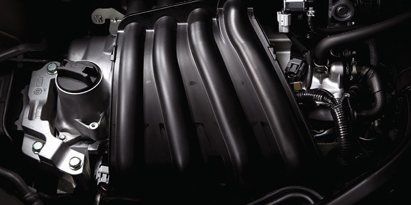
Всем привет, решил немного написать о своем двигателе, его особенностях и характеристиках.
HR15DE – полностью алюминиевый четырех цилиндровый бензиновый двигатель, разработанный Nissan совместно с Renault в рамках глобальной стратегии сотрудничества.
HR15DE пришел на замену уже устаревшим на тот момент двигателям серии QG15DE и QG16DE. Использование новых технологий позволило обеспечить более низкий расход топлива и увеличить тягу в наиболее востребованном диапазоне скоростей при городском движении. Впервые новая силовая установка была применена на Nissan Tiida, а позже в 2005 году была адаптирована для использования в Nissan Cube, Note.
Ключевые преимущества HR15DE по отношению к аналогам
Лучший в классе крутящий момент на низких и средних скоростях.
Высокая тепловая эффективность и низкое внутреннее трение (в частности, благодаря применению более тонкой полировки деталей, удалось на 30% сократить внутреннее трение).
Компактный и самый легкий среди одноклассников.
Большое внимание при разработке двигателя было уделено акустическому комфорту. Так, например, форма и длина впускных каналов была тщательно выверена с целью получения более чистого и комфортного для человеческого слуха звучания.
Основные параметры
Максимальная мощность – 109 л.с. при 6000 об/мин.
Максимальный крутящий момент – 148 Н*м при 4400 об/мин.
Тип двигателя 4-цилиндровый, DOHC
Доп. информация о двигателе Система изменения фаз газораспределения
Используемое топливо Бензин Regular (АИ-92, АИ-95)
Система снижения количества вредных выбросов (LEV) Соответствие стандарту 2005 года по 75%-му снижению выхлопных газов (SU-LEV)
Расход топлива в режиме 10/15, л/100км 5.5
Степень сжатия 11
Диаметр поршня, мм 78
Ход поршня, мм 78
Удельная мощность, кг/л.с. 9.91
Колличество форсунок впрыска топлива. 4 — в режиме D, 8 — в режиме Ds
Недавно читал какой то автомобильный журнал, в котором говорилось что это новейшая разработка — стало немного смешно если честно))