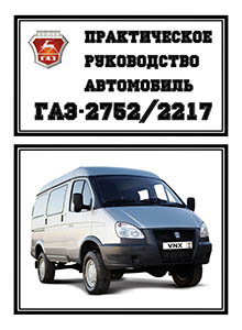
Руководства по эксплуатации, обслуживанию и ремонту ГАЗ Соболь
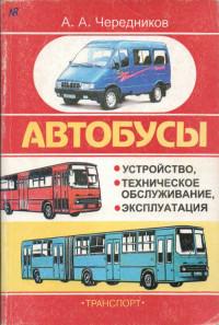
Руководство по эксплуатации и техническому обслуживанию автобусов Икарус-260/280, ЛиАЗ-5256, ПАЗ-3205, ГАЗ-3221 Газель и ГАЗ-2217 Соболь.
- Автор: А.А. Чередников
- Издательство: Транспорт
- Год издания: 1999
- Страниц: 217
- Формат: DjVu
- Размер: 4,8 Mb
Руководство по эксплуатации и техническому обслуживанию автомобилей ГАЗ Соболь.
- Автор: —
- Издательство: Автозавод ГАЗ
- Год издания: 2017
- Страниц: 116
- Формат: PDF
- Размер: 2,8 Mb
Руководство по эксплуатации и техническому обслуживанию автомобилей Соболь с дизельными двигателями Cummins ISF 2.8.
- Автор: —
- Издательство: Автозавод ГАЗ
- Год издания: 2017
- Страниц: 115
- Формат: PDF
- Размер: 2,9 Mb
Руководство по эксплуатации автомобилей Соболь с турбодизельными двигателями фирмы Cummins.
- Автор: —
- Издательство: Автозавод ГАЗ
- Год издания: 2011
- Страниц: 76
- Формат: PDF
- Размер: 1,5 Mb

Руководство по эксплуатации и техническому обслуживанию автомобилей скорой медицинской помощи ГАЗ-221727.
- Автор: —
- Издательство: Автозавод ГАЗ
- Год издания: 2017
- Страниц: 19
- Формат: PDF
- Размер: 364 Kb
Руководство по техническому обслуживанию и ремонту автомобилей Соболь.
- Автор: —
- Издательство: За рулем
- Год издания: 2000
- Страниц: 216
- Формат: PDF
- Размер: 52,1 Mb
Руководство по эксплуатации и ремонту автомобилей семейства «Соболь» ГАЗ-2217/22171/2310/2752 с бензиновыми двигателями объемом 2,3/2,5 л.
- Автор: —
- Издательство: Третий Рим
- Год издания: —
- Страниц: 212
- Формат: —
- Размер: —

Руководство по эксплуатации автомобилей Газель/Соболь с турбодизельными двигателями ГАЗ-560/5601/5602.
- Автор: —
- Издательство: Автозавод ГАЗ
- Год издания: 2005
- Страниц: 64
- Формат: PDF
- Размер: 32,5 Mb
Руководство по техническому обслуживанию и ремонту автомобилей Соболь с двигателями объемом 2,3/2,5 л.
- Автор: —
- Издательство: За рулем
- Год издания: 2012
- Страниц: 298
- Формат: —
- Размер: —
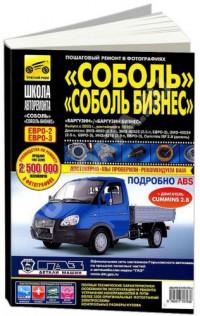
Руководство по эксплуатации, техническому обслуживанию и ремонту автомобилей Соболь, Соболь Бизнес, Баргузин, Баргузин Бизнес с 2003 года выпуска.
- Автор: —
- Издательство: Третий Рим
- Год издания: —
- Страниц: 344
- Формат: —
- Размер: —
ГАЗ-2752, ГАЗ-2217, ГАЗ-2310 (Соболь) с бензиновыми двигателями: ЗМЗ-4063 2.3 л (2285 см³) 98 л.с./72.2 кВт и ЗМЗ-40522 2.5 л (2464 см³) 145 л.с./106.6 кВт; Руководство по эксплуатации, техническому обслуживанию и ремонту, цветные электросхемы, устройство, диагностика, особенности конструкции, технические характеристики. Иллюстрированное практическое пособие грузопассажирские автомобили сегмента LCV и модификации SOBOL: GAZ 2310 грузовые с бортовой платформой и с трехместной кабиной, GAZ 2752 цельнометаллические фургоны с трех- и семиместной кабинами, GAZ 2217 автобусы 6 или 10 пассажирских мест задне- и полноприводные модели первого поколения выпуска (включая рестайлинг 2003) с ноября 1998 года
ЕСЛИ ВЫ ВИДИТЕ ОШИБКУ 406 Not Acceptable и не видите документ, то скорей всего у Вас IP РФ и его надо сменить, на любой другой страны, с помощью VPN ( Scribd и SlideShare блокируют посетителей с Российским IP).
Видео Ремонт передней подвески Соболь: замена передних пружин, сайлентблоков в верхнем рычаге, шаровых опор и карданного вала рулевого управления (GAZ Sobol с 98)
ГАЗ-2752, ГАЗ-2217, ГАЗ-2310 «Соболь» общая информация (GAZ Sobol с 1998)
Замена пружины передней подвески
Работаем на смотровой канаве при твердом ровном покрытии пола.
Снимаем переднее колесо.
Под раму устанавливаем стойку заводского изготовления с допустимой нагрузкой не менее 2 т и высотой около 600 мм.
Снимаем амортизатор.
Отсоединяем нижний конец стойки стабилизатора от нижнего рычага подвески.
Подставляем под чашку пружины
домкрат и слегка сжимаем пружину, чтобы отбойник верхнего рычага отошел от своего упора и крепежные соединения разгрузились.
Ключом или головкой «на 32» отворачиваем контргайку и ослабляем затяжку гайки оси нижнего рычага, чтобы сайлентблоки нижнего рычага имели возможность проворачиваться на оси.
Ключом «на 12» отворачиваем два болта крепления резинового буфера нижнего рычага.
Снимаем буфер.
Удерживая болт крепления кронштейна нижней шаровой опоры к нижнему рычагу головкой «на 22», отворачиваем его гайку ключом «на 24».
Вынимаем болт.
Осторожно опуская домкрат, освобождаем и вынимаем пружину и ее прокладку.
Заменяем обе пружины одновременно. При этом обратите внимание на маркировку номера группы жесткости пружины на прямом конце ее опорного нижнего витка.
Номер обозначен одной, двумя, тремя или четырьмя рисками.
В подвеску следует устанавливать пружины только одной группы.
При установке ориентируем пружину таким образом, чтобы прямой конец опорного витка совпал с углублением в нижней чашке пружины.
| № | Спецификация / Specs | Данные |
| Габариты (мм/mm) и масса (кг/kg) / Dimensions and Weight | ||
| 1 | Длина / Length | 4810-4880 |
| 2 | Ширина (без/с зеркалами) / Width | 2030-2075/2380 |
| 3 | Высота (загружен/пустой) / Height | 2200 |
| 4 | Колёсная база / Wheelbase | 2760 |
| 5 | Дорожный просвет (клиренс) / Ground clearance | 205⇒150 |
| 6 | Снаряжённая масса / Total (curb) weight | 1970-1990 |
| Полная масса / Gross (max.) weight | 2800 | |
|
Двигатель / Engine |
||
| 7 | Тип / Engine Type, Code | Бензиновый, жидкостного охлаждения, четырехтактный, ЗМЗ-4063 |
| 8 | Количество цилиндров / Cylinder arrangement: Total number of cylinders, of valves | 4-цилиндровый, рядный, 16V, DOHC с верхним расположением двух распределительных валов |
| 9 | Диаметр цилиндра / Bore | 92.0 мм |
| 10 | Ход поршня / Stroke | 86.0 мм |
| 11 | Объём / Engine displacement | 2285 см³ |
| 12 | Система питания / Fuel supply, Aspiration | Карбюратор К-151Д |
| Атмосферный | ||
| 13 | Степень сжатия / Compression ratio | 9.3:1 |
| 14 | Максимальная мощность / Max. output power kW (HP) at rpm | 72.2 кВт (98 л.с.) при 4500 об/мин |
| 15 | Максимальный крутящий момент / Max. torque N·m at rpm | 172 Нм при 3500 об/мин |
|
Трансмиссия / Transmission |
||
| 16 | Сцепление / Clutch type | Однодисковое, сухое, с диафрагменной нажимной пружиной и гасителем крутильных колебаний, постоянно замкнутого типа |
| 17 | КПП / Transmission type | МКПП 5 пятиступенчатая механическая, двухвальная, с синхронизаторами на всех передачах переднего хода |
О Книге
- Название: «Соболь» Устройство, обслуживание, диагностика, ремонт
- Бензиновые двигатели: ЗМЗ-4063 2.3 л (2285 см³) 98 л.с./72.2 кВт и ЗМЗ-40522 2.5 л (2464 см³) 145 л.с./106.6 кВт
- Выпуск с 1998 года
- Серия: «Своими силами»
- Год издания: 2012
- Автор: Коллектив авторов
- Издательство: «Ассоциация независимых издателей»
- Формат: PDF
- Страниц в книге: 298
- Размер: 117.39 МБ
- Язык: Русский
- Количество электросхем: 7
Всем привет!
Если у кого-то есть книги по ремонту, обслуживанию Газелей, Соболей и вам не лень, то делитесь ссылками. Соберём на странице.
Конечно новых материалов очень мало, но все равно, считаю это важно.
Возможно кому-то пригодится.
Спасибо всем!
=====
1) 4е издание Газель бизнес. disk.yandex.ru/i/QZV4EyKdGIZxJw
—
2) 5е издание Семейство Соболей. disk.yandex.ru/i/HemiBIcRPe8IaA
—
3) 7е издание Семейство Соболей. disk.yandex.ru/i/ODIS1RxfiS-A7Q
—
4) Соболь 2.3, 2.5i.Устройство, обслуживание, диагностика, ремонт disk.yandex.ru/i/5bGEU3Y3hQMagg
—
5) Газель 2.3, 2.5, 2.5i, 2.9. Устройство, обслуживание, диагностика, ремонт disk.yandex.ru/i/n85IS8-v37AsGw
—
6) Газель до 2009г. Устройство, обслуживание, диагностика, ремонт. disk.yandex.ru/i/umKmJZOPVfhQyA
—
7) Каталог оригинальных деталей 2003. Семейство Газель. disk.yandex.ru/i/yFAkIILqhk_2Hw
—

—
9) Руководство по эксплуатации, тех.обслуживанию, и ремонту Газель 2007. disk.yandex.ru/i/pqlUD8w_C4mEnA
—
10) Газель, Соболь. Руководство по тех.обслуживанию и ремонту двигателя ЗМЗ 40524. е3. disk.yandex.ru/i/MxzSpvT_U7mjWw
—
=====
Формат книги : файл pdf в архиве zip
Страниц : 85
Язык : Русский
Размер : 1.7 мб
Скачать книгу : бесплатно, без ограничений, на нормальной скорости, без SMS, логина и пароля. Файл взят из открытых источников.
Руководство по эксплуатации ГАЗ Соболь ГАЗ-2752, ГАЗ-27527, ГАЗ-2217, ГАЗ-22174, ГАЗ-22177, ГАЗ-22171, ГАЗ-221717, ГАЗ-2310, ГАЗ-23107.
Грузовые автомобили и автобусы ГАЗ Соболь предназначены для работы по дорогам с усовершенствованным покрытием, полноприводные автомобили – по дорогам всех технических категорий. В различных климатических условиях.
Семейство автомобилей ГАЗ Соболь, представленных в настоящем Руководстве, включает следующие модели:
Автомобили ГАЗ Соболь категории М2:
— Автобусы ГАЗ-22174 с колесной формулой 4х2 со средней крышей на 10 пассажирских мест.
— Специализированные пассажирские транспортные средства ГАЗ-2217 с колесной формулой 4×2 и ГАЗ-22177 с колесной формулой 4×4 с низкой крышей на 6 или 10 пассажирских мест.
— Специализированные пассажирские транспортные средства ГАЗ-22171 с колесной формулой 4×2 и ГАЗ-221717 с колесной формулой 4×4 со средней крышей на 6 или 10 пассажирских мест.
Автомобили ГАЗ Соболь категории N1:
— Автомобили ГАЗ-2310 с колесной формулой 4×2 и ГАЗ-23107 с колесной формулой 4×4 с трехместной кабиной и бортовой платформой.
— Автомобиль ГАЗ-2752 с колесной формулой 4×2 и ГАЗ-27527 с колесной формулой 4×4 с цельнометаллическим кузовом с трех или семиместной кабиной.
Содержание Руководства по эксплуатации ГАЗ Соболь ГАЗ-2752, ГАЗ-27527, ГАЗ-2217, ГАЗ-22174, ГАЗ-22177, ГАЗ-22171, ГАЗ-221717, ГАЗ-2310, ГАЗ-23107.
ВВЕДЕНИЕ.
1. ПАСПОРТНЫЕ ДАННЫЕ.
2. ВАШЕМУ ВНИМАНИЮ.
3. ПРАВИЛА ТЕХНИКИ БЕЗОПАСНОСТИ.
4. ТЕХНИЧЕСКАЯ ХАРАКТЕРИСТИКА ГАЗ СОБОЛЬ.
5. ОРГАНЫ УПРАВЛЕНИЯ И ПРИБОРЫ ГАЗ СОБОЛЬ.
6. ДВЕРИ, СИДЕНЬЯ И РЕМНИ БЕЗОПАСНОСТИ.
7. ОБКАТКА НОВОГО АВТОМОБИЛЯ СОБОЛЬ.
8. ЭКСПЛУАТАЦИЯ АВТОМОБИЛЯ СОБОЛЬ.
8.1. Пуск двигателя.
8.2. Движение автомобиля.
8.3. Торможение и стоянка.
8.4. Буксирные приспособления.
8.5. Отопление, вентиляция и кондиционирование кабины (салона).
8.6. Приборы освещения и световой сигнализации.
8.7. Стеклоочиститель и стеклоомыватель.
8.8. Предохранители.
8.9. Система управления двигателем.
8.10. Генераторная установка.
8.11. Стартер.
8.12. Антиблокировочная система тормозов.
9. ТЕХНИЧЕСКОЕ ОБСЛУЖИВАНИЕ АВТОМОБИЛЯ ГАЗ СОБОЛЬ.
9.1. Проверка уровня масла в картере двигателя.
9.2. Проверка уровня масла в коробке передач, в раздаточной коробке (для автомобилей Соболь с колесной формулой 4×4), в переднем (для автомобилей Соболь с колесной формулой 4×4) и в заднем мостах.
9.3. Проверка уровня охлаждающей жидкости.
9.4. Проверка уровня тормозной жидкости в бачке главного тормозного цилиндра.
9.5 Проверка уровня электролита в аккумуляторной батарее.
9.6. Проверка уровня масла в бачке системы гидроусилителя руля.
9.7. Натяжение ремней привода агрегатов.
9.8. Регулятор давления.
9.9. Свечи зажигания.
9.10. Уход за колесами и шинами.
9.11. Замена колес.
9.12. Уход за кабиной, кузовом.
9.13 Инструмент и принадлежности.
9.14. Виды технического обслуживания автомобиля.
9.15. Работы, выполняемые при техническом обслуживании.
9.15.1. Ежедневное техническое обслуживание (ЕО).
9.15.2. Периодическое техническое обслуживание (ТО).
9.15.3. Смазка автомобиля.
9.15.4. Карта смазки.
9.15.5. Зарубежные аналоги смазочных материалов и эксплуатационных жидкостей.
9.15.6. Топливо, применяемое на автомобиле Соболь.
10. ПРАВИЛА ХРАНЕНИЯ И ТРАНСПОРТИРОВАНИЯ АВТОМОБИЛЯ СОБОЛЬ.
11. УТИЛИЗАЦИЯ.
12. ПРИЛОЖЕНИЯ.
12.1. Радиооборудование.
12.2. Установка каркаса тента на платформу автомобилей ГАЗ-2310 и ГАЗ-23107.
12.3. Заправочные объемы.
12.4. Лампы, применяемые на автомобиле Соболь.
12.5. Подшипники качения, применяемые на автомобиле Соболь.
12.6. Манжеты, применяемые на автомобиле Соболь.
12.7. Моменты затяжки ответственных резьбовых соединений.
12.8. Эксплуатационные материалы.
12.9. Перечень изделий, содержащих драгоценные металлы.
Руководство по эксплуатации Соболь ГАЗ-2752, ГАЗ-27527, ГАЗ-2217, ГАЗ-22174, ГАЗ-22177, ГАЗ-22171, ГАЗ-221717, ГАЗ-2310, ГАЗ-23107 — СКАЧАТЬ КНИГУ >>>
- Manuals
- Brands
- Gazelle Manuals
- Automobile
- SOBOL
- Operating instructions manual
-
Contents
-
Table of Contents
-
Bookmarks
Quick Links
Limited Liability Company «Automobile Plant GAZ»
(LLC «AVTOZAVOD GAZ»)
GAZelle
SOBOL
VEHICLES FAMILY
OPERATING INSTRUCTIONS
3302 3902111 10ИЭ
2
nd
Edition
RUSSIA
NIZHNIY NOVGOROD
2005
Summary of Contents for Gazelle SOBOL
-
Page 1: Operating Instructions
Limited Liability Company «Automobile Plant GAZ» (LLC «AVTOZAVOD GAZ») GAZelle SOBOL VEHICLES FAMILY OPERATING INSTRUCTIONS 3302 3902111 10ИЭ Edition RUSSIA NIZHNIY NOVGOROD 2005…
-
Page 2: Introduction
INTRODUCTION “GAZelle” and “SOBOL” trucks and buses are reliable and comfortable vehicles. 4×2 trucks and buses are designed to be operated over improved roads (4×4 ones – over all types of roads) in different climatic conditions. “GAZelle” vehicles family presented in this Operating Instructions com prises the following models: GAZ 3302 —…
-
Page 3: Useful Hints
1. USEFUL HINTS Vehicles with ZMZ 4063 and ZMZ 40522 engines run on Research Oc tane Number 92 95 gasoline, with ZMZ 4061 run on Research Octane Number 76 gasoline and with GAZ 560, GAZ 5601, 5602 and Sofim 8140.43 engines – on diesel fuel (see subsection “Equivalents of Fuels, Oils, Lubricants and Flu ids”).
-
Page 4
the converter increasing sharply the temperature inside it and in its turn it will cause appearing of cracks in its ceramic block. During the operation the converter becomes very hot. Therefore when park ing the vehicle be sure that there is no combustible material (dry grass, wiping waste, chip etc.) under the converter. -
Page 5: Vehicle Identification Data
1 – location of identification number; 2 – rear spring front bracket; 3 – frame side member, right Example of Vehicle Identification Number: X96 33020050140794 , where: – manufacturer international identification code, 330200 – “GAZelle” vehicle model, 221710 — “Sobol” vehicle model – model year code (5 – 2005, 6 – 2006), 0140794 – vehicle serial number.
-
Page 6
(see Fig. 2.1, arrow “B” view). Example of Body (Cab) Number: 27050040100125 ,where: 270500 – “GAZelle” body index, 330200 – “GAZelle” cabin index 22171 – “Sobol” body index –… -
Page 7: Right Side
Vehicle identification data also appears on manufacture’s plate (Fig. 2.6 and 2.7) located on the rear pillar of the cab side panel. Fig. 2.6. Example of “GAZelle” Vehicle Fig. 2.7. Example of “Sobol” Vehicle Manufacture’s Plate with Identification Manufacture’s Plate with Identification…
-
Page 8
a – vehicle identification number; b – gross vehicle weight; c – gross vehicle weight with trailer; d – maximum front axle weight; e – maximum rear axle weight; f – engine index… -
Page 9: Specifications
3. SPECIFICATIONS 3.1. GENERAL DATA 3.1.1. “GAZelle” General Data Trucks Vehicle model GAZ 3302 GAZ 330202 GAZ 33023 GAZ 330232 GAZ 2705 GAZ 33027 GAZ 330273 GAZ 27057 4 × 4 biaxial Type Biaxial with rear axle drive Vehicle gross mass, kg…
-
Page 10
Vehicle model GAZ 3302 GAZ 330202 GAZ 33023 GAZ 330232 GAZ 2705 GAZ 33027 GAZ 330273 GAZ 27057 Wheelbase, mm 2900 3500 2900 3500 2900 2900 2900 2900 Front wheels track, 1700 1700 1700 1700 1700 1720 1720 1720 Rear wheels track (between centres of twin tyres), mm 1560… -
Page 11
Vehicle model GAZ 3302 GAZ 330202 GAZ 33023 GAZ 330232 GAZ 2705 GAZ 33027 GAZ 330273 GAZ 27057 Maximum climable gradient for laden vehicle, % Cargo body (van) loading height, mm 1040 Van freight compart ment capacity, m — — —… -
Page 12
Buses and Ambulances Vehicle model GAZ 3221 GAZ 32213 GAZ 32214 GAZ 32217 GAZ 322173 GAZ 322174 With all metal body Type Biaxial with rear axle drive 4 x 4 biaxial Vehicle gross mass 3250 3500 3500 3470 3720 3500 3550 3760 3500… -
Page 13
Vehicle model GAZ 3221 GAZ 32213 GAZ 32214 GAZ 32217 GAZ 322173 GAZ 322174 Rear wheels track (between the centres of twin tyres), mm 1560 1560 1560 1560 1560 1560 Ground clearance (under rear axle housing at total mass), mm Minimum turning radius (front outer track), m… -
Page 14
3.1. “SOBOL” GENERAL DATA Vehicle model GAZ 2752 GAZ 27527 GAZ 2217 GAZ 22177 GAZ 22171 GAZ 221717 Type All metal van 4×2 4×4 4×2 4×4 4×2 4×4 Vehicle gross mass, kg — with engines ZMZ 4063, ZMZ 40522 2800… -
Page 15
Vehicle model GAZ 2752 GAZ 27527 GAZ 2217 GAZ 22177 GAZ 22171 GAZ 221717 Ground clearance (under front suspension arms at total mass), mm — — — Minimum turning radius (front outer track), m Maximum speed, km/h, on flat, smooth high way, not less than, for vehicles with: —… -
Page 16
Number of cylinders and their arrangement 4, in line 4, in line 4, in line Cylinder bore and piston stro ke, mm 85×94 94.4×100 Displacement, l 2.134 Compression ratio 20.5 18.5 ¤— Symbol substituting the letter of engine version. For “GAZelle” vehicles. -
Page 17
Rated power, net, kW (h.p.) 70.0 (95) 81.0 (110) — Engine speed at rated power, 3800 3600 — Max. torque, net, daN·m (kgf·m) 20.0 (20.4) 25.0 (25.5) 25.0 (25.5) — at engine speed, rpm 2300 2000 — Maximum power, kW (h.p.) —… -
Page 18: Running Gear
For vehicles type 4×4. For “GAZelle” vehicles with ZMZ 40522, GAZ 5601, 5602 engines and “Sobol” vehicles. For “Sobol 4×4” vehicles and “GAZelle” vehicles with ZMZ 4061, 4063 and GAZ 560 engines. For vehicles with Sofim engine. Except for 4×2 type buses.
-
Page 19: Steering Gear
— rear Two longitudinal semielliptic springs with later al stabilizer; shock absorbers – hydraulic, tele scopic, dual acting 3.5. STEERING GEAR Steering gear without power steering Mechanical, “screw ball nut” type Steering gear with power steering Integral type, “screw ball nut” Power steering pump ШНКФ…
-
Page 20
— timing sensor 0261210113 or 23.3847 or ДС 1 — absolute pressure sensor 45.3829 or 0261230037 — coolant temperature sensor (engine control system sensor) 19.3828 or 405226 — knock sensor 0261231046 or GT 305 or 18.3885 ZMZ 40522 engine control system: —… -
Page 21
All metal, semi hood, five door. Two swing doors of the cab, one side sliding door and two rear double swing doors of passenger compartment or one rear flap door (for “Sobol” vehicles with low roof) — bus cab Two or three seat —… -
Page 22: Cab And Cargo Body
0.3 – 0.34 Clearance between rocking levers and cam heels of intake valves on cold engine at 15–20 C, mm 0.15 – 0.19 Rated coolant temperature, 85–95 For vans with two rows of seats. For “Sobol” vehicles with medium roof.
-
Page 23
— front disk brake shoes — rear drum brake linings Minimum slope at which parking brake must hold fully loaded ve hicle, % “GAZelle” Vehicles Front wheel geometry: — camber 30′ – 1 — pivot transverse inclination — caster 28′ ±… -
Page 24
240 + 10 (2.5 + 0.1) 270 + 10 (2.8 + 0.1) Note: air pressure in the tyres of each axle must be the same according to the values indicated. “Sobol” Vehicles Front wheels geometry: — caster 30′ ± 1 ±1… -
Page 25
Tyre inflation pressure , kPa (kgf/cm — front wheels 250 + 10 (2.5 + 0.1) — rear wheels 250 + 10 (2.5 + 0.1) Note: tyre inflation pressure of each axle must be the same, according to the values indicated. ×… -
Page 27
Positions of controls are given in fig. 4.1 1. Headlight aiming device control knob depending on vehicle loading (see subsection 8.7). 2, 11, 13 and 18. Reserve. 3. Warning lamps condition check up switch. 4. Side ventilation grids. 5. Turn indicator, dimmer and horn switch lever. -
Page 28
0 – all Off, the key cannot be pulled out, anti theft device is not engaged; I – ignition (instrument cluster and engine electronic control system) On; the key cannot be pulled out; II – ignition (instrument cluster and engine control system) and starter are On;… -
Page 29
In case the control lever is not equipped with horn switch (fig. 4.5), to turn on windshield wiper and washer momentarily pull the lever (in the direc tion of the arrow) from position 0. In case the control lever is equipped with horn switch (fig. 4.6), to turn on windshield wiper and washer momentarily push the lever from position 0 in the direction of arrow “A”… -
Page 30
20. Ashtray. Removal of ashtray is shown in fig. 4.8. To empty the ash tray pull it, push spring catcher upwards and remove the ashtray from its slot. Fit the ashtray back lifting up the spring catcher. Fig. 4.8. Ashtray ×… -
Page 31
25. Gearbox lever. The gearbox is equipped with safety device which pre vents accidental engagement of reverse gear during disengagement of the fifth gear. Engage reverse gear only after full stop of the vehicle. When reverse gear is engaged the backing light goes on in the tail lamps. Fig.4.10. -
Page 32
29. Service brake pedal. 30. Choke control knob (for vehicles with engines ZMZ 4061, ZMZ 4063). 31. Steering column adjustment control lever. (fig. 4.12). Pulling the le ver and moving it upwards (within the limits of 80 ) results in releasing of the steering column. -
Page 33
Positions of instruments on vehicles with ZMZ, GAZ 560, 5601, 5602 en gines are given in fig. 4.14. 10 11 12 13 14 Fig. 4.14. Instrument cluster 1. Voltmeter 2. Warning lamp (orange) of engine electronic control system (ZMZ 40522, ZMZ 4061, ZMZ 4063). When the control system is in good condi tion the warning lamp lights up when ignition is on, glows during 5–10 s, then goes out. -
Page 34
8. Speedometer. 9. Warning lamp (red) of parking brake engagement. Starts flashing after turning on the ignition key, if the parking brake is en gaged. 10. Warning lamp (green) of right turn indicators. 11. Warning lamp (red) of engine overheating. If the lamp lights up shut down the engine and eliminate the reason of over heating. -
Page 35
Positions of instruments on the vehicles with Sofim 8140. 43C engine are given in Fig. 4.15. 10 11 12 13 14 Fig. 4.15. Instrument cluster 1. Voltmeter. 2. Warning lamp of glow plug cutting in. If the warning lamp lights up after turning on of the engine control switch and then goes out, it means that the engine is ready to be started up. -
Page 36
is increased above idle level. Should the lamp light up under normal condi tions, shut down the engine immediately and check oil level in the crankcase. 12. Warning lamp (red) of engine overheating. If the lamp lights up shut down the engine and eliminate the reason of over heating. -
Page 37: Doors, Seats And Seat Belts
5. DOORS, SEATS AND SEAT BELTS Doors. To open the door from outside, pull handle 2 (Fig. 5.1). The doors are equipped with locks that can be locked from outside with key inserted in lock release 3. From inside the door is locked by pushing down button 1. To open the door from inside, pull handle 4 with lock button 1 pulled up only.
-
Page 38
For seating convenience the driver seat is adjustable. By turning handle 2 (Fig. 5.2) the seat can be moved in lengthwise direction. Required seat back rest tilt is adjusted by rotation handwheel 3. For driver’s convenience seat tilt is also adjusted by means of nuts 1. On GAZ 33023 and GAZ 330273 and on some of GAZ 2752 vehicles, sec ond row of seats is installed –… -
Page 39
Upper potion of the belt should pass across the centre of the shoulder so that it is not resting on your neck or under the arm. Lap potion of the belt should be positioned as low on the hips as possible. Otherwise release the belt and adjust its length. -
Page 40: Gaz 560, 5601, 5602 Engine Special Features
6. GAZ 560, 5601, 5602 ENGINE SPECIAL FEATURES The monoblock of the engine is a single piece structure of the cylinder block and the head of the cylinders. The pump and injector units have mechanical drive and electronic con trol. Fuel feed control is effected by microprocessor depending on engine speed, accelerator pedal position and signals of sensors mounted on the engine.
-
Page 41
Exhaust — pressure Fig. 6.2 GAZ 5601, 5602 Engine Control Diagram A – to diagnostic connector; 1 – electronic control unit; 2 – accelerator pedal position sensor; 3 – air temperature sensor; 4 – engine speed sensor; 5 – glow plugs relay; 6 – fuel injection advance angle control servo mechanism;… -
Page 42: Gaz 32214 And Gaz 322174 Special Features
7. GAZ 32214 AND GAZ 322174 SPECIAL FEATURES STORAGE BATTERIES Additional battery 50 a h, service free, with gas absorption, type 95502 “VARTA” is installed in vehicle’s compartment to connect medical equipment. To avoid the voltage drop across the medical equipment the additional battery is cut off automatically from vehicle’s electrical equipment by means of contactor KT128 or 12КД510 at the moment of engine starting.
-
Page 43
Fig. 7.1. Power Supply System Device Front Panel 1 – 2A fuse; 2 – 10A fuse; 3 – “220V” automatic switch; 4 – charging unit “Charger” automatic switch; 5 – “Charge” indicator; 6 – “On” indicator; 7 – “Power” indicator; 8 – twin two pole socket (220V, 50Hz) with side ground contacts SEQUENCE OF OPERATIONS To provide storage batteries automatic charging and 220V (50Hz) power… -
Page 44
4. To set automatic switch 4 (“Charger”) in upper position, in doing so indicator 6 (“On”) and 5 (“Charge”) showing the beginning of storage batter ies charging condition should light up. 5. To connect 220V (50Hz) power consumers to socket 8 and set switch 3 «220V»… -
Page 45
Fig. 7.2. Signaling and Loudspeaker System Control Desk 1 – power “ON” and “TEST” mode key; 2 – beacons and siren “ON” key; 3 – siren signal “ON” key; 4 – power “ON” warning lamp; 5 – flashing beacon “ON” warning lamp; 6 – overload warning lamp;… -
Page 46
MEDICAL COMPARTMENT EQUIPMENT In medical compartment it is located the following: — personal seats for doctor and attendant; — folding seat placed along the right side of medical compartment. In folded position additional stretches can be installed on it; — self contained heater mounted inside the folding seat underframe;… -
Page 47
— cupboard rack for medical equipment with niche for oxygen bottles (on the left in the rear part of the compartment); — receiving device with bogie stretches (in the middle of the compartment) allowing to shift the stretches block across the compartment and to fix it in traveling position;… -
Page 48: New Vehicle Running In And Its Operation
8. NEW VEHICLE RUNNING IN AND ITS OPERATION RUNNING IN Durability, efficiency and no failure operation of the vehicle throughout its life depend to a great extent on how fully and thoroughly you will follow recommendations stated in this section. No special running in is required for the vehicle, however during the first 2000 km of run the following rules should be observed: 1.
-
Page 49
2. Step on the accelerator pedal and pull out the carburetor choke knob as far as it will go. Release the accelerator pedal. If you do not stick to the above sequence, the choke rod can be broken. 3. Depress the clutch pedal all the way down. 4. -
Page 50
4. Turn on the starter for not more than 10 seconds. Do not depress the accelerator pedal! Warning lamps 18 and 27 should go out. 5. As soon as the engine starts, release the key and the clutch pedal. As may be required, 2–3 attempts of engine starting are allowed with the interval between them for not less than 1 minute, from “0”… -
Page 51
Should the engine fail to start it is necessary to make another attempt re peating the above procedures. Allow not less than 1 minute before the second attempt. After the third unsuccessful attempt, find and eliminate the trouble. After the engine starting and pressure appearing in engine oil system red warning lamp goes out and you may start driving the vehicle. -
Page 52
Then start the engine in the following sequence: — turn on the storage battery; — set gearshift lever to neutral; — turn engine control switch key to fixed position I; — step on the clutch pedal as far as it will go; —… -
Page 53: Fuel Air Mixture Preheating (Zmz 4061, 4063 Engines)
— turn handle 4 (see Fig. 8.2) of main Operating Instructions) of air tem perature control in the cab clockwise to the angle of not less than 10°; — start the preheater by pushing the button (timer left hand button); —…
-
Page 54
ing to drive some time at low gears and low engine speed. As oil warms up it is necessary to shift to higher gears in succession. After wading, driving through heavy rain or after washing the vehicle brak ing surfaces become coated with moisture. This will affect braking efficiency until disks, drums and brake linings are dried by intermittent light application of the brakes. -
Page 55: Braking
Leave the transfer case gearshift lever in high gear engaged position when storing and long term parking the vehicle in outdoors, under a shed or non heated indoors in winter. 8.5. VEHICLE BRAKING Design of the brakes ensures braking efficiency. Nevertheless brake the vehicle smoothly, avoiding abrupt braking and interlocking of brake gears.
-
Page 56
— off — slow speed of the blower; — normal speed of the blower; — fast speed of the blower 3. Control handle of warm (heated) air amount supplied to the passenger compartment of vans with two rows of seats and buses. It has four positions: —… -
Page 57
increases or decreases the amount of air coming to the passenger compartment or completely closes the channel of air supply. To provide comfortable conditions in the passenger compartment of vans with two rows of seats and buses the additional heater is installed which heats the air inside of the cab or passenger compartment. -
Page 58: Headlamps
Self contained heater switches are located on the medical compartment equipment control panel (in the front entresol of the compartment at the top near the bulkhead). Note: Design and operation of self contained heater, its specifications and maintenance procedure are given in the self contained heater operating manual attached to the vehicle. 8.7.
-
Page 59: Fuses
Adjust the headlamps in the following sequence: – check air pressure in tires. Bring it, if necessary, to the required level; – place the unladen vehicle on a level ground at 5 m distance from the screen (Fig. 8.5); Fig. 8.5. Screen Layout for Headlamps Adjustment: A –…
-
Page 60
Vehicles with GAZ 560, 5601, 5602 Engines Under the hood a fuse box Ф5.3722.001 is installed on the storage battery support where 90A fuse protects alternator and glow plug circuit, 40A fuse protects outdoor illumination circuit of the vehicle, 60A fuse protects the cir cuit of the rest of power consumers except for starter circuit. -
Page 61
БПР 13 FUSE BOXES Upper fuse box fuses protect the circuits of: 1. 25A – engine control system (ZMZ 40522). 2. 15A – emergency flasher warning lights. 3. 15A – frame switch (for buses), radio and cassette player 4. 10A – windscreen wiper, windscreen washer, right row dome lamps passenger compartment. -
Page 62: Thermostarter Control Unit (Sofim 8140, 43C Engine)
8.10. ANTI LOCK BRAKE SYSTEM ‘GAZelle” buses are equipped with anti lock brake system (ABS) of series 5.3 made by “Bosch”. ABS is effective in case of emergency braking on the roads…
-
Page 63
out of order (but service brake system maintains serviceability as if without ABS) When ABS failure is confirmed the troubleshooting should be carried out at service station. ABS electrical diagram is shown in Fig. 8.6. Fig.8.6. ABS System Electric Circuit Diagram Moreover, ABS failure warning lamp lights up in case of wire breakage between ABS control unit and warning lamp. -
Page 64: Vehicle Maintenance
9.VEHICLE MAINTENANCE This section describes the works which should be carried out regularly with in the intervals between the maintenance operations stated in the Service Book. 9.1. CHECKING ENGINE OIL LEVEL Check engine oil daily prior to engine starting. When doing so park the vehicle on level ground.
-
Page 65: Checking Coolant Level
9.3. CHECKING COOLANT LEVEL Checking the coolant level in expansion tank 2 (Fig. 9.3) should be car ried out only when the engine is cold. The coolant level should be not below MIN mark and not above the clamp upper edge. Fig.
-
Page 66: Checking Brake Fluid Level In Clutch Master Cylinder Tank
With cover 5 removed and with new brake linings the fluid level should be at MAX mark. If the brake hydraulic drive is in sound condition, a drop of the fluid level is associated with brake lining wear. The fluid level drop up to MIN mark is indicative in an indirect way of maximum wear of the linings.
-
Page 67: Checking Oil Level In Power Steering Reservoir
Fig. 9.6. Storage Battery: 1 – cover; 2 – plug; 3 – filler hole in them for cleanness and place back cover 1. After that wipe the battery outer surfaces with clean rugs soaked in 10% solution of ammonia spirit or sodium bicarbonate.
-
Page 68: Engine Accessories Drive Belt Tensioning
Fig. 9.7. Checking the Oil Level in the Power Steering Reservoir 9.8. ENGINE ACCESSORIES DRIVE BELT TENSIONING ZMZ – 4061, 4063, 40522 Engines. Engine accessories drive belt tension ing is carried out by changing the position of idler pulley 2 (Fig. 9.8). Check the belt tension by the size of the belt sag using spring dynamome ter.
-
Page 69: Spark Plugs
9.9. SPARK PLUGS (ZMZ 4061, 4063, 40522 ENGINES) Gap «A» (Fig. 9.9) between the spark plug electrodes – see subsection 3.10 «Main adjustment and checking data». Check the gap between the electrodes with a round wire spark plug gapping gauge. Adjust the gap by bending the side electrode.
-
Page 70: Changing A Wheel
— rotate the tires, if necessary (Fig. 9.10). The grounds for tires rotation may serve the necessity to get even wear of all tires, spare one including, as well as to provide proper selection of the tires for each axle. The tires on an axle should be of the same tread wear and more reliable tires should be in stalled on the front axle of the vehicle.
-
Page 71
clears the ground by 4–5 cm. In case of loose ground it is recommended to place a pad or a firm board under the jack base; — remove six nuts, replace the wheel and fit the nuts; — lower the vehicle; —… -
Page 72: Body (Cab) Care
— place the jack (Fig. 9.12) under front axle beam or rear axle near the wheel to be lifted and drive out screw 2 as far as it will go. In case of loose ground, place a pad or a firm board under the jack base; —…
-
Page 73: Types Of Maintenance
Never use gasoline or solvents for the above purpose. On detecting corrosive spots it is necessary to remove the rust to pure metal, prime and apply corrosion resisting mastic. You should not keep the vehicle under rubberised cover or place rubber articles on bodywork painted surface because dark spots may appear which cannot be removed with car polish.
-
Page 74: Periodic Maintenance
2. When the ignition is on: Visually — brake fluid low level warning lamp should not illuminate; — on pressing the cap, brake fluid low level warning lamp should illuminate Check operation of parking Parking brake handle should move brake system for not more than 15–20 teeth under 60 kgf effort Check tire inflation pres…
-
Page 75: Oils, Lubricants And Special Fluids
30 g Solid oil C shes and block bearings Substitute – solid oil Ж Steering knuckle pivot bu 25 g Solid oil Ж shes and block bearings Substitute – solid oil C For 4WD vehicles. For 2WD “GAZelle” vehicles.
-
Page 76
Front axle joint cross bear 24 g Lubricant 158M ings Rear axle housing 3.0 l At the temperature from –25° C to +40° C – oil “Супер Т 3” Substitute – oils “Девон Супер Т” At the temperature from –40° C to +20°… -
Page 77
Steering gear universal joints Grease Литол 24. Substitutes – grease solid oil C, solid oil Ж Master brake cylinder refil 0.67 l Brake fluid “РОСДОТ”. ling tank Substitute fluid “Томь” Master clutch cylinder refil 0.2 l Brake fluid “РОСДОТ”. ling tank Substitute fluid “Томь”… -
Page 78: Equivalents Of Fuels, Oils Lubricants And Fluids
9.16. EQUIVALENTS OF FUELS, OILS LUBRICANTS AND FLUIDS General 1. Never mix up the foreign and home made fuels, oils and lubricants. 2. Prior to using oil of foreign grade, be sure to flush the oil system. Diesel Fuels (for GAZ 560, GAZ 5601, 5602, Sofim 8140. 43C engines) Russian fuel Foreign diesel fuel Grade…
-
Page 79
Oils, lubricants and fluids Classification, equivalents Russian made materials Remarks specification Engine oils API SG, SH, SJ/CD (ZMZ 4061, 4063, ZMZ SAE 5W 30 from –25° C to +20° C 40522) SAE 5W 40 from –25° C to +35° C SAE 10W 30 from –20°… -
Page 80: Parts To Be Replaced On The Vehicle During Maintenance
9.17. PARTS TO BE REPLACED ON THE VEHICLE DURING MAINTENANCE During vehicle maintenance the following parts are subject to replacement: 1. Fuel fine filter of ZMZ 4061, ZMZ 4063 and ZMZ 40522 engines (re placed in assembly), filter designation is 2108 1117010 03 or 4021.1117010). Fuel fine filter of Sofim 8140.
-
Page 81
For GAZ 560 and GAZ 5601, 5602 engines it is recommended to use fil ter elements (non detachable, full flow): Fleetguard LF3402 and LF3449, Knecht OC59 (F0371), Mann W940 or W940/15N. Filter element of Sofim 8140. 43C engine oil filter is RD303 45.303.000.53. 4. -
Page 82: Supplements
AC12 5 1, A12 3 1 Alarm switch pilot lamp A12 1,1 Inspection lamp A12 6 2 Cigarette lighter socket light AMH12 3 1 Instrument cluster lighting bulbs A12 2,3 1 Pilot lamps A12 1,2 For “Sobol” buses with 6 passenger seats. For “Sobol” vehicles.
-
Page 83: Tightening Torque Of Most Important Junctions
Supplement 2 10.2. TIGHTENING TORQUE OF MOST IMPORTANT JUNCTIONS Tightening torque, Junction description daN·m (kgf·m) Engine ZMZ 4061, 4063, 40522 Cylinder head hold down bolts preliminary tightening 4.0 – 6.0 final tightening 13.0 – 14.5 Connecting rod nuts 6.8 – 7.5 Main bearing cap bolts 10.0 –…
-
Page 84
(“GAZelle” vehicle) 11.0 – 12.5 Tie rod clamp bolts (“GAZelle” vehicle) 2.2 – 2.5 Steering links to support hold down bolts (“Sobol” vehicle) 11.0 – 12.5 Idler arms to shafts hold down nuts (“Sobol” vehicle) 14.0 – 18.0 Connecting rod tube clamp nuts (“Sobol” vehicle) 1.5 –… -
Page 85: Filling Capacities
Power steering system (for vehicles with power steering), l Shock absorbers (each), l 0.265 Brake hydraulic drive system, l 0.67 “Sobol” 0.52 (“GAZelle”) Clutch hydraulic drive system, l Lubricant for front wheel hubs (both), g Lubricant for rear wheel hubs (both), g Windscreen washer tank, l For GAZ 560, 5601, 5602 vehicles.
-
Page 86: Table Of Contents
CONTENTS Page Introduction ……………………3 1. Useful Hints …………………… 4 2. Vehicle Identification Data ………………6 3. Specifications ………………….10 4. Controls and Instruments ………………27 5. Doors, Seats and Seat Belts ……………… 38 6. GAZ 560, 5601, 5602 Engine Special Features ……….41 7.
-
Page 87
Page 9.14.2. Periodic Maintenance …………..75 9.14.3. Vehicle Lubrication …………….75 9.15. Oils, Lubricants and Special Fluids …………76 9.16. Equivalents of Fuels, Oils, Lubricants and Fluids ……… 79 9.17. Parts to be Replaced on the Vehicle during Maintenance ….81 10.


