
MGE
TM
Galaxy
TM
5000
20 — 120 kVA
Installation and user manual
Краткое содержание страницы № 1
www.mgeups.com
MGE Galaxy 5000
40– 130KVA
Installation and User Manual
Critical Power and Cooling Services Division
Краткое содержание страницы № 2
Краткое содержание страницы № 3
Installation and User Manual MGE Galaxy 5000 40– 130KVA Uninterruptible Power Systems Installation and User Manual Schneider Electric 1660 Scenic Avenue, Costa Mesa, CA 92626, (714) 557-1636 Service Solutions Team: 1-800-438-7373 (Hours: 24/7) Revision History: A00 ECN-005986 5/28/08 B00 ECN-006020 6/20/08 Copyright © 2008 American Power Conversion Corporation. All rights reserved. Printed in U.S.A. 86-174010-00 B00 i
Краткое содержание страницы № 4
MGE Galaxy 5000 IMPORTANT SAFETY INSTRUCTIONS SAVE THESE INSTRUCTIONS – This manual contains important instructions for Galaxy 5000 that must be followed during operation and maintenance of the equipment. Opening enclosures expose hazardous voltages. Always refer service to qualified WARNING personnel only. L’ouverture des cellules expose à des tensions dangereuses. Assurez-vous ATTENTION toujours que le service ne soit fait que par des personnes qualifiees. Das öffnen der Gehäuse legen gefährl
Краткое содержание страницы № 5
Installation and User Manual WARNING HIGH LEAKAGE CURRENT. Ground connection essential before connecting supply. ATTENTION COURANT DE FUITE ELEVE. Raccordement a la terre indispensable avant le raccordement au reseau. WARNUNG! Hoher Ableitstrom Vor Inbetriebnahme Schutzleiterverbindung herstellen. Certification Standards – Three Phase UPS ◗ IEC1004/ANSI C62.41 Standards for Surge Withstand Ability. ◗ FCC Part 15, Subpart J, Class A. ◗ UL/CUL 1778, Standards for Uninterruptible Power Supply Equi
Краткое содержание страницы № 6
MGE Galaxy 5000 (This page left blank intentionally) iv 86-174010-00 B00
Краткое содержание страницы № 7
Contents IMPORTANT SAFETY INSTRUCTIONS . . . . . . . . . . . . . . . . . . . . . . . . . . . . . . . .ii Certification Standards – Three Phase UPS . . . . . . . . . . . . . . . . . . . . . . . . . . . . .iii Environment . . . . . . . . . . . . . . . . . . . . . . . . . . . . . . . . . . . . . . . . . . . . . . . . . . . . . .iii Contents CAUTION: Record All Serial Numbers! . . . . . . . . . . . . . . . . . . . . . . . . . . . . . . . . .IV Safety Rules . . . . . . . . . . . . . . . . . . . . . .
Краткое содержание страницы № 8
MGE Galaxy 5000 3.6 Operating Modes . . . . . . . . . . . . . . . . . . . . . . . . . . . . . . . . . . . . . . . . . . . .3 — 5 3.7 Load on Battery Power . . . . . . . . . . . . . . . . . . . . . . . . . . . . . . . . . . . . . . .3 — 5 3.8 UPS Personalization . . . . . . . . . . . . . . . . . . . . . . . . . . . . . . . . . . . . . . . . .3 — 6 3.9 Display Messages List . . . . . . . . . . . . . . . . . . . . . . . . . . . . . . . . . . . . . . . .3 — 7 3.10 Operation of the Relay Communicatio
Краткое содержание страницы № 9
Installation and User Manual Figures 1-1 MGE Galaxy 5000 UPS Cabinet. . . . . . . . . . . . . . . . . . . . . . . . . . . . . . . . .1 — 2 1-2 Single Line Diagram . . . . . . . . . . . . . . . . . . . . . . . . . . . . . . . . . . . . . . . . . .1 — 2 1-3 Inside MGE Galaxy 5000 UPS Cabinet . . . . . . . . . . . . . . . . . . . . . . . . . . .1 — 3 1-4 Power Connection Terminals . . . . . . . . . . . . . . . . . . . . . . . . . . . . . . . . . . .1 — 4 1-5 INTN PCA for Auxiliary Interconnections
Краткое содержание страницы № 10
MGE Galaxy 5000 CAUTION: Record All Serial Numbers! RECORD ALL SERIAL NUMBERS FOR THE MGE GALAXY 5000 AND ACCESSORIES. THESE SERIAL NUMBERS WILL BE REQUIRED IF YOUR SYSTEM NEEDS SERVICE. KEEP THIS MANUAL IN A PLACE WHERE YOU CAN REFERENCE THE SERIAL NUMBERS IF SERVICE IS REQUIRED! UPS SERIAL NUMBER: ____________________________________________________________ BATTERY SERIAL NUMBER: _______________________________________________________ AUXILIARY SERIAL NUMBER: _______________________________
Краткое содержание страницы № 11
Installation and User Manual Safety Rules Safety of persons The UPS must be installed in a room with restricted access (qualified personnel only). A UPS has its own external power source (the battery). Consequently, the power outlets may be energized even if the UPS is disconnected from the AC-power source. Dangerous voltage levels are present within the UPS. It should be opened exclusively by qualified service personnel. The UPS must be properly grounded. The battery supplied with the UPS conta
Краткое содержание страницы № 12
MGE Galaxy 5000 Symbol Usage Document Icons Display Icons Danger, these instructions Vertical selection Move up or down one are imperative. page Other selection Event selection in log Information, advice, help may by date and time Enter / Confirm Visual indication Increase Event scroll in log Action Decrease Page scroll in log Audio signal Save Fast forward LED OFF Alarm Forward LED flashing Status conditions Details LED ON Settings Ground cables Circular menu Maintenance Other cables Control
Краткое содержание страницы № 13
Installation and User Manual Section Descriptions 1 Introduction Provides a general description of the MGE Galaxy 5000 system’s intended use, single line, major components, and mechanical specifications. 2 Setup and Installation Guides the user through performing connections required for initial installation. Included are the electrical specifi- cations and connection details. 3 Operation Provides startup, shutdown, and normal operation of the MGE Galaxy 5000 UPS. Describes the operation of the
Краткое содержание страницы № 14
MGE Galaxy 5000 (This page left blank intentionally) VIII 86-174010-00 B00
Краткое содержание страницы № 15
Introduction Thank you for selecting a Schneider Electric product to protect your electrical equipment. The MGE Galaxy 5000 range has been designed with the utmost care. We recommend that you take the time to read this manual to take full advantage of the many features of your UPS. Schneider Electric pays great attention to the environmental impact of its products. Measures that have made MGE Galaxy 5000 a reference in environmental protection include: ◗ the eco-design approach used in product d
Краткое содержание страницы № 16
MGE Galaxy 5000 Figure 1-1: MGE Galaxy 5000 UPS Cabinet. UPS power rating (KVA) Dimensions (H x W x D) 40-130 75” x 28” x 33.4” 1900 x 712 x 850 mm Figure 1-2: Single Line Diagram MGE GALAXY 5000 UPS SYSTEM WITH BATTERY SINGLE LINE DIAGRAM Q3BP Bypass Optional KA2 Q4S Input Bypass Input 480Y VAC Input PFC Output Static Static Input Boost Output Main Rectifier Switch Inverter Switch Q1 Fuses KA1 Fuses Q5N Output To Main Input Critical Input Load 480 VAC Battery Static Switch Battery Charger UPS
Краткое содержание страницы № 17
Installation and User Manual 1.2 Inside the UPS Cabinet, Access to Connections Figure 1-3: Inside MGE Galaxy 5000 UPS Cabinet (1) Connectors for auxiliary interconnections of parallel UPS units (INTN PCA), optional (2) User-machine interface display (3) Slot for relay communications card (4) Open slots for optional communication cards (5) Open cabinet door (6) Screw-type terminal block for connections of contacts and coils for two external battery circuit breakers XMB07,
Краткое содержание страницы № 18
MGE Galaxy 5000 Figure 1-4: Power Connection Terminals (14) Terminals for load output (15) Terminals for bypass AC input (16) Terminals for normal AC input (17) Main grounding connector (22) Connection of external battery (+/- poles) Figure 1-5: INTN PCA for Auxiliary Interconnections of Parallel UPSs (19) DB9 connectors: exchange-current information (20) Screw connectors: position information on Q5N, Q4S and Q3BP switches, from the external bypass (21)
Краткое содержание страницы № 19
Installation and User Manual 1.4 User-Machine Interface Display Figure 1-7: User-Machine Interface Display (30) Graphical display (31) Load protected LED (32) Minor fault LED (33) Major fault LED (34) Help key (35) Function keys (36) Menu key (38) OFF button (37) ON button (42) Load supplied LED (40) UPS ON LED (41) Operation on battery power LED (43) Bypass in operation LED (39) PFC ON LED 86-174010-00 B00 Introduction 1 — 5
Краткое содержание страницы № 20
MGE Galaxy 5000 1.5 Display Screens Figure 1-8: Display Screens Frequency measurements Personalization 1 — 6 Introduction 86-174010-00 B00
-
Contents
Table of Contents -
Bookmarks
Quick Links
www.mgeups.com
Galaxy 5000
20 — 120 kVA
Battery circuit-breaker
cabinet
Installation manual
— Page 1
34003641FR/AA
Summary of Contents for MGE UPS Systems Galaxy 5000
-
Page 1
Galaxy 5000 20 — 120 kVA Battery circuit-breaker cabinet Installation manual — Page 1 34003641FR/AA… -
Page 2: Table Of Contents
Galaxy 5000 at the end of its service life. To discover the entire range of MGE UPS SYSTEMS products and the options available for the Galaxy 5000 range, we invite you to visit our web site, www.mgeups.com, or contact your local MGE UPS SYSTEMS representative.
-
Page 3: Installation Of Cabinet
1. Installation of cabinet ◗ the circuit-breaker cabinet must be located as close to the battery as possible, ◗ the cabinet is fixed to a vertical wall by means of 4 screws of diameter 8 using the fastening lugs placed in the vertical or horizontal position, ◗…
-
Page 4: Characteristics Of Cabinet
2. Characteristics of cabinet ◗ the characteristics of the cabinets indicated in the tables below are valid for a linear load charge with power factor of 0.8 and a minimum battery voltage set to 335 V on the inverter side (340 V on the battery side), ◗…
-
Page 5: Electrical Characteristics Of Cabinet
2. Characteristics of cabinet 2.2 Electrical characteristics of cabinet Inverter Maximum battery backup QF1 circuit-breaker rated power times at Pn Type Release Magnetic Thermal in kVA setting setting < or = to 10 mn NS100 TM100D 800 A > 10 mn NS100 TM100D 800 A…
-
Page 6: Connections
3. Connection 3.1 Connection points Cabinet for Galaxy 5000 of 20 kVA to 160 kVA (with battery backup time < or = to 10 mn), and of 20 kVA to 100 kVA (with battery backup time > 10 mn): ◗…
-
Page 7
Vigilohm TR5A terminal 10 8 block terminal block insulation fault Galaxy 5000 to the insulation circuit-breaker of AC normal source in the Galaxy 5000 cubicle (see figure on next page) XMB 08 XMB 07 XMS 06 — Page 7 34002025EN/AA… -
Page 8: Auxiliary Cabinet Connections In The Galaxy 5000 Cubicles
3. Connection Insulation circuit-breaker To terminals 1-2-3-4 of QF1 circuit-breaker To terminals 1-2 of cabinet XB4B XB1B To insulation circuit-breaker XB2B XB3B — Page 8 34002025EN/AA…
![]()
MGETM GalaxyTM 5000
20 — 120 kVA
Installation and user manual
Introduction
Thank you for selecting an APC by Schneider Electric product to protect your electrical equipment.
The MGETM GalaxyTM 5000 range has been designed with the utmost care.
We recommend that you take the time to read this manual to take full advantage of the many features of your UPS.
APC by Schneider Electric pays great attention to the environmental impact of its products.
Measures that have made MGETM GalaxyTM 5000 a reference in environmental protection include:
the eco-design approach used in product development,
the elimination of harmonic disturbances reinjected into the AC source,
production in an ISO 14001 certified factory,
recycling of the MGETM GalaxyTM 5000 at the end of its service life.
To discover the entire range of APC by Schneider Electric products and the options available for the MGETM GalaxyTM 5000 range, we invite you to visit our web site, www.apc.com, or contact your local APC by Schneider Electric representative.
All products in the MGETM GalaxyTM 5000 range are protected by patents. They implement original technology not available to competitors of APC by Schneider Electric.
To take into account evolving standards and technology, equipment may be modified without notice. Indications concerning technical characteristics and dimensions are not binding unless confirmed by APC by Schneider Electric.
This document may be copied only with the written consent of Schneider Electric and its affiliated companies. Authorised copies must be marked
«MGETM GalaxyTM 5000 Installation and user manual no. 3400181300″.
34001813EN/AE — Page 2

Safety
Safety rules
Safety of persons
The UPS must be installed in a room with restricted access (qualified personnel only, according to standard 62040-1-2).
A UPS has its own internal power source (the battery). Consequently, the power outlets may be energised even if the UPS is disconnected from the AC-power source.
Dangerous voltage levels are present within the UPS. It should be opened exclusively by qualified service personnel. The UPS must be properly earthed.
The battery supplied with the UPS contains small amounts of toxic materials. To avoid accidents, the instructions below must be observed.
Never operate the UPS if the ambient temperature and relative humidity are higher than the levels specified in the documentation.
Never burn the battery (risk of explosion).
Do not attempt to open the battery (the electrolyte is dangerous for the eyes and skin).
Comply with all applicable regulations for the disposal of the battery.
Caution, wait five minutes before opening the UPS to allow the capacitors to discharge.
Caution, there is high leakage current, the earthing conductor must be connected first.
The product must be installed on a non-inflammable surface (e.g. concrete).
Caution, battery replacement must be carried out by qualified personnel.
Product safety
A protection circuit breaker must be installed upstream and be easily accessible.
Never install the UPS near liquids or in an excessively damp environment.
Never let a liquid or foreign body penetrate inside the UPS.
Never block the ventilation grates of the UPS.
Never expose the UPS to direct sunlight or a source of heat.
When replacing battery cells, use the same type and number of cells.
Special precautions
The UPS connection instructions contained in this manual must be followed in the indicated order.
Check that the indications on the rating plate correspond to your AC-power system and to the actual electrical consumption of all the equipment to be connected to the UPS.
If the UPS must be stored prior to installation, storage must be in a dry place.
The admissible storage temperature range is -25° C to +45° C.
If the UPS remains de-energised for a long period, we recommend that you energise the UPS for a period of 24 hours, at least once every month. This charges the battery, thus avoiding possible irreversible damage.
The UPS is designed for normal climatic and environmental operating conditions concerning the altitude, ambient operating temperature, relative humidity and ambient transport and storage conditions.
Using the UPS within the given limits guarantees its operation, but may affect the service life of certain components, particularly that of the battery and its autonomy. The maximum storage time of the UPS is limited due to the need to recharge its integrated battery.
Unusual operating conditions may justify special design or protection measures:
—harmful smoke, dust, abrasive dust,
—humidity, vapour, salt air, bad weather or dripping,
—explosive dust and gas mixture,
—extreme temperature variations,
—bad ventilation,
—conductive or radiant heat from other sources,
—cooling water containing acid or impurities which may cause scale, silt, electrolysis or corrosion of converter parts exposed to water,
—strong electromagnetic fields,
—radioactive levels higher than those of the natural environment,
—fungus, insects, vermin, etc.,
—battery operating conditions.
The UPS must always be installed in compliance with:
the requirements of standard IEC 60364-4-42: Protection from thermal effects.
standard IEC 60364-4-41: Protection from electric shock.
standard IEC 60364-4-482: Electrical installations of buildings.
in France, the requirements of standard NFC 15-100.
34001813EN/AE — Page 3
Foreword
Pictograms
Danger, these instructions are imperative.
Information, advice, help
Visual indication
Action
Audio signal
LED OFF
LED flashing
LED ON
Earth cables
Other cables
E
S
C
D
E
L
VOLT
|
Vertical selection |
|
|
Other selection |
17 |
mai
Enter / Confirm
Event scroll in log
Page scroll in log
Fast forward
Forward
0101
1010
0101
Details
Circular menu
Graphical display
Return to previous display
Delete
Access to measurements
Buzzer off
Move up or down one page
Event selection in log by date and time
Increase
Decrease
Save
Alarm
Status conditions
Settings
Maintenance
Control
34001813EN/AE — Page 4
|
Contents |
||
|
1. Presentation |
||
|
1.1 MGE TM Galaxy TM 5000 ……………………………………………………………………………………………….. |
8 |
|
|
UPS cabinet …………………………………………………………………………………………………………………. |
8 |
|
|
External battery cabinet / auxiliary cabinet ……………………………………………………………………….. |
8 |
|
|
1.2 |
Inside the UPS cabinet, access to connections ………………………………………………………………. |
9 |
|
1.3 |
Cabinet layout (normal or false floor) ………………………………………………………………………….. |
10 |
|
1.4 |
User-machine interface ………………………………………………………………………………………………… |
11 |
|
1.5 |
Relay communication card …………………………………………………………………………………………… |
11 |
|
2. Installation |
||
|
2.1 |
Location ……………………………………………………………………………………………………………………… |
12 |
|
2.2 |
Layout of cabinets ………………………………………………………………………………………………………. |
12 |
|
2.3 |
Removing the cardboard protecting the batteries …………………………………………………………. |
13 |
|
In the UPS …………………………………………………………………………………………………………………. |
13 |
|
|
In the external battery cabinet ……………………………………………………………………………………….. |
13 |
|
|
2.4 |
Required protective devices and cable sizes ………………………………………………………………… |
14 |
|
Recommended upstream protection ………………………………………………………………………………. |
14 |
|
|
Recommended downstream protection ………………………………………………………………………….. |
14 |
|
|
Earth-leakage current ………………………………………………………………………………………………….. |
14 |
|
|
Required cable sizes ……………………………………………………………………………………………………. |
15 |
|
|
Required cable sizes for parallel UPS installations with an external bypass ………………………… |
16 |
|
|
2.5 |
2.5 System earthing arrangements ………………………………………………………………………………. |
17 |
|
TNS upstream and TNS downstream installation …………………………………………………………….. |
17 |
|
|
TNC upstream, TNS downstream ………………………………………………………………………………….. |
18 |
|
|
Installation with upstream IT and downstream TNS …………………………………………………………. |
18 |
|
|
Installation with upstream TT and downstream TT (with upstream differential protection) ……… |
18 |
|
|
Frequency converter (without Bypass AC input) ………………………………………………………………. |
19 |
|
|
Parallel configuration without external bypass cabinet and with common normal and Bypass AC |
||
|
inputs (maximum two units in parallel) ……………………………………………………………………………. |
19 |
|
|
Parallel configuration without external bypass cabinet and with separate normal and Bypass AC |
||
|
inputs (maximum two units in parallel) ……………………………………………………………………………. |
20 |
|
|
Parallel UPS with external bypass cabinet and separate Normal and Bypass AC network inputs (6 |
||
|
UPS in parallel for 4PN) ……………………………………………………………………………………………….. |
21 |
|
|
2.6 |
Connection of power cables in a single UPS unit …………………………………………………………. |
22 |
|
2.7 |
Earth-cable connection for a single unit in a TNC earthing system ……………………………….. |
23 |
|
2.8 |
Connection of power cables for parallel UPS units ……………………………………………………….. |
24 |
|
Equipotential bonding between parallel-connected units …………………………………………………… |
24 |
|
|
Redundant parallel configuration (maximum two UPS units for Pn) ……………………………………. |
25 |
|
|
2.9 |
Connection of the 150 kVA external bypass cabinet ……………………………………………………… |
28 |
|
2.10 Connection of the 360 kVA external bypass cabinet ……………………………………………………. |
29 |
|
|
2.11 Connection of the 600 kVA external bypass cabinet ……………………………………………………. |
30 |
|
|
2.12 Auxiliary interconnections between UPS units in parallel configurations …………………….. |
31 |
|
|
Redundant parallel configuration (maximum two UPS units) ……………………………………………… |
31 |
|
|
…………………………………………………………………………………………………………………………………. |
31 |
|
|
Parallel configuration for increased capacity (maximum four UPS units) …………………………….. |
32 |
|
|
Fitting the protection cover for the auxiliary interconnection cables ……………………………………. |
33 |
|
|
2.13 Connection of general shutdown or emergency power off (EPO) terminal block ………….. |
33 |
|
|
2.14 Connection of the relay communications card ……………………………………………………………. |
34 |
|
|
2.15 Running the control/communications cables ……………………………………………………………… |
36 |
|
|
Single UPS ………………………………………………………………………………………………………………… |
36 |
|
|
Parallel UPS ……………………………………………………………………………………………………………….. |
37 |
334001813EN/AE — Page 5
Contents
|
2.16 Power connections for an external battery cabinet ……………………………………………………… |
38 |
|
|
2.17 Assembly and connection of an empty battery cabinet ……………………………………………….. |
38 |
|
|
Mounting the battery circuit breaker kit ……………………………………………………………………………. |
38 |
|
|
Mounting the shelves and the battery cells ……………………………………………………………………… |
39 |
|
|
2.18 Control connections for an external battery cabinet ……………………………………………………. |
40 |
|
|
2.19 Connection of an input isolating transformer ………………………………………………………………. |
41 |
|
|
2.20 Connection of an output isolating transformer ……………………………………………………………. |
41 |
|
|
3. Operation |
||
|
3.1 |
Shutting down a single UPS …………………………………………………………………………………………. |
42 |
|
3.2 |
Restarting a single UPS ……………………………………………………………………………………………….. |
42 |
|
3.3 |
Shutting down a parallel configuration …………………………………………………………………………. |
43 |
|
3.4 |
Restarting a parallel configuration ………………………………………………………………………………… |
43 |
|
3.5 |
Operation of mimic-panel LEDs ……………………………………………………………………………………. |
44 |
|
Single UPS start sequence on Normal AC input ………………………………………………………………. |
44 |
|
|
Single UPS start sequence on Bypass AC input ………………………………………………………………. |
44 |
|
|
3.6 |
Operating modes …………………………………………………………………………………………………………. |
45 |
|
Normal (double conversion) mode …………………………………………………………………………………. |
45 |
|
|
ECO mode (single UPS only) ………………………………………………………………………………………… |
45 |
|
|
3.7 |
Load on battery power …………………………………………………………………………………………………. |
46 |
|
Transfer to battery power ………………………………………………………………………………………………. |
46 |
|
|
End of battery power ……………………………………………………………………………………………………. |
46 |
|
|
3.8 |
UPS personalisation …………………………………………………………………………………………………….. |
46 |
|
Access to the personalisation functions ………………………………………………………………………….. |
46 |
|
|
Operating mode …………………………………………………………………………………………………………… |
47 |
|
|
Frequency …………………………………………………………………………………………………………………… |
47 |
|
|
Automatic bypass ………………………………………………………………………………………………………… |
47 |
|
|
Battery ……………………………………………………………………………………………………………………….. |
47 |
|
|
3.9 |
Relay contacts (communications card) …………………………………………………………………………. |
48 |
|
3.10 Display functions ……………………………………………………………………………………………………….. |
49 |
|
|
4. Maintenance |
||
|
4.1 |
Identification of alarms ………………………………………………………………………………………………… |
50 |
|
4.2 |
Life Cycle Monitoring (LCM) …………………………………………………………………………………………. |
50 |
|
4.3 |
UPS isolation ……………………………………………………………………………………………………………….. |
51 |
|
Single UPS …………………………………………………………………………………………………………………. |
51 |
|
|
Frequency converter …………………………………………………………………………………………………….. |
51 |
|
|
UPS operating in ECO mode …………………………………………………………………………………………. |
51 |
|
|
Parallel UPS configuration without external bypass cabinet ……………………………………………….. |
52 |
|
|
Parallel UPS configuration with external bypass cabinet ……………………………………………………. |
53 |
|
|
4.4 |
Return to the normal position ………………………………………………………………………………………. |
54 |
|
Single UPS …………………………………………………………………………………………………………………. |
54 |
|
|
Frequency converter …………………………………………………………………………………………………….. |
54 |
|
|
Parallel UPS configuration without external bypass cabinet ……………………………………………….. |
55 |
|
|
Parallel UPS configuration with external bypass cabinet ……………………………………………………. |
56 |
|
|
4.5 |
Training centres …………………………………………………………………………………………………………… |
57 |
5.Environment
6.Available options
|
Backfeed option …………………………………………………………………………………………………………… |
59 |
334001813EN/AE — Page 6
|
Contents |
|
|
NMC (Network Management Card) option ………………………………………………………………………. |
59 |
|
Optional communications card with additional power relay ……………………………………………….. |
59 |
|
Optional serial communications card ……………………………………………………………………………… |
59 |
|
Telpac Power Services option ……………………………………………………………………………………….. |
59 |
|
AS4I option ………………………………………………………………………………………………………………… |
59 |
|
Multislot option ……………………………………………………………………………………………………………. |
59 |
|
External synchronisation module option …………………………………………………………………………. |
59 |
|
IP32 option …………………………………………………………………………………………………………………. |
59 |
|
7. Appendices |
|
|
7.1 Technical sheets …………………………………………………………………………………………………………. |
60 |
|
Center of gravity ………………………………………………………………………………………………………….. |
60 |
|
Electrical characteristics ………………………………………………………………………………………………. |
61 |
|
Thermal characteristics ………………………………………………………………………………………………… |
64 |
|
General characteristics of MGE TM Galaxy TM 5000 UPSs ……………………………………………… |
65 |
|
General characteristics of MGE TM Galaxy TM 5000 UPSs (cont.) ……………………………………. |
66 |
|
UPS components ………………………………………………………………………………………………………… |
66 |
|
7.2 Options ………………………………………………………………………………………………………………………. |
67 |
|
IP32 installation …………………………………………………………………………………………………………… |
67 |
|
7.3 Glossary ……………………………………………………………………………………………………………………… |
68 |
334001813EN/AE — Page 7
1. Presentation
1.1 MGETM GalaxyTM 5000
UPS cabinet
External battery cabinet / auxiliary cabinet
Dimensions
|
UPS power |
Dimensions |
|||||
|
rating (kVA) |
(H x W x D) |
|||||
|
20/30/40/60 |
1900 x 712 x 850 mm |
|||||
|
without battery |
||||||
|
80/100/120 |
1900 x 712 x 850 mm |
|||||
|
without battery |
||||||
|
20/30/40/60/80 |
1900 x 1112 x 850 mm |
|||||
|
with internal |
||||||
|
battery |
||||||
|
Weight in kg (UPS without battery or with |
||||||
|
built-in battery) |
||||||
|
Backup |
UPS power rating (kVA) |
|||||
|
time |
||||||
|
20 |
40 |
60 |
80 |
100 |
||
|
30 |
120 |
|||||
|
Without |
400 |
400 |
400 |
520 |
520 |
|
|
battery |
||||||
|
5 min |
808 |
808 |
958 |
1120 |
||
|
10 min |
808 |
958 |
1045 |
|||
|
15 min |
958 |
1045 |
||||
|
30 min |
1045 |
|||||
|
Dimensions (H x W x D) and weight |
||||||
|
Cabinet 700 |
1900 x 712 x 850 mm |
|||||
|
mm (empty) |
135 kg |
|||||
|
Cabinet |
1900 x 1012 x 850 mm |
|||||
|
1000 mm |
150 kg |
|||||
|
wide |
||||||
|
(empty) |
||||||
|
Weight in kg (cabinet alone) |
||||||
|
Backup |
UPS power rating (kVA) |
|||||
|
time |
||||||
|
40 |
60 |
80 |
100 |
120 |
||
|
5 min |
885 |
980 |
||||
|
10 min |
885 |
1142 |
1307 |
|||
|
15 min |
885 |
1142 |
1307 |
1764 |
||
|
30 min |
882 |
1307 |
1764 |
2439 |
2742 |
|
Weights highlighted in grey are for double cabinets.
34001813EN/AE — Page 8

1. Presentation
1.2 Inside the UPS cabinet, access to connections
Example of version with built-in battery
Simplified diagram of power connections
(1)Connectors for auxiliary interconnections of parallel UPS units (INTN card)
(2)User-machine interface
(3)Slot for relay communications card
(4)Free slots for optional communication cards
(5)Open cabinet door
(6)Screw-type terminal block for connections of contacts and coils for two external battery circuit breakers
(7)Screw-type terminal block for connection
of emergency power off (EPO)
(8)Q1: input switch for Normal AC input
(9)Q4S: input switch for Bypass AC input
(10)Q3BP: bypass switch
(11)Q5N: UPS output switch
(12)Protection cover for power-connection terminal blocks
(13)QF1: battery circuit breaker (only versions with built-in battery)
|
Q3BP |
|||||
|
Bypass AC |
15 |
Q4S |
|||
|
Normal AC |
Q1 |
FU |
FU |
Load |
|
|
Q5N |
|||||
|
16 |
PFC |
14 |
|||
|
22 |
|||||
|
QF1 |
Battery cabinet
34001813EN/AE — Page 9

1. Presentation
Power-connection terminal blocks (version with built-in battery)
View with terminal-block protection cover removed
(14)Terminal block for load output
(15)Terminal block for Bypass AC input
(16)Terminal block for Normal AC input
(17)Main earthing connector
(18)Secondary earthing connector (auxiliary cabinets)
Power-connection terminal blocks (version with external battery)
(14)Terminal block for load output
(15)Terminal block for Bypass AC input
(16)Terminal block for Normal AC input
(17)Main earthing connector
(22) Connection of external battery (+/- poles)
(18) Secondary earthing connector (auxiliary cabinets)
INTN card for auxiliary interconnections of parallel UPS units
|
19 |
20 |
21 |
|
|
XMS04 |
XMS05 |
||
|
XMS02 |
XMS03 |
XMS06 |
XMS07 |
(19)DB9 connectors: exchange-current information
(20)Screw connectors: position information on Q5N, Q4S and Q3BP switches, from the external bypass
(21)DB9 connectors: CAN communication information between UPSs
1.3 Cabinet layout (normal or false floor)
|
33.5 |
712 |
33.5 |
|
33.5 |
33.5 |
|
|
590 |
||
|
850 |
||
|
Cable- |
||
|
170 |
running |
|
|
zone |
||
|
70.5 |
70.5 |
|
|
33.5 |
Front |
33.5 |
|
34001813EN/AE — Page 10 |
The four feet of the cabinet are cylindrical, 40 mm in diameter.
The measurements opposite include cabinet siding (panels and door).
![]()
1. Presentation
1.4 User-machine interface
|
(30) |
Graphical display |
|
|
(31) |
Load protected LED |
|
|
(32) |
Minor fault LED |
|
|
(33) |
Major fault LED |
|
|
~ |
||
|
? |
(34) Help key |
|
|
(35) |
Function keys |
|
|
(36) |
Menu key |
|
|
I O |
(38) |
|
|
OFF button |
||
|
3s |
(37) |
ON button |
|
(42) |
Load supplied LED |
|
|
(40) |
UPS ON LED |
|
|
(41) |
Operation on battery power LED |
|
|
(43) |
Bypass in operation LED |
|
|
(39) |
PFC ON LED |
1.5 Relay communication card
(50) Card cover screws
(51) Card screw holes
(52) Card cover
(53) Cable entry holes
(54) Output terminal block
|
3 |
4 |
5 |
6 |
||
|
1 |
2 |
||||
|
BA |
(55) Input terminal block
(56) Cable clamping screws
34001813EN/AE — Page 11
2. Installation
2.1 Location
|
>500 |
mm |
||
|
0 — 600 mm* |
|||
>1000 mm
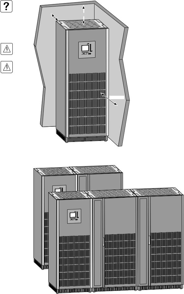
To ensure correct ventilation, leave nothing on top of the UPS.
Leave one meter of free space in front of the UPS for door opening.
The cabinet rests on four cylindrical feet, 40 mm in diameter, positioned in the four corners of the cabinet to spread the weight.
If 500 mm of free space is not maintained above the UPS, abnormal temperature rise may occur.
The UPS must be installed in a room with restricted access (qualified personnel only).
(*) The UPS can operate correctly back to the wall, but it is preferable to leave some space for easier maintenance.
2.2 Layout of cabinets
UPS cabinet
~
?
 UPS cabinet
~
?
Battery cabinet
|
Battery cabinet 1 |
Battery cabinet 2 |
34001813EN/AE — Page 12
2. Installation
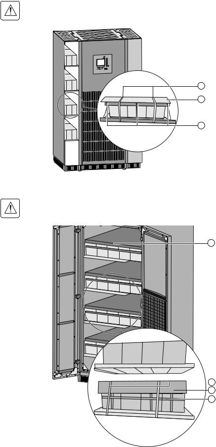
2.3 Removing the cardboard protecting the batteries
In the UPS
The cardboard protecting the batteries must always be removed once the equipment is installed in its final location.
1 — Remove the ties holding the cardboard (1).
2 — Remove the cardboard (2).
3 — Remove the struts (3).
1
2
3
In the external battery cabinet
The cardboard protecting the batteries must always be removed once the equipment is installed in its final location.
|
1 |
— Remove the battery support upright (1). |
|
|
1 |
2 — Remove the ties holding the cardboard (2) |
|
|
(1000 mm external battery cabinet). |
||
|
3 |
— Remove the cardboard protecting the |
|
|
batteries (3). |
||
|
4 |
— Remove the ties holding the batteries (4). |


 2
2
 3
3
4
34001813EN/AE — Page 13

2. Installation
2.4 Required protective devices and cable sizes
Recommended upstream protection
|
UPS |
Upstream circuit-breaker on |
Upstream circuit-breaker on |
Upstream circuit-breakers on |
|
power |
separate Normal AC input |
separate Bypass AC input |
common bypass and Normal AC |
|
rating |
input |
||
|
20 kVA |
C60L — 50 A |
NS100N 4P-TM100A |
NS100N 4P-TM100A |
|
30 kVA |
C60L — 63 A |
NS100N 4P-TM100A |
NS100N 4P-TM100A |
|
40 kVA |
NS100N 3P-TM80A |
NS100N 4P-TM100A |
NS100N 4P-TM100A |
|
60 kVA |
NS125E 3P-TM125A |
NS125E 4P-TM125A |
NS125E 4P-TM125A |
|
80 kVA |
NS160N 3P-TM160A |
NS160N 4P-TM160A |
NS160N 4P-TM160A |
|
100 kVA |
NS250N 3P-TM200A |
NS250N 4P-TM250A |
NS250N 4P-TM250A |
|
120 kVA |
NS250N 3P-TM250A |
NS250N 4P-TM250A |
NS250N 4P-TM250A |
The circuit breakers recommended above respect the requirements for discrimination with the UPS fuses
Stick a label with the following text on each upstream circuit breaker: «Isolate Uninterrptible Power Supply (UPS) before working on this circuit».
Recommended downstream protection
|
UPS power rating |
Downstream |
Trip unit |
Curve N for the downstream circuit breaker |
|
|
circuit breaker |
may be replaced by curve H or L, depending |
|||
|
on the installation. |
||||
|
20-30-40 kVA |
C60N |
C 16A |
||
|
The indicated protection ensures |
||||
|
C60N |
B 25A |
discrimination for each output circuit |
||
|
downstream of the UPS, whether supplied by |
||||
|
60 kVA |
C60N |
C 20A |
||
|
via the normal or the Bypass AC source. If |
||||
|
these recommendations are not followed, a |
||||
|
C60N |
B 32A |
|||
|
short-circuit on an output circuit can result in |
||||
|
80 kVA |
C60N |
C 25A |
a break in power longer than 20 milliseconds |
|
|
on all the other output circuits. |
||||
|
C60N |
B 50A |
|||
|
100-120 kVA |
C60N |
C 32A |
||
|
C120N |
B 63A |
|||
|
NS100 |
TMG 50A |
|||
Note. See the simplified diagrams in the appendix for common or separate AC inputs, indicating the positions of the protection devices, the characteristics of the internal UPS fuses and UPS line currents under overload conditions.
Earth-leakage current
UPS earth-leakage current is 1 A.
34001813EN/AE — Page 14

2. Installation
Required cable sizes
Cable sizes are determined for copper conductors (for aluminium conductors, increase the size by 30%). Size calculations also take into account a voltage of 400 V and grouping of four cables.
|
UPS power |
Minimum sizes for |
Minimum sizes for |
Minimum sizes |
Minimum sizes |
Battery/terminal |
|
rating |
separate Normal AC |
separate Bypass |
for common |
for copper load- |
connection |
|
input copper cables |
AC input copper |
bypass and |
circuit cables |
(<15 m) |
|
|
(<100 m) |
cables (<100 m) |
Normal AC input |
(<100 m) |
||
|
copper cables |
|||||
|
(<100 m) |
|||||
|
20 kVA |
10 mm2 |
16 mm2 |
16 mm2 |
16 mm2 |
16 mm2 |
|
30 kVA |
16 mm2 |
16 mm2 |
16 mm2 |
16 mm2 |
25 mm2 |
|
40 kVA |
16 mm2 |
16 mm2 |
16 mm2 |
16 mm2 |
35 mm2 |
|
60 kVA |
25 mm2 |
25 mm2 |
25 mm2 |
25 mm2 |
70 mm2 |
|
80 kVA |
50 mm2 |
50 mm2 |
50 mm2 |
50 mm2 |
95 mm2 |
|
100 kVA |
50 mm2 |
70 mm2 |
70 mm2 |
70 mm2 |
2 x 50 mm2 |
|
120 kVA |
70 mm2 |
70 mm2 |
70 mm2 |
70 mm2 |
2 x 70 mm2 |
Connections are made to pre-drilled terminals.
Hole diameter: 6.5 mm (8.5 mm for 120 kVA).
Earthing cables connect to the earthing plate.
Hole diameter: 6.5 mm (8.5 mm for 120 kVA).
34001813EN/AE — Page 15
2. Installation
Required cable sizes for parallel UPS installations with an external bypass
|
Rated |
Number of |
Total rated |
Bypass AC |
Cable |
|
power of |
parallel |
power of |
input or |
size(1) |
|
each UPS |
UPS units |
the UPS |
load line |
in mm2 |
|
unit |
current |
|||
|
20 kVA |
2 |
40 kVA |
58 A |
16 |
|
3 |
60 kVA |
87 A |
35 |
|
|
4 |
80 kVA |
116 A |
50 |
|
|
30 kVA |
2 |
60 kVA |
80 A |
25 |
|
3 |
90 kVA |
129 A |
50 |
|
|
4 |
120 kVA |
172 A |
70 |
|
|
40 kVA |
2 |
80 kVA |
116 A |
35 |
|
3 |
120 kVA |
174 A |
70 |
|
|
4 |
160 kVA |
232 A |
120 |
|
|
60 kVA |
2 |
120 kVA |
174 A |
70 |
|
3 |
180 kVA |
261 A |
150 |
|
|
4 |
240 kVA |
348 A |
185 |
|
|
80 kVA |
2 |
160 kVA |
232 A |
120 |
|
3 |
240 kVA |
348 A |
185 |
|
|
4 |
320 kVA |
464 A |
2 x 120 |
|
|
100 kVA |
2 |
200 kVA |
288 A |
150 |
|
3 |
300 kVA |
432 A |
2 x 95 |
|
|
4 |
400 kVA |
576 A |
2 x 150 |
|
|
120 kVA |
2 |
240 kVA |
348 A |
185 |
|
3 |
360 kVA |
522 A |
2 x 150 |
|
|
4 |
480 kVA |
696 A |
2 x 185 |
|
External bypass
The table opposite is an example for an installation with up to four UPS units.
For installations with redundant units, take into account only the number of units required to supply the loads (e.g. in a three-unit installation where one unit is redundant, only two units count in determining the input and load currents).
This table is valid for 400 V input and load phase-to-phase voltages, at rated load with a power factor of 0.8. For voltages of 380 or 415 V, multiply the current values by 1.05 or 0.96 respectively and, if necessary, modify the cable sizes accordingly.
The cable sizes in this table concern the bold sections in the diagram below.
(1) Cable sizes are determined for U1000 R02V type copper conductors (for aluminium conductors, increase the size by 30%). Size calculations also take into account a voltage of 400 V and grouping of four cables.
|
Bypass AC |
||
|
GALAXY 5000 |
||
|
Normal AC |
||
|
1 |
||
|
Bypass AC |
Bypass AC |
Load |
||
|
GALAXY 5000 |
||||
|
Normal AC |
||||
|
2 |
||||
|
Bypass AC |
||||
|
GALAXY 5000 |
||||
|
Normal AC |
||||
|
3 |
||||
34001813EN/AE — Page 16
2. Installation
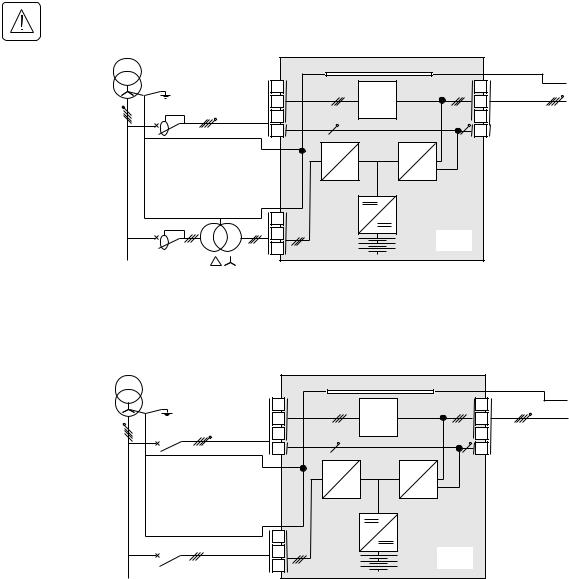
2.5 2.5 System earthing arrangements
This chapter lists the main system earthing arrangements and their wiring requirements. For system earthing arrangements which are not listed in this document, please refer to the “SEA guide” reference 34002636XT..
TNS upstream and TNS downstream installation
For separate Normal AC and Bypass AC lines from a single source.
With differential circuit breaker:
The Normal and Bypass AC lines must be galvanically isolated
Upstream differential protection rating must be at least 3A
|
PE |
PE |
|||
|
L1 |
L1 |
|||
|
L2 |
SS |
L2 |
||
|
L3 |
L3 |
Load |
||
|
Bypass AC |
N |
N |
||
|
PE |
PFC |
INV |
||
|
Normal AC |
L1 |
|||
|
L2 |
UPS |
|||
|
L3 |
||||
|
MLVS |
||||
Without differential circuit breaker: |
||||
|
PE |
PE |
|||
|
L1 |
L1 |
|||
|
L2 |
SS |
L2 |
||
|
Load |
||||
|
L3 |
L3 |
|||
|
Bypass AC |
N |
N |
||
|
PE |
PFC |
INV |
||
|
Normal AC |
L1 |
|||
|
L2 |
UPS |
|||
|
L3 |
||||
|
MLVS |
34001813EN/AE — Page 17
2. Installation
TNC upstream, TNS downstream
For separate Normal AC and Bypass AC lines from a single source
1.the UPS internal PEN bar must be connected to the Q4S neutral upstream of Q4S 2.The UPS internal PEN bar must be connected to the Q5N neutral downstream of Q5N
3.The UPS internal PE bar must be transformed into a PEN bar (cables supplied for TNC options)
|
PEN |
PE |
|||
|
L1 |
L1 |
|||
|
L2 |
SS |
L2 |
Load |
|
|
L3 |
L3 |
|||
|
Bypass AC |
N |
N |
||
|
PEN |
||||
|
PFC |
INV |
|||
|
PEN |
||||
|
Normal AC |
L1 |
|||
|
L2 |
UPS |
|||
|
L3 |
||||
MLVS
Installation with upstream IT and downstream TNS
For separate Normal AC and Bypass AC lines from a single source
|
PE |
PE |
|||
|
L1 |
L1 |
|||
|
L2 |
SS |
L2 |
||
|
R1 |
Load |
|||
|
L3 |
L3 |
|||
|
Bypass AC |
N |
N |
||
|
PFC |
INV |
|||
|
R2 |
CPI2 |
|||
|
Normal AC |
L1 |
|||
|
L2 |
UPS |
|||
|
L3 |
||||
|
MLVS |
||||
|
CPI |
Installation with upstream TT and downstream TT (with upstream differential protection)
For separate Normal AC and Bypass AC lines from the same source
The upstream differential protection rating must be at least 3A
|
PE |
||||
|
L1 |
L1 |
|||
|
L2 |
SS |
L2 |
||
|
L3 |
L3 |
Load |
||
|
Bypass AC |
N |
N |
||
|
PFC |
INV |
|||
|
Normal AC |
L1 |
|||
|
L2 |
UPS |
|||
|
L3 |
||||
MLVS
34001813EN/AE — Page 18
2. Installation
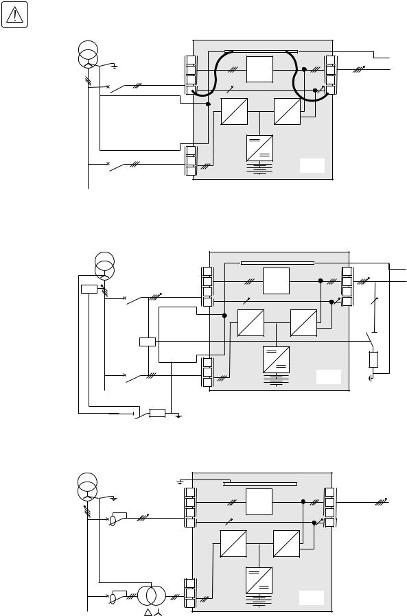
Frequency converter (without Bypass AC input)
The UPS installation may be equipped with earth-leakage protection upstream on the condition that the protection apply to:
—the normal and Bypass AC inputs
—all the parallel-connected UPSs.
Upstream and downstream: TT, TN or IT system with neutral distributed |
|||
|
Main low- |
15 |
||
|
voltage |
|||
|
switchboard |
|||
|
(MLVS) |
|||
|
16 |
14 |
Load |
|
|
Normal AC |
|||
Upstream and downstream: Neutral not distributed |
|||
|
Main low- |
15 |
||
|
voltage |
|||
|
switchboard |
|||
|
(MLVS) |
|||
|
16 |
14 |
Load |
|
|
Normal AC |
Parallel configuration without external bypass cabinet and with common normal and Bypass AC inputs (maximum two units in parallel)
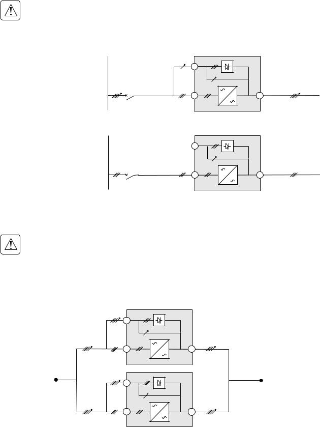
The UPS installation may be equipped with earth-leakage protection upstream on the condition that the protection apply to:
—the normal and Bypass AC inputs
—all the parallel-connected UPSs.
The requirements for the different system earthing arrangements (SEA) are similar to those for single UPS configurations. In the diagrams on page 17, simply replace the single UPS units between points A and B by the following parallel configuration.
A
Bypass AC
15
Normal AC
Bypass AC
15
B
34001813EN/AE — Page 19
2. Installation
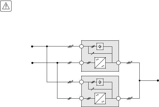
Parallel configuration without external bypass cabinet and with separate normal and Bypass AC inputs (maximum two units in parallel)
The UPS installation may be equipped with earth-leakage protection upstream on the condition that the protection apply to:
—the normal and Bypass AC inputs
—all the parallel-connected UPSs.
The requirements for the different system earthing arrangements (SEA) are similar to those for single UPS configurations. In the diagrams on page 18, simply replace the single UPS units between points A, B and C by the following parallel configuration.
|
Bypass AC |
|
|
15 |
|
|
16 |
14 |
|
Normal AC |
|
Bypass AC |
|
|
15 |
|
|
16 |
14 |
|
Normal AC |
C
34001813EN/AE — Page 20
![]()
2. Installation
Parallel UPS with external bypass cabinet and separate Normal and Bypass AC network inputs (6 UPS in parallel for 4PN)
The UPS installation may be equipped with earth-leakage protection upstream on the condition that the protection apply to:
—the normal and Bypass AC inputs
—all the parallel-connected UPSs.
The standard diagrams presented below may be adapted to your needs by qualified personnel.
The requirements for the different system earthing arrangements (SEA) are similar to those for single UPS configurations. In the diagrams on page 18, simply replace the single UPS units between points A, B and C by the following parallel configuration.
Q3BP
Q4S
A
|
Bypass AC |
|
|
15 |
|
|
16 |
14 |
|
Normal AC |
|
|
Bypass AC |
|
|
15 |
|
|
16 |
14 |
|
Normal AC |
|
|
Bypass AC |
|
|
15 |
|
|
16 |
14 |
|
Normal AC |
Connection for the Bypass AC input and the output cables to the external bypass cabinet must use cables having the same length and size to ensure correct balancing of the Bypass AC input currents.
34001813EN/AE — Page 21
 Loading…
Types of Manuals:
The main types of MGE UPS Systems Galaxy 5000 instructions:
- User guide — rules of useing and characteristics
- Service manual — repair, diagnostics, maintenance
- Operation manual — description of the main functions of equipment
Circuit Tester Instructions by MGE UPS Systems:
-
IDEAL SureTest 61-164
#61-165GFCIAFCI RMSTrueSureeTstSureTest®Circuit Analyzer#61-164#61-165IntroductionUtilizing patented technology, the SureTest® circuit analyzers “look behind walls” to identify wiring problems that can lead to personal shock hazards, electrical fires, or equipment performance issues. Personal shock hazards stem f …
SureTest 61-164 Measuring Instruments, 48
-
Greenlee LT-100
999 3293.8 © 1999 Greenlee Textron IM 1431 8/99LT-100LAMP TESTERPROBADOR DEBOMBILLASELÉCTRICASVERIFICATEURD’AMPOULEINSTRUCTION MANUALMANUAL DE INSTRUCCIONESMANUEL D’INSTRUCTIONSRead and understand all of the instructions and safetyinformation in this manual before operating or servicing this tool.Lea y entienda t …
LT-100 Circuit Tester, 32
-
Greenlee 5708
999 3261.0 © 2000 Greenlee Textron IM 1405 1/005708 • 5708-IGFCI AND CIRCUITTESTERSVERIFICADORESDE CIRCUITO Y GFCIVERIFICATEURDE CIRCUITS ETDE DISJONCTEURSDIFFERENTIELSINSTRUCTION MANUALMANUAL DE INSTRUCCIONESMANUEL D’INSTRUCTIONSRead and understand all of the instructions and safetyinformation in this manual befo …
5708 Circuit Tester, 32
-
Fluke 6500
6500 Appliance Tester Users Manual PN 2141150 April 2005, Rev 2 12/06 © 2005 Fluke Corporation, All rights reserved. Printed in EU All product names are trademarks of their respective companies. …
6500 Circuit Tester, 44
-
ABB SACE Emax 2
Doc. N.° 1SDH002037A1001 — ECN000108222 — Rev. CEmax 2Attenzione Istruzioni riguardanti il solo assemblaggio del kit di retrotitting, non sono da intendersi come sostitutive del manuale di installazione, uso e manutenzione del nuovo interruttore Emax 2.- Mettere fuori servizio il quadro ospitante- Portare …
SACE Emax 2 Industrial Electrical, 27
-
ABB SACE Emax 2
Il presente kit di terminali, consente la sostituzione totale di interruttoriaperti Entelliguard G Envelope 1, Envelope 2 e Envelope 3 con interruttori aperti in esecuzione estraibile di più moderna fattura tipo Emax 2di medesima taglia, senza dover eseguire alcuna modifica alle parti attive del quadro.E’ garant …
SACE Emax 2 Circuit breakers, 24