
-
Contents
-
Table of Contents
-
Bookmarks
Quick Links
I
M
NSTRUCTION
ANUAL
1M23N28302
Digital Proportional
R/C System
R
Related Manuals for FUTABA 4pls
Summary of Contents for FUTABA 4pls
-
Page 1
NSTRUCTION ANUAL 1M23N28302 Digital Proportional R/C System… -
Page 2
Thank you for purchasing a Futaba 4PLS-2.4GHz system. Before using your 4PLS-2.4GHz system, read this manual carefully in order to use your R/C set safely. After reading this manual, store it in a safe place. Application, Export, and Modification 1. This product may be used for models only. It is not intended for use in any application other than the control of models for hobby and recreational purposes. -
Page 3
You may contact your local recycling center for information on where to return the recycling in your area. Futaba Corporation of America’s involvement in this program is part of its commitment to protecting our environment and conserving natural re- sources. -
Page 4: Table Of Contents
Table Of Contents For Your Safety As Well As That Of Others ……8 Explanation of Symbols …………..8 2.4GHz System Precautions …………8 Receiver Mode Precautions …………8 Operation Precautions …………..9 Ni-MH/Ni-Cd Battery Handling Precautions ……10 Storage And Disposal Precautions ………..11 Other Precautions ……………11 Before Using …………..12 Features ………………12 Set Contents …………….14…
-
Page 5
Receiver Type Change & How To Link ……..30 Throttle Mode Check …………..33 Trims Initial Set-Up …………..33 Function Map …………..35 For Your Safety Operation Of Screen …………..35 As Well As Calling the menu screen …………35 That Of Others Selecting items on the menu screen ……..36 Value of each function and changing the set value ….36 Basic menu Japanese Katakana character display ….37 Before… -
Page 6
Dual ESC Mixing «DUAL ESC» ………..74 Special mixing used with Crawler and other 4WD type vehicles Gyro Mixing «GYRO MIX» …………76 Can be setting the Futaba car rate gyro. CPS Mixing «CPS MIX» …………..78 Controls the Futaba CPS-1 channel power switch. -
Page 7
Adjuster «ADJUSTER» …………..97 Steering wheel and throttle trigger correction Telemetry «TELEMETRY» …………107 Telemetry/ Log screen Map …………108 For Your Safety Telemetry Function ON/OFF ……….109 As Well As Telemetry Sensor Setting …………110 That Of Others Log Setting, Start/ Stop …………112 Log Data List …………….114 Before Reference ……………..115 Using… -
Page 8: For Your Safety As Well As That Of Others
Under other conditions, the set will not operate, or the specified performance will not be displayed even if it operates. In addition, it may cause servo trouble. Futaba will not be responsible for damage, etc. caused by combination with the products of other companies.
-
Page 9: Operation Precautions
Operation Precautions Warning Do not operate outdoors on rainy days, run through puddles of water or use when visibility is limited. Should any type of moisture (water or snow) enter any component of the system, erratic operation and loss of control may occur.
-
Page 10: Ni-Mh/Ni-Cd Battery Handling Precautions
Caution (Fail safe function) Before running (cruising), check the fail safe function. Check Method; Before starting the engine, check the fail safe function as follows: 1) Turn on the transmitter and receiver power switches. 2) Wait at least one minute, then turn off the transmitter power switch. (The transmitter automatically transfers the fail safe data to the receiver every minute.) 3) Check if the fail safe function moves the servos to the preset position when reception fails.
-
Page 11: Storage And Disposal Precautions
Always use only genuine Futaba transmitters, receivers, servos, ESCs (electronic speed con- trols), NiMH/NiCd batteries and other optional accessories. Futaba will not be responsible for problems caused by the use of other than genuine Futaba parts. Use the parts speci- fied in the instruction manual and catalog.
-
Page 12: Before Using
-Dual ESCs mixing for crawlers cars (DUAL ESC) ESC at the front and rear are controlled independently. -Gyro mixing (GYRO MIX) The sensitivity of Futaba car rate gyros can be adjusted from the T4PKSR. -CPS-1 mixing (CPS MIX) steering and throttle operation by switch only.
-
Page 13
-ESC-Link function (MC-LINK) This is a dedicated function which allows setting of the contents of the Link software which makes possible Futaba speed controller (ESC), MC950CR, MC850C, MC851C, MC602C, MC402CR, etc. variable frequency and other data changes by T4PLS. -Trigger position can be changed The position of the throttle trigger can be moved forward and backward. -
Page 14: Set Contents
Always use only genuine Futaba transmitters, receivers, servos, ESCs (electronic speed con- trols), NiMH, NiCd, Li-ion batteries and other optional accessories. Futaba will not be responsible for problems caused by the use of other than Futaba genuine parts. Use the parts speci- fied in the instruction manual and catalog.
-
Page 15: Transmittert4Pls
Transmitter T4PLS Nomenclature Antenna LCD screen Digital Trim1 (DT1) (default steering trim) Power&Display switch Digital Dial 1 (DL1) (default CH4) Edit buttons Steering wheel Digital Trim 2 (DT2) Slide switch (SW2) (default throttle trim) (default CH3) Push switch (SW1) Digital Trim 3 (DT3) (default dual rate) Digital Trim 4 (DT4) Grip Handle…
-
Page 16: Battery Replacement Method
Battery Replacement Method (4 AA Size Batteries) Load the four batteries in accordance with the po- Battery cover larity markings on the battery holder. Battery Replacement Method Remove the battery cover from the transmitter by sliding it in the direction of the arrow in the figure.
-
Page 17: When Using The Optional Battery
2 or 3 times to activate the battery. When using Futaba CR-2000 The HT5F1700B/1800B is 5-cells, so, when charging the HT- 5F1700B battery with Futaba CR-2000 charger, you have to use the RX output side. Over current protection The transmitter charging circuit is equipped with an over cur- rent protection circuit (1.0A).
-
Page 18: Low Battery Alarm
Because the low battery alarm voltage of a dry cell battery is different from that of a rechargeable battery pack (genuine Futaba option), the type of power source used must be set by system setting (P101).
-
Page 19: Power & Display Switch
Power & Display Switch The power switch and display switch of the T4PLS are integrated. In the PWR ON mode, radio waves are transmitted and in the DISP mode, model data, settings can be checked without transmitting radio waves. In addition, some setting menus may only be displayed in the DISP mode. DISP PWR ON Radio waves are not being transmitted…
-
Page 20: Display When Power Switch Is Turned On
Display when power switch is turned on Power switch turned on Battery voltage display Telemetry function :ON/OFF Receiver -> Transmitter: The reception strength is shown. Model number Model name (10 characters) ST :Steering trim display TH :Throttle trim display The current receiver mode is D/R :Steering D/R display displayed.
-
Page 21: Digital Trim Operation
Digital Trim Operation (Initial settings: DT1: Steering trim, DT2: Throttle trim,) Operating by the lever: Push the lever to the left or right (up or down) The current posi- tion is displayed on the LCD screen. Steering trim display Throttle trim display any farther.
-
Page 22: Mechanical Atl Adjustment
Mechanical ATL Adjustment Make this adjustment when you want to decrease the stroke of the brake (back) side of the throttle trigger for operation feel. Adjustment Using a 2.5mm hex wrench, adjust the trigger brake (reverse) stroke. (The screw moves the throttle trig- ger stopper.) rower.
-
Page 23: Trigger Slide Adjustment
Trigger Slide Adjustment The throttle trigger position can be moved forward and backward. Adjustment Using a 2.5mm hex wrench, loosen the trigger slide mounting screw by turning it slightly coun- terclockwise. Adjust so that the bottom Trigger slide Using a 2.5mm hex wrench, turn the trigger mark does not exceed mounting screw slide adjusting screw, and adjust the trigger…
-
Page 24: Receiver Terminology
Under other conditions, the set will not operate, or the specified performance will not be displayed even if it operates. In addition, it may cause trouble with servos and other equipment. Futaba will not be responsible for damage, etc. caused by combination with the products of other companies.
-
Page 25: Installation
Installation Receiver and Servo Connections Connect the receiver and servos as shown below. Connect and install the receiver and servos in accordance with «Installation Safety Precautions» on the next page. troller and servos separately. The receiver also depends on the set. Installation When An Electronic Speed Control Is Used Installation For Gas Powered Models Steering servo…
-
Page 26: Installation Safety Precautions
Installation Safety Precautions Warning Receiver (receiver antenna) Do not cut or bundle the receiver antenna wire. Do not bundle the receiver antenna wire together with the motor controller lead wire. Keep the receiver antenna wire at least 1cm away from motor, battery, and other wiring carrying heavy current. Install the receiver antenna holder as closely as possible to the receiver.
-
Page 27
Warning Connector Connections Be sure the receiver, servo, battery and connectors are fully and firmly connected. If vibration from the model causes a connector to work loose while the model is in operation, you may lose control . Servo Installation When you install the servos, always use the rubber grommets provided in servo hardware bags. -
Page 28
Warning Electronic Speed Control Install the heat sinks where they will not come in contact with aluminum, carbon fiber or other parts that conduct electricity. If the FET Amp (Electronic speed control) heat sinks touch other materials that conduct electricity a short circuit could occur. -
Page 29: Initial Set-Up
Initial Set-Up Preparations (Transmitter) Before setting the Transmitter functions, check and set items 1 to 4 below. (Display when power switch turned on) When the power switch is turned on, the currently selected model number is displayed. Check if this number is the model number you want to set-up. To change the model number, use the Model Select function (See page 39).
-
Page 30: Receiver Type Change & How To Link
If the receiver used and the RX type settings are different, change the RX type using the «RX MODE» function. Which RX type is set can be checked at the HOME screen. T-FHSS Normal speed T-FHSS High speed S-FHSS Normal speed S-FHSS High speed FHSS T-FH (NORM)
-
Page 31
*When using an FHSS (R603GF/R2004F, etc.) or S-FHSS(SFH) system (R2104GF, R204GF-E, etc.) receiver, after the end of setting up to here set the transmitter power switch to OFF and go to «Receivers other than T-FHSS» on P32. Bring the transmitter and receiver to within 50cm of each other (do not allow the antennae to touch) and turn on the receiver power. -
Page 32
Precaution: If there are many Futaba S-FHSS/FHSS systems turned on in close proximity to the R2104GF, your re- ceiver might not link to your transmitter. In this case, even if the receiver’s LED stays solid green, unfor- tunately the receiver might have established a link to one of other transmitters. -
Page 33: Throttle Mode Check
Throttle Mode Check The throttle servo travel can be set to 5:5 or 7:3 for throttle trigger operation as required by the throttle mode function (page 80). F5/B5 F7/B3 7 : 3 5 : 5 Forward side Brake side Forward side Brake side F5/B5 or F7/B3 Trims Initial Set-Up…
-
Page 34
— Steering dual rate (DT3) check At initial set-up, steering dual rate (D/R) is assigned to the DT3 lever, at the grip of the transmitter. Operate the DT3 and check if the D/R value displayed on the screen chang- es. After checking D/R, set the steering dual rate to 100%. — Throttle ATL (DT4) check At initial setting, throttle ATL (ATL) is assigned to to the DT4 lever, below the DT3. -
Page 35: Function Map
Function Map Operation of screen In this instruction manual, Edit Buttons are represented by the symbols shown below. The (JOG) button can be operated in the 4 directions up, down, left, and right. (JOG)button left (-) button (+) button (JOG)button right (JOG)button up (JOG)button down (JOG)button up, down, left or right…
-
Page 36: Selecting Items On The Menu Screen
Selecting items on the menu screen The item indicated by the reverse displayed cursor on the screen is selected. ure shown below is an example of the MENU 1 screen. However, movement of the cur- sor is the same at all the screens. For instance, if the (JOG) button is pressed when the cursor is at the end point (EPA) on the MENU 1 screen, the end point (END POINT) function setting screen appears.
-
Page 37: Basic Menu Japanese Katakana Character Display
Basic menu Japanese Katakana character display On the system menu, the basic menu screen shown below can be displayed in Japanese katakana characters. «KATAKANA» Alphabetic characters characters スピード SPEED TH A.B.S TH A.B.S アクセレーション TH ACCEL エンドポイント END POINT トリム TRIM リバース…
-
Page 38: Function List
Function list Function Description of function Page No abbreviation RX MODE P-29 Receiver type selection/linking with telemetry type T-FHSS system receiver MODEL Model memory call/ Model memory copy/ Model memory reset P-39 MDL NAME P-43 Model memory name set/modify, username set/modify REVERSE P-44 Servo operation reversing…
-
Page 39: Functions
Function Model «MODEL» Forty model data (data for 40 R/C cars) can be saved in the T4PLS transmitter. This menu selects the model, copies data between models. Model Menu Display The MENU 1 screen is displayed by (JOG) button up, down, left, or right operation at the HOME screen.
-
Page 40: Model Selection «Select
Model Selection «SELECT» Forty model data (model data for 40 R/C cars) can be saved in the 4PLS transmitter and used when the relevant model data is called. Using the model select function — Display the MODEL screen by referring to P39.
-
Page 41: Model Copy «Copy
Model Copy «COPY» The contents of the currently selected model data can be copied to another model. Using the model copy function — Display the MODEL screen by referring to P39. (Selection of model copy) Move the cursor to «COPY» by the (JOG) button up or down operation.
-
Page 42: Model Reset «Reset
Model Reset «RESET» This function resets and initializes the contents of the currently selected model data. However, the adjuster function (ADJUSTER), system setting (SYSTEM), and type of receiver mode (TYPE) are not initialized. Using the model reset function — Display the MODEL screen by referring to P39. (Selection of model reset) Move the cursor to «RESET»…
-
Page 43: Model Name «Mdl Name
Model Name «MDL NAME» This function allows you to assign a ten character name to each model memory and user name. Display to «MDL NAME» screen by the following method: (MENU 2 screen) (MENU 1 screen) (MDL NAME screen) (HOME screen) Model name User name Select…
-
Page 44: Servo Reverse «Reverse
Servo Reverse «REVERSE» (All channel) This function reverses the direction of operation of the servos related to transmitter steering, throttle, and channel 3 /4 operation. However, when the position set by trim or subtrim shifts from the center, the center becomes the opposite side. Display to «REVERSE»…
-
Page 45: Subtrim «Subtrim
Subtrim «SUBTRIM» (All channel) Use this function to adjust the neutral position of the steering, throttle, channel 3 and channel 4 servos. 90° *Subtrim adjusts the entire range of the servo in the set direction. Use to adjust the neutral position Display to «REVERSE»…
-
Page 46: End Point Adjuster «End Point
End Point Adjuster «END POINT» (All channel) Use this when performing left and right end point adjustments, throttle high side/ brake side operation amount adjustment, channel 3 and channel 4 servo up side/ down side operation amount adjustment during linkage. — Correct the maximum steering angle for left and right steering angles when there is a difference in the turning radius due to the characteristics, etc.
-
Page 47: End Point Adjustment
Display to «END POINT» screen by the following method: (MENU 2 screen) (MENU 1 screen) (END POINT screen) (HOME screen) Select «END POINT» Setting item selection (Steering and Throttle direction) — The direction (STR LFT and STR RGT) linked with the steering wheel is switched. — The direction (THR FWD and THR BRK) linked with the throttle trigger is switched.
-
Page 48: End Point Adjustment
Throttle (END POINT) adjustment (Preparation) — Before setting the throttle end point adjustment (END POINT), set the throttle ATL lever (initial setup: DT4) to the maximum throttle angle position 100%. — Select the setting item «FWD» by the (JOG) button up or down operation and make the following adjustments: (HOME screen) Throttle (forward side) adjustment…
-
Page 49: Fail Safe Function «Fail Safe
Fail Safe Function «FAIL SAFE» (All channel) Fail Safe Mode (F/S) This function moves each servo to a preset position when the receiver cannot receive the signals from the transmitter for some reason. -When the condition set at «FHSS» is Rx type (P29), fail safe (F/S) can be set only for throttle (TH). Other channels are set to the normal mode.
-
Page 50
Fail safe mode selection FAIL SAFE screen (Preparation) — Select the channels «MODE» to be set by the (JOG) button up, down, left, or right operation. (Mode selection) Select the mode by (+) or (-) button. (Each channel can be individually set.) When ending, move the cursor to [RT] by the (JOG) button, and return to the MENU1 screen by press- F/S mode… -
Page 51: Exponential Adjustment «Exp
Exponential Adjustment «EXP» (Steering/ Throttle system) This function is used to change the sensitivity of the servo around the neutral position. Display to «EXP» screen by the following method: (MENU 2 screen) (MENU 1 screen) (EXP screen) (HOME screen) Select «EXP» Setting item :Steering :Throttle forward side…
-
Page 52
FWD (Throttle Forward SideEXP)/ BRK (Throttle Brake Side EXP) This function makes the throttle forward side and brake side direction servo operation quicker or milder. It has no effect on the servo maximum operation amount. Advice When the course conditions are good and the surface has good grip, set each curve to the + side (quick side). -
Page 53
Throttle brake side EXP adjustment (Preparation) — On the EXP screen make the following adjustments: Select the setting item «BRK» by the (JOG) button up or down operation. Adjustment range Use the (+) button to adjust for a faster throttle response or -100 ~ 0 ~ +100% use the (-) button for a slower or milder throttle response. -
Page 54: Servo Speed «Speed
Servo Speed «SPEED» (Steering system) This function is used to change the servo speed. Display to «SPEED» screen by the following method: (MENU 2 screen) (MENU 1 screen) (SPEED screen) (HOME screen) Select «SEEED» Setting item STR TURN :Steering turn side STR RETN :Steering return side THR TURN…
-
Page 55
Steering Speed adjustment (Preparation) — On the SPEED screen make the following adjustments: «TURN» direction adjustment On the SPEED screen, Select the setting item STR «TURN» by the (JOG) button up or down operation and use the (+) or (-) Adjustment range 1~100% (each direction) buttons to adjust the delay amount. -
Page 56
THR (Throttle Speed) Sudden throttle trigger operation on a slippery road only causes the wheels to spin and the ve- hicle cannot accelerate smoothly. Setting the With «SPEED»: Quick start without skidding throttle speed function reduces wasteful battery consumption while at the same time permitting smooth, enjoyable operation. -
Page 57: Throttle Acceleration «Th Accel
Throttle Acceleration «TH ACCEL» (Throttle system) The servo will jump to the input position at its maximum possible speed. Unlike expo- nential, which adjusts the whole throttle movement into a curve, throttle acceleration simply «jumps» away from neutral and then leaves the remaining response linear. Operation — Operation near the throt- 100%…
-
Page 58
Throttle acceleration adjustment (Preparation) — On the TH ACCEL screen make the following adjustments: (Forward acceleration amount adjustment) Forward acceleration amount Select the setting item FWD «RATE» by the (FWD) (JOG) button up or down operation and use 0~100 the (+) and (-) buttons to adjust the accelera- Initial value: 0 tion amount. -
Page 59: A.b.s. Function «Th A.b.s
A.B.S. Function «TH A.B.S» (Throttle system) When the brakes are applied while cornering with a 4 Wheel Drive or other type of vehicle, understeer may occur. The genera- tion of understeer can be eliminated and corners can be smoothly cleared by using this function. Operation — When the brakes are applied, the throttle servo will pulse Without A.B.S.
-
Page 60
— DELY : Delay Sets the delay from brake operation to ABS operation. When set to 0%, the ABS func- tion is activated without any delay. At 50%, the ABS function is activated after a delay of approximately 1 second and at 100%, the ABS function is activated after a delay of approximately 2 seconds. -
Page 61
(Cycle speed adjustment) CYCL Select setting item «CYCL» by Cycle speed (CYCL) 1 ~ 30 the (JOG) button up or down Initial value: 10 operation. Use the (+) or (-) Adjustment buttons bu t t o n t o a d j u s t t h e p u l s e — Use the (+) and (-) buttons to make adjustments. -
Page 62
Fail Safe Unit When the T4PLS is used with the Futaba fail safe unit (FSU), it will operate as de- scribed below. However, FSU-1 cannot be used at the high speed mode. — When the FSU is connected to the throttle channel, and the A.B.S. function has been that the FSU responds to sudden data changes caused by A.B.S. -
Page 63: Channel3/4 «Ch3/Ch4
Channel3/4 «CH3/CH4» (3/4 channel) The channel 3/4 servo position can be set from the transmitter. When CH3 is as- signed to a dial by the switch dial function (p.65), this setting is linked to that dial. When CH3/4 is not assigned to a dial, it can be set with this screen. When CH3/4 is assigned to a switch by the switch dial function (p.65), you cannot adjust the CH3/4 via the screen.
-
Page 64: Steering Dual Rate/ Throttle Atl «D/R Atl
Steering Dual Rate/ Throttle ATL «D/R ATL» D/R (Steering dual rate) The steering left and right servo travels are adjusted simultaneously. This setting is linked to transmitter grip dial DT3. When DT3 is assigned another function, dual rate can be adjusted with this screen. ATL (Throttle ATL) This function decreases the set value when the braking effect is strong and increas- es the set value when the braking effect is weak.
-
Page 65: Select Switch Dial Function «Sw/ Dial
Select Switch Dial Function «SW/ DIAL» Selection of the function to be performed by digital trim (DT1, DT2, DT3, DT4) di- al (DL1) and switch (SW1, PS2). — The functions that can be assigned to dial, digital trim and switch are listed on the next page. — The dial and digital trim are step amount can be adjusted.
-
Page 66
Adjust button Function select switch setting Adjust with the (+) and (-) but- (Setting SW selection) tons. Select the SW you want to set by the (JOG) button up or SW1 function selection Direction of operation set- down operation. ting (Function setting) Select the function with the (+) or (-) button. -
Page 67
Set table functions (SW1) Abbreviation used on setup screen Function name, etc NT-BRK Neutral brake function ON/OFF A.B.S function ON/OFF IDLE Idle up function ON/OFF PRGMIX Program mixing function ON/OFF TH-OFF Throttle off (engine cut) function ON/OFF channel 3 channel 4 4WS MIX 4WS mixing type select TIMER… -
Page 68: Brake Mixing «Brake Mix
Brake Mixing «BRAKE MIX» (Throttle, 3rd /4th channel system) This function is used when the front and rear brakes must be adjusted independently such as a 1/5 scale GP car. This mixing uses the 2nd CH for the rear brakes and the 3rd or 4th CH for the front brakes, or controls the front brakes with the 3rd CH and 4th CH servos, or controls the 2nd CH by independent throttle and controls the rear and front brakes with the 3rd CH and 4th CH.
-
Page 69
Brake mixing adjustment (Brake mixing function ON/OFF) Function ON/OFF (MODE) Using the (JOG) button, select «MODE» of <CH3> for CH3 INH, ACT Select button brake and «MODE» of <CH4> for CH 4 brake. — Select with the (+) or (-) but- Use the (+) or (-) key and set the function to the «ACT»… -
Page 70: Programmable Mixing «Prog Mix
Programmable Mix «PROG MIX» (All channels) This function allows you to apply mixing between the steering, throttle, channel 3 and channel 4. Additional Functions -When the steering or throttle channel is the master channel (channel that applies mix- ing), trim data can be added. (Trim mode) — The mixing mode selection.
-
Page 71
(Master channel) Select setup item «MST» y the (JOG) button up or down operation, and select the master Channel selection (MST) STR, THR, CH3, CH4 channel by pressing the (+) or (-) button. Initial value :STR Select button — Select with the (+) or (-) but- These setup items are different de- tons. -
Page 72: 4Ws Mixing «4Ws
4WS Mixes «4WS» (Steering, 3rd channel system) This function can be used with crawlers and other 4WS type vehicles. It is mixing which uses the 1st CH to control the front side steering and the 3rd CH to control the rear side steering.
-
Page 73
(4WS type selection) < NO SW > Select the setting item «MODE» by the (JOG) I f f u n c t i o n ’s O N / O F F switch is not selected, button up or down operation. Use the (+) or <NO SW>… -
Page 74: Dual Esc Mixing «Dual Esc
Dual ESC mixing «DUAL ESC» (Throttle system) This function is mixing used with crawlers and other 4WD type vehicles and uses the 2nd CH to control the front motor controller and the 4th CH to control the rear motor controller. Front drive only, rear drive only, or both front and rear drive can be selected using any programmed DT (digital trim) button.
-
Page 75
The programmed DT button is used to select the drive type as shown in the figure below. Rear rate (RATE) 0 ~ 120 (Rear side travel adjustment) Initial value:100 Select the setting item «RATE» the (JOG) button up or down Adjustment buttons — Use the (+) and (-) buttons to operation. -
Page 76: Gyro Mixing «Gyro Mix
Gyro mixing «GYRO MIX» (Steering system) This function is a remote gain function which adjusts the sensitivity of the Futaba car rate gyro at the T4PLS side, and is mixing that uses the 3rd CH to adjust the gyro sensi- tivity.
-
Page 77
Setup items Gyro mixing adjustment MODE : Gyro mode (Preparation) NORM : Normal mode gain AVCS : AVCS mode gain — Refer to the gyro instruction manual and connect the gyro to the receiver. When using remote gain, connect gyro sensi- tivity adjustment to the 3rd CH of the receiver. -
Page 78: Cps Mixing «Cps Mix
CPS mixing «CPS MIX» This function controls the Futaba CPS-1 channel power switch. Normally, when using the CPS-1 unit to light the vehicle dress-up and other illumina- tion (LED) the CPS-1 unit with LED connected is connected to a vacant switch channel and the LEDs are turned on and off by switch while the vehicle is running.
-
Page 79
(Control system setup) Function selection (MODE) Operate the (JOG) button up and down and select the setting INH, CH4 FUNC, STR NTR, STR END, THR NT, THR FWD, item «CTRL». Use the (+) or (-) button and select the function. THR BRK, TH NT+BK Select button — Select with the (+) or (-) but-… -
Page 80: Throttle Mode «Th Mode
Throttle Mode «TH MODE» (Throttle system) This menu has the following 4 functions: — Servo neutral mode, which sets the throttle neutral ratio to 7:3 or 5:5 — Idle up, which raises the idling speed when starting the engine to improve engine start- ing performance of a gasoline car (boat) — Neutral brake, which applies the brakes at the neutral position of the throttle trigger — Throttle off (engine cut), which stops the engine of a boat, etc.
-
Page 81: Idle-Up «Idlup
Idle-Up «IDLUP» This is a function select switch dial function. The idle up ON/OFF switch must be set. (P65) This function is used to improve engine starting performance by raising the idling speed when starting the engine of a gasoline car (boat). It is also effective when you want to prevent the braking when the power was turned off during running, due to the effect of your gear ratio setting and choice of motor when operating an electric car.
-
Page 82: Neutral Brake «Ntbrk
Neutral brake «NTBRK» This is a function select switch dial function. The neutral brake function ON/OFF switch must be set. (P65) The neutral brake, which applies the brakes at the neutral position of the throttle trigger, set is in the operation mode before setting the neutral brake function switch to ON, the same as the idle up function (P81).
-
Page 83: Throttle Off (Engine Cut) «Thoff
Throttle off (engine cut) «THOFF» This is a function select switch dial function. The throttle off function ON/OFF switch must be set. The engine cut function stops the engine of a boat, etc. by operating the throttle servo to the slow side by switch regardless of the position of the throttle trigger and the setting of other functions (reverse function setting is effective).
-
Page 84: Esc Link Function «Mc Link
ESC Link Function «MC LINK» This is a special function which lets you set the contents of the Link software which performs Futaba speed controller (ESC), MC960CR, MC940CR, MC950CR, MC851C, MC602C, MC402CR, etc. variable frequency and other data changes at the T4PLS transmitter.
-
Page 85
-Select the setting item «MODE» by the (JOG) button, and select «READ» by (+) or (-) button. -Select the setting item «EXEC» by the (JOG) button, and press the (+) and (-) buttons simultaneously for 1 second or longer. -«COMPLETE!» blinks on the screen and the ESC type and currently set con- tents are read. -
Page 86
ESC function setup (MC601/602/850/851C, 401/402/950CR) Select the setting item by the (JOG) button. Setup item selection — Select by the (JOG) button. Set the value by (+) and (-) button. The currently set item is Adjustment buttons displayed here. — Use the (+) and (-) buttons to make adjustments. -
Page 87
LBP-(LOW BATTERY VOLT) 2.5V~6V DBA-(DEAD BAND) ±2μs~±50μs 2.5V~7.5V for MC950CR Same as Link software Dead Band. This sets the range (neutral point range) over which the Same as Link software Low Bat Protection ESC does not respond to transmitter throttle operation. This setting cuts off the output to the motor when The larger the set value, the wider this range. -
Page 88
ESC function setup (MC940CR, MC960CR) Setup item selection Select the setting item by the (JOG) button. — Select by the (JOG) button. Set the value by (+) and (-) button. Operate the following (JOG) button and switch between Adjustment buttons — Use the (+) and (-) buttons to Page1 and Page2 of the setup screen. -
Page 89
«MIn» which sets the frequency when the load is small, is set to the high frequency side (large value) when extension is desired after straight- aways and curves. «MAX» which sets the frequency when the load is large, is set to the high frequency side (large value) when you want to suppress the rise from low speed and when motor heating and commutator roughness are sensed. -
Page 90
Page1 TBM-(TURBO MODE) OFF /LEV1 /LEV2 Same as Link software Turbo Mode This function sets the turbo mode. More power can be displayed by using the turbo mode. Depending on the setting, the motor and ESC may be damaged so make this setting carefully. (Note) When LAU (LEAD ANGLE USE) is off, lead angle setting will not operate even if set to LEV1 or LEV2. -
Page 91
LAU-(LEAD ANGLE USE) ON /OFF Same as Link software Lead Angle Use This function is effective when TBM (Turbo Mode) is LEV1 or LEV2 and sets whether or not lead angle is used. This setting has priority over the TURBO MODE setting. When using in races in which the lead angle func- tion is inhibited by the ESC set this function to OFF. -
Page 92: Data Transfer «Mdl Trans
Data Transfer «MDL TRANS» This function copies the model memory data of one T4PLS to another T4PLS. Connect the communication port of both T4PLS with the optional DSC cord for T4PK. Use with this function with the T4PLS power switch at the display side. Note: If the T4PLS battery voltage drops, the display switches to low battery display.
-
Page 93
(Select the setting item ) «MODE» by the (JOG) button up or down op- Mode selection eration, and select the transfer side and re- «TRANSFER» «RECEIVE» ceive side by (+) or (-) button. Setup item selection — Select by (JOG) button up or down operation. -
Page 94: Timer Function «Timer
Timer Function «TIMER» Use the timer by selecting one of the three timers UP TIMER, DOWN TIMER, and LAP TIMER. Display » PTIMER » screen by the following method: (MENU 1 screen) (MENU 2 screen) (TH MODE screen) (HOME screen) Select «TIMER»…
-
Page 95
FUEL DOWN TIMER function Fuel down timer function — This function is primarily used to check the refueling time of a gasoline car. (The remaining time is displayed.) — Each time the switch is pressed, the timer is restarted and the set time is reset. -
Page 96
Timer screen Timer selection First, select the type of timer at the «TYPE» item. The setup screen varies depending on the type of timer. This figure shows the UP TIMER setup screen. Time display Minute display (m) Second display (s) 1/100 second display Status display RST :Reset state… -
Page 97
Using the up timer Adjustment buttons (Preparation) — Use the (+) and (-) buttons to Select the setting item «TYPE» by the (JOG) button. make adjustments. — Press the (+) and (-) buttons si- Press the (+) or (-) button and select «UP». multaneously (approx. -
Page 98
Using the fuel down timer Adjustment buttons (Preparation) — Use the (+) and (-) buttons to Select the setting item «TYPE» by the (JOG) button. make adjustments. — Press the (+) and (-) buttons si- Press the (+) or (-) button and select «DOWN». multaneously (approx. -
Page 99
Adjustment buttons Using the Lap timer — Use the (+) and (-) buttons to (Preparation) make adjustments. — Press the (+) and (-) buttons si- Select the setting item «TYPE» by the (JOG) button. multaneously (approx. 1 sec) to Press the (+) or (-) button and select «LAP». return to the HOME screen. -
Page 100: Lap List «Lap List
Lap List «LAP LIST» The lap list is displayed when checking the lap memory data (lap times) memorized by lap timer (P99) operation. — After the lap timer starts, the lap times are memorized sequentially each time the switch is operated. orized and the total time after the last lap is automatically written.
-
Page 101: System Functions «System
System Functions «SYSTEM» The graphic liquid crystal screen display mode, buzzer sound and menu character mode, etc can be set. — «CONTRA» Liquid crystal screen contrast adjustment (20 steps) — «BK-LHT» Liquid crystal screen backlighting display mode setup (OFF, ON at button operation, normally ON) — «LHT-TM»…
-
Page 102
Adjustment buttons System function setup — Use the (+) and (-) buttons to (Setting of each item) make adjustments. — Press the (+) and (-) buttons si- multaneously (approx. 1 sec) to (Adjusting the liquid crystal contrast) return to the initial value. Select the setting item «CONTRA»… -
Page 103
Note: If used with the incorrect setting, a normal low battery alarm will not be gen- erated and the system may stop before the battery alarm is generated. The usage time may also become extremely short. «N5/L2» :Futaba LiFe type battery (FT2F1700B/2100B) «N5/L2» :Futaba MiMH type battery (HT5F1800B) «DRY4″… -
Page 104
(Changing the power off forgotten alarm setting) Select the setting item «OPE-TM» by the (JOG) button, and use the (+) and (-) buttons to select the power off forgotten alarm mode. The power off forgotten alarm «10m» :If an operation is not performed within 10 min- (OPE-TM) utes while the power is on, an audible alarm 10m, OFF… -
Page 105: Adjuster «Adjuster
If an adjustment point is not within a fixed range, correction is not performed and the correction data is not updated. When button mark is not displayed even though correction was performed again, please contact a Futaba Radio Control fig-4 Customer Center.
-
Page 106
If an adjustment point is not within a fixed range, correction is not performed and the correction data is not updated. When button mark is not displayed even though correction was performed again, please contact a Futaba Radio Control Customer Center. fig-4 When ending, return to the MENU2 screen by pressing the (JOG) button. -
Page 107: Telemetry «Telemetry
Telemetry «TELEMETRY» With the telemetry system, the running status can be displayed at the transmitter and al- so recorded as a data log by mounting various sensor units to the chassis. The telemetry related screens are only displayed when the T4PLS power switch is in the PWR ON position.
-
Page 108: Telemetry/Log Screen Map
Telemetry/Log Screen Map (HOME screen) (Telemetry Function ON/OFF Screen) p.109 The cursor on [RT] The cursor on [RT] (Sensor Set Screen) p.110 (Log Data Screen) (Log Set Screen) Telemetry «TELEMETRY»…
-
Page 109: Telemetry Function On/Off
Telemetry Function ON/OFF The telemetry data can be viewed at the HOME screen and telemetry ON/OFF screen. The telemetry function can also be turned on and off at the telemetry ON/OFF screen. The telemetry ON/OFF and communication status can be checked at the HOME screen. The reception strength High No signal reception…
-
Page 110: Telemetry Sensor Setting
Telemetry Sensor Setting An audible alarm can be generated by the T4PLS from the data from a telemetry sensor. This setting sets alarm ON/OFF and the alarm conditions. Refer to the map on page 108 for the sensor setting (SENS MODE) screen display. There are receiver power source (battery) voltage and external power source (drive bat- tery) voltage settings on page 1 of the sensor setting screen and temperature and speed settings on page 2.
-
Page 111
Setting external power supply voltage alarm Display page 1 by (JOG) button left or right operation. Alarm ON/OFF Select «ALRM» of the «EXT VOLT» setting ON, OFF — Select with the (+) or (-) but- items by (JOG) button up or down operation, tons. -
Page 112: Log Setting Start/Stop
Setting the gear ratio Display page 2 by (JOG) button left or right operation. Select «RATIO» of the «R.P.M» set- ting items by (JOG) button up or down opera- Gear ratio (moderating ratio) tion, and set the location the sensor is to actu- 0.001~64 Initial value: 1 ally measure and the gear ratio of the motor…
-
Page 113
Log recording cycle (Recording cycle setting) 0.1~60s( Select the «CYCL» setting item by (JOG) but- 0.1~10s( )0.1s step ton up or down operation, and set the data ac- 10s~60s(sec)1s step Initial value: 1.0 quisition interval from a minimum 0.1 second Adjust button to a maximum 60 seconds with the (+) button — Adjust with the (+) and (-) but-… -
Page 114: Log Data List
Log Data List The log data list can be called when checking the log data memorized by logging opera- tion (P112). The maximum log data is up to 200 counts. Refer to the map on page 108 for the log list screen. Example: Receiver power supply voltage log list screen.
-
Page 115: Reference
Under other conditions, the set will not operate, or the specified performance will not be displayed even if it operates. In addition, it may cause servo trouble. Futaba will not be responsible for damage, etc. caused by combination with the products of other companies.
-
Page 116: Warning Displays
Tone will sound (9 times), then repeat. Warning When a backup error is generated, immediately stop using the system and request repair from the Futaba Service Center. If you continue to use the system, the transmitter may malfunction and cause loss of control Low Battery Alarm…
-
Page 117
Memory Error LCD screen: — To stop the alarm, turn off the power. — Turn the power back on. If the alarm is not generated again, there is no problem. Audible alarm: Tone sounds (7 times) and stops (repeated) MIX Warning LCD screen: Audible alarm: Tone sounds (7 times) and stops (repeated) -
Page 118: Optional Parts
Optional Parts Transmitter Battery Part name When requesting repair (Information needed for repair) (Warranty)
-
Page 119
Federal Communications Commission Interference Statement (for U.S.A.) Compliance Information Statement (for U.S.A.) CAUTION: Exposure to Radio Frequency Radiation… -
Page 120
While this manual has been carefully written, there may be inadvertent errors or omissions. Please contact our service center if you feel that any corrections or clarifications should be made. 1M23N24105 ©FUTABA CORPORATION 2013, 04…
Корпорация Футаба, Futaba Corporation — японская компания, основанная в 1948 году для производства электронных ламп. Шло время, производилось и элементарно. Их официальный webсайт Футаба.com.
Каталог руководств пользователя и инструкций для продуктов Futaba можно найти ниже. Продукция Futaba запатентована и зарегистрирована под торговой маркой Корпорация Футаба.
Контактная информация:
Поиск
Откройте для себя систему двунаправленной связи Futaba R7314SB ASSTest-2.4 ГГц. Этот надежный приемник поддерживает систему двойной связи Rx и датчики телеметрии, предлагая расширенные возможности мониторинга. Узнайте, как отключить передачу данных телеметрии и настроить несколько приемников для повышения безопасности. Получите максимальную отдачу от своих AZPR7214SB-24G и R7214SB-24G с помощью этого подробного руководства пользователя.
Узнайте, как использовать систему двунаправленной связи Futaba R7214SB FASSTest-2.4 ГГц, следуя пошаговым инструкциям, приведенным в данном руководстве пользователя. Откройте для себя возможности этого совместимого приемника, такие как двусторонняя связь и датчики телеметрии. Узнайте, как перейти на систему Dual Rx Link для дополнительной безопасности. Защитите приемник от вибрации и влаги, соблюдая важные меры предосторожности при использовании. Отключите передачу телеметрии или включите режим FASSTest12CH Telemetry OFF, выполнив простые действия.
Кодер S.BUS 1M23N25701 SBE-1 представляет собой преобразователь, используемый для подключения гироскопа CGY750 или другого приемника S-BUS к обычной системе. Легко конвертируйте до 10 каналов в сигналы S.BUS. Прочтите руководство, чтобы узнать об инструкциях и мерах предосторожности. Надежное решение Futaba для радиоуправляемых систем.
Узнайте, как эффективно использовать адаптер телеметрии SBS-01ML для Pixhawk, из нашего подробного руководства по эксплуатации. Монитор заряда батареиtage, воздушная скорость, высота и многое другое с этим датчиком, совместимым с Futaba. Обеспечьте правильную установку и меры предосторожности для оптимальной работы. Скачать инструкцию с Futaba webсайт для получения дополнительной информации и обновлений.
Откройте для себя всю необходимую информацию о 553-осевом гироскопе GYA32 T3MZ в этом подробном руководстве пользователя. Узнайте о режимах работы гироскопа, настройках усиления, версии программного обеспечения, емкости батареи.tage, тип крыла, выбор типа сервопривода и направление гироскопа для плавного и безаварийного полета. Обеспечьте правильную настройку и нейтральное положение ваших сервоприводов и избегайте несчастных случаев. Загрузите сейчас для получения подробных инструкций.
Откройте для себя руководство пользователя SkyLeaf Samba f Electric RC Airplane, содержащее важную информацию о модели Futaba. Обеспечьте безопасное использование с инструкциями по сборке, мерам предосторожности и техническому обслуживанию. Получите максимальное удовольствие и избегайте опасных условий с авторизованными модификациями.
Узнайте, как использовать инструмент копирования данных GY701/CGY750V2.0 для хранения и передачи данных настроек между вашим ПК и GY701 или CGY750V2.0. Совместимость с версиями прошивки GY701 версии 1.10 или выше и CGY750 версии 2.00 или выше.
Узнайте, как обновить программное обеспечение T8FG (номер модели: 1M23Z01302) с помощью этого пошагового руководства пользователя. Отформатируйте SD-карту, создайте необходимые files и обновите программное обеспечение вашего Futaba T8FG. Завершите процесс легко и эффективно для достижения оптимальной производительности.
Узнайте, как использовать приемник FASSTest Futaba R7208SB 2.4 ГГц, из нашего подробного руководства пользователя. Откройте для себя его функции, включая двунаправленную связь и систему Dual Rx Link. Следуйте пошаговым инструкциям по настройке и мерам предосторожности, чтобы обеспечить оптимальную производительность.
Узнайте, как обновить программное обеспечение Futaba R7208SB и R7308SB, с помощью этого подробного руководства пользователя. Загрузите необходимое программное обеспечение с их webсайт и следуйте пошаговым инструкциям. Получите максимум от своих продуктов Futaba!
|
10 898 торговых марок |
Diplodocs позволяет скачать несколько типов инструкций для наилучшего использования изделий FUTABA. |

|
Поиск торговой марки Расширенный поиск Вам требуется помощь по использованию изделия?
Где моя инструкция?
Все инструкции по категориям |
Вы можете скачать с сайта Diplodocs инструкцию FUTABA в формате PDF.Введите модель изделия FUTABA…
|
 Новые инструкции для FUTABA
| Часто задаваемые вопросы | Свяжитесь с командой Diplodocs | Недавно искали… Последние поступления |
Карта сайта | |||||||||
|
Торговые марки на букву A B C D E F G H I J K L M N O P Q R S T U V W X Y Z # |
Copyright © 2005 — 2012 — Diplodocs —
Все права защищены.
Торговые марки принадлежат их соответствующим владельцам.
Скачать инструкцию
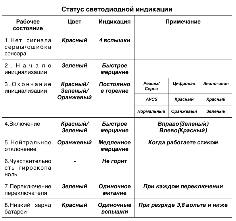
Перед использованием этого гироскопа, пожалуйста, внимательно прочтите данное руководство, чтобы использовать гироскоп правильно и безопасно. После прочтения данного руководства, храните его в надежном месте.
• Никакая часть этого руководства не может быть воспроизведена в любой форме без предварительного разрешения.
• Содержание этого руководства может быть изменено без предварительного уведомления.
• Futaba не несет ответственности за возможный ущерб, (случайный или нет)
который может возникнуть после установки.
Особенности GYA431
● Специализированная стабилизация самолета
Стабилизирует полет, даже сложно управляемых моделей копий.
● Совместимость с элеронами или рулем высоты
GYA431 может быть использована у самолетов с сервоприводами, установленными в каждом крыле. (только S.BUS)
● Функция удаленного управления
Функция удаленного управления позволяет регулировать чувствительность гироскопа и переключать режимы между AVCS/Нормальным, прямо с передатчика. Кроме того, чувствительность можно регулировать триммером на GYA431.
● Интегрированный тип, компактные размеры и небольшой вес
Высокая плотность монтажа делает GYA431 компактным (20,5 х 20,5 х
11 мм) и легким (3,5 г).
● Простая настройка
Базовые настройки обеспечивают готовность к полету сразу после установки.
● Поддержка S.BUS/S.BUS2
Подключение к приемнику только одним проводом.
Благодарим Вас за покупку авиагироскопа GYA431 . Компактный и
легкий, GYA431 предназначен для управления элеронами (ось крена) или
рулем высоты (ось тангажа). Легко настраивается и работает с S.BUS/S.BUS2.
Характеристики GYA431:
(Встроенный датчик гироскопа)
• Датчик гироскопа: MEMS гироскоп с вибрирующей структурой
• Рабочее напряжение: постоянный ток от 4.0V до 8.4V
• Потребляемый ток: 30 мА (без сервопривода)
• Диапазон рабочих температур: от -10 º C до +45 º C
• Размеры: 20,5 х 20,5 х 11,0 мм (за исключением выступа)
• Вес: 3,5 г
- Функции: (1) триммер чувствительности гироскопа, (2) Светодиодная индикация, (3) совместимость с двумя сервоприводами, (4) S.BUS/S.BUS2 совместимость, (5) работа с цифровыми/аналоговыми сервоприводами
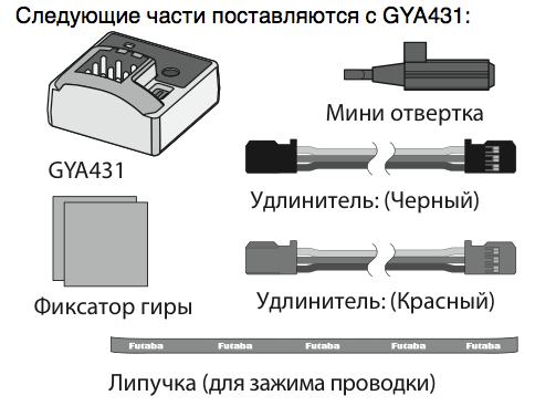
В комплект входит
Следующие части поставляются с GYA431:
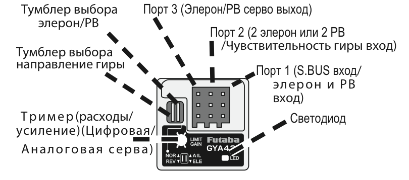
Название и функции каждой части
Предупреждение
Несоблюдение этих мер предосторожности может привести к серьезным травмам Вас и окружающих.
Проверьте, достаточно ли емкости батареи передатчика для полета.
- Определите время работы приемника , гироскопа и сервомоторов от батареи для определения количества полетов, расчеты делайте с запасом.
Аналоговые сервоприводы не могут быть использованы при включенном режиме «цифровой сервопривод».
• Аналоговые сервоприводы могут выйти из строя , если подключены в режиме «цифровой сервопривод».
Не трогайте самолет и ручки управления передатчика около
3-5 секунд после включения GYA431 (когда идет совмещение с приемником).
• GYA431 инициализируется и определяет нейтральную позицию. GYA431 инициализируется при включении питания . В режиме AVCS , нейтральное положение определяется так же. Если инициализация завершается нормально , вы увидите два повторяющихся движений серв влево и вправо.
Всегда проверяйте направление работы гироскопа.
•Попытка летать в обратном направлении крайне опасна. Всегда проверяйте направление работы вашего гироскопа для обеспечения безопасных полетов.
Не стучите гироскопом о твердые предметы. Не бросайте его на бетонную или любую другую твердую поверхность.
• Датчик может быть поврежден во время сильных воздействий.
Не используйте тримирование или микширование в режиме AVCS .
• В режиме AVCS все поправки делаются гироскопом. Поэтому, если тримирование и микширование, включены, действия будут такими же, как отклонение от нейтрального положения.
Используйте GYA431 для радиоуправляемых самолетов.
- Данный гироскоп предназначен только для RC самолетов. Не используйте его для других устройств.
Подключение
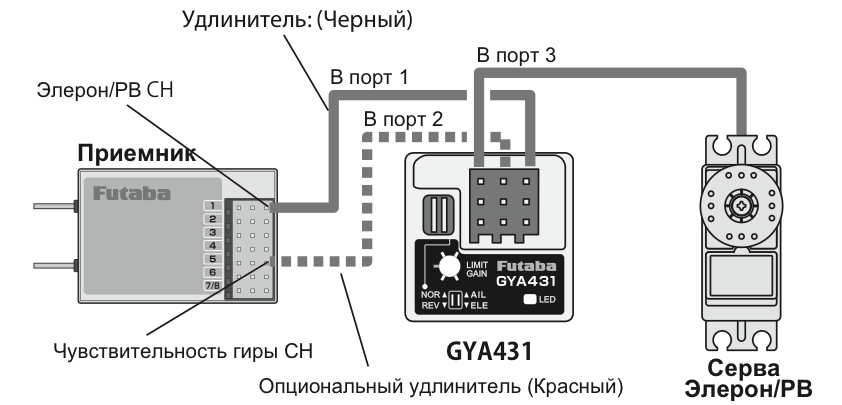
Канал порта гиры(рессивер)←подключен→Порт 2(GYA431)
Дистанционное изменение эффективности работает. Становиться активным тример расходов(GYA431)
Канал порта гиры(рессивер)←не подключен→Порт 2(GYA431) Дистанционное изменение эффективности не работает. Становиться активным тример усиления(GYA431)
*Только S.BUS совместимый сервопривод.
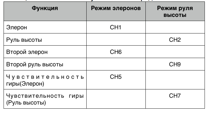
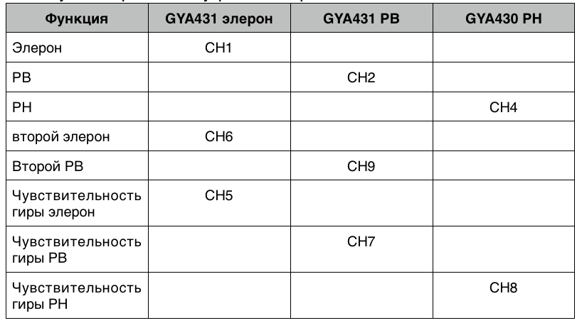
При операции S.BUS/S.BUS2 каналы устанавливаются как показано в таблице ниже. Соответствует каналам передатчика к ним.
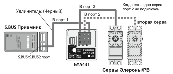
Пример подключения по трем осям S.Bus
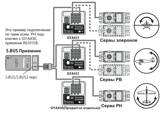
S.BUS соединение делает проводку предельно простой. GYA430 и GYA431 могут быть соединены одним 3-полосным концентратором. Сервоприводы элеронов, руля высоты и руля направления выводятся из гироскопа. Сервоприводы без поддержки S.BUS также могут быть использованы. Когда используется R6303SB выбирайте режим каналов 7CH. При этом 7CH выходы CH3, CH11, CH12. Канал CH3 является каналом газа, а CH11 и CH12 являются запасными каналами.
Параметры функции передатчика, показаны ниже. В общей сложности 9 каналов используются с тремя осями управления гироскопом.
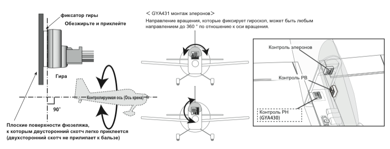
Монтаж
Гироскоп очень чувствителен к вибрации. Надежно закрепите его поставляемым в комплекте вспененным двустороннем скотчем, в месте, где вибрация минимальна и гироскоп, перпендикулярен контролируемой оси. Скотч не будет прилипать к бальзе, поэтому предварительно необходимо сделать гладкую площадку, вклеить пластик например. Уложить и зафиксировать липучкой (в комплекте) свободную проводку, чтобы она не мешала работе гиры.
Сервомоторы
Подключите сервомоторы в соответствии с инструкцией. Уложите проводку как можно аккуратней, чтобы не было не закрепленных участков.
Направление работы второго сервопривода:
во время работы второй сервопривод элеронов движется в том же направлении, что и первый. В режиме РВ, второй сервопривода движется в противоположном направлении первого.
Выбор цифровых, либо аналоговых сервомоторов.
Выбор между аналоговым и цифровым типом серв выполняется положением регулятора расходов.
Это работает следующим образом.
Цифровая серва → регулятор вращаем вправо от средней точки.
Аналоговая серва→ регулятор вращаем влево от средней точки.
Количество лимитов — промежуточная точка — минимум — максимум, если повернуть соответственно на МАХ. Выбранный режим подтверждается соответствующим цветом светодиода. Стабильность в полете при использовании цифровых серв увеличивается, из-за их более быстрой работы.
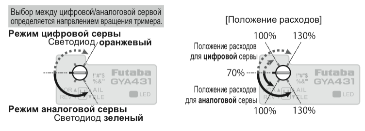
Если функция дистанционного усиления отключена, то доступен только режим аналоговой сервы. Тример начинает работает в режиме регулировки усиления.
(Использование цифрового сервомотора возможно),
- Когда вы используете аналоговый сервомотор, пожалуйста будьте уверенны, что установили аналоговый режим работы гиры. Если установить режим цифрового сервомотора, а управлять аналоговой сервой , есть опасность, что сервомотор будет разрушен.
Предполетная настройка
Настройка перед полетом [Удаленное использование усиления]
Регулировка чувствительности гироскопа с передатчика.
При подключении гиры по S.BUS или через 2 порт гиры, чувствительность гироскопа подключается на канал приемника.
- Используйте тумблер элерон/руль высоты, чтобы выбрать элерон или руль высоты. (Элерон: AIL Руль высоты: ELE)
- Включите питание своего передатчика. Установите чувствительность гироскопа приблизительно на 50% в нормальную сторону, в соответствии с инструкцией передатчика. 50% нормальной чувствительности составят 70% по курсу канала чувствительности, см. график ниже.
Чувствительности гиры ноль — Светодиод не горит
AVCS режим — красный светодиод
NORMAL режим — зеленый светодиод
- Включите питание приемника. Когда на гироскопе начинает мигать зеленый светодиод, инициализация начинается. По завершению инициализации сервопривод выполняет возвратно-поступательное движение влево и вправо. Это говорит о том, что гироскоп в состоянии готовности. Во время инициализации обеспечьте неподвижность фюзеляжа и нейтральное положение стиков передатчика. Инициализация занимает около 3-5 секунд после включения приемника. После инициализации индикатор будет светиться зеленым. Если нейтральное положение изменилось, светодиод будет гореть оранжевым цветом. В этом случае перезагрузите гироскоп. Пошевелите стиками и убедитесь, что сервы работают.
- Переместите ручки управления максимально в лево и право и отрегулируйте триммер лимитов гироскопа, так чтобы рабочий угол серво находился на максимальном положении, ни чего не задевая.
Коректировка лимитов тримером
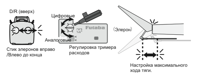
- Процесс тримирования
*Регулируйте тример осторожно, входящей в комплект отверткой.
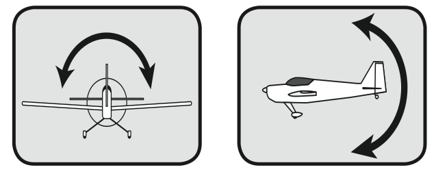
- В случае контроля за элеронами переключи выключатель управления гироскопом и настрой гироскоп так, чтобы элероны переместились полностью направо, когда самолет наклонен налево. В случае контроля за рулем высоты переключи выключатель управления гироскопом и настрой гироскоп так, чтобы руль высоты полностью отклонялся вниз, когда хвост самолета был поднят вверх. Если настройки работы гироскопа будет неправильными, то полет станет невозможным, необходима правильная настройка.
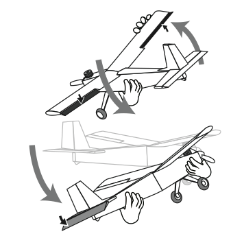
Находясь на земле, наклони самолет налево и проверь, что элероны отклоняются направо. (В случае контроля за элеронами)
Находясь на земле, наклони самолет вверх и проверь, что руль высоты отклонился вниз. (В случае контроля за рулем высоты)
[Когда функция дистанционного усиления выключена]
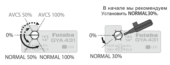
Регулировка чувствительности гироскопа с GYA431 триммером.
Не используйте в AVCS режиме.
Удаленное усиление работает при S.BUS подключении. Когда порт 2 не подключен, когда S.BUS не используется, дистанционное усиление выключено. В этом случае триммер лимитов автоматически меняется на триммер установки чувствительности.(Конечные положения фиксируется на 55 градусов в лево и в право. Управление сервой устанавливается в аналоговый режим.)
*В этом случае шаг 2 по чувствительности и шаг 4 по регулировки лимитов, будут исключены. И, как показано на рисунке, усиление регулируется триммером GYA431.
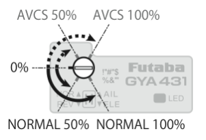
<Работа тримера усиления>
Чувствительность гироскопа и переключение AVCS
Когда дистанционная функция усиления включена в нормальном и AVCS режиме, настройка осуществляется в соответствии с направлением работы передатчика по каналу удаленного усиления. Поворот в сторону +, выбирает AVCS режим, а в сторону – выбирает НОРМАЛЬНЫЙ режим. Чувствительность меняется, положением конечной точки. Если у передатчика есть функция микширования настройки чувствительности гироскопа, настройка чувствительности выполняется непосредственно им.
Когда дистанционное усиление не используется, по часовой стрелке от центра триммера, настройка чувствительности режима AVCS (не используется) и против часовой стрелки в нормальном режиме. В центральном положении, чувствительность становится равным нулю. Когда триммер повернут до упора влево или вправо, чувствительность становится 100%.
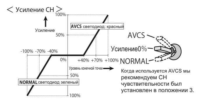
Настройка чувствительности критериев конечной точкой показано на рисунке ниже. Чувствительность становится равной нулю между конечной точкой -40% до +40% и станет 100% в конечной точке 100%.
Обратитесь к руководству по эксплуатации передатчика и установите конечную точку. Когда AVCS используется, настройте 3-х позиционный переключатель на канал чувствительности (существуют такие типы, которые не могут быть установлены на передатчик) и установите его, как показано выше. В случае 2-позиционного переключателя, подавление чувствительности гироскопа на 0%, как в нормальном режиме так и AVCS режиме, 0% чувствительность является безопасным.
Триммер работает, когда функция дистанционного усиление не используется (когда S.BUS не используется и порт 2 не подключен). Пожалуйста, не используйте AVCS, когда вы не используете пульта дистанционного усиления. Потому что, нейтральное положение не может быть сохранено. И взлет и посадка опасна.
Настройка сервомоторов на земле
Если стик перемещается, когда самолет находится на земле, сервопривод переместится в крайнее положение. В режиме AVCS, сервопривод не вернется в нейтральное положение, даже если стик вернуть в нейтральное положение, но это нормально.
Если стик переместить до упора влево или вправо, три или более раз в течение одной секунды, сервопривод вернеться в нейтральное положение.
Регулировка в полете
Подрегулируйте передатчик и гироскоп после повторном взлета и посадки, когда самолет уже на земле.
Настройки передатчика не должны быть сделаны во время полета, потому что это опасно.
- Взлетев на самолете, тримируйте его при отключеном гироскопе при 0% чувствительности или в нормальном режиме. После тримирования, переключите переключатель чувствительности в диапазоне от 0% чувствительности (или обычный режим) и режим AVCS три раза с интервалом в одну секунду, а затем установите переключатель усиления в режиме AVCS позиции. Это зафиксирует нейтральную позицию гироскопа для режима AVCS. В режиме AVCS, не выполняйте тримирование во время полета.
- Настройте чувствительность гироскопа так, чтобы рысканье (отклонение самолета в маленьких амплитудах) не происходило в направлении оси контроля. Чувствительность гироскопа отличается в зависимости от положения руля направления, скорости и используемого гироскопа. Первоначально попытайся изменить чувствительность с шагом в 5%. Если рысканье чрезмерное, самолет может быть поврежден. Рысканье имеет тенденцию исчезать, при снижении скорости.
AVCS / NORMAL режимы
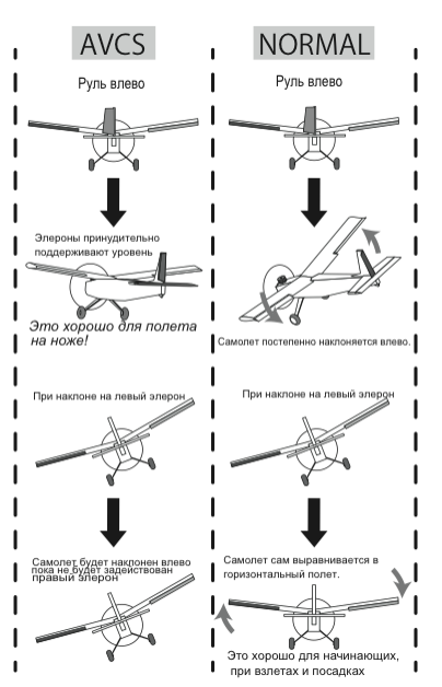
У гироскопа есть два режима работы: НОРМАЛЬНЫЙ и AVCS. В режиме AVCS гироскоп контролирует угловые ускорения, в НОРМАЛЬНОМ режиме осуществляется контроль уровня вращения. В режиме AVCS сила фиксации более сильная, чем в НОРМАЛЬНОМ режиме и направление полета самолета фиксируется сильнее. Во время полета на ноже, в зависимости от особенностей самолета, компенсация отклонений должна выполняться автоматически. В этом режиме РВ и РН меняются местами, обратите внимание на это. Будет безопаснее, переключаться на НОРМАЛЬНЫЙ режим, при взлетах и посадках.
Скачать инструкцию

2
Introduction …………………………………………………….3
Service …………………………………………………………….3
Usage Precautions: …………………………………………..4
……………………………..4
Introduction to the 6J- 2.4GHz System ……………..6
Transmitter controls ………………………………………..6
Radio Installation …………………………………………….9
Receiver Installation: ……………………………………..10
Receiver and Servo Connections …………………….14
Charging NiCd/NiMH batteries ……………………..16
Liquid Crystal Display (LCD) and Programming
Controls …………………………………………………………18
Programming the T6J-2.4GHz Radio ……………..19
(Common Functions)
Parameter (PARA) ………………………………………20
Model Select Function (MODL)……………………20
Model Name function ………………………………….21
Data Reset function (REST) …………………………22
ACRO/HELI Model type select function (TYPE) .
…………………………………………………………………23
Transmission Mode Selection (MODE) …………24
Throttle-Cut Function (TCUT) ……………………..25
Battery F/S Fail Safe (S-FHSS Mode only) ……26
Servo Reversing (REVR) …………………………….27
Dual Rates (ACRO) ……………………………………28
Exponential Settings (EXPO) – (ACRO) ……….29
Dual Rates (HELI) ……………………………………..30
Exponential Settings (EXPO) — HELI …………….32
End Point Adjustment (EPA) ………………………..33
Trim Settings (TRIM) ………………………………….34
Sub-Trims (STRM) ……………………………………..36
(Airplane Only Programming)
Programmable Mix 1 and 2 (PMX 1 and PMIX 2)
(ACRO only) ……………………………………………..37
Wing Type Selection- (ACRO only) ………………38
Flaperon mixing (FLPR)- (ACRO only) ………..39
Flap trim (FLTR)- (ACRO only) …………………..41
V-tail mixing (V-TL)- (ACRO only) ……………..42
Elevon mixing (ELVN)- (ACRO only) …………..43
Throttle Curve (T-CV)- (ACRO only) ……………44
Pitch Curve (P-CV)- (ACRO only) ……………….45
(Helicopter Only Programming)
Normal throttle curve function (N-TH)- (HELI
only)- …………………………………………………………47
Normal pitch curve (N-PI)-(HELI only) …………48
Idle Up throttle curve function (I-TH)- (HELI
Only) …………………………………………………………49
Pitch Curve Idle UP (I-PI) — (HELI only) ……….51
Throttle hold function (HOLD)- (HELI only) …52
Pitch Curve Hold (H-PI)- (HELI only) …………..53
Revolution Mixing (REVO) — (HELI only) …….54
Gyro mixing function (GYRO)-(HELI only) ….55
Swash to throttle mixing (SW-T)-(HELI only)..57
Swash Ring (RING) …………………………………….57
Swashplate type selection and Swash AFR
(SWSH) — (HELI only) ………………………………..58
Swashplate AFR (Adjustable Function Rate) —
(HELI only) ……………………………………………….60
Delay (DELY)- (HELI only) …………………………61
Hovering Pitch (HOVP)- (HELI only) …………..62
(Other Programming function)
Fail Safe (F/S) …………………………………………….63
TRNR Trainer function ………………………………..64
TIMER ………………………………………………………67
Flow Chart ACRO Mode Functions ………………..70
Adjustable length control sticks ……………………..72
Changing the T6J Stick Mode ………………………..72
Flying Safety Guidelines …………………………………73
Charge the batteries ……………………………………….73
Flight Preparation ………………………………………….74
Check the controls ………………………………………….74
GLOSSARY …………………………………………………..75
TABLE OF CONTENTS