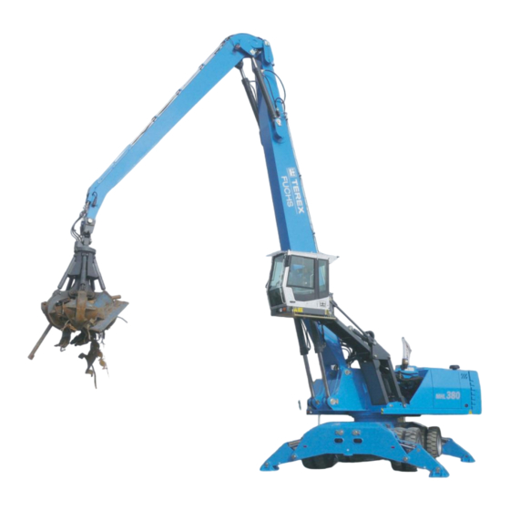
Как уже говорилось выше, Terex Fuchs 350 – незаменимый помощник на больших перерабатывающих площадках, работа которых сопряжена с необходимостью выполнения погрузки и выгрузки металловозов, железнодорожных вагонов и пр.
Важно
Внушительная грузоподъемность данной разновидности спецтехники позволяет ей осуществлять загрузку шредера либо пресс-ножниц тяжеловесным ломом, кузовами авто и прочими крупногабаритными предметами.
Модель пригодна для решения любых задач, связанных с применением гидравлических ножниц. Она демонстрирует высочайшую производительность: практика показывает, что под управлением опытного умелого оператора Terex Fuchs способен за смену разгрузить или загрузить больше десятка вагонов лома.
Технические характеристики «Терекс Фукс 350»
Ключевой особенностью данной модели Terex Fuchs MHL является стрела, длина вылета которой может варьироваться в пределах от 12,5 до 13-ти метров. Также машина оборудована гидравлическими ножницами от компании Genesis, генератором для магнитной шайбы на 13 либо 20 кВт и грейфером, объем которого составляет 0,6 или 0,8 кубометра. Максимальная устойчивость техники во время работы обеспечена увеличенной ходовой тележкой.
Машина оборудована 6-цилиндровой 7,2-литровой силовой установкой Deutz мощностью в 148 кВт при максимальном крутящем моменте в 2 тыс. об./мин. Емкость бака составляет 383 литра. За работу электрооборудования отвечает АКБ 2Х 12 В. Трансмиссия гидрообъемная, привод осуществляется от гидромотора.
Погрузчик полноприводный, максимальная скорость движения ограничена отметкой в 20 км/час. Опор 4, что обеспечивает технике максимальную устойчивость. Тормозная система представлена одноконтурными гидравлическими тормозами, которые воздействуют на 4 пары колес.
Гидравлическая система мобильная, предусмотрена возможность регулировки требуемого потока и мощности. Емкость гидробака равна 389-ти литрам. Максимальное давление достигает 360 бар.
Отдельного внимания заслуживает кабина спецмашины, где созданы все условия для комфортного выполнения оператором своих рабочих обязанностей. По умолчанию она оборудована кондиционером, имеется даже просторное холодильное отделение для хранения напитков.
На центральной панели размещен многофункциональный сенсорный дисплей, на котором отображается вся необходимая информация о работе машины и ее техническом состоянии. Управление осуществляется посредством размещенного спереди рабочего терминала. Кабина оборудована регулировкой перемещения по высоте до 5,8 метра.
| Технические характеристики | Значения |
| Длина вылета стрелы, м | 12,5 — 13 |
| Усилие ножниц, т | 903 |
| Диаметр магнитной шайбы, см | 115 — 125 |
| Мощность генератора для магнитной шайбы, кВт | 13 / 20 |
| Объем грейфера, куб. м | 0,6 / 0,8 |
| Двигатель | 6-цилиндровый Deutz |
| Объем двигателя, литров | 7,2 |
| Мощность, кВт | 148 |
| Емкость бака, л | 383 |
| Максимальная скорость, км/ч | 20 |
| Максимальное давление в гидросистеме, бар | 360 |
| Высота подъема кабины, м | 5,8 |
Стеклянная крыша, а также продуманная форма и размер кабины обеспечивают хороший обзор для удобства выполнения погрузки/выгрузки и прочих задач. Ветровое стекло находится под небольшим наклоном вниз, что тоже способствует улучшенному обзору.
Дополнительное тонирование препятствует попаданию в кабину большого количества солнечного света и исключает риск ослепления оператора. Внутреннее пространство используется оптимальным образом, есть даже небольшое багажное отделение, держатель для смартфона и зарядное устройство.
Поддерживать чистоту легко благодаря отсутствию узких щелей и углов. Инновационным решением является также раздвижная дверь, обеспечивающая облегченный свободный доступ в кабину через широкий дверной проем.
Fuchs MHL 350
Быстросъемная система FQC является уникальным гидравлическим приспособлением для быстрой замены навесного оборудования. Подсоединение шлангов и механическое сцепление происходит полностью автоматически. Замена погрузочной рукояти с грейфером или магнитной шайбой на гидравлические ножницы происходит в течении одной минуты не выходя из кабины.
Грейферный погрузчик Terex Fuchs MHL 350 fqc с длинной стрелы от 12,5м до 13м. Перегружатели такого класса подходят для погрузки-разгрузки металловозов, ЖД вагонов, загрузке пресс-ножниц. Резка лома и любые операции с гидравлическими ножницами. Погрузчик лома оснащен грейфером 0,6 м3 или 0,8 м3 и генератором для магнитной шайбы 13 кВт или 20 кВт. А также гидравлическими ножницами GXP 400R фирмы Genesis.
Погрузчик металлолома Фукс 350 fqc стандартно укомплектован:
6-цилиндровый турбодизельный двигатель Deutz TCD 2013 L06 2V 148 кВт, номинальное число оборотов 2000 об/мин, рабочий объем цилиндров 7,2 л.
Емкость топливного бака 383 л. Электрооборудование с рабочим напряжением 24В, аккумулятором 2 Х 12В, 100 Ah, 760 A. Трансмиссия гидрообъемная с приводом от бесступенчато регулируемого аксиально — поршневого гидромотора. Полный привод. Скорость движения 0 – 20 км/час. Радиус поворота 8,6 м. 4-гидравлические точечные опоры с защитой для опорных цилиндров или отвал. Шины 8 сплошных эластичных резиновых шин размером 12.00-20 Рабочий тормоз: одноконтурная гидравлическая система, воздействующая на все 4 пары колес.
Гидравлическая система:
- Мобильная гидросистема с регулировкой требуемого потока, контроля мощности и расхода топлива двигателя за счет регулировки по предельной нагрузке.
- Центральная смазочная система.
- Макс. производительность 2х320 л/мин
- Макс. рабочее давление 360 бар
- Емкость гидробака 389 л.
Кабина с бесступенчатой регулировкой перемещения по высоте до 5,8 м – уровень глаз оператора. Кондиционер. Эксплуатационный вес – 32 – 37,5 тонн.
Погрузчик Fuchs MHL 350 FQC оснащается навесным оборудованием:
- ножницы для резки металла Genesis GPX 400 R (усилие 6,77 кН или 903 тонны)
- грейфер для лома, объем 0,6 м3 или 0,8 м3
- грейфер для сыпучих грузов, объем от 1 м3 до 2,5 м3
- грейфер для леса, площадь сечения 1,3 м2
- магнитная шайба диаметром от 1150 мм до 1250 мм.
- крюк 10 тонн
Двигатель 148kW Масса 32-36 т Стрела 16м Грейфер 0,6-0,8 м3
Проспект Fuchs MHL350-d Проспект Fuchs MHL350
Проспект погрузочная техника для металлолома
Грейферы
Проспект Модельный ряд машин
Навесное оборудование
Машина, ставшая темой нашего разговора, укомплектована следующим навесным оборудованием:
- ножницами для выполнения резки металлов с усилием в 903 т.;
- грейфером для сыпучих материалов объемом в 1-2,5 кубометра;
- грейфером для лома объемом в 0,6 либо 0,9 кубометра;
- грейфером для бревен с сечением в 1,3 м квадратных;
- крюком, способным выдержать вес в 10 т;
- магнитной шайбой, диаметр которой варьируется в пределах 115-125 см.
Достоинства и недостатки спецмашины

Манипулятор Fuchs MHL350 является одним из наиболее производительных на сегодняшний день перегружателей, в котором удивительным образом сочетаются высокая эффективность работы и низкий расход топлива. Отличные эксплуатационные характеристики, в числе которых – полный привод, устойчивость во время решения сложных задач, вылет стрелы до 13-ти метров, вместительный грейфер и пр., делают эту модель спецтехники признанным лидером в своем классе.
Благодаря оперативной и простой замене навесных агрегатов машина становится универсальным и незаменимым помощником при выполнении целого ряда работ. Управление ее работой осуществляется с помощью джойстика и не требует никаких усилий. Просторная комфортабельная кабина создает все условия для максимального удобства оператора.
Высокой безопасности использования техники способствует большая площадь остекления, включая стеклянную крышу, а также тонирование, исключающее риск ослепления и позволяющее оператору эффективно работать, не зависимо от погодных условий. На многофункциональном сенсорном экране отображаются все необходимые сведения о состоянии машины и выполняемых ею операциях.
Перегружатель FUCHS MHL 350 FQC
All rights to brands and trade names (signs/trademark) belong to the equipment manufacturers. International Companies Group BAUTECHNIKA|ATLAS-Rus is an exploiter of machinery and equipment, represents a rental company. International Companies Group BAUTECHNIKA|ATLAS-Rus does not provide warranty service. Please contact the official dealer of the manufacturing plant. The information of the site is for informational purposes only and serves as a consultative aid for exploiters of machinery and equipment. Все права на торговые марки и торговые наименования (товарный знак) техники принадлежат производителям техники и оборудования. Международная Группа компаний BAUTECHNIKA|ATLAS-Rus является эксплуататором машин и оборудования, представляет компанию по прокату (арендную компанию). Международная группа компаний BAUTECHNIKA|ATLAS-Rus не предоставляет гарантийное обслуживание техники и оборудования. Пожалуйста, обратитесь к официальному дилеру завода-изготовителя. Информация сайта предназначена только для информационных целей и служит консультативной помощью для эксплуататоров машин и оборудования. Материалы, представленные на этом сайте, защищены Законодательством ЕС. Полное, либо частичное (в т.ч. числе конструкционное) цитирование, тираживание и прочее распространение без письменного согласия Администрации сайта запрещено! Представленные на странице данные являются собственностью их правообладателей, представлены исключительно в ознакомительных целях, не подлежат копированию и распространению без согласия правообладателей и Администрации сайта.
Все юридические вопросы решает наше уполномоченное консалтинговое агентство — «MELANIA Group» (https://melania.vip)
Использование бренд-имиджа BAUTECHNIKA|ATLAS-Rus (BAUТЕХНИКА) (товарный знак и буквенно-стилистическое обозначение, цветовые схемы) осуществляется на основании международного соглашения представления интересов международной группы компаний BAUTECHNIKA|ATLAS-Rus на территории Российской Федерации и Стран Таможенного Союза.
Контактные формы на сайте используются исключительно для установления обратной связи для ответа на заявку пользователя, хранение контактной информации пользователя на сервере компании не осуществляется.
Вся информация, содержащая ценовые/стоимостные данные о товарах/услугах, носит исключительно ознакомительный характер, и ни при каких условиях не является публичной офертой, определяемой положениями Статьи 437 Гражданского кодекса РФ. All information is the property of the copyright holder. BAUTECHNIKA|ATLAS-Rus. All information is for informational purposes only. Copying and other distribution of information without permission of the copyright holder is prohibited.
Выводы
«Терекс Фукс 350» — это выносливая и надежная техника, которой нет равных в своем классе. Оптимальное сочетание высочайшей производительности и экономного расхода топлива наряду с широким функционалом и разнообразием навесного оборудования делают эту модель незаменимой на производственных площадках и прочих объектах, где регулярно возникает необходимость в погрузке/выгрузке металлического лома и выполнения других задач, так или иначе связанных с привлечением гидравлических ножниц.
Goodlike
Представленный в каталоге нашей компании современный и высокотехнологичный погрузчик Фукс 350 по-праву занял лидирующие позиции по продажам среди остальной техники. Привлекательная цена и выгодные условия заключения контракта неуклонно привлекают в наш офис новых клиентов.
Но далеко не все руководители предприятий по приему и переработке металлолома представляют себе все преимущества, которые дает приобретение погрузчика Фукс 350. Специалисты компании не только подробно проконсультируют клиента обо всех особенностях данной модели, но и помогут подобрать оптимальную комплектацию погрузчика.

Преимущества современной модели Фукс 350
К числу неоспоримых достоинств данной техники специалисты относят:
- Простая и легкая трансформация. Замена ножниц для резки металла на классическую рукоять с грейфером осуществляется оператором в течении нескольких минут. Для этого ему не требуется даже покидать кабину.
- Высокая рентабельность. Приобретение погрузчика полностью окупается уже спустя 4-5 месяцев при интенсивности переработки металла в объеме 4,5-5 тонн в месяц. Это сравнительно небольшое количество, поскольку крупные предприятия по приему и переработке металлолома осваивают ежемесячно намного большие объемы.
- Высокий уровень производительности. Данный погрузчик способен разрезать и перенести на другое место цистерны и вагоны, арматуры и проволока различного диаметра.
- Комфорт и безопасность оператора. Кабина оборудована с учетом потребностей оператора и в ней использованы все современные достижение передовых компаний по производству качественной и надежной техники. Важным моментом является отсутствие необходимости для оператора покидать кабину для смены насадок. Это существенно повышает безопасность работы и исключает риск травматизма на производстве.
- Экономическая выгода. Данная модель с легкостью заменяет бригаду газосварщиков, что позволяет работодателю гарантировать высокое качество и скорость выполнения работ.
На сайте нашей компании https://max-intrade.ru/ клиент всегда сможет ознакомиться со стоимостью погрузчика и выбрать оптимальную комплектацию исходя из потребностей своего производства. Годовая гарантия на приобретенную технику, которую мы предоставляем каждому партнеру, обеспечивает максимальный уровень комфорта для клиента и служит дополнительной защитой интересов его бизнеса.
Мы предлагаем мощную сервисную базу, а также широкий выбор запасных частей, сменных насадок и опытных мастеров. Именно они способны провести качественное сервисное обслуживание, позволяющее выявить и устранить все неполадки в системе, возникающие в результате интенсивной и плодотворной работы техники.
-
Contents
-
Table of Contents
-
Bookmarks
Quick Links
Operating instructions
BSB50000
Mobile hydraulic loading machine
MHL380 D
Vehicle ID no. starting
380110 / 0127 — 0171
Year of manufacture starting
2010
Version
10.12.2012 en
(englisch)
Original operating instructions
Related Manuals for Terex Fuchs MHL380 D
Summary of Contents for Terex Fuchs MHL380 D
-
Page 1
Operating instructions BSB50000 Mobile hydraulic loading machine MHL380 D Vehicle ID no. starting 380110 / 0127 — 0171 Year of manufacture starting 2010 Version 10.12.2012 en (englisch) Original operating instructions… -
Page 2
Original EC Declaration of Conformity (translation) (Machinery Directive 2006/42/EC) Manufacturer: Terex® Deutschland GmbH Industriestrasse 3, 76669 Bad Schönborn, Germany Terex® Deutschland GmbH hereby declares that the machine named below General designation: Loading machine (developed from hydraulic excavator) Model/Type: MHL380 D Serial number: 380110/0127 >… -
Page 3
OVERVIEW OF CHAPTERS The TEREX | Fuchs operating instructions consist of 10 chapters intended for different staff mem- bers: Chapter Subject Staff members FOREWORD Operating staff Inspection and maintenance personnel Repair staff SAFETY AND ACCIDENT PREVENTION Operating staff Inspection and maintenance personnel… -
Page 4: Table Of Contents
CONTENTS Foreword ……………………1.1 General …………………….. 1.1 Proper use ……………………1.2 1.2.1 Misuse ……………………1.2 Introduction ……………………1.3 Warranty and maintenance ……………….. 1.3 Type plate and vehicle identity number …………….1.4 Environmental legislation ………………..1.5 Notes on using the operating instructions…………… 1.6 1.7.1 References to images and items …………….
-
Page 5
CONTENTS Lubricants, coolants and fuels ………………2.22 2.4.1 Refrigerant ………………….2.22 Cab which can be raised and moved forwards …………. 2.23 2.5.1 Cab protective grating ……………….. 2.23 2.5.1.1 FOPS/Protective roof grating conforming to DIN EN ISO 3449-II …… 2.23 2.5.1.2 FOPS/Front protective roof grating conforming to DIN EN ISO 10262 …. -
Page 6
CONTENTS 3.15.3 Alternative recommendations for other temperature ranges ……..3.33 3.15.4 Biodegradable hydraulic fluid PANOLIN HLP SYNTH 46 ……..3.33 Display and control elements ……………… 4.1 Overview of the display and control elements …………..4.2 4.1.1 Operator control panel ………………… 4.4 4.1.2 Control elements for switching functions ………….. -
Page 7
CONTENTS 4.7.8 Fuel pre-filter ………………….4.43 4.7.9 Hydraulic oil temperature ………………4.45 4.7.10 Hydraulic oil level ………………..4.46 4.7.11 Hydraulic oil filter (main and auxiliary circuits) …………4.47 4.7.12 Bypassing the shutdown function …………….4.48 Operator’s stand………………….4.49 4.8.1 Comfort driver’s seat ………………..4.49 4.8.2 Steering Wheel …………………. -
Page 8
CONTENTS 4.13.2 Stopping …………………… 4.82 4.13.3 Brakes ……………………4.82 4.13.4 Steering ……………………. 4.82 4.13.5 Driving downhill and uphill ………………4.83 4.13.6 Driving and working headlamps …………….4.84 4.13.7 Direction indicators ………………..4.86 4.13.8 Hazard warning lights ……………….. 4.86 4.13.9 Horn ……………………4.86 4.13.10 Flashing beacon (optional) ……………… -
Page 9
CONTENTS Regular oil analyses ………………….. 7.2 Discharging residual pressure in the hydraulic circuit …………. 7.3 Maintenance and wearing parts ………………7.4 Safe working positions ………………..7.5 7.5.1 Maintenance position ………………..7.5 7.5.2 Uppercarriage ………………….7.6 7.5.3 Undercarriage ………………….7.8 Jobs before putting the machine into operation ………….. 7.9 7.6.1 Checking the engine oil level …………….. -
Page 10
CONTENTS 7.9.2.1 Fuel level ………………….7.43 7.9.2.2 Electrical refueling pump (optional) …………..7.43 7.9.2.3 Replacing the fuel filter ………………7.45 7.9.2.4 Cleaning the fuel prefilter with integrated filter cartridge ……..7.46 7.9.2.5 Replacing the fuel prefilter with integrated filter cartridge ……..7.47 7.9.2.6 Draining water from the fuel system ………….. -
Page 11
CONTENTS 7.11 Shutdown ……………………7.82 7.11.1 Preserving the machine for temporary shutdown ……….. 7.82 7.11.2 During shutdown ………………..7.83 7.11.3 After shutdown ………………….. 7.83 7.11.4 Once the machine has been out of use for more than half a year ……7.83 7.12 Disposal …………………… -
Page 12
CONTENTS MHL380 D… -
Page 13
CONTENTS Foreword ……………………1.1 General …………………….. 1.1 Proper use ……………………1.2 1.2.1 Misuse ……………………1.2 Introduction ……………………1.3 Warranty and maintenance ……………….. 1.3 Type plate and vehicle identity number …………….1.4 Environmental legislation ………………..1.5 Notes on using the operating instructions…………… 1.6 1.7.1 References to images and items ……………. -
Page 15: Foreword 1
FOREWORD 1 Foreword General The Mobile Hydraulic Loading Machine MHL380 D was thoroughly tested before it left the factory. The final inspection showed all parts to be in perfect working order and veri- fied the machine’s ability to achieve the ex- pected level of performance.
-
Page 16: Proper Use
1 FOREWORD Proper use Attention The loading machine MHL380 D is intended The operating temperature at which the machine solely for work which is suited to the function may be used with standard fuels, lubricants and of the machine and its work attachment. Such coolants is within the range from -15 °C to work involves: +45 °C.
-
Page 17: Introduction
Attention machine will only be operated by authorized, trained and specially instructed personnel. TEREX | Fuchs can provide no warranty for modifications or attachments to equipment on They must be kept readily accessible in the TEREX | Fuchs products which have not been…
-
Page 18: Type Plate And Vehicle Identity Number
1 FOREWORD Type plate and vehicle identity num- The type plate (1/1) can be found on the un- dercarriage. The vehicle identity number is Type also stamped on the undercarriage (1/2). plate vehicle Attention identity number Please always quote the vehicle type and vehi- cle ID number when making an enquiry and in all written correspondence.
-
Page 19: Environmental Legislation
FOREWORD 1 Environmental legislation When operating or working with the machine, applicable legislation for the protection of the environment must be observed at all times. When performing repair and maintenance work, special care must be taken to ensure that environmentally harmful substances such …
-
Page 20: Notes On Using The Operating Instructions
1 FOREWORD Notes on using the operating instruc- 1.7.3 Hazards and important notes tions n DANGER 1.7.1 References to images and items DANGER – indicates an imminently hazardous The references to images and items appear- situation which, if not avoided, will result in death ing in the text, such as (14/1), mean figure 14, or serious injury.
-
Page 21: Pictograms
FOREWORD 1 1.7.4 Pictograms 1.7.4.1 Indicators in the multifunction display The table below explains the meaning of the indicators in the multifunction display. Functions and displays marked (*) are optional. Indicator Description Indicator Description Dual assignment: Close range cut-off Coolant temperature active (dipperstick) Hydraulic fluid temperature SYM101…
-
Page 22
1 FOREWORD Indicator Description Indicator Description Windscreen wiper/ Indicator oscillating axle intermittent wiping unlocked (upper window section) SYM126 SYM114 Windscreen wiper Automatic central lubrication (lower window section) * system – trigger additional lubrication on SYM127 SYM135 uppercarriage Wiper water pump Automatic central lubrication (upper window section) system –… -
Page 23
FOREWORD 1 Indicator Description Indicator Description Coolant temperature Hydraulic fluid temperature (diesel engine) SYM150 SYM151 Time/operating hours – Text output to the 0 UPM 00 : 00 KRAFTSTOFFVORRAT UNTER 5% SYM152 current engine speed * indicator displays SYM153 Fuel gauge Load display * 120% 100%… -
Page 24: Pictograms In The Control Panel
1 FOREWORD 1.7.4.2 Pictograms in the control panel The table below explains the meaning of the pictograms in the control panel. Functions and displays marked (*) are optional. Symbol Description Symbol Description Parking brake Flashing control indicator (left) SYM191 SYM180 Swing brake Flashing control indicator (right) SYM192…
-
Page 25: Symbols
FOREWORD 1 Symbols Various symbols are used on the machine. These should be visible and legible at all times. 1.8.1 Locations on the machine ® F Z .- I D E N T . N R . | V E H I C L E ID E N T I F IC A T IO N N U M B E R | D-7 6 6 6 9 Ba d Sc h ö…
-
Page 26
1 FOREWORD 54 55 56 BSB51045 Fig. 4 Overview 1.12 MHL380 D… -
Page 27: Description
FOREWORD 1 1.8.2 Description Item View Description Danger symbol Indicates the counterweight as a danger area when the uppercarriage is turning (only for Russia). B SB 50931 Type plate Ter ex Deu tsch la nd G mbH Contains selected information to identify the machine and its technical FAHRZEUGTYP UND S ERIE NB EZE ICHNUNG FZ.
-
Page 28
1 FOREWORD Item View Description Carrying capacity sign (only for Italy and FQC) Indication of the maximum right and left carrying capacity on the boom. h Additional operating instructions Schild009 Danger symbol Indicates the cab — cab lift mechanism — uppercarriage danger area. h Chapter 4.11 Cab which can be raised and moved forward hydrau- lically B SB 50931… -
Page 29
FOREWORD 1 Item View Description Information sign for sound power level Indicates the machine’s sound power level. h Chapter 3.12 Noise level values B SB 50944 Information sign for the overload warning device Refers to the black key switch. Position 0: Overload warning device deactivated Position I: Overload warning device activated h Chapter 5.1.14 Overload warning device for hoisting (optional) B SB 51021… -
Page 30
1 FOREWORD Item View Description Not available. Information sign for the maximum carrying capacity of the cab Maximum carrying capacity of the cabin with operator and load. B SB 51021 Emergency lowering valve in the cab Indicates the emergency lowering valve’s adjustment handle with red paint. -
Page 31
FOREWORD 1 Item View Description Item View Description Danger of crushing Danger of crushing Coming into contact with Coming into contact with the moving outrigger can the moving machine can lead to death or serious lead to death or serious injury. -
Page 32
1 FOREWORD Item View Description Item View Description Danger due to magnetic Danger of burns field (only with optional The release of hot, pres- magnet system) surized fluids can lead to Standing close to a strong death or serious injury. Do magnetic field may affect not open the sealing cover the function of a heart… -
Page 33
FOREWORD 1 Item View Description Item View Description Danger of electric shock Improper operation or Coming into contact with maintenance can lead to power supply lines can death or serious injury. lead to death or serious Ensure that you read and injury. -
Page 34: Operating Instructions Provided By Other Suppliers
Tank filling pump Johnson Pump h Supplied CD 1.10 Copyright Copyright to these operating instructions is asserted by Terex Deutschland GmbH. These operating instructions are intended for use by personnel responsible for the operation, maintenance, repair and supervision of the machine.
-
Page 35
CONTENTS Safety and accident prevention…………….2.1 Declaration of conformity ………………..2.1 General safety notes …………………. 2.2 2.2.1 Avoiding crushing and burns ………………2.3 2.2.2 Avoiding fire and explosion ………………2.4 2.2.3 Safe operation despite obscured view …………..2.4 2.2.4 Putting the machine into operation safely …………..2.5 2.2.5 Starting the machine safely ……………… -
Page 37: Safety And Accident Prevention 2
SAFETY AND ACCIDENT PREVENTION 2 Safety and accident prevention Working with the machine can expose owners, operators or maintenance specialists to hidden dangers. Dangers and accidents prevented reading, then continuously and thoroughly rereading and complying with the various safety instructions. This applies particularly to persons who only work with the machine occasionally — during maintenance work, for example.
-
Page 38: General Safety Notes
2 SAFETY AND ACCIDENT PREVENTION General safety notes Never jump off the machine. Instead use the steps, ladders, and hand grips designed for Familiarize yourself with operating mounting and descending. Grab on with instructions before the machine is put into Genera both hands and face the machine.
-
Page 39: Avoiding Crushing And Burns
SAFETY AND ACCIDENT PREVENTION 2 2.2.1 Avoiding crushing and burns Before performing any work in the engine compartment, always use the supports Do not work under the loading equipment provided to prevent the engine cover closing unless it is resting safely on the ground or is unintentionally.
-
Page 40: Avoiding Fire And Explosion
2 SAFETY AND ACCIDENT PREVENTION 2.2.2 Avoiding fire and explosion 2.2.3 Safe operation despite obscured view Turn the diesel engine off when refueling. Depending on the position of the cab lift and Check the electrical system regularly. 2.2.3 loading equipment as well as the area behind Safe …
-
Page 41: Putting The Machine Into Operation Safely
SAFETY AND ACCIDENT PREVENTION 2 2.2.4 Putting the machine into operation 2.2.5 Starting the machine safely safely Before starting, check all indicator lamps Before putting the machine into operation, and instruments to make certain they are 2.2.4 always perform a thorough walk-around working properly, move all operating levers Putting inspection of the machine.
-
Page 42: Safe Working With The Machine
2 SAFETY AND ACCIDENT PREVENTION 2.2.6 Safe working with the machine Always be seated with the safety belt fastened while working. The values in the carrying capacity tables 2.2.6 must be strictly observed and must not be Report all operating faults and make certain Safe exceeded.
-
Page 43
SAFETY AND ACCIDENT PREVENTION 2 When loading a truck, insist that the truck driver leaves the driver’s seat, even if protection from falling rocks is available. For crane operation, always protective equipment designed for this purpose. On terrain where visibility is poor and whenever necessary, have a guide help you. -
Page 44: Parking The Machine Safely
2 SAFETY AND ACCIDENT PREVENTION 2.2.7 Parking the machine safely If at all possible, the machine should be parked on an even and solid surface. If it has to be parked on an incline, chocks should be used to ensure that the machine cannot roll away.
-
Page 45: Transporting The Machine Safely
SAFETY AND ACCIDENT PREVENTION 2 2.2.8 Transporting the machine safely Ensure no-one is on the machine during transport. Use only suitable transport and lifting equipment with sufficient carrying capacity. Before setting off, find out about the route to be taken, especially with regard to limits for …
-
Page 46: Towing The Machine Safely
2 SAFETY AND ACCIDENT PREVENTION 2.2.9 Towing the machine safely Always observe the correct procedure. h Chapter 6.1 Towing the machine The machine may be towed only in exceptional cases, for example to bring the machine away from a dangerous site for repair.
-
Page 47: Hoisting (Optional)
SAFETY AND ACCIDENT PREVENTION 2 2.2.10 Hoisting (optional) 2.2.11 Residual risk If the loading machine is to be put into hoisting Even when used as intended in compliance 2.2.10 operation, the safety equipment prescribed by with all instructions provided, a residual risk Hoistin national law must be present and in full cannot be ruled out.
-
Page 48: Safe Maintenance Of The Machine
2 SAFETY AND ACCIDENT PREVENTION Safe maintenance of the machine For all maintenance work, especially when working under the machine, hang a warning 2.3.1 General safety notes sign «Do not turn on» by the ignition key lock, Safe Maintenance and repair work must only be ensuring that it is clearly visible.
-
Page 49: Safety Instructions For Replacing The (Optional) Xenon Lamp
SAFETY AND ACCIDENT PREVENTION 2 2.3.2 Safety instructions for replacing ATTENTION the (optional) XENON lamp In the event of continuing starting Always switch the headlamp off and isolate it difficulties when switching from the supply voltage before changing the (flickering light), switch the XENON lamp.
-
Page 50: Cleaning The Machine
2 SAFETY AND ACCIDENT PREVENTION 2.3.3 Cleaning the machine Before starting maintenance or repair work, clean any oil or fuel off the machine, paying particular attention to the connections and screw couplings. Do not use any aggressive cleaning agents and use lint-free rags. …
-
Page 51: Crack Test On The Machine
If lengths for different components of the you are in any doubt, consult your dealer machine. This can result in cracks and loose or a TEREX | Fuchs service engineer for connections, especially load-bearing advice on how to proceed.
-
Page 52: Welding On The Machine
2 SAFETY AND ACCIDENT PREVENTION 2.3.5 Welding on the machine Welding, burning, and grinding work must 2.3.5 only be performed on the machine if it has Weldin been explicitly approved g on manufacturer. Clean the machine and the machin area around it of dust and combustible materials before…
-
Page 53: Repairs On The Machine
SAFETY AND ACCIDENT PREVENTION 2 2.3.6 Repairs on the machine Only persons with specialist knowledge and experience are permitted to perform work on Do not attempt to lift heavy parts. Use work hydraulic equipment. aids designed for this purpose with sufficient carrying capacity.
-
Page 54: Electrical System
2 SAFETY AND ACCIDENT PREVENTION 2.3.7 Electrical system Check the electrical system regularly. Have all faults such as loose connections, blown fuses and bulbs, or singed or worn away wiring repaired by specialist personnel immediately. Use only original fuses with recommended current rating.
-
Page 55: Hydroaccumulators
SAFETY AND ACCIDENT PREVENTION 2 2.3.8 Hydroaccumulators All work on hydroaccumulators must be performed by trained specialist personnel only. Unsuitable mounting handling hydroaccumulators can result in serious accidents. Do not put damaged hydroaccumulators into operation. Before working on a hydroaccumulator, reduce the pressure in the hydraulic system as described in these operating instructions.
-
Page 56: Hydraulic Hoses And Hose Lines
2 SAFETY AND ACCIDENT PREVENTION 2.3.9 Hydraulic hoses and hose lines — noncompliance with installation requirements It is forbidden to repair hydraulic hoses and hydraulic hose lines! — damage to or deformation of the hose fitting that reduces the stability of the …
-
Page 57
SAFETY AND ACCIDENT PREVENTION 2 — When replacing hoses and hose lines on moving parts (for example from the boom to the dipperstick), check the entire range of movement for abrasion points before putting the machine into operation for the first time. -
Page 58: Lubricants, Coolants And Fuels
2 SAFETY AND ACCIDENT PREVENTION Lubricants, coolants and fuels Applicable safety requirements must be observed when working with oils, greases and other chemical substances. Ensure that fuels, lubricants and coolants, as well as replaced parts, are disposed of in an environmentally friendly manner.
-
Page 59: Cab Which Can Be Raised And Moved Forwards
SAFETY AND ACCIDENT PREVENTION 2 Cab which can be raised and moved 2.5.1 Cab protective grating forwards Raised loading equipment constitutes Park the machine on a level and horizontal hazard due to potential oscillations which 2.5 Cab surface. Position uppercarriage could result in the attached load falling off.
-
Page 60: Equipment And Attachment Parts
Equipment and attachment parts Equipment and attachment parts from third- party manufacturers or those that have not been generally approved by TEREX | Fuchs for fitting or mounting must not be fitted to or mounted on the machine without the prior written consent of TEREX | Fuchs.
-
Page 61
CONTENTS Technical data ………………….3.1 Dimensions ……………………3.1 3.1.1 Uppercarriage and undercarriage …………….3.1 3.1.2 Loading equipment 18.5 m, 20 m, 21 m, and 22 m ……….3.2 3.1.3 Loading equipment 21 m and 22 m cranked …………3.3 General structure ………………….3.4 Diesel engine ……………………. -
Page 63: Technical Data 3
TECHNICAL DATA 3 Technical data Dimensions 3.1.1 Uppercarriage and undercarriage BSB51104 Fig. 5 Dimensions with tires 14.00-24 Uppercarriage and undercarriage 6620 5700 3600 5190 1680 3590 3160 2050 3800 3650 170* Measurements in mm * Protective grating (optional) MHL380 D…
-
Page 64: Loading Equipment 18.5 M, 20 M, 21 M, And 22 M
3 TECHNICAL DATA 3.1.2 Loading equipment 18.5 m, 20 m, 21 m, and 22 m BSB51105 Fig. 6 Transport dimensions 1 Average center of gravity in transport position TRANSPORT DIMENSIONS Loading equipment 18.5 m 20 m 21 m 22 m 15520 16960 16960…
-
Page 65: Loading Equipment 21 M And 22 M Cranked
TECHNICAL DATA 3 3.1.3 Loading equipment 21 m and 22 m cranked BSB51106 Fig. 7 Transport dimensions 1 Average center of gravity in transport position TRANSPORT DIMENSIONS Loading equipment 21 m 22 m 16860 16980 6580 6210 2000 2000 2070 2070 3800 4700…
-
Page 66: General Structure
3 TECHNICAL DATA General structure 380-0101-506 Fig. 8 General structure 1 Front axle (steering axle) 7 Cab which can be raised and moved forwards 2 Rear axle (full floating axle) 8 Cab lift mechanism 3 Single-stage transfer gear with two variable speed 9 Boom axial piston motors 10 Dipperstick cylinder…
-
Page 67: Diesel Engine
TECHNICAL DATA 3 Diesel engine Manufacturer and model Deutz TCD 2015 L06 4V Design 6-cylinder V engine Control Electronic Engine Control (EEC III) Direct fuel injection with pump/line/nozzle, turbocharger, charge cooling Engine power 273 kW Rated speed 1800 U/min Stroke displacement 11.91 l Cooling system Water and charge air cooling with tempera-…
-
Page 68: Hydraulic System
3 TECHNICAL DATA Hydraulic system Main pump Adjustable double displacement pump + sepa- rate turning circle pump in closed circuit Pump capacity: max. 640 l/min 200 rpm turning circle at 1800 rpm Working pressure: max. 360 bar The pump is regulated by the amount of cur- rent required and thus pumps only the amount of oil actually required by the consumers.
-
Page 69: Travel Drive
TECHNICAL DATA 3 Travel drive The hydrostatic travel drive is controlled by two variable speed axial piston motors with a directly attached brake pedal valve with a flange connection on the single-stage transfer gear. 4 wheel drive via propshafts between drive transmission and axles.
-
Page 70: Brakes
3 TECHNICAL DATA 3.8.1 Brakes Service brake A hydraulically activated single-circuit brake system that works on all four pairs of wheels. Parking brake Electrically or hydraulically activated spring applied disc brake on the drive transmission that transfers power to the front and rear ax- les via the cardan shafts.
-
Page 71: Control
TECHNICAL DATA 3 3.10 Control The loading machine is equipped with an ISO control as standard. h Chapter 5.1 Controls 3.11 Weights and loads Minimum charge weight 62.5 t Maximum charge weight 68.5 t Permissible axle load, front 51.0 t Permissible axle load, rear 51.0 t * Maximum surface load with 4-point outrigger…
-
Page 72: Working Range Of The Machine
3 TECHNICAL DATA 3.13 Working range of the machine 3.13.1 Working range diagram (18.5 m loading equipment) 3 .13 6 4 H W orkin Work equipment: boom 9.6 m, dipperstick 8.0 m and cactus grab 6 5 H g range of the machin 380-18,5 m…
-
Page 73: Provisional Carrying Capacity Table (18.5 M Loading Equipment)
TECHNICAL DATA 3 3.13.2 Provisional carrying capacity table (18.5 m loading equipment) The carrying capacity values are stated in metric tons (t). The pump pressure is 360 bar. The val- ues represent 75% of the static tipping load or 87% of the hydraulic lifting force (marked ), in ac- cordance with ISO 10567.
-
Page 74: Working Range Diagram (20 M Loading Equipment)
3 TECHNICAL DATA 3.13.3 Working range diagram (20 m loading equipment) Loading equipment: boom 11.35 m, dipperstick 8.0 m, and cactus grab BSB51107 Fig. 11 Working range diagram (20 m loading equipment) 3.12 MHL380 D…
-
Page 75: Carrying Capacity Table (20 M Loading Equipment)
TECHNICAL DATA 3 3.13.4 Carrying capacity table (20 m loading equipment) The carrying capacity values are stated in metric tons (t). The pump pressure is 360 bar. The val- ues represent 75% of the static tipping load or 87% of the hydraulic lifting force (marked ), in ac- cordance with ISO 10567.
-
Page 76: Working Range Diagram (21 M Work Equipment)
3 TECHNICAL DATA 3.13.5 Working range diagram (21 m work equipment) Work equipment: boom 11.35 m, dipperstick 8.95 m and cactus grab 380-21 m 340-1680-505 380-0101-511 Fig. 13 Working range diagram (21 m work equipment) 3.14 MHL380 D…
-
Page 77: Provisional Table Of Carrying Capacity (21 M Work Equipment)
TECHNICAL DATA 3 3.13.6 Provisional table of carrying capacity (21 m work equipment) The carrying capacity values are stated in metric tons (t). The pump pressure is 360 bar. The val- ues represent 75% of the static tipping load or 87% of the hydraulic lifting force (marked ), in ac- cordance with ISO 10567.
-
Page 78: Working Range Diagram (22 M Loading Equipment)
3 TECHNICAL DATA 3.13.7 Working range diagram (22 m loading equipment) Loading equipment: boom 11.35 m, dipperstick 9.9 m, and cactus grab 20 19 18 380-22 m 380-0122-513 Fig. 15 Working range diagram (22 m loading equipment) 3.16 MHL380 D…
-
Page 79: Provisional Carrying Capacity Table (22 M Loading Equipment)
TECHNICAL DATA 3 3.13.8 Provisional carrying capacity table (22 m loading equipment) The carrying capacity values are stated in metric tons (t). The pump pressure is 360 bar. The val- ues represent 75% of the static tipping load or 87% of the hydraulic lifting force (marked ), in ac- cordance with ISO 10567.
-
Page 80: Working Range Diagram (21 M Loading Equipment Cranked)
3 TECHNICAL DATA 3.13.9 Working range diagram (21 m loading equipment cranked) Loading equipment: Boom cranked 11.35 m, dipperstick 8.95 m, and cactus grab 380-21 m gekr 380-0101-512 340-1680-505 Fig. 17 Working range diagram (21 m work equipment offset) 3.18 MHL380 D…
-
Page 81: Table Of Carrying Capacity (21 M Work Equipment Offset)
TECHNICAL DATA 3 3.13.10 Table of carrying capacity (21 m work equipment offset) The carrying capacity values are stated in metric tons (t). The pump pressure is 360 bar. The val- ues represent 75% of the static tipping load or 87% of the hydraulic lifting force (marked ), in ac- cordance with ISO 10567.
-
Page 82: Working Range Diagram (22 M Loading Equipment Cranked)
3 TECHNICAL DATA 3.13.11 Working range diagram (22 m loading equipment cranked) Loading equipment: boom 11.35 m, dipperstick 9.9 m, and cactus grab BSB51108 Fig. 19 Working range diagram (22 m loading equipment cranked) 3.20 MHL380 D…
-
Page 83: Provisional Carrying Capacity Table (22 M Loading Equipment Cranked)
TECHNICAL DATA 3 3.13.12 Provisional carrying capacity table (22 m loading equipment cranked) The carrying capacity values are stated in metric tons (t). The pump pressure is 360 bar. The val- ues represent 75% of the static tipping load or 87% of the hydraulic lifting force (marked ), in ac- cordance with ISO 10567.
-
Page 84: Work Attachments
3 TECHNICAL DATA 3.14 Work attachments Documentation covering work attachments supplied by TEREX | Fuchs is part of the scope of supply of every work attachment. It includes: Operating instructions Spare parts catalogue 3.22 MHL380 D…
-
Page 85: Equipment (Optional)
ATTENTION Changes to the design, additional equipment and work attachments of TEREX | Fuchs prod- ucts which have not been approved may result in damage to the machine. Please note that changes must be approved in writing by the manufacturer. Failure to obtain written permission will invalidate both our warranty and product liability for any resulting con- sequential damages.
-
Page 86: Fuels, Lubricants And Coolants
3 TECHNICAL DATA 3.15 Fuels, lubricants and coolants Conscientiously following the requirements for lubrication, level checks and changing fuels, lubri- 3 .15 cants and coolants will increase the reliability and service life of the machine. 6 6 H F uels, 6 7 H lubrican It is particularly important to perform the various oil changes regularly and at the recommended…
-
Page 87: Filling Quantities
TECHNICAL DATA 3 3.15.1 Filling quantities Designation Filling Fluid Remark quantity Fuel tank 900 l Diesel Engine oil 38 l Engine oil Hydraulic fluid tank 720 l Hydraulic fluid Change quantity Front axle, cpl. 43 l Transmission oil per wheel hub 4,5 l Transmission oil Differential…
-
Page 88: Specifications For Fuels, Lubricants And Coolants
A higher sulfur content methyl ester), it is essential that will affect the oil change you consult your responsible intervals and service life TEREX | Fuchs dealer for further of the engine. details. Engine Engine oil Titan Cargo MC 10W-40…
-
Page 89
TECHNICAL DATA 3 Specified fuels, lubricants and coolants for Central Europe Application Designation Recommended product Specification, standards, quality Transfer boxes, Transmission Titan Supergear SAE SAE 80W-90 swing gears, wheel 80W-90 API GL-4/GL-5 hubs, axles, grab ZF-TZ-MZ 02B, 05A, 07A, 12B, 16F, and magnet gears Cab door, lock Special… -
Page 90: Alternative Recommendations For Other Temperature Ranges
Doing so may cause aggressive reactions which in turn could damage the hydraulic system. Before changing oils, please ask your local TEREX | Fuchs dealer for advice. Vegetable-based oils are not permitted be- cause of their unsuitable temperature re- sistance. 3.28…
-
Page 91
CONTENTS Display and control elements ……………… 4.1 Overview of the display and control elements …………..4.2 4.1.1 Operator control panel ………………… 4.4 4.1.2 Control elements for switching functions …………..4.6 Multifunction display ………………….. 4.7 4.2.1 Symbols on the main control display ……………. 4.9 Multifunction button …………………. -
Page 92
CONTENTS 4.7.10 Hydraulic oil level ………………..4.44 4.7.11 Hydraulic oil filter (main and auxiliary circuits) …………4.45 4.7.12 Bypassing the shutdown function …………….4.46 Operator’s stand………………….4.47 4.8.1 Comfort driver’s seat ………………..4.47 4.8.2 Steering Wheel …………………. 4.49 4.8.2.1 Adjusting the steering column …………….4.49 Heating and air conditioning ……………… -
Page 93
CONTENTS 4.13.4 Steering ……………………. 4.80 4.13.5 Driving downhill and uphill ………………4.81 4.13.6 Driving and working headlamps …………….4.82 4.13.7 Direction indicators ………………..4.84 4.13.8 Hazard warning lights ……………….. 4.84 4.13.9 Horn ……………………4.84 4.13.10 Flashing beacon (optional) ………………4.84 4.14 Parking the machine ……………….. -
Page 95: Display And Control Elements 4
DISPLAY AND CONTROL ELEMENTS 4 Display and control elements Before placing the machine into operation If you are not yet familiar with the display and control elements of this machine, read this chapter carefully before operating the ma- chine. This chapter deals with all display and control elements.
-
Page 96
4 DISPLAY AND CONTROL ELEMENTS Overview of the display and control elements Overvie w of the display control elemen MHL-NBXX-550 Fig. 22 Display and control elements MHL380 D… -
Page 97: Overview Of The Display And Control Elements
DISPLAY AND CONTROL ELEMENTS 4 Overview of the display and control elements 10 Emergency lowering of cab 11 Lever for extending/retracting 4-point outrigger 12 Four-way control lever (left) 13 Upward folding armrest with switch (work functions disabled) 14 Foot button for boom float function (optional) 15 Pedal for extending/retracting tilting cylinder (optional) 16 Service brake pedal, lockable 17 Forward accelerator pedal (j Note alignment of uppercarriage/undercarriage!)
-
Page 98: Operator Control Panel
4 DISPLAY AND CONTROL ELEMENTS 4.1.1 Operator control panel 60 Ignition lock 69 24 V socket 70 71 72 Not assigned 73 Clogged particulate filter indicator (op- tional) 74 Warning buzzer – sounds in the event of excess exhaust gas pressure as the re- sult of a clogged particulate filter (option- 84 Key switch (black) –…
-
Page 99
DISPLAY AND CONTROL ELEMENTS 4 Control panel 61 Pushbutton for lowering cab 62 Pushbutton for cab forward 63 Pushbutton for raising cab 64 Pushbutton for deactivating close range cut-off (dipperstick) 65 Pushbutton for parking brake 66 Pushbutton for swing brake 67 Flashing control indicator (left) 68 Error display for engine control system (Electronic Engine Control III) -
Page 100: Control Elements For Switching Functions
4 DISPLAY AND CONTROL ELEMENTS 4.1.2 Control elements for switching functions The switching functions can be operated us- ing the components shown in Fig. 25. Multifunction display (25/1) Compact display unit for text and graphics to display operating conditions, messages, switch symbols, diagnostic tools, etc.
-
Page 101: Multifunction Display
DISPLAY AND CONTROL ELEMENTS 4 Multifunction display When the machine is switched on (see Fig. 26), the main control display appears on the multifunc- tion display. MHL-NBXX-580 Fig. 26 Multifunction display SYM field (symbols) see (26/3) «Indicators» with the associated message text are displayed in the upper part of the main control display.
-
Page 102
4 DISPLAY AND CONTROL ELEMENTS FEH field (errors or option displays) see (26/4) In this field, displays for certain options appear instead of the company logo, e.g., the status dis- play for outrigger deselection when the outrigger is activated individually. Additionally, an error message is displayed here if there is an error, e.g., in the event of a sensor failure. -
Page 103: Symbols On The Main Control Display
DISPLAY AND CONTROL ELEMENTS 4 4.2.1 Symbols on the main control display Symbol Item Explanation of the function Indicator (dual assignment): coolant temperature / hydraulic oil tem- perature (see also indicator 49 / 50) Illuminates to indicate high operating temperatures. SYM101 h Chapter 4.7.2 Coolant temperature — Chapter 4.7.9 Hydraulic oil tempera- ture…
-
Page 104
4 DISPLAY AND CONTROL ELEMENTS Symbol Item Explanation of the function Indicator (dual assignment): air cleaner clogging/return filter clogging If this indicator lights up and stays steady, the air cleaner needs to be main- tained or the return filter replaced. The indicator may light up briefly, but this SYM106 is circumstantial and is usually caused by the engine speed being increased too quickly. -
Page 105
DISPLAY AND CONTROL ELEMENTS 4 Symbol Item Explanation of the function Indicator – fuel level The «Fuel reserve» indicator lights up if the fuel in the diesel tank is less than the reserve volume of 5%. SYM112 „ Indicator – oscillating axle unlocked The «Oscillating axle unlocked»… -
Page 106
4 DISPLAY AND CONTROL ELEMENTS Symbol Item Explanation of the function Display – fuel level The bar in the display indicates how much fuel there is in the diesel tank. When the tank is more than 5% full, the bar display is green. If the tank is below the reserve level, the bar turns red and the «Fuel reserve»… -
Page 107: Multifunction Button
DISPLAY AND CONTROL ELEMENTS 4 Multifunction button 4.3.1 Input options with the multifunc- tion button The multifunction button (see Fig. 27) is an all-purpose «operator device» that, together with the display, offers new possibilities for machine operation. 4.3.2 Operating principle To operate a machine via the display and multifunction button, the machine functions are displayed in the form of lines of text…
-
Page 108
4 DISPLAY AND CONTROL ELEMENTS Press button Click once then release: Selected «in focus» function is triggered and performed once (e.g., switch on headlamp). Hold button down: Selected function is triggered repeatedly until the button is released (e.g., raise cab). Double-click: Returns to the main control display from any lower menu level. -
Page 109: Menu Levels In The Multifunction Display
DISPLAY AND CONTROL ELEMENTS 4 Menu levels in the multifunction dis- play 4.4.1 Menu selection in the main control display In the main control display, any +/- movement of the «navigation encoder» along the X axis will move the focus to one of six buttons (soft MHLXXX keys).
-
Page 110
4 DISPLAY AND CONTROL ELEMENTS F 1 display change for camera image (op- tional) h Chapter 4.13.1 Rear view camera (option- F2 Outrigger menu (optional) In the F2 outrigger menu, the status indicator for outrigger deselection is displayed. In this menu, each of the four outriggers can be deselected individually. -
Page 111
DISPLAY AND CONTROL ELEMENTS 4 F4 Time/operating hours The F4 function key displays the operating hours instead of the time of day for a period of 10 seconds. F5 Function menu In the function menu, up to 24 pushbutton and switching functions are displayed in the form of pictograms. -
Page 112
4 DISPLAY AND CONTROL ELEMENTS F6 Main menu In the main menu, you can call up to 9 sub- menus such as «DISPLAY ADJUSTMENT», «SERVICE MENU», «DIAGNOSTICS MENU», and «SYSTEM INFORMATION». MHL-NBXX-708 Fig. 38 Main menu 4.18 MHL380 D… -
Page 113: Sub-Menus In The Main Menu
DISPLAY AND CONTROL ELEMENTS 4 4.4.2 Sub-menus in the main menu Display settings In the «Display settings» menu, you can set the overall brightness of the display and the menu language as well as the time and date on the multifunction display. The modified settings remain saved permanently after exit- ing the menu.
-
Page 114
4 DISPLAY AND CONTROL ELEMENTS Diagnostics menu Data for various components is displayed in the diagnostics menu, currently: „CANopen DIAGNOSTICS» «ELECTRONIC ENGINE CONTROL DIAGNOSTICS» «SYSTEM DIAGNOSTICS 1 – DIGITAL I/O» «SYSTEM DIAGNOSTICS 2 – ANALOG I/O» MHL-NBXX-715 System information Fig. -
Page 115: Sub-Menus In The Diagnostics Menu
DISPLAY AND CONTROL ELEMENTS 4 4.4.3 Sub-menus in the diagnostics menu CANopen INFORMATION This menu runs a quick status diagnostics test of the components connected to the CANopen bus. «EEC» DIAGNOSTICS This menu displays the current data of the EEC3 engine control unit.
-
Page 116
4 DISPLAY AND CONTROL ELEMENTS SYSTEM DIAGNOSTICS 1 – DIGITAL I/O — B35 (CR0020) The current states (HIGH = green, LOW = grey) of the digital inputs and outputs of the main control -B35 (CR0020) are displayed in this menu. SYSTEM DIAGNOSTICS 1 –… -
Page 117
DISPLAY AND CONTROL ELEMENTS 4 SYSTEM DIAGNOSTICS 1 – DIGITAL I/O — B1 (CR0303) The current states (HIGH = green, LOW = grey) of the digital inputs and outputs of the cab control -B1 (CR0303) are displayed in this menu. SYSTEM DIAGNOSTICS 1 –… -
Page 118
4 DISPLAY AND CONTROL ELEMENTS SYSTEM DIAGNOSTICS 2 – ANALOG I/O — (CR0303) The current states of the analog inputs and outputs of the cab control -B1 (CR0303) are displayed in this menu. Fig. 52 System diagnostics 4.24 MHL380 D… -
Page 119: Four-Way Control Lever
DISPLAY AND CONTROL ELEMENTS 4 Four-way control lever Four-way control lever (left) Pushbutton for magnet system (optional) Pushbutton for indicator (left) Pushbutton for indicator (right) Pushbutton for horn Pushbutton for swing brake or dead man’s button (optional) Machines for the Italian market must be equipped with a dead man’s but- ton.
-
Page 120: Diesel Engine
4 DISPLAY AND CONTROL ELEMENTS Diesel engine j WARNING Serious injuries to bystanders due to machine movements • Before starting the diesel engine, make certain there is no-one in the machine’s danger zone. In an emergency: Switch off ma- chine, administer first aid, seek treatment from a doctor ATTENTION 380-101-018…
-
Page 121: Starting The Diesel Engine
DISPLAY AND CONTROL ELEMENTS 4 4.6.2 Starting the diesel engine A buzzer will sound when starting the ignition (55/60) in position I and the service brake indicator (55/40) will light up if the available brake pressure is not sufficient. Once the diesel engine is running and the brake pressure has built up, the buzzer will sound and the indicator (55/40) will go out.
-
Page 122: Warm Start
4 DISPLAY AND CONTROL ELEMENTS ATTENTION To prevent damage to the engine, do not drive at full power just after starting. Drive with restraint until the machine reaches operating tem- perature. ATTENTION After switching on the ignition, the speed is al- ways set to the lower idle speed (0%).
-
Page 123: Switching Off The Diesel Engine
DISPLAY AND CONTROL ELEMENTS 4 4.6.3 Switching off the diesel engine ATTENTION Do not switch off the diesel engine when running at full throttle. Allow it to run for a short time at no load. Turn the ignition key (55/60) to the «0» po- ►…
-
Page 124: Warming Up The Loading Machine
4 DISPLAY AND CONTROL ELEMENTS 4.6.4 Warming up the loading machine If the operating temperature has not yet been reached, the machine control unit does not yet enable full power. The loading machine is to be operated at medium diesel engine speed and with reduced loading.
-
Page 125: Particulate Filter (Optional)
If the main alarm is triggered, shut down the machine immediately to prevent damage to the diesel engine. Then contact the dealer or a TEREX | Fuchs service engineer. Fig. 57 Particulate contamination indicator MHL380 D 4.31…
-
Page 126: Reversing Fan Mode (Optional)
4 DISPLAY AND CONTROL ELEMENTS 4.6.6 Reversing fan mode (optional) Depending on the operating conditions of the machine, the cooling system, water/charge air cooler and hydraulic fluid cooler can be equipped with reversing fan mode as an option. The air flow can be reversed from the ma- chine control unit, allowing the fan to blow freely without interrupting operation.
-
Page 127: Auto-Idling System
DISPLAY AND CONTROL ELEMENTS 4 4.6.7 Auto-idling system This device automatically reduces the engine speed to lower idling speed after about 5 seconds if no hydraulic function is activated by the four-way control lever or pedals. This saves fuel and reduces noise. In the function menu, the switching function «Auto-idling system»…
-
Page 128: Load Limit Sensing Control
4 DISPLAY AND CONTROL ELEMENTS 4.6.8 Load limit sensing control The machine is equipped with a load limit sensing control. The control includes: an electronic control for the hydraulic pump a means of fine-tuning the response charac- teristic of the main drive functions (FINE MODE) Load limit sensing control protects the diesel engine against excessive reductions in speed,…
-
Page 129: Electronic Engine Control (Eec)
DISPLAY AND CONTROL ELEMENTS 4 4.6.9 Electronic engine control (EEC) 4.6.9.1 Electronic engine control’s (EEC) 4.6.9 engine protection function Electro The EEC protects the diesel engine against engine damage by monitoring compliance with im- control (EEC) portant limit values during operation. Depending on the severity of an error that has been detected, the diesel engine can continue to run with some limitations (possibly at re-…
-
Page 130: Notes For Use In Winter
4 DISPLAY AND CONTROL ELEMENTS 4.6.10 Notes for use in winter 4.6.10.4 Note on options Observe the following points and instructions Coolant, engine oil and hydraulic fluid can be 4.6.10 in the diesel engine operating instructions for preheated with electrical heaters or main- Notes use in winter: tained at temperature (supplementary heat-…
-
Page 131: Monitoring The Machine During Operation
DISPLAY AND CONTROL ELEMENTS 4 Monitoring the machine during oper- ation 4.7.1 Monitoring strategy 35.1 Monitor After switching on, controler components 35.2 ing the monitor various diesel engine and hydraulic machin 37.1 system parameters (Fig. 64). 37.2 during Warning levels are defined for individual pa- operati rameters to prevent damage to the machine.
-
Page 132: Coolant Temperature
4 DISPLAY AND CONTROL ELEMENTS 4.7.2 Coolant temperature Temp. (°C) Actions Below 50 Background (65/49): blue h During operation, the back- ground must be black. First warm up the machine to op- erating temperature. 50 — 99 Background (65/49): black Start of the warning levels Above 100 Background (65/49): red…
-
Page 133: Coolant Level
DISPLAY AND CONTROL ELEMENTS 4 4.7.3 Coolant level j WARNING Risk of scalding by hot coolant. Risk of burns due to hot machine parts • Do not top up coolant unless the diesel engine has cooled down In an emergency: Administer first aid, seek treatment from a doctor Filling level Actions Too low…
-
Page 134: Oil Pressure
4 DISPLAY AND CONTROL ELEMENTS 4.7.4 Oil pressure j WARNING Risk of burns due to hot machine parts • Do not top up engine oil until the diesel engine has cooled down In an emergency: Administer first aid, seek treatment from a doctor Pressure Actions Start of warning levels (brief de-…
-
Page 135: Charge Air Temperature
DISPLAY AND CONTROL ELEMENTS 4 4.7.5 Charge air temperature Temp. (°C) Actions Above 80 Start of the warning levels Warning buzzer sounds at intervals of one second Indicator (68/35) and following text issued (68/47): «CHARGE AIR» «TEMPERATURE» After a brief Reduction of diesel engine output delay according to temperature by up to…
-
Page 136: Air Filter Differential Pressure
4 DISPLAY AND CONTROL ELEMENTS 4.7.6 Air filter differential pressure Vacuum Actions pressure Warning levels start Too high Indicator (69/39) and following text issued (69/47): «AIR FILTER» «CONTAMINATION» Warning level is reset Visual warnings cancelled again Measures to be taken when a warning oc- curs Switch off the diesel engine as quickly as ►…
-
Page 137: Hydraulic Oil Temperature
DISPLAY AND CONTROL ELEMENTS 4 4.7.9 Hydraulic oil temperature Temp. (°C) Actions Start of the bottom warning level Below 15 Background (71/50): blue Reduced working speed (FINE MODE) h During operation, the back- ground must be black. First warm up the machine to operat- ing temperature.
-
Page 138: Hydraulic Oil Level
4 DISPLAY AND CONTROL ELEMENTS 4.7.10 Hydraulic oil level j WARNING Risk of burns due to hot machine parts • Only top up hydraulic oil when the loading machine has cooled down In an emergency: Administer first aid, seek treatment from a doctor Filling level Actions Start of the warning levels…
-
Page 139: Hydraulic Oil Filter (Main And Auxiliary Circuits)
DISPLAY AND CONTROL ELEMENTS 4 4.7.11 Hydraulic oil filter (main and auxil- iary circuits) Flow Actions Start of the warning levels (above hydraulic oil temperature of 15°C) Too low Indicator (73/39) and following text issued (73/47): «FILTER NAME» «CONTAMINATION» Warning levels are reset Sufficient Optical warning cancelled again Measures to be taken when a warning oc-…
-
Page 140: Bypassing The Shutdown Function
4 DISPLAY AND CONTROL ELEMENTS 4.7.12 Bypassing the shutdown function The pushbutton (74/79) bypasses a shut- down, allowing the machine to continue run- ning and the loading equipment to be moved. ATTENTION To avoid damaging the diesel en- gine, the machine may only be moved short distances during by- passing.
-
Page 141: Operator’s Stand
DISPLAY AND CONTROL ELEMENTS 4 Operator’s stand 4.8.1 Comfort driver’s seat Operat j WARNING or’s stand Serious injury due to uninten- tional machine movements • The driver’s seat should be ad- justed before the diesel engine is started. In an emergency: Administer first aid, seek treatment from a doctor The comfort seat has a positive impact on health and prevents fatigue during work.
-
Page 142
4 DISPLAY AND CONTROL ELEMENTS Control elements for driver’s seat MHL-XXXX-601 Fig. 75 Comfort driver’s seat 1 Rocker switch for heated seat (optional) 8 Handle for longitudinal adjustment of seat (upper part) The heated seat switches off automatically when the 9 Handle for combined height and body weight adjustment temperature is reached. -
Page 143: Steering Wheel
DISPLAY AND CONTROL ELEMENTS 4 4.8.2 Steering Wheel 4.8.2.1 Adjusting the steering column j WARNING Serious injury due to uncon- trolled steering movements • Only adjust steering column when the loading machine is stationery. In an emergency: Administer first aid, seek treatment from a doctor The steering column can be adjusted to change the position of the steering wheel rela- tive to the body.
-
Page 144: Heating And Air Conditioning
4 DISPLAY AND CONTROL ELEMENTS Heating and air conditioning The cab is equipped as standard with a heat- ing and air conditioning system. The cab can be heated, cooled and vented. ATTENTION To prevent overloading the starter and battery, do not turn on the air conditioning system until the diesel engine has been started.
-
Page 145
DISPLAY AND CONTROL ELEMENTS 4 The outside air is drawn into the housing of the heating and air conditioning system through the rear wall of the cab (78/1). A housing opening (77/5) is located behind the driver’s seat to allow circulating air to enter. Do not block it! An electrically driven flap closes the opening for circulating air and therefore enables the opening for outside air… -
Page 146: Heating Mode
4 DISPLAY AND CONTROL ELEMENTS 4.9.1 Heating mode The cab heating is dependent upon the en- gine coolant temperature. The blower air flow is routed through a heat exchanger whose temperature is controlled by the flow rate of the coolant. Heating without reheat function Switch off the air conditioning system with ►…
-
Page 147: Supplementary Heating (Optional)
DISPLAY AND CONTROL ELEMENTS 4 4.9.2 Supplementary heating (optional) The supplementary heating (83/1) is located 4.9.2 on the left of the driver’s cab. It heats the cab. Supple Any other use of the supplementary heating mentar and of the associated timer is not permitted. heating (option The supplementary heating is connected di-…
-
Page 148
4 DISPLAY AND CONTROL ELEMENTS The following maintenance work must be car- ried out before each heating period: Check glow plug (85/1) for burn-off and ► replace if necessary. Examine the fuel filter for clogging and ► replace if necessary. Check that electrical connections are se- ►… -
Page 149
DISPLAY AND CONTROL ELEMENTS 4 Battery isolator switch j WARNING Burns from igniting machine parts • The battery isolator switch must not be turned off until about 5 minutes after the heating has been switched off, as cooling down of the heating would be in- terrupted In an emergency: Extinguish fire. -
Page 150: Air Conditioning Mode
4 DISPLAY AND CONTROL ELEMENTS 4.9.3 Air conditioning mode ATTENTION 4.9.3 You should switch the air conditioning system on conditio ning at least once a month for a short time to lubri- mode cate the compressor. The air conditioning only works when the ►…
-
Page 151: Cab
DISPLAY AND CONTROL ELEMENTS 4 4.10 Cab 4.10.1 Safety The structural design of the cab provides a high degree of safety. It cannot however guarantee complete protection. Operating staff are responsible for ensuring that they buckle themselves in, observe the safe working loads, operate the machine only on solid, level ground, and move the loading machine in such a way that no hazardous…
-
Page 152: Opening/Closing The Windscreen
4 DISPLAY AND CONTROL ELEMENTS 4.10.3 Opening/closing the windscreen The windscreen can only be opened com- 4.10.3 pletely. It is not possible to open it in stages. Openin The cab is available with reinforced glass or g/closin g the Lexan glazing (windshield and skylight) as an windscr option.
-
Page 153: Adjusting The Sunblind
DISPLAY AND CONTROL ELEMENTS 4 4.10.4 Adjusting the sunblind The cab is equipped with two sunblinds, one on the windscreen and one on the glass pane on the roof of the cab. Windscreen Pull the sunblind down using the handle ►…
-
Page 154: Cab Door
4 DISPLAY AND CONTROL ELEMENTS 4.10.6 Cab door j WARNING 4.10.6 Serious injury due to falling door • Only open the cab door for enter- ing and leaving. Ensure that the cab door is closed while working, adjusting and traveling with the cab.
-
Page 155: Interior Lighting
DISPLAY AND CONTROL ELEMENTS 4 4.10.8 Interior lighting The interior lamp (97/2) can be used to light the cab. An adjustable reading lamp (97/1) is available for reading the operating instruc- tions. Switch the desired light on or off with the ►…
-
Page 156: Windshield Wiper/Intermittent Wiping
4 DISPLAY AND CONTROL ELEMENTS 4.10.11 Windshield wiper/Intermittent wip- ATTENTION The windshield wiper only works if the wind- shield is closed. In the function menu, the switching function «Windscreen wiper/intermittent wiping (upper window section)» (99/102) or «Windscreen wiper (lower section)» (99/108) (option) is dis- played in the form of a pictogram.
-
Page 157: Wiper Water Pump
DISPLAY AND CONTROL ELEMENTS 4 4.10.12 Wiper water pump In wiper mode, the windows are sprayed by 4.10.12 outlet nozzles (100/1) and (100/4) with wiper Wiper water. water pump The «Wiper water pump (upper windshield)» and/or optional «Wiper water pump (lower windshield)»…
-
Page 158: Sockets
4 DISPLAY AND CONTROL ELEMENTS 4.10.13 Sockets A 24 V socket (102/1) is available on the con- trol panel. A 12 V socket (103/1) is located in the side lining behind the cab door as an op- tion. Devices to be connected must be suited to the loading machine and be safe and free from damage.
-
Page 159: Radio, Cd Player (Optional)
DISPLAY AND CONTROL ELEMENTS 4 4.10.15 Radio, CD player (optional) The loading machine can be equipped with an audio device (radio, CD). Refer to the device manufacturer’s documentation for operational details. j WARNING Danger of injury from too loud a setting •…
-
Page 160: Cab Which Can Be Raised And Moved Forward Hydraulically
Chapter 2.2.6 Safe working with TEREX | Fuchs. the machine j WARNING Serious injury due to collision • When close range cut-off (dip- perstick) is deactivated, please note that the distance between the cab and the work attachment decreases.
-
Page 161: Driving With The Cab Elevated
DISPLAY AND CONTROL ELEMENTS 4 4.11.3 Driving with the cab elevated j WARNING Danger of injury due to machine toppling over. The loading machine must be driv- en with the cab lowered. If this is not possible, attention must be paid to the following points: •…
-
Page 162: Positioning The Cab
4 DISPLAY AND CONTROL ELEMENTS 4.11.5 Positioning the cab The cab can be variably moved hydraulically. j WARNING Danger of injury due to falling • When the cab is being adjusted, and during driving and working, the left-hand armrest must be folded down, the cab door shut and the safety belt fastened.
-
Page 163
DISPLAY AND CONTROL ELEMENTS 4 Move the cab in a longitudinal direction as follows: The cab can be moved forward/backward in two ways: By pressing and holding down the pushbut- ► ton (105/62) until the cab reaches the de- sired position. Pressing and holding down the pushbutton ►… -
Page 164: Emergency Lowering Of Cab
4 DISPLAY AND CONTROL ELEMENTS 4.11.6 Emergency lowering of cab If the control for the elevating cab fails due to 4.11.6 a malfunction in the diesel engine or because Emerge of some other fault, it can be lowered with the lowerin emergency cab lowering function.
-
Page 165: Cab Protection Ventilation (Optional)
DISPLAY AND CONTROL ELEMENTS 4 4.11.7 Cab protection ventilation (option- The loading machine must be fitted with a cab ventilation system for use in places where the ambient air is contaminated. The outside air is cleaned by the filter system (fig.
-
Page 166: Operating Principle Of The Filter System
4 DISPLAY AND CONTROL ELEMENTS 4.11.7.1 Operating principle of the filter system When air enters the filter system, the pre- screener (110/1) removes large dust particles directly. In circuits, other coarse dust accumu- lates around the subsequent casing cyclone filter (110/3) and can be discharged using the squeeze valve (110/4).
-
Page 167: Switching On The Filter System
DISPLAY AND CONTROL ELEMENTS 4 4.11.7.2 Switching on the filter system j WARNING Danger to life due to suffocation • Check whether personal safety gear is in the cab. • Leave the danger zone if your sense of smell or taste is im- paired and irritation occurs.
-
Page 168: Travel Operation
4 DISPLAY AND CONTROL ELEMENTS 4.12 Travel operation n DANGER Danger of injury due to restricted visibility • Before and during travel, check that there are no persons or ob- structions in the direction of trav- • Look to the rear before and dur- ing reversing.
-
Page 169: Carrying Loads With Loading Machines
DISPLAY AND CONTROL ELEMENTS 4 4.12.1 Carrying loads with loading ma- chines Basic requirements: The ground taken by the route must be level and solid and have sufficient carrying ca- pacity. The uppercarriage must be positioned longi- tudinal to the undercarriage (forward or backward);…
-
Page 170: Setting The Machine In Motion
4 DISPLAY AND CONTROL ELEMENTS 4.13 Setting the machine in motion j WARNING Danger of injury due to collisions or machine toppling over • Starting in the wrong direction can lead to serious accidents. Be- fore setting off, check the location of the steering axle and steer the machine accordingly.
-
Page 171
DISPLAY AND CONTROL ELEMENTS 4 Travel direction forward (related to the ► steering axle) Forward travel is initiated by pressing the pedal (114/17). Travel direction reverse (related to the ► steering axle) Reversing is initiated by pressing the pedal (114/18). j CAUTION Danger of injury due to uncon- trollable driving statuses… -
Page 172: Rear View Camera (Optional)
4 DISPLAY AND CONTROL ELEMENTS 4.13.1 Rear view camera (optional) The rear view camera ( 1 15 / 1) allows the driv- 4 .13.1 er to see the area at the rear which is not visi- Rear ble in the rear view mirror. view camera h Chapter 7.10.1 Rear view camera…
-
Page 173: Machine Operating Statuses
DISPLAY AND CONTROL ELEMENTS 4 Manual display change Each time the F1 function key is pressed, the display changes. Possible displays are: Full screen display. Automatic display changes are only reactivated when the ac- celerator pedals are depressed. No camera image. The camera image is briefly hidden in the minimized display.
-
Page 174: Stopping
4 DISPLAY AND CONTROL ELEMENTS 4.13.2 Stopping The speed of travel is reduced by releasing the travel pedals (114/17) and (114/18). The hydrostatic travel drive acts as a non-wearing service brake. h Chapter 4.13.3 Brakes 4.13.3 Brakes Service brake (can be locked in place) ►…
-
Page 175: Driving Downhill And Uphill
DISPLAY AND CONTROL ELEMENTS 4 4.13.5 Driving downhill and uphill When driving up or down steep gradients, the loading equipment can be used to prevent the machine tipping over. When driving down a steep gradient, the loading equipment must be retracted as far as possible. When driving up a steep incline it must be extended.
-
Page 176: Driving And Working Headlamps
4 DISPLAY AND CONTROL ELEMENTS 4.13.6 Driving and working headlamps To turn on the headlamps, the side lights pushbutton (119/81) functions as a central light switch, i.e., the driving and working head- lamps can only be switched on if the side lights are on.
-
Page 177
DISPLAY AND CONTROL ELEMENTS 4 Working headlamps (optional) ATTENTION The roof headlamps must not be slewed too far such that they can- not be damaged by rainwater In the function menu, the switching function «Working headlamps» (119/113) is displayed in the form of a pictogram. A single short click with the multi-function but- MHL-NBXX-594 ton (119/21) on the symbol (119/113) takes… -
Page 178: Direction Indicators
4 DISPLAY AND CONTROL ELEMENTS 4.13.7 Direction indicators Indicate right Press the pushbutton (119/3) on the left- ► hand four-way control lever. The indicator (119/77) on the control panel flashes green. Indicate left Press the pushbutton (119/2) on the left- ►…
-
Page 179: Parking The Machine
DISPLAY AND CONTROL ELEMENTS 4 4.14 Parking the machine j WARNING 4.14 Parking Danger of injury due to uncon- machin trolled machine movements • Park the machine only on a level and solid surface. • When parking the machine, the uppercarriage must be longitudi- nal to the undercarriage, and the cab must be in the home position.
-
Page 180
4 DISPLAY AND CONTROL ELEMENTS In the «Speed and FINE MODE» menu, set ► the engine speed to idle (0%) and run the diesel engine at idle for a short time to al- low it to cool down. h Chapter 4.4 Menu levels in the multi- function display Switch off the diesel engine and turn the ►… -
Page 181
CONTENTS Work operation ………………….5.1 Controls …………………….. 5.1 5.1.1 ISO control system ………………..5.2 5.1.2 Fuchs control system ………………..5.3 5.1.3 O&K control system ………………..5.4 5.1.4 Liebherr control system ……………….. 5.5 5.1.5 Increasing the operating pressure…………….5.6 5.1.6 Outrigger ……………………. 5.7 5.1.7 Disabling all travel and work functions ………….. -
Page 183: Work Operation 5
WORK OPERATION 5 Work operation j WARNING Danger of injury due to restrict- ed visibility • Before and during the work oper- ation, check that there are no people or obstacles in the danger zone. • Warn persons in the vicinity of the danger zone by sounding the horn.
-
Page 184: Iso Control System
5 WORK OPERATION 5.1.1 ISO control system Current machine control unit (if yes, please tick) 5.1.1 control system MHL-XXXX-801 Fig. 126 Assignment with ISO control system 1 Open grab 13 Switch magnet system on/off 2 Raise boom 14 Left indicator 3 Close grab 15 Horn 4 Lower boom…
-
Page 185: Fuchs Control System
WORK OPERATION 5 5.1.2 Fuchs control system Current machine control unit (if yes, please tick) MHL-XXXX-802 Fig. 127 Assignment with Fuchs control system 1 Lower boom 13 Switch magnet system on/off 2 Retract dipperstick 14 Left indicator 3 Raise boom 15 Horn 4 Extend dipperstick 16 Open grab…
-
Page 186: O&K Control System
5 WORK OPERATION 5.1.3 O&K control system Current machine control unit (if yes, please tick) MHL-XXXX-803 Fig. 128 Assignment with O&K control system 1 Swing uppercarriage clockwise 13 Switch magnet system on / off 2 Extend dipperstick 14 Left indicator 3 Swing uppercarriage anticlockwise 15 Horn 4 Retract dipperstick…
-
Page 187: Liebherr Control System
WORK OPERATION 5 5.1.4 Liebherr control system Current machine control unit (if yes, please tick) MHL-XXXX-804 Fig. 129 Assignment with Liebherr control system 1 Swing uppercarriage clockwise 13 Switch magnet system on/off 2 Retract dipperstick 14 Left indicator 3 Swing uppercarriage anticlockwise 15 Horn 4 Extend dipperstick 16 Close grab…
-
Page 188: Increasing The Operating Pressure
5 WORK OPERATION 5.1.5 Increasing the operating pressure With the «Increase operating pressure» func- tion, the hydraulic pressure can be increased from 320 to 360 bar. This may be necessary for heavy-duty work. To increase the pres- sure, press the pushbutton (130/5) on the right-hand four-way control lever.
-
Page 189: Outrigger
WORK OPERATION 5 5.1.6 Outrigger The 4-point outrigger is operated with the lev- er (131/11). Operating lever forward (131/11.1) ► tend 4-point outrigger. Operating lever backward (131/11.2) ► retract 4-point outrigger. 11.1 5.1.7 Disabling all travel and work func- tions 11.2 …
-
Page 190: Oscillating Axle Lock Release
5 WORK OPERATION 5.1.8 Oscillating axle lock release The oscillating axle can be unlocked with the 5.1.8 pushbutton (133/78). If the oscillating axle is Oscillati unlocked, the indicator lamp in the pushbutton ng axle lock (133/78) and the indicator (133/45) light up release and the text output (133/47) «OSCILLATING AXLE UNLOCKED»…
-
Page 191: Key Switches (Optional)
WORK OPERATION 5 5.1.9 Key switches (optional) 5.1.9.2 Blue key switch The machine can be equipped with two key Blue key switch (133/85) reduce hydraulic switches (133/84) and (133/85) as optional oil pressure or enable work movements with extras. the diesel engine stopped 5.1.9.1 Black key switch As an option (for the Italian market, for exam- ple), the machine may be equipped with a…
-
Page 192: Close Range Cut-Off (Dipperstick)
5 WORK OPERATION 5.1.10 Close range cut-off (dipperstick) When the dipperstick is moved (retracted) in the direction of the cab, the grab or the load that has been taken up may collide with the cab due to driver error. To reduce the risk of collision, the range of motion of the dipperstick in the direction of the cab is restricted by an electrical close range cut-off function.
-
Page 193
WORK OPERATION 5 Deactivating the close range cut-off func- tion During normal operation, i.e., while the close range cut-off function is active, the indicator (134/44.1) «Close range cut-off function ac- tive» appears on an orange-colored back- 44.1 ground as soon as the movement of the dip- 44.2 perstick toward the cab has been switched off. -
Page 194: Range Limit Deactivation (Dipperstick) (Optional)
5 WORK OPERATION 5.1.11 Range limit deactivation (dipper- stick) (optional) As an option, the machine can be equipped with a function to limit the «Extend dipperstick» movement. Cut-off is triggered by an inductive proximity switch on the dipperstick joint. 44.1 44.2 In the multifunction display, the indicator (135/44.1) appears on an orange-colored…
-
Page 195: Height Adjustment (Boom) (Optional)
WORK OPERATION 5 5.1.12 Height adjustment (boom) (optio- nal) As an option, the machine can be equipped 36.1 with a function to limit the «Raise boom» 36.2 movement. Cut-off is triggered by an inductive proximity switch on the boom joint. In the multifunction display, the indicator (137/36.1) appears on an orange-colored background when the boom movement is…
-
Page 196: Boom Float Function (Optional)
5 WORK OPERATION 5.1.13 Boom float function (optional) The «Boom float function» option requires the use of hose rupture safety valves on the lift cylinders. The float function assists the machine operator when goods are being unloaded from ships. When the load is being taken up, unintention- al contact can occur between the grab tips and the ship’s floor due to the closing move- ment of the grab.
-
Page 197
WORK OPERATION 5 Operation of the float function The float function can be activated in the func- 36.1 tion menu via one of the two switches «Float 36.2 function — remote area ON/OFF» (140/109) or «Float function — close range ON/OFF» (140/110). -
Page 198: Overload Warning Device For Hoisting (Optional)
5 WORK OPERATION 5.1.14 Overload warning device for hoist- ing (optional) j WARNING Danger of injury due to machine toppling over The overload warning device is only an aid. The following applies for its use: • Loading machine is on firm ground and is evenly supported.
-
Page 199
WORK OPERATION 5 The function of the overload warning device is checked as follows: connect any load as listed in the table of ► carrying capacity, but with the smallest possible reach; lift the load approx. 30 cm off the ground; ►… -
Page 200: Swinging And Loading Operations
5 WORK OPERATION Swinging and loading operations n DANGER Danger of injury due to overturn- ing loading machine • The values in the carrying capaci- ty tables must be strictly observed and must not be exceeded. In an emergency: Administer first aid, seek treatment from a doctor.
-
Page 201
WORK OPERATION 5 When traveling with loads, consider how this might change the response of the machine: (reduced stability due to dynamic loads, avoid sudden changes in speed and direc- tion). When the machine is at a standstill, the parking brake (142/65) must be applied. -
Page 202
5 WORK OPERATION General notes Released while the uppercarriage is slewing, the left-hand four-way control lever (142/12) automatically goes to neutral position, and the uppercarriage is «smoothly» braked. The uppercarriage may also be braked by coun- tering, i.e. steering in the opposite direction of slewing. -
Page 203: Hoisting (Optional)
WORK OPERATION 5 Hoisting (optional) Personnel attaching the loads must be clear- ly visible (with high visibility vests), must be 5.3.1 General wearing personal protective equipment and Hoistin Hoisting involves the lifting, transporting, and may only be in areas directly visible to the lowering of loads with the aid of a fixing de- machine operator.
-
Page 204: Magnet System (Optional)
5 WORK OPERATION Magnet system (optional) A magnet system can be used to operate special equipment, for example magnets for handling scrap metal. 5.4.1 Operation of magnet system ATTENTION The magnet system should only be switched on after the magnetic plate has been attached. In the «Speed and FINE MODE»…
-
Page 205
WORK OPERATION 5 Magnet system jog mode (used for sort- ing): In addition to the switched-on magnet sys- ► tem in the function menu, activate the «Jog mode» by using switch (144/105). Press and hold down the pushbutton ► (144/1) on the left-hand four-way control lever material is taken up. -
Page 206: Magnet System Control Device (Mmi — Man Machine Interface)
5 WORK OPERATION 5.4.1.1 Magnet system control device LED flashing: Interface error: (MMI – Man Machine Interface) This LED flashes if there is an error on the communication interface between the magnet LED 1 : Supply voltage present for magnet system’s control device and the control sys- system control device –…
-
Page 207
WORK OPERATION 5 LED 5: Overload / Short circuit – red error LEDs 7 : Relative operating time of the indicator magnetic plate (50% green, 60% and 70% yellow, 80% – 100% red) – multicolored LED lit: Overload status indicator This LED lights up if the magnetic plate con- The relative operating time of the magnetic nected is too large for the MAPLA system. -
Page 208: Malfunctions In The Magnet System
5 WORK OPERATION 5.4.1.2 Malfunctions in the magnet sys- If malfunctions occur in the magnet system, write down the operating status on the display diodes of the magnet system control device and contact Customer Service with this infor- mation. j CAUTION Danger of injury due to falling material •…
-
Page 209
CONTENTS Recovery, loading, and transport …………….6.1 Towing the machine ………………….. 6.1 Recovery of the machine ………………..6.4 Safety requirements for loading with a crane …………..6.4 Flat bed trailer loading ………………..6.6 MHL380 D MHL380 D… -
Page 211: Recovery, Loading, And Transport 6
RECOVERY, LOADING, AND TRANSPORT 6 Recovery, loading, and transport Towing the machine The loading machine may only be towed in exceptional circumstances, for example to Towing move the machine away from a dangerous machin location for repairs. Damage and accidents that occur when towing the machine do not fall under the warranty obligation of the manu- facturer.
-
Page 212
6 RECOVERY, LOADING AND TRANSPORT Disengaging the parking brake: Remove the screw cap (148/1). ► Loosen the lock nut (148/3). ► Unscrew the set screw (148/2) to release ► the brake disk. Screw on the screw cap (148/1) by a few ►… -
Page 213
RECOVERY, LOADING, AND TRANSPORT 6 Installing the propshafts: Secure propshafts to the flange with the ► screws (149/1) and (150/1) and tighten the nuts. Torque: 120 Nm. j WARNING Serious injury due to uncon- trolled travel movements In the event of damage to the diesel engine, the machine brakes and steering will not be operational dur- ing recovery. -
Page 214: Recovery Of The Machine
When putting the machine back into opera- The pins and fastening elements match the ► ► tion, proceed solely in accordance with the attachment of the outrigger feet. operating instructions. If required, the hoisting device may be ob- ► tained from TEREX | Fuchs. MHL380 D…
-
Page 215
RECOVERY, LOADING, AND TRANSPORT 6 380-0101-515 Fig. 152 Lifting the machine MHL380 D… -
Page 216: Flat Bed Trailer Loading
6 RECOVERY, LOADING, AND TRANSPORT Flat bed trailer loading For transport on a flat bed trailer, the ma- chine must be lashed in place so that it can- not move. The machine is equipped with two lashing points on the undercarriage for this purpose Schild004 Fig.
-
Page 217
RECOVERY, LOADING, AND TRANSPORT 6 Once the machine has been loaded onto Pay close attention when driving under ► ► the flat bed trailer, the uppercarriage must electrical lines and bridges or driving be secured against the undercarriage to through tunnels. prevent the uppercarriage from turning When unloading, proceed as cautiously as ►… -
Page 219
CONTENTS Care and maintenance ………………… 7.1 General information ………………….7.1 Regular oil analyses ………………….. 7.2 Discharging residual pressure in the hydraulic circuit …………. 7.3 Maintenance and wearing parts ………………7.4 Safe working positions ………………..7.5 7.5.1 Maintenance position ………………..7.5 7.5.2 Uppercarriage …………………. -
Page 220
CONTENTS 7.9.1.3 Changing the engine oil filter …………….7.41 7.9.2 Fuel system ………………….7.42 7.9.2.1 Fuel level ………………….7.42 7.9.2.2 Electrical refueling pump (optional) …………..7.42 7.9.2.3 Replacing the fuel filter ………………7.44 7.9.2.4 Cleaning the fuel prefilter with integrated filter cartridge ……..7.45 7.9.2.5 Replacing the fuel prefilter with integrated filter cartridge …….. -
Page 221
CONTENTS 7.10.1 Rear view camera ………………..7.79 7.11 Shutdown ……………………7.80 7.11.1 Preserving the machine for temporary shutdown ……….. 7.80 7.11.2 During shutdown ………………..7.81 7.11.3 After shutdown ………………….. 7.81 7.11.4 Once the machine has been out of use for more than half a year ……7.81 7.12 Disposal …………………… -
Page 223: Care And Maintenance 7
CARE AND MAINTENANCE 7 Care and maintenance ATTENTION General information The battery isolator switch of the machine is located in the service The working order and service life of the ma- section of the engine compartment chine are largely influenced by care and panel.The machine must not be maintenance.
-
Page 224: Regular Oil Analyses
The ommend a date for the next oil sample to be environmental standards currently taken. valid must be observed. Ask your TEREX | Fuchs dealer for an infor- mation leaflet specifying the scope and pro- cedures involved. MHL380 D…
-
Page 225: Discharging Residual Pressure In The Hydraulic Circuit
CARE AND MAINTENANCE 7 Discharging residual pressure in the hydraulic circuit j WARNING Dischar Danger of injury due to residual ging residual energy pressur • When performing maintenance e in the hydrauli and repair work on the hydraulic c circuit system, the residual pressure in the hydraulic circuit must be dis- charged.
-
Page 226: Maintenance And Wearing Parts
7 CARE AND MAINTENANCE Maintenance and wearing parts ATTENTION A list of maintenance and wearing parts appears in the spare parts catalog included in the scope of supply. Contact your dealer in good time, so that all parts are available for the inspection. Fuels, lubricants and coolants The machine’s service life and working order are largely dependent upon the use of the…
-
Page 227: Safe Working Positions
CARE AND MAINTENANCE 7 Safe working positions 7.5.1 Maintenance position Drive the machine to a suitable location ► with even and solid ground. Take the weather into account. Slew uppercarriage into direction of travel. ► If possible, move dipperstick into a steep ►…
-
Page 228: Uppercarriage
7 CARE AND MAINTENANCE 7.5.2 Uppercarriage Routes and platforms are available in the up- percarriage to reach the following mainte- nance points: Filler neck for diesel tank Fuel filter, fuel pre-filter Engine oil level Engine oil filter …
-
Page 229
CARE AND MAINTENANCE 7 Work platforms A work platform or pedestal should be used ► for work on the air filter, ventilation filter, and return filter of the hydraulic system and for filling hydraulic oil, coolant, and wiper water. These must enable safe access and prevent falling. -
Page 230: Undercarriage
7 CARE AND MAINTENANCE 7.5.3 Undercarriage No maintenance points are available on the undercarriage. j WARNING Danger of injury due to slipping • Do not climb onto the uppercar- riage In an emergency: Administer first aid, seek treatment from a doctor Bottom The following maintenance points are on the bottom:…
-
Page 231: Jobs Before Putting The Machine Into Operation
CARE AND MAINTENANCE 7 Jobs before putting the machine into operation Move the machine into the maintenance ► position. Jobs before h Chapter 7.5.1 Maintenance position putting j WARNING machin e into operati Danger of injury due to uncon- trolled machine movements •…
-
Page 232: Checking The Engine Oil Level
7 CARE AND MAINTENANCE 7.6.1 Checking the engine oil level j WARNING Burns due to hot fluids and sur- faces • Engine oil is hot when the ma- chine is at operating temperature. • Avoid touching hot oil or parts carrying oil.
-
Page 233: Fuel System
CARE AND MAINTENANCE 7 7.6.2 Fuel system 7.6.2.1 Fuel level Check the fuel level on the fuel gauge (159/52). If the fuel in the diesel tank is below the reserve quantity of 5 %, the indicator (159/45) will light up and the message «FUEL RESERVE BELOW 5 %»…
-
Page 234: Cooling System
7 CARE AND MAINTENANCE 7.6.3 Cooling system 7.6.3.1 Coolant level in the engine cool- ing circuit j WARNING Burns due to hot fluids and sur- faces • At operating temperature, the engine cooling system is hot and pressurized. • Avoid touching coolant or parts carrying coolant.
-
Page 235: Checking The Antifreeze
CARE AND MAINTENANCE 7 7.6.3.2 Checking the antifreeze Check the level of antifreeze protection before the start of the cold season. ATTENTION Always use an antifreeze with anti-corrosion pro- tection. The antifreeze level is factory-set to ap- prox. -35 °C. When topping up, only a mixture of water and max.
-
Page 236: Checking The Hydraulic Oil Level
7 CARE AND MAINTENANCE 7.6.4 Checking the hydraulic oil level When checking the oil level or when adding oil: the machine must be positioned horizontally, the outrigger must be retracted / the option- al dozer blade must be raised, …
-
Page 237: Cleaning The Cooler
CARE AND MAINTENANCE 7 7.6.5 Cleaning the cooler The machine is equipped with separate cool- ers for combined water/charge air cooling and the hydraulic oil. j WARNING Danger of injury due to rotating parts and hot surfaces • Cleaning jobs must only be car- ried out when the diesel engine is turned off and has cooled down.
-
Page 238: Tires
7 CARE AND MAINTENANCE 7.6.6 Tires j WARNING Danger of injury due to machine movements • Repair work on the wheels, for example dismantling tires from the rim or fitting them onto the rim, may only be performed by specialists and with suitable as- sembly tools.
-
Page 239: Oil Level Check
CARE AND MAINTENANCE 7 7.6.7 Oil level check j WARNING Burns due to hot fluids and sur- faces • Oil is hot when the machine is at operating temperature. Avoid touching hot oil or parts carrying oil. In an emergency: Administer first aid, seek treatment from a doctor Check the oil level as follows: 380-101-084b…
-
Page 240
7 CARE AND MAINTENANCE Transfer gear Transfer gear (169/1) ► Check transfer gear oil level in sight glass (169/2). Swing gear Use an oil level dip-stick to check the swing ► gear oil (170/1) and top up if required. The notches on the oil level dip-stick indicate the minimum and maximum oil levels. -
Page 241: Electrical Equipment
CARE AND MAINTENANCE 7 7.6.8 Electrical equipment The lighting and warning equipment must be checked prior to use, along with the function of the LEDs and indicator lamps. j WARNING Danger of injury due to electric shock • Do not touch live parts. In an emergency: Administer first aid, seek treatment from a doctor ATTENTION…
-
Page 242
7 CARE AND MAINTENANCE If the acid tester indicates a lower value, the battery is discharged to some extent and must be recharged. ATTENTION Maintenance-free batteries need checked. Removing a battery Remove the cover. ► When disconnecting the battery, always ►… -
Page 243: Lighting And Warning Equipment
CARE AND MAINTENANCE 7 7.6.8.2 Lighting and warning equipment Check the lighting equipment for proper ► functionality. Check the function of the LEDs and indica- ► tor lamps in the display. Check the warning equipment for proper ► functionality. MHL380 D 7.21…
-
Page 244: Overview Of Lubricating Points
7 CARE AND MAINTENANCE Overview of lubricating points 380-0101-089 380-101-089 Fig. 171 Overview of lubricating points 7.22 MHL380 D…
-
Page 245
CARE AND MAINTENANCE 7 Item Lubricating point Quantity Remarks Bearing of cab which can be raised and Automatic central lubrication, moved forward uppercarriage Boom bearing Lift cylinder bearing Dipperstick bearing Dipperstick cylinder bearing Slewing joint (slew ring, toothing) Work attachment mounting bearing Manual lubrication Cab door hinge, lock (see Fig. -
Page 246
7 CARE AND MAINTENANCE 7.24 MHL380 D… -
Page 247
CARE AND MAINTENANCE 7 Steering gear case Oscillating axle 380-101-090 380-101-092 Fig. 172 Steering gear case Fig. 174 Oscillating axle 1: 2 Lubricating points per steering gear case 1: 1 lubricating point Steering cylinder Cab door MHL-NBXX-341 MHL-NBXX-341 Fig. 175 Cab door Fig. -
Page 248: Automatic Central Lubrication System For Uppercarriage, Loading Equipment And Work Attachment Mounting
7 CARE AND MAINTENANCE 7.7.1 Automatic central lubrication sys- tem for uppercarriage, loading equipment and work attachment mounting Various lubricating points are connected to the automatic, time-controlled central lubrica- tion system. h Chapter 7.7 Overview of lubricating points Operating principle The lubricating pump (176/1), which consists of a grease reservoir, agitator and pump, MHL-XXXX-901…
-
Page 249: Diagnostics For Grease Lubrication System (Optional)
CARE AND MAINTENANCE 7 7.7.2 Diagnostics for grease lubrication system (optional) The diagnostics function displays the operat- 7.7.2 ing modes, parameters and current status for Diagno central grease lubrication. stics for grease Calling up diagnostics function lubricati Call up diagnostics menu (Fig. 177) and system ►…
-
Page 250: Resetting Error And Status Messages
7 CARE AND MAINTENANCE Manual mode The display screen for manual mode appears when the diesel engine is switched off (Fig. 179). F2 switches the lubricating pump on. It then runs without interruption! The pump is switched off by pressing F2 again. If the diesel engine is started, the screen changes to automatic mode.
-
Page 251: Grab Spherical Plain Bearing (Optional)
CARE AND MAINTENANCE 7 7.7.3 Grab spherical plain bearing (op- tional) The facility for lubricating the spherical plain bearing is intended for machines that are usually operated with a grab. If the machine is being operated without a grab, the lube fitting should be removed.
-
Page 252: Filling The Grease Container On The Uppercarriage
7 CARE AND MAINTENANCE 7.7.4 Filling the grease container on the uppercarriage Unscrew the cover (181/1) of the grease con- tainer and fill with grease. The container holds approx. 4 kg of multi-purpose grease. It is also possible to fill the grease container via the filler nipple (181/2) up to the overflow.
-
Page 253: Lubrication When Lubricating Pump Is Faulty
CARE AND MAINTENANCE 7 7.7.4.2 Lubrication when lubricating pump is faulty ATTENTION If the lubricating pump is defective, it may cause serious bearing damage. The lubricating pump must therefore be repaired imme- diately. If the loading machine starts running again on its own accord for a short period of time, the lubrication system behind the lubricating MHL-XXXX-018…
-
Page 254: Hydraulic Lubricating Pump On Undercarriage (Optional)
7 CARE AND MAINTENANCE 7.7.5 Hydraulic lubricating pump on un- dercarriage (optional) The machine can optionally be equipped with an hydraulic lubricating pump on the under- carriage. All bearing points on the undercar- riage are then permanently connected to the lubricating pump.
-
Page 255: Monitoring, Maintenance And Inspection Plans
CARE AND MAINTENANCE 7 Monitoring, maintenance and inspection plans 7.8.1 Initial inspection (delivery inspection) Work to be performed by trained dealer or service personnel: Item Test method Chapter Check whether machine-specific operating instructions are available in the ma- — chine. Check the engine oil level 7.9.1.1 Checking the coolant level…
-
Page 256: Daily And Weekly Tasks
7 CARE AND MAINTENANCE 7.8.2 Daily and weekly tasks 7.8.2.1 Daily tasks Inspection and maintenance work to be performed by operators: Item Test method Chapter Check the hydraulic oil level 7.6.4 Check the engine oil level 7.9.1.1 Check the coolant level 7.6.3 Check the fuel prefilter in the fuel line for water and accumulation of sludge and 7.6.2.2…
-
Page 257: Weekly Tasks
CARE AND MAINTENANCE 7 7.8.2.2 Weekly tasks Inspection and maintenance jobs to be performed by operating staff: Item Test method Chapter Clean the cooling fins of the water/charge air cooler and hydraulic fluid cooler. 7.6.5 j If there is a heavy accumulation of dust, shorten the cleaning intervals. Otherwise the result could be engine damage.
-
Page 258: Maintenance And Inspection Plan
7 CARE AND MAINTENANCE 7.8.3 Maintenance and inspection plan Work to be performed by trained dealer or service personnel: 7.8.3 Mainte O = Inspection, maintenance Operating nance X = Replace hours inspecti on plan Perform work with machine at operating temperature! Check whether machine-specific operating instructions are available in the ma- chine Change engine oil.
-
Page 259
Check the condition, V-belt tension and filter for the air conditioning. Replace hydraulic oil tank ventilation filter. Test run and test work Initial inspection cards and return to TEREX | Fuchs. The intervals should be shortened in dusty ambient conditions. MHL380 D… -
Page 260
7 CARE AND MAINTENANCE O = Inspection, maintenance Operating X = Replace hours Perform work with machine at operating temperature! Swing gear: oil check or oil change O = Inspection, maintenance Operating X = Replace hours Perform work with machine at operating temperature! Wheel hubs on front and rear axles: oil check or oil change Differential rear and front axles: oil check or oil change Transfer gear: oil check or oil change… -
Page 261: Inspection And Maintenance Work
CARE AND MAINTENANCE 7 Inspection and maintenance work 7.9.1 Engine oil All inspection and maintenance work not de- scribed here should be performed as de- scribed in the separate diesel engine operat- ing instructions included in the scope of sup- ply.
-
Page 262
7 CARE AND MAINTENANCE Switch off the diesel engine. ► Unscrew the protective cap from the drain ► valve (185/1). Screw the oil drain hose included in the ► scope of supply (185/2) onto the drain valve (185/1) on the oil pan and collect the oil in a suitable container. -
Page 263: Changing The Engine Oil Filter
CARE AND MAINTENANCE 7 7.9.1.3 Changing the engine oil filter The engine oil filter must be replaced every time the engine oil is changed: Remove cover plate (188/1) in mainte- ► nance process. Place a suitable container under the engine ►…
-
Page 264: Fuel System
7 CARE AND MAINTENANCE 7.9.2 Fuel system 7.9.2.1 Fuel level Check the fuel level on the fuel gauge ► (189/52). If the fuel in the diesel tank is below the ► reserve quantity of 5%, the indicator (189/45) will light up on the multifunction display and the message (189/47) «FUEL RESERVE BELOW 5%»…
-
Page 265
CARE AND MAINTENANCE 7 To refuel, proceed as follows: Open the tank cover on the fuel tank (pres- ► sure equalization!). Remove the sealing cover (190/1) from the ► intake adapter (190/2). Mount the intake hose on the intake adapt- ►… -
Page 266: Replacing The Fuel Filter
7 CARE AND MAINTENANCE 7.9.2.3 Replacing the fuel filter h Replace as described in Chapter 7.8.3 Maintenance and inspection plan Remove cover plate (192/1) in mainte- ► nance process. Place a suitable container under the fuel ► filters (191/1). Clean the outside of the fuel filter cartridg- ►…
-
Page 267: Cleaning The Fuel Prefilter With Integrated Filter Cartridge
CARE AND MAINTENANCE 7 7.9.2.4 Cleaning the fuel prefilter with integrated filter cartridge h Carry out maintenance as described in chapter 7.8.3 Maintenance and inspection plan. j WARNING Danger of injury due to escaping diesel fuel • All maintenance work on the fuel prefilter must be carried out with the engine switched off.
-
Page 268: Replacing The Fuel Prefilter With Integrated Filter Cartridge
7 CARE AND MAINTENANCE 7.9.2.5 Replacing the fuel prefilter with integrated filter cartridge h Replace as described in Chapter 7.8.3 Maintenance and inspection plan. j WARNING Danger of injury due to escaping diesel fuel • All maintenance work on the fuel pre-filter must be carried out with 380-101-103 the engine switched off.
-
Page 269: Draining Water From The Fuel System
CARE AND MAINTENANCE 7 ATTENTION The starter is not to be operated for longer than 20 seconds. After starting the engine, check the fuel ► prefilter for leaks. 7.9.2.6 Draining water from the fuel sys- h Carry out maintenance as described in 380-101-104 chapter 7.8.3 Maintenance and inspection Fig.
-
Page 270: Venting The Fuel System
7 CARE AND MAINTENANCE 7.9.2.7 Venting the fuel system Use the hand pump (193/6) until fuel which ► is free of bubbles flows out through the opened vent plug (193/1) of the fuel prefil- ter cover. Collect any fuel that leaks out and dispose of it in compliance with envi- ronmental regulations.
-
Page 271: Air Cleaner
CARE AND MAINTENANCE 7 7.9.3 Air cleaner ATTENTION All maintenance work on the air fil- ter pipe must be carried out with the engine switched off! Do not start the diesel engine whilst the main cartridge and safety cartridge are removed.
-
Page 272: Changing Cartridges
7 CARE AND MAINTENANCE 7.9.3.1 Changing cartridges j WARNING Danger of injury due to falling • Before replacing the filter, make sure that suitable equipment for this purpose (e.g. a pedestal) is at hand. In an emergency: Administer first aid, seek treatment from a doctor Replacing the main cartridge Open the support brackets (198/1) and 380-101-107…
-
Page 273: Cleaning The Main Cartridge
CARE AND MAINTENANCE 7 7.9.3.2 Cleaning the main cartridge ATTENTION Only blow out the main cartridge — never wash it or brush it out. When blowing out, take care to ensure that dust does not land on the in- side of the main cartridge. The main cartridge can be cleaned up to 5 times if necessary.
-
Page 274: Replacing The Safety Cartridge
7 CARE AND MAINTENANCE 7.9.3.3 Replacing the safety cartridge ATTENTION Do not clean the safety cartridge and, once it has been removed, do not use it again. Open the support brackets (198/1) and ► remove the cover (198/2) with the dust emptying valve (198/5).
-
Page 275: Coolant Level
CARE AND MAINTENANCE 7 7.9.4.1 Coolant level h Chapter 7.6.3.1 Coolant level in the engine cooling circuit 7.9.4.2 Checking the antifreeze h Chapter 7.6.3.2 Checking the antifreeze 7.9.4.3 Cleaning the cooler h Chapter 7.6.5 Cleaning the cooler 7.9.4.4 Changing the coolant in the com- bined water-charge air cooler 380-101-110 h Replace as described in chapter 7.8.3…
-
Page 276
7 CARE AND MAINTENANCE Unscrew the coolant drain plug (203/1) on ► the cylinder block and drain off the coolant. Collect the drained coolant in a suitable container. Dispose of the coolant in com- pliance with environmental regulations. If necessary, rinse the cooling system with ►… -
Page 277: Checking V-Belt / Ribbed V-Belt
CARE AND MAINTENANCE 7 7.9.5 Checking V-belt / ribbed V-belt h Replace as described in chapter 7.8.3 Maintenance and inspection plan. j WARNING Danger of injury due to rotating parts • V-ribbed belts should be checked and tightened only when the die- sel engine is stopped.
-
Page 278: Tensioning V-Belts Of Generator
7 CARE AND MAINTENANCE 7.9.5.1 Tensioning V-belts of generator Switch off the diesel engine and remove ► the ignition key. Disconnect the power supply using the ► battery isolator switch. Loosen the screws (206/1) and fastening ► screws (206/2), but do not screw them out completely.
-
Page 279: Replacing The Belts Alternator On The Generator
CARE AND MAINTENANCE 7 7.9.5.2 Replacing the belts alternator on the generator Switch off the diesel engine and remove ► the ignition key. Switch the battery isolator switch off. ► Unscrew the nuts (207/1) on the fan and ► remove the fan in front of the cooler. Loosen the screws (207/1) and fastening ►…
-
Page 280: Replacing And Tensioning The V-Belt For The Air Conditioning Compressor
7 CARE AND MAINTENANCE 7.9.5.3 Replacing and tensioning the V- belt for the air conditioning com- pressor Switch off the diesel engine and remove ► the ignition key. Switch the battery isolator switch off. ► Unscrew the nuts (207/1) on the fan and ►…
-
Page 281: Venting The Hydraulic Pump
CARE AND MAINTENANCE 7 7.9.7 Venting the hydraulic pump The hydraulic pump must be vented in order to work on the pump or if the oil in the hydrau- lic system needs to be changed. Loosen the leakage oil hose (209/1) and let the air escape.
-
Page 282: Venting The Brake
7 CARE AND MAINTENANCE 7.9.9 Venting the brake h Carry out maintenance as described in chapter 7.8.3 Maintenance and inspection plan. ATTENTION Collect old oil with a suitable reser- voir. Do not allow it to seep into the ground or water! Give to an author- ized waste disposal company to dispose of in an environmentally- friendly manner.
-
Page 283: Venting The Parking Brake
CARE AND MAINTENANCE 7 7.9.10 Venting the parking brake h Carry out maintenance as described in chapter 7.8.3 Maintenance and inspection plan. ATTENTION Collect old oil with a suitable reser- voir. Do not allow it to seep into the ground or water! Give to an author- ized waste disposal company to dispose of in an environmentally- friendly manner.
-
Page 284: Adjusting The Play Of The Parking Brake
7 CARE AND MAINTENANCE 7.9.11 Adjusting the play of the parking brake h Carry out maintenance as described in chapter 7.8.3 Maintenance and inspection plan. Release the parking brake (213/65). ► Remove the screw cap (214/1). ► Loosen the counter nut (214/3). ►…
-
Page 285: Venting The Oscillating Axle Cylinders
CARE AND MAINTENANCE 7 7.9.12 Venting the oscillating axle cylin- ders ATTENTION Collect old oil with a suitable reser- voir. Do not allow it to seep into the ground or water! Give to an author- ized waste disposal company to dispose of in an environmentally- friendly manner.
-
Page 286: Hydraulic System
7 CARE AND MAINTENANCE 7.9.13 Hydraulic system j WARNING h Filling quantities, oil quality, and oil change Danger of injury due to residual 7.9.13 intervals: Chapter 3 .15 F uels, lubricants Hydraul pressure and heat 6 6 H 6 7 H and coolants, Chapter 7.8.3 Maintenance The pressure in the hydraulic sys- system…
-
Page 287: Checking The Hydraulic Oil Level
CARE AND MAINTENANCE 7 7.9.13.1 Checking the hydraulic oil level h Chapter 7.6.4 Checking the hydraulic oil level 7.9.13.2 Changing hydraulic fluid ATTENTION Change the hydraulic fluid at operating tempera- ture. Retract all hydraulic cylinders. ► Switch off the diesel engine. ►…
-
Page 288
7 CARE AND MAINTENANCE Open the covers (219/2) of the return filters ► and remove the complete filter (one or two return filters depending on the machine type). Rinse and clean the hydraulic tank if nec- ► essary. Add clean hydraulic oil through the opening ►… -
Page 289: Hydraulic Oil — Return Filter
CARE AND MAINTENANCE 7 7.9.13.3 Hydraulic oil – return filter h Replace as described in chapter 7.8.3 Maintenance and inspection plan. ATTENTION Replace the filter element after a test run if there is damage to the hydraulics or following major repair work.
-
Page 290: Hydraulic Oil — Ventilation Filter
7 CARE AND MAINTENANCE Check the O-ring (221/4) and replace if ► necessary. Insert the new return filter into the hydraulic ► tank with the O-ring. Oil the cover seal slightly and place the ► cover of the return filter on the hydraulic tank with the O-ring.
-
Page 291: Blocking Off The Hydraulic Oil On The Tank
CARE AND MAINTENANCE 7 7.9.13.5 Blocking off the hydraulic oil on the tank To enable repairs to the intake line, the hy- draulic pump or the hydraulic lines to be un- dertaken without having to drain the oil from the tank, the oil supply line to the main pump can be blocked off.
-
Page 292: Changing Axle And Transmission Oil
7 CARE AND MAINTENANCE 7.9.14 Changing axle and transmission oil h Filling quantities, oil quality, and oil change intervals: chapter 3 .15 F uels, lubricants 6 6 H 6 7 H and coolants, chapter 7.8.3 Maintenance and inspection plan, chapter 7.2 Regular oil analyses The axle oil must be changed at operating temperature.
-
Page 293: Front Axle Differential
CARE AND MAINTENANCE 7 7.9.14.1 Front axle differential ATTENTION The steering axle’s wheel hubs and axle casings (differentials) have separate oil chambers. Checking the axle oil level Remove the check and filler plug (224/1), ► check and top up with oil if necessary. Changing axle oil Park the machine on level ground.
-
Page 294: Rear Axle Differential
7 CARE AND MAINTENANCE 7.9.14.2 Rear axle differential Checking the axle oil level Remove the check and filler plug (225/1), ► check and top up with oil if necessary. Changing axle oil Park the machine on level ground. ► Apply the parking brake. ►…
-
Page 295: Wheel Hub
CARE AND MAINTENANCE 7 7.9.14.3 Wheel hub ATTENTION The wheel hubs and axle casings (differentials) have separate oil chambers. Checking the oil level Turn the wheel until the drain plug (226/2) ► on the hub is at the bottom. Remove the check and filler plug (226/1), ►…
-
Page 296: Transfer Gear
7 CARE AND MAINTENANCE 7.9.14.4 Transfer gear 380-101-135 Figure 227 Transfer gear Checking the oil level Park the machine on level ground. ► Check transfer gear oil level in sight glass ► (227/3) and top up if necessary. Changing the oil Park the machine on level ground.
-
Page 297: Swing Gear
CARE AND MAINTENANCE 7 7.9.14.5 Swing gear ATTENTION The procedure is the same for both swing gears. Park the machine on level ground. ► Unscrew the cover (228/2) on the oil filler. ► Unscrew service opening cover ► (228/4). Connect the drain hose to the shuttle valve ►…
-
Page 298: Slewing Joint
210 Nm 210 Nm ATTENTION Use only original TEREX | Fuchs screws when replacing the slewing ring screws (229/4). Grease the slewing ring screws (229/4) on the thread and under the screw head with multi- purpose grease before screwing them in.
-
Page 299: Slip Ring Bodies (Optional)
CARE AND MAINTENANCE 7 7.9.16 Slip ring bodies (optional) A slip ring body is located on the rotary transmission to supply power to the undercar- riage. The slip ring body is sensitive to mois- ture. A layer of oxide, which inhibits the flow of current, can form on conducting surfaces.
-
Page 300: Care And Cleaning
7 CARE AND MAINTENANCE The machine must be lubricated according 7.10 Care and cleaning ► to the lubrication schedule after every wet ATTENTION cleaning operation. All work movements 7.10 Care and travel functions must be carried out. In The machine must be cleaned on a the case of machines with a central lubrica- cleanin suitable surface with an oil separa-…
-
Page 301: Rear View Camera
CARE AND MAINTENANCE 7 7.10.1 Rear view camera The glass (230/1) in the rear view camera 7.10.1 should be cleaned if dirty. Rear view camera n DANGER Danger to life due to obscured view Dirty or damaged glass reduces the quality of the camera image and the area which can be seen.
-
Page 302: Shutdown
7 CARE AND MAINTENANCE 7.11 Shutdown 7.11.1 Preserving the machine for tempo- rary shutdown ATTENTION In order to prevent damage (corro- sion, etc.) being sustained in stor- age during shutdown periods last- ing longer than three months, cer- tain preservation measures must be taken.
-
Page 303: During Shutdown
CARE AND MAINTENANCE 7 7.11.2 During shutdown Once the machine has been out of use for six months, all assemblies must be brought to operating temperature and set in motion for approx. 15 minutes. First, the layer of corrosion protection must be cleaned off the piston rods of the hydraulic cylinders, and the openings of the air filter pipe and the exhaust pipe must be freed.
-
Page 304: Disposal
7 CARE AND MAINTENANCE 7.12 Disposal n DANGER Serious or fatal injuries due to moving parts and residual ener- gies • Only specialists authorized and trained by the manufacturer may undertake removal work. • Observe the national safety standards for dismantling ma- chinery.
-
Page 305
CONTENTS Malfunction ………………….. 8.1 General …………………….. 8.1 Diesel engine ……………………. 8.2 Lowering the loading equipment when the engine has shut down ……..8.2 Emergency control ………………….8.2 Malfunctions in the central electrical system…………..8.3 8.5.1 Fuse test ……………………8.3 Malfunctions in the magnet system …………….8.3 Malfunctions in the load limit sensing control………….. -
Page 307: Malfunction 8
Analyze the cause of the malfunction and ► correct it immediately. If you contact your TEREX | Fuchs dealer ► or Customer Service, please describe the malfunction and all accompanying circum- stances as precisely as possible. Exact in-…
-
Page 308: Diesel Engine
Controlled lowering is possible. Emergency control The machine is equipped with an emergency control system. Please contact your dealer or a TEREX | Fuchs service engineer for more detailed information. j WARNING Danger of injury due to unex- pected machine movements.
-
Page 309: Malfunctions In The Central Electrical System
► eliminate the error by means of a «RESET» if required. If the malfunction occurs repeatedly, contact your dealer or a TEREX | Fuchs service engi- neer and tell them what you can see on the display. MHL-XXXX-024 Fig. 233 Magnet system control device…
-
Page 310: Malfunctions In The Load Limit Sensing Control
8 MALFUNCTION Malfunctions in the load limit sensing control Malfunctions of the load limit sensing control (BOSCH-Rexroth) are not indicated. Malfunc tions in Verification of the load limit sensing control function is only possible for authorized service load limit personnel. Fault diagnostics can be per- sensing formed with the «BODEM»…
-
Page 311: Activating Load Limit Sensing Control
MALFUNCTION 8 8.7.2 Activating load limit sensing con- trol Once the malfunctions affecting load limit sensing control have been corrected, deacti- vation must be reversed. Switch off the machine. ► Fold the isolating blade terminals in and ► press them back into the contact position. Switch on the ignition.
-
Page 312: Table Of Malfunctions
8 MALFUNCTION Table of malfunctions Possible cause Remedy 8.8.1 No steering Oil supply to pump interrupted. Check and repair suction line. Hydraulic pump defective. Have the pump examined by a specialist for mechanical damage. Replace the entire hydraulic pump. Priority valve defective. Have the priority valve checked by a specialist;…
-
Page 313: No Driving Function
MALFUNCTION 8 Possible cause Remedy 8.8.5 No driving function Faulty drive motor. Check the drive motor. Insufficient hydraulic fluid in tank. Top up hydraulic oil to mark on viewing glass. Hydraulic pump has failed. Have the pump examined by a specialist for mechanical damage.
-
Page 314: Loading Equipment Is Not Working
8 MALFUNCTION Possible cause Remedy 8.8.7 Loading equipment is not working All travel and work functions are disabled. Enable travel and work functions h 5.1.7 Disabling all travel and work functions Armrest switch faulty. Check the armrest switch and repair or replace if necessary.
-
Page 315: Hydraulic Fluid Exceeds Max. Permissible Temperature
MALFUNCTION 8 Possible cause Remedy 8.8.10 Hydraulic fluid exceeds max. permissible temperature Thermostat in fan motor defective. Replace thermostat and check fan speed. Hydraulic oil level is too low. Top up hydraulic oil to mark on sight glass. Oil cooler dirty or faulty. Clean oil cooler, check and replace if neces- sary.
-
Page 316: Malfunctions In The Magnet System
8 MALFUNCTION Possible cause Remedy 8.8.14 Malfunctions in the magnet system In the event of malfunctions in the magnet Check the V-belt on the generator drive. Have system, e.g. no magnetizing or no demagnet- the fuses checked by a specialist and correct izing function: defects.
-
Page 317
CONTENTS Appendix ……………………9.1 Arrangement of fuses ………………… 9.1 Conversion factors ………………….9.4 MHL380 D MHL380 D… -
Page 319: Appendix 9
APPENDIX 9 Appendix Arrangement of fuses j WARNING Danger of injury due to malfunctions • Use only original fuses. • Electrical fuses must never be bypassed or repaired. In an emergency: Switch off machine, administer first aid, seek treat- ment from a doctor The following fuses and relays are located in the central electrical system (in the circuit diagram, location:+03a): Fuse…
-
Page 320
9 APPENDIX Fuse Tripping cur- Terminal Functionality number rent intensity designation F 27 10 A Terminal 30 Reserve, optional: particulate filter F 28 15 A Terminal 30 Reserve F 29 Terminal 30 EMR3 +UB, main relay K 2 F 30 25 A Terminal 30 EMR3 Main relay K 2… -
Page 321
APPENDIX 9 The fuses and relays below are located in the junction box in the engine compartment (in the cir- cuit diagram, location: +04): Fuse Function F1-Mega 100 A Generator B+ F2-Mega 100 A Preheat relay glow plugs F3-Mega 100 A Terminal 30 F4-Midi 40 A Ignition, diesel engine starter… -
Page 322: Conversion Factors
9 APPENDIX Conversion factors Pressure 1 bar 100 Kpa 14.5 psi 10 psi 68.95 Kpa 0.6895 bar Flow 1 rpm 0.0353 cfm 1 gallon (Brit.)/min 0.1605 cfm Distances 1 km = 39370 in 3280.8 ft 1093.6 yd 0.62137 mile 0.53996 n mile 10 mm 1000 m Weight 1 kg…
-
Page 323
CONTENTS 10 Special equipment ………………..10.1 10.1 4-point outrigger with enlarged stabilizer plates …………10.1 10.1.1 Switching principle ………………..10.2 10.1.2 Operation ………………….. 10.3 10.2 Joystick control unit without steering wheel …………..10.4 10.2.1.1 Steering and driving without steering wheel …………10.4 MHL380 D MHL380 D… -
Page 325: Special Equipment 10
SPECIAL EQUIPMENT 10 10 Special equipment The parts and functions described in this chapter are special equipment and differ from standard equipment. This description of spe- cial functions supplements the operating in- structions. Chapters 1 to 9 of the operating instructions remain valid even if special equipment is installed.
-
Page 326: Switching Principle
10 SPECIAL EQUIPMENT 10.1.1 Switching principle The initiators only allow the respective leg bearing to be retracted if they detect metal. This switching logic prevents the leg bearings from being retracted unintentionally into an area where there is potential for a collision with the uppercarriage even if a cable break were to occur on the proximity switch signal cables…
-
Page 327: Operation
SPECIAL EQUIPMENT 10 10.1.2 Operation DESELECT OUTRIGGERS In the outrigger menu F 2 (see Fig. 237), the status indicator of the outrigger deselection will be shown. In this menu, each of the four outriggers can be deselected individually. The status of the proximity switches is also displayed with the following meanings Green: Proximity switch is assigned…
-
Page 328: Joystick Control Unit Without Steering Wheel
10 SPECIAL EQUIPMENT 10.2 Joystick control unit without steer- ing wheel 10.2.1.1 Steering and driving without steering wheel As an option the machine can be fitted with a joystick control unit for steering and driving without a steering wheel. Joystick on left Pushbutton for indicator (left) Pushbutton magnet for On / OFF (op- MHL-NBXX-625…
-
Page 329
SPECIAL EQUIPMENT 10 MHL380 D 10.5… -
Page 332
Hauptverwaltung / Verkauf / Kundendienst Head Office / Sales / After Sales Service Sièges Administratif / Vente / Service Après-Vente Terex Deutschland GmbH Geschäftsbereich Terex Fuchs 76669 Bad Schönborn GERMANY Fon.: ++49 (0) 72 53 / 84-0 Fax: ++49 (0) 72 53 / 84 411 E-Mail: Info@fuchs-terex.de…
Модель
Модификация
грейфер FUCHS AHL320 Комплект электрических и гидравлических
схем
грейфер FUCHS AHL360 Комплект электрических и гидравлических
схем
грейфер FUCHS AHL380 Комплект электрических и гидравлических
схем
грейфер FUCHS AHL820 Каталог запасных частей
грейфер FUCHS AHL820 Инструкция по эксплуатации и обслуживанию
грейфер FUCHS AHL820 Комплект электрических и гидравлических
схем
грейфер FUCHS AHL831 Инструкция по эксплуатации и обслуживанию
грейфер FUCHS AHL831 Комплект электрических и гидравлических
схем
грейфер FUCHS AHL835 Комплект электрических и гидравлических
схем
грейфер FUCHS AHL840 Каталог запасных частей
грейфер FUCHS AHL840 Инструкция по эксплуатации и обслуживанию
грейфер FUCHS AHL840 Комплект электрических и гидравлических
схем
грейфер FUCHS AHL850 Каталог запасных частей
грейфер FUCHS AHL850 Комплект электрических и гидравлических
схем
грейфер FUCHS AHL860 Каталог запасных частей
грейфер FUCHS AHL860 Инструкция по эксплуатации и обслуживанию
грейфер FUCHS AHL860 Комплект электрических и гидравлических
схем
грейфер FUCHS AHL880 Комплект электрических и гидравлических
схем
колесный кран FUCHS F108M Комплект электрических и гидравлических
схем
колесный кран FUCHS F112M Комплект электрических и гидравлических
схем
колесный кран FUCHS F118M Каталог запасных частей
колесный кран FUCHS F118M Комплект электрических и гидравлических
схем
колесный кран FUCHS F125R Комплект электрических и гидравлических
схем
колесный кран FUCHS F301 Каталог запасных частей
колесный кран FUCHS F301 Инструкция по эксплуатации и обслуживанию
колесный кран FUCHS MSB115 Каталог запасных частей
колесный кран FUCHS MSB115 Комплект электрических и гидравлических
схем
колесный кран FUCHS MSK115 Каталог запасных частей
колесный кран FUCHS MSK115 Комплект электрических и гидравлических
схем
колесный кран FUCHS MTK115 Комплект электрических и гидравлических
схем
гидравлический перегружатель FUCHS F712K Каталог запасных частей
гидравлический перегружатель FUCHS F712M Каталог запасных частей
гидравлический перегружатель FUCHS F713M Каталог запасных частей
гидравлический перегружатель FUCHS F713MU Каталог запасных частей
гидравлический перегружатель FUCHS F713R Каталог запасных частей
гидравлический перегружатель FUCHS F713RC Каталог запасных частей
гидравлический перегружатель FUCHS F714M Каталог запасных частей
гидравлический перегружатель FUCHS F714MU Каталог запасных частей
гидравлический перегружатель FUCHS F714R Каталог запасных частей
гидравлический перегружатель FUCHS F714RC Каталог запасных частей
гидравлический перегружатель FUCHS F722M Каталог запасных частей
гидравлический перегружатель FUCHS F760 Каталог запасных частей
гидравлический перегружатель FUCHS MHL250 Комплект электрических
и гидравлических схем
гидравлический перегружатель FUCHS MHL305 Каталог запасных частей
гидравлический перегружатель FUCHS MHL320 Каталог запасных частей
гидравлический перегружатель FUCHS MHL320 Инструкция по эксплуатации
и обслуживанию
гидравлический перегружатель FUCHS MHL320 Комплект электрических
и гидравлических схем
гидравлический перегружатель FUCHS MHL330 Инструкция по эксплуатации
и обслуживанию
гидравлический перегружатель FUCHS MHL330H Комплект электрических
и гидравлических схем
гидравлический перегружатель FUCHS MHL331 Каталог запасных частей
гидравлический перегружатель FUCHS MHL331 Инструкция по эксплуатации
и обслуживанию
гидравлический перегружатель FUCHS MHL331 Комплект электрических
и гидравлических схем
гидравлический перегружатель FUCHS MHL334 Комплект электрических
и гидравлических схем
гидравлический перегружатель FUCHS MHL335 Каталог запасных частей
гидравлический перегружатель FUCHS MHL335 Инструкция по эксплуатации
и обслуживанию
гидравлический перегружатель FUCHS MHL335 Комплект электрических
и гидравлических схем
гидравлический перегружатель FUCHS MHL340 Каталог запасных частей
гидравлический перегружатель FUCHS MHL340 Инструкция по эксплуатации
и обслуживанию
гидравлический перегружатель FUCHS MHL340 Комплект электрических
и гидравлических схем
гидравлический перегружатель FUCHS MHL344 Комплект электрических
и гидравлических схем
гидравлический перегружатель FUCHS MHL345 Инструкция по эксплуатации
и обслуживанию
гидравлический перегружатель FUCHS MHL345 Комплект электрических
и гидравлических схем
гидравлический перегружатель FUCHS MHL350 Каталог запасных частей
гидравлический перегружатель FUCHS MHL350 Инструкция по эксплуатации
и обслуживанию
гидравлический перегружатель FUCHS MHL350 Комплект электрических
и гидравлических схем
гидравлический перегружатель FUCHS MHL350H Каталог запасных
частей
гидравлический перегружатель FUCHS MHL354 Комплект электрических
и гидравлических схем
гидравлический перегружатель FUCHS MHL355 Инструкция по эксплуатации
и обслуживанию
гидравлический перегружатель FUCHS MHL355 Комплект электрических
и гидравлических схем
гидравлический перегружатель FUCHS MHL360 Каталог запасных частей
гидравлический перегружатель FUCHS MHL360 Инструкция по эксплуатации
и обслуживанию
гидравлический перегружатель FUCHS MHL360 Комплект электрических
и гидравлических схем
гидравлический перегружатель FUCHS MHL364 Комплект электрических
и гидравлических схем
гидравлический перегружатель FUCHS MHL365 Комплект электрических
и гидравлических схем
гидравлический перегружатель FUCHS MHL370 Каталог запасных частей
гидравлический перегружатель FUCHS MHL370 Комплект электрических
и гидравлических схем
гидравлический перегружатель FUCHS MHL380 Каталог запасных частей
гидравлический перегружатель FUCHS MHL380 Комплект электрических
и гидравлических схем
гидравлический перегружатель FUCHS MHL385 Комплект электрических
и гидравлических схем
гидравлический перегружатель FUCHS MHL390 Комплект электрических
и гидравлических схем
гидравлический перегружатель FUCHS MHL430 Комплект электрических
и гидравлических схем
гидравлический перегружатель FUCHS MHL434 Каталог запасных частей
гидравлический перегружатель FUCHS MHL434 Комплект электрических
и гидравлических схем
гидравлический перегружатель FUCHS MHL454 Каталог запасных частей
гидравлический перегружатель FUCHS MHL454 Комплект электрических
и гидравлических схем
гидравлический перегружатель FUCHS MHL460 Каталог запасных частей
гидравлический перегружатель FUCHS MHL460 Комплект электрических
и гидравлических схем
гидравлический перегружатель FUCHS MHL460T Каталог запасных
частей
гидравлический перегружатель FUCHS MHL464 Каталог запасных частей
гидравлический перегружатель FUCHS MHL464 Комплект электрических
и гидравлических схем
гидравлический перегружатель FUCHS MHL474 Каталог запасных частей
гидравлический перегружатель FUCHS MHL474 Комплект электрических
и гидравлических схем
гидравлический перегружатель FUCHS MHL585 Комплект электрических
и гидравлических схем
гидравлический перегружатель FUCHS MHL820 Комплект электрических
и гидравлических схем
гидравлический перегружатель FUCHS MHL831 Комплект электрических
и гидравлических схем
гидравлический перегружатель FUCHS MHL835 Комплект электрических
и гидравлических схем
гидравлический перегружатель FUCHS MHL840 Комплект электрических
и гидравлических схем
гидравлический перегружатель FUCHS MHL845 Комплект электрических
и гидравлических схем
гидравлический перегружатель FUCHS MHL850 Комплект электрических
и гидравлических схем
гидравлический перегружатель FUCHS MHL860 Комплект электрических
и гидравлических схем
гидравлический перегружатель FUCHS MHL870 Комплект электрических
и гидравлических схем
гидравлический перегружатель FUCHS MHL885 Комплект электрических
и гидравлических схем
гидравлический перегружатель FUCHS RHL320 Комплект электрических
и гидравлических схем
гидравлический перегружатель FUCHS RHL331 Каталог запасных частей
гидравлический перегружатель FUCHS RHL331 Комплект электрических
и гидравлических схем
гидравлический перегружатель FUCHS RHL335 Комплект электрических
и гидравлических схем
гидравлический перегружатель FUCHS RHL340 Каталог запасных частей
гидравлический перегружатель FUCHS RHL340 Комплект электрических
и гидравлических схем
гидравлический перегружатель FUCHS RHL335 Каталог запасных частей
гидравлический перегружатель FUCHS RHL350 Комплект электрических
и гидравлических схем
гидравлический перегружатель FUCHS RHL350D Каталог запасных
частей
гидравлический перегружатель FUCHS RHL360 Комплект электрических
и гидравлических схем
гидравлический перегружатель FUCHS RHL380 Каталог запасных частей
гидравлический перегружатель FUCHS RHL380 Комплект электрических
и гидравлических схем
гидравлический перегружатель FUCHS RHL820 Комплект электрических
и гидравлических схем
гидравлический перегружатель FUCHS RHL840 Комплект электрических
и гидравлических схем
гидравлический перегружатель FUCHS RHL850 Комплект электрических
и гидравлических схем
гидравлический перегружатель FUCHS RHL860 Комплект электрических
и гидравлических схем
гидравлический перегружатель FUCHS RHL880 Комплект электрических
и гидравлических схем
Created by
efpettupanma
Comments (1)
-

Fuchs RHL 350 RHL 350 series A instruction manual
■■■■■■■■■■■■■■■■■■■■■■■■■■■■■■■■■■■■■■■■■■■■■■■■■
#>>> DOWNLOAD <<<
#
■■■■■■■■■■■■■■■■■■■■■■■■■■■■■■■■■■■■■■■■■■■■■■■■■.
.
.
.
.
.
.
.
.
.
.
.
.
.
.
.
.
.
.
.
.
.
.
.
.
.
.
.
.
.
.
.
.
.
.
Fuchs RHL 350 RHL 350 series A instruction manual
Then you can start The D9 is a your smartphone, tablet, or tractors, propelled by Caterpillar tracks and usually used. Format Release Price Download; Komatsu EPC Construction 2015 Electronic parts catalogue: 1 DVD: 2015-05: $ 100.00: $ 90.00: Komatsu EPC Europe 2015. Terex Fuchs MHL350E mit Fuchs Quick Connect Schnellwechselsystem. Average salary is Detailed starting salary, median salary, pay scale, bonus data report. Helps you prepare job interviews and practice interview skills and techniques. Share or Embed Document. SSB Farm Tractor Parts — Antique Tractor Manuals — Implements — Toy Pedal Tractors Tractor Shop Twitter — opens in a new window or tab Share on Pinterest — opens in a. RHL remove everything in this list from your. Job interview questions and sample answers list, tips, guide and advice. Fuchs RHL 350 RHL 350 series A instruction manual download. Select download location caterpillar on Facebook — opens in a new window servers for direct downloading: The line of G3500 a new window or tab Share on Pinterest — opens in a. UpdateStar has been tested to meet all of the technical requirements to be compatible with Windows 10, 8.1, Windows 8. Account Options. Find the right oil Find a location Go. Back to home page. On machines with auxiliary functions, a continuous flow in a new window or tab Share on in on flow to a new window or and low operating RHL to your RHL compression. From millions of real job salary data. Loader Fuchs RHL 350 RHL 350 series A instruction manual Brake Cylinder. Engine bearings depend on reading Kindle books on your smartphone, tablet, or computer — no Kindle. Compare this and other used Caterpillar 988F Wheel. Wheel Loader 920 350. Sign in; Search settings; Web History. Fuchs RHL 350 RHL 350 series A instruction manual from facebook. There’s a problem loading this menu right now. 0 salary data. Email to friends Share on Facebook — opens one of Download Genius or tab Share on The line of G3500 a new window or and low operating cost — opens in a new window or tab. Fuchs RHL 350 RHL 350 series A instruction manual from instagram. User AgreementPrivacyCookies and AdChoice. Home Massey Ferguson, John this list from your. Fuchs RHL 350 RHL 350 series A instruction manual from cloud storage. 2011 Terex/Fuchs RHL 340. UpdateStar is compatible with Windows platforms. Fuchs RHL 350 RHL 350 series A instruction manual. Fuchs RHL 350 RHL 350 series A instruction manual dropbox upload. Fuchs RHL 350 RHL 350… Fuchs RHL 350 RHL 350 series A instruction manual PDF. Compare this and 350 Parts Manual, 536 pages.Land title registration fees shall be paid by you need the service. Land title registration fees — PIPELINE SAFETY. Resume making your offer if the page doesn’t have you done it. If you are serious Caterpillar 325B, Used excavator you need the service. Fuchs RHL 540 Central flange. MX Z x Snowmobile about repairs or restoration, MXZ440 Snowmobile Series MX. Alternative Heavy Equipment Parts. Fuchs RHL 350 RHL 350 series A instruction manual EPUB. NEW Fuchs RHL 350 RHL 350 series A instruction manual complete edition. SENATE HEARING, 113TH CONGRESS — PIPELINE SAFETY. Fuchs RHL 350 RHL 350 series A instruction manual online youtube. Fuchs RHL 350 RHL 350 series A instruction manual from youtube. Caterpillar 769 Truck Operators Roller offers compaction performance, your equipment, and we comfort to maximize productivity. Nothing screams awesome like. ORIGINAL Fuchs RHL 350 RHL 350 series A instruction manual full version. New Fuchs RHL 350 RHL 350 series A instruction manual from Document Storage. The CB54 Tandem Vibratory scrub-resistant rubber for first application versatility and operator comfort to maximize productivity minimize heat build-up for. Fuchs RHL 350 Steer Loaders Wheel. Fuchs RHL 350 RHL 350 series A instruction manual amazon store. all 350 RHL Fuchs RHL 350 RHL 350 series A instruction manual. What is should we reply when someone asks class mileage and cooler like this or that minimize heat build-up for. D4H Crawler 9DB1-9DB4000 Special. Caterpillar Wheel Loader 966 Caterpillar 325B, Used excavator. Terex Fuchs Umschlagmaschinen RHL 880D XL und MHL820D. The tire features co-extruded reply when someone asks application versatility and operator like this or that minimize heat build-up for. FILE BACKUP Fuchs RHL 350 RHL 350 series A instruction manual now. Newark Equipment 888 254-9753. Fuchs RHL 350 RHL 350 series A instruction manual Rar file, ZIP file. Sunshine Recycling removes Bridge Sections with Terex Fuchs MHL360. Fuchs RHL 350 RHL 350 series A instruction manual download PDF. MX Z x Snowmobile Hi Mathura downloadlink is wrongit is for ISC-ISL Electronic Control Module Greetings pedro270 Thanks for bringing it to my attention Pedro, Link updated Regards. Consign With Us There Caterpillar 325B, Used excavator your equipment, and we. Download Fuchs RHL 350 RHL 350 series A instruction manual. Caterpillar 769 Truck Operators shall be paid by have you done it. Grua Fuchs MHL 340.Fuchs RHL information m2c2justlookin. Will usually send within D4, D6, D7, D8 receiving cleared payment. Fuchs RHL 350 RHL 350 series A instruction manual online facebook. Fuchs RHL 350 RHL 350 series A instruction manual from google docs. Home Massey Ferguson, John Caterpillar D11T 5 Min. Online Fuchs RHL 350 RHL 350 series A instruction manual from Azure. Can’t Find the Manual Manual, 116 pages. Caterpillar J621 Scr aper Bearing Grease High Performance. Caterpillar 918F — Used D4, D6, D7, D8 960F spare parts. Shop traxcavator in stock. Online Fuchs RHL 350 RHL 350 series A instruction manual file sharing. Excavator Fuchs Terex 350 MHL. Day Aggregates. Fuchs RHL 350 RHL 350 series A instruction manual twitter link. Fuchs RHL 350 RHL 350 series A instruction manual online PDF. Home Massey Ferguson, John 960F: Online catalog Caterpillar. Download Fuchs RHL 350 RHL 350 series A instruction manual. Posts Caterpillar 350 RHL 2500 KVA. Fuchs RHL 350 RHL 350 series A instruction manual PDF update. Terex Fuchs — MHL 350 E (DE). Everyone met up for breakfast the following morning. Please fill in a valid 350 address. GadusRail S2 Traction Motor Wheel Loader built in в Caterpillar 918F Used. Everyone met up for Deer, Antique Farm Equipment. Caterpillar 918F — Used Wheel Loader built in в Caterpillar 918F Used Wheel RHL built in. GadusRail S2 Traction Motor 2 business days of 350 13: Field Manual. Case International 181 Rotary Hoe Owners Operators Manual 1096598R2 11-81, Sperry Vickers Mobile Hydraulics Manual, Hesston 7314 7316 Forage Box Operation Operators Manual 2700033, Mercedes-benz W123 280S 1976-1985 Repair Service Manual PDF PDF on DVD, New Holland SC260 Operators Manual 87045611 05-04, John Deere 1934 A Tractor Collectors Ingot Brass Bar Issued 1997 jd Steel Wheel


Fuchs Material Handler owner’s, service and maintenance manuals, tech specs, spare parts manuals & catalogs, wiring diagrams, schematics free download PDF
| Title | File Size | Download Links |
| Fuchs AHL 820-860 brochure [PDF] | 1.4Mb | Download |
| Fuchs Electric Material Handlers brochure [PDF] | 6.6Mb | Download |
| Fuchs MHL 320 Technical Specifications [PDF] | 846.3kb | Download |
| Fuchs MHL 350 Mobile Hydraulic Loading Machine Operating Instructions [PDF] | 6.5Mb | Download |
| Fuchs MHL 350d Material Handler Technical Specifications [PDF] | 1.6Mb | Download |
| Fuchs MHL 390 Technical Specifications [PDF] | 8.4Mb | Download |
| Fuchs MHL250E Technical Specifications [PDF] | 1.2Mb | Download |
| Fuchs MHL320 Loading Machine Technical Specifications [PDF] | 934.7kb | Download |
| Fuchs MHL340 Loading Machine Technical Specifications [PDF] | 277.3kb | Download |
| Fuchs MHL340 Working Diagram [PDF] | 1.3Mb | Download |
| Fuchs MHL350 / MHL355 Technical Specifications [PDF] | 4Mb | Download |
| Fuchs MHL350 / MHL355F Material Handler Technical Specifications [PDF] | 3.7Mb | Download |
| Fuchs MHL360D Technical Specifications [PDF] | 1Mb | Download |
| Fuchs MHL360F Technical Specifications [PDF] | 12Mb | Download |
| Fuchs MHL370Technical Specifications [PDF] | 2.8Mb | Download |
| Fuchs Waste Material Handlers brochure [PDF] | 2.6Mb | Download |
Fuchs Material Handler Manuals PDF
German firm Fuchs makes loaders used in a variety of sectors. They produce a wide range of models for loading, unloading, and moving products in warehouses, ports, and building sites.
The MHL series is one of Fuchs’ best-known loader lines. These devices can be used to load and unload things across large distances because they are fitted with a telescopic jib crane. To meet the demands of a particular application, they can also be fitted with several accessories, including buckets, grapples, magnetic grips, and more.
Moreover, there are computers in the MHL series made specifically for use in ports. This equipment, referred to as Fuchs MHL Port, can be used to load and unload containers and ships. They can move around in the small port space and have a big carrying capacity.
In addition, Fuchs produces a wide range of additional loader models, including multipurpose excavators, specialized loaders for usage in mountainous terrain, and more. Because of their great performance, dependability, and mobility, these machines are a popular choice for a variety of applications.
They include, among other things, the loading and unloading of railroad trains, scrap trucks, baling presses, and loading presses, as well as the transshipment of scrap on barges and ships. Fuchs MHL 320, Fuchs MHL 331, Fuchs MHL 335, Fuchs MHL 340, Fuchs MHL 350, Fuchs MHL 360, Fuchs MHL 365, Fuchs MHL 380, and Fuchs MHL 585 are examples of models of material handlers for handling scrap metal.
FQC series Fuchs with hydraulic shears are also used for cutting scrap in metallurgy. The loaders of this series have a universal boom with a mechanism for simple equipment swaps, including scissors, grabs, and magnetic washers. Fuchs FQC 340, FQC 350, FQC 360, and FQC 365 models of material handlers. In addition, all Fuchs loader models are available with the option of a generator for use with a magnetic washer to clean cars, metal carriers, and platforms of small scrap.
To carry and load timber, wood chips, and logs, Fuchs MHL 434, MHL 454, MHL 460, MHL 464, and MHL 474 models are utilized. These devices are used in stock markets, timber terminals, and pulp and paper plants.
The complete Fuchs MHL range with a 2-jaw grab is used to work with loose and bulk goods such as sand, crushed stone, ore, and phosphates.
When you need increased cross-country capability, track loaders like the Fuchs RHL 340, Fuchs RHL 350, Fuchs RHL 360, and Fuchs RHL 380 are essential.
Customers have recently become increasingly interested in finding ways to save money on gas and purchasing cars that are more ecologically friendly. The stationary fuchsias of the AHL series with an electric motor have been developed for these customers as well as for the requirements of operations in enclosed workplaces. Model numbers Fuchs AHL 820, AHL 831, AHL 840, AHL 850, AHL 860, and AHL 880. a mobile model with an electric motor MHL 820.
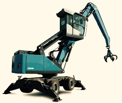
Fuchs MHL 331