Общая документация по автомобилю
Skoda Fabia II: Знакомство с автомобилем (rus.) Пособие по программе самообразования.
Содержание: Skoda Fabia, Размеры автомобиля, Система питания, Двигатели, Комбинации двигатель / КП, Коробка передач, Ходовая часть, Системы пассивной безопасности, Отопление и климатическая установка, Электрооборудование, Салон.
Skoda Fabia II 2006->: Руководство по эксплуатации, ремонту и техническому обслуживанию (rus.) Рассмотрены автомобили Skoda Fabia второго поколения с 2006 года выпуска с бензиновыми двигателями: 1.2 / 44 кВт (BBM) Simos 9.1, 1.2 / 51 кВт (BZG) Simos 9.1, 1.4 / 63 кВт (BXW) Magneti Marelli 4HV, 1.6 / 77 кВт (BTS) Bosch Motronic ME 07.05.20 и дизельными двигателями: 1.4 / 51 кВт (BNM) TDI, 1.4 / 59 кВт (BNV, BMS) TDI, 1.9 / 77 кВт (BSW, BLS) TDI. 400 страниц.
Skoda Fabia II — экономим на сервисе (rus.) Книга адресована владельцам автомобилей Skoda Fabia 2 с трехцилиндровым бензиновым двигателем. В издании приведены иллюстрированные рабочие операции по самостоятельной замене автомобильных расходников, не требующие использования сложного специального инструмента и технической подготовки владельца автомобиля. Многие операции, показанные на данном автомобиле, аналогично выполняют-ся на модификациях Skoda Fabia с другими двигателями. 89 страниц, 10 Мб.
Skoda Fabia II 2007 — : Руководство по эксплуатации, техническому обслуживанию и ремонту (rus.) Ремонт в фотографиях. Выпуск с 2007 г. Рестайлинг в 2010 г. Бензиновые двигатели: 1.2 л (BBM), BZG 1.2 л (BZG), 1.4 л (BXW), 1.6 л (BTS). Коробки передач: 5-ступенчатая механическая коробка передач 02Т, 6-ступенчатая автоматическая коробка передач 09G.
Содержание: Устройство автомобиля, Рекомендации по эксплуатации, Неисправности в пути, Техническое обслуживание, Двигатель, Трансмиссия, Ходовая часть, Рулевое управление, Тормозная система, Электрооборудование, Кузов, Система отопления, кондиционирования и вентиляции салона, Системы безопасности, Колеса и шины, Приложения, Схемы электрооборудования (электросхемы), Предметный указатель. 313 стр. 66 Мб.
Skoda Fabia II RS. Демонстрация автомобиля (rus.) Устройство и принцип действия. Программа самообучения 084 Skoda.
Основное отличие новой модели Fabia RS от модели первого поколения находится под капотом. Модель предыдущего поколения с дизельным двигателем TDI 1,9 л/96 кВт являлась воплощением мечты нетребовательных водителей о быстром, но в то же время экономичном автомобиле. Но именно этот силовой агрегат не позволял воспринимать автомобиль как поистине спортивный.
На модель Fabia RS второго поколения устанавливается бензиновый двигатель 1.4 TSI мощностью 132 кВт (180 л.с.) с турбонагнетателем и компрессором. Такое увеличение мощности стало для модели второго поколения огромным скачком вперёд, благодаря чему ей удалось сохранить динамические характеристики предшественницы: автомобиль разгоняется от 0 до 100 км/ч всего лишь за 7,3 с, а стрелка спидометра, характерного только для модификации Combi, замирает на отметке 224 км/ч или 226 км/ч. Даже при использовании всего потенциала автомобиля расход топлива новой RS остаётся на низком уровне — для преодоления 100 км автомобилю требуется всего лишь 6,4 л топлива. Мощность двигателя передаётся на колёса через 7-ступенчатую коробку передач DSG. Оптимально настроенное шасси автомобиля и система XDS (электронная блокировка дифференциала) повышают удовольствие от вождения.
Содержание: Skoda Fabia RS, Краткое описание, Габаритные размеры автомобиля: Skoda Fabia RS и Skoda Fabia Combi RS, Двигатель (CAVE), Коробка передач (DSG 0AM), Шасси, Передняя подвеска, Задняя подвеска, Рулевое управление, Тормозная система, Система XDS, Колёсные диски и шины, Салон автомобиля.
Общая информация по сервисному обслуживанию
Подходит ко многим автомобилям VW, Skoda, SEAT, Audi
ссылка на мою шкоду
- Manuals
- Brands
- Skoda Manuals
- Automobile
- Fabia II 2007
- Workshop manual
-
Contents
-
Table of Contents
-
Bookmarks
Quick Links
Service
Workshop Manual
Fabia II 2007 ➤ , Fabia II 2009 ➤ ,
Fabia II 2011 ➤ , Rapid 2011 ➤ ,
Rapid NH 2013 ➤ , Rapid NH 2014 ➤ ,
Roomster 2006 ➤
Gearbox 02T
Edition 05.2014
Service Department. Technical Information
Related Manuals for Skoda Fabia II 2007
Summary of Contents for Skoda Fabia II 2007
-
Page 1
Service Workshop Manual Fabia II 2007 ➤ , Fabia II 2009 ➤ , Fabia II 2011 ➤ , Rapid 2011 ➤ , Rapid NH 2013 ➤ , Rapid NH 2014 ➤ , Roomster 2006 ➤ Gearbox 02T Edition 05.2014 Service Department. Technical Information… -
Page 2
Service List of Workshop Manual Repair GroupsList of Workshop Manual Repair GroupsList of Workshop Manual Repair Groups R e p a i r G r o u p 00 — Technical data 30 — Clutch 34 — Controls, housing 35 — Gears, shafts 39 — Final drive — differential… -
Page 3: Table Of Contents
Clutch control …………Summary of components — foot controls (Fabia II 2007 ►; Roomster 2006 ►) ..
-
Page 4
Fabia II 2007 ➤ , Fabia II 2009 ➤ , Fabia II 2011 ➤ , Rapid 2011 ➤ , R … Gearbox 02T — Edition 05.2014 Remove and install gearshift knob and shift lever collar (Rapid) …. -
Page 5: Technical Data
Fabia II 2007 ➤ , Fabia II 2009 ➤ , Fabia II 2011 ➤ , Rapid 2011 ➤ , R … Gearbox 02T — Edition 05.2014 00 – Technical data Identification of the gearbox (SRL000700; Edition 05.2014) Assignment Fabia II ⇒…
-
Page 6
Fabia II 2007 ➤ , Fabia II 2009 ➤ , Fabia II 2011 ➤ , Rapid 2011 ➤ , R … Gearbox 02T — Edition 05.2014 Manual gearbox 5 speed 02T Manufac‐ from 12.06 06.09 01.07 06.09 tured 05.09 03.10 05.09… -
Page 7
Fabia II 2007 ➤ , Fabia II 2009 ➤ , Fabia II 2011 ➤ , Rapid 2011 ➤ , R … Gearbox 02T — Edition 05.2014 Manual gearbox 5 speed 02T Clutch control hydraulic Clutch disc ∅ ⇒ Electronic Catalogue of Original Parts Drive shaft flange ∅… -
Page 8
Fabia II 2007 ➤ , Fabia II 2009 ➤ , Fabia II 2011 ➤ , Rapid 2011 ➤ , R … Gearbox 02T — Edition 05.2014 Manual gearbox 5 speed 02T Manufac‐ from 02.07 06.09 04.07 06.09 tured 05.09 05.09 05.10… -
Page 9
Fabia II 2007 ➤ , Fabia II 2009 ➤ , Fabia II 2011 ➤ , Rapid 2011 ➤ , R … Gearbox 02T — Edition 05.2014 Manual gearbox 5 speed 02T Clutch control hydraulic Clutch disc ∅ ⇒ Electronic Catalogue of Original Parts Drive shaft flange ∅… -
Page 10: Identification Characters, Aggregate Assignment, Ratios, Filling Capacities (Roomster)
Fabia II 2007 ➤ , Fabia II 2009 ➤ , Fabia II 2011 ➤ , Rapid 2011 ➤ , R … Gearbox 02T — Edition 05.2014 Manual gearbox 5 speed 02T Manufac‐ from 02.07 06.09 tured 05.09 09.10 Assign‐ Engine 1.4 ltr./51 kW TDI-PD…
-
Page 11
Fabia II 2007 ➤ , Fabia II 2009 ➤ , Fabia II 2011 ➤ , Rapid 2011 ➤ , R … Gearbox 02T — Edition 05.2014 Manual gearbox 5 speed 02T Filling capacity 2.0 l Specification ⇒ Electronic Catalogue of Original Parts… -
Page 12
Fabia II 2007 ➤ , Fabia II 2009 ➤ , Fabia II 2011 ➤ , Rapid 2011 ➤ , R … Gearbox 02T — Edition 05.2014 Manual gearbox 5 speed 02T Identification characters Manufac‐ from 05.06 11.06 06.09 tured 11.06 05.09… -
Page 13
Fabia II 2007 ➤ , Fabia II 2009 ➤ , Fabia II 2011 ➤ , Rapid 2011 ➤ , R … Gearbox 02T — Edition 05.2014 Manual gearbox 5 speed 02T Specification ⇒ Electronic Catalogue of Original Parts Gear oil change interval… -
Page 14: Identification Characters, Aggregate Assignment, Ratios, Filling Capacities (Rapid)
Fabia II 2007 ➤ , Fabia II 2009 ➤ , Fabia II 2011 ➤ , Rapid 2011 ➤ , R … Gearbox 02T — Edition 05.2014 Manual gearbox 5 speed 02T Identification characters Manufac‐ from 08.06 11.06 06.09 tured 11.06 05.09…
-
Page 15: Identification Characters, Aggregate Assignment, Ratios, Filling Capacities (Rapid Nh)
Fabia II 2007 ➤ , Fabia II 2009 ➤ , Fabia II 2011 ➤ , Rapid 2011 ➤ , R … Gearbox 02T — Edition 05.2014 Manual gearbox 5 speed 02T Reverse gear 35 : 24 x 24 : 11 = 3.182…
-
Page 16
Fabia II 2007 ➤ , Fabia II 2009 ➤ , Fabia II 2011 ➤ , Rapid 2011 ➤ , R … Gearbox 02T — Edition 05.2014 Note Vehicles with ABS do not have the sender for speedometer — ♦ G22- . -
Page 17: Overview Of Transmission System
Fabia II 2007 ➤ , Fabia II 2009 ➤ , Fabia II 2011 ➤ , Rapid 2011 ➤ , R … Gearbox 02T — Edition 05.2014 Overview of Transmission System Designation of components and transmission ratio Note The arrow shows the direction of travel.
-
Page 18: General Repair Instructions
Fabia II 2007 ➤ , Fabia II 2009 ➤ , Fabia II 2011 ➤ , Rapid 2011 ➤ , R … Gearbox 02T — Edition 05.2014 General repair instructions To ensure flawless and successful gearbox repairs, the greatest care and cleanliness as well as the use of good and proper tools are essential.
-
Page 19
Fabia II 2007 ➤ , Fabia II 2009 ➤ , Fabia II 2011 ➤ , Rapid 2011 ➤ , R … Gearbox 02T — Edition 05.2014 Before installing Lightly lubricate the outside diameter of the gasket ring. Fill half the space between the sealing lips -arrow- with grease — G 052 128 A1- . -
Page 20
Fabia II 2007 ➤ , Fabia II 2009 ➤ , Fabia II 2011 ➤ , Rapid 2011 ➤ , R … Gearbox 02T — Edition 05.2014 Nuts and bolts ♦ Slacken and tighten fixing screws and nuts of covers and housings diagonally across in stages. -
Page 21
Fabia II 2007 ➤ , Fabia II 2009 ➤ , Fabia II 2011 ➤ , Rapid 2011 ➤ , R … Gearbox 02T — Edition 05.2014 ♦ These are not interchangeable. If re-using, allocate synchron‐ izer rings to the same sliding gear. -
Page 22: Clutch
Fabia II 2007 ➤ , Fabia II 2009 ➤ , Fabia II 2011 ➤ , Rapid 2011 ➤ , R … Gearbox 02T — Edition 05.2014 30 – Clutch Clutch control Summary of components — foot controls (Fabia II 2007 ►; Room‐…
-
Page 23: Summary Of Components — Foot Controls (Fabia Ii 2007 ►; Roomster 2006 ►)
Fabia II 2007 ➤ , Fabia II 2009 ➤ , Fabia II 2011 ➤ , Rapid 2011 ➤ , R … Gearbox 02T — Edition 05.2014 Summary of components — foot controls (Fabia II 2007 ►; Roomster 2006 ►) Note Summary of components — Hydraulics ⇒…
-
Page 24: Removing And Installing, Setting Angular Clutch Pedal Switch F36
Fabia II 2007 ➤ , Fabia II 2009 ➤ , Fabia II 2011 ➤ , Rapid 2011 ➤ , R … Gearbox 02T — Edition 05.2014 13 — 28 Nm ❑ always replace ⇒ Electronic Catalogue of Original Parts 14 — Master cylinder ❑…
-
Page 25: Removing And Installing, Setting Cylindrical Clutch Pedal Switch F36 , (Fabia Ii 2007 ►; Roomster 2006 ►)
Fabia II 2007 ➤ , Fabia II 2009 ➤ , Fabia II 2011 ➤ , Rapid 2011 ➤ , R … Gearbox 02T — Edition 05.2014 Removing – Remove the storage area on the driver’s side ⇒ Body Work; Rep. gr. 70 .
-
Page 26: Removing And Installing The Crash Strut For The Clutch Pedal (Fabia Ii 2007 ►; Roomster 2006 ►)
Fabia II 2007 ➤ , Fabia II 2009 ➤ , Fabia II 2011 ➤ , Rapid 2011 ➤ , R … Gearbox 02T — Edition 05.2014 Removing and installing the crash strut for the clutch pedal (Fabia II 2007 ►;…
-
Page 27
Fabia II 2007 ➤ , Fabia II 2009 ➤ , Fabia II 2011 ➤ , Rapid 2011 ➤ , R … Gearbox 02T — Edition 05.2014 Tightening torque Crash strut to steering column 9 Nm… -
Page 28
Fabia II 2007 ➤ , Fabia II 2009 ➤ , Fabia II 2011 ➤ , Rapid 2011 ➤ , R … Gearbox 02T — Edition 05.2014 Removing and installing the over-centre helper spring (Fabia II 2007 ►; Roomster 2006 ►) Special tools and workshop equipment required ♦… -
Page 29
Fabia II 2007 ➤ , Fabia II 2009 ➤ , Fabia II 2011 ➤ , Rapid 2011 ➤ , R … Gearbox 02T — Edition 05.2014 – Press over-centre helper spring against the bearing and posi‐ tion on the support of the clutch pedal -arrow-. -
Page 30
Fabia II 2007 ➤ , Fabia II 2009 ➤ , Fabia II 2011 ➤ , Rapid 2011 ➤ , R … Gearbox 02T — Edition 05.2014 Tightening torque Crash strut to steering column ⇒ page 22… -
Page 31: Removing And Installing The Clutch Pedal (Fabia Ii 2007 ►; Roomster 2006 ►)
Fabia II 2007 ➤ , Fabia II 2009 ➤ , Fabia II 2011 ➤ , Rapid 2011 ➤ , R … Gearbox 02T — Edition 05.2014 Removing and installing the clutch pedal (Fabia II 2007 ►; Roomster 2006 ►) Special tools and workshop equipment required ♦…
-
Page 32
Fabia II 2007 ➤ , Fabia II 2009 ➤ , Fabia II 2011 ➤ , Rapid 2011 ➤ , R … Gearbox 02T — Edition 05.2014 Tightening torques Crash strut to steering column ⇒ page 22 ⇒ page 19 Clutch pedal to bracket… -
Page 33: Summary Of Components — Foot Controls (Fabia Ii 2011 ►; Roomster 2011 ►; Rapid Nh 2013 ►)
Fabia II 2007 ➤ , Fabia II 2009 ➤ , Fabia II 2011 ➤ , Rapid 2011 ➤ , R … Gearbox 02T — Edition 05.2014 Summary of components — foot controls (Fabia II 2011 ►; Roomster 2011 ►; Rapid NH 2013 ►)
-
Page 34
Fabia II 2007 ➤ , Fabia II 2009 ➤ , Fabia II 2011 ➤ , Rapid 2011 ➤ , R … Gearbox 02T — Edition 05.2014 8 — Stop ❑ for the clutch pedal 9 — Bearing bolt ❑ always replace ⇒ Electronic Catalogue of Original Parts 10 — Over-centre helper spring ❑… -
Page 35
Fabia II 2007 ➤ , Fabia II 2009 ➤ , Fabia II 2011 ➤ , Rapid 2011 ➤ , R … Gearbox 02T — Edition 05.2014 Removing and installing tension spring – Removing and installing with hook — 3438- . -
Page 36
Fabia II 2007 ➤ , Fabia II 2009 ➤ , Fabia II 2011 ➤ , Rapid 2011 ➤ , R … Gearbox 02T — Edition 05.2014 The clutch pedal switch is installed from the front wall. – Insert the clutch pedal switch into the support of the bracket and turn it 45°… -
Page 37
Fabia II 2007 ➤ , Fabia II 2009 ➤ , Fabia II 2011 ➤ , Rapid 2011 ➤ , R … Gearbox 02T — Edition 05.2014 Tightening torque Crash strut to steering column (2 screws) 9 Nm… -
Page 38
Fabia II 2007 ➤ , Fabia II 2009 ➤ , Fabia II 2011 ➤ , Rapid 2011 ➤ , R … Gearbox 02T — Edition 05.2014 Version with one fixing screw Removing – Remove the storage area on the driver’s side ⇒ Body Work;… -
Page 39
Fabia II 2007 ➤ , Fabia II 2009 ➤ , Fabia II 2011 ➤ , Rapid 2011 ➤ , R … Gearbox 02T — Edition 05.2014 Tightening torque Crash strut to steering column (1 screw) 20 Nm… -
Page 40: Summary Of Components — Foot Controls (Rapid)
Fabia II 2007 ➤ , Fabia II 2009 ➤ , Fabia II 2011 ➤ , Rapid 2011 ➤ , R … Gearbox 02T — Edition 05.2014 Summary of components — Foot controls (Rapid) Note Summary of components — Hydraulics ⇒ page 54 ♦…
-
Page 41
Fabia II 2007 ➤ , Fabia II 2009 ➤ , Fabia II 2011 ➤ , Rapid 2011 ➤ , R … Gearbox 02T — Edition 05.2014 ❑ removing and installing ⇒ page 54 13 — Master cylinder ❑ removing and installing ⇒… -
Page 42: Removing And Installing The Bracket With The Master Cylinder (Fabia Ii 2011 ►; Roomster 2011 ►; Rapid Nh 2013 ►)
Fabia II 2007 ➤ , Fabia II 2009 ➤ , Fabia II 2011 ➤ , Rapid 2011 ➤ , R … Gearbox 02T — Edition 05.2014 – Turn the clutch pedal switch at the bracket 45° in -direction of arrow- and remove it from the support.
-
Page 43
Fabia II 2007 ➤ , Fabia II 2009 ➤ , Fabia II 2011 ➤ , Rapid 2011 ➤ , R … Gearbox 02T — Edition 05.2014 – If the master cylinder is not accessible, remove the engine control unit from the front wall ⇒ Engine; Rep. gr. 23 or ⇒… -
Page 44
Fabia II 2007 ➤ , Fabia II 2009 ➤ , Fabia II 2011 ➤ , Rapid 2011 ➤ , R … Gearbox 02T — Edition 05.2014 – Unscrew the two lower fixing nuts -arrows-. – Remove the bracket -A- from the front wall -B-. -
Page 45: Removing And Installing The Bracket With The Master Cylinder (Rapid 2011 ►)
Fabia II 2007 ➤ , Fabia II 2009 ➤ , Fabia II 2011 ➤ , Rapid 2011 ➤ , R … Gearbox 02T — Edition 05.2014 Tightening torques ⇒ page 29 -Position 4- Bracket/clutch pedal to front wall ⇒ page 29…
-
Page 46
Fabia II 2007 ➤ , Fabia II 2009 ➤ , Fabia II 2011 ➤ , Rapid 2011 ➤ , R … Gearbox 02T — Edition 05.2014 – Unscrew the two lower fixing nuts -arrows-. – Remove the bracket -A- from the front wall -B-. -
Page 47: Removing And Installing The Bracket Without The Master Cylinder (Fabia Ii 2011 ►; Roomster 2011 ►; Rapid Nh 2013 ►)
Fabia II 2007 ➤ , Fabia II 2009 ➤ , Fabia II 2011 ➤ , Rapid 2011 ➤ , R … Gearbox 02T — Edition 05.2014 ⇒ page 36 -Position 4- Master cylinder to front wall Replace self-locking nut. 1.11…
-
Page 48: Removing And Installing The Bracket Without The Master Cylinder (Rapid 2011 ►)
Fabia II 2007 ➤ , Fabia II 2009 ➤ , Fabia II 2011 ➤ , Rapid 2011 ➤ , R … Gearbox 02T — Edition 05.2014 Note Position self-locking nuts -1- and -2- for bracket -3- on front wall. – The support -A- must be located on the actuating rod -B- of the master cylinder.
-
Page 49
Fabia II 2007 ➤ , Fabia II 2009 ➤ , Fabia II 2011 ➤ , Rapid 2011 ➤ , R … Gearbox 02T — Edition 05.2014 Unlock the actuating rod/master cylinder from the clutch pedal as follows: – Pull clutch pedal slightly into the passenger compartment. -
Page 50: Removing And Installing The Clutch Pedal With The Over-Centre Helper Spring (Fabia Ii 2011 ►; Roomster 2011 ►)
Fabia II 2007 ➤ , Fabia II 2009 ➤ , Fabia II 2011 ➤ , Rapid 2011 ➤ , R … Gearbox 02T — Edition 05.2014 1.13 Removing and installing the clutch pedal with the over-centre helper spring (Fa‐ bia II 2011 ►; Roomster 2011 ►) Note Install clutch pedal with new bearing bolt.
-
Page 51
Fabia II 2007 ➤ , Fabia II 2009 ➤ , Fabia II 2011 ➤ , Rapid 2011 ➤ , R … Gearbox 02T — Edition 05.2014 – The support -2- must be located on the actuating rod -1- of the master cylinder. -
Page 52: Removing And Installing The Clutch Pedal With The Over-Centre Helper Spring (Rapid)
Fabia II 2007 ➤ , Fabia II 2009 ➤ , Fabia II 2011 ➤ , Rapid 2011 ➤ , R … Gearbox 02T — Edition 05.2014 1.14 Removing and installing the clutch pedal with the over-centre helper spring (Rap‐ Note Install the clutch pedal with a new bearing bolt.
-
Page 53: Removing And Installing The Clutch Pedal With The Tension Spring (Fabia Ii 2011 ►; Roomster 2011 ►; Rapid Nh 2013 ►)
Fabia II 2007 ➤ , Fabia II 2009 ➤ , Fabia II 2011 ➤ , Rapid 2011 ➤ , R … Gearbox 02T — Edition 05.2014 – The support -2- must be located on the actuating rod -1- of the master cylinder.
-
Page 54
Fabia II 2007 ➤ , Fabia II 2009 ➤ , Fabia II 2011 ➤ , Rapid 2011 ➤ , R … Gearbox 02T — Edition 05.2014 – Unhook the tension spring e.g with hook — 3438- . Note Only observe the right part of the fig. -arrows- when installing. -
Page 55: Summary Of Components — Hydraulic (Fabia Ii ►; Roomster ►; Rapid Nh)
Fabia II 2007 ➤ , Fabia II 2009 ➤ , Fabia II 2011 ➤ , Rapid 2011 ➤ , R … Gearbox 02T — Edition 05.2014 – Position the bolts -A- horizontally. – Turn the bearing bolt to the right -in direction of arrow-, for this purpose use the hexagon socket wrench -1-, wrench size 8 mm.
-
Page 56
Fabia II 2007 ➤ , Fabia II 2009 ➤ , Fabia II 2011 ➤ , Rapid 2011 ➤ , R … Gearbox 02T — Edition 05.2014 1 — Brake fluid reservoir ❑ test tightness ⇒ page 57 2 — Supply hose ❑… -
Page 57
Fabia II 2007 ➤ , Fabia II 2009 ➤ , Fabia II 2011 ➤ , Rapid 2011 ➤ , R … Gearbox 02T — Edition 05.2014 11 — Support ❑ holds the tube-hose line -Pos. 9- on the gearbox ❑ not fitted to all vehicles… -
Page 58: Summary Of Components — Hydraulic (Rapid 2011 ►)
Fabia II 2007 ➤ , Fabia II 2009 ➤ , Fabia II 2011 ➤ , Rapid 2011 ➤ , R … Gearbox 02T — Edition 05.2014 As of 12.05 on certain vehicles plastic return hose -1-: ♦ Gaskets -2- must be present on the return hose.
-
Page 59
Fabia II 2007 ➤ , Fabia II 2009 ➤ , Fabia II 2011 ➤ , Rapid 2011 ➤ , R … Gearbox 02T — Edition 05.2014 13 — Gasket ring/O-ring ❑ pull onto line connection ❑ insert with brake fluid ❑… -
Page 60
Fabia II 2007 ➤ , Fabia II 2009 ➤ , Fabia II 2011 ➤ , Rapid 2011 ➤ , R … Gearbox 02T — Edition 05.2014 Push the actuator rod/master cylinder in the support -A- in -direction of the arrow-. -
Page 61: Check Hydraulic Clutch Control
Fabia II 2007 ➤ , Fabia II 2009 ➤ , Fabia II 2011 ➤ , Rapid 2011 ➤ , R … Gearbox 02T — Edition 05.2014 1.18 Check hydraulic clutch control Note If the master cylinder and/or slave cylinder must be replaced ♦…
-
Page 62: Removing And Installing The Master Cylinder (Fabia Ii 2007 ►; Roomster 2006 ►)
Fabia II 2007 ➤ , Fabia II 2009 ➤ , Fabia II 2011 ➤ , Rapid 2011 ➤ , R … Gearbox 02T — Edition 05.2014 1.19 Removing and installing the master cyl‐ inder (Fabia II 2007 ►; Roomster 2006 ►)
-
Page 63
Fabia II 2007 ➤ , Fabia II 2009 ➤ , Fabia II 2011 ➤ , Rapid 2011 ➤ , R … Gearbox 02T — Edition 05.2014 Unlock the actuating rod/master cylinder from the clutch pedal as follows: – Insert pliers — T10005- in the clutch pedal recesses. -
Page 64
Fabia II 2007 ➤ , Fabia II 2009 ➤ , Fabia II 2011 ➤ , Rapid 2011 ➤ , R … Gearbox 02T — Edition 05.2014 Tightening torques Crash strut to steering column ⇒ page 22 ⇒ page 19 Clutch pedal to bracket… -
Page 65: Removing And Installing The Master Cylinder (Fabia Ii 2011 ►; Roomster 2011 ►; Rapid Nh 2013 ►)
Fabia II 2007 ➤ , Fabia II 2009 ➤ , Fabia II 2011 ➤ , Rapid 2011 ➤ , R … Gearbox 02T — Edition 05.2014 1.20 Removing and installing the master cyl‐ inder (Fabia II 2011 ►; Roomster 2011 ►;…
-
Page 66
Fabia II 2007 ➤ , Fabia II 2009 ➤ , Fabia II 2011 ➤ , Rapid 2011 ➤ , R … Gearbox 02T — Edition 05.2014 Note If the slave cylinder must be replaced due to a predetermined ♦ fault, first of all check the hydraulic clutch control ⇒… -
Page 67
Fabia II 2007 ➤ , Fabia II 2009 ➤ , Fabia II 2011 ➤ , Rapid 2011 ➤ , R … Gearbox 02T — Edition 05.2014 – Disconnect the Bowden cable support from gearbox -arrows-. – Tie up shift cable and selector cable. -
Page 68
Fabia II 2007 ➤ , Fabia II 2009 ➤ , Fabia II 2011 ➤ , Rapid 2011 ➤ , R … Gearbox 02T — Edition 05.2014 Tightening torques Slave cylinder to gearbox Fabia II, Roomster, Rapid NH ⇒ page 51 Rapid ⇒… -
Page 69: Bleeding The Clutch Control
Fabia II 2007 ➤ , Fabia II 2009 ➤ , Fabia II 2011 ➤ , Rapid 2011 ➤ , R … Gearbox 02T — Edition 05.2014 1.22 Bleeding the clutch control Special tools and workshop equipment required ♦ Brake filling and bleeding device , e. g. -VAS 5234-…
-
Page 70: Repairing The Clutch Release Mechanism
Fabia II 2007 ➤ , Fabia II 2009 ➤ , Fabia II 2011 ➤ , Rapid 2011 ➤ , R … Gearbox 02T — Edition 05.2014 Repairing the clutch release mecha‐ nism Special tools and workshop equipment required ♦ Grease — G 000 100- 1 — Clutch release bearing ❑…
-
Page 71
Fabia II 2007 ➤ , Fabia II 2009 ➤ , Fabia II 2011 ➤ , Rapid 2011 ➤ , R … Gearbox 02T — Edition 05.2014 8 — Gearbox 9 — 20 Nm 10 — Support 11 — Slave cylinder ❑… -
Page 72: Repairing Clutch
Fabia II 2007 ➤ , Fabia II 2009 ➤ , Fabia II 2011 ➤ , Rapid 2011 ➤ , R … Gearbox 02T — Edition 05.2014 Repairing clutch Fault finding power transmission — problems with the clutch and clutch control ⇒…
-
Page 73
Fabia II 2007 ➤ , Fabia II 2009 ➤ , Fabia II 2011 ➤ , Rapid 2011 ➤ , R … Gearbox 02T — Edition 05.2014 1 — Flywheel ❑ make sure the centering pins are correctly fitted ❑ The locating face for the… -
Page 74: Fault Finding Power Transmission — Problems With The Clutch And Clutch Control
Fabia II 2007 ➤ , Fabia II 2009 ➤ , Fabia II 2011 ➤ , Rapid 2011 ➤ , R … Gearbox 02T — Edition 05.2014 Centering the clutch disc and removing and installing the pressure plate for vehicles with 1.2 ltr and 1.4 ltr engines –…
-
Page 75
Fabia II 2007 ➤ , Fabia II 2009 ➤ , Fabia II 2011 ➤ , Rapid 2011 ➤ , R … Gearbox 02T — Edition 05.2014 Complaint Fault description Measure Clutch pedal does not return to ini‐ ♦ Air in line system. -
Page 76
Fabia II 2007 ➤ , Fabia II 2009 ➤ , Fabia II 2011 ➤ , Rapid 2011 ➤ , R … Gearbox 02T — Edition 05.2014 Complaint Fault description Measure ♦ Centre displacement of engine/ – Check dowel sleeves. gearbox. -
Page 77
Fabia II 2007 ➤ , Fabia II 2009 ➤ , Fabia II 2011 ➤ , Rapid 2011 ➤ , R … Gearbox 02T — Edition 05.2014 Complaint Fault description Measure ♦ Clutch disc on the serration – Check the hub for damage, if sluggish/jams. -
Page 78
Fabia II 2007 ➤ , Fabia II 2009 ➤ , Fabia II 2011 ➤ , Rapid 2011 ➤ , R … Gearbox 02T — Edition 05.2014 Complaint Fault description Measure ♦ Clutch disc worn out, burnt, – Replace clutch disc. -
Page 79
Fabia II 2007 ➤ , Fabia II 2009 ➤ , Fabia II 2011 ➤ , Rapid 2011 ➤ , R … Gearbox 02T — Edition 05.2014 Complaint Fault description Measure ♦ The contact surface of the pres‐ – Check the contact surface of the sure plate lifts off only unilater‐… -
Page 80: Controls, Housing
Fabia II 2007 ➤ , Fabia II 2009 ➤ , Fabia II 2011 ➤ , Rapid 2011 ➤ , R … Gearbox 02T — Edition 05.2014 34 – Controls, housing Shift mechanism Installation position — selector mechanism ⇒ page 76 Summary of components — Gearshift mechanism ⇒…
-
Page 81
Fabia II 2007 ➤ , Fabia II 2009 ➤ , Fabia II 2011 ➤ , Rapid 2011 ➤ , R … Gearbox 02T — Edition 05.2014 A — Shift cable B — Selector cable C — Heat shield ❑ take off before removing… -
Page 82: Summary Of Components — Gearshift Mechanism
Fabia II 2007 ➤ , Fabia II 2009 ➤ , Fabia II 2011 ➤ , Rapid 2011 ➤ , R … Gearbox 02T — Edition 05.2014 Summary of components — Gearshift mechanism Note If the battery earth strap is disconnected and connected, carry out additional operations ⇒ Electrical System;…
-
Page 83: Summary Of Components — Gearshift Knob With Shift Lever Collar
Fabia II 2007 ➤ , Fabia II 2009 ➤ , Fabia II 2011 ➤ , Rapid 2011 ➤ , R … Gearbox 02T — Edition 05.2014 Summary of components — Gearshift knob with shift lever collar 1 — Gearshift knob ❑…
-
Page 84: Remove And Install Gearshift Knob And Shift Lever Collar (Rapid)
Fabia II 2007 ➤ , Fabia II 2009 ➤ , Fabia II 2011 ➤ , Rapid 2011 ➤ , R … Gearbox 02T — Edition 05.2014 – Lever off the collar with two disassembly wedges — 3409- out of the surround of the centre console in -direction of arrow-.
-
Page 85: Remove And Install Gearshift Knob And Shift Lever Collar (Rapid Nh)
Fabia II 2007 ➤ , Fabia II 2009 ➤ , Fabia II 2011 ➤ , Rapid 2011 ➤ , R … Gearbox 02T — Edition 05.2014 – Lever off the collar frame with the disassembly wedge — T30098- out of the surround for the centre console in -direction of arrow-.
-
Page 86: Summary Of Components — Shift Lever And Shift Housing
Fabia II 2007 ➤ , Fabia II 2009 ➤ , Fabia II 2011 ➤ , Rapid 2011 ➤ , R … Gearbox 02T — Edition 05.2014 – Open clamp -arrow- and pull off gearshift knob together with the collar. Install –…
-
Page 87
Fabia II 2007 ➤ , Fabia II 2009 ➤ , Fabia II 2011 ➤ , Rapid 2011 ➤ , R … Gearbox 02T — Edition 05.2014 1 — Lock washer ❑ removing and installing ⇒ page 84 2 — Pressure spring 3 — Gasket ❑… -
Page 88: Summary Of Components — Control Cables
Fabia II 2007 ➤ , Fabia II 2009 ➤ , Fabia II 2011 ➤ , Rapid 2011 ➤ , R … Gearbox 02T — Edition 05.2014 Removing and installing lock washer – When removing and installing the circlip -A- pull the gearshift…
-
Page 89
Fabia II 2007 ➤ , Fabia II 2009 ➤ , Fabia II 2011 ➤ , Rapid 2011 ➤ , R … Gearbox 02T — Edition 05.2014 1 — Shift cable ❑ slacken from the shift lever guide within the shift mechanism ❑… -
Page 90
Fabia II 2007 ➤ , Fabia II 2009 ➤ , Fabia II 2011 ➤ , Rapid 2011 ➤ , R … Gearbox 02T — Edition 05.2014 ❑ it is not necessary, if it is a plastic relay lever 13 — Bush ❑… -
Page 91: Plastic Relay Lever As Of 06.07 (Fabia Ii, Roomster, Rapid Nh)
Fabia II 2007 ➤ , Fabia II 2009 ➤ , Fabia II 2011 ➤ , Rapid 2011 ➤ , R … Gearbox 02T — Edition 05.2014 Fitting location of gearbox shift lever – When inserting the gearbox shift lever, make sure that the tooth opening -arrow A- is located above the interrupted spac‐…
-
Page 92
Fabia II 2007 ➤ , Fabia II 2009 ➤ , Fabia II 2011 ➤ , Rapid 2011 ➤ , R … Gearbox 02T — Edition 05.2014 – Pull forward the locking mechanism as far as the stop in -direction of arrow 1-, then lock by turning to the left in -direction of arrow 2-. -
Page 93: Remove And Install Shift Mechanism (Fabia Ii, Roomster, Rapid Nh)
Fabia II 2007 ➤ , Fabia II 2009 ➤ , Fabia II 2011 ➤ , Rapid 2011 ➤ , R … Gearbox 02T — Edition 05.2014 Relay lever with clip – Remove clip -arrow°1-. – Carefully take the relay lever together with the cable lock out of its bearing point.
-
Page 94
Fabia II 2007 ➤ , Fabia II 2009 ➤ , Fabia II 2011 ➤ , Rapid 2011 ➤ , R … Gearbox 02T — Edition 05.2014 ♦ Disassembly wedge — 3409- (2 pieces) (Fabia II, Roomster) ♦ Release tool — T30098- (Rapid NH) ♦… -
Page 95
Fabia II 2007 ➤ , Fabia II 2009 ➤ , Fabia II 2011 ➤ , Rapid 2011 ➤ , R … Gearbox 02T — Edition 05.2014 – Remove underbody cover on right and left (if present) -arrows-. – Remove tunnel bridge -arrows-. -
Page 96
Fabia II 2007 ➤ , Fabia II 2009 ➤ , Fabia II 2011 ➤ , Rapid 2011 ➤ , R … Gearbox 02T — Edition 05.2014 – Always replace lock washers -3- and -4- after each disassem‐ bly ⇒ Electronic Catalogue of Original Parts . -
Page 97
Fabia II 2007 ➤ , Fabia II 2009 ➤ , Fabia II 2011 ➤ , Rapid 2011 ➤ , R … Gearbox 02T — Edition 05.2014 Tightening torques Components Tightening torque Underbody cover 2 Nm Shift housing to body ⇒ page 82 Cable support to gearbox ⇒… -
Page 98: Removing And Installing Shift Mechanism (Rapid)
Fabia II 2007 ➤ , Fabia II 2009 ➤ , Fabia II 2011 ➤ , Rapid 2011 ➤ , R … Gearbox 02T — Edition 05.2014 1.11 Removing and installing shift mecha‐ nism (Rapid) Special tools and workshop equipment required ♦…
-
Page 99
Fabia II 2007 ➤ , Fabia II 2009 ➤ , Fabia II 2011 ➤ , Rapid 2011 ➤ , R … Gearbox 02T — Edition 05.2014 – Remove underbody cover on right and left (if present) -arrows-. – Remove tunnel bridge -A- -arrows-. -
Page 100: Setting The Shift Mechanism
Fabia II 2007 ➤ , Fabia II 2009 ➤ , Fabia II 2011 ➤ , Rapid 2011 ➤ , R … Gearbox 02T — Edition 05.2014 – Apply a small quantity of grease — G 000 450 02- onto the studs -arrows- of the gearbox shift lever -1- and of the relay lever -2-.
-
Page 101
Fabia II 2007 ➤ , Fabia II 2009 ➤ , Fabia II 2011 ➤ , Rapid 2011 ➤ , R … Gearbox 02T — Edition 05.2014 • Gearbox in Neutral. Note If the battery earth strap is disconnected and connected, carry out additional operations ⇒… -
Page 102
Fabia II 2007 ➤ , Fabia II 2009 ➤ , Fabia II 2011 ➤ , Rapid 2011 ➤ , R … Gearbox 02T — Edition 05.2014 – Turn locking mechanism at shift cable and at selector cable to the right up to the stop -direction of arrow-. -
Page 103: Removing And Installing The Gearbox
Fabia II 2007 ➤ , Fabia II 2009 ➤ , Fabia II 2011 ➤ , Rapid 2011 ➤ , R … Gearbox 02T — Edition 05.2014 Removing and installing the gearbox Removing the gearbox ⇒ page 99 Installing the gearbox ⇒…
-
Page 104
Fabia II 2007 ➤ , Fabia II 2009 ➤ , Fabia II 2011 ➤ , Rapid 2011 ➤ , R … Gearbox 02T — Edition 05.2014 – Remove circlip -arrow 1- for shift cable from gearbox shift lever -A-. – Pull off shift cable from the stud. -
Page 105
Fabia II 2007 ➤ , Fabia II 2009 ➤ , Fabia II 2011 ➤ , Rapid 2011 ➤ , R … Gearbox 02T — Edition 05.2014 – Remove Bowden cable support -arrows-. – Tie up shift cable and selector cable. -
Page 106
Fabia II 2007 ➤ , Fabia II 2009 ➤ , Fabia II 2011 ➤ , Rapid 2011 ➤ , R … Gearbox 02T — Edition 05.2014 – Remove the earth strap from the engine/gearbox connecting screw -1- (on certain types of engines the earth strap is not connected). -
Page 107
Fabia II 2007 ➤ , Fabia II 2009 ➤ , Fabia II 2011 ➤ , Rapid 2011 ➤ , R … Gearbox 02T — Edition 05.2014 – Install supporting device — MP9-200 (10-222A)- . For this pur‐ pose, position the supports -C- next to the screw -arrow 1- and the support for the engine hood -arrow 2- as shown. -
Page 108
Fabia II 2007 ➤ , Fabia II 2009 ➤ , Fabia II 2011 ➤ , Rapid 2011 ➤ , R … Gearbox 02T — Edition 05.2014 – Unscrew the fixing screws -arrows- from the gearbox mount. – Remove front left wheel ⇒ Chassis; Rep. gr. 44 and raise vehicle: ♦… -
Page 109
Fabia II 2007 ➤ , Fabia II 2009 ➤ , Fabia II 2011 ➤ , Rapid 2011 ➤ , R … Gearbox 02T — Edition 05.2014 – Release the nuts -arrows- for the left steering joint ⇒ Chassis; Rep. gr. 40 (on certain vehicles release the screws, see fig. -
Page 110
Fabia II 2007 ➤ , Fabia II 2009 ➤ , Fabia II 2011 ➤ , Rapid 2011 ➤ , R … Gearbox 02T — Edition 05.2014 – Release the screws -arrows- and remove the fan shroud downwards (on newer models, the screws are no longer present and the fan shroud is only clipped in at the radiator, see fig. -
Page 111
Fabia II 2007 ➤ , Fabia II 2009 ➤ , Fabia II 2011 ➤ , Rapid 2011 ➤ , R … Gearbox 02T — Edition 05.2014 – Screw in the mounting elements -A- as shown on adjusting plate . – Position engine/gearbox jack below vehicle, ⇒ Abb. S34-0340, arrow symbol -B- on adjusting plate points in the direction of travel/vehicle. -
Page 112: Installing The Gearbox
Fabia II 2007 ➤ , Fabia II 2009 ➤ , Fabia II 2011 ➤ , Rapid 2011 ➤ , R … Gearbox 02T — Edition 05.2014 – Adjust supporting arm at slide with locking pin. Number of visible holes -arrow- = 5.
-
Page 113
Fabia II 2007 ➤ , Fabia II 2009 ➤ , Fabia II 2011 ➤ , Rapid 2011 ➤ , R … Gearbox 02T — Edition 05.2014 2.2.1 Tightening torques Gearbox to 1.2/44 kW, 1.2/47 kW, 1.2/51 kW and 1.2/55 kW en‐… -
Page 114
Fabia II 2007 ➤ , Fabia II 2009 ➤ , Fabia II 2011 ➤ , Rapid 2011 ➤ , R … Gearbox 02T — Edition 05.2014 Gearbox to 1.6 ltr./77 kW engine (Fabia II, Roomster) Pos. Screw Piece M12 x 60… -
Page 115
Fabia II 2007 ➤ , Fabia II 2009 ➤ , Fabia II 2011 ➤ , Rapid 2011 ➤ , R … Gearbox 02T — Edition 05.2014 Components Tightening torque 40 Nm + 90° Fixing screws of gearbox mount Cover plate for flywheel… -
Page 116: Inspect The Gear Oil Level In The Gearbox
Fabia II 2007 ➤ , Fabia II 2009 ➤ , Fabia II 2011 ➤ , Rapid 2011 ➤ , R … Gearbox 02T — Edition 05.2014 Inspect the gear oil level in the gear‐ Special tools and workshop equipment required ♦…
-
Page 117: Disassembling And Assembling The Gearbox
Fabia II 2007 ➤ , Fabia II 2009 ➤ , Fabia II 2011 ➤ , Rapid 2011 ➤ , R … Gearbox 02T — Edition 05.2014 Disassembling and assembling the gearbox Gearbox — Summary of components ⇒ page 113 Summary of components ⇒…
-
Page 118: Summary Of Components
Fabia II 2007 ➤ , Fabia II 2009 ➤ , Fabia II 2011 ➤ , Rapid 2011 ➤ , R … Gearbox 02T — Edition 05.2014 Summary of components I — Removing and installing gearbox housing cover and 5th gear ⇒…
-
Page 119: Removing And Installing Gearbox Housing Cover And 5Th Gear
Fabia II 2007 ➤ , Fabia II 2009 ➤ , Fabia II 2011 ➤ , Rapid 2011 ➤ , R … Gearbox 02T — Edition 05.2014 Mounting sequence ⇒ page 118 Removing and installing gearbox housing cover and 5th gear 1 — Gearbox housing ❑…
-
Page 120: Detaching And Attaching Clutch Housing
Fabia II 2007 ➤ , Fabia II 2009 ➤ , Fabia II 2011 ➤ , Rapid 2011 ➤ , R … Gearbox 02T — Edition 05.2014 13 — 5th gear shift fork ❑ disassembling and assembling ⇒ page 132 14 — Bolt ❑…
-
Page 121: Removing And Installing The Drive Shaft, Output Shaft, Differential Gear, Shift Mechanism And Gearshift Forks
Fabia II 2007 ➤ , Fabia II 2009 ➤ , Fabia II 2011 ➤ , Rapid 2011 ➤ , R … Gearbox 02T — Edition 05.2014 Removing and installing the drive shaft, output shaft, differential gear, shift mechanism and gearshift forks 1 — Differential gear ❑…
-
Page 122: Mounting Sequence
Fabia II 2007 ➤ , Fabia II 2009 ➤ , Fabia II 2011 ➤ , Rapid 2011 ➤ , R … Gearbox 02T — Edition 05.2014 12 — 5 Nm + 90° further ❑ always replace ⇒ Electronic Catalogue of Original Parts…
-
Page 123
Fabia II 2007 ➤ , Fabia II 2009 ➤ , Fabia II 2011 ➤ , Rapid 2011 ➤ , R … Gearbox 02T — Edition 05.2014 ♦ Thrust piece — T10085- ♦ Sealant — AMV 188 200 03- Change gearbox holder -T30012- Drill a new hole in the gearbox holder — T30012 (3221)- to attach the Gearbox 02T. -
Page 124
Fabia II 2007 ➤ , Fabia II 2009 ➤ , Fabia II 2011 ➤ , Rapid 2011 ➤ , R … Gearbox 02T — Edition 05.2014 – Unscrew the cover -arrow- for the gearbox housing. – Pull out the bearing bolt -1- for the 5th gear shift fork -2- and remove gearshift fork. -
Page 125
Fabia II 2007 ➤ , Fabia II 2009 ➤ , Fabia II 2011 ➤ , Rapid 2011 ➤ , R … Gearbox 02T — Edition 05.2014 – Remove transmission neutral sender — G701- -arrow-. Continued for all gearboxes – Remove the gearshift shaft with cover -A-; to do this, put the gearshift shaft in idle position. -
Page 126
Fabia II 2007 ➤ , Fabia II 2009 ➤ , Fabia II 2011 ➤ , Rapid 2011 ➤ , R … Gearbox 02T — Edition 05.2014 – Pressing the sleeve of the 5th gear sliding gear needle bearing onto the drive shaft ⇒… -
Page 127
Fabia II 2007 ➤ , Fabia II 2009 ➤ , Fabia II 2011 ➤ , Rapid 2011 ➤ , R … Gearbox 02T — Edition 05.2014 – Fit the washer — T10083/1- onto the drive shaft and carefully press in the bearing support together with the drive shaft and the output shaft up to the stop. -
Page 128
Fabia II 2007 ➤ , Fabia II 2009 ➤ , Fabia II 2011 ➤ , Rapid 2011 ➤ , R … Gearbox 02T — Edition 05.2014 – Remove transmission neutral sender — G701- -arrow-. Continued for all gearboxes – Screw in new screws -A- and tighten the bearing support of the drive shaft and output shaft. -
Page 129
Fabia II 2007 ➤ , Fabia II 2009 ➤ , Fabia II 2011 ➤ , Rapid 2011 ➤ , R … Gearbox 02T — Edition 05.2014 – Insert the 5th gear shift fork -2- and push the bearing pin -1- up to the stop. -
Page 130: Repairing Gearbox Housing And Clutch Housing
Fabia II 2007 ➤ , Fabia II 2009 ➤ , Fabia II 2011 ➤ , Rapid 2011 ➤ , R … Gearbox 02T — Edition 05.2014 Repairing gearbox housing and clutch housing Special tools and workshop equipment required ♦ Thrust piece — MP3-420 (3124)- ♦…
-
Page 131
Fabia II 2007 ➤ , Fabia II 2009 ➤ , Fabia II 2011 ➤ , Rapid 2011 ➤ , R … Gearbox 02T — Edition 05.2014 Oil filler plug or oil drain plug with hexagon socket head — 32 Nm 7 — O-ring ❑… -
Page 132
Fabia II 2007 ➤ , Fabia II 2009 ➤ , Fabia II 2011 ➤ , Rapid 2011 ➤ , R … Gearbox 02T — Edition 05.2014 19 — Bushing ❑ for gearshift shaft ❑ extracting ⇒ page 129 ❑ inserting ⇒… -
Page 133
Fabia II 2007 ➤ , Fabia II 2009 ➤ , Fabia II 2011 ➤ , Rapid 2011 ➤ , R … Gearbox 02T — Edition 05.2014 Remove bushing for gasket ring – Position the distance sleeve — MP3-458/2- and thrust piece — MP3-484 (30-555)- on the differential gear. -
Page 134: Repairing Shift Mechanism
Fabia II 2007 ➤ , Fabia II 2009 ➤ , Fabia II 2011 ➤ , Rapid 2011 ➤ , R … Gearbox 02T — Edition 05.2014 Repairing shift mechanism Special tools and workshop equipment required ♦ Thrust piece — T10203- ♦…
-
Page 135
Fabia II 2007 ➤ , Fabia II 2009 ➤ , Fabia II 2011 ➤ , Rapid 2011 ➤ , R … Gearbox 02T — Edition 05.2014 Remove locking bolt -A- from gearshift cover – Remove the outer part of the locking bolt. -
Page 136: Disassembling And Assembling The Gearshift Forks
Fabia II 2007 ➤ , Fabia II 2009 ➤ , Fabia II 2011 ➤ , Rapid 2011 ➤ , R … Gearbox 02T — Edition 05.2014 Disassembling and assembling the gearshift forks Special tools and workshop equipment required ♦ Driver — MP1-304 (10-206)- ♦…
-
Page 137
Fabia II 2007 ➤ , Fabia II 2009 ➤ , Fabia II 2011 ➤ , Rapid 2011 ➤ , R … Gearbox 02T — Edition 05.2014 7 — Bearing bolt ❑ for 5th gear shift fork Identification of shift segments and 5th gear shift fork with shift… -
Page 138
Fabia II 2007 ➤ , Fabia II 2009 ➤ , Fabia II 2011 ➤ , Rapid 2011 ➤ , R … Gearbox 02T — Edition 05.2014 Fitting the circlip – Press the circlip with a handle wrench into the slot of the shift segment. -
Page 139: Gears, Shafts
Fabia II 2007 ➤ , Fabia II 2009 ➤ , Fabia II 2011 ➤ , Rapid 2011 ➤ , R … Gearbox 02T — Edition 05.2014 35 – Gears, shafts Drive shaft Disassembling and assembling the drive shaft ⇒ page 135…
-
Page 140
Fabia II 2007 ➤ , Fabia II 2009 ➤ , Fabia II 2011 ➤ , Rapid 2011 ➤ , R … Gearbox 02T — Edition 05.2014 Note Insert all bearings, gears and synchronizer rings in the gear‐ ♦ box with gear oil. -
Page 141
Fabia II 2007 ➤ , Fabia II 2009 ➤ , Fabia II 2011 ➤ , Rapid 2011 ➤ , R … Gearbox 02T — Edition 05.2014 7 — Gearbox housing 8 — Bearing support for grooved ball bearing ❑ Always replace grooved ball bearing together with the bearing support ❑… -
Page 142
Fabia II 2007 ➤ , Fabia II 2009 ➤ , Fabia II 2011 ➤ , Rapid 2011 ➤ , R … Gearbox 02T — Edition 05.2014 ❑ removing ⇒ page 138 ❑ pressing on ⇒ page 138 ❑ Fitting position: The circlip in the bearing points towards the drive shaft 22 — Clutch housing ❑… -
Page 143
Fabia II 2007 ➤ , Fabia II 2009 ➤ , Fabia II 2011 ➤ , Rapid 2011 ➤ , R … Gearbox 02T — Edition 05.2014 Press out the bearing support for grooved ball bearing – Move the sliding sleeve for 1st and 2nd gear to 2nd gear. -
Page 144
Fabia II 2007 ➤ , Fabia II 2009 ➤ , Fabia II 2011 ➤ , Rapid 2011 ➤ , R … Gearbox 02T — Edition 05.2014 Disassembling and assembling the sliding sleeve/3rd and 4th gear synchronizer body 1 — Spring (as of production date 06.09 the springs are longer) ⇒… -
Page 145
Fabia II 2007 ➤ , Fabia II 2009 ➤ , Fabia II 2011 ➤ , Rapid 2011 ➤ , R … Gearbox 02T — Edition 05.2014 Press on the synchronizer body with the 3rd and 4th gear sliding sleeve Press on the inner ring -A- for the cylindrical-roller bearing –… -
Page 146
Fabia II 2007 ➤ , Fabia II 2009 ➤ , Fabia II 2011 ➤ , Rapid 2011 ➤ , R … Gearbox 02T — Edition 05.2014 Note The drive shafts of the individual gearboxes have different ♦ lengths due to the different heights of the serration, dimension -a-. -
Page 147
Fabia II 2007 ➤ , Fabia II 2009 ➤ , Fabia II 2011 ➤ , Rapid 2011 ➤ , R … Gearbox 02T — Edition 05.2014 Remove supporting ring – Unclip the hook -A- of the supporting ring from the synchron‐… -
Page 148: Output Shaft
Fabia II 2007 ➤ , Fabia II 2009 ➤ , Fabia II 2011 ➤ , Rapid 2011 ➤ , R … Gearbox 02T — Edition 05.2014 Output shaft Disassembling and assembling the output shaft ⇒ page 144 Disassembling and assembling the out‐…
-
Page 149
Fabia II 2007 ➤ , Fabia II 2009 ➤ , Fabia II 2011 ➤ , Rapid 2011 ➤ , R … Gearbox 02T — Edition 05.2014 1 — Clutch housing ❑ repairing ⇒ page 126 2 — Cylindrical-roller bearing ❑ with circlip ❑… -
Page 150
Fabia II 2007 ➤ , Fabia II 2009 ➤ , Fabia II 2011 ➤ , Rapid 2011 ➤ , R … Gearbox 02T — Edition 05.2014 14 — Sliding sleeve with 1st and 2nd gear synchronizer body ❑ press off together with 2nd gear sliding gear ⇒… -
Page 151
Fabia II 2007 ➤ , Fabia II 2009 ➤ , Fabia II 2011 ➤ , Rapid 2011 ➤ , R … Gearbox 02T — Edition 05.2014 Pull out the cylindrical-roller bearing from the clutch housing – When removing compress circlip of the cylindrical-roller bear‐… -
Page 152
Fabia II 2007 ➤ , Fabia II 2009 ➤ , Fabia II 2011 ➤ , Rapid 2011 ➤ , R … Gearbox 02T — Edition 05.2014 Fitting position 3rd gear pinion and 4th gear pinion. – Place the 4th gear pinion -A- on the output shaft. -
Page 153
Fabia II 2007 ➤ , Fabia II 2009 ➤ , Fabia II 2011 ➤ , Rapid 2011 ➤ , R … Gearbox 02T — Edition 05.2014 Disassembling and assembling the sliding sleeve/1st and 2nd gear synchronizer body 1 — Spring… -
Page 154
Fabia II 2007 ➤ , Fabia II 2009 ➤ , Fabia II 2011 ➤ , Rapid 2011 ➤ , R … Gearbox 02T — Edition 05.2014 Insert the circlip – Rotate the synchronizer ring in such a way that the slots are flush with the arresters. -
Page 155: Final Drive — Differential
Fabia II 2007 ➤ , Fabia II 2009 ➤ , Fabia II 2011 ➤ , Rapid 2011 ➤ , R … Gearbox 02T — Edition 05.2014 39 – Final drive — differential Replacing the flange shaft gasket rings (gearbox assembled) Removing ⇒…
-
Page 156: Install
Fabia II 2007 ➤ , Fabia II 2009 ➤ , Fabia II 2011 ➤ , Rapid 2011 ➤ , R … Gearbox 02T — Edition 05.2014 – If present, remove heat shield for drive shaft -arrows-. – Remove drive shaft from flange shaft ⇒ Chassis; Rep. gr. 40 .
-
Page 157
Fabia II 2007 ➤ , Fabia II 2009 ➤ , Fabia II 2011 ➤ , Rapid 2011 ➤ , R … Gearbox 02T — Edition 05.2014 Steering joint to track control arm ⇒ Chassis; Rep. gr. 40 Wheel bolts to wheel hub ⇒… -
Page 158: Differential Gear
Fabia II 2007 ➤ , Fabia II 2009 ➤ , Fabia II 2011 ➤ , Rapid 2011 ➤ , R … Gearbox 02T — Edition 05.2014 Differential gear Disassembling and assembling differential gear ⇒ page 154 Setting the differential gear ⇒…
-
Page 159
Fabia II 2007 ➤ , Fabia II 2009 ➤ , Fabia II 2011 ➤ , Rapid 2011 ➤ , R … Gearbox 02T — Edition 05.2014 1 — Conical screw, 25 Nm ❑ screw into threaded piece -Pos. 8- 2 — Right flange shaft ❑… -
Page 160
Fabia II 2007 ➤ , Fabia II 2009 ➤ , Fabia II 2011 ➤ , Rapid 2011 ➤ , R … Gearbox 02T — Edition 05.2014 ❑ Assignment ⇒ Electronic Catalogue of Original Parts 15 — Outer ring/tapered-roller bearing ❑ removing ⇒… -
Page 161
Fabia II 2007 ➤ , Fabia II 2009 ➤ , Fabia II 2011 ➤ , Rapid 2011 ➤ , R … Gearbox 02T — Edition 05.2014 Remove outer ring/tapered-roller bearing from gearbox housing A — Countersupport , e.g. -Kukko 22/2- B — Interior extractor 46 up to 58 mm , e.g. -
Page 162
Fabia II 2007 ➤ , Fabia II 2009 ➤ , Fabia II 2011 ➤ , Rapid 2011 ➤ , R … Gearbox 02T — Edition 05.2014 Remove inner ring/tapered-roller bearing on the side of the gear pinion – Before fitting the extractor, position distance sleeve — MP3-458/2- and thrust piece — MP3-431 (3002)- on the differ‐… -
Page 163: Adjusting The Differential Gear
Fabia II 2007 ➤ , Fabia II 2009 ➤ , Fabia II 2011 ➤ , Rapid 2011 ➤ , R … Gearbox 02T — Edition 05.2014 Press out differential bevel gear shaft The tensioning sleeve is cut during pressing out.
-
Page 164
Fabia II 2007 ➤ , Fabia II 2009 ➤ , Fabia II 2011 ➤ , Rapid 2011 ➤ , R … Gearbox 02T — Edition 05.2014 ♦ Interior extractor , e.g. -Kukko 21/7- ♦ Thrust plate — MP3-464 (30-205)- ♦ Dial gauge The differential gear must be re-set when the following compo‐… -
Page 165
Fabia II 2007 ➤ , Fabia II 2009 ➤ , Fabia II 2011 ➤ , Rapid 2011 ➤ , R … Gearbox 02T — Edition 05.2014 – Set the dial gauge to 0 with 1 mm preload on “0”. A — Dial gauge extension 30 mm –…
- Руководства по ремонту
- Руководство по ремонту Шкода Фабия 2000-2007 г.в.
Руководство по ремонту Skoda Fabia / Шкода Фабиа
Общая информация об автомобиле.
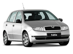
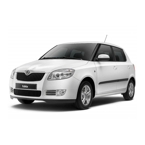
Fabia – легковой переднеприводный автомобиль с поперечным расположением силового агрегата, предназначенный для эксплуатации на дорогах с твердым покрытием.
Семейство автомобилей Fabia включает три базовые модели, различающиеся кузовами: Skoda Fabia 1.4 с кузовом типа хэтчбек, Skoda Fabia 1.4 Combi с кузовом типа универсал и Skoda Fabia 1.4 Sedan с кузовом типа седан Кузов седан предназначен в основном для перевозки пассажиров и небольшого багажа. Кузов хэтчбек более универсален, в нем можно перевозить крупногабаритный багаж, сложив заднее сиденье и увеличив за счет этого багажное отделение. Универсал – это грузопассажирский кузов, позволяющий перевозить значительный объем груза при сложенном заднем сиденье. Багажное отделение универсала намного превышает по объему багажное отделение хэтчбека. Все кузова цельнометаллические несущей конструкции.
Существуют четыре базовые комплектации автомобиля: Basic, Classik, Comfort и Elegance, различающиеся установленными на них двигателями и оборудованием.
Двигатели четырехцилиндровые бензиновые или дизельные рабочим объемом от 1,0 до 1,9 л. Все двигатели оборудованы системой улавливания паров топлива и каталитическими нейтрализаторами в системе выпуска отработавших газов.
Автомобиль оснащен двухконтурной рабочей тормозной системой с гидравлическим приводом и вакуумным усилителем, что повышает его безопасность. Передние тормозные механизмы дисковые, задние – барабанные или дисковые.
Благодаря переднеприводной компоновке автомобиль обладает улучшенными по сравнению с заднеприводными моделями характеристиками управляемости, особенно при прохождении поворотов и на скользкой дороге.
↓ Комментарии ↓
1. Шкода Фабия
1.0 Skoda Fabia
1.2. Технические характеристики автомобилей
1.3 Паспортные данные
1.4 Ключи
1.5 Двери
1.6 Капот
1.7 Багажник
1.8 Регулировка сидений
1.9 Увеличение вместимости багажника
1.10 Ремни безопасности
1.11. Подушки безопасности системы Airbag
1.12 Безопасность детей
1.13 Заправка автомобиля
1.14 Топливо
1.15 Органы управления
1.16 Комбинация приборов
1.17 Блок контрольных ламп
1.18 Рычаг переключения передач
1.19 Рычаг стояночного тормоза
1.20 Регулировка рулевой колонки
1.21 Выключатель (замок) зажигания
1.22 Подрулевой переключатель
1.23 Подсветка приборов
1.24 Корректор фар
1.25 Центральный переключатель
1.26 Прикуриватель
1.27 Пепельница
1.28 Вещевые ящики
1.29 Аварийная сигнализация
1.30 Подогрев передних сидений
1.31 Обогрев заднего стекла
1.32 Выключатель антипробуксовочной системы (ASR)
1.33 Вентиляция и отопление салона
1.34 Кондиционер
1.35 Зеркала заднего вида
1.36 Стеклоподъемники с электроприводом
1.37 Солнцезащитные козырьки
1.38 Люк в крыше с электроприводом
1.39 Сдвижная крыша с электроприводом
1.40 Освещение салона
1.41 Багажник на крыше
1.42 Тягово-сцепное устройство
1.43 Обкатка автомобиля
1.44 Пуск двигателя
1.45 Остановка двигателя
1.46 Пуск двигателя от внешнего источника
1.47 Пуск двигателя буксировкой
1.48 Буксировка автомобиля
1.49 Поднятие автомобиля
1.50. Колеса и шины
1.51 Очистители и омыватели стекол
1.52 Аккумуляторная батарея
1.53 Уход за автомобилем
1.54 Сервисная книжка
2. Двигатель
2.0 Двигатель
2.2. Установка поршня первого цилиндра в положение ВМТ такта сжатия
2.3 Замена ремня привода генератора
2.4. Замена и регулировка натяжения ремня привода распределительного вала
2.5 Замена цепи привода распределительного вала
2.6 Подбор распределительной шестерни коленчатого вала
2.7 Замена прокладки головки блока цилиндров
2.8 Замена сальника распределительного вала
2.9 Замена маслосъемных колпачков
2.10 Замена переднего сальника коленчатого вала
2.11 Задний сальник коленчатого вала
2.12. Ремонт головки блока цилиндров
2.13. Ремонт двигателя
3. Система смазки
3.0 Система смазки
3.1 Снятие и установка масляного картера двигателя
3.2 Ремонт масляного насоса на двигателях 1,0 л, 37 кВт и 1,4 л, 50 кВт
3.3 Замена масляного насоса
3.4 Масляный фильтр дизельного двигателя
3.5 Проверка уровня масла в картере двигателя
3.6 Замена масла и масляного фильтра
4. Система питания
4.0 Система питания
4.2 Замена фильтрующего элемента воздушного фильтра
4.3 Замена датчика указателя уровня топлива
4.4 Снятие и установка топливного бака
4.5 Проверка воздушного клапана
4.6 Проверка гравитационного клапана
4.7 Замена топливного фильтра
4.8 Проверка клапана подогрева топлива
4.9 Замена адсорбера системы улавливания паров топлива
4.10 Замена топливного радиатора
4.11 Снятие и установка вакуумного насоса дизельного двигателя
4.12 Снятие и установка впускной трубы двигателя
4.13 Снятие и установка педали акселератора
4.14. Снятие и установка форсунок
4.15 Проверка цепи питания форсунок бензинового двигателя
4.16 Проверка сопротивления насос-форсунки
4.17 Проверка свечей накаливания дизельного двигателя 1,9 л, 47 кВт
4.18 Проверка цепи питания свечей накаливания
4.19 Проверка датчика температуры охлаждающей жидкости
4.20 Проверка датчика температуры воздуха, поступающего в двигатель
4.21 Проверка датчика температуры топлива дизельного двигателя 1,9 л, 74 кВт
4.22 Проверка датчика частоты вращения коленчатого вала
4.23 Проверка привода дроссельной заслонки
4.24 Проверка датчика положения распределительного вала
4.25 Проверка элекромагнитного клапана рециркуляции отработавших газов
4.26 Проверка реле топливного насоса двигателей 1,4 л, 55 и 74 кВт
4.27 Проверка электромагнитного клапана продувки адсорбера
4.28 Снятие и установка турбокомпрессора
4.29 Снятие и установка промежуточного охладителя воздуха
4.30 Проверка клапана давления наддува
5. Система охлаждения
5.0 Система охлаждения
5.1 Проверка герметичности системы охлаждения
5.2 Проверка пробки расширительного бачка
5.3 Снятие и установка радиатора на моделях без кондиционера
5.4 Снятие и установка радиатора на моделях с кондиционером
5.5 Снятие и установка водяного насоса на моделях с бензиновыми двигателями
5.6 Снятие и установка водяного насоса на моделях с дизельными двигателями
5.7 Снятие и установка вентилятора радиатора
5.8 Замена датчика включения вентилятора
5.9 Снятие и установка термостата
5.10 Проверка термостата
5.11 Замена шлангов системы охлаждения двигателя
5.12 Проверка уровня охлаждающей жидкости
5.13 Замена охлаждающей жидкости
6. Система выпуска отработавших газов
6.0 Система выпуска отработавших газов
6.1 Проверка герметичности системы выпуска отработавших газов
6.2 Снятие и установка приемной трубы глушителя (бензиновые двигатели)
6.3 Снятие и установка приемной трубы глушителя (дизельные двигатели)
6.4 Замена узлов глушителя в сборе (резонатора или глушителя)
6.5 Система рециркуляции отработавших газов (двигатели 1,4 л, 55 и 74 кВт)
6.6 Система рециркуляции отработавших газов (двигатели 1,9 л, 74 кВт)
6.7 Система рециркуляции отработавших газов (двигатели 1,9 л, 47 кВт)
7. Трансмиссия и ходовая часть
7.0 Трансмиссия и ходовая часть
7.1. Технические характеристики коробок передач (КП)
7.2. Передняя подвеска
7.3. Задняя подвеска
8. Рулевое управление
8.0 Рулевое управление
8.1 Снятие и установка рулевого колеса
8.2 Снятие и установка возвратного и контактного колец в сборе
8.3. Рулевая колонка
8.4. Рулевой механизм (без усилителя)
8.5. Рулевой механизм (с усилителем)
9. Тормозная система
9.0 Тормозная система
9.1. Педальный узел
9.2 Вакуумный усилитель
9.3 Главный тормозной цилиндр
9.4 Регулятор давления (на моделях без ABS)
9.5. Тормозной механизм переднего колеса типа FS III
9.6. Тормозной механизм переднего колеса типа FS II
9.7. Тормозной механизм заднего колеса (барабанный)
9.8. Тормозной механизм заднего колеса (дисковый)
9.9. Стояночный тормоз
9.10. Антиблокировочная система (ABS)
10. Электрооборудование
10.0 Электрооборудование
10.2 Аккумуляторная батарея
10.3. Система зажигания
10.4 Снятие и установка комбинации приборов
10.5. Очиститель и омыватель ветрового стекла
10.6. Очиститель и омыватель стекла двери задка
10.7 Замена ламп
10.8 Снятие и установка фары
10.9 Снятие и установка заднего фонаря
10.10 Замена дополнительного фонаря сигнала торможения
10.11 Выключатели и переключатели
10.12 Снятие и установка звуковых сигналов
10.13 Снятие и установка динамиков
10.14 Снятие и установка антенны
11. Кузов
11.0 Кузов
11.2. Передняя дверь
11.3. Задняя дверь
11.4. Сиденья
11.5. Ремни безопасности
11.6 Снятие и установка панели приборов
11.7 Снятие и установка тягово-сцепного устройства
11.8. Отопитель
12. Электросхемы
12.0 Электросхемы
12.1. Символы, встречающиеся на схемах электрооборудования
12.2 Cхемы электрооборудования автомобиля Шкода Фабиа
инструкцияSkoda Fabia (2007)

SIMPLY CLEVER
ŠkodaFabia
РУКОВОДСТВО ПО
ЭКСПЛУАТАЦИИ
Вы тоже можетe помочъ окружающей среде!
Расход топлива в Вашем автомобиле „Škoda“ и, тем самым, содержание вредных
веществ в выпускаемых отработавшых газах в решающей мере обусловлены
Вашей техникой вождения.
Шумность автомобиля и его износ зависят от способа Вашего обращения с ним.
О том, как пользоваться Вашим автомобилем „Škoda“ с максимальным учетом
защиты окружающей среды, а при этом ездить економично
, Вы сможете узнать на
страницах настоящего Руководсва по обслуживанию.
Кроме того следует уделять большое внимание тем разделам Руководства,
которые обозначены симболом цветочка C.
Сотрудничайте с нами — в деие защиты окружающей среды.
www.skoda-auto.com
Návod k obsluze
Fabia rusky 05.07
S55.5610.02.75
5J6 012 003 BH
Fabia rusky 05.07 S55.5610.02.75
05_07_2007.indd 105_07_2007.indd 1 17.4.2007 11:19:0717.4.2007 11:19:07
Посмотреть инструкция для Skoda Fabia (2007) бесплатно. Руководство относится к категории автомобили, 21 человек(а) дали ему среднюю оценку 8.8. Руководство доступно на следующих языках: русский. У вас есть вопрос о Skoda Fabia (2007) или вам нужна помощь? Задайте свой вопрос здесь
Skoda Fabia (2007) — это компактный автомобиль, выпущенный в Чехии. Он доступен в кузовах хэтчбек и универсал, с двигателями объемом от 1,2 л до 1,9 л. Максимальная мощность достигает 105 л.с. и обеспечивает максимальную скорость 190 км/ч. Средний расход топлива составляет примерно 5-6 л на 100 км.
Внутри автомобиля Skoda Fabia (2007) имеет доступный и просторный кабинет со стандартными функциями. Пассажиры получают достаточно места для ног и головы. Багажный отсек имеет емкость от 300 до 1 163 литров в зависимости от конкретного кузова.
Skoda Fabia (2007) оснащена базовыми функциями безопасности, такими как подушки безопасности, антиблокировочная система тормозов и устойчивость при движении в поворотах. Есть также доступ к дополнительным функциям, таким как климат-контроль, электрические стеклоподъемники и круиз-контроль.
В целом, Skoda Fabia (2007) является надежным автомобилем, который обеспечивает достаточный уровень комфорта и производительности в своем классе.
Главная
Не можете найти ответ на свой вопрос в руководстве? Вы можете найти ответ на свой вопрос ниже, в разделе часто задаваемых вопросов о Skoda Fabia (2007).
Как перевести мили в километры?
1 миля равна 1,609344 километрам, а 1 километр — 0,62137119 милям.
Где я могу узнать идентификационный номер транспортного средства Skoda?
Место размещения идентификационного номера транспортного средства зависит от марки и типа транспортного средства. Номер может быть выбит на раме транспортного средства или указан на номерном знаке. Чтобы узнать место расположения идентификационного номера транспортного средства лучше всего ознакомиться с руководством по эксплуатации Skoda Fabia (2007).
Что такое идентификационный номер транспортного средства (VIN)?
Идентификационный номер транспортного средства — уникальный для каждого транспортного средства идентификационный номер. Аббревиатура VIN расшифровывается как «Vehicle Identification Number» (Идентификационный номер транспортного средства).
Когда транспортному средству Skoda требуется техническое обслуживание?
Регулярное техническое обслуживание необходимо всем транспортным средствам. С информацией о том, как часто необходимо проходить техническое обслуживание и чему именно стоит уделять особое внимание можно ознакомиться в инструкции по техническому обслуживанию. Как правило, транспортное средство требует технического обслуживания каждые 2 года или 30 000 километров пробега.
Когда следует заменять тормозную жидкость на Skoda?
Тормозную жидкость рекомендуется менять каждые два года.
В чем разница между топливом E10 и E5?
В топливе E10 содержится до десяти процентов этанола, в то время как в E5 содержится менее пяти процентов. Соответственно, топливо E10 менее вредит окружающей среде.
Одна или несколько дверей не открываются изнутри. Что мне делать?
Скорее всего, замок оснащен защитой от детей и поэтому не может быть открыт изнутри. Процедура открытия замка с защитой от детей зависит от марки и типа замка.
Автомобильный радиоприемник не включается, что делать?
Если автомобильный радиоприемник не включен, на него не будет подаваться питание. Убедитесь, что красный провод подключен к контактному источнику питания, а желтый провод — к источнику питания постоянной мощности.
Инструкция Skoda Fabia (2007) доступно в русский?
Да, руководствоSkoda Fabia (2007) доступно врусский .
Не нашли свой вопрос? Задайте свой вопрос здесь
- Manuals
- Brands
- Skoda Manuals
- Automobile
- FABIA — 05-2007
- Manual
-
Contents
-
Table of Contents
-
Bookmarks
Quick Links
SIMPLY CLE VER
ŠkodaFabia
OWNER´ S MANUAL
Related Manuals for Skoda FABIA — 05-2007
Summary of Contents for Skoda FABIA — 05-2007
-
Page 1
SIMPLY CLE VER ŠkodaFabia OWNER´ S MANUAL… -
Page 3
Introduction You have opted for a Škoda — our sincere thanks for your confidence in us. Your new Škoda offers you a vehicle featuring the most modern engineering and a wide range of equipment which you will undoubtedly wish to use to the full during your daily motoring. That is why, we recommend that you read this Owner’s Manual attentively to enable you to become familiar with your car and all that it offers as quickly as possible. -
Page 4
Introduction On-board literature The Brief instruction The on-board literature for your vehicle consists of this “Owner’s includes an overview of the most important controls of your vehicle. Manual” as well as the brochures “Quick Reference Guide”, “Service The Service schedule Schedule”… -
Page 5: Table Of Contents
Contents Contents Layout of this Owner’s Manual Communication Windshield wiper and wash system ……… . Rear mirror .
-
Page 6
Contents Driving Tips Index Battery …….. -
Page 7
Contents… -
Page 8: Layout Of This Owner’s Manual (Explanations)
Layout of this Owner’s Manual (explanations) Layout of this Owner’s Manual (explanations) The Owner’s Manual has been systematically designed, in order to make it easy for WARNING you to find and absorb the information you require. The most important notes are marked with the heading Warning. These Chapters, table of contents and subject index Warning notes draw your attention to a serious risk of accident or injury.
-
Page 9: Using The System
Cockpit Using the system Fig. 1 Certain items of equipment shown in the illustration are only fitted to particular model versions or are optional items of equipment.
-
Page 10: Cockpit
Cockpit Cockpit General view Storage compartments ……..Lever for adjusting the steering wheel* .
-
Page 11: Instruments And Indicator/Warning Lights
Instruments and Indicator/Warning Lights Instruments and Indicator/Warning Lights General view of the instrument cluster Fig. 2 Instrument cluster Engine revolutions counter ⇒ page 10 When the lights are switched on, the instrument cluster is illuminated. Coolant temperature gauge ⇒ page 10 Fuel gauge ⇒…
-
Page 12: Engine Revolutions Counter
Instruments and Indicator/Warning Lights Engine revolutions counter The operating range The engine has reached its operating temperature as soon as the pointer moves into the mid-range of the scale. The pointer may also move further to the right at ⇒ page 9, fig. 2 The start of the red zone in the revolutions counter indicates the high engine loads and high outside temperatures.
-
Page 13: Speedometer With Counter For Distance Driven
Instruments and Indicator/Warning Lights Warning against excessive speeds* Caution An acoustic warning signal will sound when the vehicle speed exceeds 120 kilome- Never run the fuel tank completely empty! An irregular fuel supply can result in tres per hour. The acoustic warning signal will switch off again when the vehicle poor ignition or misfiring.
-
Page 14: Digital Clock
Instruments and Indicator/Warning Lights Service Interval Display It is only possible to reset the Service Interval Display, if a service message or at least a pre-warning is shown on the display of the instrument cluster. ⇒ page 11, fig. 5 A key symbol appears in the counter display for distance driven about 30 days before reaching the due date for the service.
-
Page 15: Multi-Functional Indicator* (Onboard Computer)
Instruments and Indicator/Warning Lights Memory WARNING The clock should not be adjusted while driving for safety reasons but only when the vehicle is stationary. Multi-functional indicator* (onboard computer) Introduction Fig. 6 Display in engine revolutions counter: The multi-functional indicator appears in the display of the revolutions counter Multi-functional indi- ⇒…
-
Page 16
Instruments and Indicator/Warning Lights The following readouts of the selected memory will be set to zero by button Note • average fuel consumption, All information in the memory is erased if the battery of the vehicle is • distance driven, disconnected. -
Page 17
Instruments and Indicator/Warning Lights The outside temperature indicator will appear with a snowflake symbol (warning The display appears in litres/hour if the vehicle is stationary or driving at a low ⇒ page 14, fig. 8 signal for ice on the road) and a warning signal sounds* when the speed. -
Page 18: Information Display
Instruments and Indicator/Warning Lights The maximum distance indicated in both switch positions is 9999 km. The indicator Certain functions and operating conditions are always being checked on the is set back to null if this period is exceeded. vehicle when the ignition is switched on and also while driving. Functional faults, if required repair work and other information are indicated by red symbols ⇒…
-
Page 19
Instruments and Indicator/Warning Lights Menu TRIP COMPUTER (AUTO COMPUTER) ⇒ page 13 ⇒ page 18 CAR STATUS ⇒ page 20 NAVIGATION DISPLAY OFF After selecting the menu DISPLAY OFF the display is switched off. Press rocker switch for at least 1 second to switch the display on again. The Information CAR STATUSflashes in the menu if there is something which is not in proper order on the vehicle (e.g. -
Page 20: Auto Check Control
Instruments and Indicator/Warning Lights As an additional warning signal, a 3 time peep sounds if the car is driven at a speed Investigate the displayed faults as soon as possible. If several operational faults exist of more than 6km/hour and if the door or the luggage compartment door is open. at the same time, the symbols will appear one after the other and are each visible for about 2 seconds.
-
Page 21
Instruments and Indicator/Warning Lights Red symbols If several operational faults of priority 1 exist, the symbols appear one after the other and are each illuminated for about 2 seconds. A red symbol signals danger. Yellow symbols A yellow symbol signals a warning. Fig. -
Page 22: Warning Lights
Instruments and Indicator/Warning Lights Navigation system* If several operational faults of priority 2 exist, the symbols appear one after the other and are each illuminated for about 2 seconds. The controls for the navigation system, radio, CD player are located in the centre Check the relevant function as soon as possible.
-
Page 23
Instruments and Indicator/Warning Lights ⇒ page 25 Bulbs* ⇒ page 22 Turn signal lights (to the left) ⇒ page 25 Open door* ⇒ page 22 Turn signal lights (to the right) ⇒ page 25 Fluid level in windshield washer system* ⇒… -
Page 24
Instruments and Indicator/Warning Lights Alternator Note • Arrangement of the indicator lights depends on the model and model version. The warning light comes on after the ignition has been switched on. It should go The symbols shown in the following functional description are to be found as indi- out after the engine has started. -
Page 25
Instruments and Indicator/Warning Lights The following text will be displayed in the information display*: Note ENGINE WORKSHOP! (ENGINE FAULT — WORKSHOP!) There is no power-assisted steering support when the vehicle is being towed without the engine running or when the power-assisted steering is defect. The … -
Page 26
Instruments and Indicator/Warning Lights Please also refer to the additional instructions ⇒ page 156, “Cooling system”. The following text will be displayed in the information display*: The following text will be displayed in the information display*: PLEASE REFUEL STOP CHECK COOLANT SERVICE MANUAL (STOP! CHECK COOLANT OWNER’S MANUAL) … -
Page 27
Instruments and Indicator/Warning Lights • The warning light will go out if the bonnet is left open for more than 30 seconds. If brakes applied (brake light), • no engine oil has been replenished, the warning light will come on again after in lighting (low beam and/or rear light). -
Page 28
Instruments and Indicator/Warning Lights Control system for exhaust Further information on the ESP ⇒ page 125, “Electronic stability programme (ESP)*”. The warning light comes on after the ignition has been switched on. Electronic Differential Lock (EDL)* If the warning light does not go out after starting the engine or it lights up or flashes The EDL is a part of the ESP. -
Page 29
Instruments and Indicator/Warning Lights The following text will be displayed in the information display*: WARNING STOP BRAKE FAULT OWNER’S MANUAL • If the brake system warning light comes on together with the ABS For further information on the brake system ⇒ page 128, “Brakes”. warning light … -
Page 30
Instruments and Indicator/Warning Lights The functionality of the airbag system is also monitored electronically, when one airbag has been switched off The passenger front airbag and also possibly the passenger side airbag which have been switched off using the vehicle system tester: •… -
Page 31: Unlocking And Locking
Unlocking and locking Unlocking and locking Key ring The key ring only has the key number on it which is essential for producing other keys. This number can be used to order replacement keys from the Škoda Service Description Partners. The key ring with the number should be separately and securely kept in safe keeping since keys can only be replaced if they are lost or damaged by giving this number.
-
Page 32
Unlocking and locking Changing the key battery – Take the used battery out of the housing cover. – Insert the new battery. Ensure that the “+” symbol on the battery is facing downwards. The correct polarity is also shown on the cover of the transmitter housing. -
Page 33: Locking
Unlocking and locking Locking Child safety lock The child safety lock prevents the rear door from being opened from Valid for vehicles without a central locking system: the inside. Locking from outside The securing head will move upwards or downwards in the door when ⇒…
-
Page 34: Central Locking System
Unlocking and locking Central locking system* WARNING • Description Locking the doors prevents involuntary opening in an exceptional situa- tion (an accident). Locked doors prevent unwanted entry into the vehicle from outside, for example at road crossings. Locked doors do, however, Unlocking or locking the vehicle causes all doors to be unlocked or locked at the make it more difficult for rescuers to get into the vehicle in an emergency — same time by the central locking system.
-
Page 35
Unlocking and locking • The safe securing system is again activated the next time the vehicle is unlocked and All doors are unlocked (the securing knobs in the front doors must move locked again. upwards). • The boot lid is then unlocked. The doors can be opened from the inside if the vehicle is locked and the safe •… -
Page 36
Unlocking and locking • Buttons for the central locking system In the event of an accident in which the airbags are deployed, the locked doors are automatically unlocked from the inside in order to enable rescuers to gain access to the vehicle. WARNING The central locking system also operates if the ignition is switched off. -
Page 37
Unlocking and locking Locking ⇒ page 34, fig. – Remove the panel – Insert the key into the opening under the panel and press the stopping lever as far as the stop toward the inside. – Re-insert the panel. After closing the door, you can no longer open it from outside. If the child safety lock is not switched on, it is possible to open the door from the inside by pulling Fig. -
Page 38: Remote Control
Unlocking and locking WARNING (continued) Note • • The remote control is automatically deactivated when the ignition is switched Never drive with the boot lid fully opened or slightly ajar otherwise exhaust gases may get into the interior of the vehicle — risk of poisoning! •…
-
Page 39
Unlocking and locking The radio-operated key differs according to the equipment installed on The turn signal lights flash once to confirm that the vehicle has been correctly locked. the vehicle. If the turn signal lights do not flash, check the doors, bonnet and boot lid again to … -
Page 40: Anti-Theft Alarm System
Unlocking and locking Anti-theft alarm system* How is the alarm switched off? You switch the alarm off if you unlock the car with the radio remote control in the key or if you switch the ignition on. The anti-theft alarm system increases the level of protection against people seeking to break into the vehicle.
-
Page 41
Unlocking and locking The power windows operate only when ignition is switched on. WARNING • Opening a window If you lock the vehicle from the outside, do not leave any person in the vehicle since it is no longer possible to open the windows from the inside in –… -
Page 42: Electric Sliding/Tilting Roof
Unlocking and locking • Closing windows with the key repeat this operation until the window stops. – Turn the key in the lock of the driver door into the closing position and hold it there until all of the windows are closed. WARNING •…
-
Page 43
Unlocking and locking Closing Note • If the battery has been disconnected and reconnected, it is possible that the Sliding closed/closing the sliding/tilting roof sliding/tilting roof does not close fully. Here you have to set the control dial to the ⇒… -
Page 44
Unlocking and locking Emergency operation Fig. 31 Detail of the headliner: Emergency operation You can close and/or open the sliding/tilting roof by hand if the system is defect. – Carefully remove the plastic cover with a screwdriver. – Insert an Allen key, Group 4, up to the stop into the opening and close and/or open the sliding/tilting roof. -
Page 45: Lights And Visibility
Lights and Visibility Lights and Visibility Lights On models fitted with right-hand steering* the position of certain switches differs ⇒ fig. from that shown in 32. The symbols which mark the switch positions are identical, however. Switching lights on and off In certain countries, the low beam is on a reduced brightness as well as the side lights, when the ignition is switched on.
-
Page 46
Lights and Visibility − This mist has no influence on the life of the lighting system. Instrument lighting* You can adjust the brightness of the instrument lighting. Fog lights* Switching on the fog lights ⇒ page 43, … -
Page 47
Lights and Visibility ⇒ page 44, fig. 34 ⇒ fig. 35 – Turn the control dial until you have adjusted the low – Press switch to switch the hazard warning light system on beam so that oncoming traffic is not dazzled. or off. -
Page 48: Interior Lighting
Lights and Visibility • Right and left turn signal light An acoustic warning signal will sound when the driver’s door is opened if the lever is not in the middle position after removing the ignition key. The acoustic ⇒…
-
Page 49
Lights and Visibility Rear interior lighting* (Combi, Sedan) – On the version without reading lights press the switch into the middle position Switching the interior light on – Press the switch to the left into position Switching the interior light off into the middle position O. -
Page 50: Visibility
Lights and Visibility ⇒ page 47, fig. The warning light is located in the door trim panel below The rear window heater switches off automatically after 20 minutes. If you press the switch once again, the rear window heater is switched on permanently — The warning light goes on every time the door is opened.
-
Page 51: Windshield Wiper And Wash System
Lights and Visibility Windshield wiper and wash system Fast wipe – Position the lever up into position Windshield wiper Automatic wipe/wash for windscreen You can operate the windscreen wipers and automatic wipe/wash – Pull the lever towards the steering wheel into position and the using the windscreen wiper lever.
-
Page 52
Lights and Visibility Top up with wash liquid ⇒ page 164. You should remove any snow from the fixtures of the washer nozzles and clear ice in winter with a de-icing spray in order to ensure proper operation of the cleaning system. -
Page 53: Rear Mirror
Lights and Visibility Attaching a wiper blade therefore important to degrease the lips of the wiper blades after every pass through an automatic vehicle wash system. – Interlock the wiper blade into the window wiper arm — see arrow The same remarks apply here as for ⇒ page 50, “Replacing wiper blades for the WARNING windscreen wipers”.
-
Page 54
Lights and Visibility Adjusting the right-hand exterior mirror* – Turn the rotary knob to position . The movement of the mirror surface is identical to the movement of the rotary knob. Dimming the interior mirror – Pull the lever on the bottom edge of the mirror toward rear (the lever on the interior mirror must point forwards in it home position). -
Page 55: Front Seats
Seats and Stowage Seats and Stowage Front seats WARNING (continued) • It is important for the driver and front passenger to maintain a distance Basic information of at least 25 cm from the steering wheel or dash panel. Not maintaining this minimum distance will mean that the airbag system will not be able to prop- The front seats have a wide range of different settings and can thus be matched to erly protect you — hazard! The front seats and the head restraints must…
-
Page 56: Head Restraints
Seats and Stowage Head restraints Adjusting height of seat* – Lift the seat if required by pulling or pumping lever upwards. – Lower the seat if required by pushing or pumping lever down- wards. Adjust the angle of the seat backrest –…
-
Page 57: Middle Rear Head Restraint
Seats and Stowage Middle rear head restraint* Adjusting the angle of a head restraint* – The head restraint can be matched to the head of the occupant by ⇒ fig. adjusting the angle in the direction of the arrow Adjusting the angle of the head restraint provides enhanced comfort for the user.
-
Page 58: Heating The Front Seats
Seats and Stowage Heating the front seats* from the stress of the journey. Please consult your doctor, who can evaluate your specific condition. Note The seat heating should only be switched on when the engine is running. This has a significant effect of saving on the battery capacity. Rear seats Fig.
-
Page 59
Seats and Stowage To enlarge the luggage compartment, the rear seats can be folded WARNING forwards or the rear seats can be removed ⇒ page 58. The rear seats can • be folded forward individually on vehicles with divided rear seats*. The belt lock and pelvic belt must be in their original position after folding back the rear seats and seat backrest — they must be ready to use. -
Page 60: Pedals
Seats and Stowage Remove the rear seat Operation of the pedals must not be hindered! WARNING • Greater pedal distances may be needed when there is a fault in the brake system. • Do not place any footmats or other additional floor coverings in the area of the pedals in order to ensure that all the pedals can be fully depressed and are able to return unobstructed to their initial position — risk of accident! •…
-
Page 61
Seats and Stowage imagine the injuries that can occur, if this “bullet” is flying through the interior the luggage compartment. Check for yourself that the outlet nozzles are not compartment and hits an occupant. covered. WARNING Lashing eyes • Store the objects in the luggage compartment and attach them to the lashing eyes. -
Page 62
Seats and Stowage Folding double hooks* (Sedan) If, for example, it is necessary to have access to the spare wheel, it is possible to fix the raised floor cover with the loop at the hook* (Fabia), with the hook at the boot ⇒… -
Page 63
Seats and Stowage The luggage compartment cover* Caution You can use the luggage compartment cover behind the head Please ensure that the heating elements of the rear window heater are not restraints for storing light and soft items. damaged as a result of objects placed in this area. Note When opening the boot lid, lift the luggage compartment cover — risk that objects placed in this area can slip forward! -
Page 64: Net Partition (Estate)
Seats and Stowage WARNING No objects should be placed on the luggage compartment cover, the vehicle occupants could be endangered if there is sudden braking or the vehicle collides with something. Caution Please ensure that the heating elements of the rear window heater and luggage Fig.
-
Page 65
Seats and Stowage If you wish to use the entire luggage compartment, you can remove the luggage ⇒ page 61, fig. compartment cover WARNING • Ensure that the seat backrest on the rear seats is securely interlocked in position when the vehicle is fitted with three-point safety belts for the middle rear seat. -
Page 66: The Roof Luggage Rack System
Seats and Stowage The roof luggage rack system* WARNING First check for yourself that the cross road is inserted into the mounts Description the front position! Pay attention to the following points if you wish to transport luggage or other items on the roof of your vehicle: Removing and installing net partition housing •…
-
Page 67
Seats and Stowage Roof load Note A roof rail is obtainable from a Skoda Service Partner if hasn’t been fitted onto an Distribute weight evenly over the roof luggage rack system. The maximum permis- estate car at the works. sible roof load (including roof rack system) of 75 kg and the maximum permissible total weight of the vehicle should not be exceeded. -
Page 68: Drinks Can Holder
Seats and Stowage Drinks can holder* Rear cup holder* Fig. 67 Dash panel: Cup Fig. 68 Centre console: holder Cup holder The drinks can holder is designed to place 0.33 litre drinks cans in. The drinks can holder is designed to place 0.33 litre drinks cans in. …
-
Page 69: Note Holder
Seats and Stowage Note holder Removing ashtray insert – Fold out the ashtray cover and pull out the ashtray insert in the direc- ⇒ fig. tion of arrow Insert ashtray insert – Insert the ashtray insert in the guide, insert and slide in and fold down the ashtray cover.
-
Page 70: Cigarette Lighter* And Power Socket
Seats and Stowage – Insert the plug of the electrical appliance into the socket of the ciga- WARNING rette lighter. Never lay flammable objects in the ashtray basin — risk of fire! The 12 volt power socket can also be used to supply power to electrical accessories with a power uptake up to 180 watts.
-
Page 71: Storage Compartments
Seats and Stowage Power socket in the luggage compartment (Combi*, Sedan*) ⇒ page 72 Storage compartment in the front seat* ⇒ page 72 Storage compartment in the front doors ⇒ page 72 Storage compartment in the luggage compartment (estate car, sedan)* ⇒…
-
Page 72
Seats and Stowage Storage compartment on the front passenger side* Folding up the partition wall – Take hold of the partition wall at the edge or in the recess and folds it ⇒ fig. open in the direction – Press the partition wall until it clicks into place. Folding down the partition wall –… -
Page 73
Seats and Stowage – You can switch the cooling system on or off using the control dial The air inlet in the storage compartment is connected to position through ⇒ page 70, fig. adjustment of the control dial for air distribution. This position causes the maximum amount of air to flow into the storage compartment (depending on the rotary regulator position for the fan). -
Page 74
Seats and Stowage Storage compartment in the front seat* WARNING Use the stowage compartments in the door panels only for small items which do not project out of the compartment in order to avoid any interfer- ence with the proper operation of the side airbags. Storage compartment in the luggage compartment (estate car, sedan)* Fig. -
Page 75
Seats and Stowage Rear seat armrest with storage compartment* Clothes hooks* Fig. 82 Rear seats: Fig. 84 Area above rear Armrest doors: Clothes hooks ⇒ fig. A clothes hook is located above the rear doors WARNING • Ensure that any clothes hanging from the hooks do not impair your vision to the rear. -
Page 76: Heating
Heating and air conditioning system Heating and air conditioning system Heating – Pressing switch causes the recirculating air system to be switched on — recirculated air mode ⇒ Using the system Control for air distribution The heating system delivers air into the interior of the vehicle and –…
-
Page 77
Heating and air conditioning system • Set heating Blower switch in position 2 or 3, • Turn the air distribution control into the position • Recommended settings of heating controls for: Close the air outlet vents 3, • Open the air outlet vents 4, Defrosting the windscreen and side windows •… -
Page 78: Air Conditioning System
Heating and air conditioning system Redirecting air flow The recirculated air mode is switched off automatically if the air distribution control ⇒ page 74, fig. is in position 85. You can also switch recirculated air mode on – Swivel upward or downward the grille of the vents in order to change again from this setting by repeatedly pressing button …
-
Page 79
Heating and air conditioning system Using the system The heating effect is dependent upon the coolant temperature, thus full heat output only occurs when the engine has reached its operating temperature. It is possible to briefly activate recirculated air mode in order to enhance the cooling effect ⇒… -
Page 80
Heating and air conditioning system • switching cooling on and off Turn the air distribution control into the position • Close the air outlet vents 3 – Press the switch . The symbol in the switch comes on. •… -
Page 81
Heating and air conditioning system • Recirculated air mode Turn the control dial to the left up to the stop • Blower switch in position 4 In recirculated air mode air is sucked out of the interior of the vehicle •… -
Page 82
Heating and air conditioning system Air outlet vents Using the air conditioning system economically The compressor on the air conditioning system uses power from the engine when in cooling mode which will effect the fuel consumption. It recommended to open the windows or the doors of a vehicle for which the inte- rior has been strongly heated through the effect of direct sunlight in order to allow the heated air to escape. -
Page 83: Starting-Off And Driving
Starting-off and Driving Starting-off and Driving Setting steering wheel position* – Set the steering wheel to the desired position (concerning height and forward/back position). – Then push the lever up against the steering column until it locks into place. WARNING •…
-
Page 84: Ignition Lock
Starting-off and Driving Ignition lock Move the steering wheel back and forward a little if the ignition key cannot, or cannot easily be turned into this position, in order to release the steering lock. Position The engine is started in this position. At the same time switched on low beam or main beam or other electrical components with major power consumption are briefly switched off.
-
Page 85
Starting-off and Driving • The clutch pedal should be fully depressed when starting the engine which For the sake of the environment means that the starter only has to crank the engine. • Never warm up the engine when the vehicle is standing. Drive off right away. Let go of the key as soon as the engine starts otherwise there may be damage Through this the engine reaches its operating temperature more rapidly and the to the starter. -
Page 86: Switching Off The Engine
Starting-off and Driving • The glow plug warning light will come on for about one second if the engine is Note at a normal operating temperature or if the outside temperature is above +5°C. This • means that you can start the engine right away. The radiator fan may continue running for a further 10 minutes or so after the •…
-
Page 87: Handbrake
Starting-off and Driving A warning signal sounds and the following text appears in the display* if you have Note inadvertently driven off with the handbrake applied: • One should not lay the hand on the shift lever while driving the vehicle. The «Handbrake on»…
-
Page 88: Parking Aid
Starting-off and Driving Parking aid* WARNING The parking aid provides a warning of obstacles behind the vehicle. • The parking aid is not a substitute for the driver paying proper attention and it is always the driver’s responsibility to take care when parking the vehicle or carrying out similar manoeuvres.
-
Page 89
Starting-off and Driving – Press pushbutton once the required speed has been achieved. WARNING (continued) • After you have pressed press button , the speed you have just selected is main- In order to prevent unintentional use of the cruise control system, always tained at a constant speed without having to depress the accelerator. -
Page 90
Starting-off and Driving Switching off the cruise control system completely – Pressing and holding down the slide switch in this postion will cause the speed of the vehicle to be decreased continuously. Once the car has reached the desired speed, release the button. The set speed is ⇒… -
Page 91: 4-Speed Automatic Gearbox
Automatic gearbox* Automatic gearbox* 4-speed automatic gearbox It is sufficient to engage selector lever position P when parking on a flat surface. When parking on a slope you should first apply the handbrake firmly and then move the selector lever into position P. This is to ensure that there is no excessive Information for driving with an automatic gearbox pressure acting on the lock mechanism and that it is easier to subsequently move Shifting up and down through the gears is performed automatically.
-
Page 92
Automatic gearbox* Selector lever positions R — Reverse Reverse gear must only be engaged when the vehicle is stationary and the engine idling ⇒ The brake pedal must be depressed and at the same time the Shiftlock must be pressed, if you wish to obtain the selector lever positions R, P or N. The reversing lights come on when the selector lever is moved into position R when the ignition is also on. -
Page 93
Automatic gearbox* 2 — Position when driving in mountainous regions Note This position of the selector lever is suitable for long sloping sections. • Take your foot off the accelerator if you inadvertently shift into N when driving The gearbox shifts up and down automatically into first and second gear in line with and wait until the engine speed has dropped to the idling speed range before engine load, driving style and vehicle speed. -
Page 94
Automatic gearbox* Kickdown function erate rapidly (e.g. when overtaking) without having to depress the accelerator pedal fully into the kickdown range. The original programme will be reactivated to match The kickdown function provides you with maximum acceleration your particular style of driving once the gearbox has shifted up again. power. -
Page 95
Automatic gearbox* Towing a vehicle Please pay attention to the following information if it comes necessary to tow-in your car ⇒ page 182. Using the system Safety Driving Tips General Maintenance Breakdown assistance Technical Data… -
Page 96: Communication
Communication Communication Universal telephone connection* Removing the mobile phone and adapter – Press the button and remove the mobile telephone. An initialisation must be carried out: • after the first connection of the adapter, • after reconnecting the battery, • after pulling out the adapter cable from the power socket for the mobile phone.
-
Page 97: Cd Changer
Communication • CD changer* no external aerial, • external aerial incorrectly installed, • Take out and insert CD magazine transmission power greater than 10 watts. You should therefore not operate a mobile phone or two-way radio system inside the vehicle without the use of an external aerial, or with an external aerial which has been incorrectly installed.
-
Page 98
Communication – Insert individually CDs with the playback side to the bottom into You can also take out the magazine when the radio is switched off. the magazine, until they lock in place with a locking noise. Pay atten- ⇒ fig. tion to the CD-order on the right side of the magazine 100. -
Page 99
Communication • • SHFL (Shuffleplay). Please never use liquids such as gasoline, paint thinner or disk cleaner, other- • wise the surface of the CD could get damaged. CD1 … CD6 — compartment of CD magazine. • NO CD — no CD in the magazine. •… -
Page 100
Communication Technical data of car radio Note The loudspeakers in the vehicle are matched to a power output of 20 W. -
Page 101: Safety
Passive Safety Safety Passive Safety • Basic information Three-point seat belts for all the seats*, • belt force limiter for front seats*, • Driving the safe way belt tensioner for front seats, • seat belt height adjuster for front seats, Passive safety measures reduce the risk of injury in accident situa- •…
-
Page 102: Correct Seated Position
Passive Safety • Correct seated position Ensure that the lighting and the turn signal system are functioning properly. • Inspect the tyre inflation pressure. • Correct seated position for the driver Ensure that all the windows offer a good visibility to the outside. •…
-
Page 103
Passive Safety • Correct seated position for the front passenger Adjust the backrest so that you are able to reach the highest point of the steering wheel with your arms at a slight angle. The front passenger must maintain a distance of at least 25 cm from •… -
Page 104
Passive Safety Correct seated position for the occupants on the rear seats pants, in particular for the children. Do not permit an occupant to adopt an incor- rect seated position when the car is moving. Occupants on the rear seats must sit upright, keep the feet in the The following list contains the examples of seated positions which are dangerous footwell and must have their seat belts correctly fastened. -
Page 105: Seat Belts
Seat belts Seat belts Why seat belts? It is important that you pay attention to safety measures, particularly when trans- porting children in the vehicle ⇒ page 117, “Transporting children safely”. WARNING • Fasten your seat belt each time before setting off, also when driving in town! This also applies to the people seated at the rear — risk of injury! •…
-
Page 106: The Physical Principle Of A Frontal Collision
Seat belts The physical principle of a frontal collision the greater the amount of energy which has to be absorbed in the event of an acci- dent. The speed of the vehicle is, nevertheless, the most important factor. Doubling the speed of the vehicle from 25 km/h up to 50 km/hour increases the kinetic energy four times.
-
Page 107: How Are Seat Belts Correctly Fastened
Seat belts How are seat belts correctly fastened? WARNING (continued) • No two persons (also not children) should ever use a single seat belt Fastening three-point seat belts together. Fasten your seat belt before starting! • The maximum protection which seat belts can offer is only achieved if you are correctly seated ⇒…
-
Page 108
Seat belts Seat belt height adjuster – Slowly pull the belt webbing at the tongue of the lock over your chest and pelvis ⇒ – Insert the tongue of the lock into the seat belt buckle belonging to the seat until it is heard to lock in place. –… -
Page 109
Seat belts Taking seat belts off The pelvic belt The middle rear seat is fitted with a two-point pelvic belt. Fig. 110 Releasing lock tongue from belt lock Fig. 111 Extending the pelvic belt ⇒ fig. – Press the red button in the belt lock 110. -
Page 110: Belt Tensioner
Seat belts Belt tensioner – Slide the excess belt length through the plastic slider. A classic three-point safety belt is used on some vehicles instead of a pelvic belt Safety for the driver and front passenger wearing their seat belts is enhanced by ⇒…
-
Page 111: Airbag System
Airbag system Airbag system • Description of the airbag system an airbag indicator light showing a switched-off front passenger airbag* in the middle of the dash panel flashes. General information on the airbag system WARNING The front airbag system is complementary to the three-point seat belts and offers •…
-
Page 112
Airbag system • When are the airbags deployed? The dash panel must be replaced after the front passenger airbag has been deployed. • The airbag system is designed in such a way that the driver and the front passenger In the event of an accident in which the airbags are deployed: airbag* are deployed in the event of a frontal collision of major severity. -
Page 113: Front Airbag
Airbag system Front airbag The airbag is not a substitute for the seat belt, but is part of the complete passive vehicle safety concept. Please note that an airbag can only offer you optimal protection in combination with a seat belt which is fastened. Description Apart from their normal protective function, a further task of the seat belts is to The airbag system is not a substitute for the seat belt!
-
Page 114
Airbag system If the airbags are deployed, the airbags are filled with a propellant gas and inflated WARNING ⇒ page 111, fig. in front of the driver and front passenger 115. The airbags inflate • in fractions of a second and at a high speed in order to be able to offer that addi- Never transport children on the front seat of a vehicle without using a tional protection in the event of an accident. -
Page 115: Side Airbags
Airbag system You should therefore always fasten the seat belts, not only because this is required WARNING (continued) by law, but also for safety reasons and for your own protection ⇒ page 103, “Why • seat belts?”. Never place any objects on the surface of the front passenger airbag in the dash panel.
-
Page 116: Deactivating An Airbag
Airbag system Important safety information on the side airbag WARNING (continued) Correct use of the airbag system considerably reduces the risk of • Any seat or protective covers which you fit to the driver or front injury! passenger seats must only be of the type expressly authorized by Škoda Auto.
-
Page 117
Airbag system Switch for the front seat passenger airbag(s)* tries this must be in the direction of travel due to other legal regulations applying) ⇒ page 117, “Important safety information regarding the use of child safety seats” • you are not able to maintain the distance of at least 25 cm between middle of steering wheel and chest, despite the driver seat being correctly adjusted, •… -
Page 118
Airbag system – Check whether the airbag indicator light in the middle of WARNING (continued) ⇒ page 115, fig. 120 the dash panel lights up when the ignition is • turned on. If the warning light (airbag switched off) flashes: −… -
Page 119: Transporting Children Safely
Transporting children safely Transporting children safely What you should know about transporting children! WARNING An introduction to the subject Always comply with national legal provisions and instructions from the rele- vant child safety seat manufacturer when installing and using a child seat Accident statistics have revealed that children are generally more ⇒…
-
Page 120
Transporting children safely Use of child safety seats on the front passenger seat WARNING (continued) Child safety seats should always be attached to the rear seats. • Certain outside climatic conditions can cause life-threatening tempera- tures in the vehicle. • Never allow your child to be transported in a vehicle without the use of a suitable restraint system. -
Page 121
Transporting children safely Child safety and side airbag* WARNING (continued) Children must never be seated in the deployment area of side • It is essential to always switch off ⇒ page 114, “Deactivating an airbag” airbags. the front passenger airbag when attaching a child safety seat on the front passenger seat where the child is seated with its back facing in direction of travel (in some countries also when the child is facing the direction of travel). -
Page 122: Child Seat
Transporting children safely This applies particularly to children if they are not transported in accordance Child safety seats which have been tested for conformity with ECE-R 44 have a non- with legal requirements. detachable test seal (a large E within a circle and below this the test number) attached to the seat.
-
Page 123
Transporting children safely Child seats of group 0/0+ WARNING (continued) • You should have the front passenger airbag (or airbags) reactivated just as soon as you no longer use a child safety seat on the front passenger seat. Child safety seats in Group 1 Fig. -
Page 124
Transporting children safely WARNING (continued) WARNING (continued) travel (in some countries also when the child is facing the direction of travel) seats. Switch off the front passenger airbag if necessary at a specialist garage ⇒ page 115. or switch it off with the switch for front passenger airbag* ⇒ page 115. •… -
Page 125: Attaching A Child Seat Using The «Isofix»* System
Transporting children safely WARNING • When transporting a child on the front passenger seat, please comply with the appropriate national regulations regarding the use of child safety seats. Switch off the front passenger airbag if necessary at a specialist garage or switch it off with the switch for front passenger airbag* ⇒…
-
Page 126
Transporting children safely WARNING • The locking eyes have just been developed for child safety seats which use the “ISOFIX” system. You should therefore never attach other child safety seats, seat belts or objects to the locking eyes — hazard! •… -
Page 127: Driving Tips
Intelligent Technology Driving Tips Intelligent Technology Electronic stability programme (ESP)* Operating principle The ESP switches on automatically when the engine is started and then conducts a self-test. The ESP control unit processes data from the individual systems. It also General processes additional measurement data which are supplied by highly sensitive sensors: the rotational velocity of the vehicle about its vertical axis, the lateral accel- eration of the vehicle, the braking pressure and the steering angle.
-
Page 128
Intelligent Technology • Traction control system (TCS)* when driving with snow chains, • when driving in deep snow or on a loose surface, The traction control system prevents the driven wheels from spinning • when it is necessary to rock a car free when it has become stuck. when accelerating. -
Page 129
Intelligent Technology The TCS should normally always be switched on. It may be good practice in certain Operating principle exceptional cases, such as when you wish to have wheel slip, to switch off the The EDL is activated automatically, that is without any action on the part of the system. -
Page 130: Brakes
Intelligent Technology Brakes Low brake fluid level An insufficient level of brake fluid may result in problems in the brake system. The What has a negative effect on braking efficiency? level of the brake fluid is monitored electronically ⇒ page 27, “Brake system ”. Wear-and-tear WARNING Wear-and-tear to the brake pads is greatly dependent on the operating conditions…
-
Page 131: Antilock Brake System (Abs)
Intelligent Technology WARNING WARNING • • Never switch off the engine before the vehicle is stationary. The ABS can also not overcome the physical limits of your vehicle. Please • do not forget this, particularly when driving on icy or wet road surfaces. If the The brake booster only operates when the engine is running.
-
Page 132: Power Steering
Intelligent Technology pedal firmly and hold it in this position in order to achieve the shortest possible The power steering operates again if the battery is charged to a specific range when braking distance. engine is running. It also operates again, if the engine can be started with its own battery.
-
Page 133: Driving And The Environment
Driving and the Environment Driving and the Environment The first 1 500 kilometres and then afterwards Caution All the speed and engine revolution figures apply only when the engine is at its A new engine normal operating temperature. Never rev up an engine which is cold, neither when The engine has to be run in during the first 1 500 kilometres.
-
Page 134: Catalytic Converter
Driving and the Environment Catalytic converter misfiring. Unburnt fuel may get into the exhaust system and damage the catalytic converter. Proper operation of the emission control system (catalytic converter) • Filling the tank even only once with leaded petrol will result in the catalytic is of major significance for driving your vehicle in an environmen- converter being destroyed.
-
Page 135
Driving and the Environment Manual gearbox The fuel consumption can naturally also be influenced by factors which are beyond the driver’s control. It is, for example, normal for the fuel consumption to increase – Drive no more than about one length of your vehicle in first gear. in winter and under worsened conditions such as poor road conditions, towing a Always shift up into the next higher gear at approx. -
Page 136
Driving and the Environment Sensitive use of the accelerator will not only significantly reduce fuel consumption Also check the oil level after refueling. Oil consumption is dependent to a consid- but also positively influence environmental pollution and wear of your vehicle. erable extent on the load and speed of the engine. -
Page 137: Environmental Compatibility
Driving and the Environment The cold engine vehicle consumes approx. 15 — 20 litres/100 km of fuel immediately causes it to use about 1 l more fuel than normal at a speed of 100 — 120 km/h, even after starting. Fuel consumption drops to 10 litres/100 km after just 1 kilometre. The when you are not carrying a load on the roof.
-
Page 138: Motoring Abroad
Headlight stickers can be obtained as a spare part from the Skoda Service Partners. Headlights with Xenon lamps are designed for driving in countries with traffic on subject to fulfilment of the national legal regulations…
-
Page 139: Avoiding Damage To Your Vehicle
Driving and the Environment Note You can obtain further information regarding masking over or converting the head- lights from your Škoda Service Partner. Avoiding damage to your vehicle When driving on poor roads and lanes or when driving over kerbstones, steep ramps etc., you must pay particular attention to ensuring that any low-slung parts of the vehicle, such as spoiler and exhaust, do not touch the ground and get damaged.
-
Page 140: Towing A Trailer
Towing a trailer Towing a trailer Towing a trailer General Maintenance There are a number of points to pay attention to when towing a Technical requirements trailer. The towing device must satisfy certain technical requirements. Trailer load The permissible trailer load must on no account be exceeded. Your vehicle is designed primarily for transporting persons and luggage.
-
Page 141
Towing a trailer should be attached to folding arms. Adjust the mirrors so that they provide you with Distribution of weight an adequate field of view to the rear. The distribution of the weight is very poor if your vehicle is unladen and the trailer is laden. -
Page 142: Detachable Towing Device
Towing a trailer of the engine speed. One should also not drop a gear for this reason when towing Note a trailer as long as the engine can manage the slope without any drop in speed. • Do not carry out any modifications or repairs to the ball head or to any other components on the towing device.
-
Page 143: General Maintenance
Taking care of your vehicle and cleaning the vehicle General Maintenance Taking care of your vehicle and cleaning the vehicle General Care of the exterior of vehicle Proper care retains the value of your vehicle. Washing the vehicle Regular and proper care retains the value of your vehicle. It may also be one of the Frequent washing protects your vehicle.
-
Page 144
Taking care of your vehicle and cleaning the vehicle Automatic vehicle wash systems Rinse off the vehicle well after giving it a wash and dry it off using a chamois leather. The paintwork of the vehicle is sufficiently resistant that the vehicle can be washed WARNING normally in automatic vehicle wash plants without any problem. -
Page 145
Taking care of your vehicle and cleaning the vehicle WARNING Caution • You must not treat mat painted parts or plastic with polishing products or hard It is particularly important that you do not clean tyres with circular spray wax. jets. -
Page 146
Taking care of your vehicle and cleaning the vehicle Plastic parts The headlight lenses External plastic parts are cleaned by normal washing. Plastic parts and synthetic Please do not use any aggressive cleaning or chemical solvent products — risk of leather can also be treated with special solvent-free plastic cleaning agents if a damage to the plastic lenses Please use soap and clean warm water. -
Page 147
Taking care of your vehicle and cleaning the vehicle Wheels Underbody protection Steel wheels The underside of your vehicle is protected for life against chemical and mechanical influences. You should also thoroughly wash the wheels and wheel trims when giving your vehicle its regular wash. -
Page 148: Care Of The Interior Of Vehicle
Taking care of your vehicle and cleaning the vehicle Engine compartment Upholstery cloth and cloth trim on the doors, luggage compartment cover, head- liner etc. are best treated with special cleaning products, using if necessary a dry foam and a soft sponge or brush. Good corrosion protection is very important, particularly in winter when one often drives over its salt-strewn roads.
-
Page 149
Taking care of your vehicle and cleaning the vehicle Removing stains Note – Remove fresh stains which are water-based (e.g. coffee, tea, juices, • Use a care cream with light blocker and impregnation effect regularly and each blood etc.) with an absorbent cloth or household paper or use the time after cleaning the leather. -
Page 150: Fuel
Fuel Fuel Petrol The handling, performance and life of your engine are determined to a significant extent by the quality of the fuel. Do not use any petrol additives. Use a fuel complying with the standard. Grades of petrol You can find further information on refuelling ⇒ page 149. There are various grades of petrol.
-
Page 151: Refuelling
Fuel • Refuelling Water which has collected in the fuel filter can result in engine problems. Operation in winter Winter-grade diesel fuel A different grade of diesel fuel is available at filling stations in winter than during the summer. Using “summer-grade diesel fuel” at temperatures below 0°C can result in operational problems because the diesel becomes viscous as a result of paraffin separation.
-
Page 152
Fuel Closing fuel filler cap – Screw on the cap by turning it to the right until it is heard to lock. – The fuel filler cap on the fuel filler tube must be locked to the right using the vehicle key and the key then removed (only valid for vehicles which do not have remote unlocking of the fuel filler flap next to the driver’s seat). -
Page 153: Inspecting And Replenishing
Inspecting and Replenishing Inspecting and Replenishing Engine compartment Opening and closing the bonnet. Bonnet remote release Fig. 139 Radiator grille: handle Fig. 138 Bonnet release lever Bonnet remote release – Pull the unlocking lever below the dash panel on the driver’s side ⇒…
-
Page 154
Inspecting and Replenishing Working in the engine compartment – Grip with the hand under the radiator grille and lift up the bonnet. Particular care is required when carrying out any work in the engine – Take the bonnet support out of its holder and set it in the opening ⇒… -
Page 155
Inspecting and Replenishing Overview of the engine compartment WARNING (continued) The main inspection points • Do not let objects, such as e.g cleaning cloth or tools lie in the engine compartment. • If you wish to work under the vehicle, you must secure the vehicle from rolling away and support it with suitable supporting blocks: the car jack is not sufficient for this — risk of injury! •… -
Page 156: Engine Oil
Inspecting and Replenishing Engine oil Engine oil specifications for models with flexible service intervals (QG1) Engine oil specifications Engine oil specifications VW 504 00 Petrol engines The grade of engine oil should be selected in accordance with alternative VW 503 00 precise specifications.
-
Page 157
Inspecting and Replenishing Check engine oil level Oil level within range – You must top up the oil. It is sufficient, once this is done, to keep the The dipstick indicates the level of oil in the engine. oil level is within range It is normal for the engine to consume oil. -
Page 158: Cooling System
Inspecting and Replenishing Replenishing engine oil WARNING (continued) • – Inspect the oil level ⇒ page 155. Read and observe the warning notes ⇒ page 152, “Working in the engine compartment” before working in the engine compartment. – Unscrew the cap of the engine oil filler opening. •…
-
Page 159
Inspecting and Replenishing Inspecting the coolant level also protects the cooling and heating system from corrosion. It also prevents the formation of scale and significantly increases the boiling point of the coolant. You must therefore not reduce the concentration of antifreeze agent in the coolant by adding water, also not during the summer months or in countries with a warm climate. -
Page 160
Inspecting and Replenishing Losses can only occur through the pressure relief in the cap of the coolant expan- Do not fill up over the “MAX” marking! Excess coolant which is heated up is forced sion bottle which is completely free of leaks if the coolant boils as a result of over- out of the cooling system through the pressure relief valve in the cap of the coolant heating and is forced out of the cooling system. -
Page 161: Brake Fluid
Inspecting and Replenishing Radiator fan The brake fluid reservoir is located on the left of the engine compartment. The brake fluid reservoir on right-hand steering models is positioned on The radiator fan may switch on suddenly. the other side of the engine compartment. The radiator fan is driven by an electric motor and controlled by a thermostat –…
-
Page 162: Battery
Inspecting and Replenishing Battery One may only use new genuine brake fluid from Škoda Auto a.s. The specification for the brake fluid is “FMVSS 116 DOT 4”. Working on the battery We recommend that you have the brake fluid replaced by a Škoda Service Partner as part of an Inspection Service.
-
Page 163
Inspecting and Replenishing WARNING (continued) WARNING • • Never charge a frozen or thawed battery — risk of explosion and caustic The battery acid is strongly corrosive and must, therefore, be handled burns! Replace a frozen battery. with the greatest of care. Always wear protective gloves, eye and skin •… -
Page 164
Inspecting and Replenishing Battery with a charge level indicator, the so-called magic eye* Inspecting the electrolyte level The battery is practically maintenance-free under normal operating conditions. We do, however, recommend that you have the electrolyte level inspected from time to time by a Škoda Service Partner when outside temperatures are high or when driving on long trips. -
Page 165
Inspecting and Replenishing – When charging is completed: switch the charger off and unplug the Operation Operating measure mains cable from the power socket. ⇒ page 40 Electrical power window (operational – Only then should you disconnect the terminal clamps of the charger. faults) –… -
Page 166: Windshield Washer System
Inspecting and Replenishing Windshield washer system Caution • On no account should you add radiator antifreeze or other additives to the windscreen washer fluid. • If the vehicle is fitted with headlight cleaning system, you should only add cleaning products which do not attack the polycarbonate coating of the headlights to the windscreen washer fluid.
-
Page 167: Wheels And Tyres
Wheels and Tyres Wheels and Tyres Wheels Further information concerning the use of unidirectional tyres ⇒ page 169. General comments WARNING • New tyres during the first 500 km do not offer optimal grip and should • New tyres do not offer optimal grip at first and should therefore be run in for therefore be run appropriately — risk of accident! about 500 km at a moderate speed and an appropriately cautious style of driving.
-
Page 168
Wheels and Tyres setting off on a long trip. Please do not forget the spare wheel when checking the For the sake of the environment tyres. Tyres which are insufficiently inflated increase your fuel consumption. The tyre inflation pressures for summer tyres are indicated on the inside of the fuel ⇒… -
Page 169
Wheels and Tyres Changing wheels around We recommend that you have any work relating to tyres or wheels carried out by your Škoda Service Partner. Your dealer has all of the necessary special tools and replacement parts available plus the required specialist knowledge and is also in a position to properly dispose of the old tyres. -
Page 170
Wheels and Tyres The date of manufacture is also stated on the tyre wall (possibly only on the inside Note of wheel): It is not normally possible to fit wheels from other models of cars for technical DOT … 20 04… reasons. -
Page 171
Wheels and Tyres Winter tyres WARNING The handling of your vehicle will be significantly improved when driving on wintry You must on no account drive your car at more than the permissible roads if you fit winter tyres. Summer tyres do not offer the same grip on ice, snow maximum speed for your winter tyres — risk of an accident resulting from and at temperatures below 7 °C because of their construction (width, rubber blend, tyre damage and loss of control over your car. -
Page 172
Wheels and Tyres Snow chains Snow chains can be used on all tyres except type 195/50 R15 and 205/45 R16 as well as 185/60 R14 in combination with the wheel trim 6J x 14 with a depth of 38 Snow chains must only be mounted on the front wheels. When driving on wintry roads, snow chains improve not only traction, but also the braking performance. -
Page 173: Accessories, Changes And Replacement Of Parts
• tional faults. This interference can also impair not directly affected systems because Škoda Genuine Accessories which have been released for use and Skoda orig- of the networking of the electronic components. This means that the operating inal parts can be obtained from Škoda Service Partners. They will install them safety of your vehicle can be considerably jeopardized, a greater wear of vehicle professionally and correctly.
-
Page 174
Accessories, changes and replacement of parts… -
Page 175: Breakdown Assistance
Breakdown assistance Breakdown assistance Breakdown assistance First-aid box* and Warning triangle* Other types have the warning triangle located in the well under the carpet of the luggage compartment. Note Pay attention to the use-by-date of the contents of the first-aid box. Fire extinguisher* The fire extinguisher is attached with a strap and a holder to the boot lid.
-
Page 176: Vehicle Tool Kit
Breakdown assistance Vehicle tool kit WARNING (continued) • Ensure that the vehicle tool kit is safely attached in the luggage compartment. Spray for repairing a tyre* Fig. 152 Luggage compartment: Storage compartment for vehicle too kit The vehicle tool kit and the lifting jack are stored in a locable plastic box in the spare ⇒…
-
Page 177: Tyre Repair Kit
Breakdown assistance Tyre repair kit* One should check the inflation pressure in the spare wheel (at best when generally checking the tyre air pressures — see sign on the fuel filler flap ⇒ page 149) to ensure that the spare wheel is always ready to use. The tyre repair kit is intended for the repair of minor tyre defects.
-
Page 178
Breakdown assistance – Slacken the wheel bolts ⇒ page 178. – Apply the handbrake firmly. – Engage 1st gear or if your vehicle is fitted with an automatic gearbox, – Jack up the vehicle until the wheel to be changed is clear of the ground ⇒… -
Page 179
Breakdown assistance – Have the tightening torque of the wheel bolts checked with a torque Pulling off wrench as soon as possible. The tightening torque for steel and light – Hook the clamp found in the vehicle tool kit into the reinforced edge alloy wheels must be 120 Nm. -
Page 180
Breakdown assistance Wheel trim caps* Pulling off – Insert the plastic clip (in the car tool kit) sufficiently far onto the cap until the inner catches of the clip are positioned at the collar of the cap. ⇒ fig. – Pull the cap off with the plastic clip 157. -
Page 181
Breakdown assistance Tightening wheel bolts – Position the lifting jack by selecting the jacking point — lower sill — ⇒ fig. which is closest to the wheel to be removed 159. – Insert the wheel wrench fully onto the wheel bolt –… -
Page 182: Jump-Starting
Breakdown assistance Securing wheels against being stolen* We recommend that you always carry the adapter for the wheel bolts with you in the vehicle. It should be stowed in the vehicle tool kit. You need a special adapter for slackening the safety wheel bolts. Caution •…
-
Page 183
Breakdown assistance Connecting positive terminals WARNING ⇒ fig. 161 – Attach one end to the positive terminal of the • A discharged battery may already freeze at temperatures just below 0°C. discharged battery In case of frozen battery carry out no jump-starting — risk of explosion! Also –… -
Page 184: Tow-Starting And Towing Vehicle
Breakdown assistance – Note that the brake servo unit and power steering only operate if the WARNING (continued) engine is running. You will require significantly greater physical force battery being ignited by the strong spark which results from the engine to depress the brake pedal and to steer the vehicle if the engine is not being started.
-
Page 185
Breakdown assistance Front towing eye Removal of the towing eye – Unscrew the towing eye. The towing eye is stored in the box for the vehicle tool kit. – Put the protective grille in place on the side opposite the marking. –… -
Page 186
Breakdown assistance • – Switch on the ignition. The maximum towing speed is 50 km/h. • The maximum permissible towing distance is 50 km. The gear oil pump does – Wait until both vehicles are moving then release the clutch pedal not operate when the engine is not running;… -
Page 187: Fuses And Light Bulbs
Fuses and light bulbs Fuses and light bulbs Electric fuses – First shift the safety cover into the dash panel in the direction of arrow then press the safety cover in the direction of the arrow in such a way that the guide lug locks into the opening of the dash panel. Replacing fuses in the dash panel Defect fuses must be replaced.
-
Page 188
Fuses and light bulbs No. Power consumer Amperes Note Lambda probe We recommend that you have these fuses replaced by a specialist garage. S-contact Fuse assignment in the dash panel Electrically adjustable rear mirror Ventilation system, air-conditioning system, Xenon head- light Reversing light Diesel engine control unit… -
Page 189
Fuses and light bulbs No. Power consumer Amperes No. Power consumer Amperes Rear window wiper Control unit — petrol engine Parking light on the right Towing device Parking light on the left Electrical power window (at the front on the left) Injector — petrol engine Not assigned Licence plate light… -
Page 190
Fuses and light bulbs Replaces fuses at the battery – Defect fuses can be detected by their melted metal strips. Replace the defect fuse by a new fuse of the same ampere number. Caution • Never attempt to “repair” fuses and also do not replace them with a fuse of a higher amperage — risk of fire! This may also cause damage at another part of the electrical system. -
Page 191: Bulbs
Fuses and light bulbs change the light bulbs. This applies, in particular, to bulbs which can only be No. Power consumer Amperes reached from the engine compartment. Dynamo We therefore recommend that you have any bulbs changed by a Škoda Service Partner or, in exceptional cases, by calling on other professional assistance.
-
Page 192
Fuses and light bulbs Front headlight Others Bulb Side turn signal lights WY5W Licence plate light 3. Brake light Interior light C10W Reading lights Luggage compartment light Door warning light Storage compartment light — front passen- ger side Fig. 170 Protective cover for the headlight at the front WARNING… -
Page 193
– We recommend that you have the headlight setting checked by a For vehicles with a 2.0 litre/85 kW engine, we recommend that you have the light Skoda Service Partner after replacing the light bulb. bulbs for the main beam lights, low beam lights and parking lights changed by a Skoda Service Partner. -
Page 194
– Close the sprung wire clamp over the plate and engage it again. ⇒ fig. – Plug in plug 174. – We recommend that you have the headlight setting checked by a Skoda Service Partner after replacing the light bulb. -
Page 195
Fuses and light bulbs Lighting in storage compartment on front passenger side* Interior light and the reading light* Fig. 176 Remove lighting in storage compartment on front Fig. 177 Remove interior passenger side light We recommend having the light bulb replaced by a Škoda Service Partner. –… -
Page 196
Fuses and light bulbs Rear light unit – Open the boot lid and unscrew the light glass. – Take the faulty bulb out of the fixture and insert a new one. – Re-insert the light glass. Press the light glass in up to the stop — check for correct seating of the sealing rubber. -
Page 197
Fuses and light bulbs Rear light unit (estate car, sedan) Luggage compartment light Fig. 181 Remove the Fig. 182 Remove the light bulb holder (estate luggage compartment car, sedan) light – Open the boot lid/luggage compartment door. – Open the boot lid and remove the luggage compartment cover. ⇒… -
Page 198
Fuses and light bulbs Boot light (sedan) Fig. 183 Remove the boot light (sedan) ⇒ fig. – Insert a screwdriver into the slot under the light 183. Lever out the light carefully. – Unlock the lug then pull out the plug. –… -
Page 199: Technical Data
Technical Data Technical Data Technical Data General comments Weight The details given in the official vehicle registration documents always take prece- The loading capacity is reduced in line with the range of the special equipment. The dence over the details in the Owner’s Manual. Please refer to the official vehicle unloaden weight contains a fuel tank topped up to 90%.
-
Page 200: Fuel Consumption According To The Regulations Eu2, Eu3, Eu4 (99/100/Eu)
Technical Data Gearbox code, paint number, interior equipment number, engine output, Urban traffic engine code The consumption measurement in urban traffic begins with starting of the cold Partial description of the vehicle engine. Afterwards the normal urban traffic is simulated. Vehicle identification number (VIN) Non-urban traffic The vehicle identification number — VIN (vehicle body number) is stamped into the…
-
Page 201: Dimensions
Technical Data Dimensions Dimensions (mm) FABIA ESTATE CAR SEDAN Length 3970 4232 4232 4002 Width 1646 1646 1646 1646 Width including exterior mirror 1893 1893 1893 1893 Height 1451 1452 1449 1441 Wheel base 2462 2462 2462 2462 Track gauge front / rear 1435/1424 1435/1424 1435/1424…
-
Page 202: Technical Data
Technical Data Technical Data 1.2 ltr./40 kW EU 2DDK/EU 4 Engine Power output kW per rpm 40/4750 Maximum torque Nm per rpm 108/3000 3/1198 Number of cylinders/Displacement (cm Fuel — unleaded petrol min. RON Performances FABIA ESTATE CAR SEDAN PRAKTIK Maximum speed km/h Acceleration 0 — 100 km/h…
-
Page 203
Technical Data Oil capacity with oil filter change. Inspect oil level when filling; do not fill up too much. The oil level must be between the markings ⇒ page 155. Weight (in kg) FABIA FABIA ESTATE CAR FABIA SEDAN FABIA PRAKTIK 1560 Permissible gross weight 1595… -
Page 204
Technical Data 1.2 ltr./47 kW EU 2DDK/EU 4 Engine Power output kW per rpm 47/5400 Maximum torque Nm per rpm 112/3000 3/1198 Number of cylinders/Displacement (cm Fuel — unleaded petrol min. RON Performances FABIA ESTATE CAR SEDAN PRAKTIK Maximum speed km/h Acceleration 0 — 100 km/h 15,9… -
Page 205
Technical Data Oil capacity with oil filter change. Inspect oil level when filling; do not fill up too much. The oil level must be between the markings ⇒ page 155. Weight (in kg) FABIA FABIA ESTATE CAR FABIA SEDAN FABIA PRAKTIK Permissible gross weight 1570 1605… -
Page 206
Technical Data 1.4 ltr./55 kW EU 2DDK/EU 4 Engine Power output kW per rpm 55/5000 Maximum torque Nm per rpm 126/3800 4/1390 Number of cylinders/Displacement (cm Fuel — unleaded petrol min. RON Performances FABIA FABIA ESTATE CAR SEDAN Maximum speed km/h Acceleration 0 — 100 km/h 13,8… -
Page 207
Technical Data Capacities (in liter) Fuel tank capacity/of which spare 45/7,5 Reservoir for windscreen washer system/ with headlight cleaning system Engine oil Cooling system of the vehicle Oil capacity with oil filter change. Inspect oil level when filling; do not fill up too much. The oil level must be between the markings ⇒ page 155. Weight (in kg) FABIA ESTATE CAR… -
Page 208
Technical Data 1.4 ltr./59 kW EU 2DDK/EU 4 Engine Power output kW per rpm 59/5000 Maximum torque Nm per rpm 132/3800 4/1390 Number of cylinders/Displacement (cm Fuel — unleaded petrol min. RON Performances ESTATE CAR SEDAN Maximum speed km/h Acceleration 0 — 100 km/h 13,1 13,1 Fuel consumption (in ltr./100 km) and CO… -
Page 209
Technical Data Weight (in kg) ESTATE CAR SEDAN Permissible gross weight 1610 1605 Unloaden weight ready for work 1095 1090 Loading capacity Loading capacity when using the TLC Permissible front axle load Permissible rear axle load (800/450) (800/450) Permissible trailer load, trailer braked/unbraked (950/450) (950/450) Uphills up to 12%… -
Page 210
Technical Data 1.4 ltr./74 kW EU 2DDK/EU 4 Engine Power output kW per rpm 74/6000 Maximum torque Nm per rpm 126/4400 4/1390 Number of cylinders/Displacement (cm Fuel — unleaded petrol min. RON Performances FABIA ESTATE CAR SEDAN Maximum speed km/h Acceleration 0 — 100 km/h 11,5 11,6… -
Page 211
Technical Data Weight (in kg) FABIA ESTATE CAR SEDAN Permissible gross weight 1580 1615 1610 Unloaden weight ready for work 1065 1100 1095 Loading capacity Loading capacity when using the TLC Permissible front axle load Permissible rear axle load (850/450) (850/450) (850/450) Permissible trailer load, trailer braked/unbraked… -
Page 212
Technical Data 2.0 ltr./85 kW EU 2DDK/EU 4 Engine Power output kW per rpm 85/5400 Maximum torque Nm per rpm 170/2400 4/1984 Number of cylinders/Displacement (cm Fuel — unleaded petrol min. RON Performances FABIA ESTATE CAR SEDAN Maximum speed km/h Acceleration 0 — 100 km/h 10,1 10,2… -
Page 213
Technical Data Weight (in kg) FABIA ESTATE CAR SEDAN Permissible gross weight 1625 1660 1655 Unloaden weight ready for work 1110 1145 1140 Loading capacity Loading capacity when using the TLC Permissible front axle load Permissible rear axle load (1000/500) (1000/500) (1000/500) Permissible trailer load, trailer braked/unbraked… -
Page 214
Technical Data 1.4 l/51 kW TDI PD EU 4 Engine Power output kW per rpm 51/4000 Maximum torque Nm per rpm 155/2200 3/1422 Number of cylinders/Displacement (cm Fuel Diesel Performances FABIA ESTATE CAR SEDAN PRAKTIK Maximum speed km/h Acceleration 0 — 100 km/h 15,6 15,8 15,8… -
Page 215
Technical Data Weight (in kg) FABIA ESTATE CAR SEDAN PRAKTIK Permissible gross weight 1635 1670 1665 1610 Unloaden weight ready for work 1120 1155 1150 1160 Loading capacity Loading capacity when using the TLC Permissible front axle load Permissible rear axle load (900/450) (900/450) (900/450) -
Page 216
Technical Data 1.4 l/59 kW TDI PD EU 4 Engine Power output kW per rpm 59/4000 Maximum torque Nm per rpm 195/2200 3/1422 Number of cylinders/Displacement (cm Fuel Diesel Performances FABIA ESTATE CAR SEDAN Maximum speed km/h Acceleration 0 — 100 km/h 13,8 Fuel consumption (in ltr./100 km) and CO emission (in g/km) -
Page 217
Technical Data Weight (in kg) FABIA ESTATE CAR SEDAN Permissible gross weight 1645 1680 1675 Unloaden weight ready for work 1130 1165 1160 Loading capacity Loading capacity when using the TLC Permissible front axle load Permissible rear axle load (1000/450) (1000/450) (1000/450) Permissible trailer load, trailer braked/unbraked… -
Page 218
Technical Data 1.9 ltr./47 kW SDI EU 3 Engine Power output kW per rpm 47/4000 125/ Maximum torque Nm per rpm 1600-2800 4/1896 Number of cylinders/Displacement (cm Fuel Diesel Performances FABIA ESTATE CAR SEDAN PRAKTIK Maximum speed km/h Acceleration 0 — 100 km/h 17,9 18,3 18,3… -
Page 219
Technical Data Weight (in kg) FABIA ESTATE CAR SEDAN PRAKTIK Permissible gross weight 1640 1675 1670 1615 Unloaden weight ready for work 1125 1160 1155 1165 Loading capacity Loading capacity when using the TLC Permissible front axle load Permissible rear axle load (800/450) (800/450) (800/450) -
Page 220
Technical Data 1,9 l/74 kW TDI PD EU 4 Engine Power output kW per rpm 74/4000 240/ Maximum torque Nm per rpm 1800-2400 4/1896 Number of cylinders/Displacement (cm Fuel Diesel Performances FABIA ESTATE CAR SEDAN Maximum speed km/h Acceleration 0 — 100 km/h 11,5 11,6 11,6… -
Page 221
Technical Data Weight (in kg) FABIA ESTATE CAR SEDAN Permissible gross weight 1660 1695 1690 Unloaden weight ready for work 1145 1180 1175 Loading capacity Loading capacity when using the TLC Permissible front axle load Permissible rear axle load (1000/450) (1000/450) (1000/450) Permissible trailer load, trailer braked/unbraked… -
Page 222
Technical Data 1.9 ltr./96 kW TDI PD (Fabia RS) EU 4 Engine Power output kW per rpm 96/4000 Maximum torque Nm per rpm 310/1900 4/1896 Number of cylinders/Displacement (cm Fuel Diesel Performances Maximum speed km/h Acceleration 0 — 100 km/h Fuel consumption (in ltr./100 km) and CO emission (in g/km) Urban… -
Page 223
Technical Data Capacities (in liter) Fuel tank capacity/of which spare 45/7,5 Reservoir for windscreen washer system/ with headlight cleaning system Engine oil Cooling system of the vehicle Oil capacity with oil filter change. Inspect oil level when filling; do not fill up too much. The oil level must be between the markings ⇒ page 155. Weight (in kg) Permissible gross weight 1720… -
Page 224
Technical Data… -
Page 225: Index
Index Index Automatic gearbox ……89 Brakes ……..128 Emergency programme .
-
Page 226
Index Child seat ……..120 De-icing the windows ….. . . 144 Engine Classification into groups . -
Page 227
Index Fuel ……..148 Headlight cleaning system . -
Page 228
Index Luggage compartment ……58 Opening a single door ……32 Radio systems . -
Page 229
Index Seat belt warning light ….. . . 105 Sun visors ……..48 Tread depth . -
Page 230
Index Wheel Changing ……. . 175 Spare ……..175 Wheel bolts . -
Page 231
Notes… -
Page 232
Notes… -
Page 233
Notes… -
Page 234
Škoda Auto pursues a policy of constant product and model development. We trust Škoda Auto expressly reserves all rights relating to copyright laws. that you will understand that changes to models in terms of shape, equipment and We reserve the right to make changes to this document. engineering, may be introduced at any time. -
Page 235
SIMPLY CLE VER ŠkodaService ŠkodaGenuine Parts ŠkodaGenuine Accessories… -
Page 236
Look up „Environment“ in the Index to find out more. Please also refer to all the texts identified with a ; in this Owner ´ s Manual. Make your contribution — for the sake of the environment. www.skoda-auto.com Návod k obsluze Fabia anglicky 05.07 S54.5610.09.20 6Y0 012 003 LR…
This manual is also suitable for:
Fabia