- Manuals
- Brands
- BRP Manuals
- Offroad Vehicle
- can-am OUTLANDER 2021 Series
- Operator’s manual
-
Contents
-
Table of Contents
-
Troubleshooting
-
Bookmarks
Quick Links
OUTLANDER
TM
Series
WARNING
Read this guide thoroughly.
It contains important safety information.
Minimum recommended age: Operator: 16 years old.
Keep this Operator’s Guide in the vehicle.
2 1 9 0 0 2 0 9 3
Original Instructions
Related Manuals for BRP can-am OUTLANDER 2021 Series
Summary of Contents for BRP can-am OUTLANDER 2021 Series
-
Page 1
OUTLANDER Series WARNING Read this guide thoroughly. It contains important safety information. Minimum recommended age: Operator: 16 years old. Keep this Operator’s Guide in the vehicle. 2 1 9 0 0 2 0 9 3 Original Instructions… -
Page 2
– QS3 is a trademark of Fox Factory, Inc. † 219002093 en COJT ®™ and the BRP logo are trademarks of Bombardier Recreational Products Inc. or its affiliates. ©2020 Bombardier Recreational Products Inc. and BRP US Inc. All rights reserved. -
Page 3: Foreword
FOREWORD OPERATOR’S GUIDE 2021 Outlander 650 Outlander 850 Outlander DPS 650 Outlander DPS 850 Outlander XU 650 Outlander XT 650 Outlander XT 850 Outlander XT 1000R Outlander North Edition 850 Outlander Mossy Oak Hunting Edition 650 Outlander XT-P 850 Outlander XT-P 1000R Outlander X xc 1000R Outlander MAX DPS 650 Outlander MAX XT 650…
-
Page 4
Can-Am ® ATV. It is backed by the servicing information, please ask your BRP warranty and a network of autho- dealer. rized Can-Am dealers ready to provide At delivery, you were also informed of the parts, service or accessories you the warranty coverage and signed the may require. -
Page 5: Know Before You Go
Also, read all safety labels on your a potential injury hazard. watch attentively SAFETY VIDEO located at https://can- am.brp.com/off-road/safety. WARNING Indicates a potential hazard, if not avoided, could result in serious in- jury or death. CAUTION Indicates a hazard situation which, if not avoided, This vehicle is for off road use only.
-
Page 6
Due to late changes, some differences be- tween the manufactured product and the descriptions and/or specifications in this guide may occur. BRP reserves the right at any time to discontinue or change specifications, designs, fea- tures, models or equipment without incurring any obligation upon itself. -
Page 7: Table Of Contents
TABLE OF CONTENTS FOREWORD …………….1 Know Before you Go ..
-
Page 8
TABLE OF CONTENTS VEHICLE INFORMATION CONTROLS …………….92 1) Throttle Lever . -
Page 9
TABLE OF CONTENTS BASIC PROCEDURES …………126 Starting the Engine. -
Page 10
US EPA EMISSION-RELATED WARRANTY ……..207 BRP INTERNATIONAL LIMITED WARRANTY: 2021 CAN-AM ® ATV ..210 BRP LIMITED WARRANTY FOR THE EUROPEAN ECONOMIC AREA, THE COMMONWEALTH OF THE INDEPENDENT STATES AND TURKEY: 2021 CAN-AM ®… -
Page 11
TABLE OF CONTENTS CONTACT US…………..225 Asia. -
Page 12
TABLE OF CONTENTS ______________… -
Page 13: Safety Information
SAFETY INFORMATION ________ ________ SAFETY INFORMATION…
-
Page 14: General Precautions
BRP for the vehicle. These modifications have not Avoid Gasoline Fires and been tested by BRP and they may in- Other Hazards crease the risk of injury or loss of con- trol, or render the vehicle illegal to ride.
-
Page 15: Special Safety Messages
SPECIAL SAFETY MESSAGES THIS VEHICLE IS NOT A TOY AND CAN BE HAZARDOUS TO OPERATE. – This vehicle handles differently from other vehicles including motorcycles and cars. A collision or rollover can occur quickly, if you fail to take proper precautions, even during routine maneuvers such as turning and driving on hills or over obstacles.
-
Page 16
When it is safe to proceed in reverse, go slowly. Take into account that on a 2-UP model the passenger can obstruct your view. – BRP recommends sitting on your ATV when operating in reverse. Avoid stand- ing up. Your weight could shift forward against throttle lever, causing an unex- pected acceleration and may lead to a loss of control. -
Page 17
SPECIAL SAFETY MESSAGES 2-UP Models Driver must: – Not forget is responsible for the safety of the passenger. – Inform the passenger concerning the basic rules for a safe ride. – Instruct the passenger to read the vehicle’s safety labels and to watch the SAFETY VIDEO –… -
Page 18: Operation Warnings
OPERATION WARNINGS The following warning and their format have been requested by the United States Consumer Product Safety Commission and are required to be in the Operator’s Guide for all ATVs. NOTE: The following illustrations are general representations only. Your model may differ.
-
Page 19
OPERATION WARNINGS WARNING V00A1AQ POTENTIAL HAZARD Failure to follow the age recommendations for this vehicle. WHAT CAN HAPPEN A lack of respect for this age recommendation can lead to severe injury or death of the child. Even though a child may be within the age group for which this vehicle is recommended, he may not have the skills, abilities, or judgment needed to operate this vehicle safely and may be involved in a serious accident. -
Page 20
OPERATION WARNINGS 2-UP Models Only WARNING vmo2014-005-100 POTENTIAL HAZARD Failure to respect the physical limitations of the passeng er on 2-UP models. WHAT CAN HAPPEN A passenger that cannot completely lean his feet on footrests can be ejected when riding on uneven terrain. HOW TO AVOID THE HAZARD The passenger must be capable of keeping his feet on the footrests and his hands on grab handles at all times when he is seated on the vehicle. -
Page 21
OPERATION WARNINGS 1-UP Models Only WARNING V00A02Q POTENTIAL HAZARD Carrying a passenger on this vehicle. WHAT CAN HAPPEN Greatly reduces your ability to balance and control this vehicle. Could cause an accident, resulting in harm to you and/or your passenger. HOW TO AVOID THE HAZARD Never carry passenger. -
Page 22
OPERATION WARNINGS 2-UP Models Only WARNING V00A1CQ POTENTIAL HAZARD Carrying more than one (1) passenger on this vehicle. WHAT CAN HAPPEN Carrying more than one (1) passenger reduces your ability to balance and control this vehicle. Could cause an accident, resulting in harm to you and/or your passengers. HOW TO AVOID THE HAZARD Never carry more than one (1) passenger. -
Page 23
OPERATION WARNINGS WARNING V00A2DQ POTENTIAL HAZARD Allowing passenger(s) to sit on front or rear racks on this vehicle. WHAT CAN HAPPEN Allowing a passenger could: – Impair vehicle stability which could lead to a loss of control. – Result in injury to passenger(s) from impact on hard surfaces. –… -
Page 24
OPERATION WARNINGS WARNING POTENTIAL HAZARD Operating this vehicle on public streets, roads or highways. WHAT CAN HAPPEN You can collide with another vehicle. HOW TO AVOID THE HAZARD Never operate this vehicle on any public street, road or highway, even a dirt or gravel one. -
Page 25
OPERATION WARNINGS WARNING POTENTIAL HAZARD Riding this vehicle without wearing an approved helmet, eye protection and protective gear. On 2-UP models, passenger should also have an approved helmet with a rigid chin guard. WHAT CAN HAPPEN – Riding without an approved helmet increases the chances of a severe head injury or death in the event of an accident. -
Page 26
OPERATION WARNINGS WARNING V00A07Q POTENTIAL HAZARD Using this vehicle with drugs or alcohol. WHAT CAN HAPPEN Could cause the passenger to fall off (2-UP models). Could seriously affect your judgment. Could cause you to react more slowly. Could affect your balance and perception. Could result in an accident or death. -
Page 27
OPERATION WARNINGS WARNING V00A08Q POTENTIAL HAZARD Operating this vehicle at excessive speeds. WHAT CAN HAPPEN Increases your chances of losing control of the vehicle, which can result in an accident. HOW TO AVOID THE HAZARD Always travel at a speed which is appropriate for the terrain, visibility and operating conditions, and your experience. -
Page 28
OPERATION WARNINGS WARNING POTENTIAL HAZARD Attempting wheelies, jumps and other stunts. WHAT CAN HAPPEN Increases the chance of an accident, including an overturn. HOW TO AVOID THE HAZARD Never attempt stunts, such as wheelies or jumps. Do not try to show off. WARNING POTENTIAL HAZARD Failure to inspect the vehicle before operating. -
Page 29
OPERATION WARNINGS WARNING POTENTIAL HAZARD Riding on frozen waterways. WHAT CAN HAPPEN Breaking through the ice can lead to severe injury or death. HOW TO AVOID THE HAZARD Never ride this vehicle on a frozen surface before you are sure the ice is thick enough and sound enough to support the vehicle and its load, as well as the force that is created by a moving vehicle. -
Page 30
OPERATION WARNINGS WARNING POTENTIAL HAZARD Failure to use extra care when operating this vehicle on unfamiliar terrain. WHAT CAN HAPPEN You can come upon hidden rocks, bumps, or holes, without enough time to react. Could result in the vehicle overturning, passenger ejection (2-UP models) or loss of control. -
Page 31
OPERATION WARNINGS WARNING POTENTIAL HAZARD Failure to use extra care when operating on excessively rough, slippery or loose terrain. WHAT CAN HAPPEN Could cause loss of traction or vehicle control, which could result in an acci- dent, including an overturn or passenger ejection (2-UP models). HOW TO AVOID THE HAZARD Do not operate on excessively rough, slippery or loose terrain until you have learned and practiced the skills necessary to control this vehicle on… -
Page 32
OPERATION WARNINGS WARNING POTENTIAL HAZARD Turning improperly. WHAT CAN HAPPEN Vehicle could go out of control, causing a collision or an overturn or a pas- senger ejection (2-UP models). HOW TO AVOID THE HAZARD Always follow proper procedures for turning as described in this Operator’s Guide. -
Page 33
OPERATION WARNINGS WARNING POTENTIAL HAZARD Operating on excessively steep hills. WHAT CAN HAPPEN The vehicle can overturn more easily on extremely steep hills than on level surfaces or small hills. HOW TO AVOID THE HAZARD Never operate this vehicle on hills too steep for the vehicle or for your abili- ties. -
Page 34
OPERATION WARNINGS WARNING POTENTIAL HAZARD Climbing hills improperly. WHAT CAN HAPPEN Could cause loss of control, passenger ejection (2-UP models) or cause ve- hicle to overturn. HOW TO AVOID THE HAZARD Always follow proper procedures for climbing hills as described in this Op- erator’s Guide. -
Page 35
OPERATION WARNINGS WARNING POTENTIAL HAZARD Going down a hill improperly. WHAT CAN HAPPEN Could cause loss of control, passenger ejection (2-UP models) or cause ve- hicle to overturn. HOW TO AVOID THE HAZARD Always follow proper procedures for going down hills as described in this Operator’s Guide. -
Page 36
OPERATION WARNINGS WARNING POTENTIAL HAZARD Improperly crossing hills or turning on hills. WHAT CAN HAPPEN Could cause loss of control, passenger ejection (2-UP models) or cause ve- hicle to overturn. HOW TO AVOID THE HAZARD Never attempt this maneuver on 2-UP models when the passenger is on board. -
Page 37
OPERATION WARNINGS WARNING V00A1PQ POTENTIAL HAZARD Stalling, rolling backwards or improperly dismounting while climbing a hill. WHAT CAN HAPPEN Could result in vehicle overturning. HOW TO AVOID THE HAZARD Use low gear and maintain steady speed when climbing a hill. If you lose all forward speed: Operator and passenger (2-UP models) must keep their weight uphill. -
Page 38
OPERATION WARNINGS WARNING POTENTIAL HAZARD Improperly operating over obstacles. WHAT CAN HAPPEN Could cause loss of control (passenger ejection on 2-UP models), or a colli- sion. Could cause the vehicle to overturn. HOW TO AVOID THE HAZARD Before operating in a new area, check for obstacles. Never attempt to ride over large obstacles, such as large rocks or fallen trees. -
Page 39
OPERATION WARNINGS WARNING POTENTIAL HAZARD Skidding or sliding improperly. WHAT CAN HAPPEN You may lose control of this vehicle. You may also regain traction unexpectedly, which may cause the vehicle to overturn or passenger ejection (2-UP models). HOW TO AVOID THE HAZARD Learn to safely control skidding or sliding by practicing at low speeds and on level smooth terrain. -
Page 40
OPERATION WARNINGS WARNING POTENTIAL HAZARD Operating this vehicle through deep or fast flowing water. WHAT CAN HAPPEN Tires may float, causing loss of traction and loss of control, which could lead to an accident. HOW TO AVOID THE HAZARD Never operate this vehicle in fast flowing water or in deep water. Check water depth and current before you attempt to cross any water. -
Page 41
OPERATION WARNINGS WARNING POTENTIAL HAZARD Improperly operating in reverse. WHAT CAN HAPPEN You could hit an obstacle or person behind the vehicle, resulting in serious injury. HOW TO AVOID THE HAZARD When you select reverse gear, make sure there are no obstacles or people behind the vehicle. -
Page 42
OPERATION WARNINGS WARNING POTENTIAL HAZARD Operating this vehicle with improper tires, or with improper or uneven tire pressure. WHAT CAN HAPPEN Use of improper tires on this vehicle, or operation of this vehicle with improper or uneven tire pressure, may cause loss of control, tire blow outs, tire to move around on its rim, and increases the risk of an accident. -
Page 43
Never modify this vehicle through improper installation or use of acces- sories. All parts and accessories added to this vehicle should be approved by BRP and should be installed and used according to instructions. If you have questions, consult an authorized Can-Am dealer. -
Page 44
OPERATION WARNINGS WARNING POTENTIAL HAZARD Overloading this vehicle, carrying or towing cargo improperly. WHAT CAN HAPPEN Could cause changes in vehicle handling which could lead to an accident. HOW TO AVOID THE HAZARD Never exceed the stated load capacity for this vehicle including operator and passenger (2-UP models) as well as other loads and added accessories. -
Page 45
OPERATION WARNINGS WARNING V03M01Q POTENTIAL HAZARD Transporting flammable or dangerous material can lead to explosions. WHAT CAN HAPPEN This can cause serious injury or death. HOW TO AVOID THE HAZARD Never transport flammable or dangerous material. ________ ________ SAFETY INFORMATION… -
Page 46: Pre-Ride Inspection
PRE-RIDE INSPECTION WARNING Perform a pre-ride inspection before each ride to detect any potential prob- lem that could occur during operation. The pre-ride inspection can help you monitor component wear and deterioration before they become a problem. Correct any problem that you discover to reduce the risk of a breakdown or crash.
-
Page 47
PRE-RIDE INSPECTION ITEMS TO BE ✔ INSPECTION TO PERFORM INSPECTED If you transport a cargo, respect the load capacity. LOADING THE CARGO RACKS Refer to Ensure cargo is properly secured to the racks If you are pulling a trailer or another equipment: Cargo –… -
Page 48
PRE-RIDE INSPECTION What to Do After the Engine is Started ITEMS TO BE ✔ INSPECTION TO PERFORM INSPECTED Check if steering operates freely by completely turning it Steering from side to side Shift lever Check operation of shift lever (P, R, N, H and L) 2WD/4WD selector Check operation of 2WD/4WD selector Drive forward slowly a few feet and apply brake lever… -
Page 49: Riding The Vehicle
BRP dealer performs the preseason preparation of your vehicle. Each visit to your authorized BRP dealer is a great opportunity for your dealer to verify if your vehicle is included in any safety campaign. We also urge you to visit your authorized BRP dealer in a timely manner if you become aware of any safety related campaigns.
-
Page 50: Riding Gear
RIDING THE VEHICLE Riding Gear Actual weather conditions should help you decide how to dress. Dress for the coldest weather expected. Thermal underwear next to the skin also provides a good insulation. It is important that the operator always wears the appropriate protective riding gear and apparel, including an approved helmet, eye protection, boots, gloves, a long sleeved shirt and pants.
-
Page 51: Carrying A Passenger
NEVER install other passenger’s seat other than the one recommended by BRP. Do not use the racks or their location to carry passenger(s). Carrying more than one (1) passenger may affect the stability and your control of the vehicle.
-
Page 52: Environment
RIDING THE VEHICLE First aid kit Adjustable wrench Mobile phone Knife Friction tape Flashlight A rope Colored lens goggles Trail map Spare light bulbs Provided tool kit Snack Environment One of the benefits of this vehicle is that it can take you off the beaten path away from most communities.
-
Page 53: Riding Techniques
RIDING THE VEHICLE An operator who takes a vehicle off-road should always exercise the utmost care in selecting the safest path and keeping close watch on the terrain ahead of him. On no account should the vehicle be operated by anyone who is not completely famil- iar with the driving instructions applicable to the vehicle, nor should it be operated on steep or treacherous terrain.
-
Page 54
RIDING THE VEHICLE vmo2012-012-520 2 2 -UP Models The passenger must keep his hands on the grab handles and his feet on footrests at all times. The passenger must synchronize his movements with the operator. Crossing Roads If you have to cross a road, the lead driver should get off his vehicle, then observe and give directions to the other riders. -
Page 55
RIDING THE VEHICLE Avoid sudden inputs to steering, throttle or brakes while turning. WARNING Do not attempt turns at excessive speed. vmo2012-012-525 If you do get into a slide or skid, it may help to turn the handlebar in the direction of the skid until you regain control. -
Page 56
RIDING THE VEHICLE Reverse Operation When operating in reverse, check that the path behind the vehicle is free of people or obstacles. Proceed slowly and avoid sharp turns. When riding on a 2-UP model, take into account that the passenger can obstruct your view. -
Page 57
RIDING THE VEHICLE vmo2012-012-526 2 2 -UP Models The passenger must synchronize his movements with the operator. The passen- ger must remain seated at all times. Do not forget, the operator is responsible for the safety of the passenger. In doubt, disembark the passenger before climbing a hill. -
Page 58
RIDING THE VEHICLE V00A1XL Vehicle Behaviors Due to configuration, this vehicle has excellent climbing ability, so much so that it is possible to tip over before traction is lost. For example, it is common to encounter terrain situations where the top of the hill has eroded to a point that the hill peak rises very sharply. -
Page 59
RIDING THE VEHICLE Decelerating while negotiating a slippery downhill slope could “toboggan” the vehicle. Maintain steady speed and/or accelerate slightly to regain control. Try to avoid steep inclines. If you’re not careful, you could tip over when going down hills. vmo2012-012-523 2 2 -UP Models The operator is responsible for the safety of the passenger;… -
Page 60
RIDING THE VEHICLE Vehicle Behaviors This vehicle can climb slopes that are steeper than it can safely descend. There- fore, it is essential to ensure that a safe route exists to descend a slope before you climb it. Side Hilling This is one of the most risky types of riding since it may drastically change the bal- ance of the vehicle. -
Page 61
RIDING THE VEHICLE Drop-Offs This vehicle will “bottom-out” and usually stop if either the front or rear wheels are driven over a drop-off. If the drop is sharp or deep, the vehicle will nose dive and tip over. When riding on a 2-UP model, the operator is responsible for the safety of the pas- senger;… -
Page 62
RIDING THE VEHICLE On 2-UP models, the operator is responsible for the safety of the passenger; in doubt, do not attempt to cross. Ice will also affect the control of the vehicle. Slow down and do not “gun” the throttle. This will only result in spinning of the tires and possible tip over of the vehicle or passenger ejection (2-UP models). -
Page 63
RIDING THE VEHICLE At the end of each ride it is a good practice to clean the vehicle body and all moving components (brakes, steering components, drivelines, controls, radiator fan etc.) from any snow or ice accumulations. Wet snow will turn to ice during the shut down period and become more difficult to remove at the next pre-ride inspection. -
Page 64: Moving Loads And Doing Work
MOVING LOADS AND DOING WORK Working with your Vehicle WARNING Your vehicle can help you perform a The vehicle handling, stability and number of different LIGHT tasks rang- braking distance are affected when ing from snow removal to pulling wood loading racks and using the vehi- or carrying cargo.
-
Page 65: Loading The Cargo Racks
MOVING LOADS AND DOING WORK MAXIMUM LOAD TABLE 235 kg 1-UP TOTAL Includes weight of operator, passenger, MODELS (517 lb) LOAD cargo, accessories and trailer tongue 2-UP 272 kg ALLOWED weight. MODELS (600 lb) 45 kg FRONT LOAD Evenly distributed. (100 lb) Evenly distributed.
-
Page 66: Pulling A Trailer (If Equipped With Hitch)
(if Equipped with Hitch) the label on the hitch. NOTICE A BRP approved rear hitch must be properly installed on the vehicle for hauling trailers. Riding this vehicle with a trailer sub- stantially increases the risk of toppling, especially on inclined slopes.
-
Page 67: Important On-Product Labels (Canada/United States)
IMPORTANT ON-PRODUCT LABELS (CANADA/UNITED STATES) Hang Tag This vehicle comes with a hang tag and labels containing important safety informa- tion. Any person who rides this vehicle should read and understand this information be- fore riding. 704903310 TYPICAL — 1-UP MODELS ________ ________ SAFETY INFORMATION…
-
Page 68
IMPORTANT ON-PRODUCT LABELS (CANADA/UNITED STATES) NEVER USE WITH DRUGS OR ALCOHOL. 704903314 704903314 TYPICAL — 2-UP MODELS . Operating, servicing and WARNING maintaining an off-road vehicle can expose you to chemicals including engine exhaust, carbon monoxide, phthalates, and lead, which are known to the State of California to cause cancer and birth defects or other reproductive harm. -
Page 69: Vehicle Safety Labels
IMPORTANT ON-PRODUCT LABELS (CANADA/UNITED STATES) Vehicle Safety Labels Read and understand all the safety la- bels on your vehicle. These labels are affixed to the vehicle for the safety of the operator, passen- ger (2-UP) or bystanders. The safety labels on your vehicle should be considered permanent parts of the vehicle.
-
Page 70
IMPORTANT ON-PRODUCT LABELS (CANADA/UNITED STATES) vmo2012-012-044_a vmo2012-012-045_c vmo2013-007-004_e TYPICAL _______ ________ SAFETY INFORMATION… -
Page 71
QR code link or visit Can-am web site before operation. LOCATE AND READ OPERATOR’S GUIDE FOLLOW ALL INSTRUCTIONS & WARNINGS. 8010 Patent : www.brp.com/en/about-brp/patents.html EN-704908010-DEC LABEL 1 — 1-UP MODELS ________ ________ SAFETY INFORMATION… -
Page 72
Read and understand all safety labels, locate and read operator’s guide and watch the safety video using the QR code link or visit Can-am web site before operation. Patent : www.brp.com/en/about-brp/patents.html 8014 EN-704908014-DEC LABEL 1 — 2-UP MODELS… -
Page 73
IMPORTANT ON-PRODUCT LABELS (CANADA/UNITED STATES) NEVER ride as a passenger. Passengers can cause a UNDER loss of control, resulting in SEVERE INJURY or DEATH. 704906851 EN-704906851-DEC Operating this ATV if you are under the LABEL 4 — 1-UP MODELS age16 increases the chance of SEVERE INJURYor DEATH. -
Page 74
IMPORTANT ON-PRODUCT LABELS (CANADA/UNITED STATES) PASSENGER SAFETY To reduce the risk of SEVERE INJURY or DEATH NEVER RIDE NEVER CARRY AFTER USING MORE THAN DRUGS OR 1 PASSENGER. OR ALCOHOL. NEVER carry a passenger too small to firmly plant feet on footrests and securely grasp hand holds. -
Page 75
IMPORTANT ON-PRODUCT LABELS (CANADA/UNITED STATES) • NEVER carry a passenger on this carrier. • MAXIMUM FRONT LOAD: 45 kg (100 lb) evenly distributed. • MAXIMUM REAR LOAD: 90 kg (200 lb) evenly distributed. (Includes trailer tongue weight if applicable). EN-704905995-DEC LABEL 6 ALWAYS use the trailer hitch or the recovery hook to pull… -
Page 76
IMPORTANT ON-PRODUCT LABELS (CANADA/UNITED STATES) Improper tire pressure or overloading can cause loss of control, resulting in SEVERE INJURY or DEATH. ALWAYS maintain proper tire pressure according to the load on the vehicle. Refer to table. NEVER underinflate tire as it could cause the tire to disloge from the rim. NEVER exceed the vehicle load capacity of 235 kg (517 lb), NEVER… -
Page 77
IMPORTANT ON-PRODUCT LABELS (CANADA/UNITED STATES) This vehicle is an all terrain vehicle and is not intended for use on public roads. 704905680 Ce véhicule est un véhicule tout terrain qui n’est pas destiné a être utilisé sur les vmo2010-010-100_a voies publiques. LABEL 11 EN_704905680_DEC LABEL 9… -
Page 78: Compliance Labels
IMPORTANT ON-PRODUCT LABELS (CANADA/UNITED STATES) 704905706 EN-704905706-DEC LABEL 13 — LOCATED ON COOLANT RESERVOIR Compliance Labels These labels indicate vehicle’s compli- ance. EMISSION CONTROL INFORMATION EN-EPA-DEC TYPICAL — UNDER SEAT — APPLICABLE WHEN EQUIVALENT TO A MODEL CERTIFIED TO US EPA STANDARDS Bombarider Recreational Products Inc.
-
Page 79: Technical Information Labels
IMPORTANT ON-PRODUCT LABELS (CANADA/UNITED STATES) Technical Information Labels 707800373 UNDER SEAT Unleaded fuel only Recommended: PREMIUM 91 (min (R+M)/2) SUPER 95 704907508 (min RON) EN-704907508-DEC NEAR GAS CAP OF 1000R ENGINES < 750 kg (1654 lb) 7355 N < 75 kg (165 lb) 736 N EN-704908748-DEC ON TRAILER HITCH — IF EQUIPPED ________…
-
Page 80: Important On-Product Labels
IMPORTANT ON-PRODUCT LABELS (ALL COUNTRIES EXCEPT CANADA/UNITED STATES) Vehicle Safety Labels Read and understand all the safety la- bels on your vehicle. These labels are affixed to the vehicle for the safety of the operator, passen- ger (2-UP) or bystanders. The safety labels on your vehicle should be considered permanent parts of the vehicle.
-
Page 81
IMPORTANT ON-PRODUCT LABELS (ALL COUNTRIES EXCEPT CANADA/UNITED STATES) 219002093-002 TYPICAL 219002093-003 ________ ________ SAFETY INFORMATION… -
Page 82
– Never carry a passenger on 1-up models and NEVER carry more than one passenger on 2-up models. – Never use with drugs or alcohol. Safety Video https:// can-am.brp.com /off-road/safety Patent : www.brp.com/en/about-brp/patents.html 8012 EN-704908012-DEC LABEL 1 — 1-UP MODELS _______ ________ SAFETY INFORMATION… -
Page 83
IMPORTANT ON-PRODUCT LABELS (ALL COUNTRIES EXCEPT CANADA/UNITED STATES) Safety Video https:// can-am.brp.com Patent : www.brp.com/en/about-brp/patents.html 8015 EN-704908015-DEC LABEL 1 — 2-UP MODELS L L abel 2 WARNING Operating this ATV if you are under the age of 16 increases the chance… -
Page 84
IMPORTANT ON-PRODUCT LABELS (ALL COUNTRIES EXCEPT CANADA/UNITED STATES) Label 3 NOTICE This vehicle must be stopped before shifting lever. AL- WAYS apply foot brake to shift from Park (P) and Neutral (N). EN-704905694-DEC LABEL 4 — 2-UP MODELS STOP EN-704908379-DEC LABEL 3 L L abel 4 WARNING… -
Page 85
IMPORTANT ON-PRODUCT LABELS (ALL COUNTRIES EXCEPT CANADA/UNITED STATES) Label 5 WARNING – NEVER carry a passenger on this carrier. – MAXIMUM FRONT LOAD: 45 kg (100 lb) evenly distributed. – MAXIMUM REAR LOAD: 90 kg (200 lb) evenly distributed (including trailer tongue weight if applicable). -
Page 86
IMPORTANT ON-PRODUCT LABELS (ALL COUNTRIES EXCEPT CANADA/UNITED STATES) Label 7 WARNING – Locate and read operator’s guide. Improper tire pressure or overloading can cause loss of control, resulting in SEVERE INJURY or DEATH. – ALWAYS maintain proper tire pressure as shown. –… -
Page 87
IMPORTANT ON-PRODUCT LABELS (ALL COUNTRIES EXCEPT CANADA/UNITED STATES) < 272 kg (600 lb) 68.9 kpa 68.9 kpa (10 psi) (10 psi) km/h 750 kg (1654 lb) km/h 75 kg (165 lb) > 132 kg (290 lb) EN-704907619-DEC LABEL 7 — 2-UP MODELS L L abel 8 Label 9 WARNING… -
Page 88: Compliance Labels
IMPORTANT ON-PRODUCT LABELS (ALL COUNTRIES EXCEPT CANADA/UNITED STATES) Compliance Labels Label 10 These labels indicate vehicle’s compli- WARNING ance. – 1) Ensure the latch lever is in the open position by pulling it to- wards the front of seat. EMISSION CONTROL INFORMATION –…
-
Page 89: Technical Information Labels
IMPORTANT ON-PRODUCT LABELS (ALL COUNTRIES EXCEPT CANADA/UNITED STATES) Technical Information Labels 707800373 UNDER SEAT Unleaded fuel only Recommended: PREMIUM 91 (min (R+M)/2) SUPER 95 704907508 (min RON) EN-704907508-DEC NEAR GAS CAP OF 1000R ENGINES ________ ________ SAFETY INFORMATION…
-
Page 90
IMPORTANT ON-PRODUCT LABELS (ALL COUNTRIES EXCEPT CANADA/UNITED STATES) This page is intentionally blank _______ ________ SAFETY INFORMATION… -
Page 91: Reporting Safety Defects
REPORTING SAFETY DEFECTS In Canada, if you believe that your vehicle has a defect which could cause a crash or could cause injury or death, you should immediately inform Transport Canada in addition to notifying Bombardier Recreational Products Inc. If Transport Canada receives similar complaints, it may open an investigation, and if it finds that a safety defect exists in a group of vehicles, it may order a recall and remedy campaign.
-
Page 92
REPORTING SAFETY DEFECTS This page is intentionally blank _______ ________ SAFETY INFORMATION… -
Page 93
VEHICLE INFORMATION _______________… -
Page 94: Controls
CONTROLS All Models 219002093-005 TYPICAL 1) Throttle Lever The throttle lever is located on the RH side of the handlebar. The throttle lever controls the engine speed. To increase or maintain vehicle speed, press the throttle lever with your right thumb.
-
Page 95: Lh Brake Lever
CONTROLS 2) LH Brake Lever The brake lever is located on the LH side of the handlebar. 219001872-001_c TYPICAL 1. Brake lever 2. Parking brake lever The parking brake function is to main- 219001872-001_d tain brakes to all wheels to prevent ve- 1.
-
Page 96: Brake Pedal
CONTROLS WARNING Make sure parking brake is re- leased before operating the ve- hicle. If parking brake is left ON while riding, it may cause damage to the brake system and cause loss of braking capacity and/or fire. 4) Brake Pedal The brake pedal is located on the RH side footrest.
-
Page 97: Keys
CONTROLS NOTICE P: Park Use the low speed range to pull a trailer, carry heavy cargo, The park position locks the gearbox to go over obstacles or drive uphill and help prevent vehicle movement. downhill. WARNING 6) Keys Always use the PARK (P) position when the vehicle is not in oper- D.E.S.S.
-
Page 98: Lh Handlebar Switches
CONTROLS 7) LH Handlebar Switches priate. For example, in wide-open straight trails, operators may prefer the performance key. Normal Key The normal key limits the vehicle rate of acceleration and/or the vehicle speed to 70 km/h (43 MPH). WARNING On steep downhills, the engine speed limiter may not prevent the 219001854-002_a vehicle from accelerating beyond…
-
Page 99
CONTROLS Engine Start Button 219001733-003_a HEADLIGHT SWITCH FUNCTIONS 1. Lights OFF 2. Low beam and taillight 219001731-001_d 3. High beam and taillight TYPICAL 1. Engine start button 2. Engine stop switch Engine Stop Switch When engine start button is pressed and held, it starts the engine. -
Page 100: 2Wd/4Wd And Driving Modes (If Equipped) Selector Switch
CONTROLS DPS Function (Models with DPS) This button is also used to change the DPS (Dynamic Power Steering) mode. For complete information on DPS TUNE YOUR RIDE modes, refer to 9) 2WD/4WD and Driving Modes (if equipped) Selector Switch The 2WD/4WD and Driving Modes se- 219001731-001_c lector is located on the RH side of the TYPICAL…
-
Page 101
CONTROLS 219001961-004_b 219001961-004_e 4WD MODE — TYPICAL The SPORT mode provides a crisper throttle response. Press LEFT to acti- To engage the 2WD mode, press the vate, RIGHT to deactivate. switch up. NOTE: The SPORT mode can be acti- vated with all key types and provides the maximum power with the used key. -
Page 102: Horn Switch (On Applicable Vehicles)
CONTROLS NOTE: For a smoother ride on bumpy trails, do not activate Sport mode. 10) Horn Switch (On applicable vehicles) For vehicles sold in Finland Press on the horn switch to activate the horn. 219002093-004 While reading this Operator’s Guide, remember that: WARNING Indicates a potential hazard that, if not avoided, could result in serious injury or death.
-
Page 103: Digital Display
4.5″ DIGITAL DISPLAY Multifunction Display Left Lateral Display Lower Display 219001961-711 The left lateral display includes: 219001961-710 – Fuel level indicator May display the following: – 2X4 / 4X4 telltale – RPM – Speed – Engine Temperature – Battery Voltage –…
-
Page 104: Warning Lamps And Indicators
4.5″ DIGITAL DISPLAY Central Display The MODE display indicates the se- lected mode of operation: – SPORT – WORK A message of the selected mode will be displayed on the lower display at activation and deactivation as follow: MESSAGE DRIVE MESSAGE AT MODE DEACTIVATION…
-
Page 105: Settings
4.5″ DIGITAL DISPLAY NOTE: Some warning indicators ap- Icons and Indicators — Multifunction pear in the display of the multifunction Display gauge and function the same as an in- ICONS AND INDICATORS dicator lamp but do not display when starting the vehicle. Denotes SPORT mode is selected.
-
Page 106
4.5″ DIGITAL DISPLAY Setting Brightness Using LOWER (MENU) button, se- lect BRIGHTNESS and hold button to change brightness. Using LOWER (MENU) button, adjust brightness then push and hold LOWER (MENU) button to acknowledge selec- tion. Setting Clock Using LOWER (MENU) button, Select CLOCK and hold to change units. -
Page 107: Digital Display
7.6″ DIGITAL DISPLAY Basic Functions Left Lateral Display Multifunction Gauge Description WARNING iVTS Do not adjust the display while rid- ing, you could lose control. General View 219002027-302 The left lateral display includes: – Fuel level indicator – Tripmeter (A — B) iVTS –…
-
Page 108
7.6″ DIGITAL DISPLAY May display the following: – RPM – Vehicle speed Transmission Position Display iVTS 219001961-004_d RH SIDE OF HANDLEBAR 1. Driving modes selector 219002027-305 A message of the selected mode will This display shows gears position of be displayed on the lower display at gearbox: activation and deactivation as follow: –… -
Page 109: Settings
7.6″ DIGITAL DISPLAY WARNING AND TELLTALE LIGHTS RED — (Steady ON) Low Brake Fluid 219001961-717 4X4 ICON FOR ALL OTHER COUNTRIES BLUE — High Beam Middle Left Display GREEN — Neutral GREEN — Flashers (T Category iVTS models only) Icons and Indicators 219002027-308 ICONS AND INDICATORS The middle left lateral display includes:…
-
Page 110
7.6″ DIGITAL DISPLAY As you proceed under a constant speed setting, keep your attention level up to maintain good situational awareness. Slowing down is a matter of releasing the throttle. Activating Speed Limiter Mode 1. Press the Gauge Switch to go to the SETTINGS menu. -
Page 111
7.6″ DIGITAL DISPLAY Hold menu button to confirm selected Setting Clock speed limit. Using MENU button, Select CLOCK NOTE: Activating speed limiter mode and hold to change time. of operation only limits the maximum 1. Press MENU button to select clock speed available when depressing the display. -
Page 112: Equipment
EQUIPMENT 219002027-403_a TYPICAL — 1-UP MODELS ______________…
-
Page 113
EQUIPMENT 219002027-402_a TYPICAL — 2-UP MODELS ______________… -
Page 114: Windshield (If Equipped)
EQUIPMENT 1) Windshield (If Equipped) Windshield Removal and Installation To remove the windshield, completely unscrew both knobs, then pull the windshield forward. vmo2012-012-020_a 1. Seat latch Pull seat upward then rearward. Con- tinue lifting movement until you can release the front retaining device then completely remove seat.
-
Page 115
EQUIPMENT WARNING Without its passenger’s seat, the vehicle becomes a ONE RIDER ve- hicle (1-UP model) and NO PAS- SENGER must be allowed on ve- hicle. NEVER carry passenger on glove box and NEVER ride without a passenger seat if no glove box is installed. -
Page 116
EQUIPMENT Passenger’s Seat Installation 3. Align and insert glove box latching system into this vehicle’s «LINQ» 1. Ensure the latch lever is in the open opening. position by pulling it towards the front of seat. 2. Using a forward motion, insert both front tabs of the seat into the vehicle anchor housings. -
Page 117: Footpegs
EQUIPMENT vmo2013-007-010_a vmo2013-007-007_a TYPICAL — 2-UP SHOWN TYPICAL 1. Operator’s LH footpeg 1. Latch 2. Passenger’s LH footpeg 3. Remove glove box. WARNING 4. Reinstall passenger’s seat. Refer to Passenger must have both feet on PASSENGER’S SEAT in this section. footpegs at all time during vehicle operation.
-
Page 118: Heated Throttle Lever (If Equipped)
EQUIPMENT 219001854-002_c 219001854-002_e 1. Heated grips switch 1. Heated throttle lever switch Press the switch again to increase the Press the switch again to increase the heat level. Each time the switch is heat level. Each time the switch is pressed, the heat level increases.
-
Page 119: Passenger’s Heated Grips (If Equipped)
EQUIPMENT
 Passenger’s Heated 10) Heated Visor Grips (If Equipped) Connector (If Equipped) The heated grips have 2 levels of heat. Connector specifically designed to The switch is located on the RH grab power a heated helmet visor. handle. Front Connector 219001854-003_a 1.
 -
Page 120: Cargo Racks
EQUIPMENT 12) Cargo Racks Cargo racks are convenient for carry- ing equipment and various other cargo. They must never be used to carry a passenger. vmo2012-012-023_b 1. Rear storage compartment cover WARNING Always engage the PARK position on the shift lever before opening cover.
-
Page 121: Trailer Hitch
EQUIPMENT 13) Trailer Hitch Convenient hitch to install a ball to tow a trailer or other equipment. Install the proper ball size as per trailer man- ufacturer recommendations. Refer to SPECIFICATIONS for carrying loads and towing recommendations. 219001731-001_f TYPICAL 1. Rewind 2.
-
Page 122: Gps Receiver (Global Positioning System) (If Equipped)
EQUIPMENT Also, when winching for more than The GPS comes from factory with 30 seconds, it is recommended to in- all the necessary accessories to be crease engine RPM in the range of specifically used on this vehicle. It in- 3000 RPM to increase charging power cludes: to the battery.
-
Page 123: Recovery Hook
EQUIPMENT WARNING Remember, the data provided by the GPS receiver is for reference only. For your safety, NEVER rely solely on this information. GPS Receiver Installation Remove tamper resistant screw on front of GPS receiver. 219001961-005_b Insert GPS receiver onto the lower tab 1.
-
Page 124: Additional Accessories
ADDITIONAL ACCESSORIES Some models are equipped with factory installed accessories. 219002027-401 1) Underbody Protective Plates Aluminum plates that provide protec- tion to underbody and suspension arms. 219001854-007 ______________…
-
Page 125: Fuel
FUEL Fuel Requirements For 1000R engines use premium un- leaded gasoline with an AKI (R+M)/2 NOTICE Always use fresh gaso- octane rating of 91, or a RON octane line. Gasoline will oxidize; the re- rating of 95. sult is loss of octane, volatile com- pounds, and the production of gum and varnish deposits which can damage the fuel system.
-
Page 126
FUEL 3. Unscrew slowly the fuel reservoir cap counterclockwise to remove it. vmo2012-012-027_a 1. Fuel reservoir cap WARNING If a differential pressure condition is noticed (whistling sound heard when loosening fuel reservoir cap) have vehicle inspected and/or re- paired before further operation. 4. -
Page 127: Break-In Period
BREAK-IN PERIOD Operation During Break-In A break-in period of 10 operating hours or 300 km (200 mi) is required for the vehicle. Engine During the break-in period: – Avoid full throttle operation – Maximum throttle should not ex- ceed 3/4 –…
-
Page 128: Basic Procedures
BASIC PROCEDURES Starting the Engine Changing Gear Selection The shift lever must be set to PARK or Apply brakes and immobilize vehicle, NEUTRAL. then select the desired shift lever posi- tion. NOTE: For your convenience, an over- ride mode allows the engine to be Release brakes.
-
Page 129
BASIC PROCEDURES Set shift lever in PARK position. Use the vehicle engine stop switch to stop the vehicle Remove D.E.S.S. key from D.E.S.S. post. If you must park on a steep incline or if the vehicle is carrying cargo, block the wheels using rocks or bricks. -
Page 130: Special Procedures
SPECIAL PROCEDURES What to Do if Water Entered the CVT The CVT drain plug is located on the rear portion of the CVT cover. It is ac- cessible from the rear LH fender. Inspect the CVT drain plug to validate if water is present.
-
Page 131: What To Do If Vehicle Is Turned Over
SPECIAL PROCEDURES What to Do if Vehicle is NOTICE Immersion of the vehi- cle can cause serious damage if the Turned Over correct restart procedure is not fol- When vehicle is turned over or stays lowed. tilted on the side, put the vehicle back on its wheel.
-
Page 132: Tune Your Ride
TUNE YOUR RIDE WARNING FRONT SUSPENSION FACTORY PRELOAD SETTINGS Suspension adjustment could af- fect vehicle handling. Always take FACTORY ADJUSTMENT MODEL time to familiarize yourself with SETTING the vehicle’s behavior after any suspension adjustment have been models made. except XT-P, position 3 Following are guidelines to fine-tune X xc and…
-
Page 133
TUNE YOUR RIDE Spring Preload Adjustment WARNING The left and right shock adjust- ment on front or rear suspension must always be set to the same position. Never adjust one only. Uneven adjustment can cause poor handling and loss of stability, which could lead to an accident. -
Page 134
TUNE YOUR RIDE Shock Absorber Damping (X xc Model) FRONT SUSPENSION DAMPING FACTORY SETTINGS 12 clicks CCW from Rebound full stop High Speed 2.25 turn CCW from 219001682-007_a Compression full stop 1. Position 1 2. Position 2 Slow Speed 2.25 turn CCW from 3. -
Page 135: Dynamic Power Steering (Dps) Assist Level Adjustment
TUNE YOUR RIDE the vehicle’s speed and rider’s de- ACTION RESULT mand, in order to provide maximum Increasing Firmer steering power at lower speed where compression compression the demand is normally higher. As damping force damping speed increases, the assistance is pro- gressively reduced to keep maximum Decreasing Softer…
-
Page 136
TUNE YOUR RIDE 219001731-001_e 1. Override/DPS button 2. Check the multifunction gauge to confirm the active DPS mode. 219001961-710 4.5″ DIGITAL DISPLAY iVTS 219002027-301 7.6″ DIGITAL DISPLAY To change the DPS mode, proceed as follows: 1. Press and hold Override/DPS but- ton for 2 seconds to go to the next setting. -
Page 137: Transporting The Vehicle
TRANSPORTING THE VEHICLE When contacting a towing or trans- SAFETY PRECAUTIONS porting service, be sure to ask if they Ensure you have a good have a flatbed trailer, loading ramp or Visibility visibility during the entire power ramp to safely lift the vehicle maneuver.
-
Page 138: Using A Winch To Pull Vehicle Onto Trailering Equipment
TRANSPORTING THE VEHICLE 3. Back off the vehicle, verify ramps 3. If the vehicle is not equipped with a are still secure, then proceed at winch, proceed as follows: proper speed. 3.1 Attach strap to lower front 4. Carefully drive vehicle onto platform bumper anchor.
-
Page 139: Getting Vehicle Out Of Trailer
TRANSPORTING THE VEHICLE vmo2013-007-014_a TYPICAL 1. Front tie-down point location vmo2013-007-003_a TYPICAL 1. Rear tie-down point location NOTICE Securing vehicle at other locations may damage the vehicle. Getting vehicle out of trailer WARNING Vehicle may have moved during transport. Ensure vehicle is prop- erly aligned with ramps before proceeding.
-
Page 140
TRANSPORTING THE VEHICLE This page is intentionally blank ______________… -
Page 141
MAINTENANCE ______________… -
Page 142: Maintenance Schedule
For emission-related warranty claims, BRP is limiting the diagnosis and repair of emission-related parts to the authorized Can-Am Off-Road dealers. For more US EPA EMISSION-RELATED WARRANTY…
-
Page 143: Maintenance Schedule Legend
MAINTENANCE SCHEDULE MAINTENANCE SCHEDULE LEGEND Operation in trail riding conditions Operation in severe riding conditions (dusty or muddy) or carrying heavy loads condition MAINTENANCE SCHEDULE Make sure to perform proper maintenance at recommended intervals as indicated in the tables. Some items of the maintenance schedule must be performed in function of the calendar, regardless of the distance or time of operation.
-
Page 144
MAINTENANCE SCHEDULE EVERY 3 000 KM (2,000 MI) OR 100 HOURS (whichever comes first) EVERY 1 500 KM (1,000 MI) OR 50 HOURS (whichever comes first) The following must be performed at least once a year: Change engine oil and filter Lubricate throttle cable Inspect and clean brake system Inspect battery condition… -
Page 145
MAINTENANCE SCHEDULE EVERY 12 000 KM (8,000 MI) OR 5 YEARS (whichever comes first) EVERY 6 000 KM (4,000 MI) OR 5 YEARS (whichever comes first) Replace engine coolant ______________… -
Page 146: Maintenance Procedures
MAINTENANCE PROCEDURES This section includes instructions for Air Filter Removal basic maintenance procedures. NOTICE Never remove or mod- ify any component in the air filter WARNING housing. Otherwise, engine perfor- Unless otherwise indicated, al- mance degradation or damage can ways remove D.E.S.S. key from occur.
-
Page 147
MAINTENANCE PROCEDURES vmr2012-010-017_a vmo2012-012-039_a TYPICAL — SOME PARTS REMOVED FOR 1. Air filter cover CLARITY 1. Air filter housing inlet drain tube Remove air filter. 3. Check air filter dirty chamber for cleanliness. – If any debris or water are found, clean air filter chamber using a vacuum cleaner. -
Page 148
MAINTENANCE PROCEDURES Air Filter Cleaning and Oiling CAUTION Always wear propriate skin and eye protection. Chemicals can cause a skin rash and eye injury. Paper Filter Cleaning 1. Ensure that the foam filter is re- vbs2009-012-005 moved from paper filter. TYPICAL — DRY 2. -
Page 149: Engine Oil
MAINTENANCE PROCEDURES sorbent cloth and squeezing gently. Install console as the reverse of re- This will also ensure a full oil cover- moval. However, pay attention to the age on foam filter. following. 5. Reinstall the foam filter over the pa- Align console front tabs with slots, per filter.
-
Page 150
Properly tighten dipstick. Recommended Engine Oil Rotax ® engines were developed and validated using the XPS™ oil. BRP rec- ommends the use of its XPS engine oil vmo2006-007-013_a or an equivalent at all time. Damages TYPICAL — RH SIDE OF ENGINE caused by the use of an oil not suitable 1. -
Page 151: Oil Filter
MAINTENANCE PROCEDURES XPS RECOMMENDED ENGINE OIL Scandinavia: 4T 10W50 SYNTHETIC OIL (EUR) Warm (P/N 779240) temperature Other Countries: 4T 10W50 vmo2012-012-058_a SYNTHETIC OIL 1. Drain plug (P/N 779234) Allow enough time for oil to flow out of IF THE RECOMMENDED XPS oil filter.
-
Page 152: Radiator
MAINTENANCE PROCEDURES 4. Remove oil filter. vmr2006-008-001_a 1. Slightly oil tmr2011-010-004_a 2. Slightly oil 1. Oil filter screw 2. Oil filter cover 5. Install the cover on the engine. 3. O-ring 4. Oil filter 6. Tighten oil filter cover screws to rec- ommended specification.
-
Page 153: Engine Coolant
MAINTENANCE PROCEDURES Inspect radiating fins. They must be clean, free of mud, dirt, leaves and any other deposit that would prevent the radiator to cool properly. Remove as much deposits as you can with your hands. If water is available in proximity, try rinsing the radiating fins.
-
Page 154
MAINTENANCE PROCEDURES Engine Coolant Replacement Cooling System Draining Remove the gauge support. 219001854-001_b Step 1: Hook Step 2: Engage retaining tab WARNING In order to avoid potential burns, 219001854-001_a do not remove the radiator cap if Step 1: Pull up the engine is hot. -
Page 155
MAINTENANCE PROCEDURES vmo2012-012-058_b 1. Coolant drain plug NOTE: Do not unscrew the coolant tmo2011-001-501_a drain plug completely. TYPICAL 1. Front cylinder bleed screw 650 Models Disconnect the lower radiator hose and drain the remaining coolant into a suitable container. NOTE: Take note of the position of the hose clamp on the lower radiator hose at the radiator. -
Page 156: Muffler Spark Arrester
MAINTENANCE PROCEDURES 5. Continue adding coolant until sys- tem is full up to the pressure cap. 6. Refill coolant tank up to MAX level mark. 7. Run engine at idle with the radiator cap off. Slowly add coolant if neces- sary.
-
Page 157: Cvt Air Filter (850/1000R)
MAINTENANCE PROCEDURES Remove carbon deposits from the TIGHTENING TORQUE spark arrester using a brush. Tail pipe NOTICE Use a soft brush and be screws careful to avoid damaging spark ar- 11 N•m ± 1 N•m rester mesh. (97 lbf•in ± 9 lbf•in) Cover screws CAUTION Wear eye protection and gloves.
-
Page 158: Gearbox Oil
MAINTENANCE PROCEDURES CVT Air Filter Installation Models with Slip-On Air Filter Install air filter on CVT inlet by stretch- ing its sides. Models with Clip-On Air Filter Install air filter on CVT by inserting tabs in their slots and push on air filter until it clicks.
-
Page 159
NOTE: The XPS oil is specially formu- lated to meet the lubrication require- NOTE: Clean drain plug from any ments of this gearbox. BRP strongly metallic particles prior to installation. recommends the use of its XPS oil. Refill gearbox with recommended oil. -
Page 160: Throttle Cable
MAINTENANCE PROCEDURES TIGHTENING TORQUE 5 N•m ± 0.6 N•m Oil level plug (44 lbf•in ± 5 lbf•in) Wipe off any spillage. Throttle Cable Throttle Cable Lubrication (If applicable) V07I0GY The throttle cable must be lubricated with a silicone based lubricant or an 1.
-
Page 161
MAINTENANCE PROCEDURES V07I0JY TYPICAL V07I0IY NOTE: Place a rag around the throttle Remove the throttle body side cover. cable adjuster to prevent the lubricant from splashing. Add lubricant until it runs out at throttle body end of the throttle cable. Reinstall and adjust the cable. -
Page 162: Spark Plugs
MAINTENANCE PROCEDURES 219001737-010_a RH SIDE — REAR CYLINDER 1. Spark plug V07I010 1. Throttle lever A. 2 mm (.079 in) Tighten lock nut and reinstall protector. With the shift lever on PARK position, start the engine. Check if the throttle cable is adjusted correctly by turning handlebar fully to the right then fully to the left.
-
Page 163: Cvt Cover
MAINTENANCE PROCEDURES CAUTION Do not overtighten spark plugs, engine damage can oc- cur. TIGHTENING TORQUE Spark plug 20 N•m ± 2.4 N•m (15 lbf•ft ± 2 lbf•ft) (650) Spark plug (850 11 N•m ± 1 N•m and 1000R) (97 lbf•in ± 9 lbf•in) 219002021-101 TYPICAL 1.
-
Page 164: Drive Belt
MAINTENANCE PROCEDURES Vmr2012-018-005_a Vmr2012-018-003_a 1. Puller/locking tool CVT COVER TIGHTENING SEQUENCE 2. Fixed sheave of driven pulley TIGHTENING TORQUE Slide the belt over the top edge of fixed sheave to remove it. CVT cover 7 N•m ± 0.8 N•m (62 lbf•in ± 7 lbf•in) screws Drive Belt Removing the Drive Belt…
-
Page 165: Drive And Driven Pulleys
MAINTENANCE PROCEDURES Driven Pulley Inspect the bushings of the cam and of the sliding sheave of the driven pulley, replace worn parts. Battery CAUTION Never charge a bat- tery while installed in vehicle. vmr2007-051-006_a These vehicles are equipped with a 1.
-
Page 166: Fuses
MAINTENANCE PROCEDURES Remove corrosion from battery cable terminals and battery posts using a firm wire brush. Battery Installation Battery installation is the reverse of the removal procedure. NOTICE Always connect RED (+) battery cable first. 219001854-001_a Step 1: Pull up Fuses Step 2: Slide CAUTION Always remove key…
-
Page 167
MAINTENANCE PROCEDURES Rear Fuse Holder(s) FRONT FUSE BOX All except X xc models and NRMM DESCRIPTION RATING compliant models Relays 10 A All except Base and DPS equipped Gauge (Speedo) with 850 engines Injectors/ 10 A The rear fuse holder is located under Ignition coils, seat near battery. -
Page 168: Lights
MAINTENANCE PROCEDURES Headlight Bulb Replacement NOTICE Never touch glass portion of a halogen bulb with bare fingers, it shortens its operating life. If glass is touched, clean it with isopropyl al- cohol which will not leave a film on the bulb. Unplug connector from bulb.
-
Page 169: Drive Shaft Boot And Protector
MAINTENANCE PROCEDURES Rotate light bulb counterclockwise to remove it from taillight. vmo2012-012-059_b LOW BEAM ADJUSTMENT 1. Adjustment knobs vmo2012-012-062_a Remove bulb socket from taillight. Installation is the reverse of the re- moval procedure. Drive Shaft Boot and Protector Drive Shaft Boot and Protector Inspection Visually inspect drive shaft protectors vmo2012-012-060_a…
-
Page 170: Wheel Bearing
MAINTENANCE PROCEDURES Wheels and Tires Tire Pressure WARNING Tire pressure greatly affects vehi- cle handling and stability. Insuf- ficient pressure may cause tire to deflate and rotate on wheel. Overpressure may burst the tire. 219001961-010_a Always follow recommended TYPICAL — REAR OF VEHICLE pressure.
-
Page 171
MAINTENANCE PROCEDURES Tire Replacement Tires replacement should be per- formed by an authorized Can-Am dealer. WARNING – Replace tires only with the same type and size as original tires. – For unidirectional tread pat- tern, ensure that the tires are installed in the correct direction vmo2008-001-002_a of rotation. -
Page 172
MAINTENANCE PROCEDURES NOTE: It is normal that the beadlock clamp ring flexes slightly to match the tire bead. Wheel Beadlock Gap Verification 1. Verify the gap between tire and beadlock clamp ring, it should be 219001737-003_a practically equal all around the ring. TYPICAL 1. -
Page 173
MAINTENANCE PROCEDURES 219001737-004_a 1. Tire 219001737-001_b 2. Beadlock clamp ring edge TYPICAL — TIGHTENING SEQUENCE A. Gap equal all around beadlock clamp ring 4. At this time check if the tire is still If the gap is not acceptable, centered on wheel. Reposition it if –… -
Page 174: Steering
MAINTENANCE PROCEDURES Rear Suspension Lubrication WARNING Lubricate rear stabilizer bar links and Never exceed tire’s recommended pivot bushing at grease fittings. maximum pressure for seating beads. SUSPENSION GREASE SYNTHETIC Steering SUSPENSION Scandinavia GREASE (EUR) Steering Inspection (P/N 779226) Tie-Rod Ends SYNTHETIC Place vehicle on a level surface.
-
Page 175: Brakes
MAINTENANCE PROCEDURES Check the brake fluid level, the reser- voir is full when the fluid reaches of the top of window. Visually inspect lever boot condition. Check for cracks, tears, etc. Replace if damaged. tmo2011-001-131_a TYPICAL WARNING The ball joint must be replaced if the boot is cracked or it shows an abnormal play.
-
Page 176
MAINTENANCE PROCEDURES WARNING WARNING Clean filler cap before removing. The brake fluid replacement or brake system maintenance and repairs should be performed by an Remove screws retaining the reservoir authorized Can-Am dealer. cap. Remove reservoir cap. Add fluid as required using a clean fun- nel. -
Page 177: Vehicle Care
VEHICLE CARE Post-Operation Care Non Compatible Cleaning Products When vehicle is used in salt-water en- NON-COMPATIBLE MATERIAL vironment (beach area, launching and CLEANING TYPE loading boats etc.), rinsing the vehi- PRODUCTS cle with fresh water is necessary to preserve vehicle and its components. ANY PETROLEUM Metallic parts lubrication is highly rec- BASE CLEANING…
-
Page 178
VEHICLE CARE vbs2012-006-001 SAFE FOR POLYPROPYLENE ______________… -
Page 179: Storage And Preseason Preparation
STORAGE AND PRESEASON PREPARATION When a vehicle is not in use for more than four (4) months, proper storage is a necessity. When using your vehicle after storage, a preparation is required. See an authorized Can-Am dealer, re- pair shop or person of your own choos- ing to have your vehicle prepared for either storage or the preseason.
-
Page 180
STORAGE AND PRESEASON PREPARATION This page is intentionally blank ______________… -
Page 181: Technical Information
TECHNICAL INFORMATION ______________…
-
Page 182: Vehicle Identification
VEHICLE IDENTIFICATION Engine Identification The main components of your vehicle (engine and frame) are identified using Number (EIN) different serial numbers. It may some- times become necessary to locate these numbers for warranty purposes or to trace your vehicle in the event of loss.
-
Page 183: Radio Frequency Digitally Encoded Security System (Rf D.e.s.s. Key)
VEHICLE IDENTIFICATION Radio Frequency Digitally Encoded Security System (RF D.E.S.S. key) This device complies with FCC Part 15 and Industry Canada license exempt RSS standard(s). Operation is subject to the following two conditions: (1) this device may not cause interference, and (2) this device must accept any in- terference, including interference that may cause undesired operation of the…
-
Page 184: Noise Emission Control System Regulation
NOISE EMISSION CONTROL SYSTEM REGULATION (CANADA/UNITED STATES) Tampering with Noise Control Sys- tem Is Prohibited! U.S. Federal law and Canadian provin- cial laws may prohibit the following acts or the causing there of: 1. The removal or rendering inoper- ative by any person other than for purposes of maintenance, repair or replacement of any device or ele- ment of design incorporated into…
-
Page 185: Canada/United States)
NOISE EMISSION AND VIBRATION VALUES (ALL COUNTRIES EXCEPT CANADA/UNITED STATES) MODEL 1000R NOISE EMISSION AND VIBRATION VALUES 78 dB(A) @ 3600 80 dB(A) @ 4000 80 dB(A) @ 4000 Sound pressure Noise RPM (Uncertainty RPM (Uncertainty RPM (Uncertainty ) 3 dB(A)) ) 3 dB(A)) ) 3 dB(A)) 3.5 m/s…
-
Page 186: Ec-Declaration Of Conformity
EC-DECLARATION OF CONFORMITY DoC_ATV_MY21-EN 15997 ______________…
-
Page 187: Eac Declaration Of Conformity
EAC DECLARATION OF CONFORMITY Left blank for Eurasian Conformity mark where applicable ______________…
-
Page 188: Specifications
976 cm³ (59.6 in³) Spark arrestor approved Exhaust system by USDA Forest Service Catalyst on NRMM models Air filter Synthetic paper filter with foam LUBRICATION SYSTEM Wet sump. Replaceable Type cartridge oil filter Oil filter BRP Rotax paper type, replaceable ______________…
-
Page 189
SPECIFICATIONS LUBRICATION SYSTEM Capacity (oil change with 2.0 L (2.1 qt (U.S. liq.)) filter) 4T 10W50 SYNTHETIC OIL (EUR) (P/N 779240) 4T 5W40 SYNTHETIC Recommended oil BLEND OIL (EUR) (P/N 779290) Scandinavia 4T 0W40 SYNTHETIC OIL (EUR) (P/N 779286) 4T 10W50 SYNTHETIC Engine oil OIL (P/N 779234) 4T 5W40 SYNTHETIC… -
Page 190
SPECIFICATIONS GEARBOX Dual range (HI-LO) with park, Type neutral and reverse Capacity 450 ml (15.22 U.S. oz) 75W140 Scandinavia: SYNTHETIC GEAR OIL (EUR) (P/N 779215) Gearbox oil All other countries: Recommended 75W140 SYNTHETIC GEAR OIL (P/N 779160) or a 75W140 API GL-5 synthetic gear oil ELECTRICAL SYSTEM Without DPS… -
Page 191
SPECIFICATIONS FUEL SYSTEM Electronic Fuel Injection (EFI), 46 Type (650) mm throttle body, 1 injector per cylinder Fuel delivery Electronic Fuel Injection (EFI), 54 Type mm throttle body, 1 injector (850-1000R) per cylinder Fuel pump Type Electrical (in fuel tank) 1400 RPM Idle speed 850/1000R… -
Page 192
SPECIFICATIONS DRIVE SYSTEM Capacity 250 ml (8.45 U.S. oz) 75W140 Scandinavia: SYNTHETIC GEAR OIL (EUR) (P/N 779215) Rear final drive oil All other countries: Type 75W140 SYNTHETIC GEAR OIL (P/N 779160) or synthetic gear oil 75W140 API GL-5 CV JOINT GREASE (P/N 293 CV joint grease 550 062) or an equivalent… -
Page 193
SPECIFICATIONS REAR SUSPENSION XT-P and Fox QS3† shocks with piggyback Limited Type reservoir, quick switch 3 positions Fox RC2 shock with piggyback Shock absorber X xc reservoir, dual speed compression Type damping adjustment and rebound adjustment. All other models Type XT-P, X xc and Limited Threaded Preload adjustment type… -
Page 194
SPECIFICATIONS TIRES Base models 26×8-12 Mossy Oak (205/90-12) Hunting edition Front 27x9R14 MAX Limited (240/70R14) 26x8R14 All other models (205/75R14) Size Base models Mossy Oak 26×10-12 Hunting edition (255/70-12) Rear 27x11R14 MAX Limited (280/60R14) 26x10R14 All other models (255/65R14) WHEELS Base, DPS and Steel Type… -
Page 195
SPECIFICATIONS DIMENSIONS 1-UP 218.4 cm (86 in) Overall length 2-UP 238.8 cm (94 in) Overall width 121.9 cm (48 in) 1-UP without windshield 126 cm (49.5 in) Overall height 2-UP without windshield 135 cm (53 in) All models with windshield 156.4 cm (61.6 in) 1-UP 129.5 cm (51 in) -
Page 196
SPECIFICATIONS This page is intentionally blank ______________… -
Page 197: Troubleshooting
TROUBLESHOOTING ______________…
-
Page 198: Troubleshooting Guidelines
TROUBLESHOOTING GUIDELINES ENGINE DOES NOT TURN 1. D.E.S.S. key is not installed on D.E.S.S. post. – Securely install D.E.S.S. key to D.E.S.S. post. 2. Engine stop switch. – Make sure that engine stop switch is in ON position. 3. Transmission is not set on PARK or NEUTRAL. –…
-
Page 199
TROUBLESHOOTING GUIDELINES ENGINE TURNS OVER BUT FAILS TO START (cont’d) 2. No fuel to the engine (spark plug dry when removed). – Check fuel tank level. – A failure of the fuel pump may have occurred. – Check fuel pump fuse and relay. –… -
Page 200
TROUBLESHOOTING GUIDELINES ENGINE LACKS ACCELERATION OR POWER (cont’d) 5. CVT dirty or worn-out. – Contact an authorized Can-Am dealer. 6. Engine is under a protection (limp home) mode. – Check multifunction gauge display for messages. – Multifunction gauge CHECK ENGINE indicator lamp is on and display shows CHECK ENGINE or LIMP HOME, seek service from an authorized Can-Am dealer, repair shop or person of your own choosing for maintenance, repair or replacement. -
Page 201
TROUBLESHOOTING GUIDELINES VEHICLE CANNOT REACH FULL SPEED 1. Engine. – Refer to ENGINE LACKS ACCELERATION OR POWER. 2. Parking Brake. – Ensure parking brake is completely removed. 3. Air filter/housing plugged or dirty. – Check air filter and clean if necessary. –… -
Page 202: Multifunction Gauge Messages
MULTIFUNCTION GAUGE MESSAGES PILOT LAMP(S) MESSAGE DESCRIPTION Indicates that you have used the wrong D.E.S.S. key, use BAD KEY Check engine the proper key for this vehicle. DESS KEY NOT Indicates that there possibly is a bad contact, remove and Check engine RECOGNIZED clean key.
-
Page 203
MULTIFUNCTION GAUGE MESSAGES MAINTENANCE None Displayed in gauge when vehicle is due for a maintenance. REQUIRED Throttle position sensor does not work properly. Seek service from an authorized Can-Am dealer, repair shop or TPS FAULT PRESS person of your own choosing for maintenance, repair or OVERRIDE BUTTON TO Check engine replacement. -
Page 204
MULTIFUNCTION GAUGE MESSAGES This page is intentionally blank ______________… -
Page 205: Warranty
WARRANTY ______________…
-
Page 206: Brp Limited Warranty Usa And Canada: 2021 Can-Am Atv
BRP. BRP reserves the right to modify this limited warranty at any time, be- ing understood that such modification will not alter the warranty conditions appli- cable to the products sold while this warranty is in effect.
-
Page 207
BRP will not honor this limited warranty to any private use owner or commercial use owner if one of the preceding conditions has not been met. Such limitations are necessary in order to allow BRP to preserve both the safety of its products, and also that of its consumers and the general public. -
Page 208
BRP reserves the right to improve or modify products from time to time without as- suming any obligation to modify products previously manufactured. -
Page 209: Epa Emission-Related Warranty
2. It is free from defects in materials and workmanship that may keep it from meeting the requirements of 40 CFR 1051 and 40 CFR 1060. Where a warrantable condition exists, BRP will repair or replace, as it elects, any part or component with a defect in materials or workmanship that would increase the engine’s emissions of any regulated pollutant within the stated warranty…
-
Page 210
Components Covered The emission-related warranty covers all components whose failure would in- crease an engine’s emissions of any regulated pollutant, including the following listed components: 1. For exhaust emissions, emission-related components include any engine parts related to the following systems: –… -
Page 211
If you have any question regarding your warranty rights and responsibility, you should contact Bombardier Recreational Products at 1-888-272-9222. * In the USA, products are distributed and serviced by BRP US Inc. ______________… -
Page 212: Brp International Limited Warranty: 2021 Can-Am Atv
BRP. BRP reserves the right to modify this warranty at any time, being understood that such modification will not alter the warranty conditions applicable to the products sold while this warranty is in effect.
-
Page 213
– Damage resulting from removal of parts, improper repairs, service, main- tenance, modifications or use of parts or accessories not manufactured or approved by BRP which in its reasonable judgement are either incompatible with the product or adversely affect its operation, performance and durability, or resulting from repairs done by a person that is not an authorized servicing Can-Am ATV Distributor/Dealer;… -
Page 214
BRP will not honour this limited warranty to any private use owner or commercial use owner if one of the preceding conditions has not been met. Such limitations are necessary in order to allow BRP to preserve both the safety of its products, and also that of its consumers and the general public. -
Page 215
BRP reserves the right to improve or modify products from time to time without as- suming any obligation to modify products previously manufactured. TRANSFER If the ownership of a product is transferred during the warranty coverage period, this warranty shall also be transferred and be valid for the remaining coverage pe-… -
Page 216: Brp Limited Warranty For The European Economic Area, The Commonwealth Of The Independent States And Turkey: 2021 Can-Am Atv
BRP. BRP reserves the right to modify this warranty at any time, being understood that such modification will not alter the warranty conditions applicable to the products sold while this warranty is in effect.
-
Page 217
Can-Am ATV Distributor/Dealer authorized to distribute Can-Am ATVs in the country in which the sale occurred; – The BRP specified pre-delivery inspection process must be completed and doc- umented; – The product must have undergone proper registration by an authorized Can-Am ATV Distributor/Dealer;… -
Page 218
BRP will not honour this limited warranty to any private use owner or commercial use owner if one of the preceding conditions has not been met. Such limitations are necessary in order to allow BRP to preserve both the safety of its products, and also that of its consumers and the general public. -
Page 219
Can-Am ATV Distributor/Dealer’s service manager or owner. If the matter still remains unresolved, contact BRP by filling out the customer con- tact form at www.brp.com or contact BRP by mail at one of the addresses listed CONTACT US under the section of this guide. -
Page 220
ADDITIONAL TERMS AND CONDITIONS FOR FRANCE ONLY The following terms and conditions are applicable to products sold in France only: The seller shall deliver goods that are complying with the contract and shall be re- sponsible for defects existing upon delivery. The seller shall also be responsible for defects resulting from packaging, assembling instructions or the installation when it is its responsibility per the contract or if accomplished under its responsibility. -
Page 221: Maintenance Records
MAINTENANCE RECORDS Send photocopy of maintenance record to BRP if needed. PREDELIVERY Serial number: Signature/Print: Mileage / km: Hours: Date: Dealer no: Notes: Refer to vehicle Pre-Delivery Bulletin for detailed installation procedures FIRST INSPECTION Mileage / km: Signature/Print: Hours: Date:…
-
Page 222
SERVICE Mileage / km: Signature/Print: Hours: Date: Dealer no: Notes: For maintenance schedule refer to Maintenance Information section of this operator’s guide SERVICE Mileage / km: Signature/Print: Hours: Date: Dealer no: Notes: For maintenance schedule refer to Maintenance Information section of this operator’s guide SERVICE Mileage / km: Signature/Print:… -
Page 223
SERVICE Mileage / km: Signature/Print: Hours: Date: Dealer no: Notes: For maintenance schedule refer to Maintenance Information section of this operator’s guide SERVICE Mileage / km: Signature/Print: Hours: Date: Dealer no: Notes: For maintenance schedule refer to Maintenance Information section of this operator’s guide SERVICE Mileage / km: Signature/Print:… -
Page 224
SERVICE Mileage / km: Signature/Print: Hours: Date: Dealer no: Notes: For maintenance schedule refer to Maintenance Information section of this operator’s guide SERVICE Mileage / km: Signature/Print: Hours: Date: Dealer no: Notes: For maintenance schedule refer to Maintenance Information section of this operator’s guide ______________… -
Page 225: Customer Information
CUSTOMER INFORMATION ______________…
-
Page 226: Privacy Information
PRIVACY INFORMATION BRP wishes to inform you that your coordinates will be used for safety and war- ranty related purposes. Furthermore, BRP and its affiliates may use its customer list to distribute marketing and promotional information about BRP and related products.
-
Page 227
CONTACT US North America www.brp.com 565 de la Montagne Street Asia Valcourt (Québec) J0E 2L0 Canada Room 4609, Tower 2, Grand Gateway 3 Hong Qiao Sa De Cv, Av. Ferrocarril 202 Road Shanghai, Parque Ind. Querétaro, Lote2-B China 200020 76220 Santa Rosa Jáuregui, Qro., Mexico… -
Page 228
Notifying BRP, even after the expiration of the limited warranty, is very important as it enables BRP to reach the ATV owner if necessary, like when safety recalls are initiated. It is the owner’s responsibility to notify BRP. -
Page 229
CHANGE OF ADDRESS/OWNERSHIP ______________… -
Page 230
CHANGE OF ADDRESS/OWNERSHIP This page is intentionally blank ______________… -
Page 231
CHANGE OF ADDRESS/OWNERSHIP ______________… -
Page 232
CHANGE OF ADDRESS/OWNERSHIP This page is intentionally blank ______________… -
Page 233
CHANGE OF ADDRESS/OWNERSHIP NOTES ______________… -
Page 234
CHANGE OF ADDRESS/OWNERSHIP NOTES ______________… -
Page 235
To be completed by the dealer at the time of the sale. DEALER IMPRINT AREA V00A2IL Please verify with your dealer to ensure your vehicle has been registered with BRP. While reading this Operator’s Guide, remember that: WARNING Indicates a potential hazard that, if not avoided, could result in serious… -
Page 236
OPERATOR’S GUIDE OUTLANDER Series / ENGLISH GUIDE DU CONDUCTEUR Séries OUTLANDER / ANGLAIS FAIT AU / MADE IN CANADA ®TM AND THE BRP LOGO ARE TRADEMARKS OF BOMBARDIER RECREATIONAL PRODUCTS INC. OR ITS AFFILIATES. ©2020 BOMBARDIER RECREATIONAL PRODUCTS INC. ALL RIGHTS RESERVED. PRINTED IN CANADA.
 Passenger’s Heated 10) Heated Visor Grips (If Equipped) Connector (If Equipped) The heated grips have 2 levels of heat. Connector specifically designed to The switch is located on the RH grab power a heated helmet visor. handle. Front Connector 219001854-003_a 1.
Инструкция на русском языке по эксплуатации и техническому обслуживанию гусеничного комплекта Apache Track Kit для мотовездеходов марки Can-Am.
- Издательство: BRP Inc.
- Год издания: 2007
- Страниц: 33
- Формат: PDF
- Размер: 5,7 Mb

Инструкция на русском языке по эксплуатации и техническому обслуживанию гусеничного комплекта Apache 360 Track Kit для мотовездеходов марки Can-Am.
- Издательство: BRP Inc.
- Год издания: 2011
- Страниц: 33
- Формат: PDF
- Размер: 3,0 Mb

Сборник руководств на русском языке по эксплуатации и техническому обслуживанию мотовездеходов Can-Am моделей Commander 800R и Commander 1000 2011-2014 годов выпуска.
- Издательство: BRP Inc.
- Год издания: 2010-2013
- Страниц: —
- Формат: PDF
- Размер: 37,6 Mb
Руководство на английском языке по техническому обслуживанию и ремонту мотовездеходов Can-Am моделей Commander 800R и Commander 1000 2011 года выпуска.
- Издательство: BRP Inc.
- Год издания: 2010
- Страниц: 423
- Формат: PDF
- Размер: 63,2 Mb
Сборник руководств на английском языке по эксплуатации и техническому обслуживанию квадроциклов Can-Am моделей DS 70/DS 90/DS 90X/DS 250/DS 650 2007-2011 годов выпуска.
- Издательство: BRP Inc.
- Год издания: 2006-2010
- Страниц: —
- Формат: PDF
- Размер: 31,7 Mb

Сборник руководств на русском языке по эксплуатации и техническому обслуживанию квадроциклов Can-Am моделей DS 70/DS 90/DS 90X/DS 250/DS 450/DS 450X 2010-2014 годов выпуска.
- Издательство: BRP Inc.
- Год издания: 2009-2013
- Страниц: —
- Формат: PDF
- Размер: 47,1 Mb

Сборник руководств на русском языке по эксплуатации и техническому обслуживанию квадроциклов Can-Am модели Maverick 2013-2014 годов выпуска.
- Издательство: BRP Inc.
- Год издания: 2012/2013
- Страниц: 158/138
- Формат: PDF
- Размер: 70,1 Mb

Руководство на русском языке по эксплуатации и техническому обслуживанию квадроциклов Can-Am модели Maverick Max 2014 года выпуска.
- Издательство: BRP Inc.
- Год издания: 2013
- Страниц: 142
- Формат: PDF
- Размер: 5,7 Mb
Руководство на английском языке по эксплуатации и техническому обслуживанию квадроциклов Can-Am модели Outlander 400 EFI 2009 года выпуска.
- Издательство: BRP Inc.
- Год издания: 2009
- Страниц: 148
- Формат: PDF
- Размер: 9,6 Mb
Сборник руководств на русском языке по эксплуатации и техническому обслуживанию квадроциклов Can-Am моделей Outlander/Outlander Max 400/500/650/800/1000 2006-2014 годов выпуска.
- Издательство: BRP Inc.
- Год издания: 2006-2013
- Страниц: —
- Формат: PDF
- Размер: 214,3 Mb
Руководство на английском языке по техническому обслуживанию и ремонту мотовездеходов Can-Am моделей Outlander 500/650/800 и Renegade 500/800 2007-2008 годов выпуска.
- Издательство: BRP Inc.
- Год издания: —
- Страниц: 504
- Формат: PDF
- Размер: 28,9 Mb
Сборник руководств на русском языке по эксплуатации и техническому обслуживанию квадроциклов Can-Am модели Renegade 500/800R/1000 2010-2014 годов выпуска.
- Издательство: BRP Inc.
- Год издания: 2009-2013
- Страниц: —
- Формат: PDF
- Размер: 61,1 Mb

Руководство на русском языке по эксплуатации и техническому обслуживанию трициклов Can-Am модели Spyder RS 2011 года выпуска.
- Издательство: BRP Inc.
- Год издания: 2010
- Страниц: 150
- Формат: PDF
- Размер: 18,8 Mb

Руководство на русском языке по эксплуатации и техническому обслуживанию трициклов Can-Am модели Spyder RT 2011 года выпуска.
- Издательство: BRP Inc.
- Год издания: 2010
- Страниц: 178
- Формат: PDF
- Размер: 12,3 Mb

Руководство на русском языке по техническому обслуживанию и ремонту трициклов Can-Am моделей Spyder GS и Spyder RS 2008-2011 годов выпуска.
- Издательство: BRP Inc.
- Год издания: 2011
- Страниц: 698
- Формат: PDF
- Размер: 91,1 Mb

Руководство на русском языке по техническому обслуживанию и ремонту трициклов Can-Am модели Spyder RT 2010-2011 годов выпуска.
- Издательство: BRP Inc.
- Год издания: 2011
- Страниц: 782
- Формат: PDF
- Размер: 85,1 Mb
-
Page 1
OUTLANDER Series WARNING Read this guide thoroughly. It contains important safety information. Minimum recommended age: Operator: 16 years old. Keep this Operator’s Guide in the vehicle. 2 1 9 0 0 2 0 9 3 Original Instructions… -
Page 2
– QS3 is a trademark of Fox Factory, Inc. † 219002093 en COJT ®™ and the BRP logo are trademarks of Bombardier Recreational Products Inc. or its affiliates. ©2020 Bombardier Recreational Products Inc. and BRP US Inc. All rights reserved. -
Page 3: Foreword
FOREWORD OPERATOR’S GUIDE 2021 Outlander 650 Outlander 850 Outlander DPS 650 Outlander DPS 850 Outlander XU 650 Outlander XT 650 Outlander XT 850 Outlander XT 1000R Outlander North Edition 850 Outlander Mossy Oak Hunting Edition 650 Outlander XT-P 850 Outlander XT-P 1000R Outlander X xc 1000R Outlander MAX DPS 650 Outlander MAX XT 650…
-
Page 4
Can-Am ® ATV. It is backed by the servicing information, please ask your BRP warranty and a network of autho- dealer. rized Can-Am dealers ready to provide At delivery, you were also informed of the parts, service or accessories you the warranty coverage and signed the may require. -
Page 5: Know Before You Go
Also, read all safety labels on your a potential injury hazard. watch attentively SAFETY VIDEO located at https://can- am.brp.com/off-road/safety. WARNING Indicates a potential hazard, if not avoided, could result in serious in- jury or death. CAUTION Indicates a hazard situation which, if not avoided, This vehicle is for off road use only.
-
Page 6
Due to late changes, some differences be- tween the manufactured product and the descriptions and/or specifications in this guide may occur. BRP reserves the right at any time to discontinue or change specifications, designs, fea- tures, models or equipment without incurring any obligation upon itself. -
Page 7: Table Of Contents
TABLE OF CONTENTS FOREWORD …………….1 Know Before you Go ..
-
Page 8
TABLE OF CONTENTS VEHICLE INFORMATION CONTROLS …………….92 1) Throttle Lever . -
Page 9
TABLE OF CONTENTS BASIC PROCEDURES …………126 Starting the Engine. -
Page 10
US EPA EMISSION-RELATED WARRANTY ……..207 BRP INTERNATIONAL LIMITED WARRANTY: 2021 CAN-AM ® ATV ..210 BRP LIMITED WARRANTY FOR THE EUROPEAN ECONOMIC AREA, THE COMMONWEALTH OF THE INDEPENDENT STATES AND TURKEY: 2021 CAN-AM ®… -
Page 11
TABLE OF CONTENTS CONTACT US…………..225 Asia. -
Page 12
TABLE OF CONTENTS ______________… -
Page 13: Safety Information
SAFETY INFORMATION ________ ________ SAFETY INFORMATION…
-
Page 14: General Precautions
BRP for the vehicle. These modifications have not Avoid Gasoline Fires and been tested by BRP and they may in- Other Hazards crease the risk of injury or loss of con- trol, or render the vehicle illegal to ride.
-
Page 15: Special Safety Messages
SPECIAL SAFETY MESSAGES THIS VEHICLE IS NOT A TOY AND CAN BE HAZARDOUS TO OPERATE. – This vehicle handles differently from other vehicles including motorcycles and cars. A collision or rollover can occur quickly, if you fail to take proper precautions, even during routine maneuvers such as turning and driving on hills or over obstacles.
-
Page 16
When it is safe to proceed in reverse, go slowly. Take into account that on a 2-UP model the passenger can obstruct your view. – BRP recommends sitting on your ATV when operating in reverse. Avoid stand- ing up. Your weight could shift forward against throttle lever, causing an unex- pected acceleration and may lead to a loss of control. -
Page 17
SPECIAL SAFETY MESSAGES 2-UP Models Driver must: – Not forget is responsible for the safety of the passenger. – Inform the passenger concerning the basic rules for a safe ride. – Instruct the passenger to read the vehicle’s safety labels and to watch the SAFETY VIDEO –… -
Page 18: Operation Warnings
OPERATION WARNINGS The following warning and their format have been requested by the United States Consumer Product Safety Commission and are required to be in the Operator’s Guide for all ATVs. NOTE: The following illustrations are general representations only. Your model may differ.
-
Page 19
OPERATION WARNINGS WARNING V00A1AQ POTENTIAL HAZARD Failure to follow the age recommendations for this vehicle. WHAT CAN HAPPEN A lack of respect for this age recommendation can lead to severe injury or death of the child. Even though a child may be within the age group for which this vehicle is recommended, he may not have the skills, abilities, or judgment needed to operate this vehicle safely and may be involved in a serious accident. -
Page 20
OPERATION WARNINGS 2-UP Models Only WARNING vmo2014-005-100 POTENTIAL HAZARD Failure to respect the physical limitations of the passeng er on 2-UP models. WHAT CAN HAPPEN A passenger that cannot completely lean his feet on footrests can be ejected when riding on uneven terrain. HOW TO AVOID THE HAZARD The passenger must be capable of keeping his feet on the footrests and his hands on grab handles at all times when he is seated on the vehicle. -
Page 21
OPERATION WARNINGS 1-UP Models Only WARNING V00A02Q POTENTIAL HAZARD Carrying a passenger on this vehicle. WHAT CAN HAPPEN Greatly reduces your ability to balance and control this vehicle. Could cause an accident, resulting in harm to you and/or your passenger. HOW TO AVOID THE HAZARD Never carry passenger. -
Page 22
OPERATION WARNINGS 2-UP Models Only WARNING V00A1CQ POTENTIAL HAZARD Carrying more than one (1) passenger on this vehicle. WHAT CAN HAPPEN Carrying more than one (1) passenger reduces your ability to balance and control this vehicle. Could cause an accident, resulting in harm to you and/or your passengers. HOW TO AVOID THE HAZARD Never carry more than one (1) passenger. -
Page 23
OPERATION WARNINGS WARNING V00A2DQ POTENTIAL HAZARD Allowing passenger(s) to sit on front or rear racks on this vehicle. WHAT CAN HAPPEN Allowing a passenger could: – Impair vehicle stability which could lead to a loss of control. – Result in injury to passenger(s) from impact on hard surfaces. –… -
Page 24
OPERATION WARNINGS WARNING POTENTIAL HAZARD Operating this vehicle on public streets, roads or highways. WHAT CAN HAPPEN You can collide with another vehicle. HOW TO AVOID THE HAZARD Never operate this vehicle on any public street, road or highway, even a dirt or gravel one. -
Page 25
OPERATION WARNINGS WARNING POTENTIAL HAZARD Riding this vehicle without wearing an approved helmet, eye protection and protective gear. On 2-UP models, passenger should also have an approved helmet with a rigid chin guard. WHAT CAN HAPPEN – Riding without an approved helmet increases the chances of a severe head injury or death in the event of an accident. -
Page 26
OPERATION WARNINGS WARNING V00A07Q POTENTIAL HAZARD Using this vehicle with drugs or alcohol. WHAT CAN HAPPEN Could cause the passenger to fall off (2-UP models). Could seriously affect your judgment. Could cause you to react more slowly. Could affect your balance and perception. Could result in an accident or death. -
Page 27
OPERATION WARNINGS WARNING V00A08Q POTENTIAL HAZARD Operating this vehicle at excessive speeds. WHAT CAN HAPPEN Increases your chances of losing control of the vehicle, which can result in an accident. HOW TO AVOID THE HAZARD Always travel at a speed which is appropriate for the terrain, visibility and operating conditions, and your experience. -
Page 28
OPERATION WARNINGS WARNING POTENTIAL HAZARD Attempting wheelies, jumps and other stunts. WHAT CAN HAPPEN Increases the chance of an accident, including an overturn. HOW TO AVOID THE HAZARD Never attempt stunts, such as wheelies or jumps. Do not try to show off. WARNING POTENTIAL HAZARD Failure to inspect the vehicle before operating. -
Page 29
OPERATION WARNINGS WARNING POTENTIAL HAZARD Riding on frozen waterways. WHAT CAN HAPPEN Breaking through the ice can lead to severe injury or death. HOW TO AVOID THE HAZARD Never ride this vehicle on a frozen surface before you are sure the ice is thick enough and sound enough to support the vehicle and its load, as well as the force that is created by a moving vehicle. -
Page 30
OPERATION WARNINGS WARNING POTENTIAL HAZARD Failure to use extra care when operating this vehicle on unfamiliar terrain. WHAT CAN HAPPEN You can come upon hidden rocks, bumps, or holes, without enough time to react. Could result in the vehicle overturning, passenger ejection (2-UP models) or loss of control. -
Page 31
OPERATION WARNINGS WARNING POTENTIAL HAZARD Failure to use extra care when operating on excessively rough, slippery or loose terrain. WHAT CAN HAPPEN Could cause loss of traction or vehicle control, which could result in an acci- dent, including an overturn or passenger ejection (2-UP models). HOW TO AVOID THE HAZARD Do not operate on excessively rough, slippery or loose terrain until you have learned and practiced the skills necessary to control this vehicle on… -
Page 32
OPERATION WARNINGS WARNING POTENTIAL HAZARD Turning improperly. WHAT CAN HAPPEN Vehicle could go out of control, causing a collision or an overturn or a pas- senger ejection (2-UP models). HOW TO AVOID THE HAZARD Always follow proper procedures for turning as described in this Operator’s Guide. -
Page 33
OPERATION WARNINGS WARNING POTENTIAL HAZARD Operating on excessively steep hills. WHAT CAN HAPPEN The vehicle can overturn more easily on extremely steep hills than on level surfaces or small hills. HOW TO AVOID THE HAZARD Never operate this vehicle on hills too steep for the vehicle or for your abili- ties. -
Page 34
OPERATION WARNINGS WARNING POTENTIAL HAZARD Climbing hills improperly. WHAT CAN HAPPEN Could cause loss of control, passenger ejection (2-UP models) or cause ve- hicle to overturn. HOW TO AVOID THE HAZARD Always follow proper procedures for climbing hills as described in this Op- erator’s Guide. -
Page 35
OPERATION WARNINGS WARNING POTENTIAL HAZARD Going down a hill improperly. WHAT CAN HAPPEN Could cause loss of control, passenger ejection (2-UP models) or cause ve- hicle to overturn. HOW TO AVOID THE HAZARD Always follow proper procedures for going down hills as described in this Operator’s Guide. -
Page 36
OPERATION WARNINGS WARNING POTENTIAL HAZARD Improperly crossing hills or turning on hills. WHAT CAN HAPPEN Could cause loss of control, passenger ejection (2-UP models) or cause ve- hicle to overturn. HOW TO AVOID THE HAZARD Never attempt this maneuver on 2-UP models when the passenger is on board. -
Page 37
OPERATION WARNINGS WARNING V00A1PQ POTENTIAL HAZARD Stalling, rolling backwards or improperly dismounting while climbing a hill. WHAT CAN HAPPEN Could result in vehicle overturning. HOW TO AVOID THE HAZARD Use low gear and maintain steady speed when climbing a hill. If you lose all forward speed: Operator and passenger (2-UP models) must keep their weight uphill. -
Page 38
OPERATION WARNINGS WARNING POTENTIAL HAZARD Improperly operating over obstacles. WHAT CAN HAPPEN Could cause loss of control (passenger ejection on 2-UP models), or a colli- sion. Could cause the vehicle to overturn. HOW TO AVOID THE HAZARD Before operating in a new area, check for obstacles. Never attempt to ride over large obstacles, such as large rocks or fallen trees. -
Page 39
OPERATION WARNINGS WARNING POTENTIAL HAZARD Skidding or sliding improperly. WHAT CAN HAPPEN You may lose control of this vehicle. You may also regain traction unexpectedly, which may cause the vehicle to overturn or passenger ejection (2-UP models). HOW TO AVOID THE HAZARD Learn to safely control skidding or sliding by practicing at low speeds and on level smooth terrain. -
Page 40
OPERATION WARNINGS WARNING POTENTIAL HAZARD Operating this vehicle through deep or fast flowing water. WHAT CAN HAPPEN Tires may float, causing loss of traction and loss of control, which could lead to an accident. HOW TO AVOID THE HAZARD Never operate this vehicle in fast flowing water or in deep water. Check water depth and current before you attempt to cross any water. -
Page 41
OPERATION WARNINGS WARNING POTENTIAL HAZARD Improperly operating in reverse. WHAT CAN HAPPEN You could hit an obstacle or person behind the vehicle, resulting in serious injury. HOW TO AVOID THE HAZARD When you select reverse gear, make sure there are no obstacles or people behind the vehicle. -
Page 42
OPERATION WARNINGS WARNING POTENTIAL HAZARD Operating this vehicle with improper tires, or with improper or uneven tire pressure. WHAT CAN HAPPEN Use of improper tires on this vehicle, or operation of this vehicle with improper or uneven tire pressure, may cause loss of control, tire blow outs, tire to move around on its rim, and increases the risk of an accident. -
Page 43
Never modify this vehicle through improper installation or use of acces- sories. All parts and accessories added to this vehicle should be approved by BRP and should be installed and used according to instructions. If you have questions, consult an authorized Can-Am dealer. -
Page 44
OPERATION WARNINGS WARNING POTENTIAL HAZARD Overloading this vehicle, carrying or towing cargo improperly. WHAT CAN HAPPEN Could cause changes in vehicle handling which could lead to an accident. HOW TO AVOID THE HAZARD Never exceed the stated load capacity for this vehicle including operator and passenger (2-UP models) as well as other loads and added accessories. -
Page 45
OPERATION WARNINGS WARNING V03M01Q POTENTIAL HAZARD Transporting flammable or dangerous material can lead to explosions. WHAT CAN HAPPEN This can cause serious injury or death. HOW TO AVOID THE HAZARD Never transport flammable or dangerous material. ________ ________ SAFETY INFORMATION… -
Page 46: Pre-Ride Inspection
PRE-RIDE INSPECTION WARNING Perform a pre-ride inspection before each ride to detect any potential prob- lem that could occur during operation. The pre-ride inspection can help you monitor component wear and deterioration before they become a problem. Correct any problem that you discover to reduce the risk of a breakdown or crash.
-
Page 47
PRE-RIDE INSPECTION ITEMS TO BE ✔ INSPECTION TO PERFORM INSPECTED If you transport a cargo, respect the load capacity. LOADING THE CARGO RACKS Refer to Ensure cargo is properly secured to the racks If you are pulling a trailer or another equipment: Cargo –… -
Page 48
PRE-RIDE INSPECTION What to Do After the Engine is Started ITEMS TO BE ✔ INSPECTION TO PERFORM INSPECTED Check if steering operates freely by completely turning it Steering from side to side Shift lever Check operation of shift lever (P, R, N, H and L) 2WD/4WD selector Check operation of 2WD/4WD selector Drive forward slowly a few feet and apply brake lever… -
Page 49: Riding The Vehicle
BRP dealer performs the preseason preparation of your vehicle. Each visit to your authorized BRP dealer is a great opportunity for your dealer to verify if your vehicle is included in any safety campaign. We also urge you to visit your authorized BRP dealer in a timely manner if you become aware of any safety related campaigns.
-
Page 50: Riding Gear
RIDING THE VEHICLE Riding Gear Actual weather conditions should help you decide how to dress. Dress for the coldest weather expected. Thermal underwear next to the skin also provides a good insulation. It is important that the operator always wears the appropriate protective riding gear and apparel, including an approved helmet, eye protection, boots, gloves, a long sleeved shirt and pants.
-
Page 51: Carrying A Passenger
NEVER install other passenger’s seat other than the one recommended by BRP. Do not use the racks or their location to carry passenger(s). Carrying more than one (1) passenger may affect the stability and your control of the vehicle.
-
Page 52: Environment
RIDING THE VEHICLE First aid kit Adjustable wrench Mobile phone Knife Friction tape Flashlight A rope Colored lens goggles Trail map Spare light bulbs Provided tool kit Snack Environment One of the benefits of this vehicle is that it can take you off the beaten path away from most communities.
-
Page 53: Riding Techniques
RIDING THE VEHICLE An operator who takes a vehicle off-road should always exercise the utmost care in selecting the safest path and keeping close watch on the terrain ahead of him. On no account should the vehicle be operated by anyone who is not completely famil- iar with the driving instructions applicable to the vehicle, nor should it be operated on steep or treacherous terrain.
-
Page 54
RIDING THE VEHICLE vmo2012-012-520 2 2 -UP Models The passenger must keep his hands on the grab handles and his feet on footrests at all times. The passenger must synchronize his movements with the operator. Crossing Roads If you have to cross a road, the lead driver should get off his vehicle, then observe and give directions to the other riders. -
Page 55
RIDING THE VEHICLE Avoid sudden inputs to steering, throttle or brakes while turning. WARNING Do not attempt turns at excessive speed. vmo2012-012-525 If you do get into a slide or skid, it may help to turn the handlebar in the direction of the skid until you regain control. -
Page 56
RIDING THE VEHICLE Reverse Operation When operating in reverse, check that the path behind the vehicle is free of people or obstacles. Proceed slowly and avoid sharp turns. When riding on a 2-UP model, take into account that the passenger can obstruct your view. -
Page 57
RIDING THE VEHICLE vmo2012-012-526 2 2 -UP Models The passenger must synchronize his movements with the operator. The passen- ger must remain seated at all times. Do not forget, the operator is responsible for the safety of the passenger. In doubt, disembark the passenger before climbing a hill. -
Page 58
RIDING THE VEHICLE V00A1XL Vehicle Behaviors Due to configuration, this vehicle has excellent climbing ability, so much so that it is possible to tip over before traction is lost. For example, it is common to encounter terrain situations where the top of the hill has eroded to a point that the hill peak rises very sharply. -
Page 59
RIDING THE VEHICLE Decelerating while negotiating a slippery downhill slope could “toboggan” the vehicle. Maintain steady speed and/or accelerate slightly to regain control. Try to avoid steep inclines. If you’re not careful, you could tip over when going down hills. vmo2012-012-523 2 2 -UP Models The operator is responsible for the safety of the passenger;… -
Page 60
RIDING THE VEHICLE Vehicle Behaviors This vehicle can climb slopes that are steeper than it can safely descend. There- fore, it is essential to ensure that a safe route exists to descend a slope before you climb it. Side Hilling This is one of the most risky types of riding since it may drastically change the bal- ance of the vehicle. -
Page 61
RIDING THE VEHICLE Drop-Offs This vehicle will “bottom-out” and usually stop if either the front or rear wheels are driven over a drop-off. If the drop is sharp or deep, the vehicle will nose dive and tip over. When riding on a 2-UP model, the operator is responsible for the safety of the pas- senger;… -
Page 62
RIDING THE VEHICLE On 2-UP models, the operator is responsible for the safety of the passenger; in doubt, do not attempt to cross. Ice will also affect the control of the vehicle. Slow down and do not “gun” the throttle. This will only result in spinning of the tires and possible tip over of the vehicle or passenger ejection (2-UP models). -
Page 63
RIDING THE VEHICLE At the end of each ride it is a good practice to clean the vehicle body and all moving components (brakes, steering components, drivelines, controls, radiator fan etc.) from any snow or ice accumulations. Wet snow will turn to ice during the shut down period and become more difficult to remove at the next pre-ride inspection. -
Page 64: Moving Loads And Doing Work
MOVING LOADS AND DOING WORK Working with your Vehicle WARNING Your vehicle can help you perform a The vehicle handling, stability and number of different LIGHT tasks rang- braking distance are affected when ing from snow removal to pulling wood loading racks and using the vehi- or carrying cargo.
-
Page 65: Loading The Cargo Racks
MOVING LOADS AND DOING WORK MAXIMUM LOAD TABLE 235 kg 1-UP TOTAL Includes weight of operator, passenger, MODELS (517 lb) LOAD cargo, accessories and trailer tongue 2-UP 272 kg ALLOWED weight. MODELS (600 lb) 45 kg FRONT LOAD Evenly distributed. (100 lb) Evenly distributed.
-
Page 66: Pulling A Trailer (If Equipped With Hitch)
(if Equipped with Hitch) the label on the hitch. NOTICE A BRP approved rear hitch must be properly installed on the vehicle for hauling trailers. Riding this vehicle with a trailer sub- stantially increases the risk of toppling, especially on inclined slopes.
-
Page 67: Important On-Product Labels (Canada/United States)
IMPORTANT ON-PRODUCT LABELS (CANADA/UNITED STATES) Hang Tag This vehicle comes with a hang tag and labels containing important safety informa- tion. Any person who rides this vehicle should read and understand this information be- fore riding. 704903310 TYPICAL — 1-UP MODELS ________ ________ SAFETY INFORMATION…
-
Page 68
IMPORTANT ON-PRODUCT LABELS (CANADA/UNITED STATES) NEVER USE WITH DRUGS OR ALCOHOL. 704903314 704903314 TYPICAL — 2-UP MODELS . Operating, servicing and WARNING maintaining an off-road vehicle can expose you to chemicals including engine exhaust, carbon monoxide, phthalates, and lead, which are known to the State of California to cause cancer and birth defects or other reproductive harm. -
Page 69: Vehicle Safety Labels
IMPORTANT ON-PRODUCT LABELS (CANADA/UNITED STATES) Vehicle Safety Labels Read and understand all the safety la- bels on your vehicle. These labels are affixed to the vehicle for the safety of the operator, passen- ger (2-UP) or bystanders. The safety labels on your vehicle should be considered permanent parts of the vehicle.
-
Page 70
IMPORTANT ON-PRODUCT LABELS (CANADA/UNITED STATES) vmo2012-012-044_a vmo2012-012-045_c vmo2013-007-004_e TYPICAL _______ ________ SAFETY INFORMATION… -
Page 71
QR code link or visit Can-am web site before operation. LOCATE AND READ OPERATOR’S GUIDE FOLLOW ALL INSTRUCTIONS & WARNINGS. 8010 Patent : www.brp.com/en/about-brp/patents.html EN-704908010-DEC LABEL 1 — 1-UP MODELS ________ ________ SAFETY INFORMATION… -
Page 72
Read and understand all safety labels, locate and read operator’s guide and watch the safety video using the QR code link or visit Can-am web site before operation. Patent : www.brp.com/en/about-brp/patents.html 8014 EN-704908014-DEC LABEL 1 — 2-UP MODELS… -
Page 73
IMPORTANT ON-PRODUCT LABELS (CANADA/UNITED STATES) NEVER ride as a passenger. Passengers can cause a UNDER loss of control, resulting in SEVERE INJURY or DEATH. 704906851 EN-704906851-DEC Operating this ATV if you are under the LABEL 4 — 1-UP MODELS age16 increases the chance of SEVERE INJURYor DEATH. -
Page 74
IMPORTANT ON-PRODUCT LABELS (CANADA/UNITED STATES) PASSENGER SAFETY To reduce the risk of SEVERE INJURY or DEATH NEVER RIDE NEVER CARRY AFTER USING MORE THAN DRUGS OR 1 PASSENGER. OR ALCOHOL. NEVER carry a passenger too small to firmly plant feet on footrests and securely grasp hand holds. -
Page 75
IMPORTANT ON-PRODUCT LABELS (CANADA/UNITED STATES) • NEVER carry a passenger on this carrier. • MAXIMUM FRONT LOAD: 45 kg (100 lb) evenly distributed. • MAXIMUM REAR LOAD: 90 kg (200 lb) evenly distributed. (Includes trailer tongue weight if applicable). EN-704905995-DEC LABEL 6 ALWAYS use the trailer hitch or the recovery hook to pull… -
Page 76
IMPORTANT ON-PRODUCT LABELS (CANADA/UNITED STATES) Improper tire pressure or overloading can cause loss of control, resulting in SEVERE INJURY or DEATH. ALWAYS maintain proper tire pressure according to the load on the vehicle. Refer to table. NEVER underinflate tire as it could cause the tire to disloge from the rim. NEVER exceed the vehicle load capacity of 235 kg (517 lb), NEVER… -
Page 77
IMPORTANT ON-PRODUCT LABELS (CANADA/UNITED STATES) This vehicle is an all terrain vehicle and is not intended for use on public roads. 704905680 Ce véhicule est un véhicule tout terrain qui n’est pas destiné a être utilisé sur les vmo2010-010-100_a voies publiques. LABEL 11 EN_704905680_DEC LABEL 9… -
Page 78: Compliance Labels
IMPORTANT ON-PRODUCT LABELS (CANADA/UNITED STATES) 704905706 EN-704905706-DEC LABEL 13 — LOCATED ON COOLANT RESERVOIR Compliance Labels These labels indicate vehicle’s compli- ance. EMISSION CONTROL INFORMATION EN-EPA-DEC TYPICAL — UNDER SEAT — APPLICABLE WHEN EQUIVALENT TO A MODEL CERTIFIED TO US EPA STANDARDS Bombarider Recreational Products Inc.
-
Page 79: Technical Information Labels
IMPORTANT ON-PRODUCT LABELS (CANADA/UNITED STATES) Technical Information Labels 707800373 UNDER SEAT Unleaded fuel only Recommended: PREMIUM 91 (min (R+M)/2) SUPER 95 704907508 (min RON) EN-704907508-DEC NEAR GAS CAP OF 1000R ENGINES < 750 kg (1654 lb) 7355 N < 75 kg (165 lb) 736 N EN-704908748-DEC ON TRAILER HITCH — IF EQUIPPED ________…
-
Page 80: Important On-Product Labels
IMPORTANT ON-PRODUCT LABELS (ALL COUNTRIES EXCEPT CANADA/UNITED STATES) Vehicle Safety Labels Read and understand all the safety la- bels on your vehicle. These labels are affixed to the vehicle for the safety of the operator, passen- ger (2-UP) or bystanders. The safety labels on your vehicle should be considered permanent parts of the vehicle.
-
Page 81
IMPORTANT ON-PRODUCT LABELS (ALL COUNTRIES EXCEPT CANADA/UNITED STATES) 219002093-002 TYPICAL 219002093-003 ________ ________ SAFETY INFORMATION… -
Page 82
– Never carry a passenger on 1-up models and NEVER carry more than one passenger on 2-up models. – Never use with drugs or alcohol. Safety Video https:// can-am.brp.com /off-road/safety Patent : www.brp.com/en/about-brp/patents.html 8012 EN-704908012-DEC LABEL 1 — 1-UP MODELS _______ ________ SAFETY INFORMATION… -
Page 83
IMPORTANT ON-PRODUCT LABELS (ALL COUNTRIES EXCEPT CANADA/UNITED STATES) Safety Video https:// can-am.brp.com Patent : www.brp.com/en/about-brp/patents.html 8015 EN-704908015-DEC LABEL 1 — 2-UP MODELS L L abel 2 WARNING Operating this ATV if you are under the age of 16 increases the chance… -
Page 84
IMPORTANT ON-PRODUCT LABELS (ALL COUNTRIES EXCEPT CANADA/UNITED STATES) Label 3 NOTICE This vehicle must be stopped before shifting lever. AL- WAYS apply foot brake to shift from Park (P) and Neutral (N). EN-704905694-DEC LABEL 4 — 2-UP MODELS STOP EN-704908379-DEC LABEL 3 L L abel 4 WARNING… -
Page 85
IMPORTANT ON-PRODUCT LABELS (ALL COUNTRIES EXCEPT CANADA/UNITED STATES) Label 5 WARNING – NEVER carry a passenger on this carrier. – MAXIMUM FRONT LOAD: 45 kg (100 lb) evenly distributed. – MAXIMUM REAR LOAD: 90 kg (200 lb) evenly distributed (including trailer tongue weight if applicable). -
Page 86
IMPORTANT ON-PRODUCT LABELS (ALL COUNTRIES EXCEPT CANADA/UNITED STATES) Label 7 WARNING – Locate and read operator’s guide. Improper tire pressure or overloading can cause loss of control, resulting in SEVERE INJURY or DEATH. – ALWAYS maintain proper tire pressure as shown. –… -
Page 87
IMPORTANT ON-PRODUCT LABELS (ALL COUNTRIES EXCEPT CANADA/UNITED STATES) < 272 kg (600 lb) 68.9 kpa 68.9 kpa (10 psi) (10 psi) km/h 750 kg (1654 lb) km/h 75 kg (165 lb) > 132 kg (290 lb) EN-704907619-DEC LABEL 7 — 2-UP MODELS L L abel 8 Label 9 WARNING… -
Page 88: Compliance Labels
IMPORTANT ON-PRODUCT LABELS (ALL COUNTRIES EXCEPT CANADA/UNITED STATES) Compliance Labels Label 10 These labels indicate vehicle’s compli- WARNING ance. – 1) Ensure the latch lever is in the open position by pulling it to- wards the front of seat. EMISSION CONTROL INFORMATION –…
-
Page 89: Technical Information Labels
IMPORTANT ON-PRODUCT LABELS (ALL COUNTRIES EXCEPT CANADA/UNITED STATES) Technical Information Labels 707800373 UNDER SEAT Unleaded fuel only Recommended: PREMIUM 91 (min (R+M)/2) SUPER 95 704907508 (min RON) EN-704907508-DEC NEAR GAS CAP OF 1000R ENGINES ________ ________ SAFETY INFORMATION…
-
Page 90
IMPORTANT ON-PRODUCT LABELS (ALL COUNTRIES EXCEPT CANADA/UNITED STATES) This page is intentionally blank _______ ________ SAFETY INFORMATION… -
Page 91: Reporting Safety Defects
REPORTING SAFETY DEFECTS In Canada, if you believe that your vehicle has a defect which could cause a crash or could cause injury or death, you should immediately inform Transport Canada in addition to notifying Bombardier Recreational Products Inc. If Transport Canada receives similar complaints, it may open an investigation, and if it finds that a safety defect exists in a group of vehicles, it may order a recall and remedy campaign.
-
Page 92
REPORTING SAFETY DEFECTS This page is intentionally blank _______ ________ SAFETY INFORMATION… -
Page 93
VEHICLE INFORMATION _______________… -
Page 94: Controls
CONTROLS All Models 219002093-005 TYPICAL 1) Throttle Lever The throttle lever is located on the RH side of the handlebar. The throttle lever controls the engine speed. To increase or maintain vehicle speed, press the throttle lever with your right thumb.
-
Page 95: Lh Brake Lever
CONTROLS 2) LH Brake Lever The brake lever is located on the LH side of the handlebar. 219001872-001_c TYPICAL 1. Brake lever 2. Parking brake lever The parking brake function is to main- 219001872-001_d tain brakes to all wheels to prevent ve- 1.
-
Page 96: Brake Pedal
CONTROLS WARNING Make sure parking brake is re- leased before operating the ve- hicle. If parking brake is left ON while riding, it may cause damage to the brake system and cause loss of braking capacity and/or fire. 4) Brake Pedal The brake pedal is located on the RH side footrest.
-
Page 97: Keys
CONTROLS NOTICE P: Park Use the low speed range to pull a trailer, carry heavy cargo, The park position locks the gearbox to go over obstacles or drive uphill and help prevent vehicle movement. downhill. WARNING 6) Keys Always use the PARK (P) position when the vehicle is not in oper- D.E.S.S.
-
Page 98: Lh Handlebar Switches
CONTROLS 7) LH Handlebar Switches priate. For example, in wide-open straight trails, operators may prefer the performance key. Normal Key The normal key limits the vehicle rate of acceleration and/or the vehicle speed to 70 km/h (43 MPH). WARNING On steep downhills, the engine speed limiter may not prevent the 219001854-002_a vehicle from accelerating beyond…
-
Page 99
CONTROLS Engine Start Button 219001733-003_a HEADLIGHT SWITCH FUNCTIONS 1. Lights OFF 2. Low beam and taillight 219001731-001_d 3. High beam and taillight TYPICAL 1. Engine start button 2. Engine stop switch Engine Stop Switch When engine start button is pressed and held, it starts the engine. -
Page 100: 2Wd/4Wd And Driving Modes (If Equipped) Selector Switch
CONTROLS DPS Function (Models with DPS) This button is also used to change the DPS (Dynamic Power Steering) mode. For complete information on DPS TUNE YOUR RIDE modes, refer to 9) 2WD/4WD and Driving Modes (if equipped) Selector Switch The 2WD/4WD and Driving Modes se- 219001731-001_c lector is located on the RH side of the TYPICAL…
-
Page 101
CONTROLS 219001961-004_b 219001961-004_e 4WD MODE — TYPICAL The SPORT mode provides a crisper throttle response. Press LEFT to acti- To engage the 2WD mode, press the vate, RIGHT to deactivate. switch up. NOTE: The SPORT mode can be acti- vated with all key types and provides the maximum power with the used key. -
Page 102: Horn Switch (On Applicable Vehicles)
CONTROLS NOTE: For a smoother ride on bumpy trails, do not activate Sport mode. 10) Horn Switch (On applicable vehicles) For vehicles sold in Finland Press on the horn switch to activate the horn. 219002093-004 While reading this Operator’s Guide, remember that: WARNING Indicates a potential hazard that, if not avoided, could result in serious injury or death.
-
Page 103: Digital Display
4.5″ DIGITAL DISPLAY Multifunction Display Left Lateral Display Lower Display 219001961-711 The left lateral display includes: 219001961-710 – Fuel level indicator May display the following: – 2X4 / 4X4 telltale – RPM – Speed – Engine Temperature – Battery Voltage –…
-
Page 104: Warning Lamps And Indicators
4.5″ DIGITAL DISPLAY Central Display The MODE display indicates the se- lected mode of operation: – SPORT – WORK A message of the selected mode will be displayed on the lower display at activation and deactivation as follow: MESSAGE DRIVE MESSAGE AT MODE DEACTIVATION…
-
Page 105: Settings
4.5″ DIGITAL DISPLAY NOTE: Some warning indicators ap- Icons and Indicators — Multifunction pear in the display of the multifunction Display gauge and function the same as an in- ICONS AND INDICATORS dicator lamp but do not display when starting the vehicle. Denotes SPORT mode is selected.
-
Page 106
4.5″ DIGITAL DISPLAY Setting Brightness Using LOWER (MENU) button, se- lect BRIGHTNESS and hold button to change brightness. Using LOWER (MENU) button, adjust brightness then push and hold LOWER (MENU) button to acknowledge selec- tion. Setting Clock Using LOWER (MENU) button, Select CLOCK and hold to change units. -
Page 107: Digital Display
7.6″ DIGITAL DISPLAY Basic Functions Left Lateral Display Multifunction Gauge Description WARNING iVTS Do not adjust the display while rid- ing, you could lose control. General View 219002027-302 The left lateral display includes: – Fuel level indicator – Tripmeter (A — B) iVTS –…
-
Page 108
7.6″ DIGITAL DISPLAY May display the following: – RPM – Vehicle speed Transmission Position Display iVTS 219001961-004_d RH SIDE OF HANDLEBAR 1. Driving modes selector 219002027-305 A message of the selected mode will This display shows gears position of be displayed on the lower display at gearbox: activation and deactivation as follow: –… -
Page 109: Settings
7.6″ DIGITAL DISPLAY WARNING AND TELLTALE LIGHTS RED — (Steady ON) Low Brake Fluid 219001961-717 4X4 ICON FOR ALL OTHER COUNTRIES BLUE — High Beam Middle Left Display GREEN — Neutral GREEN — Flashers (T Category iVTS models only) Icons and Indicators 219002027-308 ICONS AND INDICATORS The middle left lateral display includes:…
-
Page 110
7.6″ DIGITAL DISPLAY As you proceed under a constant speed setting, keep your attention level up to maintain good situational awareness. Slowing down is a matter of releasing the throttle. Activating Speed Limiter Mode 1. Press the Gauge Switch to go to the SETTINGS menu. -
Page 111
7.6″ DIGITAL DISPLAY Hold menu button to confirm selected Setting Clock speed limit. Using MENU button, Select CLOCK NOTE: Activating speed limiter mode and hold to change time. of operation only limits the maximum 1. Press MENU button to select clock speed available when depressing the display. -
Page 112: Equipment
EQUIPMENT 219002027-403_a TYPICAL — 1-UP MODELS ______________…
-
Page 113
EQUIPMENT 219002027-402_a TYPICAL — 2-UP MODELS ______________… -
Page 114: Windshield (If Equipped)
EQUIPMENT 1) Windshield (If Equipped) Windshield Removal and Installation To remove the windshield, completely unscrew both knobs, then pull the windshield forward. vmo2012-012-020_a 1. Seat latch Pull seat upward then rearward. Con- tinue lifting movement until you can release the front retaining device then completely remove seat.
-
Page 115
EQUIPMENT WARNING Without its passenger’s seat, the vehicle becomes a ONE RIDER ve- hicle (1-UP model) and NO PAS- SENGER must be allowed on ve- hicle. NEVER carry passenger on glove box and NEVER ride without a passenger seat if no glove box is installed. -
Page 116
EQUIPMENT Passenger’s Seat Installation 3. Align and insert glove box latching system into this vehicle’s «LINQ» 1. Ensure the latch lever is in the open opening. position by pulling it towards the front of seat. 2. Using a forward motion, insert both front tabs of the seat into the vehicle anchor housings. -
Page 117: Footpegs
EQUIPMENT vmo2013-007-010_a vmo2013-007-007_a TYPICAL — 2-UP SHOWN TYPICAL 1. Operator’s LH footpeg 1. Latch 2. Passenger’s LH footpeg 3. Remove glove box. WARNING 4. Reinstall passenger’s seat. Refer to Passenger must have both feet on PASSENGER’S SEAT in this section. footpegs at all time during vehicle operation.
-
Page 118: Heated Throttle Lever (If Equipped)
EQUIPMENT 219001854-002_c 219001854-002_e 1. Heated grips switch 1. Heated throttle lever switch Press the switch again to increase the Press the switch again to increase the heat level. Each time the switch is heat level. Each time the switch is pressed, the heat level increases.
-
Page 119: Passenger’s Heated Grips (If Equipped)
EQUIPMENT
Passenger’s Heated 10) Heated Visor Grips (If Equipped) Connector (If Equipped) The heated grips have 2 levels of heat. Connector specifically designed to The switch is located on the RH grab power a heated helmet visor. handle. Front Connector 219001854-003_a 1.
-
Page 120: Cargo Racks
EQUIPMENT 12) Cargo Racks Cargo racks are convenient for carry- ing equipment and various other cargo. They must never be used to carry a passenger. vmo2012-012-023_b 1. Rear storage compartment cover WARNING Always engage the PARK position on the shift lever before opening cover.
-
Page 121: Trailer Hitch
EQUIPMENT 13) Trailer Hitch Convenient hitch to install a ball to tow a trailer or other equipment. Install the proper ball size as per trailer man- ufacturer recommendations. Refer to SPECIFICATIONS for carrying loads and towing recommendations. 219001731-001_f TYPICAL 1. Rewind 2.
-
Page 122: Gps Receiver (Global Positioning System) (If Equipped)
EQUIPMENT Also, when winching for more than The GPS comes from factory with 30 seconds, it is recommended to in- all the necessary accessories to be crease engine RPM in the range of specifically used on this vehicle. It in- 3000 RPM to increase charging power cludes: to the battery.
-
Page 123: Recovery Hook
EQUIPMENT WARNING Remember, the data provided by the GPS receiver is for reference only. For your safety, NEVER rely solely on this information. GPS Receiver Installation Remove tamper resistant screw on front of GPS receiver. 219001961-005_b Insert GPS receiver onto the lower tab 1.
-
Page 124: Additional Accessories
ADDITIONAL ACCESSORIES Some models are equipped with factory installed accessories. 219002027-401 1) Underbody Protective Plates Aluminum plates that provide protec- tion to underbody and suspension arms. 219001854-007 ______________…
-
Page 125: Fuel
FUEL Fuel Requirements For 1000R engines use premium un- leaded gasoline with an AKI (R+M)/2 NOTICE Always use fresh gaso- octane rating of 91, or a RON octane line. Gasoline will oxidize; the re- rating of 95. sult is loss of octane, volatile com- pounds, and the production of gum and varnish deposits which can damage the fuel system.
-
Page 126
FUEL 3. Unscrew slowly the fuel reservoir cap counterclockwise to remove it. vmo2012-012-027_a 1. Fuel reservoir cap WARNING If a differential pressure condition is noticed (whistling sound heard when loosening fuel reservoir cap) have vehicle inspected and/or re- paired before further operation. 4. -
Page 127: Break-In Period
BREAK-IN PERIOD Operation During Break-In A break-in period of 10 operating hours or 300 km (200 mi) is required for the vehicle. Engine During the break-in period: – Avoid full throttle operation – Maximum throttle should not ex- ceed 3/4 –…
-
Page 128: Basic Procedures
BASIC PROCEDURES Starting the Engine Changing Gear Selection The shift lever must be set to PARK or Apply brakes and immobilize vehicle, NEUTRAL. then select the desired shift lever posi- tion. NOTE: For your convenience, an over- ride mode allows the engine to be Release brakes.
-
Page 129
BASIC PROCEDURES Set shift lever in PARK position. Use the vehicle engine stop switch to stop the vehicle Remove D.E.S.S. key from D.E.S.S. post. If you must park on a steep incline or if the vehicle is carrying cargo, block the wheels using rocks or bricks. -
Page 130: Special Procedures
SPECIAL PROCEDURES What to Do if Water Entered the CVT The CVT drain plug is located on the rear portion of the CVT cover. It is ac- cessible from the rear LH fender. Inspect the CVT drain plug to validate if water is present.
-
Page 131: What To Do If Vehicle Is Turned Over
SPECIAL PROCEDURES What to Do if Vehicle is NOTICE Immersion of the vehi- cle can cause serious damage if the Turned Over correct restart procedure is not fol- When vehicle is turned over or stays lowed. tilted on the side, put the vehicle back on its wheel.
-
Page 132: Tune Your Ride
TUNE YOUR RIDE WARNING FRONT SUSPENSION FACTORY PRELOAD SETTINGS Suspension adjustment could af- fect vehicle handling. Always take FACTORY ADJUSTMENT MODEL time to familiarize yourself with SETTING the vehicle’s behavior after any suspension adjustment have been models made. except XT-P, position 3 Following are guidelines to fine-tune X xc and…
-
Page 133
TUNE YOUR RIDE Spring Preload Adjustment WARNING The left and right shock adjust- ment on front or rear suspension must always be set to the same position. Never adjust one only. Uneven adjustment can cause poor handling and loss of stability, which could lead to an accident. -
Page 134
TUNE YOUR RIDE Shock Absorber Damping (X xc Model) FRONT SUSPENSION DAMPING FACTORY SETTINGS 12 clicks CCW from Rebound full stop High Speed 2.25 turn CCW from 219001682-007_a Compression full stop 1. Position 1 2. Position 2 Slow Speed 2.25 turn CCW from 3. -
Page 135: Dynamic Power Steering (Dps) Assist Level Adjustment
TUNE YOUR RIDE the vehicle’s speed and rider’s de- ACTION RESULT mand, in order to provide maximum Increasing Firmer steering power at lower speed where compression compression the demand is normally higher. As damping force damping speed increases, the assistance is pro- gressively reduced to keep maximum Decreasing Softer…
-
Page 136
TUNE YOUR RIDE 219001731-001_e 1. Override/DPS button 2. Check the multifunction gauge to confirm the active DPS mode. 219001961-710 4.5″ DIGITAL DISPLAY iVTS 219002027-301 7.6″ DIGITAL DISPLAY To change the DPS mode, proceed as follows: 1. Press and hold Override/DPS but- ton for 2 seconds to go to the next setting. -
Page 137: Transporting The Vehicle
TRANSPORTING THE VEHICLE When contacting a towing or trans- SAFETY PRECAUTIONS porting service, be sure to ask if they Ensure you have a good have a flatbed trailer, loading ramp or Visibility visibility during the entire power ramp to safely lift the vehicle maneuver.
-
Page 138: Using A Winch To Pull Vehicle Onto Trailering Equipment
TRANSPORTING THE VEHICLE 3. Back off the vehicle, verify ramps 3. If the vehicle is not equipped with a are still secure, then proceed at winch, proceed as follows: proper speed. 3.1 Attach strap to lower front 4. Carefully drive vehicle onto platform bumper anchor.
-
Page 139: Getting Vehicle Out Of Trailer
TRANSPORTING THE VEHICLE vmo2013-007-014_a TYPICAL 1. Front tie-down point location vmo2013-007-003_a TYPICAL 1. Rear tie-down point location NOTICE Securing vehicle at other locations may damage the vehicle. Getting vehicle out of trailer WARNING Vehicle may have moved during transport. Ensure vehicle is prop- erly aligned with ramps before proceeding.
-
Page 140
TRANSPORTING THE VEHICLE This page is intentionally blank ______________… -
Page 141
MAINTENANCE ______________… -
Page 142: Maintenance Schedule
For emission-related warranty claims, BRP is limiting the diagnosis and repair of emission-related parts to the authorized Can-Am Off-Road dealers. For more US EPA EMISSION-RELATED WARRANTY…
-
Page 143: Maintenance Schedule Legend
MAINTENANCE SCHEDULE MAINTENANCE SCHEDULE LEGEND Operation in trail riding conditions Operation in severe riding conditions (dusty or muddy) or carrying heavy loads condition MAINTENANCE SCHEDULE Make sure to perform proper maintenance at recommended intervals as indicated in the tables. Some items of the maintenance schedule must be performed in function of the calendar, regardless of the distance or time of operation.
-
Page 144
MAINTENANCE SCHEDULE EVERY 3 000 KM (2,000 MI) OR 100 HOURS (whichever comes first) EVERY 1 500 KM (1,000 MI) OR 50 HOURS (whichever comes first) The following must be performed at least once a year: Change engine oil and filter Lubricate throttle cable Inspect and clean brake system Inspect battery condition… -
Page 145
MAINTENANCE SCHEDULE EVERY 12 000 KM (8,000 MI) OR 5 YEARS (whichever comes first) EVERY 6 000 KM (4,000 MI) OR 5 YEARS (whichever comes first) Replace engine coolant ______________… -
Page 146: Maintenance Procedures
MAINTENANCE PROCEDURES This section includes instructions for Air Filter Removal basic maintenance procedures. NOTICE Never remove or mod- ify any component in the air filter WARNING housing. Otherwise, engine perfor- Unless otherwise indicated, al- mance degradation or damage can ways remove D.E.S.S. key from occur.
-
Page 147
MAINTENANCE PROCEDURES vmr2012-010-017_a vmo2012-012-039_a TYPICAL — SOME PARTS REMOVED FOR 1. Air filter cover CLARITY 1. Air filter housing inlet drain tube Remove air filter. 3. Check air filter dirty chamber for cleanliness. – If any debris or water are found, clean air filter chamber using a vacuum cleaner. -
Page 148
MAINTENANCE PROCEDURES Air Filter Cleaning and Oiling CAUTION Always wear propriate skin and eye protection. Chemicals can cause a skin rash and eye injury. Paper Filter Cleaning 1. Ensure that the foam filter is re- vbs2009-012-005 moved from paper filter. TYPICAL — DRY 2. -
Page 149: Engine Oil
MAINTENANCE PROCEDURES sorbent cloth and squeezing gently. Install console as the reverse of re- This will also ensure a full oil cover- moval. However, pay attention to the age on foam filter. following. 5. Reinstall the foam filter over the pa- Align console front tabs with slots, per filter.
-
Page 150
Properly tighten dipstick. Recommended Engine Oil Rotax ® engines were developed and validated using the XPS™ oil. BRP rec- ommends the use of its XPS engine oil vmo2006-007-013_a or an equivalent at all time. Damages TYPICAL — RH SIDE OF ENGINE caused by the use of an oil not suitable 1. -
Page 151: Oil Filter
MAINTENANCE PROCEDURES XPS RECOMMENDED ENGINE OIL Scandinavia: 4T 10W50 SYNTHETIC OIL (EUR) Warm (P/N 779240) temperature Other Countries: 4T 10W50 vmo2012-012-058_a SYNTHETIC OIL 1. Drain plug (P/N 779234) Allow enough time for oil to flow out of IF THE RECOMMENDED XPS oil filter.
-
Page 152: Radiator
MAINTENANCE PROCEDURES 4. Remove oil filter. vmr2006-008-001_a 1. Slightly oil tmr2011-010-004_a 2. Slightly oil 1. Oil filter screw 2. Oil filter cover 5. Install the cover on the engine. 3. O-ring 4. Oil filter 6. Tighten oil filter cover screws to rec- ommended specification.
-
Page 153: Engine Coolant
MAINTENANCE PROCEDURES Inspect radiating fins. They must be clean, free of mud, dirt, leaves and any other deposit that would prevent the radiator to cool properly. Remove as much deposits as you can with your hands. If water is available in proximity, try rinsing the radiating fins.
-
Page 154
MAINTENANCE PROCEDURES Engine Coolant Replacement Cooling System Draining Remove the gauge support. 219001854-001_b Step 1: Hook Step 2: Engage retaining tab WARNING In order to avoid potential burns, 219001854-001_a do not remove the radiator cap if Step 1: Pull up the engine is hot. -
Page 155
MAINTENANCE PROCEDURES vmo2012-012-058_b 1. Coolant drain plug NOTE: Do not unscrew the coolant tmo2011-001-501_a drain plug completely. TYPICAL 1. Front cylinder bleed screw 650 Models Disconnect the lower radiator hose and drain the remaining coolant into a suitable container. NOTE: Take note of the position of the hose clamp on the lower radiator hose at the radiator. -
Page 156: Muffler Spark Arrester
MAINTENANCE PROCEDURES 5. Continue adding coolant until sys- tem is full up to the pressure cap. 6. Refill coolant tank up to MAX level mark. 7. Run engine at idle with the radiator cap off. Slowly add coolant if neces- sary.
-
Page 157: Cvt Air Filter (850/1000R)
MAINTENANCE PROCEDURES Remove carbon deposits from the TIGHTENING TORQUE spark arrester using a brush. Tail pipe NOTICE Use a soft brush and be screws careful to avoid damaging spark ar- 11 N•m ± 1 N•m rester mesh. (97 lbf•in ± 9 lbf•in) Cover screws CAUTION Wear eye protection and gloves.
-
Page 158: Gearbox Oil
MAINTENANCE PROCEDURES CVT Air Filter Installation Models with Slip-On Air Filter Install air filter on CVT inlet by stretch- ing its sides. Models with Clip-On Air Filter Install air filter on CVT by inserting tabs in their slots and push on air filter until it clicks.
-
Page 159
NOTE: The XPS oil is specially formu- lated to meet the lubrication require- NOTE: Clean drain plug from any ments of this gearbox. BRP strongly metallic particles prior to installation. recommends the use of its XPS oil. Refill gearbox with recommended oil. -
Page 160: Throttle Cable
MAINTENANCE PROCEDURES TIGHTENING TORQUE 5 N•m ± 0.6 N•m Oil level plug (44 lbf•in ± 5 lbf•in) Wipe off any spillage. Throttle Cable Throttle Cable Lubrication (If applicable) V07I0GY The throttle cable must be lubricated with a silicone based lubricant or an 1.
-
Page 161
MAINTENANCE PROCEDURES V07I0JY TYPICAL V07I0IY NOTE: Place a rag around the throttle Remove the throttle body side cover. cable adjuster to prevent the lubricant from splashing. Add lubricant until it runs out at throttle body end of the throttle cable. Reinstall and adjust the cable. -
Page 162: Spark Plugs
MAINTENANCE PROCEDURES 219001737-010_a RH SIDE — REAR CYLINDER 1. Spark plug V07I010 1. Throttle lever A. 2 mm (.079 in) Tighten lock nut and reinstall protector. With the shift lever on PARK position, start the engine. Check if the throttle cable is adjusted correctly by turning handlebar fully to the right then fully to the left.
-
Page 163: Cvt Cover
MAINTENANCE PROCEDURES CAUTION Do not overtighten spark plugs, engine damage can oc- cur. TIGHTENING TORQUE Spark plug 20 N•m ± 2.4 N•m (15 lbf•ft ± 2 lbf•ft) (650) Spark plug (850 11 N•m ± 1 N•m and 1000R) (97 lbf•in ± 9 lbf•in) 219002021-101 TYPICAL 1.
-
Page 164: Drive Belt
MAINTENANCE PROCEDURES Vmr2012-018-005_a Vmr2012-018-003_a 1. Puller/locking tool CVT COVER TIGHTENING SEQUENCE 2. Fixed sheave of driven pulley TIGHTENING TORQUE Slide the belt over the top edge of fixed sheave to remove it. CVT cover 7 N•m ± 0.8 N•m (62 lbf•in ± 7 lbf•in) screws Drive Belt Removing the Drive Belt…
-
Page 165: Drive And Driven Pulleys
MAINTENANCE PROCEDURES Driven Pulley Inspect the bushings of the cam and of the sliding sheave of the driven pulley, replace worn parts. Battery CAUTION Never charge a bat- tery while installed in vehicle. vmr2007-051-006_a These vehicles are equipped with a 1.
-
Page 166: Fuses
MAINTENANCE PROCEDURES Remove corrosion from battery cable terminals and battery posts using a firm wire brush. Battery Installation Battery installation is the reverse of the removal procedure. NOTICE Always connect RED (+) battery cable first. 219001854-001_a Step 1: Pull up Fuses Step 2: Slide CAUTION Always remove key…
-
Page 167
MAINTENANCE PROCEDURES Rear Fuse Holder(s) FRONT FUSE BOX All except X xc models and NRMM DESCRIPTION RATING compliant models Relays 10 A All except Base and DPS equipped Gauge (Speedo) with 850 engines Injectors/ 10 A The rear fuse holder is located under Ignition coils, seat near battery. -
Page 168: Lights
MAINTENANCE PROCEDURES Headlight Bulb Replacement NOTICE Never touch glass portion of a halogen bulb with bare fingers, it shortens its operating life. If glass is touched, clean it with isopropyl al- cohol which will not leave a film on the bulb. Unplug connector from bulb.
-
Page 169: Drive Shaft Boot And Protector
MAINTENANCE PROCEDURES Rotate light bulb counterclockwise to remove it from taillight. vmo2012-012-059_b LOW BEAM ADJUSTMENT 1. Adjustment knobs vmo2012-012-062_a Remove bulb socket from taillight. Installation is the reverse of the re- moval procedure. Drive Shaft Boot and Protector Drive Shaft Boot and Protector Inspection Visually inspect drive shaft protectors vmo2012-012-060_a…
-
Page 170: Wheel Bearing
MAINTENANCE PROCEDURES Wheels and Tires Tire Pressure WARNING Tire pressure greatly affects vehi- cle handling and stability. Insuf- ficient pressure may cause tire to deflate and rotate on wheel. Overpressure may burst the tire. 219001961-010_a Always follow recommended TYPICAL — REAR OF VEHICLE pressure.
-
Page 171
MAINTENANCE PROCEDURES Tire Replacement Tires replacement should be per- formed by an authorized Can-Am dealer. WARNING – Replace tires only with the same type and size as original tires. – For unidirectional tread pat- tern, ensure that the tires are installed in the correct direction vmo2008-001-002_a of rotation. -
Page 172
MAINTENANCE PROCEDURES NOTE: It is normal that the beadlock clamp ring flexes slightly to match the tire bead. Wheel Beadlock Gap Verification 1. Verify the gap between tire and beadlock clamp ring, it should be 219001737-003_a practically equal all around the ring. TYPICAL 1. -
Page 173
MAINTENANCE PROCEDURES 219001737-004_a 1. Tire 219001737-001_b 2. Beadlock clamp ring edge TYPICAL — TIGHTENING SEQUENCE A. Gap equal all around beadlock clamp ring 4. At this time check if the tire is still If the gap is not acceptable, centered on wheel. Reposition it if –… -
Page 174: Steering
MAINTENANCE PROCEDURES Rear Suspension Lubrication WARNING Lubricate rear stabilizer bar links and Never exceed tire’s recommended pivot bushing at grease fittings. maximum pressure for seating beads. SUSPENSION GREASE SYNTHETIC Steering SUSPENSION Scandinavia GREASE (EUR) Steering Inspection (P/N 779226) Tie-Rod Ends SYNTHETIC Place vehicle on a level surface.
-
Page 175: Brakes
MAINTENANCE PROCEDURES Check the brake fluid level, the reser- voir is full when the fluid reaches of the top of window. Visually inspect lever boot condition. Check for cracks, tears, etc. Replace if damaged. tmo2011-001-131_a TYPICAL WARNING The ball joint must be replaced if the boot is cracked or it shows an abnormal play.
-
Page 176
MAINTENANCE PROCEDURES WARNING WARNING Clean filler cap before removing. The brake fluid replacement or brake system maintenance and repairs should be performed by an Remove screws retaining the reservoir authorized Can-Am dealer. cap. Remove reservoir cap. Add fluid as required using a clean fun- nel. -
Page 177: Vehicle Care
VEHICLE CARE Post-Operation Care Non Compatible Cleaning Products When vehicle is used in salt-water en- NON-COMPATIBLE MATERIAL vironment (beach area, launching and CLEANING TYPE loading boats etc.), rinsing the vehi- PRODUCTS cle with fresh water is necessary to preserve vehicle and its components. ANY PETROLEUM Metallic parts lubrication is highly rec- BASE CLEANING…
-
Page 178
VEHICLE CARE vbs2012-006-001 SAFE FOR POLYPROPYLENE ______________… -
Page 179: Storage And Preseason Preparation
STORAGE AND PRESEASON PREPARATION When a vehicle is not in use for more than four (4) months, proper storage is a necessity. When using your vehicle after storage, a preparation is required. See an authorized Can-Am dealer, re- pair shop or person of your own choos- ing to have your vehicle prepared for either storage or the preseason.
-
Page 180
STORAGE AND PRESEASON PREPARATION This page is intentionally blank ______________… -
Page 181: Technical Information
TECHNICAL INFORMATION ______________…
-
Page 182: Vehicle Identification
VEHICLE IDENTIFICATION Engine Identification The main components of your vehicle (engine and frame) are identified using Number (EIN) different serial numbers. It may some- times become necessary to locate these numbers for warranty purposes or to trace your vehicle in the event of loss.
-
Page 183: Radio Frequency Digitally Encoded Security System (Rf D.e.s.s. Key)
VEHICLE IDENTIFICATION Radio Frequency Digitally Encoded Security System (RF D.E.S.S. key) This device complies with FCC Part 15 and Industry Canada license exempt RSS standard(s). Operation is subject to the following two conditions: (1) this device may not cause interference, and (2) this device must accept any in- terference, including interference that may cause undesired operation of the…
-
Page 184: Noise Emission Control System Regulation
NOISE EMISSION CONTROL SYSTEM REGULATION (CANADA/UNITED STATES) Tampering with Noise Control Sys- tem Is Prohibited! U.S. Federal law and Canadian provin- cial laws may prohibit the following acts or the causing there of: 1. The removal or rendering inoper- ative by any person other than for purposes of maintenance, repair or replacement of any device or ele- ment of design incorporated into…
-
Page 185: Canada/United States)
NOISE EMISSION AND VIBRATION VALUES (ALL COUNTRIES EXCEPT CANADA/UNITED STATES) MODEL 1000R NOISE EMISSION AND VIBRATION VALUES 78 dB(A) @ 3600 80 dB(A) @ 4000 80 dB(A) @ 4000 Sound pressure Noise RPM (Uncertainty RPM (Uncertainty RPM (Uncertainty ) 3 dB(A)) ) 3 dB(A)) ) 3 dB(A)) 3.5 m/s…
-
Page 186: Ec-Declaration Of Conformity
EC-DECLARATION OF CONFORMITY DoC_ATV_MY21-EN 15997 ______________…
-
Page 187: Eac Declaration Of Conformity
EAC DECLARATION OF CONFORMITY Left blank for Eurasian Conformity mark where applicable ______________…
-
Page 188: Specifications
976 cm³ (59.6 in³) Spark arrestor approved Exhaust system by USDA Forest Service Catalyst on NRMM models Air filter Synthetic paper filter with foam LUBRICATION SYSTEM Wet sump. Replaceable Type cartridge oil filter Oil filter BRP Rotax paper type, replaceable ______________…
-
Page 189
SPECIFICATIONS LUBRICATION SYSTEM Capacity (oil change with 2.0 L (2.1 qt (U.S. liq.)) filter) 4T 10W50 SYNTHETIC OIL (EUR) (P/N 779240) 4T 5W40 SYNTHETIC Recommended oil BLEND OIL (EUR) (P/N 779290) Scandinavia 4T 0W40 SYNTHETIC OIL (EUR) (P/N 779286) 4T 10W50 SYNTHETIC Engine oil OIL (P/N 779234) 4T 5W40 SYNTHETIC… -
Page 190
SPECIFICATIONS GEARBOX Dual range (HI-LO) with park, Type neutral and reverse Capacity 450 ml (15.22 U.S. oz) 75W140 Scandinavia: SYNTHETIC GEAR OIL (EUR) (P/N 779215) Gearbox oil All other countries: Recommended 75W140 SYNTHETIC GEAR OIL (P/N 779160) or a 75W140 API GL-5 synthetic gear oil ELECTRICAL SYSTEM Without DPS… -
Page 191
SPECIFICATIONS FUEL SYSTEM Electronic Fuel Injection (EFI), 46 Type (650) mm throttle body, 1 injector per cylinder Fuel delivery Electronic Fuel Injection (EFI), 54 Type mm throttle body, 1 injector (850-1000R) per cylinder Fuel pump Type Electrical (in fuel tank) 1400 RPM Idle speed 850/1000R… -
Page 192
SPECIFICATIONS DRIVE SYSTEM Capacity 250 ml (8.45 U.S. oz) 75W140 Scandinavia: SYNTHETIC GEAR OIL (EUR) (P/N 779215) Rear final drive oil All other countries: Type 75W140 SYNTHETIC GEAR OIL (P/N 779160) or synthetic gear oil 75W140 API GL-5 CV JOINT GREASE (P/N 293 CV joint grease 550 062) or an equivalent… -
Page 193
SPECIFICATIONS REAR SUSPENSION XT-P and Fox QS3† shocks with piggyback Limited Type reservoir, quick switch 3 positions Fox RC2 shock with piggyback Shock absorber X xc reservoir, dual speed compression Type damping adjustment and rebound adjustment. All other models Type XT-P, X xc and Limited Threaded Preload adjustment type… -
Page 194
SPECIFICATIONS TIRES Base models 26×8-12 Mossy Oak (205/90-12) Hunting edition Front 27x9R14 MAX Limited (240/70R14) 26x8R14 All other models (205/75R14) Size Base models Mossy Oak 26×10-12 Hunting edition (255/70-12) Rear 27x11R14 MAX Limited (280/60R14) 26x10R14 All other models (255/65R14) WHEELS Base, DPS and Steel Type… -
Page 195
SPECIFICATIONS DIMENSIONS 1-UP 218.4 cm (86 in) Overall length 2-UP 238.8 cm (94 in) Overall width 121.9 cm (48 in) 1-UP without windshield 126 cm (49.5 in) Overall height 2-UP without windshield 135 cm (53 in) All models with windshield 156.4 cm (61.6 in) 1-UP 129.5 cm (51 in) -
Page 196
SPECIFICATIONS This page is intentionally blank ______________… -
Page 197: Troubleshooting
TROUBLESHOOTING ______________…
-
Page 198: Troubleshooting Guidelines
TROUBLESHOOTING GUIDELINES ENGINE DOES NOT TURN 1. D.E.S.S. key is not installed on D.E.S.S. post. – Securely install D.E.S.S. key to D.E.S.S. post. 2. Engine stop switch. – Make sure that engine stop switch is in ON position. 3. Transmission is not set on PARK or NEUTRAL. –…
-
Page 199
TROUBLESHOOTING GUIDELINES ENGINE TURNS OVER BUT FAILS TO START (cont’d) 2. No fuel to the engine (spark plug dry when removed). – Check fuel tank level. – A failure of the fuel pump may have occurred. – Check fuel pump fuse and relay. –… -
Page 200
TROUBLESHOOTING GUIDELINES ENGINE LACKS ACCELERATION OR POWER (cont’d) 5. CVT dirty or worn-out. – Contact an authorized Can-Am dealer. 6. Engine is under a protection (limp home) mode. – Check multifunction gauge display for messages. – Multifunction gauge CHECK ENGINE indicator lamp is on and display shows CHECK ENGINE or LIMP HOME, seek service from an authorized Can-Am dealer, repair shop or person of your own choosing for maintenance, repair or replacement. -
Page 201
TROUBLESHOOTING GUIDELINES VEHICLE CANNOT REACH FULL SPEED 1. Engine. – Refer to ENGINE LACKS ACCELERATION OR POWER. 2. Parking Brake. – Ensure parking brake is completely removed. 3. Air filter/housing plugged or dirty. – Check air filter and clean if necessary. –… -
Page 202: Multifunction Gauge Messages
MULTIFUNCTION GAUGE MESSAGES PILOT LAMP(S) MESSAGE DESCRIPTION Indicates that you have used the wrong D.E.S.S. key, use BAD KEY Check engine the proper key for this vehicle. DESS KEY NOT Indicates that there possibly is a bad contact, remove and Check engine RECOGNIZED clean key.
-
Page 203
MULTIFUNCTION GAUGE MESSAGES MAINTENANCE None Displayed in gauge when vehicle is due for a maintenance. REQUIRED Throttle position sensor does not work properly. Seek service from an authorized Can-Am dealer, repair shop or TPS FAULT PRESS person of your own choosing for maintenance, repair or OVERRIDE BUTTON TO Check engine replacement. -
Page 204
MULTIFUNCTION GAUGE MESSAGES This page is intentionally blank ______________… -
Page 205: Warranty
WARRANTY ______________…
-
Page 206: Brp Limited Warranty Usa And Canada: 2021 Can-Am Atv
BRP. BRP reserves the right to modify this limited warranty at any time, be- ing understood that such modification will not alter the warranty conditions appli- cable to the products sold while this warranty is in effect.
-
Page 207
BRP will not honor this limited warranty to any private use owner or commercial use owner if one of the preceding conditions has not been met. Such limitations are necessary in order to allow BRP to preserve both the safety of its products, and also that of its consumers and the general public. -
Page 208
BRP reserves the right to improve or modify products from time to time without as- suming any obligation to modify products previously manufactured. -
Page 209: Epa Emission-Related Warranty
2. It is free from defects in materials and workmanship that may keep it from meeting the requirements of 40 CFR 1051 and 40 CFR 1060. Where a warrantable condition exists, BRP will repair or replace, as it elects, any part or component with a defect in materials or workmanship that would increase the engine’s emissions of any regulated pollutant within the stated warranty…
-
Page 210
Components Covered The emission-related warranty covers all components whose failure would in- crease an engine’s emissions of any regulated pollutant, including the following listed components: 1. For exhaust emissions, emission-related components include any engine parts related to the following systems: –… -
Page 211
If you have any question regarding your warranty rights and responsibility, you should contact Bombardier Recreational Products at 1-888-272-9222. * In the USA, products are distributed and serviced by BRP US Inc. ______________… -
Page 212: Brp International Limited Warranty: 2021 Can-Am Atv
BRP. BRP reserves the right to modify this warranty at any time, being understood that such modification will not alter the warranty conditions applicable to the products sold while this warranty is in effect.
-
Page 213
– Damage resulting from removal of parts, improper repairs, service, main- tenance, modifications or use of parts or accessories not manufactured or approved by BRP which in its reasonable judgement are either incompatible with the product or adversely affect its operation, performance and durability, or resulting from repairs done by a person that is not an authorized servicing Can-Am ATV Distributor/Dealer;… -
Page 214
BRP will not honour this limited warranty to any private use owner or commercial use owner if one of the preceding conditions has not been met. Such limitations are necessary in order to allow BRP to preserve both the safety of its products, and also that of its consumers and the general public. -
Page 215
BRP reserves the right to improve or modify products from time to time without as- suming any obligation to modify products previously manufactured.TRANSFER If the ownership of a product is transferred during the warranty coverage period, this warranty shall also be transferred and be valid for the remaining coverage pe-…
-
Page 216: Brp Limited Warranty For The European Economic Area, The Commonwealth Of The Independent States And Turkey: 2021 Can-Am Atv
BRP. BRP reserves the right to modify this warranty at any time, being understood that such modification will not alter the warranty conditions applicable to the products sold while this warranty is in effect.
-
Page 217
Can-Am ATV Distributor/Dealer authorized to distribute Can-Am ATVs in the country in which the sale occurred; – The BRP specified pre-delivery inspection process must be completed and doc- umented; – The product must have undergone proper registration by an authorized Can-Am ATV Distributor/Dealer;… -
Page 218
BRP will not honour this limited warranty to any private use owner or commercial use owner if one of the preceding conditions has not been met. Such limitations are necessary in order to allow BRP to preserve both the safety of its products, and also that of its consumers and the general public. -
Page 219
Can-Am ATV Distributor/Dealer’s service manager or owner. If the matter still remains unresolved, contact BRP by filling out the customer con- tact form at www.brp.com or contact BRP by mail at one of the addresses listed CONTACT US under the section of this guide. -
Page 220
ADDITIONAL TERMS AND CONDITIONS FOR FRANCE ONLY The following terms and conditions are applicable to products sold in France only: The seller shall deliver goods that are complying with the contract and shall be re- sponsible for defects existing upon delivery. The seller shall also be responsible for defects resulting from packaging, assembling instructions or the installation when it is its responsibility per the contract or if accomplished under its responsibility. -
Page 221: Maintenance Records
MAINTENANCE RECORDS Send photocopy of maintenance record to BRP if needed. PREDELIVERY Serial number: Signature/Print: Mileage / km: Hours: Date: Dealer no: Notes: Refer to vehicle Pre-Delivery Bulletin for detailed installation procedures FIRST INSPECTION Mileage / km: Signature/Print: Hours: Date:…
-
Page 222
SERVICE Mileage / km: Signature/Print: Hours: Date: Dealer no: Notes: For maintenance schedule refer to Maintenance Information section of this operator’s guide SERVICE Mileage / km: Signature/Print: Hours: Date: Dealer no: Notes: For maintenance schedule refer to Maintenance Information section of this operator’s guide SERVICE Mileage / km: Signature/Print:… -
Page 223
SERVICE Mileage / km: Signature/Print: Hours: Date: Dealer no: Notes: For maintenance schedule refer to Maintenance Information section of this operator’s guide SERVICE Mileage / km: Signature/Print: Hours: Date: Dealer no: Notes: For maintenance schedule refer to Maintenance Information section of this operator’s guide SERVICE Mileage / km: Signature/Print:… -
Page 224
SERVICE Mileage / km: Signature/Print: Hours: Date: Dealer no: Notes: For maintenance schedule refer to Maintenance Information section of this operator’s guide SERVICE Mileage / km: Signature/Print: Hours: Date: Dealer no: Notes: For maintenance schedule refer to Maintenance Information section of this operator’s guide ______________… -
Page 225: Customer Information
CUSTOMER INFORMATION ______________…
-
Page 226: Privacy Information
PRIVACY INFORMATION BRP wishes to inform you that your coordinates will be used for safety and war- ranty related purposes. Furthermore, BRP and its affiliates may use its customer list to distribute marketing and promotional information about BRP and related products.
-
Page 227
CONTACT US North America www.brp.com 565 de la Montagne Street Asia Valcourt (Québec) J0E 2L0 Canada Room 4609, Tower 2, Grand Gateway 3 Hong Qiao Sa De Cv, Av. Ferrocarril 202 Road Shanghai, Parque Ind. Querétaro, Lote2-B China 200020 76220 Santa Rosa Jáuregui, Qro., Mexico… -
Page 228
Notifying BRP, even after the expiration of the limited warranty, is very important as it enables BRP to reach the ATV owner if necessary, like when safety recalls are initiated. It is the owner’s responsibility to notify BRP. -
Page 229
CHANGE OF ADDRESS/OWNERSHIP ______________… -
Page 230
CHANGE OF ADDRESS/OWNERSHIP This page is intentionally blank ______________… -
Page 231
CHANGE OF ADDRESS/OWNERSHIP ______________… -
Page 232
CHANGE OF ADDRESS/OWNERSHIP This page is intentionally blank ______________… -
Page 233
CHANGE OF ADDRESS/OWNERSHIP NOTES ______________… -
Page 234
CHANGE OF ADDRESS/OWNERSHIP NOTES ______________… -
Page 235
To be completed by the dealer at the time of the sale. DEALER IMPRINT AREA V00A2IL Please verify with your dealer to ensure your vehicle has been registered with BRP. While reading this Operator’s Guide, remember that: WARNING Indicates a potential hazard that, if not avoided, could result in serious… -
Page 236
OPERATOR’S GUIDE OUTLANDER Series / ENGLISH GUIDE DU CONDUCTEUR Séries OUTLANDER / ANGLAIS FAIT AU / MADE IN CANADA ®TM AND THE BRP LOGO ARE TRADEMARKS OF BOMBARDIER RECREATIONAL PRODUCTS INC. OR ITS AFFILIATES. ©2020 BOMBARDIER RECREATIONAL PRODUCTS INC. ALL RIGHTS RESERVED. PRINTED IN CANADA.
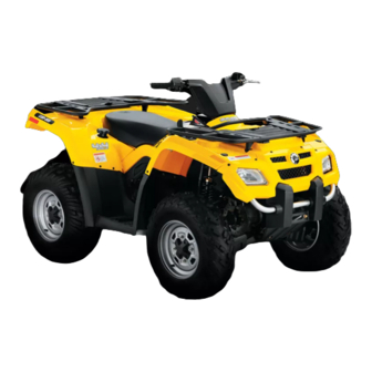
- Manuals
- Brands
- Can-Am Manuals
- Offroad Vehicle
- outlander 400
- Operator’s manual
-
Contents
-
Table of Contents
-
Troubleshooting
-
Bookmarks
Quick Links
Related Manuals for Can-Am outlander 400
Summary of Contents for Can-Am outlander 400
-
Page 2
The following trademarks are the property of Bombardier Recreational Prod- ucts Inc.: ® OUTLANDER ROTAX XP-S Can-Am™ Printed in Canada. (vmo2007-011 DR) ®™ and the BRP logo are trademarks of Bombardier Recreational Products Inc. or its affiliates. ©2006 Bombardier Recreational Products Inc. and BRP US Inc. All rights reserved. -
Page 3
FOREWORD Congratulations on your purchase of a The information and components/ new Can-Am™ ATV. It is backed by the system descriptions contained in this BRP warranty and a network of autho- document are correct at the time of rized Can-Am dealers ready to provide publication. -
Page 4: Table Of Contents
TABLE OF CONTENTS While reading this Operator’s Guide, remember that: WARNING Indicates a potential hazard that, if not avoided, could result in serious in- jury or death. NOTICE…………….7 INTRODUCTION ..
-
Page 5
NOISE EMISSION CONTROL SYSTEM REGULATION ….. . . 62 EMISSION REQUIREMENTS ……….. . . 63 BREAK-IN PERIOD. -
Page 6
Winch Operation …………..89 Stopping the Engine .. -
Page 7
STORAGE AND PRESEASON PREPARATION ……. 128 WARRANTY BRP LIMITED WARRANTY NORTH AMERICA: 2007 CAN-AM ATV . .. 130 BRP INTERNATIONAL LIMITED WARRANTY: 2007 CAN-AM ATV . -
Page 8
_______________________… -
Page 9: Notice
NOTICE This Operator’s Guide has been pre- pared to acquaint the owner/operator of a new vehicle with the various ve- hicle controls, maintenance and safe operating instructions. It is indispens- able for the proper use of the product. This Operator’s Guide uses the follow- ing symbols.
-
Page 10: Introduction
INTRODUCTION Your dealer should have provided you The contents of this Operator’s Guide with some basic information on the provide riding information which has particular controls and features of your been proven reliable by other users. new vehicle. Please take the time to They are not intended as a definitive study this Operator’s Guide and all means of avoiding accidents.
-
Page 11: Safety Information
SAFETY INFORMATION ____________ ____________ SAFETY INFORMATION…
-
Page 12: Special Safety Messages
Operator’s Guide. instructor. Contact an authorized Always keep both hands on the Can-Am dealer for more informa- handlebars and both feet on the tions. footrests of the vehicle during op- USA and Canada Only: to find eration.
-
Page 13
Never operate this vehicle on hills Always use proper procedures if too steep for the vehicle or for your you stall or roll backwards when abilities. Practice on smaller hills climbing a hill. To avoid stalling, before attempting larger hills. use proper gear and maintain a steady speed when climbing a hill. -
Page 14
Allow greater distance for braking. MORE INFORMATION ABOUT ATV SAFETY, contact an authorized Can-Am dealer to find out about available training courses nearest you. USA and Canada Only: call the Specialty Vehicle Institute of Amer-… -
Page 15: Operation Warnings
Beginning and inexperienced operators should complete a training course. They should then regularly practice the skills learned in the course and the operating techniques described in this Operator’s Guide. For more information about the training course, contact an authorized Can-Am dealer. ____________ ___________ SAFETY INFORMATION…
-
Page 16
WARNING POTENTIAL HAZARD Failure to follow the age recommendations for this vehicle. WHAT CAN HAPPEN A lack of respect for this age recommendation can lead to severe injury or death of the child. Even though a child may be within the age group for which this vehicle is recommended, he may not have the skills, abilities, or judgment needed to operate this vehicle safely and may be involved in a serious accident. -
Page 17
WARNING POTENTIAL HAZARD Carrying a passenger on this vehicle. WHAT CAN HAPPEN Greatly reduces your ability to balance and control this vehicle. Could cause an accident, resulting in harm to you and/or your passenger. HOW TO AVOID THE HAZARD Never carry passenger. Even with a long seat that provides unrestricted operator movement, it is not designed nor intended to carry passenger(s). -
Page 18
WARNING POTENTIAL HAZARD Operating this vehicle on paved surfaces. WHAT CAN HAPPEN The tires are designed for off-road use only, not for use on pavement. Paved surfaces may seriously affect handling and control of this vehicle, and may cause the vehicle to go out of control. HOW TO AVOID THE HAZARD Never operate this vehicle on any paved surfaces, including sidewalks, driveways, parking lots and streets. -
Page 19
WARNING POTENTIAL HAZARD Operating this vehicle on public streets, roads or highways. WHAT CAN HAPPEN You can collide with another vehicle. HOW TO AVOID THE HAZARD Never operate this vehicle on any public street, road or highway, even a dirt or gravel one. In many states or provinces it is illegal to operate this vehicle on public streets, roads or highways. -
Page 20
WARNING POTENTIAL HAZARD Riding this vehicle without wearing an approved helmet, eye protection and protective clothing. WHAT CAN HAPPEN The following items concern all ATV’s operator: – riding without an approved helmet increases the chances of a severe head injury or death in the event of an accident –… -
Page 21
WARNING POTENTIAL HAZARD Riding this vehicle after consuming alcohol or drugs. WHAT CAN HAPPEN Could seriously affect your judgment. Could cause you to react more slowly. Could affect your balance and perception. Could result in an accident or death. HOW TO AVOID THE HAZARD Never consume alcohol or drugs before or while riding this vehicle. -
Page 22
WARNING POTENTIAL HAZARD Operating this vehicle at excessive speeds. WHAT CAN HAPPEN Increases your chances of losing control of the vehicle, which can result in an accident. HOW TO AVOID THE HAZARD Always travel at a speed which is proper for the terrain, visibility and op- erating conditions, and your experience. -
Page 23
WARNING POTENTIAL HAZARD Attempting wheelies, jumps and other stunts. WHAT CAN HAPPEN Increases the chance of an accident, including an overturn. HOW TO AVOID THE HAZARD Never attempt stunts, such as wheelies or jumps. Do not try to show off. ____________ ___________ SAFETY INFORMATION… -
Page 24
WARNING POTENTIAL HAZARD Failure to inspect the vehicle before operating. Failure to properly maintain the vehicle. WHAT CAN HAPPEN Increases the possibility of an accident or equipment damage. HOW TO AVOID THE HAZARD Always inspect your vehicle each time you use it to make sure the vehicle is in safe operating condition. -
Page 25
WARNING POTENTIAL HAZARD Removing hands from handlebar or feet from the footrests during opera- tion. WHAT CAN HAPPEN Removing even one hand or foot can reduce your ability to control the vehicle or could cause you to lose your balance and fall off the vehicle. If you remove a foot from the footrests, your foot or leg may come into contact with the rear wheels, which could injure you or cause an accident. -
Page 26
WARNING POTENTIAL HAZARD Failure to use extra care when operating this vehicle on unfamiliar terrain. WHAT CAN HAPPEN You can come upon hidden rocks, bumps, or holes, without enough time to react. Could result in the vehicle overturning or loss of control. HOW TO AVOID THE HAZARD Go slowly and be extra careful when operating on unfamiliar terrain. -
Page 27
WARNING POTENTIAL HAZARD Failure to use extra care when operating on excessively rough, slippery or loose terrain. WHAT CAN HAPPEN Could cause loss of traction or vehicle control, which could result in an accident, including an overturn. HOW TO AVOID THE HAZARD Do not operate on excessively rough, slippery or loose terrain until you have learned and practiced the skills necessary to control this vehicle on such terrain. -
Page 28
WARNING POTENTIAL HAZARD Turning improperly. WHAT CAN HAPPEN Vehicle could go out of control, causing a collision or overturn. HOW TO AVOID THE HAZARD Always follow proper procedures for turning as described further in this Operator’s Guide. Practice turning at low speeds before attempting to turn at faster speeds. -
Page 29
WARNING POTENTIAL HAZARD Operating on excessively steep hills. WHAT CAN HAPPEN The vehicle can overturn more easily on extremely steep hills than on level surfaces or small hills. HOW TO AVOID THE HAZARD Never operate this vehicle on hills too steep for the vehicle or for your abil- ities. -
Page 30
WARNING POTENTIAL HAZARD Climbing hills improperly. WHAT CAN HAPPEN Could cause loss of control or cause vehicle to overturn. HOW TO AVOID THE HAZARD Always follow proper procedures for climbing hills as described further in this Operator’s Guide. Always check the terrain carefully before you start up any hill. Never climb hills with excessively slippery or loose surfaces. -
Page 31
WARNING POTENTIAL HAZARD Going down a hill improperly. WHAT CAN HAPPEN Could cause loss of control or cause vehicle to overturn. HOW TO AVOID THE HAZARD Always follow proper procedures for going down hills as described further in this Operator’s Guide. NOTE: A special technique is required when braking as you go down a hill. -
Page 32
WARNING POTENTIAL HAZARD Improperly crossing hills or turning on hills. WHAT CAN HAPPEN Could cause loss of control or cause vehicle to overturn. HOW TO AVOID THE HAZARD Never attempt to turn the vehicle around on any hill until you have mas- tered the turning technique as described further in this Operator’s Guide on level ground. -
Page 33
WARNING POTENTIAL HAZARD Stalling, rolling backwards or improperly dismounting while climbing a hill. WHAT CAN HAPPEN Could result in vehicle overturning. HOW TO AVOID THE HAZARD Use proper gear and maintain steady speed when climbing a hill. If you lose all forward speed: Keep your weight uphill. -
Page 34
WARNING POTENTIAL HAZARD Improperly operating over obstacles. WHAT CAN HAPPEN Could cause loss of control or a collision. Could cause the vehicle to overturn. HOW TO AVOID THE HAZARD Before operating in a new area, check for obstacles. Never attempt to ride over large obstacles, such as large rocks or fallen trees. -
Page 35
WARNING POTENTIAL HAZARD Skidding or sliding improperly. WHAT CAN HAPPEN You may lose control of this vehicle. You may also regain traction unexpectedly, which may cause the vehicle to overturn. HOW TO AVOID THE HAZARD Learn to safely control skidding or sliding by practicing at low speeds and on level smooth terrain. -
Page 36
WARNING POTENTIAL HAZARD Operating this vehicle through deep or fast flowing water. WHAT CAN HAPPEN Tires may float, causing loss of traction and loss of control, which could lead to an accident. HOW TO AVOID THE HAZARD Never operate this vehicle in fast flowing water or in water deeper than that specified further in this Operator’s Guide. -
Page 37
WARNING POTENTIAL HAZARD Improperly operating in reverse. WHAT CAN HAPPEN You could hit an obstacle or person behind the vehicle, resulting in serious injury. HOW TO AVOID THE HAZARD When you select reverse gear, make sure there are no obstacles or people behind the vehicle. -
Page 38
WARNING POTENTIAL HAZARD Operating this vehicle with improper tires, or with improper or uneven tire pressure. WHAT CAN HAPPEN Use of improper tires on this vehicle, or operation of this vehicle with im- proper or uneven tire pressure, may cause loss of control, tire blow outs, tire to move around on its rim and increases the risk of an accident. -
Page 39
All parts and accessories added to this vehicle should be approved by BRP and should be installed and used according to instructions. If you have questions, consult an authorized Can-Am dealer. NEVER install passenger seat or use the racks to carry a passenger. -
Page 40
WARNING POTENTIAL HAZARD Overloading this vehicle or carrying or towing cargo improperly. WHAT CAN HAPPEN Could cause changes in vehicle handling which could lead to an accident. HOW TO AVOID THE HAZARD Never exceed the stated load capacity for this vehicle including operator, as well as other loads and added accessories. -
Page 41
WARNING POTENTIAL HAZARD Transporting flammable or dangerous material can lead to explosions. WHAT CAN HAPPEN This can cause serious injury or death. HOW TO AVOID THE HAZARD Never transport flammable or dangerous material. While reading this Operator’s Guide, remember that: WARNING Indicates a potential hazard that, if not avoided, could result in serious in- jury or death. -
Page 42: Riding The Vehicle
ATV clubs, a recognized ATV train- Each will ride and handle differently. ing organization or contact an autho- Never assume that the vehicle will go rized Can-Am dealer. everywhere safely. Sudden changes USA and Canada Only: to find out in terrain caused by holes, depres- about available training course nearest sions, banks, softer or harder «ground»…
-
Page 43: Pre-Operation Check
• Check location of controls and en- found before riding. See an autho- sure they work properly. rized Can-Am dealer as necessary. • Verify if steering operates freely. • Activate throttle control lever sever- al times to ensure it operates freely.
-
Page 44: Clothing
Clothing Actual weather conditions should help you decide how to dress. However, it is important that the operator always wear the appropriate protective clothing and apparel, including an approved helmet, eye protection, boots, gloves, long sleeved shirt and pants. This type of clothing will provide you protection from some of the minor hazards you may encounter en route.
-
Page 45: Carrying Loads
Your vehicle can help you perform a number of different LIGHT tasks ranging from snow removal to pulling wood or carrying cargo. A variety of accessories are available from your authorized Can-Am dealer. However, always respect the load and capacities of the vehicle. Overloading of the vehicle can overstress the components and cause failure.
-
Page 46: Environment
Always keep a safe distance from other riders. Your judgment of speed, ter- rain conditions, weather, mechanical condition of your vehicle and the «trust in judgment» you have in others around you will help you make a better choice of appropriate safe distance.
-
Page 47: General Operating And Safety Precautions
An operator who takes a vehicle off-road should always exercise the utmost care in selecting the safest path and keeping close watch on the terrain ahead of him. On no account should the vehicle be operated by anyone who is not completely familiar with the driving instructions applicable to the vehicle, nor should it be operated on steep or treacherous terrain.
-
Page 48: Side Hilling
Side Hilling Whenever possible, such operation should be avoided. If necessary, do so with extreme caution. Side hilling on steep inclines could result in rollover. In addi- tion, slippery or unfirm surfaces could result in uncontrollable side sliding. Do not attempt to turn the vehicle downhill with the slide. Avoid all objects or de- pressions that will intensify the raising of one side of the vehicle higher than the other, thus causing rollover.
-
Page 49
Even though there is an adequate suspensions system on this vehicle there are «washboard» or rough terrain conditions that will make you feel uncomfortable and even cause back injury. «Posting» or riding in a crouched position will often be required. Slow down and allow your flexed legs to absorb impact. This vehicle is not designed for riding on roads or highways. -
Page 50
Water will affect the braking ability of your vehicle. Make sure you dry the brakes by applying them several times after the vehicle leaves the water. Mud or marsh lands may be encountered near water. Be prepared for sudden «holes» or changes in depth. Similarly so, be watchful of hazards such as rocks, logs, etc., partially covered by vegetation. -
Page 51
When riding in sand dunes it is advisable to equip the vehicle with an antenna type safety flag. This will help make your location more visible to others over the next sand dune . Proceed carefully should you see another safety flag ahead. Since the antenna type safety flag can snag and rebound on your body if caught, do not use it in areas where there are low hanging branches or obstacles. -
Page 52
Uphill Keep your body weight forward towards the top of the hill. Keep your feet on the footpegs and shift into low gear then accelerate and when necessary, change gear quickly as you climb. Do not over-speed since this may cause the front of the vehicle to lift from the ground and fall back on you. -
Page 53
Downhill Keep your body weight rearwards. Apply the brake gradually to prevent skidding. Do not «coast» down the slope using solely engine compression or in neutral gear. While reading this Operator’s Guide, remember that: WARNING Indicates a potential hazard that, if not avoided, could result in serious in- jury or death. -
Page 54
Side Hilling This is one of the most risky types of riding since it may drastically change the balance of the vehicle. It should be avoided wherever possible. If it is necessary to do so however, it is important that you ALWAYS keep your body weight on the upside of the slope… -
Page 55: Routine Maintenance
Part of your responsibility towards safety is to respect the contents of this Op- erator’s Guide. It provides valuable advice on how to properly take care of your vehicle. If further assistance is required your authorized Can-Am dealer is always willing to help.
-
Page 56: Hang Tag
HANG TAG This vehicle comes with a hang tag and labels containing important safety infor- mation. Any person who rides this vehicle should read and understand this information before riding. USA and Canada Only vmo2006-005-009_en ___________ ___________ SAFETY INFORMATION…
-
Page 57: On-Product Labels
The following labels are on your vehicle and they should be considered perma- nent parts of the vehicle. If missing or damaged, they can be replaced free of charge. See an authorized Can-Am dealer. NOTE: The following illustrations used in this Operator’s Guide are a general representation only.
-
Page 58
Label 1 Label 3 Label 4 Label 2 Label 5 ___________ ___________ SAFETY INFORMATION… -
Page 59
Label 6 Label 9 vmo2006-016-008_en Label 7 USA and Canada Models vmo2007-002-002 LOCATED UNDER SEAT ON THE UPPER BAR OF FRAME International Models Only Label 10 vmo2006-005-010_en FRONT AND REAR FENDER International Models vmo2006-005-010_en FRONT FENDER ONLY Label 8 vmo2006-014-003_a vmo2006-007-002_aen ____________ ___________… -
Page 60
Label 11 vmo2006-005-010_en REAR FENDER ONLY ___________ ___________ SAFETY INFORMATION… -
Page 61: Vehicle Information
VEHICLE INFORMATION _____________________…
-
Page 62: How To Identify Your Vehicle
It may sometimes become necessary to locate these num- bers for warranty purposes or to trace your vehicle in the event of loss. These numbers are required by the authorized Can-Am dealer to complete warranty claims properly. No warranty will be allowed by BRP if the engine identification number (EIN) or vehicle identification number (VIN) is removed or mutilated in any way.
-
Page 63: Compliance Label
Compliance Label This label indicates vehicle’s compli- ance in many countries. LABEL LOCATION Under seat, on the All Outlander upper bar of frame USA AND CANADA OTHER COUNTRIES IN THE WORLD _____________________…
-
Page 64: Noise Emission Control System Regulation
NOISE EMISSION CONTROL SYSTEM REGULATION USA and Canada Only Tampering with Noise Control System Is Prohibited! U.S. Federal law and Canadian provincial laws may prohibit the following acts or the causing there of: 1. The removal or rendering inoperative by any person other than for purposes of maintenance, repair or replacement of any device or element of design incorporated into any new vehicle for the purpose of noise control prior to its sale or delivery to the ultimate purchaser or while it is in use or…
-
Page 65: Emission Requirements
EMISSION REQUIREMENTS USA Only The California Air Resources Board (CARB) requires that your vehicle comply with applicable exhaust emissions standards during its useful life, when operated and maintained according to the instructions supplied. A noncompliance Red Label (as well as a Green Label) is obtained annually during California Vehicle registration.
-
Page 66: Break-In Period
(185 mi) or 30 days after the pur- chase, whichever comes first, your vehicle be inspected by an authorized Can-Am dealer. This inspection will give you the opportunity to discuss the unanswered questions you may have encountered during the first hours of operation.
-
Page 67: Controls/Instruments/Equipment
CONTROLS/INSTRUMENTS/EQUIPMENT NOTE: Some controls/instruments/equipment are optional. vmo2006-005-033_a _____________________…
-
Page 68
vmo2006-005-034_a vmo2006-005-035_a vmo2006-005-036_a ______________________… -
Page 69: Throttle Lever
While reading this Operator’s Guide, remember that: WARNING Indicates a potential hazard that, if not avoided, could result in serious in- jury or death. NOTE: This section gives basic func- tions of the various controls of your ve- hicle. For more details of how to op- erate one control in conjunction with some others, refer to OPERATING IN- STRUCTIONS further in this section.
-
Page 70: Parking Brake
TYPICAL 1. Brake. lever 2. To apply brakes TYPICAL 4) Parking Brake 1. Brake lever lock 2. Press to apply parking brakes When applied, it prevents the vehicle from moving. Useful when the brake To release mechanism: Squeeze needs to be locked for example when brake lever.
-
Page 71: Multi-Function Switch
CAUTION: Always completely stop the vehicle and apply the brake prior to moving the transmission lever. P: Park This position locks the transmission to help prevent vehicle movement. Al- ways use when the vehicle is not in operation. In some circumstances, it may be necessary to rock the vehicle back and forth to move the gears in the transmission to allow the park to…
-
Page 72
vmo2006-005-013_b IGNITION SWITCH POSITIONS 1. OFF 2. ON «with light» 3. ON «without light» Engine Stop Switch This switch can be used to stop engine and as an emergency control. TYPICAL 1. Engine start button To stop engine, fully release throttle 2. -
Page 73: Speedometer
TYPICAL 1. Override button 2. Engine stop switch CHOKE LEVER IN THE FULL CHOKE POSITION Choke Lever Located at bottom of multi-function The other positions between OFF and switch. This device features a variable FULL position, will be use depending lever to ease cold start.
-
Page 74
18 volts in the electrical system, caused by a disconnected or defective voltage regulator. Check voltage regulator connection or contact an authorized Can-Am dealer for voltage regulator replacement. vmo2006-005-016_a 1. Locking tab Plug connectors to change units from miles to kilometers. -
Page 75
Speedometer Reads SCALE Trip Meter (TRIP 1/TRIP 2) your convenience, your speedometer equipped with two separate trip meter. The trip meter records distance trav- elled since it has been reset. Distance travelled is displayed either in miles or kilometers. It can be used to establish a fuel tank range or distance between 2 way vmo2006-005-038 points for instance. -
Page 76: 12-Volt Power Outlet
Unscrew counterclockwise and re- at the rear of vehicle. See an autho- move cap to allow fuel tank filling then rized Can-Am dealer for more details. fully tighten clockwise. 9) Ignition Switch Key-operated, this is a 3-position switch: OFF, ON with lights and ON without lights.
-
Page 77: Fuel Gauge
WARNING Always stop engine before re- fueling. Open cap slowly. If a differential pressure condition is noticed (whistling sound heard when loosening fuel tank cap) have vehicle inspected and/or re- paired before further operation. Fuel is flammable and explosive under certain conditions. Never use an open flame to check fuel level.
-
Page 78: Brake Pedal
14) Footpeg RES (reserve) When fuel is exhausted in the fuel tank Use this area to keep your feet stable. when in the ON position, an emergen- cy supply of fuel is available by turn- ing the knob to RES. The reserve con- tains approximately 12% of the fuel tank capacity.
-
Page 79: Rear Storage Compartment
16) Rear Storage Compartment Convenient location to carry personal articles such as a spare spark plugs, first aid kit, etc. Unlatch cover, gently lift then remove cover. The compartment is equipped with a drain plug. Remove plug to allow draining when necessary. Reinstall vmo2006-005-027_b plug when finished.
-
Page 80: Cargo Racks
NOTE: Follow manufacturer’s instruc- WARNING tions for proper attachment. Make sure seat is securely latched before riding. 20) Radiator Cap Located in service compartment, un- 18) Cargo Racks der access panel. Convenient racks to carry gear. WARNING WARNING In order to avoid getting burned, do not remove the radiator cap Ensure to properly secure material when the engine is hot.
-
Page 81: Tool Kit
Located on right side of vehicle. Au- to-rewind type. To engage mecha- nism, pull handle slowly until a resis- tance is felt then continue to slowly pull the handle until the compression stroke peak (strong rotating resis- tance) is overpassed then, pull vigor- ously.
-
Page 82: Winch
25) Winch XT Models vmo2006-005-032_a 1. In 2. Out 27) Roller Fairlead vmo2007-003-016_a 1. Winch XT Models 2. Roller fairlead 3. Winch hook The roller fairlead is used to prevent damages to the vehicle and guide the 26) Winch Control Switch wire rope into the winch.
-
Page 83: Winch Remote Control Connection
vmo2007-003-001_a vmo2007-003-017_a FRONT ACCESS PANEL TYPICAL — FRONT SERVICE 1. Winch remote control COMPARTMENT 1. Remote control connection To use the winch remote control switch instead of the handlebar con- trol switch, connect the remote con- trol into the provided connection of the front service compartment.
-
Page 84: Liquids
LIQUIDS While reading this Operator’s Guide, remember that: WARNING Indicates a potential hazard that, if not avoided, could result in serious in- jury or death. NOTE: This section specifies the rec- Fuel Level ommended liquids and procedures to check their levels. Refer to MAINTE- WARNING NANCE for procedures to replace the Always stop engine before refu-…
-
Page 85
Oil Viscosity SAE 5W30 oil is recommended for all seasons. However, during the hottest days of the summer the BRP XP-S 10W40 mineral oil (P/N 219 700 346) can be used. NOTE: For improved overall perfor- mance and all season applications, use XP-S 5W40 synthetic oil (P/N 293 600 039). -
Page 86: Engine Coolant
NOTE: A cooling system that fre- quently requires coolant is the indica- tion of leaks or engine problems. See an authorized Can-Am dealer. Coolant Replacement Refer to MAINTENANCE section. ______________________…
-
Page 87: Brake Fluid
NOTE: A low level may indicate leaks or worn brake pads. See an autho- rized Can-Am dealer. Brake Lever Fluid Reservoir Turn steering in the straight-ahead position to ensure reservoir is level.
-
Page 88: Operating Instructions
• Verify if steering operates freely. Correct any problem you may have • Activate throttle control lever sever- found before riding. See an autho- al times to ensure it operates freely. rized Can-Am dealer as necessary. It must return to idle position when released. ______________________…
-
Page 89: Starting The Engine
Starting the Engine After a few seconds, move the choke lever from full choke position to an in- Initial Cold Starting termediate position until the best en- gine RPM is achieved. Insert key in ignition switch and turn to ON position. NOTE: Over using the choke may flood the engine and make it hard Place the engine stop switch to RUN.
-
Page 90: Shifting The Transmission
2WD/4WD Selector Follow the starting procedures above but instead use the rewind starter to The 4WD mode may be selected start. or deselected when the vehicle is Hold manual starter handle firmly and, stopped. slowly, crank the engine until a resis- CAUTION: The vehicle must be tance is felt.
-
Page 91: Winch Operation
Remove key from ignition switch. Post-Operation Care When vehicle is used in salt-water environment (beach area, launching/ loading boats etc.), rinsing the vehi- cle with fresh water is necessary to preserve vehicle and its components. Metallic parts lubrication is highly rec- ommended.
-
Page 92: Special Procedures
Before starting engine, check engine oil level and refill if necessary. If the oil pressure light stays ON after starting engine, stop engine and see an autho- rized Can-Am dealer as soon as possi- ble. Vehicle Immersion Should the vehicle become immersed,…
-
Page 93: Cargo And Transportation
CARGO AND TRANSPORTATION While reading this Operator’s Guide, remember that: WARNING Indicates a potential hazard that, if not avoided, could result in serious in- jury or death. Cargo WARNING The vehicle handling, stability and braking distance are affected when load- ing racks and using the vehicle.
-
Page 94
Transportation Front Location When transporting a vehicle, secure vehicle to trailer or in pickup box with suitable tie-downs. Using ordinary ropes is not recommended. WARNING vmo2006-016-005_a TYPICAL Rear Location Never tip this vehicle on end for transporting. We recommend that you carry the vehicle in its nor- mal operating position (on all four wheels). -
Page 95: Troubleshooting
– Check charging system fuse. – Check connections and terminals condition. – Have the battery checked. – Contact an authorized Can-Am dealer. ENGINE TURNS OVER BUT FAILS TO START 1. Engine stop switch. – Make sure that engine stop switch is in ON position.
-
Page 96
• Let engine cool down. Check coolant level and refill if possible. See EN- GINE COOLANT. • See an authorized Can-Am dealer as soon as possible. – If overheating persists, contact an authorized Can-Am dealer. 5. Air filter/housing plugged or dirty. -
Page 97
ENGINE BACKFIRE 1. Exhaust system leakage. – Contact an authorized Can-Am dealer. 2. Engine is running too hot. – See ENGINE LACKS ACCELERATION OR POWER. 3. Ignition timing is incorrect or there is an ignition system failure. – Contact an authorized Can-Am dealer. -
Page 98
1. The transmission is on PARK or NEUTRAL position. – Select the R, HI or LO position. 2. CVT dirty or worn-out. – Contact an authorized Can-Am dealer. 3. Water in the CVT housing. – Contact an authorized Can-Am dealer. -
Page 99: Specifications
SPECIFICATIONS VEHICLE MODEL OUTLANDER™ 400 SERIES ENGINE Rotax ® 400, 4-stroke. Single Over Type Head Camshaft (SOHC) Number of cylinder Single cylinder Number of valves 4 valves (mechanical adjustment) Displacement 400 cc (24.4 cu. in) Bore Standard 91 mm (3.58 in) Stroke 61.5 mm (2.42 in) 10.3:1…
-
Page 100
VEHICLE MODEL OUTLANDER™ 400 SERIES ELECTRICAL Make Denso Magneto generator Type 400 W @ 6000 RPM Ignition type CDI (Capacitor Discharge Ignition) Ignition timing Not adjustable Engine RPM limiter 8000 RPM (any gear in forward) Vehicle speed limiter 15 km/h (9 MPH) in reverse Make Spark plug Type… -
Page 101
VEHICLE MODEL OUTLANDER™ 400 SERIES SUSPENSION Independent suspension Type MacPherson type Front Travel 178 mm (7 in) Type TTI™ Independent Rear Travel 203 mm (8 in) TIRES Carlisle ACT/Radial Make/Type Other Othsu/Bias Front 25 x 8 x 12 25 x 11 x 12 Size Rear 25 x 10 x 12… -
Page 102
VEHICLE MODEL OUTLANDER™ 400 SERIES LOADING CAPACITY Front racks 45 kg (100 lb) Rear racks (including tongue load) 90 kg (200 lb) Rear storage box 10 kg (22 lb) Total vehicle load allowed (includes operator, all other loads 230 kg (500 lb) and added accessories) 460 kg (1014 lb) GVWR (Gross Vehicle Weight Rating) -
Page 103
VEHICLE MODEL OUTLANDER™ 400 SERIES LIQUIDS and GREASES Engine oil type SAE 5W30 API classification SM, SL or (engine and transmission) SJ. Refer to OIL VISCOSITY CHART Ethylene-glycol/water mix (50% coolant, 50% distilled water). Use BRP premixed Coolant coolant or a coolant specially designed for aluminum engines Type Regular unleaded gasoline… -
Page 104
_____________________… -
Page 105: Maintenance Information
MAINTENANCE INFORMATION _____________________…
-
Page 106: Maintenance Chart
Can-Am dealer. PERIODIC MAINTENANCE CHART INITIAL INSPECTION 10 H OR 30 DAYS OR 300 km (185 mi) (To be performed by an authorized Can-Am dealer. The initial maintenance is very important and must not be neglected.) A: ADJUST…
-
Page 107
PERIODIC MAINTENANCE CHART INITIAL INSPECTION 10 H OR 30 DAYS OR 300 km (185 mi) (To be performed by an authorized Can-Am dealer. The initial maintenance is very important and must not be neglected.) A: ADJUST 25 H OR 750 km (470 mi) -
Page 108
PERIODIC MAINTENANCE CHART INITIAL INSPECTION 10 H OR 30 DAYS OR 300 km (185 mi) (To be performed by an authorized Can-Am dealer. The initial maintenance is very important and must not be neglected.) A: ADJUST 25 H OR 750 km (470 mi) -
Page 109
PERIODIC MAINTENANCE CHART INITIAL INSPECTION 10 H OR 30 DAYS OR 300 km (185 mi) (To be performed by an authorized Can-Am dealer. The initial maintenance is very important and must not be neglected.) A: ADJUST 25 H OR 750 km (470 mi) -
Page 110: General
Other items found in MAINTENANCE CHART must be performed by an authorized Can-Am dealer. NOTE: Among other things, this sec- tion gives the procedures to replace the liquids. Refer to LIQUIDS for pro- cedures to check levels and refill.
-
Page 111: Engine/Transmission
ENGINE/TRANSMISSION Oil Change and Oil Filter Replacement Oil and filter are to be replaced at the same time. Oil change should be done with a warm engine. WARNING The engine oil can be very hot. In order to avoid potential burns, do not remove the engine drain plug or the filter cover if the engine is hot.
-
Page 112: Oil Strainer Cleaning
Oil Strainer Cleaning The oil strainer must be cleaned every 200 hours or every 2 years or every 6000 km (3730 mi). Contact an authorized Can-Am dealer. Coolant Replacement WARNING In order to avoid potential burns, do not remove the radiator cap or loosen the coolant drain plug if the 1.
-
Page 113: Air Filter
1. Hose pincher Fill the radiator until the coolant comes out by the thermostat housing hole. Install the bleeding screw then re- move the hose pincher. Complete the radiator filling. Check the level in the coolant reservoir and refill if necessary. Run engine at idle with the radiator cap off.
-
Page 114: Air Filter Housing Draining
Installation Properly reinstall removed parts in the reverse order of their removal. Air Filter Housing Draining Periodically inspect air filter housing drain tube for liquids or deposits. 1. Release clamps Loosen clamp and remove air filter. 1. Clamp TYPICAL 2. Air filter 1.
-
Page 115: Drive Belt
Valve Adjustment When liquids/deposits are found, the air filter must be inspected/dried/ See an authorized Can-Am dealer for replaced depending on its condition. valves adjustment. Remove air filter as explained below. Insufficient clearance will cause loss of power and possibly damage the Drive Belt valves.
-
Page 116: Radiator
Stop engine and allow muffler to cool. LOW PRESSURE ONLY, NEVER USE A HIGH PRESSURE WASHER. Reinstall the cleanout plug. See an authorized Can-Am dealer to Radiator check the performance of the cooling system. Periodically check the radiator area for cleanliness.
-
Page 117: Carburetor
CARBURETOR See an authorized Can-Am dealer each year to verify and clean the fuel sys- tem. _____________________…
-
Page 118: Fuel System
FUEL SYSTEM Throttle Cable Lubrication Lubrication The throttle cable must be lubricated with silicone lubricant (P/N 293 600 041) or an equivalent. WARNING Always use a silicone-based lubri- cant. Using another lubricant (like a water-based lubricant) could cause the throttle lever/cable stick- 1.
-
Page 119: Throttle Lever Adjustment
NOTE: Place a rag around the throttle cable adjuster to prevent the lubricant Remove the carburetor side cover. from splashing. Add lubricant until it runs out at carbu- retor end of the throttle cable. Reinstall and adjust the cable. Throttle Lever Adjustment Slide rubber protector back to expose throttle cable adjuster.
-
Page 120
With the transmission lever on PARK position, start the engine. Check if the throttle cable is adjusted correctly by turning handlebar fully right then ful- ly left. If the engine RPM increases, readjust the throttle lever free play. _____________________… -
Page 121: Electrical
ELECTRICAL Battery WARNING Unless otherwise indicated, al- WARNING ways turn ignition switch to the OFF position before performing Never charge a battery while in- any maintenance or repair on elec- stalled in vehicle. trical system. Removal Spark Plug Disconnect BLACK (-) cable first then RED (+) cable.
-
Page 122: Fuses
WARNING Connect RED (+) cable first then BLACK (-) cable. Always connect RED (+) cable first. Fuses WARNING Always turn the ignition switch to vmo2006-005-029_a OFF position before replacing a de- 1. Accessories (15 A) (power outlet and fective fuse. auxiliary supply) 2.
-
Page 123
Headlamps CAUTION: Never touch glass por- tion of an halogen bulb with bare fingers, it shortens its operating life. If glass is touched, clean it with isopropyl alcohol which will not leave a film on the bulb. To replace the headlamp bulb, proceed as follows. -
Page 124
Taillight Unscrew lens screws to expose bulbs. 1. Lens 2. Screws TYPICAL Push the bulb in and hold while turning counterclockwise to release. Properly reinstall removed parts in the Install the new bulb by first pushing in reverse order of their removal. while turning clockwise. -
Page 125: Drive Train
Push and pull the wheels from the up- Inspection per edge to feel the play. See an au- Visually inspect drive shaft protectors thorized Can-Am dealer if there is any and boots conditions. Check protec- play. tors for damage or rubbing against shafts.
-
Page 126
Tire Pressure Occasionally, wheel nuts should be re- moved to apply anti-seize lubricant on WARNING studs to ease future removal. This is particularly important when vehicle is Tire pressure greatly affects vehi- used in salt-water environment or in cle handling and stability. Under- mud. -
Page 127: Suspension
See an authorized Can-Am dealer as neces- sary. Trailing Arms Check trailing arms for distortion, cracks or bending. See an authorized Can-Am dealer if any problem is de- tected. 1. Adjusting cams 2. Smooth adjustment 3. Hard adjustment A-Arms Check A-arms for cracks, bending or other damages.
-
Page 128: Brake
Rear disc 4.3 mm (.170 in) thickness Maximum discs 0.3 mm (.010 in) warpage See your authorized Can-Am dealer if a problem is detected concerning the brake system. Brake Fluid Replacement WARNING The brake fluid replacement or any brake system repairs should be performed by an authorized Can-Am dealer.
-
Page 129: Body/Frame
Seat Fasteners Remove seat and check latch mecha- nism and pin for wear. See an autho- rized Can-Am dealer for parts replace- ment if damaged. While reading this Operator’s Guide, remember th at: WARNING Indicates a potential hazard that, if not avoided, could result in serious in- jury or death.
-
Page 130: Storage And Preseason Preparation
CHART. When a vehicle is not in use for more than one month, proper storage is a necessity. See an authorized Can-Am dealer for proper procedures. When using your vehicle after storage, a preparation is required. See an au- thorized Can-Am dealer for proper pro- cedures.
-
Page 131: Warranty
WARRANTY _____________________…
-
Page 132: Brp Limited Warranty North America: 2007 Can-Am
(as hereinafter defined) at the time of delivery of the 2007 Can-Am ATV, carry the same warranty as that of the Can-Am ATV. If your 2007 Outlander™ 400 XT, Outlander 400 XT Max, Outlander 500 XT, Out- lander 500 XT Max, Outlander 650 HO EFI XT, Outlander 650 HO EFI XT Max,…
-
Page 133
3) CONDITIONS TO HAVE WARRANTY COVERAGE This warranty coverage is available only on 2007 Can-Am ATVs purchased as new and unused by its first owner from a Can-Am dealer authorized to distribute Can-Am ATV products in the country in which the sale occurred (“Can-Am ATV dealer”), and then only after the BRP specified pre-delivery inspection process… -
Page 134
4) WHAT TO DO TO OBTAIN WARRANTY COVERAGE The customer must notify a servicing Can-Am dealer within two (2) days of the appearance of a defect, and provide it with reasonable access to the product and reasonable opportunity to repair it. The customer must also present to the authorized Can-Am dealer, proof of purchase of the product and must sign the repair/work order prior to starting the repair in order to validate the warranty repair. -
Page 135
Can-Am dealer and gives the coordinates of the new owner; or b) BRP or an authorized Can-Am dealer receives a proof that the former owner agreed to the transfer of ownership, in addition to the coordinates of the new owner. -
Page 136
If the issue has not yet been resolved, please submit your complaint in writing or call the appropriate number below: IN CANADA IN USA BOMBARDIER RECREATIONAL BRP US Inc. PRODUCTS INC. CAN-AM ATV CAN-AM ATV CONSUMER SERVICES GROUP CONSUMER SERVICES GROUP 7575 BOMBARDIER COURT VALCOURT QC J0E 2L0 WAUSAU WI 54401 Tel.: (819) 566-3366… -
Page 137: Brp International Limited Warranty: 2007 Can-Am
Can-Am distributor/dealer (as hereinafter defined) at the time of delivery of the 2007 Can-Am ATV, carry the same warranty as that of the Can-Am ATV. Use of the product for racing or any other competitive activity, at any point, even by a previous owner;…
-
Page 138
BRP’s obligations under this warranty are limited to, at its sole discretion, repair- ing parts found defective under normal use, maintenance and service; or replac- ing such parts with new genuine Can-Am ATV parts without charge for parts and labour, at any authorized Can-Am distributor/dealer. -
Page 139
If the ownership of a product is transferred during the warranty coverage period, this warranty shall also be transferred and be valid for the remaining coverage period provided BRP or an authorized Can-Am distributor/dealer receives a proof that the former owner agreed to the transfer of ownership, in addition to the coordinates of the new owner. -
Page 140: Privacy Obligation/Disclaimer
PRIVACY OBLIGATION/DISCLAIMER We wish to inform you that your coordinates will be used for safety and warranty purposes. Sometimes, we also use the coordinates of our clients to inform them about our products and to present them offers. Should you prefer not to receive information on our product, services and offers, please let us know by writing to the address below.
-
Page 141: Change Of Address/Ownership
(715) 848-4957 (USA) or (819) STOLEN UNITS: If your personal ATV 566-3366 (Canada); is stolen, you should notify BRP or an authorized Can-Am dealer. We – notifying an authorized Can-Am will ask you to provide your name, dealer. address, phone number, the vehicle…
-
Page 142
_____________________… -
Page 143
(715) 848-4957 (USA) or (819) STOLEN UNITS: If your personal ATV 566-3366 (Canada); is stolen, you should notify BRP or an authorized Can-Am dealer. We – notifying an authorized Can-Am will ask you to provide your name, dealer. address, phone number, the vehicle… -
Page 144
_____________________… -
Page 145
(715) 848-4957 (USA) or (819) STOLEN UNITS: If your personal ATV 566-3366 (Canada); is stolen, you should notify BRP or an authorized Can-Am dealer. We – notifying an authorized Can-Am will ask you to provide your name, dealer. address, phone number, the vehicle… -
Page 146
_____________________… -
Page 147
Please verify with your dealer to ensure your vehicle has been registered with BRP. While reading this Operator’s Guide, remember that: WARNING Indicates a potential hazard that, if not avoided, could result in serious in- jury or death.
Руководство по эксплуатации Меры безопасности Устройство мотовездехода Техническое обслуживание ПРЕДОСТЕРЕЖЕНИЕ Внимательно изучите настоящее Руководство. Оно содержит важную информацию по безопасности. Минимальный возраст водителя — 16 лет. Мотовездеход предназначен для эксплуатации только
! ПРЕДОСТЕРЕЖЕНИЕ МОТОВЕЗДЕХОД ОТНОСИТСЯ К ЧИСЛУ ТРАНСПОРТНЫХ СРЕДСТВ ПОВЫШЕННОЙ ОПАСНОСТИ. Если не принять соответствующих мер предосторожности, даже при выполнении обычных маневров, таких как поворот, движение по склону или преодоление препятствий, может произойти столкновение или опрокидывание
ВВЕДЕНИЕ Deutsch Dieses Handbuch ist möglicherweise in Ihrer Landessprache verfügbar. Bitte wenden Sie sich an Ihren Händler oder besuchen Sie: www.operatorsguide.brp.com English This guide may be available in your language. Check with your dealer or go to: www.operatorsguide.brp.com Español Es
ВВЕДЕНИЕ Предупреждения В настоящем Руководстве для выделения важной информации используются следующие типы предупреждений: Д анный с имвол ! предупреж д ает о потенциальной опасности получения травмы. ! ПРЕДОСТЕРЕЖЕНИЕ Инфор ми рует о поте нц иа льно опасных ситуациях, которые мог у т с тать
ОГЛАВЛЕНИЕ ВВЕДЕНИЕ ……………………………………………………………………………………………………….. 1 Прежде чем начать движение ……………………………………………………………………………………..1
ОГЛАВЛЕНИЕ 16) Сцепное устройство …………………………………………………………………………………………….73 17) Возимый комплект инструментов ……………………………………………………………………….. 74 18) Лебёдка
ОГЛАВЛЕНИЕ Трубки и фитинги задней подвески с пневмоподкачкой (ACS) ………………………………… 118 Рулевое управление ……………………………………………………………………………………………….. 118 Тормозная система
ИНФОРМАЦИЯ ПО БЕЗОПАСНОСТИ
ОСНОВНЫЕ МЕРЫ ПРЕДОСТОРОЖНОСТИ Избегайте отравления угарным газом Отработавшие газы всех двигателей содержат оксид углерода (угарный газ), который в определённых условиях может представлять смертельную опасность. Вдыхание угарного газа может стать причиной появления головной боли, головокружения,
ОСНОВНЫЕ МЕРЫ ПРЕДОСТОРОЖНОСТИ Аксессуары и внесение изменений в конструкцию Не вносите изменения в конструкцию мотовездехода и не используйте дополнительное оборудование, не одобренное BRP. Так как подобные изменения не были протестированы BRP, они могут увеличить риск получения травмы или
РЕКОМЕНДАЦИИ ПО МЕРАМ БЕЗОПАСНОСТИ МОТОВЕЗДЕХОД — НЕ ИГРУШКА И МОЖЕТ БЫТЬ ОПАСЕН. – Управление мотовездеходом отличается от управления другими транспортными средствами. Если не принять соответствующих мер предосторожности, даже при выполнении обычных маневров, таких как поворот, движение по склону
РЕКОМЕНДАЦИИ ПО МЕРАМ БЕЗОПАСНОСТИ – Не направляйте мотовездеход на склоны, которые могут оказаться слишком крутыми для Вашей машины; сообразуйтесь с собственным опытом водителя. Потренируйтесь в управлении мотовездеходом сначала на пологих склонах, а затем и на более крутых. – При движении в гору
РЕКОМЕНДАЦИИ ПО МЕРАМ БЕЗОПАСНОСТИ – Компания BRP рекомендует во время движения задним ходом занимать на мотовездеходе положение сидя. Не вставайте. Вес Вашего тела переместится вперёд, по направлению к рычагу дроссельной заслонки, что может стать причиной неожиданного ускорения и потери контроля
БЕЗОПАСНАЯ ЭКСПЛУАТАЦИЯ ПРИМЕЧАНИЕ: Иллюстрации даны для общего (типового) случая. Ваша модель может отличаться. ! ПРЕДОСТЕРЕЖЕНИЕ ВОЗМОЖНАЯ ОПАСНОСТЬ Эксплуатация мотовездехода неподготовленным водителем. ЧТО МОЖЕТ ПРОИЗОЙТИ Велика вероятность несчастного случая, если водитель не знает, как
БЕЗОПАСНАЯ ЭКСПЛУАТАЦИЯ ! ПРЕДОСТЕРЕЖЕНИЕ ВОДИТЕЛЬ ДО ВОЗМОЖНАЯ ОПАСНОСТЬ Пренебрежение возрастным ограничением при управлении мотовездеходом. ЧТО МОЖЕТ ПРОИЗОЙТИ Эксплуатация мотовездехода детьми может привести к серьёзной травме или гибели ребёнка. Даже если ребёнок достиг возраста, при котором
БЕЗОПАСНАЯ ЭКСПЛУАТАЦИЯ ! ПРЕДОСТЕРЕЖЕНИЕ ВОЗМОЖНАЯ ОПАСНОСТЬ Перевозка пассажира на данных моделях мотовездехода. ЧТО МОЖЕТ ПРОИЗОЙТИ Перевозка пассажира может привести к потере устойчивости и управляемости мотовездехода. Велика опасность аварии с тяжёлыми последствиями для Вас и/или пассажира.
БЕЗОПАСНАЯ ЭКСПЛУАТАЦИЯ ! ПРЕДОСТЕРЕЖЕНИЕ ВОЗМОЖНАЯ ОПАСНОСТЬ Движение по дороге с покрытием. ЧТО МОЖЕТ ПРОИЗОЙТИ Шины мотовездехода предназначены только для внедорожного применения и не рассчитаны на движение по полотну дороги. На мощёной дороге управляемость мотовездехода заметно ухудшается, Вы
БЕЗОПАСНАЯ ЭКСПЛУАТАЦИЯ ! ПРЕДОСТЕРЕЖЕНИЕ ВОЗМОЖНАЯ ОПАСНОСТЬ Движение по дорогам общего пользования, улицам или скоростным магистралям. ЧТО МОЖЕТ ПРОИЗОЙТИ Возможно столкновение с другим транспортным средством. КАК ИЗБЕЖАТЬ ОПАСНОСТИ Не выезжайте на улицы, шоссе, дороги общественного пользователя
БЕЗОПАСНАЯ ЭКСПЛУАТАЦИЯ ! ПРЕДОСТЕРЕЖЕНИЕ ВОЗМОЖНАЯ ОПАСНОСТЬ Отсутствие надлежащей экипировки: защитного шлема, очков и защитной одежды. ЧТО МОЖЕТ ПРОИЗОЙТИ Следующие предостережения справедливы по отношению к водителю: – Езда без шлема значительно увеличивает вероятность серьёзной травмы головы
БЕЗОПАСНАЯ ЭКСПЛУАТАЦИЯ ! ПРЕДОСТЕРЕЖЕНИЕ ВОЗМОЖНАЯ ОПАСНОСТЬ Эксплуатация мотовездехода под воздействием алкоголя или наркотических веществ. ЧТО МОЖЕТ ПРОИЗОЙТИ Уменьшение способности к правильной оценке ситуации. Замедление реакции. Ухудшение координации движений и восприятия. Может привести к
БЕЗОПАСНАЯ ЭКСПЛУАТАЦИЯ ! ПРЕДОСТЕРЕЖЕНИЕ ВОЗМОЖНАЯ ОПАСНОСТЬ Нарушение скоростного режима. ЧТО МОЖЕТ ПРОИЗОЙТИ Увеличивается вероятность потери управления и совершения аварии. КАК ИЗБЕЖАТЬ ОПАСНОСТИ Выбирайте скорость, соответствующую рельефу местности, условиям видимости и Вашему водительскому
БЕЗОПАСНАЯ ЭКСПЛУАТАЦИЯ ! ПРЕДОСТЕРЕЖЕНИЕ ВОЗМОЖНАЯ ОПАСНОСТЬ Попытка двигаться на задних колёсах, совершать прыжки и выполнять другие трюки. ЧТО МОЖЕТ ПРОИЗОЙТИ Увеличивается вероятность несчастного случая, в том числе переворачивания. КАК ИЗБЕЖАТЬ ОПАСНОСТИ Не пытайтесь выполнять такие трюки, как
БЕЗОПАСНАЯ ЭКСПЛУАТАЦИЯ ! ПРЕДОСТЕРЕЖЕНИЕ ВОЗМОЖНАЯ ОПАСНОСТЬ Движение по замёрзшему водоёму. ЧТО МОЖЕТ ПРОИЗОЙТИ Очень велика опасность травмирования или гибели водителя и/или пассажира в результате затопления мотовездехода. КАК ИЗБЕЖАТЬ ОПАСНОСТИ Не выезжайте на замёрзший водоём, не проверив
БЕЗОПАСНАЯ ЭКСПЛУАТАЦИЯ ! ПРЕДОСТЕРЕЖЕНИЕ ВОЗМОЖНАЯ ОПАСНОСТЬ Пренебрежение мерами предосторожности при движении на мотовездеходе по незнакомой местности. ЧТО МОЖЕТ ПРОИЗОЙТИ Не имея достаточного времени, чтобы отреагировать, Вы можете наехать на скрытый камень, неровность или яму. Это может
БЕЗОПАСНАЯ ЭКСПЛУАТАЦИЯ ! ПРЕДОСТЕРЕЖЕНИЕ ВОЗМОЖНАЯ ОПАСНОСТЬ Пренебрежение мерами предосторожности при движении на мотовездеходе по неровной, скользкой или рыхлой поверхности. ЧТО МОЖЕТ ПРОИЗОЙТИ Возможна потеря сцепления колёс с дорогой и потеря управления, что может привести к несчастному
БЕЗОПАСНАЯ ЭКСПЛУАТАЦИЯ ! ПРЕДОСТЕРЕЖЕНИЕ ВОЗМОЖНАЯ ОПАСНОСТЬ Неверная техника выполнения поворота. ЧТО МОЖЕТ ПРОИЗОЙТИ Возможна потеря управления и, как следствие, авария или опрокидывание мотовездехода. КАК ИЗБЕЖАТЬ ОПАСНОСТИ При выполнении поворота следуйте инструкциям, приведённым в настоящем
БЕЗОПАСНАЯ ЭКСПЛУАТАЦИЯ ! ПРЕДОСТЕРЕЖЕНИЕ ВОЗМОЖНАЯ ОПАСНОСТЬ Движение по чрезмерно крутым склонам. ЧТО МОЖЕТ ПРОИЗОЙТИ На крутом склоне мотовездеход может перевернуться гораздо легче, чем при движении по ровной поверхности или пологим склонам. КАК ИЗБЕЖАТЬ ОПАСНОСТИ Не направляйте мотовездеход на
БЕЗОПАСНАЯ ЭКСПЛУАТАЦИЯ ! ПРЕДОСТЕРЕЖЕНИЕ ВОЗМОЖНАЯ ОПАСНОСТЬ Неверная техника движения вверх по склону. ЧТО МОЖЕТ ПРОИЗОЙТИ Потеря управления, опрокидывание мотовездехода. КАК ИЗБЕЖАТЬ ОПАСНОСТИ При движении в гору соблюдайте инструкции, приведённые в настоящем Руководстве. Перед подъёмом
БЕЗОПАСНАЯ ЭКСПЛУАТАЦИЯ ! ПРЕДОСТЕРЕЖЕНИЕ ВОЗМОЖНАЯ ОПАСНОСТЬ Неверная техника движения вниз по склону. ЧТО МОЖЕТ ПРОИЗОЙТИ Потеря управления, опрокидывание мотовездехода. КАК ИЗБЕЖАТЬ ОПАСНОСТИ При движении вниз по склону действуйте так, как рекомендовано в настоящем Руководстве. ПРИМЕЧАНИЕ: Для
БЕЗОПАСНАЯ ЭКСПЛУАТАЦИЯ ! ПРЕДОСТЕРЕЖЕНИЕ ВОЗМОЖНАЯ ОПАСНОСТЬ Неверная техника пересечения склона или поворота на склоне. ЧТО МОЖЕТ ПРОИЗОЙТИ Потеря управления, опрокидывание мотовездехода. КАК ИЗБЕЖАТЬ ОПАСНОСТИ Вы должны хорошо владеть техникой разворота на склоне, описанной в данном Руководстве.
БЕЗОПАСНАЯ ЭКСПЛУАТАЦИЯ ! ПРЕДОСТЕРЕЖЕНИЕ ВОЗМОЖНАЯ ОПАСНОСТЬ Остановка двигателя, скатывание вниз по склону или неверная техника схода с мотовездехода при движении вверх по склону. ЧТО МОЖЕТ ПРОИЗОЙТИ Опрокидывание мотовездехода. КАК ИЗБЕЖАТЬ ОПАСНОСТИ При движении вверх по склону поддерживайте
БЕЗОПАСНАЯ ЭКСПЛУАТАЦИЯ ! ПРЕДОСТЕРЕЖЕНИЕ ВОЗМОЖНАЯ ОПАСНОСТЬ Неверная техника преодоления препятствий. ЧТО МОЖЕТ ПРОИЗОЙТИ Потеря управления, опрокидывание мотовездехода. Мотовездеход может перевернуться. КАК ИЗБЕЖАТЬ ОПАСНОСТИ На незнакомой местности, прежде всего, проверьте, нет ли препятствий.
БЕЗОПАСНАЯ ЭКСПЛУАТАЦИЯ ! ПРЕДОСТЕРЕЖЕНИЕ ВОЗМОЖНАЯ ОПАСНОСТЬ Неконтролируемая пробуксовка или занос. ЧТО МОЖЕТ ПРОИЗОЙТИ Потеря управления. При внезапном возобновлении сцепления колёс с дорогой возможно опрокидывание мотовездехода. КАК ИЗБЕЖАТЬ ОПАСНОСТИ Научитесь контролировать мотовездеход при
БЕЗОПАСНАЯ ЭКСПЛУАТАЦИЯ ! ПРЕДОСТЕРЕЖЕНИЕ ВОЗМОЖНАЯ ОПАСНОСТЬ Движение по глубокой воде или в быстром водном потоке. ЧТО МОЖЕТ ПРОИЗОЙТИ Возможно всплывание колёс, что приведёт к потере сцепления колёс с дорогой, утрате контроля над мотовездеходом, и в результате — к несчастному случаю. КАК
БЕЗОПАСНАЯ ЭКСПЛУАТАЦИЯ ! ПРЕДОСТЕРЕЖЕНИЕ ВОЗМОЖНАЯ ОПАСНОСТЬ Неверная техника движения задним ходом. ЧТО МОЖЕТ ПРОИЗОЙТИ Наезд на препятствие или человека, стоящего позади Вас, что приведёт к серьёзной травме. КАК ИЗБЕЖАТЬ ОПАСНОСТИ Перед началом движения задним ходом убедитесь в отсутствии
БЕЗОПАСНАЯ ЭКСПЛУАТАЦИЯ ! ПРЕДОСТЕРЕЖЕНИЕ ВОЗМОЖНАЯ ОПАСНОСТЬ Эксплуатация мотовездехода с нерекомендованным типом шин или с неправильно, или неравномерно накачанными шинами. ЧТО МОЖЕТ ПРОИЗОЙТИ Потеря управления, сдутие колёс, проворачивание шины относительно колёсных дисков, в результате чего
БЕЗОПАСНАЯ ЭКСПЛУАТАЦИЯ ! ПРЕДОСТЕРЕЖЕНИЕ ВОЗМОЖНАЯ ОПАСНОСТЬ Эксплуатация мотовездехода с недопустимыми изменениями конструкции. ЧТО МОЖЕТ ПРОИЗОЙТИ Неверная установка дополнительного оборудования или самостоятельная модификация конструкции мотовездехода изменяют его динамические качества, что в
БЕЗОПАСНАЯ ЭКСПЛУАТАЦИЯ ! ПРЕДОСТЕРЕЖЕНИЕ ВОЗМОЖНАЯ ОПАСНОСТЬ Перегрузка мотовездехода, нарушение правил перевозки или буксировки груза. ЧТО МОЖЕТ ПРОИЗОЙТИ Ухудшение управляемости, что может привести к аварии. КАК ИЗБЕЖАТЬ ОПАСНОСТИ Предельная нагрузка на мотовездеход, указанная в Руководстве,
БЕЗОПАСНАЯ ЭКСПЛУАТАЦИЯ ! ПРЕДОСТЕРЕЖЕНИЕ ВОЗМОЖНАЯ ОПАСНОСТЬ Транспортировка легковоспламеняющихся и взрывоопасных веществ. ЧТО МОЖЕТ ПРОИЗОЙТИ Серьёзные травмы или гибель людей. КАК ИЗБЕЖАТЬ ОПАСНОСТИ Не перевозите легковоспламеняющиеся и взрывоопасные вещества. 38 ИНФОРМАЦИЯ ПО БЕЗОПАСНОСТИ
БЕЗОПАСНОЕ ВОЖДЕНИЕ Для того чтобы в полной мере испытать радость и удовольствие от езды на мотовездеходе, Вы должны знать и неукоснительно соблюдать определённые правила техники безопасности. Некоторые правила могут быть для Вас новыми и незнакомыми, другие — известными и вполне очевидными.
БЕЗОПАСНОЕ ВОЖДЕНИЕ опасно крениться или опрокидываться, лучшим решением будет СОЙТИ С НЕГО в направлении, противоположном опрокидыванию. Контрольный осмотр перед поездкой ! ПРЕДОСТЕРЕЖЕНИЕ Выполняйте контрольный осмотр перед каждой поездкой для выявления потенциальных проблем, которые могут
БЕЗОПАСНОЕ ВОЖДЕНИЕ Контрольный лист осмотра мотовездехода перед поездкой Перед запуском двигателя (ключ в положении «OFF») УЗЕЛ, СИСТЕМА ОПЕРАЦИЯ Эксплуатационные жидкости Проверьте уровень топлива, моторного масла и охлаждающей жидкости. Утечки Осмотрите поверхность под мотовездеходом на наличие
БЕЗОПАСНОЕ ВОЖДЕНИЕ Перед запуском двигателя (ключ в положении «ON») УЗЕЛ, СИСТЕМА Многофункциональный информационный центр ОПЕРАЦИЯ Проверьте функционирование сигнальных ламп информационного центра (в течение первых нескольких секунд после поворачивания ключа в положение «ON»). Проверьте наличие
БЕЗОПАСНОЕ ВОЖДЕНИЕ Шлем Экран, защищающий глаза Щиток, закрывающий подбородок Защита грудной клетки Длинные рукава Перчатки Длинные прочные брюки Башмаки Правильная экипировка Перевозка пассажира запрещена Перевозка пассажиров на мотовездеходах данного типа не допускается. Сиденье мотовездехода
БЕЗОПАСНОЕ ВОЖДЕНИЕ МАКСИМАЛЬНАЯ ГРУЗОПОДЪЁМНОСТЬ, кг СУММАРНАЯ ДОПУСТИМАЯ НАГРУЗКА 235 Включает вес водителя, всего груза и дополнительного оборудования, а также нагрузку на тягово-сцепное устройство. НАГРУЗКА НА ЗАДНИЙ БАГАЖНИК 90 Груз равномерно распределён. Включает вес груза на заднем
БЕЗОПАСНОЕ ВОЖДЕНИЕ Если Вы собираетесь долго пробыть в пути, запаситесь дополнительными инструментами, питьевой водой, едой и аварийным оборудованием. Заранее продумайте, где Вы будете заправляться в пути. Будьте готовы к встрече с различными условиями, в которых Вы можете оказаться. Аптечка
БЕЗОПАСНОЕ ВОЖДЕНИЕ Конструктивные ограничения Ваш мотовездеход обладает хорошим запасом прочности для машин своего класса, но все же он остаётся лёгким транспортным средством, и возможности его ограничены. Любое увеличение нагрузки на ту или иную систему немедленно сказывается на эксплуатационных
БЕЗОПАСНОЕ ВОЖДЕНИЕ когда передняя часть достигнет вершины, произойдёт перераспределение веса на заднюю часть мотовездехода и может произойти опрокидывание. То же самое может произойти, если в склоне холма встретится какой-то залегающий объект, который резко приподнимет переднюю часть
БЕЗОПАСНОЕ ВОЖДЕНИЕ сообразно снижать скорость перед выполнением маневра, это позволит предотвратить потерю контроля над мотовездеходом. Рыхлый снег, поднимаемый мотовездеходом при движении, может оседать (таять) на компонентах мотовездехода, например, тормозных дисках. Вода, снег или лёд могут
БЕЗОПАСНОЕ ВОЖДЕНИЕ Мотовездеход имеет хорошую подвеску, тем не менее, тряска во время движения по поверхности, напоминающей стиральную доску, может быть очень неприятной и даже стать причиной травмирования спины. Может потребоваться занять положение стоя или с согнутыми ногами. Снизьте скорость и
БЕЗОПАСНОЕ ВОЖДЕНИЕ Вода влияет на эффективность тормозов. После преодоления водной преграды просушите тормозные колодки, несколько раз нажав педаль тормоза. На подходе к водоёму почва обычно бывает топкая, болотистая. Здесь Вас могут ждать разного рода ловушки и провалы. Будьте к этому готовы.
БЕЗОПАСНОЕ ВОЖДЕНИЕ Движение по мелким камням или гравию очень напоминает движение по льду. На таком покрытии мотовездеход может легко заскользить и перевернуться, особенно на большой скорости. Тормозной путь также становится больше. Имейте в виду, что при ускорении колеса Вашего мотовездехода
БЕЗОПАСНОЕ ВОЖДЕНИЕ ком крут, и Вы чувствуете, что машина может покатиться назад, включите тормоз, но остерегайтесь скольжения. Сойдите с мотовездехода и выполните U- или К-образный разворот (при этом находитесь на стороне, обращённой к вершине холма, руки постоянно держите на рычаге тормоза и
БЕЗОПАСНОЕ ВОЖДЕНИЕ vmo20 12-0 12-527 ИНФОРМАЦИЯ ПО БЕЗОПАСНОСТИ 53
ПРЕДУПРЕЖДАЮЩИЕ ТАБЛИЧКИ На корпусе мотовездехода прикреплены таблички с важной информацией, касающейся Вашей безопасности. Владелец и водитель мотовездехода должны знать и понимать содержание указаний и предупреждений, содержащихся в табличках. Предупреждающие таблички СПОРТИВНАЯ МОДЕЛЬ
ПРЕДУПРЕЖДАЮЩИЕ ТАБЛИЧКИ Расположение предупреждающих табличек Прочитайте и уясните информацию, содержащуюся на предупреждающих табличках. Предупреждающие таблички должны рассматриваться как неотъемлемая часть мотовездехода. В случае утери или повреждения наклейки следует заменить. Обратитесь к
ПРЕДУПРЕЖДАЮЩИЕ ТАБЛИЧКИ vmo20 13-0 09-021 _a vmo20 13-0 09-025 _a vmo20 13-0 09-028 _a vmo20 13-0 09-027 _a 56 ИНФОРМАЦИЯ ПО БЕЗОПАСНОСТИ
ПРЕДУПРЕЖДАЮЩИЕ ТАБЛИЧКИ ПРЕДОСТЕРЕЖЕНИЕ ПРЕДОСТЕРЕЖЕНИЕ Нарушение правил эксплуатации мотовездехода ОПАСНО ДЛЯ ЖИЗНИ. Перевозка пассажиров ЗАПРЕЩЕНА. ВСЕГДА НАДЕВАЙТЕ ИСПОЛЬЗОВАНИЕ ПЕРЕВОЗКА НА ДОРОГА ШЛЕМ И ЗАЩИТНУЮ ПАССАЖИРОВ ОБЩЕГО ЭКИПИРОВКУ НЕ ДОПУСКАЕТСЯ ПОЛЬЗОВАНИЯ НЕ ДОПУСКАЕТСЯ Перевозка
ПРЕДУПРЕЖДАЮЩИЕ ТАБЛИЧКИ ПРЕДОСТЕРЕЖЕНИЕ • Перевозка пассажира ЗАПРЕЩЕНА. • МАКСИМАЛЬНАЯ НАГРУЗКА НА ЗАДНЮЮ БАГАЖНУЮ ПЛОЩАДКУ: 90 кг равномерно распределенного груза (с учетом вертикальной нагрузки на тягово-сцепное устройство, если оно установлено). 704 903 225 ТАБЛИЧКА 6 — ПЕРЕДНЕЕ И ЗАДНЕЕ
ПРЕДУПРЕЖДАЮЩИЕ ТАБЛИЧКИ 704 902 779 A ТАБЛИЧКА 10 ДЛЯ МОТОВЕЗДЕХОДОВ РЕАЛИЗУЕМЫХ ЗА ПРЕДЕЛАМИ КАНАДЫ И США НЕ ОТКРЫВАТЬ, ПОКА ДВИГАТЕЛЬ ГОРЯЧИЙ vmo20 10-0 10-100 _a ТАБЛИЧКА 11 — РАСПОЛАГАЕТСЯ НА КРЫШКЕ РАДИАТОРА ПРЕДОСТЕРЕЖЕНИЕ Необходимо привыкнуть к управлению данным мотовездеходом; его
ПРЕДУПРЕЖДАЮЩИЕ ТАБЛИЧКИ Таблички соответствия Приведённые ниже таблички удостоверяют соответствие данной модели мотовездехода требованиям стандартов различных стран. Таблички с техническими характеристиками ТЕХНИЧЕСКОЕ ОБСЛУЖИВАНИЕ ТЕХНИЧЕСКОЕ ОБСЛУЖИВАНИЕ ДОЛЖНО ВЫПОЛНЯТЬСЯ В СООТВЕТСТВИИ С
ИНФОРМАЦИЯ О ТРАНСПОРТНОМ СРЕДСТВЕ
ОРГАНЫ УПРАВЛЕНИЯ/ПРИБОРЫ/ОБОРУДОВАНИЕ ПРИМЕЧАНИЕ: Некоторые органы управления и приборы поставляются только на заказ и входят в комплект дополнительно приобретаемого оборудования. 18,20 7 5 4 3 9 1,2 10 10 6,19,22 8 11 11 17,23 13 12 15 14,21 16 vmo20 13-0 09-031 _b ТИПОВОЙ ВАРИАНТ 62
ОРГАНЫ УПРАВЛЕНИЯ/ПРИБОРЫ/ОБОРУДОВАНИЕ 1) Рычаг дроссельной заслонки Рычаг дроссельной заслонки располагается на правой стороне руля. Нажатие на рычаг вперёд приводит к увеличению оборотов двигателя на выбранной передаче. При полном отпускании рычага двигатель должен автоматически переходить в
ОРГАНЫ УПРАВЛЕНИЯ/ПРИБОРЫ/ОБОРУДОВАНИЕ При отпускании рычаг тормоза должен автоматически возвращаться в исходное положение. Эффективность торможения пропорциональна силе нажатия на рычаг. ПРИМЕЧАНИЕ: Как и у любой другой колёсной машины, центр тяжести мотовездехода при торможении стремится
ОРГАНЫ УПРАВЛЕНИЯ/ПРИБОРЫ/ОБОРУДОВАНИЕ Включение стояночного тормоза: Нажмите на рычаг тормоза и, удерживая его, пальцем сдвиньте замок — рычаг остаётся прижатым. Стояночный тормоз включён. vmo20 12-0 12-010 РАСПОЛОЖЕНИЕ РЫЧАГА ПЕРЕКЛЮЧЕНИЯ ПЕРЕДАЧ vmo20 12-0 05-005 _a ТИПОВОЙ ВАРИАНТ 1. Замок
ОРГАНЫ УПРАВЛЕНИЯ/ПРИБОРЫ/ОБОРУДОВАНИЕ Р: Стоянка При нахождении рычага переключения передач в положении «P» (стоянка) трансмиссия блокируется, что позволяет предотвратить движение мотовездехода. ! ПРЕДОСТЕРЕЖЕНИЕ Если Вы не пользуетесь мотовездеходом, переводите рычаг переключения передач в
ОРГАНЫ УПРАВЛЕНИЯ/ПРИБОРЫ/ОБОРУДОВАНИЕ Переключатель света фар vmo20 12-0 05-001 _a vmo20 12-0 05-003 _a ФУНКЦИИ ПЕРЕКЛЮЧАТЕЛЯ СВЕТА ФАР 1. Переключатель света фар 2. Ближний свет и задний фонарь 3. Дальний свет и задний фонарь ПРИМЕЧАНИЕ: Для выключения фар переведите ключ зажигания в положение
ОРГАНЫ УПРАВЛЕНИЯ/ПРИБОРЫ/ОБОРУДОВАНИЕ Кнопка отмены ограничения OVERRIDE/изменения режимов работы усилителя рулевого управления (DPS)/изменения настроек задней подвески с пневмоподкачкой (ACS) В зависимости от модификации мотовездехода на данную кнопку может быть возложено управление несколькими
ОРГАНЫ УПРАВЛЕНИЯ/ПРИБОРЫ/ОБОРУДОВАНИЕ Порядок изменения настроек подвески приведён в разделе «НАСТРОЙКА МОТОВЕЗДЕХОДА». 7) Электрическая розетка (12 В) Удобная розетка для подключения ручного фонаря и другого переносного оборудования. Снимите заглушку. После использования установите заглушку на
ОРГАНЫ УПРАВЛЕНИЯ/ПРИБОРЫ/ОБОРУДОВАНИЕ ! ПРЕДОСТЕРЕЖЕНИЕ Опрокидывание, переворачивание, столкновение и потеря контроля над мотовездеходом и, как результат, серьёзные травмы или гибе ль воз мож ны при ис поль зовании ключа любого типа. Использование нормального ключа не отменяет необходимость
ОРГАНЫ УПРАВЛЕНИЯ/ПРИБОРЫ/ОБОРУДОВАНИЕ vmo20 13-0 09-009 _a ТИПОВОЙ ВАРИАНТ 1. Опорные гребёнки подножек для нормального движения 11) Опорные гребёнки подножек для движения в грязи Подножки для движения в грязи располагаются с правой и левой сторон мотовездехода рядом с двигателем, позади опорных
ОРГАНЫ УПРАВЛЕНИЯ/ПРИБОРЫ/ОБОРУДОВАНИЕ 13) Сиденье Снятие сиденья Чтобы снять сиденье водителя, потяните за его защёлку вперёд. Защёлка расположена под задней частью сиденья. vmo20 13-0 07-008 _a 1. Фиксатор вещевого ящика 2. Отверстие системы крепления «LINQ» 3. Поверните рукоятку фиксатора по
ОРГАНЫ УПРАВЛЕНИЯ/ПРИБОРЫ/ОБОРУДОВАНИЕ 15) Грузовые багажные дуги Багажник является удобным место для перевозки снаряжения и других грузов. Не допускается использовать багажник для перевозки пассажира. ! ПРЕДОСТЕРЕЖЕНИЕ vmo20 12-0 12-023 _b ТИПОВОЙ ВАРИАНТ 1. Крышка заднего багажного отделения !
ОРГАНЫ УПРАВЛЕНИЯ/ПРИБОРЫ/ОБОРУДОВАНИЕ ! ПРЕДОСТЕРЕЖЕНИЕ Размер шарового шарнира должен соответствовать параметрам буксируемого груза. Для разматывания троса лебёдки нажмите на левую грань переключателя (OUT). Для наматывания троса — на правую грань (IN). ПРИМЕЧАНИЕ: Чтобы обеспечить правильную
ОРГАНЫ УПРАВЛЕНИЯ/ПРИБОРЫ/ОБОРУДОВАНИЕ 21) Пульт дистанционного управления лебёдкой Пульт дистанционного управления, облегчающий управление лебёдкой, входит в комплект поставки мотовездехода. Пульт дистанционного управления лебёдкой располагается в панели доступа заднего багажного отделения. vmo20
ОРГАНЫ УПРАВЛЕНИЯ/ПРИБОРЫ/ОБОРУДОВАНИЕ vmo20 13-0 07-018 _a 1. Штуцер компрессора 6. Доведите давление в шинах до рекомендованного значения. ПРИМЕЧАНИЕ: Обычно, чтобы накачать шину мотовездехода должным образом, необходимо выбрать настройку подвески ACS 1. ПРИМЕЧАНИЕ: Для Вашего удобства комплект
ИНФОРМАЦИОННЫЙ ЦЕНТР (АНАЛОГО-ЦИФРОВОЙ) Описание информационного центра Информационный центр (аналого-цифровой) располагается на рулевой колонке. Аналого-цифровой информационный центр состоит из цифрового дисплея и двух аналоговых указателей (спидометра и тахометра). На цифровом дисплее
ИНФОРМАЦИОННЫЙ ЦЕНТР (АНАЛОГО-ЦИФРОВОЙ) 1) Аналоговый спидометр Отображает скорость движения мотовездехода в км или милях в час. 2) Кнопка MODE (M) Нажатие кнопки MODE (M) приведёт к последовательному отображению функций основного цифрового дисплея. ПОСЛЕДОВАТЕЛЬНОСТЬ ФУНКЦИЙ ДЕЙСТВИЯ Для изменения
ИНФОРМАЦИОННЫЙ ЦЕНТР (АНАЛОГО-ЦИФРОВОЙ) 6) Основной цифровой дисплей На дисплее в режиме реального времени отображается полезная для водителя информация. 7) Многофункциональный дисплей Может отображаться скорость движения мотовездехода или частота вращения коленчатого вала двигателя. См. «КНОПКА
ИНФОРМАЦИОННЫЙ ЦЕНТР (АНАЛОГО-ЦИФРОВОЙ) 4. Если выбран 12-часовой формат отображения времени, будет мигать символ «А» или «P». Нажимайте кнопку MODE (M), чтобы выбрать «A» (AM) или «P» (PM). 5. Нажимайте кнопку SET (S), чтобы изменить значение в позиции часы. 6. Нажмите кнопку МODE (M), чтобы
ТОПЛИВО Рекомендуемое топливо Используйте стандартный неэтилированный бензин с максимальным содержанием этилового спирта МАКСИМУМ 10%. Используемый бензин должен отвечать следующим требованиям по минимальному октановому числу. МИНИМАЛЬНОЕ ОКТАНОВОЕ ЧИСЛО 92 RON ВНИМАНИЕ Запрещается
ОБКАТКА МОТОВЕЗДЕХОДА Эксплуатация в период обкатки Мотовездеход требует обкатки в течение 10 моточасов или 300 км пробега. По завершении периода обкатки мотовездеход должен пройти осмотр у авторизованного дилера Can-Am. См. раздел «ТЕХНИЧЕСКОЕ ОБСЛУЖИВАНИЕ». Двигатель В течение периода обкатки: –
ОСНОВНЫЕ ОПЕРАЦИИ Запуск двигателя Рычаг переключения передач должен быть установлен в положение PARK или NEUTRAL. ПРИМЕЧАНИЕ: Для Вашего удобства, режим OVERRIDE позволяет запустить двигатель при любой включённой передаче. Нажмите и удерживайте рычаг (-и) или педаль тормоза, в то время как
СПЕЦИАЛЬНЫЕ ОПЕРАЦИИ Если в вариатор попала вода Дренажный резервуар располагается в задней части крышки вариатора. Дос туп к нему открывается из заднего левого крыла. Осмотрите дренажный резервуар вариатора, чтобы убедиться в отсутствии воды. vmo20 13-0 09-004 _a ПОЗАДИ ЛЕВОЙ ПОДНОЖКИ 1. Пробка
СПЕЦИАЛЬНЫЕ ОПЕРАЦИИ – чистку воздушного фильтра и шланга компрессора подвески с пневмоподкачкой; – проверку вентиляции (вентилятора радиатора системы охлаждения, насоса системы охлаждения, расширительного бачка, топливного бака, коробки передач, переднего дифференциала и заднего редуктора); –
СПЕЦИАЛЬНЫЕ ОПЕРАЦИИ Если мотовездеход затоплен Если мотовездеход затоплен, незамедлительно остановите двигатель. Не включайте: – электрическое оборудование; – лебёдку; – ACS. Мотовездеход, пострадавший от затопления, необходимо как можно скорее доставить дилеру Can-Am. НЕ ЗАПУСКАЙТЕ ДВИГАТЕЛЬ!
НАСТРОЙКА МОТОВЕЗДЕХОДА ! ПРЕДОСТЕРЕЖЕНИЕ Регулировка подвески оказывает существенное влияние на управляемость мотовездехода. Всегда уделяйте время для привыкания к поведению мотовездехода после изменения регулировок подвески. Регулировка подвески Регулировка подвески и степень загрузки мотовез
НАСТРОЙКА МОТОВЕЗДЕХОДА Чтобы просмотреть фактические настройки подвески, выполните следующее: 1. Однократно нажмите кнопку выбора режима индикации, чтобы на дисплее отобразилось сообщение AIR_SUSP. 2. На дисплее многофункционального центра проверьте соответствие фактических настроек. vmo20 12-0
НАСТРОЙКА МОТОВЕЗДЕХОДА vmo20 12-0 12-014 _b ТИПОВОЙ ВАРИАНТ 1. Кнопка изменения режимов работы усилителя рулевого управления (DPS) 2. Тек ущие настройки отобразятся на дисплее многофункционального информационного центра. ОТОБРАЖЕНИЕ РЕЖИМОВ DPS Изменение режимов работы усилителя рулевого
ТРАНСПОРТИРОВКА МОТОВЕЗДЕХОДА Мотовездеход, перевозимый на прицепе или в кузове, должен быть надёжно закреплён с помощью ремней и растяжек. Не рекомендуется использовать для этой цели обычные верёвки. ! ПРЕДОСТЕРЕЖЕНИЕ Не буксируйте мотовездеход автомобилем или иным транспортным средством.
ТЕХНИЧЕСКОЕ ОБСЛУЖИВАНИЕ
ОСМОТР МОТОВЕЗДЕХОДА ПОСЛЕ ОБКАТКИ Ваш мотовездеход нуждается в проведении контрольного осмотра после наработки первых 10 моточасов или 300 км пробега (в зависимости от того, что наступит раньше). Проведение контрольного осмотра очень важно — не следует пренебрегать им. ПРИМЕЧАНИЕ: Контрольный
ОСМОТР МОТОВЕЗДЕХОДА ПОСЛЕ ОБКАТКИ ОСМОТР МОТОВЕЗДЕХОДА ПОСЛЕ ОБКАТКИ Заменить моторное масло и фильтр Проверить надёжность крепления опор двигателя Проверить и, при необходимости, отрегулировать зазоры клапанов Проверить уровень охлаждающей жидкости Очистить радиатор и выполнить проверку
РЕГЛАМЕНТ ТЕХНИЧЕСКОГО ОБСЛУЖИВАНИЯ Регулярное проведение технического обслуживания очень важно для поддержания мотовездехода в безопасном для эксплуатации состоянии. Должное обслуживание — это обязанность владельца. Обслуживание мотовездехода должно выполняться в соответствии с Регламентом
РЕГЛАМЕНТ ТЕХНИЧЕСКОГО ОБСЛУЖИВАНИЯ КАЖДЫЕ 750 КМ ПРОБЕГА ИЛИ 25 МОТОЧАСОВ ЭКСПЛУАТАЦИИ В НОРМАЛЬНЫХ УСЛОВИЯХ (в зависимости от того, что наступит раньше) КАЖДЫЕ 375 КМ ИЛИ 12,5 МОТОЧАСОВ ЭКСПЛУАТАЦИИ В ЭКСТРЕМАЛЬНЫХ УСЛОВИЯХ (в зависимости от того, что наступит раньше) Проверить состояние и
РЕГЛАМЕНТ ТЕХНИЧЕСКОГО ОБСЛУЖИВАНИЯ КАЖДЫЕ 3000 КМ ИЛИ 100 МОТОЧАСОВ ЭКСПЛУАТАЦИИ В НОРМАЛЬНЫХ УСЛОВИЯХ, ИЛИ 1 ГОД (в зависимости от того, что наступит раньше) КАЖДЫЕ 1500 КМ ИЛИ 50 МОТОЧАСОВ ЭКСПЛУАТАЦИИ В ЭКСТРЕМАЛЬНЫХ УСЛОВИЯХ, ИЛИ 6 МЕСЯЦЕВ (в зависимости от того, что наступит раньше) Заменить
РЕГЛАМЕНТ ТЕХНИЧЕСКОГО ОБСЛУЖИВАНИЯ КАЖДЫЕ 6000 КМ ИЛИ 200 МОТОЧАСОВ ЭКСПЛУАТАЦИИ В НОРМАЛЬНЫХ УСЛОВИЯХ, ИЛИ 2 ГОДА (в зависимости от того, что наступит раньше) КАЖДЫЕ 3000 КМ ИЛИ 100 МОТОЧАСОВ ЭКСПЛУАТАЦИИ В ЭКСТРЕМАЛЬНЫХ УСЛОВИЯХ, ИЛИ 1 ГОД (в зависимости от того, что наступит раньше) Заменить
ОПЕРАЦИИ ТЕХНИЧЕСКОГО ОБСЛУЖИВАНИЯ В данном разделе приведена информация об основных операциях технического обслуживания. Если вы обладаете требуемой квалификацией и необходимыми инструментами, Вы можете выполнять эти операции самостоятельно. В противном случае, обратитесь к авторизованному дилеру
ОПЕРАЦИИ ТЕХНИЧЕСКОГО ОБСЛУЖИВАНИЯ Потяните консоль назад. Чтобы снять крышку воздушного фильтра, поверните её против часовой стрелки. ПРИМЕЧАНИЕ: Бумажный фильтрующий элемент имеет ограниченный срок службы, если фильтр забит или сильно засорен, его необходимо заменить. ВНИМАНИЕ Не рекомендуется
ОПЕРАЦИИ ТЕХНИЧЕСКОГО ОБСЛУЖИВАНИЯ 2. Выждите 3 минуты. 3. Промойте фильтрующий элемент водопроводной водой. 4. Тщательно просушите предварительный фильтрующий элемент. vbs2 009 -012-014 ТИПОВОЙ ВАРИАНТ — НАНЕСЕНИЕ МАСЛА НА ПРЕДВАРИТЕЛЬНЫЙ ФИЛЬТРУЮЩИЙ ЭЛЕМЕНТ vbs2 009 -012-005 ТИПОВОЙ ВАРИАНТ —
ОПЕРАЦИИ ТЕХНИЧЕСКОГО ОБСЛУЖИВАНИЯ ПРИМЕЧАНИЕ: Во время проверки уровня масла, осмотрите моторный отсек на наличие утечек. vmo20 06-0 07-013 _a ПРАВАЯ СТОРОНА ДВИГАТЕЛЯ 1. Щуп Установите мотовездеход на ровной горизонтальной площадке, выключите двигатель и дайте ему остыть. Проверьте уровень масла:
ОПЕРАЦИИ ТЕХНИЧЕСКОГО ОБСЛУЖИВАНИЯ Масляный фильтр Замена масляного фильтра Снимите правую крышку двигателя. Снимите крышку масляного фильтра. vmo20 06-0 07-019 _a ТИПОВОЙ ВАРИАНТ 1. Пробка отверстия для слива масла 2. Педаль тормоза Подождите, пока стечёт масло из масляного фильтра. Замените
ОПЕРАЦИИ ТЕХНИЧЕСКОГО ОБСЛУЖИВАНИЯ Осмотрите радиатор и шланги на наличие утечек или повреждений. Чтобы получить дост уп к шлангам и расширительному бачку системы охлаждения двигателя, снимите крышку радиатора. Освободите защёлки с обеих сторон крышки, нажмите на два фиксатора и снимите крышку.
ОПЕРАЦИИ ТЕХНИЧЕСКОГО ОБСЛУЖИВАНИЯ Долив охлаждающей жидкости vmo20 13-0 09-018 _a Шаг 1: Освободите защёлки Шаг 2: Нажмите на фиксаторы 1. Крышка радиатора 2. Установив мотовездеход на ровной горизонтальной площадке, проверьте уровень охлаждающей жидкости: он должен находиться между метками «MIN»
ОПЕРАЦИИ ТЕХНИЧЕСКОГО ОБСЛУЖИВАНИЯ vmo20 06-0 07-022 _a 1. Винт отверстия для удаления воздуха vmo20 13-0 09-006 _a ТИПОВОЙ ВАРИАНТ 1. Крышка радиатора Отверните пробку сливного отверстия, расположенного на насосе системы охлаждения, и слейте охлаждающую жидкость в подходящую ёмкость. vmo20 06-0
ОПЕРАЦИИ ТЕХНИЧЕСКОГО ОБСЛУЖИВАНИЯ Снимите крышку глушителя. Утилизируйте винты крепления. ВНИМАНИЕ Д л я в ы в о рач и в а н и я винтов не используйте ударный инструмент. tmo2011-001-041_a ТИПОВОЙ ВАРИАНТ 1. Искрогаситель 2. Уплотнительная прокладка 3. Выхлопная труба Щёткой очистите искрогаситель
ОПЕРАЦИИ ТЕХНИЧЕСКОГО ОБСЛУЖИВАНИЯ Осмотрите камеру искрогасителя в глушителе. При необходимости удалите любые загрязнения. Установите новую прокладку, выхлопную трубу и новые винты крепления. Установите на место кожух глушителя — используйте новые крепёжные винты. Затяните указанным моментом.
ОПЕРАЦИИ ТЕХНИЧЕСКОГО ОБСЛУЖИВАНИЯ Масло для коробки передач Уровень масла в коробке передач vmo20 13-0 07-019 _a 1. Воздушный фильтр вариатора Установка воздушного фильтра вариатора 1. Осторожно нажимайте на воздушный фильтр вариатора, пока не защёлкнутся три фиксатора,а затем закрепите его тремя
ОПЕРАЦИИ ТЕХНИЧЕСКОГО ОБСЛУЖИВАНИЯ ВНИМАНИЕ Использование других сортов масел не допускается. Не смешивайте разные сорта масел. Замена масла в коробке передач Установите мотовездеход на ровной горизонтальной площадке. Очистите поверхности, прилегающие к отверстиям для слива и проверки уровня масла.
ОПЕРАЦИИ ТЕХНИЧЕСКОГО ОБСЛУЖИВАНИЯ Снимите боковую крышк у корпуса дроссельной заслонки. 1. Чехол троса 2. Регулировочная муфта троса 3. Контргайка 4. Кожух рычага дроссельной заслонки Выверните регулировочную муфту, чтобы ослабить натяжение троса. Удалите внутренний чехол кожуха. vmo20 06-0 07-032
ОПЕРАЦИИ ТЕХНИЧЕСКОГО ОБСЛУЖИВАНИЯ Свечи зажигания Получение доступа к свечам зажигания Снимите боковые панели. Отсоедините провод свечи зажигания. Снятие свечи зажигания 1. Чехол троса 2. Регулировочная муфта троса 3. Контргайка 4. Кожух рычага дроссельной заслонки Ослабьте контргайку. Вращая
ОПЕРАЦИИ ТЕХНИЧЕСКОГО ОБСЛУЖИВАНИЯ С помощью щупов для регулирования зазоров отрегулируйте искровой зазор, который должен быть равен 0,6–0,7 мм. Нанесите противозадирную смазку на медной основе на резьбовую часть свечи зажигания. Вверните свечу зажигания рукой, затем подтяните её динамометрическим
ОПЕРАЦИИ ТЕХНИЧЕСКОГО ОБСЛУЖИВАНИЯ vmo20 13-0 09-029 _a ТИПОВОЙ ВАРИАНТ 1. Предохранитель 2. Нить ВНИМАНИЕ Не пользуйтесь предохранителями, рассчитанными на больший ток (большего номинала) — это может привести к серьёзным повреждениям. Расположение переднего блока предохранителей Чтобы получить
ОПЕРАЦИИ ТЕХНИЧЕСКОГО ОБСЛУЖИВАНИЯ Расположение заднего блока предохранителей Задний блок предохранителей располагается в задней части мотовездехода около аккумуляторной батареи. Замена ламп головного света ВНИМАНИЕ Не прикасайтесь пальцами к колбе галогенной лампы, так как это сокращает срок её
ОПЕРАЦИИ ТЕХНИЧЕСКОГО ОБСЛУЖИВАНИЯ Замена лампы заднего фонаря/ стоп-сигнала Поверните фонарь против часовой стрелки, чтобы извлечь его из корпуса. vmo20 12-0 12-059 _b РЕГУЛИРОВКА БЛИЖНЕГО СВЕТА 1. Регулировочные рукоятки vmo20 12-0 12-061 _a ЧТОБЫ СНЯТЬ, ПОВЕРНИТЕ ФОНАРЬ ПРОТИВ ЧАСОВОЙ СТРЕЛКИ
ОПЕРАЦИИ ТЕХНИЧЕСКОГО ОБСЛУЖИВАНИЯ Колеса и шины Давление в шинах ! ПРЕДОСТЕРЕЖЕНИЕ vmo20 12-0 15-003 _a ТИПОВОЙ ВАРИАНТ — ПЕРЕДНЯЯ СТОРОНА МОТОВЕЗДЕХОДА 1. Чехлы приводных валов 2. Кожух приводного вала Давление воздуха в шинах оказ ы в ает з н ач ите л ьное в л и я ние на управляемость и
ОПЕРАЦИИ ТЕХНИЧЕСКОГО ОБСЛУЖИВАНИЯ Замена шин Замена шин должна выполняться авторизованным дилером Can-Am. ! ПРЕДОСТЕРЕЖЕНИЕ – П р и з а м е н е ш и н н е с т а в ьт е в пару шины с диагональным и рад иальным кордом. Такая комбинация ухудшает управляемость и устойчивость мотовездехода. – Не ставьте
ОПЕРАЦИИ ТЕХНИЧЕСКОГО ОБСЛУЖИВАНИЯ ВНИМАНИЕ Используйте только рекомендованные гайки, соответствующие типу колёс. Использование не рекомендованных гаек может стать причиной повреждения колёсных дисков. Подвеска Смазка подвески Смажьте передние А-образные рычаги подвески. СМАЗКА ДЛЯ КОМПОНЕНТОВ
ОПЕРАЦИИ ТЕХНИЧЕСКОГО ОБСЛУЖИВАНИЯ При необходимости долейте тормозную жидкость. Не переливайте. Прежде чем снять крышку компенсационного бачка, её необходимо очистить. ПРИМЕЧАНИЕ: Низкий уровень тормозной жидкости может указывать на наличие утечек или износ накладок тормозных колодок. Обратитесь к
УХОД ЗА МОТОВЕЗДЕХОДОМ Заключительные операции после поездки Чтобы защитить мотовездеход и его компоненты при эксплуатации в перечисленных ниже условиях, мойте его пресной водой в соответствии с указаниями, приведёнными в параграфе «ЧИСТКА И ЗАЩИТНАЯ ОБРАБОТКА МОТОВЕЗДЕХОДА». – эксплуатация в
ХРАНЕНИЕ И ПРЕДСЕЗОННАЯ ПОДГОТОВКА ! ПРЕДОСТЕРЕЖЕНИЕ Посетите авторизованного дилера Can-Am для проведения проверки системы подачи топлива в соответствии с указаниями, приведёнными в Регламенте технического обслуживания. Проведите консервацию мотовездехода, если Вы не собираетесь пользоваться им в
ТЕХНИЧЕСКАЯ ИНФОРМАЦИЯ
ИДЕНТИФИКАЦИОННЫЕ НОМЕРА МОТОВЕЗДЕХОДА Основные сборочные единицы мотовездехода (двигатель и рама) имеют индивидуальные заводские номера. Эти номера могут потребоваться в гарантийных случаях или для идентификации мотовездехода в случае его кражи. Кроме того, идентификационные номера также
ТЕХНИЧЕСКИЕ ХАРАКТЕРИСТИКИ МОДЕЛЬ OUTLANDER 1000 X mr ДВИГАТЕЛЬ ROTAX® 1010 4-тактный, жидкостное охлаждение, один распределительный вал верхнего расположения (OHC) Тип двигателя Число цилиндров 2 4 клапана на цилиндр (механическая регулировка) Число клапанов Диаметр цилиндра, мм 91 Ход поршня, мм
ТЕХНИЧЕСКИЕ ХАРАКТЕРИСТИКИ МОДЕЛЬ OUTLANDER 1000 X mr ЭЛЕКТРООБОРУДОВАНИЕ Мощность магнето-генератора, Вт (об/мин) Тип системы зажигания IDI (индуктивное зажигание) Угол опережения зажигания Количество Свеча зажигания Изготовитель, тип Зазор, мм Ограничение частоты вращения коленчатого вала, об/мин
ТЕХНИЧЕСКИЕ ХАРАКТЕРИСТИКИ МОДЕЛЬ OUTLANDER 1000 X mr КОРОБКА ПЕРЕДАЧ С двумя передачами для движения вперёд (повышающая, понижающая), парковочной, нейтралью и передачей заднего хода Тип Масло для коробки передач Заправочный объём, мл 400 Рекомендуемое масло XPS SYNTHETIC GEAR OIL (75W 140) (P/N
ТЕХНИЧЕСКИЕ ХАРАКТЕРИСТИКИ МОДЕЛЬ OUTLANDER 1000 X mr ТОРМОЗНАЯ СИСТЕМА Передние тормоза Тип Два тормозных диска с поперечным сверлением (диаметр 214 мм) с гидравлическими двухпоршневыми тормозными механизмами Задний тормоз Тип Один тормозной диск с поперечным сверлением (диаметр 214 мм) с
ТЕХНИЧЕСКИЕ ХАРАКТЕРИСТИКИ МОДЕЛЬ OUTLANDER 1000 X mr РАЗМЕРЫ Общая длина, см 246 Общая ширина, см 127 Общая ширина руля, см 78 Общая высота, см 119 Колёсная база, см Ширина колеи, см 150 Передняя Задняя 103,5 100 МАССА И ГРУЗОПОДЪЁМНОСТЬ Заднее багажное отделение, л Багажник, кг Задний Суммарная
ДИАГНОСТИКА И УСТРАНЕНИЕ НЕИСПРАВНОСТЕЙ
УКАЗАНИЯ ПО ПОИСКУ И УСТРАНЕНИЮ НЕИСПРАВНОСТЕЙ КОЛЕНЧАТЫЙ ВАЛ ДВИГАТЕЛЯ НЕ ПРОВОРАЧИВАЕТСЯ 1. Ключ зажигания находится в положении «OFF» (выкл.). – Поверните ключ зажигания в положение «ON». 2. Выключатель двигателя. – Выключатель двигателя должен находиться в положении «ON». 3. Рычаг переключения
УКАЗАНИЯ ПО ПОИСКУ И УСТРАНЕНИЮ НЕИСПРАВНОСТЕЙ КОЛЕНЧАТЫЙ ВАЛ ДВИГАТЕЛЯ ВРАЩ АЕТСЯ, НО ДВИГАТЕЛЬ НЕ ЗАПУСКАЕТСЯ (продолжение) 3. Неисправна свеча или система зажигания (отсутствует искра). – Проверьте состояние главного предохранителя. – Выверните свечу зажигания, наденьте на неё провод высокого
УКАЗАНИЯ ПО ПОИСКУ И УСТРАНЕНИЮ НЕИСПРАВНОСТЕЙ ДВИГАТЕЛЬ ПЕРЕГРЕВАЕТСЯ (продолжение) 3. Не работает вентилятор охлаждения. – Проверить предохранитель вентилятора системы охлаждения. См. раздел «ОПЕРАЦИИ ТЕХНИЧЕСКОГО ОБСЛУЖИВАНИЯ». Если предохранитель исправен, обратитесь к авторизованному дилеру
УКАЗАНИЯ ПО ПОИСКУ И УСТРАНЕНИЮ НЕИСПРАВНОСТЕЙ ОБОРОТЫ ДВИГАТЕЛЯ УВЕЛИЧИВАЮТСЯ, НО МОТОВЕЗДЕХОД НЕ ТРОГАЕТСЯ С МЕСТА 1. Включена передача «PARK» или «NEUTRAL». – Включите передачу «R», «HI» или «LO». 2. Засорен или изношен вариатор (CVT). – Обратитесь к авторизованному дилеру Can-Am. 3. Попадание
СООБЩЕНИЯ АНАЛОГО-ЦИФРОВОГО ИНФОРМАЦИОННОГО ЦЕНТРА ГОРИТ СИГН. ЛАМПА (-Ы) НАЗНАЧЕНИЕ INVALID KEY Check engine Ключ зажигания не подходит к данному мотовездеходу. Вставьте правильный ключ. Возможно, плохой контакт — выньте и протрите ключ зажигания. PARK BRAKE Стояночный тормоз Предупреждение о том,
ГАРАНТИЙНЫЕ ОБЯЗАТЕЛЬСТВА
ОГРАНИЧЕННАЯ ГАРАНТИЯ КОМПАНИИ BRP ДЛЯ ЕВРОПЕЙСКОГО СОЮЗА, РОССИИ И ТУРЦИИ: 2013 CAN-AMTM ATV 1) ОБЪЕМ ГАРАНТИЙНЫХ ОБЯЗАТЕЛЬСТВ Bombardier Recreational Products Inc. (далее BRP)* гарантирует отсутствие дефектов материалов и производственных дефектов в мотовездеходах Can-Am ATV 2013 года, проданных
ОГРАНИЧЕННАЯ ГАРАНТИЯ BRP – повреждения, связанные пренебрежением или нарушением правил ухода и/или хранения, которые изложены в настоящем Руководстве по эксплуатации; – повреждения, возникшие в результате снятия компонентов, неквалифицированного ремонта и технического обслуживания, внесения
ОГРАНИЧЕННАЯ ГАРАНТИЯ BRP 5) УСЛОВИЯ ПРИЗНАНИЯ ГАРАНТИЙНЫХ ОБЯЗАТЕЛЬСТВ Данная гарантия действительна только при нижеследующих условиях: – мотовездеход 2013 Can-Am ATV приобретён первым владельцем в новом, не эксплуатировавшемся состоянии у дистрибьютора/дилера Can-Am ATV, уполномоченного
ОГРАНИЧЕННАЯ ГАРАНТИЯ BRP или аннулирования продажи мотовездехода владельцу. Вы можете иметь иные юридические права, которые в различных странах могут отличаться. В случае необходимости выполнения обслуживания за пределами ЕС, СНГ или Турции владелец обязан нести дополнительные расходы согласно
ИНФОРМАЦИЯ ДЛЯ ВЛАДЕЛЬЦА
КОНФИДЕНЦИАЛЬНАЯ ИНФОРМАЦИЯ Все предоставленные Вами сведения личного характера будут использованы с целью обеспечения Вашей безопасности и для того, чтобы компания BRP могла выполнить свои гарантийные обязательства. Однако компания BRP и её филиалы могут использовать данные о покупателях для
ИЗМЕНЕНИЕ АДРЕСА ВЛАДЕЛЬЦА ИЛИ ПЕРЕПРОДАЖА В случае изменения адреса владельца или, если Вы являетесь новым владельцем мотовездехода, заполните приведённую ниже карту и отправьте авторизованному дилеру Can-Am. – Необходимо уведомить авторизованного дилера Can-Am. В случае перепродажи мотовездехода
СЕРВИСНАЯ КНИЖКА
Место для вклейки Гарантийного талона Ц Е З РА ОБ Ц Е АЗ Р Б О ОБ Ц Е З РА
ОТМЕТКИ О ПРОХОЖДЕНИИ РЕГЛАМЕНТНЫХ РАБОТ Проведение регулярного и квалифицированного технического обслуживания транспортного средства является очень важным фактором для поддержания его в технически исправном и безопасном для эксплуатации состоянии. Периодически проверяйте техническое состояние
ОТМЕТКИ О ПРОХОЖДЕНИИ РЕГЛАМЕНТНЫХ РАБОТ Техническое обслуживание Консервация Предсезонная подготовка Дата: Пробег: Наработка: Дилер: Сервис-менеджер: Подпись: Рекомендации: км моточасы Техническое обслуживание Консервация Предсезонная подготовка Дата: Пробег: Наработка: Дилер:
ОТМЕТКИ О ПРОХОЖДЕНИИ РЕГЛАМЕНТНЫХ РАБОТ Техническое обслуживание Консервация Предсезонная подготовка Дата: Пробег: Наработка: Дилер: Сервис-менеджер: Подпись: Рекомендации: км моточасы Техническое обслуживание Консервация Предсезонная подготовка Дата: Пробег: Наработка: Дилер:
ТРАНСПОРТНОЕ СРЕДСТВО МОДЕЛЬ № ТРАНСПОРТНОЕ СРЕДСТВО ИДЕНТИФИКАЦИОННЫЙ НОМЕР (VIN) ДВИГАТЕЛЬ ИДЕНТИФИКАЦИОННЫЙ НОМЕР (EIN) Владелец: СТРАНА Ф.И.О. ПОЧТОВЫЙ ИНДЕКС УЛИЦА Дата продажи: Дата истечения гарантийного срока: ГОРОД № ДОМА № КВАРТИРЫ ГОД МЕСЯЦ ДЕНЬ ГОД МЕСЯЦ ДЕНЬ Заполняется дилером при
ПРЕДОСТЕРЕЖЕНИЕ МОТОВЕЗДЕХОД ЯВЛЯЕТСЯ ИСТОЧНИКОМ ПОВЫШЕННОЙ ОПАСНОСТИ. Обычный маневр, например, поворот, движение в гору или объезд препятствия, может привести к аварии или опрокидыванию вследствие несоблюдения мер предосторожности. Несоблюдение приведенных ниже инструкций может стать ПРИЧИНОЙ