![]()
Я отыграл большое количество часов и могу поделится с вами своим опытом. Вся информация взята из свободных ресурсов таких как форумы, сайт игры, мой личный опыт и англоговорящие ютуберы которые посвятили все свое время только этой игре. Я попытался собрать все воедино что бы вам было удобнее, на русском пространстве вы такое точно не найдете, так как я постарался быть краток и максимально информативен.
В гайде описаны самые необходимый на мой взгляд методы, которые помогут вам влиться в игру с первых же минут, я постарался уложится как можно короче что бы вы не устали это читать.
В нем вы поймете кнопки которые вам нужно нажать на своем самолете, чтобы активировать автопилот (это не то же самое, что ваш второй пилот на верхней панели). Это не подробный гайд на 100 листов, как я уже сказал выше только самое необходимо.
— Основы
Многие самолеты не имеют автопилота, но некоторые из них есть, и это действительно здорово, если вы хотите отойти и заняться другими делами.
Это немного сложнее, чем настроить круиз-контроль на машине, но все же это простое нажатие кнопок. Для некоторых из этих вещей есть привязки клавиш, но я обнаружил, что они иногда ничего не делают, и более надежно просто нажимать кнопки с помощью мыши. Кроме того, наведение курсора на кнопки помогает понять, что они иногда делают, если они обозначены немного иначе, чем вы привыкли. Я рекомендую сделать это в незнакомом самолете перед взлетом, особенно чтобы убедиться, что вы знаете, где находятся все кнопки автопилота, чтобы вам не было сложно управлять самолетом, а также пытаться их найти.

Итак, вот кнопки, которые вам нужно знать. Как правило, все они расположены на одной панели, поэтому, как только вы найдете одну, вы найдете их все. Я думаю, что легче всего понять самолеты с навигационными системами G1000, такими как Cessna 172 и Beechcraft Bonanaza G36.
— Основы
Многие самолеты не имеют автопилота, но некоторые из них есть, и это действительно здорово, если вы хотите отойти и заняться другими делами.
Это немного сложнее, чем настроить круиз-контроль на машине, но все же это простое нажатие кнопок. Для некоторых из этих вещей есть привязки клавиш, но я обнаружил, что они иногда ничего не делают, и более надежно просто нажимать кнопки с помощью мыши. Кроме того, наведение курсора на кнопки помогает понять, что они иногда делают, если они обозначены немного иначе, чем вы привыкли. Я рекомендую сделать это в незнакомом самолете перед взлетом, особенно чтобы убедиться, что вы знаете, где находятся все кнопки автопилота, чтобы вам не было сложно управлять самолетом, а также пытаться их найти.
Итак, вот кнопки, которые вам нужно знать. Как правило, все они расположены на одной панели, поэтому, как только вы найдете одну, вы найдете их все. Я думаю, что легче всего понять самолеты с навигационными системами G1000, такими как Cessna 172 и Beechcraft Bonanaza G36.
AP = Автопилот
Я также видел его по какой-то причине с маркировкой AAP и CMD, но обычно это AP. Сам по себе он не так нужен, но необходим, чтобы все остальные кнопки работали. Однако он может помешать вам наклониться, даже не нажимая никаких других кнопок.
ALT = удержание высоты
Это следующая кнопка, которую вы захотите нажать. Когда вы окажетесь на желаемой высоте, нажмите ее, и вы останетесь там. Довольно просто. Выбранная вами высота отображается в верхней части полосы высоты. Есть способы заставить автопилот перейти на следующую высоту для вас, но я предпочитаю добираться туда вручную, чтобы стартовать. Иногда кажется слегка ненадежным позволить автопилоту делать это. Иногда эта кнопка на самом деле является ручкой, которую вы нажимаете, но мы рассмотрим функцию ручки позже.
NAV = Навигация
Это третья кнопка, которую вы нажимаете. Это та, которая на самом деле следует вашим линиям GPS и управляет самолетом за вас. На самолетах G1000 убедитесь, что вы нажали кнопку CDI в нижней части левой панели, чтобы на индикаторе направления появились пурпурные линии вместо зеленых, иначе он не будет работать (кнопка CDI видна внизу панель на втором рисунке этого руководства). На 747, я думаю, вам нужно нажать VNAV и LNAV или что-то в этом роде, чтобы он работал. Я предполагаю, что это означает вертикальную и боковую навигацию. Иногда на других планах вещи обозначаются немного иначе. Опять же, наведите указатель мыши на кнопки, чтобы увидеть их функции в незнакомой кабине.
— Дополнительные параметры автопилота
Это абсолютная основа, но есть и другие кнопки, которые могут быть полезны:
HDG = режим курса
Не путать с ручкой HDG.
Нажатие кнопки заставляет самолет следовать по прямой линии по выбранному вами курсу, который отображается в виде маркера на индикаторе вашего курса. Вы выбираете этот заголовок с помощью ручки HDG, и обычно вы можете нажать на ручку, чтобы синхронизировать его с вашим текущим курсом.
FLC = Контроль эшелона полета
Если вы хотите, чтобы автопилот доставил вас на другую высоту (очень полезно для полетов на больших высотах на авиалайнерах, сначала поверните ручку ALT, пока не установите желаемое значение. Самолет не будет пытаться изменить высоту, пока вы не нажмете эту кнопку. Он работает, пытаясь перейти на другую высоту, изменяя угол подъема / спуска, при этом пытаясь сохранить воздушную скорость относительно одной и той же точки. На G1000 есть кнопки, обозначенные носом вверх и носом вниз, чтобы увеличивать и уменьшать эту скорость. Я не уверен, что они могут присутствовать в других системах или быть помечены как-то еще.

VS = вертикальная скорость
Это устанавливает вашу вертикальную скорость, и самолет будет пытаться изменить другие аспекты, чтобы сохранить их неизменными, пока вы не достигнете заданной высоты. Я бы не рекомендовал использовать это, потому что он в основном делает то же самое, что и FLC, но FLC лучше. Но я решил, что все равно расскажу об этом.
Всем спасибо, теперь вы знаете все основы и конечно же, Удачи в ваших полётах!
— Авторство
Автор гайда — Tiloppes
Материалы предназначены для сайта PlayGround.ru. Гайд был написан для выполнения задания.
-
Contents
-
Table of Contents
-
Bookmarks
Quick Links
Distributed by
Any reference to Raytheon or
RTN in this manual should be
interpreted as Raymarine.
The names Raytheon and RTN
are owned by the
Raytheon Company.
Related Manuals for Raymarine autopilot
Summary of Contents for Raymarine autopilot
-
Page 1
Distributed by Any reference to Raytheon or RTN in this manual should be interpreted as Raymarine. The names Raytheon and RTN are owned by the Raytheon Company. -
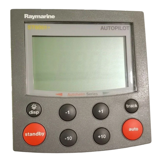
Page 2: Control Unit
ST6001+ Autopilot Control Unit Owner’s Handbook Document number: 81190-2 Date: May 2001…
-
Page 3
ST6001+ Autopilot Control Unit — Owner’s Handbook Autohelm, HSB (High Speed Bus), SailPilot, SeaTalk and SportPilot are registered trademarks of Raymarine Ltd. Raymarine, AST (Advanced Steering Technology), AutoAdapt, AutoLearn, AutoRelease, AutoSeastate, AutoTack, AutoTrim, FastTrim, GyroPlus, RayGyro, RayPilot and WindTrim are trademarks of Raymarine Ltd. -
Page 4: Table Of Contents
Keypad functions … 4 Display layout … 5 2.2 Using Auto mode … 6 Engaging the autopilot (Auto mode) … 6 Disengaging the autopilot (Standby mode) … 6 Changing course in Auto mode … 7 Adjusting performance – Type 150G/400G … 7 Adjusting performance –…
-
Page 5
Step 1 — Switch on … 56 Step 2 — Check the SeaTalk and NMEA connections … 57 Step 3 — Check the autopilot operating sense … 58 Step 4 — Adjust basic autopilot settings … 59 6.2 Seatrial Calibration … 63 Calibrating the compass … -
Page 6
Dealer Calibration screens and settings … 88 Dealer Calibration defaults: Types 150/150G & 400/400G … 97 Dealer Calibration options: Types 150/150G & 400/400G … 98 Using the autopilot (non-150/400 systems) … 100 Commissioning the autopilot (non-150/400 systems) … 101 Dockside Checks … 101 Seatrial Calibration … -
Page 7
ST6001+ Autopilot Control Unit — Owner’s Handbook… -
Page 8: About This Handbook
Preface About this handbook Welcome to the handbook for the ST6001+ autopilot control unit. This handbook contains two main parts: Part 1: Using the ST6001+ Chapter 1: Introduction Introduces the autopilot, its features and its use. Chapter 2: Basic Operation…
-
Page 9: Important Information
Important Information Warranty To register your new Raymarine product, please take a few minutes to fill out the warranty card. It is important that you complete the owner information and return the card to us to receive full warranty benefits.
-
Page 10: Emc Conformance
Make proper allowance for tidal set – the autopilot cannot. • Even when your autopilot is locked onto the desired track using a navigation aid, always maintain a log and make regular positional plots. Navigation signals can produce significant errors under some circumstances and the autopilot will not be able to detect these errors.
-
Page 11
ST6001+ Autopilot Control Unit — Owner’s Handbook… -
Page 12
Part 1: Using the ST6001+… -
Page 14: Chapter 1: Introduction
2. Auto : autopilot steers the boat to maintain a locked heading (see page 6) 3. Track : autopilot steers the boat to maintain a track between two waypoints created on a navigation aid (see page 16) 4. Wind Vane : autopilot steers the boat to maintain a course relative to a true or apparent wind angle (see page 23) 5.
-
Page 15
• it can use boat speed from a SeaTalk speed instrument to optimize track-keeping performance You can also use the ST6001+ autopilot with any navigator (GPS, Decca, Loran) or wind instrument that transmits National Marine Electronics Association (NMEA) 0183 data. -
Page 16: Chapter 2: Basic Operation
Adjusting display/keypad lighting Explains how to change the lighting on the control unit display and keypad. Note: If you are using the control unit with a non-150/400 autopilot system, refer to the notes in the Appendix. page 4 page 6…
-
Page 17: Using The Control Unit
2.1 Using the control unit Start-up mode The autopilot always powers up in Standby mode with the display showing the boat’s current compass heading. Note: You can press standby at any time to return to manual steering. Keypad functions The autopilot is controlled using simple push-button operations, all of which are confirmed with a short beep.
-
Page 18: Display Layout
Display Calibration, see page 79. Rudder position indicator or error bar Heading indicators Distance units: • no units = kilometres • nm = nautical miles • SM = statute miles Autopilot mode indicators Port and Starboard direction-to-steer indicators Calibration mode indicator (displayed on…
-
Page 19: Using Auto Mode
• in Auto mode, the display shows the locked autopilot heading CAUTION: Autopilot course control makes it easier to sail a boat, but it is NOT a substitute for good seamanship. ALWAYS maintain a permanent watch by the helm. Disengaging the autopilot (Standby mode) Press standby to disengage the autopilot: •…
-
Page 20: Changing Course In Auto Mode
The main way you can adjust the performance of Type 150G/400G (GyroPlus) autopilot systems is by changing the response level. This is the only user adjustment you should need to make to the autopilot on a regular basis. The response level controls the relationship between the autopilot’s course keeping accuracy and the amount of helm/drive activity.
-
Page 21: Adjusting Performance — Types 150/400 And 100/300
Calibration (see page 85). This determines the default power-up response level. However, when using your autopilot on a day-to-day basis, you can make temporary adjustments to the response level. By doing this you can match autopilot performance to different conditions.
-
Page 22
Calibration (see page 85). This determines the default power-up response level. However, when using your autopilot on a day-to-day basis, you will need to make temporary adjustments to the response level. By doing this you can match autopilot performance to different conditions. -
Page 23: Off Course Warning
Dodging obstacles and then resuming course To avoid an obstacle when your boat is under autopilot control, you can dodge the obstacle and then resume your previous course.
-
Page 24
2. To accept this heading, and resume this course, press auto when the display is flashing. Note: If you do not press auto while the display is flashing, the autopilot will maintain the current heading. Returning to last heading 1 SECOND… -
Page 25: Using Sail Boat Features
AutoTack — Port Wind Preventing accidental gybes Note: For the gybe inhibit feature to work, the autopilot needs suitable wind information (see page 23). The gybe inhibit feature stops the boat from performing an AutoTack away from the wind – this will prevent accidental gybes. On Type…
-
Page 26: Gusty Conditions
• you will be able to perform an AutoTack into the wind • to prevent accidental gybes, the autopilot will prevent the boat from performing an AutoTack away from the wind • with gybe inhibit off: •…
-
Page 27: Adjusting Display/Keypad Lighting
Note: You can also adjust the lighting level from any other SeaTalk instrument or control unit. Note: When you switch off the unit you lose any changes you have made to the lighting level. ST6001+ Autopilot Control Unit — Owner’s Handbook D3313-3…
-
Page 28: Chapter 3: Advanced Operation
Describes how to use data pages to display SeaTalk and NMEA information on the control unit. This section also explains the Watch timer feature. Note: If you are using the control unit with a non-150/400 autopilot system, refer to the notes in the Appendix. page 16…
-
Page 29: Using Track Mode
4. Check that it is safe for the boat to turn onto the new course. 5. Press the track key: • the autopilot will turn the boat onto the new course in a controlled way • the display shows the heading required to achieve the required track ST6001+ Autopilot Control Unit — Owner’s Handbook…
-
Page 30: Exiting Track Mode
Note: The closer the boat is to the correct heading and track when you press track , the quicker the autopilot will bring the boat onto the new course. If the boat is more than 0.3 nm from the track, the Large Cross Track Error warning will sound (see page 17).
-
Page 31: Tidal Stream Compensation
Tidal stream compensation Under most conditions, the autopilot will hold the selected track to within ±0.05 nm (300 ft) or better. The autopilot takes account of the boat’s speed when computing course changes to ensure optimum performance over a wide range of boat speeds.
-
Page 32: Waypoint Arrival And Advance
Arrival As the boat arrives at the target waypoint the navigation aid will select the next target waypoint and transmit this to the autopilot. The autopilot will then detect the new target waypoint name, sound the Waypoint Advance warning and display the Waypoint Advance ( NEXT WPT ) screen.
-
Page 33: Waypoint Advance Warning — Summary
Note: If you do not press track to accept the Waypoint Advance, the autopilot will maintain the current heading and continue sounding the warning. Skipping a waypoint – SeaTalk navigators only…
-
Page 34: Dodges In Track Mode
Auto mode • Dodges in Track mode When the autopilot is in Track mode you still have full control from the keypad. Initiating a dodge maneuver In Track mode, you can make a dodge maneuver by using the course change keys ( -1 , +1 , -10 or +10 ) to select the desired course change.
-
Page 35: Safety In Track Mode
Plot frequency • In open water, you should make plots at least every hour. • In confined waters or when near to potential hazards, you should make plots more frequently. ST6001+ Autopilot Control Unit — Owner’s Handbook…
-
Page 36: Using Wind Vane Mode — Sail Boats
Chapter 3: Advanced Operation 3.2 Using Wind Vane mode – sail boats Note: You can only select Wind Vane mode if the autopilot is receiving suitable SeaTalk or NMEA wind direction information. About Wind Vane mode When the autopilot is in Wind Vane mode it uses the fluxgate compass as the primary heading reference.
-
Page 37: Selecting Wind Vane Mode
(e.g. WIND 145P indicates an wind angle of 145° to port) • if the autopilot does not enter Wind Vane mode, it is not receiving wind data — check the instrument and connections The autopilot will then adjust the boat’s heading to maintain the locked wind angle.
-
Page 38: Returning To The Previous Wind Angle (Last Wnd)
Note: If you do not accept the previous wind angle within 10 seconds, the autopilot will lock onto the current wind angle. Dodges in Wind Vane mode When the autopilot is in Wind Vane mode you still have full control from the keypad. Initiating a dodge maneuver…
-
Page 39: Wind Shift Warning
Wind Shift warning If the autopilot detects a wind shift of more than 15° it will sound the wind shift warning and display the WIND SHIFT message: • To cancel the warning, and retain the existing wind angle and new heading, press standby and auto together.
-
Page 40: Operating Hints For Wind Vane Mode
Chapter 3: Advanced Operation When you AutoTack in Wind Vane mode, the boat turns through the AutoTack angle. The autopilot will then trim the heading to mirror the locked wind angle from the previous tack. Operating hints for Wind Vane mode •…
-
Page 41
2. If you increase the rudder gain setting on a Type 150G/400G autopilot, you must also increase the counter rudder setting. ST6001+ Autopilot Control Unit — Owner’s Handbook heading… -
Page 42: Displaying Data
(see page 81) 2. Select the data page you want to use as the main display: • the current autopilot mode is shown at the left of the display and the autopilot bar graph remains in use •…
-
Page 43: Watch Timer
Auto mode, you must first exit the WATCH screen (see below). Exiting the Watch screen To exit the Watch screen: press disp to display a different data page • press standby • ST6001+ Autopilot Control Unit — Owner’s Handbook…
-
Page 44: Warning Messages
Chapter 3: Advanced Operation Warning messages Shallow warning (SHALLOW) The ST6001+ shows the Shallow warning if it receives a shallow depth message from an instrument on the SeaTalk system. Press standby or disp to cancel the warning. Man Overboard warning (MOB) The ST6001+ activates the Man Overboard warning if it receives a man overboard (MOB) message from another instrument on the SeaTalk system.
-
Page 45
ST6001+ Autopilot Control Unit — Owner’s Handbook… -
Page 46: Chapter 4: Fault Finding & Maintenance
If a fault occurs with your autopilot, use the fault finding tables in this section to help identify the problem and provide a solution.If you cannot resolve the problem yourself, refer to the product support information.
-
Page 47: Fault Finding
Northern hemisphere (or Southerly headings in the Southern hemisphere) You cannot enter Seatrial Calibration The autopilot will not ‘talk’ to other SeaTalk instruments Position information not received The autopilot will not auto advance to the next waypoint ST6001+ Autopilot Control Unit — Owner’s Handbook CAUSE and SOLUTION No power –…
-
Page 48: Autopilot Alarm Messages
Chapter 4: Fault Finding & Maintenance Autopilot alarm messages When the autopilot detects a fault or failure on the system, it will activate one of the alarm messages listed in the following table. • Unless otherwise stated, you should respond to the alarm by pressing standby to clear the alarm and return to hand steering, before you attempt to resolve the problem.
-
Page 49
Caused by any of the following situations: • the compass is not connected • the autopilot is in Wind Vane mode and it has not received wind angle data for 30 seconds • the autopilot is in Track mode and: •… -
Page 50: General Maintenance
Routine checks CAUTION: The control unit does not contain any user serviceable parts. It should be serviced only by authorized Raymarine service technicians. The control unit is a sealed unit. As a result, user maintenance is limited to the following checks: •…
-
Page 51: Product Support
2 seconds you see control unit software version press disp to display the course computer software version • press disp again to display the total number of hours the autopilot • has been used in Auto mode (Note: Type 100/300 systems do not display hours used.)
-
Page 52: Product Details Table
1 second Time autopilot used in Auto Product details table For future reference, you may want to use this table to record serial and software information for your autopilot system: Control unit Course computer Hours used 4 seconds Control unit…
-
Page 53
ST6001+ Autopilot Control Unit — Owner’s Handbook… -
Page 54
Part 2: Installing the ST6001+… -
Page 56: Chapter 5: Installing The St6001
Chapter 5: Installing the ST6001+ Chapter 5: Installing the ST6001+ The sections in this chapter explain how to install the ST6001+ control unit and connect it to an autopilot system: Select the location How to select a suitable location for the ST6001+ control unit.
-
Page 57: Select The Location
The ST6001+ front cover is waterproof when installed according to the following instructions. However, you must protect the rear of the control unit from water in a ventilated and drained area. ST6001+ Autopilot Control Unit — Owner’s Handbook 24 mm 110 mm (4.33 in) (0.95 in)
-
Page 58: Cabling Guidelines
EMC installation guidelines All Raymarine equipment and accessories are designed to the best industry standards for use in the recreational marine environment. Their design and manufacture conforms to the appropriate…
-
Page 59: Connections To Other Equipment
Raymarine equipment. Always use the ferrites supplied by Raymarine. Connections to other equipment If your Raymarine equipment is to be connected to other equipment using a cable not supplied by Raymarine, a suppression ferrite MUST always be attached to the cable near to the Raymarine unit.
-
Page 60: Control Unit Installation
Chapter 5: Installing the ST6001+ 5.2 Control unit installation Surface mount control units To fit a surface mount control unit: 1. Apply the surface mount template (supplied at the back of this handbook) to the selected bulkhead. 2. Mark the centers of the two fixing holes and the cable boss. 3.
-
Page 61: Flush Mount Control Units
8. Locate the bracket onto the fixing studs and secure the assembly to the panel with the thumb-nuts. Hand-tighten the thumb nuts – do NOT use a wrench. Aperture ST6001+ Autopilot Control Unit — Owner’s Handbook in) thick. cut-out Self-adhesive…
-
Page 62: Seatalk Connections
SeaTalk equipment. Connecting to a course computer If you are using the ST6001+ as the main control unit for a course computer autopilot system, connect it directly to the course computer SeaTalk terminals. To do this: •…
-
Page 63: Nmea Connections
To decode the maximum amount of NMEA data (so it can be transmitted onto SeaTalk), connect the navigator to the course computer NMEA terminals. Refer to the Autopilot System Installation Guide for more information. Receiving NMEA data…
-
Page 64: Nmea Cabling
Chapter 5: Installing the ST6001+ Information Course Over Ground Speed Over Ground Cross Track Error Bearing to Waypoint Distance to Waypoint Waypoint Number Apparent Wind Speed Apparent Wind Angle Speed Through Water Depth Water Temperature Note: The ST6001+ only decodes the last four characters of waypoint names. This means that the last four characters of long waypoint names must be unique for the waypoint advance function to work.
-
Page 65: Nmea Cable Connectors
(if your system includes a course computer) • use a SeaTalk/NMEA Interface (part number: E85001) to convert SeaTalk data to NMEA data (if your system does not include a course computer) ST6001+ Autopilot Control Unit — Owner’s Handbook D3286-2…
-
Page 66: Functional Test — Repeater Units Only
Note: If you have connected the ST6001+ as part of a new autopilot installation, you MUST calibrate the autopilot as described in Chapter 6: Commissioning the Autopilot.
-
Page 67
ST6001+ Autopilot Control Unit — Owner’s Handbook… -
Page 68: Chapter 6: Commissioning The Autopilot
Seatrial Calibration The purpose of this seatrial is to calibrate the compass and optimize the autopilot set-up for your boat. Note: If you have connected the ST6001+ to a non-150/400 autopilot system refer to the notes in the Appendix. page 56…
-
Page 69: Dockside Checks
Step 1 — Switch on 1. When you have installed the ST6001+ control unit and the rest of the autopilot system, switch on the main power breaker. 2. If the control unit and system are active, the control unit will beep and display the control unit type ( ST6001 ) for 2 seconds.
-
Page 70: Step 2 — Check The Seatalk And Nmea Connections
• navigator is not configured to transmit the required data format Wind instrument connections If you have connected the autopilot to an NMEA or SeaTalk wind instrument, check the links by pressing standby and auto together: • the ST6001+ should display the Wind Vane mode screen, with the…
-
Page 71: Step 3 — Check The Autopilot Operating Sense
Check the autopilot steering sense 1. Manually center the wheel, then press the auto key so the autopilot is in Auto mode. Check that the display shows AUTO . Be ready to press standby if the rudder moves hardover. 2. Press the +10 key once. Check that the rudder moves to starboard a few degrees and then stops.
-
Page 72: Step 4 — Adjust Basic Autopilot Settings
Semi Displacement: SEMI DIS • Planing: PLANING • Stern (I/O) Drive: STERN DRV • Work Boat: WORK BOAT • Sail Boat: SAIL BOAT • Note: When you select the vessel type, the autopilot will select appropriate defaults for various other calibration settings.
-
Page 73
— press disp to move forwards through items (*sail boats only) — press disp for 1 second to move backwards — use -1, +1, -10, +10 to adjust settings — press standby for 2 seconds to save changes ST6001+ Autopilot Control Unit — Owner’s Handbook 2 seconds auto 1 second… -
Page 74
Chapter 6: Commissioning the Autopilot Set the drive type 1. With the autopilot still in Dealer Calibration, use the disp key to page through the calibration screens until you reach the Drive Type screen ( DRIVE TYP ). 2. Use the -1 or +1 keys to select the appropriate drive type: •… -
Page 75
RUDD DAMP screen. 2. Use the -1 or +1 keys to adjust the rudder damping: • increase the damping one level at a time until the autopilot stops hunting, and always use the lowest acceptable value Save the new settings… -
Page 76: Seatrial Calibration
1. Calibrate the compass: • complete the automatic deviation correction • align the compass heading 2. Adjust the autopilot settings to suit your boat: • automatically on Type 150G/400G autopilot systems • manually on Type 150/400 (non-GyroPlus) and Type 100/300…
-
Page 77: Calibrating The Compass
The deviation correction procedure (swinging the compass) involves turning your boat in slow circles so the autopilot can determine the deviation and calculate any correction required. You must carry out this procedure in calm conditions and preferably on flat water.
-
Page 78: Compass Calibration
Coarse adjustment: If COG is available from GPS, press then fine tune manually (see below). Fine adjustment: If COG is not available (or after setting heading to COG), align autopilot heading manually: Adjust the autopilot heading so it shows the…
-
Page 79
3. If you have a GPS connected to your autopilot: • increase the boat speed to more than 3 knots press the auto key: the autopilot will then set the heading to • agree with the COG (course over ground) heading received from the GPS •… -
Page 80
Chapter 6: Commissioning the Autopilot Adjusting the heading alignment If you experience difficulties with compass alignment, you can check the compass alignment after completing the deviation correction procedure (swinging the compass). After completing the initial compass calibration, you can make further adjustments to the alignment without swinging the compass again. -
Page 81: Adjusting Autopilot Settings
Adjusting autopilot settings The next stage of the seatrial is to set key autopilot parameters that affect the autopilot’s steering characteristics. You can do this in one of two ways: • using AutoLearn: Type 150G and Type 400G autopilot systems use AutoLearn –…
-
Page 82
Chapter 6: Commissioning the Autopilot AutoLearn calibration Enter Seatrial Calibration 2 sec Start the AutoLearn To prepare for the AutoLearn: • steer straight ahead at cruising speed (planing boats – off the plane) • head into wind and waves Boat completes AutoLearn… -
Page 83
Note: If you need to cancel the AutoLearn for any reason, press the standby or disp key. 5. When the autopilot has finished learning, the control unit will beep and the display will change to LRN PASS or LRN FAIL : LRN PASS = AutoLearn completed successfully •… -
Page 84
2. Press auto to lock onto the current heading. The autopilot should hold a constant heading in calm sea conditions. 3. Use the -1 , +1 , -10 and +10 keys to check how the autopilot alters the course to port and starboard in multiples of 1° and 10°. -
Page 85
To check the counter rudder setting 1. Set RESPONSE to level 3. 2. Sail your boat at cruising speed in clear water 3. Press auto to switch the autopilot to Auto mode, then make a 90° course change: ST6001+ Autopilot Control Unit — Owner’s Handbook… -
Page 86
2. Use the -1 or +1 keys to adjust the counter rudder. 3. Press and hold standby for 2 seconds to save the changes. 4. Press auto to check the autopilot performance in Auto mode. The pilot is now calibrated and ready for use. -
Page 87
ST6001+ Autopilot Control Unit — Owner’s Handbook… -
Page 88: Chapter 7: Adjusting Autopilot Settings
Chapter 7: Adjusting Autopilot Settings This chapter explains all of the calibration settings you can adjust on the autopilot system. You will have adjusted many of these settings when commissioning the system (see Chapter 6), and they should not require further adjustment.
-
Page 89: Calibration Basics
Seatrial Calibration (SEATRIAL CAL) The Seatrial Calibration group is specifically designed for use during the initial autopilot seatrial (see page 63 of Chapter 6 for full details). You should not need to access Seatrial Calibration during normal autopilot operation.
-
Page 90
Chapter 7: Adjusting Autopilot Settings Calibration Mode Overview 2 seconds (saves changes) Calibration Mode 1 second auto standby -1 and +1 Calibration lock Vessel type Drive type Align rudder Rudder limit Rudder gain Counter rudder Rudder damping AutoTrim Response level… -
Page 91: Accessing The Calibration Mode
Accessing the Calibration mode You can only access Calibration mode from Standby mode: 1. With the autopilot in Standby mode, press and hold the standby key for 2 seconds. The display will change to show DISPLAY CAL . 2. Press the disp key to scroll down through the 4 calibration…
-
Page 92: Display Calibration
STEER BAR BAR OFF Heading selection This screen allows you to display any heading as either a magnetic or true value. During normal autopilot operation the screen will indicate MAG for magnetic headings and TRUE for true headings. Options HDG MAG…
-
Page 93
1 second Display Calibration 1 second Data pages 1-7 Press disp for next page ST6001+ Autopilot Control Unit — Owner’s Handbook 2 seconds 1 second 1 second 1 second To adjust values use To exit and save changes 2 seconds… -
Page 94: Data Pages
5 -7 *Note: It is good practice to keep the BTW and DTW pages for display. If the autopilot receives a man overboard (MOB) message, these data pages will show the bearing and distance to the MOB location. To change the data displayed on a data page: Press disp to move to the appropriate data page setup screen.
-
Page 95
*NOTE: There are 3 depth pages (meters, feet and fathoms) and 2 water temperature pages (°C and °F). The ST6001+ will display the water temperature or depth data in the units defined by data page you select. ST6001+ Autopilot Control Unit — Owner’s Handbook Displayed as HEADING WATER °C… -
Page 96: User Calibration
Chapter 7: Adjusting Autopilot Settings 7.3 User Calibration Note: If you are connecting the ST6001+ to a non-150/400 autopilot system, the User Calibration group is not available. Refer to the Appendix for full details. The User Calibration group includes settings that you may need to adjust on a regular basis due to changing conditions.
-
Page 97
2 seconds (saves changes) Calibration Mode 1 second User Calibration 1 second 1 second 1 second ST6001+ Autopilot Control Unit — Owner’s Handbook 2 seconds 1 second 1 second Sail boats only 1 second To adjust values use 1 second To exit &… -
Page 98: Wind Selection
• the autopilot will maintain the true wind angle Options Range = 1 to 9 Lower values (1 to 3) = autopilot responds to longer term wind changes (less pilot activity) Typical values = 4 to 6 Higher values (7 to 9) = autopilot responds to shorter term…
-
Page 99: Magnetic Variation
If required, set this value to the level of magnetic variation present at your boat’s current position – indicated as east ( VAR EAST ) or west ( VAR WEST ). The autopilot sends this variation setting to other instruments on the SeaTalk system, and it can be updated by other SeaTalk instruments.
-
Page 100: Seatrial Calibration
You should not need to access Seatrial Calibration to adjust settings during normal autopilot operation. Note: If you are connecting the ST6001+ to a non-150/400 autopilot system, the Seatrial Calibration group is not available. You will need to use the Compass Calibration group instead. Refer to the Appendix…
-
Page 101: Dealer Calibration
After you have commissioned the autopilot, you should not normally need to alter the Dealer Calibration values. Note: If you are connecting the ST6001+ to a non-150/400 autopilot system, the items in the Dealer Calibration group appear in a different order and several items will not be available. Refer to the Appendix for full details.
-
Page 102
Chapter 7: Adjusting Autopilot Settings Accessing Dealer Calibration 2 seconds (saves changes) Calibration Mode Dealer Calibration 1 second Sail boats only Stern drives only 2 seconds 1 second To adjust values use To exit & save changes 2 seconds Not sail boats… -
Page 103: Vessel Type
PLANING STERN DRV WORK BOAT SAIL BOAT Note: When you select the vessel type, the autopilot will set appropriate defaults for several other calibration settings. Refer to the table on page 97 for default values. Drive type The drive type setting controls how the autopilot drives the steering system.
-
Page 104: Rudder Limit
Chapter 7: Adjusting Autopilot Settings Rudder limit Use the rudder limit screen to set the limits of autopilot rudder control just inside the mechanical end stops. This will avoid putting the steering system under unnecessary load. You should adjust this setting when commissioning the autopilot (see page 61).
-
Page 105: Rudder Damping
Rudder damping Adjust the rudder damping value if the autopilot ‘hunts’ when trying to position the rudder (see page 62). Increasing the rudder damping value reduces hunting. Screen text RUDD DAMP AutoTrim The AutoTrim setting determines the rate at which the autopilot applies ‘standing helm’…
-
Page 106: Response Level
User Calibration – see page 85 for full details (or refer to the Appendix for Type 100/300 autopilots). Turn rate limit Note: Not available if vessel type = SAIL BOAT . This limits your boat’s rate of turn under autopilot control. Screen text TURN RATE Off course warning angle This screen determines the angle used by the OFF COURSE warning (see page 10).
-
Page 107: Wind Type
Notes: 1. Only available if vessel type = SAIL BOAT . 2. Not available on Type 100/300 autopilot systems. With gybe inhibit on you can only AutoTack into the wind. This screen also appears in User Calibration – see page 83 for full details.
-
Page 108: Cruise Speed
AUTOADAPT Sth Note: If you set AUTOADAPT to nth or Sth , you then need to enter your current latitude in the next screen ( LATITUDE ), so that the autopilot can provide accurate course keeping by automatically adjusting the rudder gain depending on the heading.
-
Page 109: Autopilot Reset
Note: Not available on Type 100/300 autopilot systems. WARNING: Do NOT use this feature unless advised to do so by a Raymarine dealer. If you complete a reset you will lose ALL autopilot calibration settings. You will then need to repeat the autopilot commissioning process.
-
Page 110: Dealer Calibration Defaults: Types 150/150G & 400/400G
Chapter 7: Adjusting Autopilot Settings Dealer Calibration defaults: Types 150/150G & 400/400G Calibration setting Calibration lock Vessel type DISPLACE SEMI Drive type Rudder alignment 0 Rudder limit Rudder gain Counter rudder Rudder damping AutoTrim Response: with G non-G Turn rate limit…
-
Page 111: Dealer Calibration Options: Types 150/150G & 400/400G
Gybe inhibit Wind type Wind Trim Cruise speed AutoAdapt Latitude Variation Autopilot reset ST6001+ Autopilot Control Unit — Owner’s Handbook Vessel type OFF, ON WORK BOAT, SAIL BOAT 3, 4, 5 -7 to +7 10 to 40 1 to 9…
-
Page 112: Appendix: Using The St6001+ With Non-150/400 Autopilots
Introduction The information in this Appendix explains the key differences when using, commissioning and calibrating the autopilot if you have connected the ST6001+ to a Raymarine autopilot other than a Type 150/150G or Type 400/400G. Using the autopilot (non-150/400 systems) This section explains the key differences when using the ST6001+ to control a non-150/400 autopilot.
-
Page 113: Using The Autopilot (Non-150/400 Systems)
The ST6001+ will return to Standby mode if you release the joystick button or if you press the standby key on the control unit. You can set the autopilot to power steer in either proportional or bang-bang mode (see page 106).
-
Page 114: Commissioning The Autopilot (Non-150/400 Systems)
Dockside Checks With the boat safely tied up, complete the dockside checks described on page 56 to page 57 of Chapter 6: Commissioning the Autopilot: 1. Switch on. 2. Check the autopilot operating sense.
-
Page 115: Calibration Mode (Non-150/400 Systems)
Calibration mode (non-150/400 systems) Calibration groups When connected to an autopilot other than a Type 150/150G or 400/400G, the Calibration mode provides 3 main calibration groups: Display Calibration (DISPLAY CAL) The items in Display Calibration only affect the individual control unit.
-
Page 116
Appendix: Using the ST6001+ With Non-150/400 Autopilots Calibration Mode Overview 100/300 Autopilot Systems 2 seconds (saves changes) Calibration Mode 1 second auto standby -1 and +1 Vessel type Calibration lock Rudder gain Counter rudder Align rudder Rudder limit Turn rate limit… -
Page 117: Dealer Calibration Screens
Rudder gain This screen determines the default rudder gain setting. Rudder gain is a measure of how much helm the autopilot will apply to correct course errors. The higher the setting, the more rudder will be applied. You should adjust this setting when commissioning the autopilot.
-
Page 118
Appendix: Using the ST6001+ With Non-150/400 Autopilots Counter rudder Counter rudder is the amount of rudder the autopilot applies to try to prevent the boat from yawing off course. Higher counter rudder settings result in more rudder being applied. You should set the default counter rudder when commissioning the autopilot (see page 72). -
Page 119: Power Steer
AUTO TRIM 2 AUTO TRIM 3 AUTO TRIM 4 Power steer If you have a joystick connected to your Type 100/300 autopilot system, use power steer to select the required joystick mode of operation (see table). Options PWR STEER OFF…
-
Page 120
If required, set this value to the level of magnetic variation present at your boat’s current position – indicated as east ( VAR EAST ) or west ( VAR WEST ). The autopilot sends this variation setting to other instruments on the SeaTalk system, and it can be updated by other SeaTalk instruments. -
Page 121: Autotack Angle
Note: If you set AUTOADAPT to nth or Sth , you then need to enter your current latitude in the next screen ( LATITUDE ), so that the autopilot can provide accurate course keeping by automatically adjusting the rudder gain depending on the heading.
-
Page 122
AUTORELSE Response level This is the default response setting. The response level controls the relationship between the autopilot’s course keeping accuracy and the amount of helm/drive activity. You can make temporary changes to response during normal operation (see page 7). -
Page 123: Dealer Calibration: Possible Settings With Type 100/300
Wind Trim (displacement only) AutoTack angle (displacement only) AutoRelease (stern drives only) Response Note: Information applies to Type 100/300 Course Computers with Version 15 software. ST6001+ Autopilot Control Unit — Owner’s Handbook Vessel type SEMIDISP PLANING NORTH NORTH STERNDRV NORTH…
-
Page 124: Specifications
• Improved track-keeping • Steers to true and apparent wind in Wind Vane mode • Improved calibration access, but without AutoLearn • Uses Raymarine steering algorithm without AST • No FastTrim Type 100/300 • Standard functionality using Raymarine steering algorithm without AST •…
-
Page 125: Glossary
Marked on Raymarine products that comply with defined European Community standards counter rudder Counter rudder is the amount of rudder the autopilot applies to try to prevent the boat from yawing off course. Higher counter rudder settings result in more rudder being applied.
-
Page 126
The autopilot response level controls the relationship between course keeping accuracy and the amount of helm/drive activity. rudder gain Rudder gain is a measure of how much helm the autopilot will apply to correct course errors. The higher the setting the more rudder will be applied. SeaTalk SeaTalk is Raymarine’s proprietary communication system. -
Page 127
ST6001+ Autopilot Control Unit — Owner’s Handbook… -
Page 128: Index
Index Index Adjusting autopilot settings 75 Accessing Calibration mode 78 Calibration groups 76 – Dealer Calibration 88 Aligning rudder 90 AutoAdapt 95 Autopilot reset 96 AutoRelease 93 AutoTrim 92 Counter rudder 91 Cruise speed 95 Drive type 90 Latitude 96…
-
Page 129
Explanation 17 LARGE XTE warning 17 Cruise speed 95 Current limit alarm 35 Data pages Displaying 29 ST6001+ Autopilot Control Unit — Owner’s Handbook Dealer Calibration 88 Disengaging the autopilot 6 Display Calibration 79 Display, Layout 5 Dodging obstacles –… -
Page 130
Inputs on control unit 51 Receiving 50 Transmitting 52 No data alarm 36 No pilot alarm 36 Non-150/400 autopilots 99 Adjusting autopilot settings 102 Commissioning the autopilot 101 Using the autopilot 100 Off course warning Operating (steering) sense 58 Operating modes… -
Page 131
– Wind Vane mode 23 Adjusting wind angle 24 Apparent wind 23 AutoTack 26 ST6001+ Autopilot Control Unit — Owner’s Handbook Dodging obstacles 25 Entering Wind Vane mode 24 Exiting Wind Vane mode 24 Previous wind angle 25 True wind 23… -
Page 132
Drill 5 mm (3/16 inch) Control unit — surface mount template diameter hole Machine hole 90 mm (3.55 inch) diameter Drill 5 mm (3/16 inch) diameter hole D3441-3… -
Page 134
Control unit — flush mount template 4 holes 6 mm (0.25 in) diameter Remove the shaded area 109 mm (4.3 in) D4437-3… -
Page 136: Warranty Limitations
During this period, except for certain products, travel costs (auto mileage and tolls) up to 100 round trip highway miles (160 kilometres) and travel time of 2 hours, will be assumed by Raymarine only on products where proof of installation or commission by authorized service agents, can be shown.
-
Page 137
Factory Service Centers United States of America Raymarine Inc 22 Cotton Road, Unit D Nashua, NH 03063-4219, USA Telephone: +1 603 881 5200 Fax: +1 603 864 4756 www.raymarine.com Sales & Order Services Telephone: +1 800 539 5539 Ext. 2333 or +1 603 881 5200 Ext.
This manual is also suitable for:
St6001+
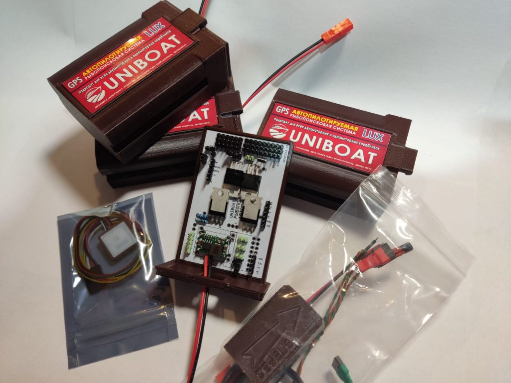
- Комплектация автопилота
- Какие бывают модификации автопилотов
- На какие кораблики можно установить автопилот
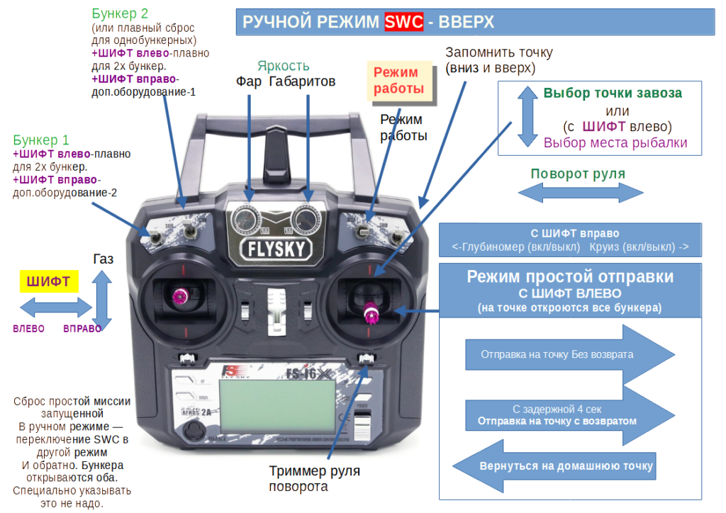
- Режим ручного управления
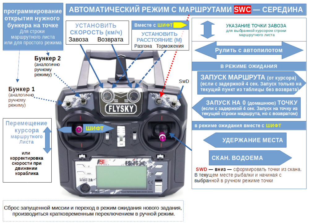
- Режим автопилота
- Калибровка компаса
- Почему не особо нужна калибровка
- Режим поиска рыбы
- Встроенная панель администратора
- Обновление прошивки
- Подключение эхолота LUCKY к автопилоту
- Настройка пульта FlySKY i6 для работы с автопилотом UNIBOAT
- Прошивка пульта для использования с автопилотом UNIBOAT
- Подключение адресных светодиодов, рекомендуемая схема размещения
- Подключение аудио усилителя и динамика к АВТОПИЛОТУ — голосовое сопровождение
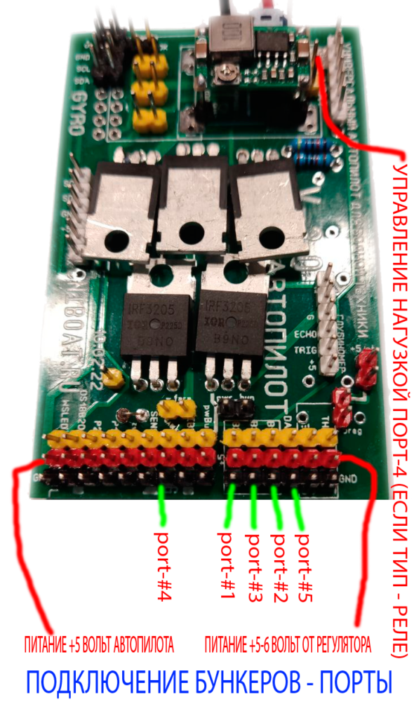
- Распределение бункеров, разбрасывателей и пр., что такое порты
- Подключение кнопки к автопилоту для работы с корабликом без пульта
- Рекомендации по установке и компоновке оборудования на кораблике
Режим ручного управления
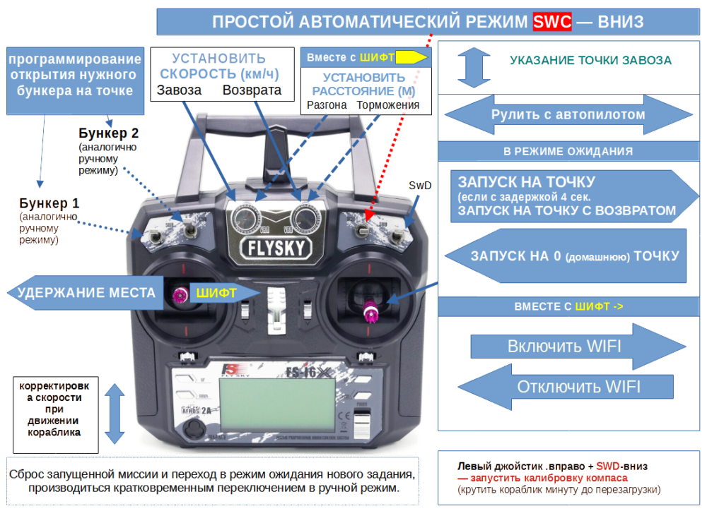
Режим ручного управления выбирается установкой переключателя SWC в верхнее (первое из трех) положение. Как управлять корабликом, сохранять точки, открывать и закрывать бункера и многое другое вы можете узнать здесь
Управление в режиме автопилота
Сохранив точки можно использовать их для автоматической отправки прикормочного кораблика на них и сброса прикормки. Режим управления автопилотом выбирается установкой переключателя SWC в среднее (второе из трех) Перейдите по этой ссылке и вы будете удивлены, как легко это происходит.
Подключение эхолота LUCKY к автопилоту
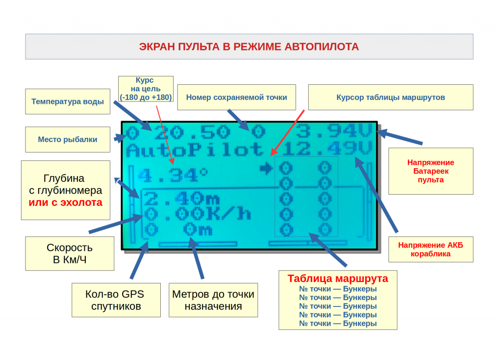
Многие кораблики UNIBOAT, как и кораблики других производителей укомплектованы глубиномерами, которые поддерживаются автопилотом. Но гораздо более интересно подключить к автопилоту полноценный эхолот и наблюдать рыбу, глубину и рельеф дна прямо на экране пульта управления корабликом. Эту уникальную возможность поддерживает только наш автопилот. Подробности здесь
Автоматическое сканирование водоема с поиском рыбы и авто сохранением точек для рыбалки
Смотрите инструкцию здесь
Встроенная панель администратора
Автопилот UNIBOAT является сложным и универсальным навигационным прибором и может устанавливаться на разные типы кораблей с разными гидродинамическими характеристиками, силовыми установками и рулевым управлением. Для настройки прямого хода к точке, скоростей, расстояний разгона необходима возможность удобной настройки параметров и желательно во время нахождения кораблика на воде. На воде очень удобно настраивать автопилот. Ввод настроек в нашем автопилоте можно производить используя Wifi подключение к сотовому телефону. Подробности можно узнать здесь.
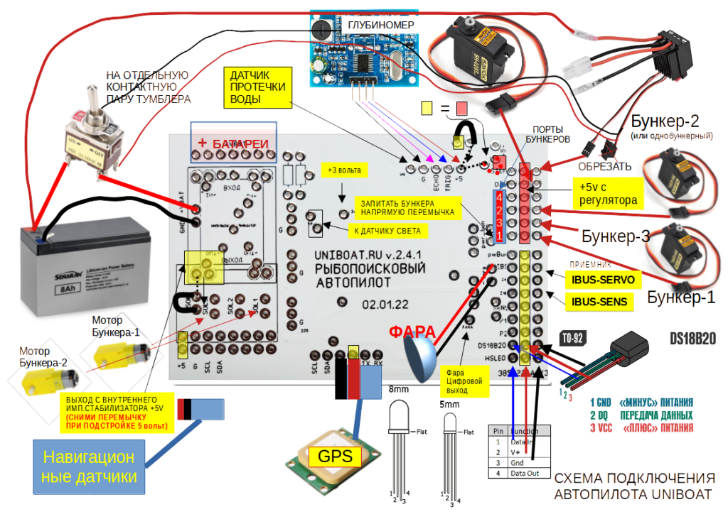
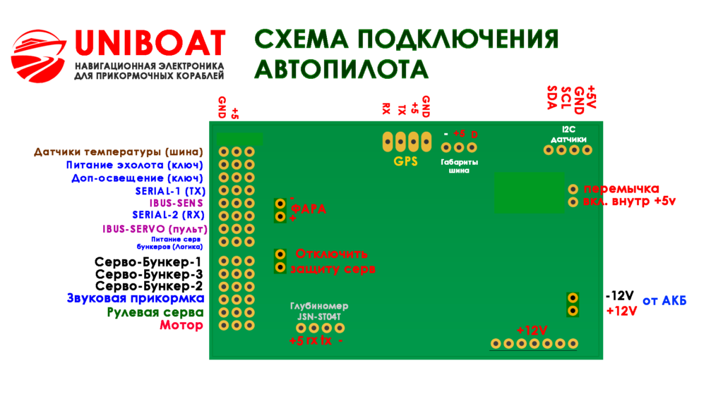
Схема подключения автопилота UNIBOAT к карповому кораблику
Инструкция как настроить пульт FlySKY I6 (каналы и пр.)
Прошивка пульта — инструкция
Схема подключения адресных светодиодов здесь.
Время на прочтение
7 мин
Количество просмотров 22K
Привет, Хабр. Это пост-отчет-тьюториал про беспилотные автомобили — как (начать) делать свой без расходов на оборудование. Весь код доступен на github, и помимо прочего вы научитесь легко генерить такие класные картинки:
Поехали!
Вкратце
Краткое содержание для знакомых с темой: традиционно для набора обучающей выборки для автопилота на основе машинного обучения нужен был специально оборудованный автомобиль с достаточно информативной CAN шиной и интерфейсом к ней, что дорого. Мы поступим проще и бесплатно — будем набирать такие же по сути данные просто со смартфона на лобовом стекле. Подходит любой авто, никаких модификаций оборудования. В этой серии — вычисляем поворот руля в каждый момент времени по видео. Если в этом абзаце всё понятно, можно перепрыгивать через введение сразу к сути подхода.
Что-зачем-почему более подробно
Итак, ещё пару лет назад без серьёзных ресурсов большой корпорации в тему автопилотов было не сунуться — один только LIDAR сенсор стоил десятки тысяч долларов, но недавняя революция в нейросетях всё изменила. Стартапы из нескольких человек с простейшими наборами сенсоров из пары вебкамер на равных конкурируют по качеству результата со знаменитыми брендами. Почему бы не попробовать и нам, тем более столько качественных компонентов уже в открытом доступе.
Автопилот преобразует данные сенсоров в управляющие воздействия — поворот руля и требуемое ускорение/замедление. В системе с лазерными дальномерами, как у Google, это может выглядеть так:
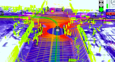
Простейший же вариант сенсора — видеокамера, «смотрящая» через лобовое стекло. С ним и будем работать, ведь камера на телефоне уже есть у каждого.
Для вычисления управляющих сигналов из «сырого» видео хорошо работают сверточные нейросети, но, как и любой другой подход машинного обучения, предсказывать правильный результат их нужно научить. Для обучения нужно (а) выбрать архитектуру модели и (б) сформировать обучающую выборку, которая будет демонстрировать модели различные входные ситуации и «правильные ответы» (например, угол поворота руля и положение педали газа) на каждую из них. Данные для обучающей выборки обычно записывают с заездов, где машиной управляет человек. То есть водитель демонстрирует роботу, как надо управлять машиной.
Хороших архитектур нейросетей хватает в открытом доступе, а вот с данными ситуация более печальная: во-первых данных просто мало, во-вторых почти все выборки — из США, а у нас на дорогах много от тех мест отличий.
Дефицит открытых данных легко объясним. Во-первых данные — не менее ценный актив, чем экспертиза в алгоритмах и моделях, поэтому делиться никто не торопится:
The rocket engine is the models and the fuel is the data.
Andrew Ng
Во-вторых, процесс сбора данных недёшев, особенно если действовать «в лоб». Хороший пример — Udacity. Они специально подобрали модель автомобиля, где рулевое управление и газ/тормоз завязаны на цифровую шину, сделали интерфейс к шине и считывают оттуда данные напрямую. Плюс подхода — высокое качество данных. Минус — серьезная стоимость, отсекающая подавляющее большинство непрофессионалов. Ведь далеко не каждый даже современный авто пишет в CAN всю нужную нам информацию, да и с интерфейсом придется повозиться.
Мы поступим проще. Записываем «сырые» данные (пока что это будет просто видео) смартфоном на лобовом стекле как видеорегистратором, затем софтом «выжимаем» оттуда нужную информацию — скорость движения и поворотов, на которых уже можно будет обучать автопилот. В результате получаем почти бесплатное решение — если есть держалка для телефона на лобовое стекло, достаточно нажать кнопку, чтобы набирать обучающие данные по дороге на работу.
В этой серии — «выжималка» угла поворота из видео. Все шаги легко повторить своими силами с помощью кода на github.
Задача
Решаем задачу:
- Есть видео с камеры, жестко закрепленной к авто (т.е. камера не болтается).
- Требуется для каждого кадра узнать текущий угол поворота руля.
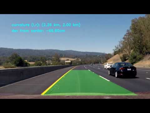
Ожидаемый результат:
Сразу чуть упростим — вместо угла поворота руля будем вычислять угловую скорость в горизонтальной плоскости. Это примерно эквивалентная информация если знать поступательную скорость, которой мы займемся в следующей серии.
Решение
Решение можно собрать из общедоступных компонент, немного их доработав:
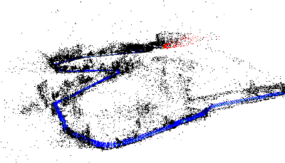
Восстанавливаем траекторию камеры
Первый шаг — восстановление траекториии камеры в трехмерном пространстве с помощью библиотеки SLAM по видео (simultaneous localization and mapping, одновременная локализация и построение карты). На выходе для каждого (почти, см. нюансы) кадра получаем 6 параметров положения: 3D смещение и 3 угла ориентации.
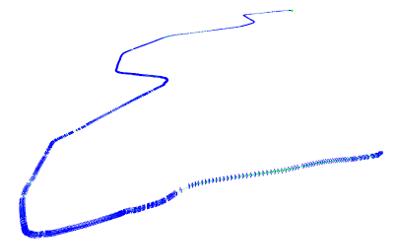
В коде за эту часть отвечает модуль optical_trajectories
Нюансы:
- При записи видео не гонитесь за максимальным разрешением — дальше определенного порога оно только повредит. У меня хорошо работают настройки в окрестностях 720х480.
- Камеру нужно будет откалибровать (инструкции, теория — актуальны части 1 и 2) на тех же настройках, с которыми записывалось видео с заезда.
- Системе SLAM нужна «хорошая» последовательность кадров, за которую можно «зацепиться» как за точку отсчета, поэтому часть видео в начале, пока система не «зацепится» останется не аннотированным. Если на вашем видео локализация не работает совсем, вероятны либо проблемы с калибровкой (попробуйте откалибровать несколько раз и посмотрите на разброс результатов), либо проблемы с качеством видео (слишком высокое разрешание, слишком сильное сжатие и т.д.).
- Возможны срывы отслеживания SLAM системой, если между соседними кадрами потеряется слишком много ключевых точек например, стекло на мгновение залило всплеском из лужи). В этом случае система сбросится в исходное не локализованное состояние и будет локализовываться заново. Поэтому из одного видео можно получить несколько траекторий (не пересекающихся во времени). Системы координат в этих траекториях будут совершенно разными.
- Конкретная библиотека ORB_SLAM2, которой я воспользовался, дает не очень надежные результаты по поступательным перемещениям, поэтому их пока игнорируем, а вот вращения определяет неплохо, их оставляем.
Определяем плоскость дороги
Траектория камеры в трехмерном пространстве — это хорошо, но напрямую еще не дает ответа на конечный вопрос — поворачивать налево или направо, и насколько быстро. Ведь у системы SLAM нет понятий «плоскость дороги», «верх-низ», и т.д. Эту информацию тоже надо добывать из «сырой» 3D траектории.
Здесь поможет простое наблюдение: автомобильные дороги обычно протягиваются гораздо дальше по горизонтали, чем по вертикали. Бывают конечно исключения, ими придется пренебречь. А раз так, можно принять ближайшую плоскость (т.е. плоскость, проекция на которую дает минимальную ошибку реконструкции) нашей траектории за горизонтальную плоскость дороги.
Горизонтальную плоскость выделяем прекрасным методом главных компонент по всем 3D точкам траектории — убираем направление с наименьшим собственным числом, и оставшиеся два дадут оптимальную плоскость.
За логику выделения плоскости также отвечает модуль optical_trajectories
Нюанс:
-
Из сути главных компонент понятно, что кроме горных дорог выделение главной плоскости будет плохо работать если машина всё время ехала по прямой, — ведь тогда только одно направление настоящей горизонтальной плоскости будет иметь большой диапазон значений, а диапазон по оставшемуся перпендикулярному горизонтальному направлению и по вертикали будут сопоставимы.
Чтобы не загрязнять данные большими погрешностями с таких траекторий, проверяем, что разброс по последнему главному компоненту значительно (в 100 раз) меньше, чем по предпоследнему. Не прошедшие траектории просто выкидываем.
Вычисляем угол поворота
Зная базисные векторы горизонтальной плоскости v1 и v2 (два главных компонента с наибольшими собственными значениями из предыдущей части), проецируем на горизонтальную плоскость оптическую ось камеры:

Таким образом из трехмерной ориентации камеры получаем курсовой угол автомобиля (с точностью до неизвестной константы, т.к. ось камеры и ось автомобиля в общем случае не совпадает). Поскольку нас интересует только интенсивность поворота (т.е. угловая скорость), эта константа и не нужна.
Угол поворота между соседними кадрами дает школьная тригонометрия (первый множитель — абсолютная величина поворота, второй — знак, определяющий направление налево/направо). Здесь под at понимаем вектор проекции ahorizontal в момент времени t:
Эта часть вычислений тоже делается модулем optical_trajectories. На выходе получаем JSON файл следующего формата:
{
  "plane": [
    [ 0.35, 0.20, 0.91],
    [ 0.94, -0.11, -0.33]
  ],
   "trajectory": [
    ...,
    {
      "frame_id": 6710,
      "planar_direction": [ 0.91, -0.33 ],
      "pose": {
        "rotation": {
          "w": 0.99,
          "x": -0.001,
          "y": 0.001,
          "z": 0.002
        },
        "translation": [ -0.005, 0.009, 0.046 ]
      },
      "time_usec": 223623466,
      "turn_angle": 0.0017
    },
    .....
}
Значения компонент:
plane— базисные векторы горизонтальной плоскости.trajectory— список элементов, по одному на каждый успешно отслеженный системой SLAM кадр.frame_id— номер кадра в исходном видео (начиная с 0).planar_direction— проекция отпической оси на горизонтальную плоскостьpose— положение камеры в 3D пространствеrotation— ориентация оптической оси в формате единичного кватерниона.translation— смещение.
time_use— время с начала видео в микросекундахturn_angle— горизонтальное вращение относительно предыдущего кадра в радианах.
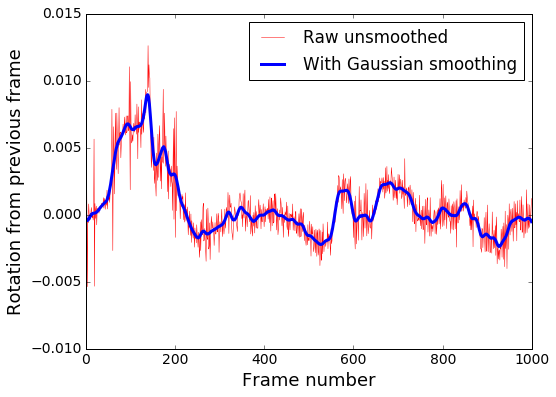
Убираем шум
Мы почти у цели, но остается еще проблема. Посмотрим на получившийся (пока что) график угловой скорости:
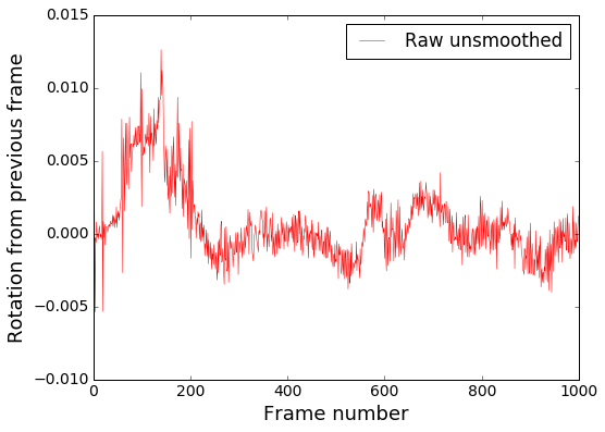
Визуализируем на видео:
Видно, что в общем направление поворота определяется правильно, но очень много высокочастотного шума. Убираем его Гауссовским размытием, которое является низкочастотным фильтром.
Сглаживание в коде производится модулем smooth_heading_directions
Результат после фильтра:
Это уже можно «скормить» обучаемой модели и рассчитывать на адекватные результаты.
Визуализация
Для наглядности по данным из JSON файлов траекторий можно наложить виртуальный руль на исходное видео, как на демках выше, и проверить, правильно ли он крутится. Этим занимается модуль render_turning.
Также легко построить покадровый график. Например, в IPython ноутбуке с установленным matplotlib:
import matplotlib
%matplotlib inline
import matplotlib.pyplot as plt
import json

json_raw = json.load(open('path/to/trajectory.json'))
rotations = [x['turn_angle'] for x in json_raw['trajectory']]
plt.plot(rotations, label='Rotations')
plt.show()
На этом пока всё. В следующей серии — определяем поступательную скорость, чтобы обучить еще и управление скоростью, а пока что приветствуются pull-request’ы.
Беспилотный автомобиль — это когда машина сама умеет ездить по дорогам общего пользования, как будто ей управляет настоящий водитель. Она сама выбирает маршрут, следит за обстановкой на дороге, объезжает препятствия и не нарушает правила дорожного движения. Разбираемся, как это работает.
Уровни автопилота
В зависимости от того, что машина умеет делать сама, инженеры разделили автопилот на 6 уровней:
Level 0 — автопилота нет, водитель всё делает сам. Газель-маршрутка — это как раз машина с автопилотом Level 0.
Level 1 — помощь водителю. Автомобили такого уровня могут сами ускоряться или тормозить. Если на машине установлен круиз-контроль — это Level 1. Сюда же можно отнести некоторые системы автопарковки, когда водитель нажимает кнопку, а машина сама паркуется в сложном месте.
Level 2 — начальный уровень. Здесь машина уже может сама ехать, тормозить и ускоряться, но в разных ситуациях она сразу передаёт управление водителю. Первые Теслы умели как раз вот так.
Level 3 — средний уровень. Машина справляется почти со всеми ситуациями, но водитель всё равно нужен, чтобы среагировать, если что-то пойдёт не так. Сейчас это стало стандартом, и большинство беспилотных машин так умеют.
Level 4 — высокий уровень. В теории тут уже можно отпустить руль — машина сама со всем справится, а если нет — просто остановится. Но на практике водитель всё равно нужен — мало ли что, вдруг машина не сможет правильно среагировать и передаст управление. Самые современные беспилотники — здесь, их работу мы и будем разбирать.
Level 5 — полный автопилот. Можно ездить не держась за руль, можно сесть на пассажирское сиденье или вообще убрать руль из машины. Так пока никто не умеет, кроме робокаров-грузчиков на складах и закрытых площадках, где нет людей.
Что нужно для работы беспилотного авто
Чтобы превратить обычную машину в беспилотную, в неё нужно установить дополнительное железо и алгоритмы:
- радар;
- лидар;
- камеры;
- датчики погодных условий;
- датчики работы основных узлов автомобиля;
- система компьютерного зрения и распознавания образов;
- алгоритмы принятия решений — что машина должна сделать в разных штатных и нештатных ситуациях.
Инженеры чаще всего так и делают — берут серийный автомобиль, навешивают на него всё это железо и ставят внутрь компьютер для обработки сигналов и команд.

Радар
Задача радара — провести первичную разведку того, что находится вокруг машины.
Основной радар на беспилотной машине всё время крутится на крыше, посылает радиоимпульсы и смотрит, какие из них вернулись раньше других. Чем раньше вернулся импульс — тем ближе объект к радару. Радар крутится быстро, и алгоритм анализирует изменения в сигналах. Так машина примерно понимает:
- какое расстояние до каждого объекта;
- что из этого движется, а что не движется.
Это очень грубые данные, но благодаря им машина понимает, на чём нужно сосредоточиться, а что пока не представляет опасности. Ещё есть несколько радаров спереди и сзади автомобиля — они контролируют скорость и расстояние до машин спереди и сзади.

Лидар
Лидар — это более крутая версия радара, построенная на лазерах. Вместо радиосигнала лидар посылает лазерные лучи и моментально узнаёт точное расстояние до объекта:

Но главный плюс лидара в том, что он позволяет строить трёхмерную модель окружающего пространства с точностью ±1 сантиметр. Для этого лидар сканирует пространство 50—100 раз в секунду, совмещает данные и формирует трёхмерное изображение:

Камеры
Задача камер в беспилотных авто — получать картинку вокруг машины, чтобы с ней могли потом работать алгоритмы распознавания образов. Обычно в машины ставят несколько камер для кругового обзора, камеру для анализа дорожного покрытия и несколько дополнительных камер для увеличения обзора.
Именно от камер и алгоритмов обработки зависит то, как машина будет вести себя на дороге. Дело в том, что вся нынешняя разметка, знаки и сигналы направлены на визуальное восприятие — водитель их видит и принимает правильное решение. Чтобы компьютер мог делать то же самое, ему нужно научиться видеть окружающий мир так, как его видит человек.
В камерах инженеры всё время ищут баланс между качеством картинки и скоростью передачи сигнала. Чем качественнее видео, тем больше битов нужно для кодирования такого потока, а значит, алгоритму нужно больше времени, чтобы получить готовый кадр. Наоборот тоже работает: чем хуже и проще картинка, тем быстрее она попадает в обработку, но точность распознавания там тоже хуже.
Алгоритмы компьютерного зрения
Компьютер постоянно распознаёт кадры, поступающие с камер, чтобы найти на них что-то знакомое:
- другие автомобили;
- пешеходов;
- дорожные знаки;
- разметку;
- здания и деревья;
- типичные препятствия, например столб, шлагбаум или открытый люк.
Эта информация потом используется компьютером, чтобы понять — можно тут проехать или нет с соблюдением всех правил дорожного движения.
Как «видит» машина окружающий мир — зависит от алгоритма, который там используется:


Датчики погоды
Машине всё время важно знать, в каком состоянии находится дорога, для этого она использует камеру, направленную вниз, и датчики погоды. Например, если идёт дождь, то компьютер вносит поправки в коэффициент сцепления шин с дорогой и пересчитывает возможную скорость движения. Температурный датчик помогает понять, возможен ли гололёд, а от датчика освещённости зависит максимальная скорость — ночью машина будет ехать медленнее, чем днём.
Система управления основными узлами автомобиля
Чтобы компьютер мог управлять машиной, её нужно доработать — добавить блоки управления на основные части:
- педали газа и тормоза,
- руль,
- поворотники,
- фары и фонари,
- сигнал клаксона.
Благодаря этому компьютер может делать всё то, что делает настоящий водитель: управлять машиной и подавать сигналы остальным участникам дорожного движения. В современных серийных машинах всем, кроме торможения, можно управлять электронно, а в электрокарах даже это можно сделать с помощью бортового компьютера. Почти все современные беспилотные авто — электрические, потому что ими гораздо проще управлять: достаточно подключить блок управления к внутренней проводке машины.
Алгоритмы принятия решений
Это самый важный компонент в любой беспилотной машине — от него зависит, что будет делать машина в любой ситуации:
- как объехать препятствие;
- когда включать поворотник;
- когда нужно снизить скорость перед поворотом;
- что делать, если на дорогу внезапно выбежит человек.
Для этого используются линейные алгоритмы, нейросети и самообучающиеся алгоритмы — они обрабатывают огромный поток данных со всех радаров, камер и датчиков и принимают решение, что делать дальше. Это позволяет избежать аварии в сложных ситуациях — посмотрите на эту подборку, где автопилот спасает жизни водителей, пешеходов и даже животных:
Но если с такими ситуациями компьютер уже справляется, то с остальными всё пока сложно. И это нас приводит к моральной проблеме беспилотных машин.
Моральная проблема беспилотных машин
Существует принципиальная проблема, которую не могут решить разработчики беспилотных авто — что делать, когда ситуация угрожает жизни пассажиров или пешеходов? Классический пример — едет такая машина с двумя пассажирами, на дорогу внезапно выбегают дети, а единственный способ избежать столкновения с ними — увести машину в столб.
Это не вопрос автоматизации, программирования и алгоритмов — в современном виде инженер может запрограммировать любое поведение машины, и она это исполнит (в рамках законов физики). Проблема в том, что люди ещё не сталкивались с вопросом, как алгоритму доверить такой сложный моральный выбор, связанный с жизнью людей, поэтому ни у кого нет правильного ответа. По этой причине все автомобили с подобными системами до сих пор требуют, чтобы водитель держал руки на руле — и в сложной ситуации сам принял решение.