![]()

Preface
Copyright
This publication, including all photographs, illustrations and software, is protected under international copyright laws, with all rights reserved. Neither this manual, nor any of the material contained herein, may be reproduced without written consent of the author.
Version 2.0
Disclaimer
The information in this document is subject to change without notice. The manufacturer makes no representations or warranties with respect to the contents hereof and specifically disclaims any implied warranties of merchantability or fitness for any particular purpose. The manufacturer reserves the right to revise this publication and to make changes from time to time in the content hereof without obligation of the manufacturer to notify any person of such revision or changes.
Trademark Recognition
Microsoft, MS-DOS and Windows are registered trademarks of Microsoft Corp.
MMX, Pentium, Pentium-II, Pentium-III, Pentium-4, Celeron are registered trademarks of Intel Corporation.
Other product names used in this manual are the properties of their respective owners and are acknowledged.
Federal Communications Commission (FCC)
This equipment has been tested and found to comply with the limits for a Class B digital device, pursuant to Part 15 of the FCC Rules. These limits are designed to provide reasonable protection against harmful interference in a residential installation. This equipment generates, uses, and can radiate radio frequency energy and, if not installed and used in accordance with the instructions, may cause harmful interference to radio communications. However, there is no guarantee that interference will not occur in a particular installation. If this equipment does cause harmful interference to radio or television reception, which can be determined by turning the equipment off and on, the user is encouraged to try to correct the interference by one or more of the following measures:
•Reorient or relocate the receiving antenna
•Increase the separation between the equipment and the receiver
•Connect the equipment onto an outlet on a circuit different from that to which the receiver is connected
•Consult the dealer or an experienced radio/TV technician for help
Shielded interconnect cables and a shielded AC power cable must be employed with this equipment to ensure compliance with the pertinent RF emission limits governing this device. Changes or modifications not expressly approved by the system’s manufacturer could void the user’s authority to operate the equipment.
Preface
ii
Declaration of Conformity
This device complies with part 15 of the FCC rules. Operation is subject to the following conditions:
•This device may not cause harmful interference, and
•This device must accept any interference received, including interference that may cause undesired operation
Canadian Department of Communications
This class B digital apparatus meets all requirements of the Canadian Interference-causing Equipment Regulations.
Cet appareil numérique de la classe B respecte toutes les exigences du Réglement sur le matériel brouilieur du Canada.
About the Manual
The manual consists of the following:
Chapter 1
Introducing the Motherboard
Chapter 2
Installing the Motherboard
Chapter 3
Using BIOS
Chapter 4
Using the Motherboard Software
Chapter 5
VIA VT8237 SATA RAID
Setup Guide
Describes features of the motherboard. Go to H page 1
Describes installation of motherboard components.
Go to H page 7
Provides information on using the BIOS Setup Utility.
Describes the motherboard software
Describes the information about SATA RAID Setup
Preface

iii
|
TABLE OF CONTENTS |
|
|
Preface |
i |
|
Chapter 1 |
1 |
|
Introducing the Motherboard |
1 |
|
Introduction……………………………………………………………………………………. |
1 |
|
Feature……………………………………………………………………………………………. |
2 |
|
Motherboard Components……………………………………………………………… |
4 |
|
Chapter 2 |
7 |
|
Installing the Motherboard |
7 |
|
Safety Precautions………………………………………………………………………….. |
7 |
|
Choosing a Computer Case…………………………………………………………….. |
7 |
|
Installing the Motherboard in a Case……………………………………………… |
7 |
|
Checking Jumper Settings………………………………………………………………. |
8 |
|
Setting Jumpers…………………………………………………………………… |
8 |
|
Checking Jumper Settings…………………………………………………….. |
9 |
|
Jumper Settings…………………………………………………………………… |
9 |
|
Connecting Case Components……………………………………………………… |
10 |
|
Front Panel Connector……………………………………………………….. |
12 |
|
Installing Hardware……………………………………………………………………….. |
13 |
|
Installing the Processor……………………………………………………… |
13 |
|
Installing Memory Modules………………………………………………… |
15 |
|
Installing a Hard Disk Drive/CD-ROM/SATA Hard Drive…….. |
18 |
|
Installing a Floppy Diskette Drive……………………………………….. |
18 |
|
Installing Add-on Cards …………………………………………………….. |
19 |
|
Connecting Optional Devic…………………………………………………. |
21 |
|
Connecting I/O Devices……………………………………………………………….. |
24 |
|
Chapter 3 |
25 |
|
Using BIOS |
25 |
|
About the Setup Utility…………………………………………………………………. |
25 |
|
The Standard Configuration……………………………………………….. |
25 |
|
Entering the Setup Utility…………………………………………………….. |
25 |
|
Updating the BIOS…………………………………………………………….. |
27 |
|
Using BIOS…………………………………………………………………………………… |
27 |
|
Standard CMOS Setup……………………………………………………….. |
28 |
|
Advanced Setup…………………………………………………………………. |
29 |
|
Features Setup………………………………………………………………….. |
32 |
iv
|
Power Management Setup………………………………………………….. |
33 |
|
PCI/Plug and Play Setup……………………………………………………. |
35 |
|
BIOS Security Features………………………………………………………. |
36 |
|
CPU PnP Setup…………………………………………………………………. |
37 |
|
Hardware Monitor…………………………………………………………….. |
38 |
|
Load Optimal Defaults………………………………………………………. |
39 |
|
Save Changes and Exit………………………………………………………. |
39 |
|
Discard Changes and Exit………………………………………………….. |
39 |
|
Chapter 4 |
41 |
|
Using the Motherboard Software |
41 |
|
About the Software CD-ROM………………………………………………………. |
41 |
|
Auto-installing under Windows 98/ME/2000/XP………………………….. |
41 |
|
Running Setup…………………………………………………………………… |
42 |
|
Manual Installation………………………………………………………………………. |
44 |
|
Utility Software Reference……………………………………………………………. |
44 |
|
Chapter 5 |
45 |
|
VIAVT8237 SATARAID Setup Guide |
45 |
|
VIA RAID Configurations…………………………………………………………….. |
45 |
|
Installing RAID Software & Drives………………………………………………. |
52 |
|
Using VIARAID Tool…………………………………………………………………… |
54 |

1
Chapter 1
Introducing the Motherboard
Introduction
Thank you for choosing the P4M890T-M motherboard. This motherboard is a high performance, enhanced function motherboard that supports LGA775 Intel CoreTM2 Duo/Celeron D processors for high-end business or personal desktop markets.
The motherboard incorporates the P4M890 Northbridge (NB) and VT8237R plus/VT8237A Southbridge (SB) chipsets. The Northbridge supports a Front Side Bus (FSB) frequency of 1066/800/533 MHz FSB and Hyper-Threading technology. The memory controller supports DDR2 memory DIMM frequencies of 533/400. It supports two DDR2 Sockets with up to maximum memory of 4 GB. High resolution graphic via two PCI Express slots, intended for Graphics Interface, are fully compliant to the PCI Express Base Specification revision 1.1.
The VT8237R plus/VT8237A Southbridge is a highly integrated peripheral controller, it includes an integrated keyboard controller with PS2 mouse support, two-channel Serial ATA/RAID hard disk controller, master mode enhanced Parallel IDE controller with full scatter/gather capability and extension to UltraDMA-133/100/66 for 133/100/66 MB/sec transfer rate, integrated USB 2.0 interface, supporting up to eight functional ports, and OnNow/ACPI compliant advanced configuration and power management interface. The VT8237R plus/VT8237A integrated networking MAC controller with standard MII interface to an external PHY for 100/10 Mb Base-T Ethernet.
This motherboard is equipped with advanced full set of I/O ports in the rear panel, including PS/2 mouse and keyboard connectors, COM1, one VGA port, one optional Print port, four USB ports, one optional LAN port, and audio jacks for microphone, line-in and 6-ch/8- channel (optional) line-out.
Introducing the Motherboard
2
Feature
Processor
This motherboard uses an LGA775 type of Intel CoreTM2 Duo//Celeron D that carries
the following features:
•Accommodates Intel CoreTM2 Duo/Celeron D processors
•Supports a system bus (FSB) of 1066/800/533 MHz
•Supports “Hyper-Threading” technology CPU
“Hyper-Threading” technology enables the operating system into thinking it’s hooked up to two processors, allowing two threads to be run in parallel, both on separate “logical” processors within the same physical processor.
Chipset
The P4M890 Northbridge (NB) and VT8237R plus/VT8237A Southbridge (SB) chipset is based on an innovative and scalable architecture with proven reliability and performance.
|
P4M890 |
• |
High performance Northbridge with 1066/800/533 MHz FSB |
|
(NB) |
• |
for Pentium D/Pentium 4/Celeron D processors |
|
High Bandwidth 533 MB/Sec 8-bit V-Link Host Controller |
||
|
• |
Integrated UniChrome Pro 3D/2D Graphics & Video Control- |
|
|
ler, Microsoft DirectX 7.0 compatible, OpenGL™supported |
||
|
• |
Advanced 64-bit DDR2 and DDR SDRAM controller |
|
|
• |
Advanced DuoView™Capability |
|
|
• |
High Quality Video Processor |
|
|
VT8237R plus/ |
• |
Supports 16-bit 66 MHz, Ultra V-Link interface with 1GB/ |
|
8237A |
sec total bandwidth |
|
|
(SB) |
• |
Compliant with PCI 2.3 specification at 33 MHz, supporting |
|
up to 6 PCI masters |
||
|
• |
Integrated Dual Channel Serial ATA/RAID Host Controllers, |
|
|
supporting data transfer rates up to 1.5Gb/s |
||
|
• |
Integrated UltraDMA 133/100/66 Master Mode EIDE Control- |
|
|
ler |
||
|
• |
USB 2.0 Controller, supporting up to 8 USB 2.0 ports |
|
|
• |
Direct Sound Ready AC97 Digital Audio Controller (VT8237R |
|
|
plus only) |
||
|
• |
Intel High Definition Audio Codec(s) supporting 6/8-channel |
|
|
audio output (VT8237A only) |
||
|
• |
Integrated keyboard Controller with PS2 mouse support |
Memory
•Supports DDR2 533/400 DDR2 SDRAM DIMMs
•Up to 2 GB per DIMM with maximum memory size up to 4 GB
Onboard LAN
•Supports 10 Mb/s and 100 Mb/s N-way Auto-negotiation operation
•Single Chip 100Base-TX/10Base-T Physical Layer Solution
•Half/Full Duplex capability
Introducing the Motherboard

3
Audio (Optional)
The onboard Audio controller provides either of the following features:
•Compliant with AC’97 v2.3 CODEC
•Support 6-channel audio CODEC designed for PC multimedia systems
•Provides three analog line-level stereo inputs with 5-bit volume control: Line-in, CD, AUX
•Meets Microsoft WHQL/WLP 2.0 audio requirements
•8-channel of DAC support 24/20/16-bit PCM format for 7.1 audio solution
•Supports 192K/96K/48K/44.1KHz DAC sample rate
•Power support: Digital: 3.3V; Analog: 3.5V~5.25V
•Meets Microsoft WHQL/WLP 2.x audio requirements
•Direct Sound 3DTM compatible
•DolbyR Digital Encoder output for consumer electronic application
•5.1 Channel High Definition Audio Codec
•ADCs support 44.1k/48k/96k sample rate
•Meets Microsoft WHQL/WLP 3.0x audio requirements
•Direct Sound 3DTM compatible
Expansion Options
The motherboard comes with the following expansion options:
•One PCI Express x16 slot for Graphic Interface
•One PCI Express x1 slot
•Two 32-bit PCI v2.3 compliant slots
•Two 40-pin IDE connectors supporting up to 4 IDE devices
•One floppy disk drive interface
•Two 7-pin SATA connectors
This motherboard supports UltraDMA bus mastering with transfer rates of 133/100/66 MB/s.
Integrated I/O
The motherboard has a full set of I/O ports and connectors:
•Two PS/2 ports for mouse and keyboard
•One serial port
•One VGA port
•Four USB ports
•One parellel port (optional)
•One LAN port (optional)
•Audio jacks for microphone, line-in and 6-ch/8-channel (optional) line-out
BIOS Firmware
This motherboard uses AMI BIOS that enables users to configure system features including the following:
•Power management
•Wake-up alarms
•CPU parameters
•CPU and memroy timing
The firmware can also be used to set parameters for different processor clock speeds.
Some hardware specifications and software items are subject to change without prior notice.
Introducing the Motherboard

Introducing the Motherboard
![]()
5
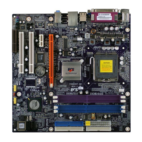
Table of Motherboard Components
|
LABEL |
COMPONENT |
||
|
1 |
CPU Socket |
LGA775 socket for Intel CoreTM2 Duo/ |
|
|
Celeron D processors |
|||
|
2 CPU_FAN |
CPU cooling fan connector |
||
|
3 |
DDRII1~2 |
240-pin DDR2 SDRAM slots |
|
|
4 |
ATX1 |
Standard 24-pin ATX power connector |
|
|
5 |
IDE1 |
Primary IDE connector |
|
|
6 |
IDE2 |
Secondary IDE connector |
|
|
7 |
CLR_CMOS |
Clear CMOS jumper |
|
|
8 |
SATA1~2 |
Serial ATA connectors |
|
|
9 |
PANEL1 |
Front Panel switch/LED header |
|
|
10 BIOS_WP * |
BIOS protect jumper |
||
|
11 COM2 * |
Onboard serial port header |
||
|
12 FDD |
Floppy diskette drive connector |
||
|
13 USB 3~4 |
Front Panel USB headers |
||
|
14 SPDIFO1 |
SPDIF out header |
||
|
15 CD_IN1 |
Analog audio input header |
||
|
16 AUDIO1 |
Front panel audio header |
||
|
17 AUX_IN1 |
Auxiliary audio input header |
||
|
18 PCI1~2 |
32-bit add-on card slots |
||
|
19 IR * |
Infrared header |
||
|
20 PCIEX1 |
PCI express x1 slot |
||
|
21 PCIEX16 |
PCI express x16 slot |
||
|
22 SYS_FAN |
System cooling fan connector |
||
|
23 ATX_12V1 |
Auxiliary 4-pin power connector |
||
|
24 LPT * |
Print port |
* Stands for optional components
This concludes Chapter 1. The next chapter explains how to install the motherboard.
Introducing the Motherboard
Introducing the Motherboard

7
Chapter 2
Installing the Motherboard
Safety Precautions
•Follow these safety precautions when installing the motherboard
•Wear a grounding strap attached to a grounded device to avoid damage from static electricity
•Discharge static electricity by touching the metal case of a safely grounded object before working on the motherboard
•Leave components in the static-proof bags they came in
•Hold all circuit boards by the edges. Do not bend circuit boards
Choosing a Computer Case
There are many types of computer cases on the market. The motherboard complies with the specifications for the Micro ATX system case. First, some features on the motherboard are implemented by cabling connectors on the motherboard to indicators and switches on the system case. Make sure that your case supports all the features required. Secondly, this motherboard supports one floppy controller and four enhanced IDE drives. Make sure that your case has sufficient power and space for all drives that you intend to install.
Most cases have a choice of I/O templates in the rear panel. Make sure that the I/O template in the case matches the I/O ports installed on the rear edge of the motherboard.
This motherboard carries a Micro ATX form factor of 244 x 210 mm. Choose a case that accommodates this form factor.
Installing the Motherboard in a Case
Refer to the following illustration and instructions for installing the motherboard in a case.
Most system cases have mounting brackets installed in the case, which correspond the holes in the motherboard. Place the motherboard over the mounting brackets and secure the motherboard onto the mounting brackets with screws.
Ensure that your case has an I/O template that supports the I/O ports and expansion slots on your motherboard.
Installing the Motherboard

8
Do not over-tighten the screws as this can stress the motherboard.
Checking Jumper Settings
This section explains how to set jumpers for correct configuration of the motherboard.
Setting Jumpers
Use the motherboard jumpers to set system configuration options. Jumpers with more than one pin are numbered. When setting the jumpers, ensure that the jumper caps are placed on the correct pins.
|
The illustrations show a 2-pin jumper. When |
||
|
the jumper cap is placed on both pins, the |
||
|
jumper is SHORT. If you remove the jumper |
||
|
cap, or place the jumper cap on just one pin, |
||
|
the jumper is OPEN. |
SHORT |
OPEN |
This illustration shows a 3-pin jumper. Pins 1 and 2 are SHORT
Installing the Motherboard

9
Checking Jumper Settings
The following illustration shows the location of the motherboard jumpers. Pin 1 is labeled.
Jumper Settings
|
Jumper |
Type |
Description |
Setting (default) |
||||||
|
1-2: NORMAL |
|||||||||
|
CLR_CMOS |
3-pin |
CLEAR CMOS |
2-3: CMOS CLEAR |
1 |
|||||
|
Before clearing the |
|||||||||
|
CMOS, make sure to |
CLR_CMOS |
||||||||
|
turn off the system. |
|||||||||
|
BIOS_WP |
BIOS WRITE |
1-2: DISABLE |
1 |
||||||
|
3-pin |
|||||||||
|
(Optional) |
PROTECT |
2-3: ENABLE |
|||||||
|
BIOS_WP |
|||||||||
To avoid the system unstability after clearing CMOS, we recommend users to enter the main BIOS setting page to “Load Optimal Defaults” and then “Save Changes and Exit”.
Installing the Motherboard

10
Connecting Case Components
After you have installed the motherboard into a case, you can begin connecting the motherboard components. Refer to the following:
1Connect the CPU cooling fan cable to CPU_FAN.
2Connect the system cooling fan connector to SYS_FAN.
3Connect the case switches and indicator LEDs to the PANEL1.
4Connect the standard power supply connector to ATX1.
5Connect the auxiliary case power supply connector to ATX_12V1.
Connecting 20/24-pin power cable
Users please note that the 20-pin and 24-pin power cables can both be connected to the ATX1 connector. With the 20-pin power cable, just align the 20-pin power cable with the pin 1 of the ATX1 connector. However, using 20-pin power cable may cause the system to become unbootable or unstable because of insufficient electricity. A minimum power of 300W is recommended for a fully-configured system.
20-pin power cable
24-pin power cable
With ATX v1.x power supply, users please note that when installing 20-pin power cable, the latche of power cable clings to the left side of the ATX1 connector latch, just as the picture shows.
With ATX v2.x power supply, users please note that when installing 24-pin power cable, the latches of power cable clings to the right side of the ATX1 connector latch.
Installing the Motherboard

11
CPU_FAN: CPU FAN Power Connector
|
Pin |
Signal Name |
Function |
|
1 |
GND |
System Ground |
|
2 |
+12V |
Power +12V |
|
3 |
Sense |
Sensor |
|
4 |
CONTROL |
CPU FAN control |
Users please note that the fan connector supports the CPU cooling fan of 1.1A~2.2A (26.4W max.) at +12V.
SYS_FAN: System cooling FAN Power Connector
|
Pin |
Signal Name |
Function |
|
1 |
GND |
System Ground |
|
2 |
+12V |
Power +12V |
|
3 |
Sense |
Sensor |
ATX_12V1: ATX 12V Power Connector
1Ground
2Ground
3+12V
4+12V
ATX1: ATX 24-pin Power Connector
|
Pin |
Signal Name |
Pin |
Signal Name |
|
1 |
+3.3V |
13 |
+3.3V |
|
2 |
+3.3V |
14 |
-12V |
|
3 |
Ground |
15 |
Ground |
|
4 |
+5V |
16 |
PS_ON |
|
5 |
Ground |
17 |
Ground |
|
6 |
+5V |
18 |
Ground |
|
7 |
Ground |
19 |
Ground |
|
8 |
PWRGD |
20 |
-5V |
|
9 |
+5VSB |
21 |
+5V |
|
10 |
+12V |
22 |
+5V |
|
11 |
+12V |
23 |
+5V |
|
12 |
+3.3V |
24 |
Ground |
Installing the Motherboard

12
Front Panel Connector
The front panel connector (PANEL1) provides a standard set of switch and LED connectors commonly found on ATX or Micro ATX cases. Refer to the table below for information:
|
Pin |
Signal |
Function |
Pin |
Signal |
Function |
|
1 |
HD_LED_P |
Hard disk LED(+) |
2 |
FP PWR/SLP |
*MSG LED(+) |
|
3 |
HD_LED_N |
Hard disk LED(-) |
4 |
FP PWR/SLP |
*MSG LED(-) |
|
5 |
RST_SW_N |
Reset Switch(-) |
6 |
PWR_SW_P |
Power Switch(+) |
|
7 |
RST_SW_P |
Reset Switch(+) |
8 |
PWR_SW_N |
Power Switch(-) |
|
9 |
RSVD |
Reserved |
10 |
Key |
Nopin |
* MSG LED (dual color or single color)
Hard Drive Activity LED
Connecting pins 1 and 3 to a front panel mounted LED provides visual indication that data is being read from or written to the hard drive. For the LED to function properly, an IDE drive should be connected to the onboard IDE interface. The LED will also show activity for devices connected to the SCSI (hard drive activity LED) connector.
Power/Sleep/Message waiting LED
Connecting pins 2 and 4 to a single or dual-color, front panel mounted LED provides power on/off, sleep, and message waiting indication.
Reset Switch
Supporting the reset function requires connecting pin 5 and 7 to a momentary-contact switch that is normally open. When the switch is closed, the board resets and runs POST.
Power Switch
Supporting the power on/off function requires connecting pins 6 and 8 to a momentarycontact switch that is normally open. The switch should maintain contact for at least 50 ms to signal the power supply to switch on or off. The time requirement is due to internal debounce circuitry. After receiving a power on/off signal, at least two seconds elapses before the power supply recognizes another on/off signal.
Installing the Motherboard

13
Installing Hardware
Installing the Processor
Caution: When installing a CPU heatsink and cooling fan make sure that you DO NOT scratch the motherboard or any of the surface-mount resistors with the clip of the cooling fan. If the clip of the cooling fan scrapes across the motherboard, you may cause serious damage to the motherboard or its components.
On most motherboards, there are small surface-mount resistors near the processor socket, which may be damaged if the cooling fan is carelessly installed.
Avoid using cooling fans with sharp edges on the fan casing and the clips. Also, install the cooling fan in a well-lit work area so that you can clearly see the motherboard and processor socket.
Before installing the Processor
This motherboard automatically determines the CPU clock frequency and system bus frequency for the processor. You may be able to change these settings by making changes to jumpers on the motherboard, or changing the settings in the system Setup Utility. We strongly recommend that you do not over-clock processors or other components to run faster than their rated speed.
Warning: Over-clocking components can adversely affect the reliability of the system and introduce errors into your system. Over-clocking can permanently damage the motherboard by generating excess heat in components that are run beyond the rated limits.
This motherboard has a LGA775 socket. When choosing a processor, consider the performance requirements of the system. Performance is based on the processor design, the clock speed and system bus frequency of the processor, and the quantity of internal cache memory and external cache memory.
Installing the Motherboard

14
CPU Installation Procedure
The following illustration shows CPU installation components.
A.Read and follow the instructions shown on the sticker on the CPU cap.
B.Unload the cap
·Use thumb & forefinger to hold the lifting tab of the cap.
·Lift the cap up and remove the cap completely from the socket.
C.Open the load plate
·Use thumb & forefinger to hold the
hook of the lever, pushing down and pulling aside unlock it.
·Lift up the lever.
·Use thumb to open the load plate. Be careful not to touch the contacts.
D.Install the CPU on the socket
·Orientate CPU package to the socket.
Make sure you match triangle marker to pin 1 location.
E.Close the load plate
·Slightly push down the load plate onto the tongue side, and hook the lever.
·CPU is locked completely.
F.Apply thermal grease on top of the CPU.
G.Fasten the cooling fan supporting base onto the CPU socket on the motherboard.
H.Make sure the CPU fan is plugged to the CPU fan connector. Please refer to the CPU cooling fan user’s manual for more detail installation procedure.
1.To achieve better airflow rates and heat dissipation, we suggest that you use a high quality fan with 3800 rpm at least. CPU fan and heatsink installation procedures may vary with the type of CPU fan/heatsink sup plied. The form and size of fan/heatsink may also vary.
2.DO NOT remove the CPU cap from the socket before installing a CPU.
3.Return Material Authorization (RMA) requests will be accepted only if the motherboard comes with thecap on the LGA775 socket.
Installing the Motherboard
 Loading…
В представленном списке руководства для конкретной модели Материнской платы — ECS P4M890T-M (V1.0). Вы можете скачать инструкции к себе на компьютер или просмотреть онлайн на страницах сайта бесплатно или распечатать.
- Инструкции и файлы
- Характеристики
- Основные поломки
- Сервисы по ремонту
В случае если инструкция на русском не полная или нужна дополнительная информация по этому устройству, если вам нужны
дополнительные файлы: драйвера, дополнительное руководство пользователя (производители зачастую для каждого
продукта делают несколько различных документов технической помощи и руководств), свежая версия прошивки, то
вы можете задать вопрос администраторам или всем пользователям сайта, все постараются оперативно отреагировать
на ваш запрос и как можно быстрее помочь. Ваше устройство имеет характеристики:Socket: LGA775, Поддерживаемые процессоры: Intel Core 2 Duo/Pentium D/Pentium 4/Celeron D, Системная шина: 533 МГц — 1066 МГц, Поддержка Hyper-Threading: есть, Поддержка многоядерных процессоров: есть, Чипсет: VIA P4M890, полные характеристики смотрите в следующей вкладке.
Для многих товаров, для работы с ECS P4M890T-M (V1.0) могут понадобиться различные дополнительные файлы: драйвера, патчи, обновления, программы установки. Вы можете скачать онлайн эти файлы для конкретнй модели ECS P4M890T-M (V1.0) или добавить свои для бесплатного скачивания другим посетителями.
Если вы не нашли файлов и документов для этой модели то можете посмотреть интсрукции для похожих товаров и моделей, так как они зачастую отличаются небольшим изменениями и взаимодополняемы.
Обязательно напишите несколько слов о преобретенном вами товаре, чтобы каждый мог ознакомиться с вашим отзывом или вопросом. Проявляйте активность что как можно бльше людей смогли узнать мнение настоящих людей которые уже пользовались ECS P4M890T-M (V1.0).

вроде нормальная
варпвр
2017-12-19 15:12:12
dtukmfhnmd dty rtu dy
загрузим и оценим
Роман
2018-05-03 18:24:16
хорошо
да норм
загрузим и оценим
загрузим и оценим
Только включил
Максим Владимирович Леонтьев
2018-11-06 16:20:41
впыпыппап
Не очень
Игорь
2019-01-08 13:55:59
Норм
Karim
2019-02-10 19:47:10
Нормальная материнская плата для своего года.
Хз, щас проверим. Ещё грёбаный комментарий строчить надо…
Евгений
2019-03-01 00:57:41
Хорошо
Victor
2019-04-10 13:40:54
Разбираемся…
скачаю — все расскажу
Сергей
2019-09-03 01:20:27
вставляешь 2 оперативки по 2 гб, первую определяет как 2 гб,а вторую 512 мб. ищу причину.
Archi
2019-10-13 13:01:53
Один большой тормоз
Ща скачаю
Виктор
2019-11-27 16:52:17
Норм
Роман
2019-12-08 17:15:25
Вроде нормальная мать
Сергей
2020-08-12 19:13:09
Qqqquhhhcgh
Александр
2020-08-25 10:42:50
Здравствуйте! Купил с рук недорого материнскую плату «ECS P4M890T-M REV: 1.0″ с памятью 3 ГБ (2+1) и процессором INTEL M C » 05 E2180 PENTIUM R DUAL-C0RE SLA8Y MALAY 2.00 GHZ/1M/800/06 Q828A660 в работающем состоянии. Решил сделать «up grade» процессора, поставив другой, заведомо исправный процессор INTEL M C » 06 E7400 INTEL R CORE TM 2 DUO SLB9Y MALAY 2.80 GHZ/3M/1066/06 Q910A290 E4. Однако, по непонятной причине м/плата с этим процессором не захотела работать. Скажите, пожалуйста, в чём дело? Помогите, пожалуйста разобраться. Александр.
[email protected]
2020-11-03 13:33:55
нормал
SHURIK
2020-11-14 07:50:58
Не пользовался ещё,но вроде не плоха
Основные и самые важные характеристики модели собраны из надежных источников и по характеристикам можно найти похожие модели.
| Процессор | |
| Socket | LGA775 |
| Поддерживаемые процессоры | Intel Core 2 Duo/Pentium D/Pentium 4/Celeron D |
| Системная шина | 533 МГц — 1066 МГц |
| Поддержка Hyper-Threading | есть |
| Поддержка многоядерных процессоров | есть |
| Чипсет | |
| Чипсет | VIA P4M890 |
| BIOS | AMI |
| Поддержка SLI/CrossFire | нет |
| Память | |
| Память | DDR2 DIMM, 400 — 533 МГц |
| Количество слотов памяти | 2 |
| Максимальный объем памяти | 4 Гб |
| Дисковые контроллеры | |
| IDE | количество слотов: 2, UltraDMA 133 |
| SATA | количество разъемов SATA 1.5Gb/s: 2, , RAID: 0, 1 |
| Слоты расширения | |
| Слоты расширения | 1xPCI-E x16, 2xPCI |
| Аудио/видео | |
| Звук | 5.1CH, AC’97, на основе Realtek ALC655 |
| Встроенный видеоадаптер | есть |
| Сеть | |
| Ethernet | 10/100 Мбит/с, на основе VIA VT6103L |
| Подключение | |
| Наличие интерфейсов | 8 USB, 1xCOM, D-Sub, Ethernet, PS/2 (клавиатура), PS/2 (мышь), LPT |
| Разъемы на задней панели | 4 USB, 1xCOM, D-Sub, Ethernet, PS/2 (клавиатура), PS/2 (мышь), LPT |
| Основной разъем питания | 24-pin |
| Разъем питания процессора | 4-pin |
| Дополнительные параметры | |
| Форм-фактор | microATX |
| Дополнительная информация | 1 слот CNR |
Здесь представлен список самых частых и распространенных поломок и неисправностей у Материнских плат. Если у вас такая поломка то вам повезло, это типовая неисправность для ECS P4M890T-M (V1.0) и вы можете задать вопрос о том как ее устранить и вам быстро ответят или же прочитайте в вопросах и ответах ниже.
| Название поломки | Описание поломки | Действие |
|---|---|---|
| Разрыв Печатных Проводников | ||
| Обрыв Конденсаторов Или Резисторов | ||
| Короткое Замыкание В Электрических Цепях | ||
| Разрушение Разъемов И Слотов | ||
| Поломка Процессорного Разъема | ||
| Выгорание Портов | ||
| Микротрещины В Плате | ||
| Выход Из Строя Сетевого Адаптера | ||
| Перегрев Компонентов | ||
| Не Запускается При Включении | При Включении Не Загружается. В Биос Не Входит. Пост Код — А3 | |
| Какой Компонент | Подскажите Марку Траyзистора Q46? | |
| Не Работает Ps/2 | Сначала Отвалилась Клавиатура, А Через Некоторое Время 6 Коротких Гудков И Не Запускается | |
| Подключить Переднюю Панель | Не Могу Подключить Переднюю Панель | |
| Судя По Всему Отвал Биоса | Материнка Стартует Секунд На 5,Кулер Процессора Берет Обороты И Останавливается.и Так-Циклически,Без Остановок.запуск Невозможен.вечером Либо Завтра Буду Пытаться Его Восстановить,Потом Может Дополню | |
| Пропал Звук На Материнке | Пропал Звук На Материнке, Отображается Только Nvidia Hdmi. Переустановка Драйверов С Офсайта Не Помогла. | |
| Биос | При Старте Звук Через Промежетки Времени Примерно В 1-3 Мин Три Сигнала Потом Стартует Винда , Недавно Вообще Написал Cmos Setting Wrong И C7, Жму Del Меняется На B2 Чтоб Воити В Биос Три Сигнала По Одному Через Промеежутки Времени 1-3 Мин И Черный Экра | |
| Asus M2A-Vm Hdmi | Не Запускается Процессор Phenom Ii X4 945 Rev. C3, На Socket-Ам 3, Нет Даже Сигнала, Черный Экран | |
| Не Включается | После Замены Конденсаторов С34 И С35 Не Включается | |
| Черный Экран | Все Уже Перепробовал И Озу Менял И Переставлял И Ластиком Чистил, И Батарейку Вынимал И Измерял, И Видеокарту С Бп На Заведомо Годную Ставил Исход Один, Черный Экран И Speaker Издает 1 Длинный 2 Коротких, Если Я Не Путаю. | |
| Неправильно Отображается Память | При Установленной Памяти 4 Гигабайта В Биосе Отображается 8. Установил Одну Планку 2 Гига — Отображается 4 | |
В нашей базе сейчас зарегестрированно 18 353 сервиса в 513 города России, Беларусии, Казахстана и Украины.

SLIPARD
⭐
⭐
⭐
⭐
⭐
Адресс:
Волгоградский пр-т, д.93
Телефон:
Сайт:
n/a
Время работы
Время работы не указано
ПРИНТЕРЫ-КОМПЬЮТЕРЫ
⭐
⭐
⭐
⭐
⭐
Адресс:
2-й Автозаводский проезд, д. 3а
Телефон:
74957809503
Сайт:
n/a
Время работы
Время работы не указано
КОМПРАЙЭКСПРЕСС — КОМПЬЮТЕРНЫЙ МАСТЕР-СЕРВИС
⭐
⭐
⭐
⭐
⭐
Адресс:
ул. Краснобогатырская, д. 13
Телефон:
79153203397
Сайт:
n/a
Время работы
Круглосуточно
REMOBI
⭐
⭐
⭐
⭐
⭐
Адресс:
ул. Гарибальди, 23, ТЦ Панорама
Телефон:
74993222524
Сайт:
n/a
Время работы
Ежедневно: с 1000 до 2100
ТОЧКА РЕМОНТА
⭐
⭐
⭐
⭐
⭐
Адресс:
ул. Люблинская 27/2
Телефон:
74956644245
Сайт:
n/a
Время работы
Будни: с 1100 до 1900
Суббота: с 1100 до 1800
Воскресенье: с 1100 до 1800
материнская плата ECS P4M890T-M
1:39
Очень доволен
хочу
авпваы
Хочу купить
ирлдоьвап ькеьпрлджыкеь дзьакерджь щзрбкежбрь апкыезрбкыеджрбеджр щзапбкерл
Только приобрела,а инструкции нет
Только приобрела,а инструкции нет
Отвалился распрыскиватель
![]()
ECS P4M890T-M REV 1.0 SCH

Type:  (PDF)
(PDF)
Size
985.4 KB
Page
29
Category
NOTEBOOK-PC
SERVICE MANUAL
If you get stuck in repairing a defective appliance
download
this repair information for help. See below.
Good luck to the repair!
Please do not offer the downloaded file for sell only
use it for personal usage!
Looking for similar ecs manual?
Document preview [1st page]

Click on the link for free download!
Document preview [2nd page]

Click on the link for free download!
Please tick the box below to get download link:
- Also known:
ECS P-4M-890TM REV P4M890TM 1.0 890 TM P4M890T P4M890T-M
- If you have any question about repairing write your question to the Message board. For this no need registration.
- Please take a look at the below related repair forum topics. May be help you to repair.
Warning!
If you are not familiar with electronics, do not attempt to repair!
You could suffer a fatal electrical shock! Instead, contact your nearest service center!
Note! To open downloaded files you need acrobat reader or similar pdf reader program. In addition,
some files are archived,
so you need WinZip or WinRar to open that files. Also some files are djvu so you need djvu viewer to open them.
These free programs can be found on this page: needed progs
If you use opera you have to disable opera turbo function to download file!
If you cannot download this file, try it with CHROME or FIREFOX browser.
Üdvözlet mindenkinek!
A címben említett készülék a következő hibát produkálja egyaránt a saját hangszóróján és a fülhallgató kimeneten is,mégpedig recseg hang mint a bakelitlejátszóknál amikor poros a lemez.ALC 268 típusú audio codec van a készülékben.Találkozott már valaki hasonlóval,mit lenne érdemes megvizsgálnom,mi okozhatja ezt a hibát.
Előre is köszönöm a segítséget.
A HIBÁT A WINDOWS OKOZTA.ÚJRATELEPÍTÉS MEGOLDOTTA A PROBLÉMÁT.KÖSZÖNÖM A SEGÍTSÉGET.
Üdv:Mitu
Similar manuals:
If you want to join us and get
repairing help
please sign in or sign up by completing a simple electrical test
or write your question to the Message board without registration.
You can write in English language into the forum (not only in Hungarian)!
E-Waste Reduce
P4M900-M7 SE/P4M890-M7 TE
Setup Manual
FCC Information and Copyright
This equipment has been tes ted and found to comply with the limits of a Class
B digital devic e, purs uant to Part 15 of the FCC Rules . T hese limits are designed
to provide reasonable protec tion against harmful interference in a residential
installation. T his equipment generates , uses , and c an radiate radio frequency
energy and, if not ins talled and used in accordance with the instructions , may
cause harmful interference to radio communications . There is no guarantee
that interference will not occur in a particular ins tallation.
The vendor makes no representations or warranties with respec t to the
contents here and s pecially disclaims any implied warranties of merchantability
or fitness for any purpose. Further the vendor reserves the right to revise this
publication and to make c hanges to the c ontents here without obligation to
notify any party beforehand.
Duplication of this publication, in part or in whole, is not allowed without first
obtaining the vendor’s approval in writing.
The content of this user’s manual is subject to be c hanged without notice and
we will not be res ponsible for any mis takes found in this user’s manual. All the
brand and produc t names are trademarks of their respec tive companies .
- Manuals
- Brands
- ECS Manuals
- Motherboard
- P4M890T-M2
- Installing
-
Contents
-
Table of Contents
-
Bookmarks
Quick Links
Related Manuals for ECS P4M890T-M2
Summary of Contents for ECS P4M890T-M2
-
Page 3
Preface Copyright This publication, including all photographs, illustrations and software, is protected under international copyright laws, with all rights reserved. Neither this manual, nor any of the material contained herein, may be reproduced without written consent of the author. Version 1.0B Disclaimer The information in this document is subject to change without notice. -
Page 4
Declaration of Conformity This device complies with part 15 of the FCC rules. Operation is subject to the following conditions: • This device may not cause harmful interference, and • This device must accept any interference received, including interference that may cause undesired operation Canadian Department of Communications This class B digital apparatus meets all requirements of the Canadian Interference-causing Equipment Regulations. -
Page 5: Table Of Contents
T T T T T ABLE OF CONTENTS ABLE OF CONTENTS ABLE OF CONTENTS ABLE OF CONTENTS ABLE OF CONTENTS Preface Chapter 1 Introducing the Motherboard Introduction………………..1 Feature………………….2 Motherboard Components…………….4 7 7 7 7 7 Chapter 2 Installing the Motherboard Safety Precautions………………7 Choosing a Computer Case……………7 Installing the Motherboard in a Case…………7…
-
Page 6
Power Management Setup…………36 PCI/Plug and Play Setup………….37 BIOS Security Features…………..38 CPU PnP Setup…………….39 Hardware Monitor……………40 Load Optimal Defaults…………..41 Save Changes and Exit…………..41 Discard Changes and Exit…………41 Chapter 4 43 43 43 43 Using the Motherboard Software About the Software CD-ROM…………..43 Auto-installing under Windows 2000/XP……….43 Running Setup…………….43 Manual Installation………………46… -
Page 7: Introducing The Motherboard
Chapter 1 Introducing the Motherboard Introduction Thank you for choosing the P4M890T-M2 motherboard. This motherboard is a high performance, enhanced function motherboard that supports LGA775 Pentium 4/Celeron D/Pentium D processors for high-end business or personal desktop markets. The motherboard incorporates the P4M890 Northbridge (NB) and VT8237R+/VT8237A Southbridge (SB) chipsets.
-
Page 8: Feature
Feature Processor This motherboard uses an LGA775 type of Pentium 4/Celeron D/Pentium D that carries the following features: • Accommodates Intel Pentium 4/Celeron D/Pentium D processors • Supports a system bus (FSB) of 1066/800/533 MHz • Supports “Hyper-Threading” technology CPU “Hyper-Threading”…
-
Page 9
Onboard LAN (Optional) The onboard LAN controller provides any of the following features: • MII Interface to Ethernet Controller (MAC) • Compliant with IEEE 802.3/802.3u, 10Base-T and 100Base-TX standards • Serial MI Interface for Configuration & Status • Supports 10/100 Mb/s N-way Auto negotiation operation •… -
Page 10: Motherboard Components
Motherboard Components Introducing the Motherboard…
-
Page 11
Table of Motherboard Components LABEL COMPONENT 1 CPU Socket LGA775 socket for Pentium 4/Celeron D/ Pentium D CPUs 2 CPU_FAN CPU cooling fan connector 3 DDRII1~2 240-pin DDR2 SDRAM slots 4 DDR1~2 184-pin DDR SDRAM slots 5 ATX1 Standard 24-pin ATX power connector 6 FDD Floppy disk drive connector 7 IDE2… -
Page 12
Memo Introducing the Motherboard… -
Page 14: Checking Jumper Settings
Checking Jumper Settings The following illustration shows the location of the motherboard jumpers. Pin 1 is labeled. Jumper Settings Jumper Type Description Setting (default) 1-2: NORMAL 2-3: CLEAR CLR_CMOS 3-pin Clear CMOS Before clearing the CMOS, make sure to CLR_CMOS turn off the system.
-
Page 15: Connecting Case Components
Connecting Case Components After you have installed the motherboard into a case, you can begin con- necting the motherboard components. Refer to the following: Connect the CPU cooling fan cable to CPU_FAN. Connect the system cooling fan connector to SYS_FAN. Connect the case switches and indicator LEDs to the PANEL1.
-
Page 16
CPU_FAN/SYS_FAN: Cooling FAN Power Connectors Signal Name Function System Ground Power +12V +12V Sense Sensor CPU FAN control Users please note that the fan connector supports the CPU cooling fan of 1.1A~2.2A (26.4W max.) at +12V. ATX_12V1: ATX 12V Power Connector Signal Name Ground Ground… -
Page 17
Table A: DDR2 (memory module) QVL (Qualified Vendor List) The following DDR2 memory modules have been tested and qualified for use with this motherboard. Type Size Vendor Model Name Hynix HYMP532U646-E3 AA DDR2 256 MB NANYA NT256T64UH4A0F-5A SAMSUNG M378T3253FG0-GCCC A-DATA M2OHY2F3G3110A1B0Z Elixir M2U25664TUH4A0F-37B… -
Page 18: Installing A Hard Disk Drive/Cd-Rom/Sata Hard Drive
Installing a Hard Dish Drive/CD-ROM/SATA Hard Drive This section describes how to install IDE devices such as a hard disk drive and a CD-ROM drive. About IDE Devices Your motherboard has two IDE channels interface. An IDE ribbon cable supporting two IDE devices is bundled with the motherboard.
-
Page 19
About SATA Connectors Your motherboard features two SATA connectors supporting a total of two drives. SATA , or Serial ATA (Advanced Technology Attachment) is the standard interface for the IDE hard drives which are currently used in most PCs. These connectors are well designed and will only fit in one orientation. -
Page 20: Installing A Floppy Diskette Drive
Installing a Floppy Diskette Drive The motherboard has a floppy diskette drive (FDD) interface and ships with a diskette drive ribbon cable that supports one or two floppy diskette drives. You can install a 5.25-inch drive and a 3.5-inch drive with various capacities. The floppy diskette drive cable has one type of connector for a 5.25-inch drive and another type of connector for a 3.5-inch drive.
-
Page 21: Installing Add-On Cards
Installing Add-on Cards The slots on this motherboard are designed to hold expansion cards and connect them to the system bus. Expansion slots are a means of adding or enhancing the motherboard’s features and capabilities. With these efficient facilities, you can increase the motherboard’s capabili- ties by adding hardware that performs tasks that are not part of the basic system.
-
Page 22
Follow these instructions to install an add-on card: Remove a blanking plate from the system case corresponding to the slot you are going to use. Install the edge connector of the add-on card into the expansion slot. Ensure that the edge connector is correctly seated in the slot. Secure the metal bracket of the card to the system case with a screw. -
Page 23: Connecting Optional Devices
Connecting Optional Devices Refer to the following for information on connecting the motherboard’s optional devices: USB3~4: Front Panel USB headers The motherboard has four USB ports installed on the rear edge I/O port array. Additionally, some computer cases have USB ports at the front of the case. If you have this kind of case, use auxiliary USB connector to connect the front-mounted ports to the motherboard.
-
Page 24
AUDIO1: Front Panel Audio header This header allows the user to install auxiliary front-oriented microphone and line-out ports for easier access. Signal Name Function AUD_MIC Front Panel Microphone input signal AUD_GND Ground used by Analog Audio Circuits AUD_MIC_BIAS Microphone Power AUD_VCC Filtered +5V used by Analog Audio Circuits AUD_F_R… -
Page 25
SATA1~2: Serial ATA connectors These connectors are use to support the new Serial ATA devices for the highest date transfer rates (1.5 Gb/s), simpler disk drive cabling and easier PC assembly. It eliminates limitations of the current Parallel ATA interface. But maintains register compatibility and software compatibility with Parallel ATA. -
Page 26: Connecting I/O Devices
Connecting I/O Devices The backplane of the motherboard has the following I/O ports: PS2 Mouse Use the upper PS/2 port to connect a PS/2 pointing device. PS2 Keyboard Use the lower PS/2 port to connect a PS/2 keyboard. Parallel Port (LPT1) Use LPT1 to connect printers or other parallel communications devices.
![]()
ECS P4M890T-M REV 1.0 SCH
Type: (PDF)
Size
985.4 KB
Page
29
Category
NOTEBOOK-PC
SERVICE MANUAL
If you get stuck in repairing a defective appliance
download
this repair information for help. See below.
Good luck to the repair!
Please do not offer the downloaded file for sell only
use it for personal usage!
Looking for similar ecs manual?
Document preview [1st page]
Click on the link for free download!
Document preview [2nd page]
Click on the link for free download!
Please tick the box below to get download link:
- Also known:
ECS P-4M-890TM REV P4M890TM 1.0 890 TM P4M890T P4M890T-M
- If you have any question about repairing write your question to the Message board. For this no need registration.
- If the site has helped you and you also want to help others, please Upload a manual, circuit diagram or eeprom that is not yet available on the site.
Have a nice Day! - Please take a look at the below related repair forum topics. May be help you to repair.
Warning!
If you are not familiar with electronics, do not attempt to repair!
You could suffer a fatal electrical shock! Instead, contact your nearest service center!
Note! To open downloaded files you need acrobat reader or similar pdf reader program. In addition,
some files are archived,
so you need WinZip or WinRar to open that files. Also some files are djvu so you need djvu viewer to open them.
These free programs can be found on this page: needed progs
If you use opera you have to disable opera turbo function to download file!
If you cannot download this file, try it with CHROME or FIREFOX browser.
Üdvözlet mindenkinek!
A címben említett készülék a következő hibát produkálja egyaránt a saját hangszóróján és a fülhallgató kimeneten is,mégpedig recseg hang mint a bakelitlejátszóknál amikor poros a lemez.ALC 268 típusú audio codec van a készülékben.Találkozott már valaki hasonlóval,mit lenne érdemes megvizsgálnom,mi okozhatja ezt a hibát.
Előre is köszönöm a segítséget.
A HIBÁT A WINDOWS OKOZTA.ÚJRATELEPÍTÉS MEGOLDOTTA A PROBLÉMÁT.KÖSZÖNÖM A SEGÍTSÉGET.
Üdv:Mitu
Similar manuals:
If you want to join us and get
repairing help
please sign in or sign up by completing a simple electrical test
or write your question to the Message board without registration.
You can write in English language into the forum (not only in Hungarian)!
E-Waste Reduce